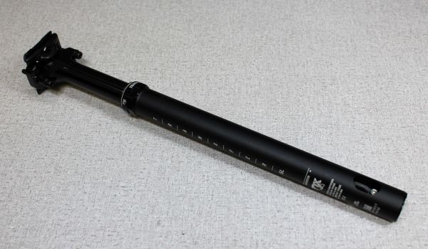
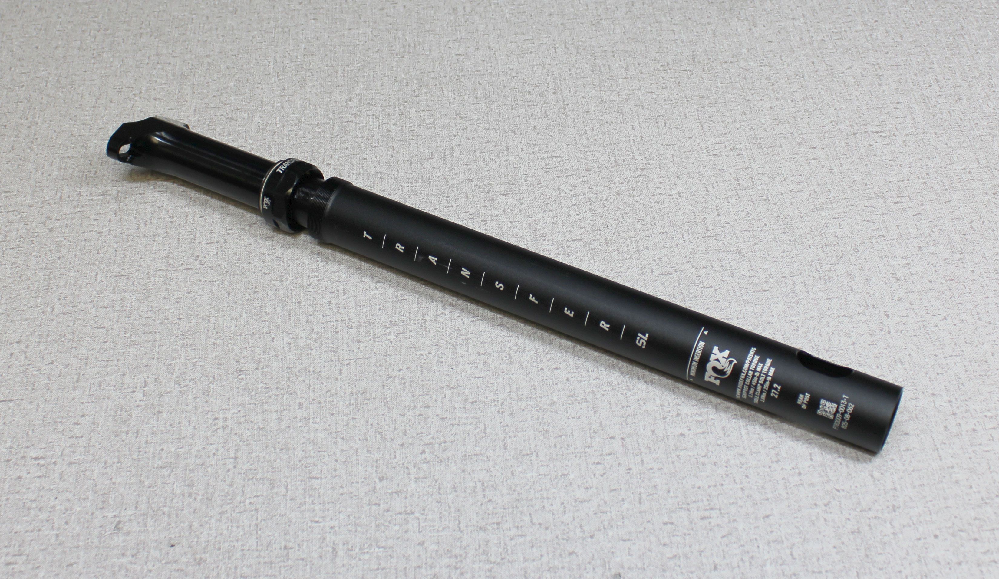
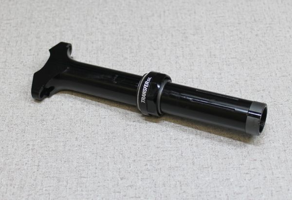
2022 Transfer SL 27.2mm/ Easton EA90AX Rebuild
Required Parts
- 803-01-743 Kit: Rebuild, 2022 Transfer SL Seatpost, 27.2
- 803-01-744 Kit: Rebuild, 2022 Easton EA90 AX Seatpost, 27.2
Required Tools
- 398-00-838 Tooling: Driver, Retaining Lug, Transfer SL 31.6/ 30.9/ 27.2
- 398-00-911 Tooling: Collar Torque Driver, Transfer SL 27.2/ EA90AX
- 398-00-912 Tooling: Locking Spring Preloader, Transfer SL 27.2/ EA90AX
- 398-00-916 Tooling: T/O Cap Driver, Transfer SL 31.6/ 30.9/ 27.2
- 398-00-917 Tooling: Bullet, Wiper, Transfer SL 27.2/ EA90AX
- 803-01-582 Kit: Service Tool, 2022 Transfer SL 27.2/ EA90AX, Upper Bushing Installer
WARNING: Always wear safety glasses and protective gloves during service to prevent potential injury. Failure to wear protective equipment during service may lead to SERIOUS INJURY OR DEATH.
WARNING: FOX products should be serviced by a qualified bicycle service technician, in accordance with FOX specifications. If you have any doubt whether or not you can properly service your FOX product, then DO NOT attempt it. Improperly serviced products can fail, causing the rider to lose control resulting in SERIOUS INJURY OR DEATH.
WARNING: Modification, improper service, or use of aftermarket replacement parts with FOX forks, shocks, and seatposts may cause the product to malfunction, resulting in SERIOUS INJURY OR DEATH. DO NOT modify any part of a fork, shock, or seatpost including the fork brace (lower leg cross brace), crown, steerer, upper and lower leg tubes, or internal parts, except as instructed herein. Any unauthorized modification may void the warranty, and may cause failure or the fork or shock, resulting in SERIOUS INJURY OR DEATH.
WARNING: FOX products contain pressurized nitrogen, air, oil, or all 3. Misuse can cause property damage, SERIOUS INJURY OR DEATH. DO NOT puncture, incinerate or crush any portion of a FOX product. DO NOT attempt to disassemble any portion of a FOX product, unless expressly instructed to do so by the applicable FOX technical documentation, and then ONLY while strictly adhering to all FOX insturctions and warnings in that instance.
WARNING: Safety glasses MUST be worn during disassembly and reassembly of the Transfer SL seatpost. Transfer SL seatposts contain a highly preloaded spring and this stored energy must be released slowly according to FOX technical instructions to ensure safety during service. Failure to wear safety glasses while servicing the Transfer SL may cause SERIOUS INJURY OR DEATH.
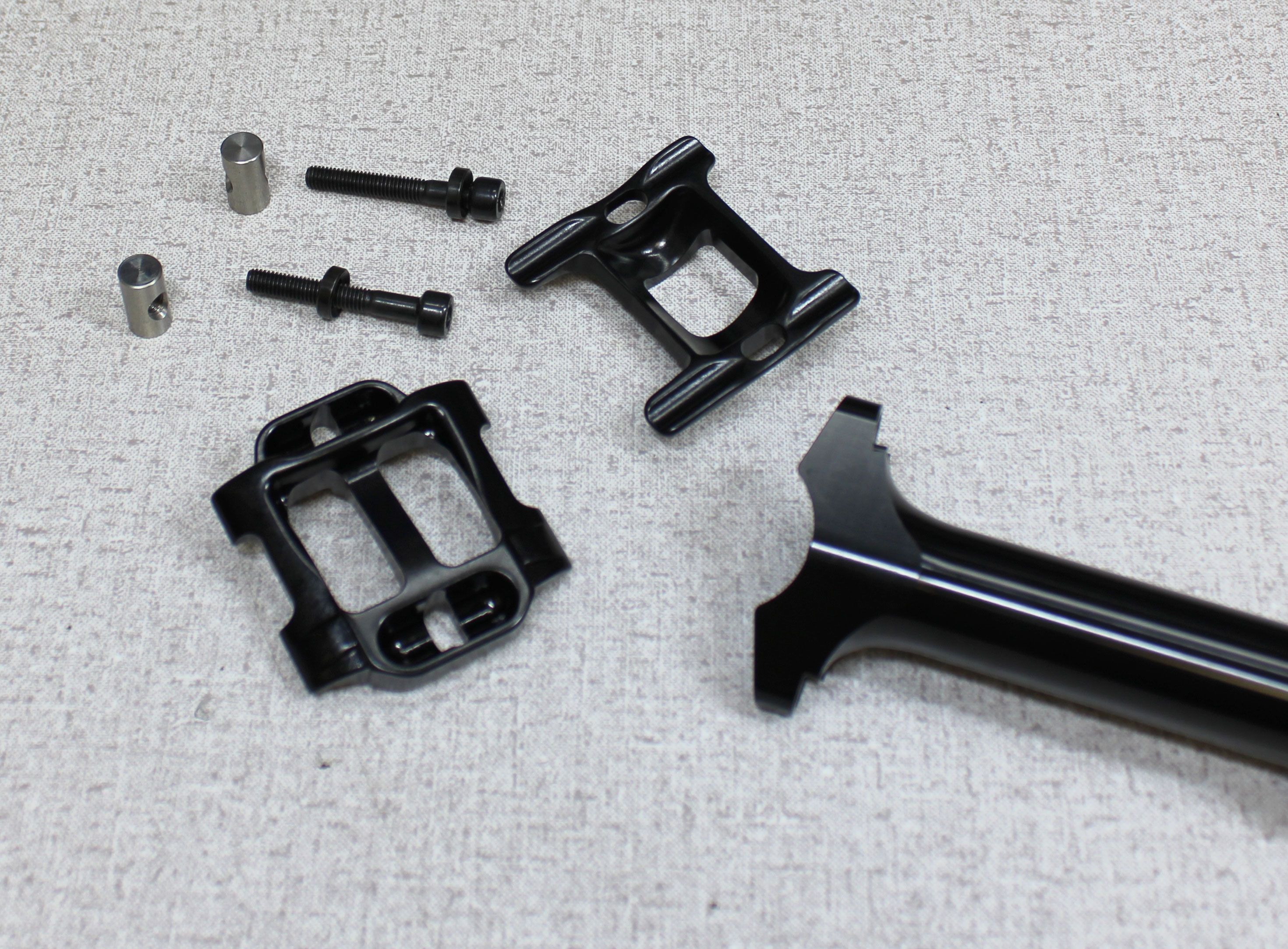
Step 1
Remove the saddle clamps and hardware. Turn the 4mm hex bolts counter-clockwise to remove them from the barrel nuts. Set all clamps and hardware aside.


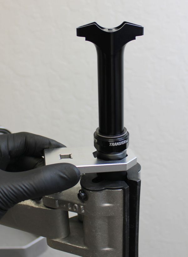
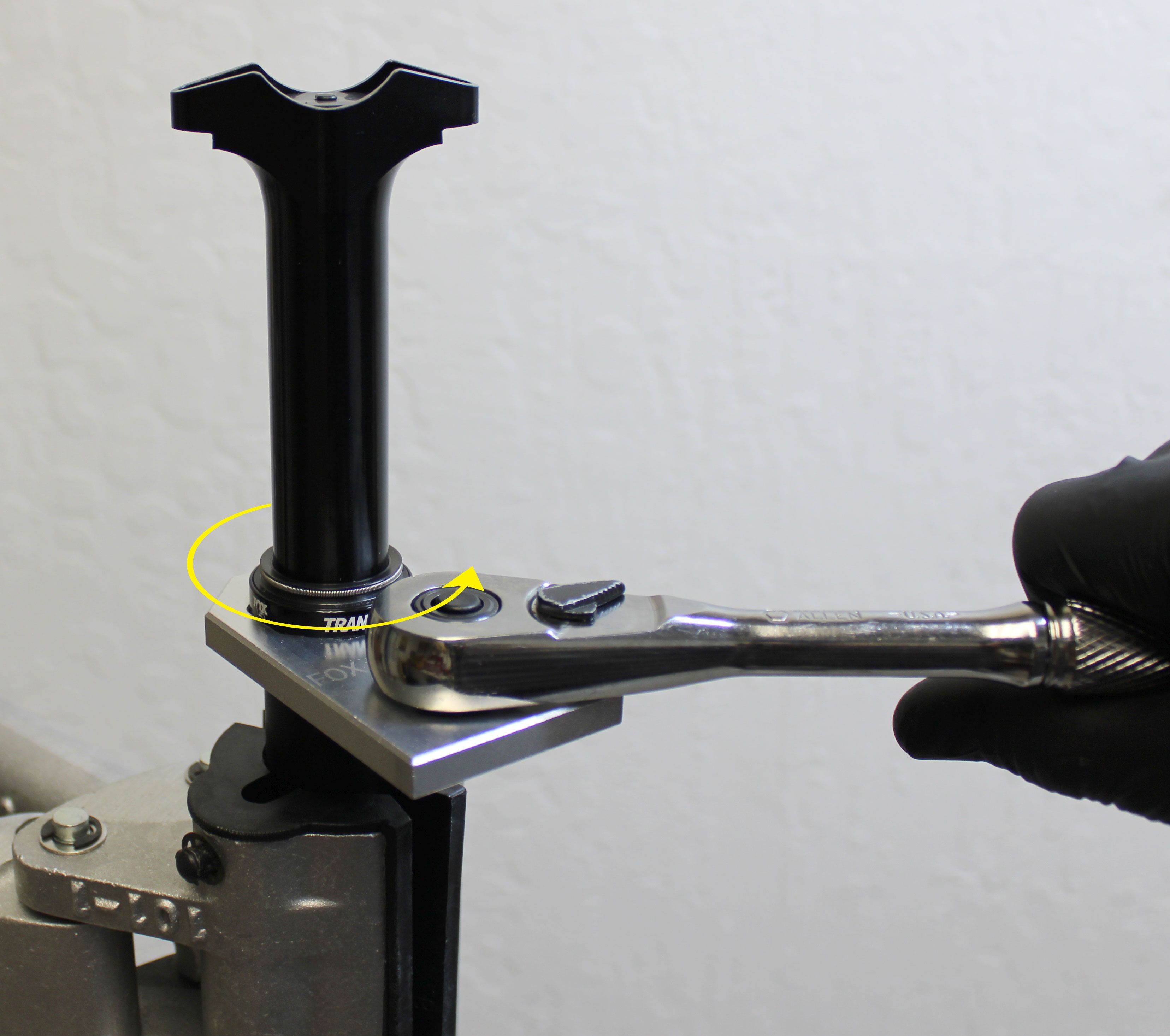
Step 2
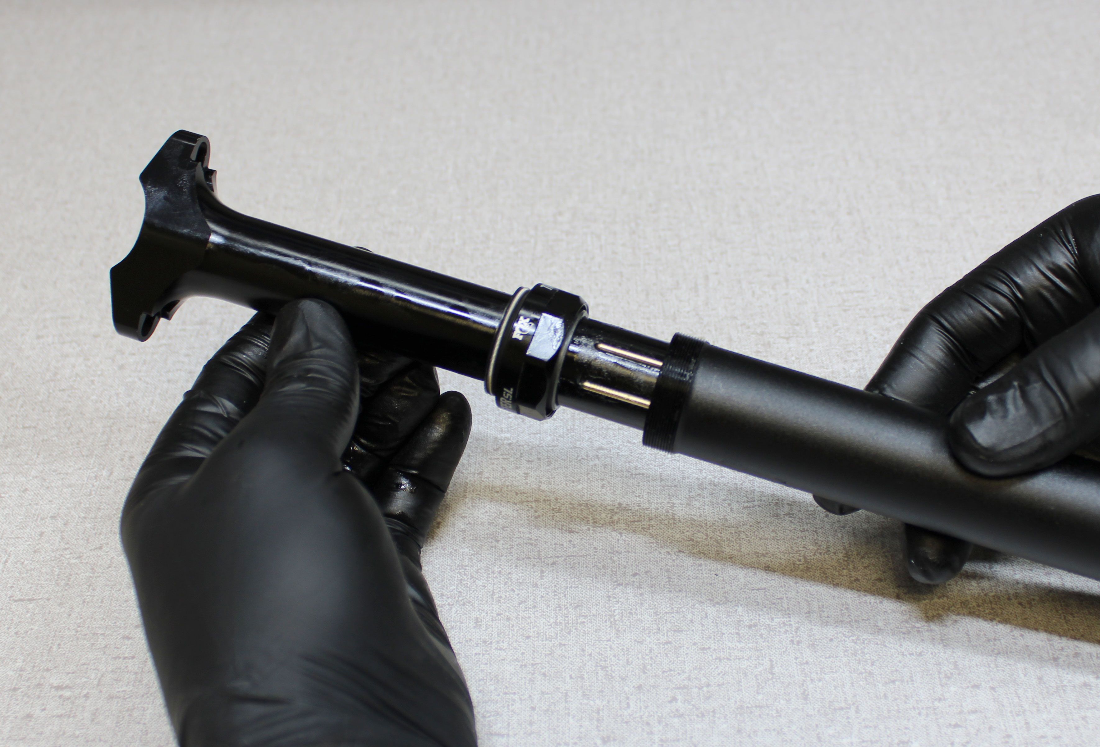
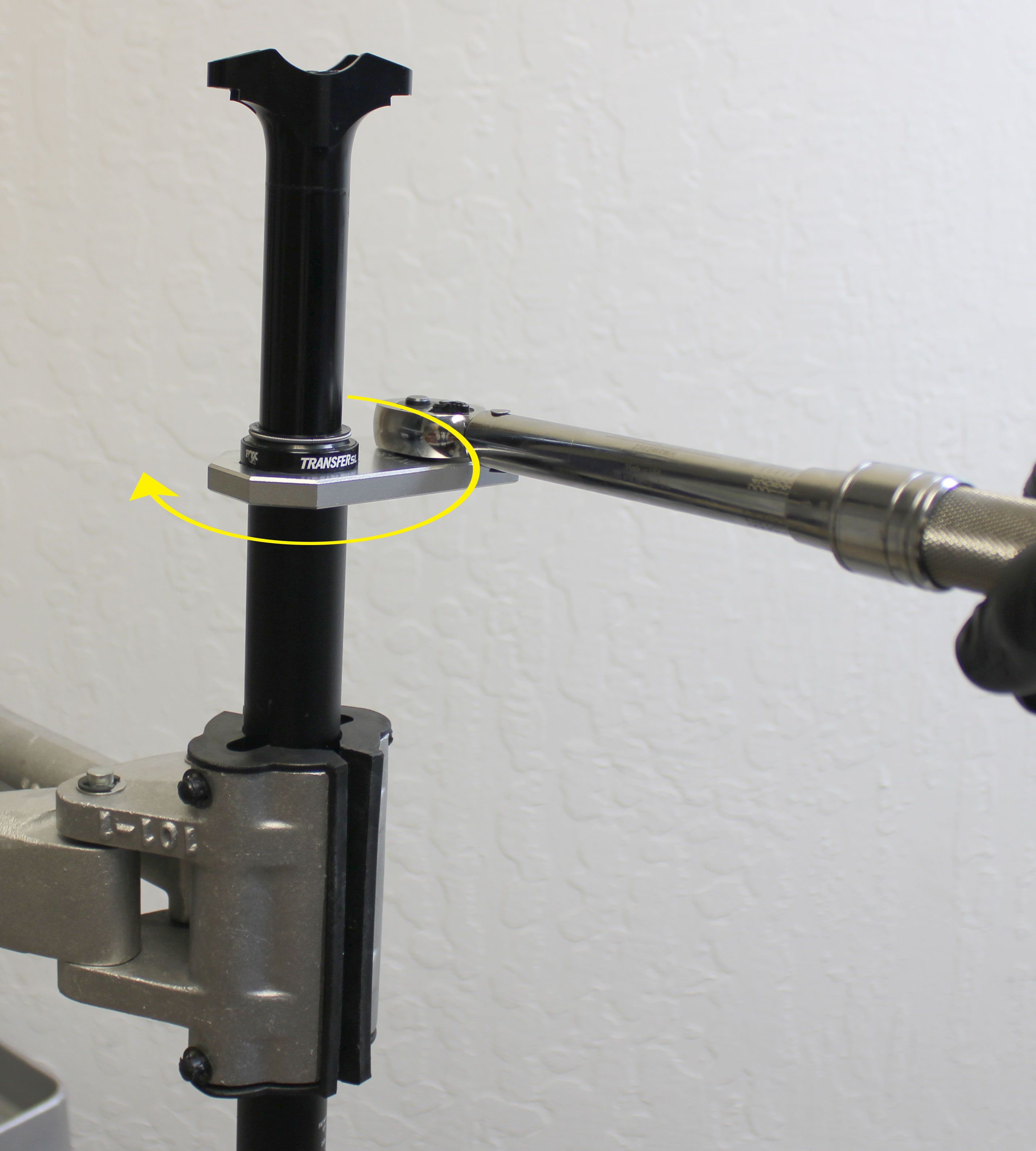
Clean your bike work stand clamps and the exterior of the seatpost to prevent damage during clamping. Insert the seatpost through the collar torque driver (PN: 398-00-911) then clamp in your workstand. Unthread the sealhead counter-clockwise from the lower post.


Step 3
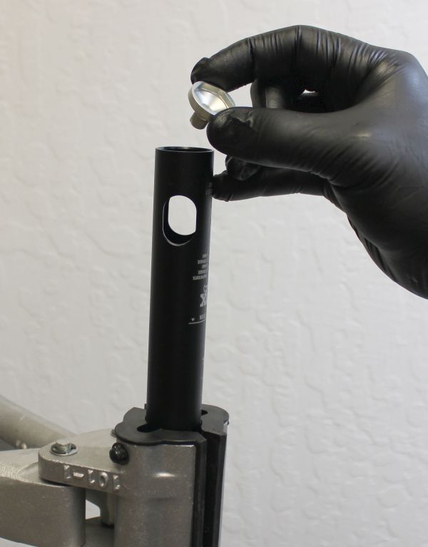
Invert the post in your workstand then remove the end cap by pulling it out with your fingernail. Remove the cable pinch bolt by unthreading it counter-clockwise with a 3mm hex wrench. Set the end cap and cable pinch bolt aside.
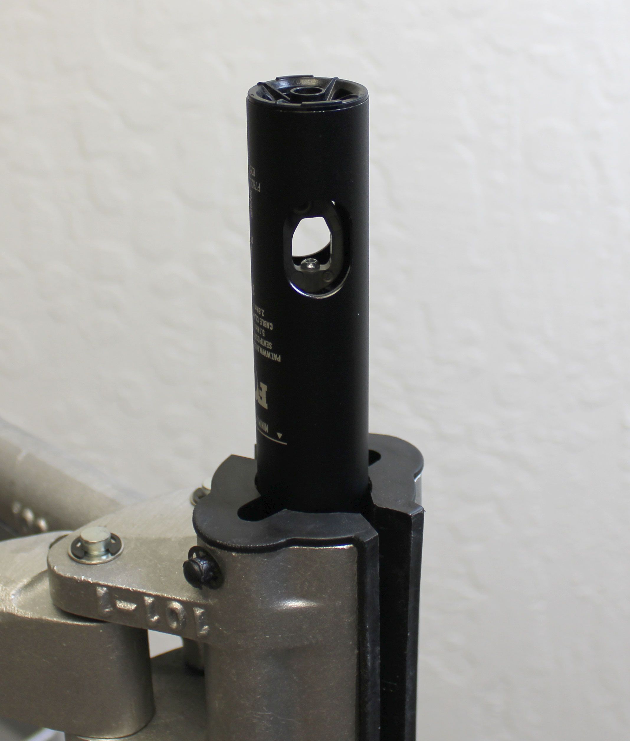


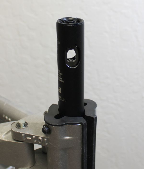
Step 4
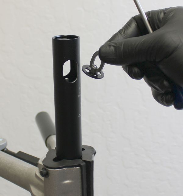
Hold the cable hangar from turning while you unthread the T8 Torx fastener counter-clockwise. Remove the cable hangar and set it aside. Remove the foam debris cover from the lower retention bolt.


Step 5
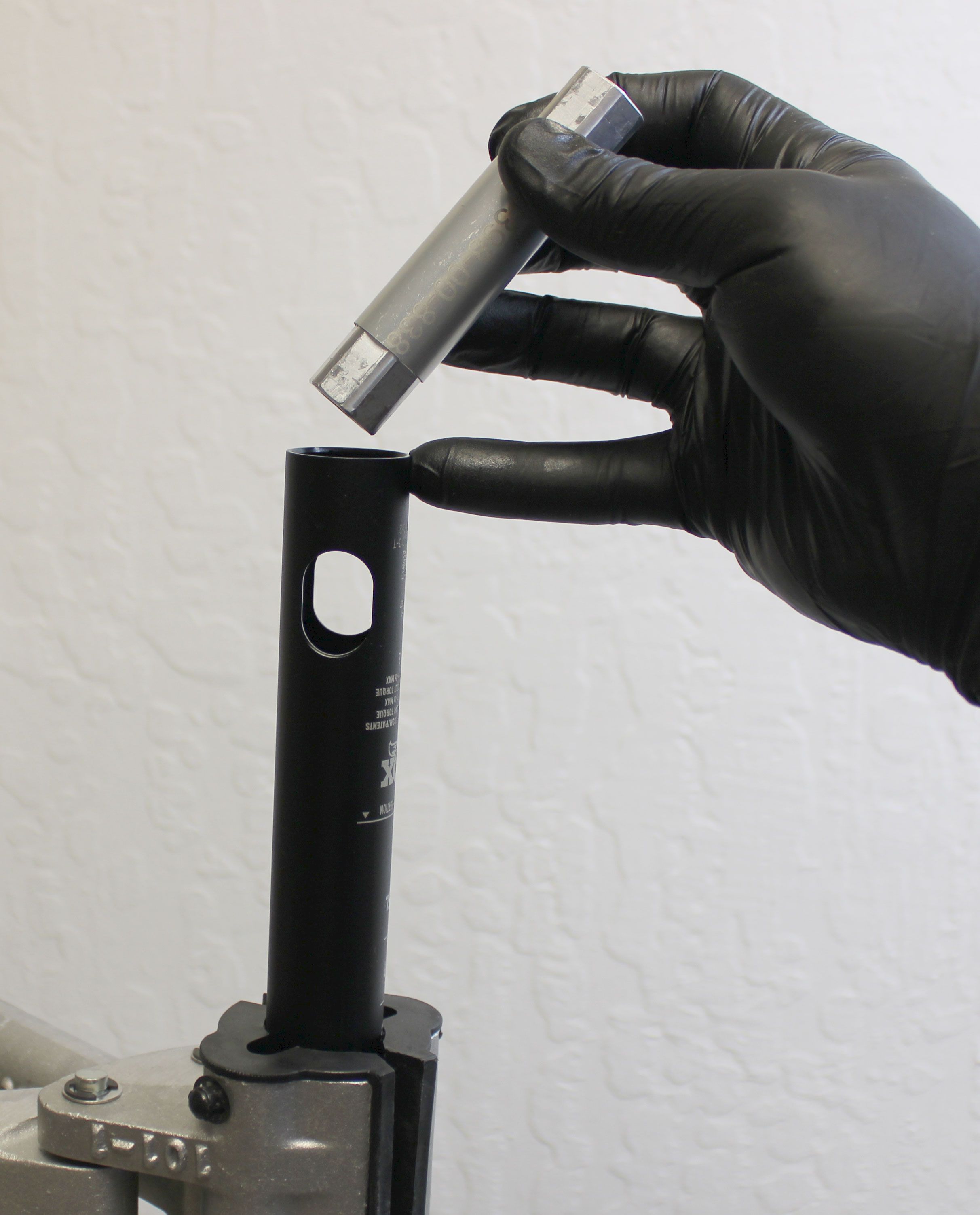
Use the retention lug driver (PN: 398-00-838) and an 18mm wrench to unthread the lower retention bolt counter-clockwise. Remove the lower retention bolt and set it aside.


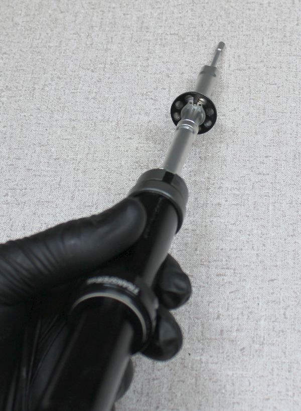
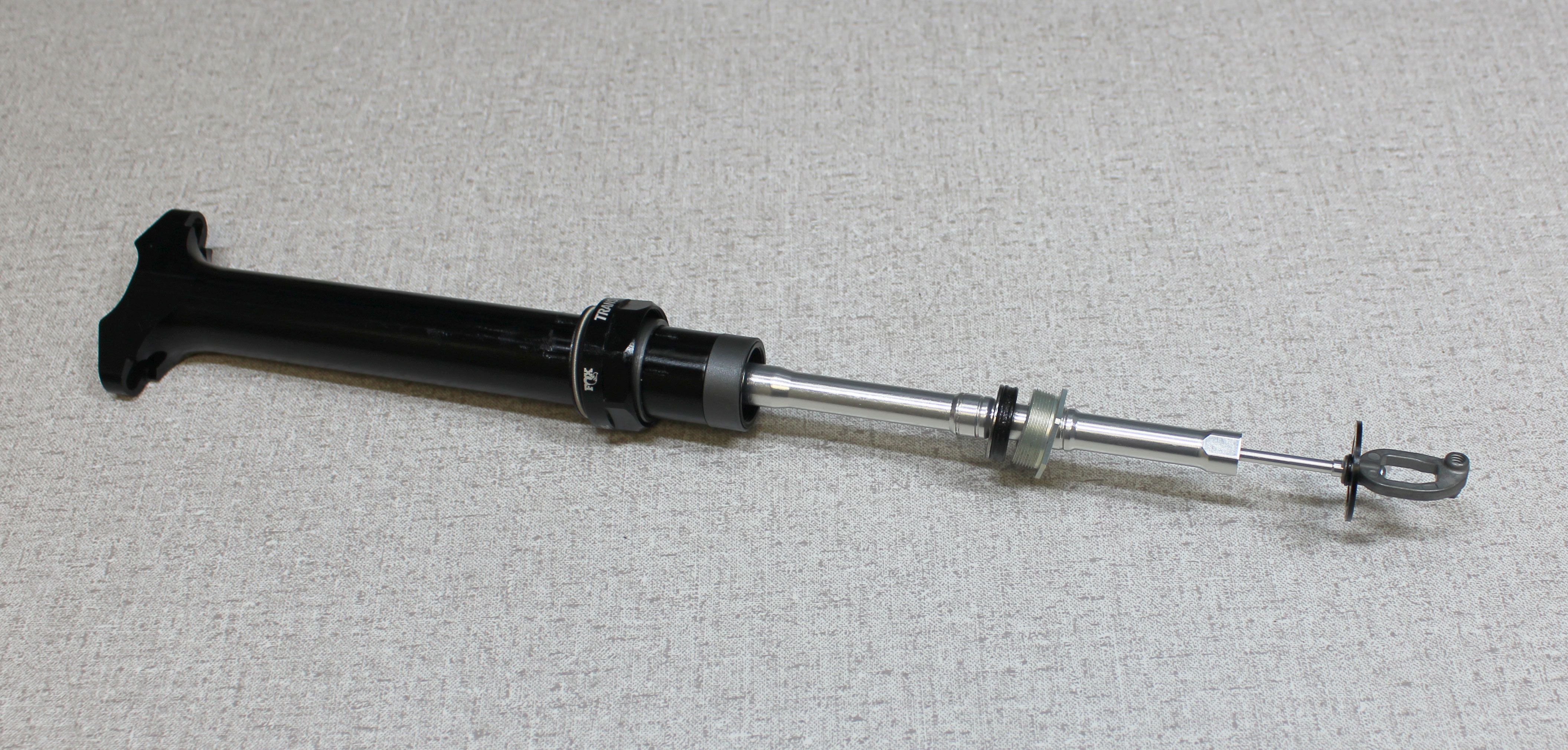
Step 6
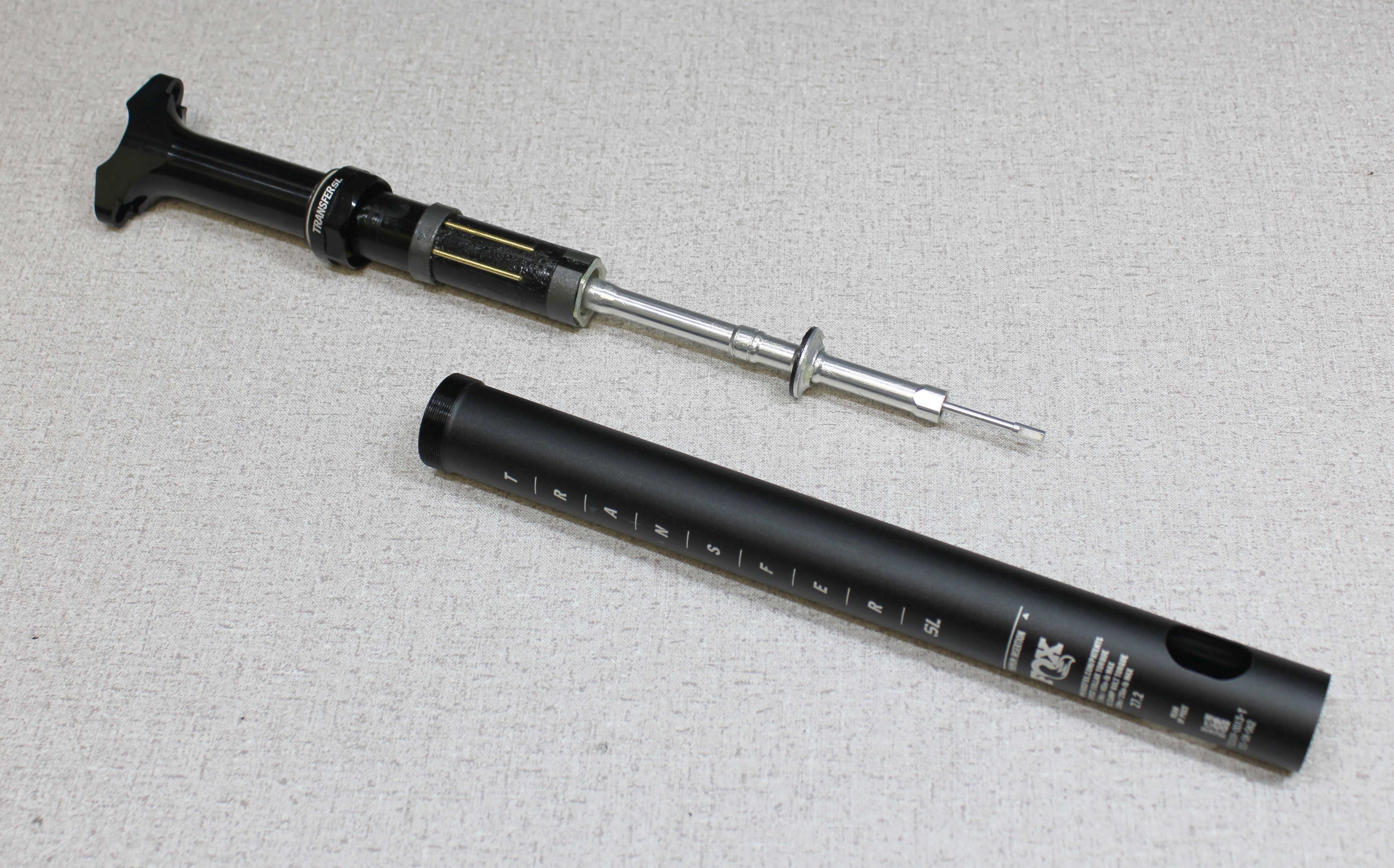
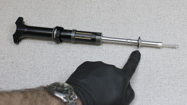
Remove the post from your workstand then separate the upper post from the lower over your workbench. Take care not to lose any of the brass index pins as they may fall out during separation. Remove the shaft lug from the lower post if it did not come out with the upper post.


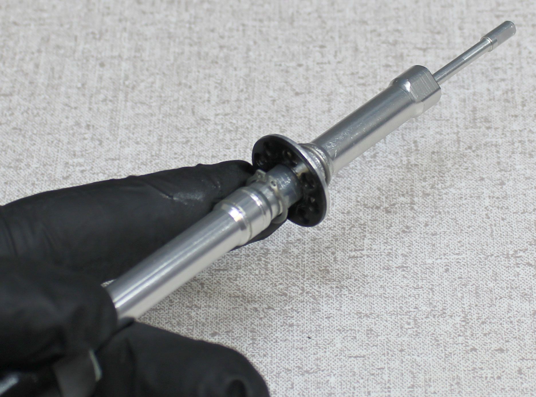
Step 7
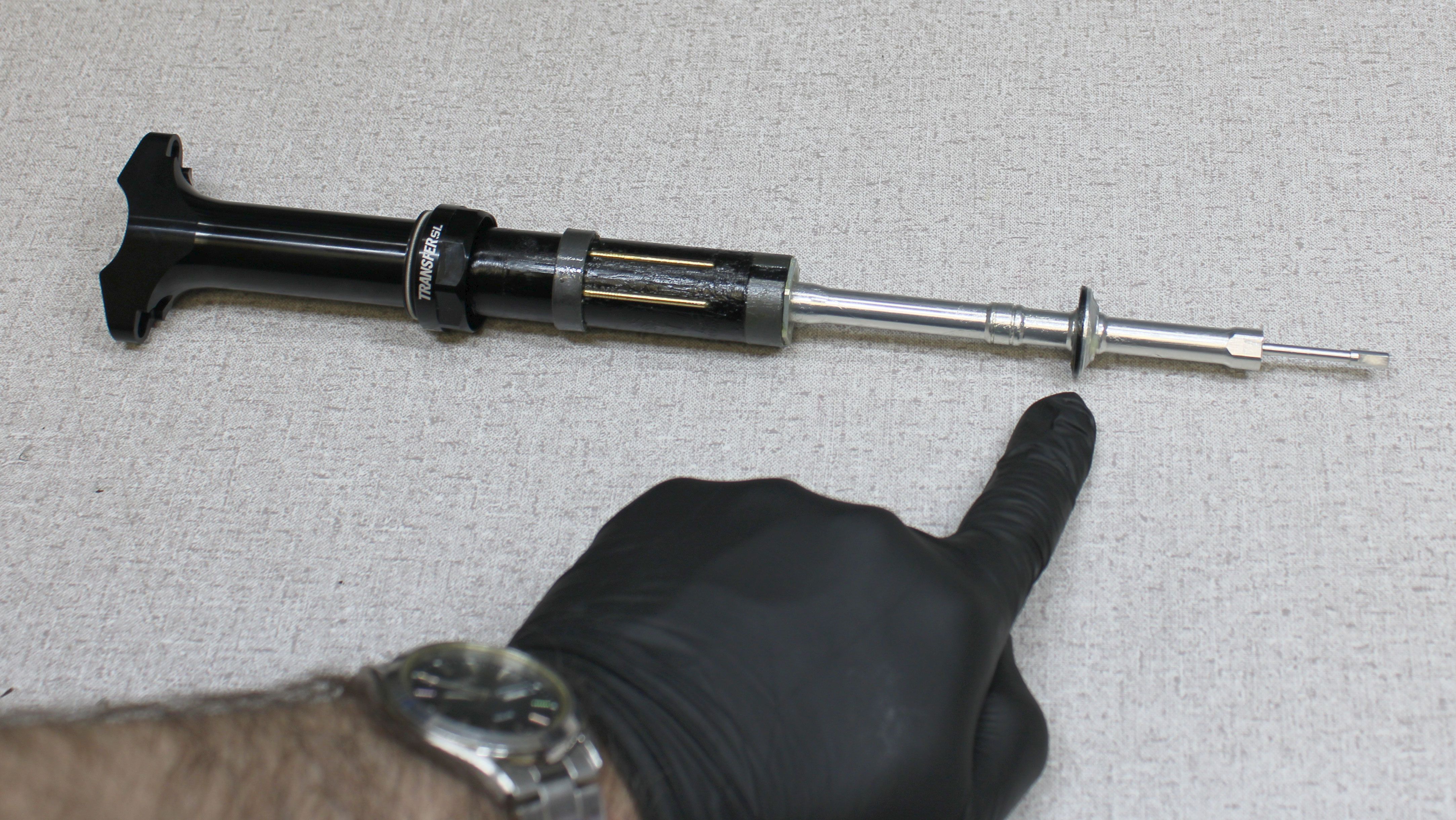
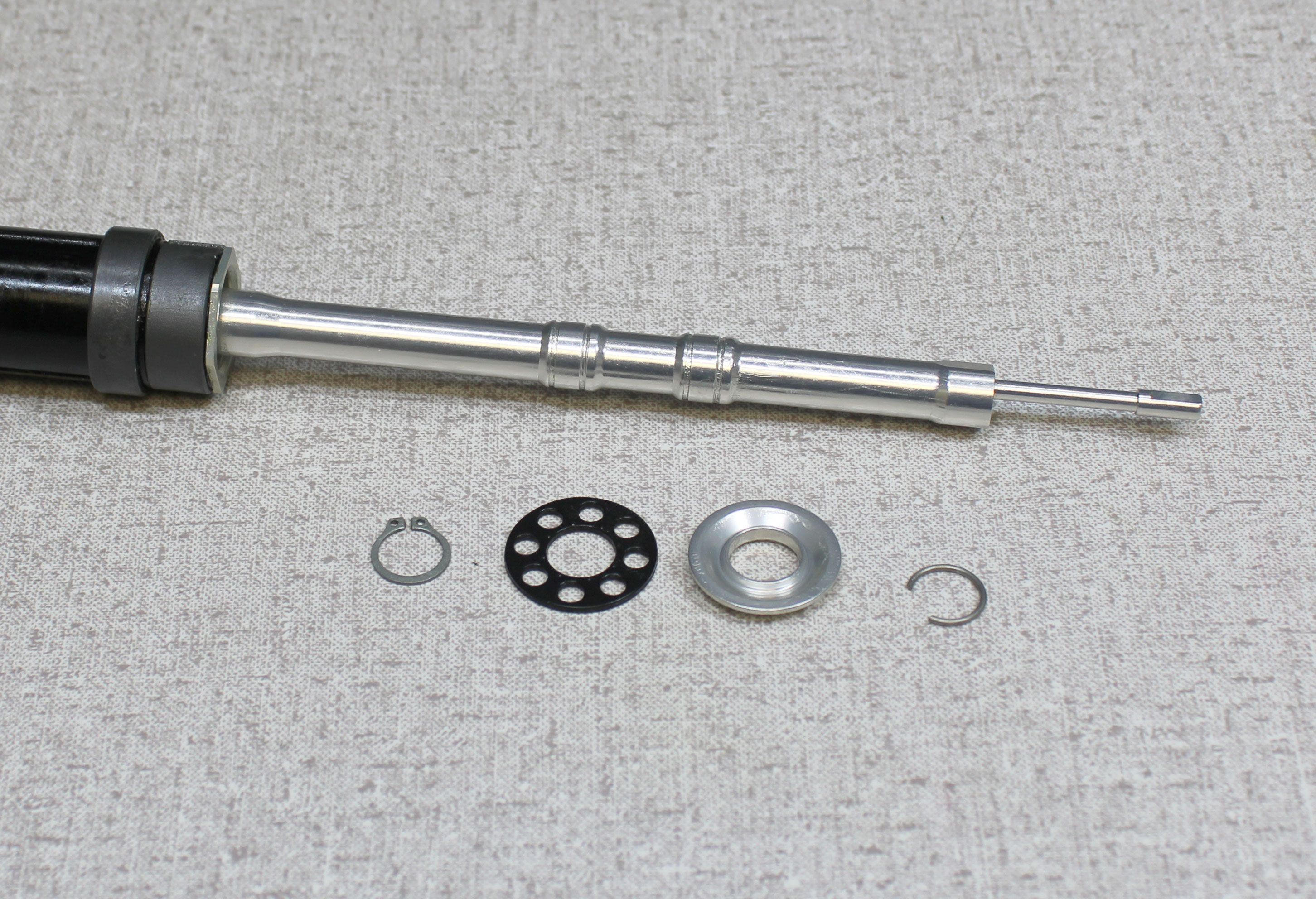
Note the position of the bottom out spacer and bumper. This determines the travel of your post. Remember the original position so you can return the post in the user's original configuration. Remove the brass index pins and set them aside.

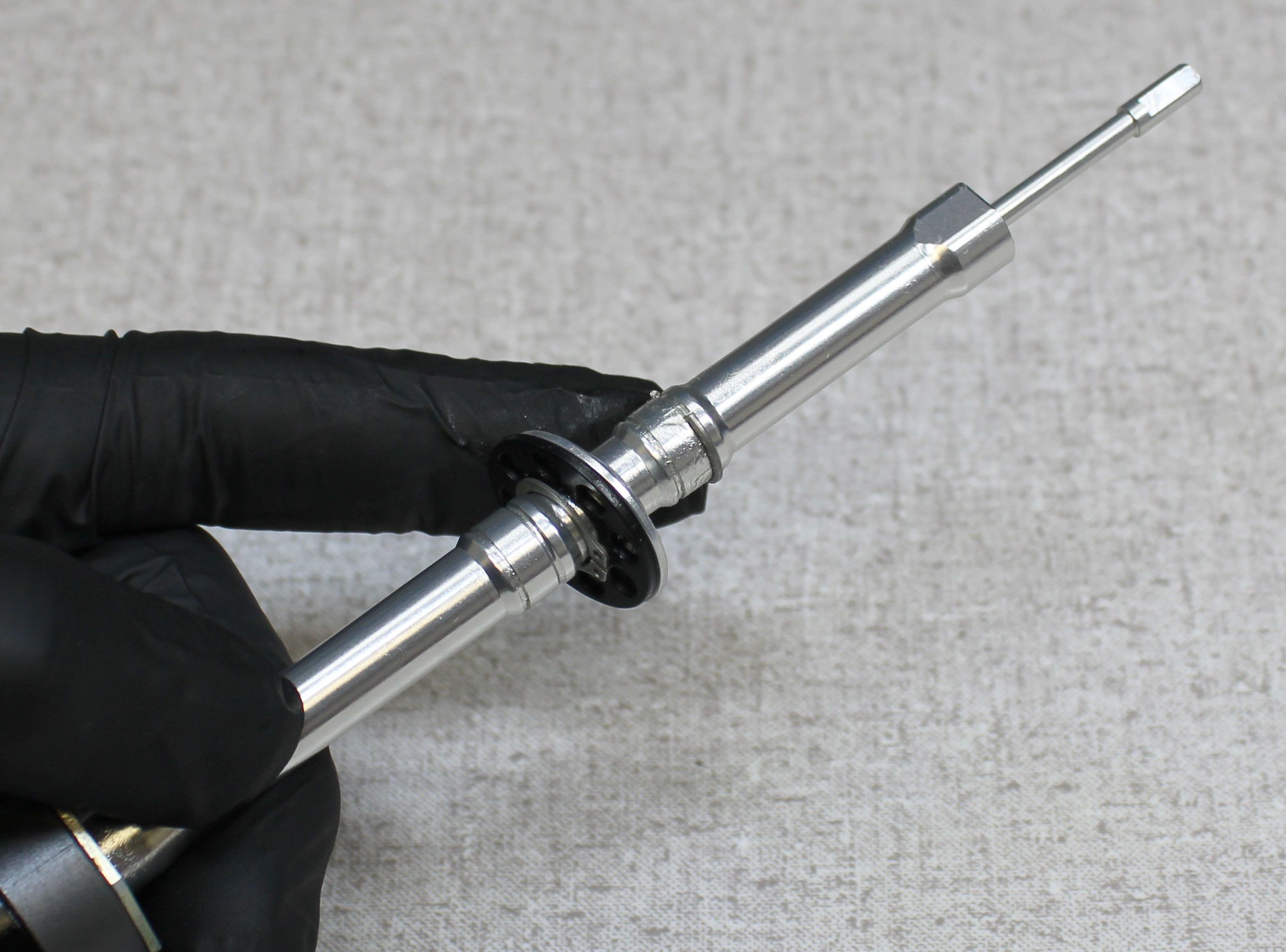
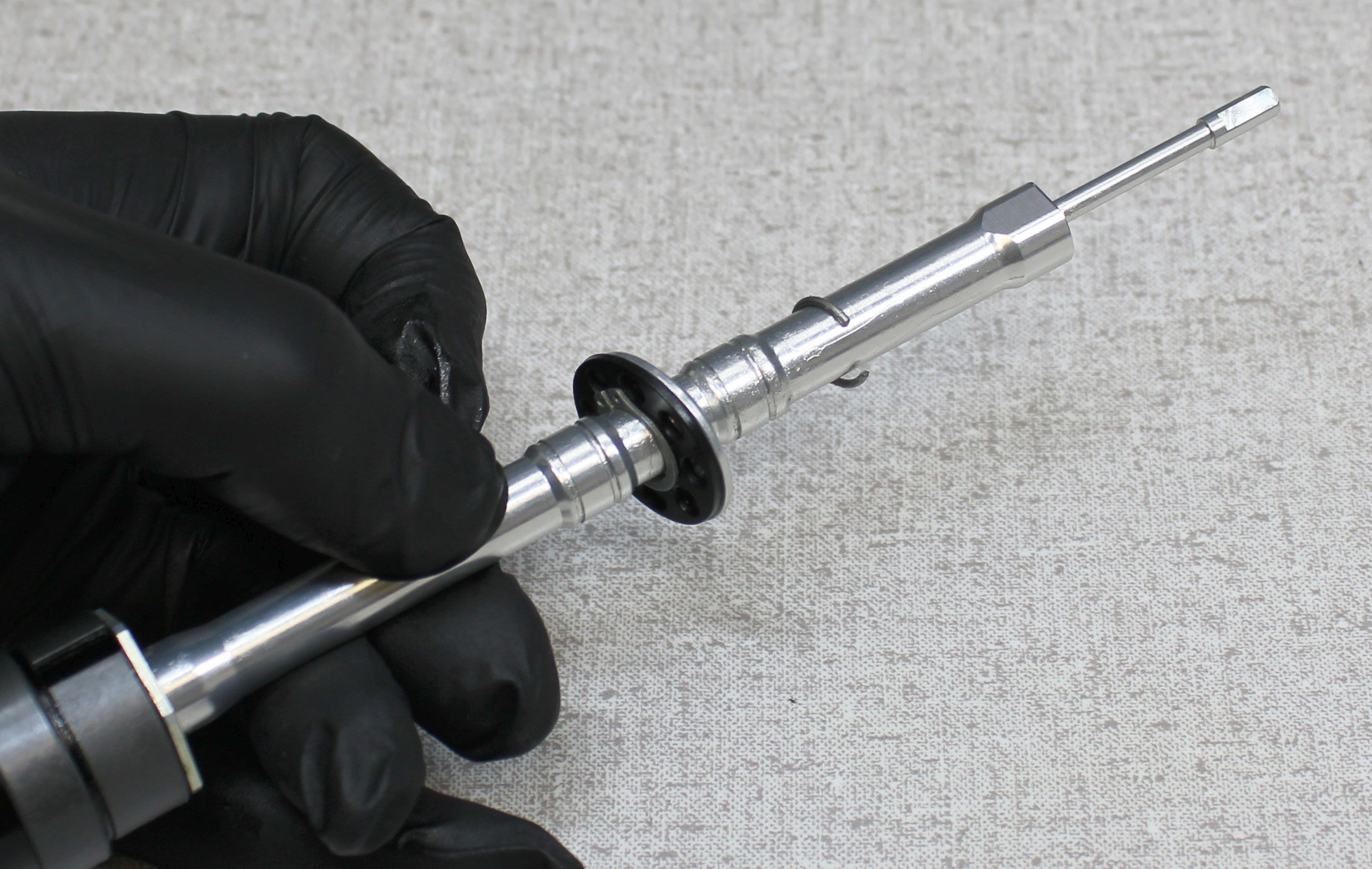
Step 8
Use snap-ring pliers to unseat the external retaining ring from it's groove. Move the bottom out bumper and spacer toward the top of the post. Remove the round wire retaining ring from it's groove. Carefully move all bottom out parts including both retaining rings off of the end of the locking body assembly and set them aside.


Step 9
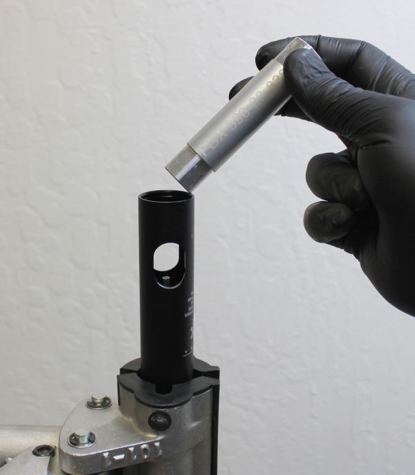
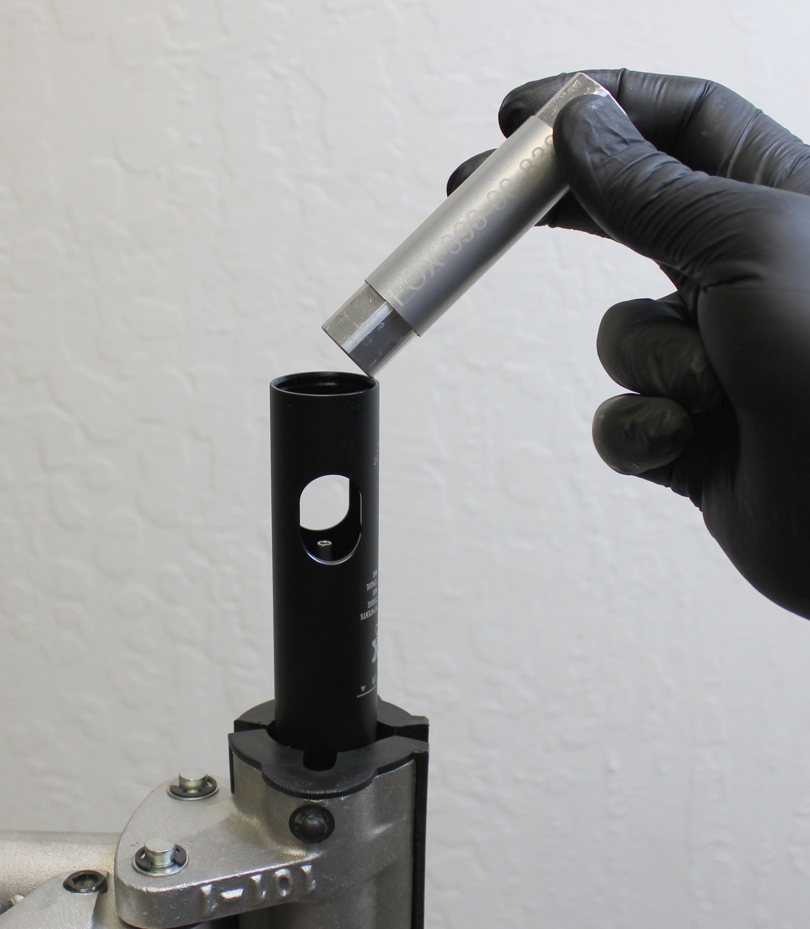
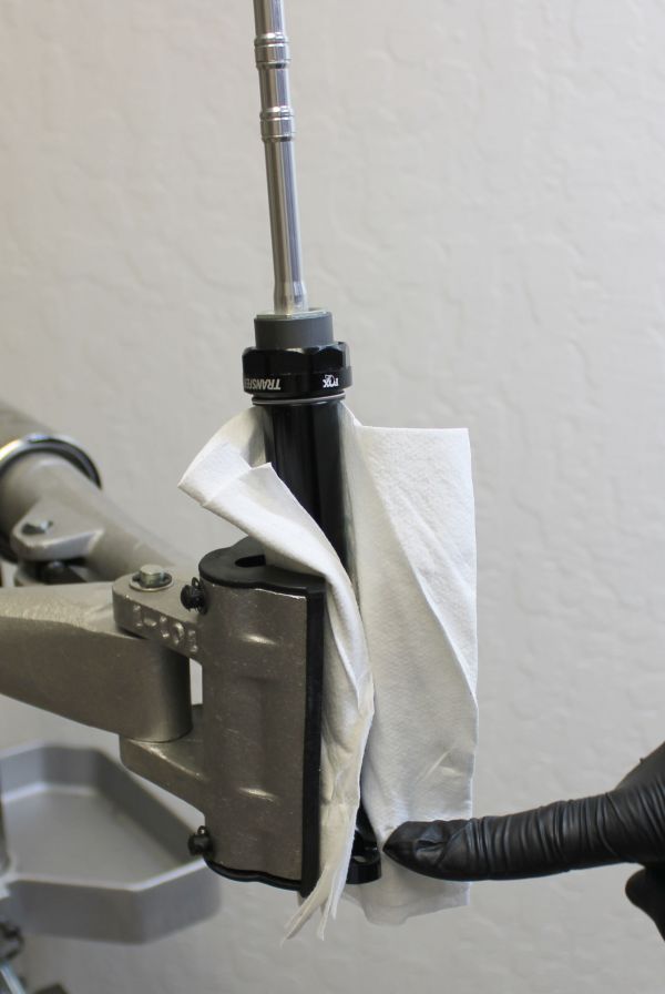
Cover the upper post with a clean lint-free paper towel then lightly clamp it in your workstand as shown with one saddle clamp tab between the clamps to prevent rotation. Use the smaller side of the topout cap driver (PN: 398-00-916) held firmly against the topout cap to unthread the topout cap counter-clockwise from the upper post. Failure to hold the topout cap driver tightly against the topout cap can lead to damage if the tool slips.


Step 10
Remove the topout bumper (quad ring) and topout plate from within the end of the upper post. Reinstall the cable hangar onto the end of the pull rod by engaging the flats, holding the cable hangar from turning, then threading the screw clockwise to 6 in-lb torque with a T8 Torx driver.


WARNING: Safety glasses MUST be worn during disassembly and reassembly of the Transfer SL seatpost. Transfer SL seatposts contain a highly preloaded spring and this stored energy must be released slowly according to FOX technical instructions to ensure safety during service. Failure to wear safety glasses while servicing the Transfer SL may cause SERIOUS INJURY OR DEATH.
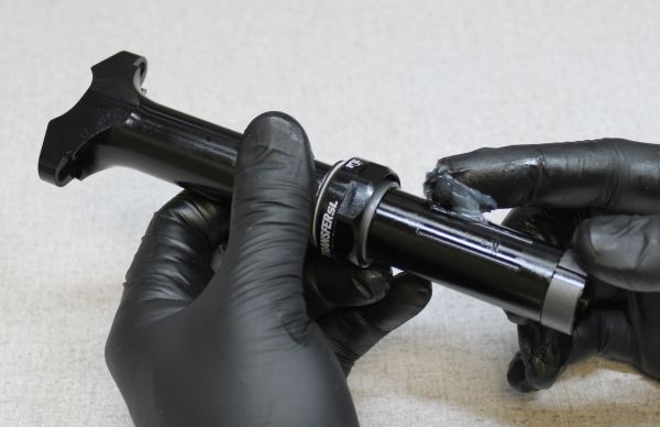
Step 11
Cover the bottom end of the upper post with while holding the upper post tightly. Pull the cable hangar away from the upper post to unlock the post from it's current position. Slowly allow the spring to push the locking body assembly out of the upper post without losing any of the 4 ball bearings as shown below.
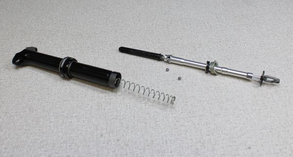
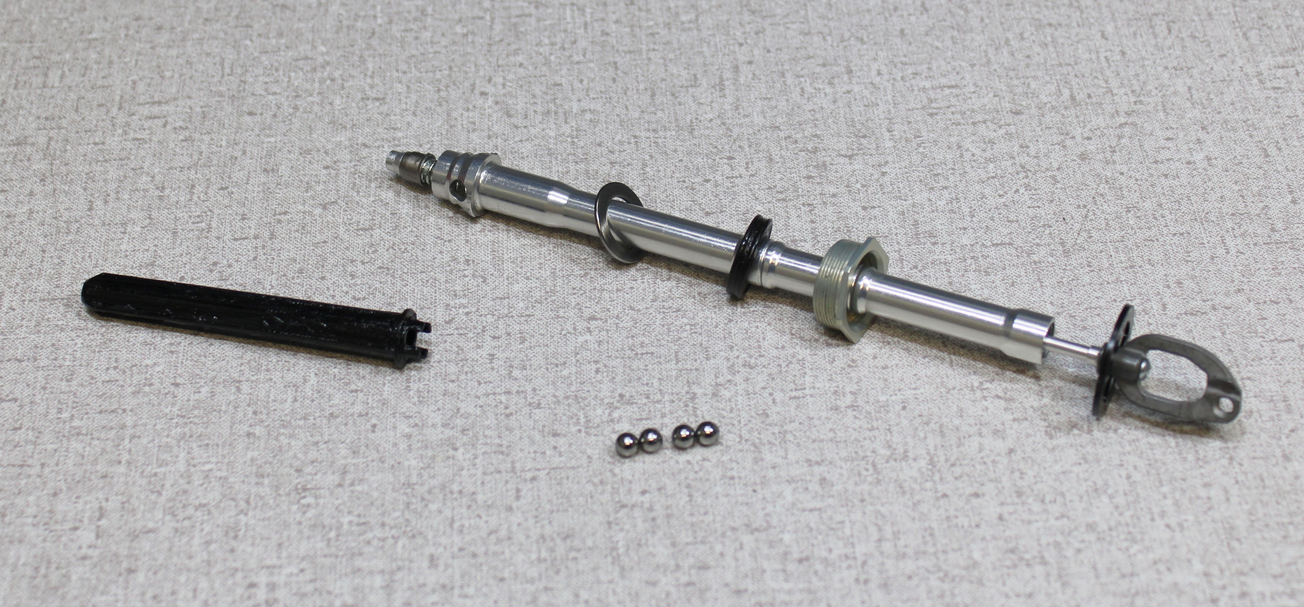
Step 12
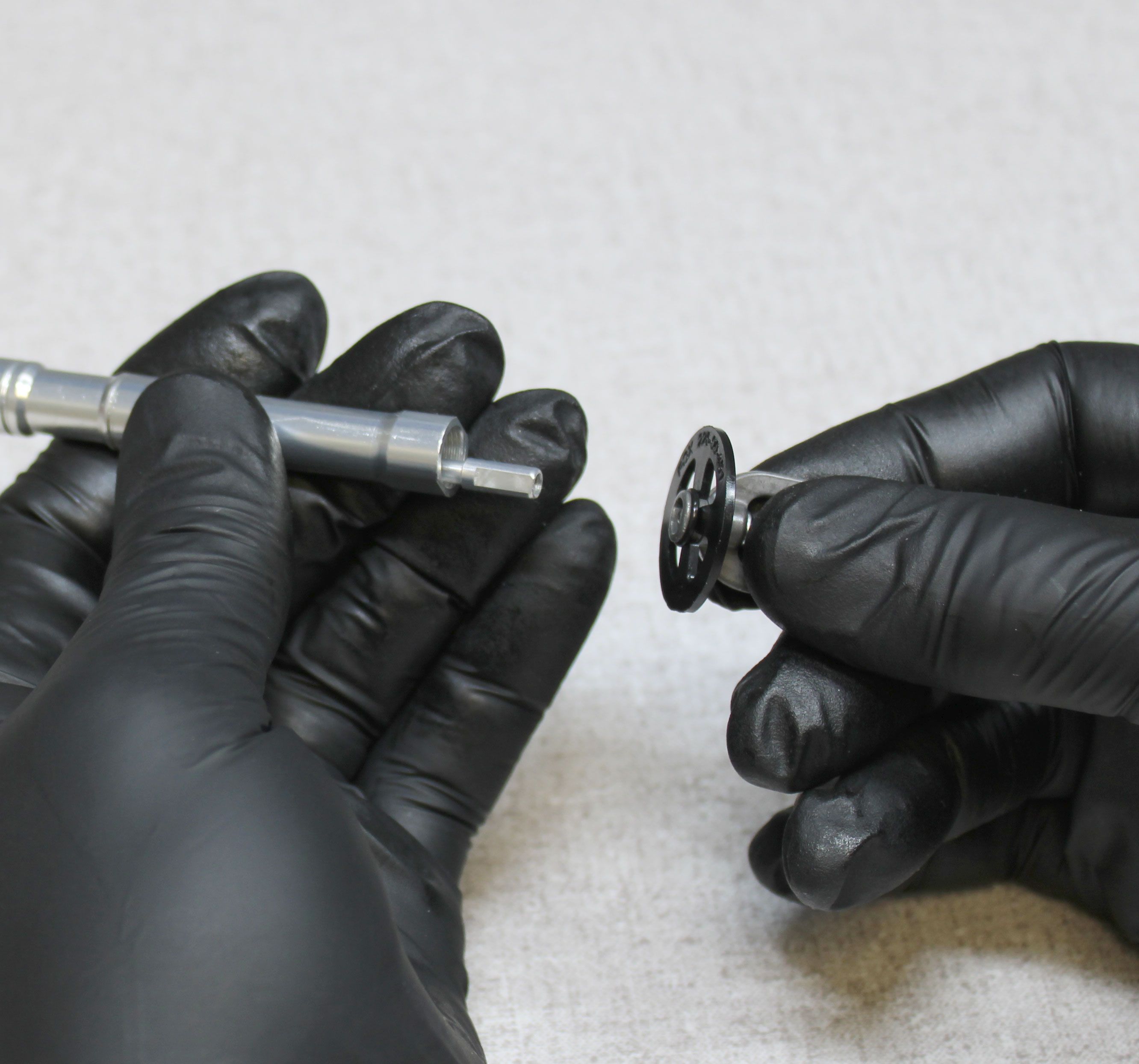
Remove the spring from the upper post. Remove the 4 ball bearings from the locking body assembly. Remove the lower spring guide from the end of the locking body.


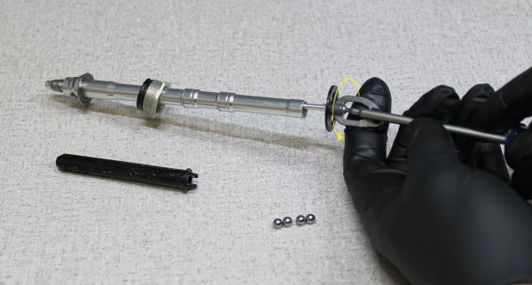
Step 13
Hold the cable hangar from turning while you unthread the T8 Torx fastener counter-clockwise. Remove the cable hangar and set it aside. Remove the topout cap then replace the topout bumper (quad ring) with a new lightly greased one from the kit. Reinstall the topout cap then set the locking body assembly aside.


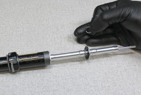
Step 14
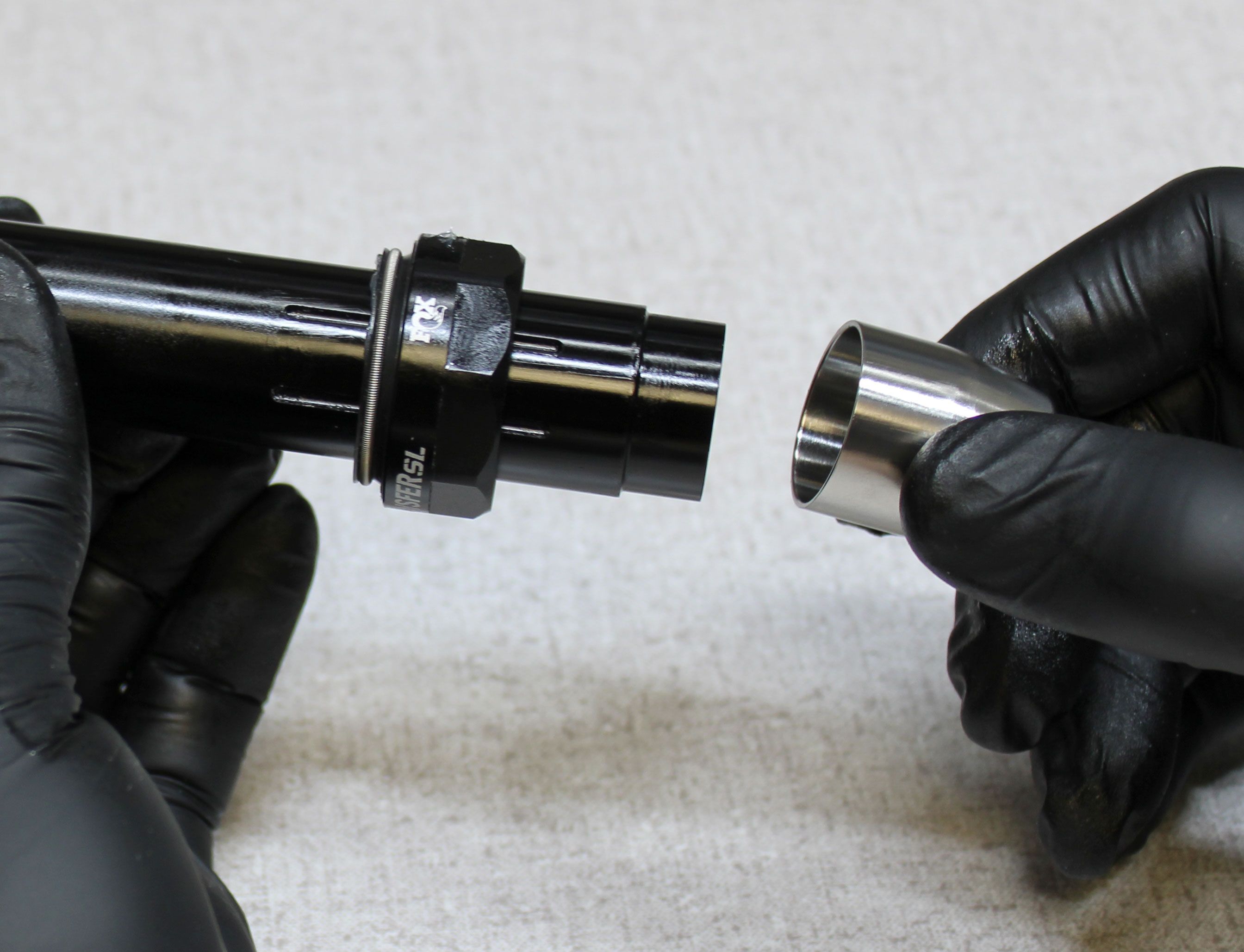
Remove the lower bushing, upper bushing, and sealhead assembly with foam ring from the upper post. Install the bullet tool (PN: 398-00-917) then apply a thin film of Slick Honey to the bullet.


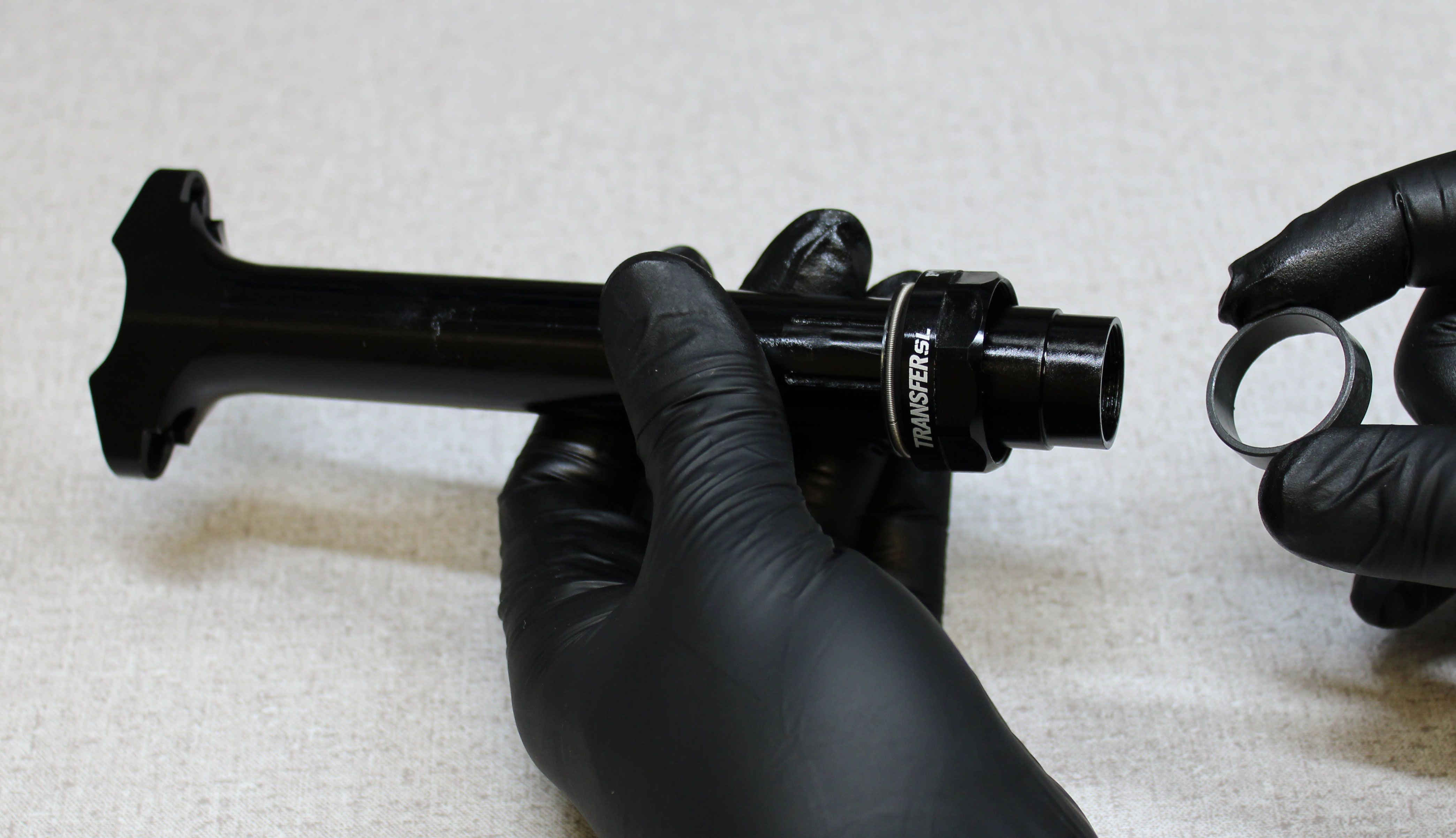


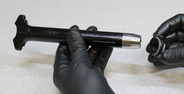
Step 15
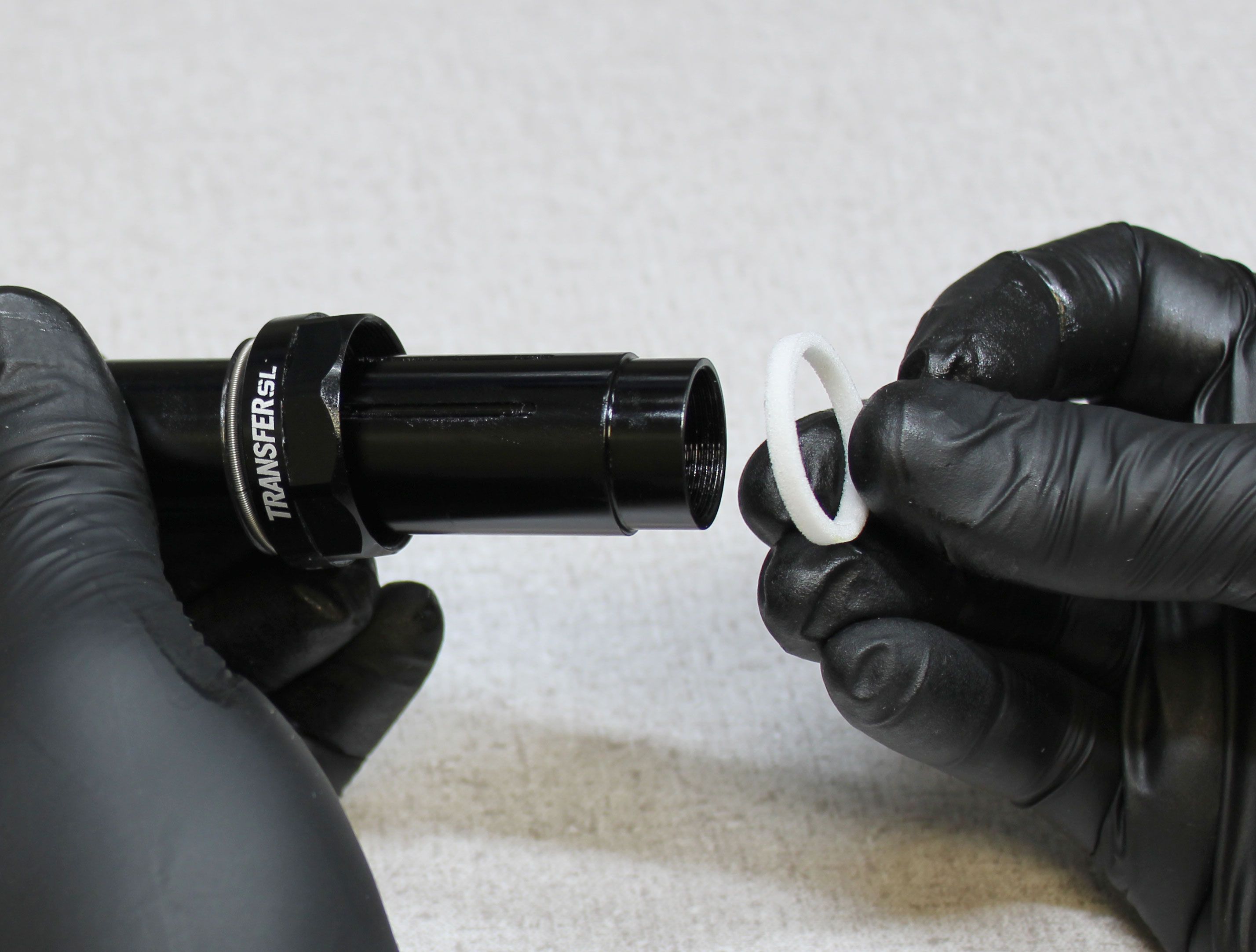
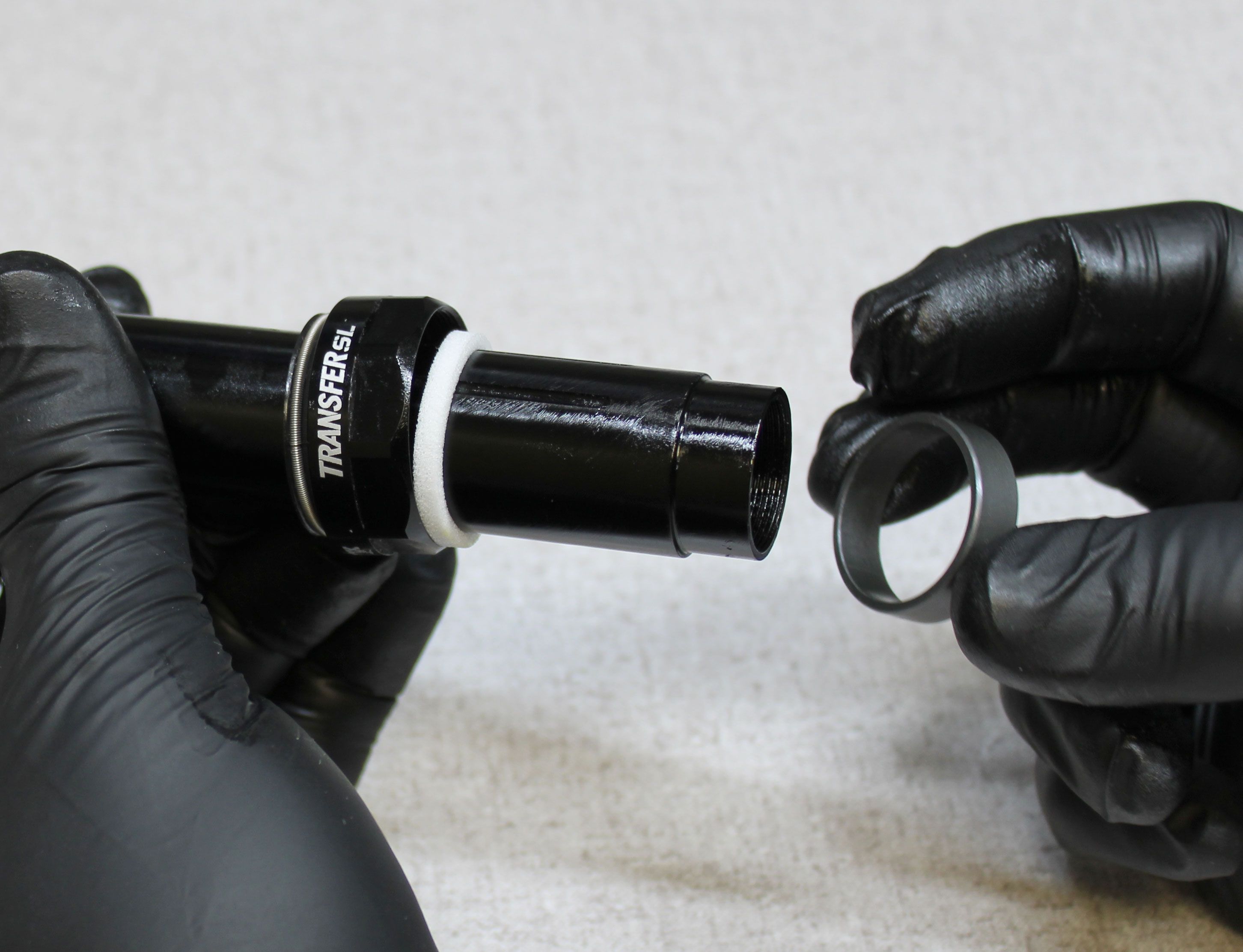
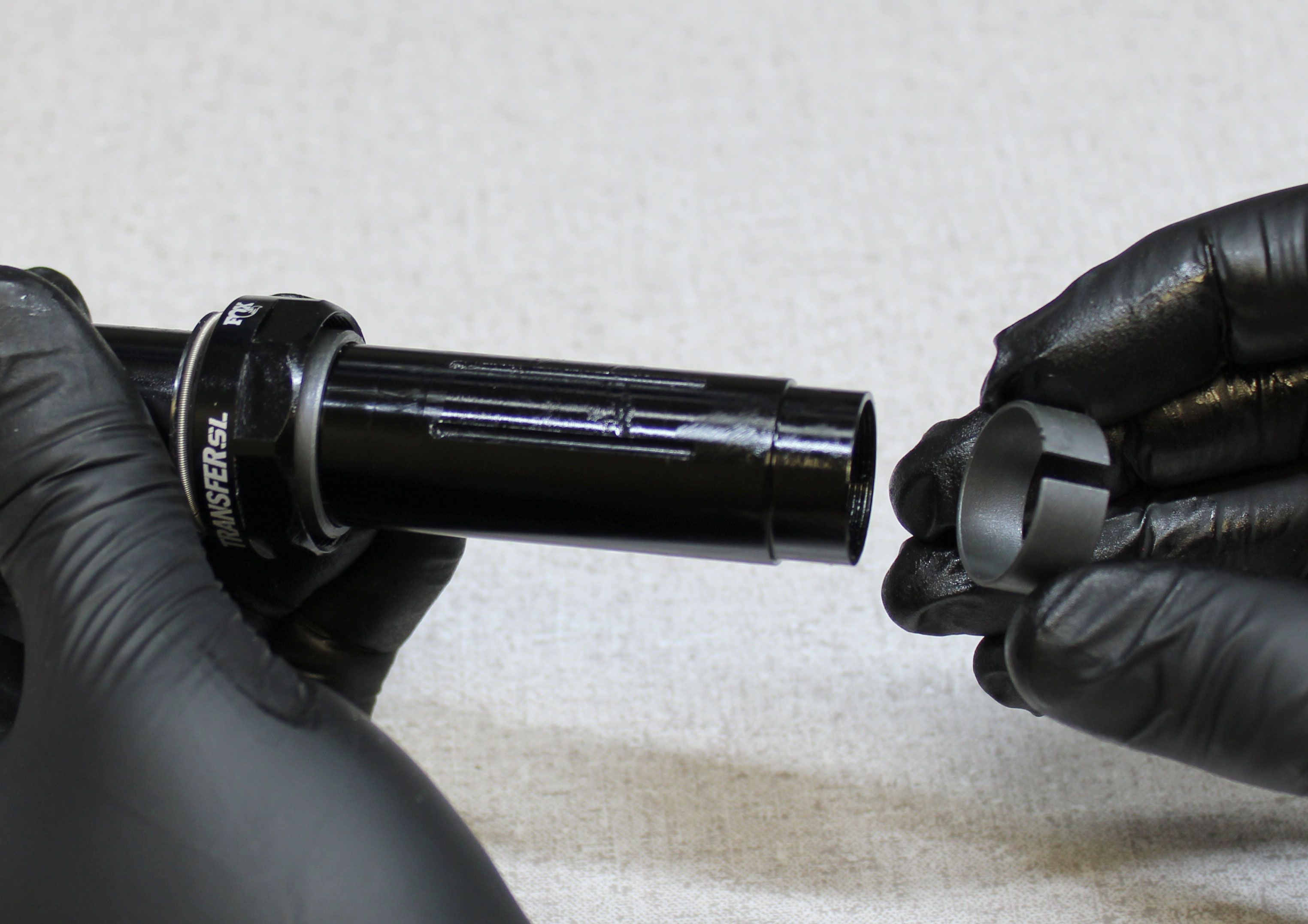
Coat the inner surface of the new wiper in the sealhead with a thin film of Slick Honey. Install the new sealhead onto the upper post as shown. Remove the bullet tool then install a new foam ring that has been soaked in Slick Honey, a new greased upper bushing, and greased lower bushing from the kit as shown.

Step 16
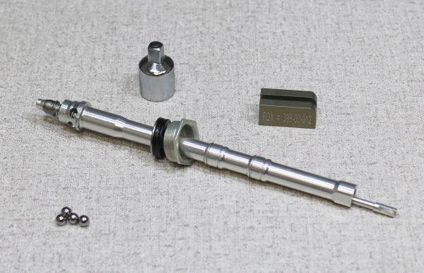
Use a 3/8"-to-1/4" square drive adaptor or similar tool to help you install the preload tool (PN: 398-00-912) to the locking body assembly. Press the upper end of the pullrod within the locking body assembly down onto the adaptor. Hold the locking body and pullrod down against the adaptor while you install the preload tool as shown.


Step 17
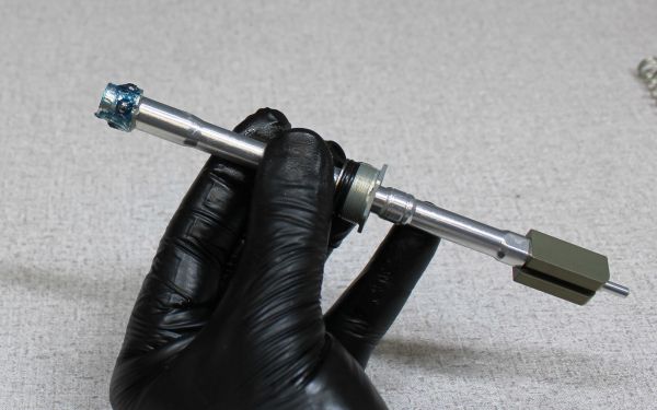
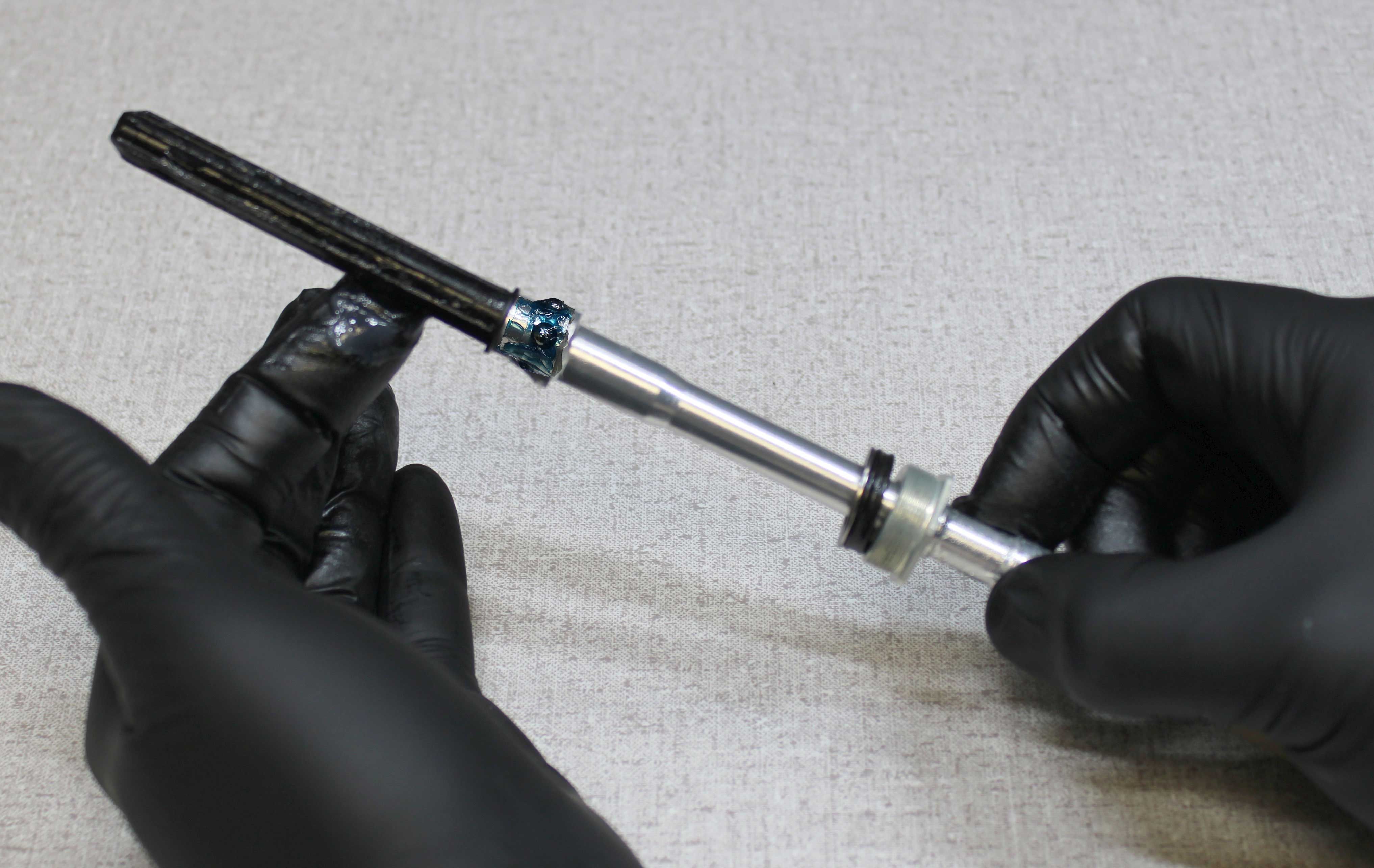
Coat the upper end of the locking body with Ultraplex LT2 waterproof marine grease then reinstall the 4 locking ball bearings followed by the lower spring guide. Coat the lower spring guide with a thin film of Slick Honey then reinstall the spring into the upper post and over the lower spring guide as shown.


Step 18
When looking at the locking body assembly, note that pairs of locking ball bearings close together and the flats at the bottom end of the locking body should be aligned with the sides of the seatpost. Carefully guide the locking body assembly into the upper post, pushing in until the locking ball bearings click into place and retain the locking body within the upper post. Install the topout plate and bumper into the upper post, then thread the topout cap into the upper post clockwise by hand. Once the topout cap is hand tight, the preload tool should become loose. Remove the preload tool. Note: Ultraplex LT2 grease should cover the locking ball bearings in a thick layer (not shown).
Step 19
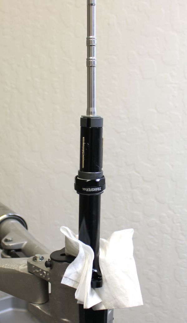
Cover the upper post with a clean lint-free paper towel then lightly clamp it in your workstand as shown with one saddle clamp tab between the clamps to prevent rotation. Use the smaller side of the topout cap driver (PN: 398-00-916) held firmly against the topout cap to tighten the topout cap clockwise to 120 in-lb (13.6 Nm) torque. Failure to hold the topout cap driver tightly against the topout cap can lead to damage if the tool slips.


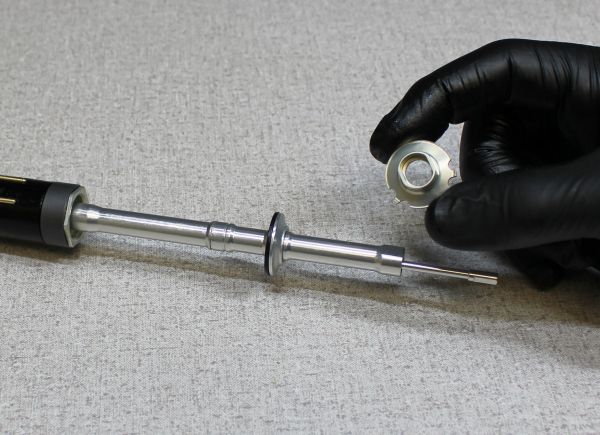
Step 20
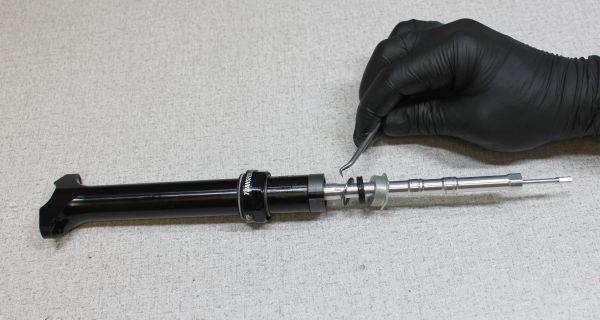
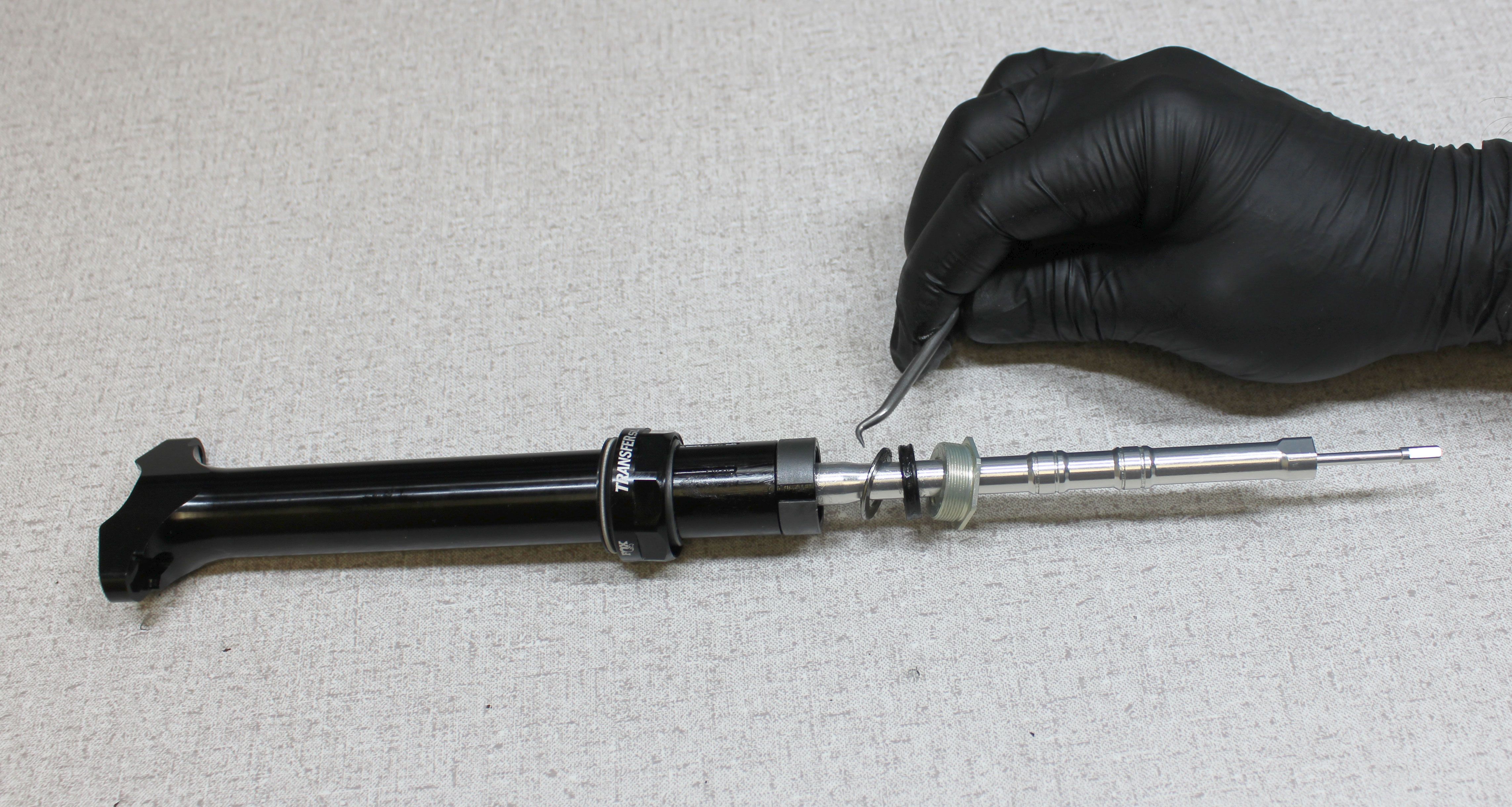
Reinstall the external retaining ring followed by the bottom out bumper, spacer, and round wire retaining ring back onto the locking body. Reinstall the round wire retaining ring into it's original groove then position the bottom out spacer and new bumper in place. Reinstall the external retaining ring back into it's groove with snap-ring pliers. Make sure both retaining rings are fully seated in their grooves.


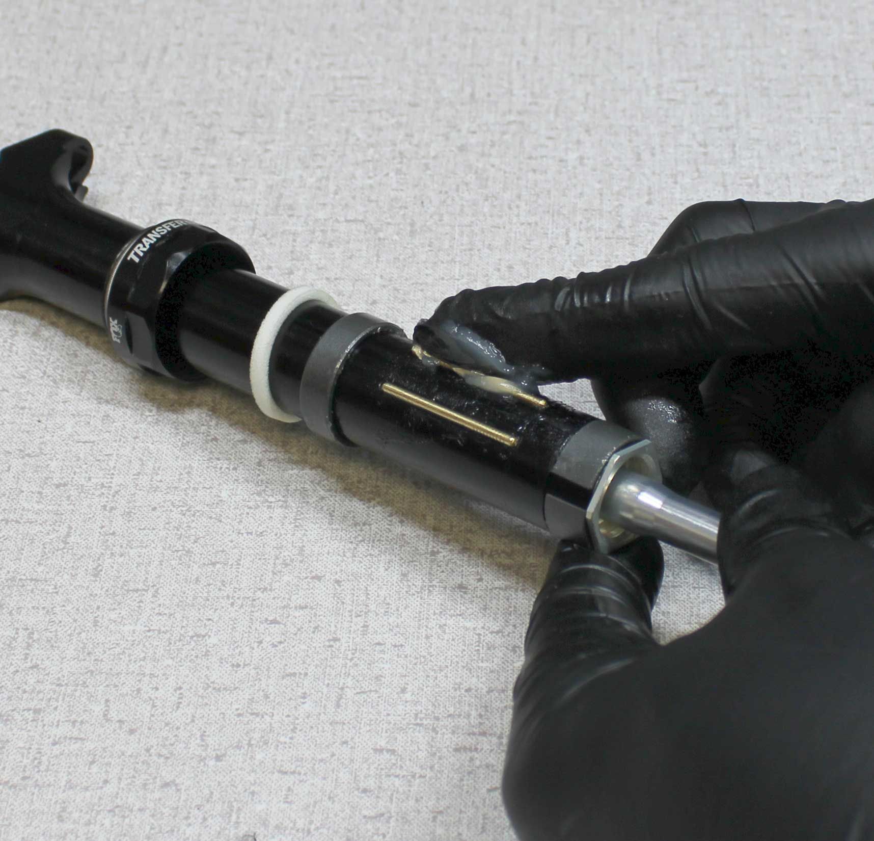
Step 21
Coat the pin grooves in the upper post with a thick coating of Slick Honey. Reinstall the 3 brass index pins into their grooves as shown. Coat the outside of the brass index pins with a thick film of Slick Honey.


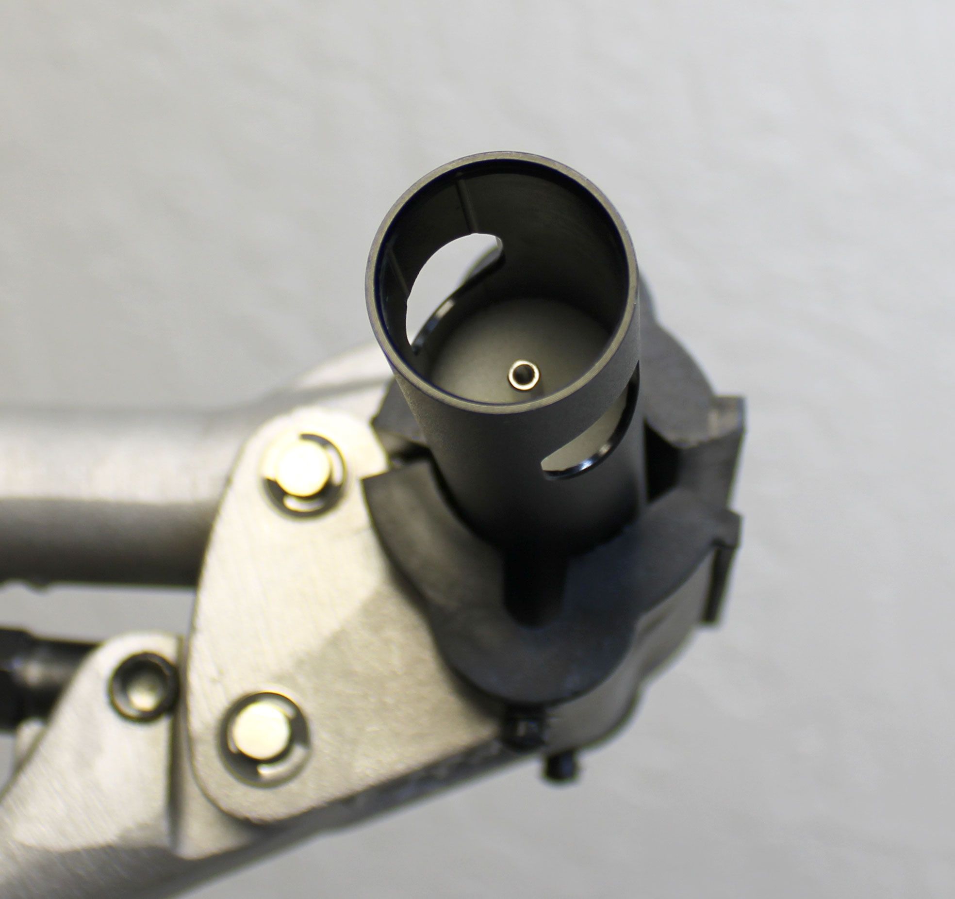
Step 22
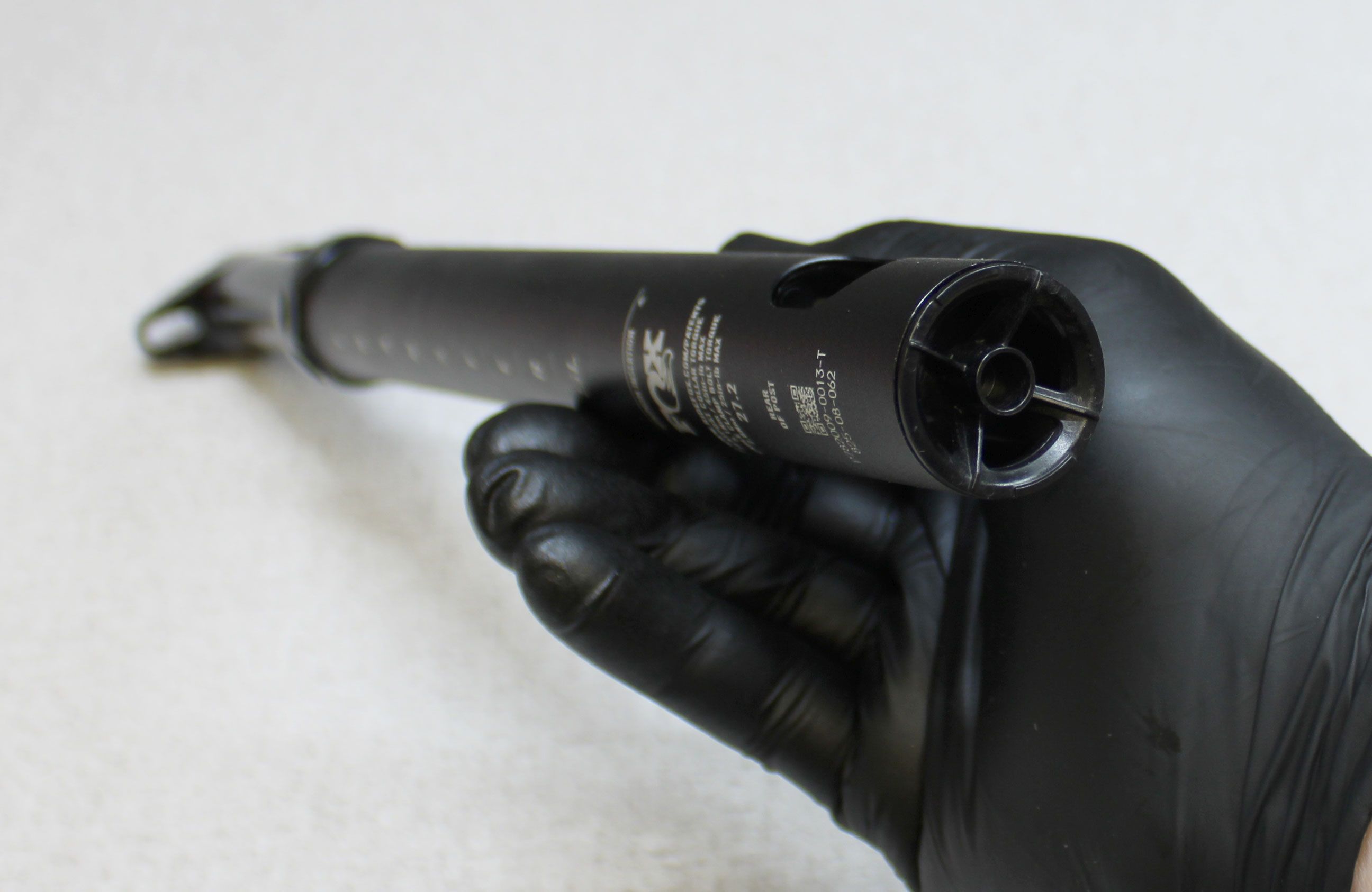
Reinstall the shaft lug with it's milled features oriented toward the front of the seatpost. Make sure to engage the flats of the shaft lug with the flats of the locking body. Reinstall the upper post into the lower post aligning the shaft lug and index pins with the internal grooves of the lower post.


Step 23
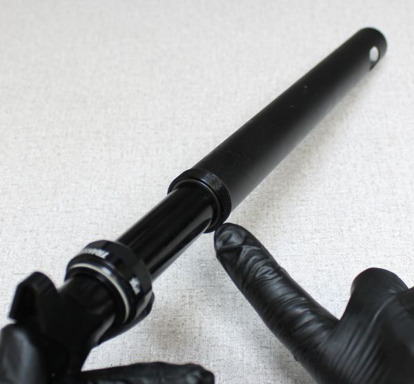
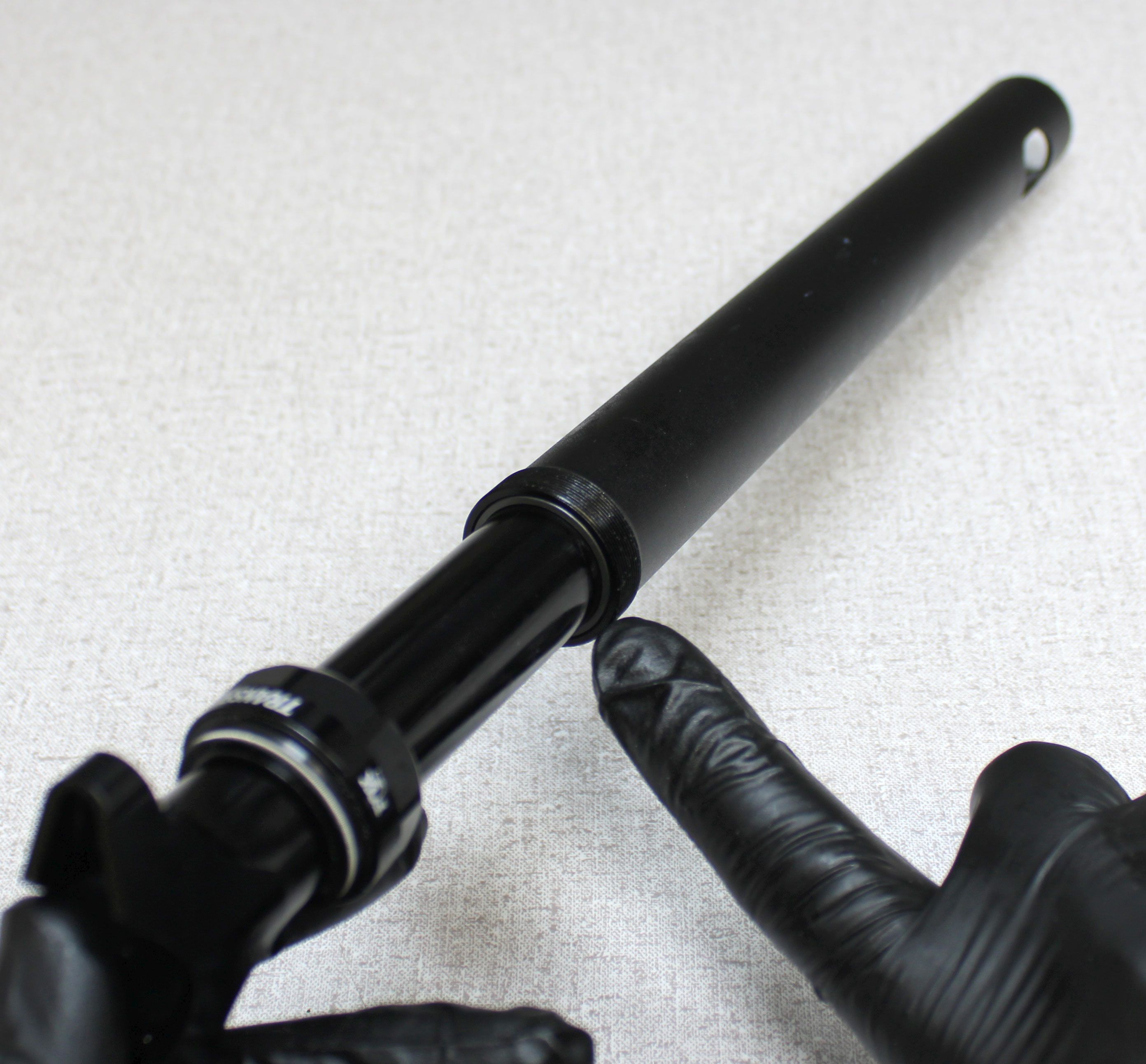
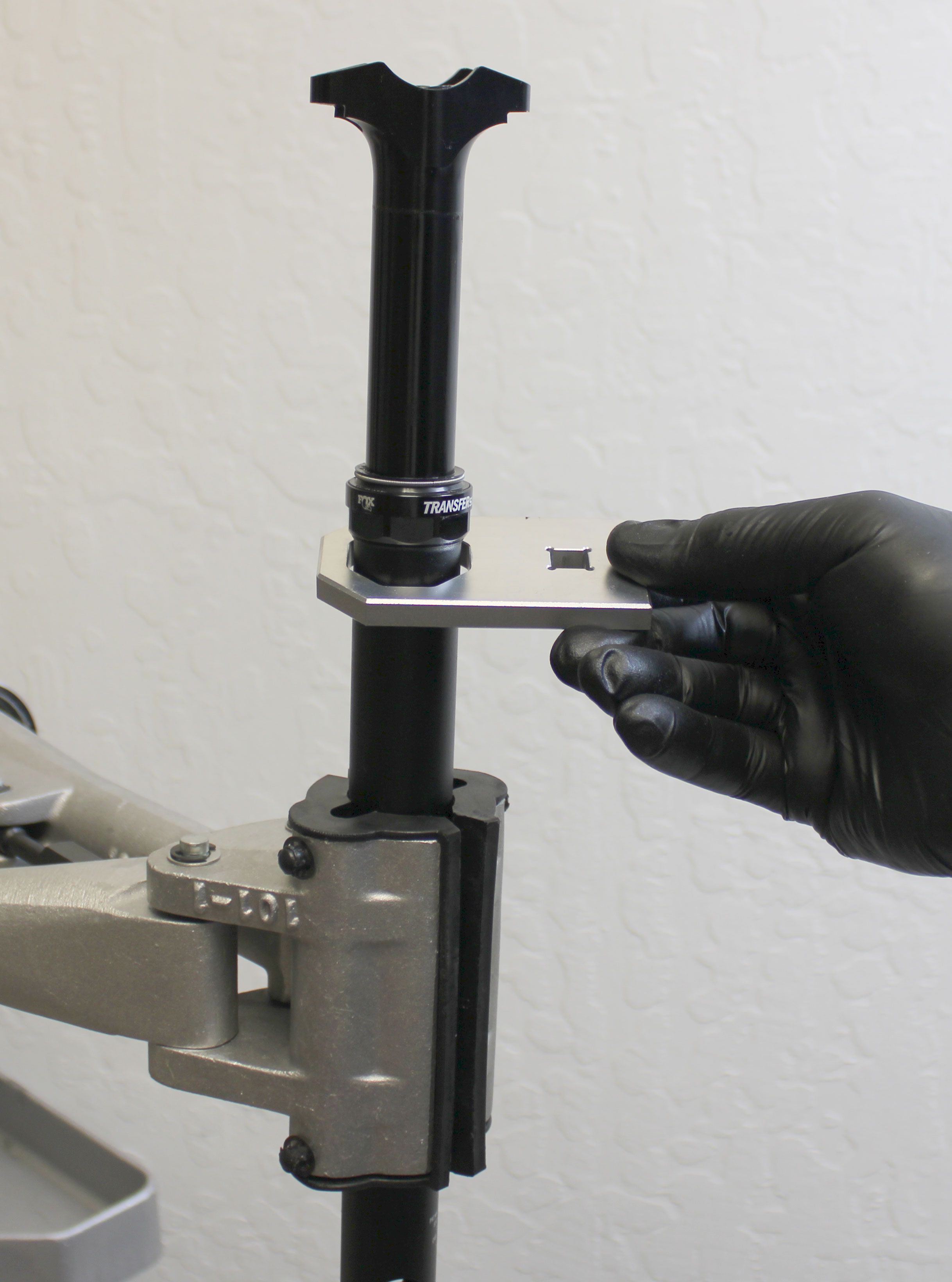
Make sure that the upper bushing is fully seated within the lower post. You can use the upper bushing installer (PN: 803-01-582) or your fingers to seat the upper bushing within the end of the lower post as shown. Tighten the sealhead clockwise onto the lower post by hand. Insert the seatpost through the collar torque driver (PN: 398-00-911) then clamp in your workstand. Tighten the sealhead clockwise to 144 in-lb (16.3 Nm) torque.

Step 24
Invert the post in your workstand then reinstall the lower retention bolt. Use the retention lug driver and an 18mm socket to tighten the lower retention bolt clockwise to 60 in-lb (6.8 Nm) torque. Install a new foam debris cover from the kit into the lower retention bolt. You can use the retention lug driver to press the foam debris cover into place.


Step 25
Reinstall the cable hangar making sure to hold it from turning while you tighten the screw clockwise with a T8 Torx driver to 6.7 in-lb (0.8 Nm) torque. Reinstall the cable pinch bolt clockwise into the cable hangar with a 3mm hex wrench. Make sure to install the pinch bolt from the correct side in order to pinch the cable appropriately during seatpost installation.


Step 26
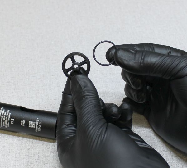
Replace the o-ring on the end cap with a new ungreased one from the kit. Reinstall the end cap into the lower post.


Step 27
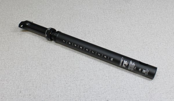
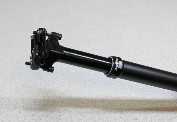
Reinstall the saddle clamps and hardware. Make sure that the spherical washers oriented properly and that the rear of the saddle clamps are oriented toward the rear of the post (indicated by the laser etching on the lower post). Clean the exterior of your seatpost.


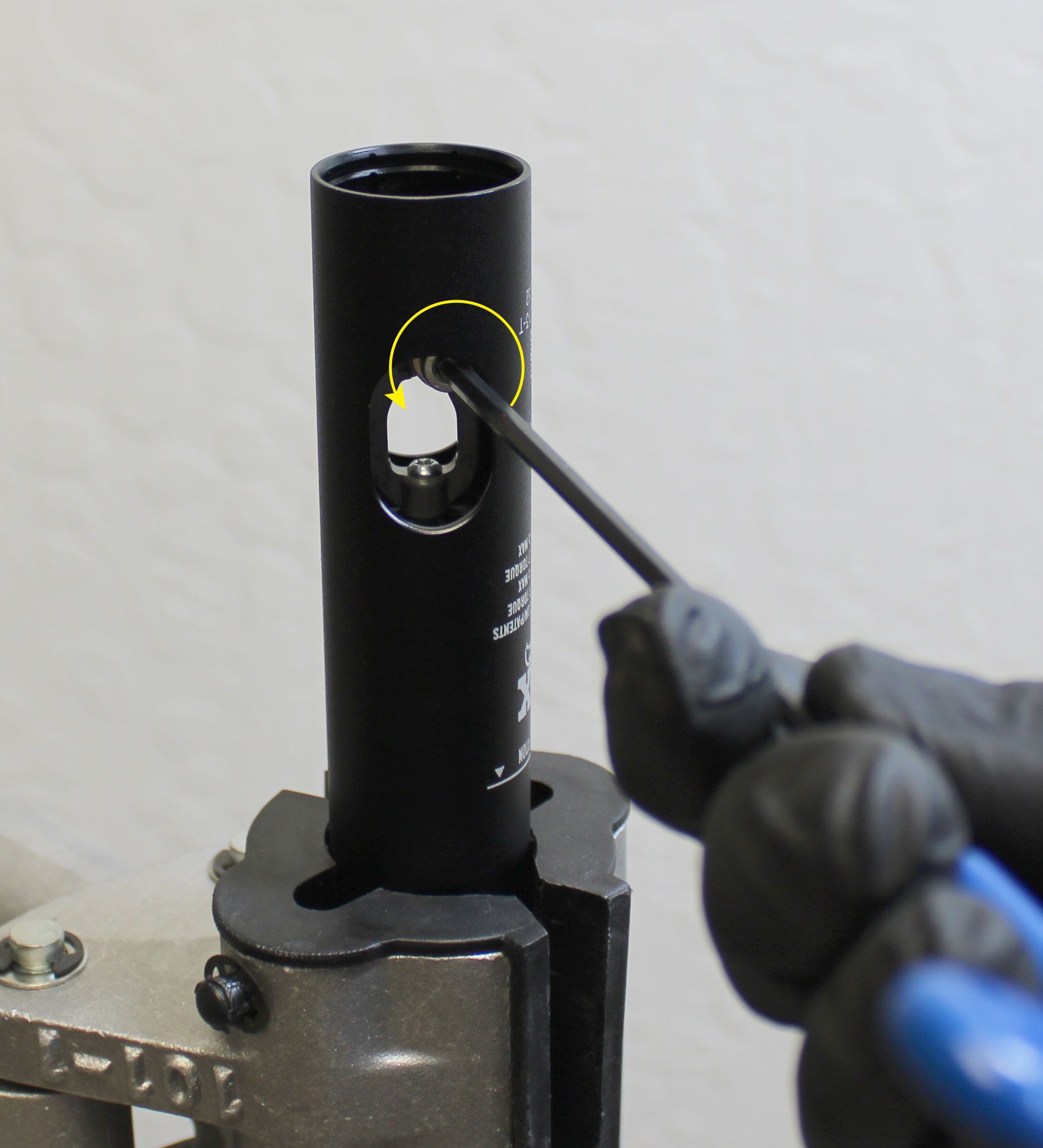
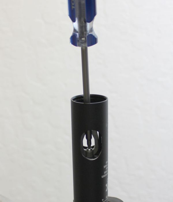
Step 28
Test the function of the seatpost by actuating the cable hanger with a hex wrench or other similar tool as shown.