2014-2017 FLOAT Nude 3 Rebuild (BV and Dish)
Required Parts
- 803-00-142 Kit: Rebuild, FLOAT Line Air Sleeve, Special Q-Ring
- 803-00-867 Seal Kit: SCOTT Nude 3 Boost Valve and Dish Shock Rebuild
Required Tools
- 398-00-227-A Tooling: Piston Tool Weldment [2X Ø.094 on .500 BC]
- 398-00-280 Tooling: Eyelet Torque Tool
- 803-00-805 Kit: Shaft Clamps, Shocks, CTD 9mm, 3/8in, 1/2in, 5/8in
- Nitrogen Fill Station (Tank with Regulator) required for full rebuild .
WARNING: Always wear safety glasses and protective gloves during service to prevent potential injury. Failure to wear protective equipment during service may lead to SERIOUS INJURY OR DEATH.
This service procedure guides you through the rebuild of a FLOAT CTD Nude 3 rear shock. For additional information and complete assembly drawings please visit the FLOAT CTD Nude 3 parts list page at: PARTLIST - SHOCK- 2014 FLOAT CTD Nude 3 »
Some pictures used below show different models of shocks, but all procedural information is the same. Please use this service procedure for information regarding all FLOAT CTD Nude 3 shocks.
WARNING: FOX products should be serviced by a qualified bicycle service technician, in accordance with FOX specifications. If you have any doubt whether or not you can properly service your FOX product, then DO NOT attempt it. Improperly serviced products can fail, causing the rider to lose control resulting in SERIOUS INJURY OR DEATH.
General Disassembly
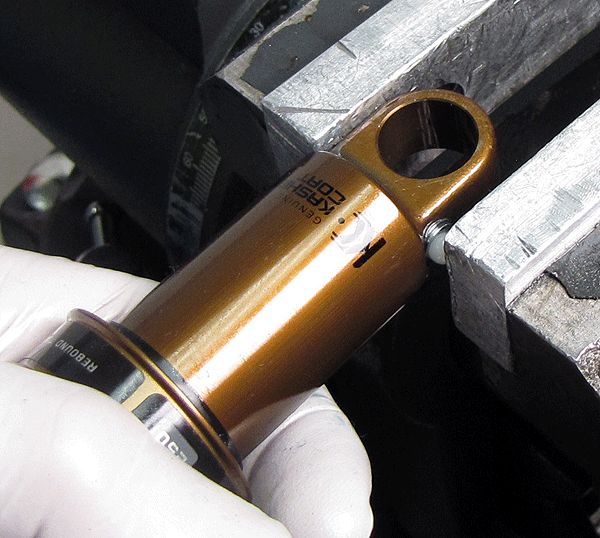
Step 1
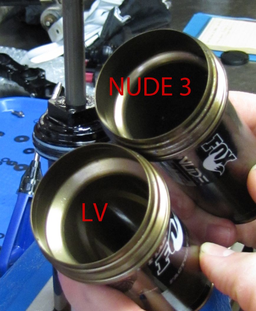
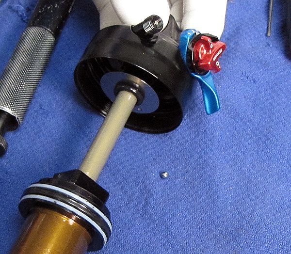
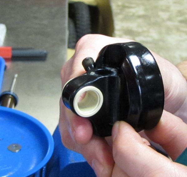
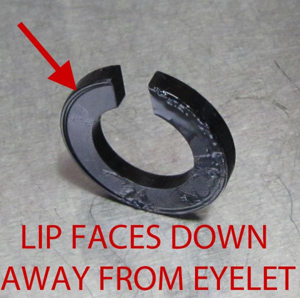
Release the air pressure and unthread the air sleeve. Pull the air sleeve down until the Nude 3 Volume Spacer hits the body bearing assembly and can be removed from the air sleeve. Note the orientation of the Volume Spacer, its lip must be facing down, away from the eyelet assembly. Nude 3 shocks use Nude 3 specific air sleeves. Do not attempt to use an LV air sleeve on a Nude 3 shock.


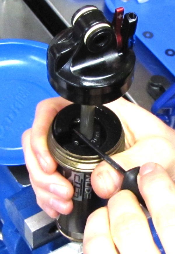
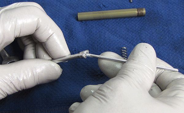
Step 2
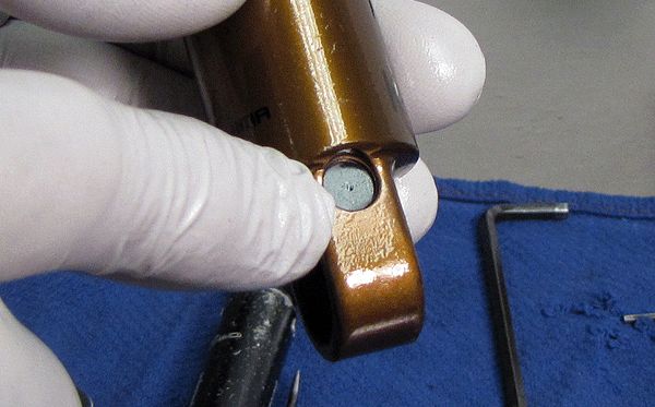
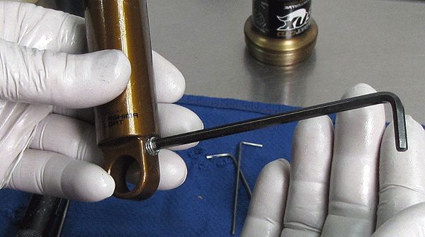
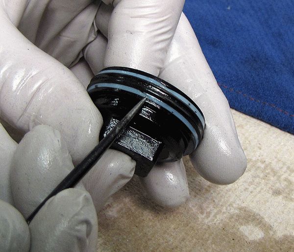
Using a pick tool, remove the nylon plug to access the pellet screw. Use a 5/32" hex to release the nitrogen pressure and remove the pellet retaining screw. Remove the pellet with the pick tool.


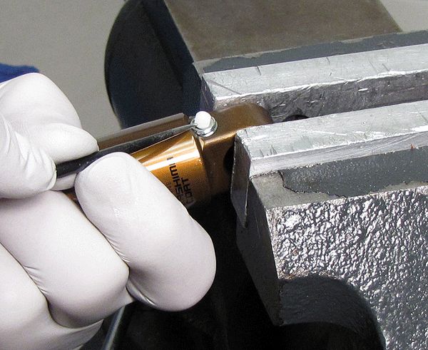
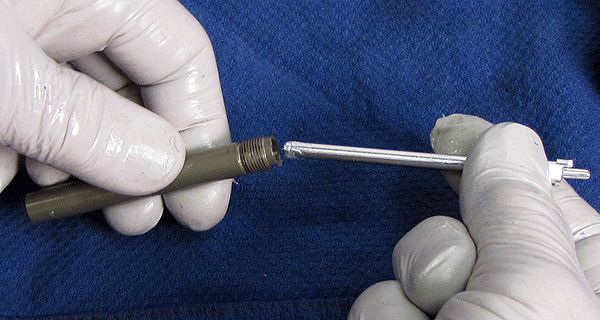
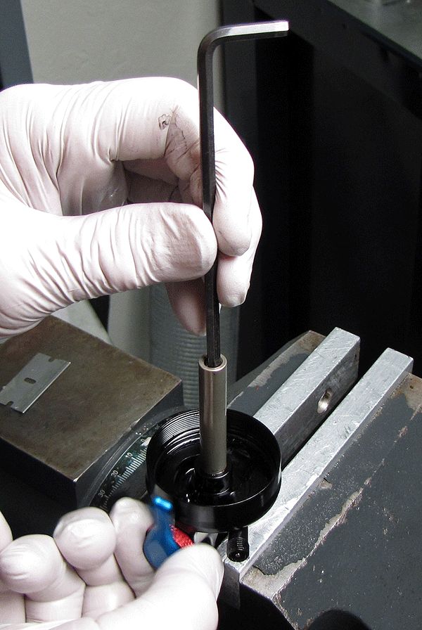
Step 3
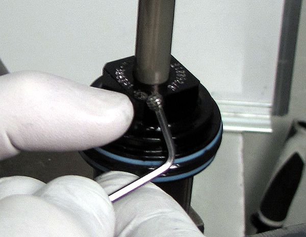
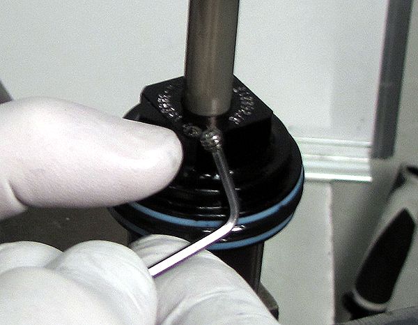
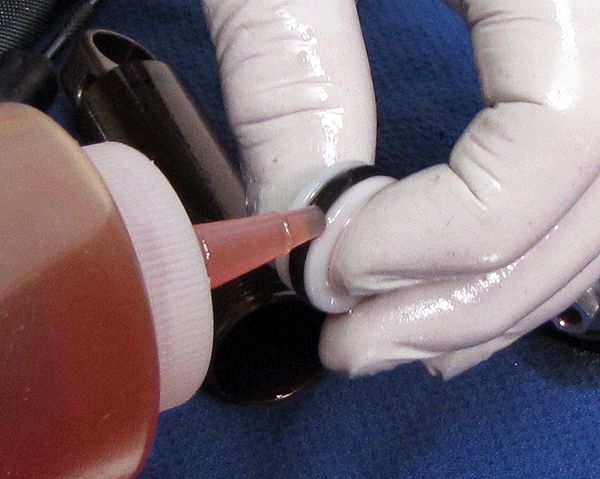
Clamp the shock vertically and use a 5/64" hex to remove the bleed screw. As you first crack the bleed screw, pay attention to the oil quality as it leaks out; foaming indicates aerated oil.

Step 4
Remove the shock from the vice and while inverting it over a clean towel, tap out the bleed screw ball. This can also be accomplished by compressing the shock slightly. Be very careful with this, as oil and the ball bearing may shoot out.
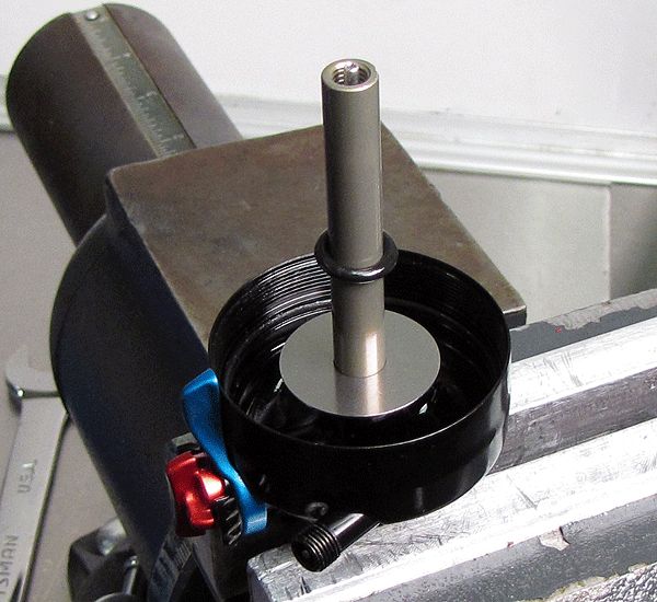
Step 5
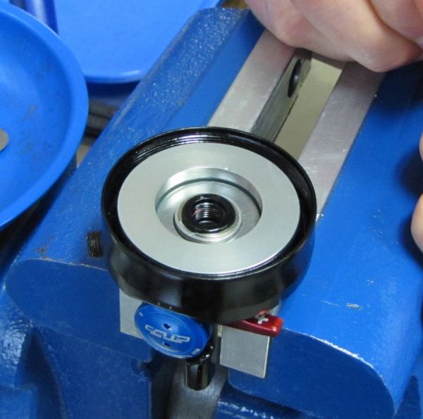
Clamp the shock body eyelet to remove the body cap with a 3/4" wrench.


Step 6
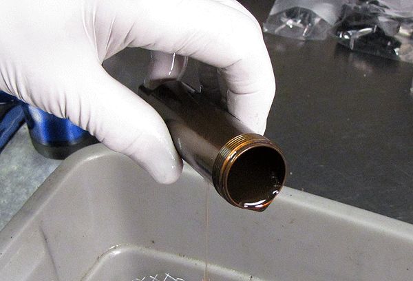
Drain the oil from the shock body.
Step 7
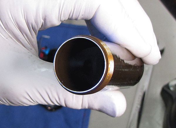
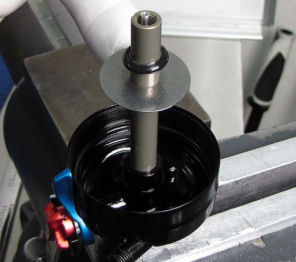
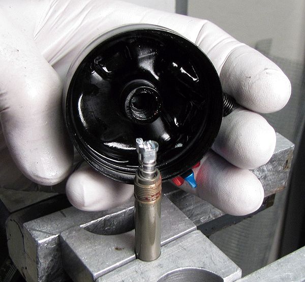
Remove the IFP using carefully applied air pressure. Inspect the body for damage or excessive wear.

Step 8
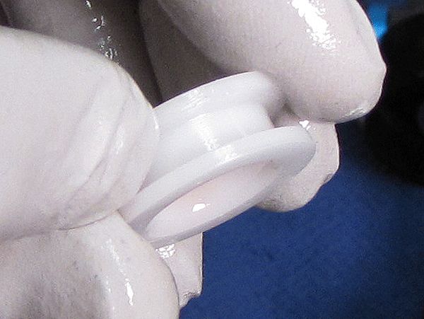
Remove the IFP o-ring and inspect its gland on the piston itself for any damage or contamination. Apply Slick Honey grease to the new IFP o-ring from the replacement seal kit, and install it on the piston.


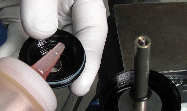
Step 9
Apply oil over the IFP o-ring, to displace any trapped air.

Step 10
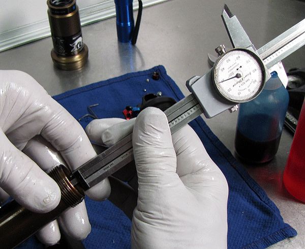
Set the IFP to the proper depth for your shock size.
| SIZE | IFP DEPTH |
| 6.500 x 1.500 | 1.880in. |
| 7.500 x 2.000 | 2.310in. |
| 7.875 x 2.250 | 2.500in. |
| 8.500 x 2.500 | 2.740in. |


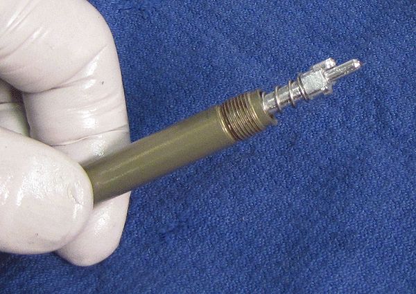
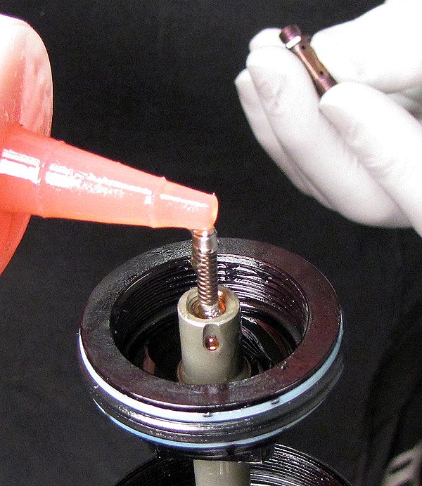
Step 11
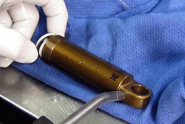
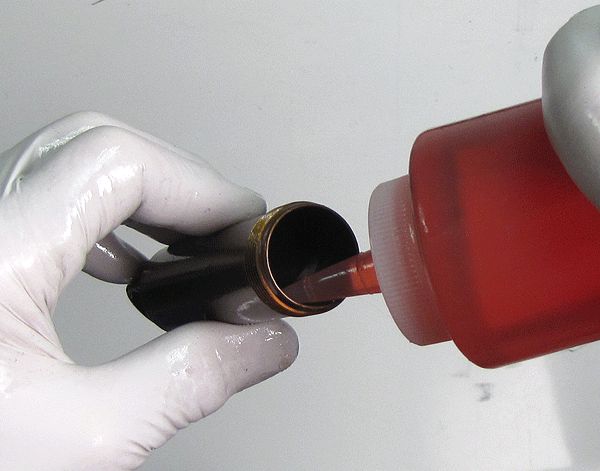
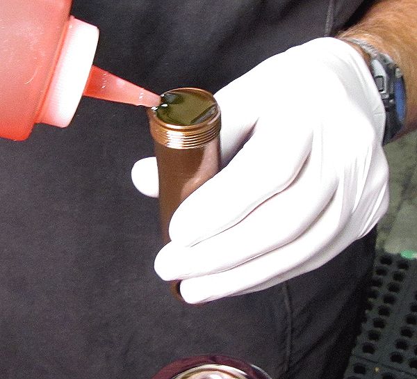
Install a new pellet from the service kit, the flat side facing up, and secure with the pellet screw. Prefill the shock body with oil, pouring down the side to minimize potential aeration of the oil. Set the body aside in a vertical position and move on to the topcap, allowing time for any trapped air to escape.

Boost Valve Damper Disassembly
If servicing a Nude 3 Dish shock, please go to the Dish Damper Disassembly section »
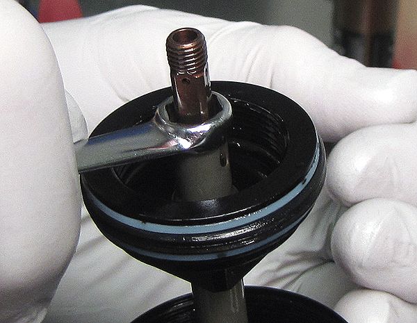
Step 1
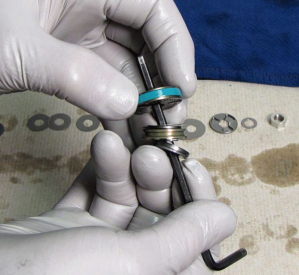
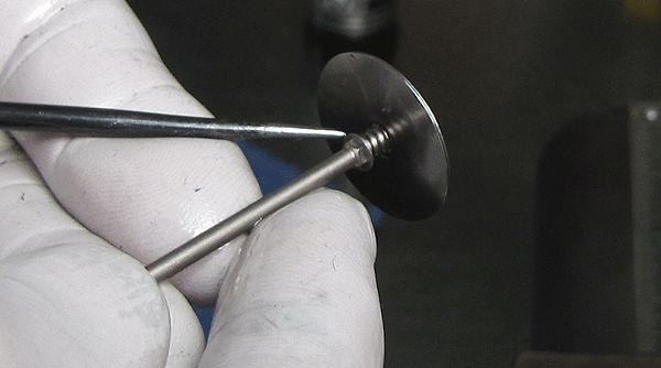
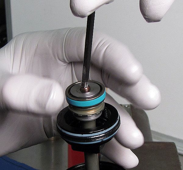
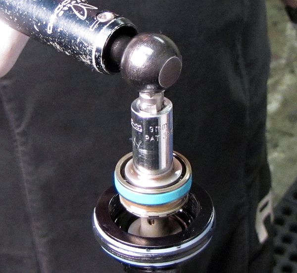
Using a 9 mm wrench, remove the piston nut. Be careful not to lose the 4 x 10 valve shim that can stick to the nut.


Step 2
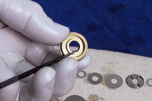
Remove the valving assembly and lay it out in assembly sequence on a clean lint-free towel. Carefully inspect the shims for damage or excessive wear.


Verify that you are using the latest version of the Boost Valve parts by viewing the Boost Valve TSB »
Step 3
Replace all boost valve o-rings and the piston glide ring from the replacement parts kit. Be sure to replace the o-ring that is installed underneath the glide ring.


Step 4
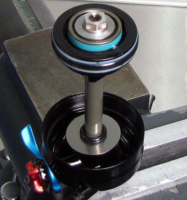
After replacing all seals and any worn or damaged valve shims, reassemble and stage the stack as shown and set it aside for now.

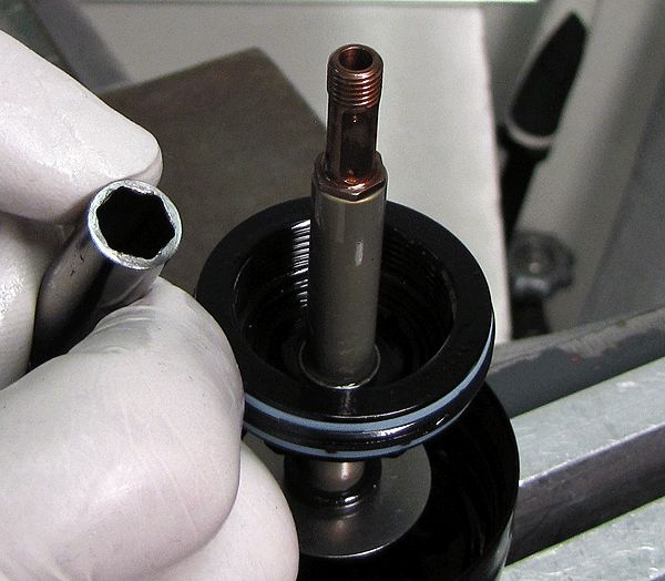
Step 5
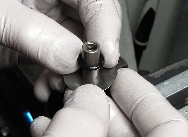
Remove the piston post with a chamfer-less 8 mm socket, followed by the Propedal piston and spring, setting all these parts aside.


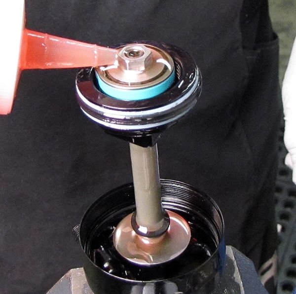
Step 6
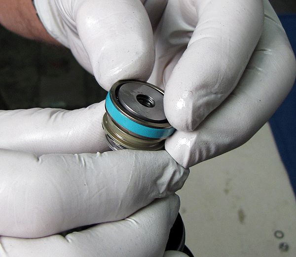
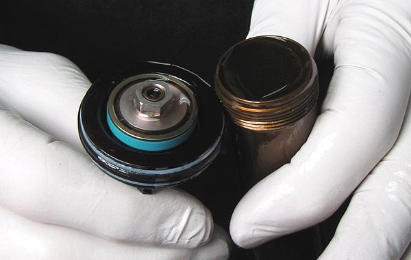
Remove the body bearing. Replace the o-rings, quad ring and backup rings from the replacement parts kit, installing with Slick Honey.


Step 7
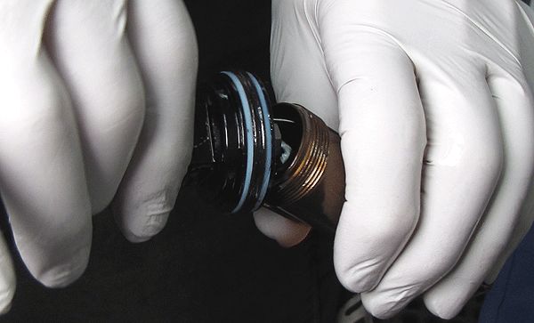
When replacing the quad ring and backup rings, be sure the ends are aligned properly.


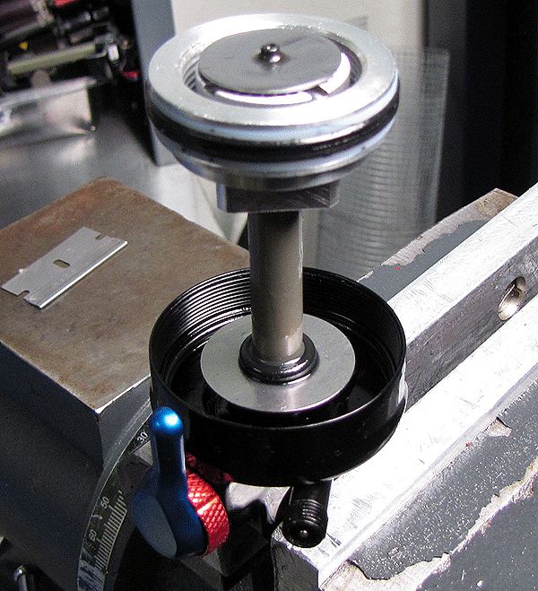
Step 8
Remove the bottom-out bumper and shim, invert the eyelet assembly and clamp it by the shaft using the appropriate shaft clamps.


Step 9
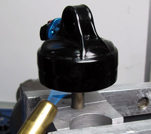
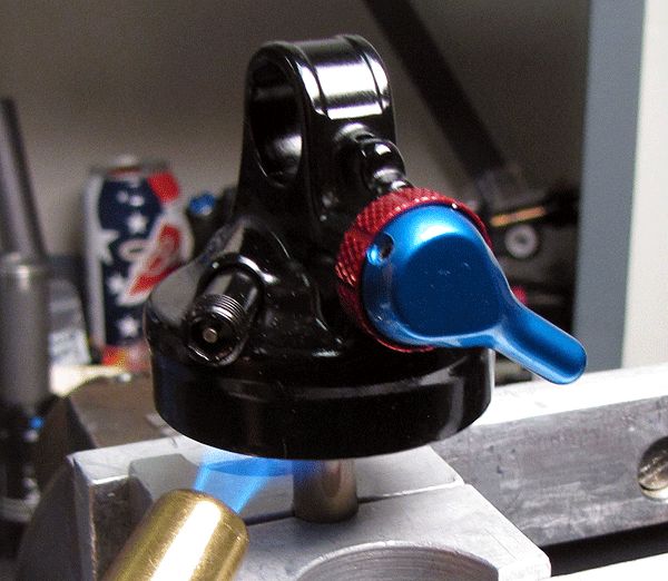
Apply some heat to the outside of the eyelet to soften the red Loctite, then remove the eyelet assembly from the shaft.


Step 10
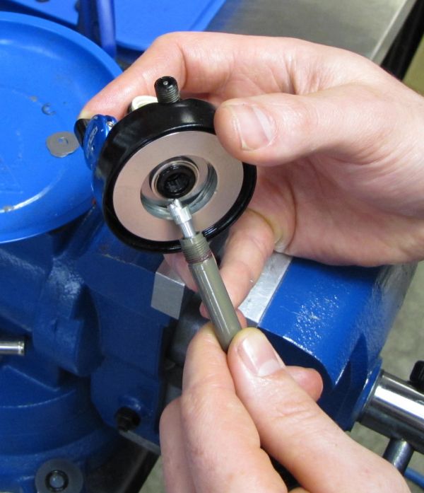
Remove the rebound and compression rod assembly

Step 11
Inspect the compression/rebound rods and the end of the shaft, for any signs of corrosion or scratches. If either rod is damaged, replace it with a current revision part. Replace the shaft o-ring.
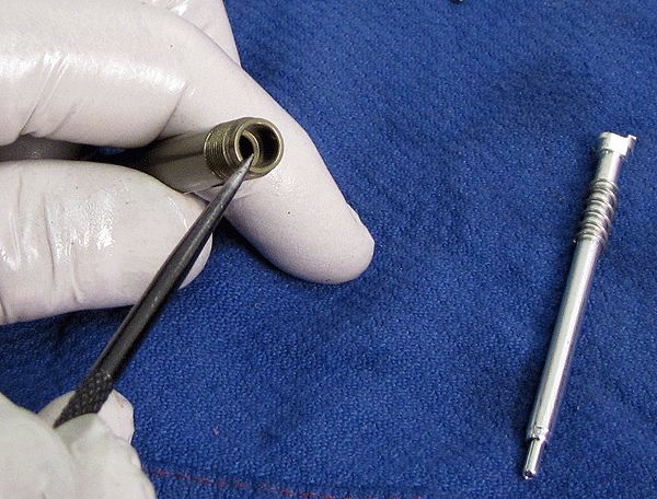

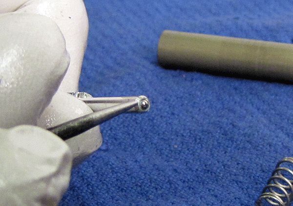
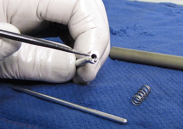
Step 12
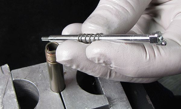
Remove the compression rod and spring, being very careful not to lose the ball on the rod tip. Replace the o-ring inside the rebound rod.
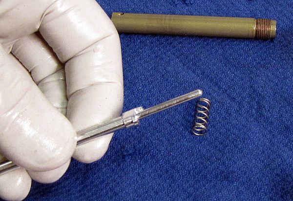
Step 13
Apply a small amount of Slick Honey to the non-ball end of the compression rod, then slide it back into the rebound rod either end first. Install the rebound assembly spring.


Step 14
Apply a small amount of Slick Honey to the rebound assembly and install it into the shaft assembly. Apply a small amount of Slick Honey to both ends of the rebound/compression rods, to lubricate the junction point with the CTD compression cam.

If servicing a Nude 3 Boost Valve shock, skip to the Nude 3 Eyelet Rebuild »
Dish Damper Disassembly
If servicing a Nude 3 Boost Valve shock, please go to the Boost Valve Damper Disassembly section »
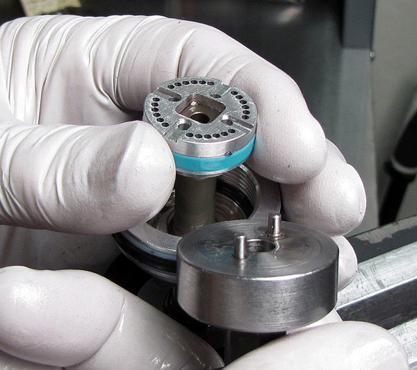
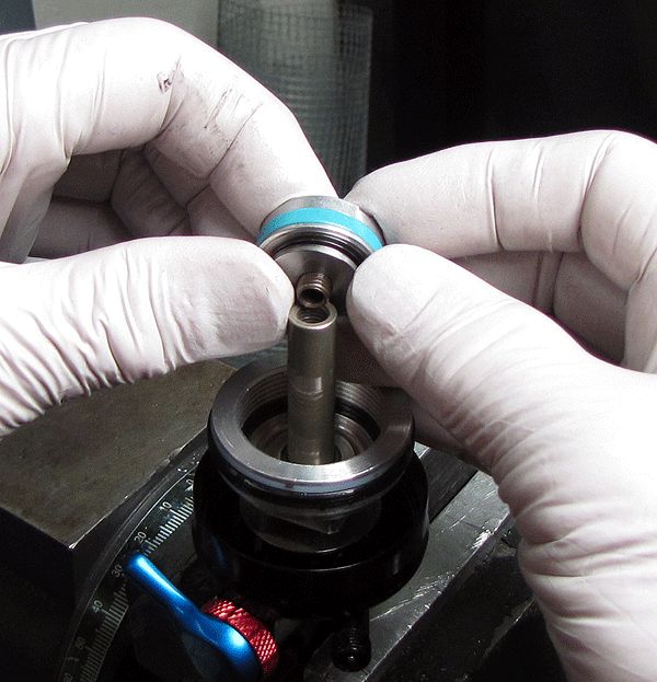
Step 1
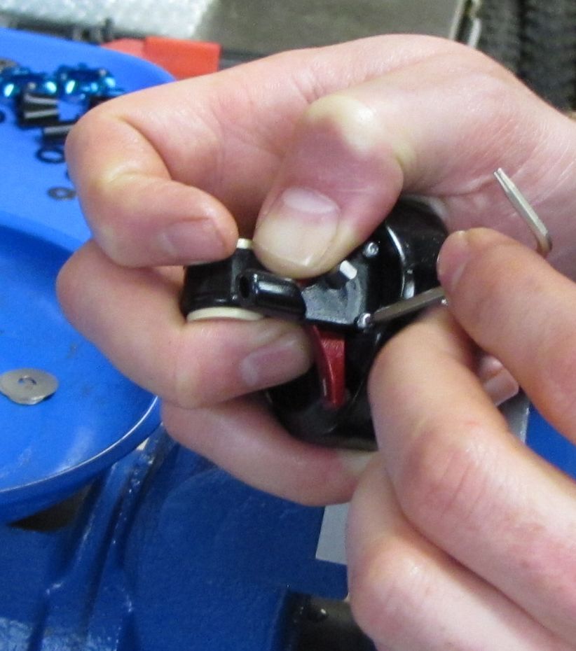
Place the piston/eyelet assembly in the vise as shown, and lift out the lockout plate.


Step 2
Inspect the lockout plate spring to ensure that it is functioning normally, not stuck. Also inspect the plate itself for its overall condition (not bent, corroded, or pitted). Replace damaged parts if necessary.

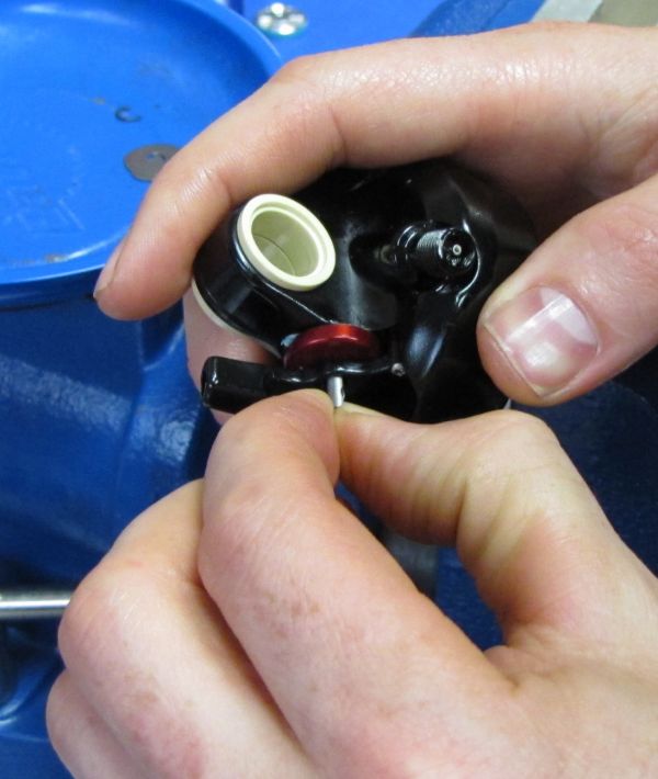
Step 3
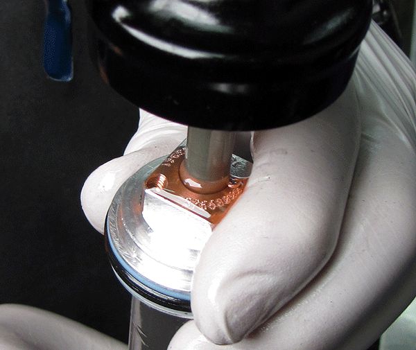
Use the Fox tool PN 398-00-227-A to remove the piston and valve shim stack. Lay these parts out in assembly order on a clean lint-free paper towel.


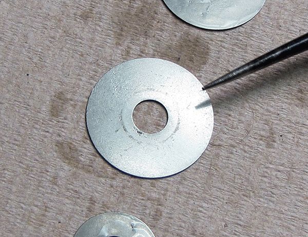
Step 4
Thoroughly clean the valve shims, and inspect each for wear, rust or cracks. Replace these as necessary.

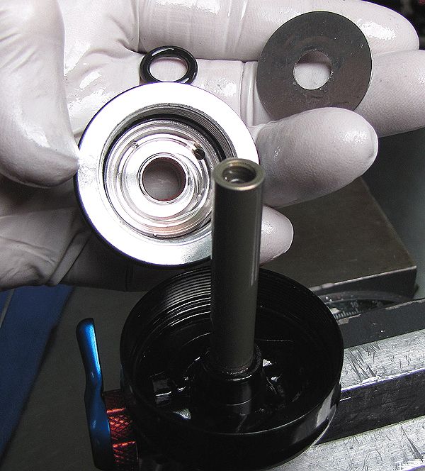
Step 5
Remove the body bearing, bottom-out o-ring and bottom-out plate. Invert and clamp the eyelet assembly using the appropriate shaft clamps.

Step 6
After applying some heat to break down the red Loctite, remove the eyelet assembly from the shaft.


Step 7
Remove the rebound and compression rod assembly.

Nude 3 Eyelet Rebuild
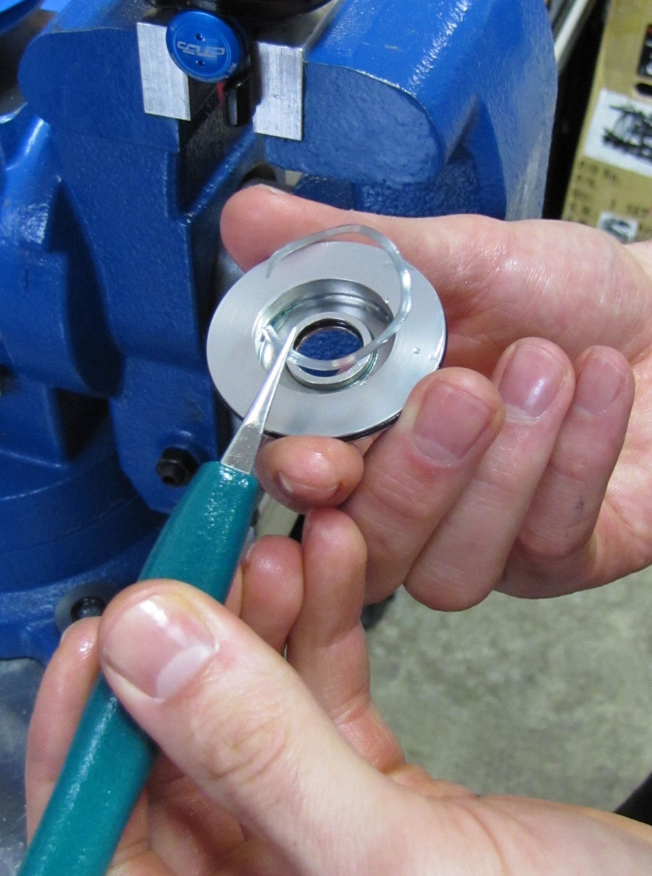
Step 1
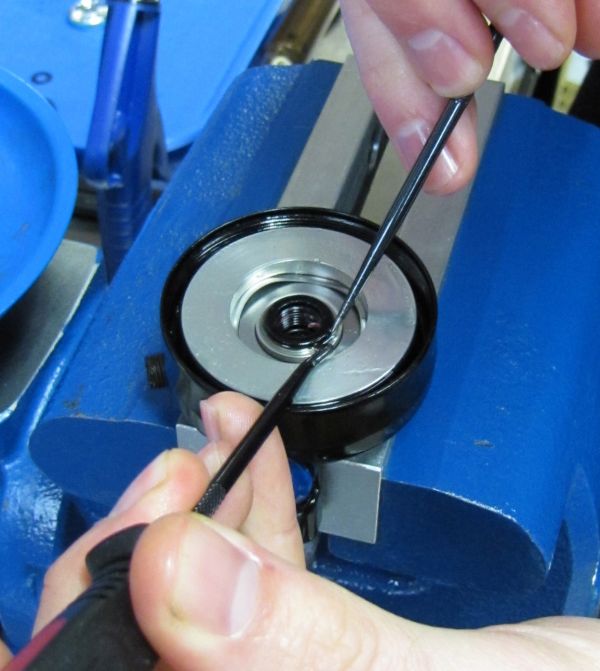
With the Nude 3 Eyelet assembly clamped in your soft-jawed vice, remove retaining ring 038-00-112 from the eyelet base, then remove Eyelet Base by pulling it up with a gentle rocking motion.


Step 2
Remove Wave Spring 039-00-296 from the Eyelet Base and replace if damaged. Using a pick, gently push the Check Valve out of the Eyelet Base as shown, then clean with isopropyl alcohol (replace if damaged). Replace the inner and outer Eyelet Base o-rings at this time.


Step 3
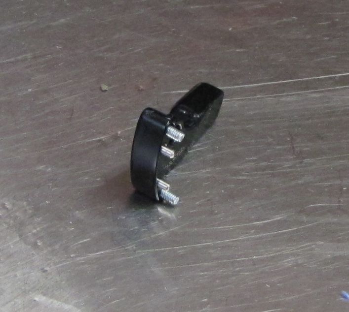
Remove the Travel Adjuster Rod by pulling it up. Inspect and replace the Travel Adjuster Rod (210-22-776) if damaged.


Step 4
Try to remove the O-ring Retainer Insert (210-22-777) by pulling it up with needle-nosed pliers. If the O-ring Retainer Insert is difficult to remove, you can remove it by using a small EZ-Out or similar screw extractor as shown but it must be replaced.


Step 5
Remove and replace the shaft-to-eyelet o-ring (029-08-079). Remove and replace the o-ring beneath the O-ring Retainer Insert (removed in the previous step).

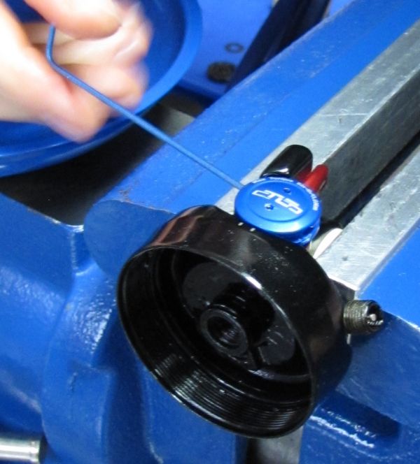
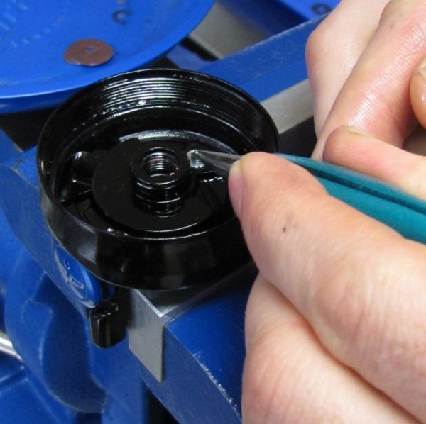
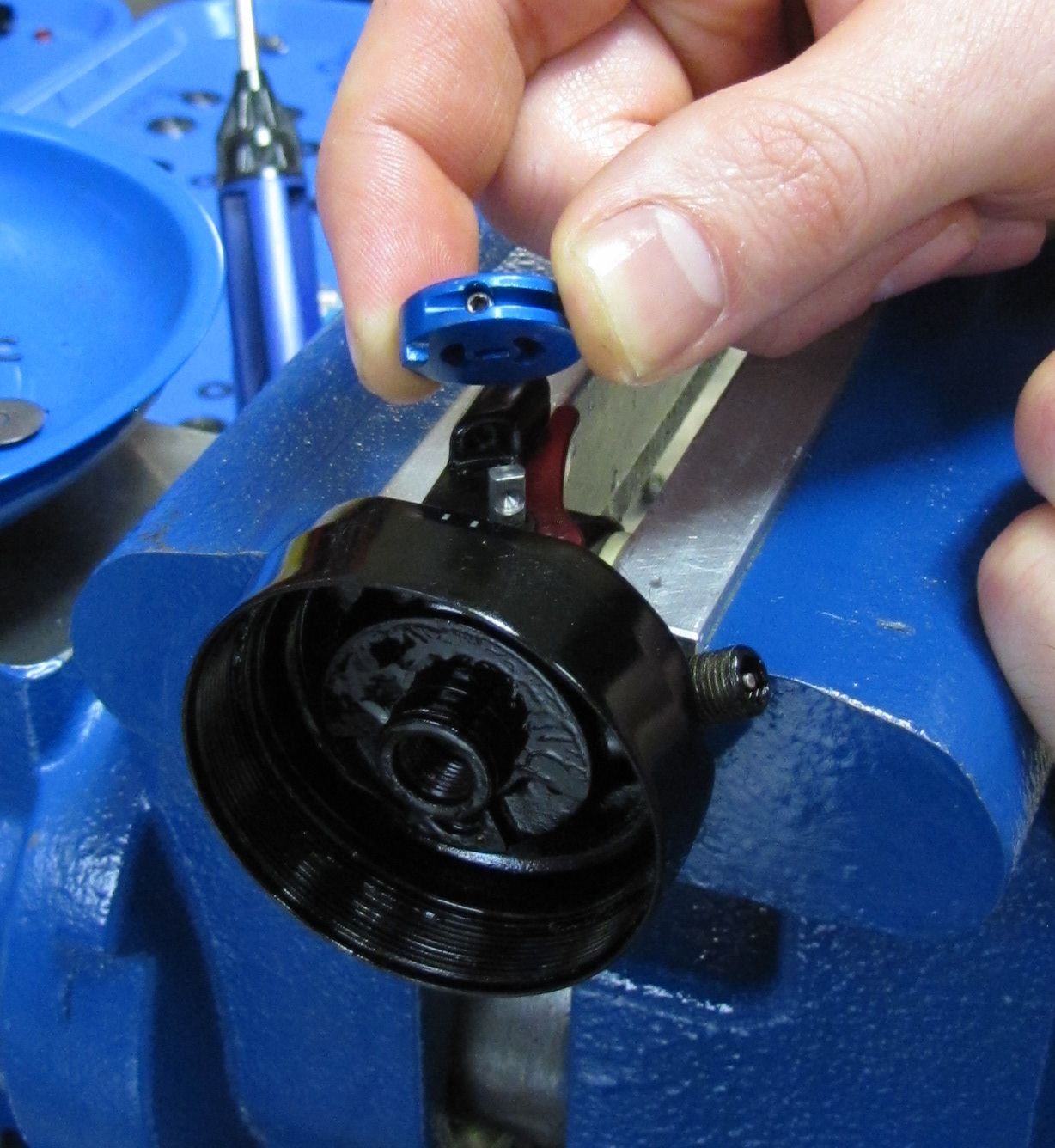
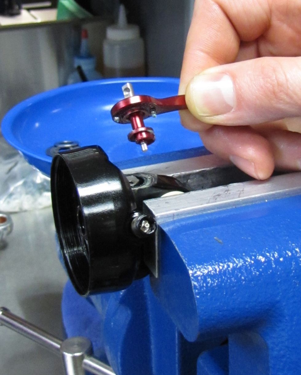
Step 6
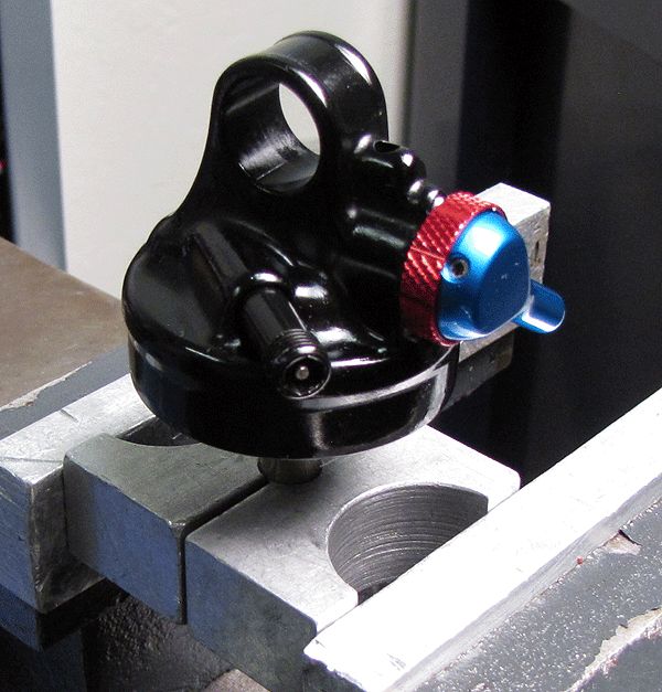
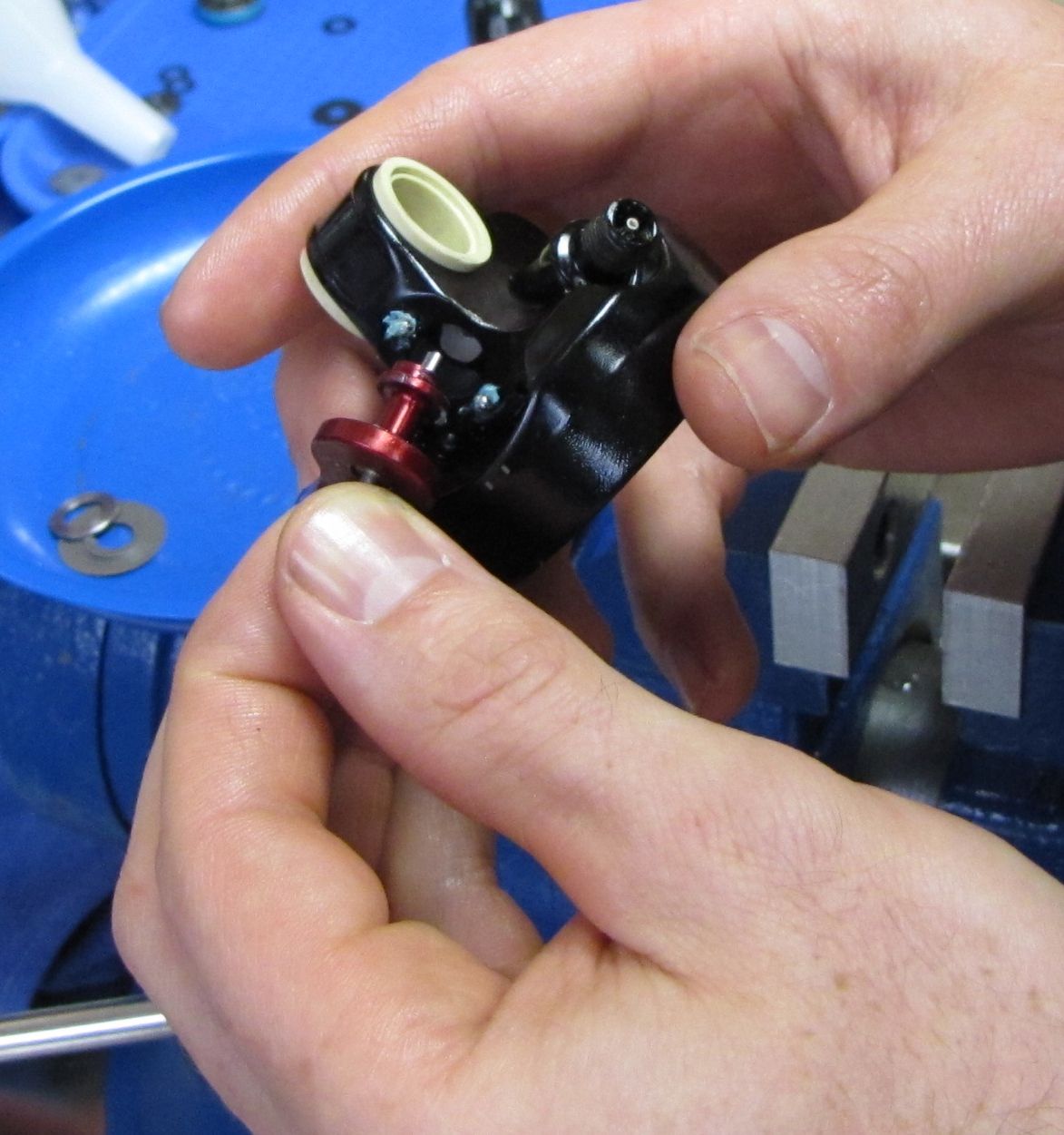
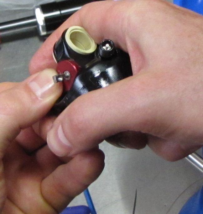
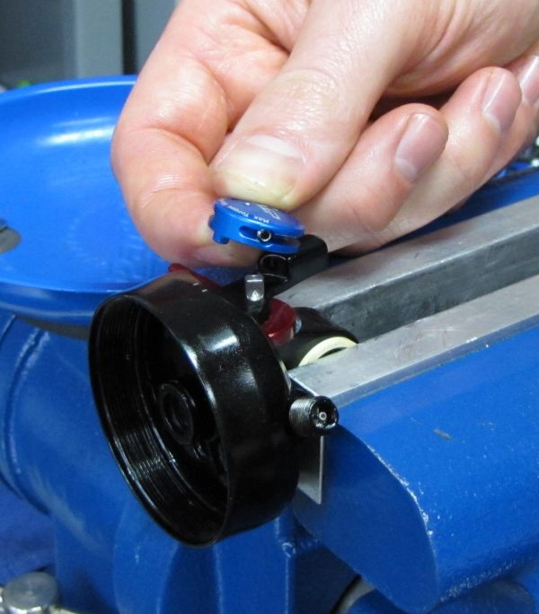
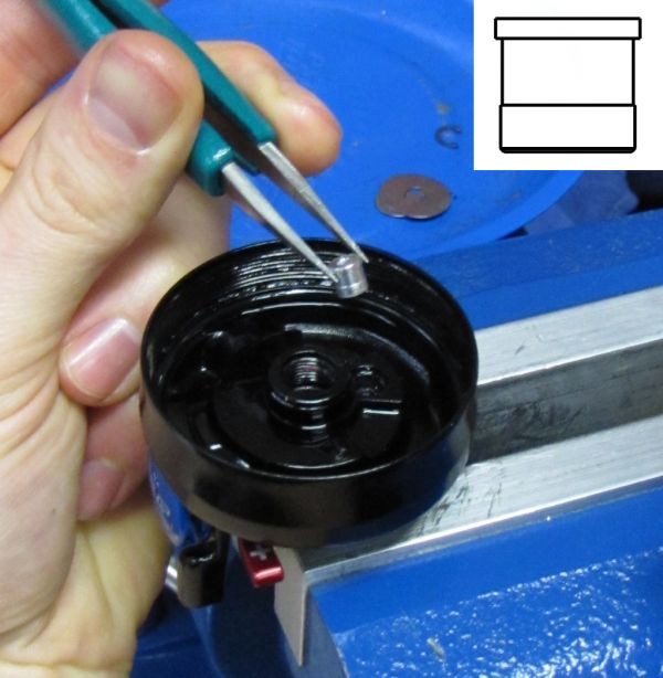
Use a 1.5mm hex wrench to back out the set screw securing the blue Nude3 CTD pulley to the camshaft (not necessary to remove completeley). Pull up on the pulley to remove it and unwind the torsion spring.


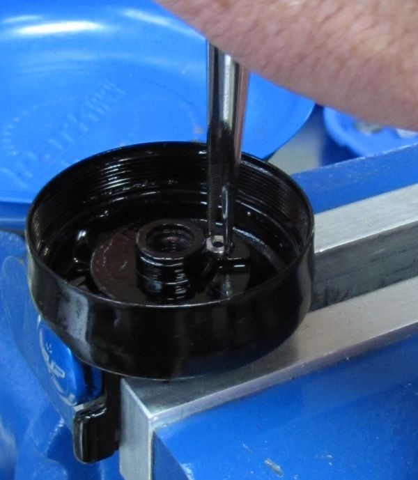
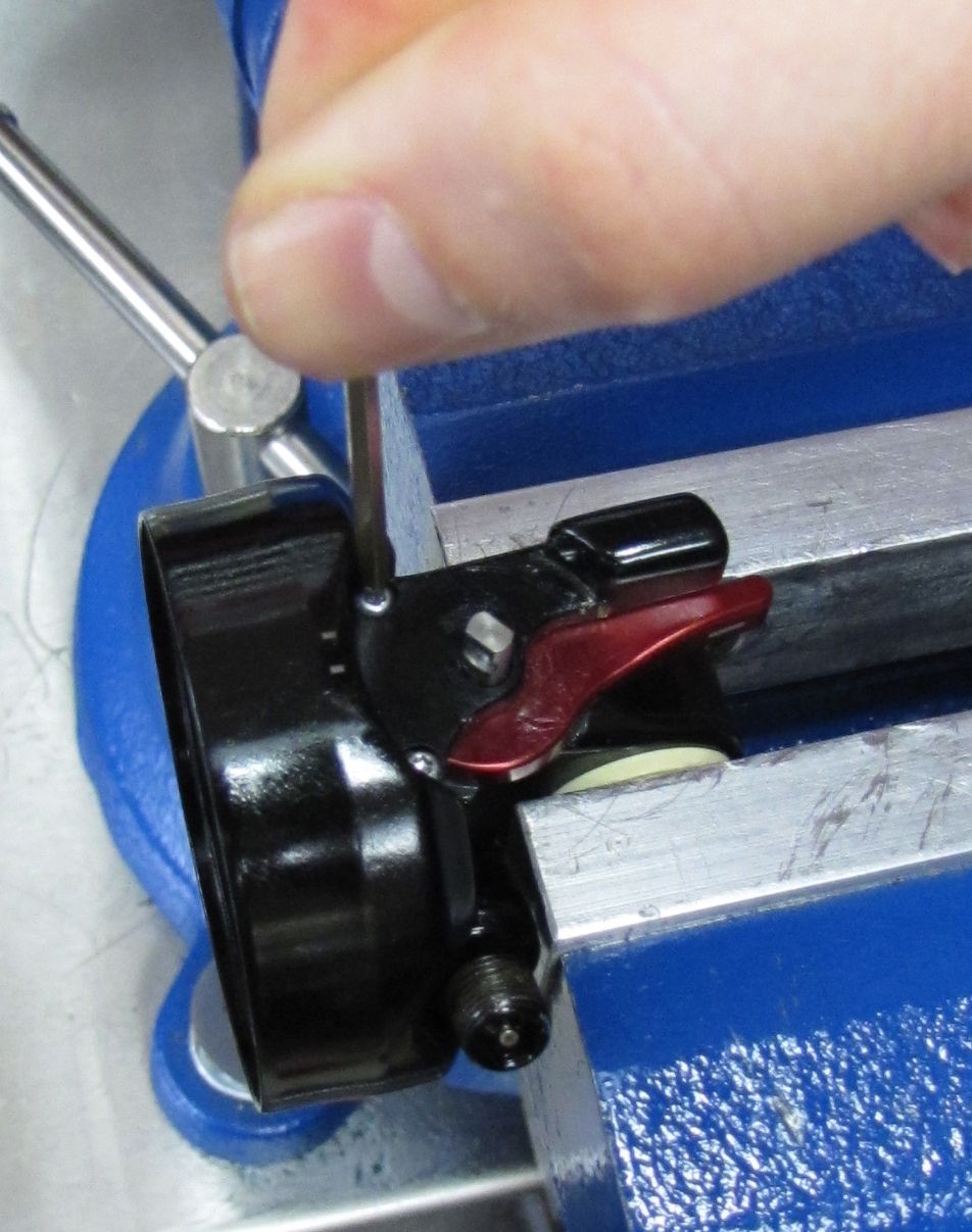
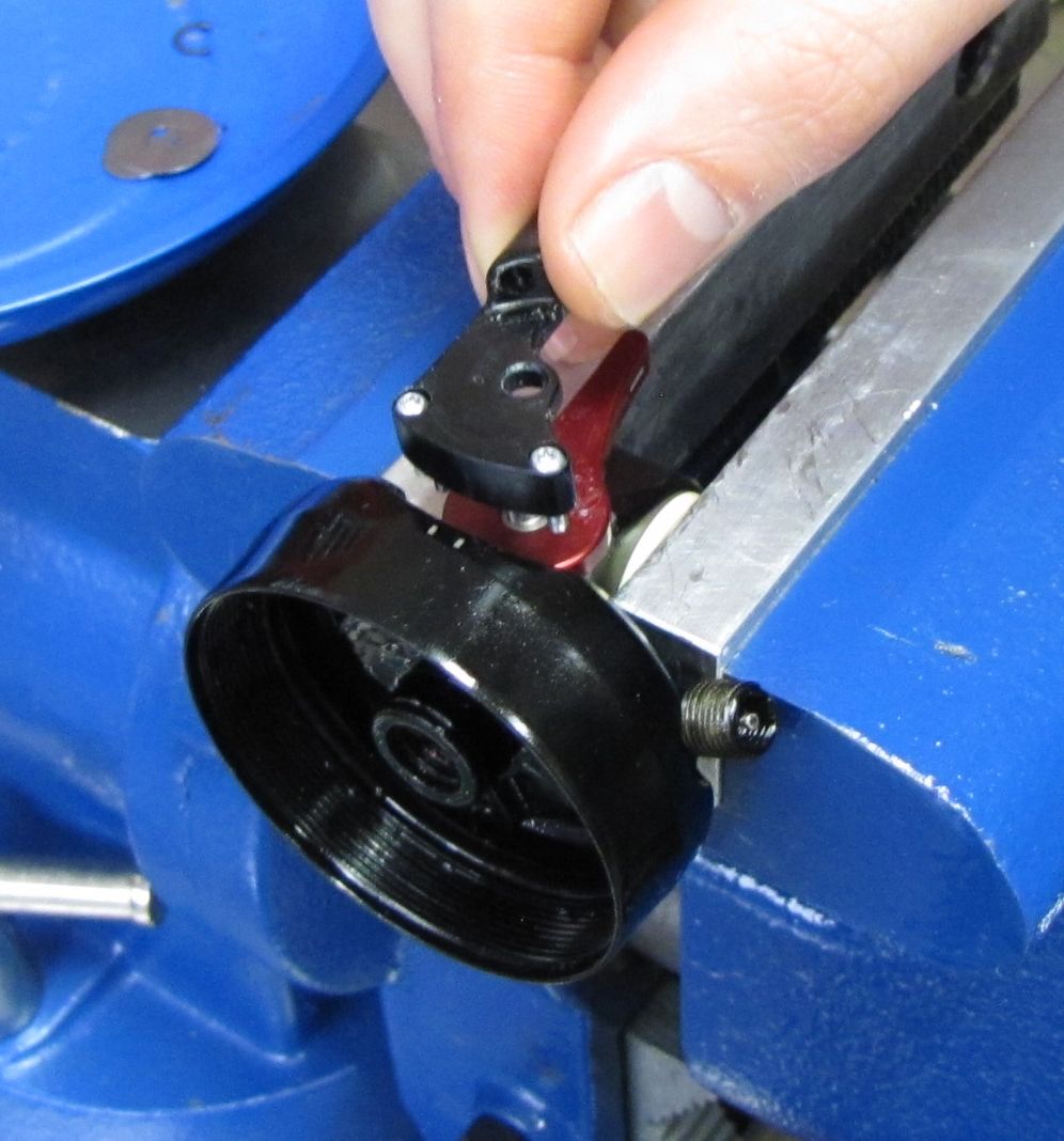
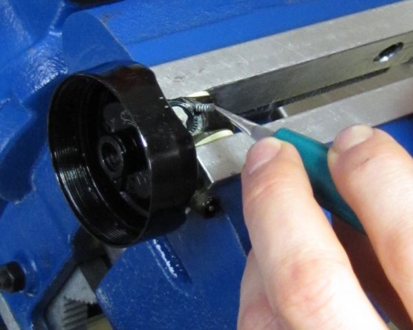
Step 7
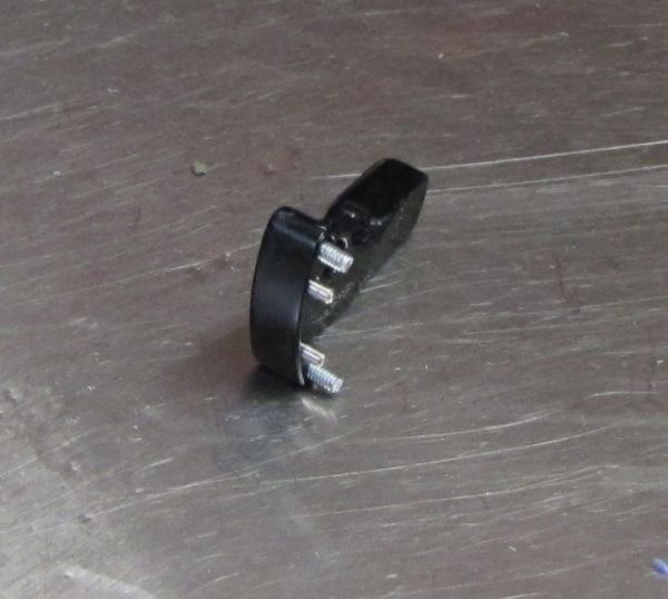
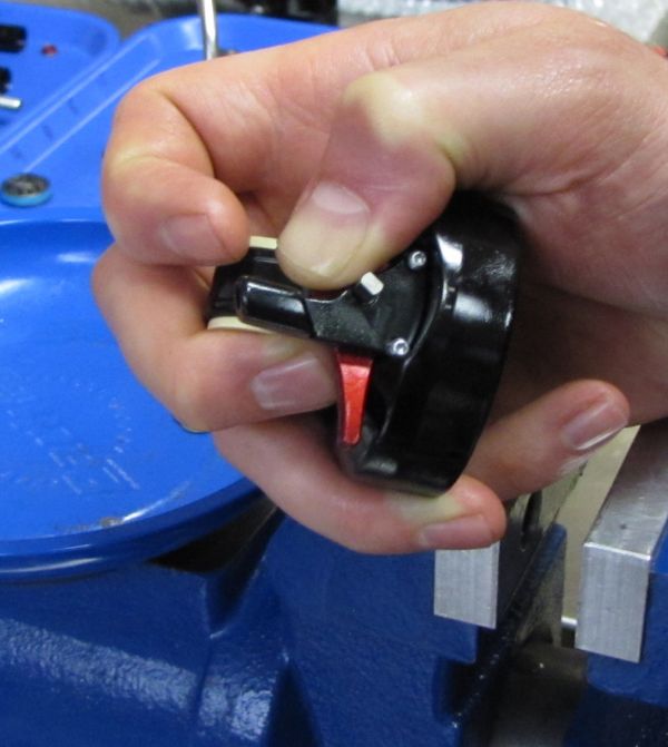
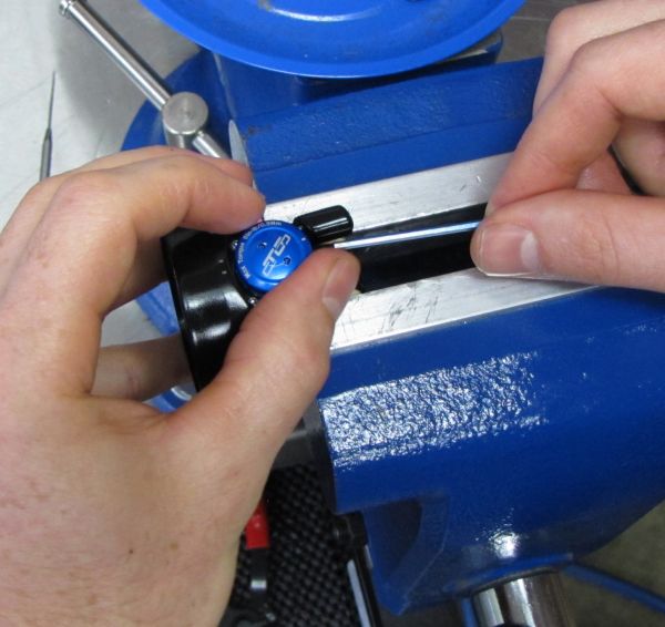
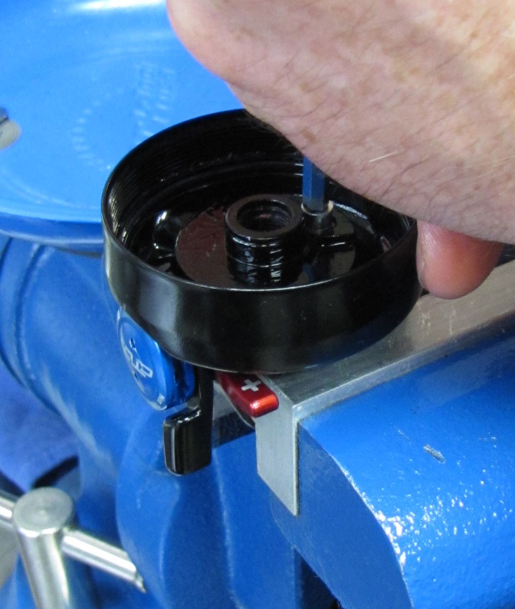
Use a T6 Torx driver to loosen the two screws securing the housing stop to the eyelet assembly. Lift up on the housing stop to remove it with both Torx screws.

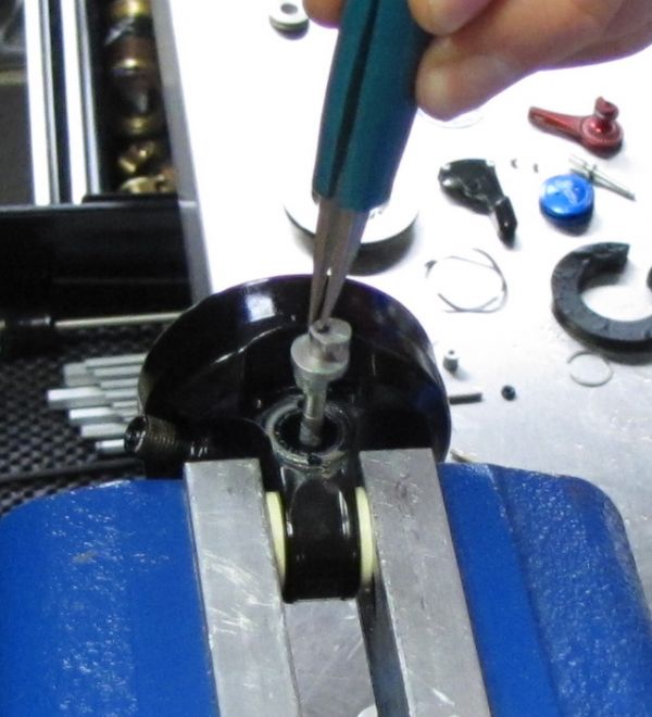
Step 8
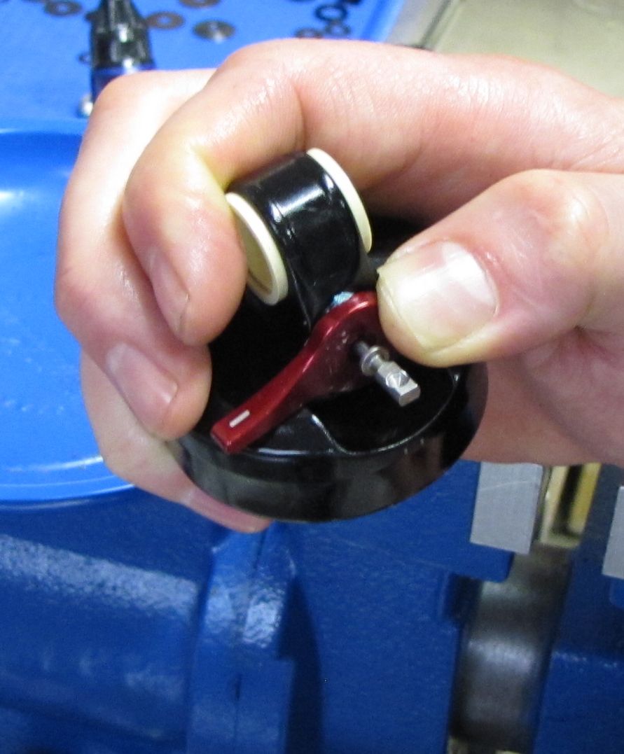
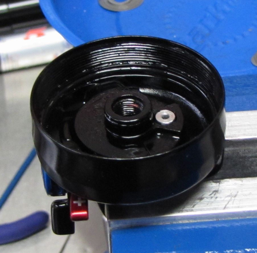
Lift up on the red rebound knob to remove both the knob and the camshaft. Be careful not to lose the two detent balls that may stick to the underside of the rebound knob. Separate the camshaft and rebound knob and set aside.

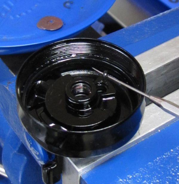
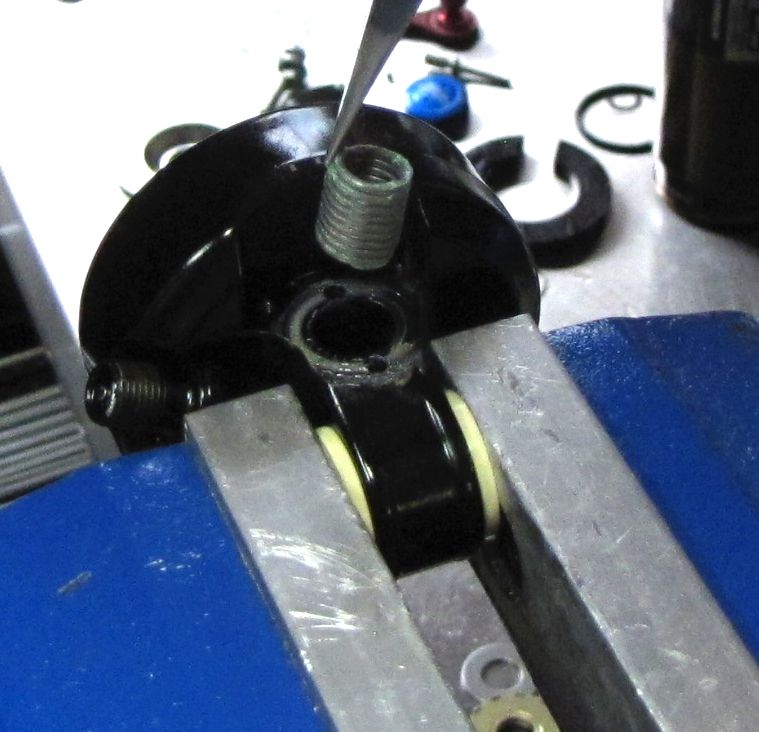
Step 9
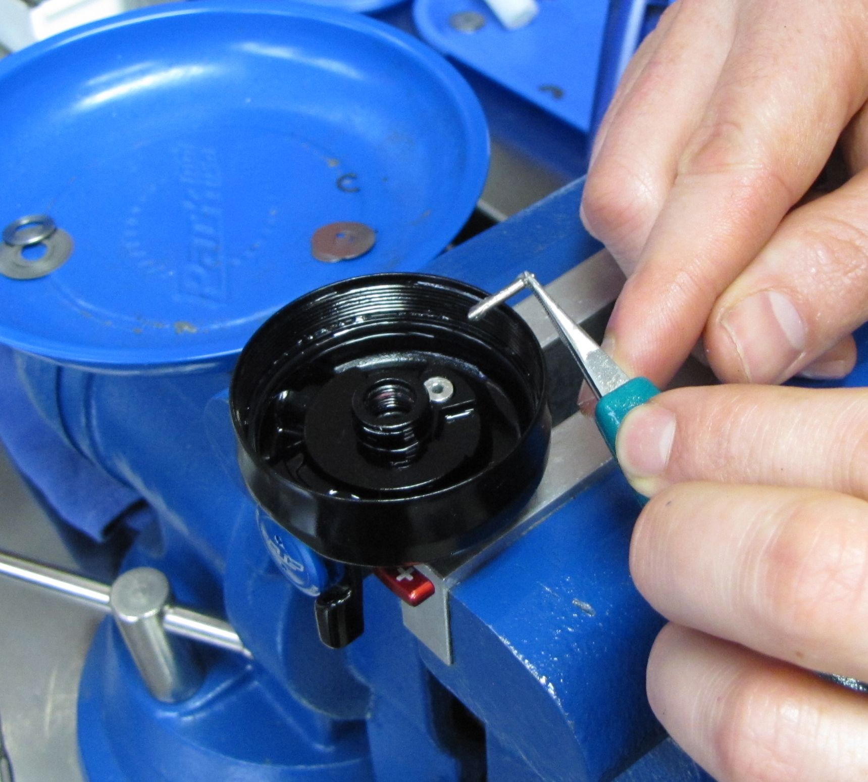
Remove the 2 rebound detent springs and set aside.

Step 10
Carefully lift out the cam followed by the torsion spring. Replace the torsion spring (039-00-295) with the new one from the kit.

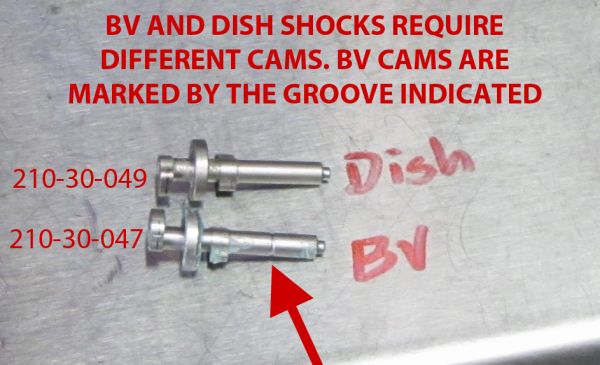
Step 11
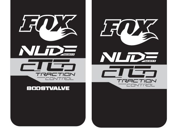
BV and Dish shocks require different cams. Make sure that you are using the appropriate cam for the shock being serviced. The only external differences between BV and Dish shocks are the decals and 4-digit codes. Take note of which shock you are servicing before proceeding.

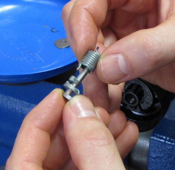
Step 12
Coat the new Torsion Spring (039-00-295) with blue Hi-Temp grease (Sta-Lube SL3125 or similar) and insert its non-marked tang into the pocket on the cam. The red tang should face away from the cam.

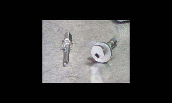
Step 13
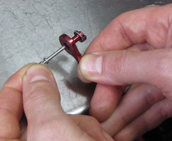
Take note of the unique interface between the Camshaft and Cam. Use the keyed Camshaft (210-30-048) to help install the Cam/Greased Torsion Spring assembly. Start by loading the Cam/Greased Torsion Spring assembly onto the Camshaft as shown.


Step 14
Insert the Cam/Greased Torsion Spring/Camshaft assembly into the eyelet with the red tang of the Torsion Spring in the 3 o’clock position. Push the assembly against the back wall of the eyelet and slowly rotate clockwise 90 degrees until the red spring tang drops into the hole in the eyelet. Check to make sure the spring tang has engaged its hole by rotating the Camshaft a few degrees in both directions, you should feel the spring winding rather than spinning.
Step 15
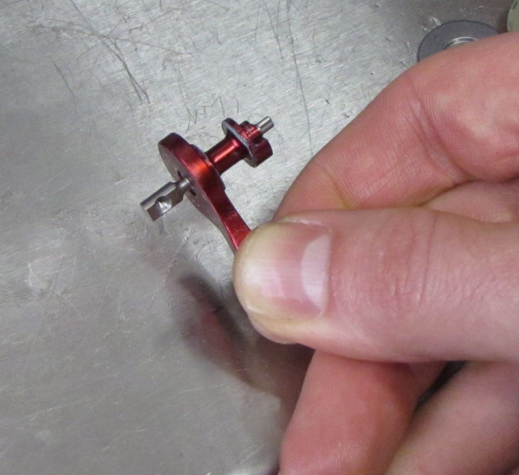
Use a small tool like a 2mm hex wrench inserted into the eyelets shaft hole to hold the Cam in place as you remove the Camshaft by pulling it out of the Cam/Torsion Spring.


Step 16
Install the 2 Rebound Detent Springs (039-00-109) into the eyelet as shown. If springs sit flush or lower they should be replaced with new springs. Cover the exposed spring ends with blue Hi-Temp grease (Sta-Lube SL3125 or similar), then position the detent balls (010-01-002-A) on the springs.


Step 17
Prepare the Housing Stop by inserting the 2 T6 Torx screws and checking to make sure that the 2 dowel pins (060-00-021) are pressed in. If the Dowel Pins have fallen out, press them back into the two centermost holes on the back side of the Housing Stop. Inspect the inside surface of the Camshaft hole in the Housing Stop for damage or excessive wear and replace if necessary.

Step 18
Insert the Camshaft into the red Rebound Knob from the front as shown.

Step 19
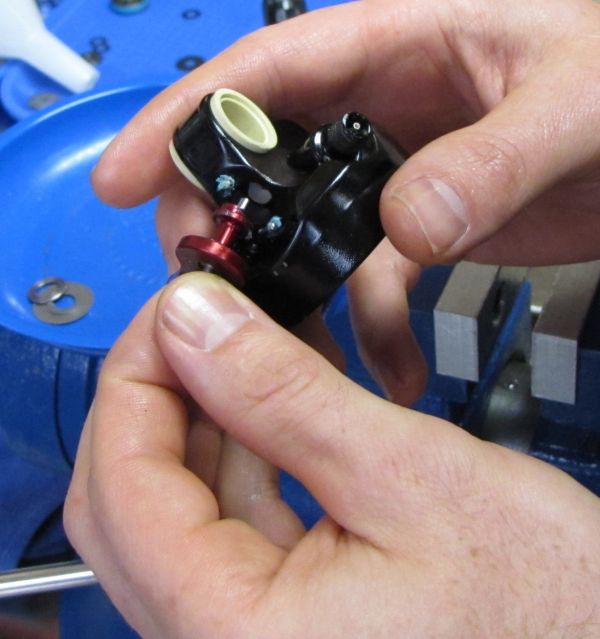
Insert the red Rebound Knob into the eyelet letting the Camshaft protrude as you push the Rebound Knob in against the detent balls. Hold the Rebound Knob against the detent balls while you rotate the Camshaft and use gentle pressure to insert the Camshaft into the keyed Cam. When installed correctly, the counterbore on the Camshaft for the pulley set screw will face the air valve (approximately 4 o’clock).
Step 20
While holding the red Rebound Knob against the rebound detent balls, install the prepared Housing Stop, lining up the dowel pins and T6 Torx screws with their respective holes in the Eyelet. Torque the screws to 3.5in.-lb (0.4 Nm).

Step 21
Check to make sure that the Torsion Spring, Cam, and Camshaft are properly installed by rotating the Camshaft a few degrees in both directions. You should feel the Torsion Spring wind rather than spin. Check for rebound detents by rotating the red Rebound Knob through its entire adjustment range.

Step 22
Line up the blue Nude 3 CTD pulley with the Camshaft so the M3 (uses 1.5mm hex wrench) set screw that attaches the pulley to the Camshaft is in line with the counterbore. The tang of the blue Nude 3 CTD pulley will sit against the housing stop in this step, preventing the pulley from sitting down in its fully seated position.


Step 23
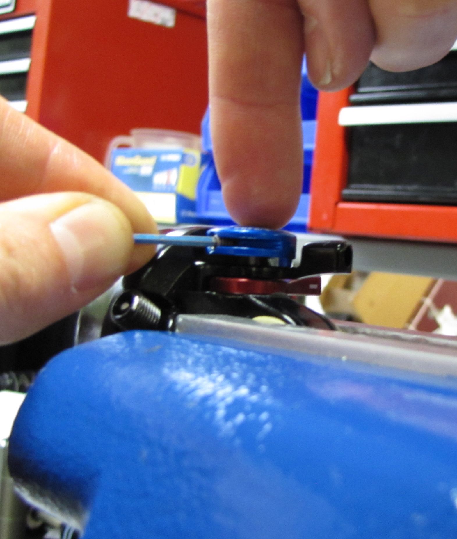
Rotate the blue Nude 3 CTD pulley clockwise until you can insert a 2mm hex wrench into the cable fixing set screw. Use the 2mm hex wrench to help you continue to rotate the pulley clockwise until the tang of the pulley passes the Housing Stop and lets the pulley drop down into its fully seated position. Torque the M3 set screw to 3.5in.-lb (0.4 Nm)


Step 24
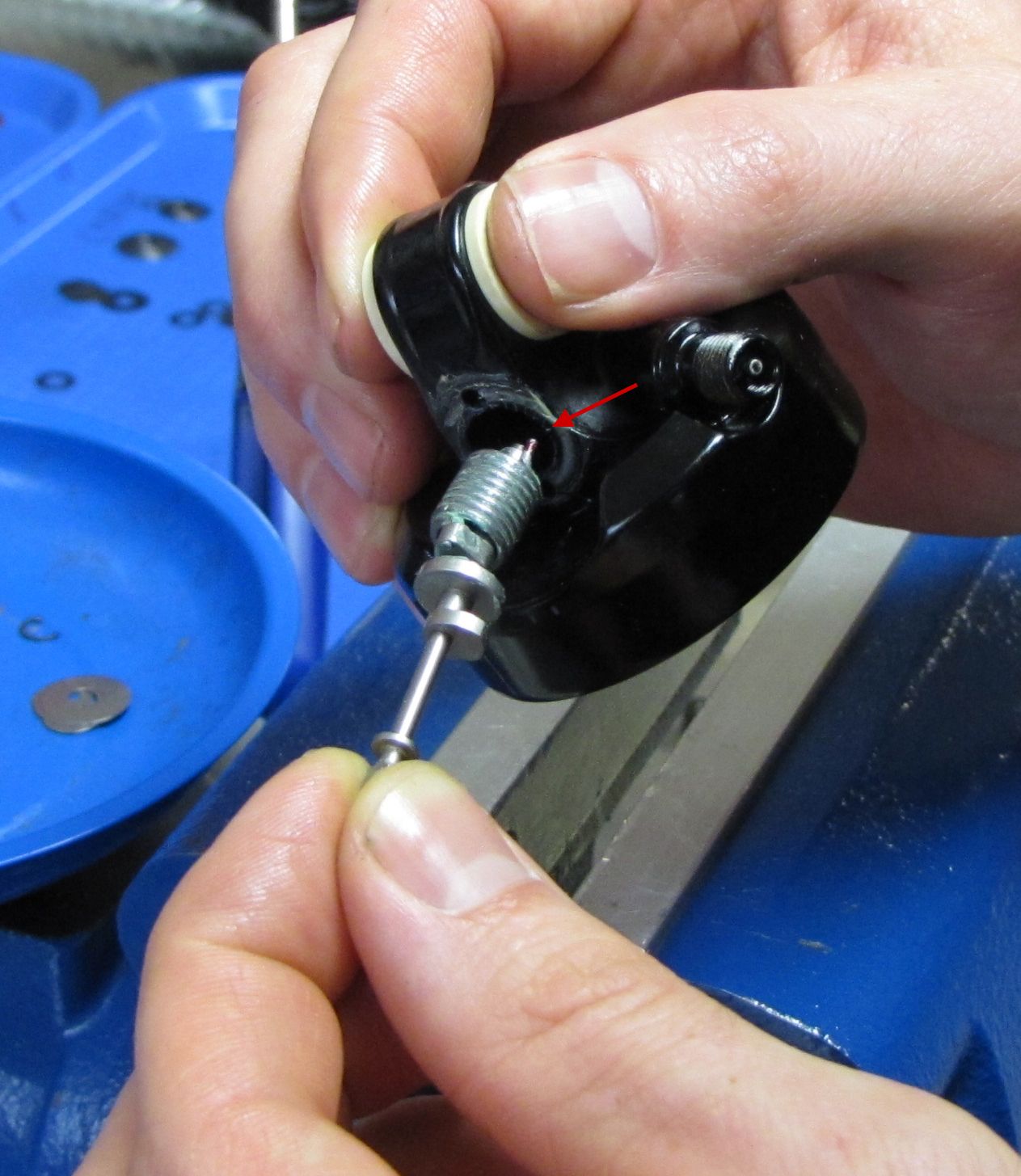
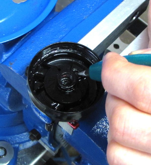
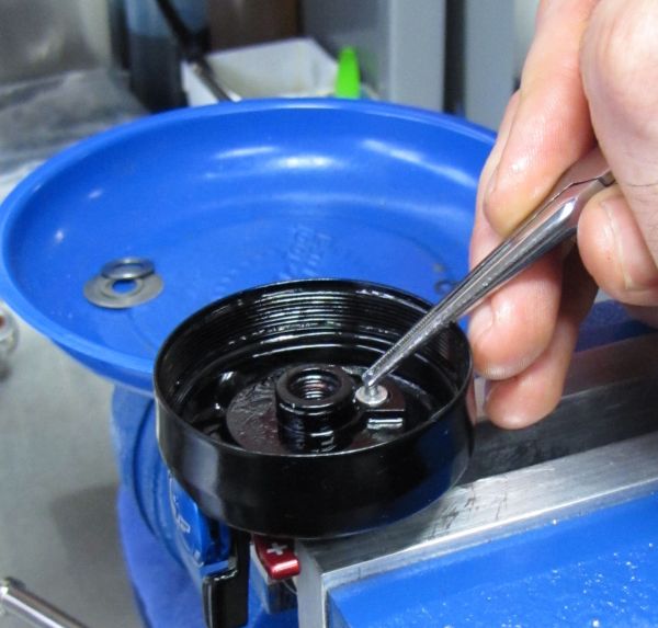
Grease o-ring 029-08-162 with Slick Honey and install into the hole as shown. Make sure that the o-ring is seated at the bottom of the bore and not caught on the shoulder marked by red arrows.


Step 25
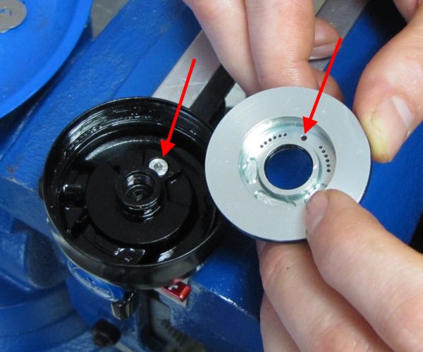
Start the O-ring Retainer Insert into its hole as shown. Finish installation with a blunt tool (6mm hex wrench works well) and downward pressure. Note how the O-ring Retainer Insert sticks up beyond flush when installed properly to orient the Eyelet Base.


Step 26
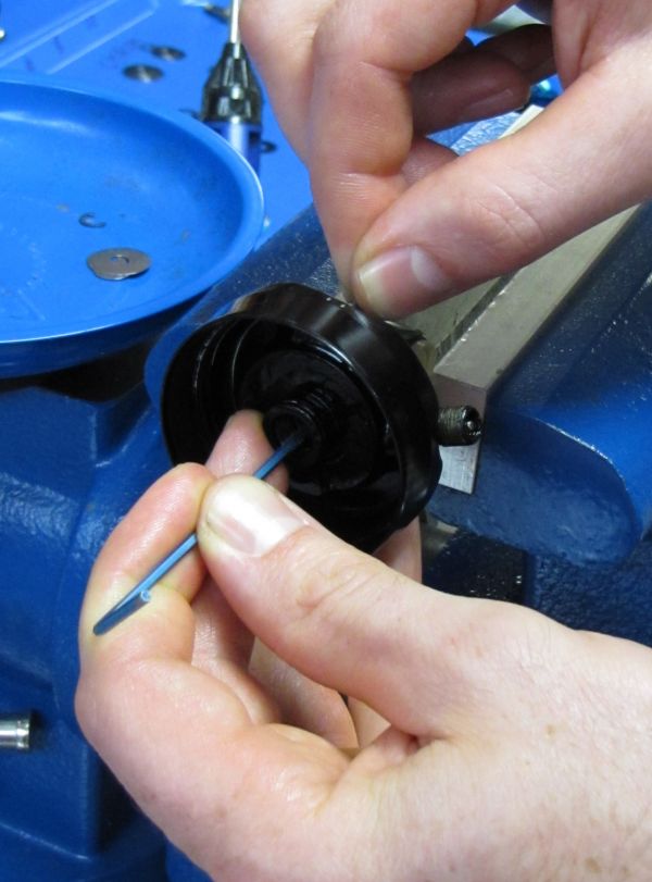
Hold the Travel Adjuster Rod by its smallest diameter portion. Coat the Travel Adjuster Rod with Slick Honey and insert it into the O-ring Retainer Insert with the tapered end first.

Step 27
Cycle the Travel Adjuster Rod up and down approximately 4mm to verify that the o-ring it travels through (029-08-162 installed earlier) is seated properly and that the Travel Adjuster Rod slides smoothly inside the o-ring. Leave Travel Adjuster Rod in its lowest position.


Step 28
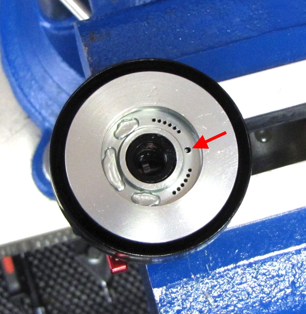
Apply a small amount of Slick Honey to the o-rings and align the Travel Adjuster Rod hole in the Eyelet Base with the Travel Adjuster Rod installed in the Eyelet as shown. Install the Eyelet Base into the Eyelet by pushing down and wiggling gently. Proper installation has been achieved when the Eyelet Base is stopped by the O-ring Retainer Insert and cannot rotate and the Travel Adjuster Rod can be seen through its hole in the Eyelet Base.


Step 29
Install Retaining Ring 038-00-112 into its groove on the Eyelet as shown. If ring cannot engage the ring groove, verify that the Eyelet Base has been completely installed.

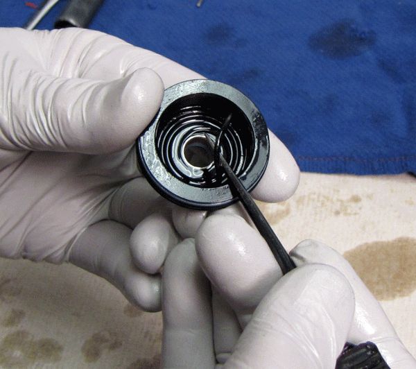
Step 30
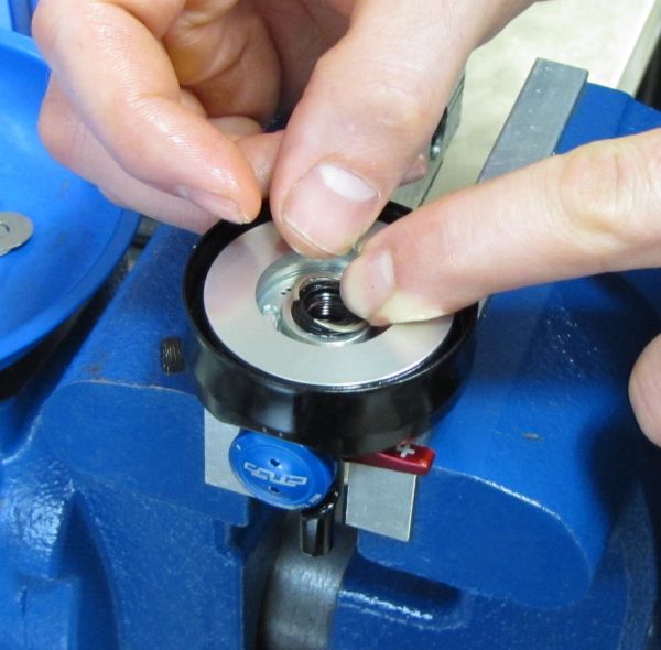
Clean the Check Shim (043-15-102) with Isopropyl alcohol and reinstall it into the eyelet base followed by the wave spring. Position the wave spring so the low point of the wave that is opposite the split in the ring, is aligned with the indicator mark on the Eyelet Base. Make sure that the Wave Spring is retained around its entire circumference.


Step 31
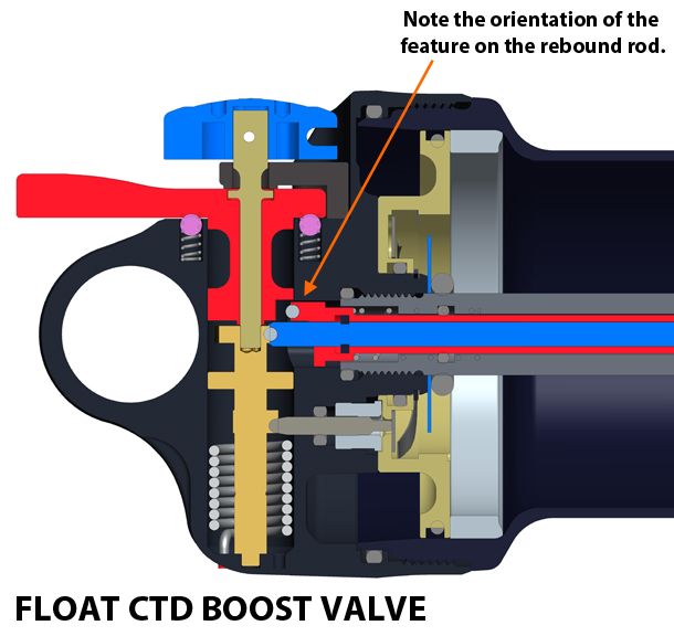
Apply a drop of red Loctite 277 to the eyelet shaft threads. As you thread the shaft assembly into the Eyelet, be sure that the rebound and compression metering rods are correctly oriented with the rebound and compression cams as illustrated. BV and Dish shocks use different metering rods and cams, but for Nude 3 assemblies, both orient the ball bearing at the end of the rebound metering rod toward the front of the shock (closest to the adjusters).


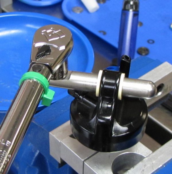
Step 32
After cleaning the clamps and shaft with Isopropyl Alcohol, clamp the shaft enough to secure but not damage it. Torque the Eyelet Assembly to 85in-lb (9.6 Nm).

If servicing a Dish shock, skip to the Dish Damper Reassembly »
Boost Valve Damper Reassembly

Step 1
Invert the eyelet assembly in the vise and install the bottom-out plate and bumper.

Step 2
Lightly install the bleed screw into the body bearing without the bleed screw ball, to plug the bleed hole. Install the body bearing onto the shaft, coating the shaft o-ring with Slick Honey.
Step 3
Install the Propedal check valve and spring, then coat with red oil. Install the piston post over the Propedal check valve and coat with red oil. Using an 8 mm wrench, gently snug the piston post. Do not torque fully!


Step 4
Install the pre-assembled valve stack, tightening the piston nut finger tight. As you press the Propedal piston check valve down with a 2 mm hex wrench, pre-fill the piston bolt area with red oil. This action helps to allow oil to flow below the valve stack.


Step 5
Tighten the valve stack piston nut into the piston bolt to 60 in-lb torque; both the piston nut and bolt simultaneously tighten to the same torque. Continue with pre-filling the piston area, to further evacuate any trapped air.

If servicing a Boost Valve shock, skip to Final Assembly »
Dish Damper Reassembly
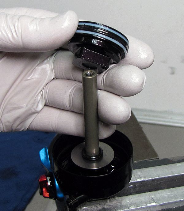
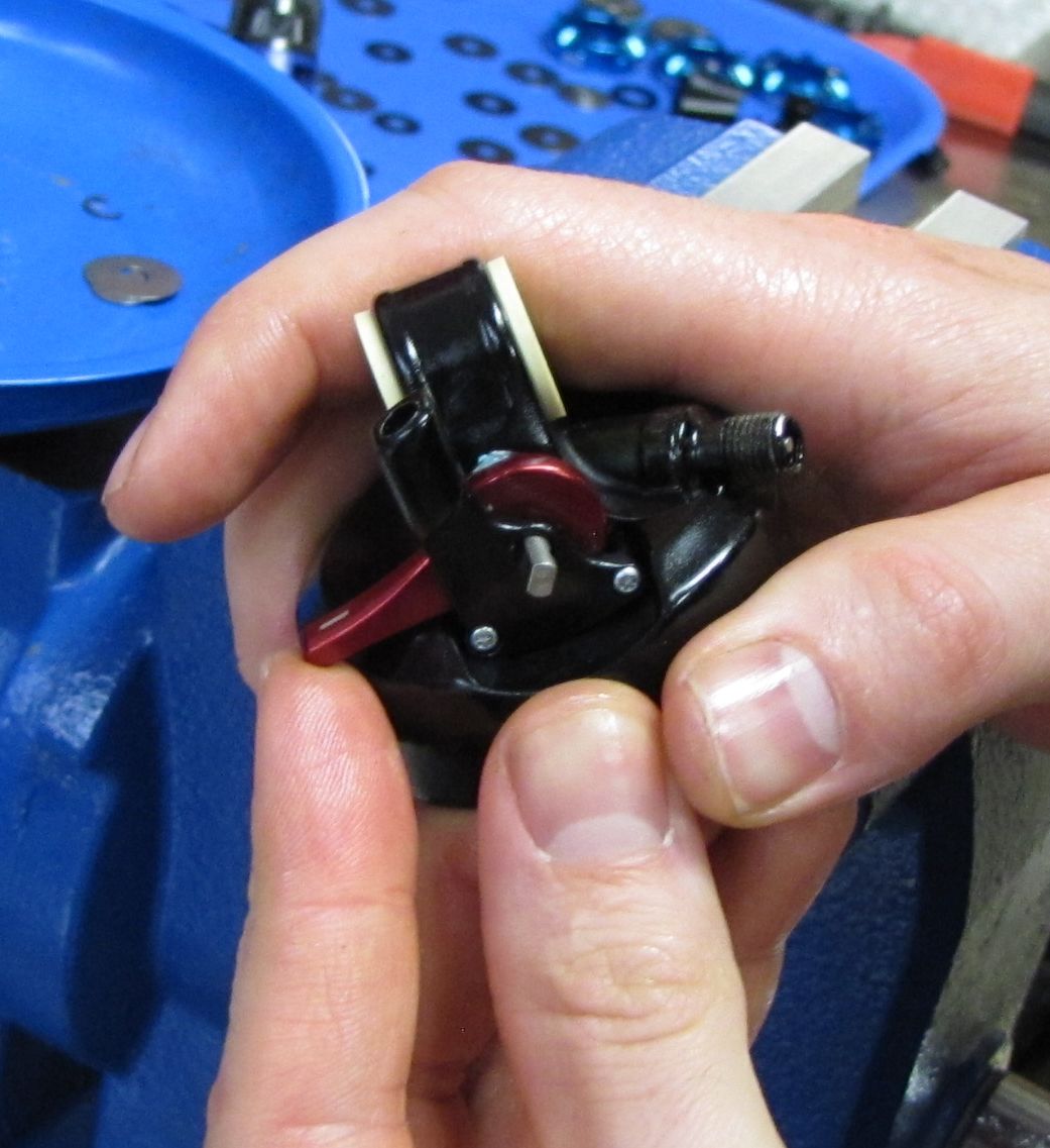
Step 1
Invert and clamp the eyelet assembly in the vise. Test the rebound knob by activating the knob as you press into the shaft with a hex wrench; the tool should lower and raise as you decrease and increase the rebound.

Step 2
Install the bottom-out plate and the bottom-out bumper.

Step 3
Lightly install the bleed screw into the body bearing without the bleed screw ball, to plug the bleed hole. Install the bearing cap and piston assembly. Tighten the piston assembly to ~75 in-lb torque.


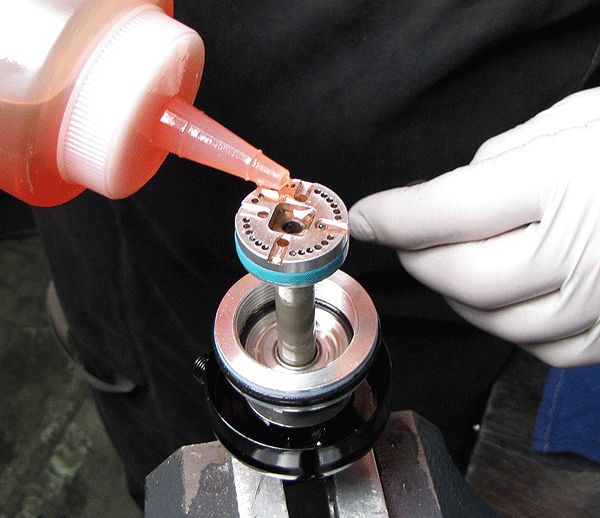
Step 4
Pre-fill the piston ports with some oil to help the bleeding process. Avoid allowing oil to run down the piston bolt hole.

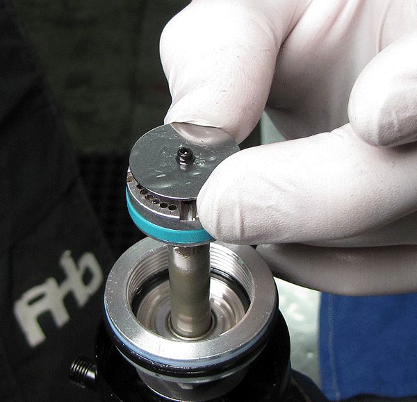
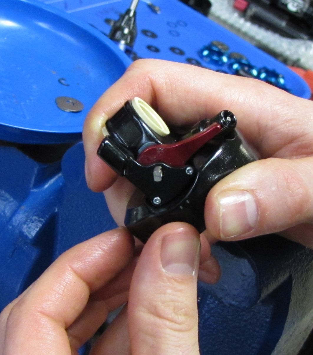
Step 5
Install the lockout plate. Test for proper functionality by gently pressing the lockout plate down as you actuate the CTD compression lever. Two distinct positions should be felt: 1) plate closes against the piston (lockout), and 2) plate raises and separates itself from the piston (open).


Step 6
Make sure the lockout plate is in the open position (plate raised from the piston). Pull the body cap up to surround the piston then top off the body and prime the piston assembly with oil.

Final Assembly
Step 1
Make sure that the body is full of red 10wt. oil. With the oil-filled body in one hand and the eyelet assembly in the other, join the two in one swift movement.

Step 2
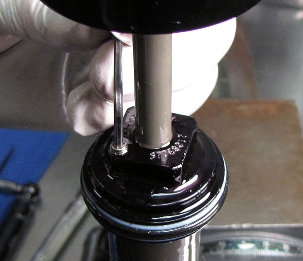
Before threading the body bearing to the body, remove the bleed hole screw. Keeping the bleed hole at the high point, hand-tighten the body into the body cap from below, watching for air bubbles escaping the bleed hole. As you thread the two parts together, gently tap the body to help any trapped air to escape.

Step 3
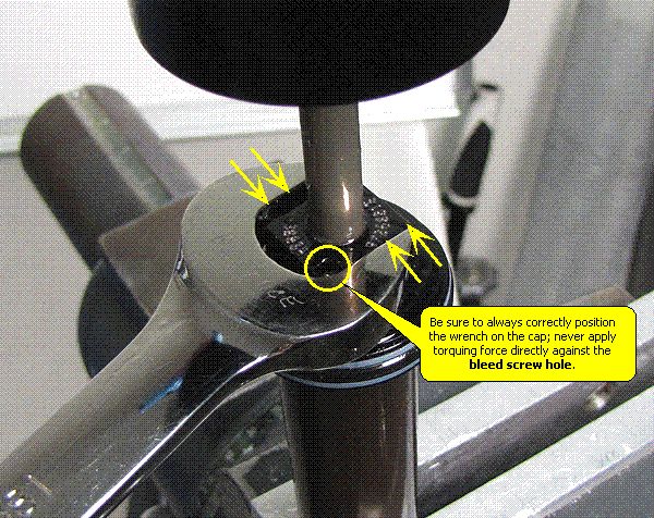
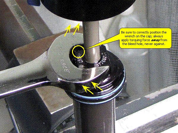
Clamp the shock in the vise by the body eyelet. Tighten the body bearing onto the body to 20 ft-lb (240 in-lb or 27.1 Nm), remembering not to apply wrenching force directly on the flat immediately next to the bleed hole.

Step 4
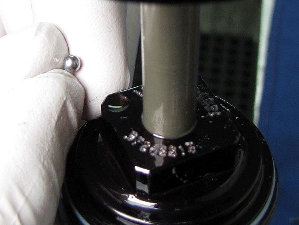
Install the bearing into the bleed hole followed by the bleed screw. Torque to 10in-lb (1.1 Nm).


Step 5
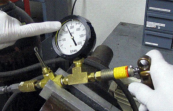
BV Shocks: Pressurize the IFP chamber to the appropriate Boost Valve pressure.
- 7.875 x 2.250 BV Nude 3 shocks: 225 psi
- 8.500 x 2.500 BV Nude 3 shocks: 275 psi
Dish Shocks: Pressurize the IFP chamber to 500 psi
Step 6
Nude 3 shocks use Nude 3 specific air sleeves. Do not attempt to use an LV air sleeve on a Nude 3 shock. Start the air sleeve onto the damper and then install the Nude 3 volume spacer into the air sleeve with the lip facing down away from the eyelet. Thread the air sleeve to the eyelet until hand-tight.


Step 7
Install a new Delrin ball into the pellet retainer and air your shock up to the appropriate pressure. Thoroughly clean the exterior of your shock.