2022-2024 32mm TC Service Procedure
Required Parts
- 803-00-962 Seal Kit: 32 FLOAT NA2 Rebuild
Required Tools
- 398-00-657 Tooling: Bullet, Sealhead To Shaft, Float NA 2
- 398-00-681 2002-017 32 Damper-side and ALL 32-34-36-40 Spring-side Removal Tool
- 398-00-918 Tooling: 2022 TC Fork Air-Damper Nut Torque Tool
- 803-01-324 Kit: Tooling: 2019 Clamps, Grip Damper, Body and Shaft
- 820-09-084-KIT Service Tooling: 2022 TC Fork Air-Damper Shaft Removal Assembly KIT
WARNING: Always wear safety glasses and protective gloves during service to prevent potential injury. Failure to wear protective equipment during service may lead to SERIOUS INJURY OR DEATH.
WARNING: FOX products should be serviced by a trained bicycle service technician, in accordance with FOX specifications. If you have any doubt whether or not you can properly service your FOX product, then DO NOT attempt it. Improperly serviced products can fail, causing the rider to lose control resulting in SERIOUS INJURY OR DEATH.
WARNING: Never attempt to modify air volume spacers or air shaft assemblies, as this can damage your fork causing a loss of control of the bicycle leading to SERIOUS INJURY or DEATH.
WARNING: FOX suspension products contain pressurized nitrogen, air, oil, or all 3. Suspension misuse can cause property damage, SERIOUS INJURY OR DEATH. DO NOT puncture, incinerate or crush any portion of a FOX suspension product. DO NOT attempt to disassemble any portion of a FOX suspension product, unless expressly instructed to do so by the applicable FOX technical documentation, and then ONLY while strictly adhering to all FOX instructions and warnings in that instance.
WARNING: Modification, improper service, or use of aftermarket replacement parts with FOX forks and shocks may cause the product to malfunction, resulting in SERIOUS INJURY OR DEATH. DO NOT modify any part of a fork or shock, including the fork brace (lower leg cross brace), crown, steerer, upper and lower leg tubes, or internal parts, except as instructed herein. Any unauthorized modification may void the warranty, and may cause failure or the fork or shock, resulting in SERIOUS INJURY OR DEATH.
NOTE: Full damper cartridge rebuild instructions specific to your damper can be found here: Service Procedures »
Step 1
Remove the black air cap and cover the air valve with a rag as you release the air pressure.


Step 2
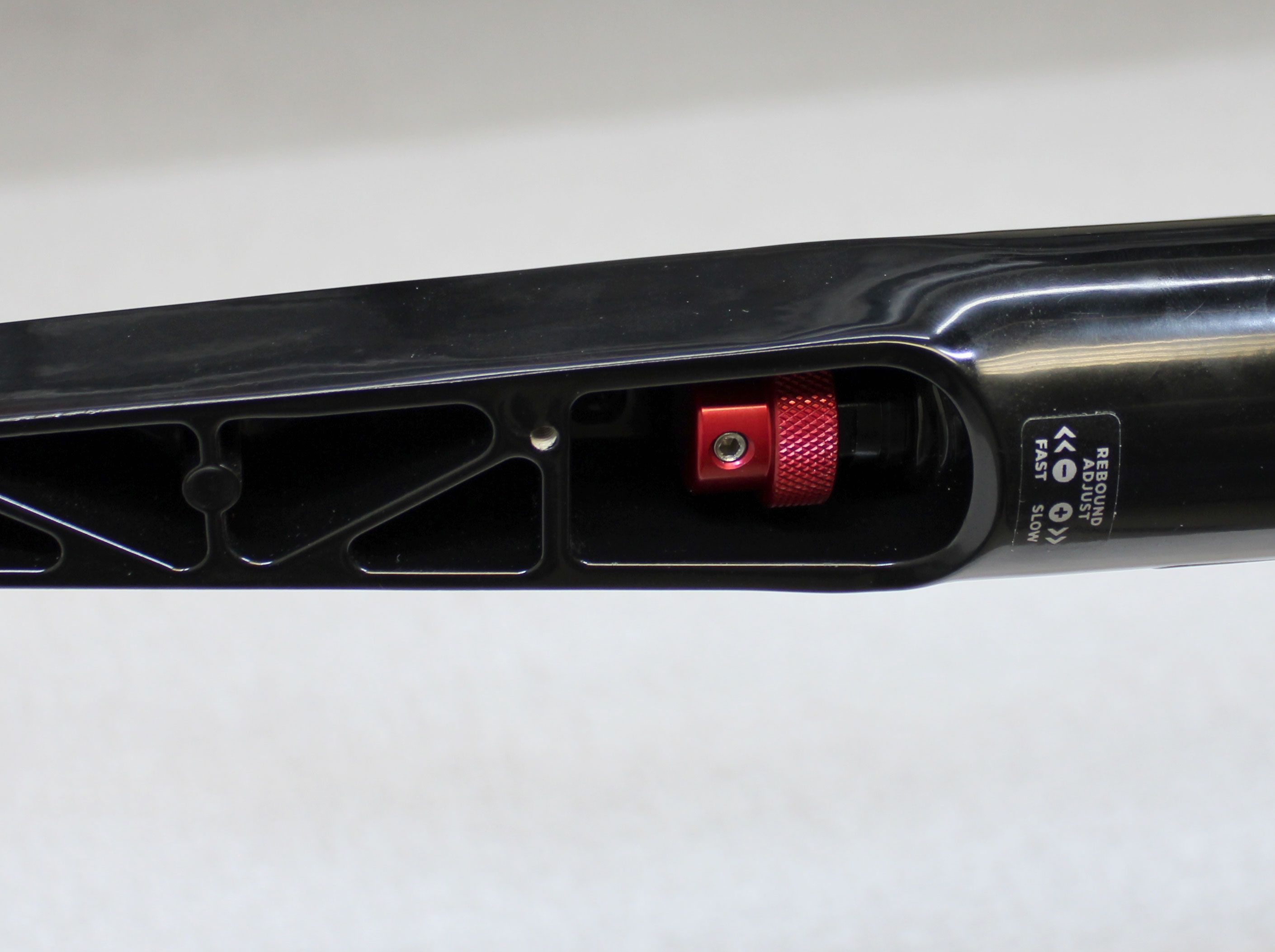
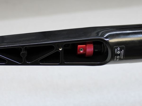
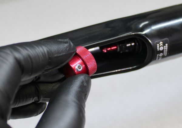
Use a 2mm hex wrench to unthread the set screw in the red rebound knob. Remove the knob and set it aside.


Step 3
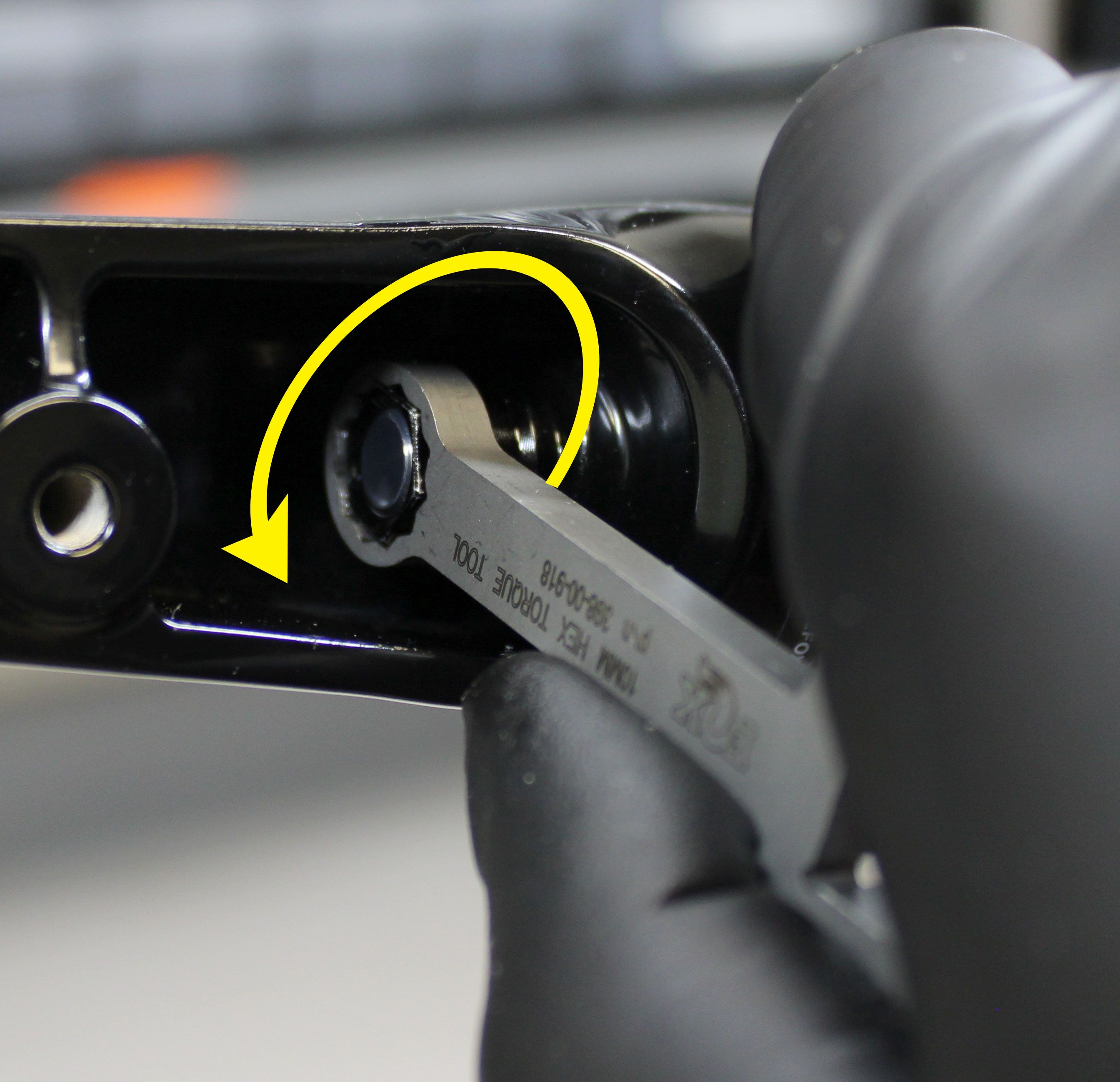
Use the TC Nut Torque Tool (PN: 398-00-918) to unthread the bottom nuts counter-clockwise. Take care not to damage the painted finish on the lower leg when using the TC Nut Torque Tool. Remove the bottom nuts and crushwashers. Discard the original crush washers that may be stuck to the bottom nuts.


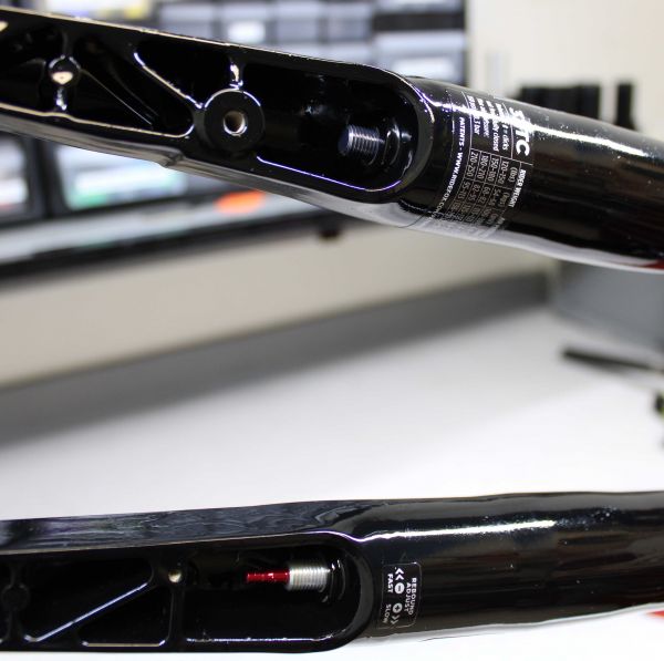
Step 4
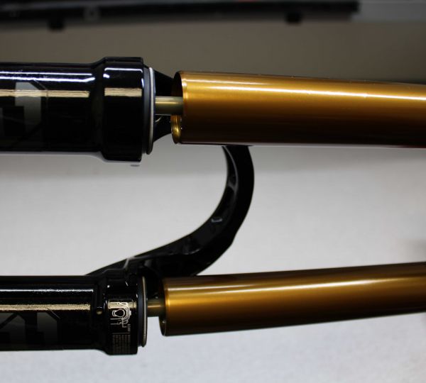
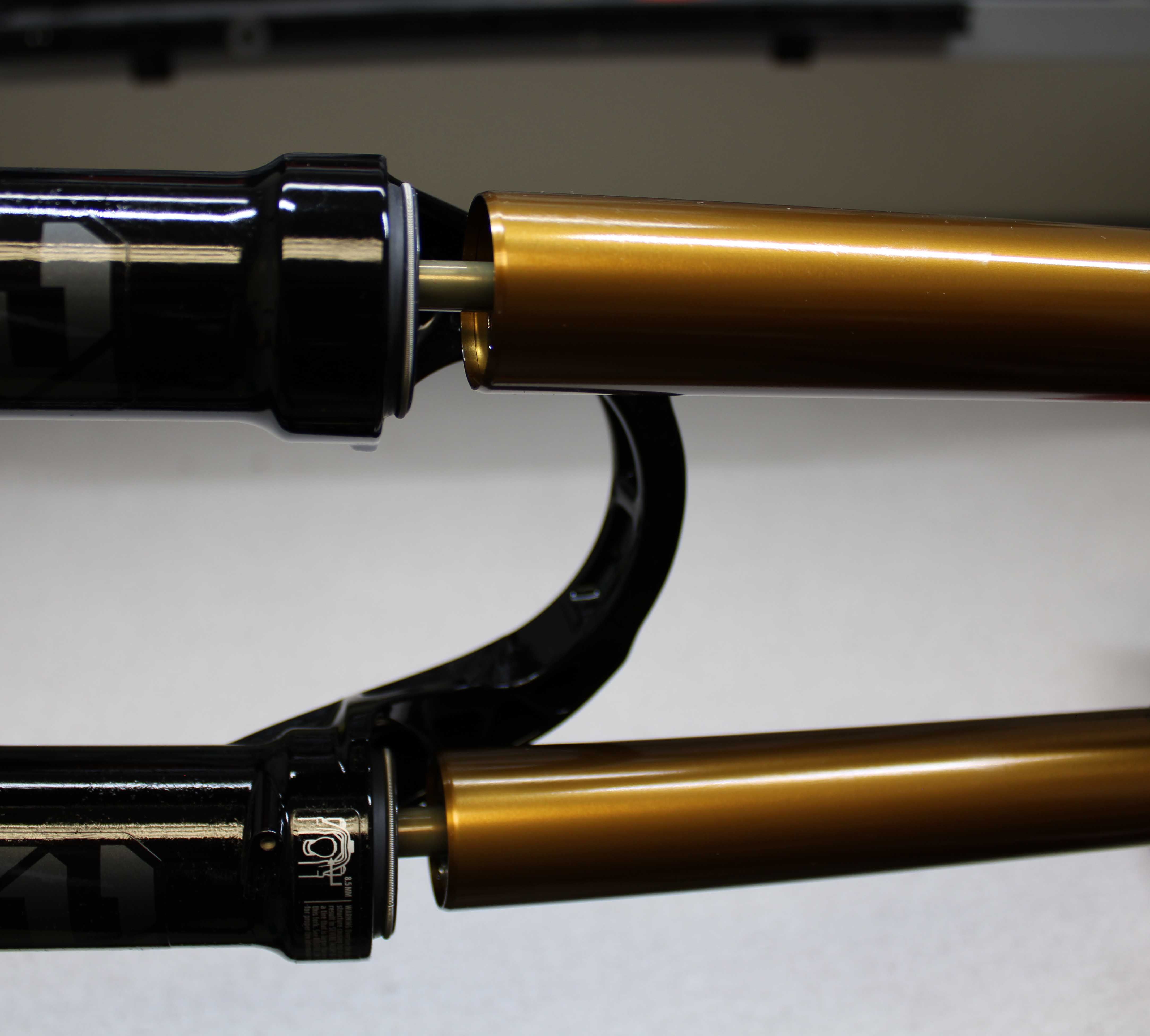
Install the dummy Bottom Nut that comes with the TC Damper Removal Tool Assembly (PN: 820-09-084-KIT) onto the bottom stud threads with it's larger diameter end toward the fork. Make sure to engage approximately half of the available threads with your tool. Place the Bottom Nut Plate of the removal tool onto the dummy Bottom Nut. Carefully hit the upper Strike Plate with your mallet to dislodge the shaft from the lower leg. Remove the dummy Bottom Nut then repeat on the other side. Bring the fork upright over your waste oil basin. Separate the lower legs from the upper tubes and set the lowers aside.


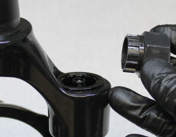
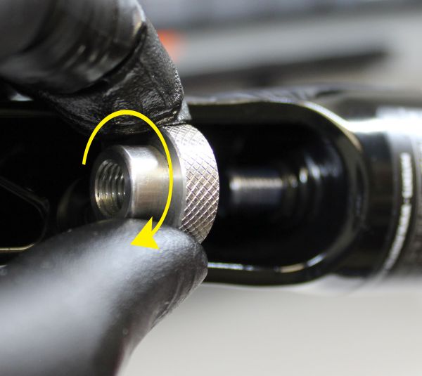
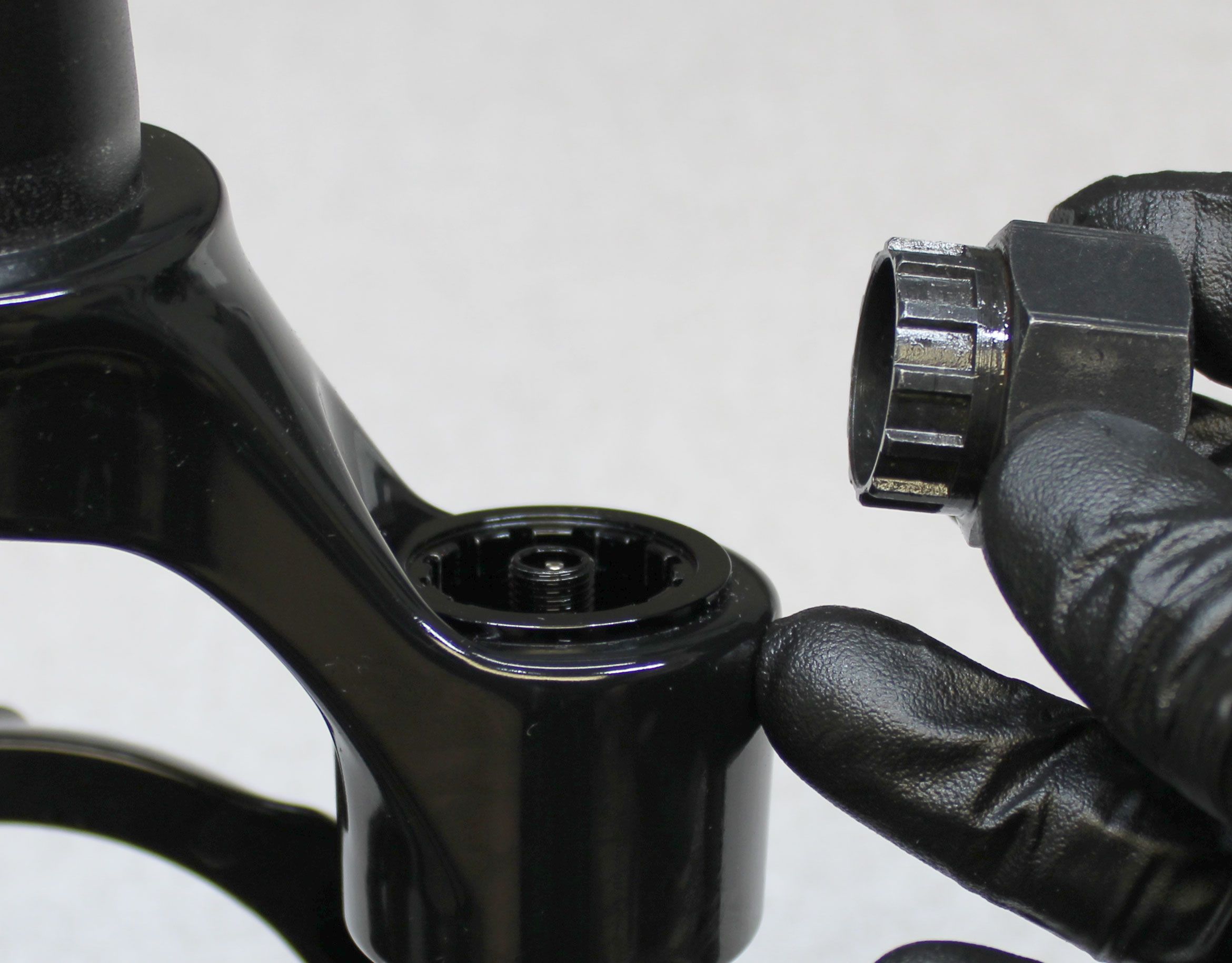
Step 5
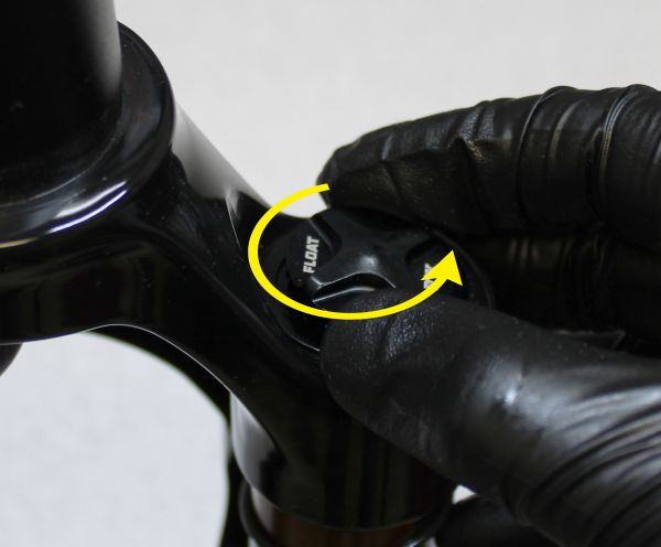
Use a Park Tool FR-5 or FR-5.2 Cassette tool to unthread the air chamber topcap by turning it counter-clockwise. Pull up to remove the topcap from the fork chassis.


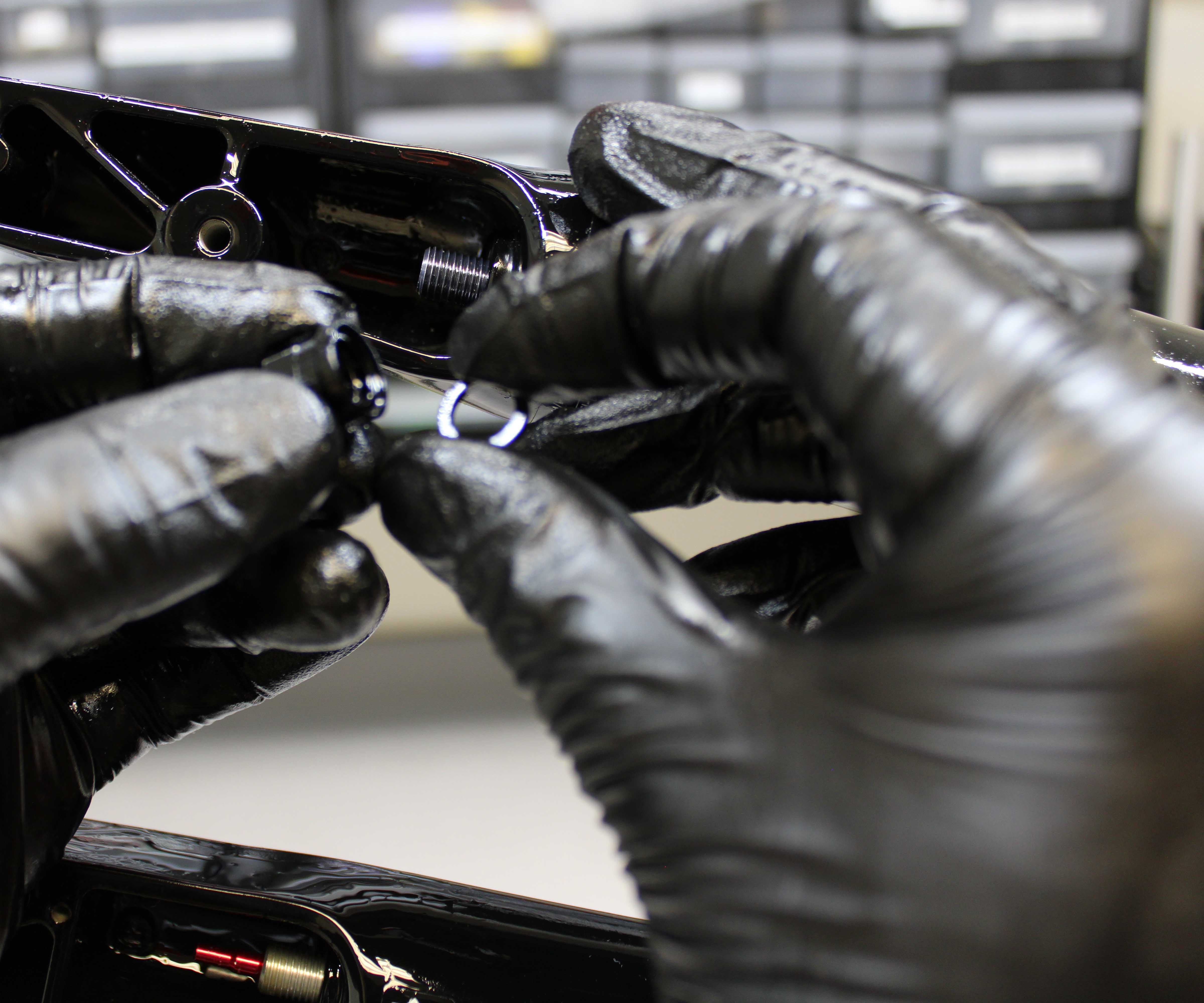
Step 6
Carefully remove the retaining ring from the bottom of the air side upper tube, taking care not to scratch the upper tube.


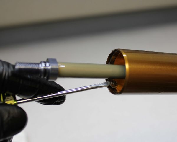
Step 7
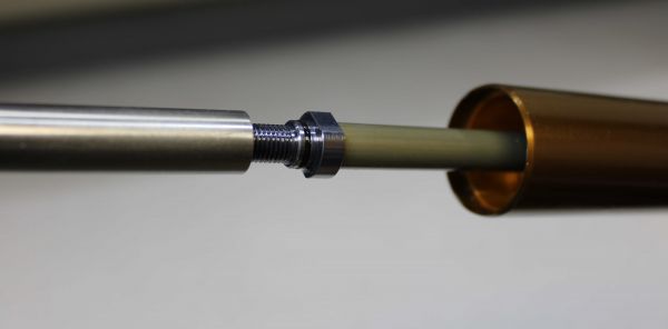
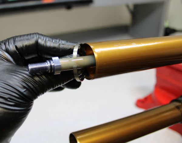
Thread the damper removal tool (PN: 398-00-681) onto the air shaft and pull out from the upper tube to remove the air shaft assembly.


Step 8
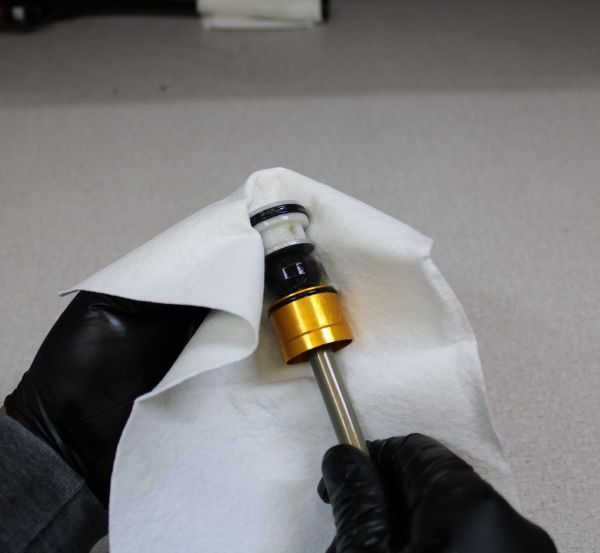
Wipe grease off of the air shaft assembly to make it easier to handle, then slide the neg plate toward the base stud, leaving enough space to access the base stud wrench flats.


Step 9
Use a lint-free paper towel to remove the quad-ring from the air piston. DO NOT use any tools to remove the q-ring as you can damage the sealing surfaces of the piston. Install a new greased q-ring from the kit making sure it is fully seated and not twisted.


Step 10
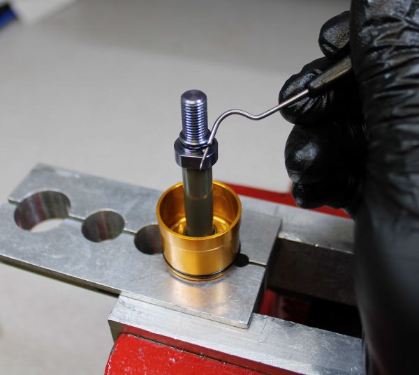
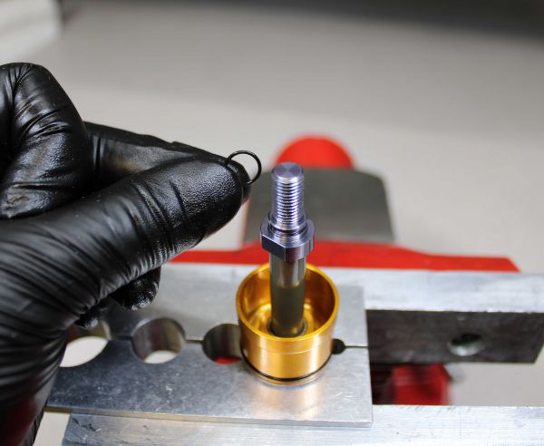
Clean the shaft with Isopropyl alcohol then clamp it in your 10mm shaft clamps (PN: 803-01-324). Remove and discard the o-ring from the base stud then carefully apply heat to the shaft at the base stud with a propane torch for 5-10 seconds to break down the Loctite.


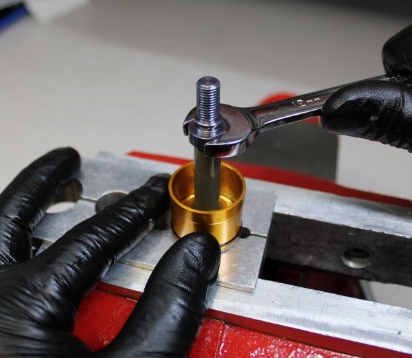
Step 11
Be careful as the base stud may be hot! Unthread the base stud counter-clockwise with a 12mm wrench, then lift up to remove. remove the remaining o-ring on the base stud and replace with a new greased one from the kit.


Step 12
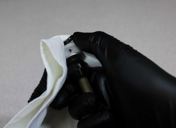
Lift up on the neg plate to remove it from the shaft. Remove the external o-ring and replace it with a new greased one from the kit. Remove the seal from the inside of the neg plate and replace it with a new greased one from the kit.


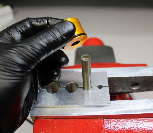
Step 13
Insert the FLOAT NA2 bullet tool (PN: 398-00-657) into the shaft, then coat it with a thin film of Slick Honey. Reinstall the neg plate with it's flat side down. Remove the bullet tool.


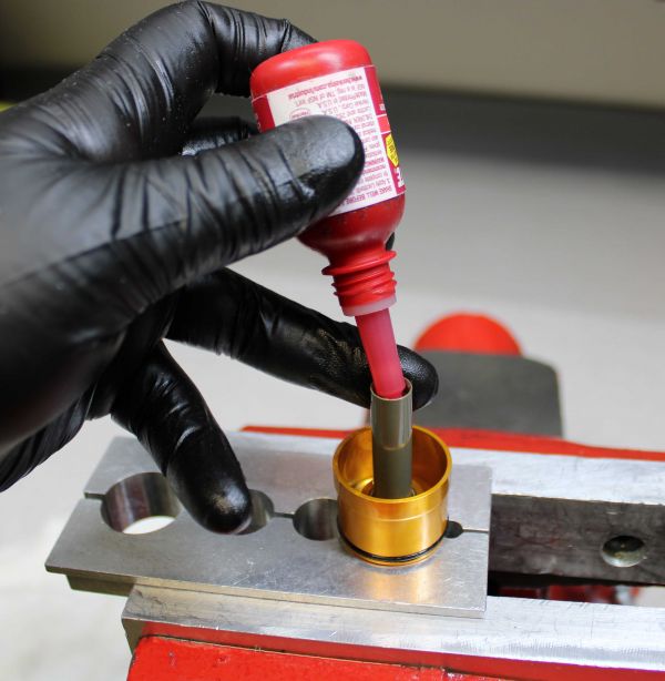
Step 14
Apply 1-2 drops of red Loctite 262 to the threads inside the shaft, taking caution not to get Loctite in the area of the shaft where the base stud o-ring will seat. Insert the base stud and thread it in clockwise, tightening to 50 in-lb (5.7 Nm) torque with a 12mm crow's foot (oriented 90 degrees from the handle of your torque wrench).


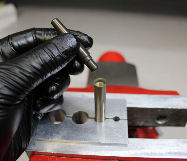
Step 15
Install a new greased o-ring from the kit onto the base stud.


Step 16
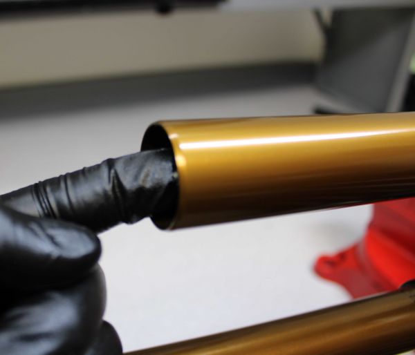
Apply a thin film of Slick Honey to the inside of the upper tube. Apply a thick film of Slick Honey to the air shaft assembly in the areas of the piston, neg plate, and shaft above the neg plate.


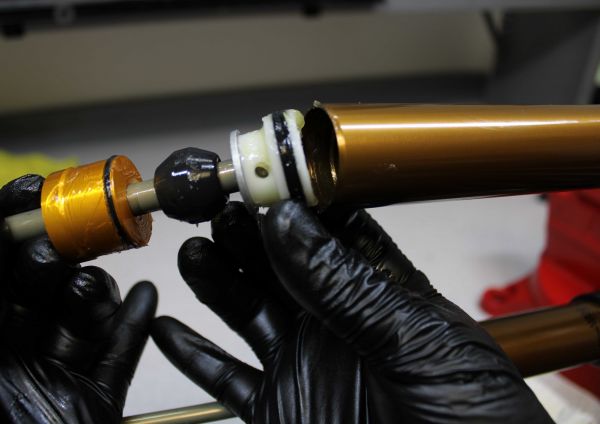
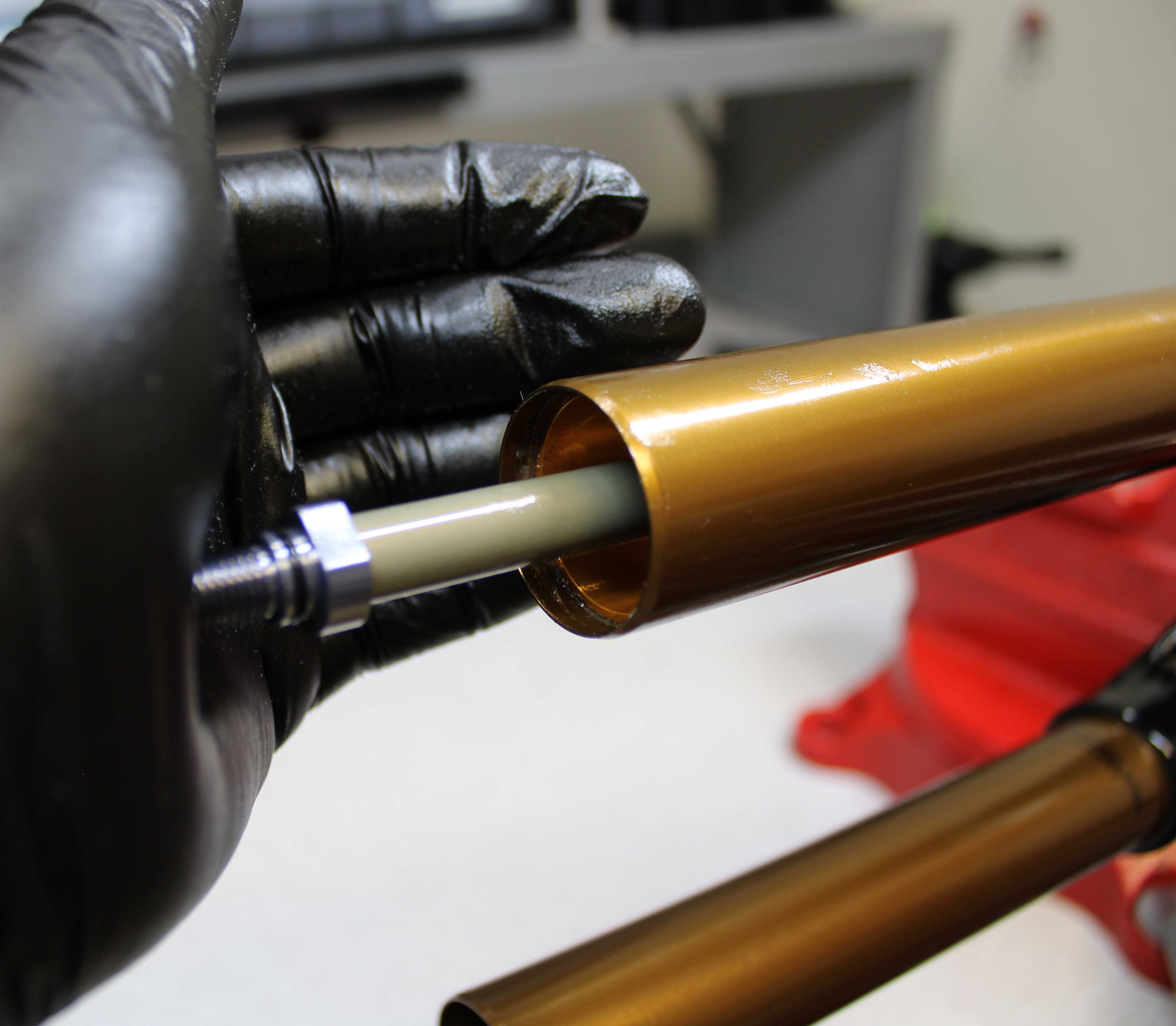
Step 17
insert the air shaft assembly into the end of the upper tube. Push the air shaft assembly into the upper tube far enough to allow you to start the neg plate into the upper tube. Push the shaft into the upper tube to pull the neg plate into its installed position.


Step 18
Replace the retaining ring making sure it is fully seated in its groove by pulling on the air shaft. Do not scratch the shaft with the ends of the retaining ring.


Step 19
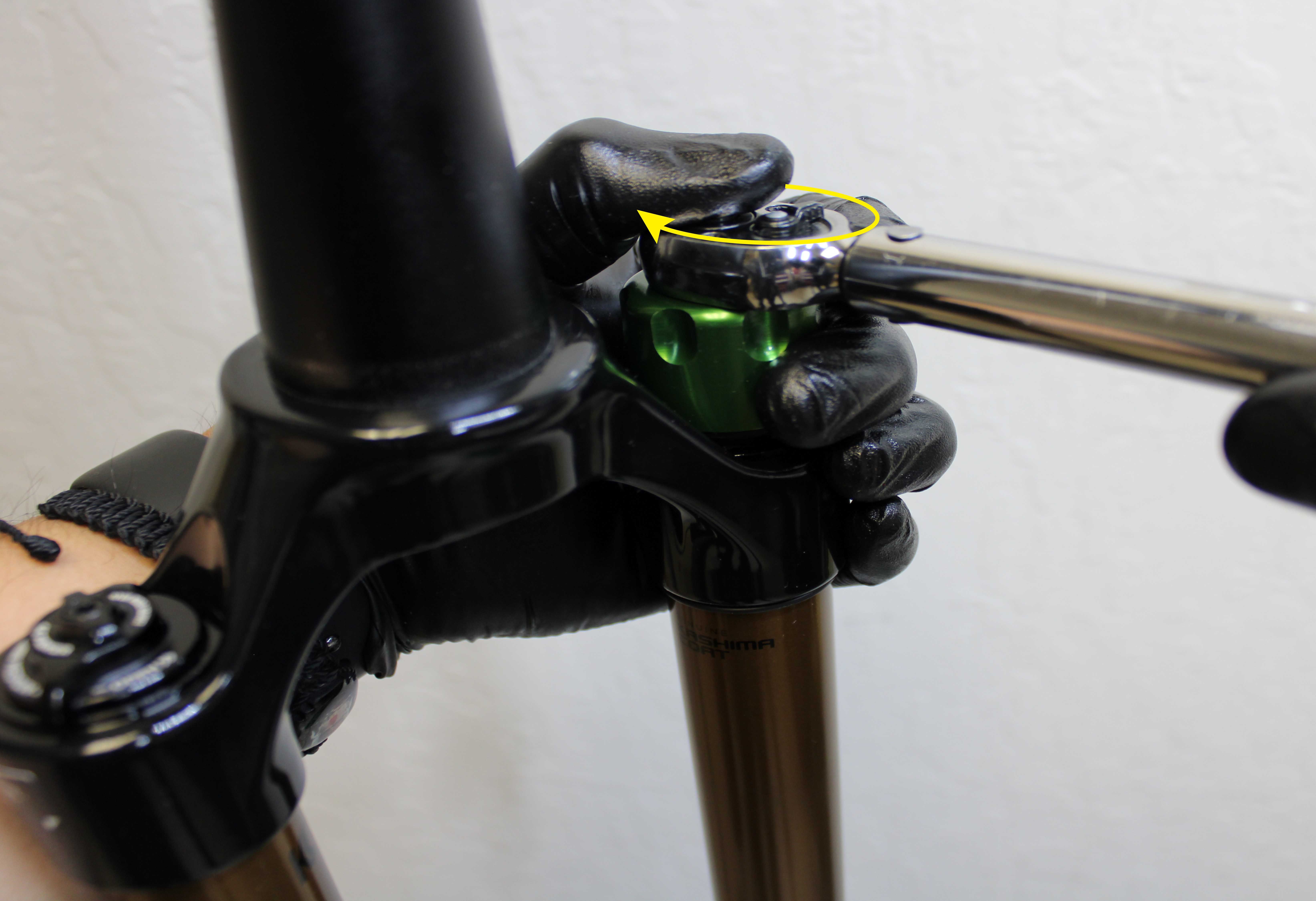
Inject 3cc of FOX 20wt. Gold oil into the main air chamber through the top of the upper tube. Reinstall the topcap into the fork crown and tighten clockwise to 220 in-lb (24.8 Nm) torque with Park Tool FR-5 or FR-5.2 Cassette tool.


Step 20
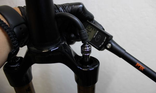
Add air pressure to your desired setting using a FOX high pressure pump. See the Setting Fork Air Pressure section for more information. Reinstall the black air cap.


Step 21
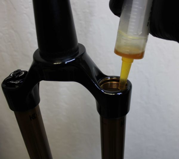
Install the Lower Leg Assembly onto the upper tubes. Inject the approprate amount of FOX 20wt. Gold oil into each leg through the bottom hole.
| Oil Application | Oil Volume/ Type |
| Grip Damper-Side Bath | 40cc (5wt. FOX Teflon Infused Oil) |
| FIT4 Damper-Side Bath | 12cc (20wt. Gold FOX Oil) |
| FLOAT NA2 Air-Side Bath | 12cc (20wt. Gold FOX Oil) |


Step 22
Install a new crushwasher on each side followed by the appropriate bottom nut. With the TC Nut Torque Tool set 90 degrees offset from your torque wrench, tighten both bottom nuts clockwise to 50in-lb (5.7 Nm).


Step 23
Use a 2mm hex wrench to reinstall the red rebound knob. Make sure that the set screw lines up with the depression in the rebound adjuster shaft. Clean the exterior of your fork.