3-POS Remote Installation
WARNING: Always wear safety glasses and protective gloves during service to prevent potential injury. Failure to wear protective equipment during service may lead to SERIOUS INJURY OR DEATH.
FIT4 3-POS PTL REMOTE INSTALL
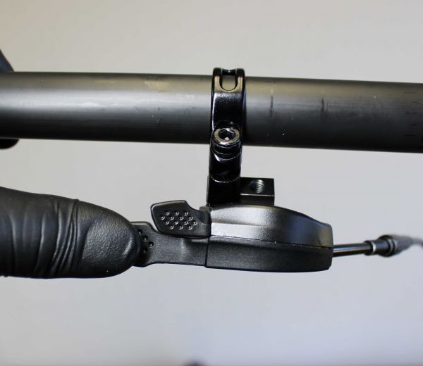
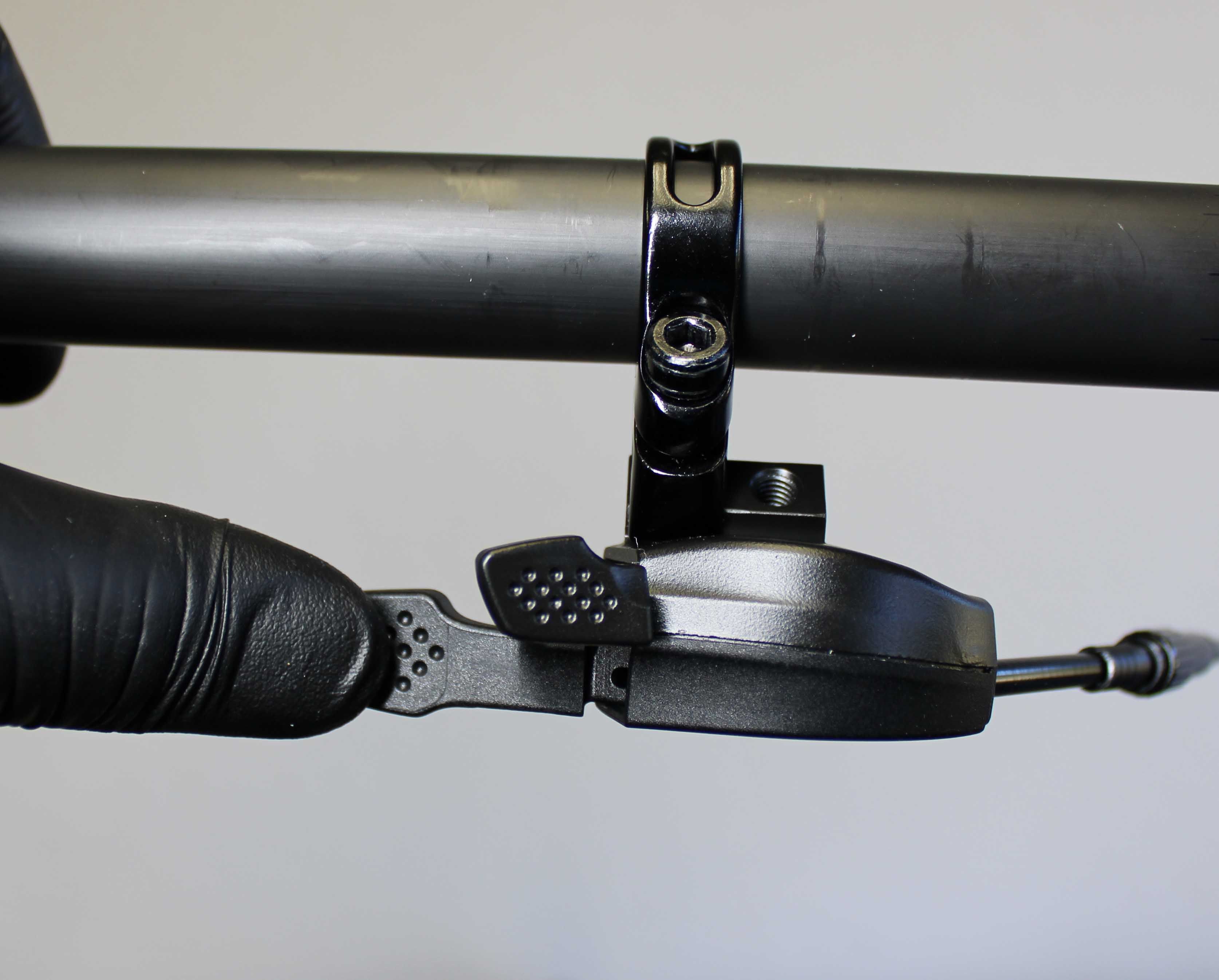
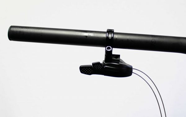
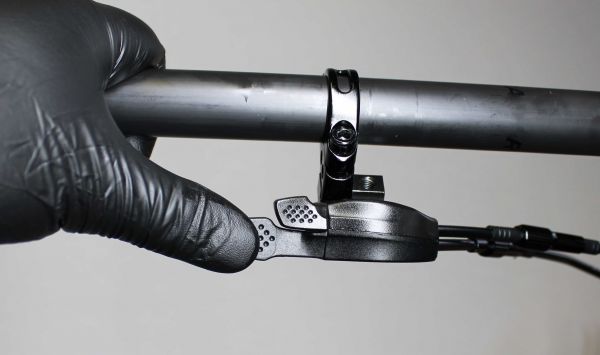
Step 1
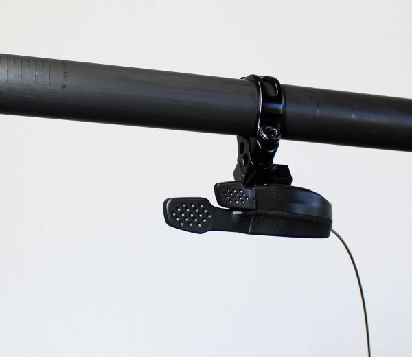
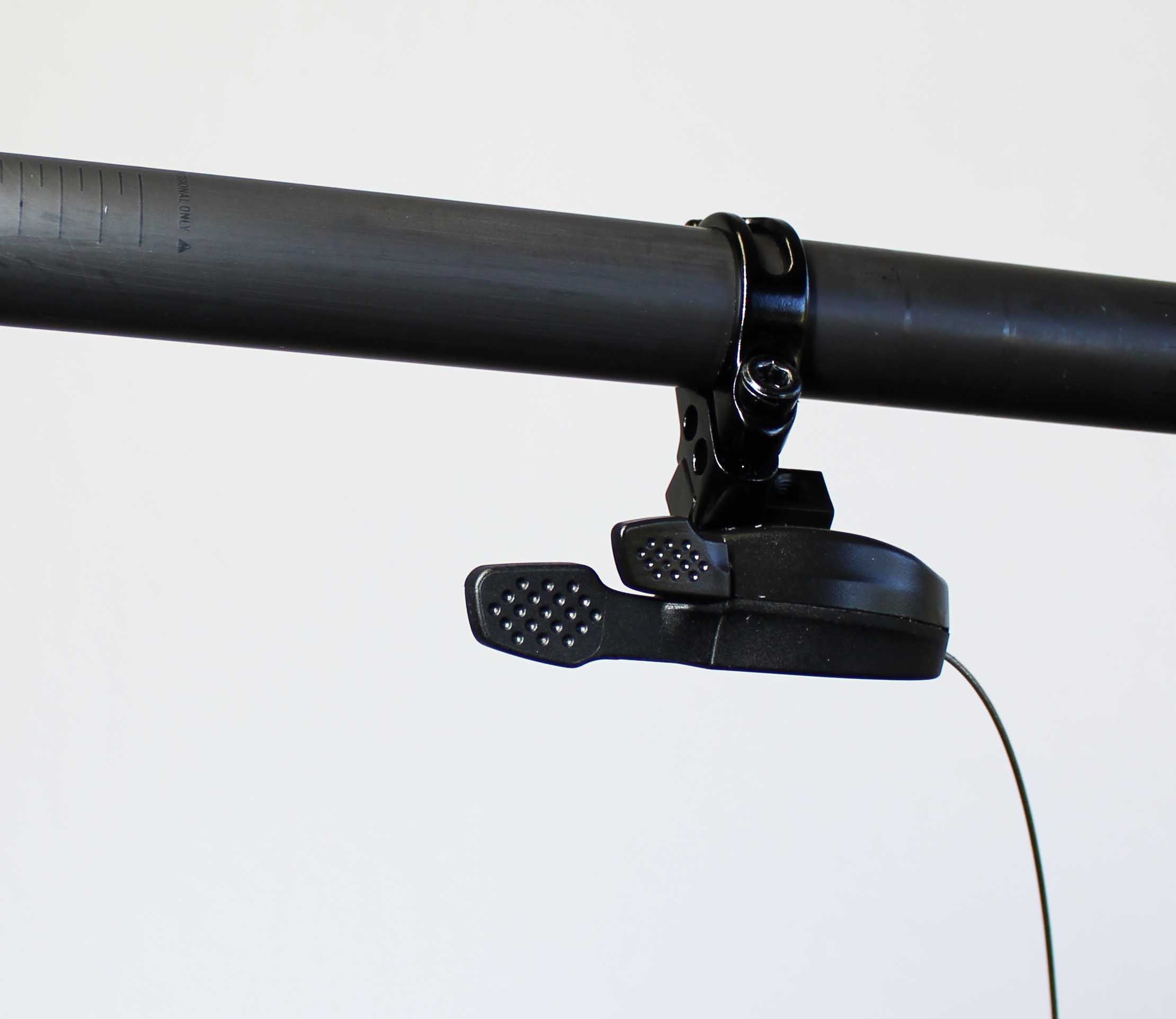
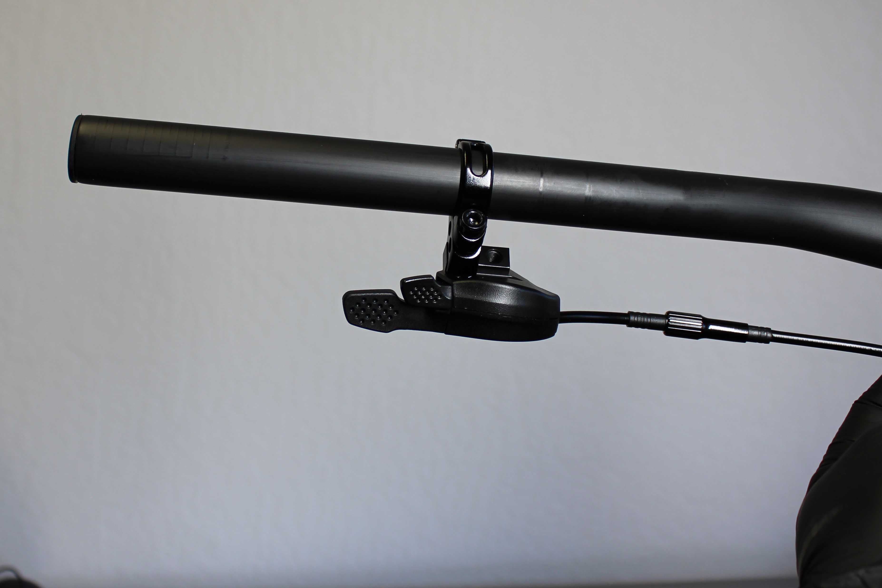
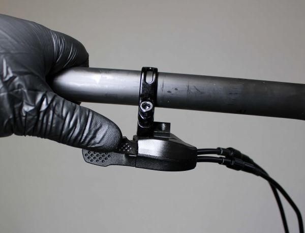
Install the remote lever under bar on the rider's left side. Tighten the clamp screw clockwise to 15in-lb (1.7Nm)

Step 2
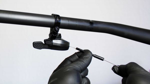
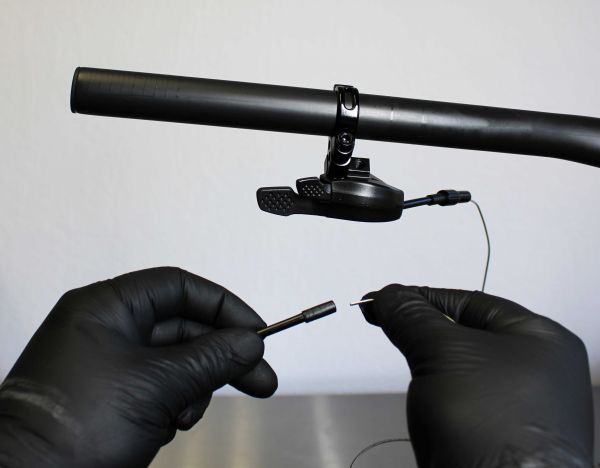
Install a short piece of housing with one ferrule. Fully seat the housing in the remote lever


Step 3
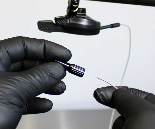
Install the in-line barrel adjuster with it fully threaded together for maximum adjust range.


Step 4
Install cable housing with ferrules on both ends

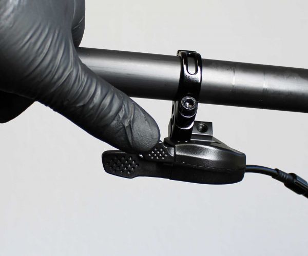
Step 5
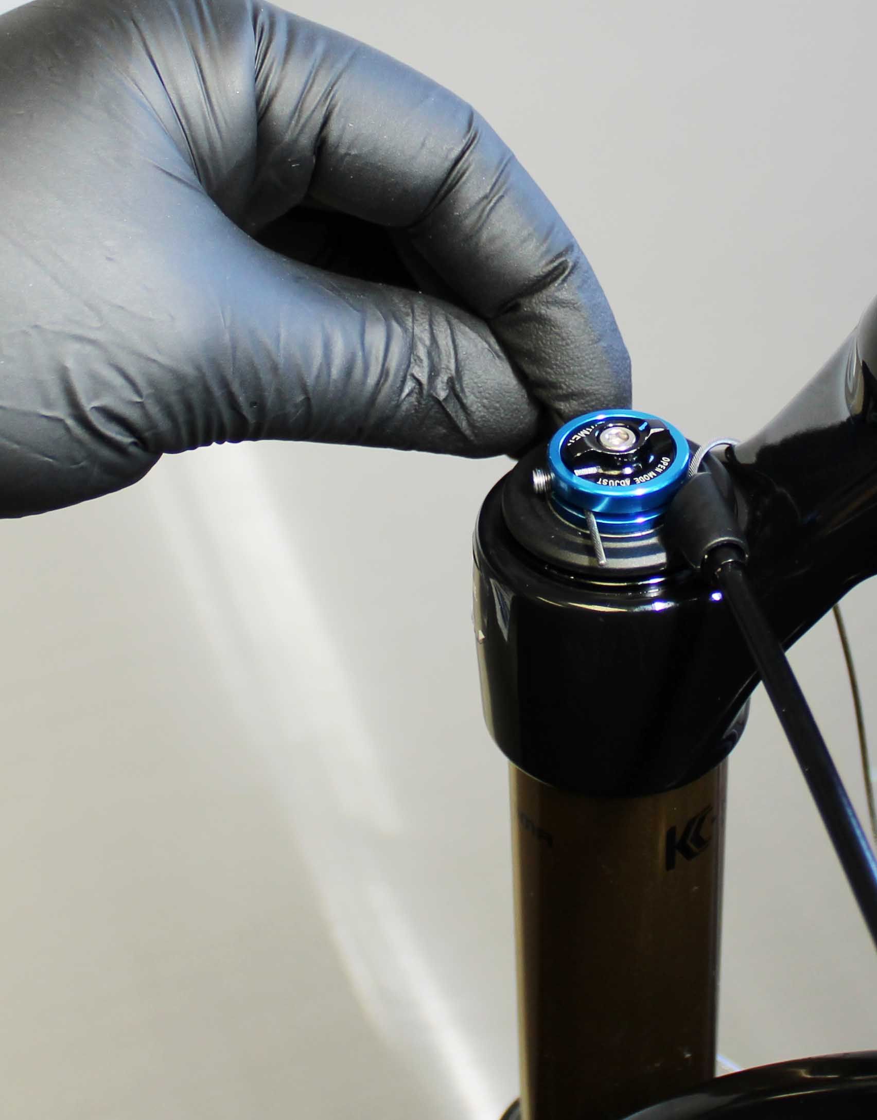
Push the release lever to set the remote to open mode.

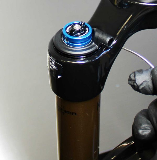
Step 6
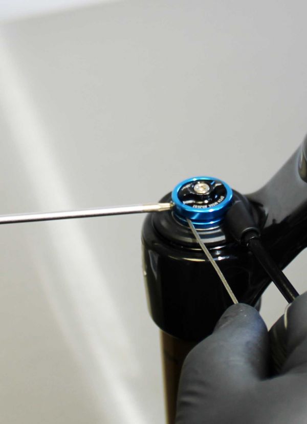
With all the housing fully seated thread the cable through the remote housing and around the pulley.


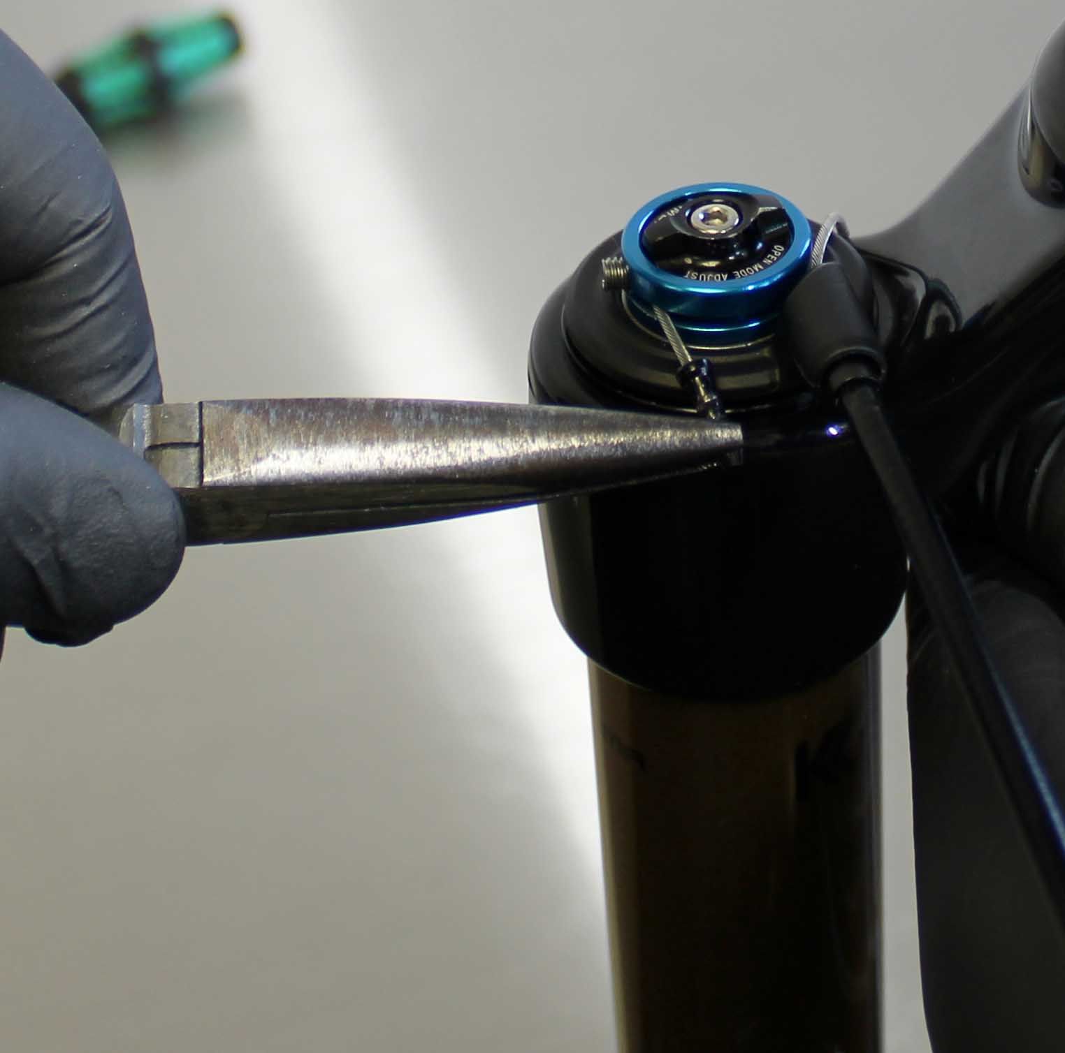
Step 7
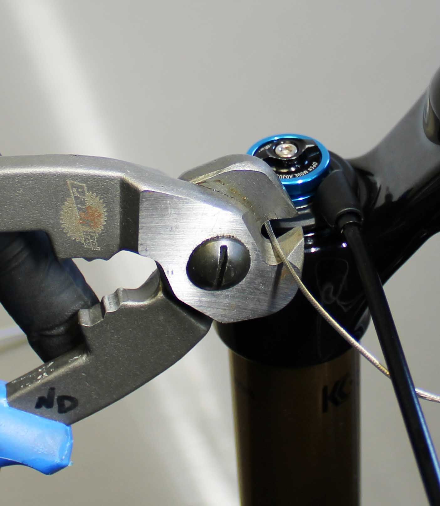
While holding the cable tight, tighten the pinch bolt with a 2mm Hex Wrench then cut off exccess cable and crimp the end.


Step 8
Test remote function.


3-POS PTL DUAL REMOTE INSTALL
Step 1
Install the remote lever under bar on the rider's left side. Tighten the clamp screw clockwise to 15in-lb (1.7Nm)


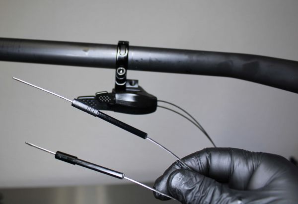
Step 2
Install short pieces of housing with one ferrule, fully seat them in the remote lever.


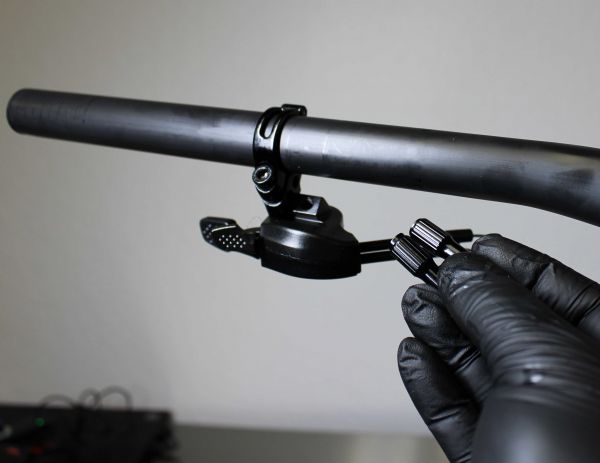
Step 3
Install the in-line barrel adjusters in their fully threaded together configuration for maximum range.


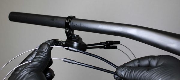
Step 4
Install housing with a ferrule on both ends for the fork and shock.


Step 5
Push the release lever to set the remote to open mode.


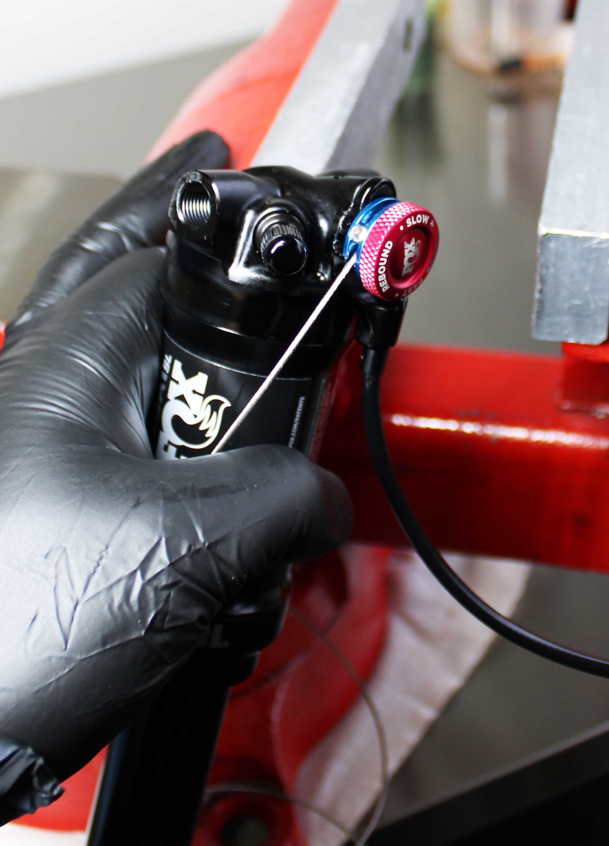
Step 6
With all the housing fully seated and no slack in the system, thread the cable through the remote housing and around the pulley


Step 7
While holding the cable tight, tighten the pinch bolt with a 2mm hex wrench, cut off excess cable and crimp the end.


Step 8
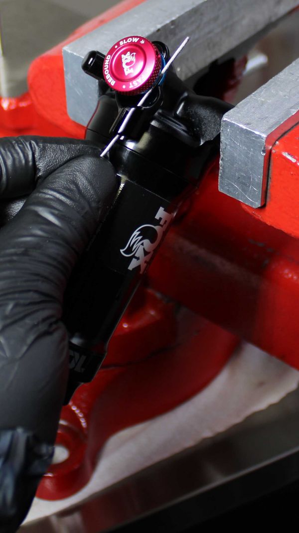
With all housing fully seated and no slack in the system, thread the second cable though the shock remote housing and around the pulley.

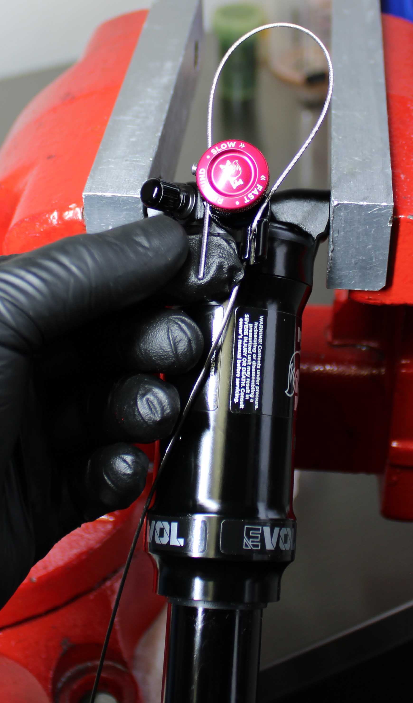
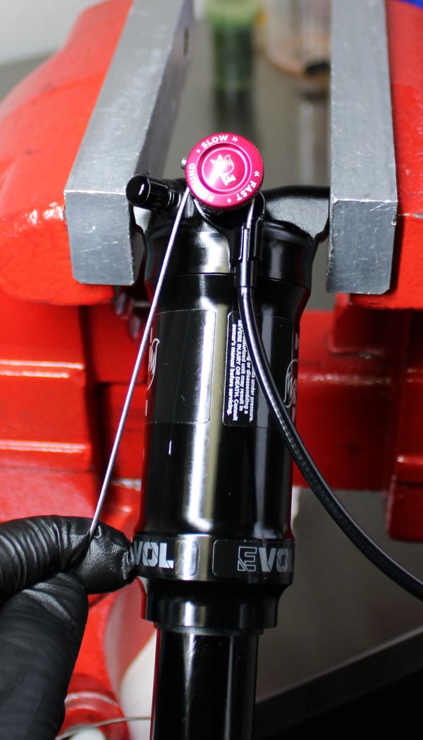
Step 9
While holding the cable tight, tighten the pinch bolt with a 2mm hex wrench. Do not turn the torx screw that attaches the remote pulley to the shock.


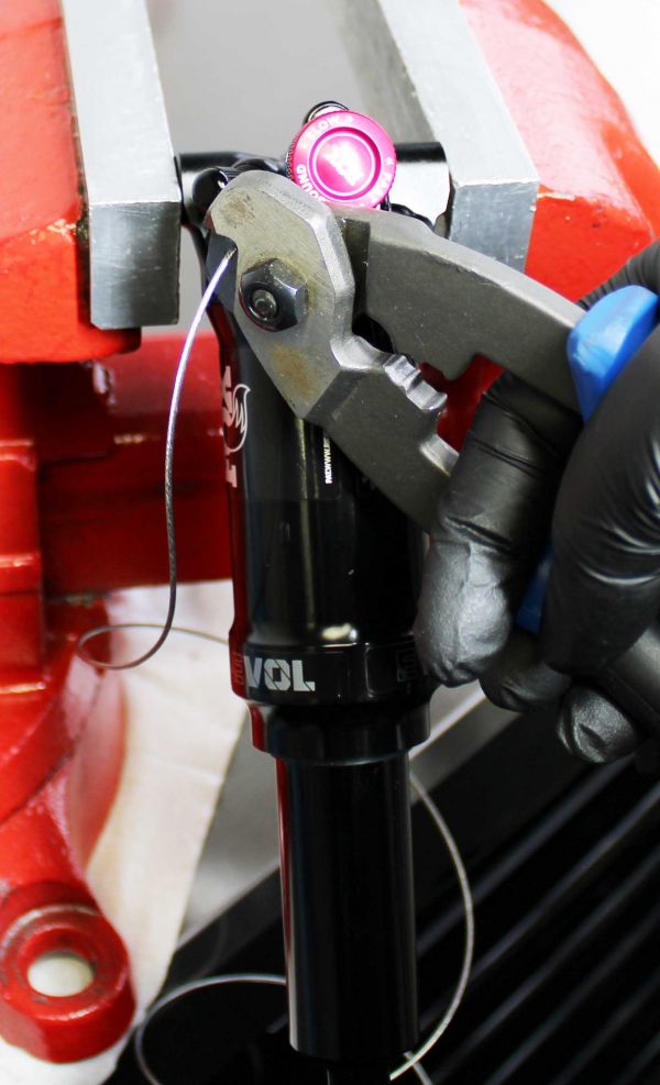
Step 10
Cut off excess cable and crimp the end.


Step 11
Test remote function.


WARNING: FOX products should be installed by a qualified bicycle service technician, in accordance with FOX installation specifications. If you have any doubts as to whether or not you can properly install the remote lever on your bicycle, defer to a professionally trained bicycle service technician. Improperly installed products can fail, causing the rider to lose control, potentially causing SERIOUS INJURY OR DEATH.
WARNING: Make sure that the remote lever does not interfere with normal brake and shift lever operation. Failure to do so can result in loss of control, potentially causing SERIOUS INJURY OR DEATH.
WARNING: Make sure to leave enough cable housing length to accomodate normal steering operation. Failure to do so can result in loss of control, potentially causing SERIOUS INJURY OR DEATH.