2015 FLOAT CTD DrCV RG Full Rebuild
Required Parts
- 803-00-142 Kit: Rebuild, FLOAT Line Air Sleeve, Special Q-Ring
- 803-00-589 Service Set: DRCV RG Supplemental Seal Kit (Use with 803-00-816)
- 803-00-816 Seal Kit: CTD Boost Valve and Dish Shock Rebuild
Required Tools
- 398-00-306 Tooling: DrCV Eyelet Base Removal Assembly
- 398-00-614 Tooling: 2015 Trek RG Valve Stack Transfer Tool
- 803-00-566 Kit: DYAD IFP Depth Setting Tool Set
- 803-00-805 Kit: Shaft Clamps, Shocks, CTD 9mm, 3/8in, 1/2in, 5/8in
- Nitrogen Fill Station (Tank with Regulator) required for full rebuild .
Supplies Needed
WARNING: Always wear safety glasses and protective gloves during service to prevent potential injury. Failure to wear protective equipment during service may lead to SERIOUS INJURY OR DEATH.
WARNING: FOX products should be serviced by a qualified bicycle service technician, in accordance with FOX specifications. If you have any doubt whether or not you can properly service your FOX product, then DO NOT attempt it. Improperly serviced products can fail, causing the rider to lose control resulting in SERIOUS INJURY OR DEATH.
IFP Pressure is 350psi
| Bike Model | Shock Size | IFP Depth |
| EX 27.5/29 | 7.250 x 1.875 | 2.385" (60.58mm) |
| Lush Carbon 29 | 6.750 x 1.750 | 2.216" (56.29mm) |
| Remedy 27.5 | 7.750 x 2.250 | 2.598" (65.99mm) |
| Remedy 29 | 7.750 x 2.125 | 2.598" (65.99mm) |
Main Disassembly
Step 1
Release the air pressure and remove the air sleeve and air sleeve spacer. Carefully clean the air sleeve and replace the air sleeve seals with new greased ones from the air sleeve rebuild kit (PN: 803-00-142).


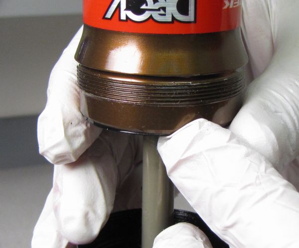
Step 2
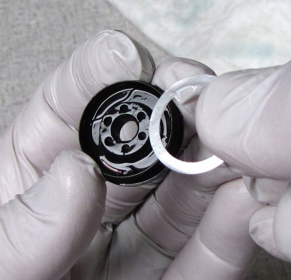
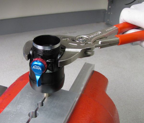
Use a soft-jawed vice and smooth-jawed pliers to unthread the eyelet cap counter-clockwise. Replace the eyelet cap o-ring with a new liberally greased o-ring from the rebuild kit. Make sure to seat the o-ring in the o-ring gland.


Step 3
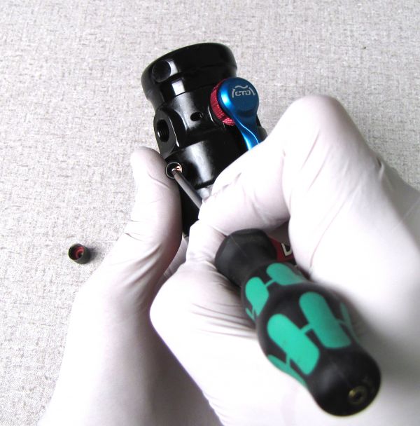
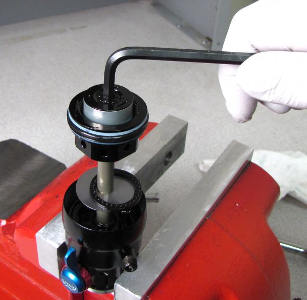
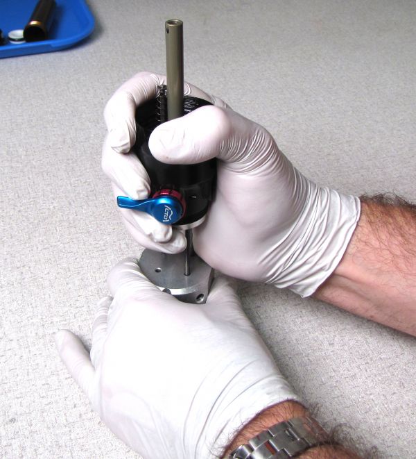
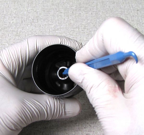
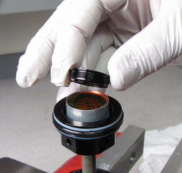
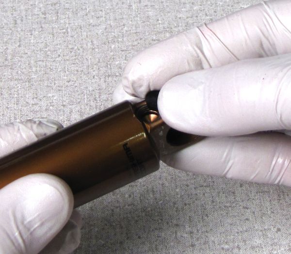
Remove the Delrin ball from the pellet retainer, then carefully unthread the pellet retainer with a 5/32" (4mm) hex wrench to release the nitrogen pressure from the IFP chamber. Remove the black rubber pellet.

Step 4
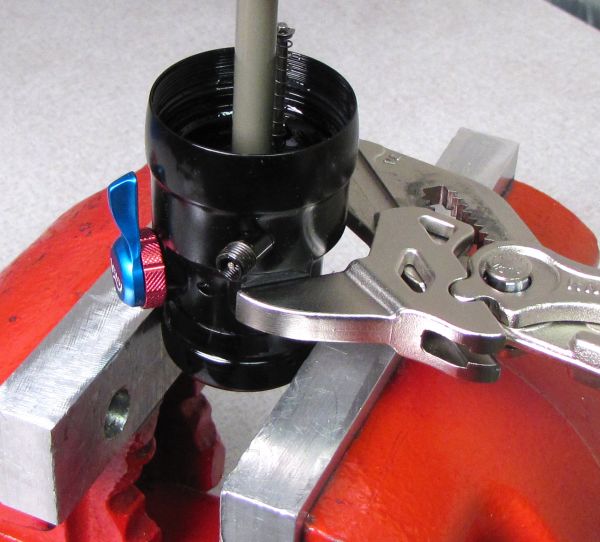
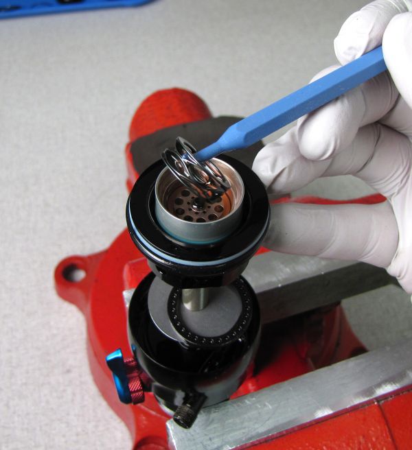
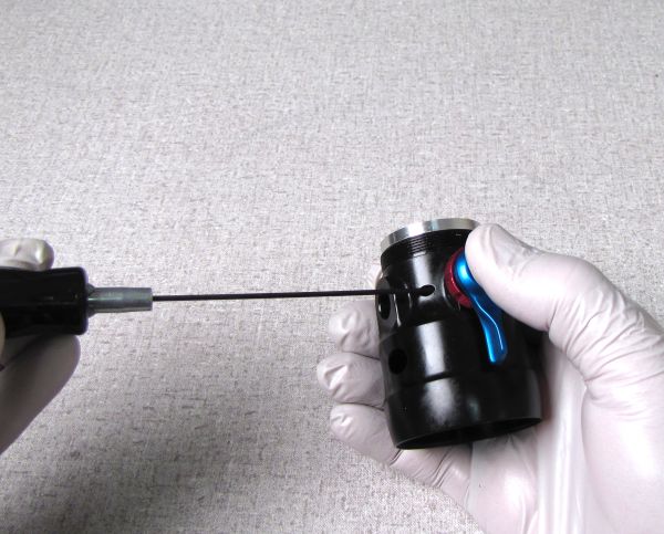
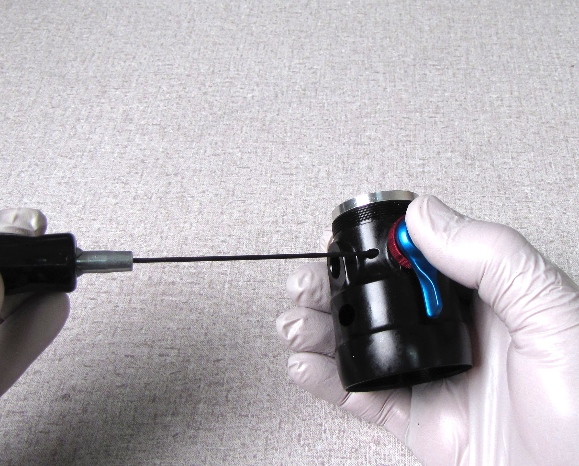
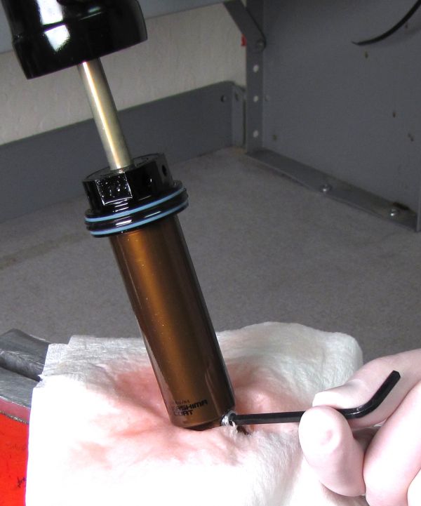
Lift the valve out of the way to access the DrCV bumper. Use a pick to lift the DrCV bumper out of the groove in the bearing assembly to access the bleed screw. Remove the bleed screw with a 5/64" (2mm) hex wrench. Use a magnet to remove the ball bearing from the bleed screw hole.


Push the valve up against the spring loaded DrCV fluted valve and let it sit on an angle. This will hold it above the body bearing and out of your way while accessing the bleed screw and ball bearing.
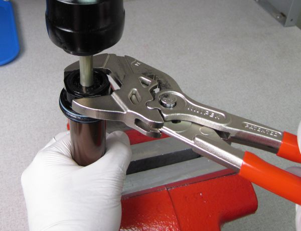
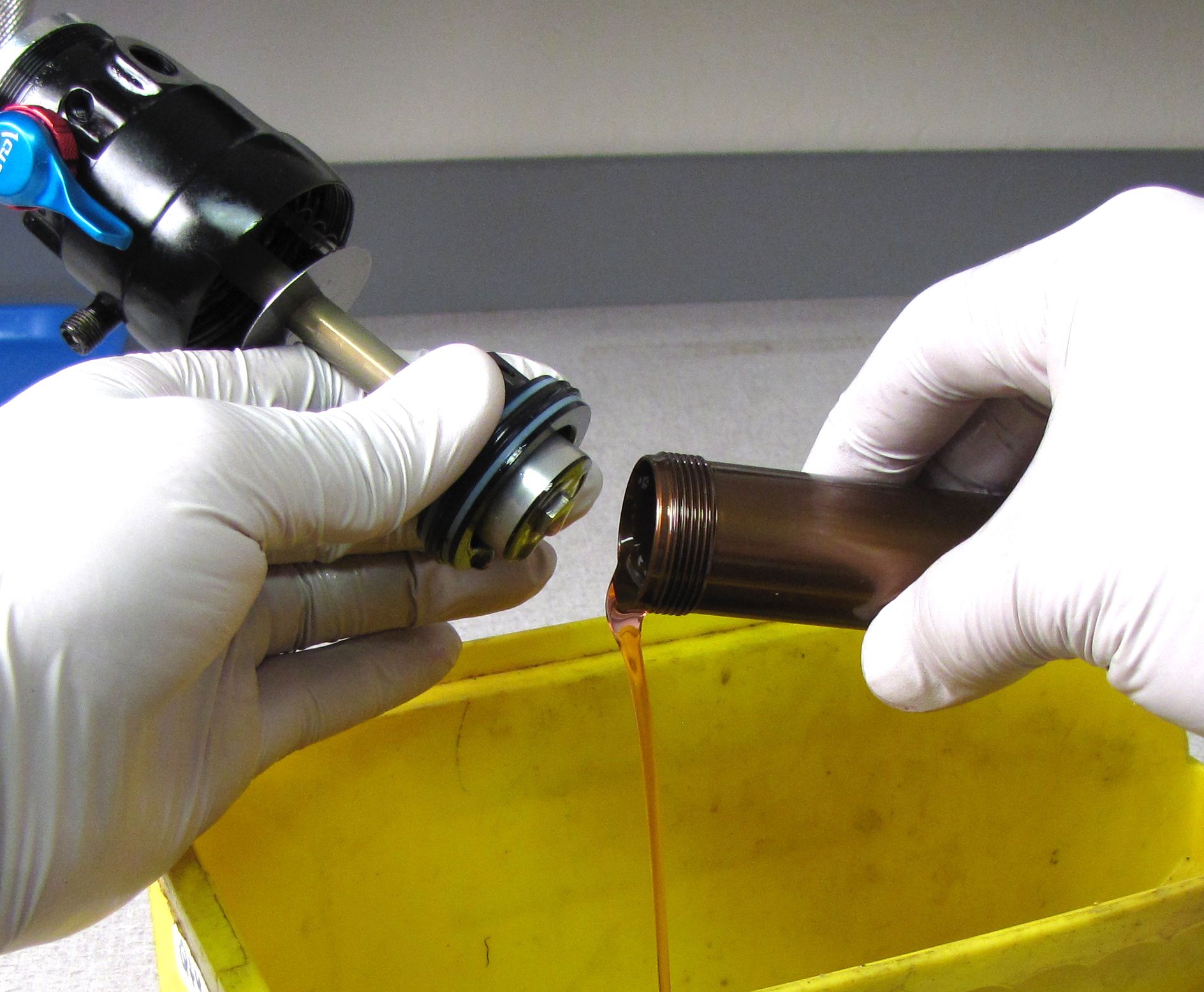
Step 5
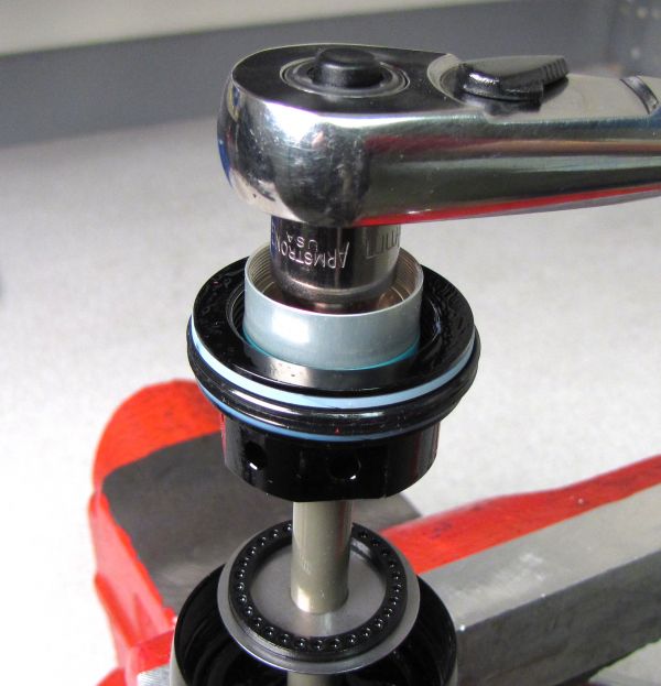
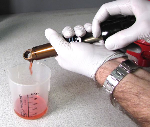
Clamp the body eyelet in your soft-jawed vice and unthread the body bearing assembly with a 30mm wrench. Drain the oil into a waste oil container.

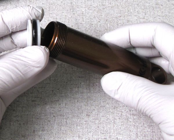
Step 6
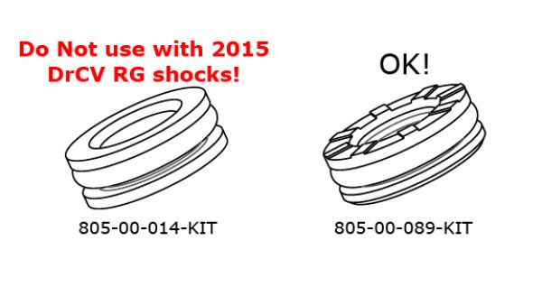
Use compressed air to gently blow the IFP out of the shock body. If the shock came with a standard FLOAT style IFP, please replace it with the 805-00-089-KIT piston assembly. If servicing a DrCV RG shock with the castellated IFP, replace the o-ring with a new greased one from the rebuild kit.


Servicing the Trek RG Valve
Step 1
Support the eyelet assembly in your soft-jawed vice and use a 6-point chamfer-less 8mm socket to remove the RD Check Bolt. Remove the check shim and set aside.


Step 2
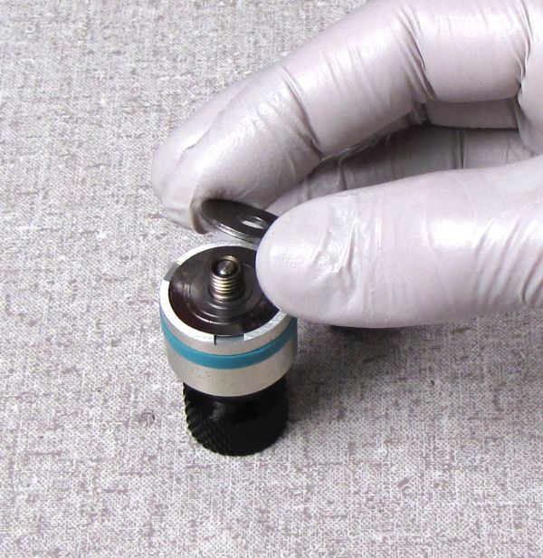
Use a 5mm hex wrench to unthread (counter-clockwise) and remove the RG Valve Housing Cap.


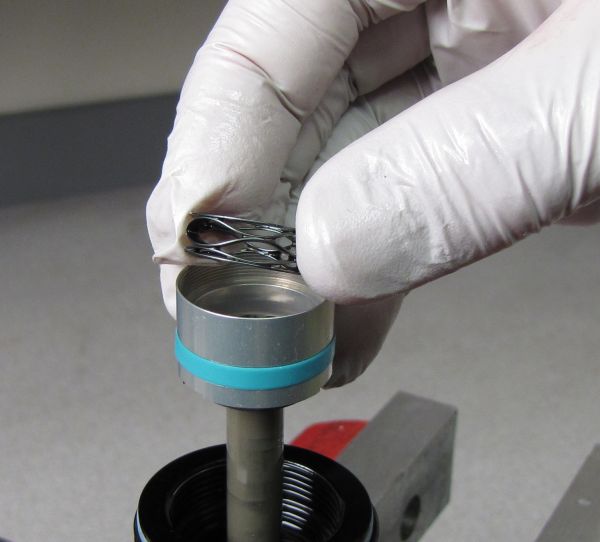
Step 3
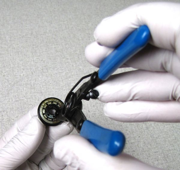
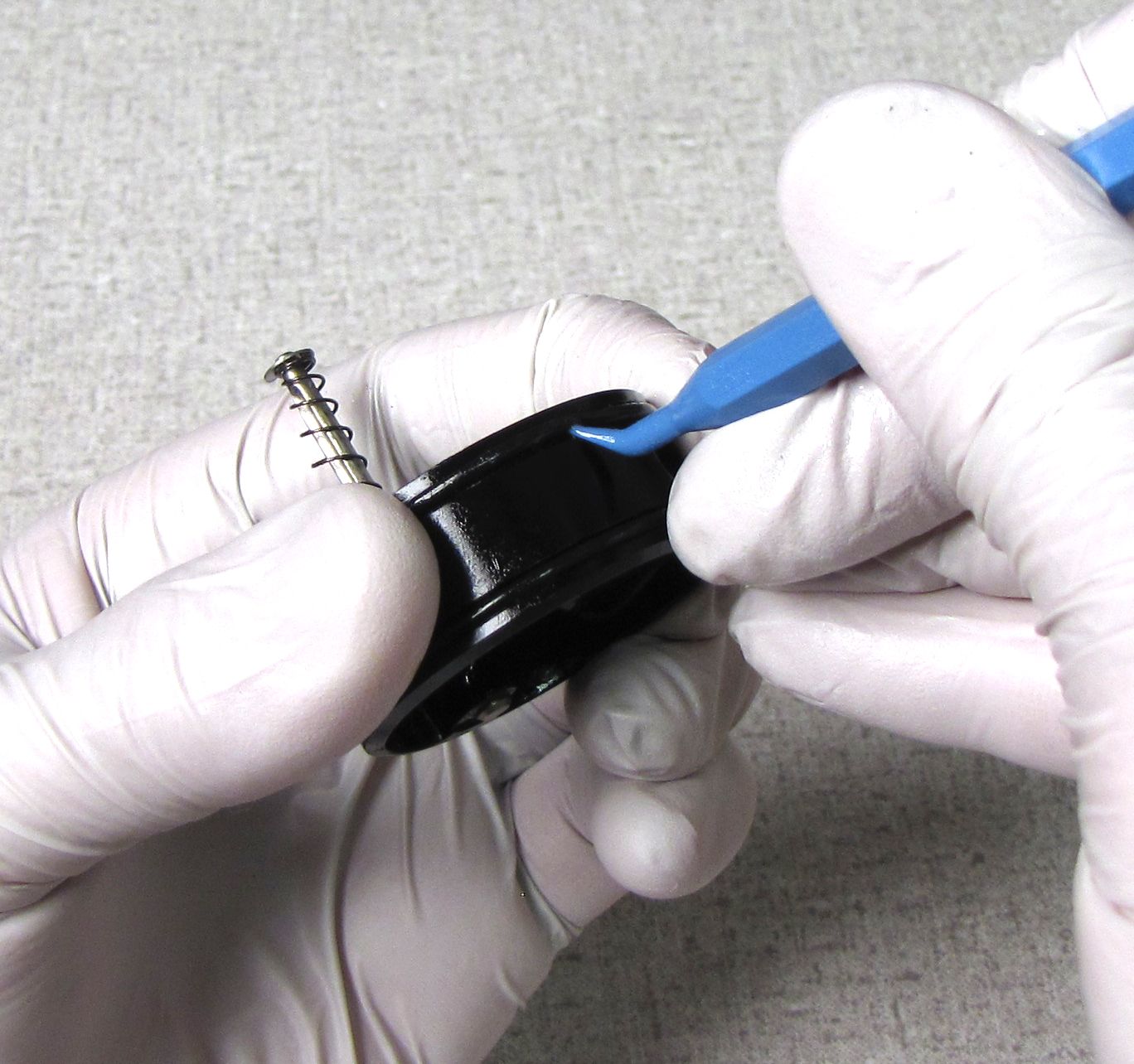
Use fine snap-ring pliers to hold the inner Blowoff Piston Valve as you separate it from the outer black Valving Housing Cap Piston.

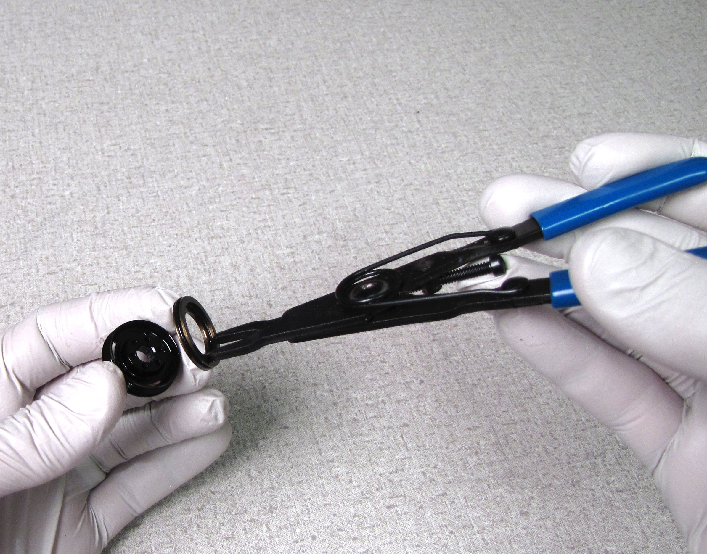
Step 4
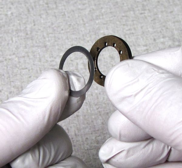
Separate the ring shim from the Blowoff Piston Valve if necessary. Replace the o-ring on the Blowoff Piston Valve with a greased one from the rebuild kit.


Step 5
Install the ring shim into the black Valve Housing Cap Piston. Carefully install the Blowoff Piston Valve into the black Valve Housing Cap Piston without pinching the new o-ring. Press the parts together to seat them fully.
Install these parts with the same care that you would for assembling a Boost Valve.


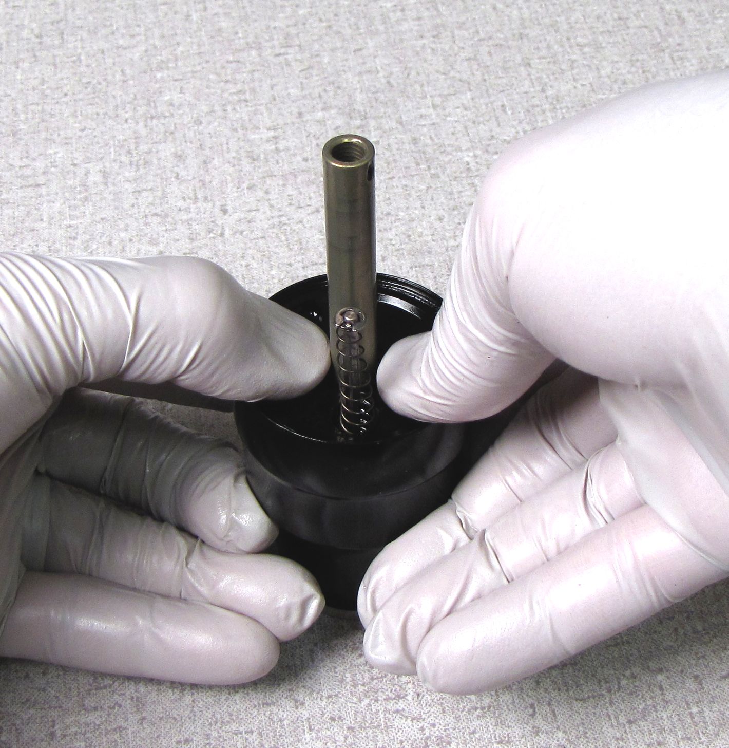
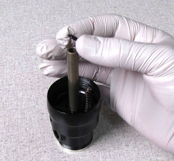
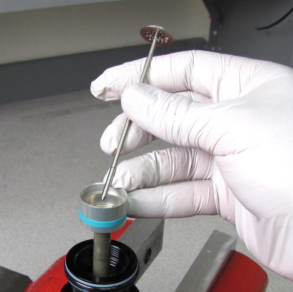
Step 6
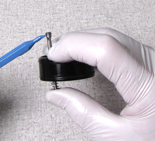
Remove the wave spring and discard it as you will be replacing it with a new one from the rebuild kit. Lift out the CTD rod assembly by lightly pinching the small screw with needle-nosed pliers.


Step 7
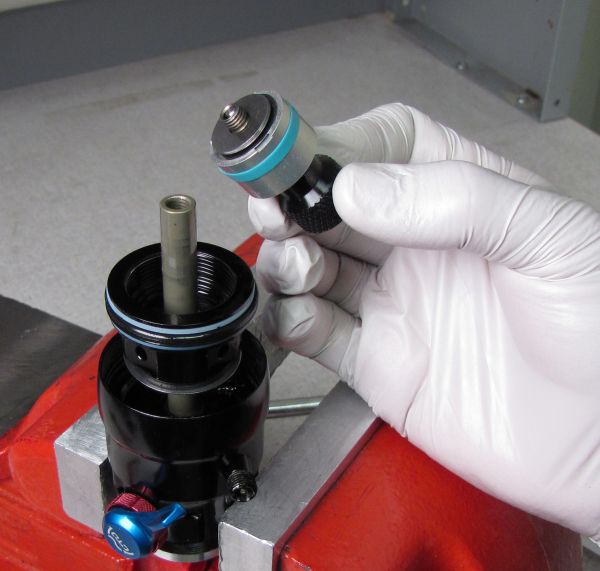
Use a 6-point chamfer-less 8mm socket to remove the Piston Bolt. Carefully remove the valving assembly to keep the shims in their correct order.


Step 8
Use the FOX 2015 Trek RG Valve Stack Transfer Tool (PN: 398-00-614) to support the valving assembly as you replace parts on the Valve Housing Piston. Stage the parts in order on the tool starting with the piston bolt.


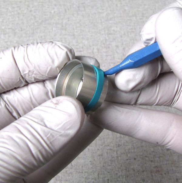
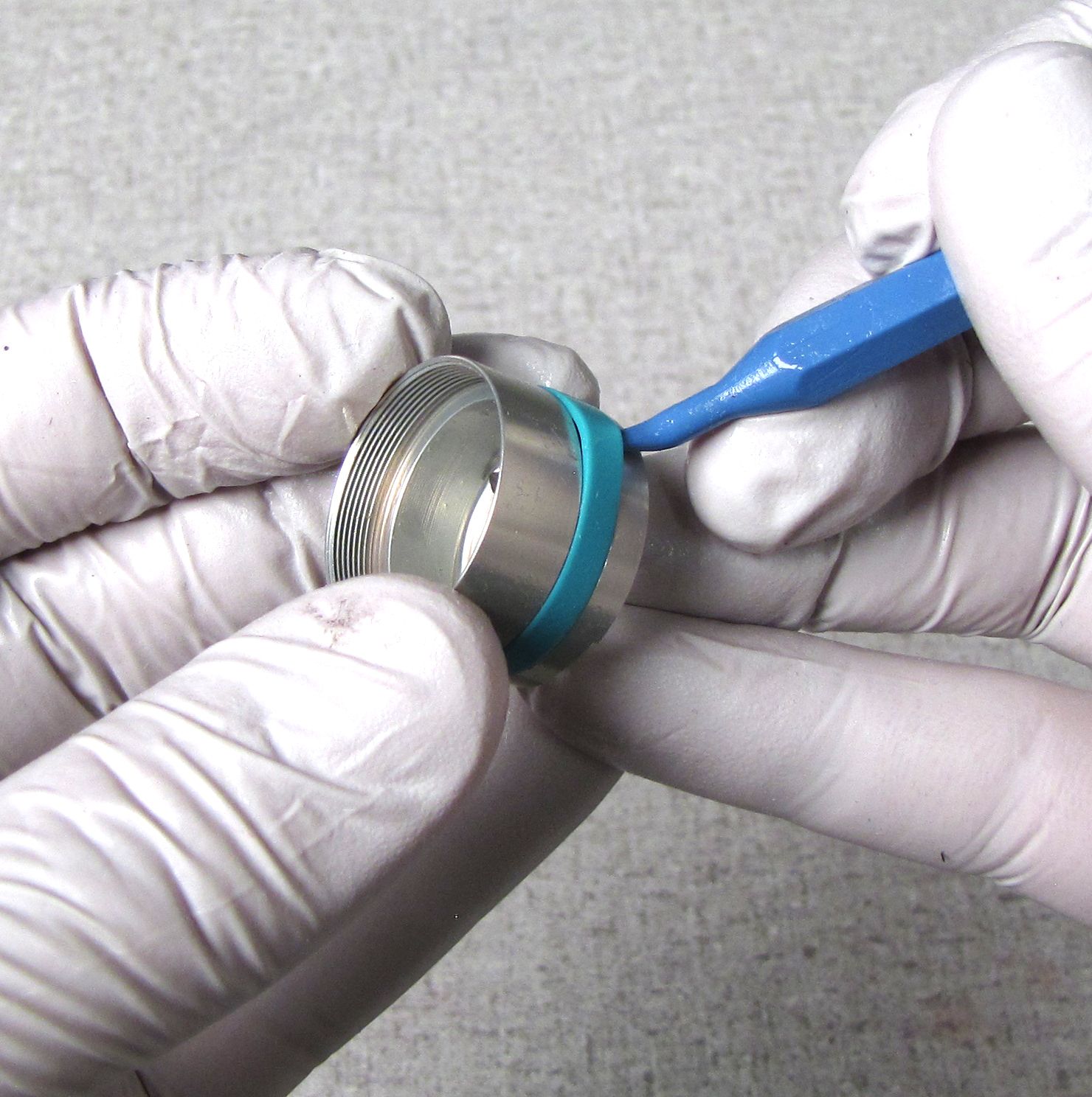
Step 9
Replace the blue glide ring and the o-ring under it with new parts from the rebuild kit. Add the Valve Housing Piston to the stack on the Valve Stack Transfer Tool.

Step 10
Add the remainder of the shims to the Valve Stack Transfer Tool and set aside until needed during reassembly.


Shaft and Eyelet Disassembly

Step 1
Remove the Body Bearing Assembly by pulling it off of the shaft. Replace the shaft o-ring and body o-ring with greased replacement parts from the rebuild kit. Replace the main air seal and back-up rings with greased ones from the air sleeve rebuild kit (PN: 803-00-142).

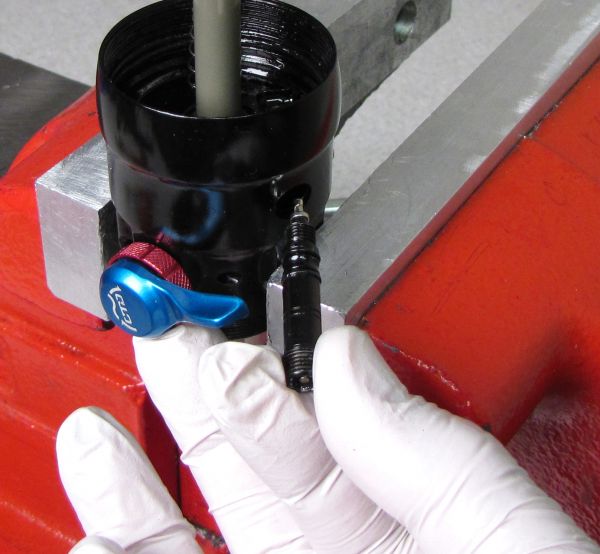
Step 2
Remove the DrCV Bumper and shim. Do NOT remove the valve core. Use a 3/16" hex wrench to remove the Air Valve Assembly. Replace the Air Valve Assembly o-rings with new greased ones from the rebuild kit.


Step 3
Remove the bottom-out o-ring and the air sleeve o-ring inside the skirt of the eyelet assembly.


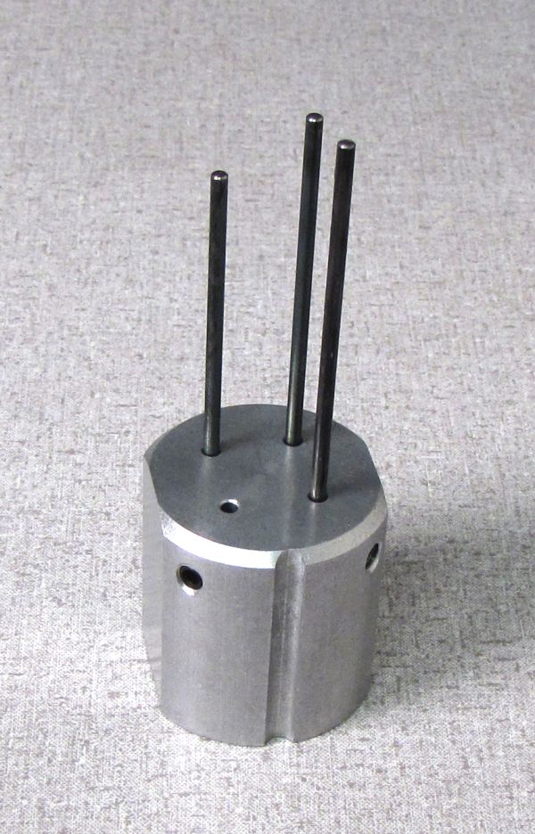
Step 4
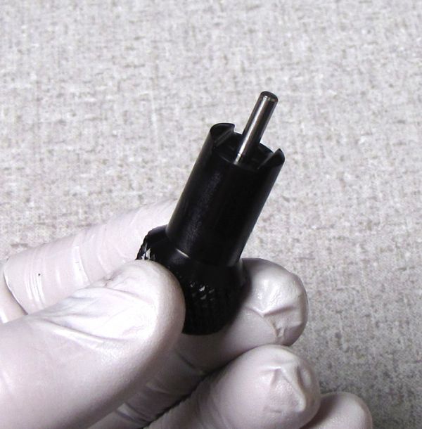
Prepare the DrCV Eyelet Base Removal Tool (PN: 398-00-306) for CTD DrCV shocks by removing the forward left rod. Use a 3mm hex to loosen the set screw, then pull the rod out of the tool base. Your tool should look like the image shown before going to the next step.

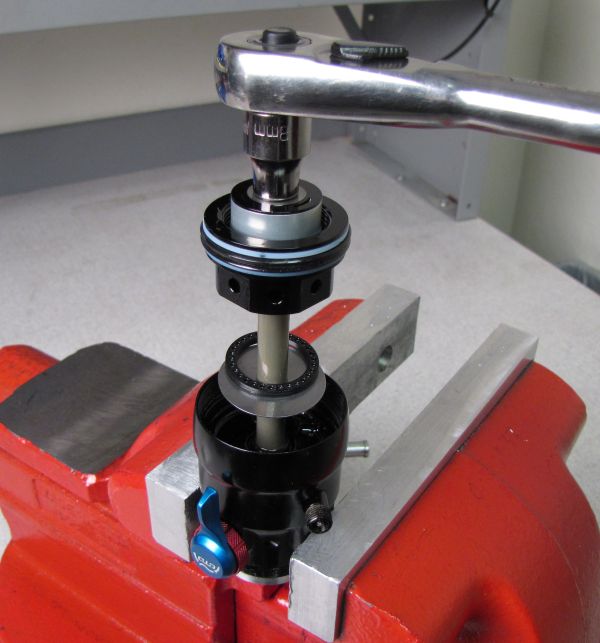
Step 5
Position your eyelet assembly on the DrCV Eyelet Base Removal Tool so the adjusters are in line with the groove in the tool. Press the eyelet assembly down against the tool until the Eyelet Base Assembly can be removed from the shaft.


Step 6
Replace the DrCV valve o-ring, shaft o-ring, and both external o-rings with new greased ones from the rebuild kit.


Step 7
Clamp the shaft in the 9mm shaft clamp (PN: 803-00-805) and heat the shaft/eyelet interface with a propane torch for a few seconds until the Loctite has broken down enough to let you unthread the eyelet from the shaft (counter-clockwise).


Step 8
Clean off any Loctite residue from the shaft and eyelet threads. Replace the shaft o-ring with a new greased one from the rebuld kit.

Step 9
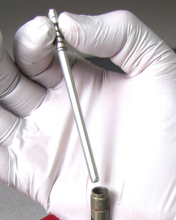
Remove the rebound metering rod by pulling it straight up and out of the shaft. Be careful not to lose the 1.5mm diameter ball bearing. Replace the square cut o-ring inside the rebound metering rod and the o-ring inside the shaft with new greased ones from the rebuild kit.


Step 10
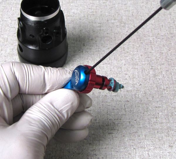
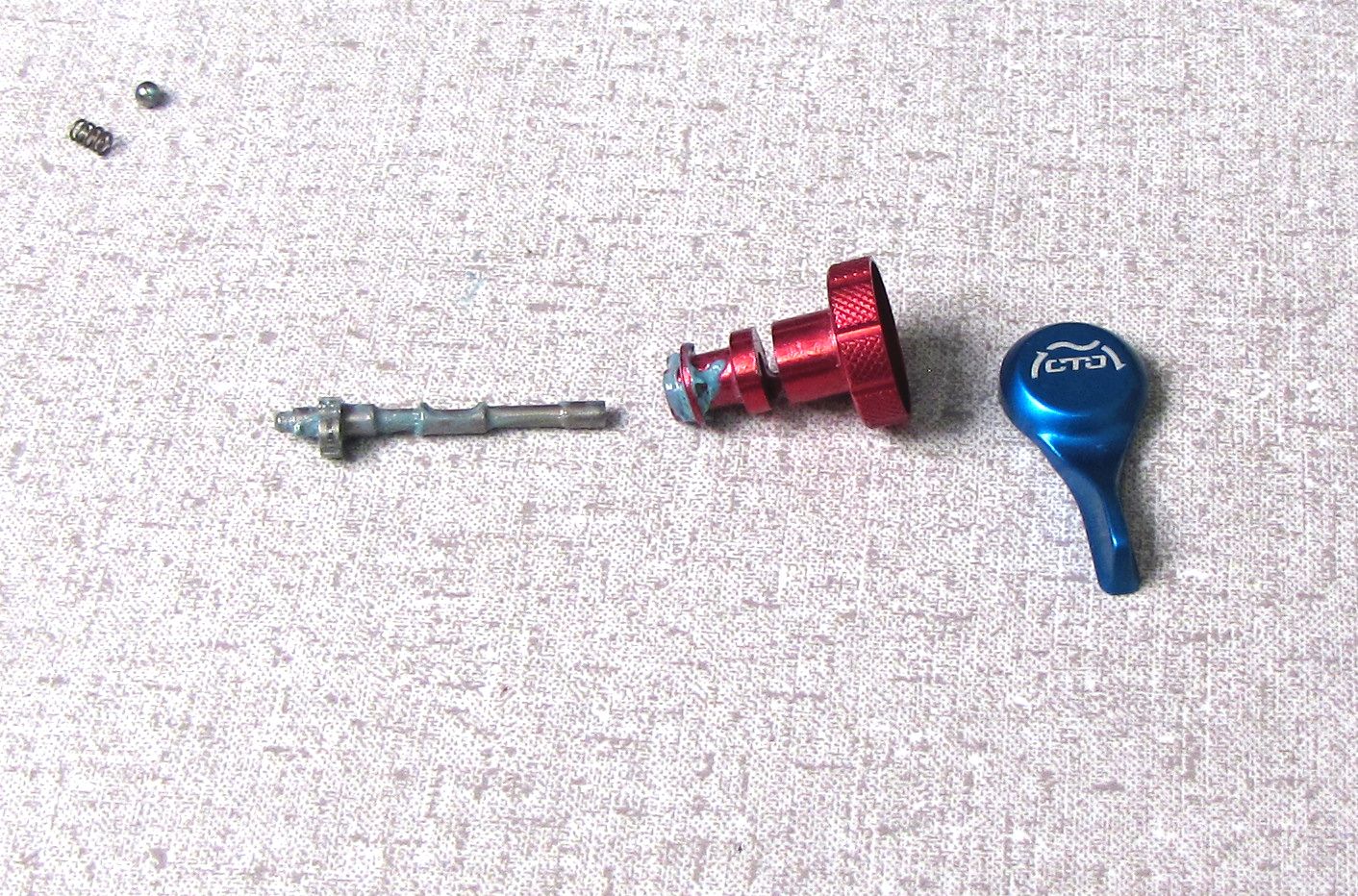
Hold the rebound knob and CTD lever in against the eyelet as you remove the set screw from the side with a 1.5mm hex wrench. Slowly remove the knob assembly and watch for the 1/8" ball bearing and small spring.


Step 11
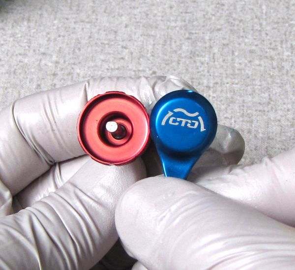
Separate the knobs from each other and the cam to clean their mating surfaces by unthreading the set screw in the CTD lever with a 1.5mm hex wrench.

The 2015 DrCV RG uses a different cam (PN: 210-30-045) than previous CTD DrCV shocks. Do not attempt to use previous generation DrCV cams (PN: 210-30-046) with this assembly.
Reassembly
Step 1
Coat the cam and rebound knob cam and detent surfaces with a film of Hi-Temp grease (such as Sta-Lube SL3125 or similar). Install the blue CTD lever by lining up its set screw with the flat portion of the cam. Tighten the set screw with a 1.5mm hex wrench to 5 in-lb (0.6 Nm).


Step 2
Coat the detent spring and ball with Hi-Temp grease and install them (spring first) into the hole just above the hole for the adjusters. Slightly compress the rebound knob and CTD lever against the detent ball and spring while inistalling the set screw from the side with a 1.5mm hex wrench. Gently tighten the set screw until it just touches the cam and then back it out 1/4 turn.


Step 3
Apply 1 drop of red Loctite 277 to the shaft threads. Install the rebound metering rod into the eyelet from the bottom so the ball bearing at the top end is oriented toward the front of the shock (toward the adjuster knobs). Hold the rebound metering rod in the eyelet assembly as you insert the bottom end of the metering rod into the shaft. Thread the eyelet onto the shaft torquing to 85 in-lb (9.6 Nm).


Step 4
Install the Eyelet Base Assembly onto the shaft. Align the eyelet base so the air valve assembly hole lines up with the hole in the eyelet. Make sure that the external o-rings on the Eyelet Base Assembly are generousely coated with Slick Honey and not pinched or twisted during installation. Press the Eyelet Base Assembly into the eyelet fully.

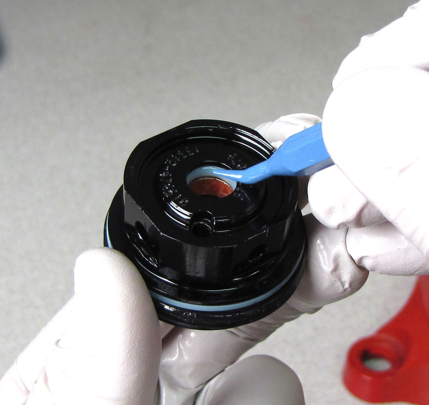
Step 5
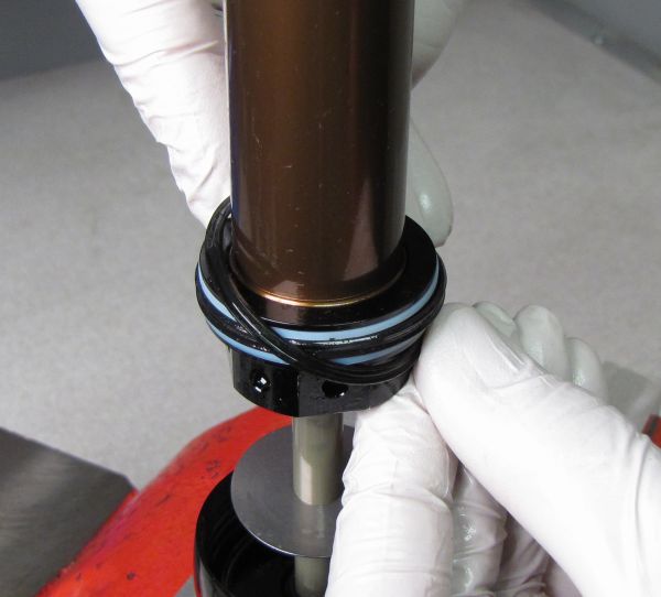
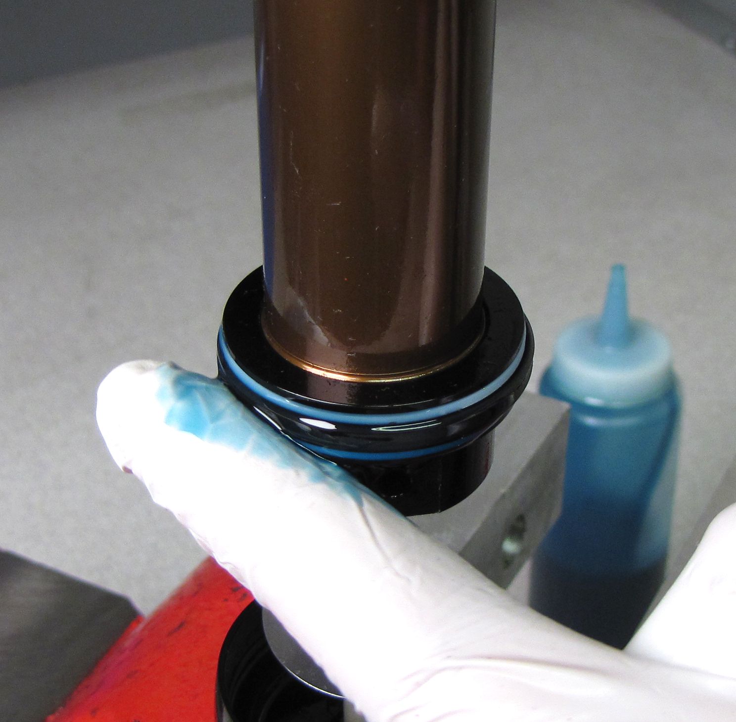
Install a new greased bottom-out o-ring onto the shaft. Install a new greased air sleeve o-ring into the gland inside the skirt of the eyelet. Make sure to seat the air sleeve o-ring in the seal gland (pictured in yellow).


Step 6
Do NOT remove the valve core. Coat the new o-rings on the Air Valve Assembly with Float Fluid then carefully install the assembly into the eyelet. Do not pinch or damage the Air Valve Assembly o-rings during installation. Use a 3/16" hex wrench to torque to 35 in-lb (4 Nm).


If the Dual Core Air Valve Assembly is not functioning properly, replace the Air Valve Assembly with a new one (PN: 802-00-009-KIT)
Step 7
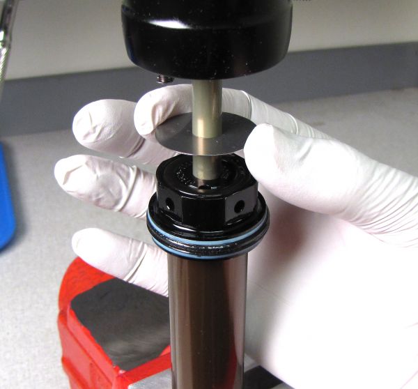
Reinstall the large shim onto the shaft followed by a new DrCV bumper and Body Bearing Assembly.


Step 8
Use the Valve Stack Transfer Tool and your fingers to install the piston assembly prepared earlier. Torque the piston bolt to 60 in-lb (6.8 Nm) with a 6-point chamfer-less 8mm socket.


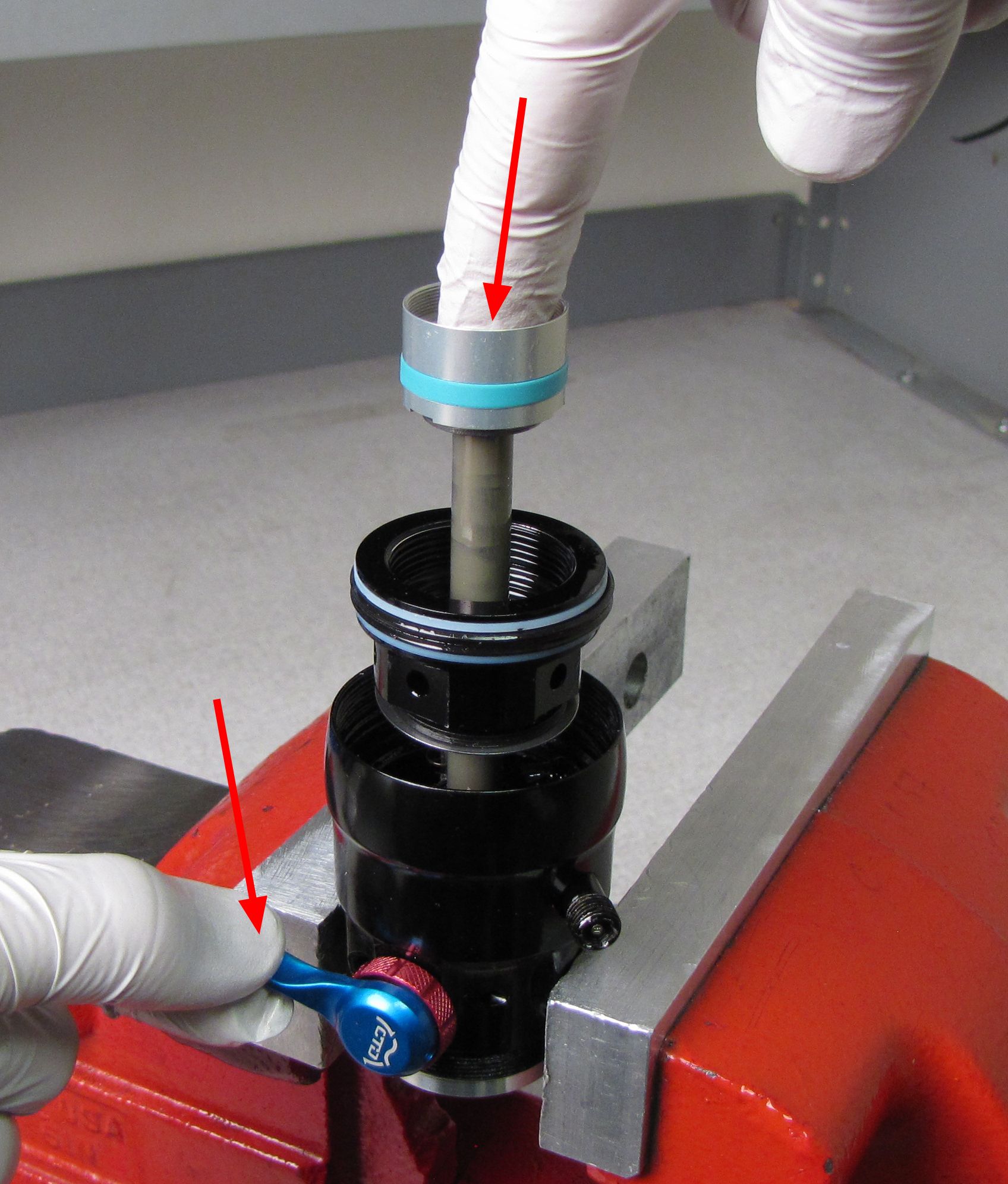
Step 9
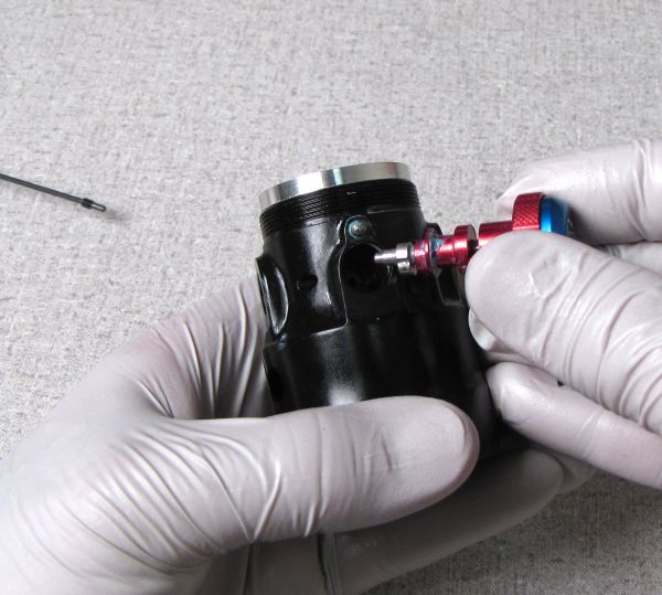
Carefully install the CTD rod assembly being careful not to damage the o-ring inside the shaft that the CTD rod goes through. Set the blue CTD lever to Descend Mode (fully counter-clockwise) while gently pushing the CTD rod assembly as far into the Valve Housing Piston as possible.

Step 10
Install a new wave spring from the rebuild kit, then fill the Valve Housing Piston with FOX 10wt. Red oil. Make sure to wait until all bubbles are gone before proceeding to the next step.


Step 11
Thread the Valve Housing Cap into the Valve Housing Piston. Install the RD Check Valve and bolt and torque the entire assembly to 22 in-lb (2.5 Nm) using a 6-point chamfer-less six-point 8mm socket.


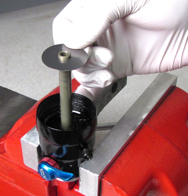
Step 12
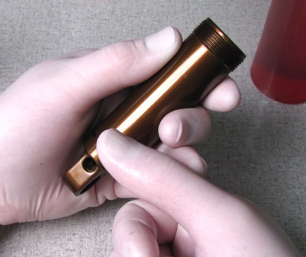
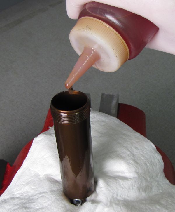
Plug the port in the body with your gloved thumb then fill body completely with FOX 10wt. red oil. There should be no IFP installed in the body at this point.


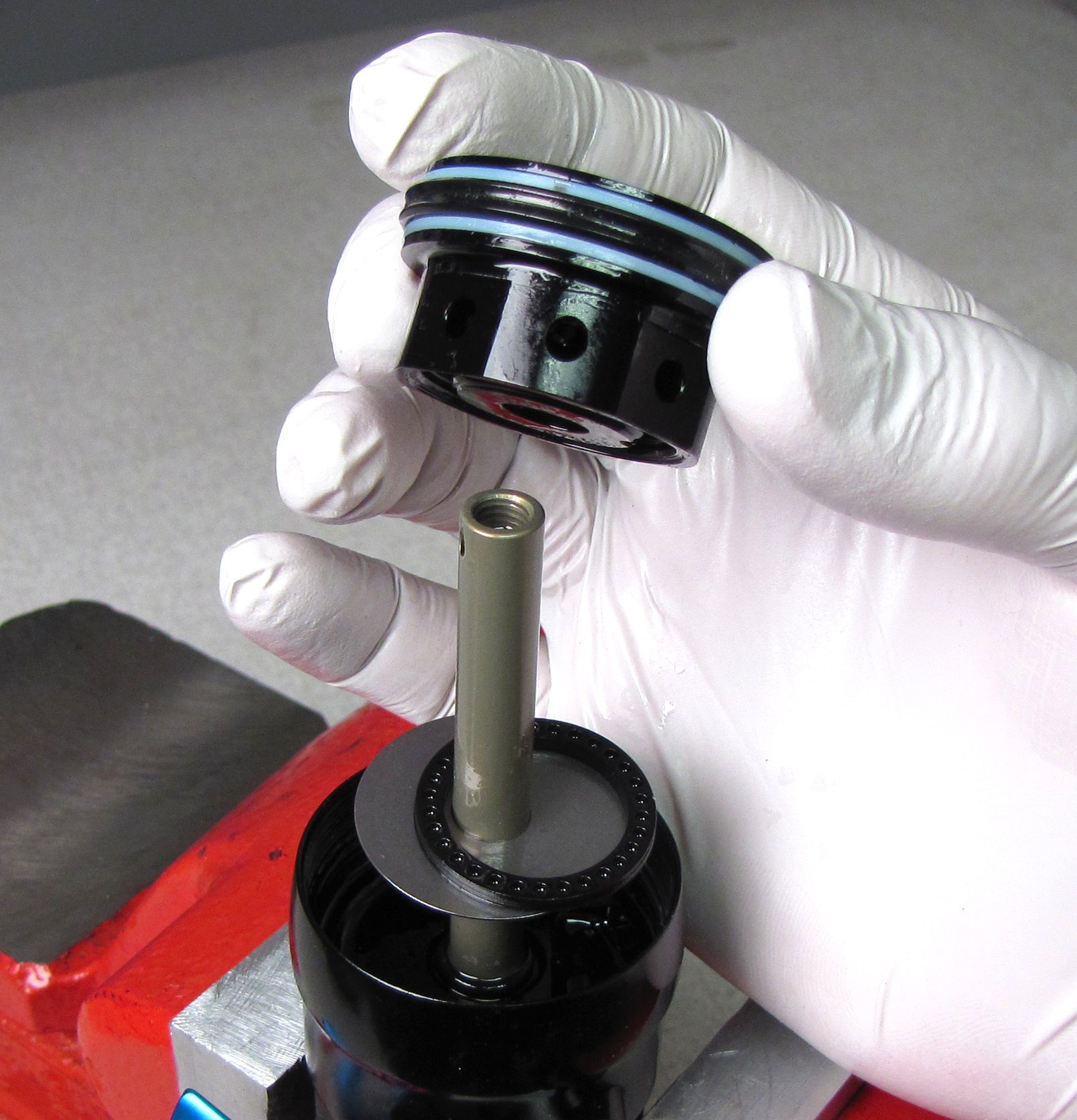
Step 13
Insert the IFP assembly (PN: 805-00-089-KIT) into the body with its castellated side (the side with the "stand-off" features) facing up.
Press the IFP gently into the body, while relaxing the thumb covering the port in the body, allowing some fluid to exit.


Step 14
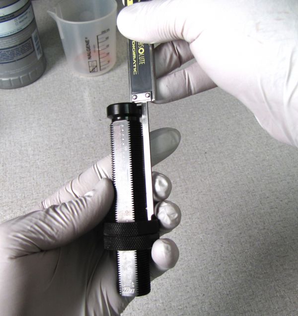
Adjust the IFP setting tool (PN: 803-00-566) to the correct depth for your shock. Be as precise as possible as the IFP depth on DrCV RG shocks is critical for proper function.
| Bike Model | Shock Size | IFP Depth |
| EX 27.5/29 | 7.250 x 1.875 | 2.385" (60.58mm) |
| Lush Carbon 29 | 6.750 x 1.750 | 2.216" (56.29mm) |
| Remedy 27.5 | 7.750 x 2.250 | 2.598" (65.99mm) |
| Remedy 29 | 7.750 x 2.125 | 2.598" (65.99mm) |
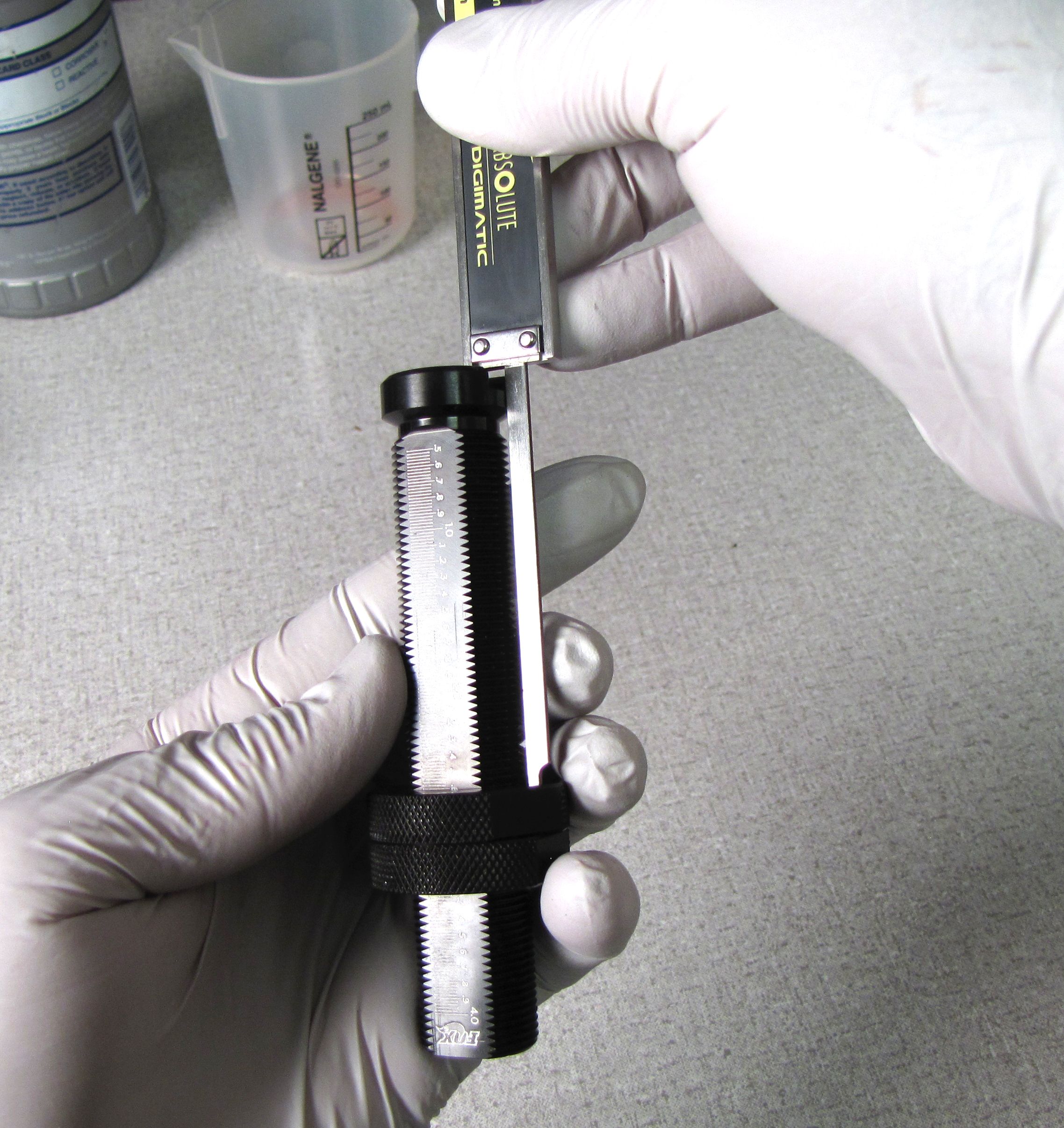
Step 15
Insert your carefully adjusted IFP setting tool into the body with the port in the body still covered by your thumb, over an oil cup. Push the IFP setting tool into the body while metering out oil of the body port with your thumb, until the collar of the tool touches the end of the shock body.


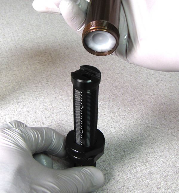
Step 16
Install a new pellet from the service kit, the flat side facing up, then secure with the pellet retainer.


Poke a small hole in a lint-free paper towel and stretch it over your shock body to act as a bib catching oil overflow during shaft assembly installation.
Step 17
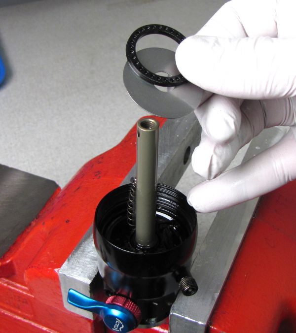
Completely fill the body with FOX 10wt. red shock oil. Plug the bleed port in the Bearing Assembly with your DrCV bumper, then pre-fill the piston and bearing assemblies to evacuate any trapped air.


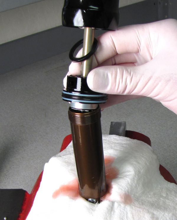
Step 18
Set the damper to the Open mode with Rebound set fully counter-clockwise.
Slowly insert the valving assembly into the oil-filled body, then thread the Body Bearing Assembly to the Body while watching for clean bubble-free oil coming out of the bleed hole.
Make sure that the DrCV bumper is not blocking the bleed hole.


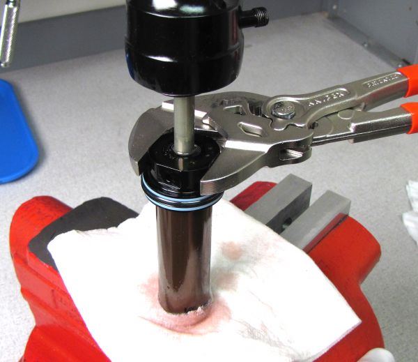
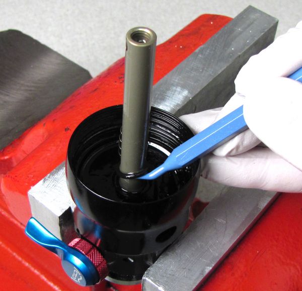
Step 19
Torque the Body Bearing Assembly to 240 in-lb (27.1 Nm). Install the ball bearing into the bleed screw hole followed by the bleed screw. Torque to 10 in-lb (1.1 Nm).


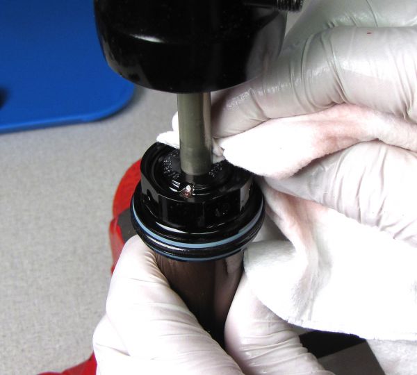
Step 20
Clean excess oil out of the groove for the DrCV Bumper then seat the entire bumper in the groove.


Step 21
Unthread the pellet retainer with a 5/32" (4mm) hex wrench then remove and discard the black rubber pellet.


Step 22
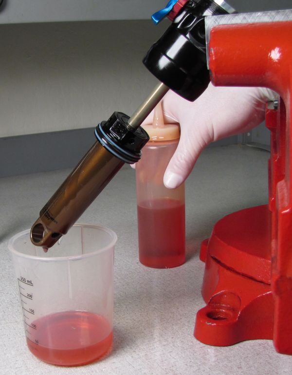
With the opening of the body over an oil cup, cycle the shock damper completely through its entire travel at least 6-7 times to purge out all oil from the IFP chamber.
Fully extend the shock after purging all oil from the IFP chamber.


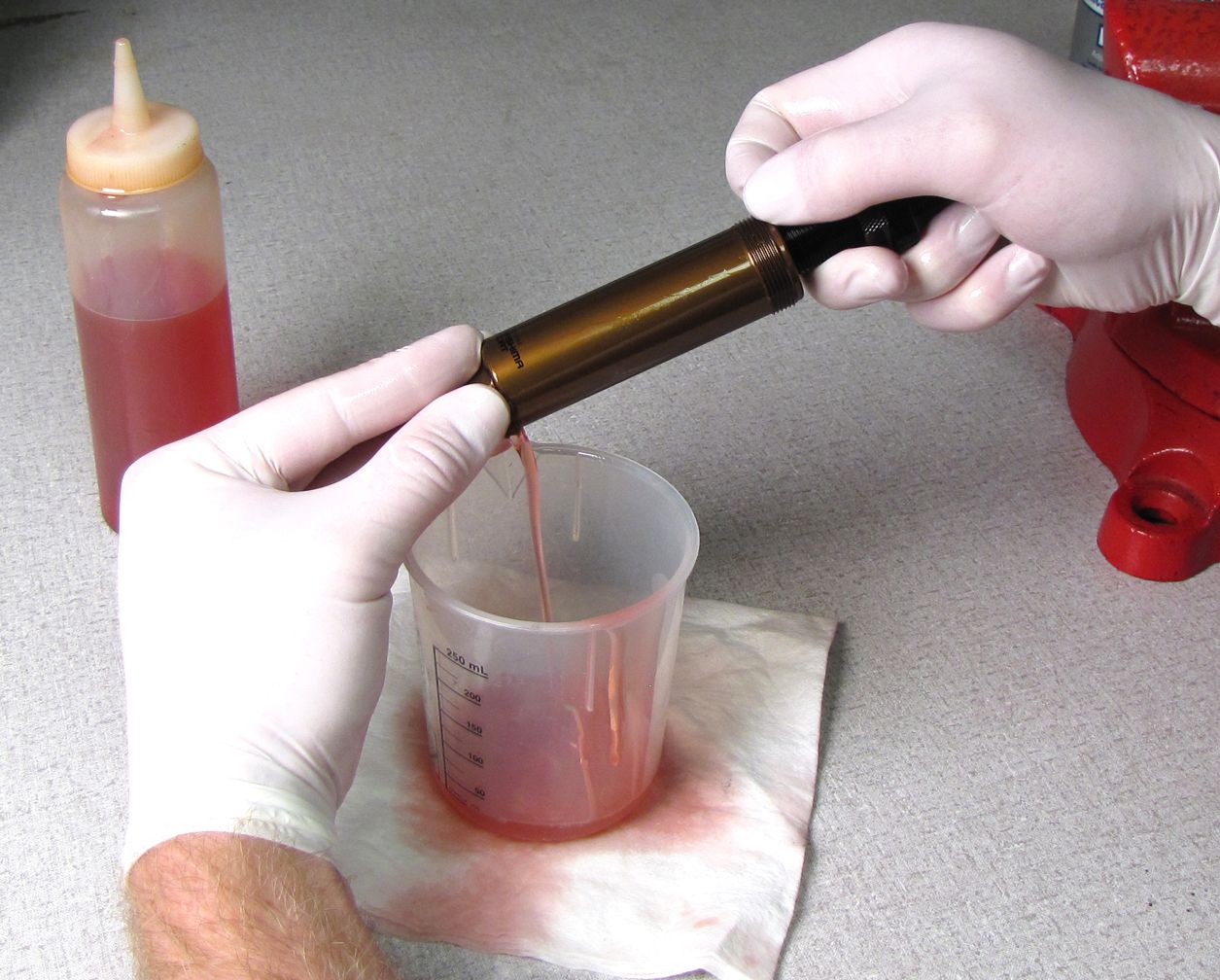
Step 23
Position the shock at a 45â° angle with the port at the end of the body oriented down over an oil cup.
Let the shock sit in this position for a minimum of 5 minutes.

The shock must remain in this position for at least 5 minutes in order to fully drain the IFP chamber of any oil.
Step 24
Install a new pellet from the service kit, the flat side facing up, then secure with the pellet retainer.


Step 25
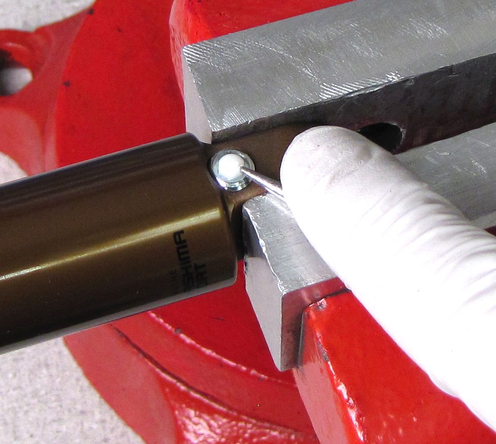
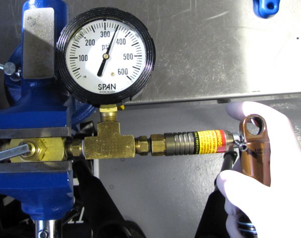
Pressurize the IFP chamber to 350psi then torque the Pellet Retainer to 14 in-lb (1.6 Nm). Dyno test the shock to check damper function and to verify that there is no feeling of the piston hitting the IFP. When satisfied with damper function, install a new Delrin ball into the Pellet Retainer with your soft-jawed vice.


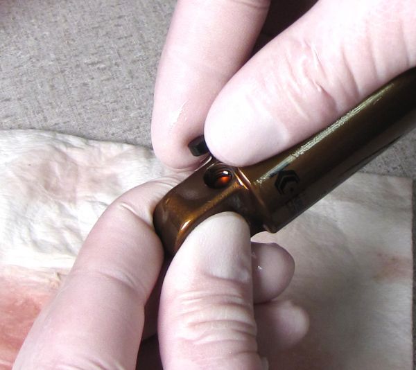
Step 26
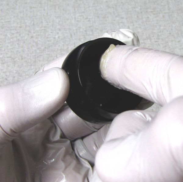
Liberally grease the Eyelet Cap o-ring before installing the Eyelet Cap to the Eyelet. Torque to 180 in-lb (20.3 Nm).


Step 27
Install the DrCV Air Sleeve Spacer with its flat surface toward the eyelet as shown. Coat the air seal and backup rings with Float Fluid. Coat the seals in the end of the Air Sleeve with Float Fluid and begin to install the Air Sleeve onto the shock body.


Step 28
Adhere the DrCV Air Sleeve Spacer to the end of the Air Sleeve with a small drop of Float Fluid. Torque the Air Sleeve to 180 in-lb (20.3 Nm). The Air Sleeve should be flush with the Eyelet when torqued properly. Pressurize the shock and hold under water to check for any air leaks. Clean the exterior of your shock.

.jpg)
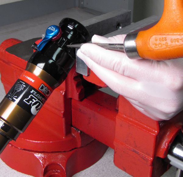
Step 29
Once completed, mark the eyelet with a punch mark as shown to indicate that the shock has been serviced and has recieved the updated IFP.

