2014-2015 3-Position Remote Installation
WARNING: Always wear safety glasses and protective gloves during service to prevent potential injury. Failure to wear protective equipment during service may lead to SERIOUS INJURY OR DEATH.
CTD Remote Installation (Front Fork Only)

Step 1
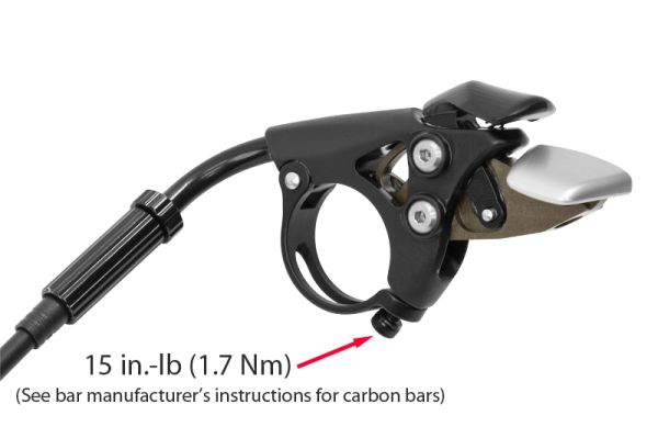
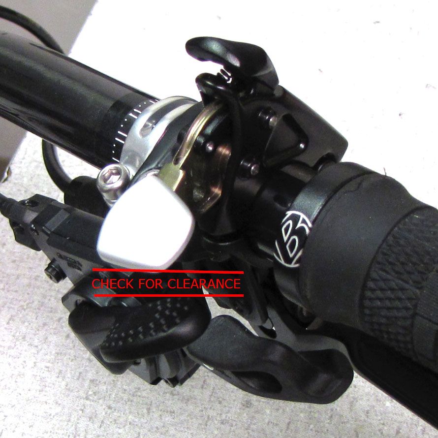
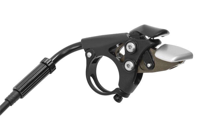
Install the remote lever onto your handlebar. Do not exceed 15 in.-lb (1.7 Nm) torque. Less torque may be needed for carbon bars. Please see bar manufacturer's instructions for use with carbon bars. Make sure to check for clearance between the remote lever and any brake or shifter controls.


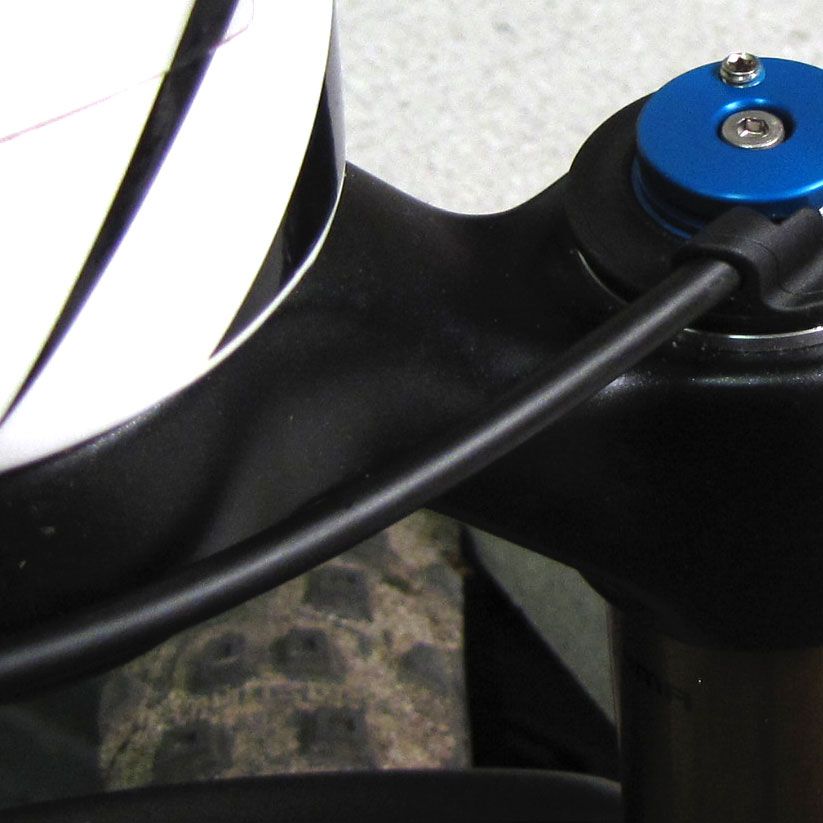
Step 2
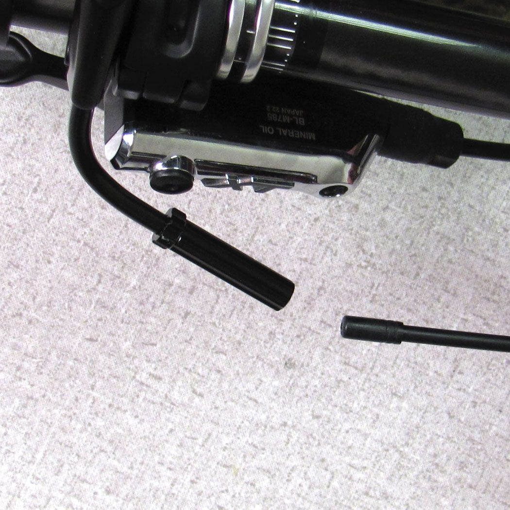
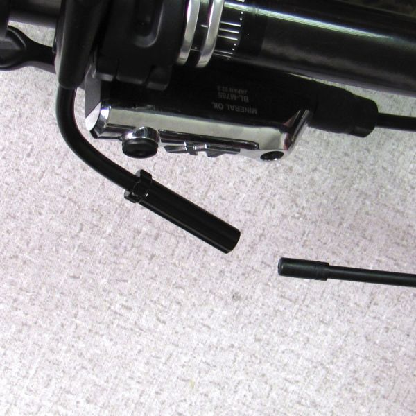
Route cable housing from the fork topcap, around the rear of the crown, to the remote lever and cut to length. Install a ferrule on the end of the housing at the remote lever. The end of the housing at the fork topcap does not require a ferrule.


Step 3
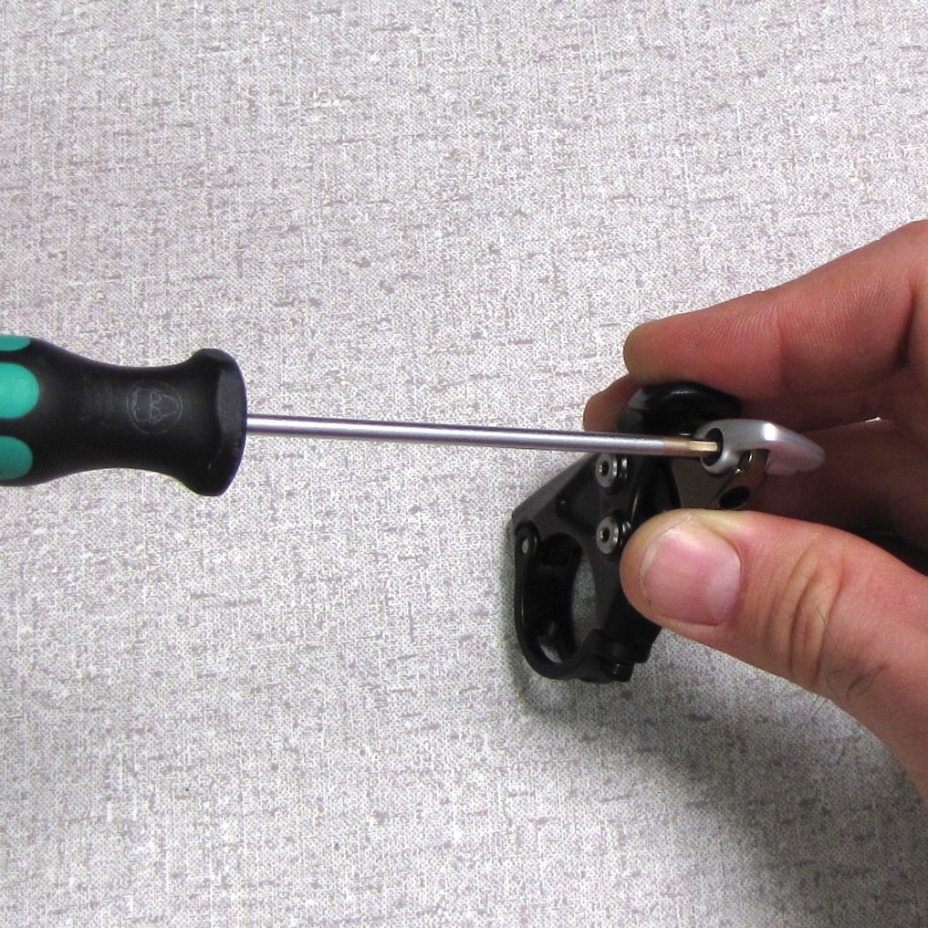
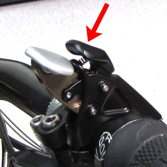
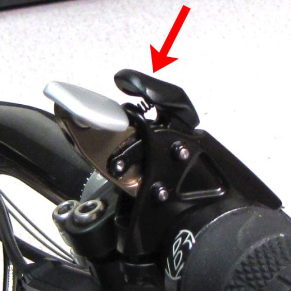
Set the remote lever to Descend mode by pushing the black lever. Make sure that the cable head is completely seated in the remote lever.


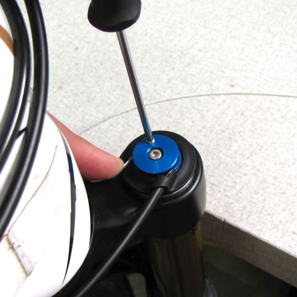
Step 4
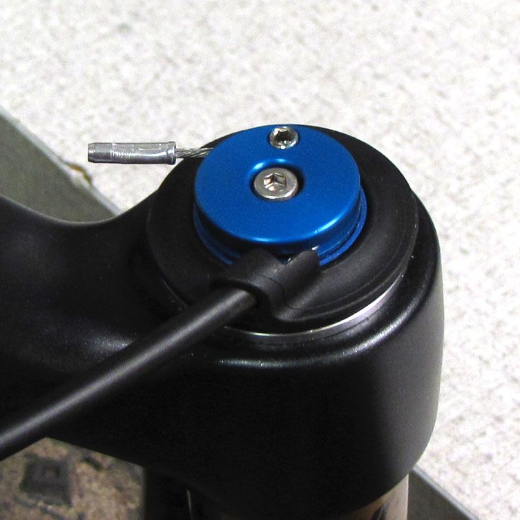
With all cable housing fully seated and no slack in the system, lightly lubricate the inner cable and thread it through the cable housing and around the fork remote pulley. Tighten the pinch bolt, cut off excess inner cable, and crimp the end.

CTD Remote Installation (Rear Shock Only)
Step 1
Install the remote lever onto your handlebar. Do not exceed 15 in.-lb (1.7 Nm) torque. Less torque may be needed for carbon bars. Please see bar manufacturer's instructions for use with carbon bars. Make sure to check for clearance between the remote lever and any brake or shifter controls.

Step 2
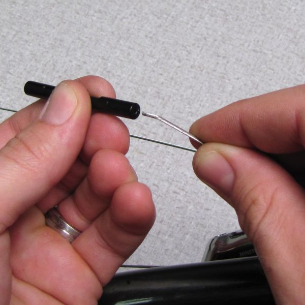
Route cable housing from the remote lever to the rear shock cable stop and cut to length. Install ferrules on both ends.


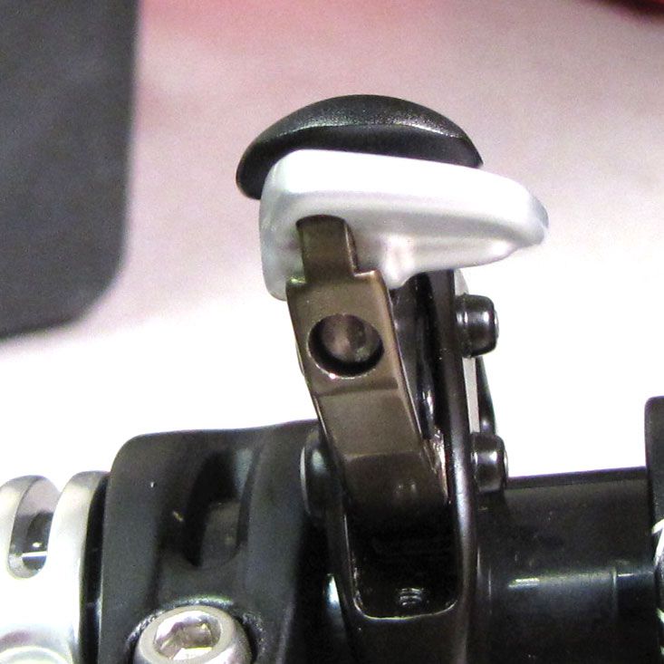
Step 3
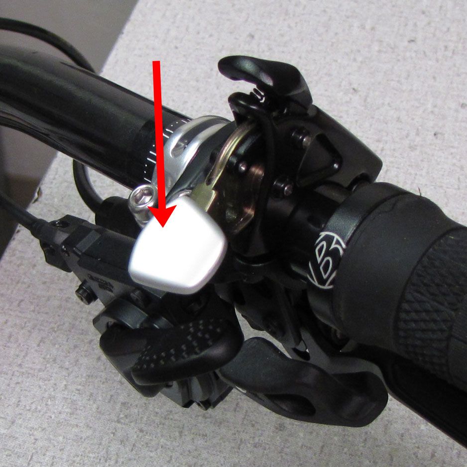
Set the remote lever to Descend mode by pushing the black lever. Make sure that the cable head is completely seated in the remote lever.


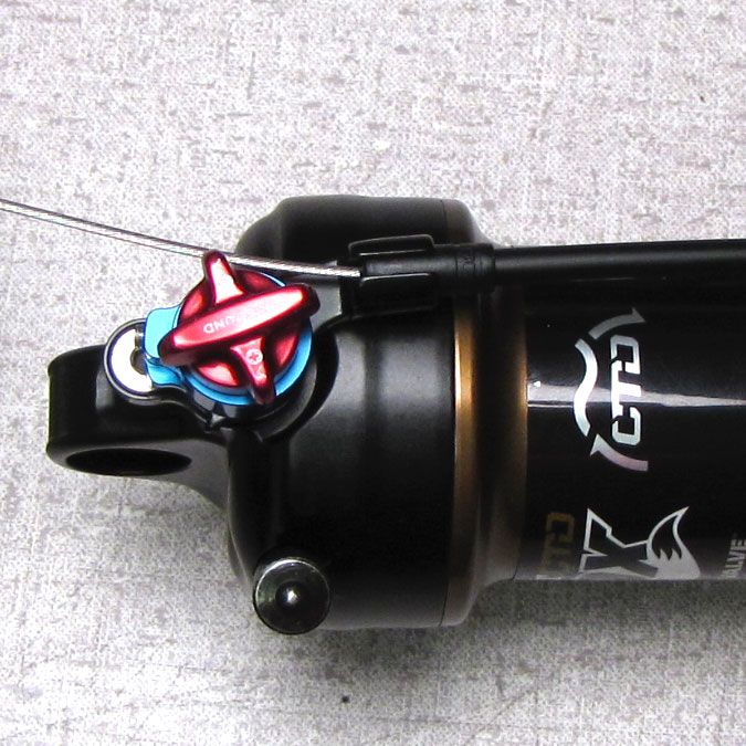
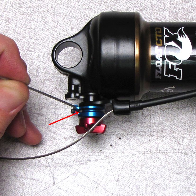
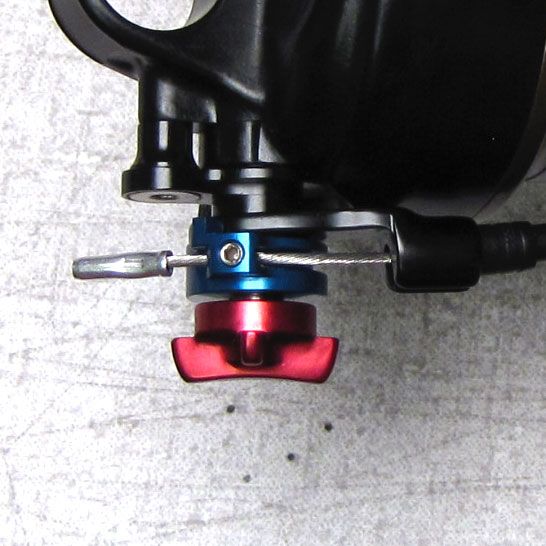
Step 4
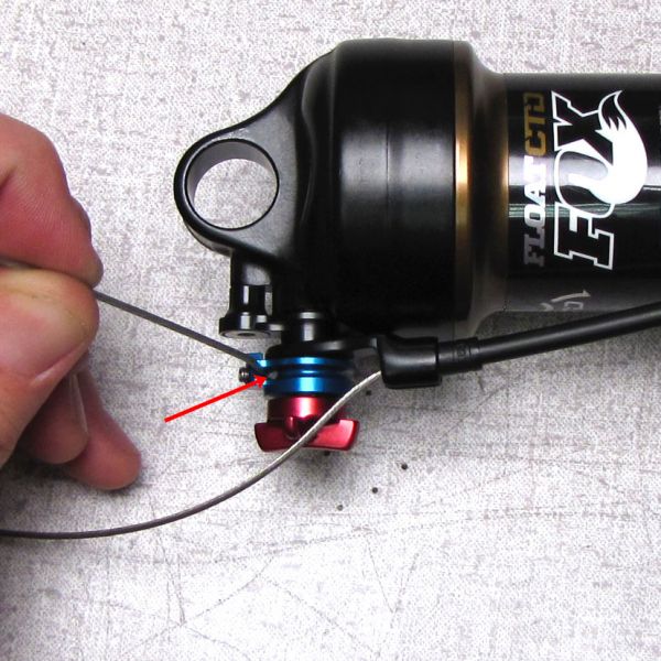
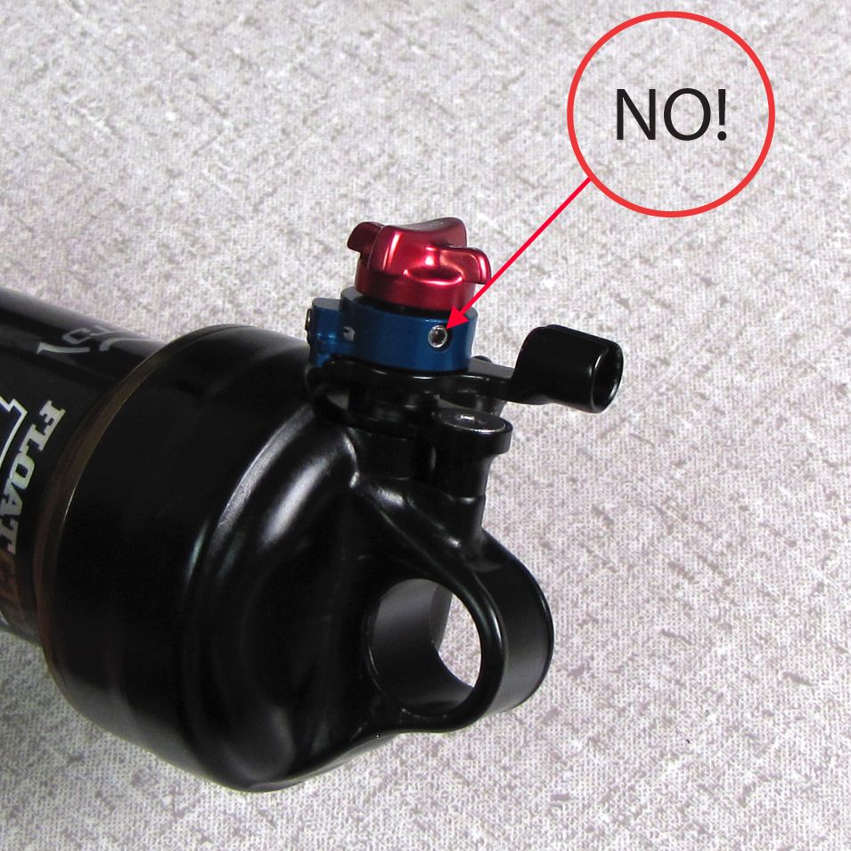
With all cable housing fully seated and no slack in the system, lightly lubricate the inner cable and thread it through the cable housing and the small hole in the blue remote pulley. Do not turn the flush mounted set screw that attaches the blue remote pulley to the shock! The cable pinch bolt is located in the protruding portion of the blue remote pulley. If you need to reinstall the pulley onto the shock after mistakenly turning the flush mounted set screw, reinstallation instructions can be found as part of Reversing the FLOAT CTD Remote rear shock cable stop »


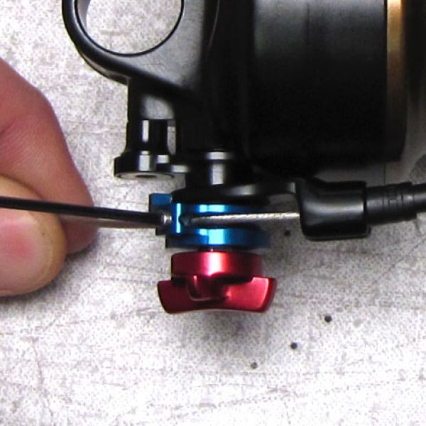
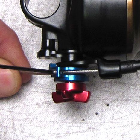
Step 5
While holding the cable tight, tighten the pinch bolt, cut off excess cable, and crimp the end.


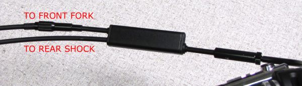
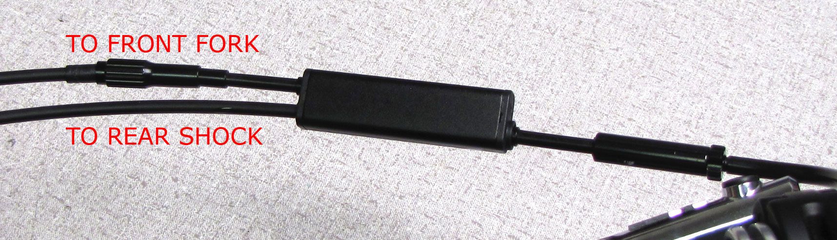
CTD Remote Installation (Dual Cable Fork and Shock)

Step 1
Install the remote lever onto your handlebar. Do not exceed 15 in.-lb (1.7 Nm) torque. Less torque may be needed for carbon bars. Please see bar manufacturer's instructions for use with carbon bars. Make sure to check for clearance between the remote lever and any brake or shifter controls.


Step 2
Make sure the head of cable #1 (coming from lever) is completely seated in the remote lever, then set the lever to Climb mode by pushing the silver lever to its lowest position.

Step 3
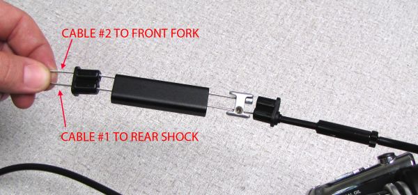
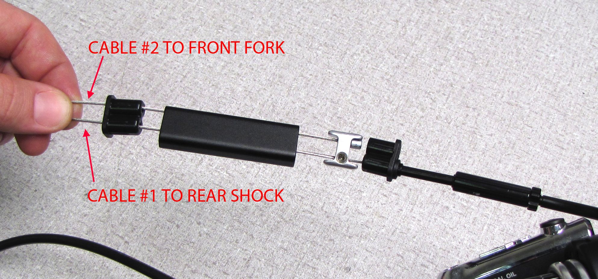
Lightly lubricate cable #1 and thread it into one of the 1.75in. (44mm) pieces of cable housing with ferrules on both ends, then into the single splitter end as shown below.

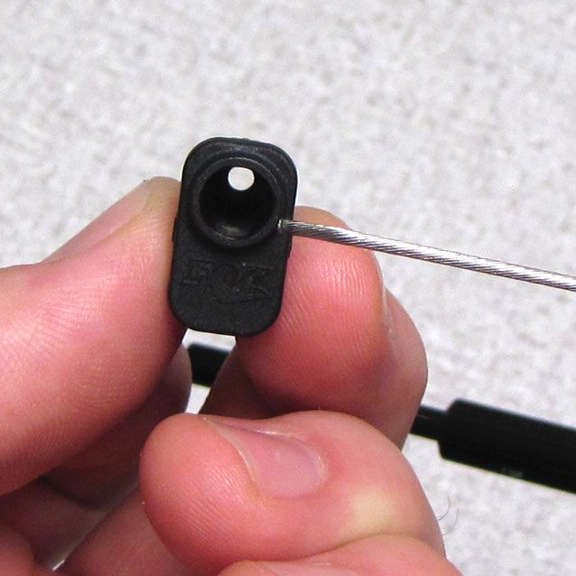

Step 4
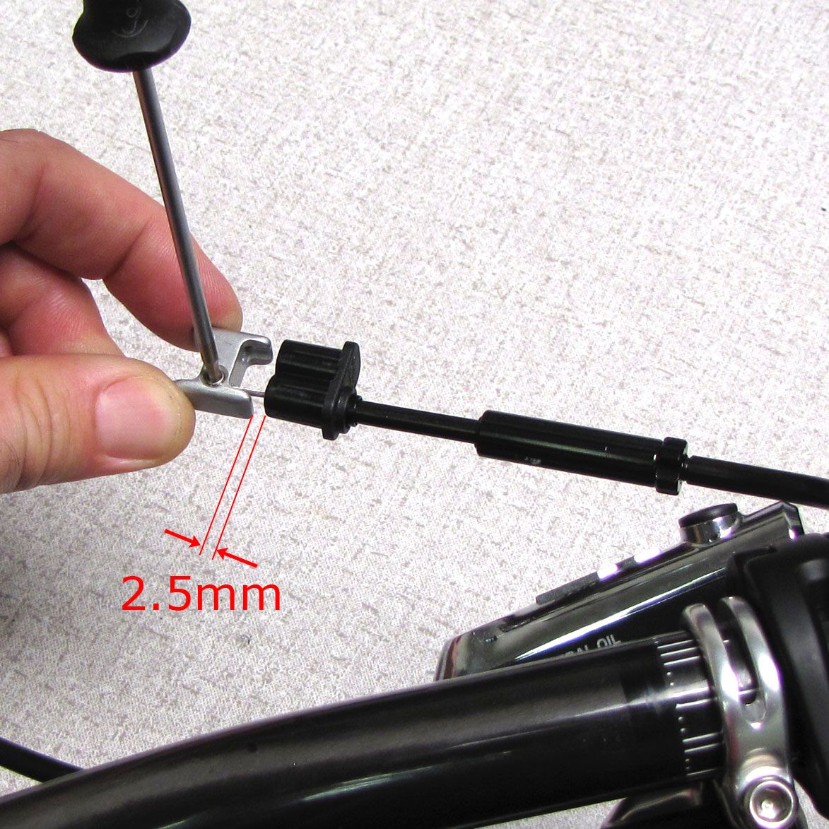
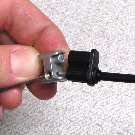
Insert cable #1 into the through-hole of the shuttle that has the threaded set screw. Make sure that the counter-bore for the head of the second cable is oriented toward the lever. Ensure that there is no slack in the cable or cable housing. Leave 2.5mm of clearance between the shuttle and the single splitter end, then tighten the shuttle pinch bolt onto cable #1.
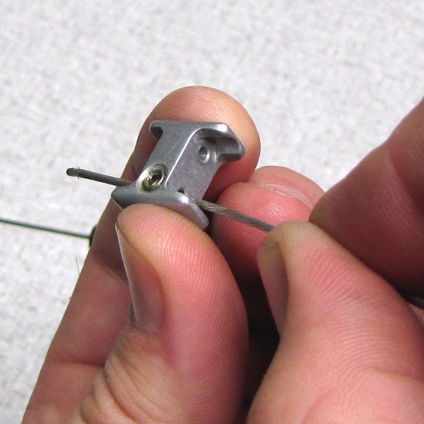

Step 5
Lightly lubricate cable #2 and thread it through the remaining hole in the shuttle. Make sure that the head of cable #2 is seated into the counter-bore of the shuttle as shown below.
Step 6
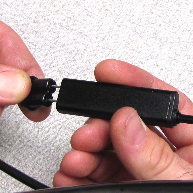
Thread both cables through the splitter body and the dual splitter end.

Step 7
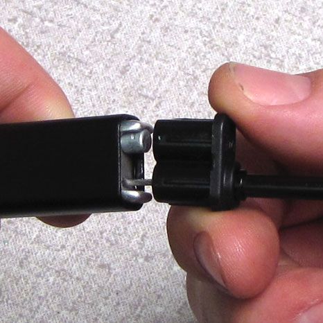
Lightly lubricate the shuttle and press both splitter ends into the splitter body making sure that the cables do not cross inside the splitter body. Fully seat both splitter ends against the splitter body.
Step 8
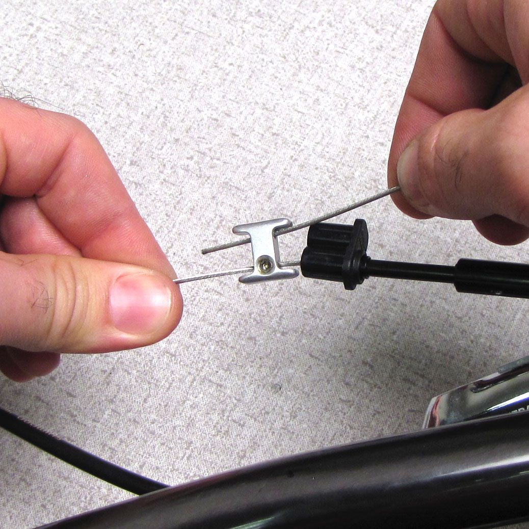
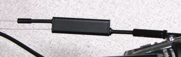
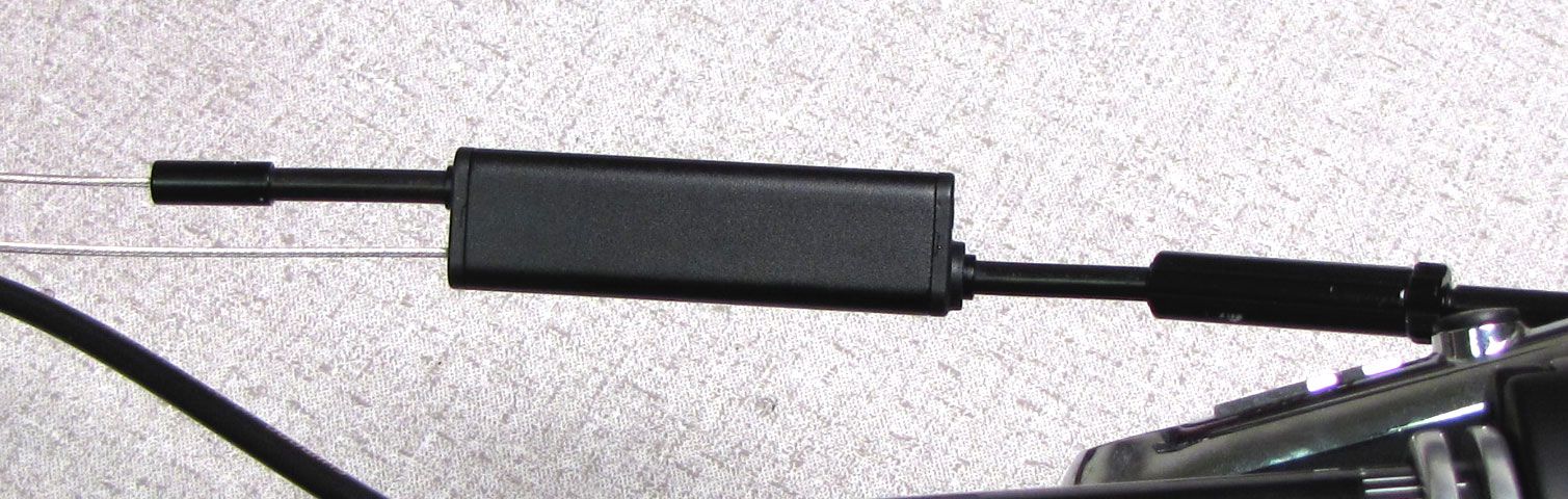
Thread cable #2 through the second 1.75in. (44mm) piece of cable housing with ferrules on both ends.
Step 9
Thread cable #2 through the inline barrel adjuster.

Step 10
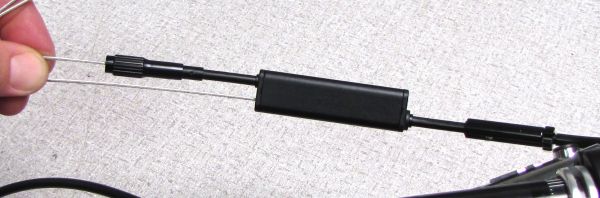
Route cable housing for cable #1 from the dual splitter end to the rear shock, cut to length and install ferrules on both ends. Route cable housing for cable #2 from fork topcap (exiting the topcap at the rider's 7 o'clock position), around the rear of the crown, to the inline barrel adjuster. Cut to length and install a ferrule on the barrel adjuster end only.

Step 11
Set the remote lever to Descend mode by pushing the black lever. Make sure that the head of cable #1 is completely seated in the remote lever.


Step 12
With all cable housing seated and no slack in the system, thread cable #1 through the cable housing and the small hole in the blue remote pulley. Do not turn the flush mounted set screw that attaches the blue remote pulley to the shock! The cable pinch bolt is located in the protruding portion of the blue remote pulley. If you need to reinstall the pulley onto the shock after mistakenly turning the flush mounted set screw, reinstallation instructions can be found as part of Reversing the FLOAT CTD Remote rear shock cable stop »

Step 13
While holding the cable tight, tighten the pinch bolt, cut off excess cable, and crimp the end.
Step 14
With all cable housing fully seated and no slack in the system, thread cable #2 through the cable housing and around the fork remote pulley. Tighten the pinch bolt, cut off excess cable, and crimp the end.


Reversing the 2014 CTD Remote Lever
The 2014 CTD Remote Lever Assembly can be mounted on either the left or right side of your handlebar. When switching from one mounting location to another, the silver lever can be reoriented to be easily reached by either hand.


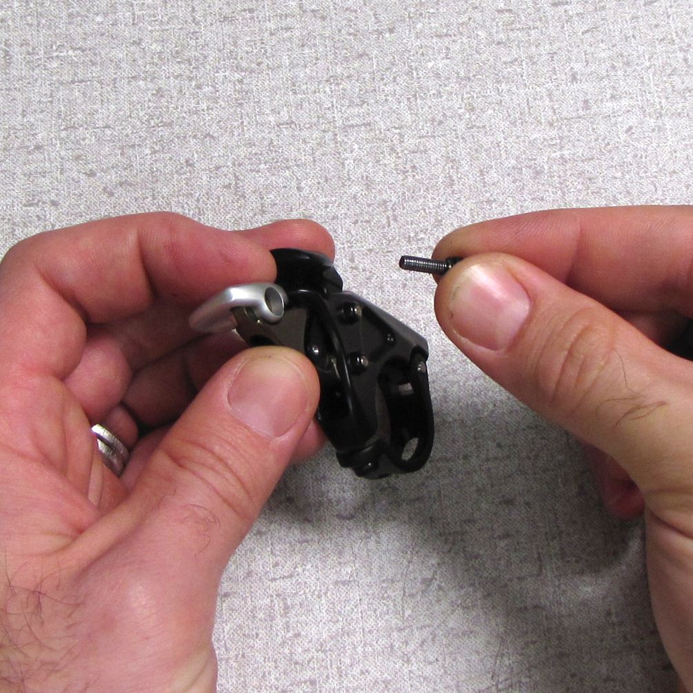
Step 1
Remove the M3 x 10mm bolt with a 2.5mm hex wrench.
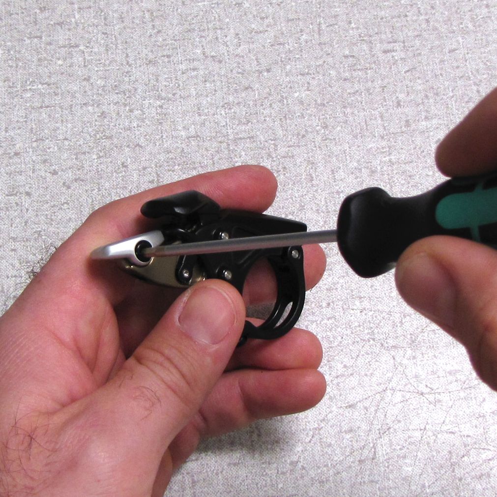
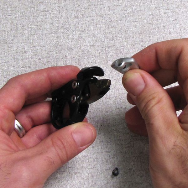
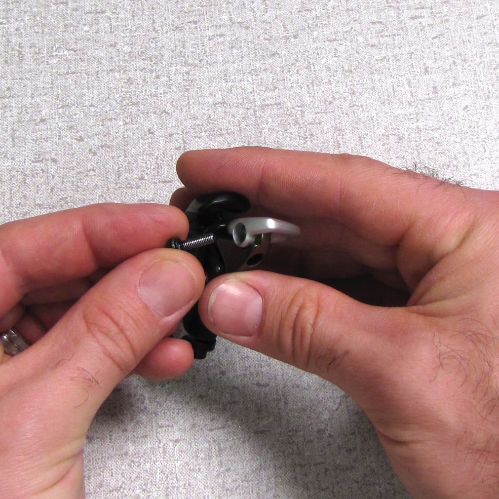
Step 2
Remove the silver lever and reinstall in your desired orientation. Reinstall the M3 x 10mm bolt.

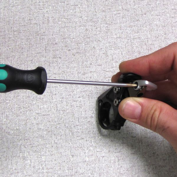
Step 3
Torque the M3 x 10mm bolt to 15 in.-lb then install Remote Lever Assembly to handlebar torquing clamp set screw to 15 in.-lb.