2016-2024 FLOAT DPS and 2024 FLOAT SL Rebuild
Required Parts
- 025-03-008 Oil: AM, FOX Suspension Fluid [32 oz.], 10 WT Green
- 025-03-063 Oil: Suspension Fluid, 4 WT, 1.0 Liter Bottle
- 803-00-142 Kit: Rebuild, FLOAT Line Air Sleeve, Special Q-Ring
- 803-00-816 Seal Kit: CTD Boost Valve and Dish Shock Rebuild (Same for DPS shocks)
Required Tools
- 398-00-280 Tooling: Eyelet Torque Tool
- 398-00-374 Tooling: Pellet Retainer Tool, Nitrogen Fill
- 398-00-574 Tooling: Dial Indicator, 1" Measuring Range, 0.001" Graduation, 3/8" Stem Diameter
- 398-00-637 Tooling: Custom Socket, 5/8", 2016 Float DPS, Piston Bolt
- 398-00-638 Tooling: Custom Spanner Socket, 3 pin, Float DPS, Lockout Piston
- 398-00-950 Tooling: Custom Socket, 5/8", 2024 Float LV, Piston Bolt
- 802-01-000-KIT Service Set: Air Valve Assy, Nitrogen Safety Needle Assy w/Manual, Complete w/out Gauge
- 803-00-566 Kit:Bike IFP Depth Setting Tool Set
- 803-00-805 Kit: Shaft Clamps, Shocks, CTD 9mm, 3/8in, 1/2in, 5/8in
- 803-00-806 Kit: Tooling, iCD/CTD Dish Shock Dial Indicator Attachment for Plate Lift Measurement
- 803-01-351 Kit: Tooling: Clamps, DPS, DPX2, Piston Band Sizer
- Nitrogen Fill Station (Tank with Regulator) required for full rebuild .
WARNING: Always wear safety glasses and protective gloves during service to prevent potential injury. Failure to wear protective equipment during service may lead to SERIOUS INJURY OR DEATH.
WARNING: FOX products should be serviced by a qualified bicycle service technician, in accordance with FOX specifications. If you have any doubt whether or not you can properly service your FOX product, then DO NOT attempt it. Improperly serviced products can fail, causing the rider to lose control resulting in SERIOUS INJURY OR DEATH.
WARNING: Modification, improper service, or use of aftermarket replacement parts with FOX forks and shocks may cause the product to malfunction, resulting in SERIOUS INJURY OR DEATH. DO NOT modify any part of a fork or shock, including the fork brace (lower leg cross brace), crown, steerer, upper and lower leg tubes, or internal parts, except as instructed herein. Any unauthorized modification may void the warranty, and may cause failure or the fork or shock, resulting in SERIOUS INJURY OR DEATH.
WARNING: FOX suspension products contain pressurized nitrogen, air, oil, or all 3. Suspension misuse can cause property damage, SERIOUS INJURY OR DEATH. DO NOT puncture, incinerate or crush any portion of a FOX suspension product. DO NOT attempt to disassemble any portion of a FOX suspension product, unless expressly instructed to do so by the applicable FOX technical documentation, and then ONLY while strictly adhering to all FOX insturctions and warnings in that instance.
WARNING: Never attempt to pull apart, open, disassemble, or service a FOX shock that is in a "stuck down" condition. A "stuck down" condition results from a failure of the dynamic air seal (located between the positive and negative air chambers within the non-EVOL shock air sleeve), resulting with the negative chamber retaining a higher pressure than the positive chamber. To test whether the shock is in fact "stuck down":
- Remove the air cap and depress the Schrader valve, to completely release air pressure from the positive chamber of the shock.
- If the shock body retracts into the air sleeve near bottom-out after the air is released from the positive chamber, attach a FOX high pressure pump and pressurize the shock to 250psi (17 bar).
- If the shock does not fully extend, it is in a "stuck down" condition.
Any attempt to service FOX air shocks in the "stuck down" condition can lead to SERIOUS INJURY OR DEATH. Contact FOX or an Authorized Service Center for repair.
IFP Information:
| IFP Pressure: | 500psi |
| Standard Size | IFP Height (all measurements +/- 0.020in) |
| 5.50 x 1.00 | 1.510in/ 38.35mm |
| 6.00 x 1.25 | 1.720in/ 43.69mm |
| 6.50 x 1.50 | 1.940in/ 49.28mm |
| 7.25 x 1.75 | 2.150in/ 54.61mm |
| 7.50 x 2.00 | 2.360in/ 59.94mm |
| 7.875 x 2.00 | 2.360in/ 59.94mm |
| 7.875 x 2.25 | 2.580in/ 65.53mm |
| 8.50 x 2.50 | 2.790in/ 70.87mm |
| Metric/Trunnion Sizing | IFP Height (all measurements +/- .020in) |
| 145(T) x 35 | 1.830 +/- 0.020in |
| 170 x 35 | 1.830 +/- 0.020in |
| 165(T) x 45 | 2.150 +/- 0.020in |
| 190 x 45 | 2.150 +/- 0.020in |
| 185(T) x 55 | 2.500 +/- 0.020in |
| 210 x 55 | 2.500 +/- 0.020in |
| 205(T) x 65 | 2.830 +/- 0.020in |
| 230 x 65 | 2.830 +/- 0.020in |
| 225(T) x 75 | 3.170 +/- 0.020in |
| 250 x 75 | 3.170 +/- 0.020in |
Using the EVOL Air Sleeve
The EVOL air sleeve is an option on FLOAT DPS and FLOAT X models. The EVOL air sleeve provides an external negative air chamber added to the main air sleeve to significantly reduce the force to initiate travel, providing excellent small bump performance. The system is also more linear in its progression offering improved mid stroke support and better bottom out resistance. It is important to add or remove air from the EVOL sleeve as detailed below to experience the best possible performance.
When adding air to the air chamber, it is important to equalize the positive and negative air chambers by slowly compressing the shock through 25% of its travel 10-20 times after every 50psi addition.
- Adding air to the shock without periodically equalizing the air chambers can lead to a condition in which the shock has more pressure in the positive chamber than the negative. In this condition the shock will be very stiff and can top-out. You can equalize the air chambers by slowly compressing the shock until you feel and hear a transfer of air. Hold the shock at this point for a few seconds to allow the air to transfer from the positive to the negative chamber.
When releasing air from the air chamber, it is important to do this slowly so the shock can transfer air from the negative to positive chamber and then be realeased through the Schrader valve.
- Releasing the air pressure too quickly can induce a condition in which the negative chamber has more pressure than the positive chamber. In this condition the shock will compress into its travel and not fully extend. You can remedy this by adding air pressure until the shock extends, then slowly compressing the shock through 25% of its travel 10-20 times.
General Disassembly
Releasing the air pressure too quickly can induce a condition in which the negative chamber has more pressure than the positive chamber. In this condition the shock will compress into its travel and not fully extend. You can remedy this by adding air pressure until the shock extends, then slowly compressing the shock through 25% of its travel 10-20 times. Release air pressure slowly via the bleed button of your shock pump to prevent Stuckdown.
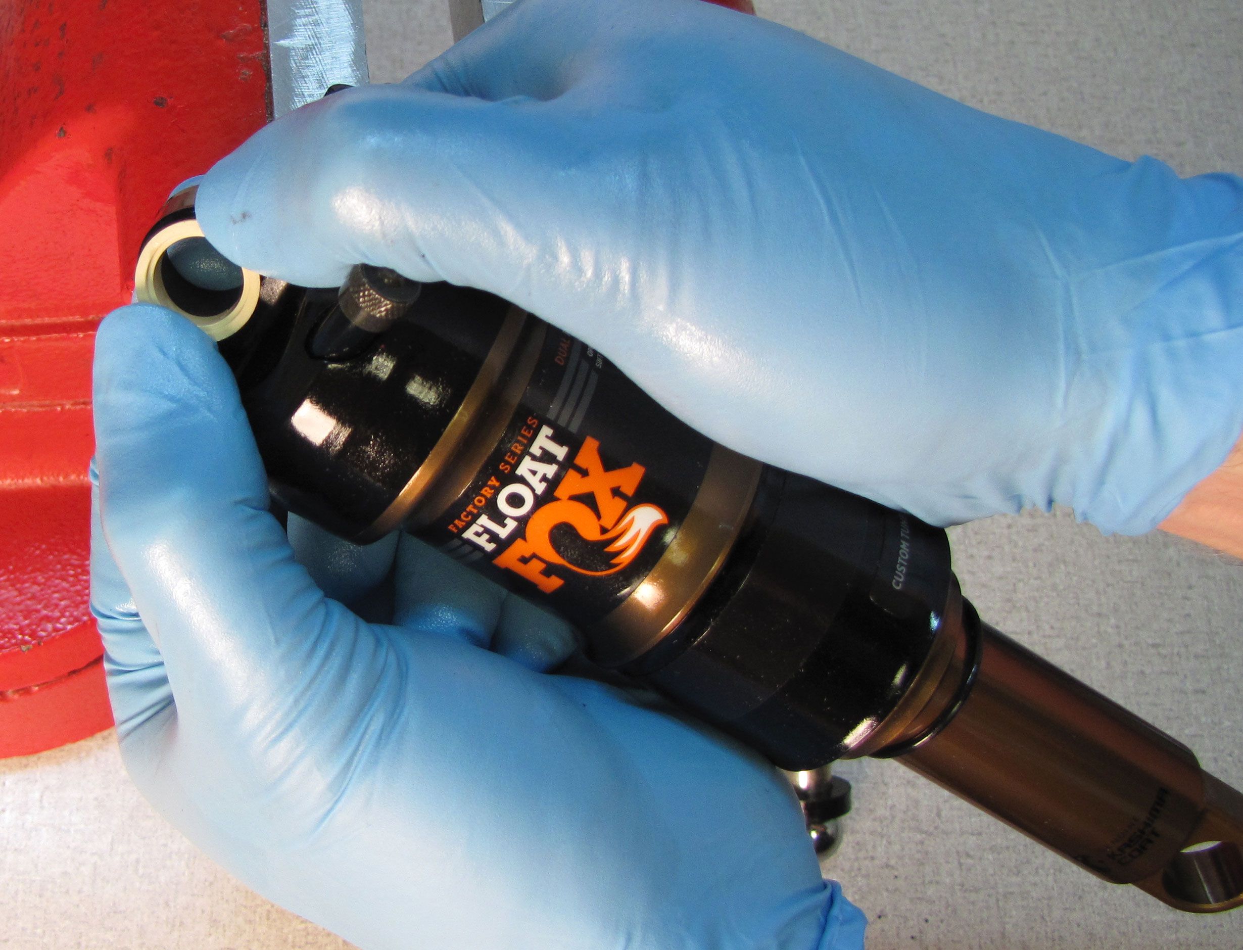
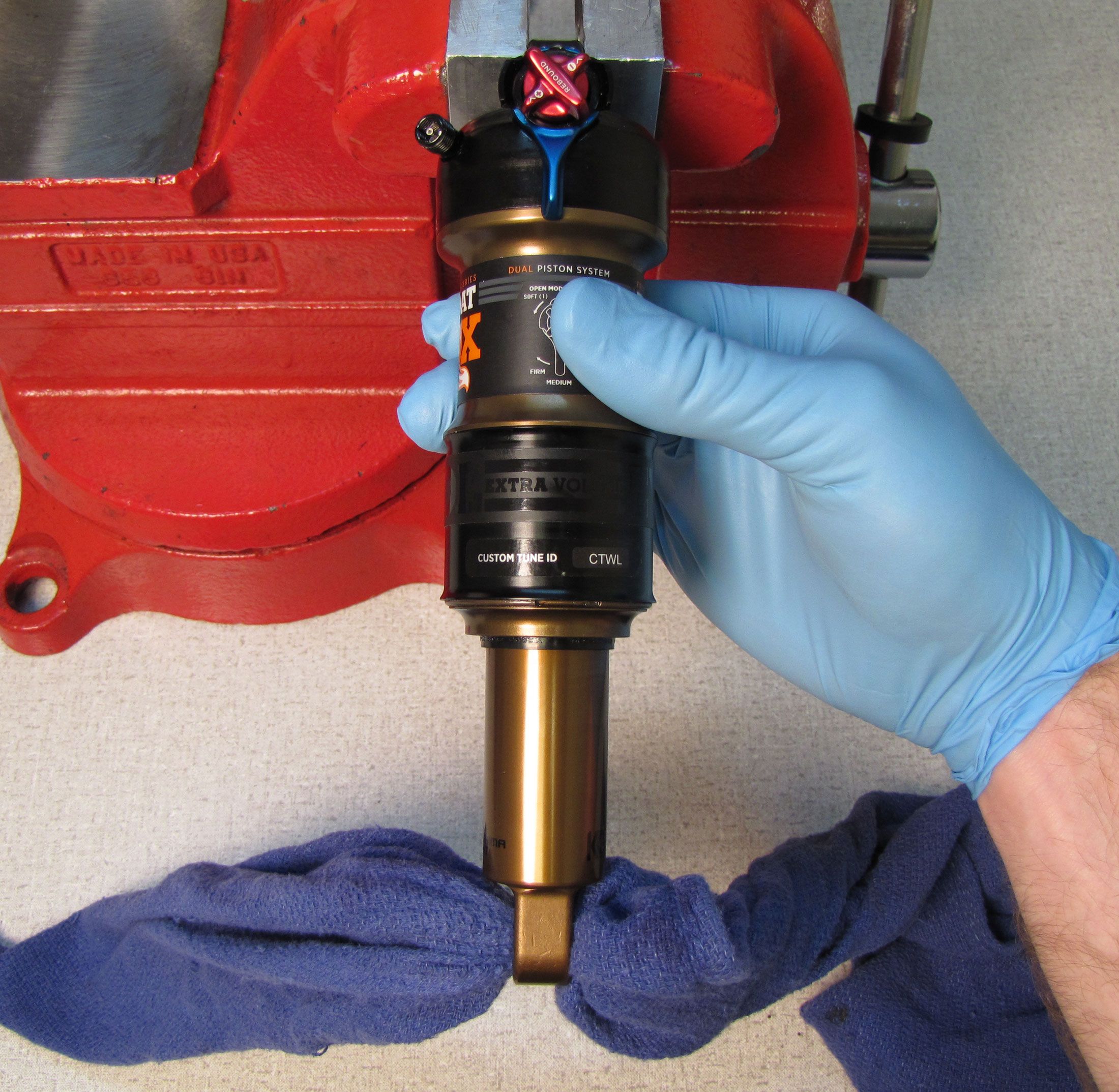
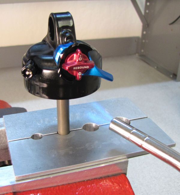
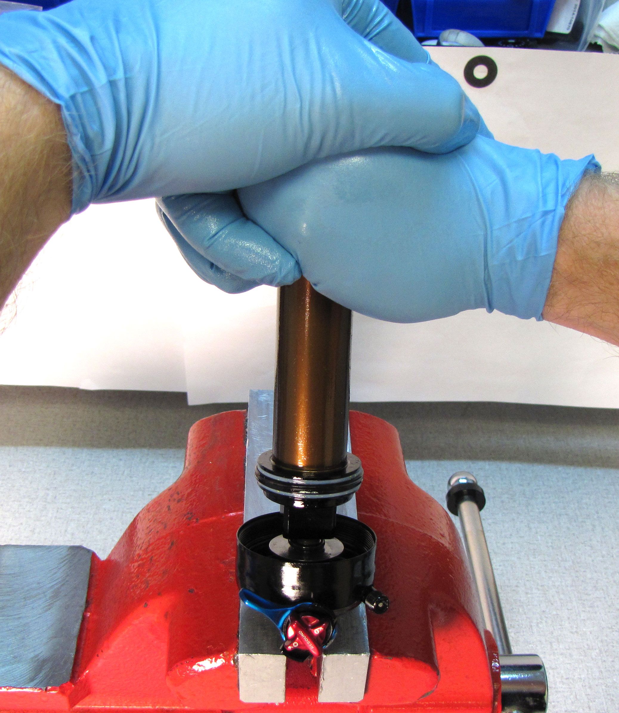
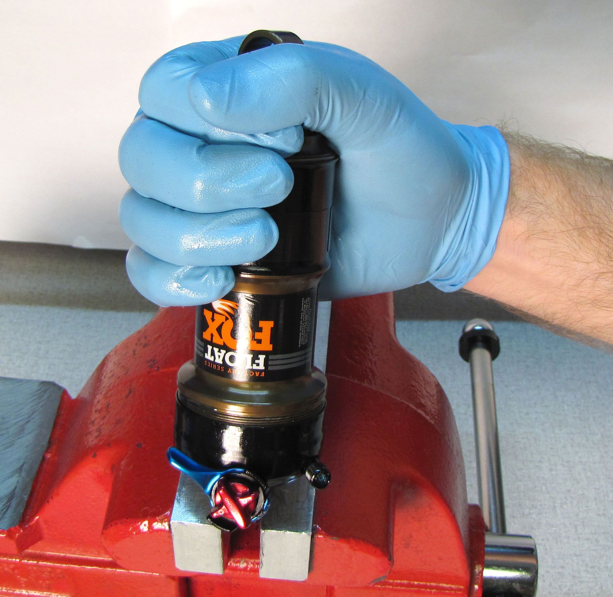
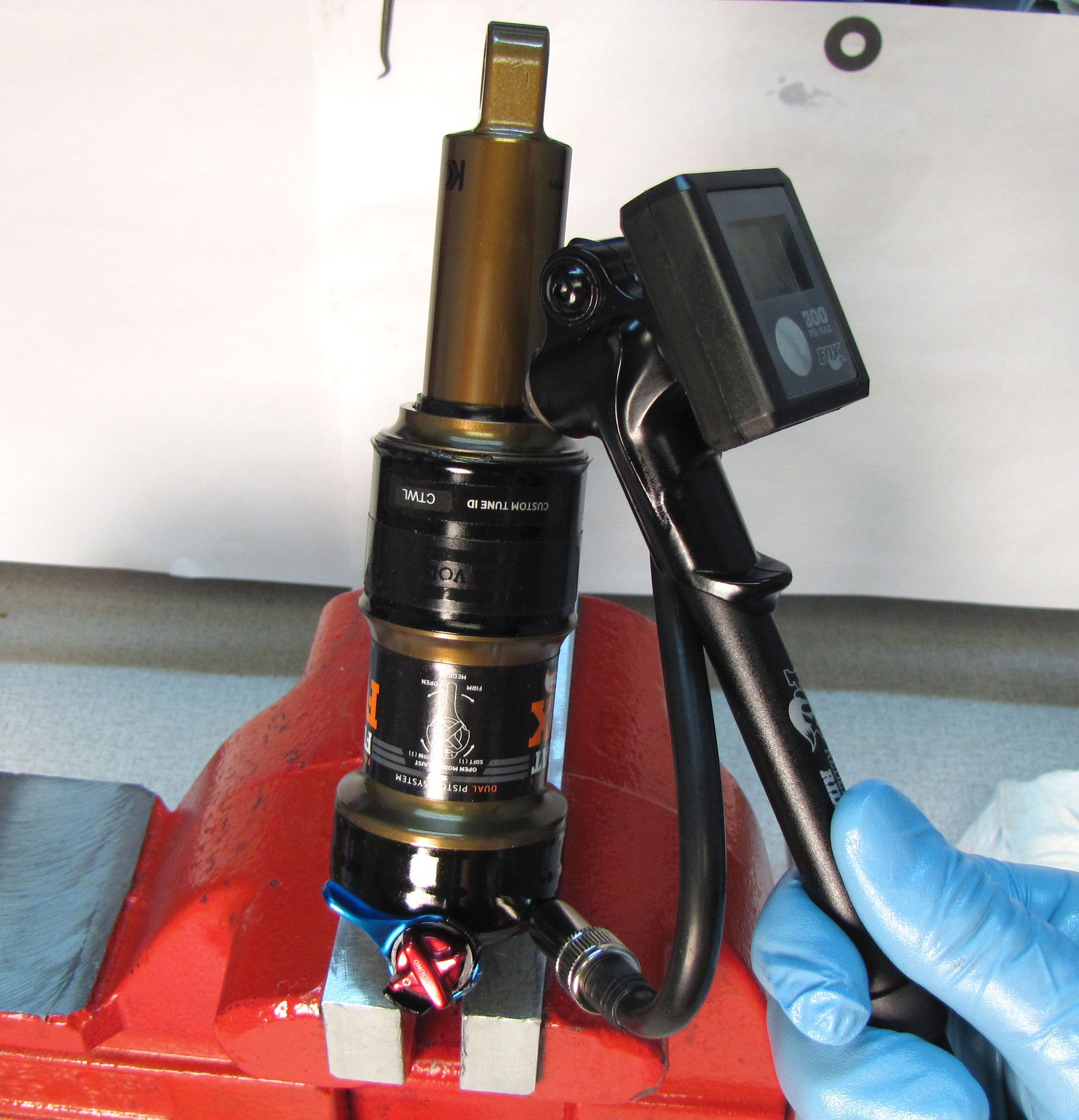
Step 1
Clamp your shock in a soft-jawed vice. Remove the black air cap and thread on your FOX shock pump. Slowly release all air from the main air chamber with your pump, then remove the pump.


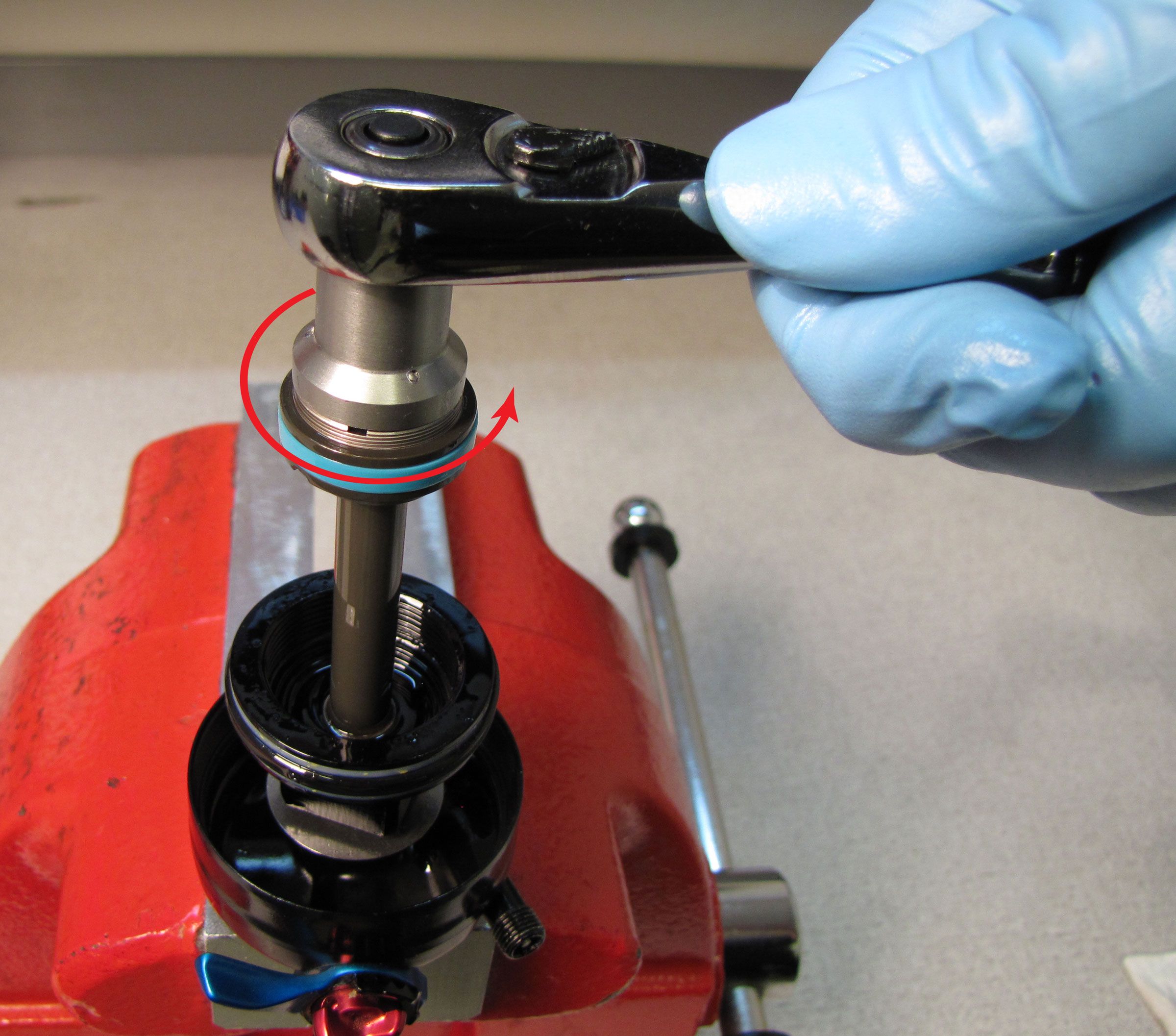
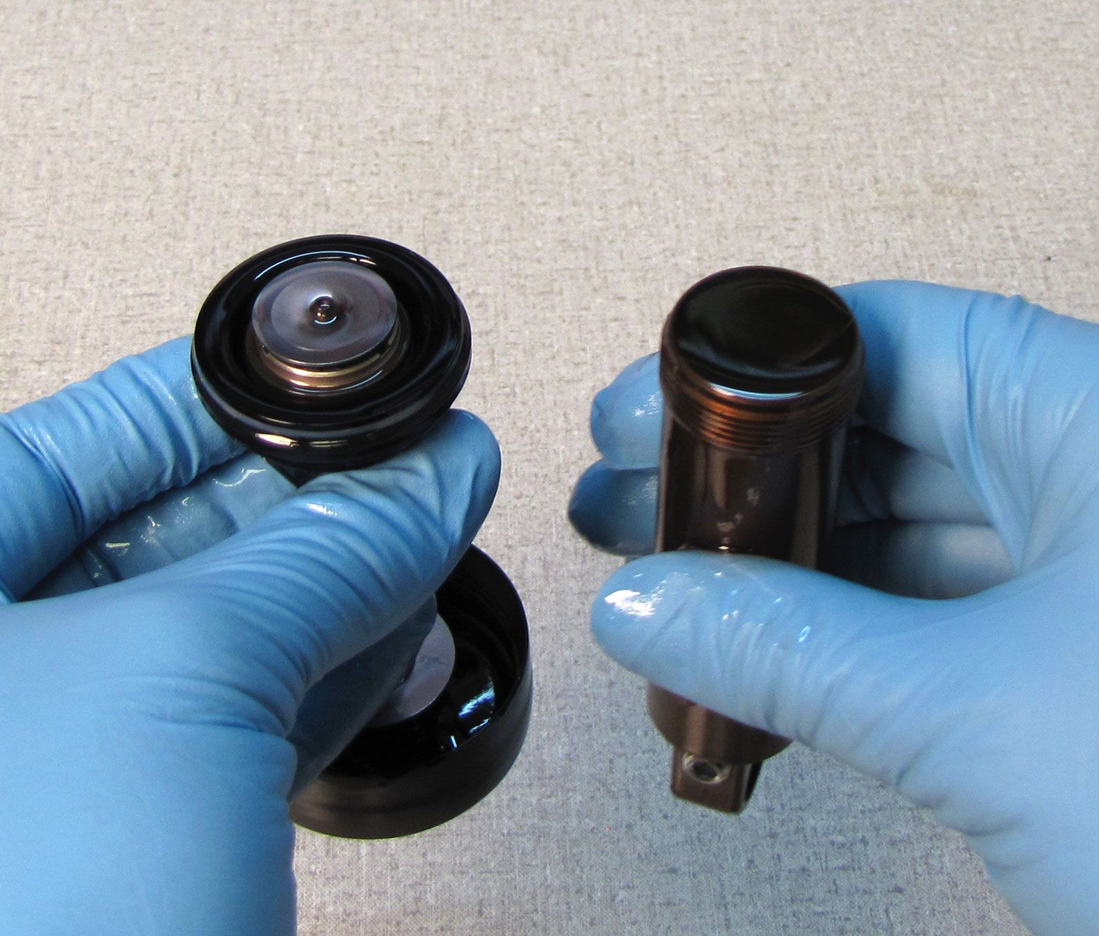
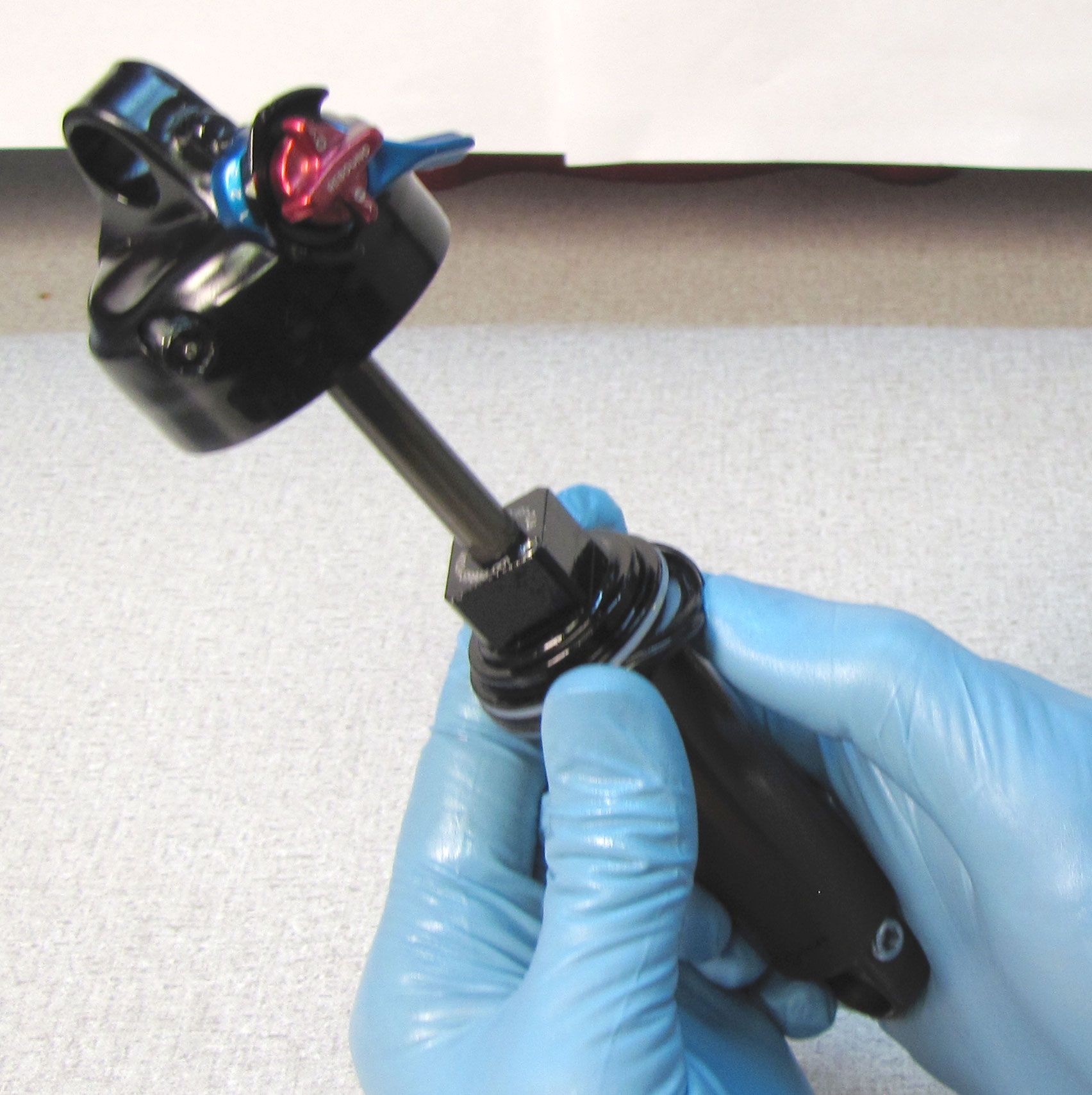
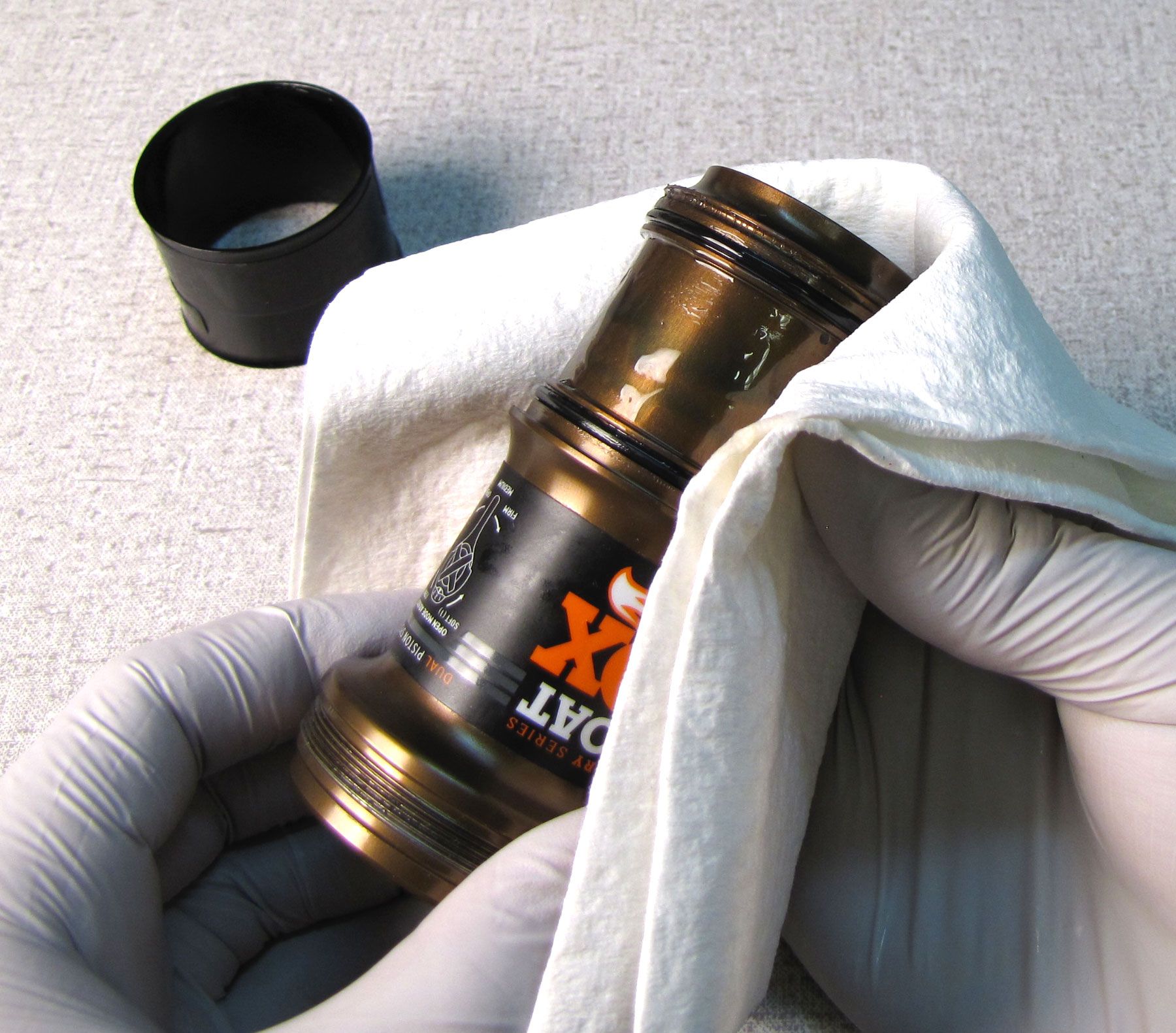
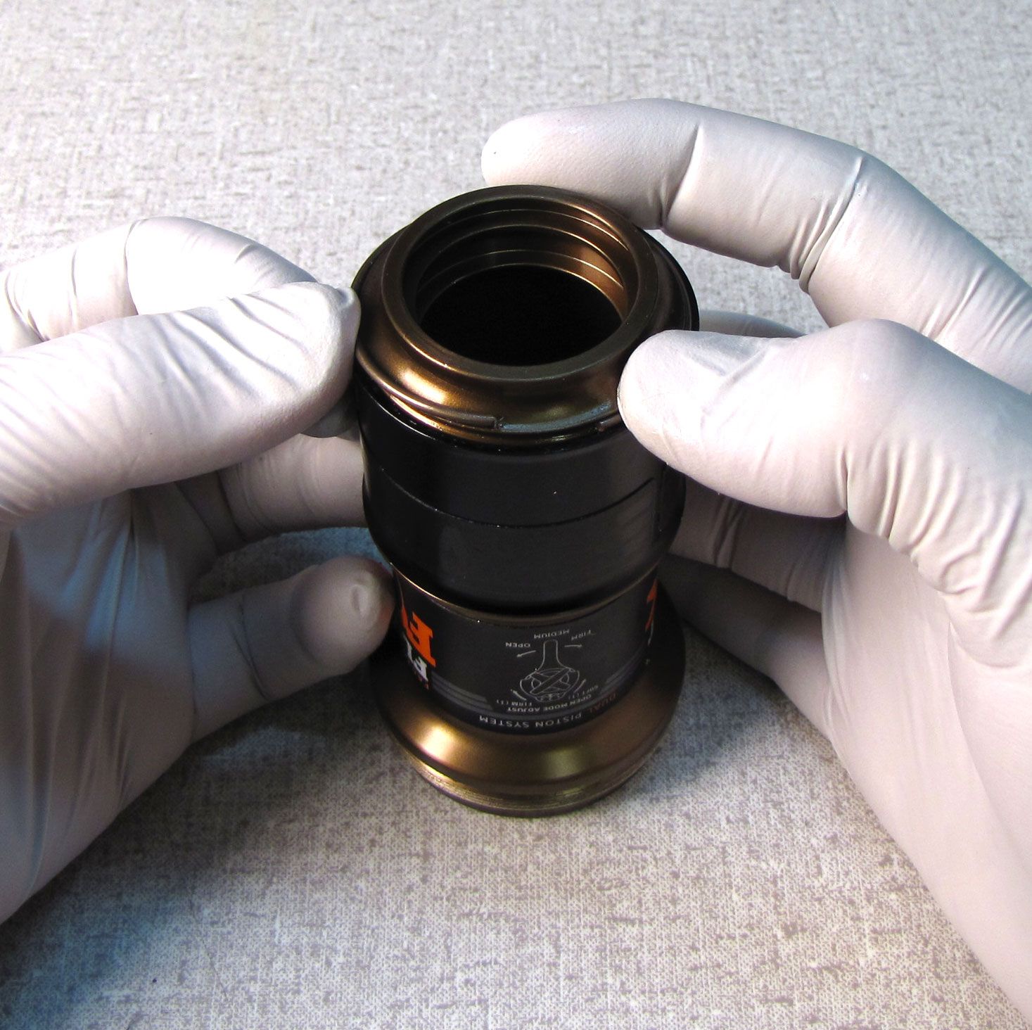
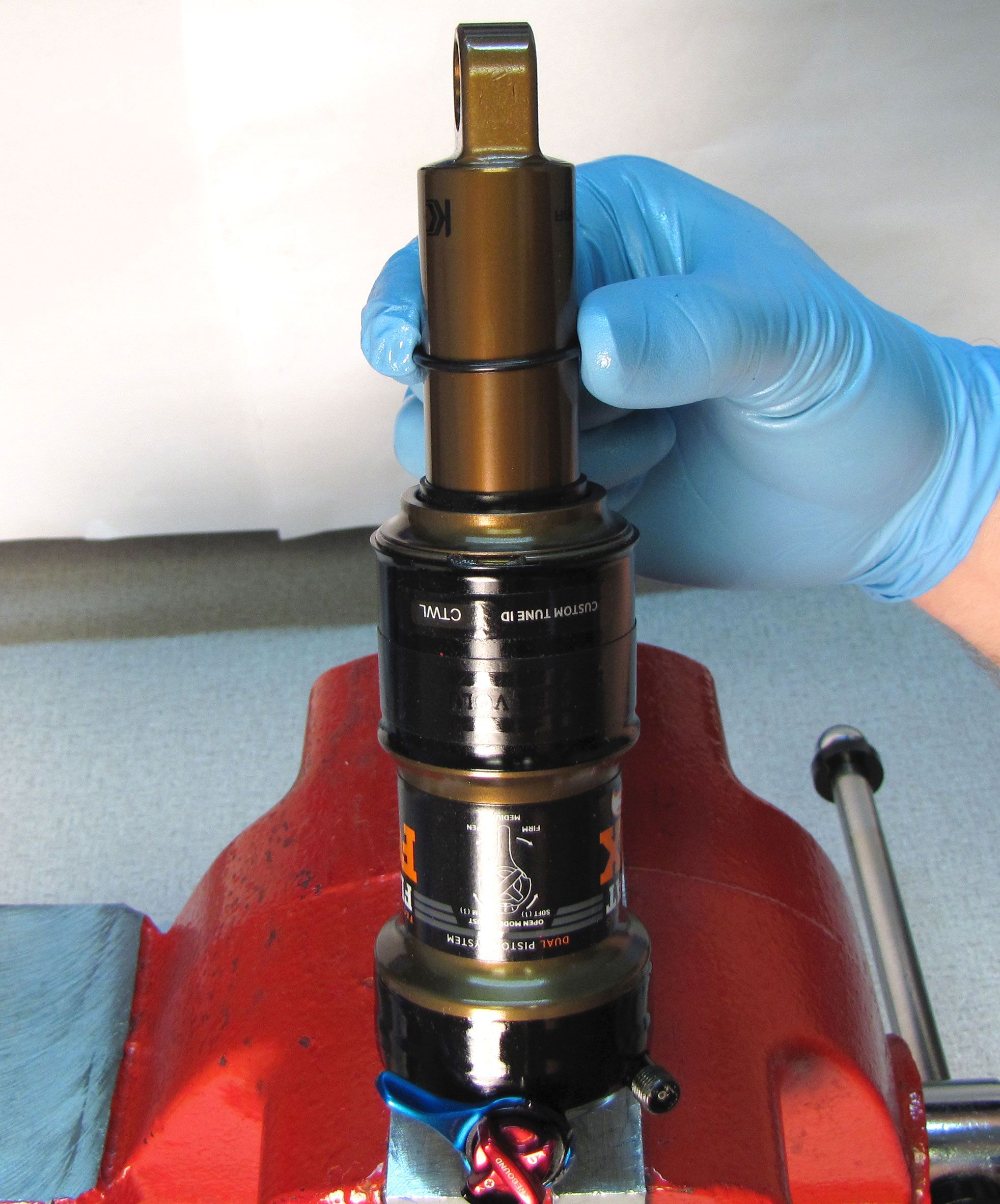
Step 2
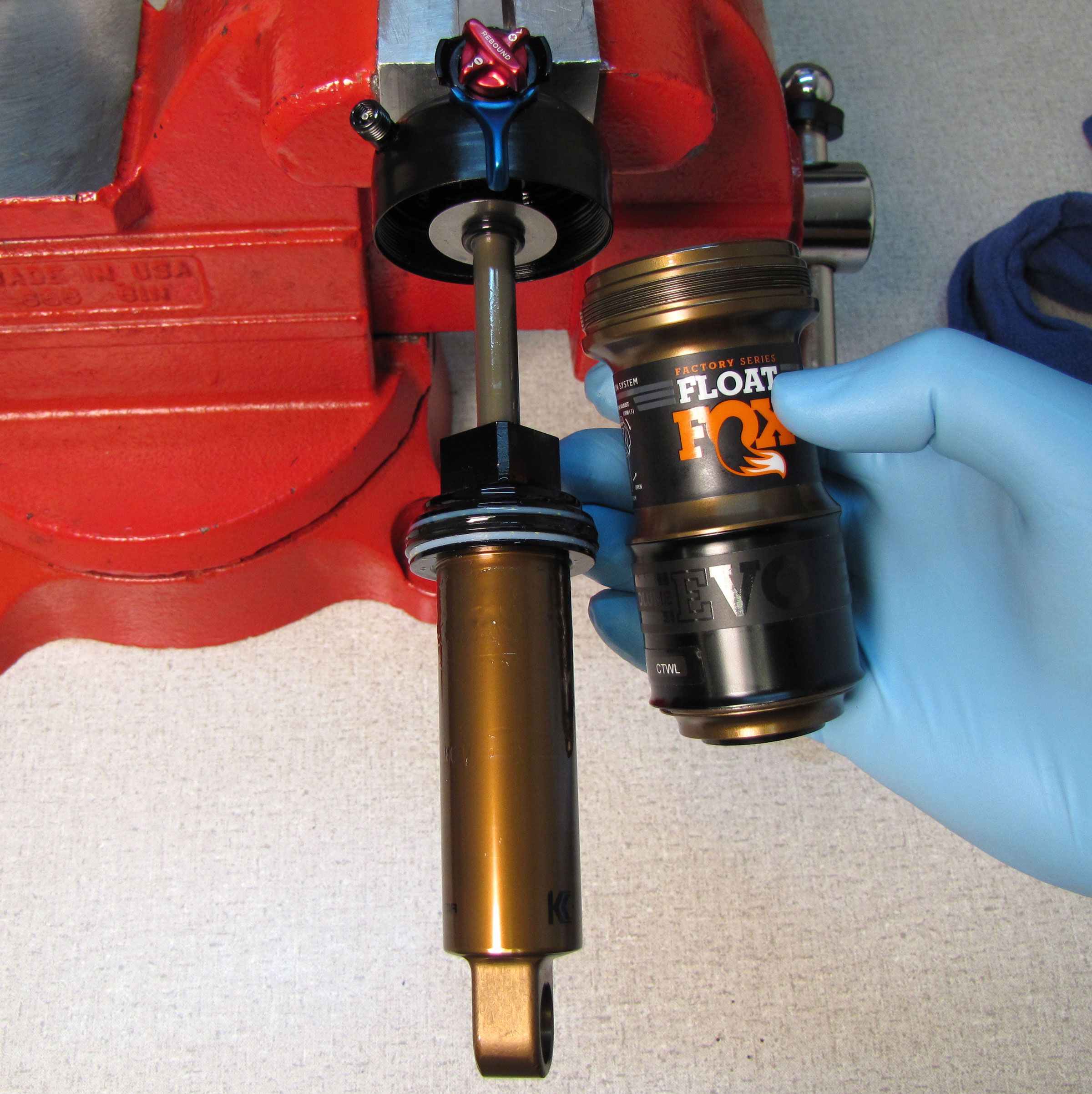
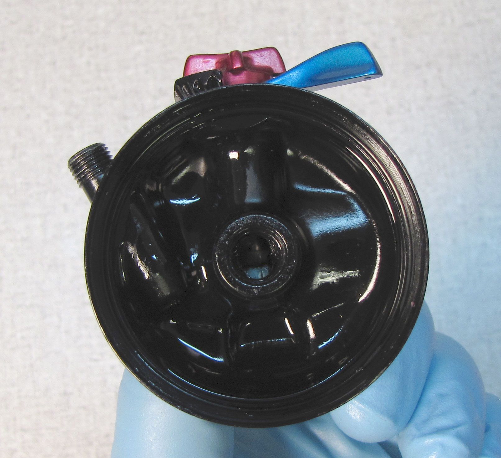
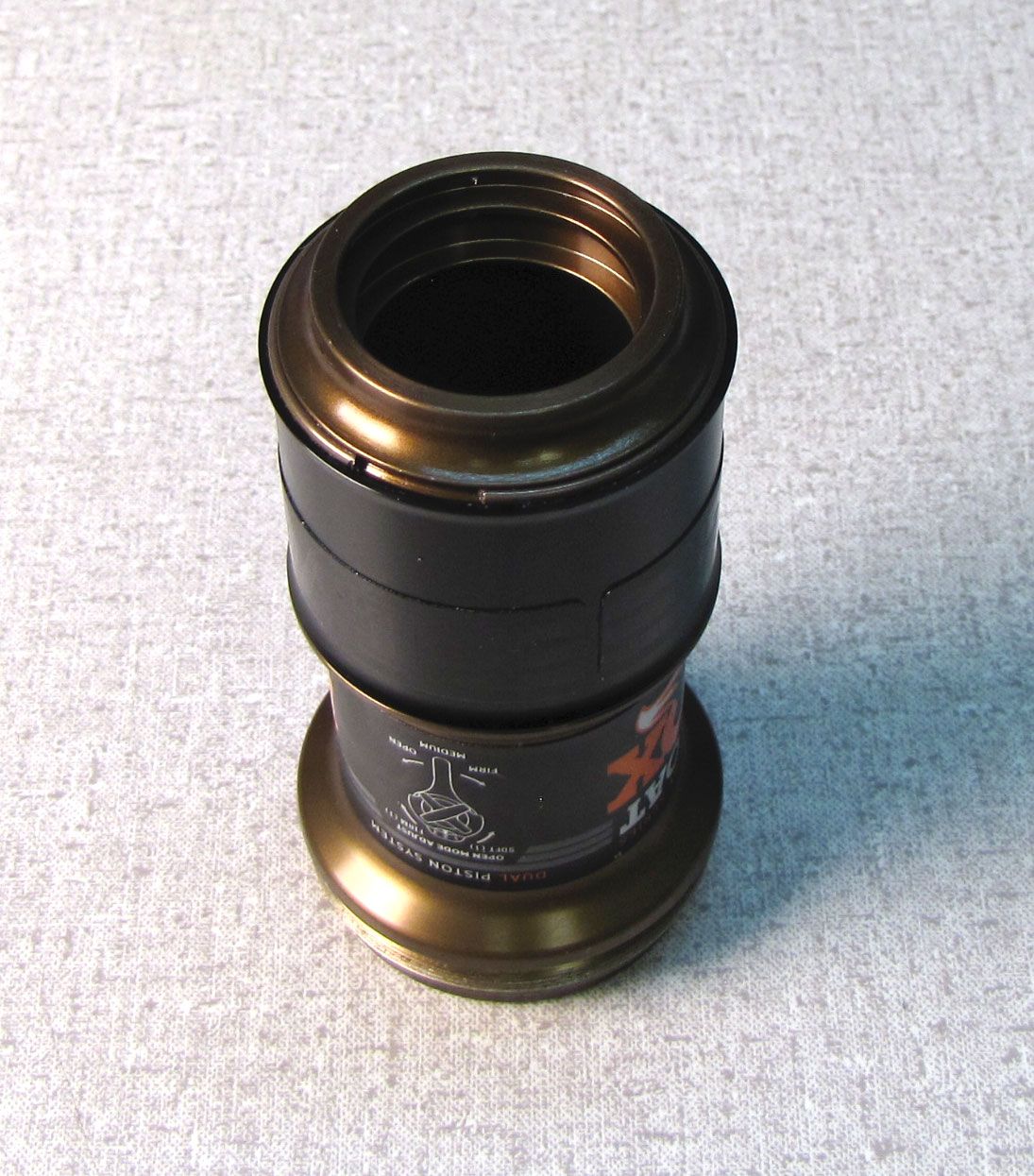
Thread a cloth rag through the body eyelet of your shock, then unthread the air sleeve. Unthread the rag and pull the air sleeve off to remove.
Step 3
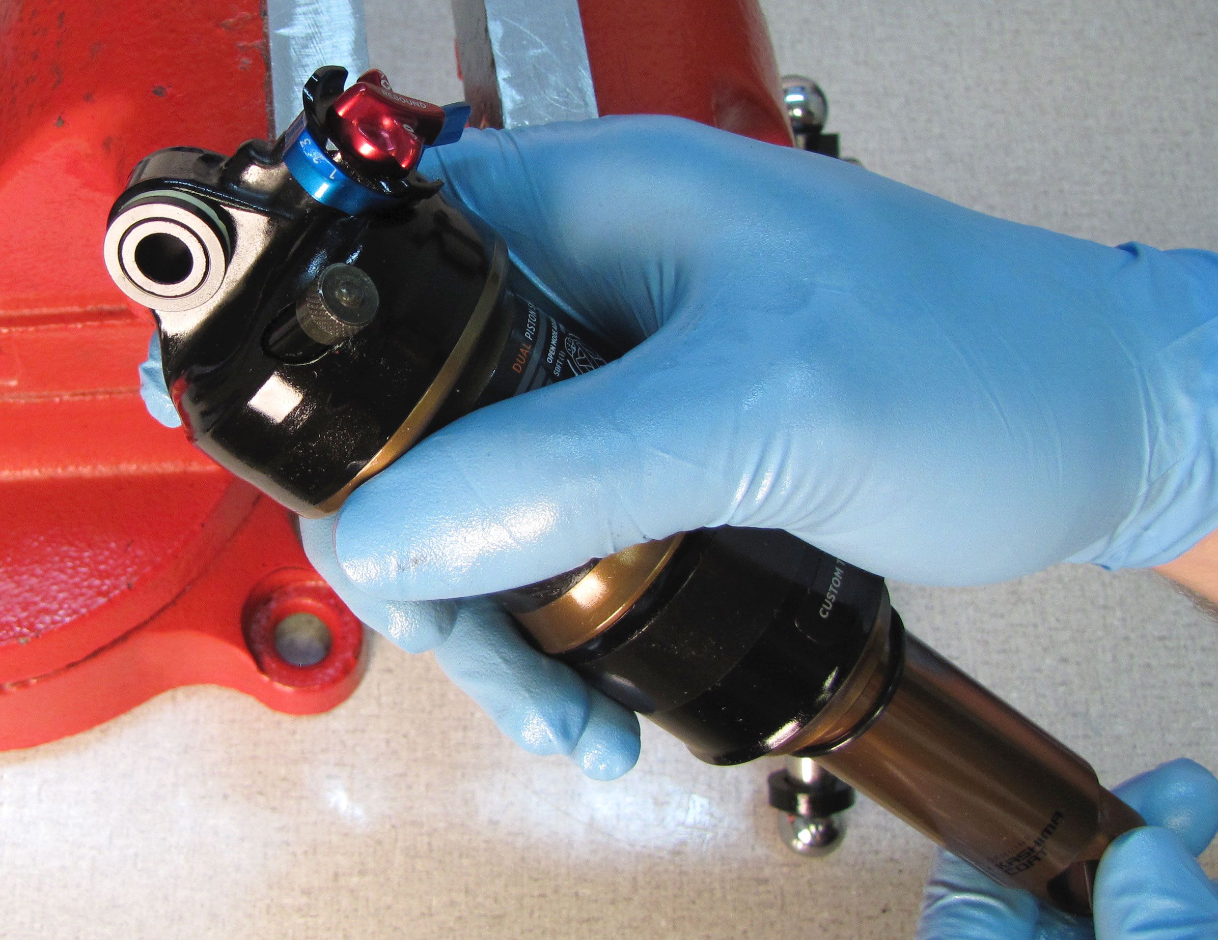
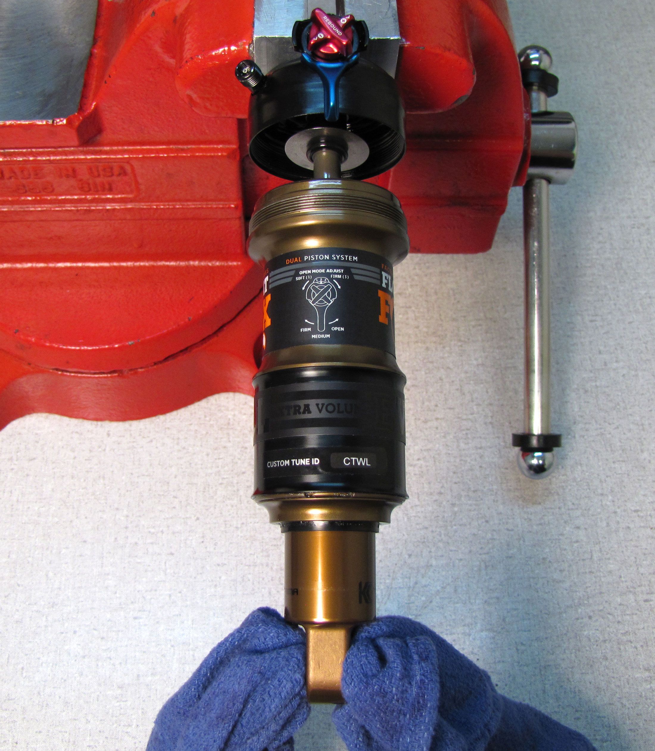
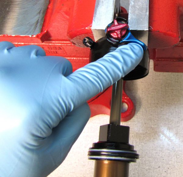
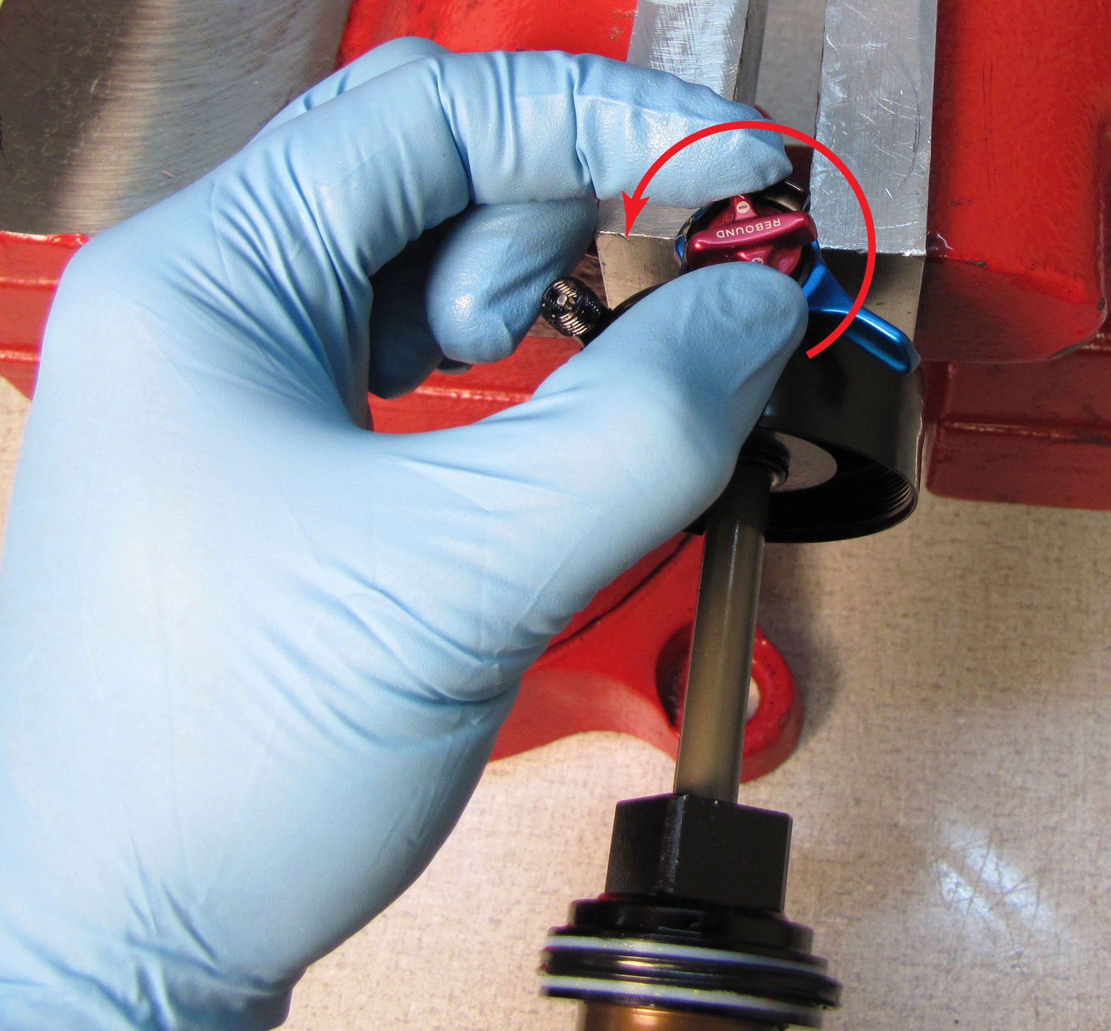
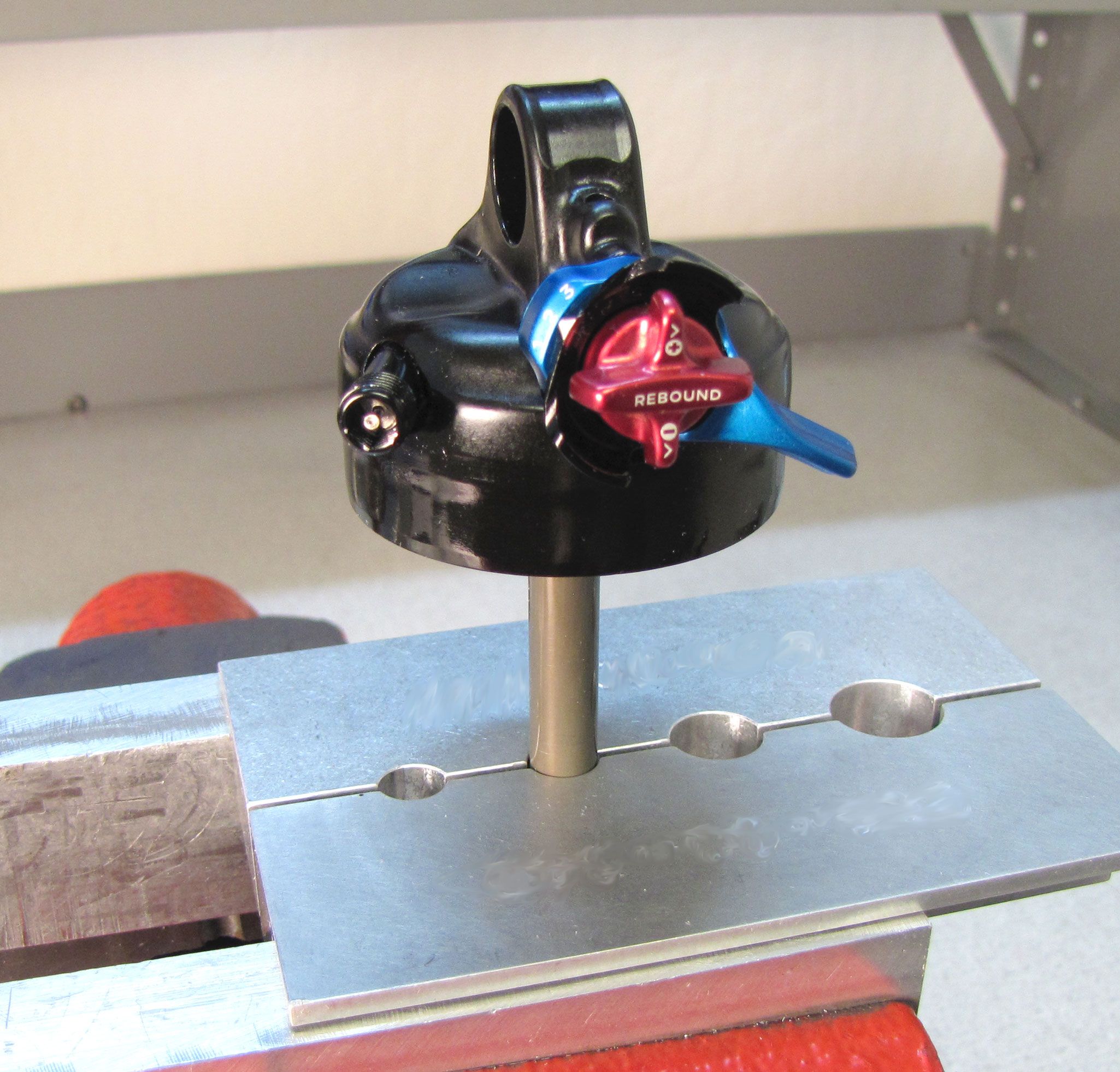
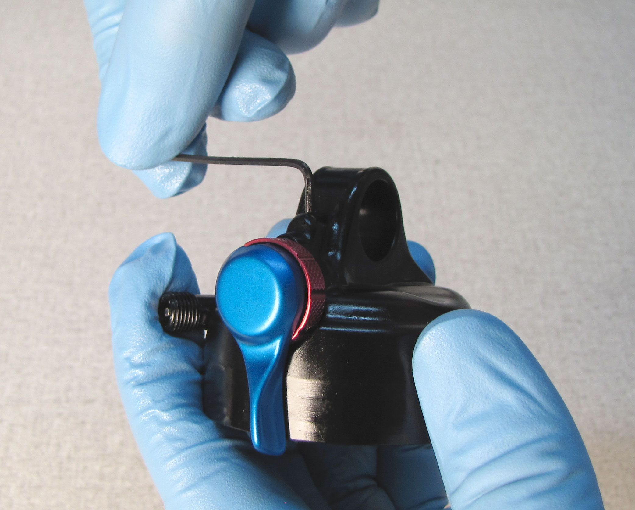
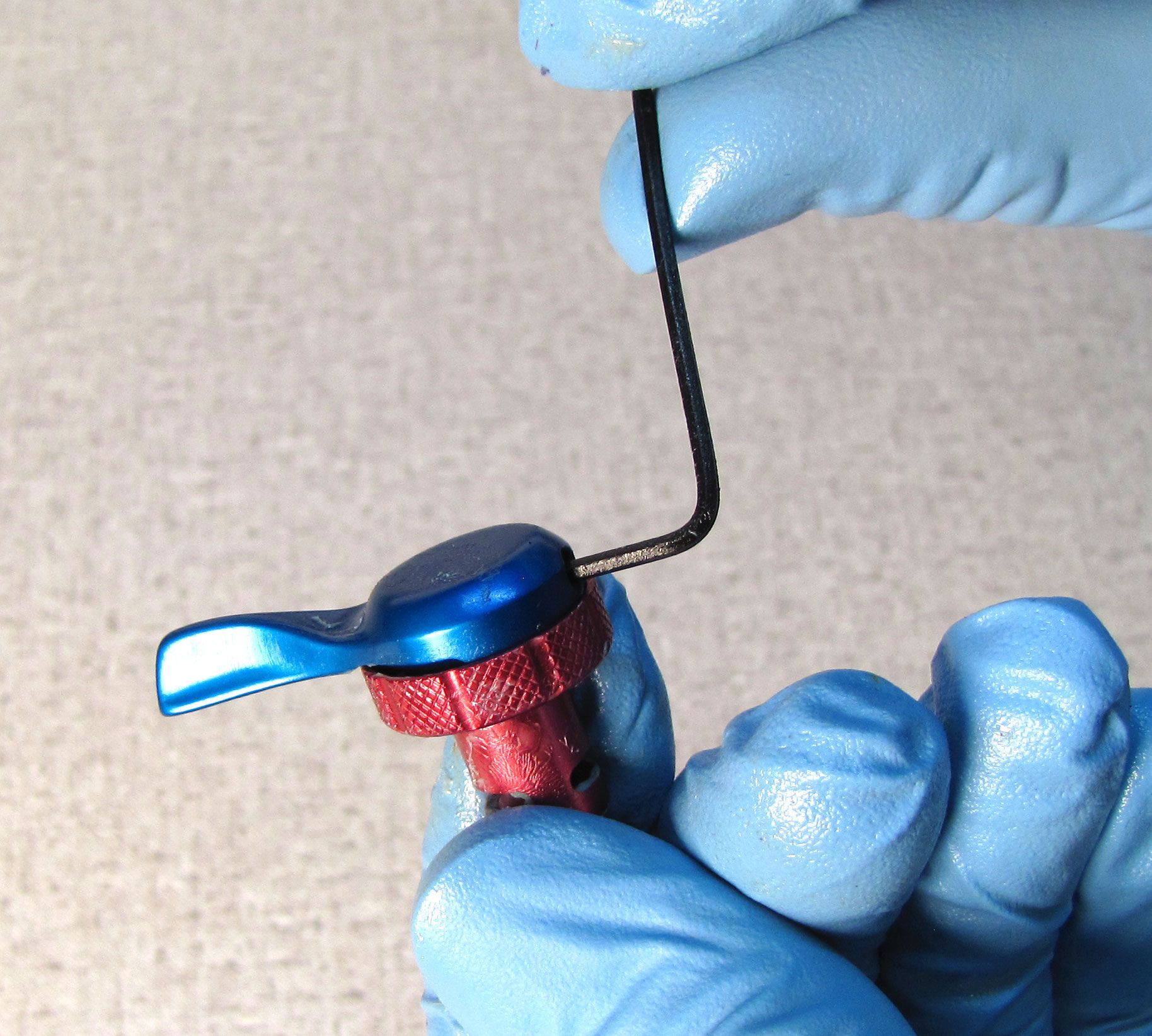
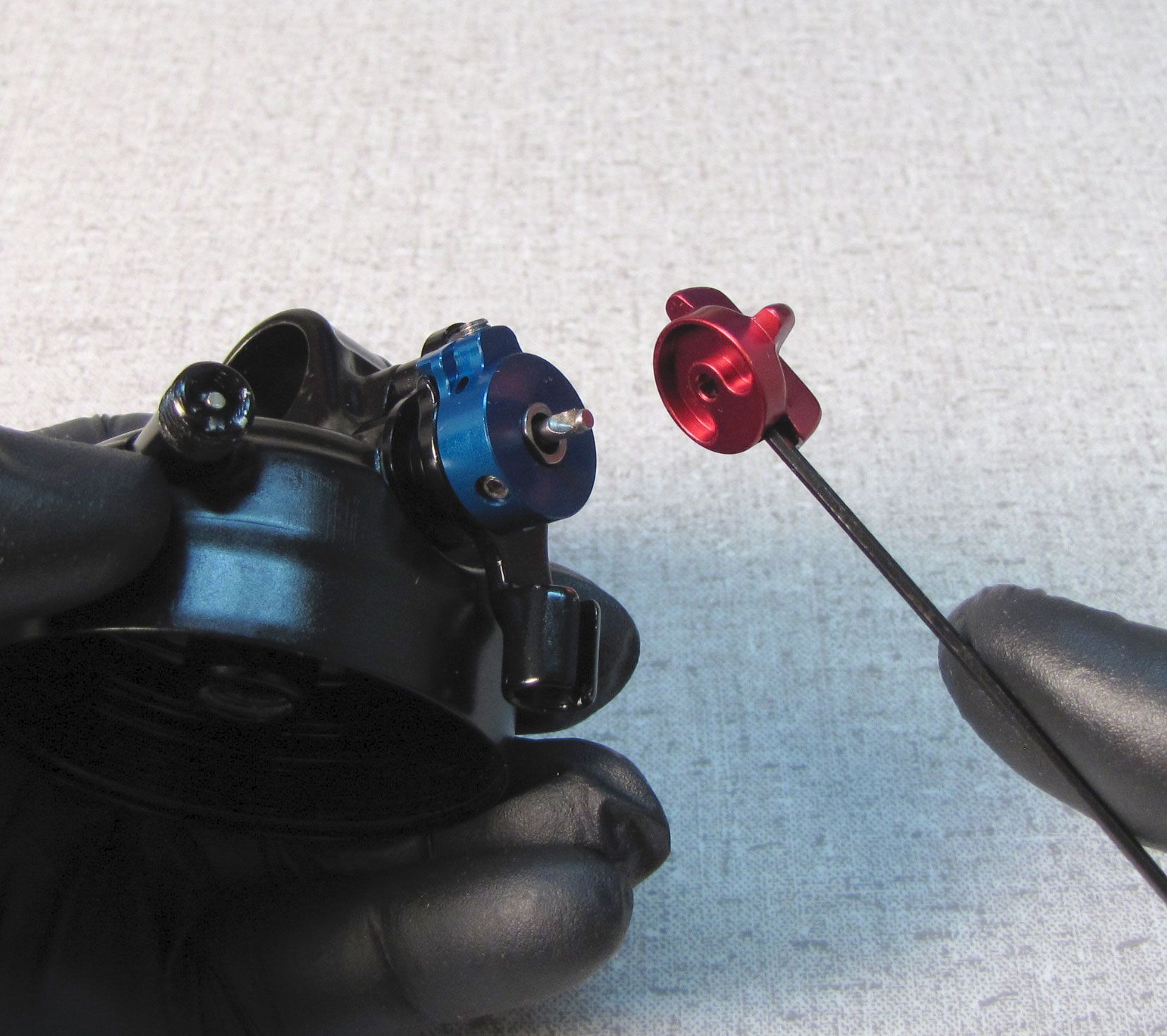
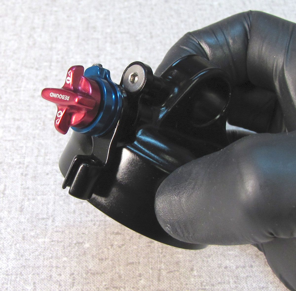
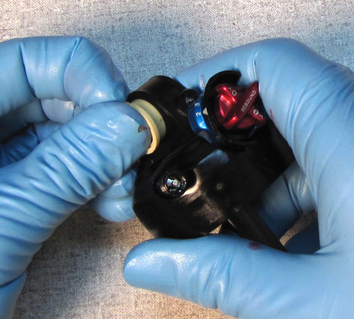
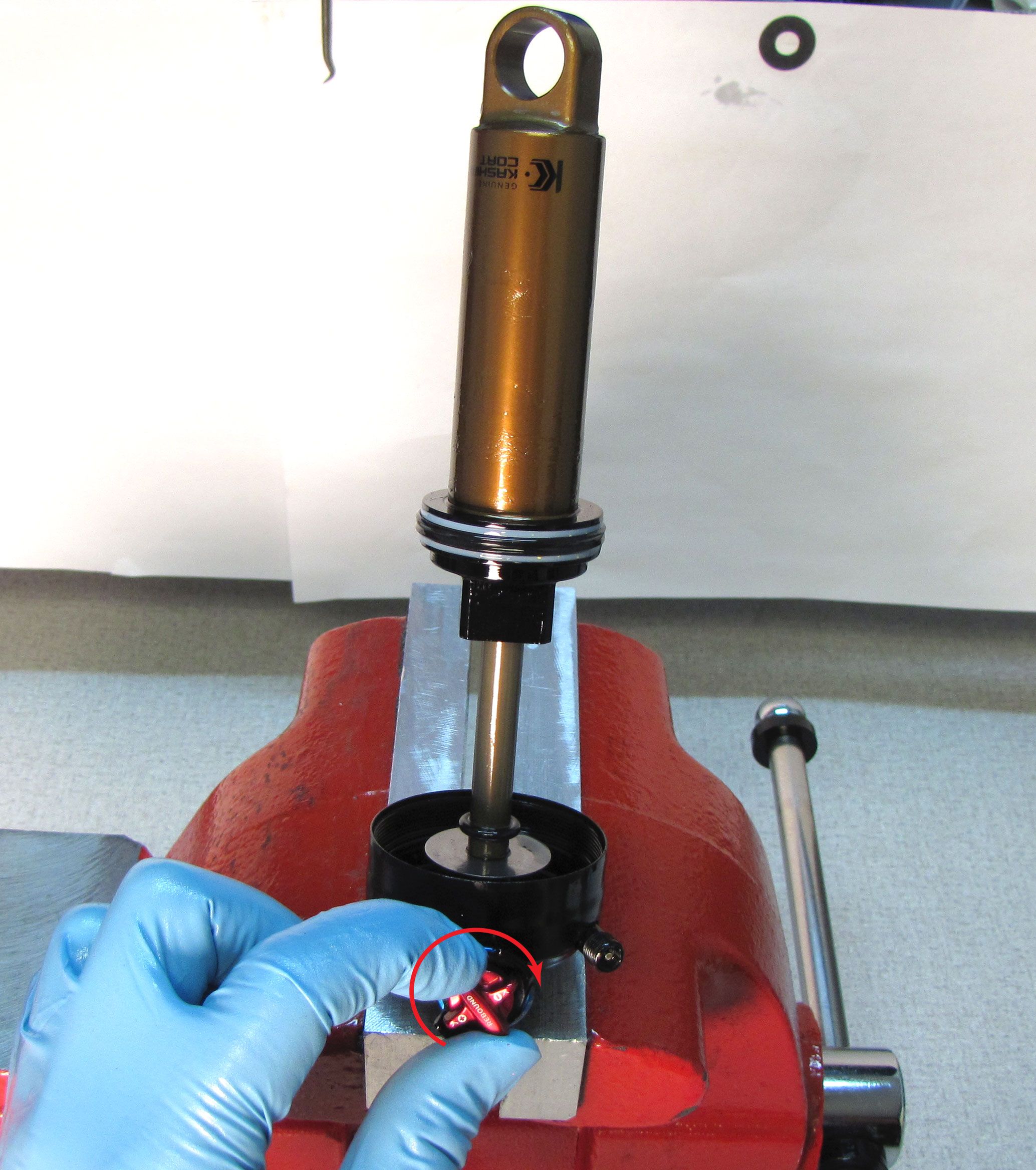
Turn the blue compression adjust lever and the red rebound knob to the open position (fully counter-clockwise).

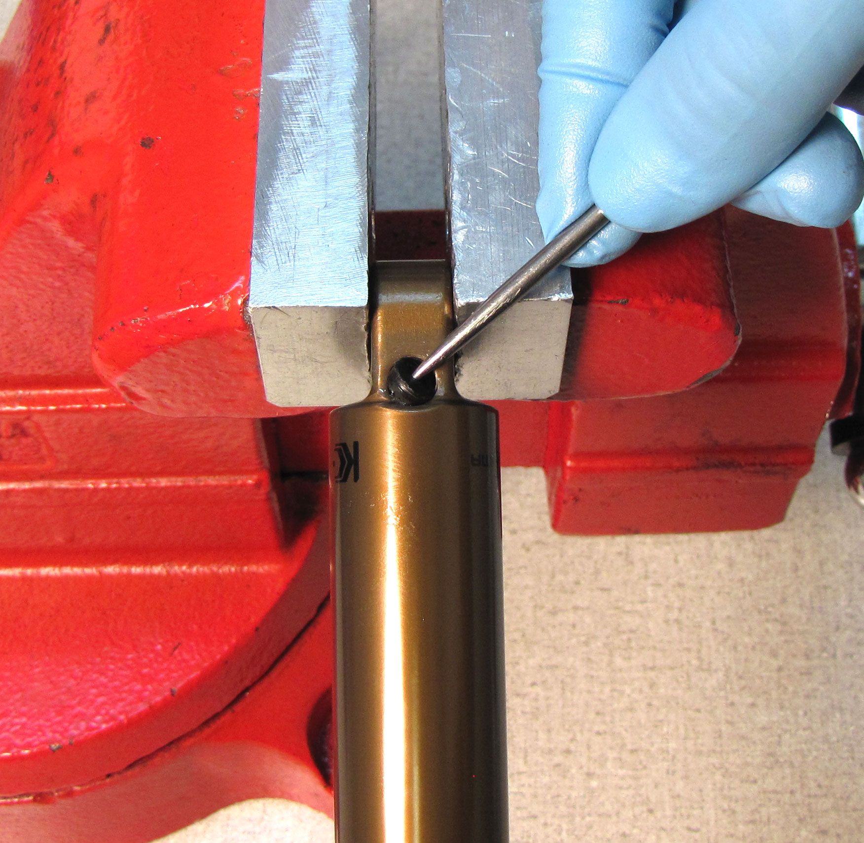
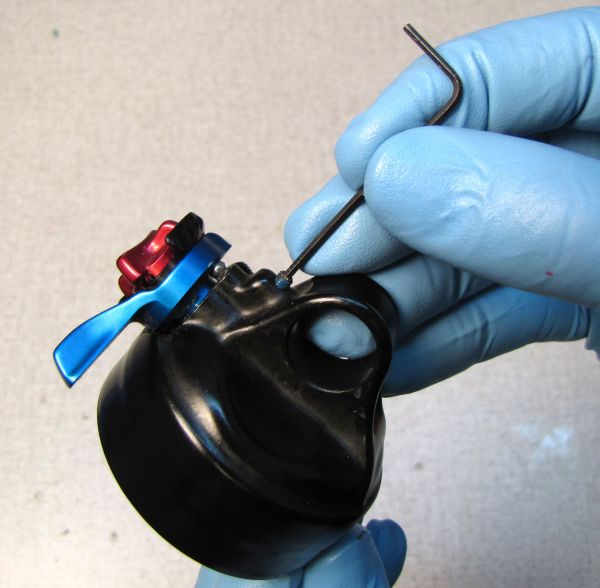
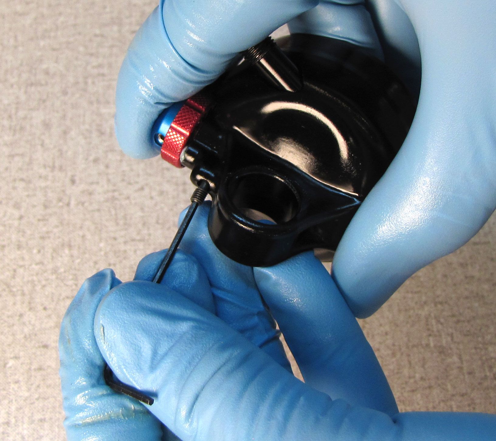
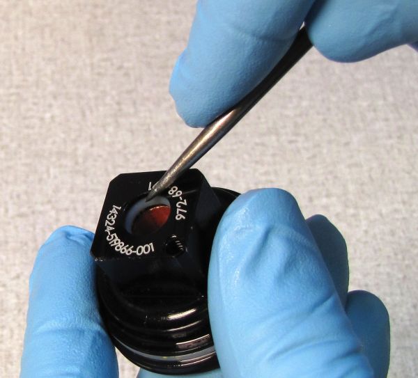
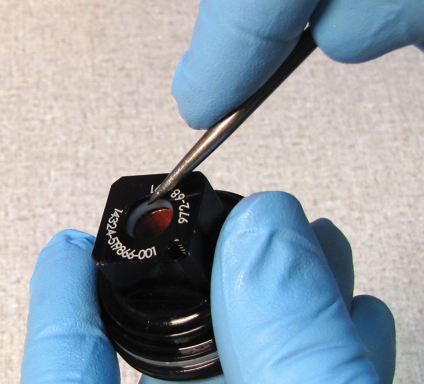
Step 4
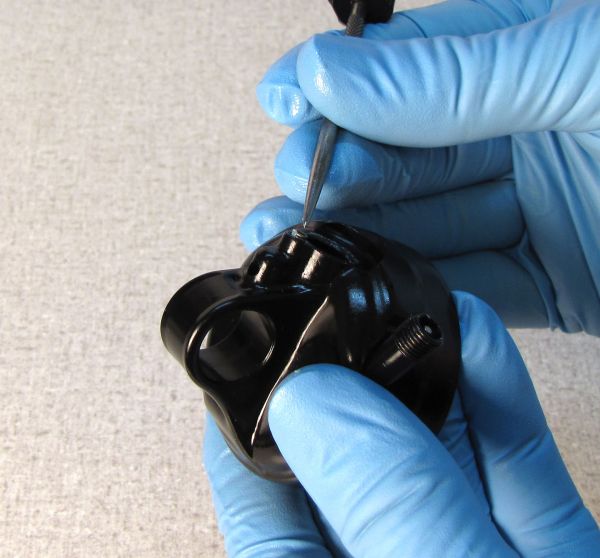
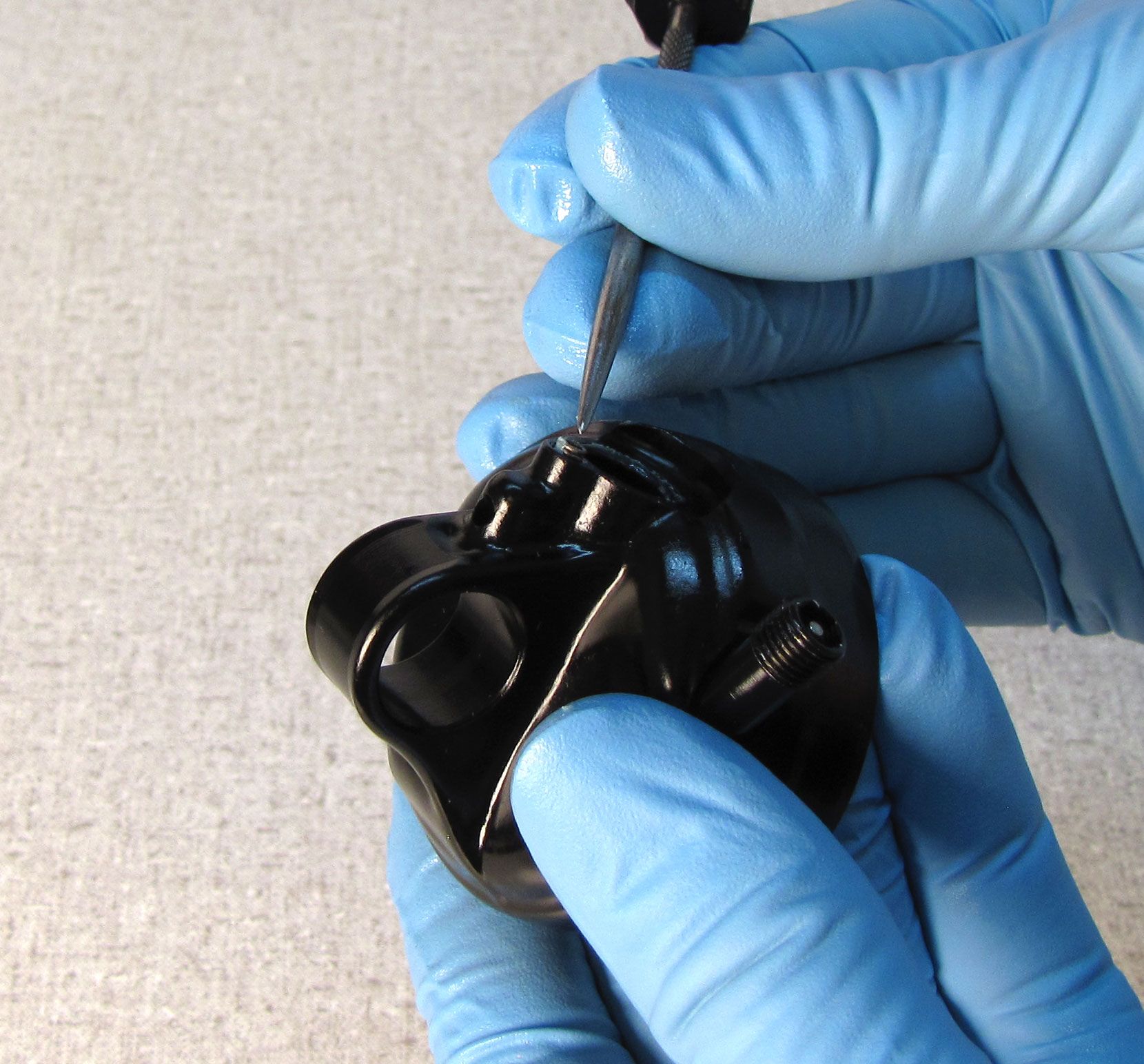
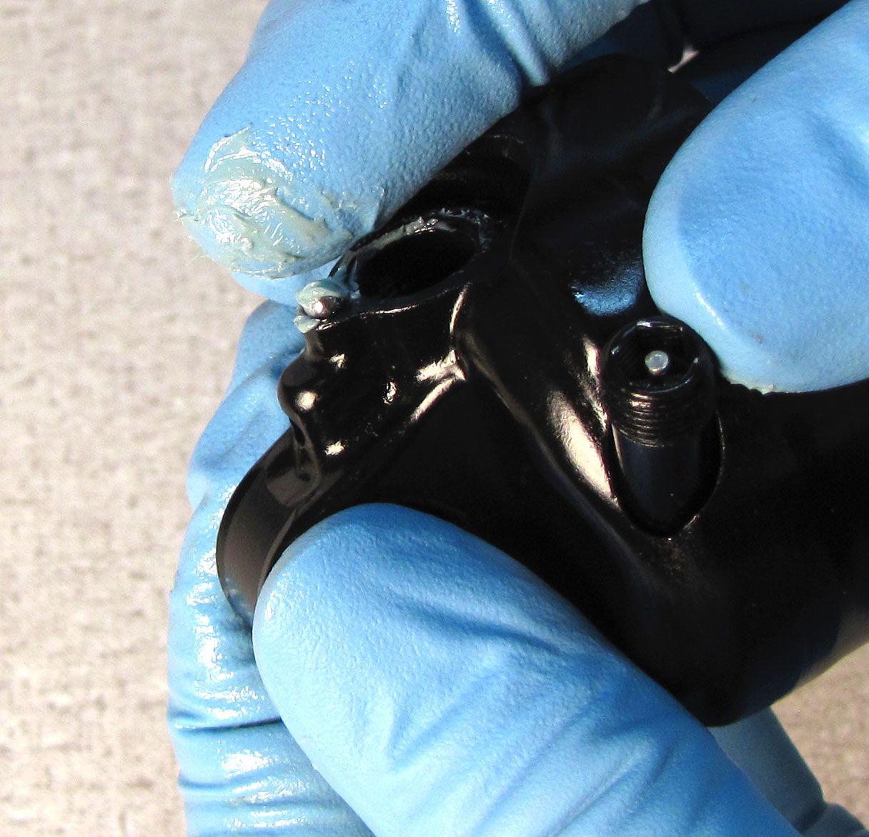
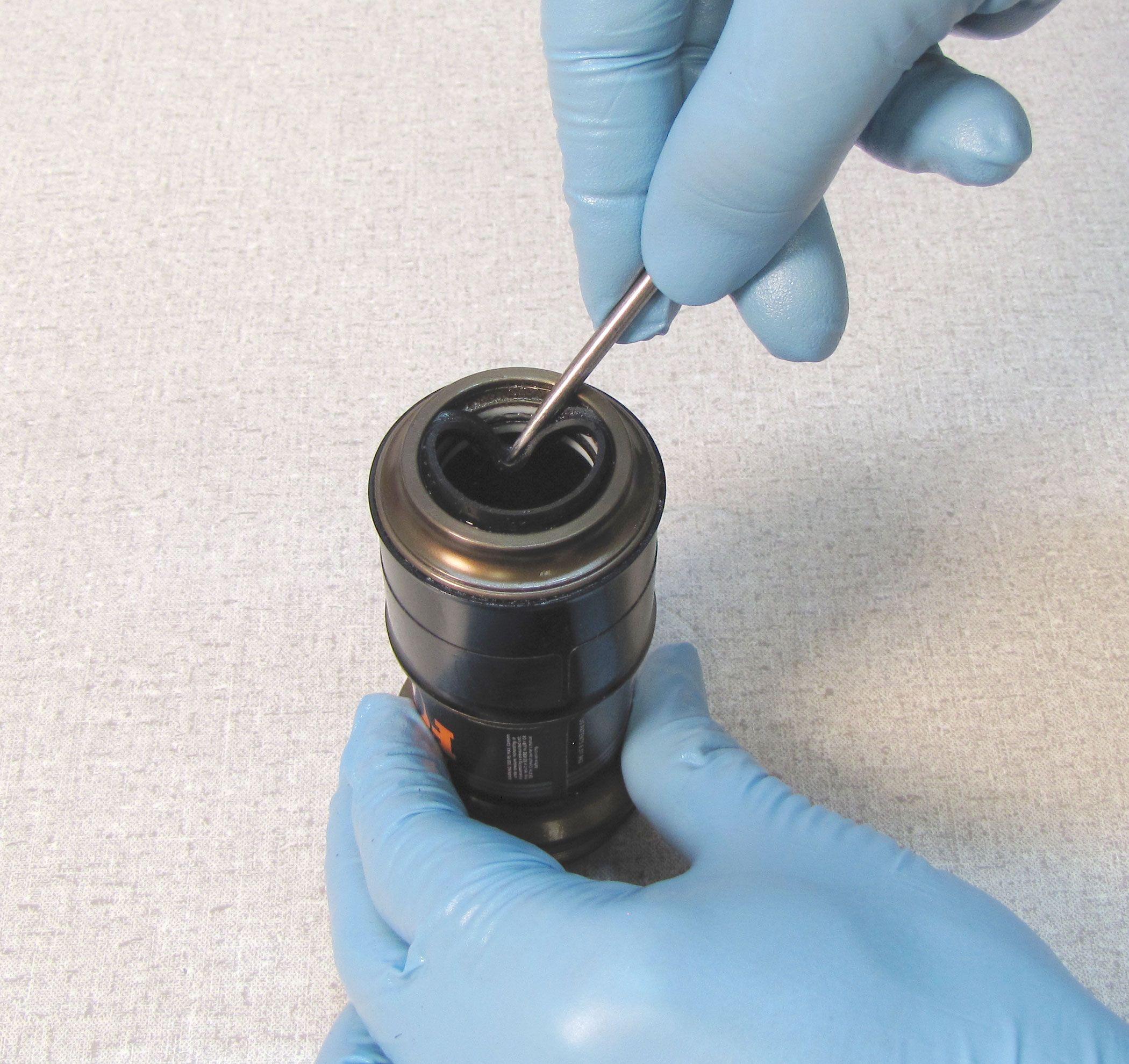
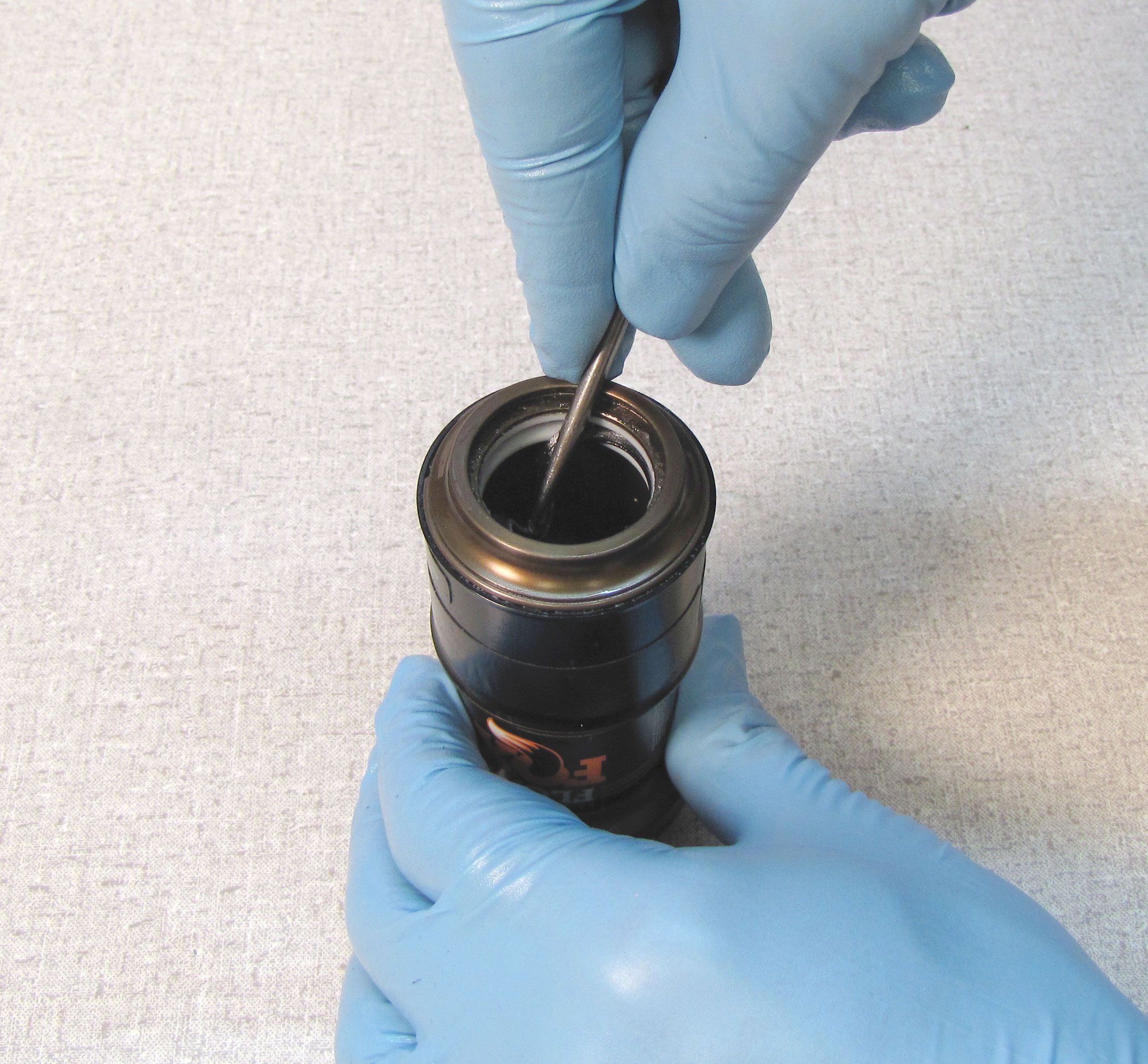
Using a pick tool, remove the nylon plug to access the pellet screw. Use a 5/32" hex to release the nitrogen pressure and remove the pellet retainer. Remove the pellet with the pick tool.
WARNING: FLOAT DPS Remote PTU shocks may contain high pressure oil, air, or nitrogen after releasing the IFP charge and removing the bleed screw at the bearing housing. Always actuate the PTU remote pulley after releasing the IFP pressure and removing the bleed screw at the bearing housing. This will release any pressurized oil, air, or nitrogen trapped between the IFP and the lockout piston. Failure to actuate the remote pulley and release the pressurized oil can lead to parts ejecting from the shock upon disassembly which can cause SEVERE INJURY or DEATH.

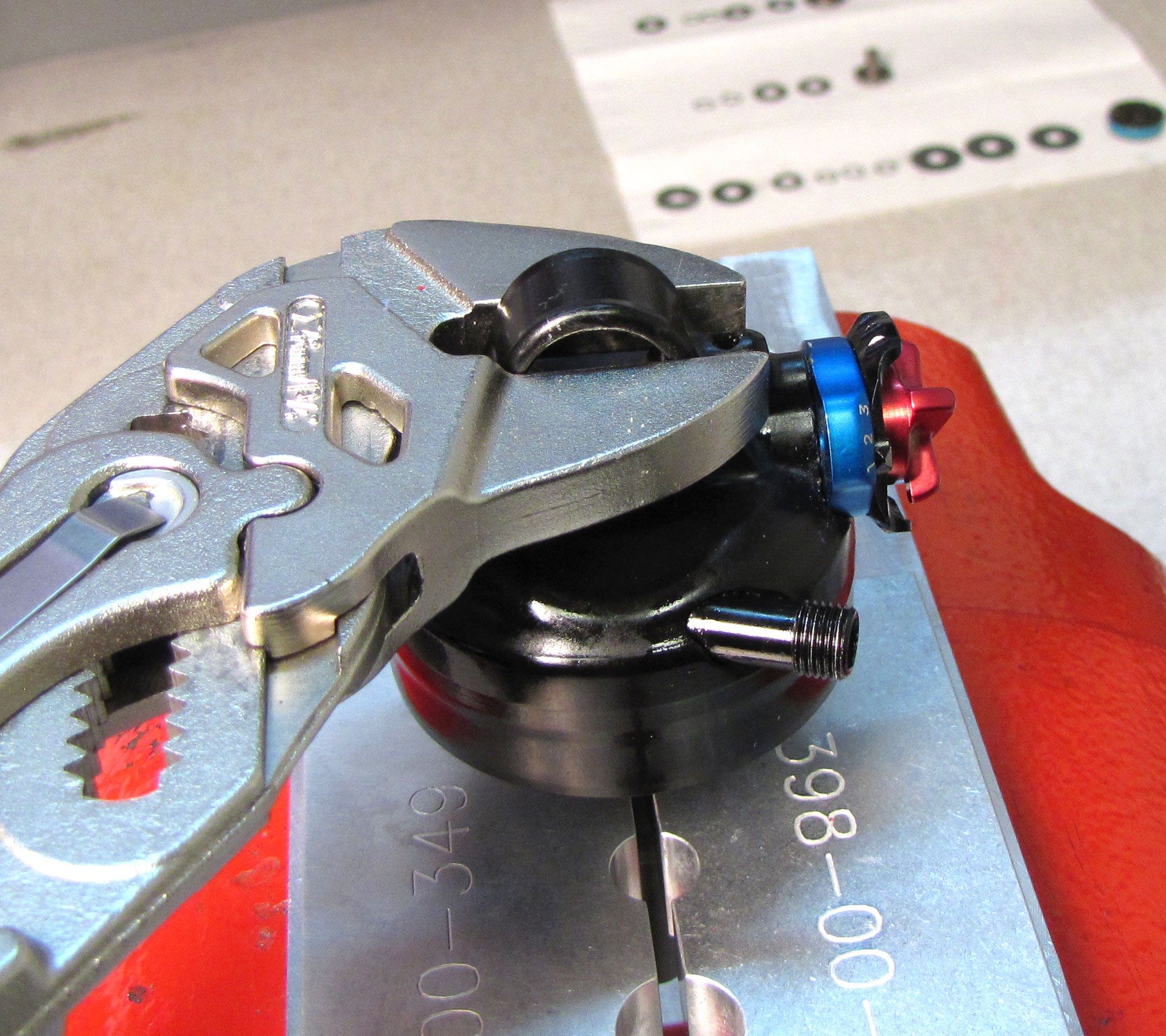
Step 5
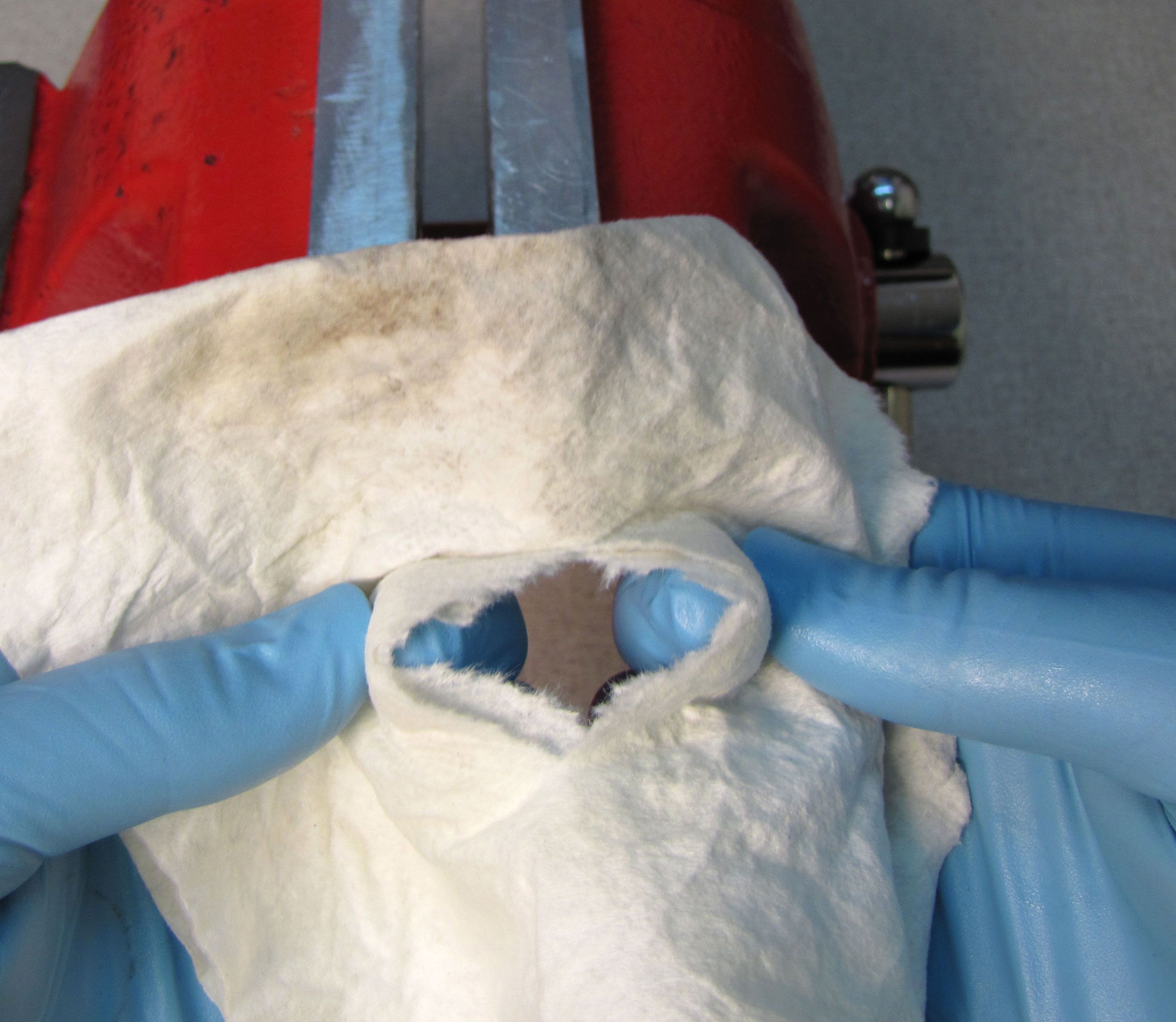
TIP: Poke a hole in a lint-free paper towel and stretch it over your shock damper to collect oil from this step.
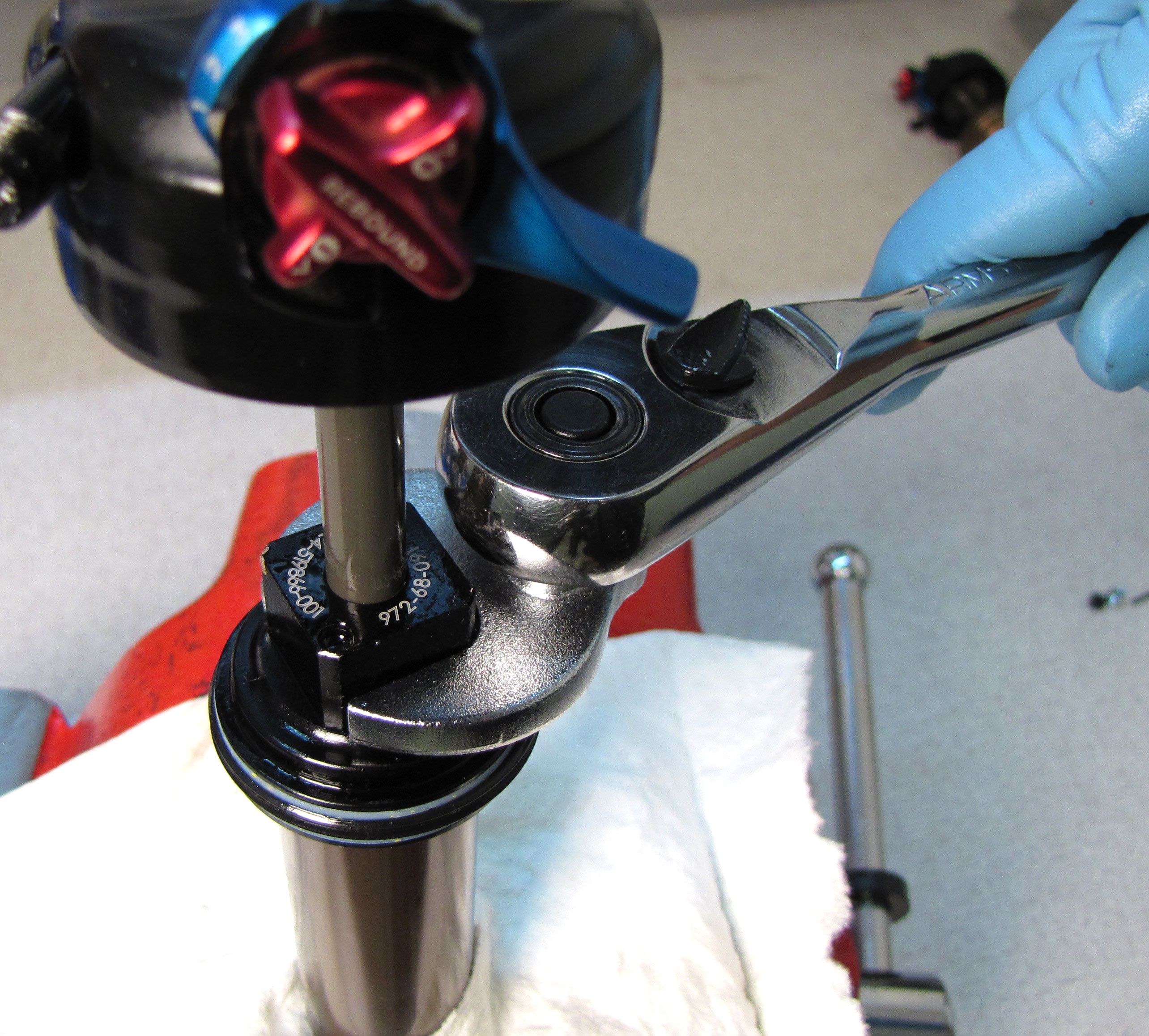
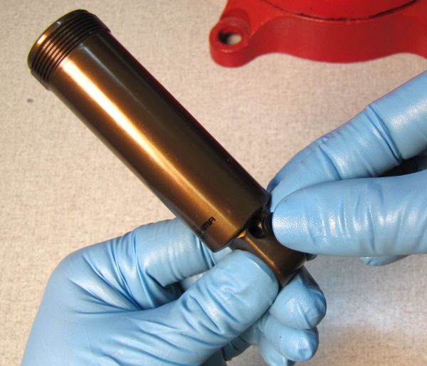
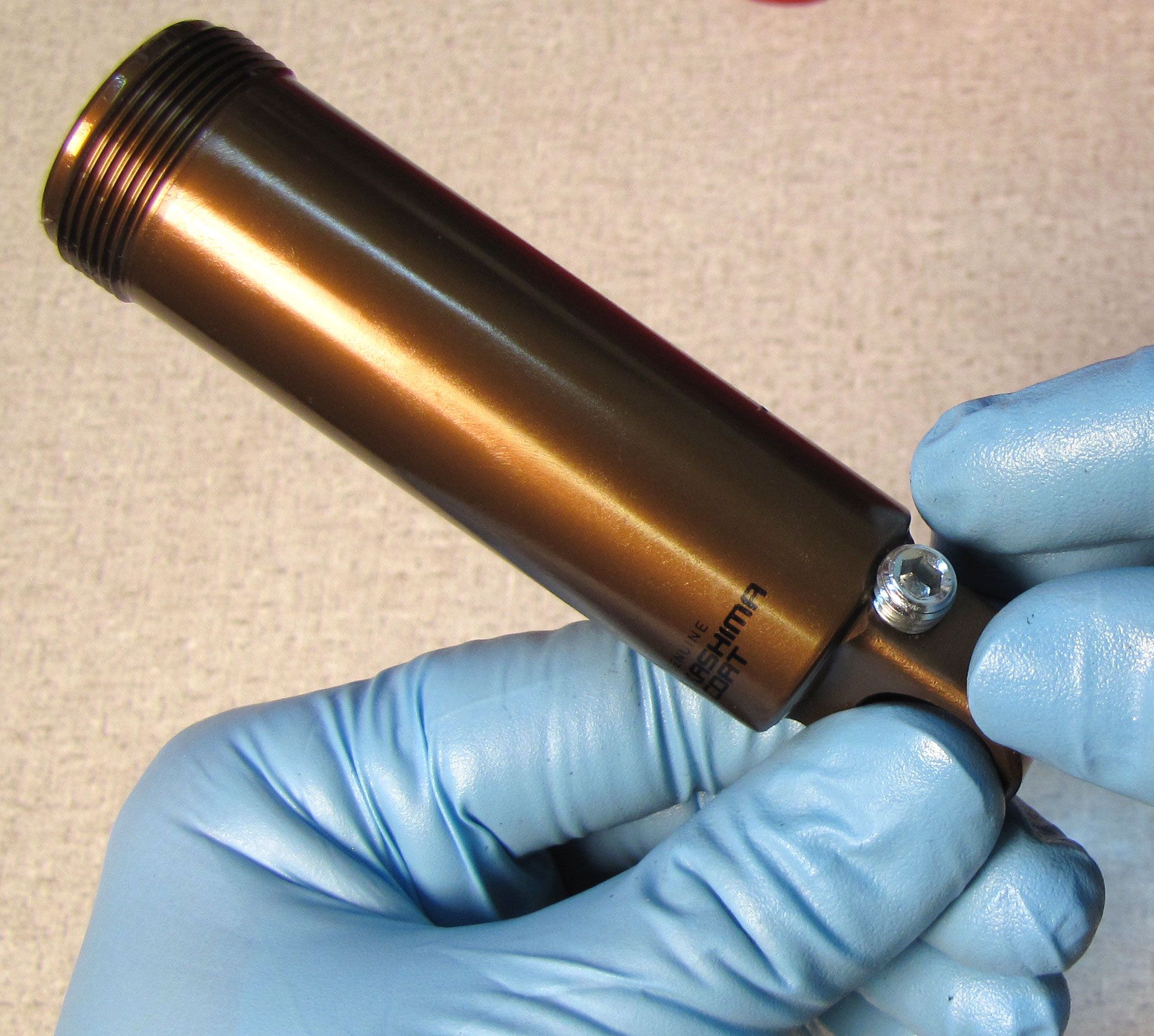
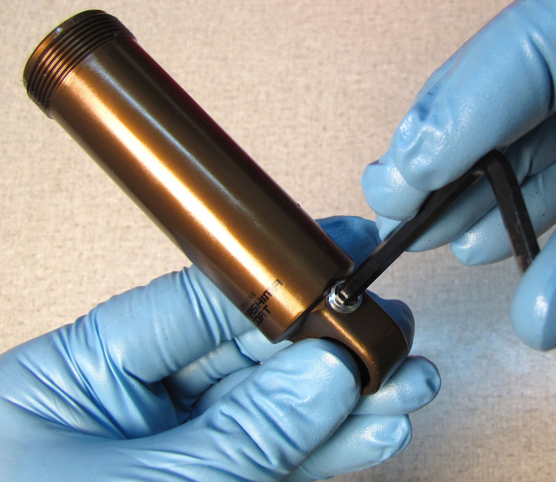
Clamp the shock vertically and use a 5/64" hex to slowly remove the bleed screw. Use a magnet to remove the ball from under the bleed screw. Unthread the bearing assembly from the shock body with a 3/4in wrench. Position your wrench so the wrench does not apply torque to the bleed hole.

Step 6
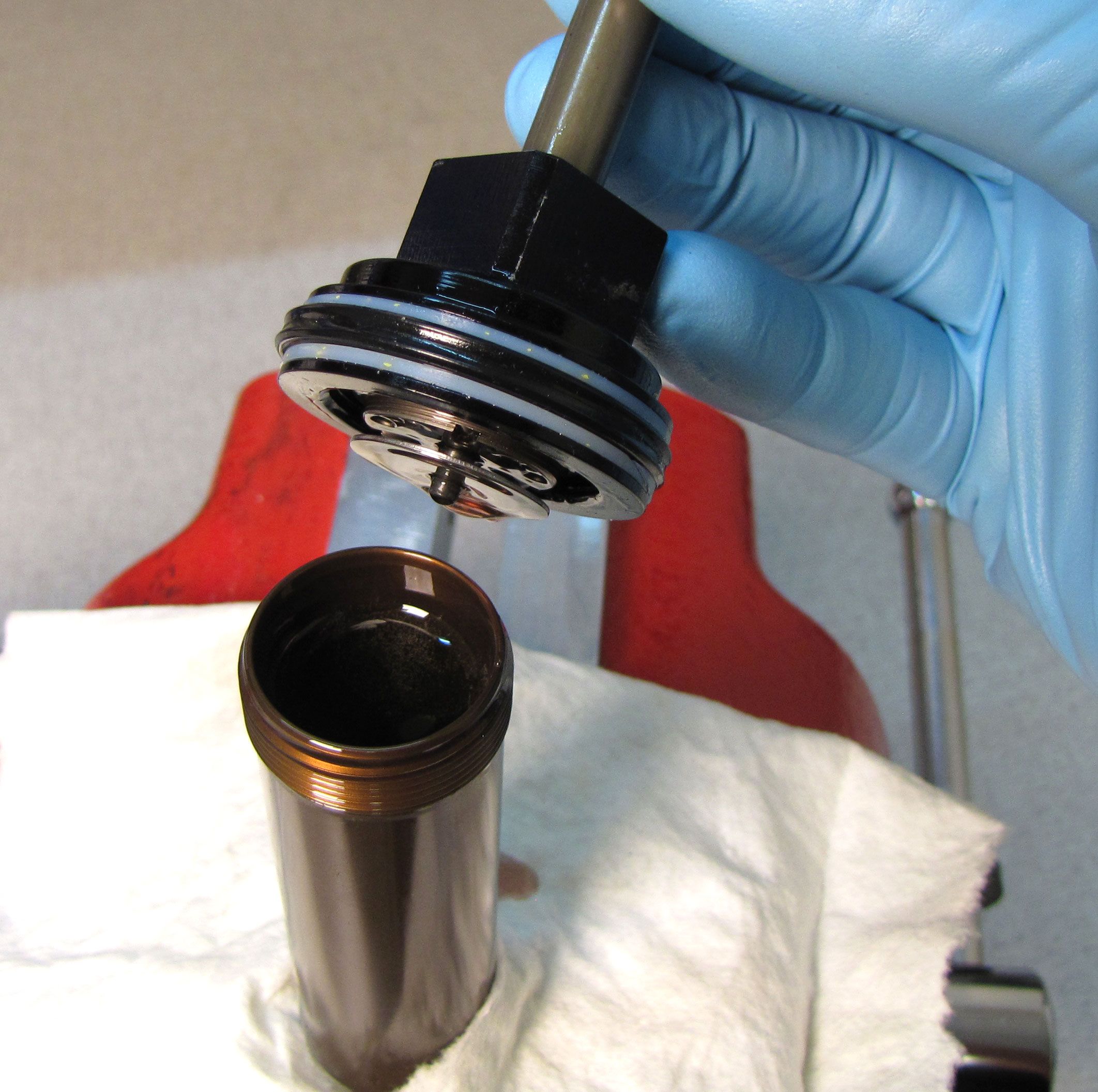
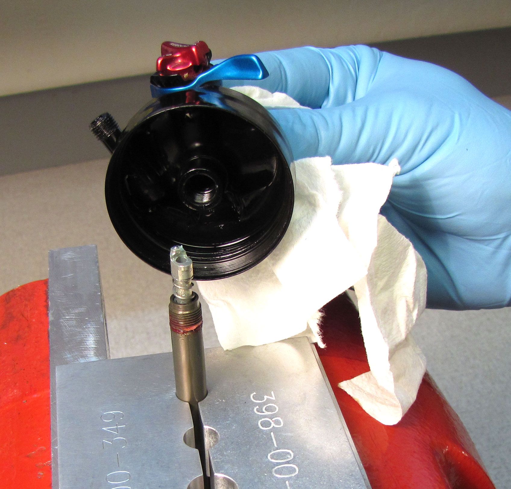
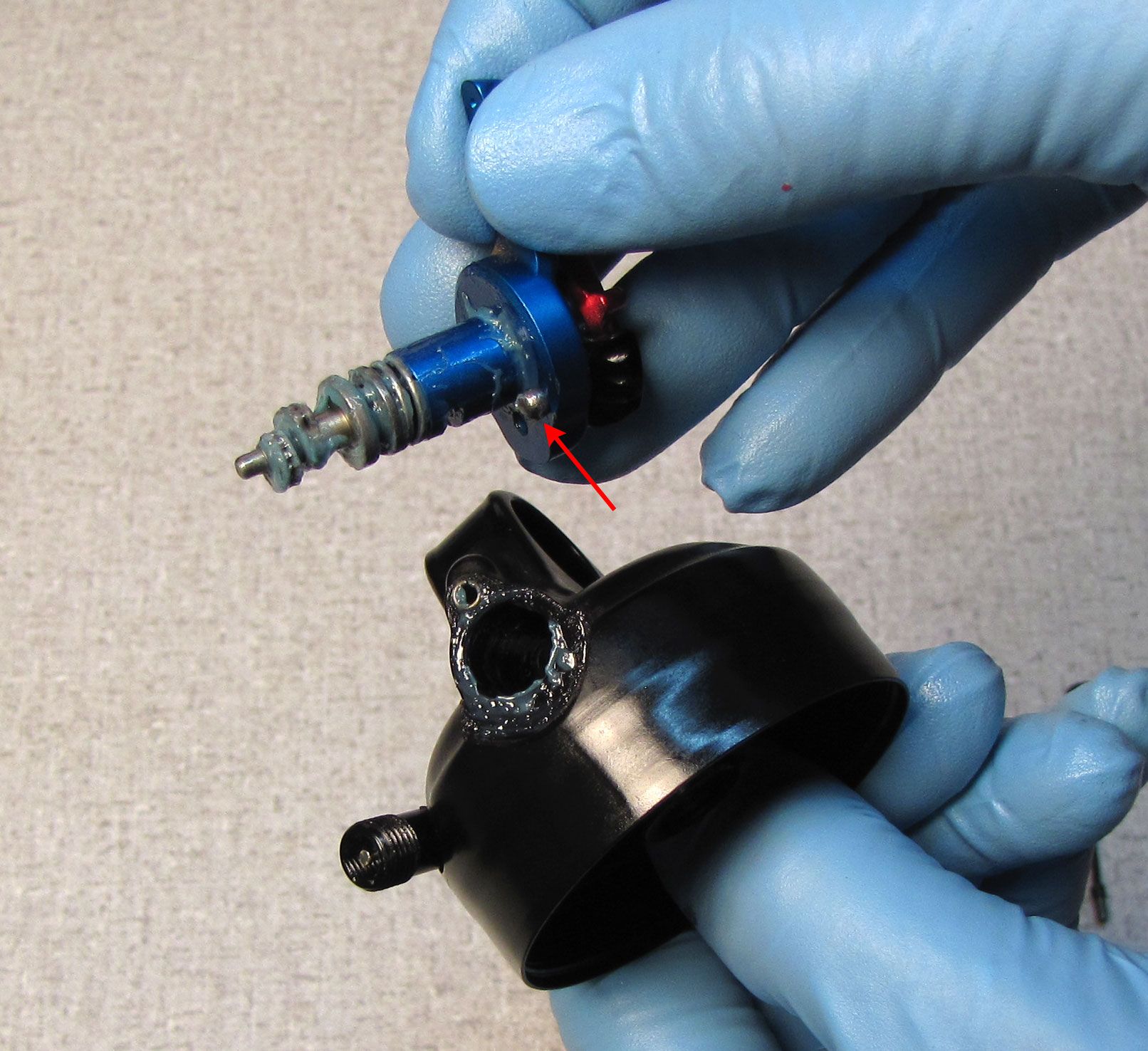
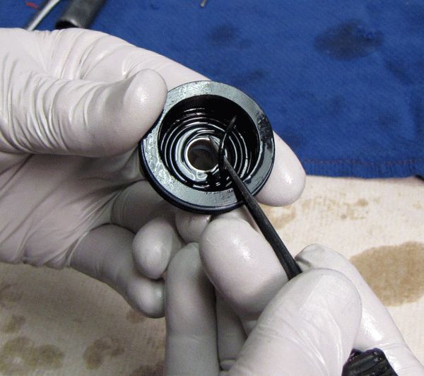
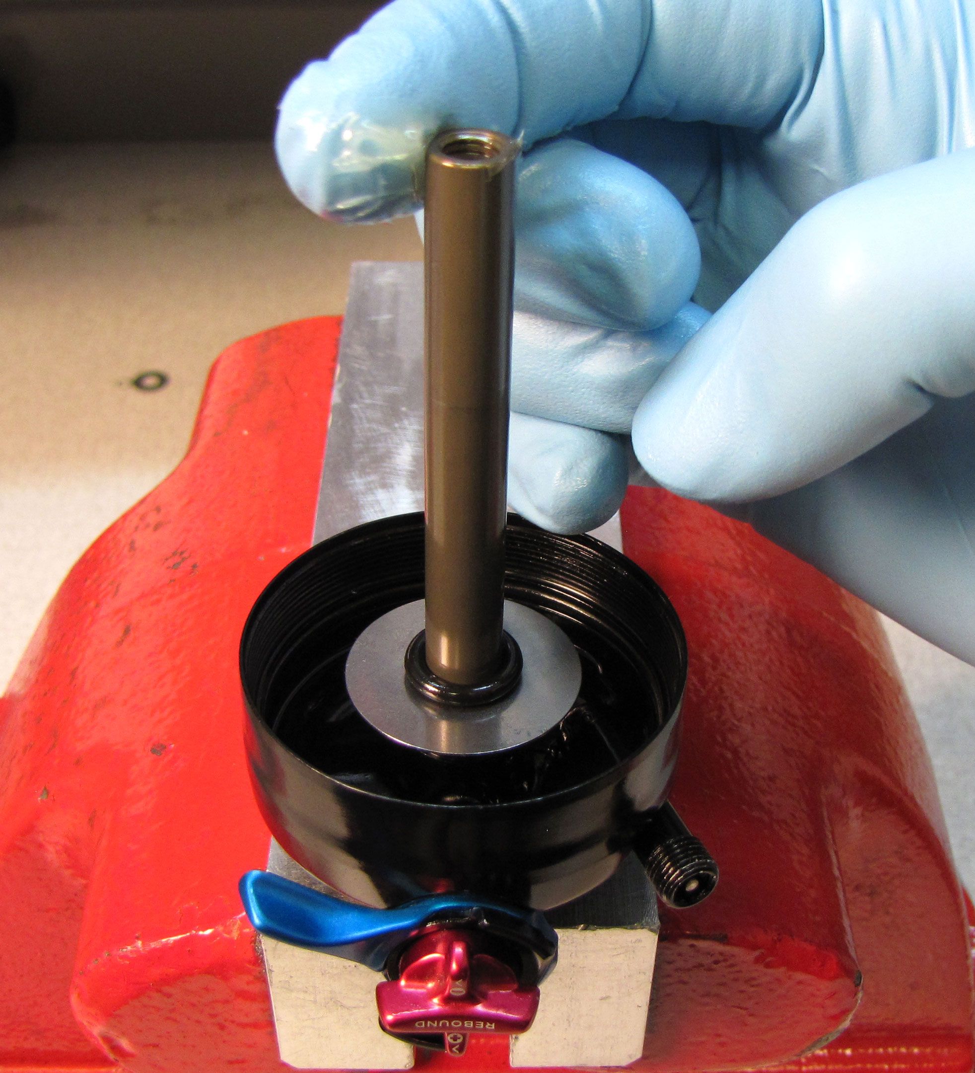
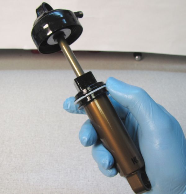
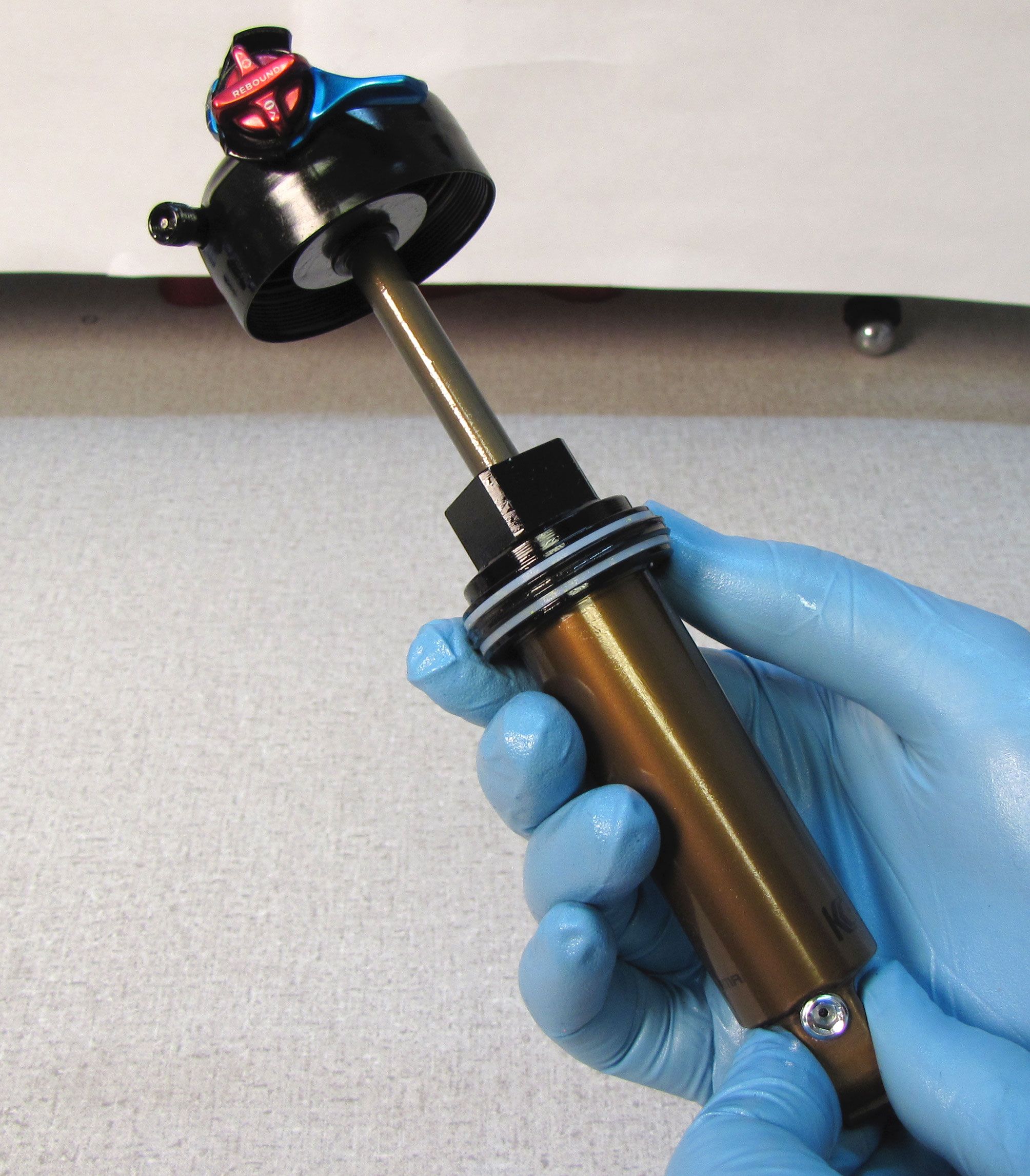
Remove the shaft assembly from the body and pour out the damper oil. Remove the IFP using carefully applied air pressure. Inspect the body for damage or excessive wear.
Step 7
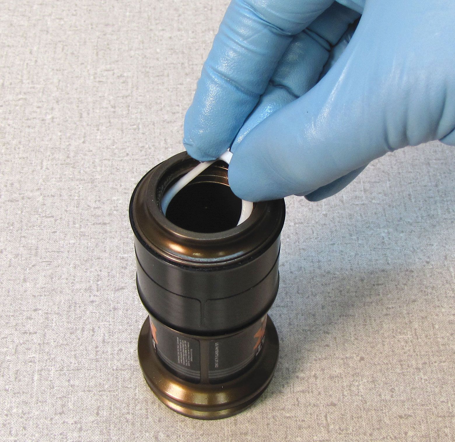
Remove the IFP o-ring and inspect its gland on the piston itself for any damage or contamination. Apply Slick Honey grease to the new IFP o-ring from the replacement seal kit, and install it on the piston.

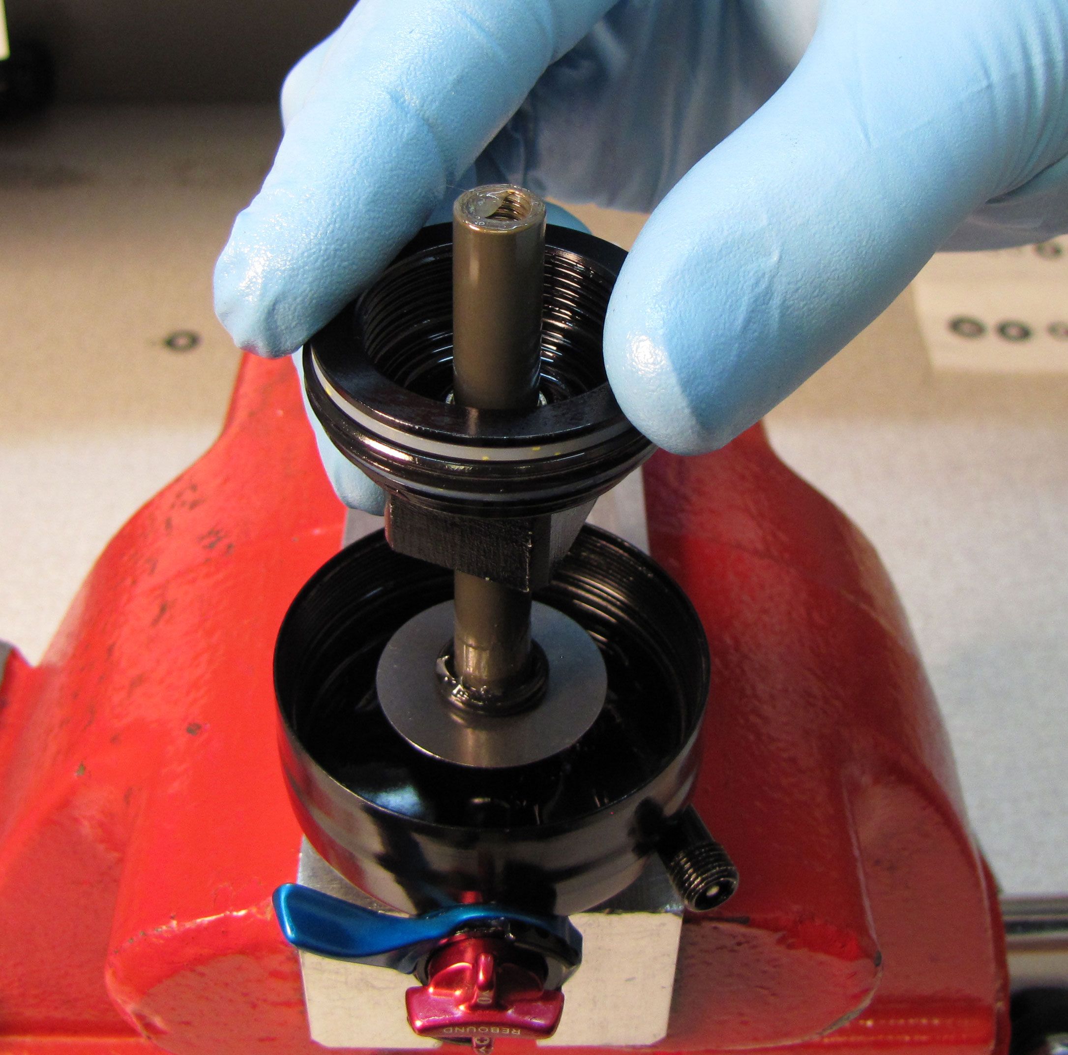
Step 8
Apply a very thin film of Slick Honey to the inside of the shock body, then insert the IFP with it's slot facing up. Adjust your IFP depth setting tool (PN: 803-00-566) to the correct IFP depth for your shock. Use your IFP depth setting tool to push the IFP down to it's appropriate depth.
| Shock Size | IFP Height (all measurements +/- .020in) | |
| 5.500 x 1.000 | 1.510in/ 38.35mm | |
| 6.000 x 1.250 | 1.720in/ 43.69mm | |
| 6.500 x 1.500 | 1.940in/ 49.28mm | |
| 7.250 x 1.750 | 2.150in/ 54.61mm | |
| 7.500/7.875 x 2.000 | 2.360in/ 59.94mm | |
| 7.875 x 2.250 | 2.580in/ 65.53mm | |
| 8.500 x 2.500 | 2.790in/ 70.87mm | |
Step 9
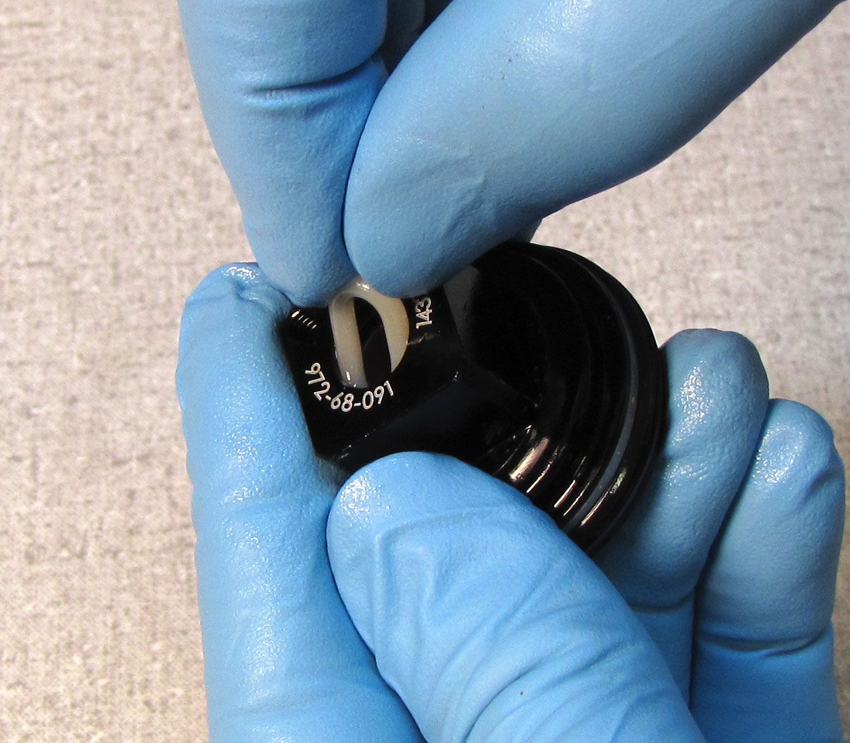
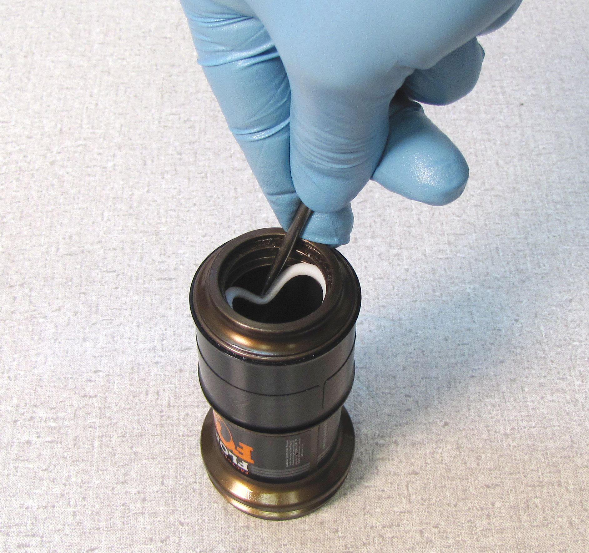
Install a new pellet from the service kit with the flat side facing up, then lightly secure with the pellet retainer.


Step 10
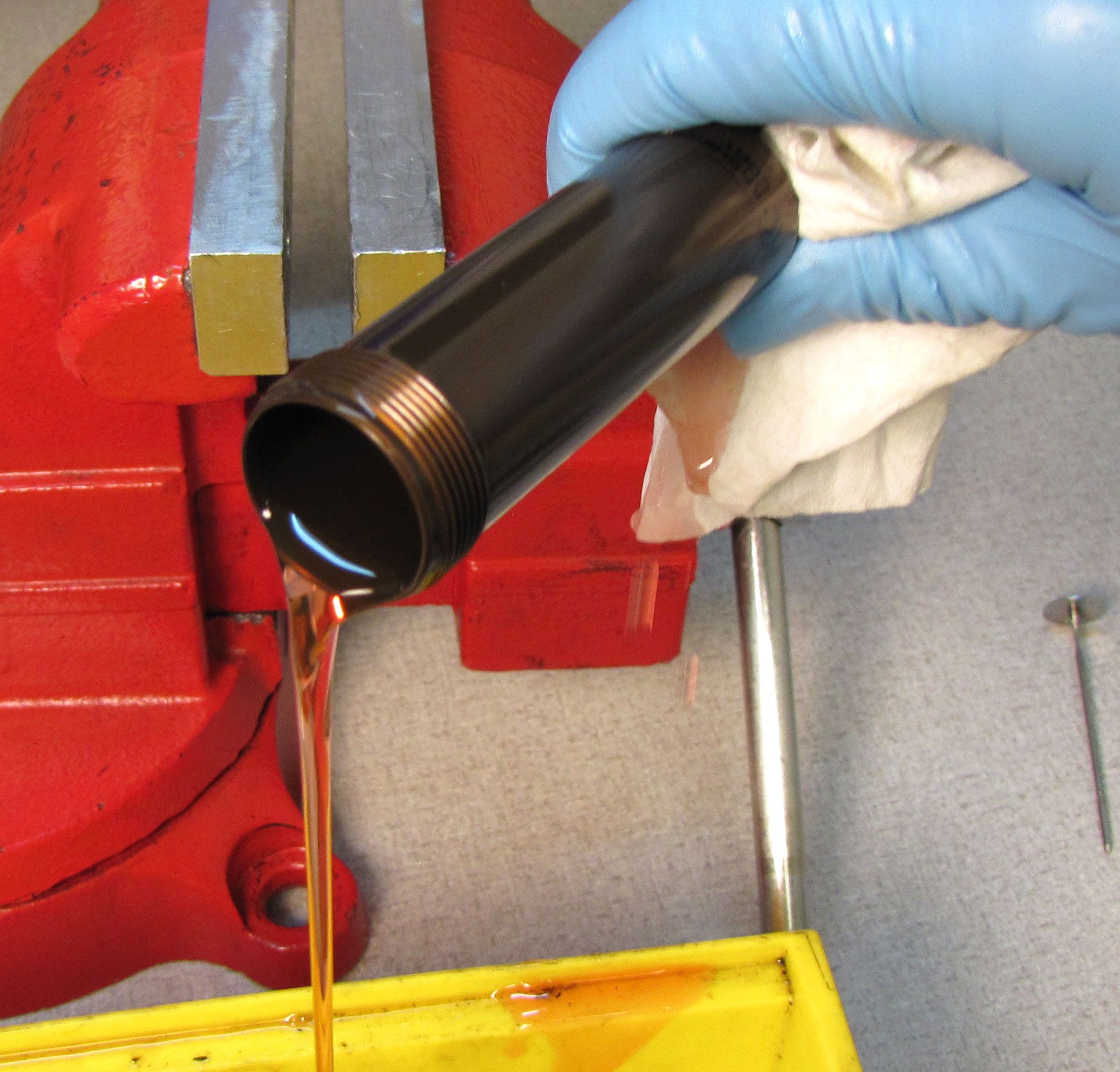
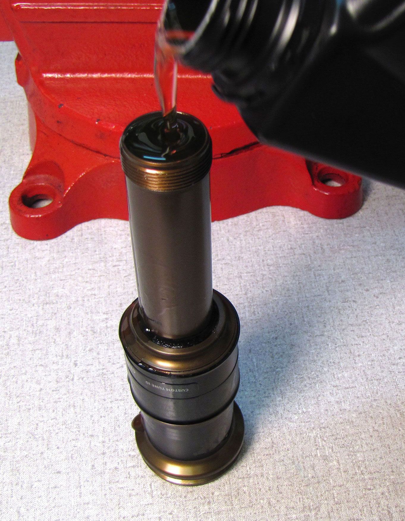
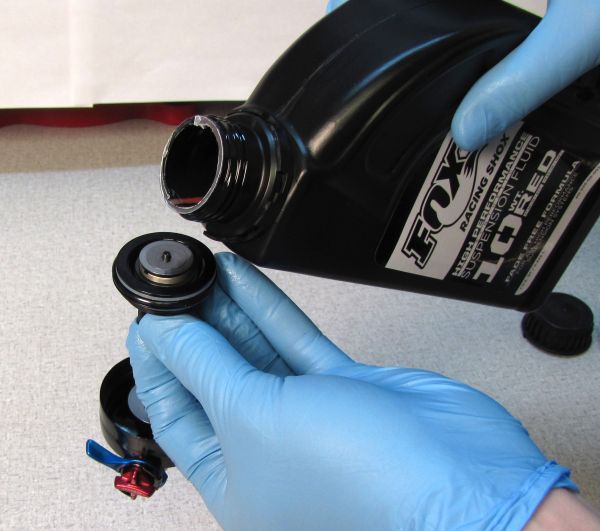
Prefill the shock body with oil. FLOAT DPS shocks use FOX 10wt. green oil, while FLOAT SL shocks use FOX 4wt. oil. Pour oil down the side to minimize potential aeration of the oil. Set the body aside in a vertical position and move on to the next step. This allows time for any trapped air to escape.

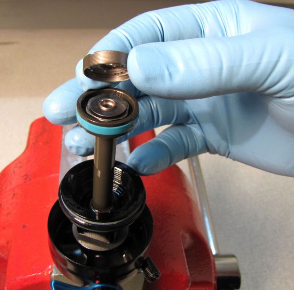
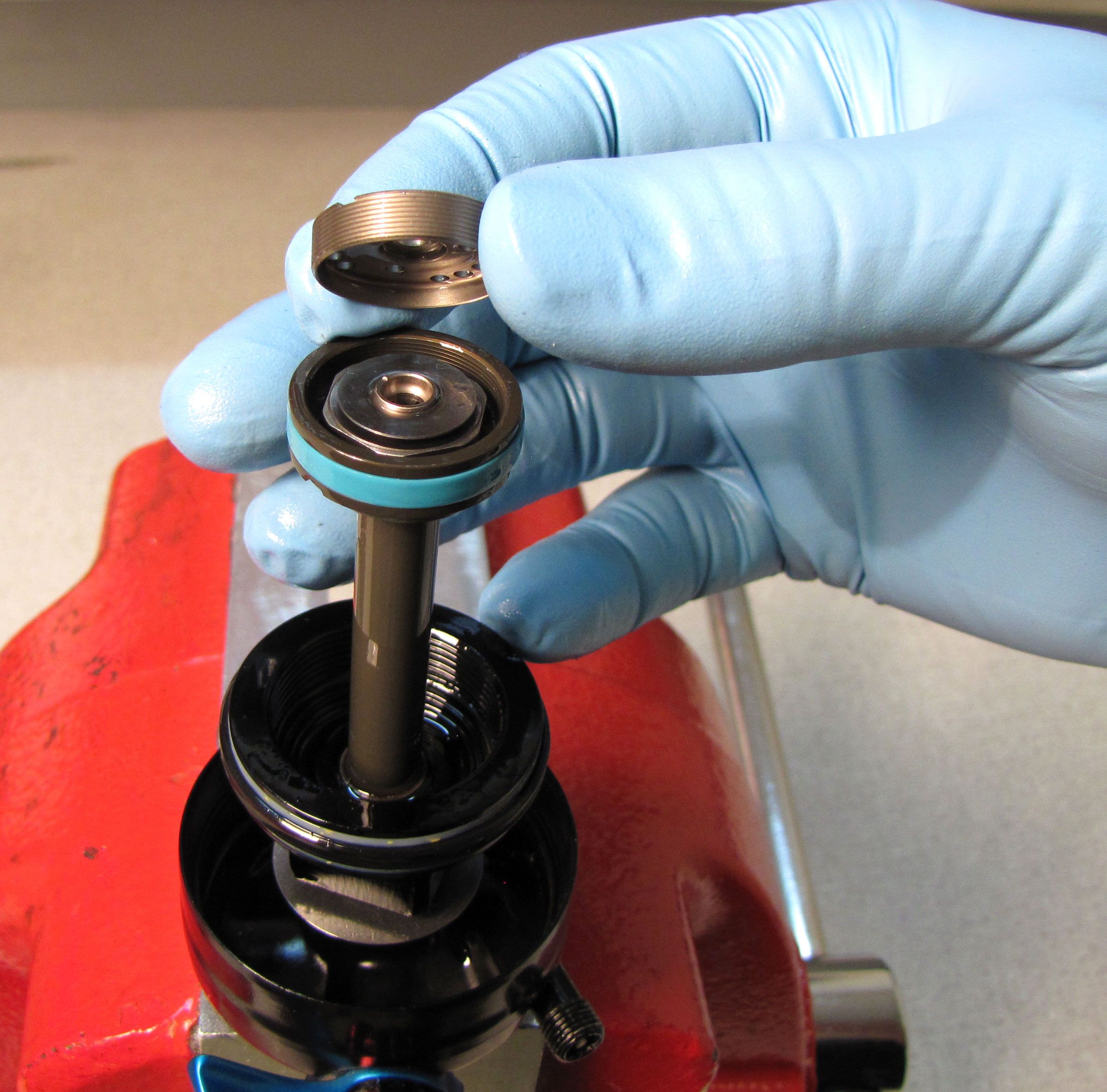
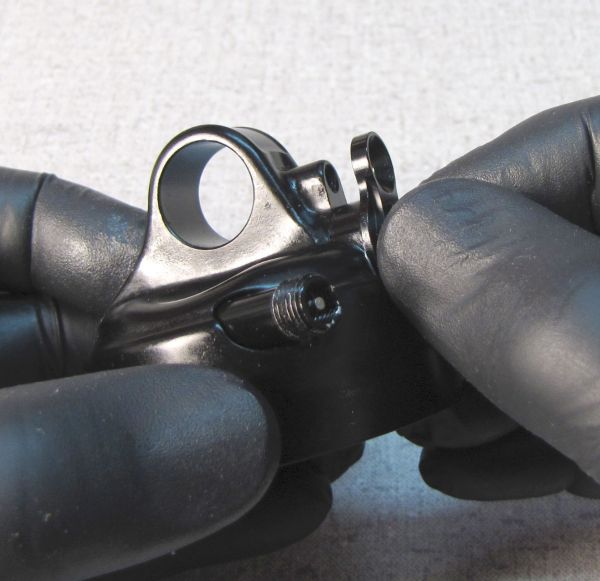
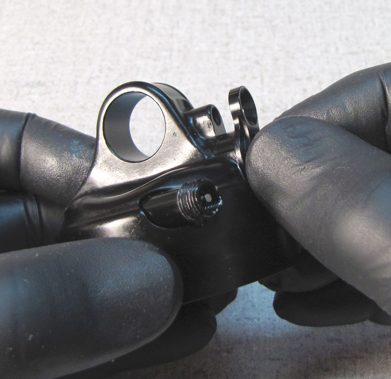
Step 11
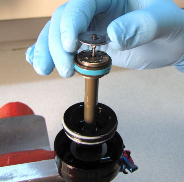
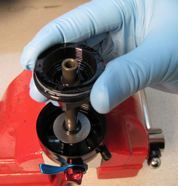
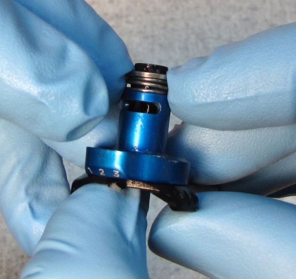
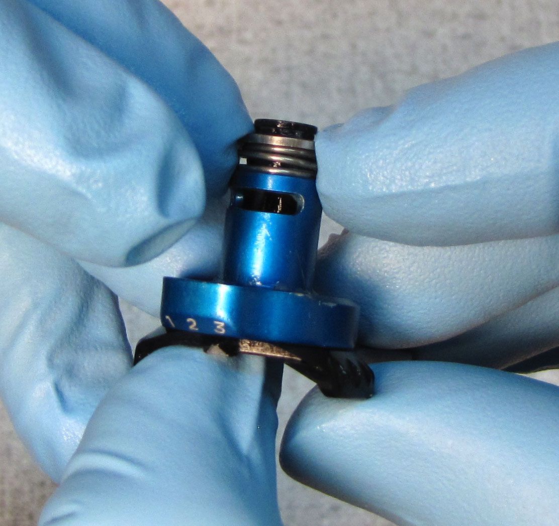
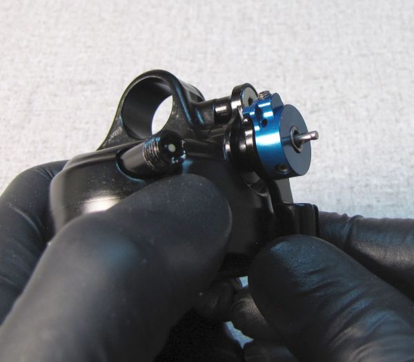
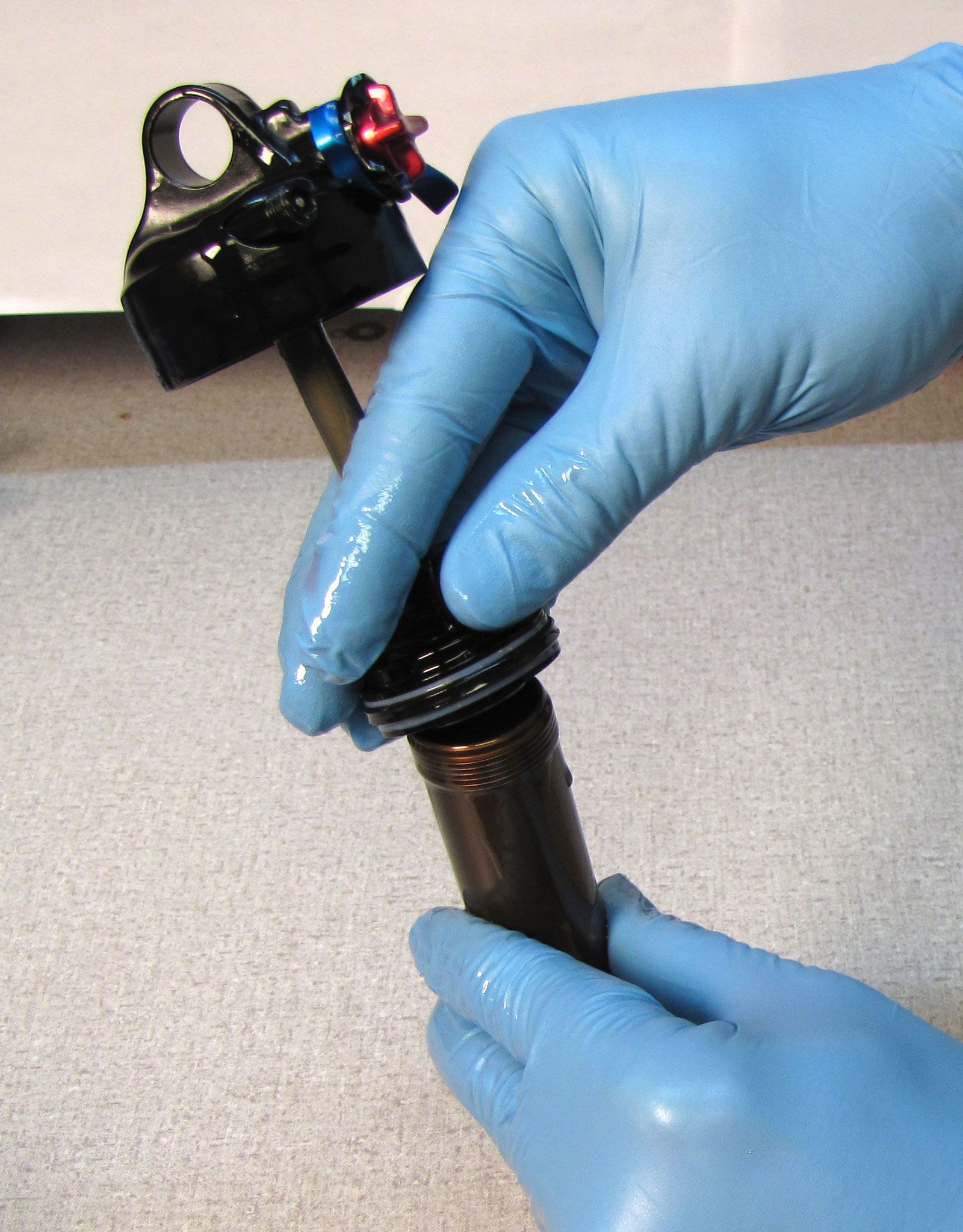
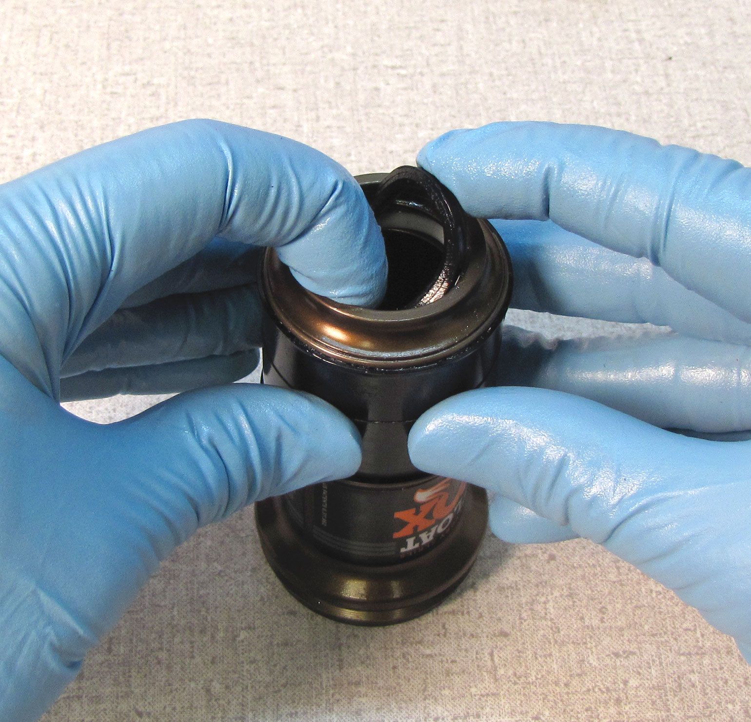
Clamp the eyelet assembly in your soft-jawed vice and carefully lift up on the lockout plate to remove.

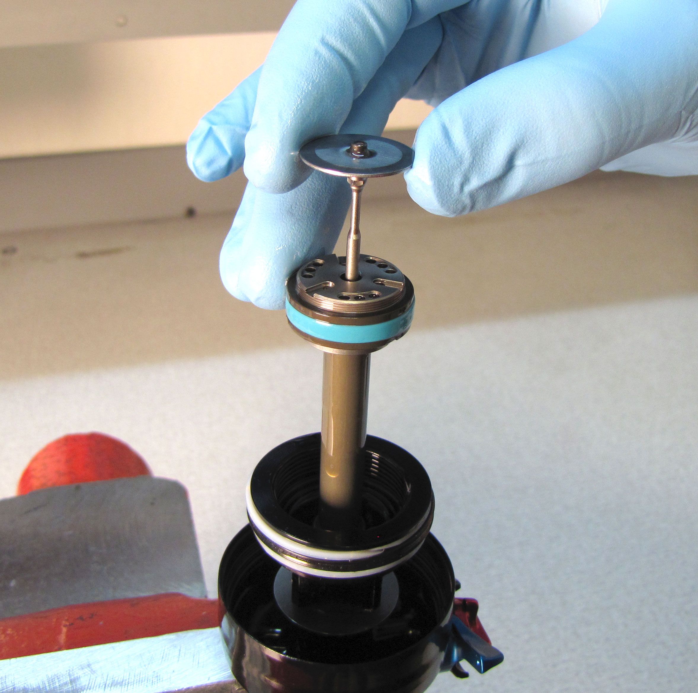

Step 12
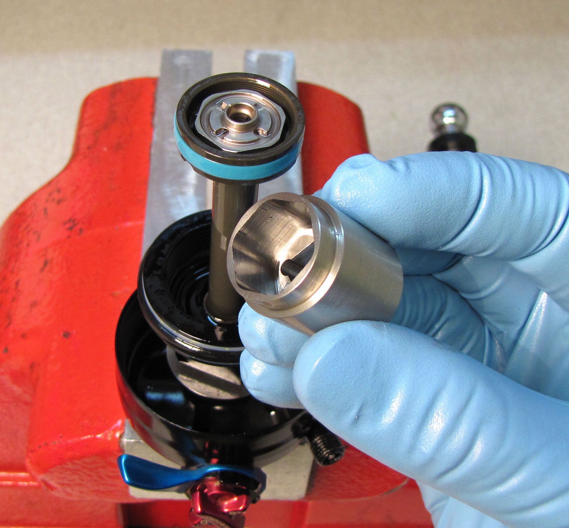
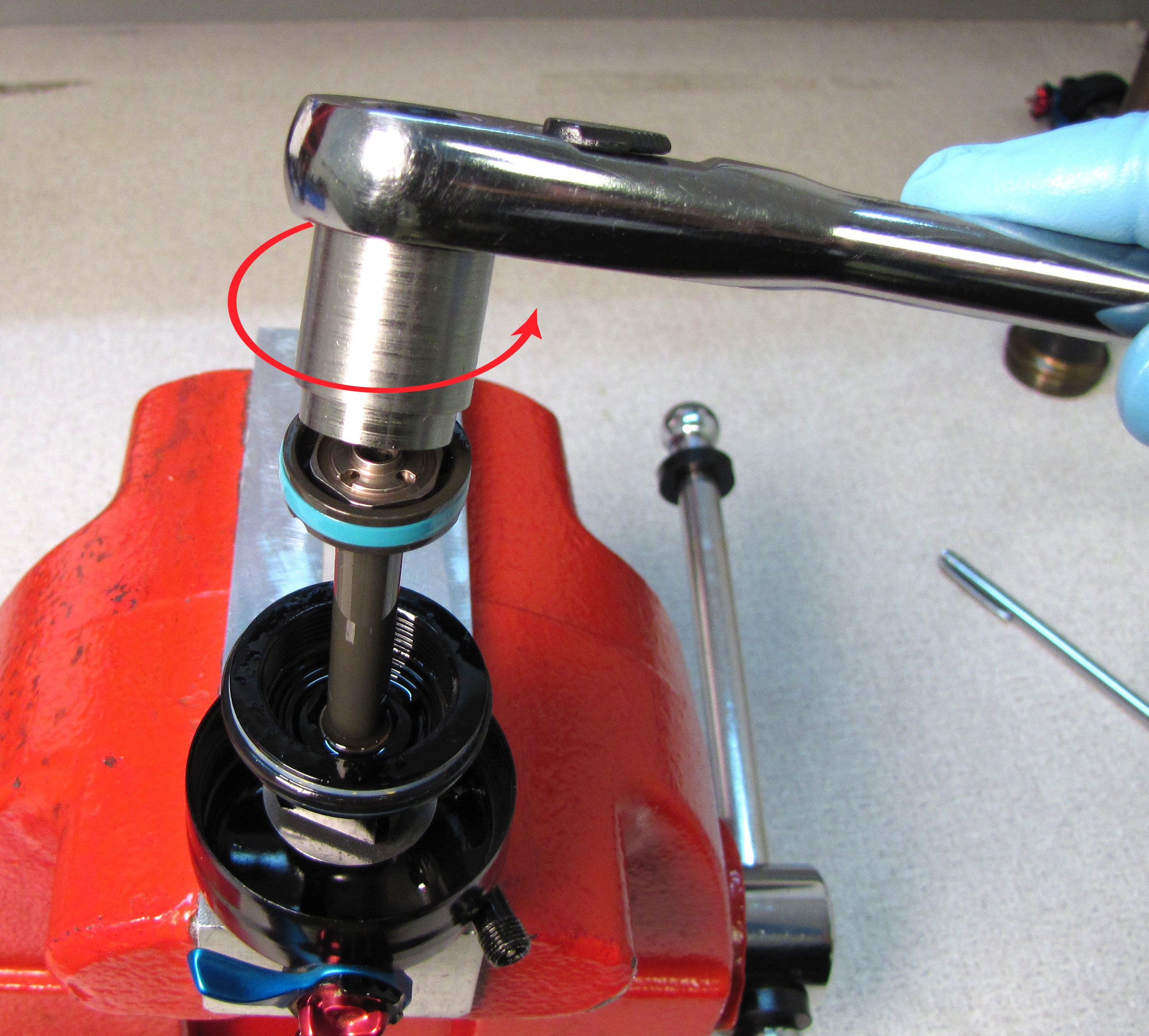
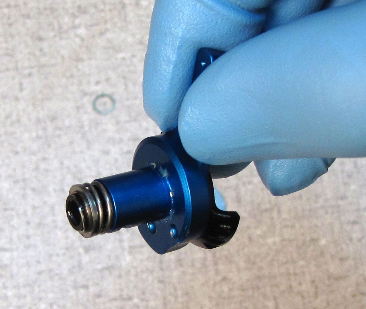
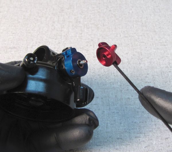
Use the FLOAT DPS lockout piston tool (PN: 398-00-638) to unthread the lockout piston from the piston assembly.
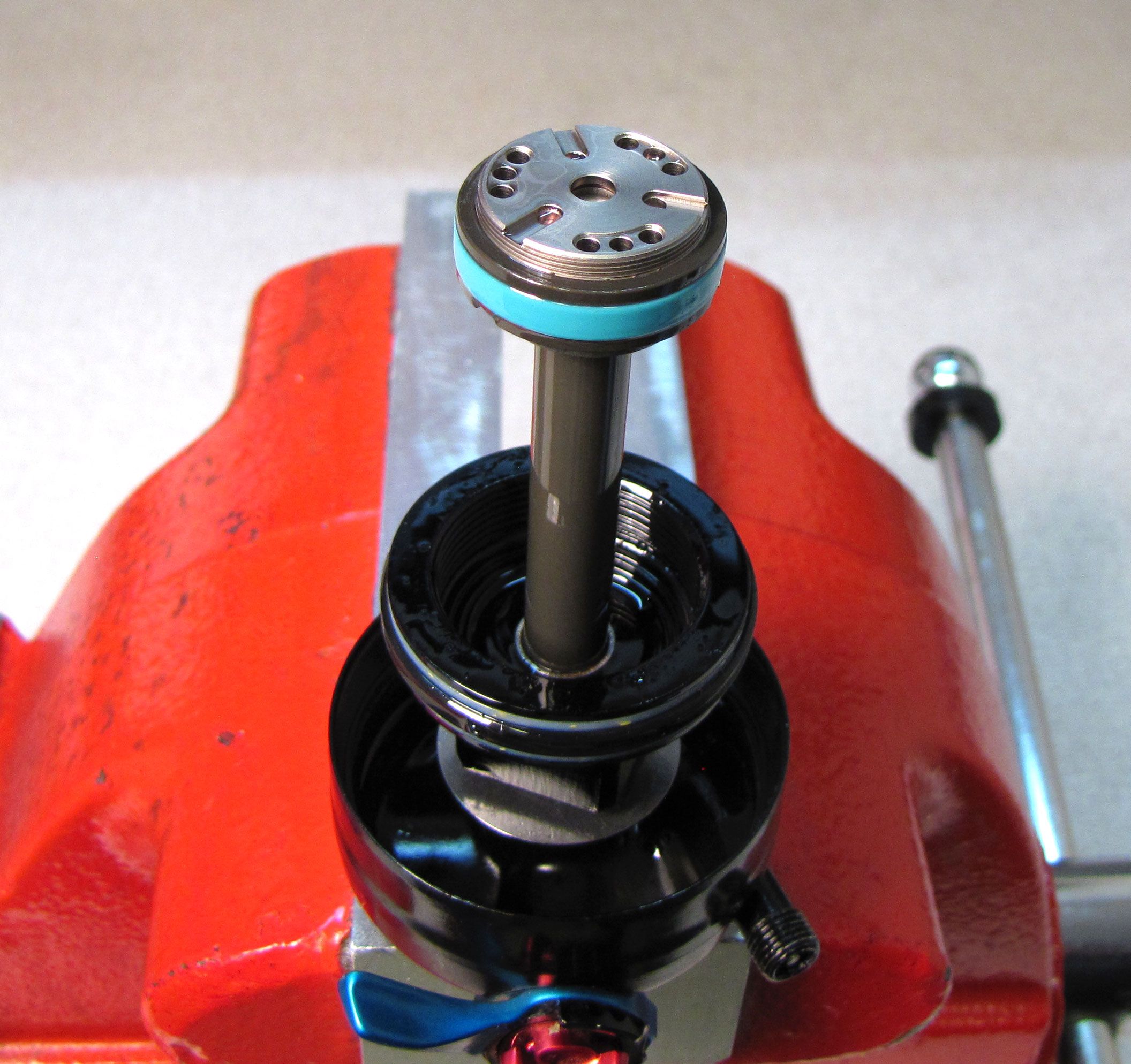
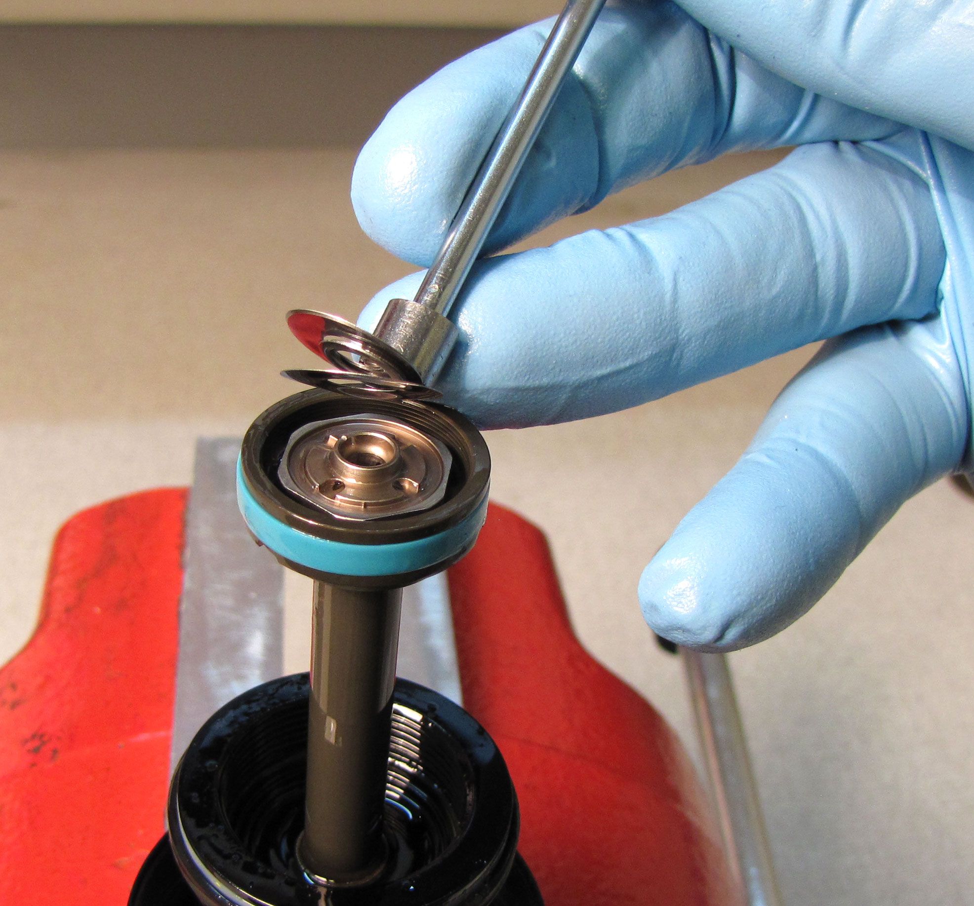
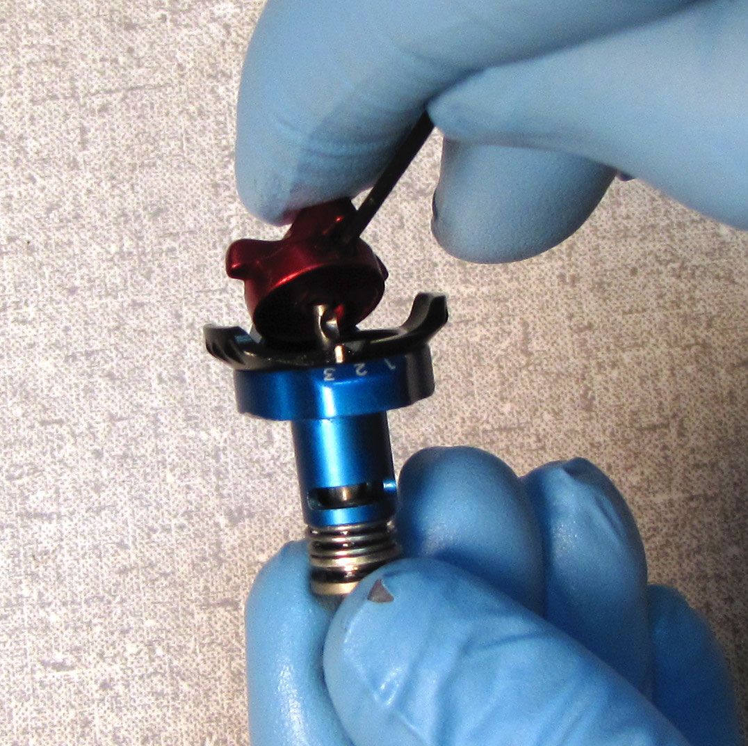
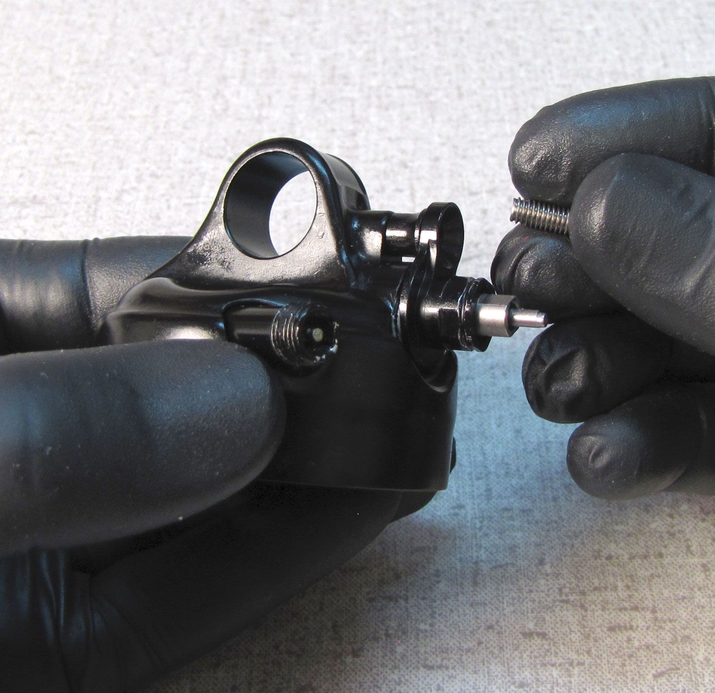
Step 13
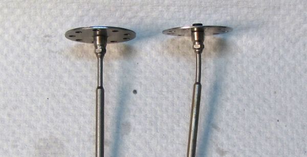
Remove the lockout piston then remove the lockout shim stack with a magnet.

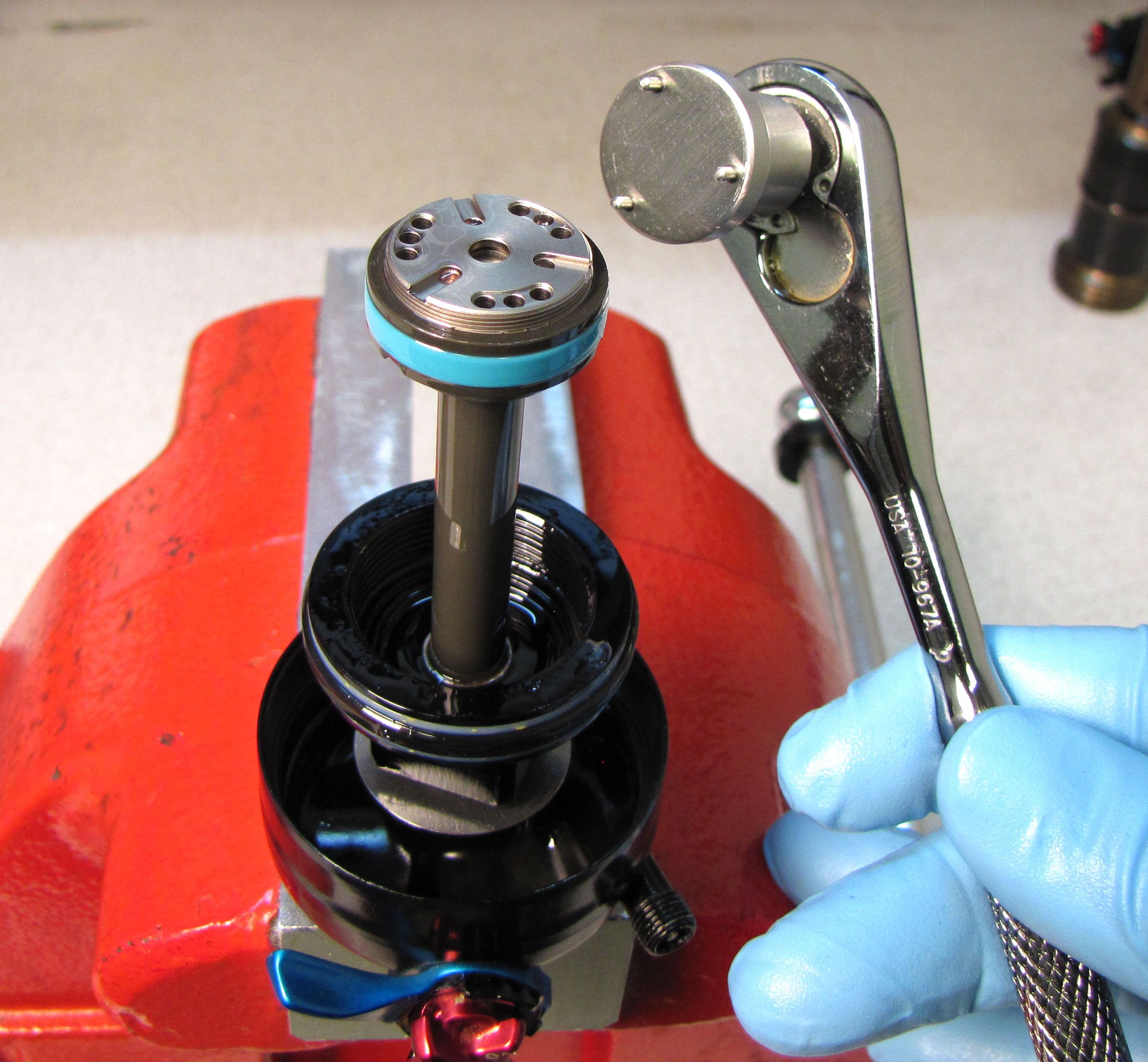
Step 14
Use the FLOAT DPS piston bolt tool (PN: 398-00-637) or the FLOAT SL piston tool (PN: 398-00-950) to unthread the piston bolt. Remove the piston assembly and set it aside.
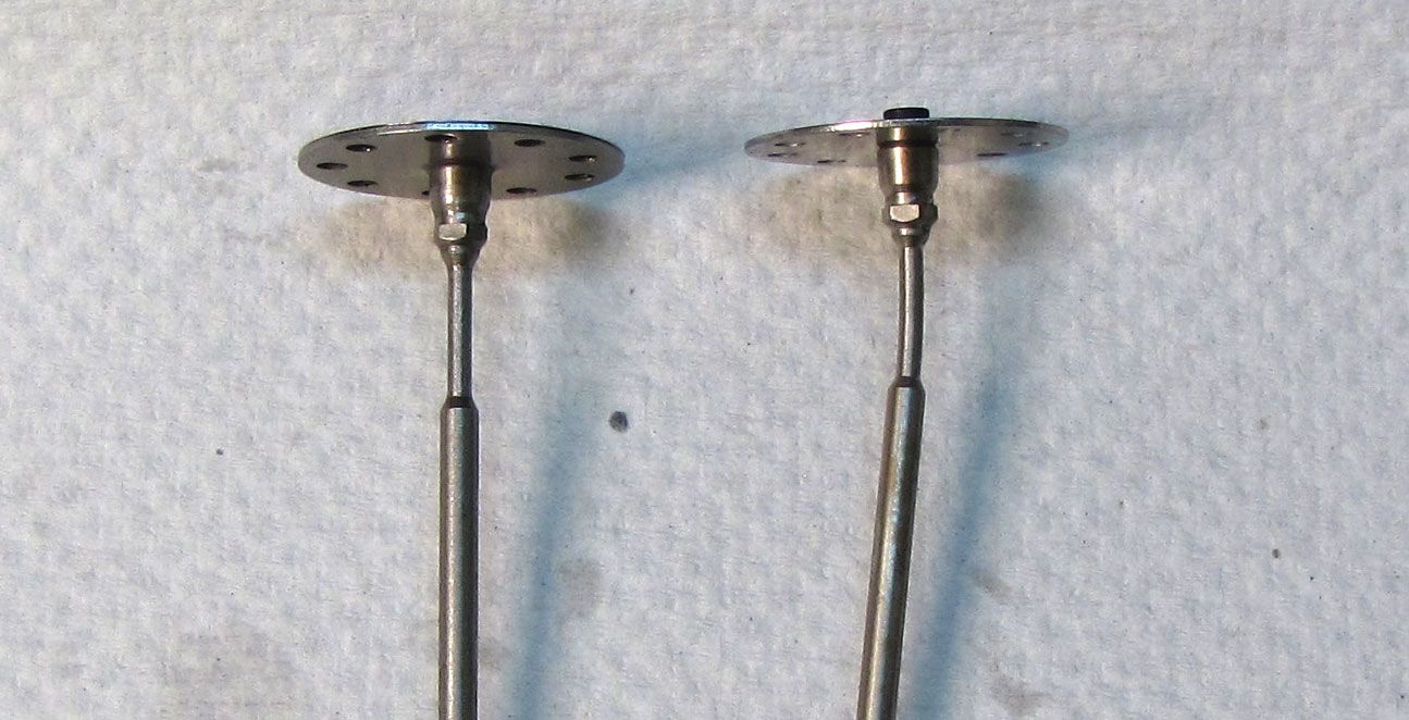
Step 15
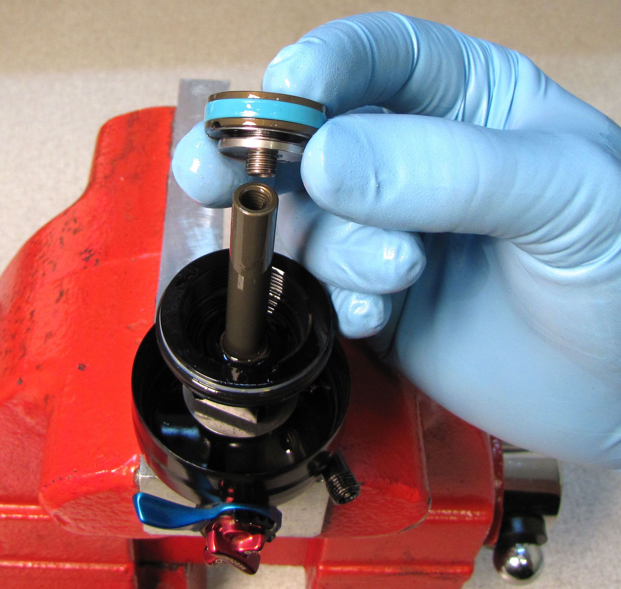
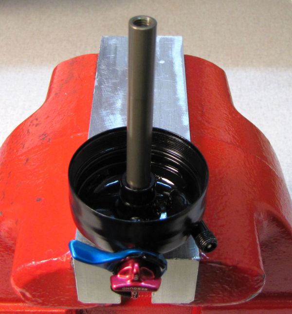
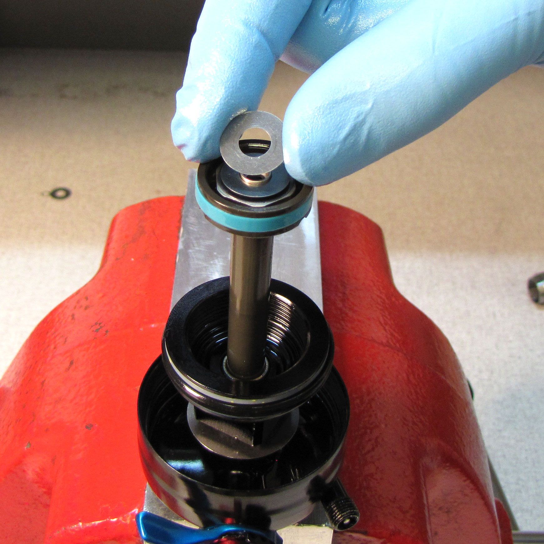
Remove the bearing assembly by lifting it off the shaft. Remove the bottom out o-ring and bottom out plate.

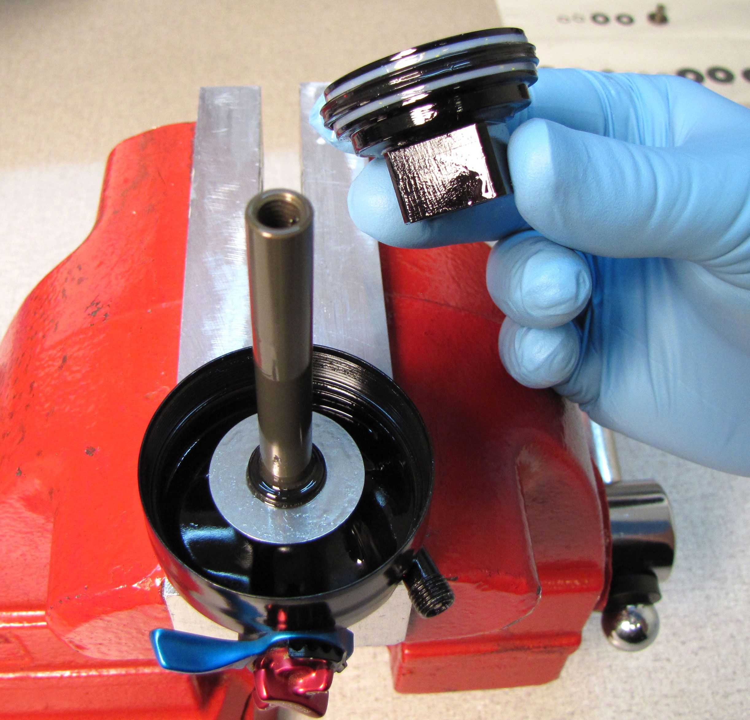

Step 16
Clean the shaft with Isopropyl alcohol and a lint-free paper towel. Carefully clamp the shaft in your 9mm shaft clamps (PN: 803-00-805).

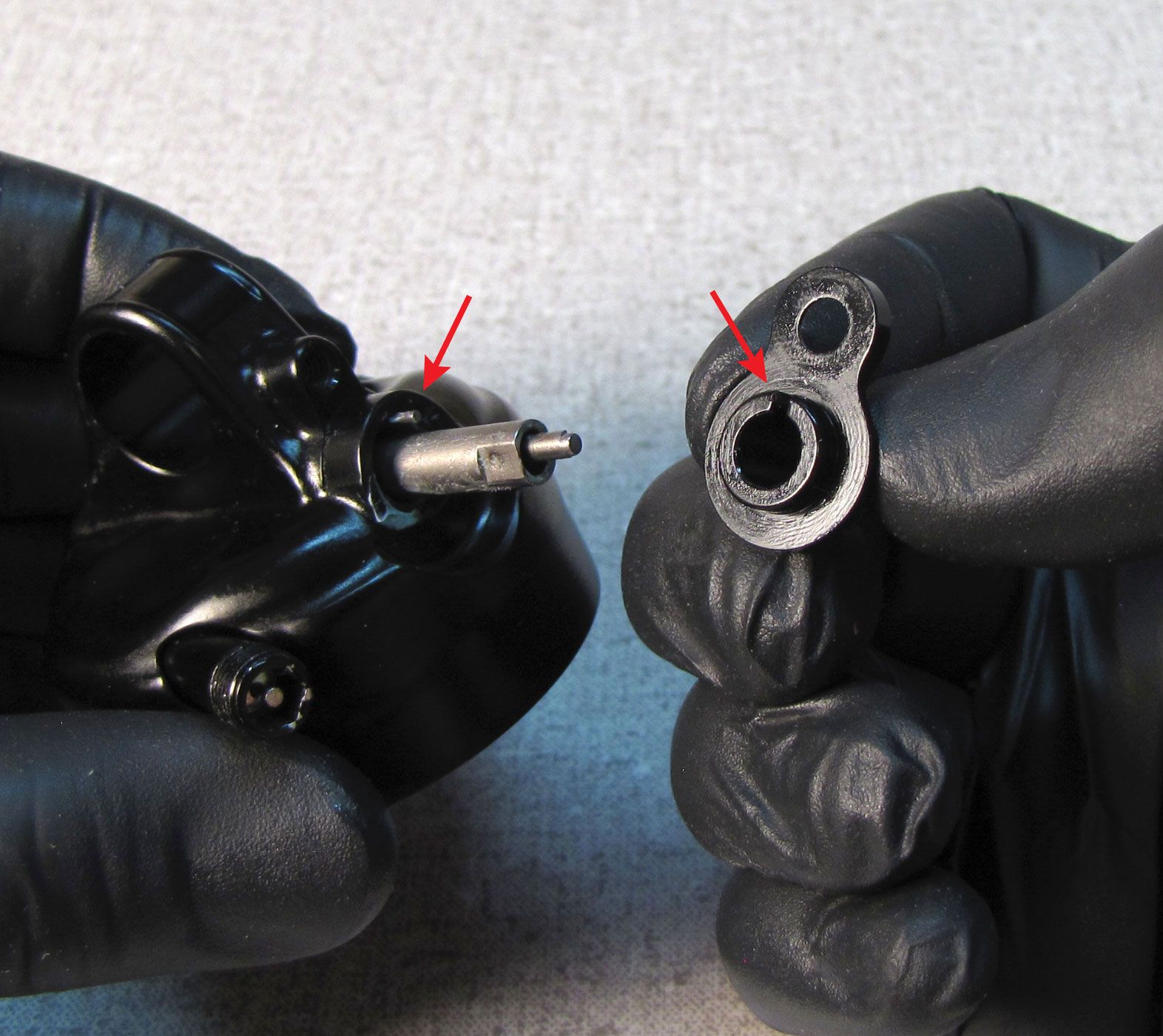
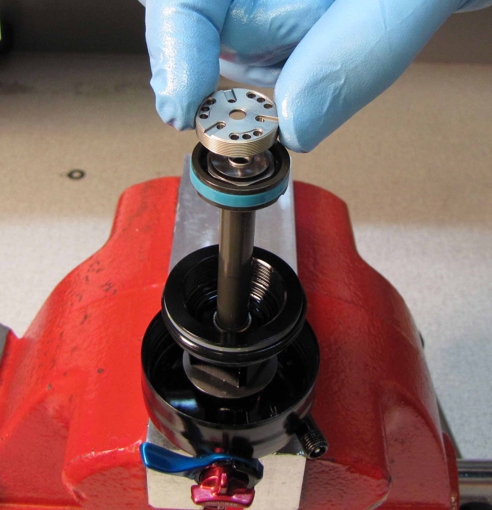
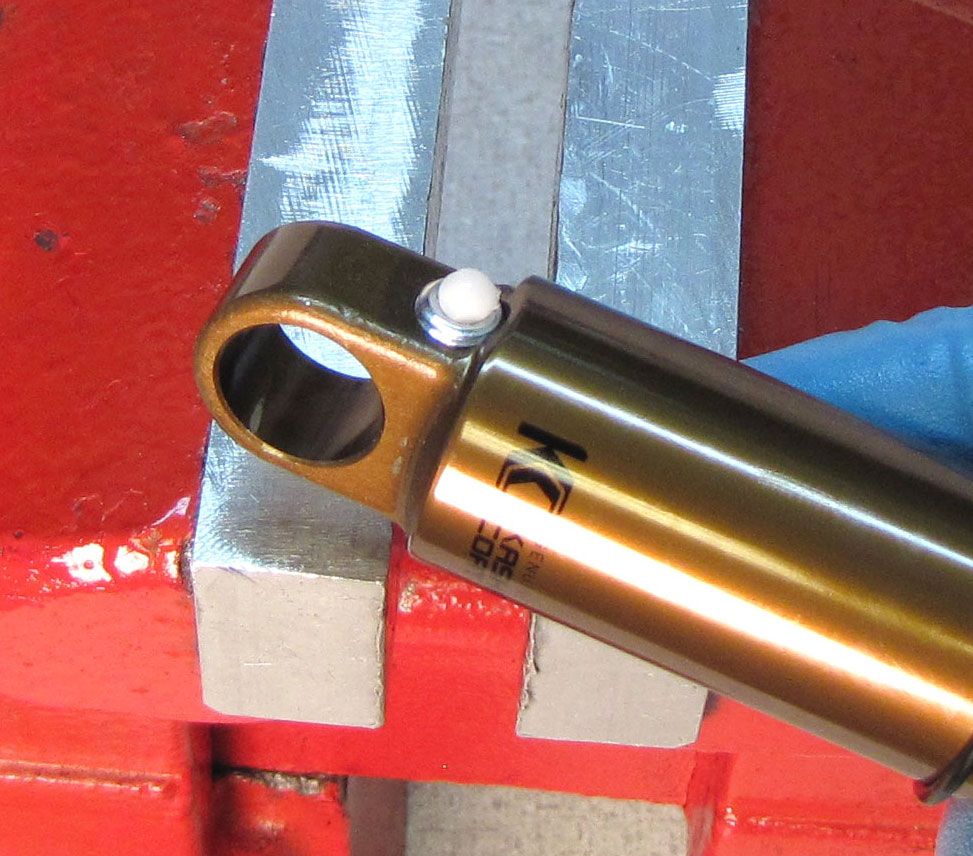
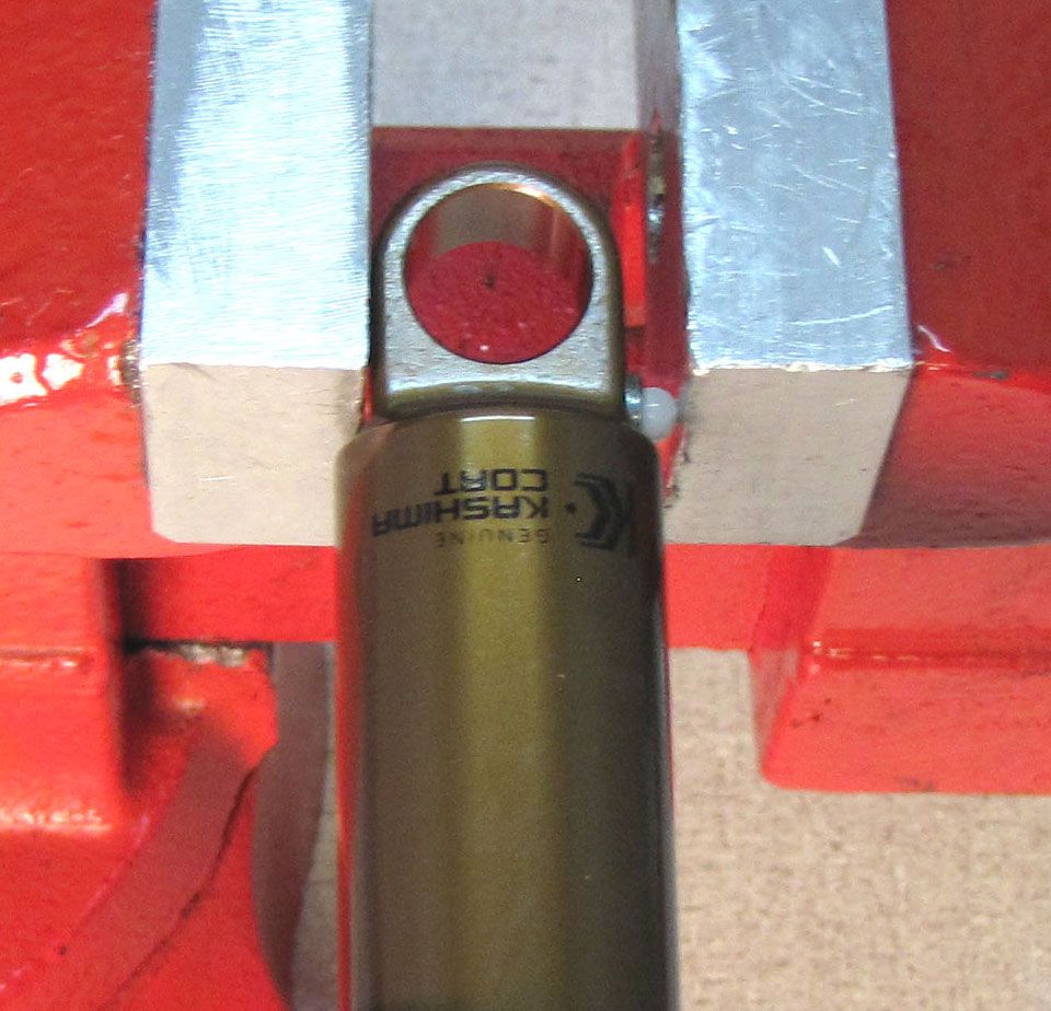
Step 17
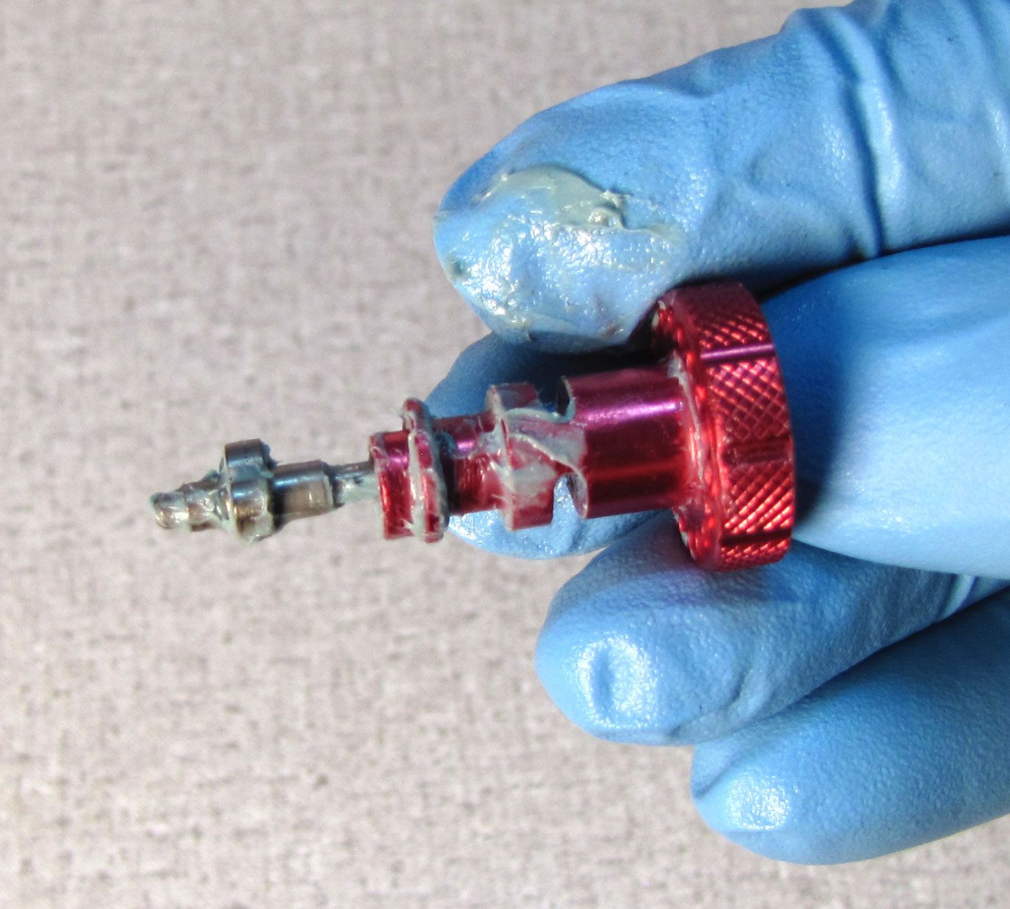
Carefully apply heat to the connection between the shaft and the eyelet with a propane torch for 5-10 seconds to break down the Loctite. Unthread the eyelet counter-clockwise, then lift up to remove.


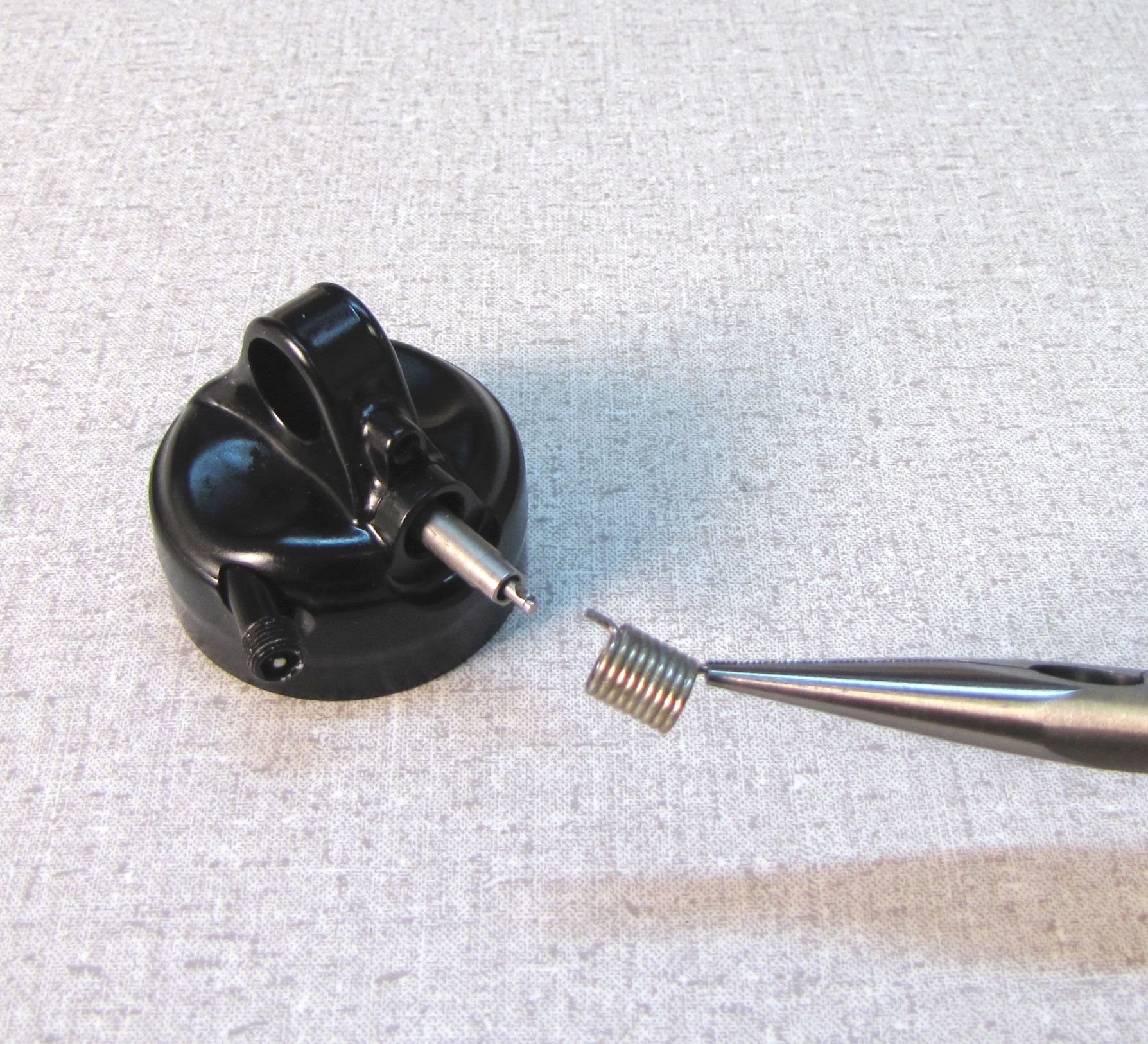
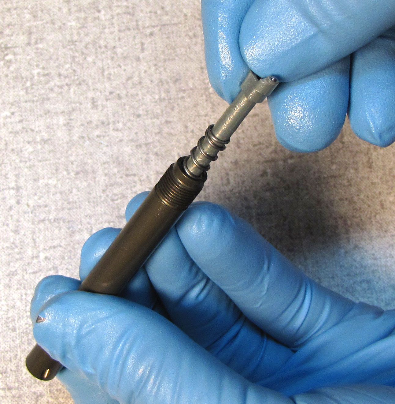
Step 18
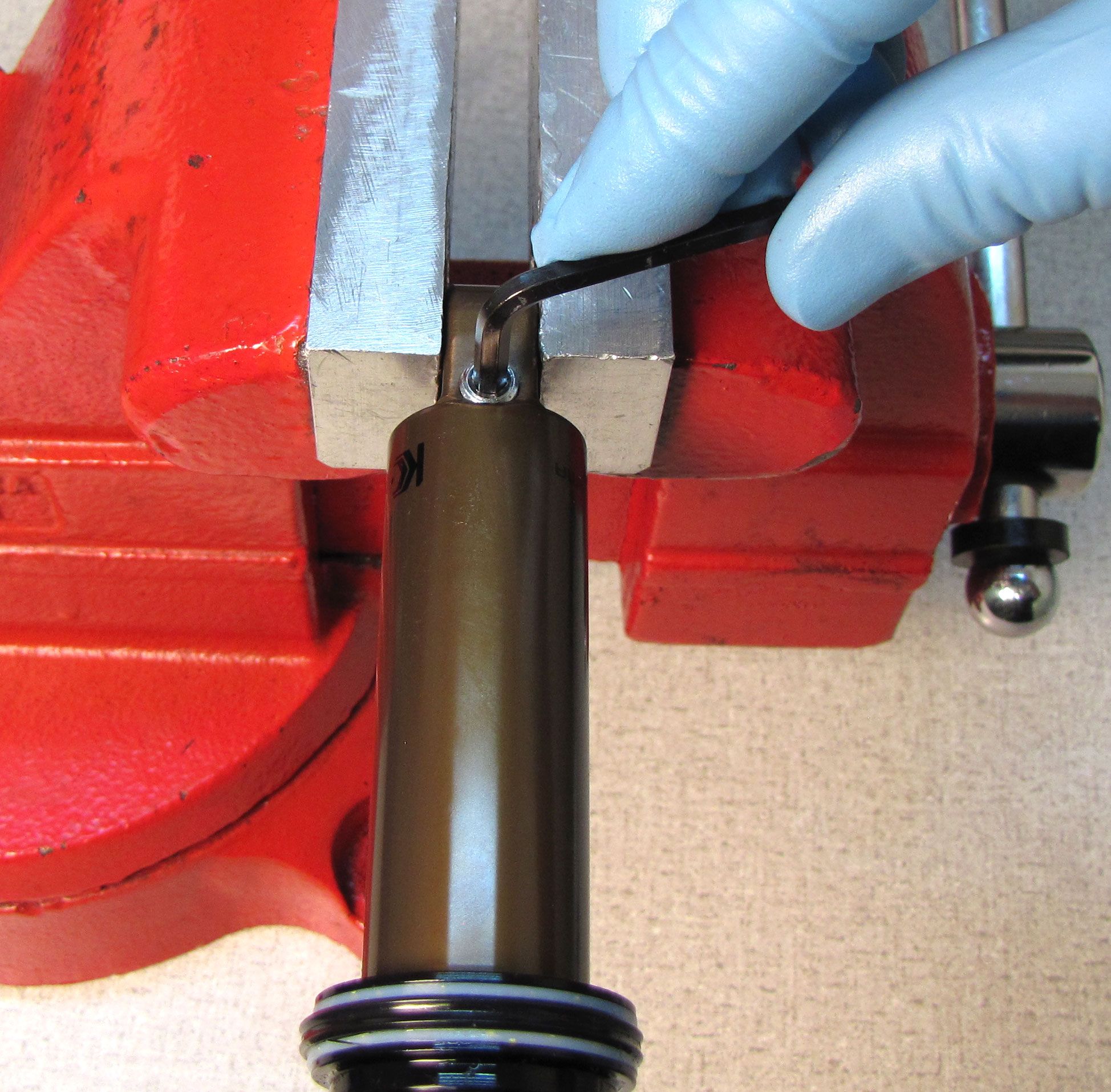
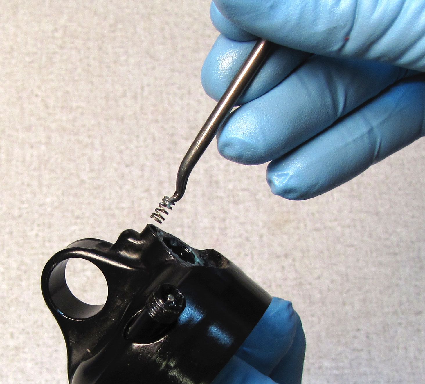
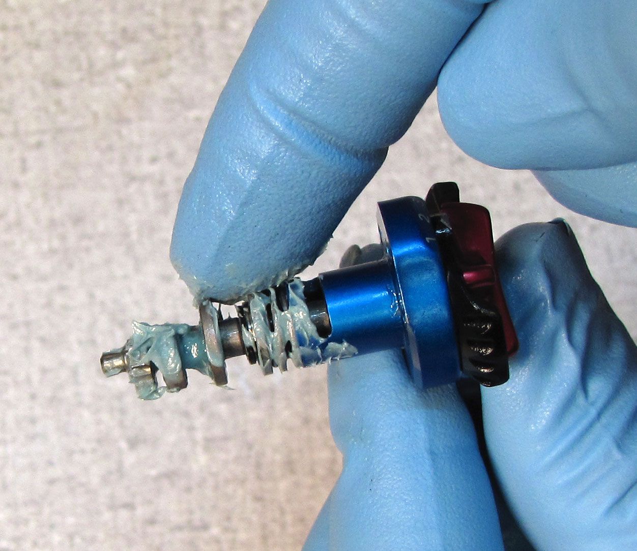
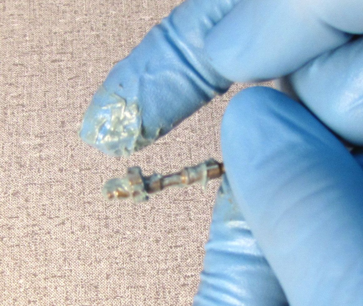
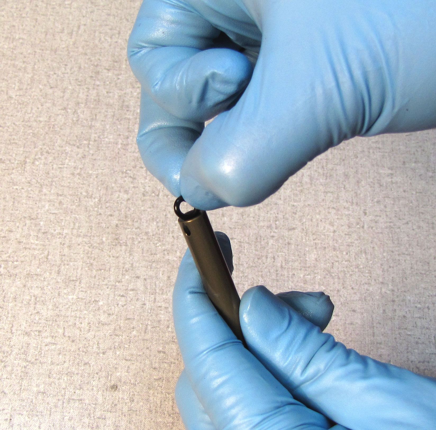
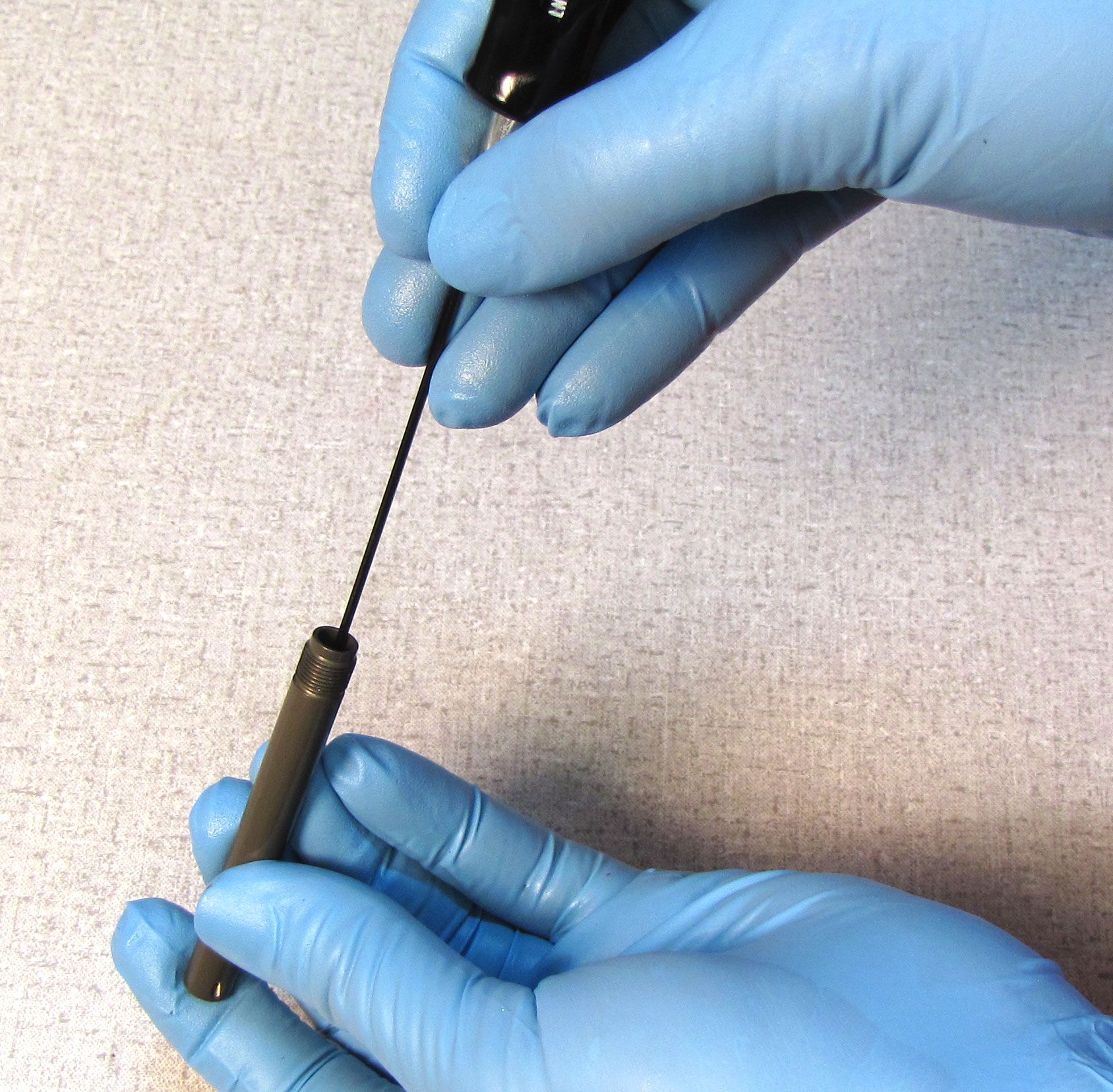
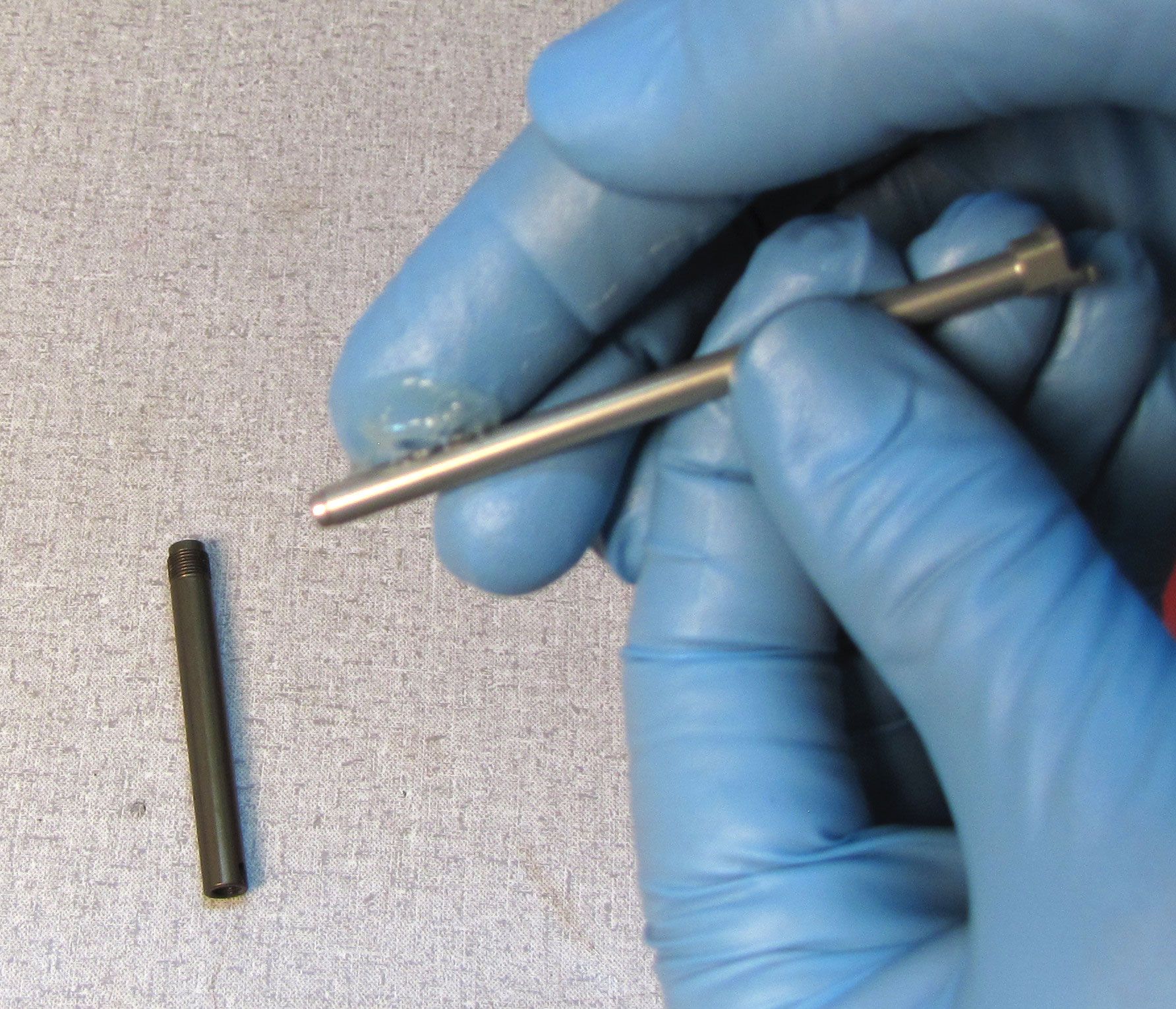
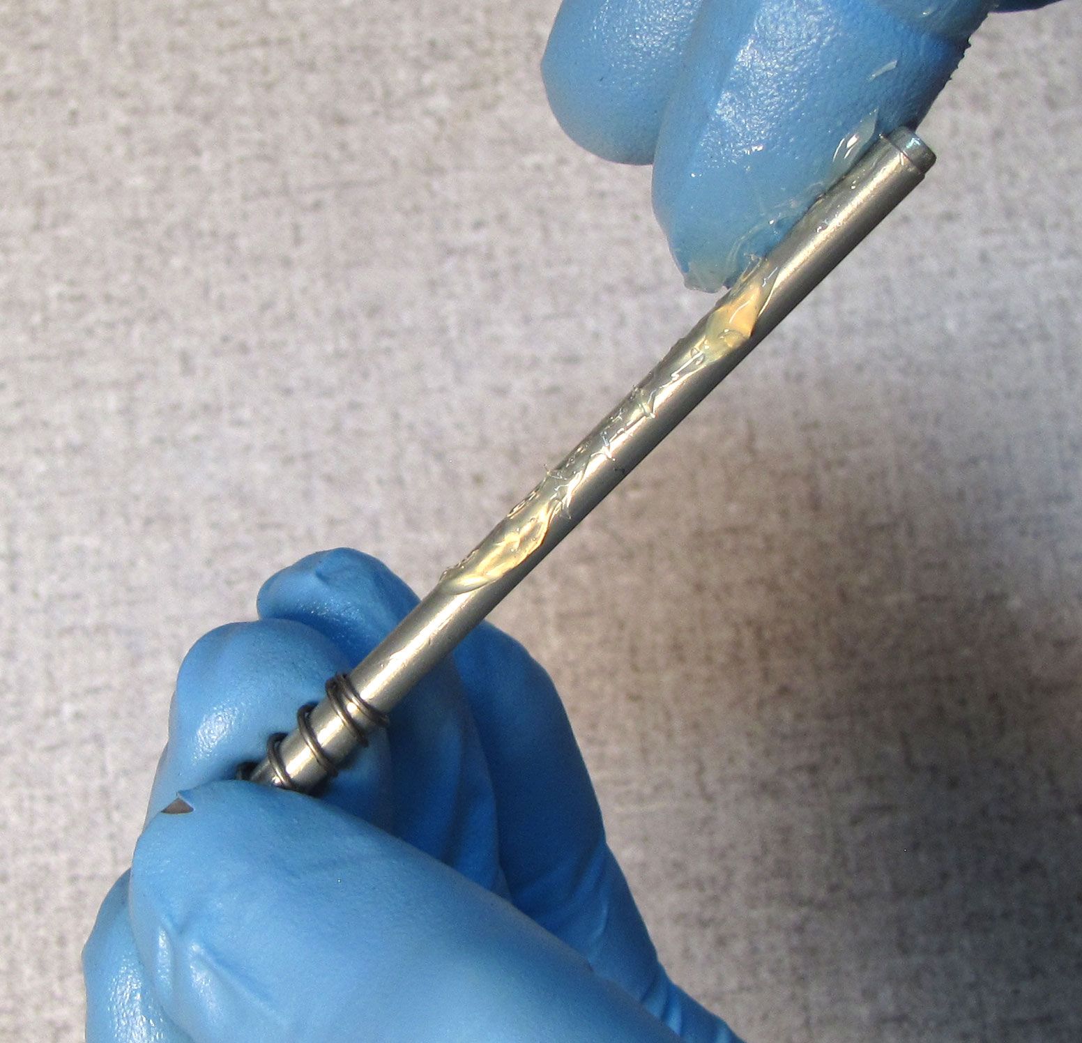
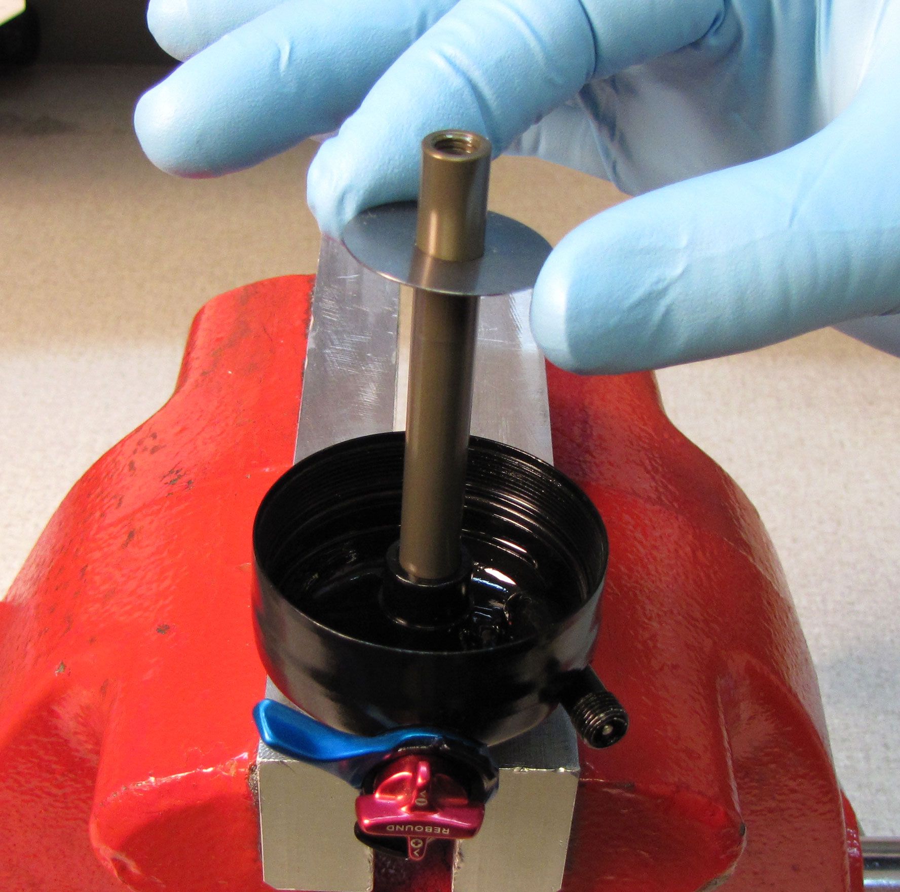
Remove the rebound metering rod by pulling it up and out of the shaft. Be careful not to lose the small ball bearing at the square end of the rebound metering rod. Carefully remove any Loctite residue from the shaft and eyelet with a plastic pick tool.
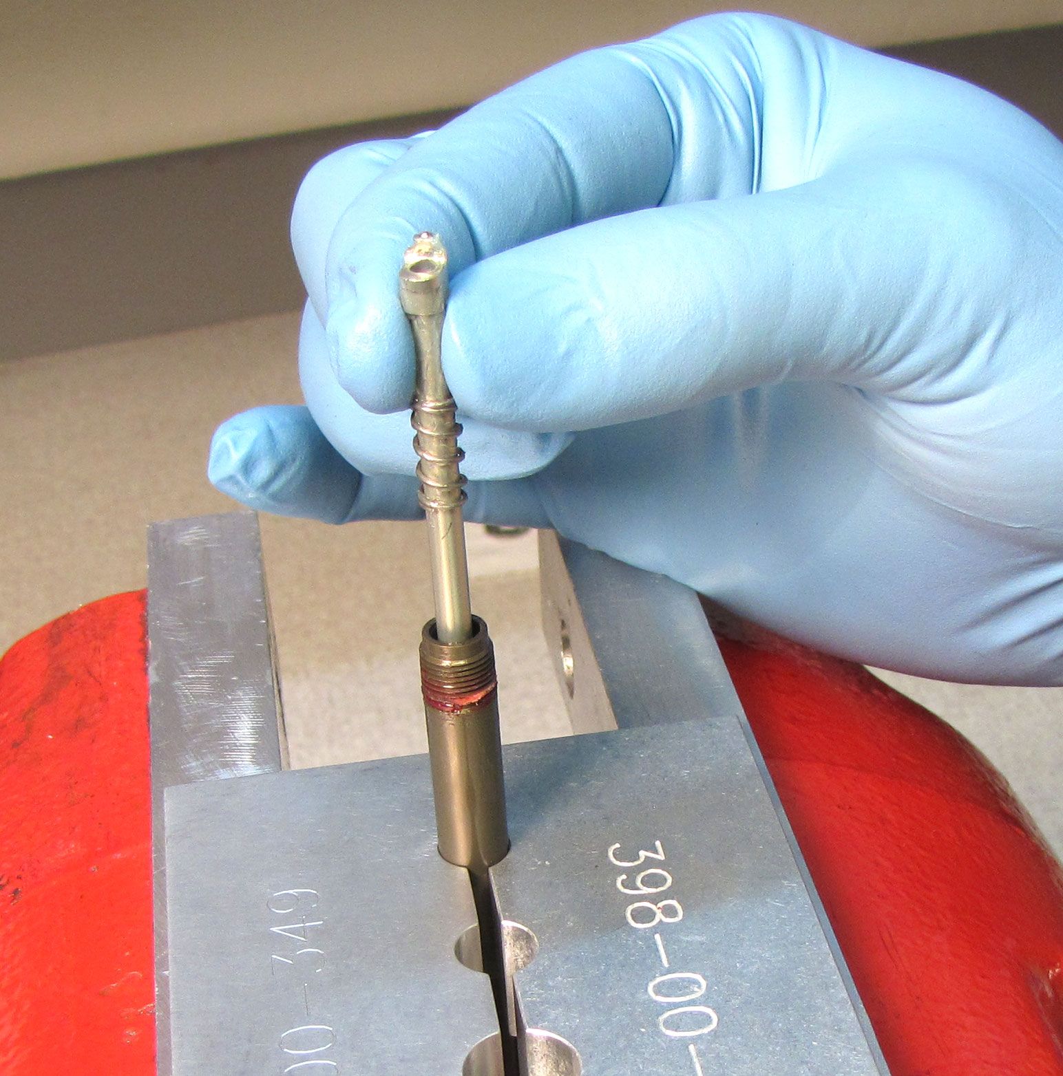
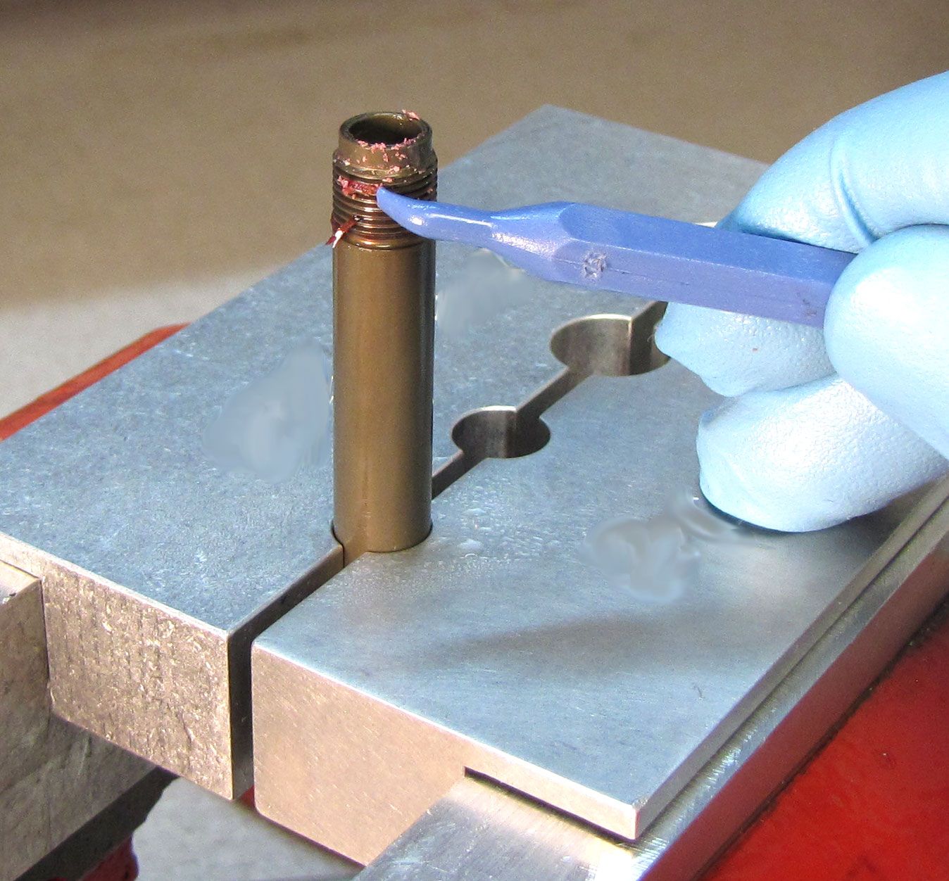

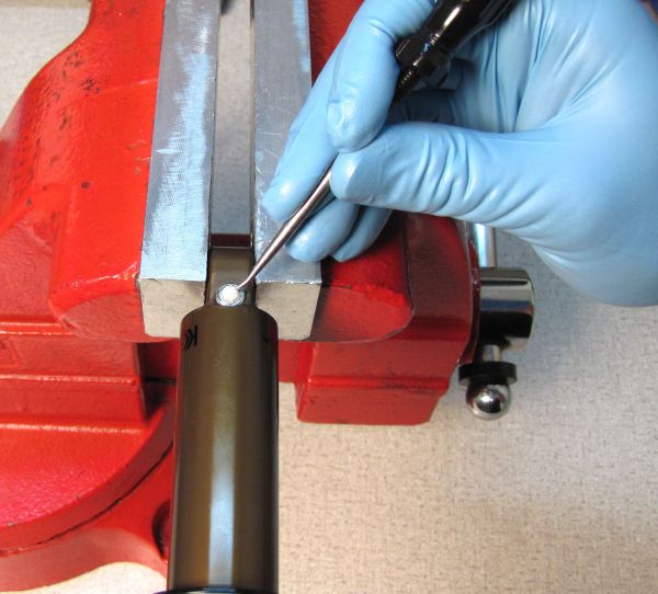
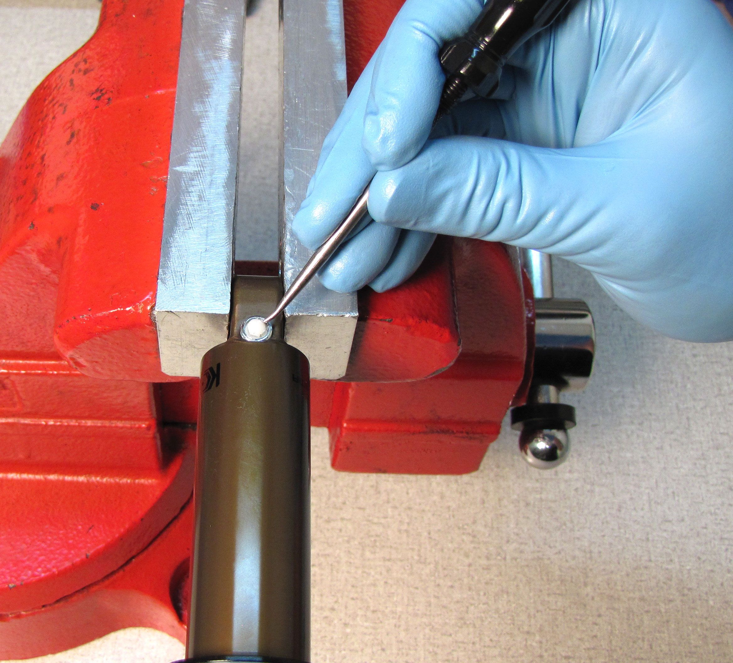
Step 19
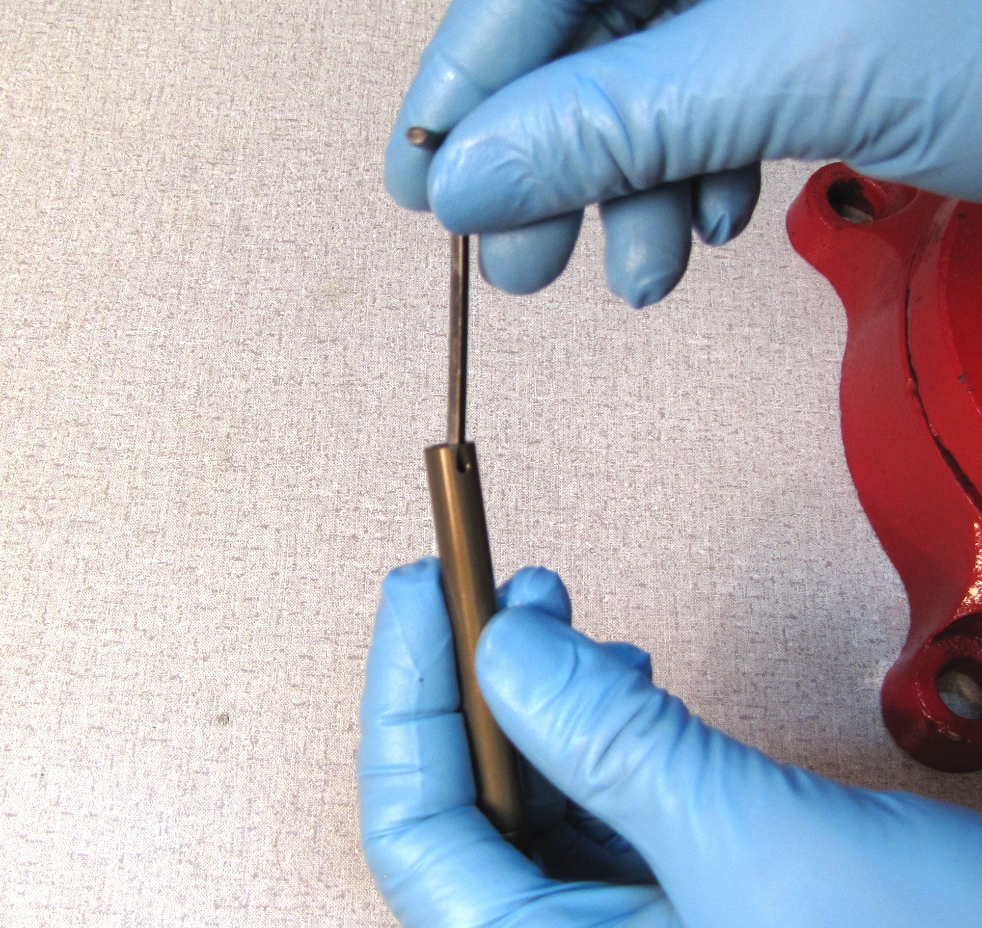
Carefully remove the o-ring from inside the shaft with a pick tool. A blunt tool like a small hex wrench can be used inside the shaft to push the o-ring out once pulled away from the wall with the pick tool.
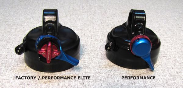
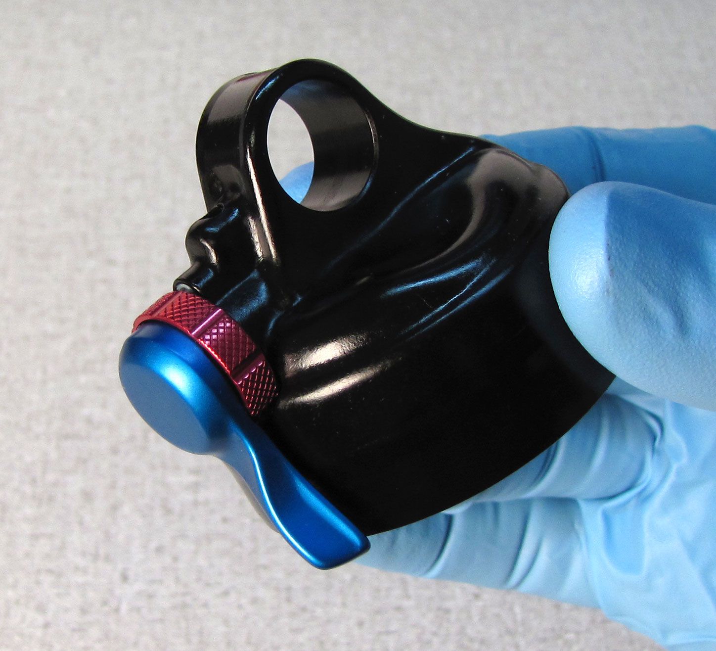
Factory and Performance Elite Series Eyelet Rebuild
Eyelet assemblies do not need to be rebuilt as part of a standard shock service. You should only disassemble the eyelet assembly in order to replace damaged or missing parts or to clean out contamination if the adjusters feel gritty when used. If not rebuilding the eyelet assembly, please go to General Reassembly »
Step 1
The Factory and Performance Elite Series eyelet assemblies are identical to each other but different from the Performance Series eyelet. For instructions to service the Performance Series eyelet assembly you can skip to that section by going to Performance Series Eyelet Rebuild »

If servicing a Remote shock you can skip the Factory/Performance Elite and Performance Series Eyelet Rebuild sections and continue servicing your shock by going to Remote Eyelet Rebuild »
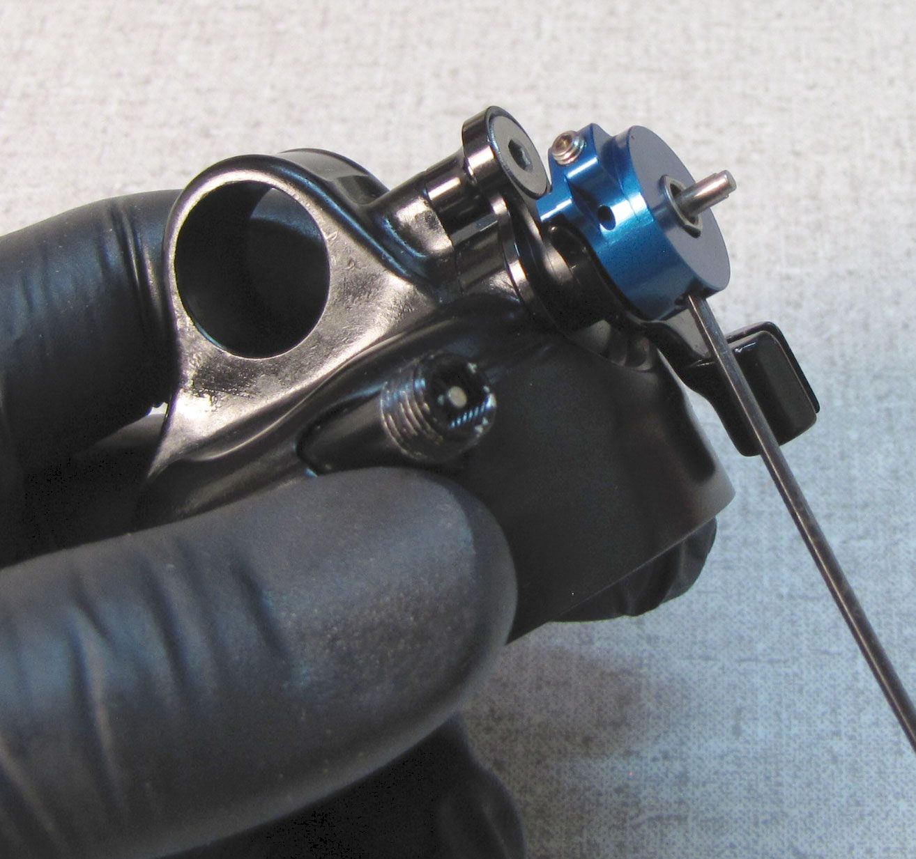
Step 2
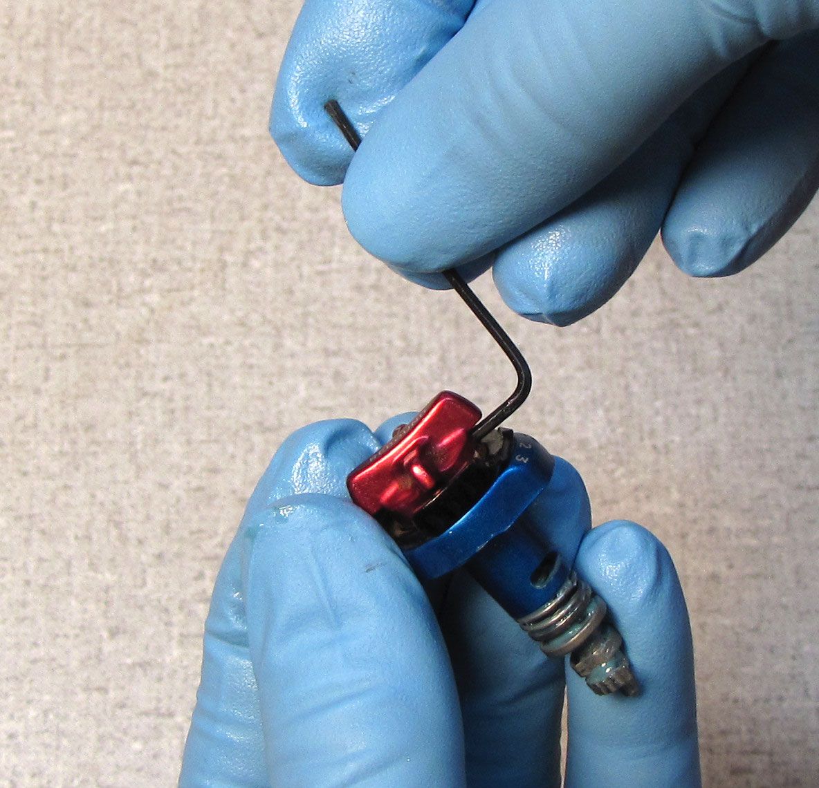
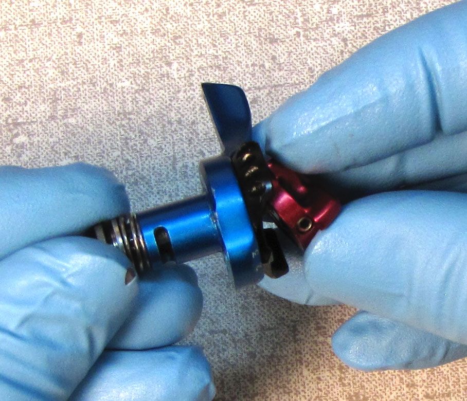
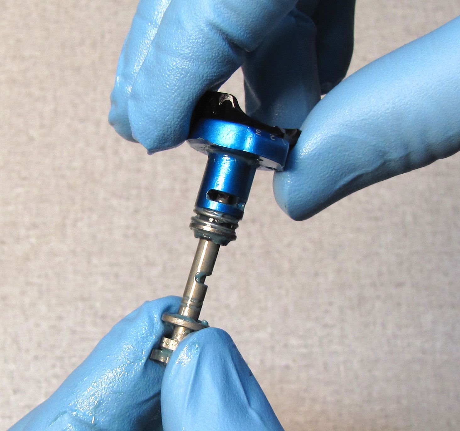
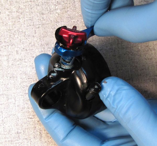
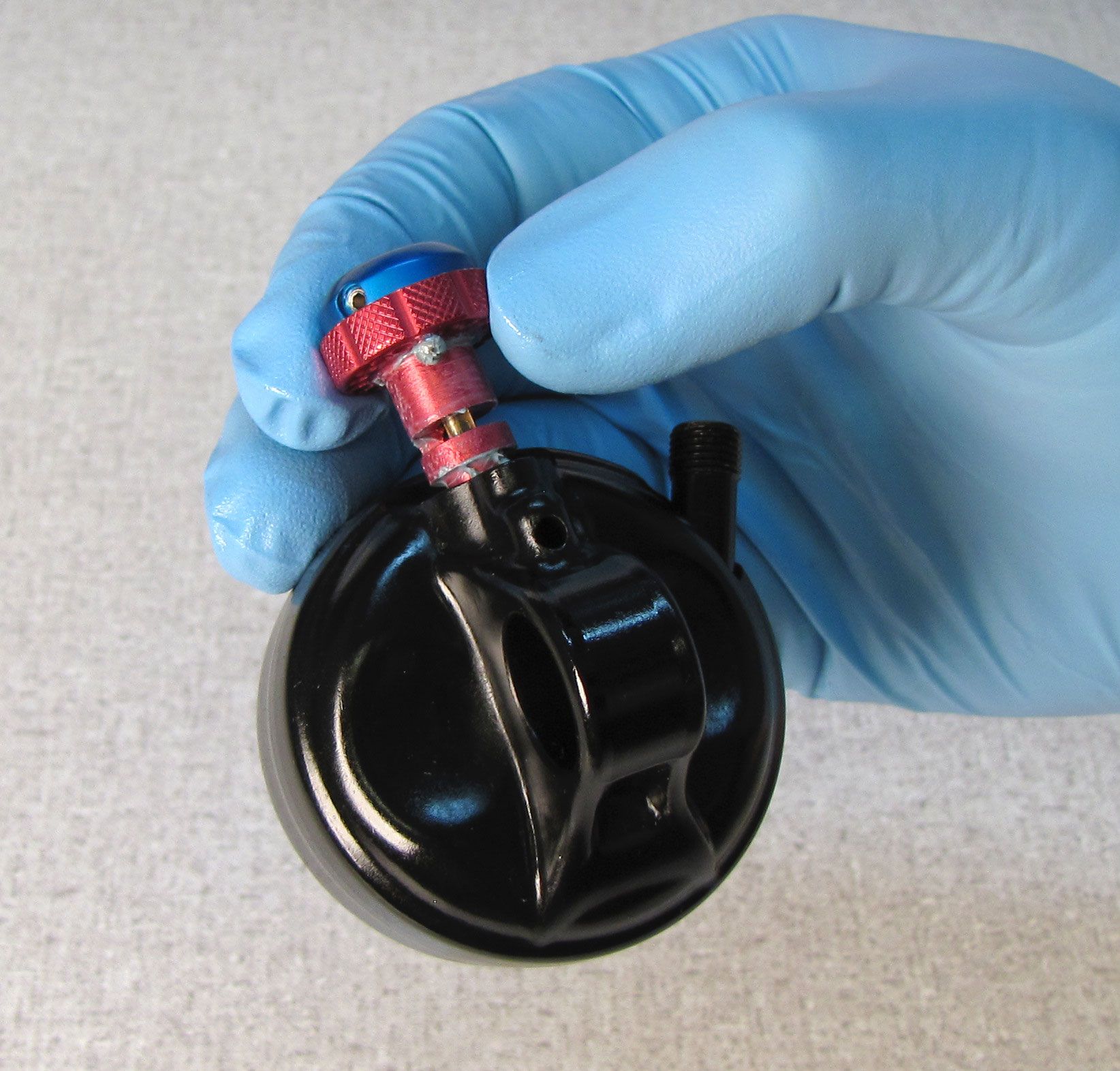
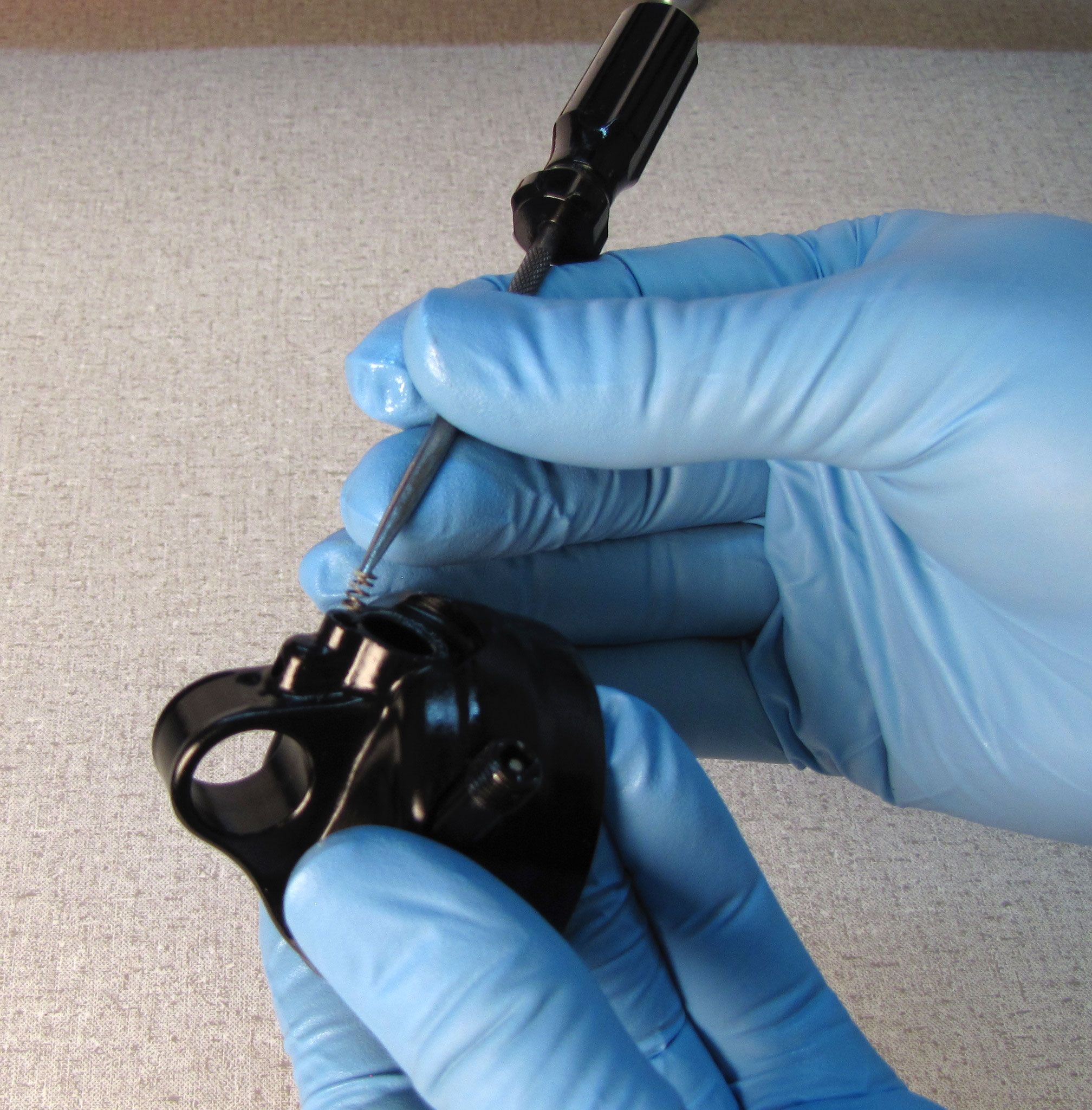
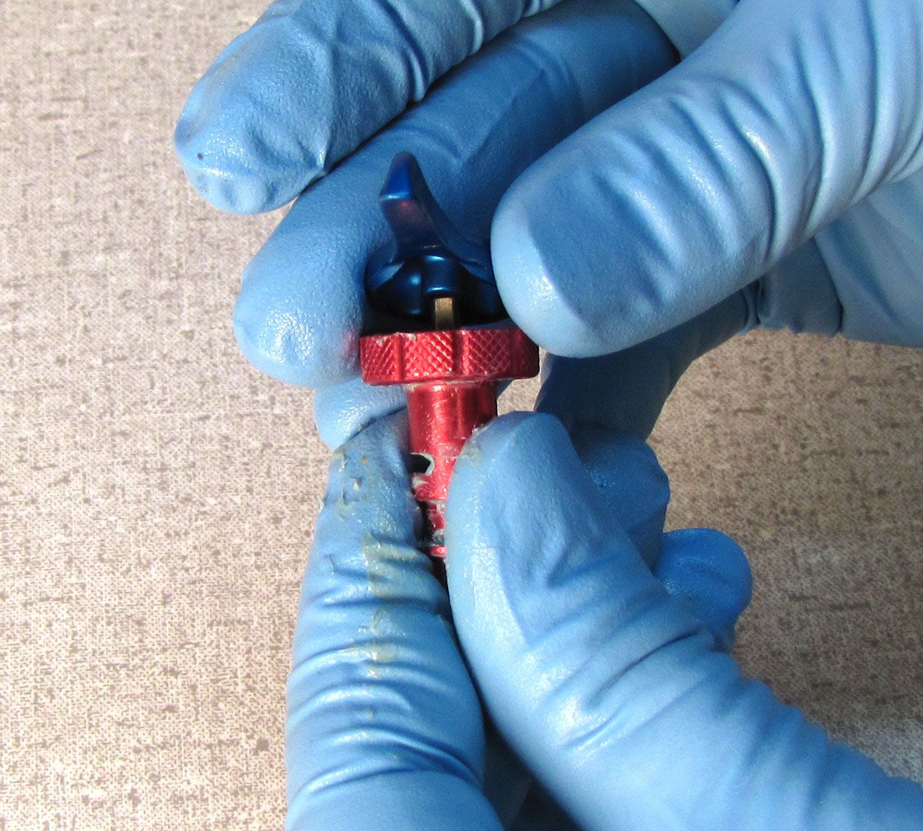
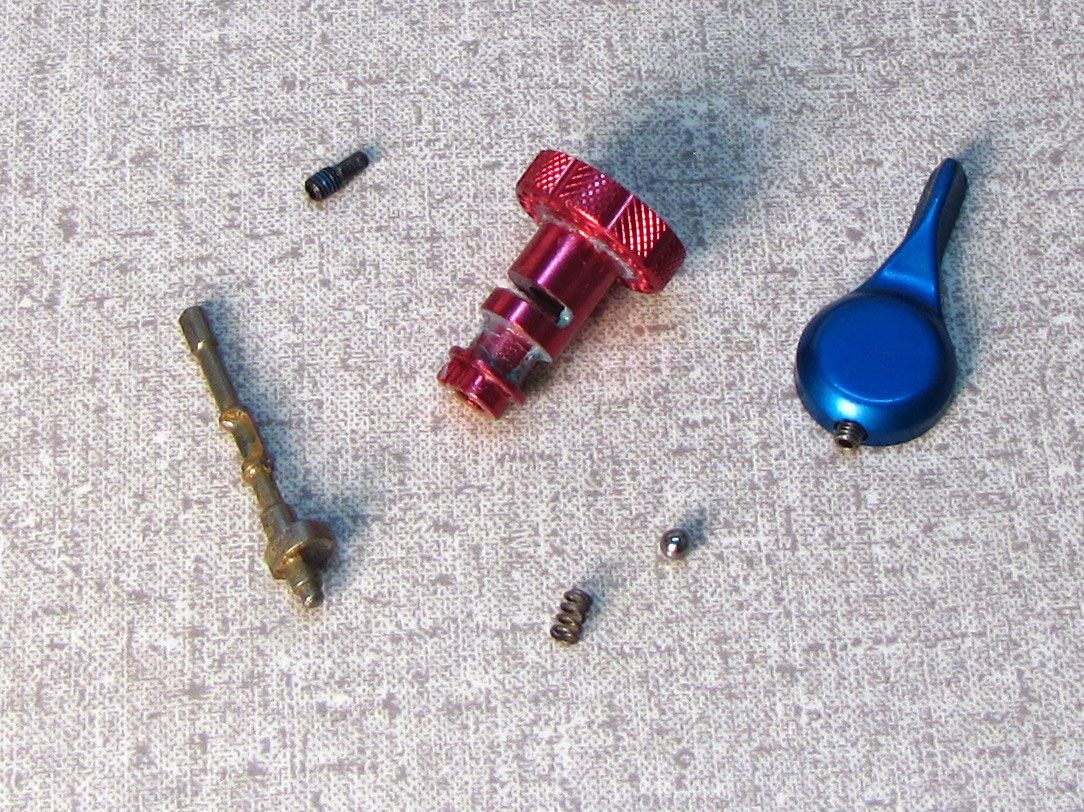
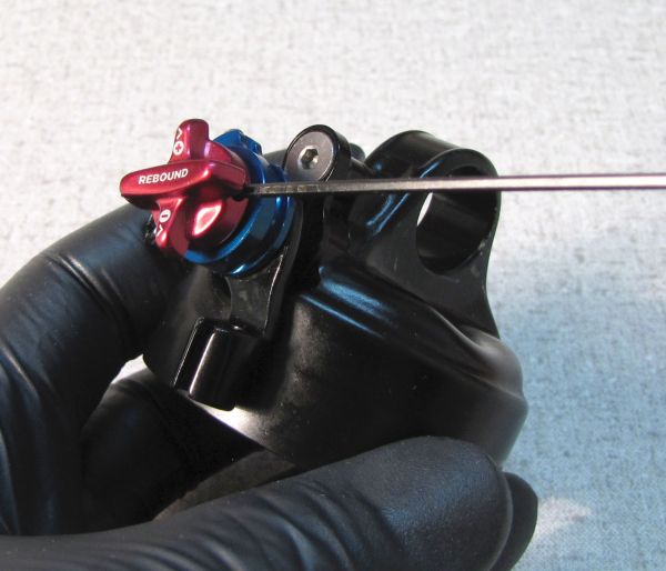
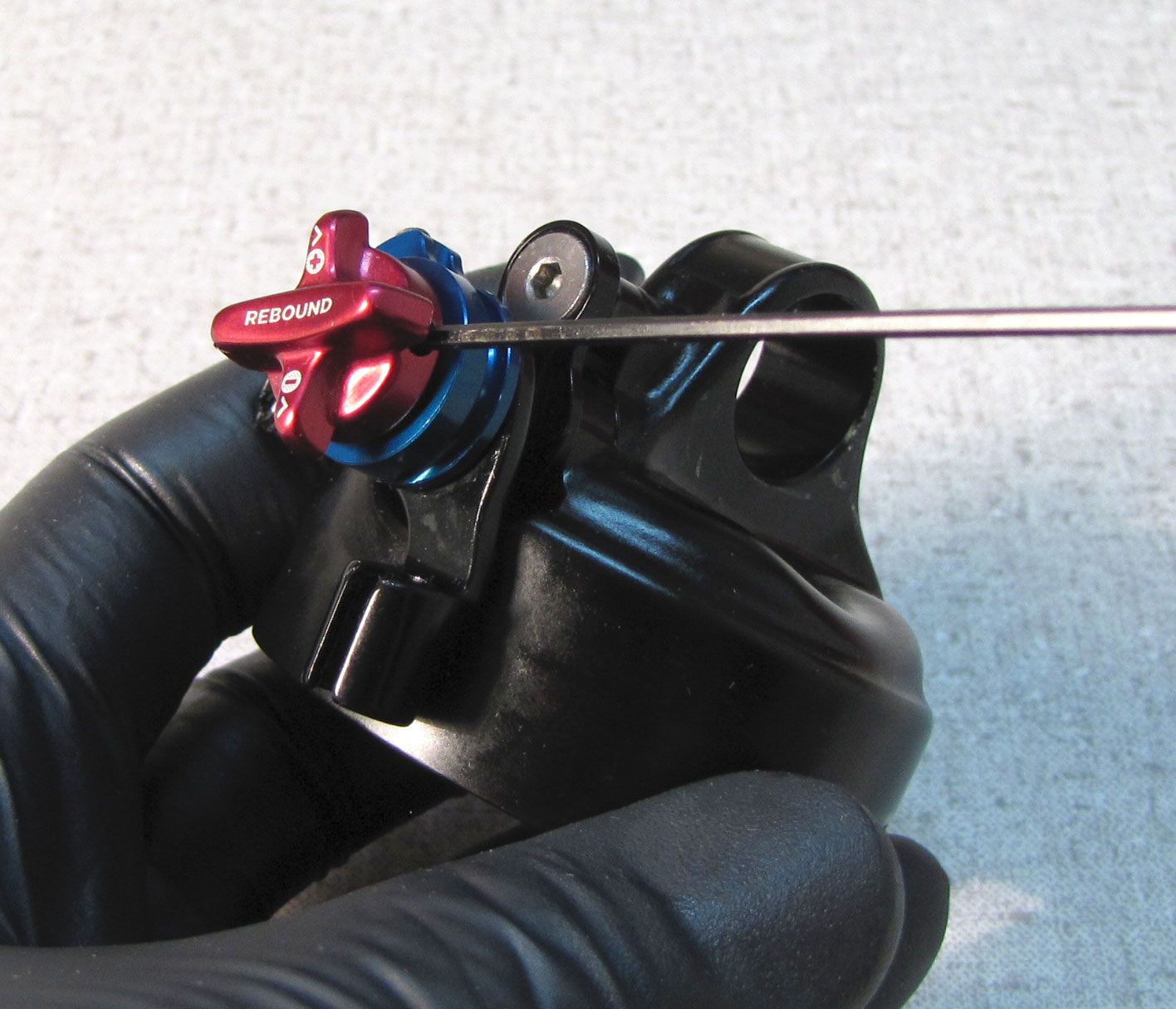
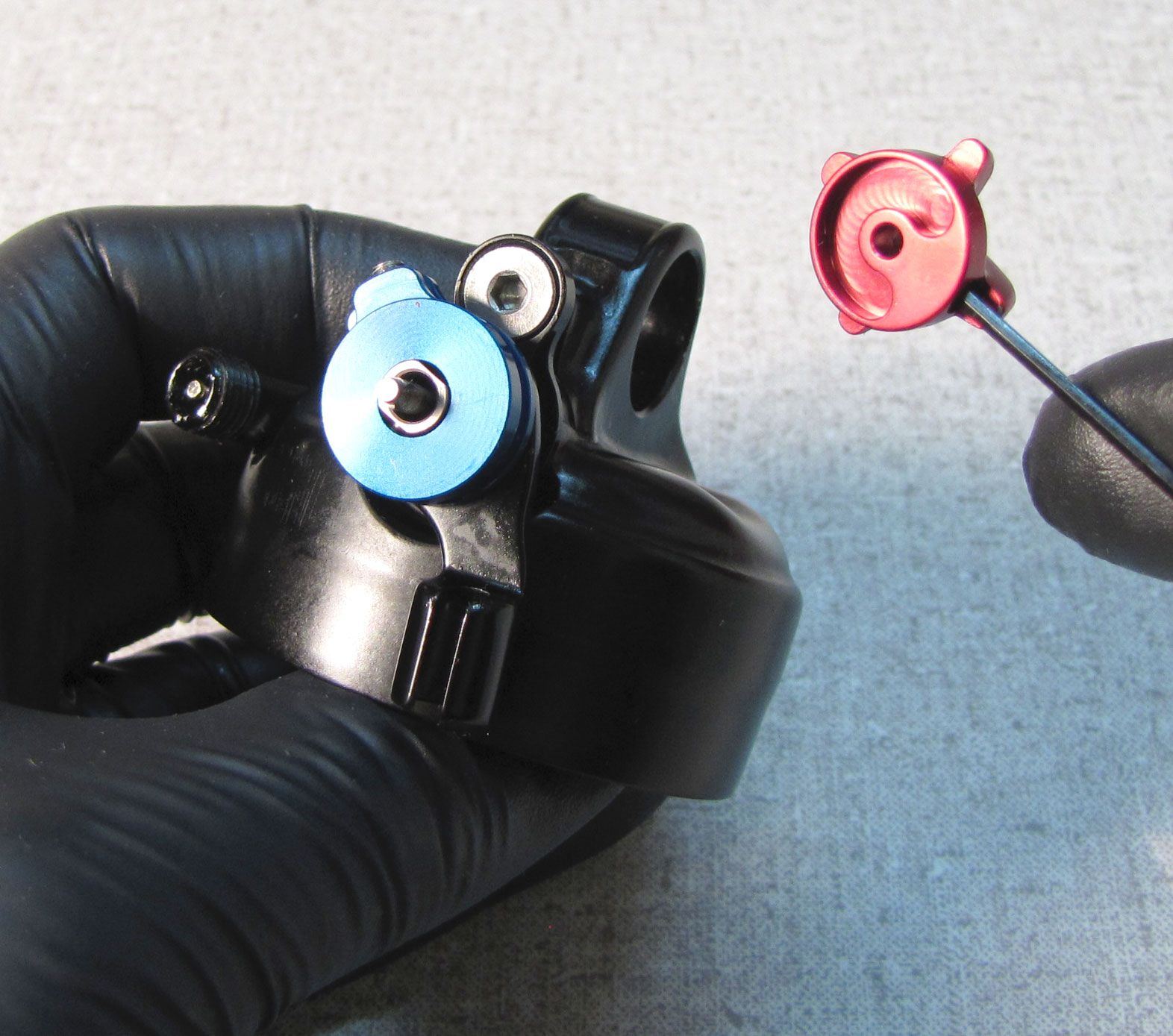
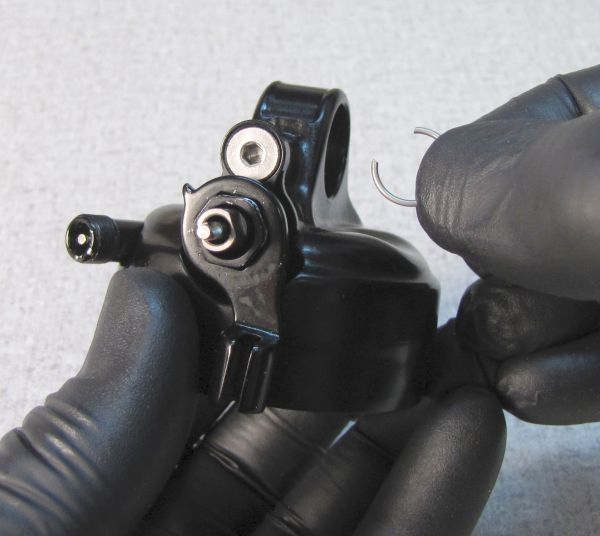
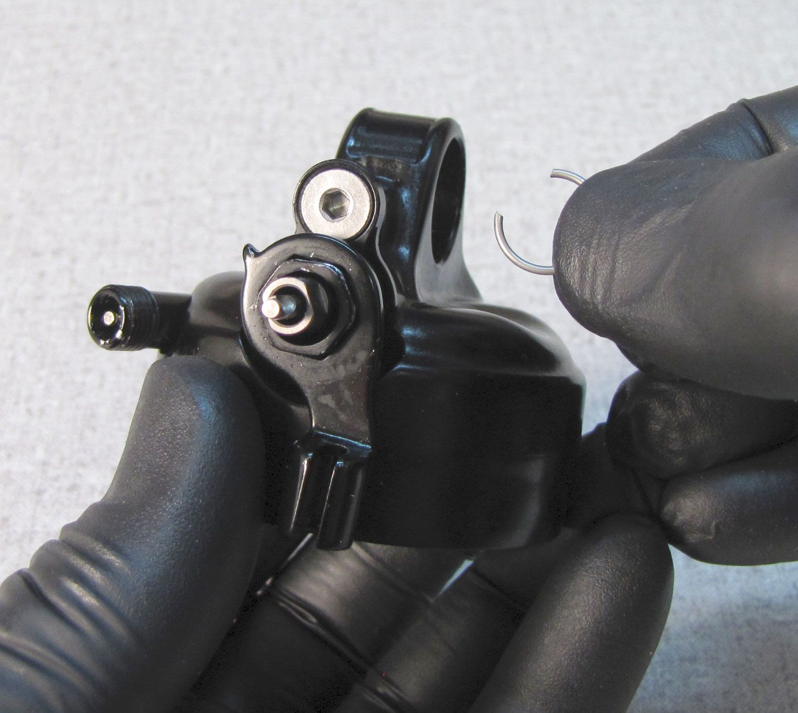
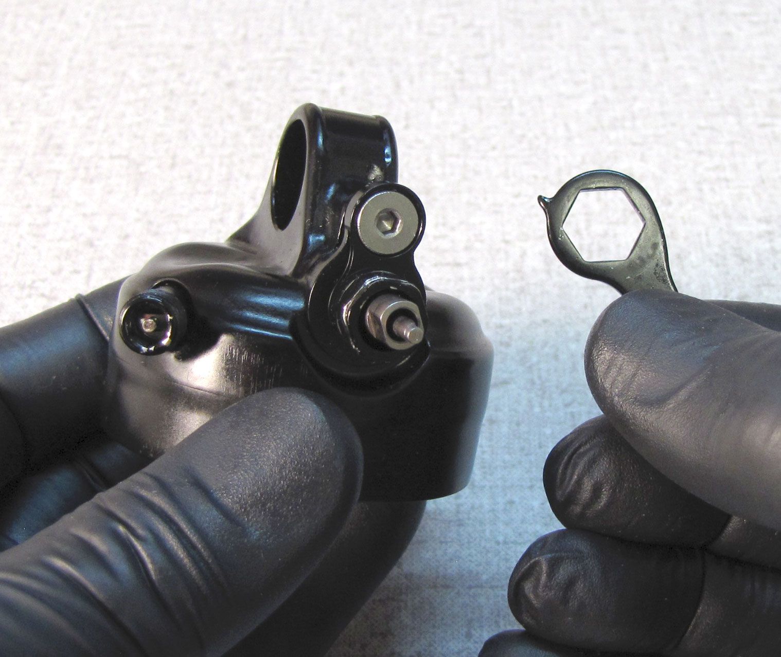
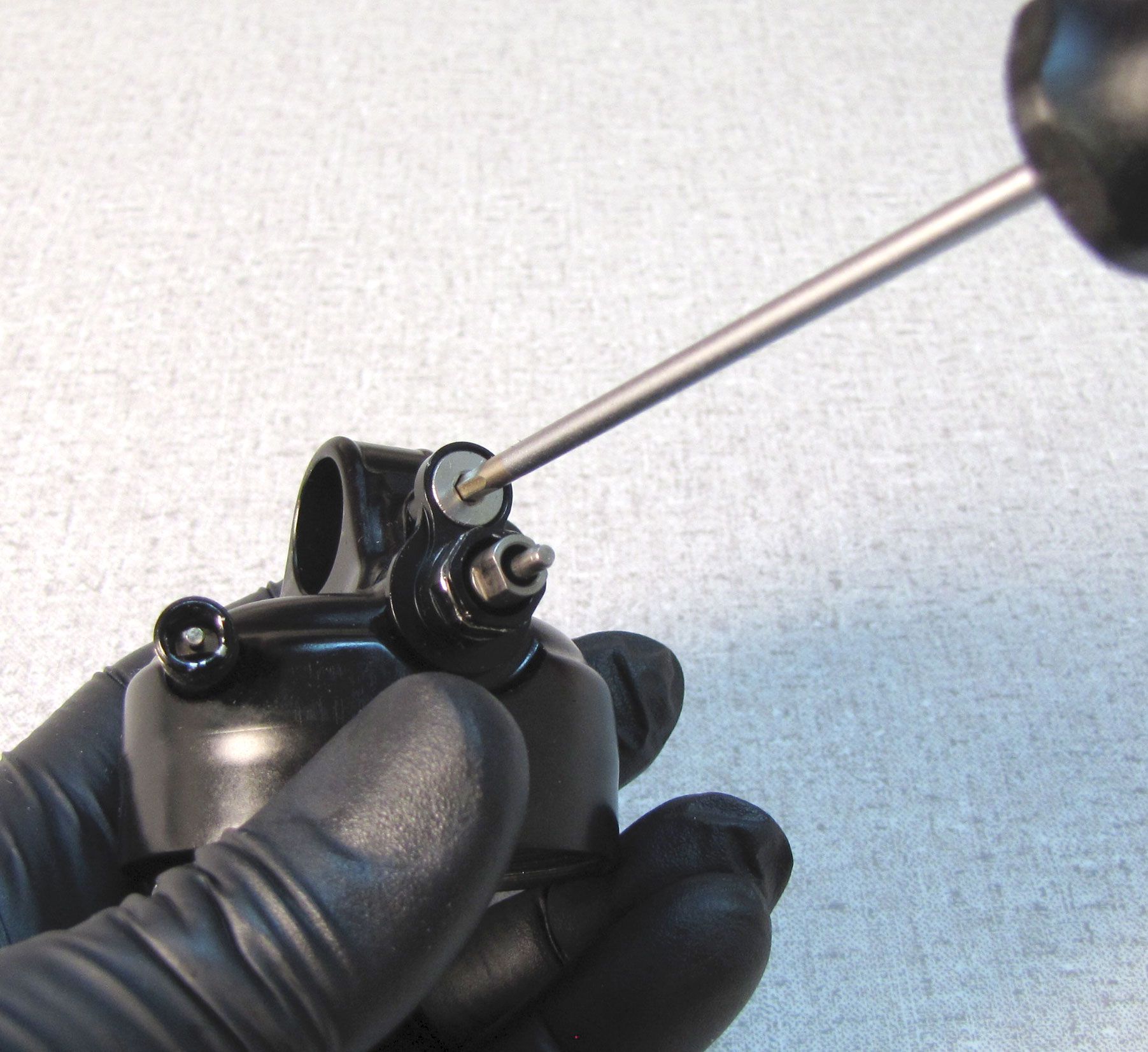
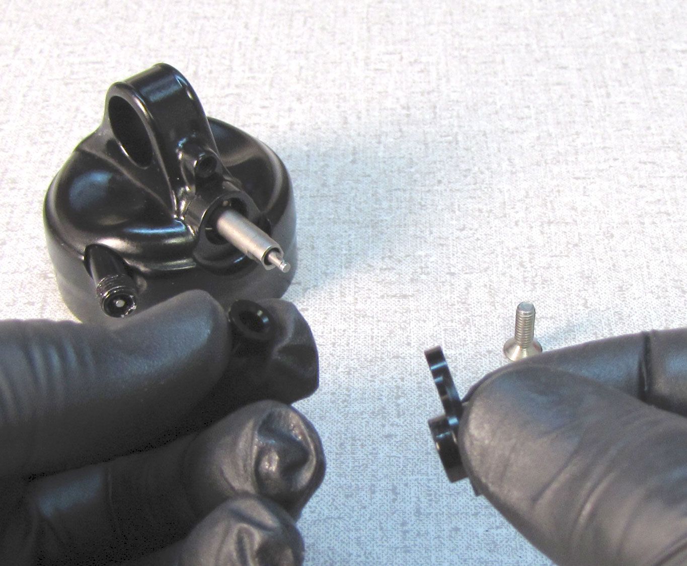
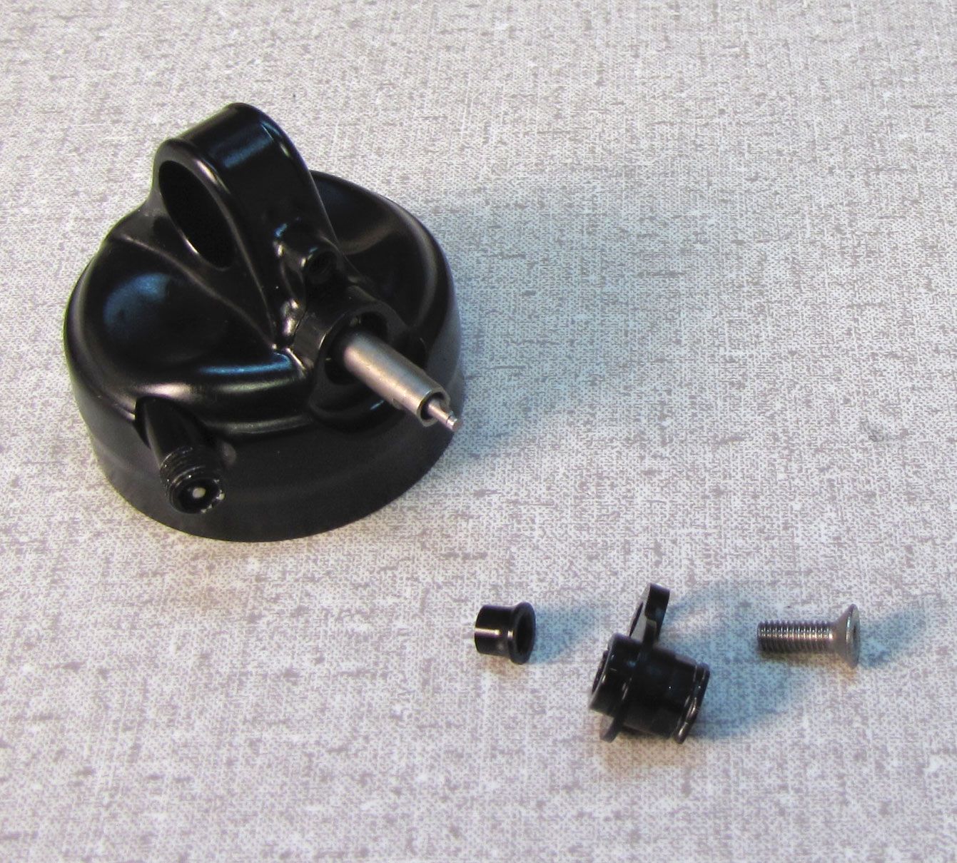
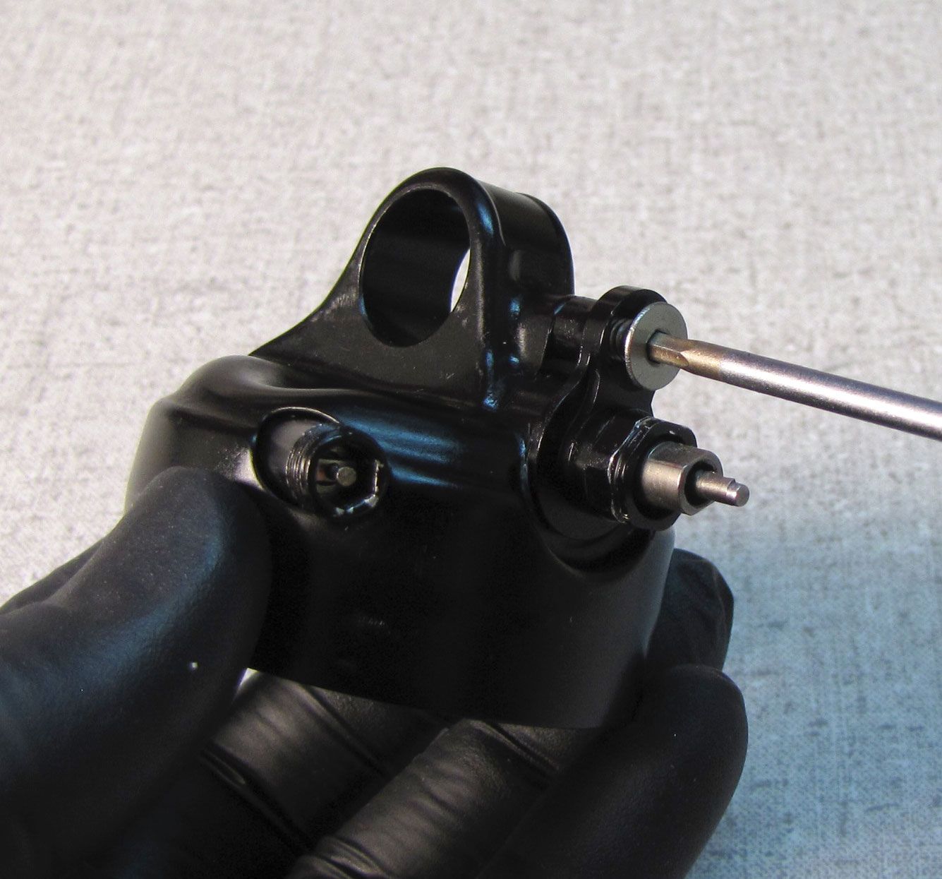
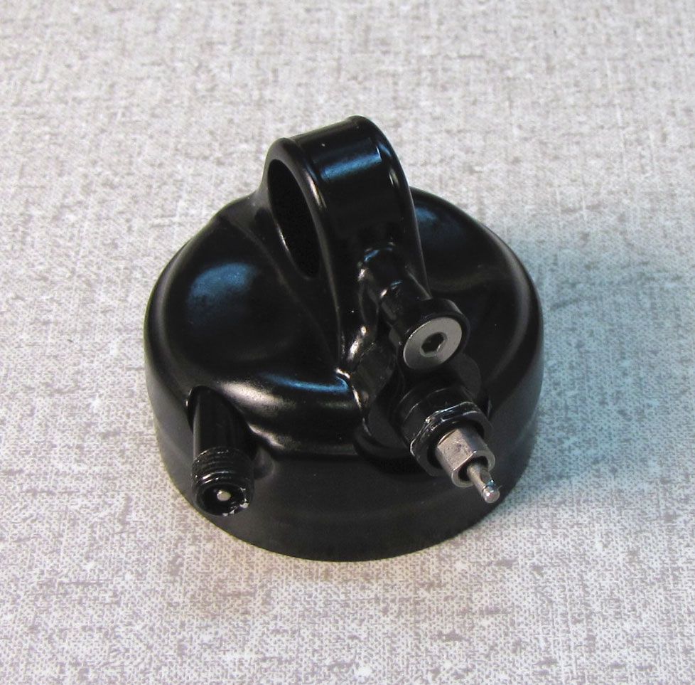
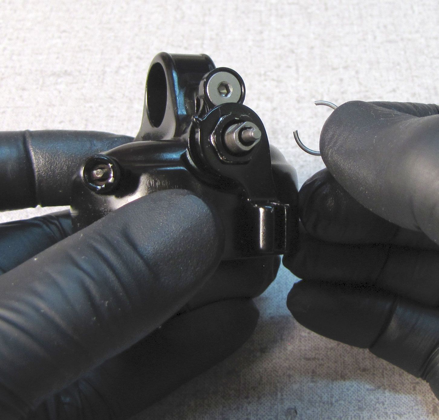
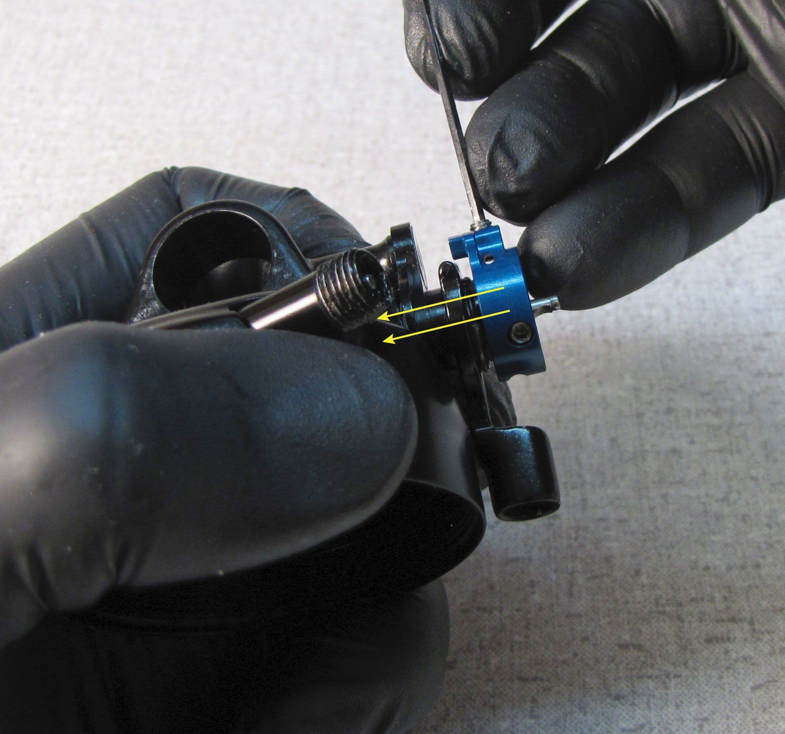
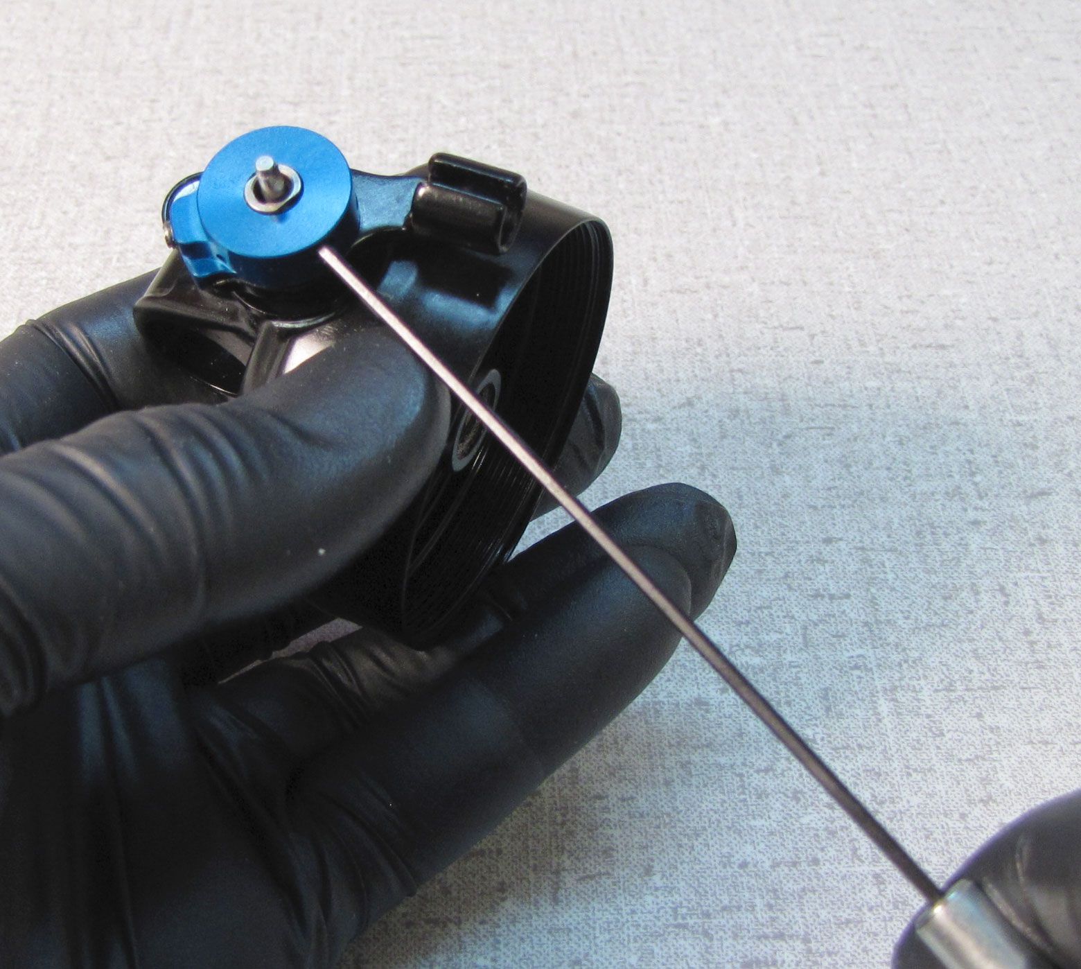
Use a 1.5 mm hex wrench to remove the set screw from the top of the eyelet assembly. Remove the DPS lever assembly by pulling it out of the eyelet. Be careful not to lose the detent ball from behind the lever assembly. Remove the detent spring with a pick. Clean the bare eyelet and set aside.


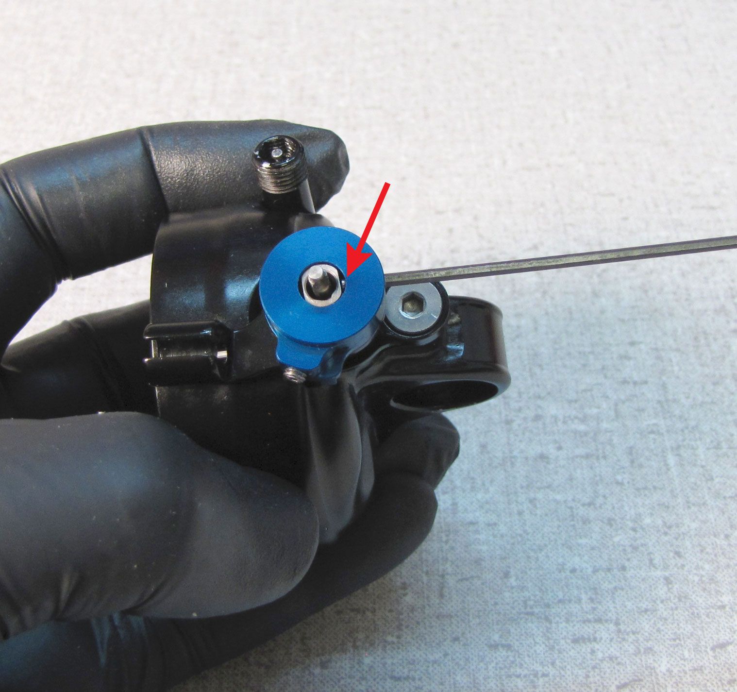
Step 3
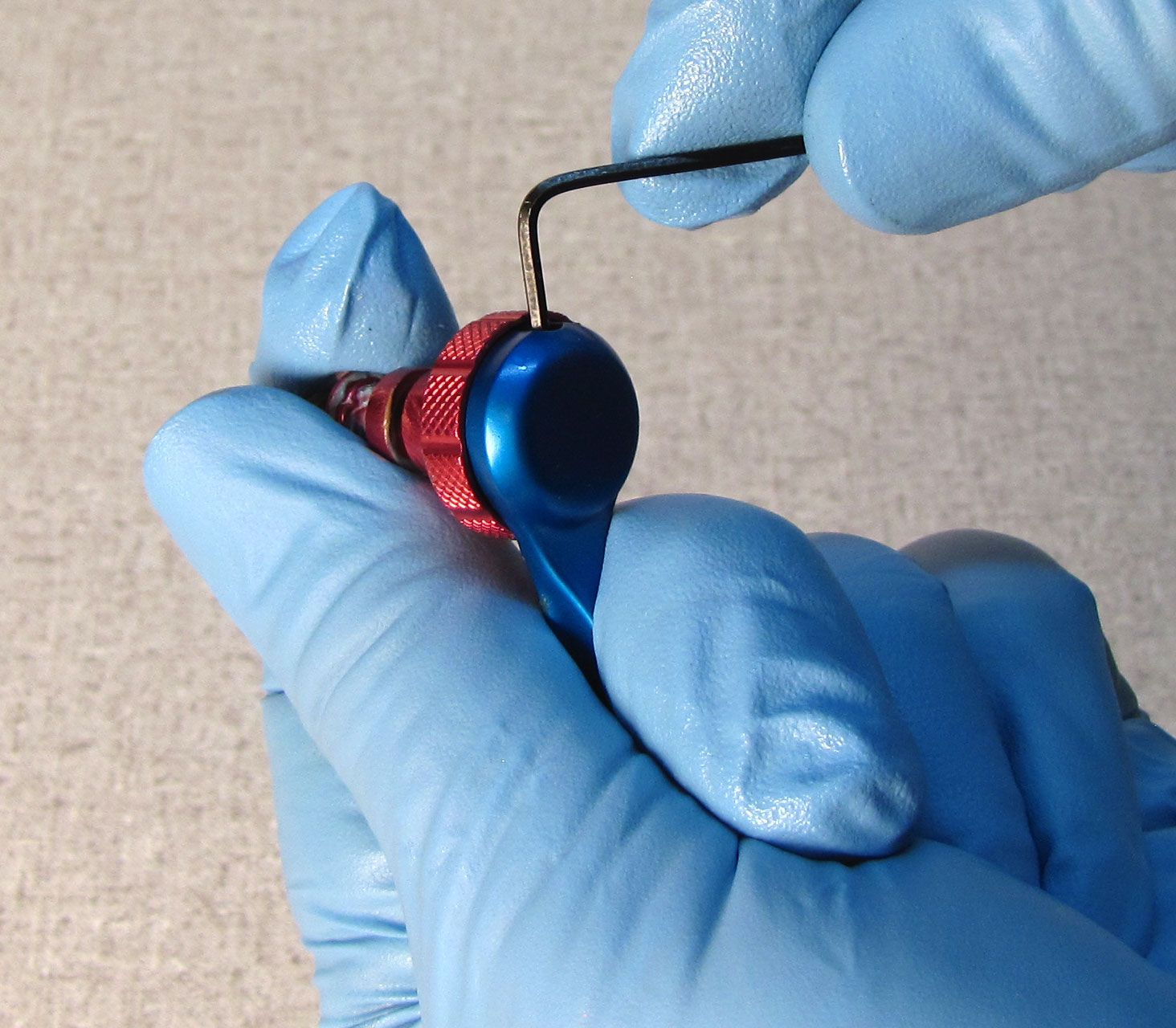
Use a 1.5mm hex wrench to unthread the rebound knob set screw. Remove the red rebound knob by pulling it away from the lever assembly. Remove the cam by pulling it out of the lever assembly from the back. Use a thin shim to remove the small retaining ring that holds the black adjuster to the blue compression selector lever.
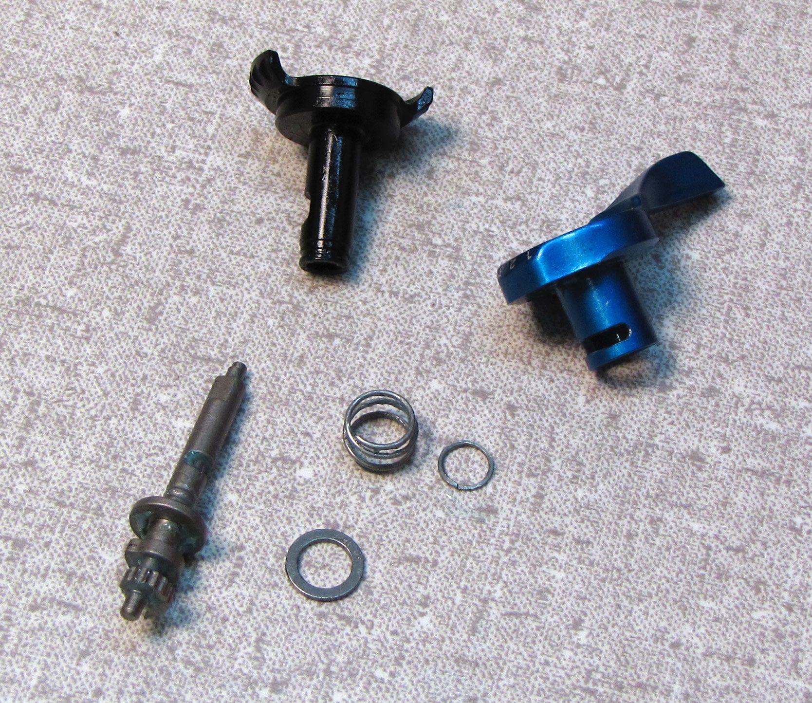
Step 4
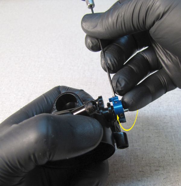
Insert the black adjuster into the blue compression selector lever followed by the spring, spring retainer, and retaining ring. Compress the spring against the blue compression selector lever to make room to install the retaining ring. Reinstall the red rebound knob and tighten the 1.5mm set screw to 5 in-lb (0.6 Nm) torque. Coat the cam and spring with a film of waterproof grease such as Sta-Lube SL3125.
Step 5
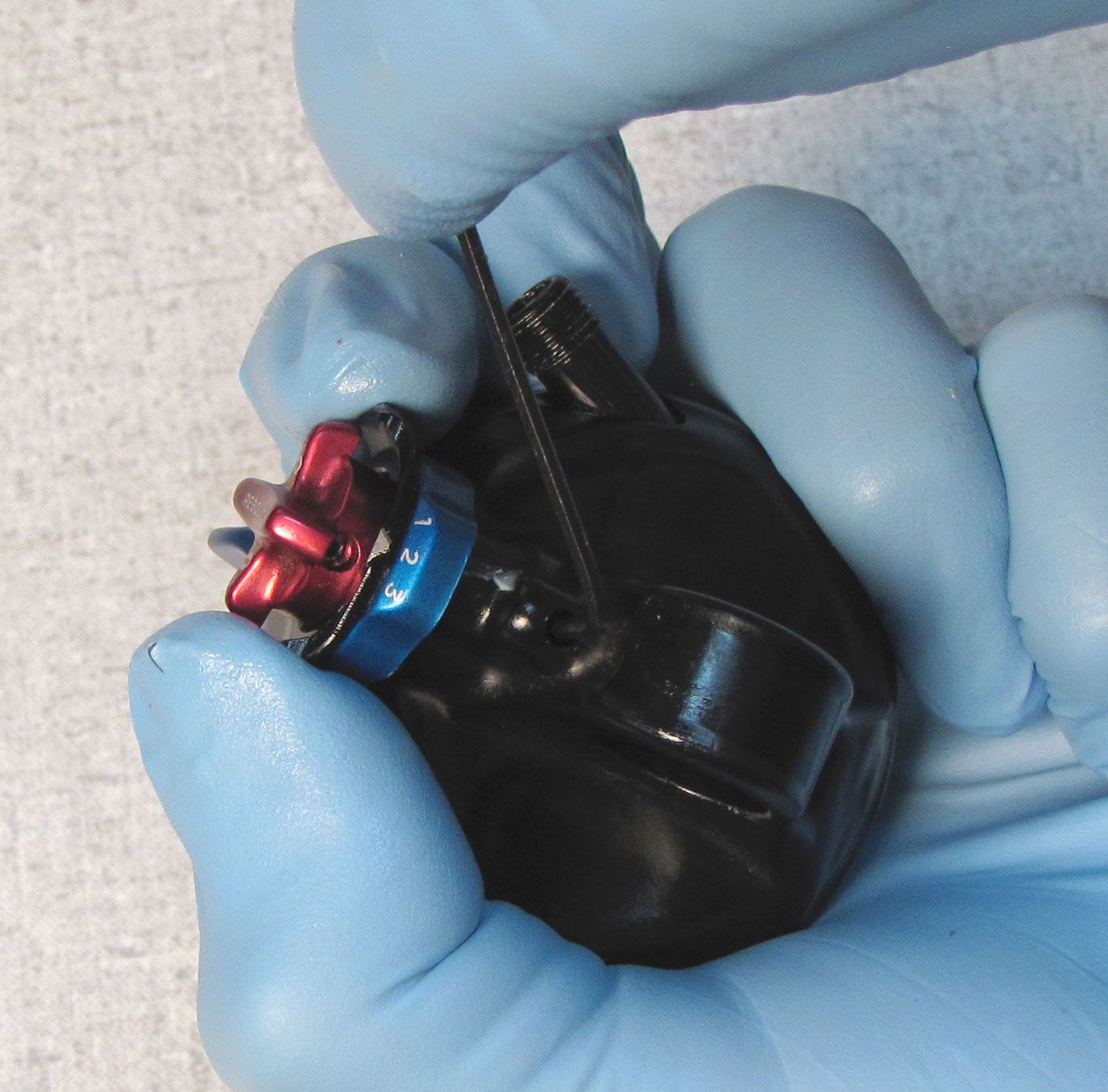
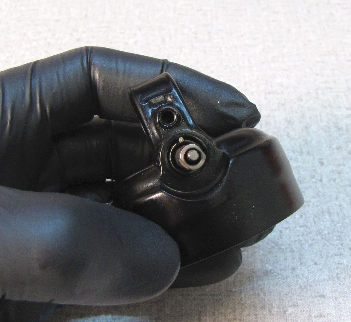
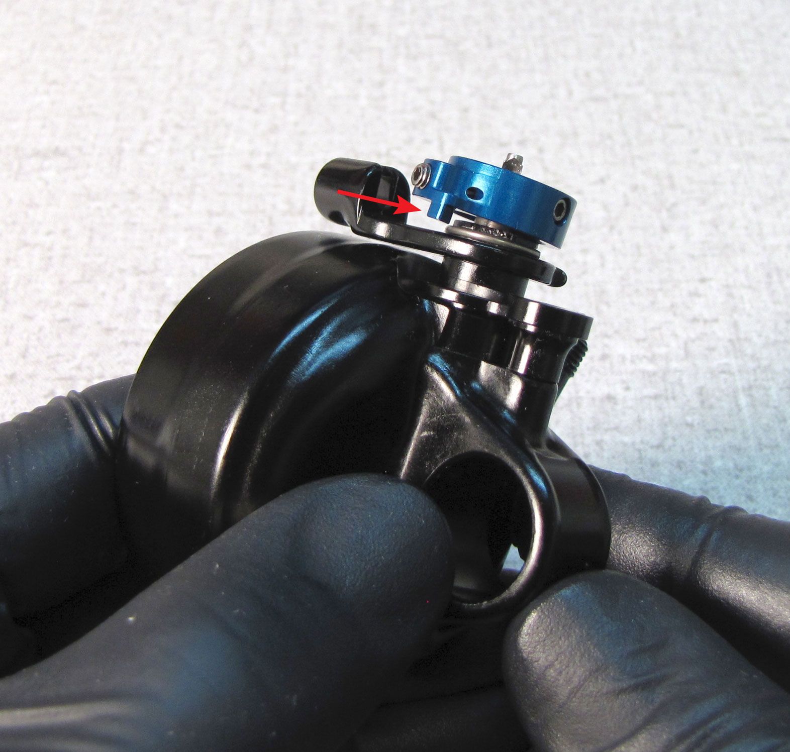
Insert the greased detent spring into the small hole in the face of the eyelet, followed by the detent ball. Carefully insert the lever assembly into the eyelet without dislodging the detent ball and spring. Compress the detent spring by pushing the lever assembly into the eyelet, then install and gently tighten the set screw in the top of the eyelet fully, then back it out 1/4 turn.

Performance Series Eyelet Rebuild
Eyelet assemblies do not need to be rebuilt as part of a standard shock service. You should only disassemble the eyelet assembly in order to replace damaged or missing parts or to clean out contamination if the adjusters feel gritty when used. If not rebuilding the eyelet assembly, please go to General Reassembly »
If servicing a Factory or Performance Elite Series shock you can skip the Performance Series Eyelet Rebuild section and continue servicing your shock by going to General Reassembly »

Step 1
Use a 1.5 mm hex wrench to remove the set screw from the top of the eyelet assembly. Remove the DPS lever assembly by pulling it out of the eyelet. Be careful not to lose the detent ball from behind the lever assembly. Remove the detent spring with a pick. Clean the bare eyelet and set aside.


Step 2
Use a 1.5mm hex wrench to unthread the set screw in the blue compression selector lever. Separate the blue lever from the cam and the red rebound knob.

Step 3
Coat the cam in waterproof grease such as Sta-Lube SL3125 then insert it into the red rebound knob from the back. Coat the parts of the rebound knob that will be within the eyelet with waterproof grease. Reinstall the blue compression selector lever and tighten its set screw against the depression in the cam with a 1.5mm hex wrench to 5 in-lb (0.6 Nm).
Step 4
Insert the greased detent spring into the small hole in the face of the eyelet, followed by the detent ball. Carefully insert the lever assembly into the eyelet without dislodging the detent ball and spring. Compress the detent spring by pushing the lever assembly into the eyelet, then install and gently tighten the set screw in the top of the eyelet fully, then back it out 1/4 turn.
Remote Eyelet Rebuild
If servicing a non-Remote shock you can skip the Remote Eyelet Rebuild section and continue servicing your shock by going to General Reassembly »
Eyelet assemblies do not need to be rebuilt as part of a standard shock service. You should only disassemble the eyelet assembly in order to replace damaged or missing parts or to clean out contamination if the adjusters feel gritty when used. If not rebuilding the eyelet assembly, please go to General Reassembly »
Step 1
Remove the red rebound knob and blue remote pulley by unthreading (counter-clockwise) their 1.5mm set screws. Do not completely remove the set screws from the knobs before setting the knobs aside.
Step 2
Remove the round wire retaining ring, then remove the housing stop.

Step 3
Use a 2.5mm hex wrench to unthread (counter-clockwise) and remove the base plate fixing bolt. Remove the spacer and base plate.

Step 4
Remove the torsion spring.

Step 5
Remove the cams by pulling them out of the eyelet. Separate the cams for cleaning.
Step 6
Coat the cams and torsion spring with a thin film of waterproof grease such as Sta-Lube SL3125. Align the tang of the spring with the slot in the cam.

Step 7
Insert the cams and torsion spring into the eyelet assembly, then align the notch in the back of the base plate with the other tang of the torsion spring.
Step 8
Hold the base plate as you insert the spacer followed by the fixing screw. Tighten the screw to 25 in-lb (2.8 Nm) with your 2.5mm hex wrench.
Step 9
Install the housing stop in your chosen orientation, then secure it with the round wire retaining ring.
A video showing the winding of the torsion spring and final installation of the remote pulley can be found at: SHOCK- Reversing the Remote rear shock cable stop »

Step 10
Install the blue pulley onto the flat sided cam. Lightly tighten the pulley fixing screw without seating the pulley completely against the housing stop.
Step 11
Use a 1.5mm hex wrench in the cable pinch bolt to help wind the pulley clockwise past the pulley stop feature on the black housing stop. After winding past the pulley stop, press the blue pulley down against the black housing stop.

Step 12
Tighten the pulley fixing screw to 5 in-lb (0.6 Nm) with your 1.5mm hex wrench.

Test the function of the remote pulley by turning it clockwise and feeling for spring torsion retracting the pulley counter-clockwise. If no spring tosion is felt, repeat the Remote Eyelet Rebuild process.
Step 13
Reinstall the red rebound knob. Align the set screw with the depression in the rebound cam. Tighten the set screw to 5 in-lb (0.6 Nm) with your 1.5mm hex wrench.
General Reassembly

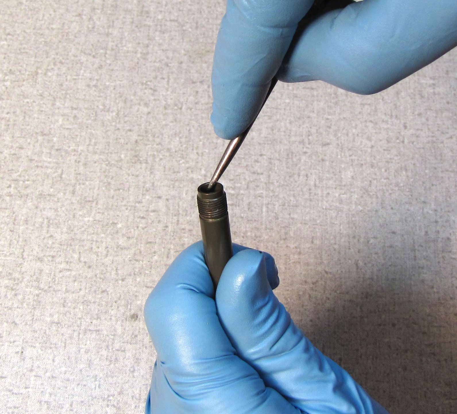
Step 1
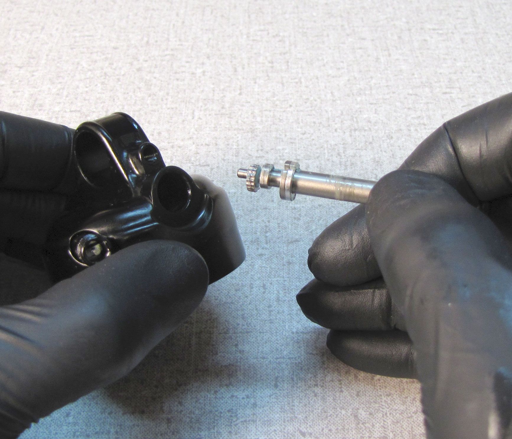
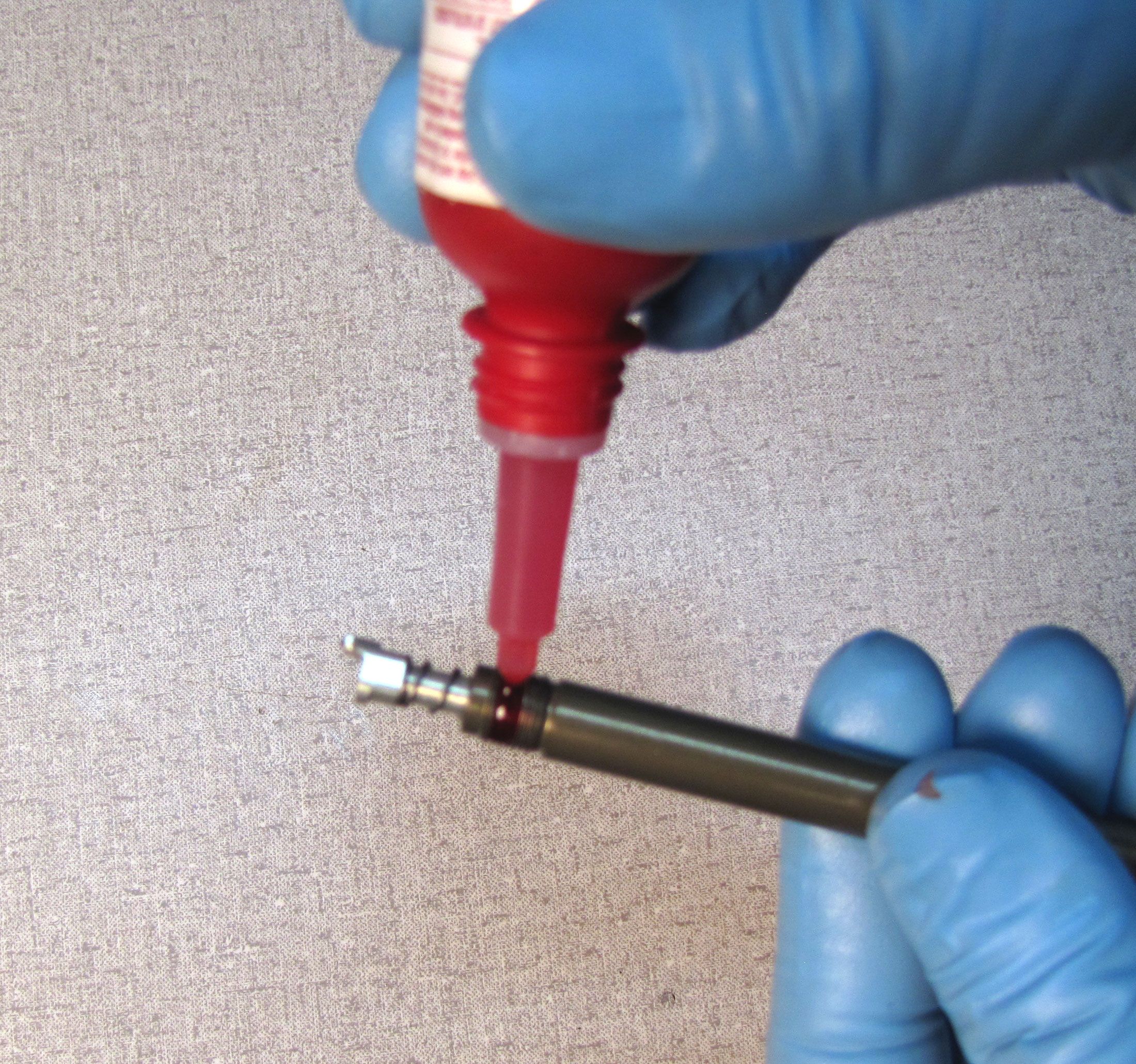
Coat the new o-ring from the kit with Slick Honey and install it into the shaft using blunt tools such as hex wrenches to fit it into position within its seal groove.

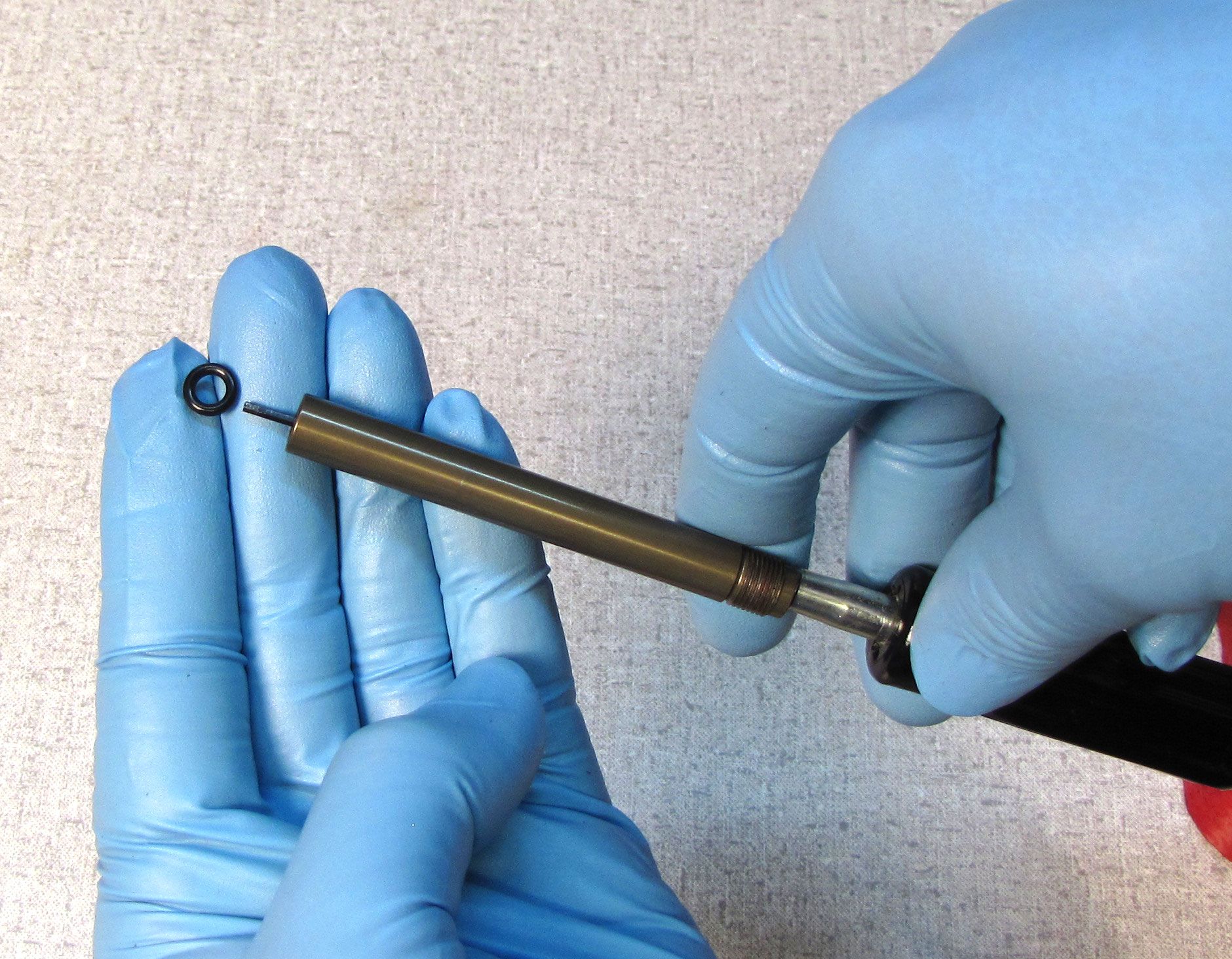
Step 2
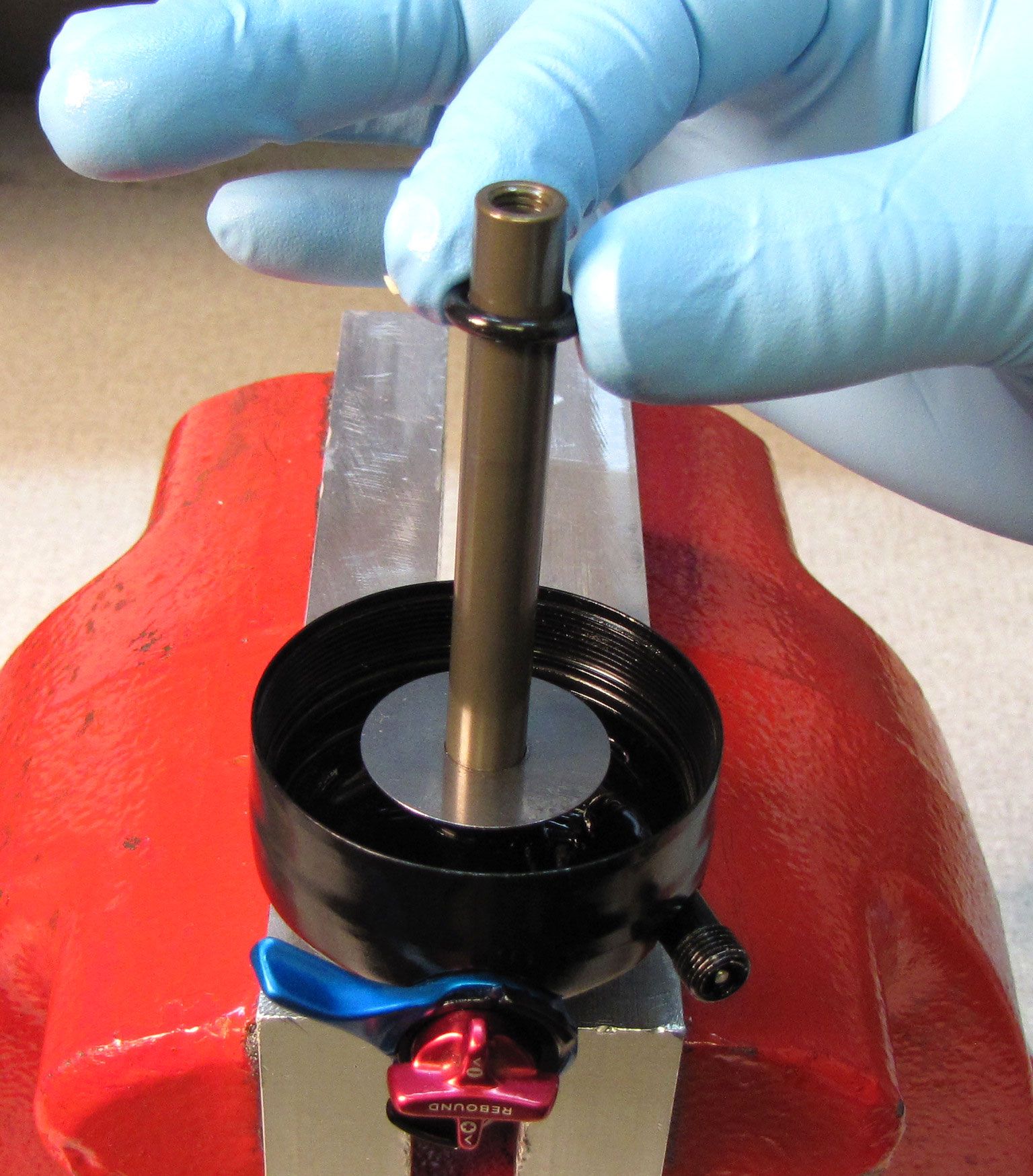
Replace the square cut o-ring in the end of the rebound metering rod with a new greased one from the kit. Coat the narrow end of the rebound metering rod with a thin film of Slick Honey and carefully insert it into the internal shaft o-ring to seat it completely within its groove.
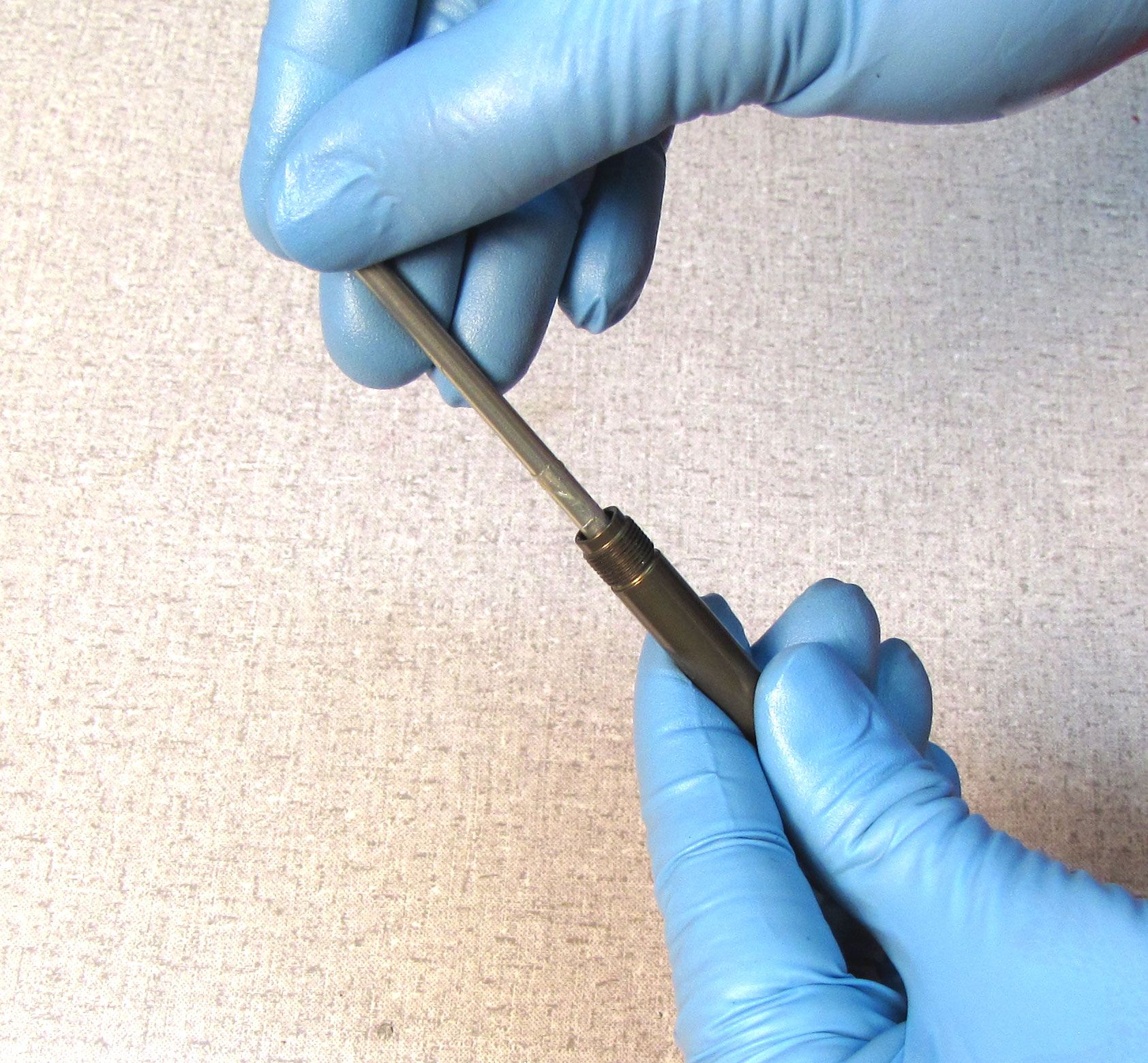

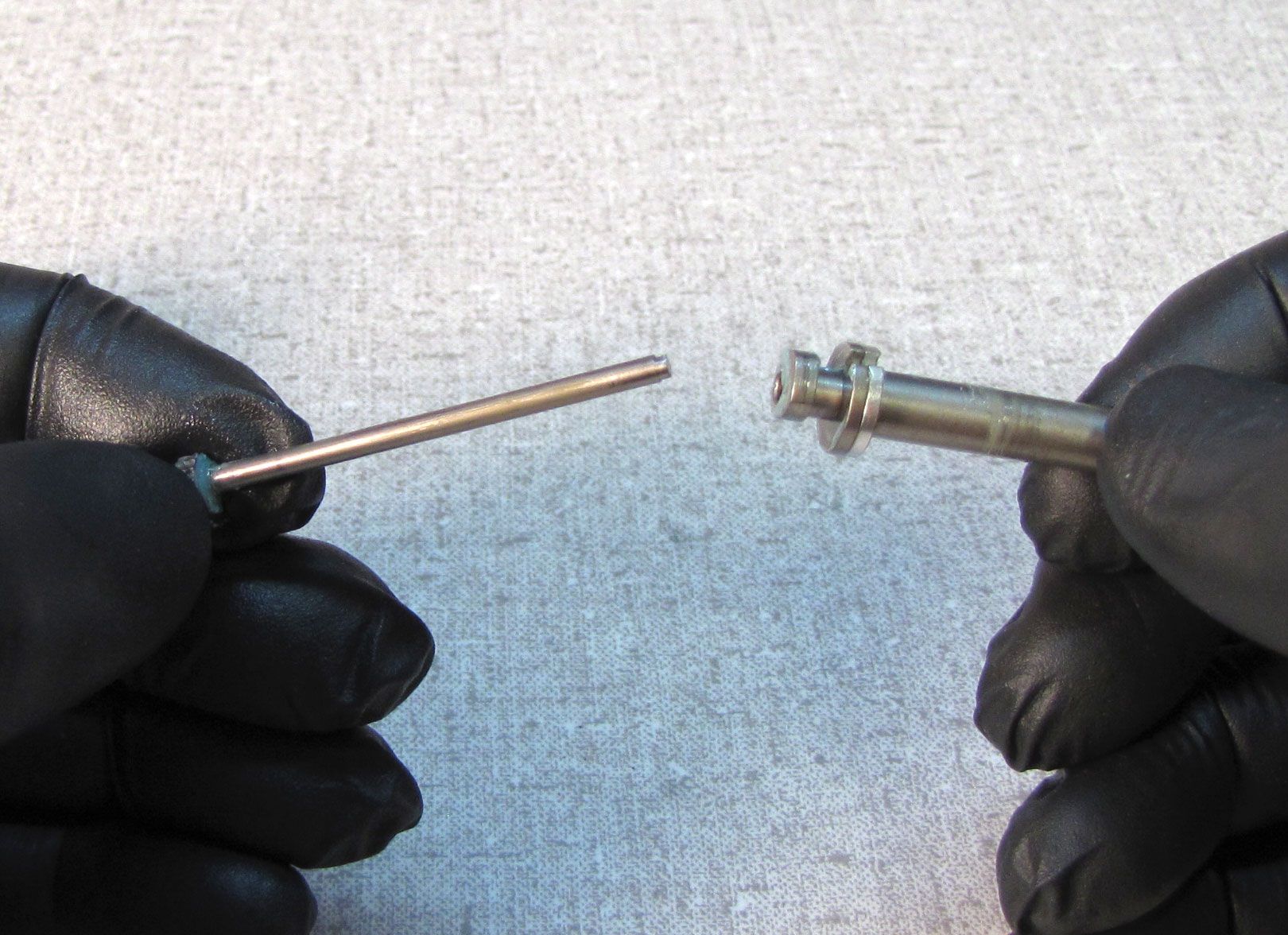
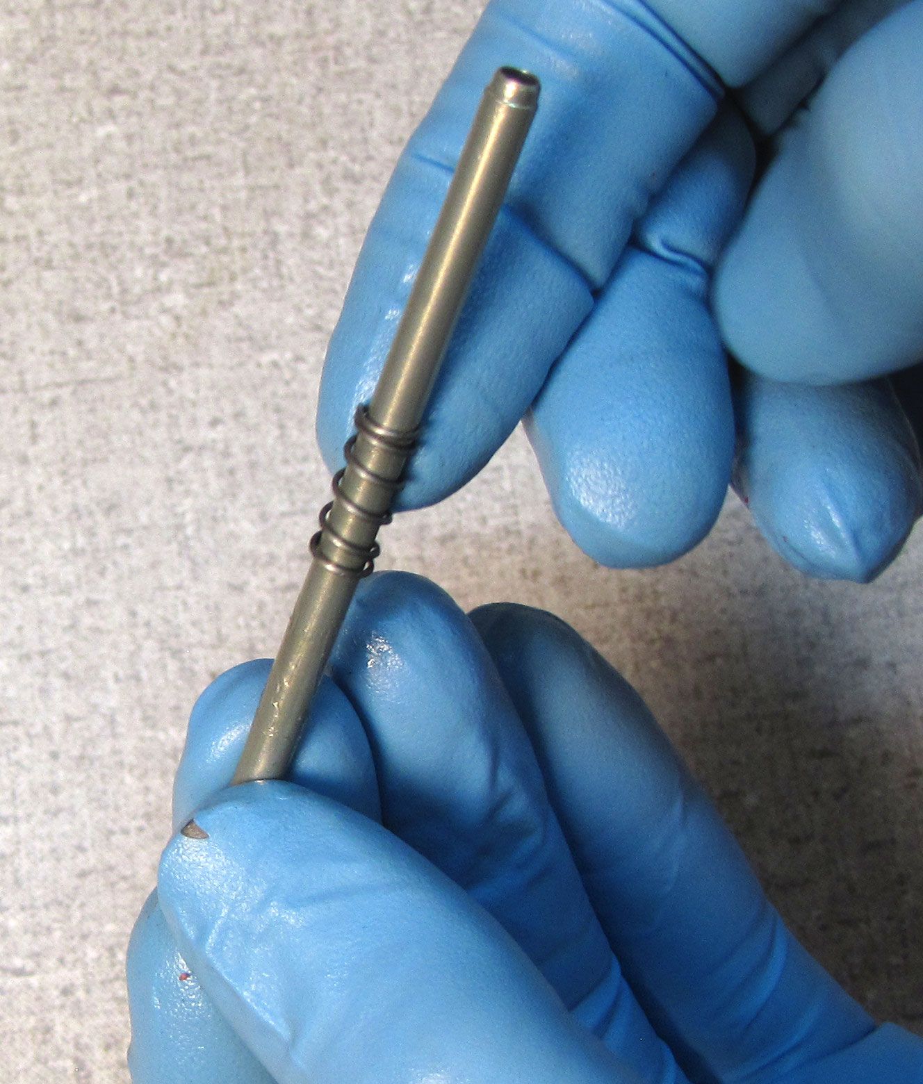
Step 3
Reinstall the spring onto the rebound metering rod. Coat the metering rod with a thin film of Slick Honey, then install it into the shaft with the square end of the metering rod nearest the external shaft threads. Be careful not to damage the o-ring inside the shaft when inserting the metering rod.
Step 4
Replace the two o-rings within the eyelet with new greased ones from the kit. Reinstall the eyelet bushings to prepare to tighten it to the shaft in the next step.


Step 5
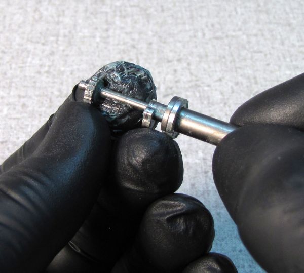
Apply a small drop of red Loctite 277 to the shaft threads.
F-S and P-Se shocks: Install the shaft into the eyelet with the ball bearing on the metering rod oriented toward the back of the shock.
P-S shocks: Install the shaft into the eyelet with the ball bearing on the metering rod oriented toward the front of the shock.

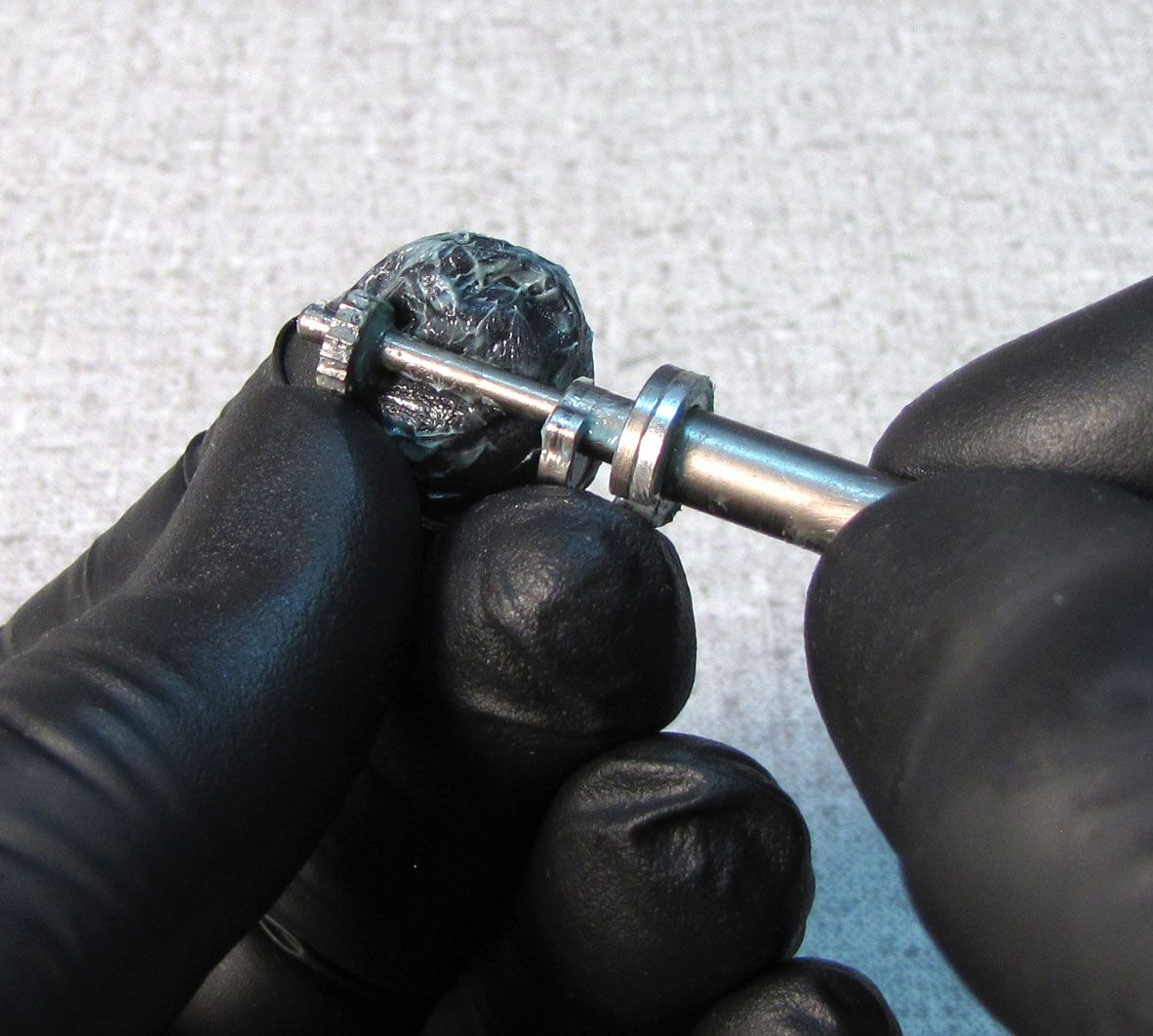
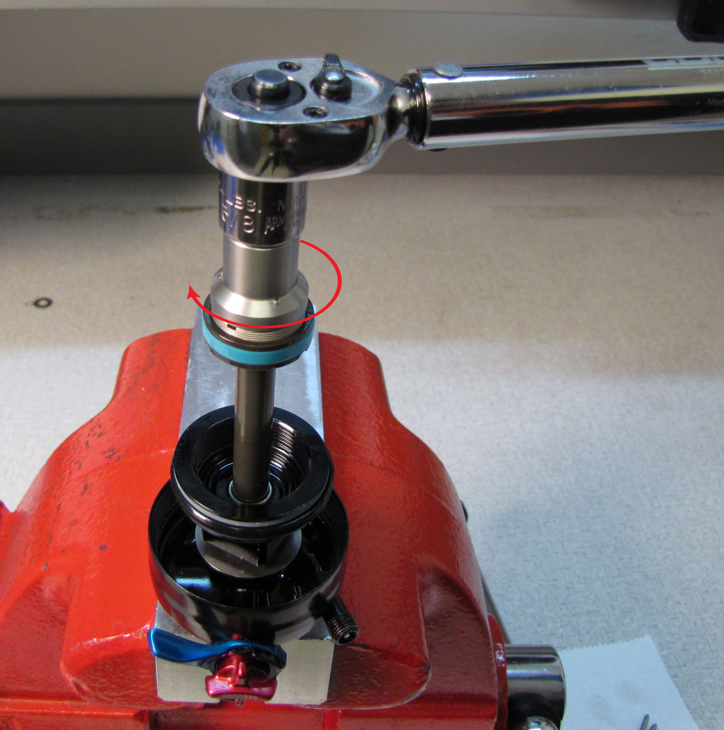
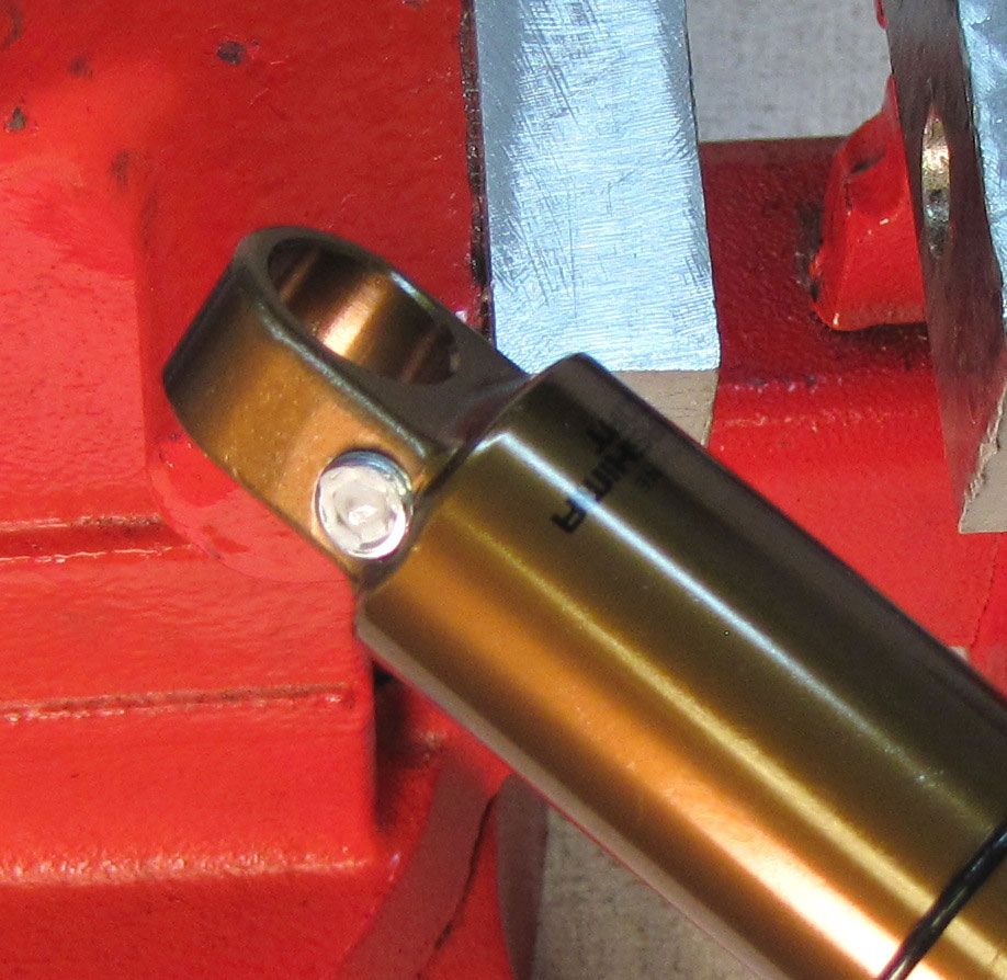
Step 6
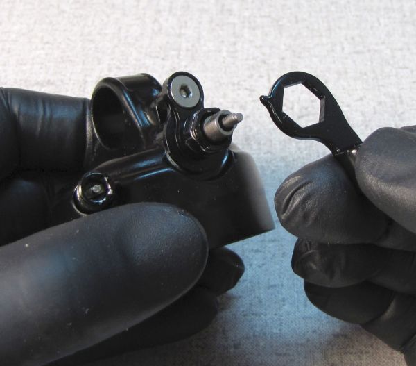
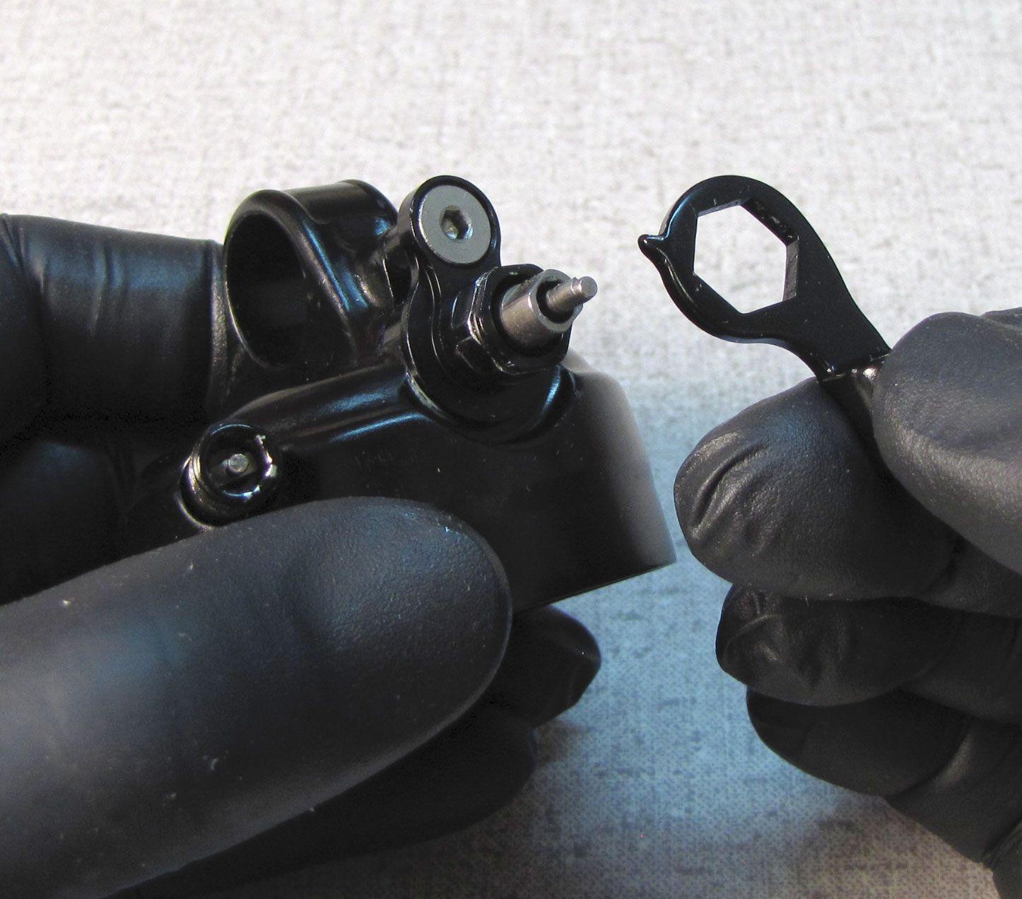
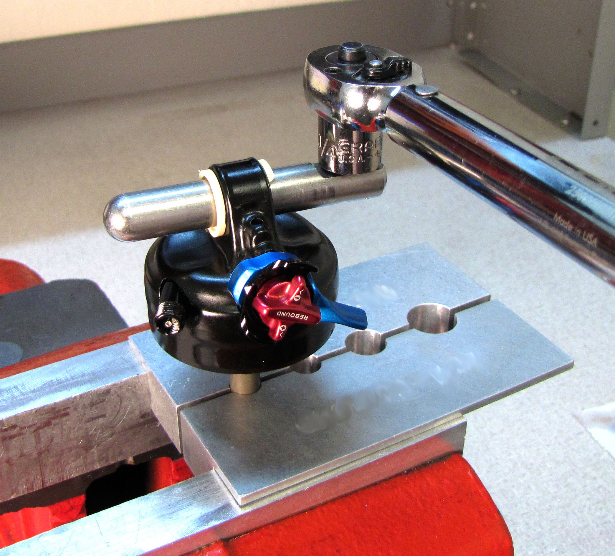
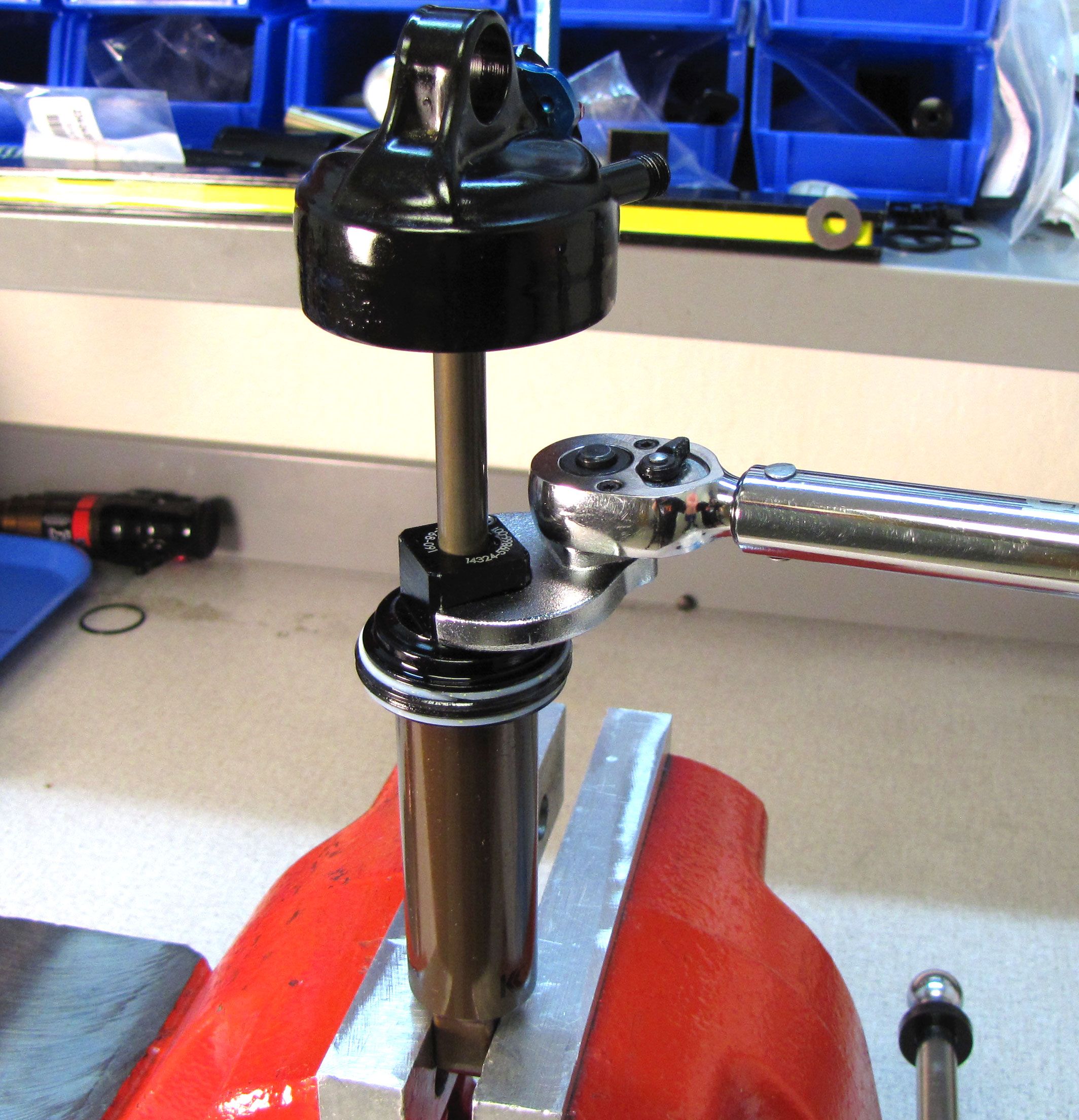
Clean the shaft with Isopropyl alcohol then clamp it in your 9mm shaft clamps. Use your eyelet torque tool (PN: 398-00-280) to tighten the eyelet to 85 in-lb (9.6 Nm) torque.
Step 7
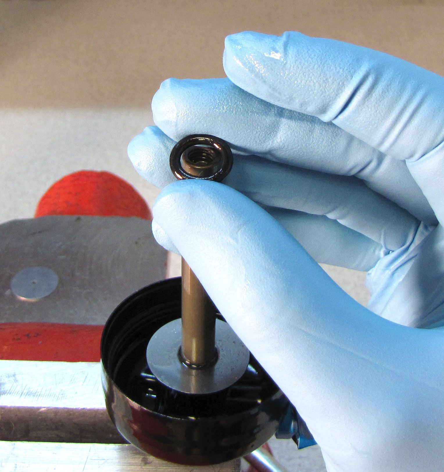
Reinstall the bottom out plate followed by a new bottom out o-ring from the kit.

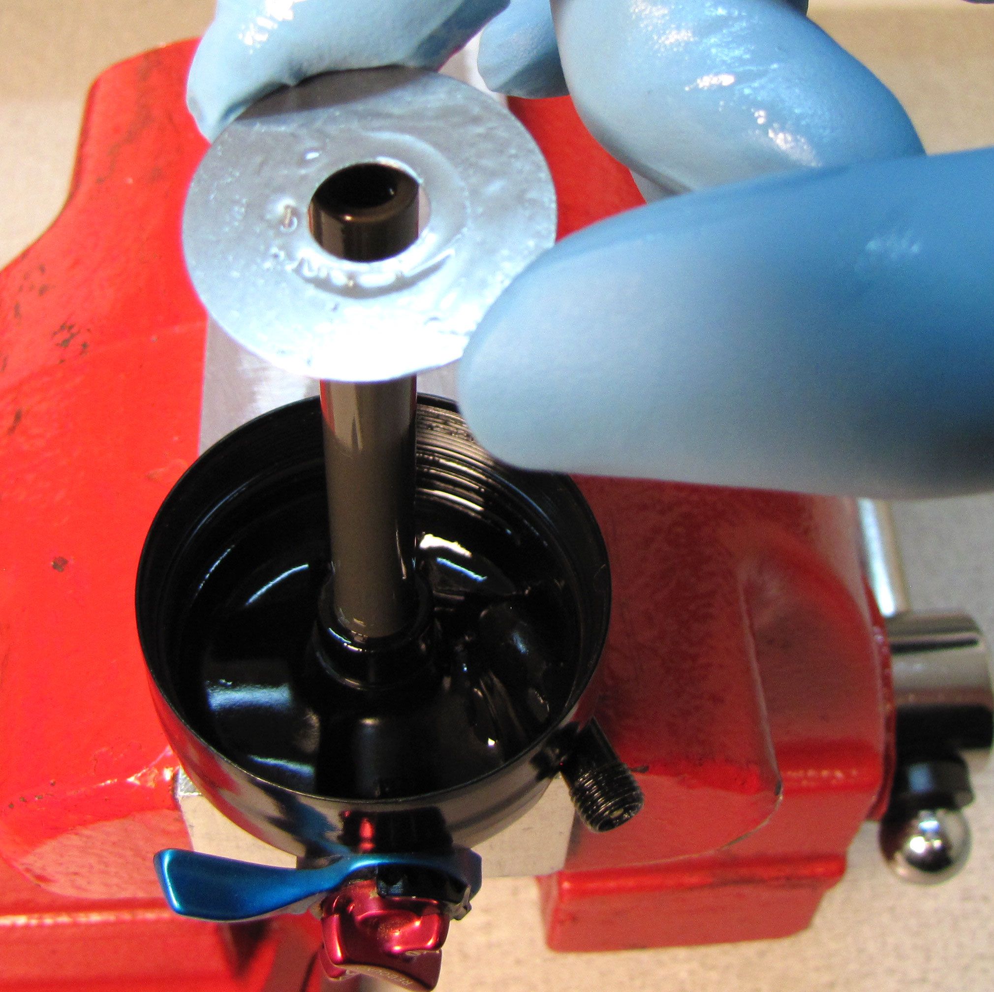
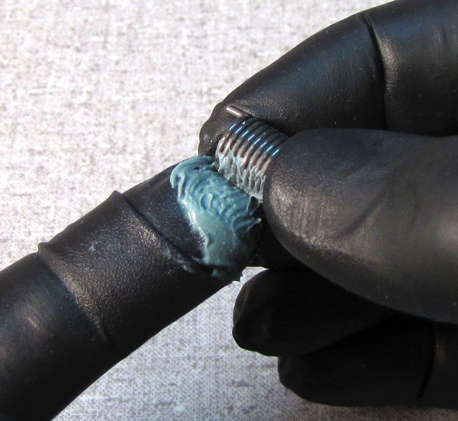
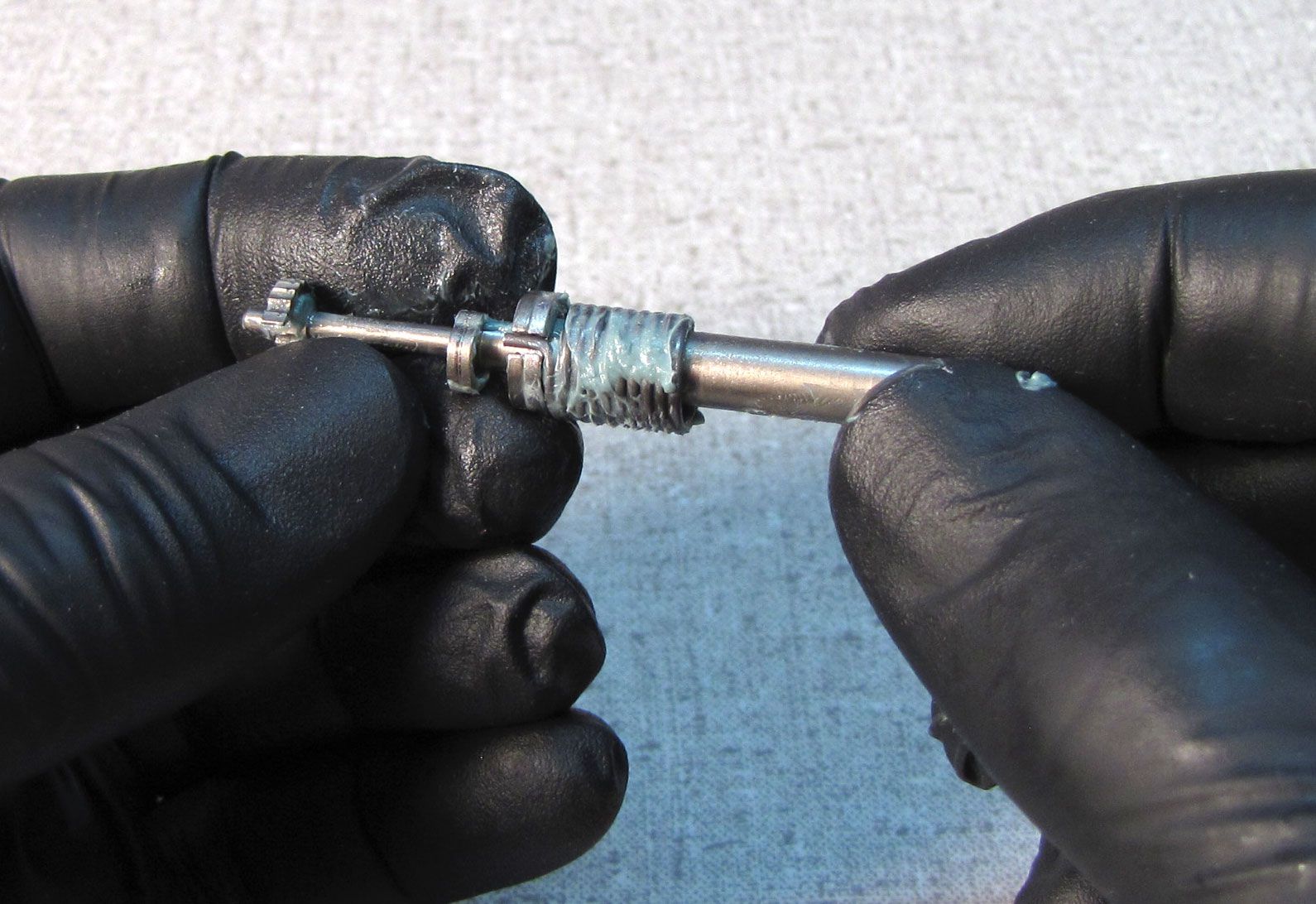
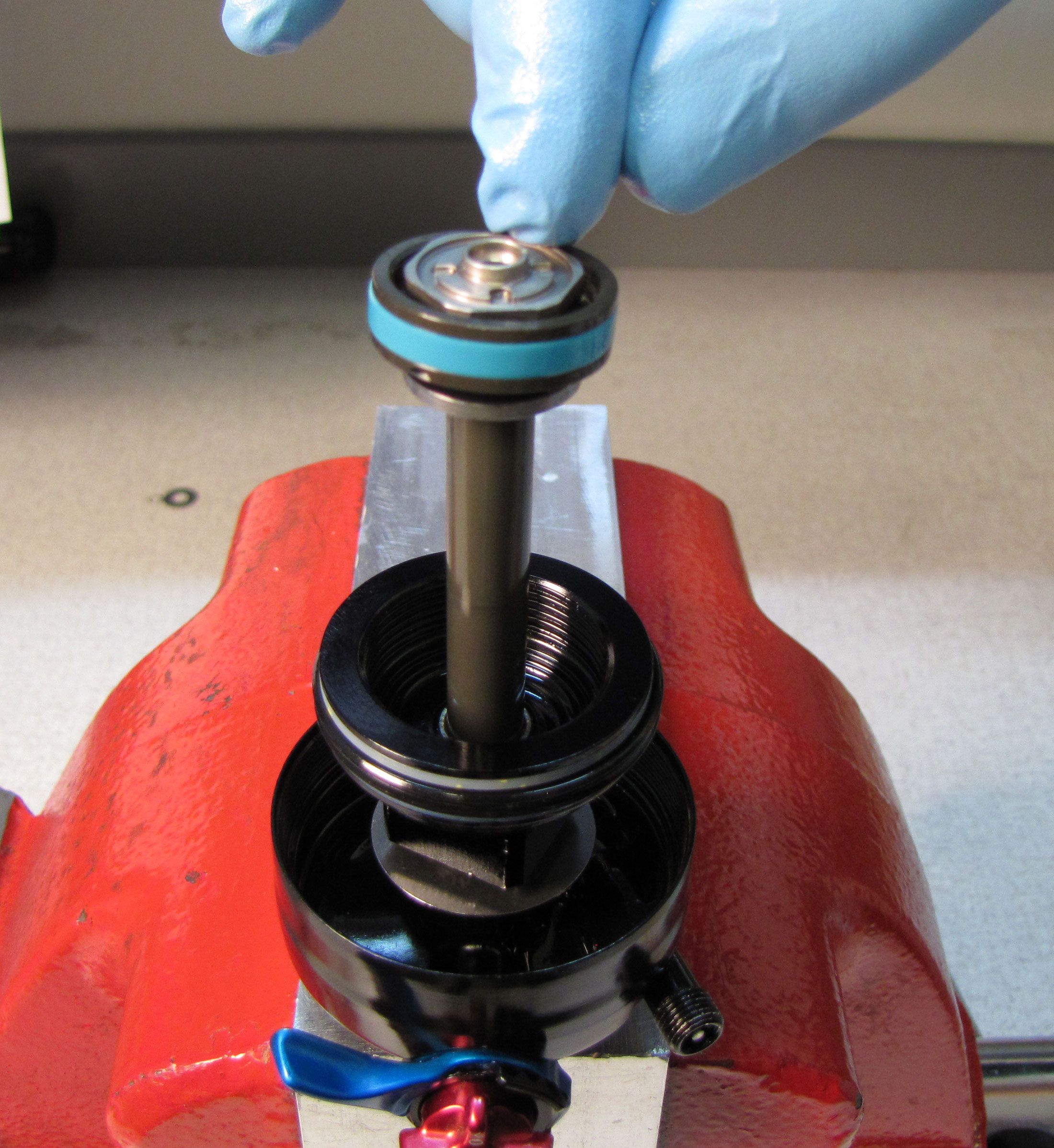
Step 8
Replace the two o-rings within the bearing assembly with new greased ones from the kit. Coat the shaft with a thin film of Slick Honey, then reinstall the bearing assembly onto the shaft.

Step 9
Install the valving assembly up to the piston bolt. Tighten the piston bolt clockwise with the FLOAT DPS piston bolt tool (398-00-637) or the FLOAT SL piston tool (PN: 398-00-950) to 60 in-lb (6.8 Nm).


Step 10
Reinstall the lockout shim stack, followed by the lockout piston. Tighten the lockout piston clockwise to 22 in-lb (2.5 Nm) with the FLOAT DPS lockout piston tool (PN: 398-00-638).
The compression rod can be easily bent if not installed properly. Always push against the bolt in the center of the lockout plate when installing the compression rod. Never push on the edges of the lockout plate when installing the compression rod as this can cause damage to the part not covered under warranty.
Step 11
Insert the compression rod through the lockout piston, being careful not to damage the o-ring within the rebound metering rod or bending the compression rod. Only press against the bolt in the center of the lockout plate when installing the compression rod.
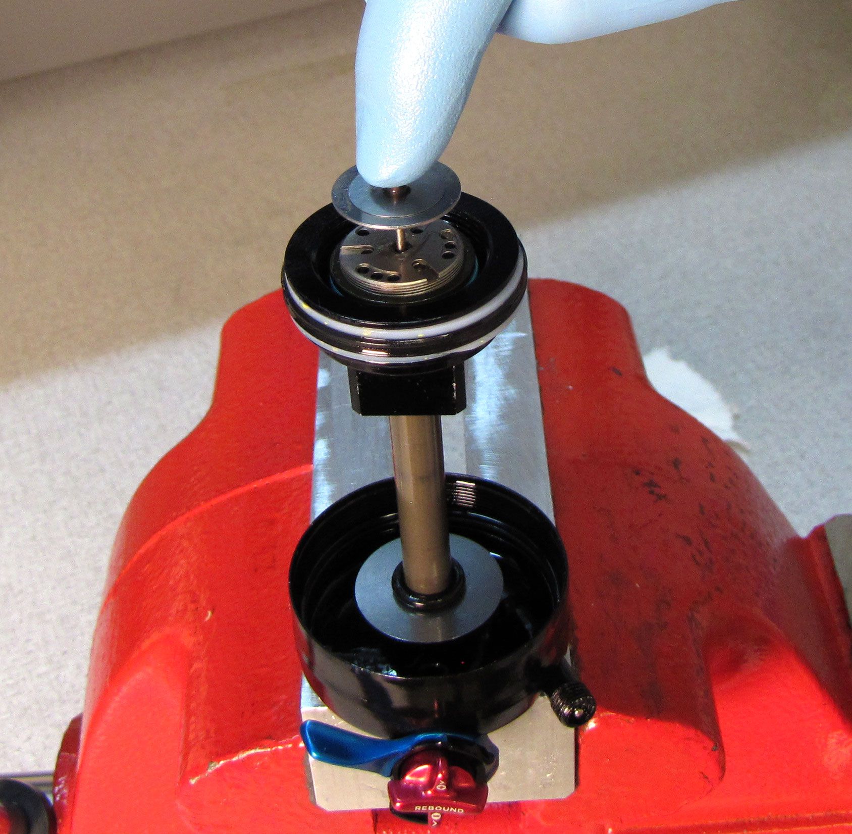
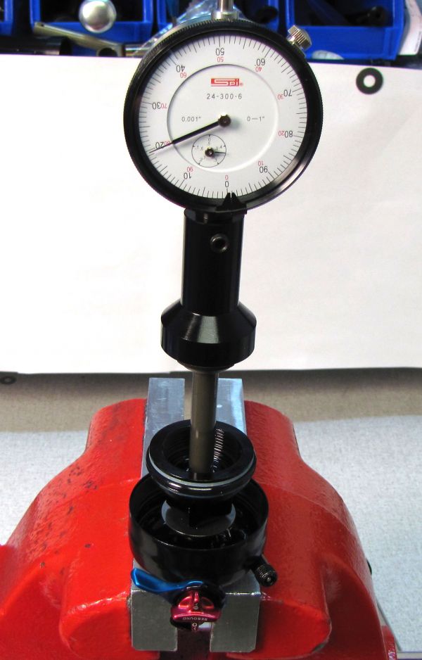
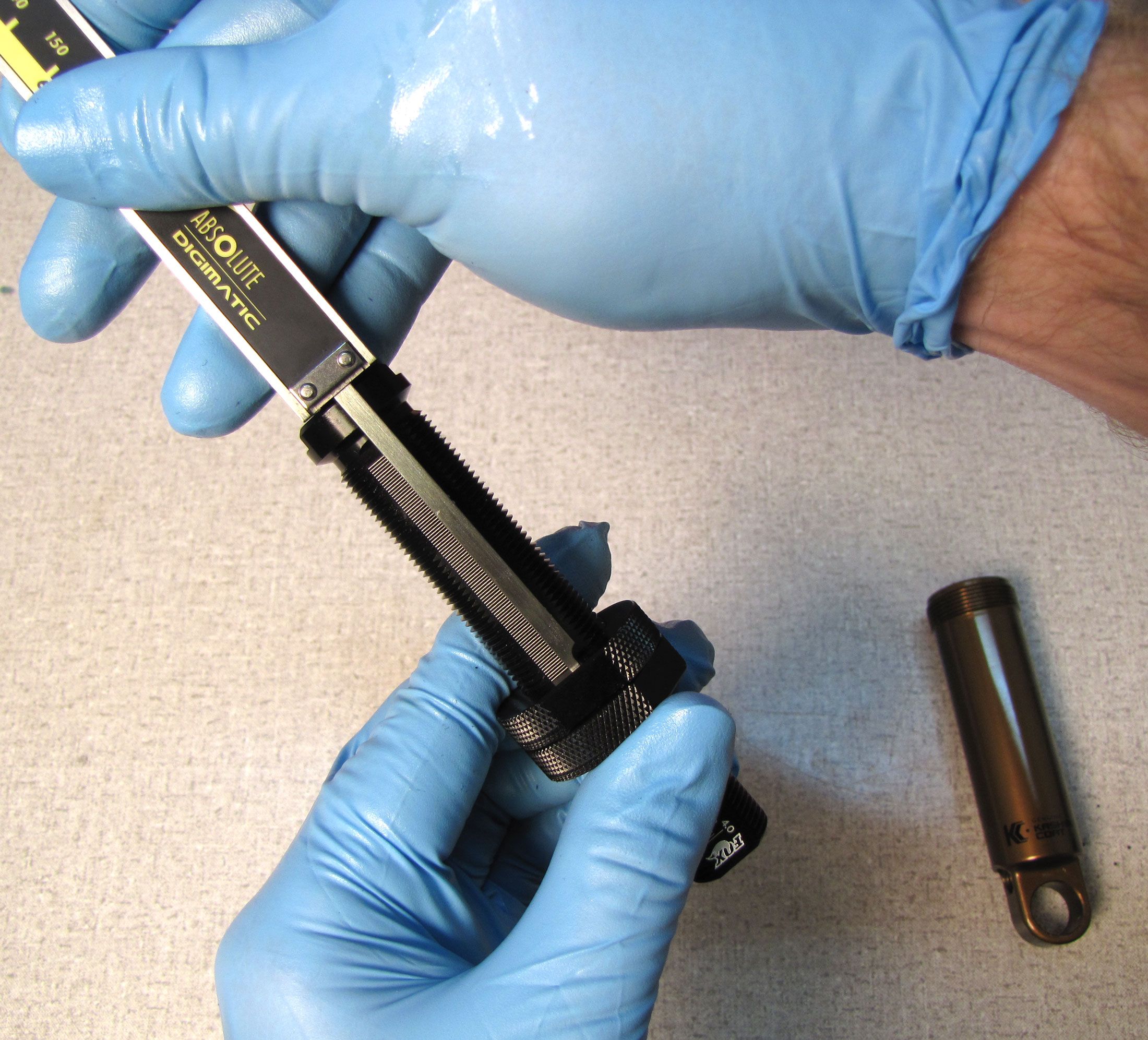
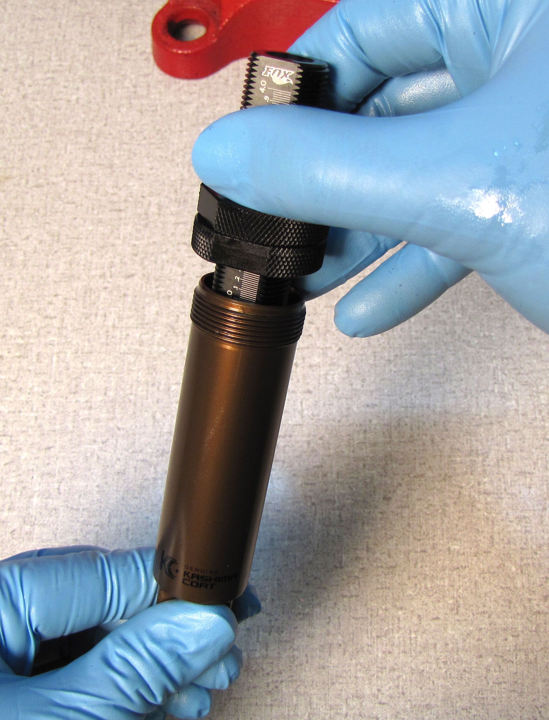
Step 12
Use the shock dial indicator (PN: 803-00-806 and 398-00-574) to measure lockout plate lift.
For Lever models: When switching from Firm to Medium modes, Lockout plate lift should measure between 0.030-0.047in (0.77-1.19mm).
For Remote models: When switching from Firm to Open modes, Lockout plate lift should measure between 0.072-0.090in (1.83-2.29mm).
1 or 2 spacers (044-20-035 or 044-10-035) may be added or removed from the lockout shim stack to adjust lockout plate lift to within approved range.

Step 13
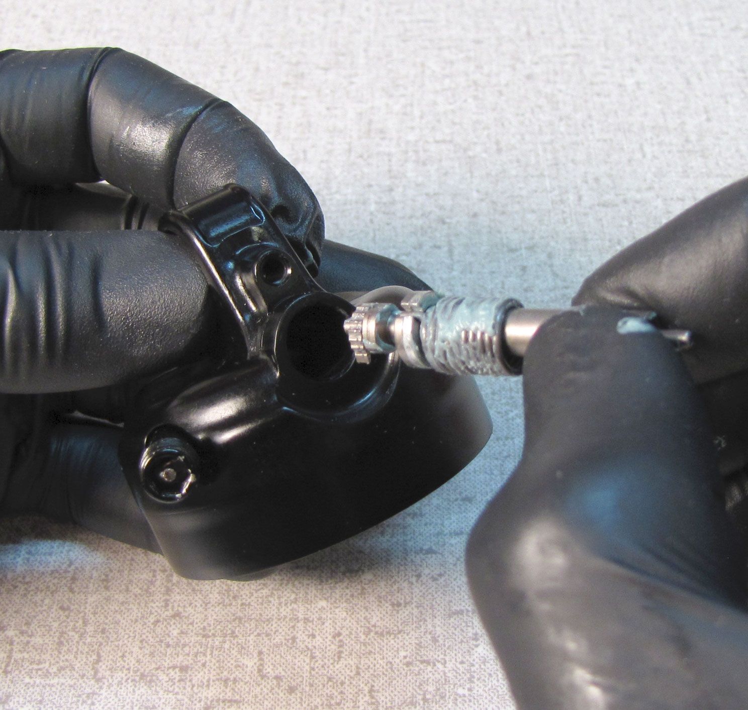
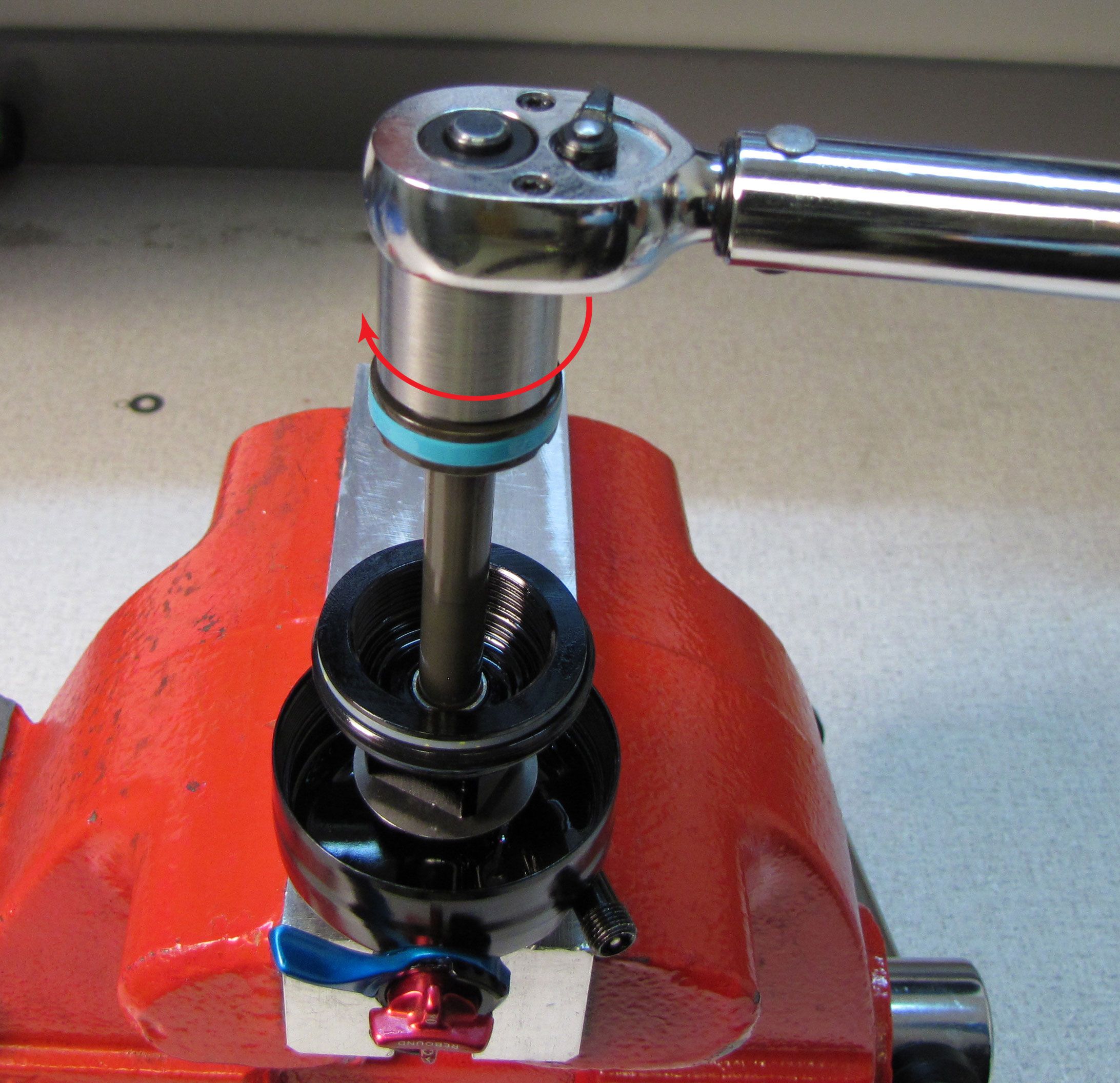
Turn the red rebound knob and blue compression selector lever to their open positions (fully counter-clockwise).
Slide the bearing assembly toward the piston assembly, then pre-fill the piston assembly with oil. FLOAT DPS shocks use FOX 10wt. green oil, while FLOAT SL shocks use FOX 4wt. oil. Invert the shaft assembly inserting the piston assembly into the previousely prepared and filled shock body. Thread the bearing assembly onto the body then tighten to 240 in-lb (27.1 Nm) with your 3/4in crow's foot. Position your crow's foot so the wrench does not apply torque to the bleed hole in the bearing assembly.

Step 14
Insert the ball bearing followed by the bleed screw into the bleed hole in the bearing assembly. Tighten the bleed screw to 10-15 in-lb (1.1-1.7 Nm) with a 5/64" hex wrench.

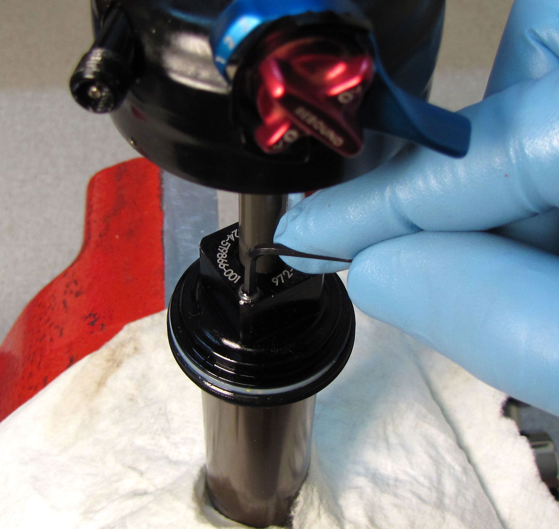
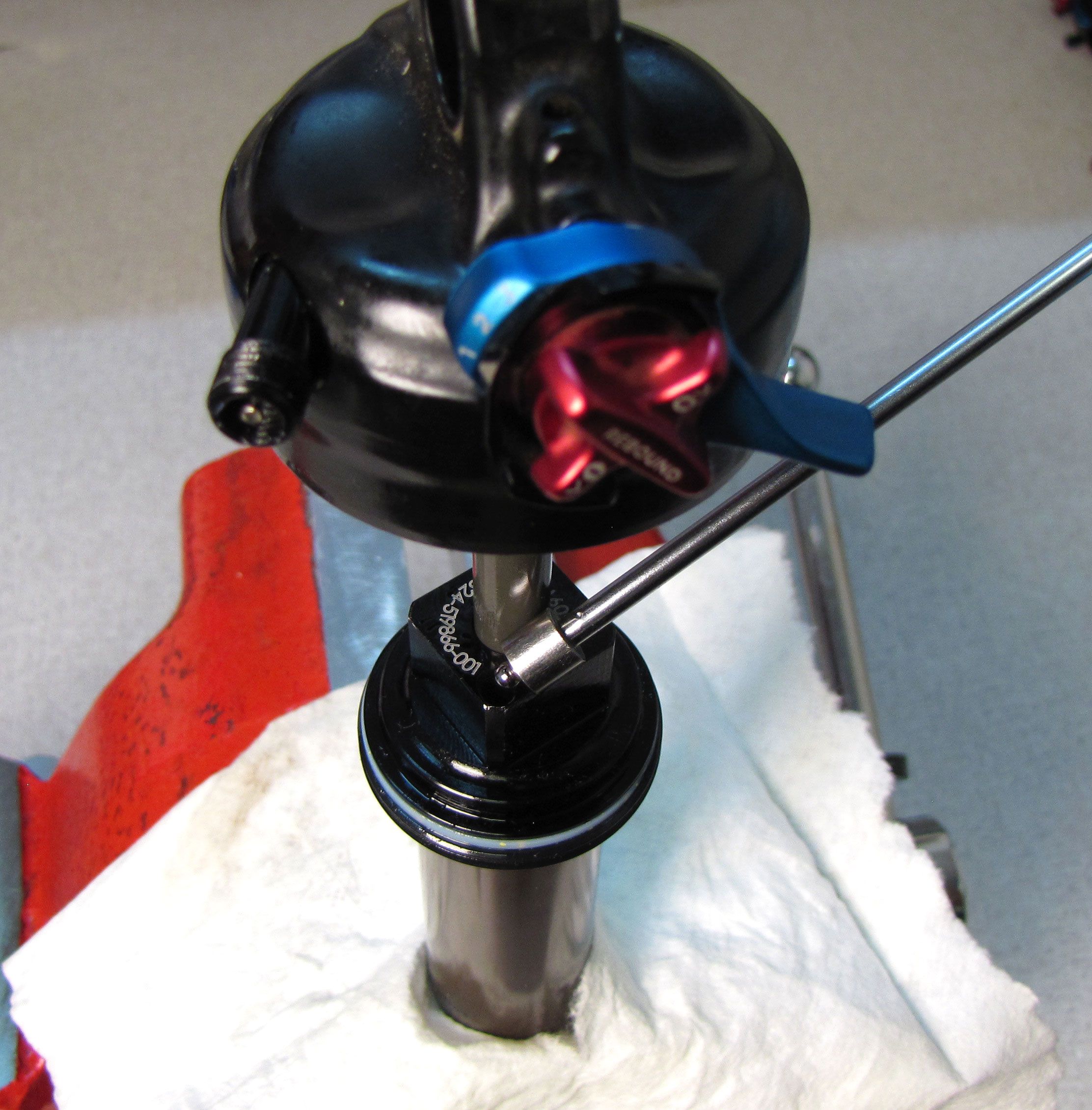
Step 15
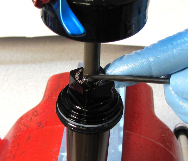
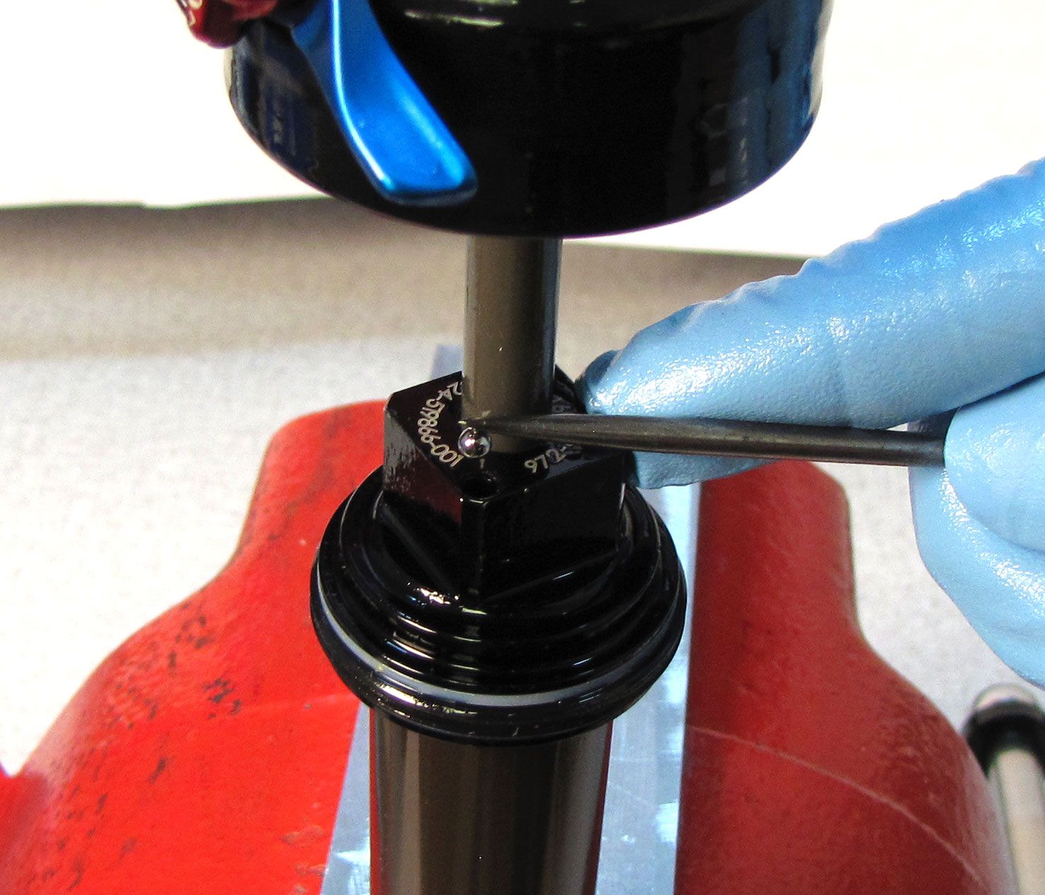
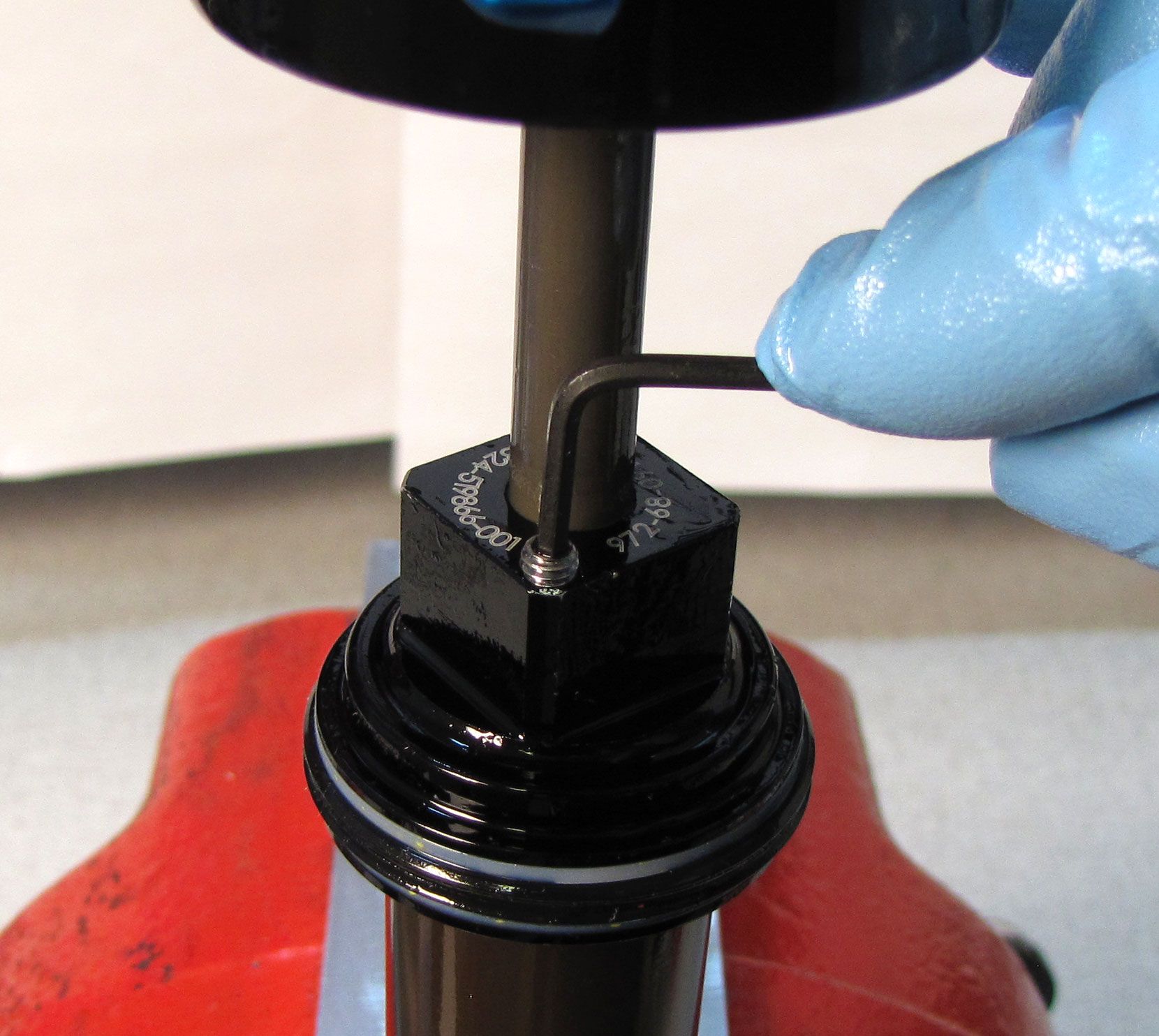
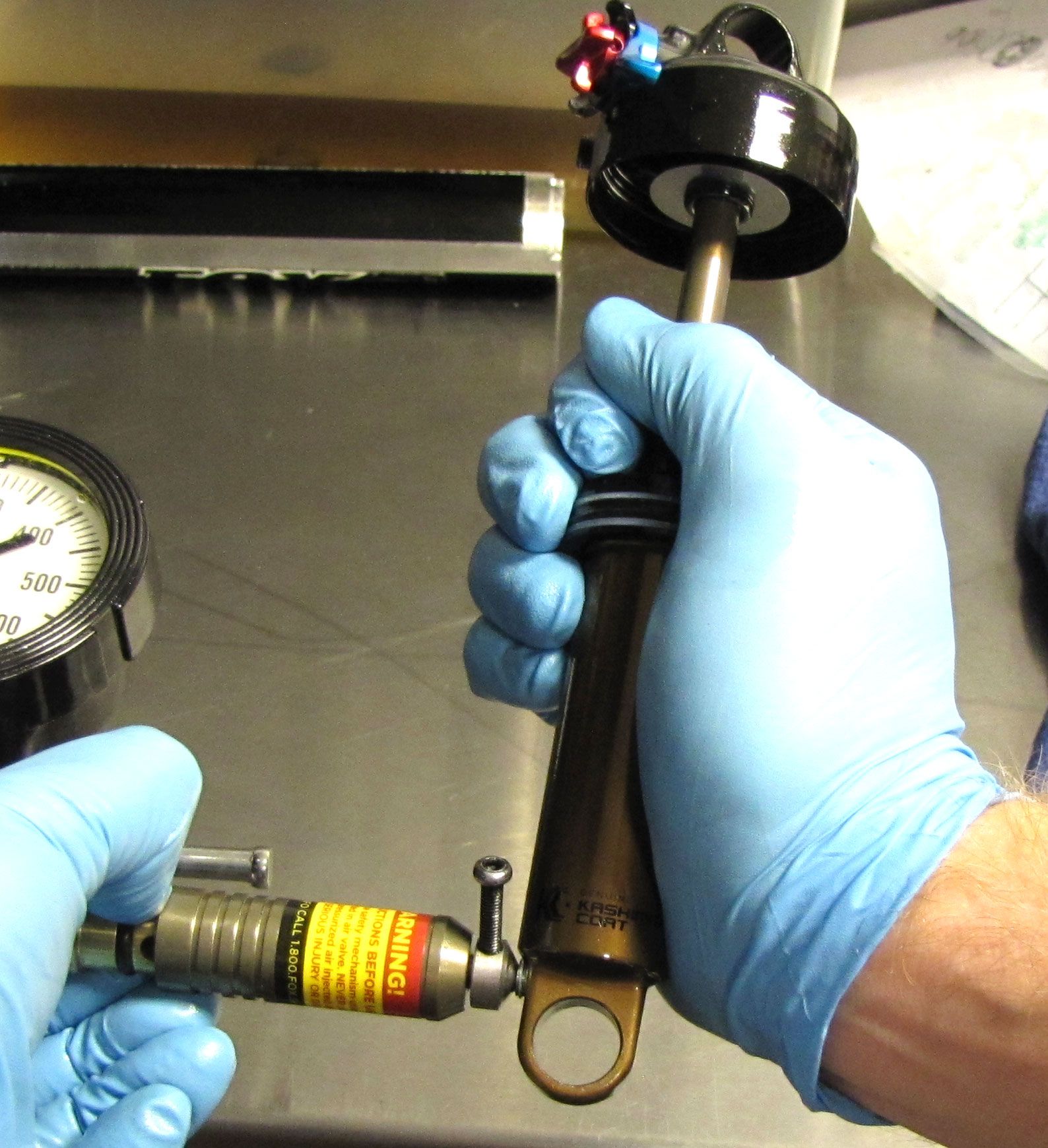
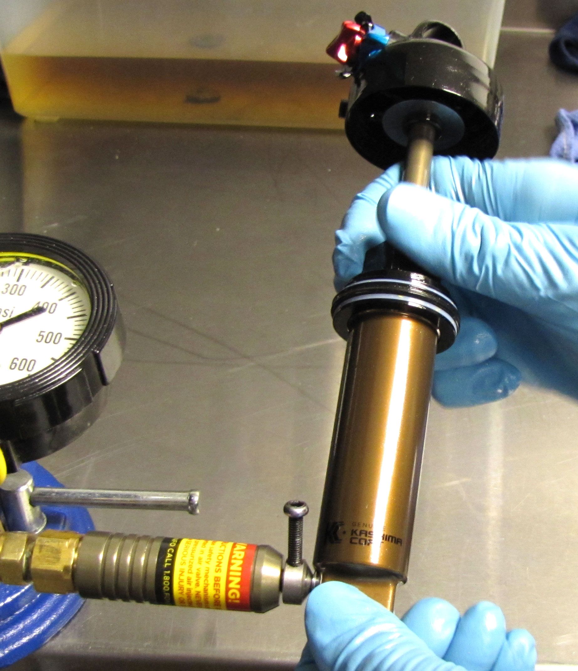
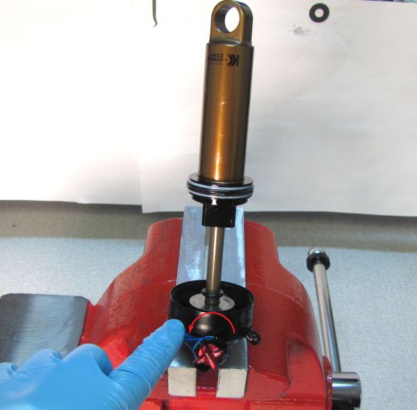
Insert the Nitrogen Fill Pellet Retainer tool (PN: 398-00-374) into the pellet retainer near the end of the body. Use the Pellet Retainer tool to unthread the pellet retainer 1/4 turn. Depress the safety button on the nitrogen fill needle (PN: 802-01-000-KIT), then slide the shock onto the needle by pressing toward the nitrogen fill needle. Charge the IFP chamber to 500 psi. Use the Pellet Retainer tool to gently tighten the pellet retainer by 1/4 turn. Quickly pull the shock straight away from the nitrogen fill needle. A loud pop will be heard. Use a 5/32" hex wrench to tighten the pellet retainer to 14 in-lb (1.6 Nm).

Step 16
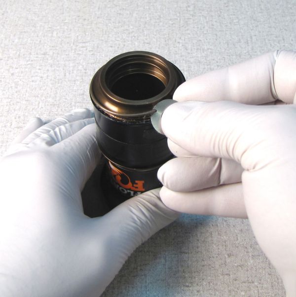
Compress the shock in all modes to test its function. Insert a new Delrin ball from the kit into the pellet retainer. Press the Delrin ball into the pellet retainer with your soft-jawed vice.
Air Sleeve Service

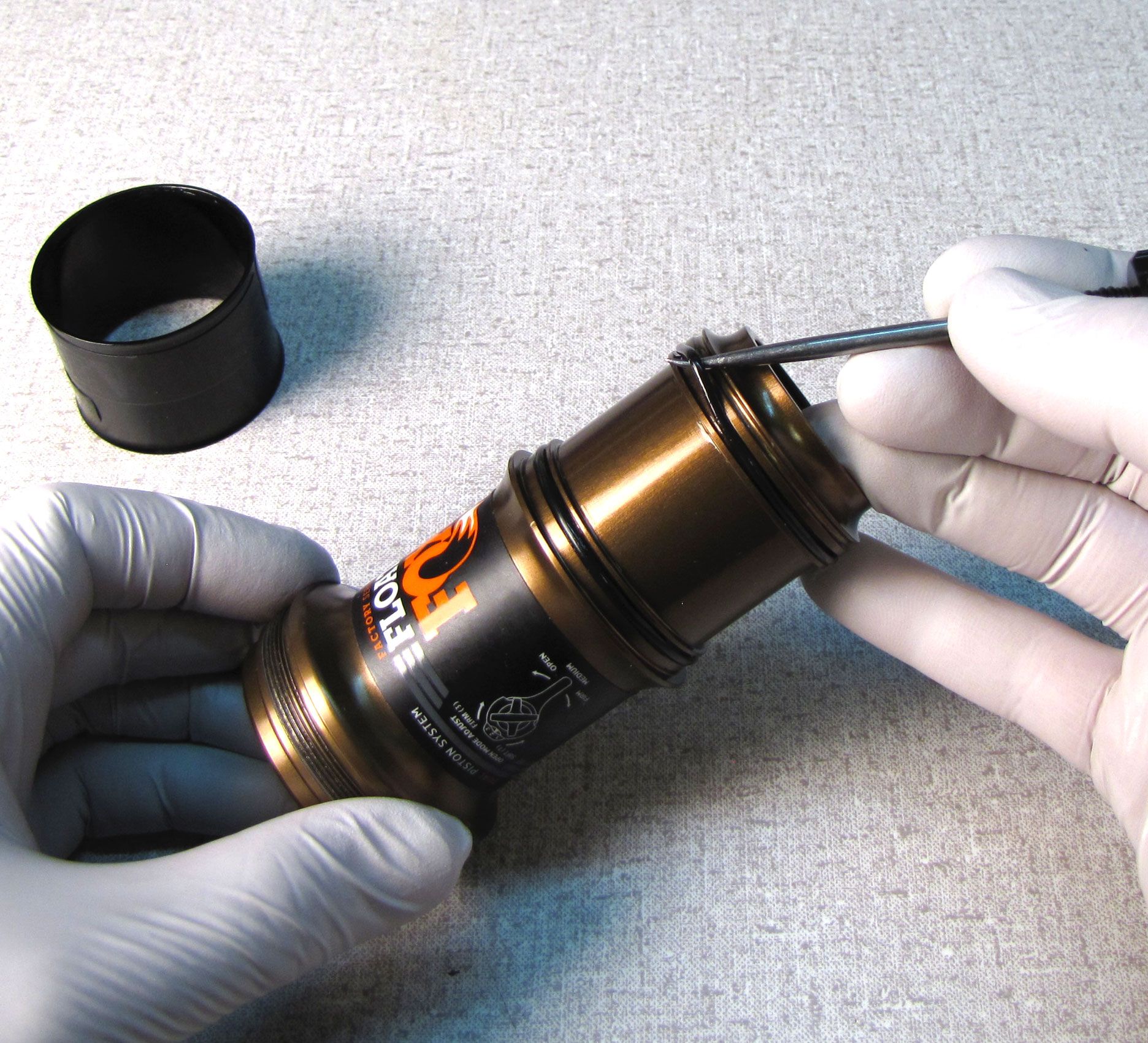
Step 1
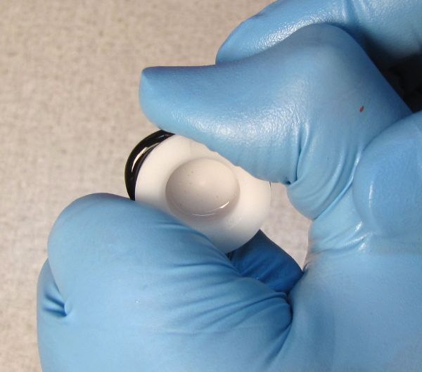
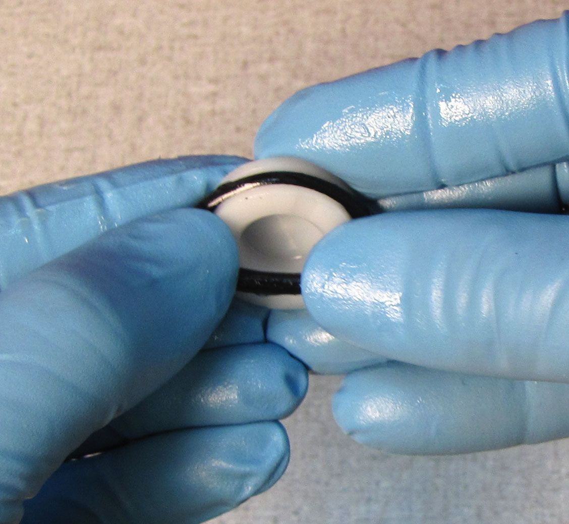
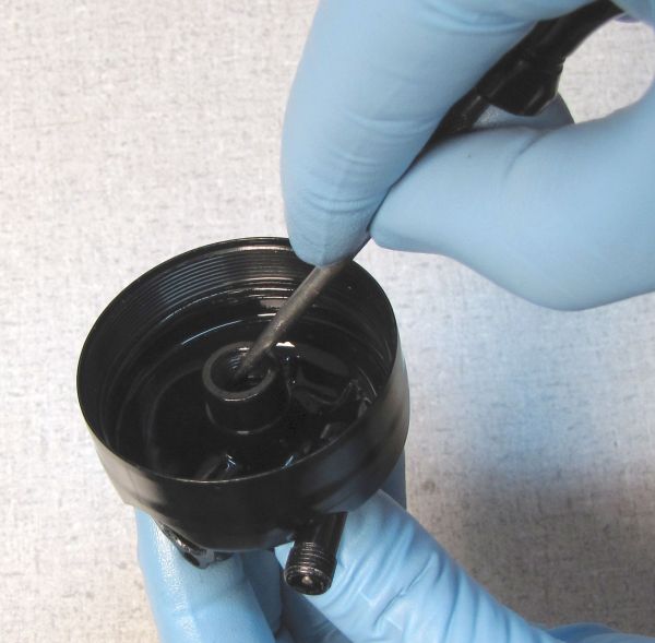
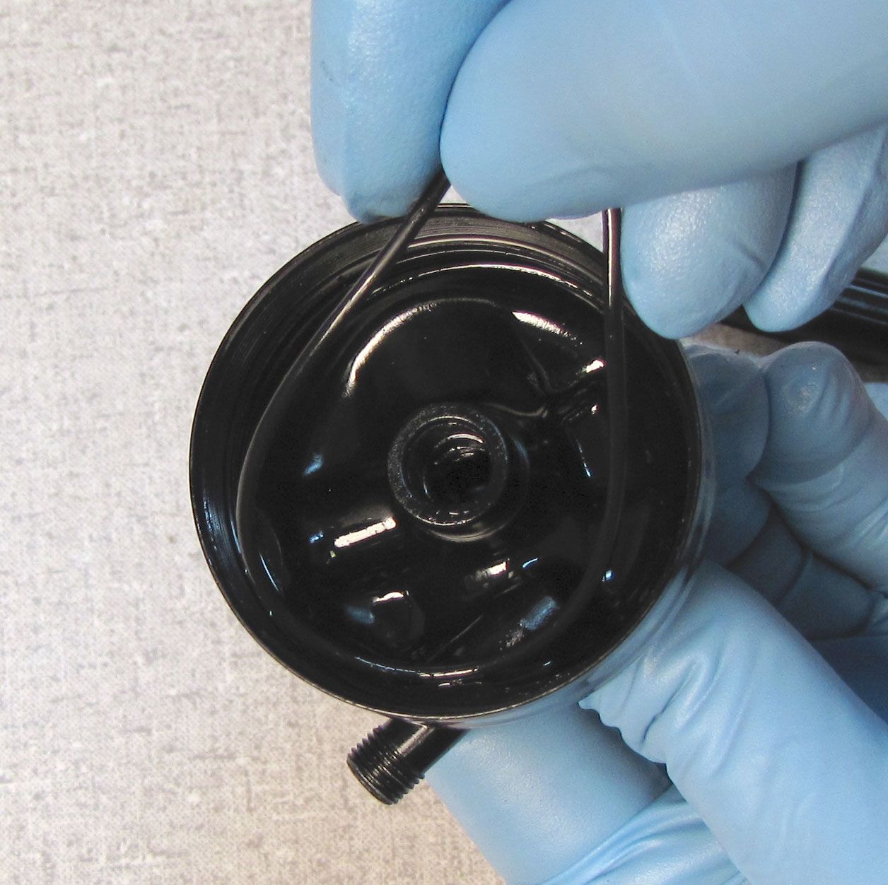
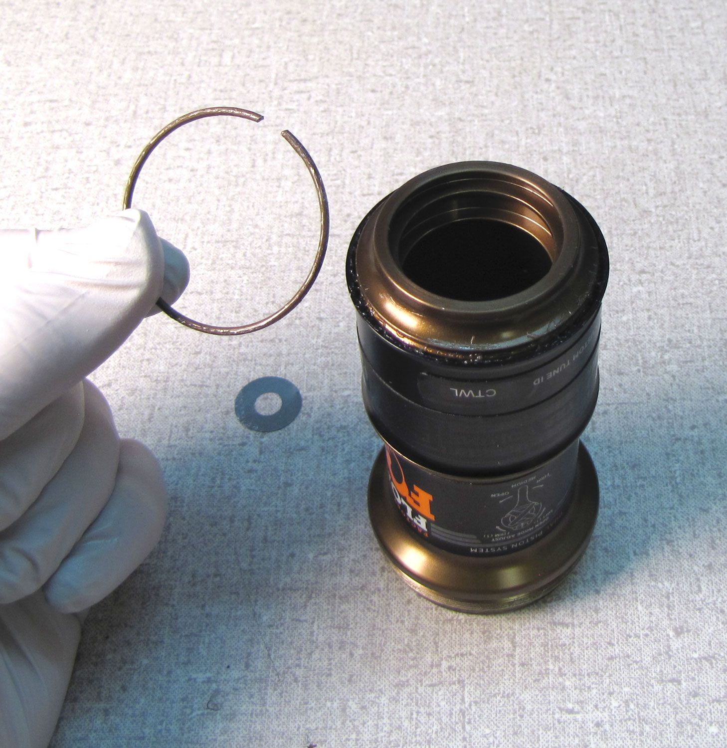
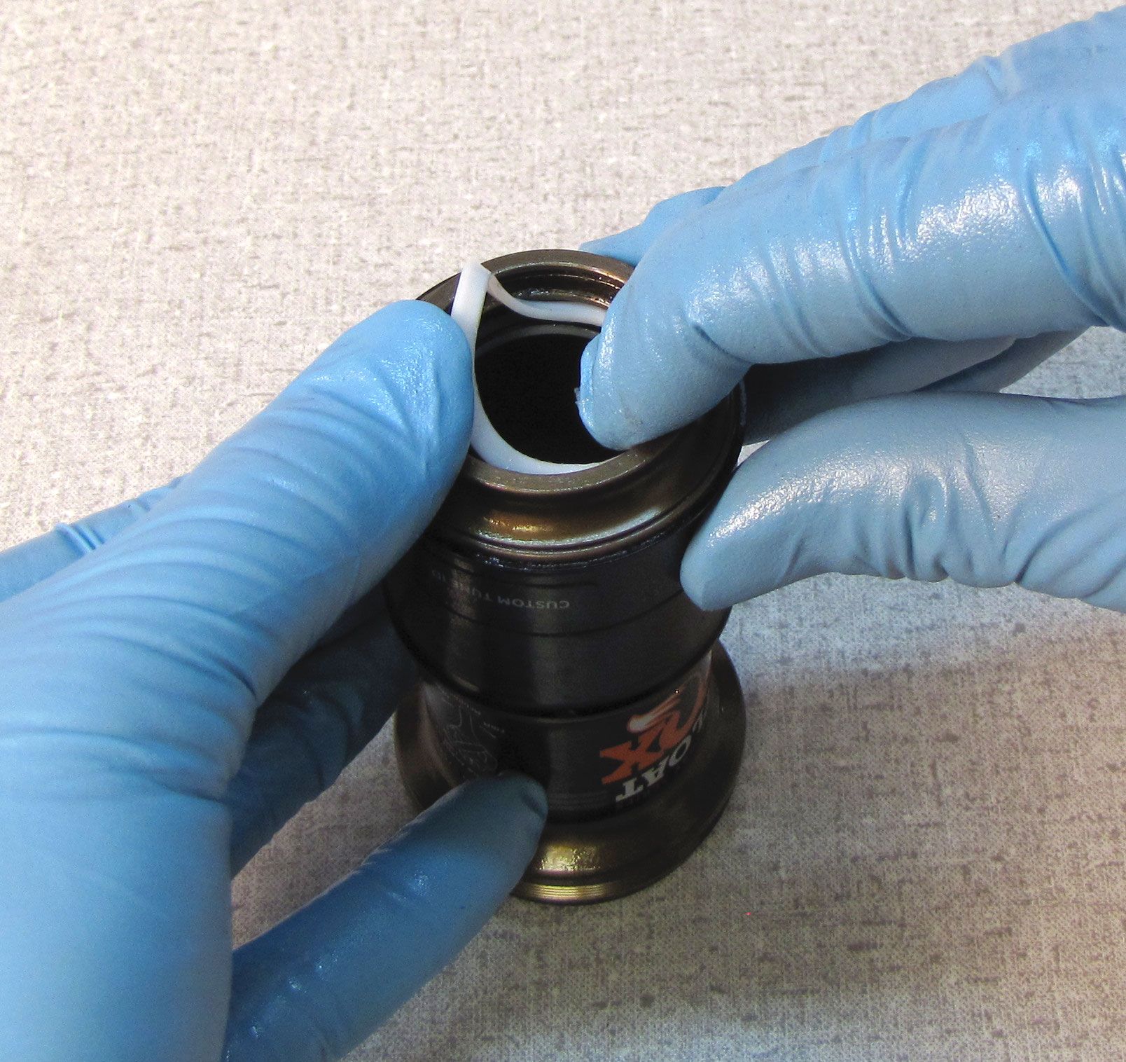
Remove the main air seal and backup rings from the body bearing.
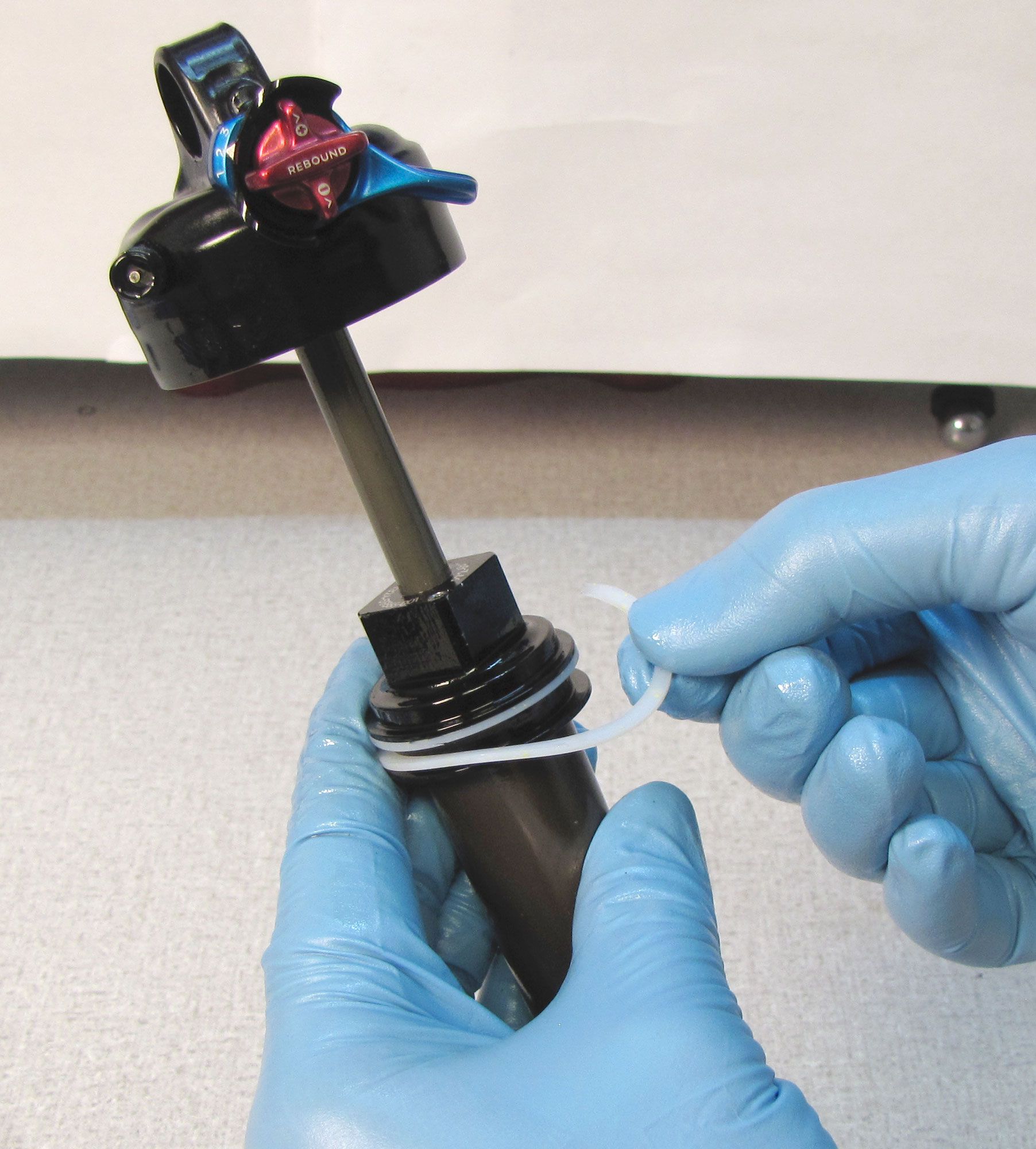
Step 2
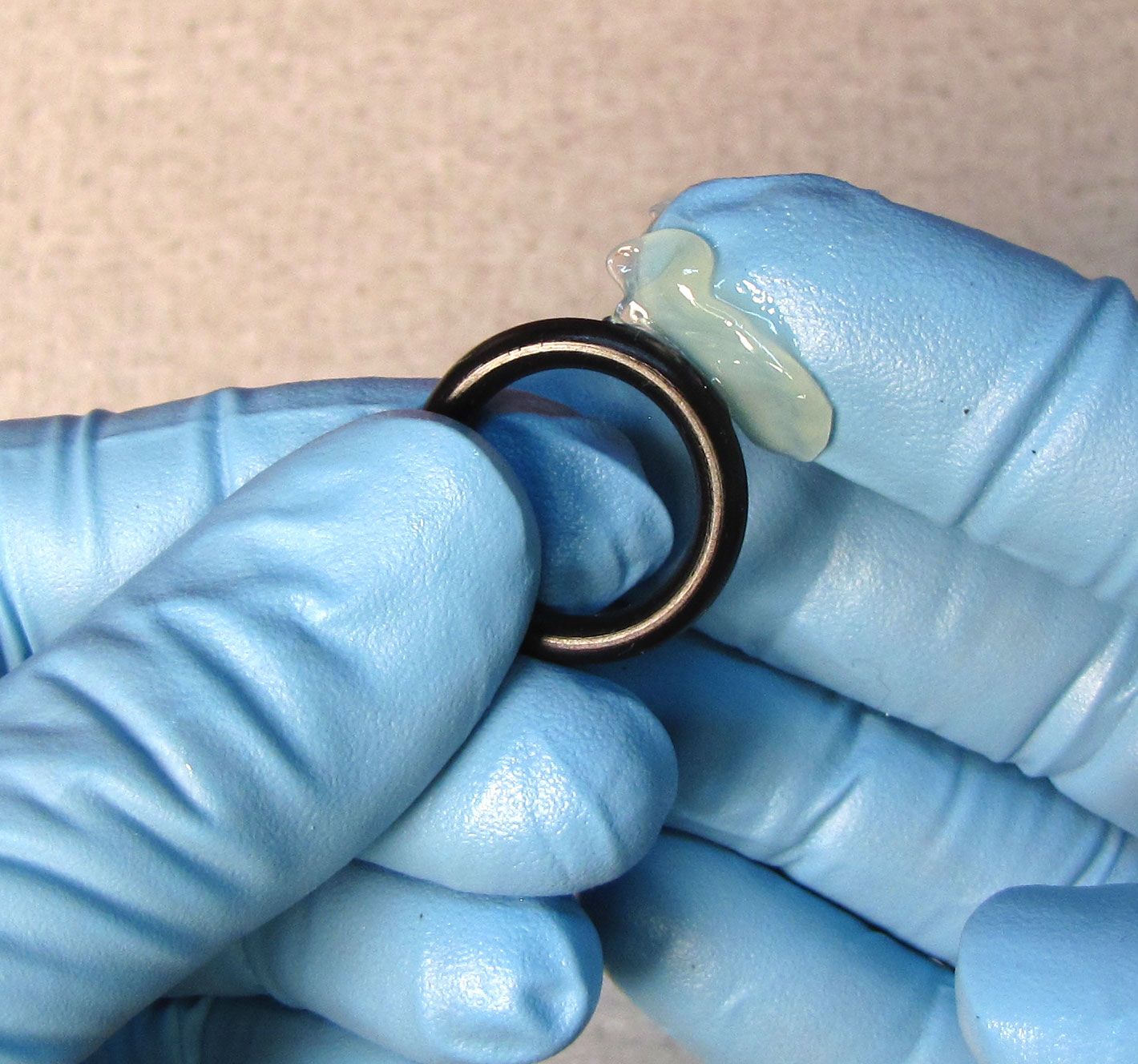
Install a new backup ring from the kit, followed by the new main air seal coated with a thin film of Slick Honey, then the second backup ring. Make sure that the overlapping portions of the backup rings are correctly position with the two beveled edges of each ring facing each other.


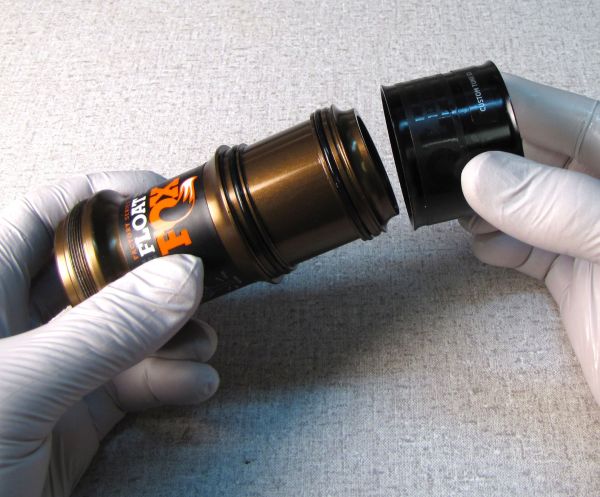
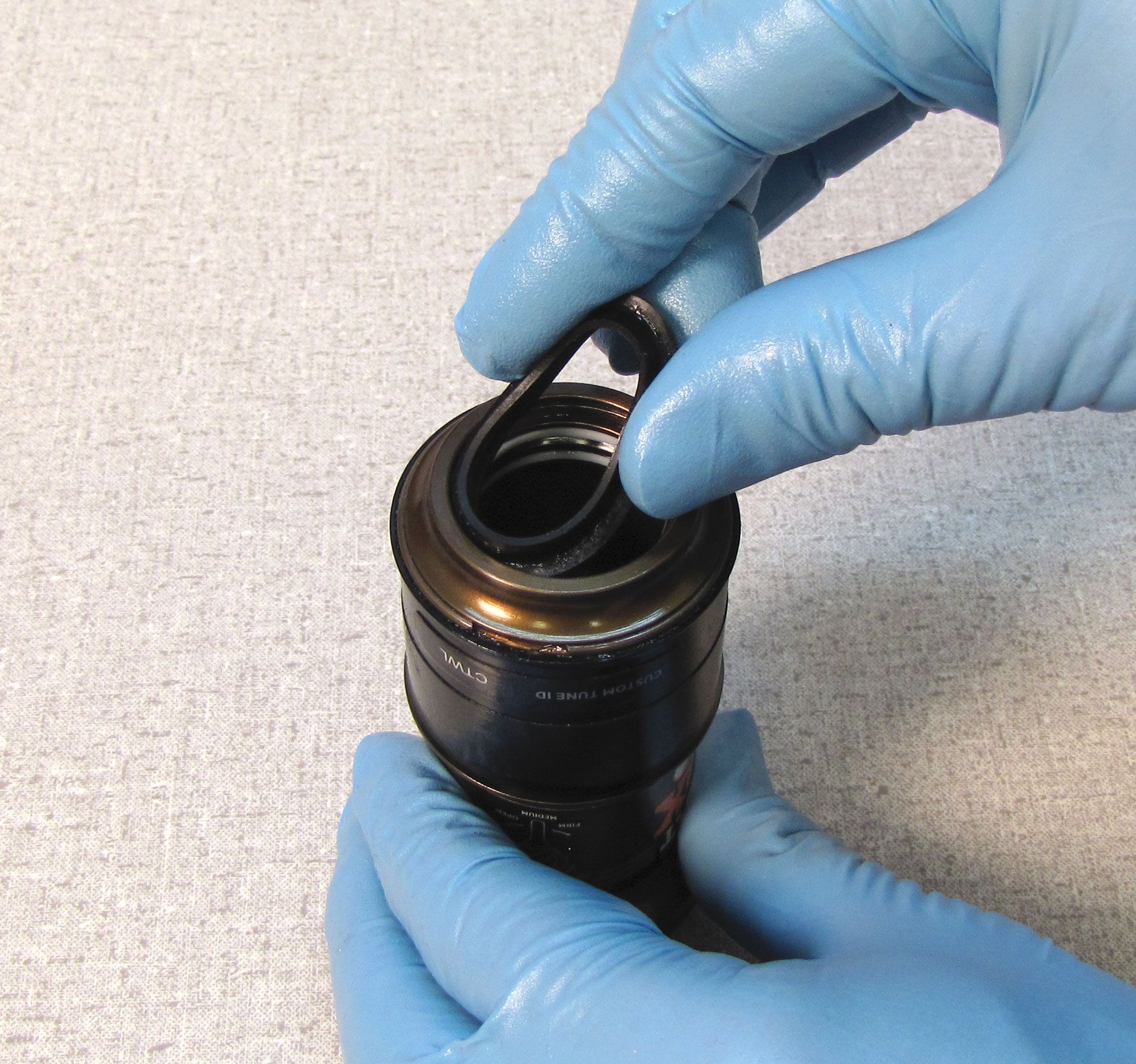
Step 3
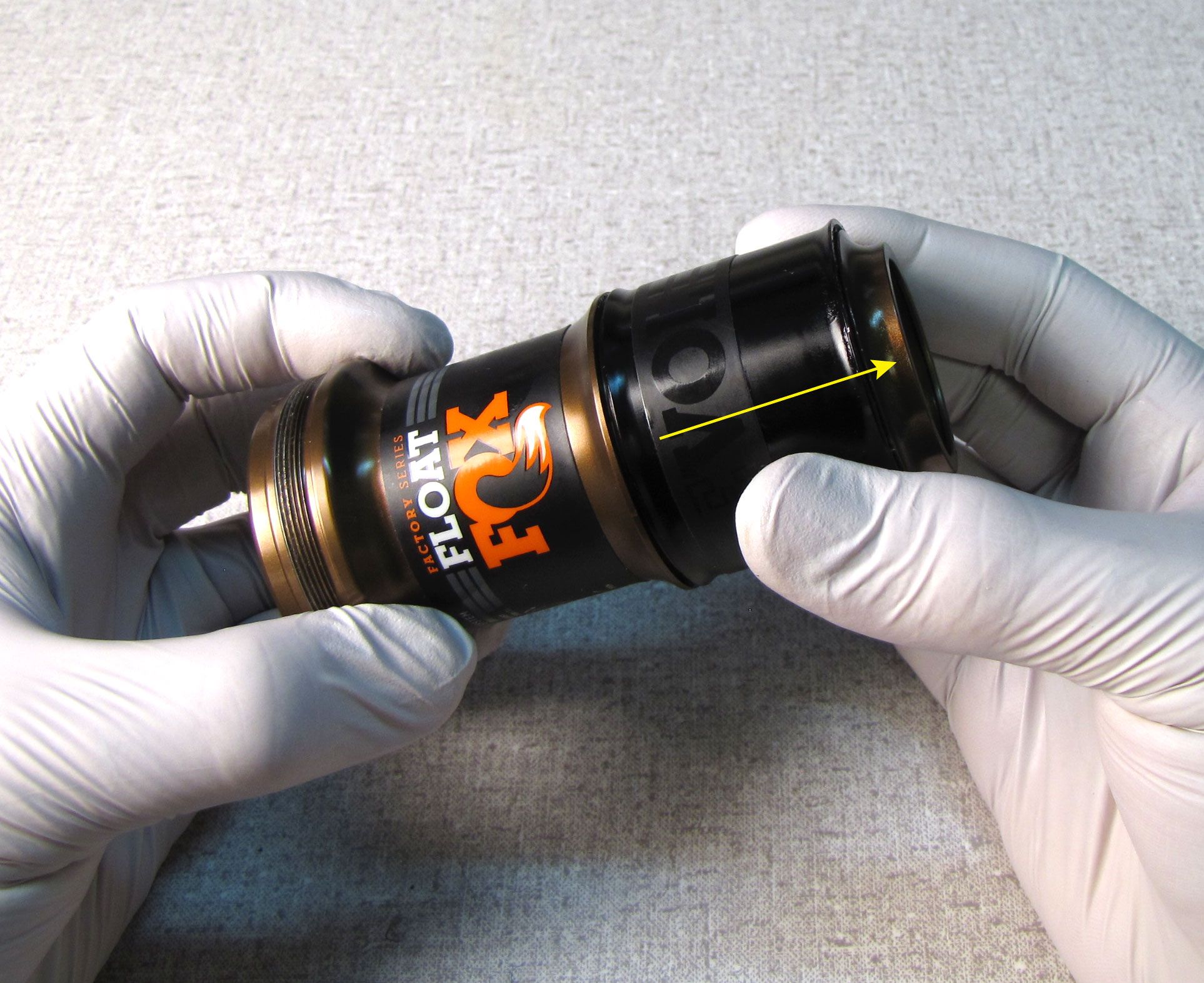
Carefully remove the wiper seal, backup rings, and negative air seal from the end of the air sleeve without scratching any portion of the air sleeve. Use a plastic or wooden pick to remove the internal seals to prevent scratching the air sleeve. A scratched air sleeve can cause air loss not covered under warranty.
If servicing a non-EVOL air sleeve, skip to Air Sleeve Service step 7.
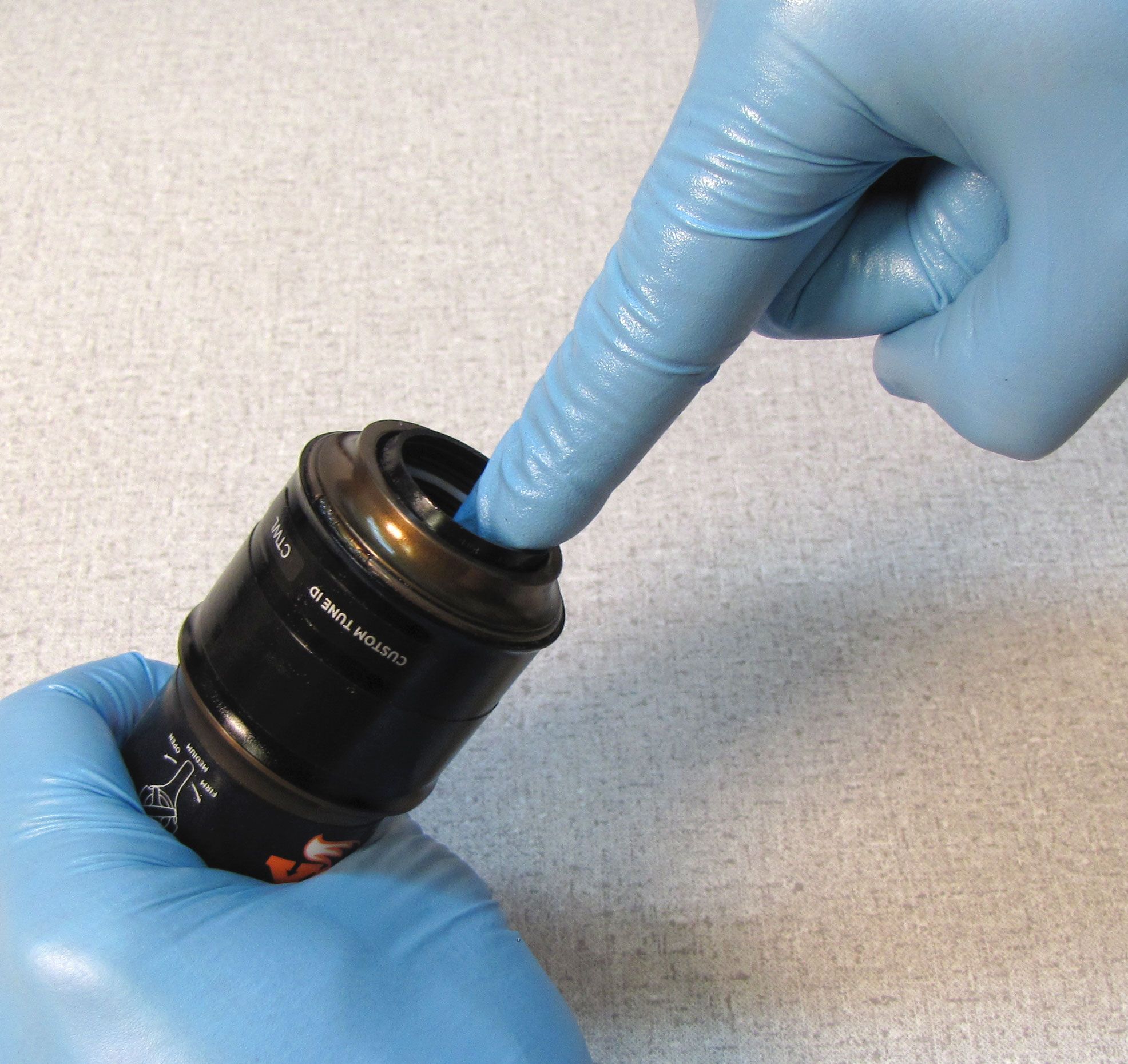
Step 4
Use a shim or seal pick to carefully remove the wire retaining ring from the end of the EVOL air sleeve. Pull the EVOL portion of the air sleeve off of the inner air sleeve to remove.

Step 5
Clean the air sleeve and replace the two EVOL o-rings with new greased ones from the kit.
Step 6
Reinstall the EVOL portion of the air sleeve onto the inner air sleeve. Make sure to fully seat the EVOL sleeve againt the feature in the middle of the inner air sleeve. Replace the wire retaining ring, seating it fully in the ring groove.


Step 7
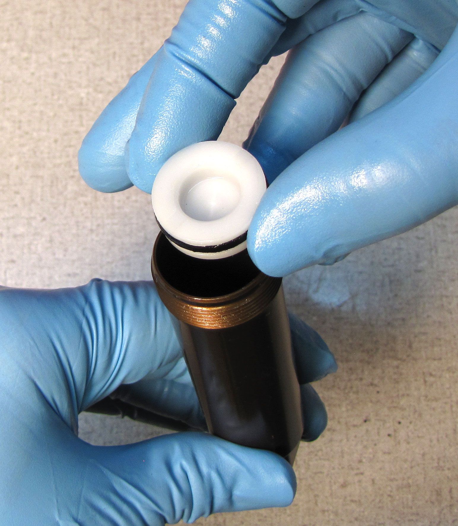
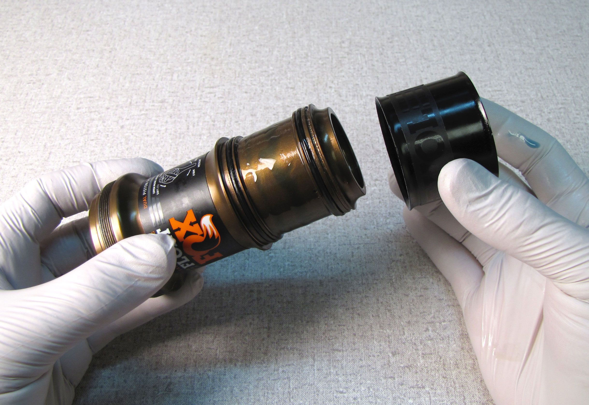
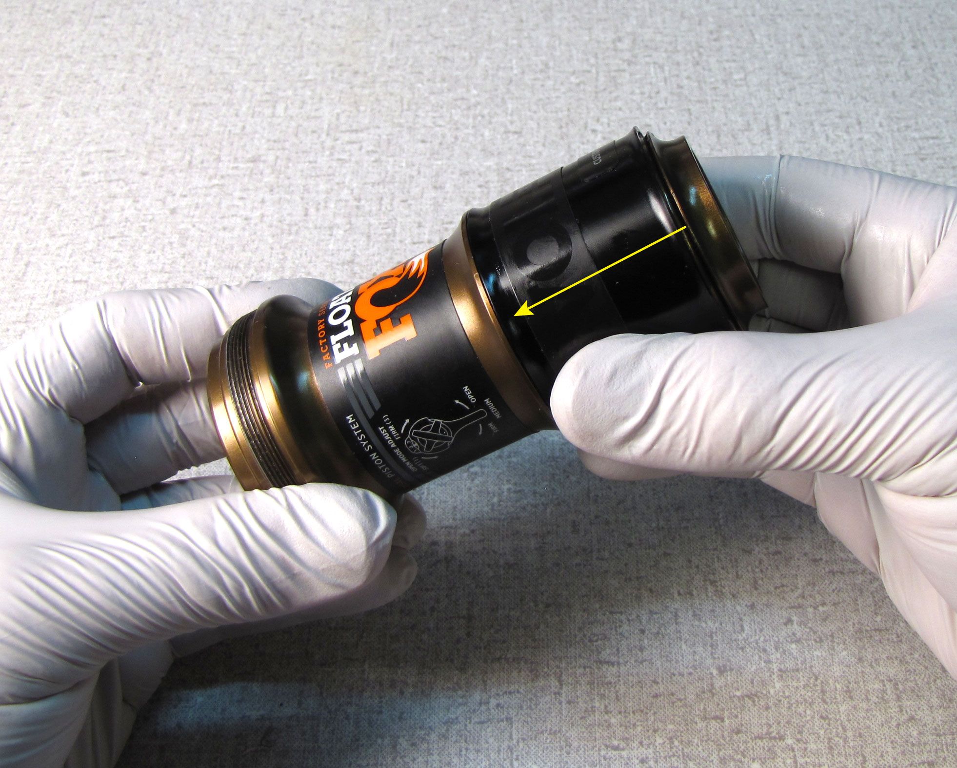
Insert a new backup ring into the air sleeve followed by the new greased negative air seal and the last backup ring. These parts should fit tightly into the inner seal groove in the end of the air sleeve. Install the wiper seal with its lip facing out into the outermost seal groove. Press all parts against the wall of the air sleeve to make sure they are all seated correctly.
Step 8
Verify that the blue compression adjust lever and the red rebound knob are in the open position (fully counter-clockwise).


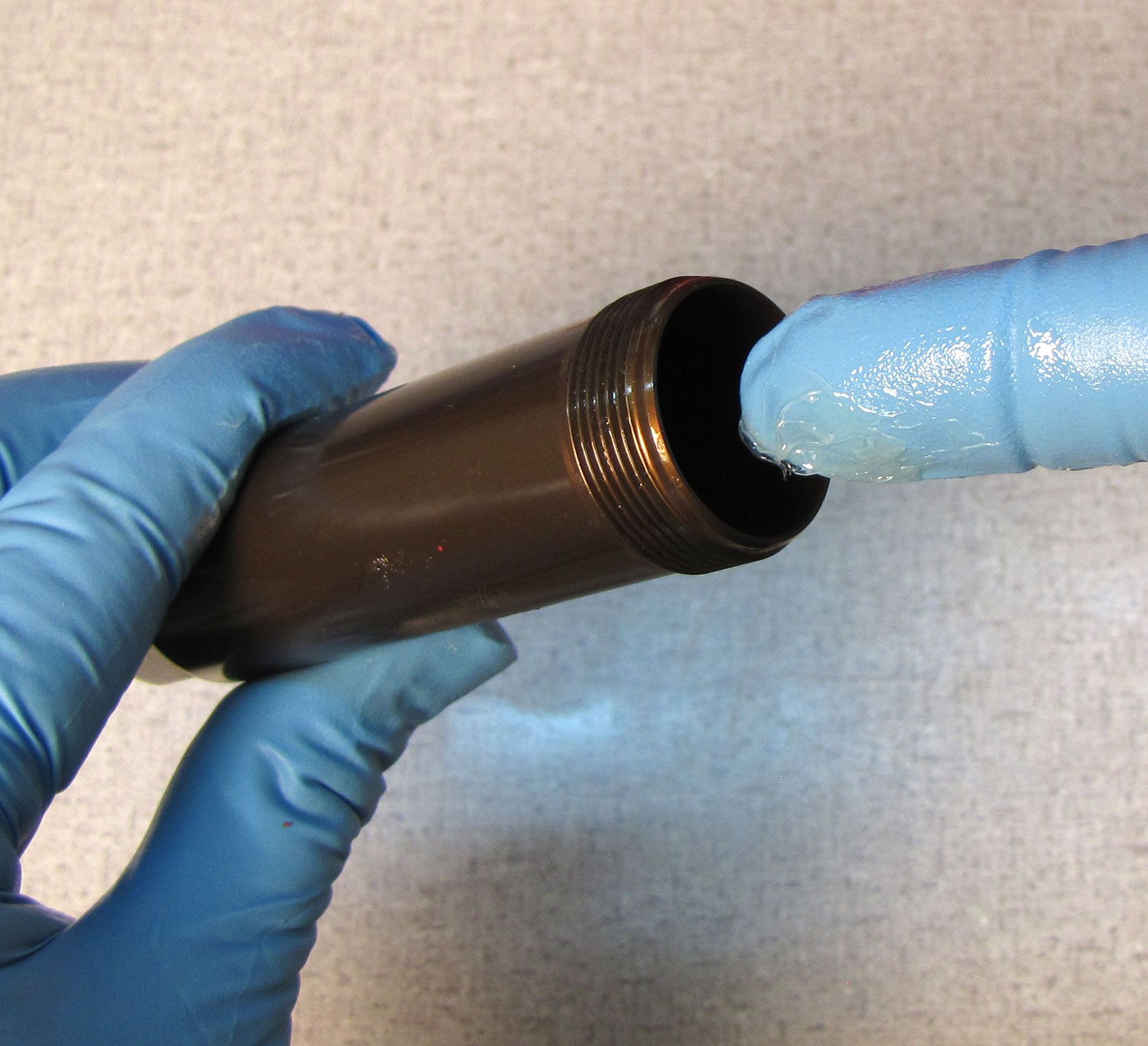
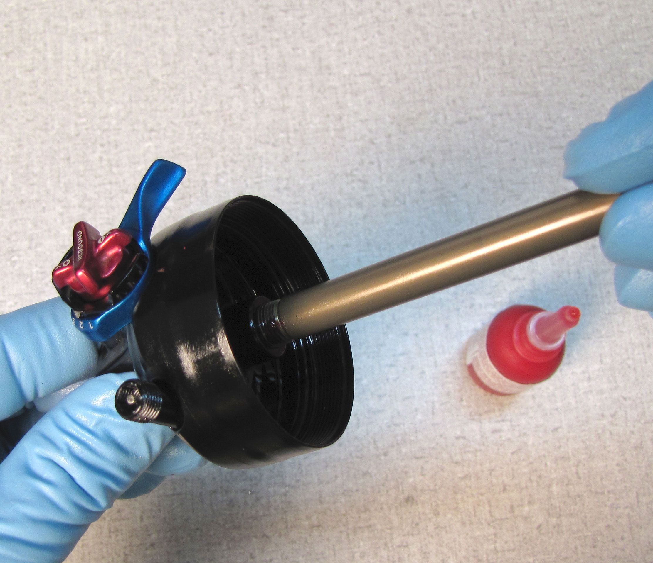
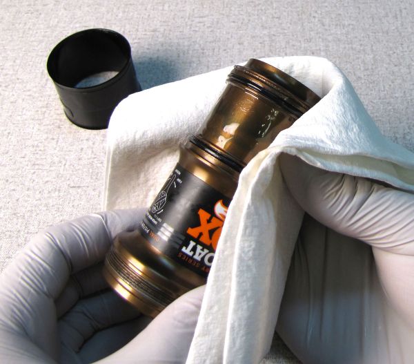
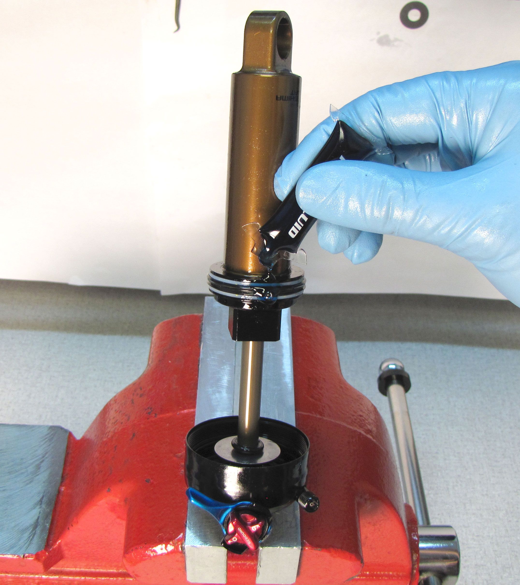
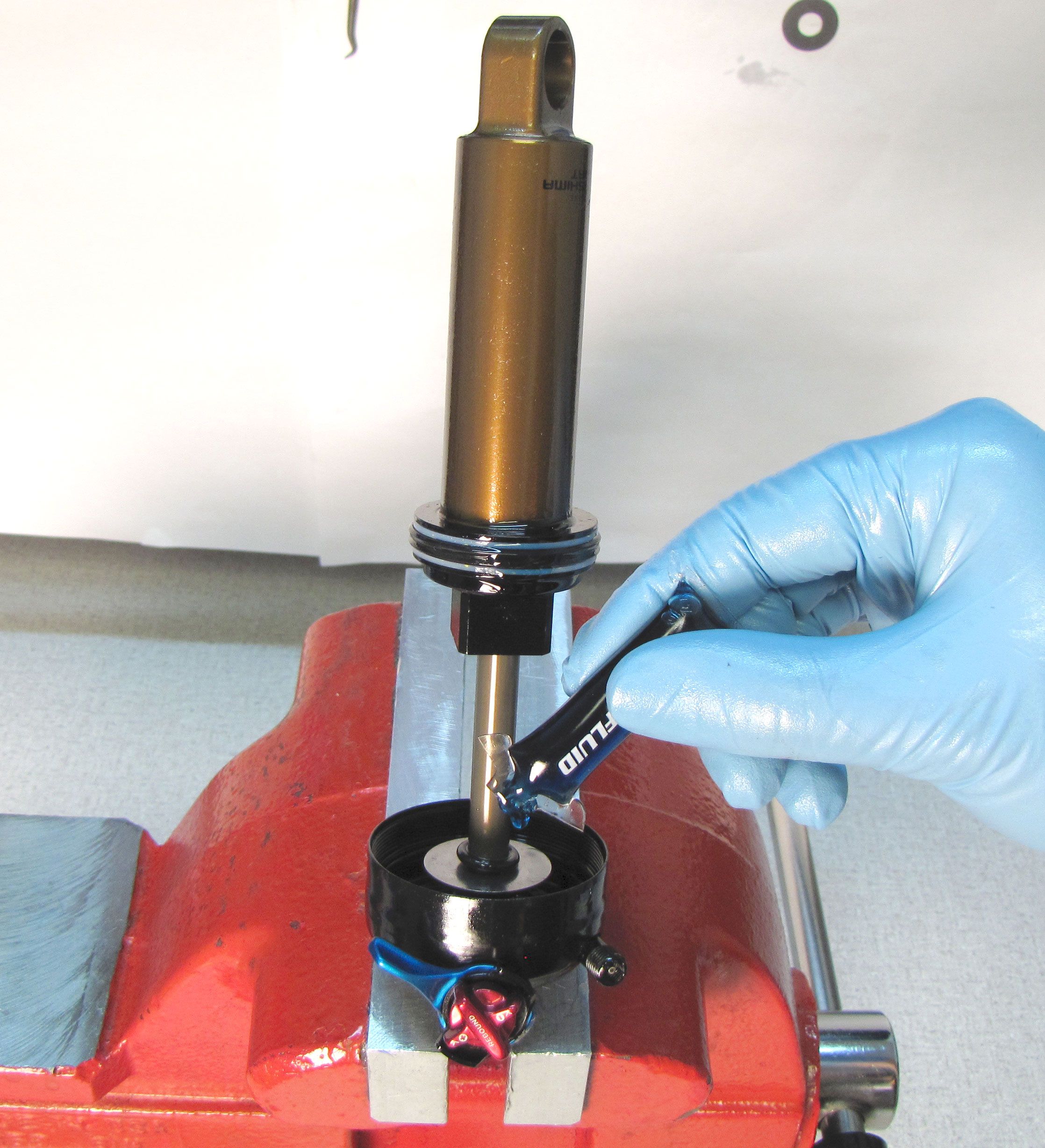
Step 9
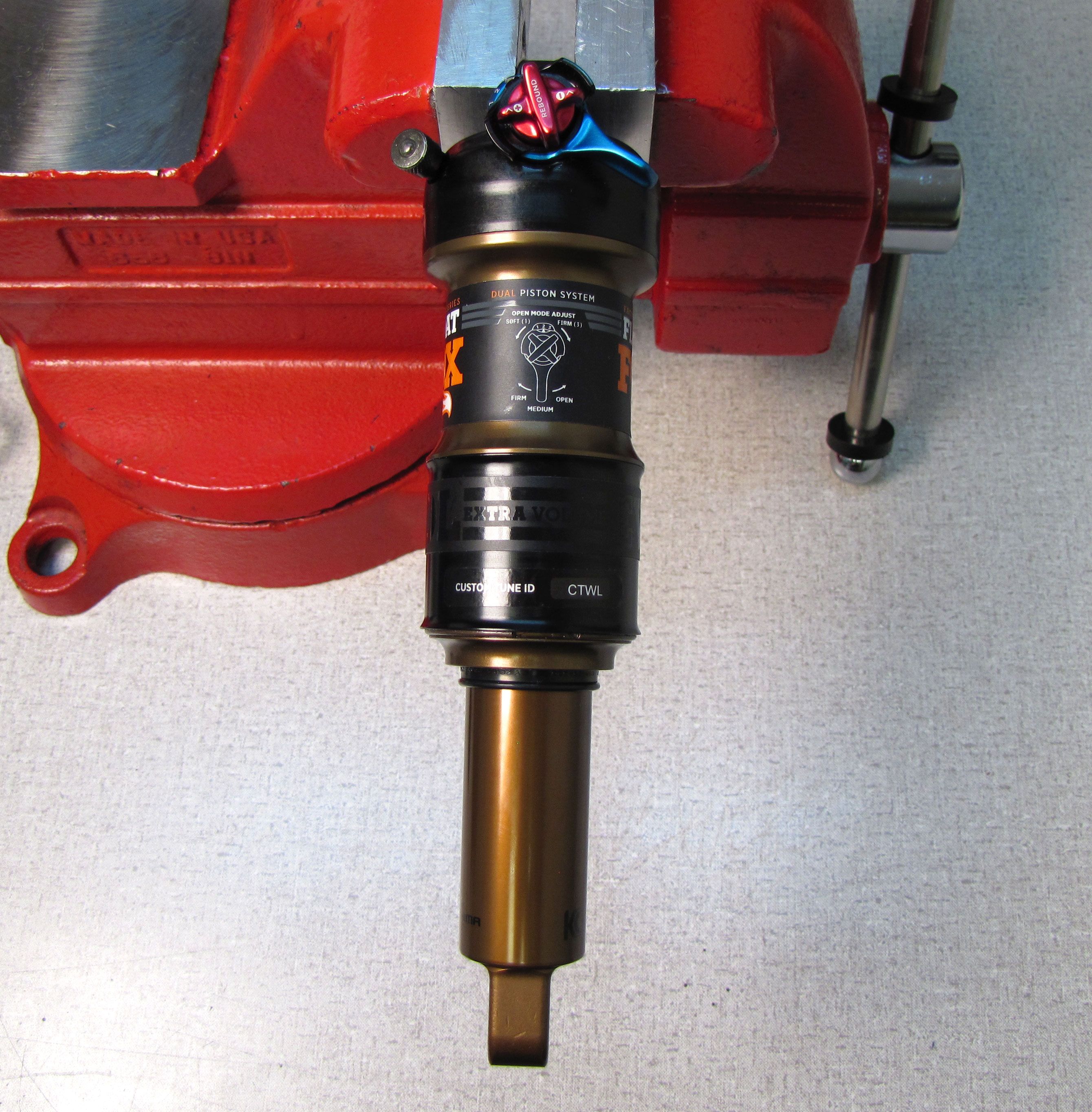
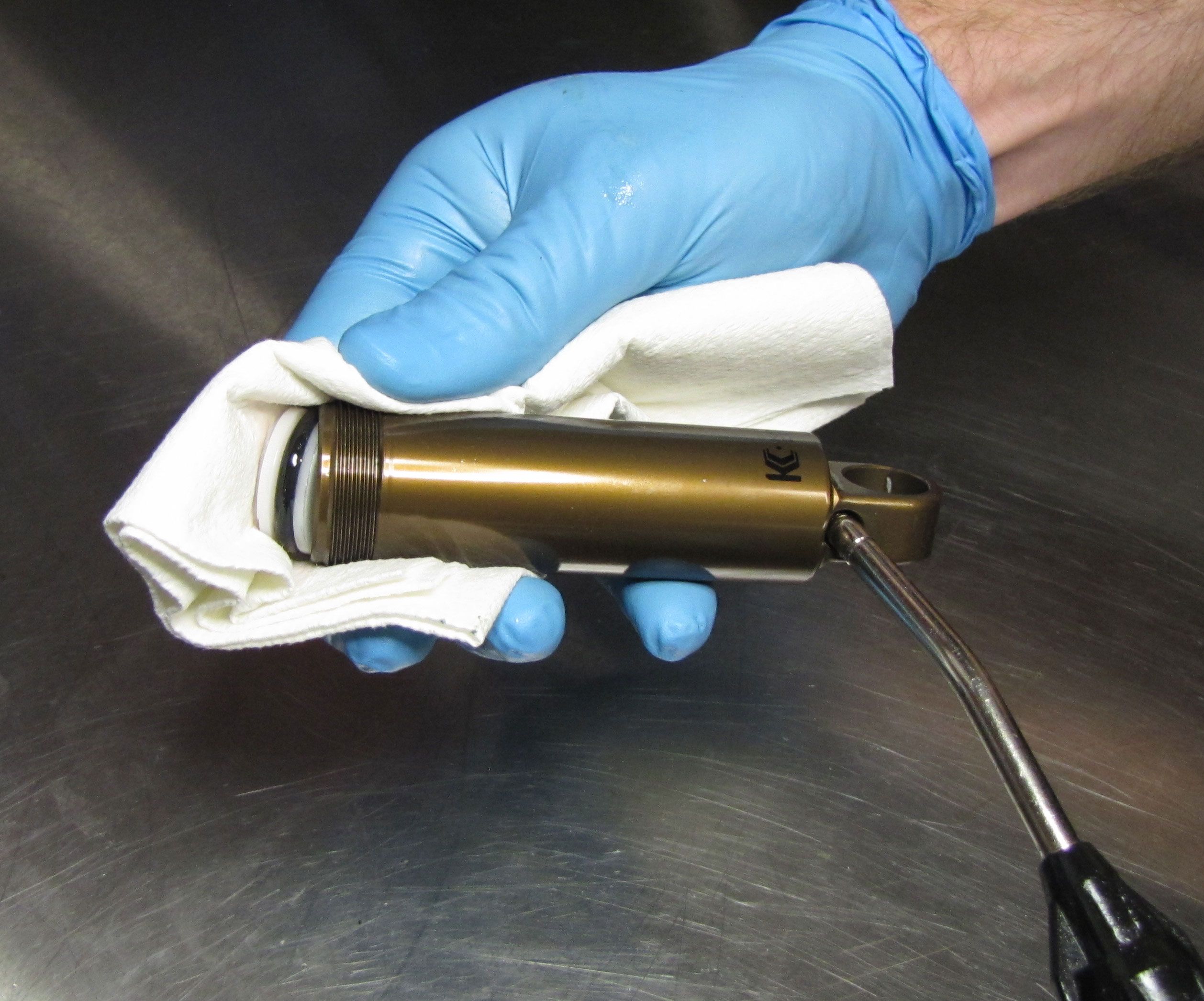
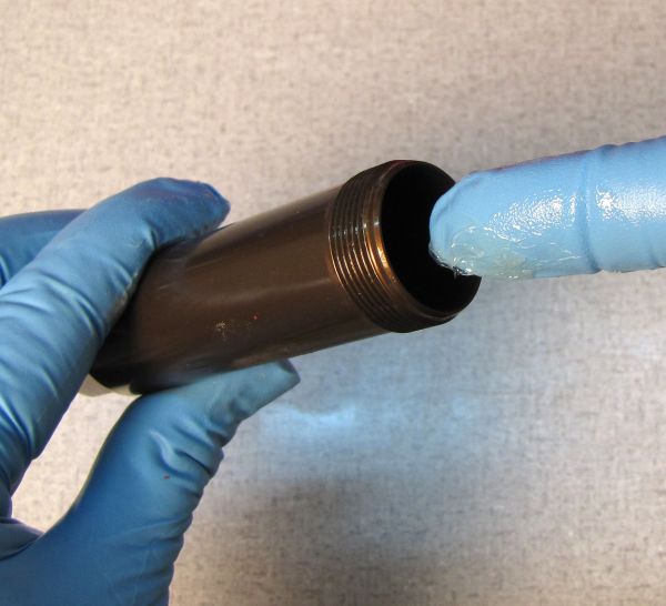
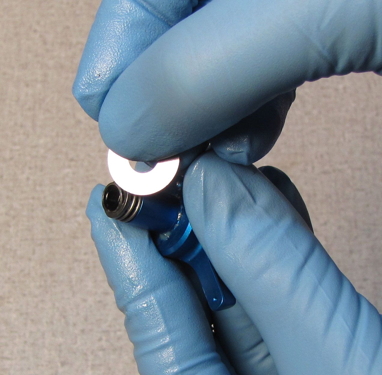
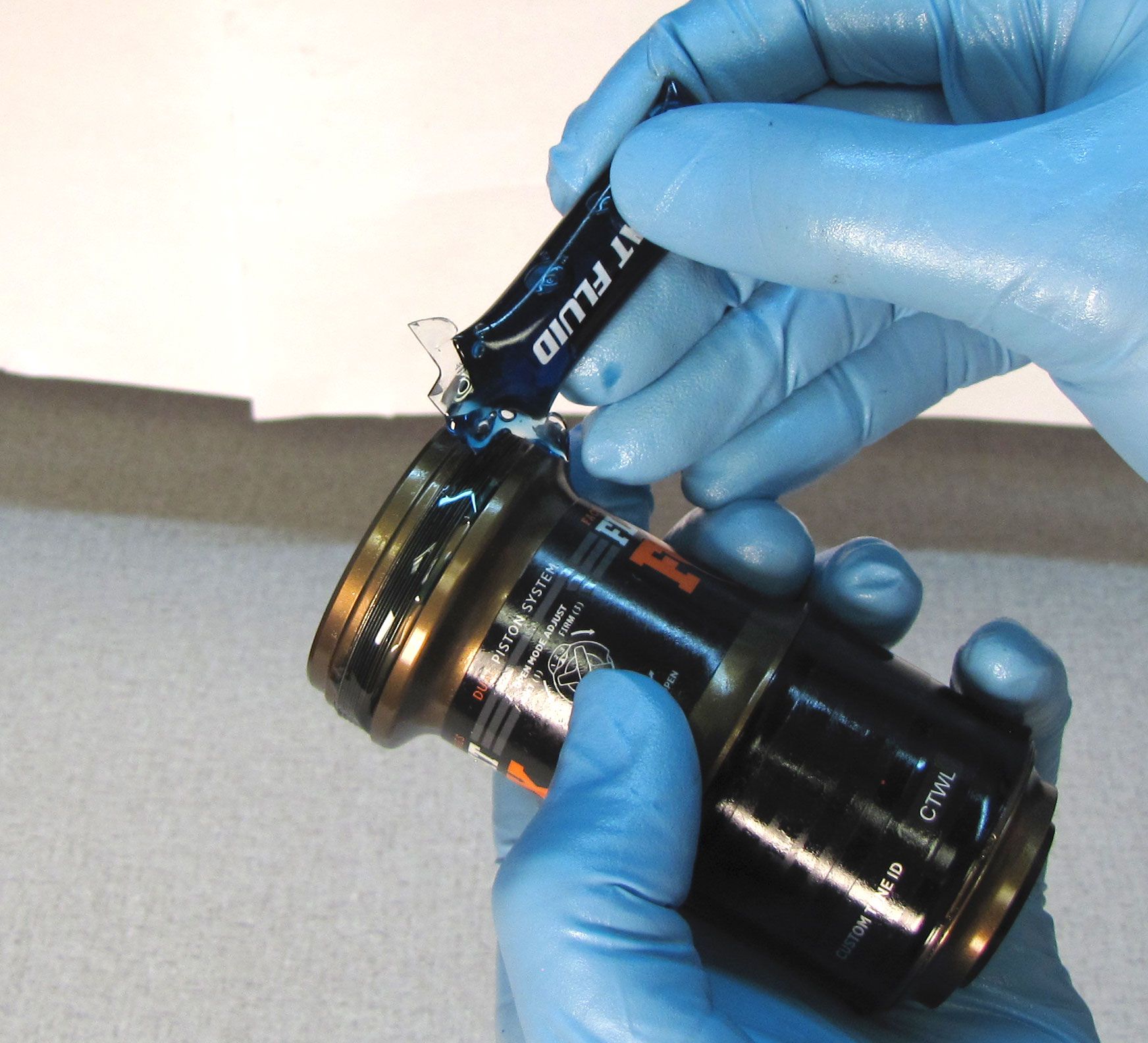
Coat the main air seal and the air sleeve threads with a thin film of Float Fluid. Add 2cc of Float Fluid to the main air chamber, then slide the air sleeve in place over the main air seal. Compress the shock damper to help overcome trapped air pressure to thread the air sleeve to the eyelet. Tighten the air sleeve until hand tight (approximately 45 in-lb/ 5.1 Nm).

Step 10
Install a new sag indicator o-ring onto the shock body. Add air to your desired pressure by slowly compressing the shock through 25% of its travel 10-20 times after every 50psi addition. Reinstall the black air valve cap.
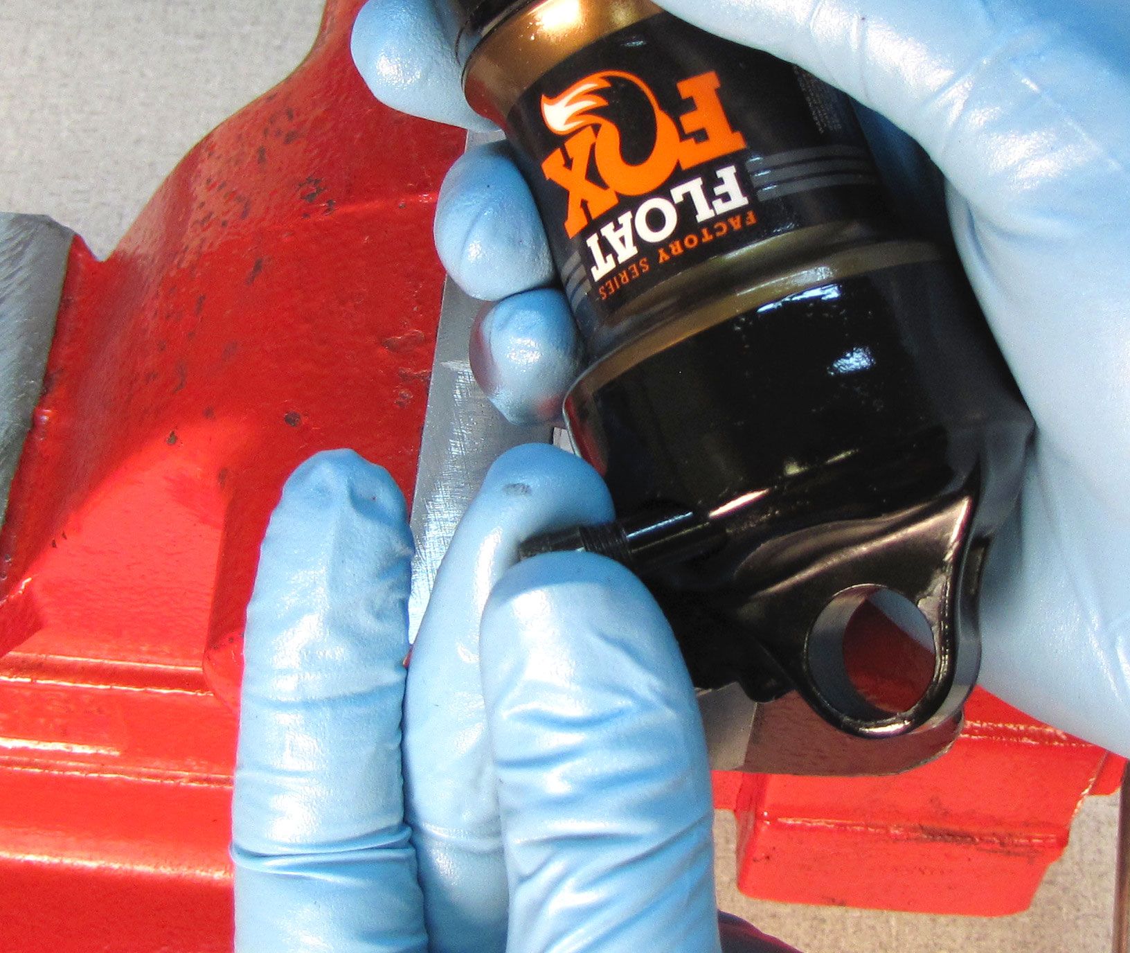

Step 11
Replace any eyelet hardware and clean the exterior of your shock. You have now completed the rebuild.