2016-2018 32mm/34mm P-S FIT4 3pos Damper Cartridge Rebuild
Required Parts
- 025-03-010 Oil: AM, FOX Bath Oil [32 oz.], 20wt. Gold
- 025-06-007 Oil: Suspension Fluid [1.00 Quart] R3, 5WT, ISO 15
- 803-00-960 Seal Kit: 32 & 34 FIT4 Cartridge Rebuild
Required Tools
- 398-00-320 Tool: 8mm Shaft Bullet, 32 FIT Cartridge
- 398-00-371 Tooling: Sealhead To Shaft Bullet, 10mm
- 398-00-681 2002-017 32 Damper-side and ALL 32-34-36-40 Spring-side Removal Tool
- 398-00-682 2005-017 34-36-40 Damper-side Removal Tool
- 398-00-702 Tooling: Fork Topcap Socket, 26mm, 3/8 Drive
- 803-00-147 Kit: Shaft Clamps, 07 FORX, Set #2 (32 X Body, 36, 40 Forx) (For 8mm Shafts)
- 803-00-276 Service Kit: Hand Bleed, Syringe and Tube, 2010 32 Fit RL-RLC Cartridge
- 803-00-830 Service Set: Tooling: 2014 RC2, Shaft Clamps (For 10mm Shafts)
WARNING: Always wear safety glasses and protective gloves during service to prevent potential injury. Failure to wear protective equipment during service may lead to SERIOUS INJURY OR DEATH.
The following procedure guides you through the rebuild of the 32mm/34mm P-S FIT4 3pos damper cartridge.
32mm: Complete part information and technical drawings for 2016 32mm forks can be found by clicking: 32mm Part Information »
32mm: To link directly to the technical drawings for the 2016 32mm FIT4 3pos cartridge and its assemblies, click here »
34mm: Complete part information and technical drawings for 2016 34mm forks can be found by clicking: 34mm Part Information »
34mm: To link directly to the technical drawings for the 2016 34mm FIT4 3pos cartridge and its assemblies, click here »
WARNING: FOX products should be serviced by a trained bicycle service technician, in accordance with FOX specifications. If you have any doubt whether or not you can properly service your FOX product, then DO NOT attempt it. Improperly serviced products can fail, causing the rider to lose control resulting in SERIOUS INJURY OR DEATH.
WARNING: FOX suspension products contain pressurized nitrogen, air, oil, or all 3. Suspension misuse can cause property damage, SERIOUS INJURY OR DEATH. DO NOT puncture, incinerate or crush any portion of a FOX suspension product. DO NOT attempt to disassemble any portion of a FOX suspension product, unless expressly instructed to do so by the applicable FOX technical documentation, and then ONLY while strictly adhering to all FOX instructions and warnings in that instance.
WARNING: Modification, improper service, or use of aftermarket replacement parts with FOX forks and shocks may cause the product to malfunction, resulting in SERIOUS INJURY OR DEATH. DO NOT modify any part of a fork or shock, including the fork brace (lower leg cross brace), crown, steerer, upper and lower leg tubes, or internal parts, except as instructed herein. Any unauthorized modification may void the warranty, and may cause failure or the fork or shock, resulting in SERIOUS INJURY OR DEATH.
Removal From Fork Chassis
Step 1
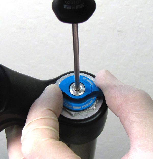
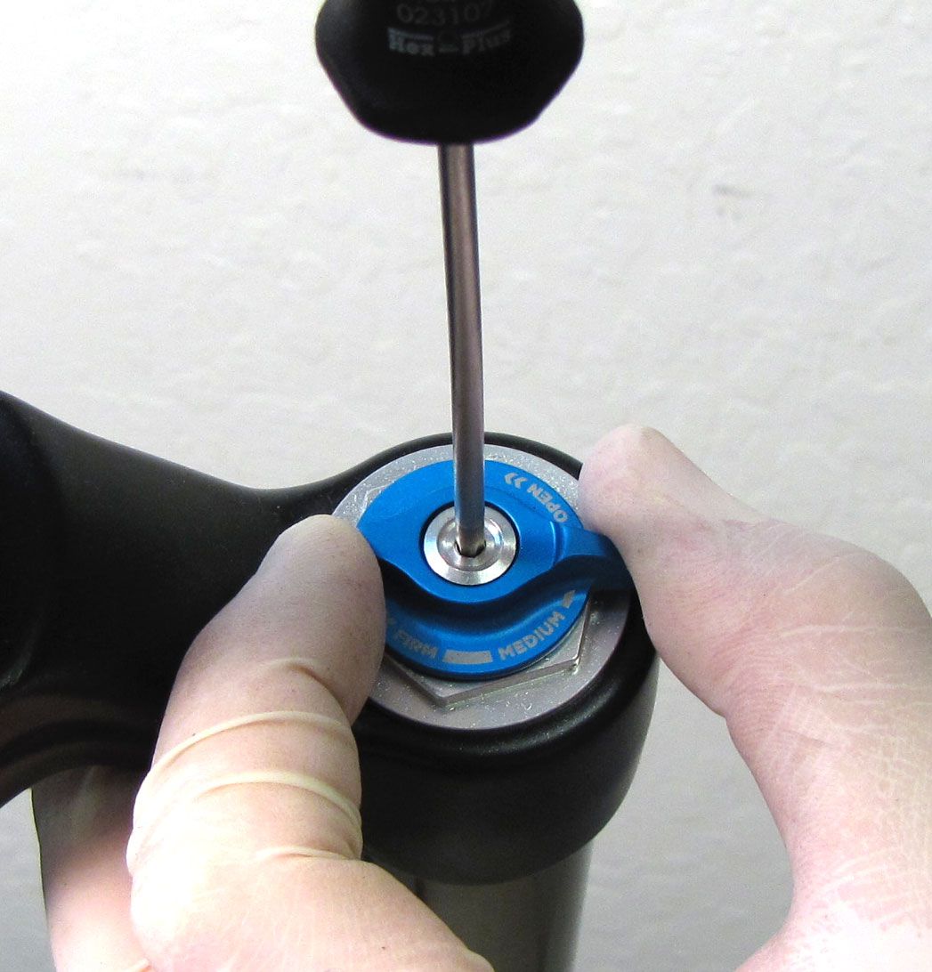
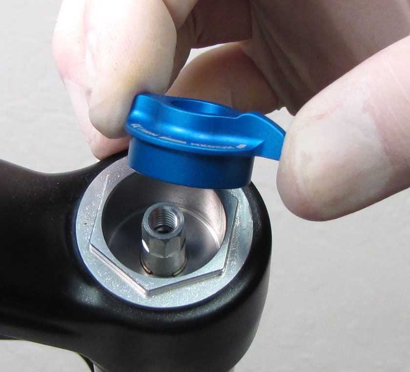
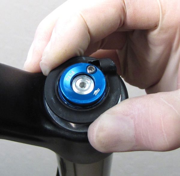
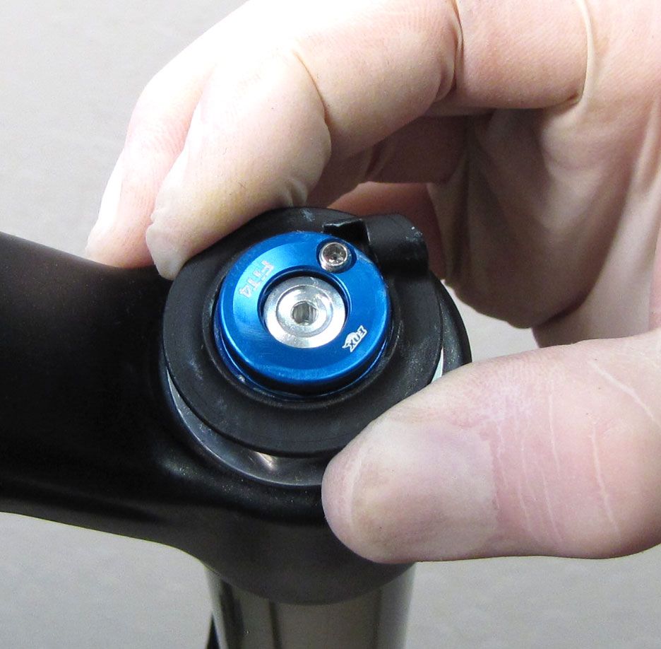
For Levers: Set the fork to Open mode by turning the blue lever fully counter-clockwise. Hold the blue knob while unthreading the set screw (counter-clockwise) with your 2.5mm hex wrench.
For Remote: Cut off the end crimp, unthread the cable pinch bolt without removing it completely, then remove the cable and housing. Hold the blue pulley while unthreading the set screw (counter-clockwise) with your 2.5mm hex wrench.
Step 2
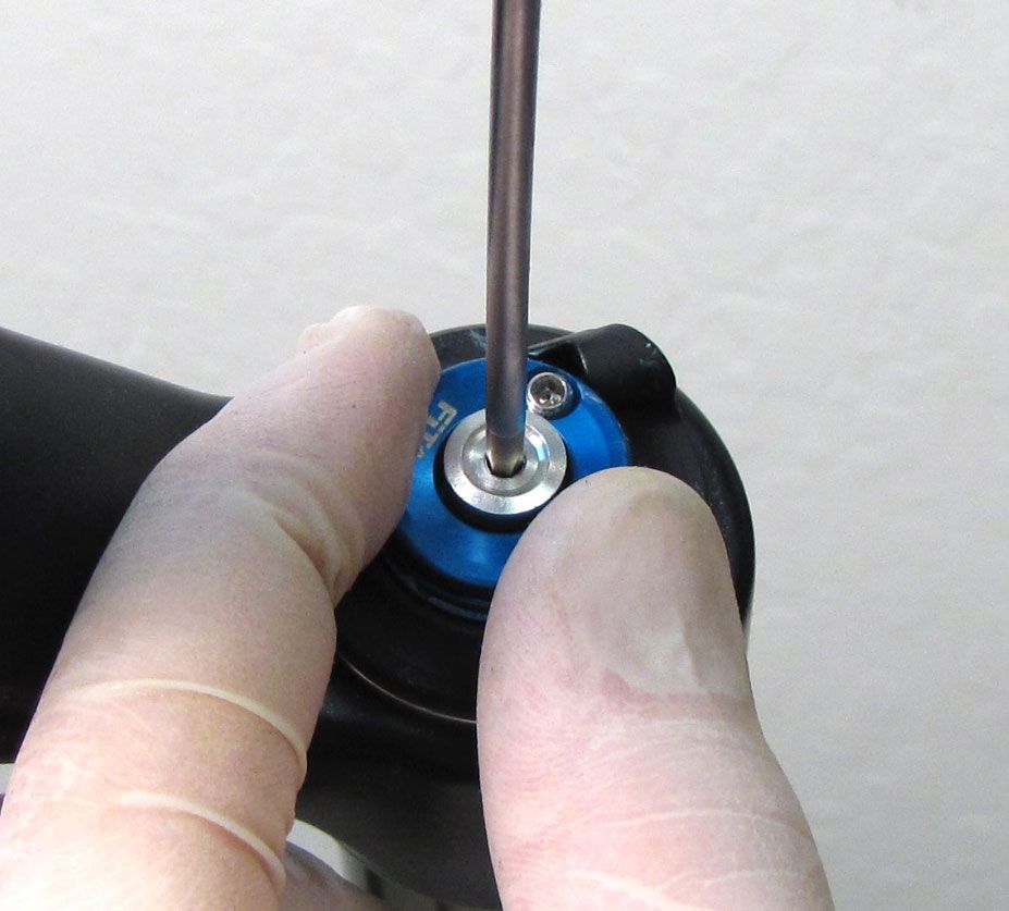
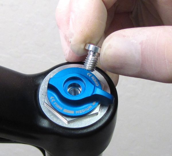
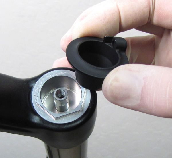
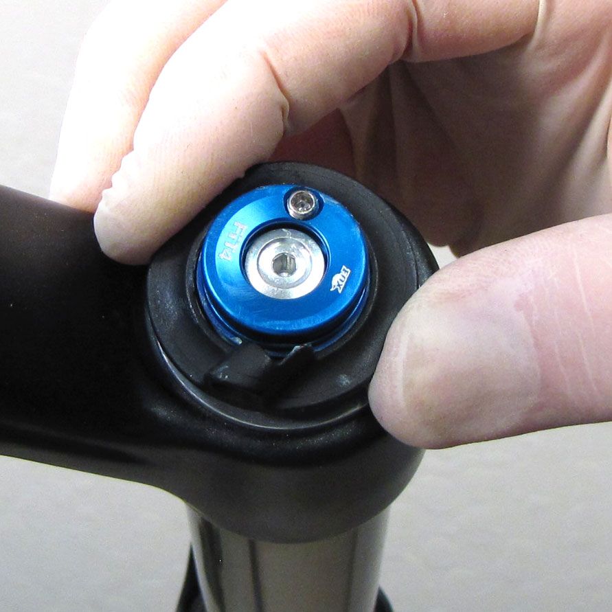
For Levers: Remove the 2.5mm hex screw followed by the blue lever.
For Remote: Remove the 2.5mm hex screw, then lift up on the blue pulley to remove it and the torsion spring. Remove the black remote housing.


Step 3
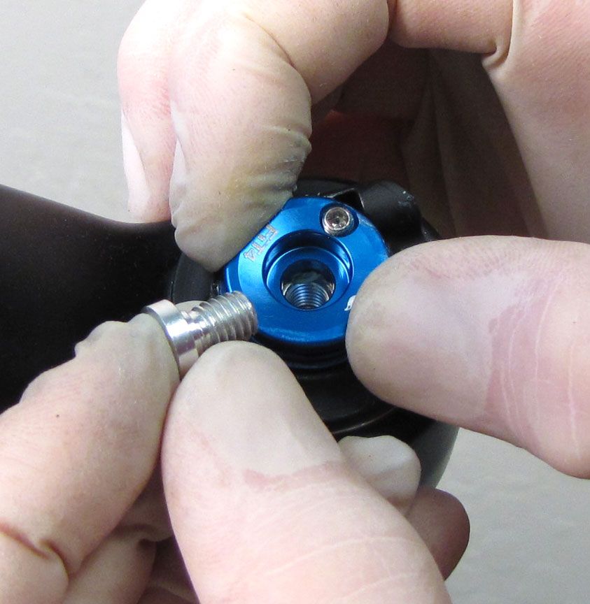
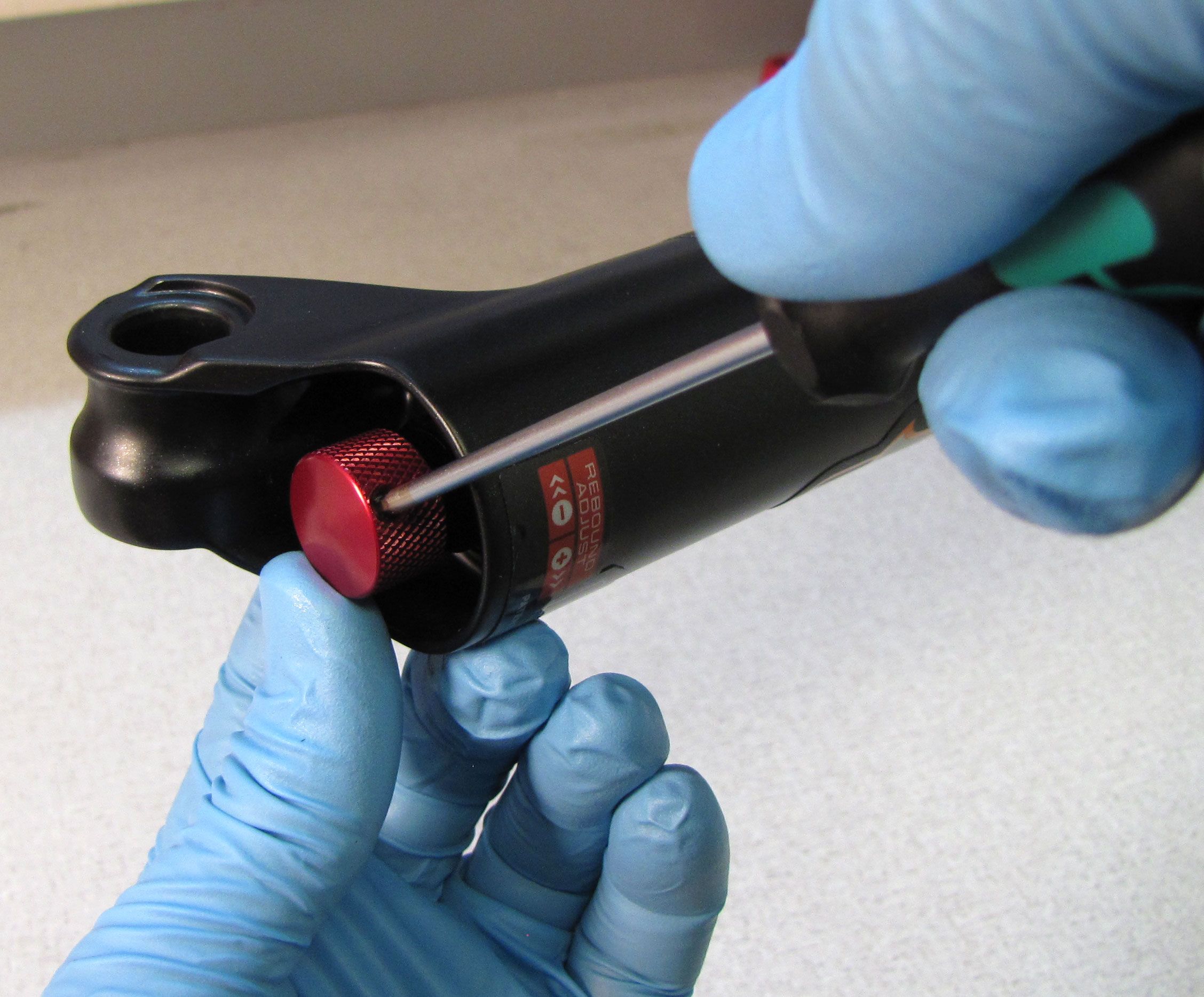
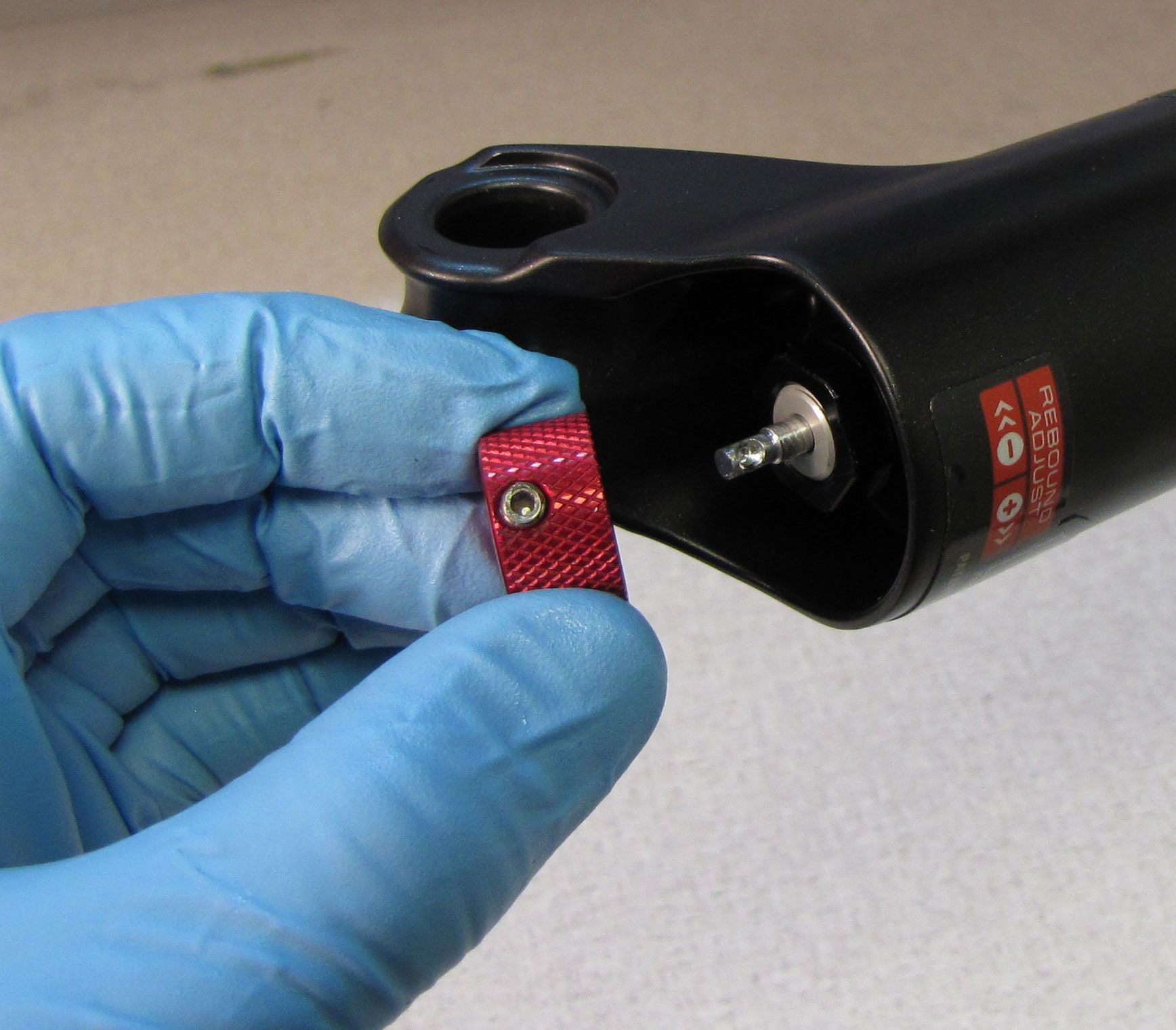
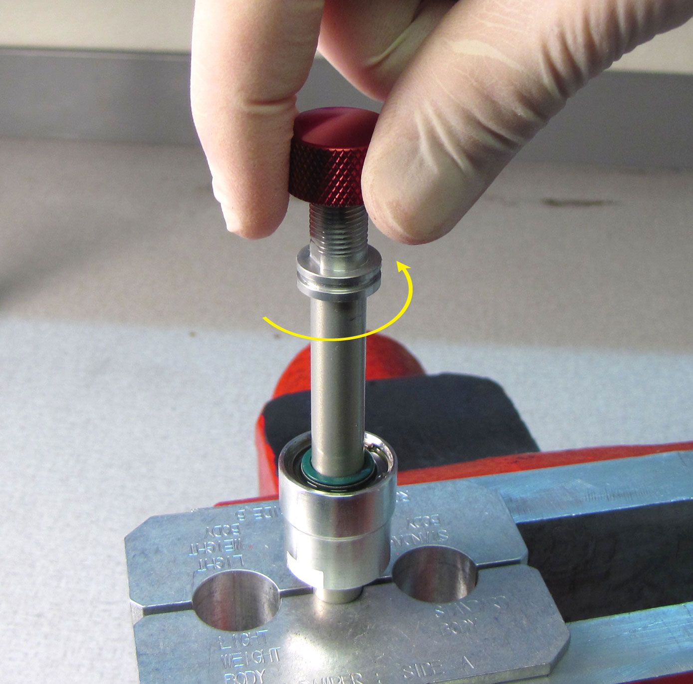
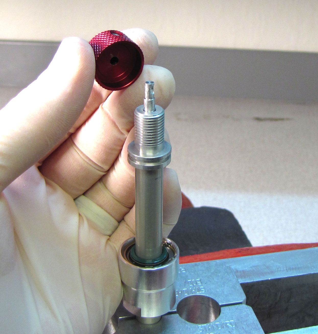
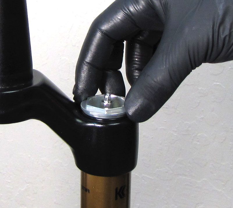
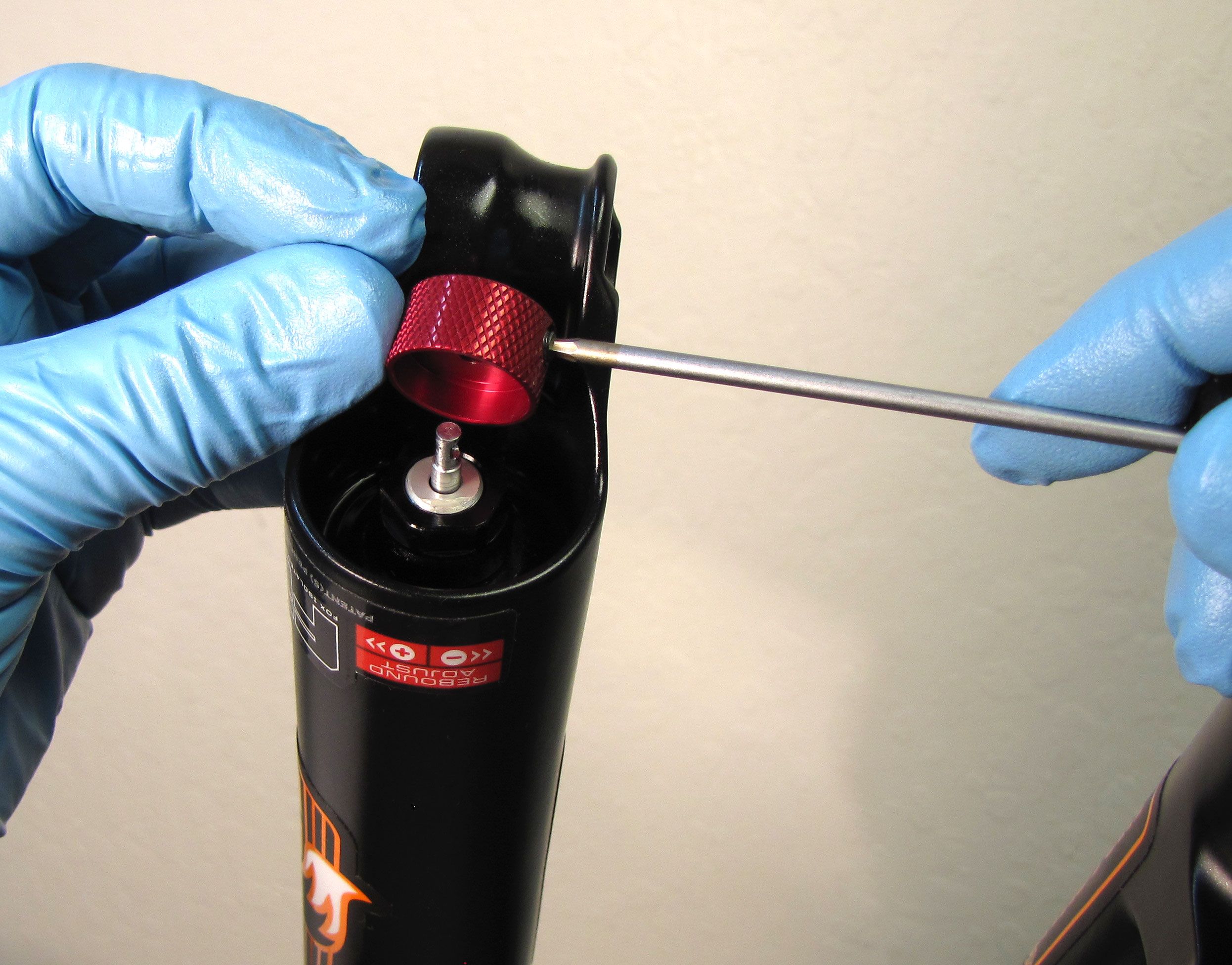
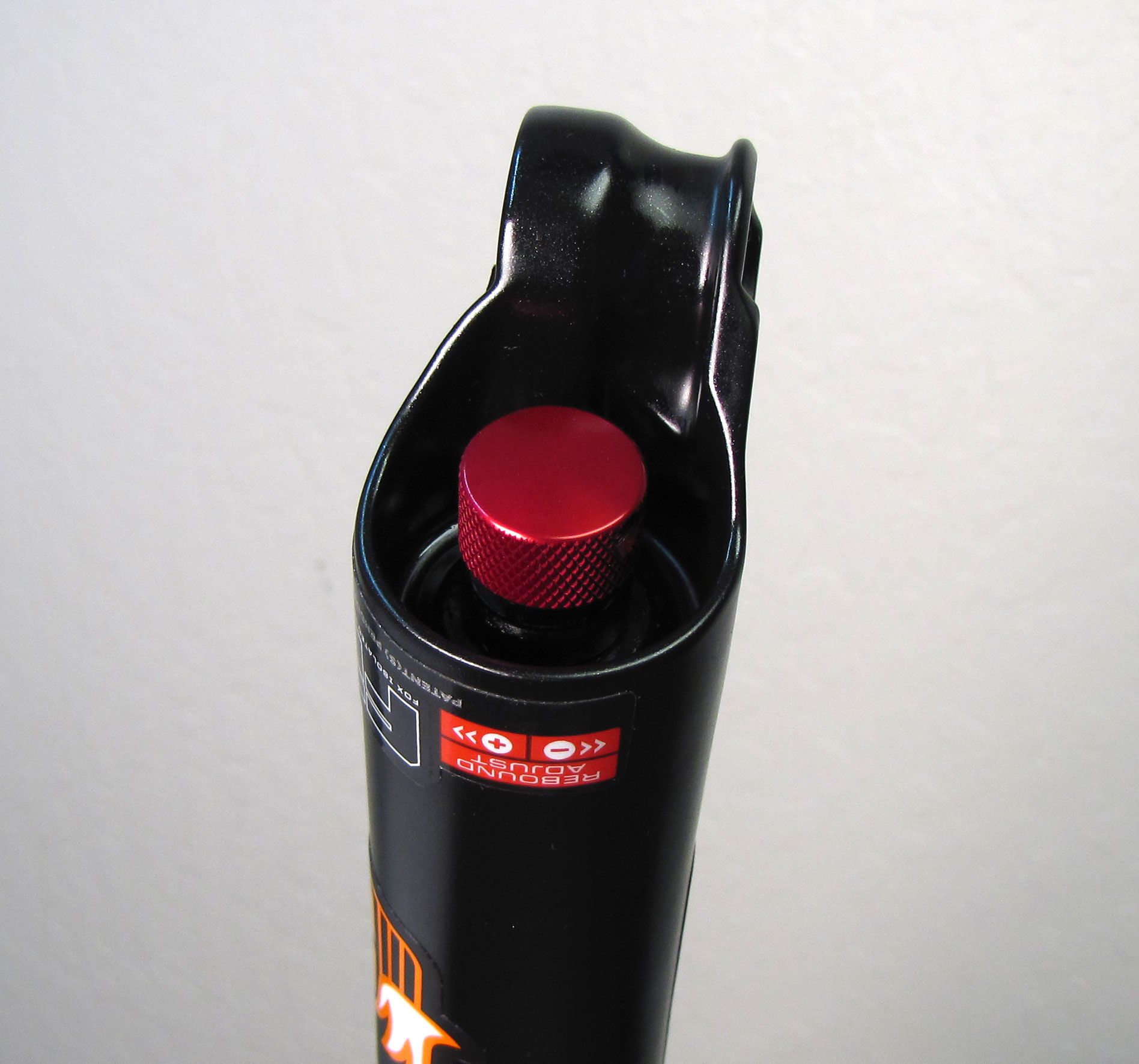
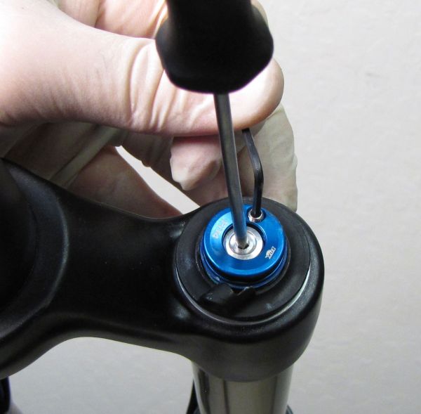
Use a 2mm hex wrench to unthread the set screw in the red rebound knob. Remove the knob and set it aside.

Step 4
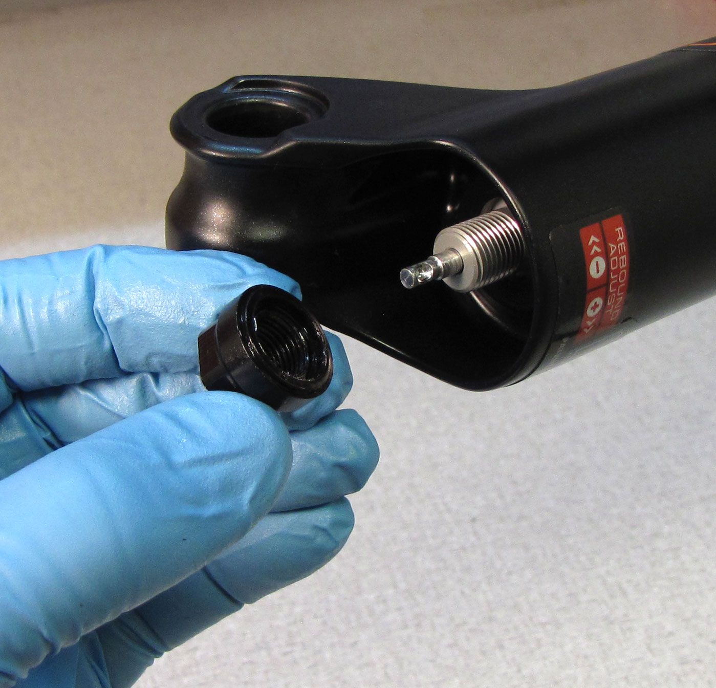
32mm: Use a 10mm socket to remove the damper side bottom nut. Remove and discard the original crushwasher.
Note: You may need a custom 10mm socket that has been reduced in outer diameter to clear certain Step-Cast lower leg castings.
34mm: Use a 15mm socket to remove the damper side bottom nut. Make sure to remove and discard the orginal crushwasher which may be stuck to the bottom nut.
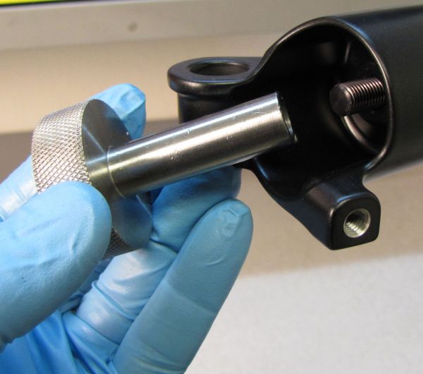
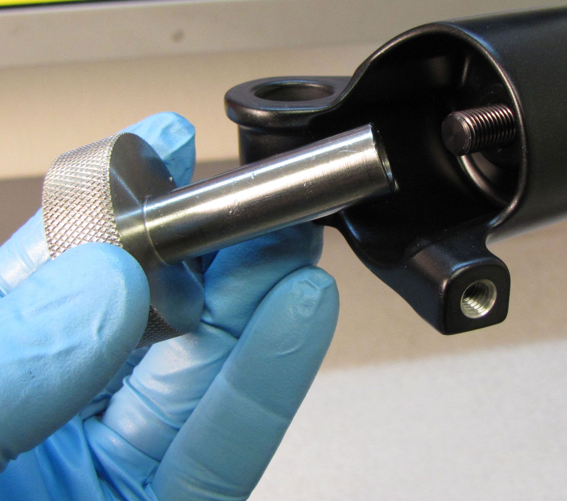
Step 5
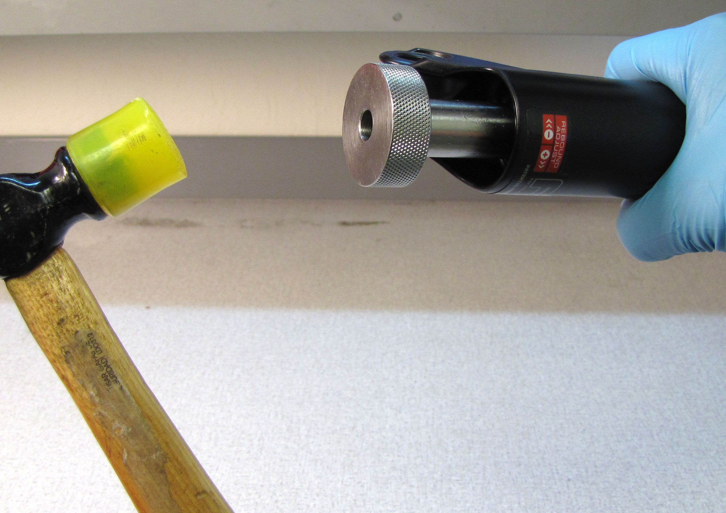
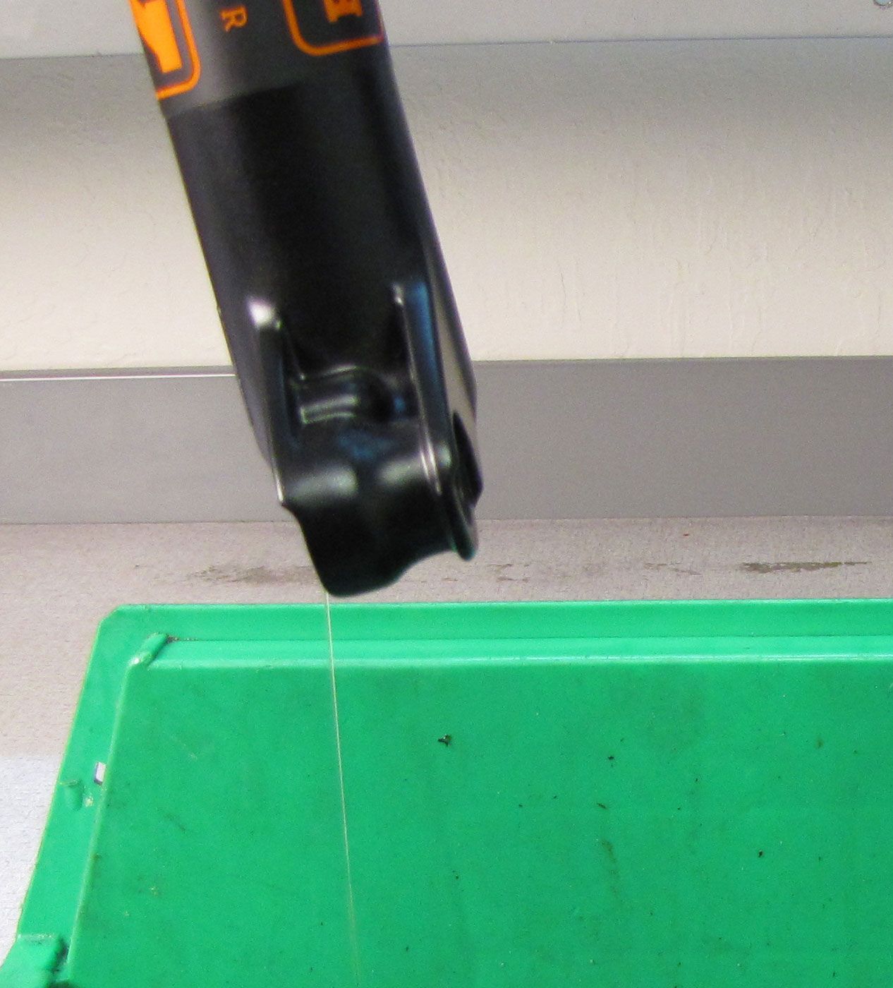
Use Damper Removal Tool 398-00-681 for 32mm forks and 398-00-682 for 34mm forks to dislodge the shaft from the lowers. Make sure that you have approximately half of the available threads engaged with your tool before striking with your mallet. Remove the damper removal tool, then bring the fork upright over an oil basin to drain.

Step 6
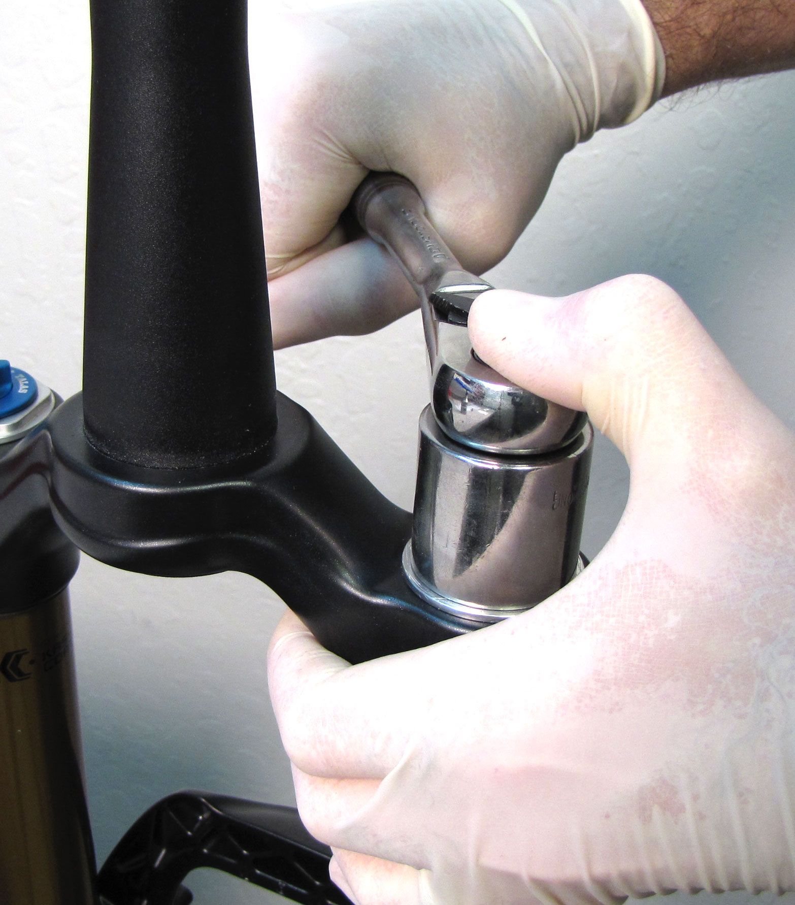
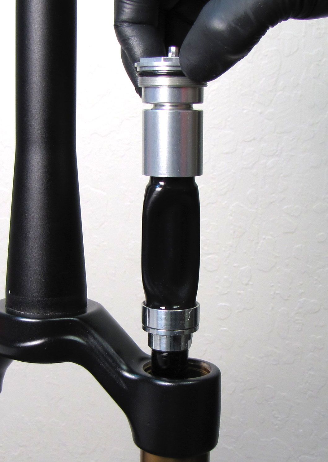
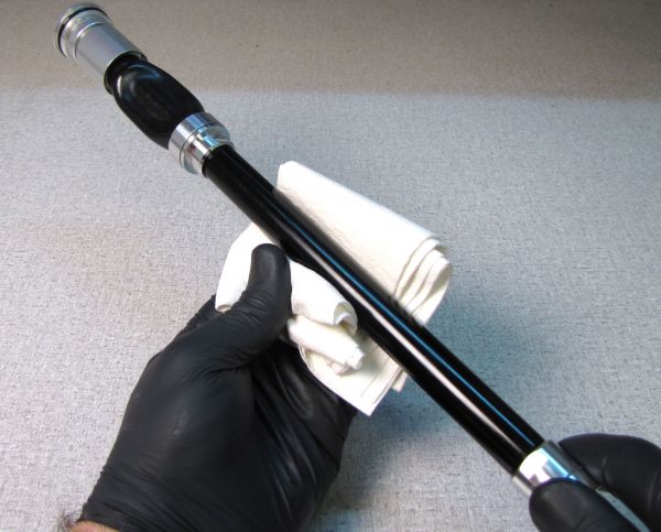
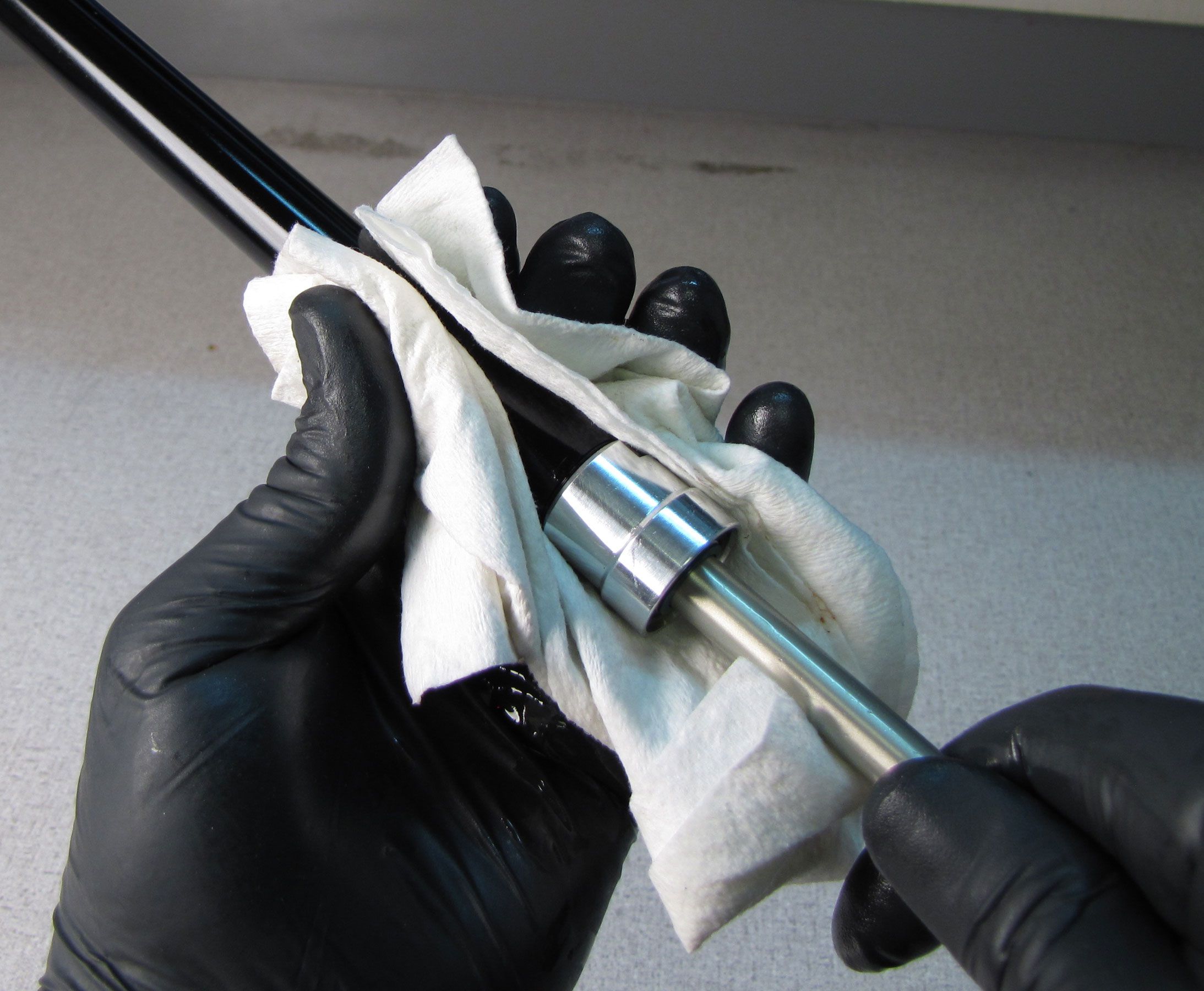
With a chamfer-less 6-point 26mm socket (PN: 398-00-602), unthread the damper cartridge completely (counter-clockwise). Pull straight up to remove the entire damper cartridge from the right side upper tube. Clean off excess bath oil with a lint-free paper towel.
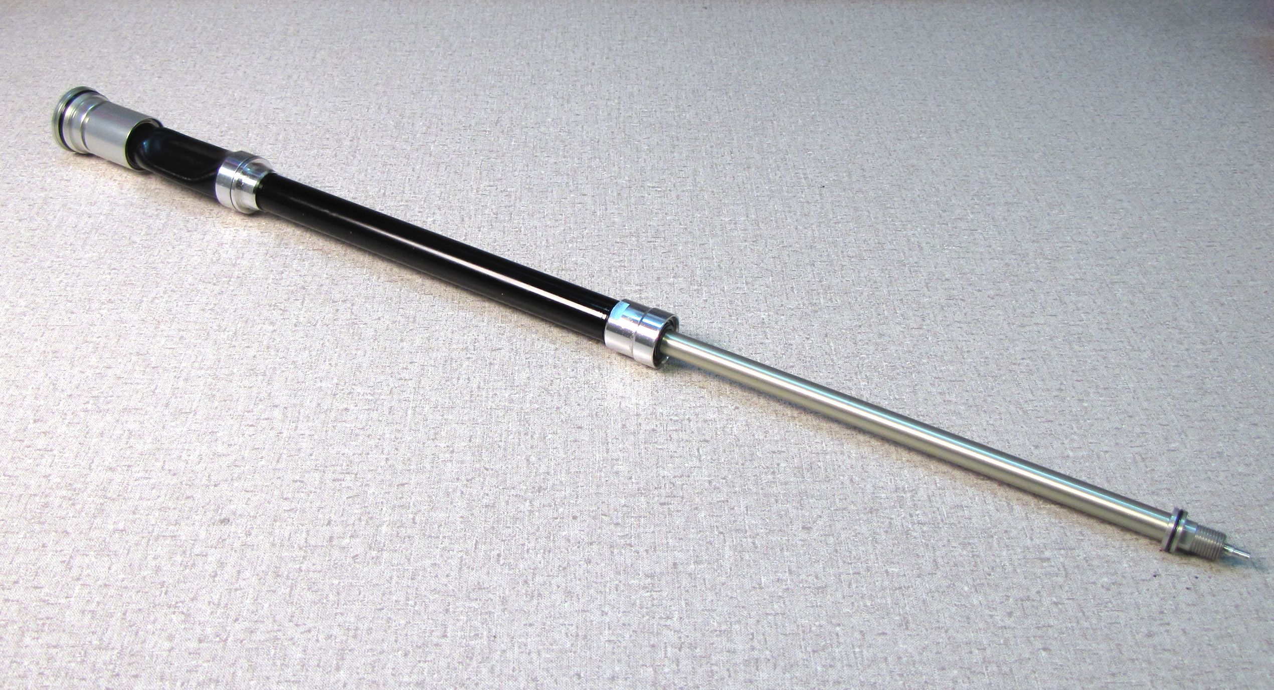
Damper Cartridge Rebuild
Step 1
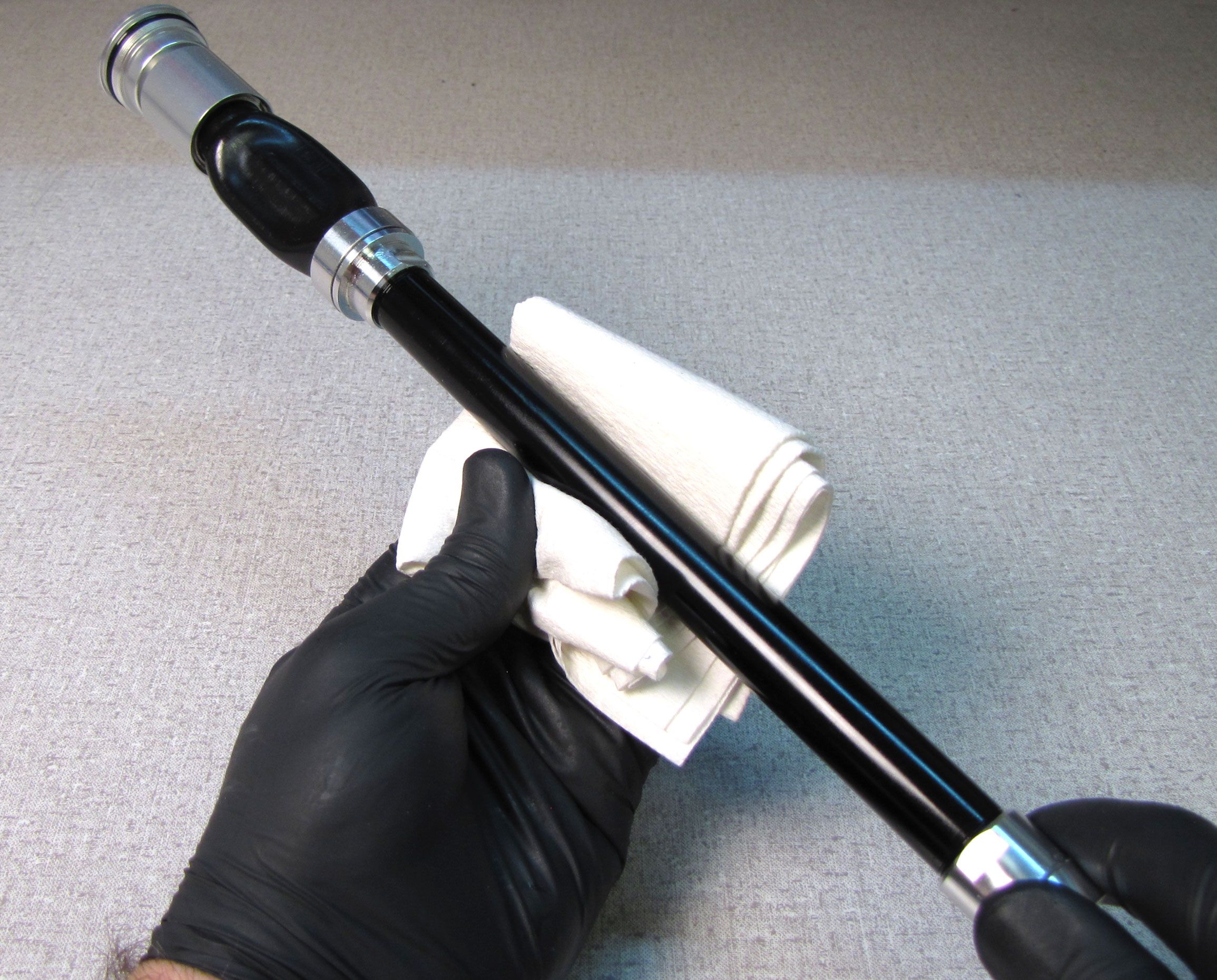
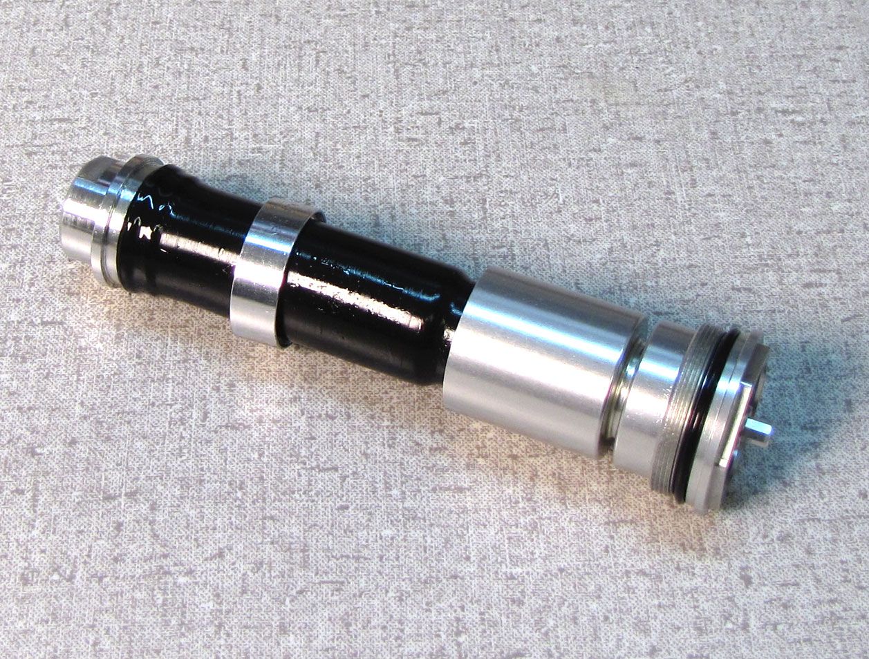
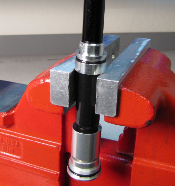
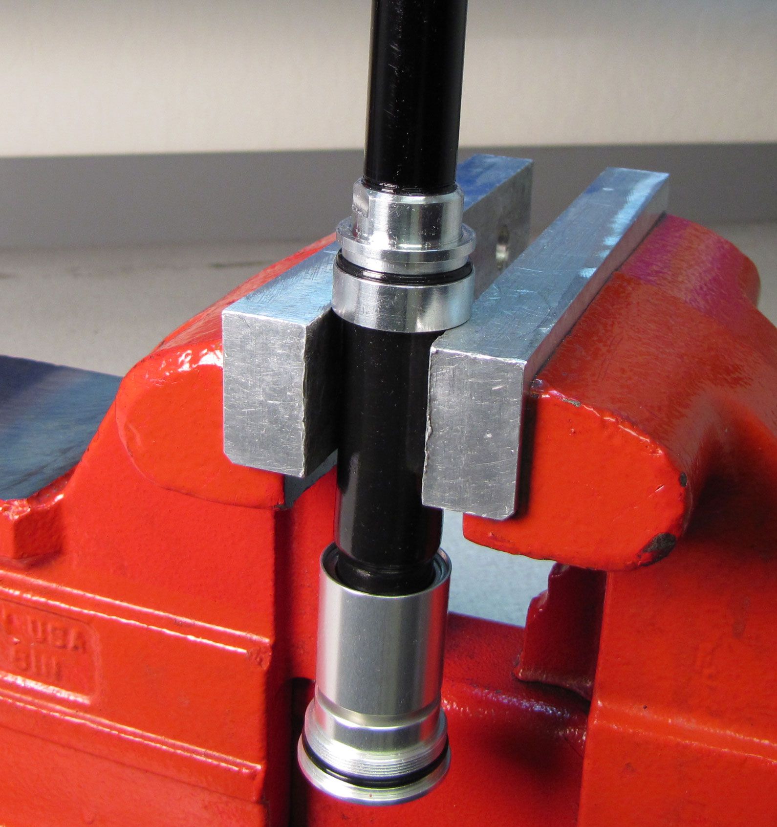
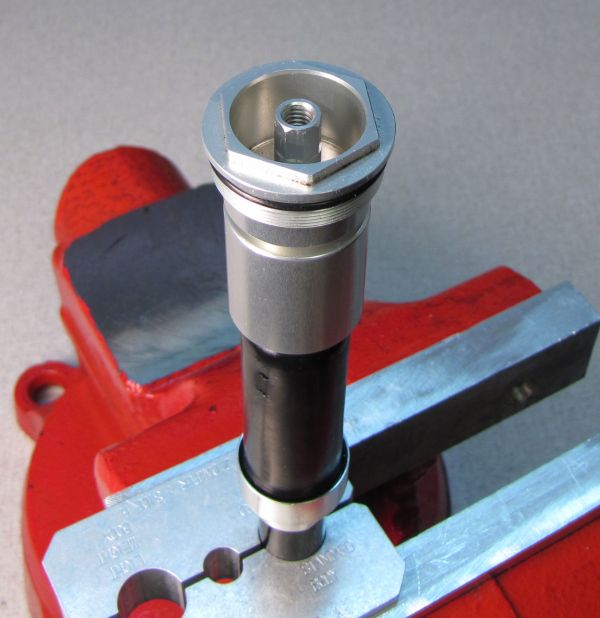
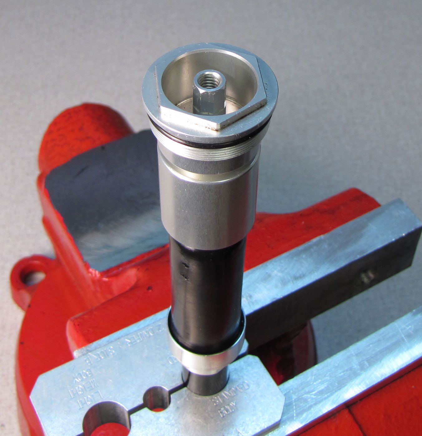
Clean the cartridge body with isopropyl alcohol and a lint-free paper towel, then clamp it in your shaft clamps (PN: 803-00-830).
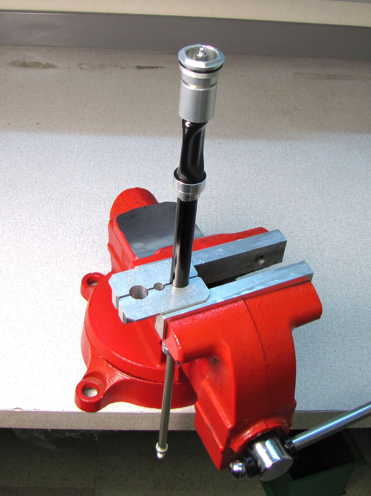
Step 2
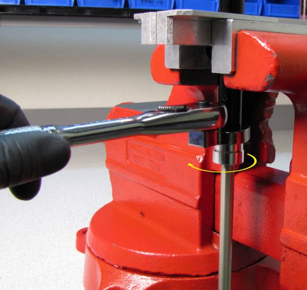
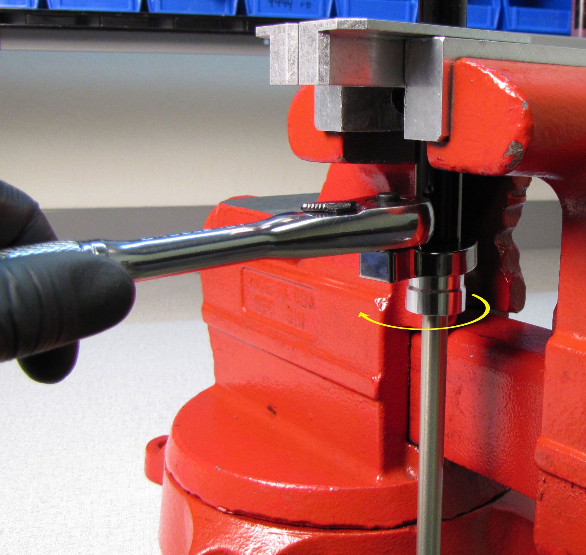
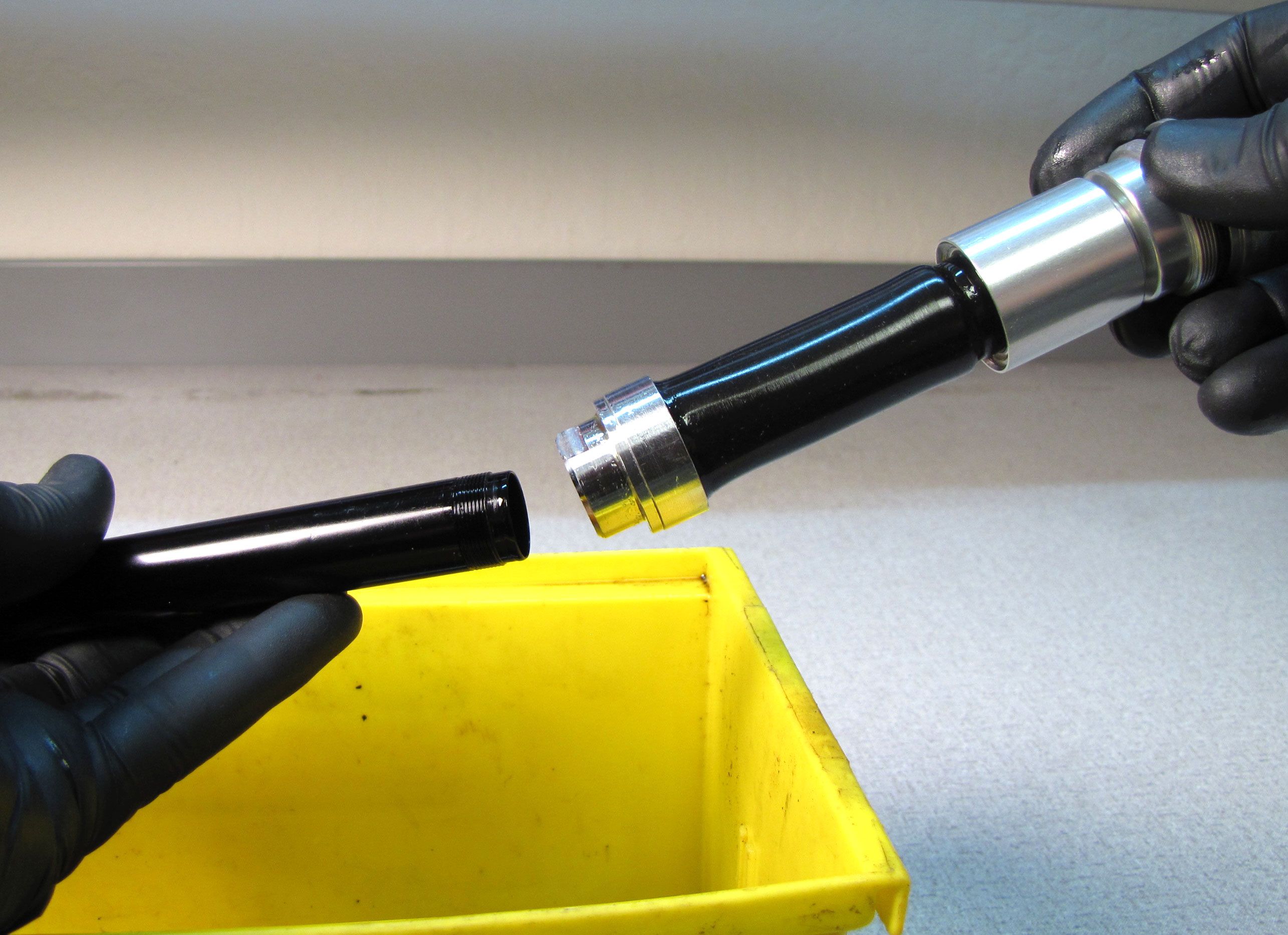
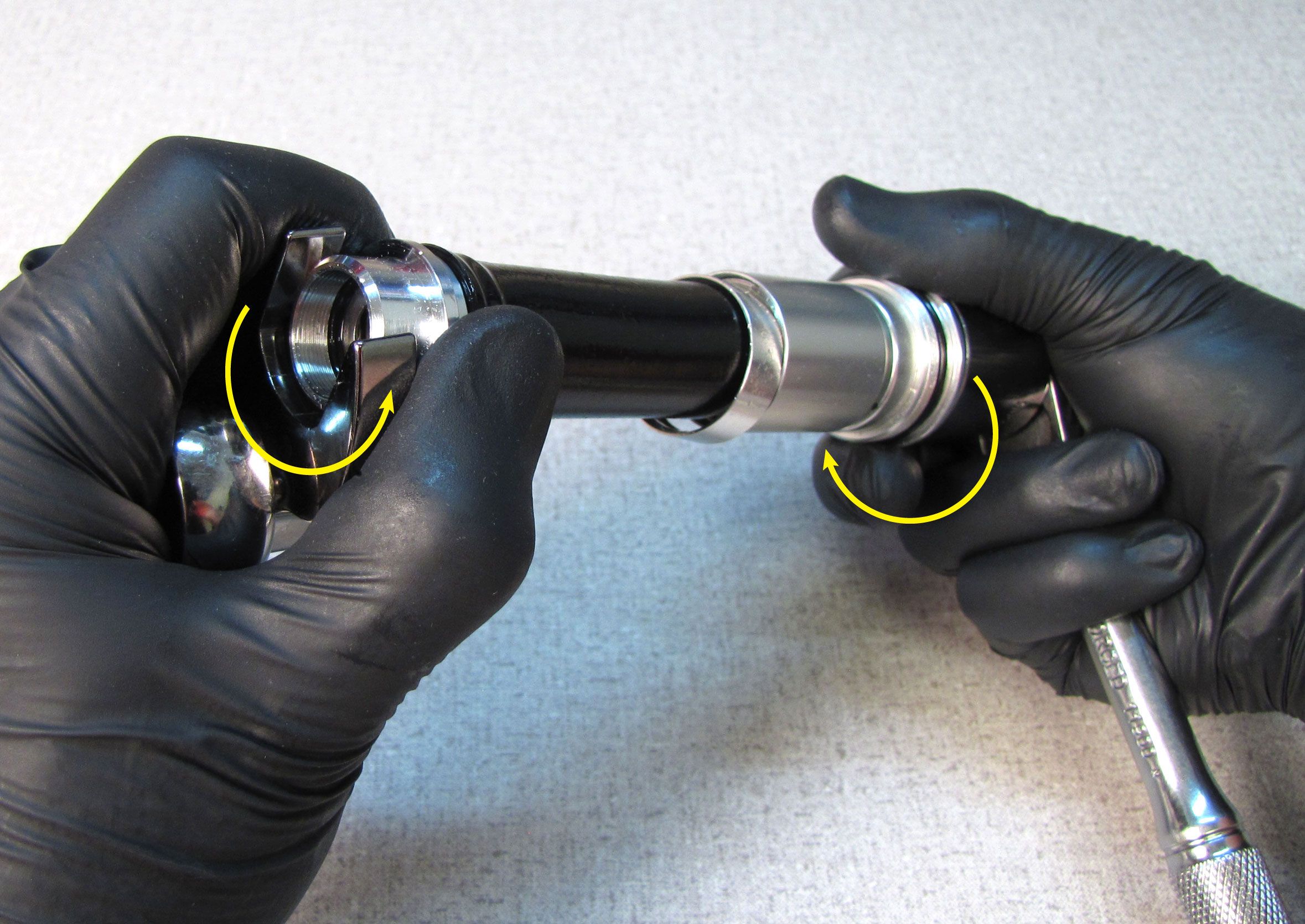
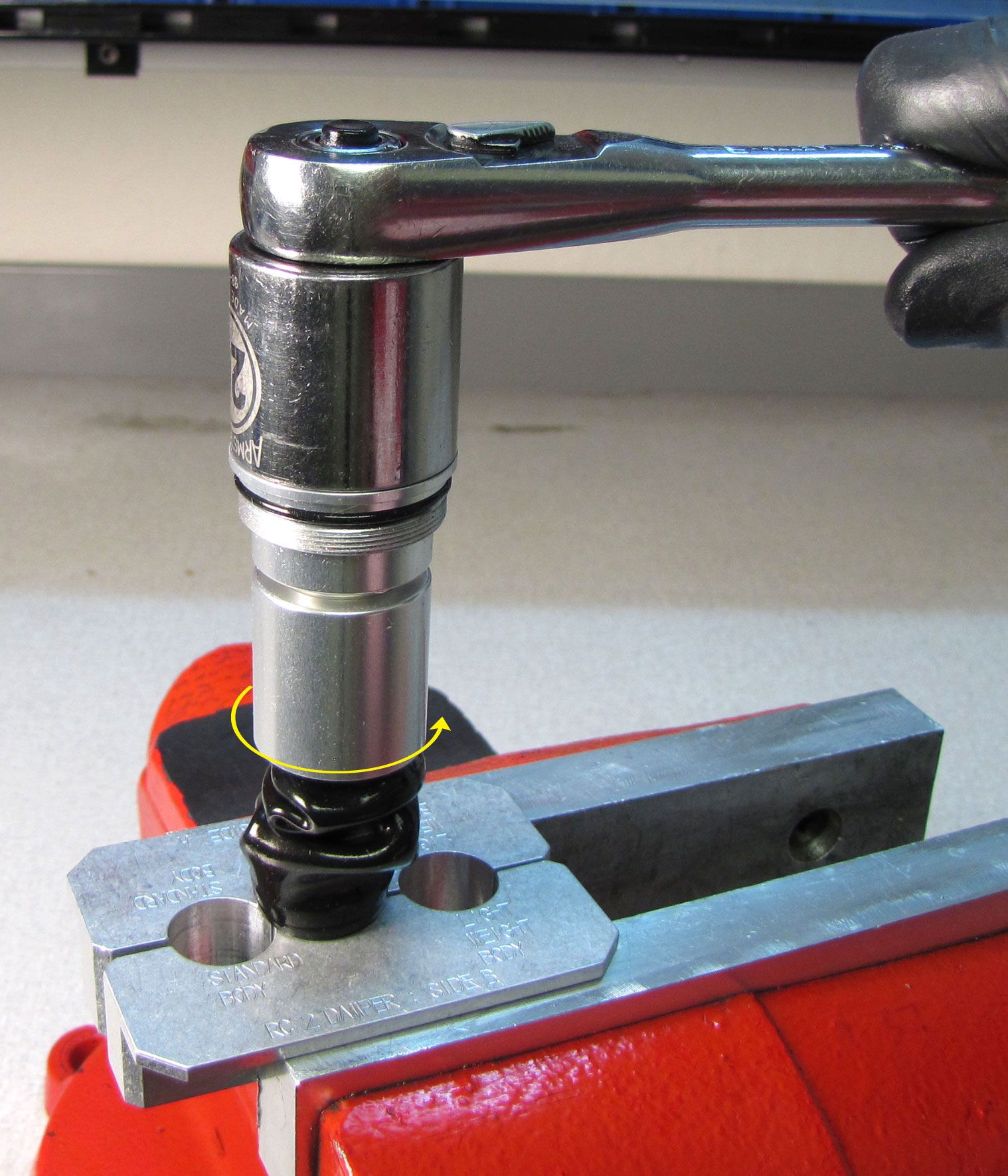
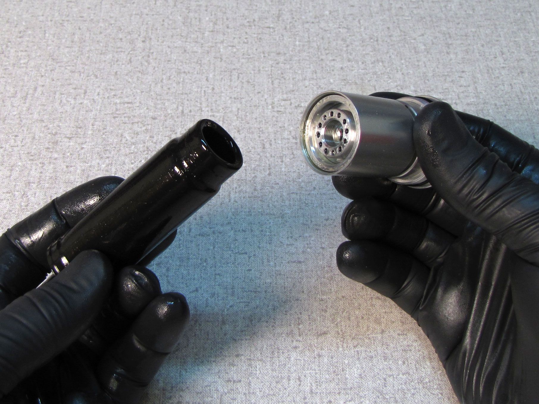
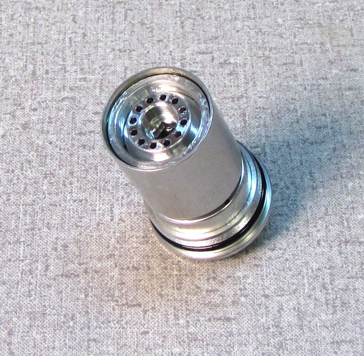
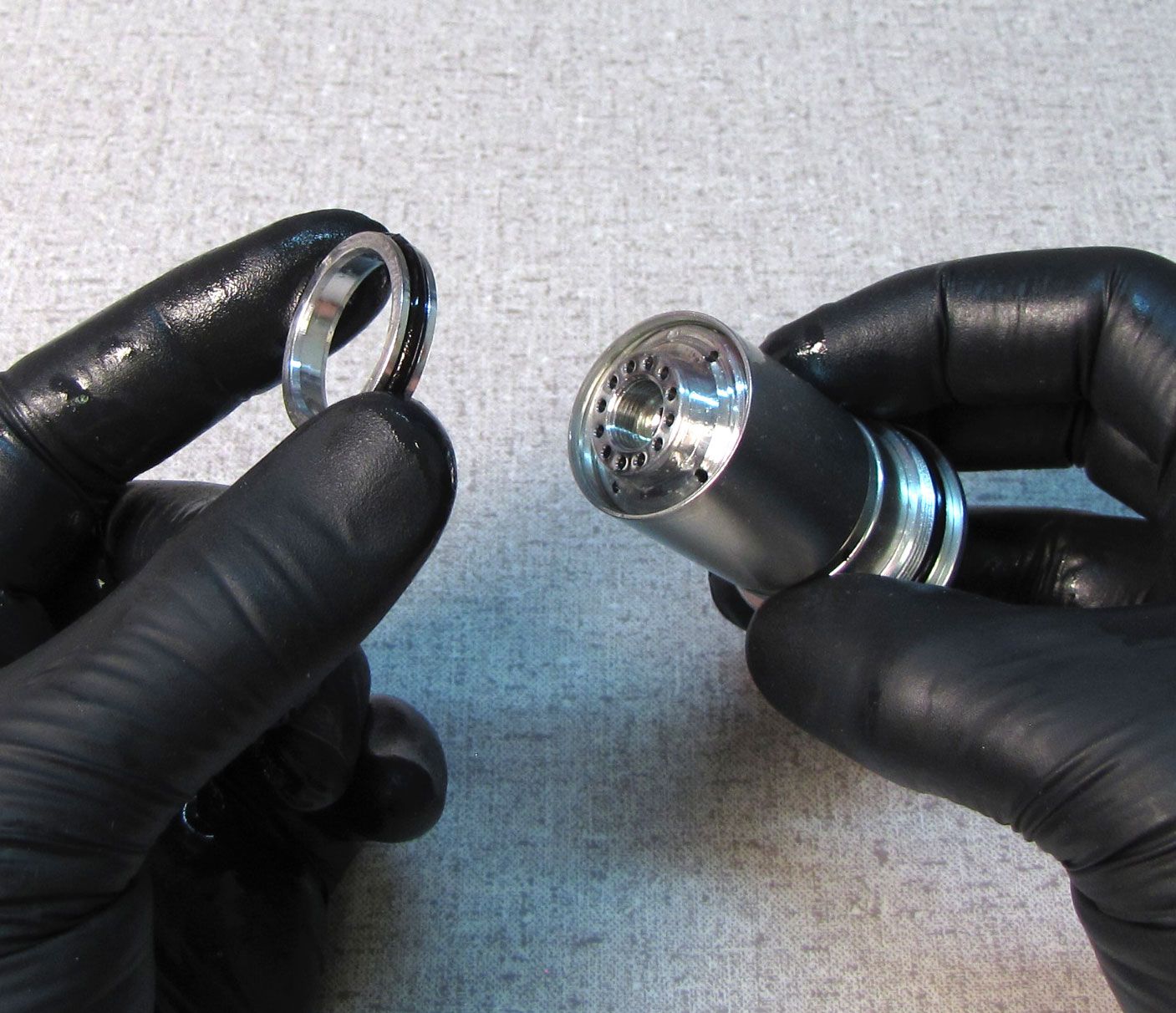
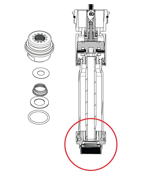
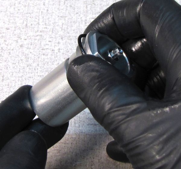
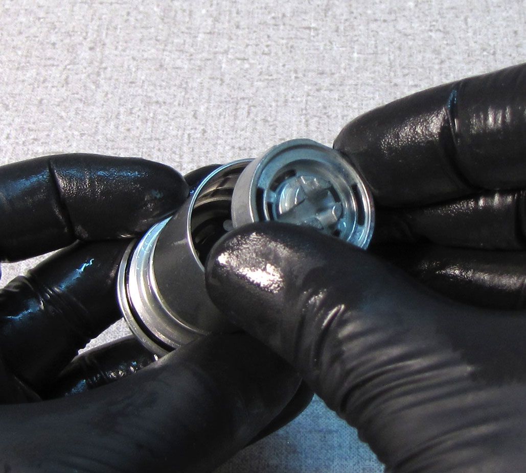
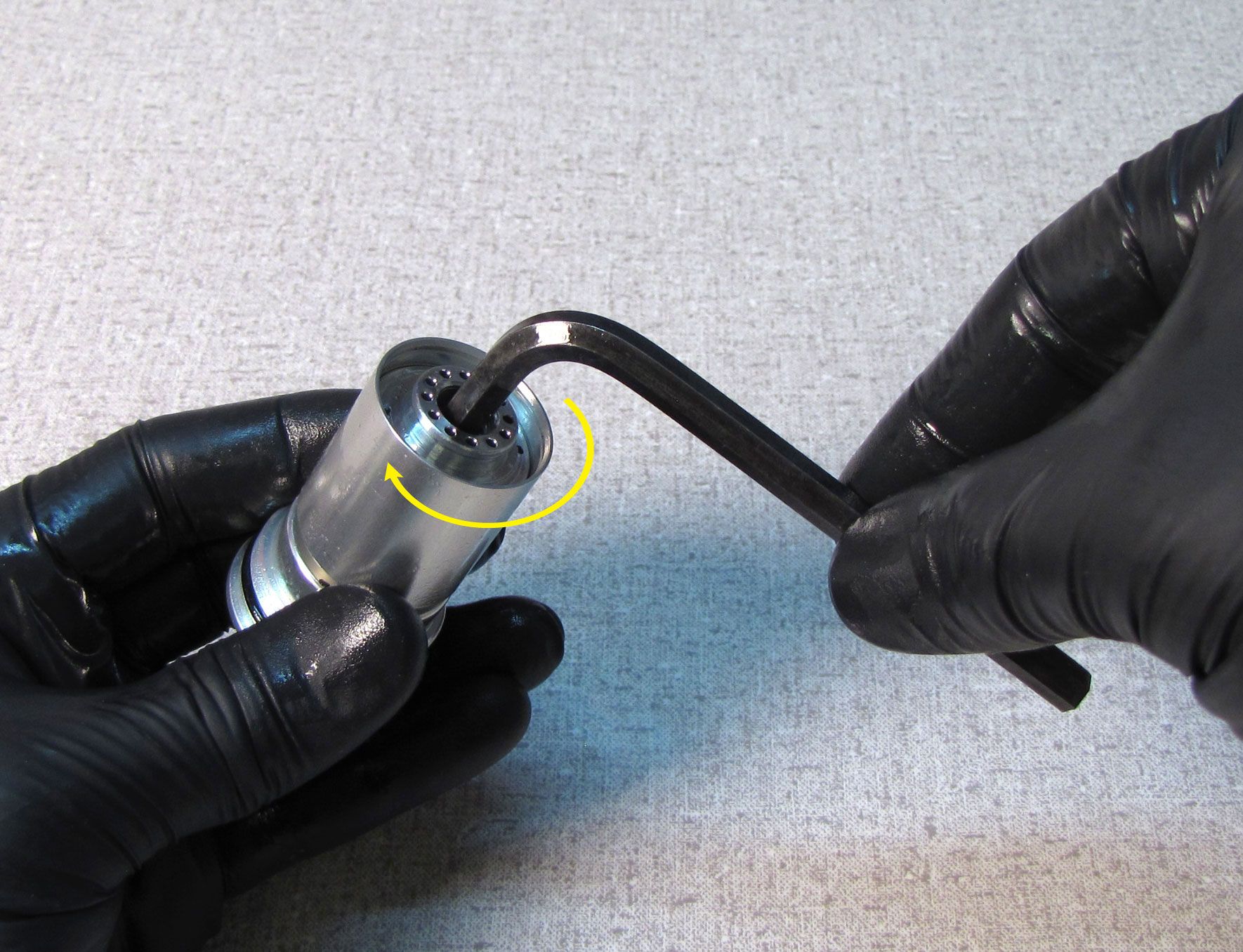
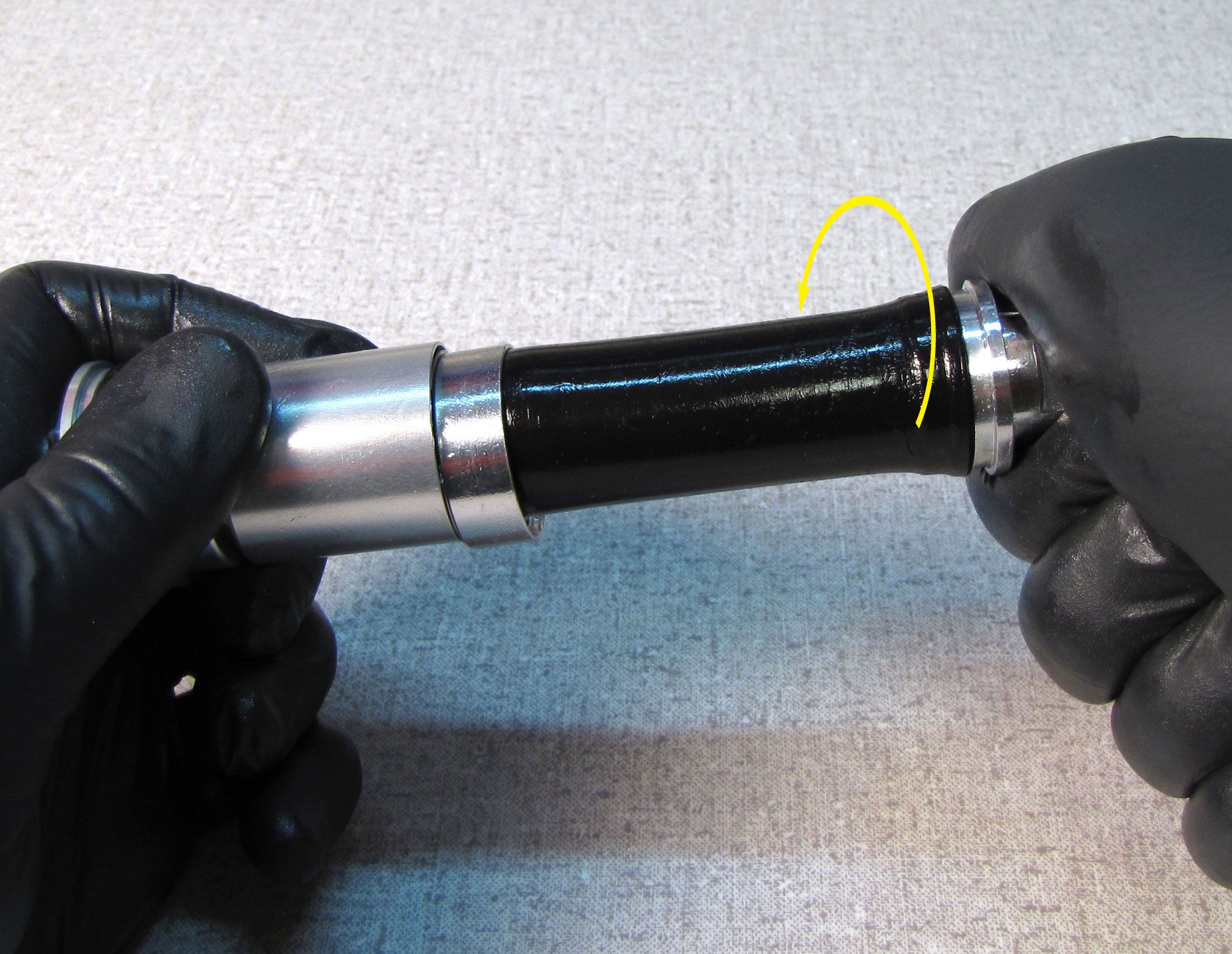
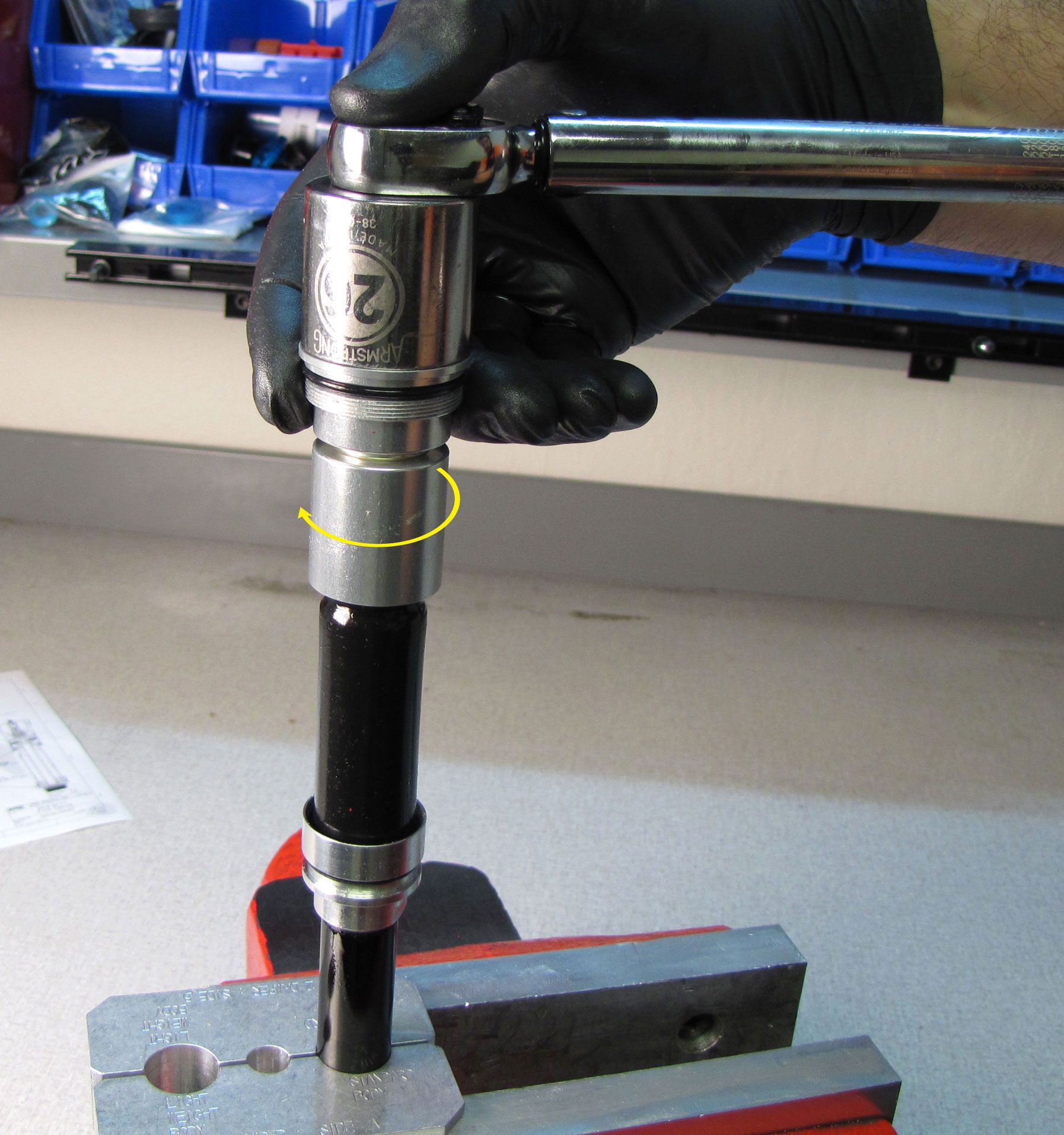
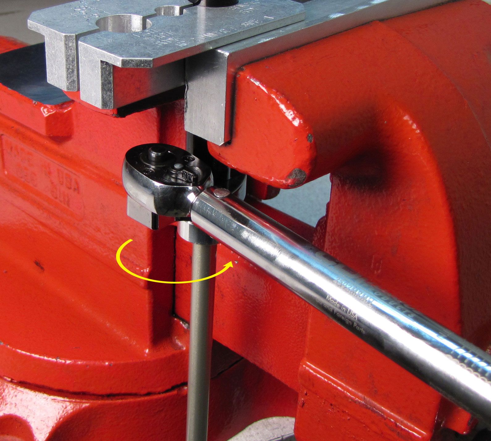
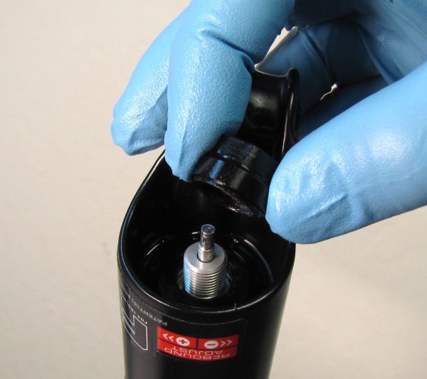
Break the sealhead (listed as the bearing housing assembly on the technical drawings) free from the cartridge body 1/4 turn with a 19mm wrench (counter-clockwise when viewed from below). Break the Reflow cap free from the cartridge body 1/4 turn with a 19mm wrench (counter-clockwise when viewed from the top). Remove the cartridge from the vice before unthreading the sealhead from the cartridge body over an oil drain.

Step 3
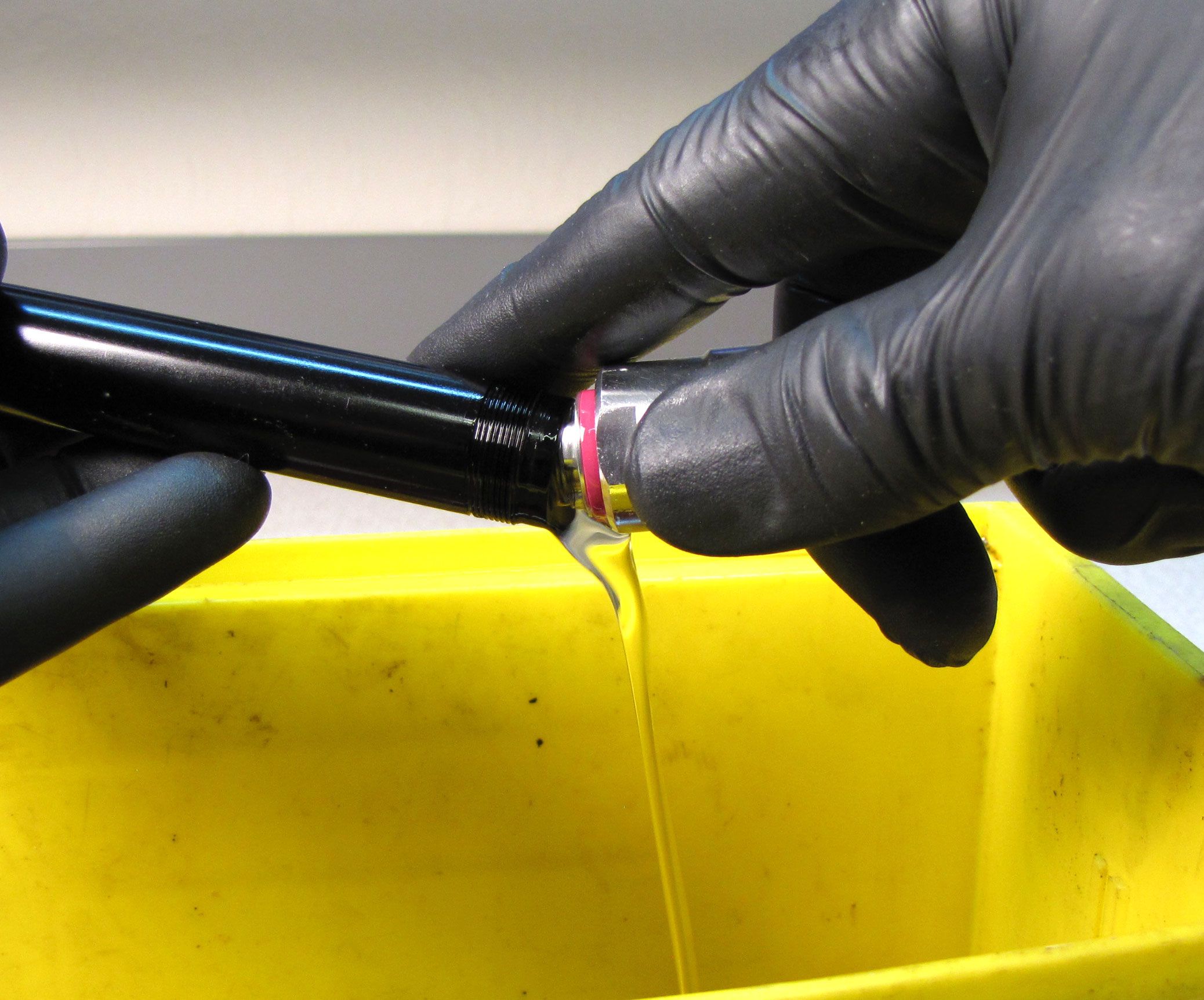
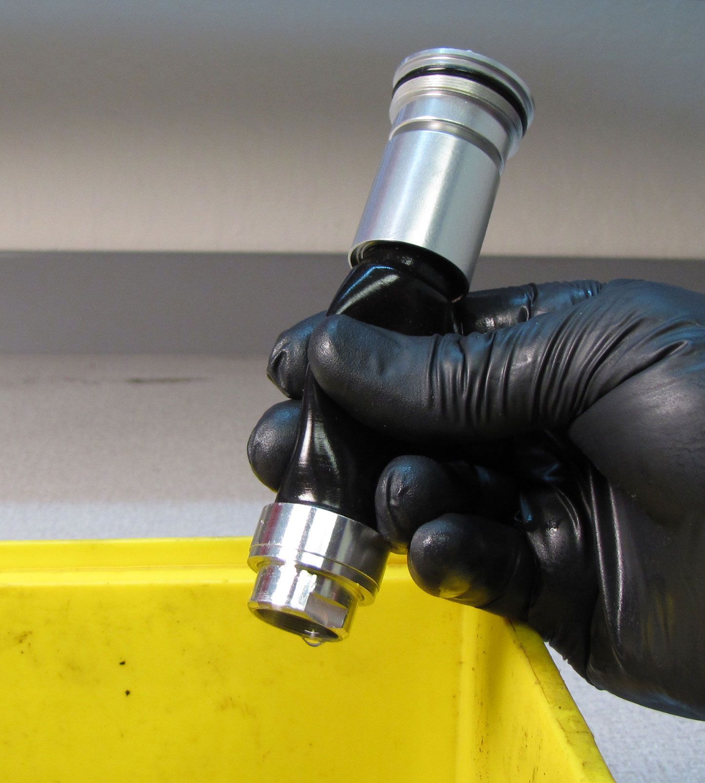
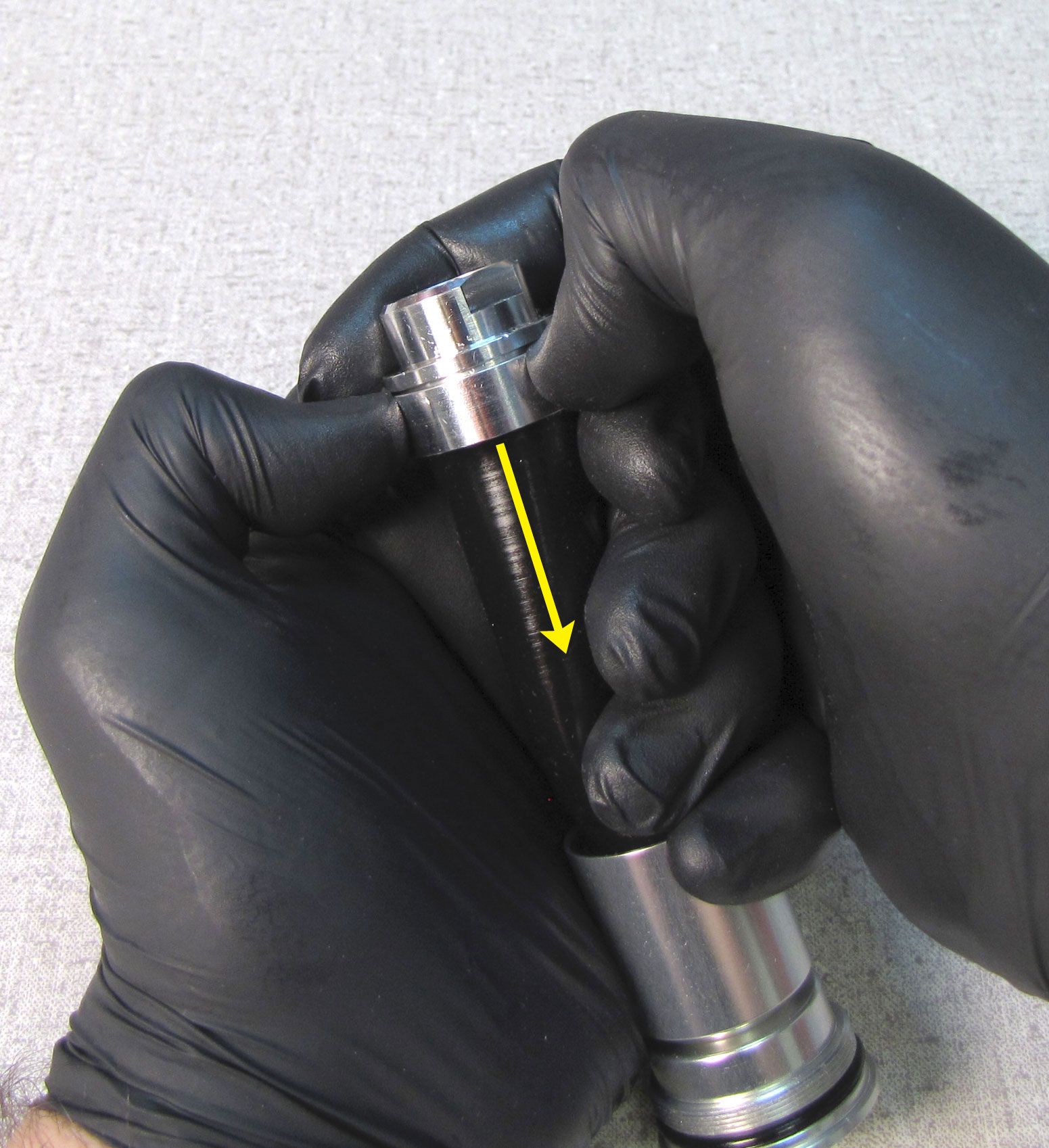
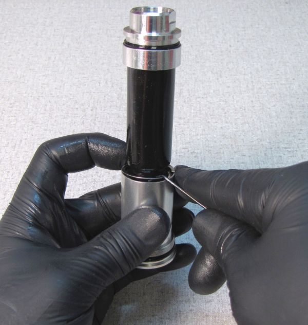
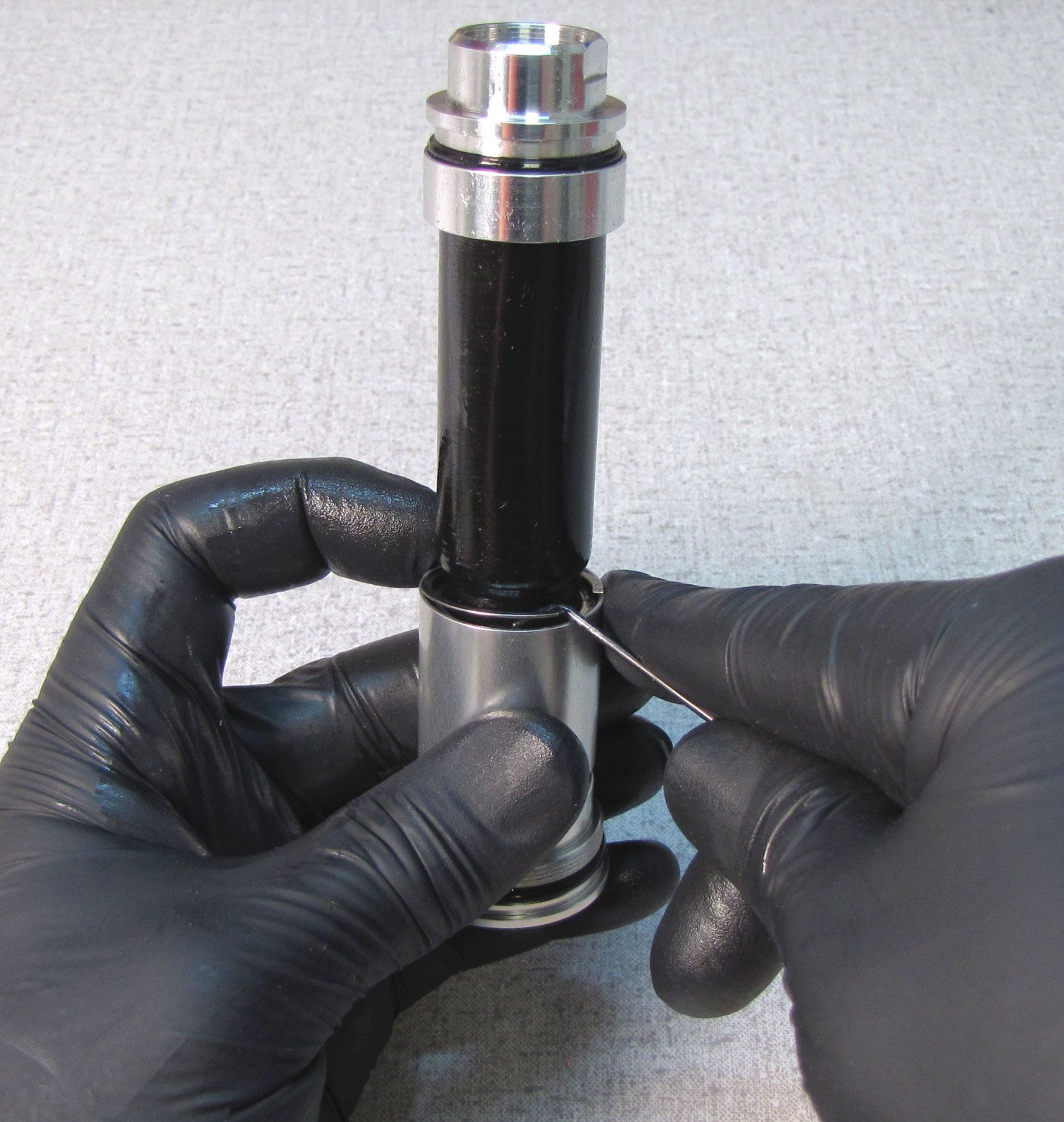
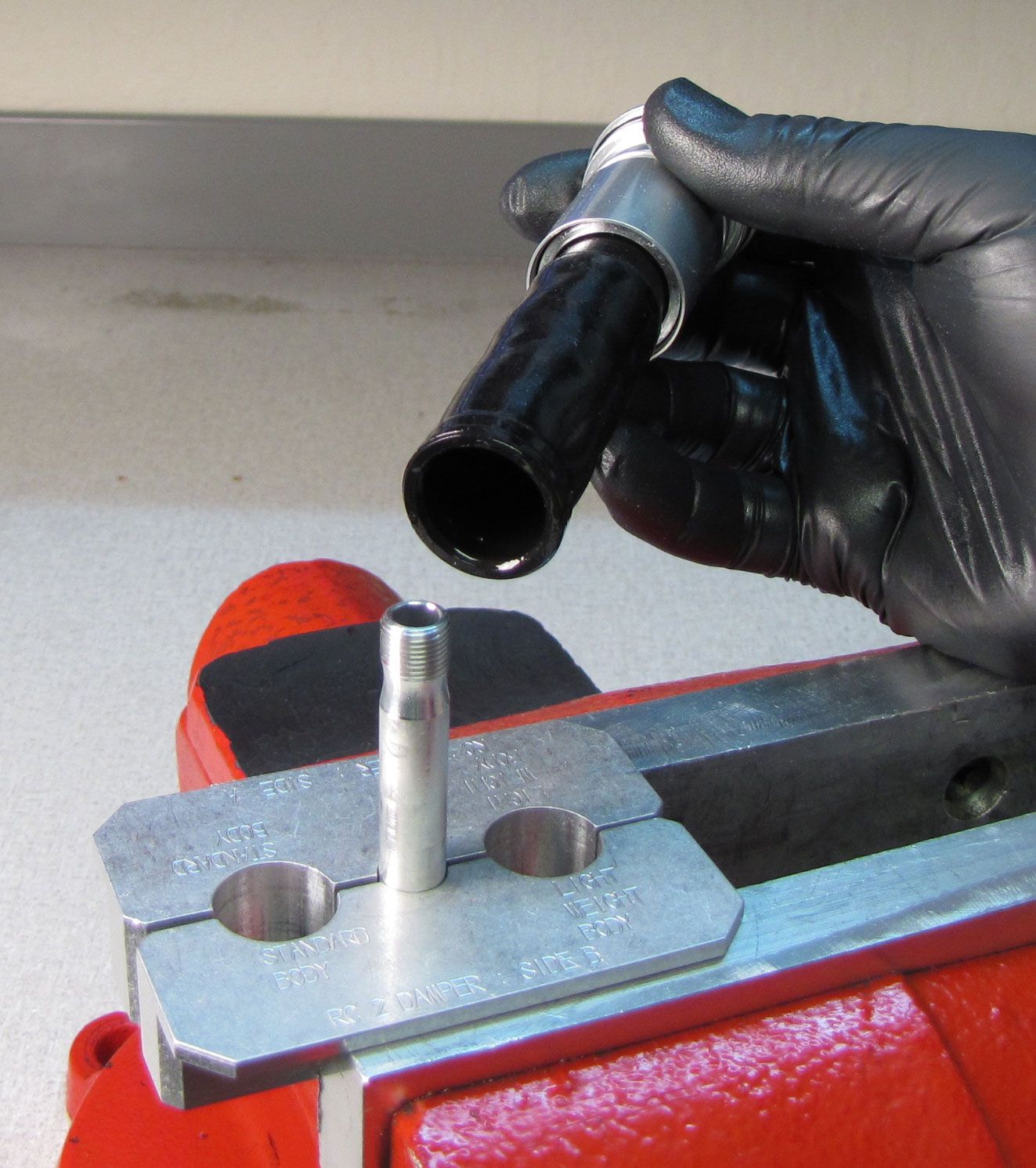
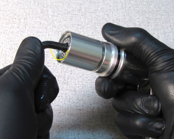
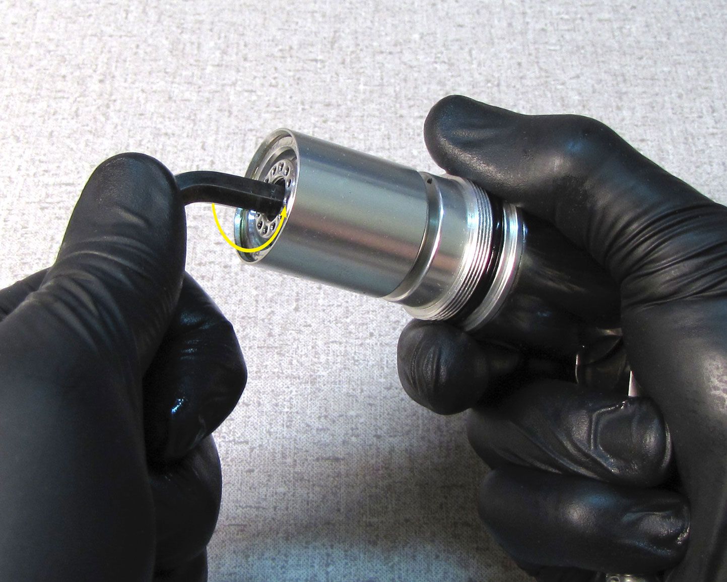
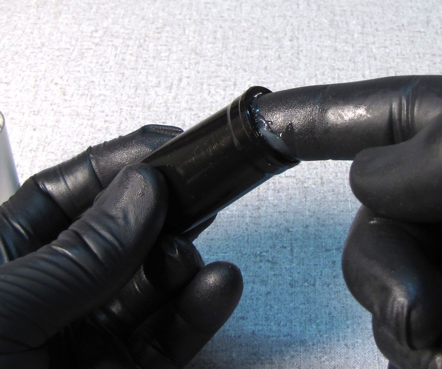
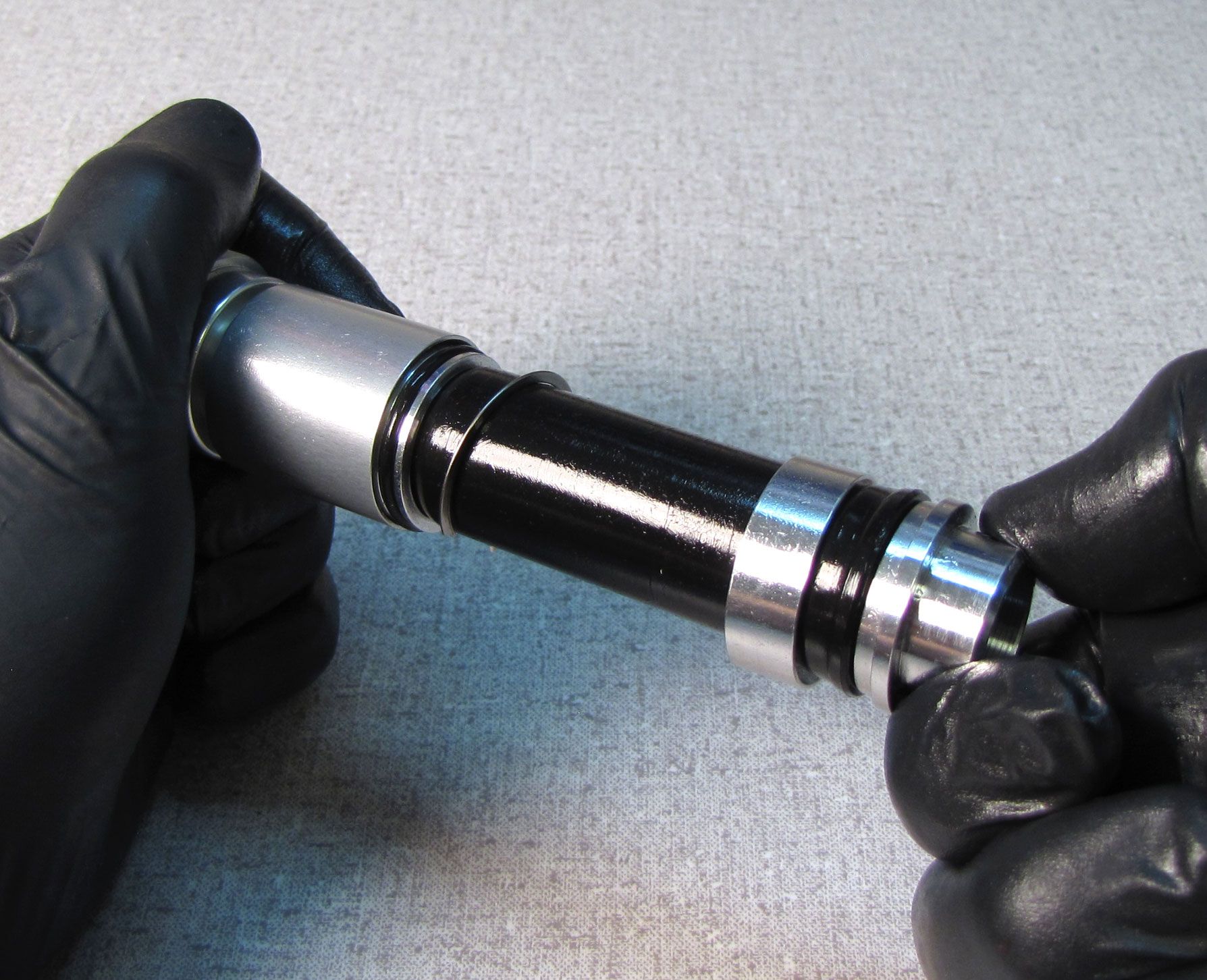
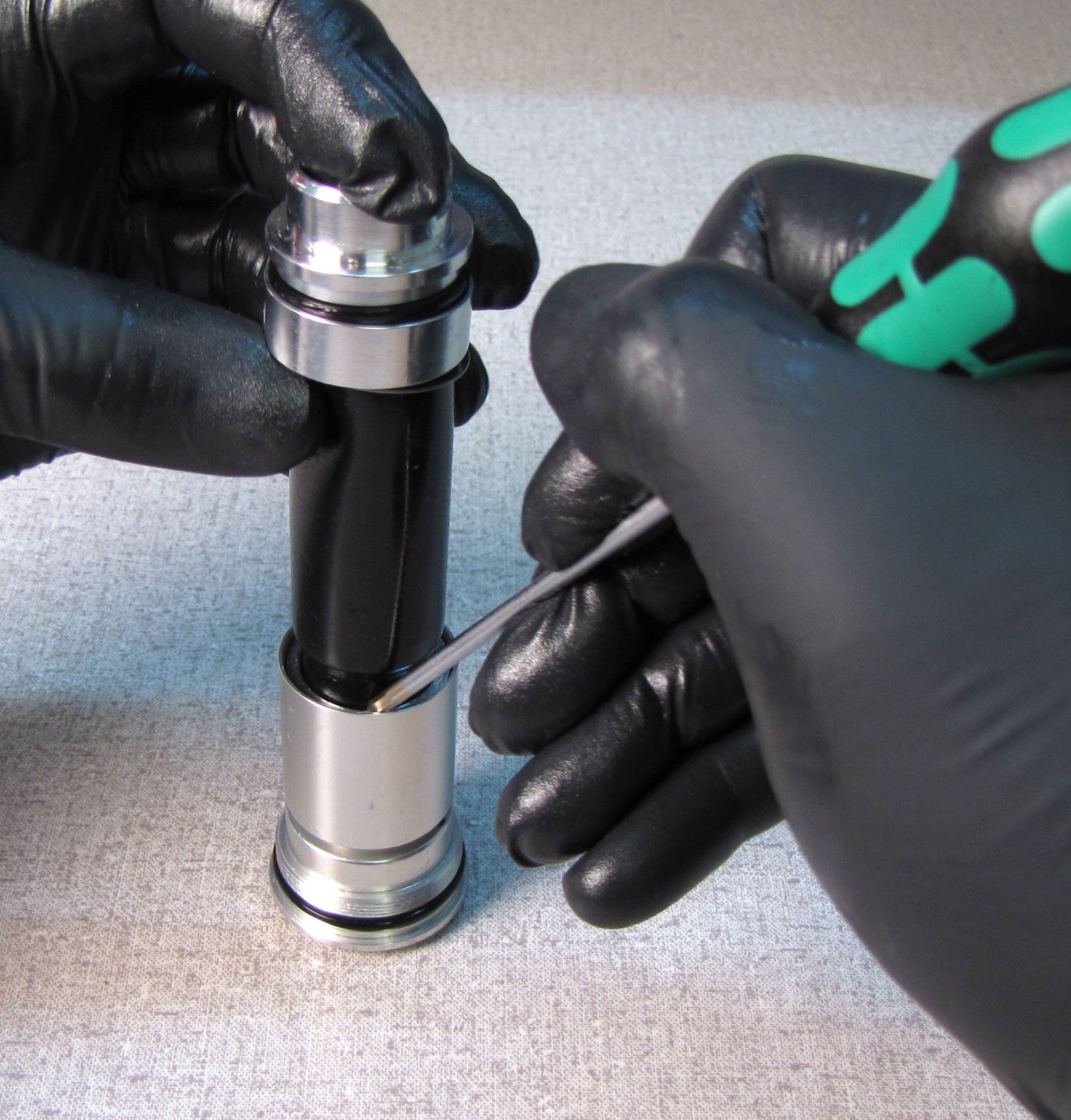
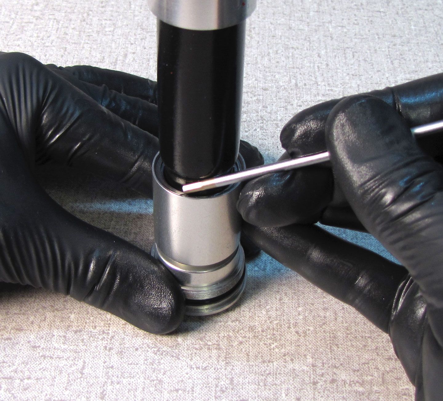
Squeeze the bladder while holding the open reflow cap over your oil drain to evacuate most of the oil from the damper. Slide the lower bladder ring up toward the topcap to release that end of the bladder.
Step 4
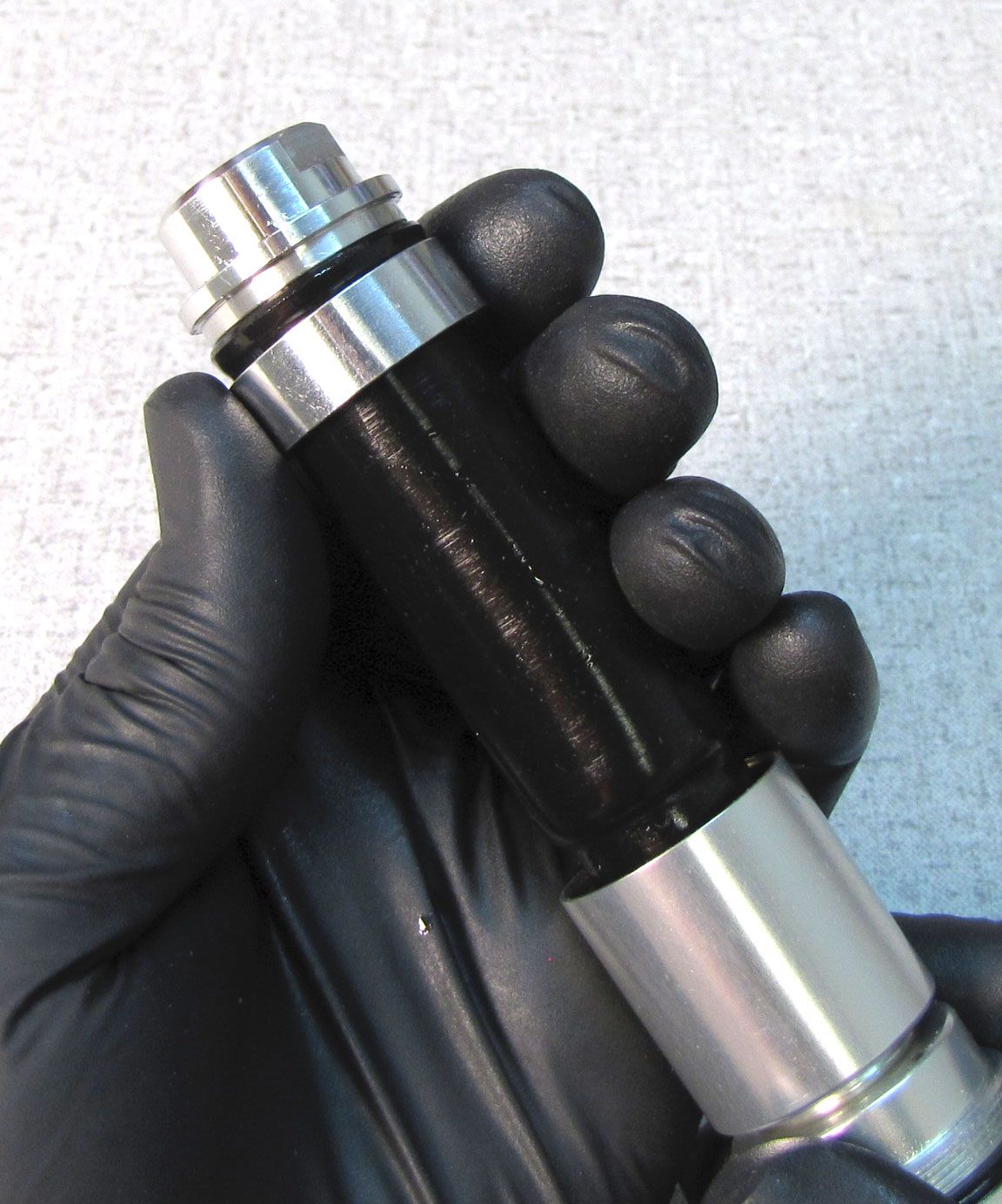
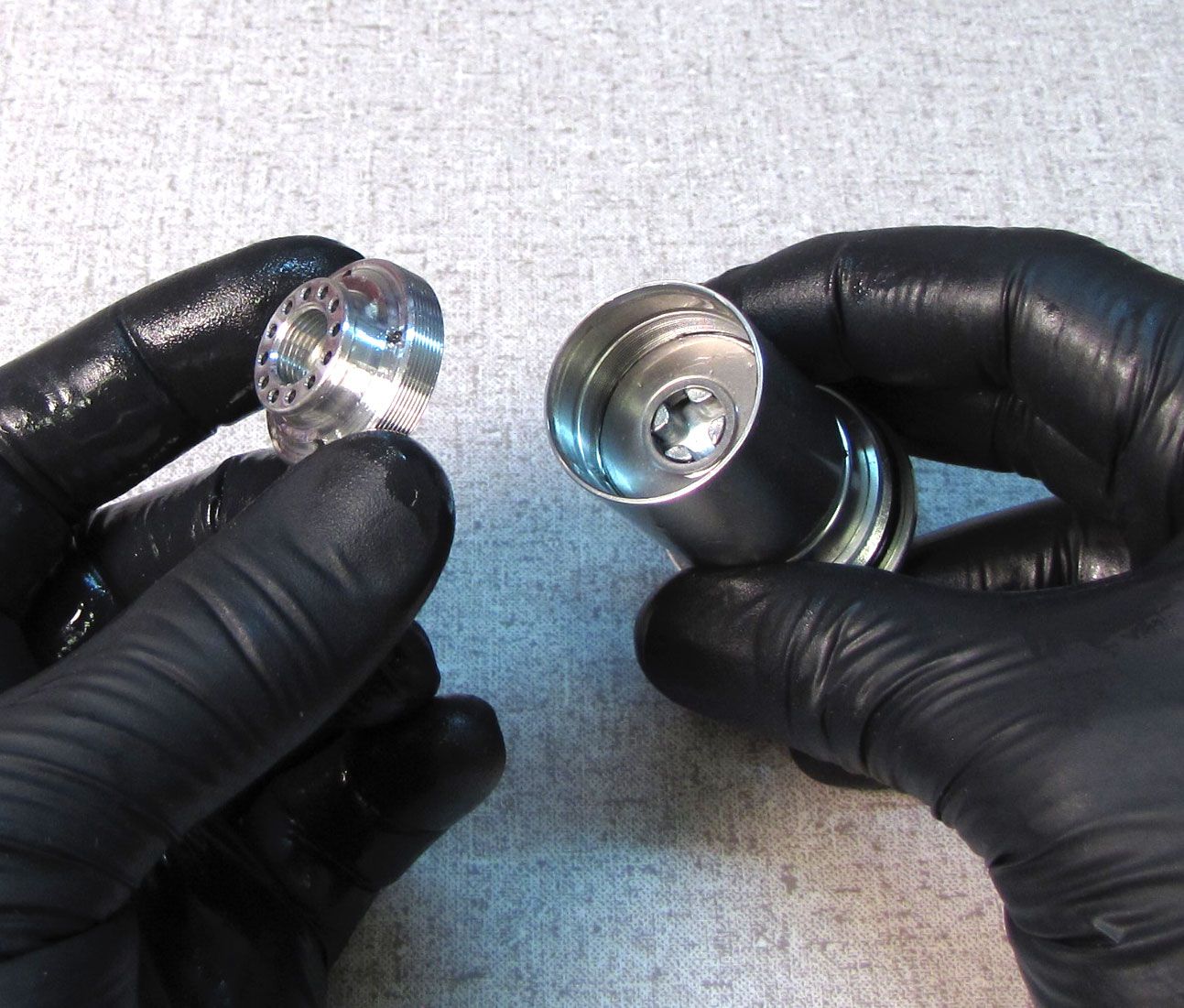
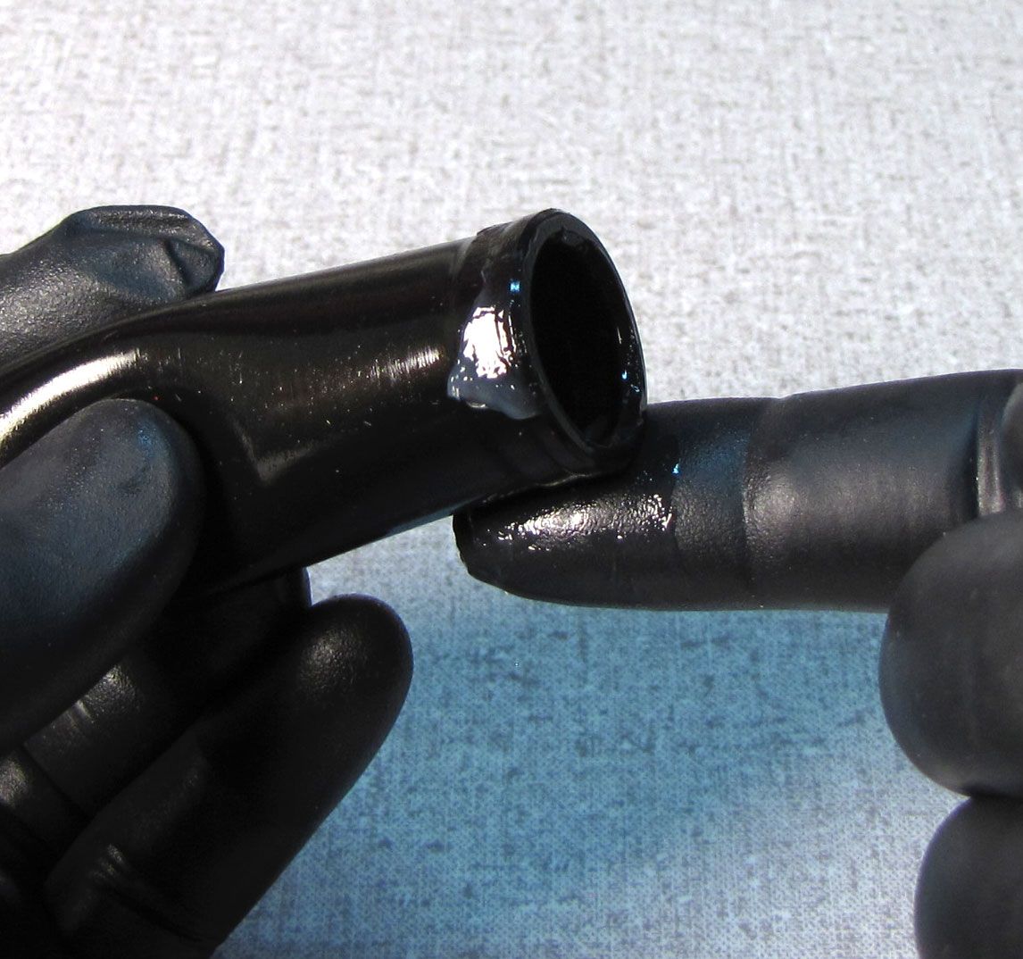
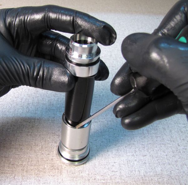
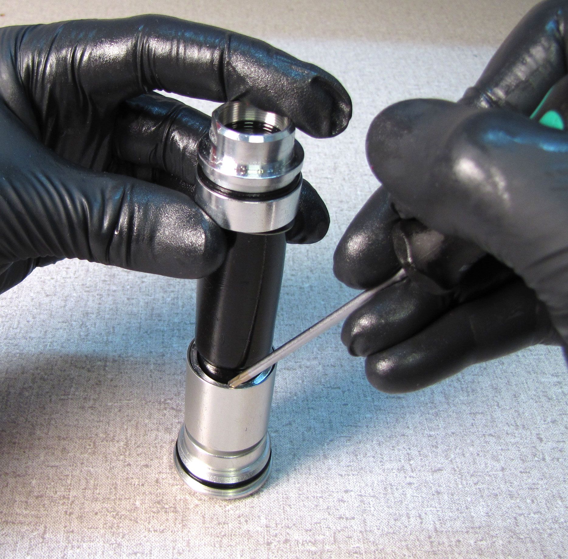
Unseat the retaining ring at the top end of the bladder. Use your 19mm wrench to unthread the reflow cap from the topcap assembly.
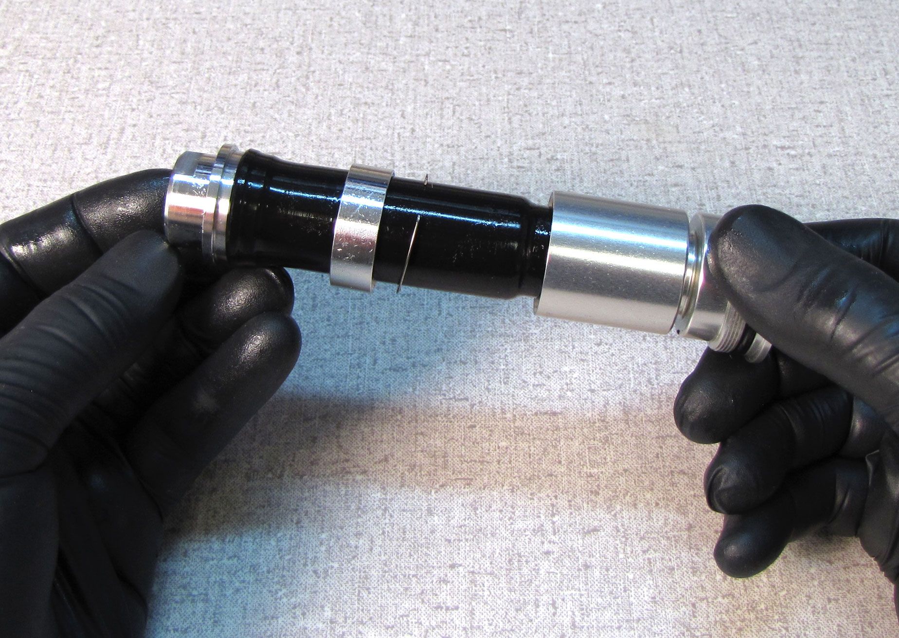
As the reflow cap, coupler shaft, and compression pistion clamp share the same torque spec, the coupler shaft may remain attached to the reflow cap or the compression piston clamp during disassembly. Follow the appropriate steps below that show the configuration in which your cartridge was disassembled.


Step 5
If the coupler shaft remains attached to the reflow cap during disassembly, remove the lower bladder ring and retaining ring, then clamp the shaft in your shaft clamps and unthread the reflow cap 2-3 turns with your 19mm wrench. Do not remove the reflow cap completely.


Step 6
If the coupler shaft remains attached to the compression piston clamp during disassembly, remove the lower bladder ring and retaining ring. Compress the bladder vertically, exposing the coupler shaft. Clamp the shaft and unthread (counter-clockwise) the topcap with you 6-point chamfer-less 26mm socket.
Step 7
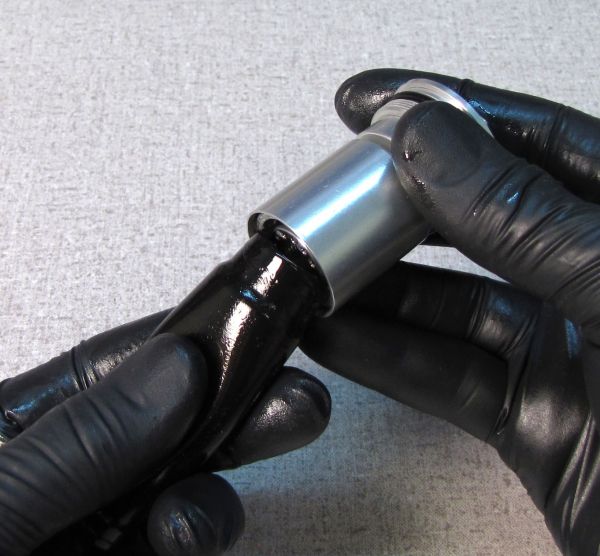
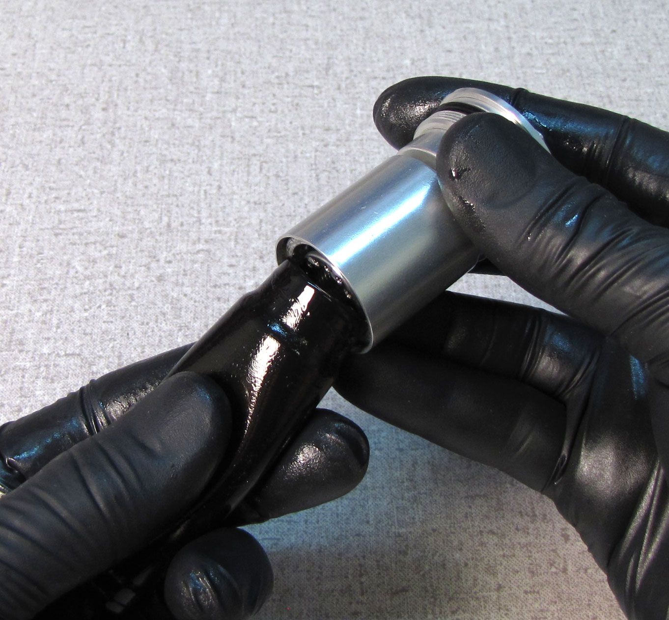
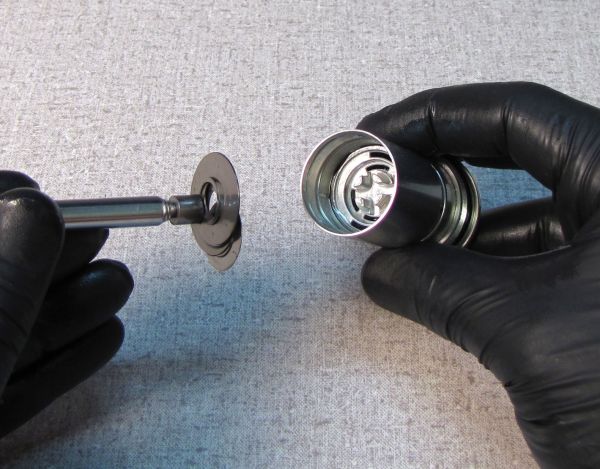
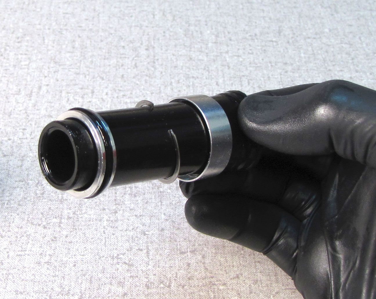
Remove the bladder from the topcap by pulling it out of the upper bladder ring. Discard the original bladder as you will replace it with a new one from the kit in a later step.
Step 8
Use a 6mm hex wrench to unthread (counter-clockwise) the compression pistion clamp from the topcap assembly. As the compression pistion clamp is unthreading it will pull the upper bladder ring out of the topcap. Remove the upper bladder ring and replace its o-ring with a new greased one from the kit.
Step 9
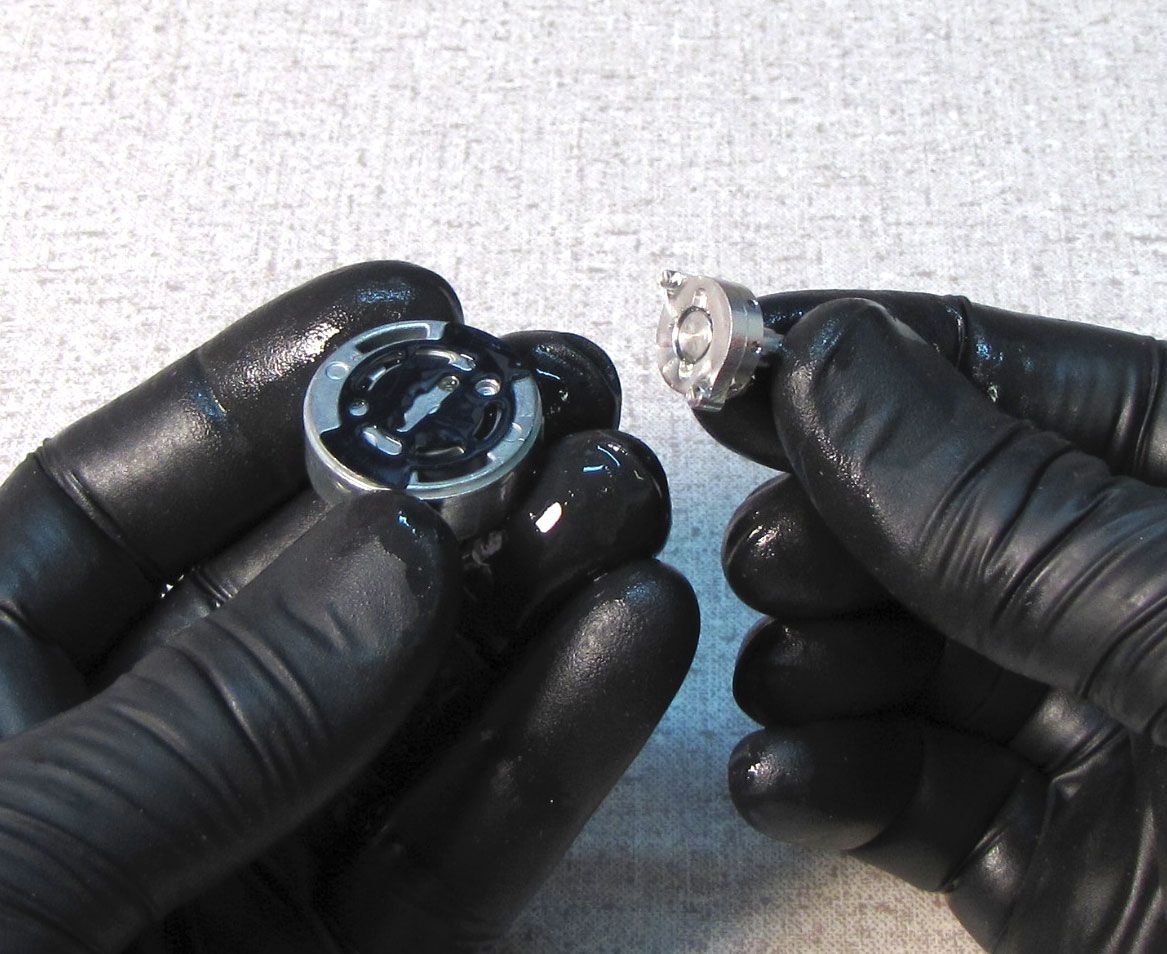
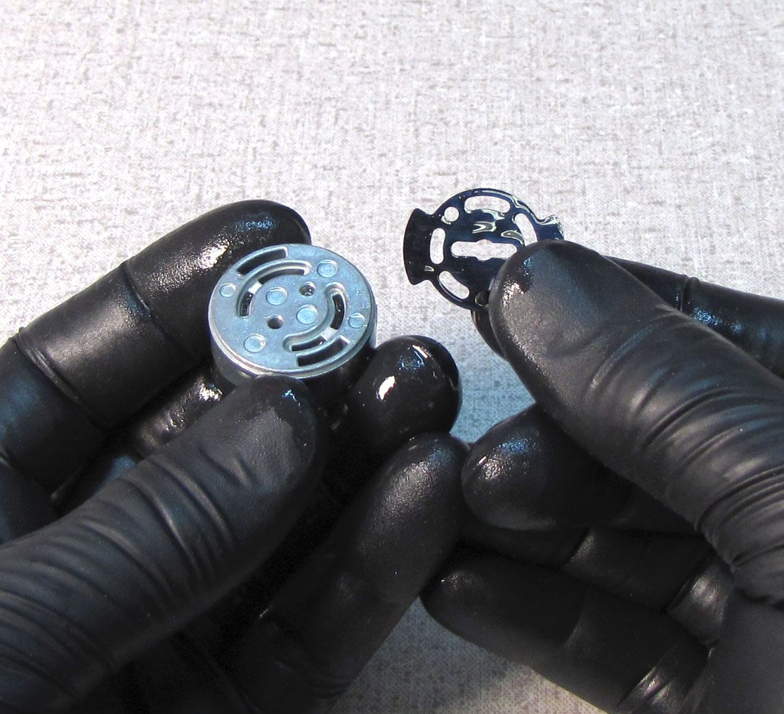
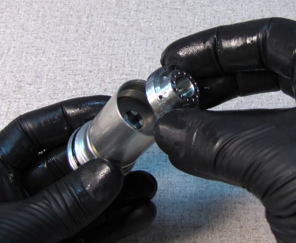
Remove the valving assembly with a plastic pick or magnet. Keep the valves in their original order and set aside. Remove the compression piston and selector shaft with wave spring. Remove the butterfly valve and set it aside.


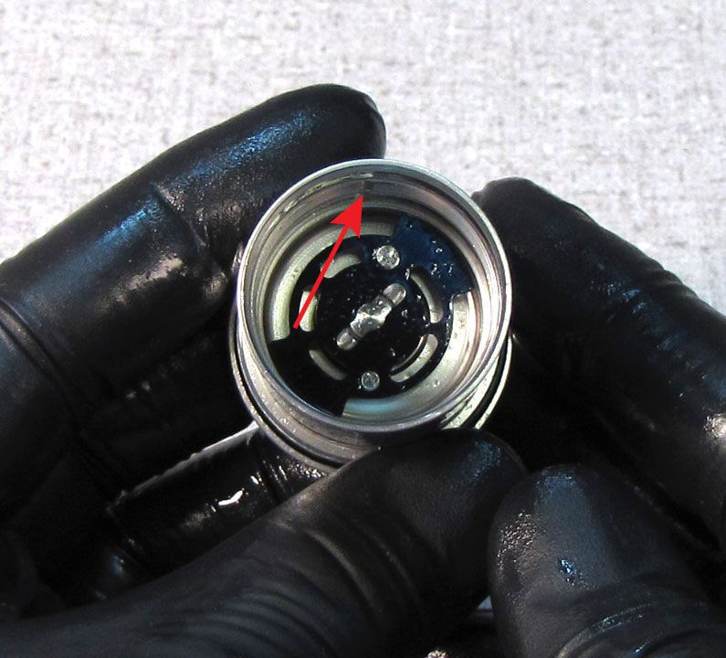
Step 10
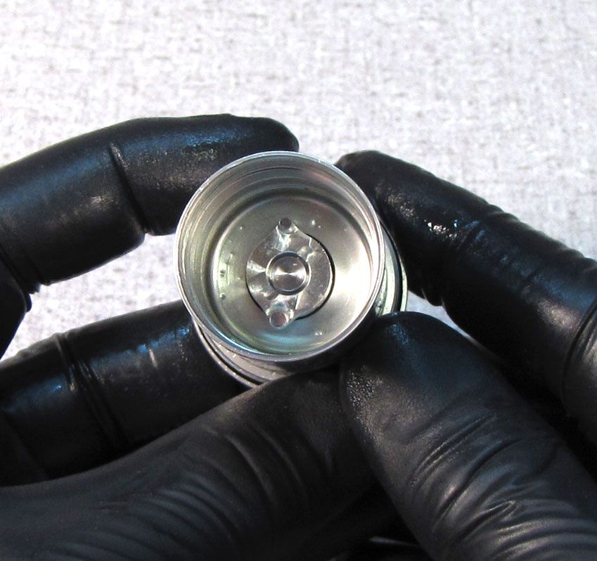
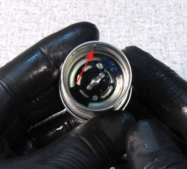
Remove and replace the o-ring inside the bottom of the reflow cap, making sure to retain the check valve, spring, and valve in their original order as shown.
Step 11
Replace the topcap o-ring with a new greased one from the kit.

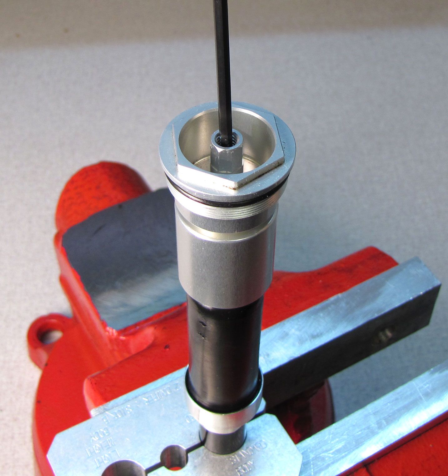
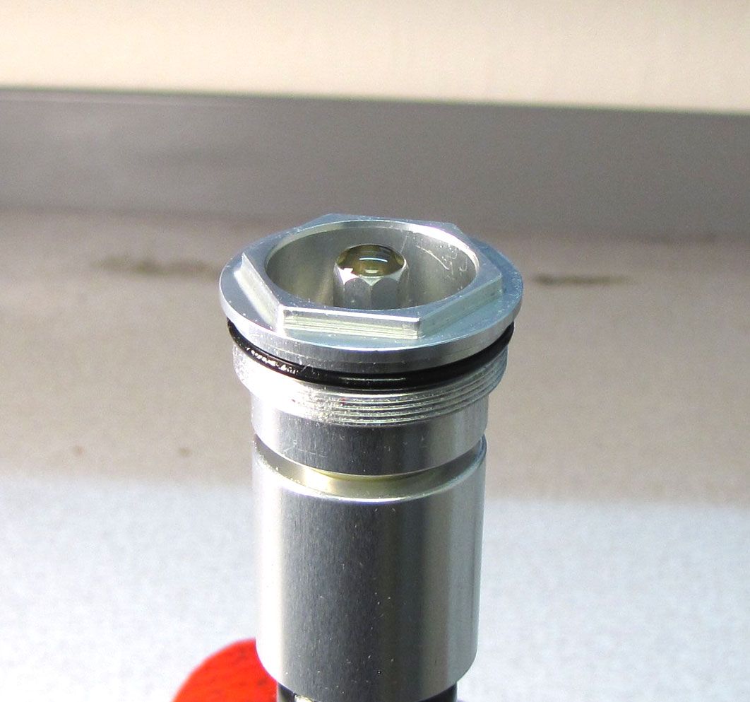
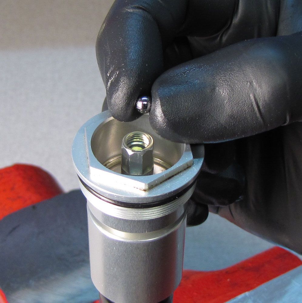
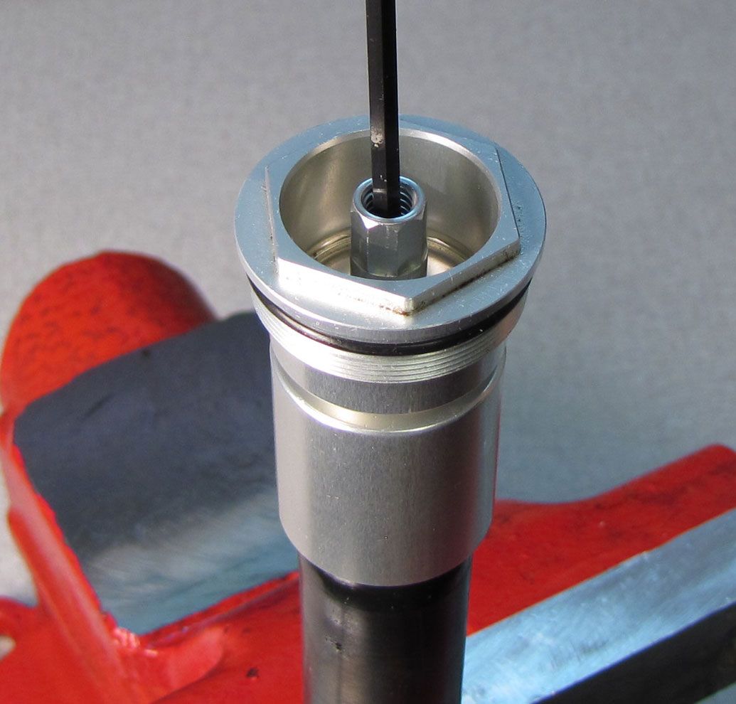
Step 12
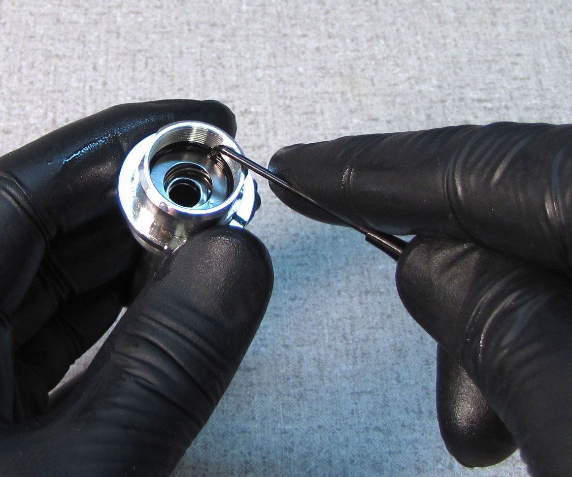
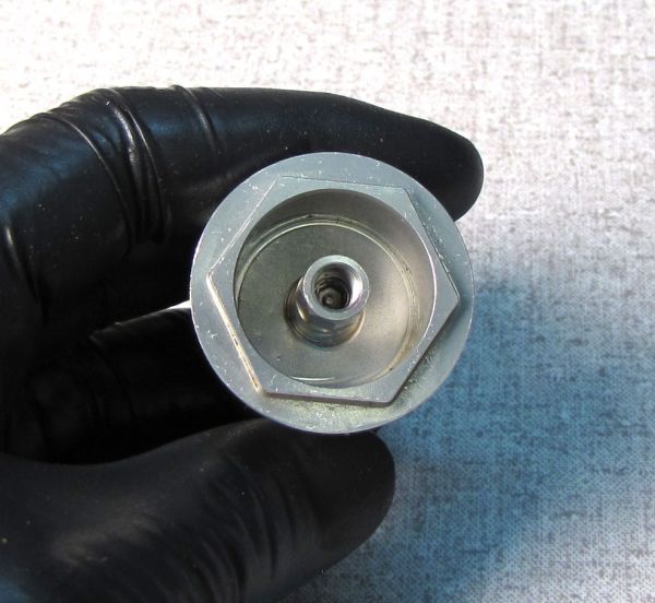
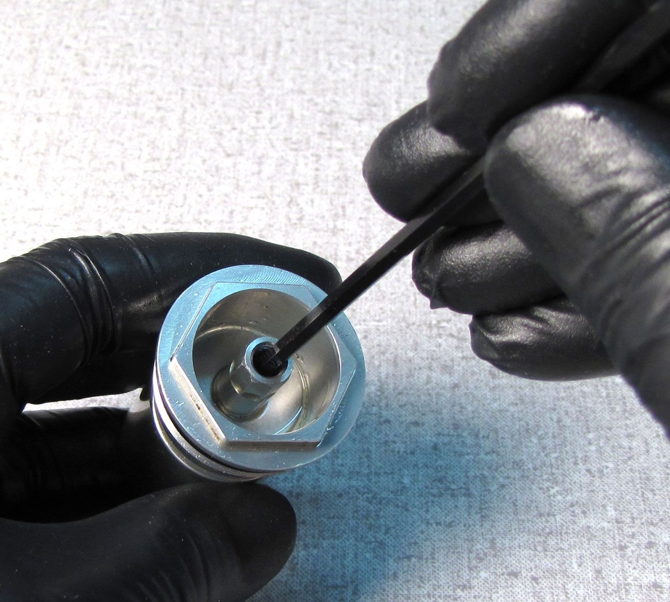
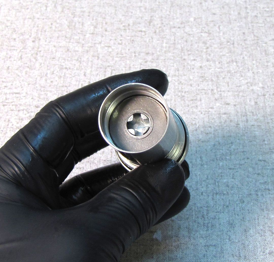
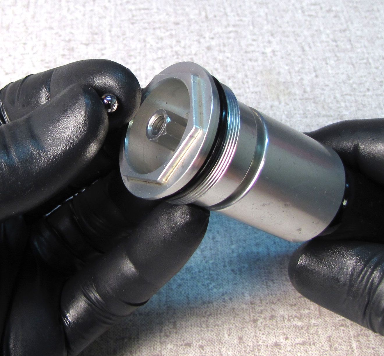
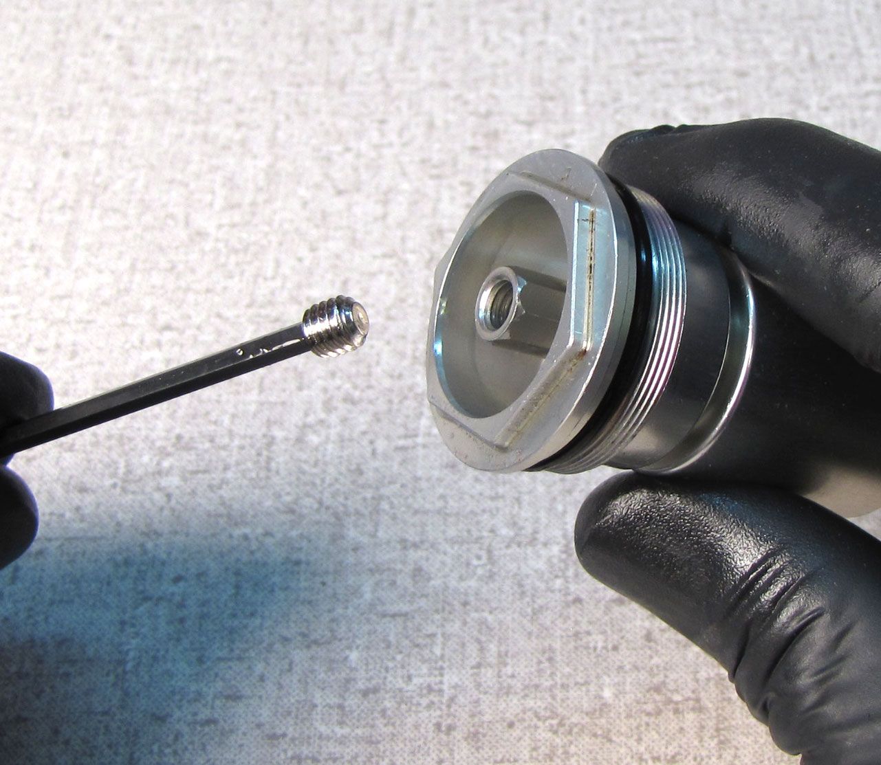
Use a 3mm hex wrench to unthread (counter-clockwise) the bleed screw from within the compression selector shaft. Remove the screw then remove the ball bearing with a magnet.

Step 13
Reinstall the selector shaft with wave spring into the underside of the topcap. Make sure the lobes of the selector shaft allign with the hole in the bottom of the compression selector shaft.
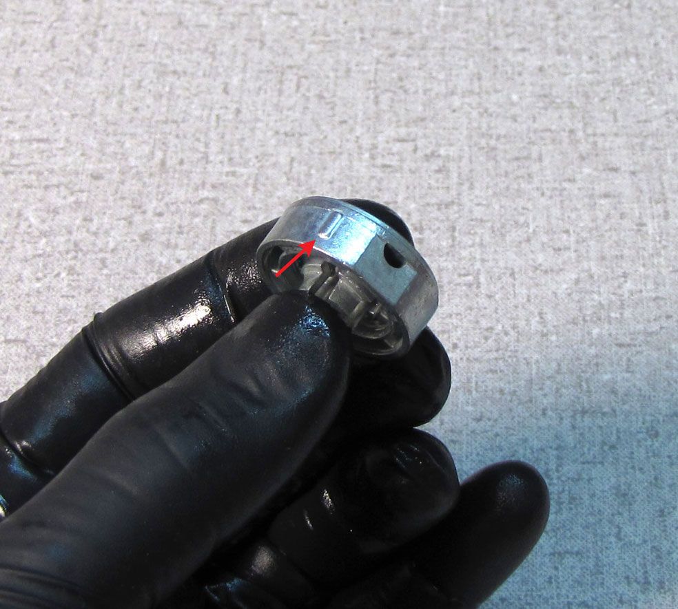
Step 14
Turn the compression selector shaft to the middle position by aligning the bigger pin from the lockout selector with the groove on the inside wall of the topcap body. Use a magnet to install the butterfly valve onto the lockout selector making sure that the holes in the butterfly valve allign with the appropriate sized posts on the lockout selector.
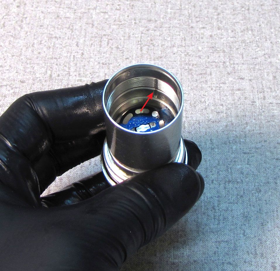
Step 15
Locate the feature that protrudes from the circumference of the compression piston (or the detent ball on newer pistons) and align that with the notch in the topcap body. Install the compression piston into the topcap with it's flat side facing toward the butterfly valve. Press down on the piston after installation to check for spring return. This helps verify correct piston installation. Install the valving assembly onto the compression piston, centering the shims on the stand-offs in the center of the piston.

Step 16
Reinstall the compression piston clamp into the topcap, threading it in (clockwise) until just snug with a 6mm hex wrench.


Step 17
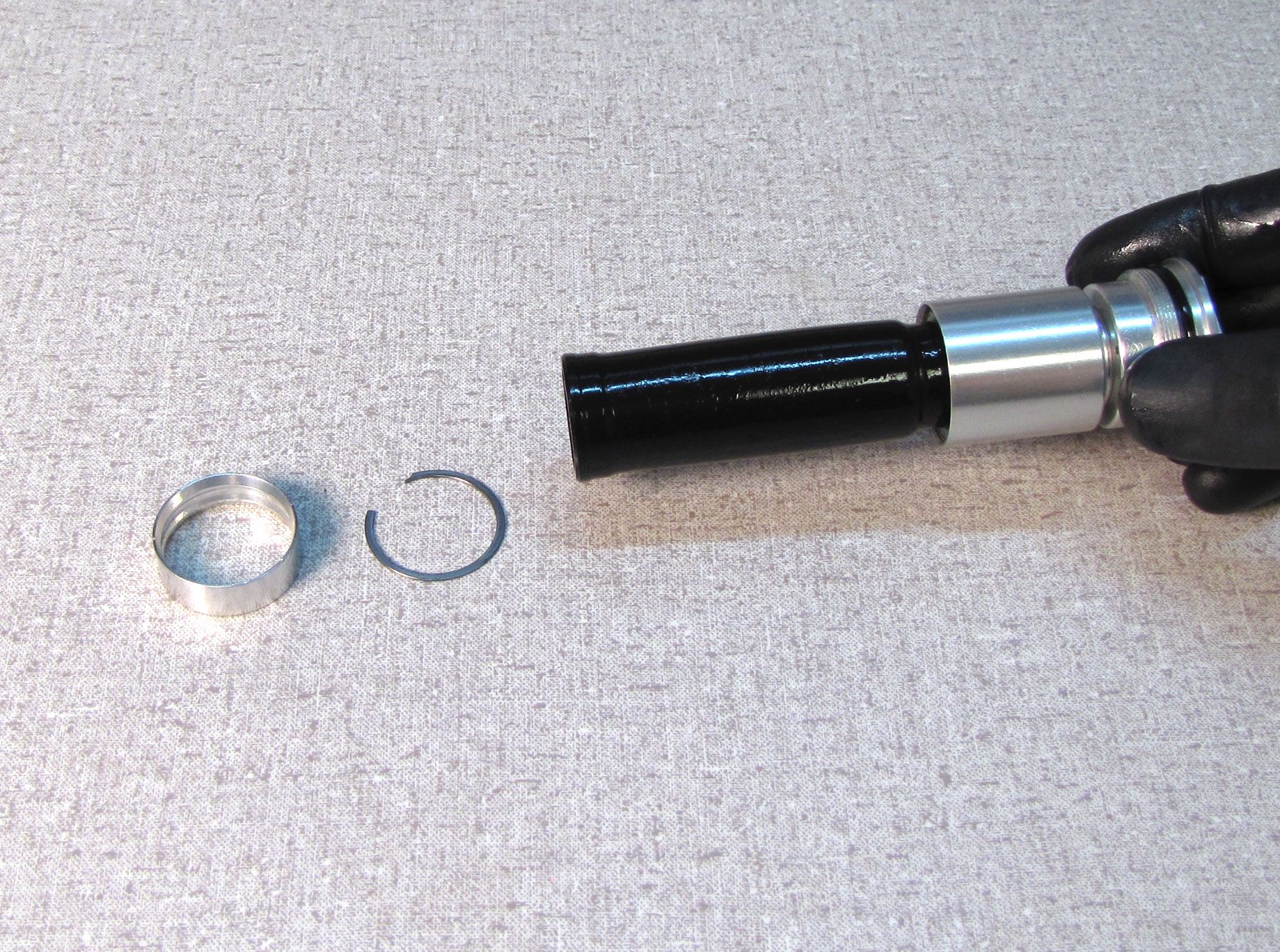
Apply a thin coating of Slick Honey to the inside and outside of both ends of a new bladder from the kit, then install the lower bladder ring, retaining ring, and upper bladder ring. The bladder rings are not directional.
Step 18
With the reflow cap loosely threaded onto the coupler shaft, insert the coupler shaft into the large end of the bladder so the coupler shaft protrudes from the small end of the bladder. Thread (clockwise) the coupler shaft into the compression piston clamp already inside the bottom of the topcap.

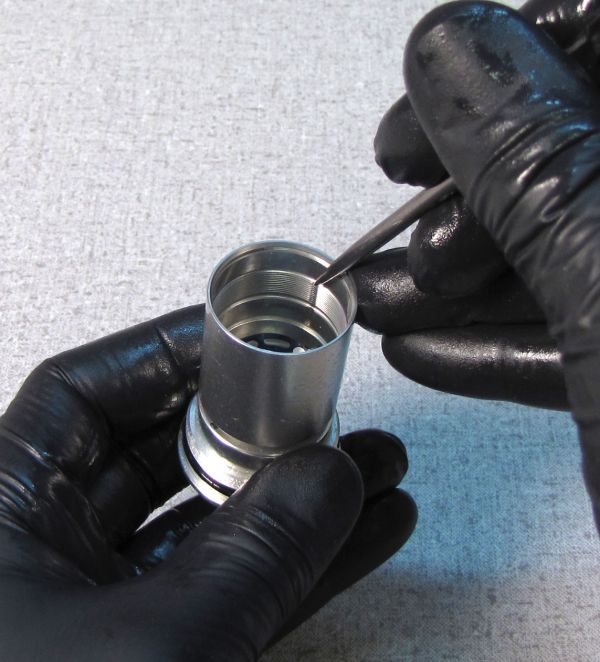
Step 19
Seat the upper bladder ring fully into the topcap by pushing it in with a blunt tool such as a 2mm hex wrench. Reinstall the retaining ring into the topcap, again using a blunt tool for installation to prevent damaging the bladder.

Step 20
Thread (clockwise) the rebuilt topcap assembly onto the cartridge body, tightening to 55 in-lb (6.2 Nm) with a 6-point chamfer-less 26mm socket.
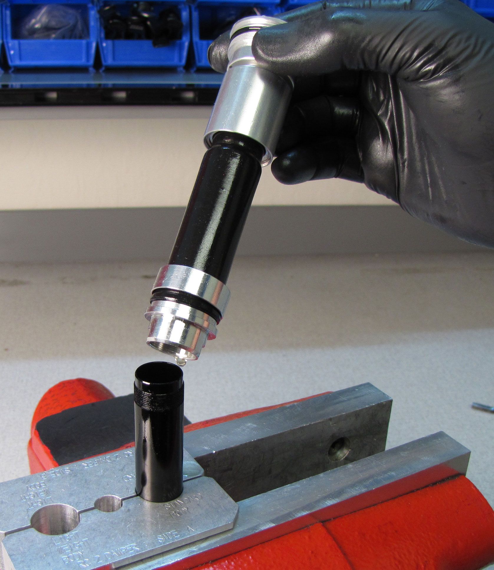
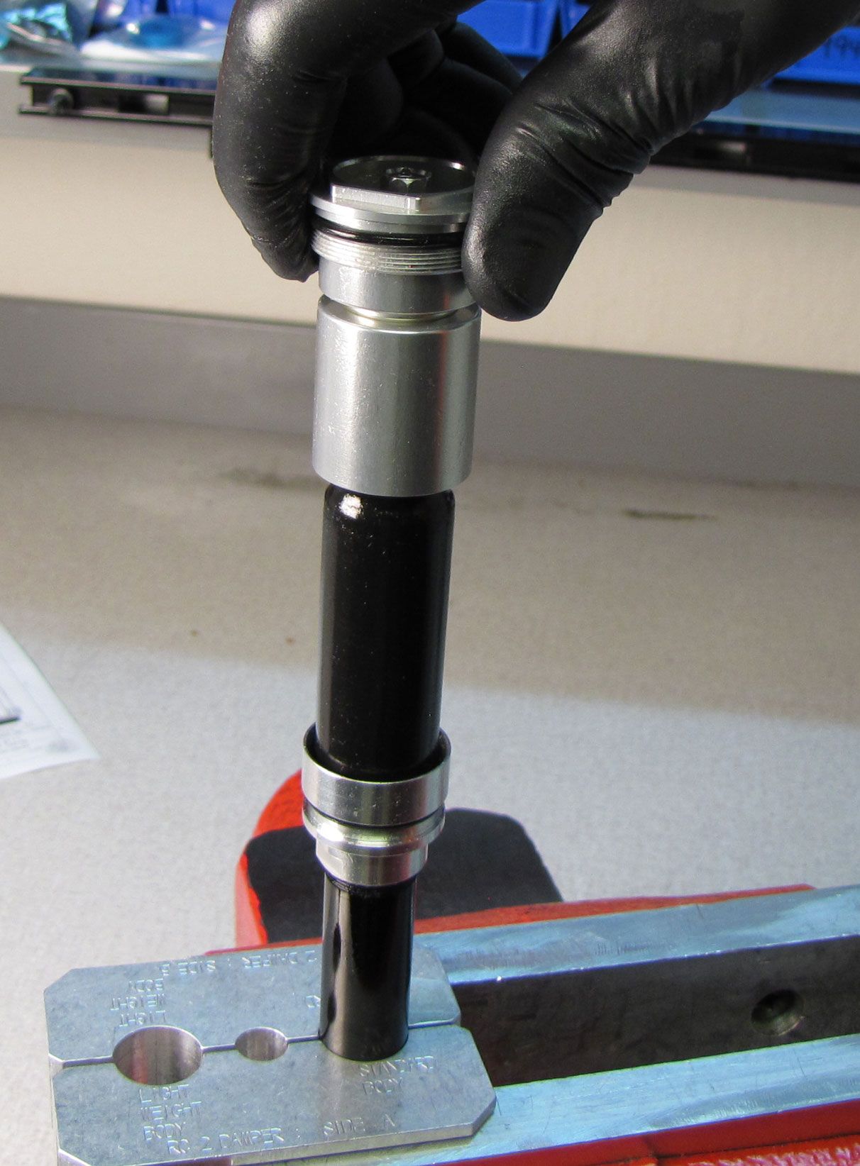
Step 21
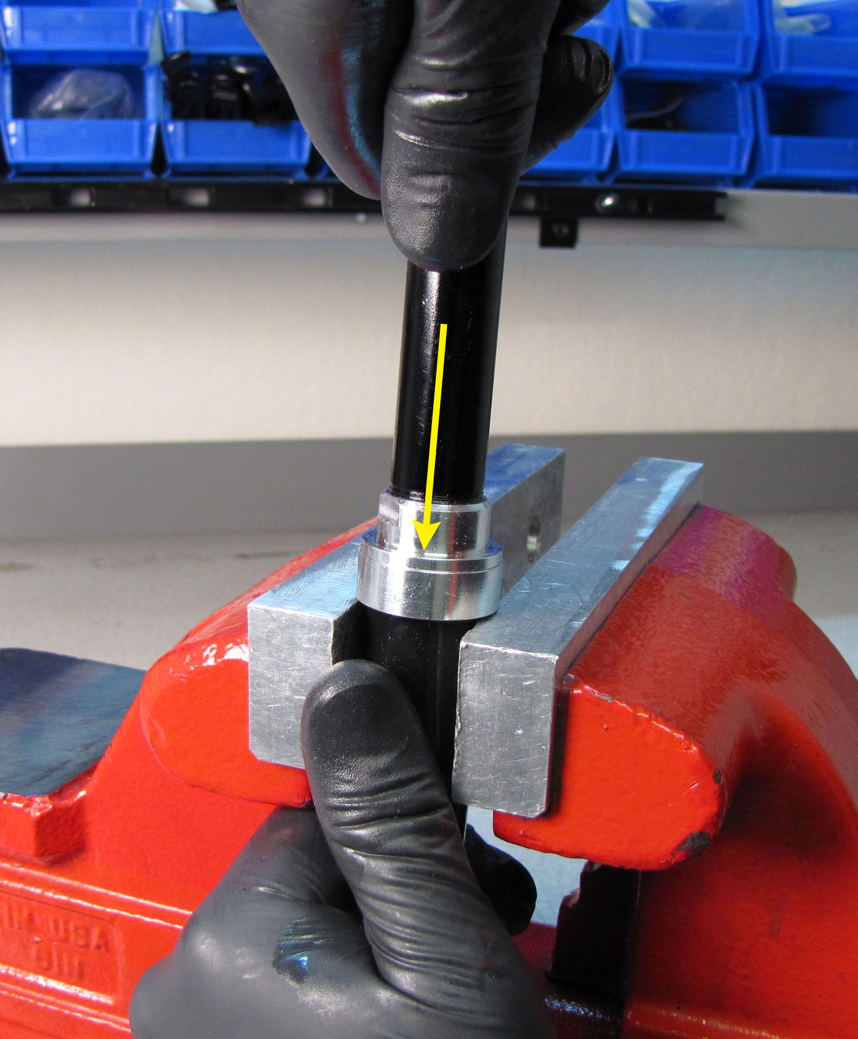
Seat the lower bladder ring against the reflow cap. You can rest the lower bladder ring on your soft-jawed vice and push down on the cartridge body to seat the bladder ring. Do not clamp or pinch the bladder in your vice.

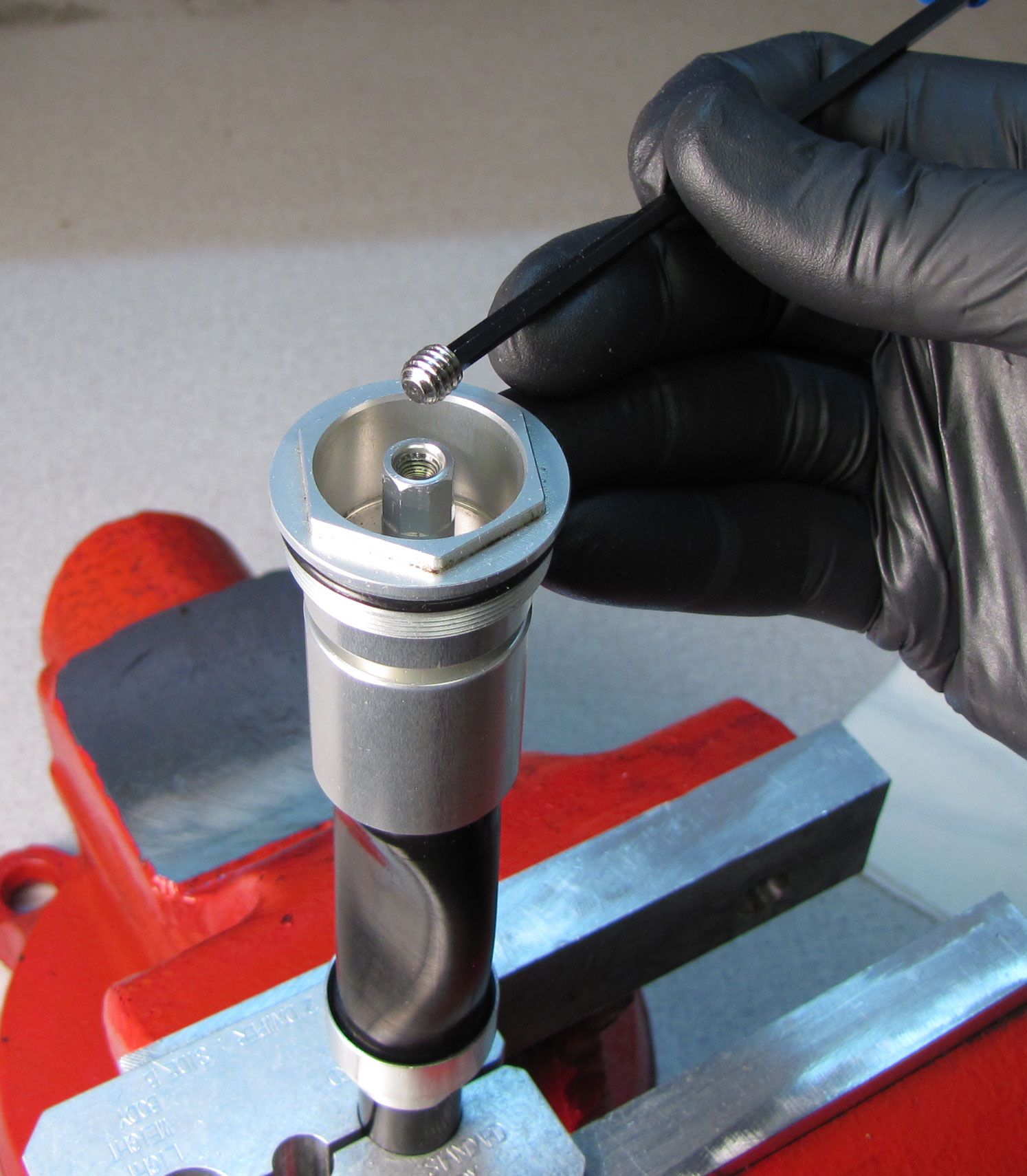
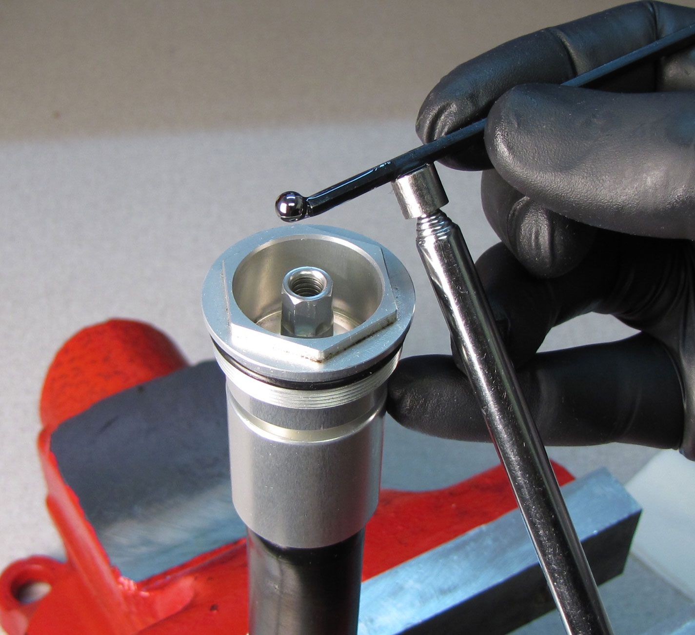
Step 22
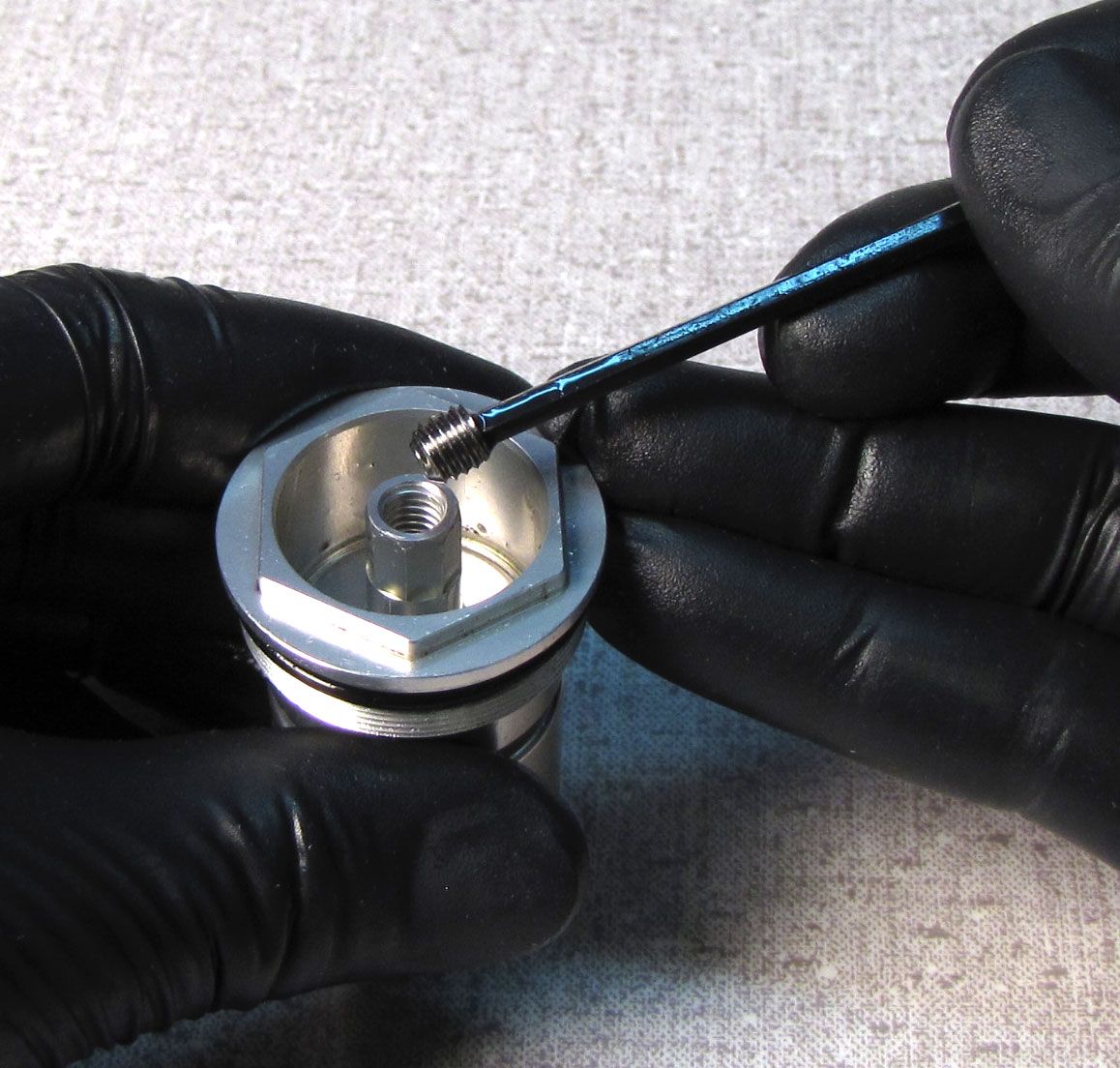
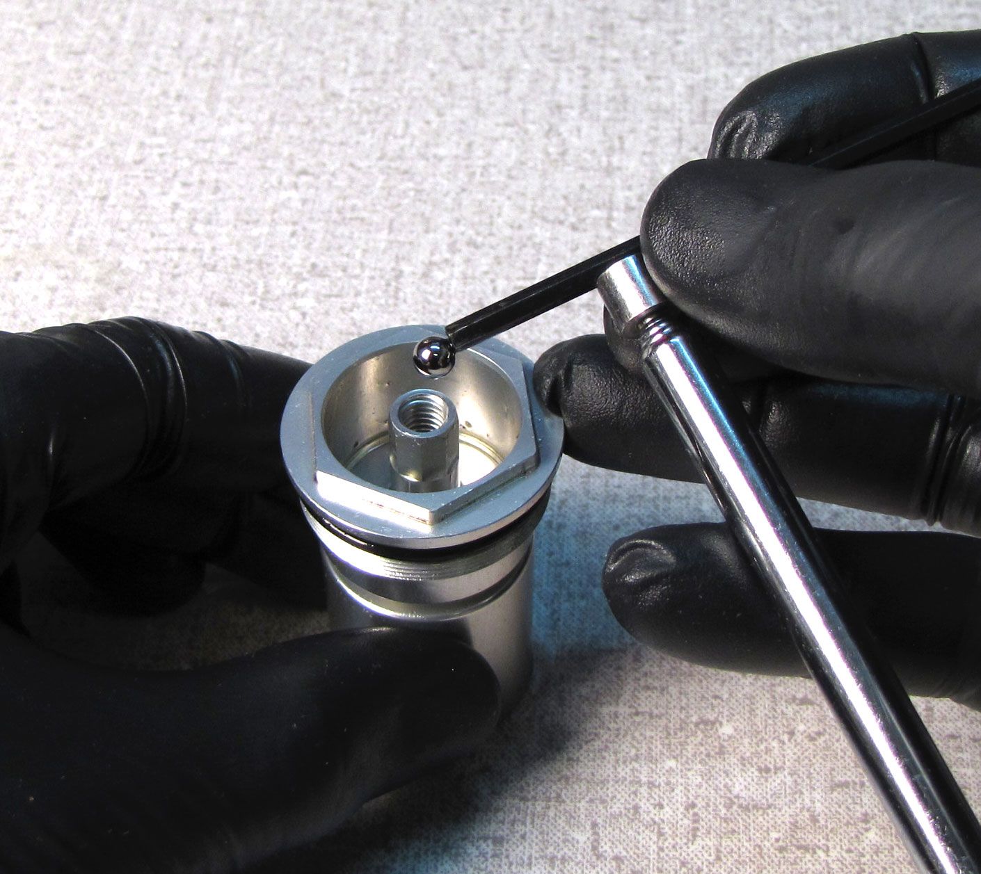
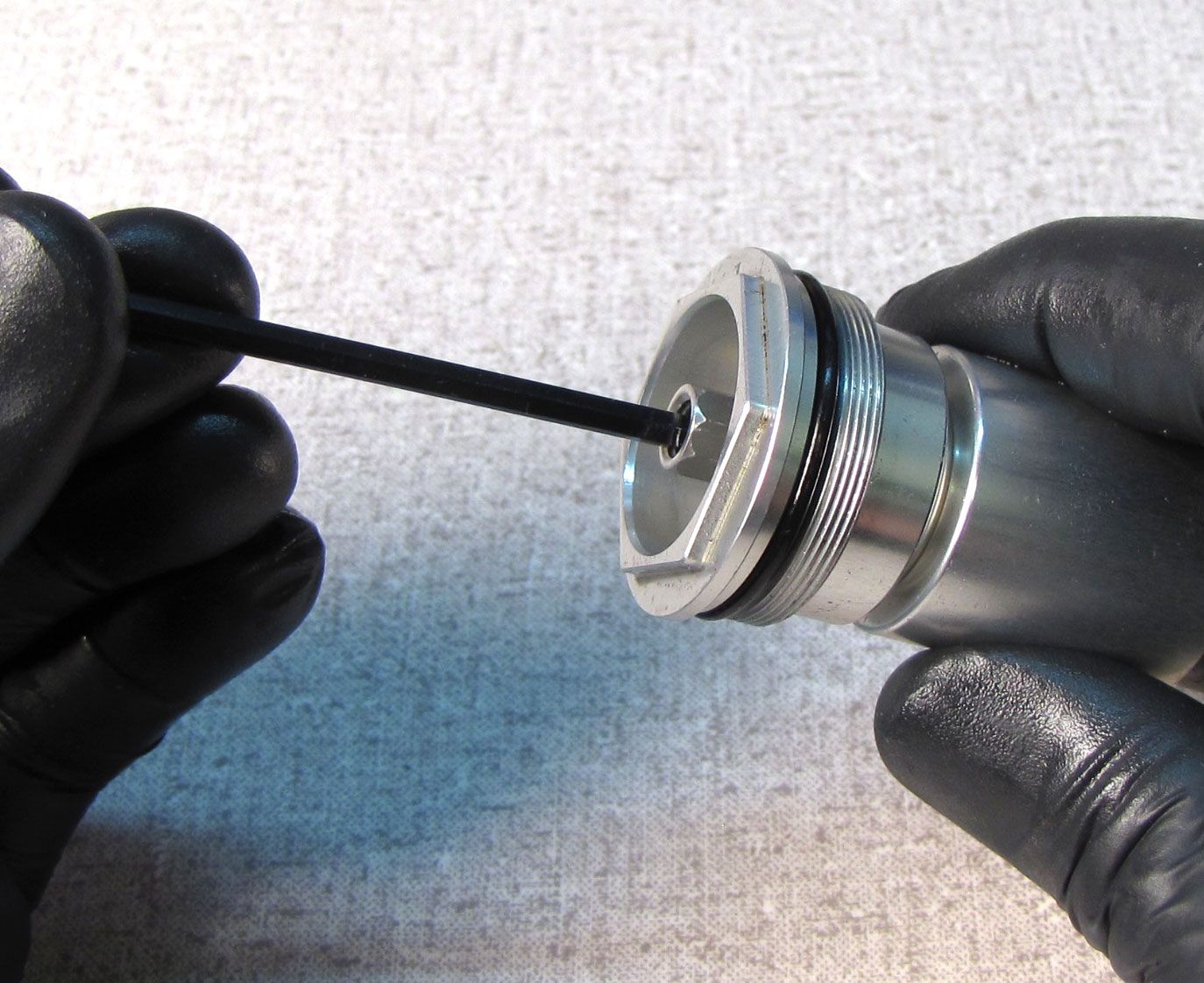
Reinstall the ball bearing and bleed screw into the compression selector shaft with your 3mm hex wrench, tightening to 10 in-lb (1.1 Nm) or just snug.
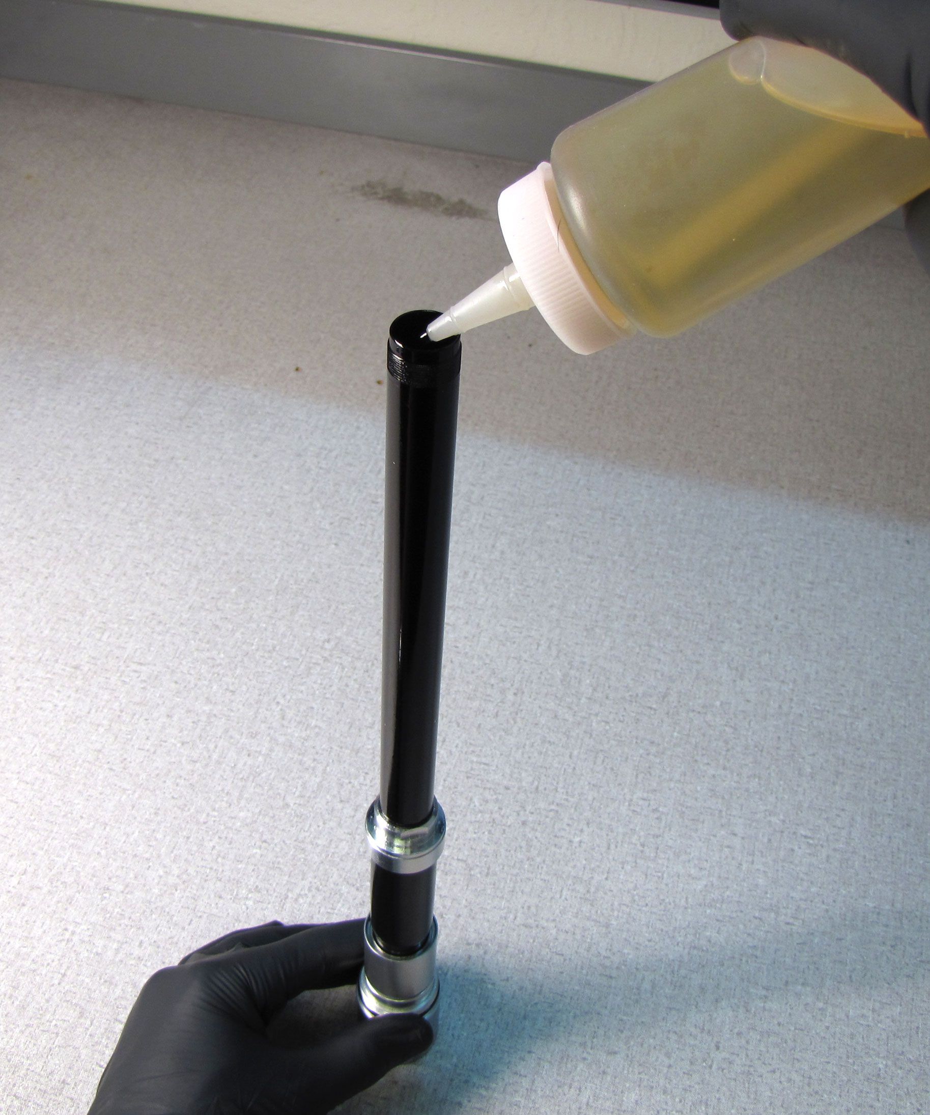
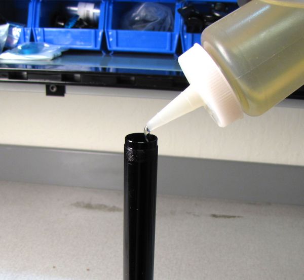
Step 23
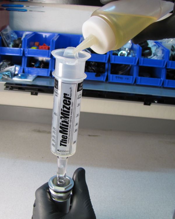
Rest the topcap in your 6-point chamfer-less 26mm socket and fill the cartridge body with FOX R3 5wt oil leaving approximately 3 inches (75mm) of air space above the oil within the cartridge body. Squeeze the bladder to expell air and ingest oil. Repeatedly squeeze the bladder and add oil until the oil level is approximately 3 inches (75mm) below the end of the body when not squeezing the bladder.

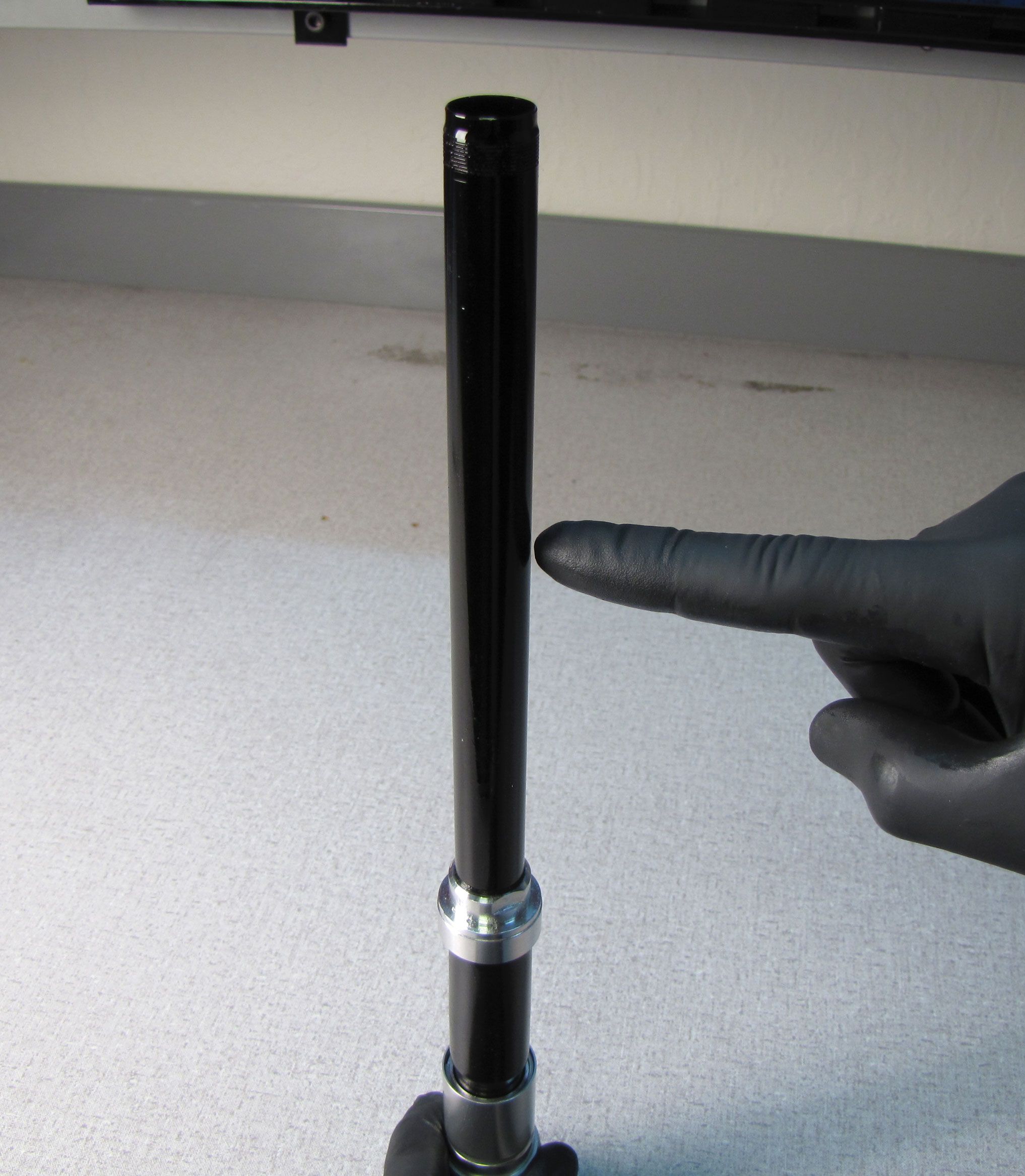
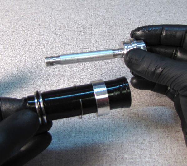
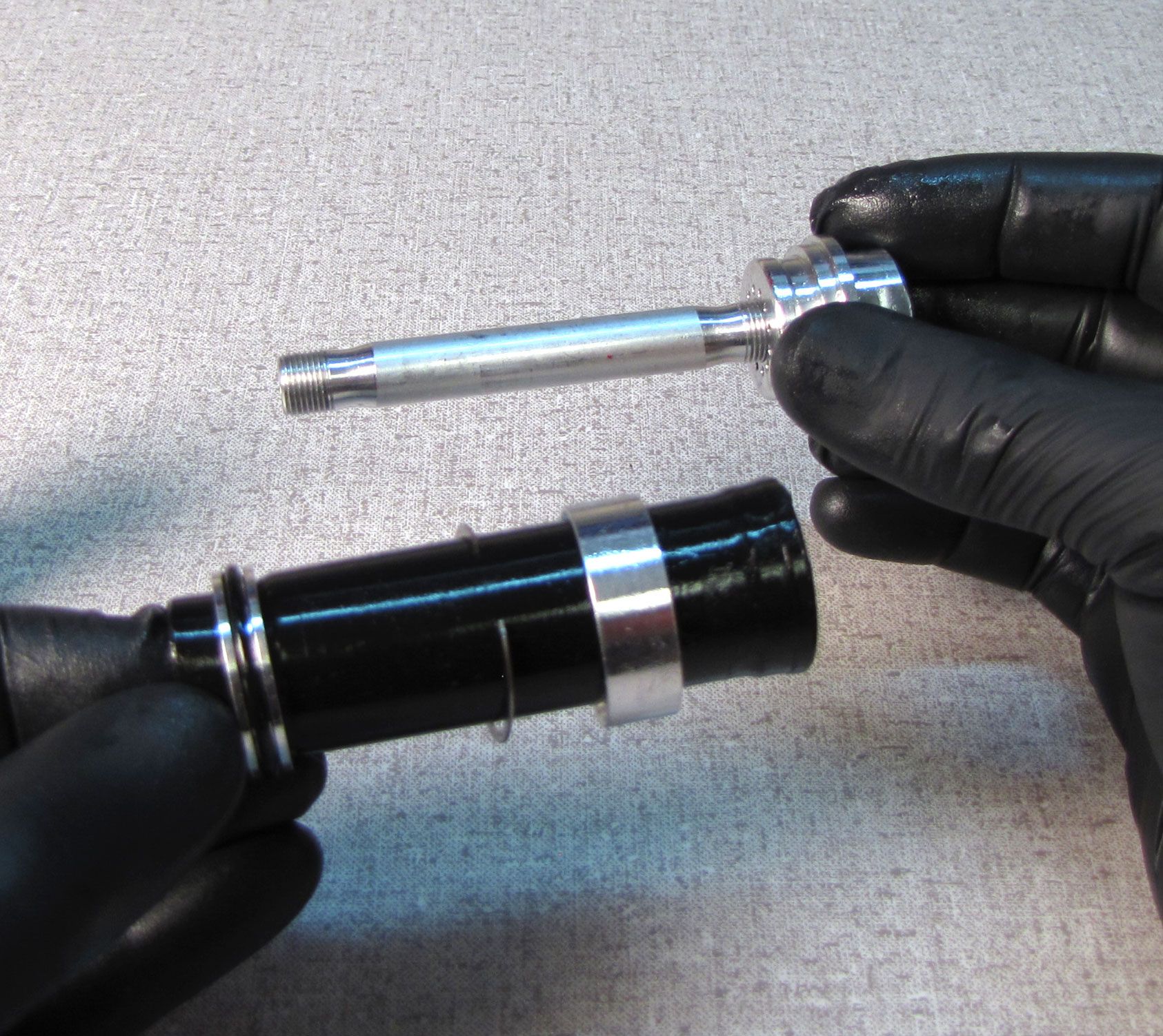
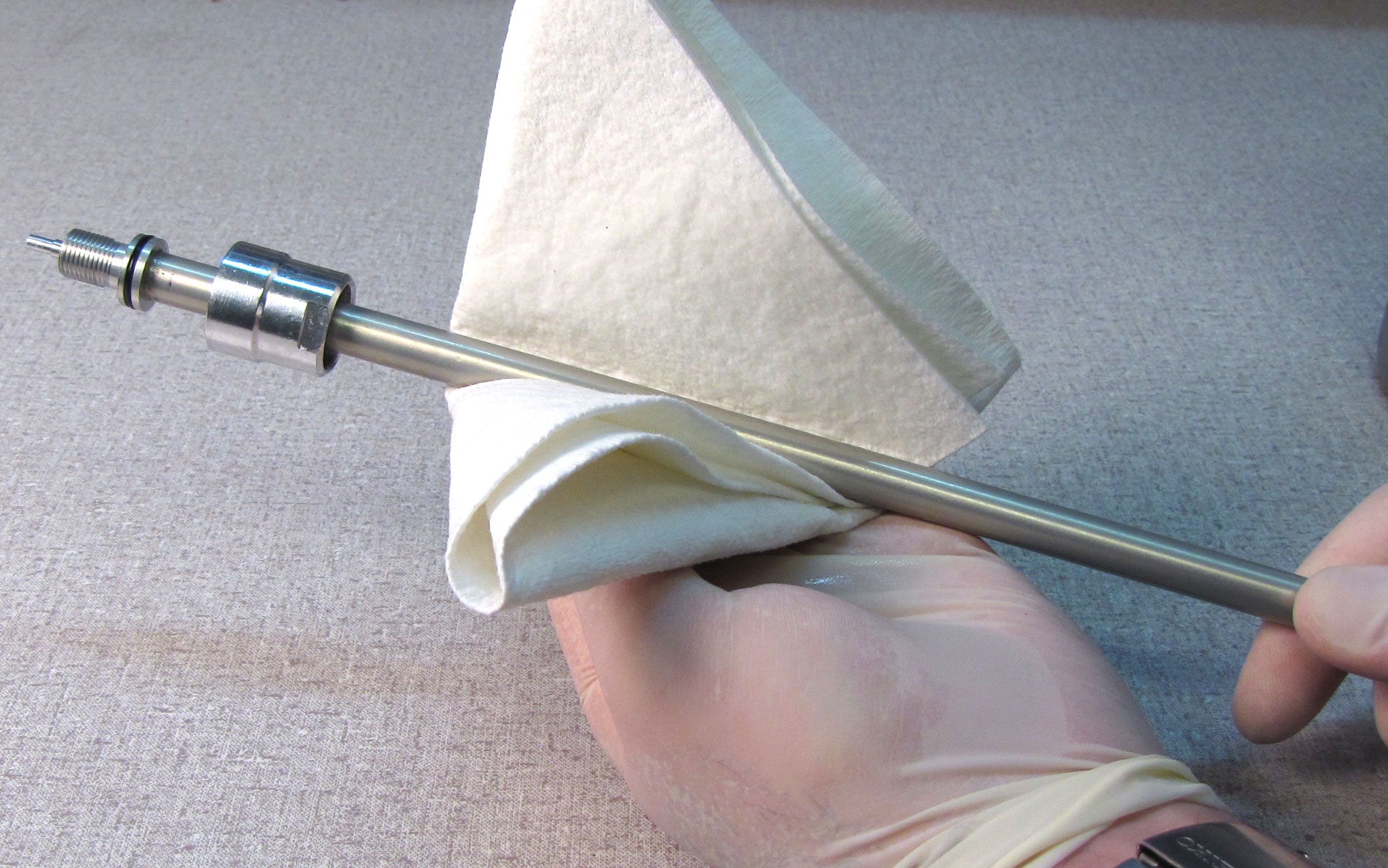
Step 24
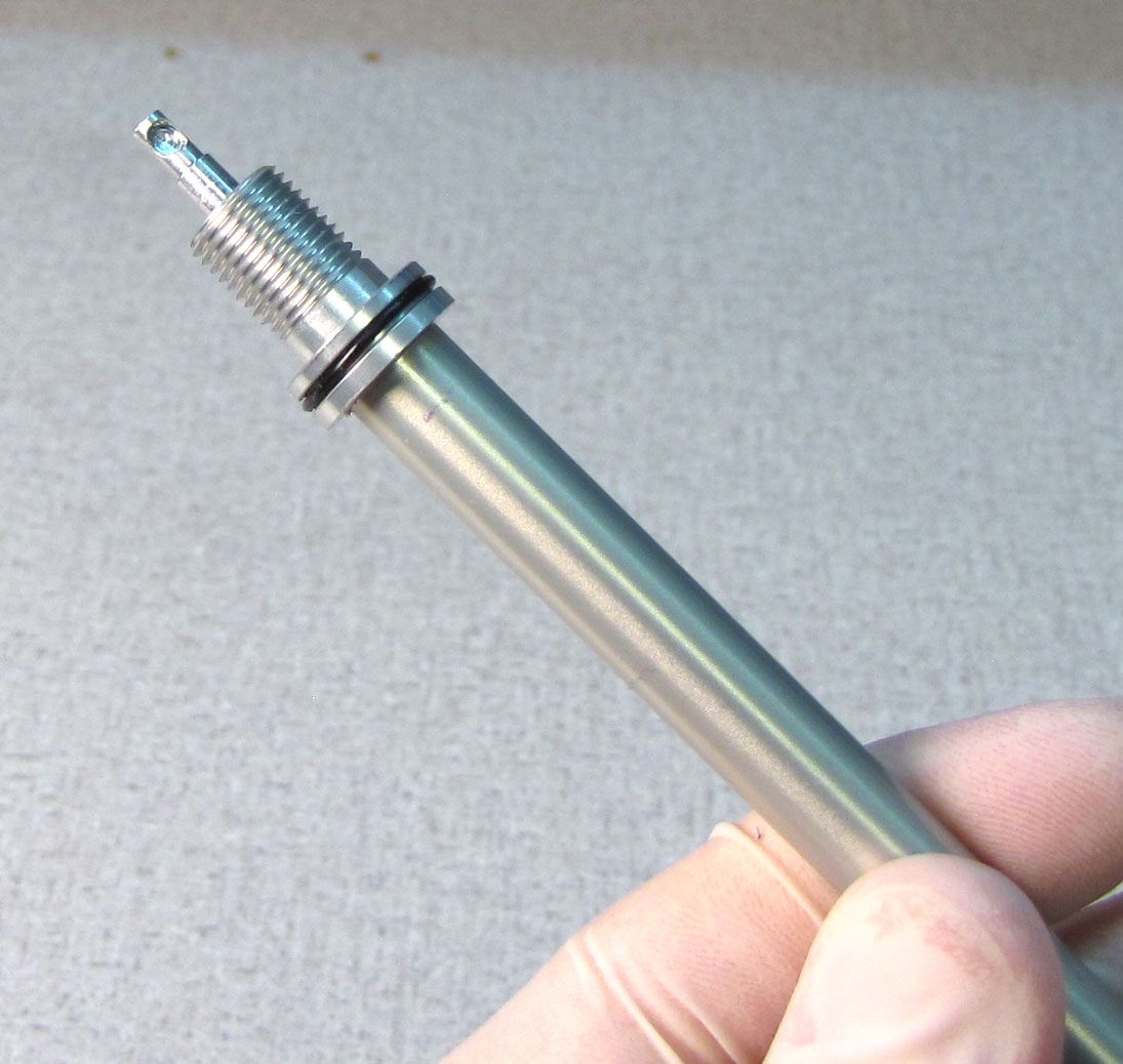
Slide the sealhead toward the rebound adjuster (listed as the base stud in the technical drawings), leaving about 1 inch (25mm) space between the sealhead and rebound adjuster. Clean the shaft with isopropyl alcohol and a lint-free paper towel.
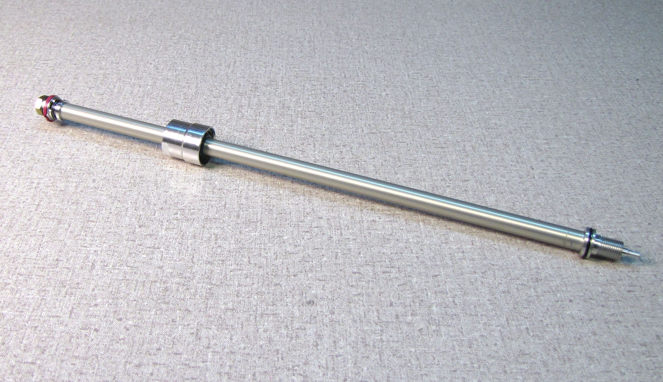
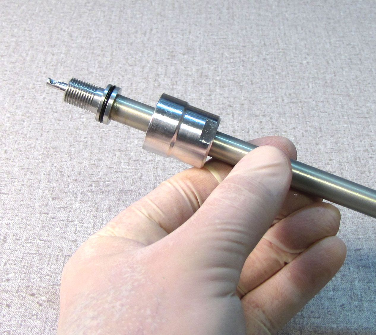
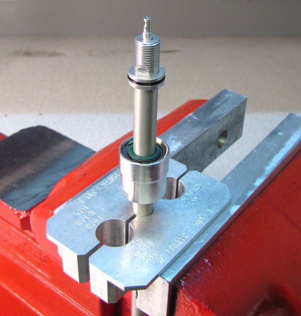
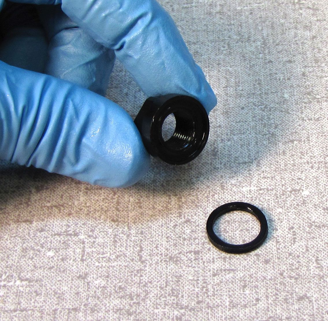
Step 25
Clamp the shaft in your shaft clamps (PN: 803-00-830 for 10mm shafts or PN: 803-00-174 for 8mm shafts) and remove and discard the o-ring from the rebound adjuster.

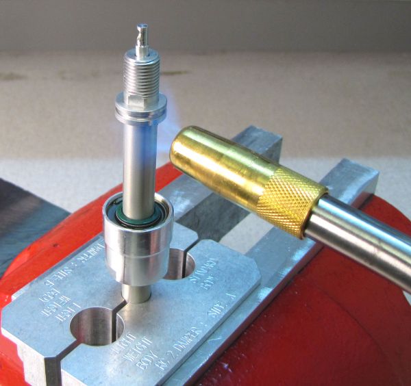
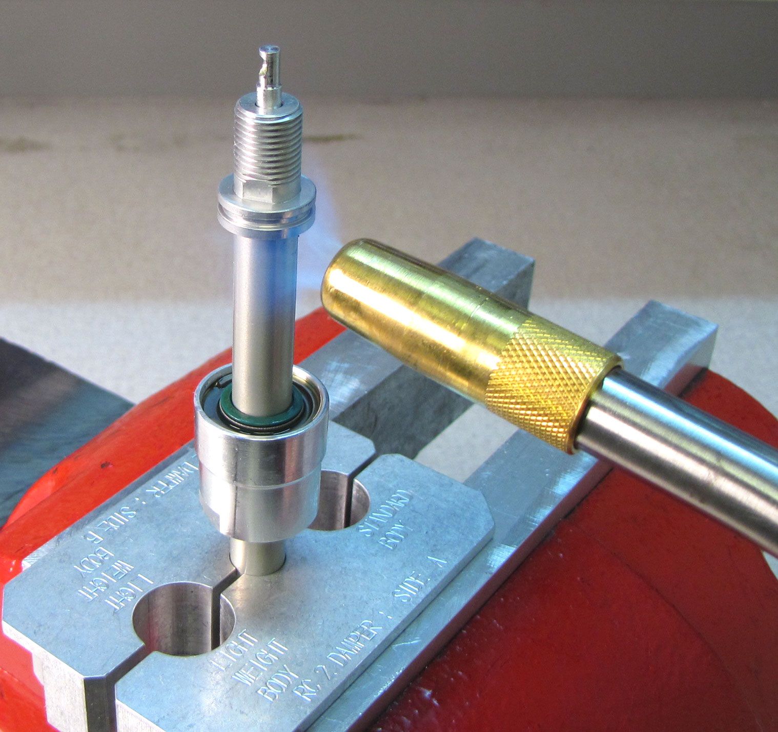
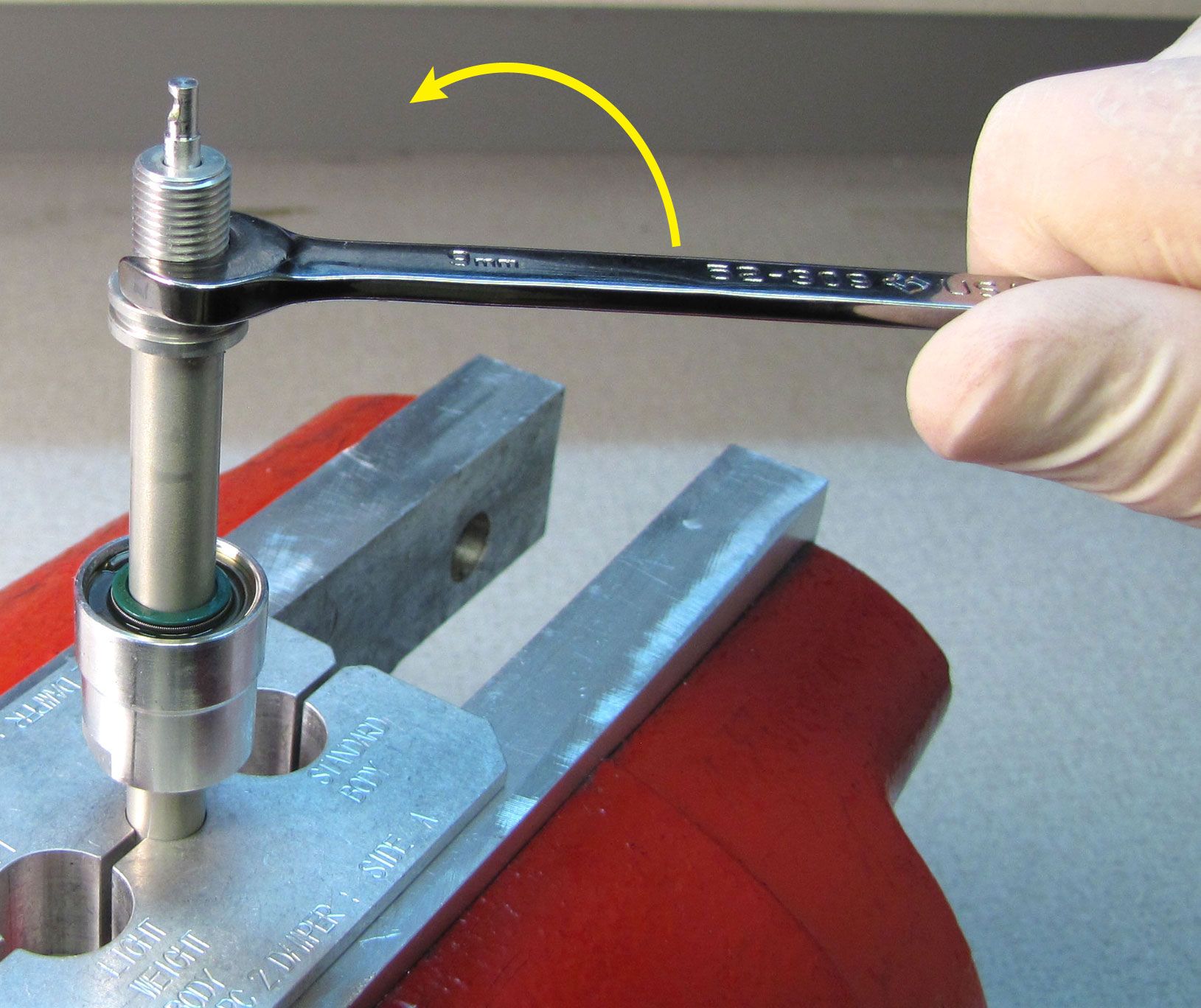
Step 26
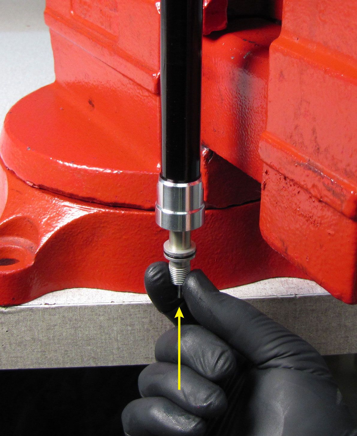
Carefully apply heat to the shaft at the rebound adjuster with a propane torch for 5-10 seconds to break down the Loctite. Unthread the rebound adjuster counter-clockwise with a 7mm (32mm forks) or 9mm (34mm forks) wrench.

Step 27
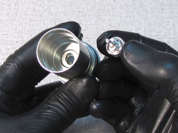
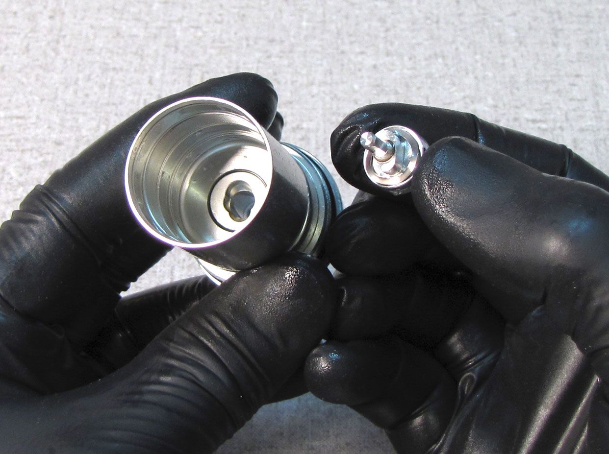
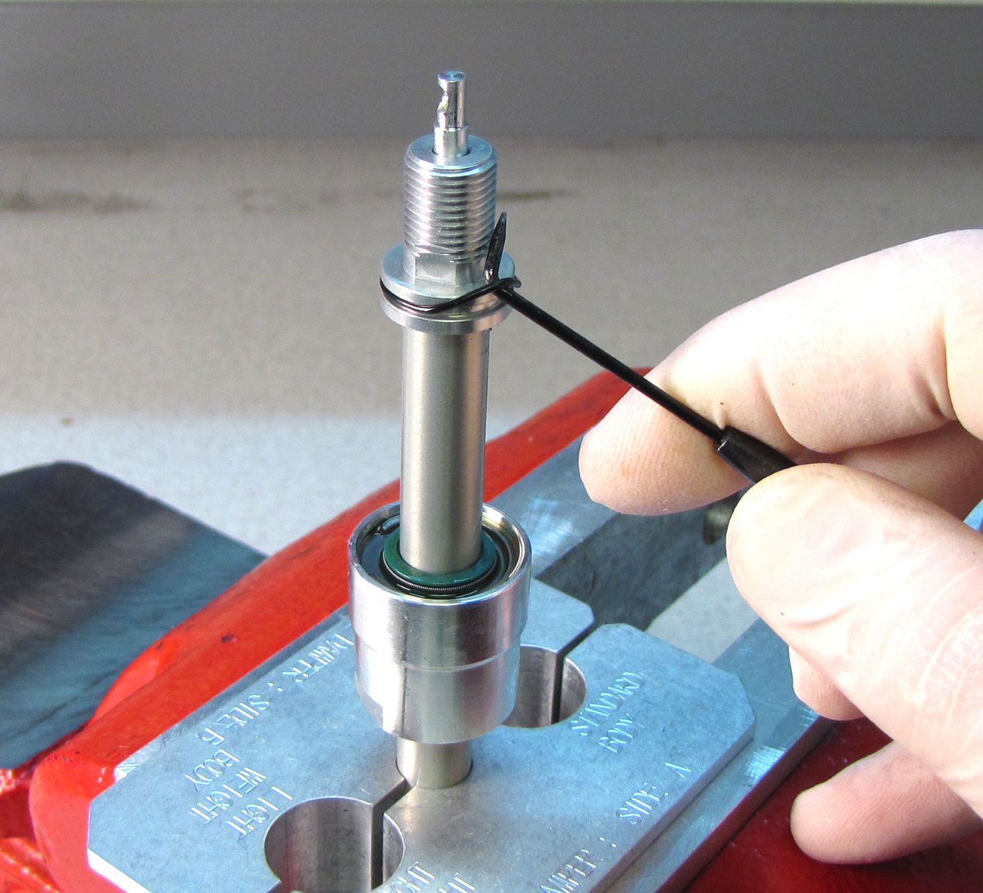
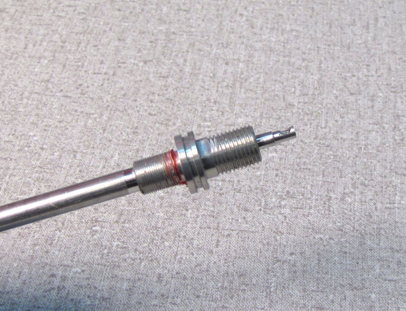
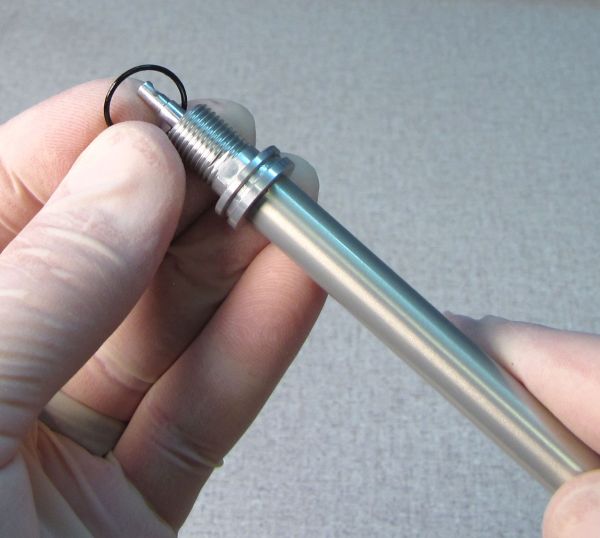
Lift the rebound adjuster with rebound needle straight up and out of the shaft. Replace the o-ring at the fluted end of the needle with a new greased one from the kit.
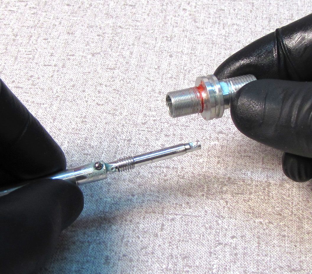
Step 28
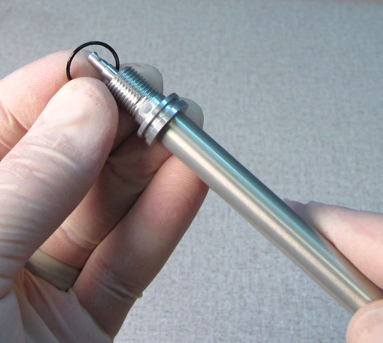
Slowly unthread the rebound adjuster (counter-clockwise) from the rebound needle. After a few turns you will be able to see the rebound detent ball. Hold the needle with the rebound detent ball pointing up as you slowly unthread the rebound adjuster fully.

Step 29
Coat the threads of the rebound needle with waterproof grease such as Sta-Lube SL3125. While holding the rebound needle with the detent ball facing up, thread the rebound adjuster clockwise onto the needle. Thread the adjuster fully onto the needle, then back it off 1/4 turn.
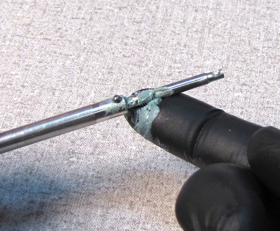
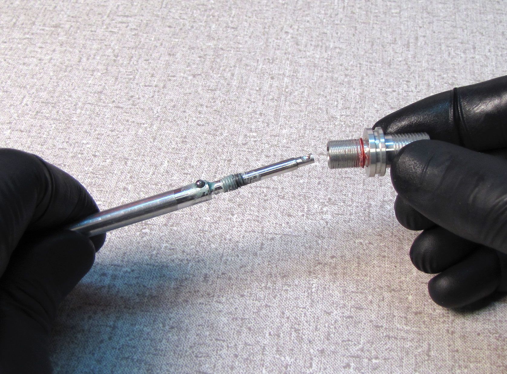
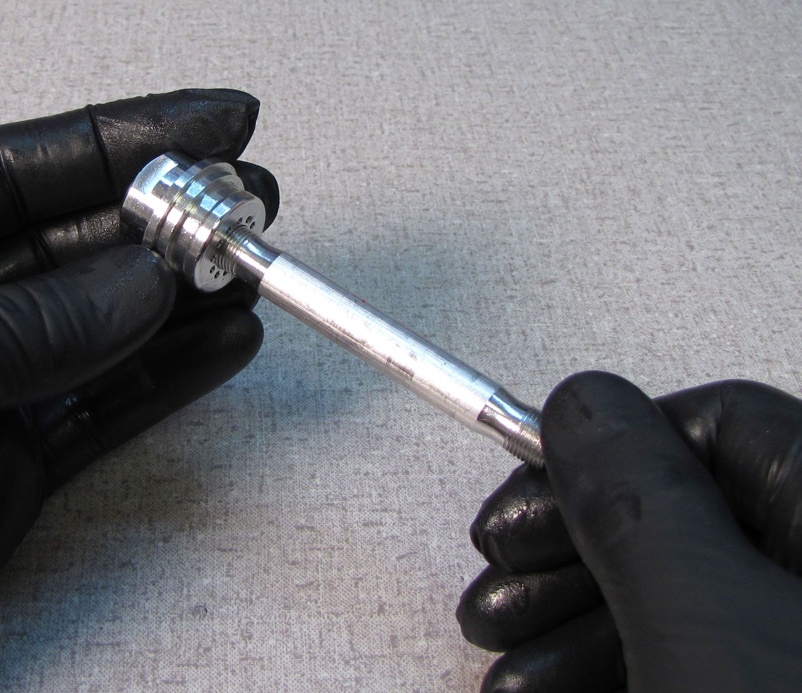
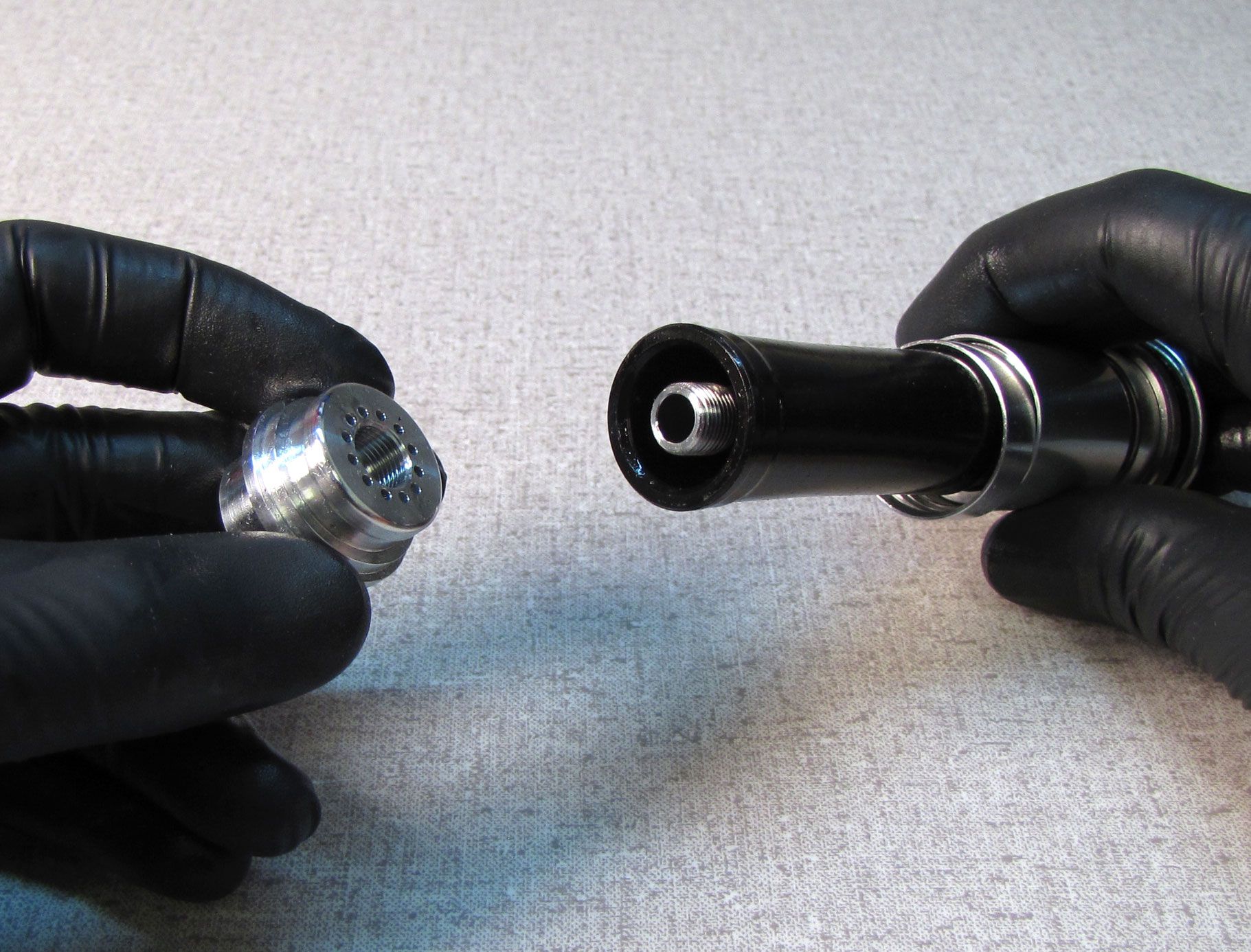
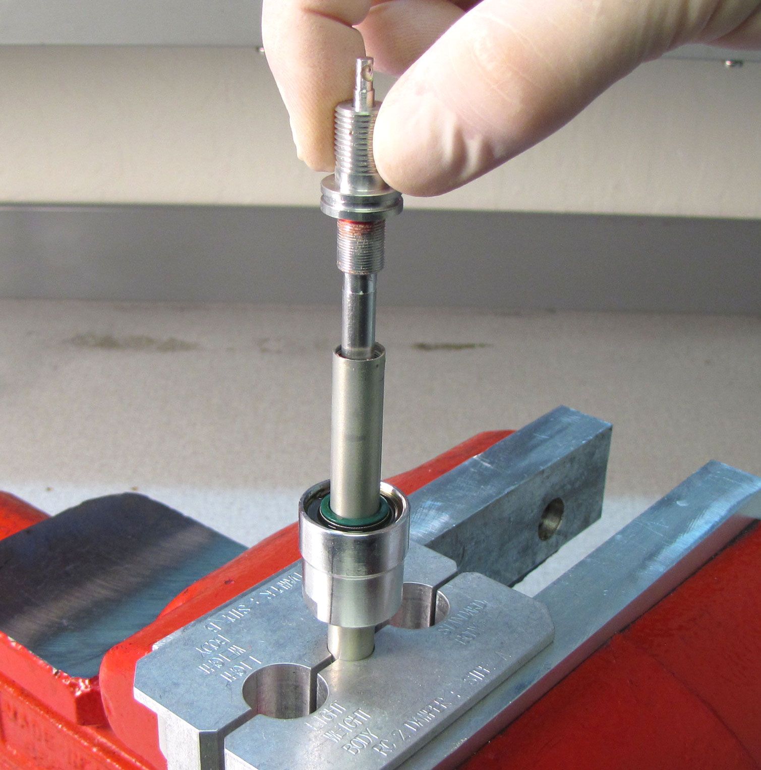
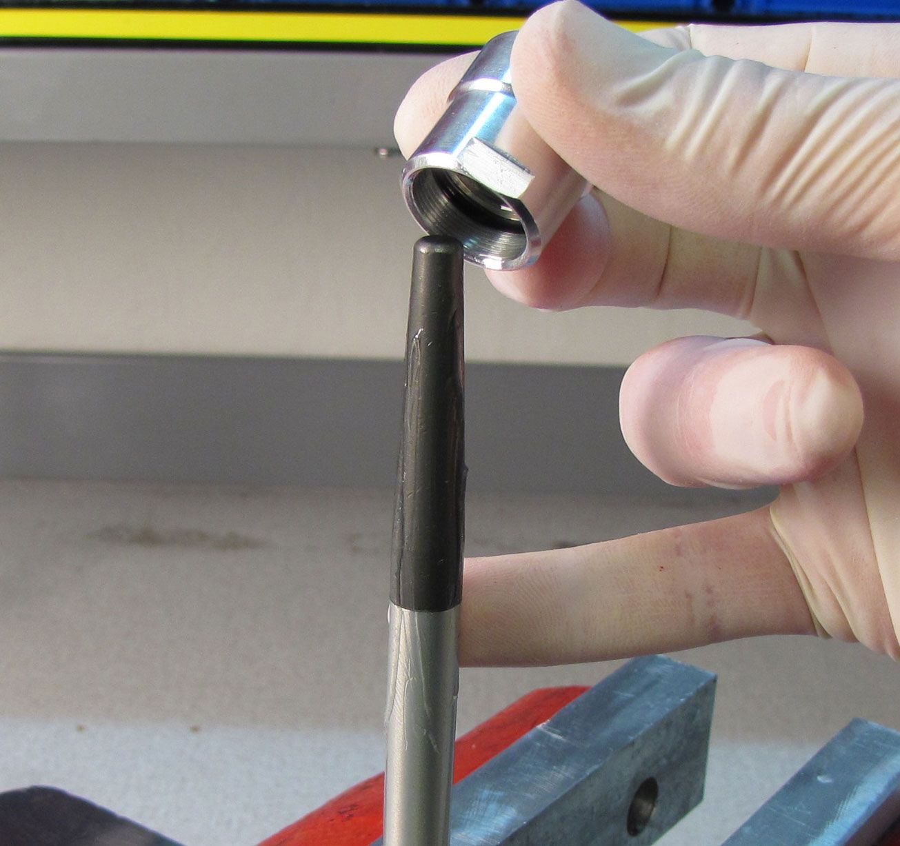
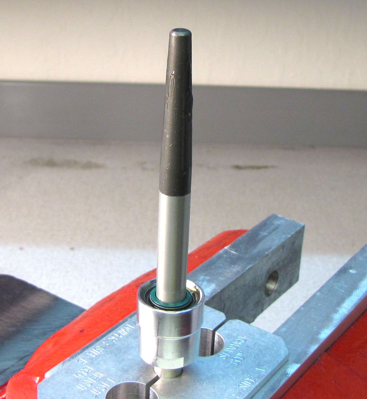
Step 30
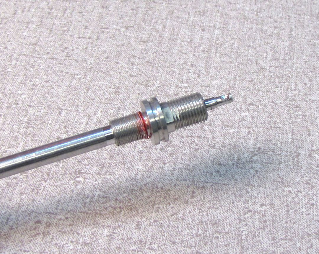
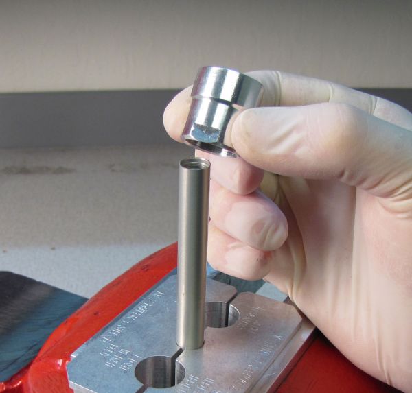
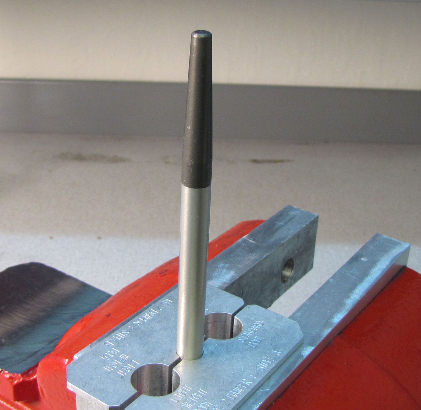
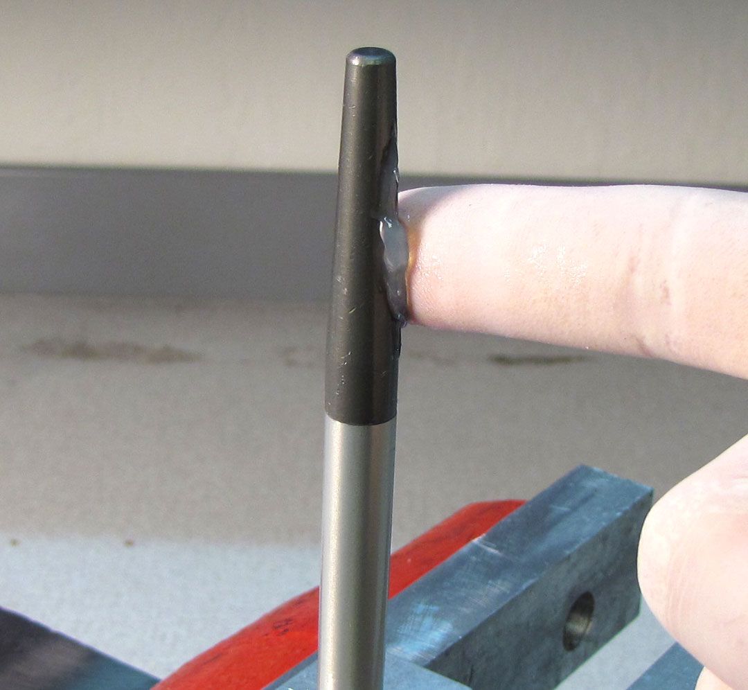
Remove and discard the original sealhead. Install the 10mm bullet tool (PN: 398-00-371 for 10mm shafts or PN: 398-00-320 for 8mm shafts) into the shaft, then coat the bullet with a film of Slick Honey.


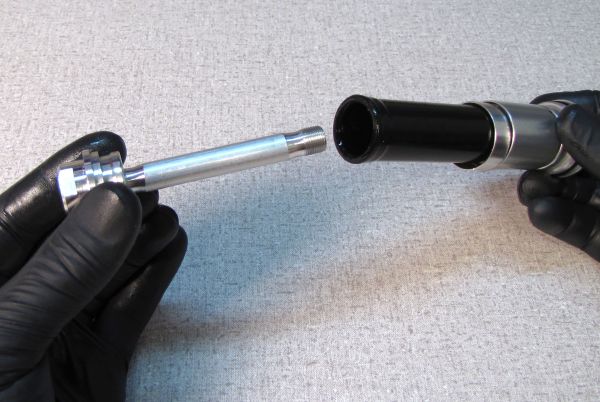
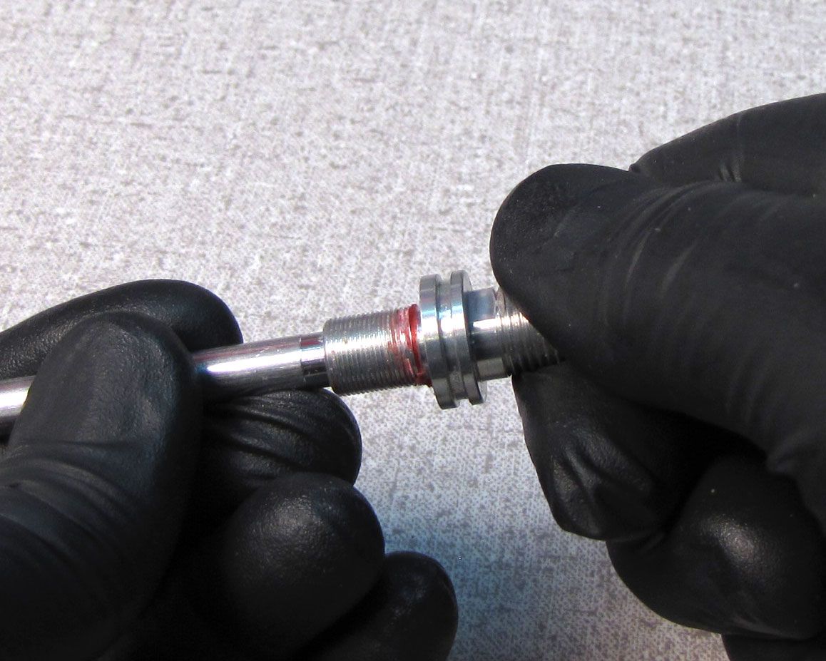
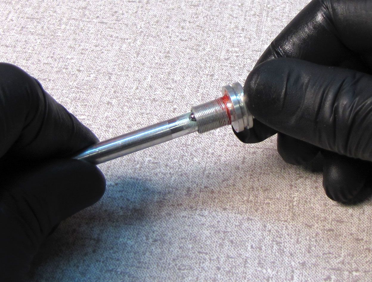
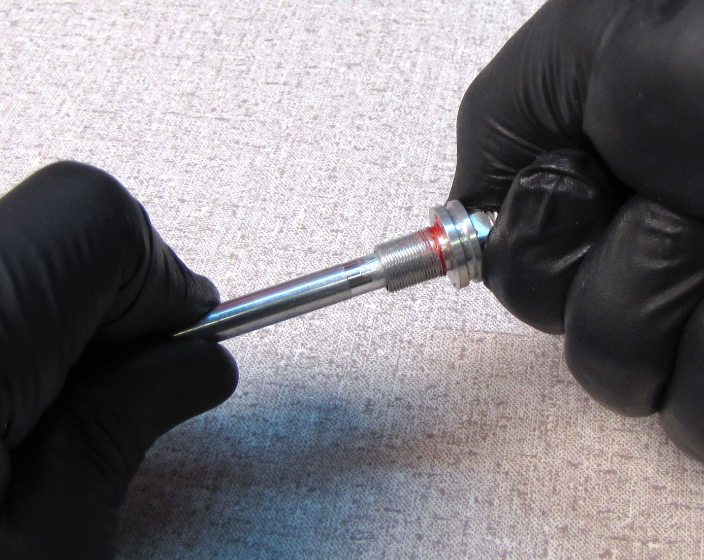
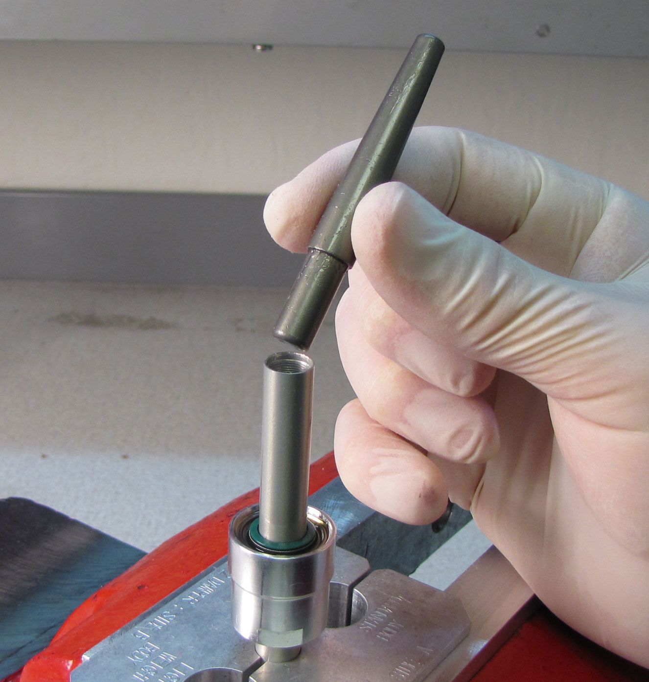
Step 31
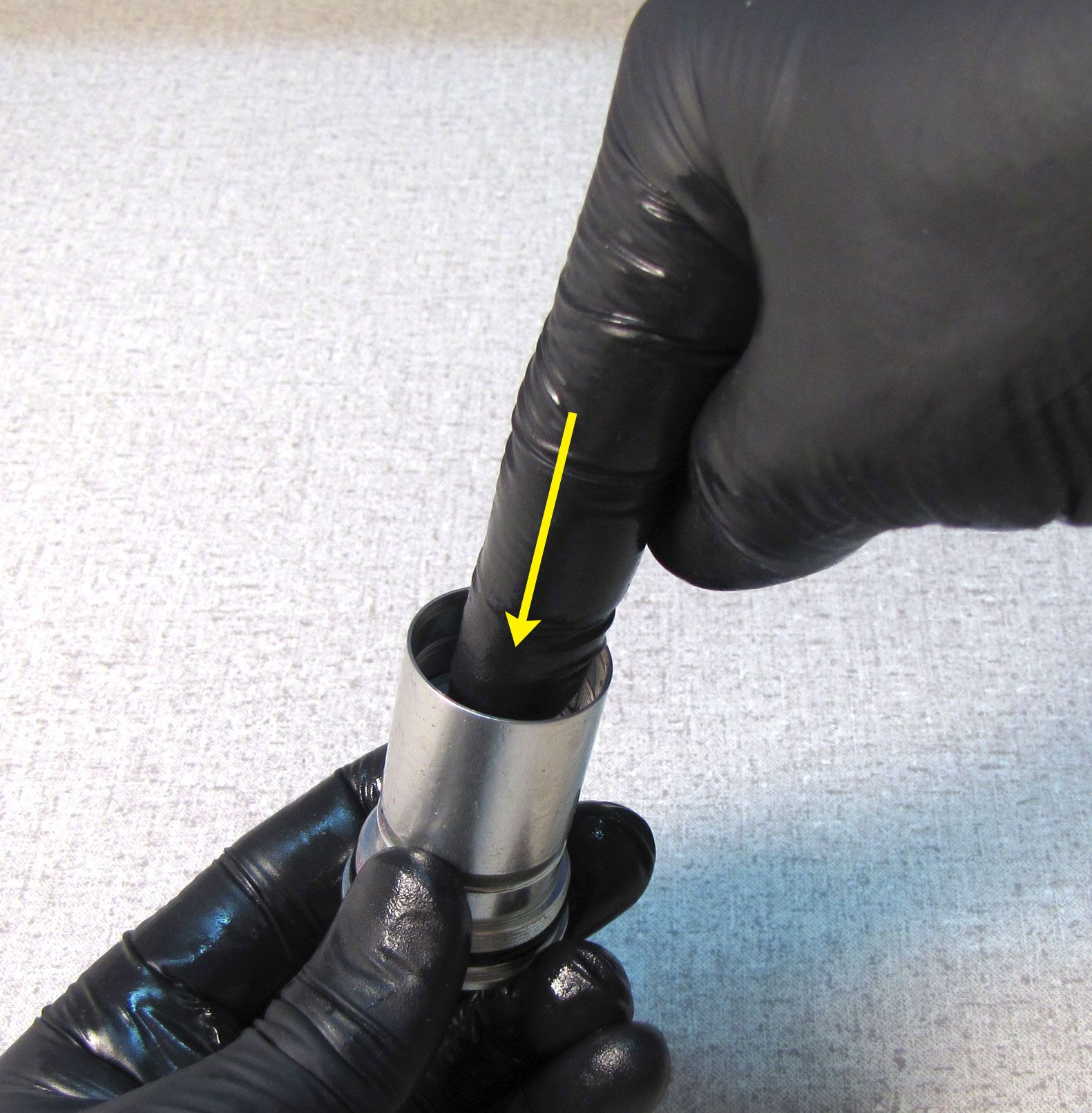
Install the new sealhead from the kit onto the shaft with its threaded end first. Remove the bullet tool.

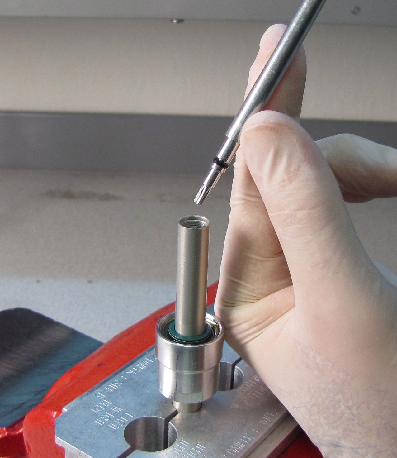
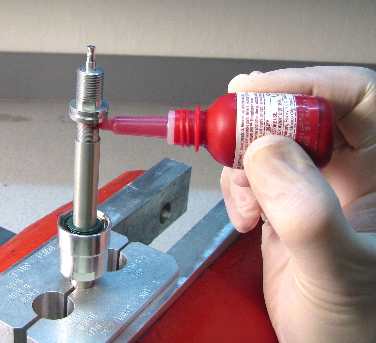
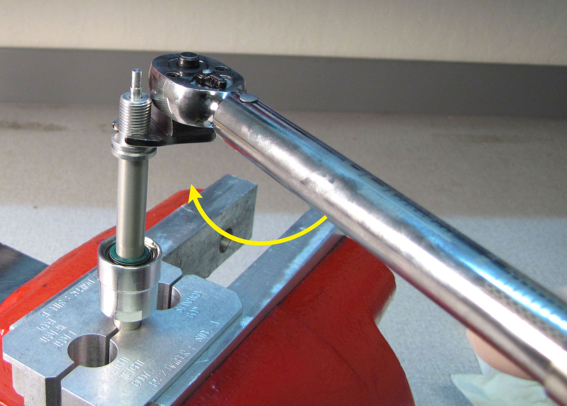
Step 32
Drop the rebound needle and adjuster assembly into the shaft, then apply a drop of Loctite 262 to the rebound adjuster threads. Tighten the rebound adjuster to the shaft to 30 in-lb (3.4 Nm) torque with a 7mm (32mm forks) or 9mm (34mm forks) crows foot.
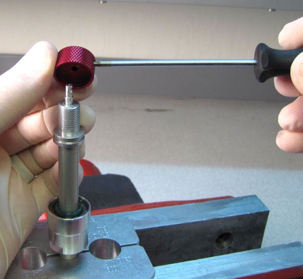
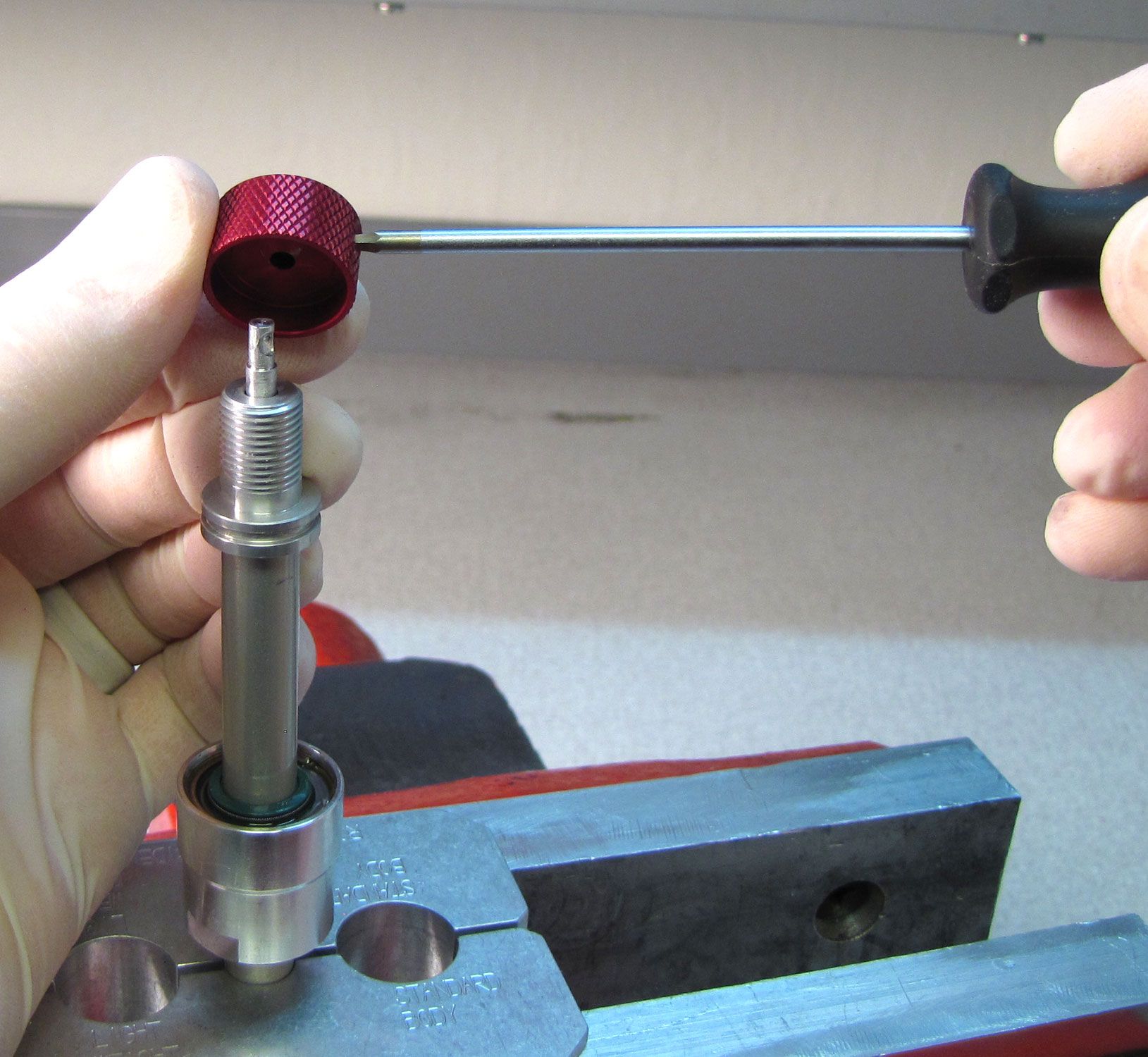
Step 33
Temporarily reinstall the rebound knob with your 2mm hex wrench making sure to allign the set screw with the detent in the rebound needle. Turn the rebound adjuster counter-clockwise to its full open position. Remove the rebound knob.
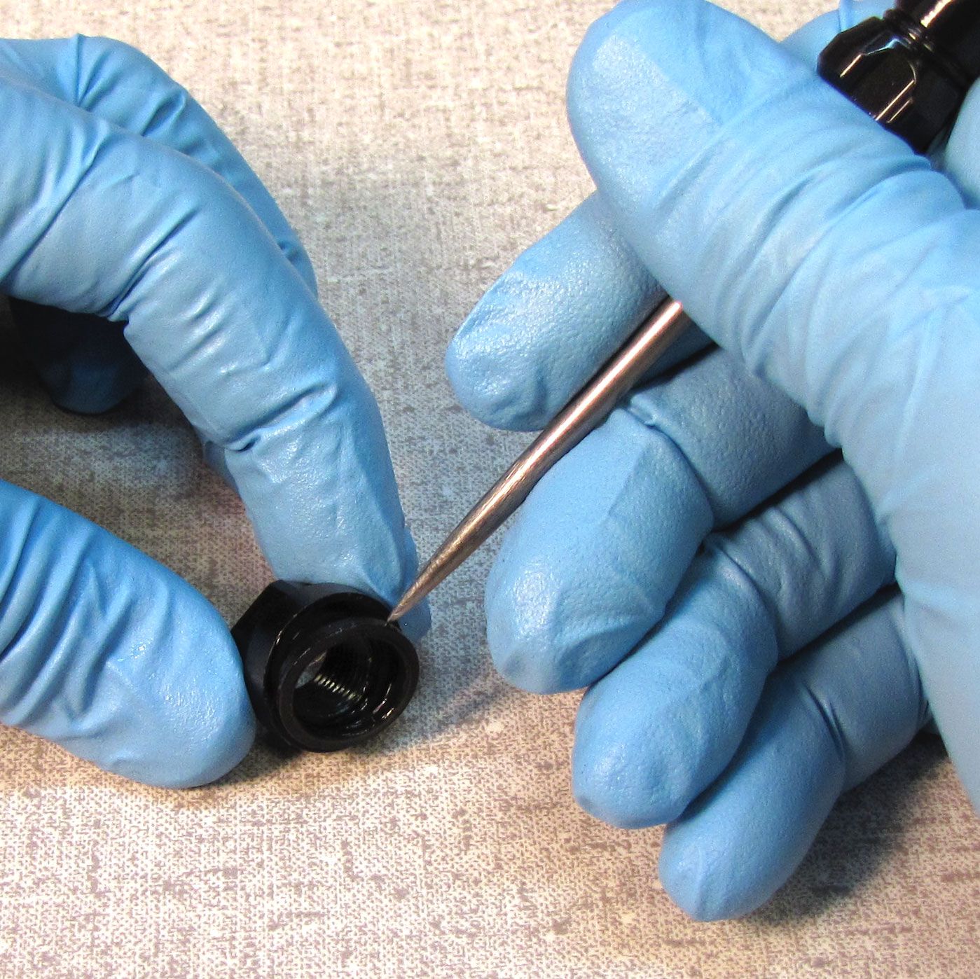
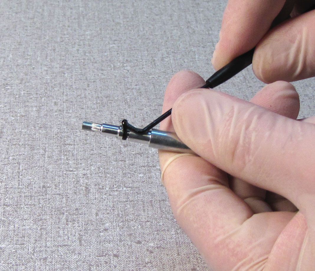
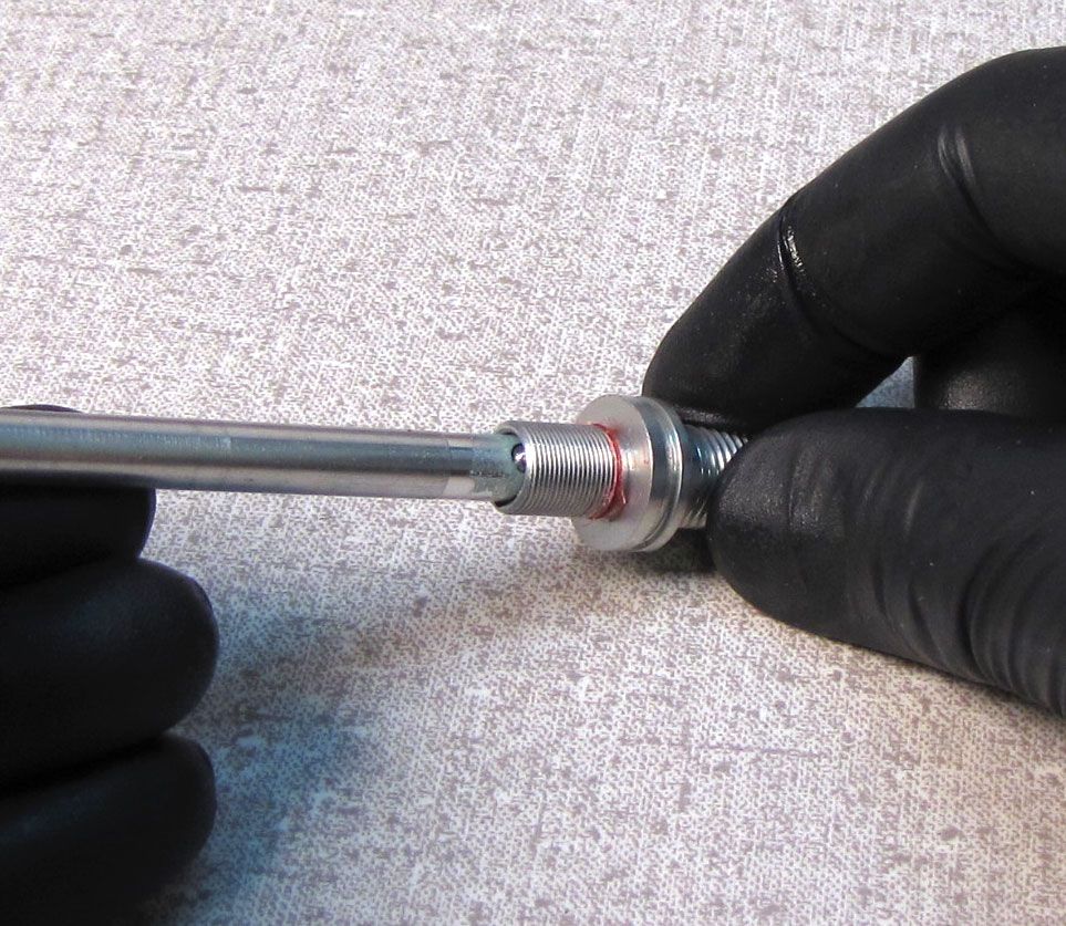
Step 34
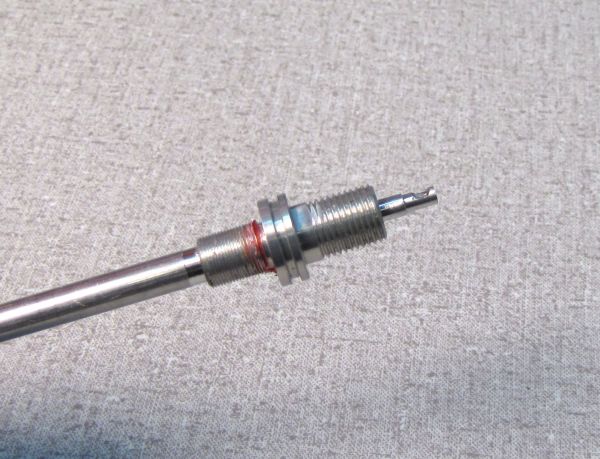
Install a new greased o-ring from the kit onto the rebound adjuster.
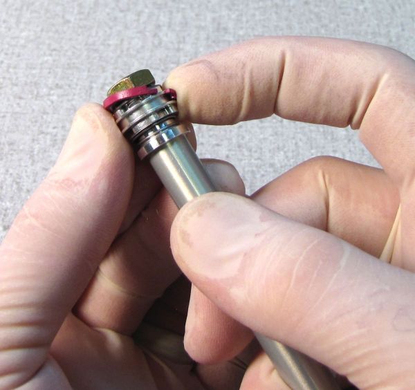
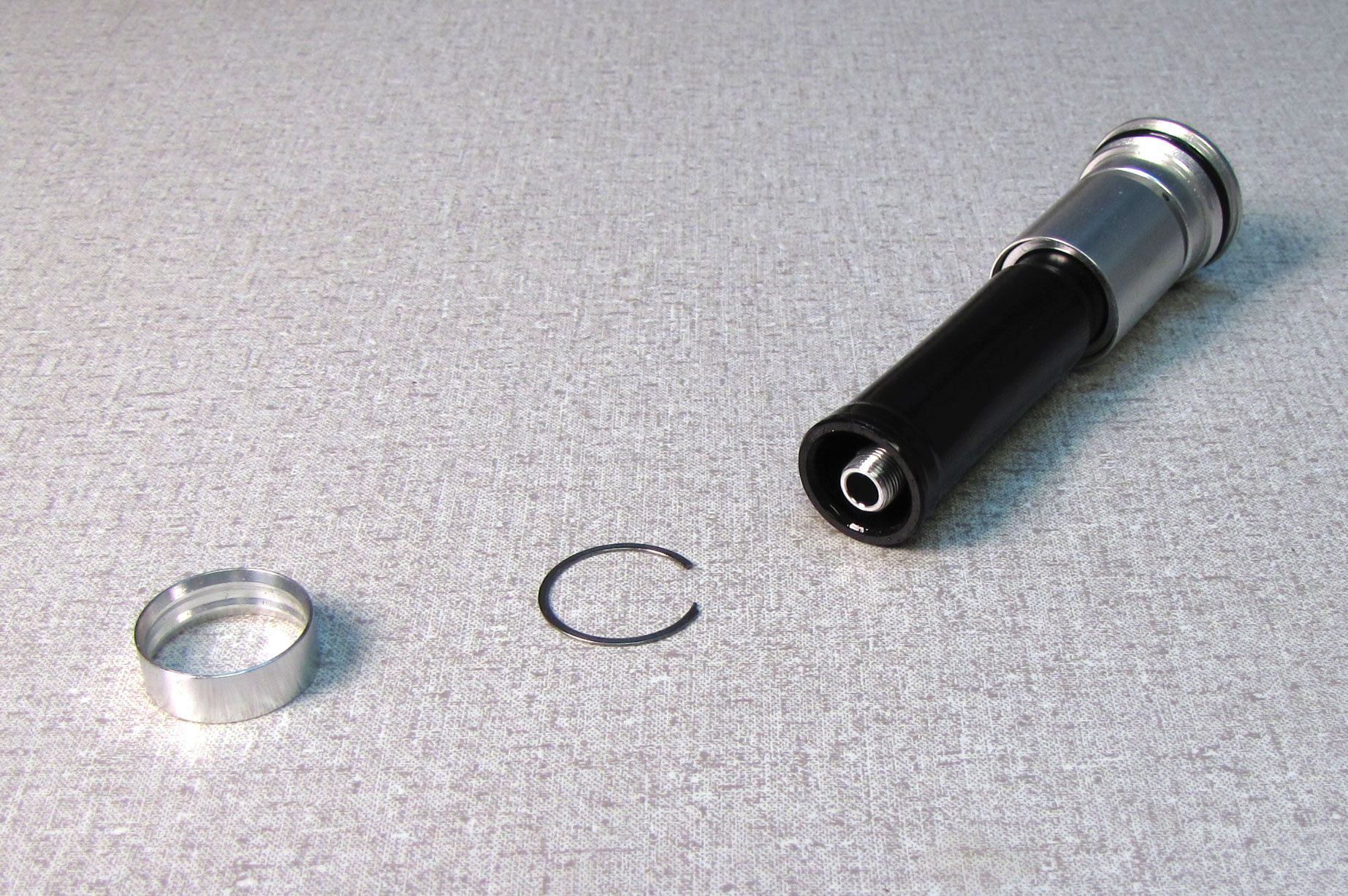
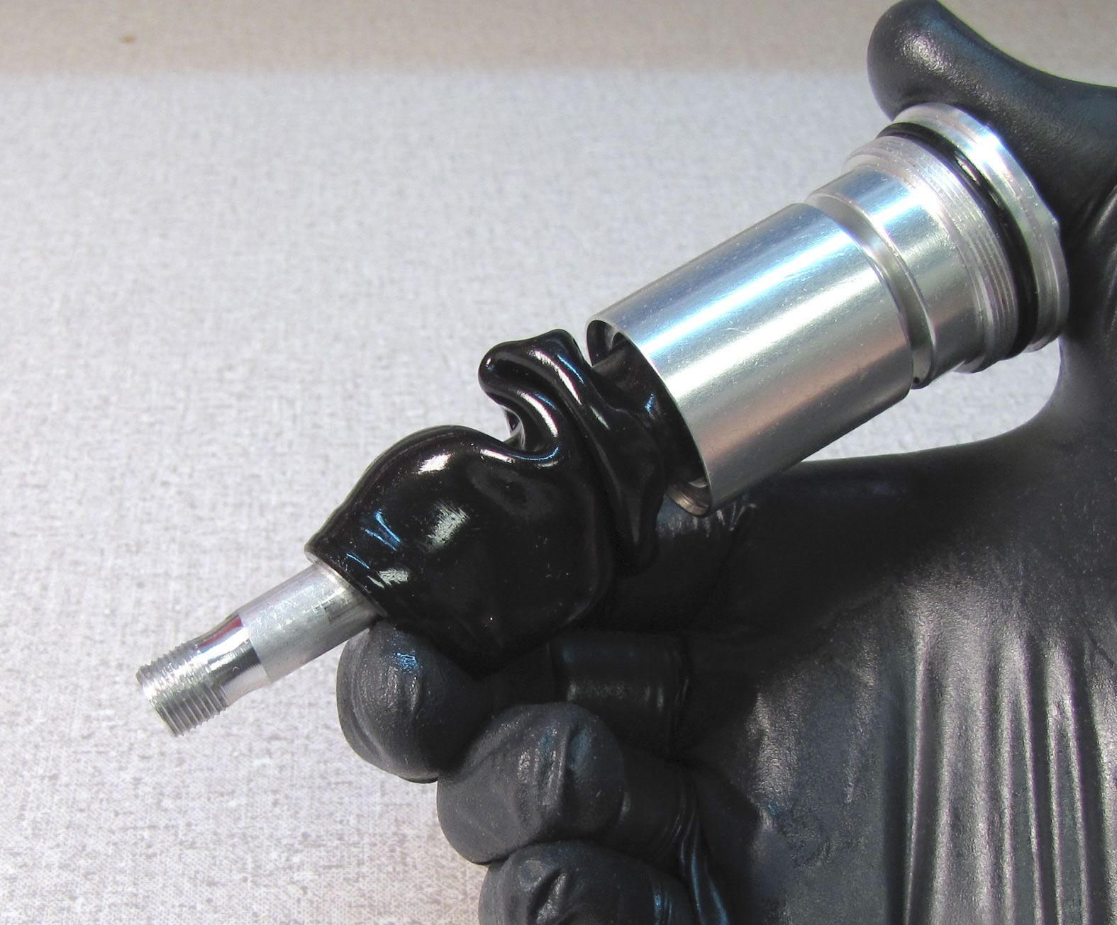
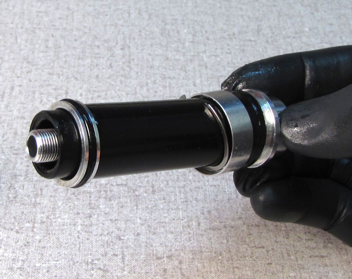
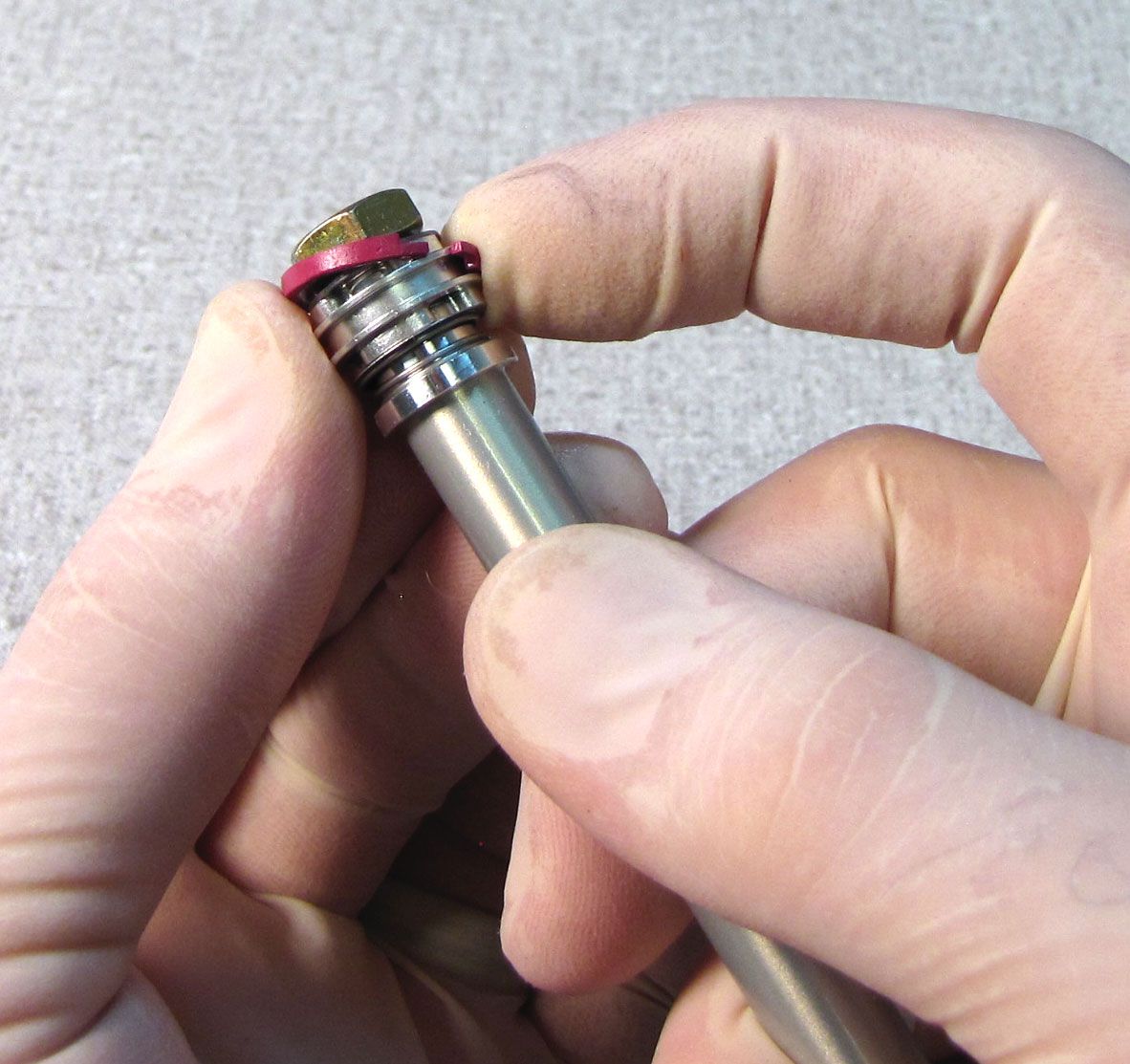
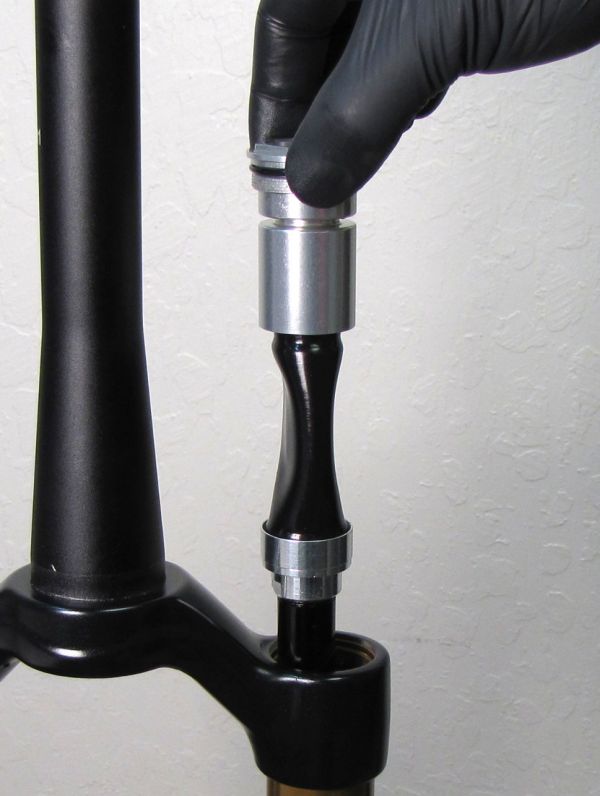
Step 35
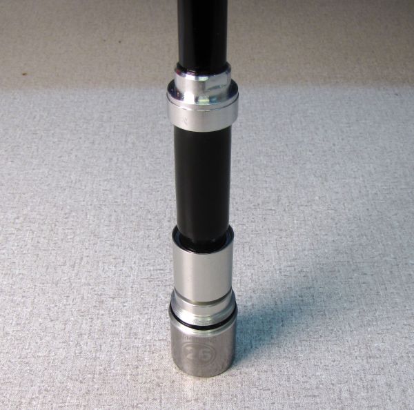
Remove and replace the pink piston glide ring with a new one from the kit. The new glide ring will appear larger than the old one, but will compress once inside the cartridge body. Slide the sealhead all the way toward the rebound piston end.

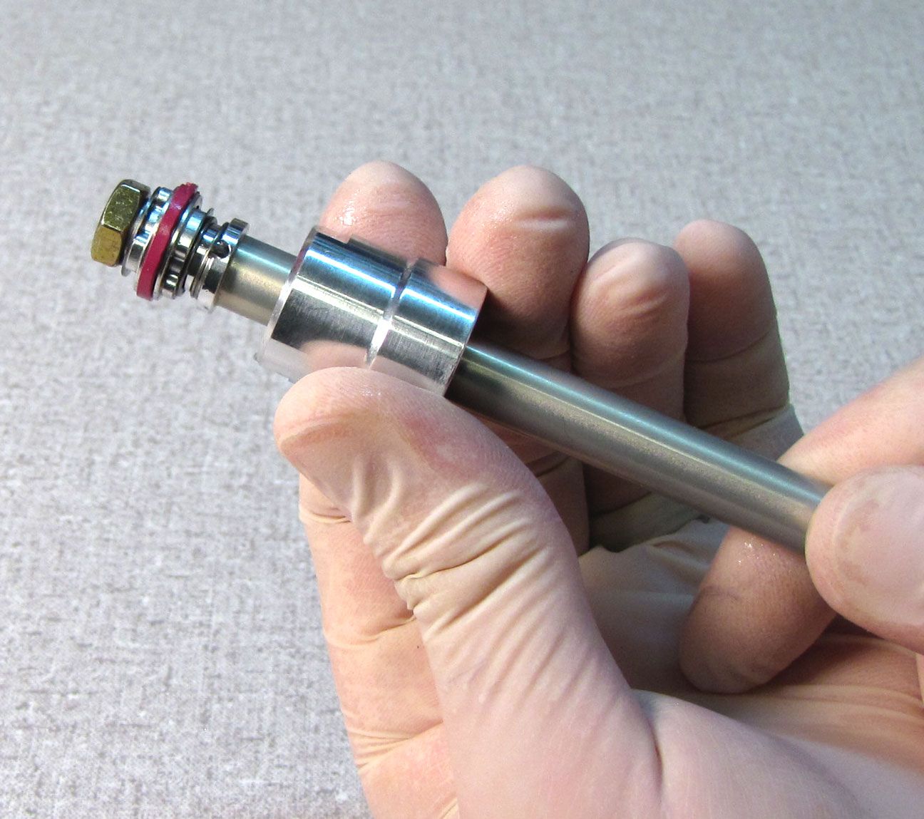
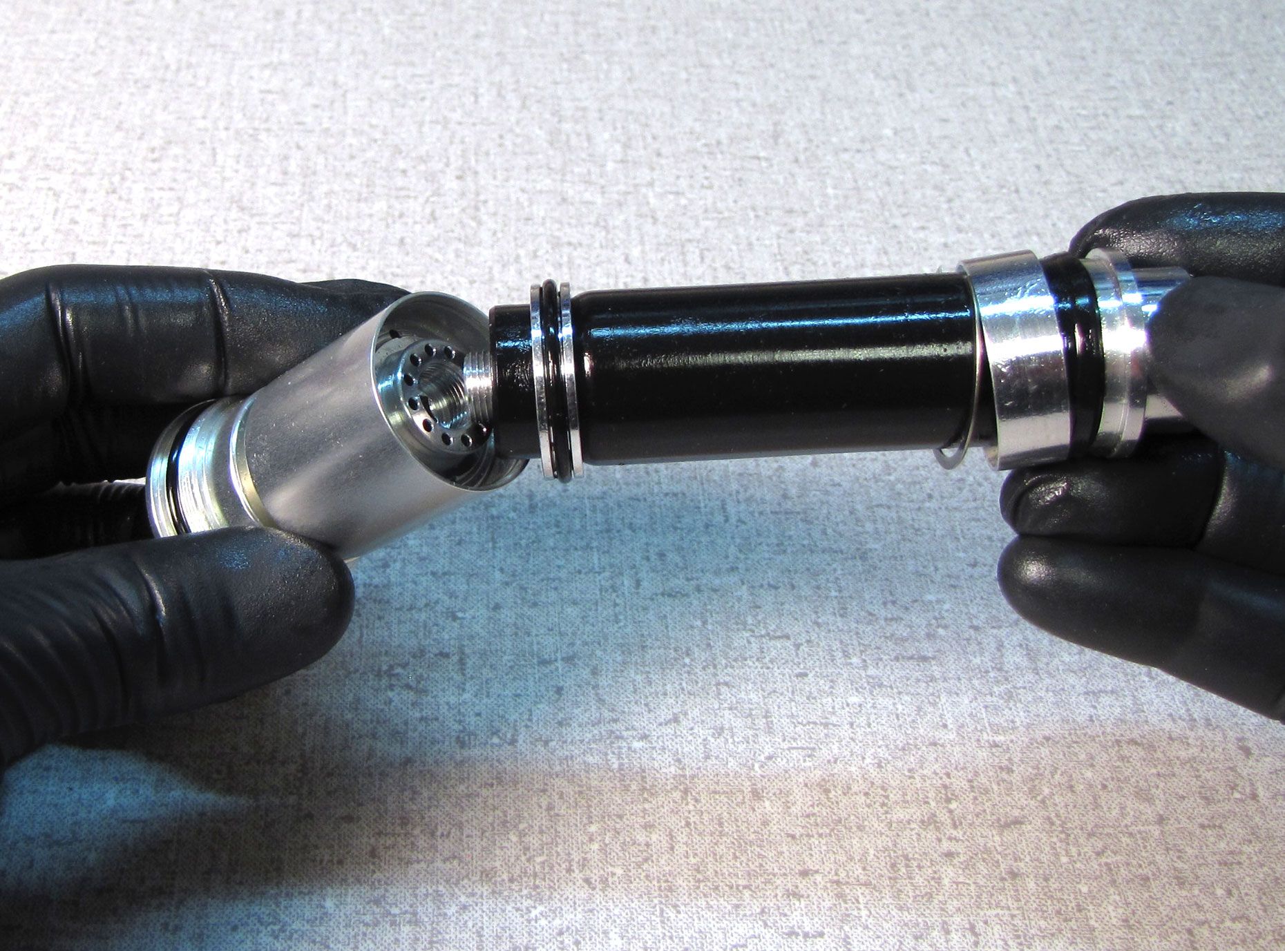
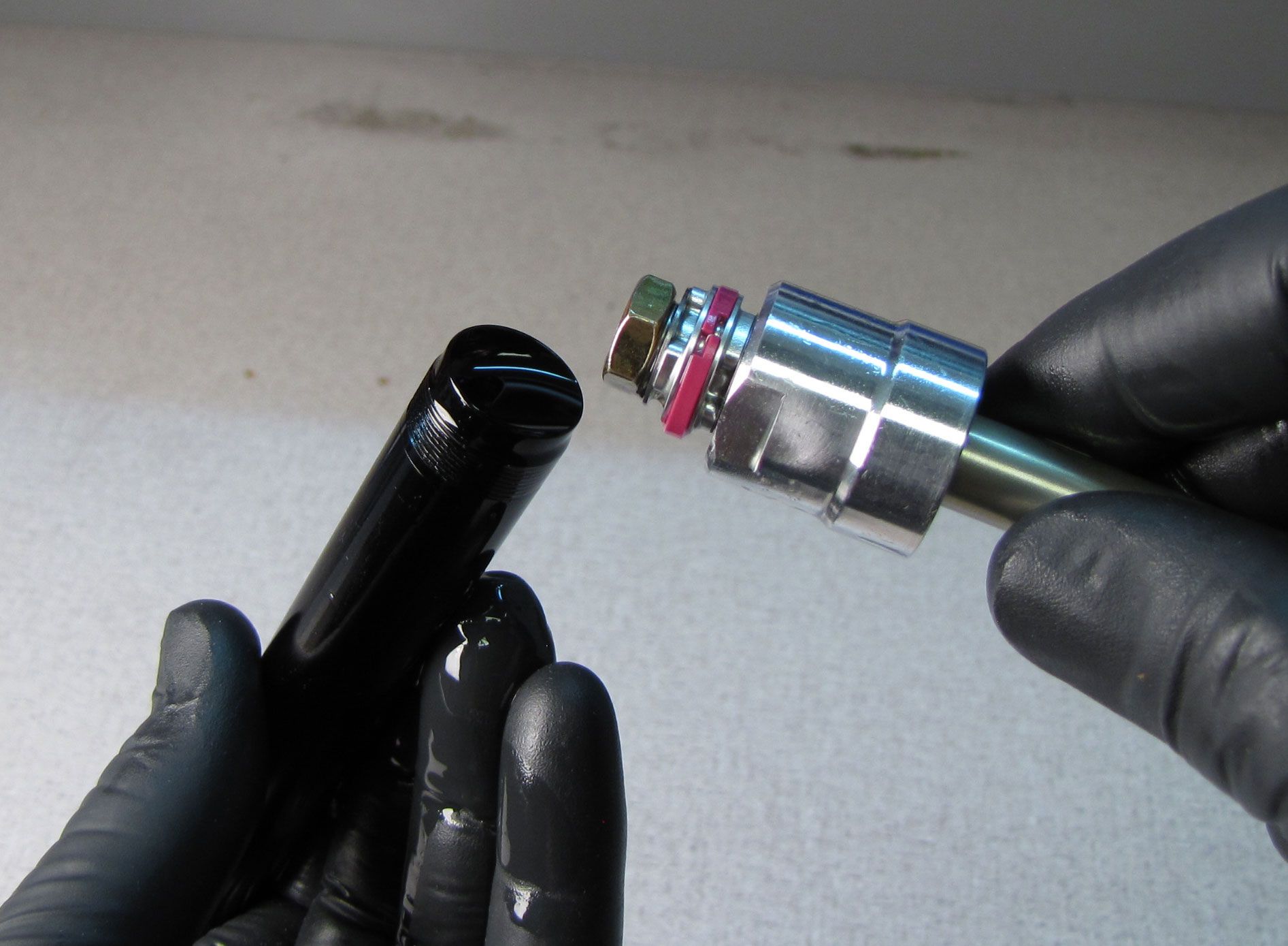
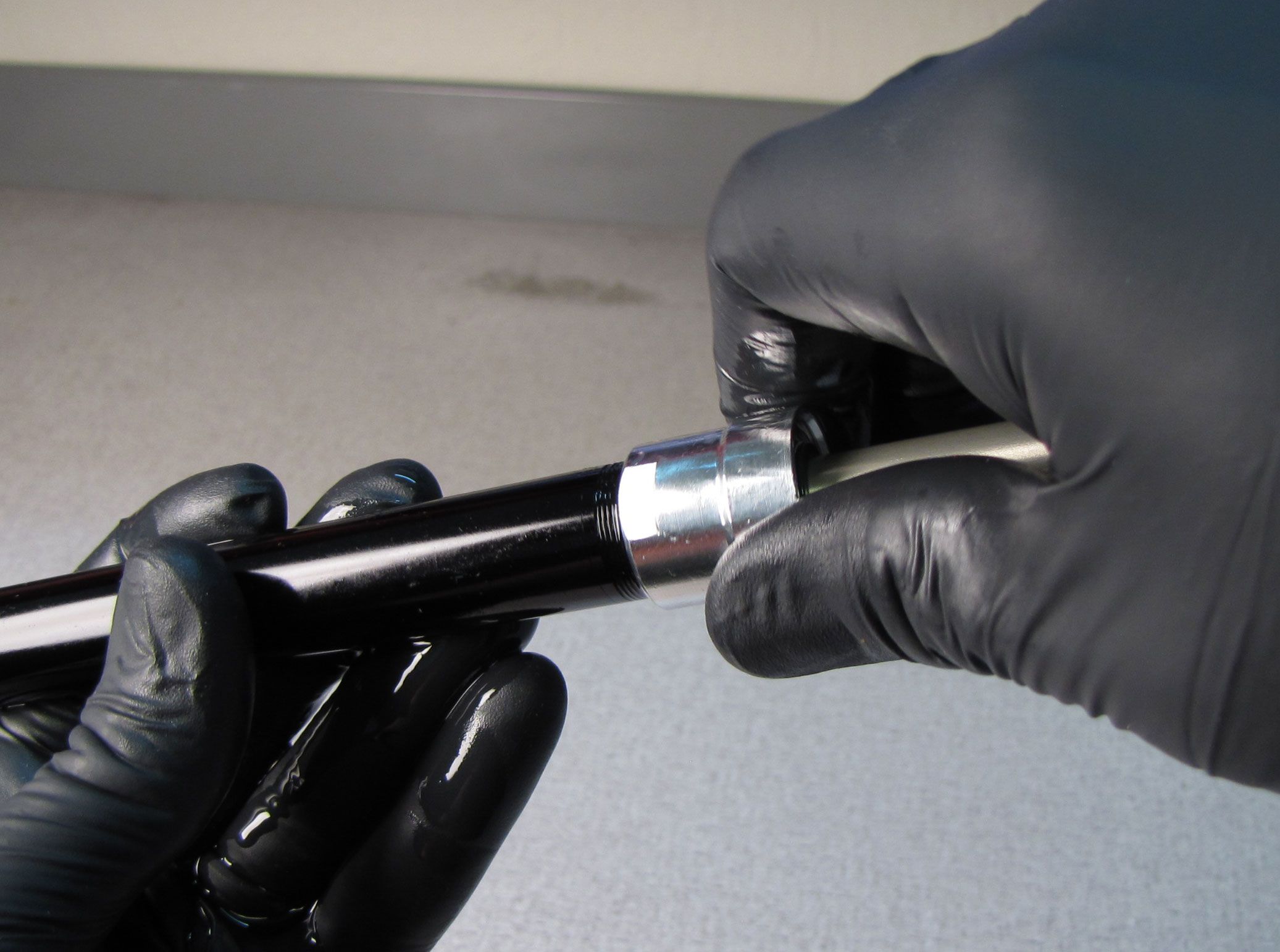
Step 36
Top off the cartridge body with FOX R3 5wt. oil then install the shaft assembly threading the sealhead onto the cartridge body until hand tight.

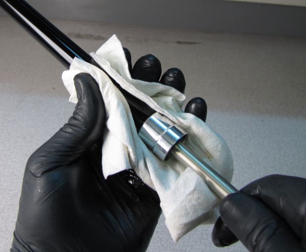
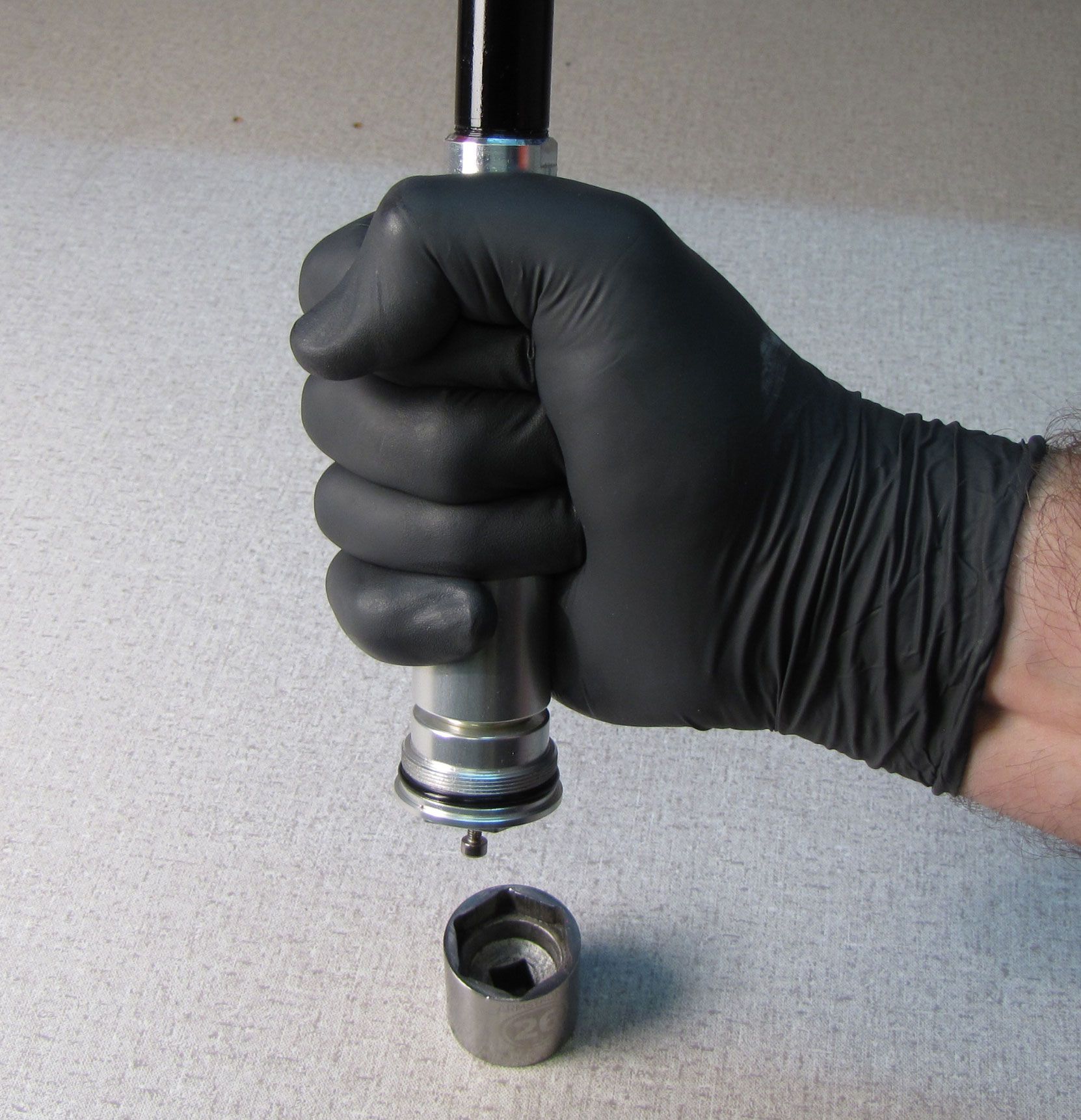
Step 37
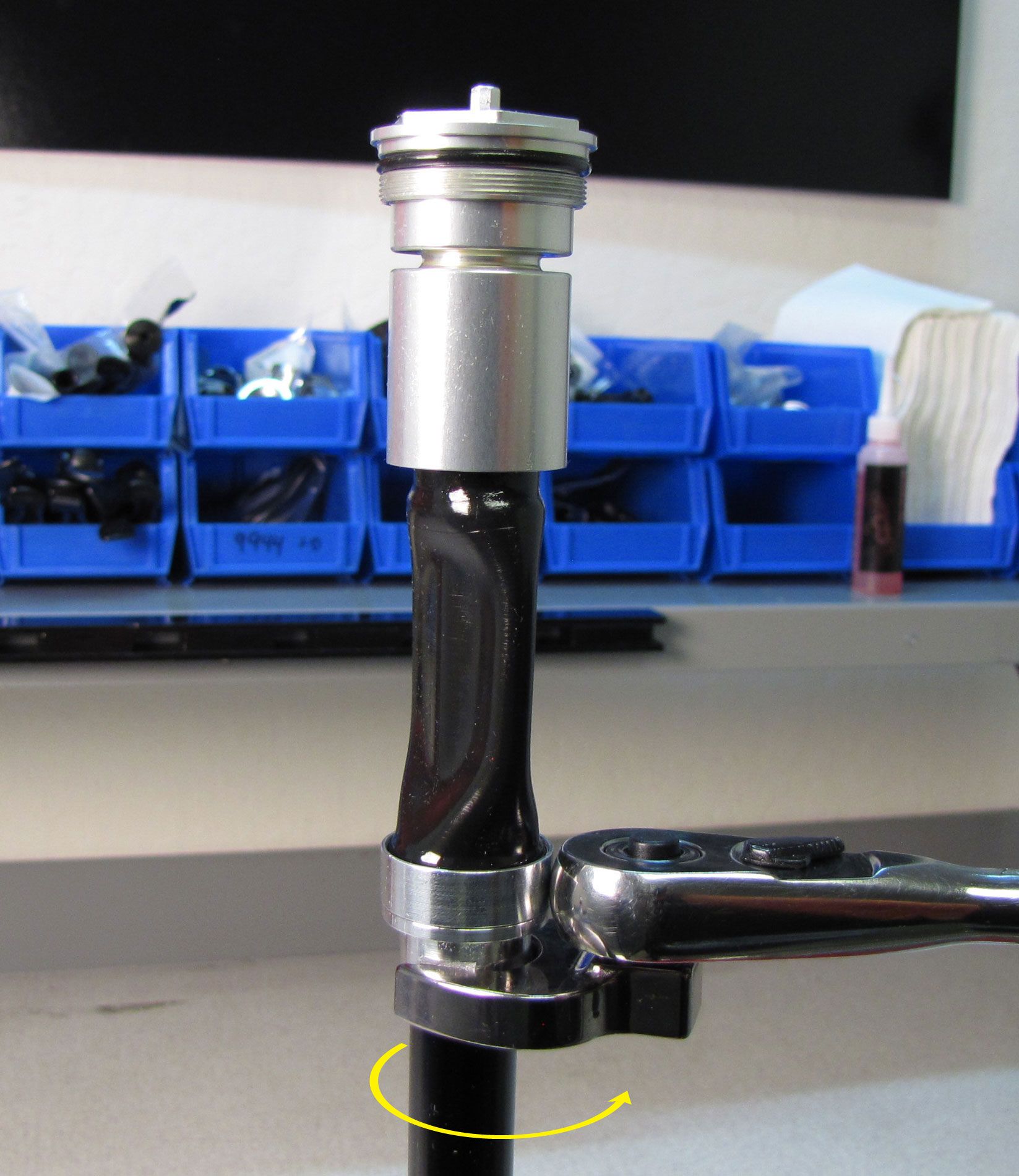
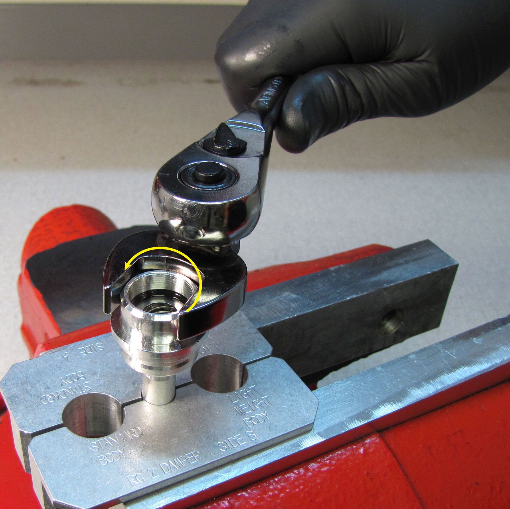
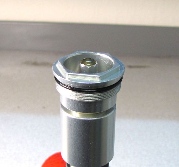
Clean the cartridge body with isopropyl alcohol and a lint-free paper towel, then clamp it in your shaft clamps (PN: 803-00-830). Tighten (clockwise when viewed from below) the sealhead to the cartridge body to 55 in-lb (6.2 Nm) torque with a 19mm crows foot.
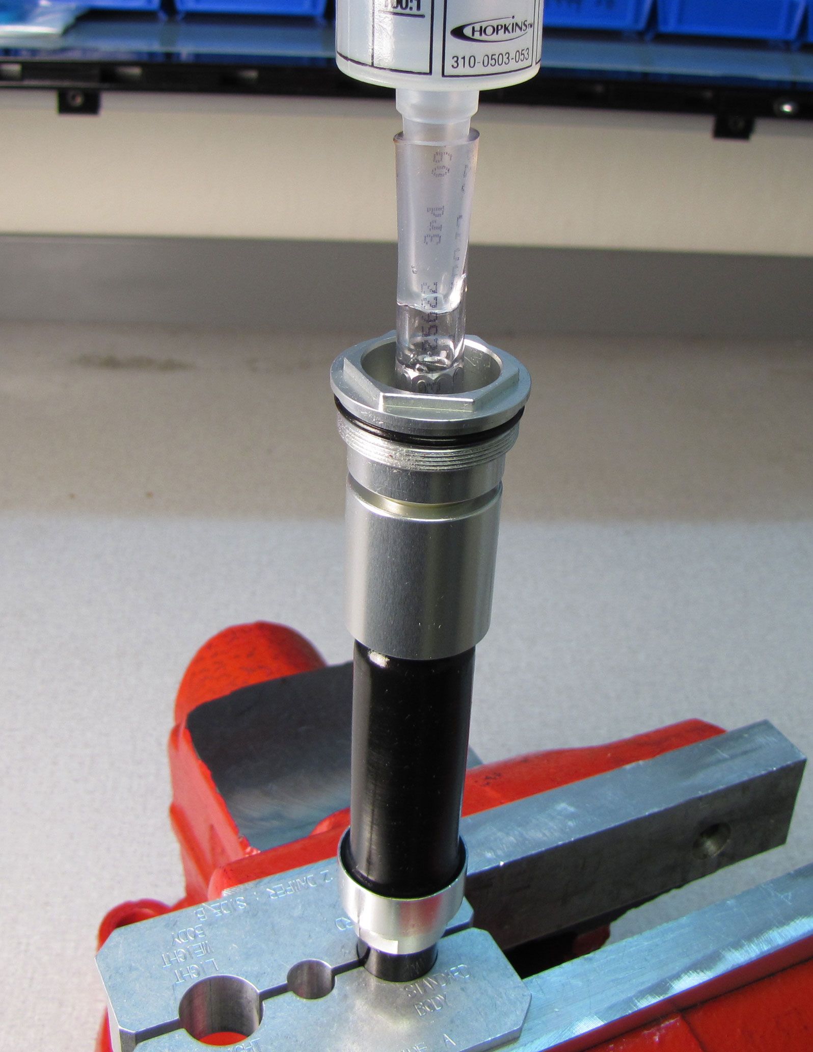
Step 38
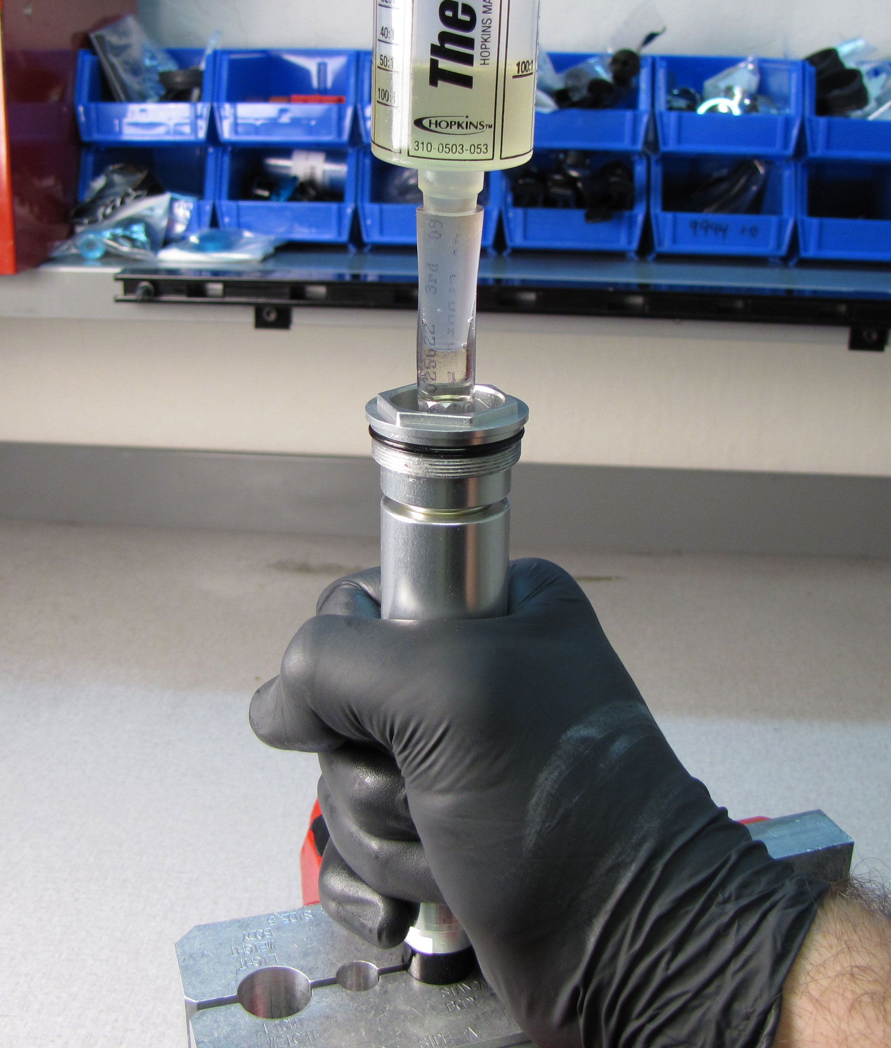
Use a 3mm hex wrench to unthread (counter-clockwise) the bleed screw from within the compression selector shaft. Remove the screw followed by the ball bearing beneath. Install a piece of clear vinyl tubing with an internal diameter of 5/16 inches (~8mm) onto the compression selector shaft. Install a FOX bleeder syringe (with plunger removed) into the vinyl tubing. Make sure that the tubing fits tightly and makes a complete seal. Turn the compression selector shaft to its fully counter-clockwise setting to set the damper in open mode for easiest bleeding.
Step 39
Slowly cycle the shaft up while squeezing the bladder to force any trapped air out into your syringe. Do not release your squeeze on the bladder or cycle the shaft down until all air bubbles in your syringe have risen to the surface. Do not suck bubbles back into the cartridge. Periodically add oil to your syringe so you do not let the syringe go dry as the cartridge ingests oil. Repeat this step until all air trapped in the cartridge is bled out.

Step 40
Remove the bleed syringe and vinyl tubing and top off the compression selector shaft with FOX R3 5wt. oil. Reinstall the ball bearing and bleed screw, tightening to 10 in-lb (1.1 Nm).

Cycle the damper by hand to check that all air was properly bled out of the cartridge in previous steps. If you hear or feel excessive air still trapped within the cartridge, go back to step 39 and try bleeding the cartridge again. The bladder should appear underfilled in this step. This is due to the 2 inch purge performed in step 41 and allows for a longer service life.
Reinstallation Into Fork Chassis
Step 1
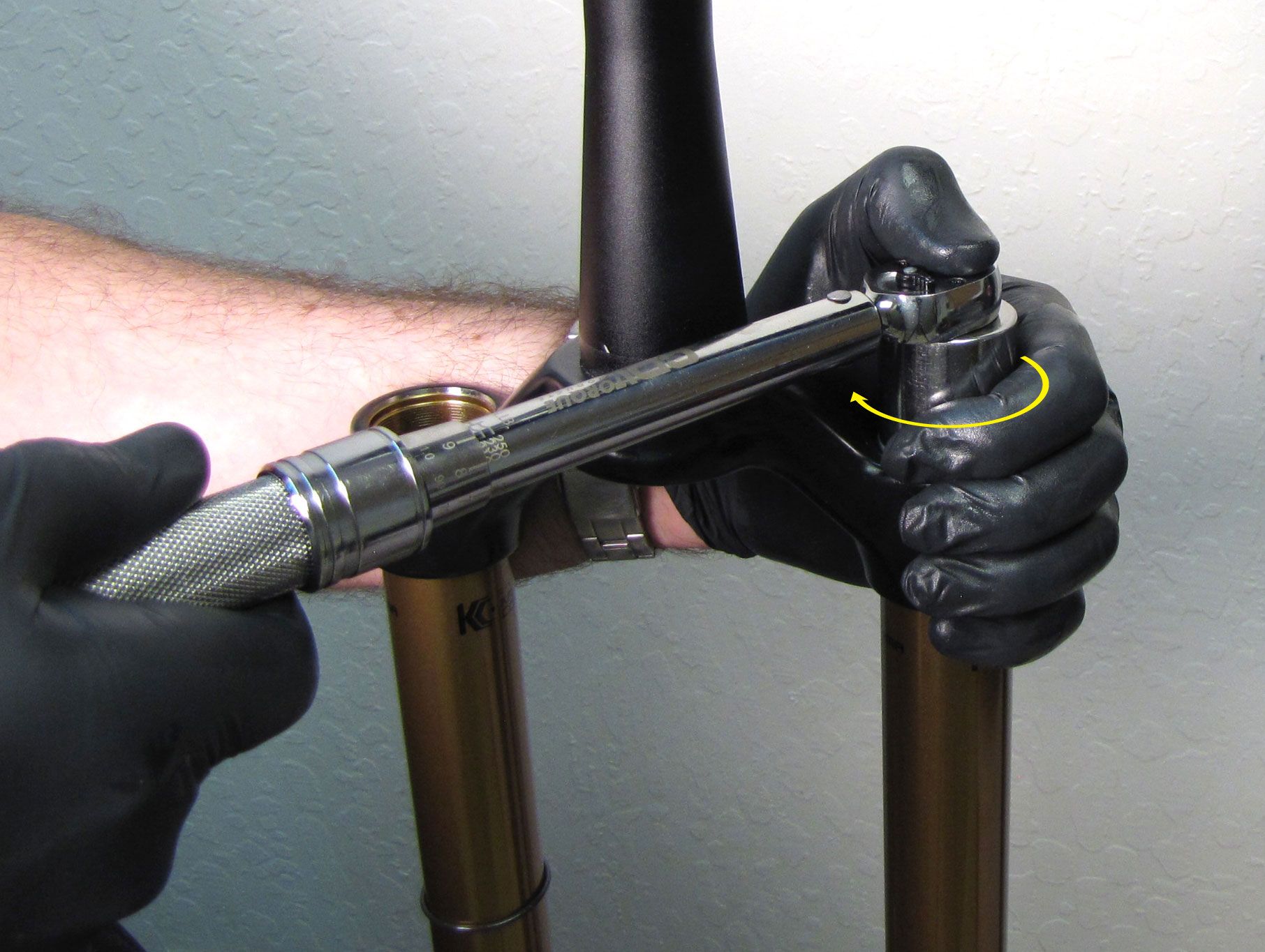
Install the cartridge into the upper tube. Tighten the topcap clockwise to 220 in-lb (24.8 Nm) torque with your 6-point chamfer-less 26mm socket.

Step 2
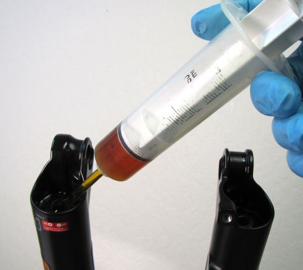
Invert the fork and inject the 15cc of FOX 20wt. Gold oil into the damper side lower leg.
Pre-2016 bath oil volumes can be found under "Fork- Basic Maintenance" by clicking: All Service Procedures »

Step 3
Install a new crush washer into the damper side bottom nut (use a small amount of Slick Honey to retain the crush washer during installation). Install the bottom nut, tightening to 50 in-lb (5.7 Nm) with a 10mm (32mm forks) or 15mm (34mm forks) socket. Use a 2mm hex wrench to reinstall the red rebound knob. Make sure that the set screw lines up with the depression in the rebound adjuster shaft.


Step 4
For Levers: Use the blue lever to set the cartridge to its middle position. Remove the knob and reposition it to point to the rider's three o'clock position. Install the set screw. Hold the blue lever stationary while tightening the set screw to 11 in-lb (1.2 Nm) with your 2.5mm hex wrench. This completes reinstallation for lever equipped forks.
For Remote: Skip to step 5.


Step 5
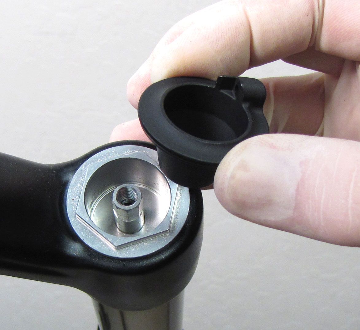
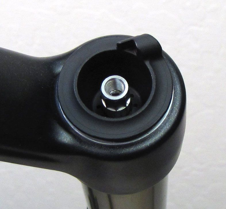
For Remote: Place the black remote housing into the topcap with the cable stop oriented toward the rider's 1 o'clock position.

Step 6
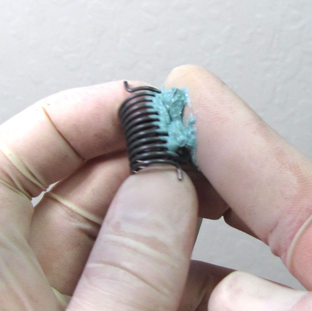
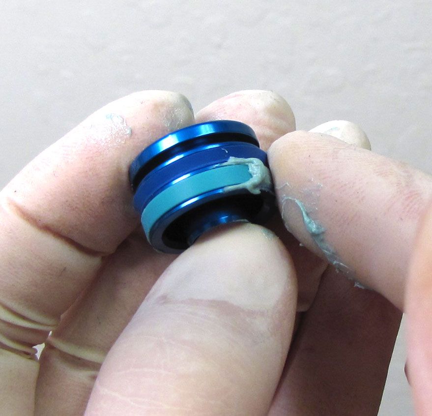
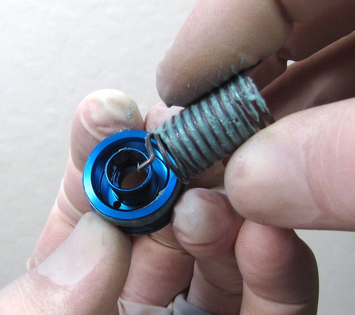
Coat the torsion spring and the blue remote pulley glide ring with a thick film of waterproof grease such as Sta-Lube SL3125 then install one tang of the spring into the hole in the underside of the blue remote pulley.
Step 7
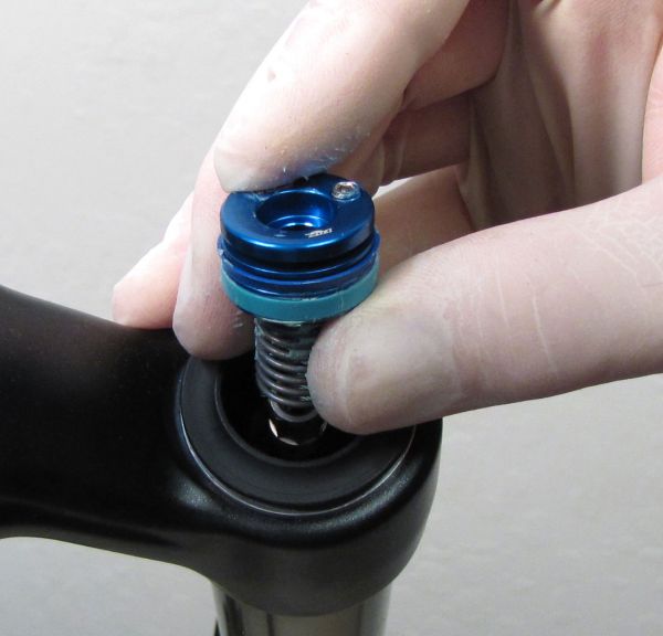
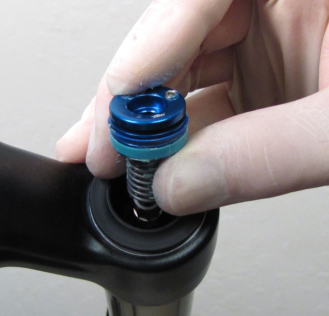
Insert the remote pulley and greased torsion spring into the black remote housing so the pinch bolt is at the rider's 1 o'clock position. Make sure that the bottom spring tang seats into a hole in the black remote housing.

Step 8
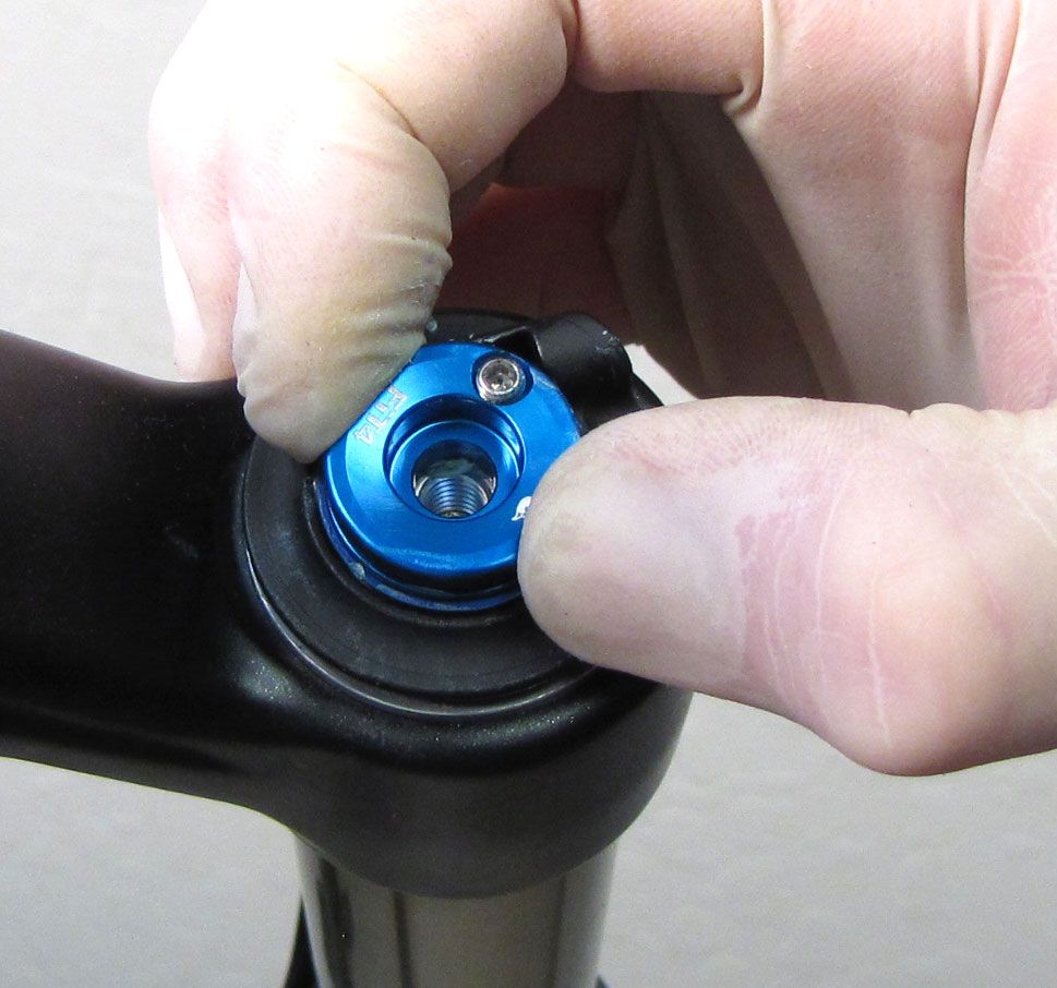
Start the 2.5mm hex screw only 1-2 turns. Do not tighten it fully in this step.


Step 9
Lift up on the black remote housing and rotate counter-clockwise until the cable stop is oriented toward the riders 7 o'clock position (180 degrees). Lower the black remote housing back onto the topcap wrench flats. If you cannot lift the black remote housing, try loosening the 2.5mm hex screw until it retains the knobs while allowing you to lift the black housing past the topcap wrench flats to rotate it.
Step 10
Hold the blue pulley from rotating while you tighten the 2.5mm hex screw to 11 in-lb (1.2 Nm).

Clean the exterior of your fork and test all of its functions before reinstalling onto the bike.