2016-2017 36mm/40mm F-S/P-Se FIT HSC/LSC (RC2) Damper Cartridge Rebuild
Required Parts
- 025-03-010 Oil: AM, FOX Bath Oil [32 oz.], 20 WT Gold
- 025-06-007 Oil: Suspension Fluid [1.00 Quart] R3, 5WT, ISO 15
- 803-00-501 Service Set: Seal Kit, 2011 36 & 40 Inverted RC2 Cartridge
Required Tools
- 398-00-371 Tooling: Sealhead To Shaft Bullet, 10mm
- 398-00-682 2005-017 34-36-40 Damper-side Removal Tool
- 803-00-147 Kit: Shaft Clamps, FORX, Set #2
- 803-00-276 Service Kit: Hand Bleed, Syringe and Tube, 2010 32 Fit RL-RLC Cartridge
- 803-00-830 Service Set: Tooling: 2014 RC2, Shaft Clamps
Supplies Needed
- 1.5mm Hex Wrench
- 10mm Crow's Foot
- 10mm Socket
- 10mm Wrench
- 15mm Crow's Foot
- 15mm Socket
- 15mm wrench
- 16mm Socket
- 2.5mm Hex Wrench
- 21mm Crow's Foot
- 21mm Wrench
- 2mm Hex Wrench
- 5mm Hex Wrench
- 6-point Chamfer-less 32mm Socket
- Magnet
- Mallet
- Propane Torch
- Ratchet
- Seal Pick
- Thin 10mm wrench
- Torque Wrench
- 32mm 6-point Chamfer-less Box-end Wrench Available for purchase at RockyMtnAtv.com
WARNING: Always wear safety glasses and protective gloves during service to prevent potential injury. Failure to wear protective equipment during service may lead to SERIOUS INJURY OR DEATH.
The following procedure guides you through the rebuild of the 36mm/40mm F-S/P-Se FIT HSC/LSC (RC2) damper cartridge.
Complete part information and technical drawings for 2016 36mm forks can be found by clicking: 36mm Part Information »
To link directly to the technical drawings for the 2016 36mm F-S/P-Se FIT HSC/LSC (RC2) cartridge and its assemblies, click here »
Complete part information and technical drawings for 2016 40mm forks can be found by clicking: 40mm Part Information »
To link directly to the technical drawings for the 2016 40mm F-S/P-Se FIT HSC/LSC (RC2) cartridge and its assemblies, click here »
WARNING: FOX products should be serviced by a trained bicycle service technician, in accordance with FOX specifications. If you have any doubt whether or not you can properly service your FOX product, then DO NOT attempt it. Improperly serviced products can fail, causing the rider to lose control resulting in SERIOUS INJURY OR DEATH.
WARNING: FOX suspension products contain pressurized nitrogen, air, oil, or all 3. Suspension misuse can cause property damage, SERIOUS INJURY OR DEATH. DO NOT puncture, incinerate or crush any portion of a FOX suspension product. DO NOT attempt to disassemble any portion of a FOX suspension product, unless expressly instructed to do so by the applicable FOX technical documentation, and then ONLY while strictly adhering to all FOX instructions and warnings in that instance.
WARNING: Modification, improper service, or use of aftermarket replacement parts with FOX forks and shocks may cause the product to malfunction, resulting in SERIOUS INJURY OR DEATH. DO NOT modify any part of a fork or shock, including the fork brace (lower leg cross brace), crown, steerer, upper and lower leg tubes, or internal parts, except as instructed herein. Any unauthorized modification may void the warranty, and may cause failure or the fork or shock, resulting in SERIOUS INJURY OR DEATH.
Removal From Fork Chassis
Step 1
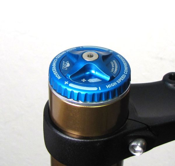
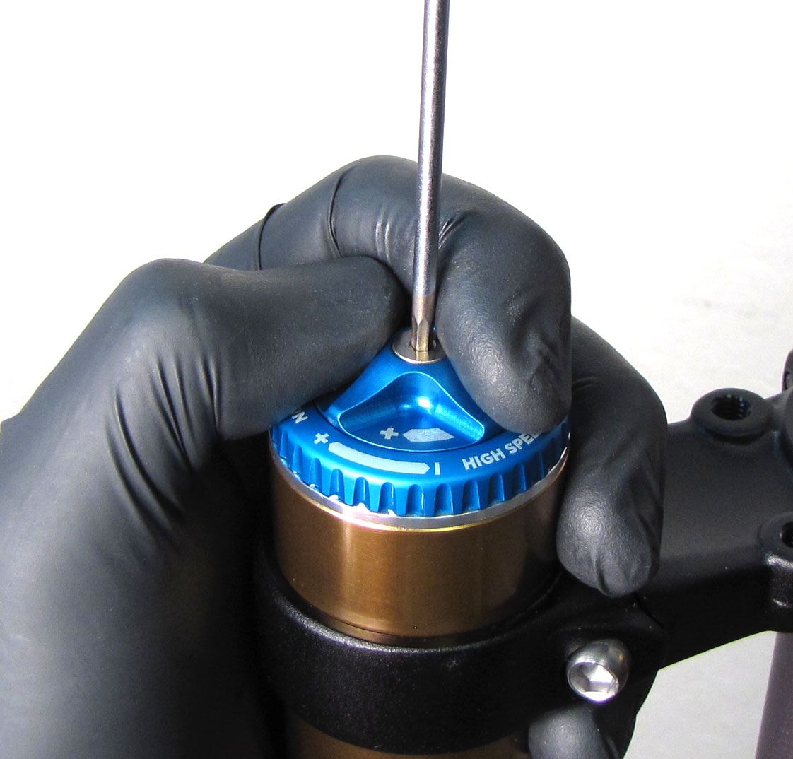
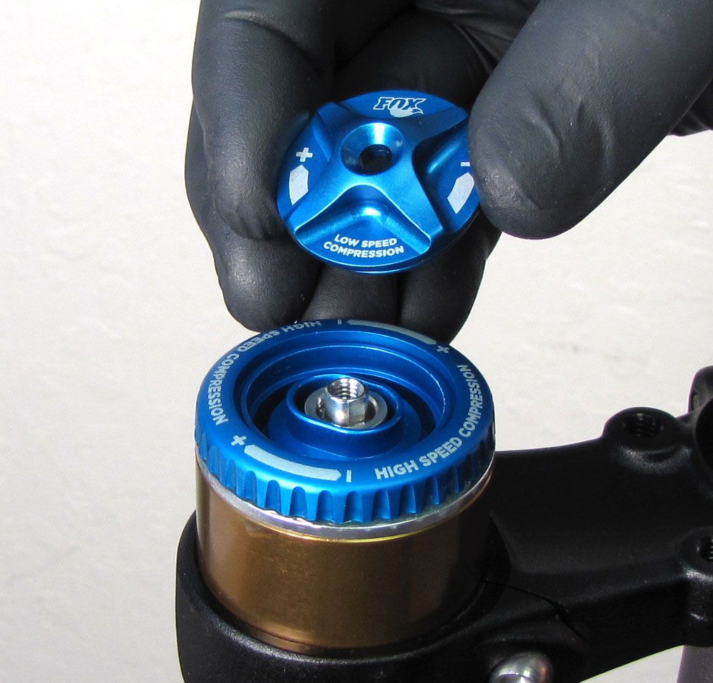
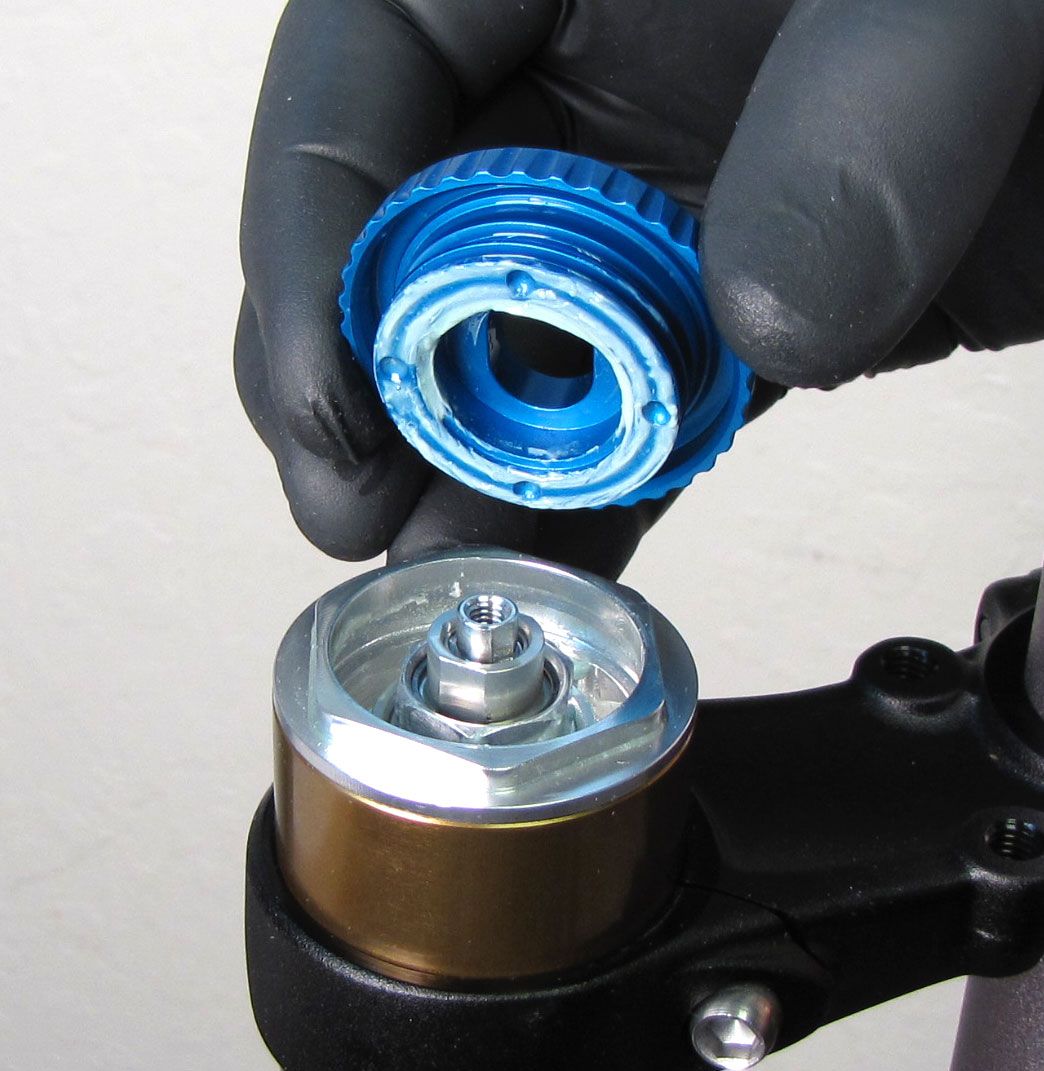
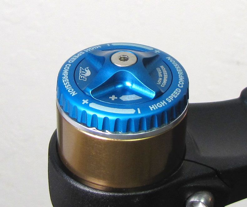
Set both compression adjusters to their open (fully counter-clockwise) positions, then hold the low-speed compression knob from turning while you unscrew (counter-clockwise) and remove the 2.5mm hex screw. Remove the compression knobs making sure to check for detent balls stuck to the bottom of the high-speed compression knob. Remove both detent balls and springs and set aside.


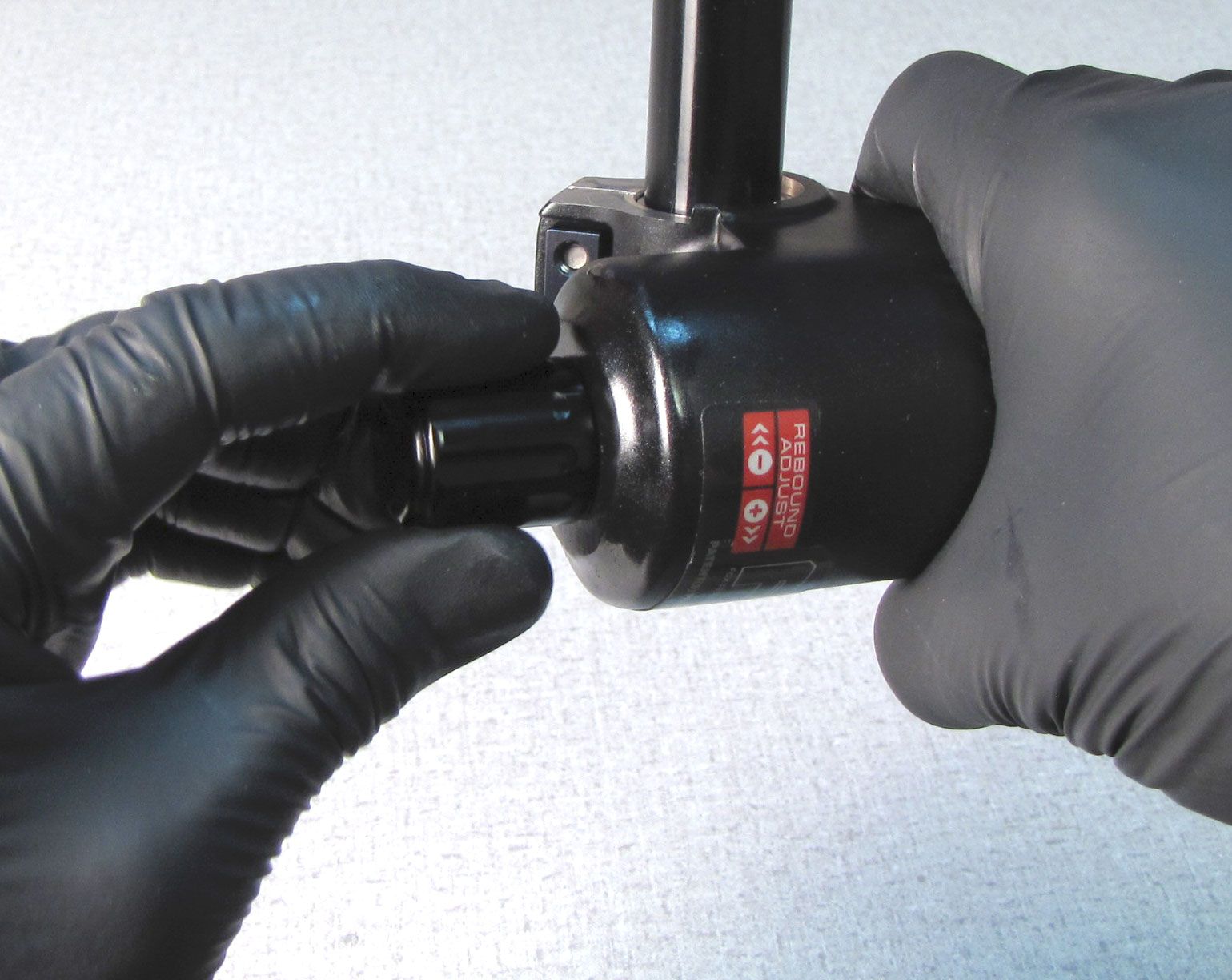
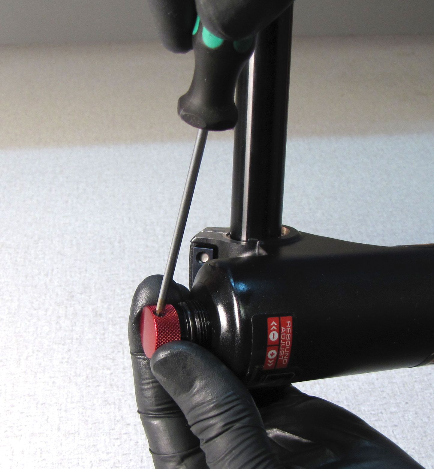
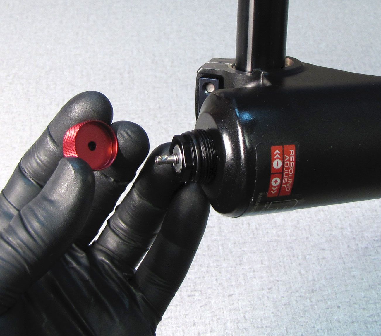
Step 2
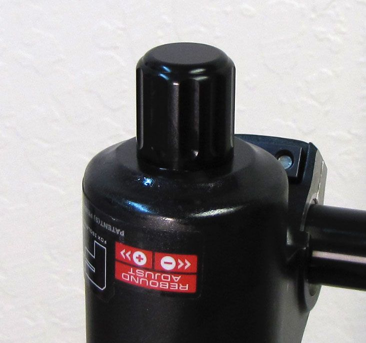
With the fork slightly inverted (the bottom of the fork up past horizontal), remove the black cover, turn the red rebound knob fully counter-clockwise, then use a 2mm hex wrench to remove the rebound knob.
Step 3
Use a 15mm socket to remove the damper side bottom nut. Make sure to remove and discard the orginal crushwasher which may be stuck to the bottom nut.
Step 4
Use Damper Removal Tool 398-00-682 to dislodge the shaft from the lowers. Make sure that you have approximately half of the available threads engaged with your tool before striking with your mallet. Remove the damper removal tool, then bring the fork upright over an oil basin to drain.
Step 5
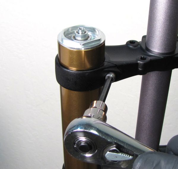
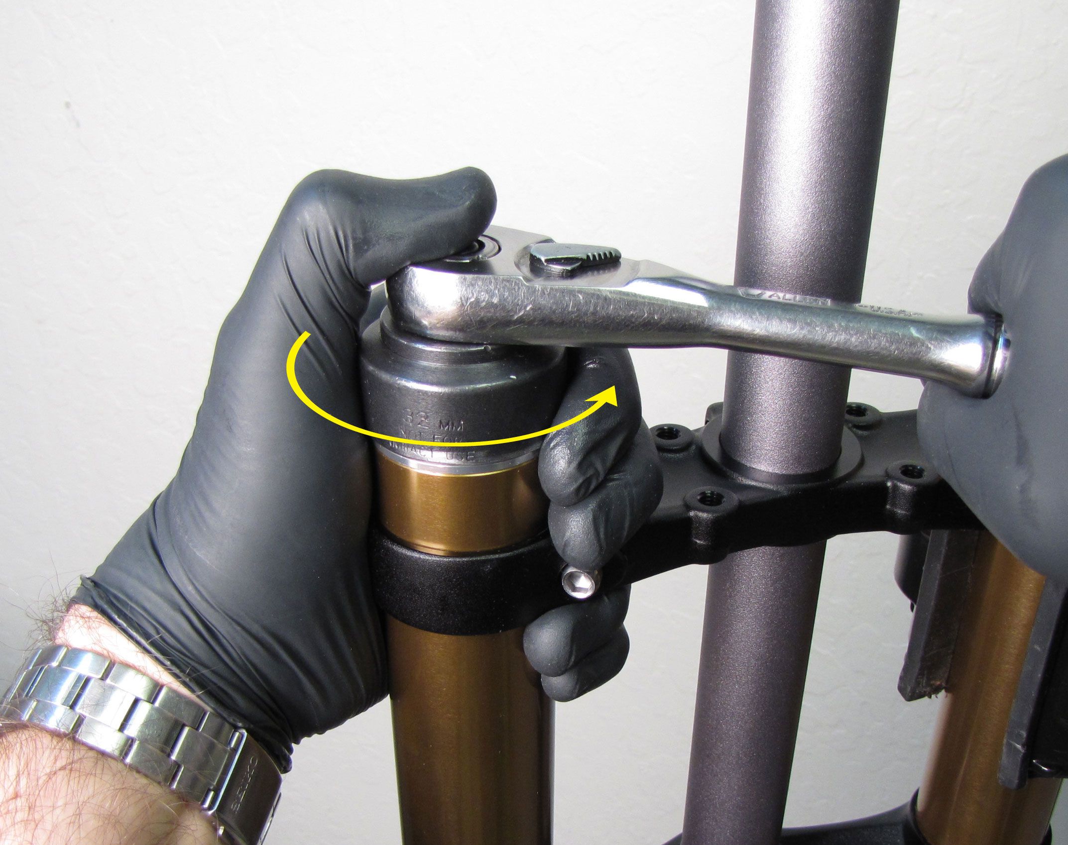
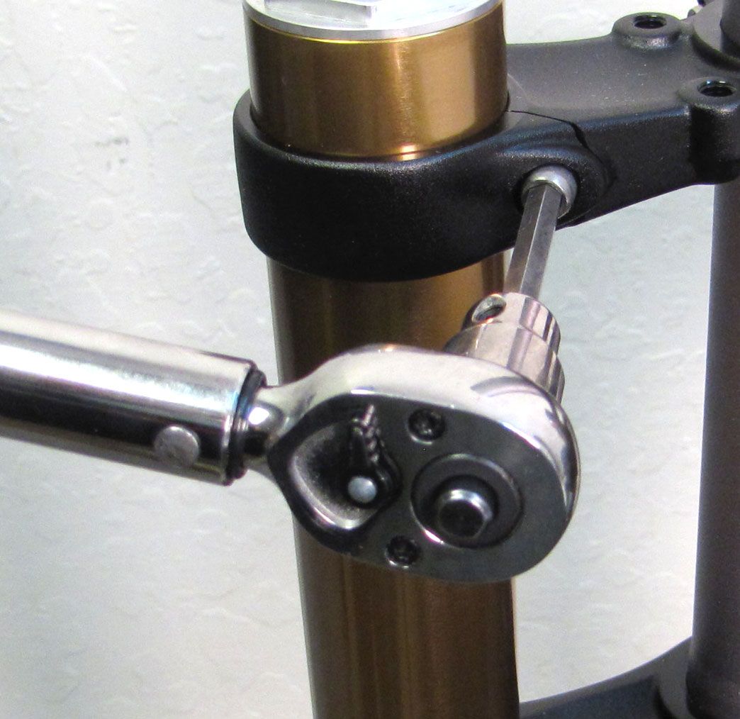
40mm Only: Loosen the 5mm hex bolt (counter-clockwise) on the damper-side of the upper crown.
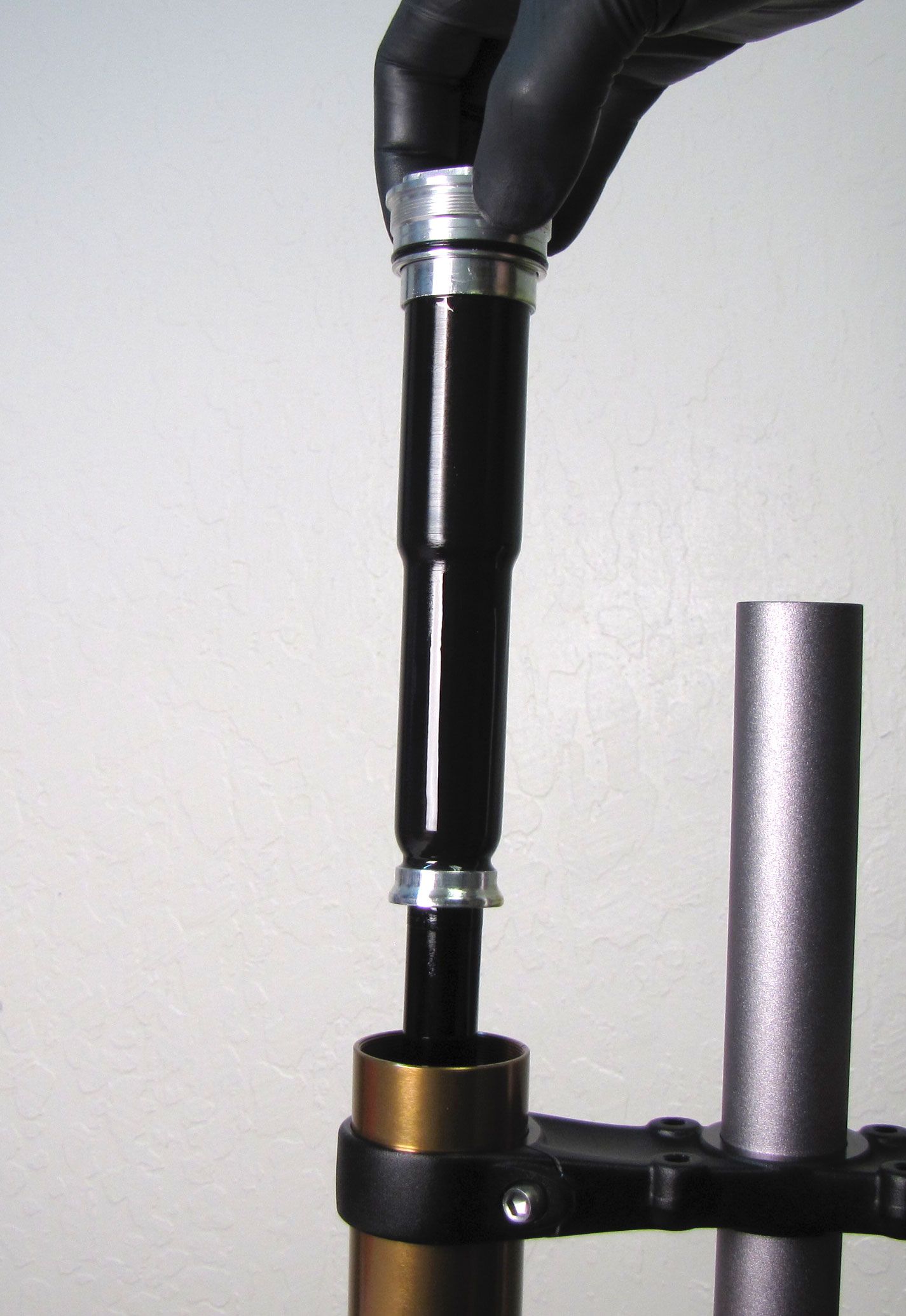
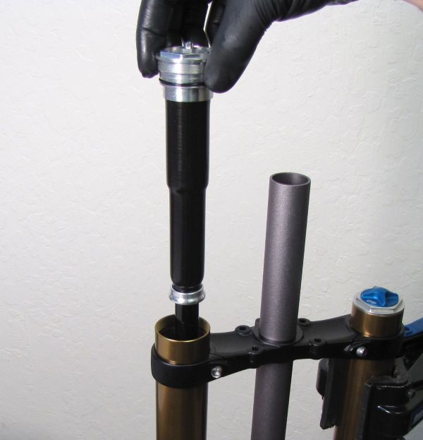
All Forks: With a chamfer-less 6-point 32mm socket (PN: 398-00-605), unthread the damper cartridge completely (counter-clockwise). Pull straight up to remove the entire damper cartridge from the right side upper tube.

Damper Cartridge Rebuild

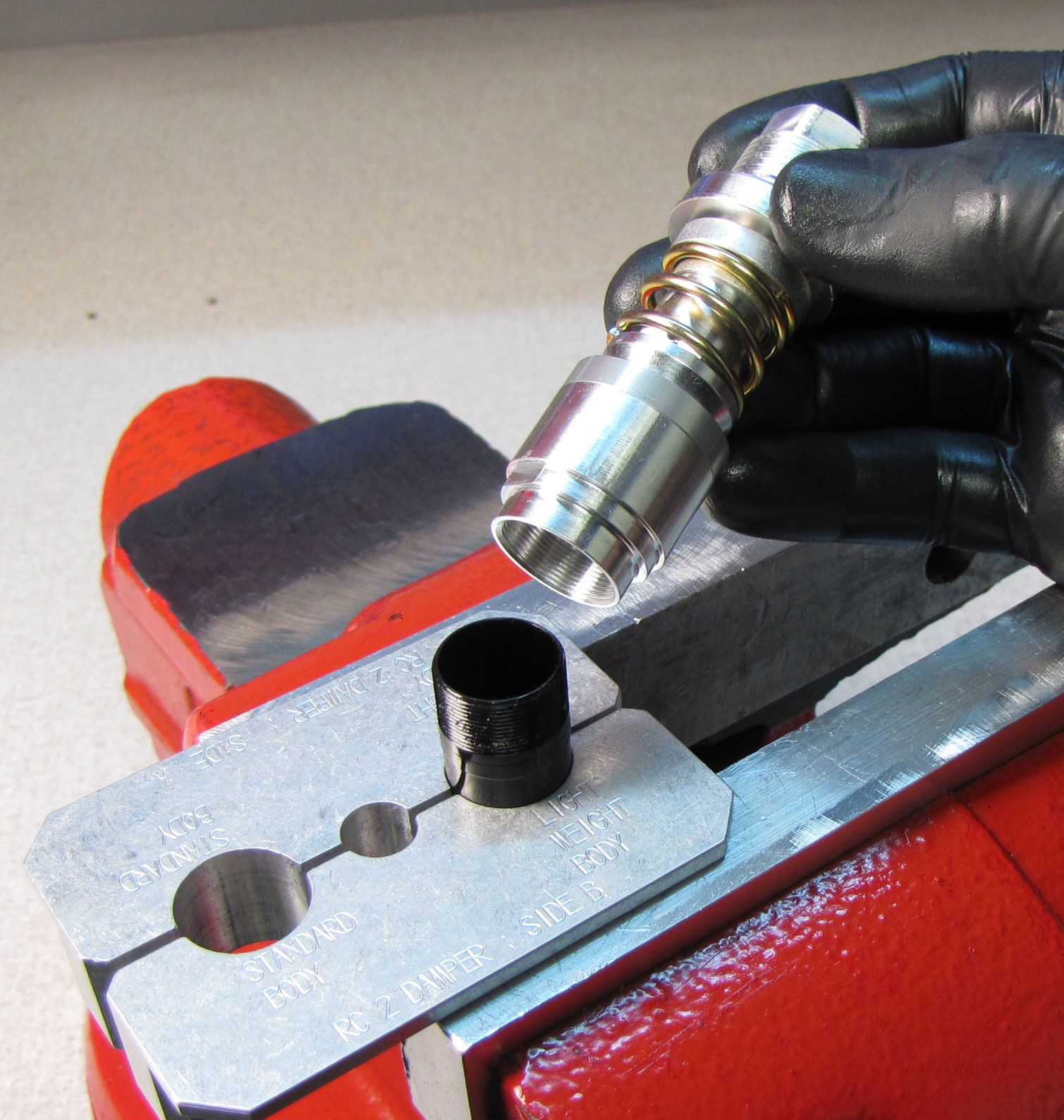
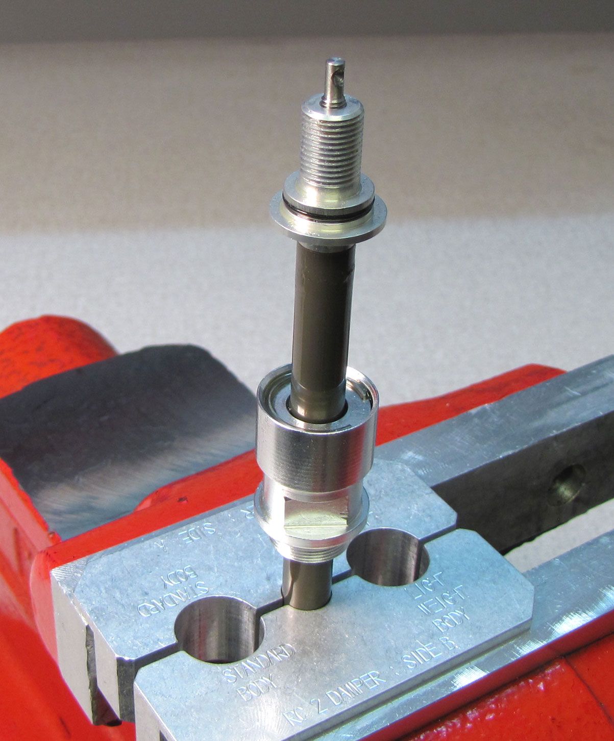
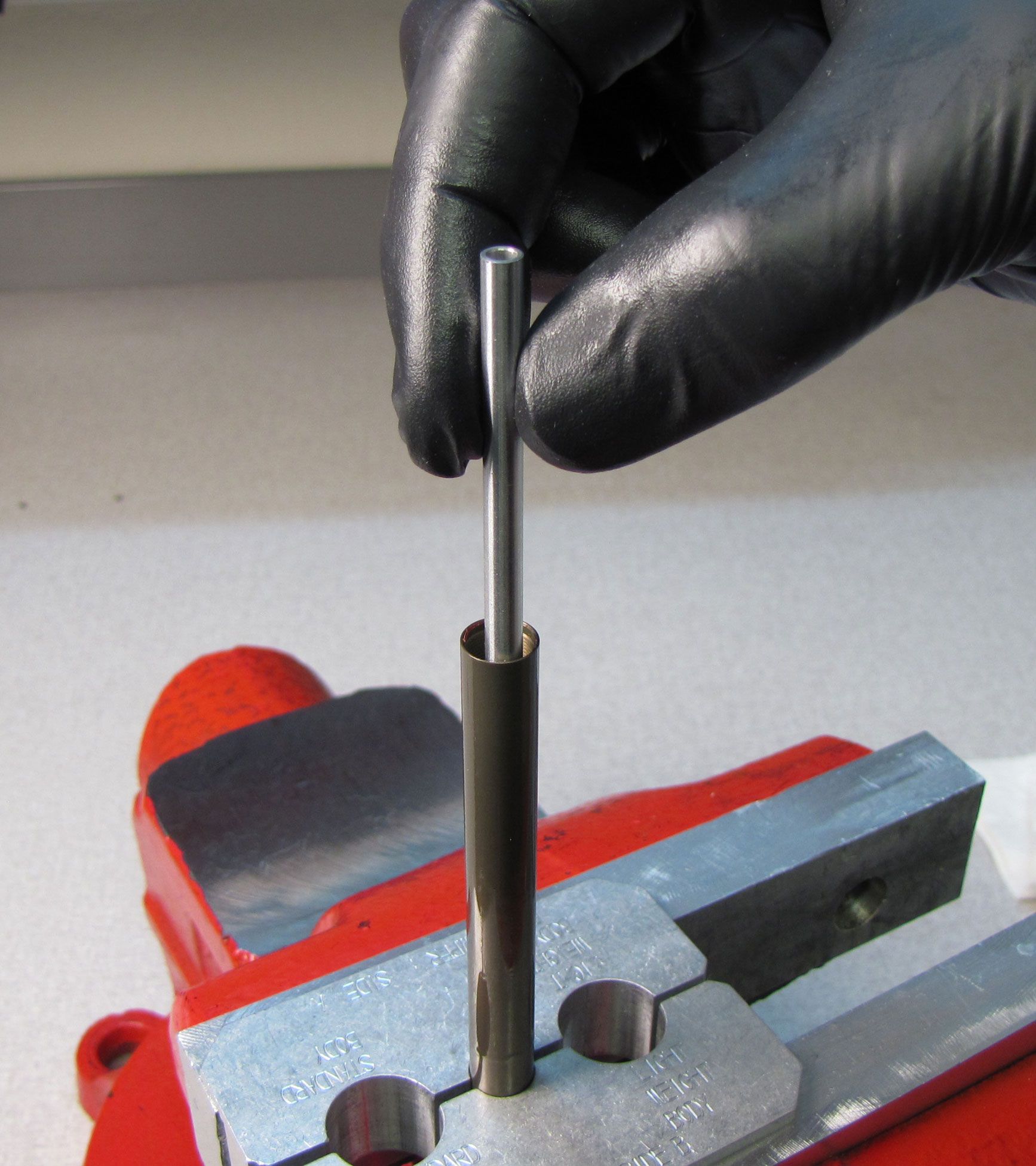
Step 1
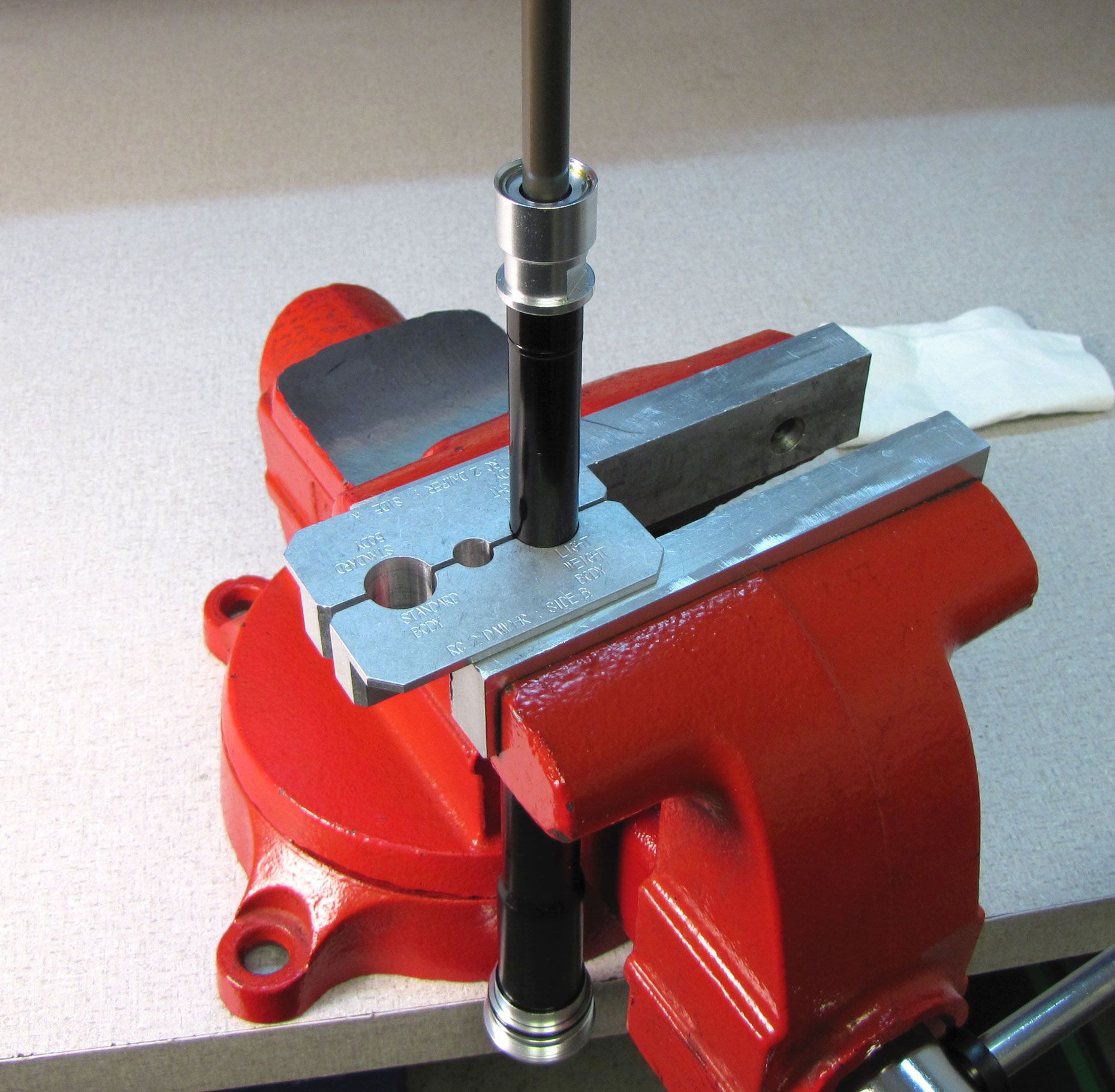
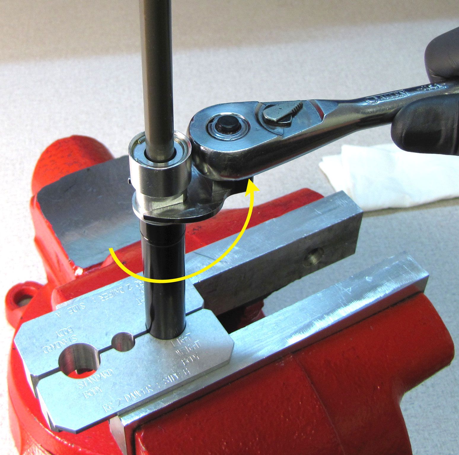
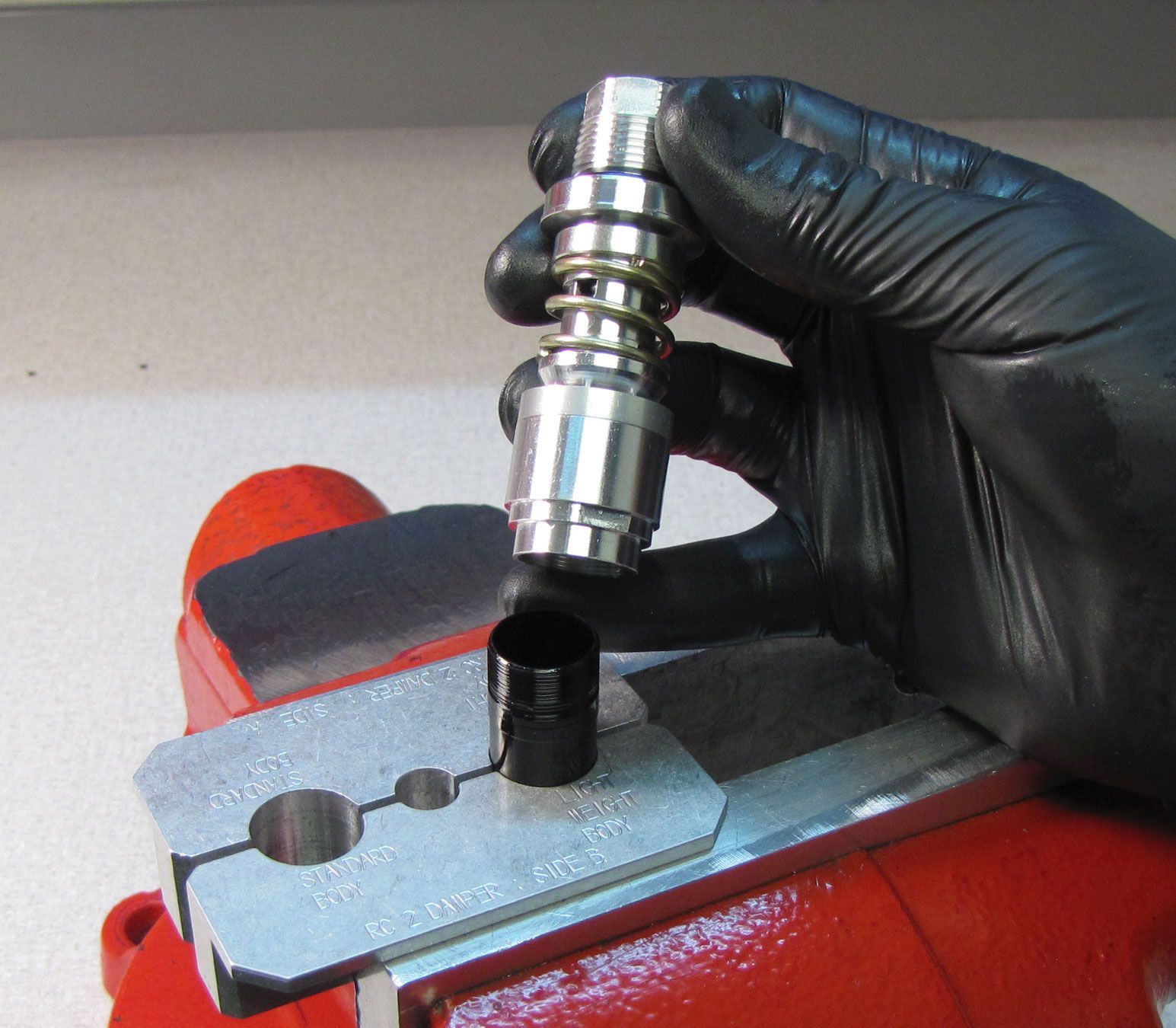
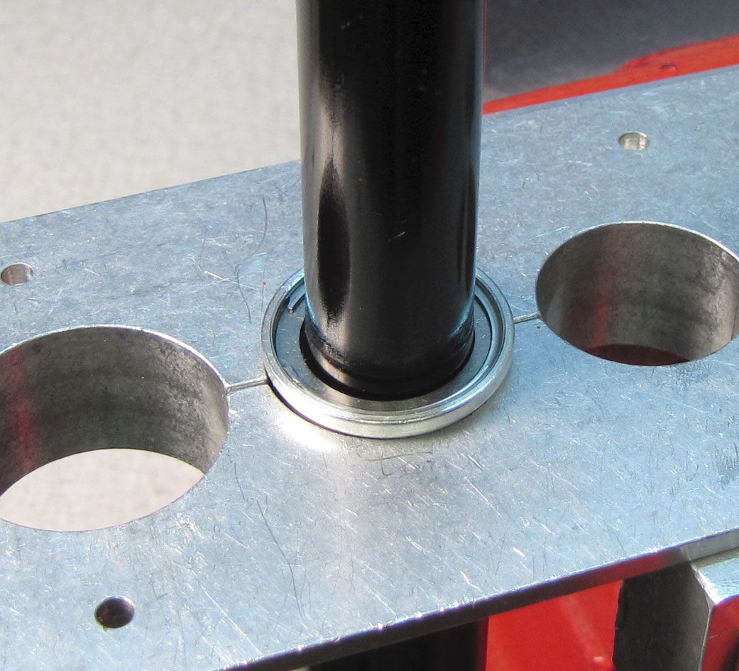
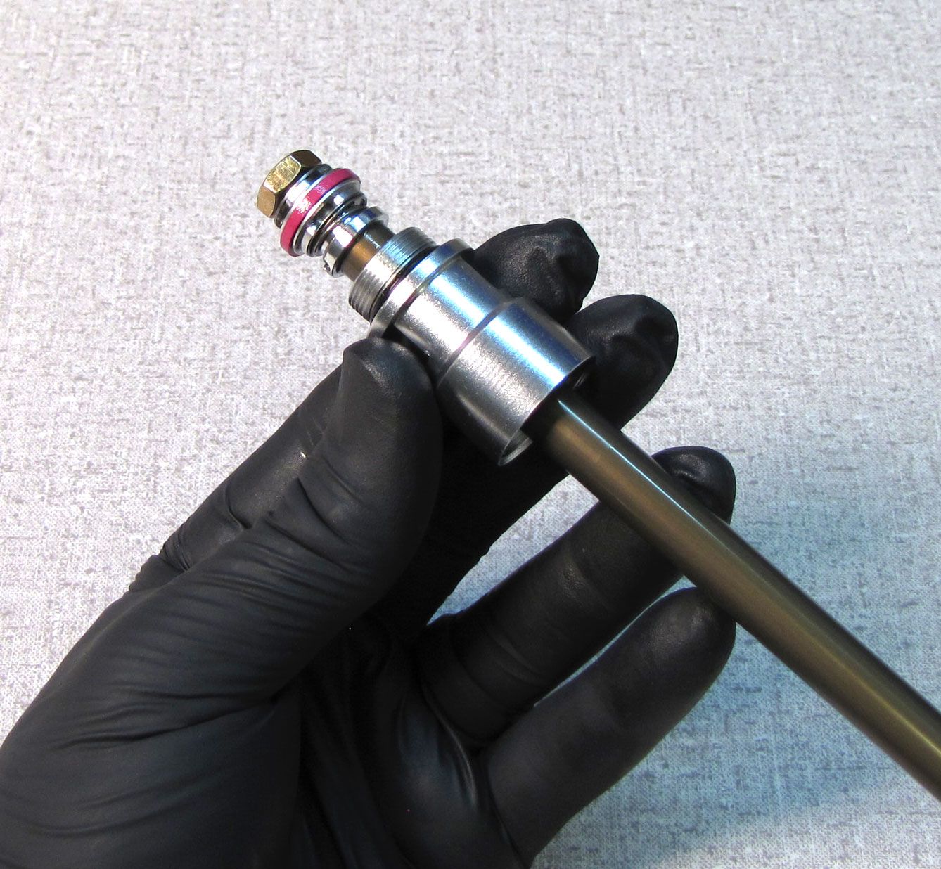
Clean the cartridge body with isopropyl alcohol and a lint-free paper towel, then clamp it in the "Lightweight Body" hole of your shaft clamps (PN: 803-00-830) as shown.

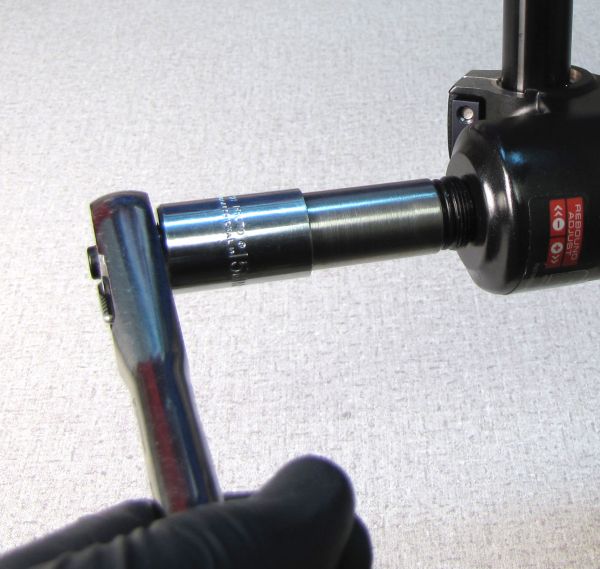
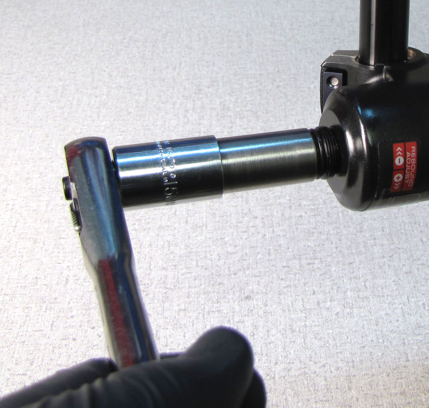
Step 2
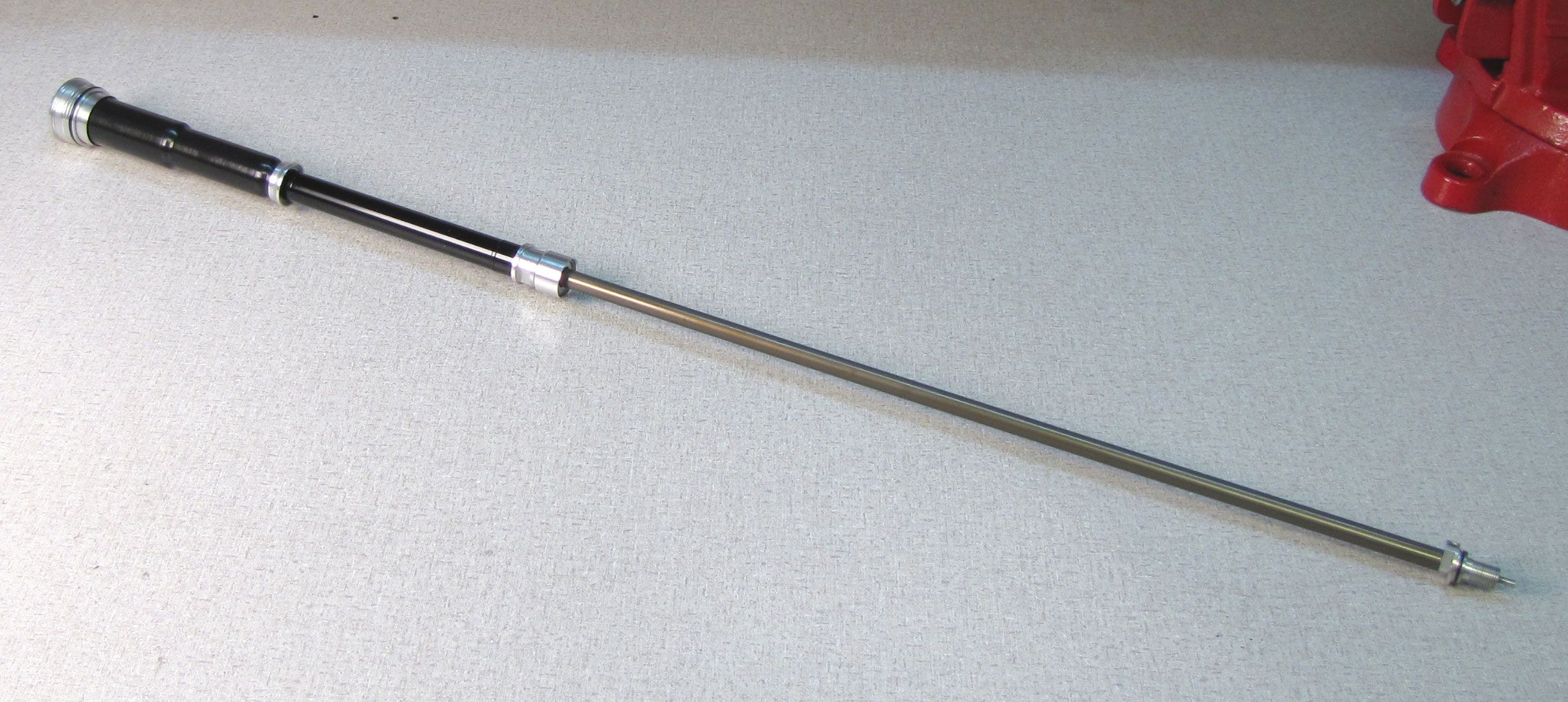
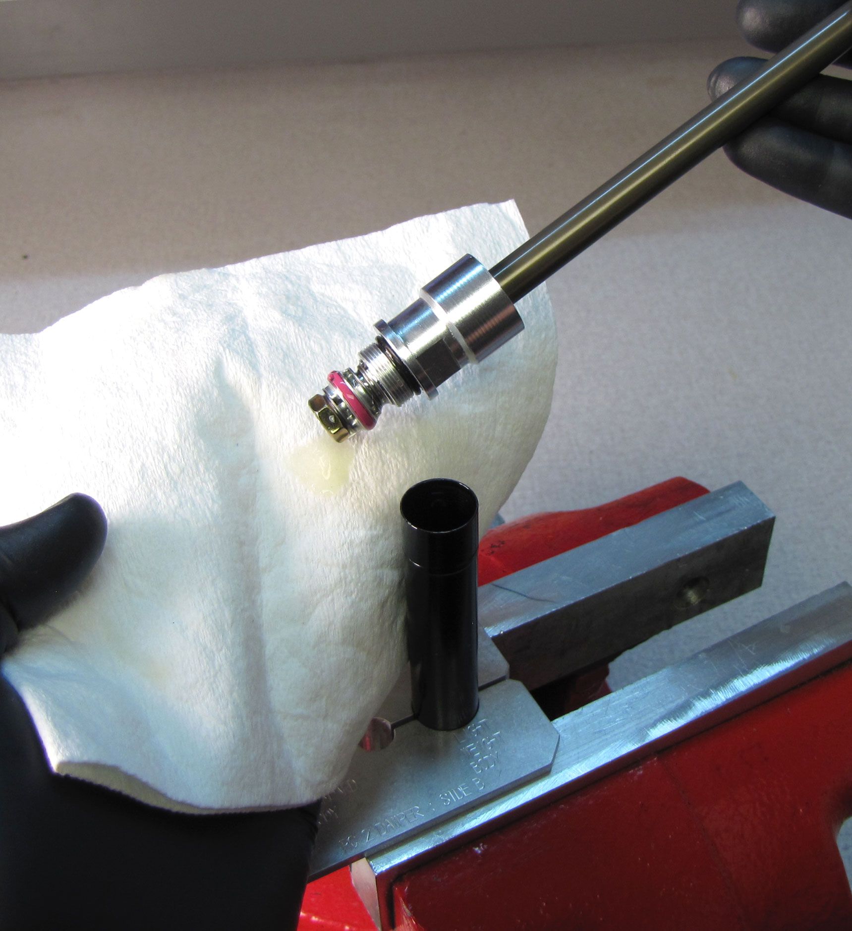
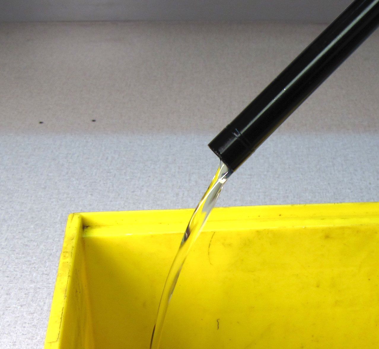
Unthread the sealhead from the cartridge body with a 15mm wrench (counter-clockwise). Remove the cartridge from the vice and empty it over an oil drain.

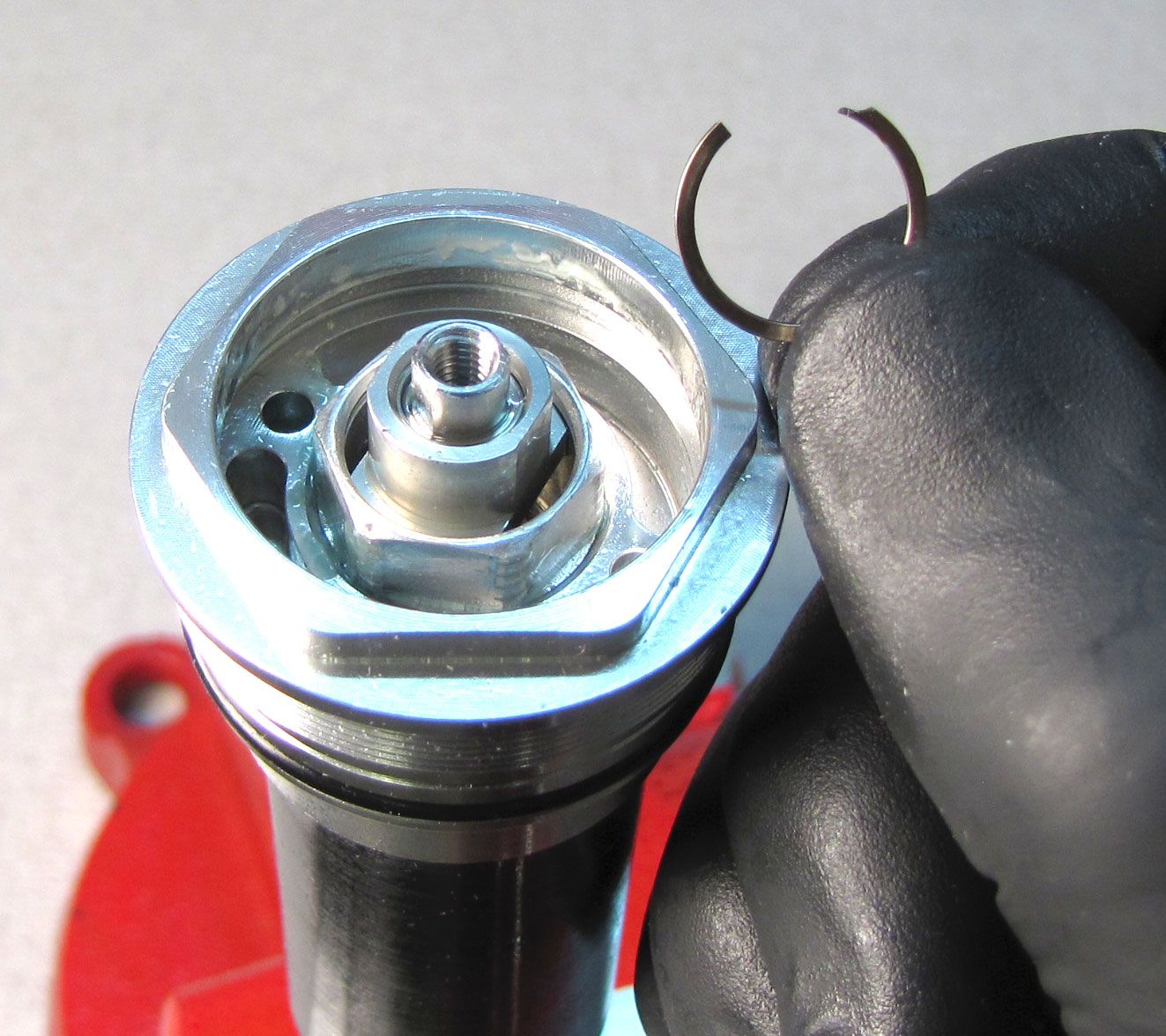
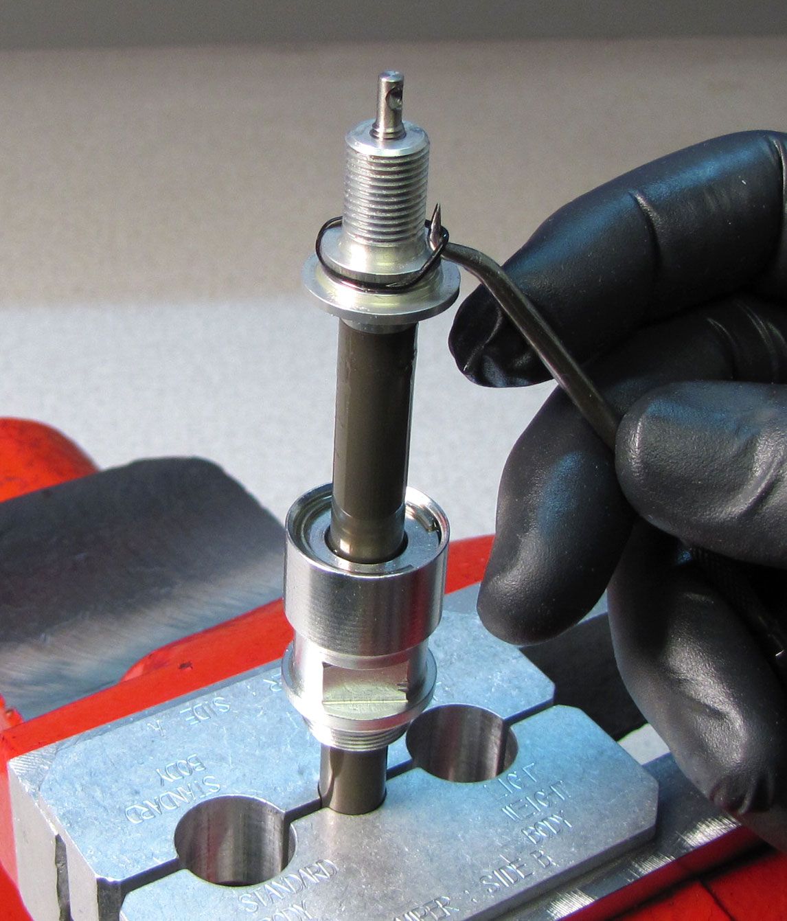
Step 3
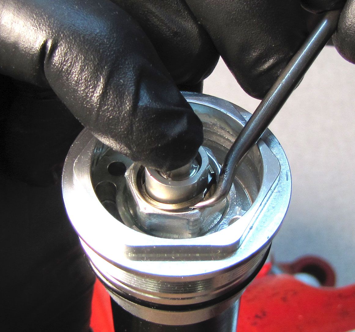
Clamp the cartridge body in your shaft clamps (making sure not to clamp the bladder sealing portion of the cartridge body). Remove the adjuster assembly retaining ring while keeping a finger on top of the adjuster to prevent the retaining ring from popping off.
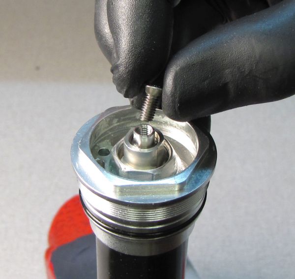
Step 4
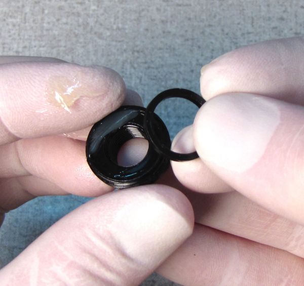
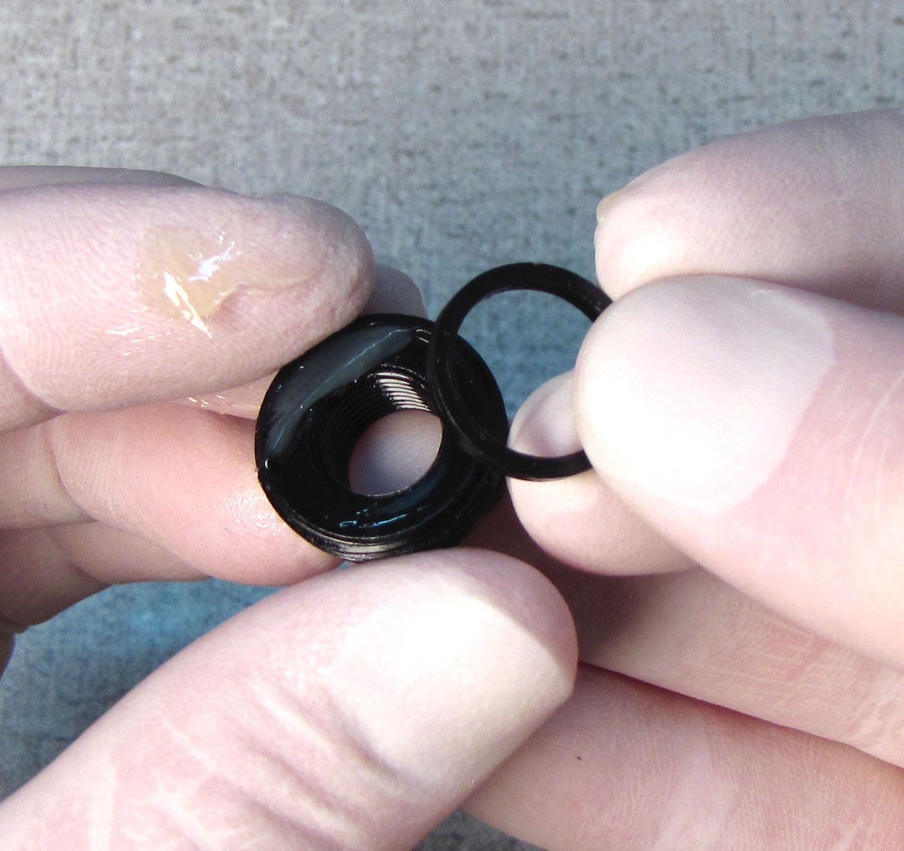
Reinstall the 2.5mm hex screw into the adjuster assembly. Pull up on the screw to remove the adjuster assembly. Replace the o-ring on the adjuster assembly with a new greased one from the kit and set it aside.


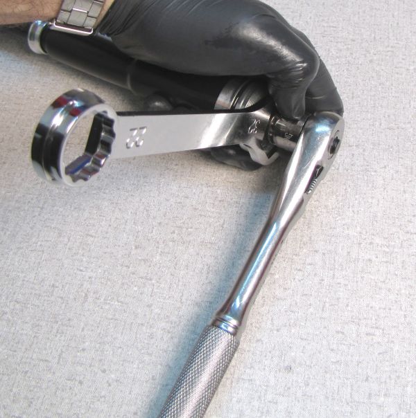
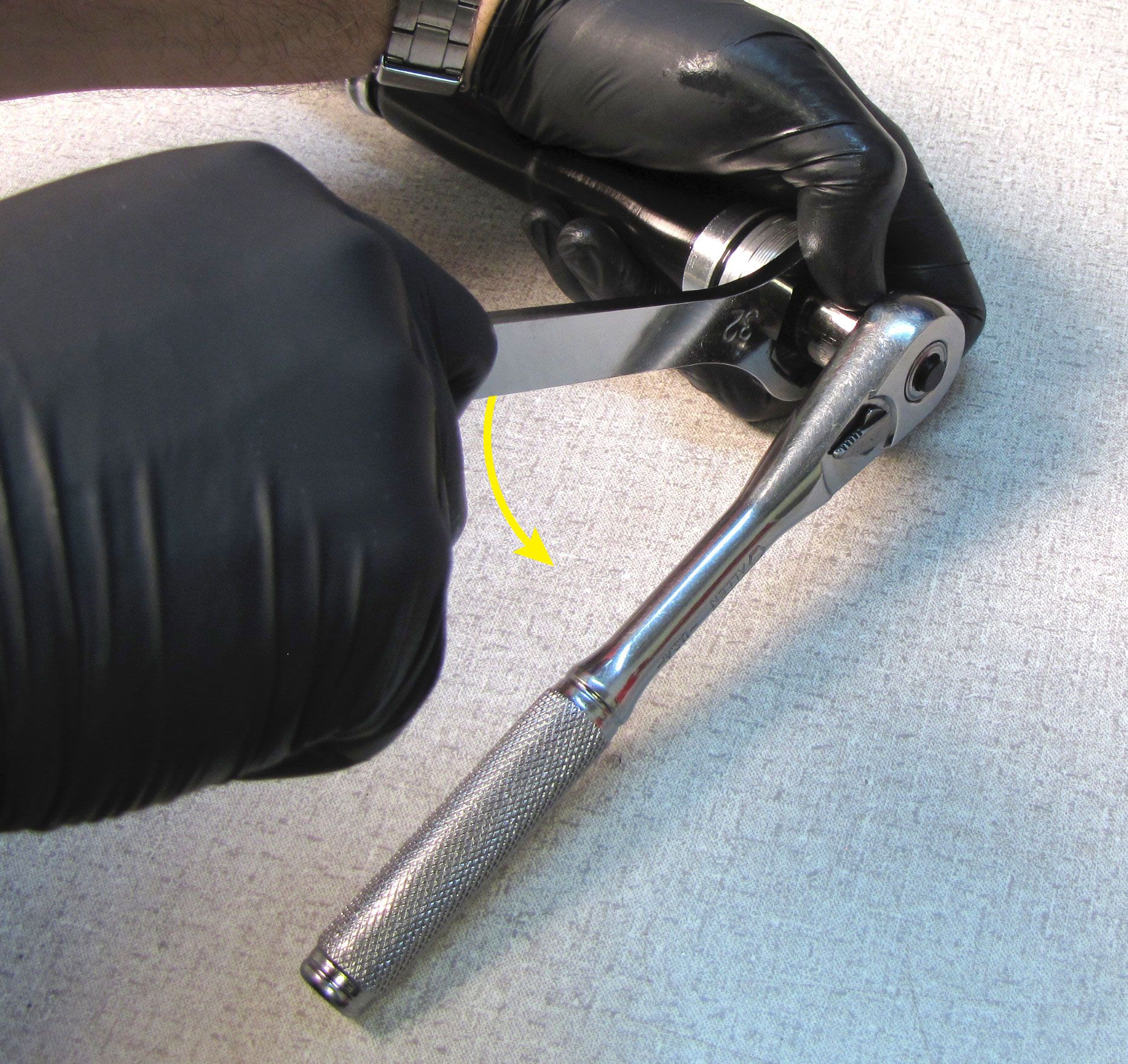
Step 5
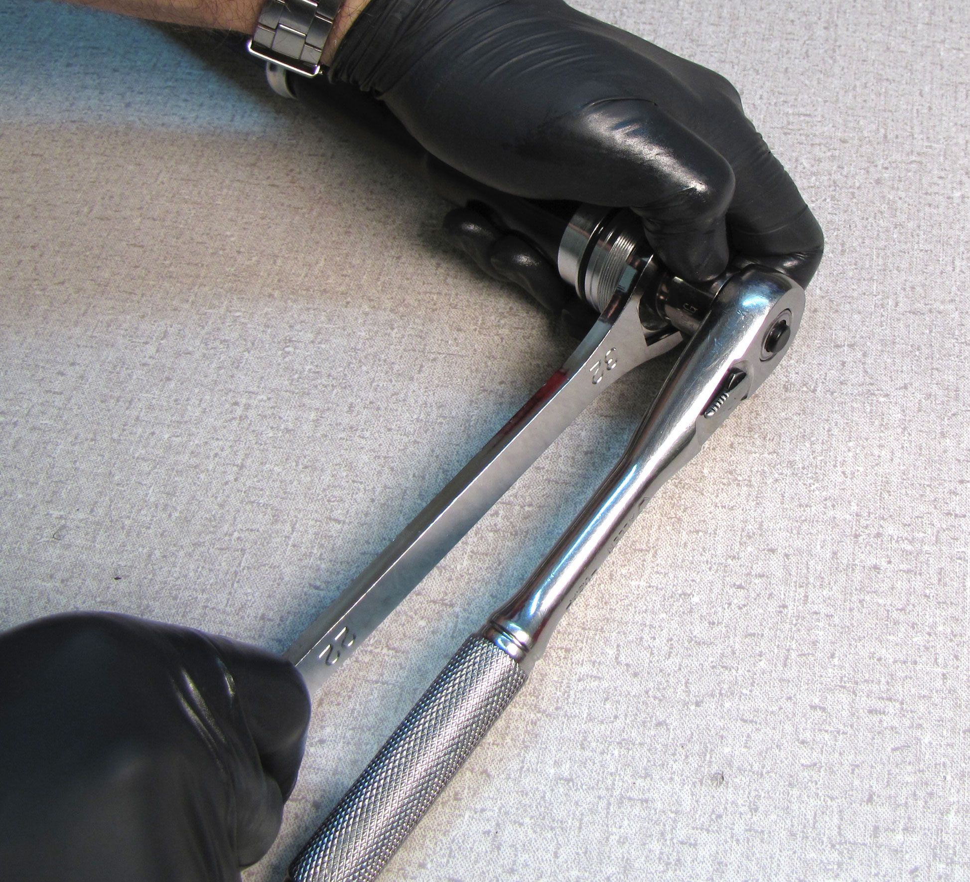
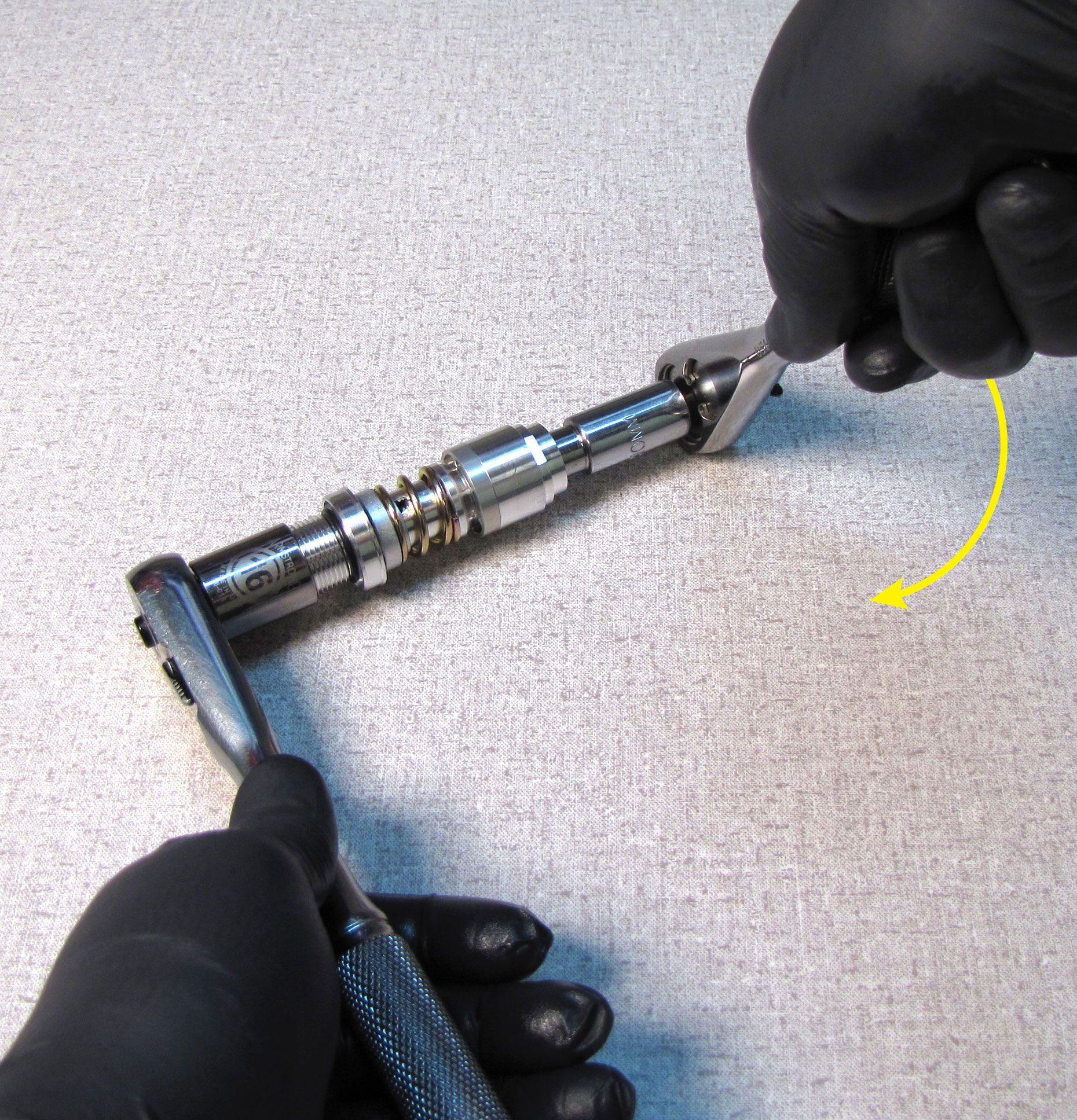
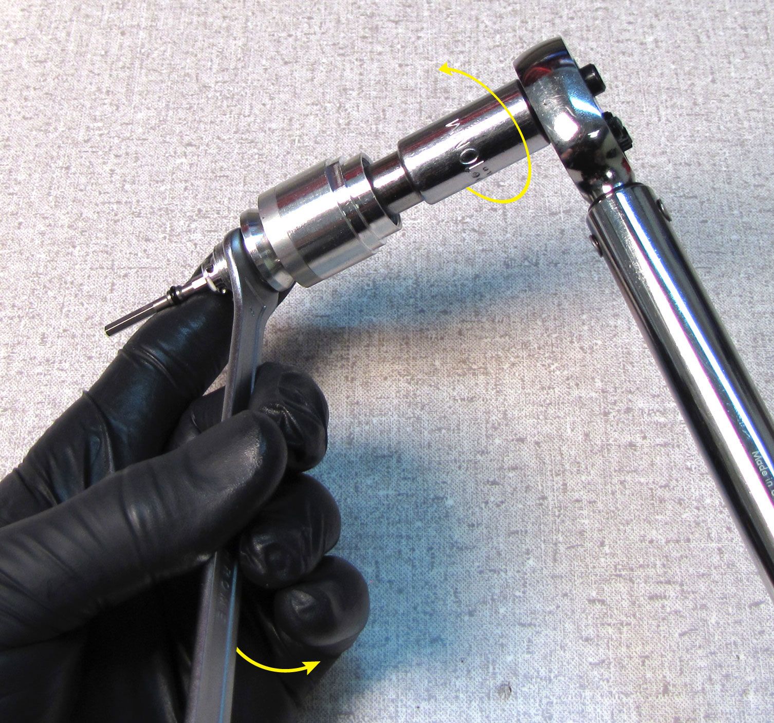
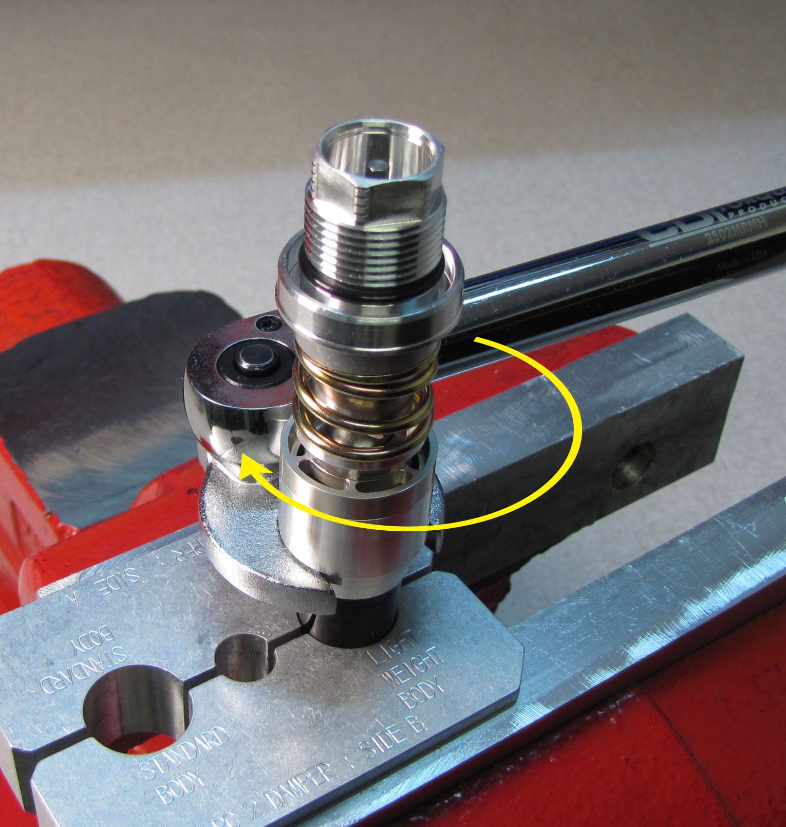
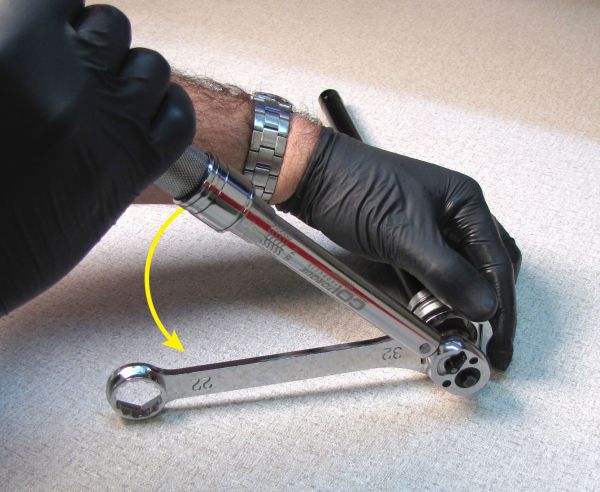
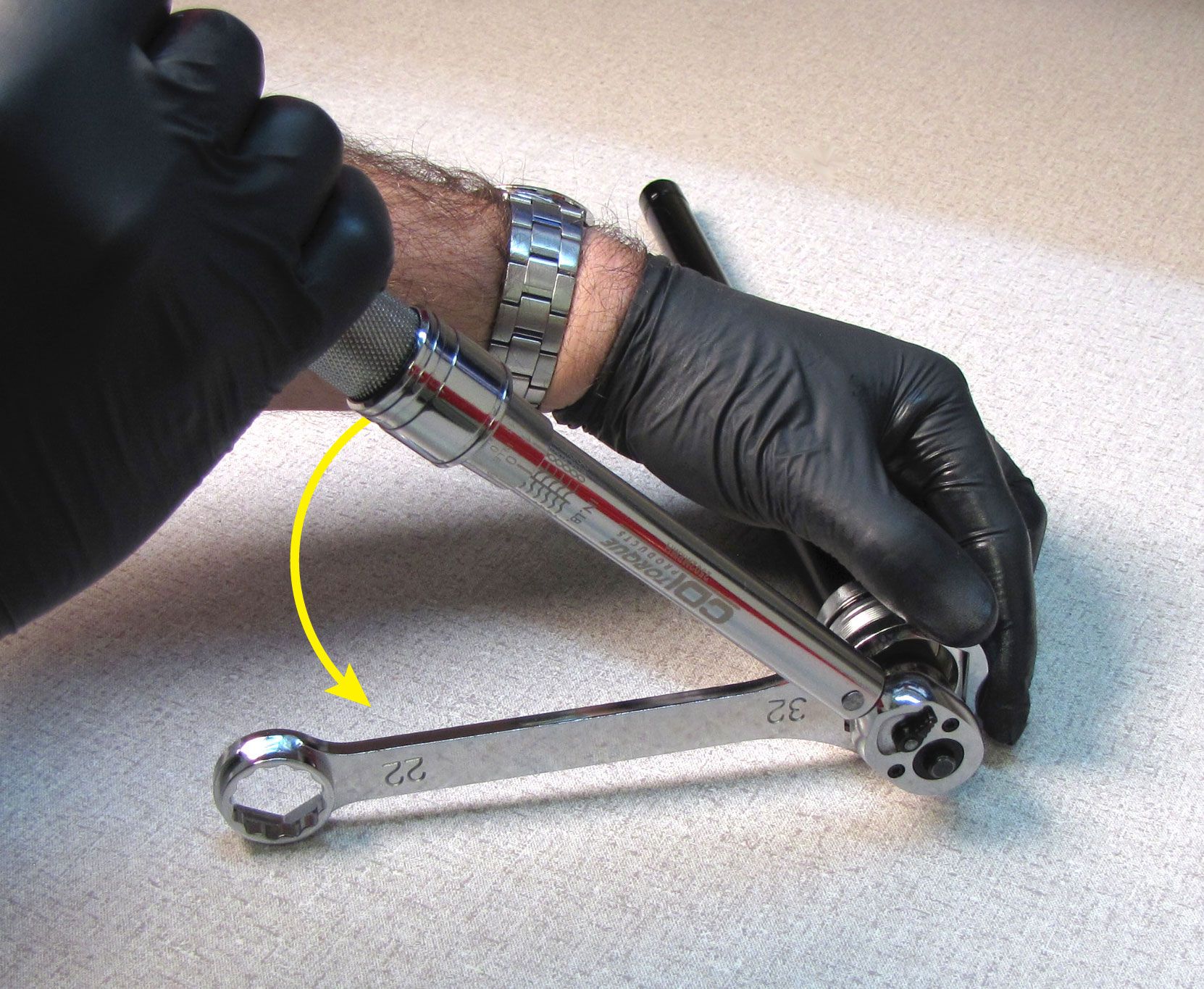
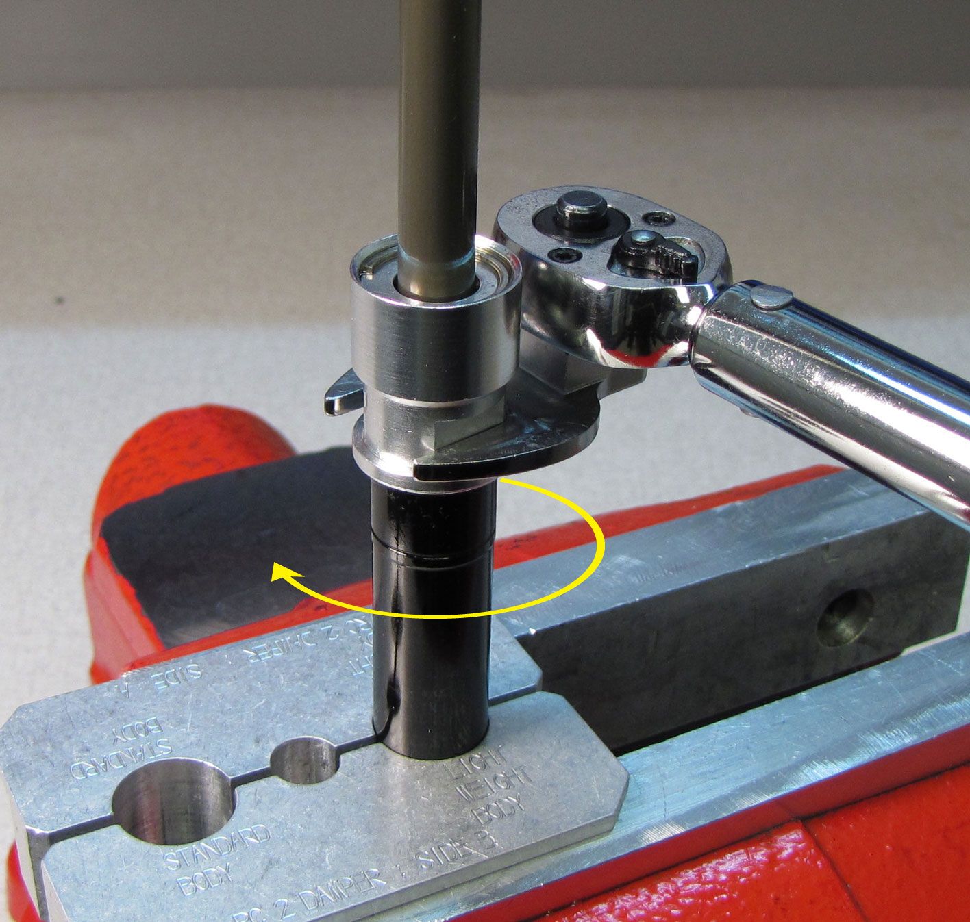
Position a 32mm 6-point chamfer-less box-end wrench on the topcap, and a 16mm socket on the base valve upper stud. Rest the ratchet handle against the work surface, then loosen and remove the topcap with the 32mm wrench, as shown. Work slowly and carefull so you don't damage the topcap wrench flats.

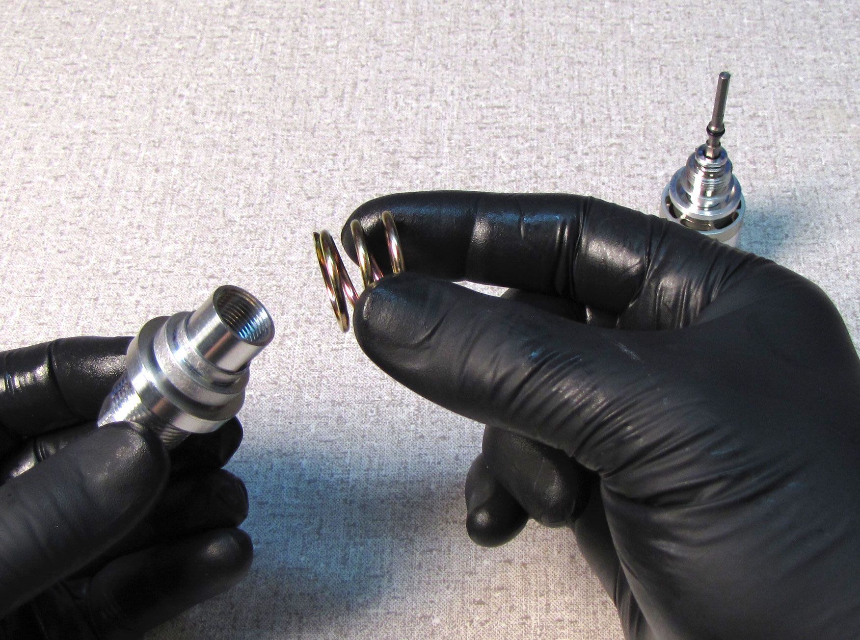
Step 6
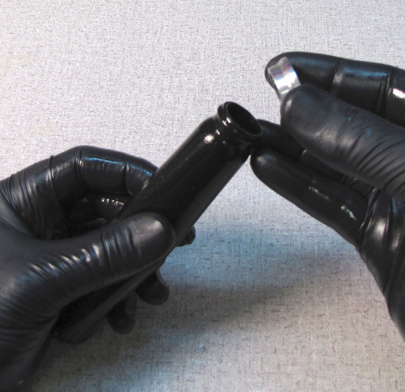
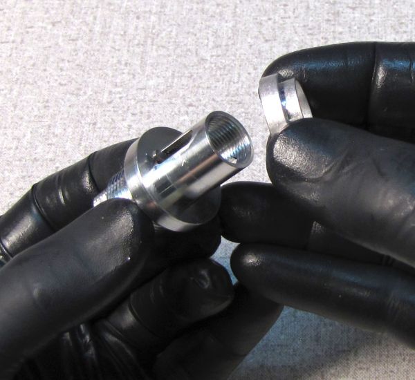
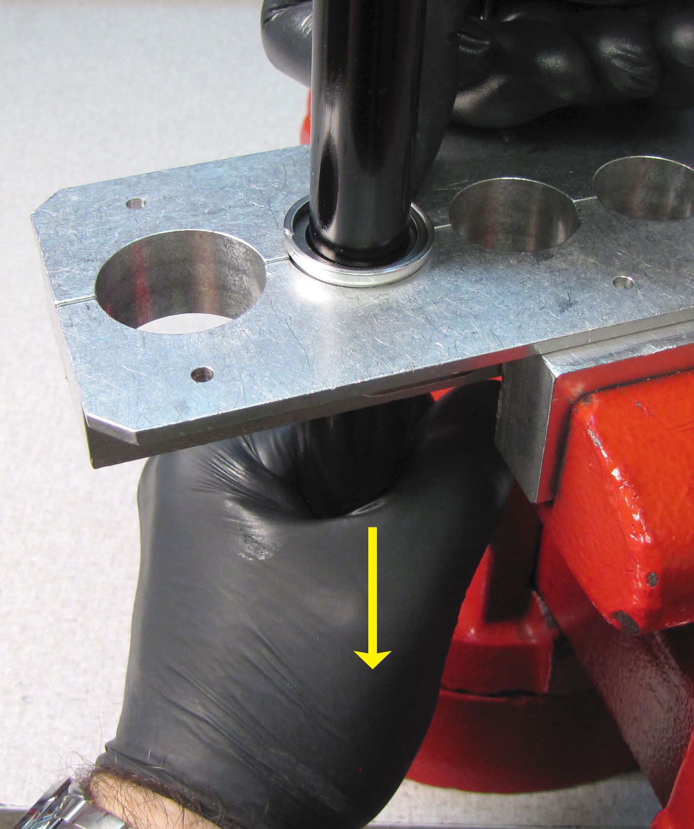
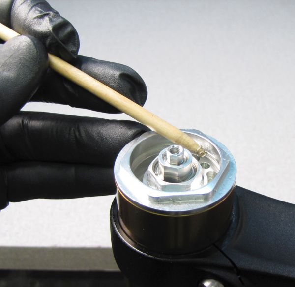
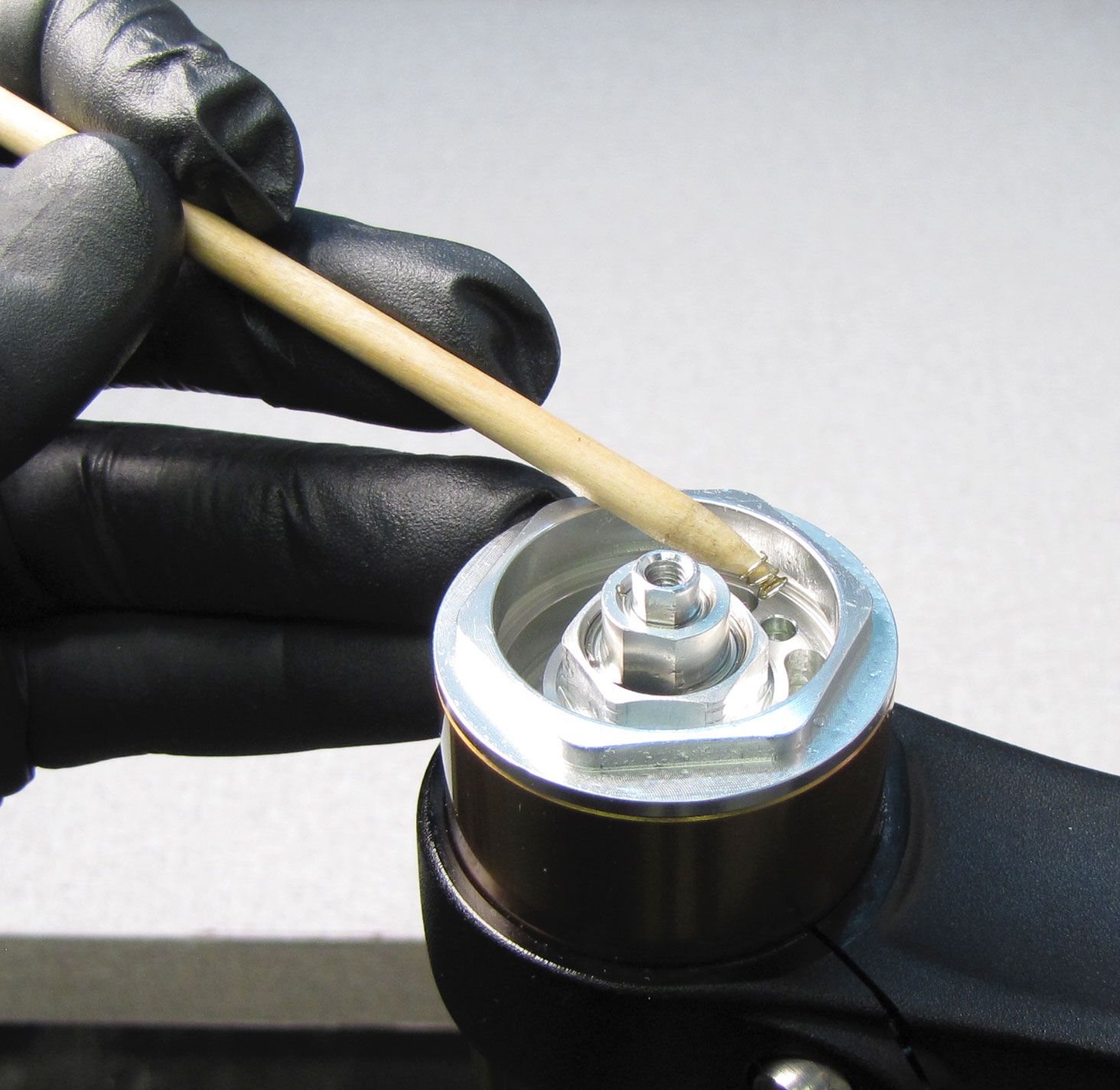
Remove the upper bladder ring by pushing it up, away from the bladder with your thumbs.
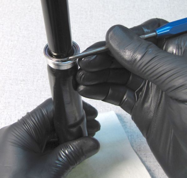
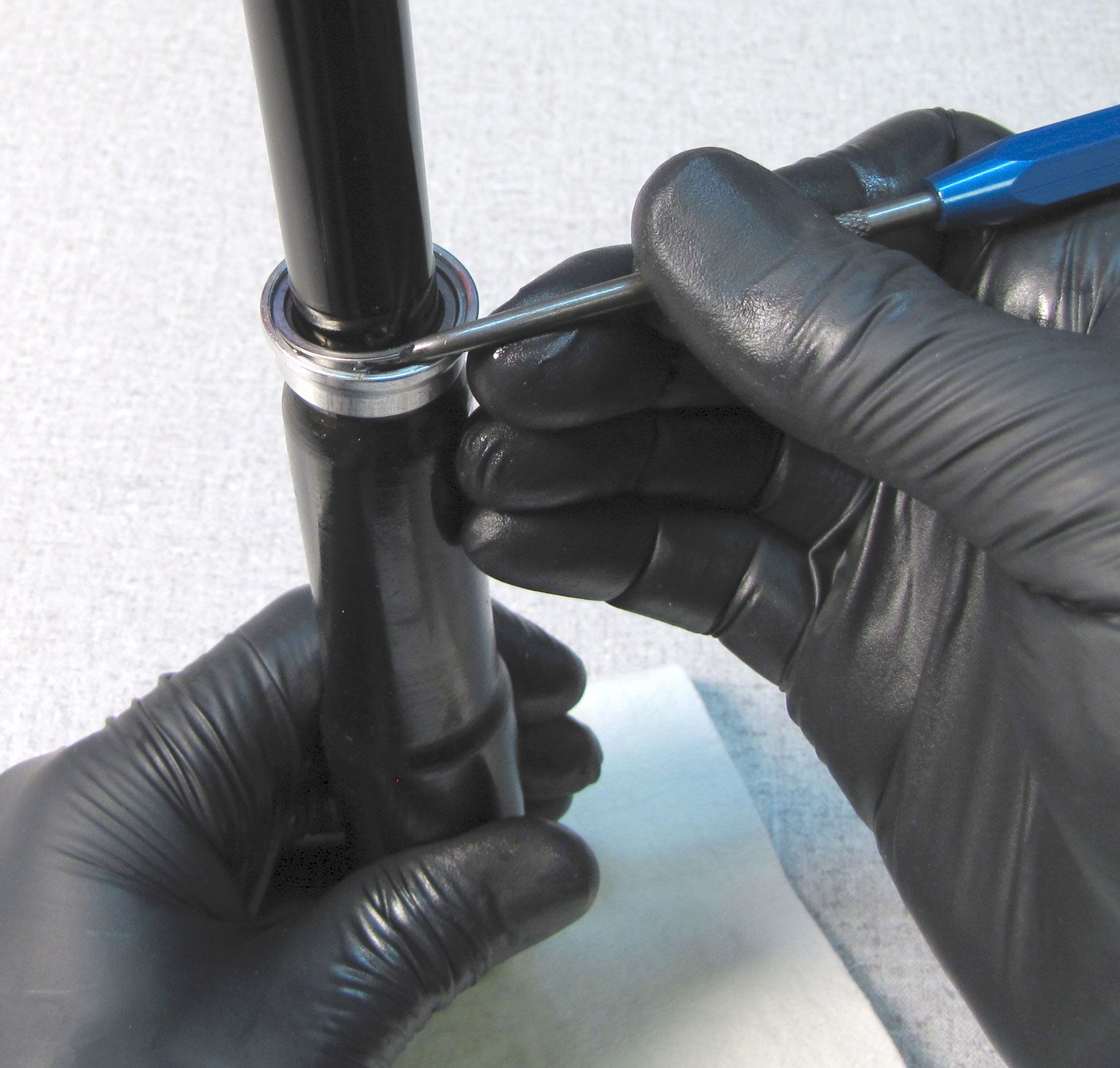
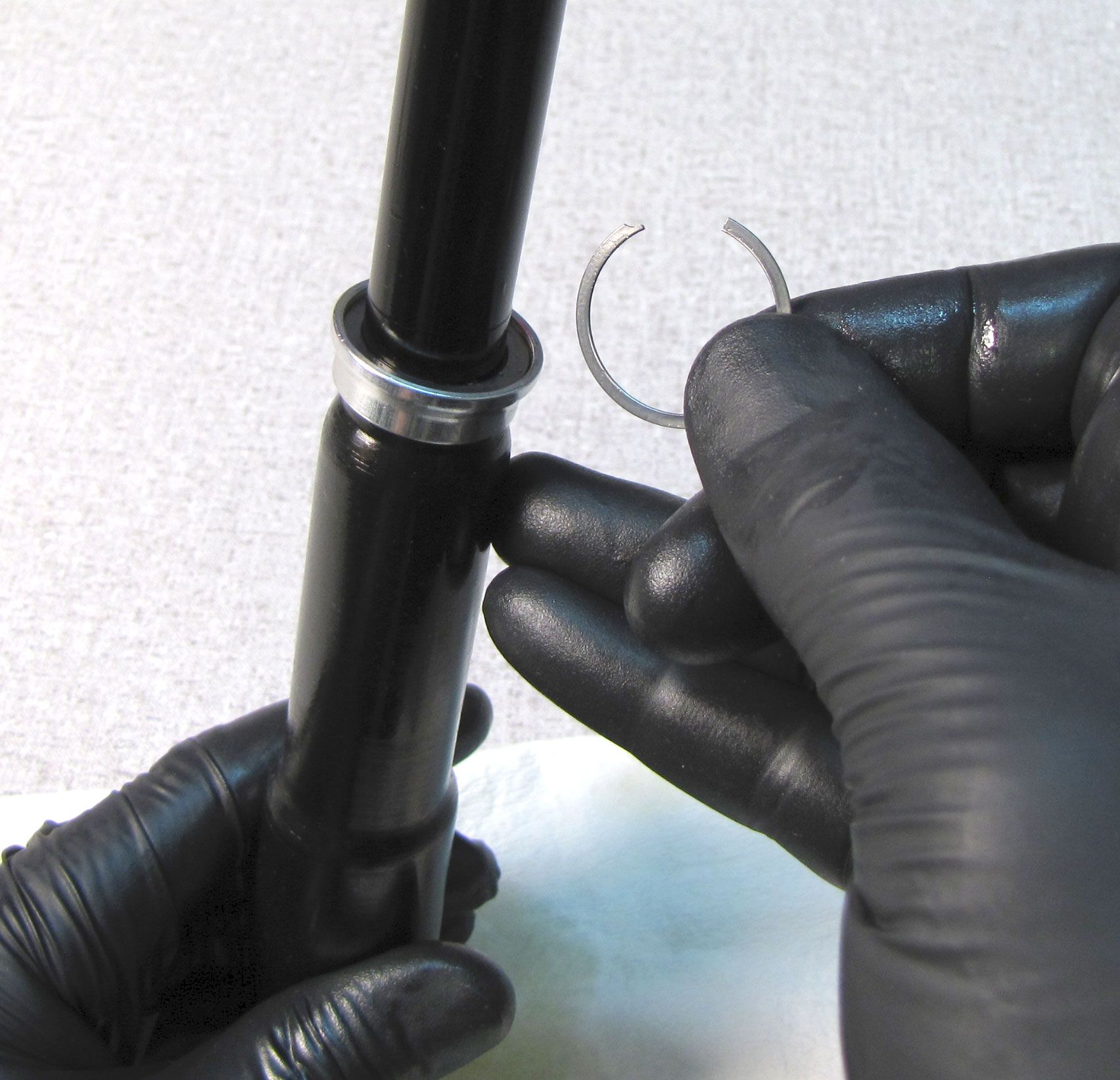
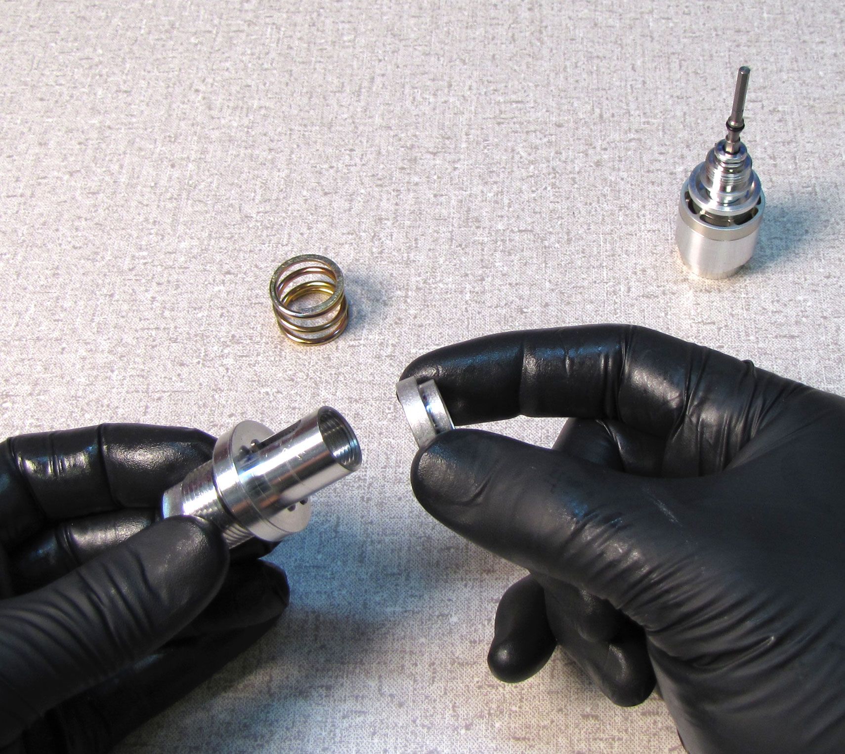
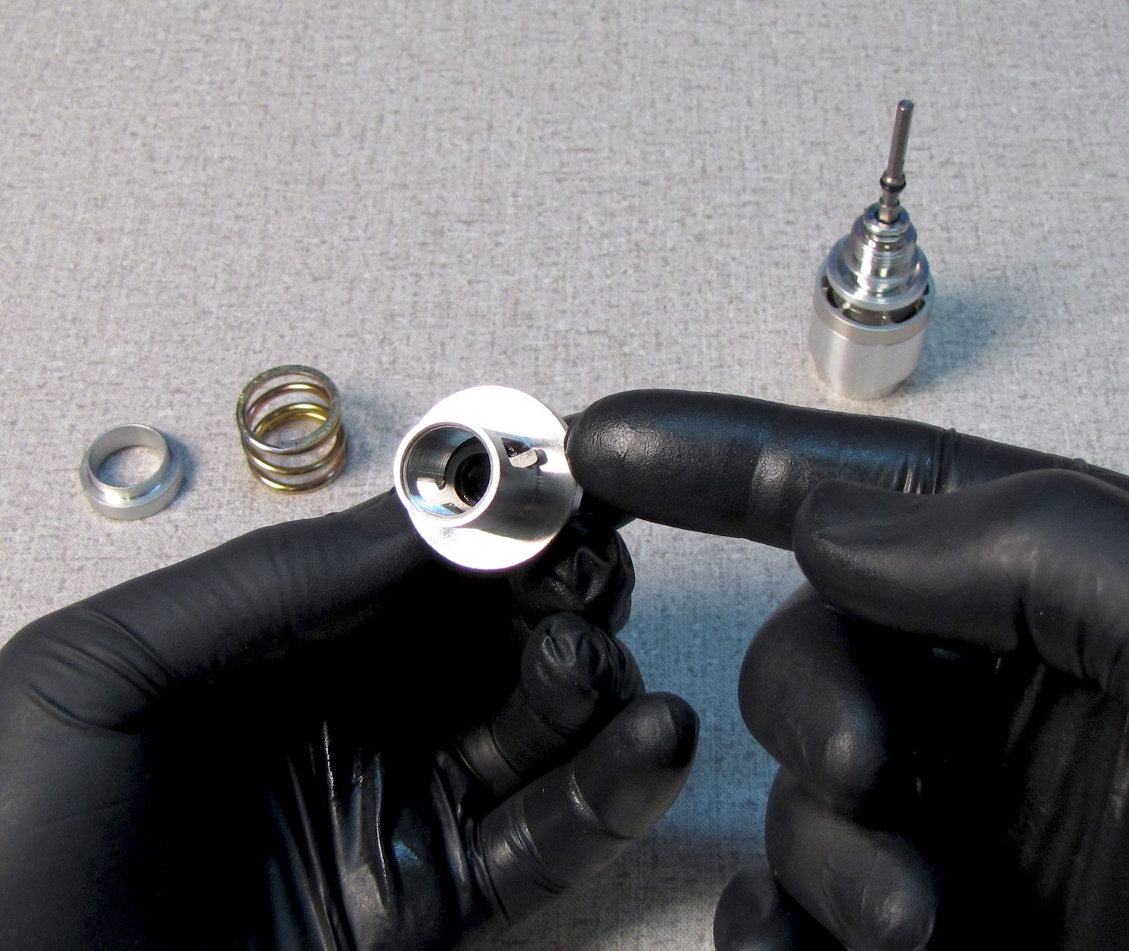
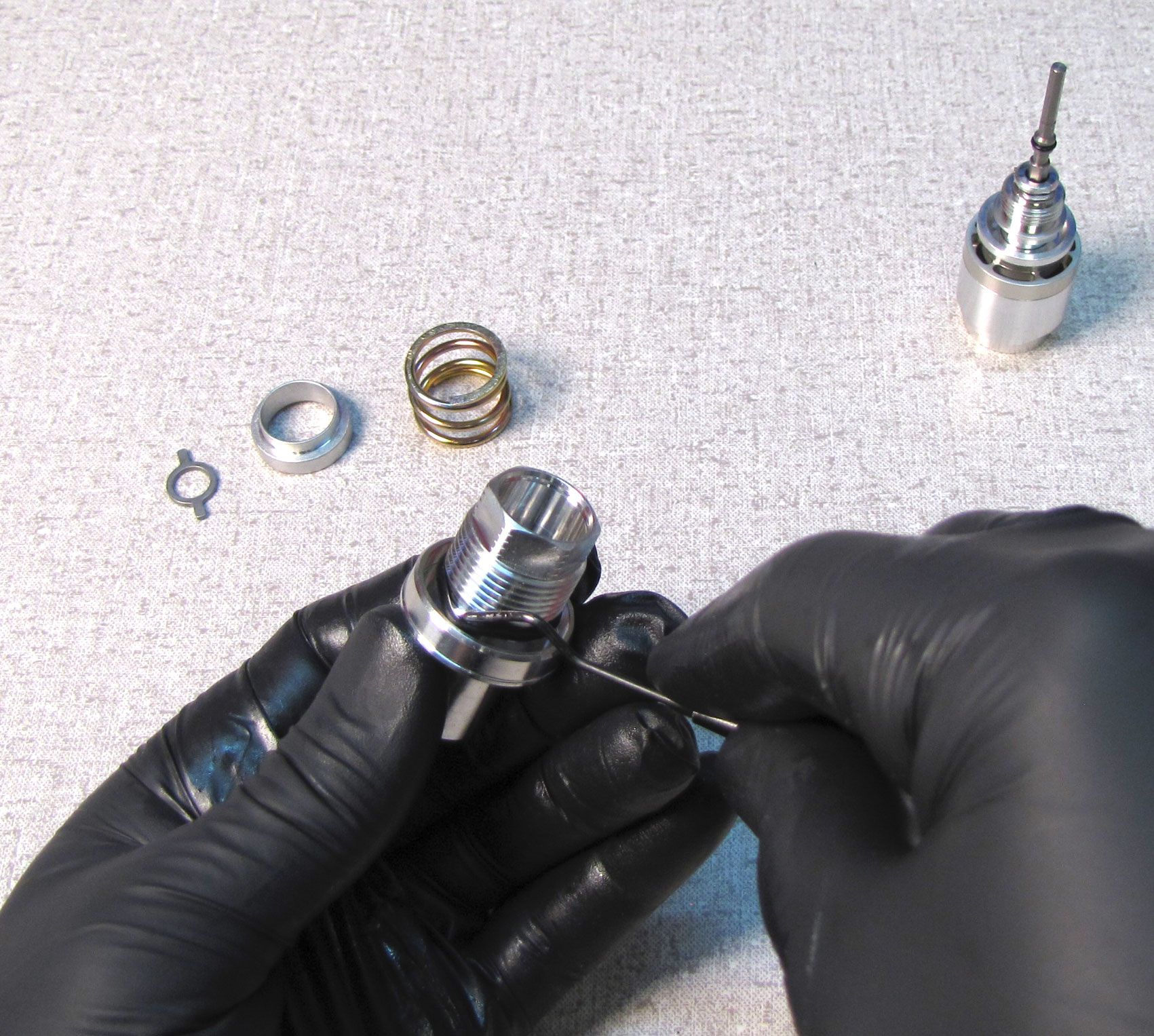
Step 7
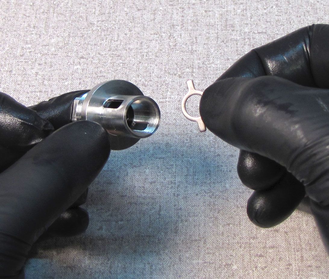
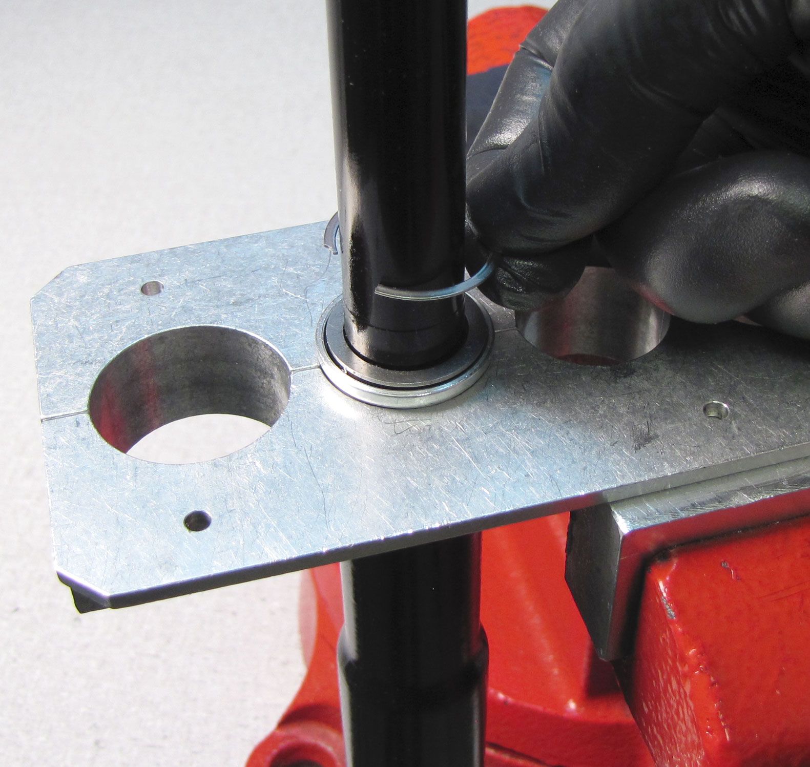
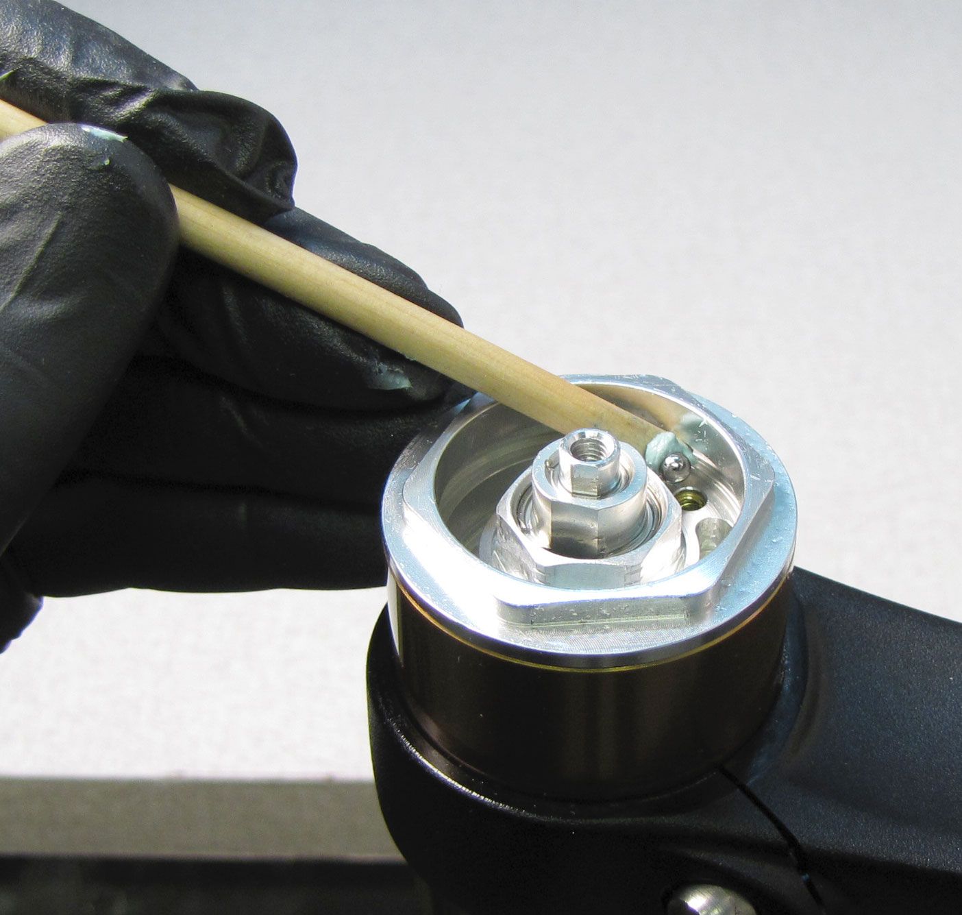
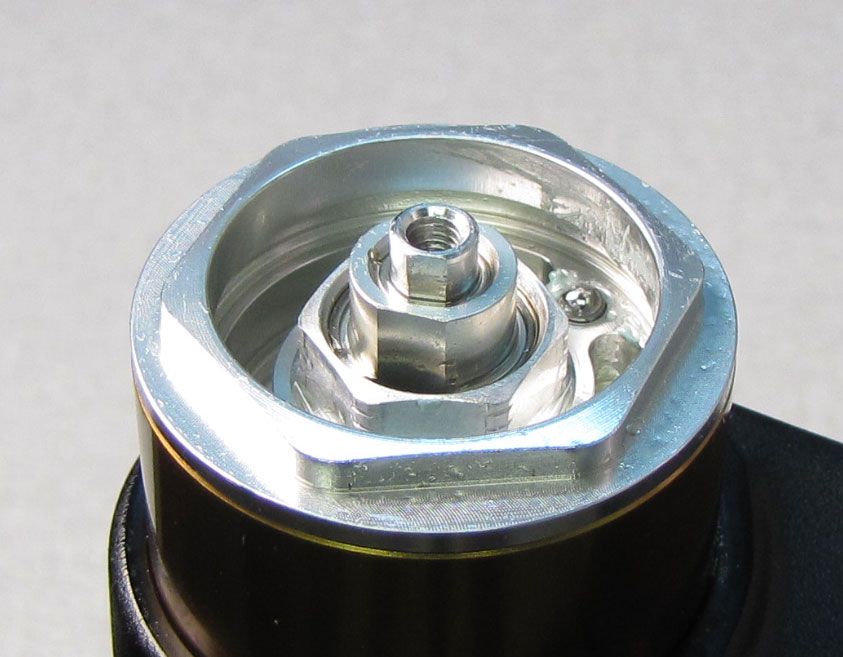
Remove the retaining ring and bladder ring retainer being careful not to scratch the smooth bladder sealing surface on the black cartridge body.
Step 8
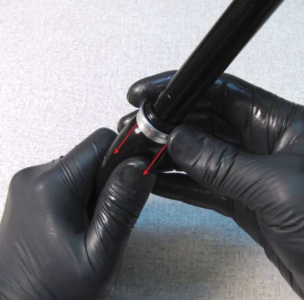
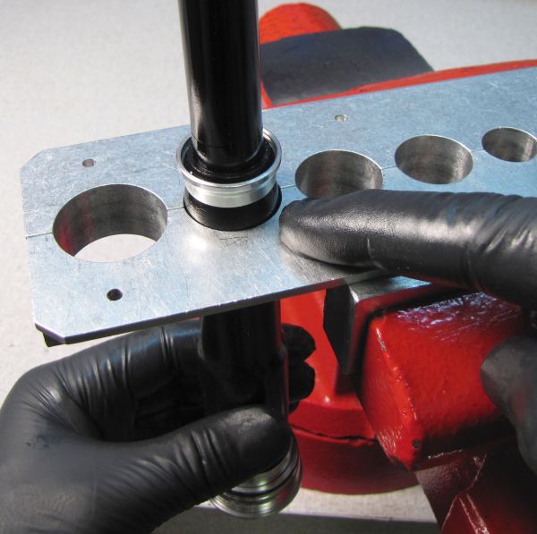
Slide the lower bladder ring up toward the fatter end of the bladder to release it from squeezing the bladder against the cartridge body. Slide the bladder with lower bladder ring down and off the end of the cartridge body. Remove the bladder ring and discard the original bladder as you will be replacing it with a new one from the kit in a later step.

-m.jpg)
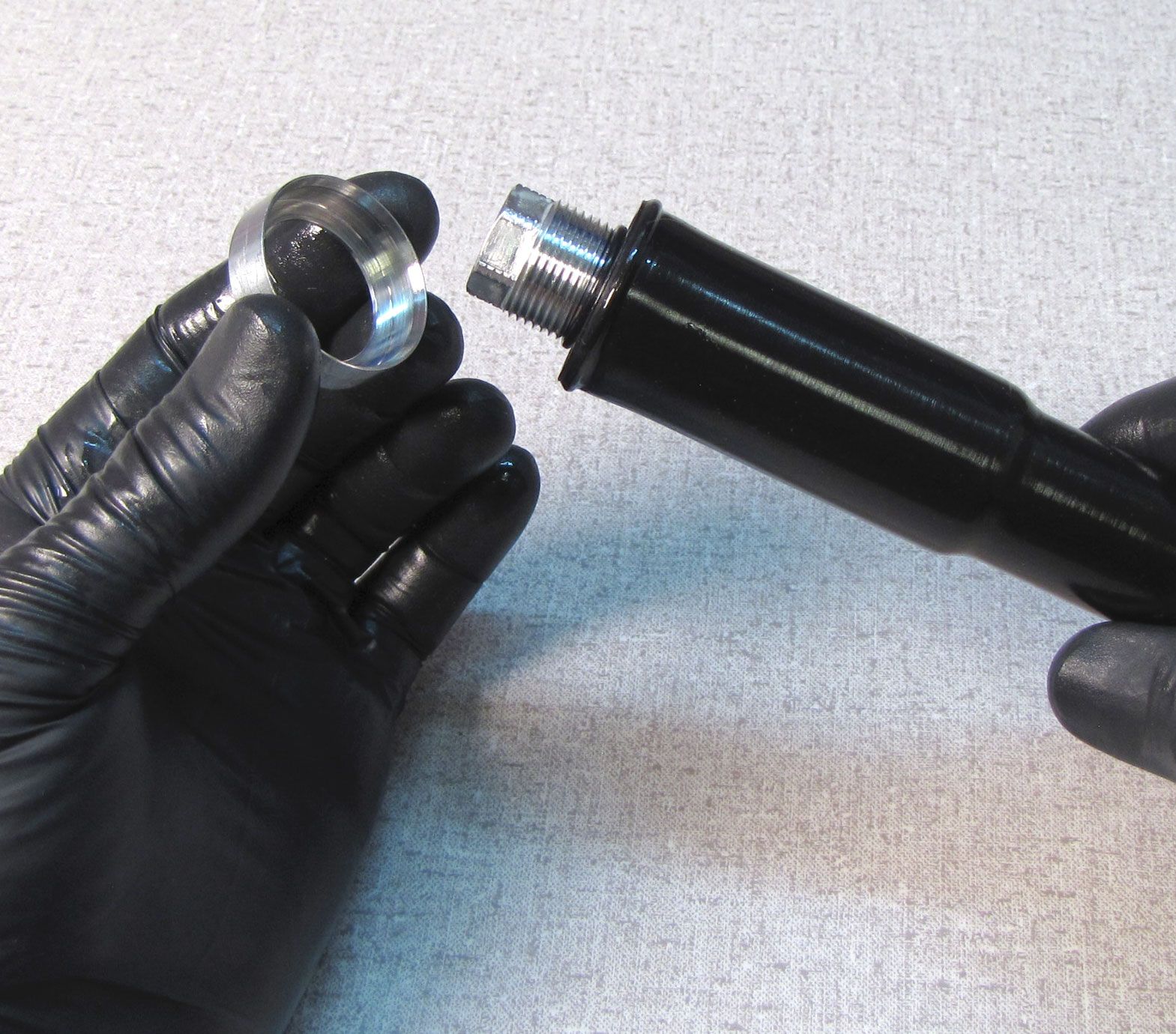
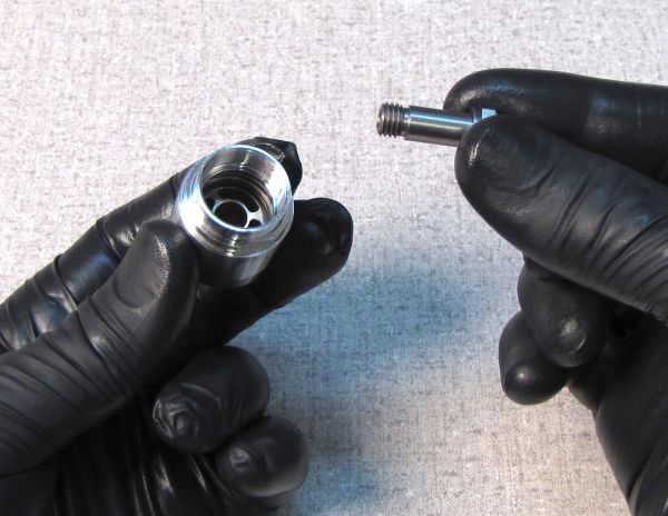
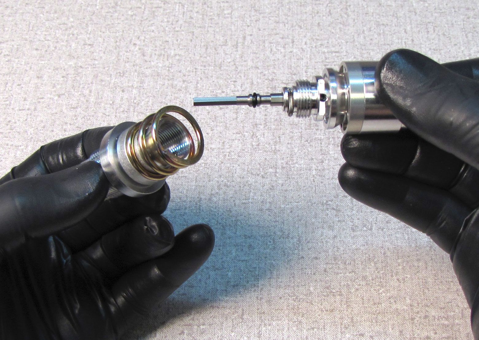
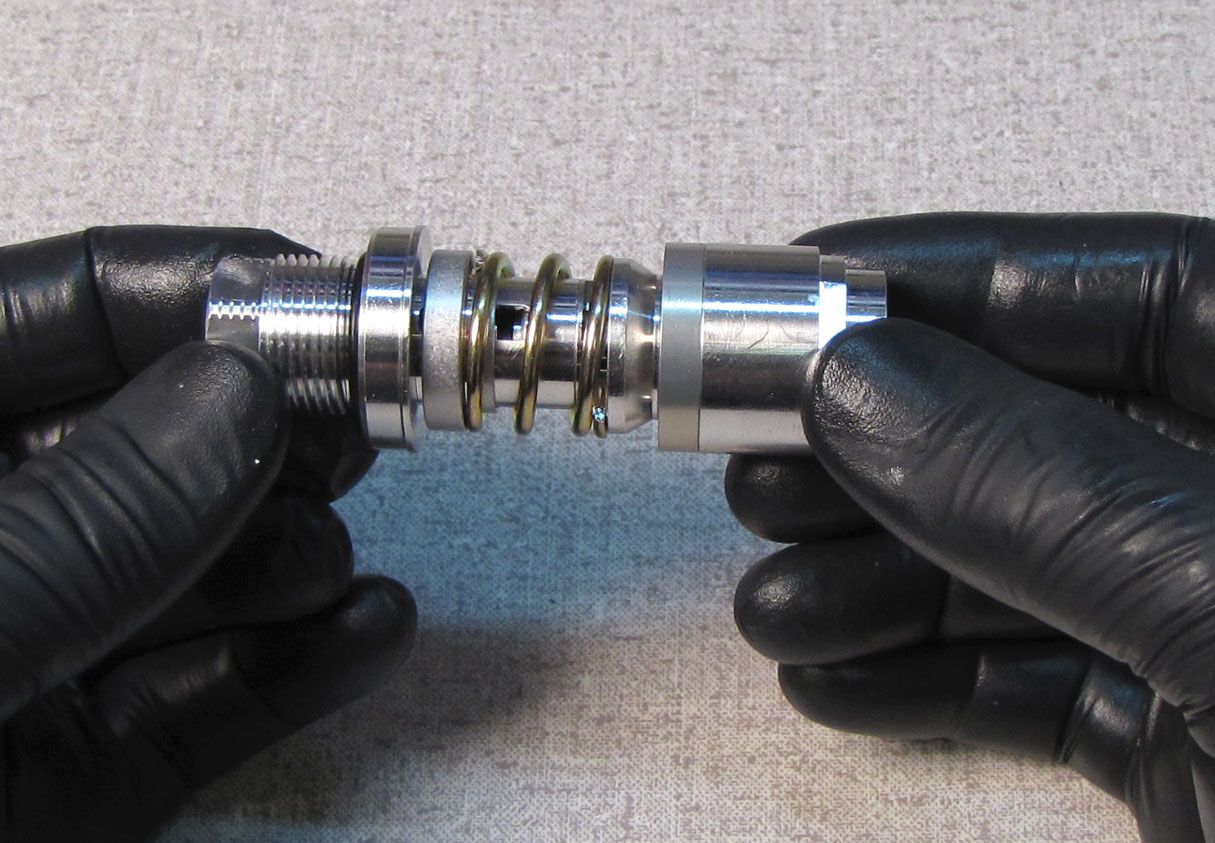
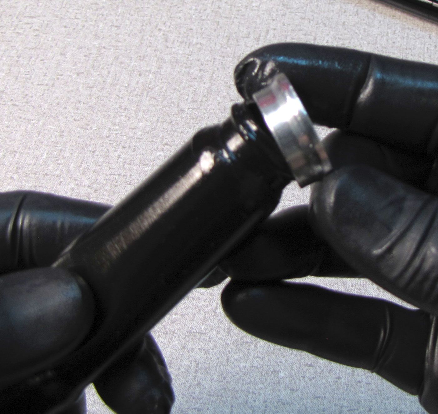
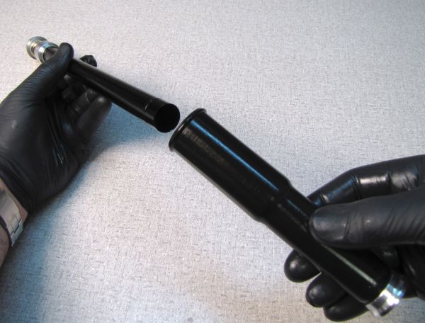
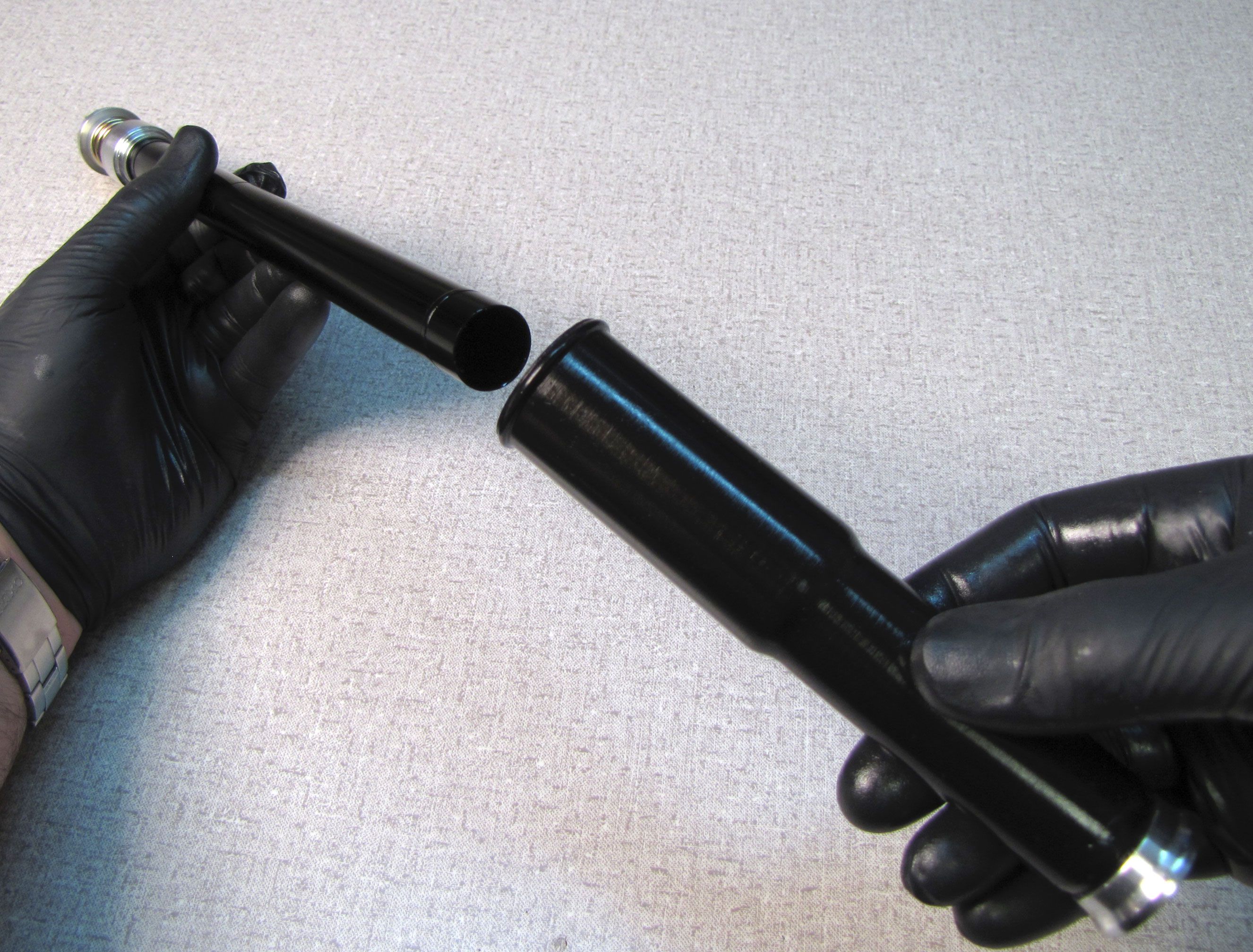
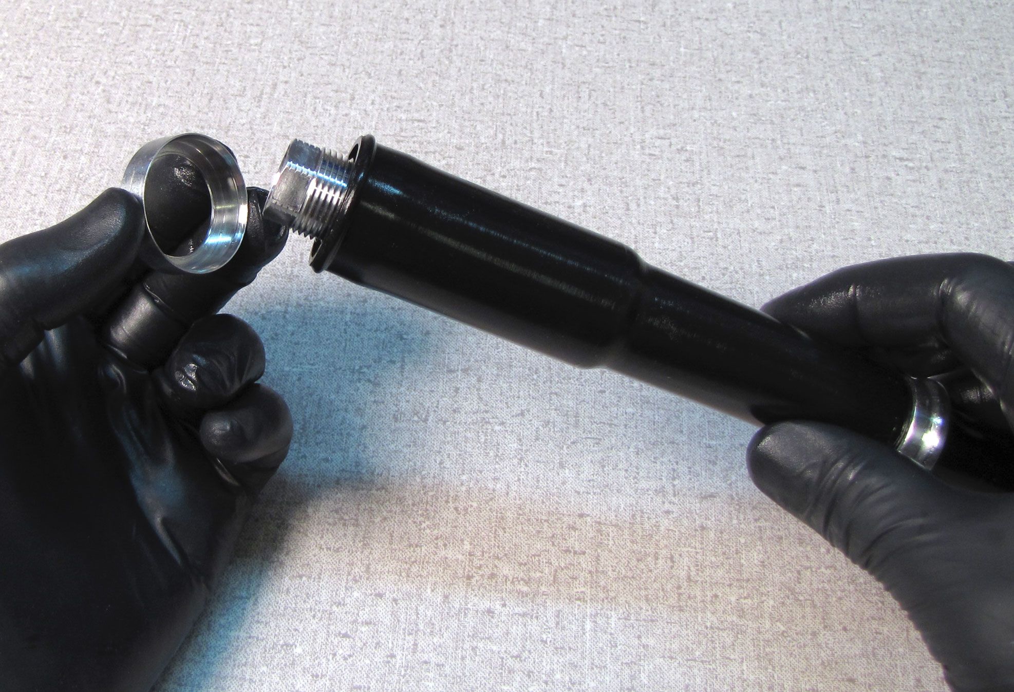
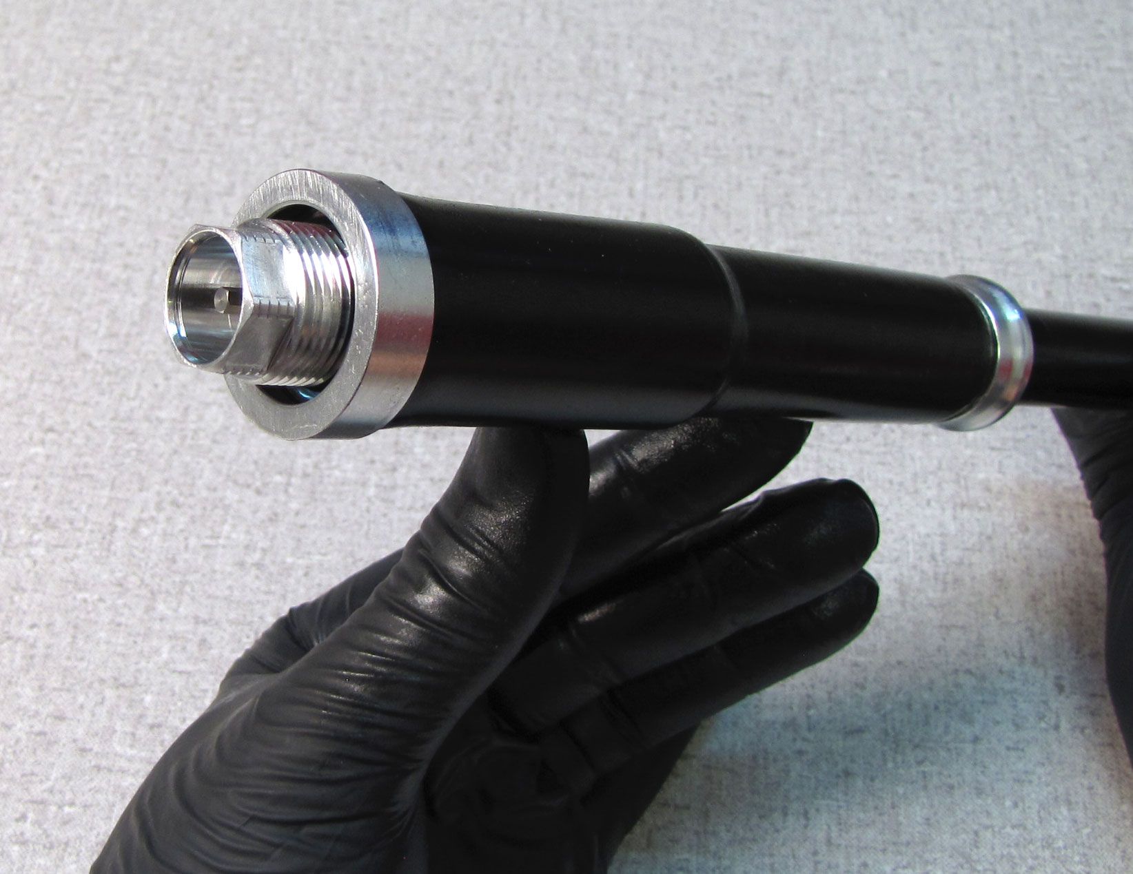
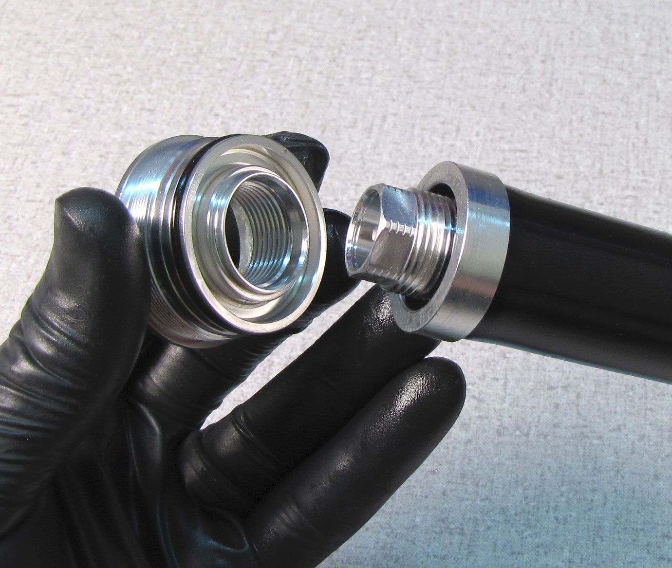
Step 9
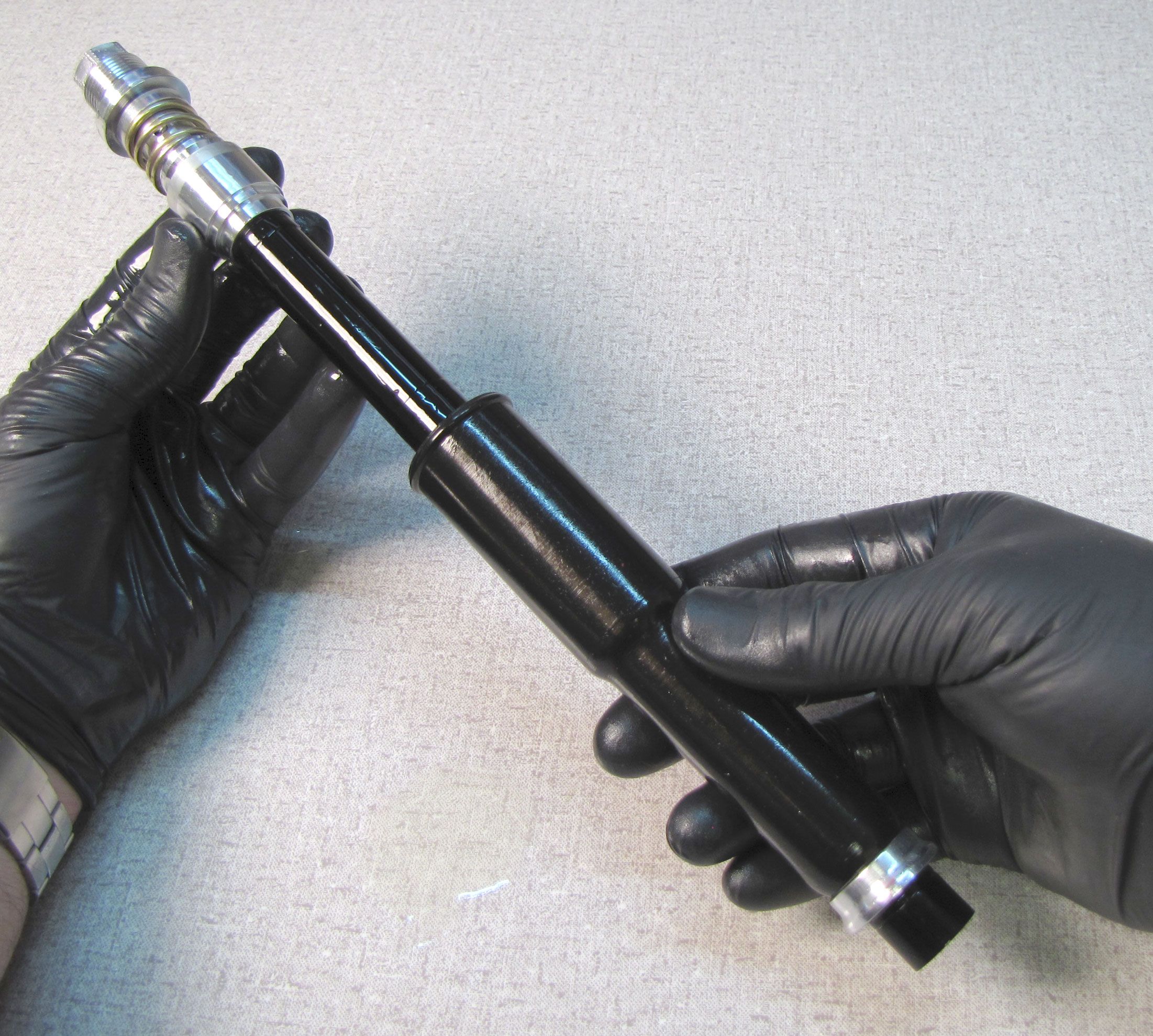
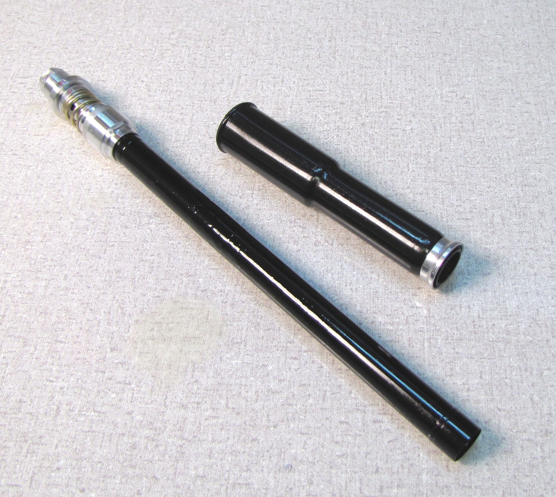
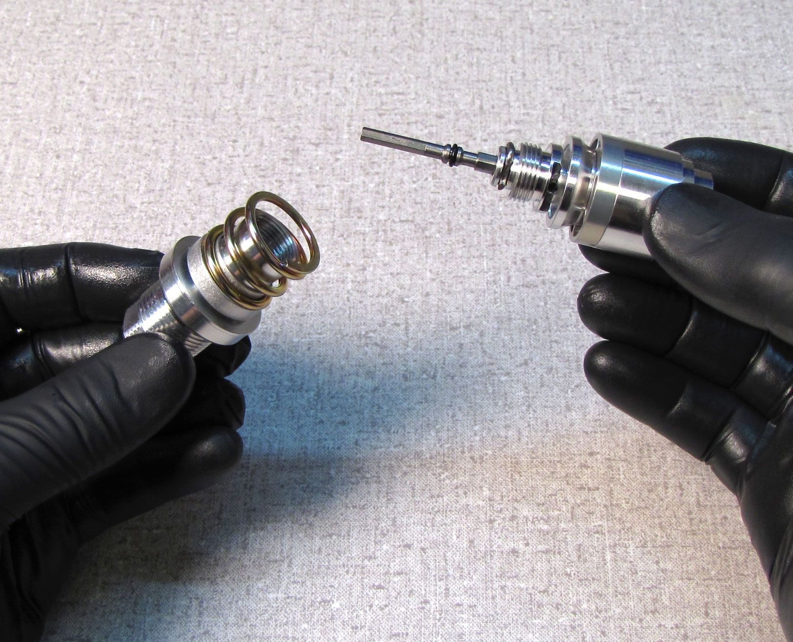
Clamp the cartridge body in your shaft clamps with the base valve up. Use a 21mm wrench to unthread the coupler counter-clockwise. Remove the base valve assembly from the cartridge body.
.jpg)
Most damper cartridge rebuilds will not require disassembly of the base valve. You should only rebuild the base valve if needed to solve a specific base valve related issue. Complete disassembly and reassembly is shown, but you may skip to Damper Cartridge Rebuild step 19 if you do not need to rebuild the base valve.

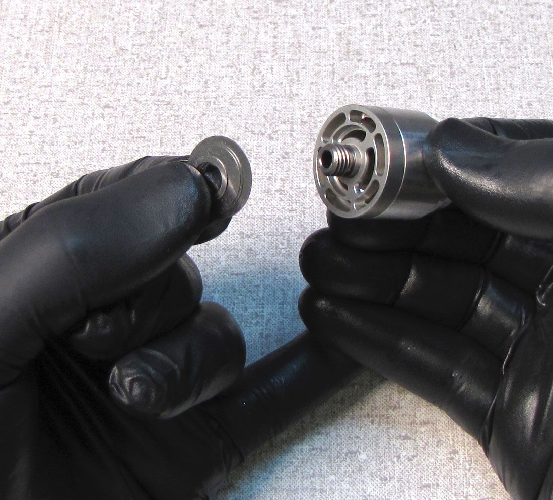
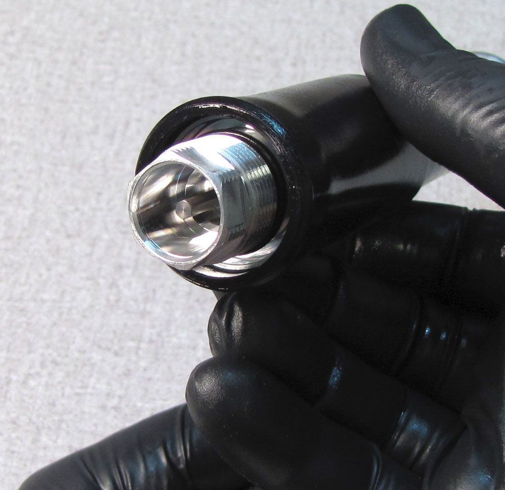
Step 10
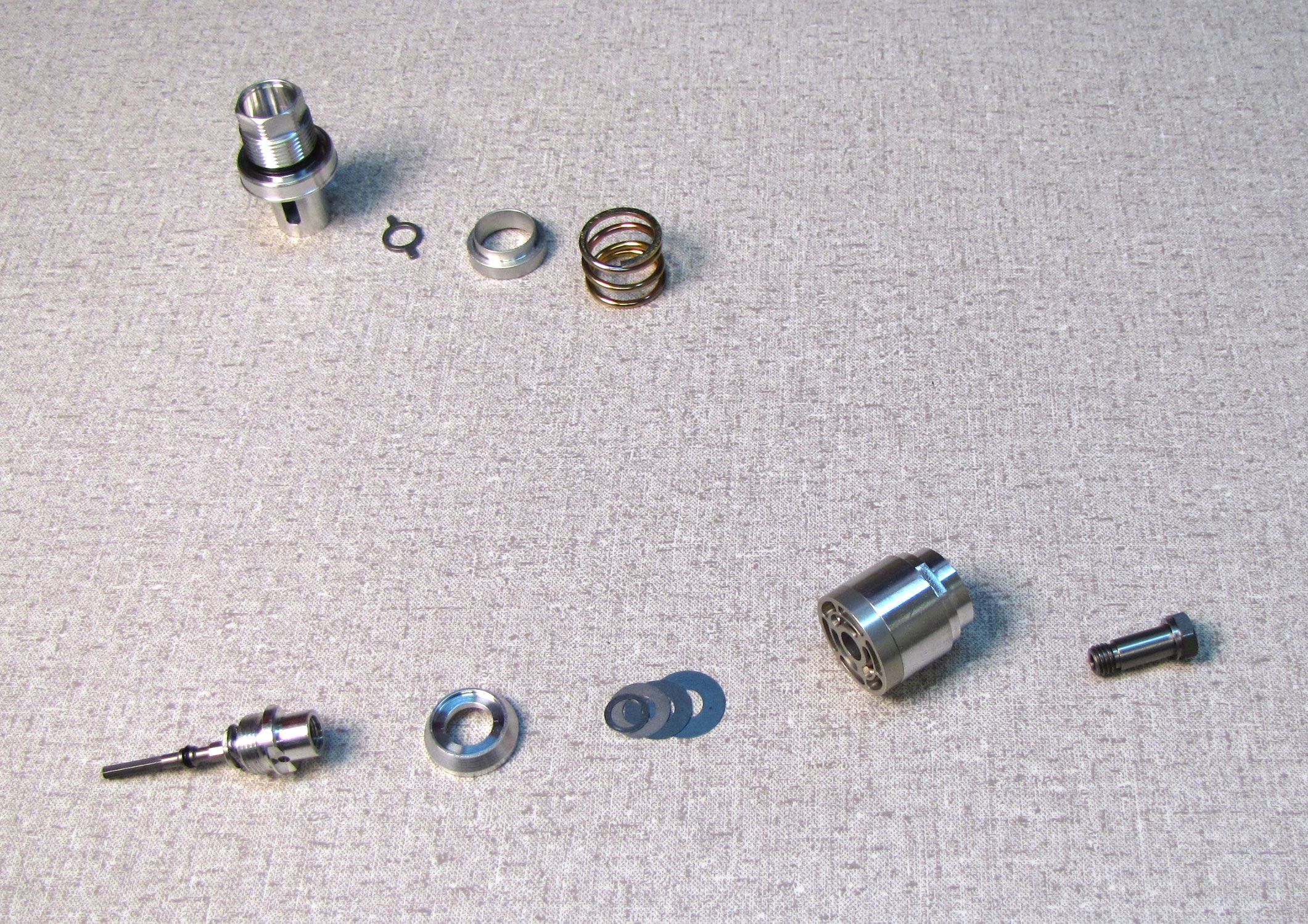
Use 10mm and 16mm sockets to begin disassembly of the base valve as shown. Lay out the spring, high-speed preloader, and preload plate in order as you remove them. Replace the o-ring on the base valve upper stud with a new greased one from the kit.
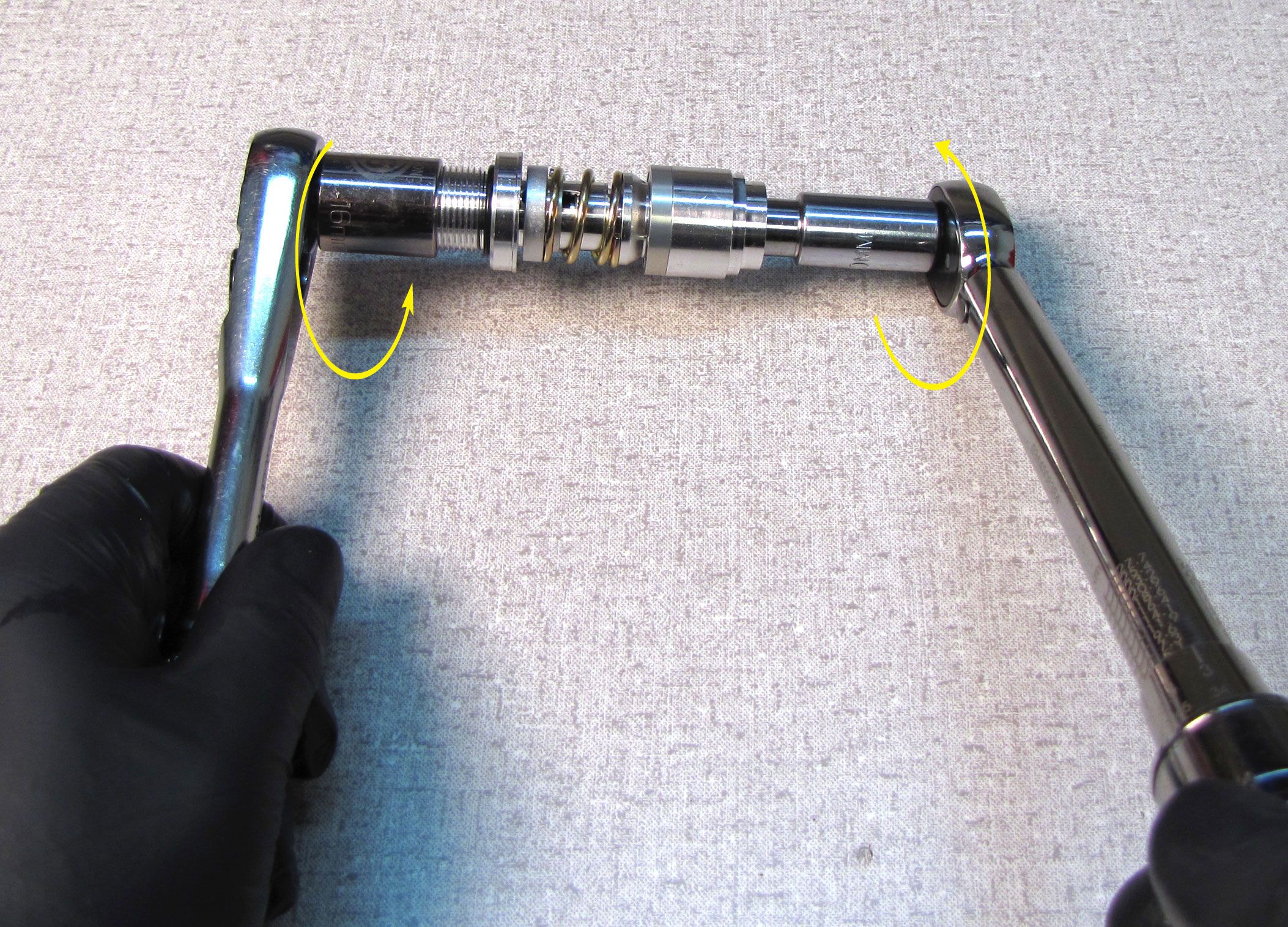
Step 11
Use a thin 10mm wrench on the LSC coupler and a 10mm socket on the compression bolt to further disassemble the base valve as shown. Lay the parts out in order as they are removed.

Step 12
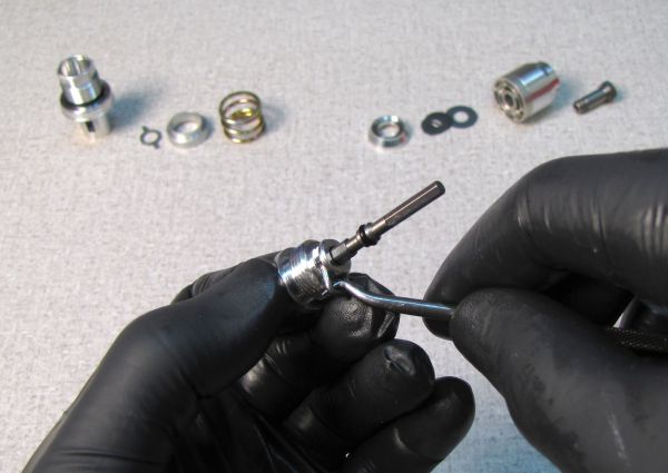
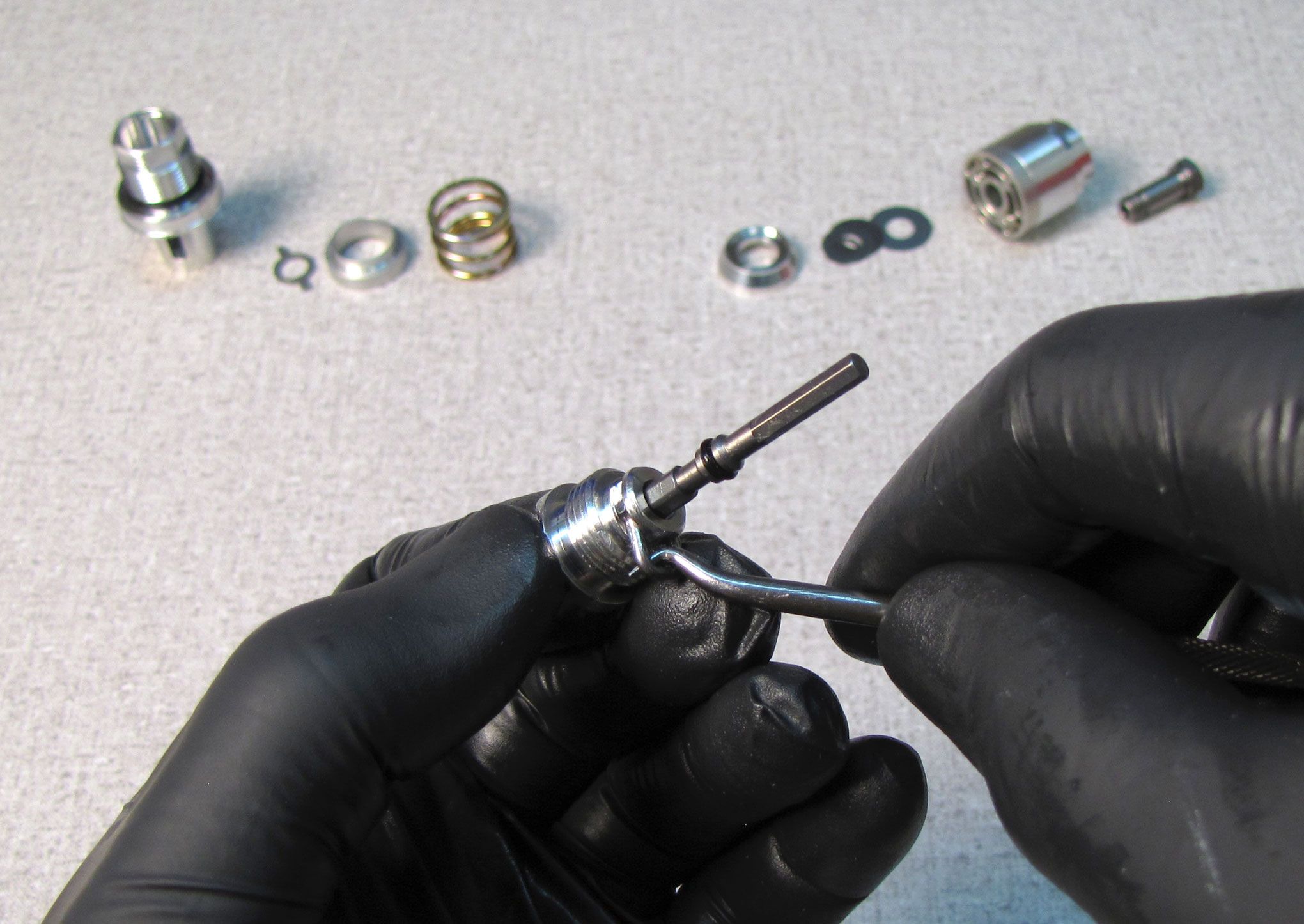
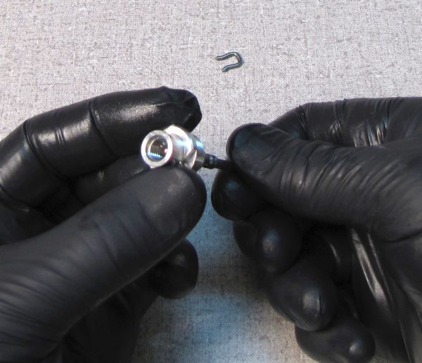
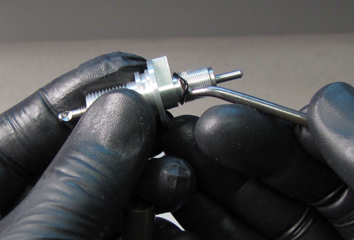
With a pick tool, pull the LSC detent wire spring from the LSC coupler. Remove the o-ring from the low speed adjuster, then remove the low speed adjuster from the LSC coupler unthreading it.
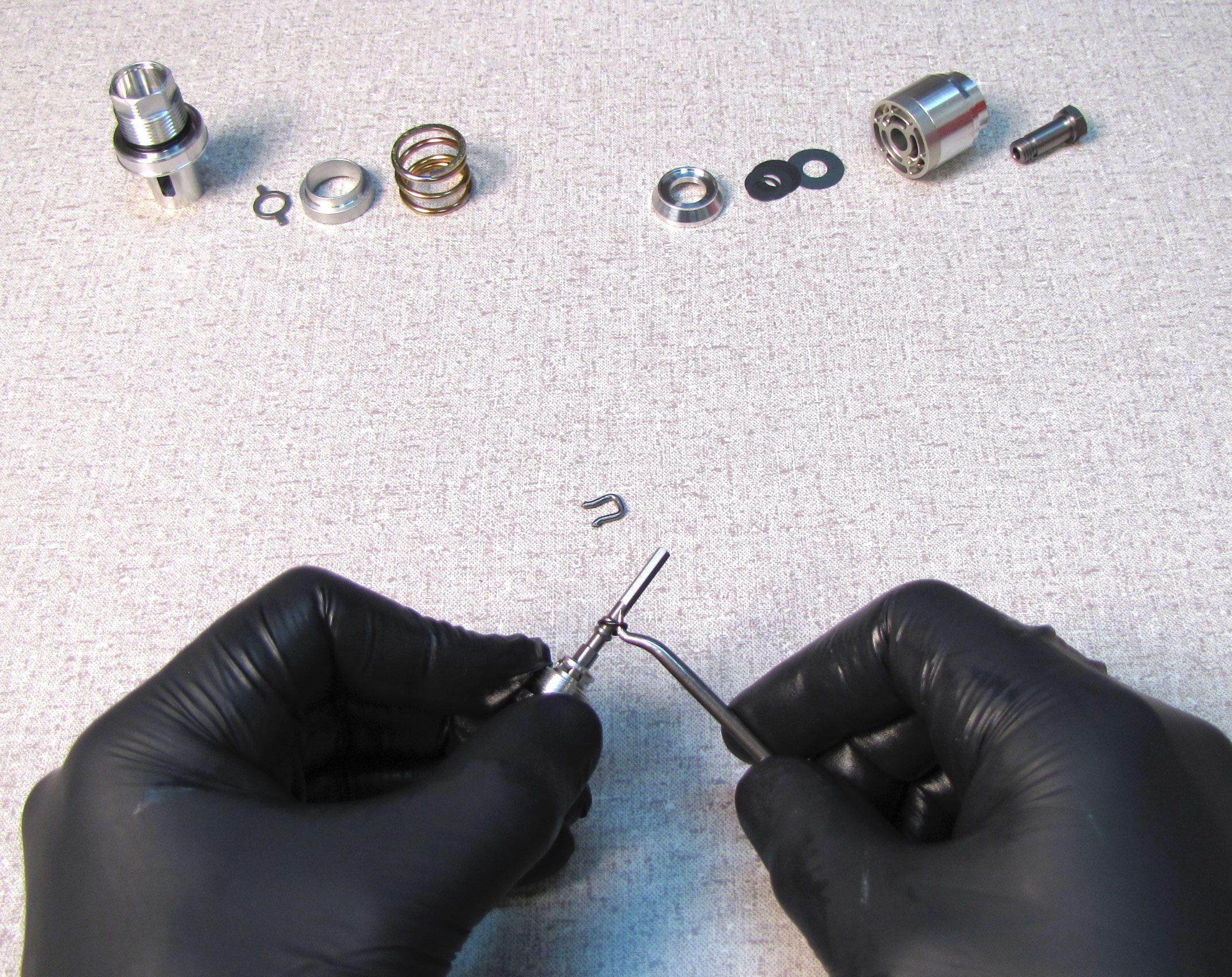
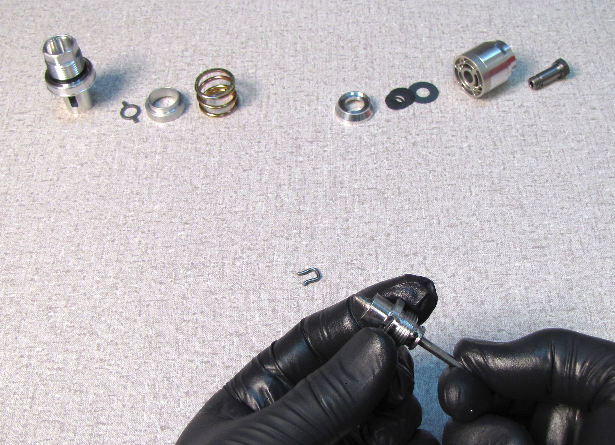
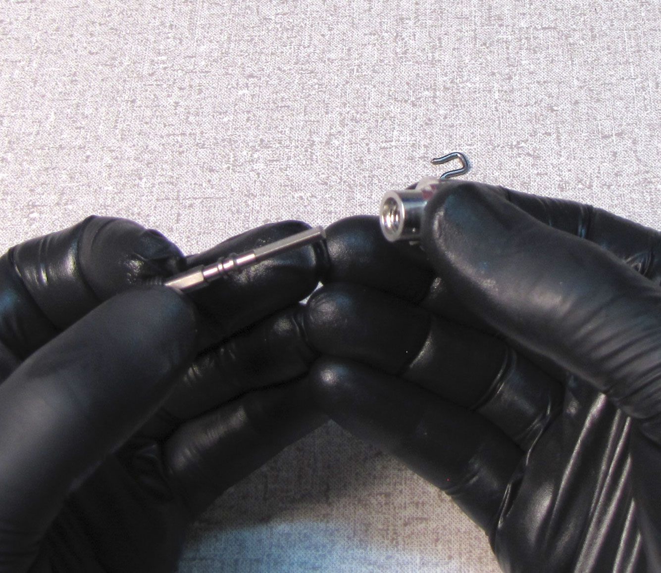
Step 13
Reinstall the low speed adjuster into the LSC coupler, threading the adjuster fully into the LSC coupler. Reinstall the wire detent spring onto the LSC coupler. Install a new, greased o-ring from the kit onto the low speed adjuster.
Step 14
Insert the compression bolt into the open end of the coupler. Reinstall the valve stack with the largest valve against the compression bulkhead. Rest the preload hat in place over the valve stack.


Step 15
Thread the LSC coupler onto the compression bolt making sure to insert the shaft portion of the LSC coupler through the preload hat. Use your thin 10mm wrench and 10mm socket to tighted the assembly to 50 in-lb (5.7 Nm) as shown.


Step 16
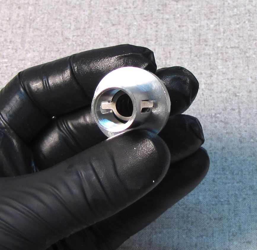
Reinstall the preload plate into the upper stud so its ears protrude from the two slots and the plate lays flat inside the upper stud.
Step 17
Reinstall the high-speed preloader followed by the spring. Thread the LSC coupler into the base valve and tighten to 50 in-lb (5.7 Nm) with a 16mm and 10mm sockets.


Step 18
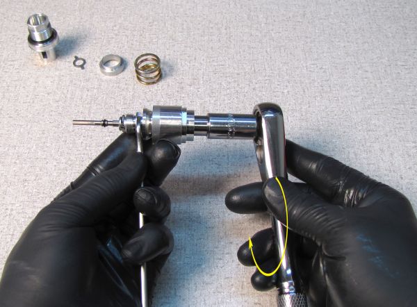
Clamp the cartridge body in your shaft clamps and reinstall the base valve assembly, tightening (clockwise) to 75 in-lb (8.5 Nm) with your 21mm crow's foot.
Step 19
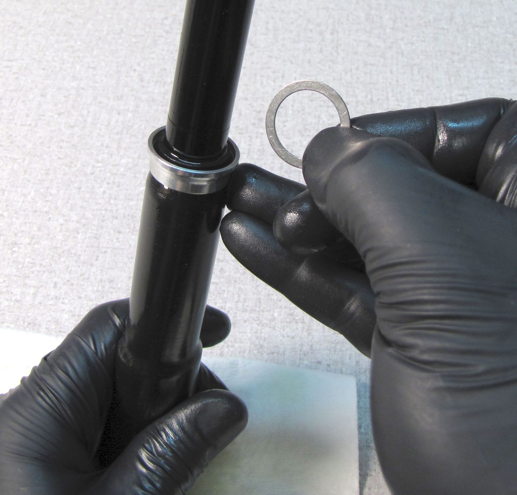
Apply a thin coating of Slick Honey to the inside and outside of both ends of a new bladder from the kit, then install the lower bladder ring as shown with it's larger end oriented toward the small end of the bladder.


Step 20
Install the bladder (larger end first) with lower bladder ring onto the cartridge body. Slide the bladder up so that approximately 1/4in (6mm) of the bladder is up past the rim of the upper stud.

Step 21
Install the upper bladder ring onto the bladder, then thread the topcap on (clockwise) by hand to press the upper bladder ring into place, seating the bladder.
Step 22
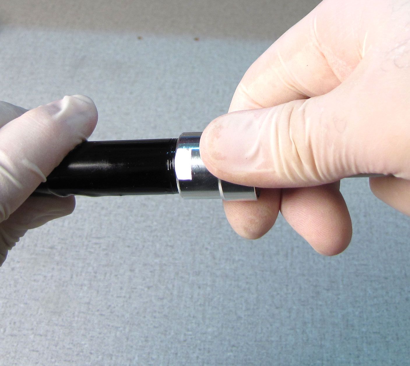
Position a 32mm 6-point chamfer-less box-end wrench on the topcap, and a 16mm socket on the base valve upper stud. Rest the 32mm wrench handle against the work surface, then tighten (counter-clockwise) the base valve upper stud with the 16mm socket, as shown. Work slowly and carefull so you don't damage the topcap wrench flats.
Step 23
Place the bladder and cartridge body assembly into the second largest hole in the sahft clamps #2 (PN: 803-00-147) as shown; loosely resting the bladder ring on the clamps, no clamping pressure applied to the bladder ring. While gently tugging the bladder from below, you will seat the bladder in the bladder ring deep enough to install the bladder retainer and retaining ring.

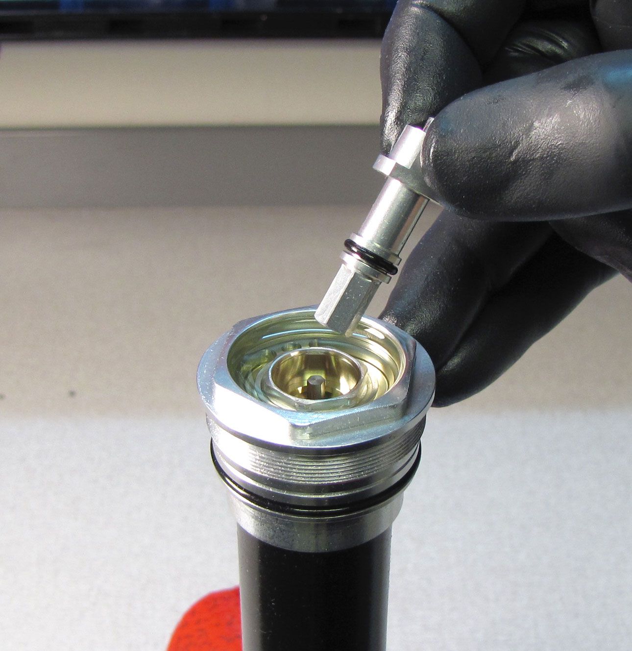
Step 24
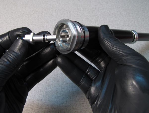
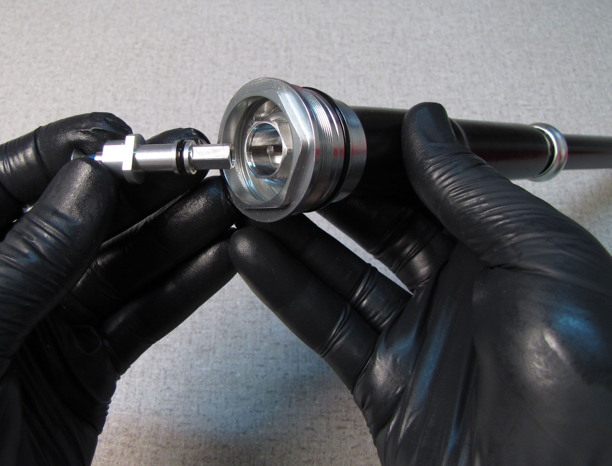
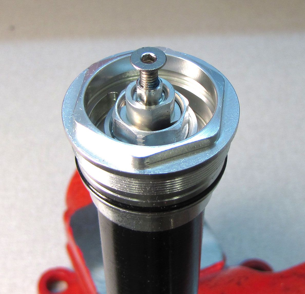
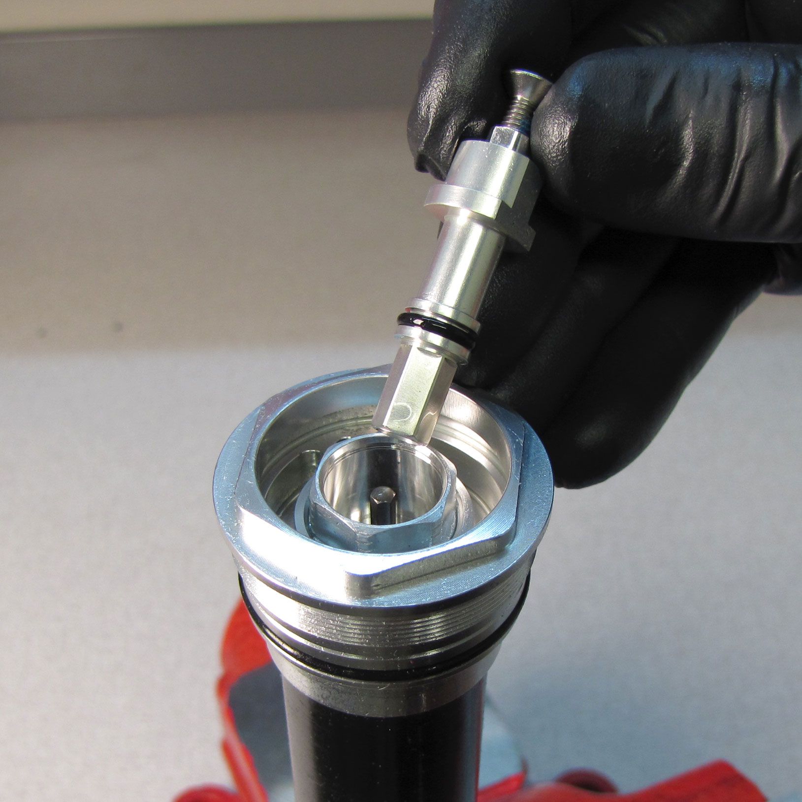
Temporarily install the compression adjust assembly into the base valve upper stud to seal the topcap. Make sure to engage the internal hex to seat the compression adjust assembly fully.
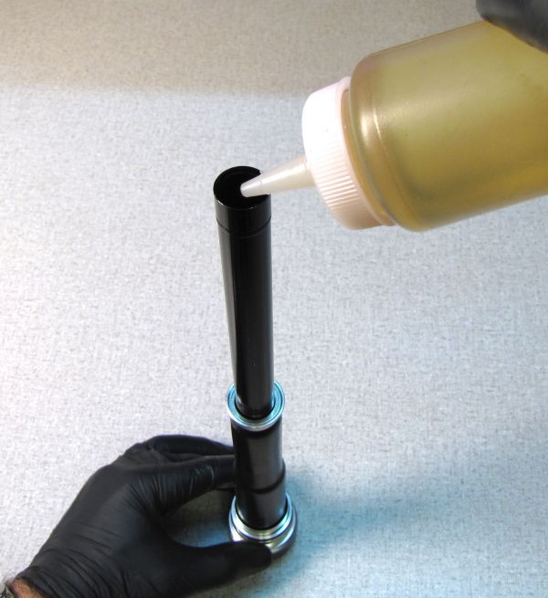
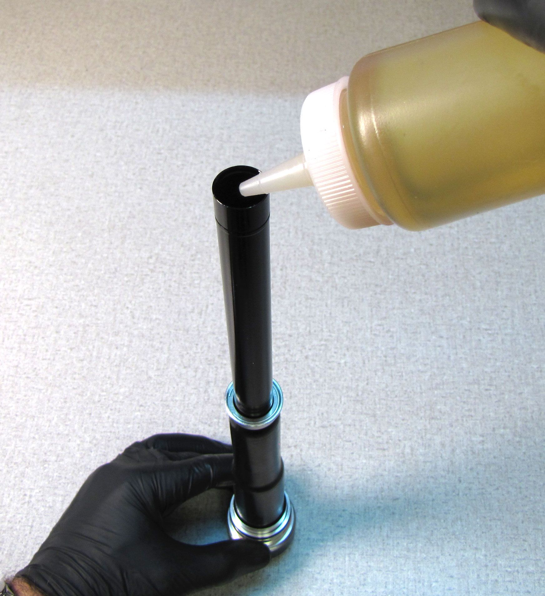
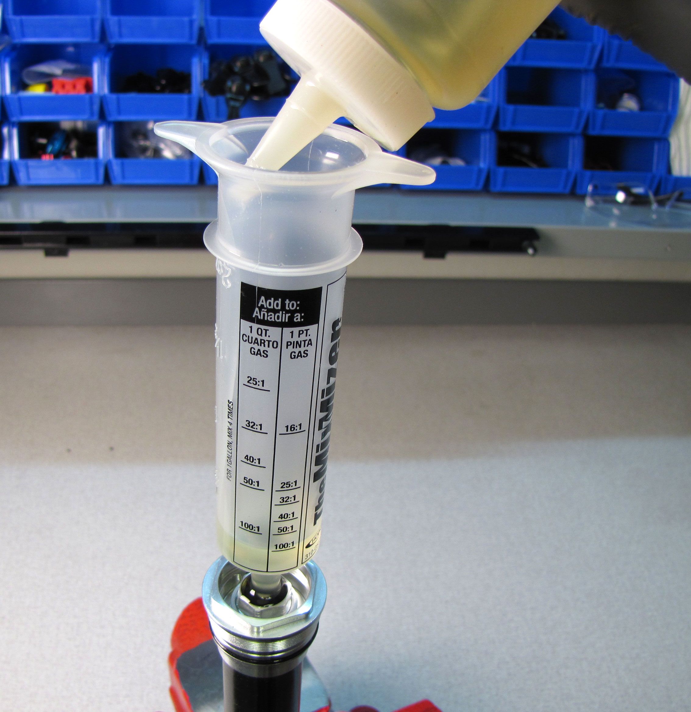
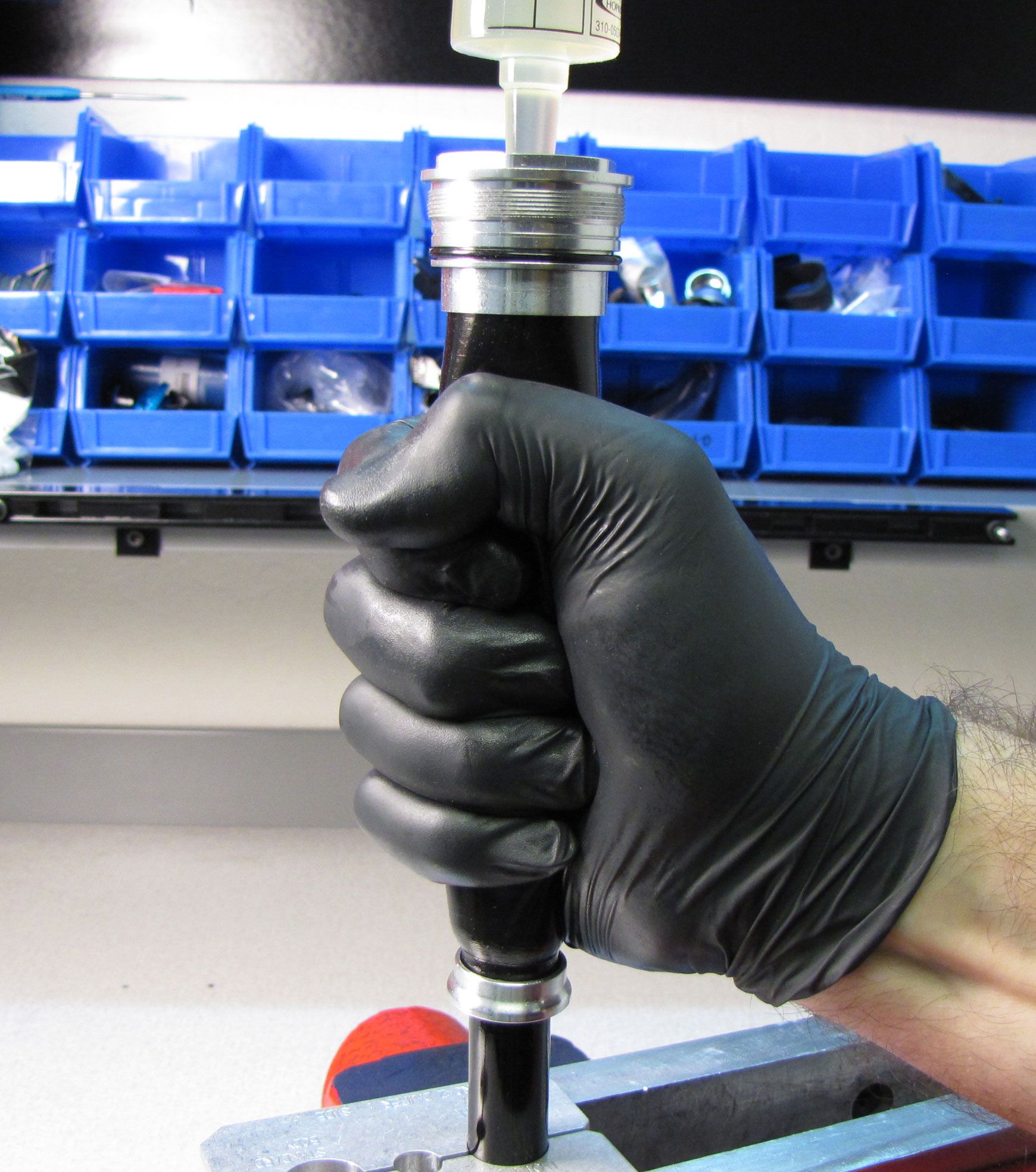
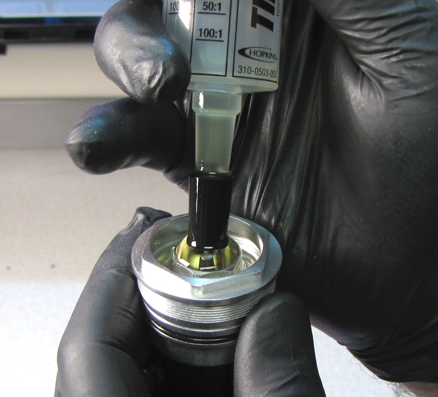
Step 25
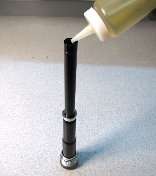
Rest the topcap in your 6-point chamfer-less 32mm socket and fill the cartridge body with FOX R3 5wt oil leaving approximately 2 inches (50mm) of air space above the oil within the cartridge body. Squeeze the bladder to expell air and ingest oil. Repeatedly squeeze the bladder and add oil until the oil level is approximately 2 inches (50mm) below the end of the body when not squeezing the bladder.
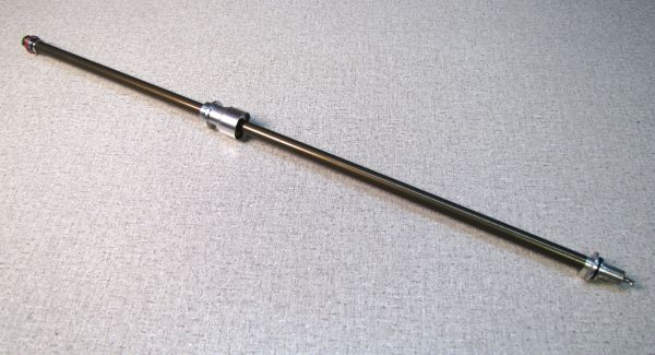
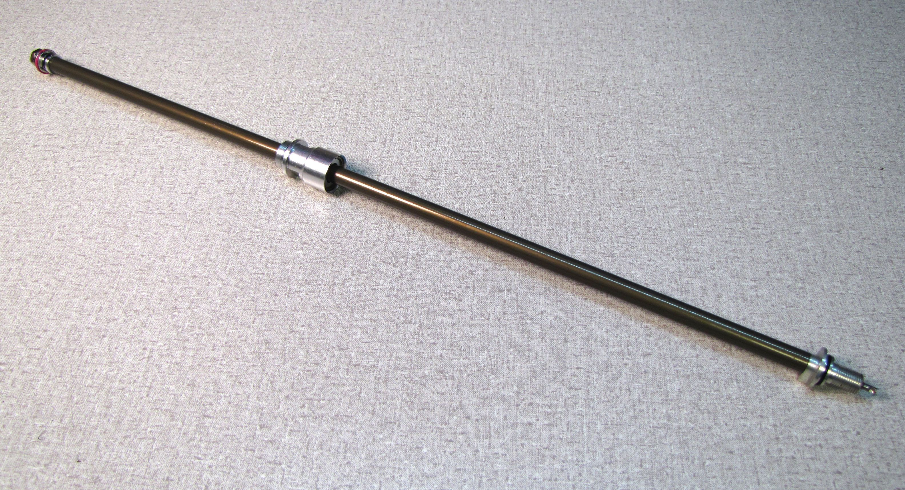
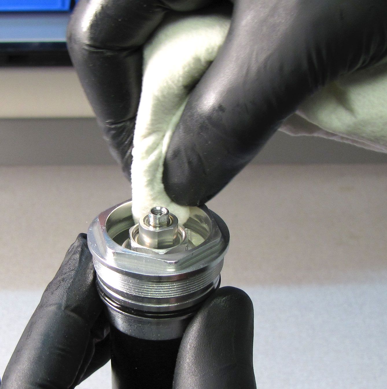
Step 26
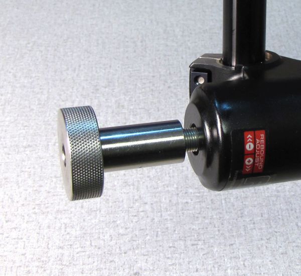
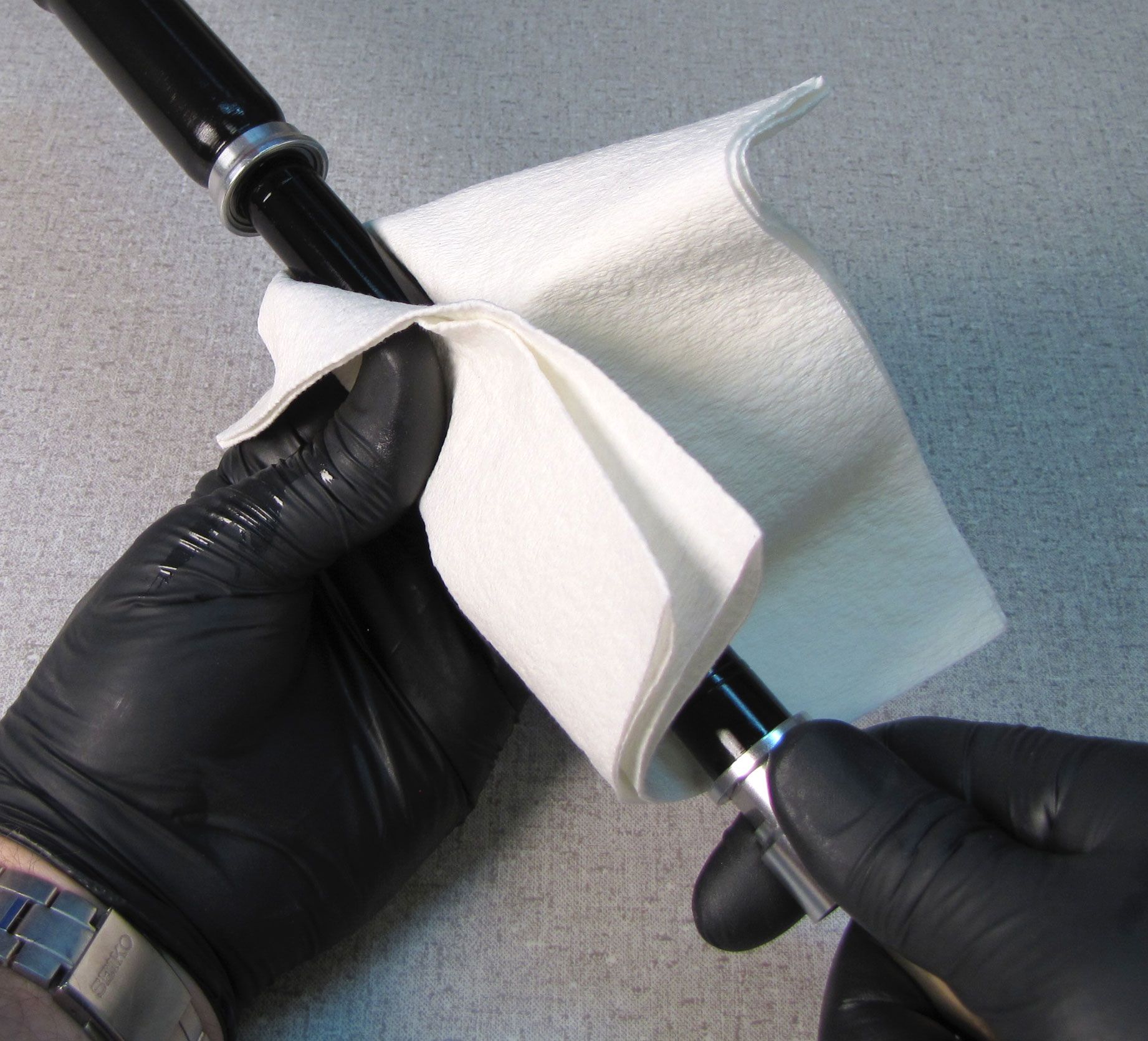
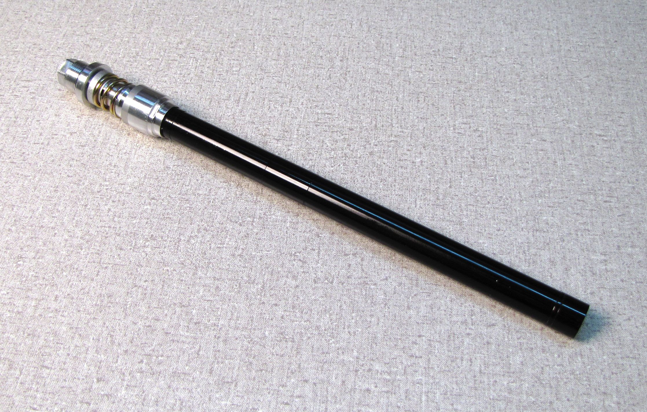
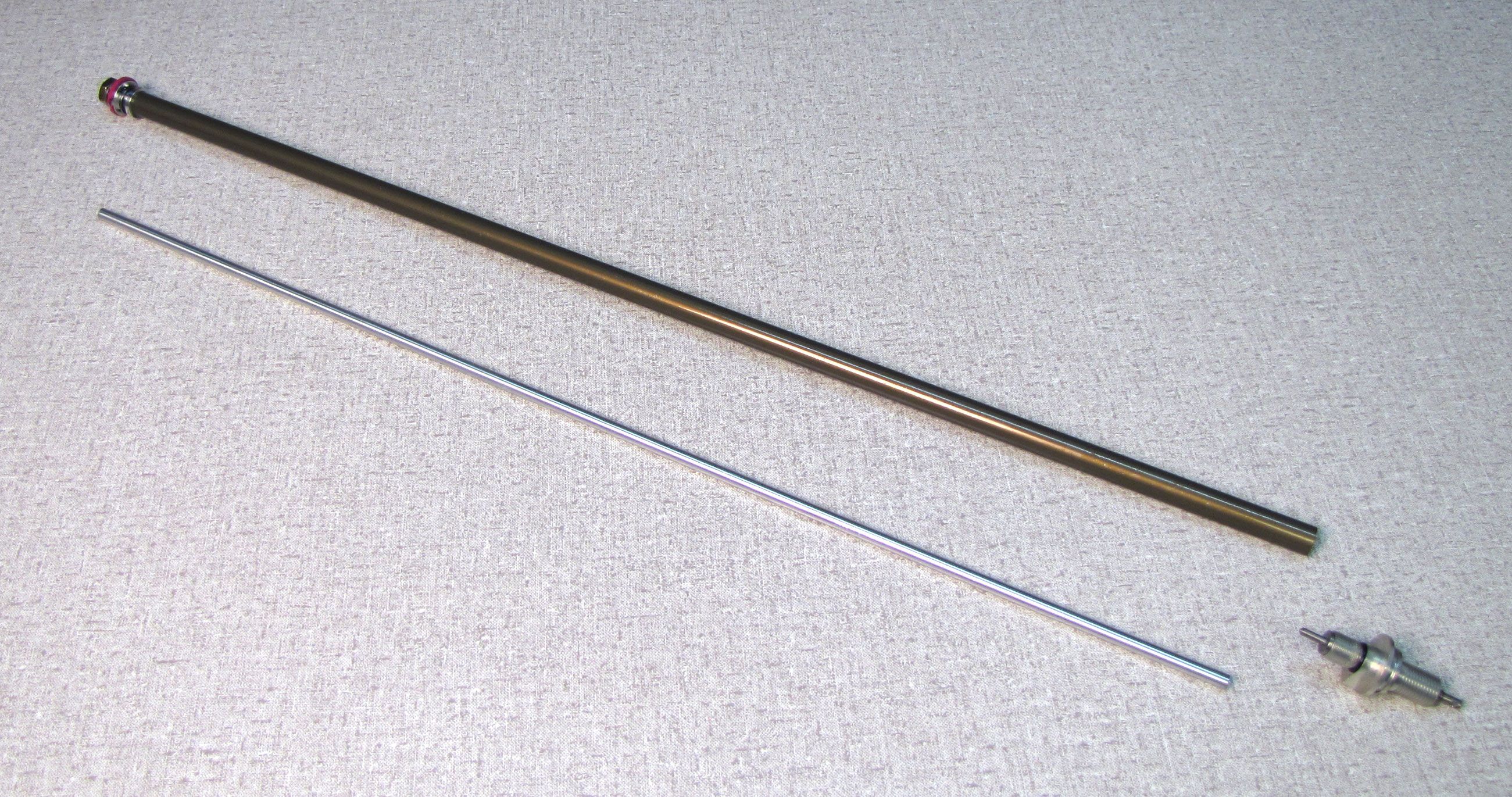
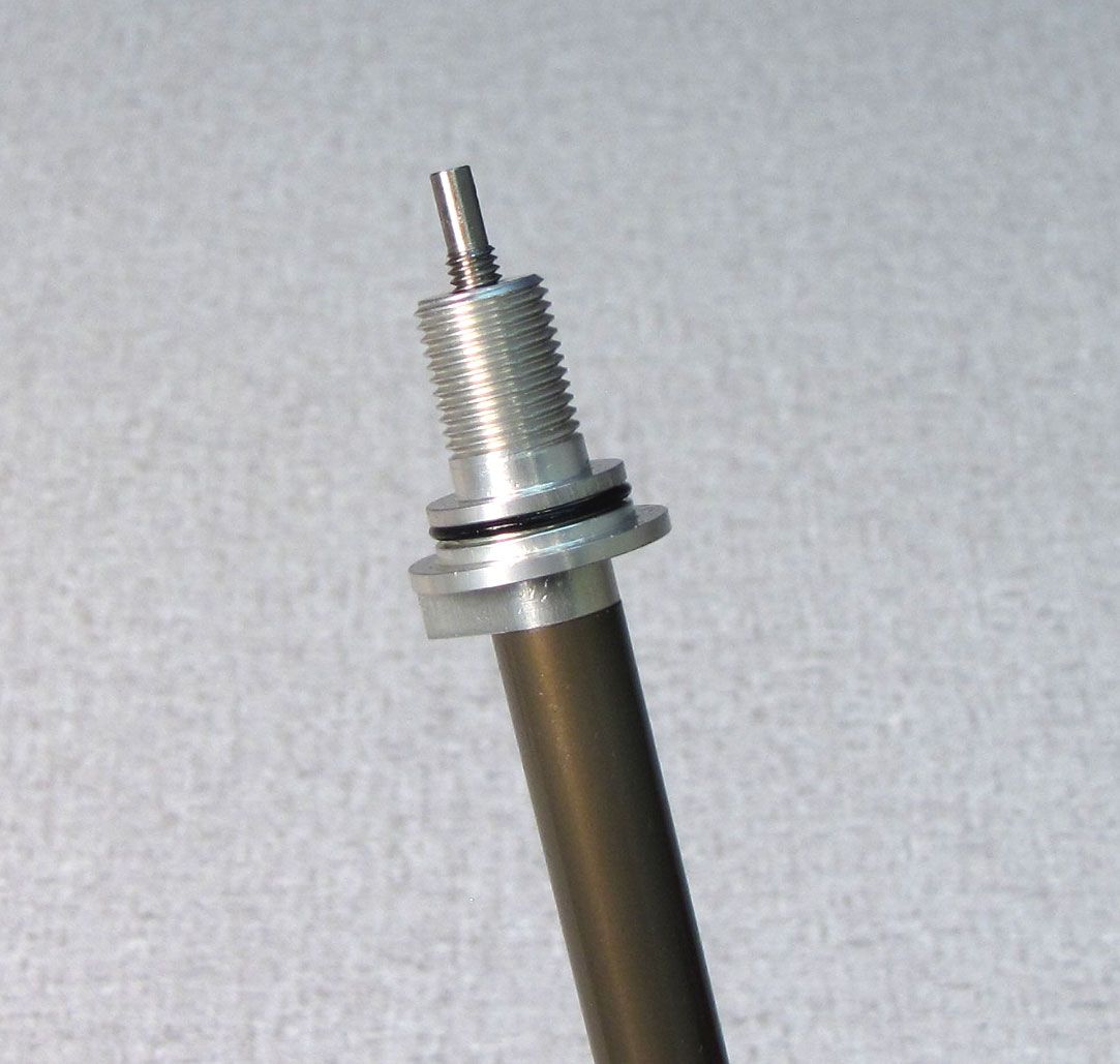
Slide the sealhead toward the rebound adjuster, leaving about 1 inch (25mm) space between the sealhead and rebound adjuster. Clean the shaft with isopropyl alcohol and a lint-free paper towel.
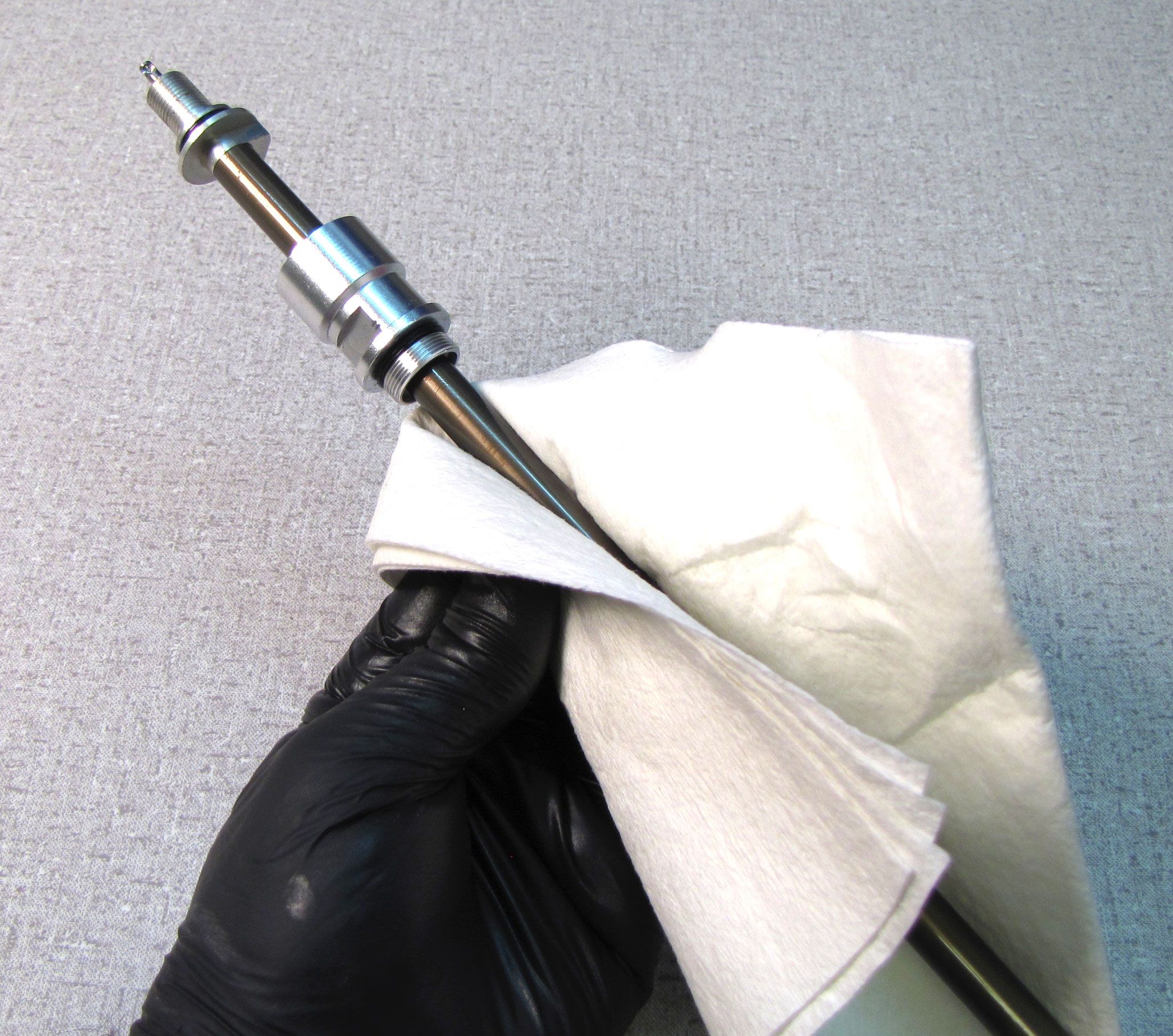

Step 27
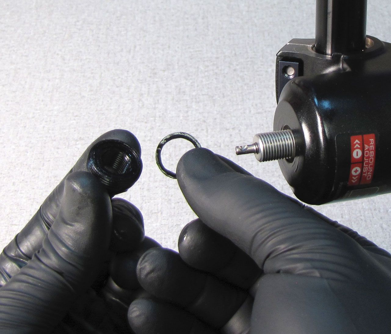
Clamp the shaft in your shaft clamps (PN: 803-00-830) and remove and discard the o-ring from the rebound adjuster.
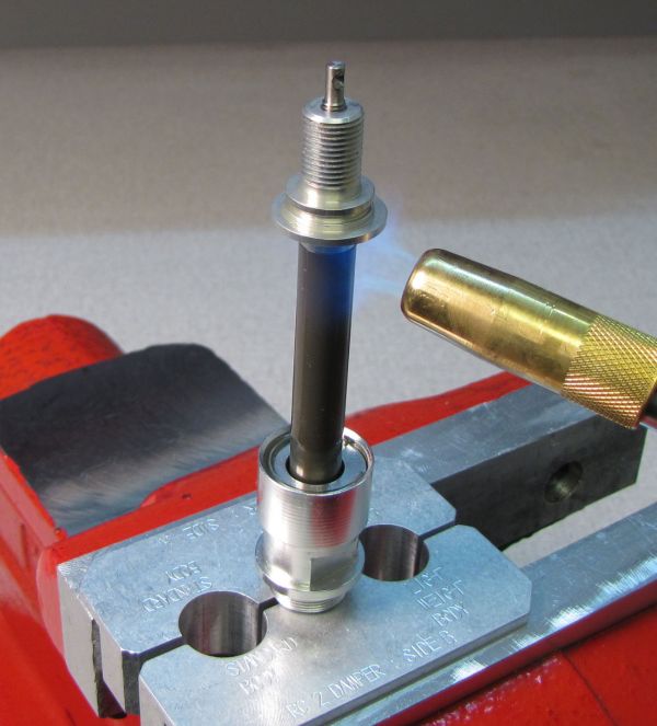
Step 28
Carefully apply heat to the shaft at the rebound adjuster with a propane torch for 5-10 seconds to break down the Loctite. Unthread the rebound adjuster counter-clockwise with a 10mm wrench.

Step 29
Lift the rebound adjuster up and out of the shaft. Replace the o-ring on the rebound adjuster with a new greased one from the kit.

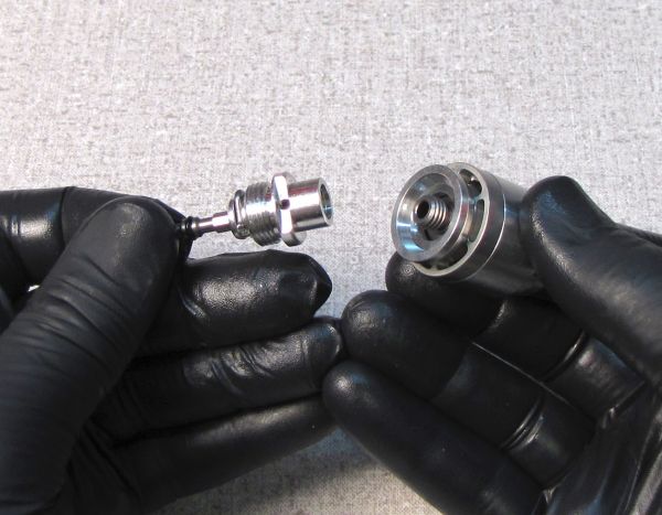
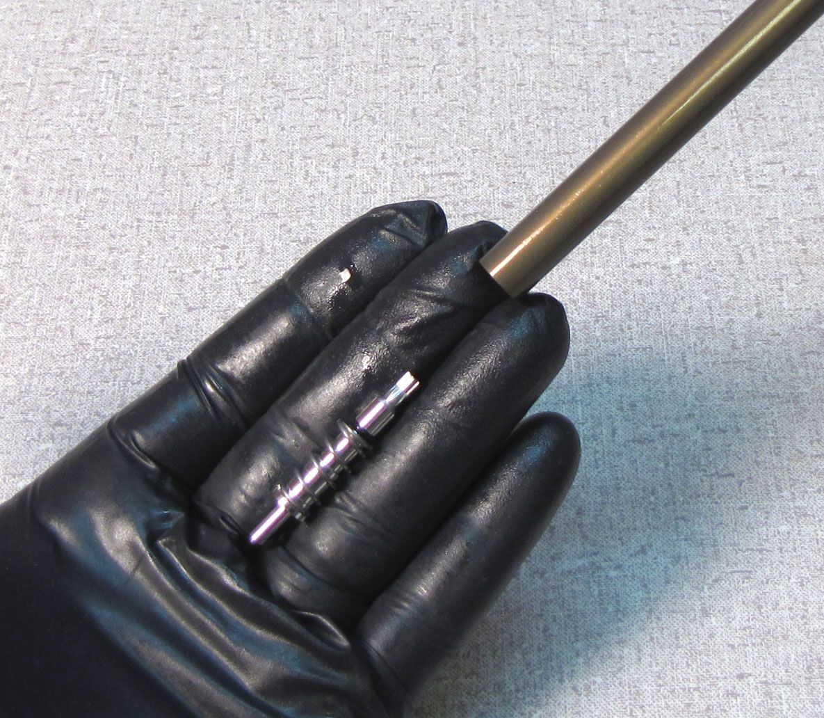
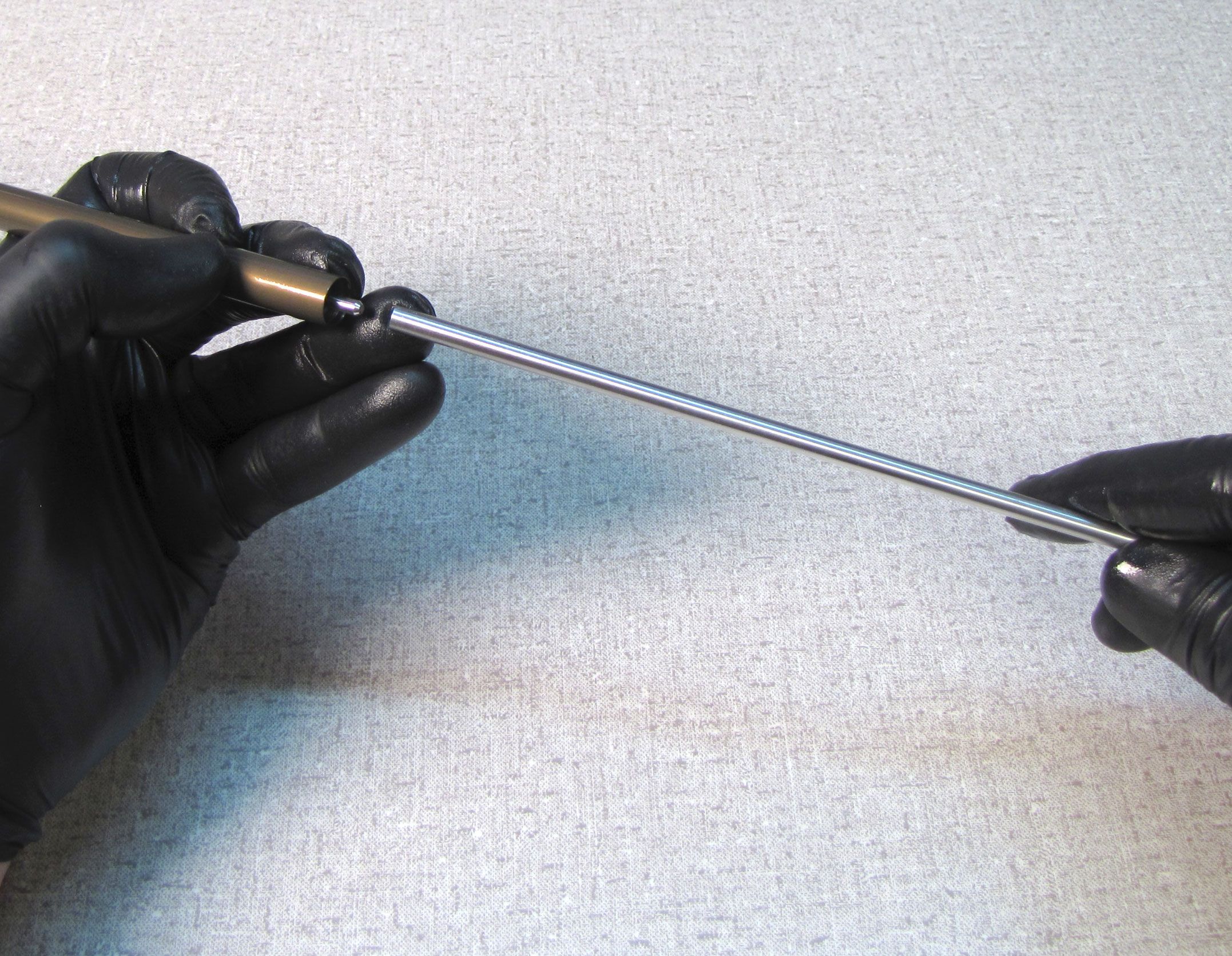
Step 30
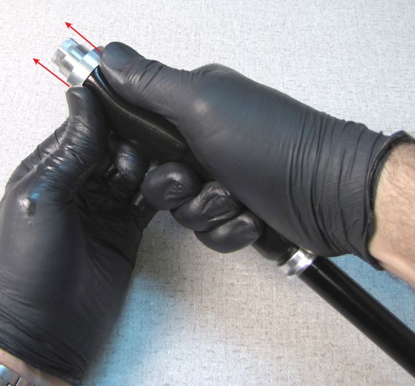
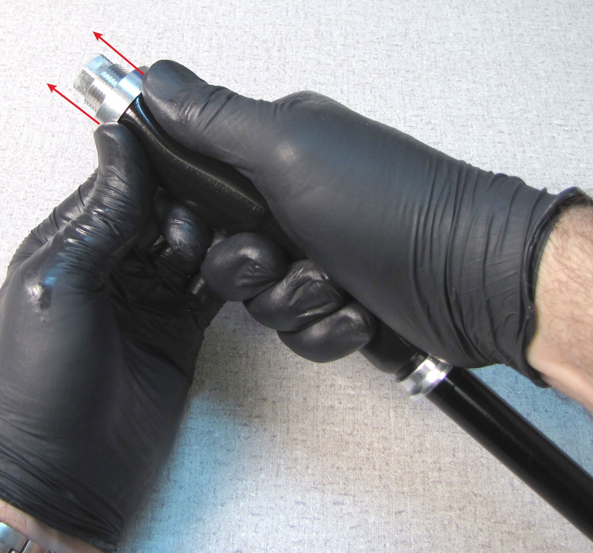
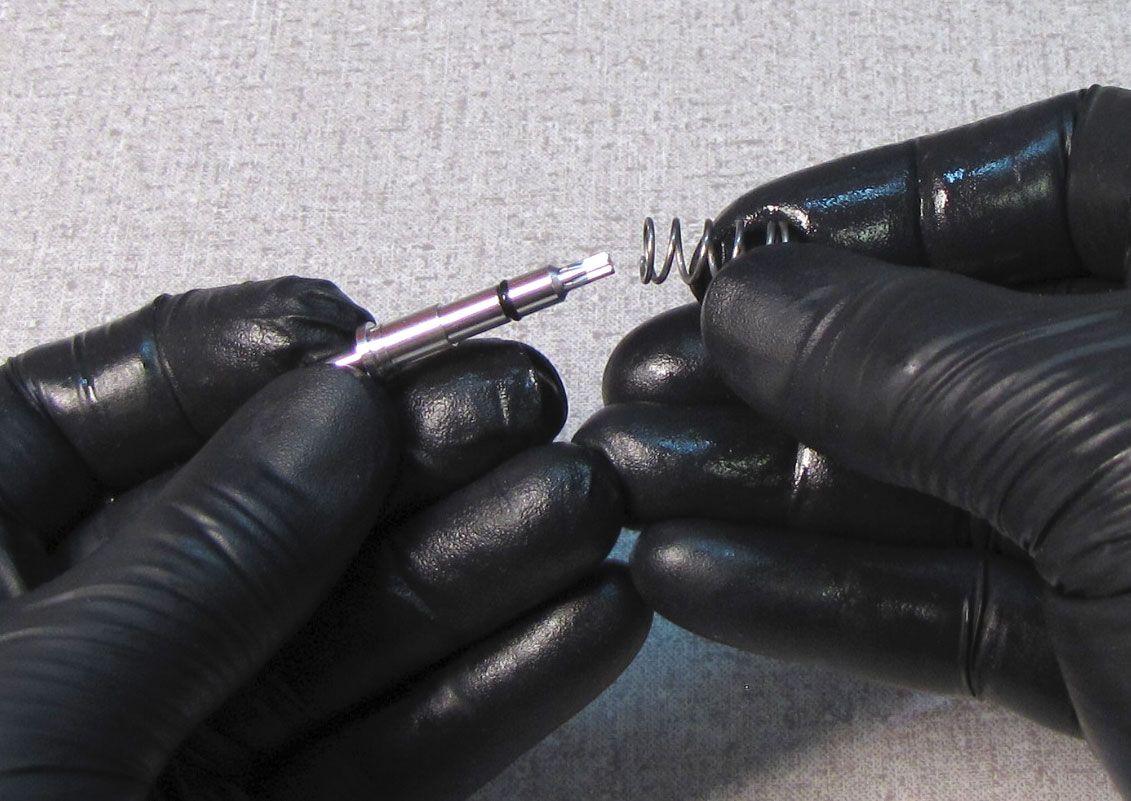
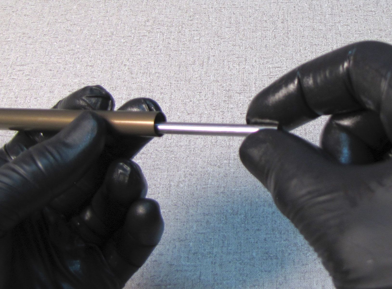
Remove and discard the original sealhead. Remove the rebound tube from within the shaft.


Step 31
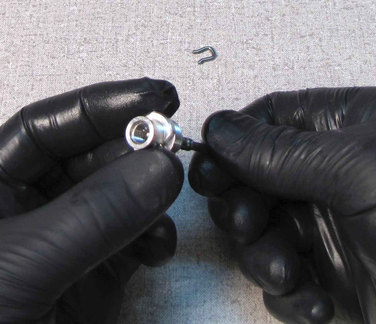
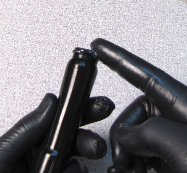
Use a 1.5mm hex wrench or similar thin blunt tool to unseat the rebound needle from within the rebound piston assembly. Invert the open end of the shaft to allow the rebound needle and spring to drop out.
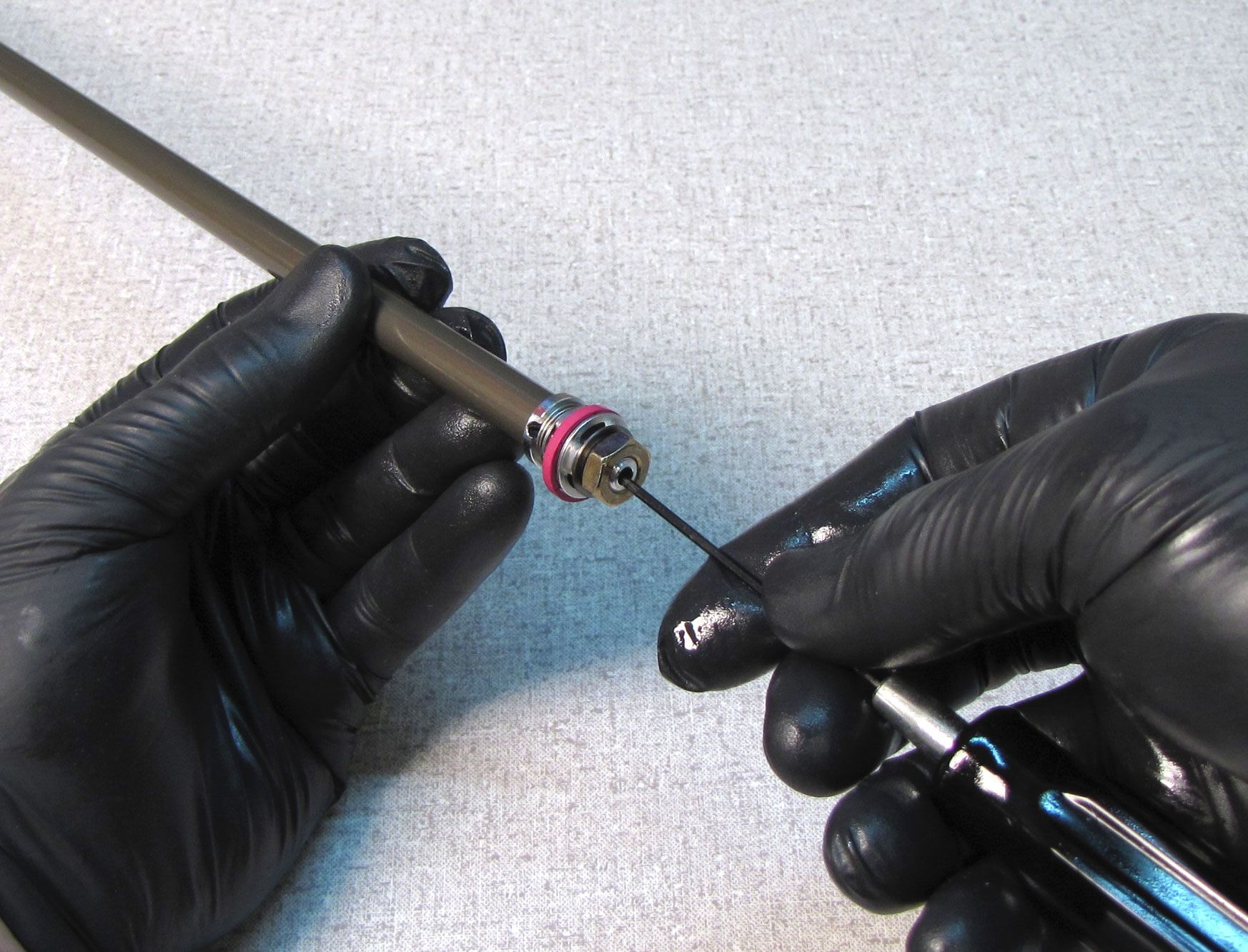
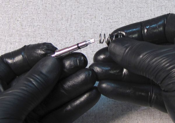
Step 32
Replace the o-ring on the rebound needle with a new greased one from the kit. Reinstall the spring and needle together into the end of the shaft. Use the rebound tube to gently push the rebound needle and spring toward the piston end of the shaft. Remove the rebound tube.
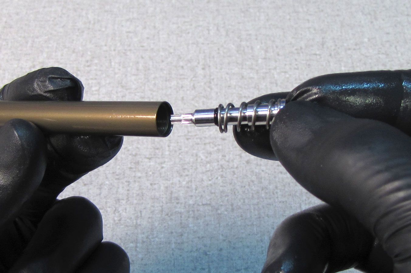

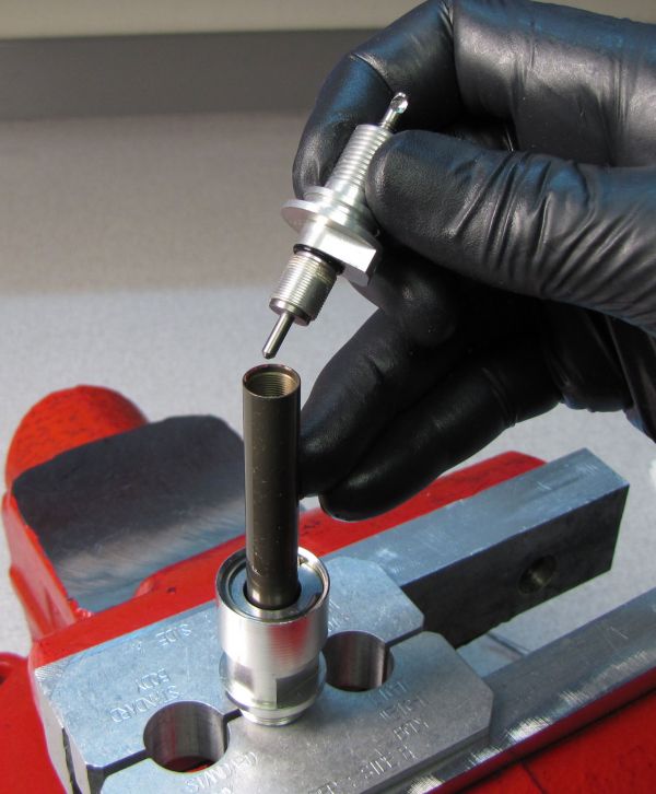
Step 33
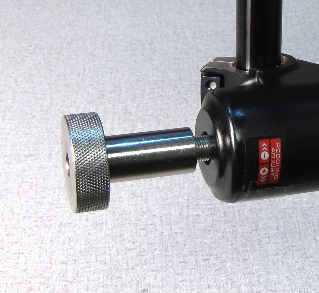
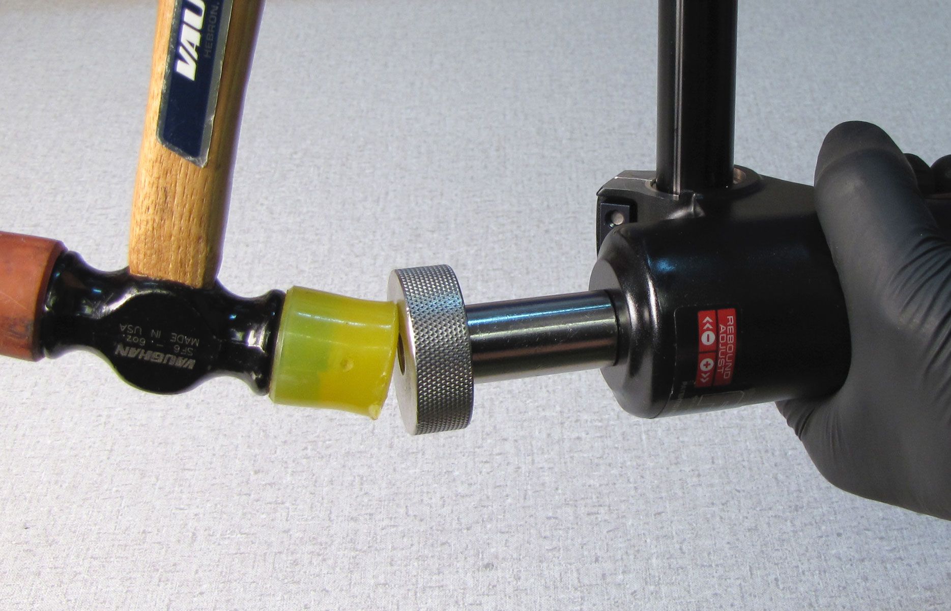
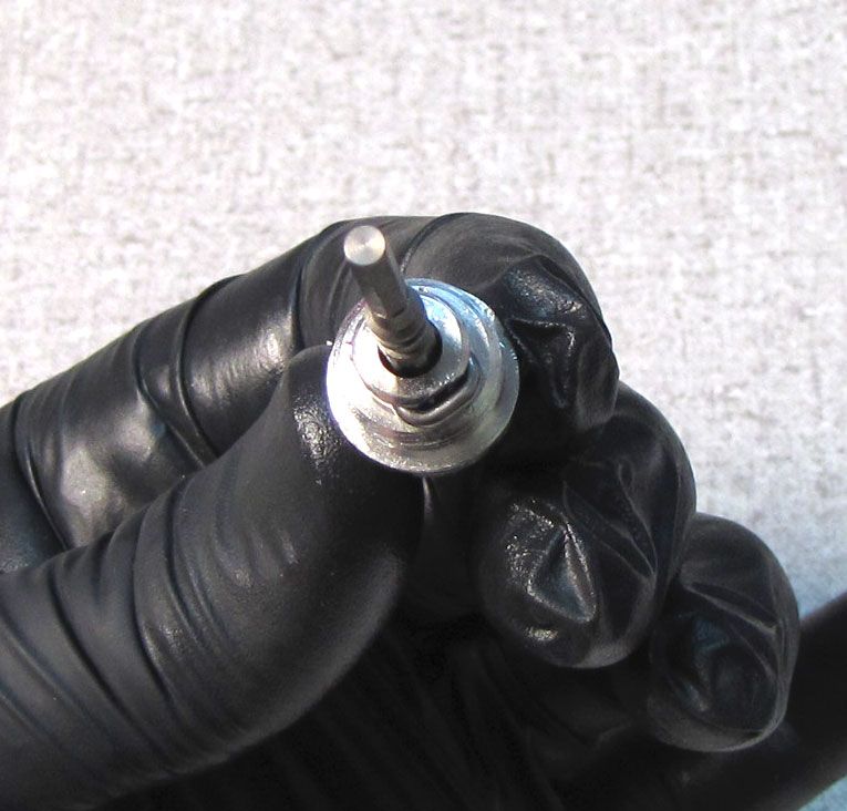
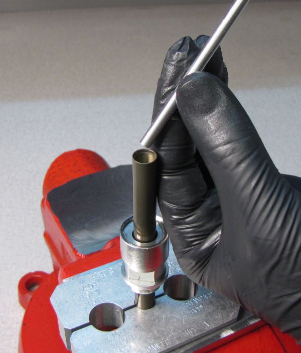
Clamp the shaft in your shaft clamps with the open end facing up. Install the 10mm shaft bullet (PN: 398-00-371), then coat the bullet with a film of Slick Honey.
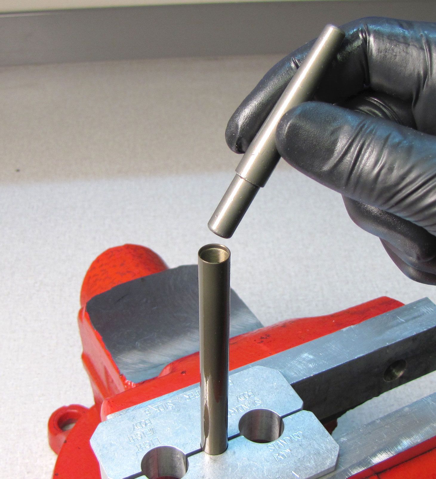
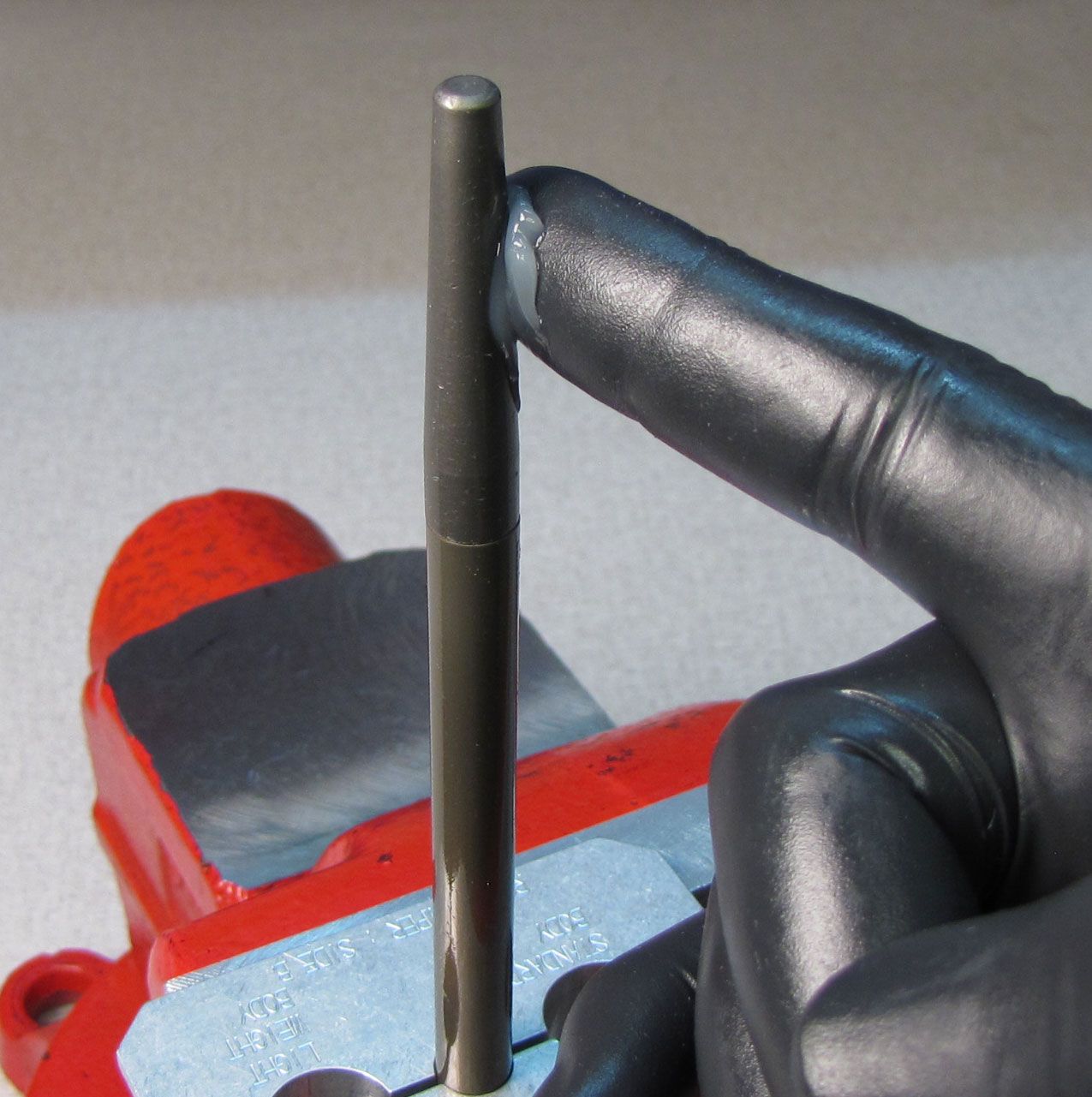
Step 34
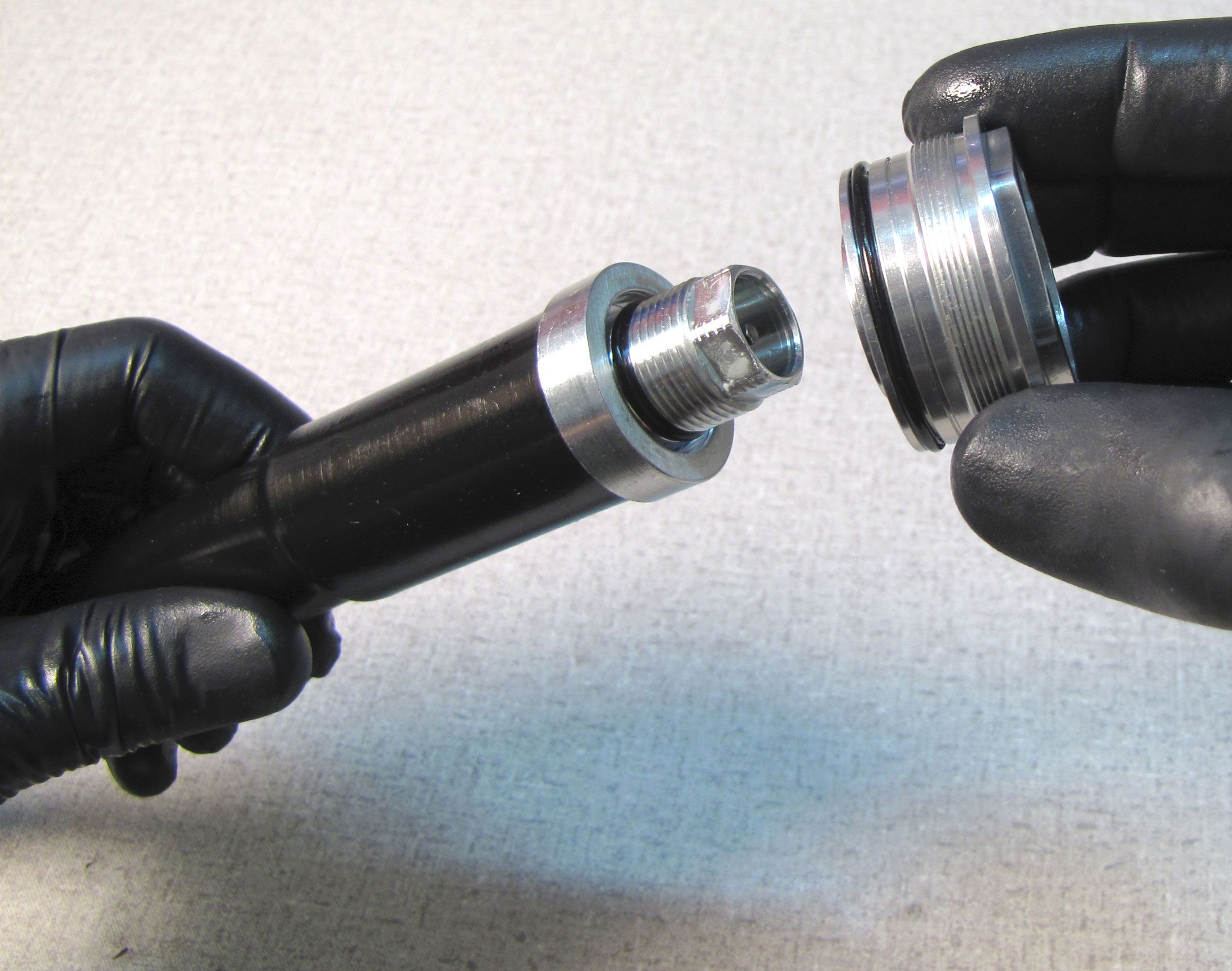
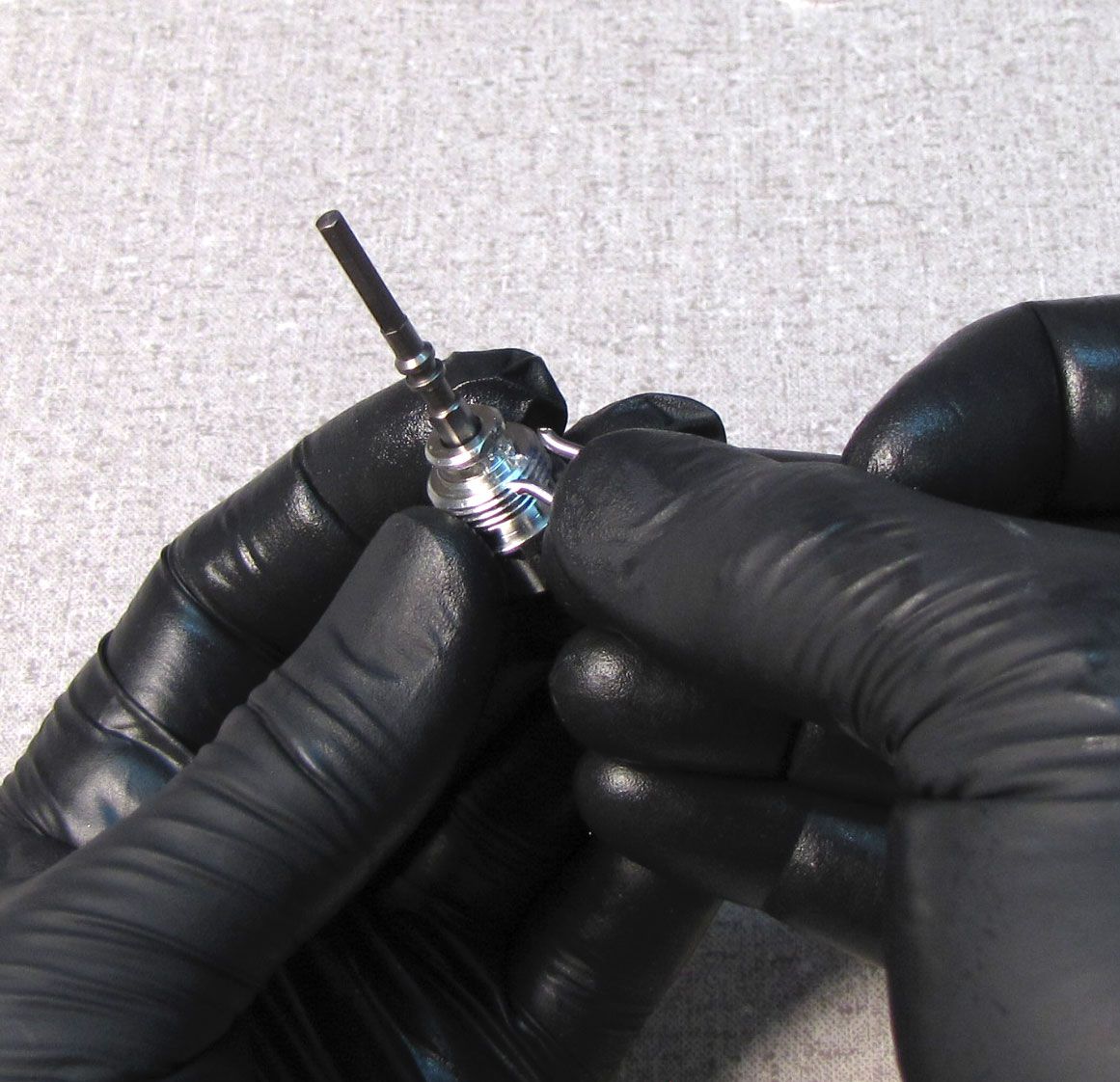
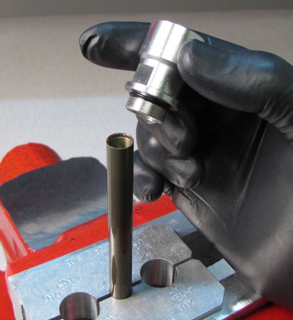
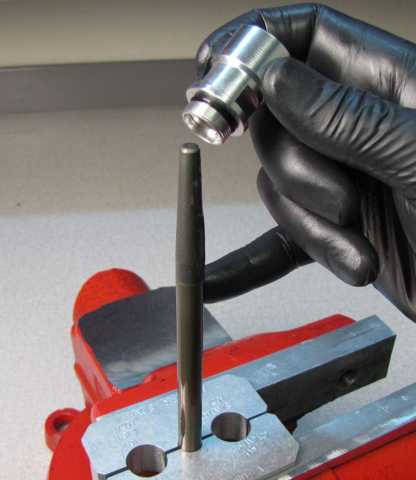
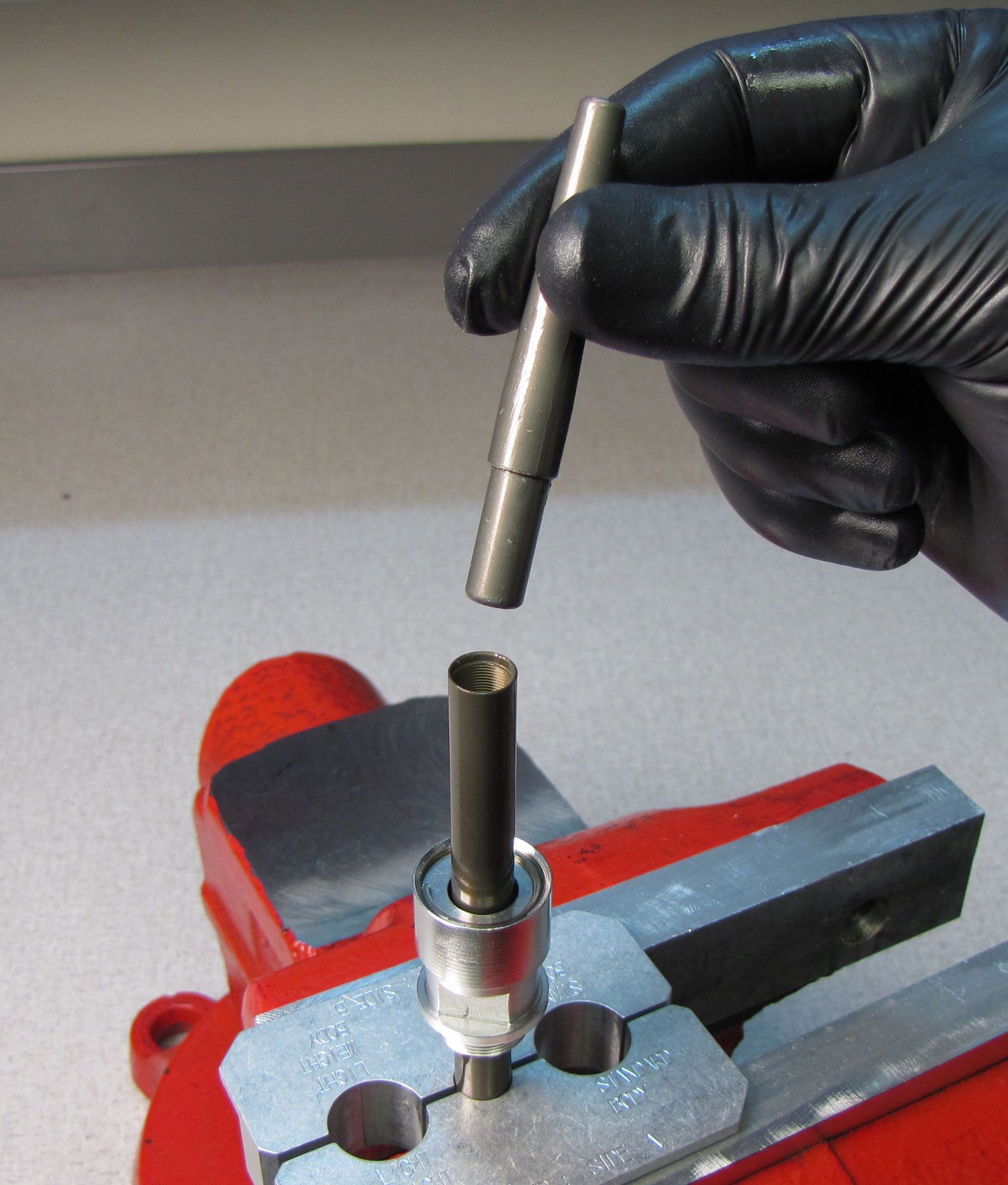
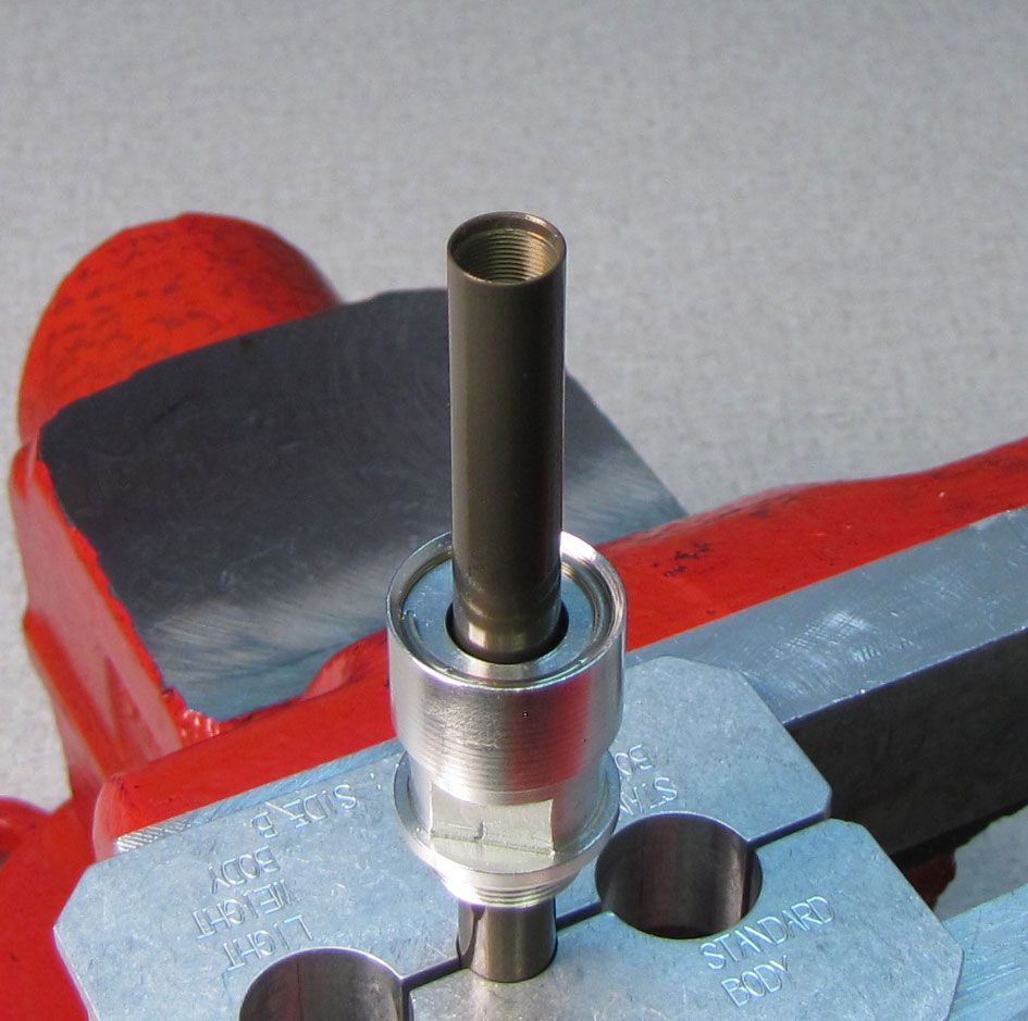
Install the new sealhead from the kit onto the shaft with its threaded end first. Remove the bullet tool.

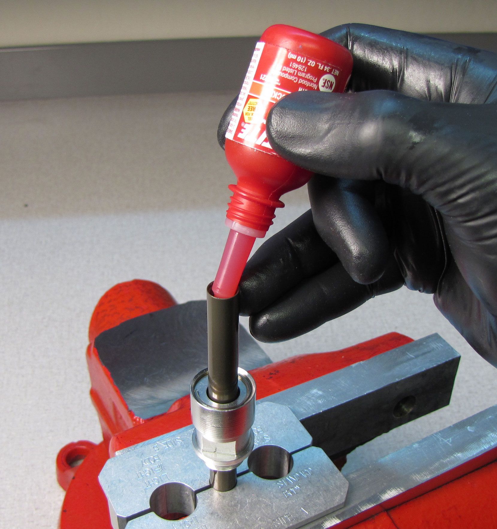
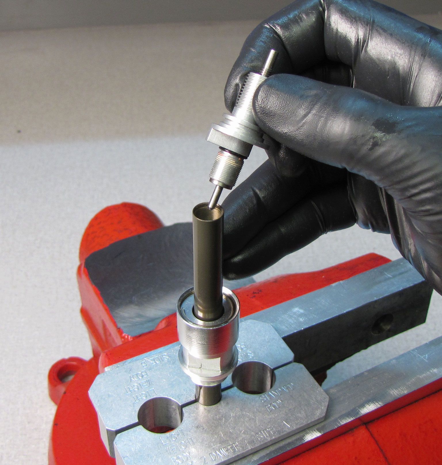
Step 35
Install the rebound tube into the shaft making sure to seat the rebound tube on the rebound needle. Apply 1-2 drops of red Loctite 262 to the threads inside the shaft. Insert the rebound adjuster and thread it in clockwise, tightening to 30 in-lb (3.4 Nm) torque with a 10mm crow's foot. Install a new greased o-ring from the kit onto the rebound adjuster.

Step 36
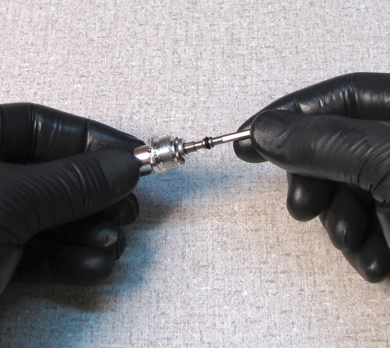
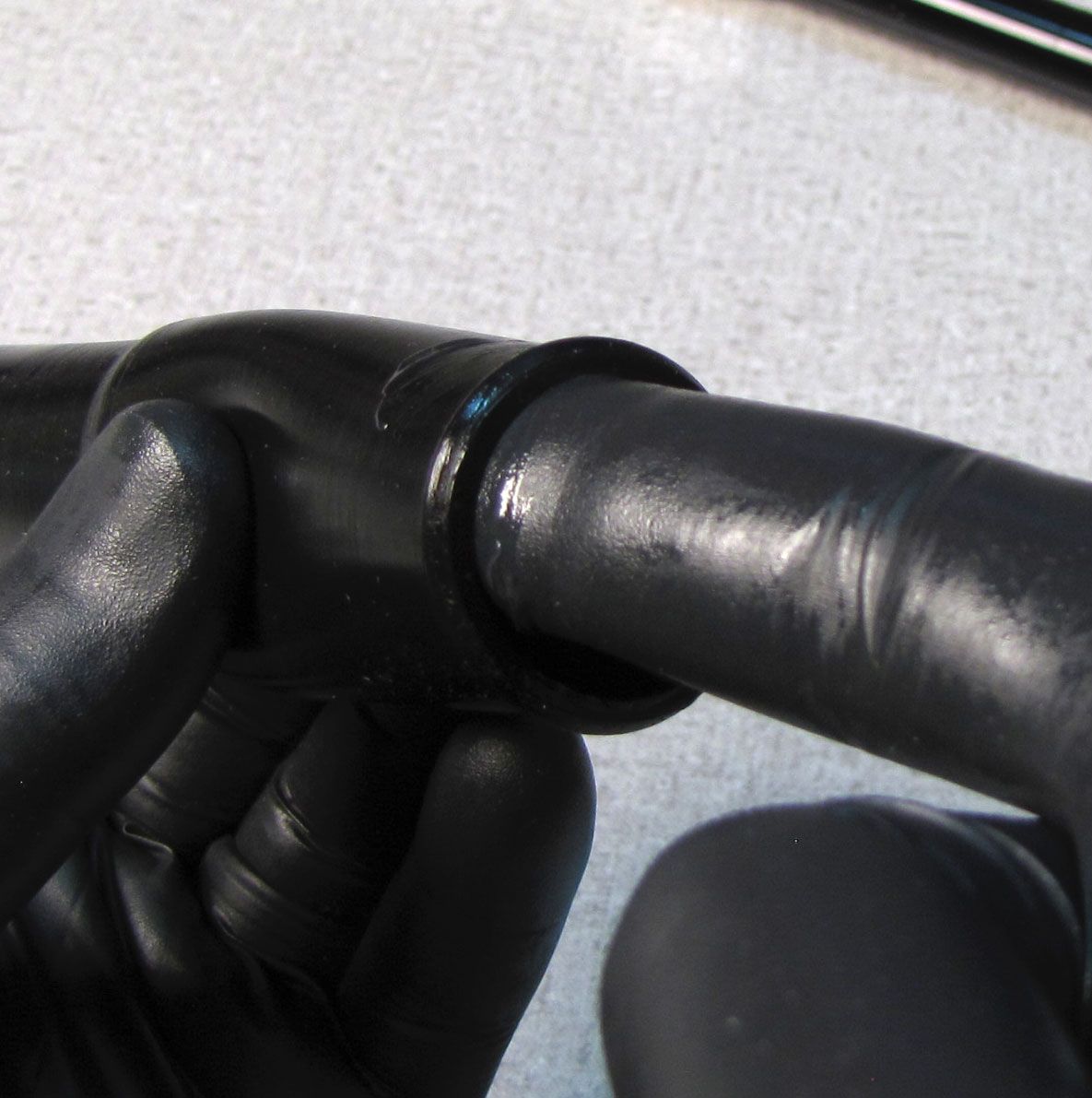
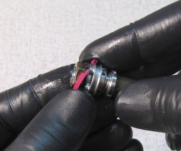
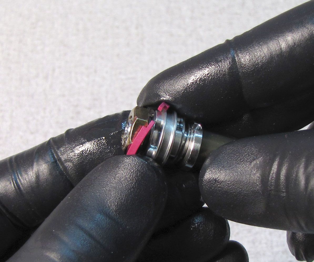
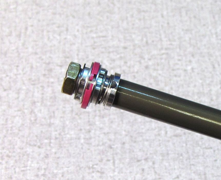
Remove and replace the pink piston glide ring with a new one from the kit. The new glide ring will appear larger than the old one, but will compress once inside the cartridge body. Slide the sealhead all the way toward the rebound piston end.
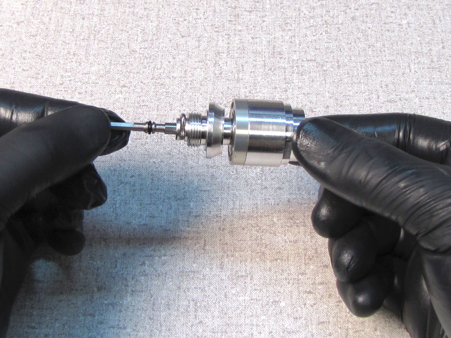
Step 37
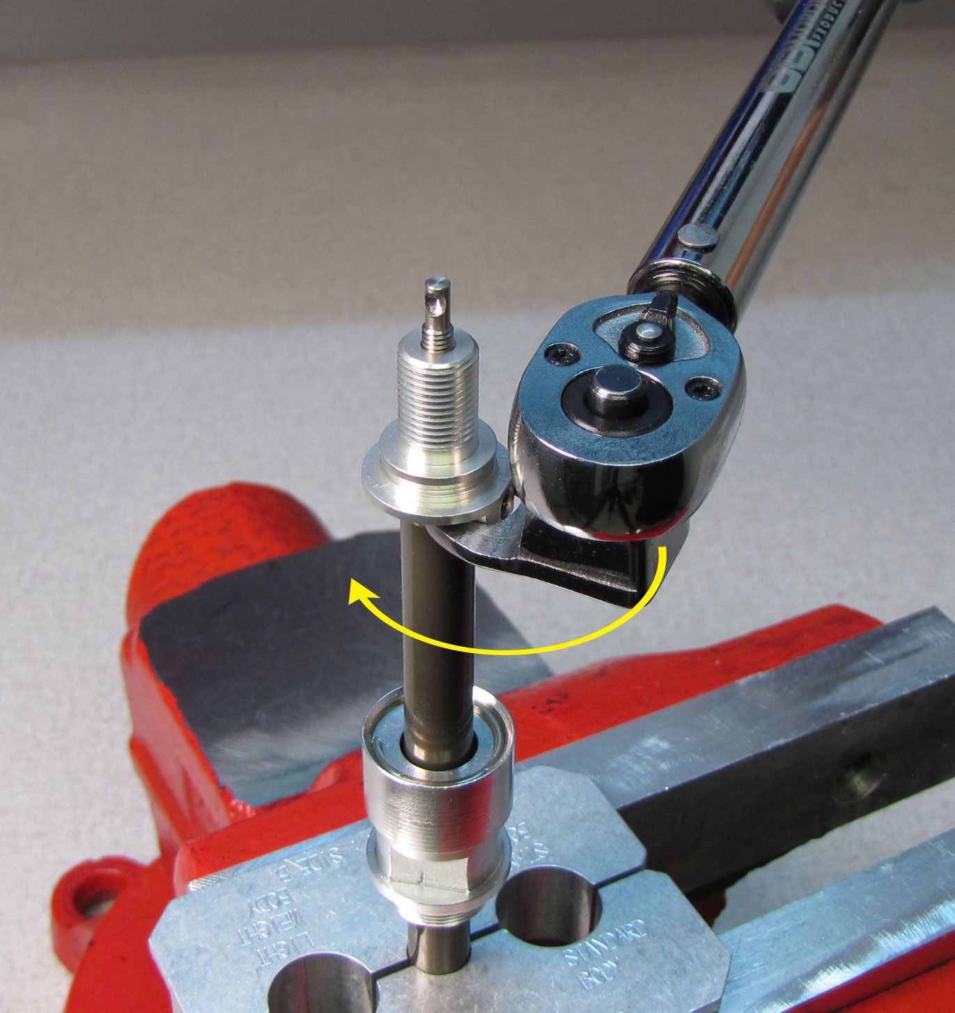
Top off the cartridge body with FOX R3 5wt. oil then install the shaft assembly threading the sealhead onto the cartridge body until hand tight. Clean the cartridge body with Isopropyl alcohol and clamp in your shaft clamps. Tighten the sealhead (clockwise) to 75 in-lb (8.5 Nm) with a 15mm crow's foot.


Step 38
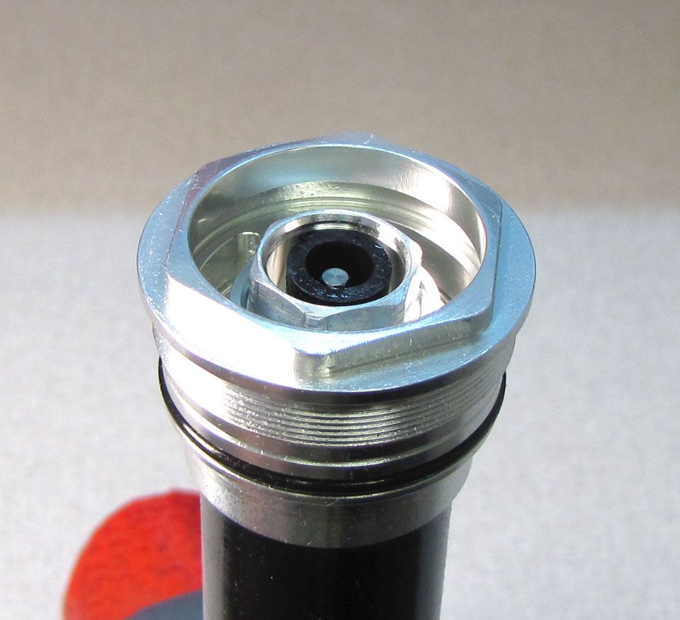
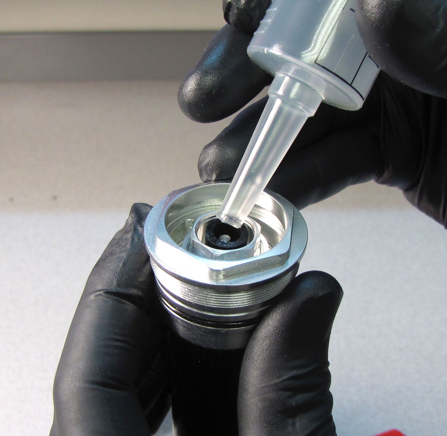
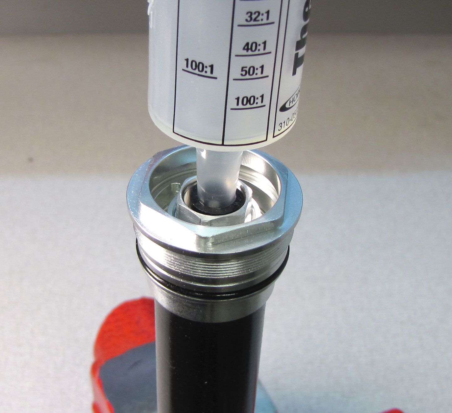
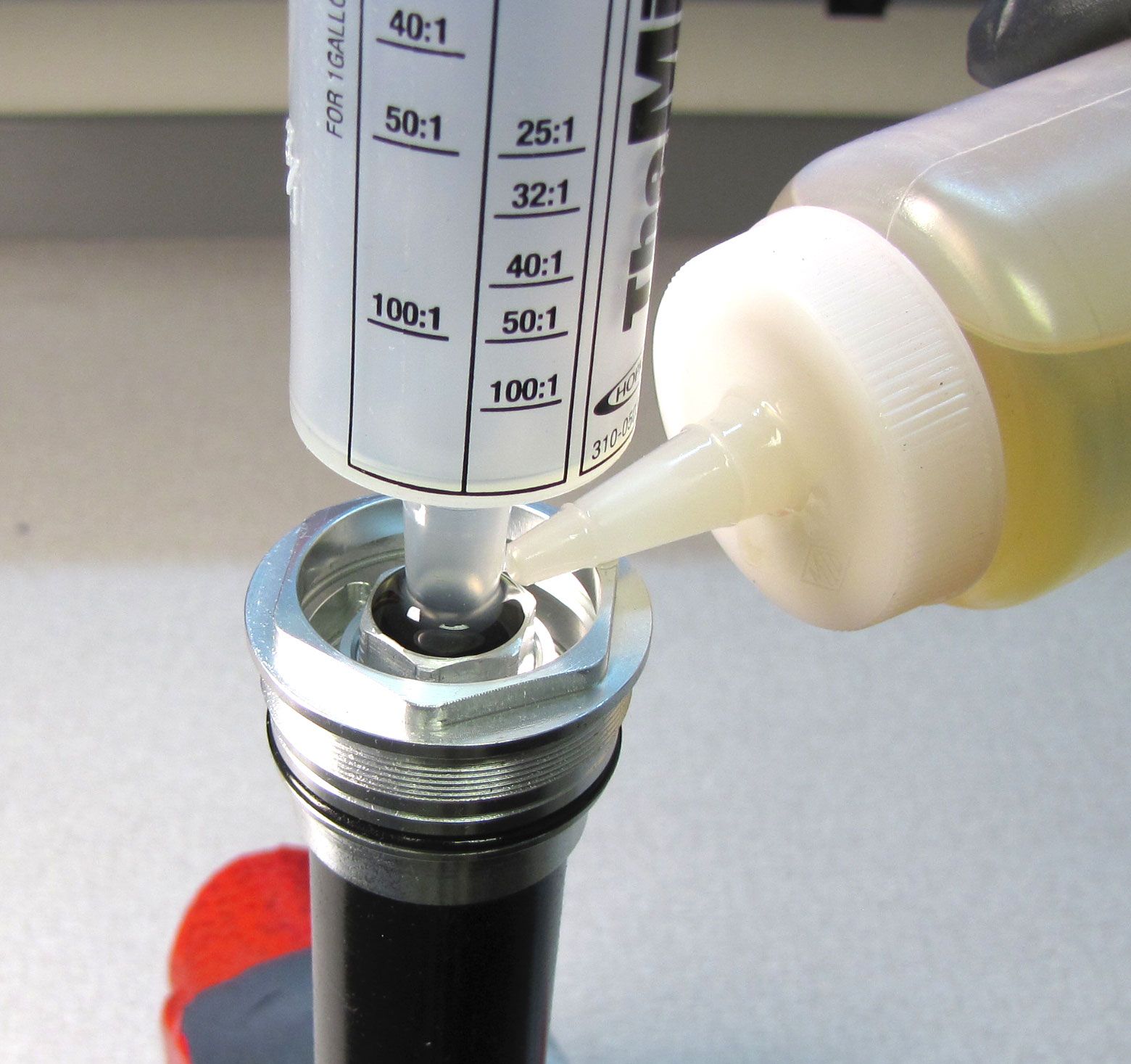
Remove the compression adjust coupler by pulling it up. Install the rubber tubing from the FOX Bleeder syringe into the base valve upper stud as deeply as possible. Insert the FOX bleeder syringe into the rubber tubing, making a tight seal. Cover the rubber tubing with FOX R3 5wt. oil to prevent any air ingestion at this junction.
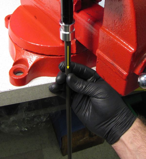
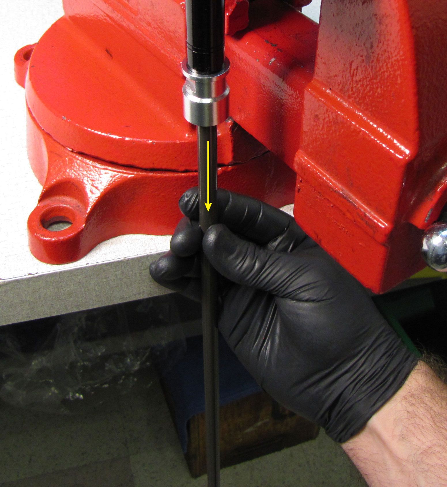
Step 39
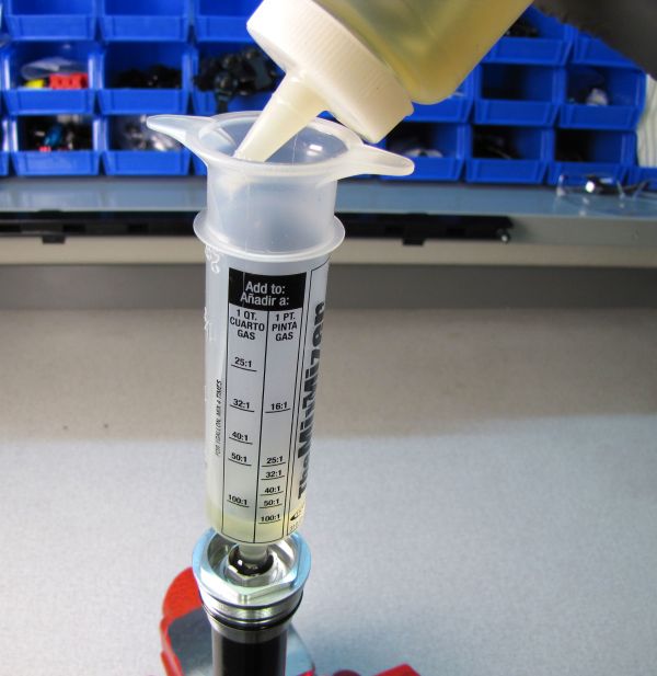
Slowly cycle the shaft up while squeezing the bladder to force any trapped air out into your syringe. Do not release your squeeze on the bladder or cycle the shaft down until all air bubbles in your syringe have risen to the surface. Do not suck bubbles back into the cartridge. Periodically add oil to your syringe so you do not let the syringe go dry as the cartridge ingests oil. Repeat this step until all air trapped in the cartridge is bled out.

Step 40
With the cartridge fully extended, remove the bleed syringe and rubber tubing and top off the base valve upper stud with FOX R3 5wt. oil.

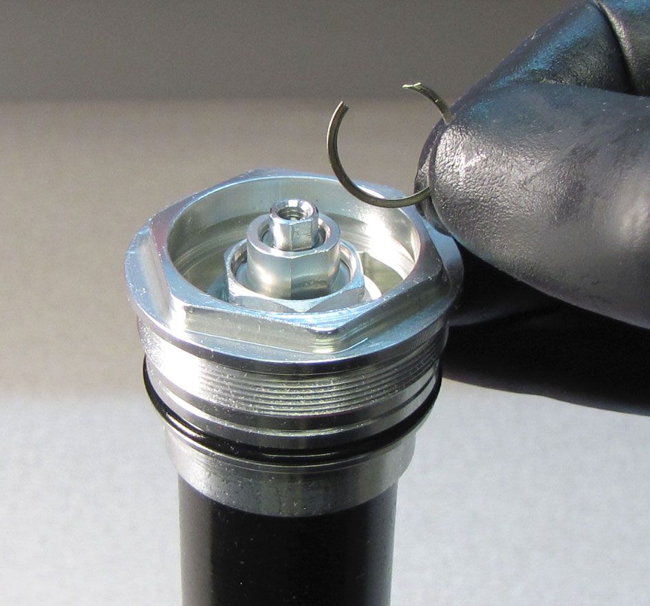
Step 41
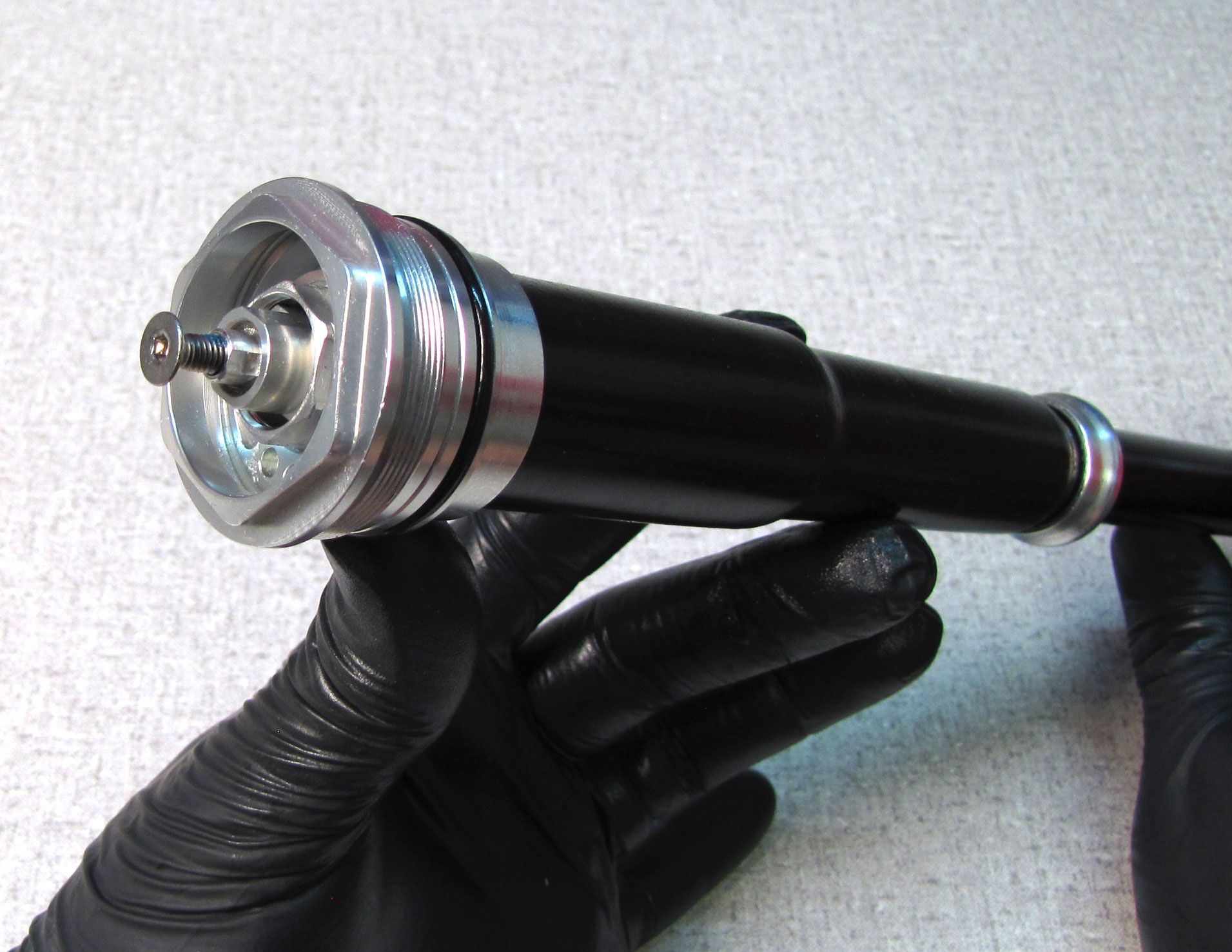
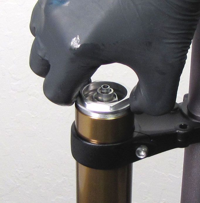
Remove the 2.5mm hex screw from the adjuster assembly, then reinstall the adjuster assembly into the base valve upper stud. Make sure to engage the internal hex to seat the compression adjust assembly fully. Clean off excess oil and install the retaining ring.
Cycle the damper by hand to check that all air was properly bled out of the cartridge in previous steps. If you hear or feel excessive air still trapped within the cartridge, go back to step 38 and try bleeding the cartridge again.
Reinstallation Into Fork Chassis
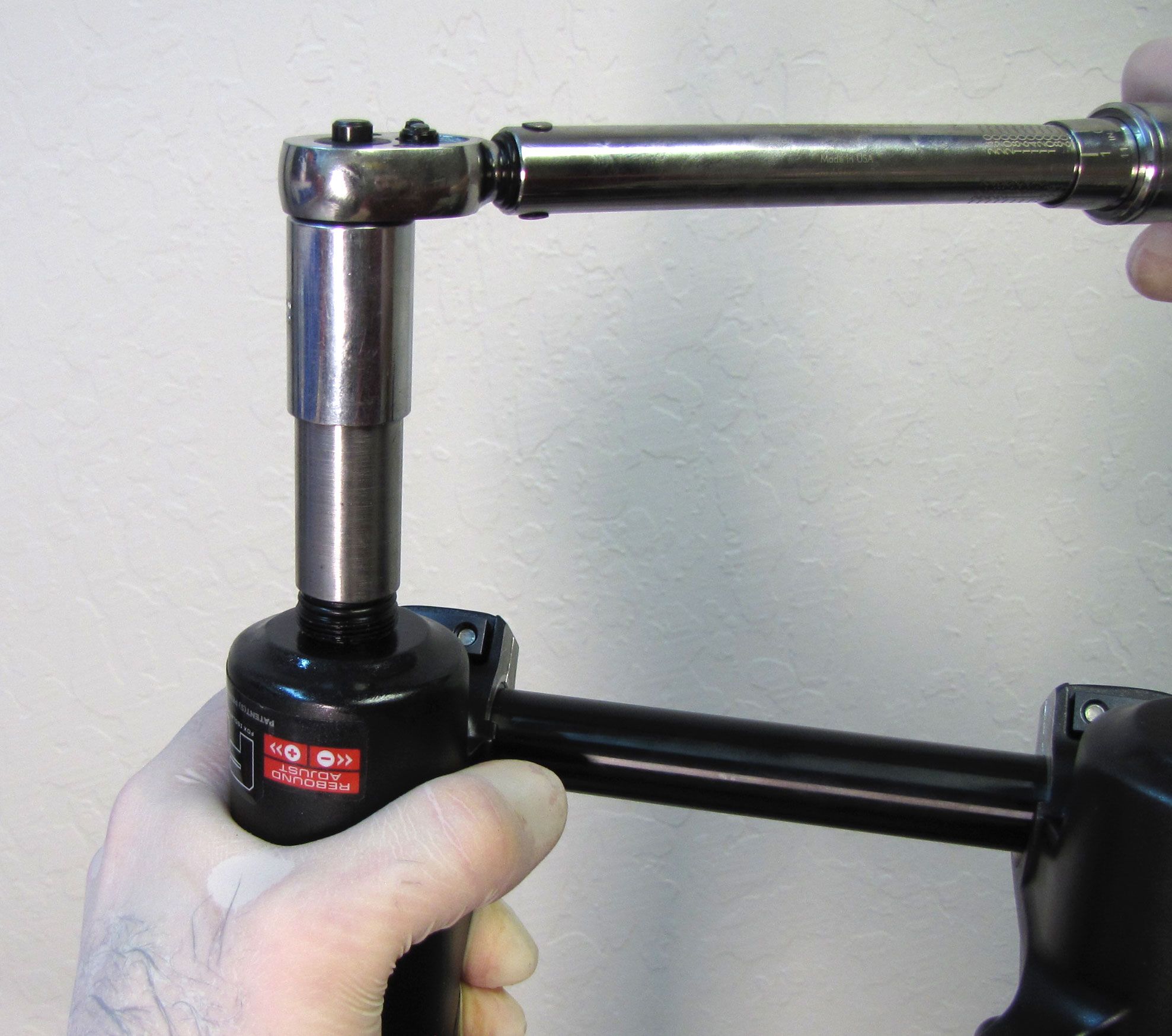
Step 1
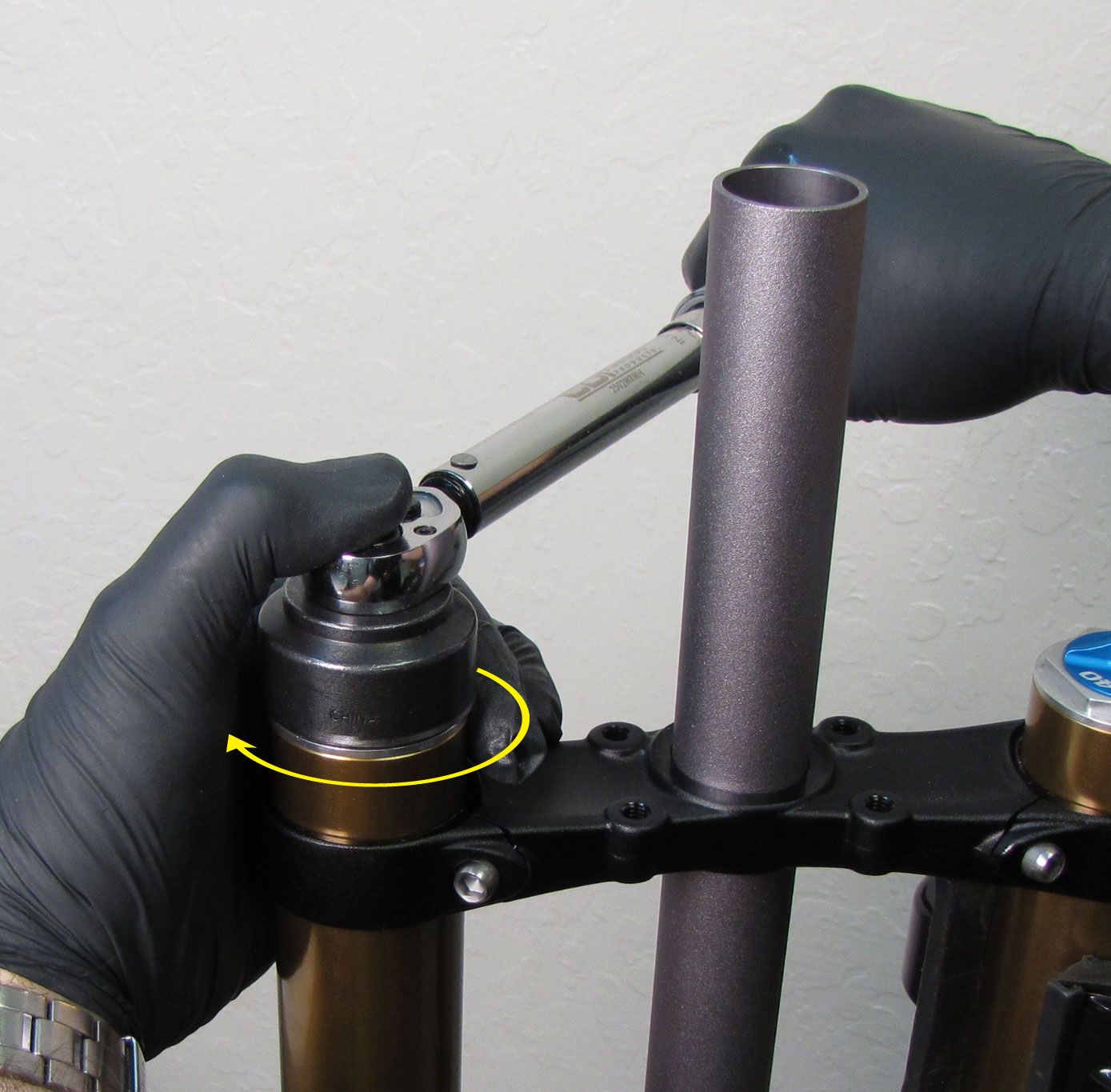
Install the cartridge into the upper tube. Tighten the topcap clockwise to 220 in-lb (24.8 Nm) torque with your 6-point chamfer-less 32mm socket.
40mm Only: Tighten (clockwise) the 5mm hex bolt on the damper-side of the upper crown to 65 in-lb (7.34 Nm).

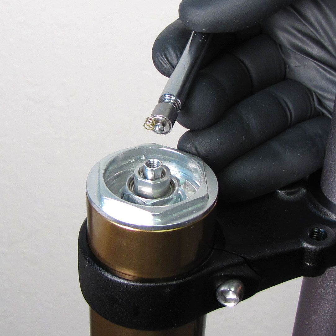
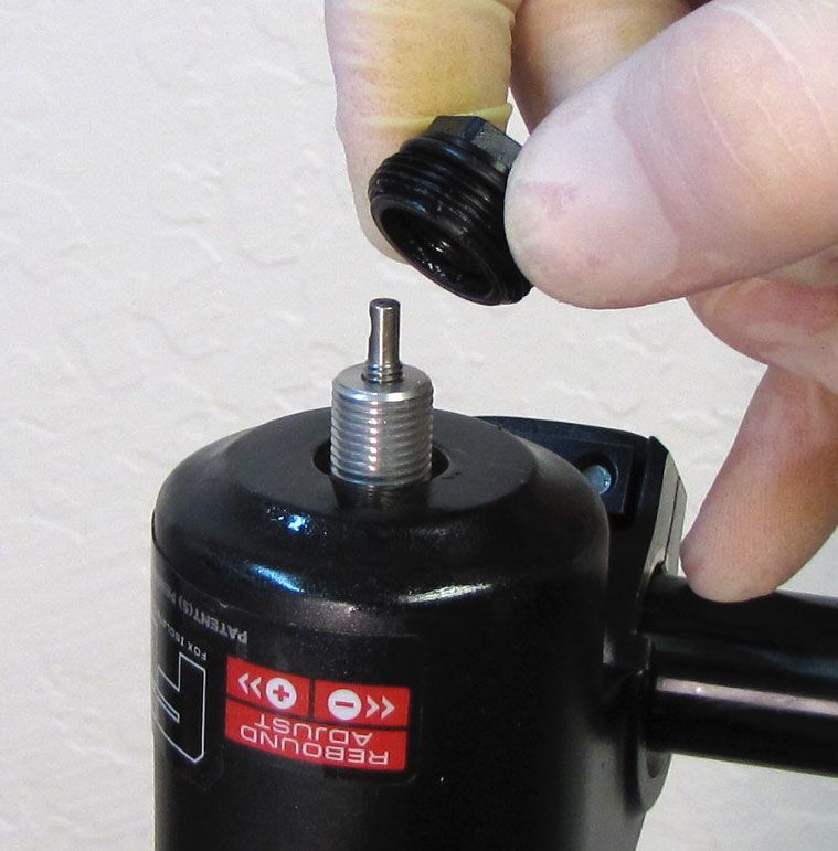
Step 2
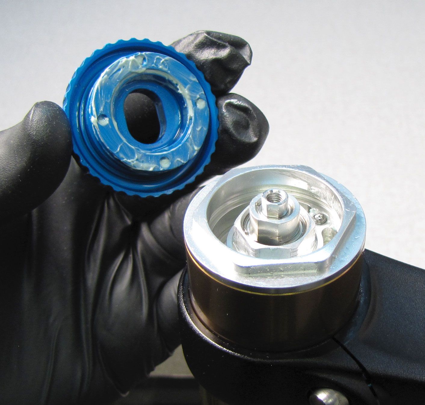
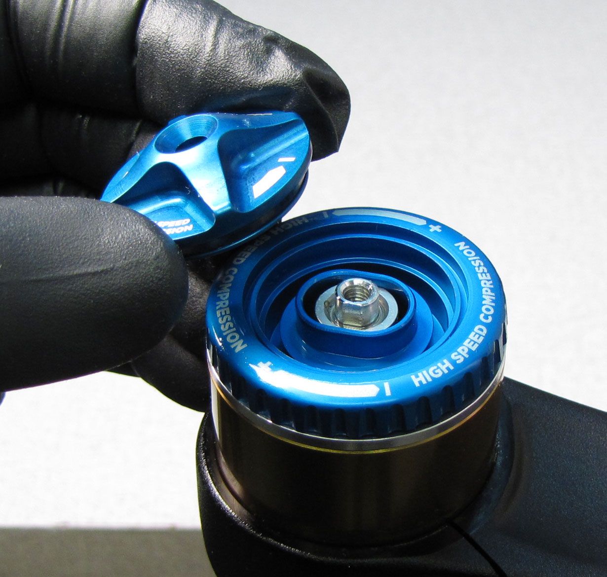
Install the detent springs and ball bearings into the two detent holes in the topcap. Coat the underside of the high-speed compression knob with a thin film of waterproof grease such as Sta-Lube SL3125 then install it followed by the low-speed compression knob.
Step 3
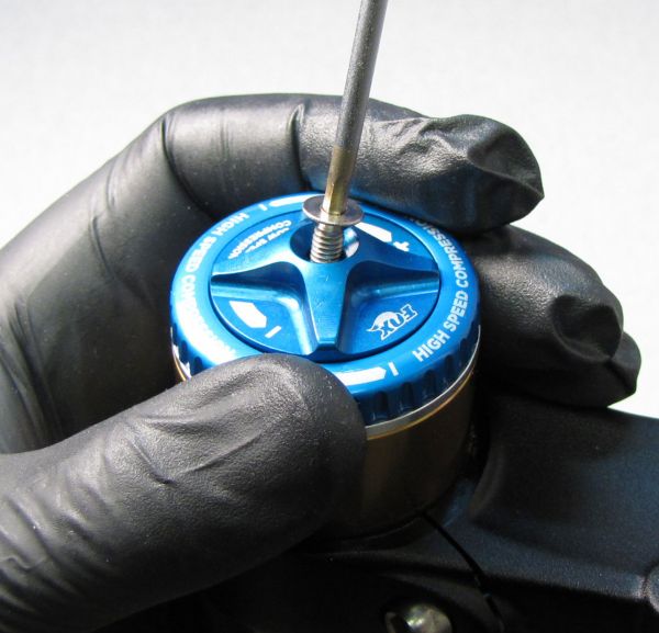
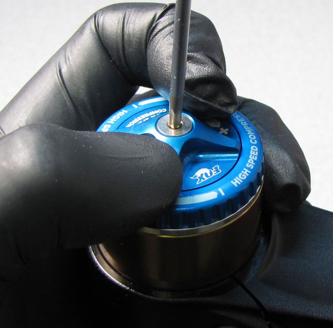
Install the 2.5mm hex screw and hold the low-speed compression knob from turning while you tighten the screw (clockwise) to 11 in-lb (1.2 Nm) torque.


Step 4
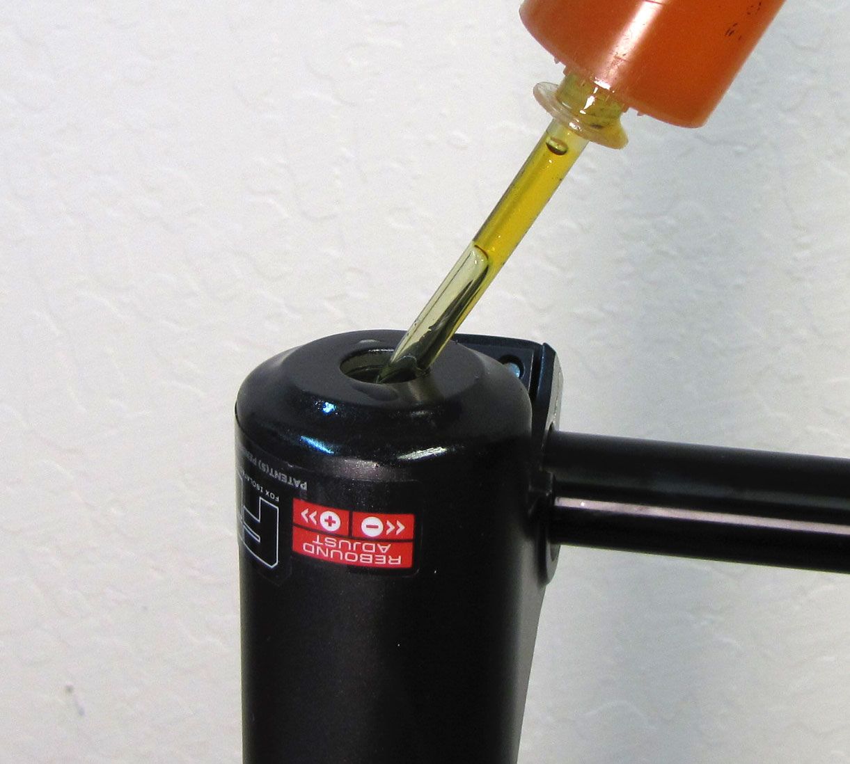
Invert the fork and inject the appropriate amount of FOX 20wt. Gold oil into the damper-side lower leg.
36mm FIT HSC/LSC (RC2) Damper-Side Bath oil volume: 30cc
40mm FIT HSC/LSC (RC2) Damper-Side Bath oil volume: 50cc
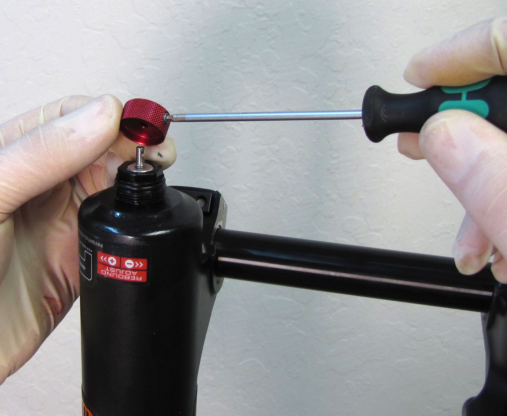
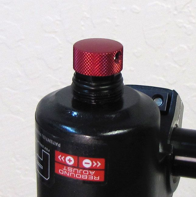
Step 5
Install a new crush washer into the damper side bottom nut (use a small amount of Slick Honey to retain the crush washer during installation). Install the bottom nut, tightening to 50 in-lb (5.7 Nm) with a 15mm socket. Use a 2mm hex wrench to install the red rebound knob. Make sure that the set screw lines up with the depression in the rebound adjuster shaft. Replace the black rebound knob cover.
Clean the exterior of your fork and test all of its functions before reinstalling onto the bike.