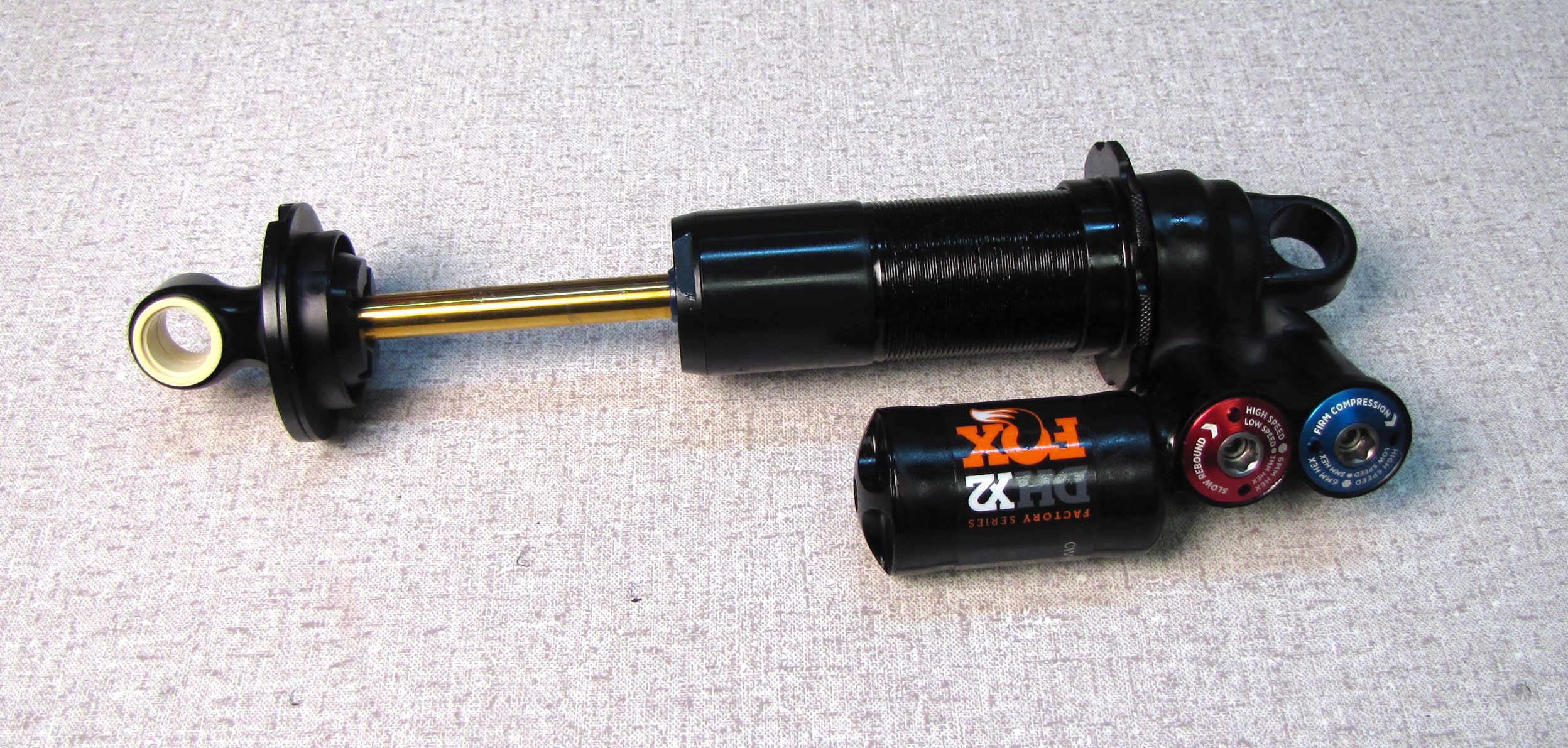
2016-2020 DHX2 Rebuild
Required Parts
- 803-00-950 Seal Kit: DHX2 Damper Rebuild
Required Tools
- 027-00-018 Pump: Fox Digital HP w/ Bleed, Foldable, Replaceable Battery, 350 psi, Swivel Head
- 398-00-797 Tooling: Float X2 Steel Shaft, Bullet Tool
- 803-00-463 Kit: Fill Machine Adapter, 04-07 Epic IV, DHX Air, RC2_RC4 Shocks
- 803-00-566 Kit: Bike IFP Depth Setting Tool Set
- 803-00-805 Kit: Shaft Clamps, Shocks, CTD 9mm, 3/8in, 1/2in, 5/8in
Sections
WARNING: Always wear safety glasses and protective gloves during service to prevent potential injury. Failure to wear protective equipment during service may lead to SERIOUS INJURY OR DEATH.
WARNING: FOX products should be serviced by a trained bicycle service technician, in accordance with FOX specifications. If you have any doubt whether or not you can properly service your FOX product, then DO NOT attempt it. Improperly serviced products can fail, causing the rider to lose control resulting in SERIOUS INJURY OR DEATH.
WARNING: FOX suspension products contain pressurized nitrogen, air, oil, or all 3. Suspension misuse can cause property damage, SERIOUS INJURY OR DEATH. DO NOT puncture, incinerate or crush any portion of a FOX suspension product. DO NOT attempt to disassemble any portion of a FOX suspension product, unless expressly instructed to do so by the applicable FOX technical documentation, and then ONLY while strictly adhering to all FOX instructions and warnings in that instance.
WARNING: Modification, improper service, or use of aftermarket replacement parts with FOX forks and shocks may cause the product to malfunction, resulting in SERIOUS INJURY OR DEATH. DO NOT modify any part of a fork or shock, including the fork brace (lower leg cross brace), crown, steerer, upper and lower leg tubes, or internal parts, except as instructed herein. Any unauthorized modification may void the warranty, and may cause failure or the fork or shock, resulting in SERIOUS INJURY OR DEATH.
The Damping Adjuster Cartridge Assemblies should be considered non-rebuildable as they are difficult to dissassemble and reassemble. The Damping Adjuster Cartridge Assemblies do not need to be removed from the shock to perform a full rebuild. If damaged, please replace as complete assemblies.
For instructions guiding you through the removal and reinstallation of the X2 Damping Adjuster Cartridge Assemblies please go to: X2 Damping Adjuster Cartridge Assembly Removal/Installation »
For information regarding the X2 2-Position Lever please go to: FLOAT X2 and DHX2 2-Position Lever Upgrade »
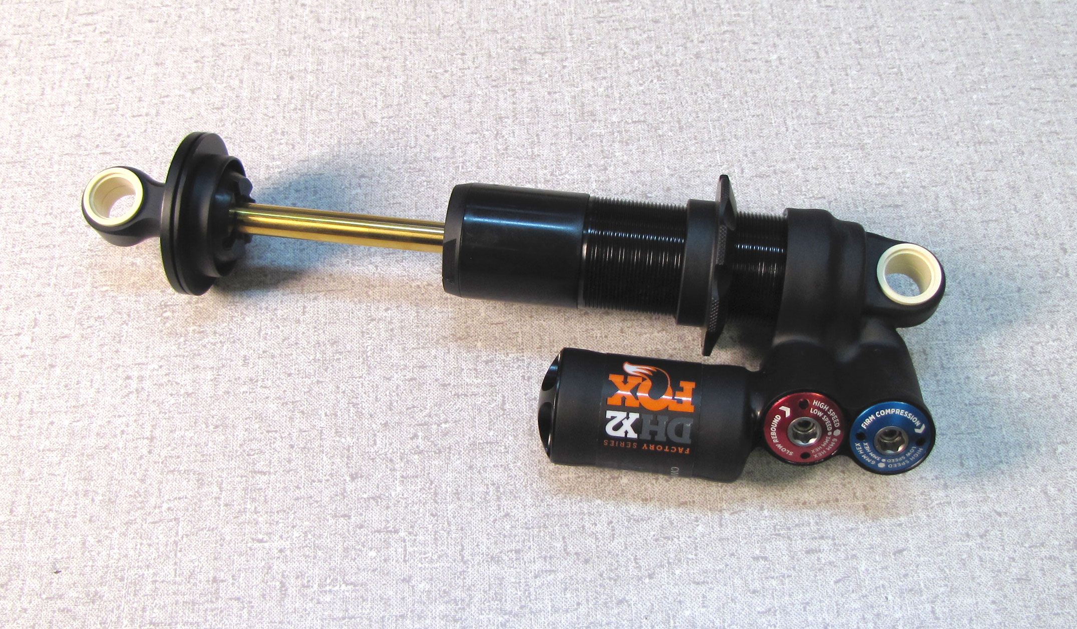
The following procedure guides you through the rebuild of the DHX2 shock.
Complete part information and technical drawings for the DHX2 shocks can be found by clicking: DHX2 Part Information »

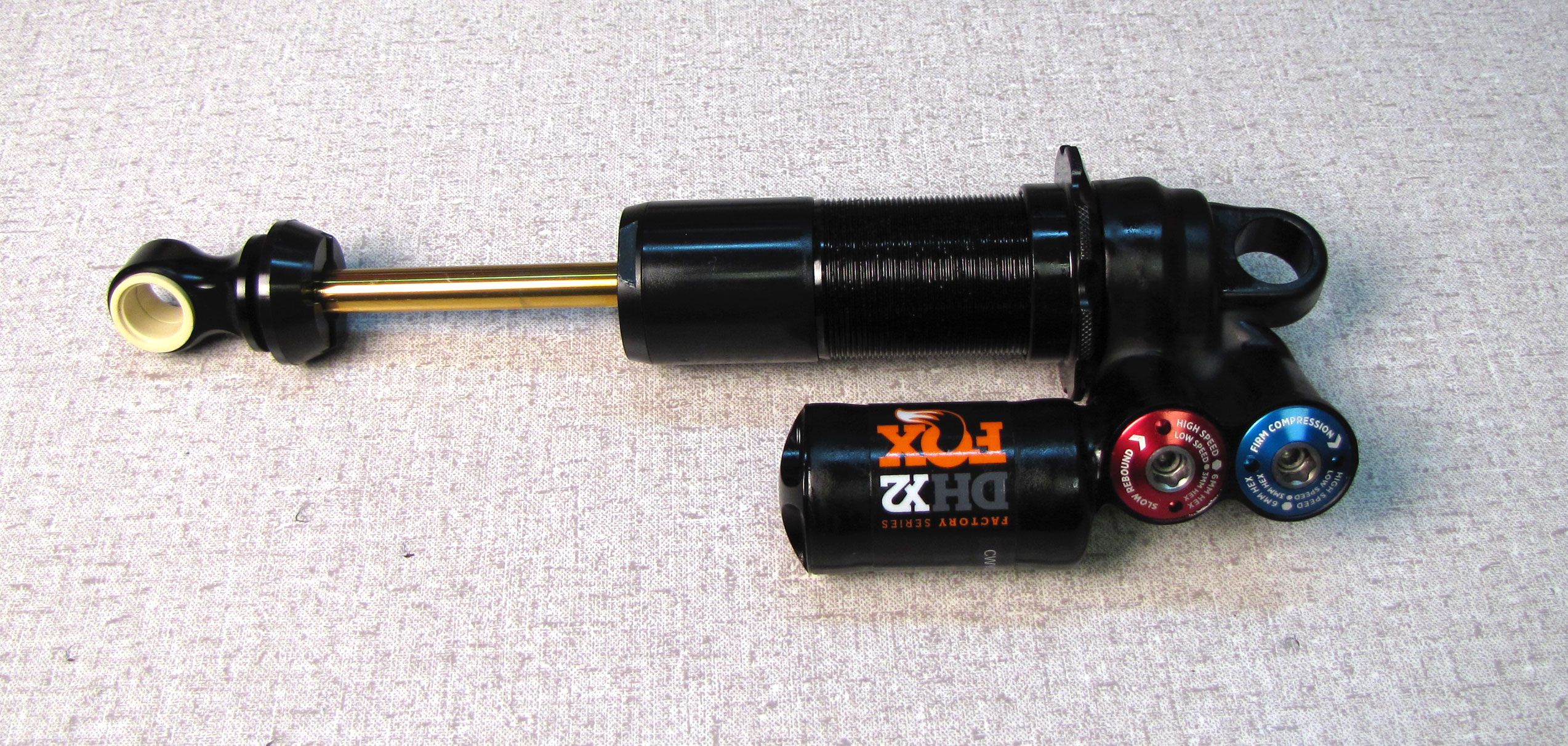
Step 1
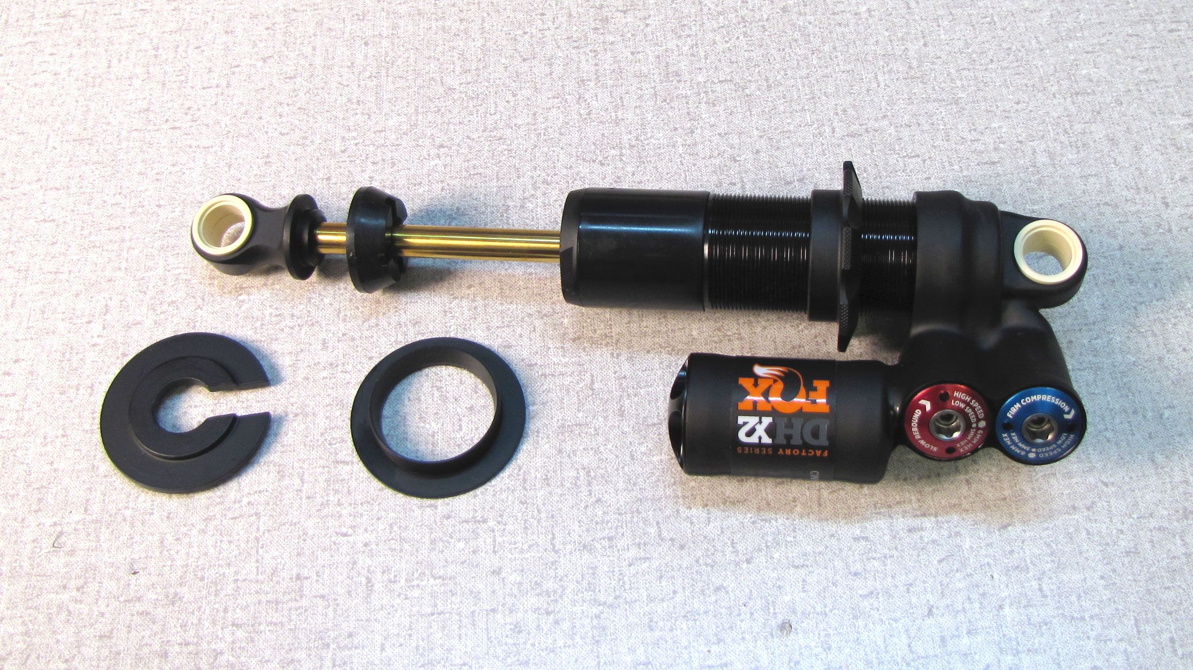
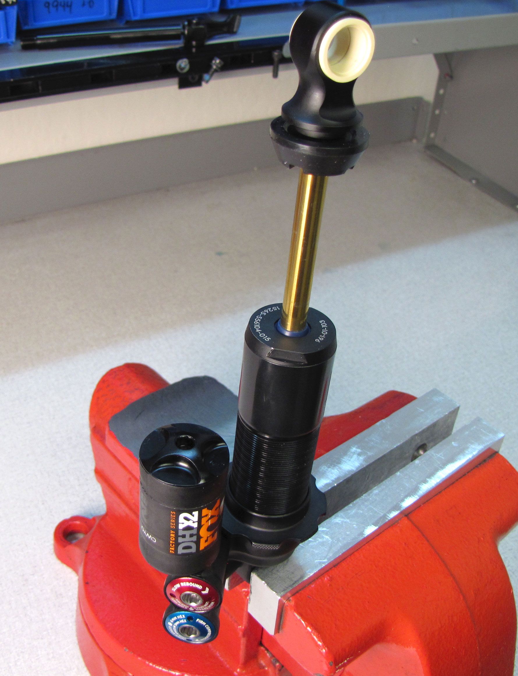
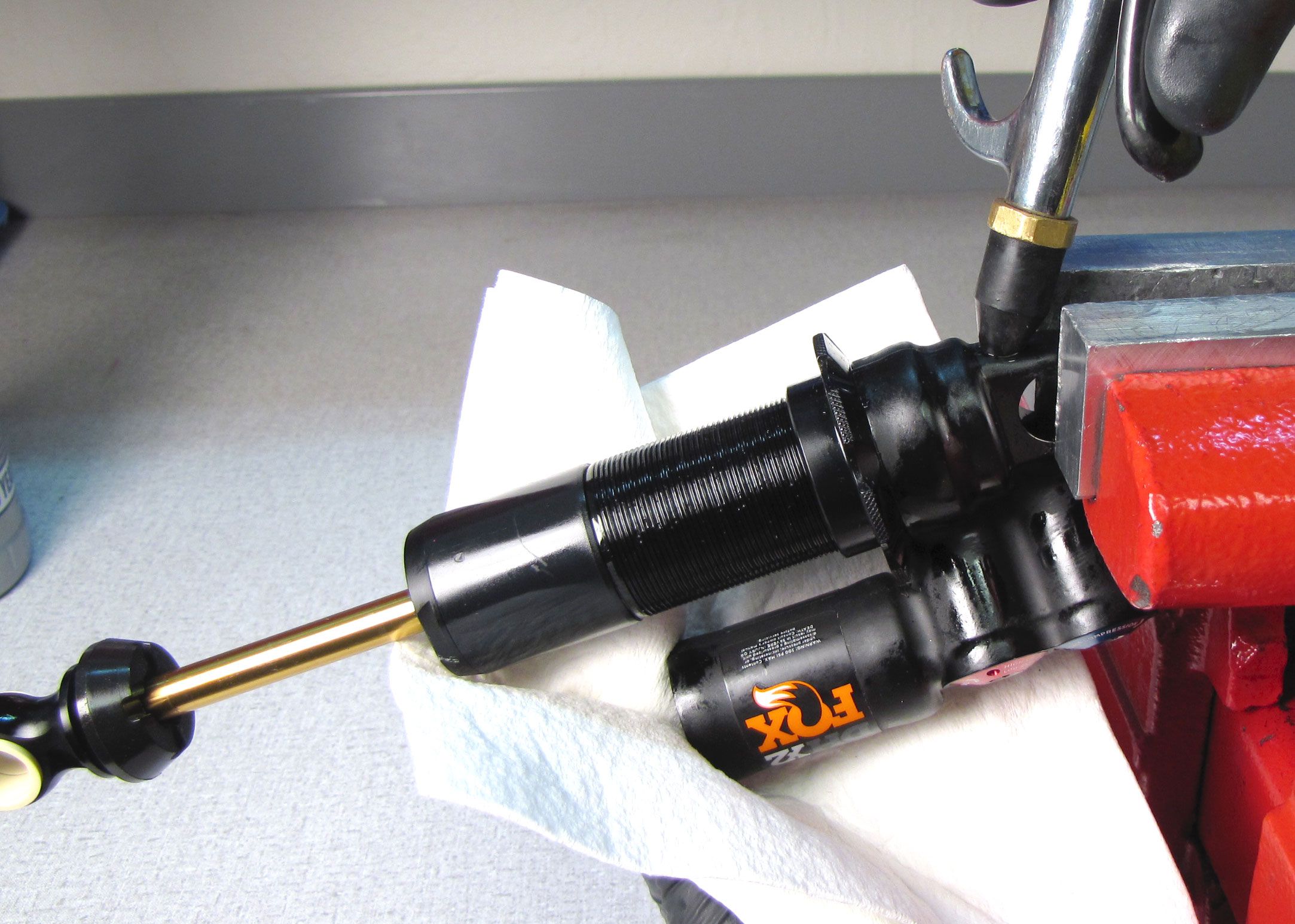
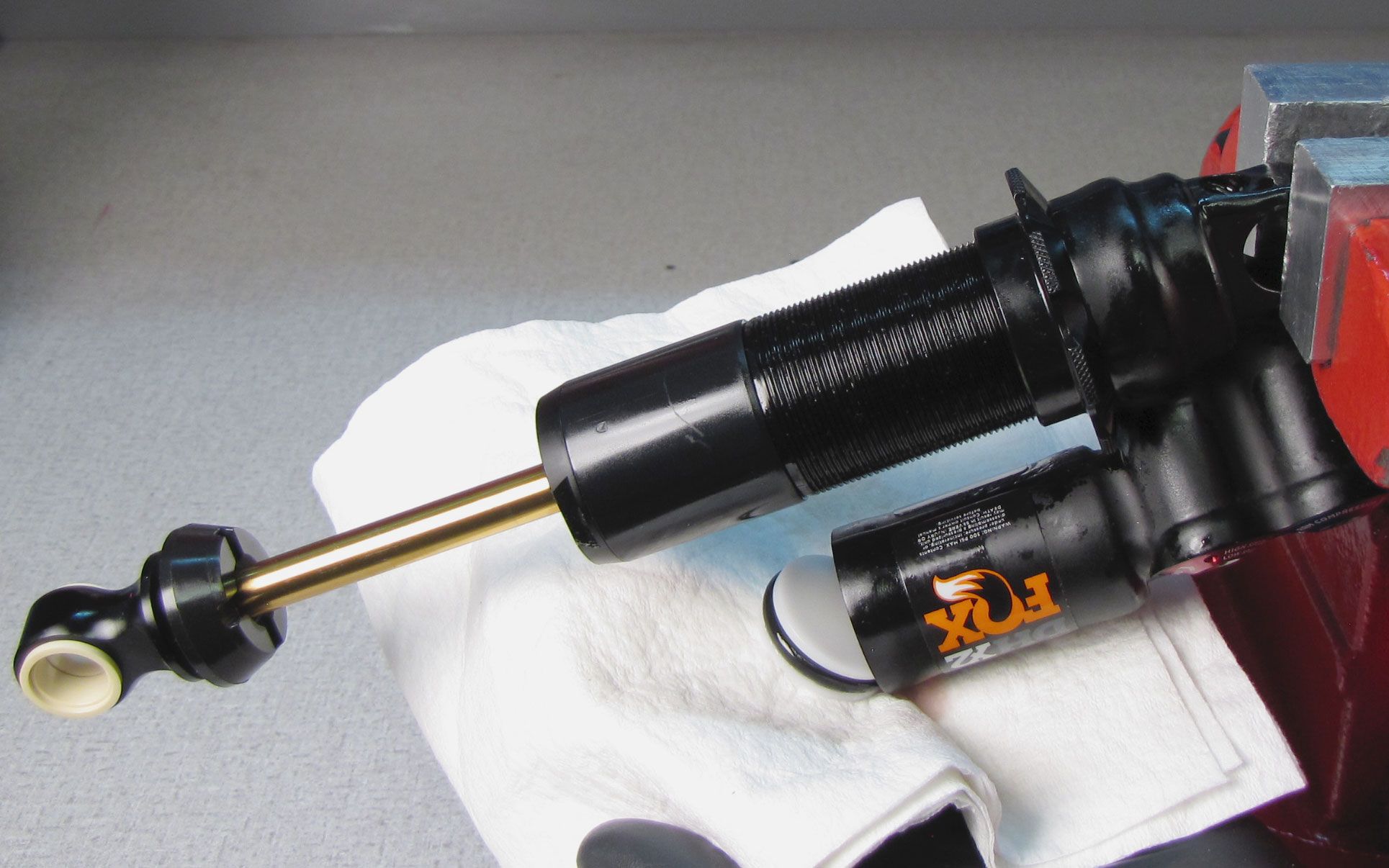
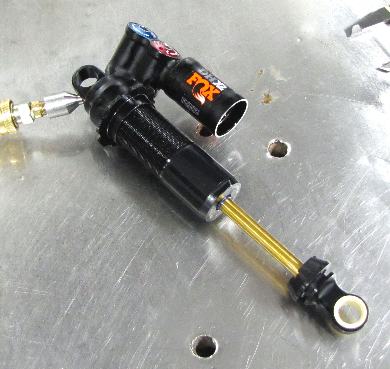
Remove the slotted spring retainer and spring retainer insert and set aside. Clamp your shock in the soft-jawed vice with the shaft up.
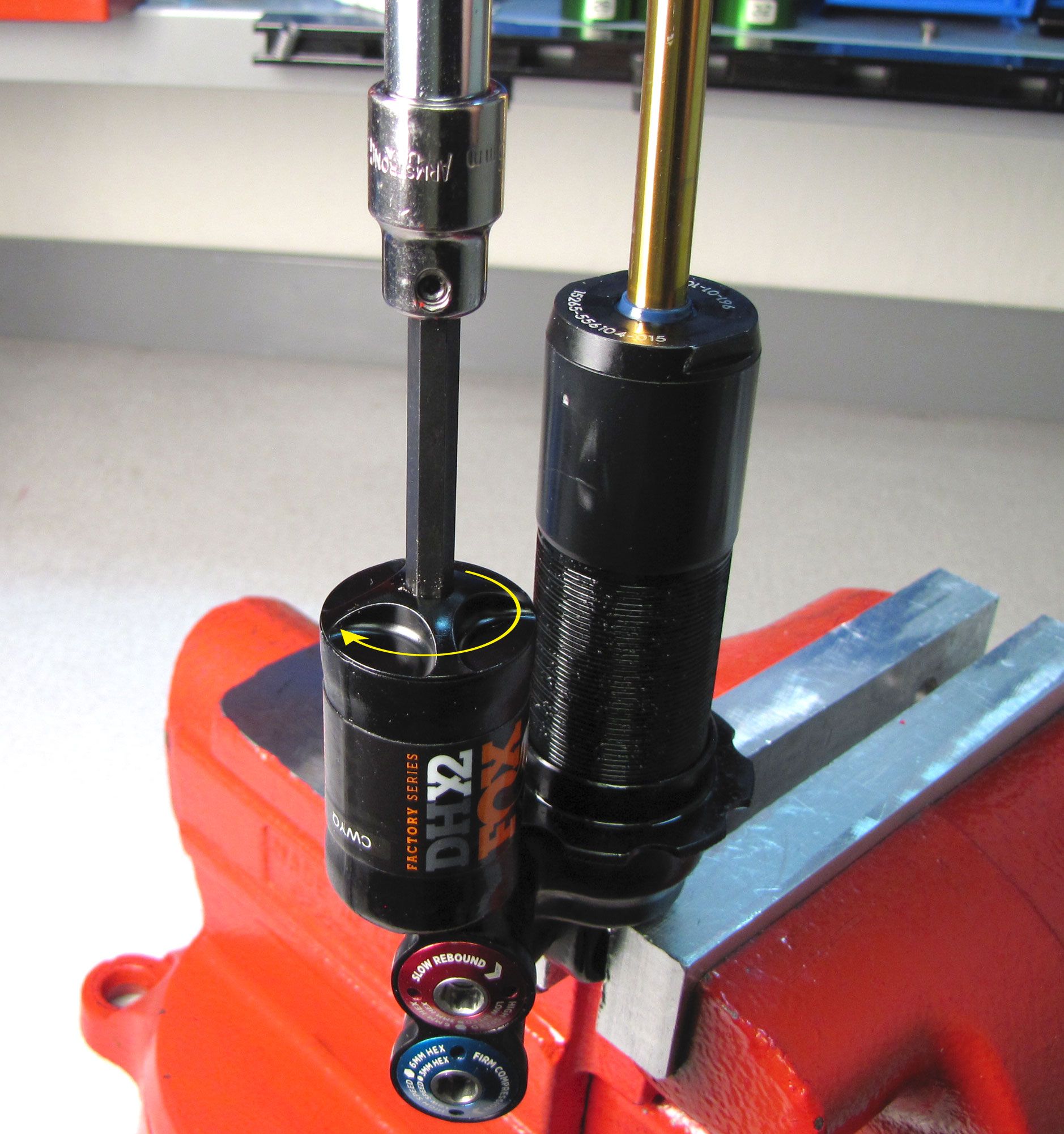
Step 2
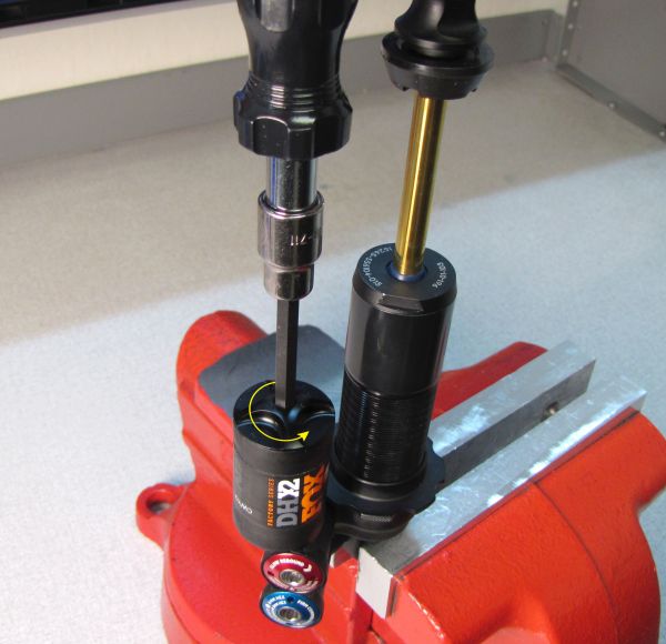
Unthread (counter-clockwise) the reservoir end cap assembly from the reservoir with a 6mm hex wrench. Remove the reservoir end cap assembly and replace its o-ring with a new one from the kit.

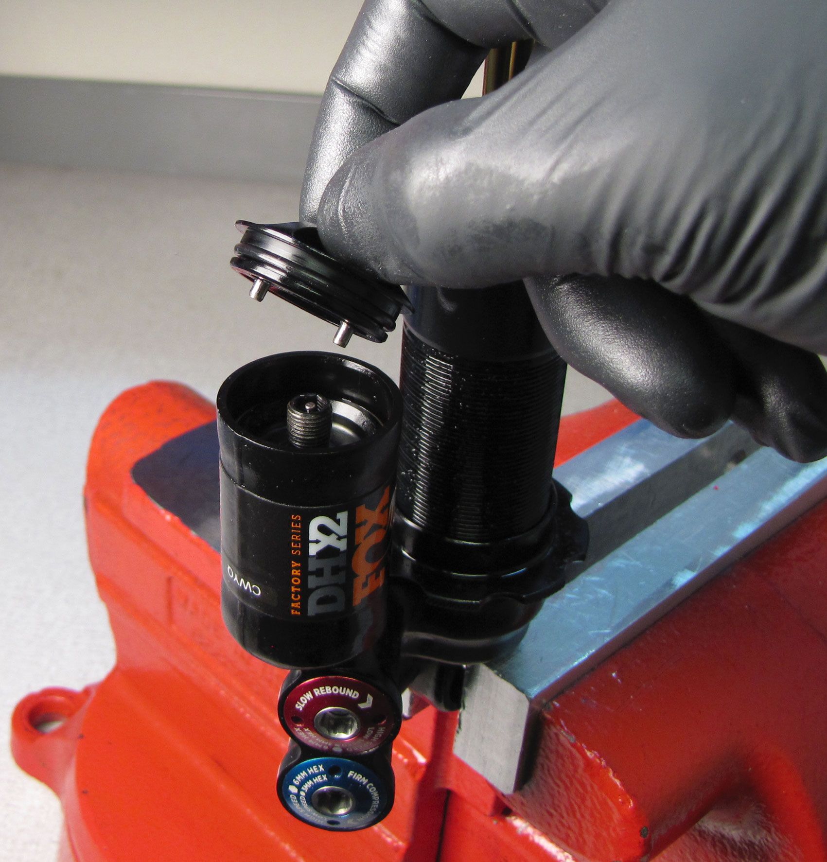
Step 3
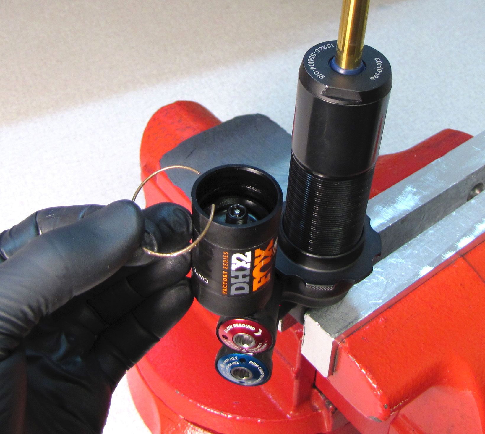
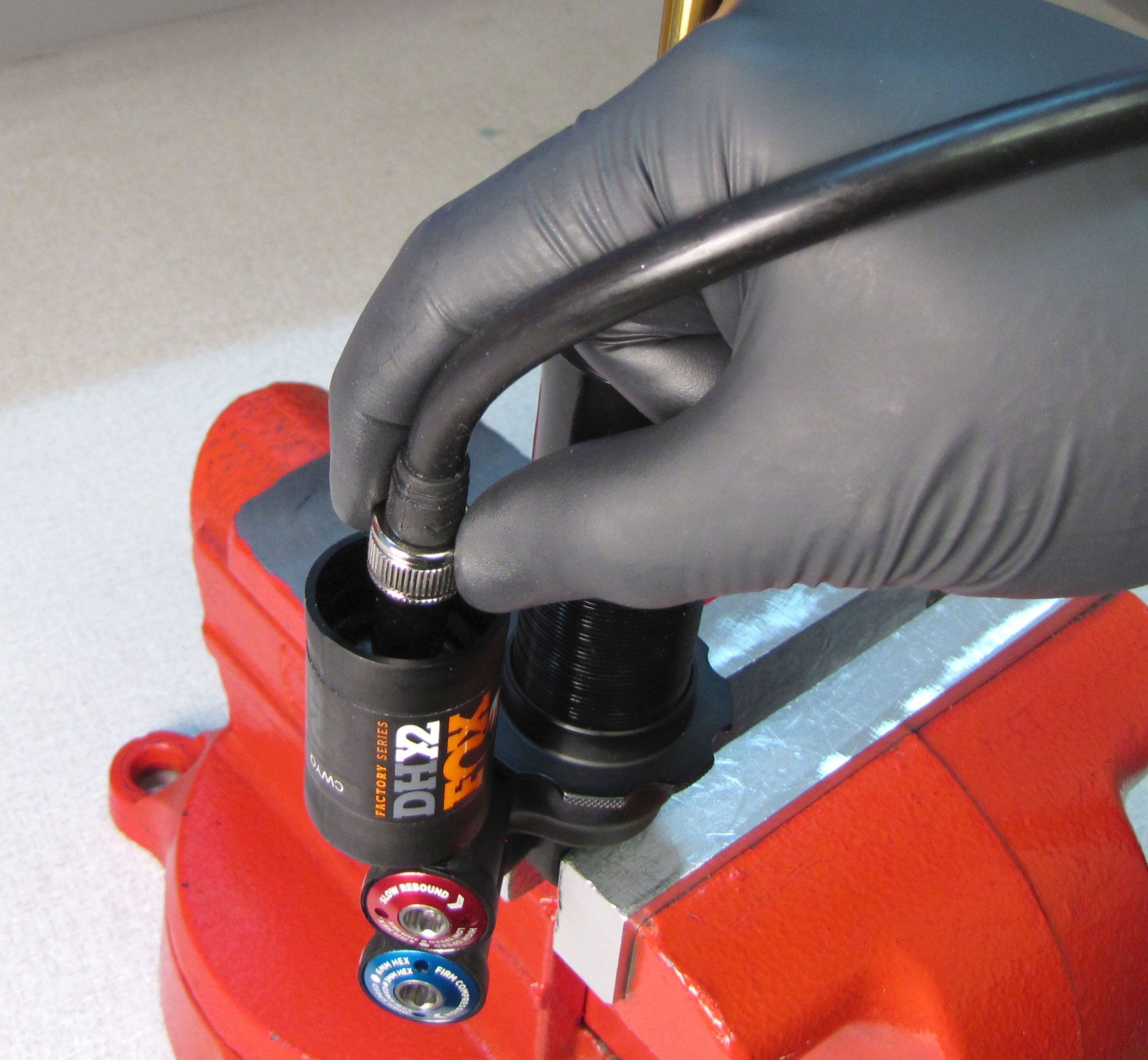
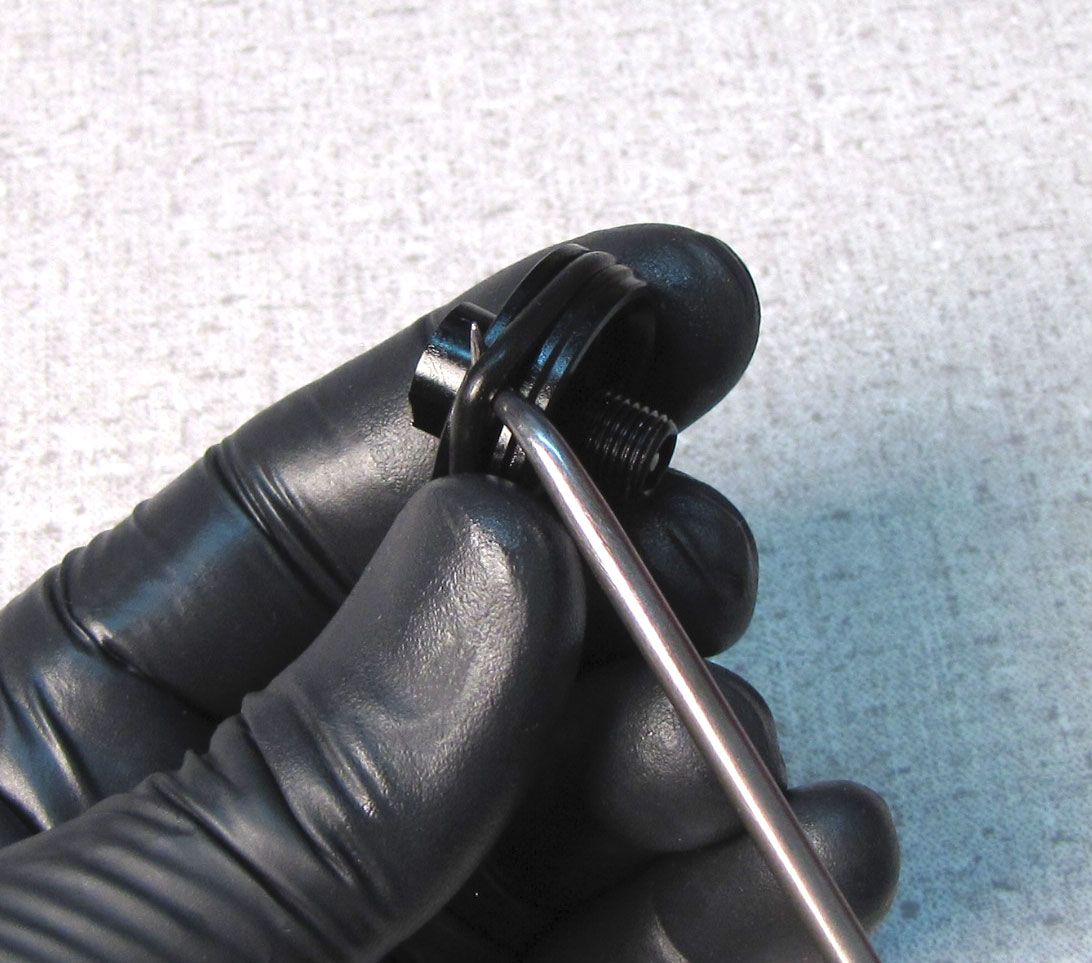
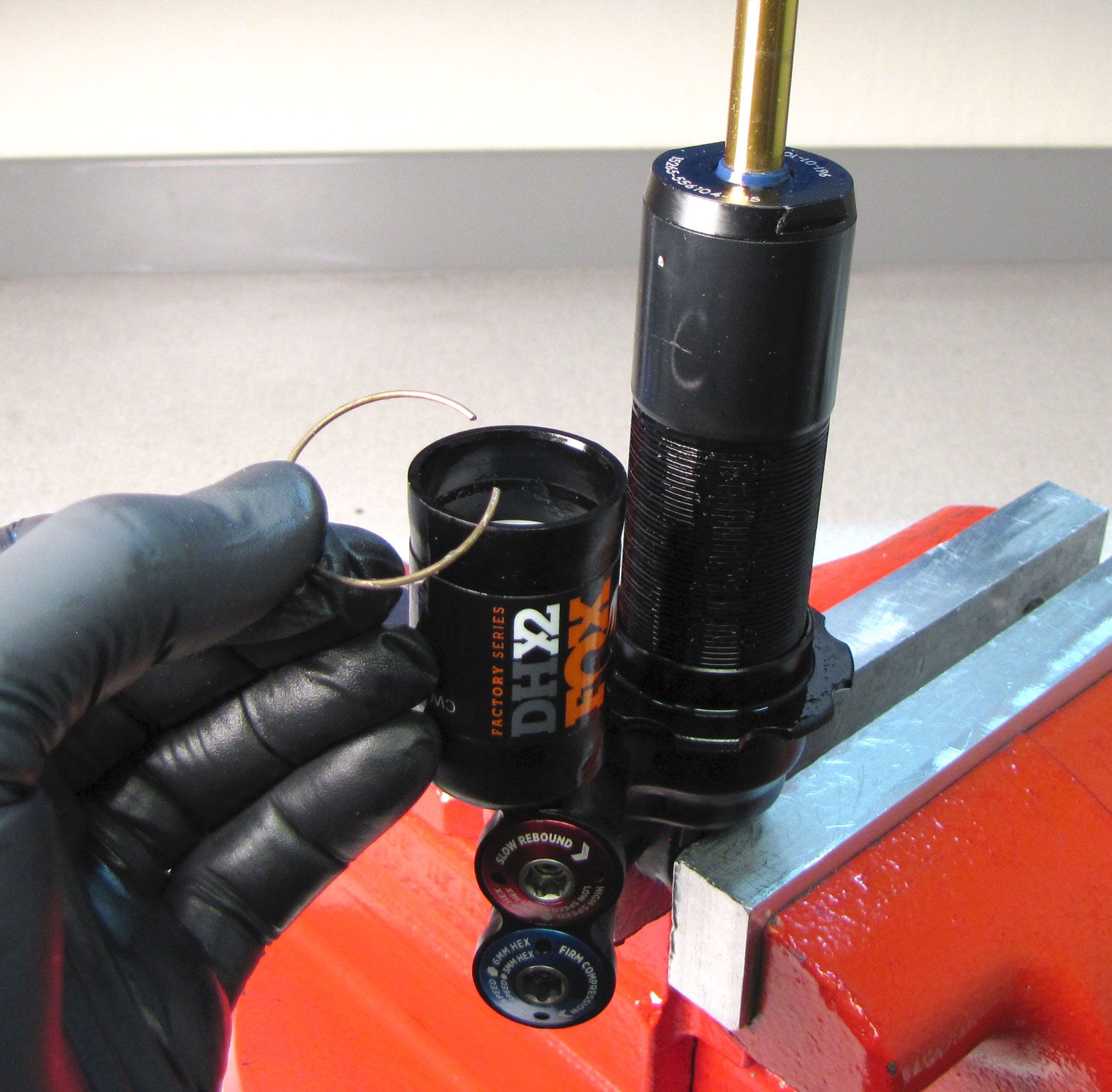
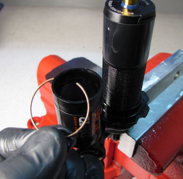
Release the nitrogen charge by depressing the Schrader valve within the reservoir. Remove the wire retaining ring from inside the reservoir. Thread your shock pump onto the Schrader valve of the reservoir end cap, then use your pump to pull the cap out of the reservoir.

Step 4
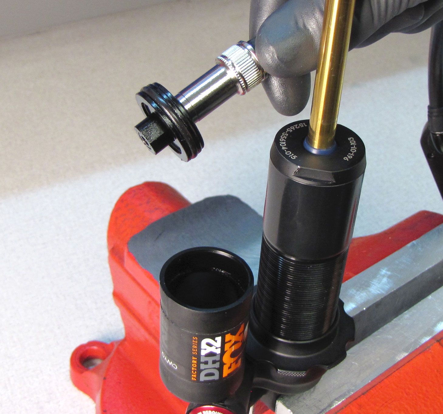
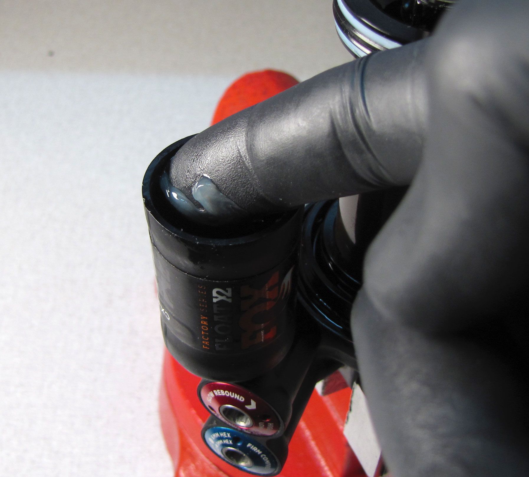
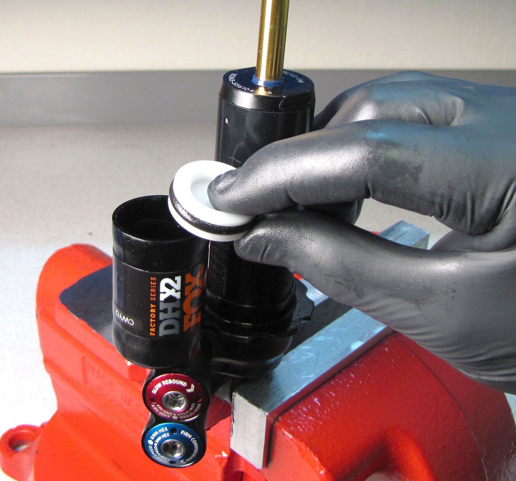
Replace the o-ring on the reservior end cap with a new greased one from the kit, then set aside. Fill the ring groove on the inner wall of the reservoir with slick honey to help prevent damage to the IFP during removal.
Step 5
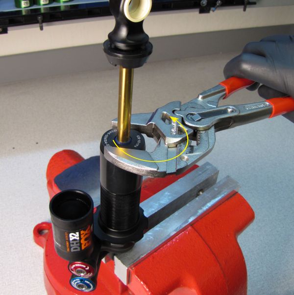
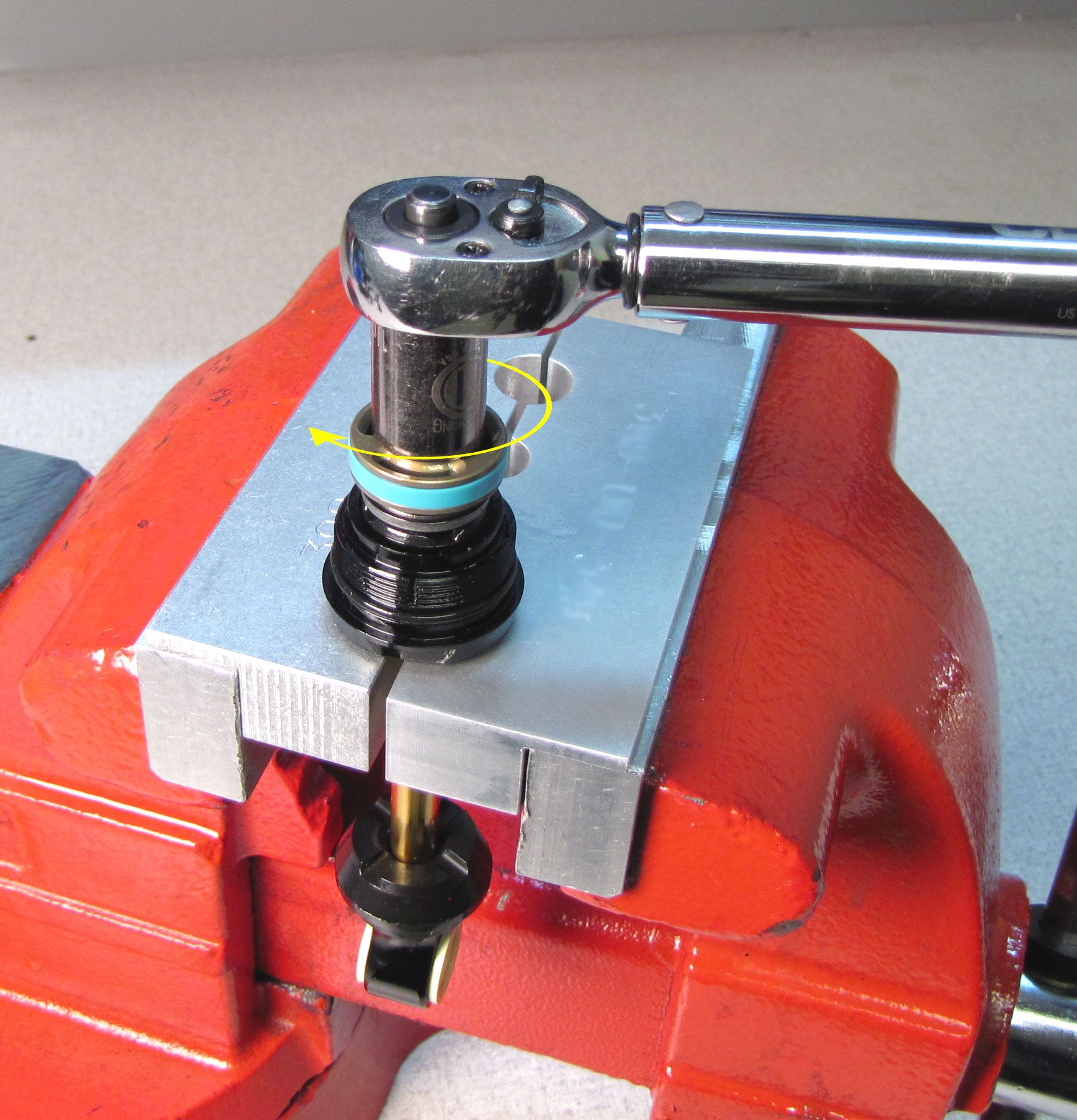
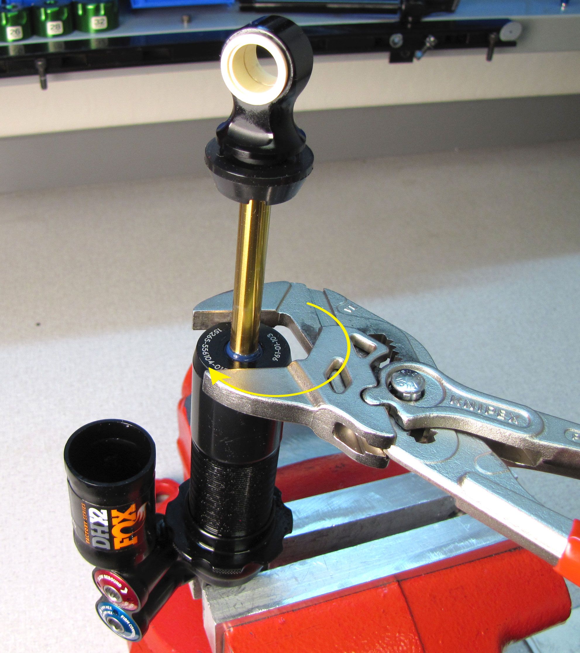
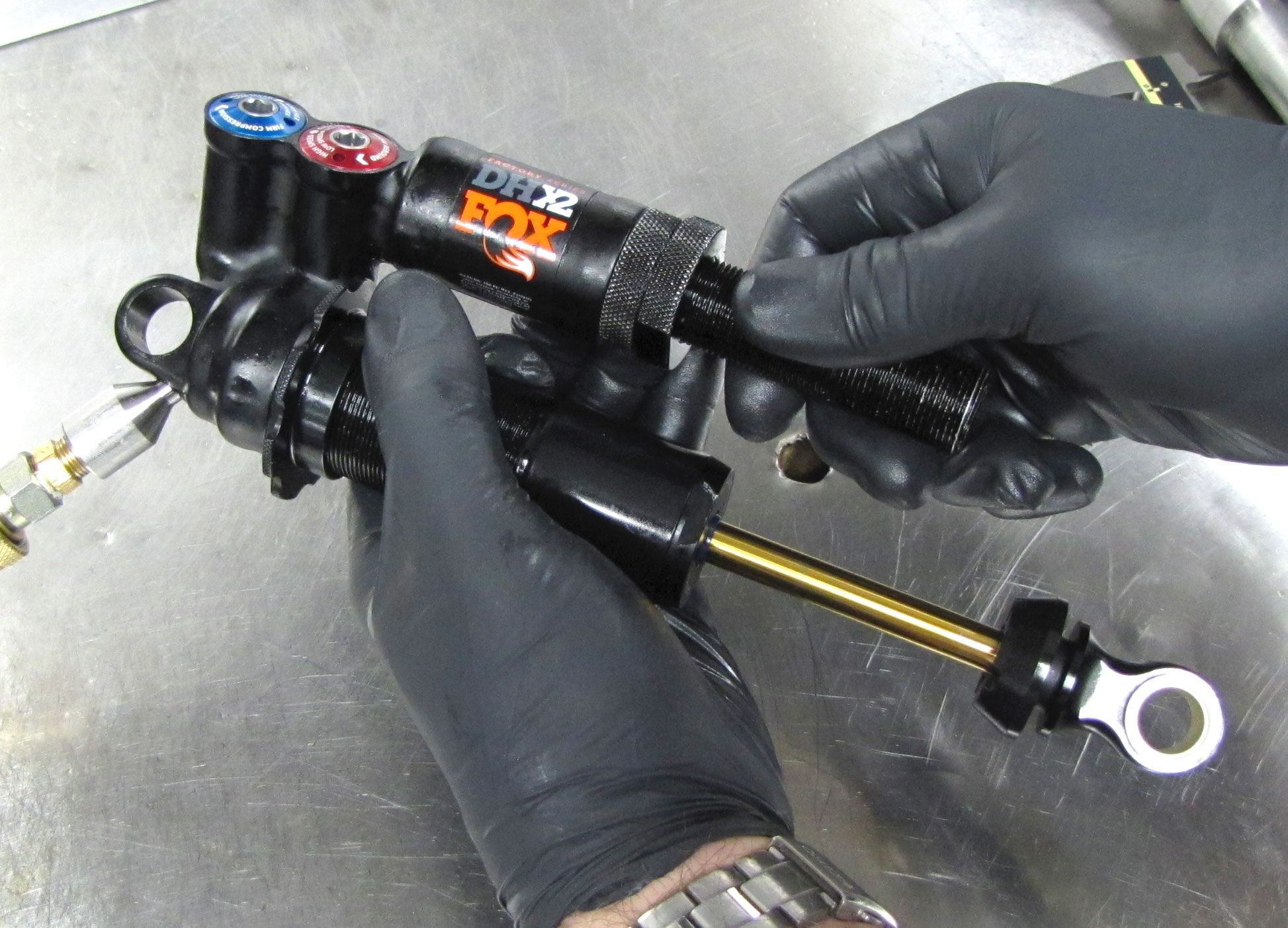
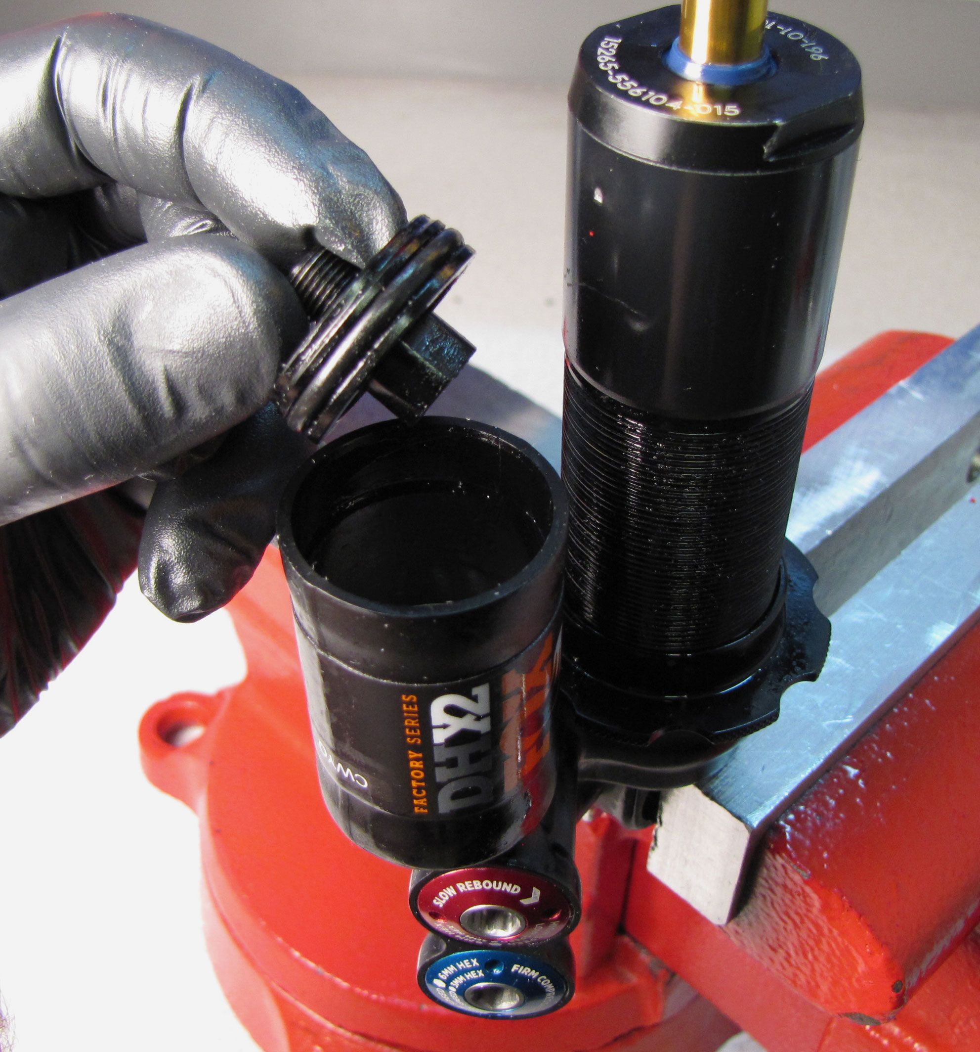
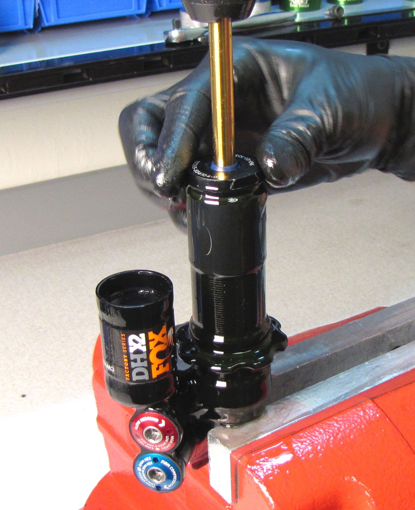
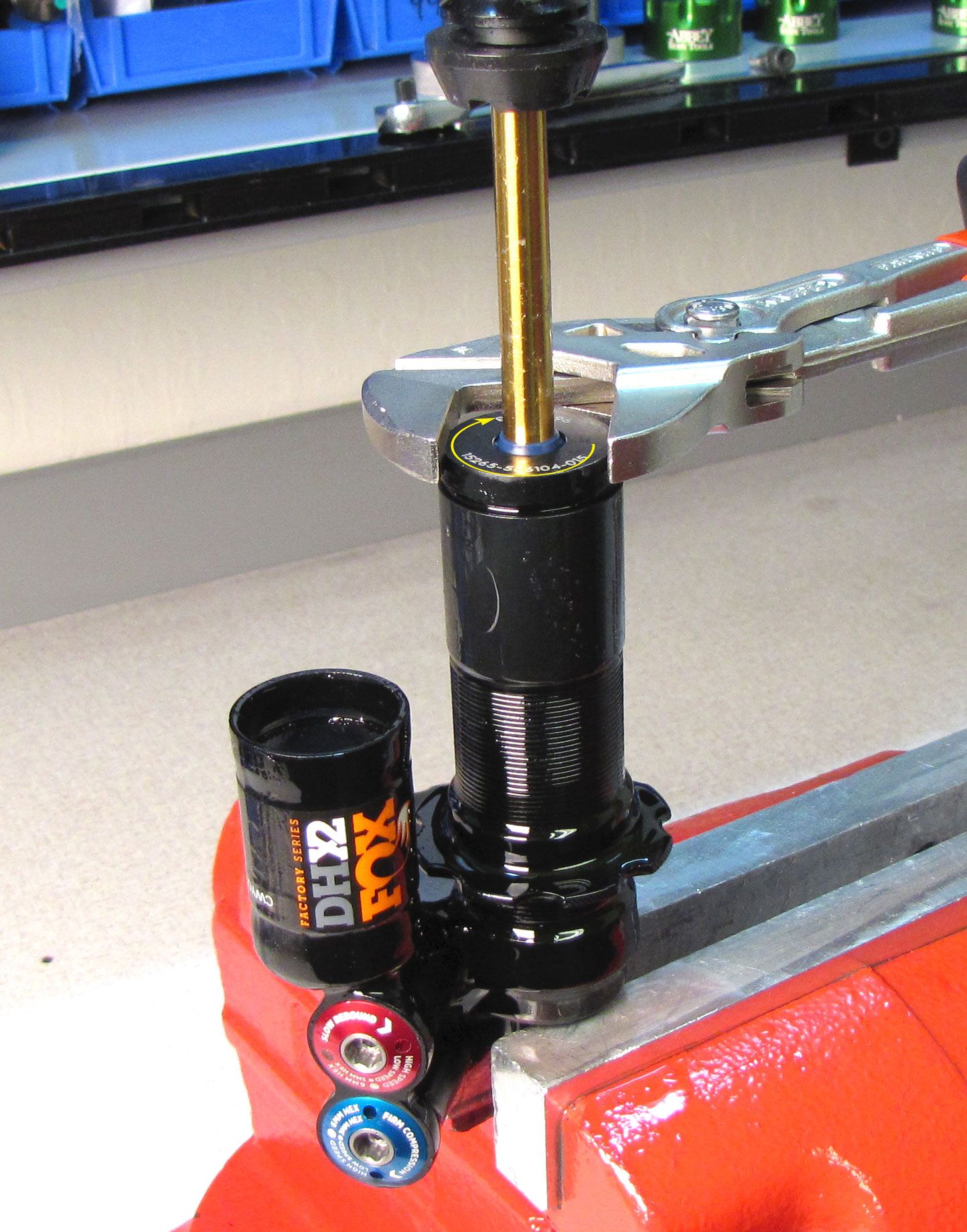
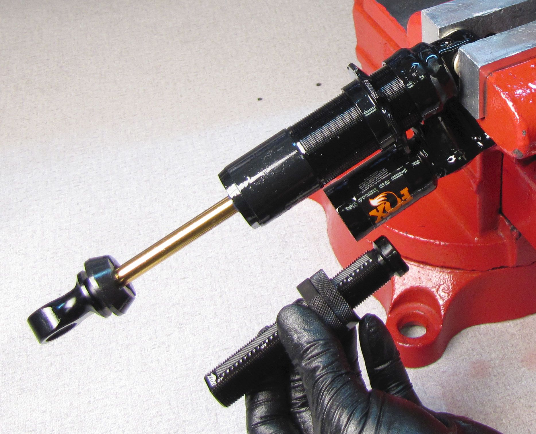
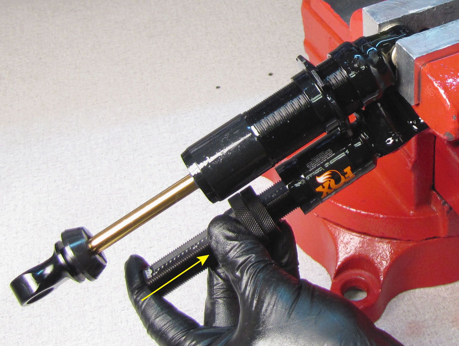
Unthread the bearing assembly from the body (counter-clockwise) with Knipex smooth/parallel jawed pliers or a 1.125" wrench. Remove the bearing assembly with inner body by pulling up.

Step 6
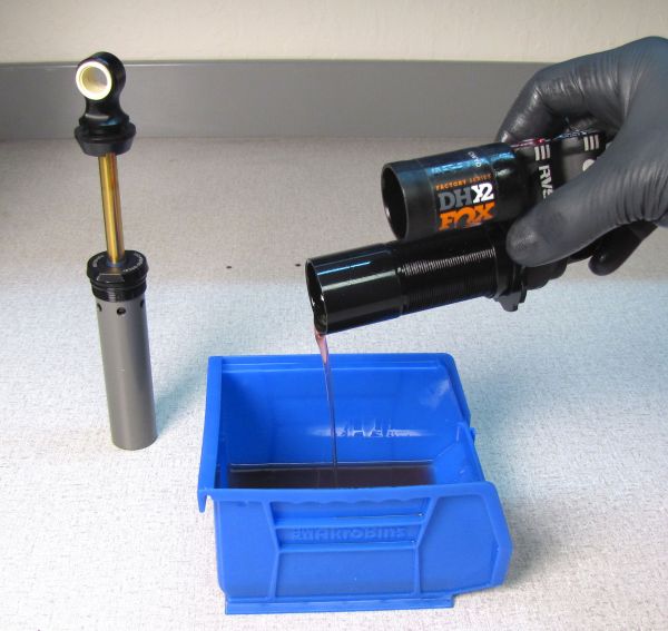
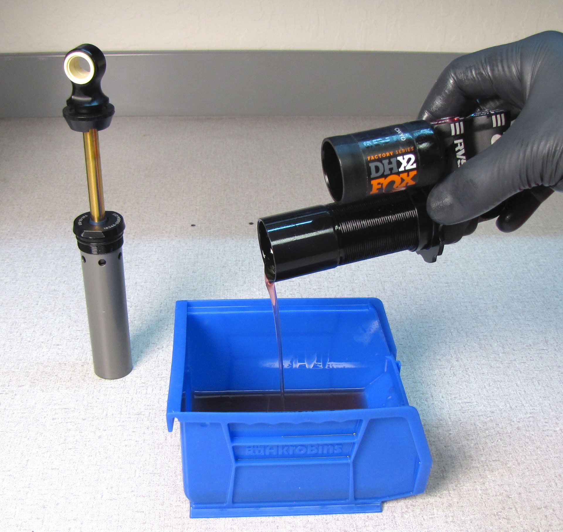
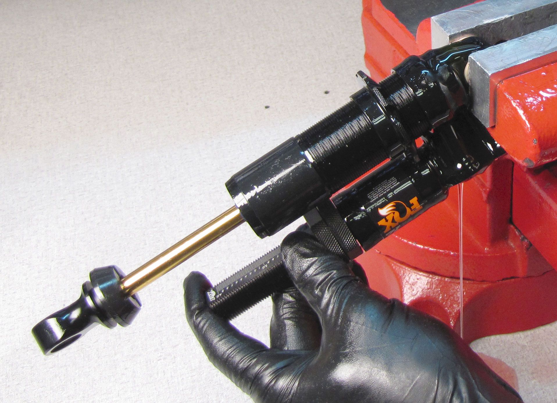
Remove the shock from the vice and pour out the oil. Temporarily reinstall the bearing assembly with inner body into the outer body, threading (clockwise) until just hand tight.

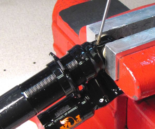
Step 7
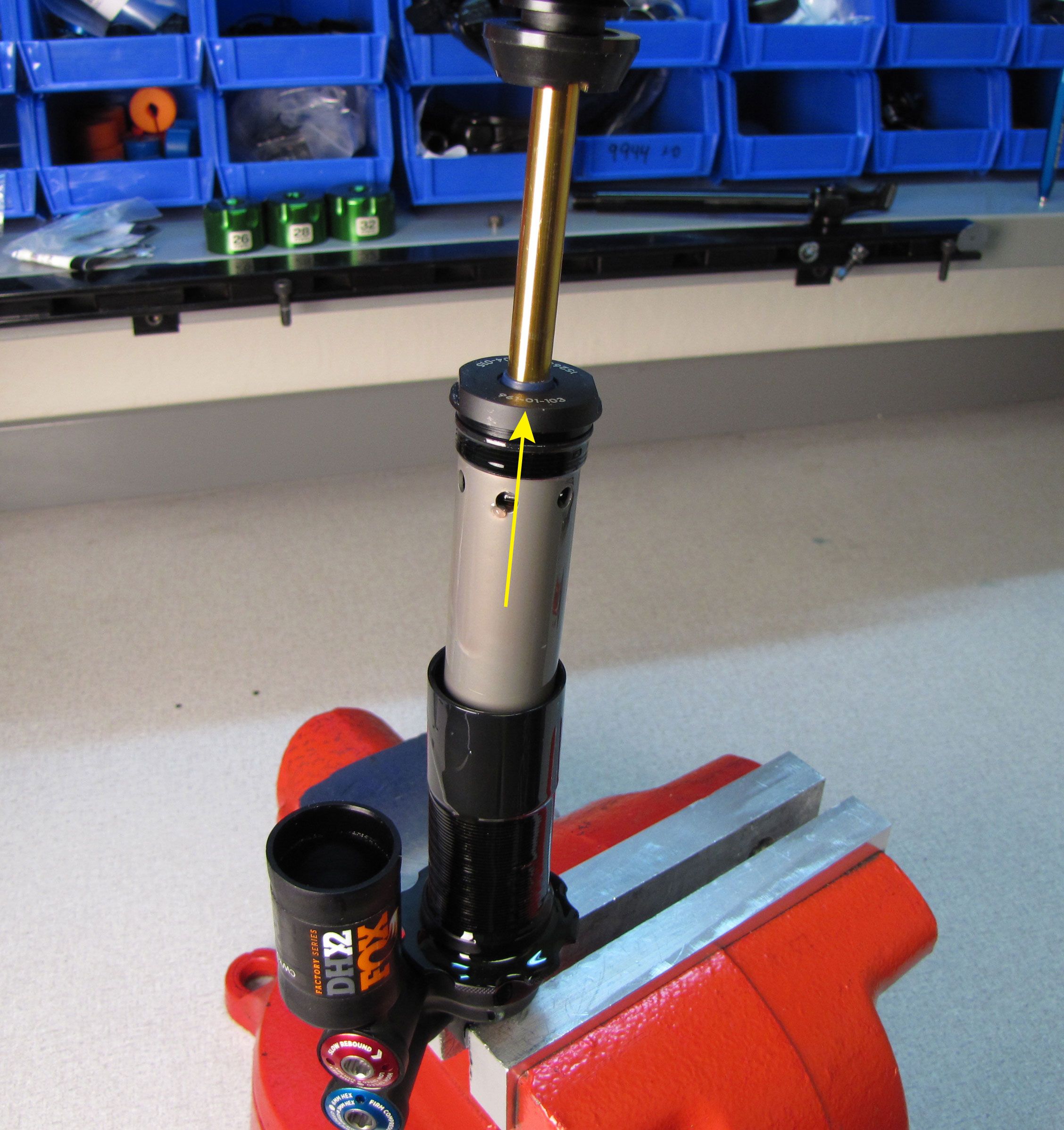
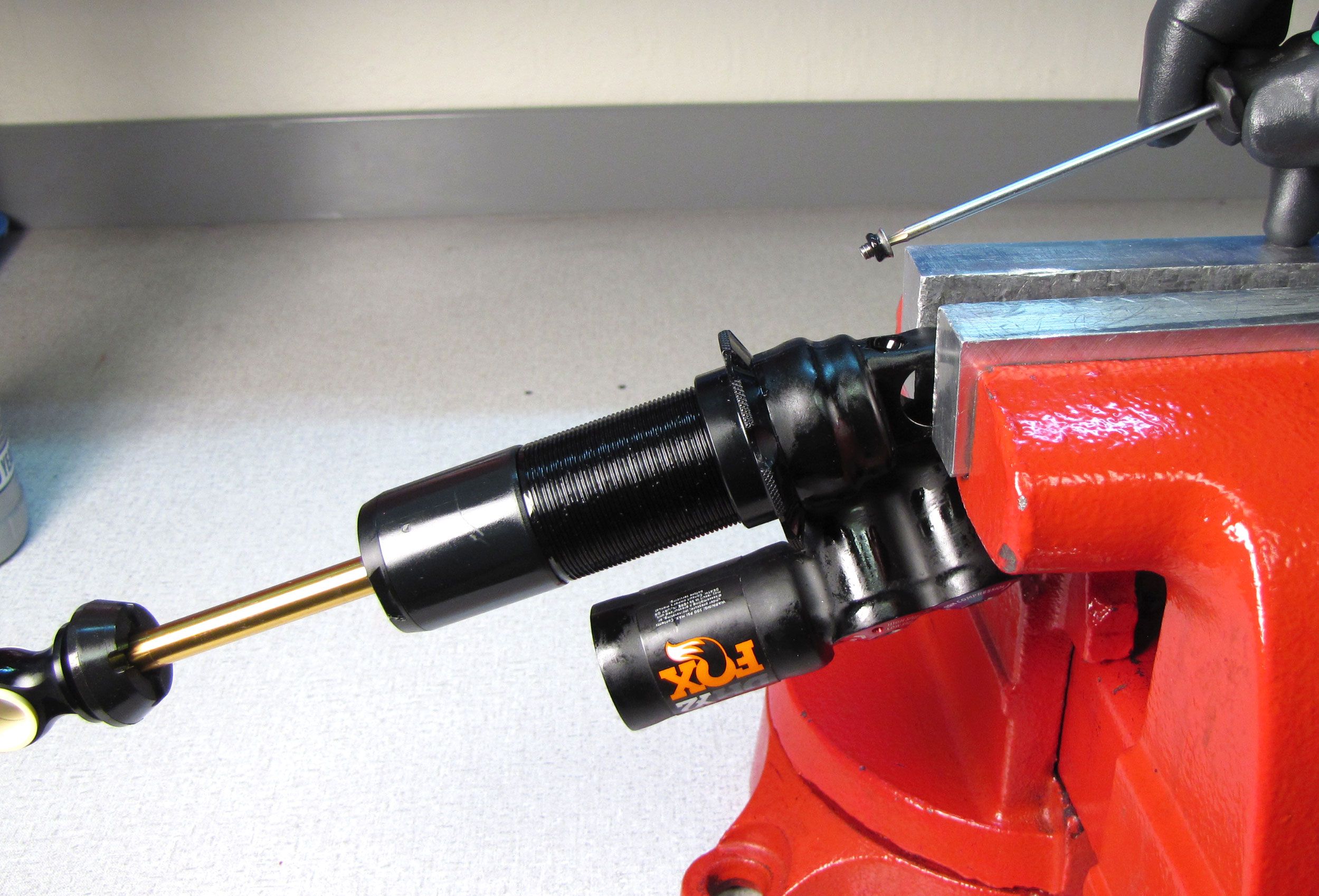
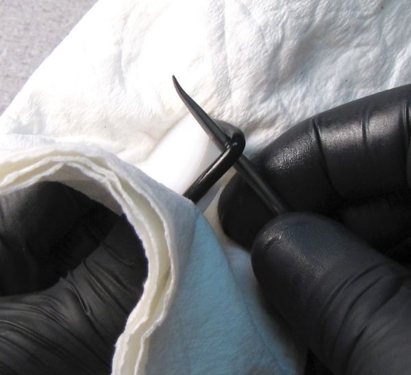
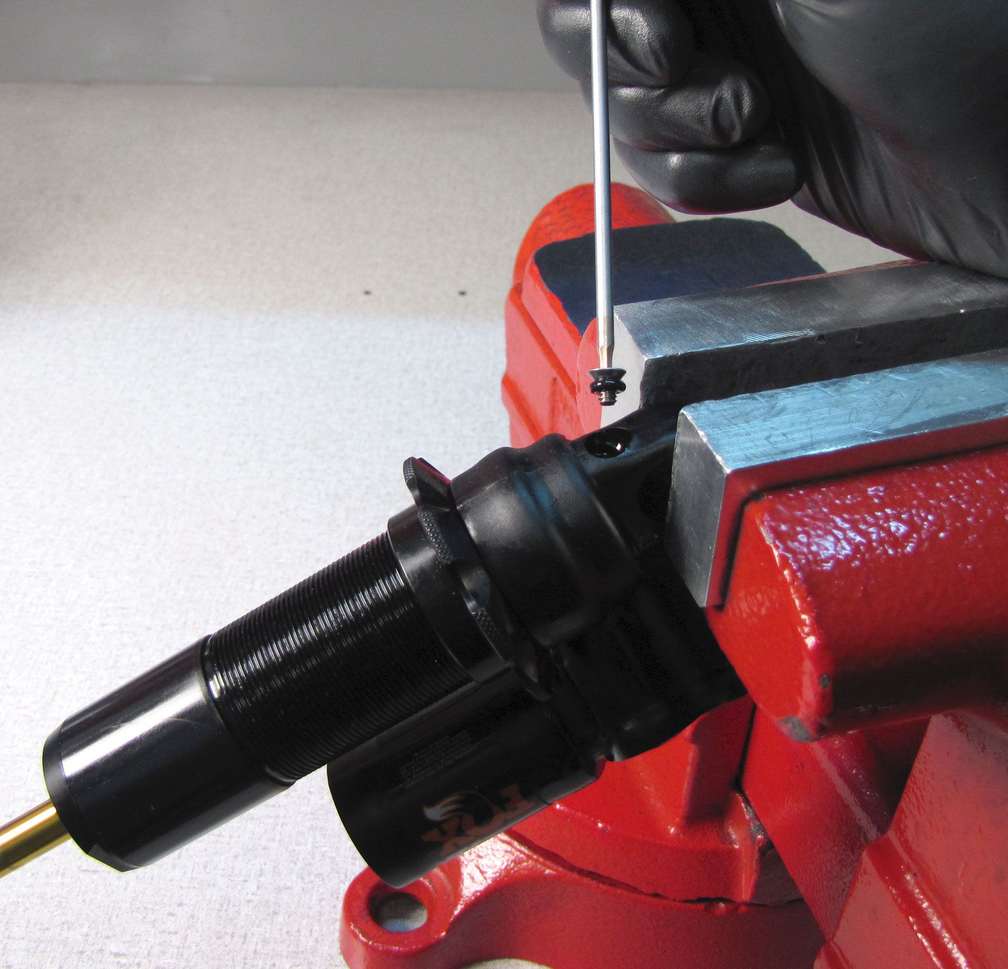
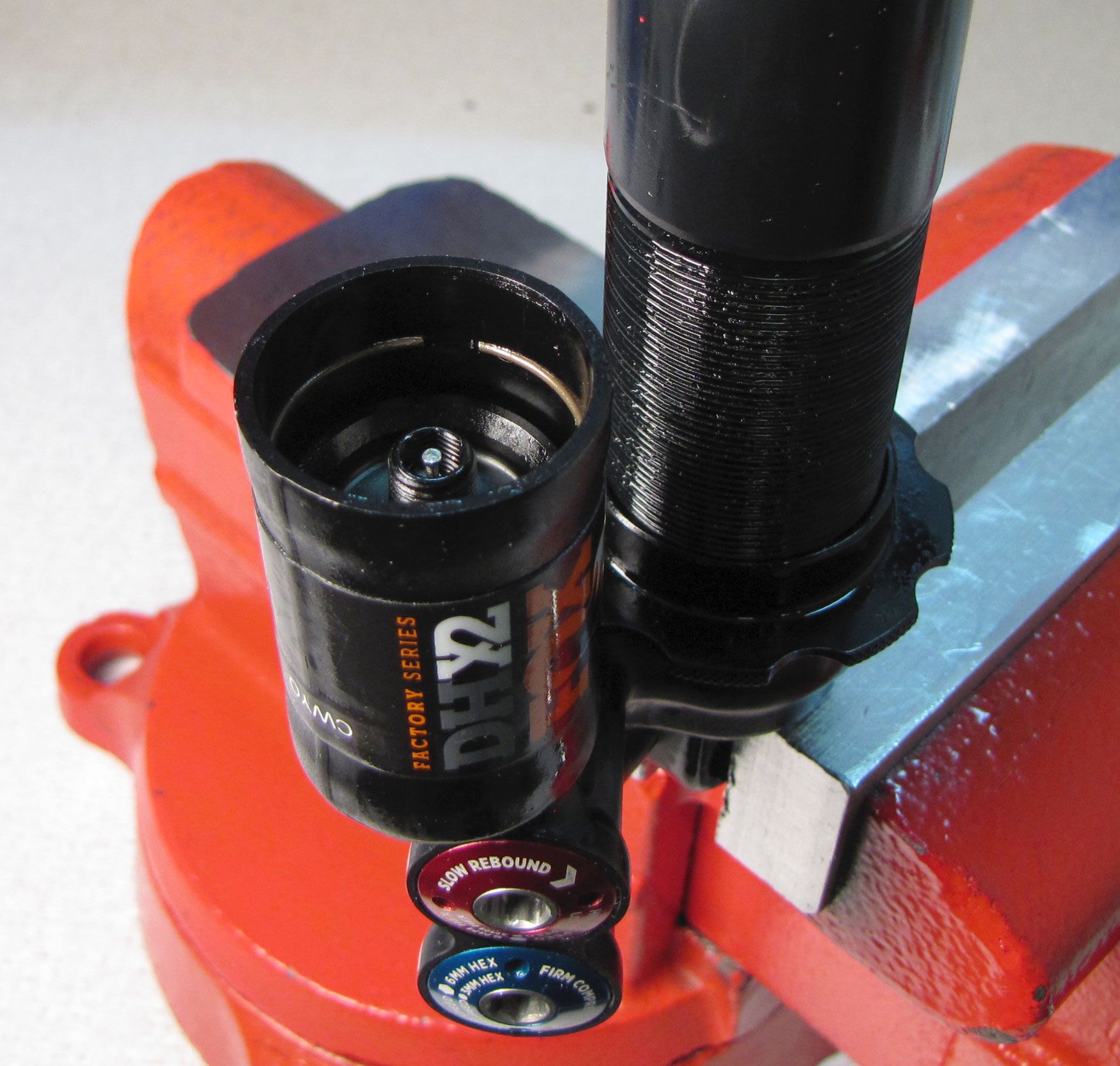
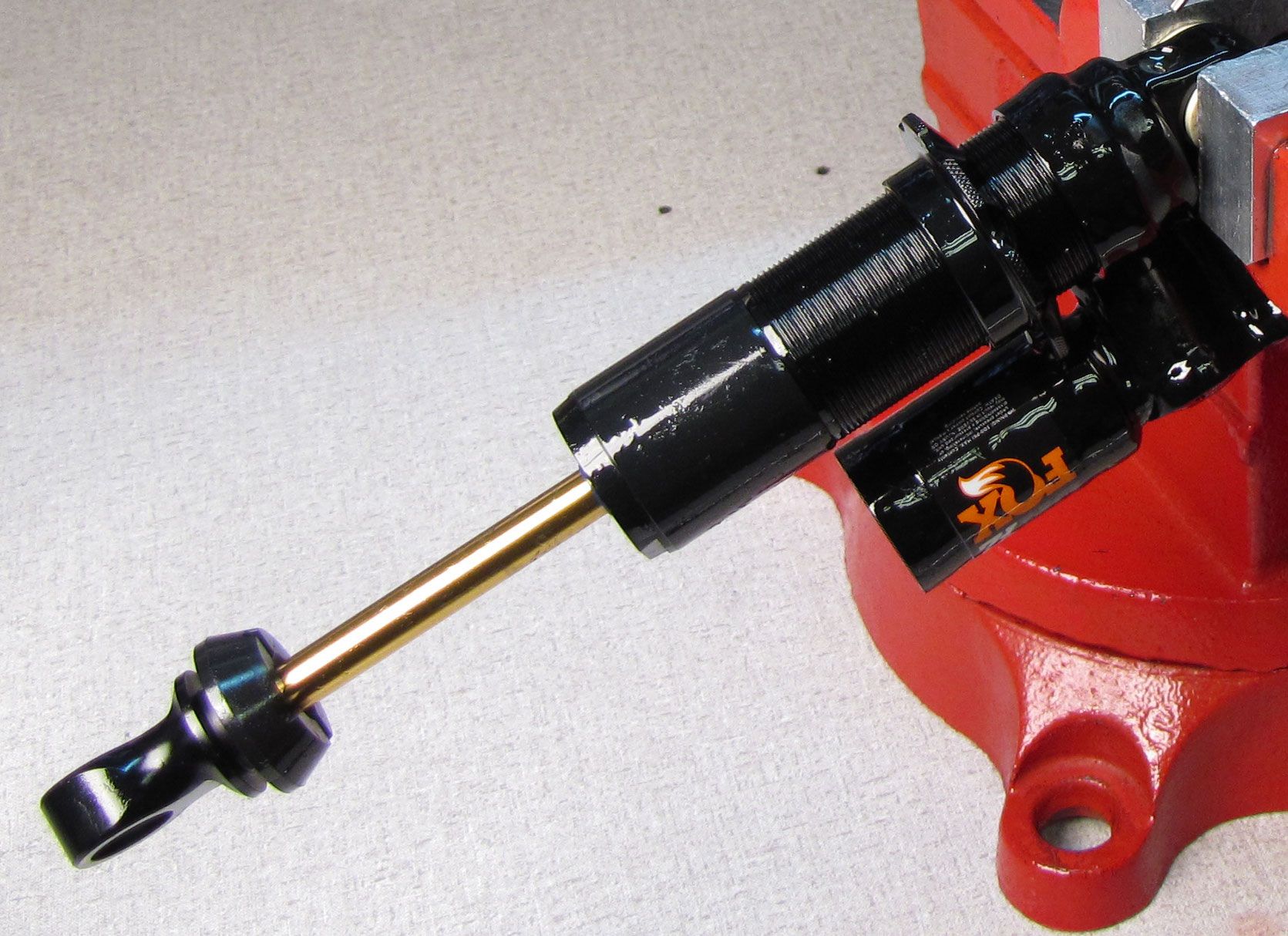
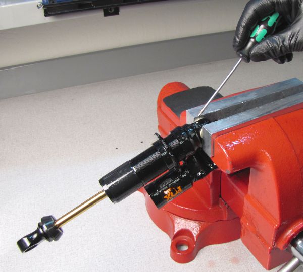
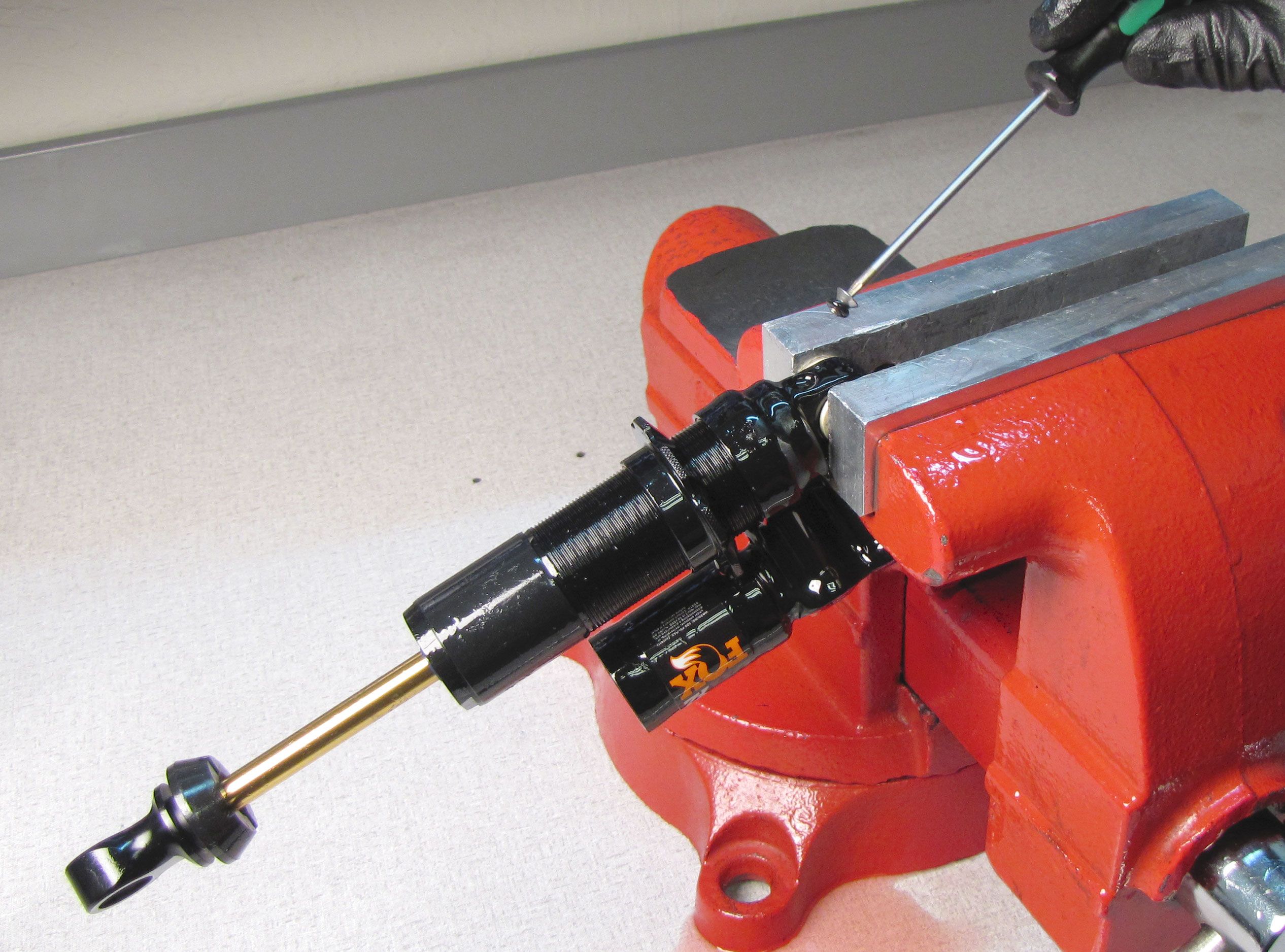
Unthread and remove the set screw and o-ring from the back of the adjuster eyelet with a 2mm hex wrench. Cover the reservoir with a lint-free paper towel and inject compressed air into the port on the back of the adjuster eyelet to blow out the IFP.
Step 8
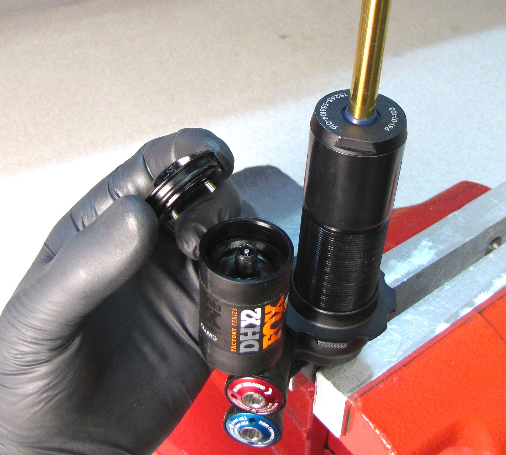
Replace the IFP o-ring with a new greased one from the kit, then set aside in a clean area. Unthread (counter-clockwise) and remove the bearing assembly with inner body.


Step 9
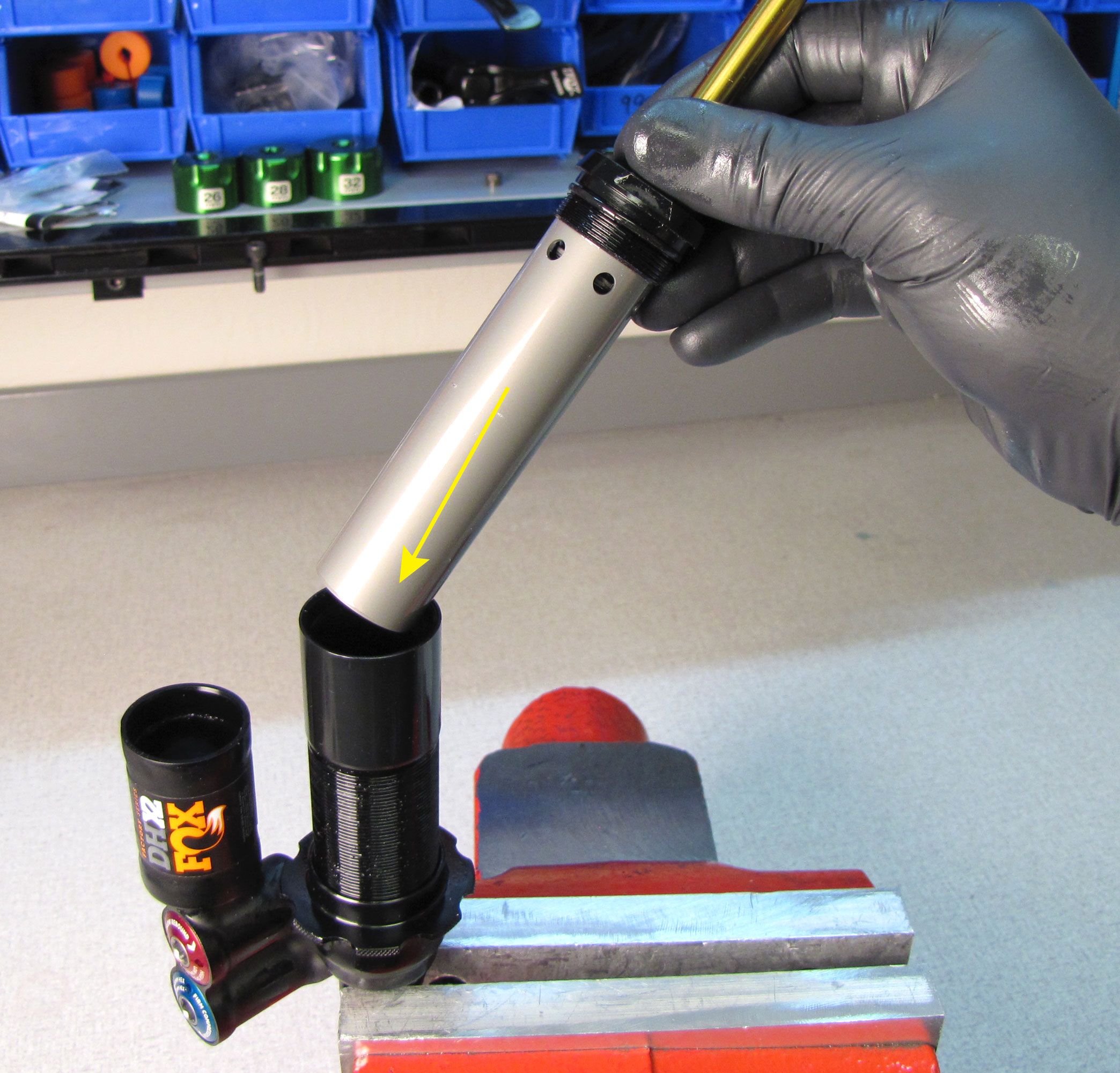
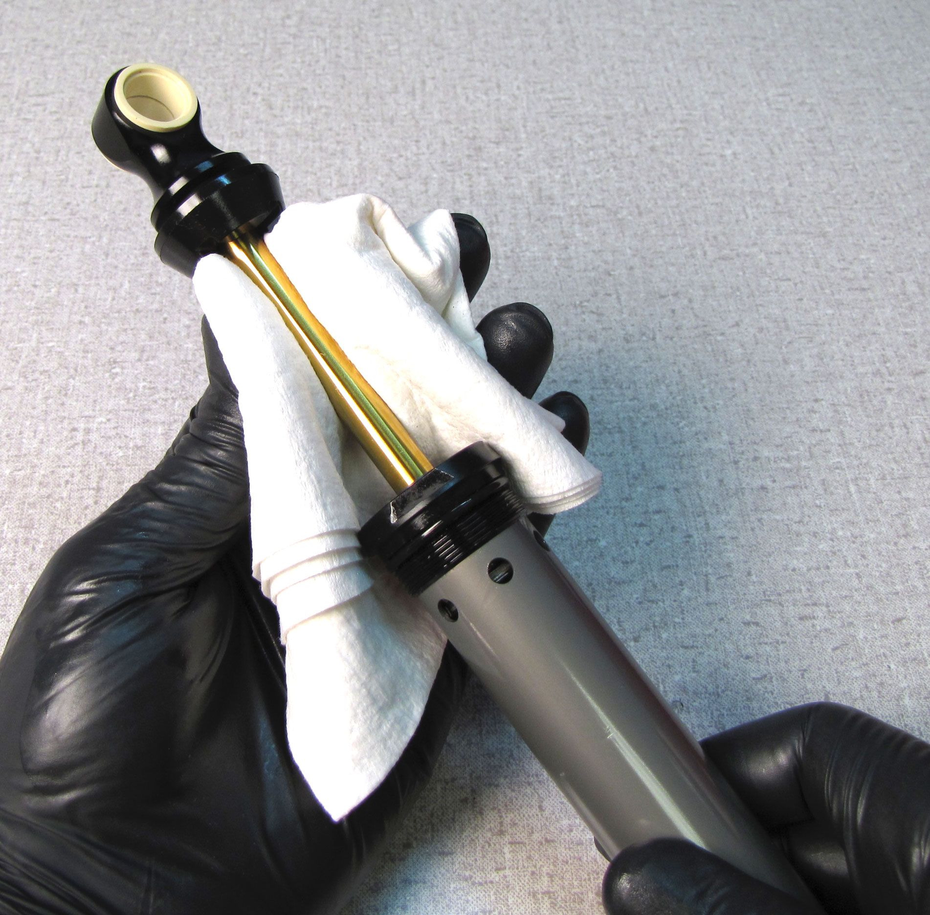
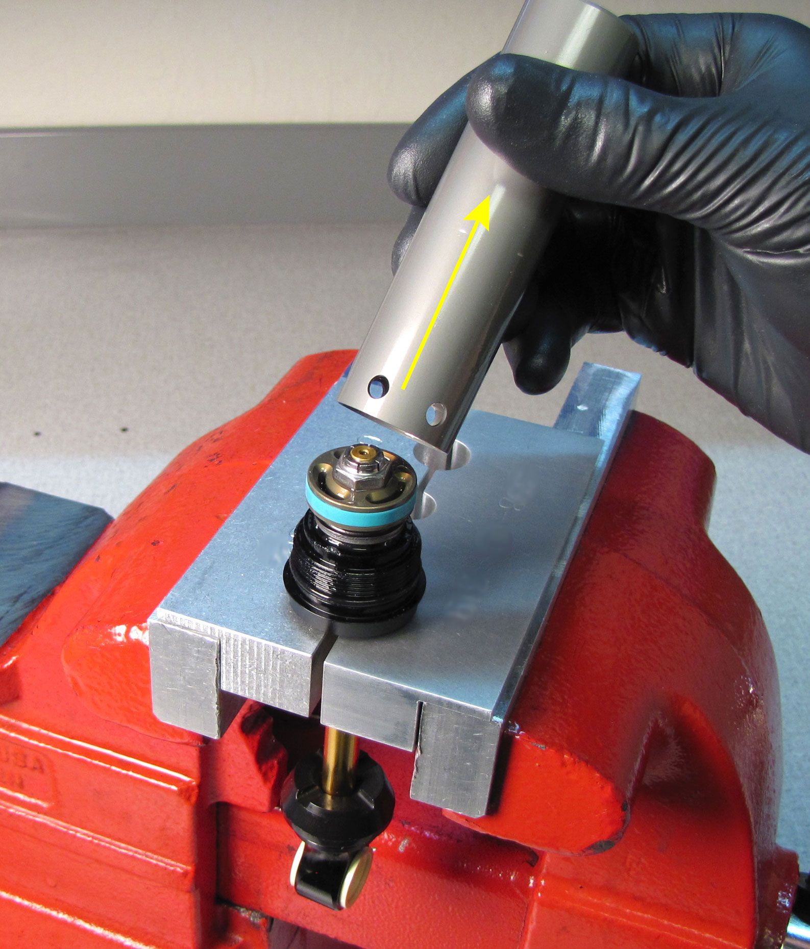
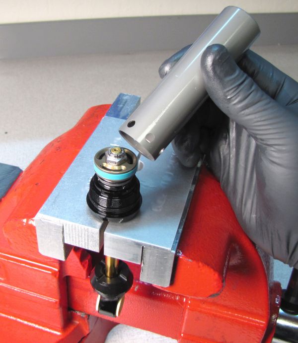
Clean the shaft with Isopropyl alcohol and a clean lint-free paper towel, then clamp in your 9mm shaft clamps with the inner body facing up. Pull up on the inner body to remove it from the bearing assembly. This part can be tight on the bearing assembly and can require significant force to remove. Do not bend the shaft while removing the inner body.
Step 10
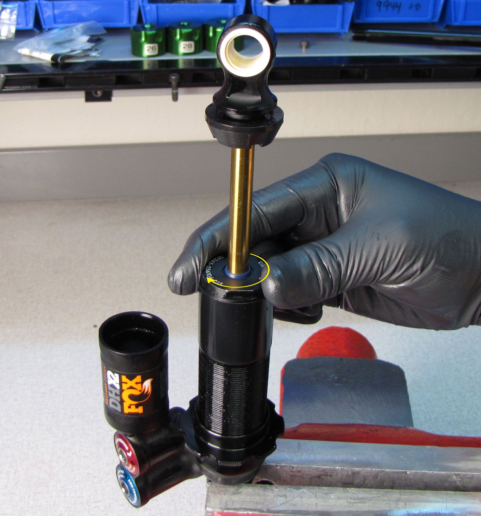
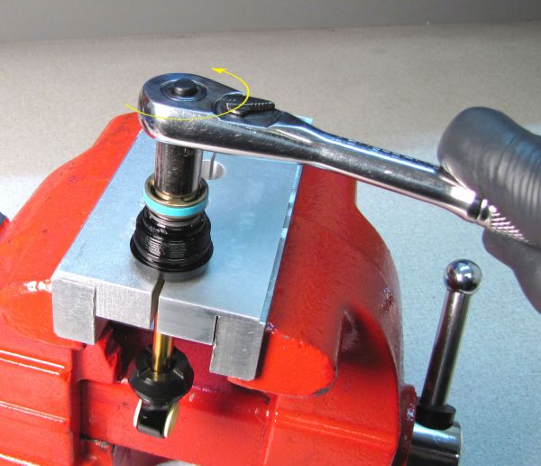
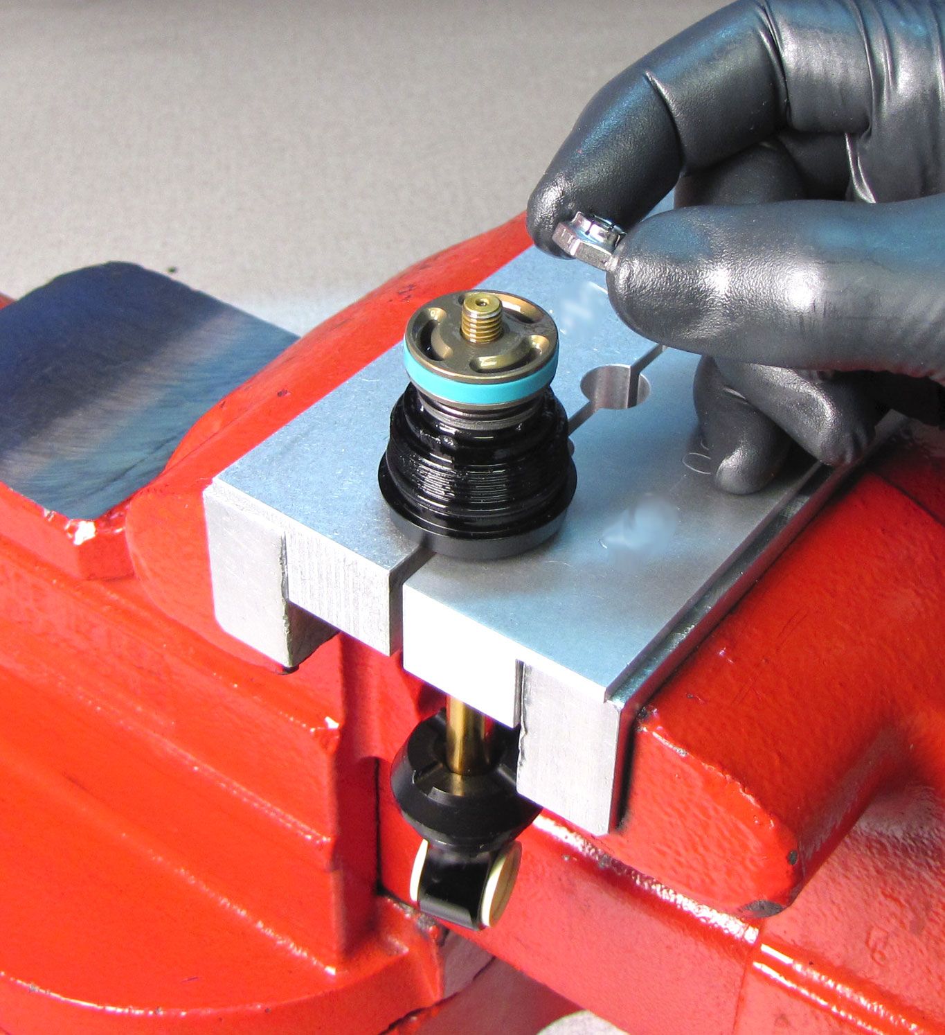
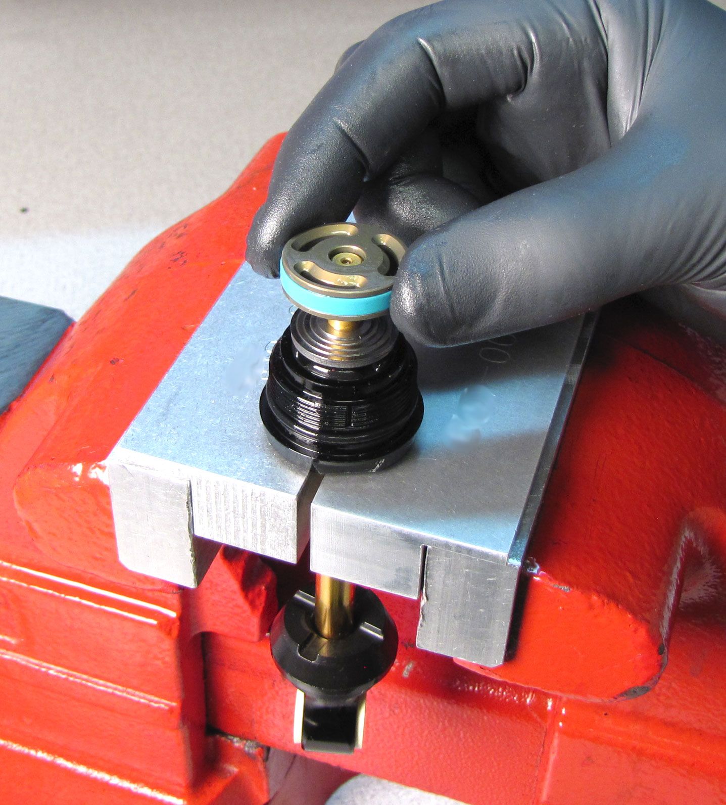
Use an 11mm socket to unthread (counter-clockwise) and remove the piston nut. Remove the piston and valving assembly keeping all parts in their original order. Replace the blue glide ring and o-ring on the piston with new ones from the kit.

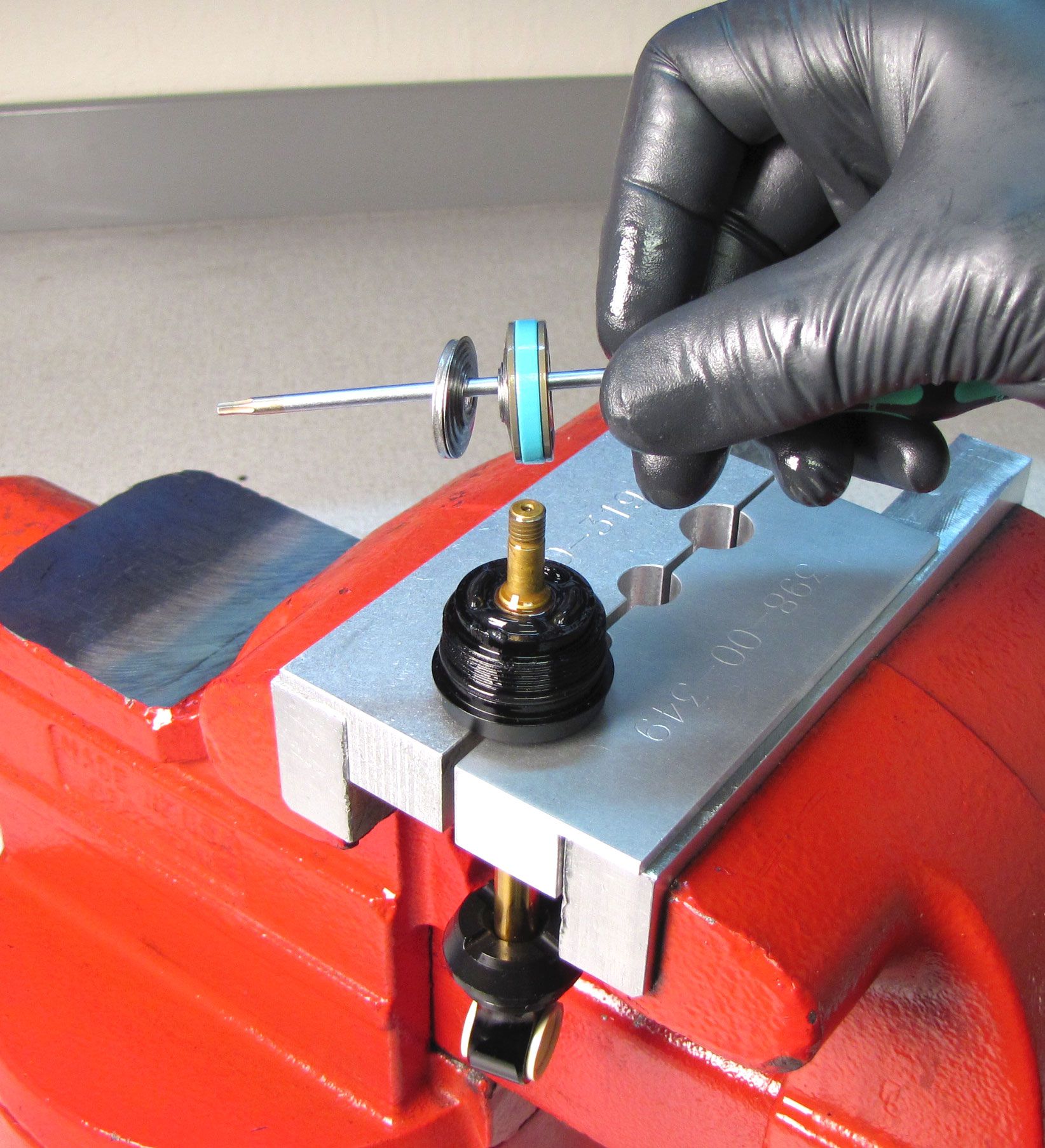

Step 11
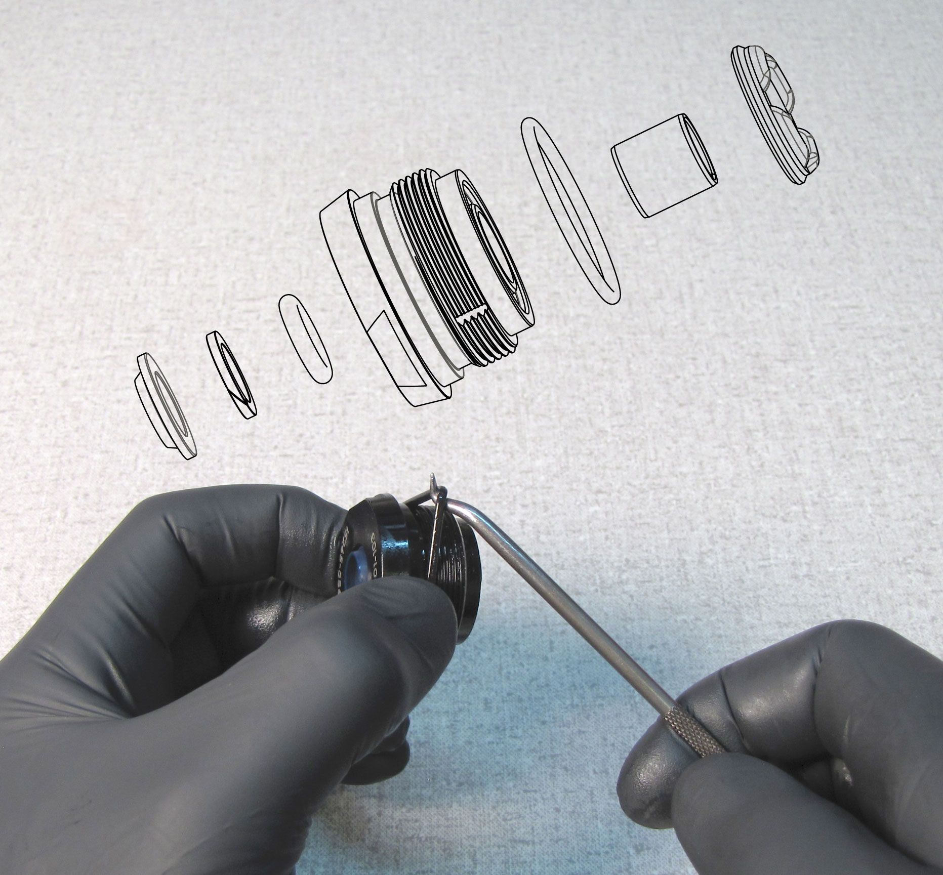
Remove the bearing assembly and replace all seals and backup rings with new greased ones from the kit. Please reference the TSB regarding the updated DHX2 shaft seals: DHX2 Shaft Seal Update »
Step 12
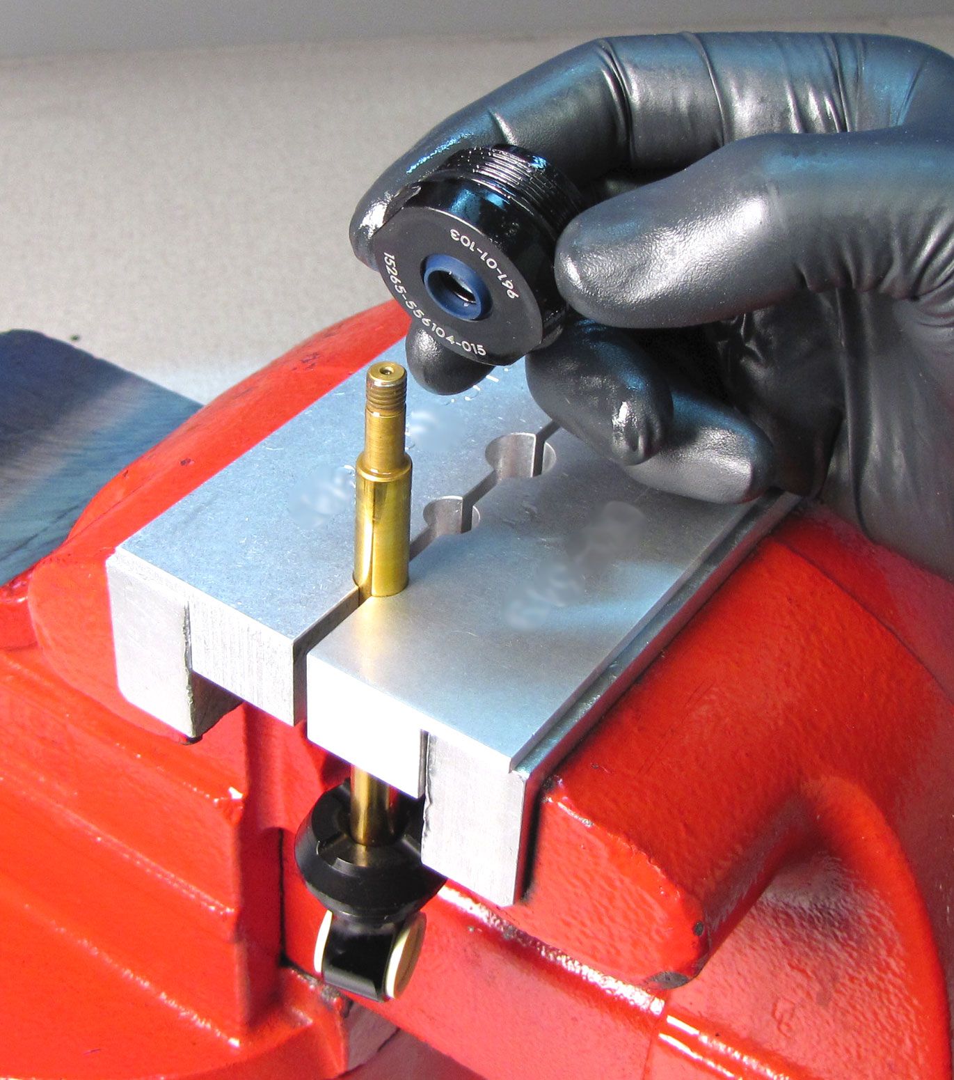
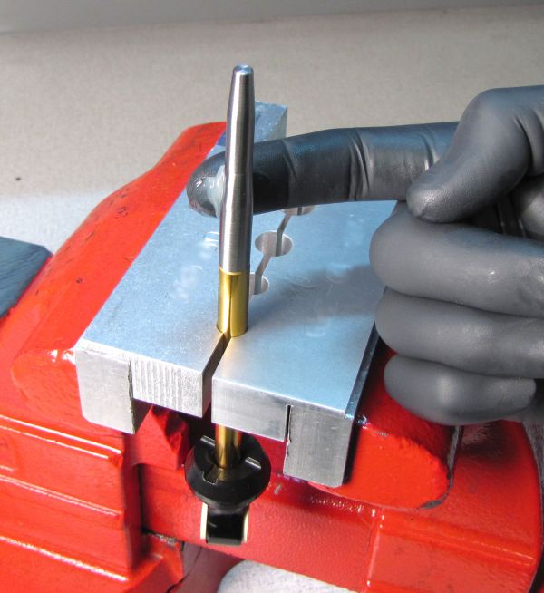
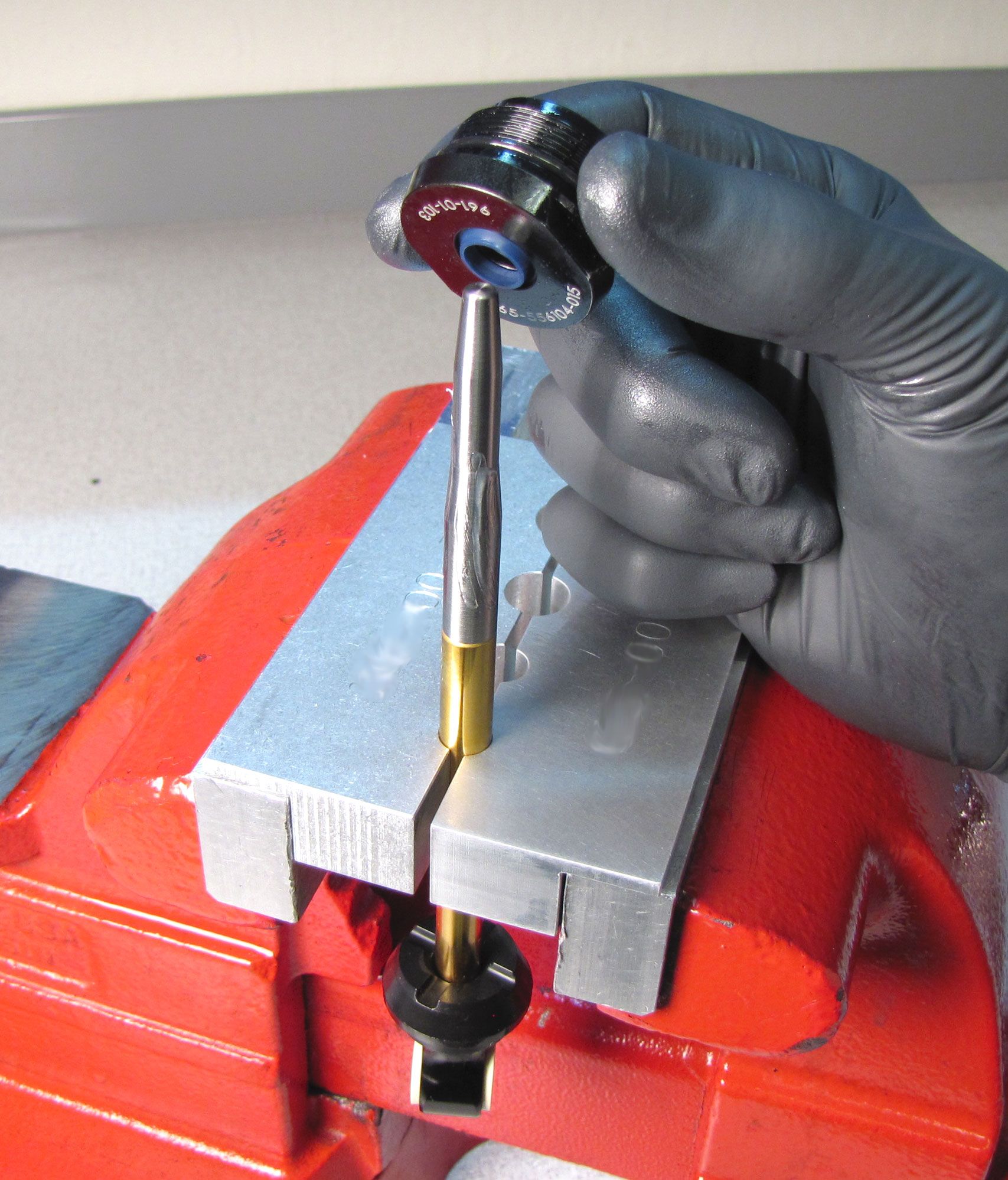
Install the X2 bullet onto the shaft and apply a thin film of Slick Honey to the taper of the bullet. Install the rebuilt bearing assembly onto the shaft as shown. Remove the bullet tool.


Step 13
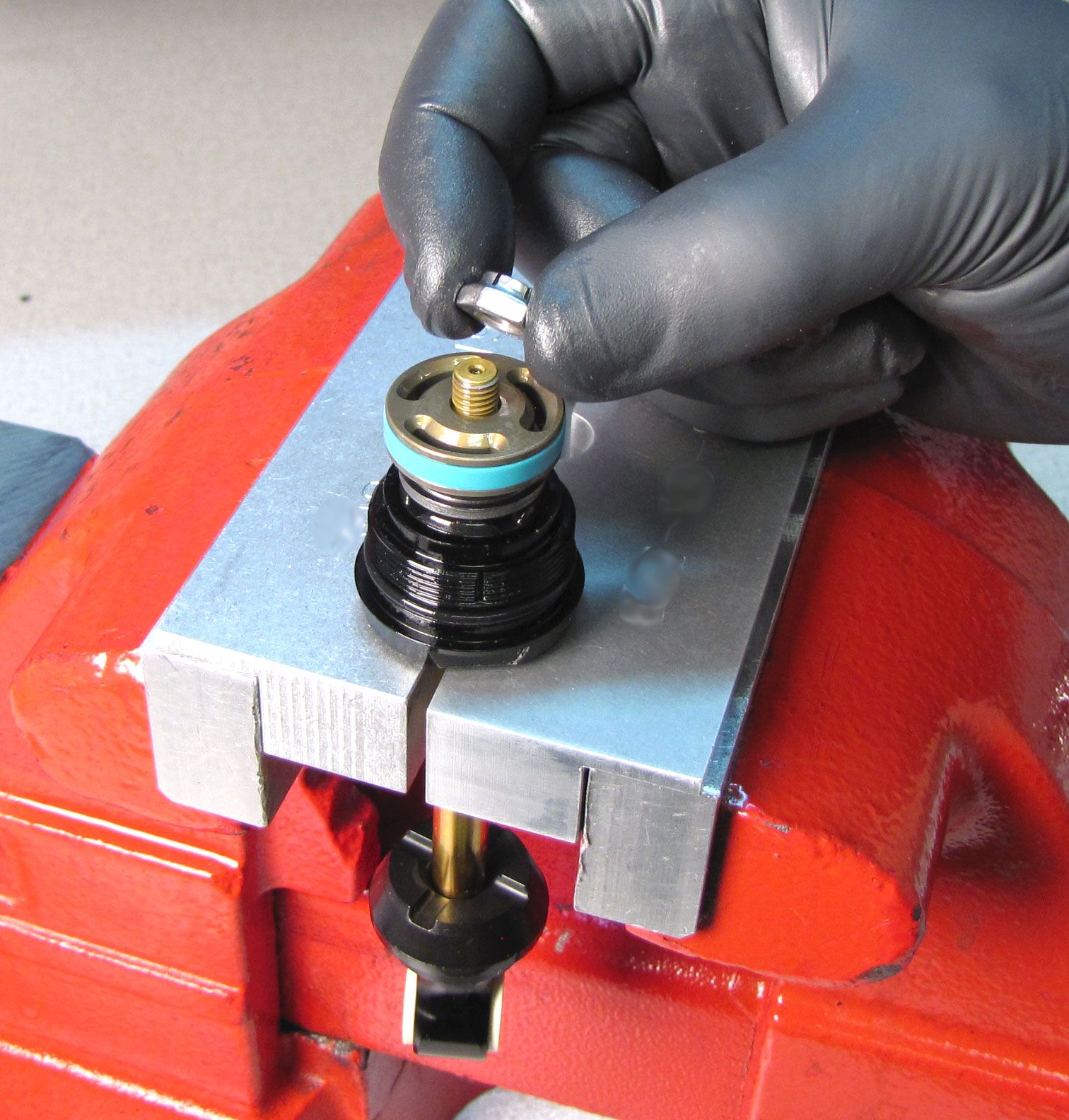
Reinstall the valving assembly, piston, and piston nut. Tighten the nut clockwise to 80 in-lb (9.0 Nm).
While FOX recommends using the Andreani vacuum bleeder, the DHX2 shock can be hand bled if needed.
For hand bleed info please skip to Optional Hand Bleed Instructions » after completing step 13
Step 14
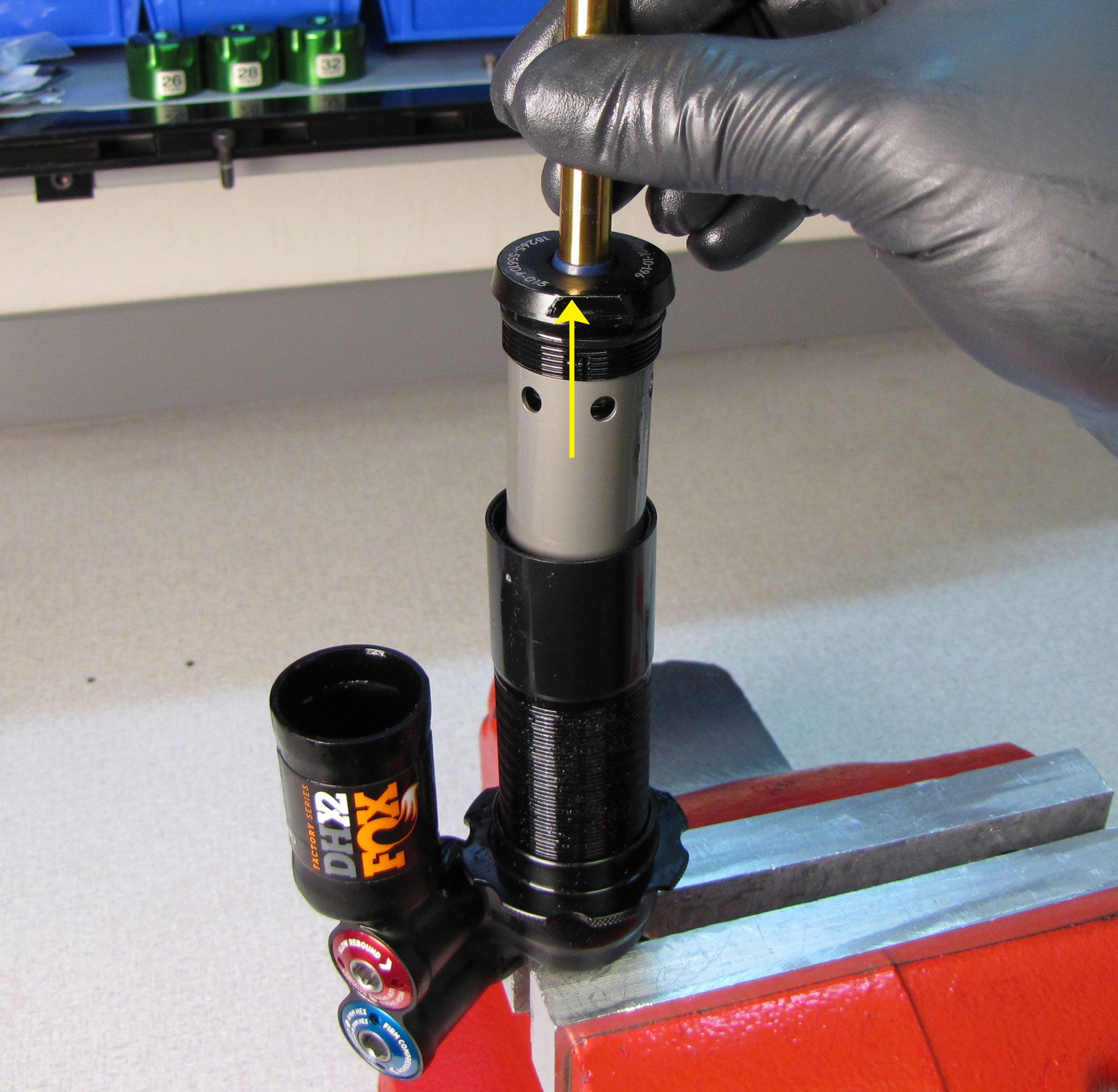
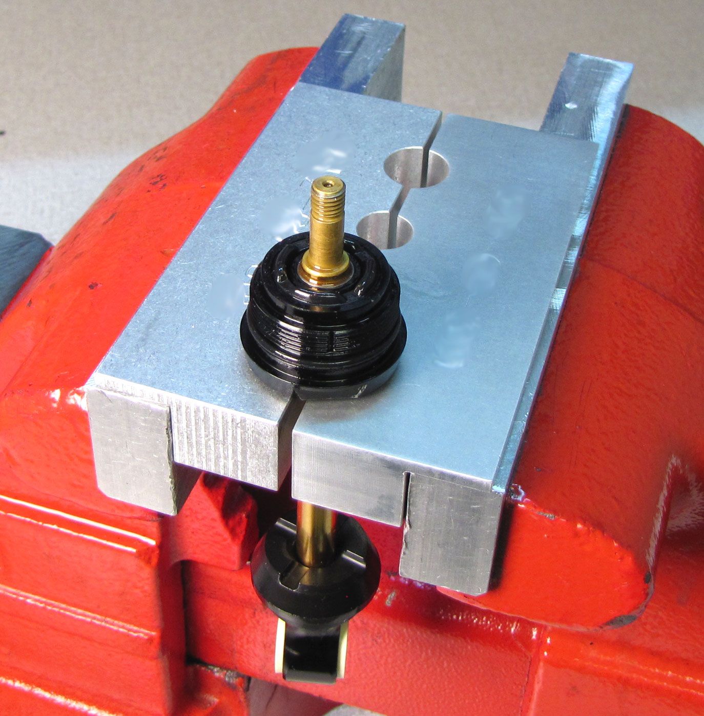
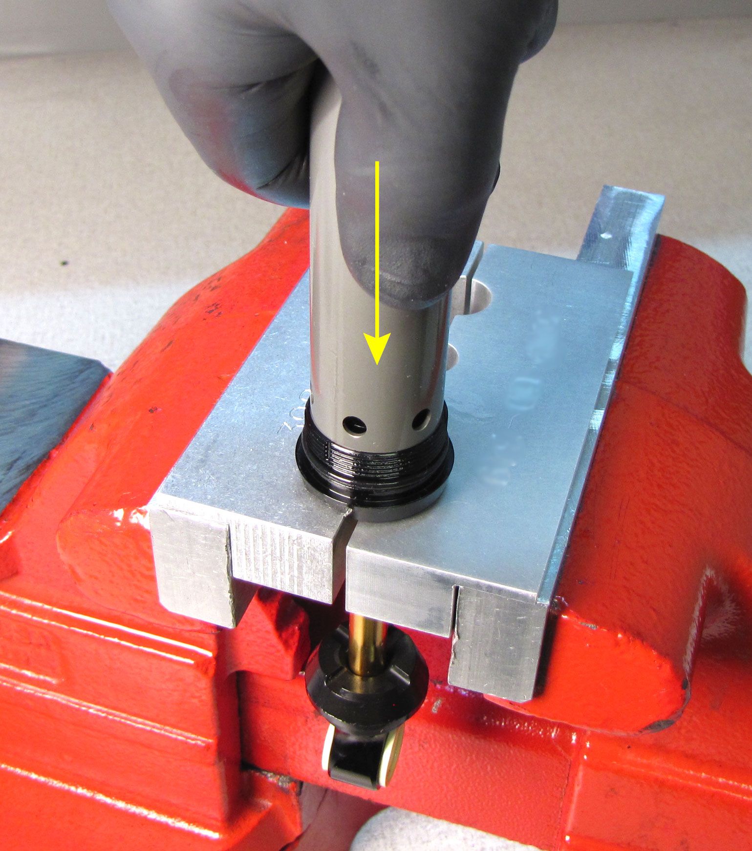
Reinstall the inner body with the ports oriented toward the bearing assembly. Press down on the inner body to completely seat it on the bearing assembly.

Step 15
Install the inner body into the outer body. Thread the bearing assembly to the outer body, then use Knipex smooth/parallel jawed pliers or a 1.125" wrench to tighten (clockwise) the bearing assembly to 145 in-lb (16.3 Nm).


Step 16
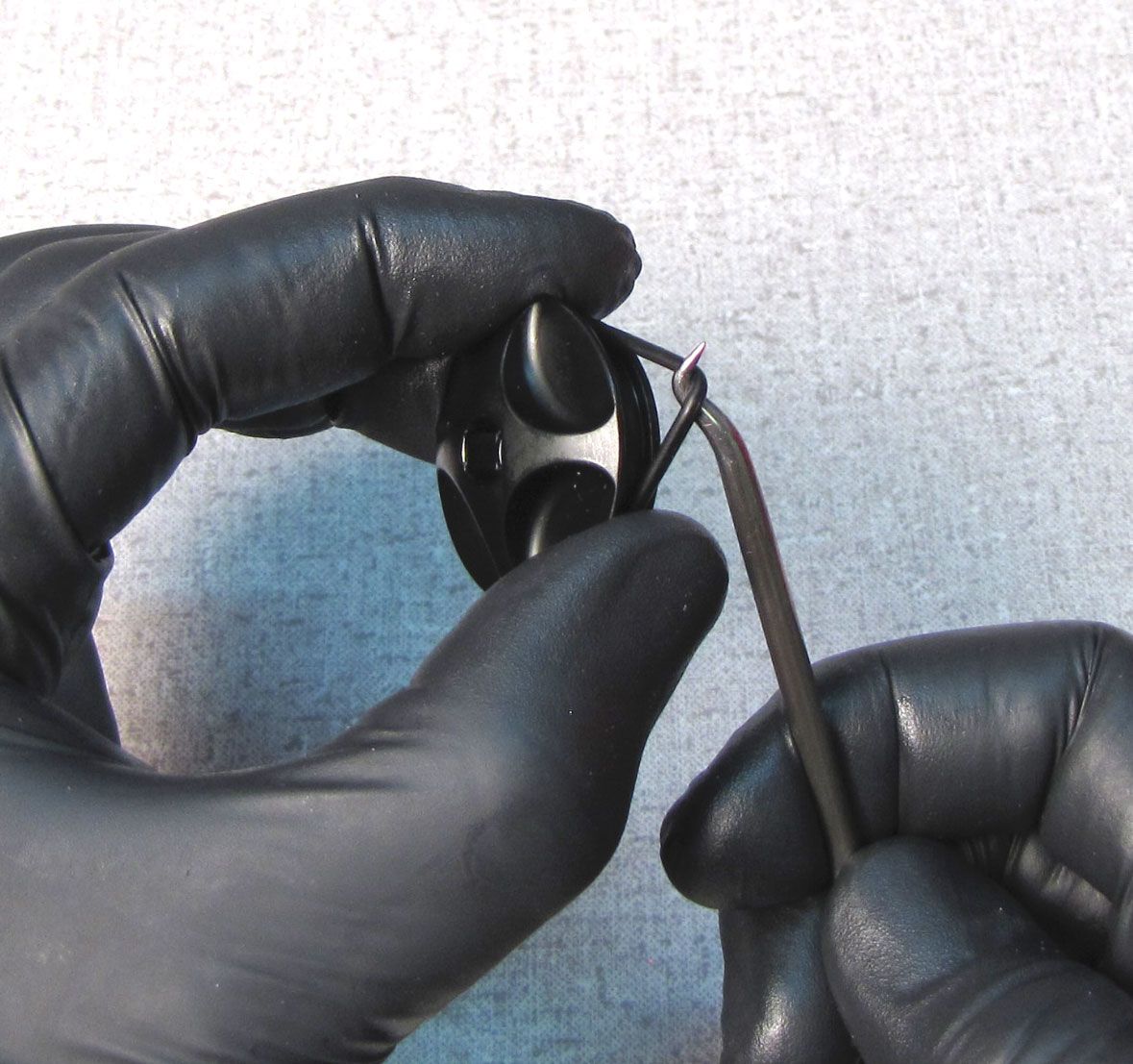
Reinstall the IFP into the reservoir with the counterbore facing the open end of the reservoir. Replace the wire retaining ring to retain the IFP during the oil fill steps later.
Step 17
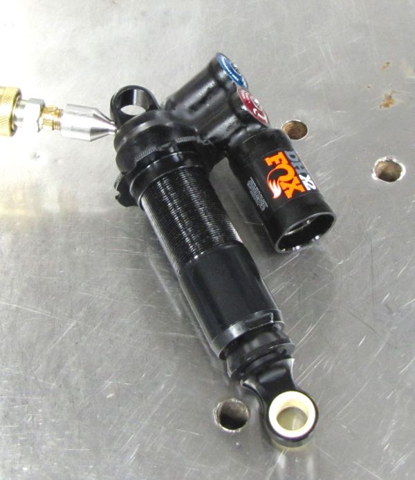
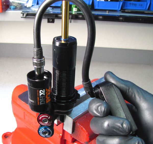
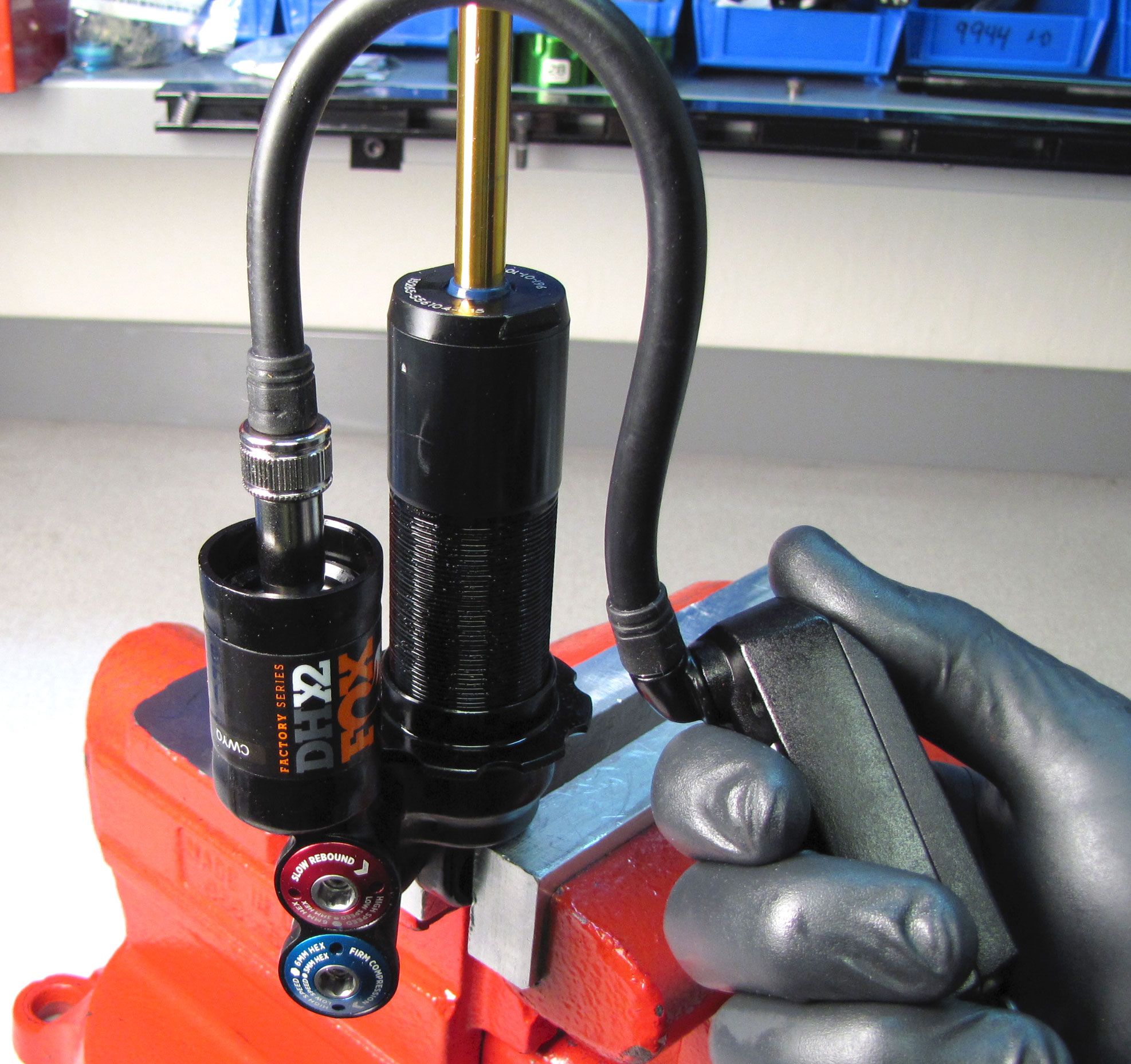
Thread the Fill Machine Adapter (803-00-463) from the Andreani machine into the port on the back of the adjuster eyelet. Vacuum the shock, then fill with 10wt. red oil (or FOX 4wt. oil if 10wt. red is not available). Set the IFP to the appropriate depth using your IFP depth setting tool (803-00-566). Reinstall the set screw with a new greased o-ring from the kit and tighten to 14 in-lb (1.6 Nm).
| Shock Size | IFP Height (+/-0.050in) |
| 7.875 x 2.250 | 1.243in/ 31.57mm |
| 8.500 x 2.500 | 1.293in/ 32.84mm |
| 8.750 x 2.750 | 1.343in/ 34.11mm |
| 9.500 x 3.000 | 1.393in/ 35.38mm |
| 10.500 x 3.500 | 1.443in/ 36.65mm |

Step 18
Remove the wire ring from within the reservoir, then grease and reinstall the reservoir end cap followed by the wire retaining ring.

Step 19
Fill the IFP chamber to 150 psi (10.3 bar) with your shock pump, then install the reservoir end cap, tightening to 30 in-lb (3.4 Nm) with your 6mm hex wrench.
Step 20
Install the spring retainer insert followed by the slotted spring retainer.
Dyno test all functions of the shock to verify proper performance, then clean the exterior of the shock.
If you have performed a vacuum bleed with the Andreani machine, you do not need to continue with the hand bleed steps below. If you intend to perform the hand bleed shown below, you must start with your shock as configured in step 13
Optional Hand Bleed Instructions
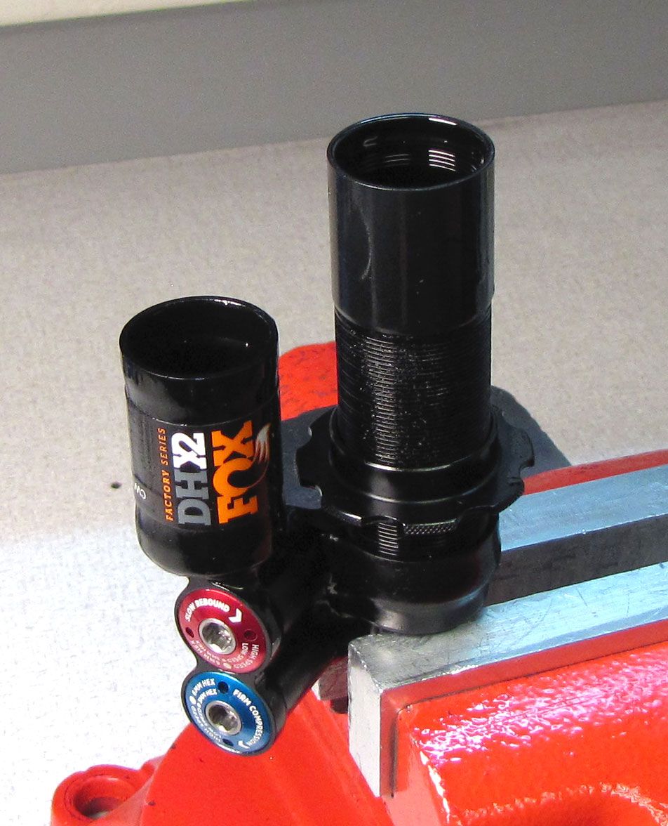
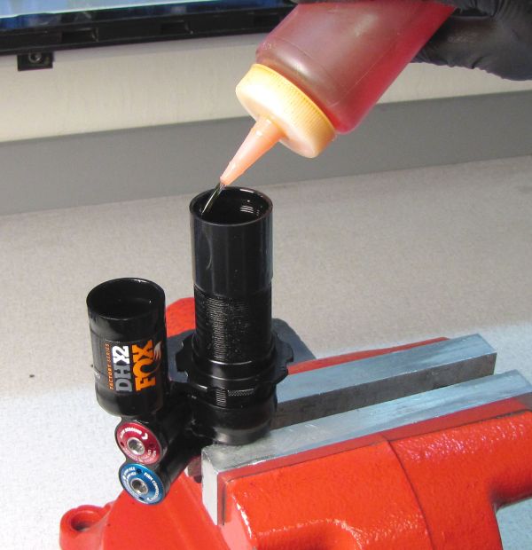
Step 1
Reinstall the bleed screw in the back of the eyelet with a 2mm hex and tighten clockwise to 14 in-lb (1.6 Nm). Add FOX 10wt. red oil to the main body. The oil will slowly transfer into the piggy-back reservoir through the eyelet. Stop adding oil once it has reached the level of the retaining ring groove on the inside of the reservoir.


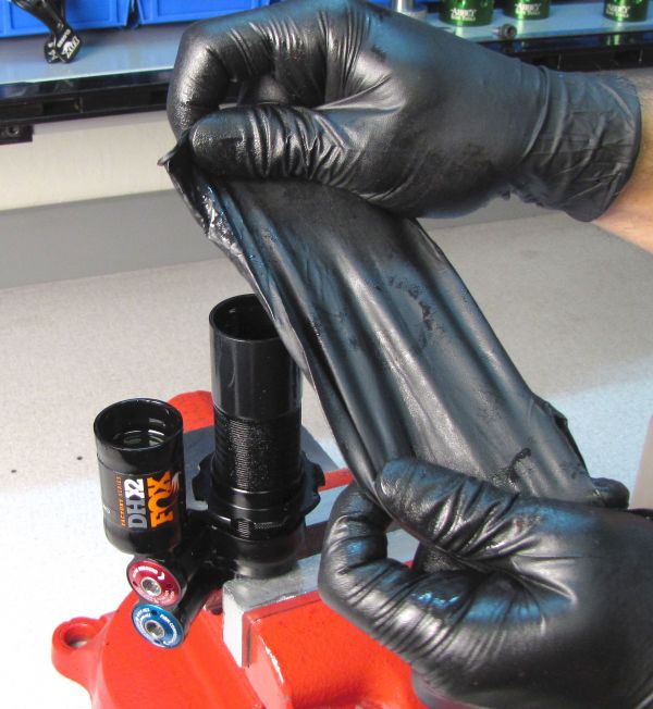
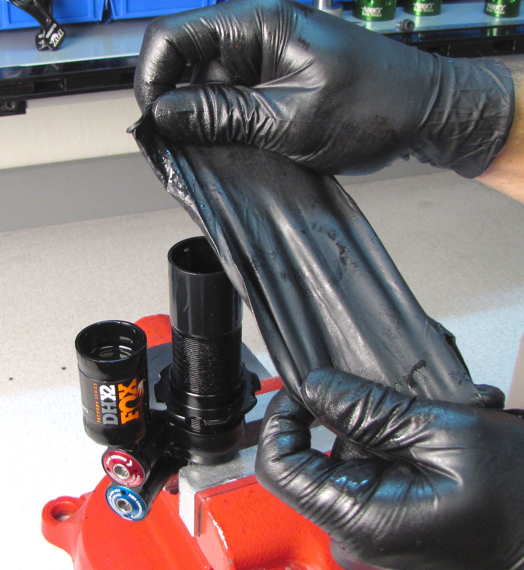
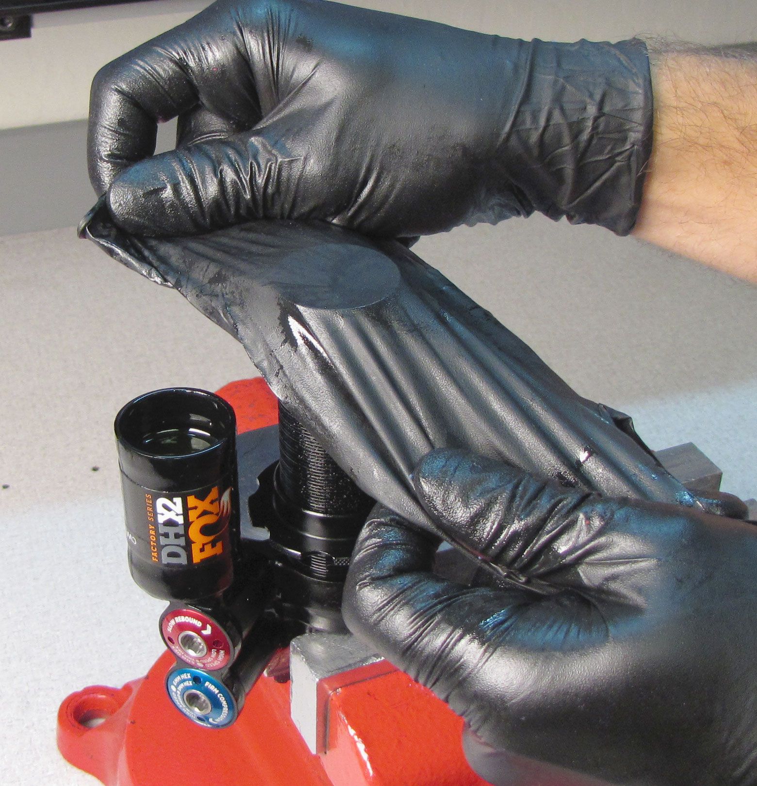
Step 2
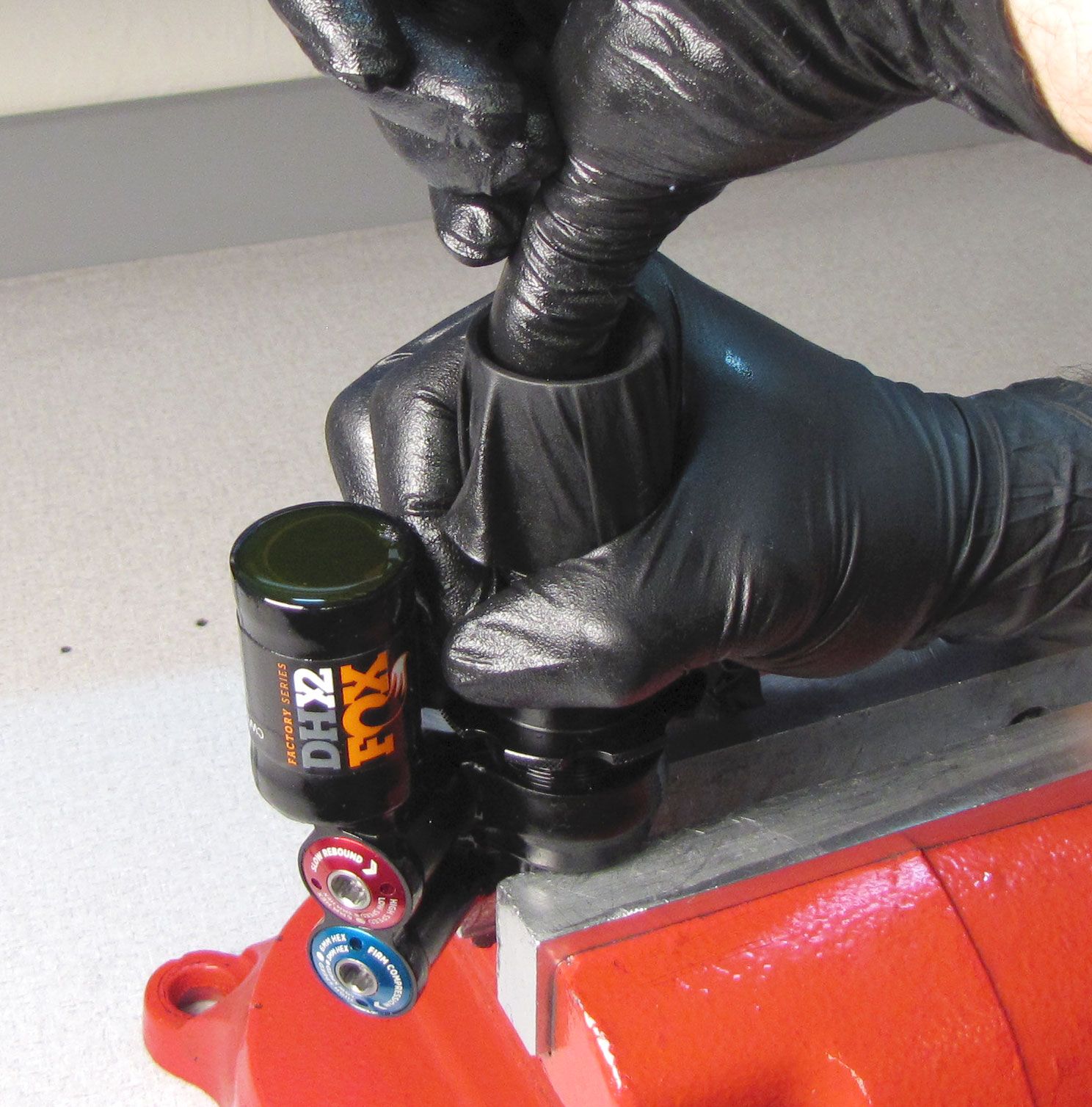
Take a new nitrile glove and stretch it over the open main body making an airtight seal.
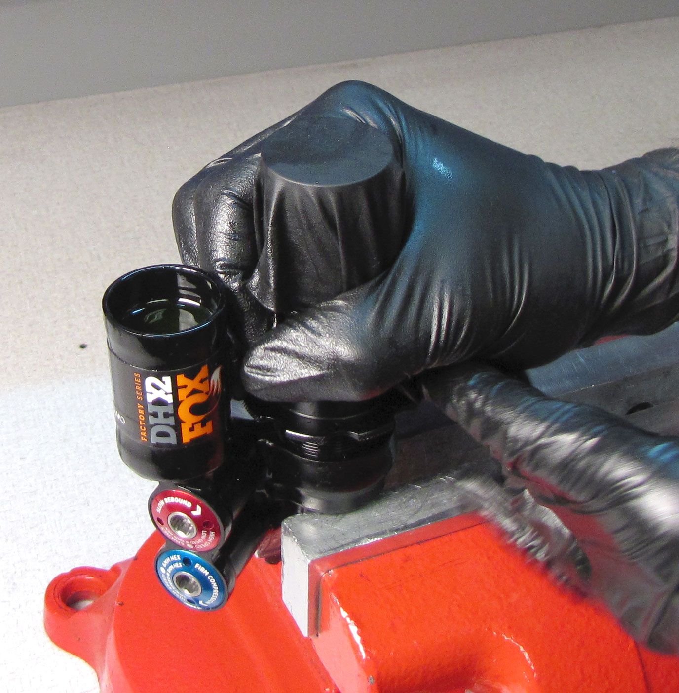
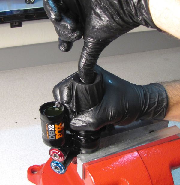
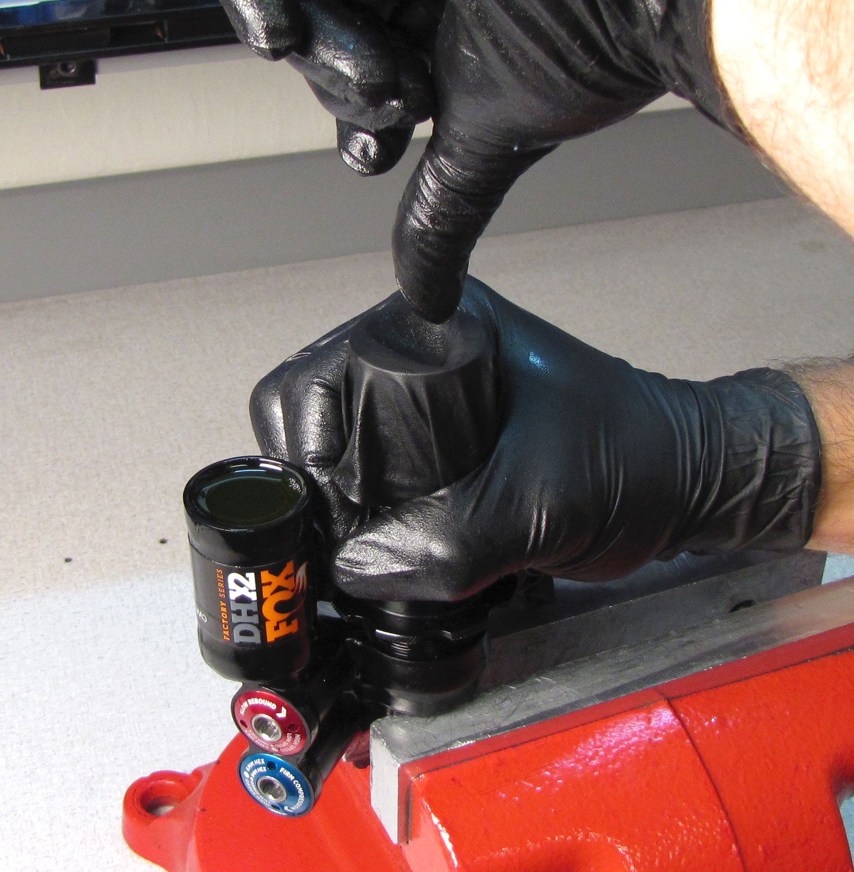
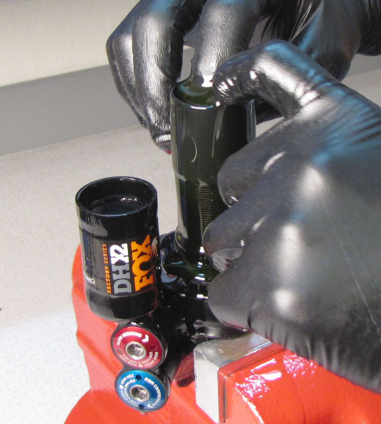
Step 3
Hold the glove tightly over the main body, then slowly push a finger into the main body and remove. This forces fluid and any air through the eyelet and adjuster, into the piggy-back reservoir. Repeat until you feel that only clean fluid is moving through the eyelet and no new bubbles appear in the reservoir.


Step 4
Remove the glove and add fluid to the main body until the fluid level in the reservior slowly rises to the very top.


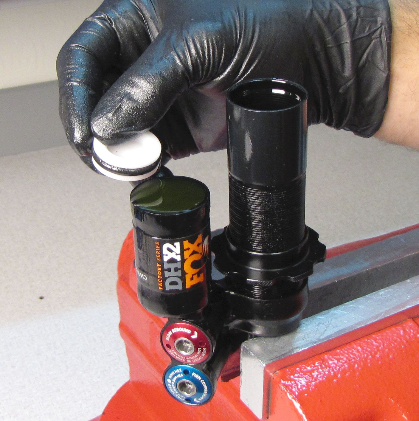
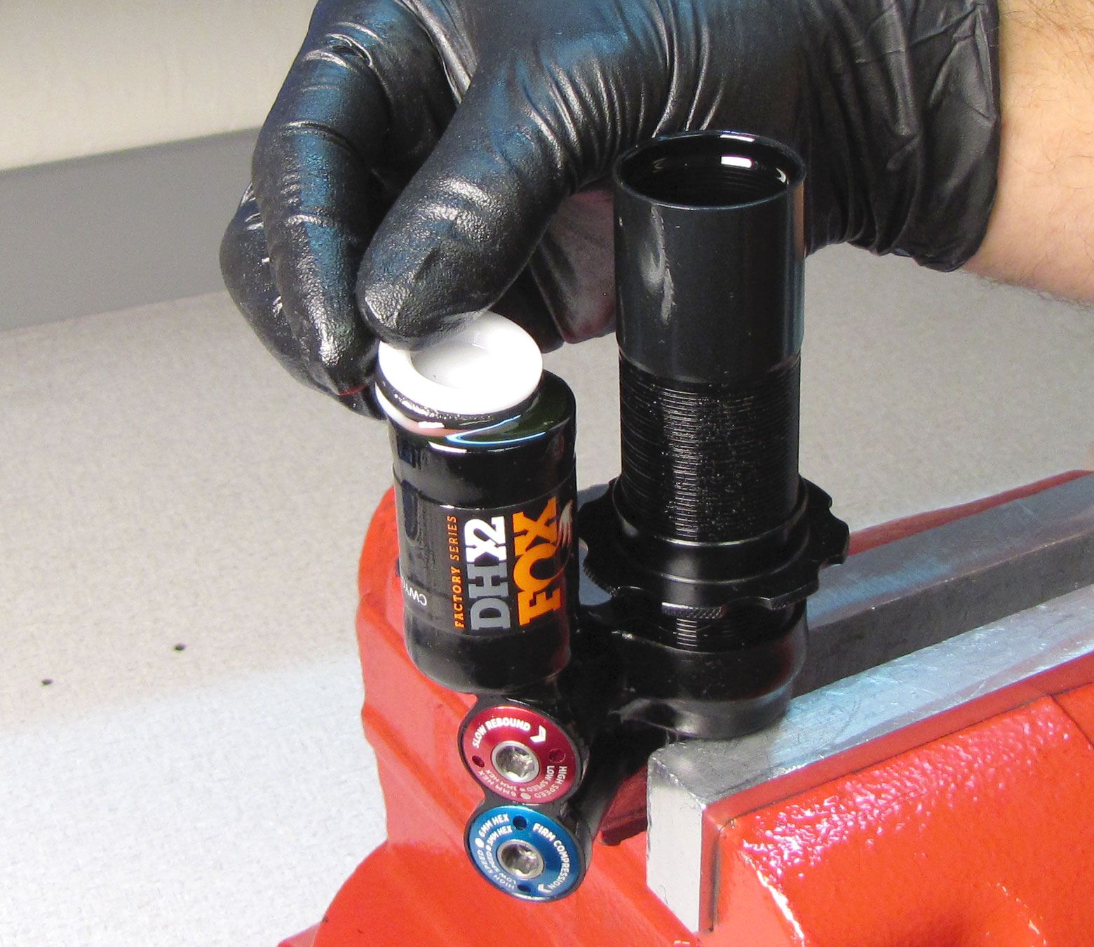
Step 5
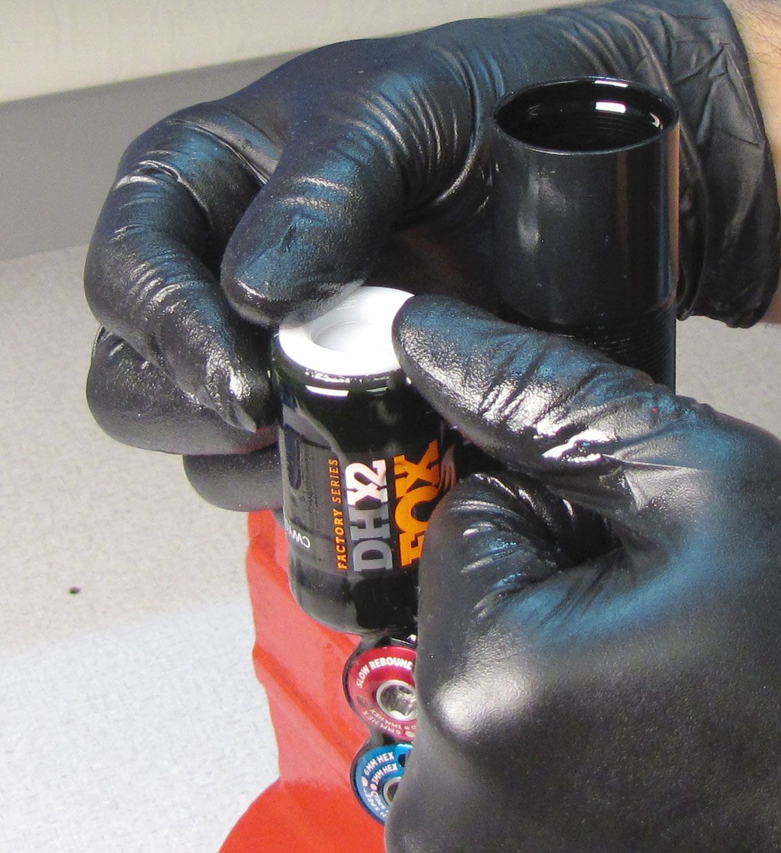
Install a new greased o-ring onto the IFP, then slowly slide it into the reservoir making sure to not trap any air beneath it. Orient the IFP so the counterbore faces up. Keep the IFP flat and press it into the reservoir until it is beneath the retaining ring groove.

Step 6
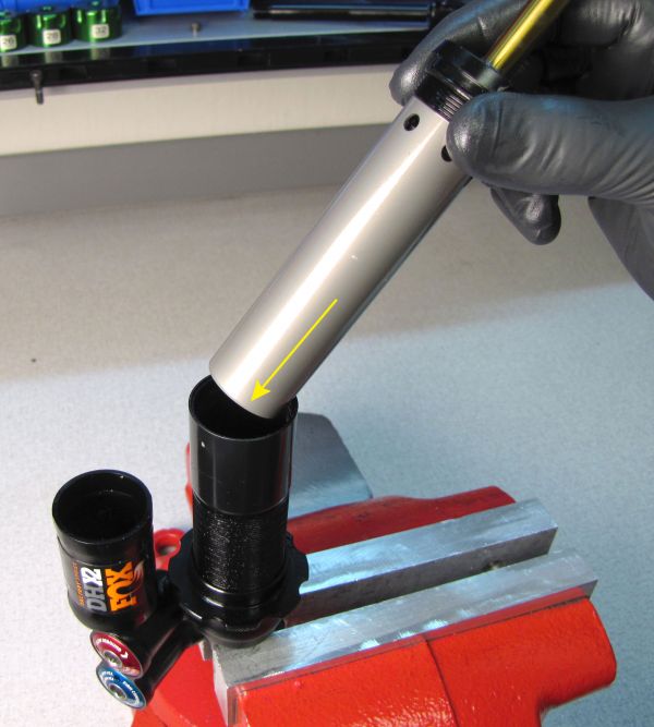
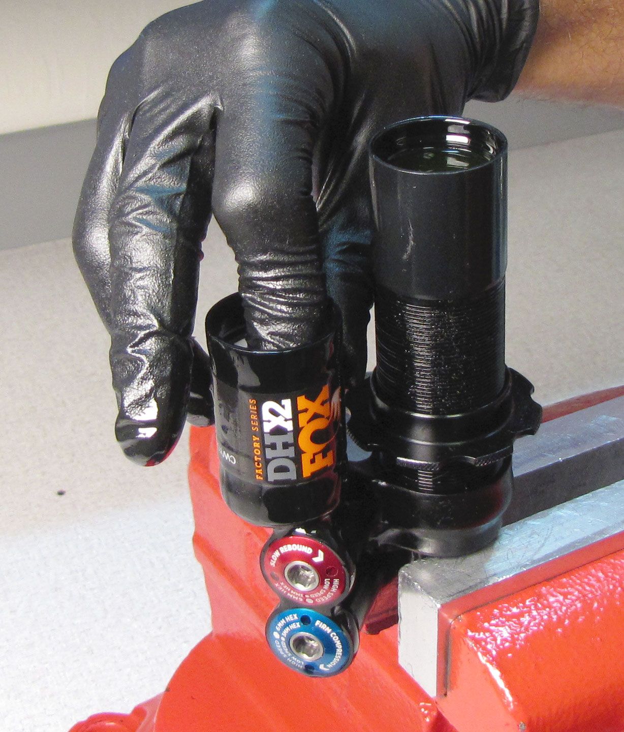
Slowly install the inner body into the outer body with the ports at the top. Push the inner body in to fully seat it in the eyelet.
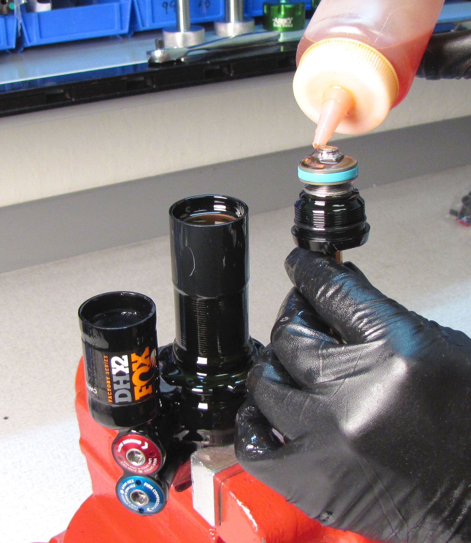
Step 7
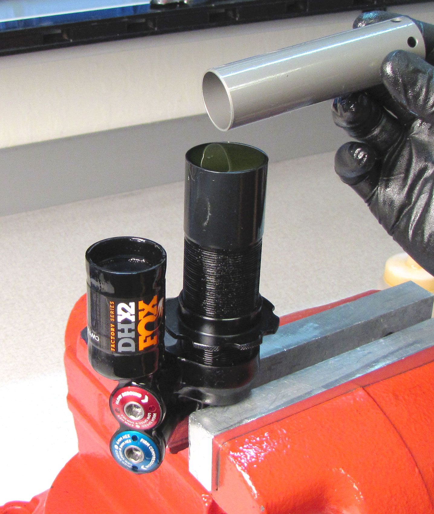
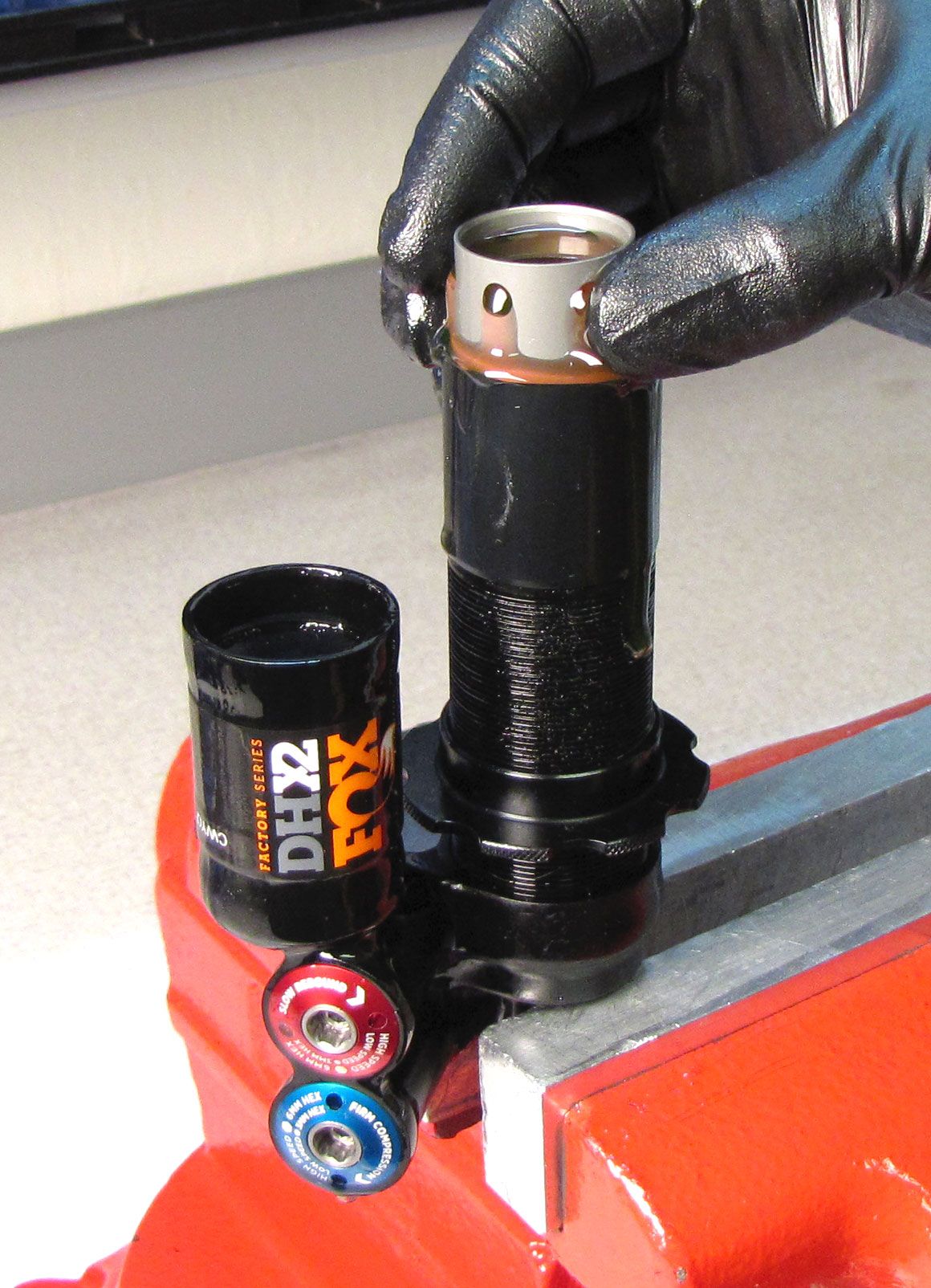
Top off the body and pre-fill all ports of the piston and bearing assembly with FOX 10wt. red oil. Quickly and smoothly, install the piston assembly into the body and turn it clockwise to begin threading it in.

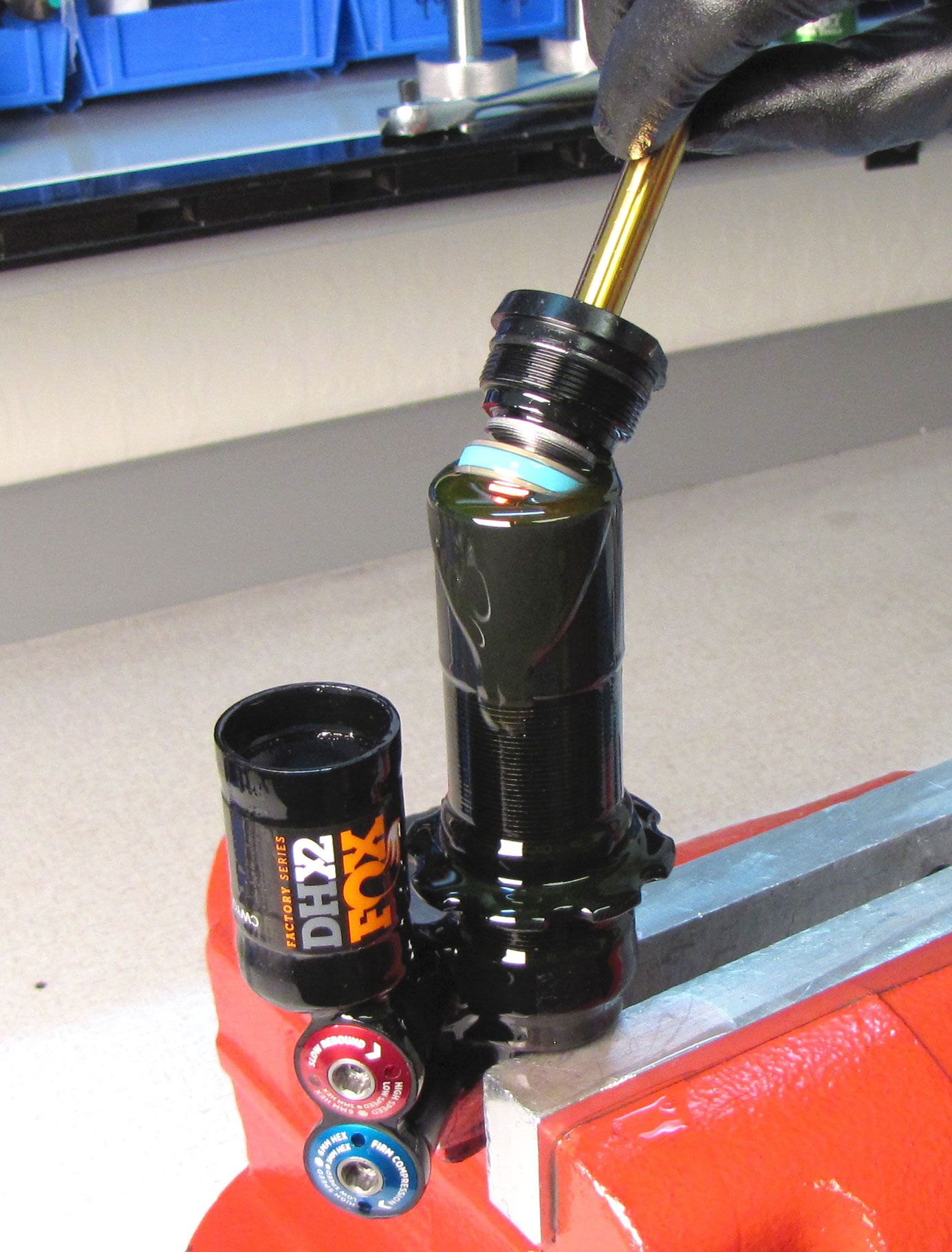

Step 8
Use Knipex smooth/parallel jawed pliers or a 1.125" wrench to tighten (clockwise) the bearing assembly to 145 in-lb (16.3 Nm). Reposition your shock in the vice so the bleed port on the back of the eyelet is the highest part of the shock as shown.
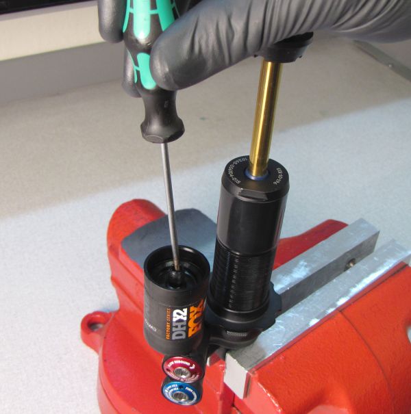
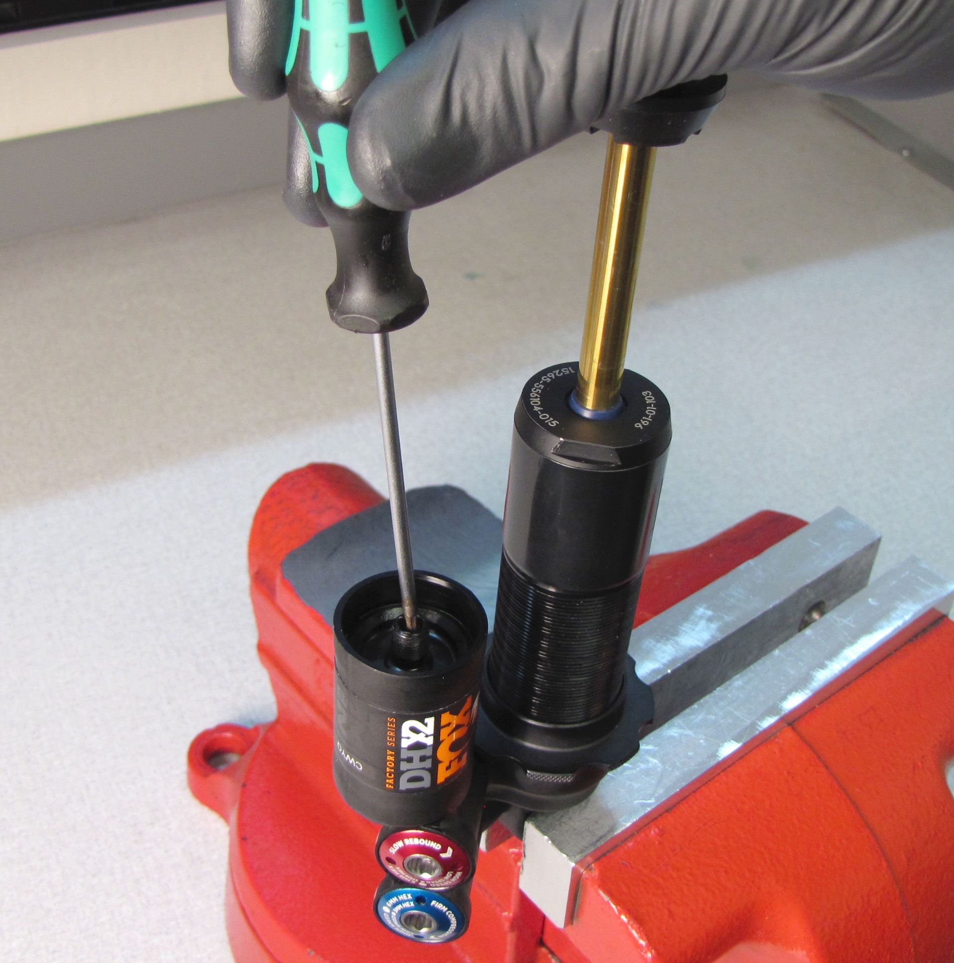
Step 9
Remove the bleed screw from the back of the eyelet with a 2mm hex wrench. Set the IFP to the appropriate depth using your IFP depth setting tool (803-00-566). Reinstall the set screw with a new greased o-ring from the kit and tighten to 14 in-lb (1.6 Nm).
| Shock Size | IFP Height (+/-0.050in) |
| 7.875 x 2.250 | 1.243in/ 31.57mm |
| 8.500 x 2.500 | 1.293in/ 32.84mm |
| 8.750 x 2.750 | 1.343in/ 34.11mm |
| 9.500 x 3.000 | 1.393in/ 35.38mm |
| 10.500 x 3.500 | 1.443in/ 36.65mm |

After completing the hand bleed, please return to step 18 for instructinos to finalize the shock rebuild.