2017 Grip Remote Topcap Interface Parts Clocking
WARNING: Always wear safety glasses and protective gloves during service to prevent potential injury. Failure to wear protective equipment during service may lead to SERIOUS INJURY OR DEATH.
Clocking a 2017 Grip Remote damper is different than clocking a FIT4 or CTD Remote damper. Use the video and printed instructions below to guide you through the process of clocking the 2017 Grip Remote damper.
These instructions show images and video of the 2017 Grip Remote damper with its cable exit oriented at the riders 7 o'clock position. Clocking the 2017 Grip Remote with its cable exit at the riders 1 o'clock position or any other orientation is simple and is covered in both the step-by-step guide and video below.
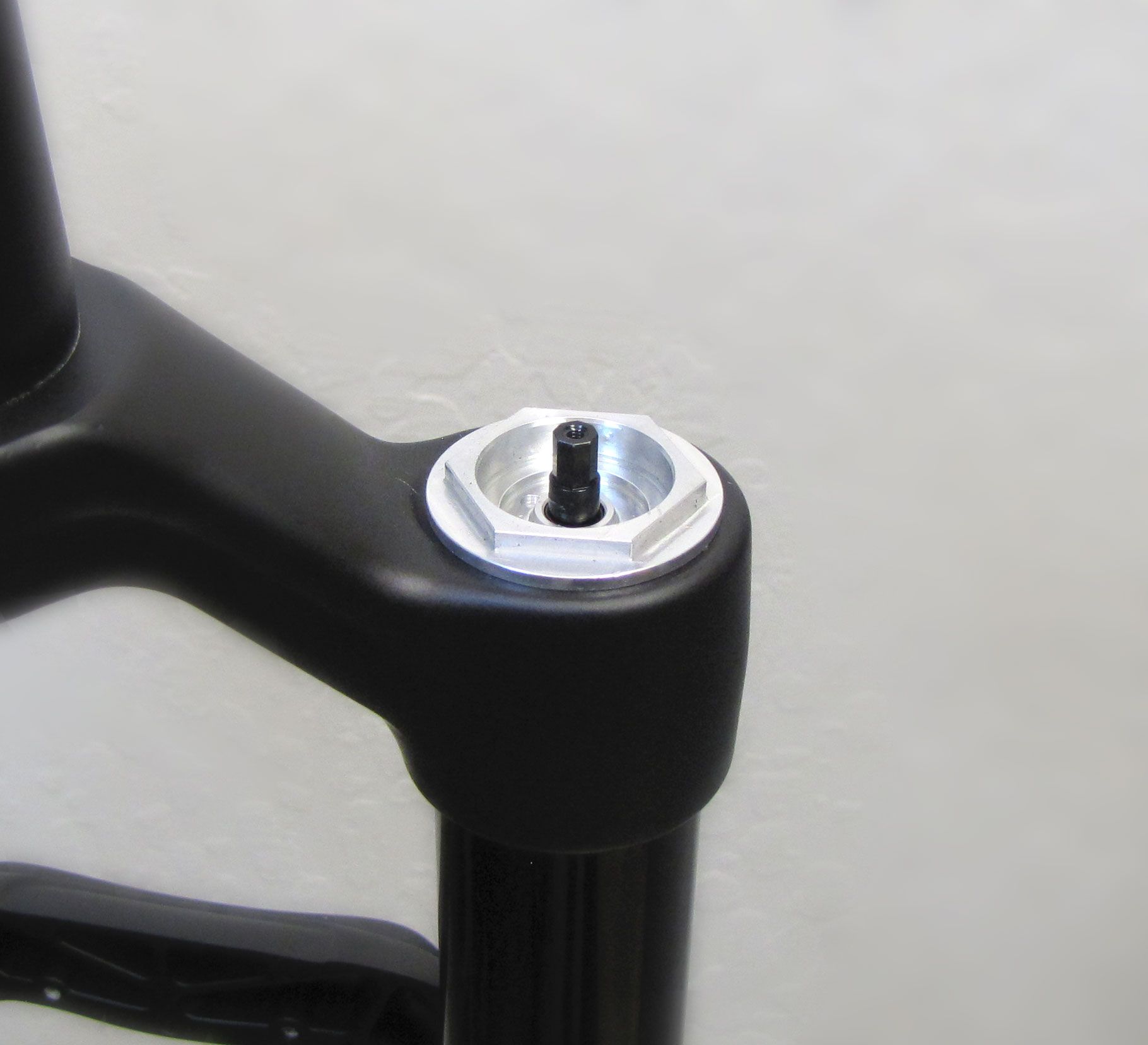
NOTE: Non-Remote Grip dampers cannot be converted to be used with a remote lever. You must use a remote-specific Grip damper if utilizing a remote lever. Remote-specific Grip dampers can be identified by the black colored compression needle as shown in step 1 below. Non-remote Grip dampers have a silver colored compression needle.
NOTE: Do not overtighten the black compression needle during remote topcap interface part installation. Overtightening of the needle can cause internal damage that may require replacement of the topcap assembly.
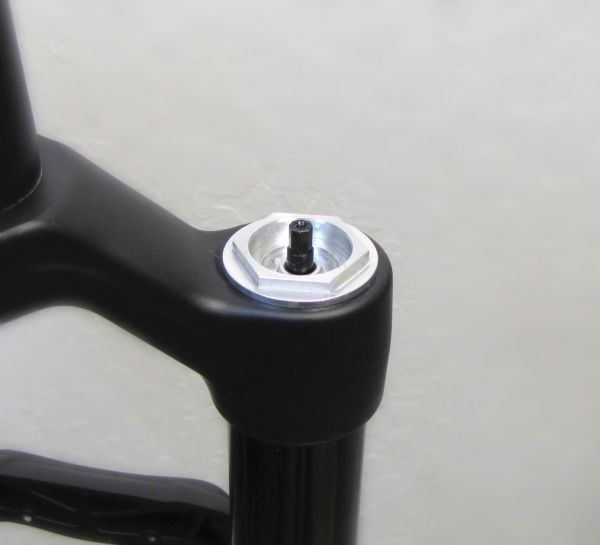
Step 1
Turn the Compression Needle clockwise until you feel it lightly stop (approximately 4 in-lb or 0.4 Nm).
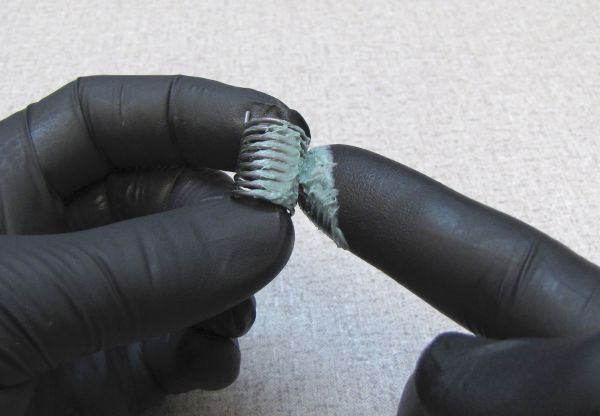
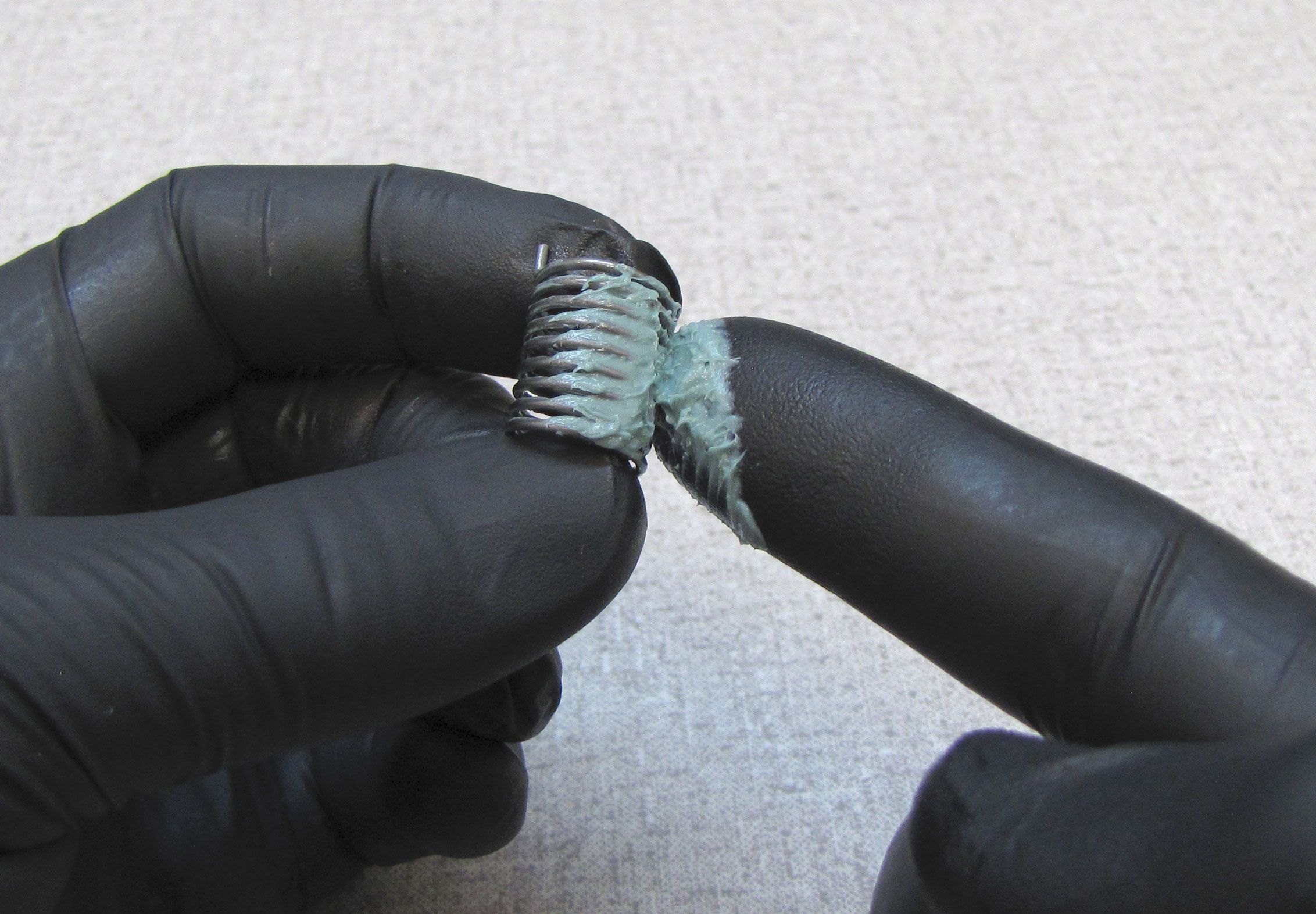
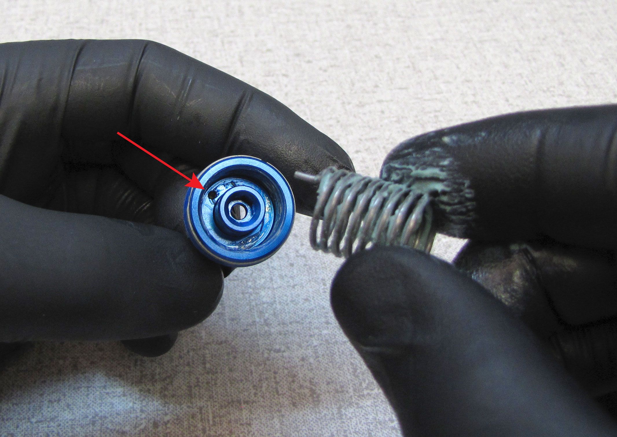
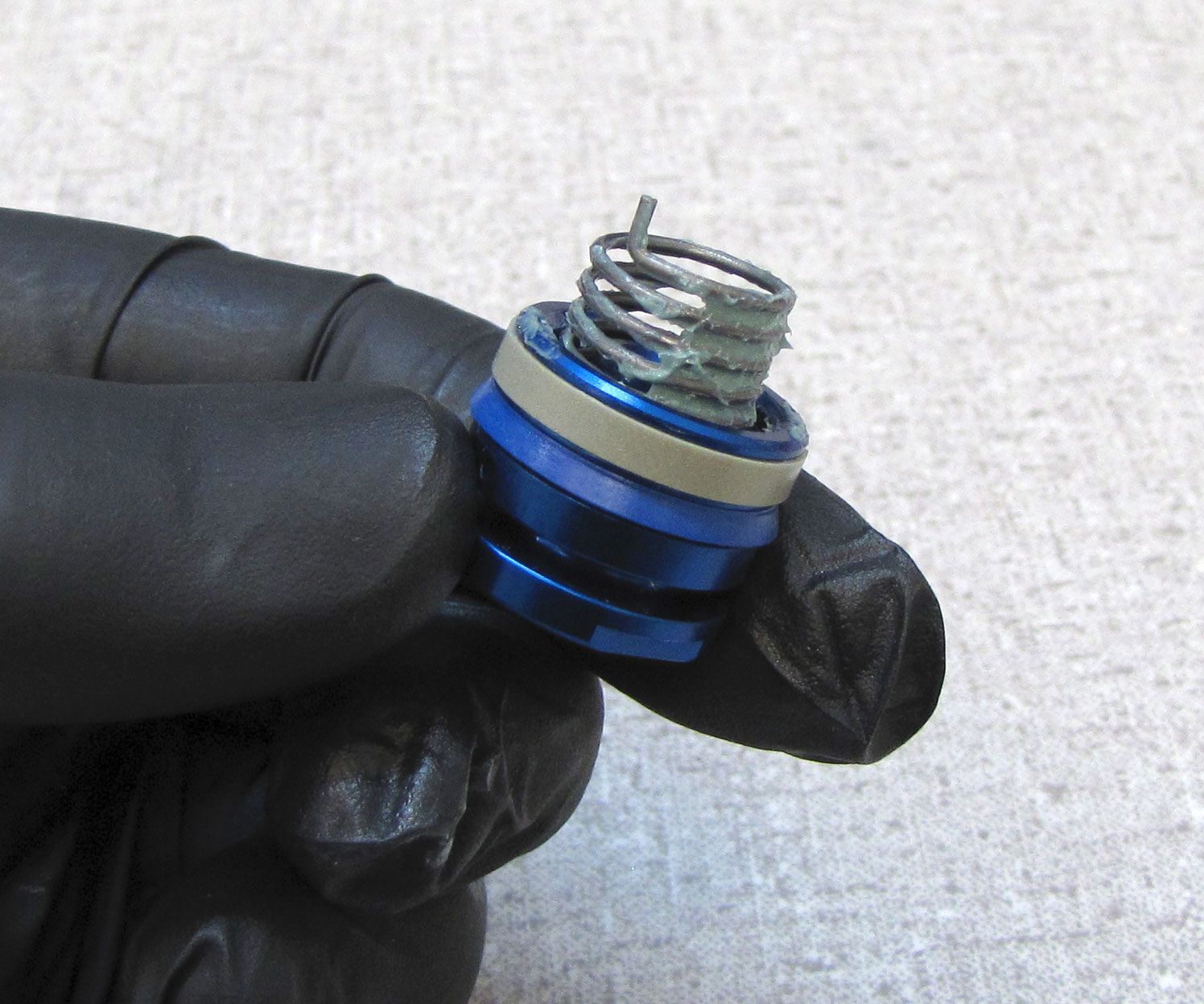
Step 2
Grease the torsion spring using a waterproof grease such as Sta-Lube SL3125 then install one tang of the spring into the hole in the underside of the blue remote pulley.
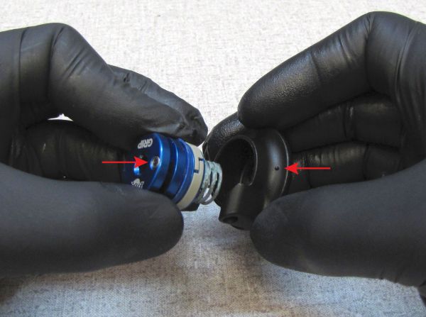
Step 3
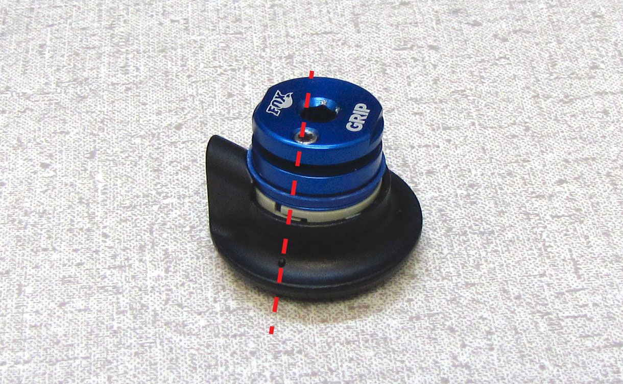
Insert the remote pulley and greased torsion spring into the black remote housing so the pinch bolt is aligned with the indicator mark closest to the cable stop. Make sure that the bottom spring tang seats into a hole in the black remote housing.


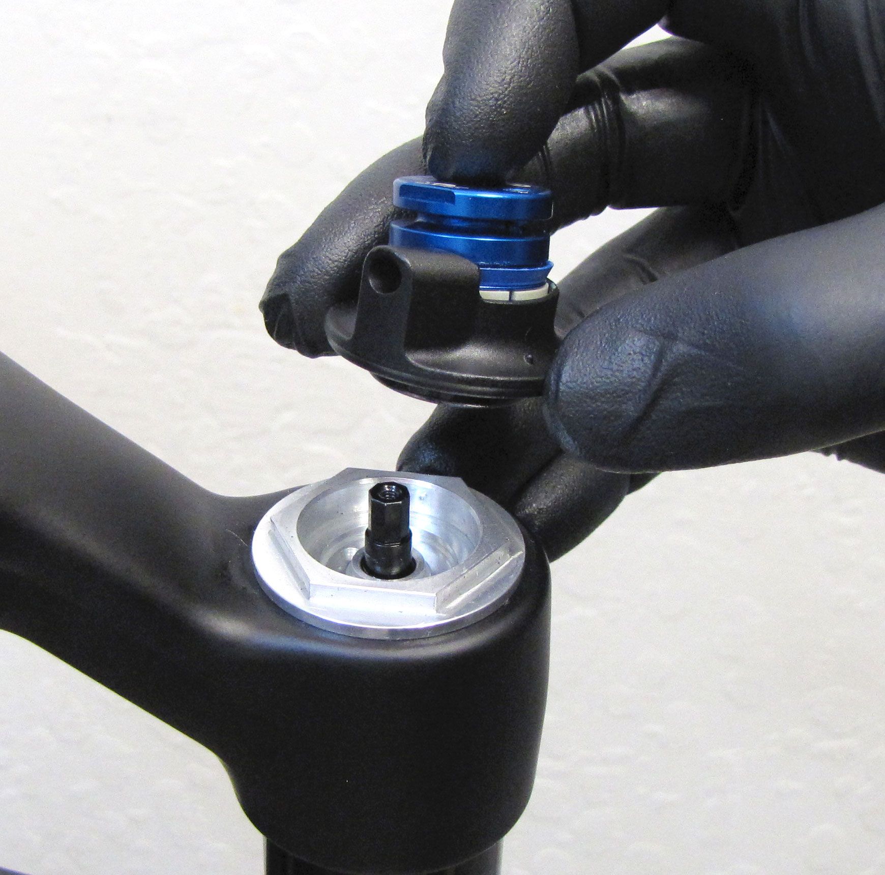
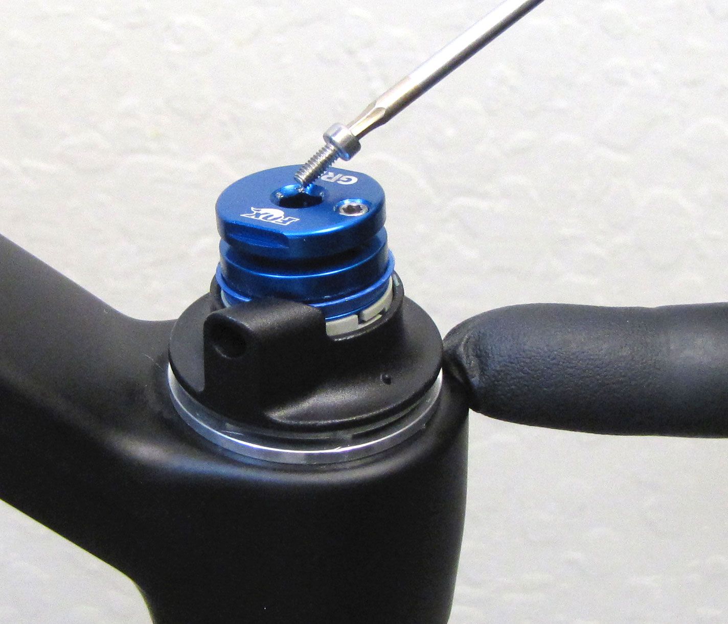
Step 4
Position the black housing stop, pulley, and spring onto the damper topcap, orienting the housing stop to your desired cable exit angle. Install the pulley set screw. Hold the pulley while tightening clockwise to 4 in-lb (0.4 Nm) torque with a 2mm hex wrench.
The images show the cable exiting at the riders 7 o'clock position, follow the rest of the clocking instructions even if the housing stop is positioned at a different cable exit angle.
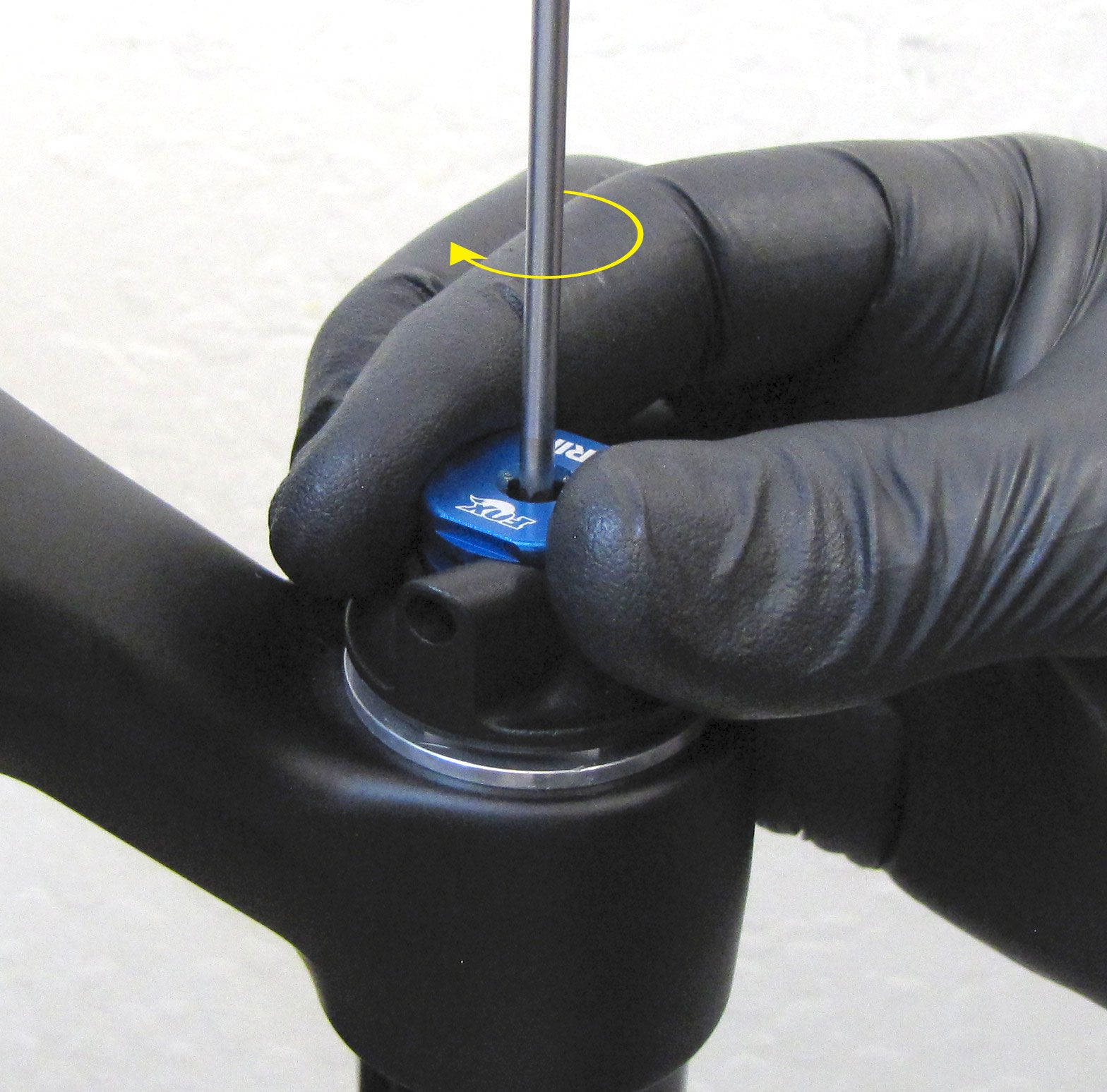

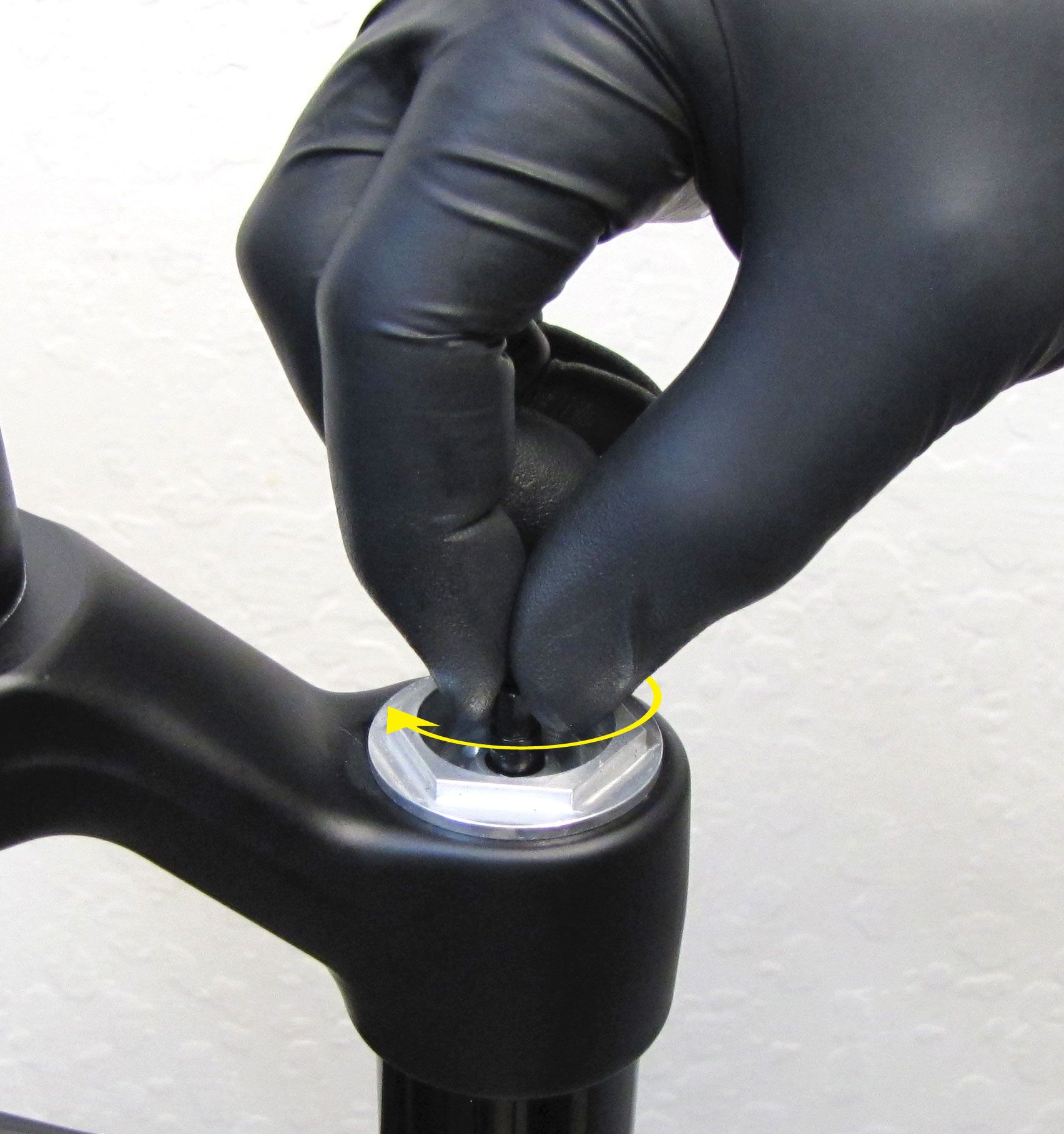
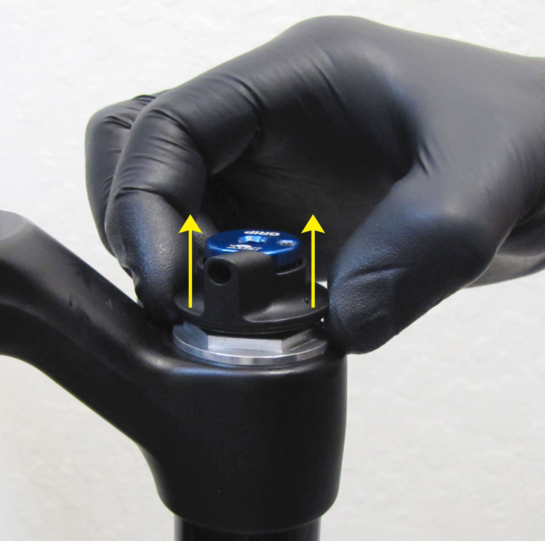
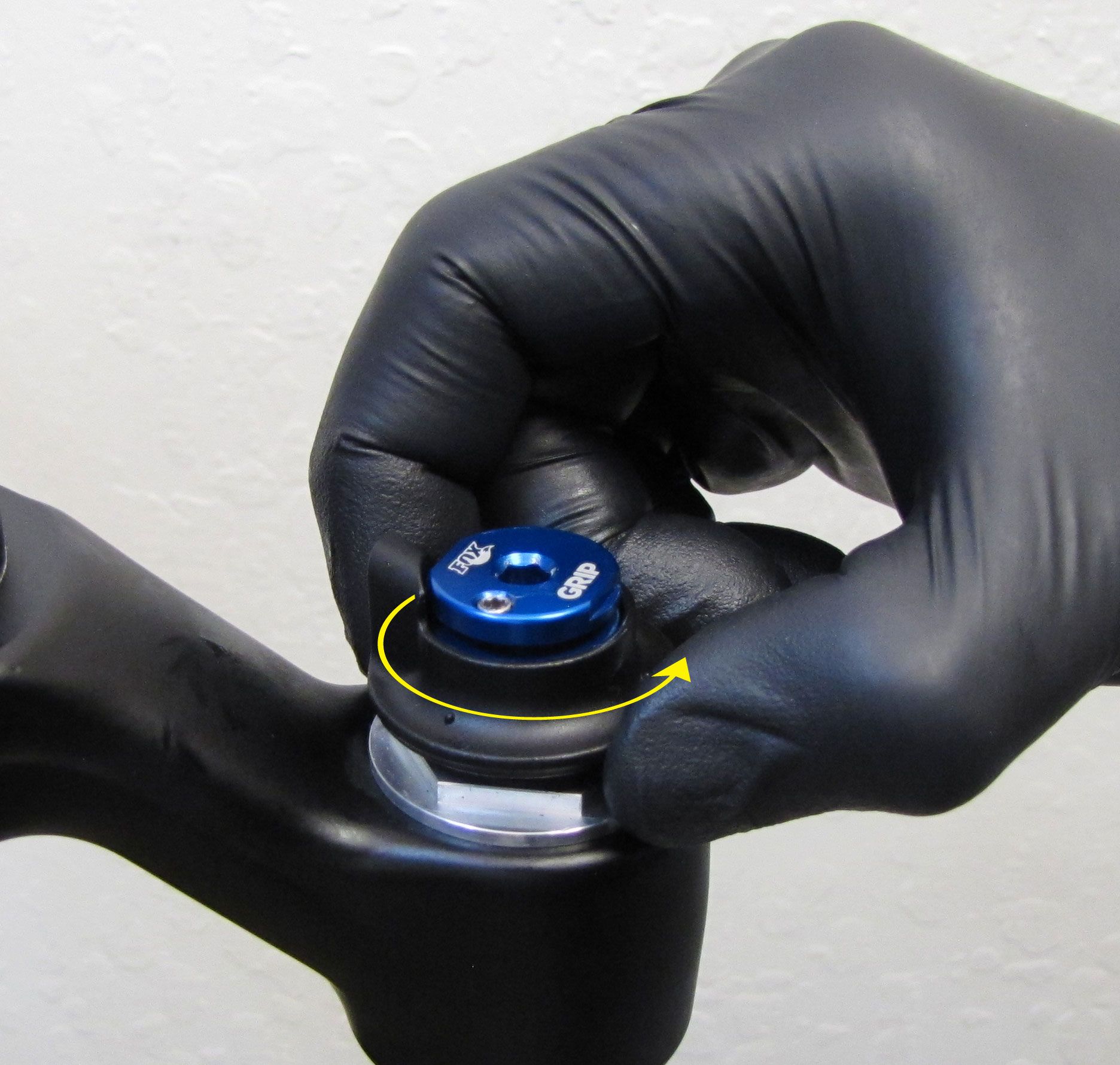
Step 5
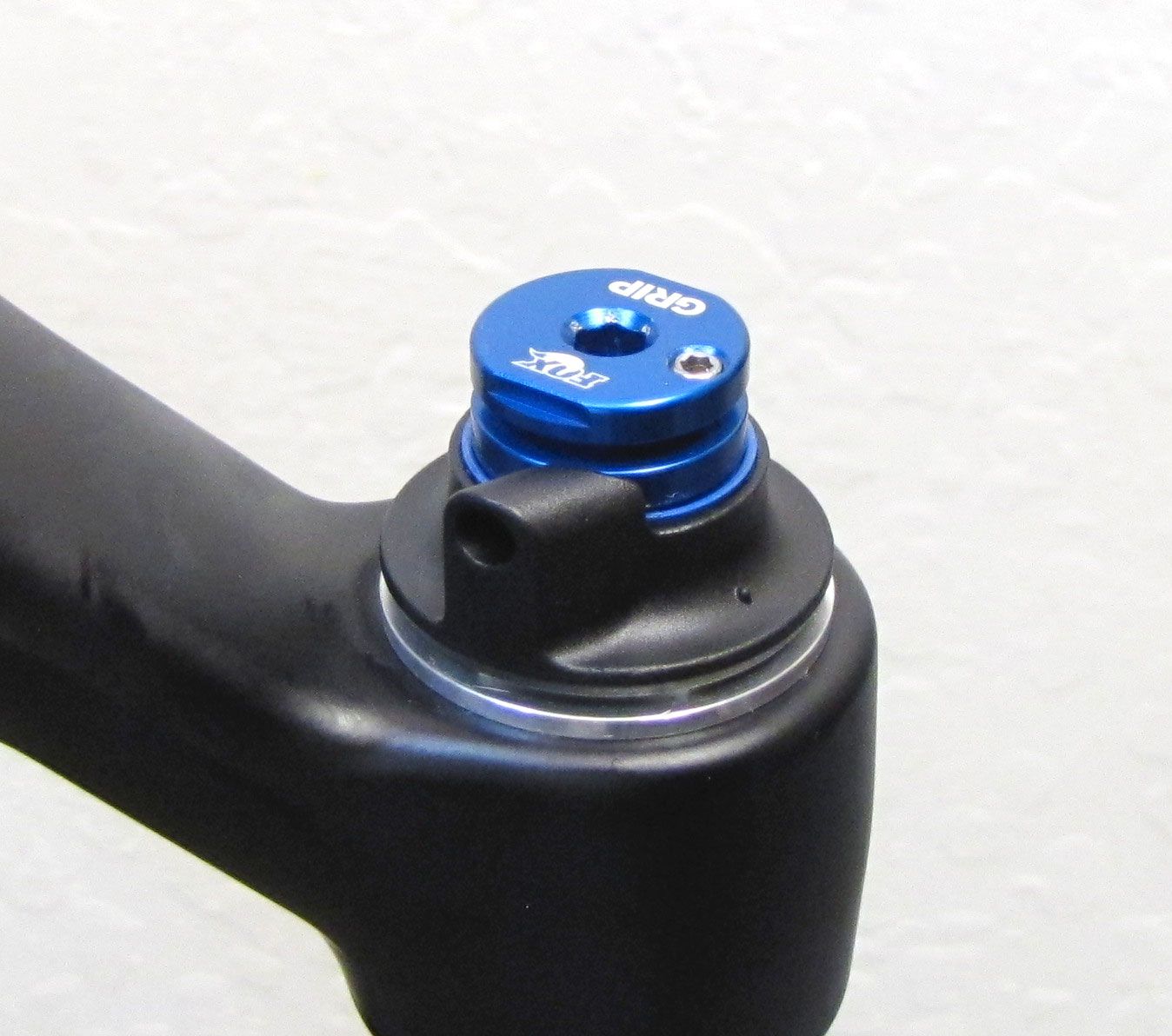
Lift up on the black remote housing and rotate counter-clockwise a full 360 degrees. Lower the black remote housing back onto the topcap wrench flats.
The pulley may rotate with the black housing in this step. You will wind the spring up during remote cable installation.
For information guiding you through the remote installation go to: 2017 Remote Installation »
WARNING: FOX products should be serviced by a qualified bicycle service technician, in accordance with FOX specifications. If you have any doubt whether or not you can properly service your FOX product, then DO NOT attempt it. Improperly serviced products can fail, causing the rider to lose control resulting in SERIOUS INJURY OR DEATH.
WARNING: FOX suspension products contain pressurized nitrogen, air, oil, or all 3. Suspension misuse can cause property damage, SERIOUS INJURY OR DEATH. DO NOT puncture, incinerate or crush any portion of a FOX suspension product. DO NOT attempt to disassemble any portion of a FOX suspension product, unless expressly instructed to do so by the applicable FOX technical documentation, and then ONLY while strictly adhering to all FOX insturctions and warnings in that instance.
WARNING: Modification, improper service, or use of aftermarket replacement parts with FOX forks and shocks may cause the product to malfunction, resulting in SERIOUS INJURY OR DEATH. DO NOT modify any part of a fork or shock, including the fork brace (lower leg cross brace), crown, steerer, upper and lower leg tubes, or internal parts, except as instructed herein. Any unauthorized modification may void the warranty, and may cause failure or the fork or shock, resulting in SERIOUS INJURY OR DEATH.
NOTE: Actuate the release lever with the suspension unweighted for immediate changes between damping settings. Actuating the release lever with the suspension under load may cause a slight delay transitioning between damping modes.