2016-2017 FIT4 Remote Clocking Information
WARNING: Always wear safety glasses and protective gloves during service to prevent potential injury. Failure to wear protective equipment during service may lead to SERIOUS INJURY OR DEATH.
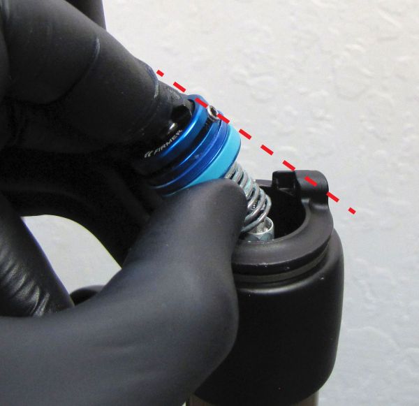
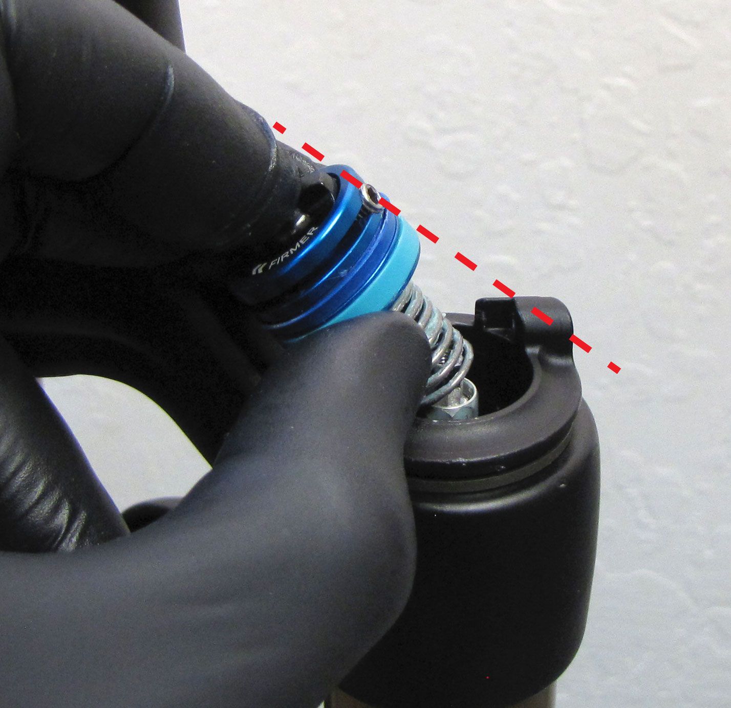
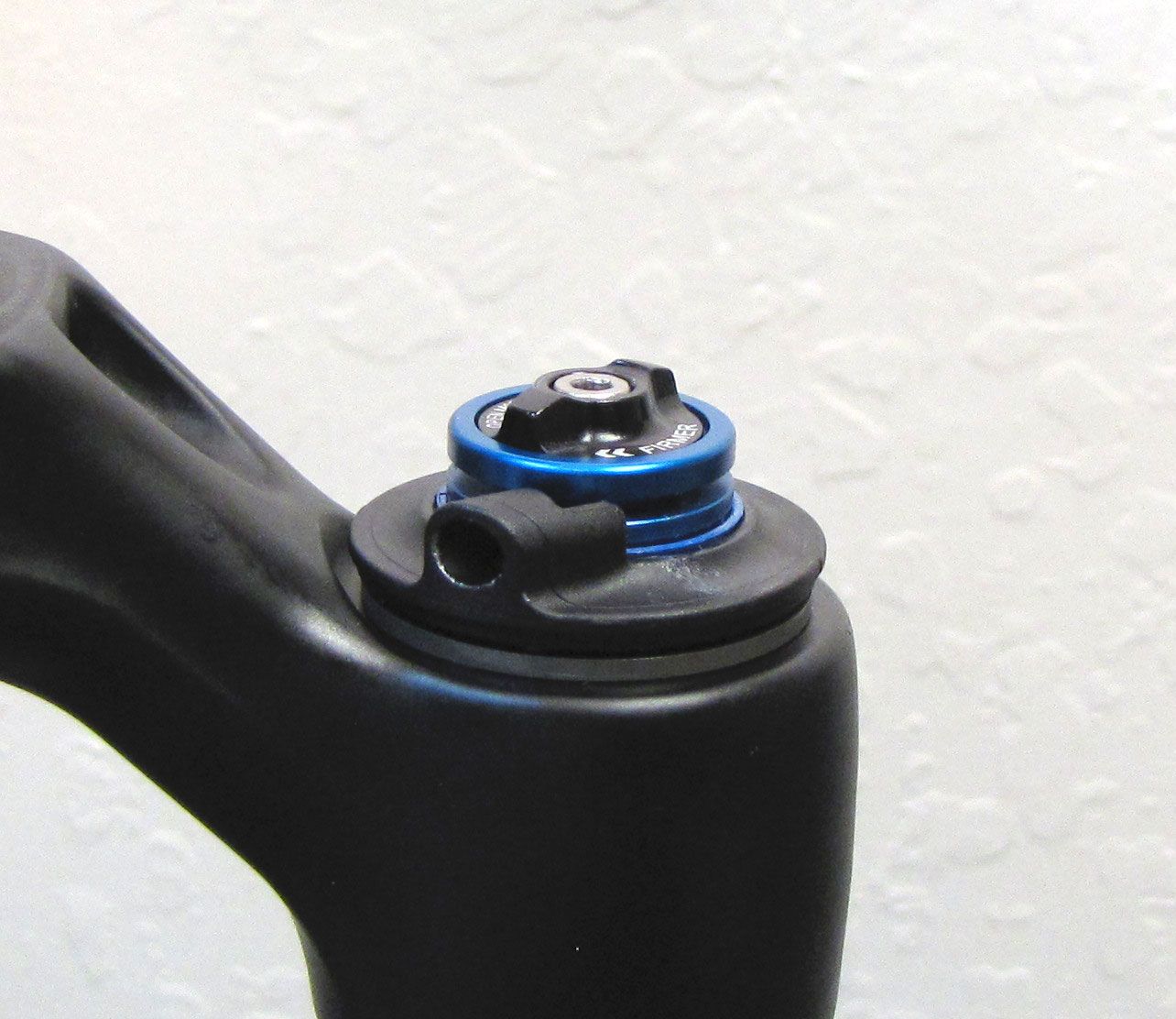
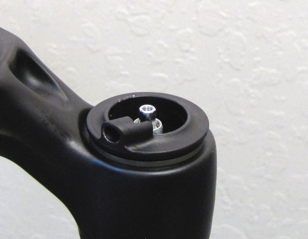
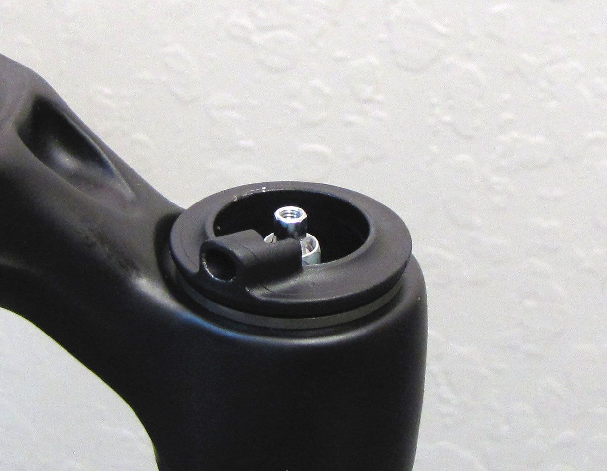
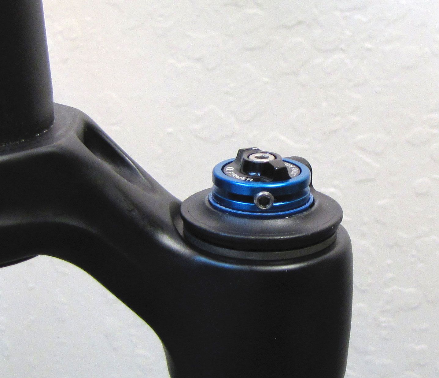
FOX FIT4 Remote forks may have their cable housing exit the topcap at one of the two approved orientations shown below.


If you find a FOX FIT4 Remote fork with its cable housing exiting the topcap in any orientation other than the 1 o'clock or 7 o'clock position, it may have been improperly clocked after leaving the FOX factory. Improperly clocked FIT4 damper topcaps may result in inadequate spring torsion which can prevent the fork from returning to the Open mode after cable is released via the remote lever. Re-clocking the FIT4 remote topcap interface parts will allow for proper spring torsion and fork function.

Forks that come stock with the 2016-2017 FIT4 Remote damper do not need to have their topcap interface parts clocked unless they have been disassembled after leaving the FOX Factory. Do not attempt to increase return spring torsion by winding the spring more than the 180 degrees specified in the instructions below.
Videos
The video below guides you through the installation of the 2016-2017 FIT4 remote topcap interface parts so the cable exits the fork topcap at the rider's 1 o-clock.
The video below guides you through the installation of the 2016-2017 FIT4 remote topcap interface parts so the cable exits the fork topcap at the rider's 7 o-clock.
Disassembly and Part Preparation
Step 1
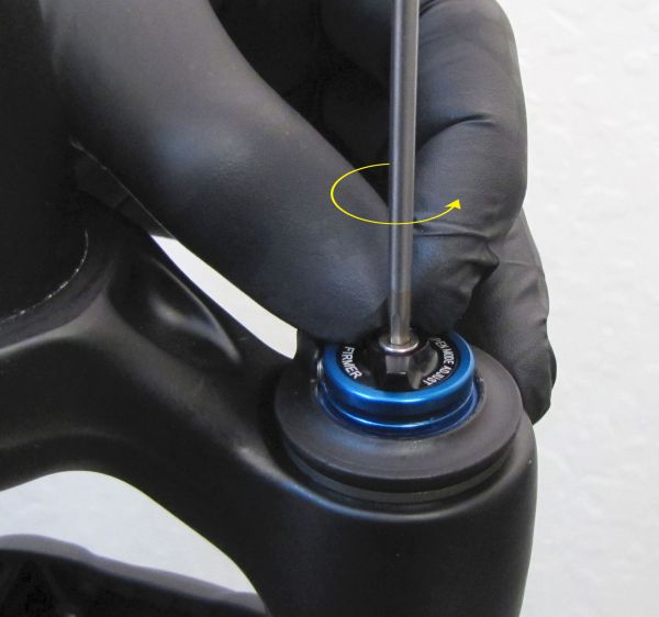
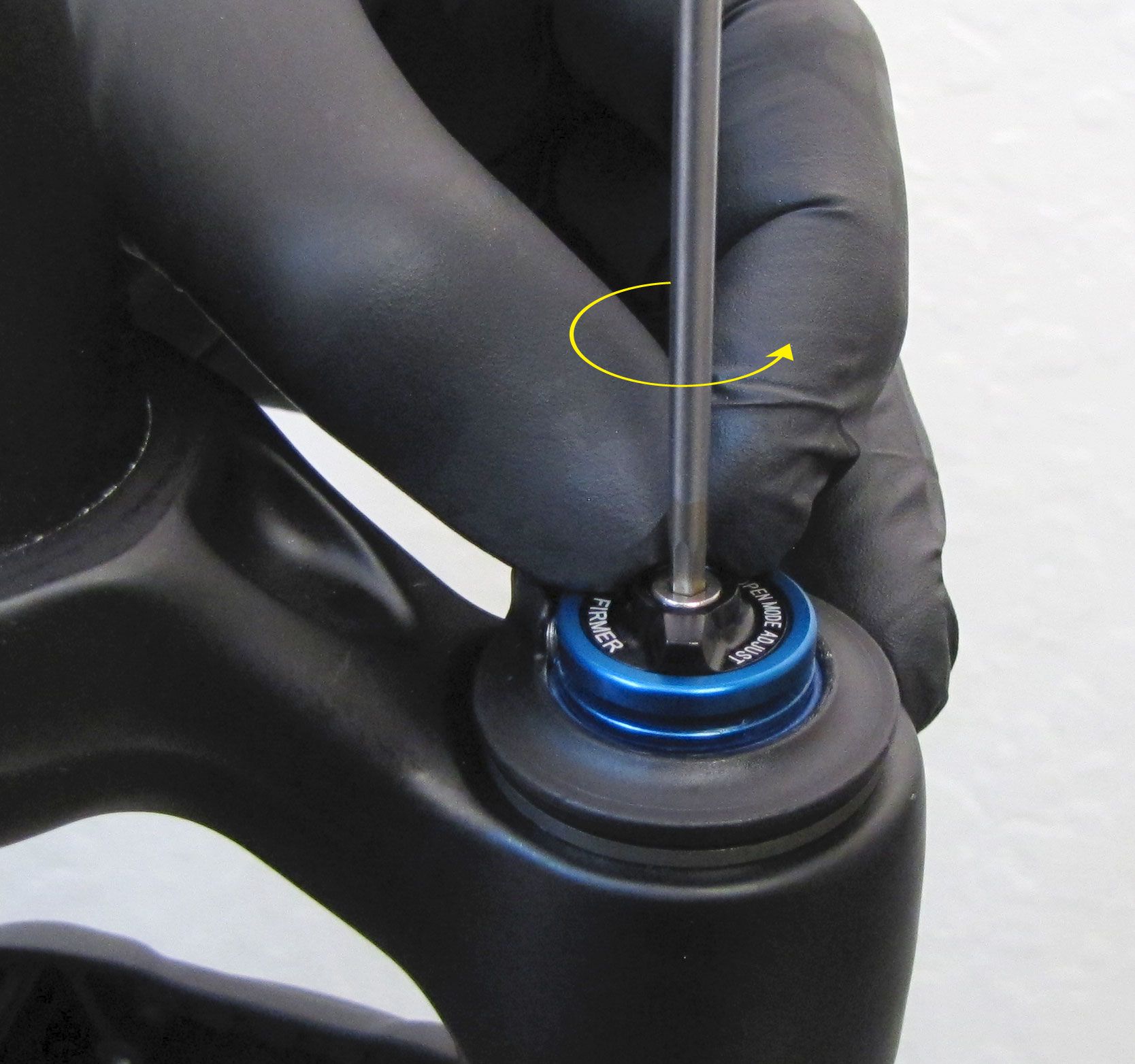
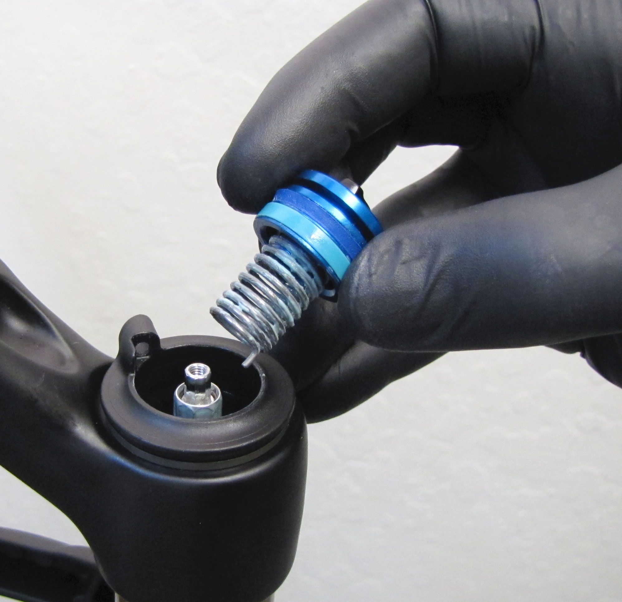
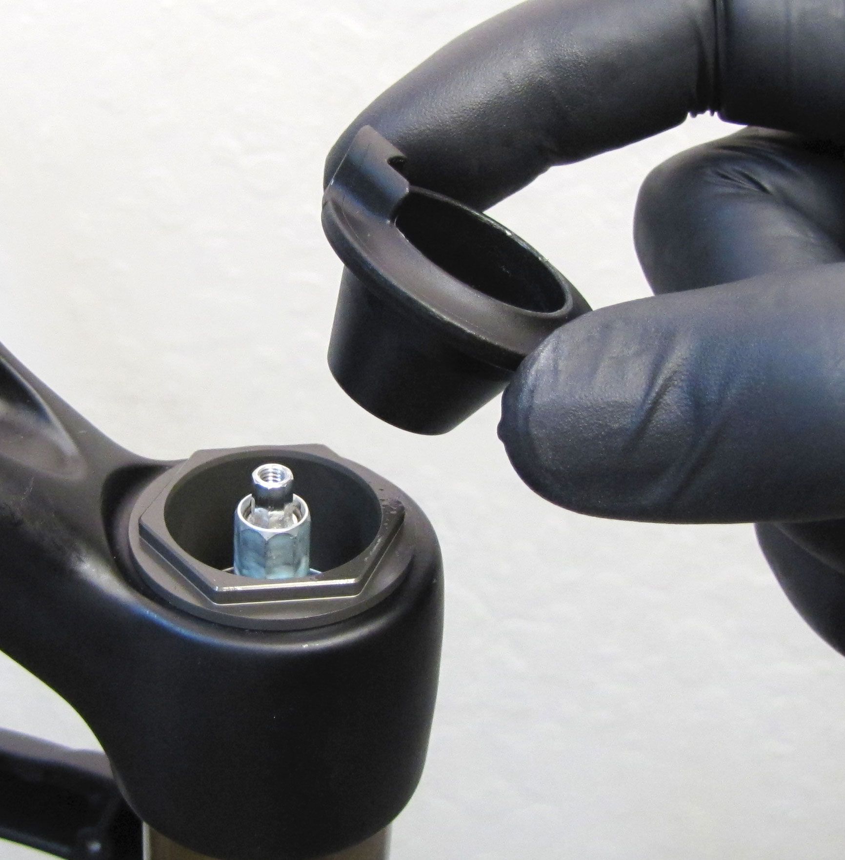
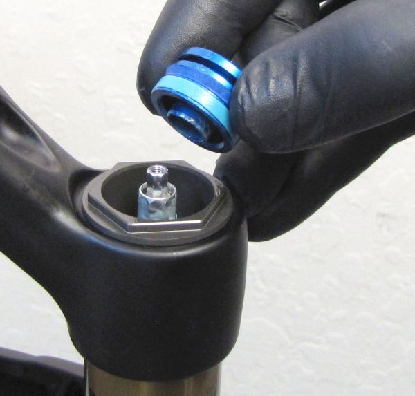
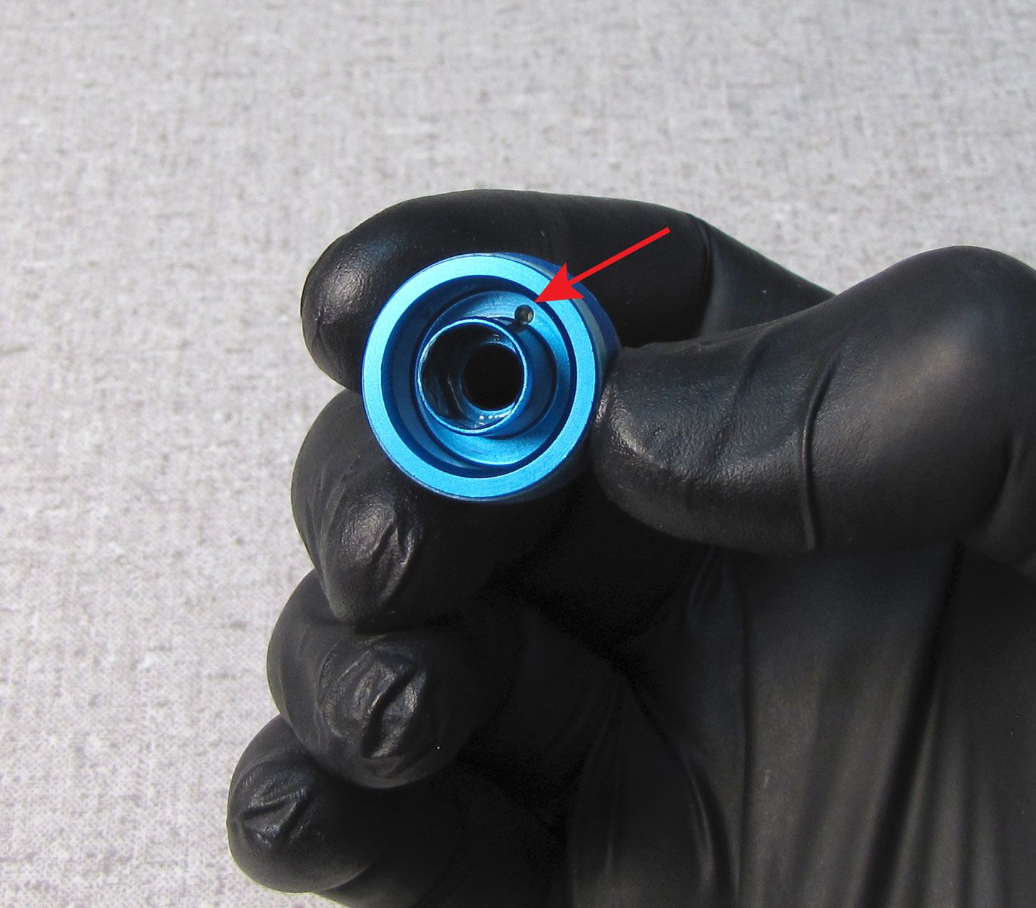
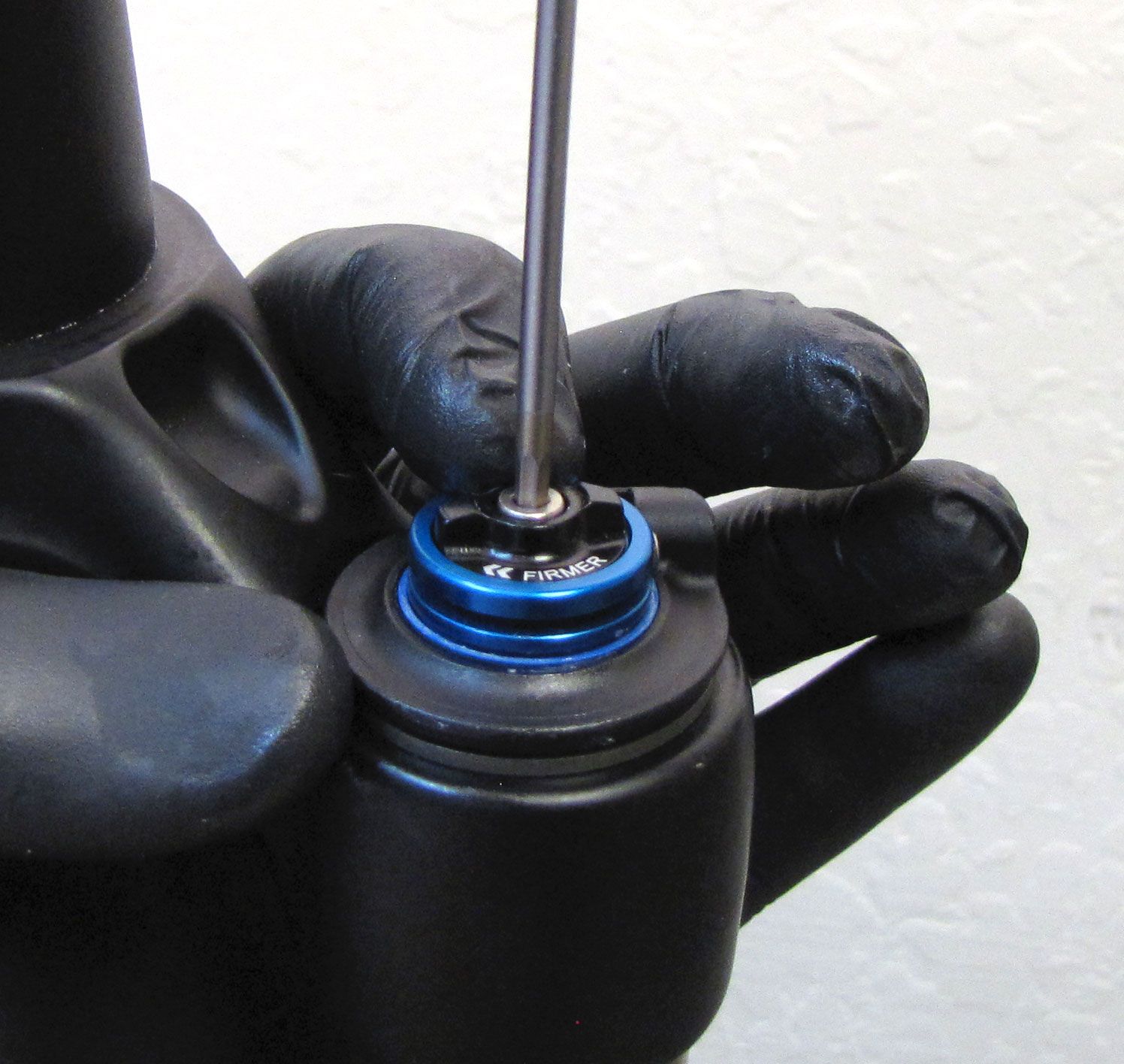
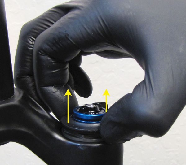
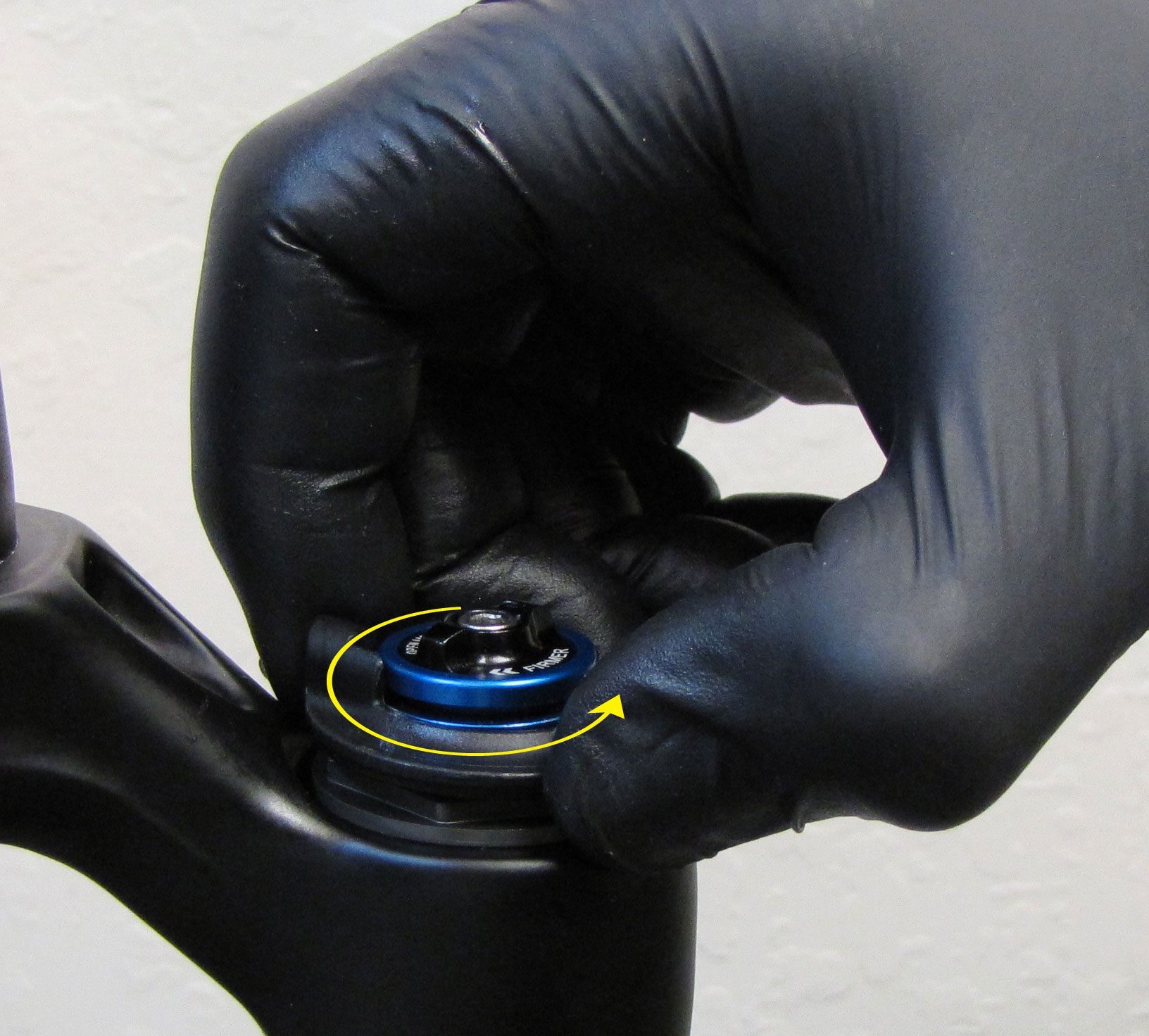
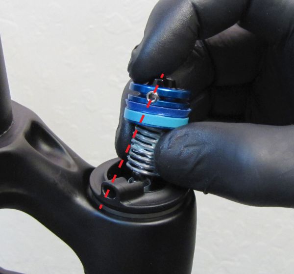
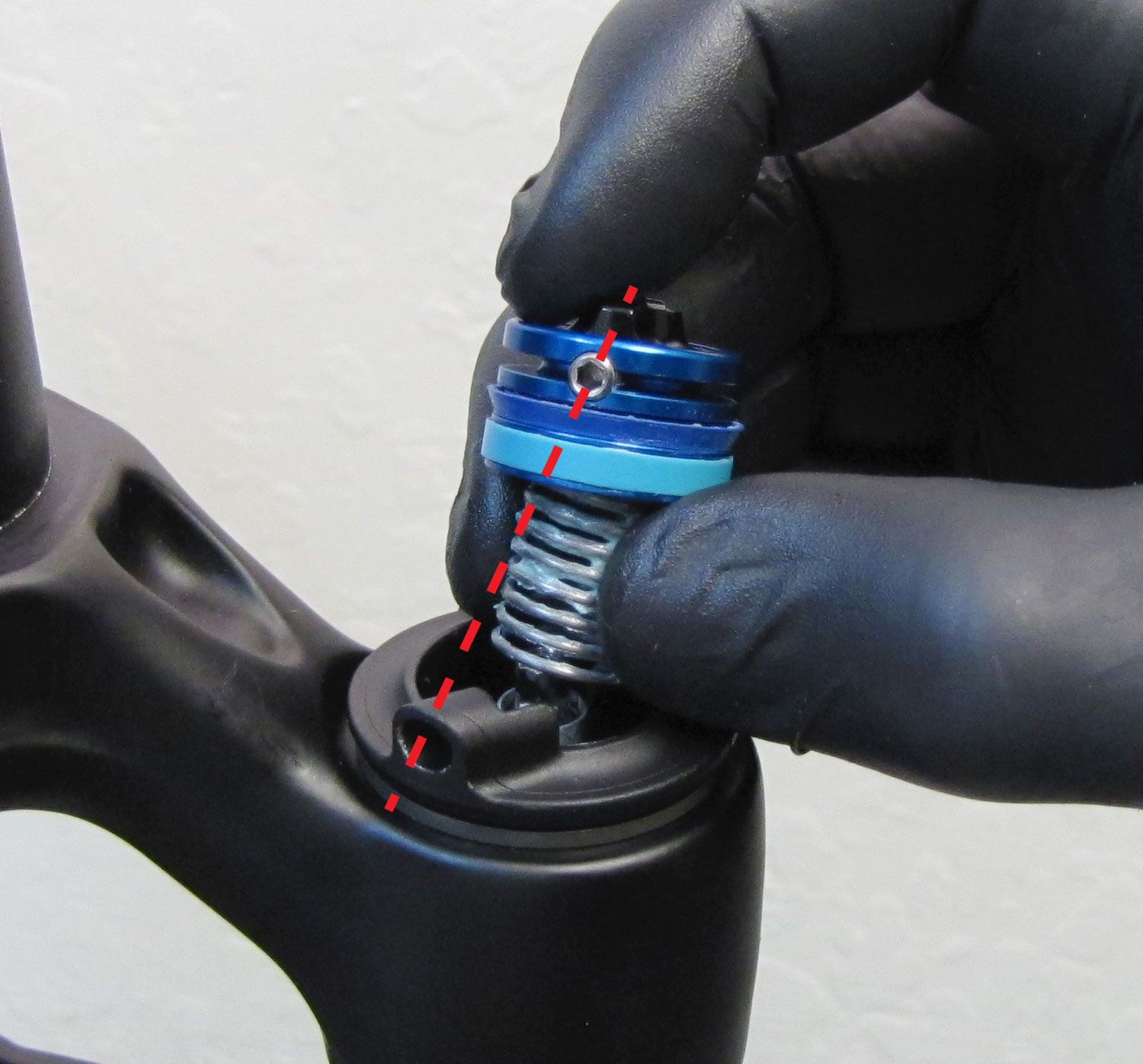
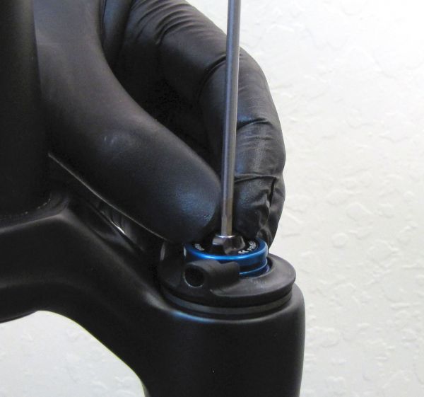
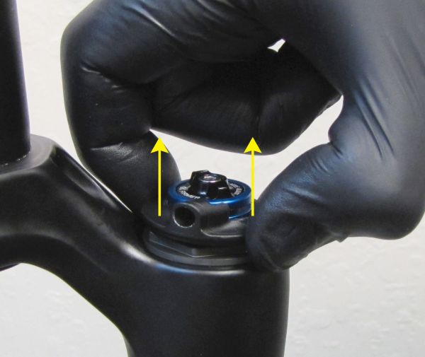
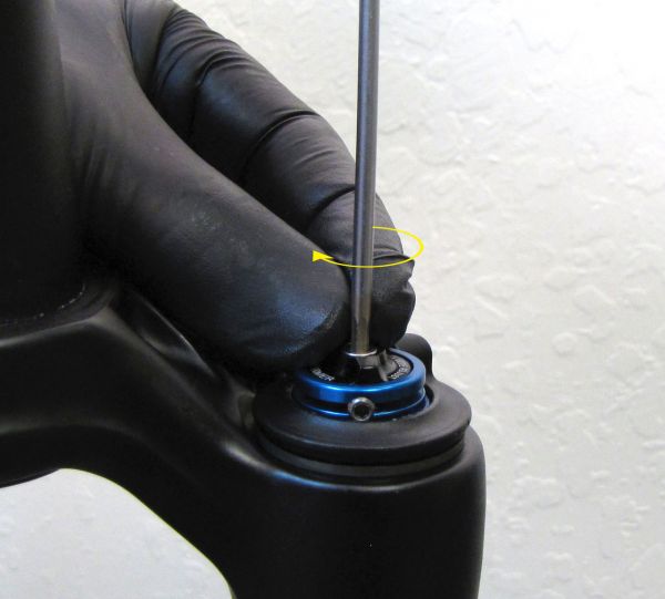
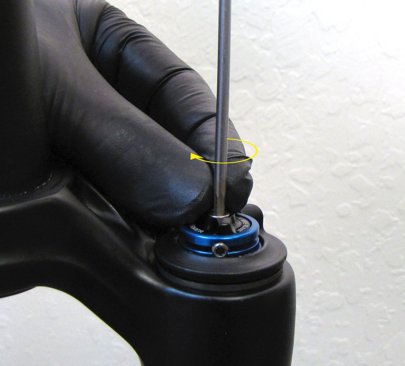
Hold the black knob while unthreading the set screw (counter-clockwise) with your 2.5mm hex wrench. Remove the blue pulley with black knob and torsion spring by lifting up. Remove the black remote housing stop.
Step 2
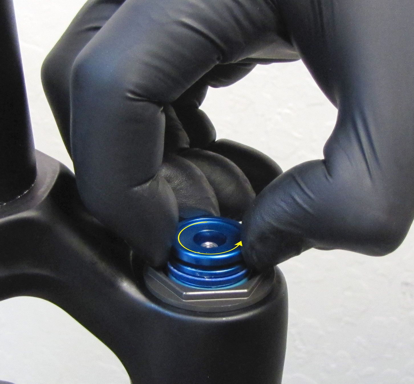
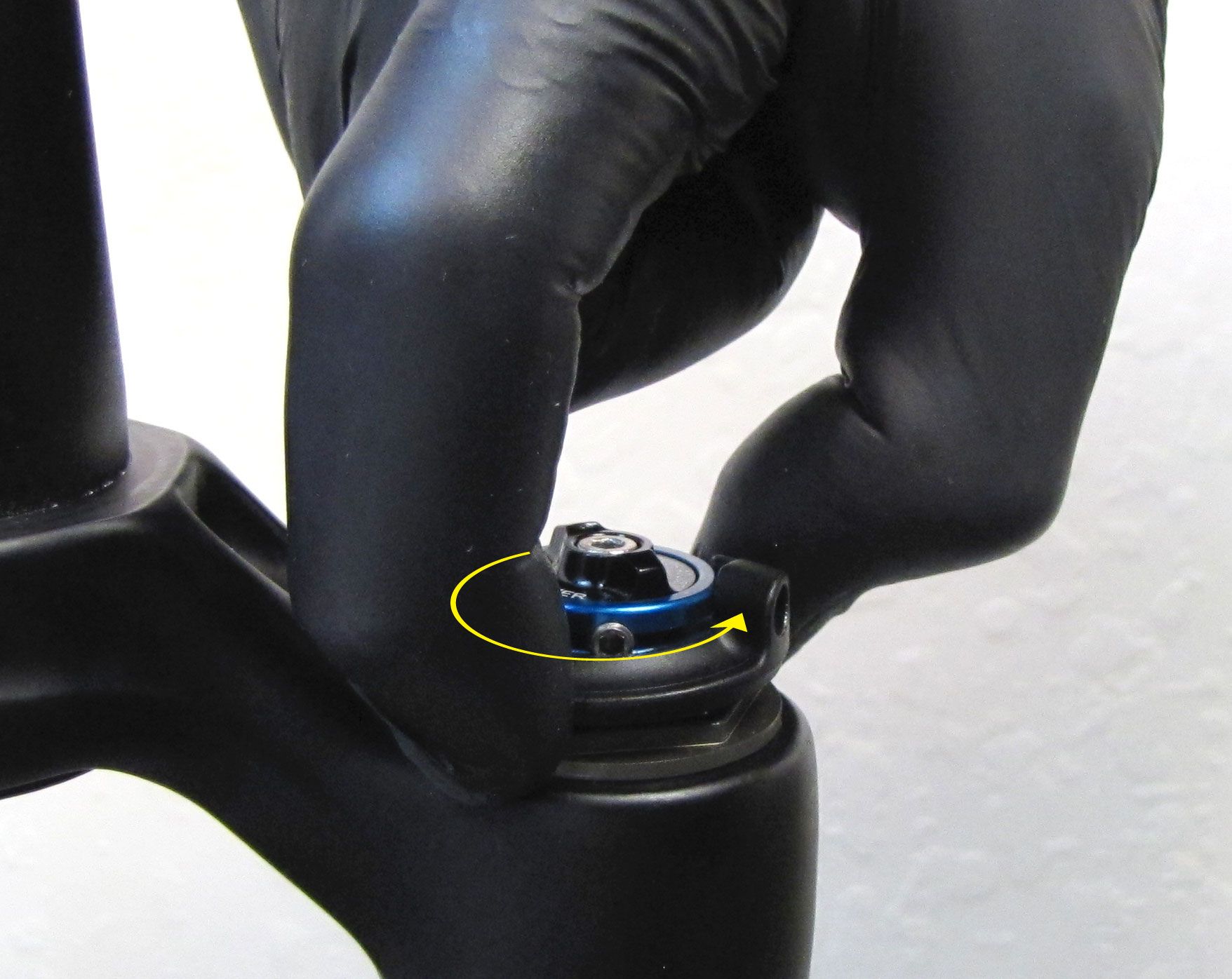
Use the blue remote pulley to turn the compression adjuster shaft fully counter-clockwise to set the fork to Open mode.

Step 3
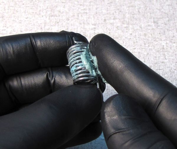
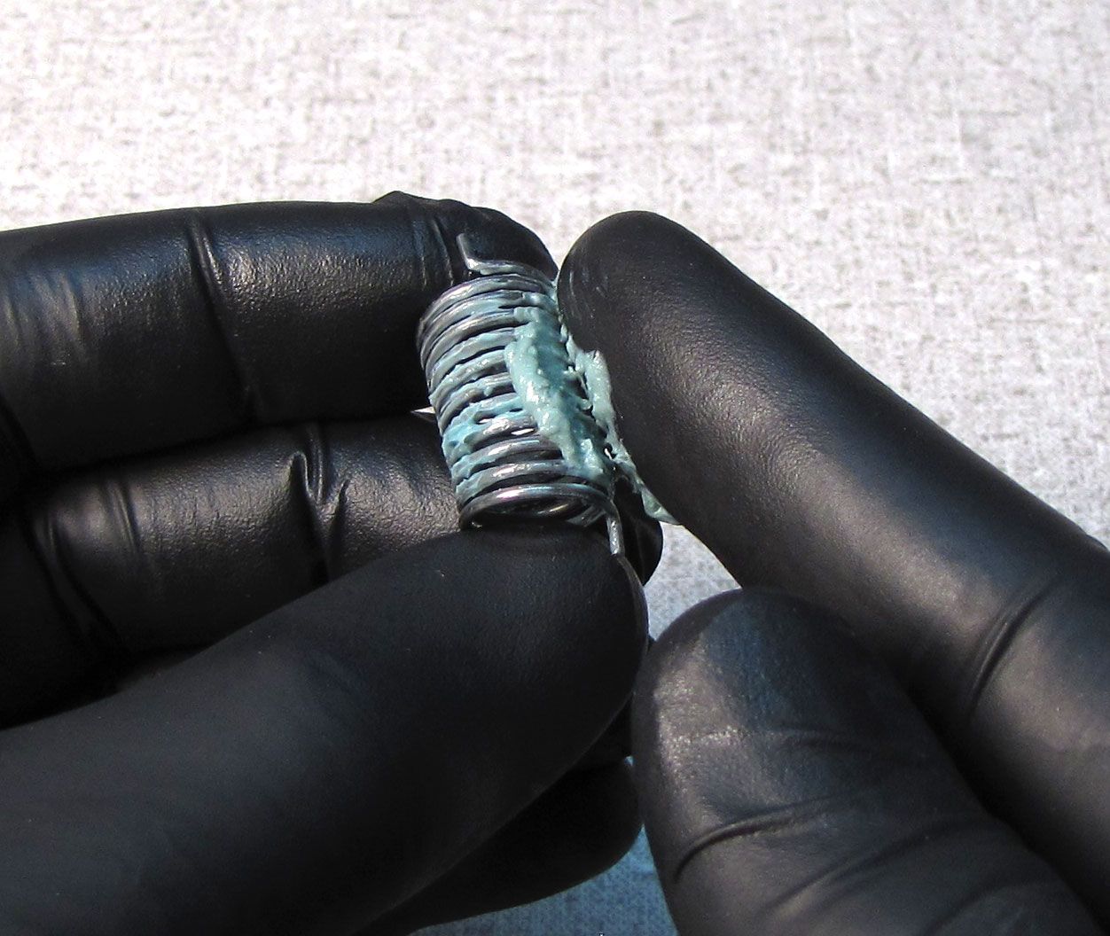
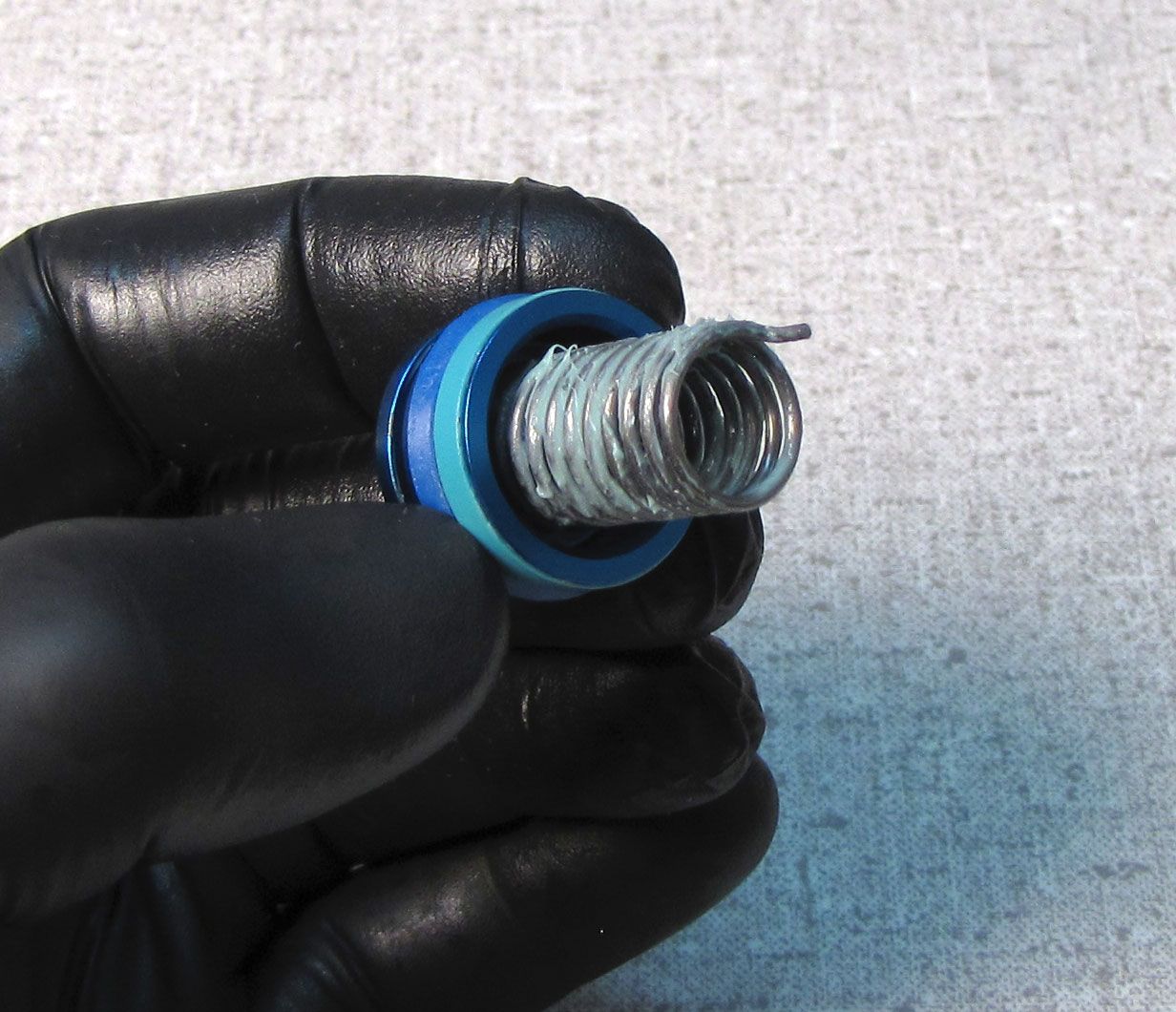
Coat the torsion spring and the blue remote pulley glide ring with a thick film of waterproof grease such as Sta-Lube SL3125 then install one tang of the spring into the hole in the underside of the blue remote pulley.
Clocking for cable housing exit at the riders 7 o'clock
You may choose between 2 approved cable housing exit orientations at the fork topcap. If you desire a cable exit orientation at the riders 7 o'clock, follow the steps immediately below. If you desire a cable exit orientation at the riders 1 o'clock, click here: Clocking for cable housing exit at the riders 1 o'clock »
Step 1
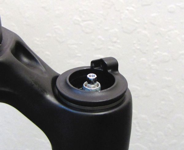
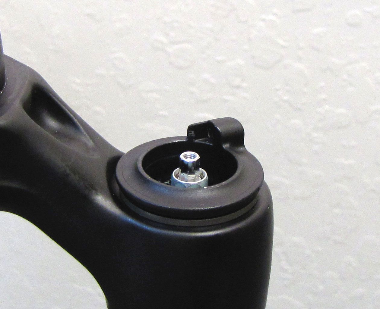
Place the black remote housing into the topcap with the cable stop oriented toward the rider's 1 o'clock position.
Step 2
Insert the remote pulley with black knob and greased torsion spring into the black remote housing so the pinch bolt is aligned with the cable stop at the rider's 1 o'clock position. Make sure that the bottom spring tang seats into a hole in the black remote housing.

Step 3
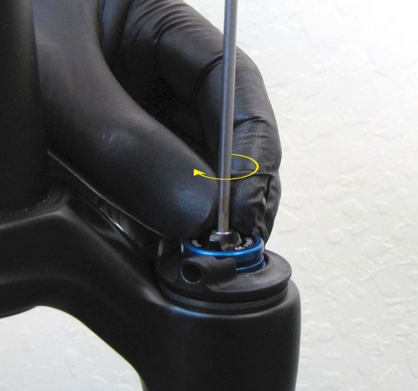
Start the 2.5mm hex screw only 1-2 turns. Do not tighten it fully in this step.
Step 4
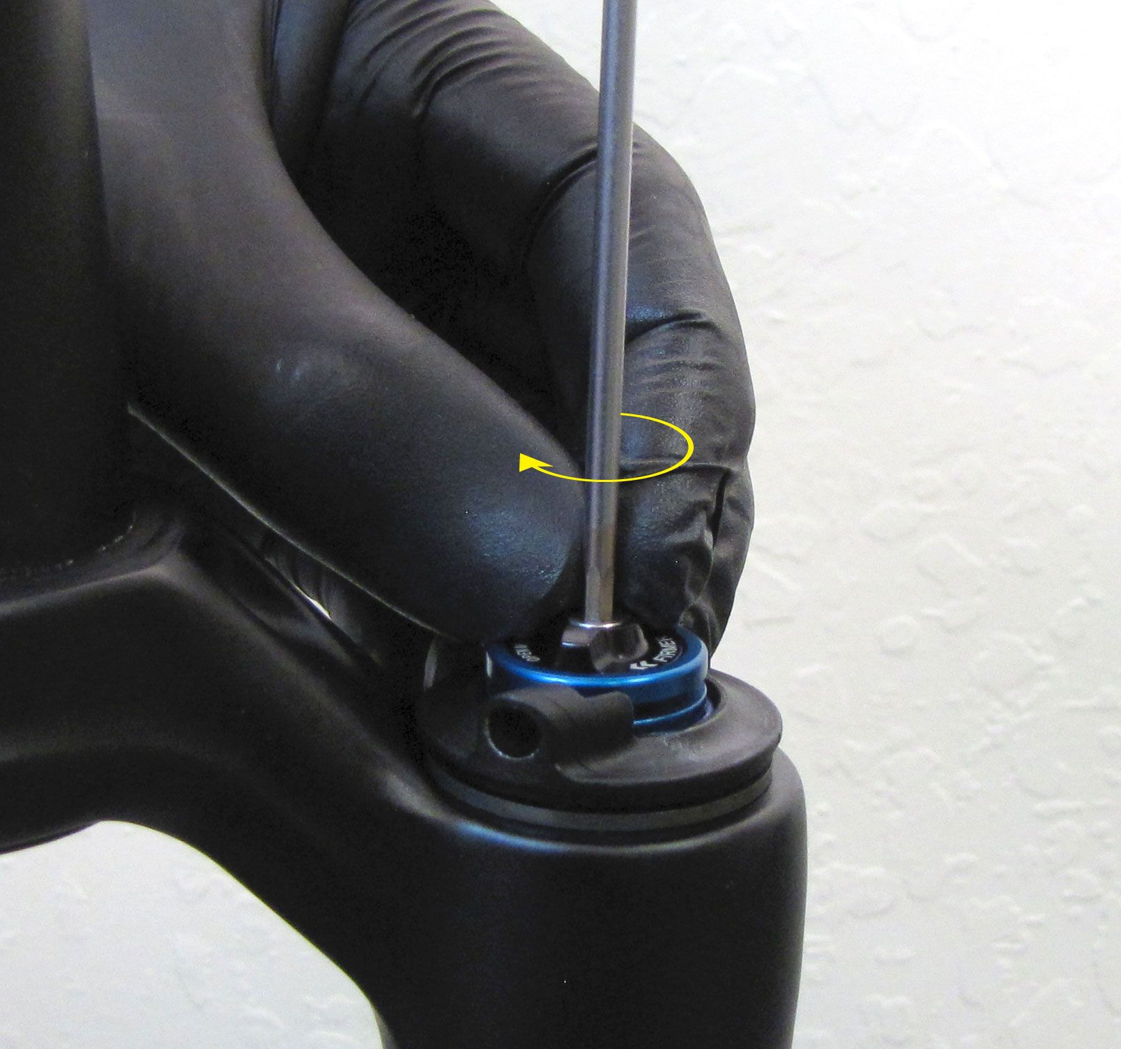
Lift up on the black remote housing and rotate counter-clockwise until the cable stop is oriented toward the riders 7 o'clock position (180 degrees). Lower the black remote housing back onto the topcap wrench flats. If you cannot lift the black remote housing, try loosening the 2.5mm hex screw until it retains the knobs while allowing you to lift the black housing past the topcap wrench flats to rotate it.

Step 5
Hold the black Open mode adjust knob from rotating while you tighten the 2.5mm hex screw to 11 in-lb (1.2 Nm). Do not allow the blue pulley to rotate while tightening the 2.5mm hex screw.
Install the remote lever and test the function of the FIT4 damper. For information guiding you through remote installation go to: 2017 Remote Installation »
Clocking for cable housing exit at the riders 1 o'clock
You may choose between 2 approved cable housing exit orientations at the fork topcap. If you desire a cable exit orientation at the riders 1 o'clock, follow the steps immediately below. If you desire a cable exit orientation at the riders 7 o'clock, click here: Clocking for cable housing exit at the riders 7 o'clock »
Step 1
Place the black remote housing into the topcap with the cable stop oriented toward the rider's 7 o'clock position.
Step 2
Insert the remote pulley with black knob and greased torsion spring into the black remote housing so the pinch bolt is aligned with the cable stop at the rider's 7 o'clock position. Make sure that the bottom spring tang seats into a hole in the black remote housing.
Step 3
Start the 2.5mm hex screw only 1-2 turns. Do not tighten it fully in this step.

Step 4
Lift up on the black remote housing and rotate counter-clockwise until the cable stop is oriented toward the riders 1 o'clock position (180 degrees). Lower the black remote housing back onto the topcap wrench flats. If you cannot lift the black remote housing, try loosening the 2.5mm hex screw until it retains the knobs while allowing you to lift the black housing past the topcap wrench flats to rotate it.

Step 5
Hold the black Open mode adjust knob from rotating while you tighten the 2.5mm hex screw to 11 in-lb (1.2 Nm). Do not allow the blue pulley to rotate while tightening the 2.5mm hex screw.
Install the remote lever and test the function of the FIT4 damper. For information guiding you through remote installation go to: 2017 Remote Installation »
WARNING: FOX products should be serviced by a qualified bicycle service technician, in accordance with FOX specifications. If you have any doubt whether or not you can properly service your FOX product, then DO NOT attempt it. Improperly serviced products can fail, causing the rider to lose control resulting in SERIOUS INJURY OR DEATH.
WARNING: FOX suspension products contain pressurized nitrogen, air, oil, or all 3. Suspension misuse can cause property damage, SERIOUS INJURY OR DEATH. DO NOT puncture, incinerate or crush any portion of a FOX suspension product. DO NOT attempt to disassemble any portion of a FOX suspension product, unless expressly instructed to do so by the applicable FOX technical documentation, and then ONLY while strictly adhering to all FOX insturctions and warnings in that instance.
WARNING: Modification, improper service, or use of aftermarket replacement parts with FOX forks and shocks may cause the product to malfunction, resulting in SERIOUS INJURY OR DEATH. DO NOT modify any part of a fork or shock, including the fork brace (lower leg cross brace), crown, steerer, upper and lower leg tubes, or internal parts, except as instructed herein. Any unauthorized modification may void the warranty, and may cause failure or the fork or shock, resulting in SERIOUS INJURY OR DEATH.
NOTE: Actuate the release lever with the suspension unweighted for immediate changes between damping settings. Actuating the release lever with the suspension under load may cause a slight delay transitioning between damping modes.