SHOCK- 2014/2015 Specialized IV Rebuild
Required Parts
- 803-00-142 Kit: Rebuild, FLOAT Line Air Sleeve, Special Q-Ring
- 803-00-879 Seal Kit: 2014 Specialized Micro Brain Damper Rebuild
Required Tools
- 029-12-000 Seals: O-Ring, Square Cut [0.087 Id X 0.039 Wall X 0.036 Th], Na103-70, Dynamic
- 398-00-280 Tooling: Eyelet Torque Tool
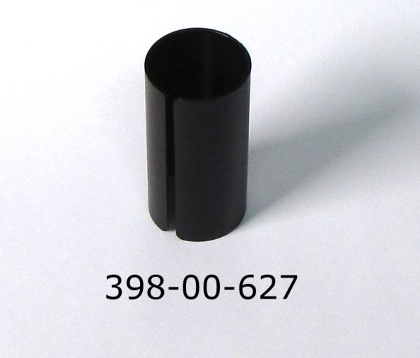
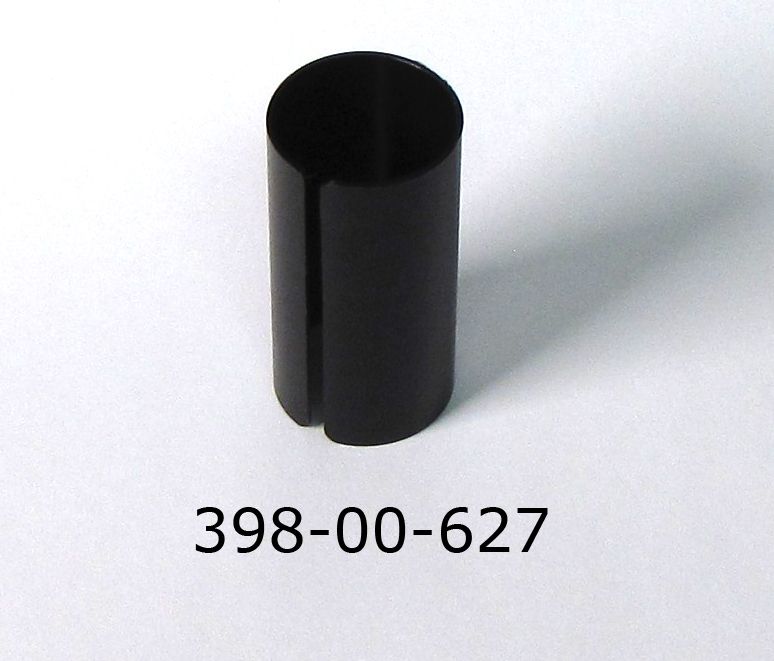
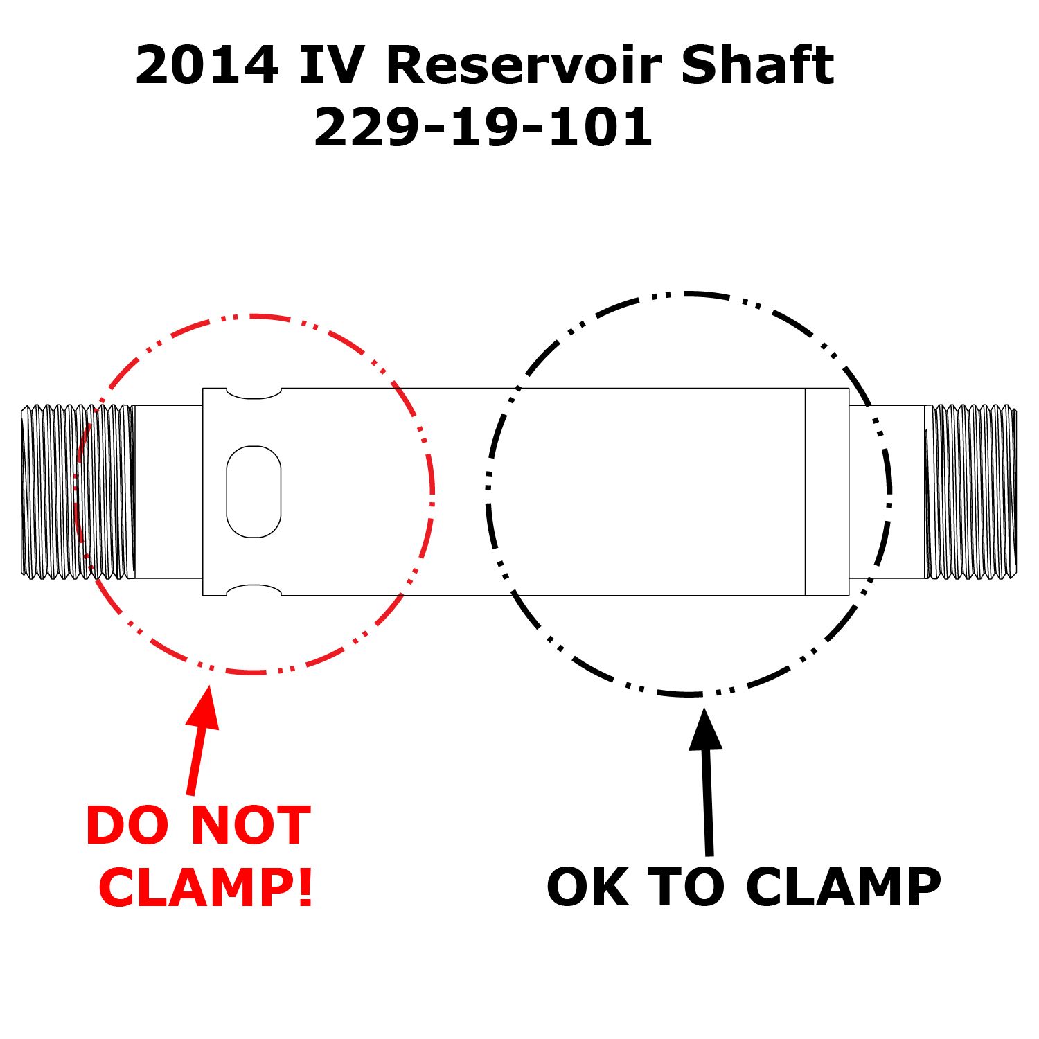
- 398-00-627 Tooling: My14 IV Rezi Shaft Clamp Shim
- 398-00-629 Tooling: My14 IV Resi Torque Socket Assembly
- 398-00-632 Tooling: My14 IV Cartridge Disassembly Assembly
- 803-00-383 Kit: Shaft Clamps, MY10 SHOX, BRAIN
- 803-00-500 Service Set: FIll Machine Adapter, TerraLogic FIT Damper
- 803-00-566 Kit: DYAD IFP Depth Setting Tool Set
Supplies Needed
- 1.5mm Hex Wrench
- 21mm Crows Foot
- 22mm Crow's Foot
- 3/8" Socket
- 3/8" Square-drive Ratchet
- 5/32" (4mm) Hex Wrench
- 5/64" (2mm) Hex Wrench
- Magnet
- Needle-Nosed Pliers
- Seal Pick
- Torque Wrench
- Waste Oil Basin
- 0.050" AA Slotted Shim McMaster Part Number: 97235K161
WARNING: FOX products should be serviced by a qualified bicycle service technician, in accordance with FOX specifications. If you have any doubt whether or not you can properly service your FOX product, then DO NOT attempt it. Improperly serviced products can fail, causing the rider to lose control resulting in SERIOUS INJURY OR DEATH.
Main Disassembly
Step 1
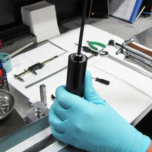
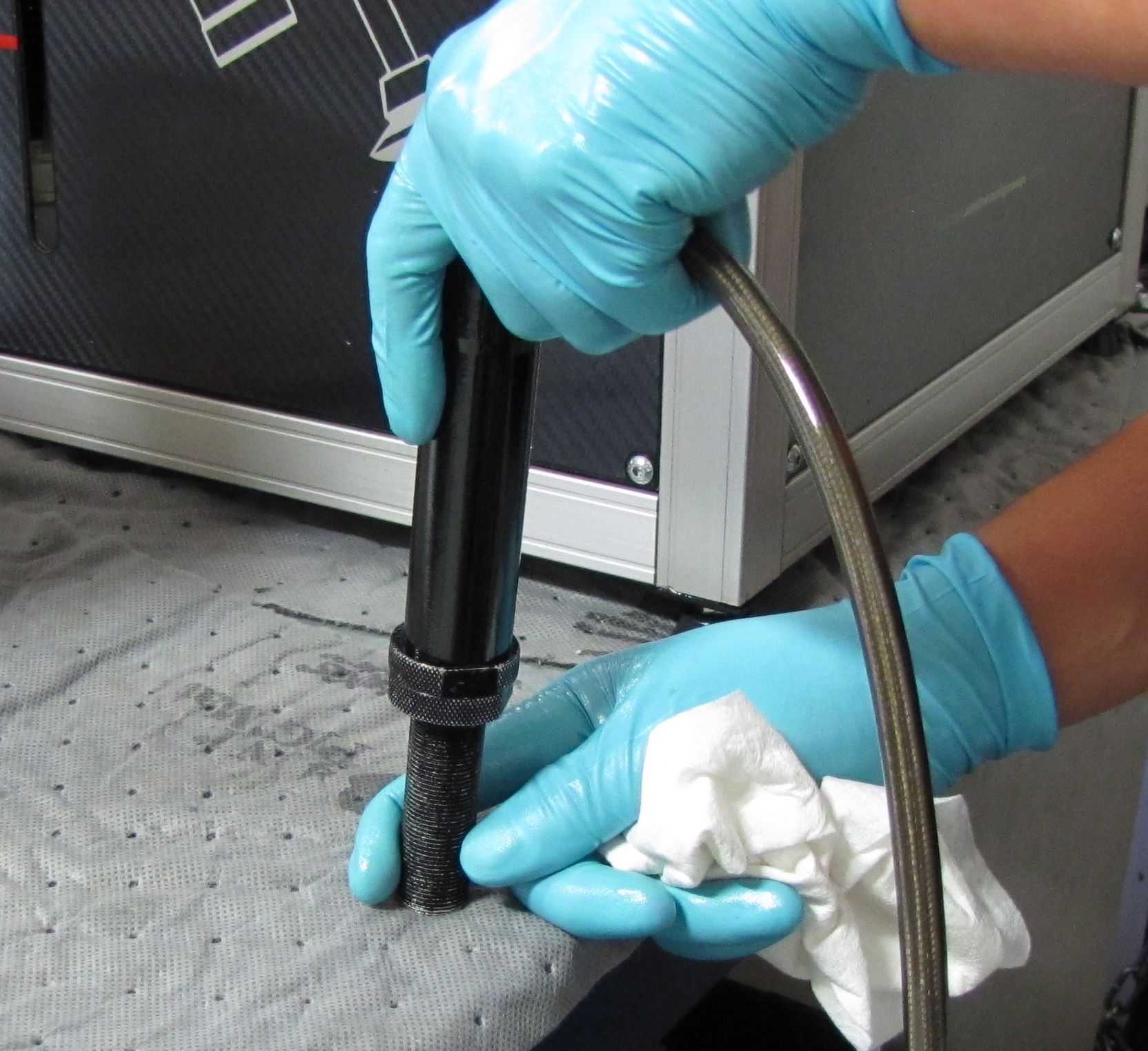
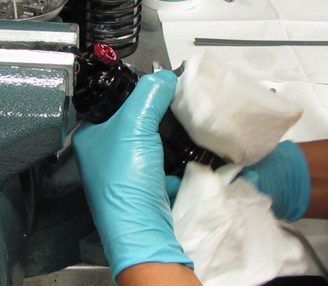
Remove the black air cap and release the air pressure. Unthread the air sleeve and let it rest on the hose.

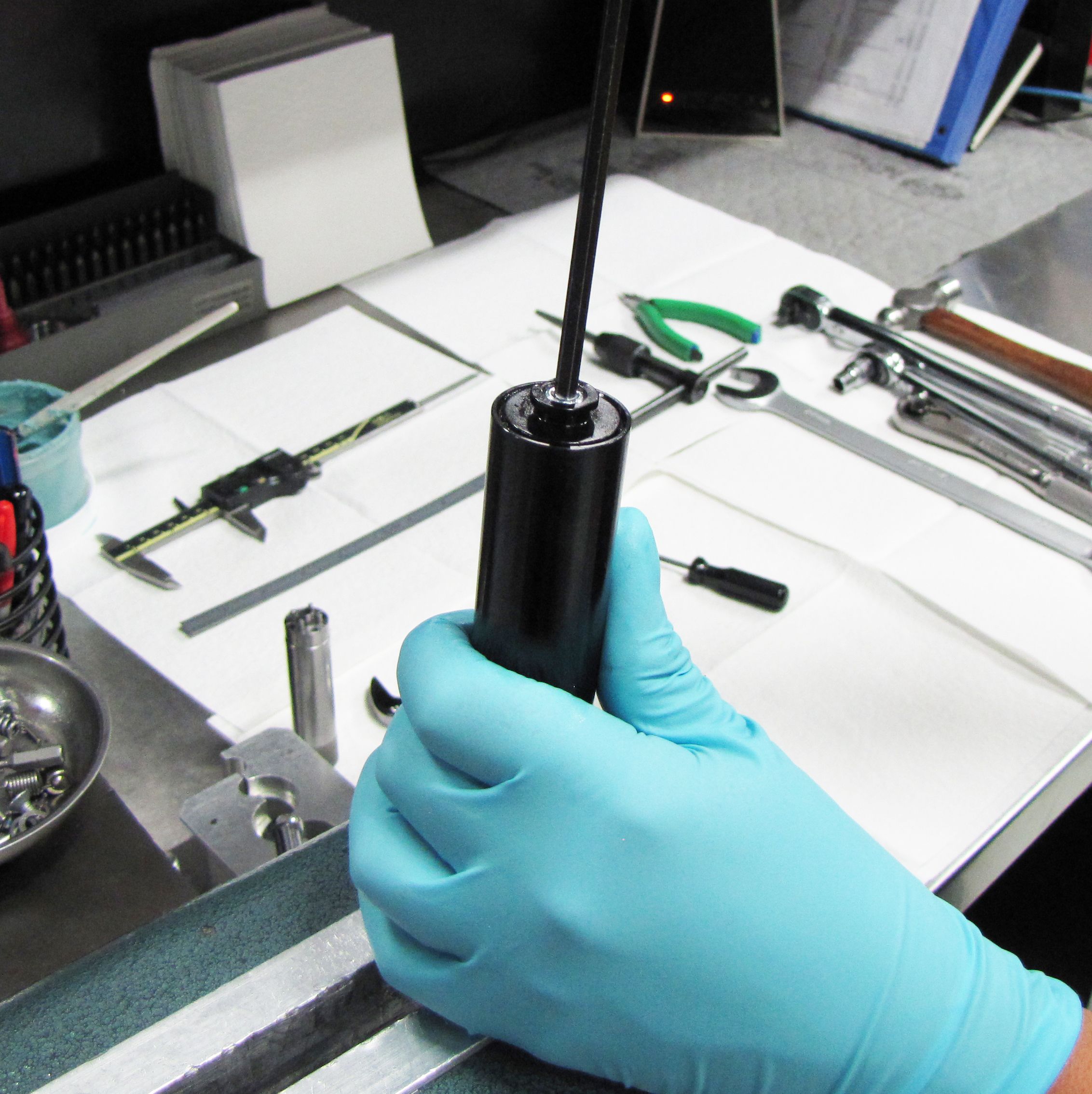
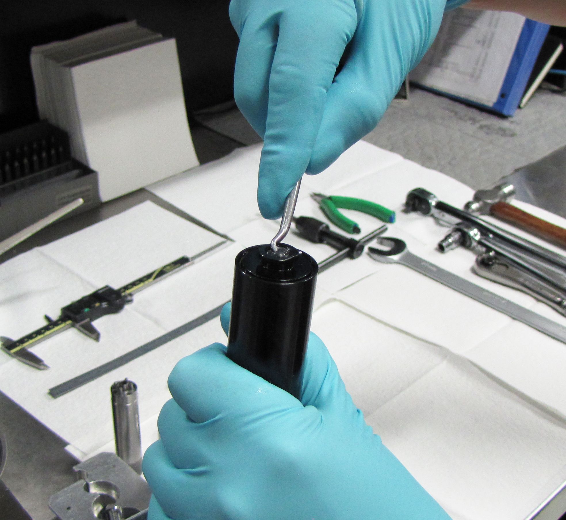
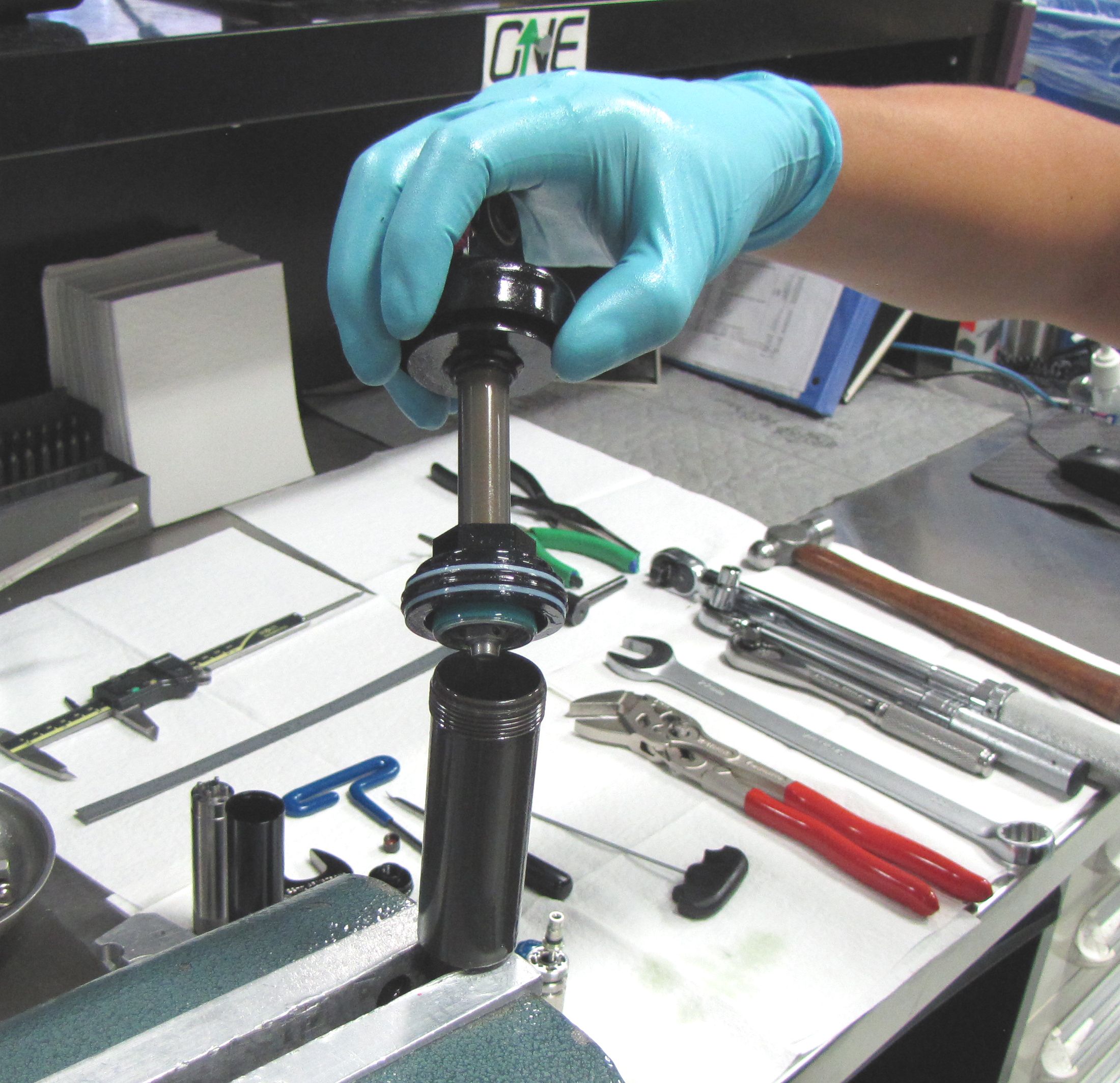
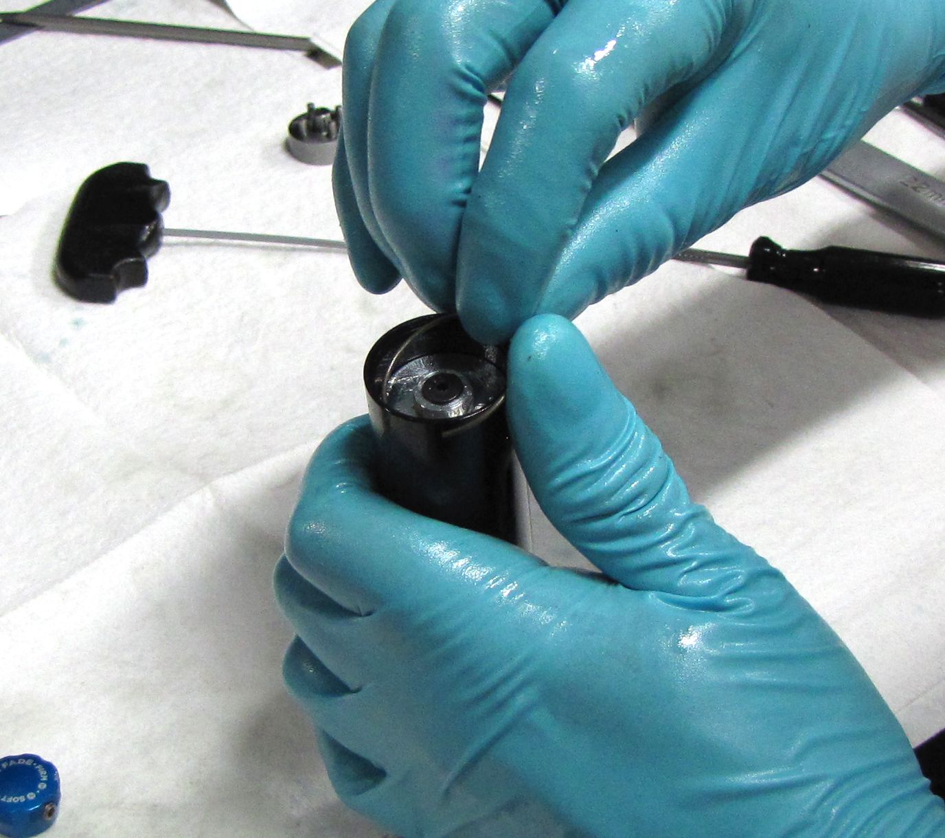
Step 2
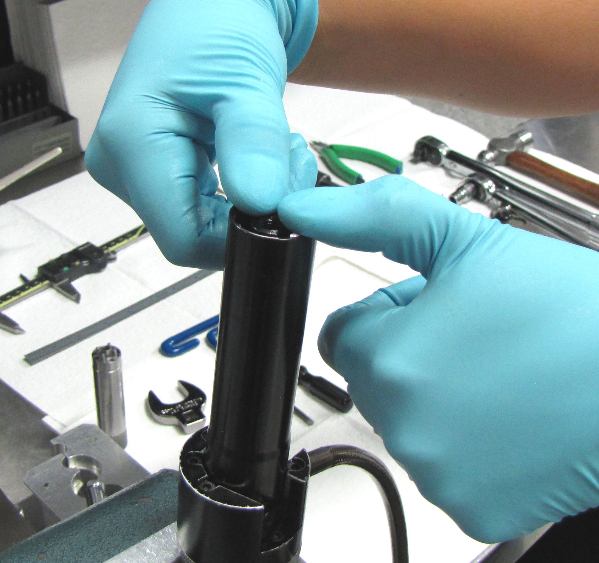
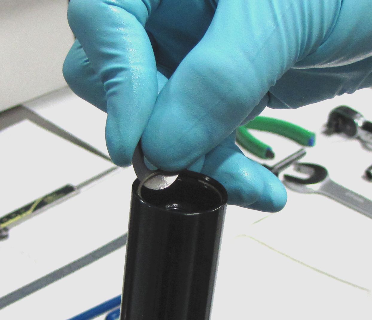
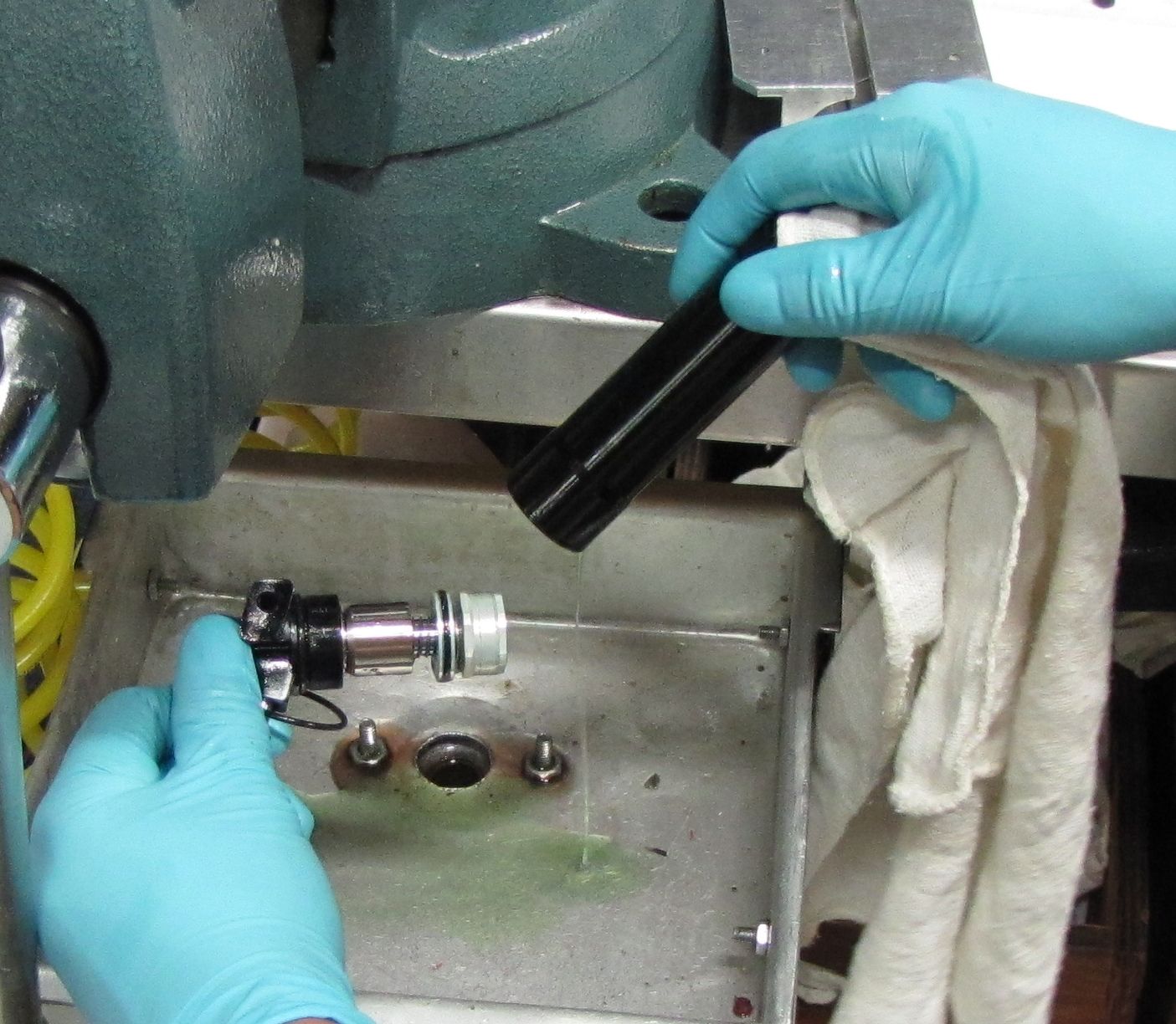
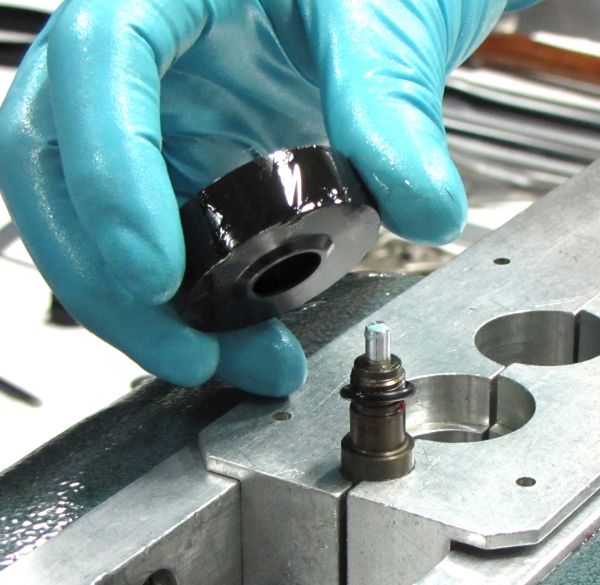
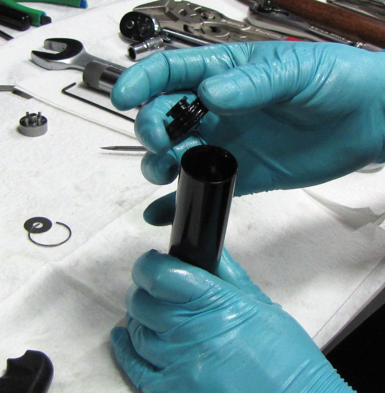
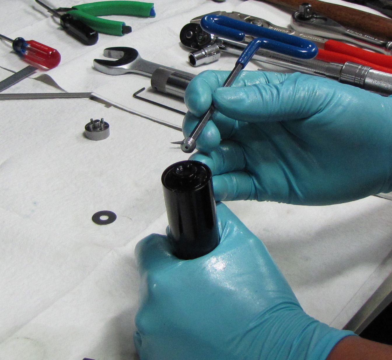
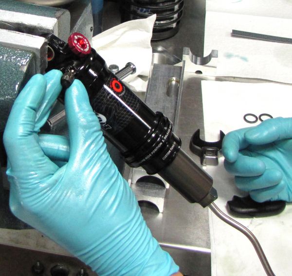
Rest the reservoir in the Resi Torque Socket (PN:398-00-629) and remove the nylon plug with a pick tool.

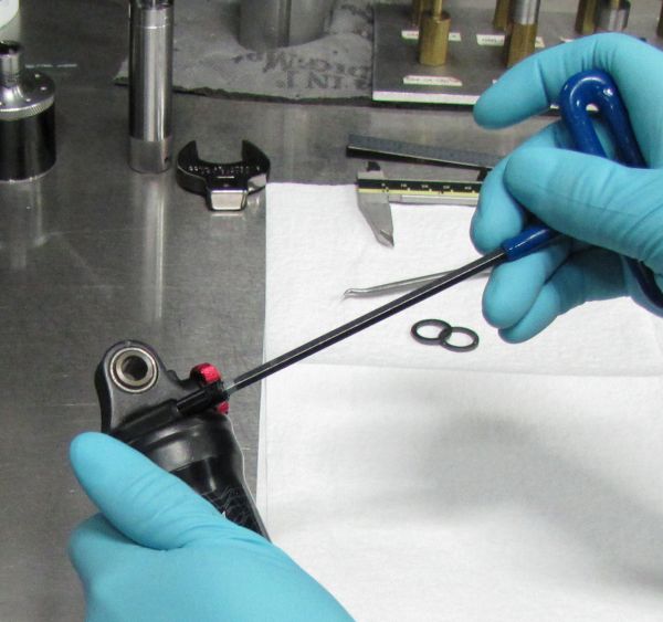
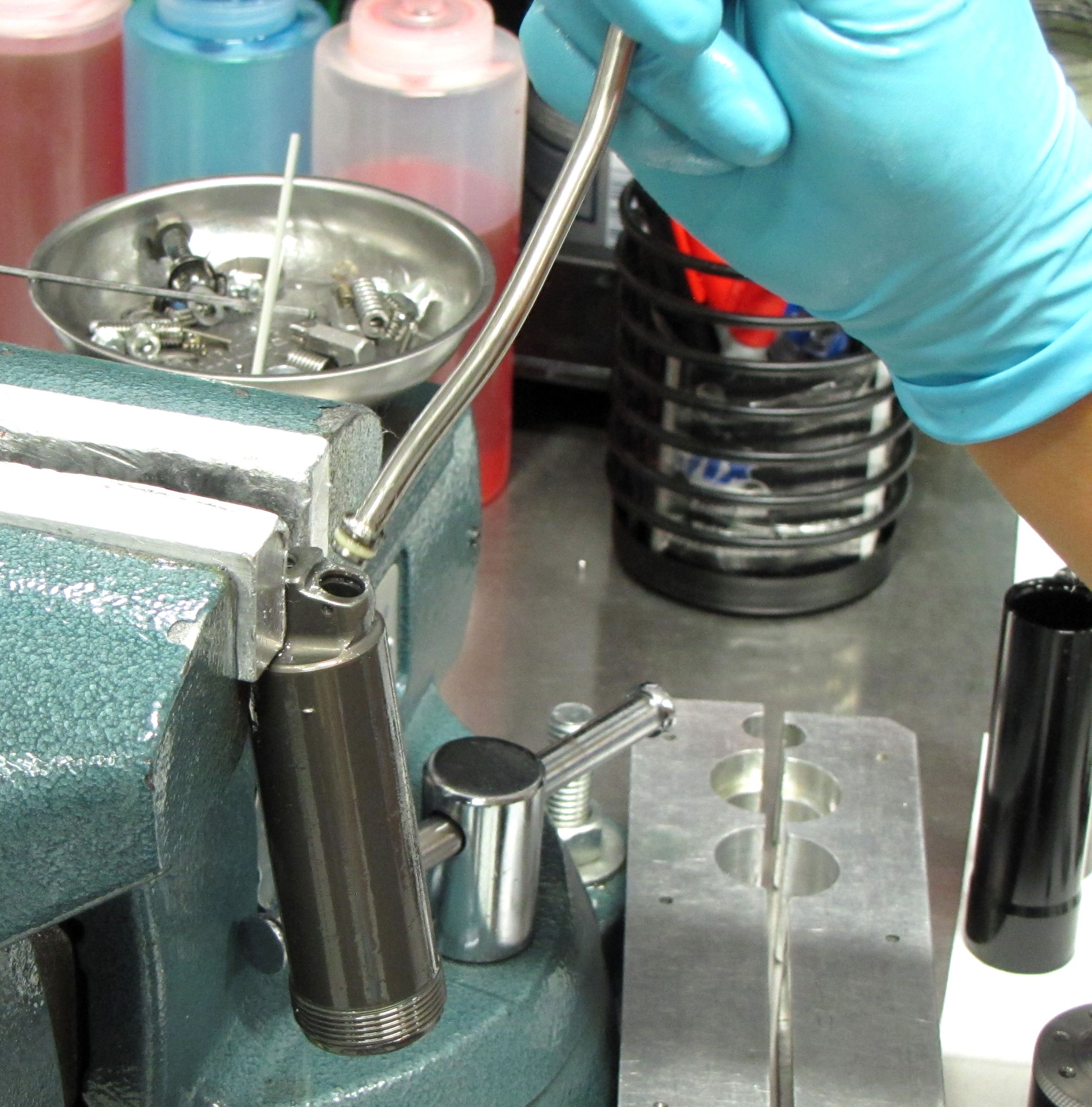
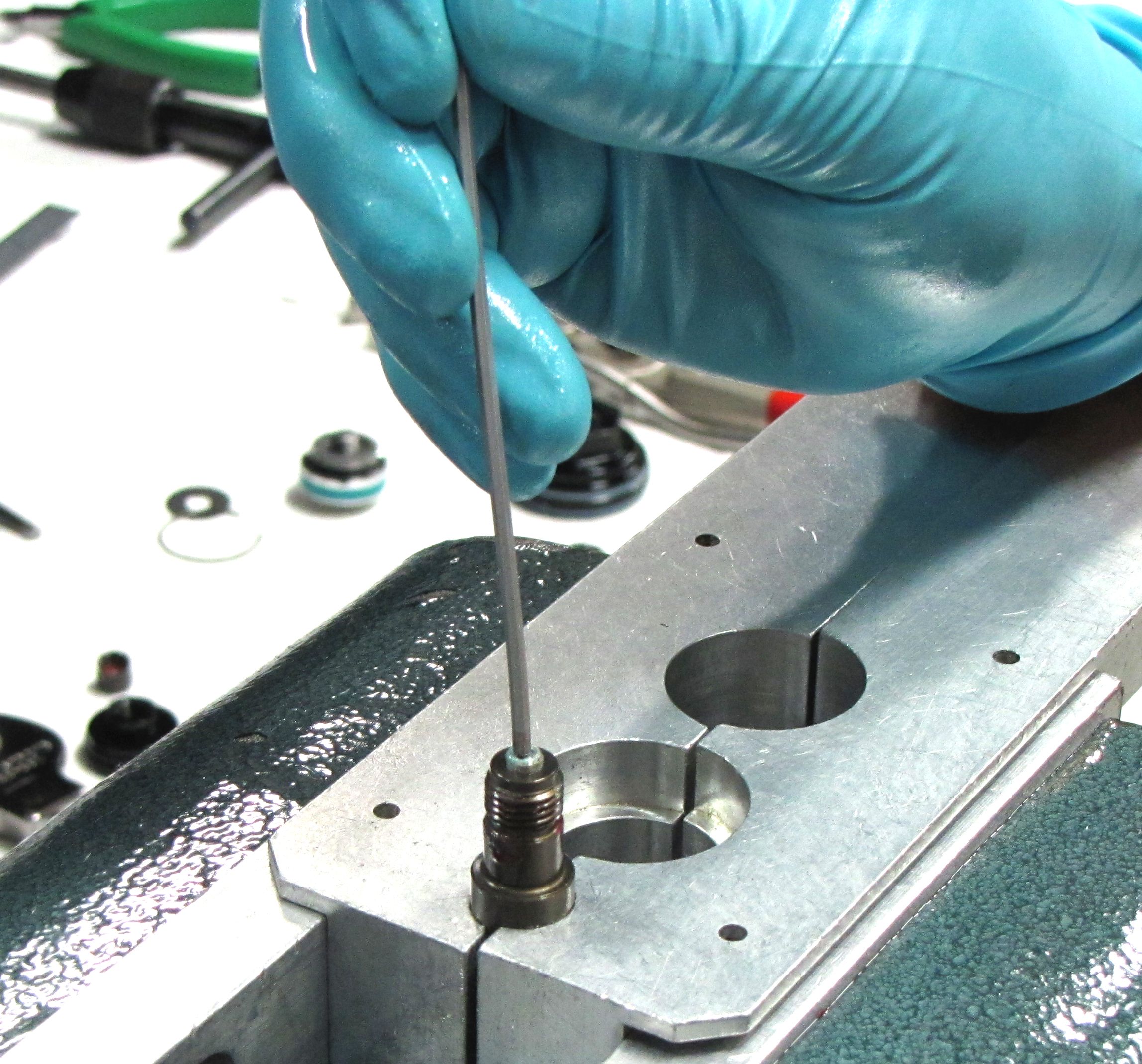
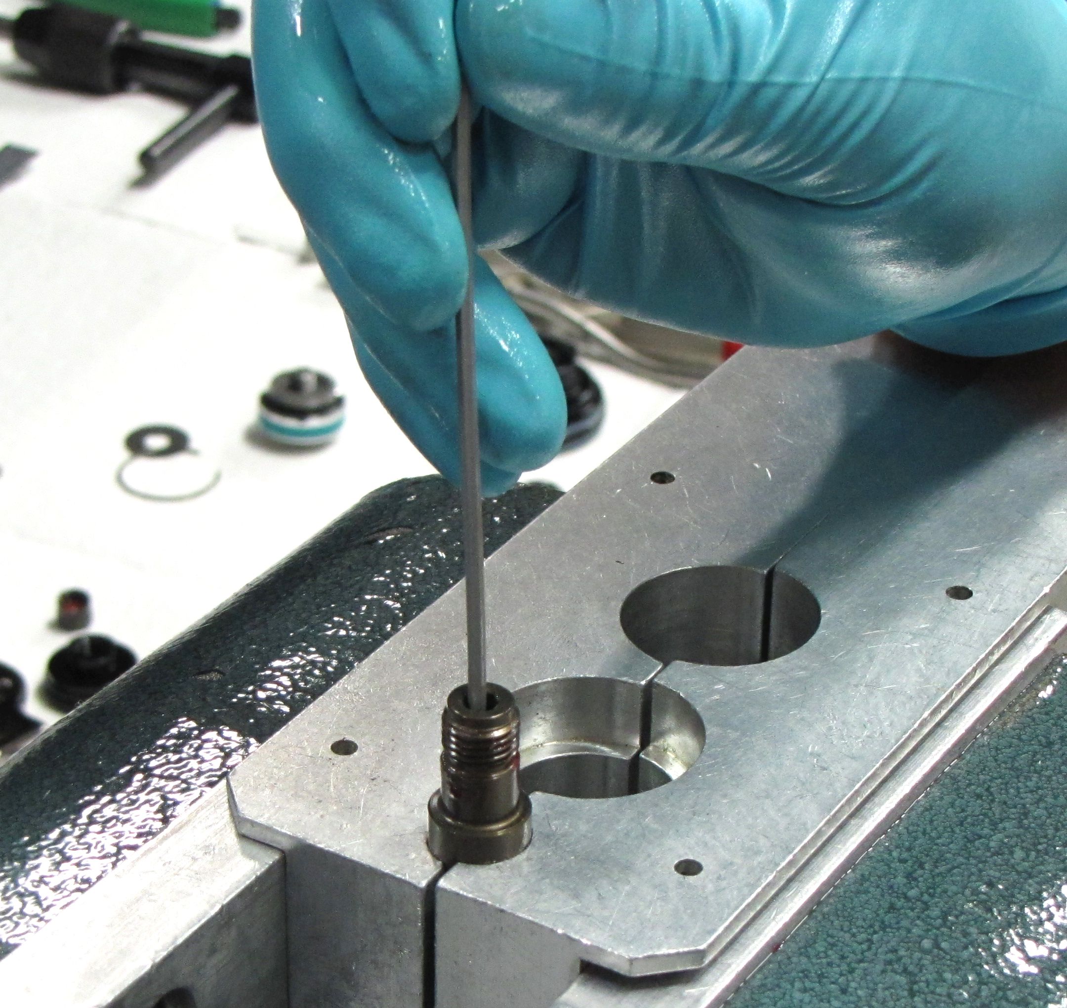
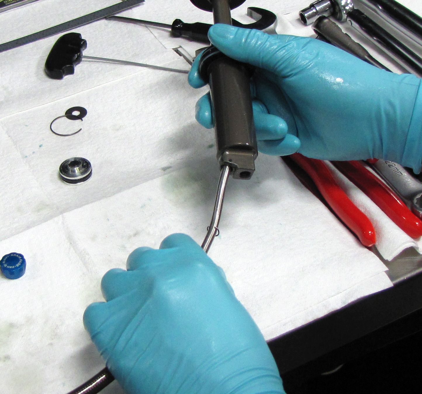
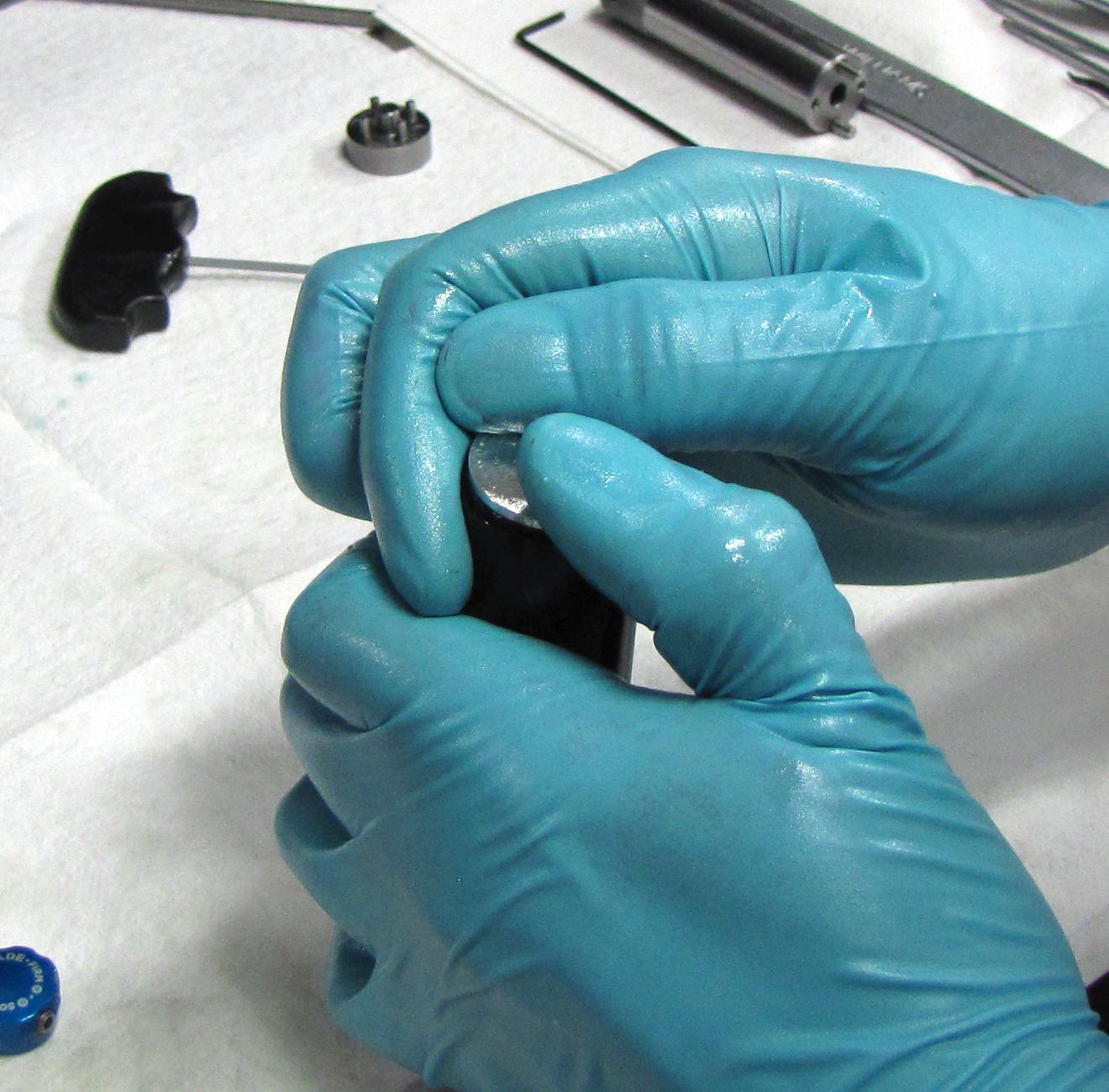
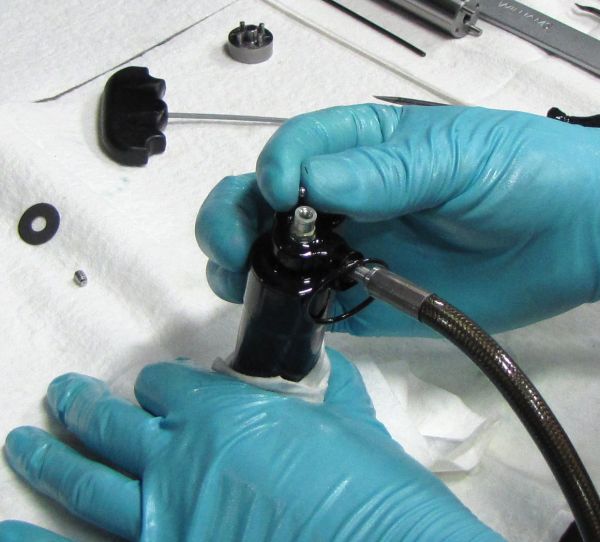
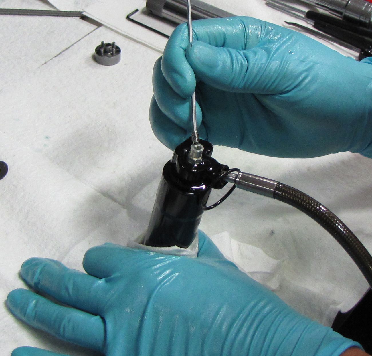
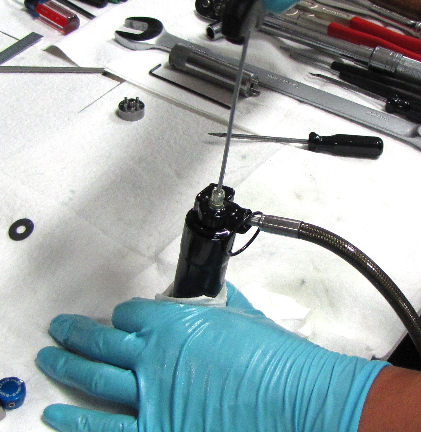
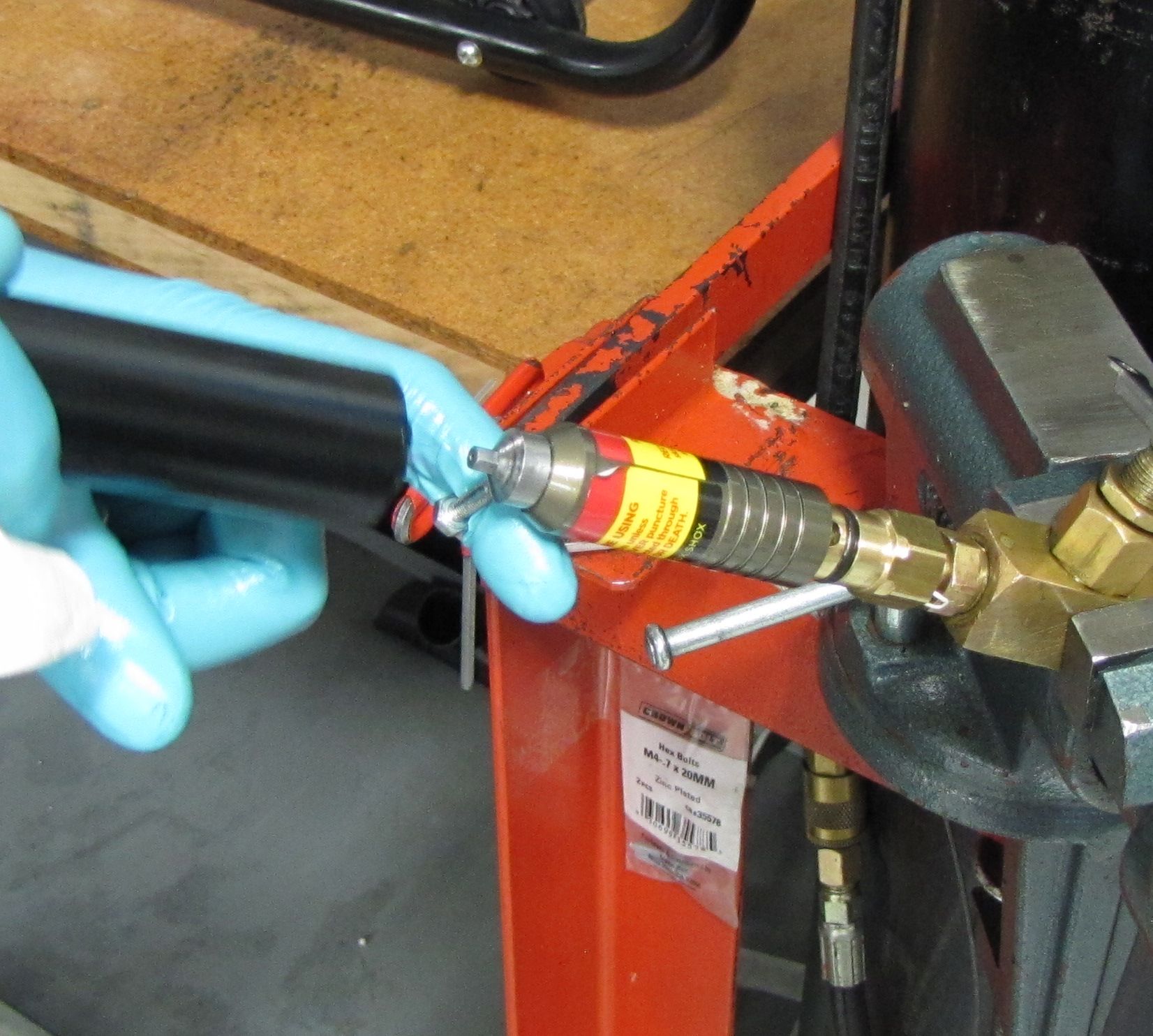
Step 3
Carefully unthread the pellet retainer with a 5/32" (4mm) hex wrench to release the nitrogen pressure from the IFP chamber. Remove the black rubber pellet.
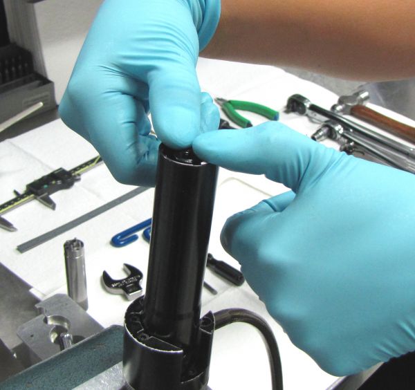
Step 4
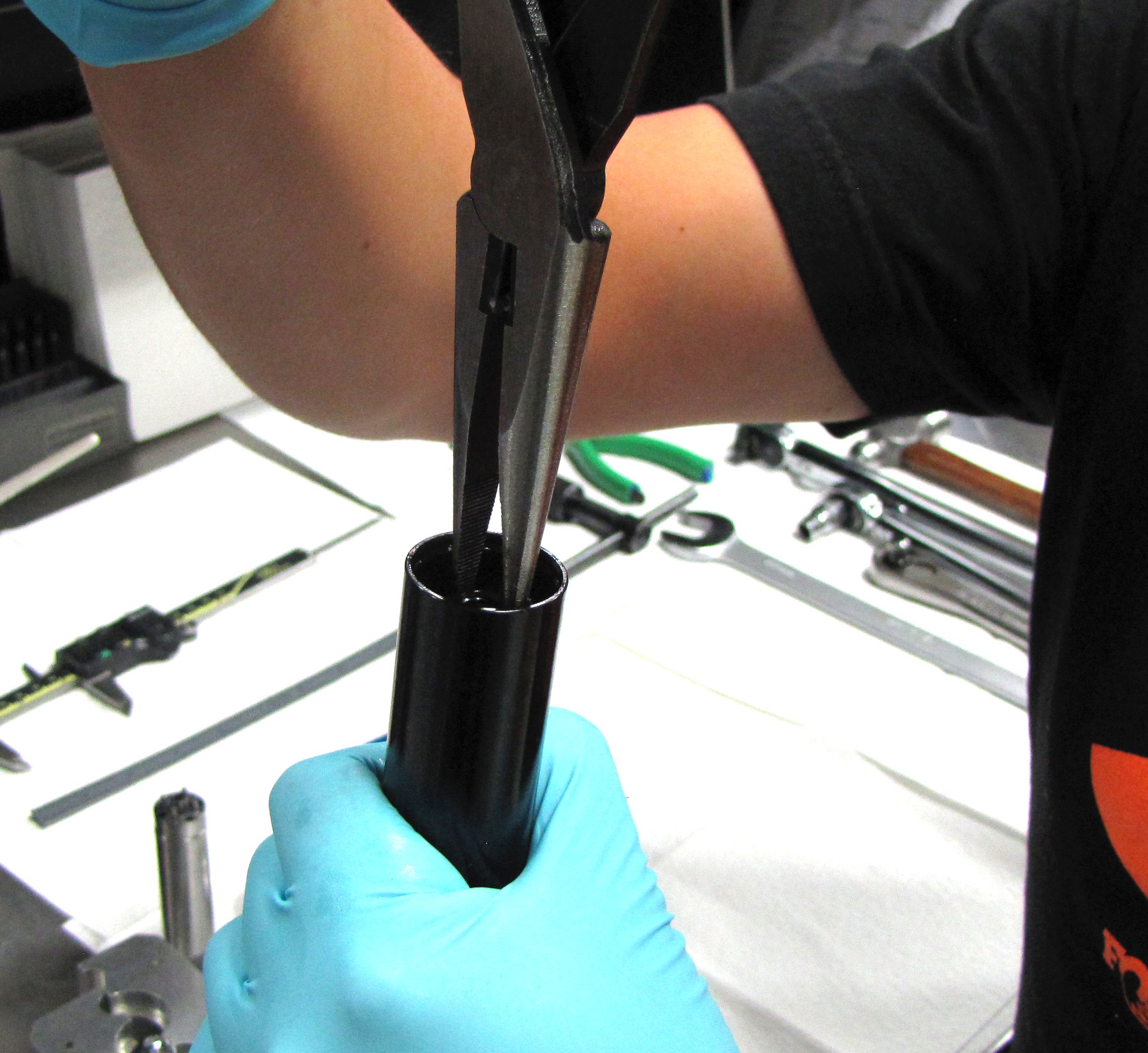
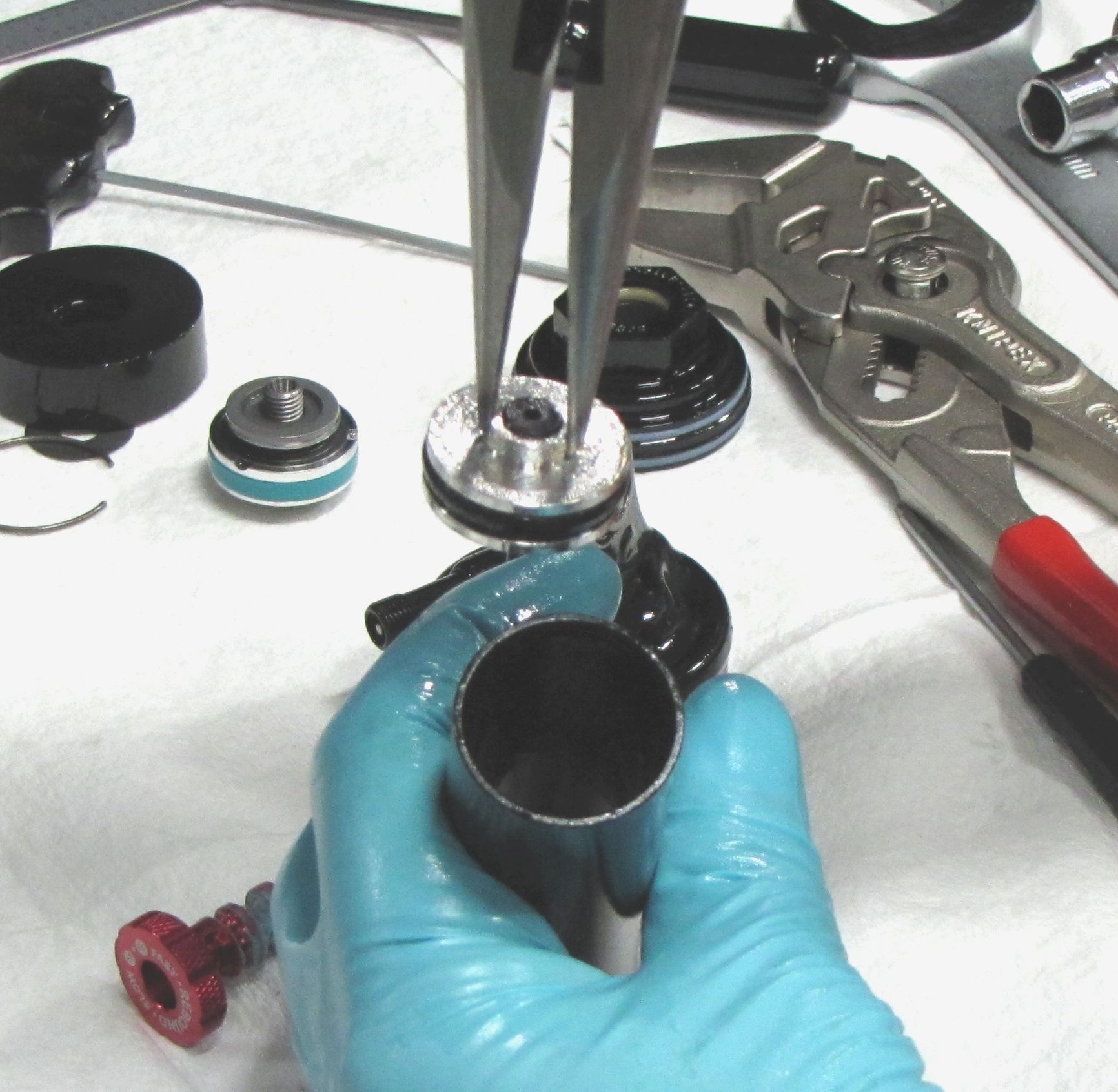
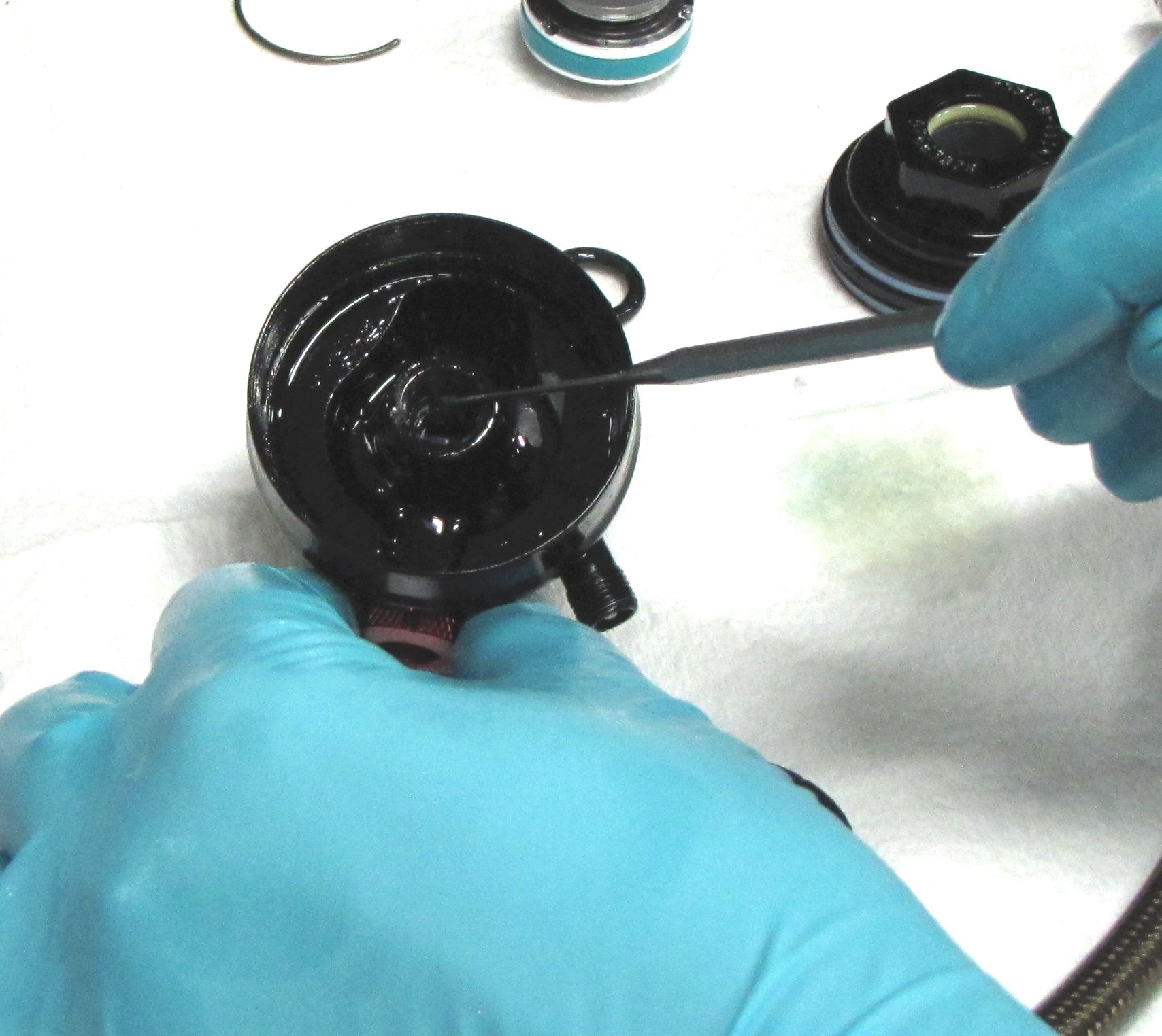
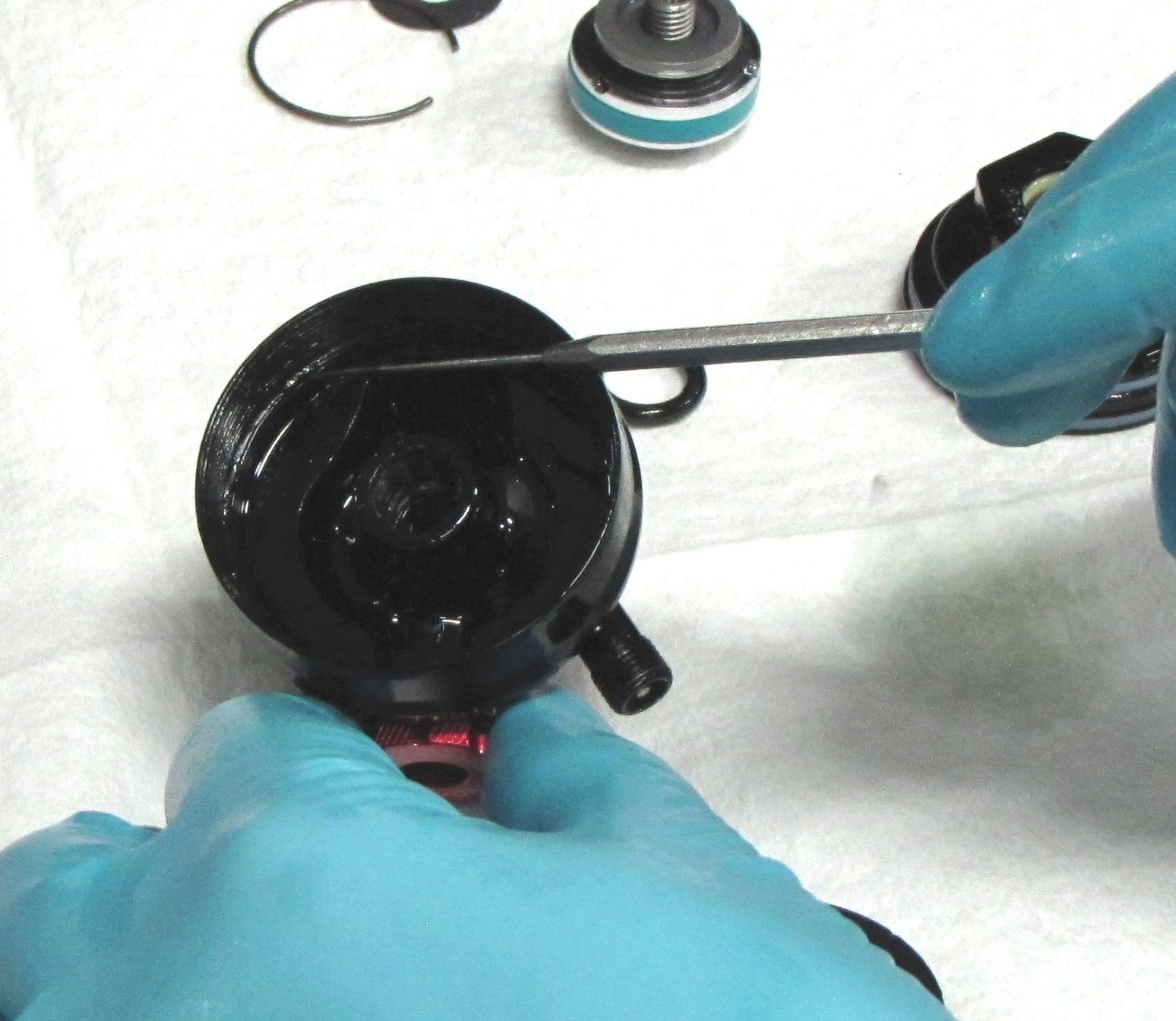
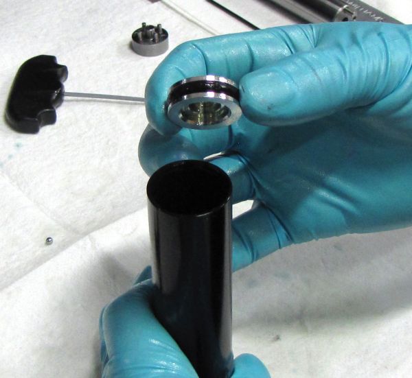
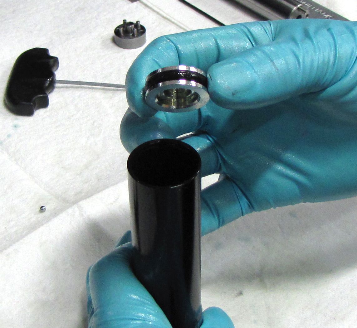
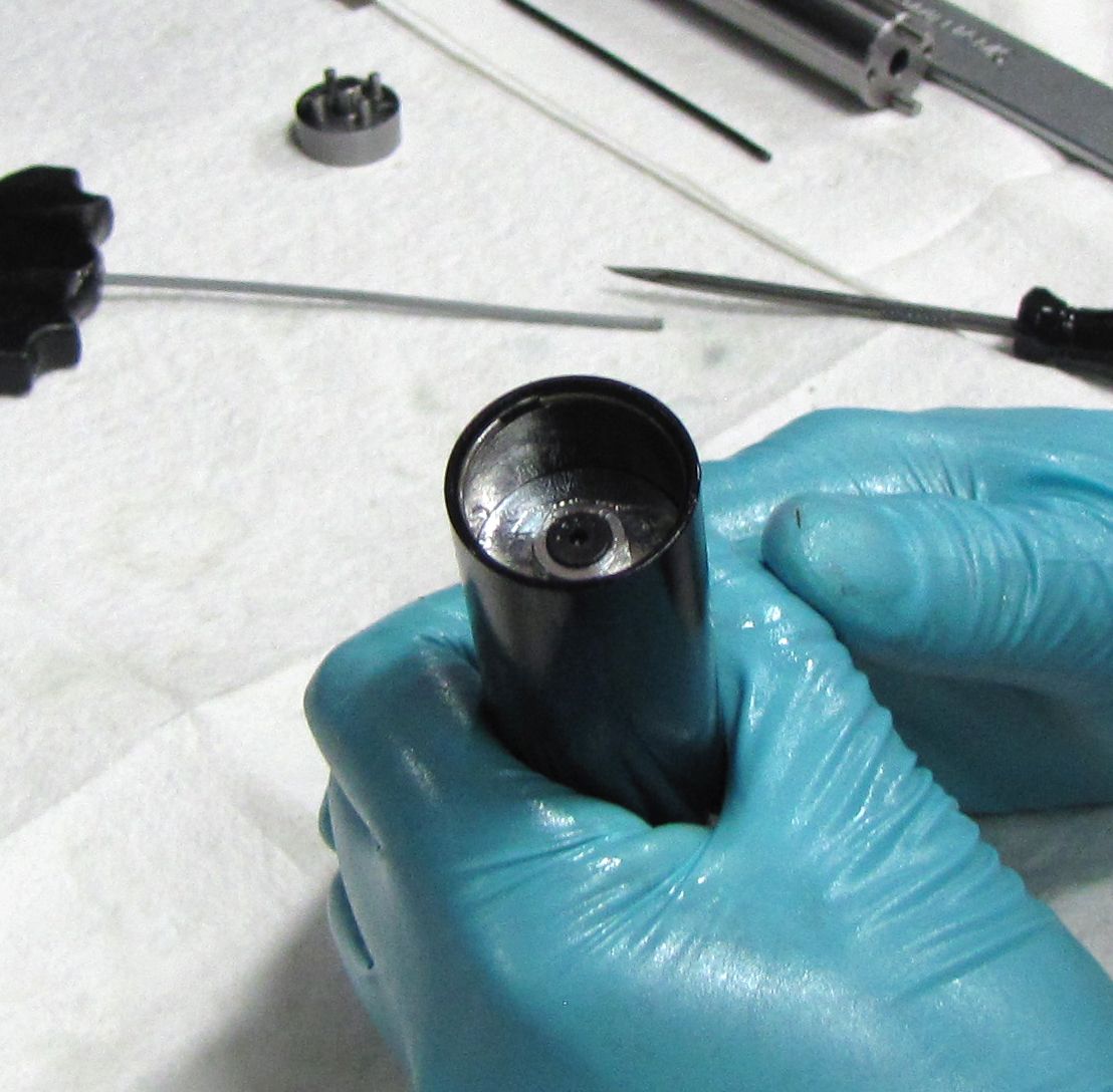
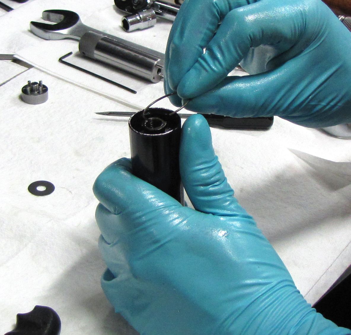
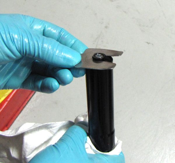
Push the Reservoir End Cap into the Reservoir with your thumbs. Use a thin shim to remove the wire retaining ring.

Step 5
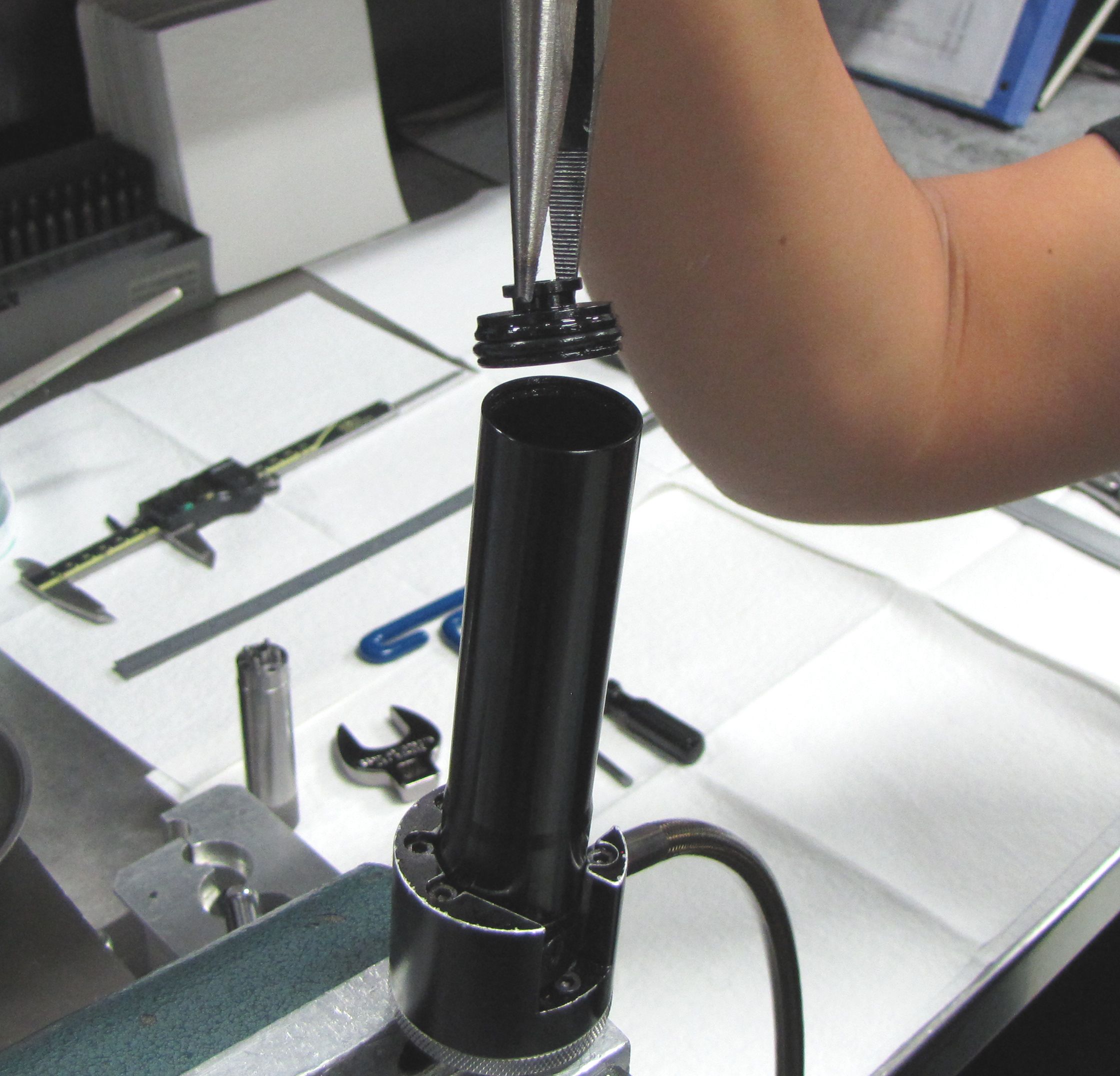
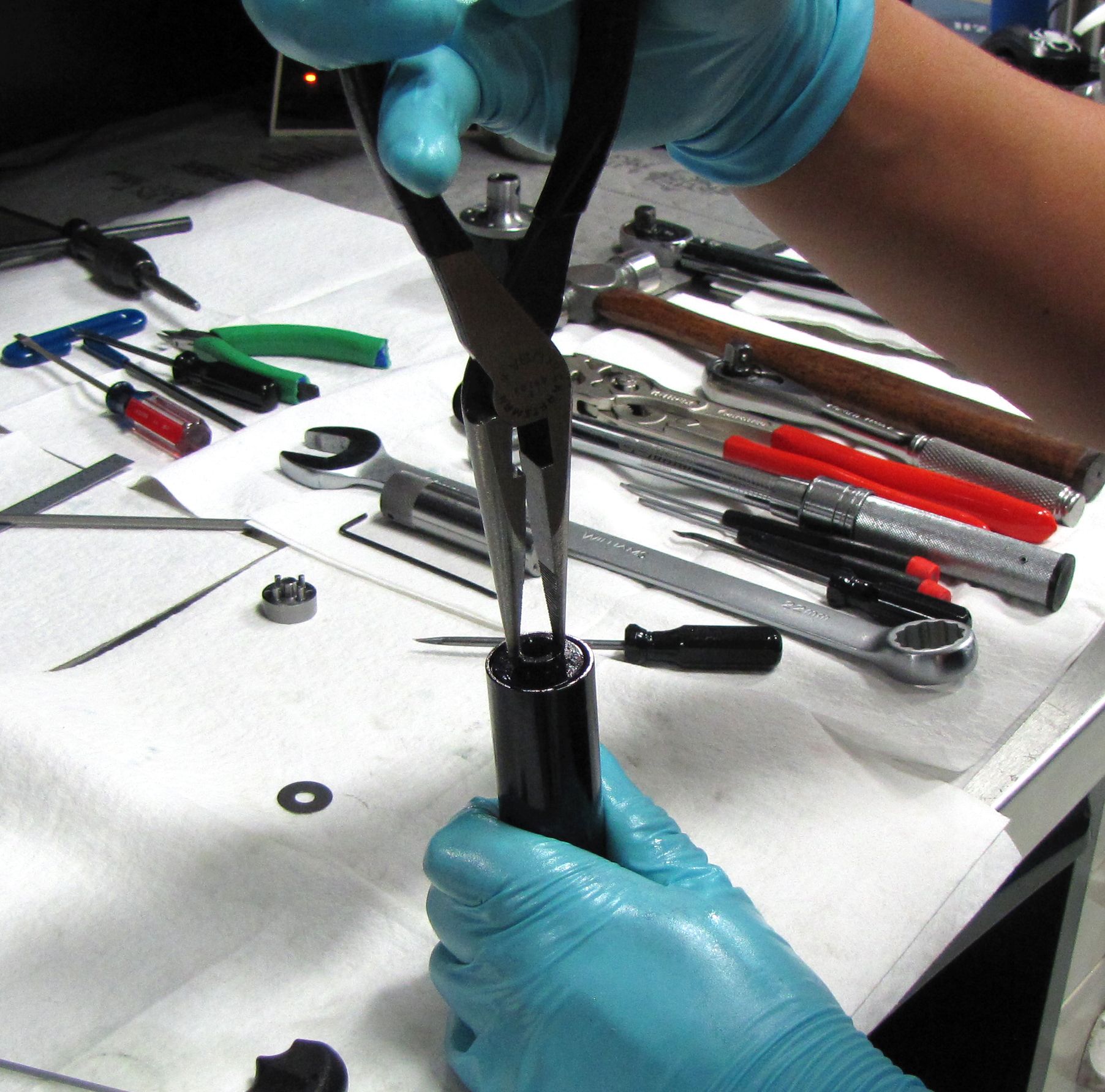
Use needle-nosed pliers to lift out the Reservoir End Cap. Replace the o-ring with a new greased one from the rebuild kit, then set the end cap aside.
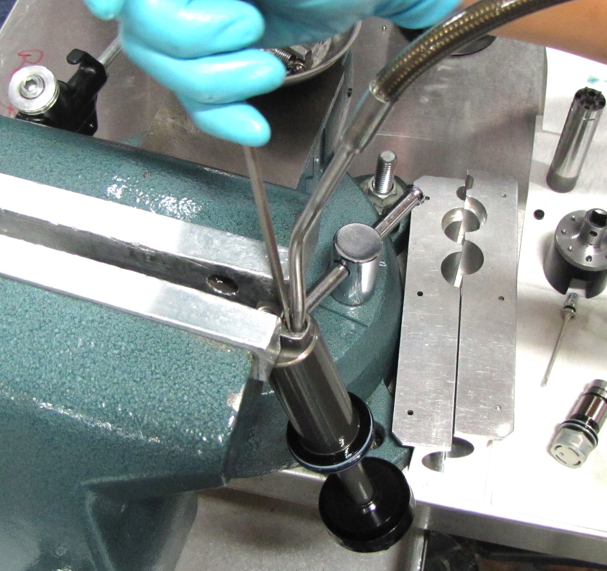
Step 6
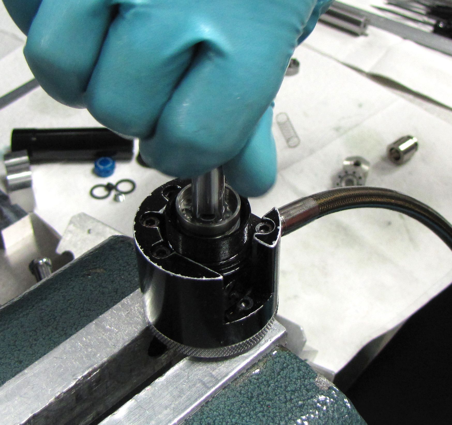
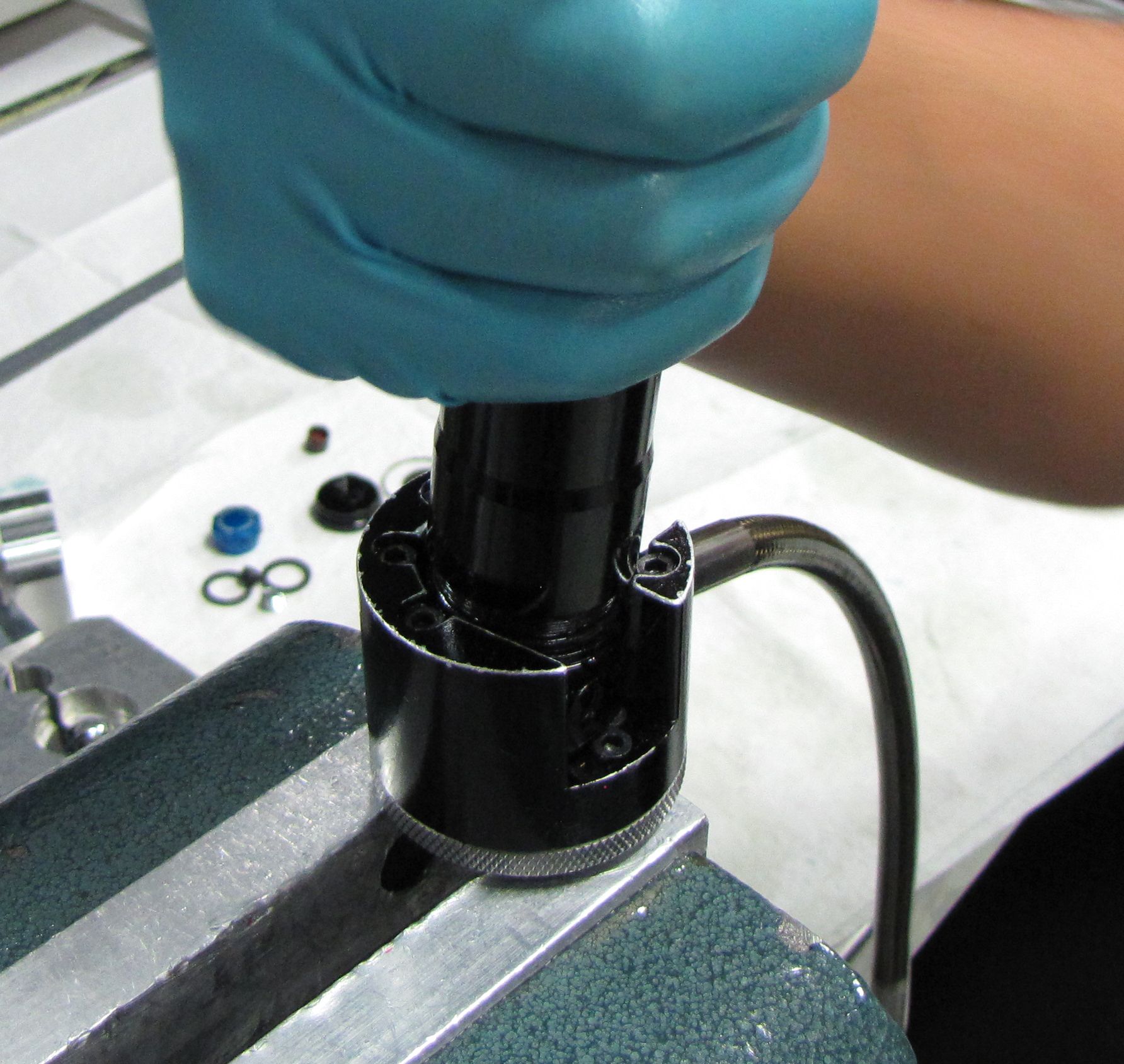
Clamp the Reservoir in the Brain specific shaft clamps (PN: 803-00-383) using the MY14 IV Resi Shaft Clamp Shim (PN: 398-00-627) then use the Resi Torque Socket (PN: 398-00-629) and your ratchet to unthread the Resi Housing and Mount from the Resi body. Separate the Resi Housing and Mount from the Resi Body over your waste oil basin. Remove the IFP from the Reservoir with needle-nosed pliers, then replace its o-ring with a new greased one from the rebuild kit.
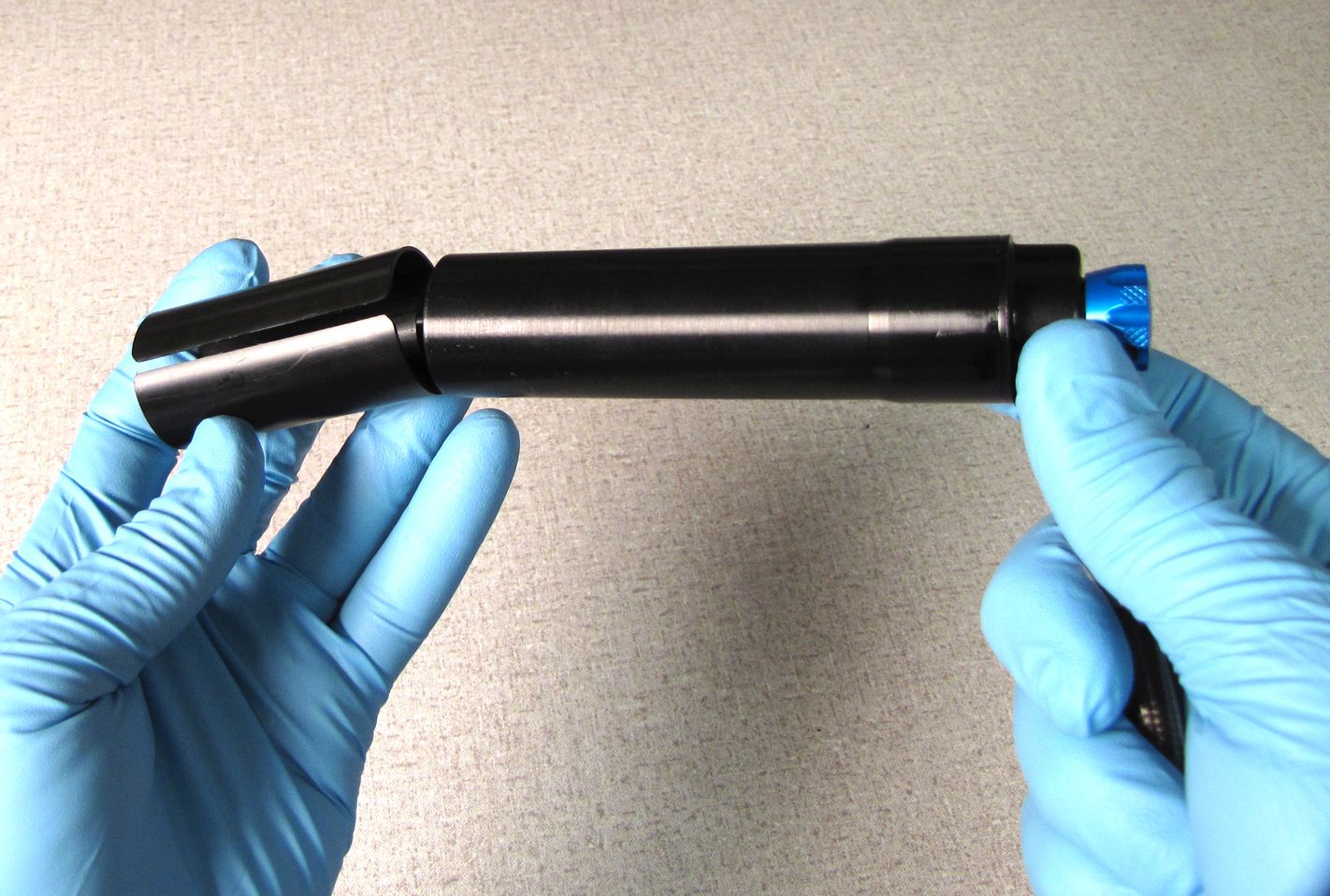
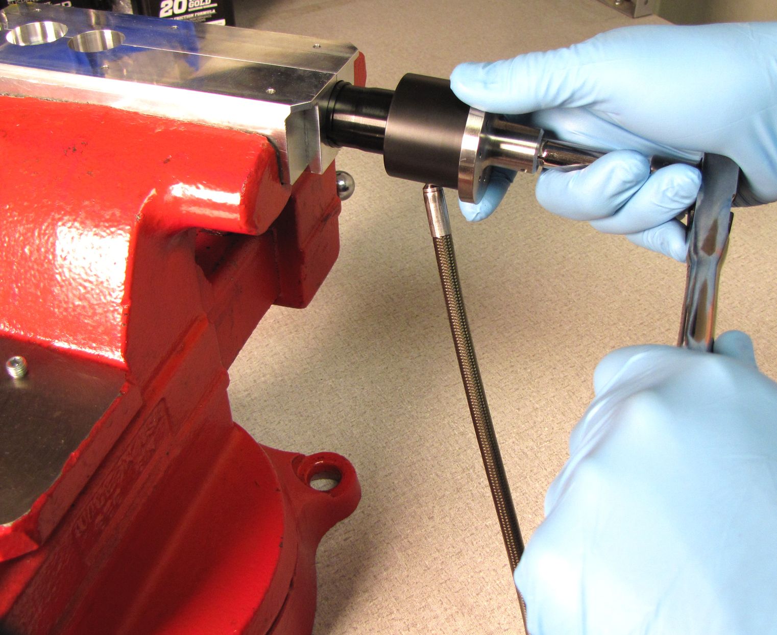
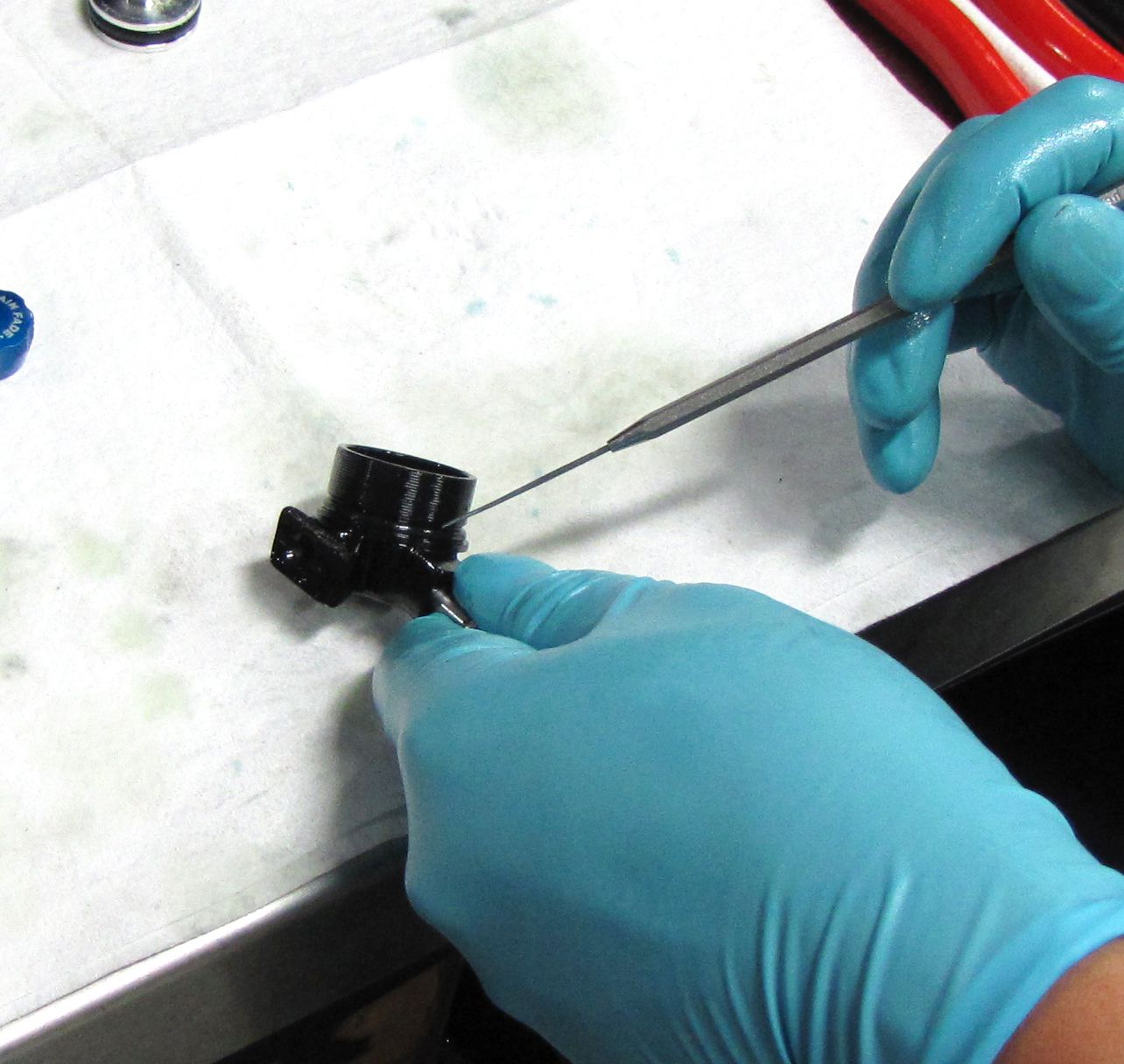
Step 7
Use a 5/64in (2mm) hex wrench to remove the Brain Fade knob. With the Resi Housing and Mount in the Resi Torque Socket, use a 21mm or Knipex smooth-jawed pliers on the Refill Chamber Nut to unthread the assembly. Separate the assembly from the Resi Housing and Mount by pulling them apart over your work bench.

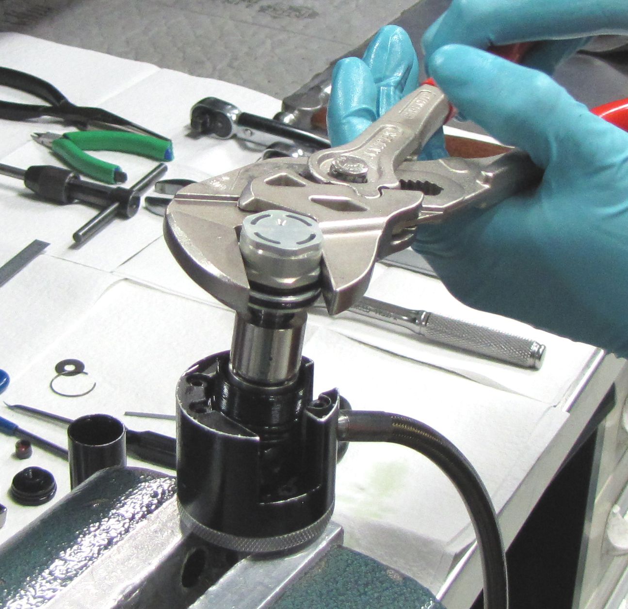
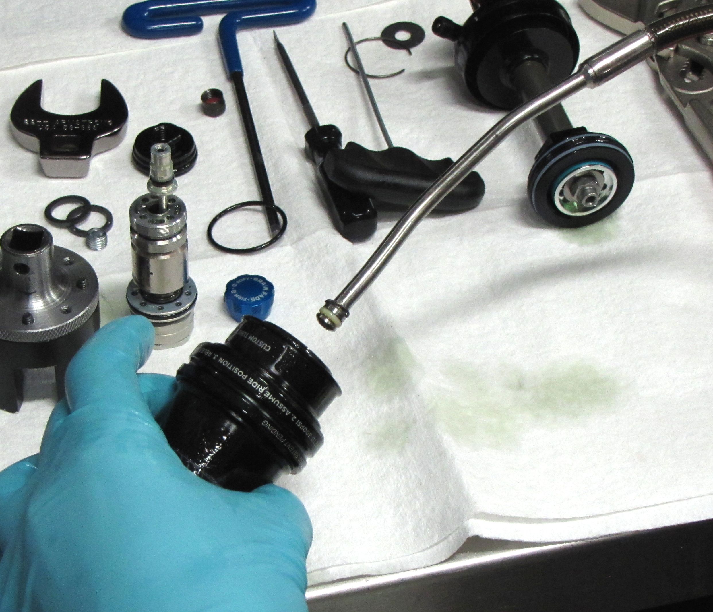
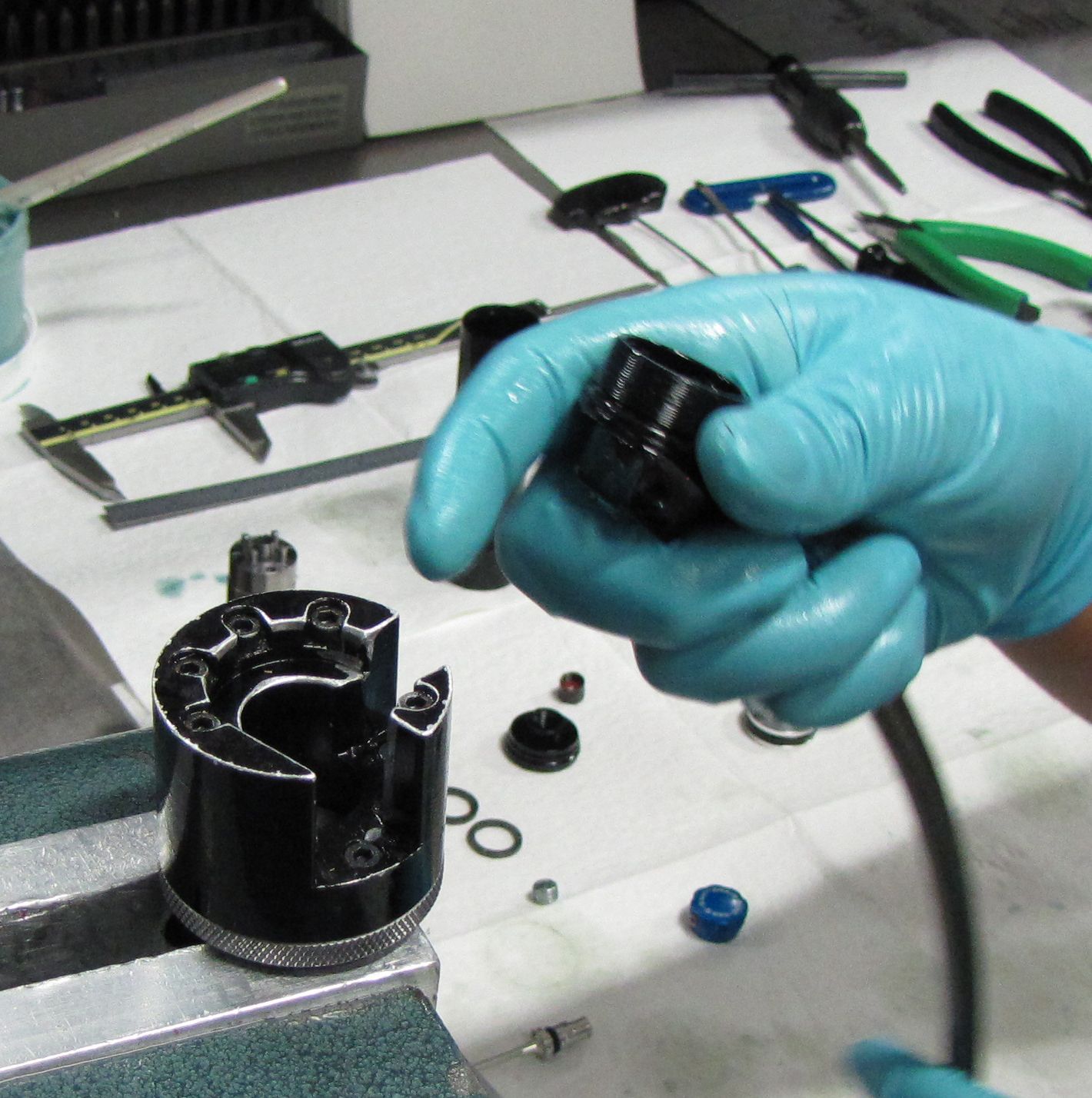
Step 8
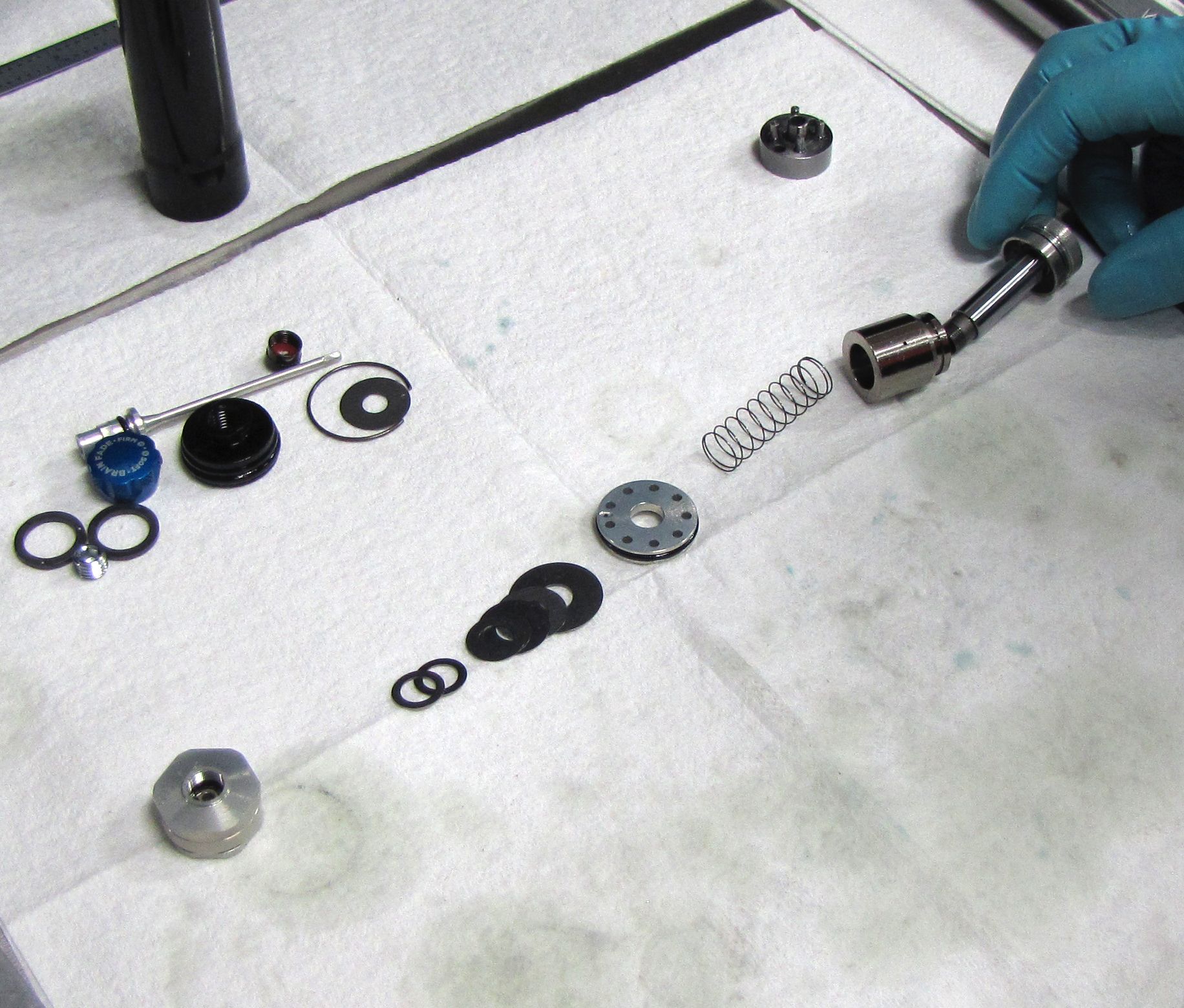
Use the IV Cartridge Disassembly Tool (PN: 398-00-632) and a 21mm wrench or Knipex smooth-jawed pliers on the Refill Chamber Nut to disassemble the IV assembly. Lay out the parts in order.

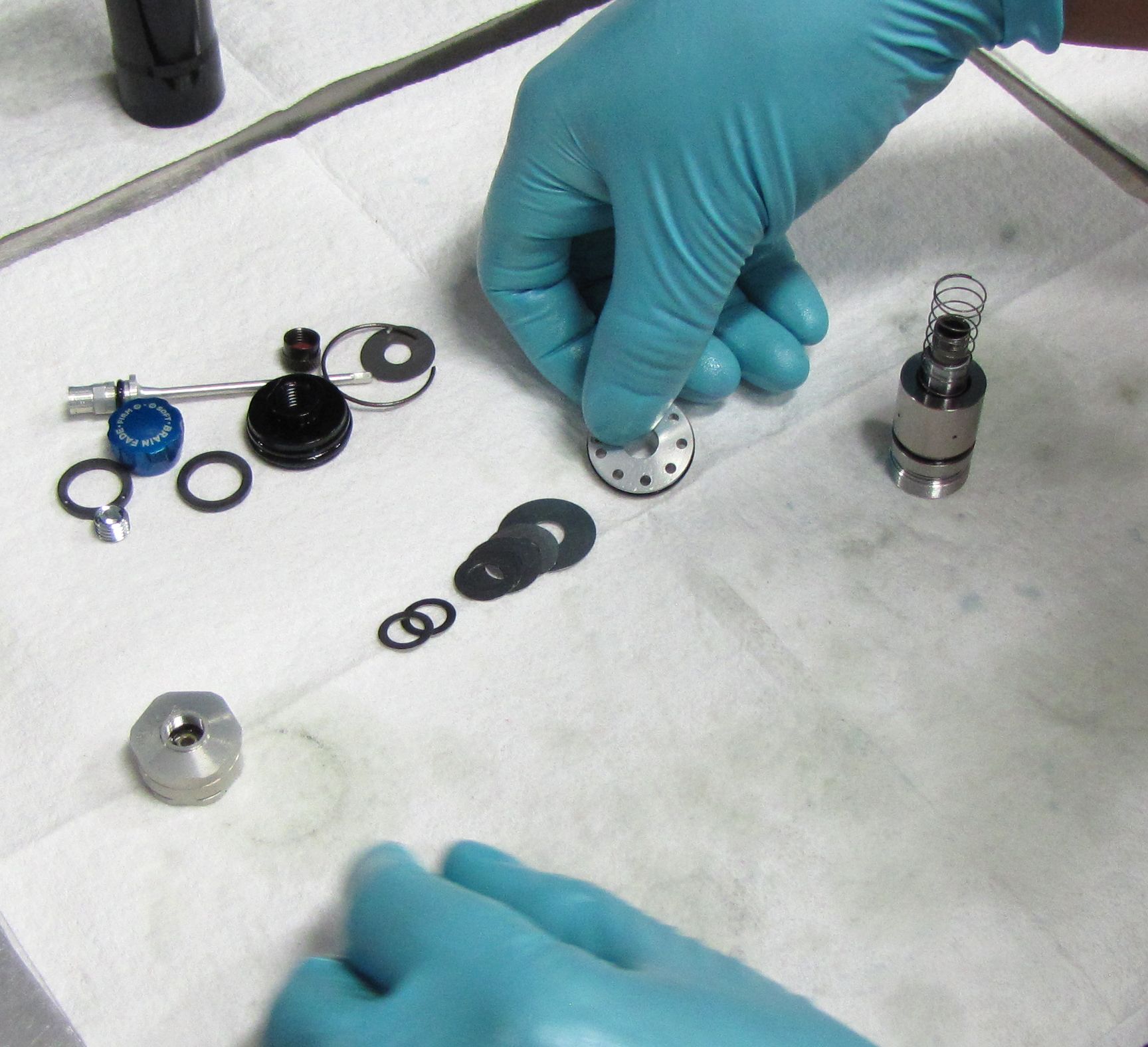
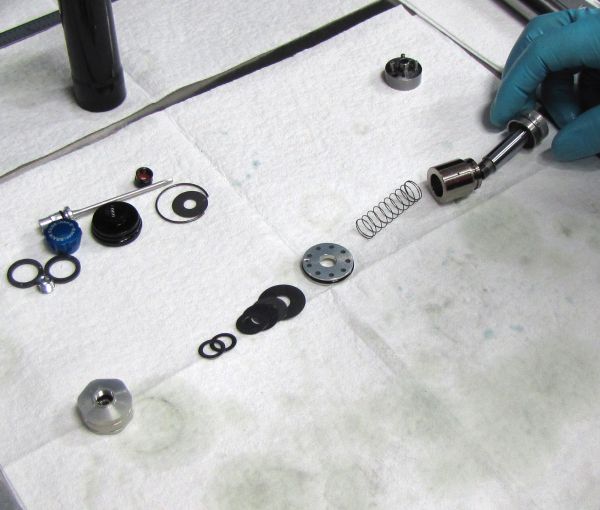
Step 9
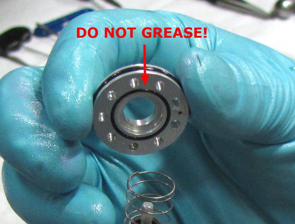
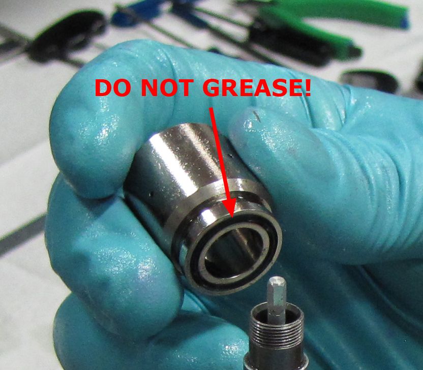
Replace the o-rings on the individual components with new ones from the rebuild kit. As standard practice you should coat all new o-rings with Slick Honey except when directed not to. There are two o-rings in this assembly that SHOULD NOT BE GREASED. The two o-rings that should be installed dry and seated fully and flat are the o-rings in the end of the Inertia Valve and the face of the Reservoir Compression Piston.
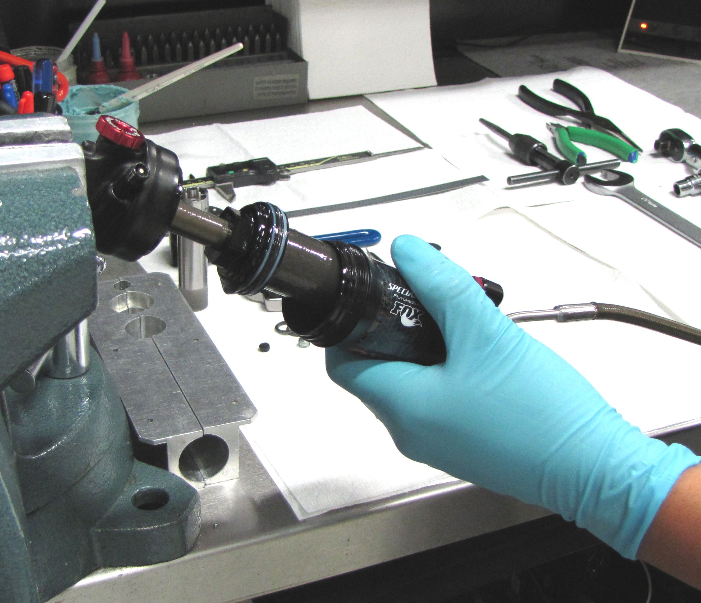
Step 10
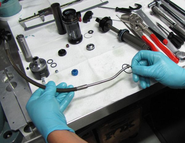
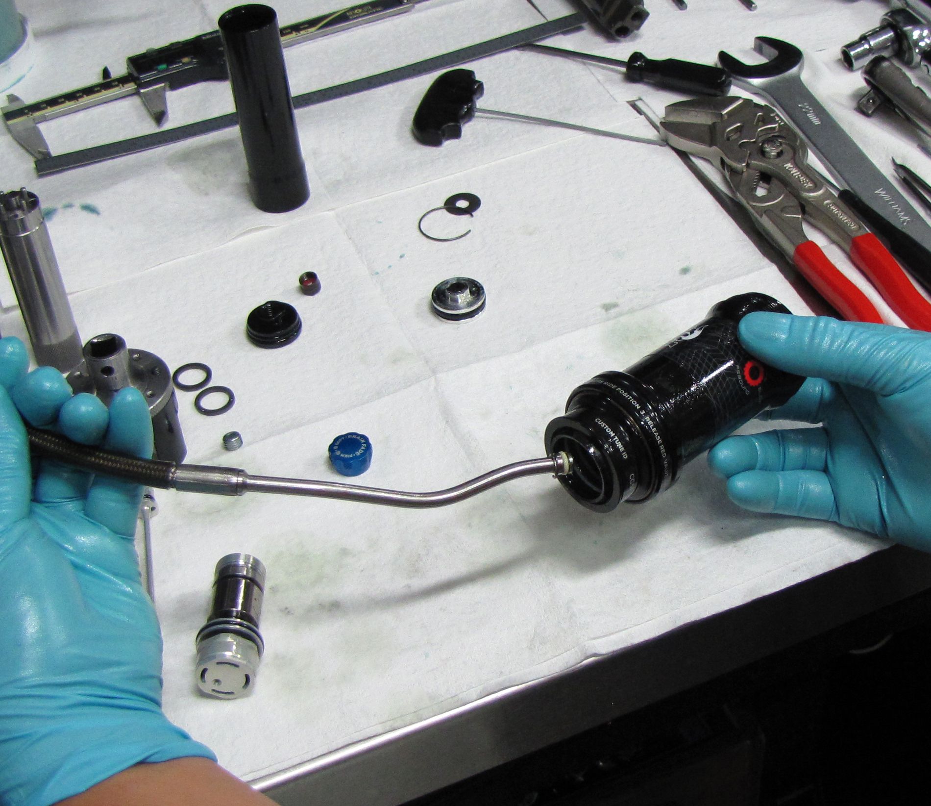
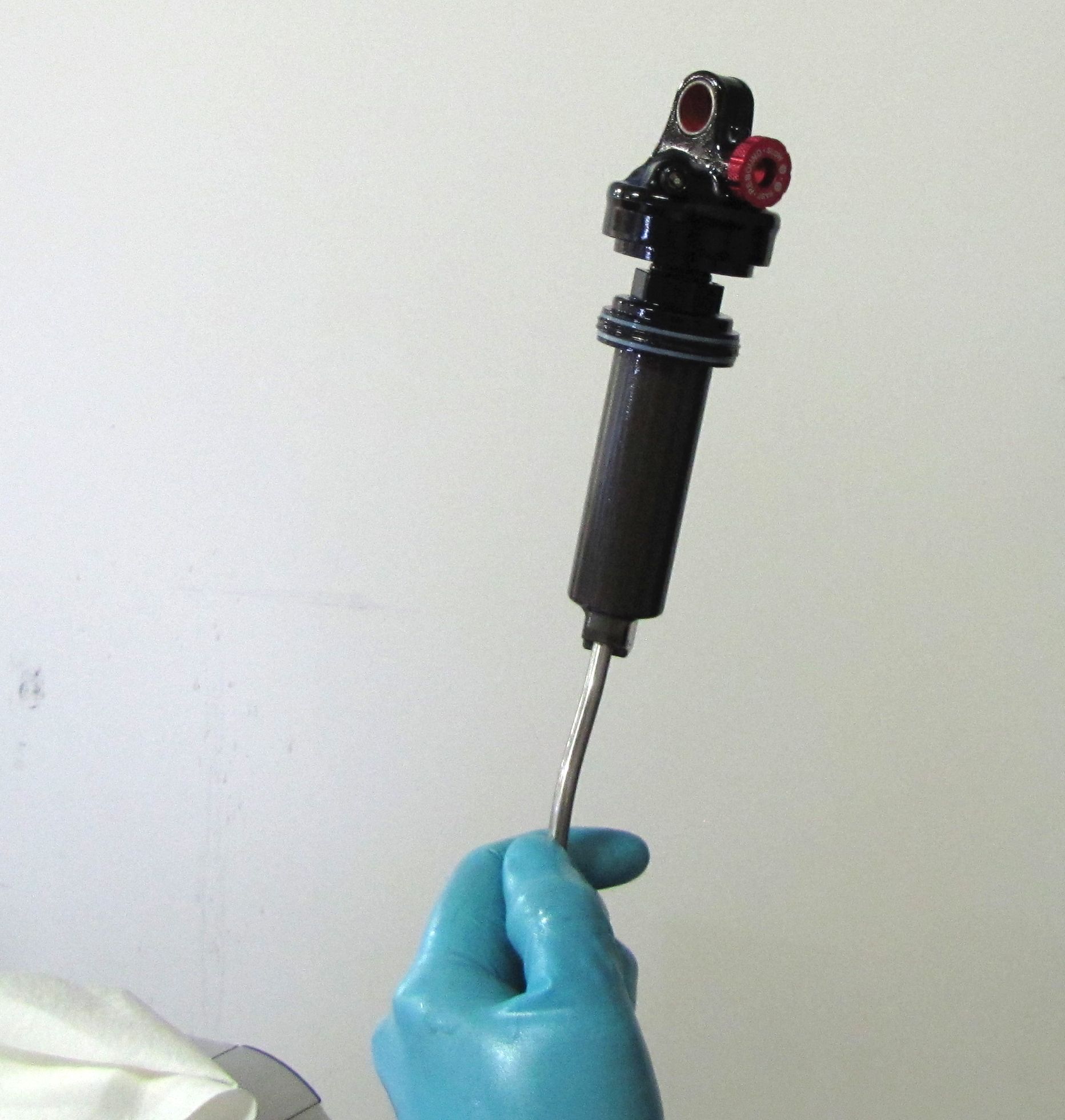
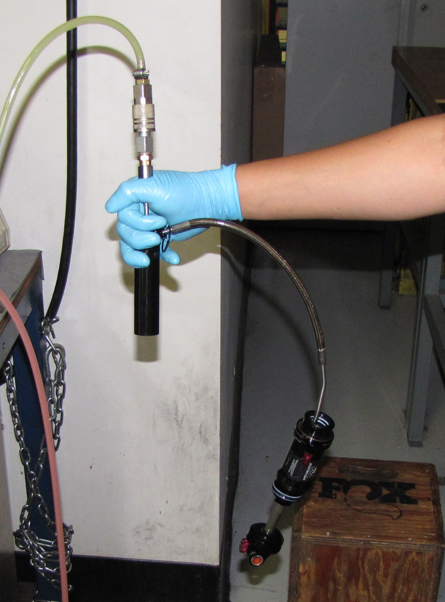
Place the end of the hose with the Resi Housing and Mount still attached above your waste oil basin. With the shock damper upright, cycle the shock a few times to purge most of the damping oil out through the Resi Housing and Mount.

Step 11
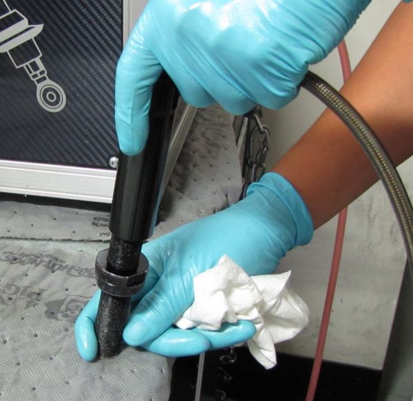
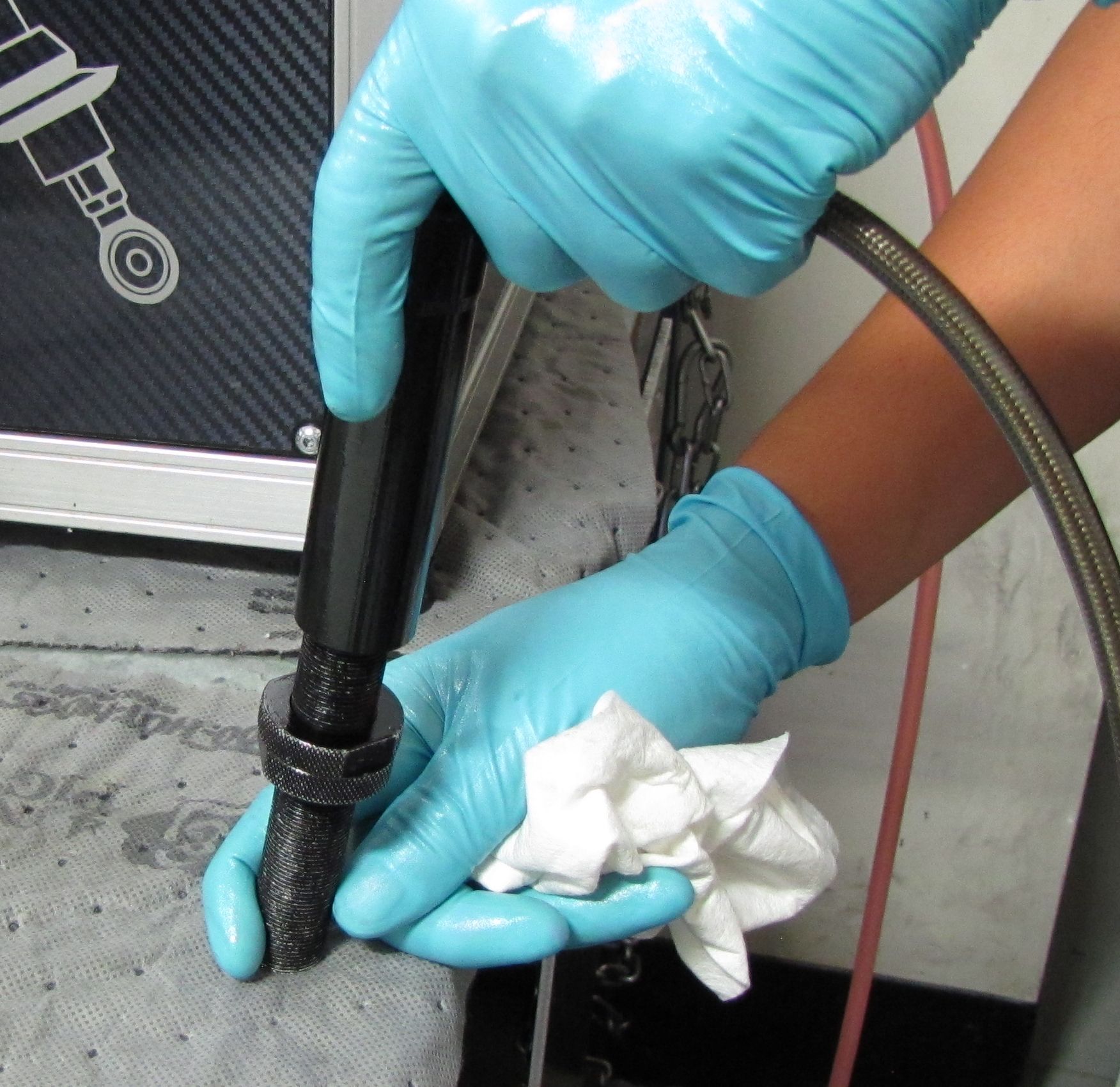
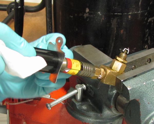
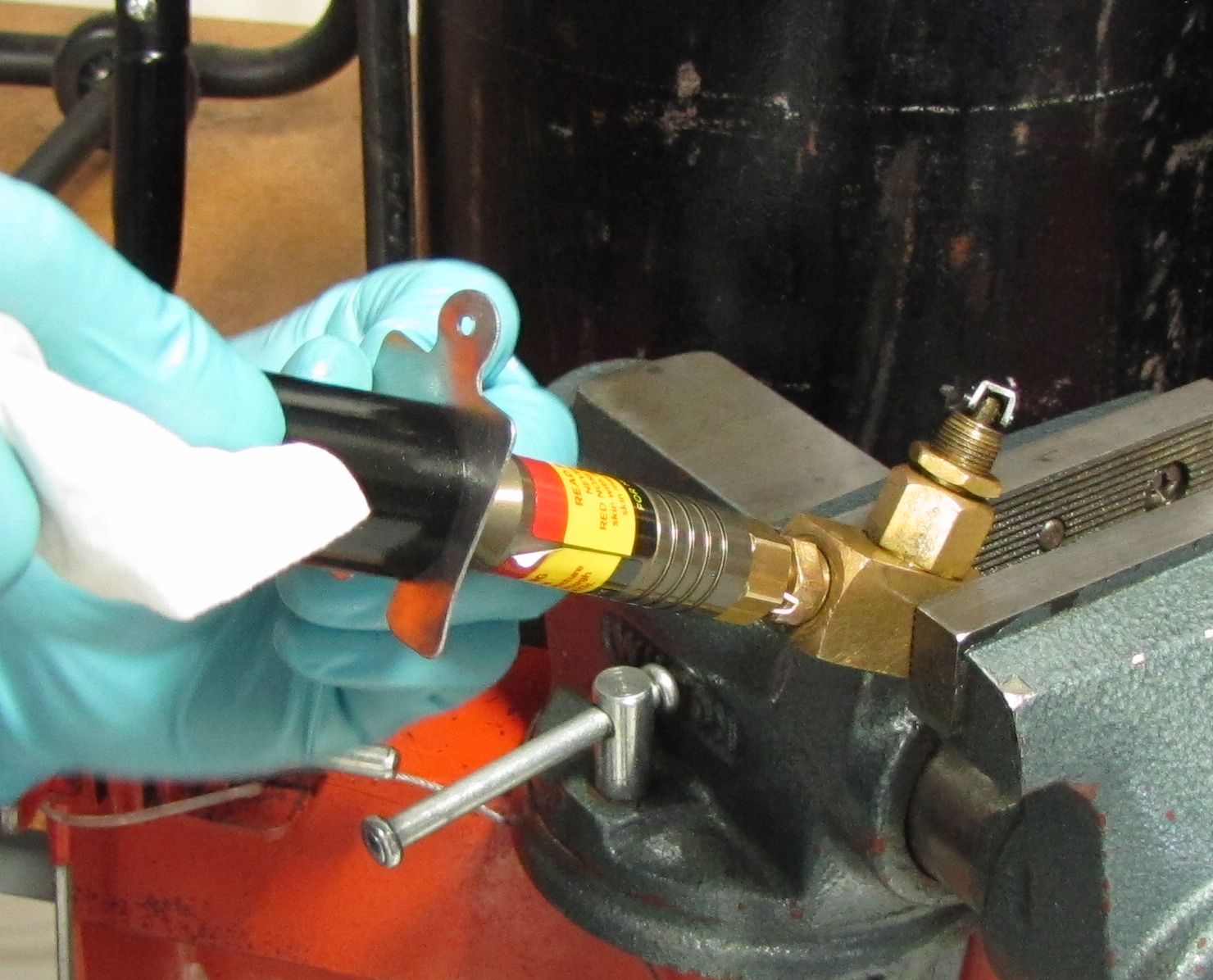
Clamp the body eyelet in your soft-jawed vice, then use a 22mm wrench to unthread the Bearing Assembly.


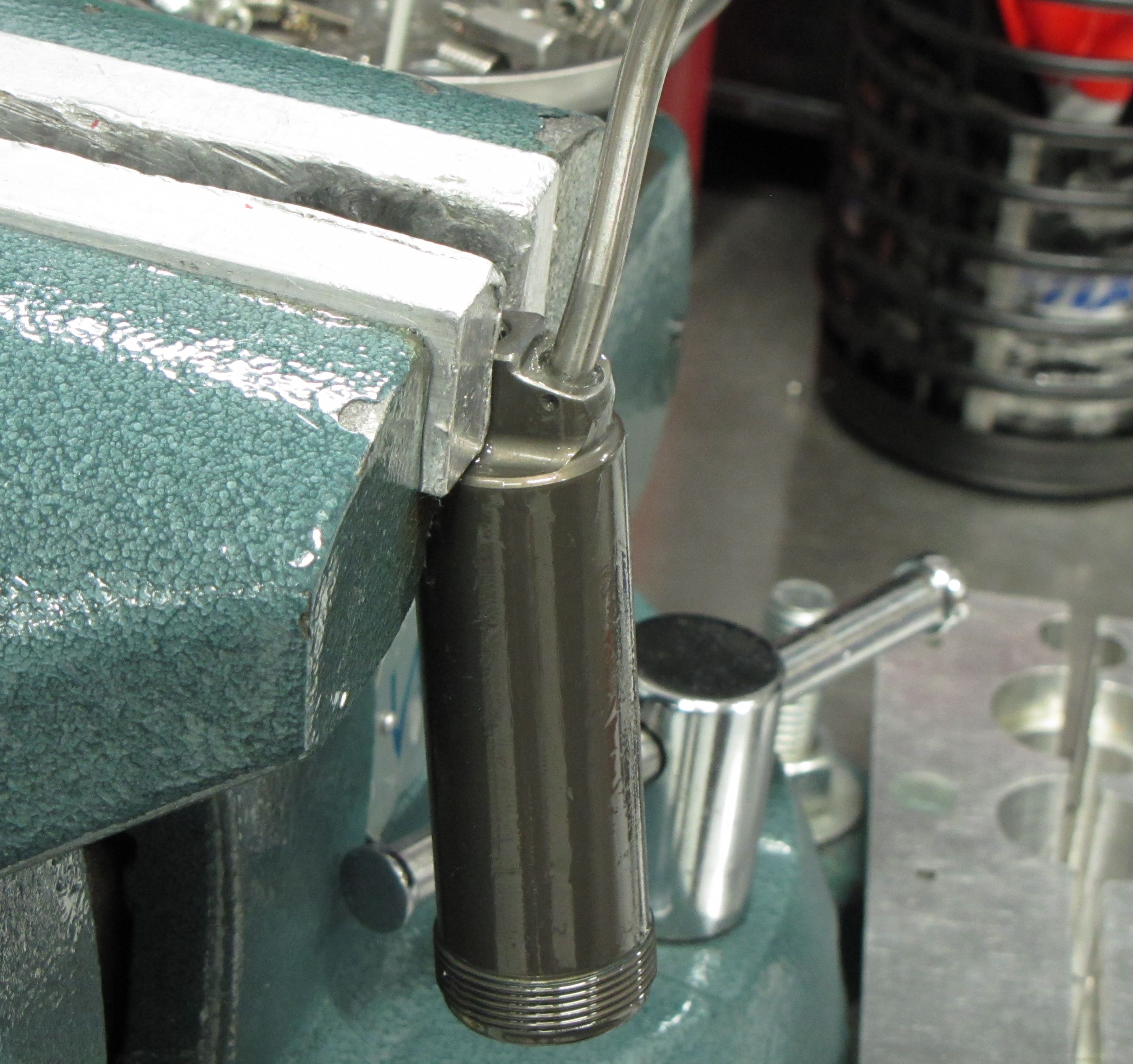
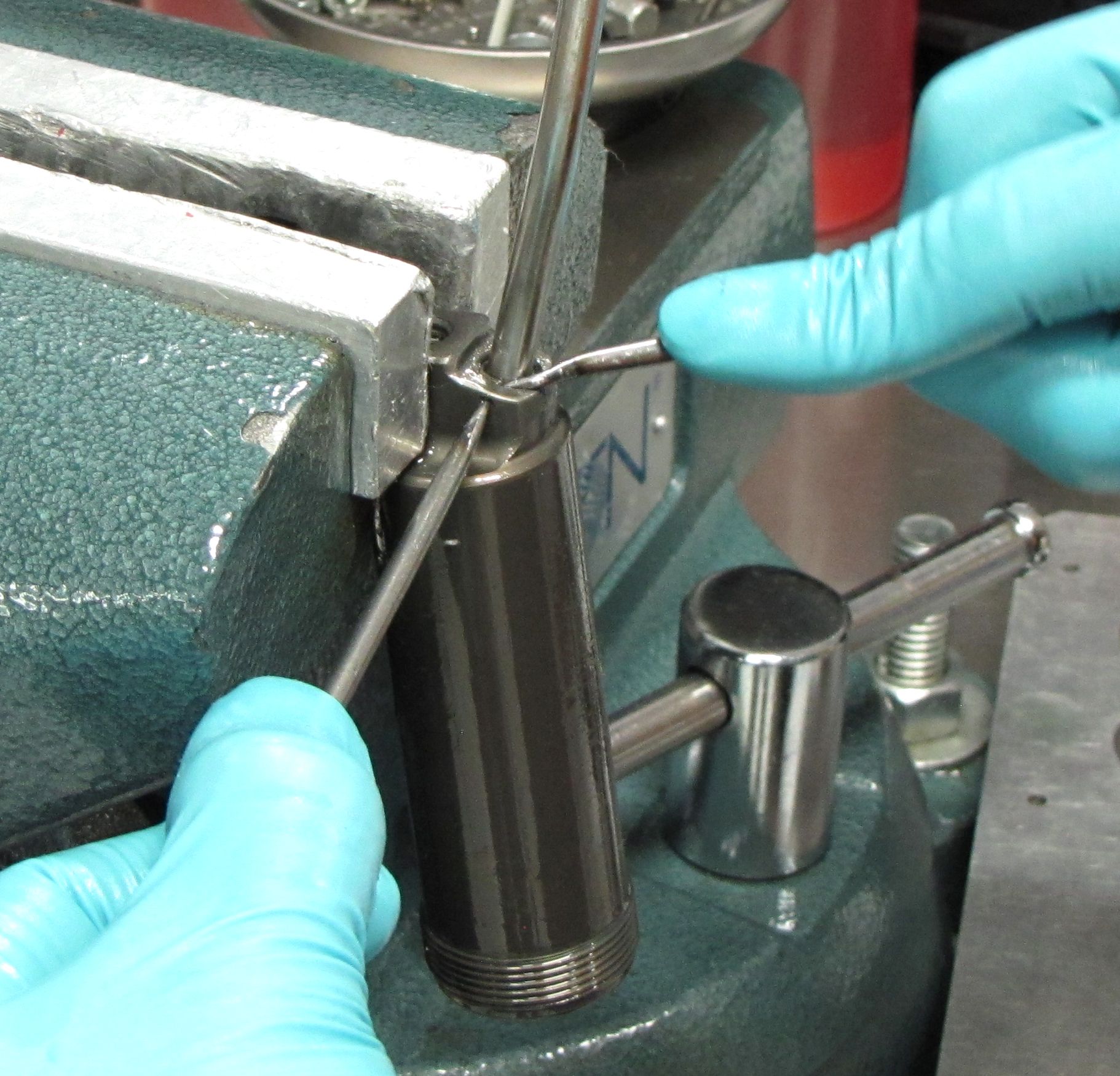
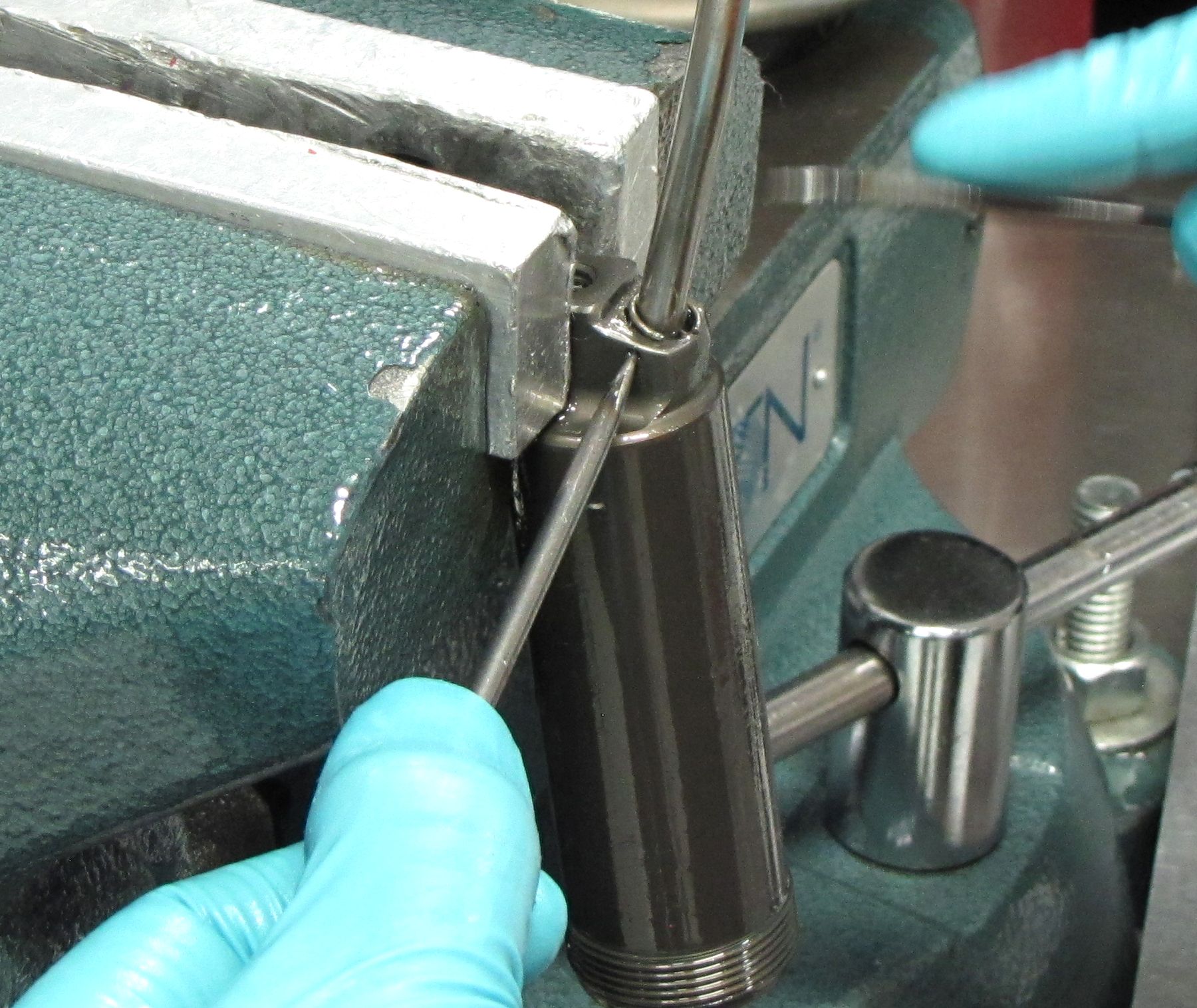
Step 12
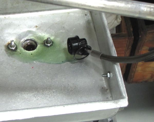
Clamp the strut body in your soft-jawed vice and rotate the small wire ring until the opening in the ring is facing the side of the body that the hose mounts to. Use a pick tool through the hole in the side of the body and a pick tool against the ring itself to lift out the retaining ring. Pull the hose to separate it from the body.

Step 13
Remove the Air Sleeve Assembly from the hose. Replace the air seals in the air sleeve with new greased replacements from the Air Sleeve Rebuild kit (PN: 803-00-142).
Eyelet and Shaft Disassembly

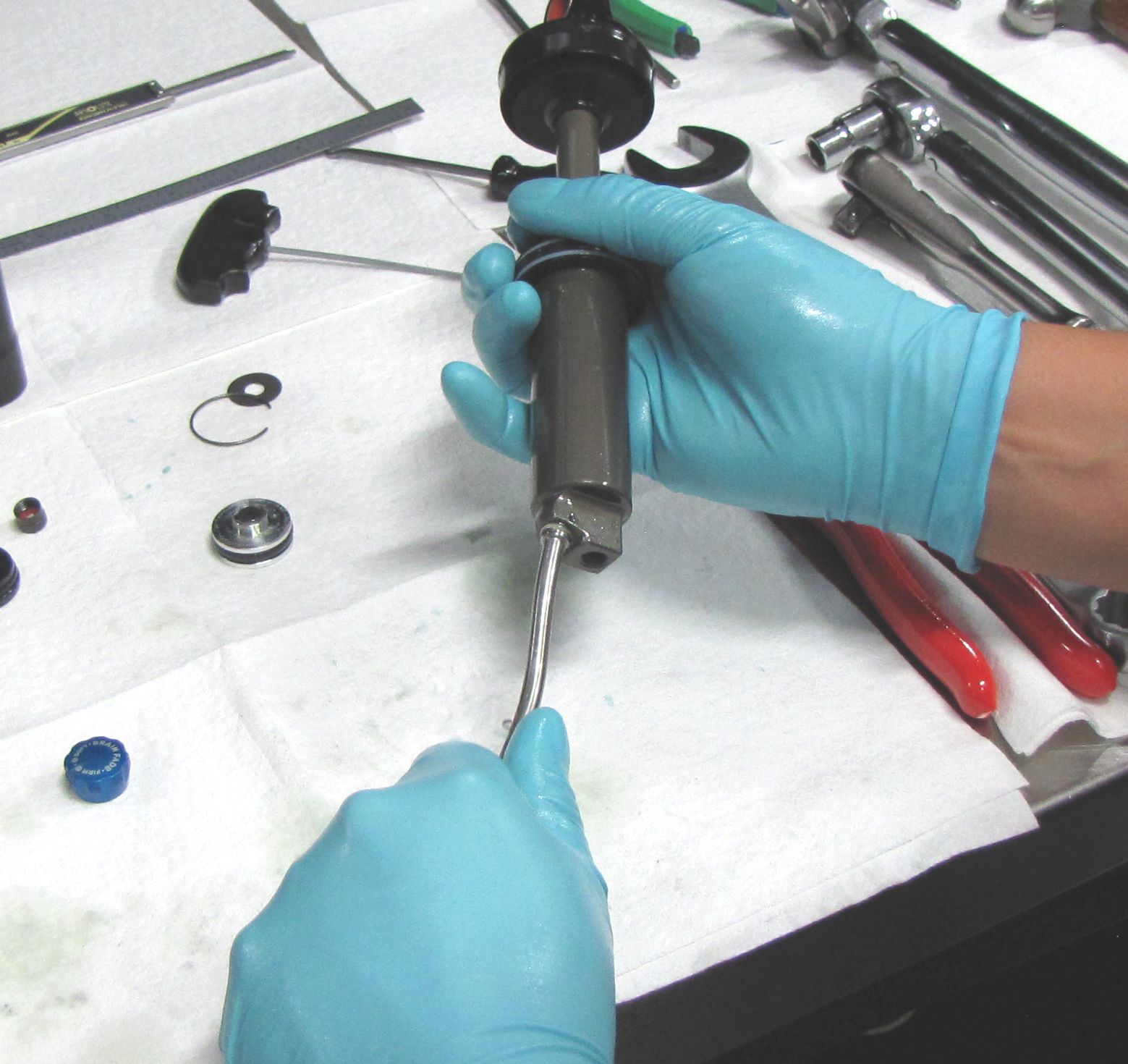
Step 1
Use a 3/8in socket to unthread the Piston Bolt. Keep the valving assembly in order as you remove it from the shaft assembly. Replace the blue glide ring on the valving assembly with the new one from the rebuild kit.

Step 2
Remove the Body Bearing Assembly by pulling it off of the shaft. Replace the shaft o-ring and body o-ring with greased replacement parts from the rebuild kit. Replace the main air seal and back-up rings with greased ones from the air sleeve rebuild kit (PN: 803-00-142).
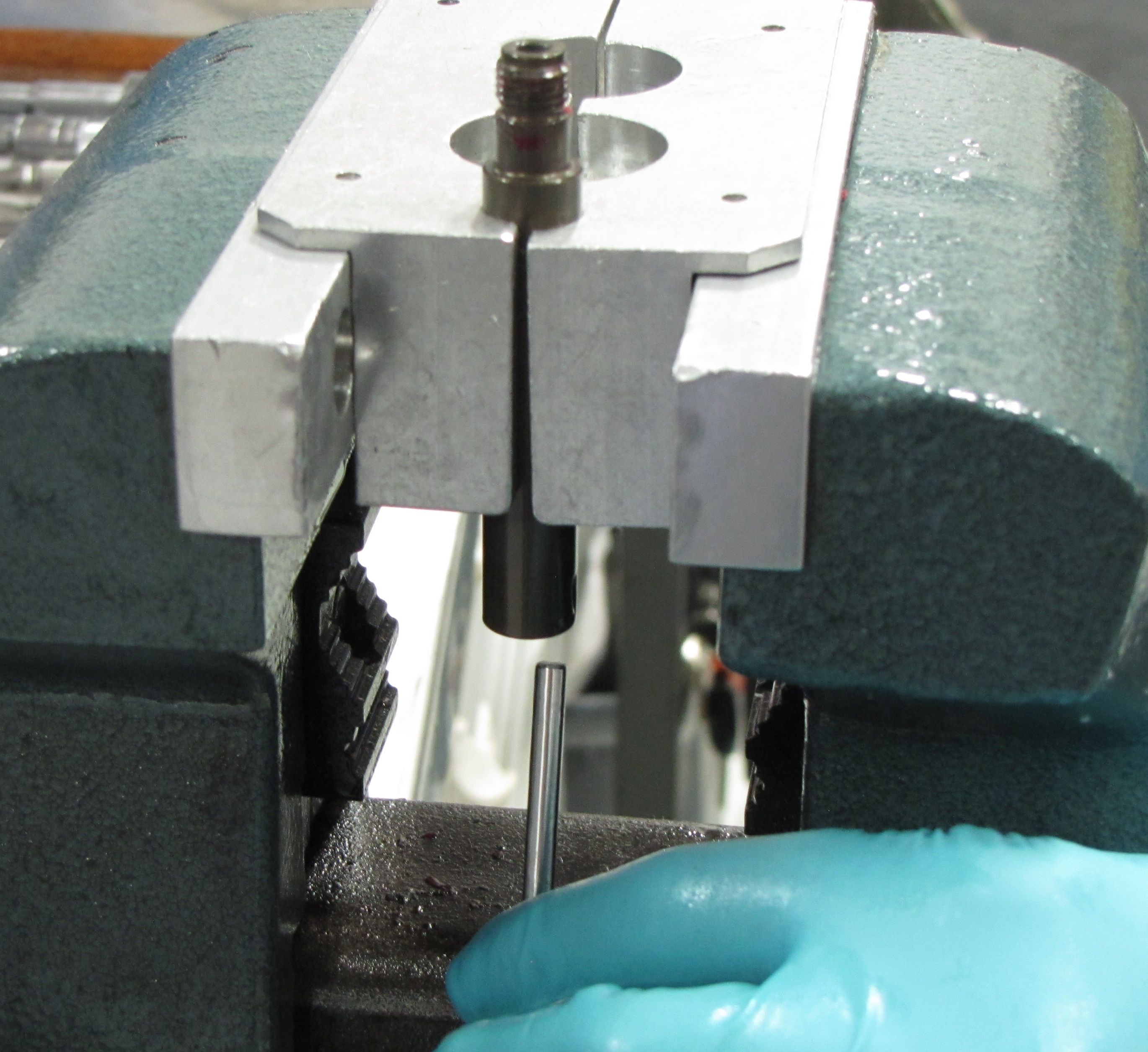
Step 3
Remove the bottom out o-ring then clamp the shaft and unthread the Eyelet Assembly from the shaft (counter-clockwise).

Step 4
Remove the Volume and Travel Spacer and o-ring from the shaft. Use a small tool to push the Metering Rod down and out through the bottom of the shaft.

Step 5
Replace the o-ring inside the end of the shaft with a new greased one from the rebuild kit. Replace the two o-rings inside the Eyelet Assembly with new greased ones from the kit.

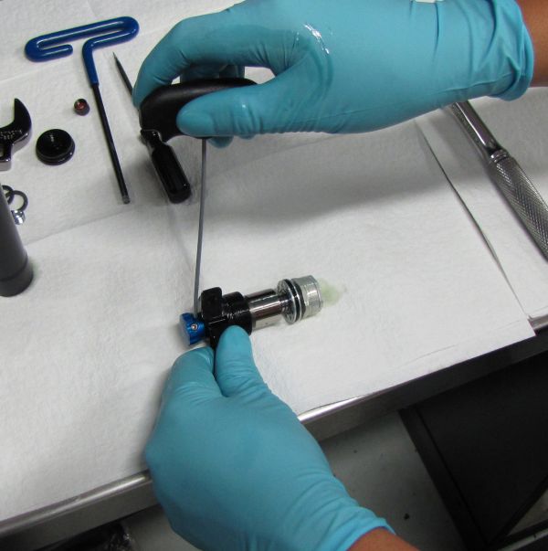
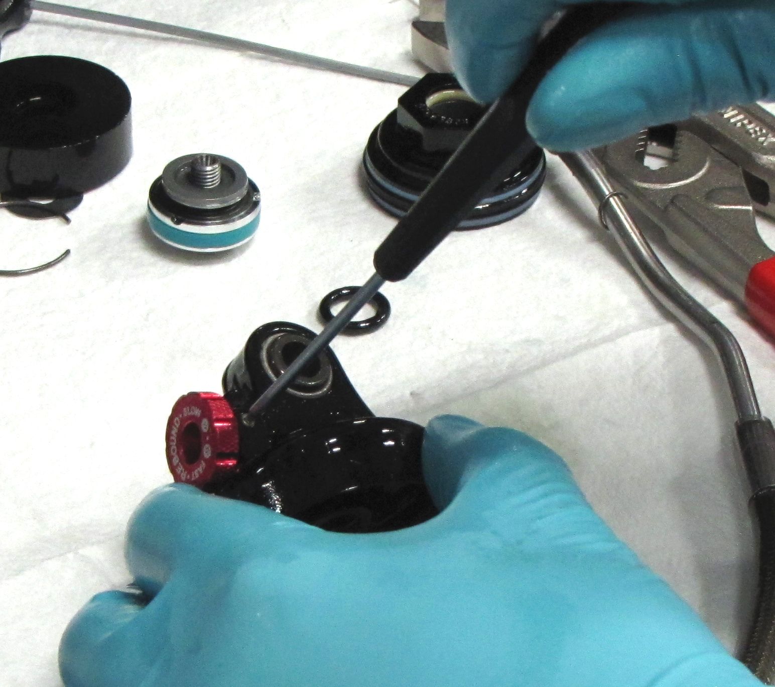
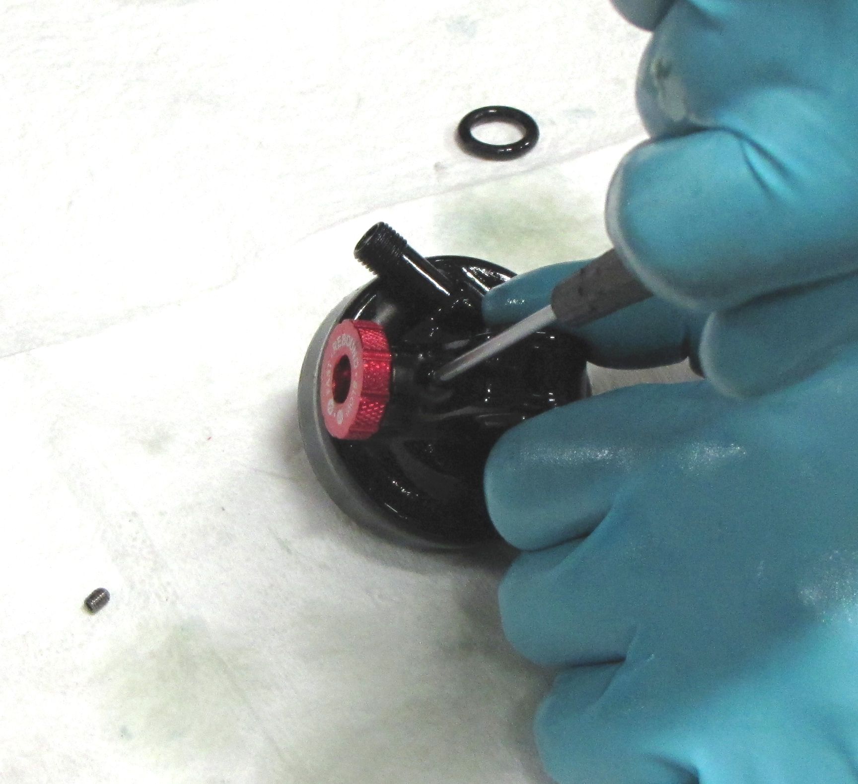
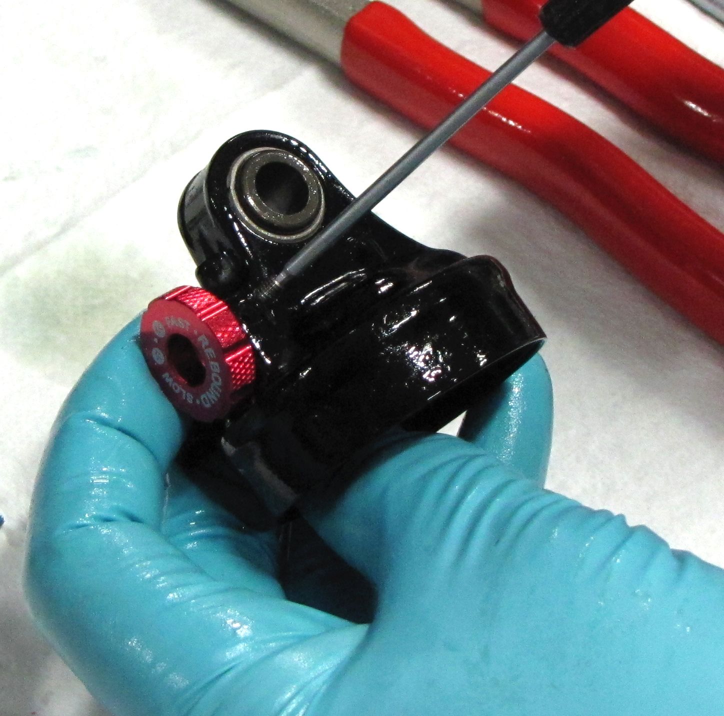
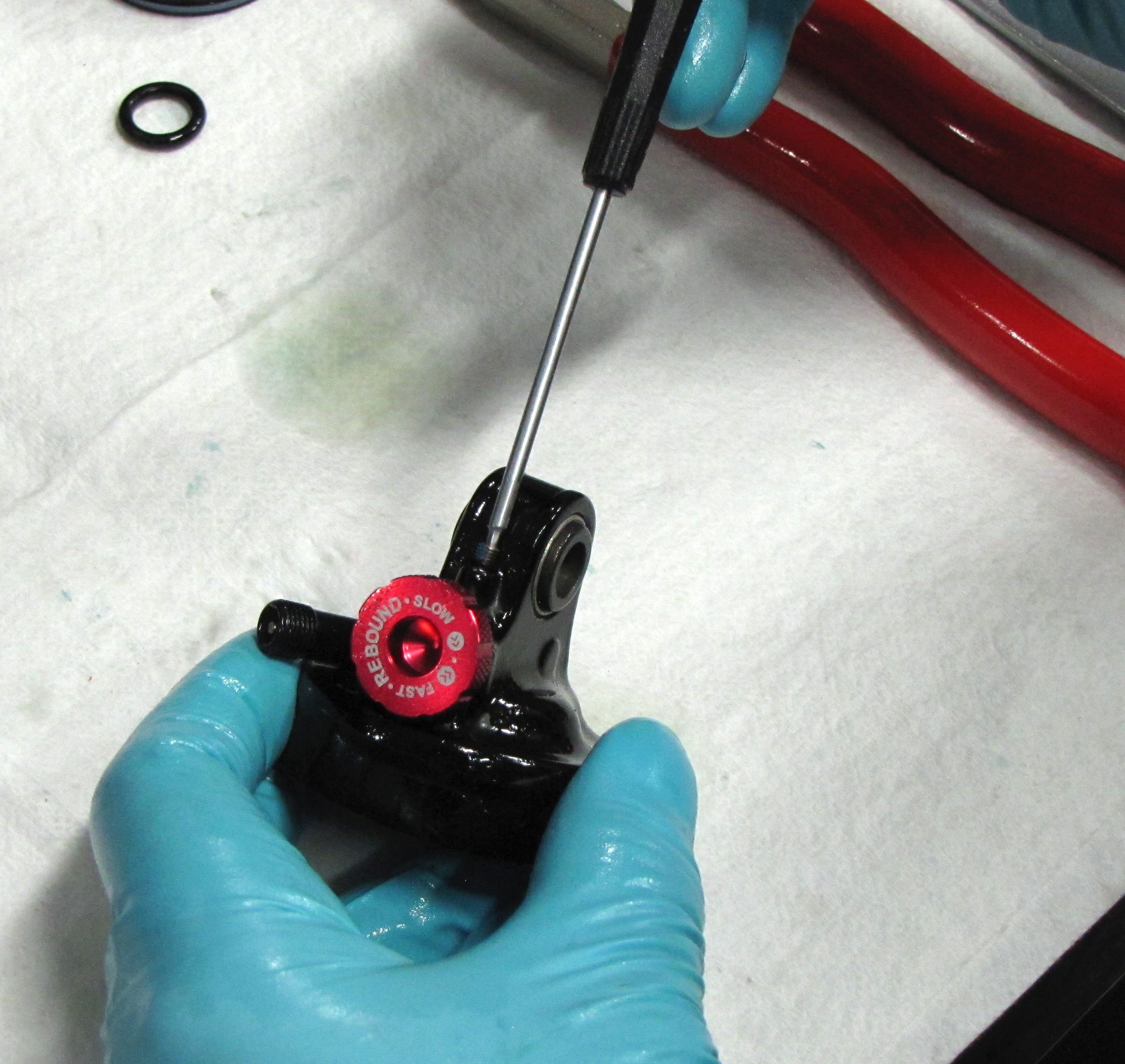
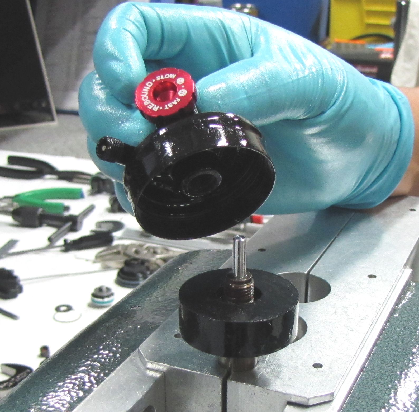
Step 6
Use a 1.5mm hex wrench to remove the set screw that retains the red Rebound Knob from the side of the Eyelet Assembly. Use a 1.5mm hex wrench to remove the set screw from above the red Rebound Knob. Remove the detent spring and ball bearing and set aside.
Eyelet and Shaft Assembly
Step 1
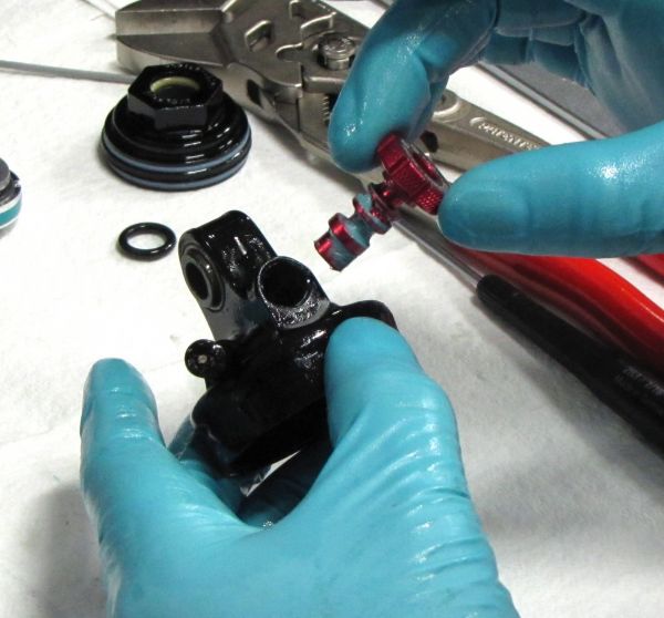
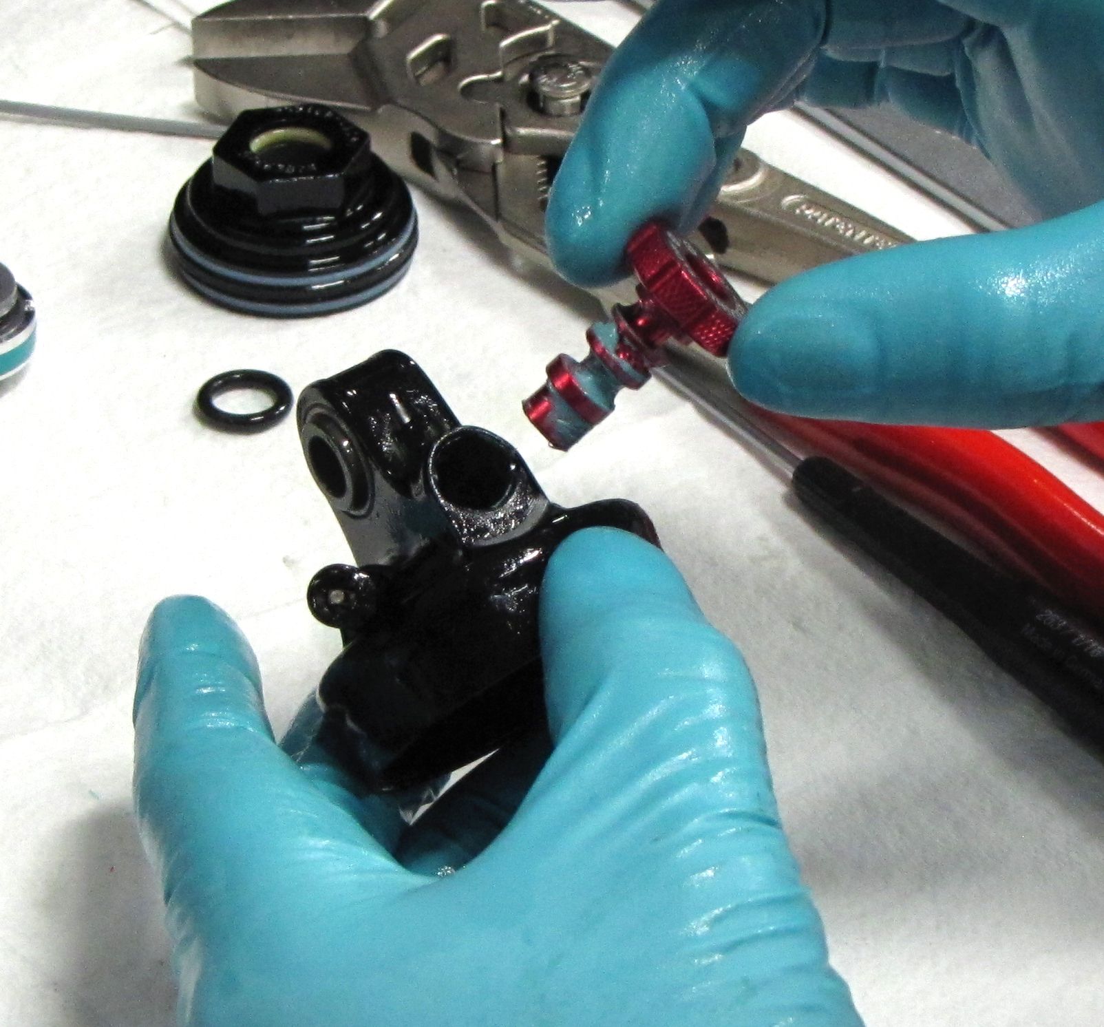
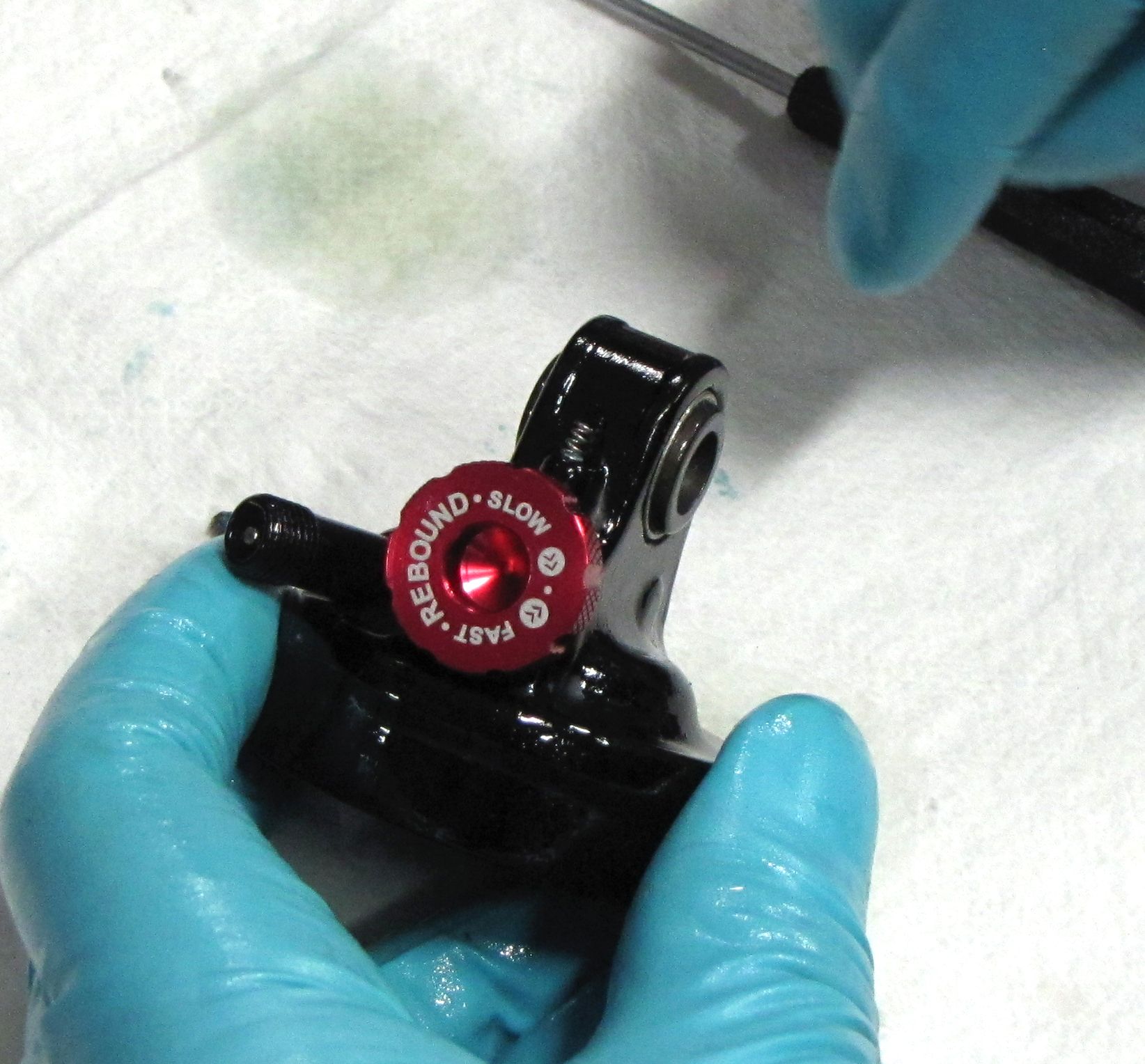
Coat the Rebound Knob with a film of Hi-Temp grease (such as Sta-Lube SL3125 or similar). Insert the Rebound Knob into the Eyelet then install the set screw into the side of the eyelet with a 1.5mm hex wrench. Thread the set screw in until it gently touches the Rebound Knob, then back it off 1/4 turn.
Step 2
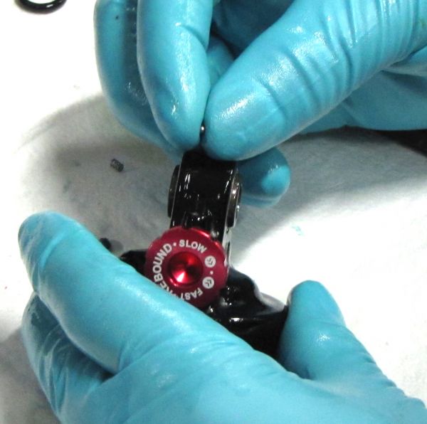
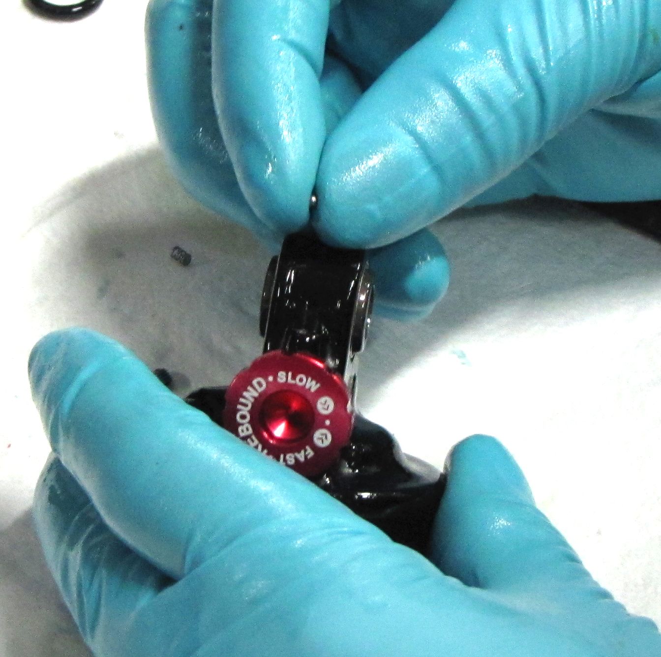
Drop the rebound detent ball into the hole in the top of the Eyelet Assembly followed by the detent spring. Install the set screw with a 1.5mm hex wrench until 1/2 to 1 turn past flush and you feel a good detent click when turning the red Rebound Knob.
Turn the red rebound knob fully counter clockwise, then set aside.
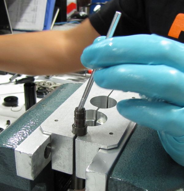
Step 3
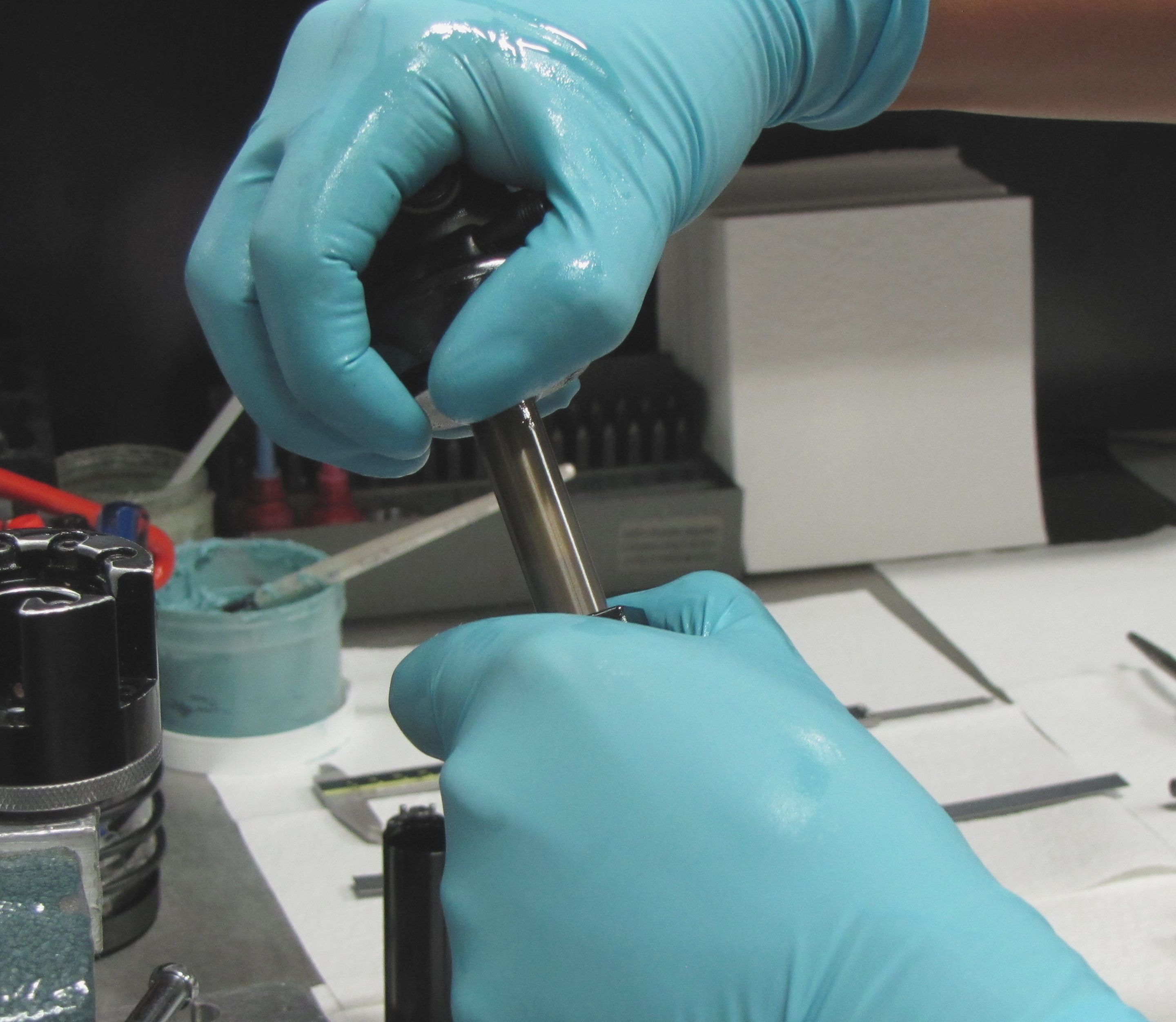
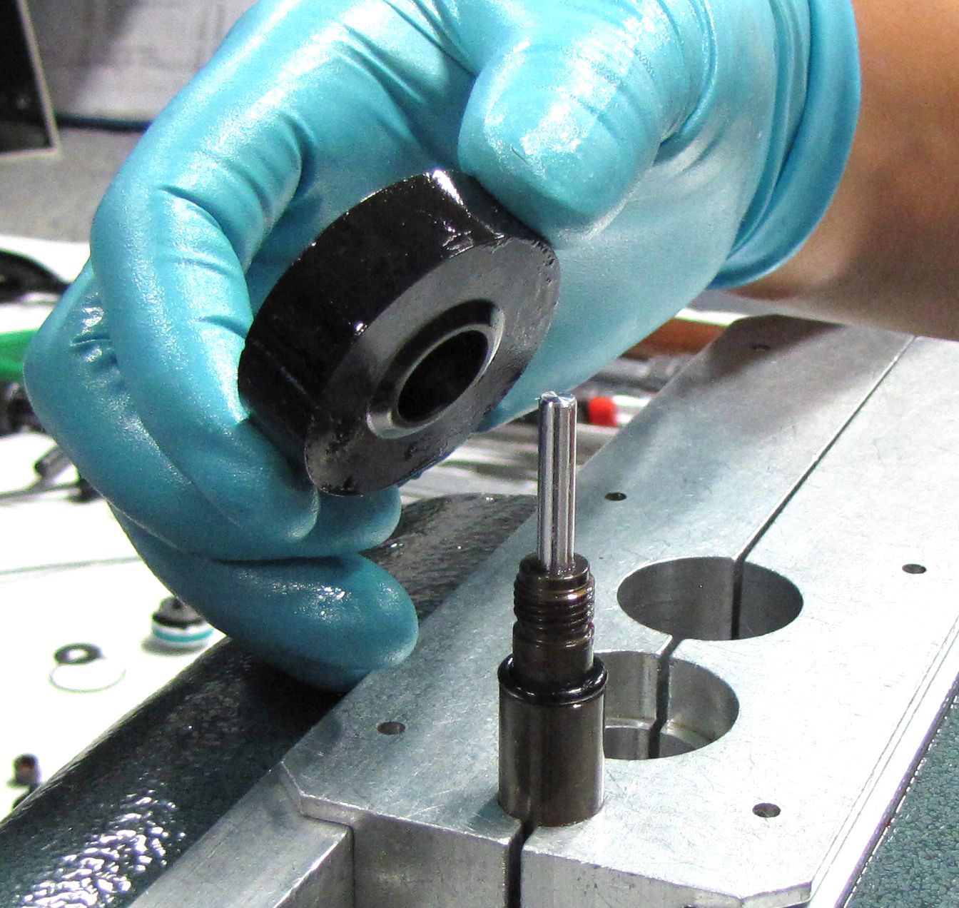
Apply a thin film of Slick Honey to the Metering Rod and carefully insert it into the shaft leaving approximately 1in (25mm) sticking up above the end of the shaft. Install a new greased shaft o-ring from the rebuild kit, then install the Volume and Travel Spacer with its convex side oriented down toward the shaft.


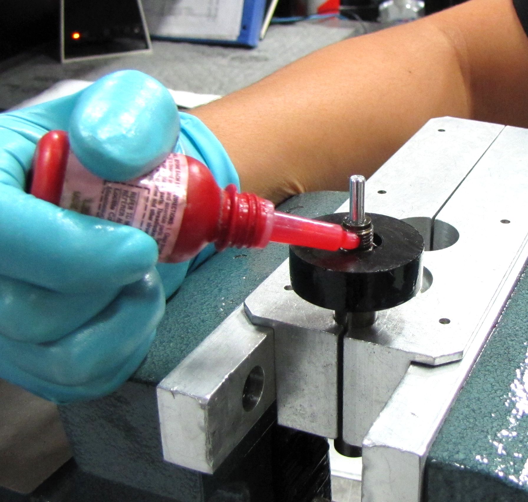
Step 4
Apply one drop of Red Loctite 277 to the shaft threads. Install the Eyelet Assembly onto the shaft making sure that the Metering Rod contacts the red Rebound Knob. Thread the Eyelet Assembly onto the shaft and torque to 110 in-lb (12.4 Nm) using the Eyelet Torque Tool (PN: 398-00-280).
Step 5
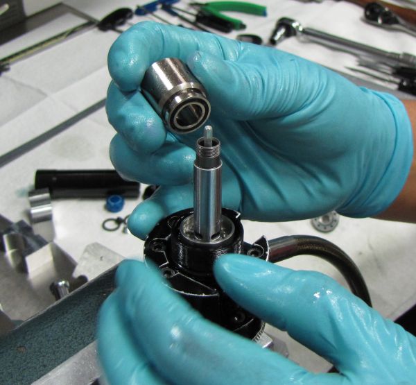
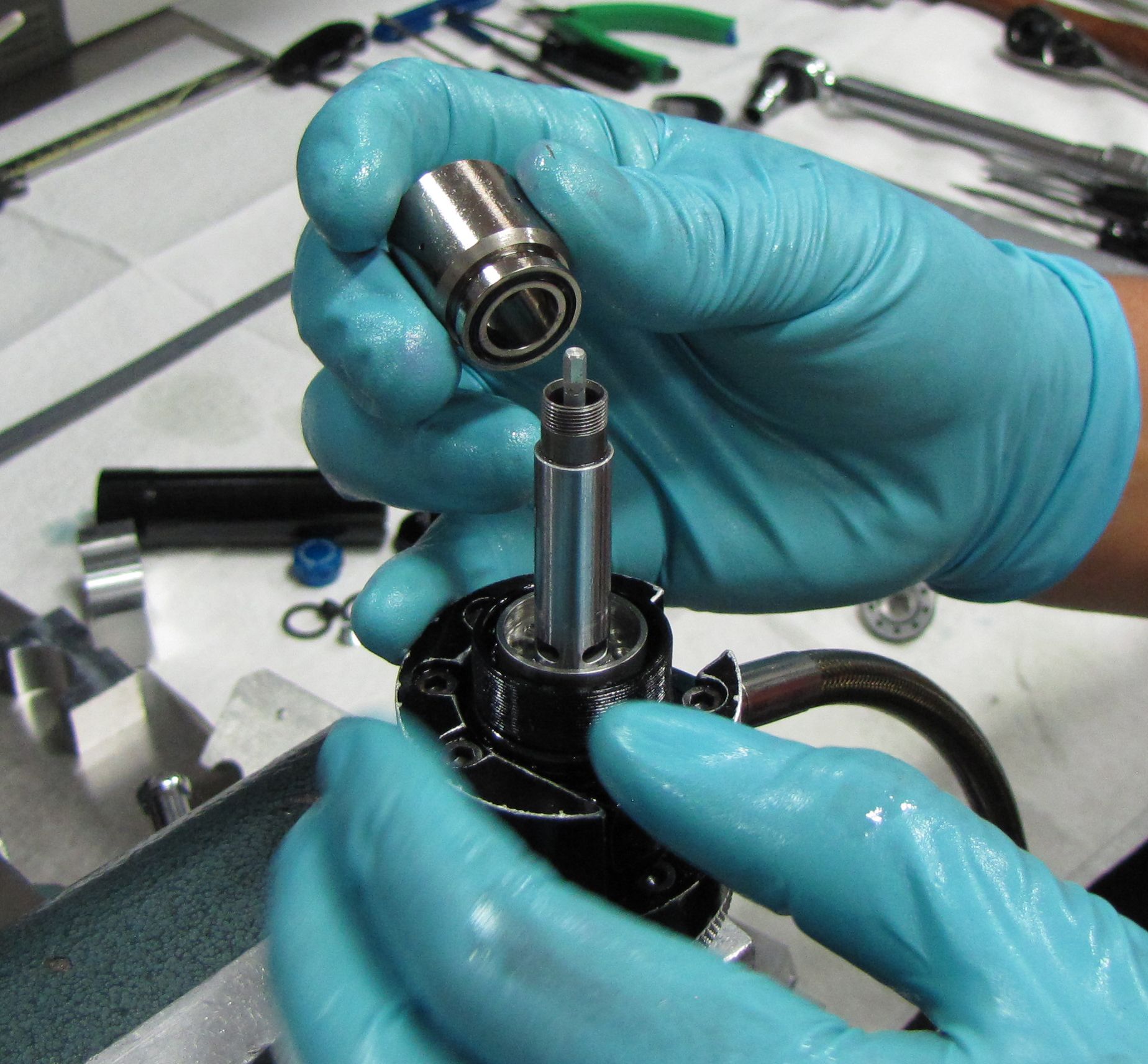
Install a new greased bottom out o-ring onto the shaft followed by the rebuilt Bearing Assembly.


Step 6
Install the Valving Assembly onto the shaft. Use a 3/8in socket to torque the Piston Bolt to 75 in-lb (8.5 Nm).
Final Assembly

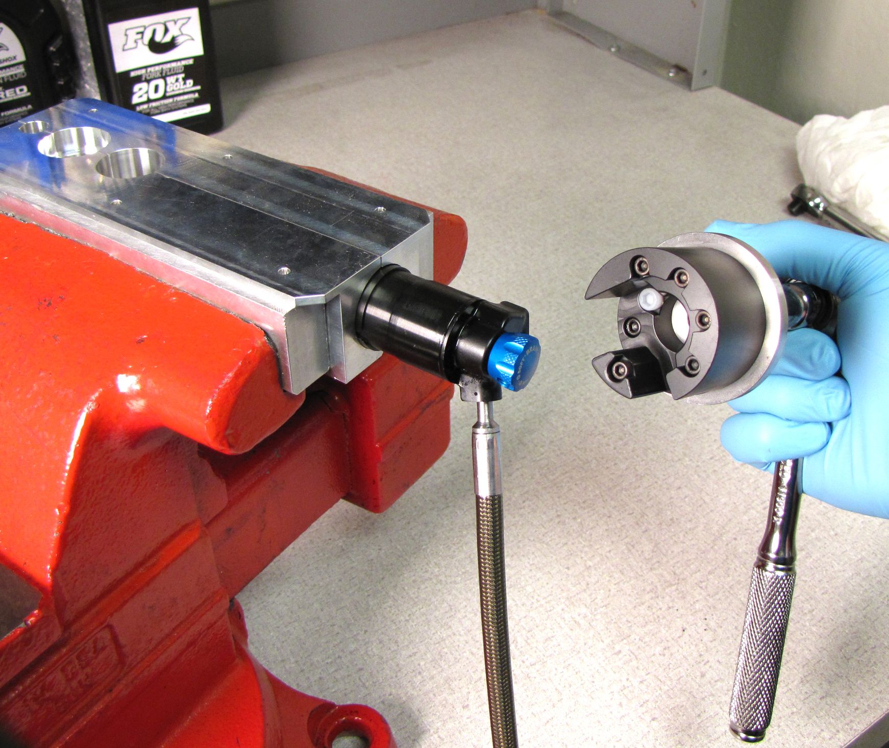
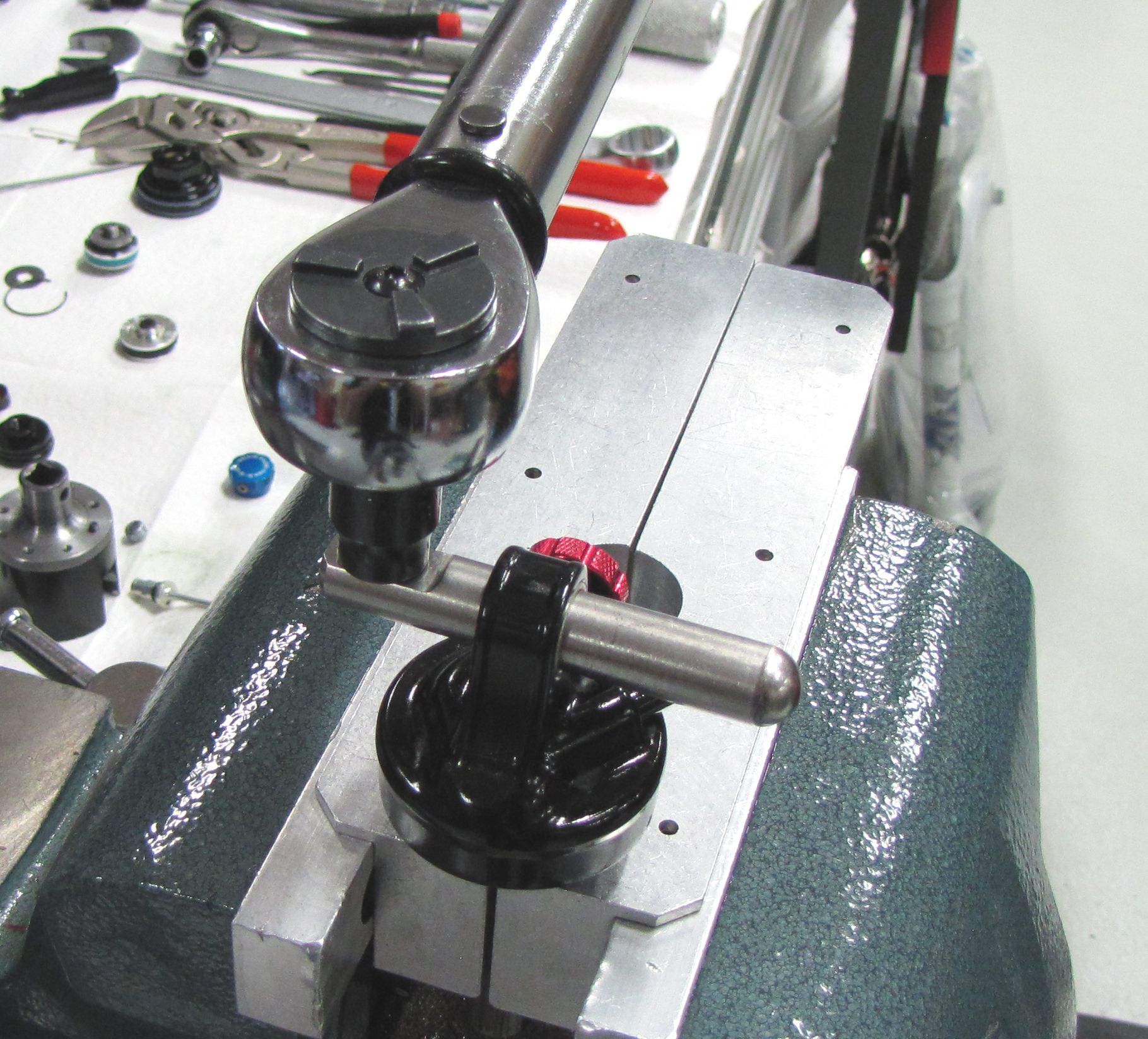
Step 1
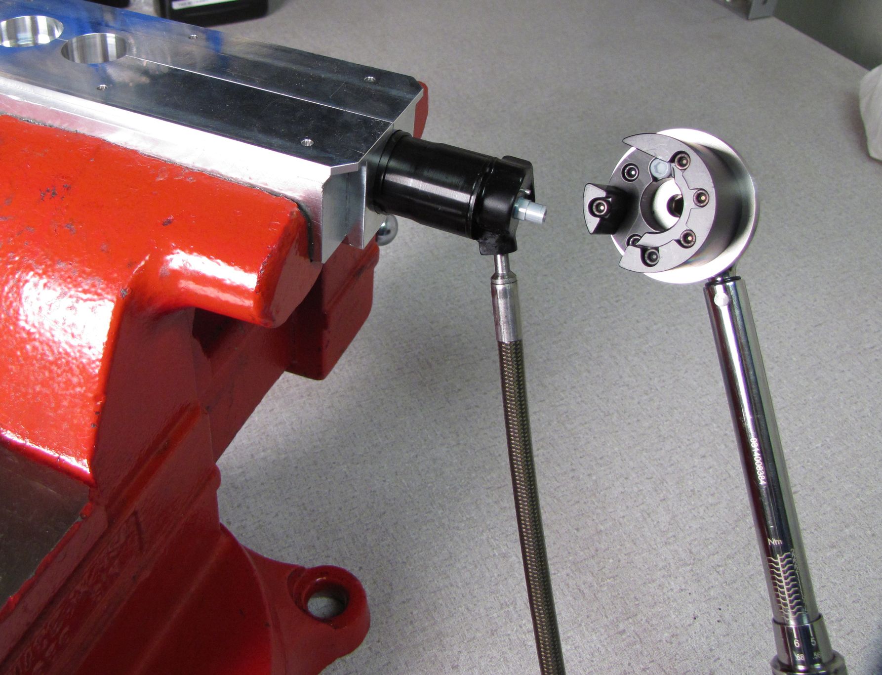
Clamp the Body in your soft-jawed vice, then thread the Bearing Assembly onto the Body. Use a 22mm crowsfoot to torque the assembly to 240 in-lb (27.1 Nm).
Step 2
Load the a new Sag Indicator o-ring from the rebuild kit onto the hose followed by the rebuilt Air Sleeve Assembly. Make sure to install the Air Sleeve so the threaded end is oriented toward the bare end of the hose.

Step 3
Coat the end of the hose with Slick Honey then press the hose end into the port in the Body. Use a pick tool or small flat driver to seat the small wire retaining ring.


Step 4
Replace the o-ring on the outside of the Reservoir Housing and Mount with a new greased one from the rebuild kit. Position the Reservoir Housing and Mount in the Resi Torque Socket.
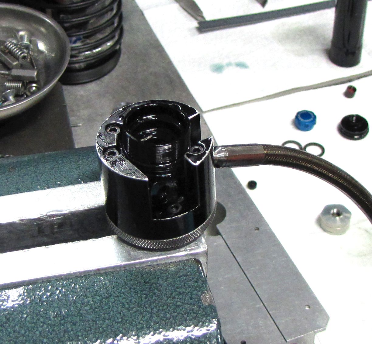
Step 5
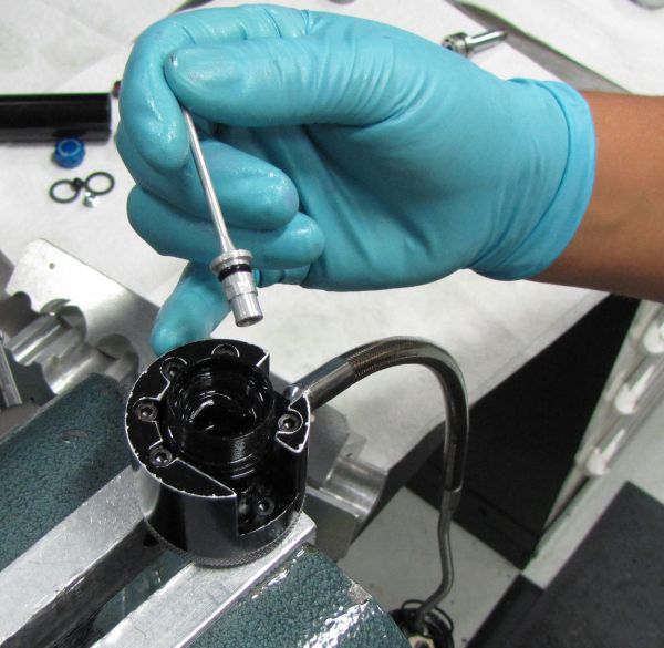
Replace the o-ring on the Adjuster Rod with a new greased one from the rebuild kit, then set the Rod in the Reservoir Housing and Mount.

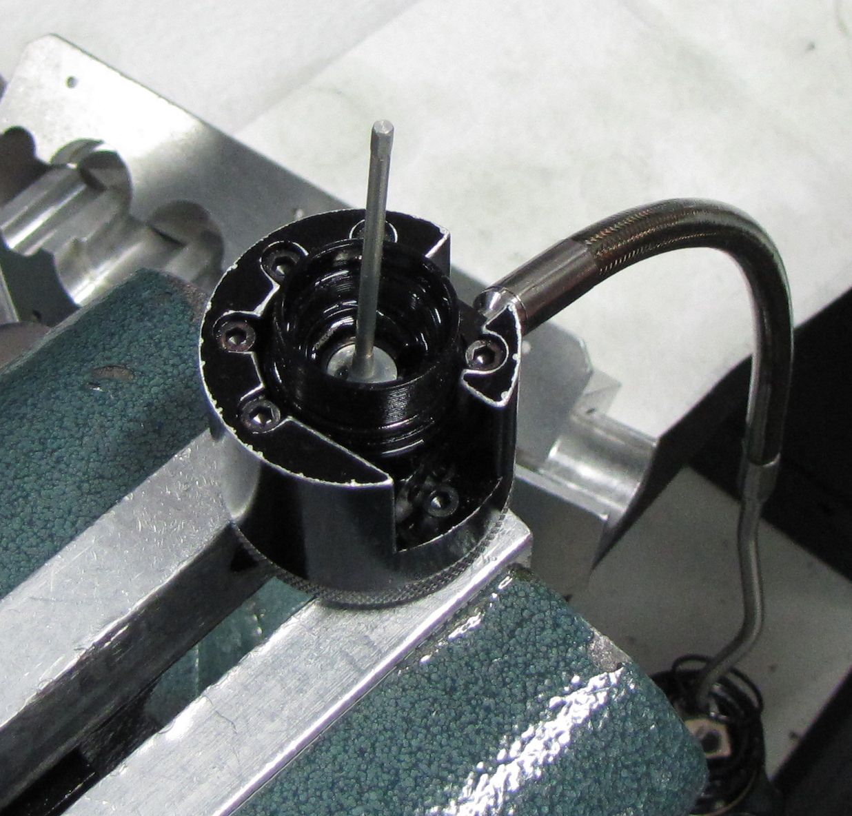

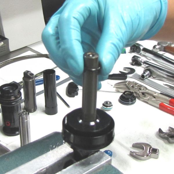
Step 6
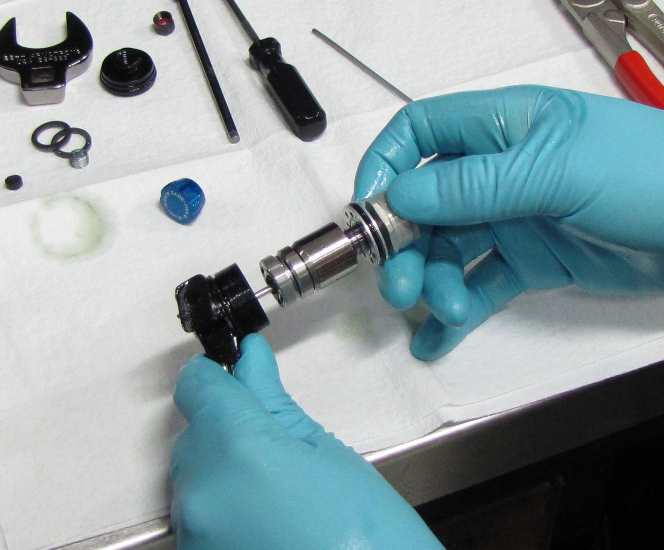
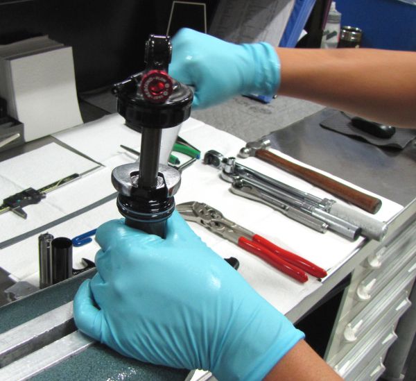
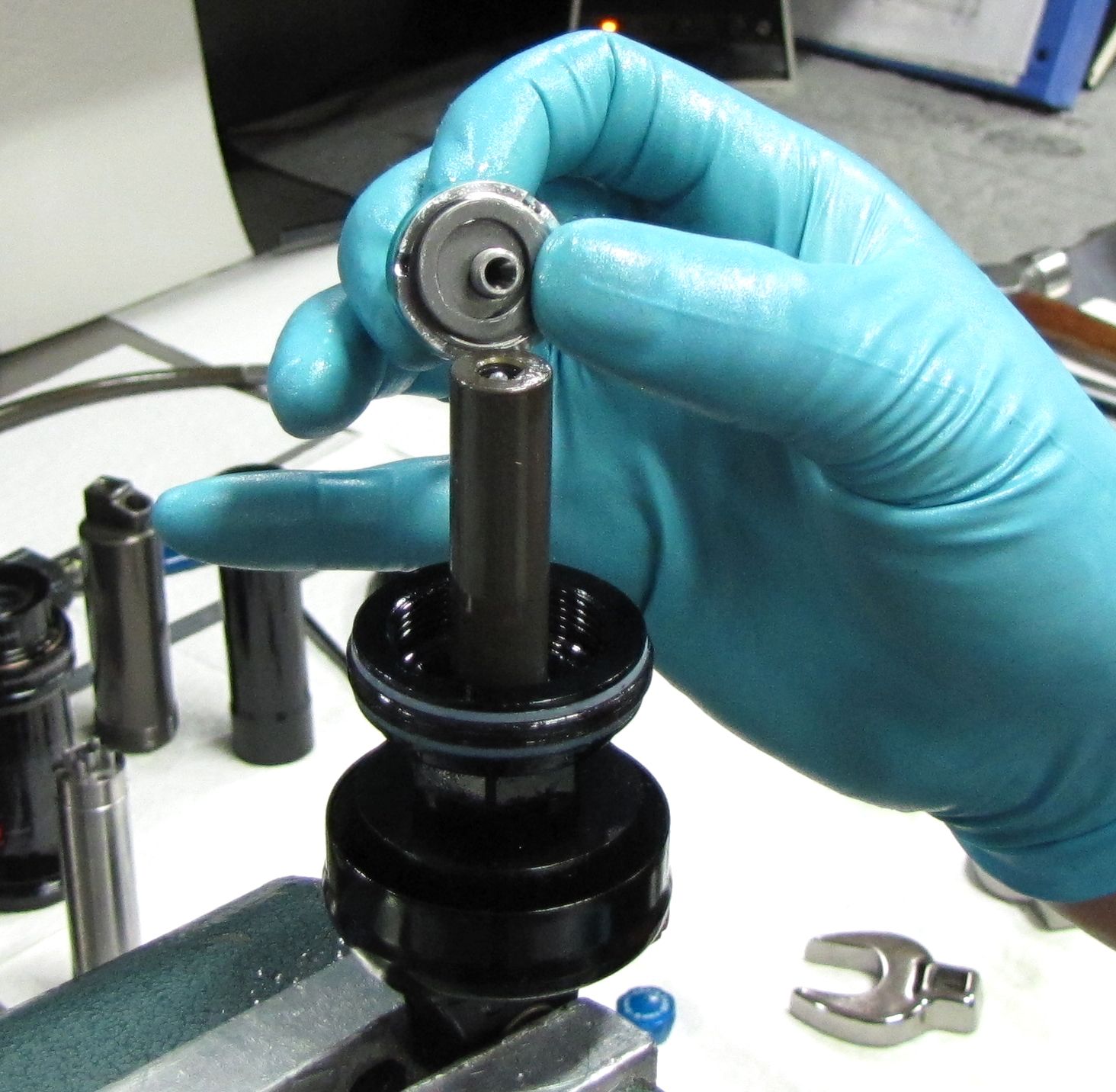
Install the Shaft assembly over the Adjuster Rod, then use the shaft to thread the Reservoir Threshold Valving Assembly into the Reservoir Housing and Mount.
If needed, you may disassemble the Reservoir Threshold Valving Assembly further by carefully clamping the IV Shaft in your 3/8in shaft clamps and using the IV Cartridge Disassembly Tool (PN: 398-00-632) to unthread the Reservoir Threshold Piston.
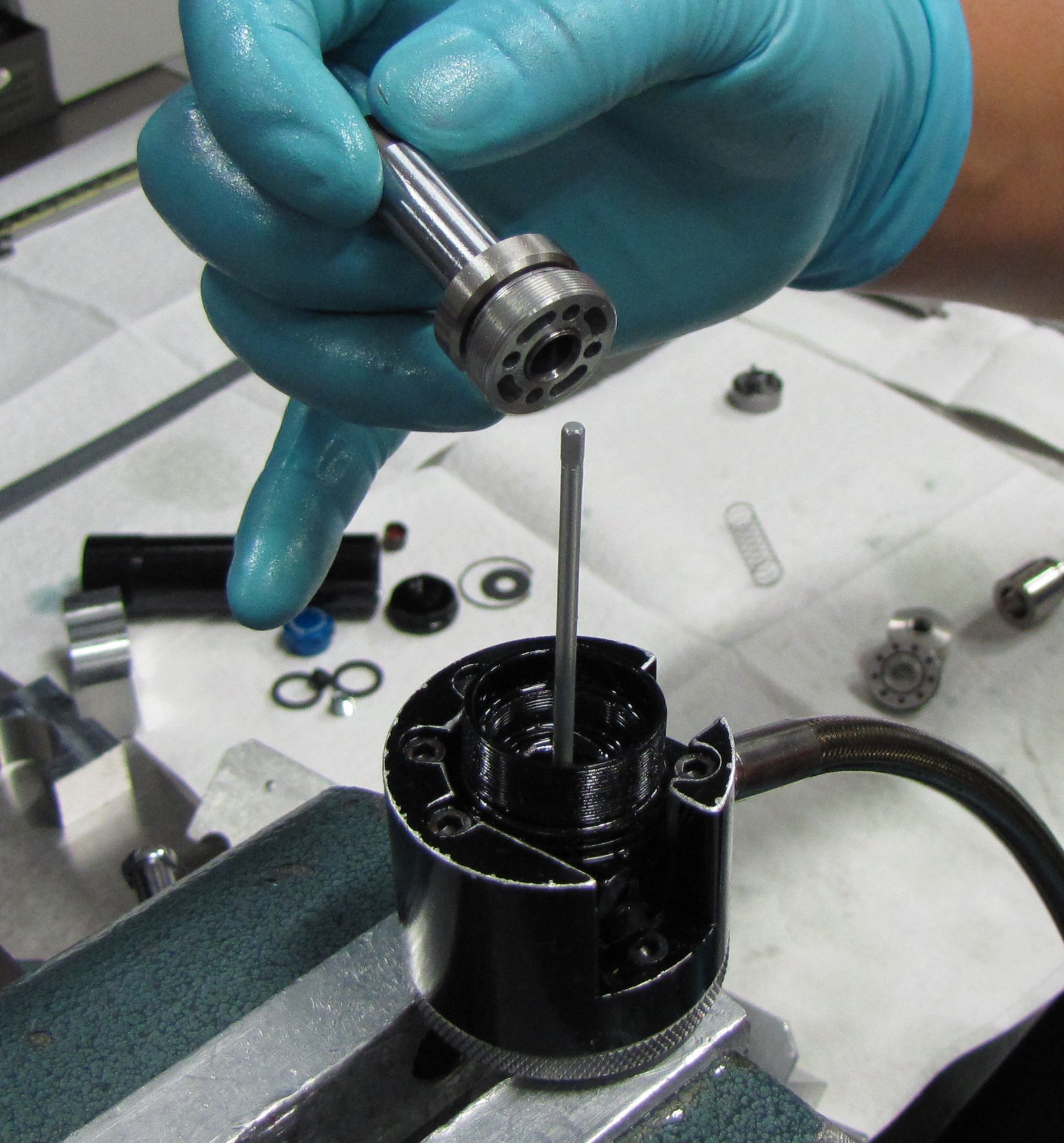
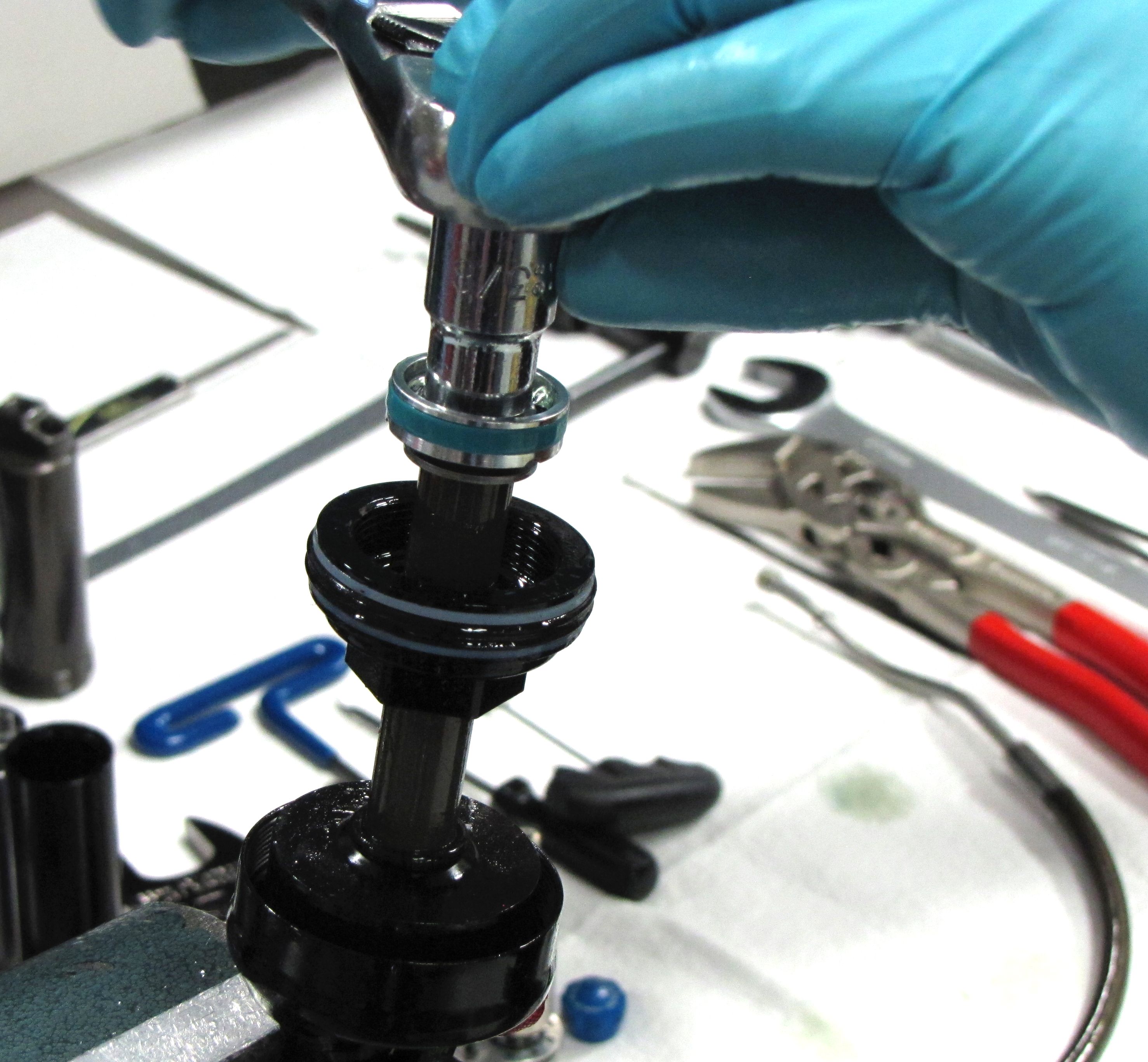
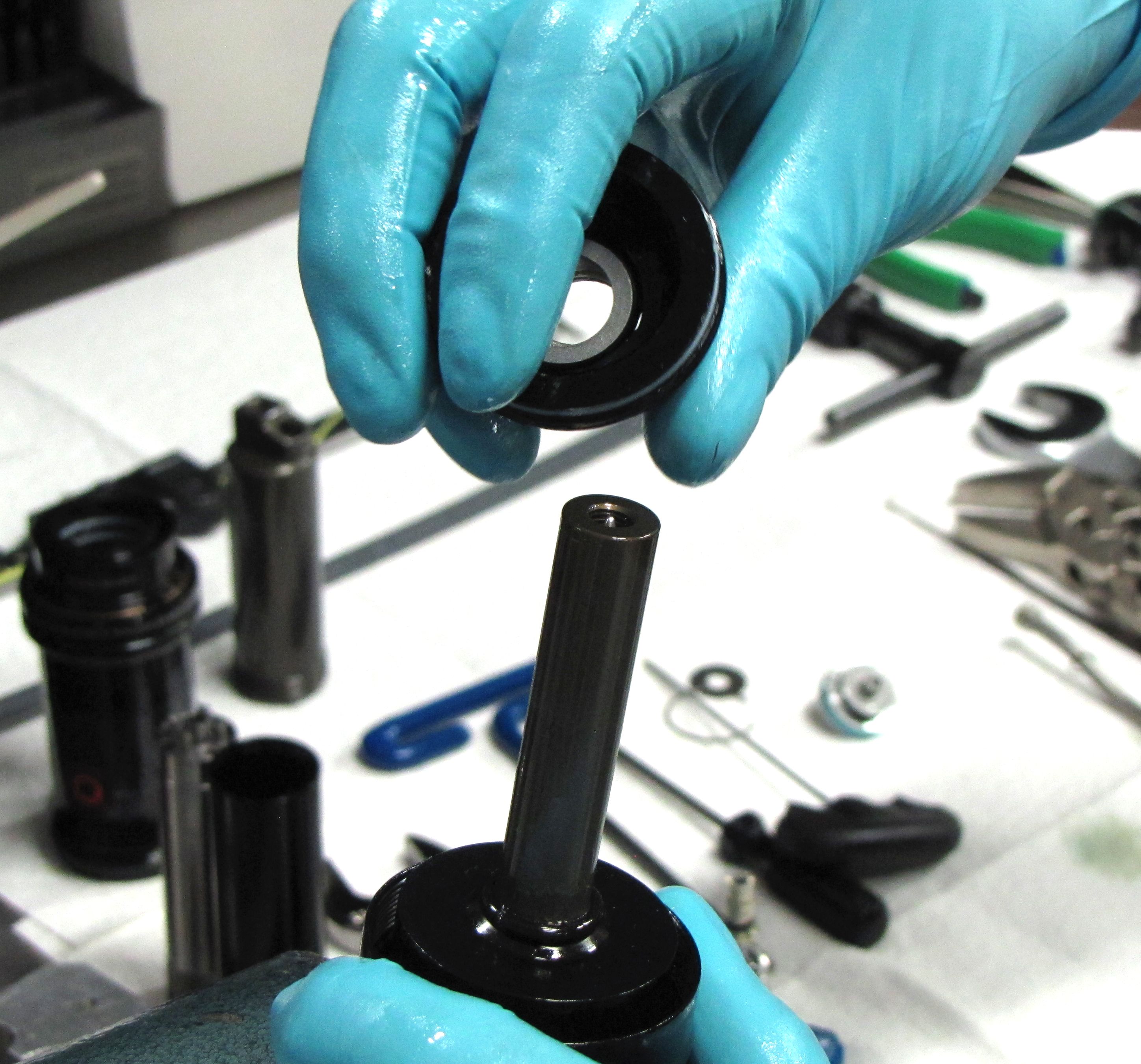
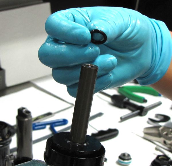
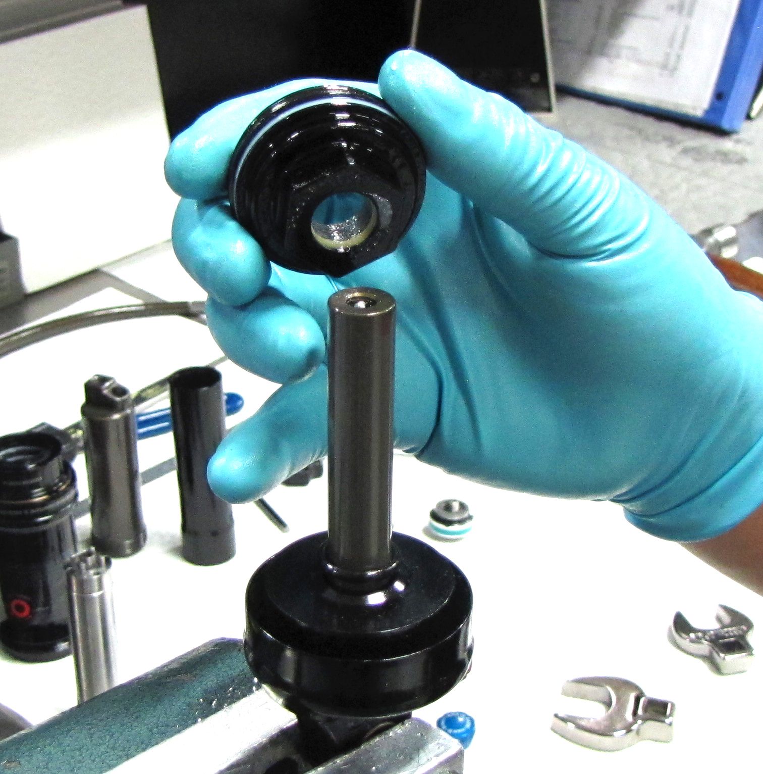
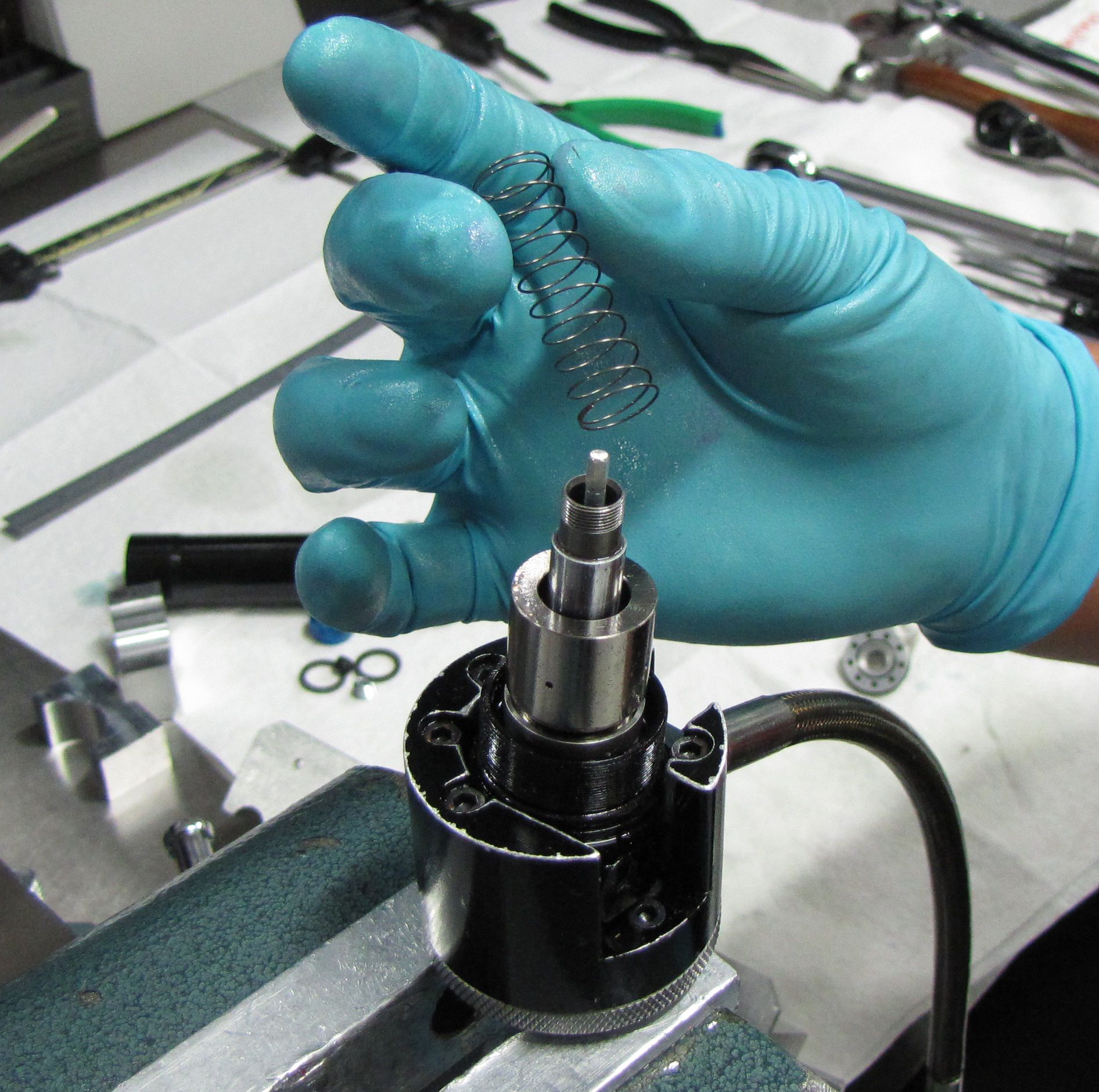
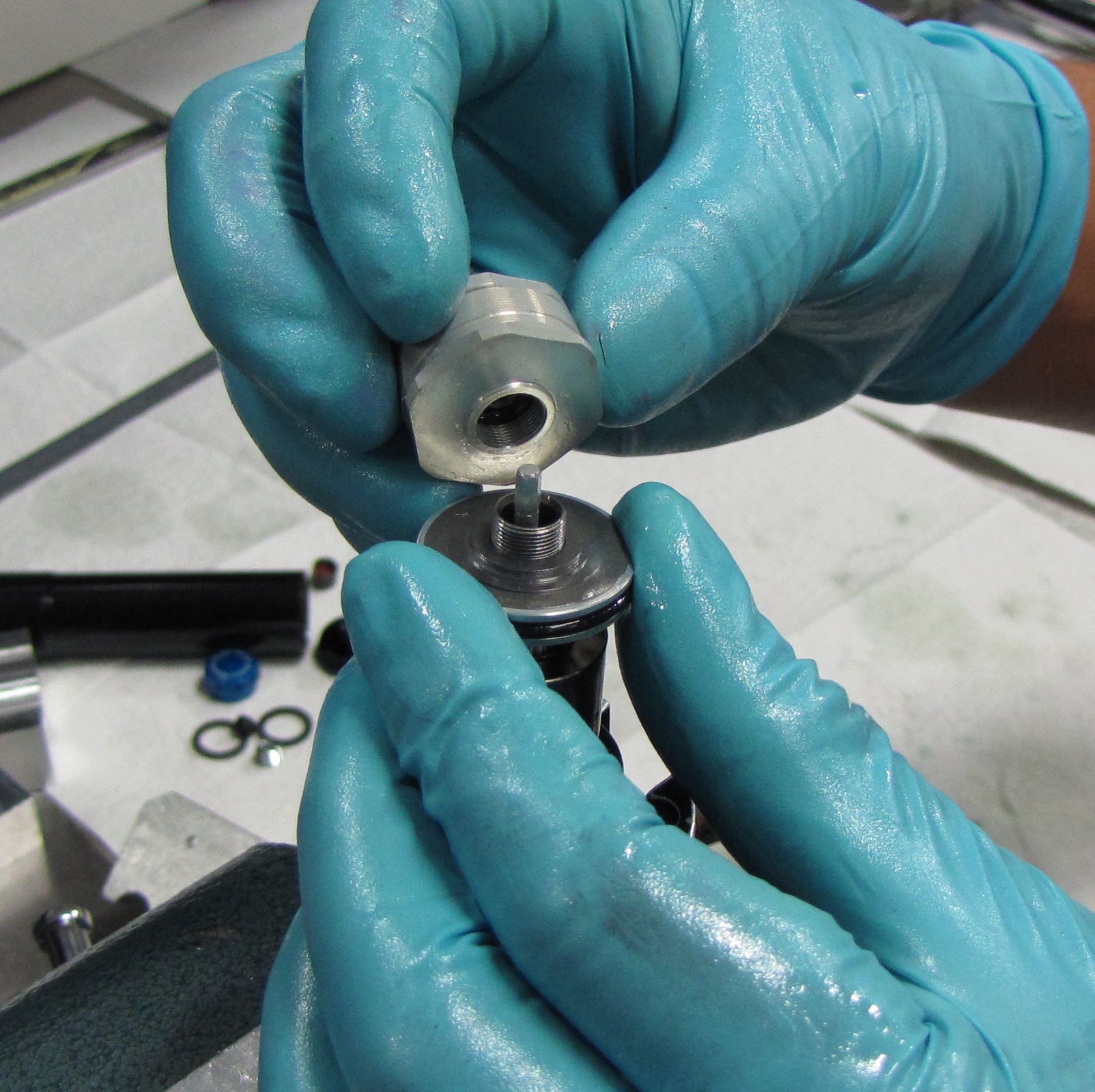
Step 7
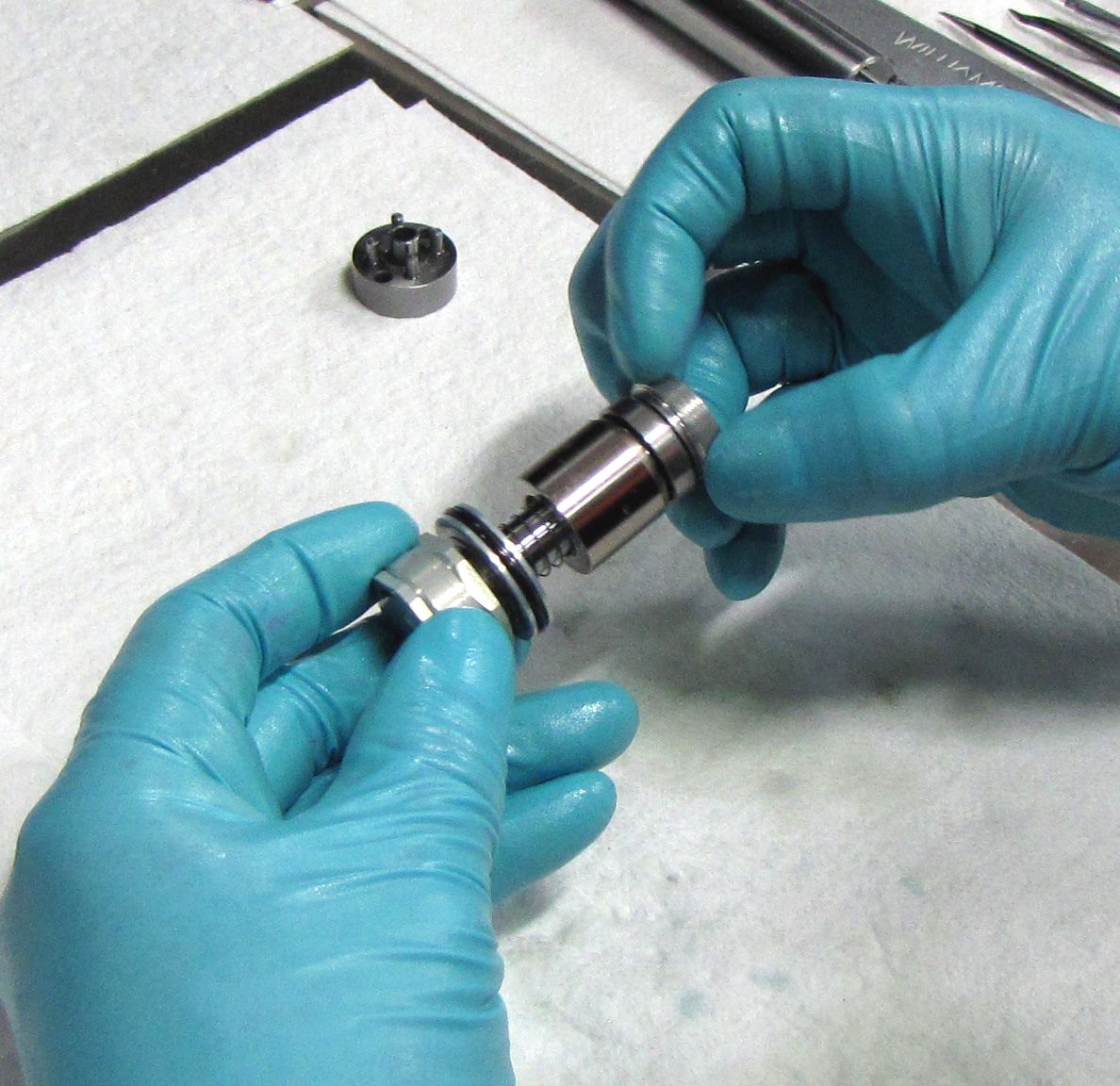
Make sure that the UN-GREASED o-ring in the end of the Inertia Valve is fully seated and flat. Install the Inertia Valve onto the shaft with the o-ring end oriented toward the Reservoir Housing and Mount. Install the spring onto the shaft followed by the Reservoir Compression Valving Assembly with it's UN-GREASED o-ring facing the Inertia Valve.
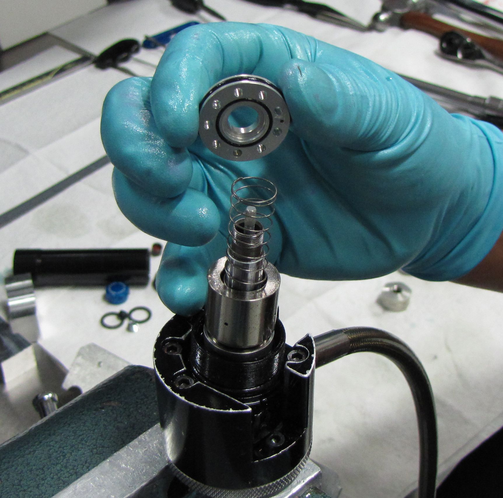
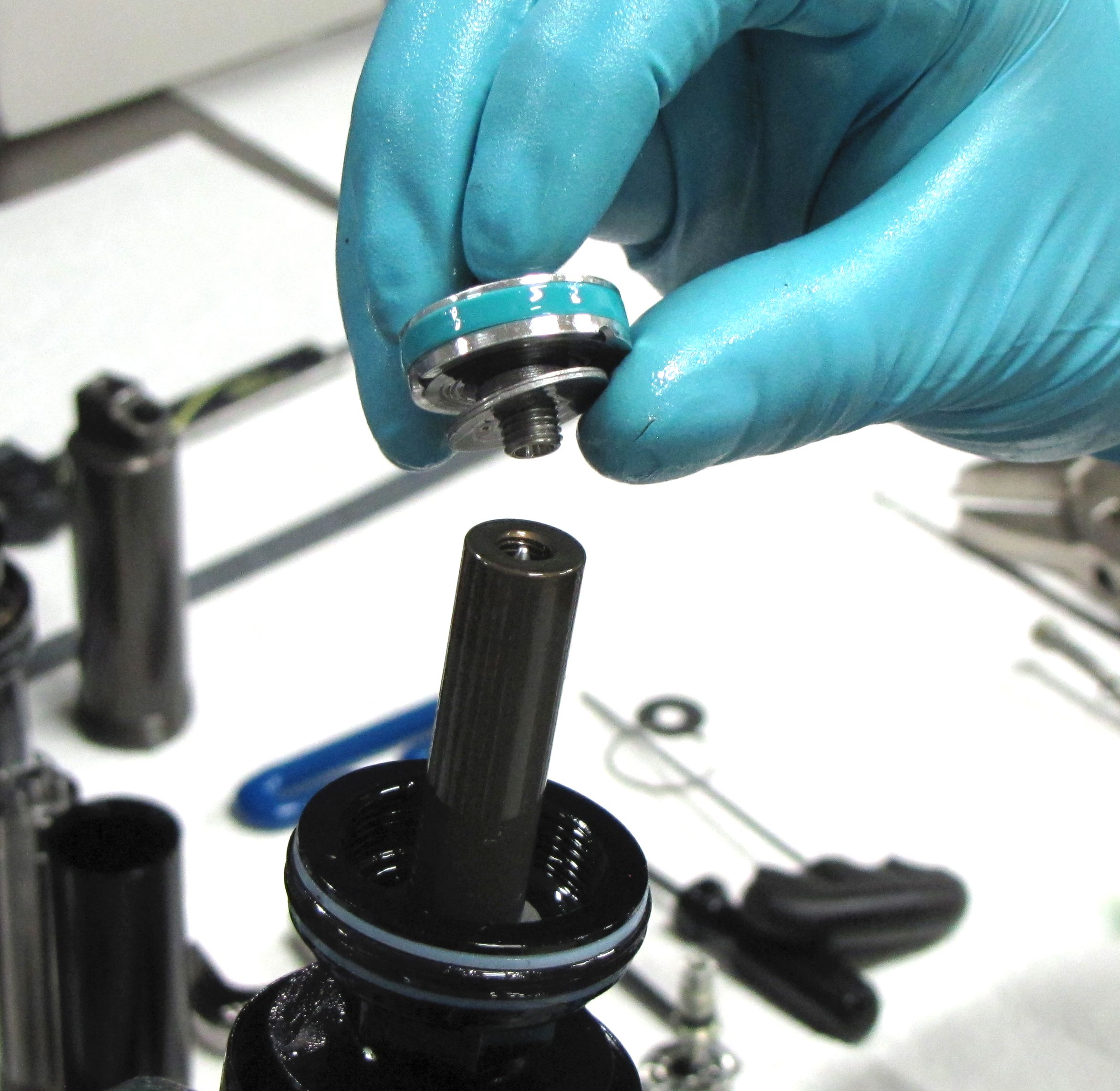
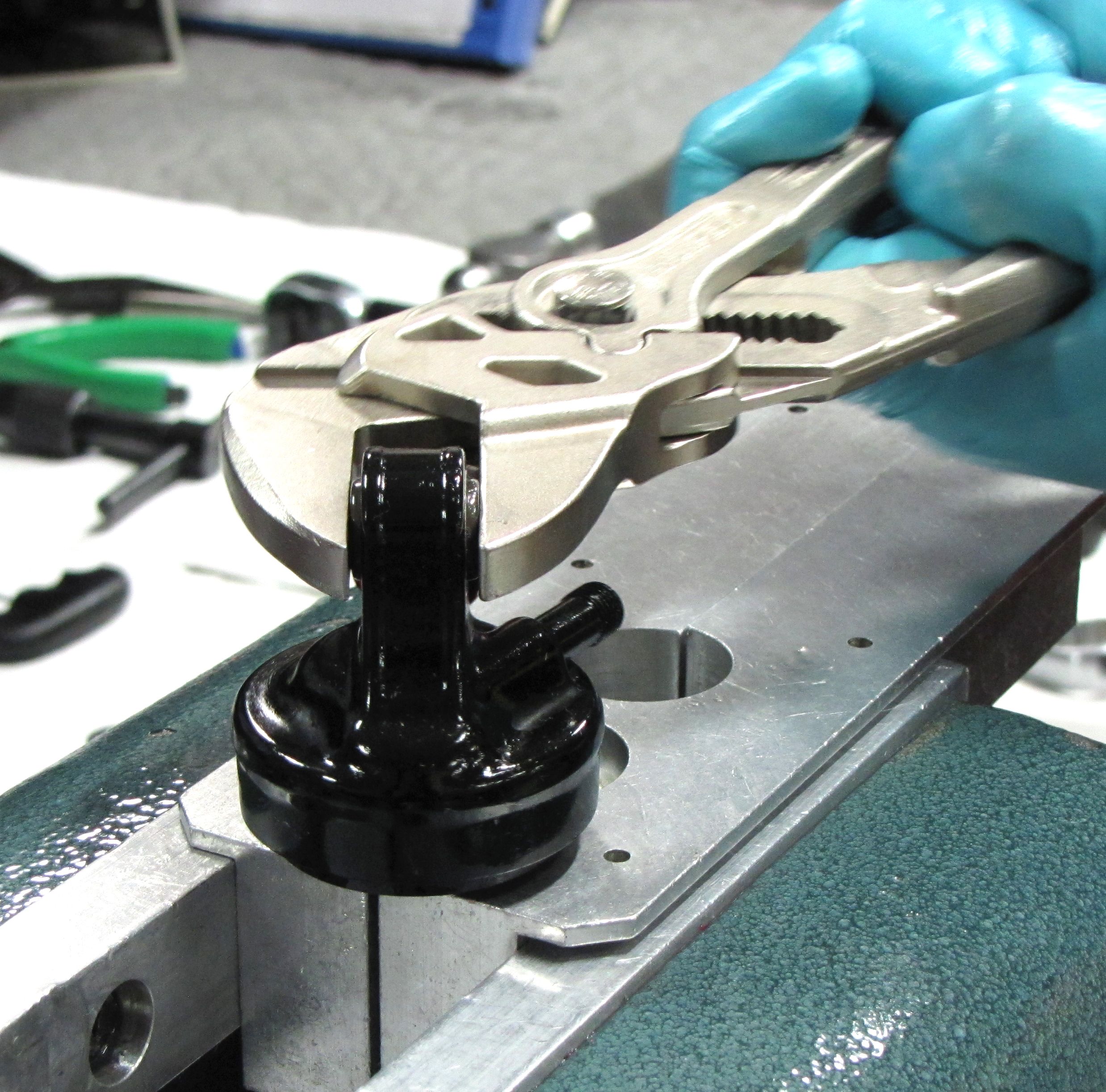
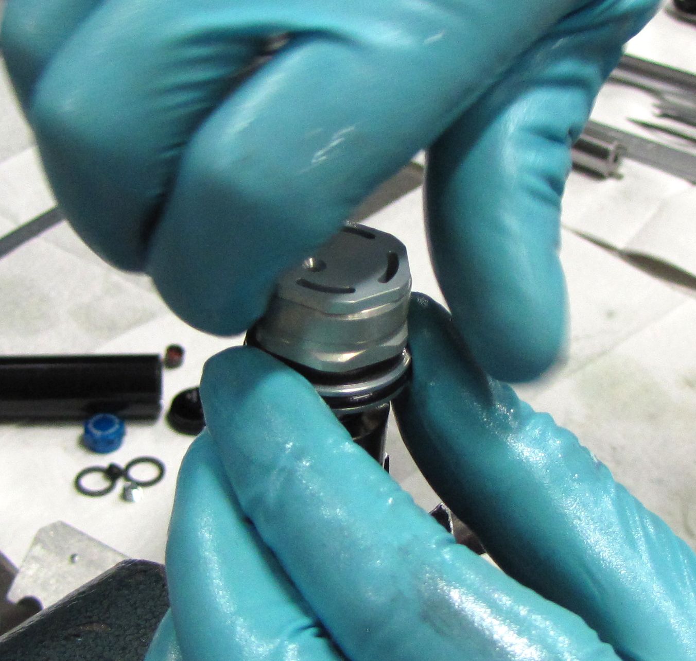
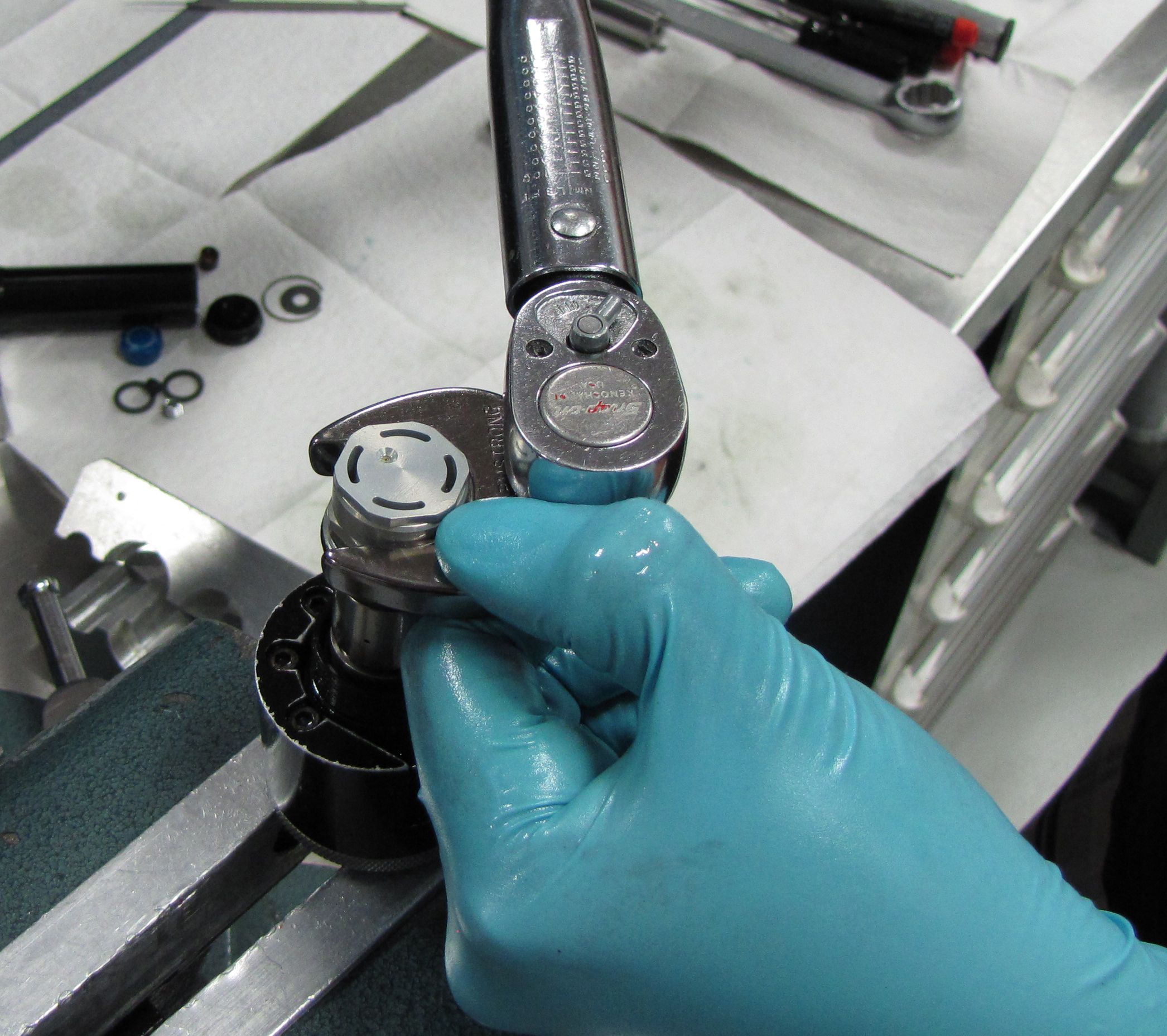
Step 8
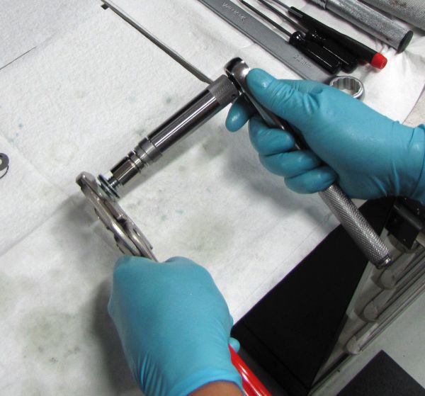
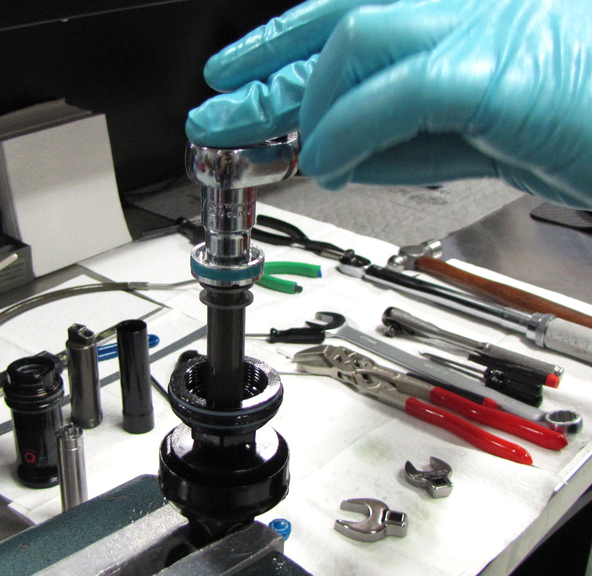
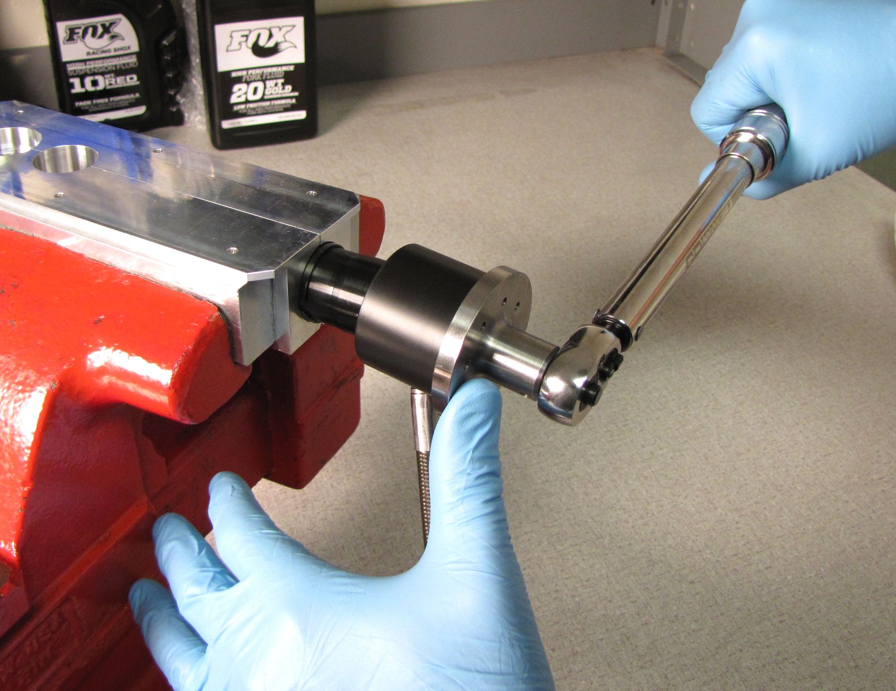
Hold the Reservoir Compression Piston down against the spring as you install the valve stack onto the shaft followed by the Refill Chamber Nut. Torque the Refill Chamber Nut to 75 in-lb (8.5 Nm) with a 21mm crowsfoot.


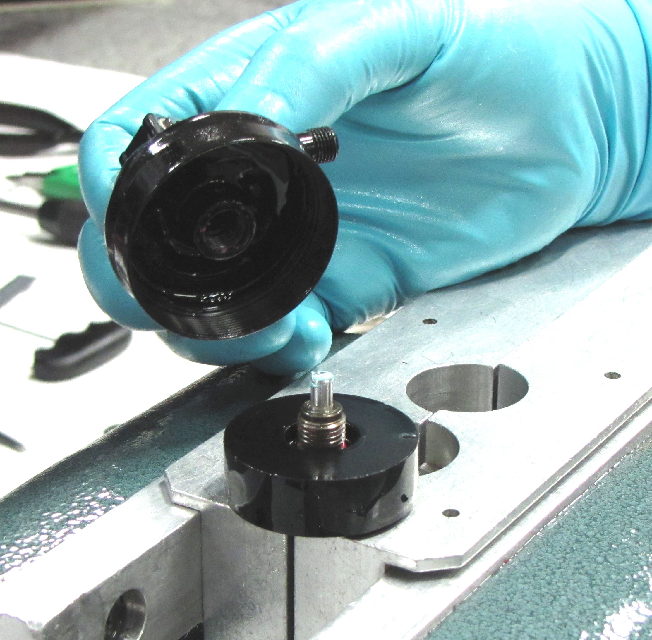
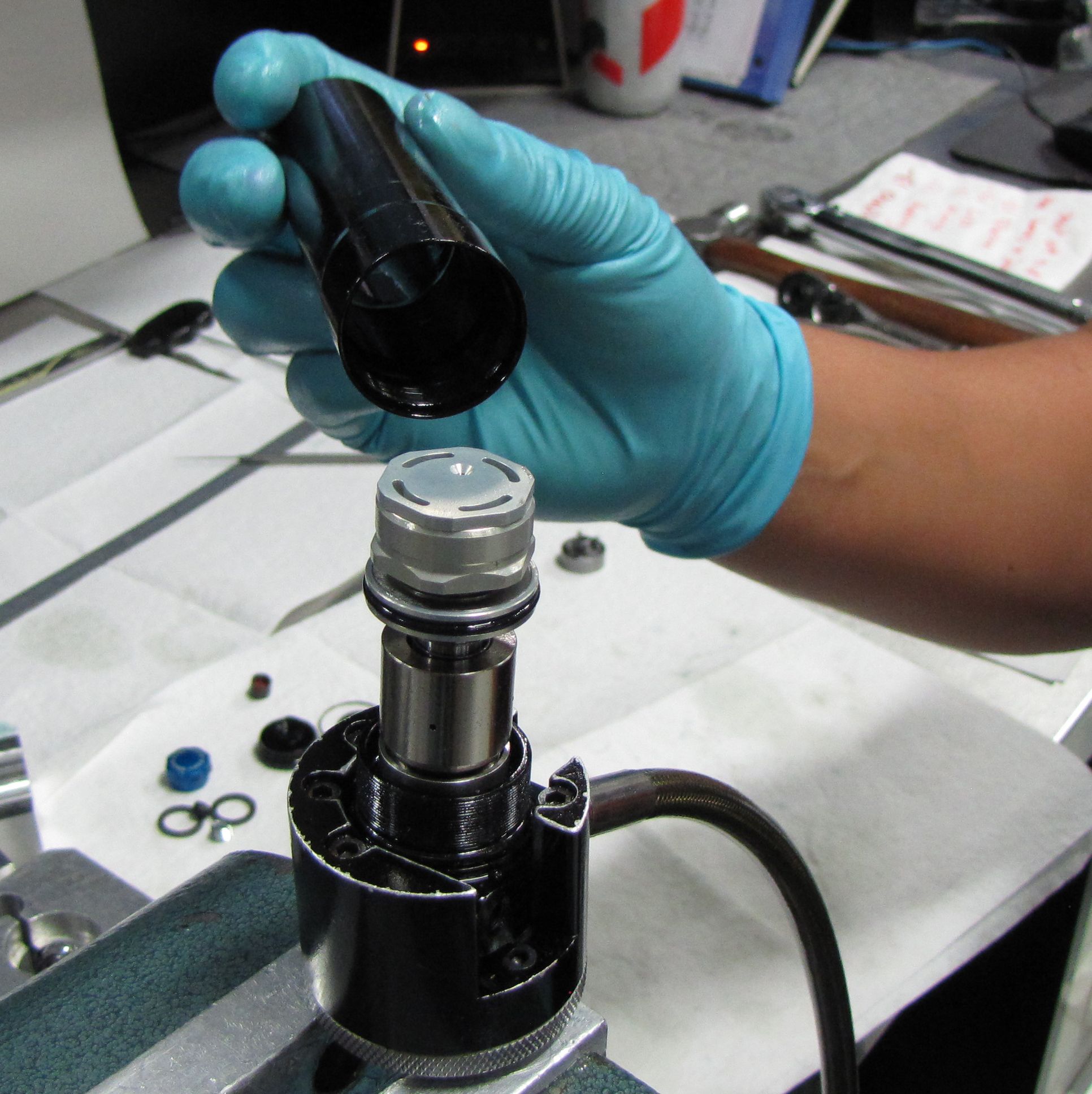
Step 9
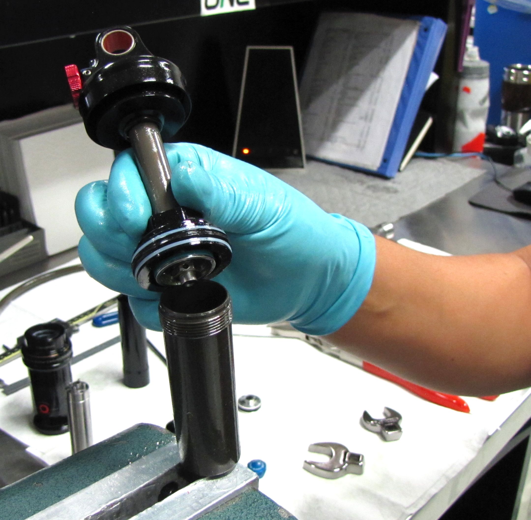
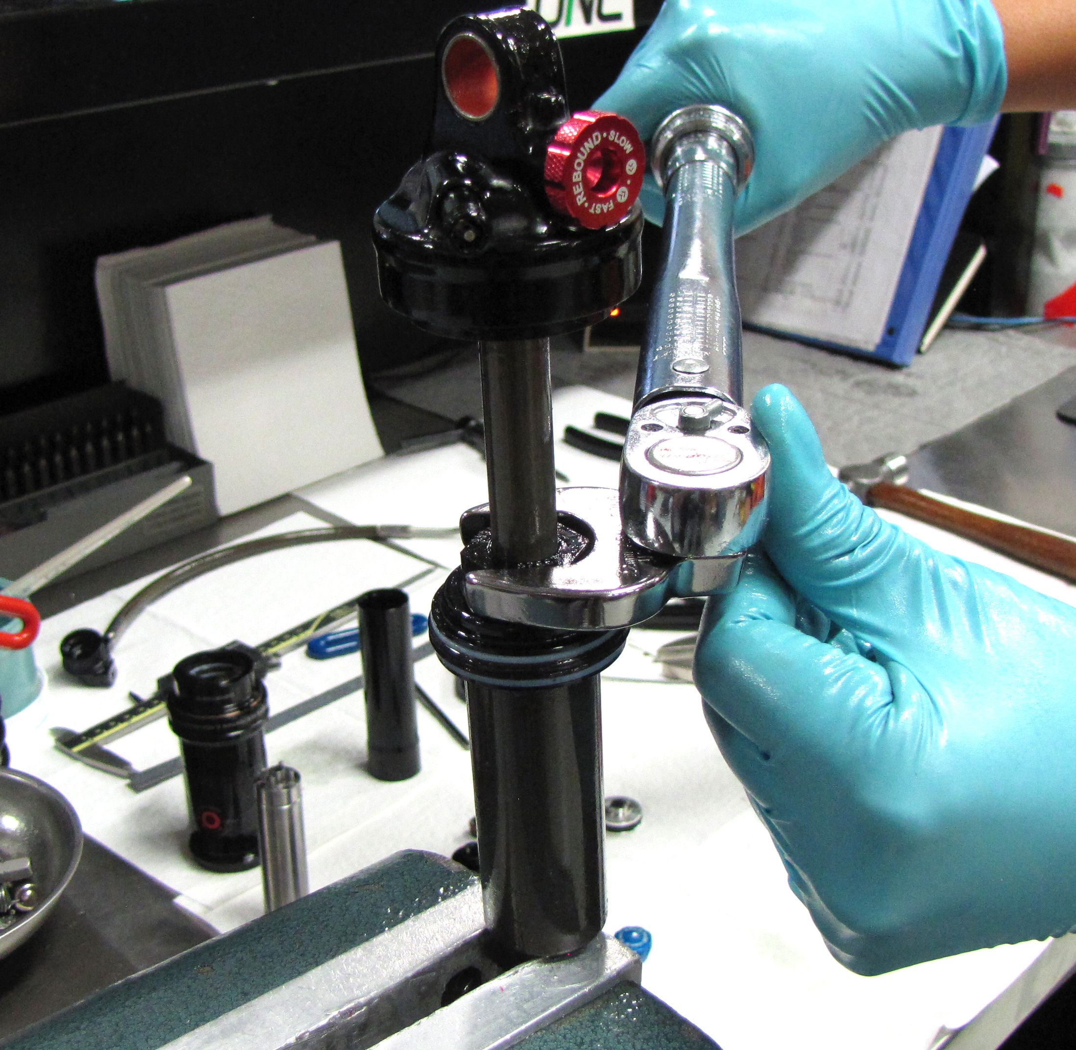
Install the Reservoir over the IV assembly and thread it down by hand. Clamp the Reservoir in your shaft clamps using the Resi Shaft Clamp Shim and torque the Reservoir Housing and Mount to 180 in-lb (20.3 Nm) with the Resi Torque Socket.

Step 10
Use the blue Brain Fade knob to turn the IV reservoir compression adjuster rod fully counter-clockwise, then set the knob aside.
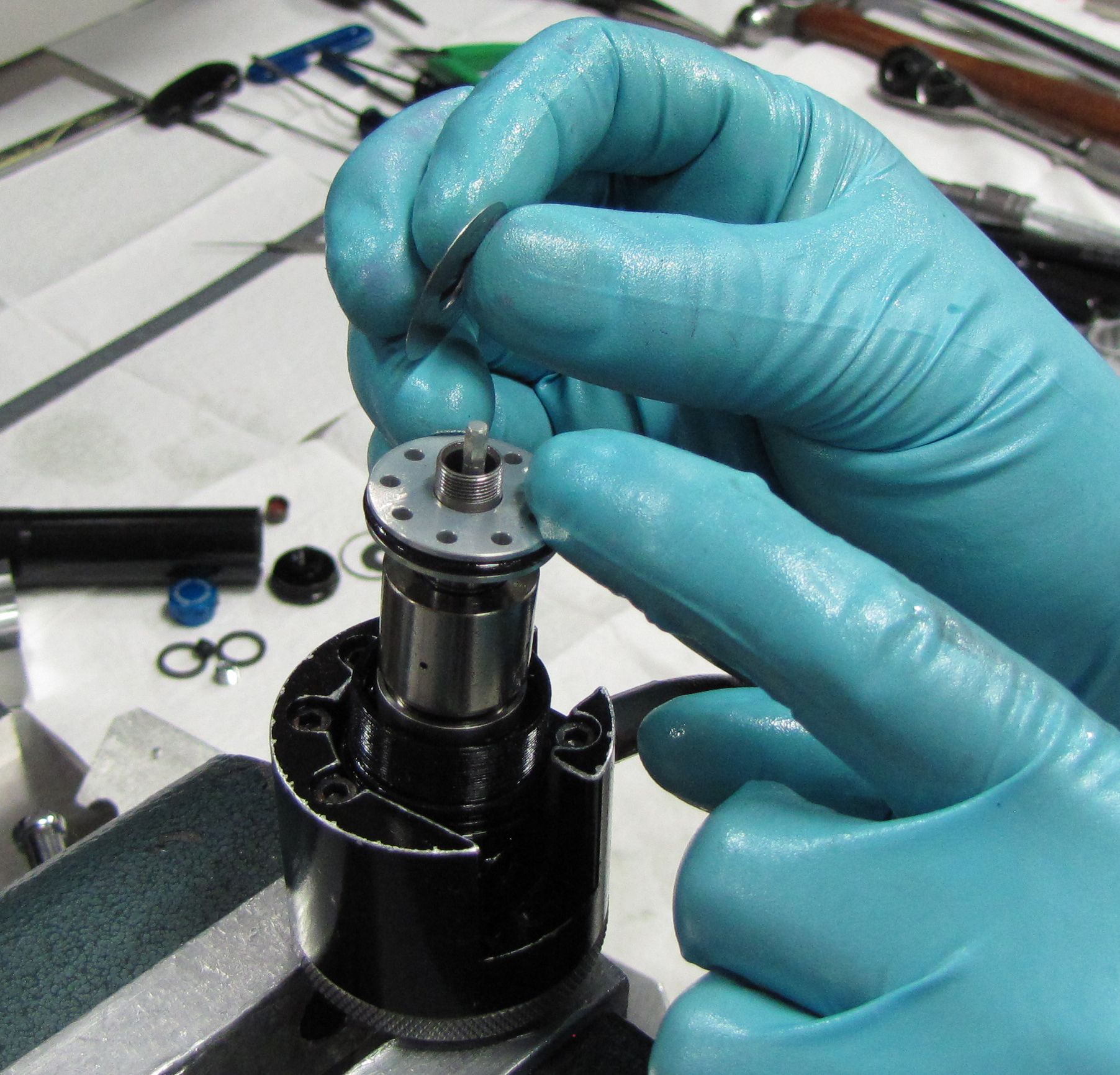
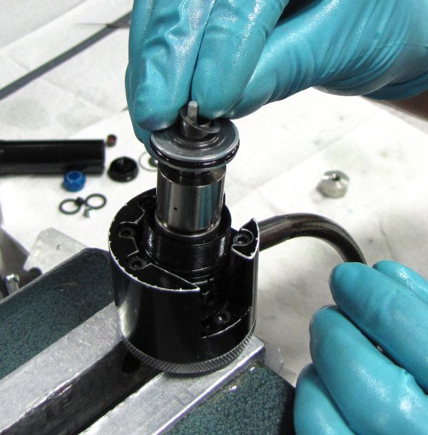
Step 11
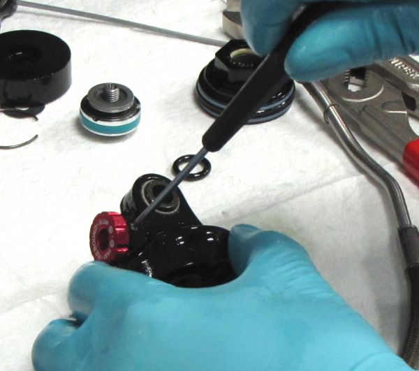
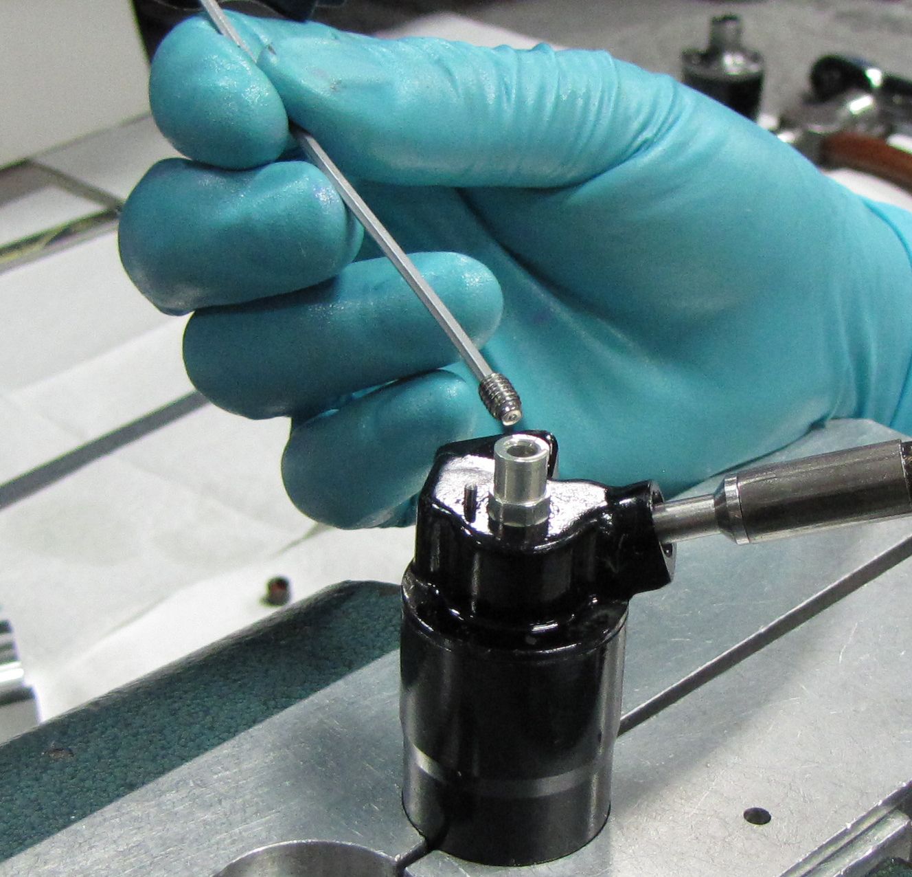
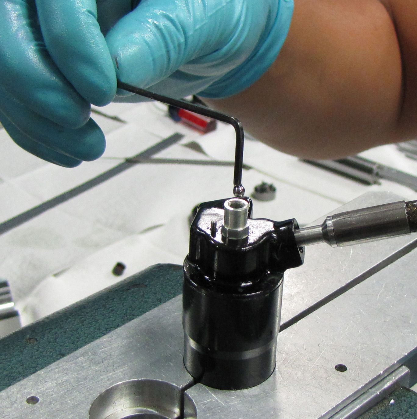
Use a 5/64" or 2mm hex wrench to remove the set screw from the end of the IV reservoir compression adjuster rod. Use a magnet to remove the 0.125" steel ball.
Step 12
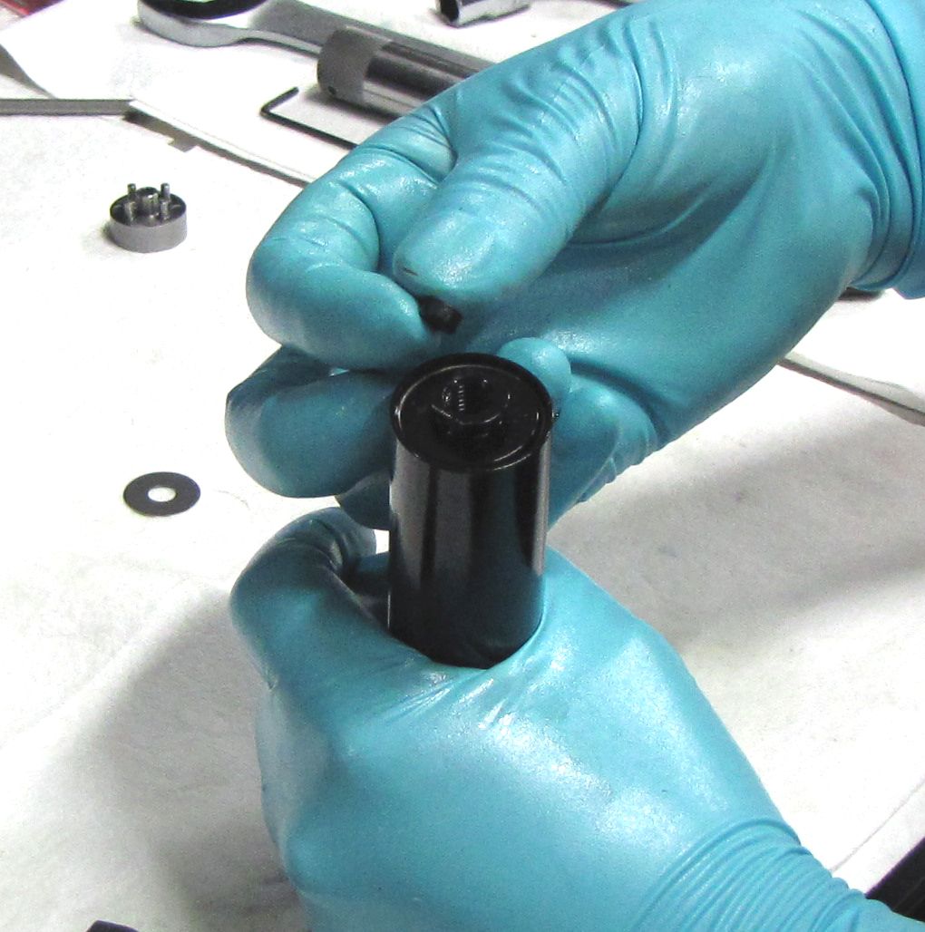
Install the rebuilt IFP assembly into the open end of the reservoir with the bleed screw facing out. Install the wire retaining ring in its groove at the end of the reservoir.

Step 13
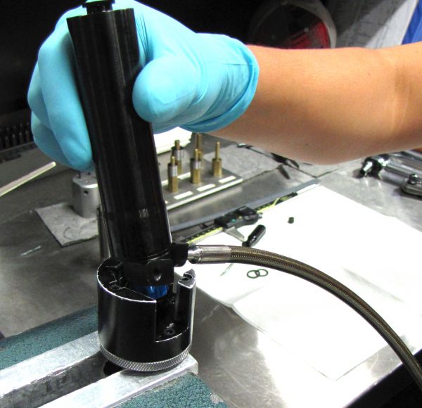
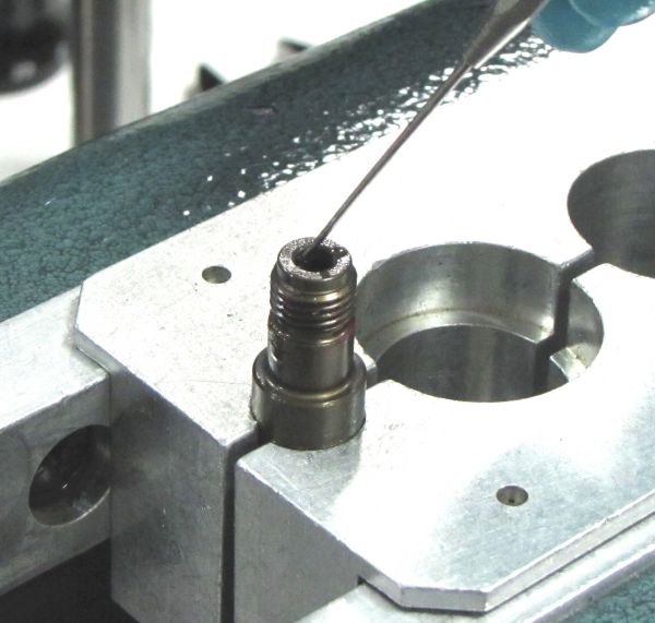
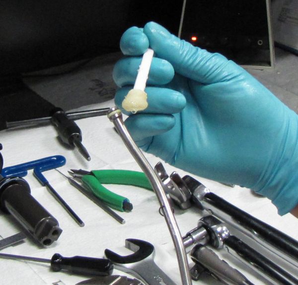
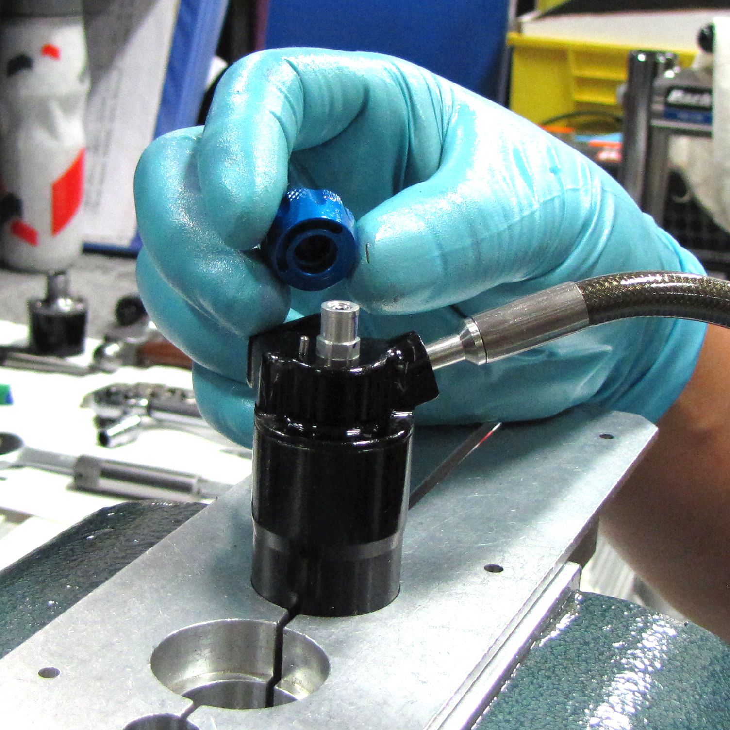
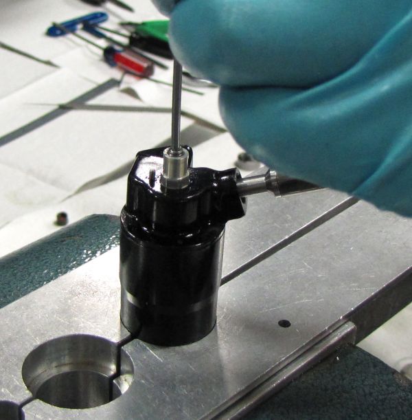
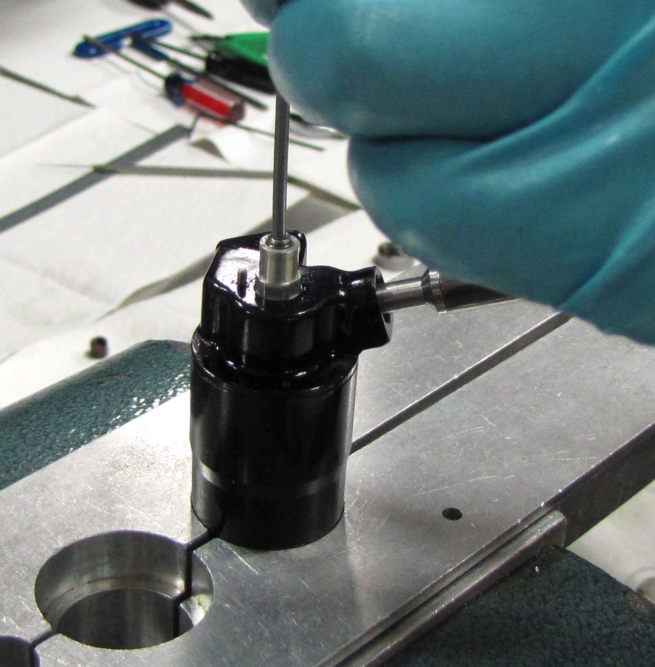
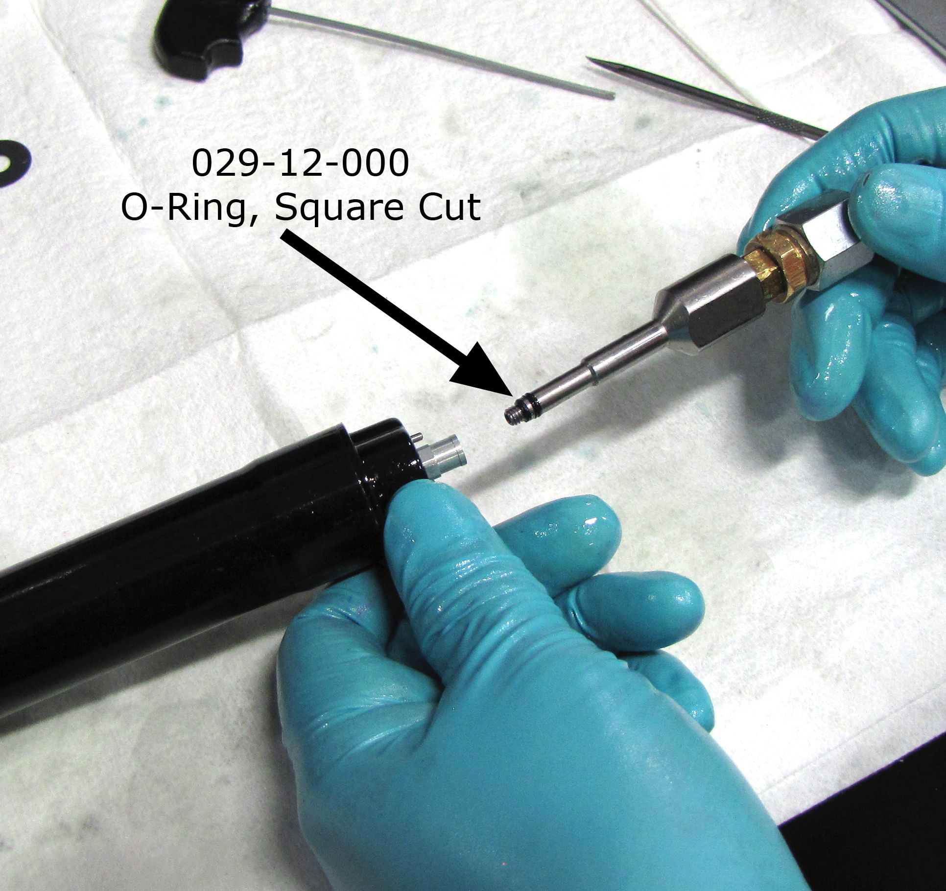
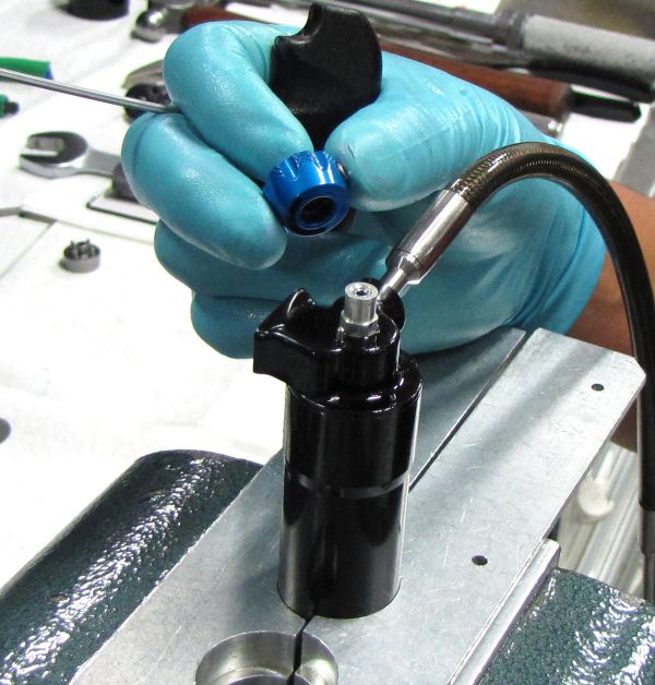
Install the Terralogic Fill Machine Adaptor (PN: 803-00-500) onto your Andreani Machine setup for FOX 10wt. Green oil.
Install a Square Cut O-ring (PN: 029-12-000) on the end of the Terralogic Fill Machine Adaptor as shown. The o-ring should be just past the threads, but not in the separate o-ring gland.
Step 14
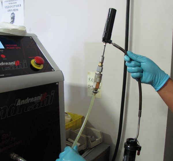
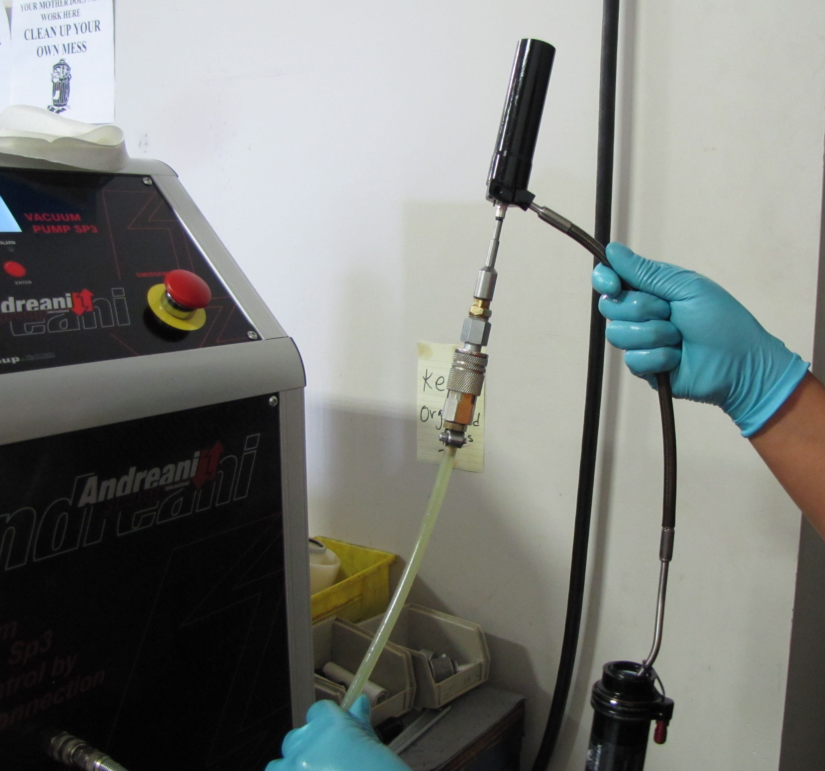
Thread the Terralogic Fill Machine Adaptor into the end of the IV reservoir compression adjuster rod.
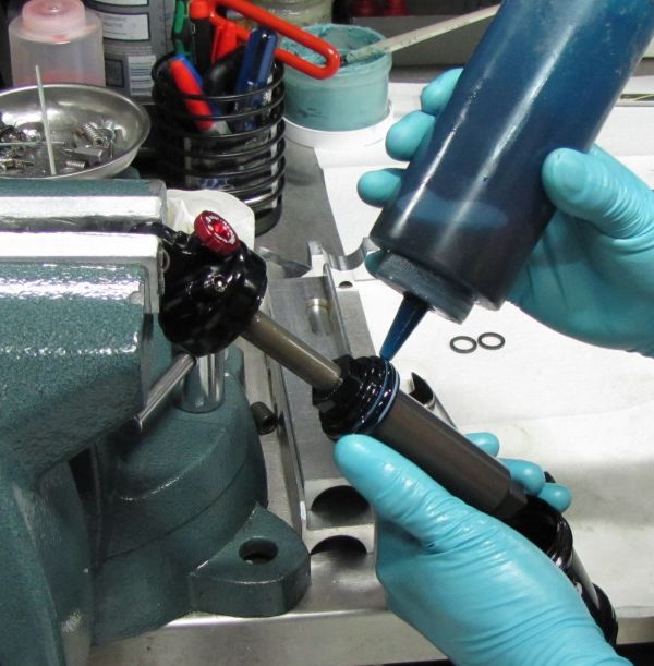
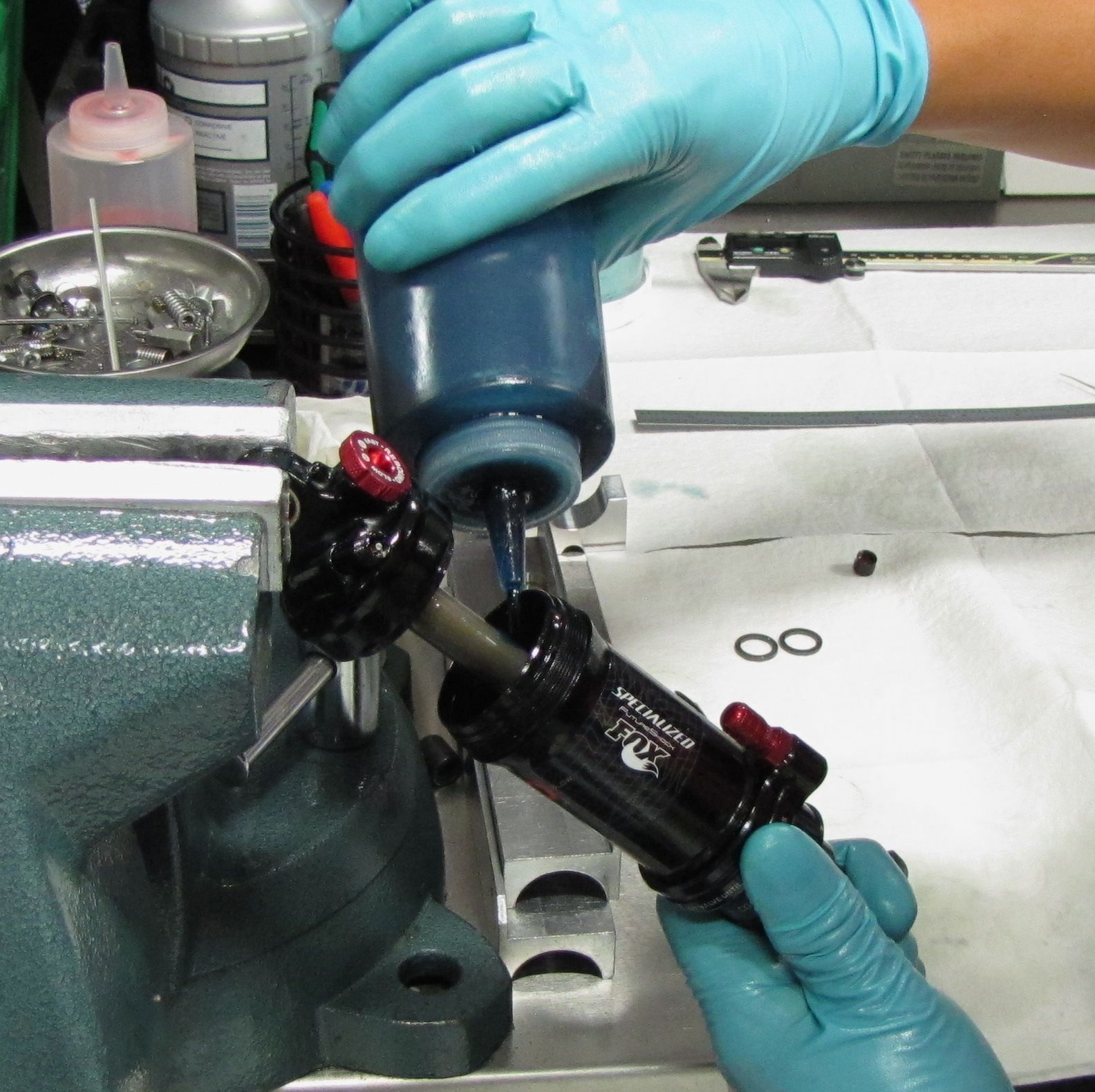
Draw vacuum with the Andreani machine. With the shock positioned above the Andreai machine, cycle the damper and activate the Inertia Valve while under vacuum.

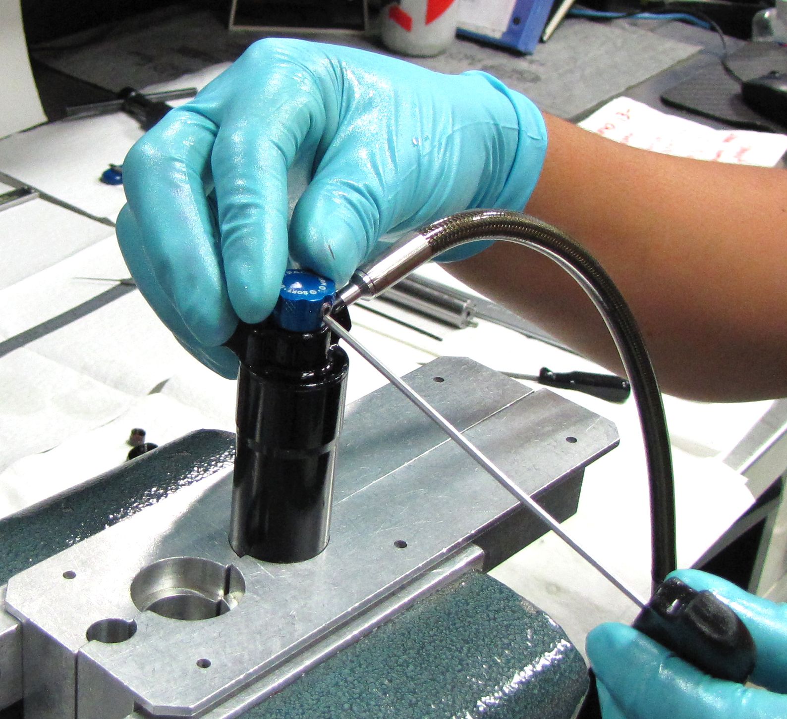
Step 15
After vacuuming, switch the Andreani machine to fill with the shock positioned lower than the fill machine. Cycle the shock damper and activate the Inertia Valve while filling.
Step 16
After fill is complete and the damper is fully extended, set the IFP to 1.323" using IFP Depth Setting Tool (PN: 803-00-566).
Step 17
Insert the 0.125" ball into the end of the IV reservoir compression adjuster rod. Thread the set screw into the end of the IV reservoir compression adjuster rod, then tighten to 10 in-lb (1.1 Nm).

Step 18
Install the blue Brain Fade knob onto the end of the IV reservoir compression adjuster rod. Make sure that the dowel pin is positioned in the channel on the underside of the knob. Tighten the set screw in the knob to 5 in-lb (0.6 Nm) with a 5/64" (2mm) hex wrench.

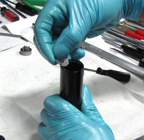
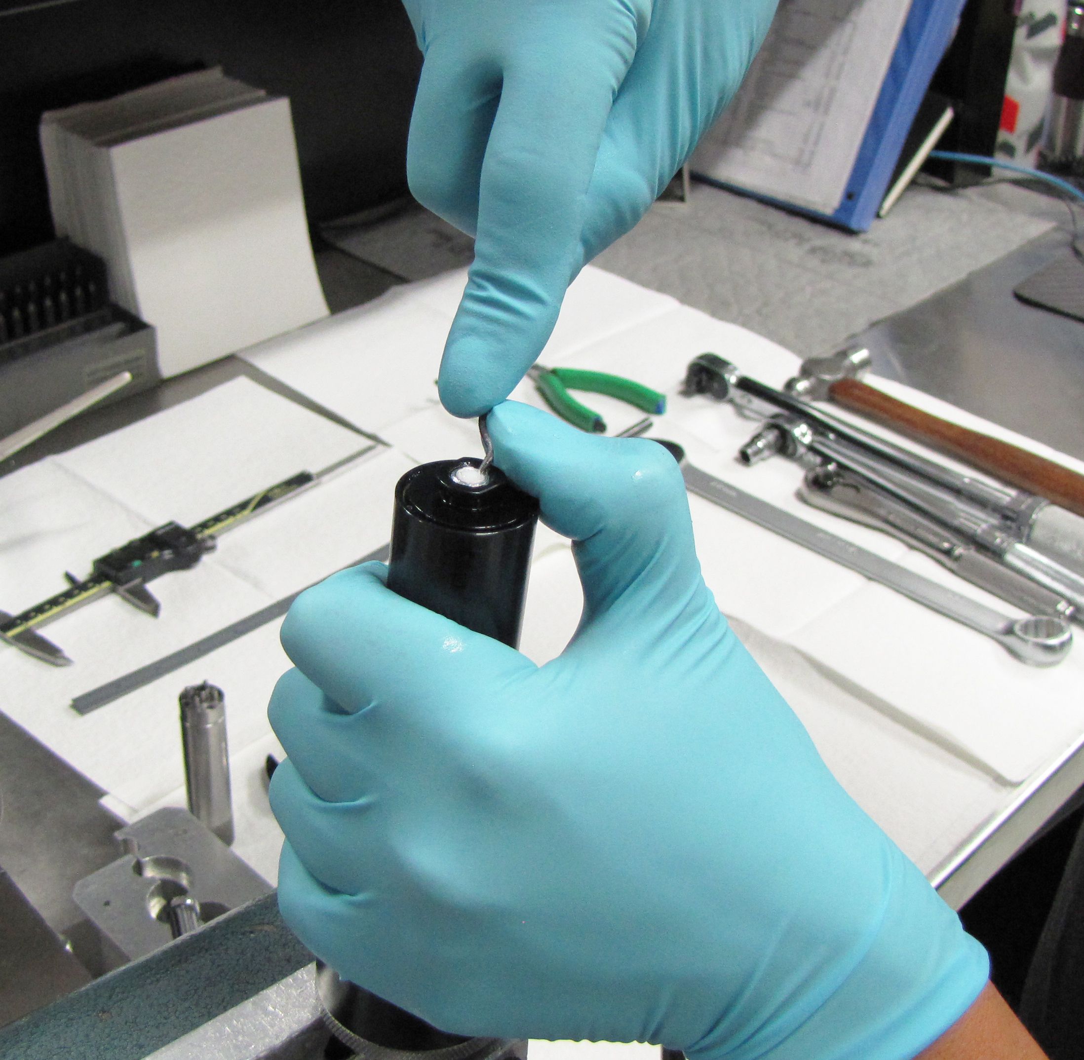
Step 19
Use a thin shim to remove the wire retaining ring.

Step 20
Insert the Reservoir End Cap Assembly into the end of the Reservoir, then reinstall the retaining ring and lift the Reservoir End Cap Assembly with needle-nosed pliers until it is snug against the retaining ring.

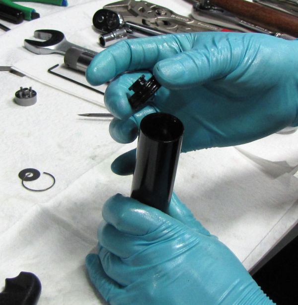
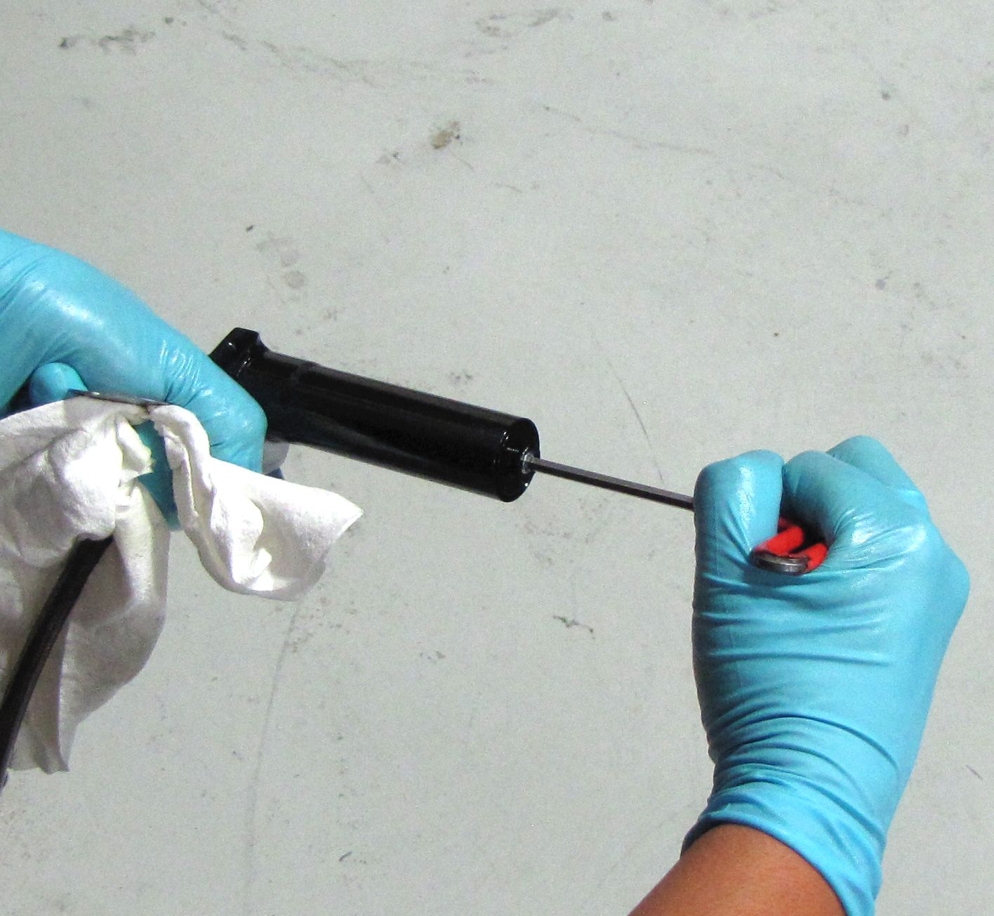
Step 21
Install a new pellet from the service kit, the flat side facing up, then secure with the pellet retainer.
Step 22
Slide a 0.050" AA Slotted Shim onto the Reservoir End Cap Assembly to prevent it from being pushed into the Reservoir during Nitrogen filling. The 0.050" AA Slotted Shim (Mcmaster.com PN: 97235K161) can be purchased at McMaster.com »

Step 23
Fill the IFP chamber to 200psi with Nitrogen, then tighten the pellet retainer to 14 in-lb (1.6 Nm) with a 5/32" (4mm) hex wrench.
Dyno the shock to check all functions.
Step 24
Apply a coating of Float Fluid to the main air seals, then slide the airsleeve onto the damper and inject 2cc of Float Fluid into the main air chamber. Thread the airsleev to the eyelet and tighten to 45 in-lb (5.1 Nm).

Step 25
Pressurize the main air chamber then replace the black air valve cap. Clean the exterior of your shock.
