2011-2020 VAN P-S Rebuild
Required Parts
- 803-00-122 Kit: Rebuild, DHX, VAN R, VAN RC
Required Tools
- 398-00-280 Tooling: Eyelet Torque Tool
- 398-00-951 Tooling: Torque Fixture, 54mm Trunnion Eyelet, tall
- 803-00-208 Kit: Clamp, Shaft and Body, 2005 DHX
- 803-00-463 Kit: Fill Machine Adapter, 04-07 Epic IV, DHX Air, RC2_RC4 Shocks
- 803-00-566 Kit: Bike IFP Depth Setting Tool Set
- Nitrogen Fill Station (Tank with Regulator) required for full rebuild .
WARNING: Always wear safety glasses and protective gloves during service to prevent potential injury. Failure to wear protective equipment during service may lead to SERIOUS INJURY OR DEATH.
WARNING: FOX products should be serviced by a trained bicycle service technician, in accordance with FOX specifications. If you have any doubt whether or not you can properly service your FOX product, then DO NOT attempt it. Improperly serviced products can fail, causing the rider to lose control resulting in SERIOUS INJURY OR DEATH.
WARNING: FOX suspension products contain pressurized nitrogen, air, oil, or all 3. Suspension misuse can cause property damage, SERIOUS INJURY OR DEATH. DO NOT puncture, incinerate or crush any portion of a FOX suspension product. DO NOT attempt to disassemble any portion of a FOX suspension product, unless expressly instructed to do so by the applicable FOX technical documentation, and then ONLY while strictly adhering to all FOX instructions and warnings in that instance.
WARNING: Modification, improper service, or use of aftermarket replacement parts with FOX forks and shocks may cause the product to malfunction, resulting in SERIOUS INJURY OR DEATH. DO NOT modify any part of a fork or shock, including the fork brace (lower leg cross brace), crown, steerer, upper and lower leg tubes, or internal parts, except as instructed herein. Any unauthorized modification may void the warranty, and may cause failure or the fork or shock, resulting in SERIOUS INJURY OR DEATH.
The following procedure guides you through the rebuild of the VAN rear shock.
Complete part information and technical drawings for the VAN shocks can be found by clicking: VAN Part Information »
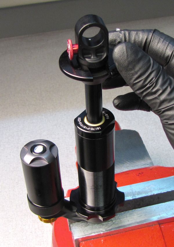
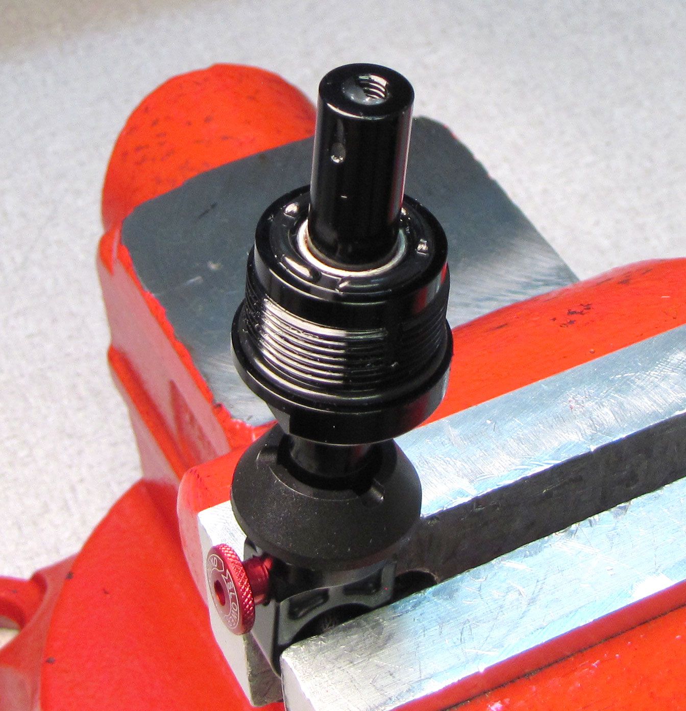
Step 1
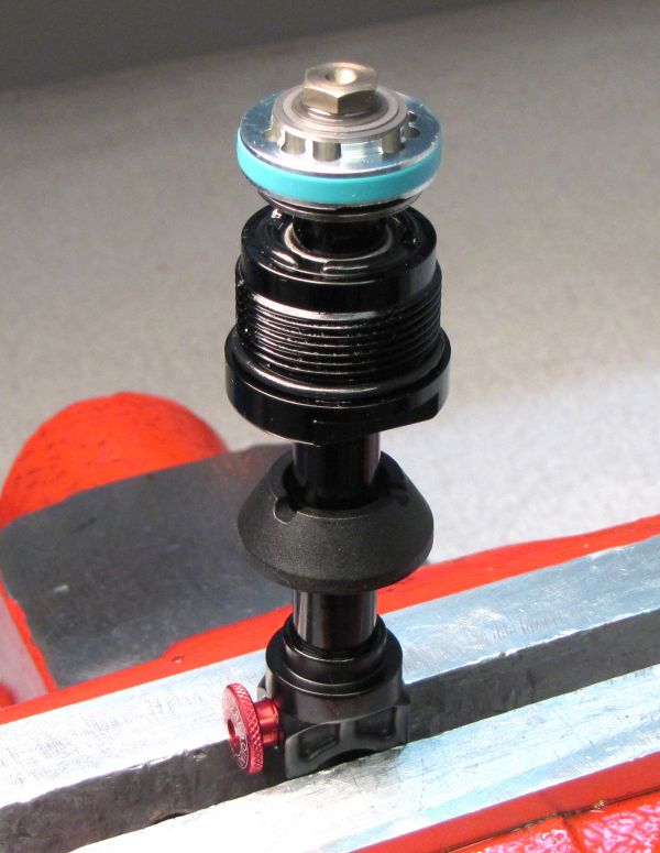
Remove the slotted spring retainer and set aside. Clamp your shock in the soft-jawed vice with the shaft up.


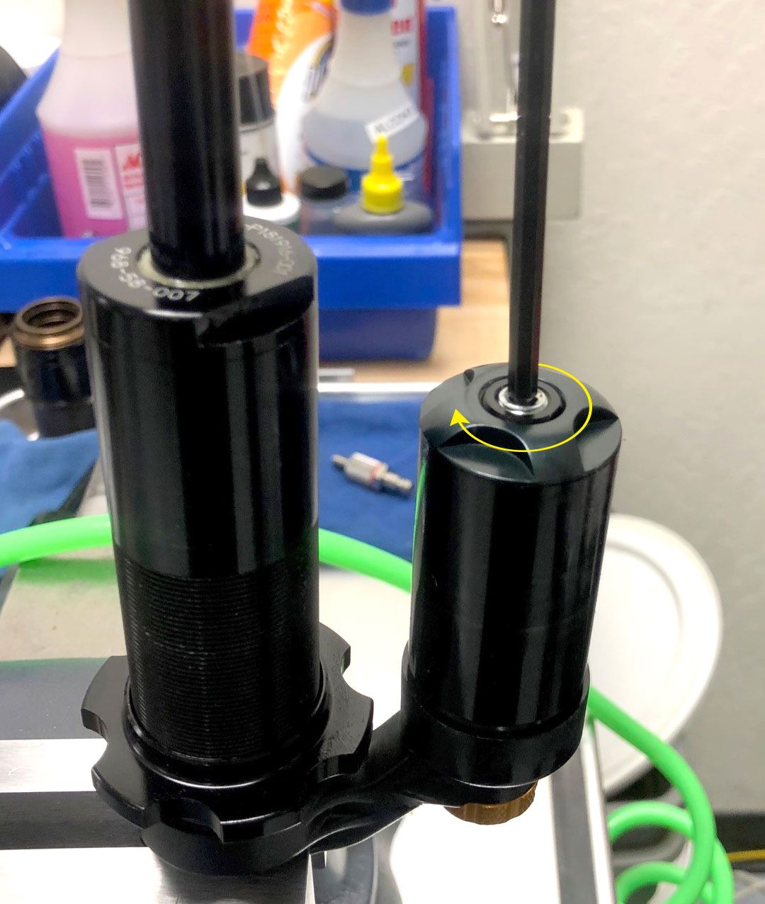
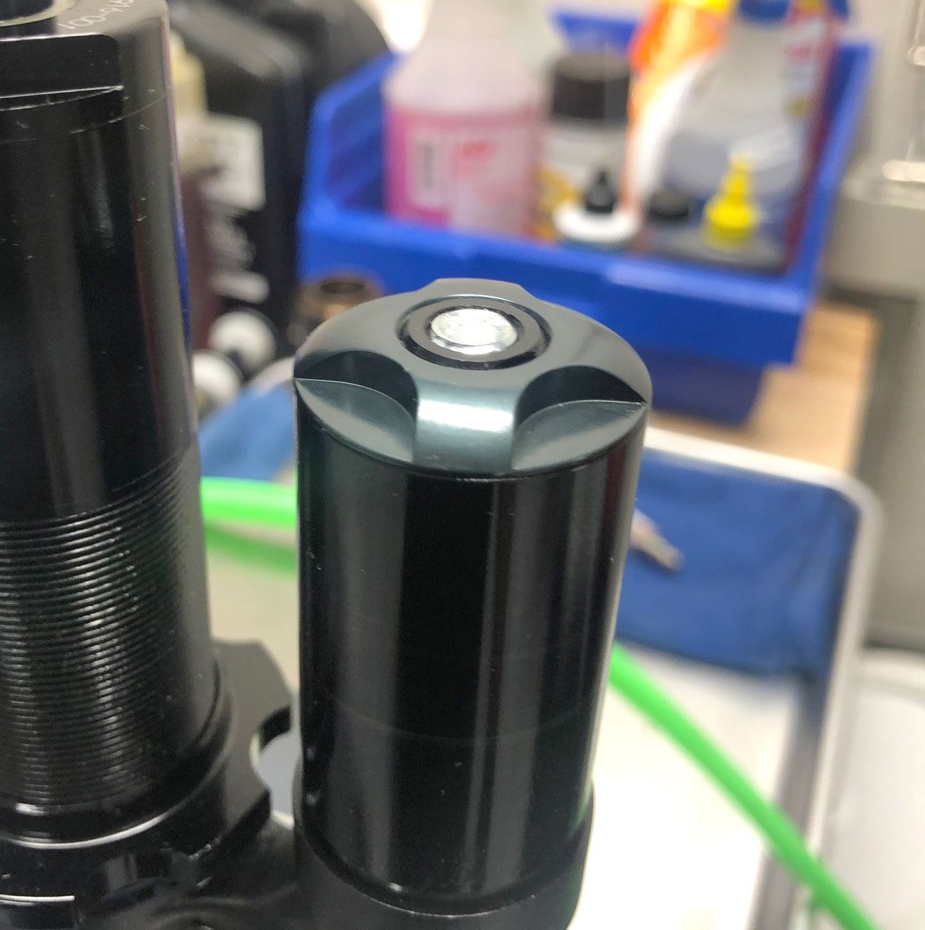
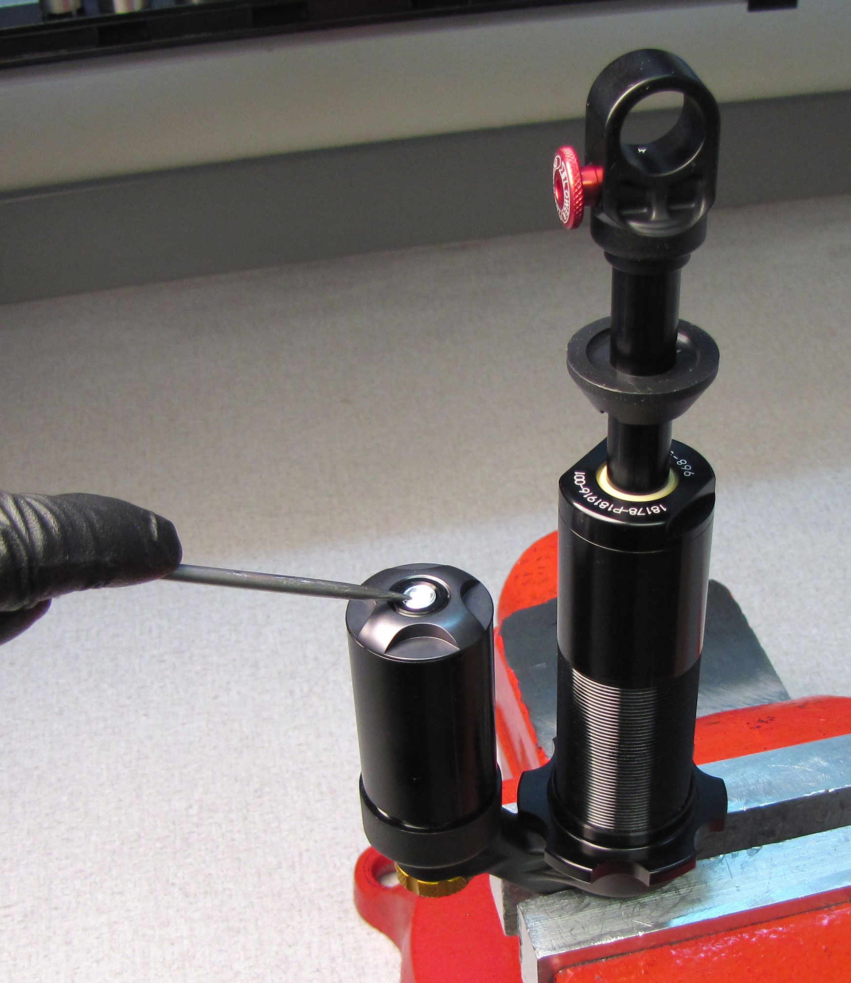
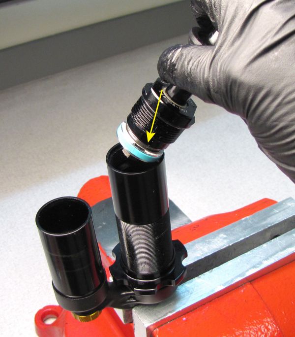
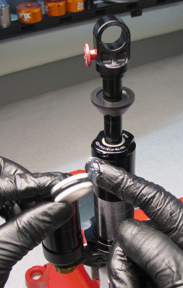
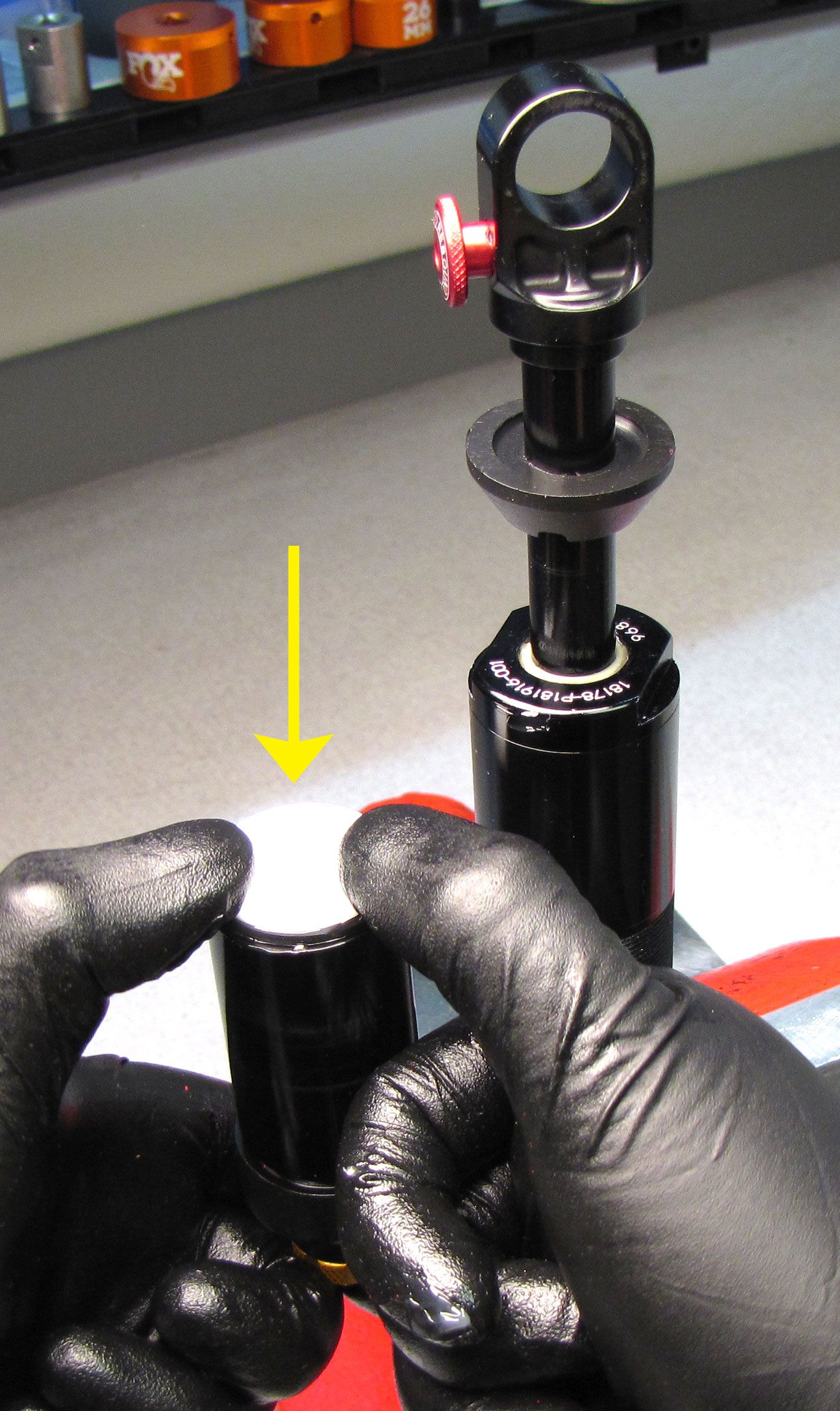
Step 2
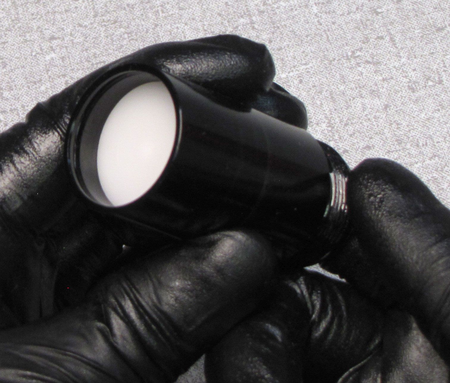
Remove the white Delrin ball from the pellet retainer in the reservoir end cap. Release the Nitrogen charge by unthreading the pellet retainer counter-clockwise with a 5/32" hex wrench. Remove the pellet retainer then discard the original pellet.


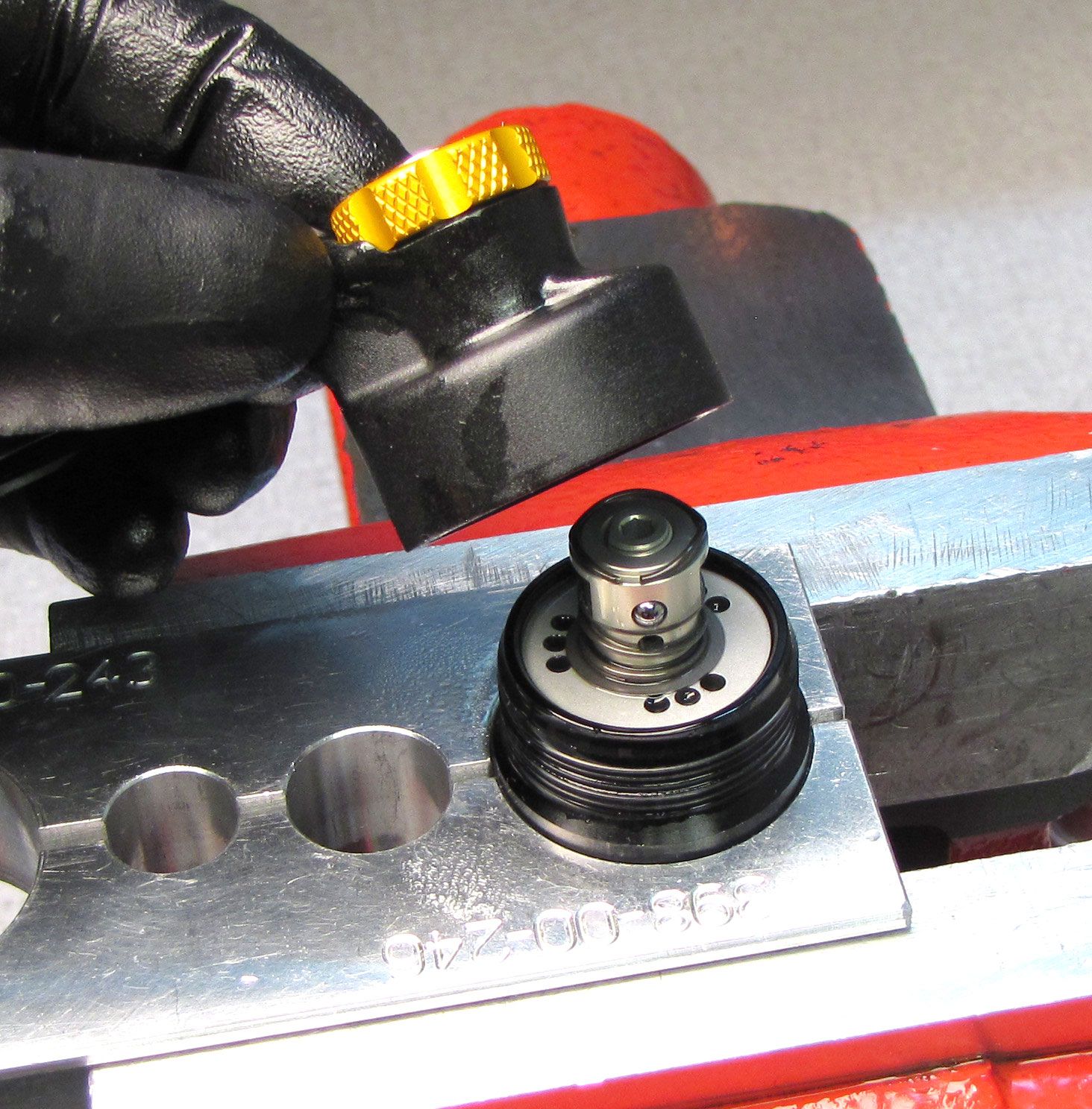
Step 3
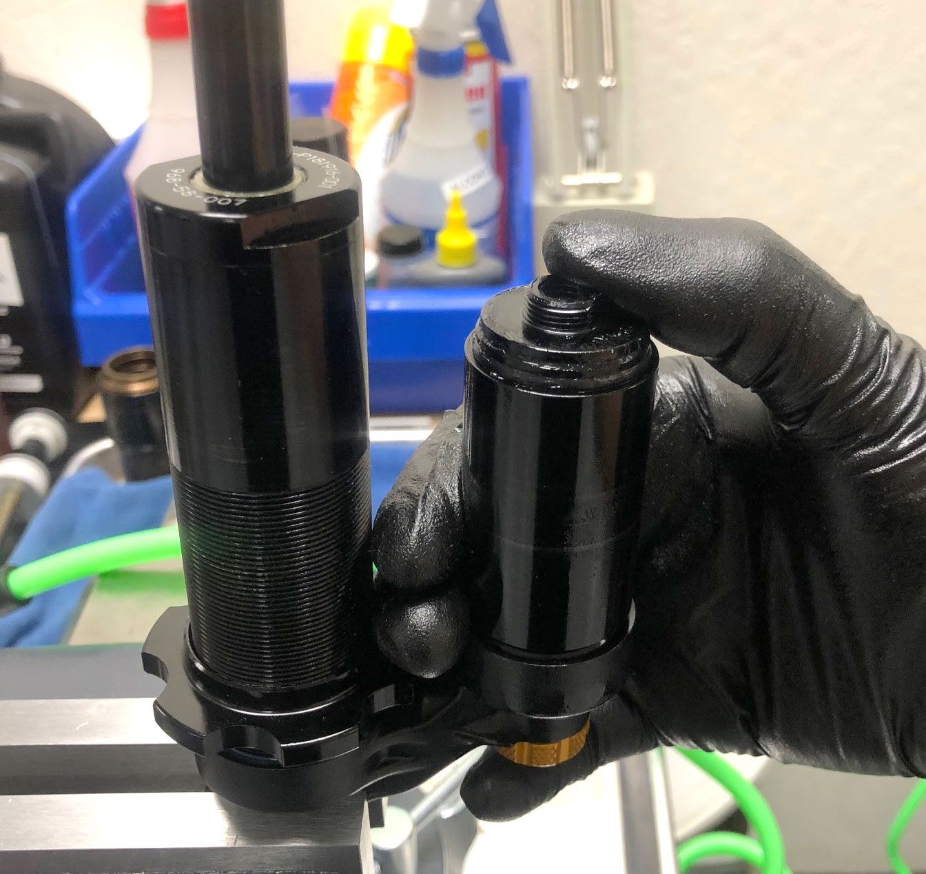
Unthread and remove the End Cap Lockring by turning it counter-clockwise. Push the End Cap Assembly into the reservoir to access the wire retaining ring.


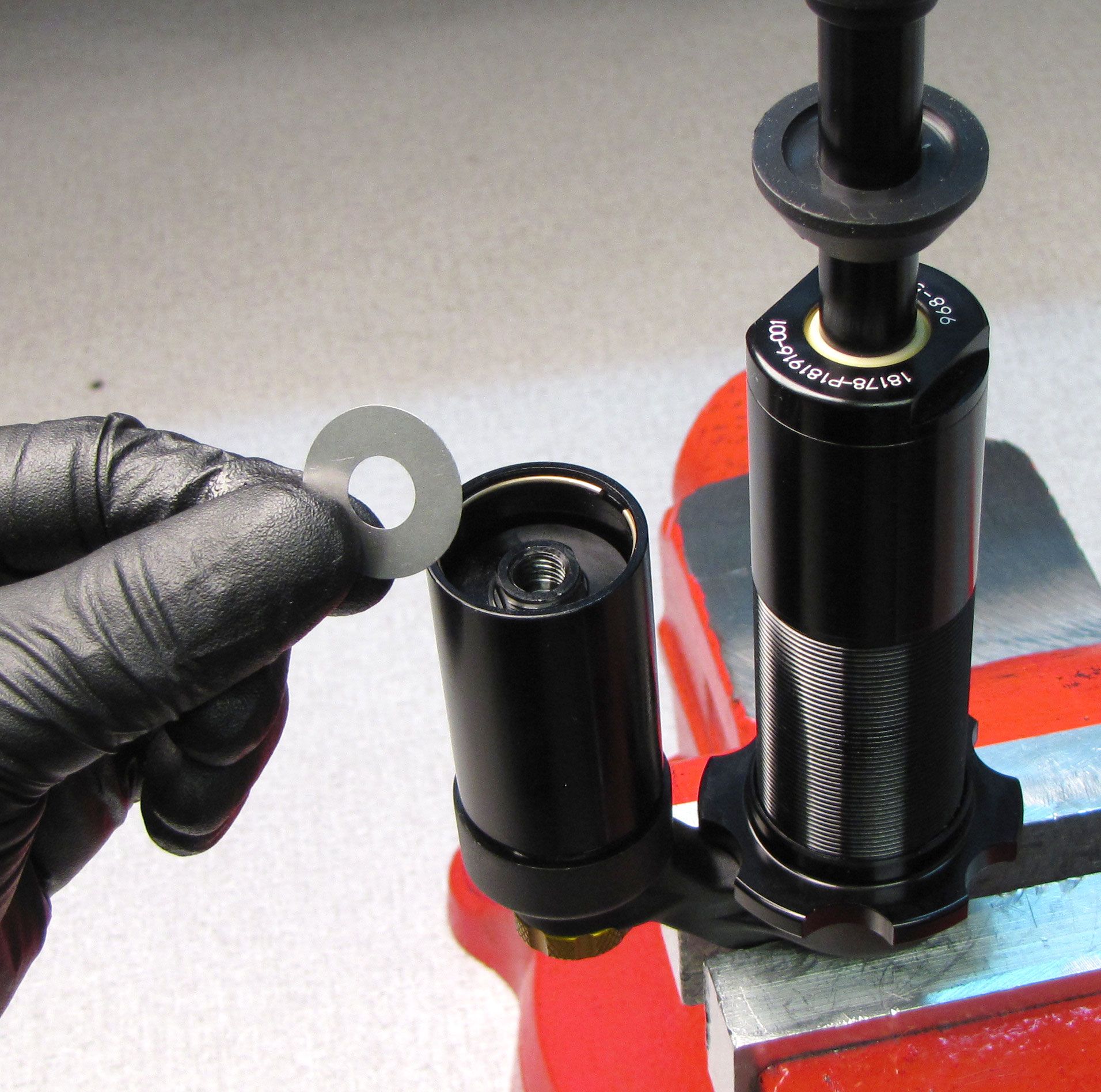
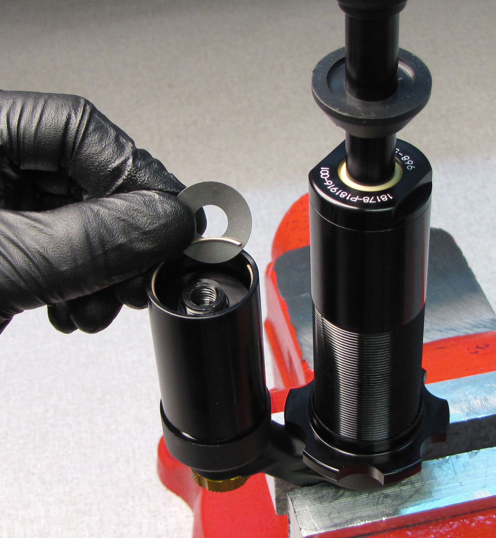
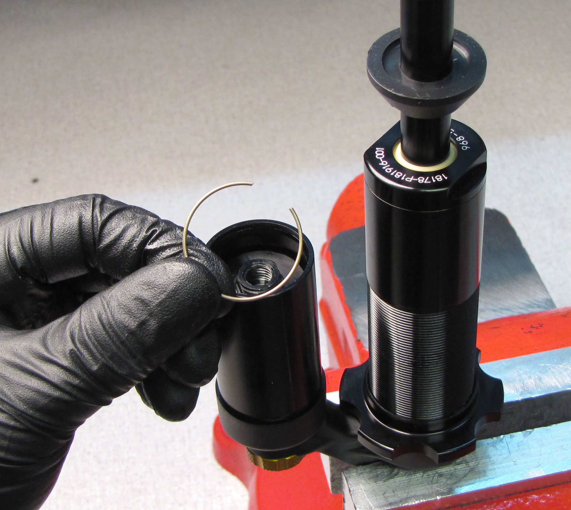
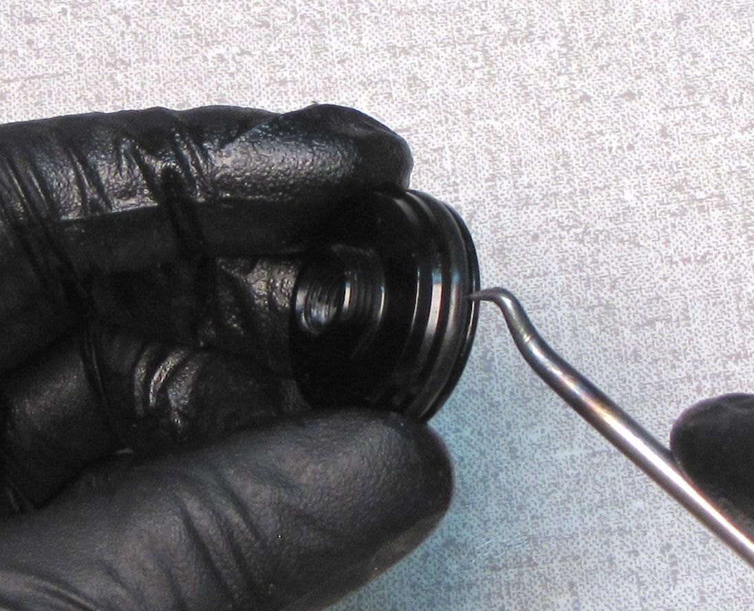
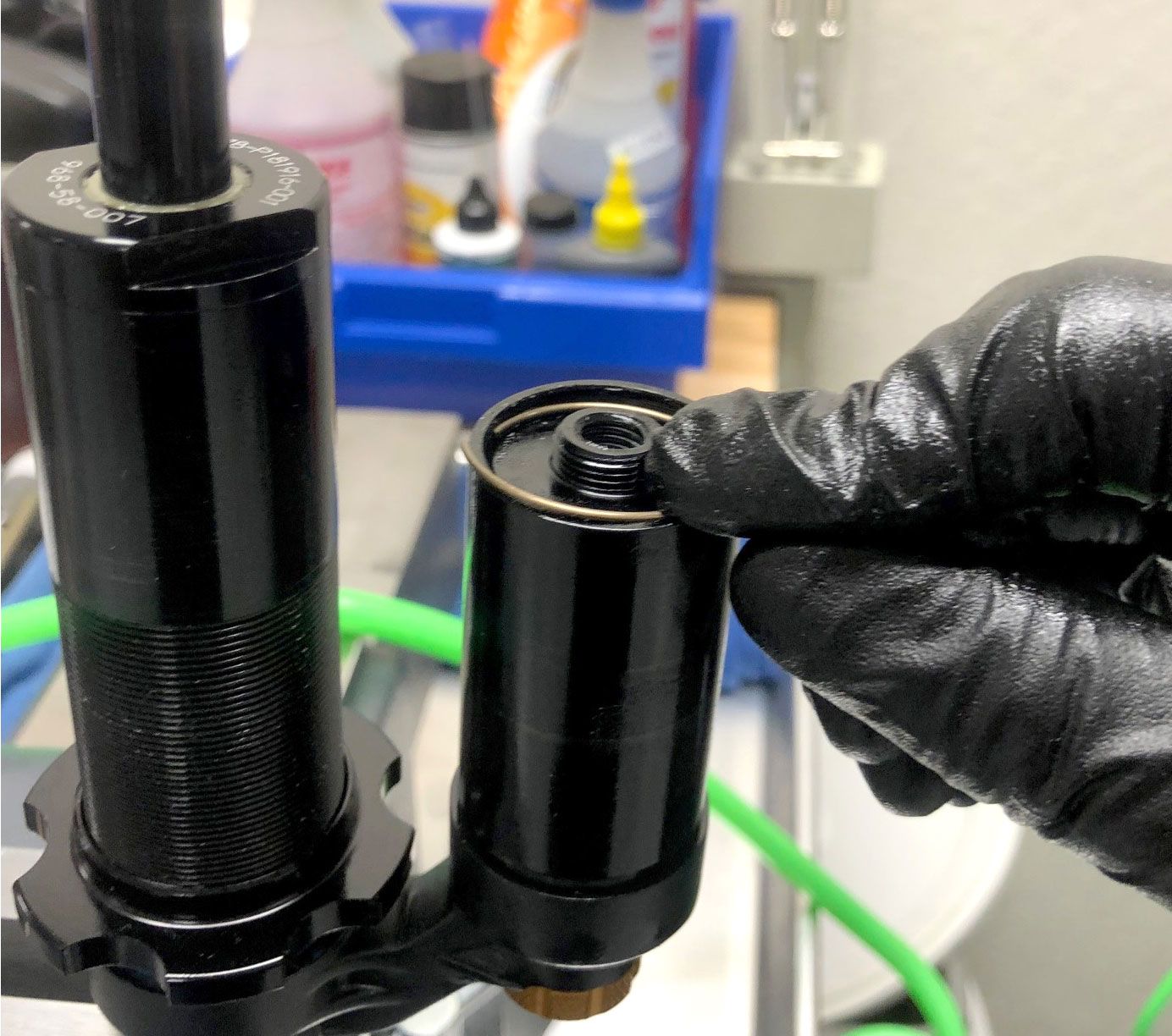
Step 4
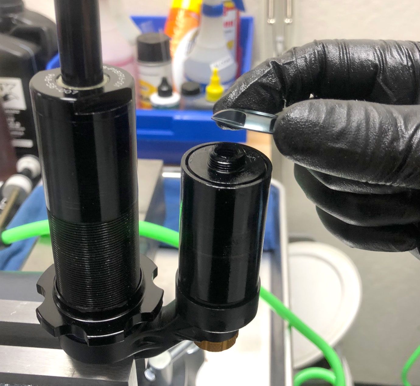
Remove the wire retaining ring from within the reservoir. You may use a shim to help lift the retaining ring.
Step 5
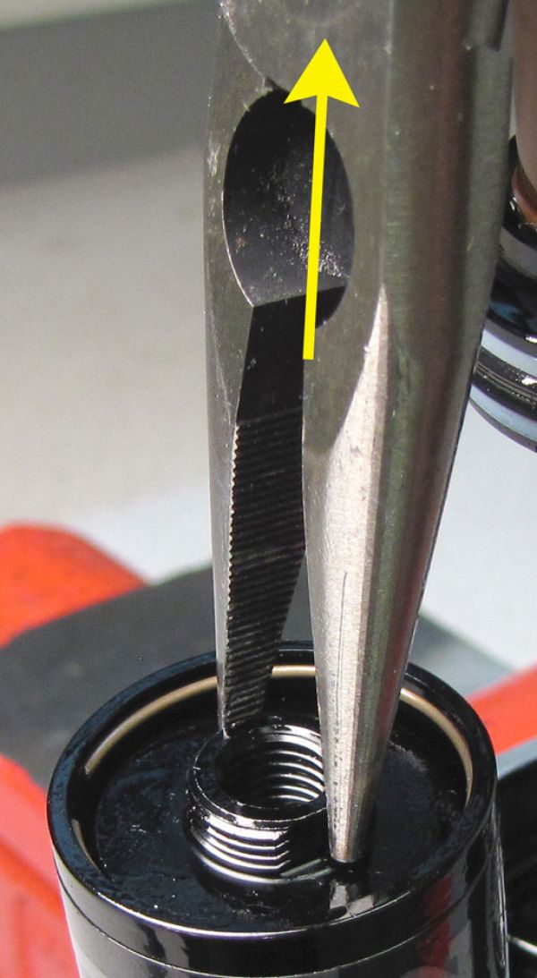
Remove the End Cap Assembly by threading a bolt (PN:018-02-034) into the internal threads of the End Cap and pulling up. You may also use an inverted End Cap Lockring to catch the external threads of the End Cap to pull it out if it hasn't been pushed in too deep.
If needed you may remove the End Cap Assembly by pulling it up with pliers. Only grip the End Cap Assembly by its flats and not the external threads. Replace the o-ring on the End Cap Assembly with a new greased one from the kit and set aside until reassembly.


Step 6
Unthread and remove the set screw and o-ring from the back of the adjuster eyelet with a 2mm hex wrench. Cycle the shock with the bleed port facing your waste oil basin to purge the majority of the damper oil.

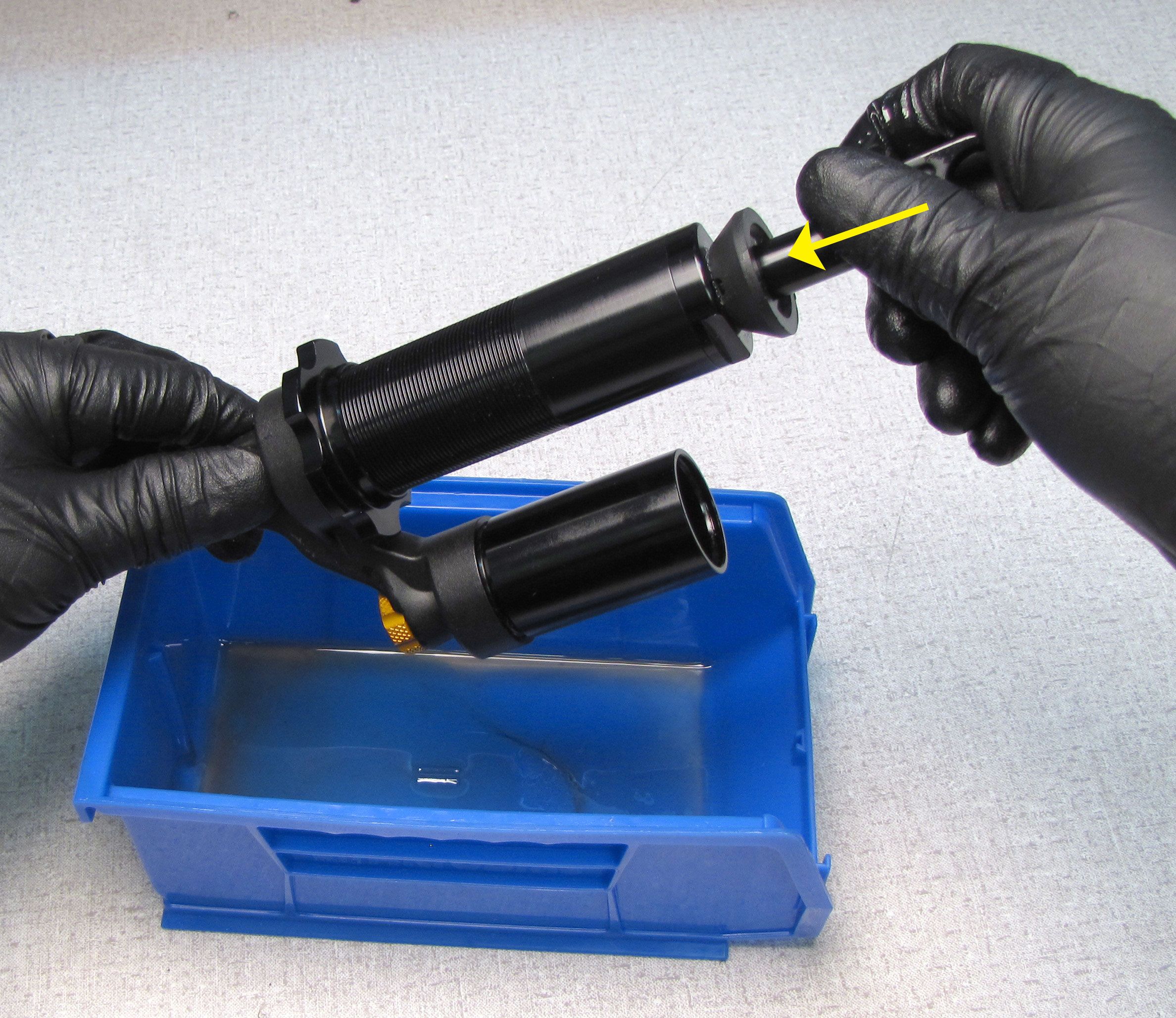
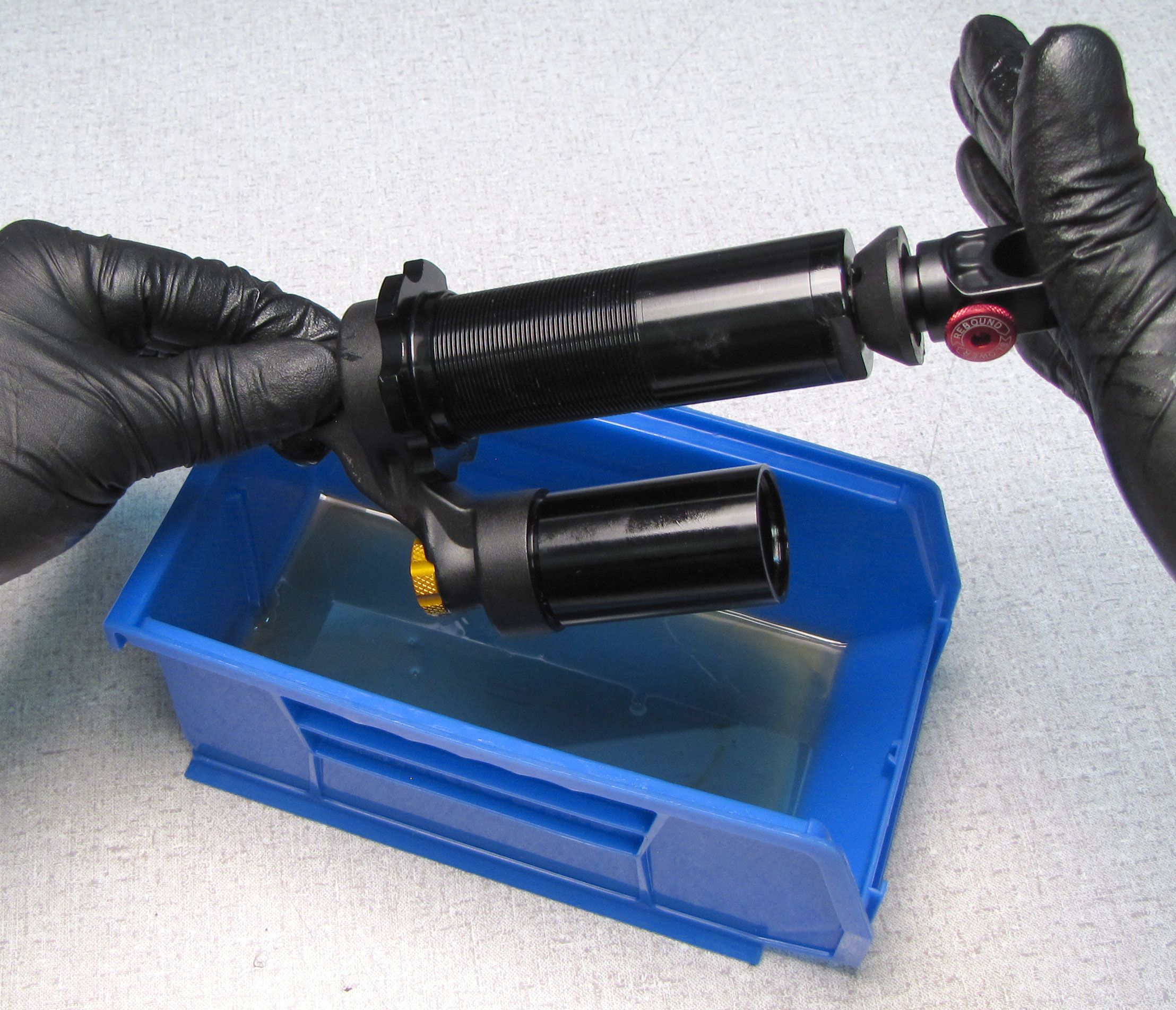
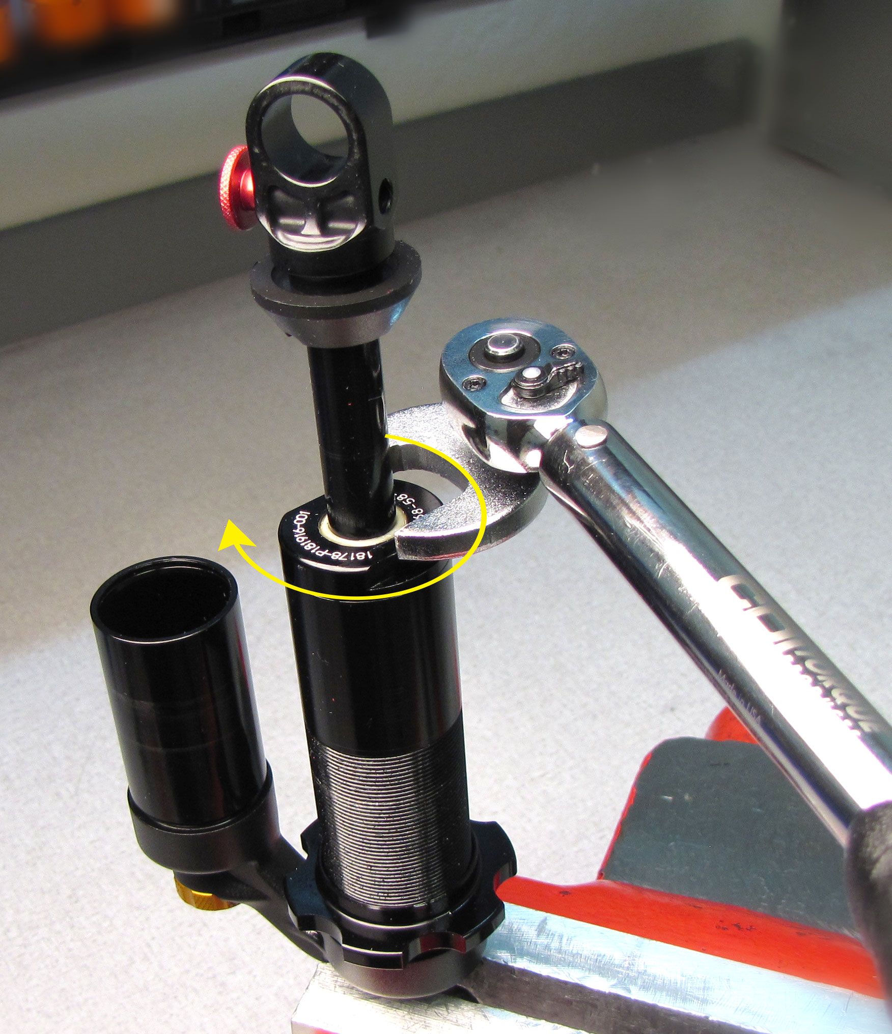
Step 7
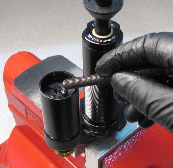
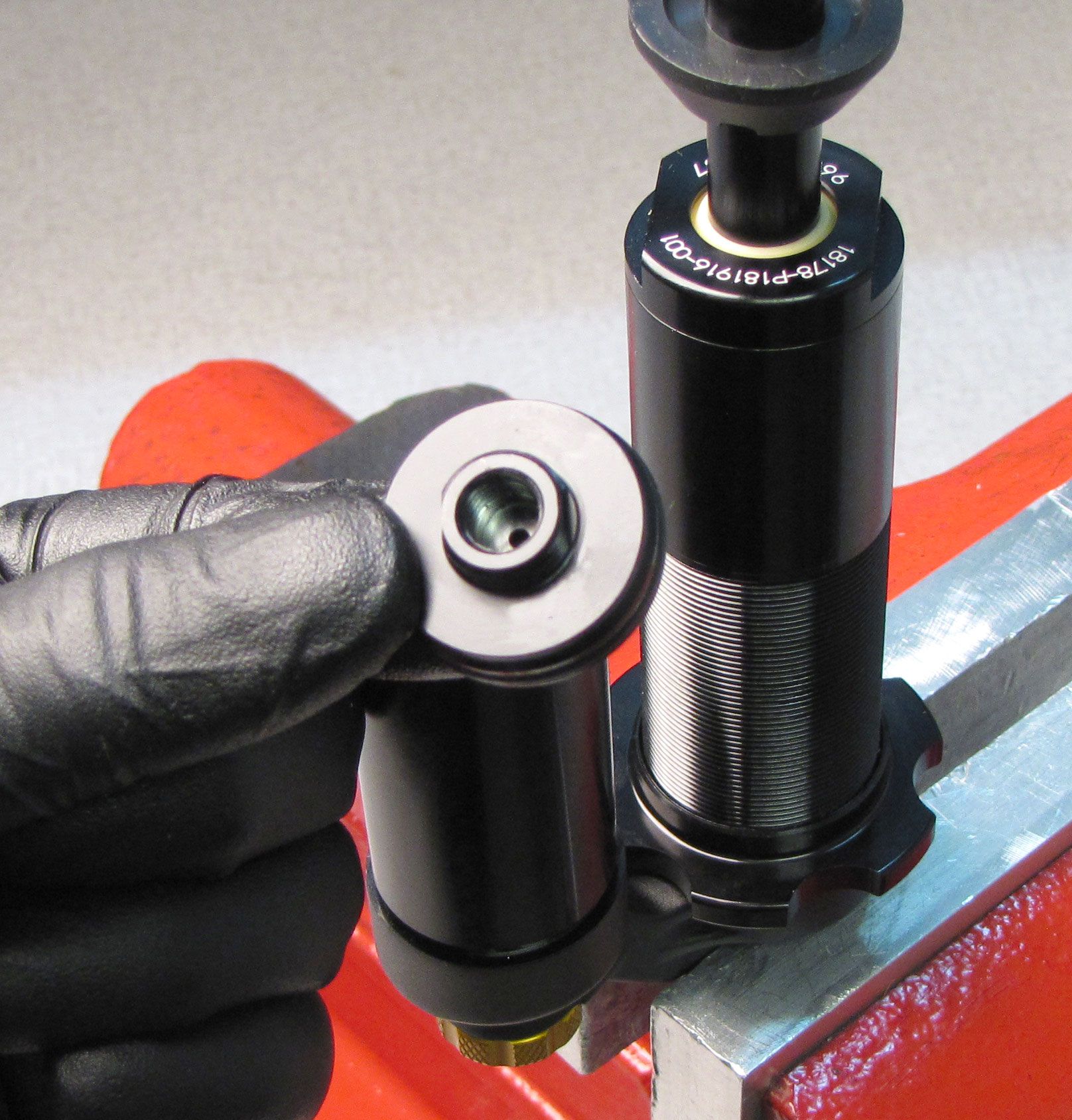
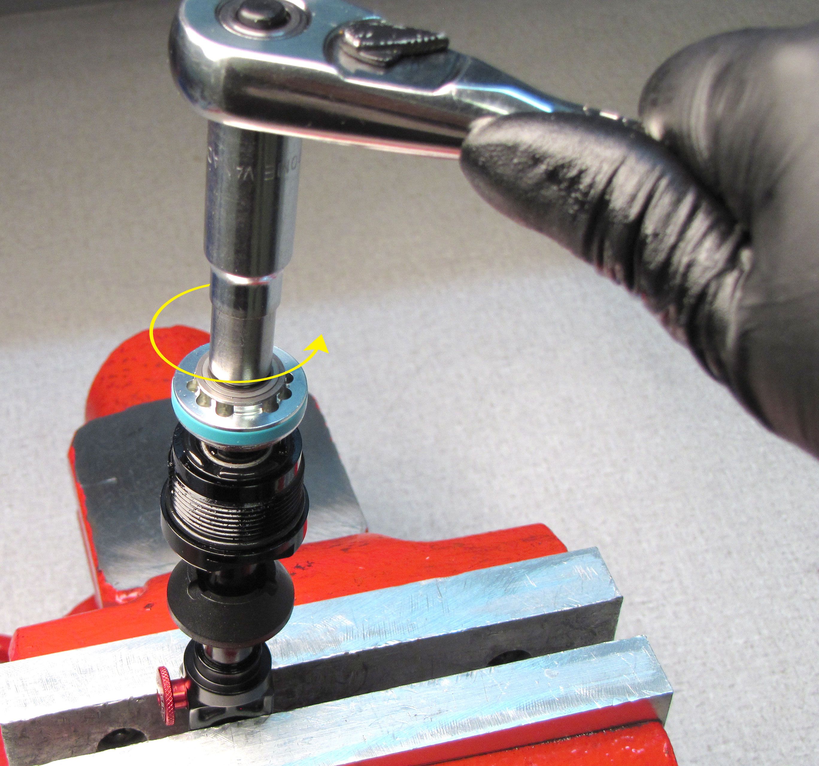
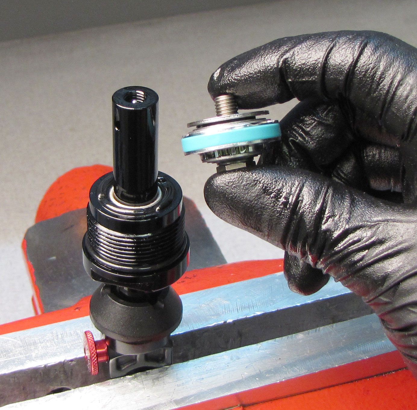
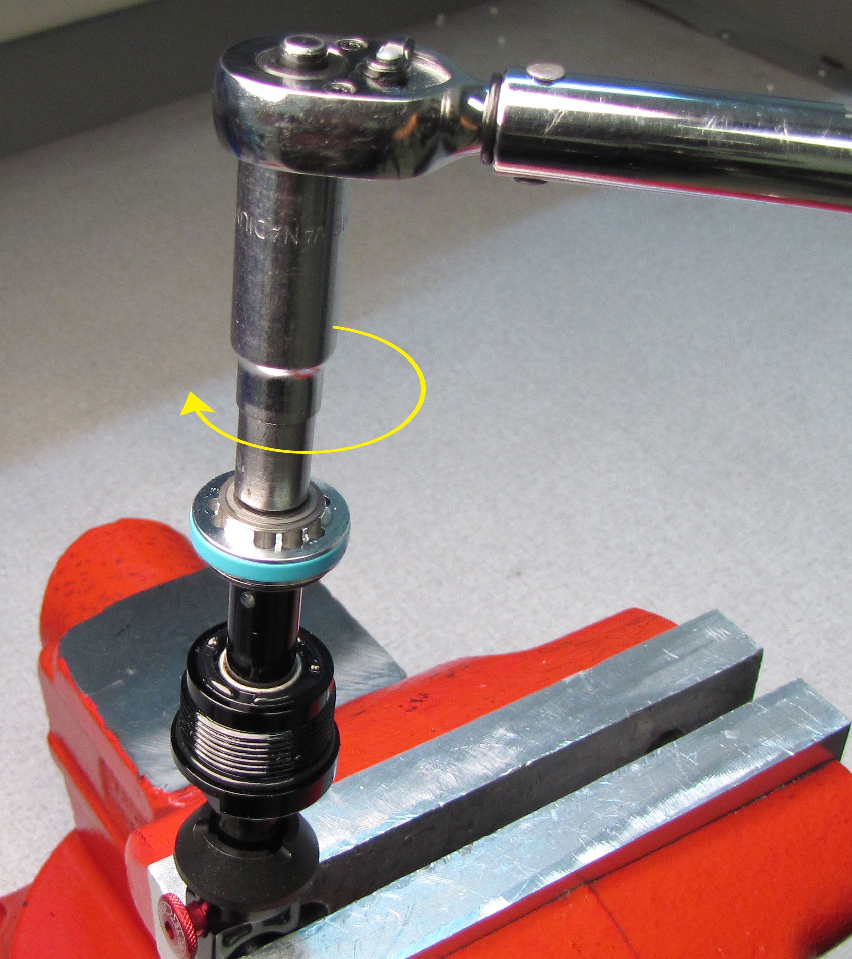
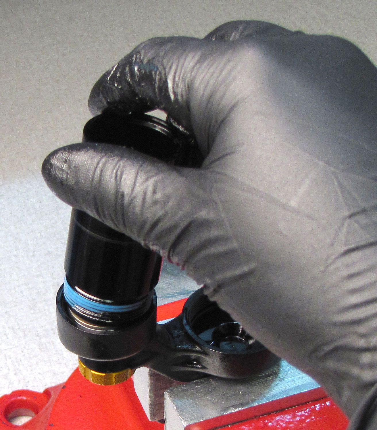
Unthread the bearing assembly from the body (counter-clockwise) with Knipex smooth/parallel jawed pliers or a 1" wrench. Remove the shaft assembly by pulling up.

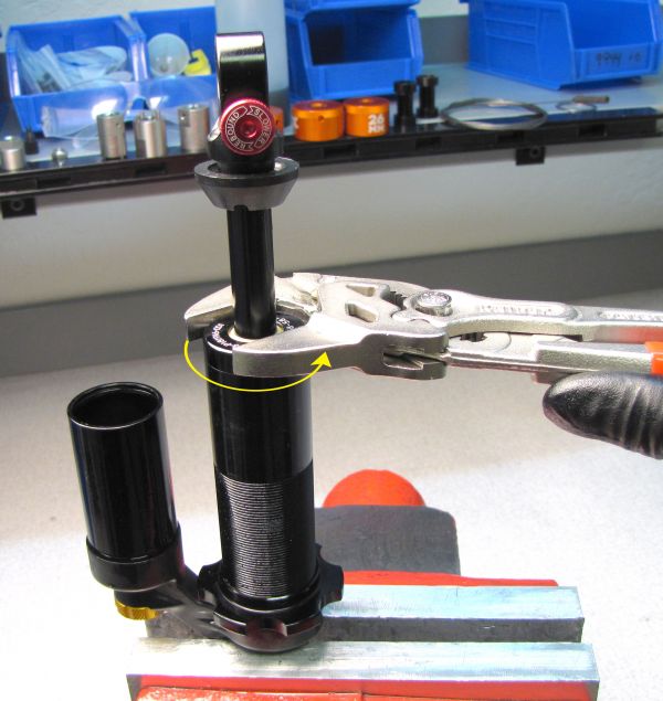
Step 8
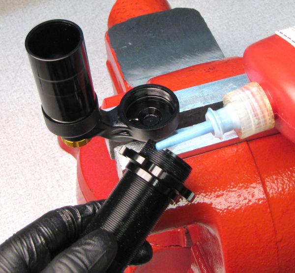
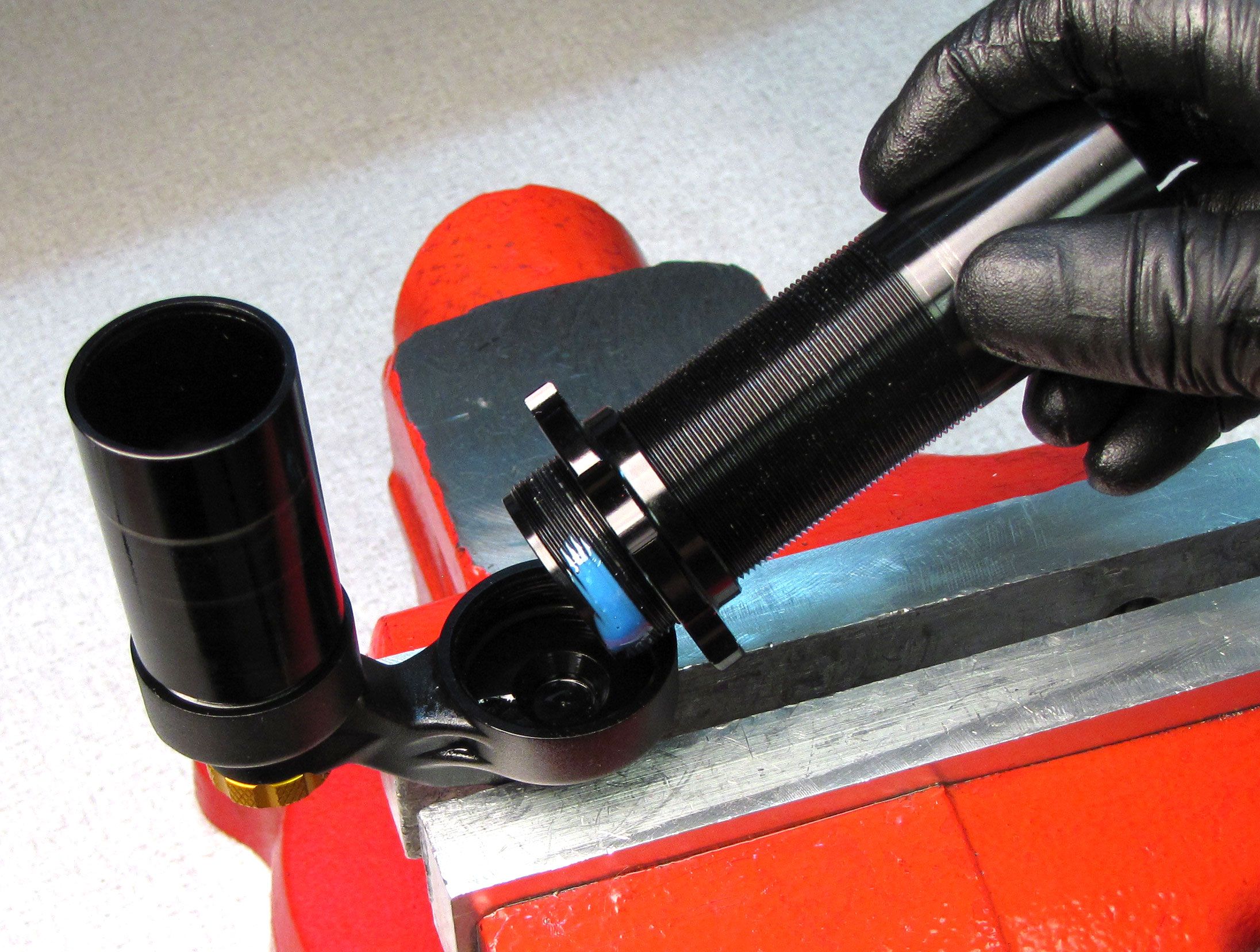
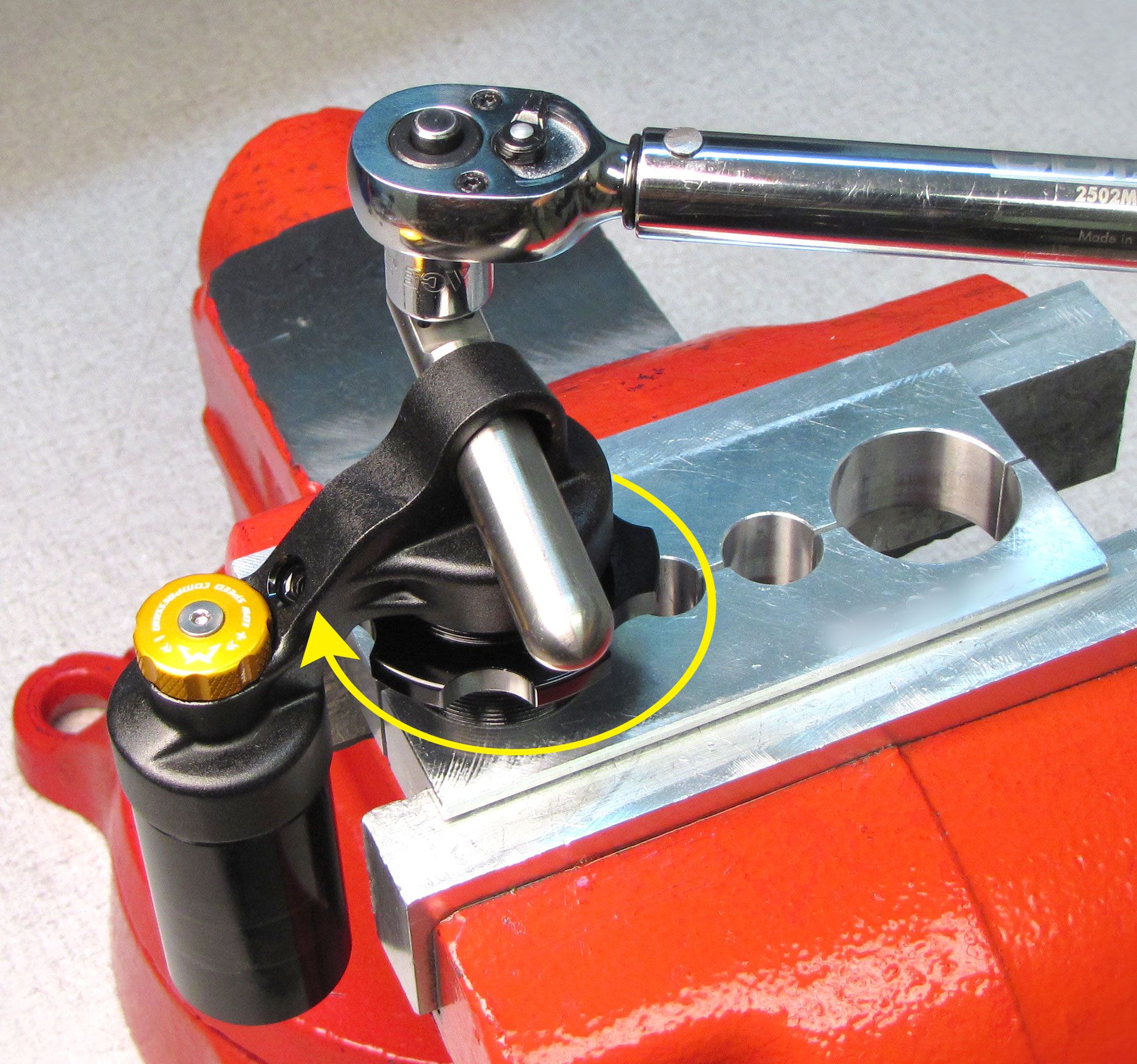
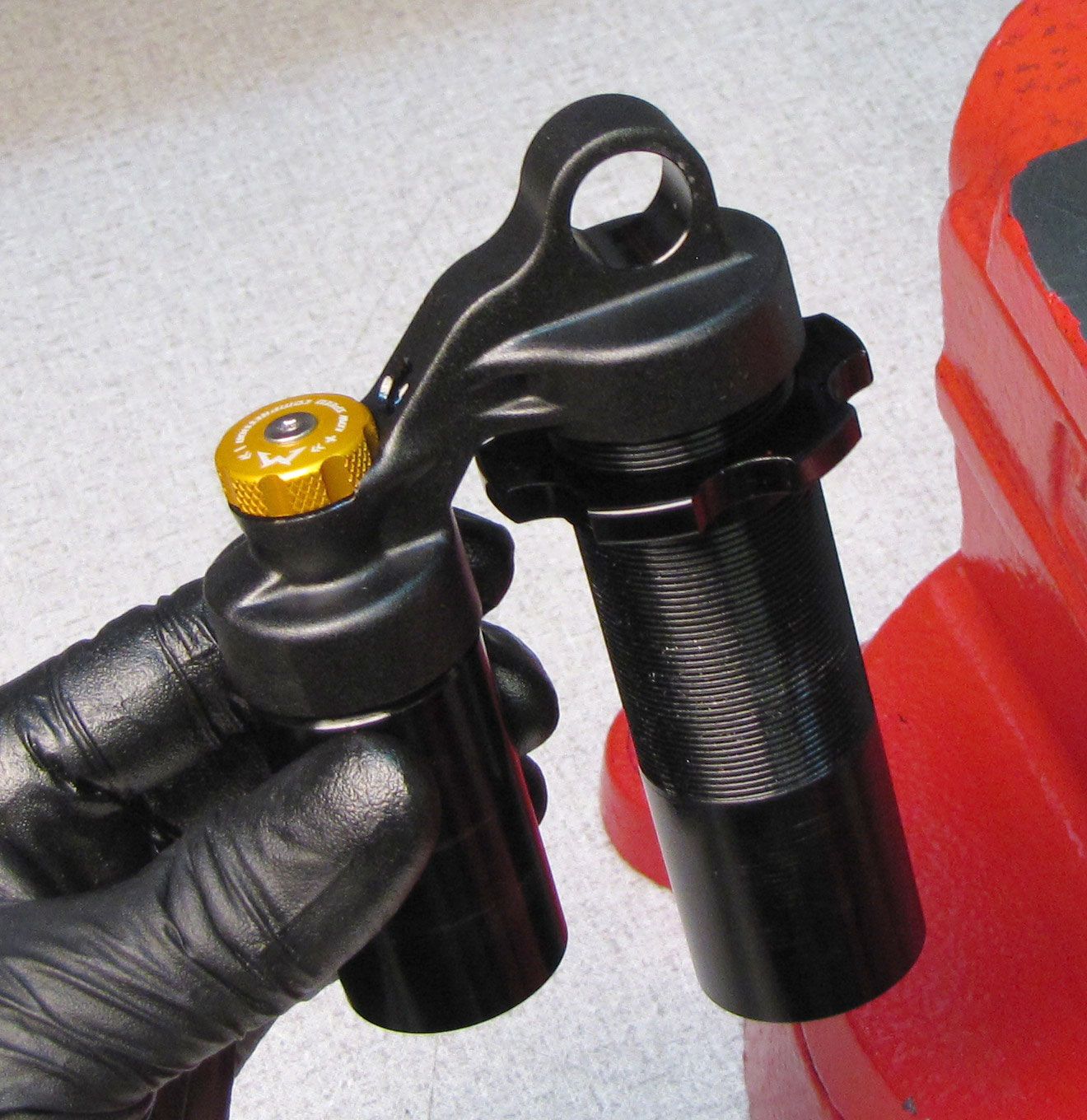
Clean the threaded portion of the body with Isopropyl alcohol and a lint-free paper towel. Clamp the body in shaft clamps PN: 803-00-208 and apply heat with a propane torch to the area where the eyelet overlaps the shock body. Unthread the eyelet counter-clockwise from the body. You will need to reposition the body in your shaft clamps multiple times to fully unthread the eyelet.

Step 9
Remove the decal from the reservoir then clean the outside of the reservoir with Isopropyl alcohol and a lint-free paper towel. Clamp the reservoir in shaft clamps PN: 803-00-208 and apply heat with a propane torch to the area where the eyelet overlaps the reservoir. Turn the eyelet counter-clockwise to unthread it from the reservoir.

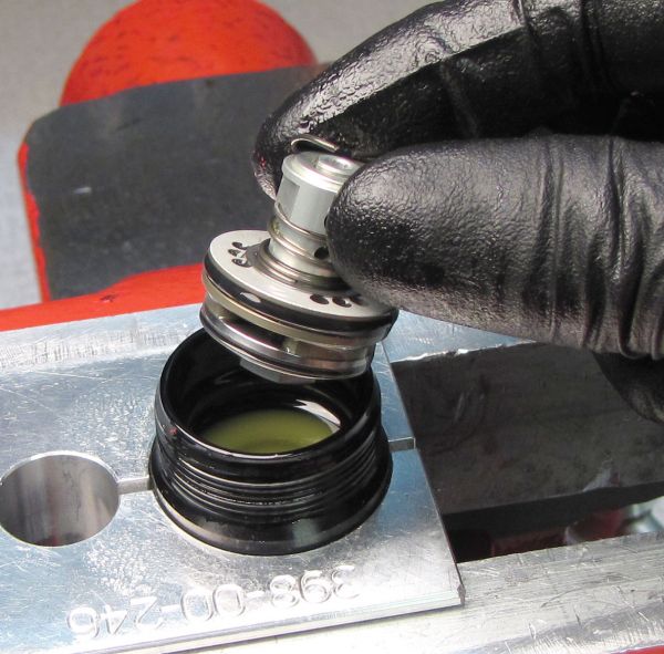
Step 10
Remove the Damping Adj Assembly from the reservoir by pulling it up. Replace the o-ring on the outside of the Damping Adj Assembly with a new greased one from the kit.


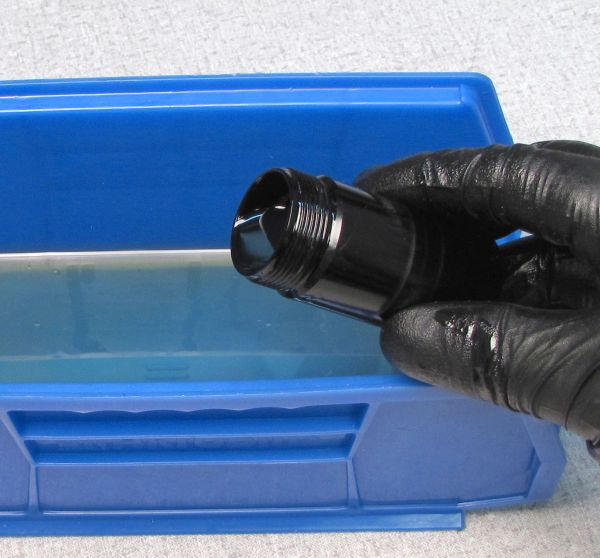
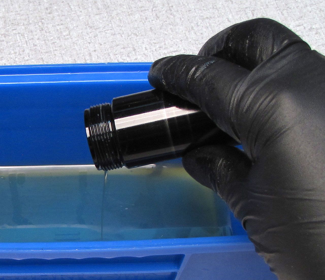
Step 11
Remove the reservoir from the shaft clamps then invert and pour out the oil into your waste oil basin. Push the IFP out through the unthreaded end of the reservoir. Replace the IFP o-ring with a new greased one from the kit.


Step 12
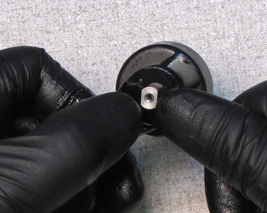
Clamp the rebound adjuster eyelet in your soft-jawed vise (do not clamp the red rebound knob). Unthread the piston bolt counter-clockwise with a 3/8" socket. Remove the valving assembly keeping all parts in their original order.

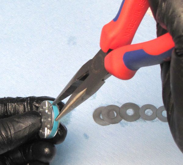
Step 13
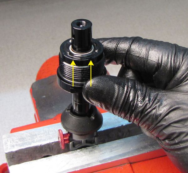
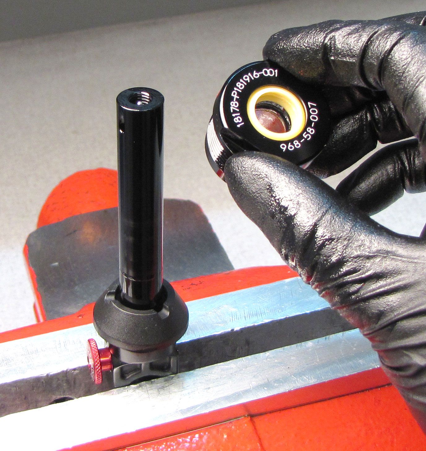
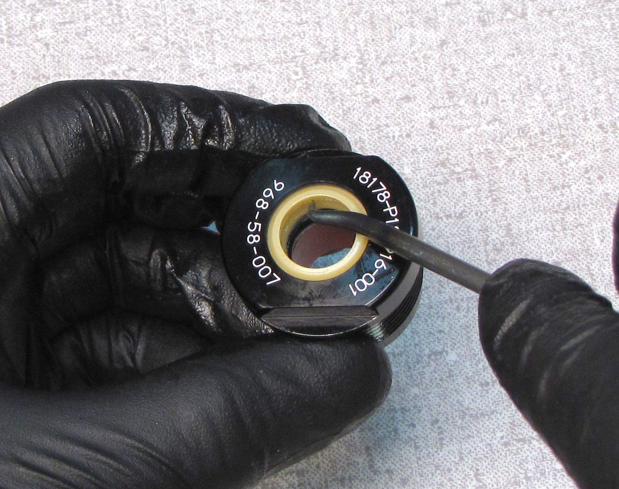
Remove the bearing assembly from the shaft by pulling it up. Replace all the seals on the bearing assembly with new greased ones from the kit and set aside.


Step 14
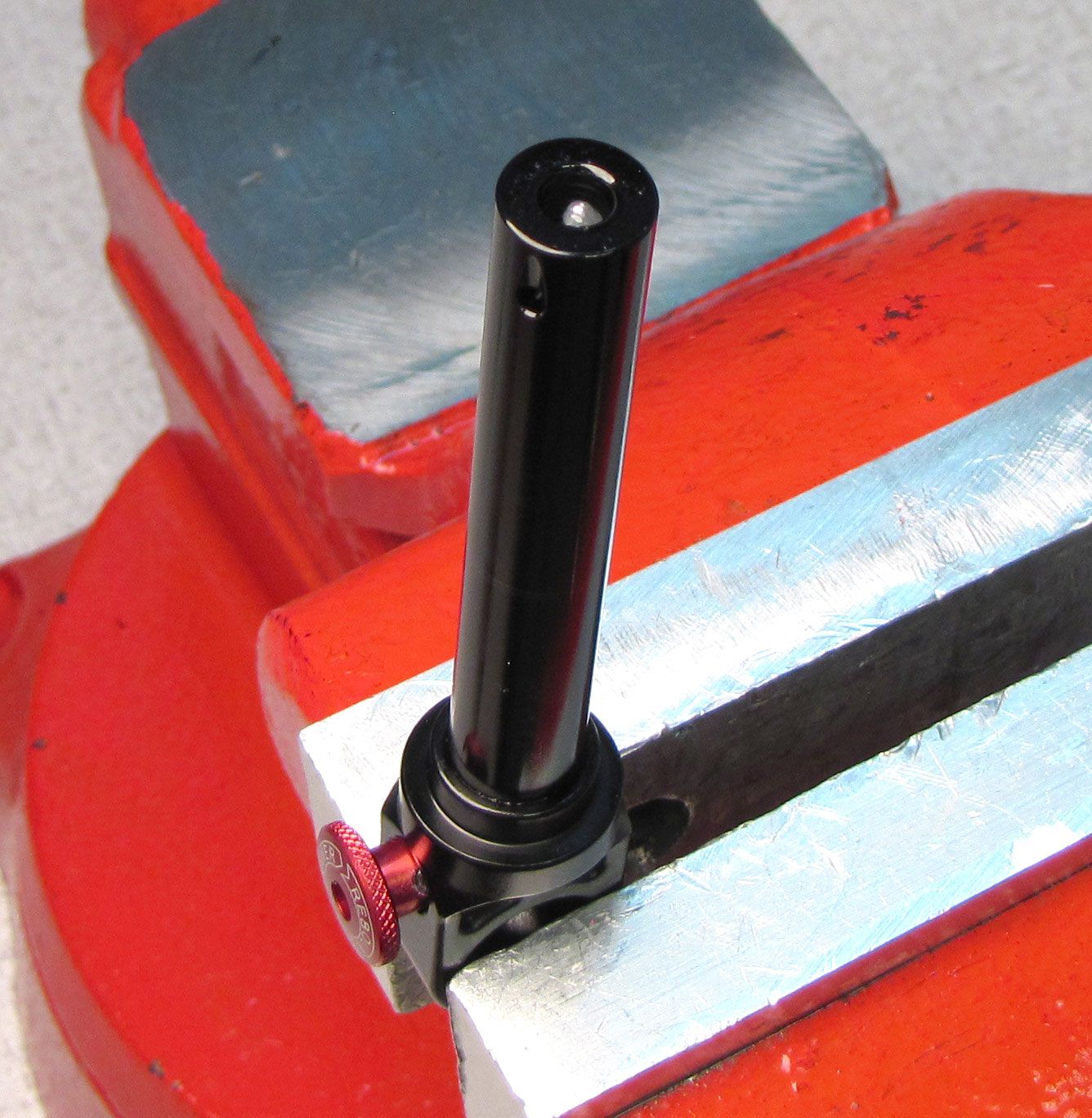
Remove the bottom out bumper by pulling it up off of the shaft. Invert the shaft in your shaft clamps.

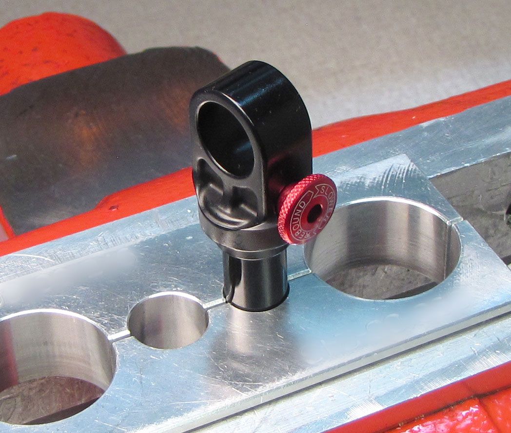
Step 15
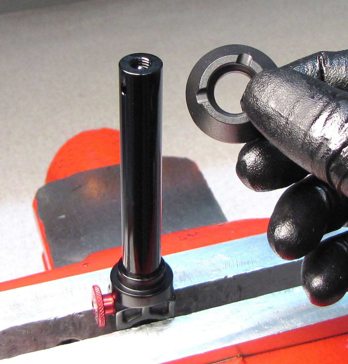
Apply heat to the shaft eyelet with a propane torch to break down the Loctite. Unthread the eyelet counter-clockwise from the shaft.


Step 16
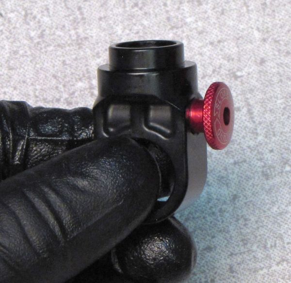
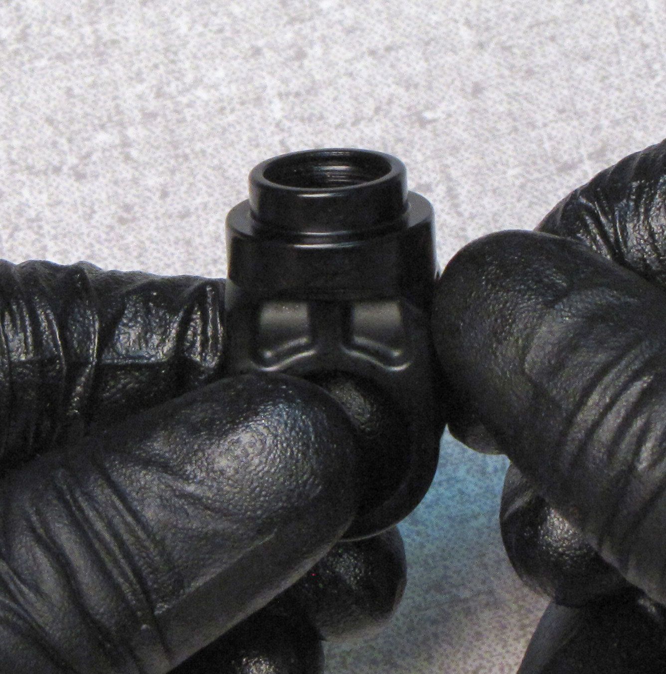
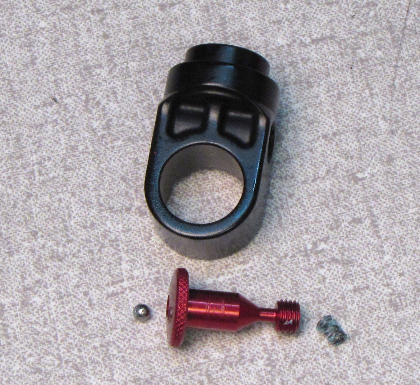
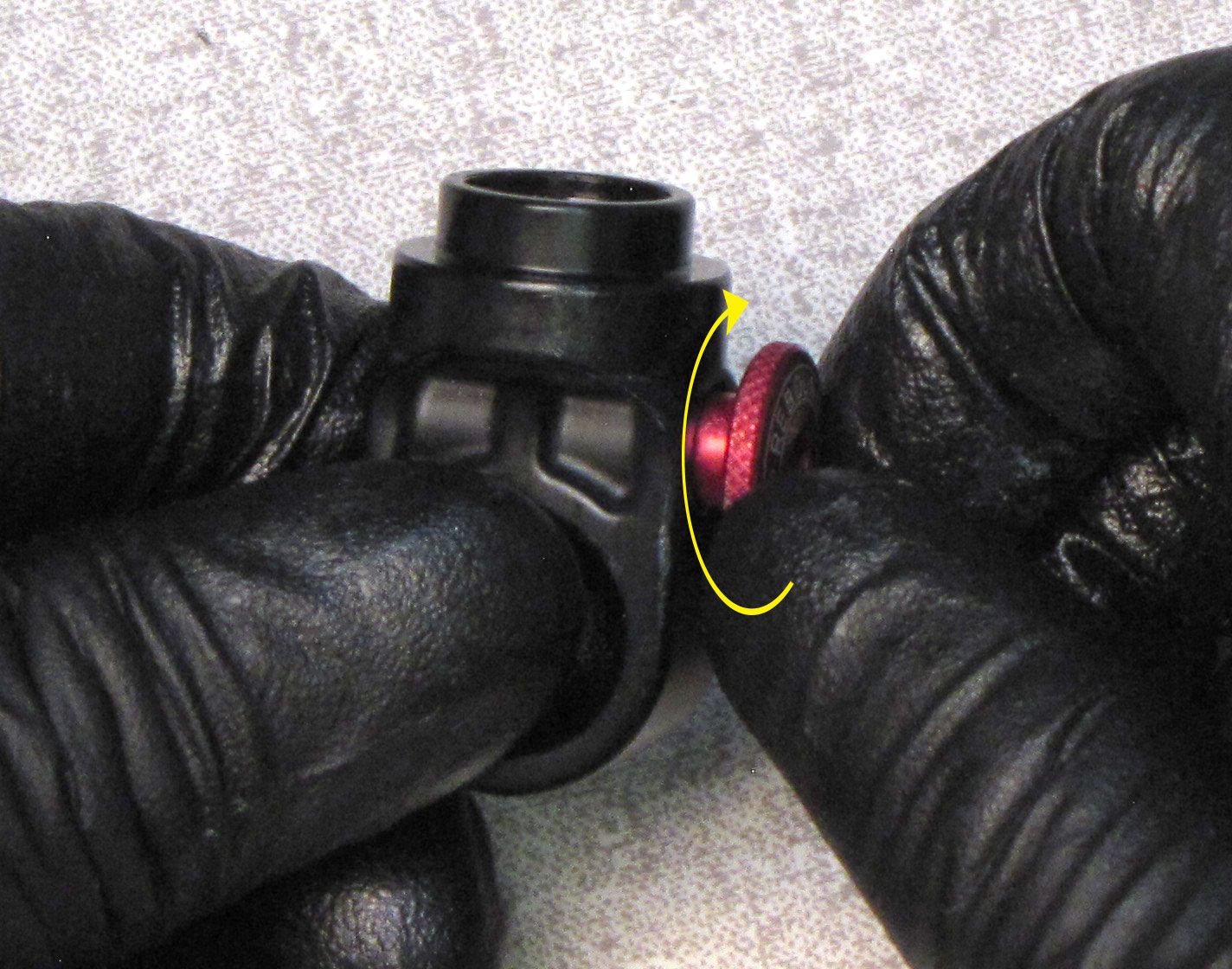
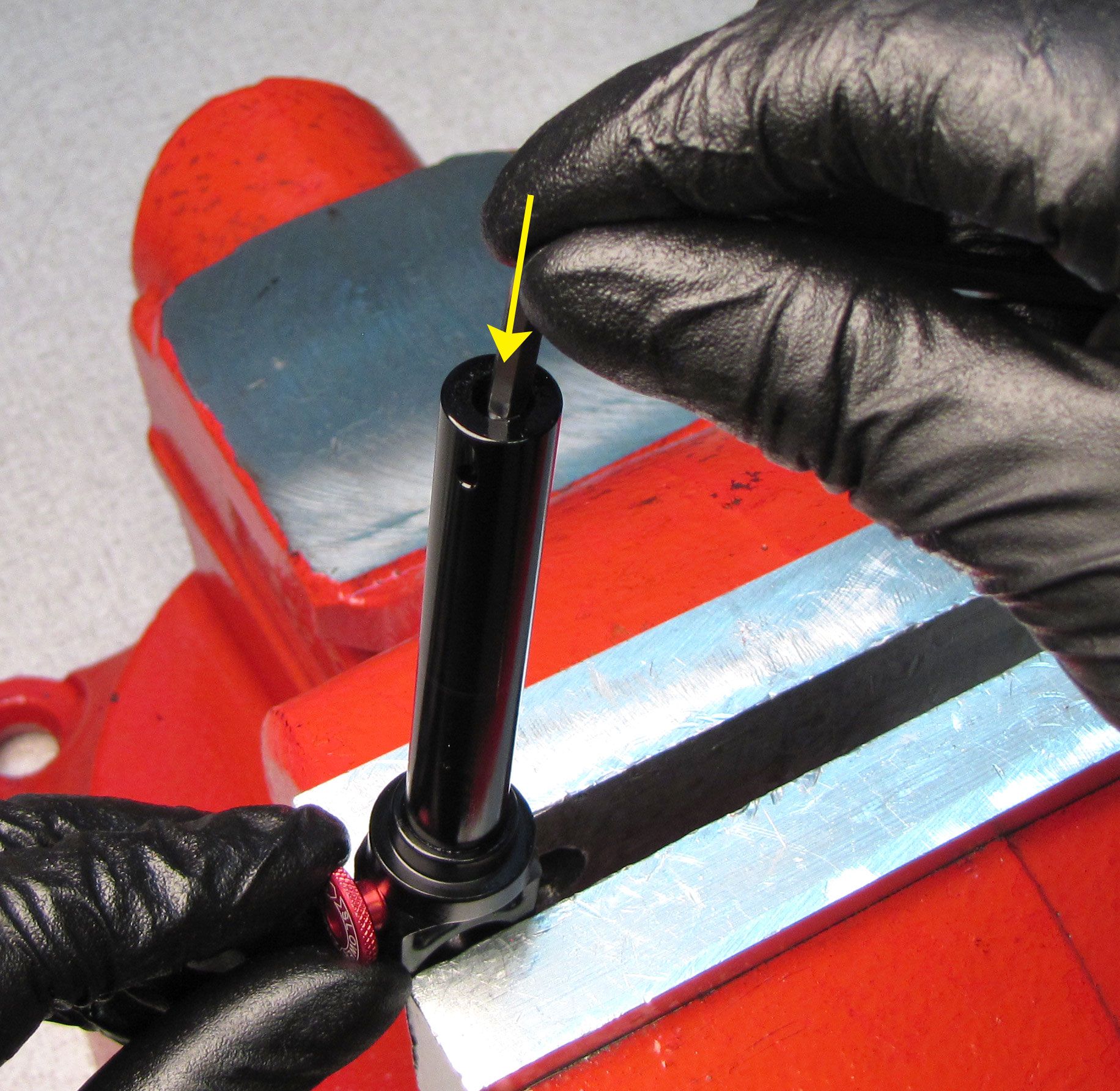
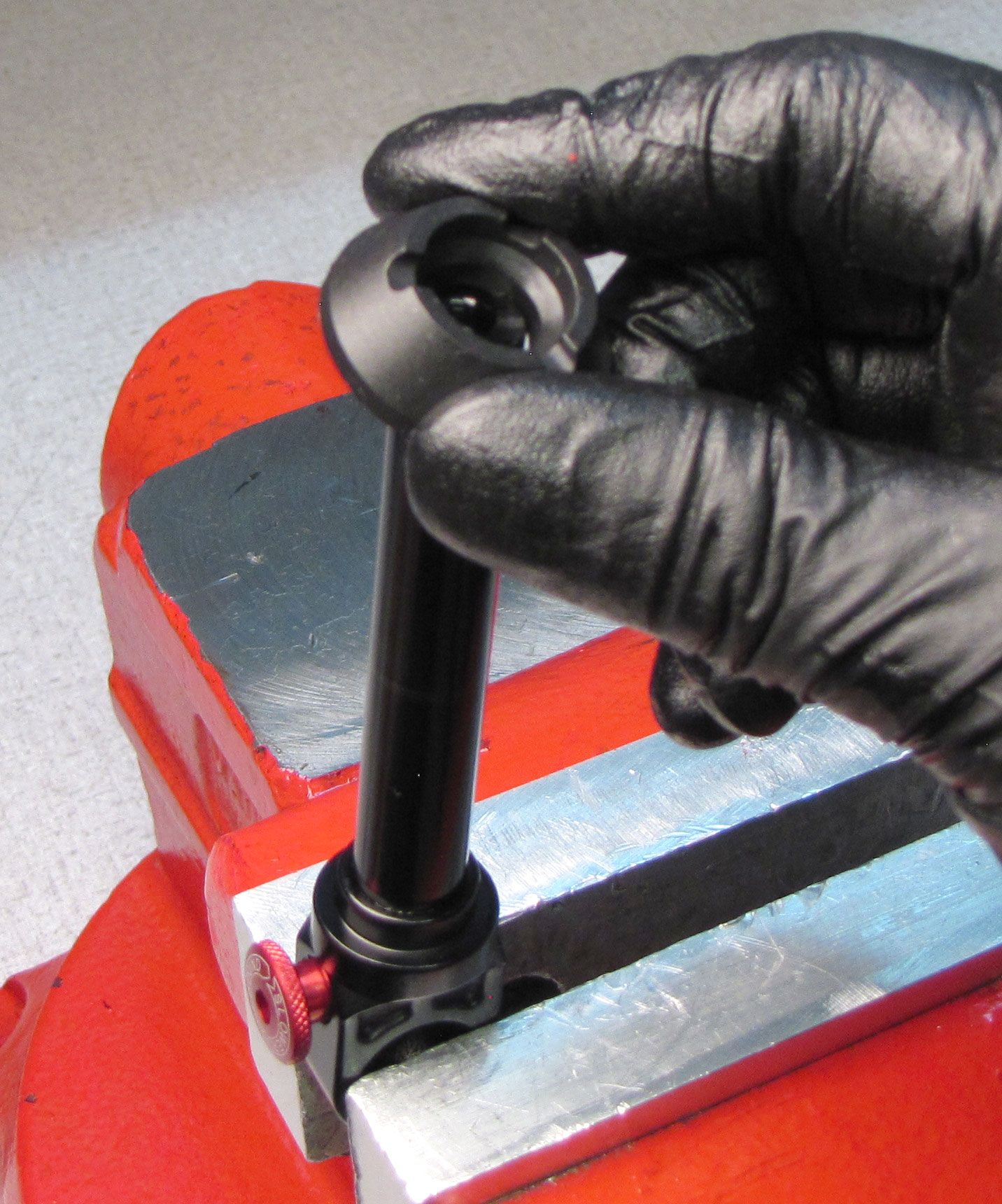
Unthread the red rebound knob counter-clockwise from the shaft eyelet while carefully watching for the detent ball and spring. Remove the ball and spring and clean all components with Isopropyl alcohol.


Step 17
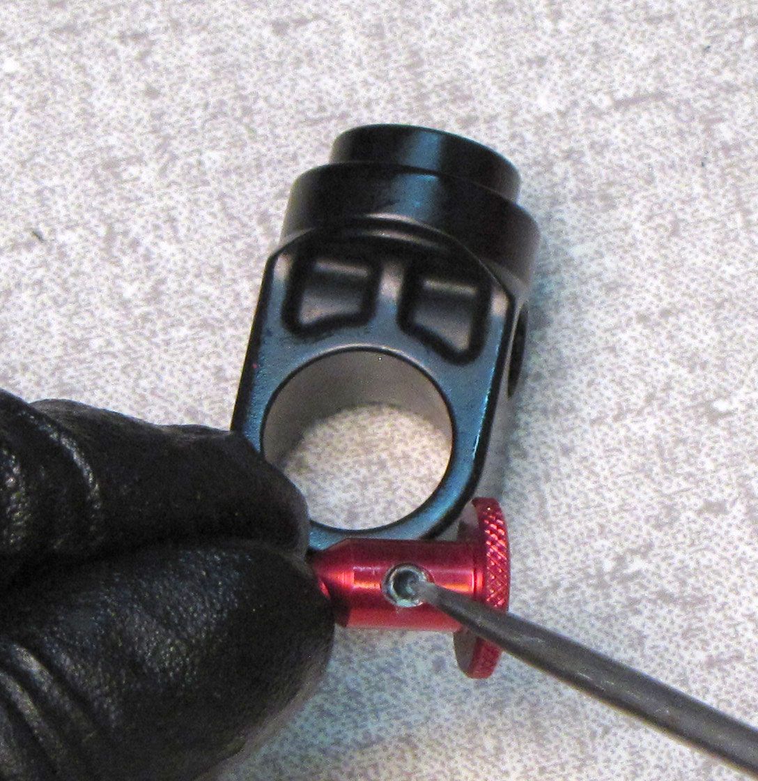
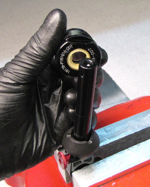
Coat the detent spring with a thin film of waterproof marine grease such as STA-LUBE SL3125. Insert the greased spring into the hole in the red rebound knob. Position the detent ball on the spring. Guide the ball into the eyelet as you thread the red rebound knob clockwise.

Step 18
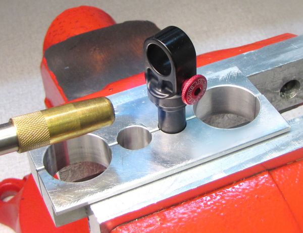
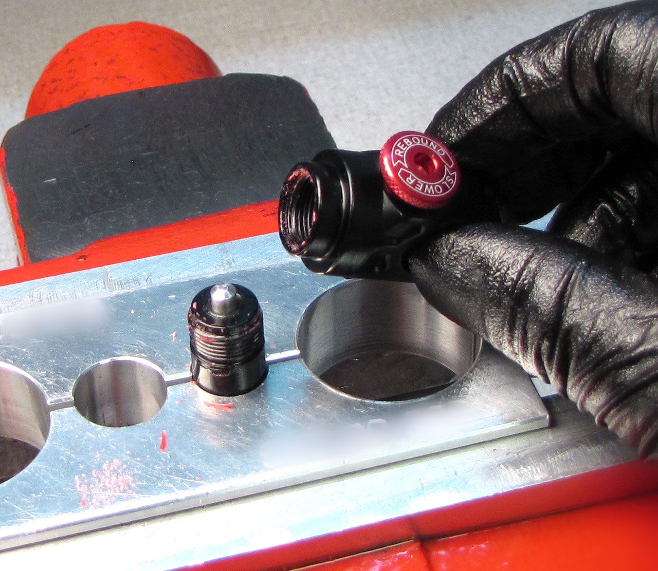
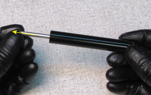
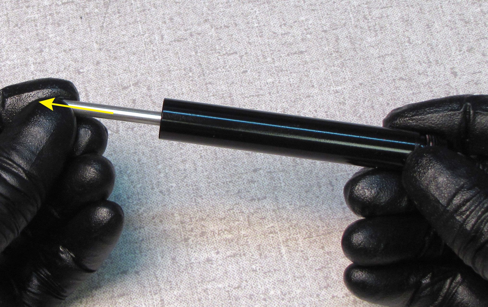
Remove the rebound metering rod from the shaft. Replace the o-ring inside the shaft with a new greased one from the kit.
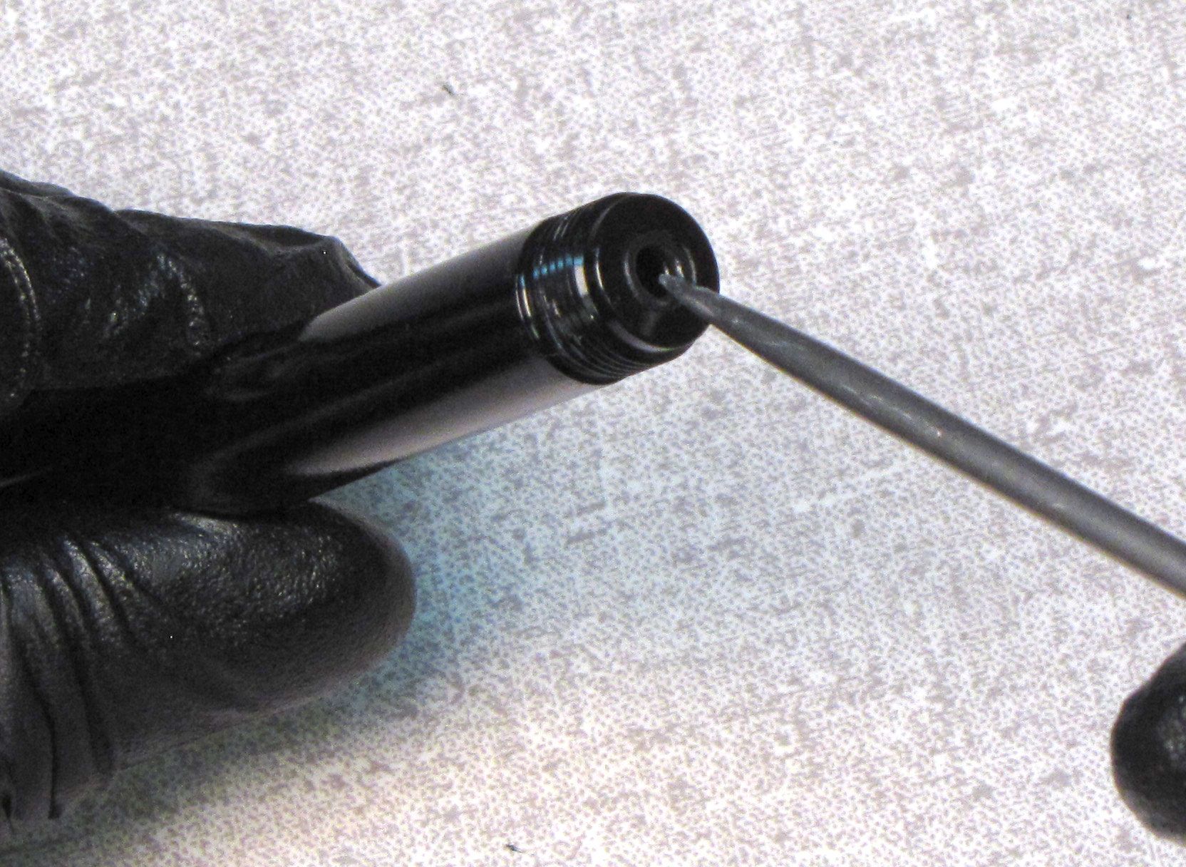

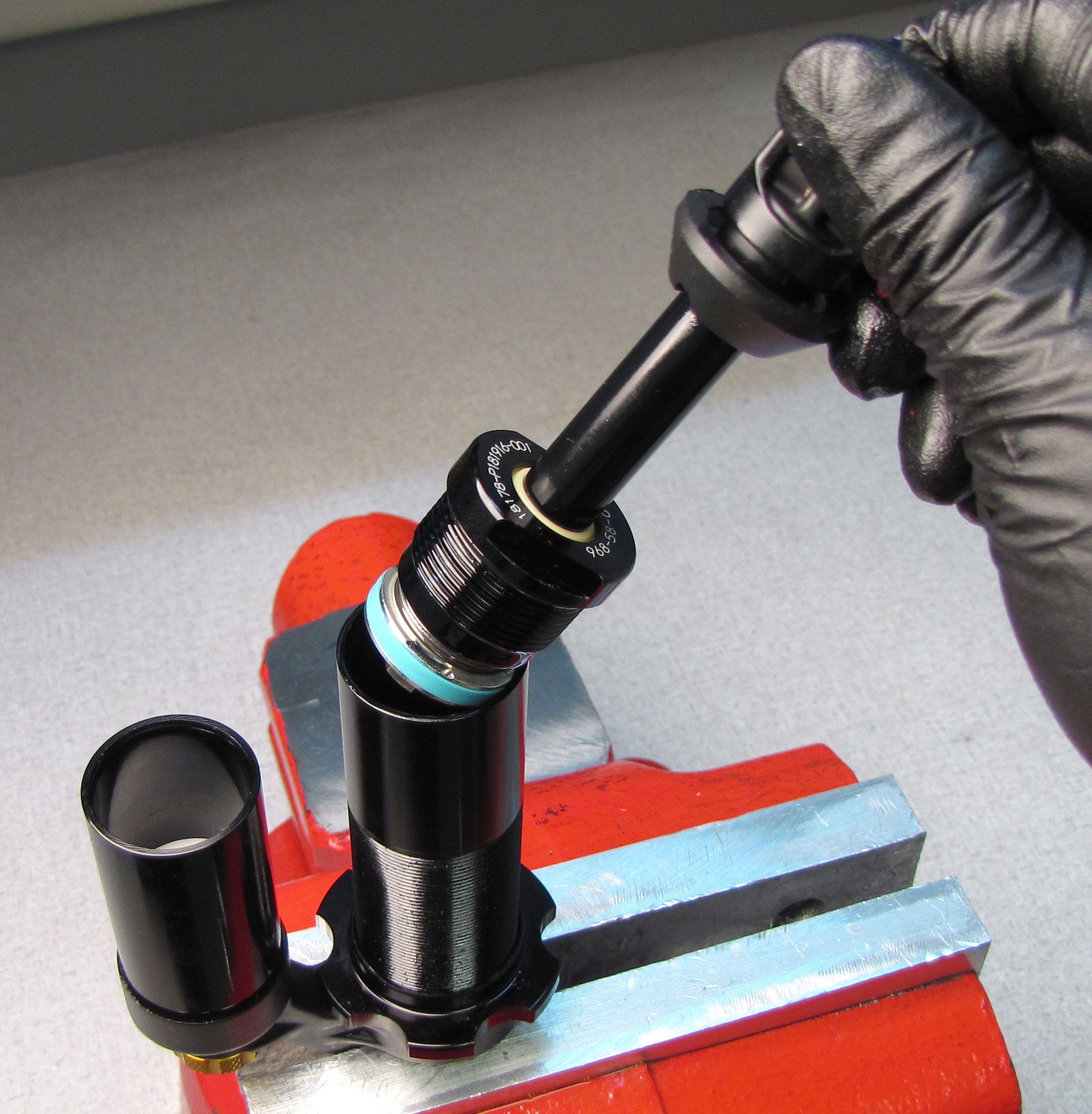
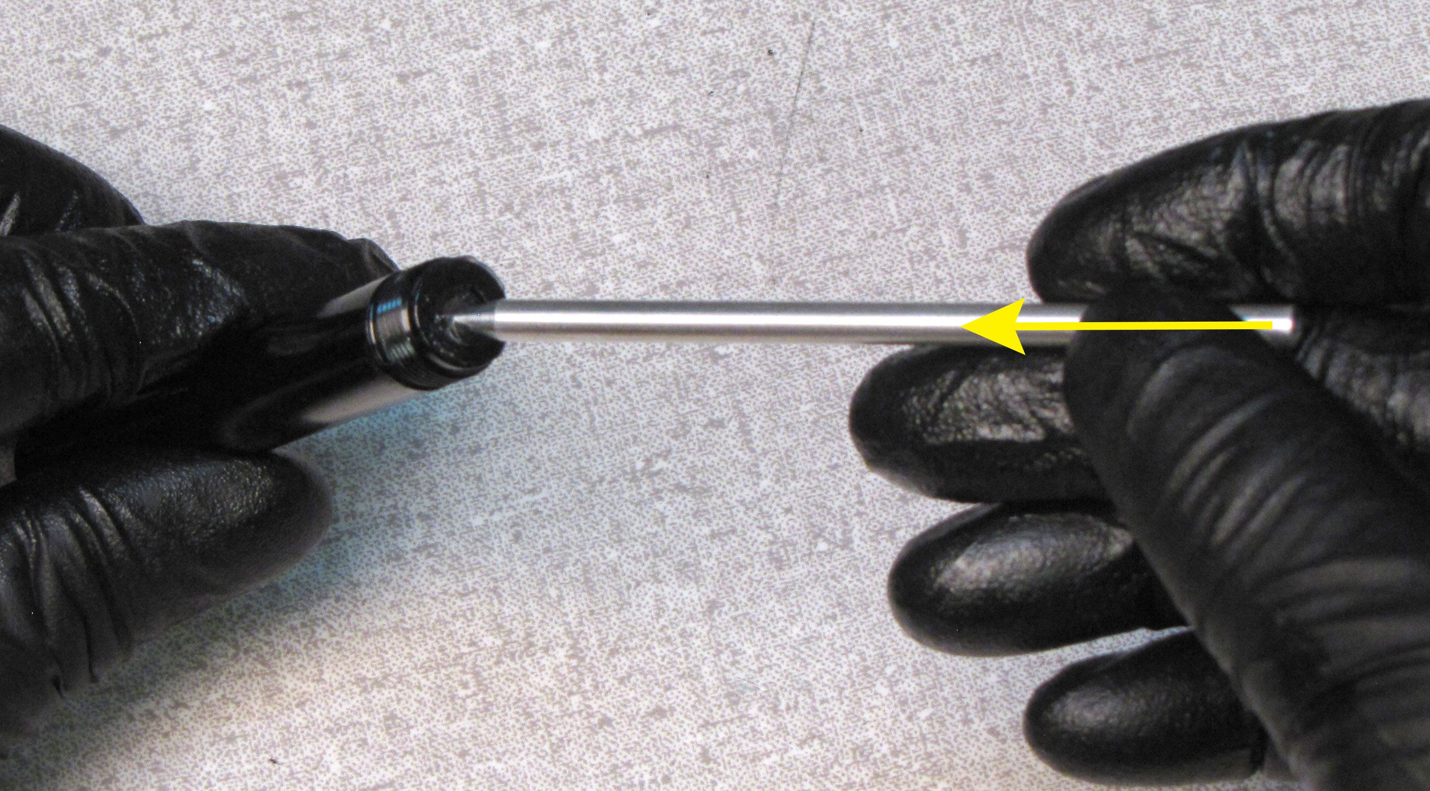
Step 19
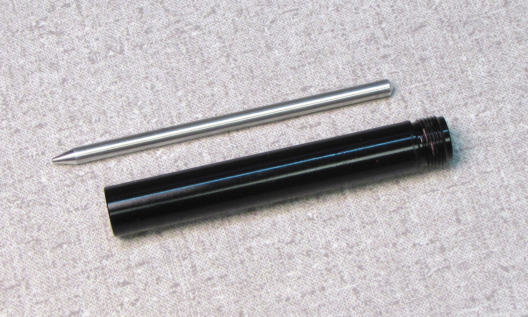
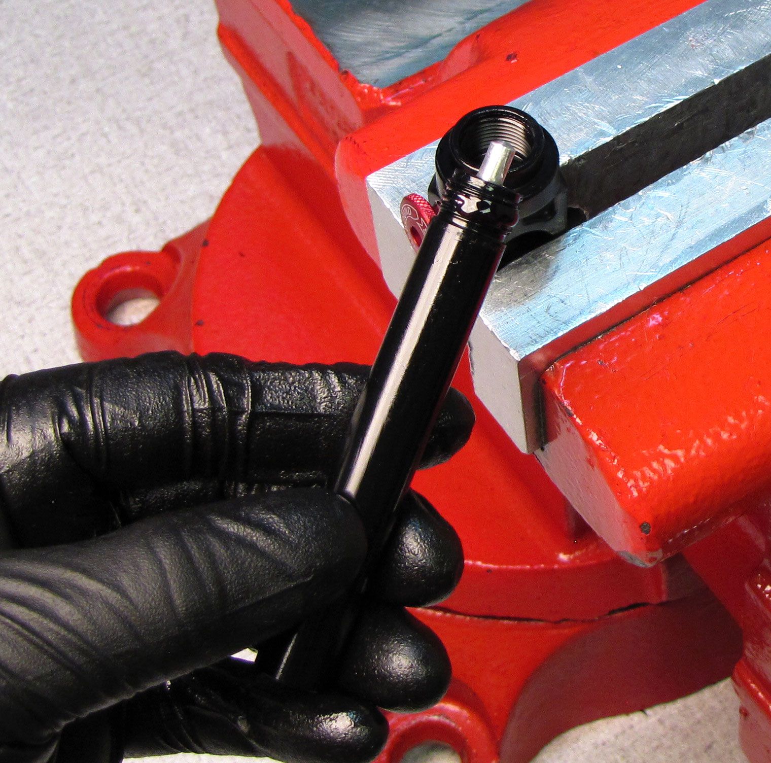
Reinsert the Rebound Metering Rod with its pointed end first, through the externally threaded end of the shaft.
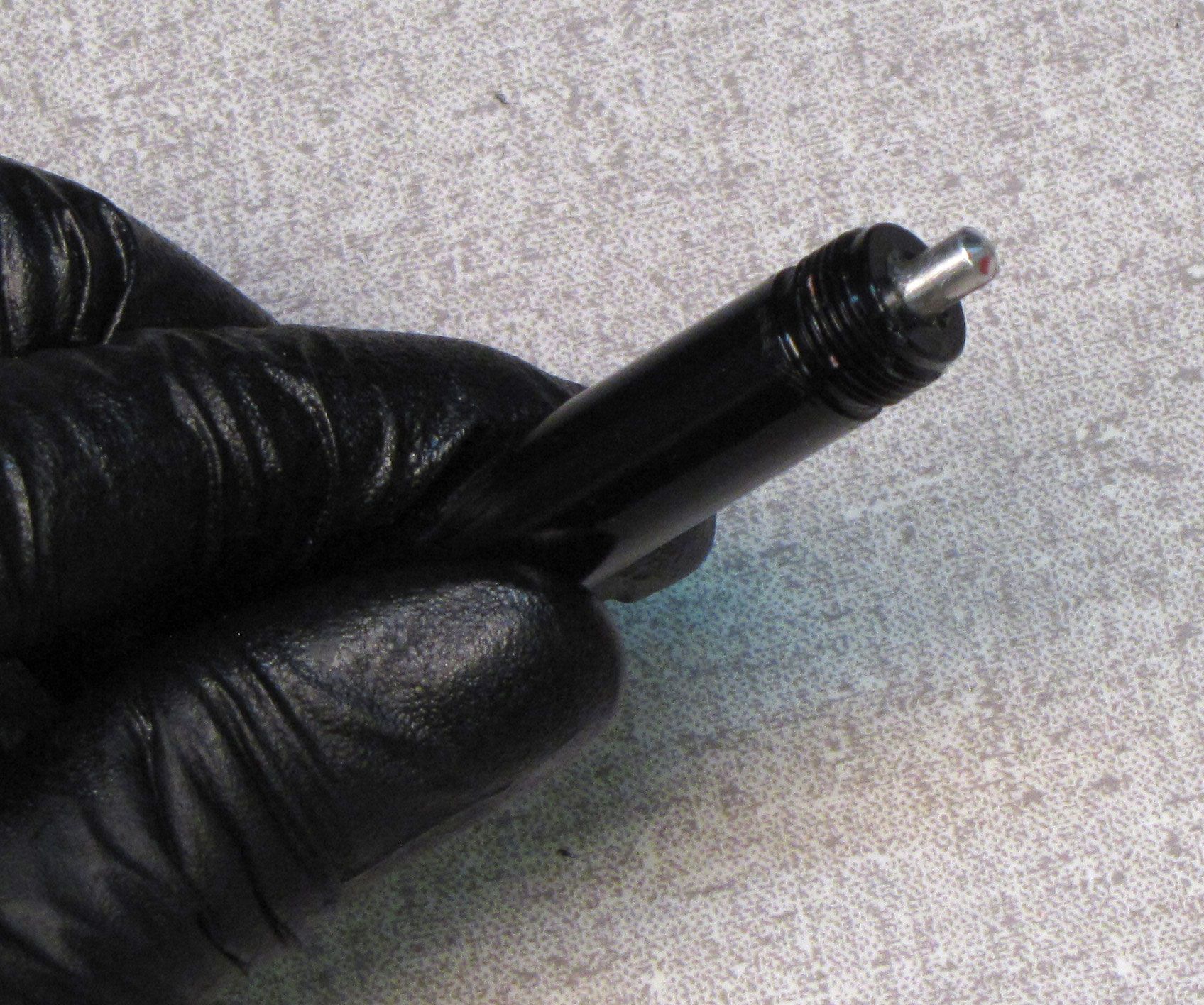
Step 20
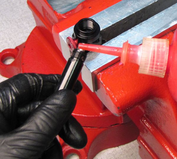
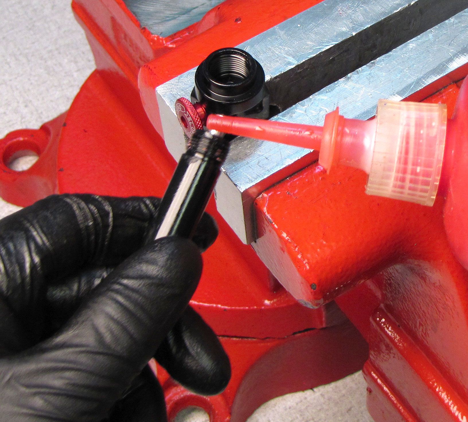
Apply red Loctite 277 a full 360Ëš for 2-3 threads on the external threads of the shaft. Insert the shaft into the shaft eyelet and thread clockwise. Clean the shaft with Isopropyl alcohol and a lint-free paper towel. Clamp the shaft in your shaft clamps and tighten the eyelet clockwise to 245 in-lb (27.7 Nm) torque with the Eyelet Torque Tool (PN: 398-00-280).

Step 21
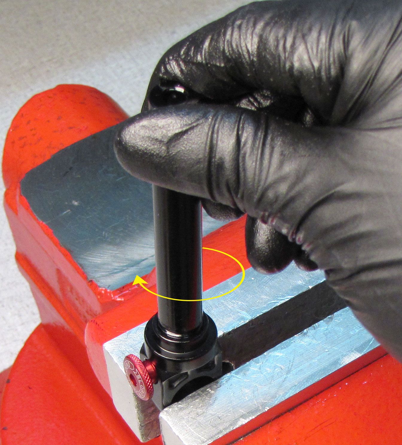
Use a blunt tool like a hex wrench to push down on the Rebound Metering Rod while turning the red rebound knob counter-clockwise. This positions the Rebound Metering Rod down in it's travel so it does not interfere with installation of the Piston Bolt later. Install the Bottom Out Bumper as shown.
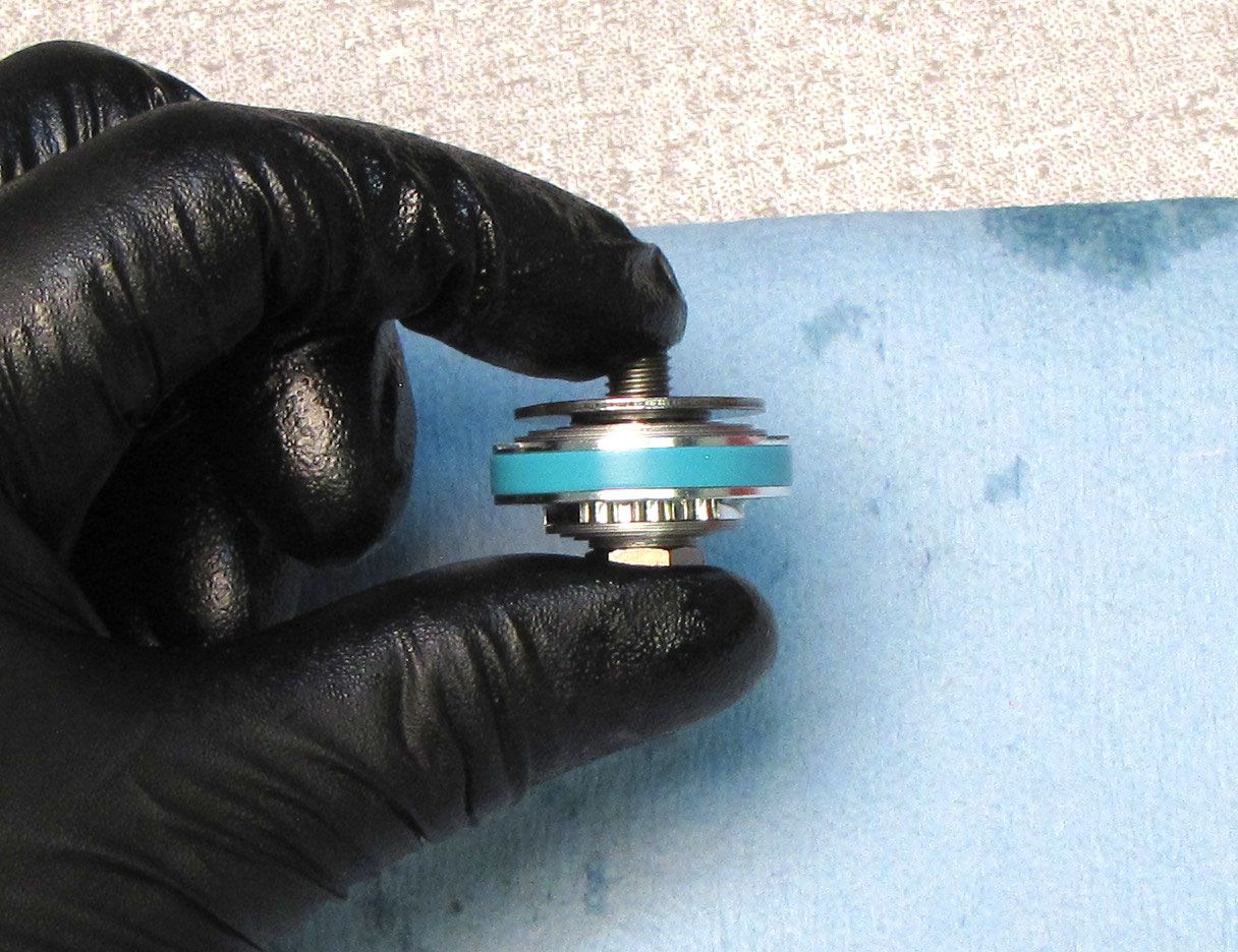
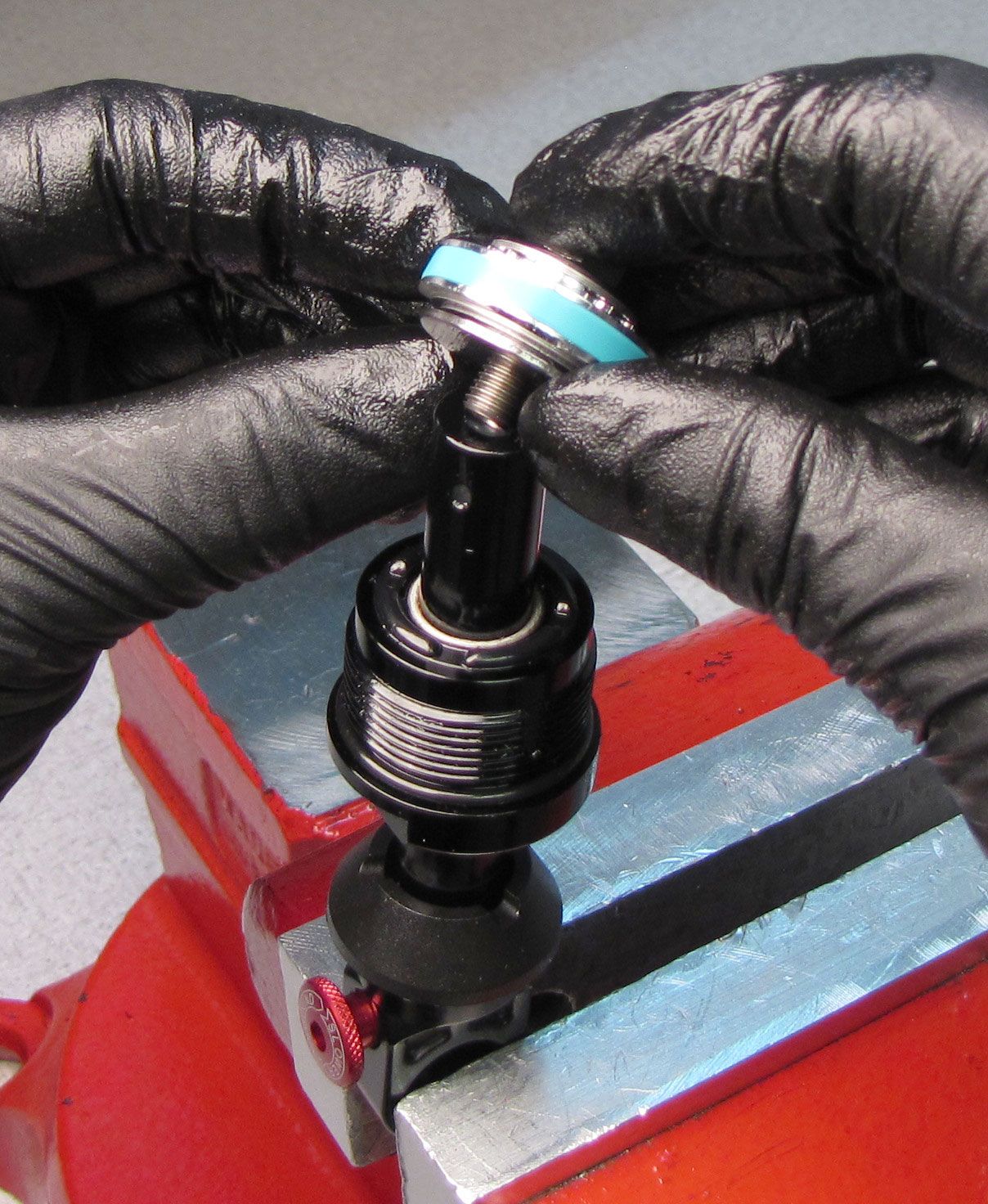
Step 22
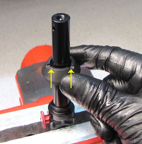
Install the rebuilt Bearing Assembly onto the shaft as shown.

Step 23
Replace the blue glide ring on the damping piston with a new one from the kit. Replace any damaged or broken shims. With all shims in their original order, reinstall the Valving Assembly onto the shaft. Tighten the piston bolt clockwise to 75 in-lb (8.5 Nm) torque with a 3/8" socket.


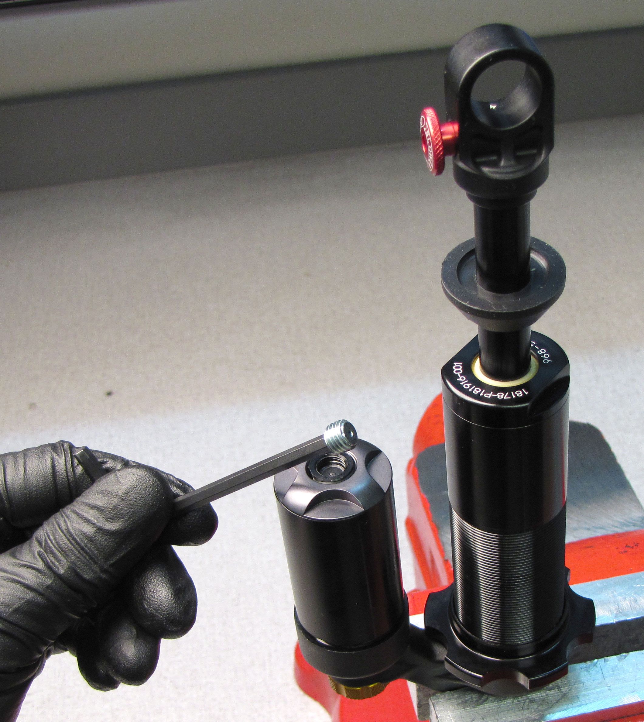
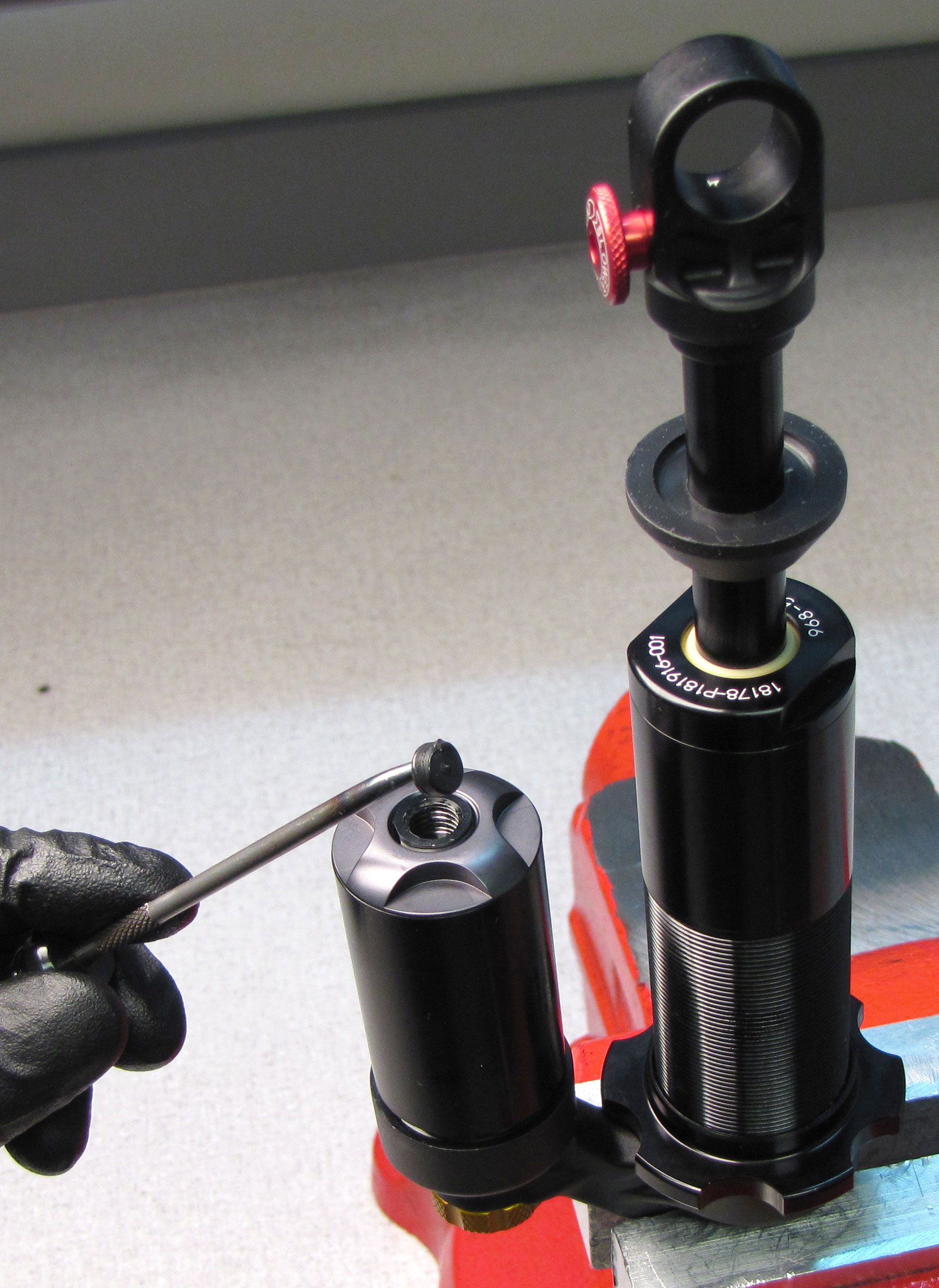
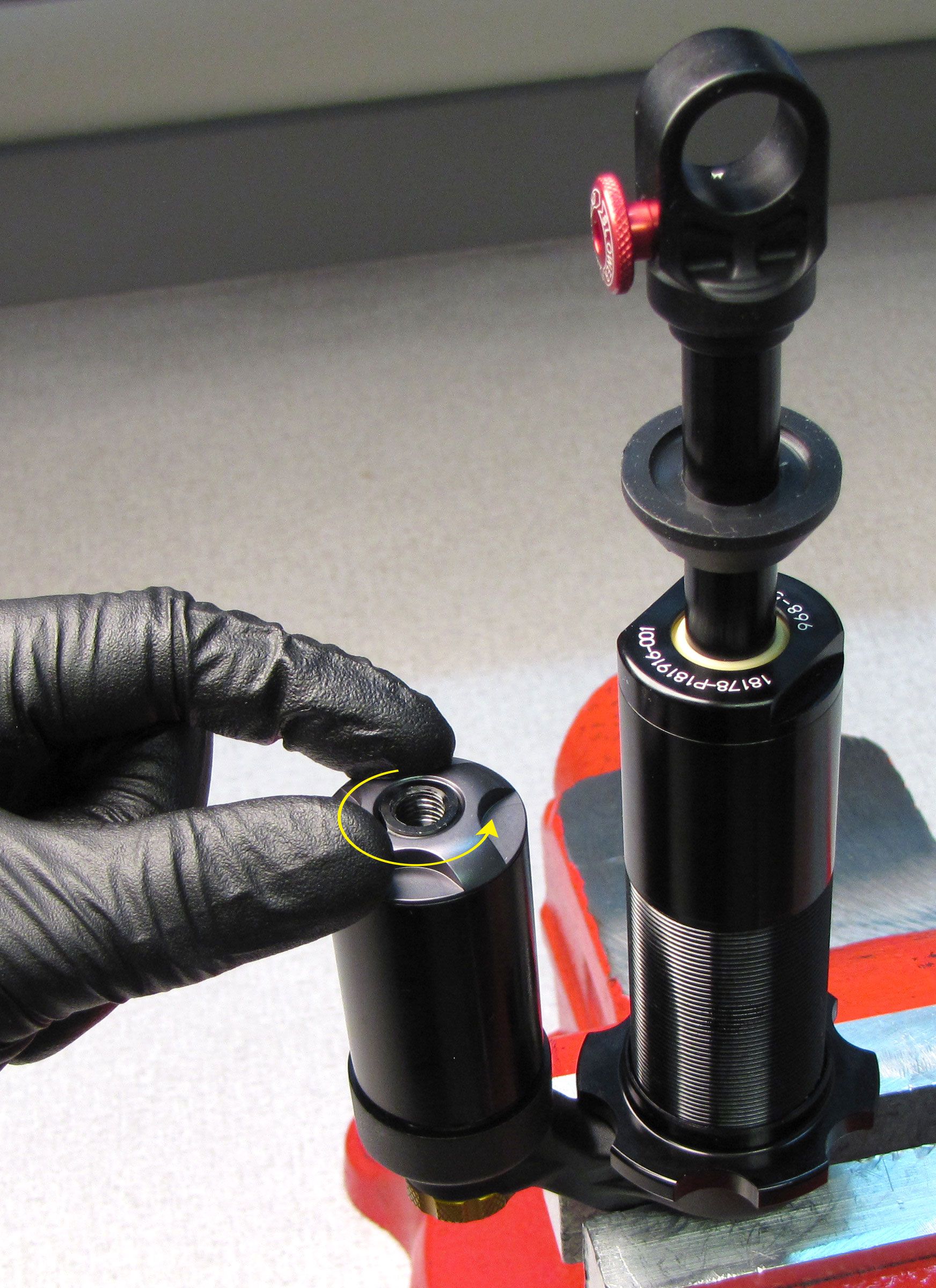
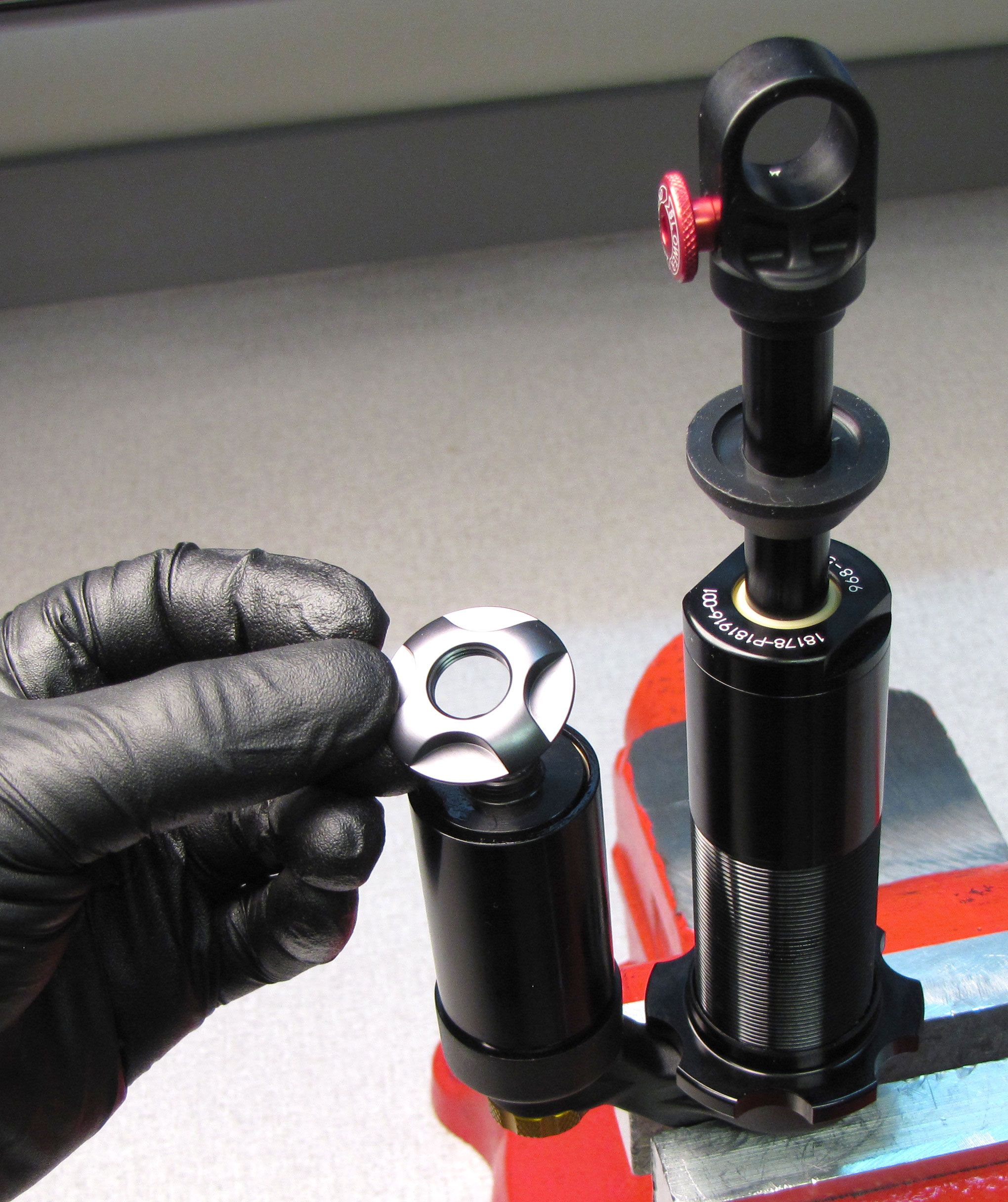
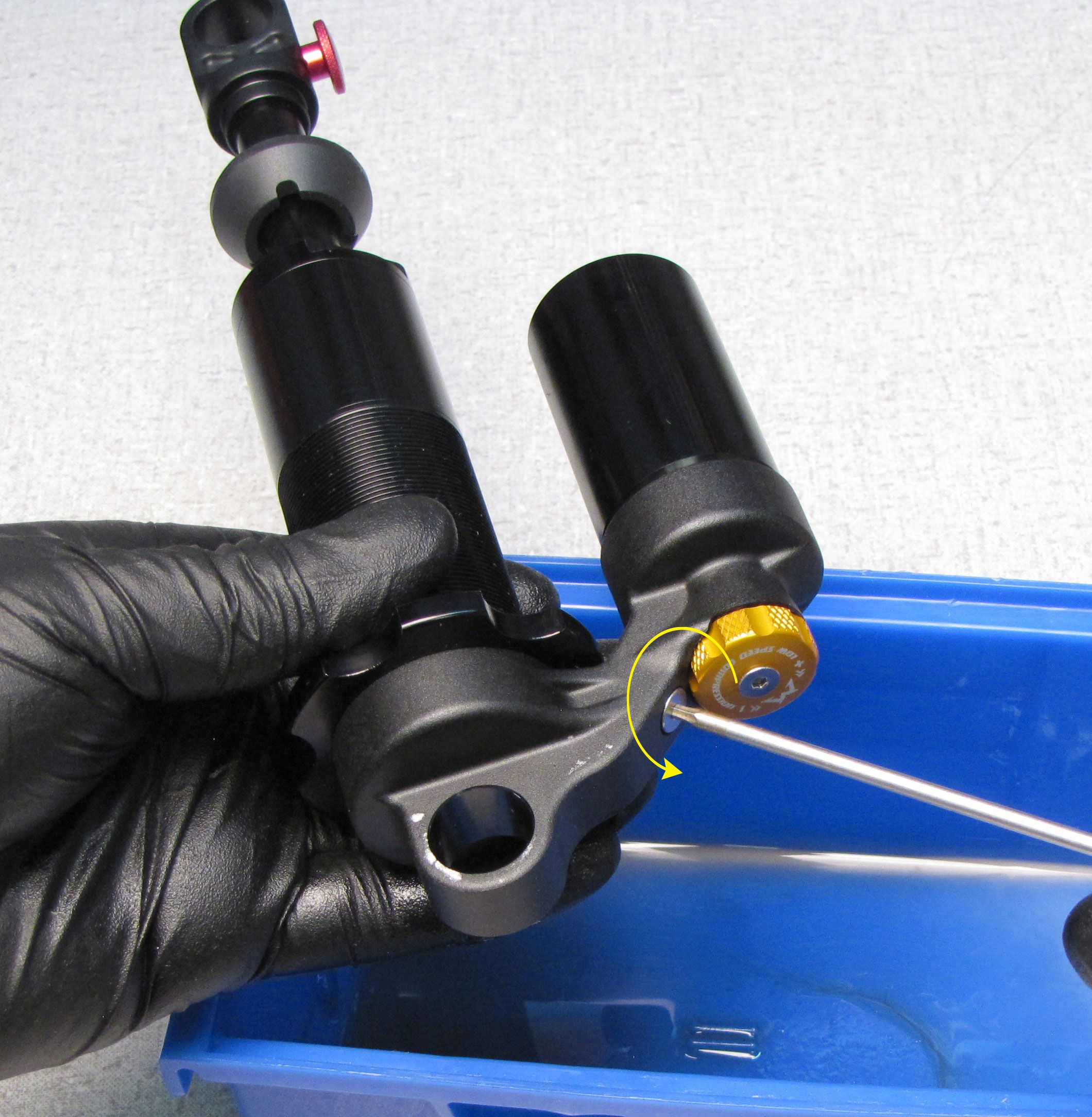
Step 24
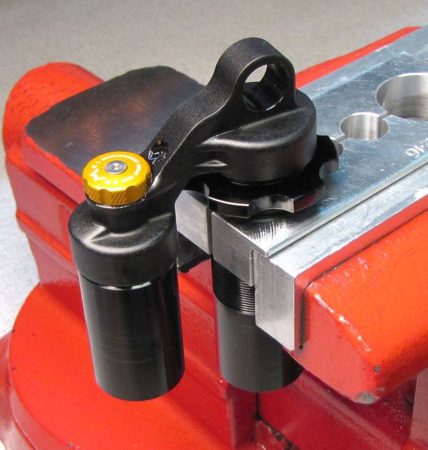
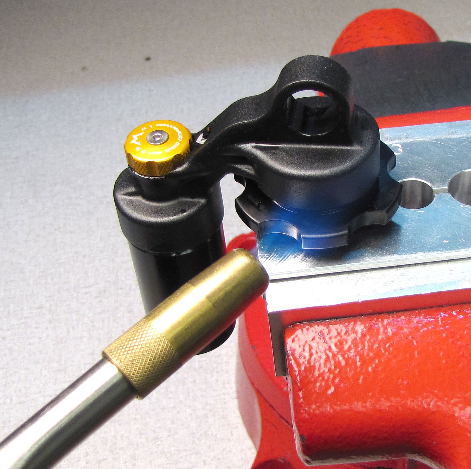
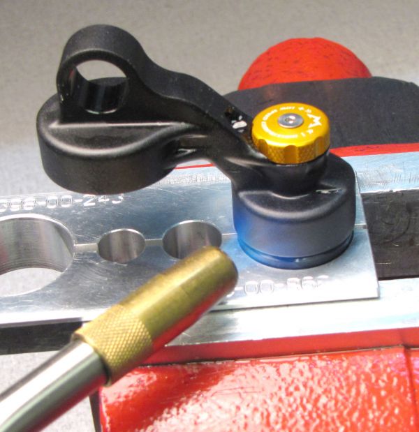
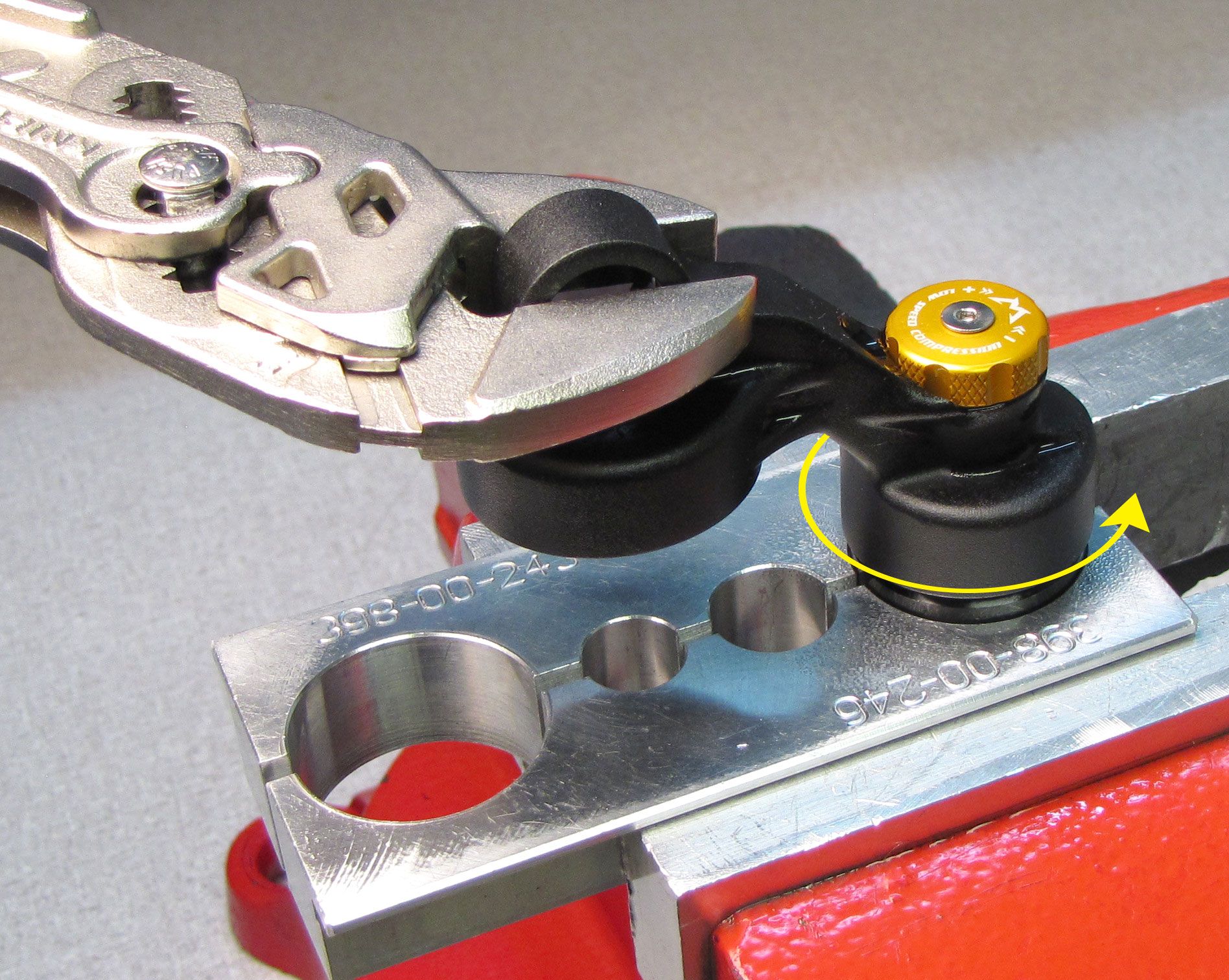
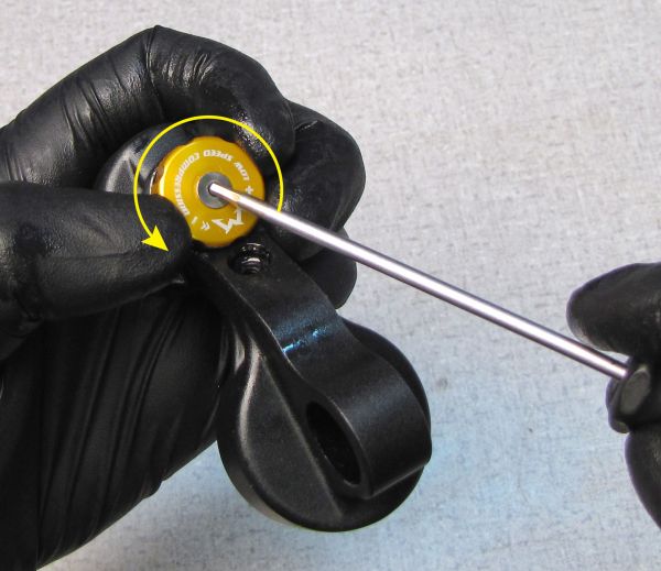
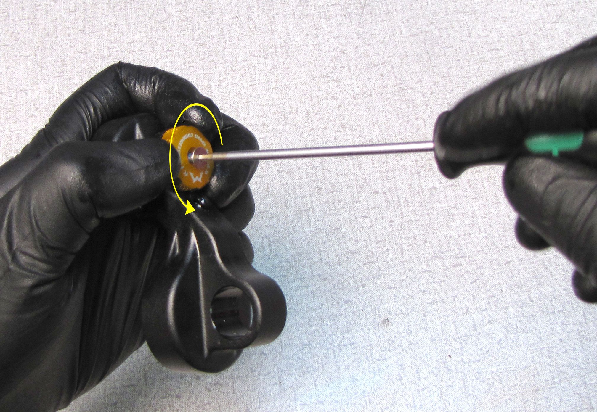
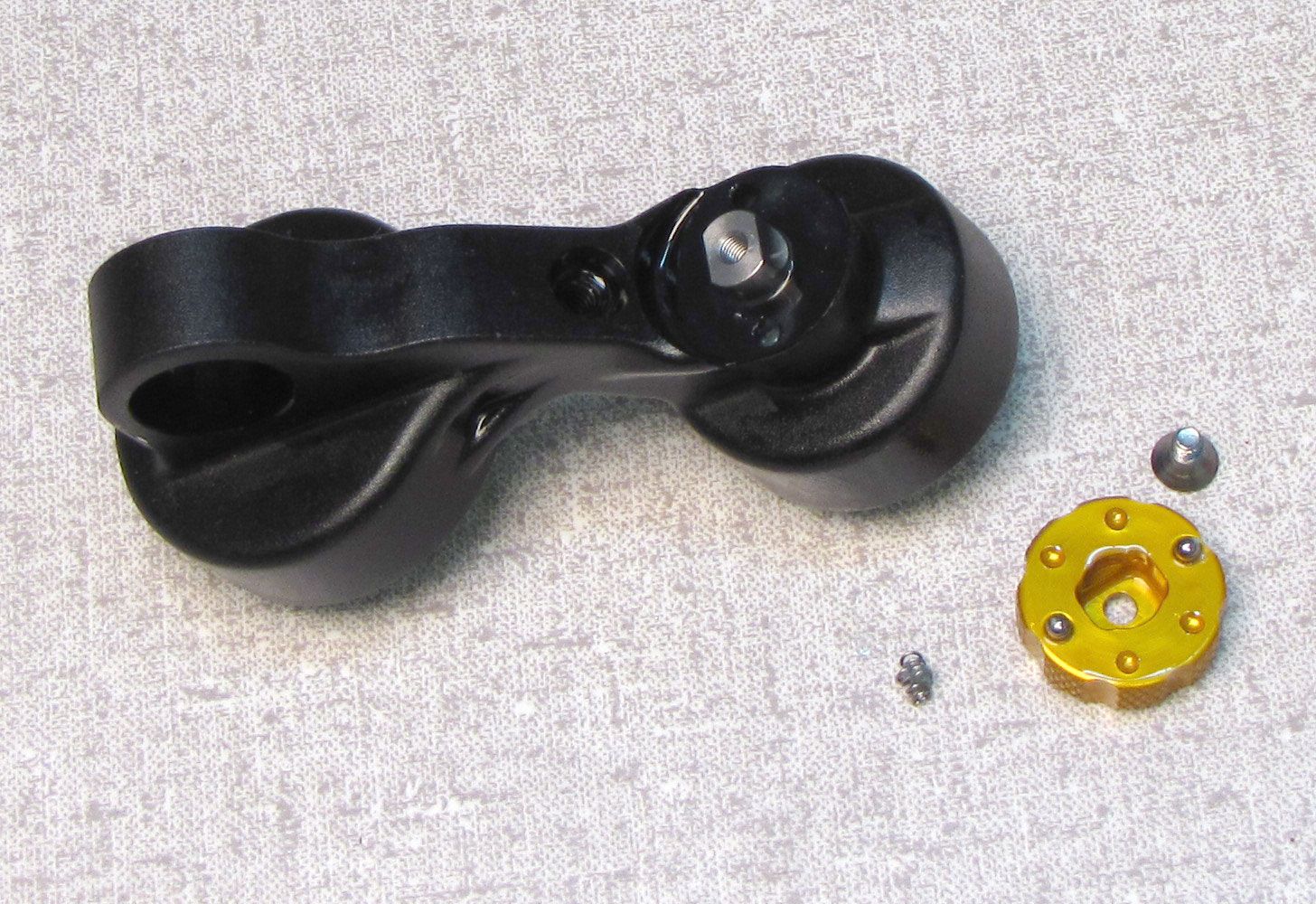
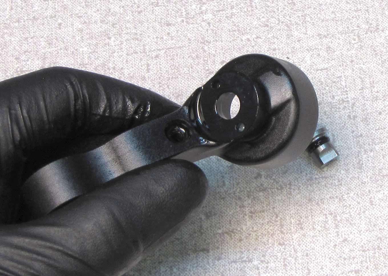
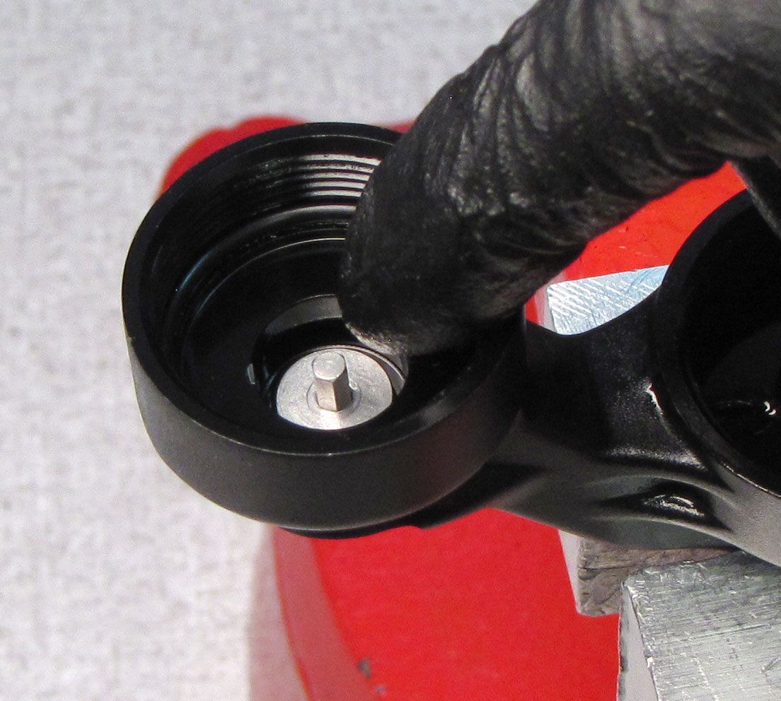
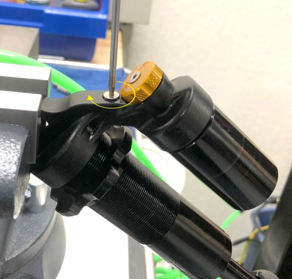
Hold the Compression Adjust knob from turning then unthread the set screw counter-clockwise with a 2mm hex wrench. Carefully lift off the knob so you don't lose any of the balls or springs beneath it. Remove the ball bearings and springs from beneath the knob.


Step 25
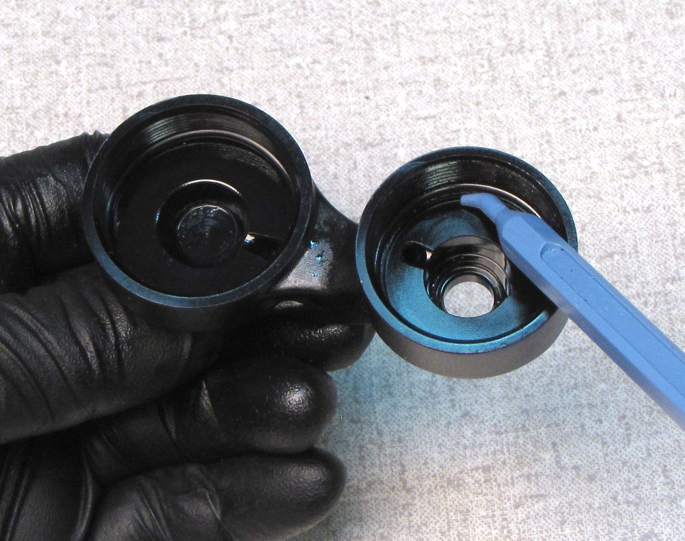
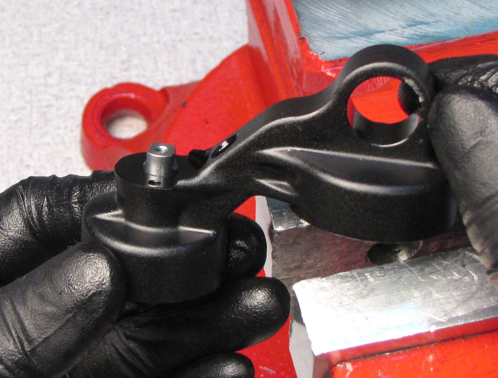
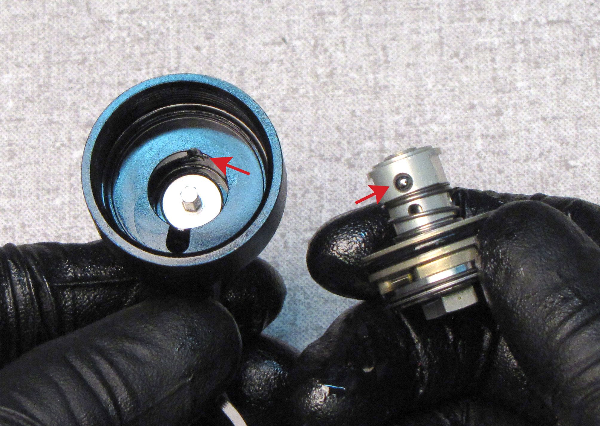
Push the Low Speed Damping Adjuster out of the reservoir cap. Replace the o-ring on the Low Speed Damping Adjuster as well as the o-rings on the inside of the eyelet.


Step 26
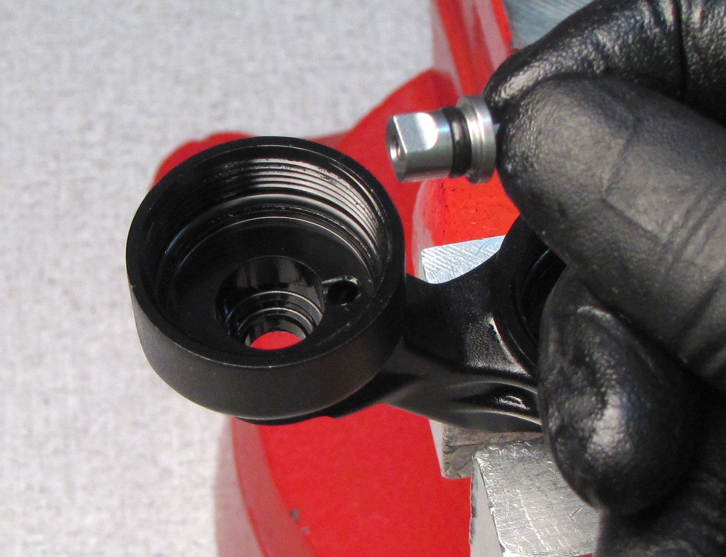
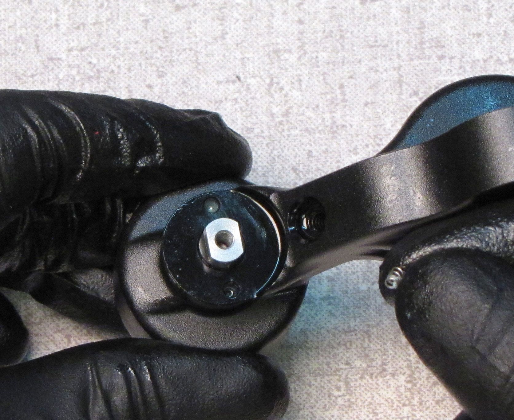
Reinsert the Low Speed Damping Adjuster into the reservoir cap as shown.

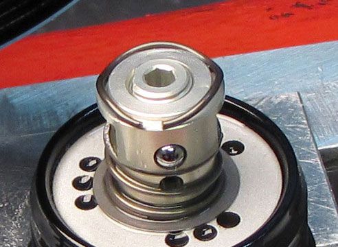
Step 27
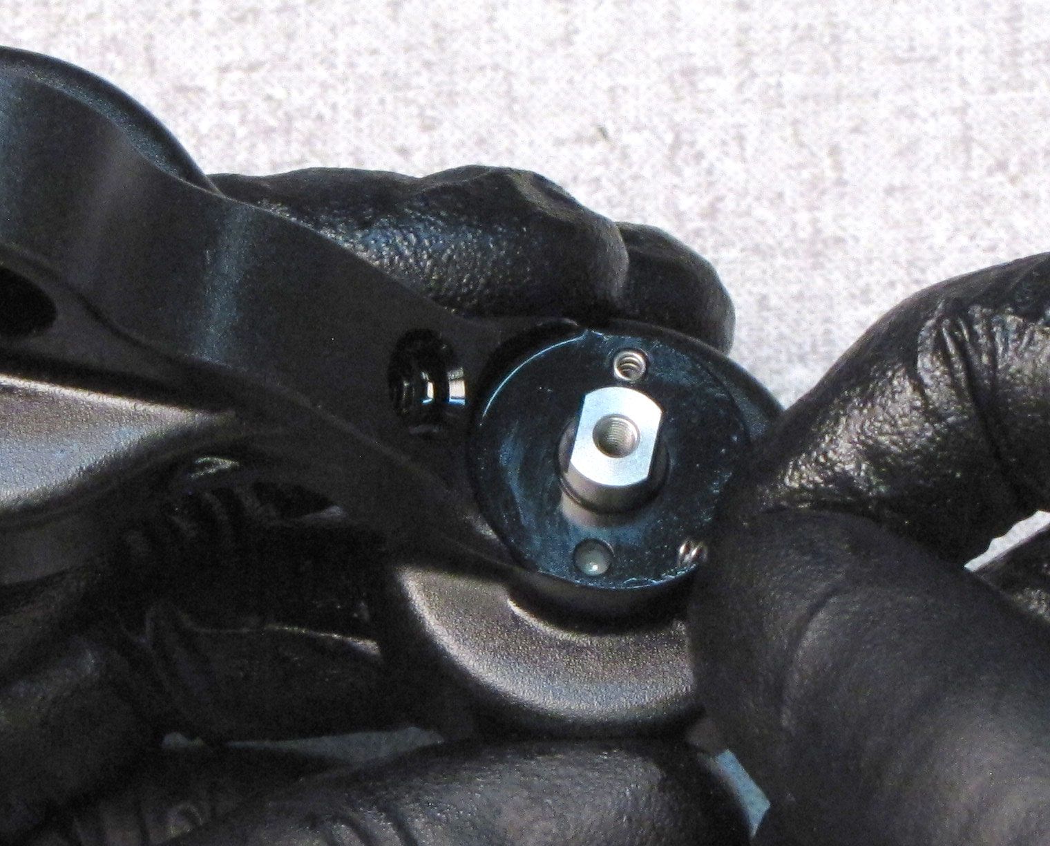
Apply a small amount of Slick Honey to the two detent holes in the top of the reservoir cap. Reinsert the detent springs then place the one ball bearing on top of each spring.

Step 28
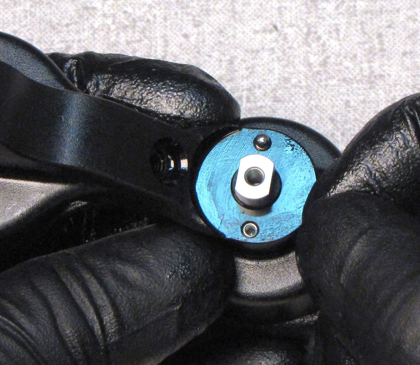
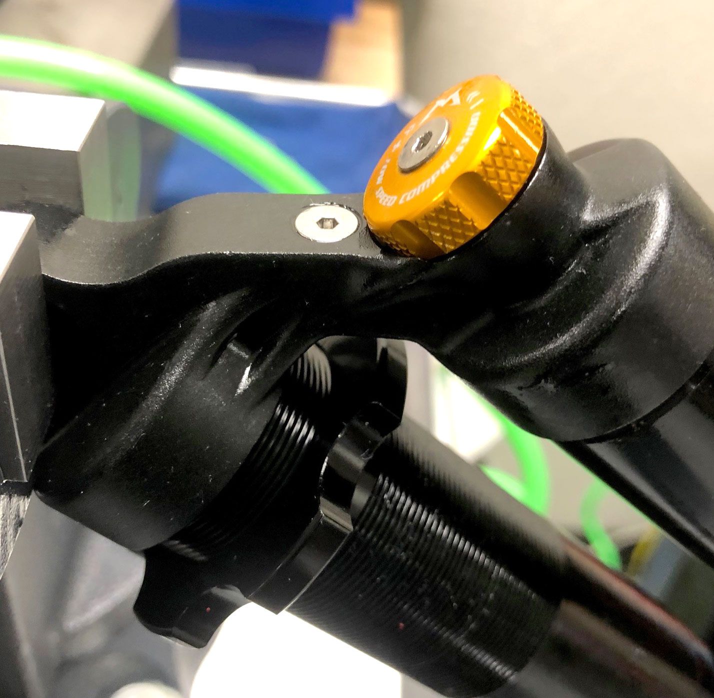
Reinstall the Compression Adjust Knob being careful not to dislodge the detent balls. Reinstall the set screw and hold the Compression Adjust Knob from turning while you tighten the screw clockwise to 7 in-lb (0.8 Nm) torque with a 2mm hex wrench.


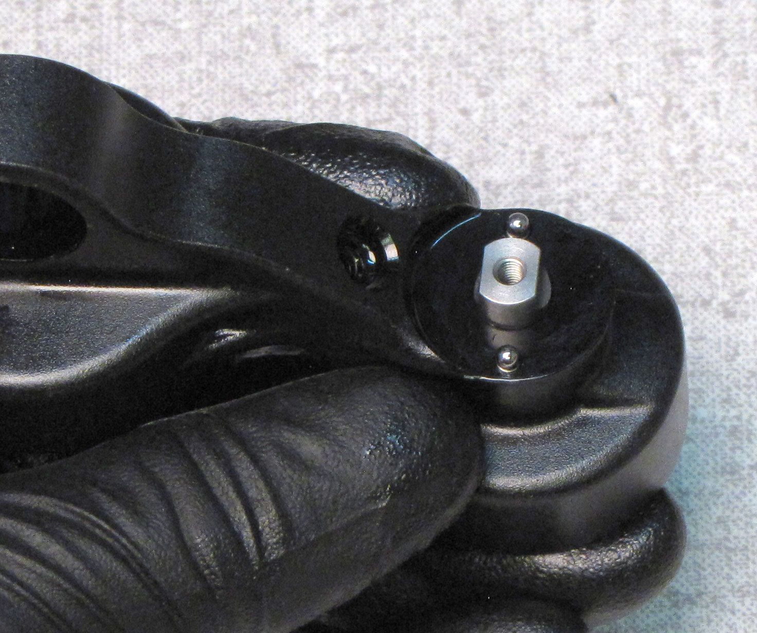
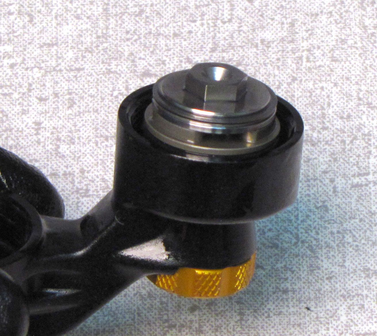
Step 29
Reposition the wave spring on top of the Damping Adj Assembly as shown. Invert the eyelet assembly onto the Damping Adj Assembly making sure to align the ball bearing protruding from the side of the Damping Adj Assembly with the small notch on the inside of the eyelet. Align the hex feature of the Damping Adj Assembly with the hex feature of the Low Speed Damping Adjuster by turning the Compression Damping Knob as needed.
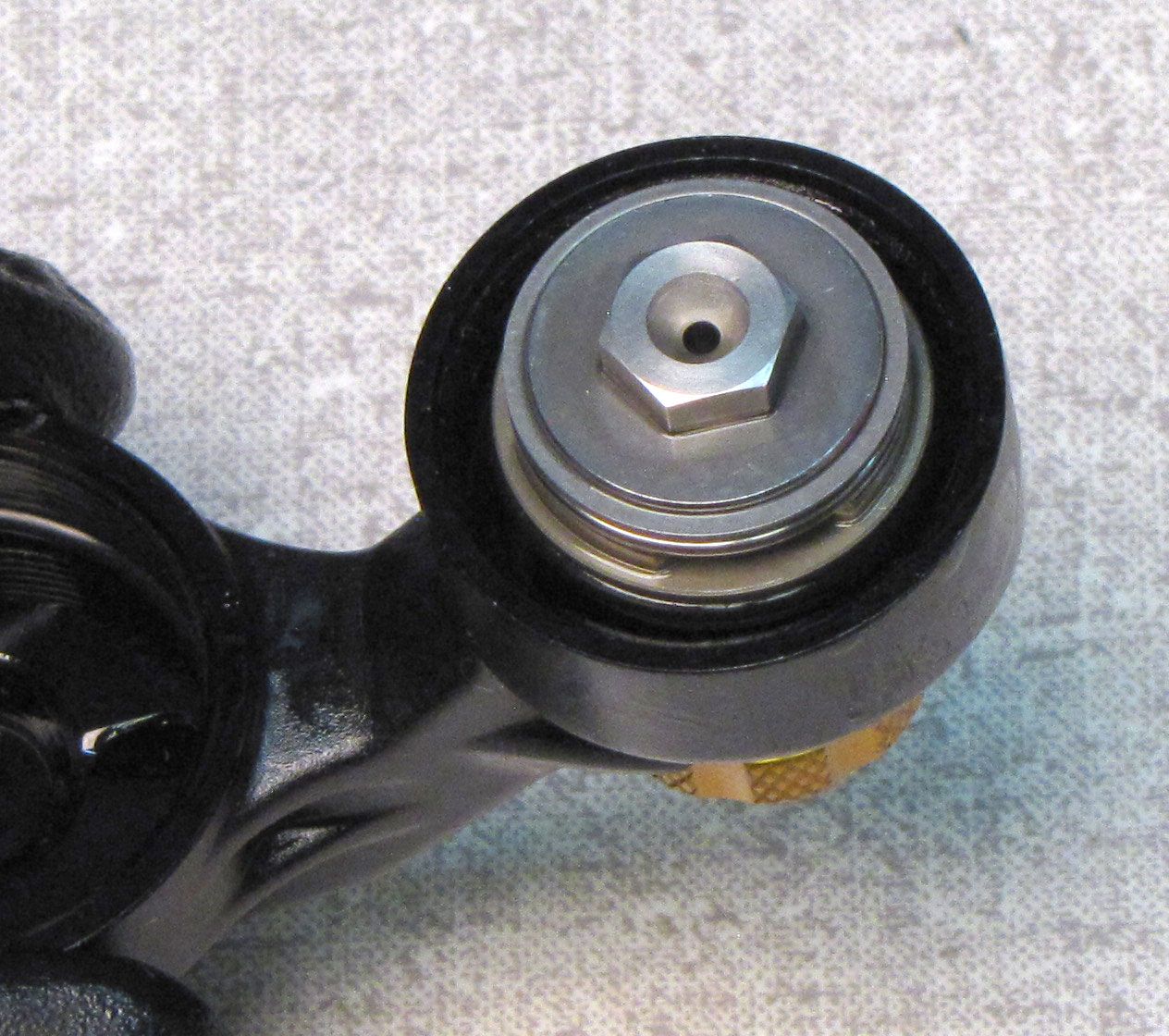

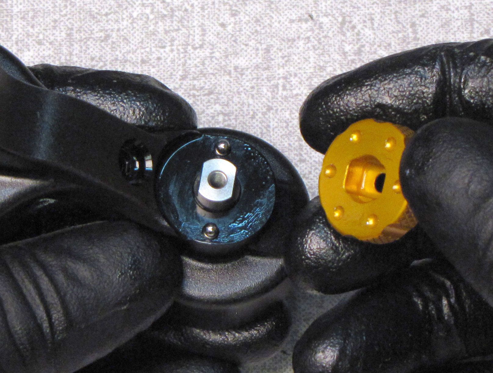
Step 30
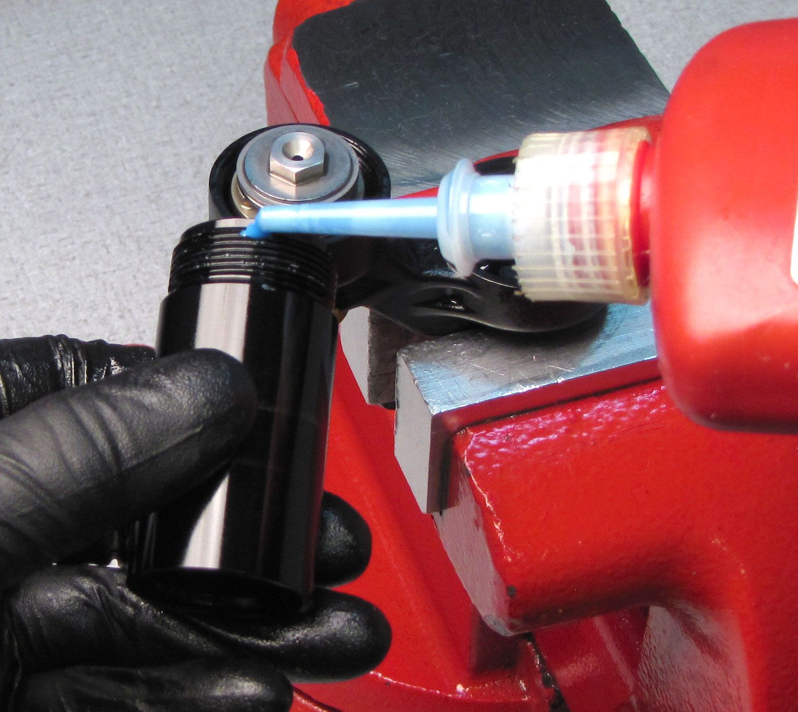
Apply a small amount of blue Loctite 242 to the cleaned and dried threads of the reservoir. Install the reservoir over the Damping Adjust Assembly then thread clockwise by hand into the eyelet.
Step 31
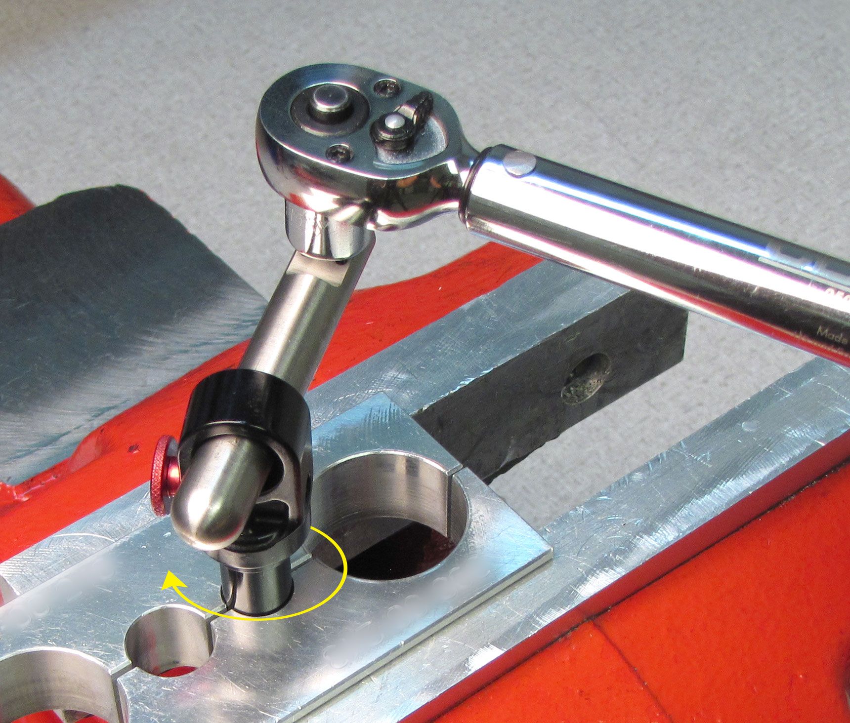
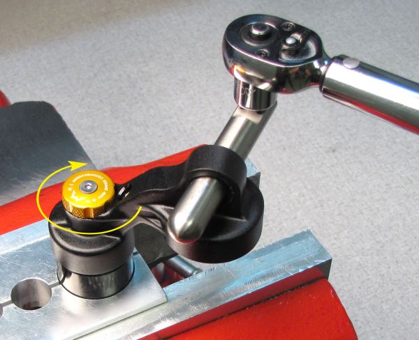
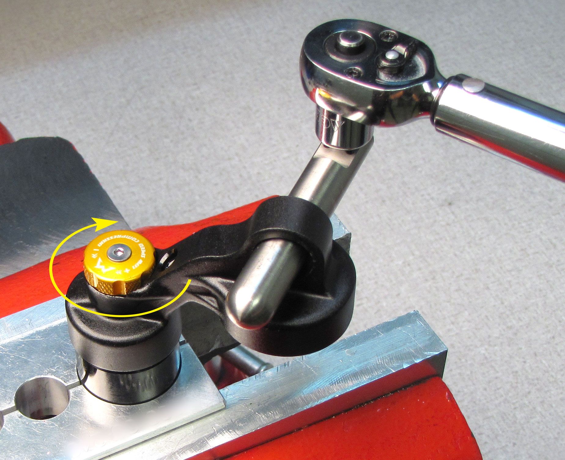
Clamp the reservoir in shaft clamps PN: 803-00-208 and tighten the eyelet clockwise to 360 in-lb (40.7 Nm) torque with the appropriate eyelet torque tool (398-00-280 for standard eyelets, 398-00-099 for trunnion eyelets).
Step 32
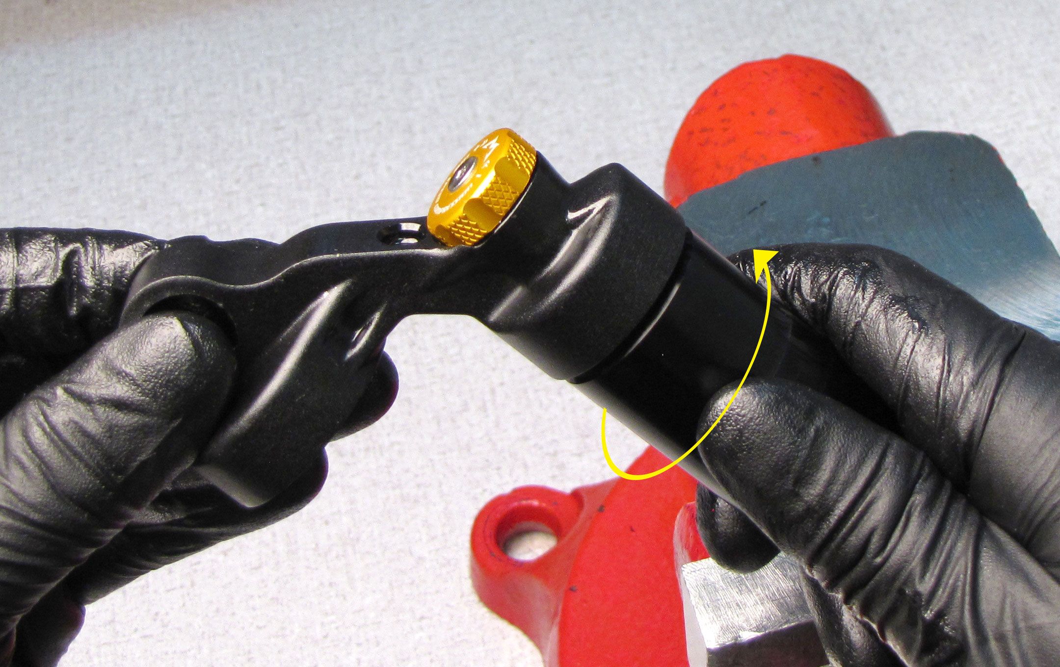
Apply a small amount of blue Loctite 242 to the threaded end of the body making sure not to get any Loctite on the threads used by the Preload Collar. Thread the body clockwise into the eyelet by hand. Clamp the body in shaft clamps PN: 803-00-208 then thread the eyelet clockwise onto the body using your eyelet torque tool until you reach 420 in-lb (47.4 Nm) torque. You may need to reposition the body in your shaft clamps as you thread in order to prevent damage from the reservoir hitting the vise.

Step 33
Invert the rebuilt shaft assembly and reinstall it into the shock body. Tighten the bearing assembly clockwise to 420 in-lb (47.4 Nm) torque with a 1" crowsfoot.


Step 34
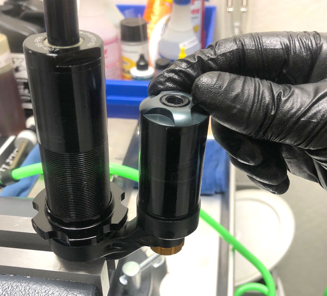
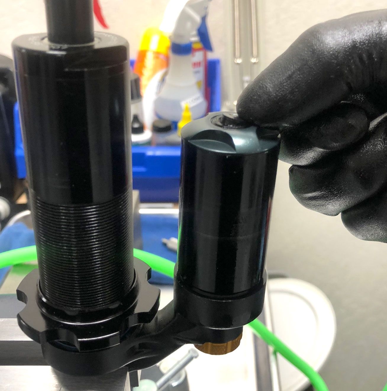
Coat the rebuilt IFP with a thin film of Slick Honey then reinstall into the reservoir with the concave face oriented toward the Compression Adjust Assembly. Reinstall the wire retaining ring (this will contain the IFP during the vacuum/fill process).


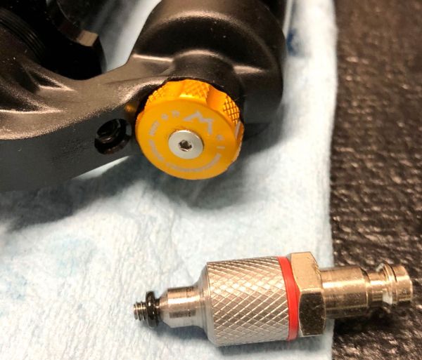
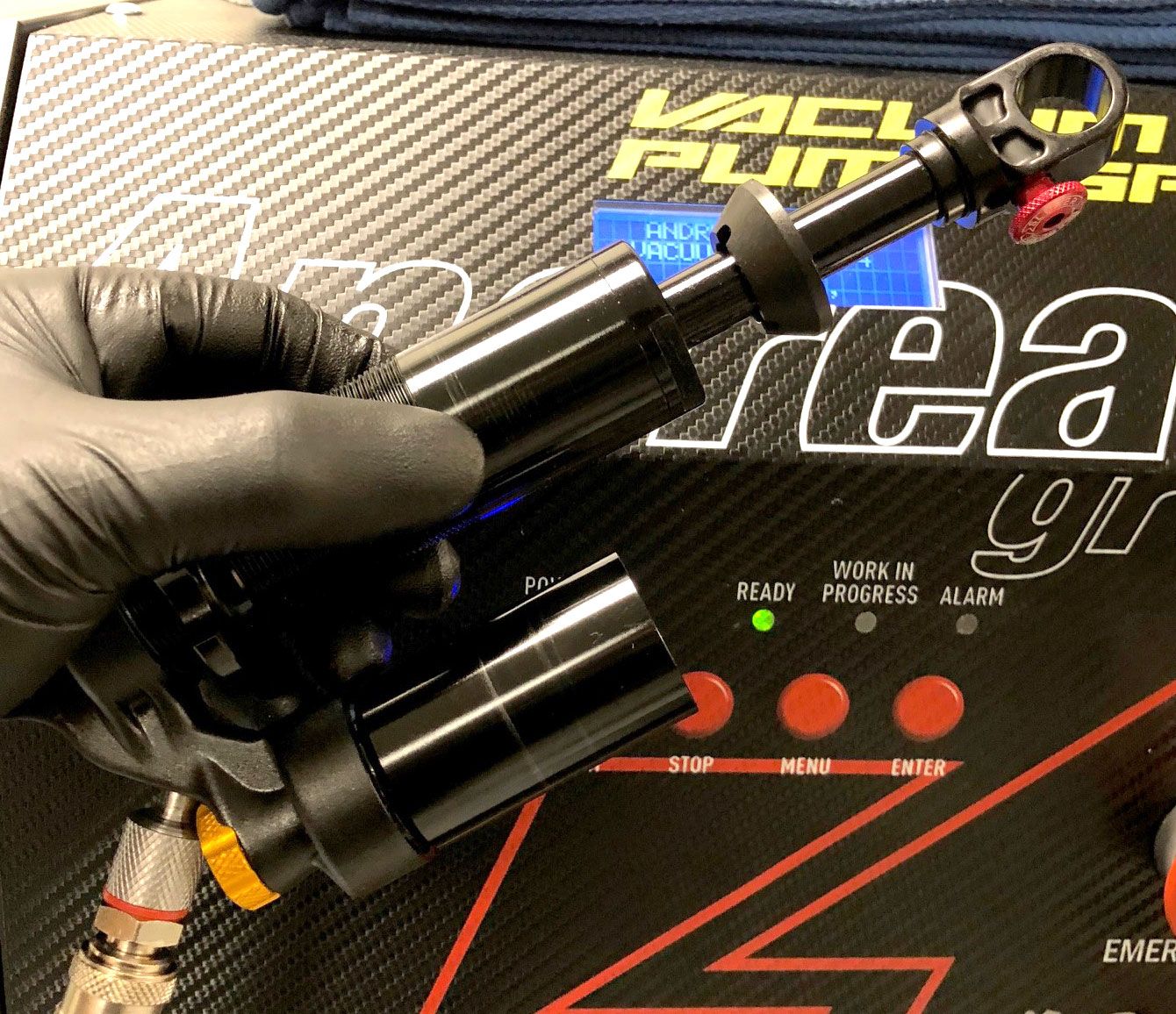
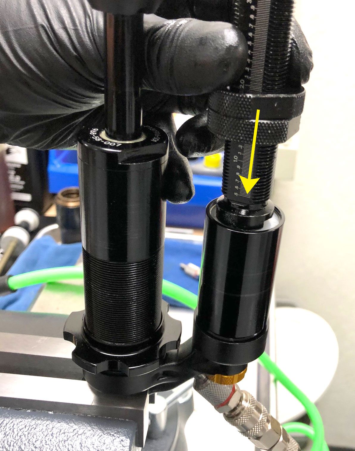
Step 35
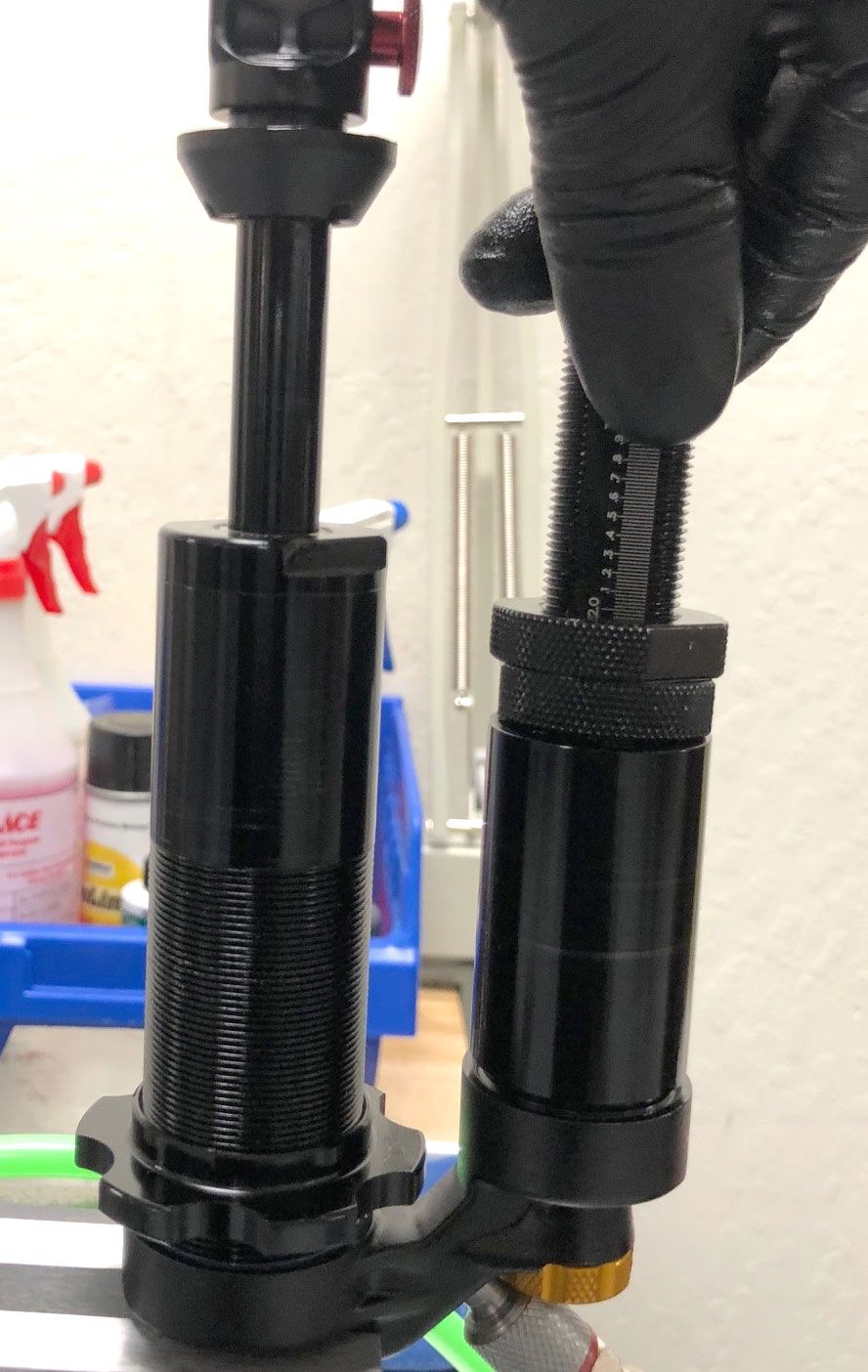
Connect the Bleed Port to the Andreani Fill Machine using the Fill Machine Adaptor (PN: 803-00-463). Cycle the shock by hand while you perform the vacuum cycle. Then cycle the shock by hand as you perform the fill cycle. Repeat as necessary to purge all air from the shock. Set the IFP to 1.38"/35mm (1.55"/39.4mm for 3.5" travel shocks) with the IFP depth setting tool PN: 803-00-566.

Step 36
Orient the shock so the bleed port is at the highest point. Remove the Fill adapter and reinstall the bleed screw with new greased o-ring from the kit. Tighten clockwise to 14 in-lb (1.6 Nm) torque with a 2mm hex wrench.

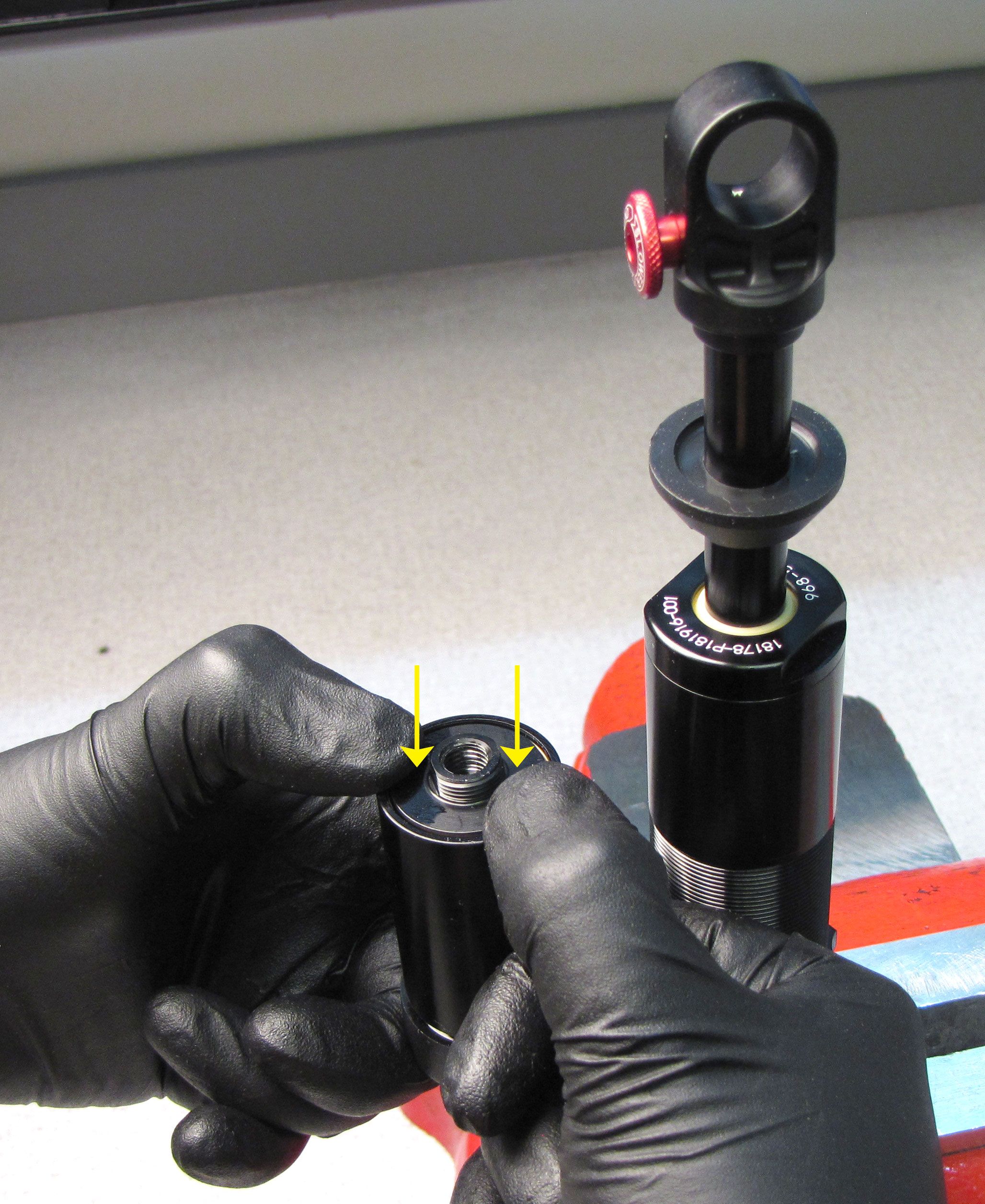
Step 37
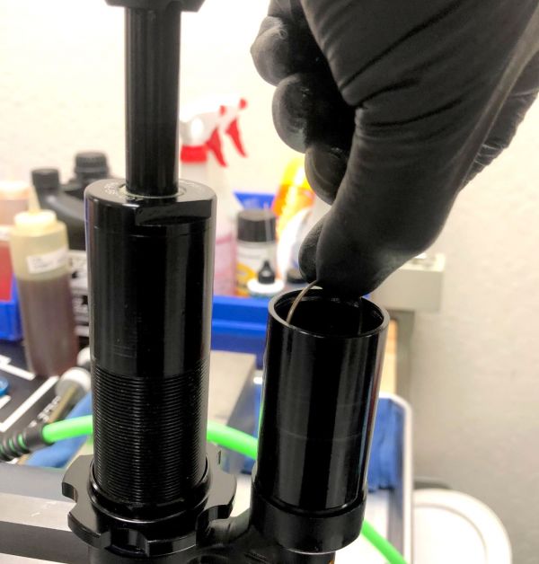
Remove the wire retaining ring from within the reservoir. Reinstall the Reservoir End Cap Assembly with new greased o-ring into the Reservoir as shown. Reinstall the wire retaining ring.

Step 38
Seat the End Cap Assembly against the wire retaining ring by pulling it up with pliers. Only grip the End Cap Assembly by its flats and not the external threads. Install the End Cap Lockring by threading it clockwise onto the End Cap Assembly until hand tight.


Step 39
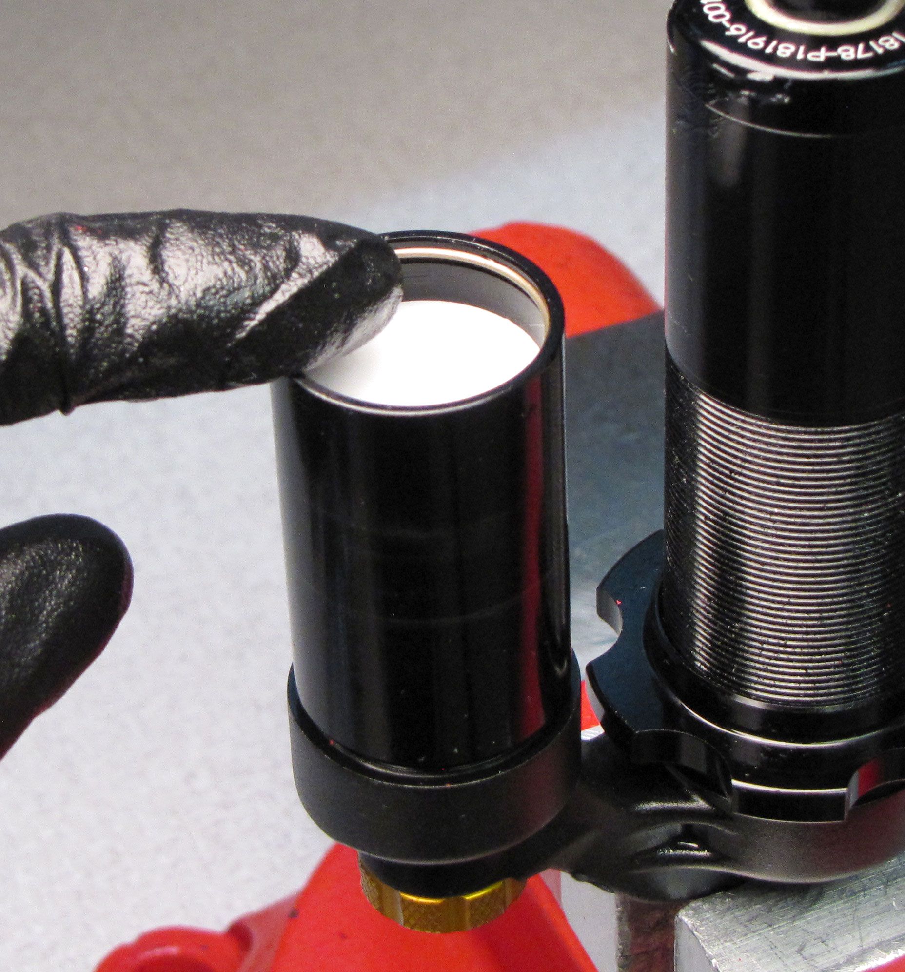
Insert a new pellet with beveled side first into the End Cap Assembly followed by the Pellet Retainer.


Step 40
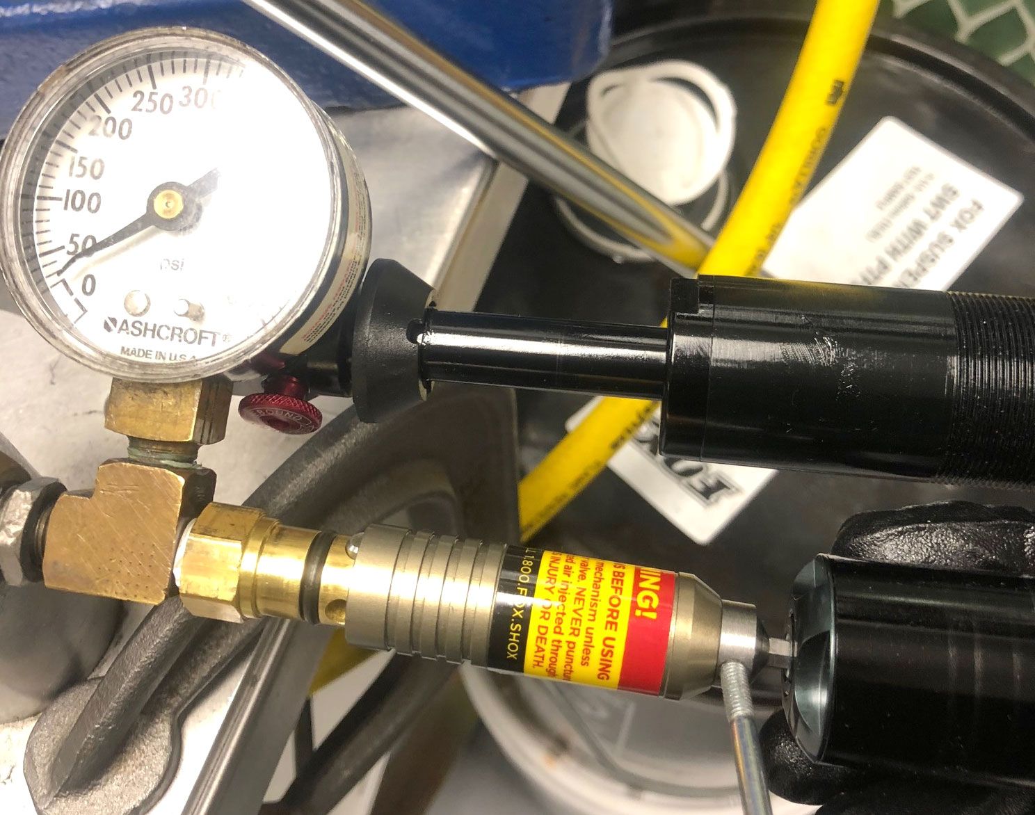
With the Pellet Retainer just snug, fill the IFP chamber to 300psi.

Step 41
Tighten the pellet retainer clockwise to 14 in-lb (1.6 Nm) torque. Dyno the shock to check all damper functions. Once happy with the dyno results, install a new white Delrin ball into the Pellet Retainer.