2020 TREK Thru Shaft Shock Rebuild
Required Parts
- 803-00-142 Kit: Rebuild, FLOAT Line Air Sleeve, Missing Q-Ring
- 803-01-435 Seal Kit: TREK 9mm Thru Shaft Rebuild
Required Tools
- 398-00-614 Tooling: 2015 Trek RG Valve Stack Transfer Tool
- 398-00-749 Service tooling: Trek Thru Shaft IFP removal tool
- 398-00-811 Tooling: Bullet tool, Slave shaft install, 9mm thru shaft
- 398-00-822 Tooling: IFP Depth Set and Torque Tool, 9mm Thru Shaft
- 398-00-823 Tooling: 15mm Hex, Body/Bearing/Clevis Torque Tool, 3/8" drive, 9mm Thru Shaft
- 398-00-951 Tooling: Torque Fixture, 54mm Trunnion Eyelet, Tall
Sections
WARNING: Always wear safety glasses and protective gloves during service to prevent potential injury. Failure to wear protective equipment during service may lead to SERIOUS INJURY OR DEATH.
WARNING: FOX products should be serviced by a qualified bicycle service technician, in accordance with FOX specifications. If you have any doubt whether or not you can properly service your FOX product, then DO NOT attempt it. Improperly serviced products can fail, causing the rider to lose control resulting in SERIOUS INJURY OR DEATH.
WARNING: Modification, improper service, or use of aftermarket replacement parts with FOX forks and shocks may cause the product to malfunction, resulting in SERIOUS INJURY OR DEATH. DO NOT modify any part of a fork or shock, including the fork brace (lower leg cross brace), crown, steerer, upper and lower leg tubes, or internal parts, except as instructed herein. Any unauthorized modification may void the warranty, and may cause failure or the fork or shock, resulting in SERIOUS INJURY OR DEATH.
WARNING: FOX suspension products contain pressurized nitrogen, air, oil, or all 3. Suspension misuse can cause property damage, SERIOUS INJURY OR DEATH. DO NOT puncture, incinerate or crush any portion of a FOX suspension product. DO NOT attempt to disassemble any portion of a FOX suspension product, unless expressly instructed to do so by the applicable FOX technical documentation, and then ONLY while strictly adhering to all FOX insturctions and warnings in that instance.
WARNING: Never attempt to pull apart, open, disassemble, or service a FOX shock that is in a "stuck down" condition. A "stuck down" condition results from a failure of the dynamic air seal (located between the positive and negative air chambers within the non-EVOL shock air sleeve), resulting with the negative chamber retaining a higher pressure than the positive chamber. To test whether the shock is in fact "stuck down":
- Remove the air cap and depress the Schrader valve, to completely release air pressure from the positive chamber of the shock.
- If the shock body retracts into the air sleeve near bottom-out after the air is released from the positive chamber, attach a FOX high pressure pump and pressurize the shock to 250psi (17 bar).
- If the shock does not fully extend, it is in a "stuck down" condition.
Any attempt to service FOX air shocks in the "stuck down" condition can lead to SERIOUS INJURY OR DEATH. Contact FOX or an Authorized Service Center for repair.
NOTE: Never dyno the shock without the Air Sleeve, Reservoir End Cap, or with less than 100 psi in the main air chamber. Doing so may upset the IFP and require a shock rebuild to reset the IFP.
Disassembly

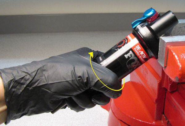
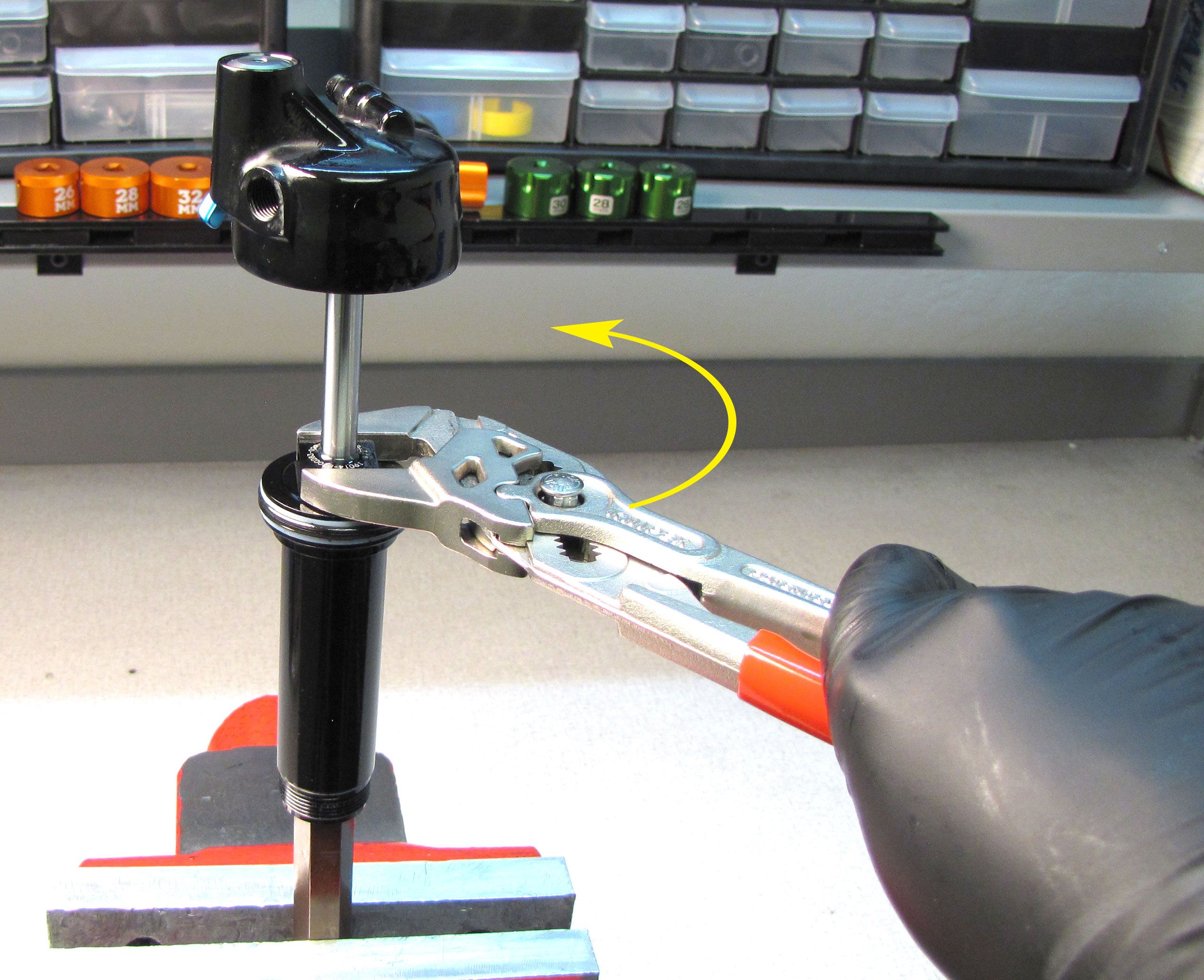
Step 1
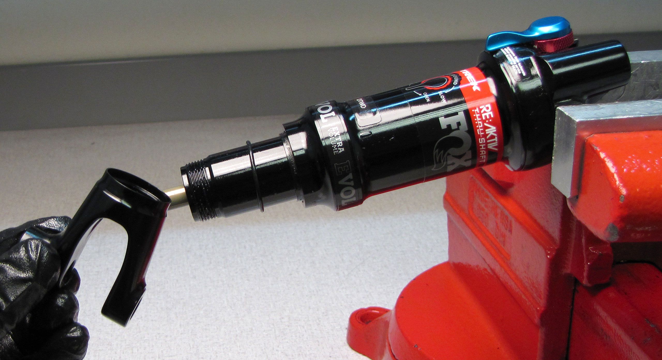
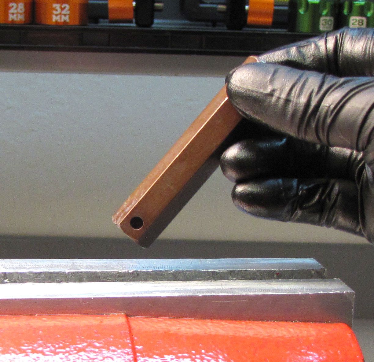
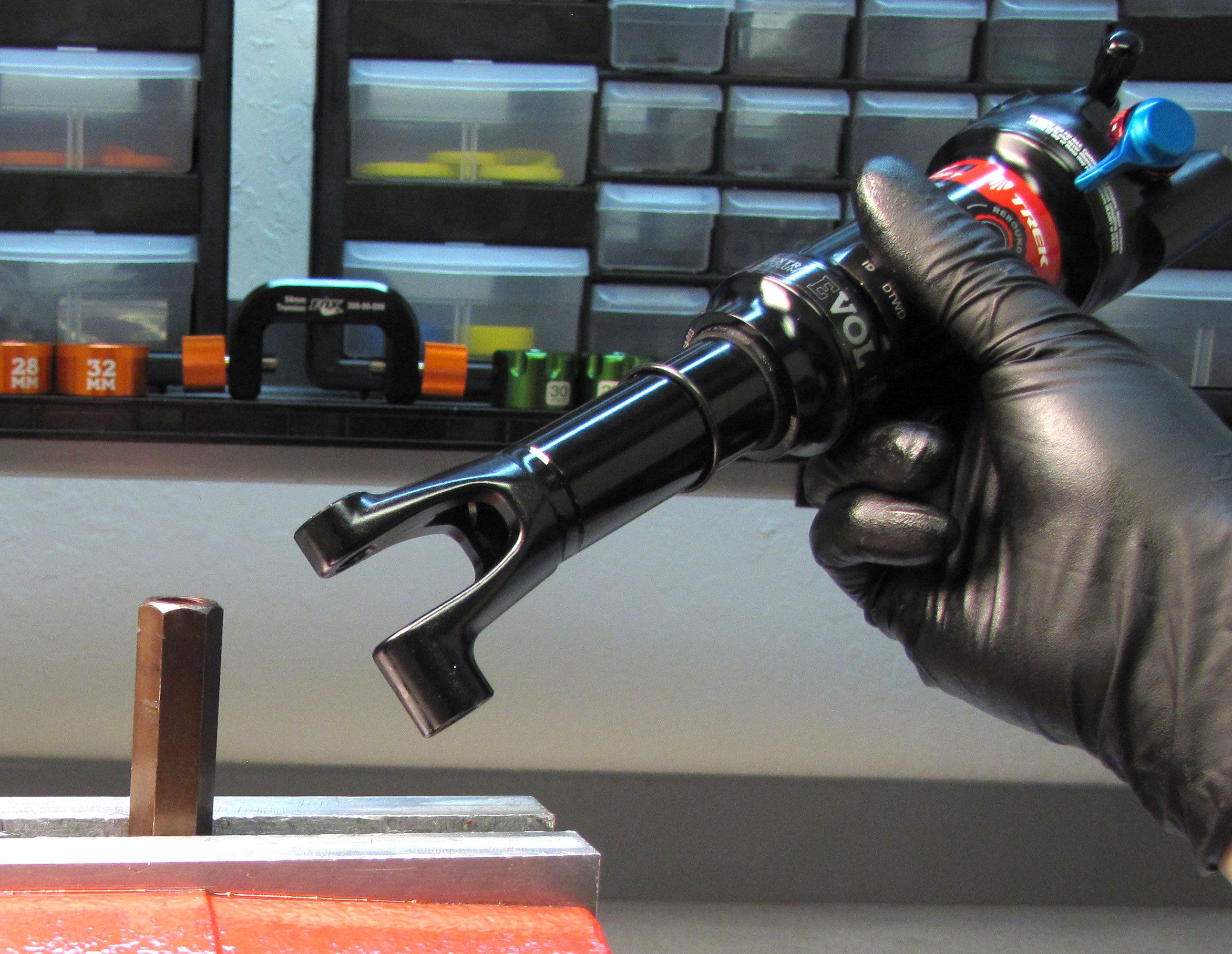
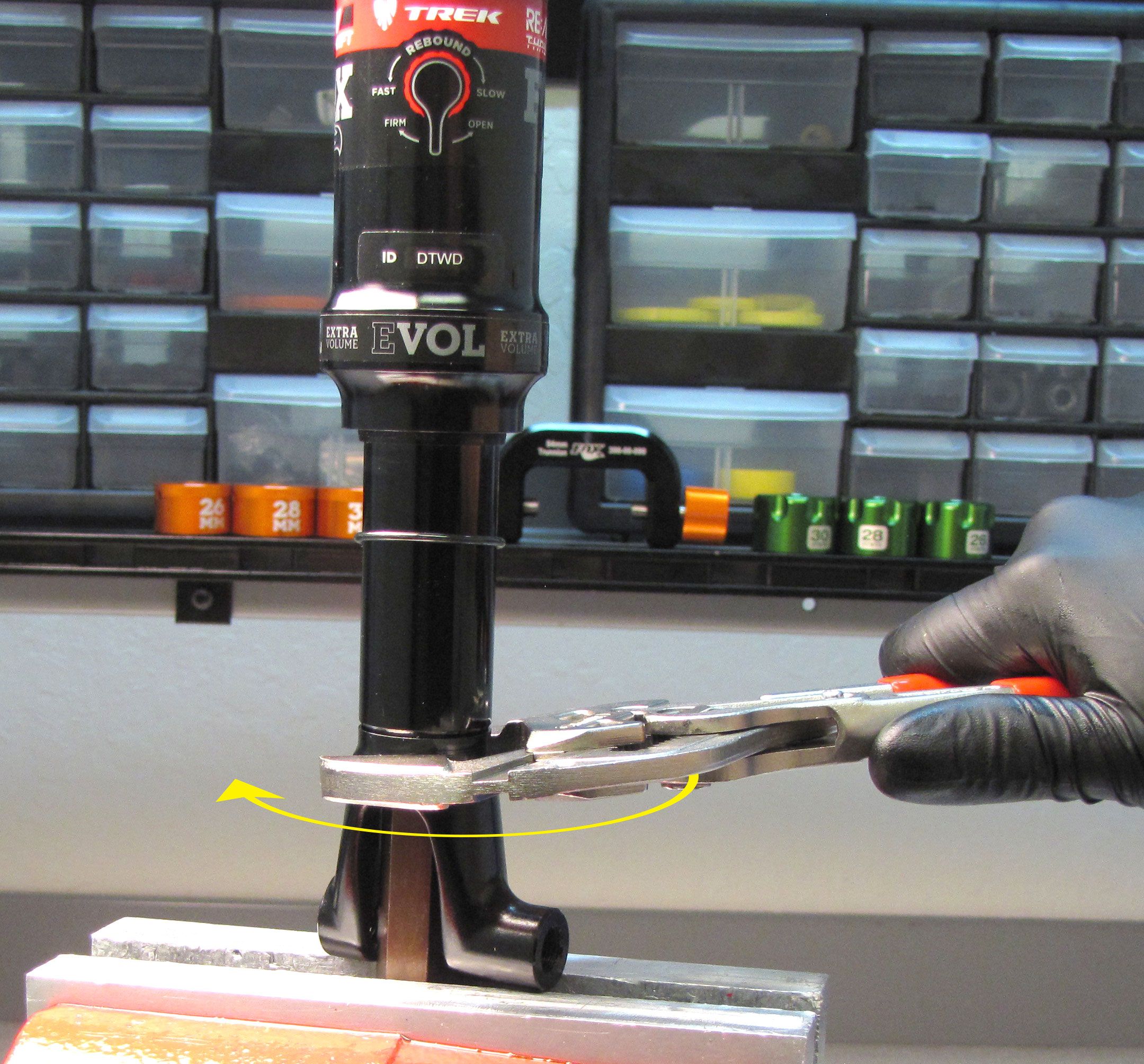
Turn the red Rebound knob fully counter-clockwise. Place the 15mm Hex torque tool (PN: 398-00-823) into your vise. Position the 2020 9mm Thru-Shaft shock onto the hex tool engaging the flats within the body. Use smooth-jawed parallel pliers (Knipex) on the flats of the Clevis to unthread the Clevis counter-clockwise from the body.

Step 2
Remove the black air cap and slowly release all air from the main air chamber. Verify that all air has been released by depressing the Schrader valve with a lint-free towel covering the valve to prevent any oil spray.


WARNING: Please verify that all air has been released from the air chamber by pushing down on the Schrader valve core. Failure to release all air pressure before further disassembly may cause parts to eject causing SEVERE INJURY OR DEATH.
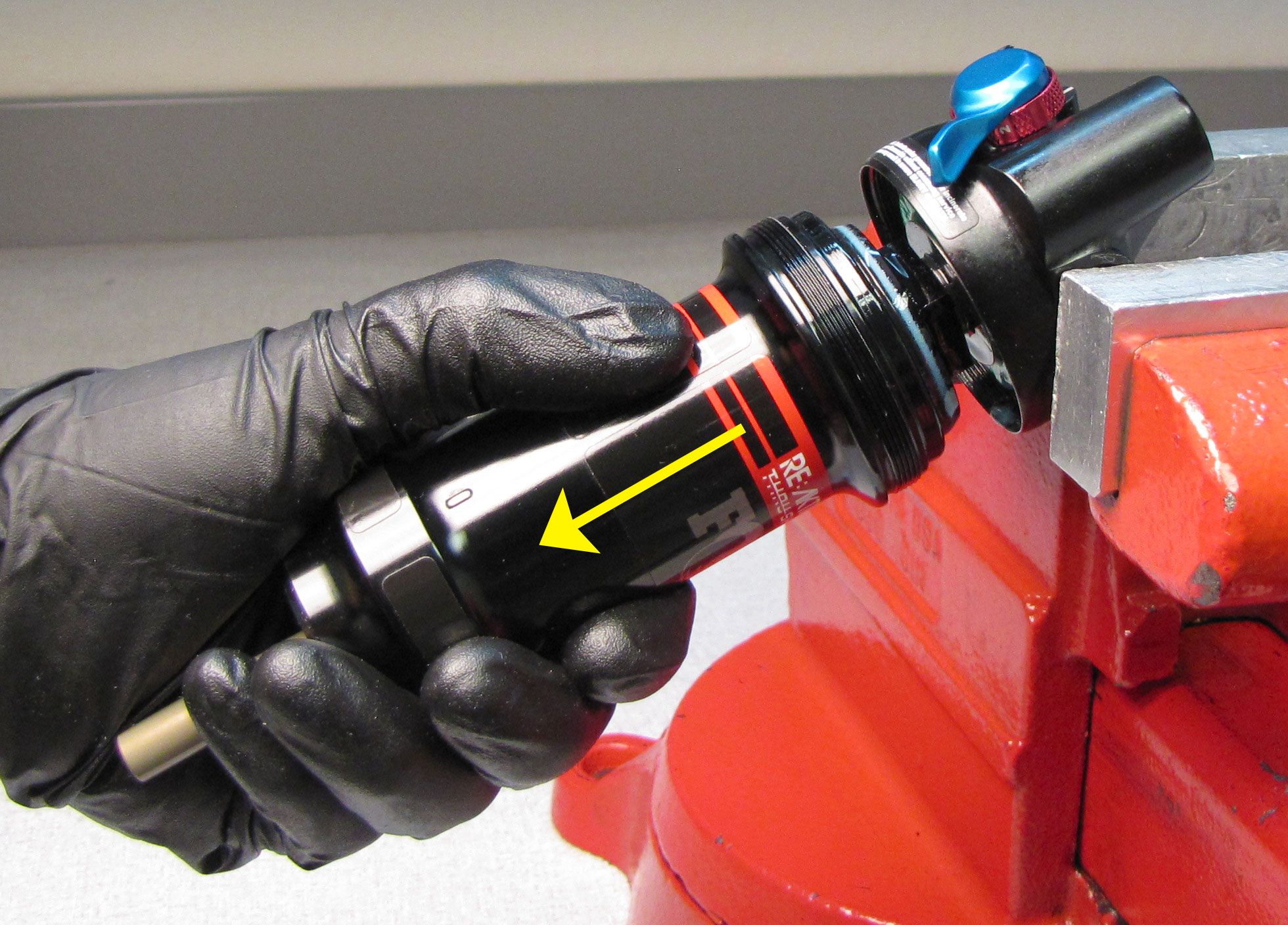
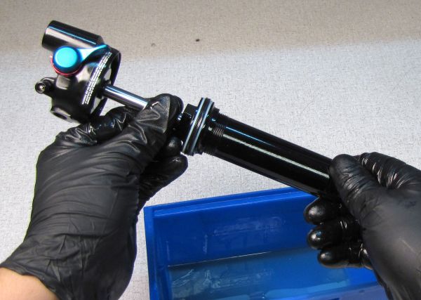
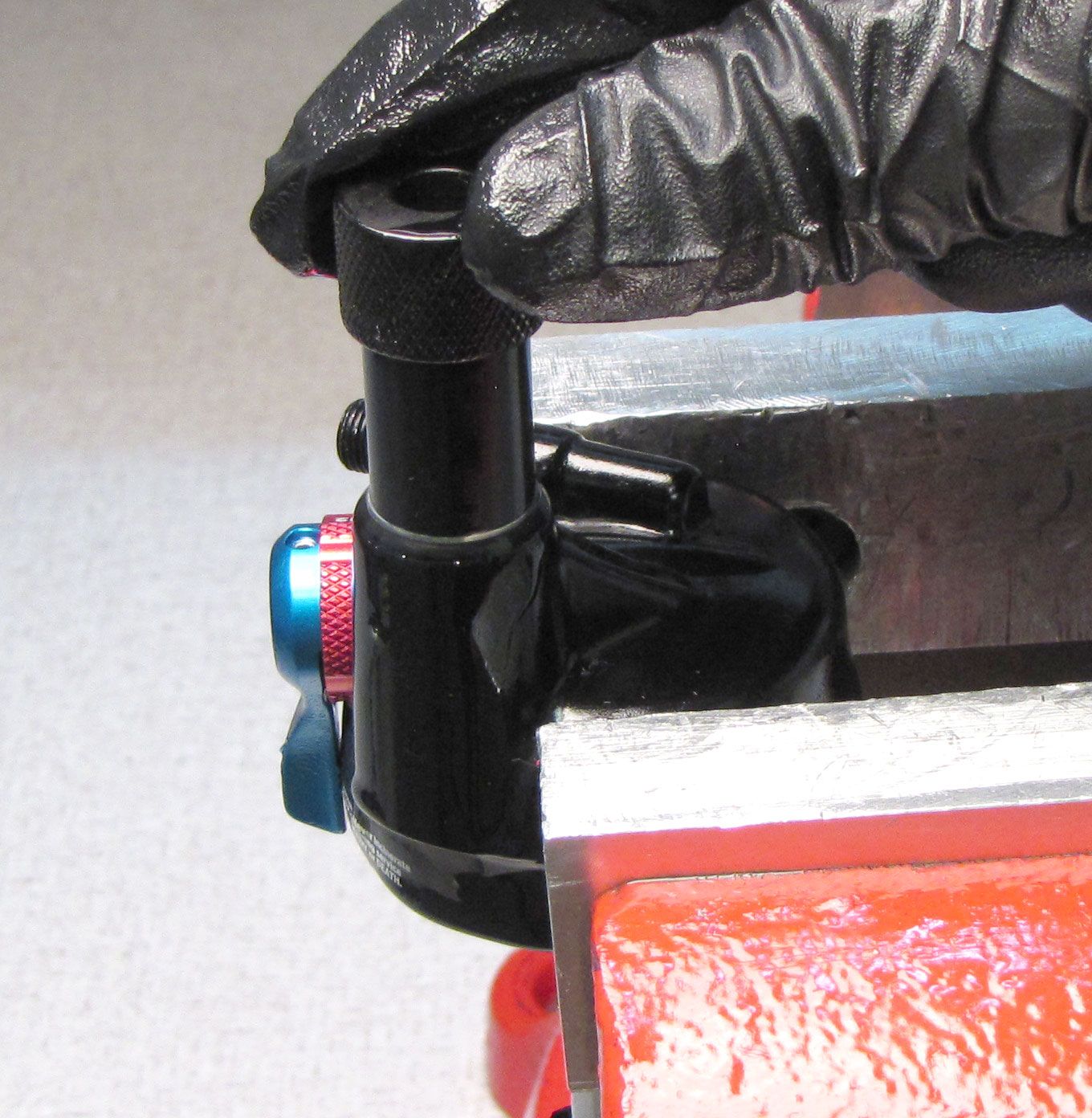
Step 3
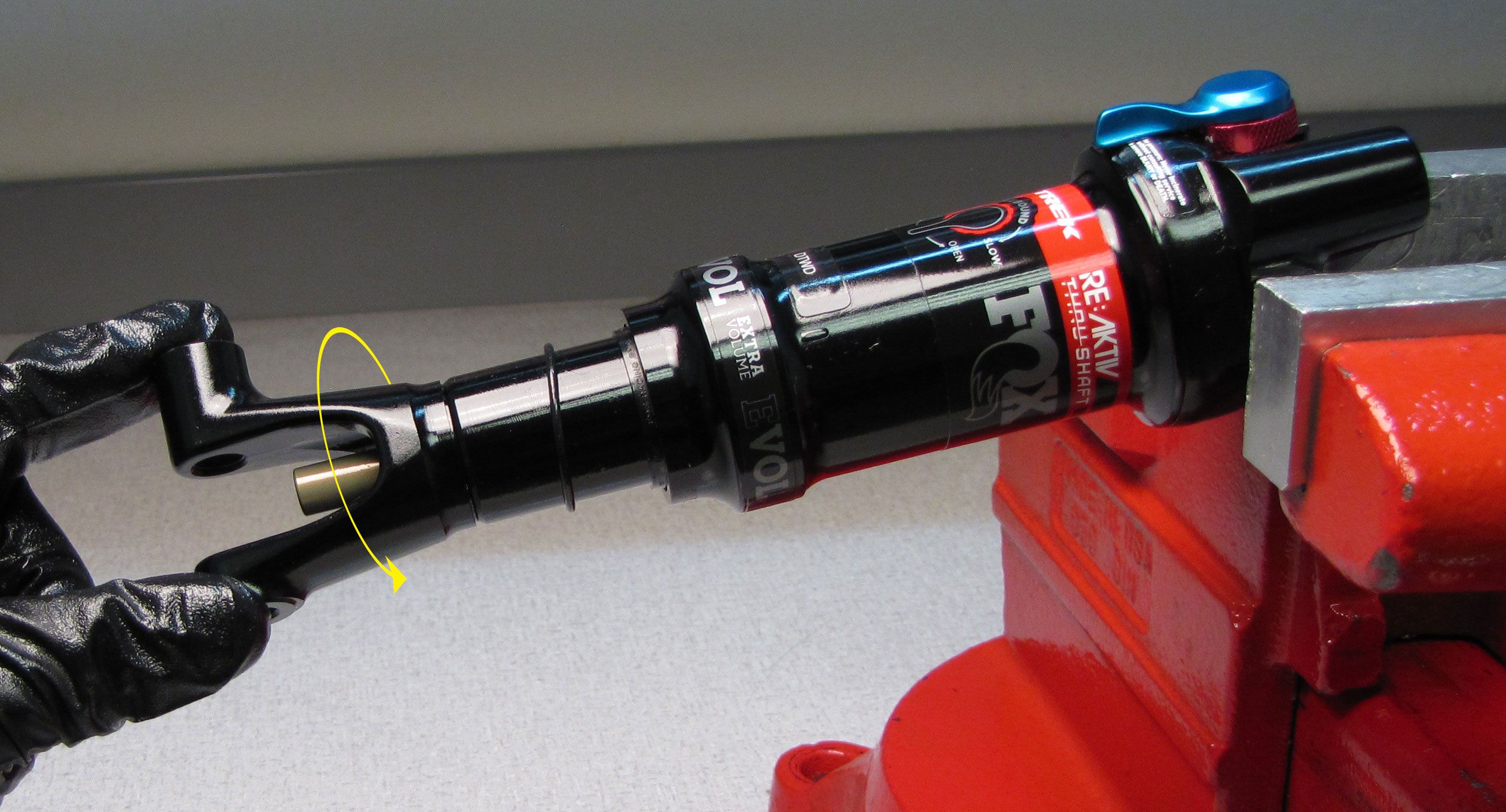
Unthread the air sleeve from the eyelet by turning it counter-clockwise. Remove the air sleeve after unthreading by pulling it away from the shock.

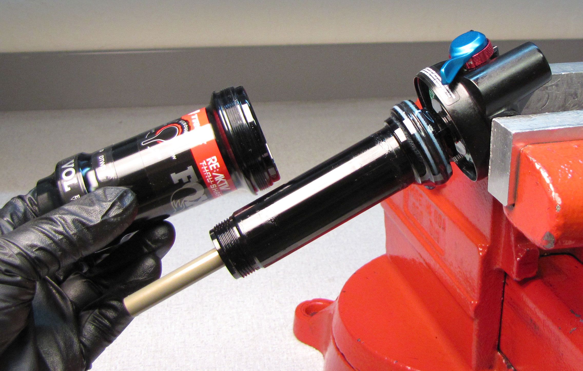
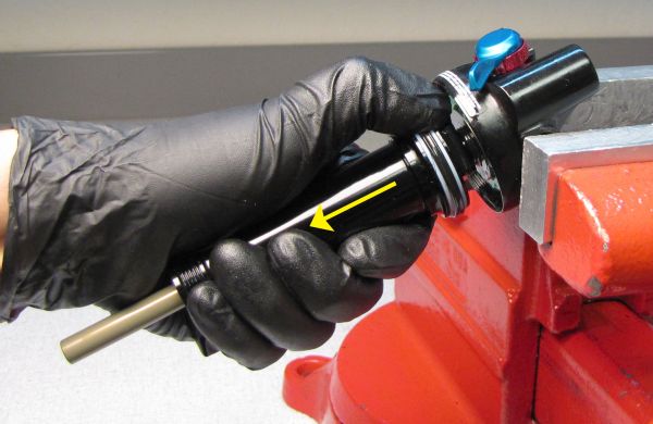
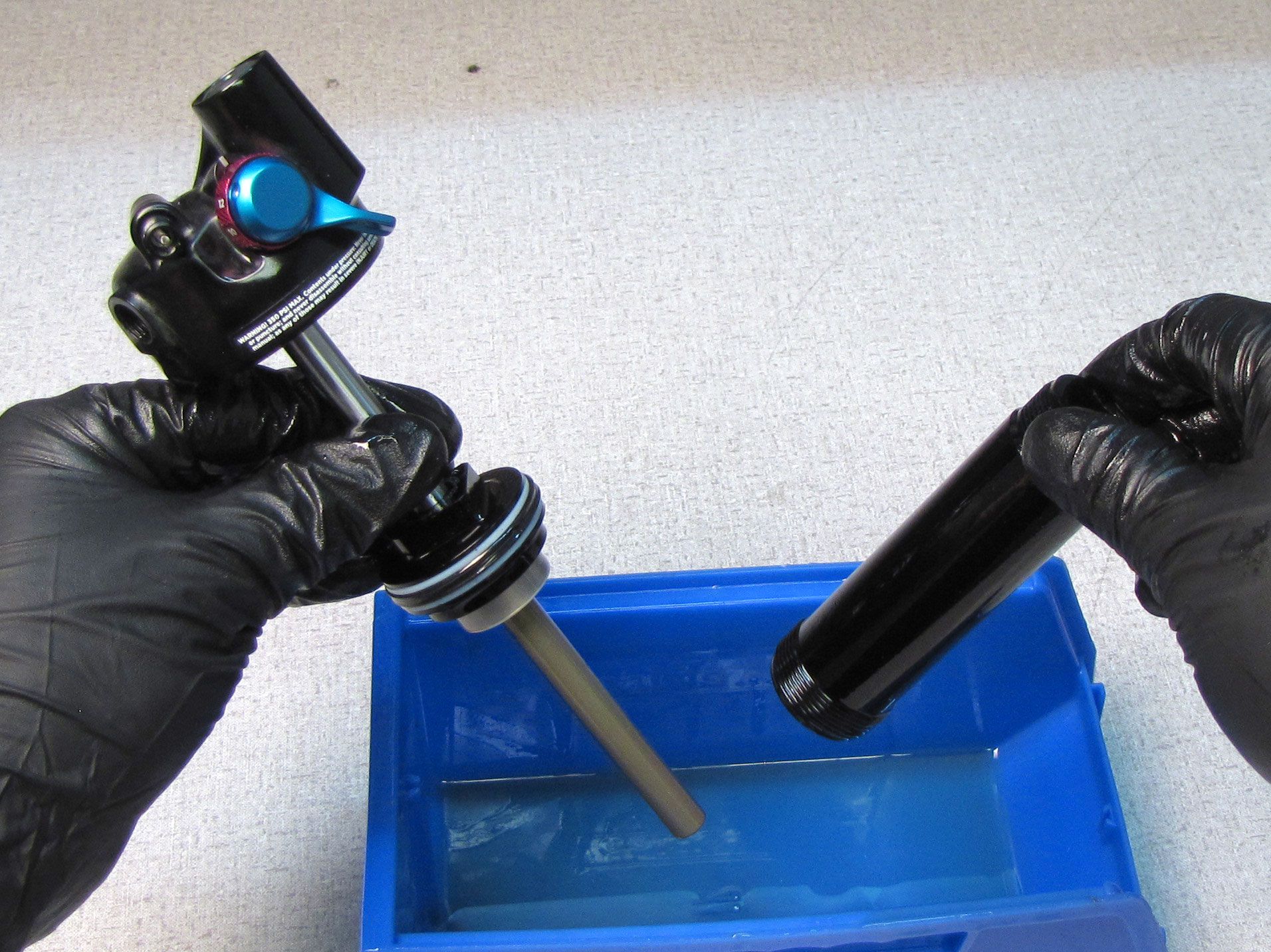
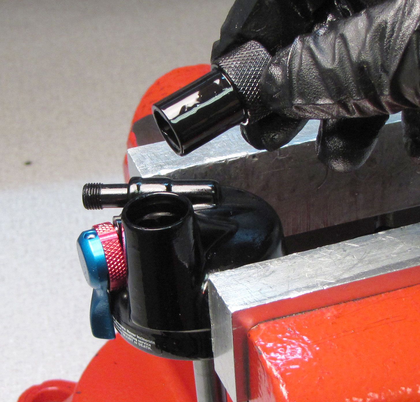
Step 4
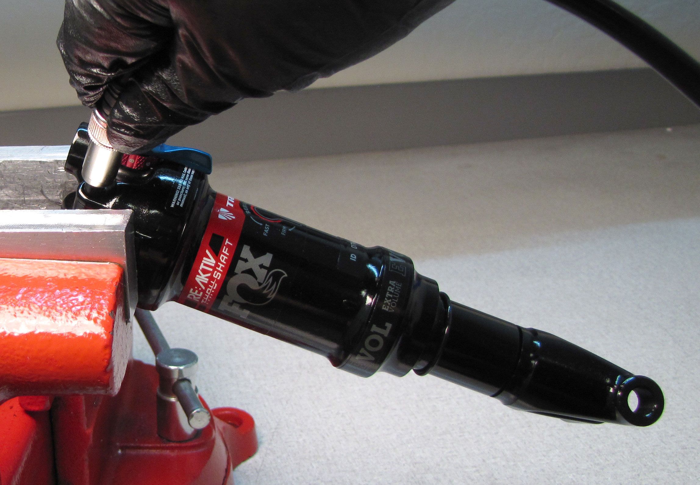
Pull the shock body down away from the adjuster eyelet. Place the 15mm torque tool back into the vise then place the shock body onto the tool engaging the wrench flats within the body with the hex tool.


Step 5
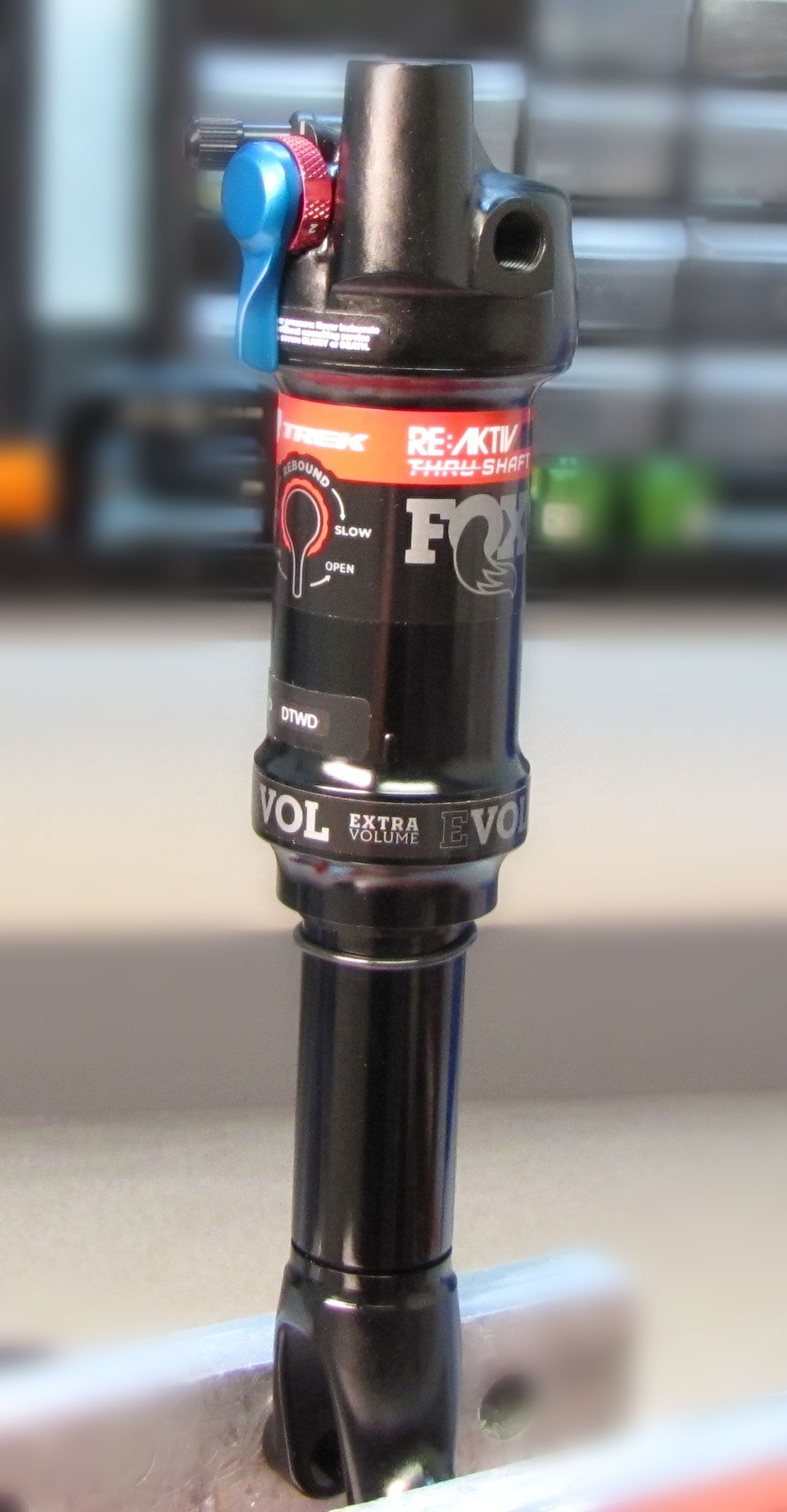
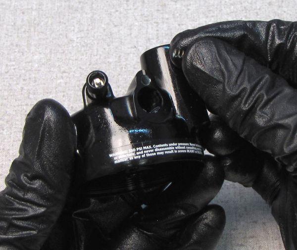
Use a 5/64" hex to unthread the bleed screw counter-clockwise. Use a magnetic tool to remove the ball from under the bleed screw. Unthread the bearing assembly from the shock body with a 3/4in wrench. Position your wrench so the wrench does not apply torque to the bleed hole.

Step 6
Unthread the bearing assembly from the body over a waste oil basin.


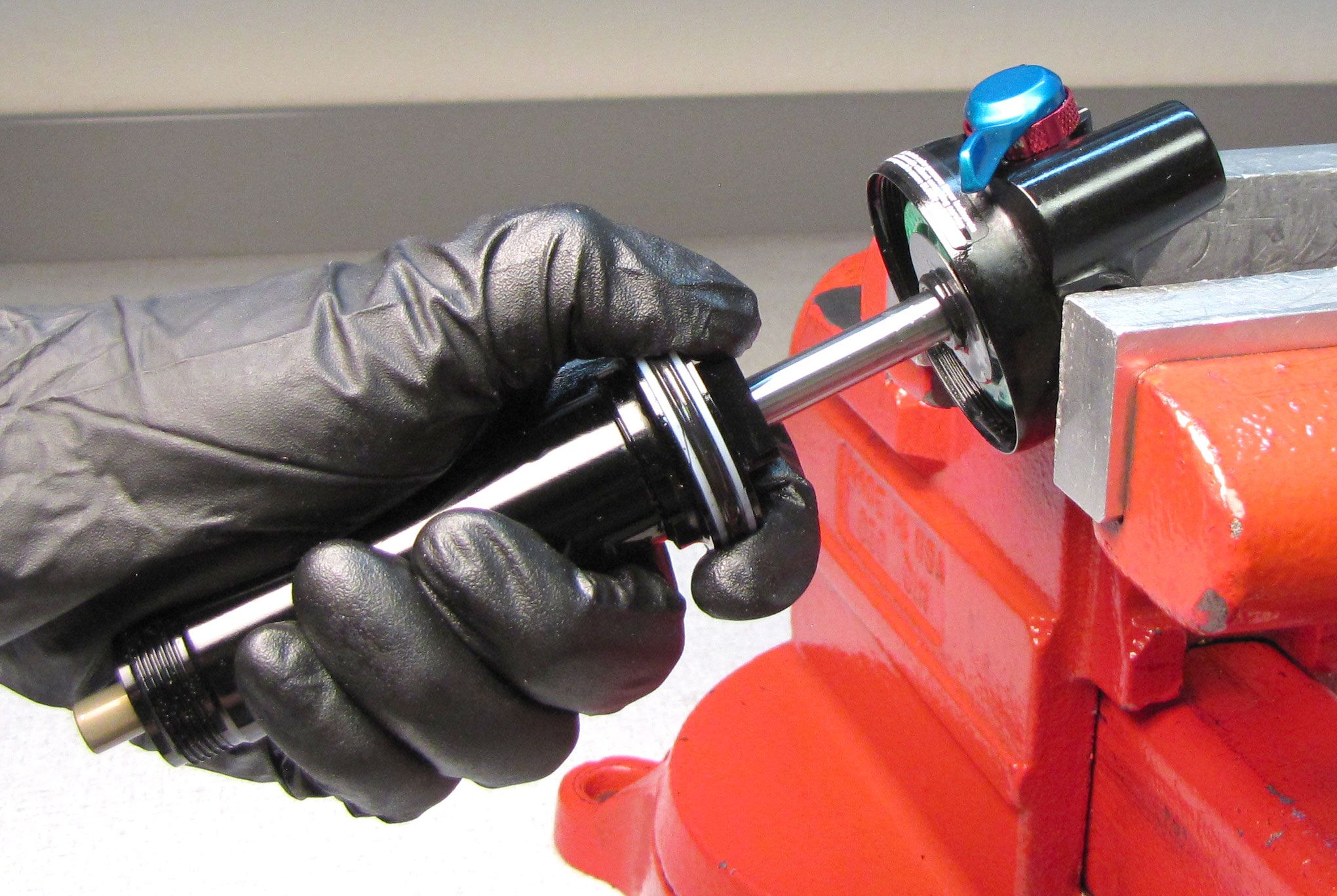
Step 7
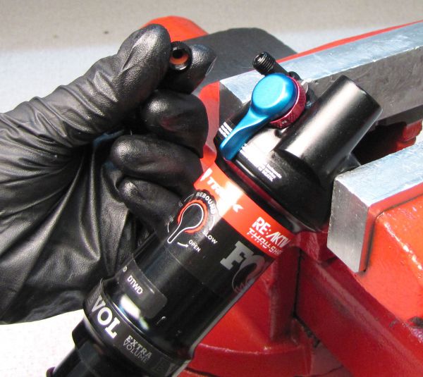
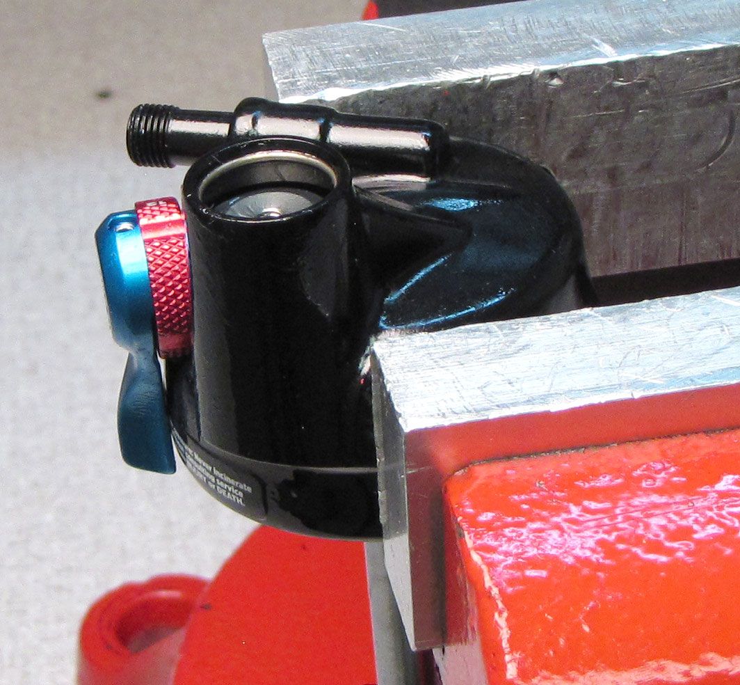
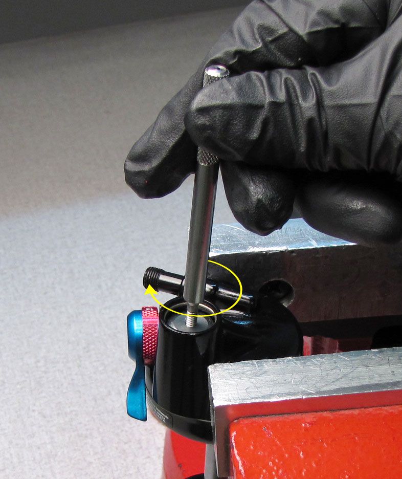
Clamp the Trunnion eyelet in your soft-jawed vise then unthread the Slave Shaft counter-clocklwise with a 5mm hex wrench. Remove the Slave Shaft and set aside.

Step 8
Remove the RE:aktiv Valve Housing Cap by unthreading it counter-clockwise with a 5mm hex wrench.


Step 9
Remove the wave spring followed by the Spring Perch with Compression metering rod by lifting up.
Step 10
Unthread the Piston Bolt counter-clockwise with an 8mm socket. Remove the bolt and valving assembly together by aligning them on the Trek RG Valve Stack Transfer tool (PN: 398-00-614) then set aside.

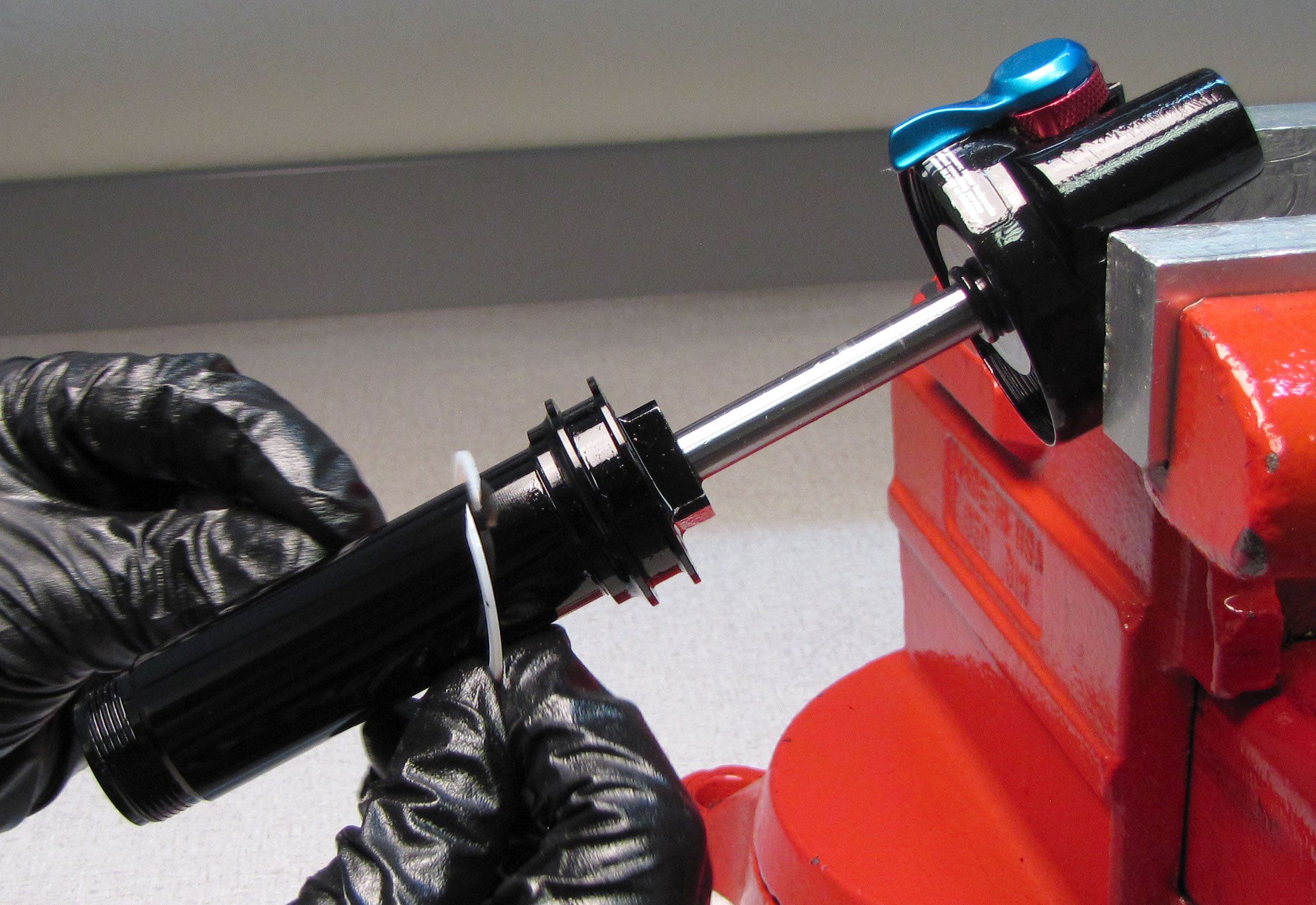
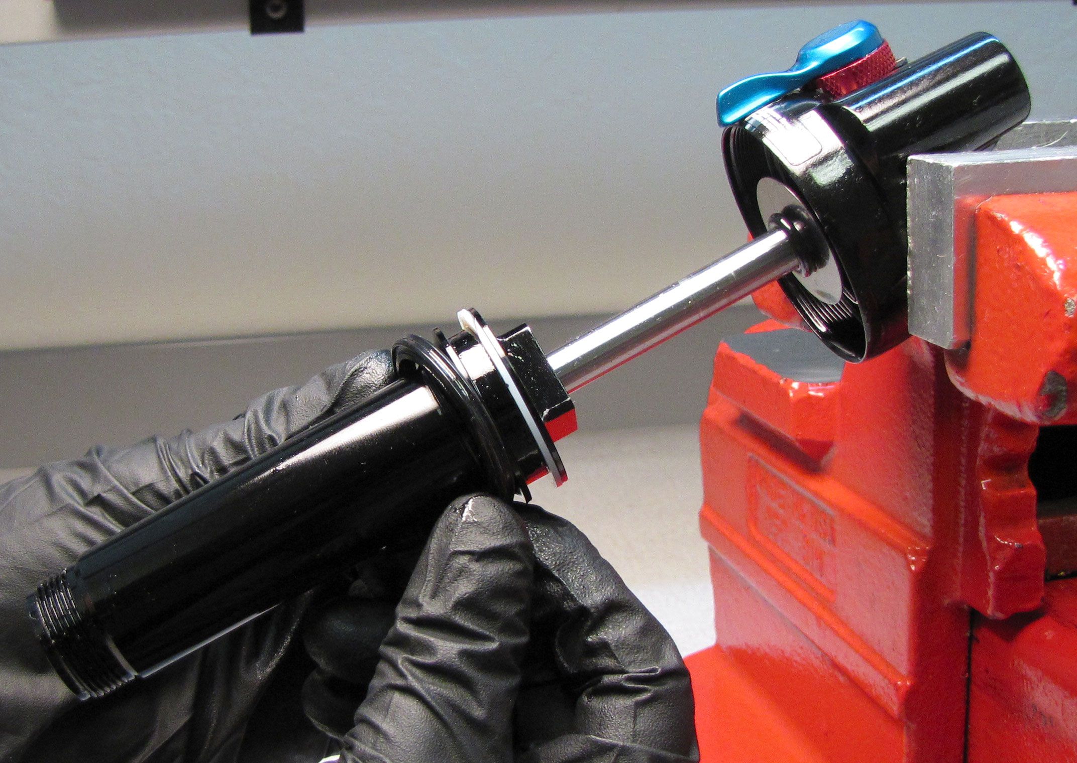
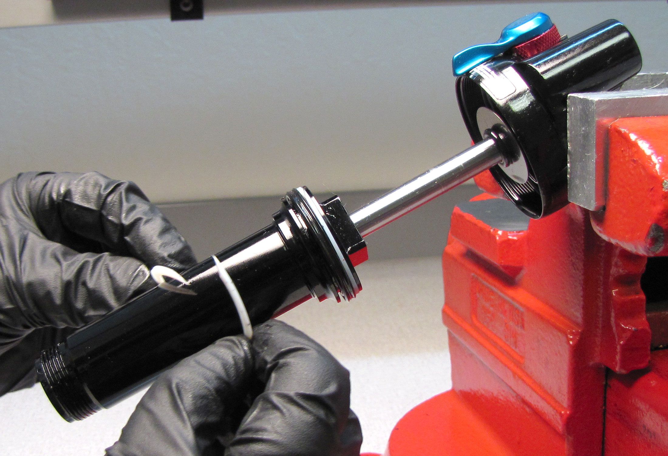
Step 11
Remove the Bearing assembly by pulling it up off of the shaft. Remove the bottom out o-ring and plate by pulling them up off of the shaft.


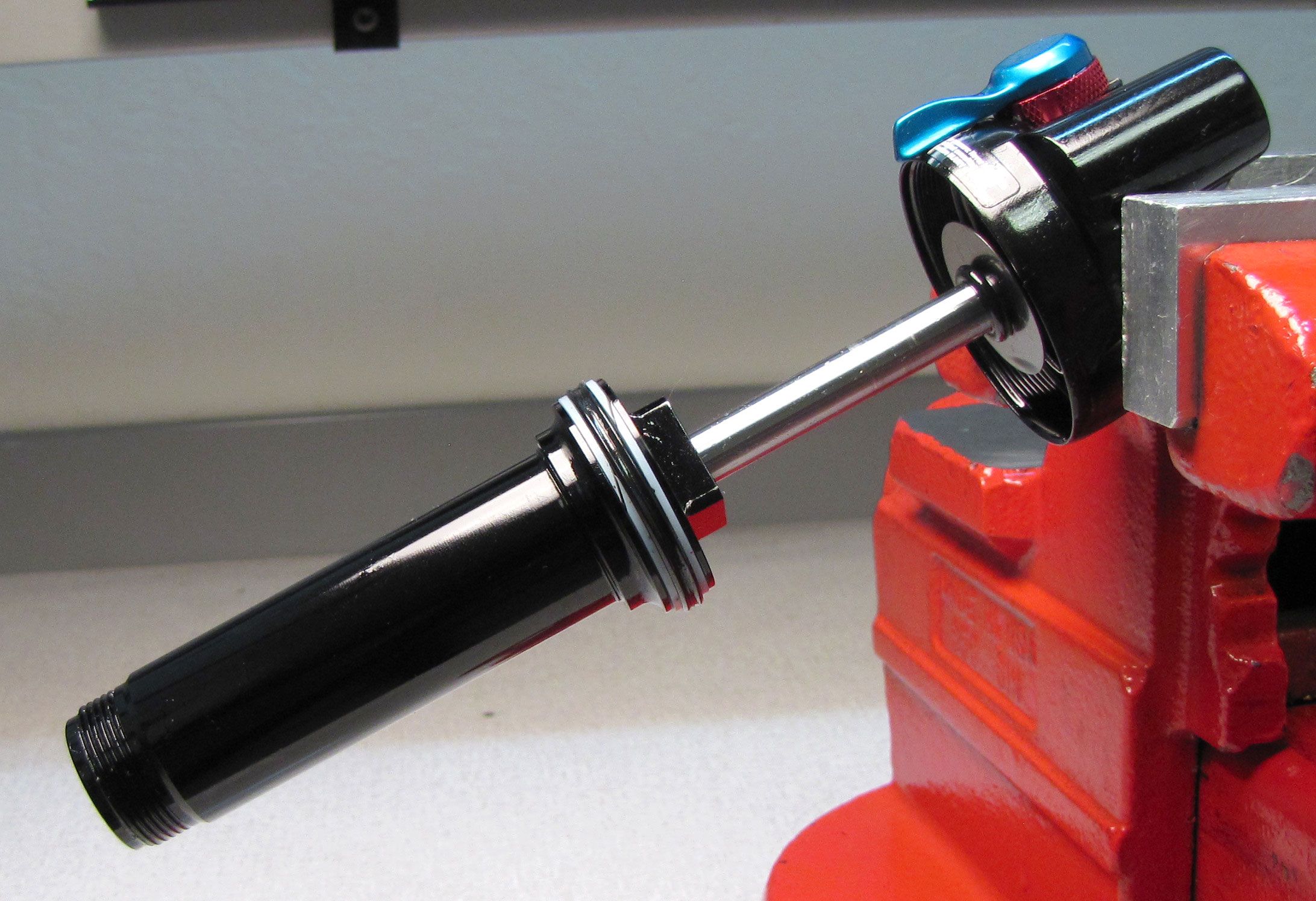
Step 12
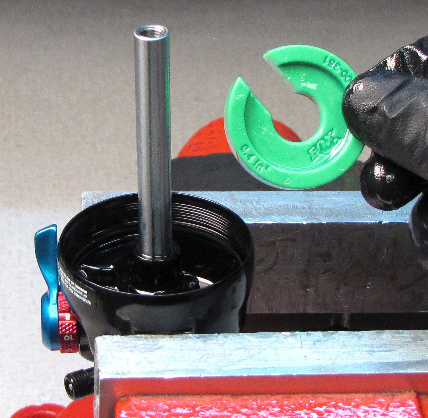
Remove the volume spacer from the eyelet if present.

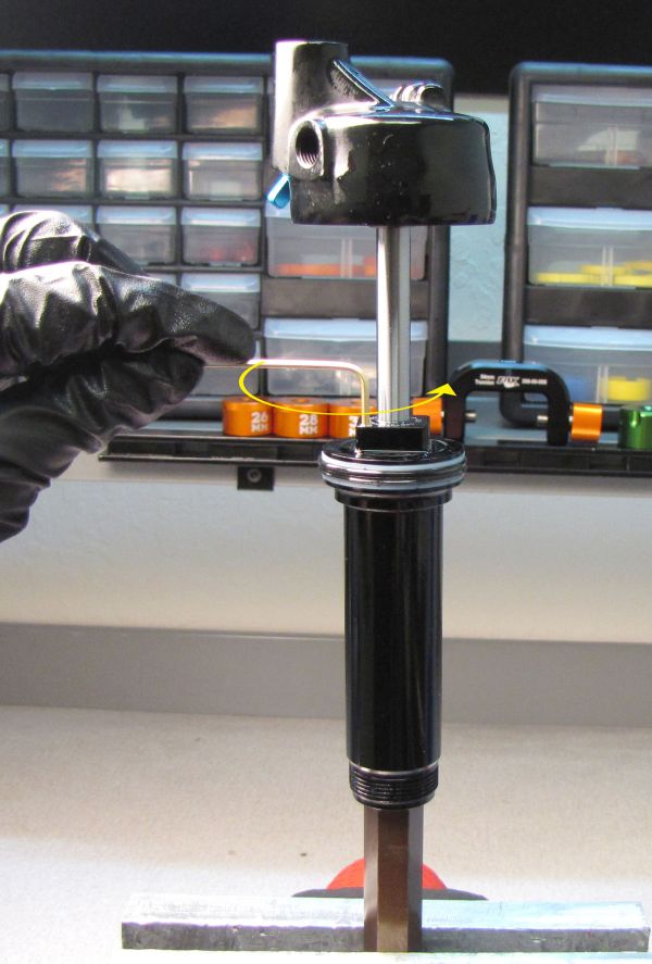
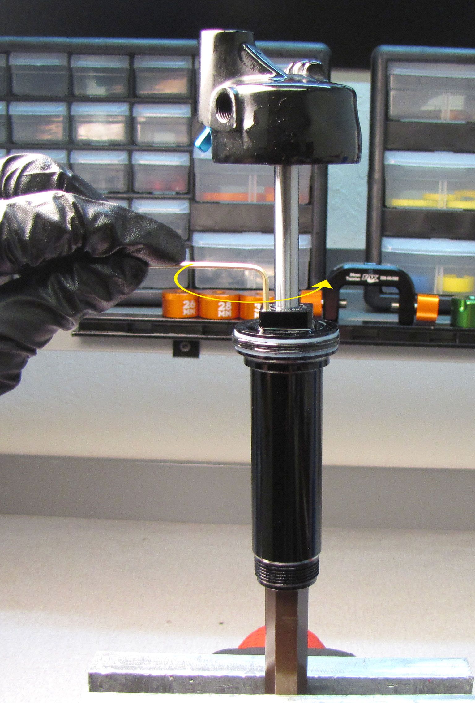
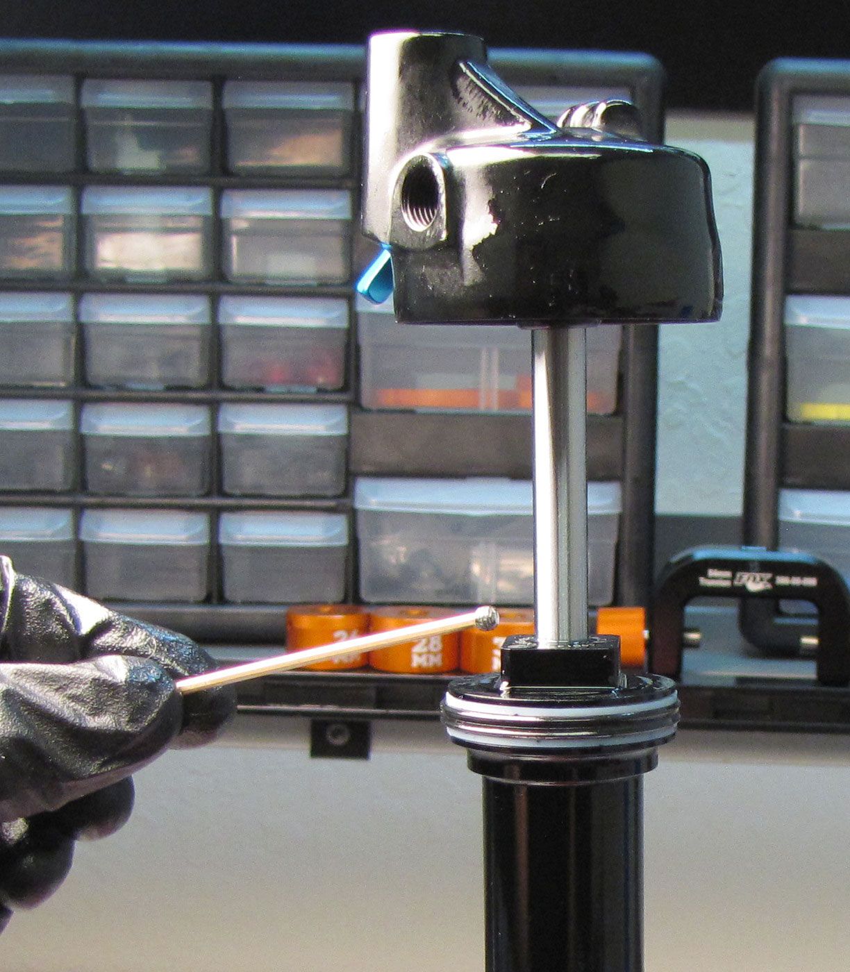
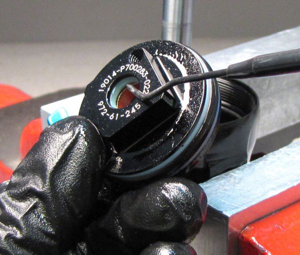
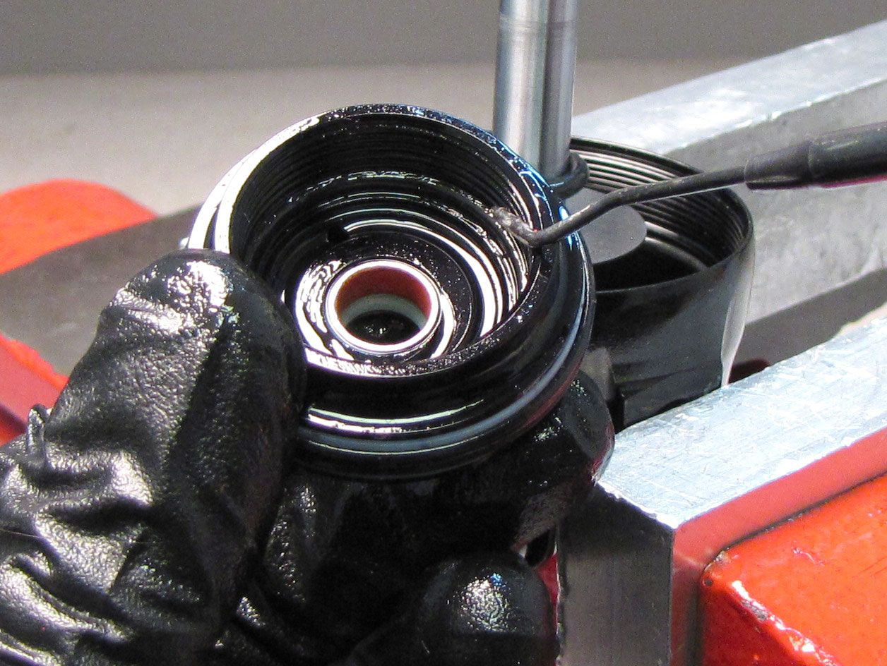
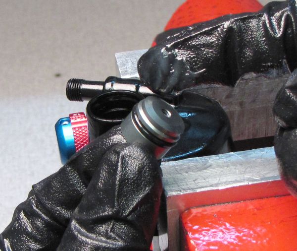
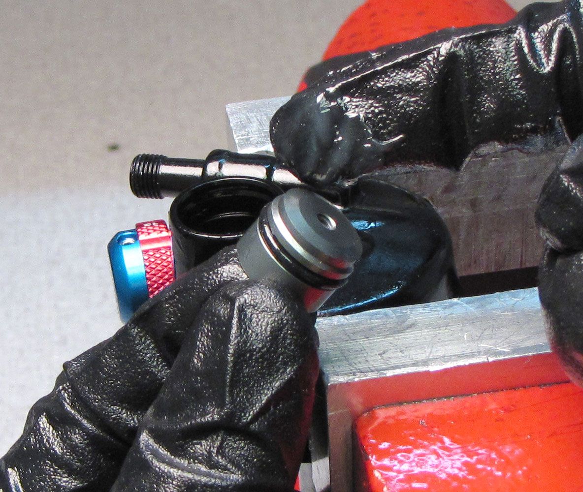
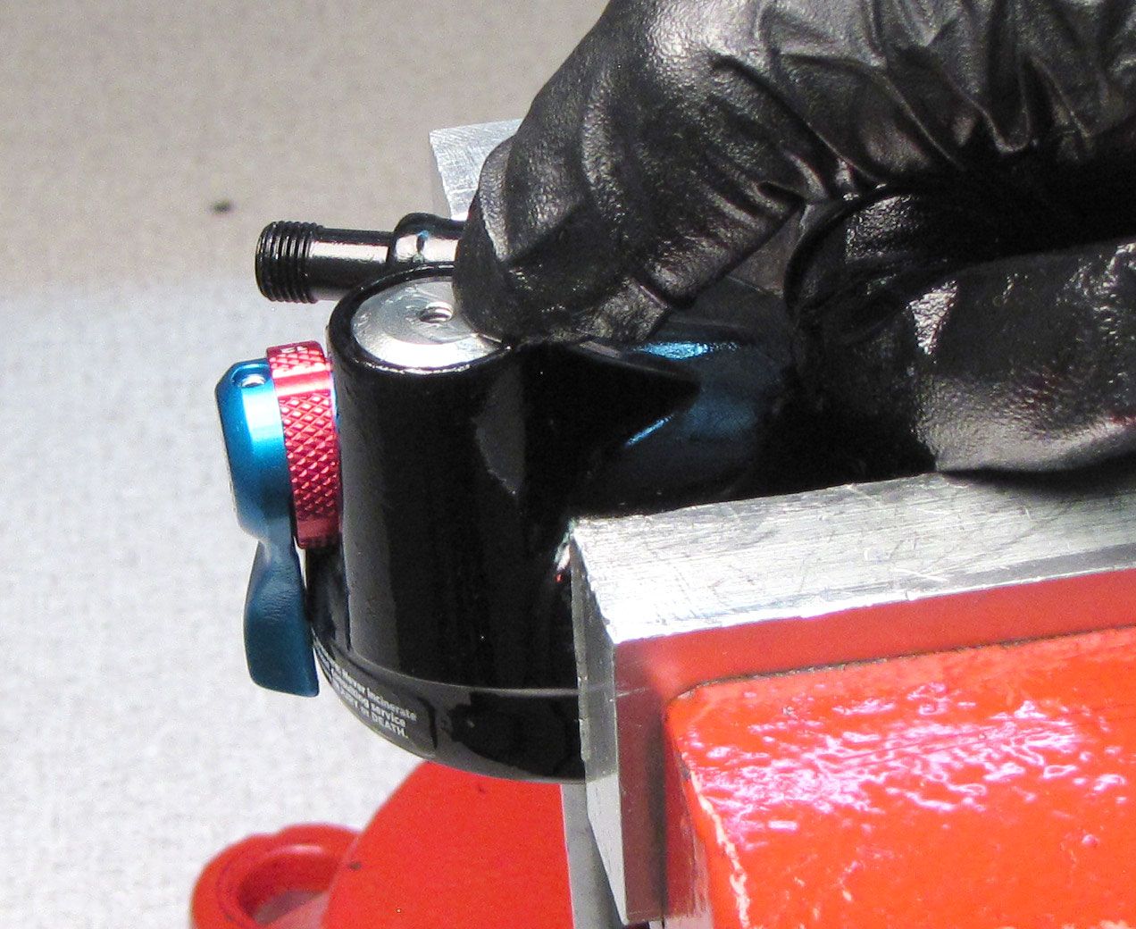
Step 13
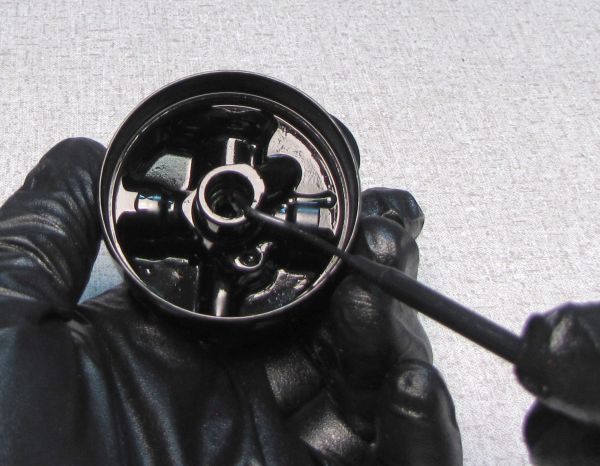
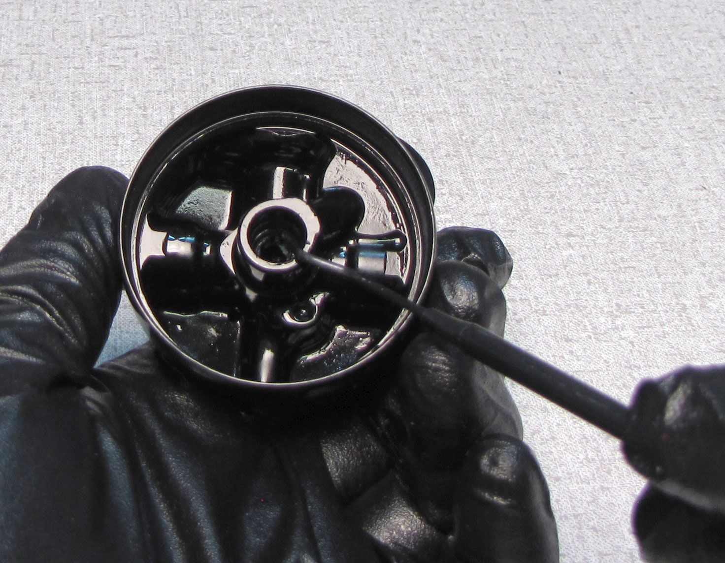
Clamp the shaft using PN: 803-00-805 9mm shaft clamps. Push the Rezi End Cap into the reservoir to expose the retaining ring. Use extreme caution if using a metal pick not to scratch the bore or o-ring glands. Remove the wire retaining ring.


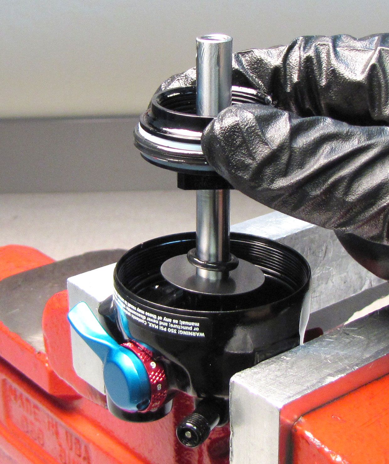
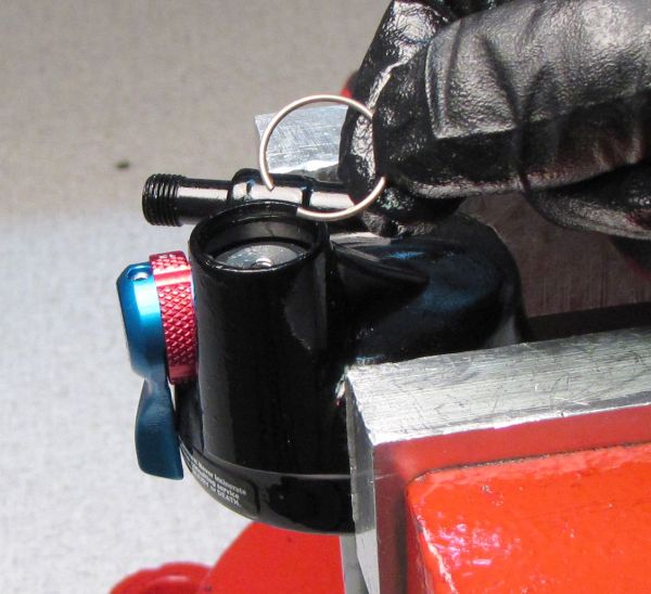
Step 14
Thread the IFP removal tool (PN: 398-00-749) clockwise into the Rezi End Cap, then pull up to remove the End Cap.

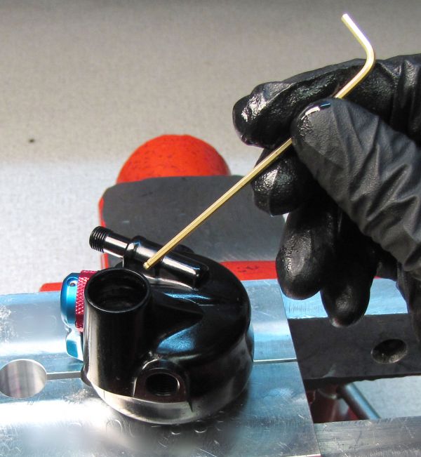
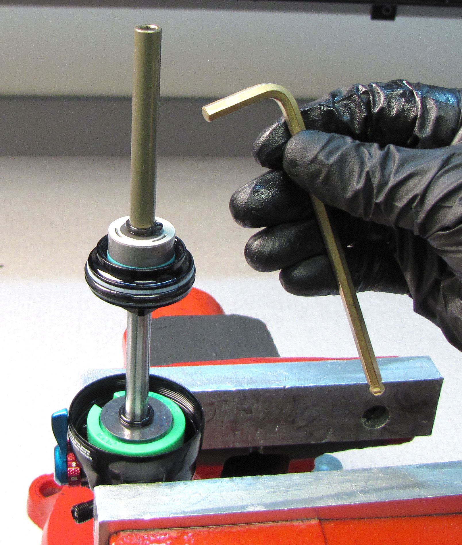
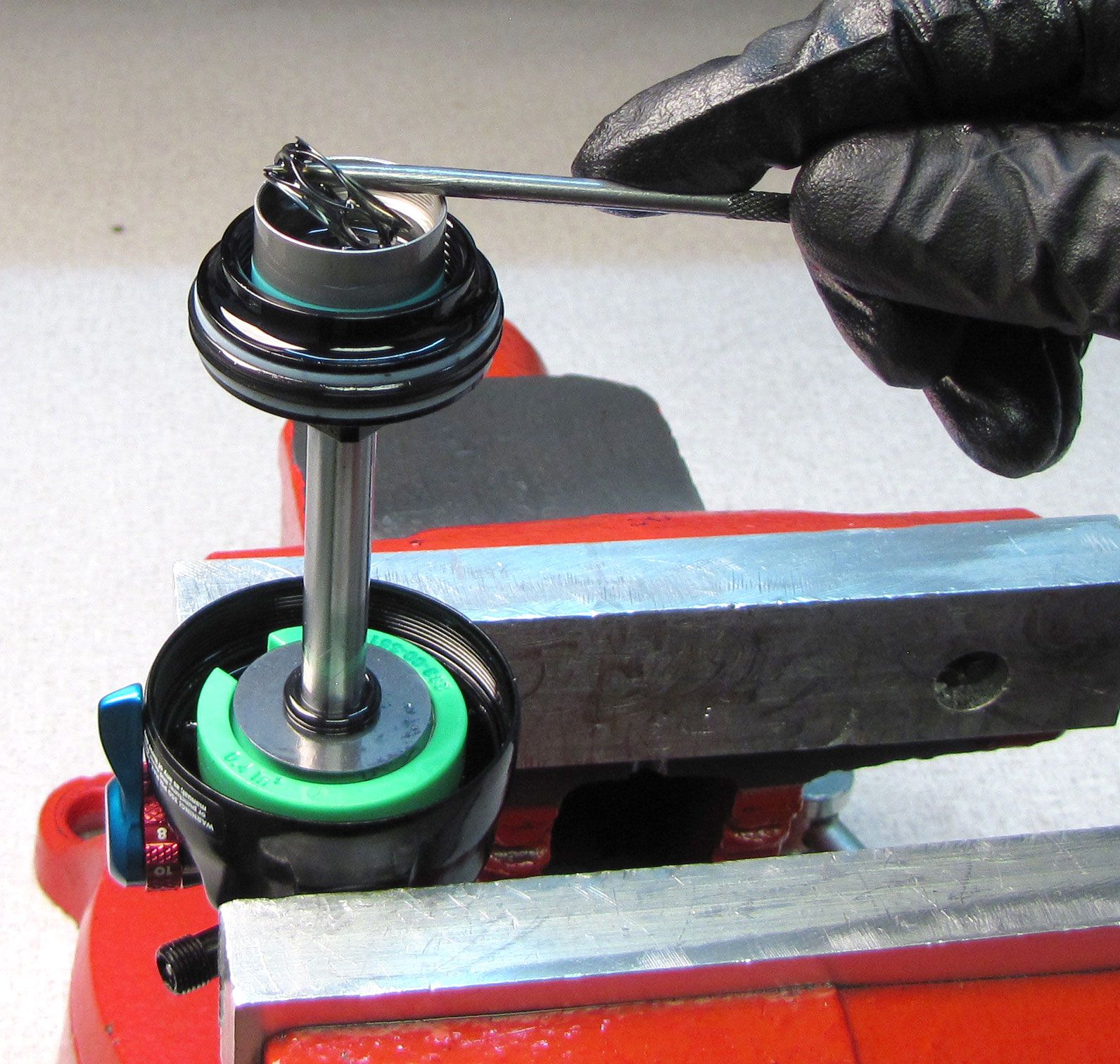
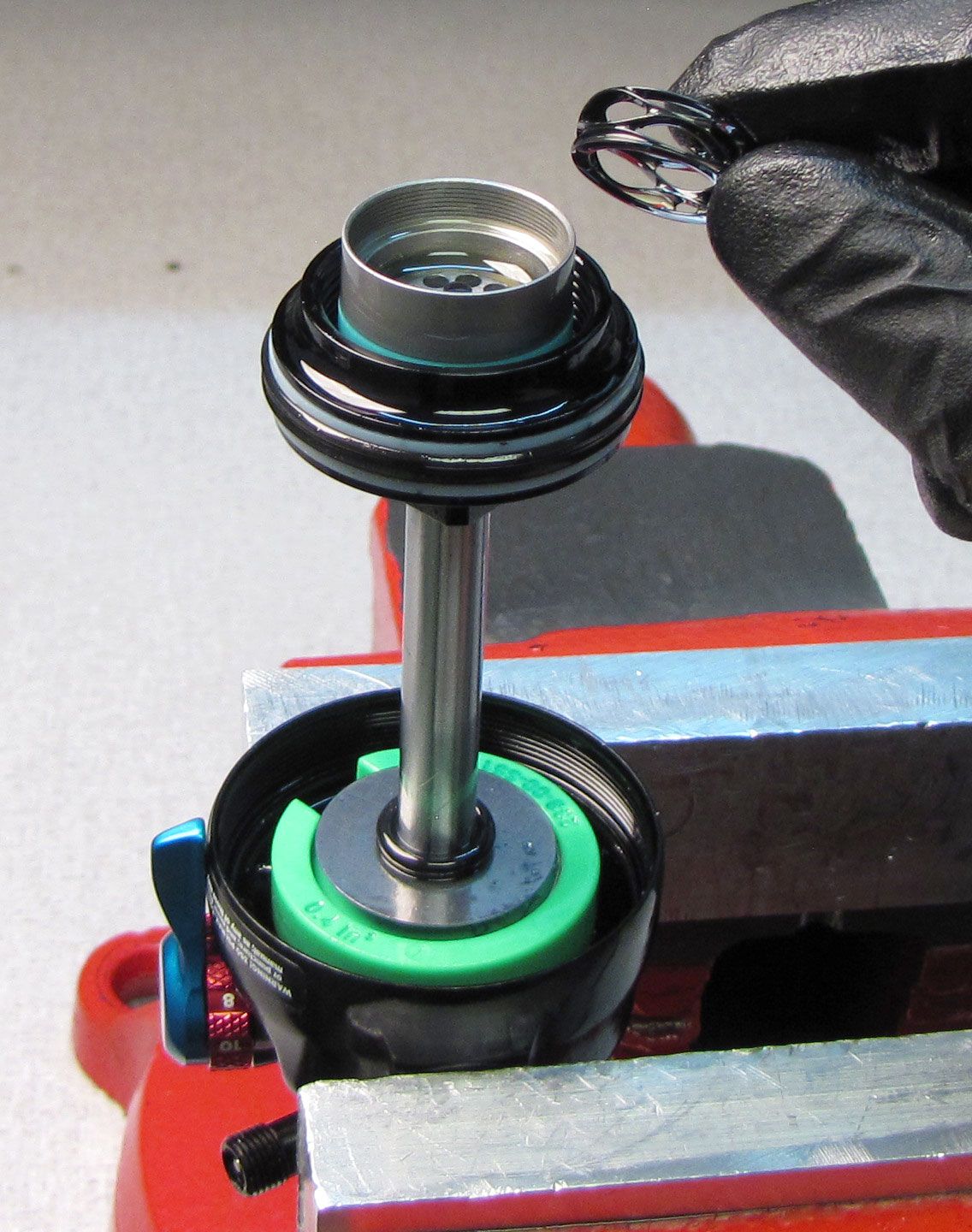
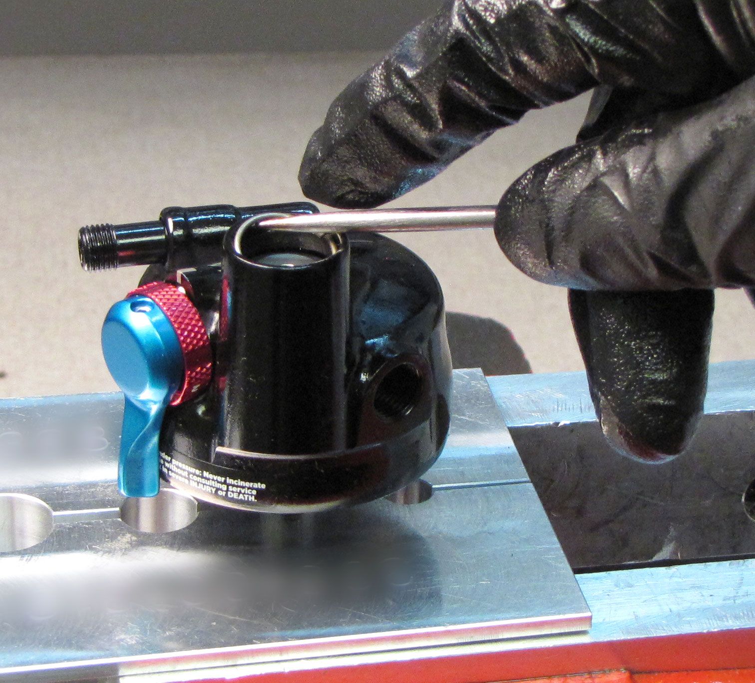
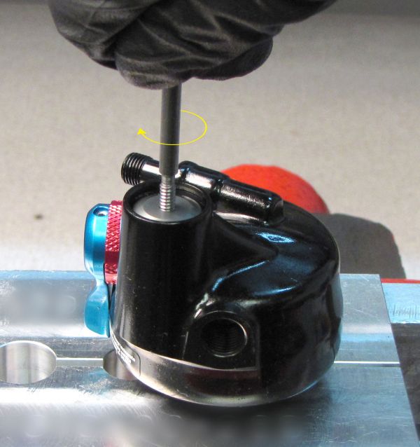
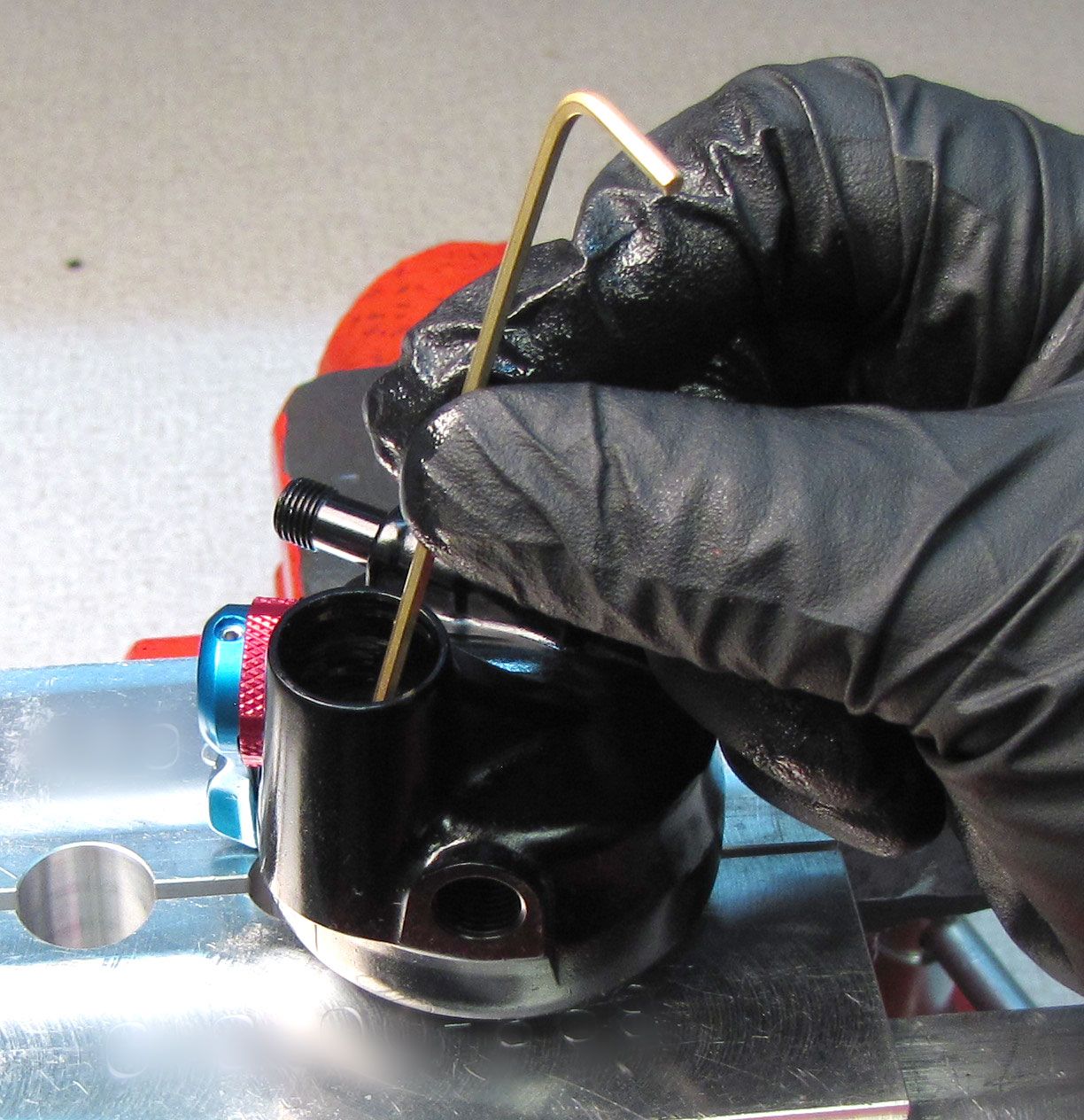
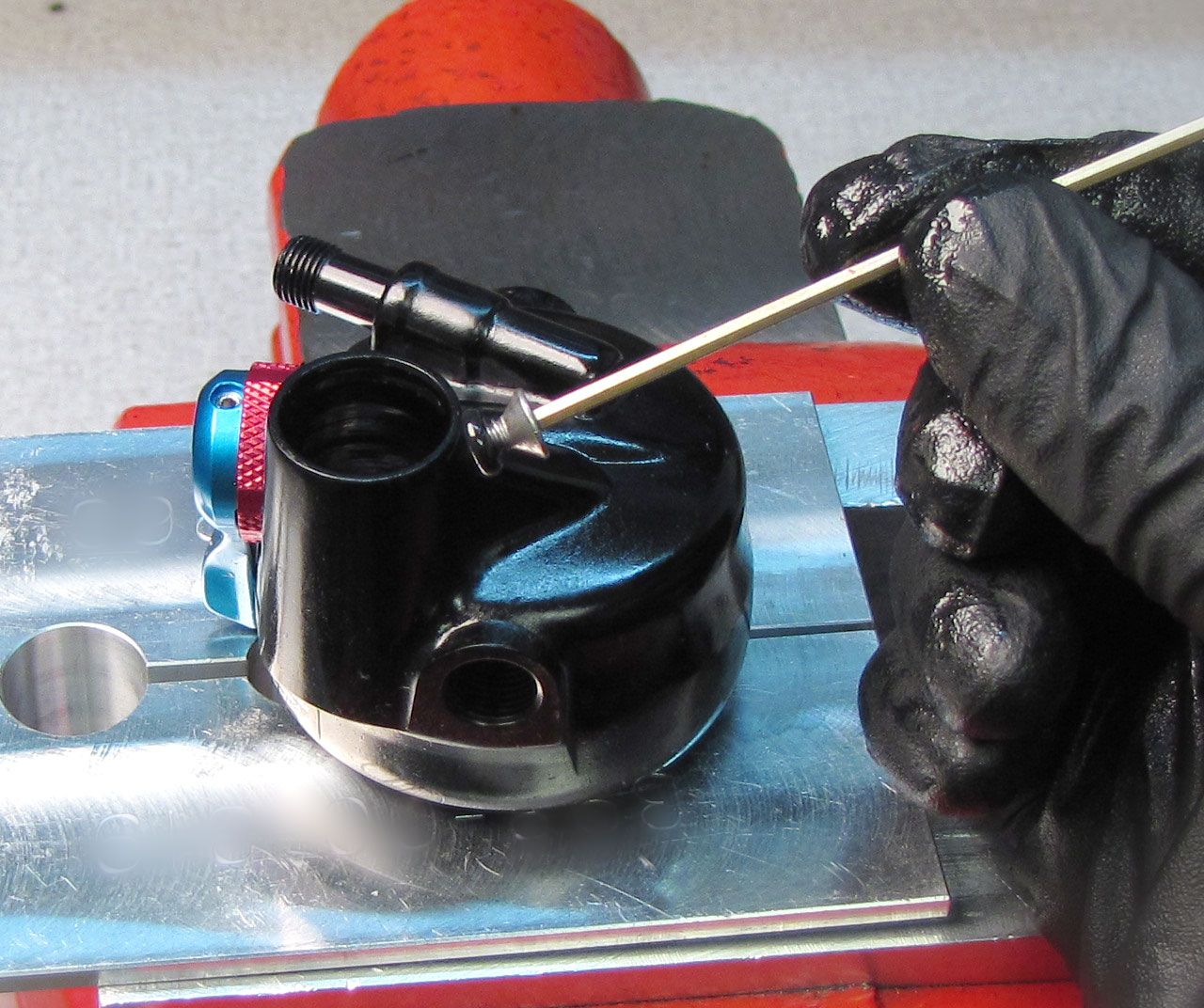
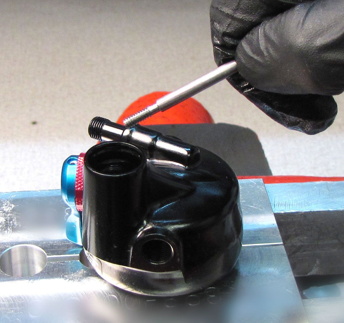
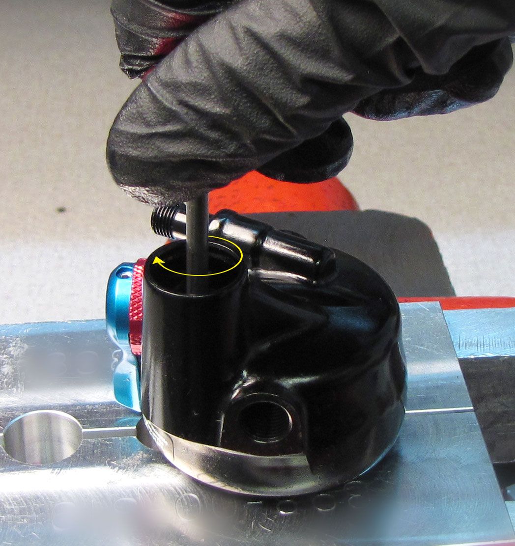
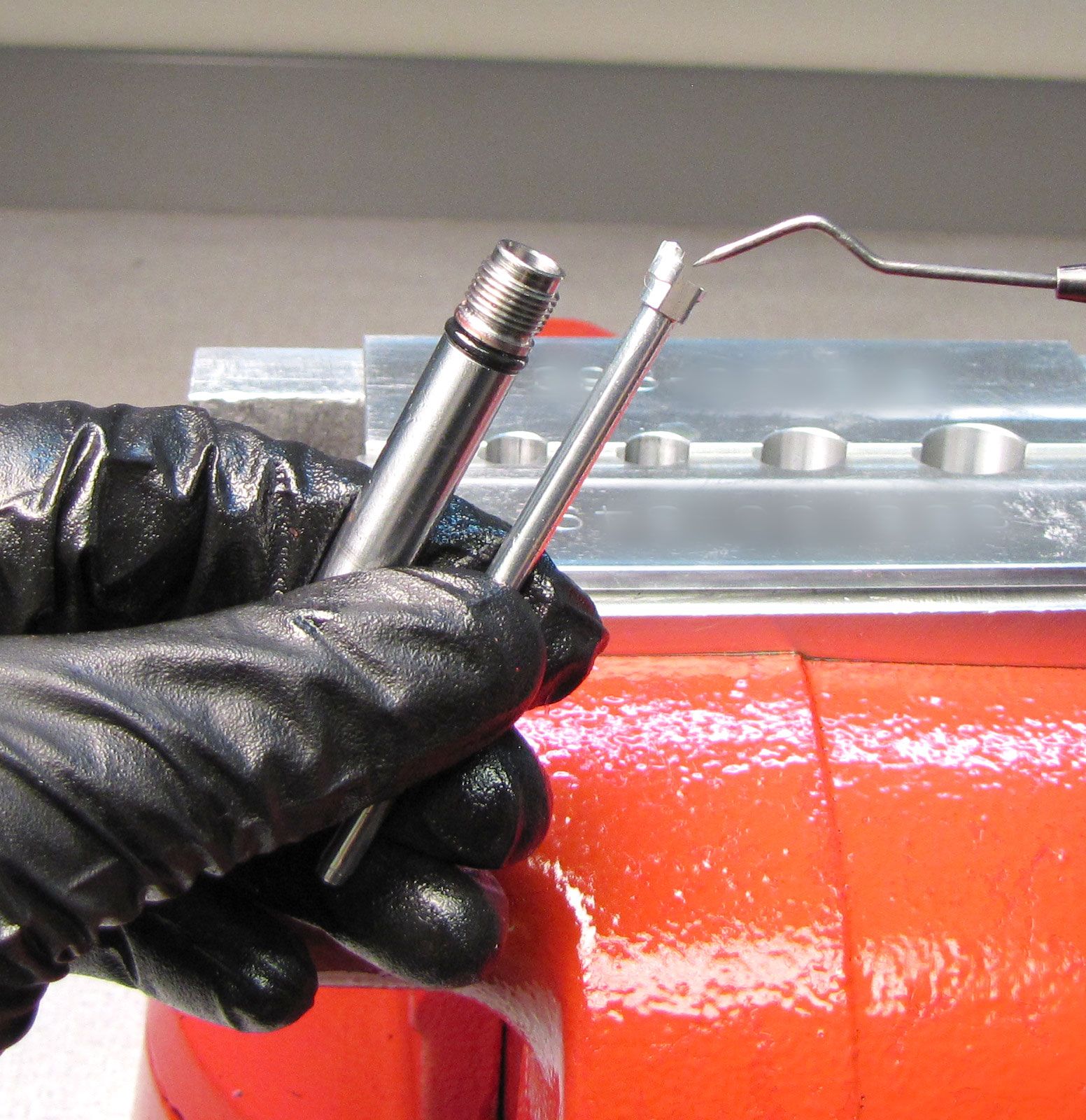
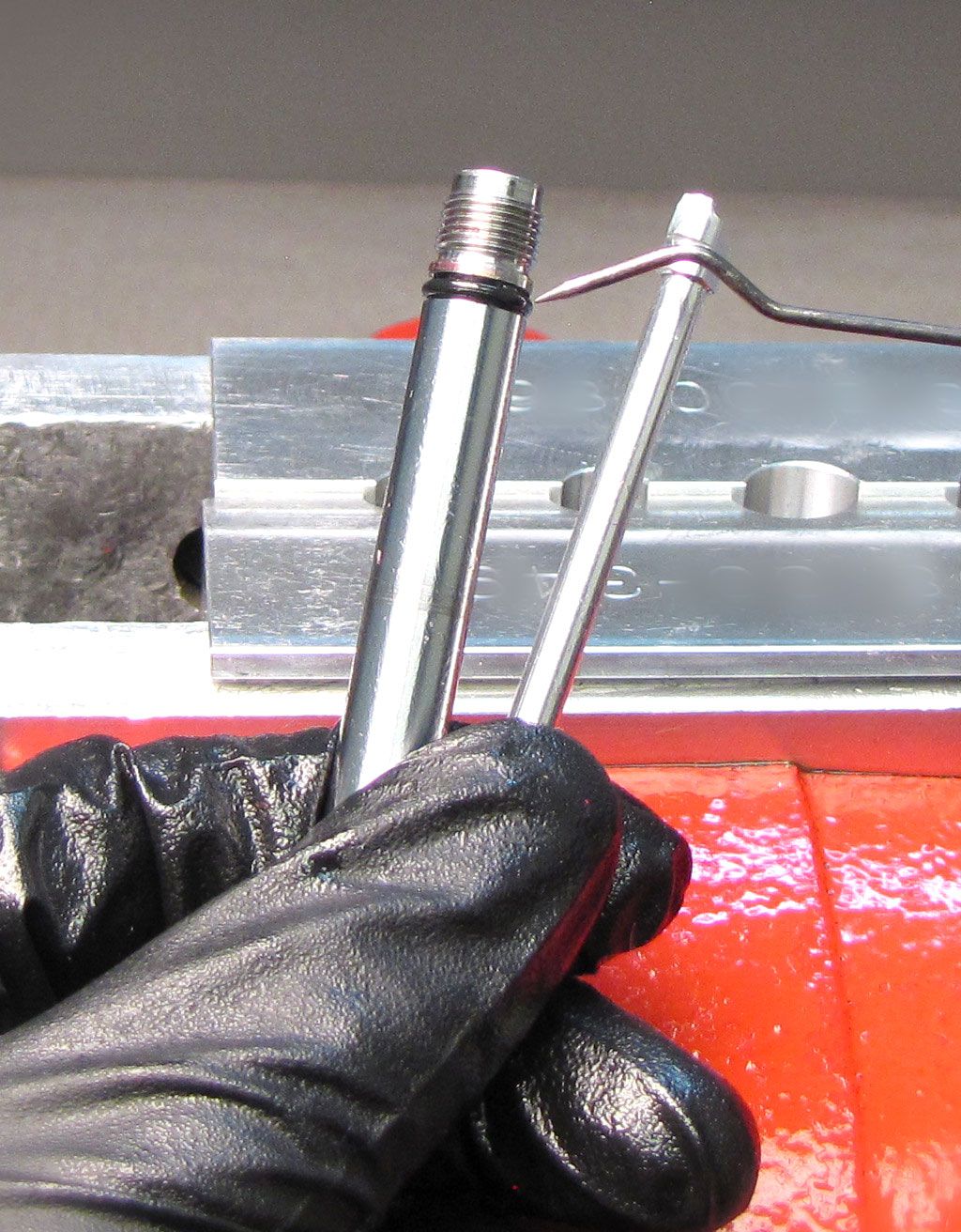
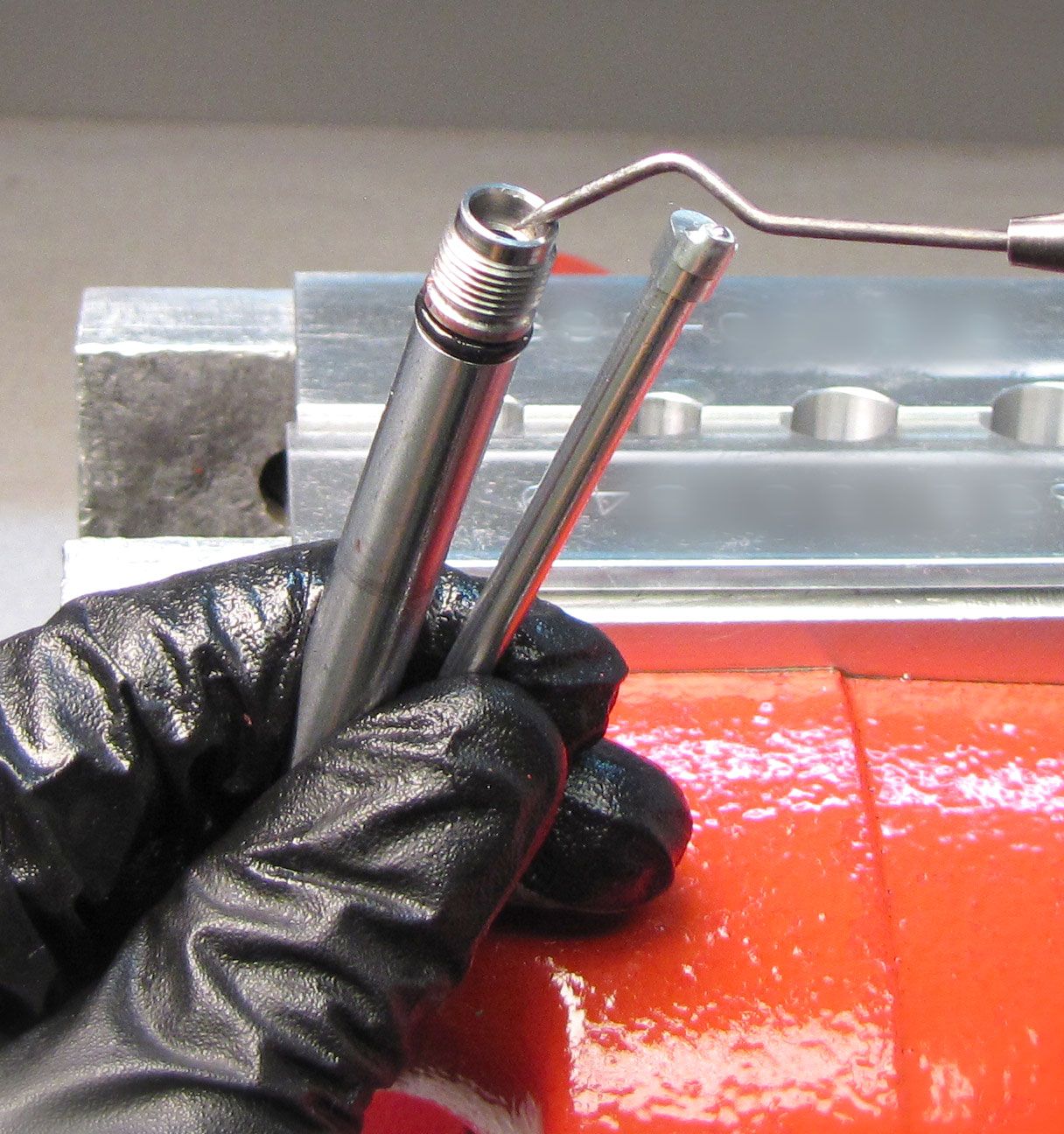
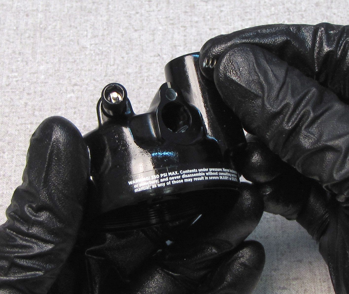
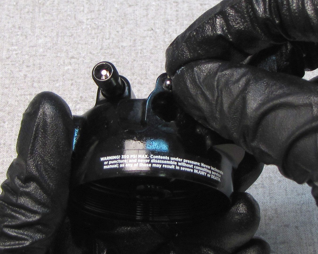
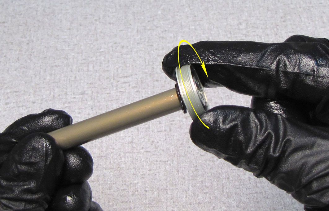
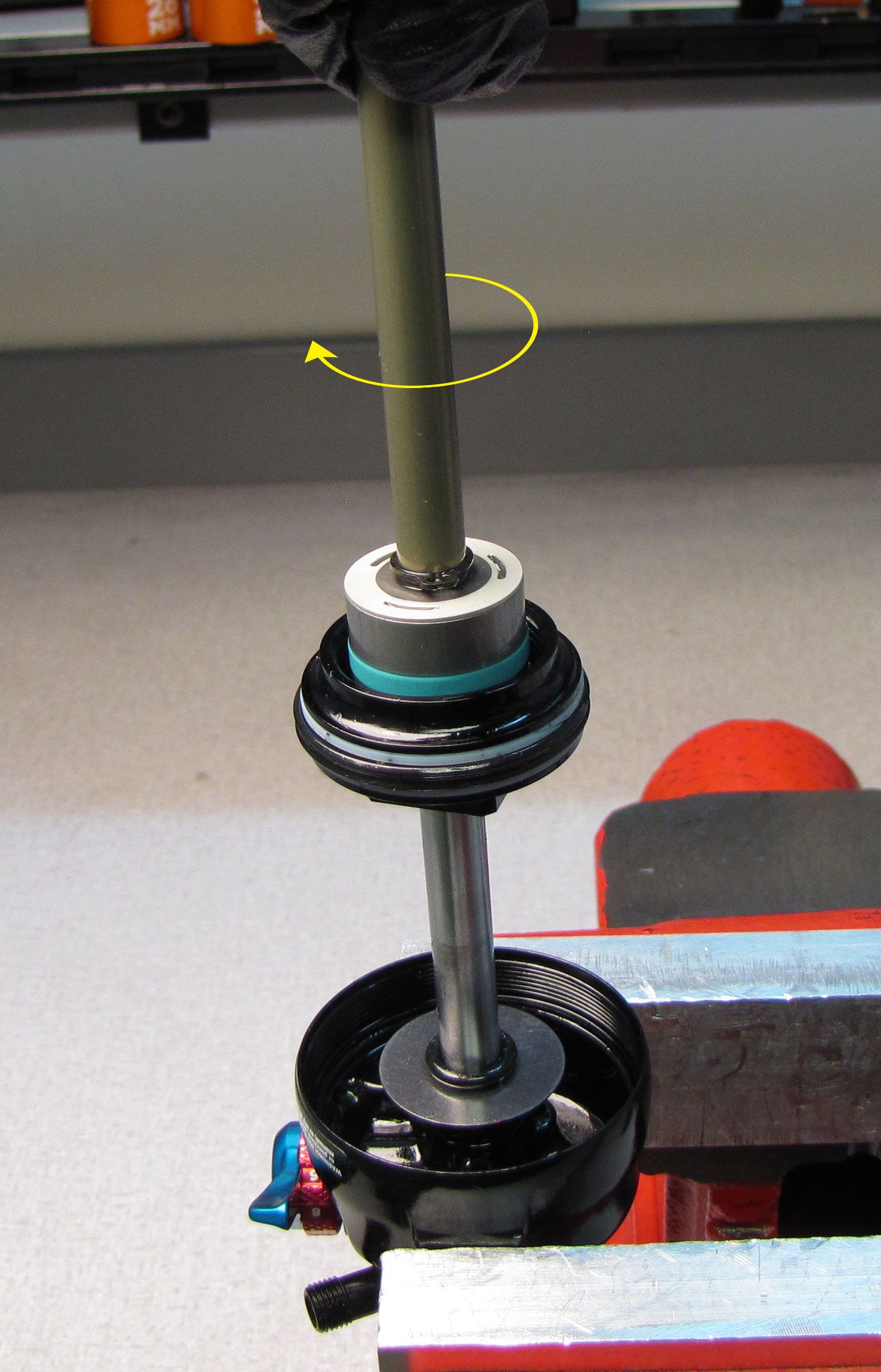
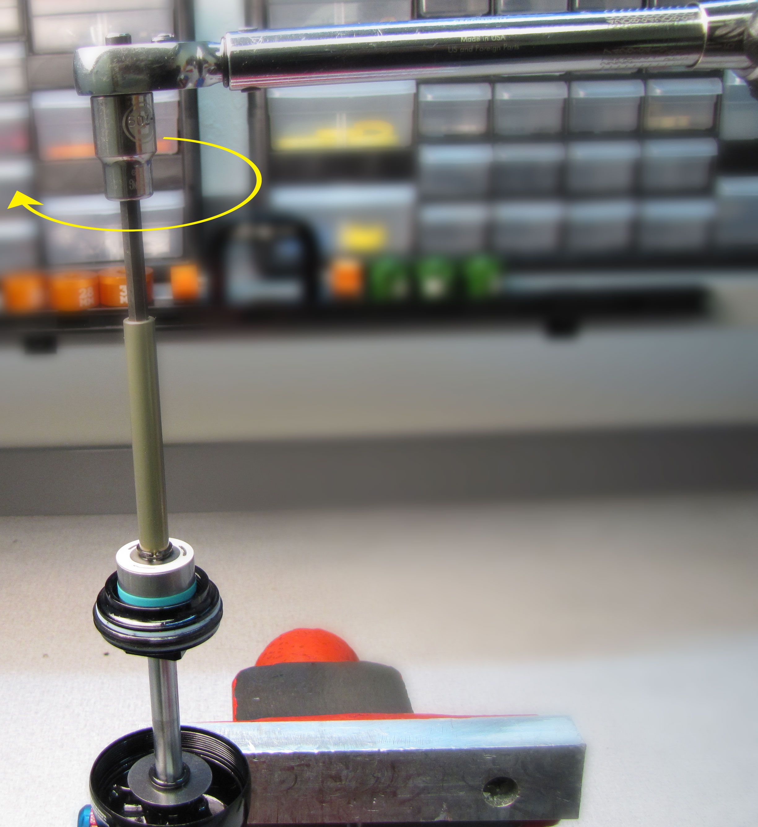
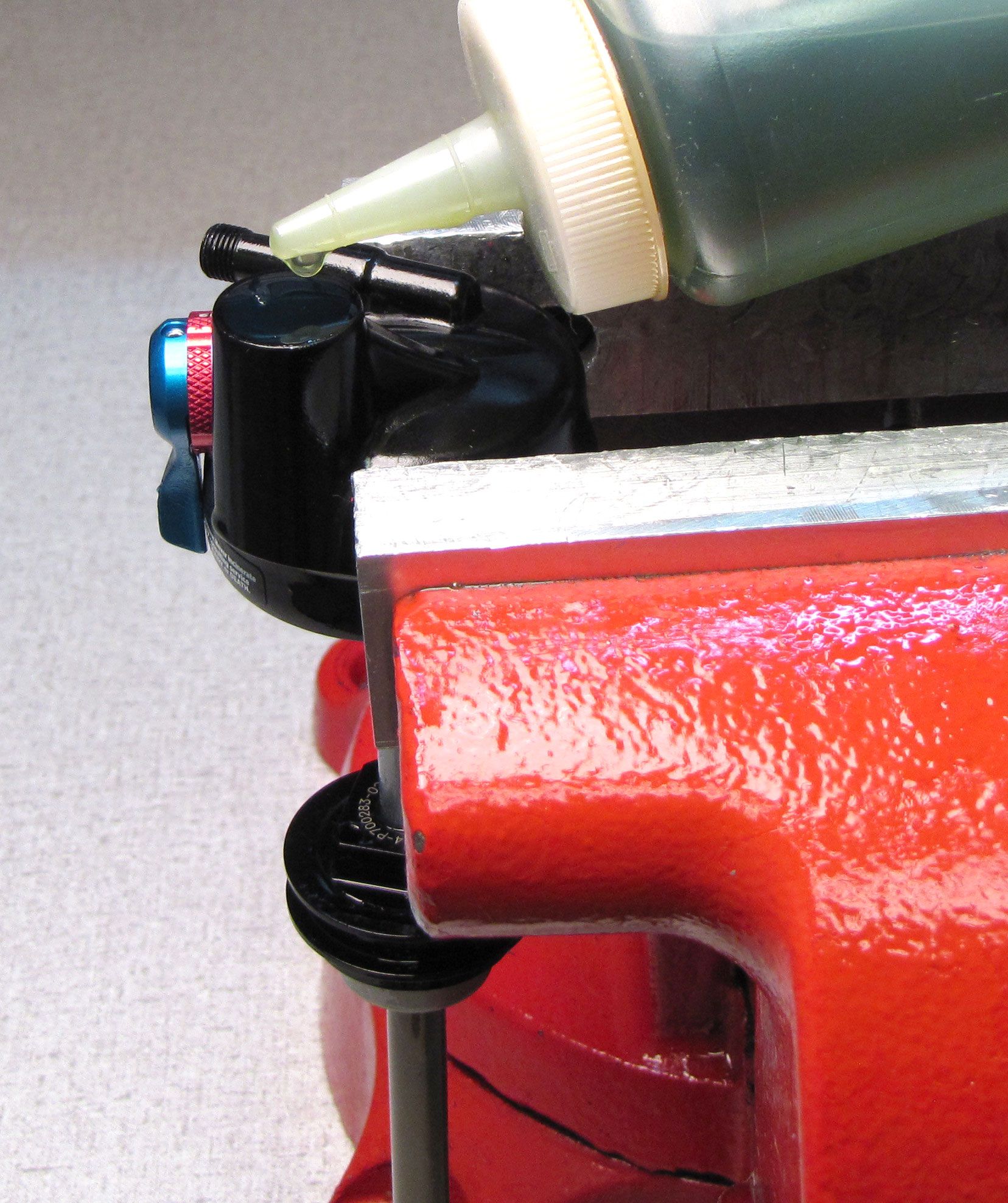
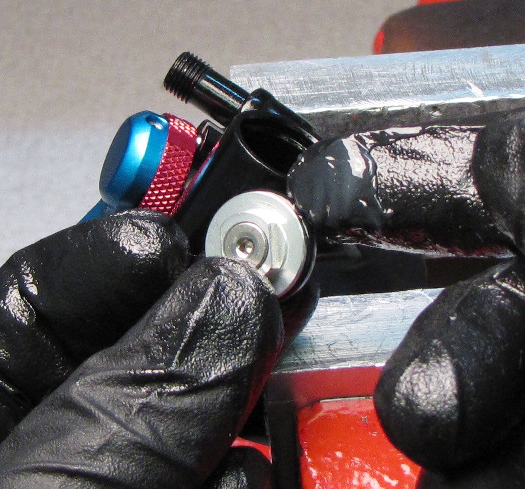
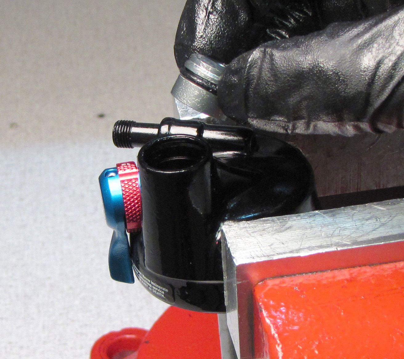
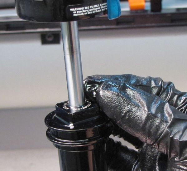
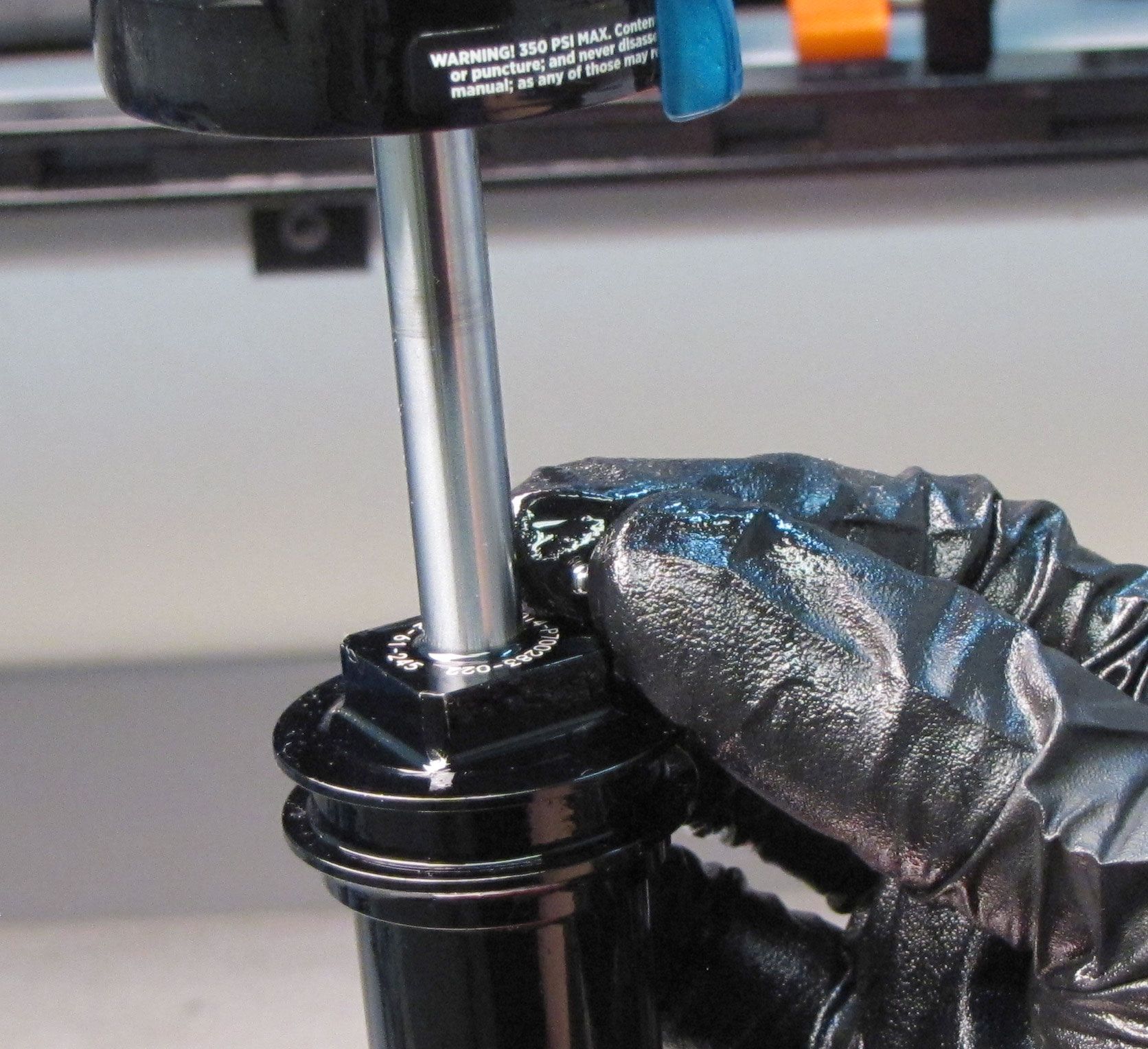
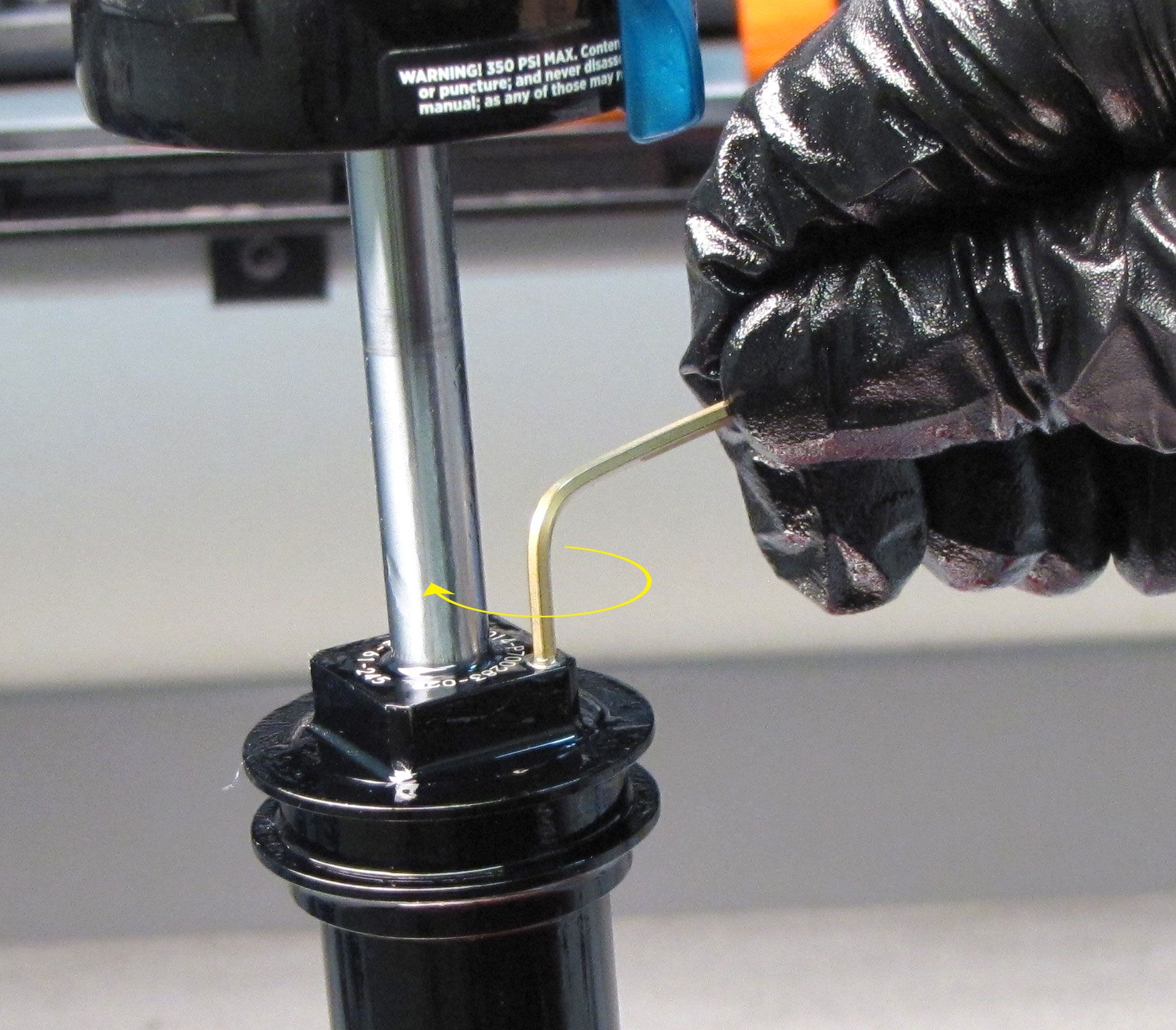
Step 15
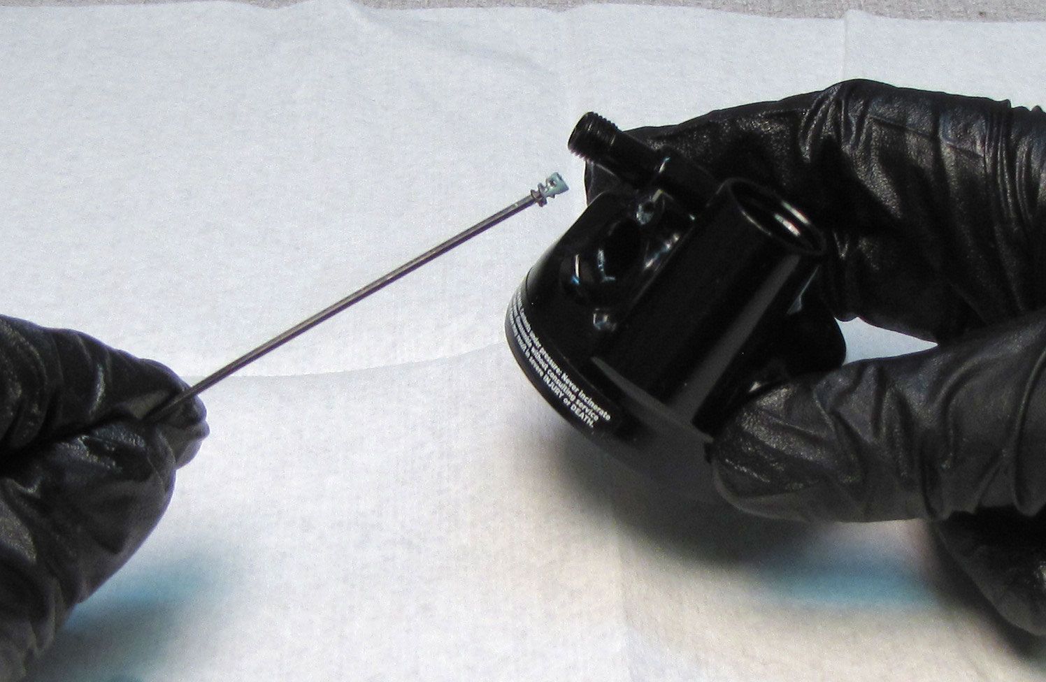
Use a 2mm hex wrench to unthread counter-clockwise the bleed screw in the IFP.

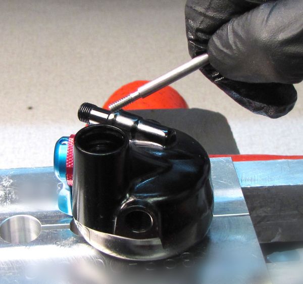
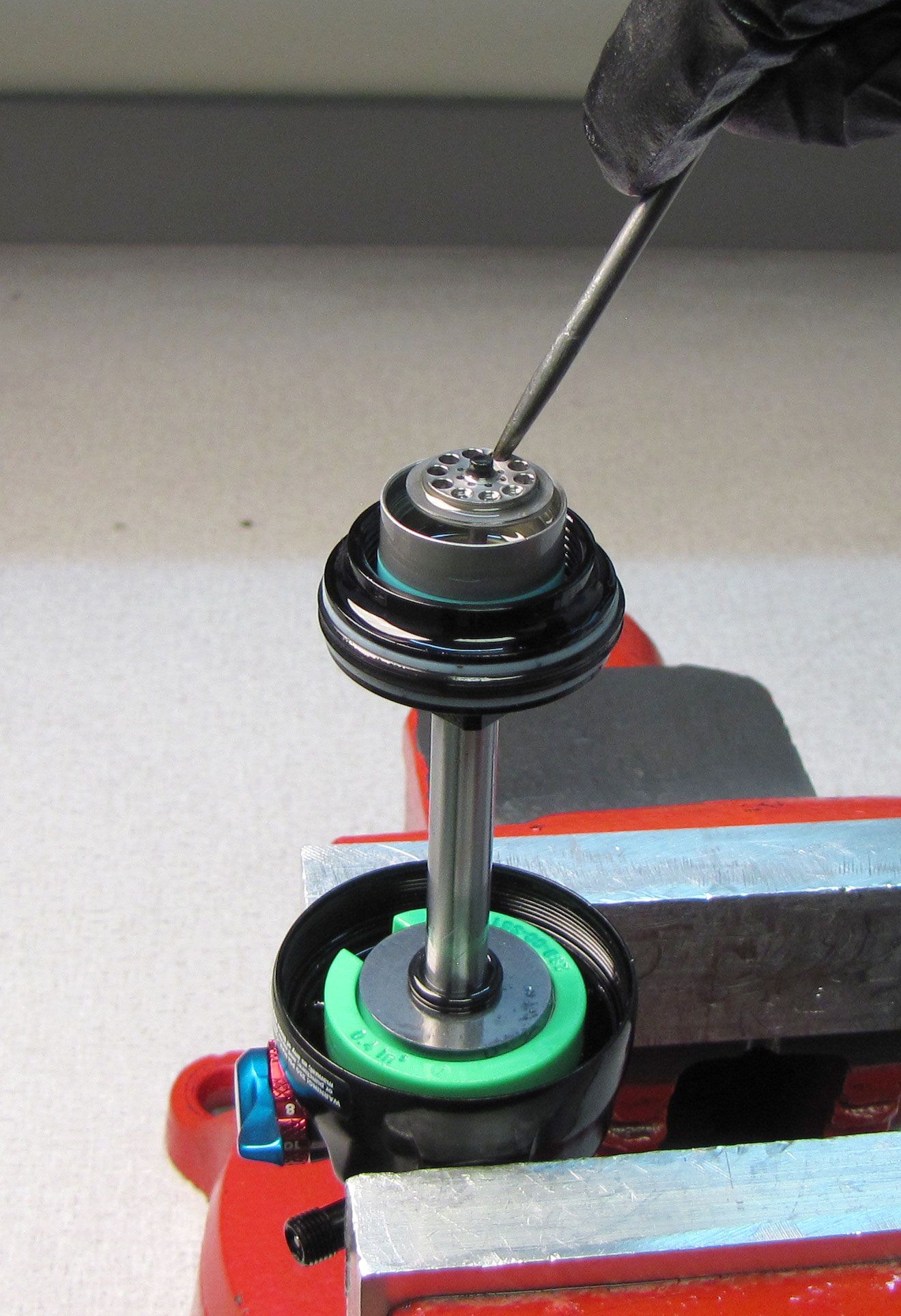
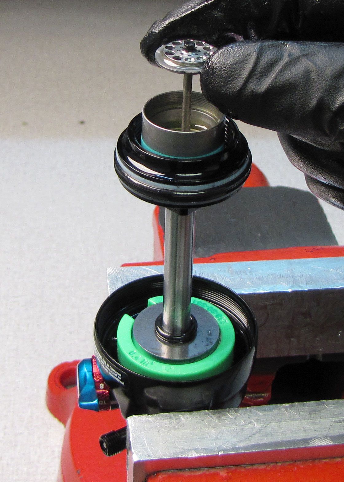
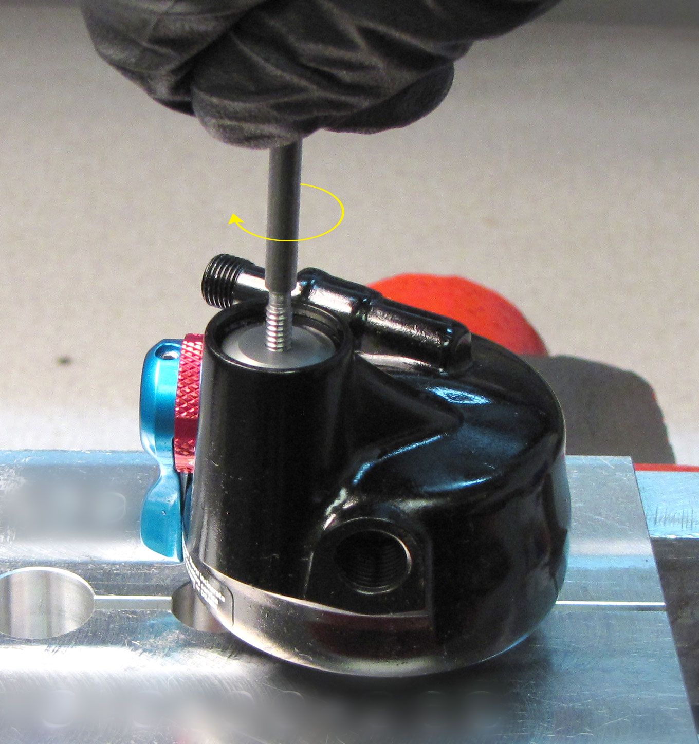
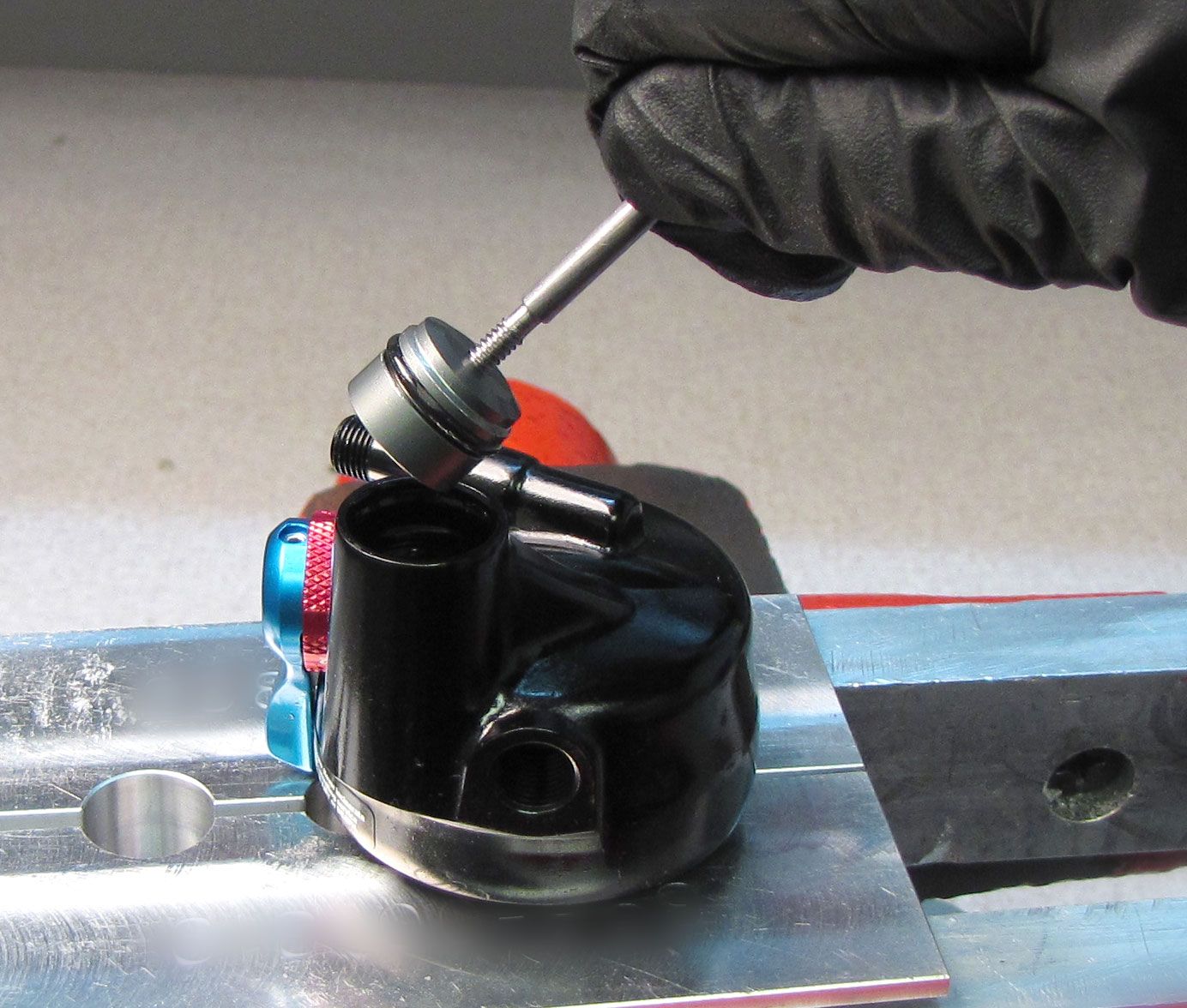
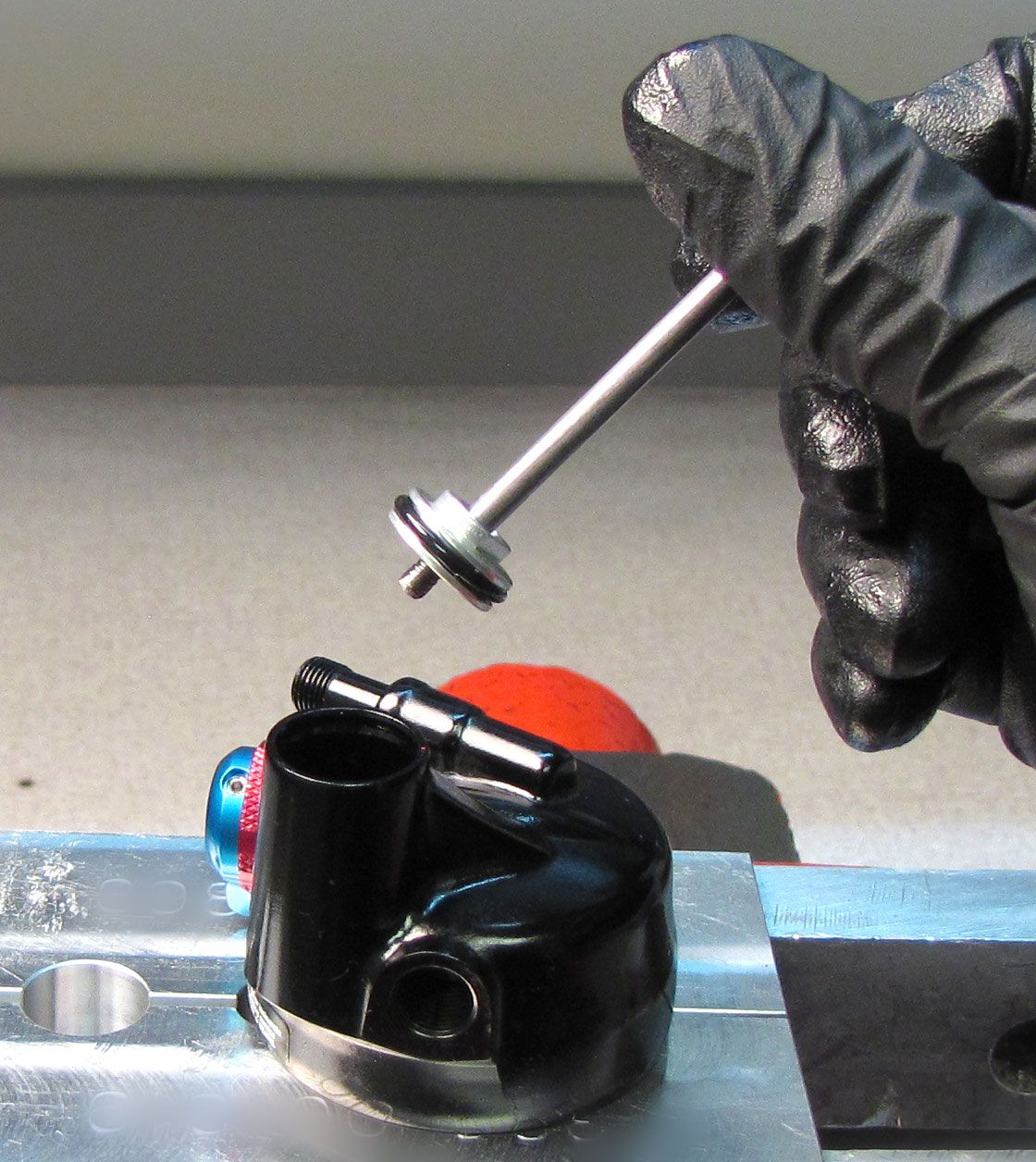
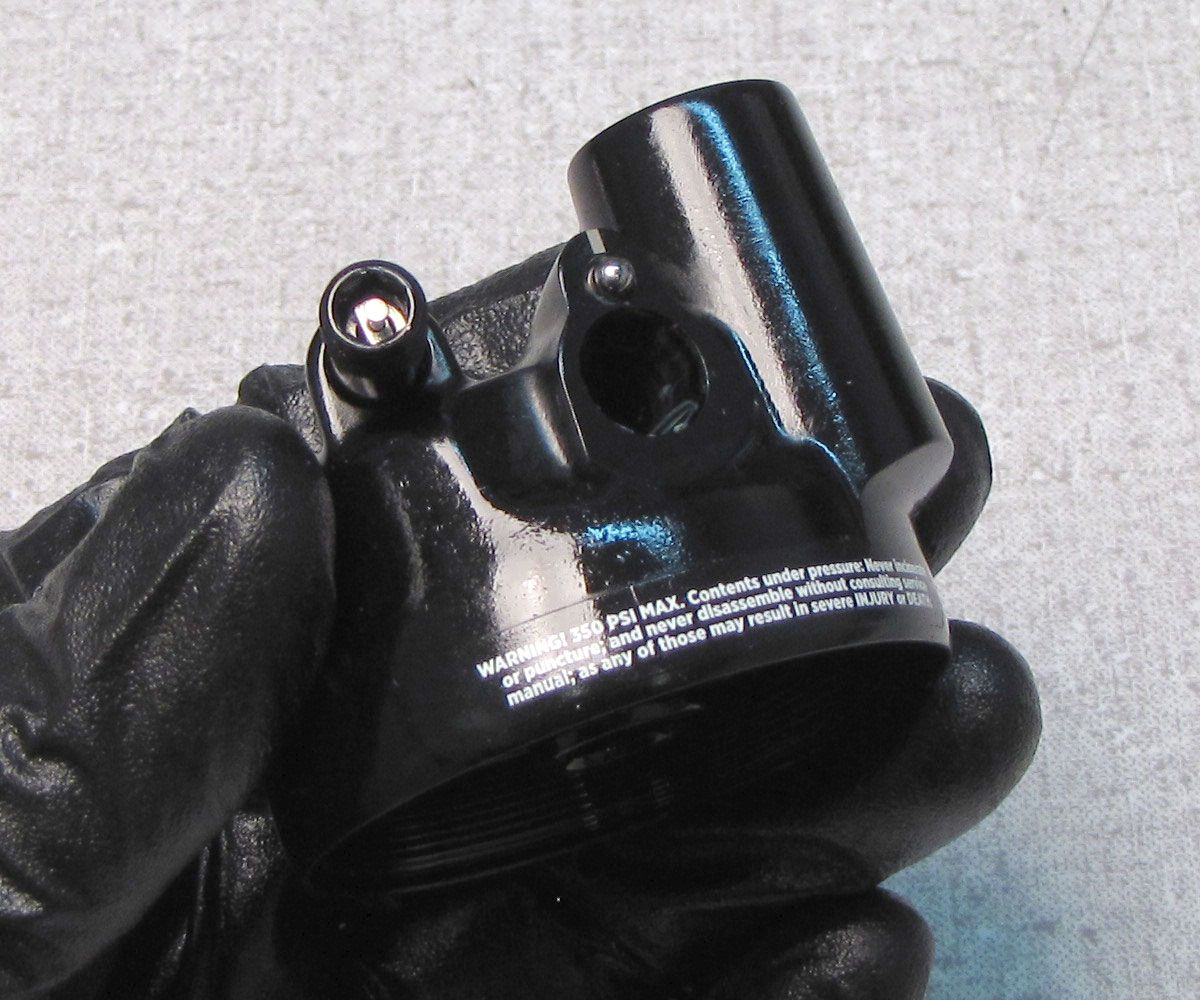
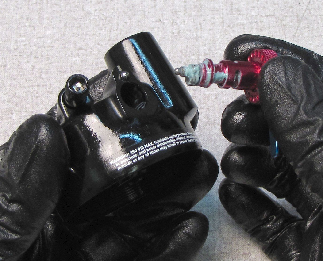
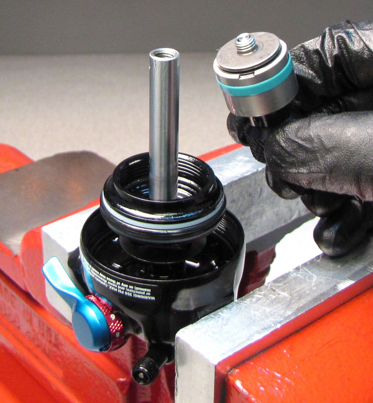
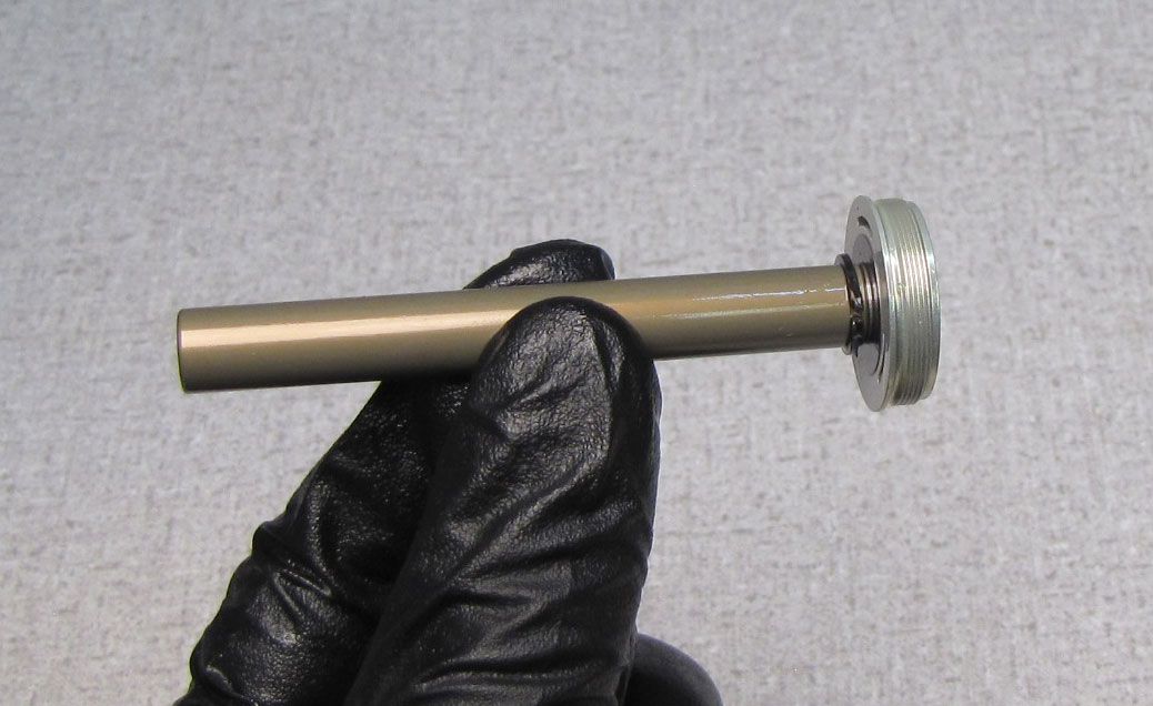
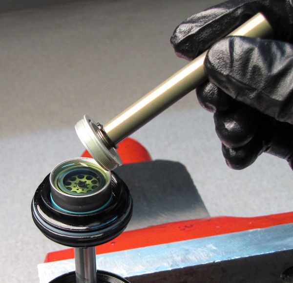
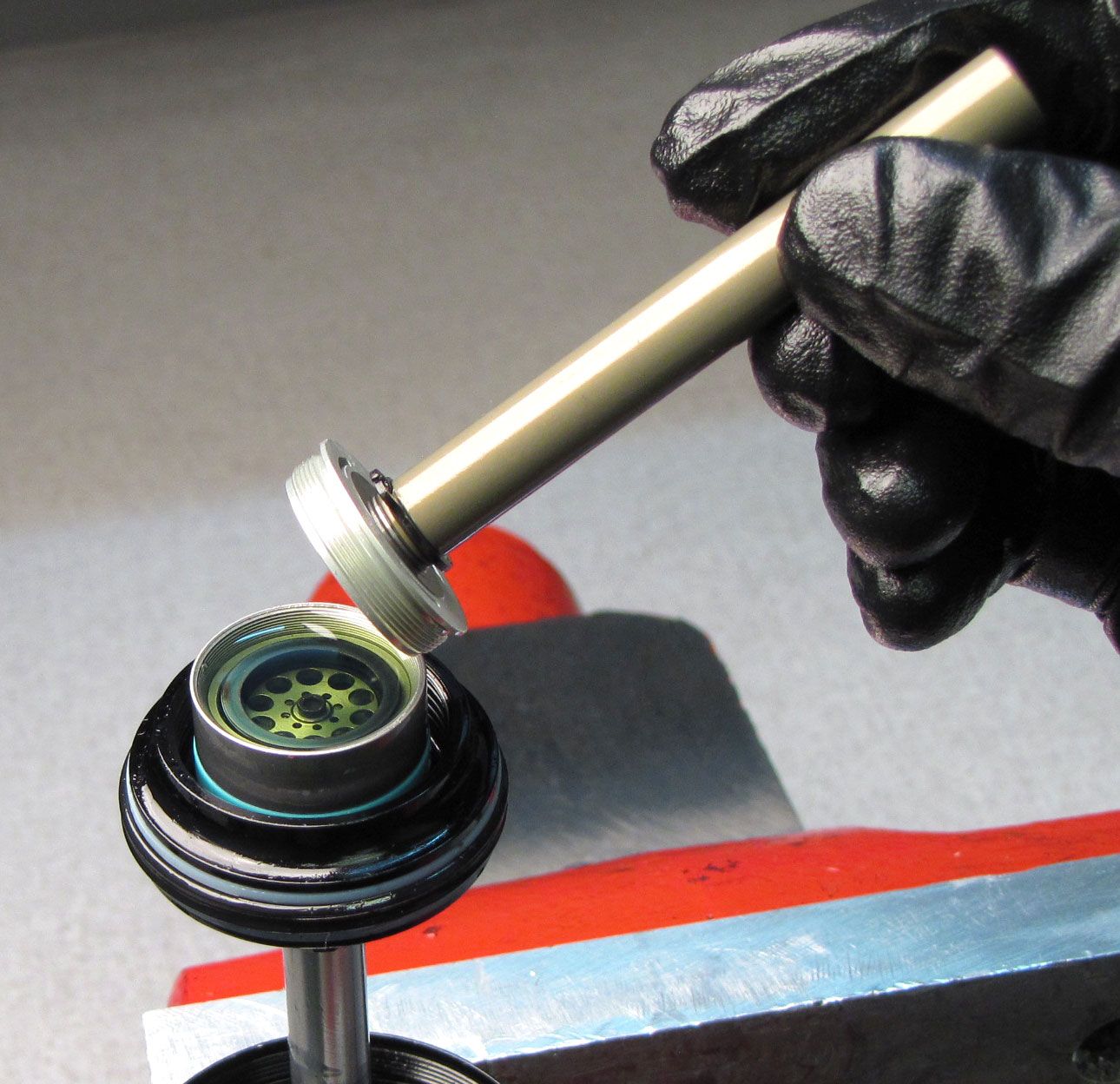
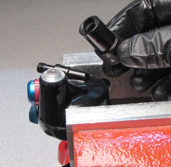
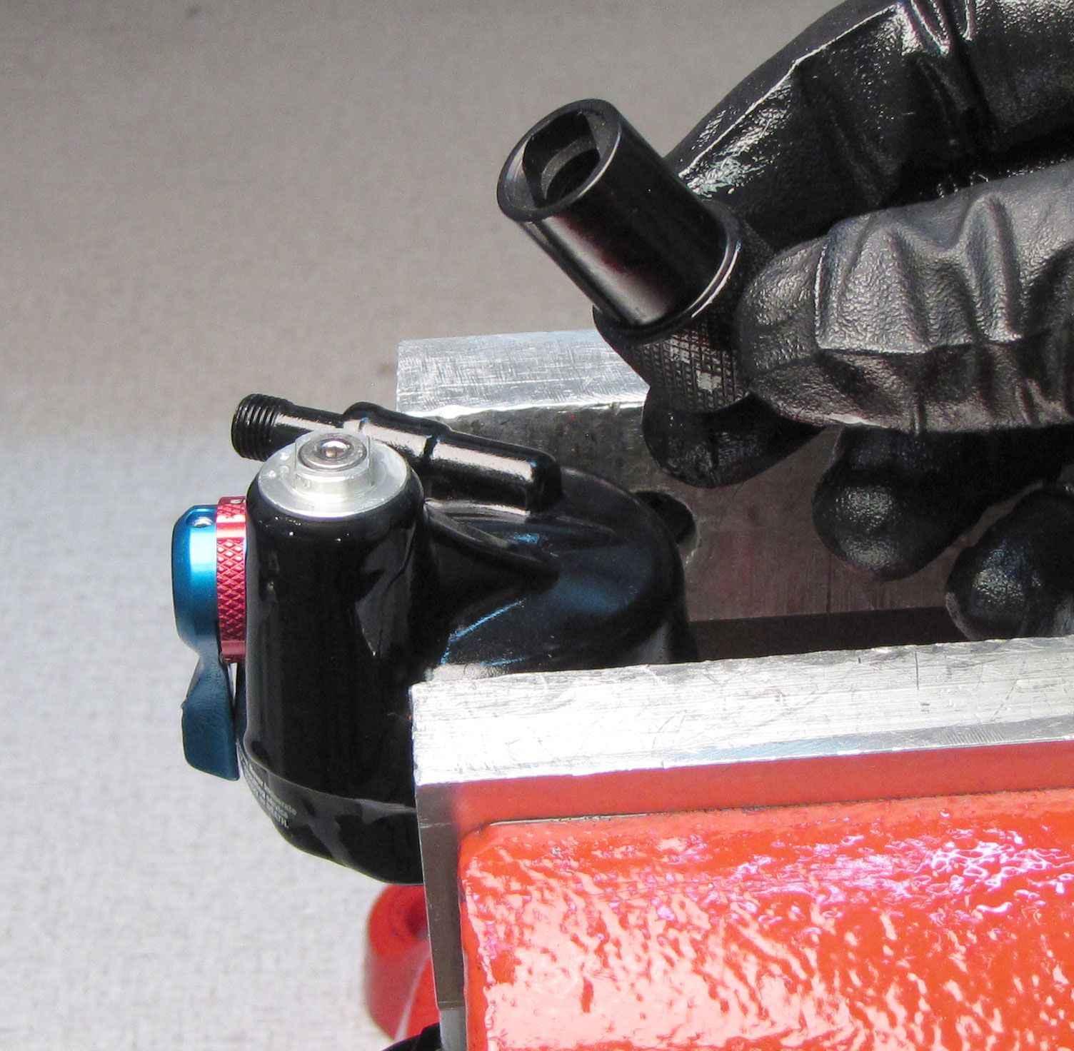
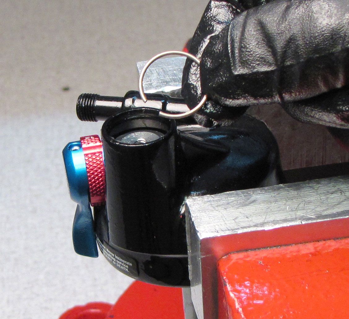
Step 16
Thread the IFP removal tool (PN: 398-00-749) clockwise into the IFP, then pull up to remove the IFP.

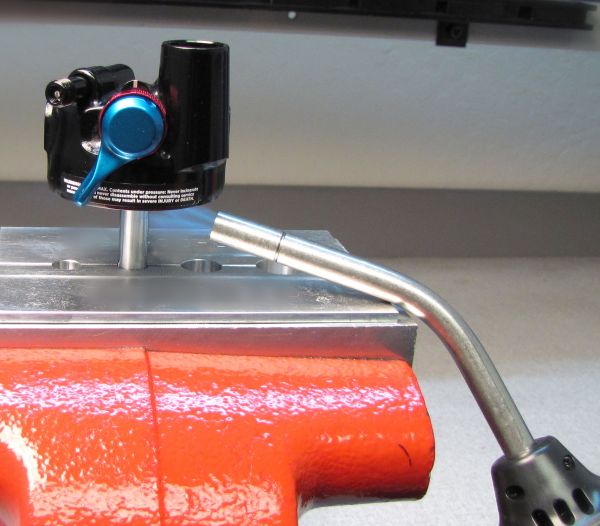
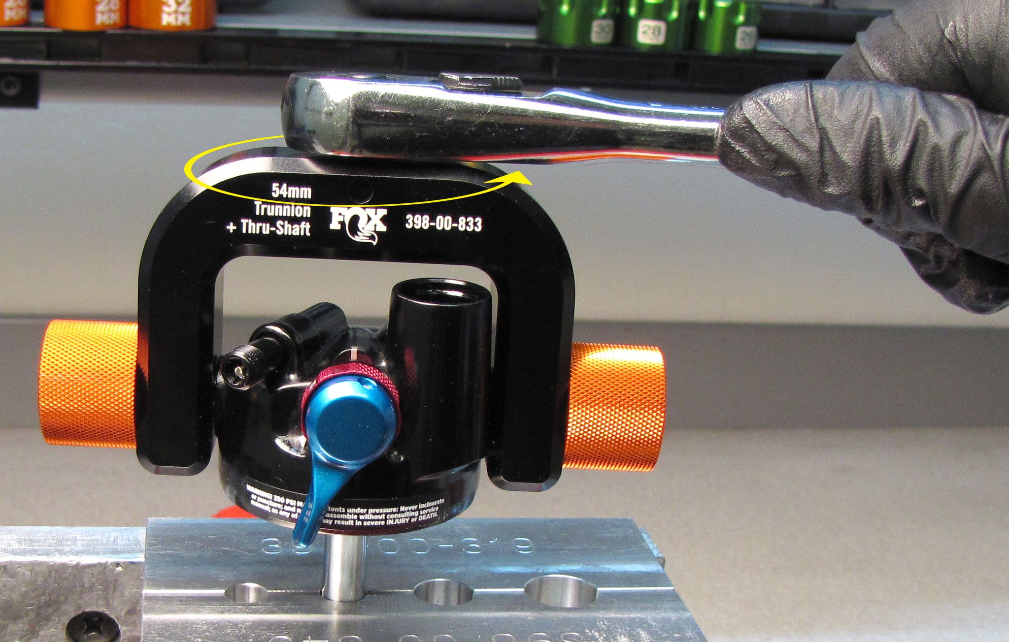
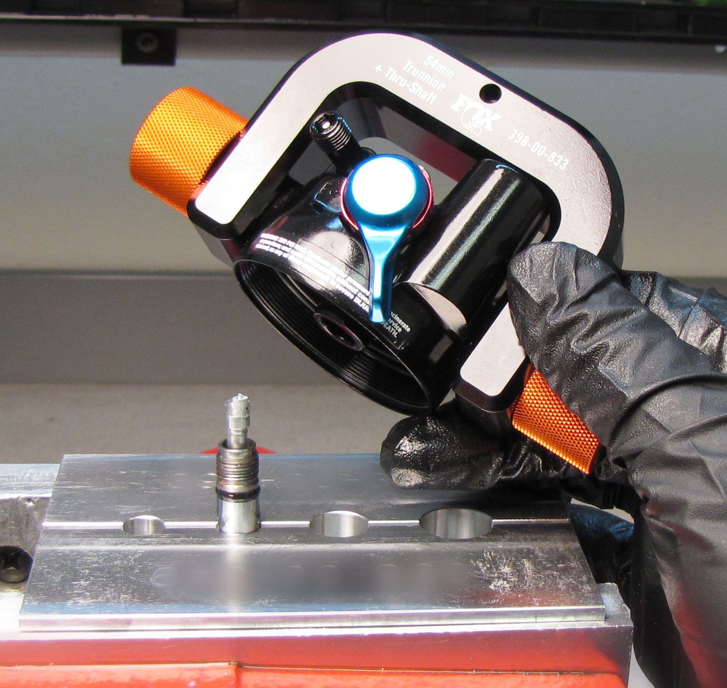
Step 17
Carefully apply heat to the connection between the shaft and the eyelet with a propane torch for 5-10 seconds to break down the Loctite. Unthread the eyelet counter-clockwise with the Trunnion Eyelet tool (PN: 398-00-833), then lift up to remove.


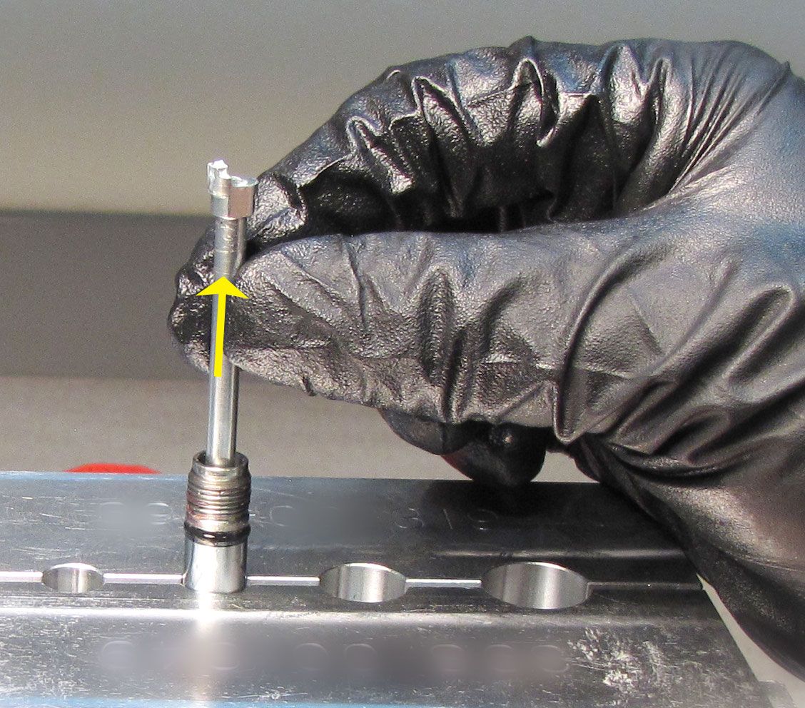
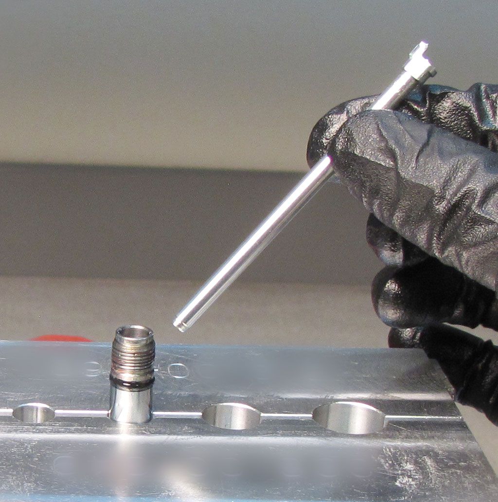
Step 18
Lift up on the Rebound metering rod to remove it from the shaft. Replace all o-rings inside and outside of both rebound rod and shaft. Clean any remaining Loctite from the shaft threads.
Step 19
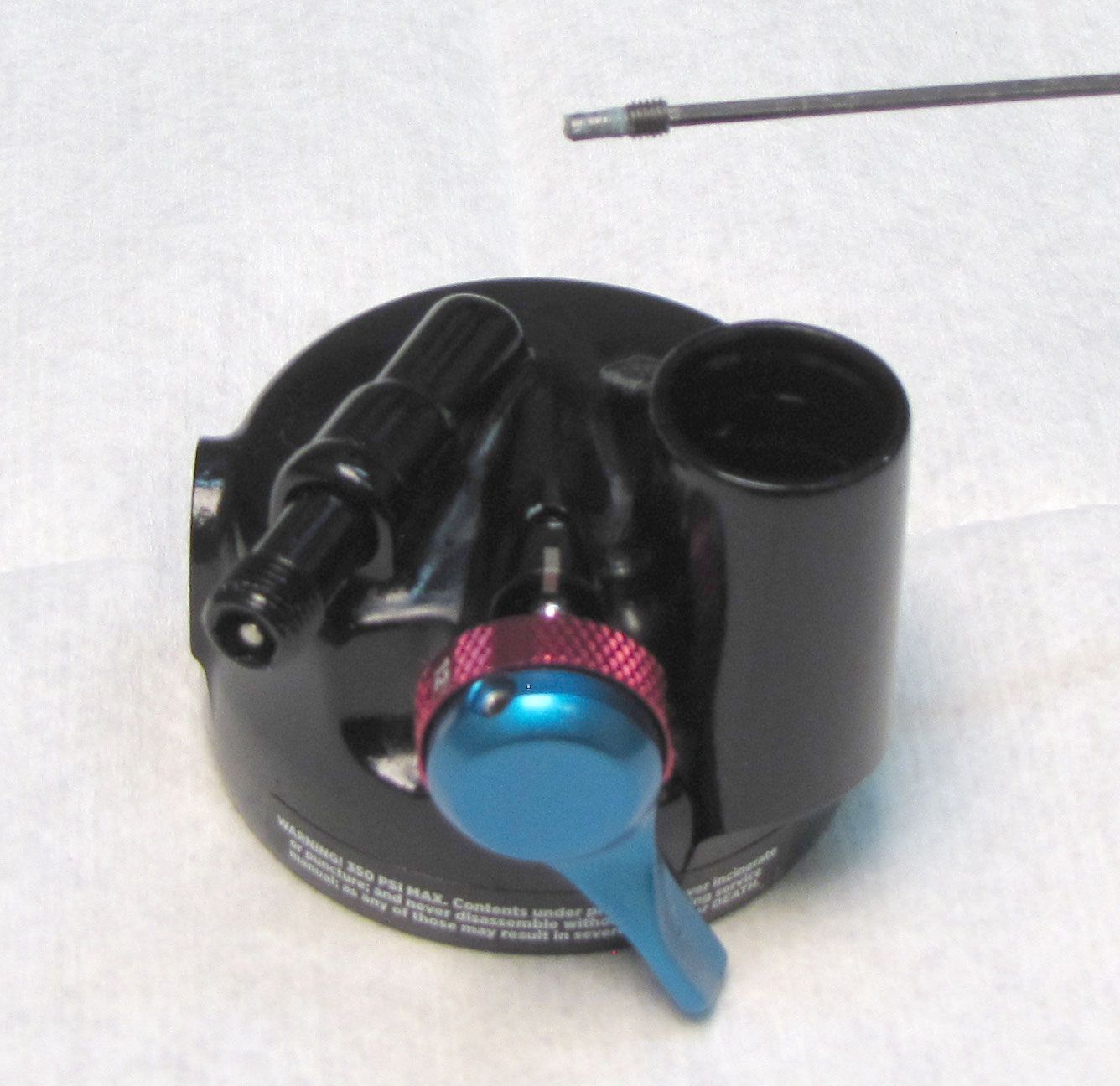
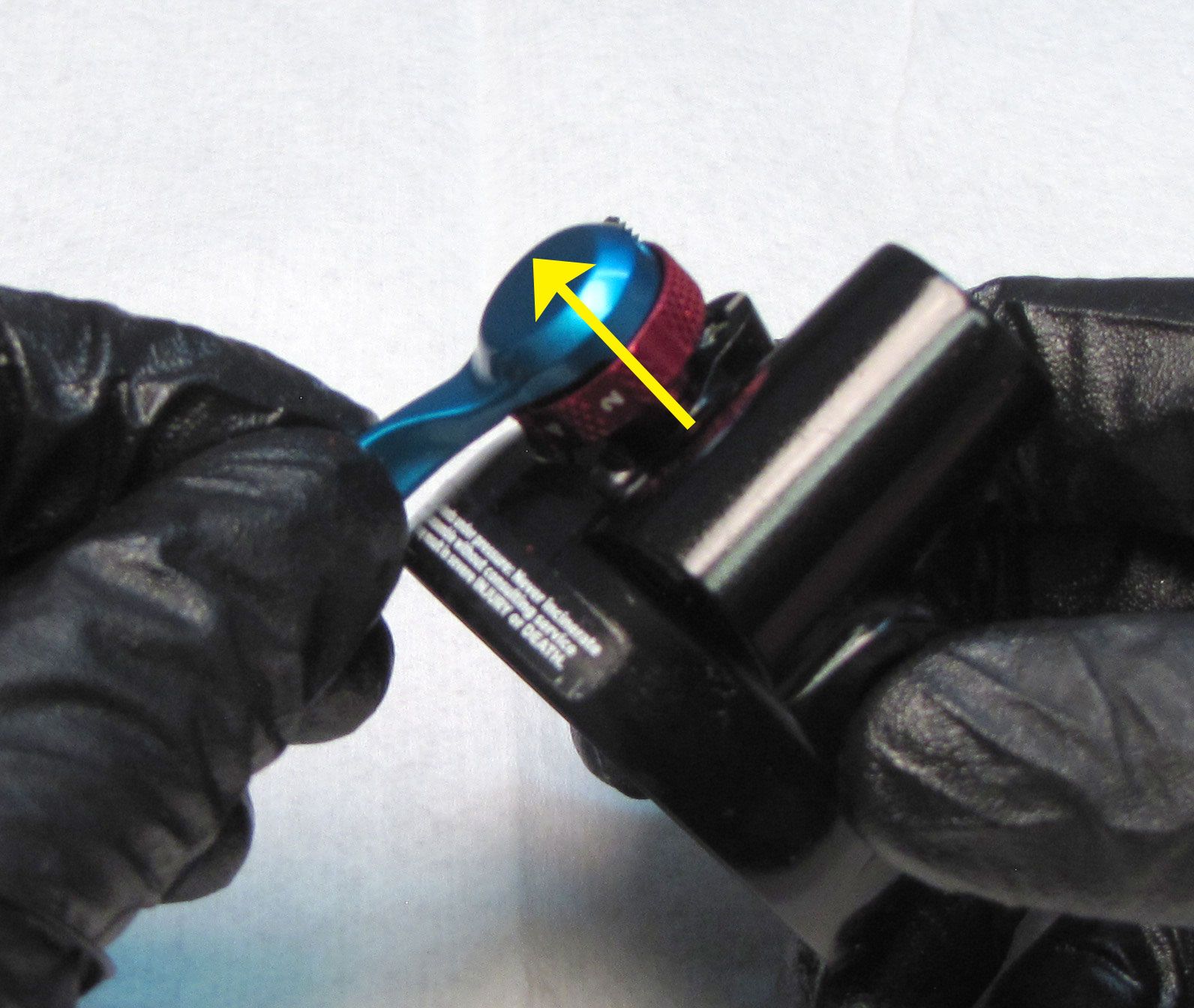
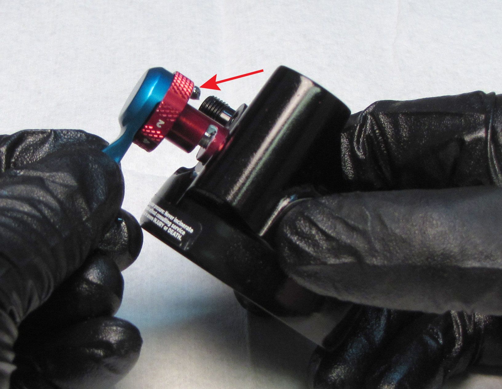
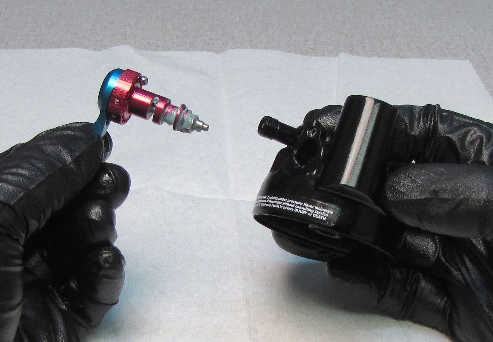
Unthread the set screw that retains the adjuster assembly by turning it counter-clockwise with a 1.5mm hex wrench. Pull the adjusters out of the eyelet making sure not to lose the detent ball. Remove the detent spring and set it aside.

Step 20
Clean out any remaining Loctite from the eyelet shaft threads. Replace the o-rings inside the eyelet with new greased ones from the kit. Replace the wiper in the end of the body with a new greased one from the kit.


Reassembly
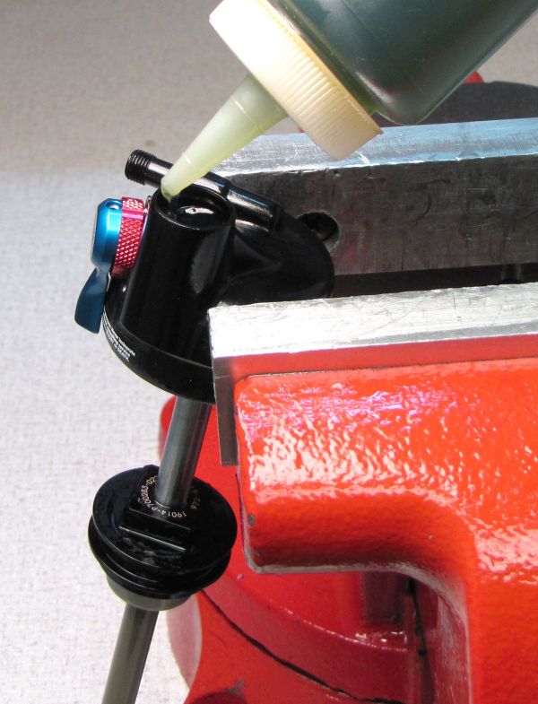
Step 1
Coat the detent spring with waterproof marine grease (Sta-Lube 3125) then reinsert into the small hole in the face of the eyelet. Stick the detent ball into position on the end of the detent spring with waterproof marine grease.

Step 2
Coat the adjuster assembly with a thick film of waterproof marine grease (Sta-Lube 3125) then reinsert into the eyelet. Compress the detent spring by pushing the lever assembly into the eyelet, then install and gently tighten the set screw in the top of the eyelet fully, then back it out 1/4 turn.
Step 3
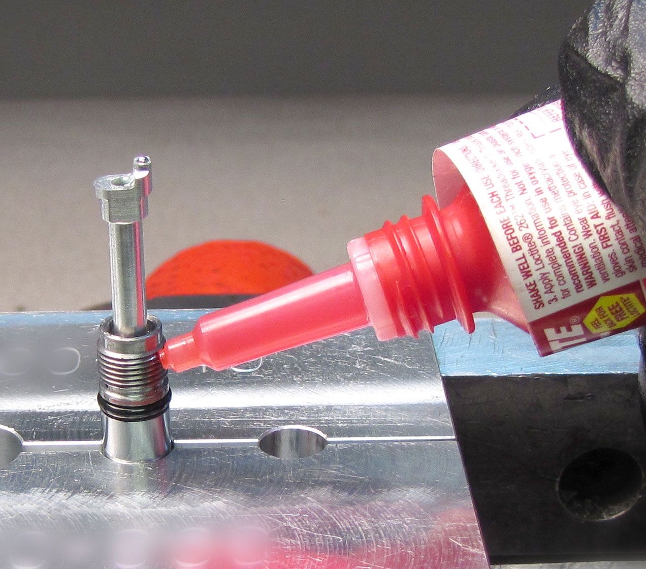
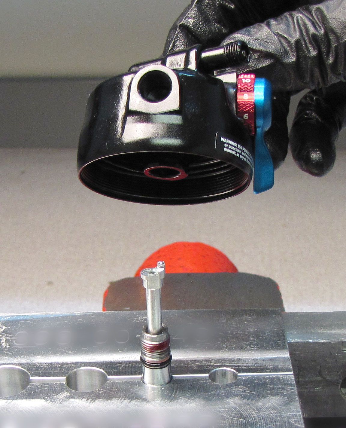
Insert the Rebound metering rod into the shaft. Apply a very small amount Red Loctite 277 to the shaft threads. Make sure not to apply excess Loctite as it can clog ports and can damage the o-ring. Install the shaft into the eyelet with the ball bearing on the metering rod oriented toward the front of the shock.

Step 4
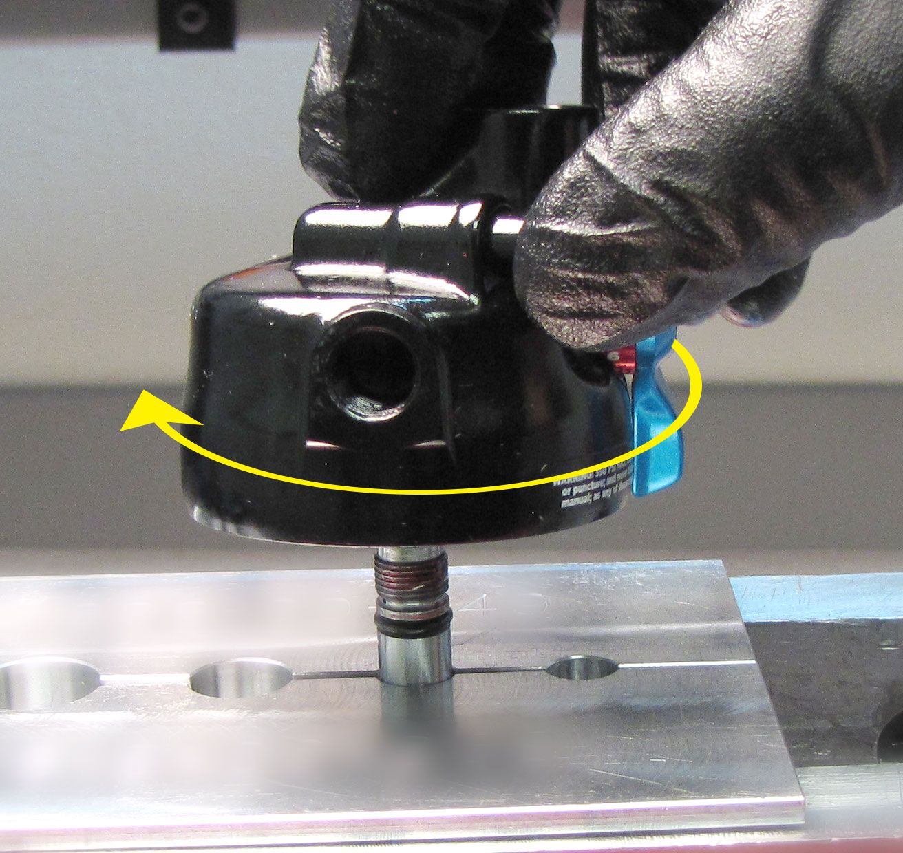
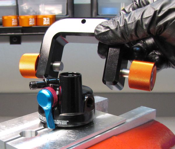
Use the Trunnion Eyelet tool (PN: 398-00-833) to tighten the eyelet onto the shaft clockwise to 85 in-lb (9.6 Nm) torque.


Step 5
Invert the Topcap Assembly and clamp it in your soft-jawed vise. Reinstall the Bottom-out plate onto the shaft followed by a new greased Bottom-out O-ring from the kit.

Step 6
Replace all seals on the Bearing Assembly with new greased ones from the kit. Reinstall the Bearing Assembly onto the shaft.


Step 7
Replace the Glide Ring and O-ring on the outside of the RE:aktiv Piston Assembly with new ones from the kit. Using the Trek RG Valve Stack Transfer tool (PN: 398-00-614), reinstall the Valving Assembly onto the shaft.
Step 8
Tighten the Piston Bolt clockwise to 60 in-lb (6.8 Nm) torque with an 8mm socket. Lightly grease the tip of the Compression rod with Slick Honey, then reinstall the Spring Perch with Compression metering rod into the shaft through the Piston Bolt.

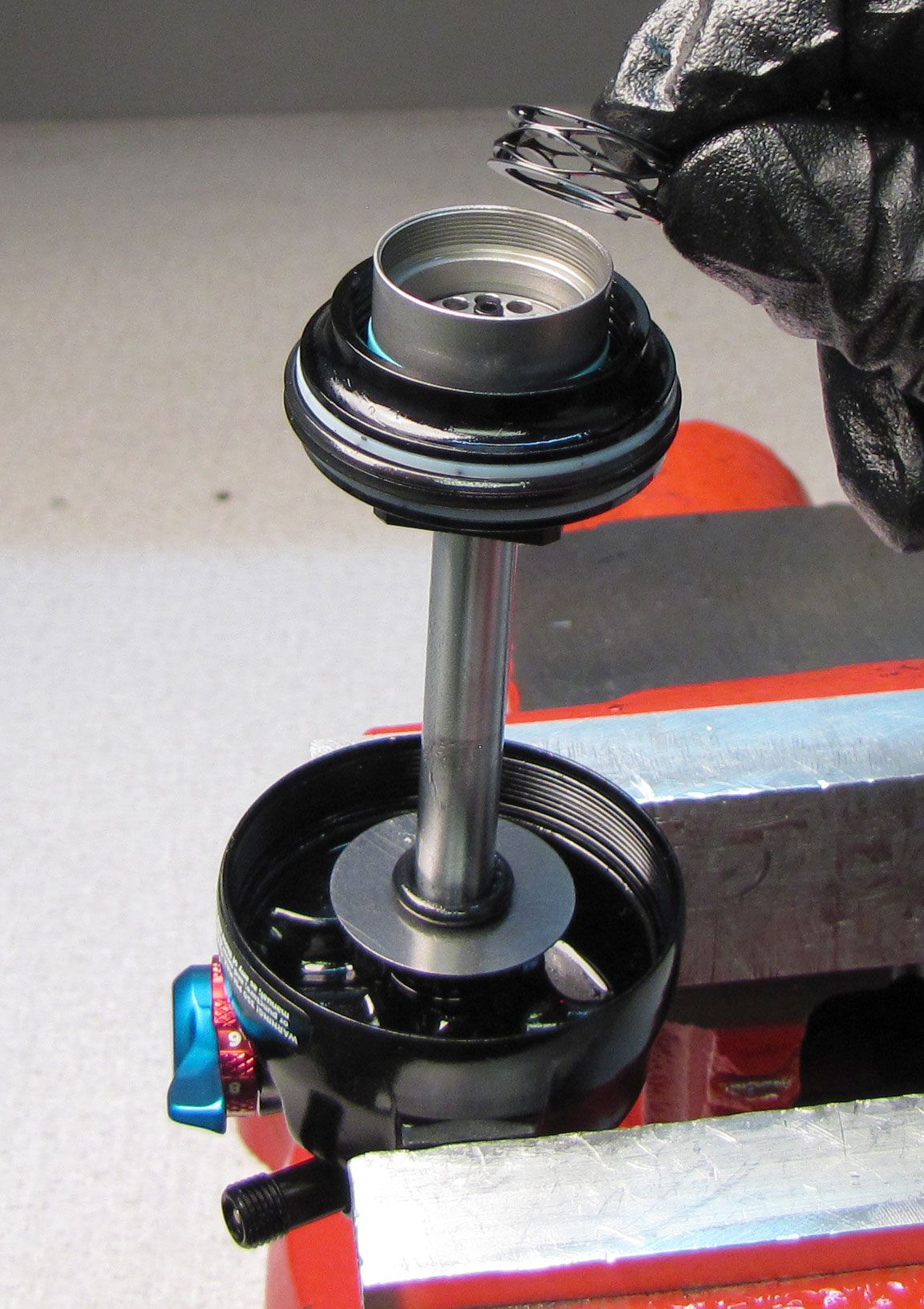
Step 9
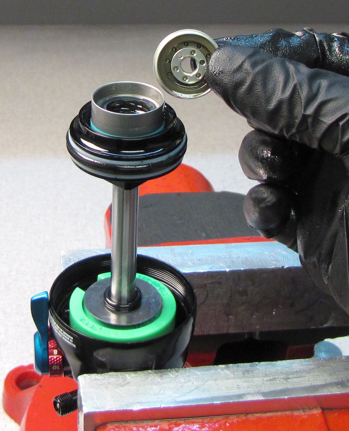
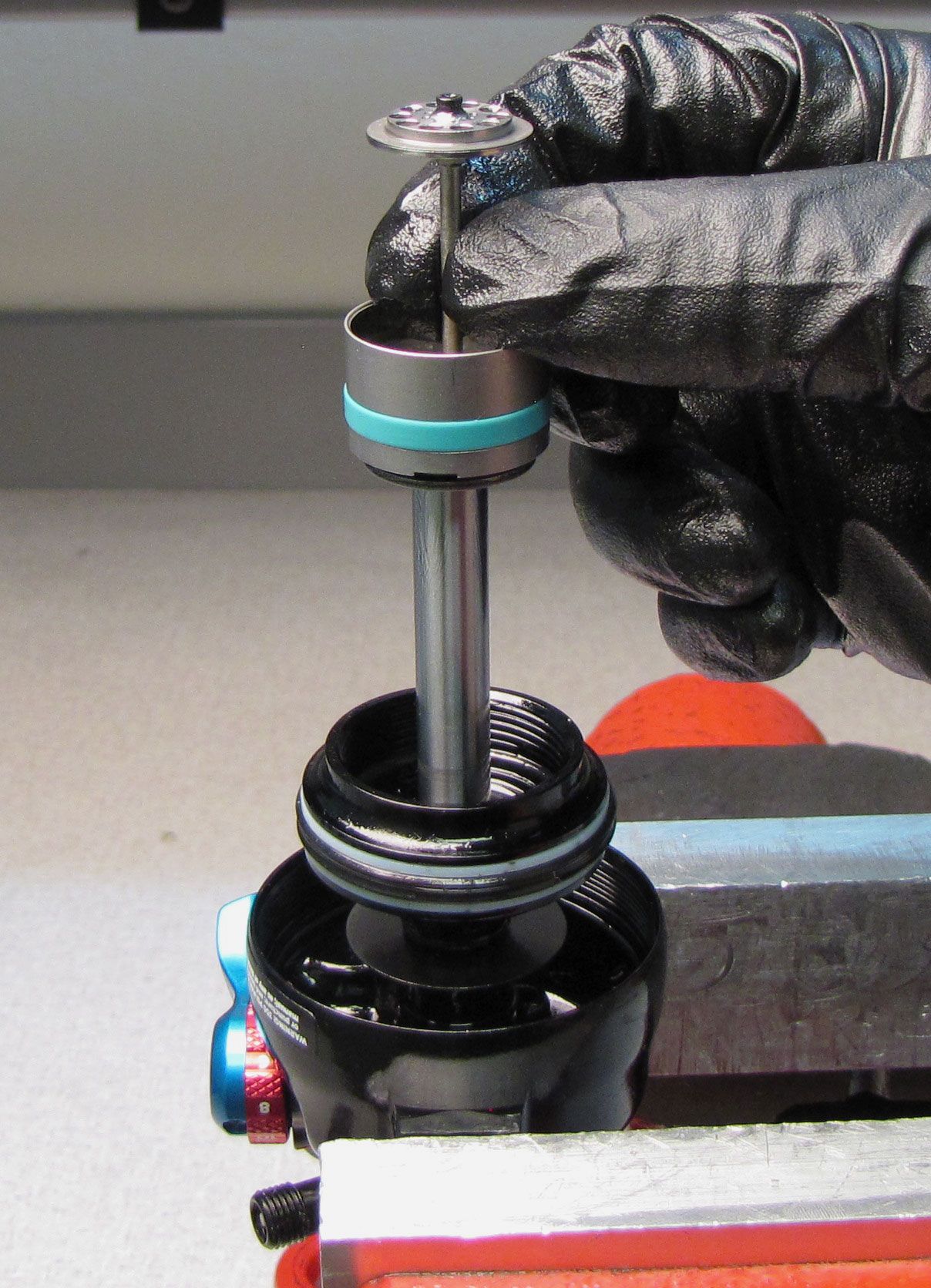
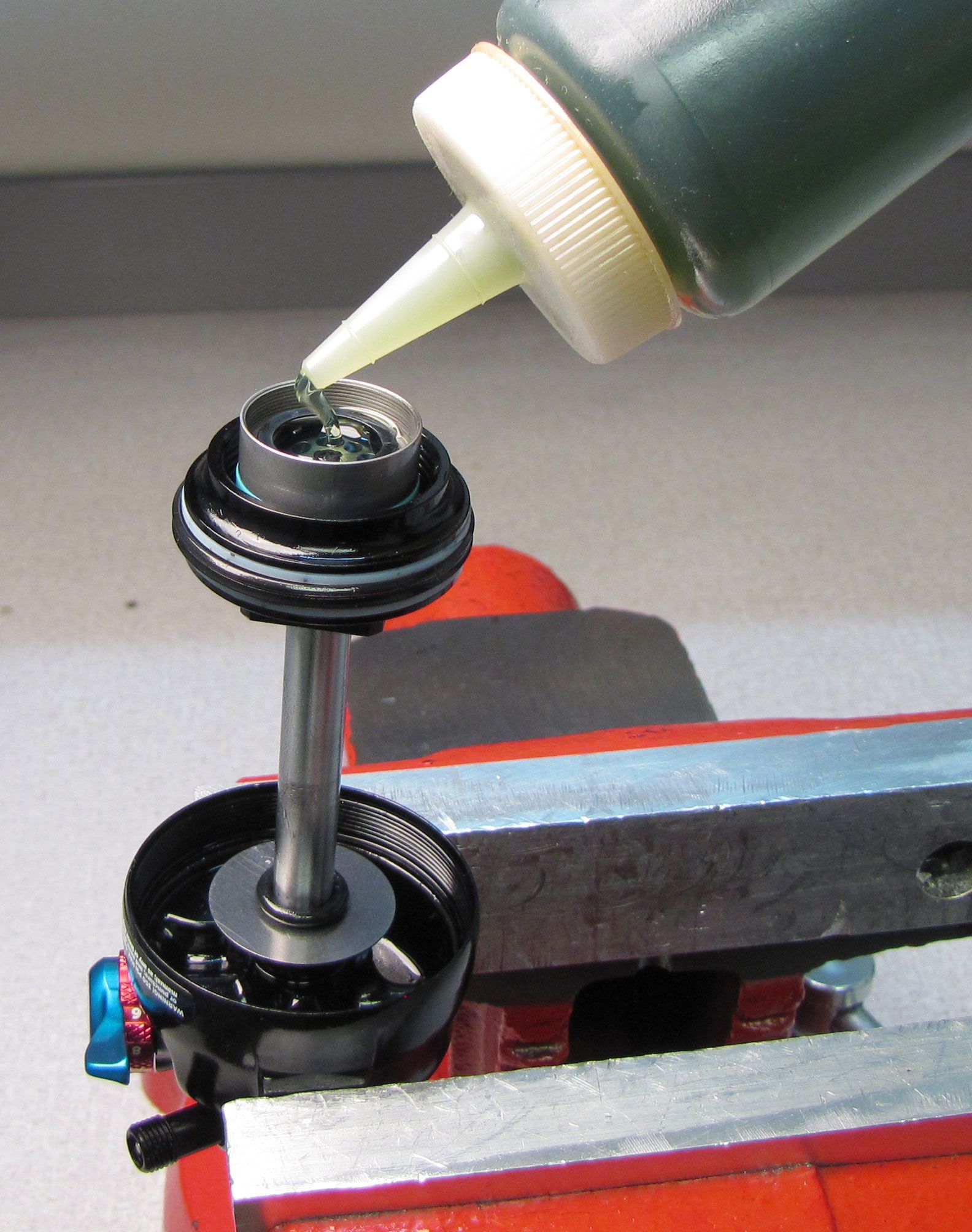
Reinstall the Wave Spring. Make sure the Bearing Assembly is tight against the Piston Assembly then fill the Piston Assembly with FOX 10wt. Green oil.
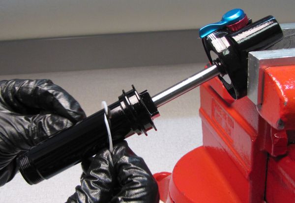
Step 10
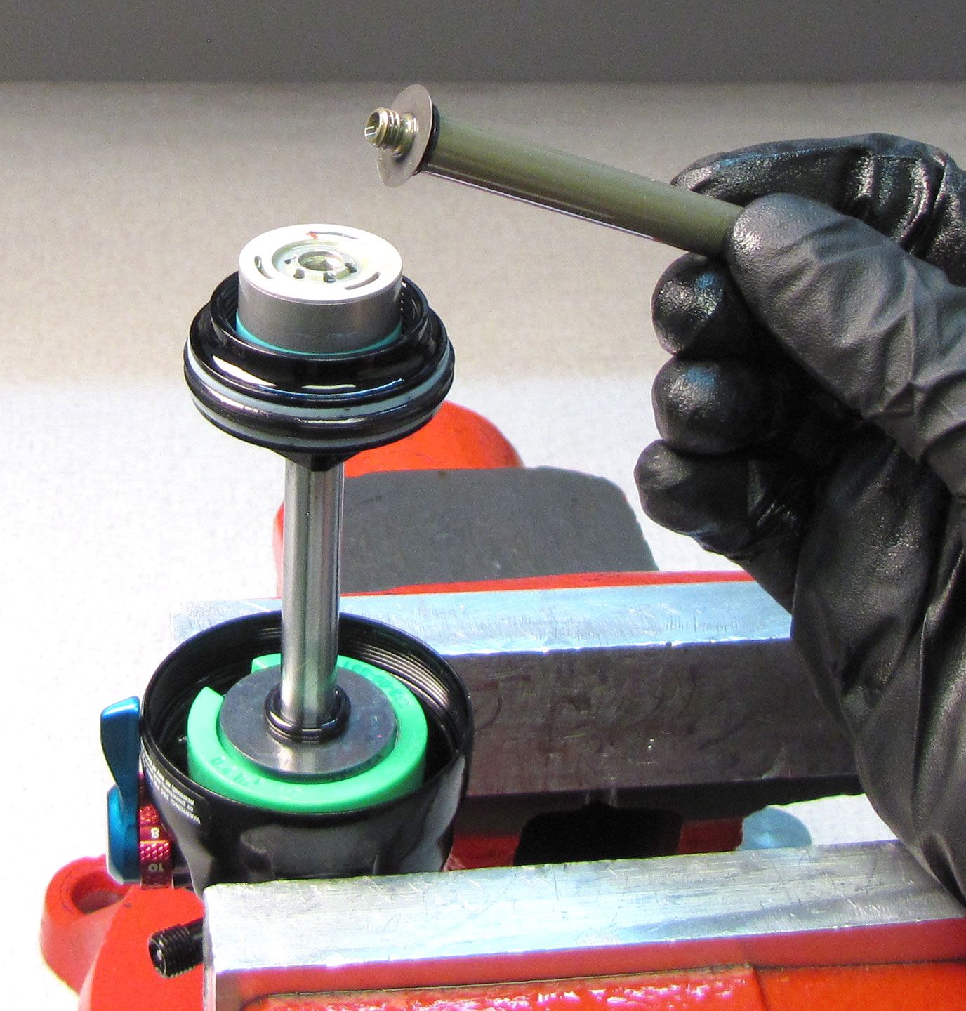
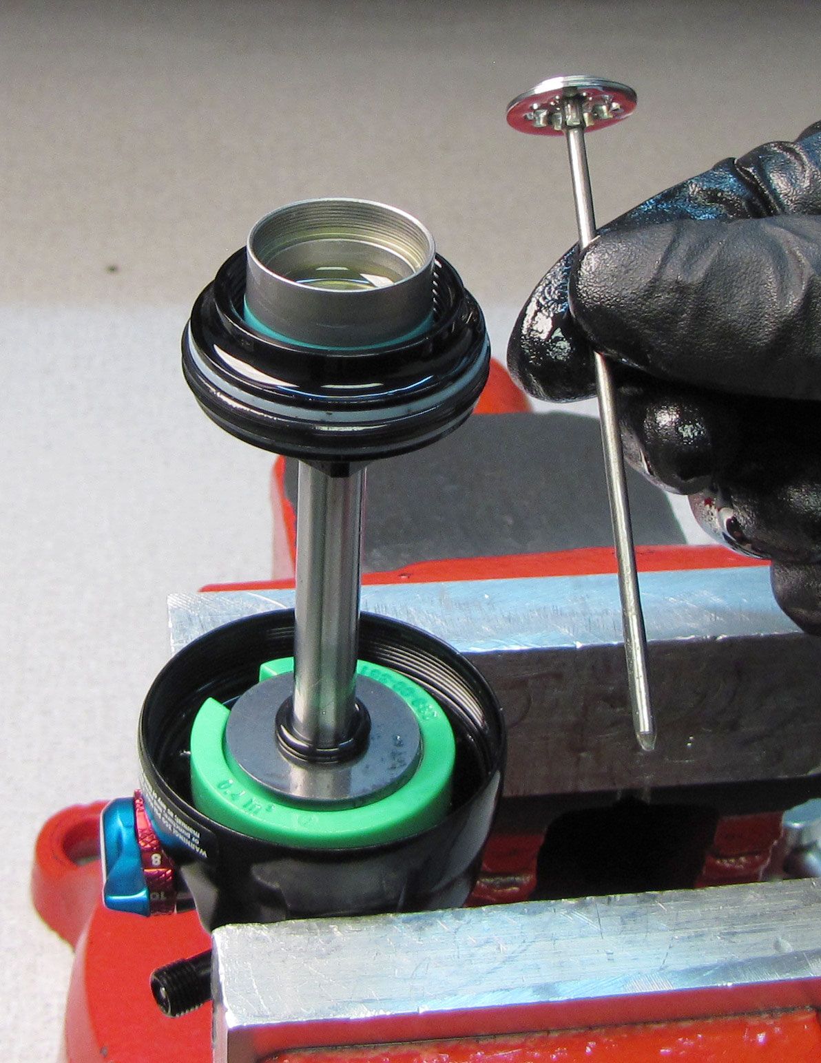
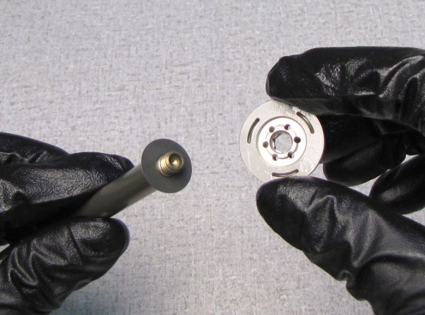
Thread the Slave Shaft into the RE:aktiv Valve Housing Cap clockwise by hand as shown taking care not to pinch the shim.

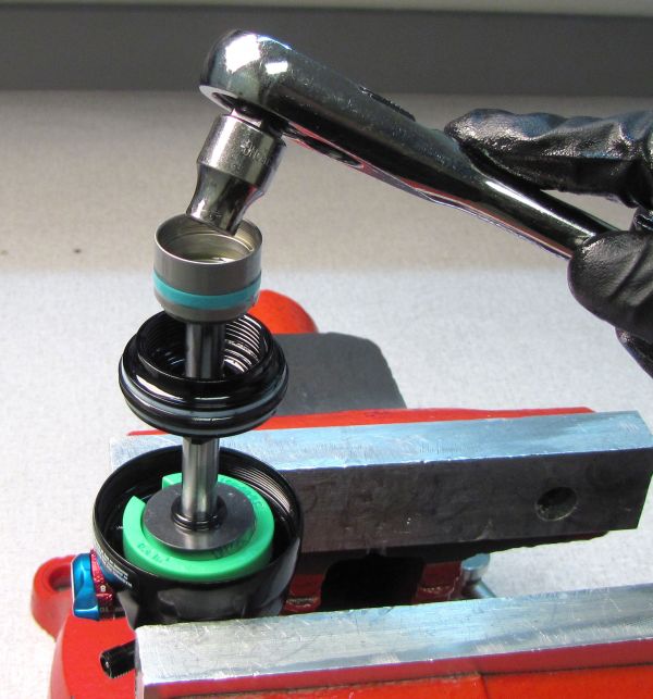
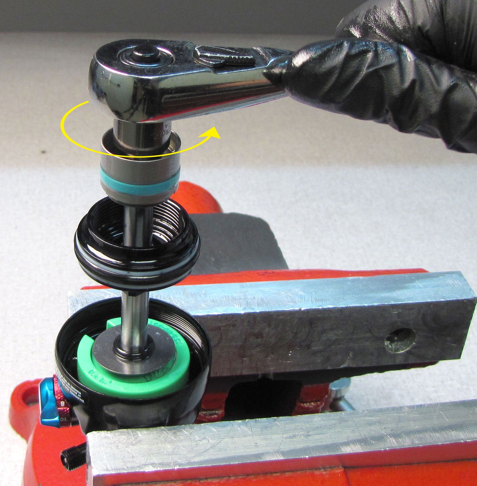
Step 11
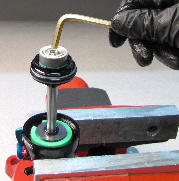
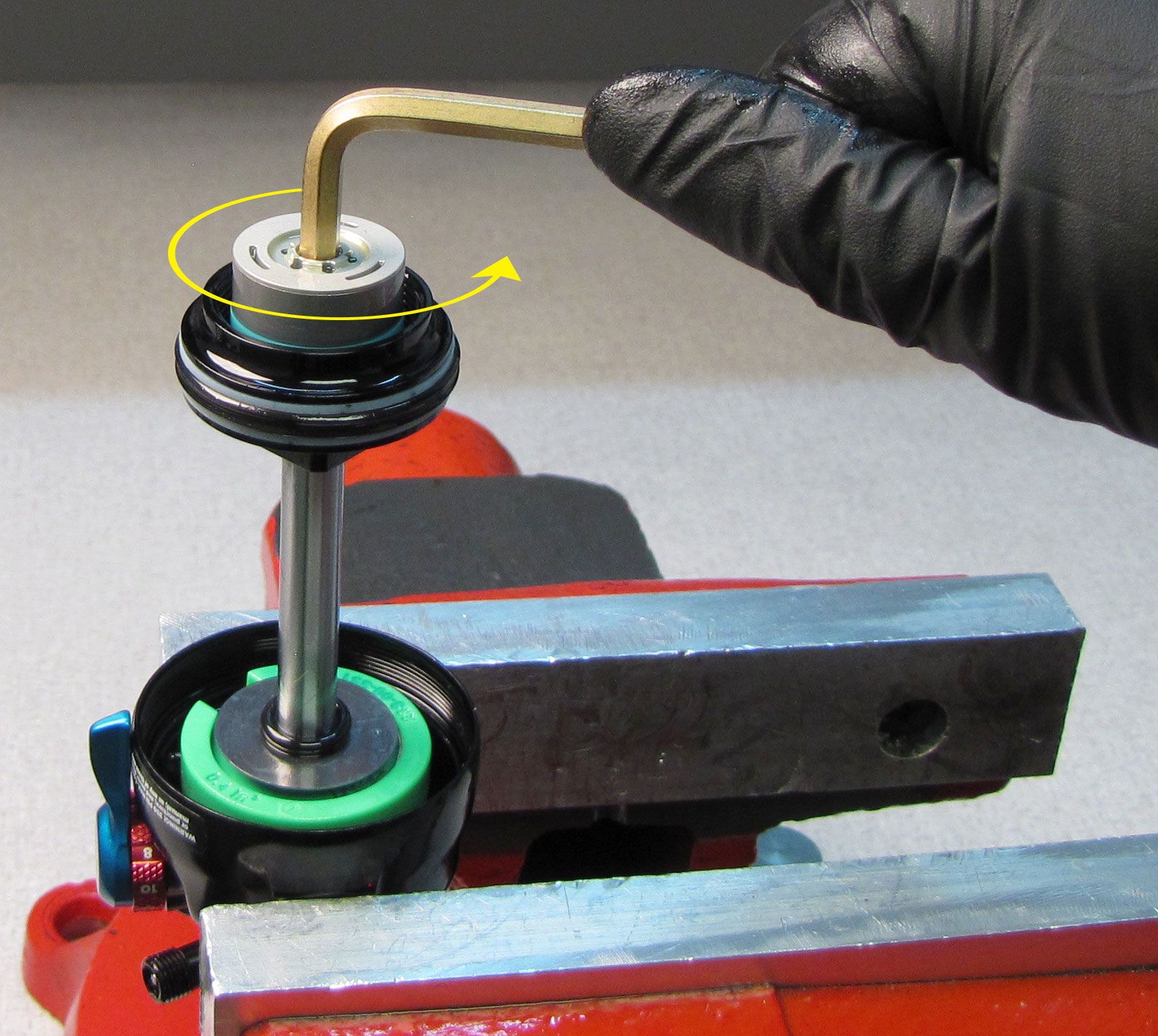
Reinstall the RE:aktiv Valve Housing Cap with Slave Shaft tightening clockwise with a 5mm hex wrench to 22 in-lb (2.4 Nm) torque.

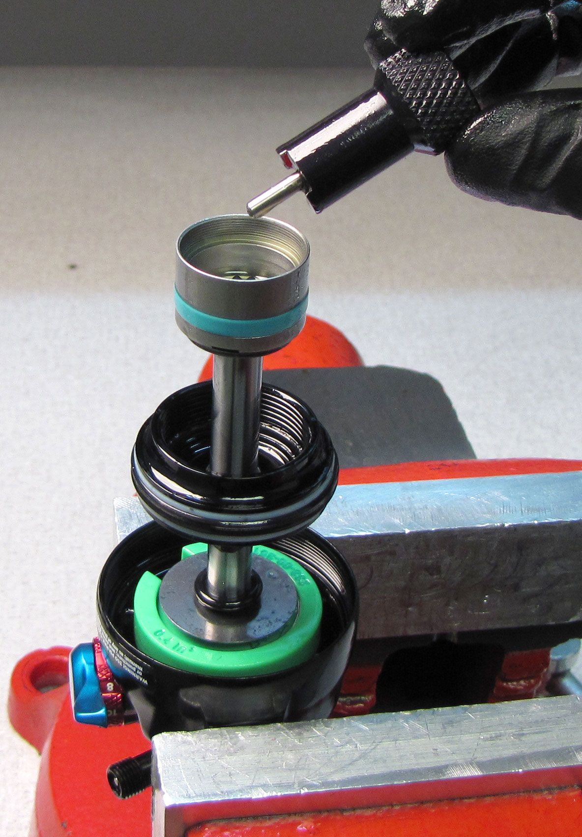
Step 12
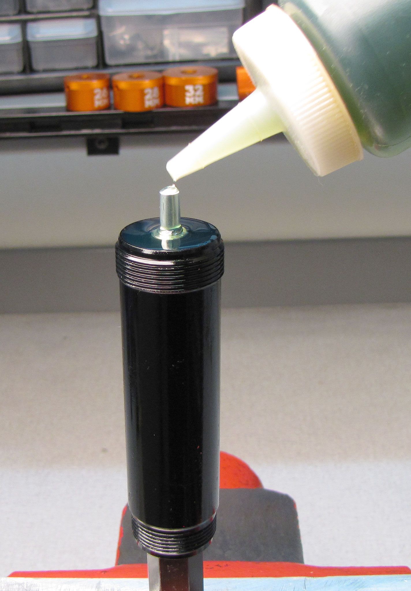
Fill the reservoir with FOX 10wt. Green oil. Replace the IFP and bleed screw o-rings with a new greased ones from the kit. Reinstall the bleed screw into the IFP tightening clockwise to 5 in-lb (0.6 Nm) torque then insert the IFP into the reservoir with the bleed screw facing up.


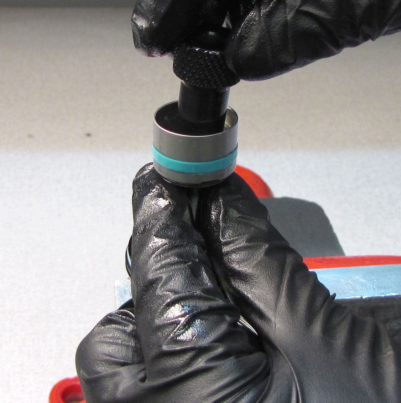
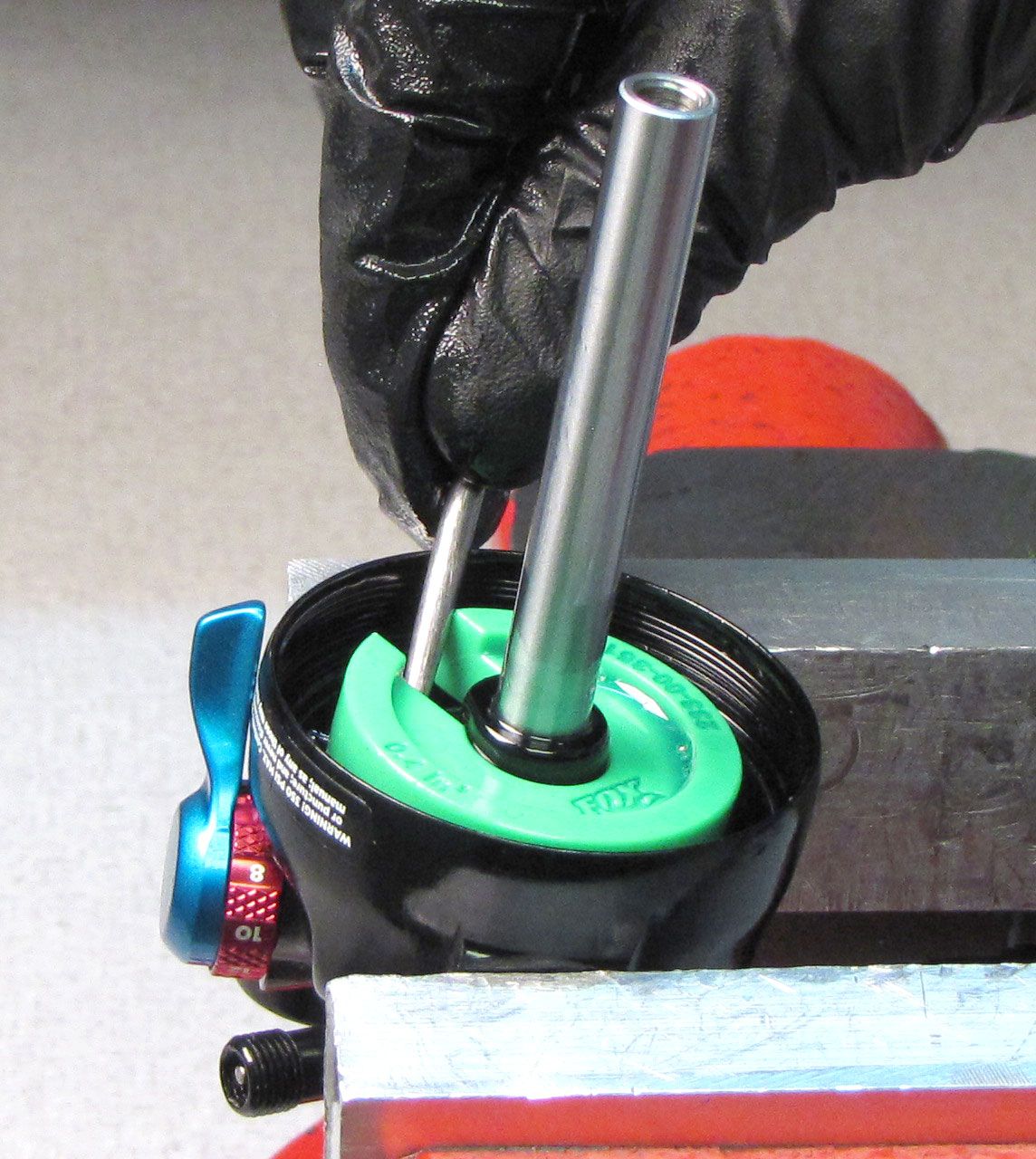
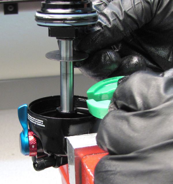
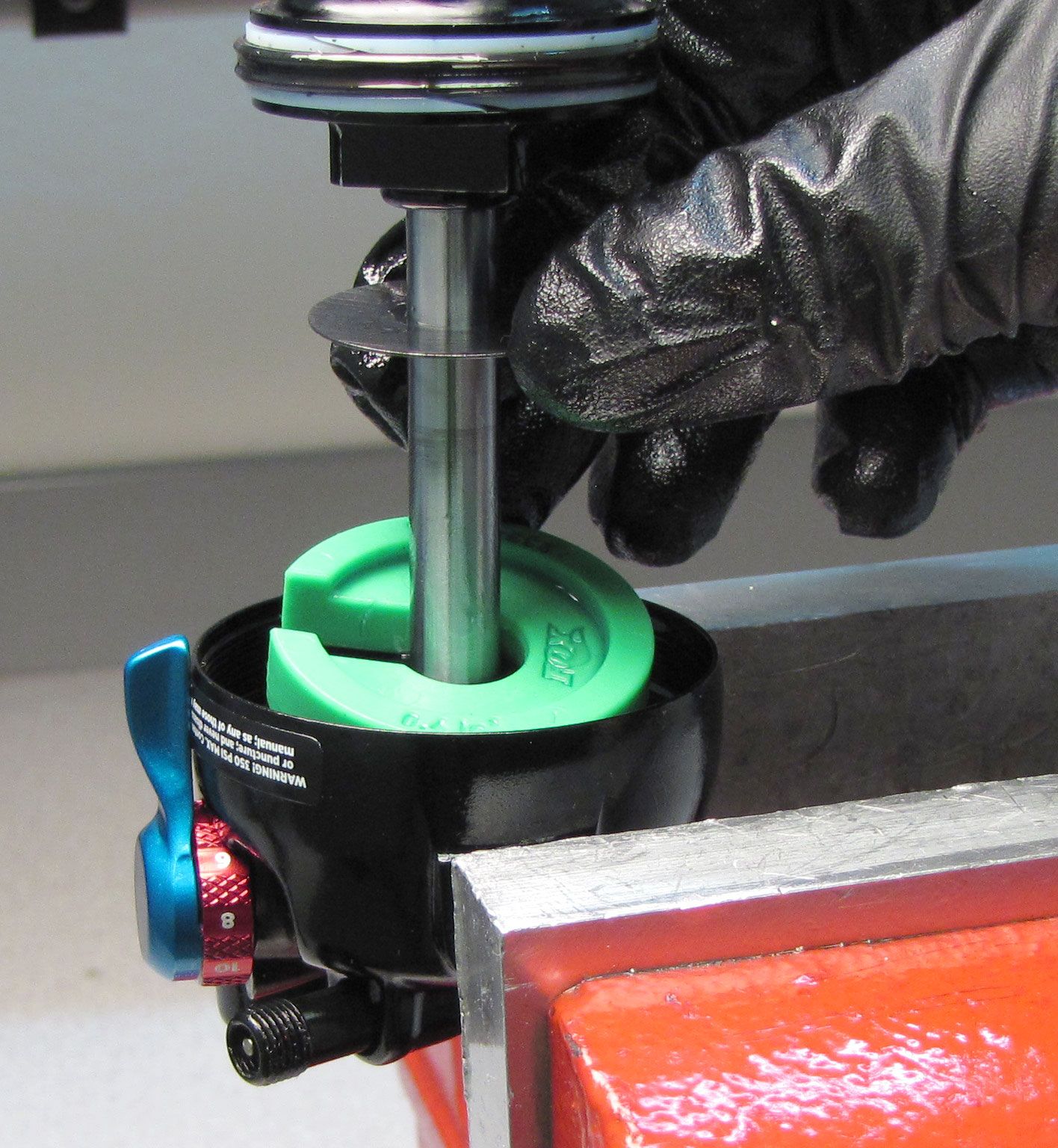
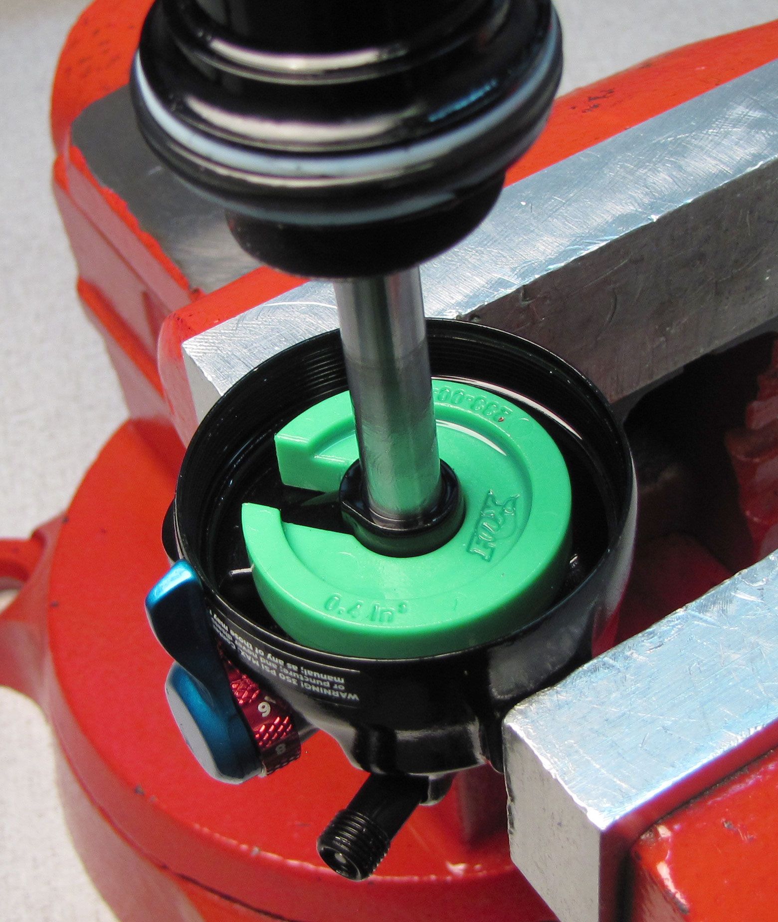
Step 13
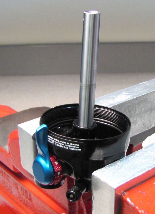
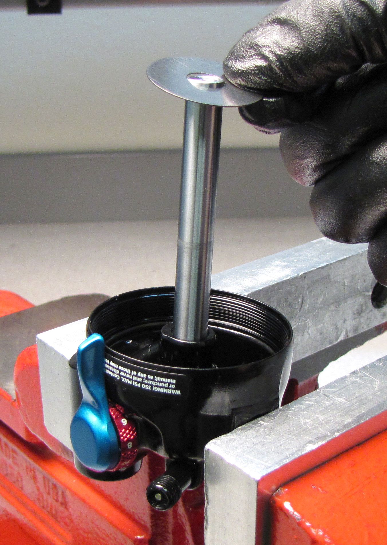
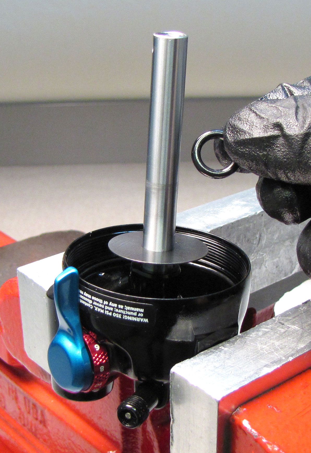
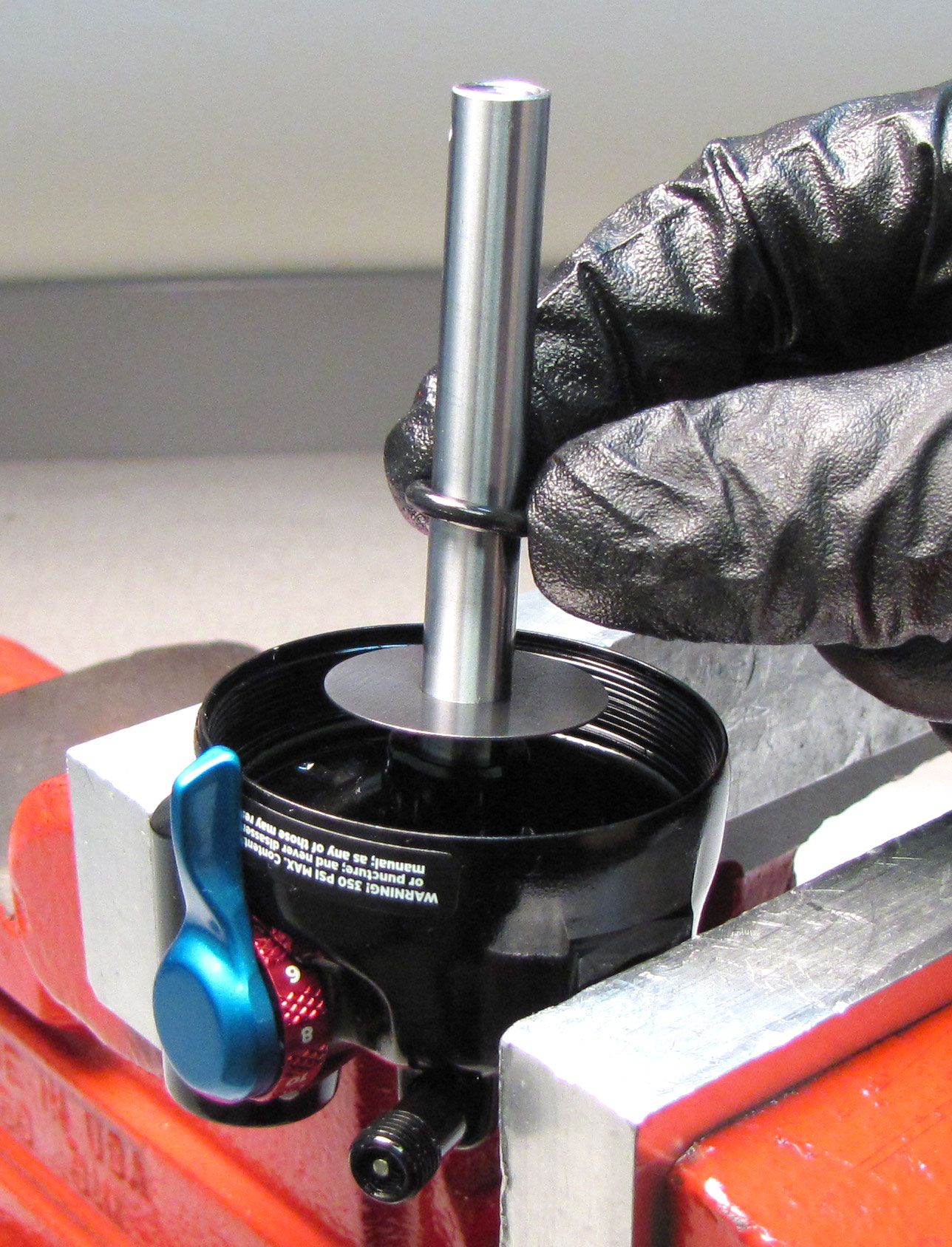
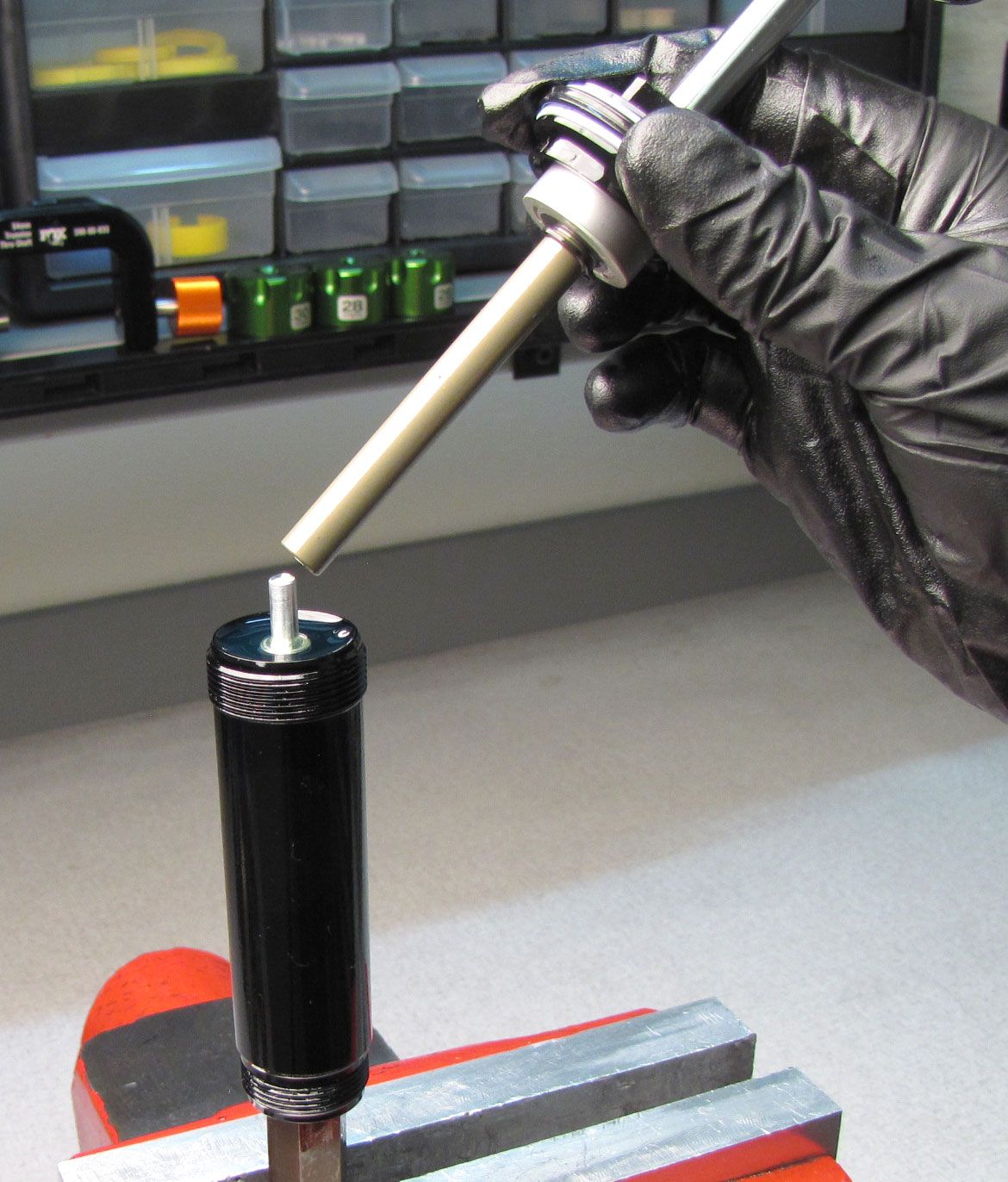
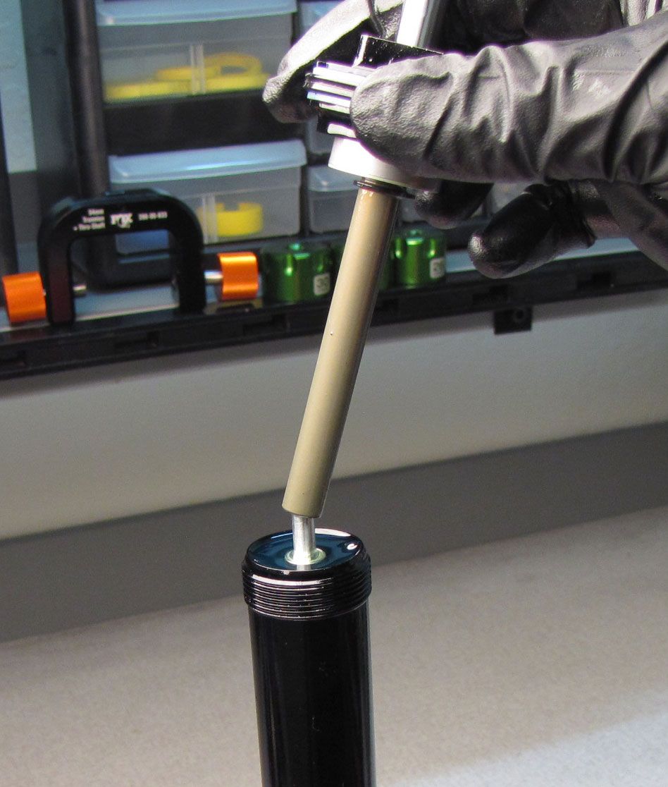
Use the IFP Depth setting tool (PN: 398-00-822) to push the IFP down to it's proper depth. Engage the flats of the tool with the flats of the IFP, then press in until it stops.

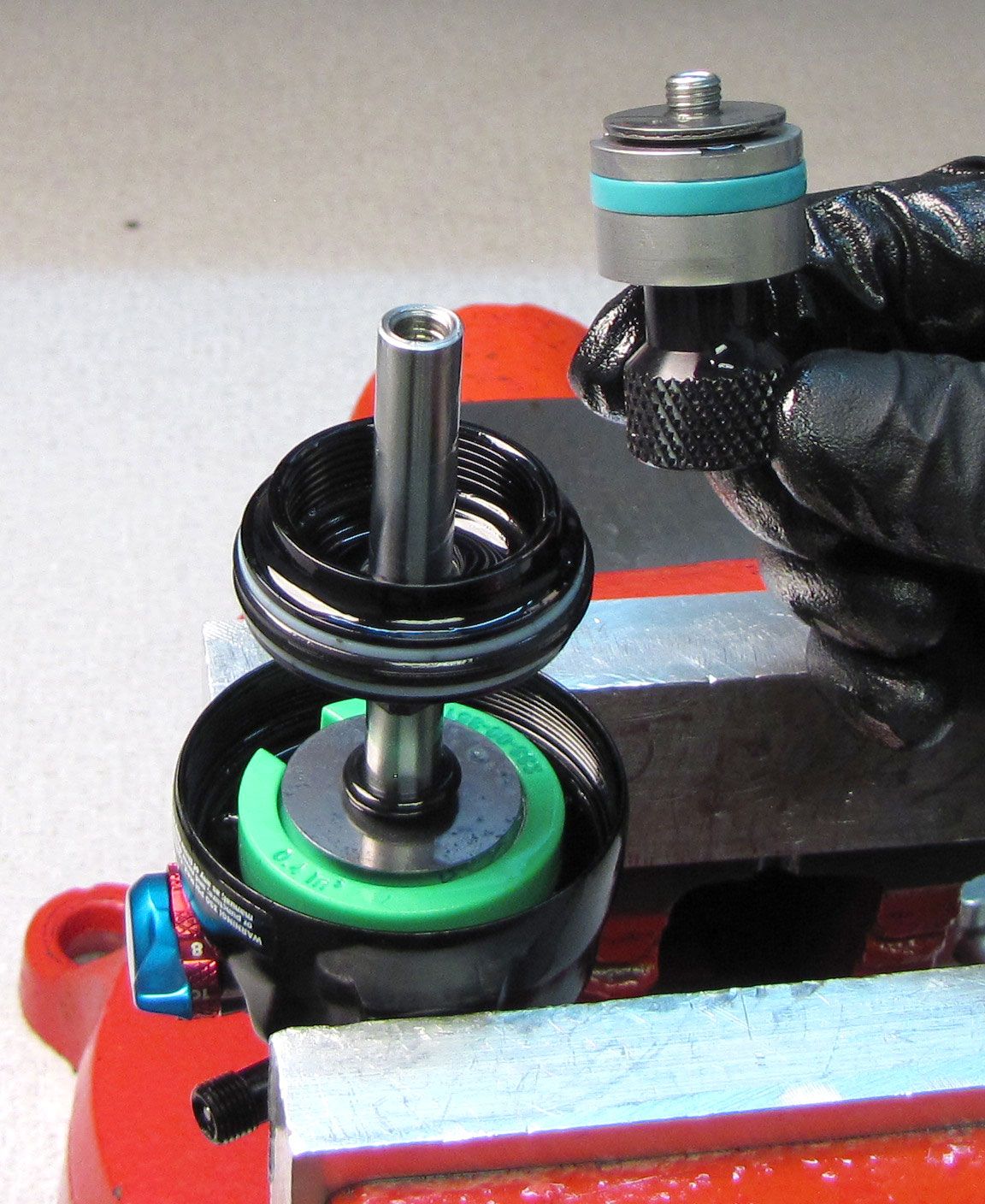
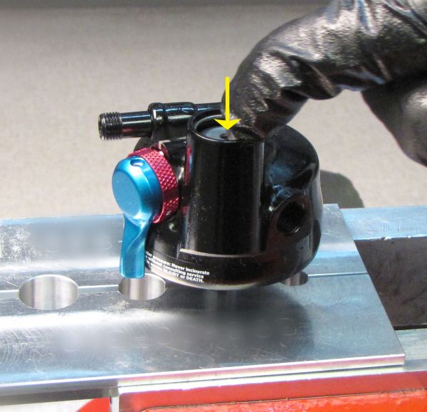
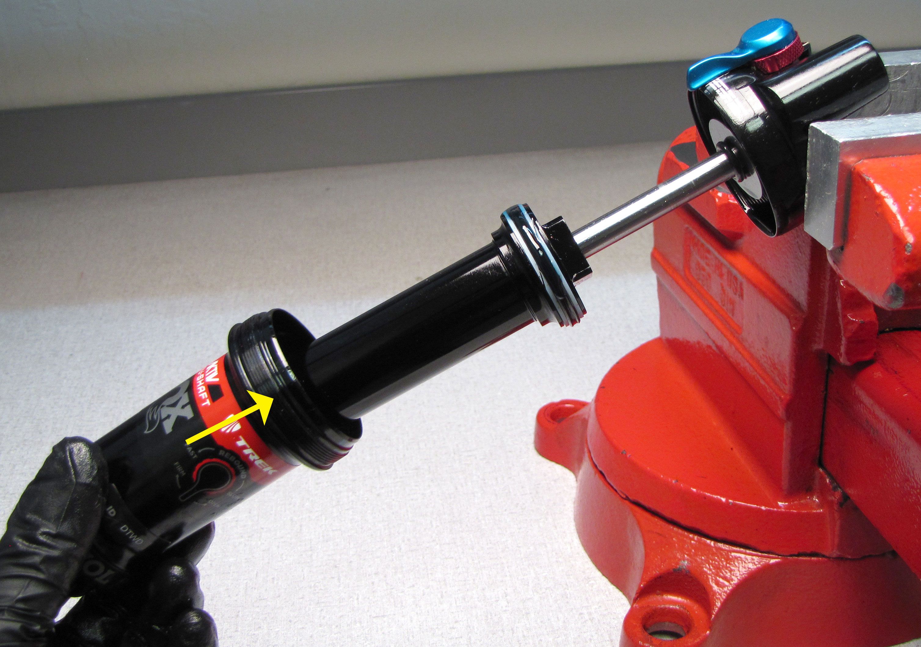
Step 14
Replace the o-ring on the Rezi End Cap with a new greased one from the kit. Reinsert the Rezi End Cap into the Reservoir with the open end facing into the shock. Push the Rezi End Cap into the Reservoir to allow for installation of the retaining ring.
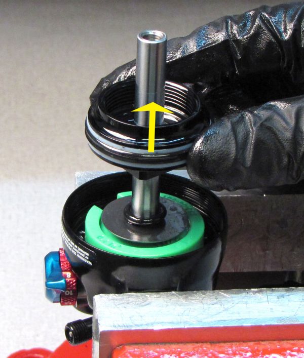
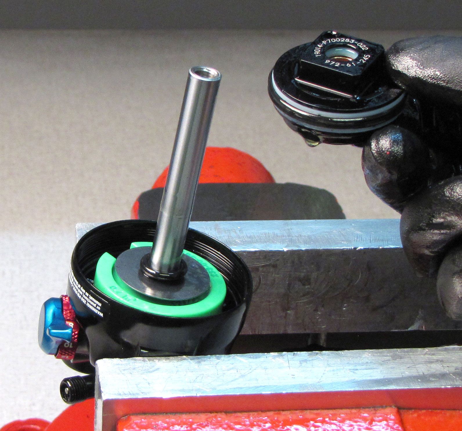
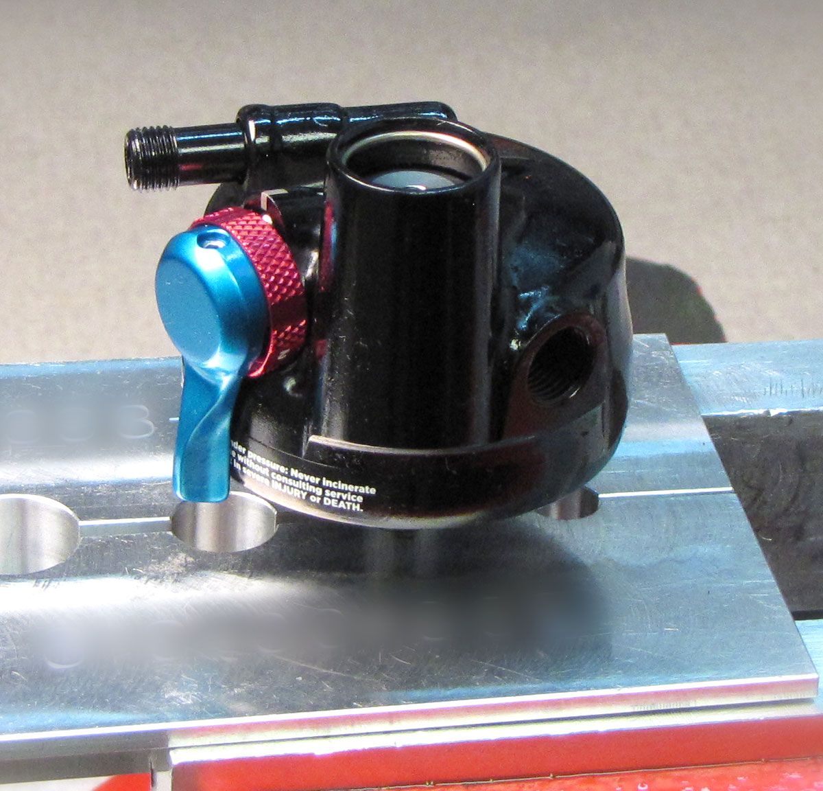
Step 15
Reinstall the wire retaining ring into the groove inside the reservoir. Use the IFP removal tool to pull the IFP up against the retaining ring.

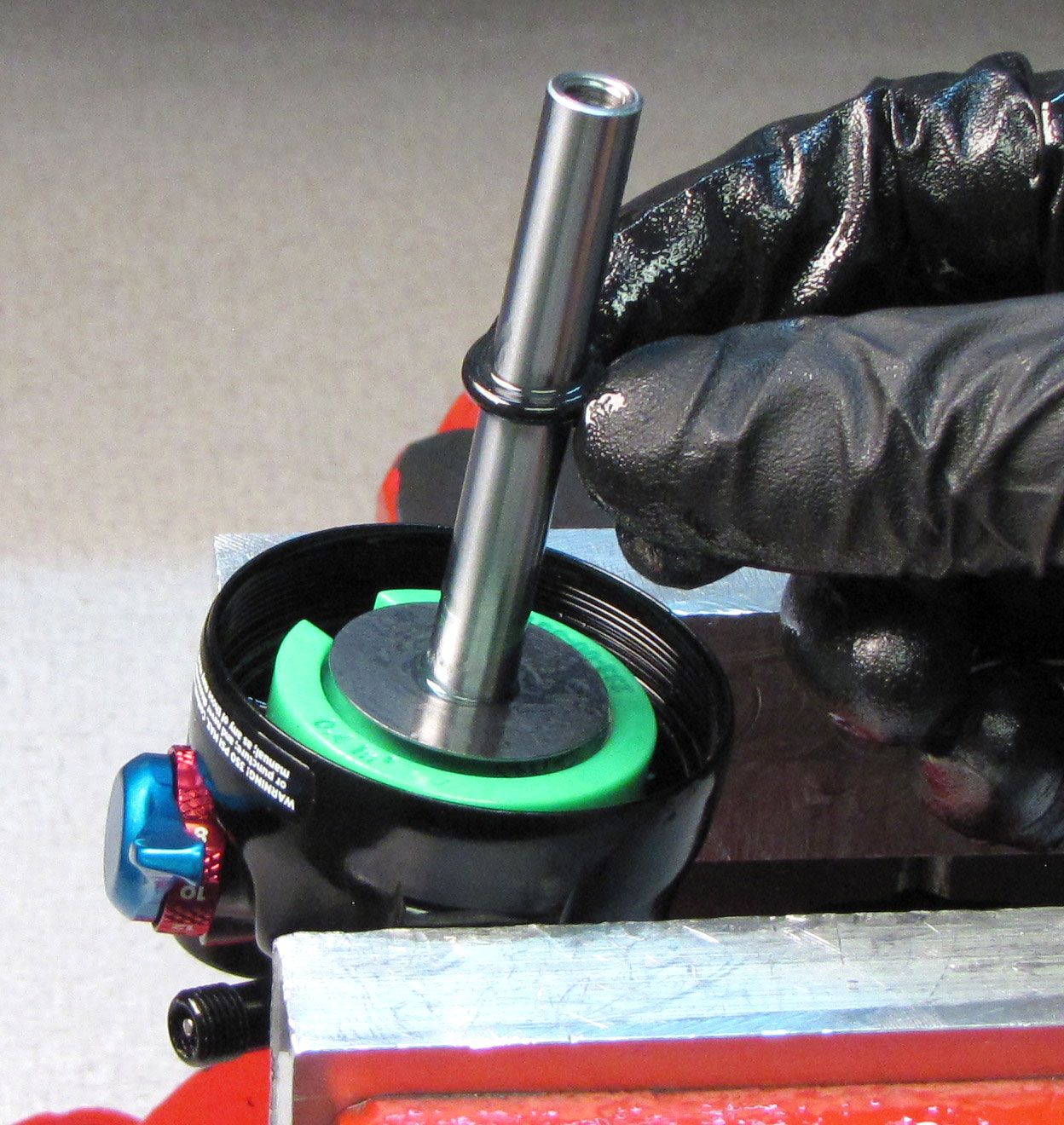
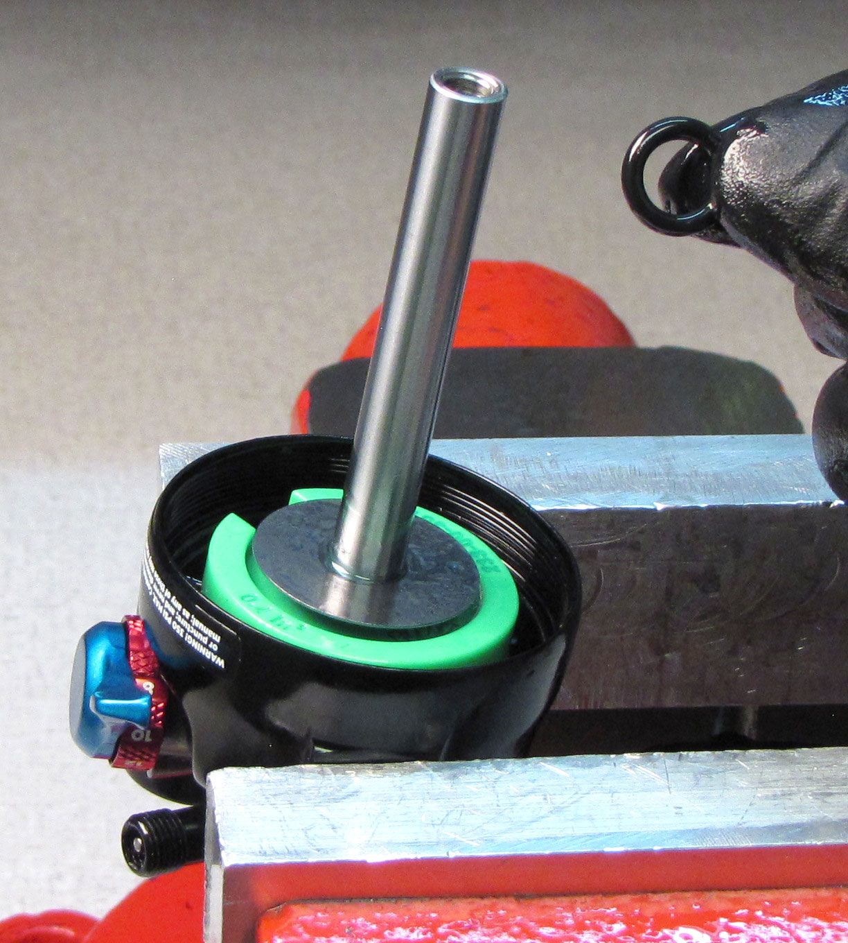
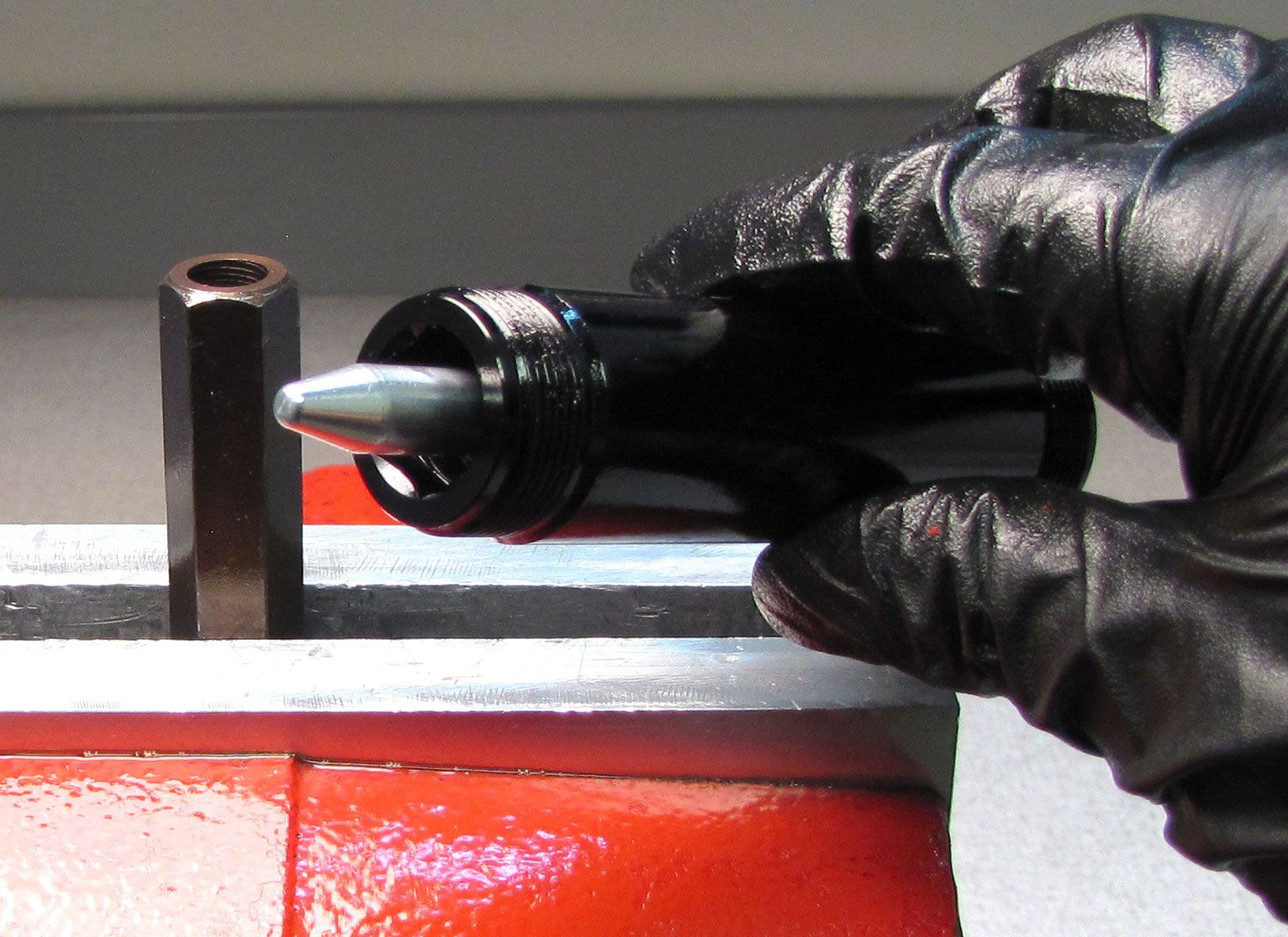
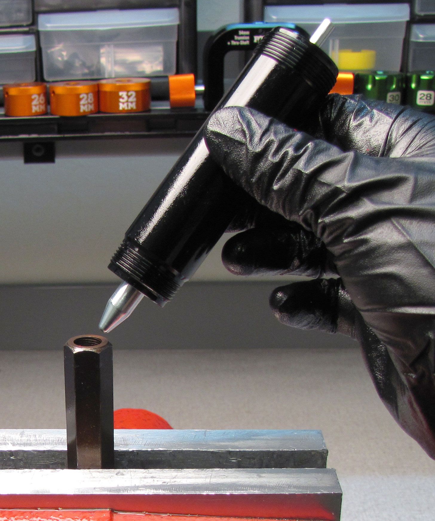
Step 16
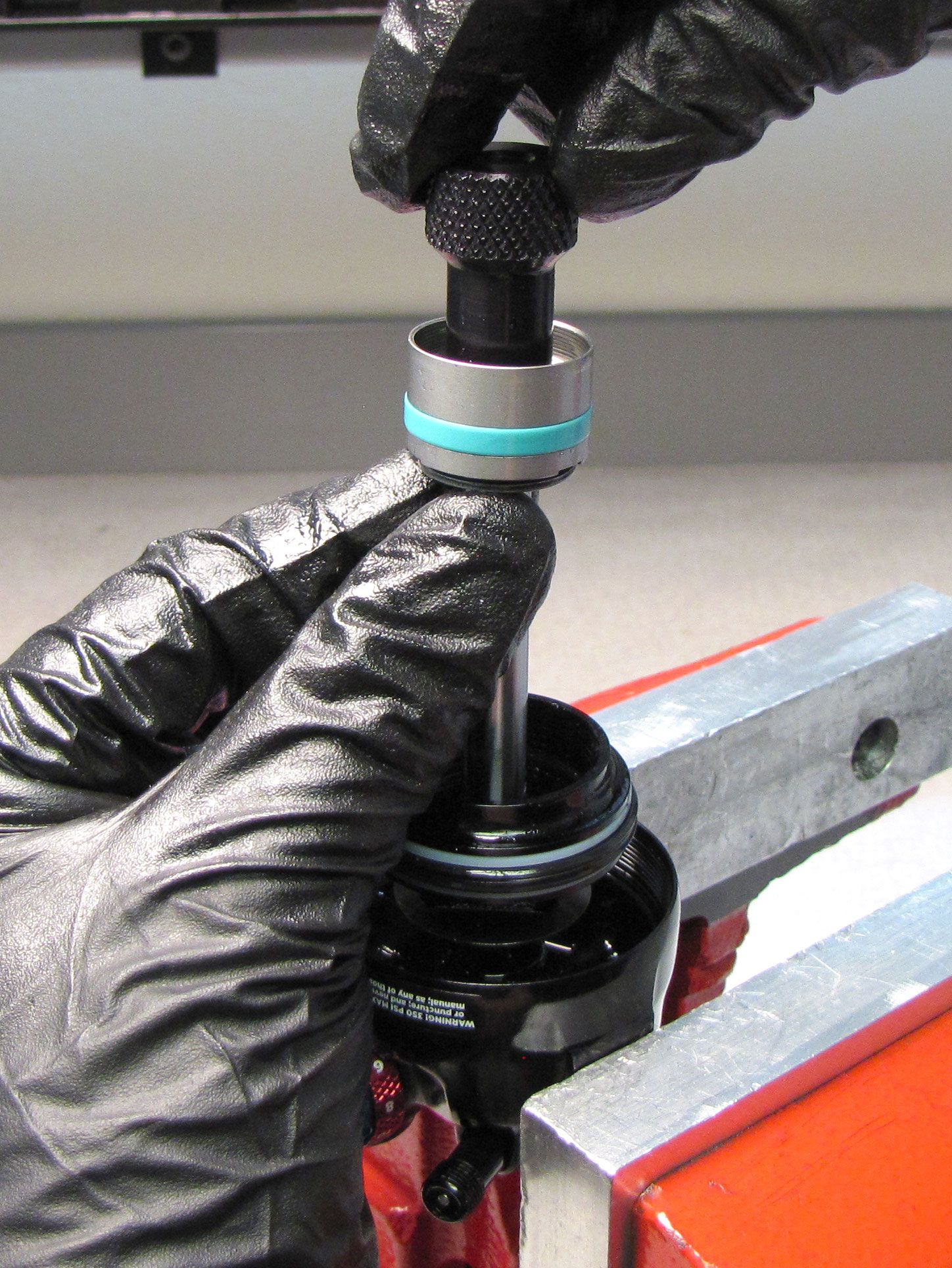
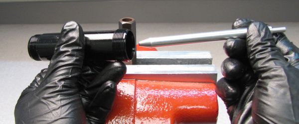
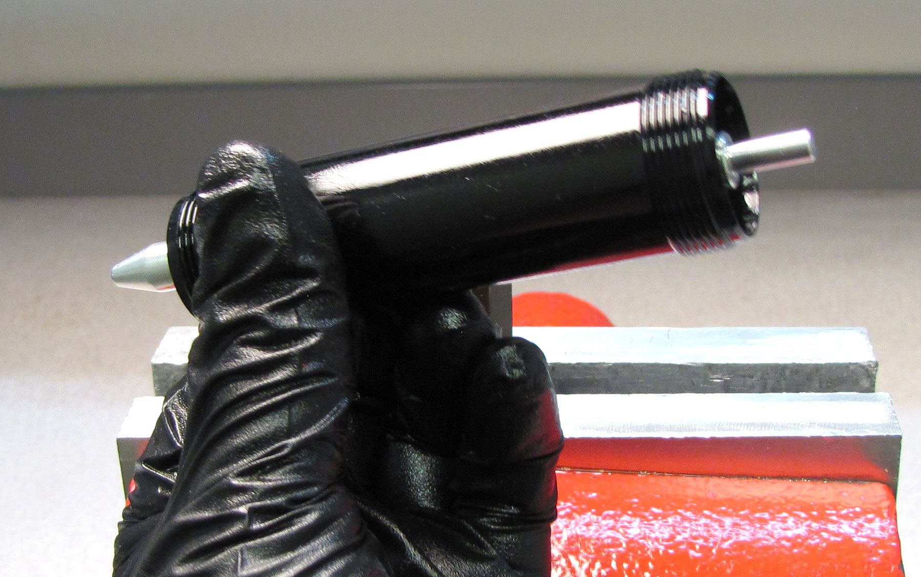
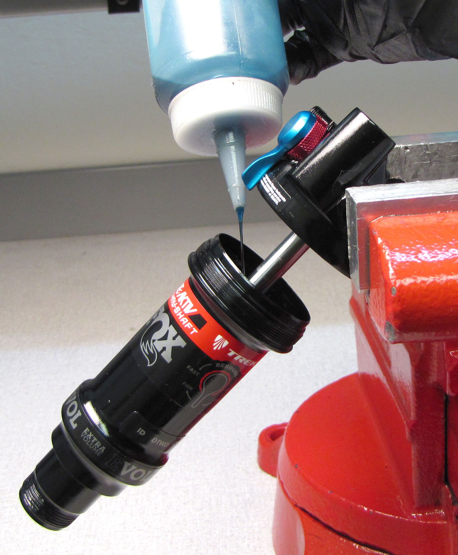
Replace the scraper seal in the end of the body with a new greased one from the kit, then insert the tapered end of the bullet tool (PN: 398-00-811) into the open end of the body (the side without the hex feature) as shown. Place the prepared body onto the 15mm hex tool (PN: 398-00-823).

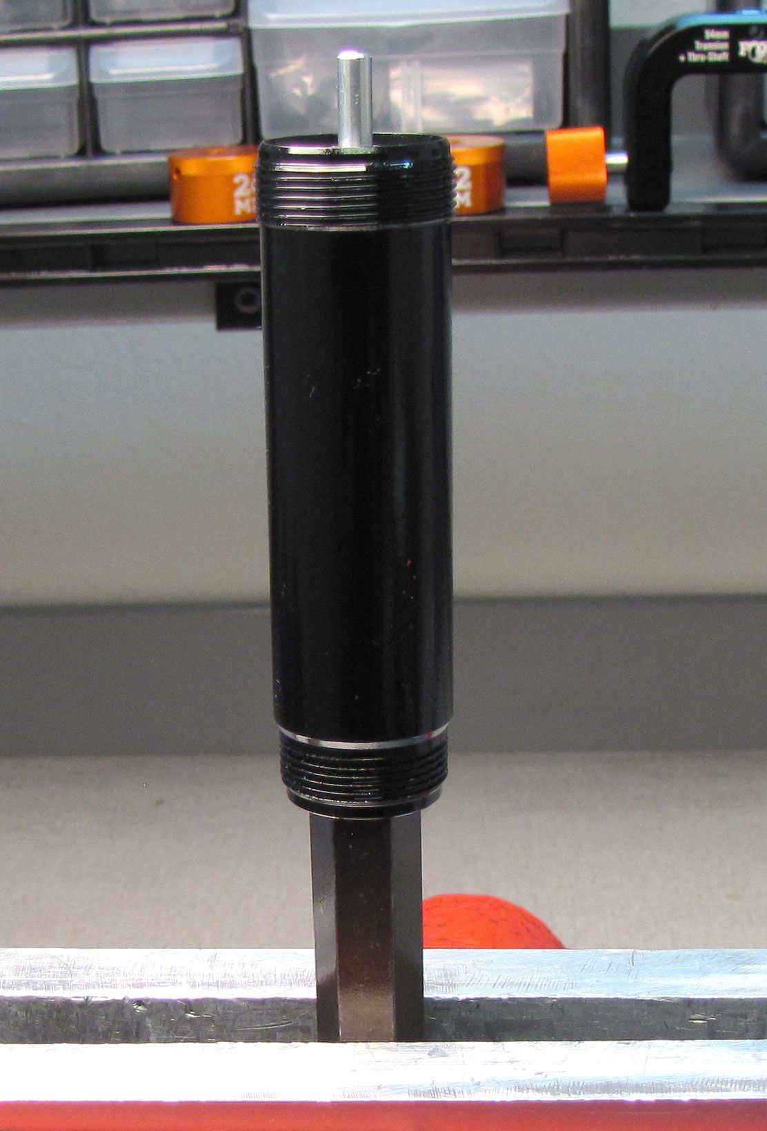

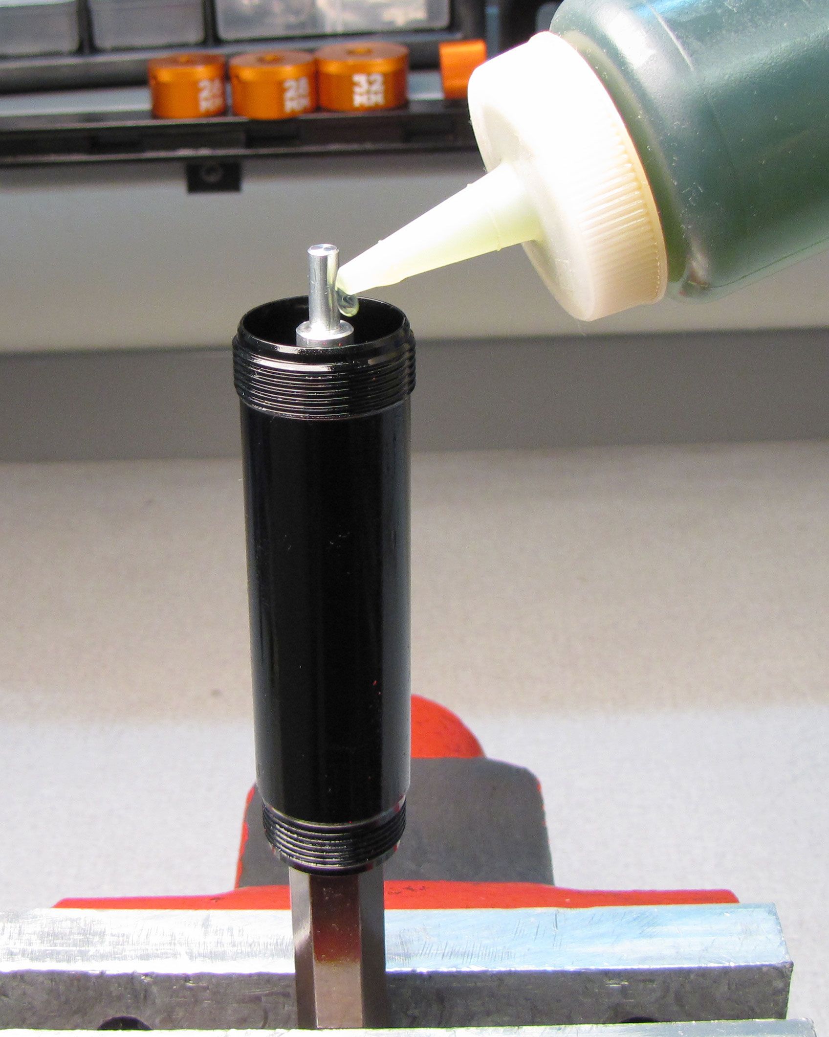
Step 17
Fill the prepared body with FOX 10wt. Green oil.

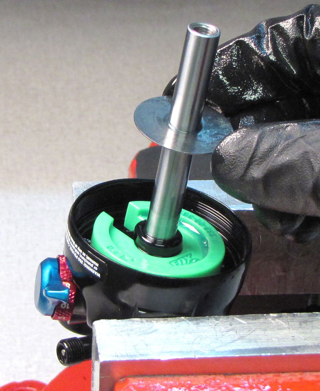
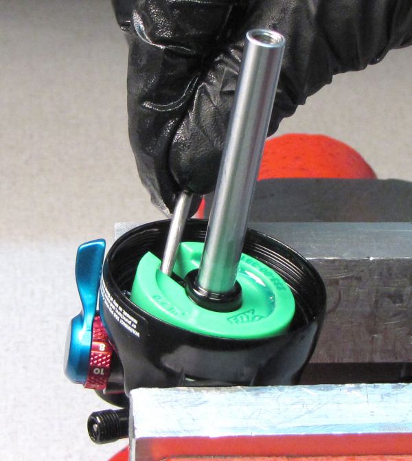
Step 18
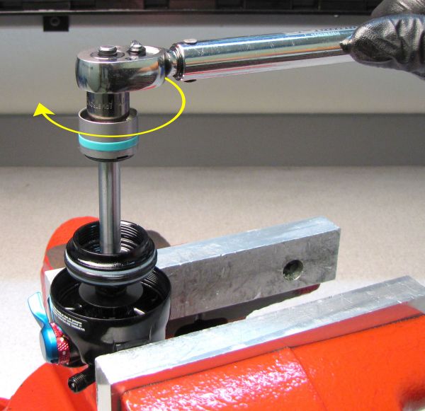
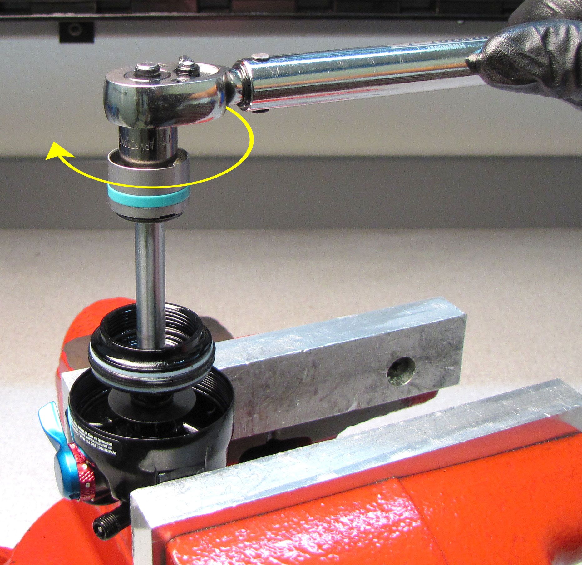
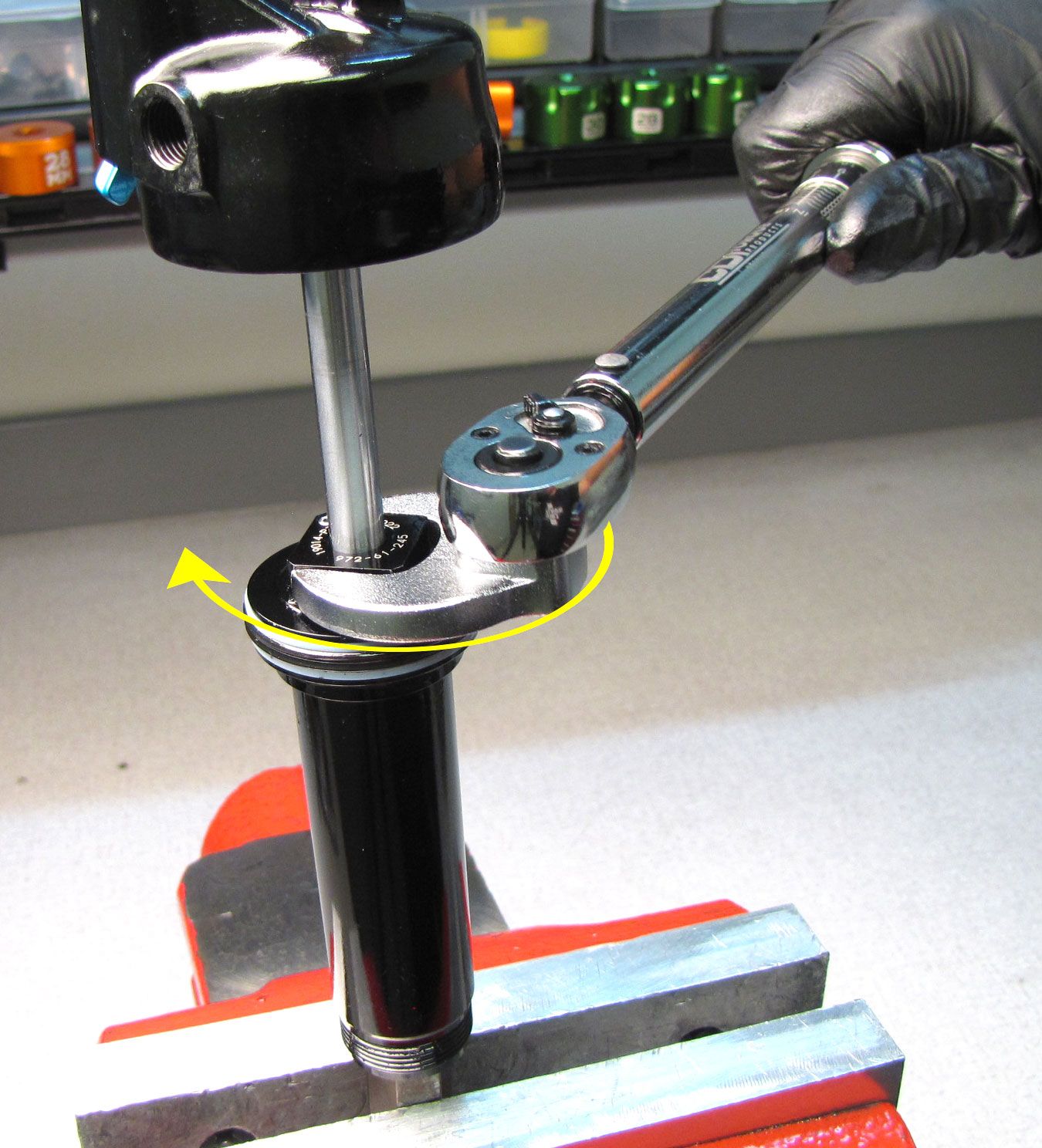
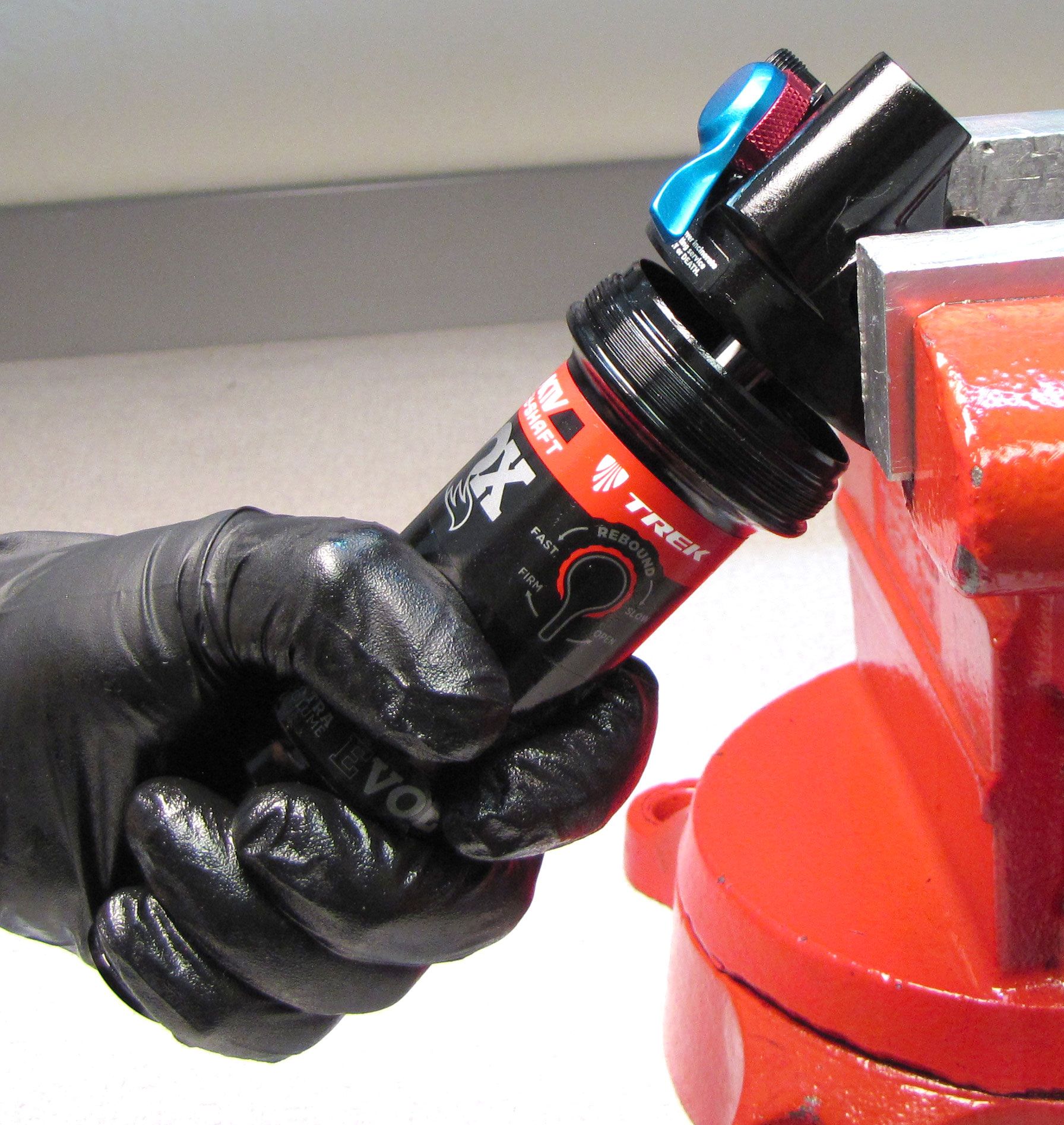
Insert the end of the bullet tool into the open end of the Slave Shaft. Push the damper assembly down into the body using the Slave Shaft to push the bullet tool out through the bottom of the body. Thread the Bearing Assembly clockwise onto the body. Tighten clockwise to 180 in-lb (20.3 Nm) with a 3/4" crows foot oriented 90 degrees from handle of your torque wrench.


Step 19
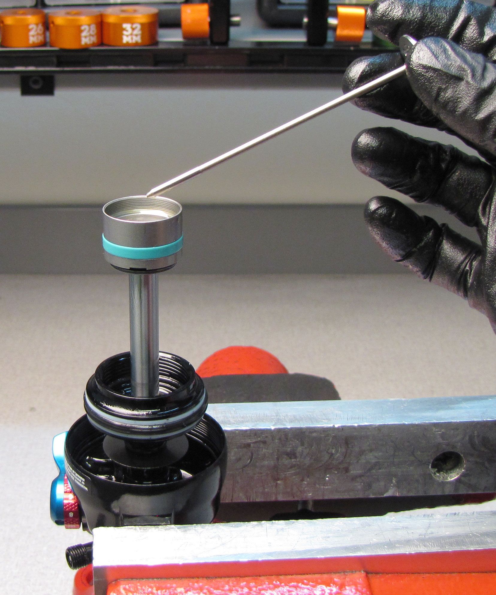
Reinstall the ball bearing into the bleed hole of the Bearing Assembly. Reinstall the set screw tightening clockwise to 10-15 in-lb (1.1-1.7 Nm) torque with a 5/64" hex wrench.

Step 20
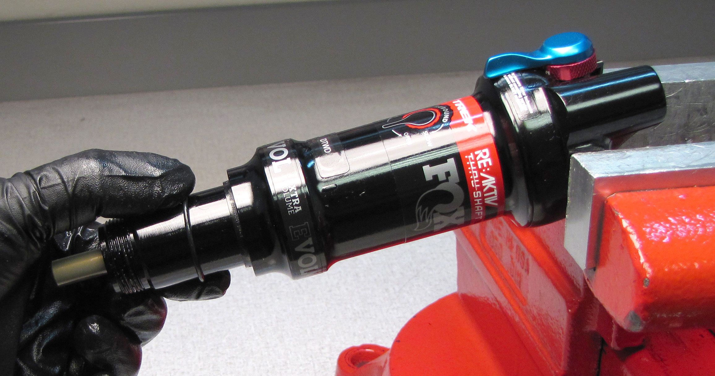
Install new back-up rings and new greased air seal from the kit (PN: 803-00-142) onto the Bearing Assembly.

Step 21
Install new back-up rings and new greased seal from the kit (PN: 803-00-142) into the end of the Air Sleeve. Do not grease the outside of the wiper seal. Install the wiper seal in the end of the Air Sleeve.

Step 22
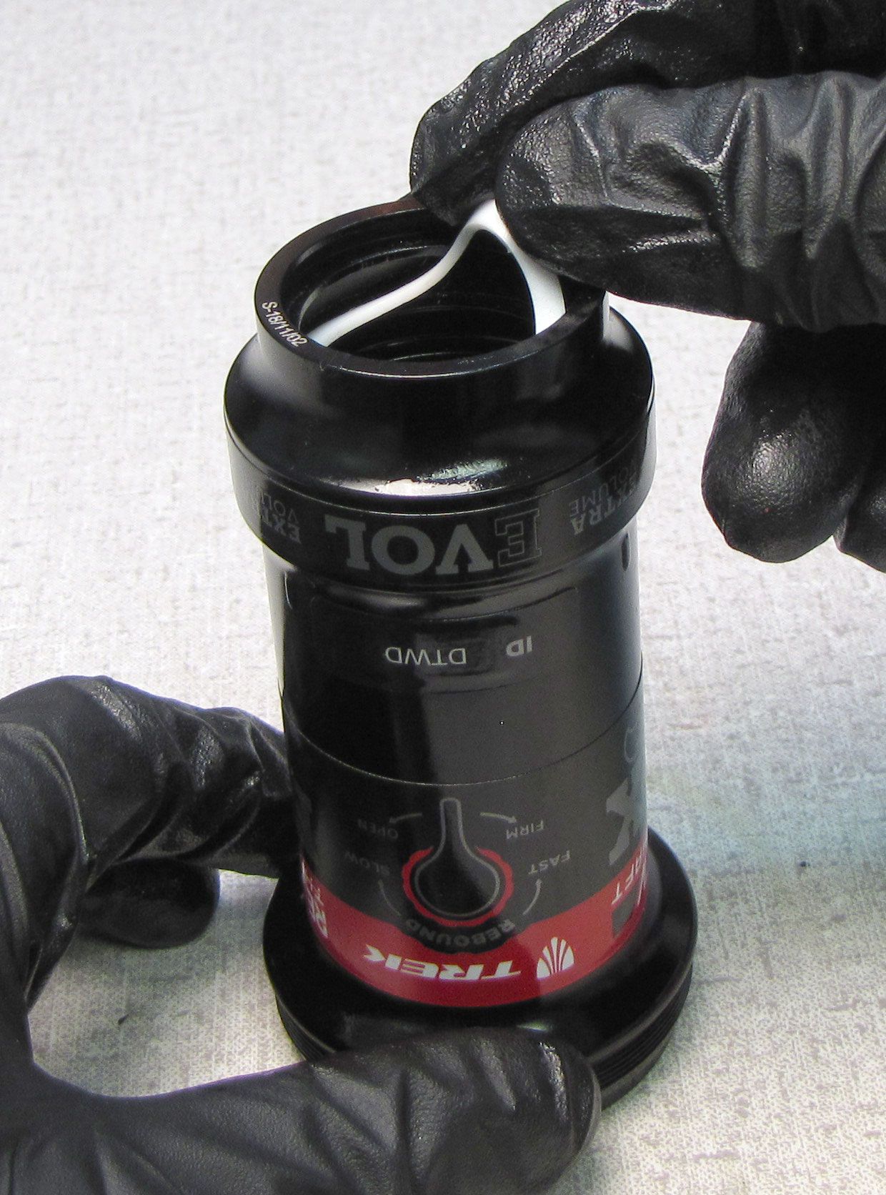
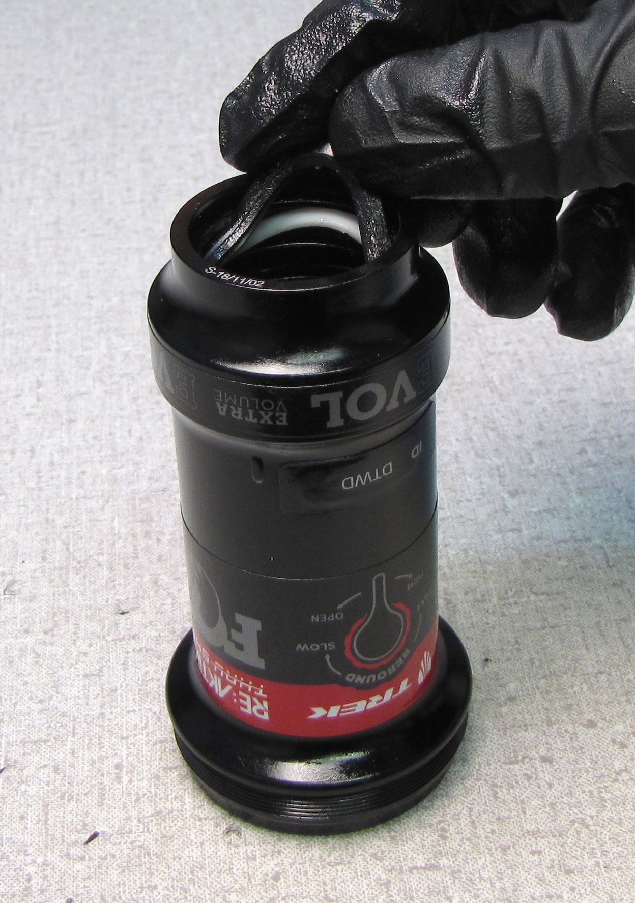
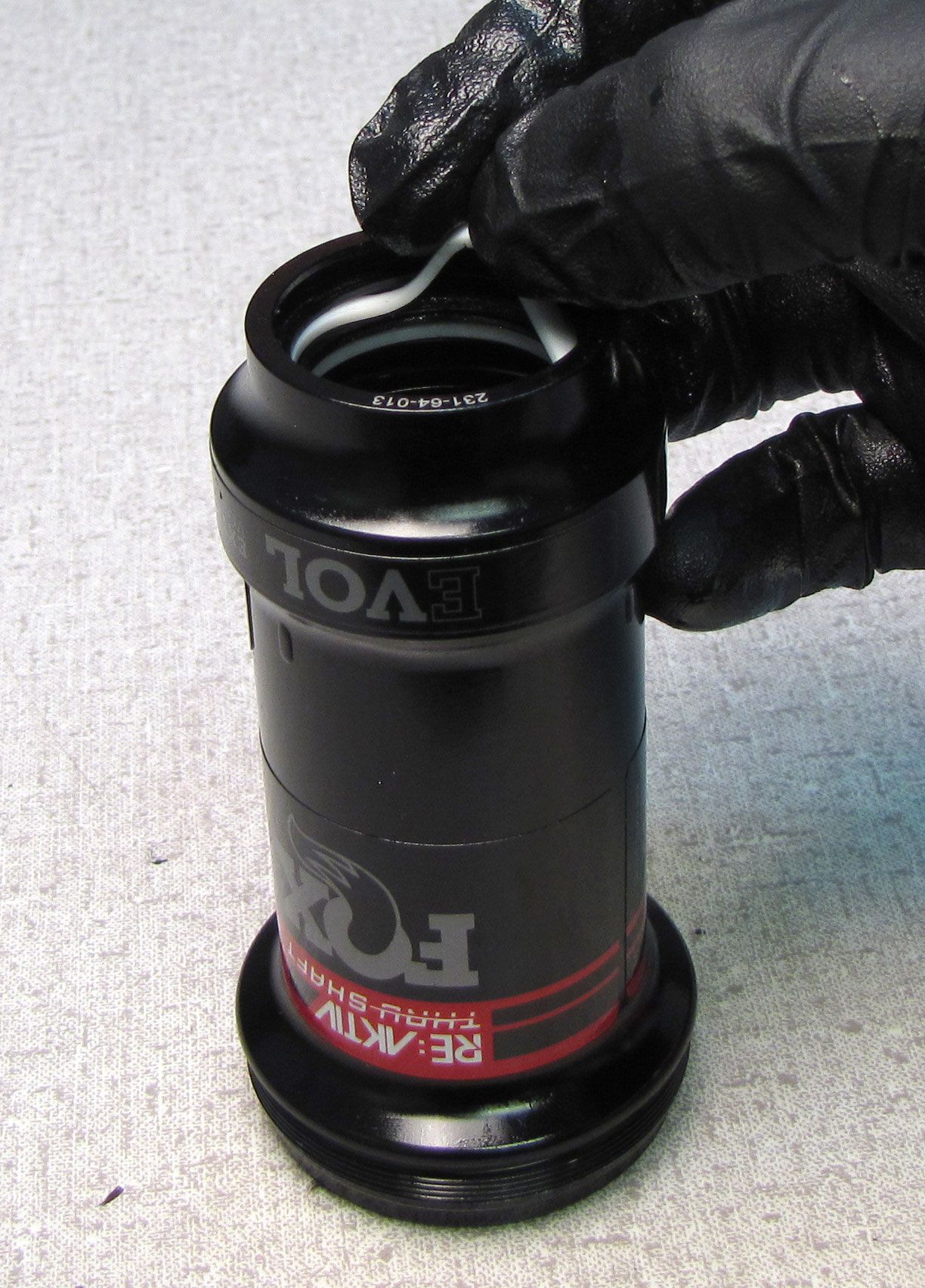
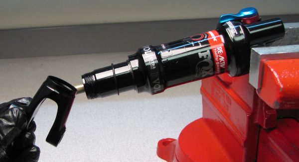
Lift up the Bottom Out Plate and Bottom Out O-ring, then reinstall the volume spacer with the part number facing the Bearing Assembly.


Step 23
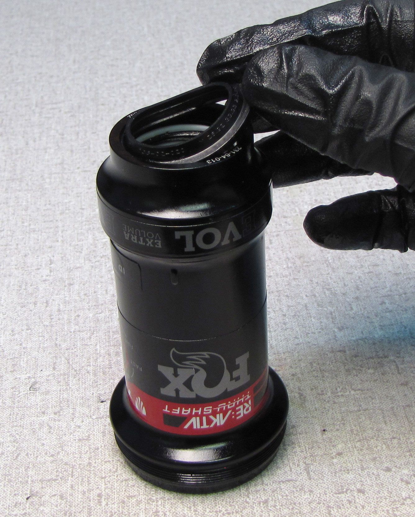
Coat the air seals on the Bearing Assembly and the Air Sleeve with a film of Float Fluid. Add 2cc of Float Fluid to the main air chamber, then slide the air sleeve in place over the main air seal. Tighten the air sleeve clockwise until hand tight (approximately 45 in-lb/ 5.1 Nm). Install a new ungreased sag-indicator o-ring from the kit onto the body.


NOTE: Never dyno the shock without the Air Sleeve, Reservoir End Cap, or with less than 100 psi in the main air chamber. Doing so may upset the IFP and require a shock rebuild to reset the IFP.
Step 24
Reinstall the Clevis, tightening clockwise onto the body by hand. Position the body with Clevis onto the hex tool. Tighten clockwise to 180 in-lb (20.3 Nm) torque with smooth-jawed parallel pliers (Knipex). Add air to the main air chamber then dyno the shock to check for proper functionality.