2020 TREK IsoStrut Rebuild
Required Parts
- 803-01-410 Seal Kit: IsoStrut Damper Rebuild
- 803-01-411 Seal Kit: IsoStrut Air Sleeve Rebuild
Required Tools
- 803-00-566 Kit:Bike IFP Depth Setting Tool Set
- 803-00-805 Kit: Shaft Clamps, Shocks, CTD 9mm, 3/8in, 1/2in, 5/8in
- 803-01-436 Kit: Tooling: IsoStrut
- 803-01-437 Kit: Dyno, IsoStrut & ThruShaft
- Nitrogen Fill Station (Tank with Regulator) required for full rebuild .
Supplies Needed
- 1.5mm Hex Wrench
- 2mm Hex Wrench
- 3/4" Crowsfoot
- 3/8" Square Drive Extension
- 5/32" Hex Wrench
- 5/64" Hex Wrench
- Knipex Smooth-Jawed Parallel Pliers
- Magnet
- Needle-nosed Pliers
- Propane Torch
- RaceFace BSA30 12-Spline Bottom Bracket Tool
- Ratchet
- Seal Pick
- Snap-Ring Pliers
- T40 Torx Driver
- T8 Torx Driver
- Torque Wrench
- Waste Oil Basin
- Wooden Dowel
WARNING: Always wear safety glasses and protective gloves during service to prevent potential injury. Failure to wear protective equipment during service may lead to SERIOUS INJURY OR DEATH.
WARNING: FOX products should be serviced by a trained bicycle service technician, in accordance with FOX specifications. If you have any doubt whether or not you can properly service your FOX product, then DO NOT attempt it. Improperly serviced products can fail, causing the rider to lose control resulting in SERIOUS INJURY OR DEATH.
WARNING: FOX suspension products contain pressurized nitrogen, air, oil, or all 3. Suspension misuse can cause property damage, SERIOUS INJURY OR DEATH. DO NOT puncture, incinerate or crush any portion of a FOX suspension product. DO NOT attempt to disassemble any portion of a FOX suspension product, unless expressly instructed to do so by the applicable FOX technical documentation, and then ONLY while strictly adhering to all FOX instructions and warnings in that instance. Always wear safety glasses during FOX service to prevent injury from flying debris, components, or oils.
WARNING: Modification, improper service, or use of aftermarket replacement parts with FOX forks and shocks may cause the product to malfunction, resulting in SERIOUS INJURY OR DEATH. DO NOT modify any part of a fork or shock, including the fork brace (lower leg cross brace), crown, steerer, upper and lower leg tubes, or internal parts, except as instructed herein. Any unauthorized modification may void the warranty, and may cause failure or the fork or shock, resulting in SERIOUS INJURY OR DEATH.

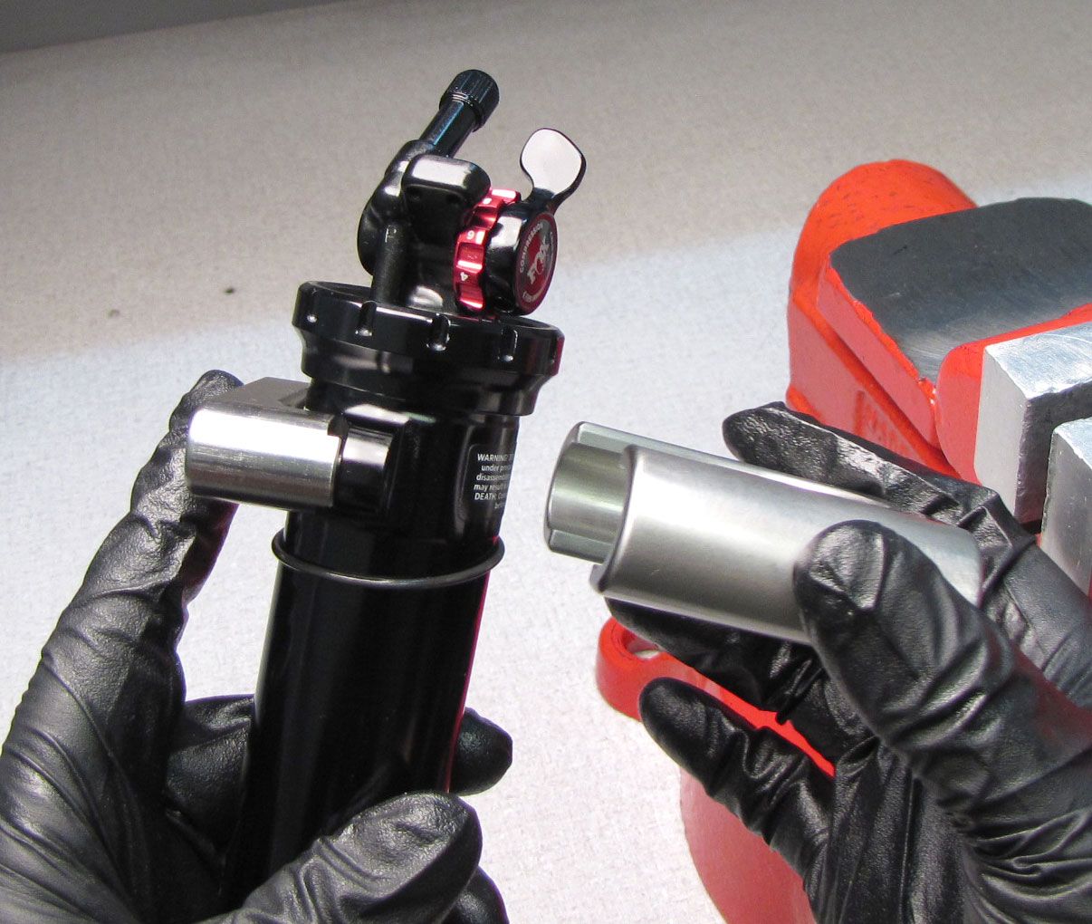
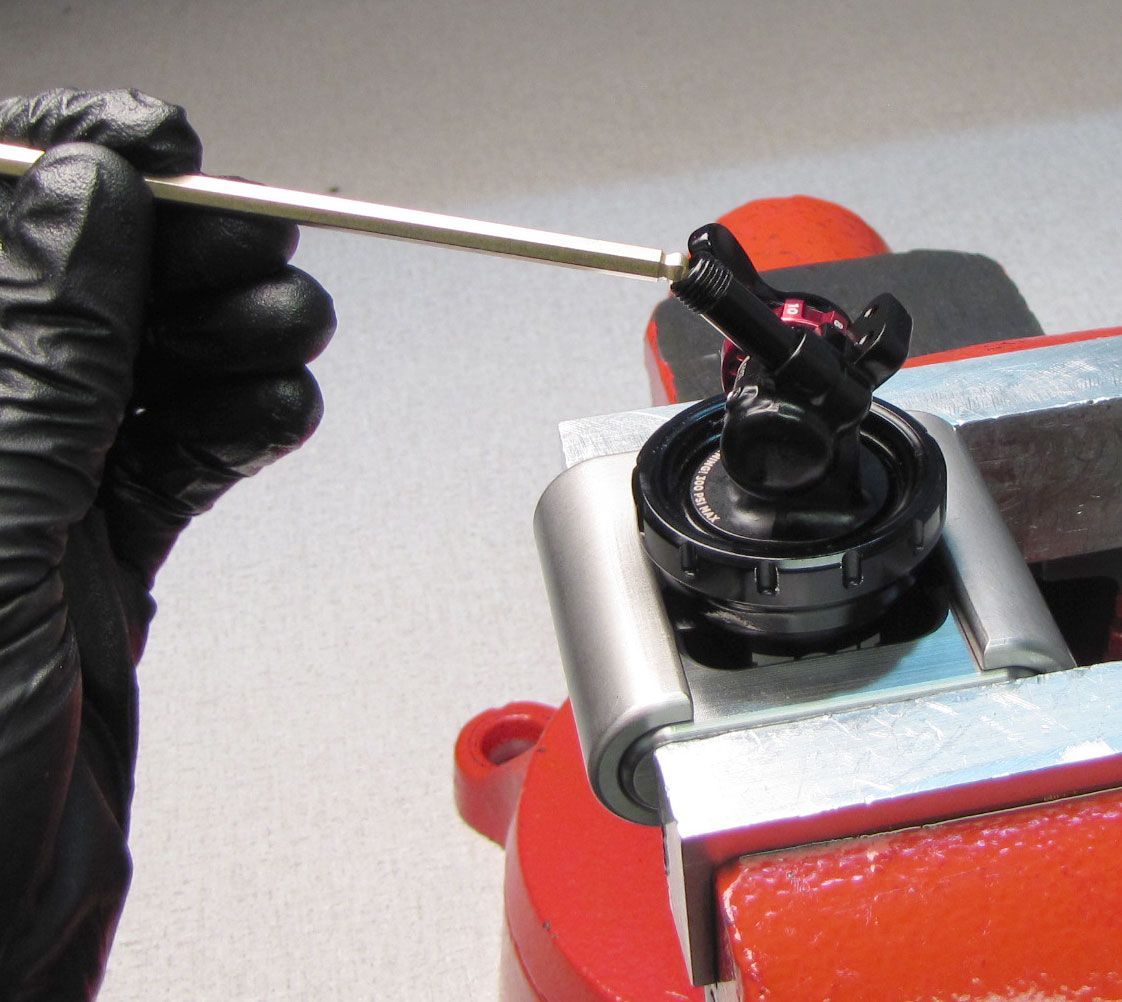
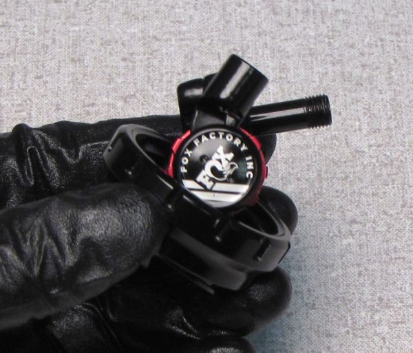
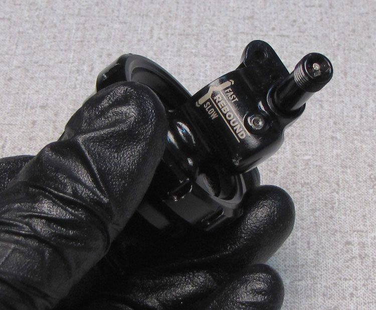
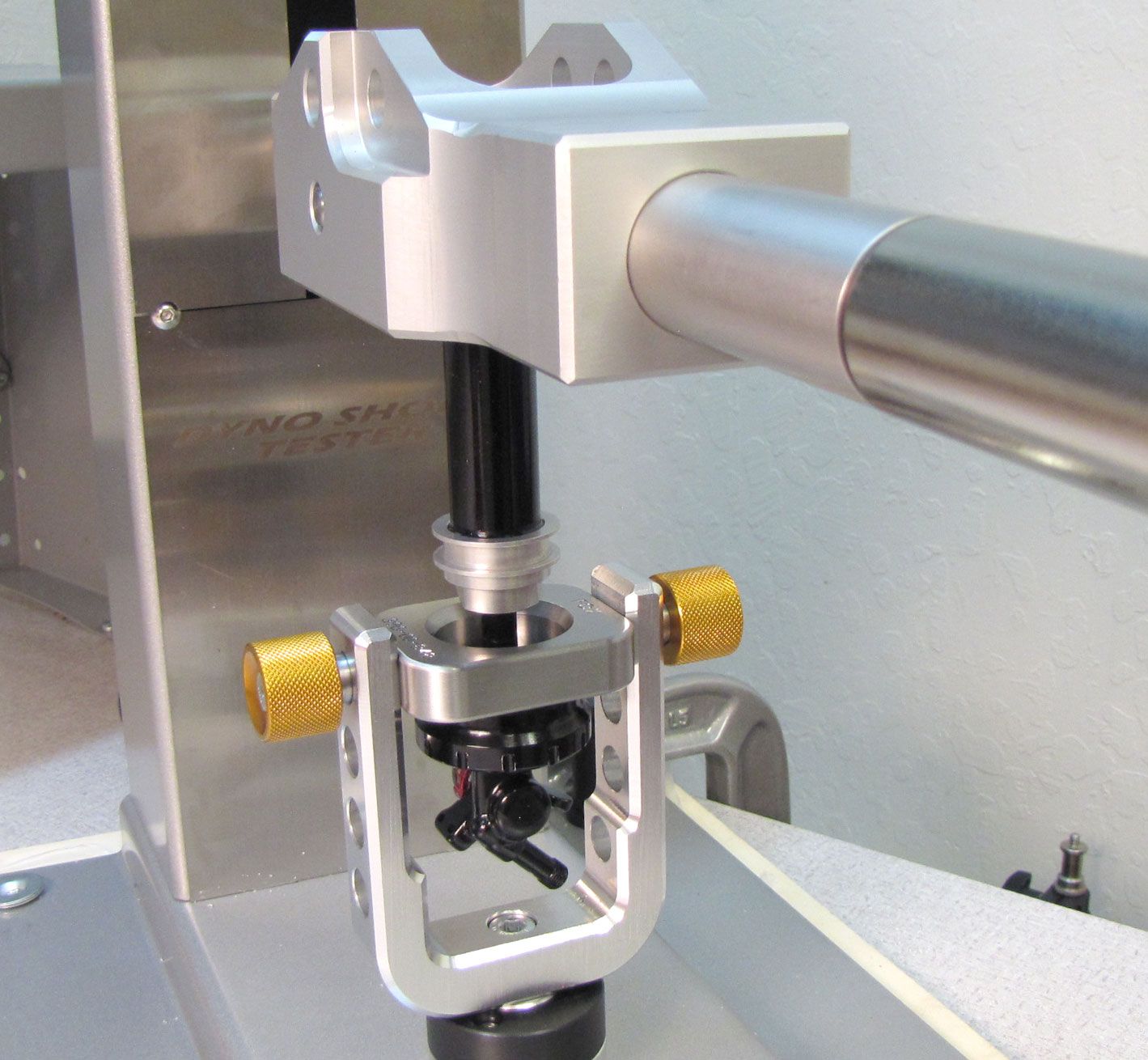
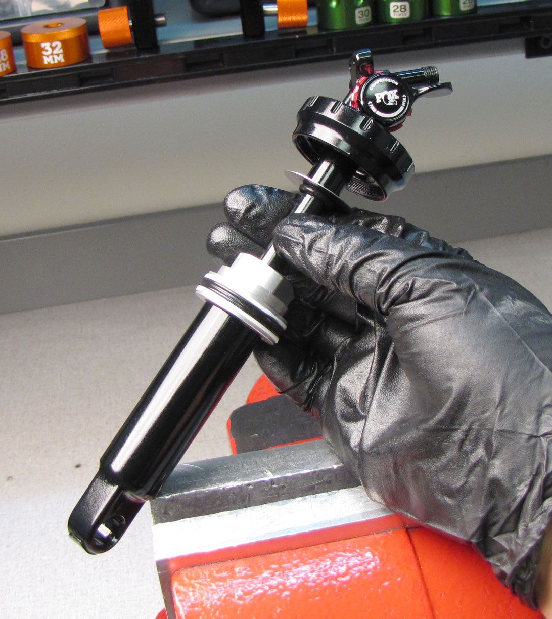
Step 1
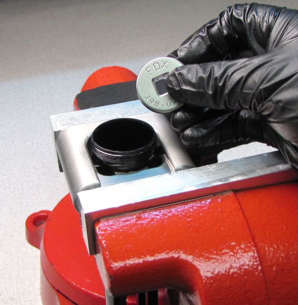
Mount the Isostrut Dyno Coupler to the tabs of the IsoStrut Sleeve Assembly as shown. Mate the Inner Coupler with the side of the tabs that have counter-bores. The Outer coupler engages the flat side of the tabs. Make sure the coupler tools are fully seated then clamp in your soft-jawed vise as shown. Remove the black air cap.

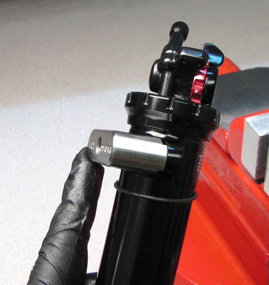
WARNING: Please verify that all air has been released from the air chamber by pushing down on the Schrader valve core. Failure to release all air pressure before further disassembly may cause parts to eject causing SEVERE INJURY OR DEATH.

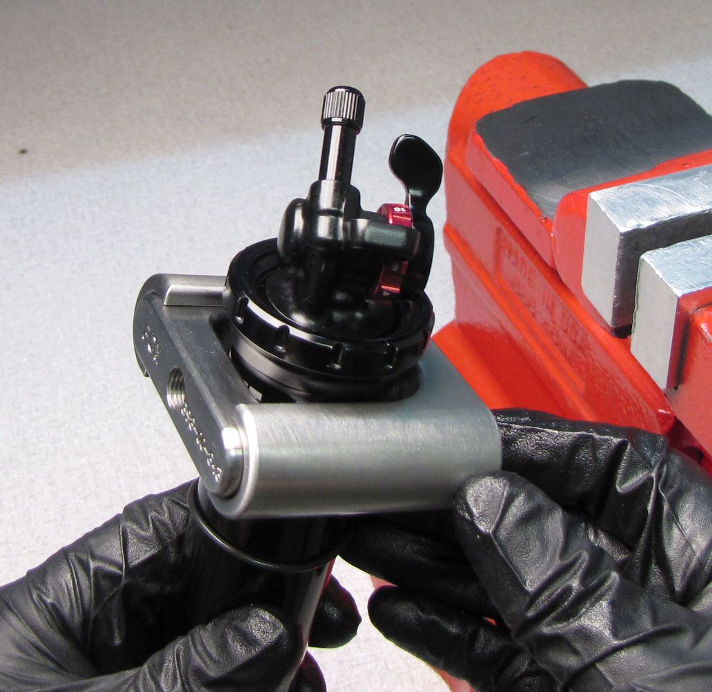
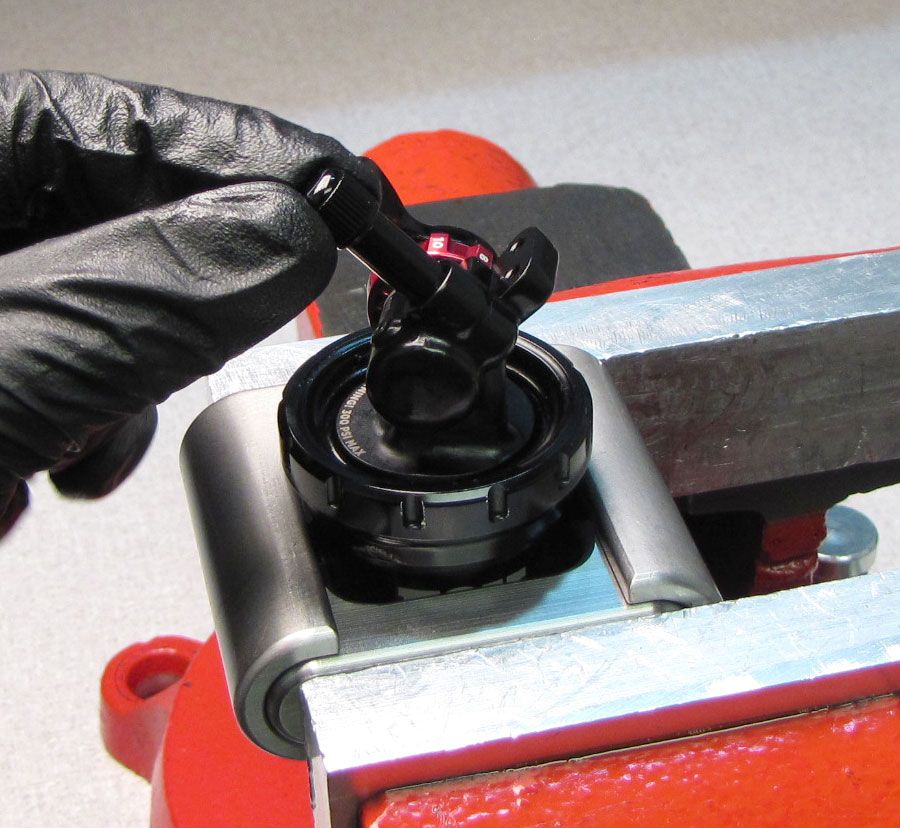
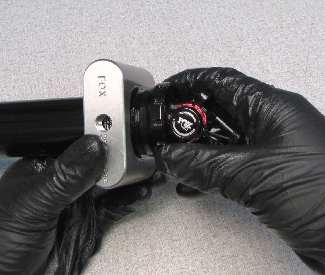
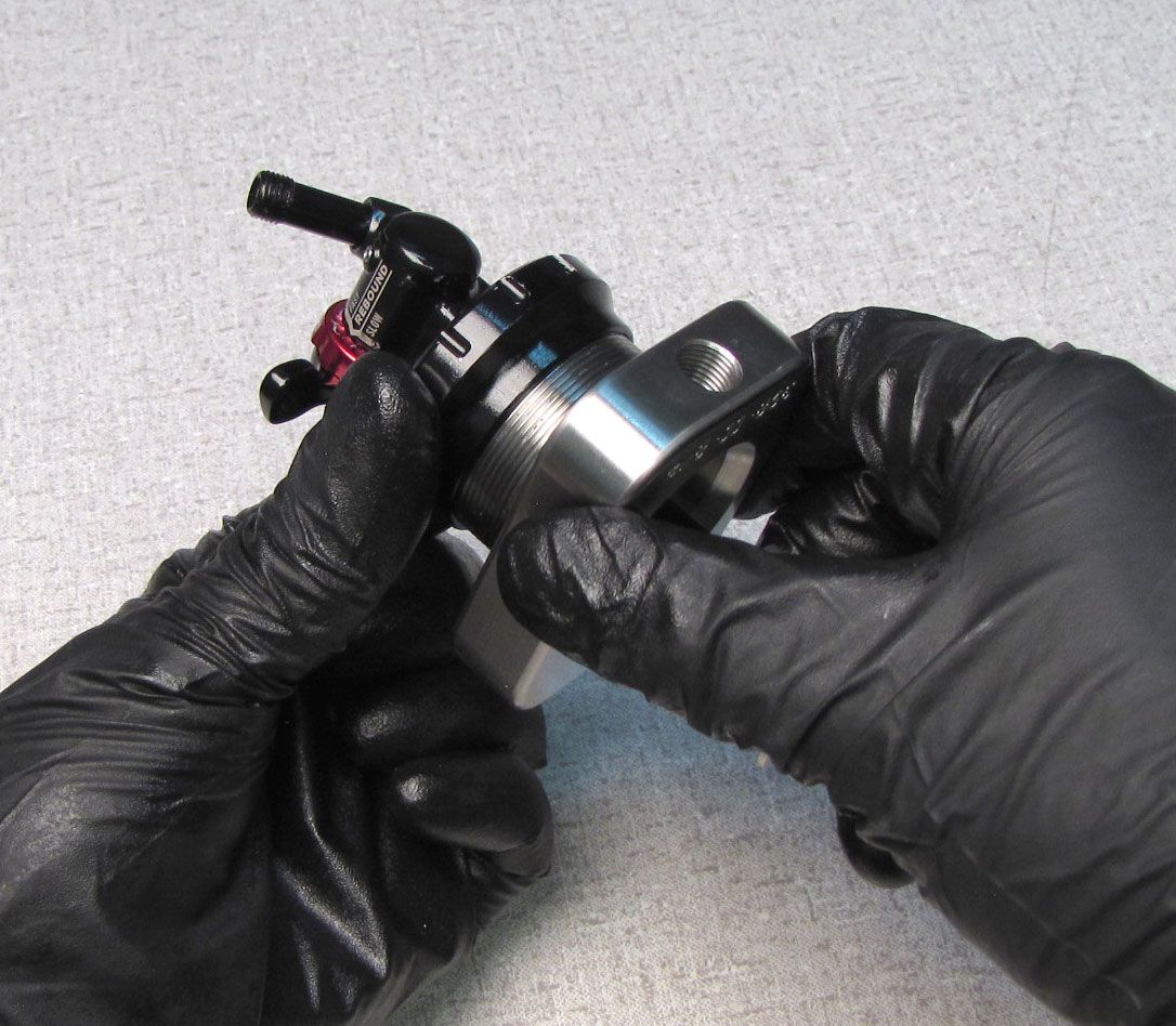
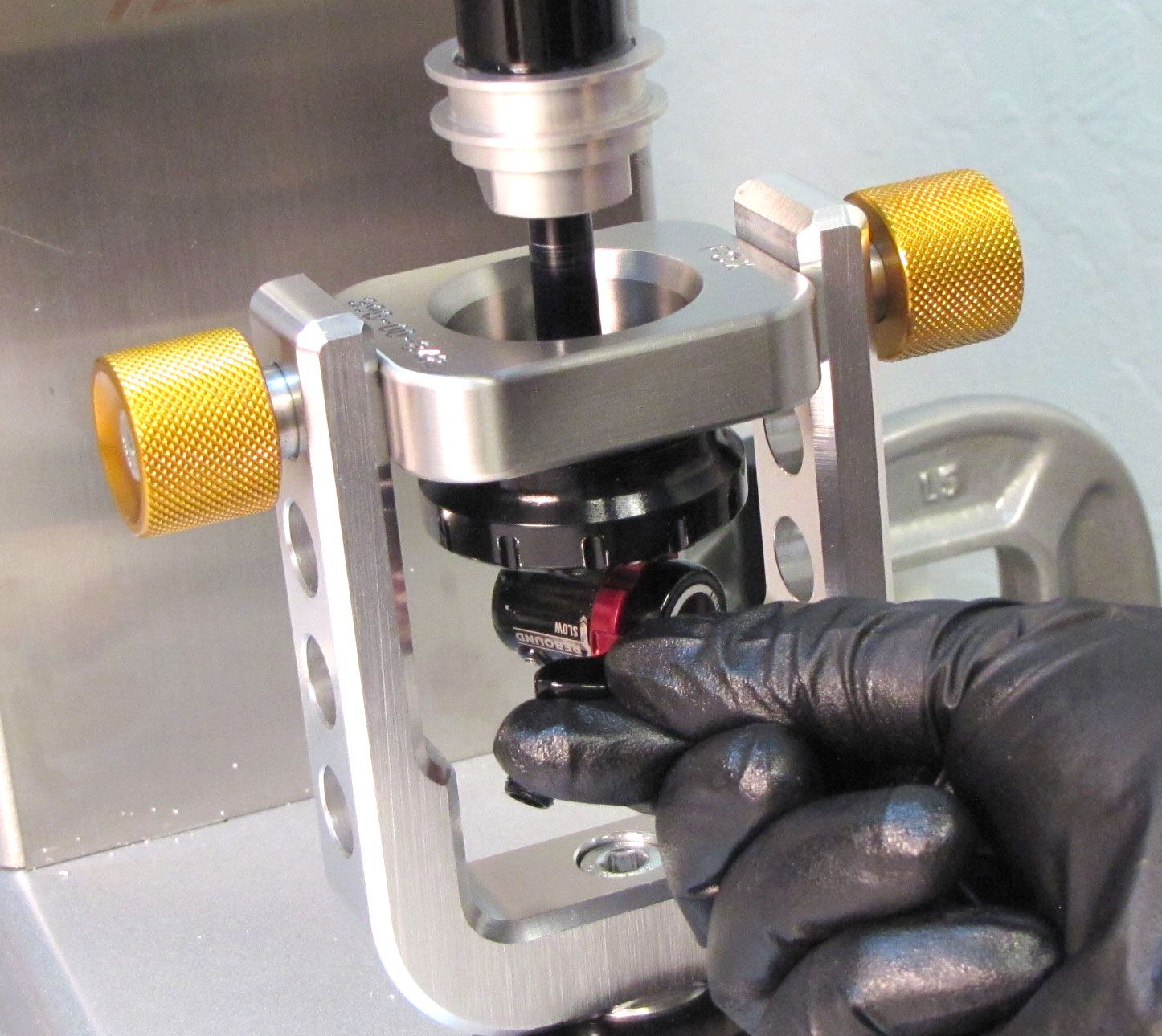
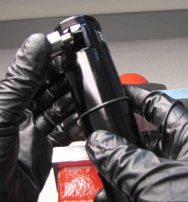
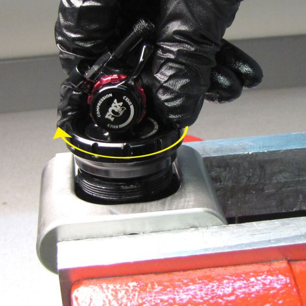
Step 2
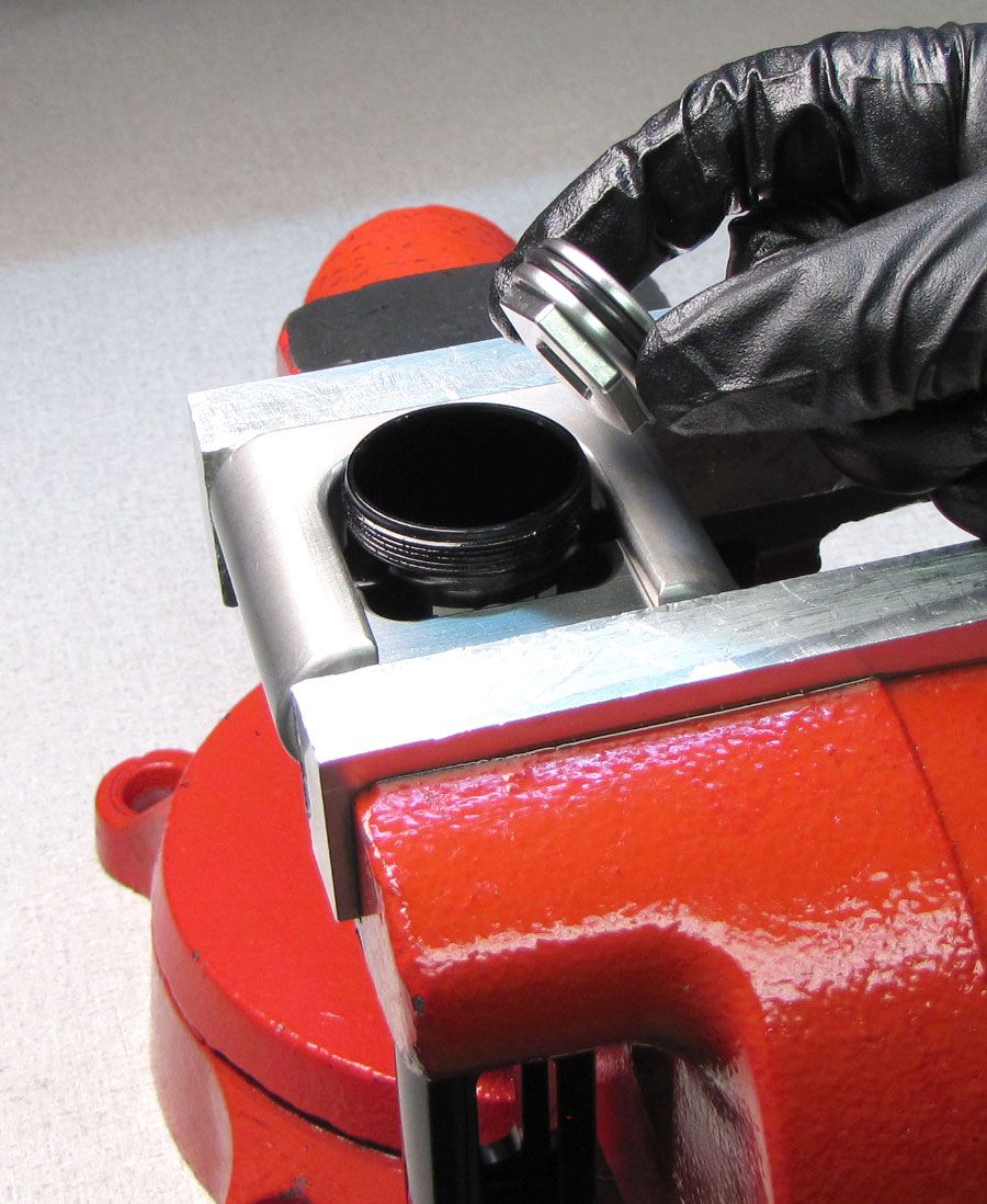
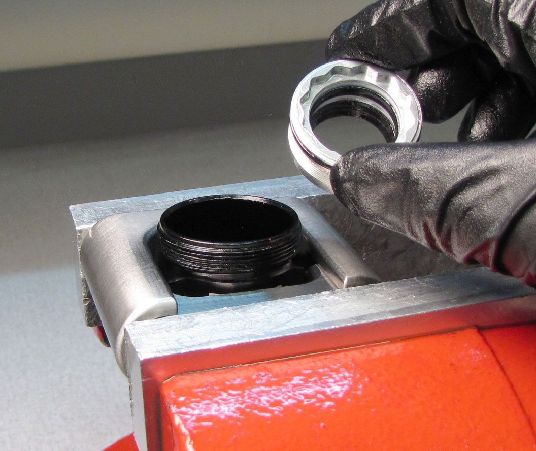
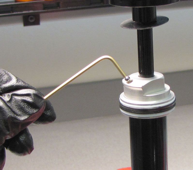
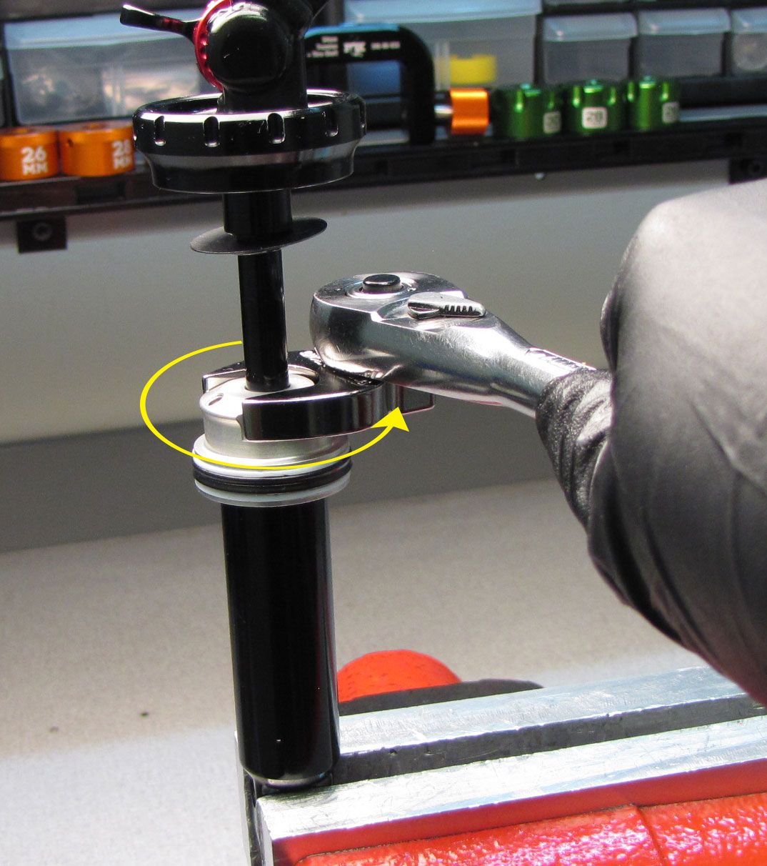
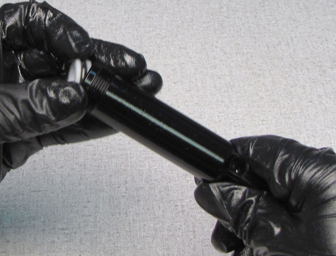
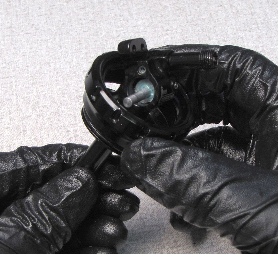
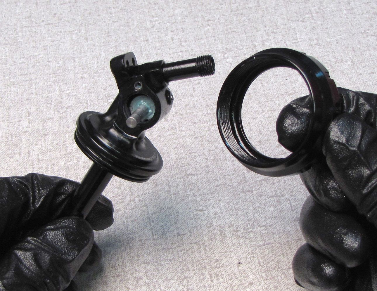
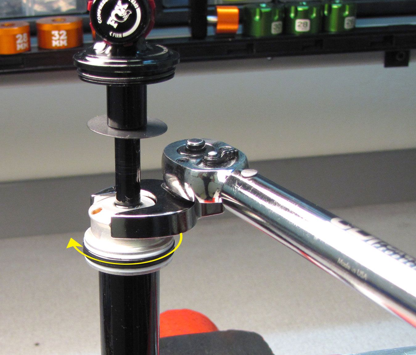
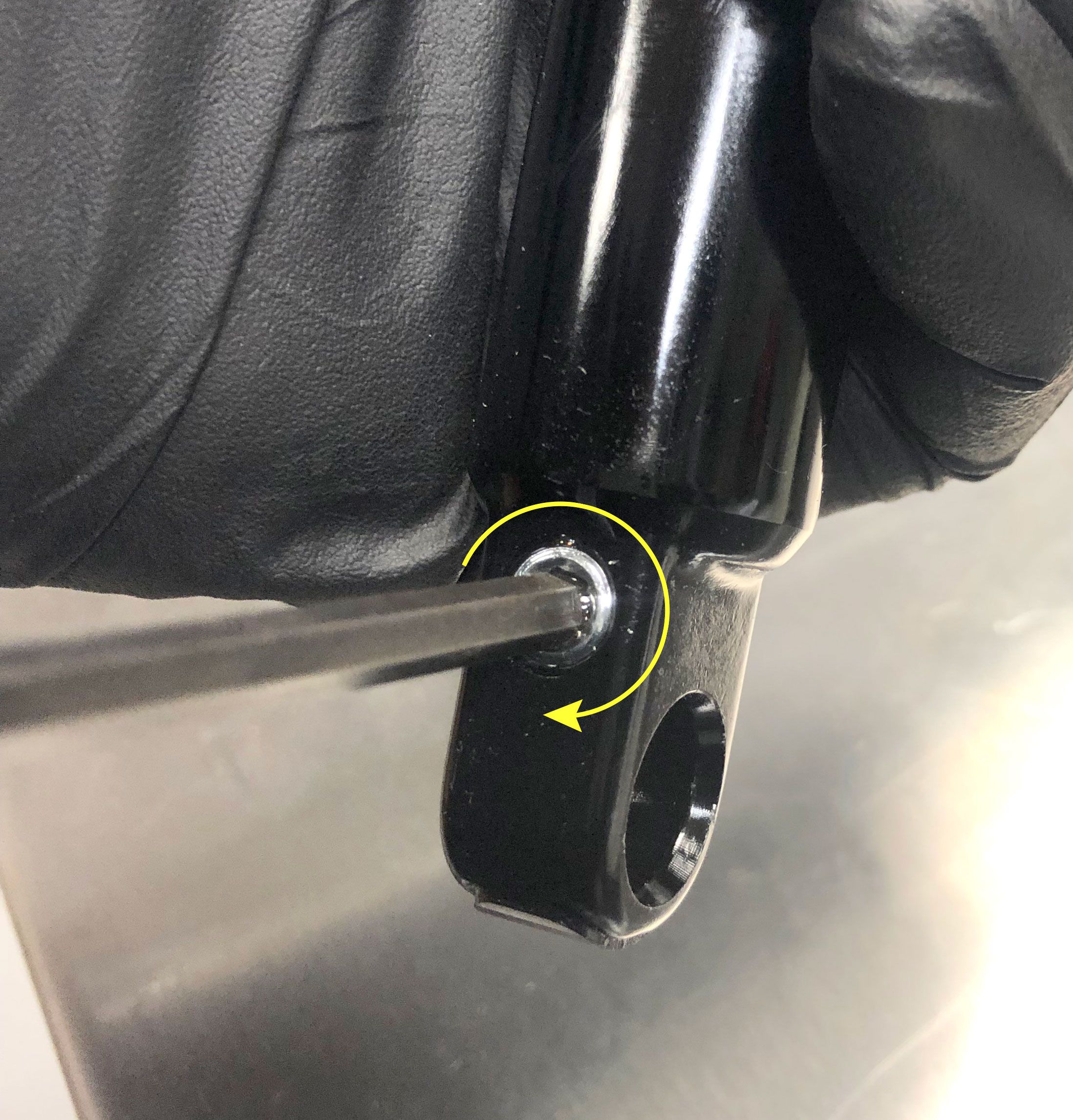
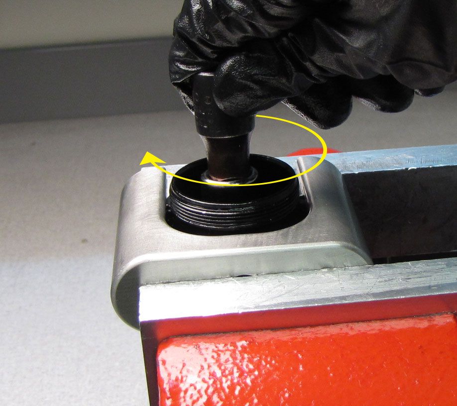
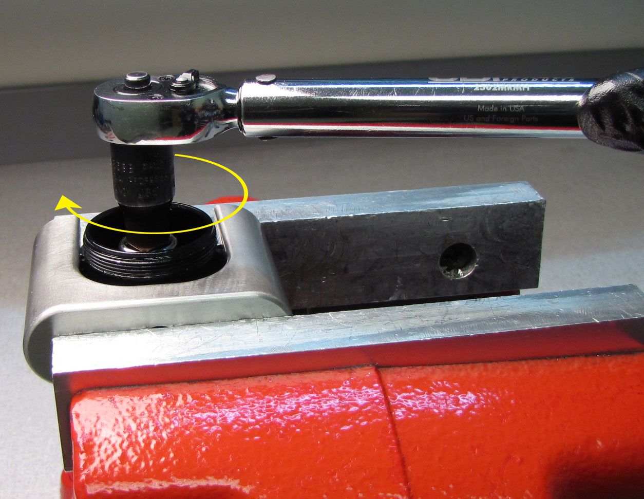
Release all air pressure by depressing the valve core completely. Unthread the Eyelet Collar counter-clockwise with a Race Face 12-spline bottom bracket tool.

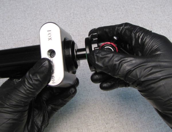
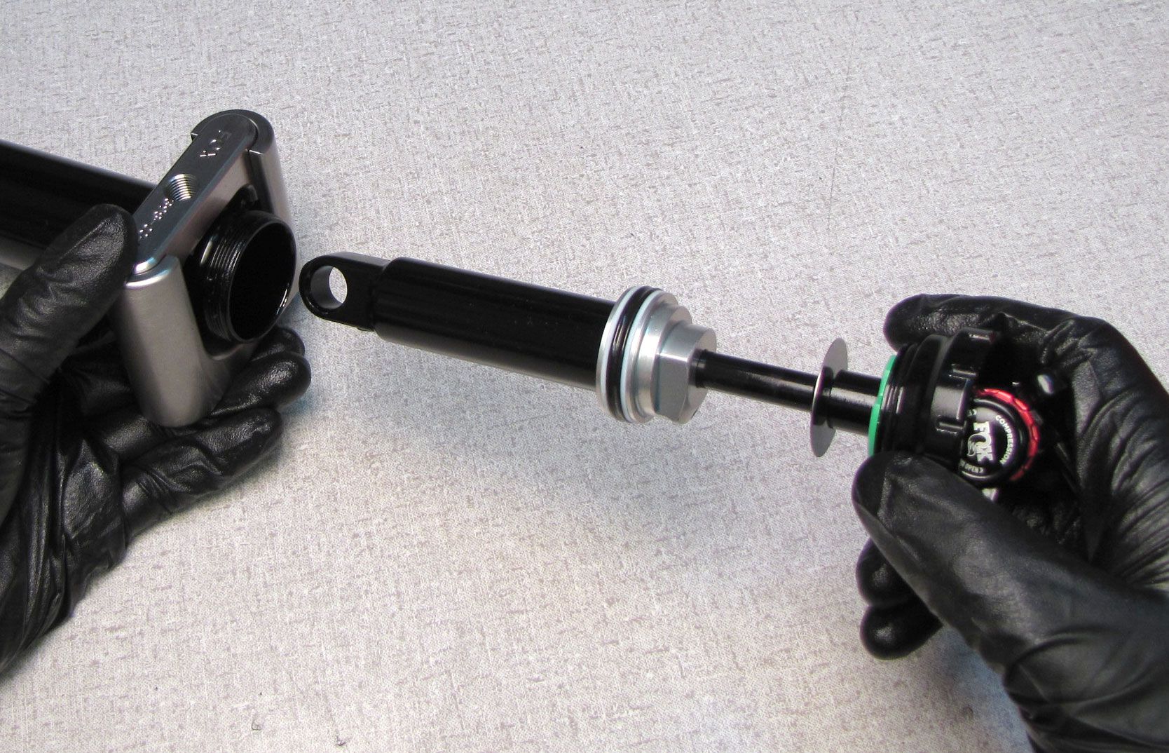
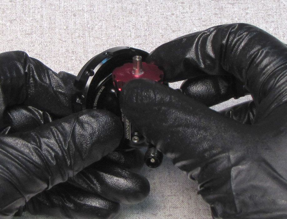
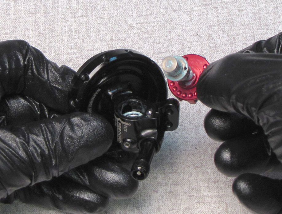
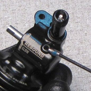
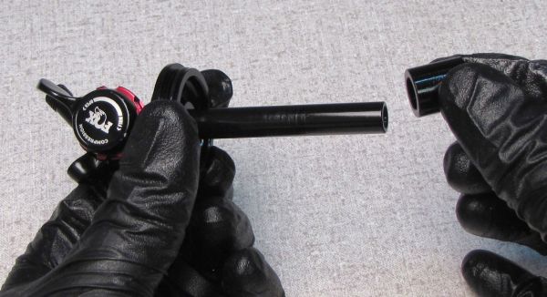
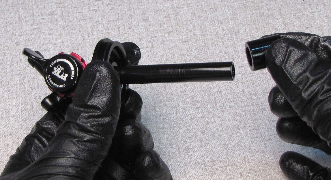
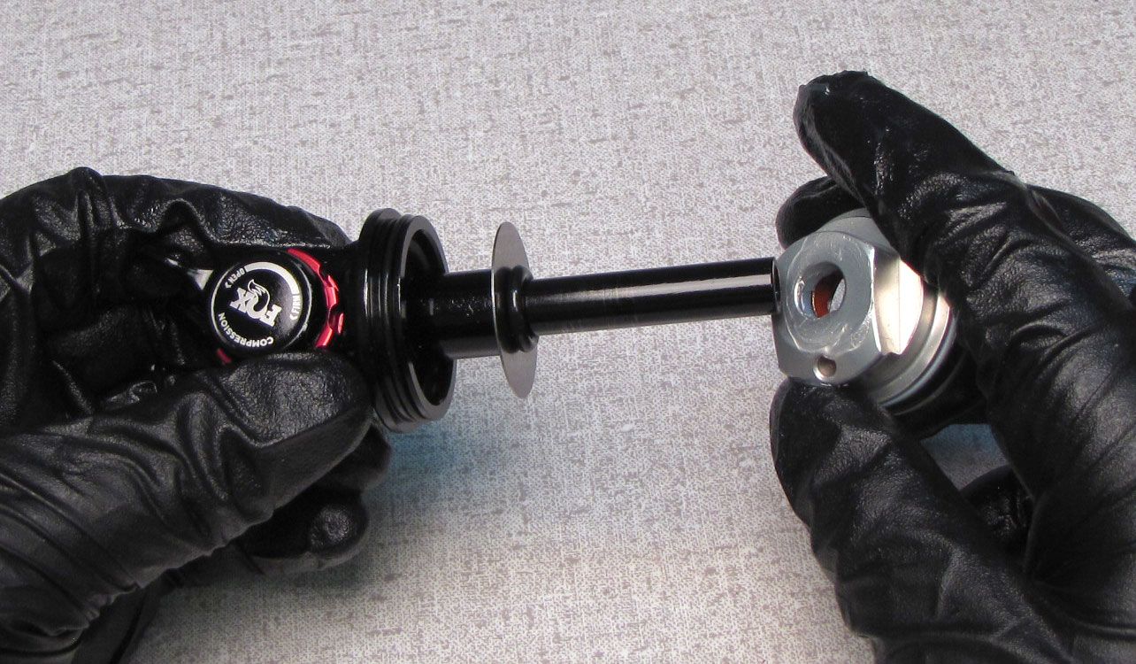
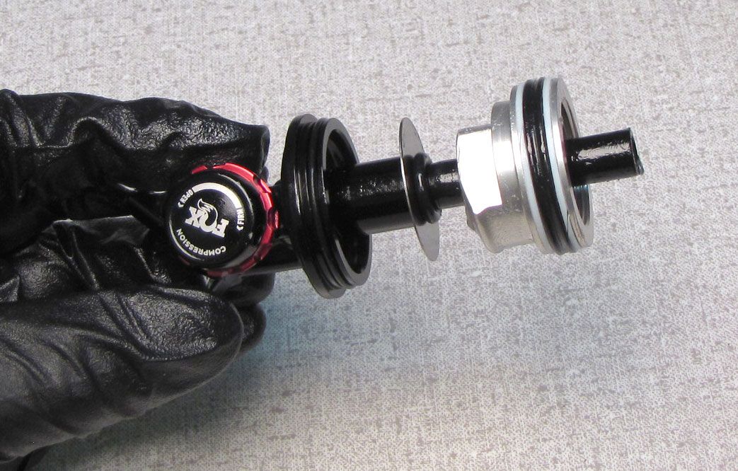
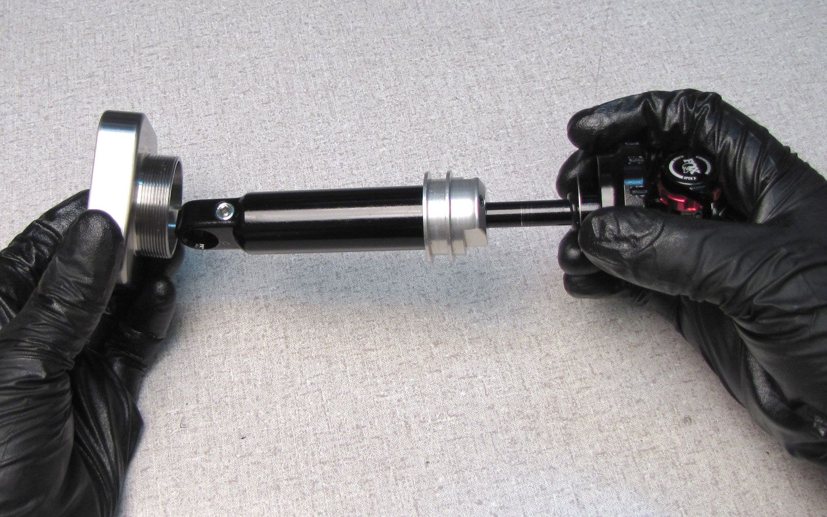
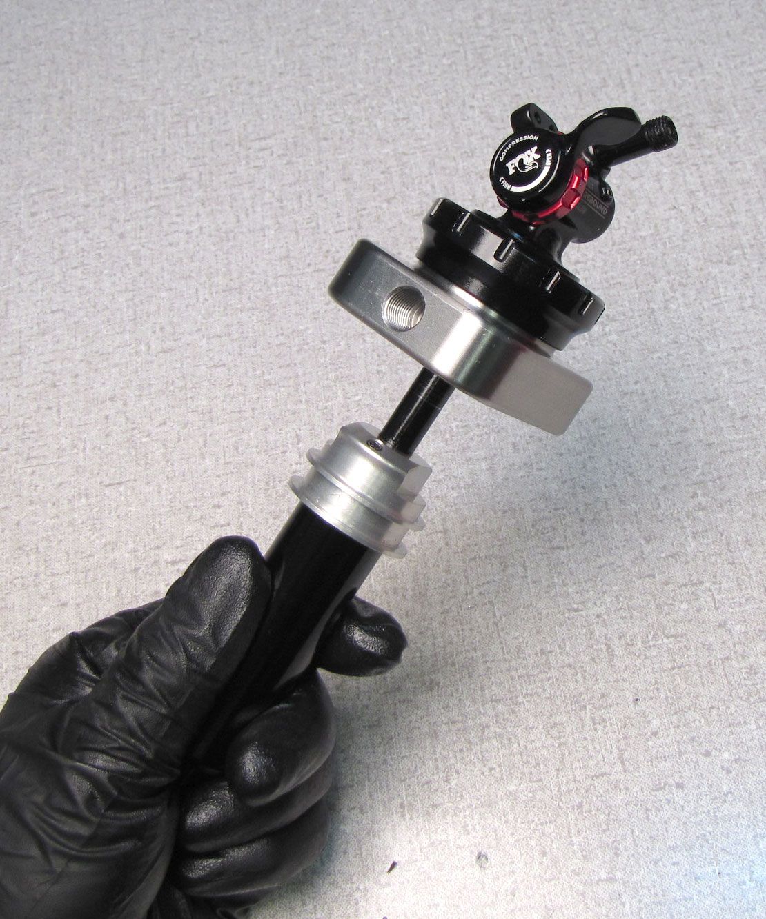
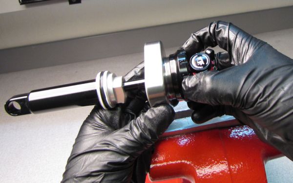
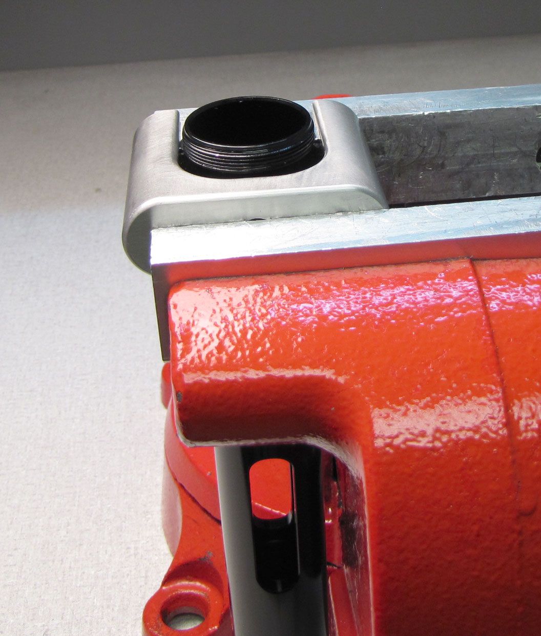
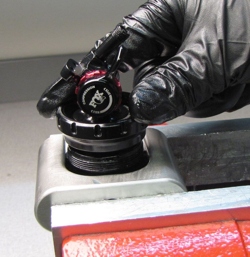
Step 3
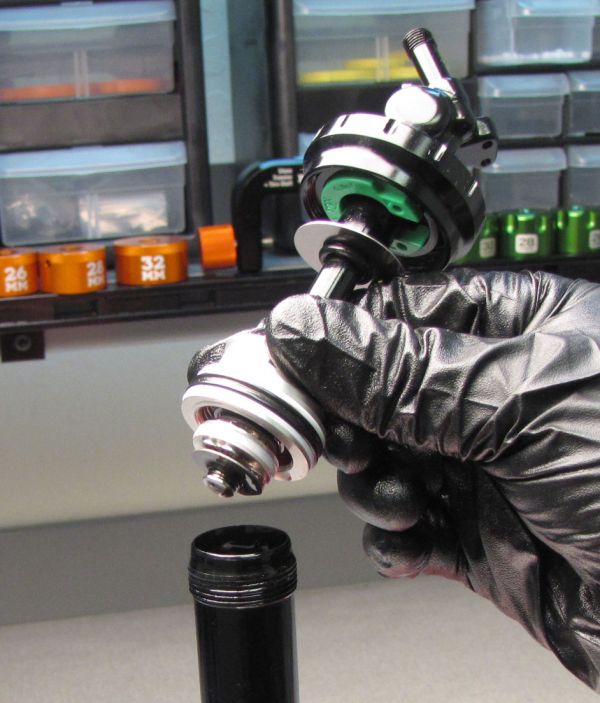
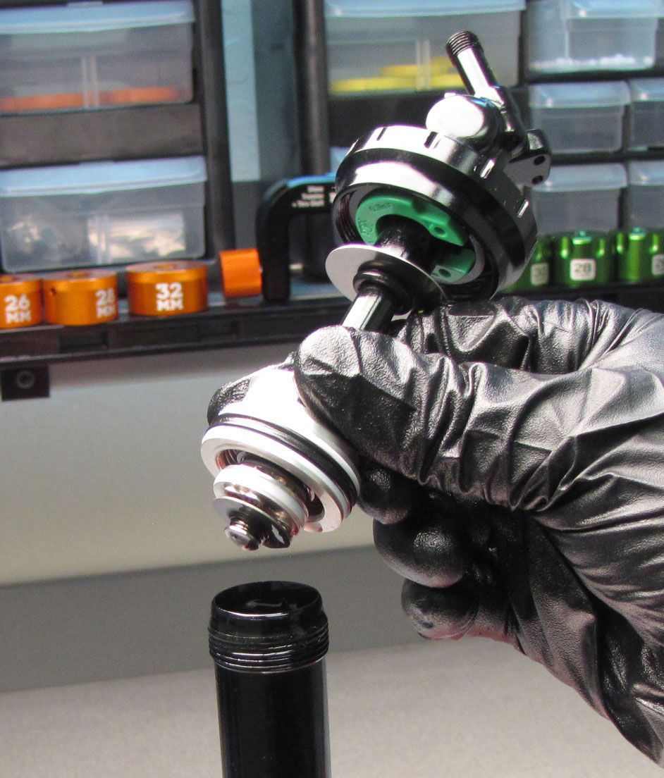
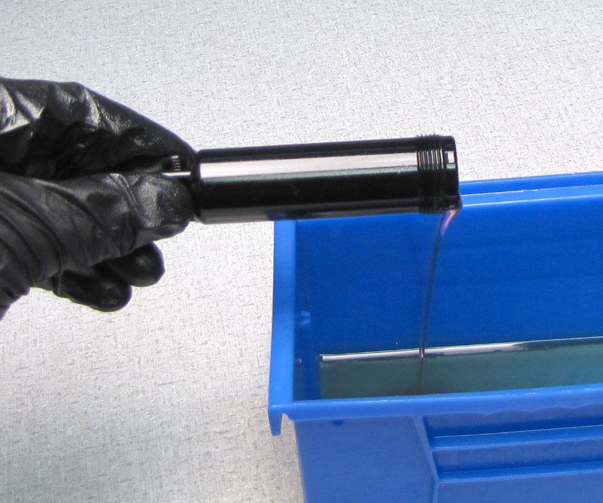
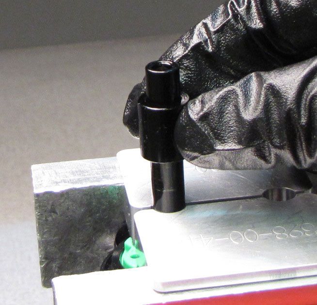
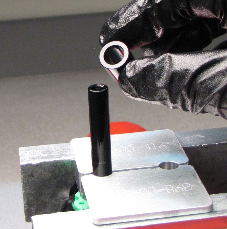
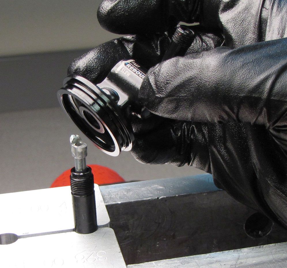
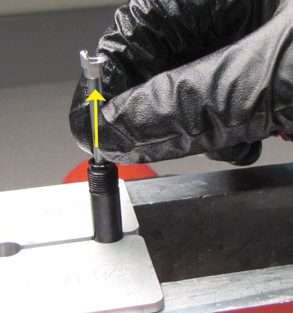
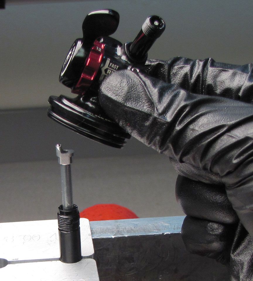
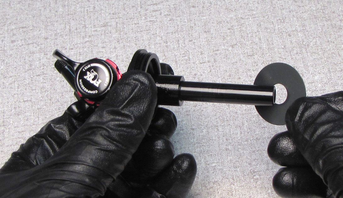
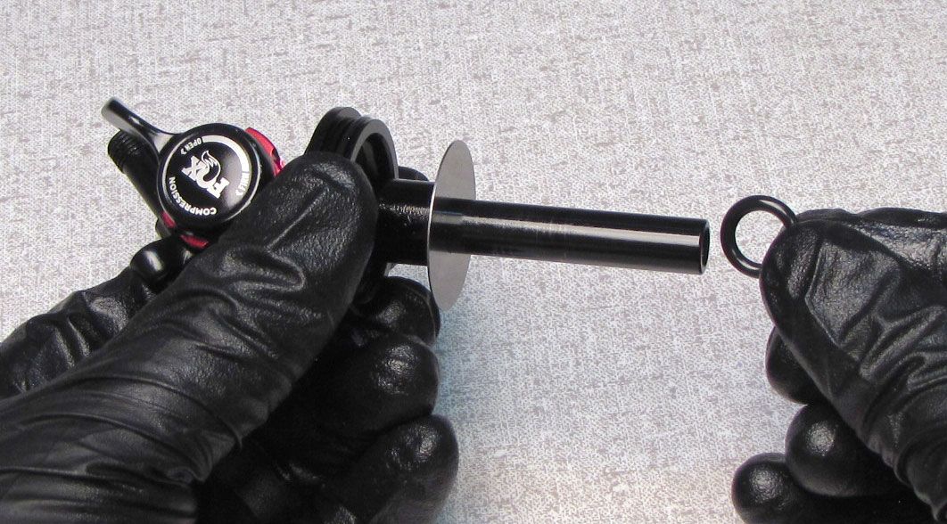
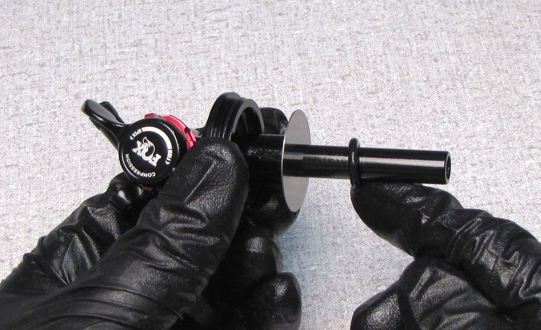
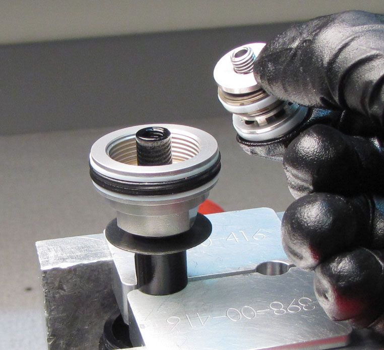
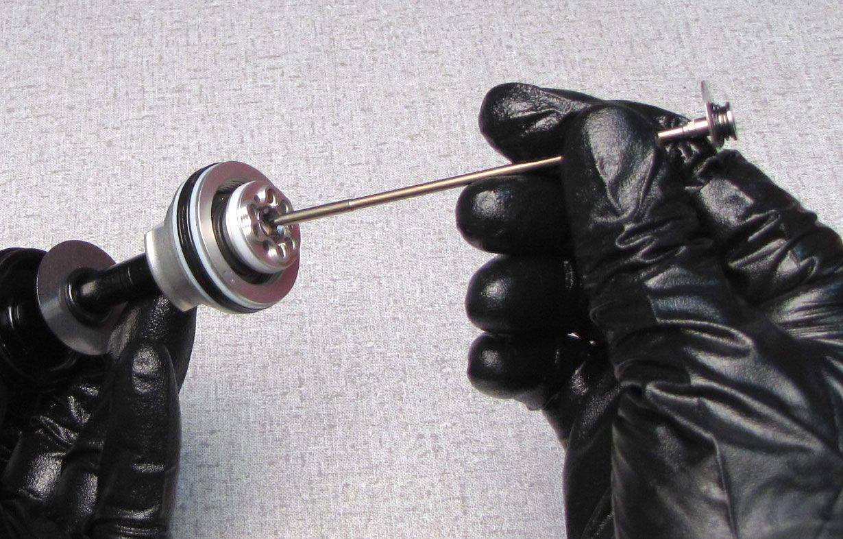
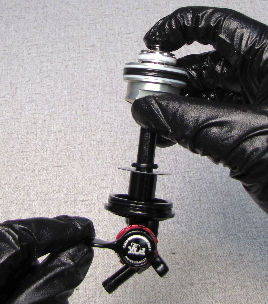
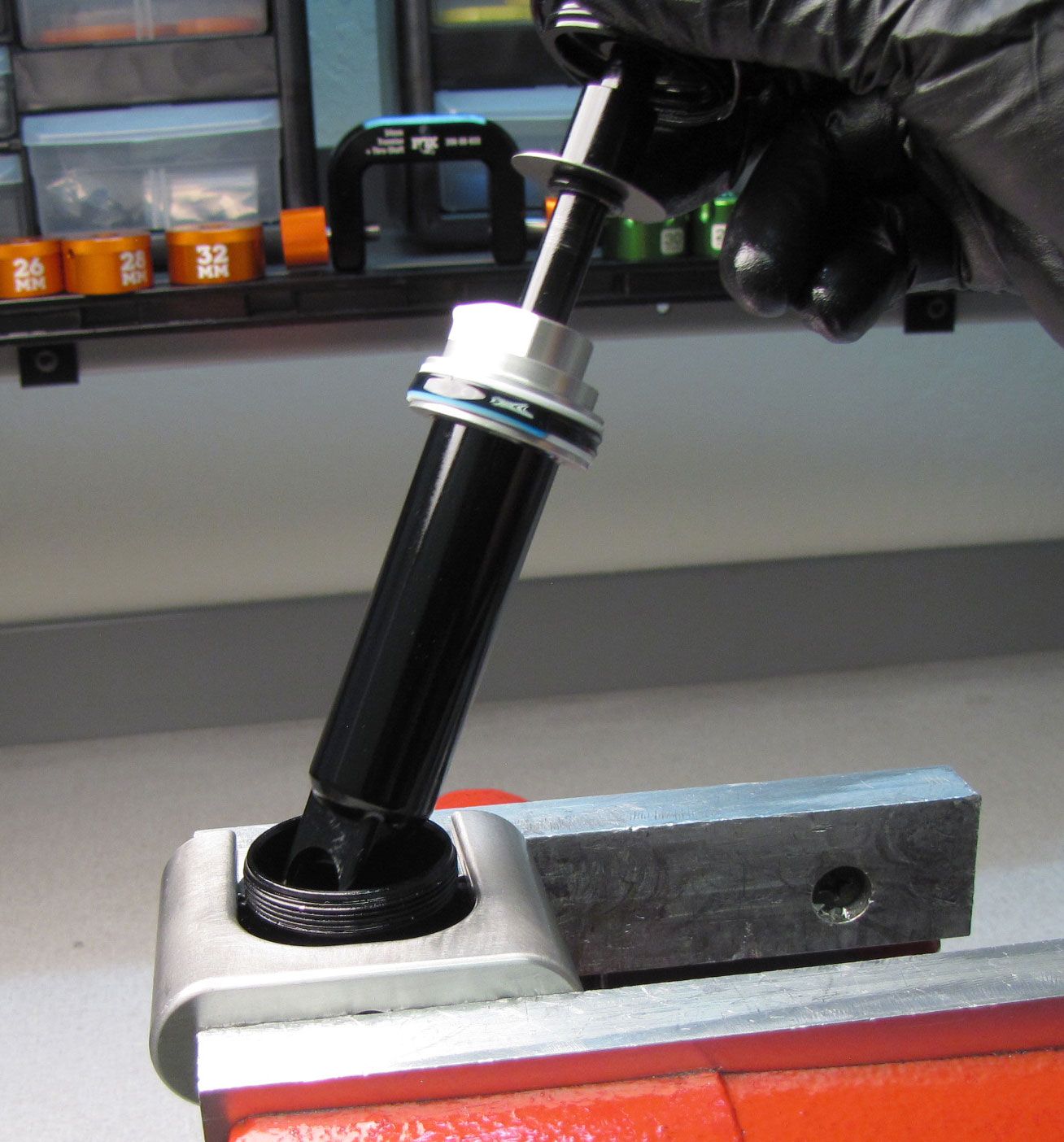
Remove the damper assembly from the Sleeve Assembly by pulling it out.


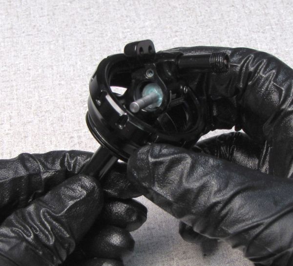
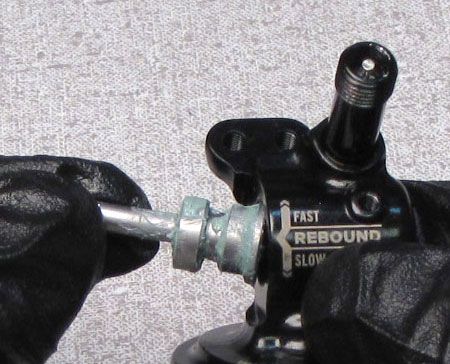
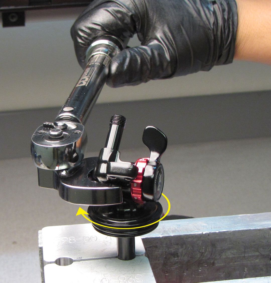
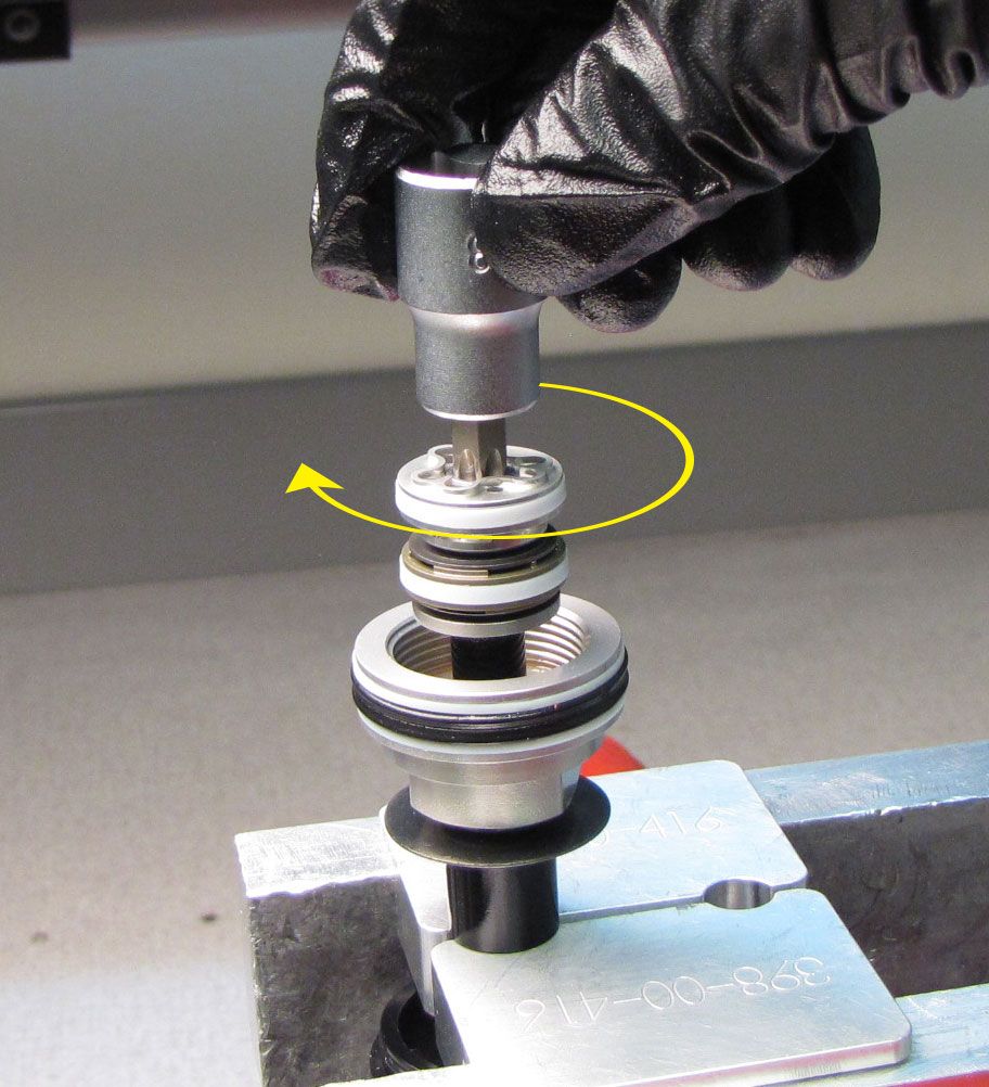
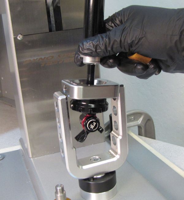
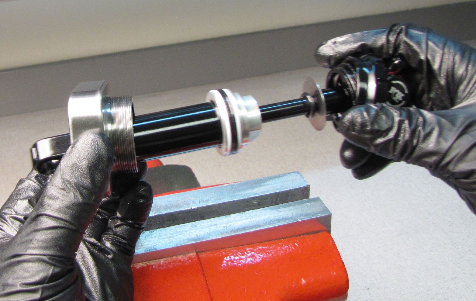
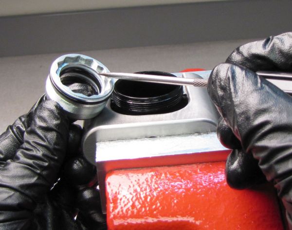
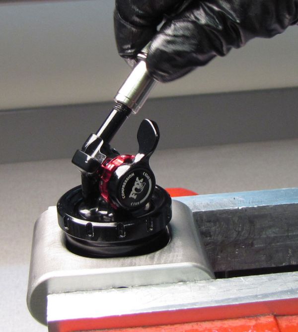
Step 4
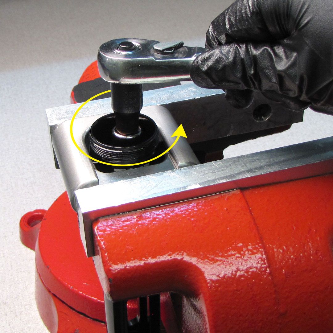
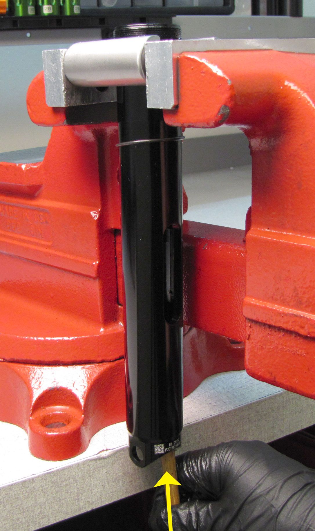
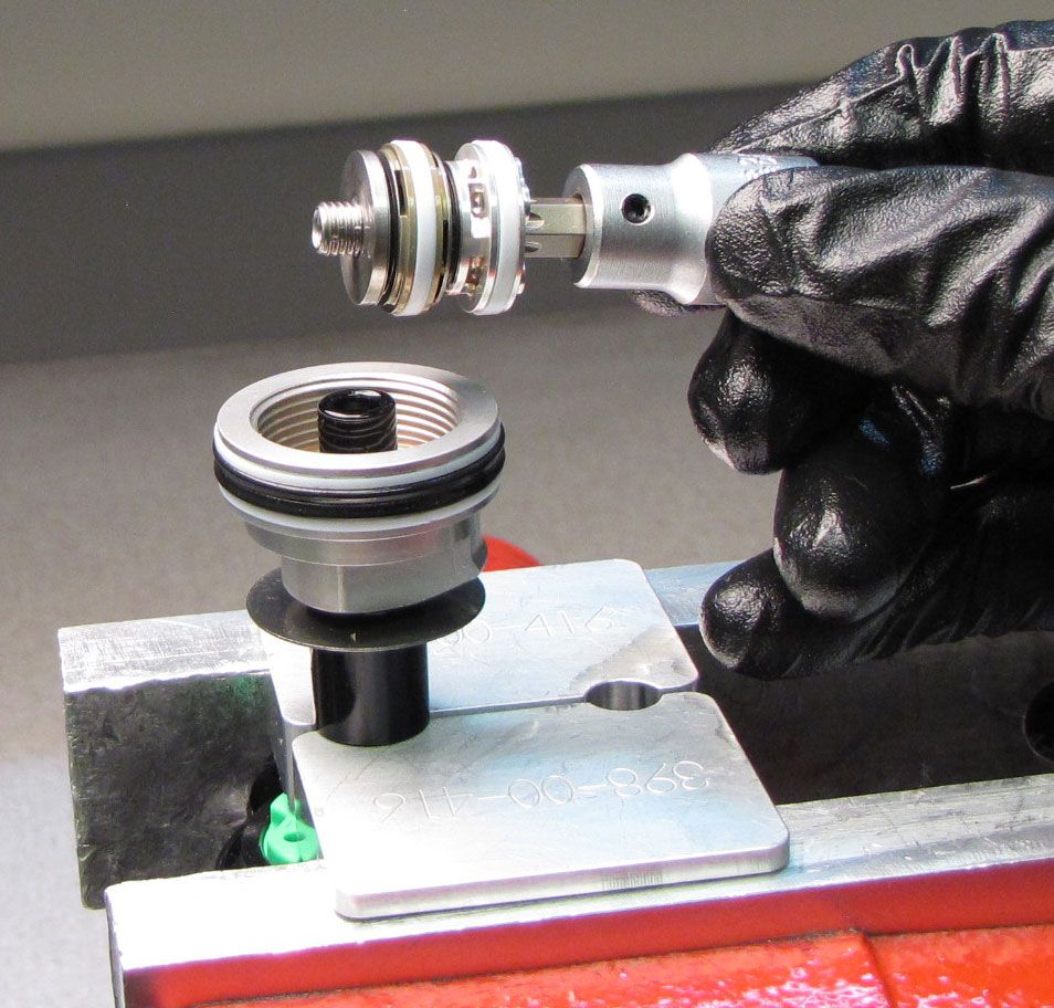
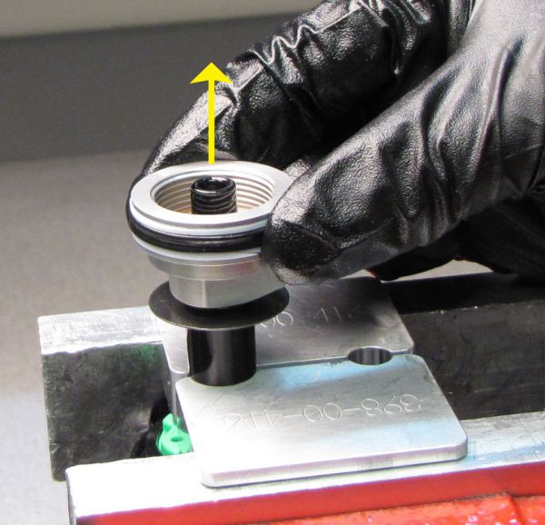
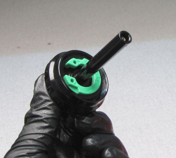
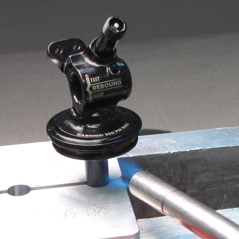
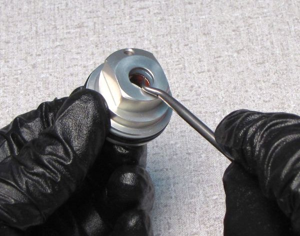
Clamp the Dyno Coupler in the vise to hold the Sleeve Assembly. Insert the Neg Plate tool into the Sleeve Assembly with the hex side facing into the sleeve. Use a 3/8" square drive extension and your ratchet to unthread the Neg Plate Assembly counter-clockwise. Push up from below with a non-marring tool (wooden dowel) to push the Neg Plate out through the top of the Sleeve.


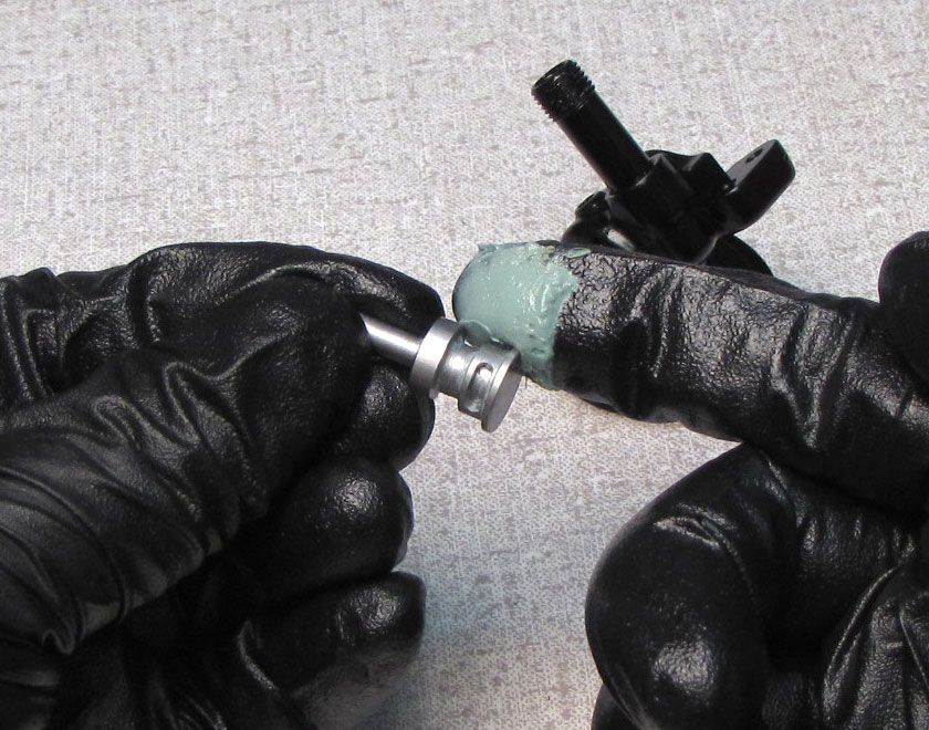
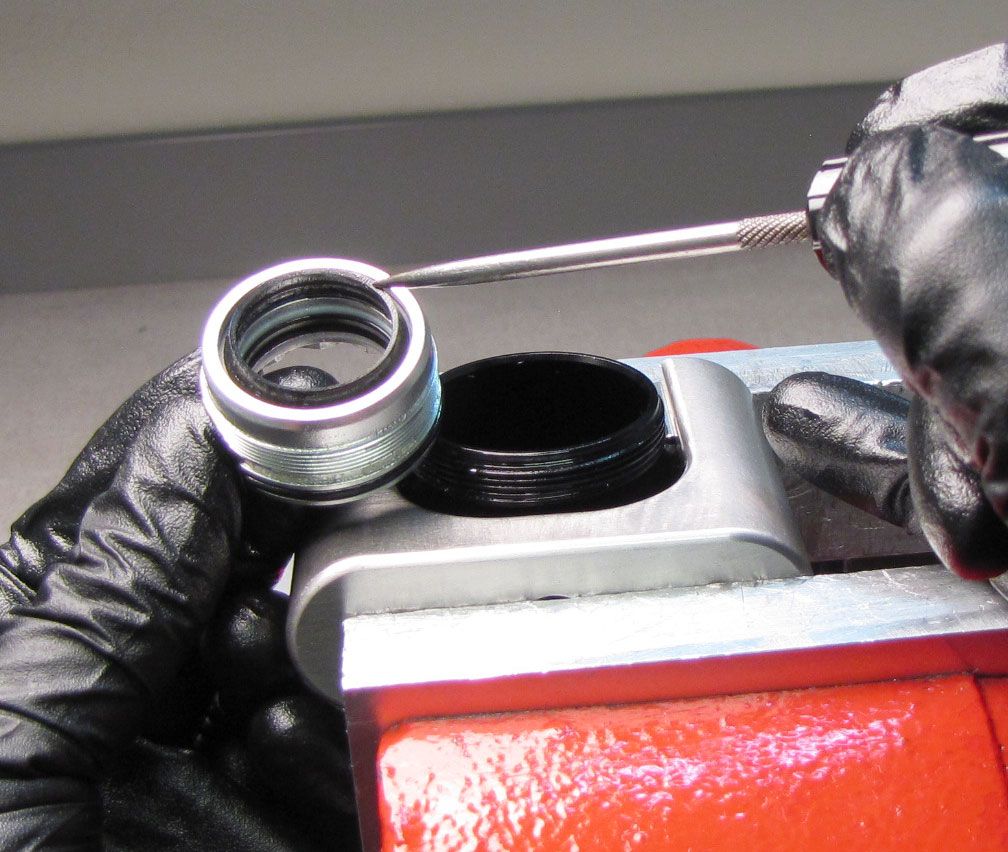
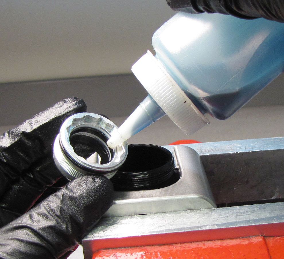
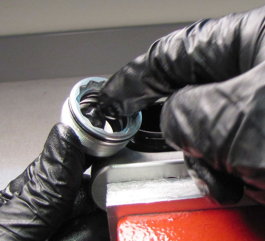
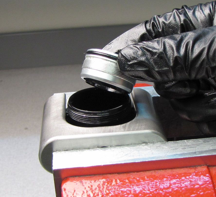
Step 5
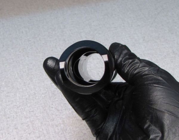
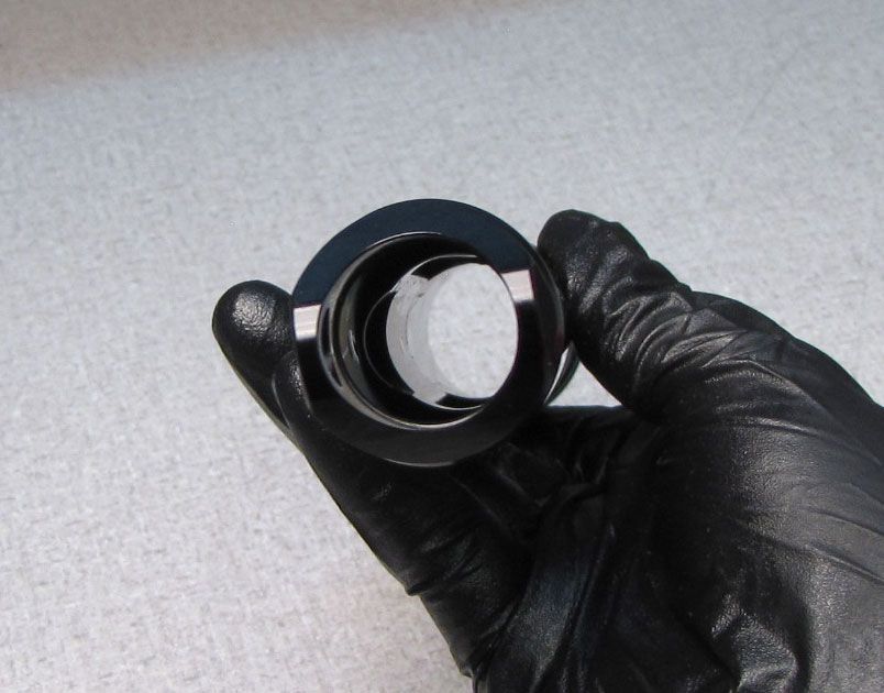
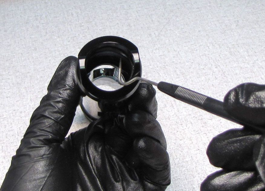
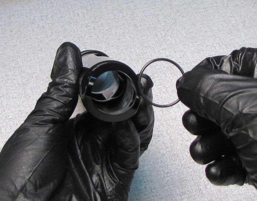
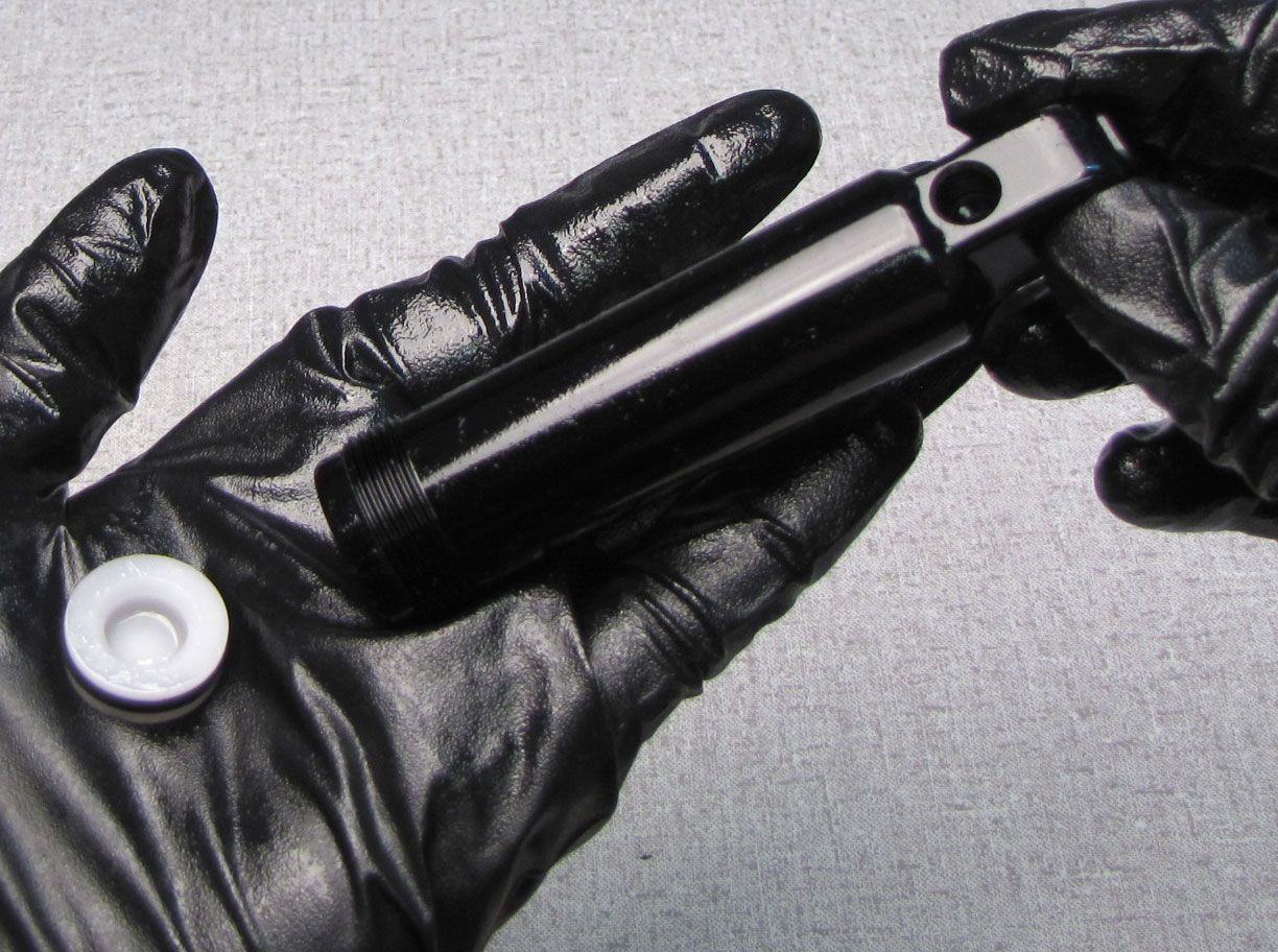
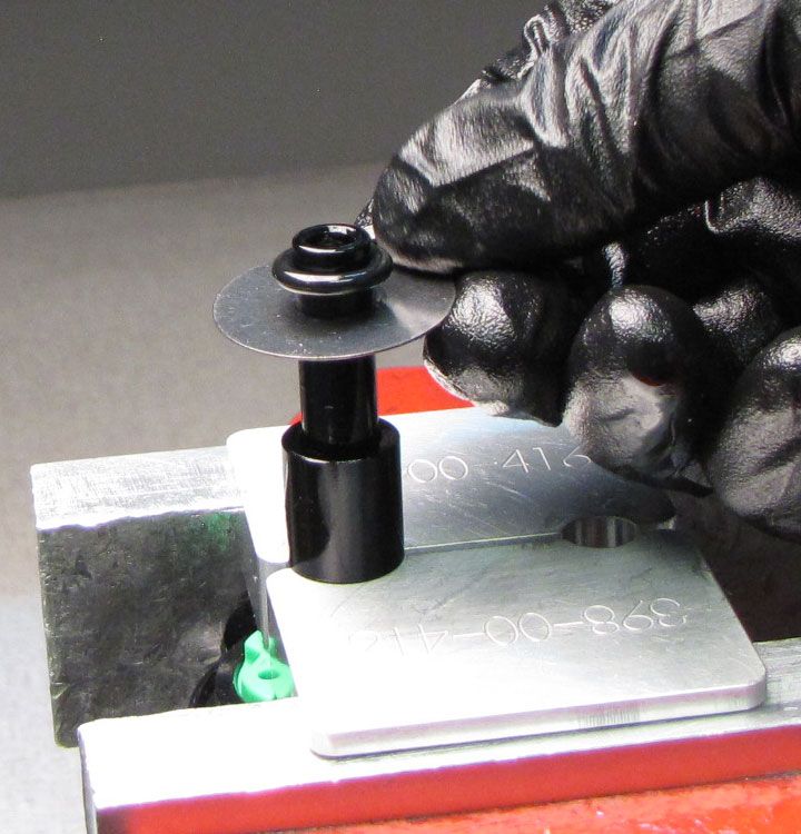
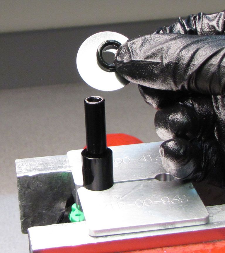
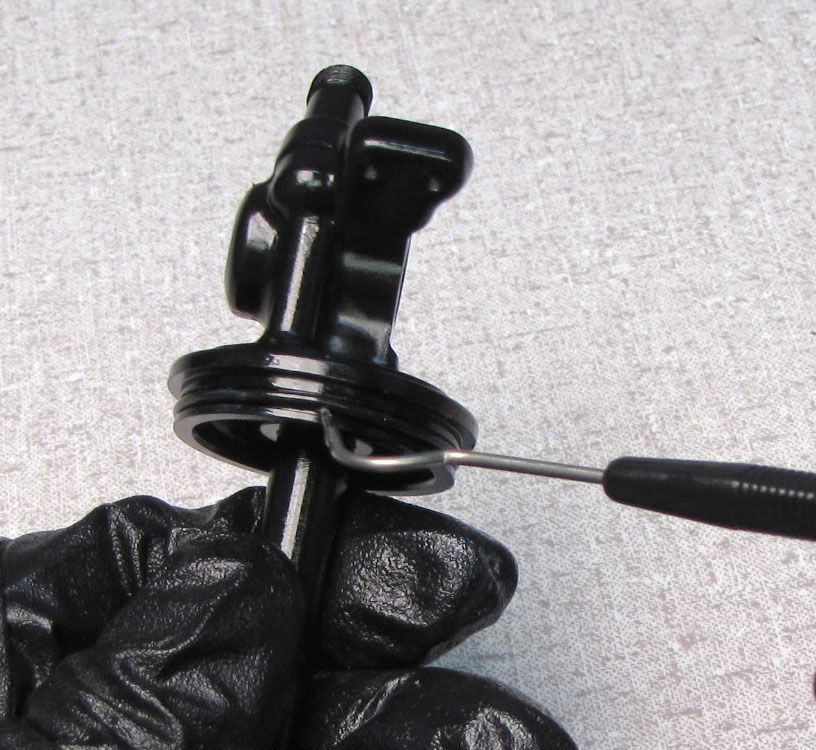
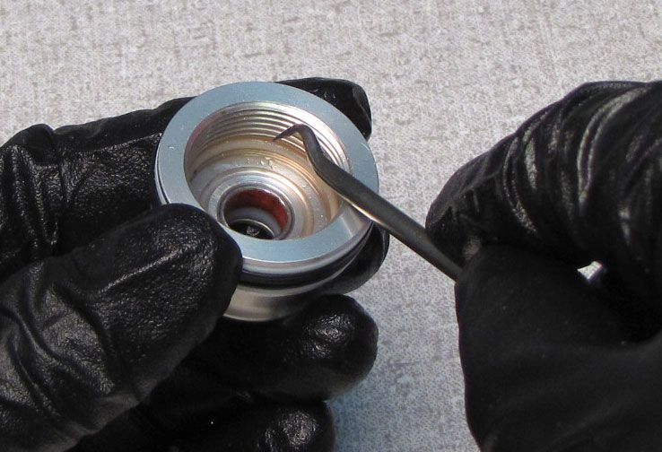
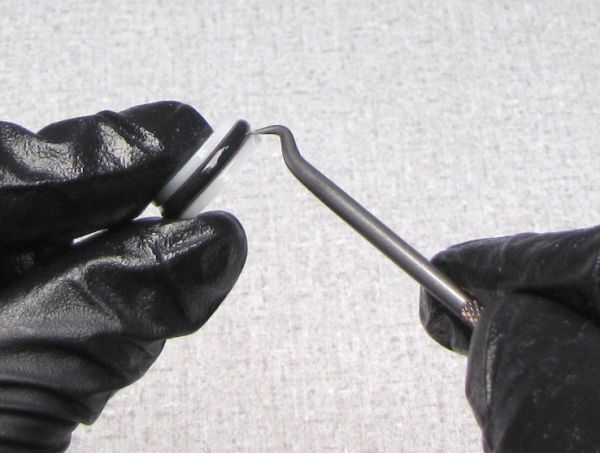
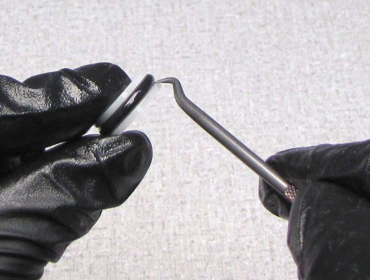
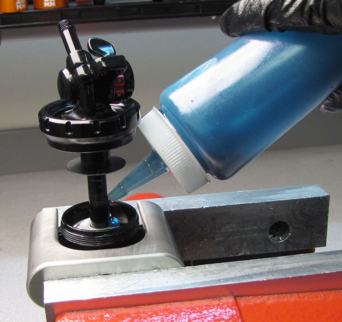
Replace the o-ring in the non-threaded end of the air sleeve with a new greased one from the kit.

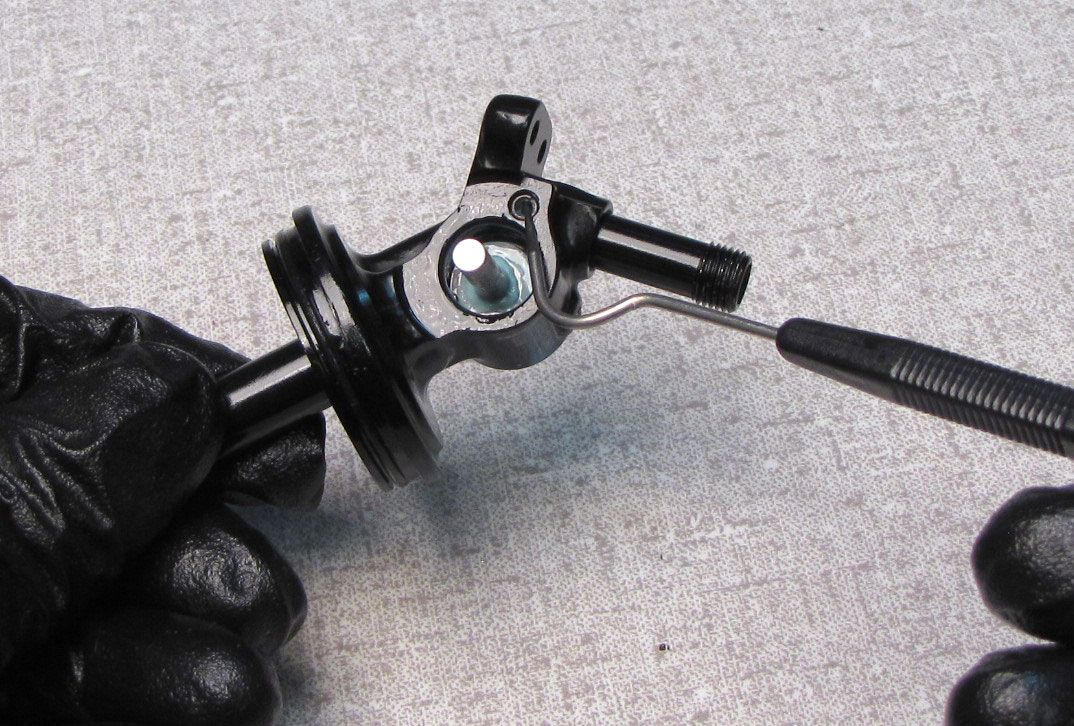
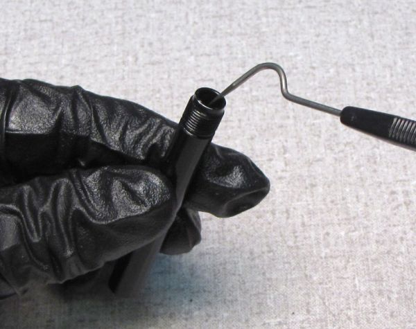
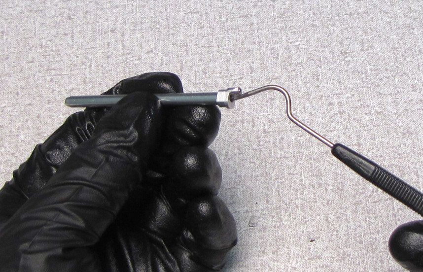
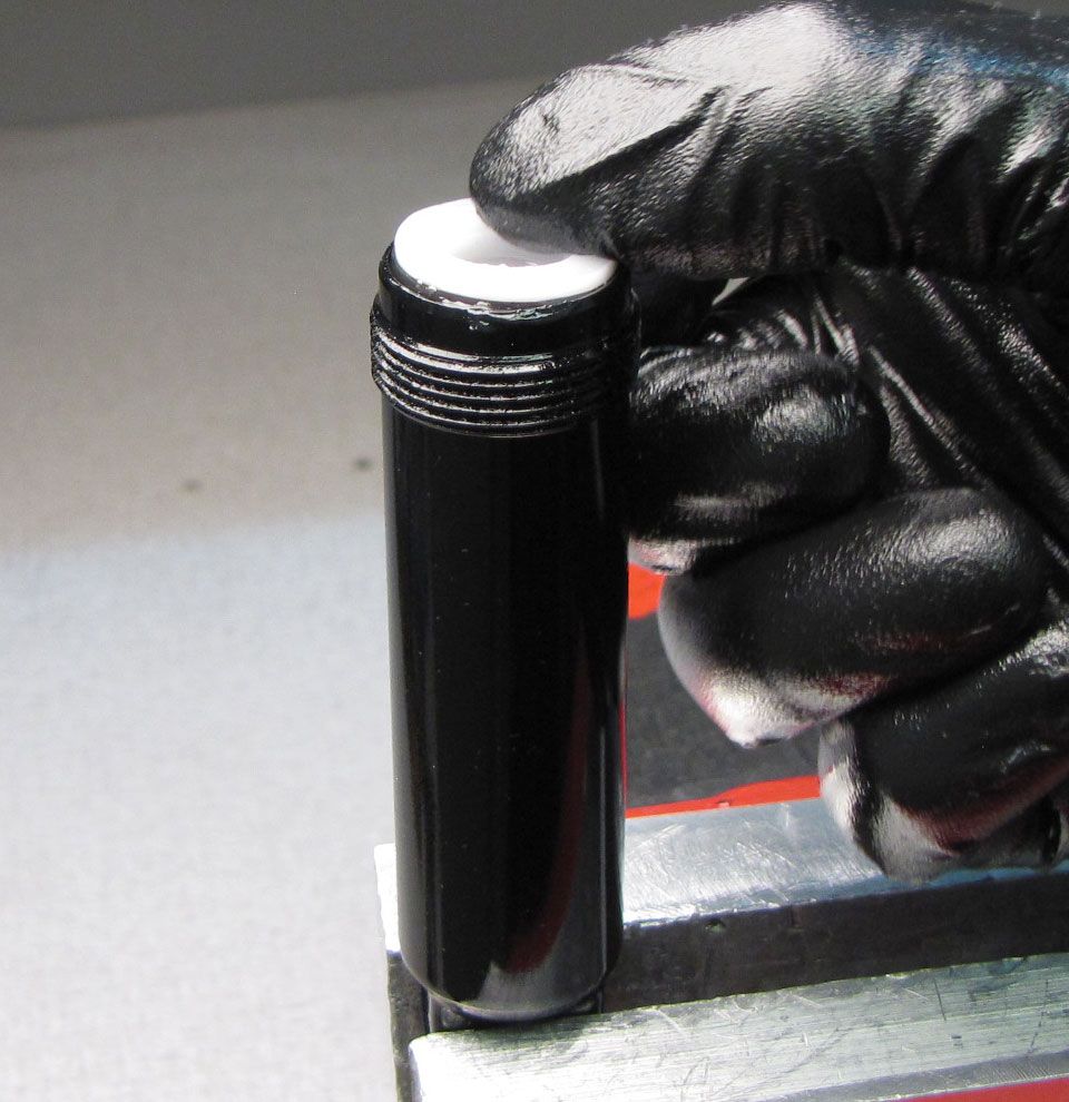
Step 6
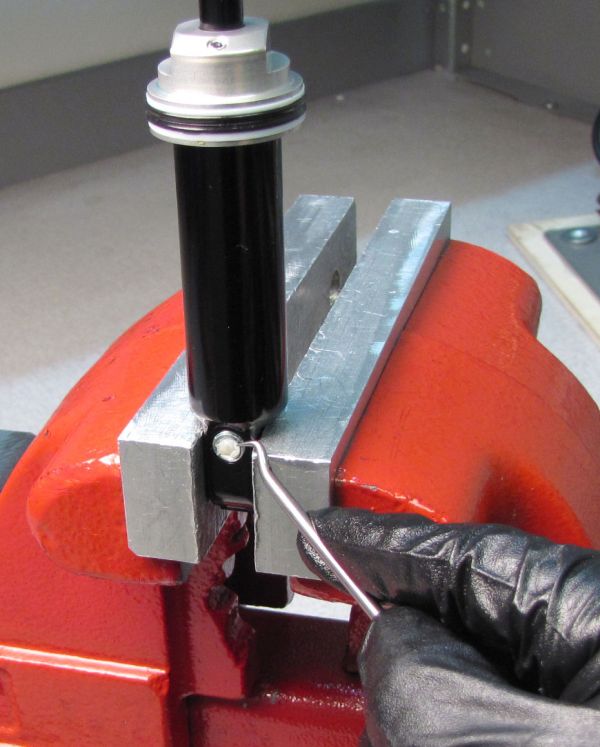
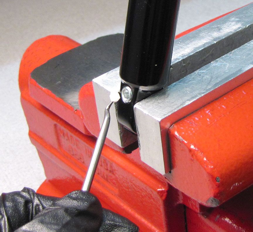
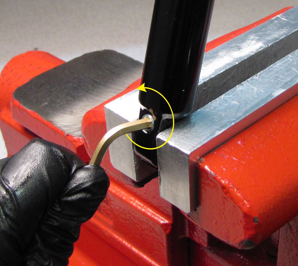
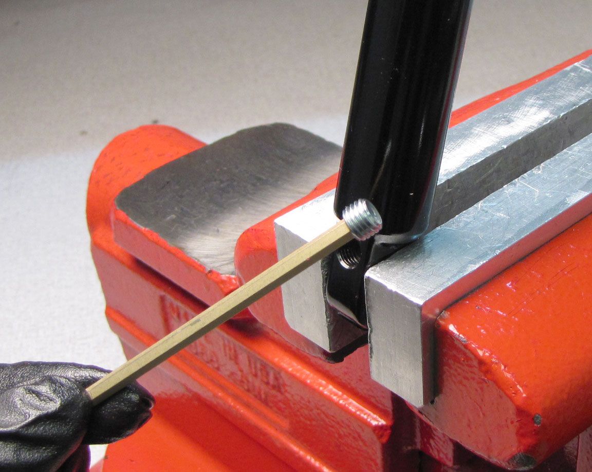
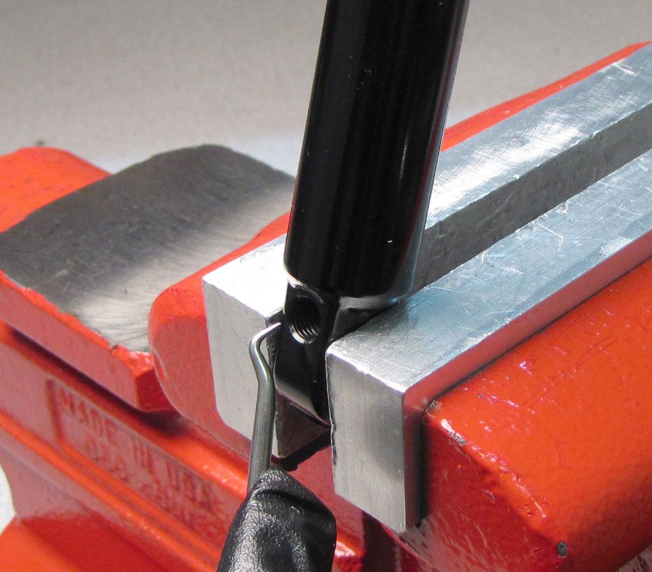
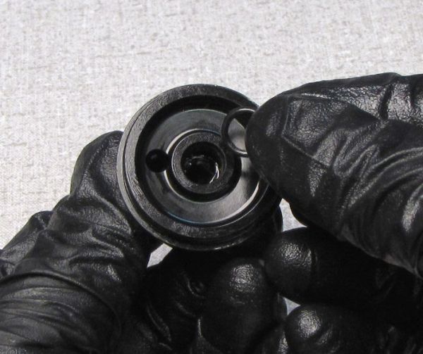
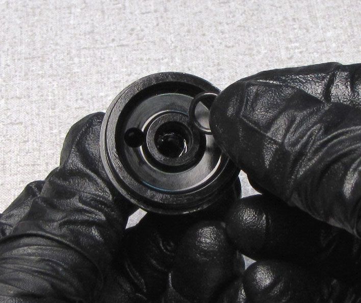
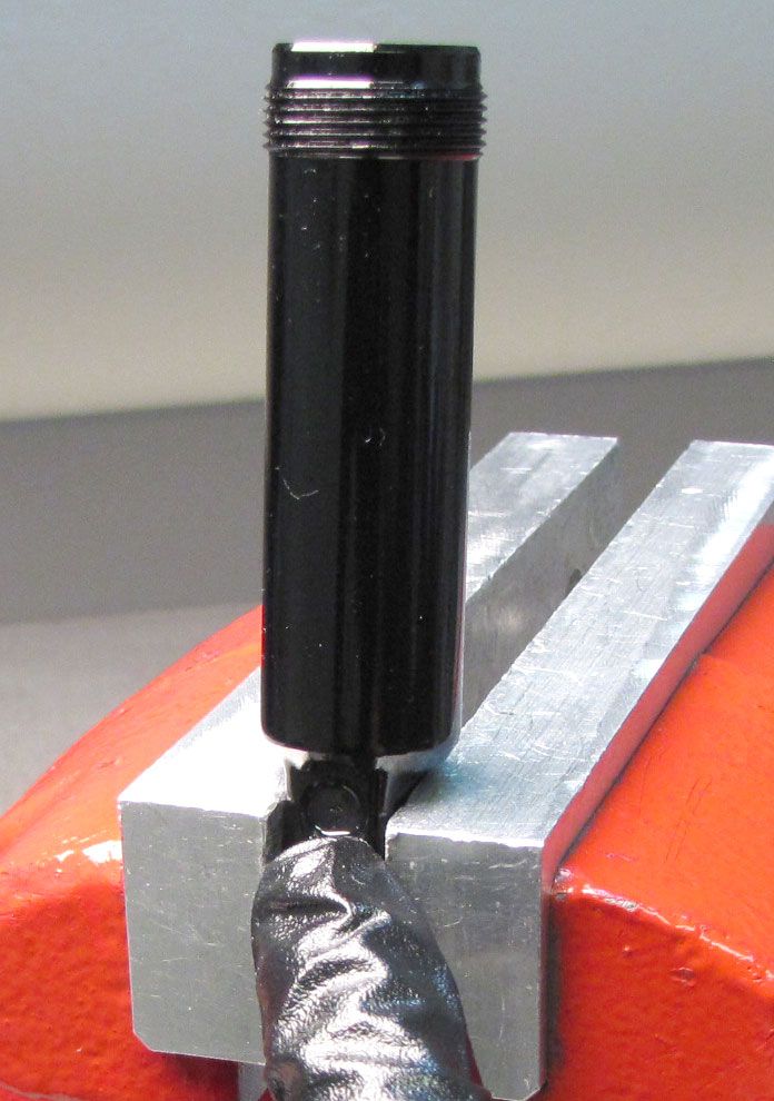
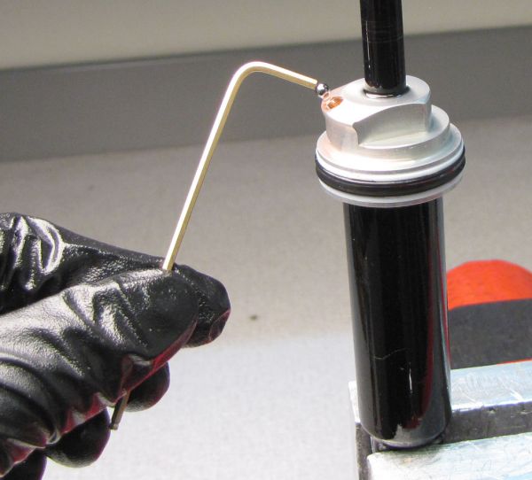
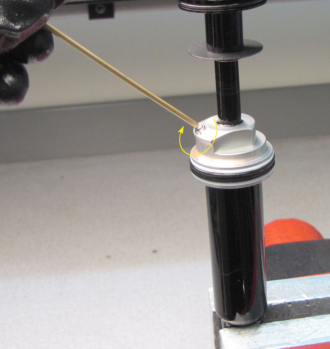
Clamp the damper body in your soft-jawed vise. Using a pick tool, remove the nylon plug to access the pellet screw. Heating the pick with a propane torch may make it easier to stab the nylon plug for removal. Use a 5/32" hex to release the nitrogen pressure and remove the pellet retainer. Remove the pellet with the pick tool.


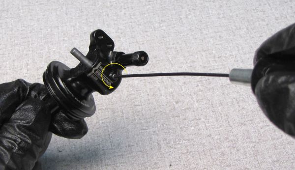
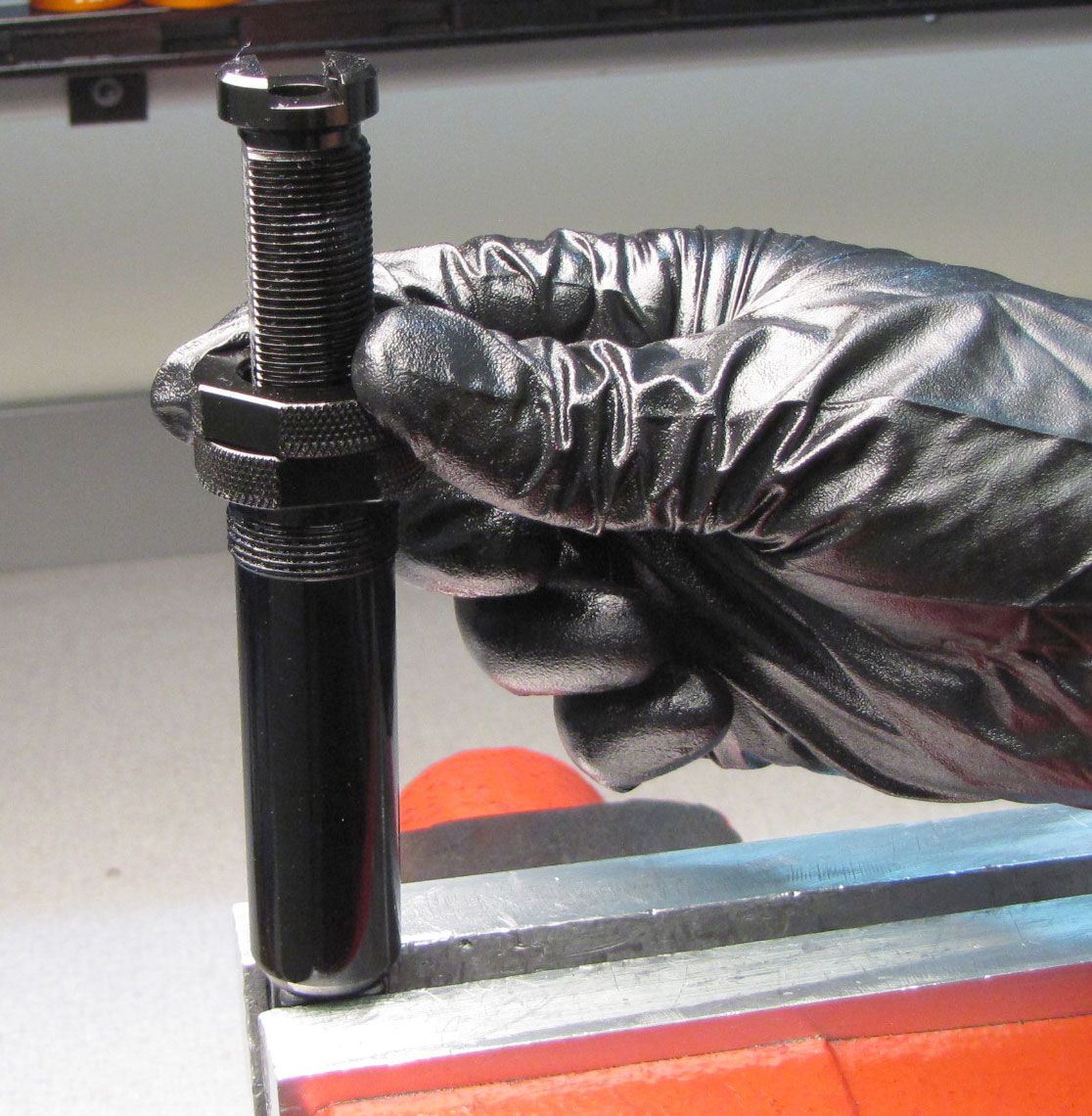
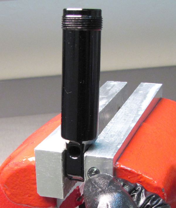
Step 7
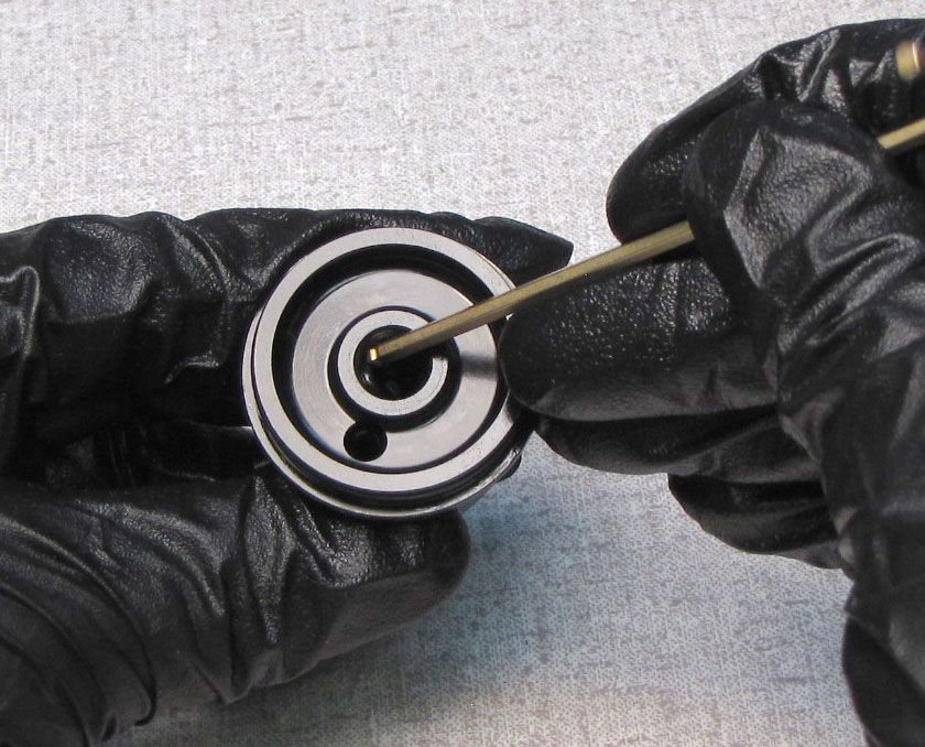
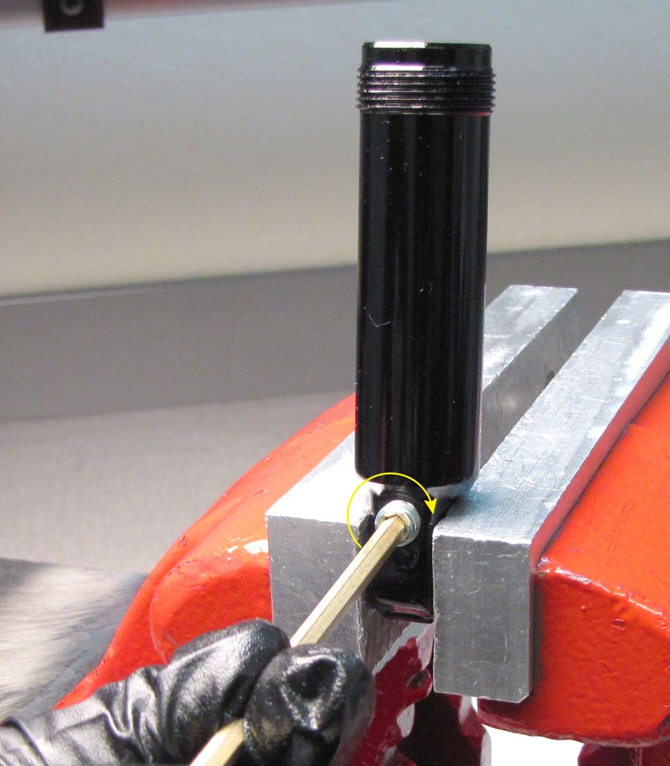
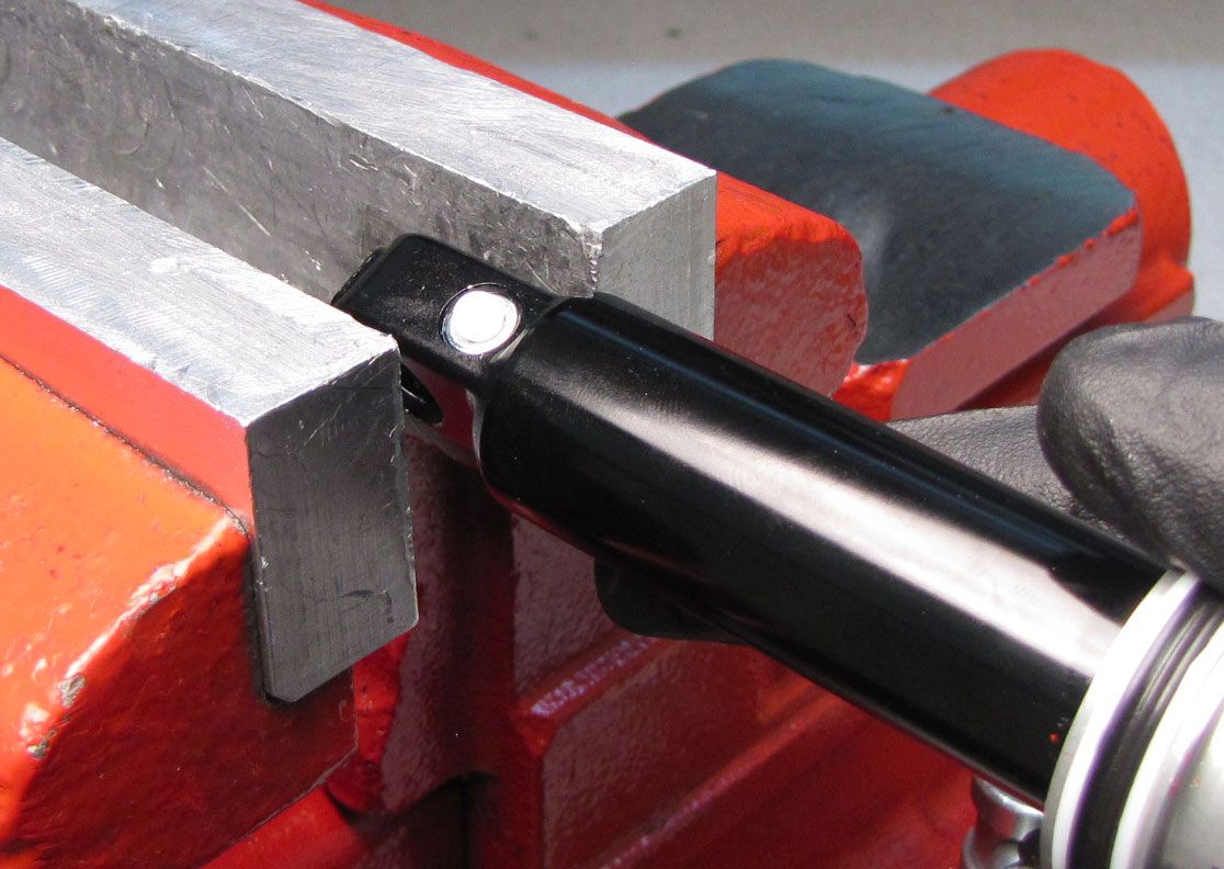
Clamp the shock vertically and use a 5/64" hex to slowly remove the bleed screw. Use a magnet to remove the ball from under the bleed screw. Unthread the bearing assembly from the shock body with a 3/4in wrench.

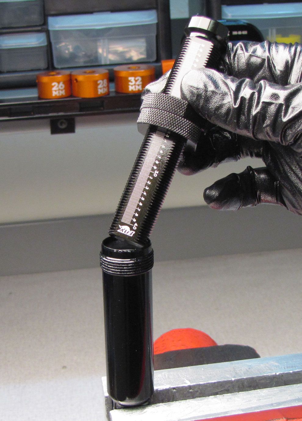
Step 8
Remove the shaft assembly from the body and pour out the damper oil. Remove the IFP using carefully applied air pressure. Inspect the body for damage or excessive wear.
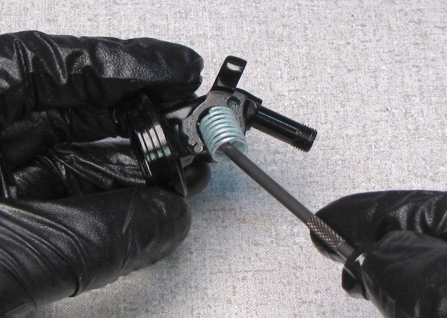
Step 9
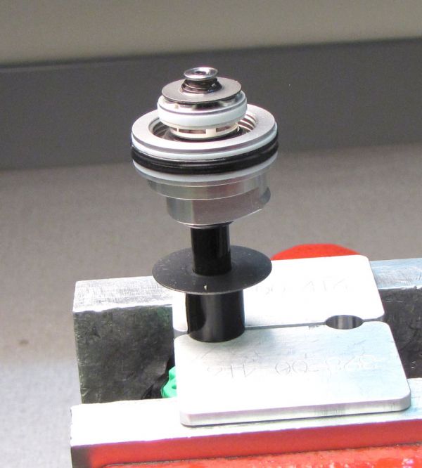
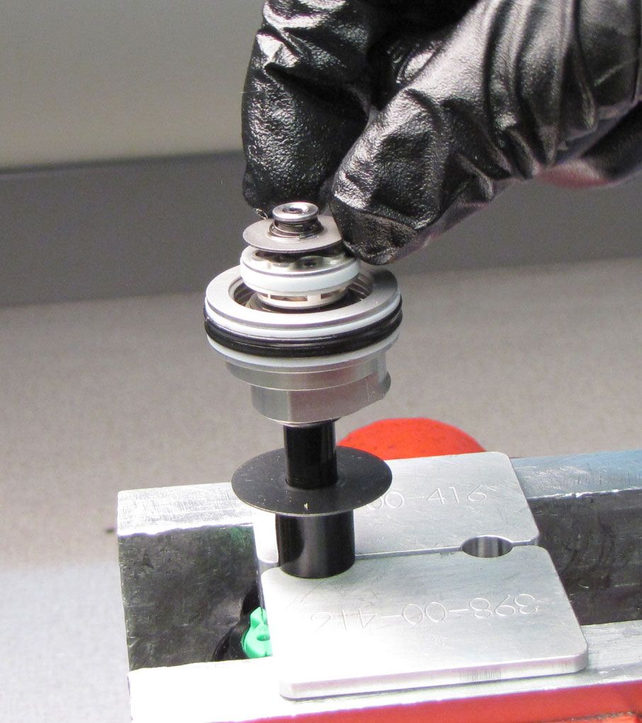
Invert the Eyelet Assembly and clamp in your 9mm shaft clamps (PN: 803-00-805) with the travel spacer above the clamps. Lift out the lockout plate with compression rod. Unthread the Piston Bolt counter-clockwise with a T40 Torx wrench. Lift off the complete valving assembly and set aside.

Step 10
Lift the Bearing Housing up to remove it from the shaft. Remove the bottom out o-ring and bottom out plate from the shaft. Remove the travel spacer.


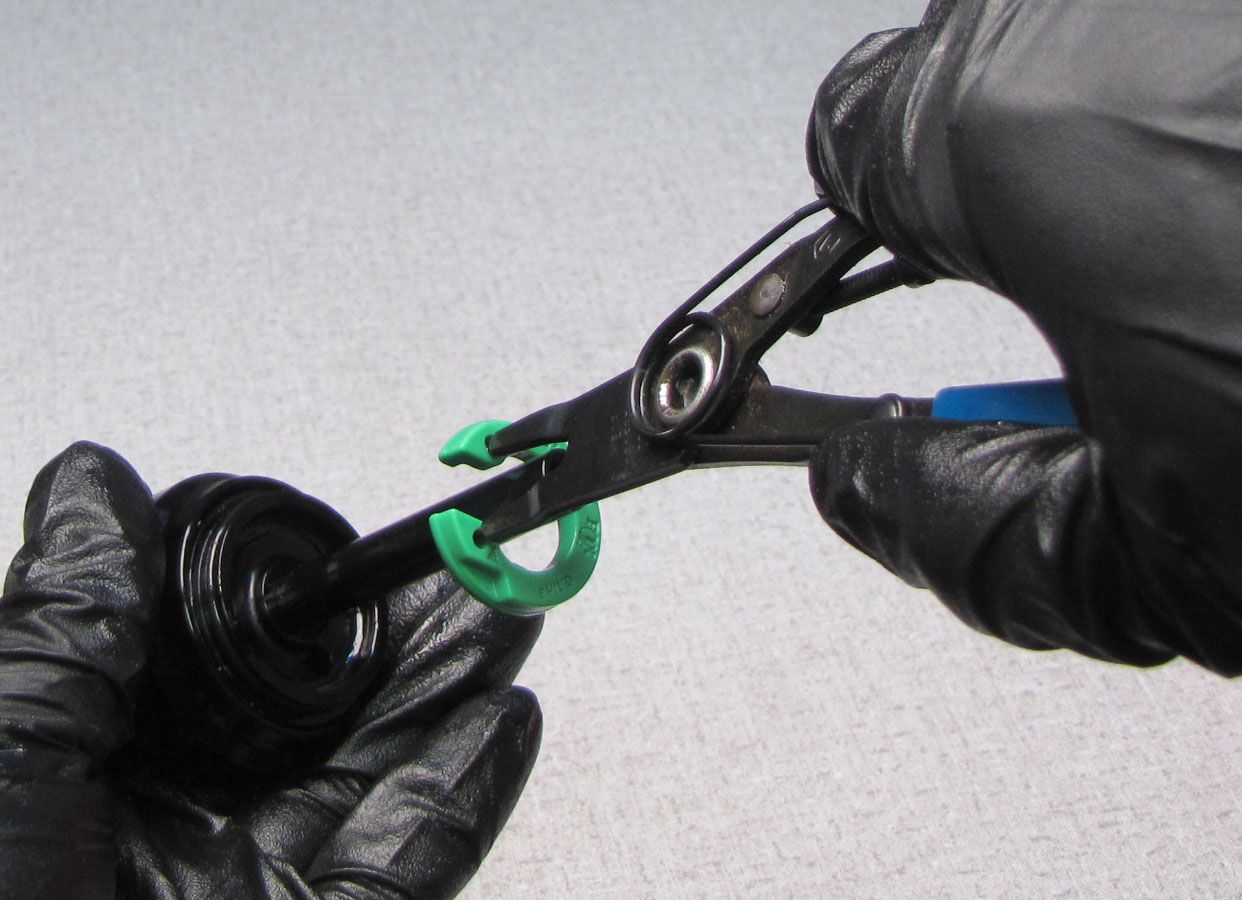
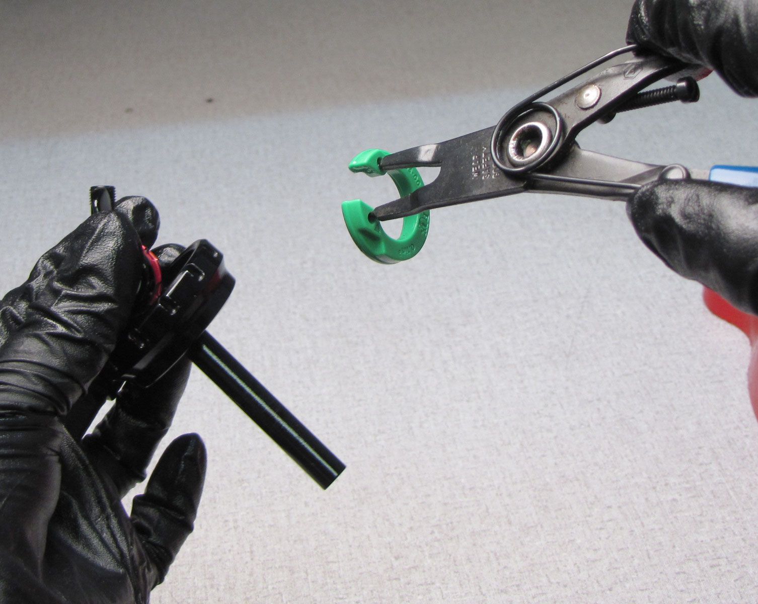
Step 11
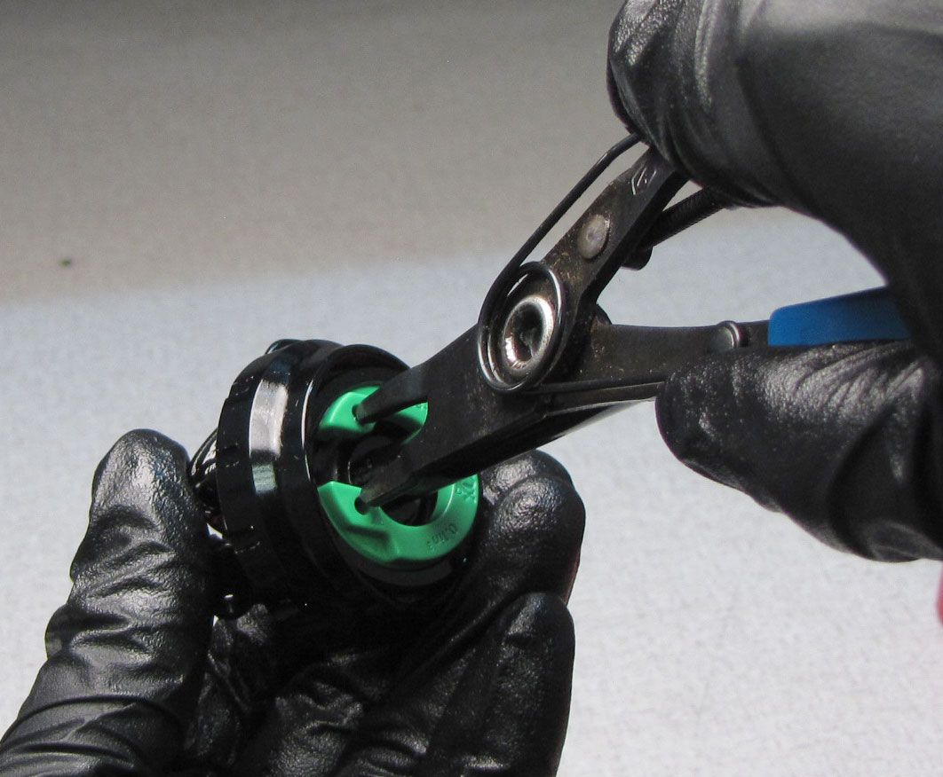
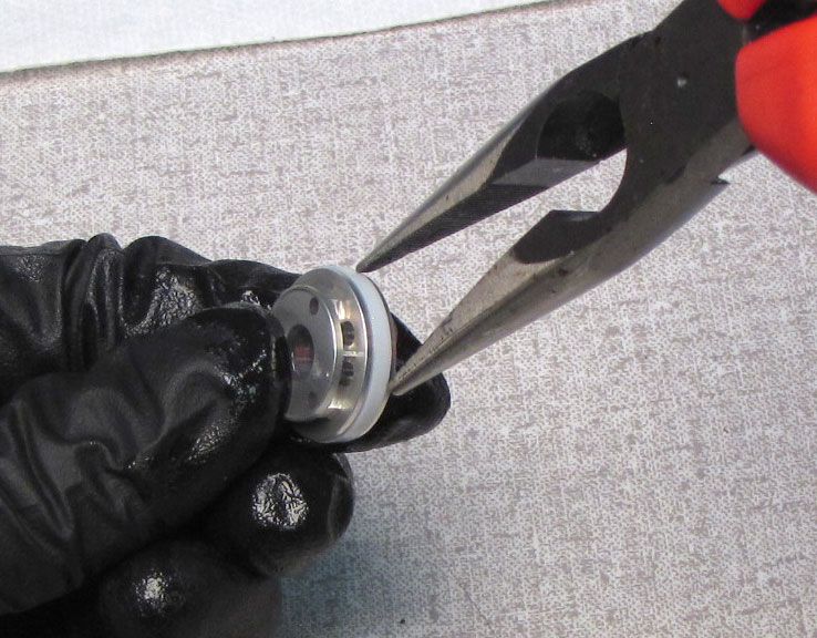
Use a pin-spanner or snap-ring pliers to remove the volume spacer from inside the eyelet. Squeeze the spacer slightly with your pin-spanner or snap-ring pliers to remove then set aside.


Step 12
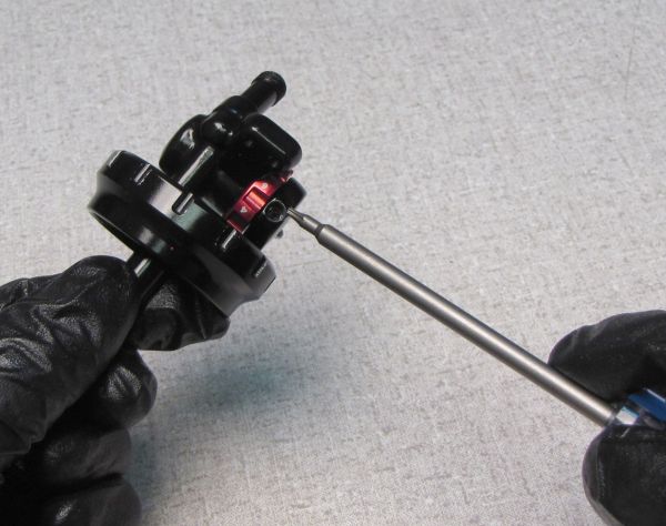
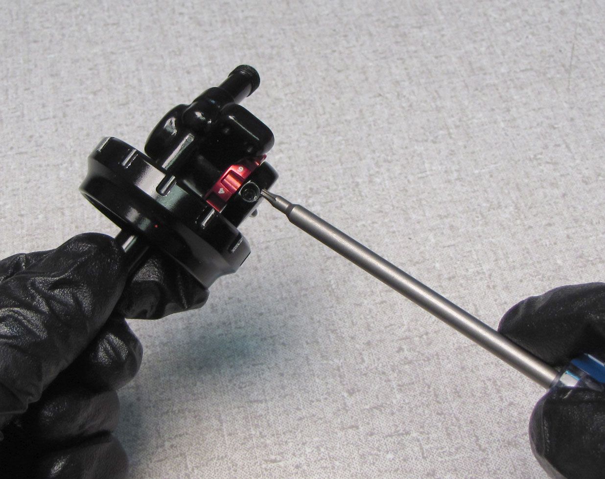
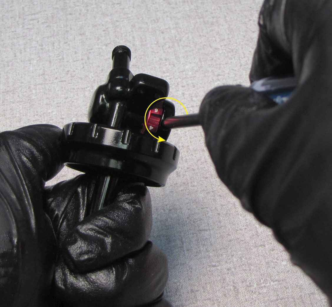
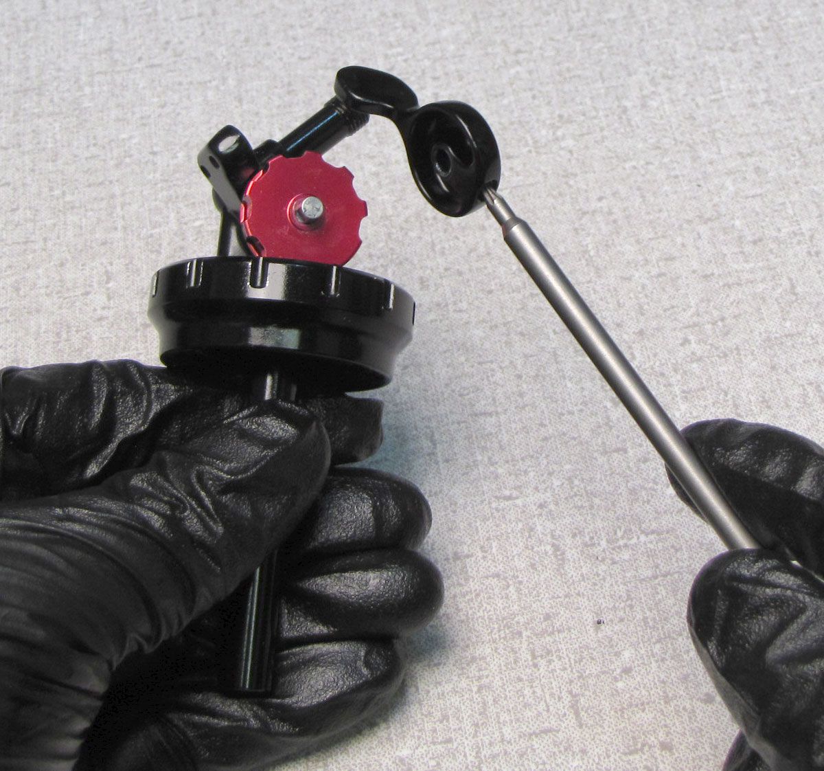
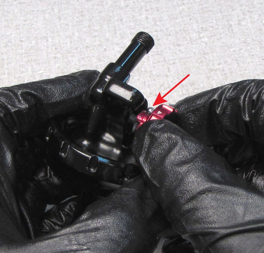
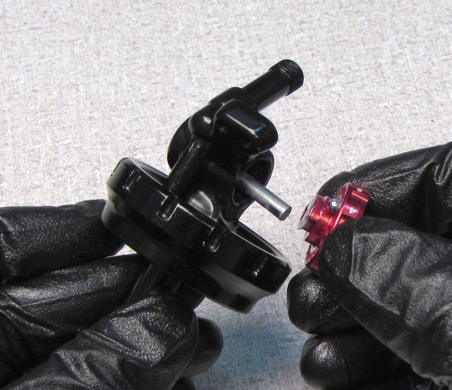
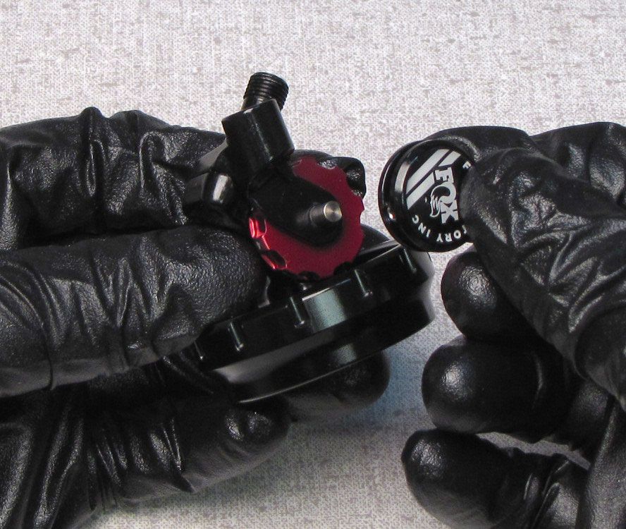
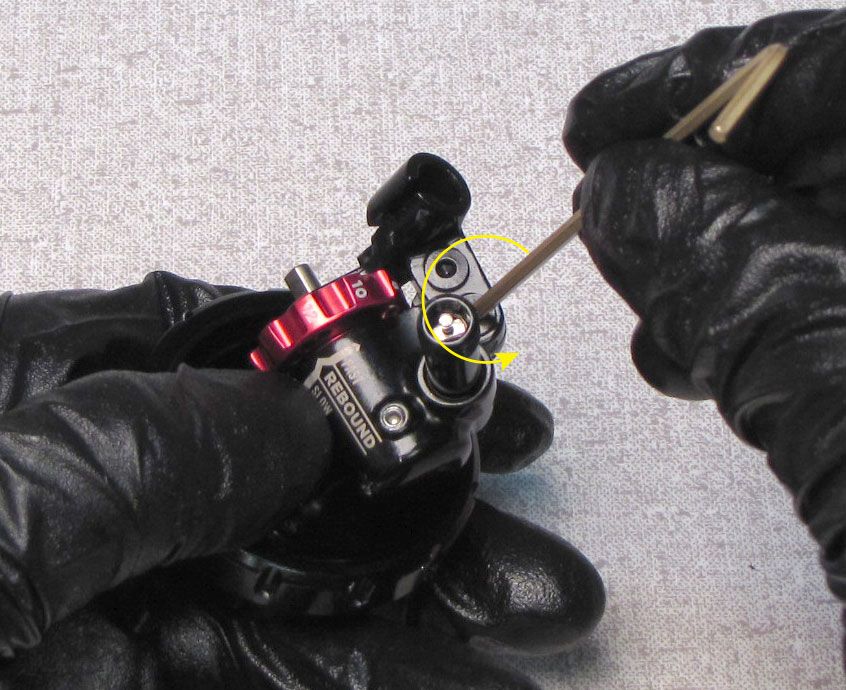
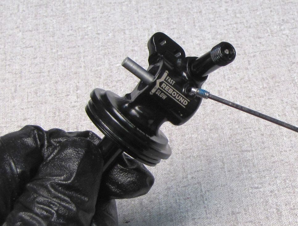
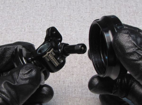
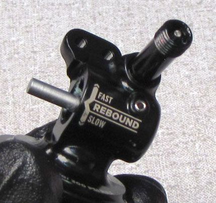
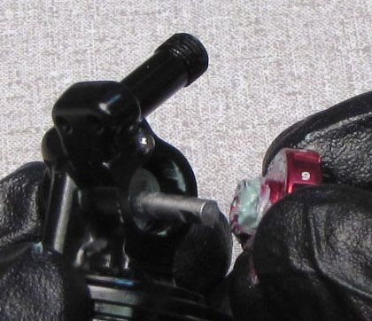
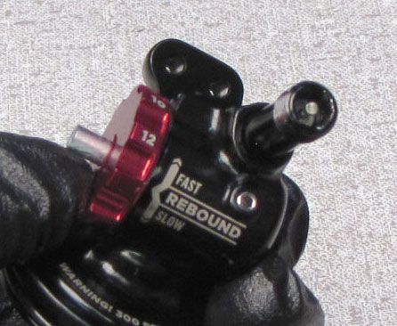
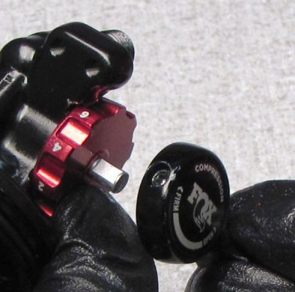
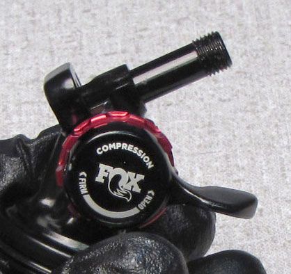
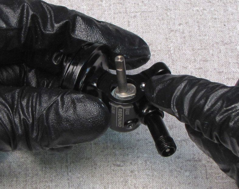
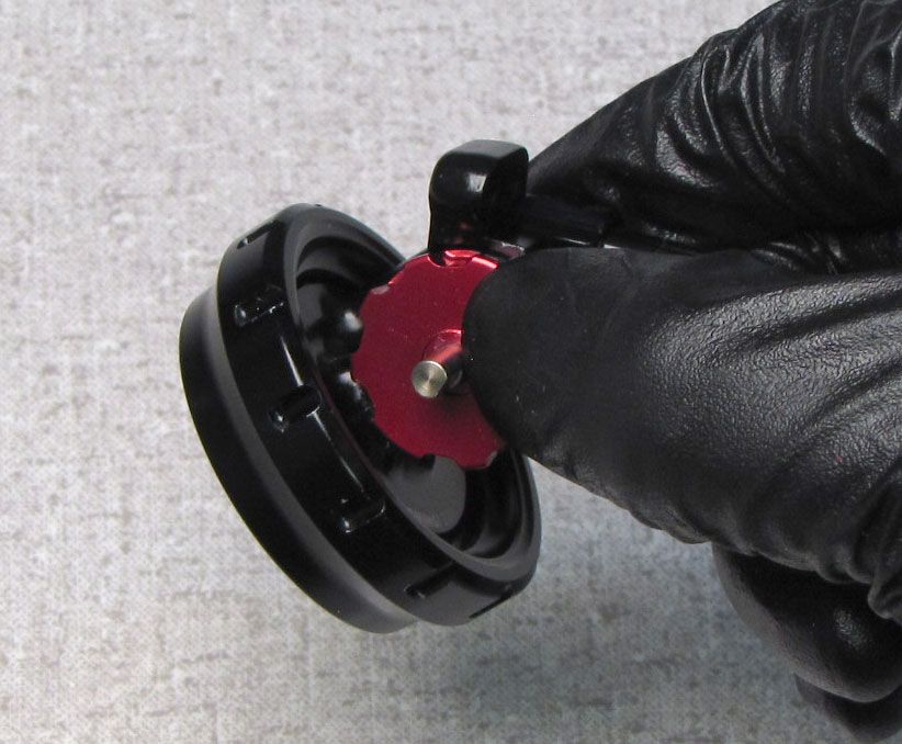
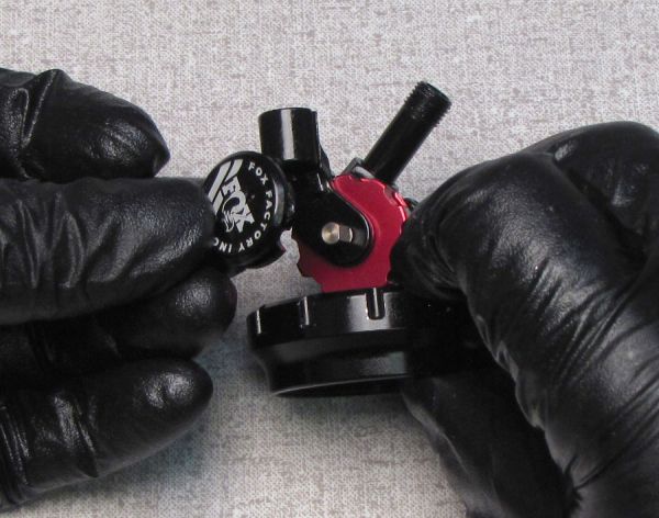
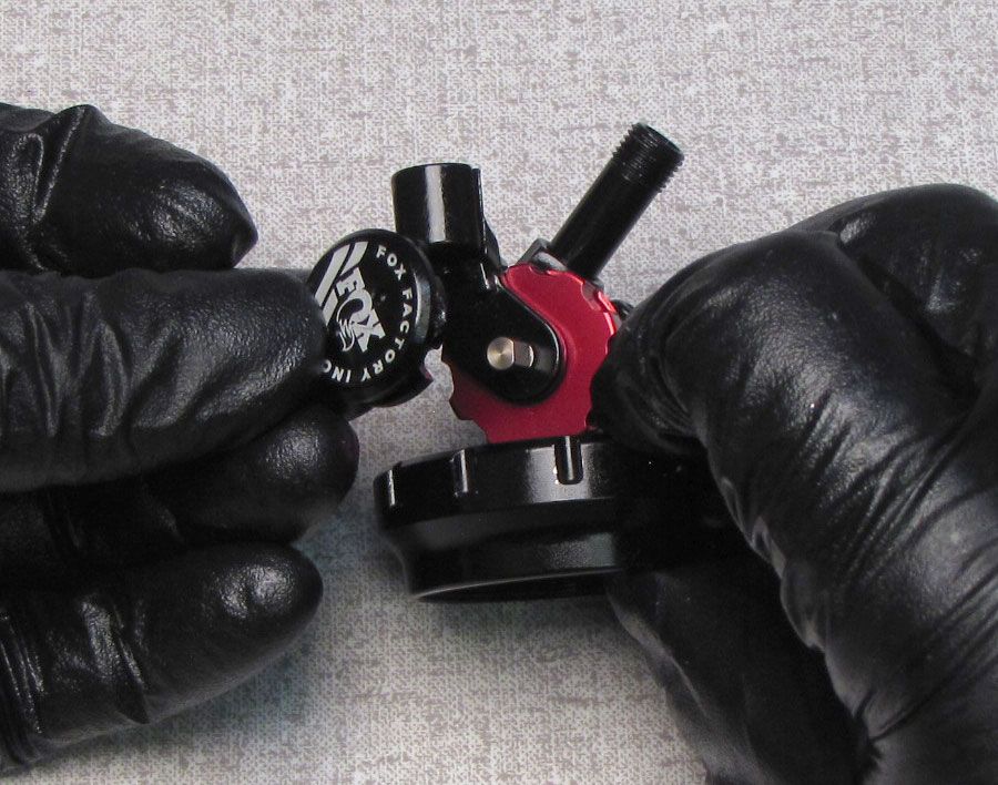
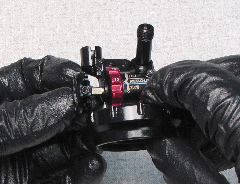
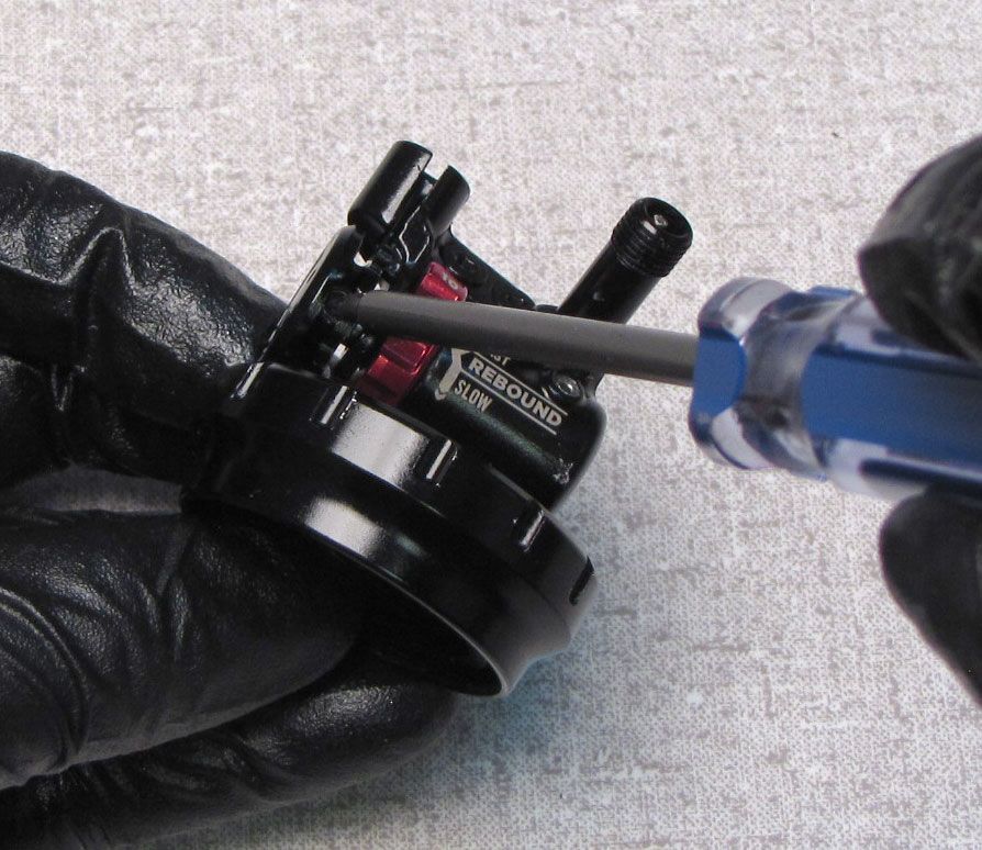
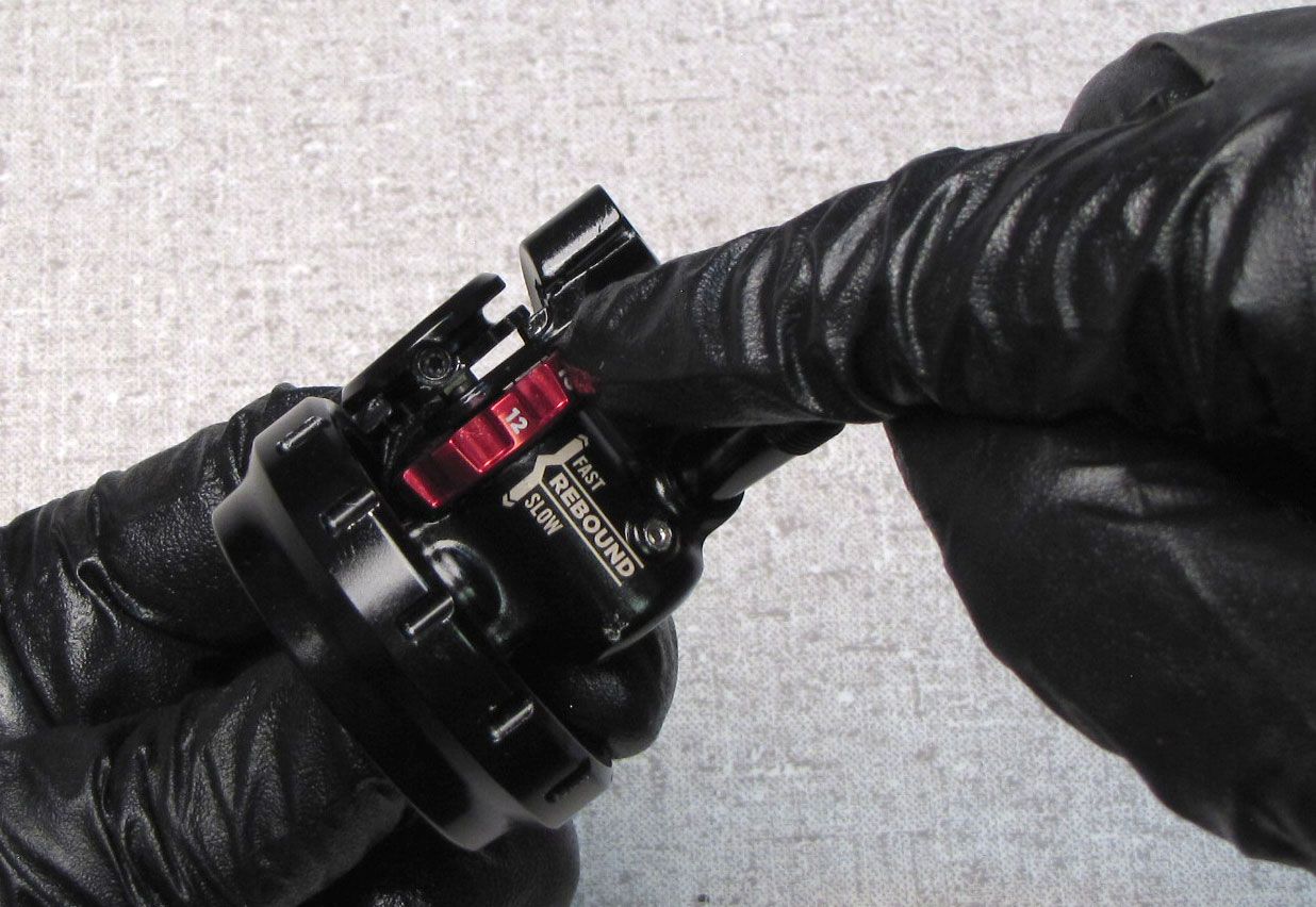
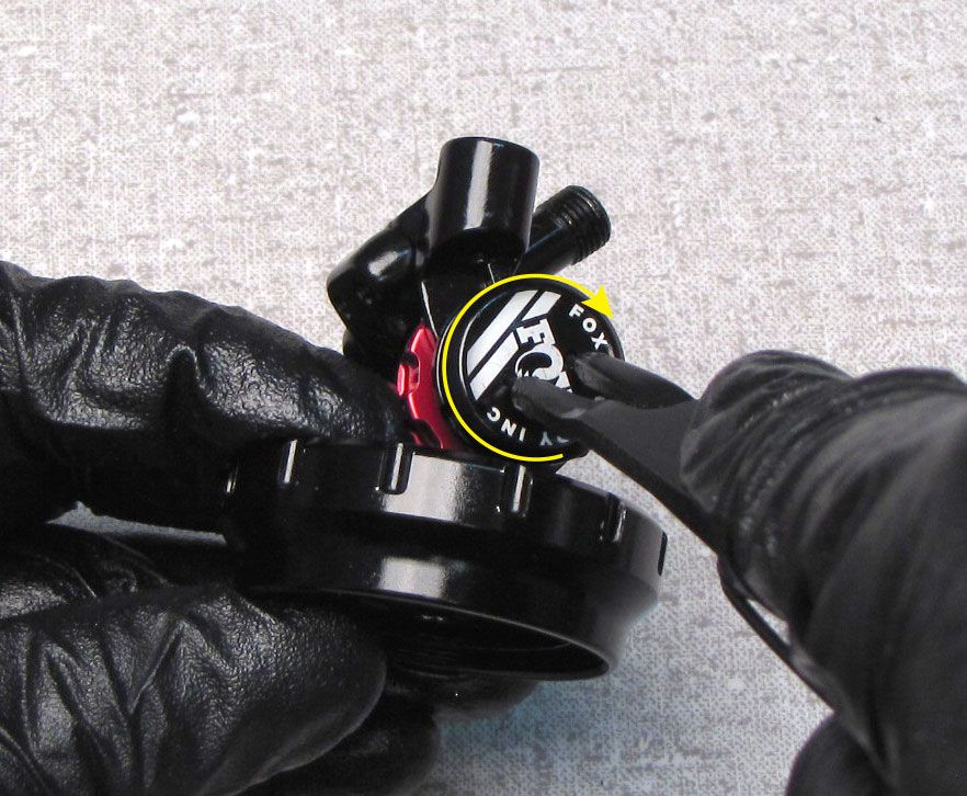
FOR LEVER EYELETS: Unthread the lever set screw counter-clockwise with a T8 Torx, then remove the lever from the cam. Remove the red Rebound knob taking care not to lose the detent ball and spring between the Rebound knob and the eyelet.
Step 13
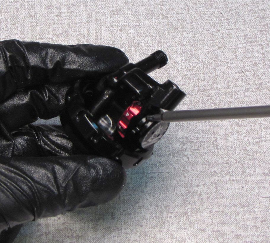
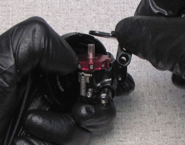
FOR REMOTE EYELETS: Unthread the pulley set screw counter-clockwise with a T8 Torx, then remove the pulley from the cam.


Step 14
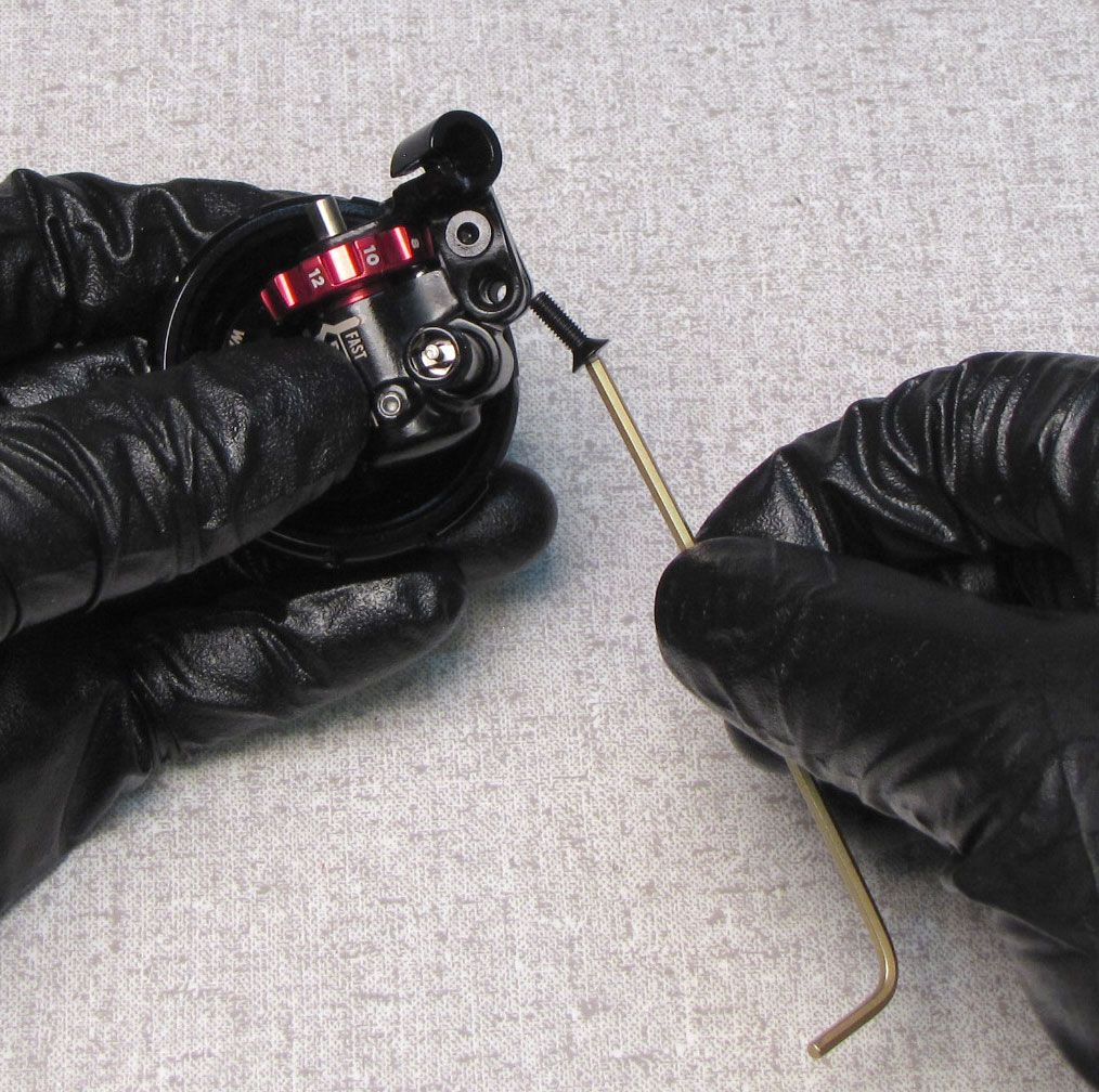
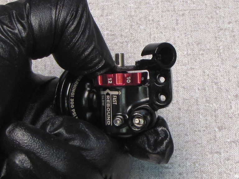
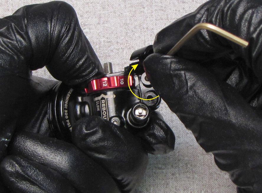
FOR REMOTE EYELETS: Unthread the two screws holding the Cable Hanger by turning them counter-clockwise with a 2mm hex wrench. Remove the Cable Hanger taking care not to lose the rebound detent ball or spring beneath the red Rebound Knob.


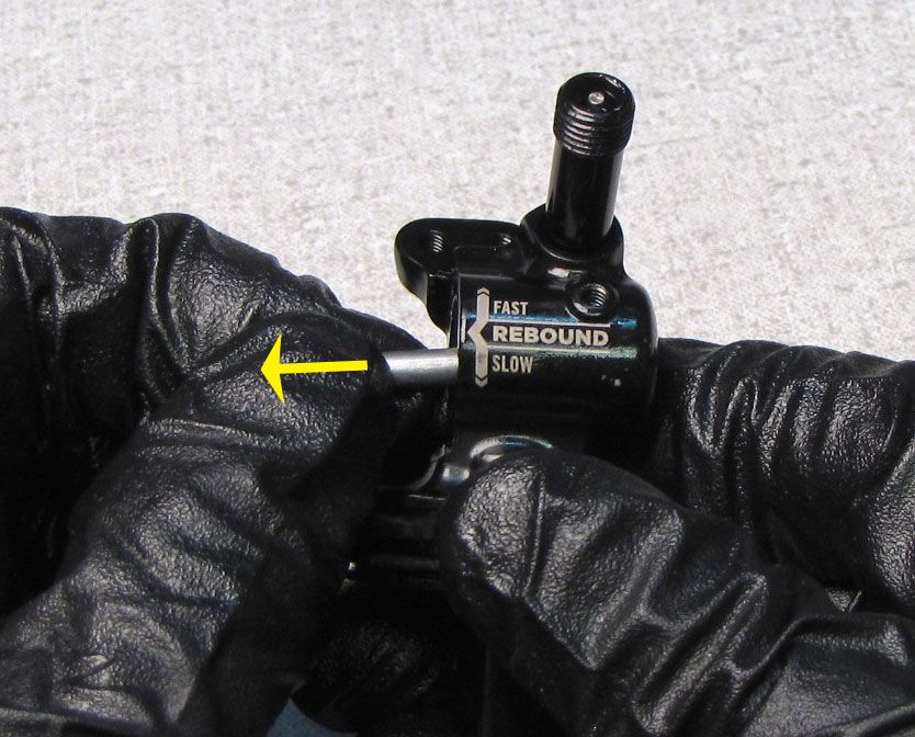
Step 15
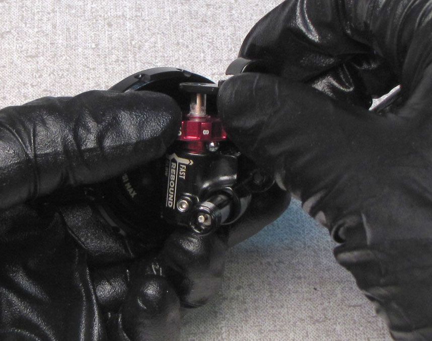
FOR REMOTE EYELETS: Remove the red Rebound Knob and cam. Remove the rebound detent ball. Remove the torsion spring from the eyelet.
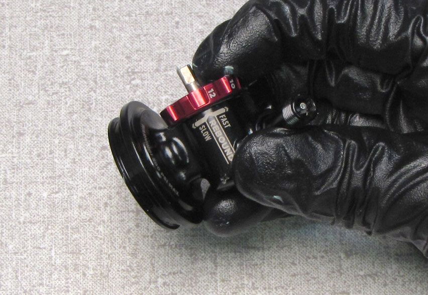
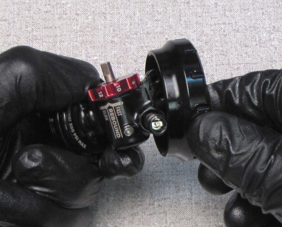
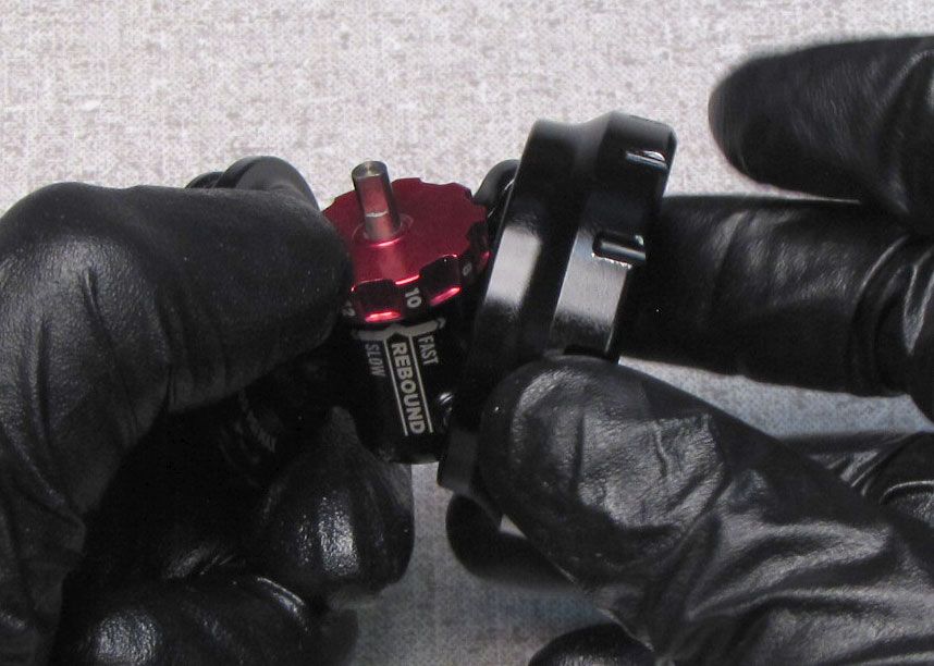
Step 16
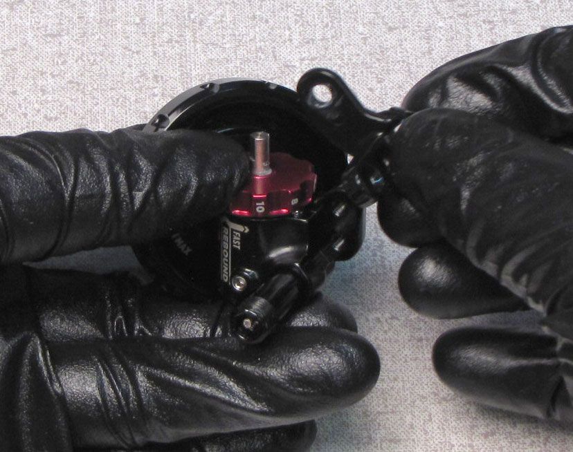
Remove the Eyelet Collar. Remove the rebound detent spring.


Step 17
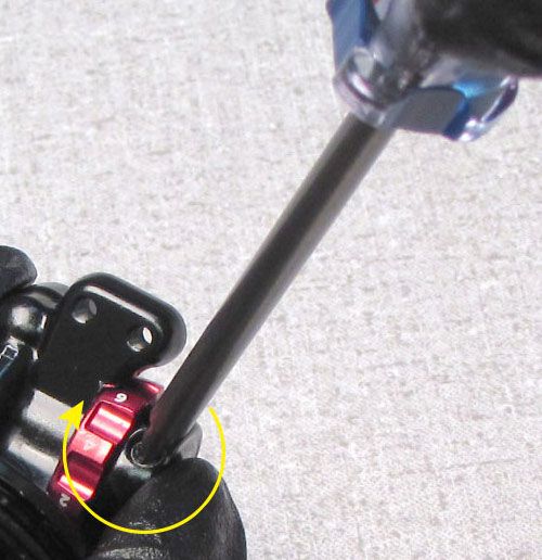
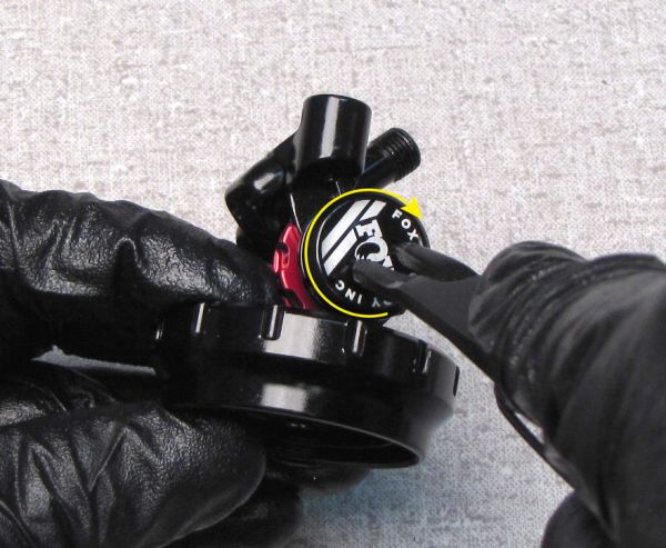
Do not remove the set screw from remote eyelets. Unthread and remove the set screw from the lever eyelet by turning it couter-clockwise with a 1.5mm hex wrench. Remove the cam if still present.

Step 18
Remove the external eyelet o-ring. Clamp the shaft in your 9mm shaft clamps then carefully apply heat to the connection between the shaft and the eyelet with a propane torch for 5-10 seconds to break down the Loctite. Use smooth-jawed parallel pliers (Knipex) inline with the cam bore to unthread the eyelet counter-clockwise. Lift up to remove.


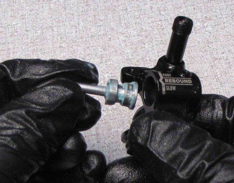
Step 19
Lift the Rebound Metering rod out of the shaft and set aside. Clean out the eyelet cam bore and remove any Loctite from the shaft threads within the eyelet. Remove the shaft o-ring within the eyelet.

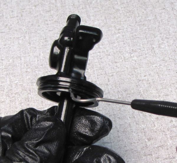
Step 20
Install new greased o-rings from the kit into the shaft bore and the outside of the eyelet.

Step 21
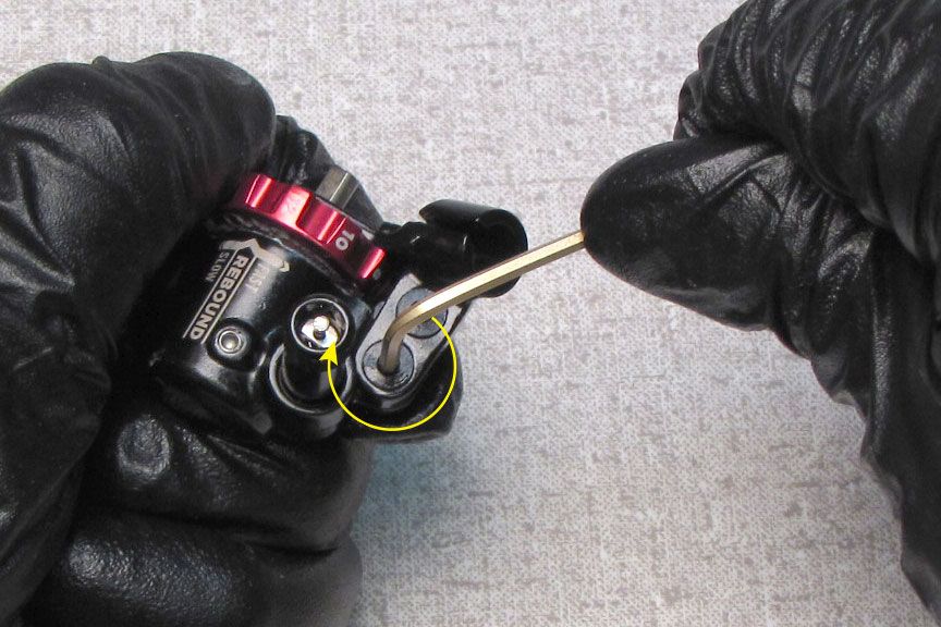
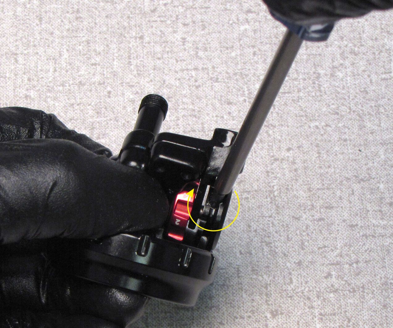
FOR LEVER EYELETS: Reinstall the Eyelet Collar onto the Eyelet. Coat the cam in a thick film of waterproof marine grease (Sta-Lube SL3125). Insert the cam into the eyelet bore then reinstall the set screw tightening clockwise with a 1.5mm hex until it touches the cam, then loosen out 1/4 turn.


Step 22
FOR LEVER EYELETS: Replace the rebound detent spring then stick the detent ball to the spring with a bit of waterproof marine grease. Coat the back of the red Rebound Knob with a film of waterproof marine grease (Sta-Lube SL3125) then slide into place over the cam making sure to capture the detent ball.

Step 23
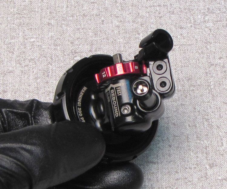
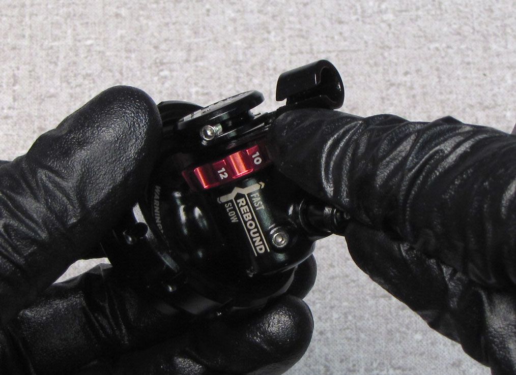
FOR LEVER EYELETS: Push the lever fully onto the cam, then align the set screw of the black lever with the flat on the cam. Tighten the set screw clockwise to 8 in-lb (0.9 Nm) torque. Turn the red Rebound knob to verify that it moves freely with good detents.


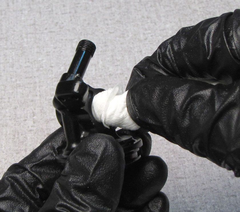
Step 24
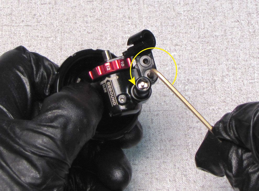
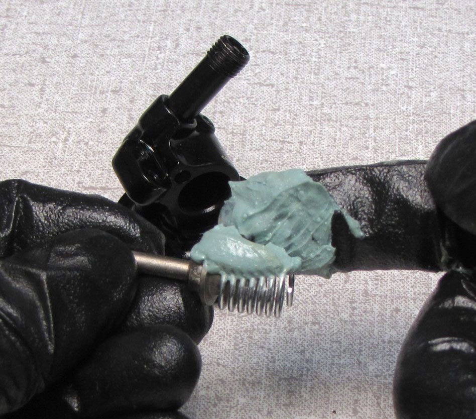
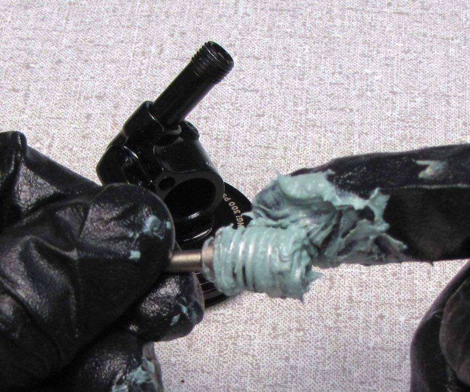
FOR REMOTE EYELETS: Insert the protruding tang of the torsion spring into the hole in the cam as shown. Coat the torsion spring and cam with a thick film of waterproof marine grease (Sta-Lube SL3125).

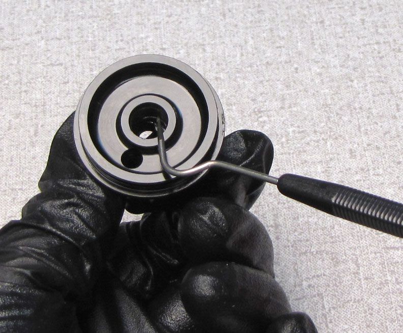
Step 25
FOR REMOTE EYELETS: Align the tang of the torsion spring that is bent toward the center of the spring barrel with the slot in the back of the eyelet cam bore. Install the cam with torsion spring into the eyelet.


Step 26
FOR REMOTE EYELETS: Replace the rebound detent spring then stick the detent ball to the spring with a bit of waterproof marine grease. Coat the back of the red Rebound Knob with a film of waterproof marine grease (Sta-Lube SL3125) then slide into place over the cam making sure to capture the detent ball.


Step 27
FOR REMOTE EYELETS: Reinstall the Eyelet Collar while holding the rebound knob in place to retain the detent ball.

Step 28
FOR REMOTE EYELETS: Reinstall the Cable Stop by aligning it with the cam and the two screw holes. Reinstall the two set screws tightening clockwise to 11 in-lb (1.2 Nm) torque with a 2mm hex wrench.

Step 29
FOR REMOTE EYELETS: Install the black remote Pulley onto the Compression Cam so the T8 Torx screw is oriented toward the flat of the Cam. Leave the Pulley far enough from the face of the Cable Hanger to allow for its rotation. Tighten the T8 Torx screw just enough to allow for the Pulley to rotate the cam while still being able to be pushed further onto the Cam once in its final position
Step 30
FOR REMOTE EYELETS: Rotate the pulley clockwise past the pulley stop feature on the black Cable Hanger. After winding past the pulley stop, press the black pulley down against the black Cable Hanger. Tighten the T8 Torx screw to 8 in-lb (0.9 Nm) torque.
Step 31
Replace the o-rings inside the shaft and rebound metering rod with a new greased ones from the kit. Coat the rebound metering rod with a thin film of Slick Honey then reinstall it into the shaft.


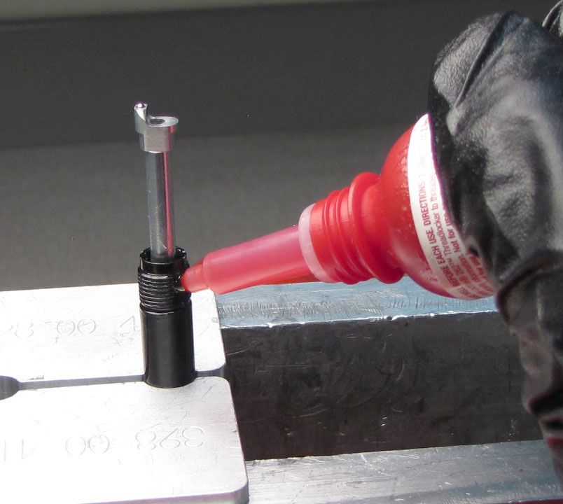
Step 32
Apply 1-2 drops of red Loctite 277 to the shaft threads then reinstall the eyelet assembly making sure to orient the ball bearing on the Rebound Metering rod toward the adjuster side of the eyelet assembly. Thread the eyelet clockwise onto the shaft then clamp the shaft in your 9mm shaft clamps. Tighten the eyelet to 85 in-lb (9.6 Nm) torque.
Step 33
Reinstall the travel spacer, bottom out plate, and new greased bottom out o-ring from the kit.
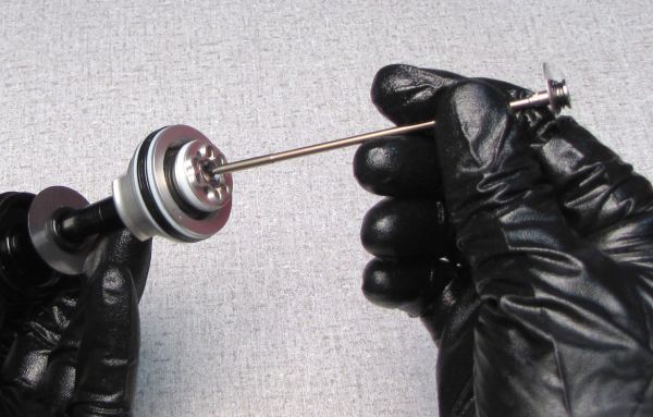
Step 34
Replace the o-rings, air seal, and backup rings on the Bearing Assembly with new greased ones from the kit. Reinstall the Bearing Assembly onto the shaft as shown. Turn the Red Rebound knob fully counter-cloclwise while pushing the rebound needle in with a blunt tool to prevent damage to the Rebound Needle when tightening the Piston Bolt. Make sure that the cam has moved to it's most open position and the needle has moved out of the way of the Piston Bolt.


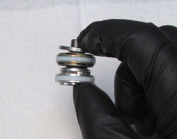
Step 35
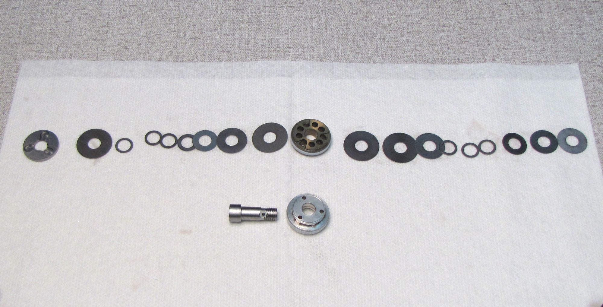
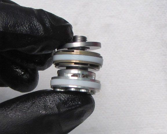
Inspect the Valving Assembly for any damaged shims and replace if necesarry. Replace the glide rings and o-rings on the pistons with new greased ones from the kit. Maintain the original order of all valving assembly parts during inspection and service.

Step 36
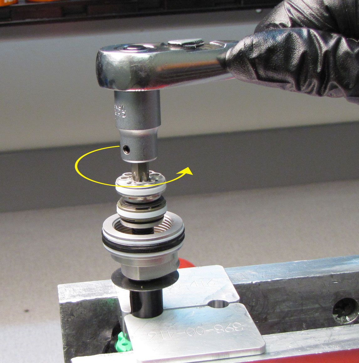
Clean the shaft then clamp it in your 9mm shaft clamps. Reinstall the Valving Assembly onto the shaft, tightening the piston bolt clockwise to 60 in-lb (6.8 Nm) torque with a T40 Torx wrench.
Step 37
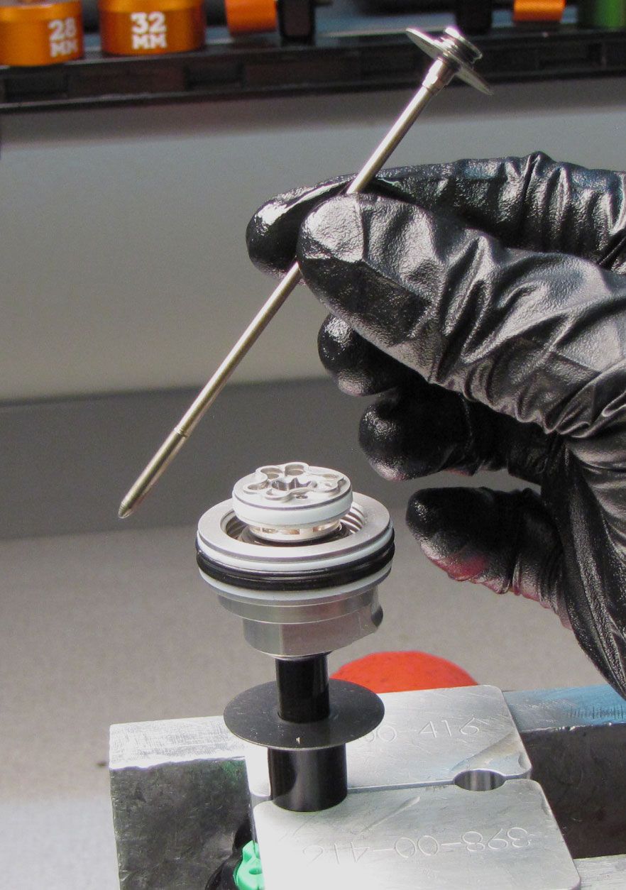
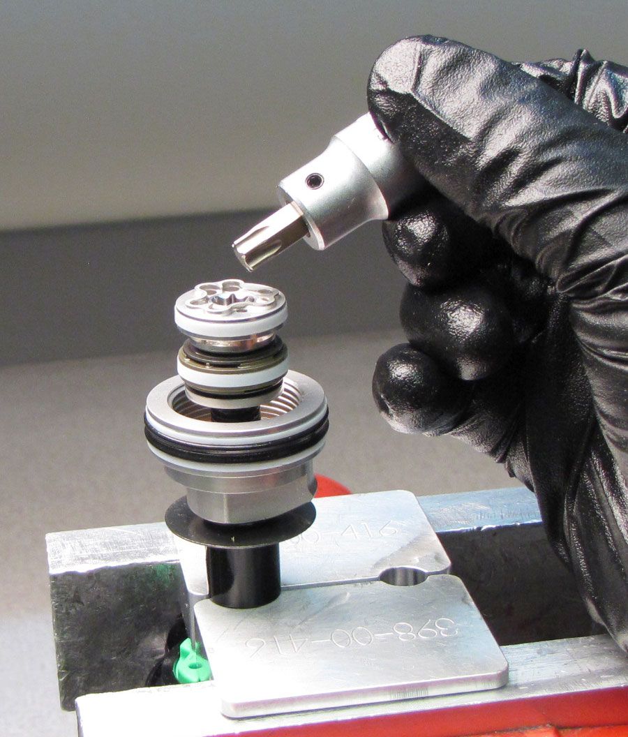
Coat the Compression rod with a thin film of Slick Honey, then reinstall into the Piston bolt. Push the Lockout Plate down while actuating the lever or remote pulley to make sure the Compression rod is fully inserted into the shaft.

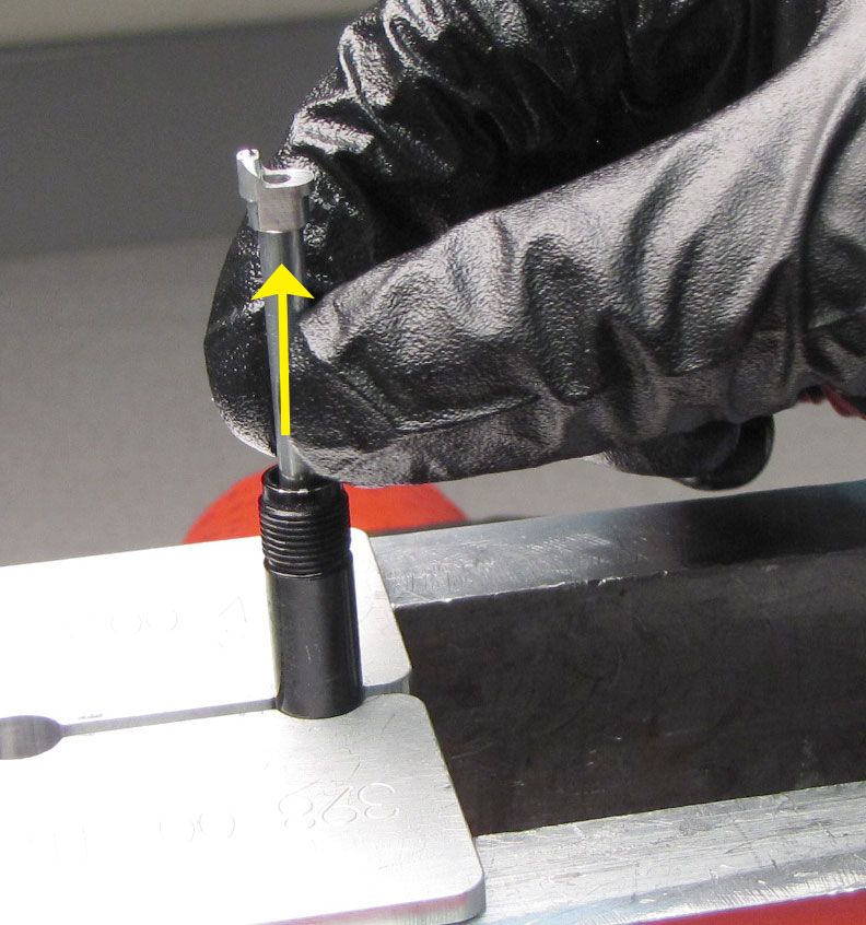
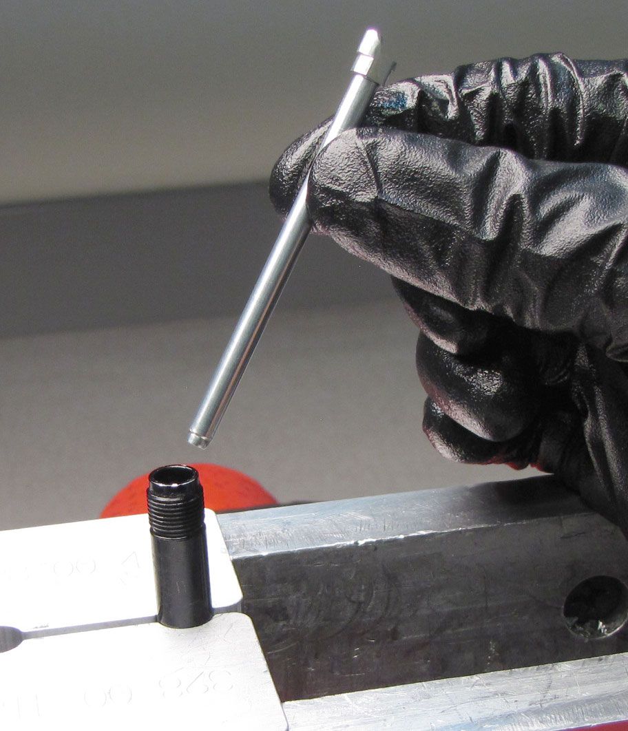
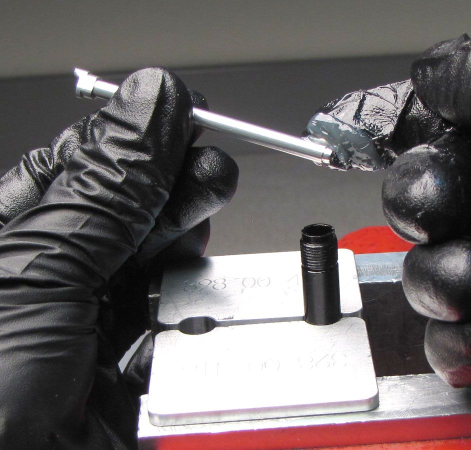
Step 38
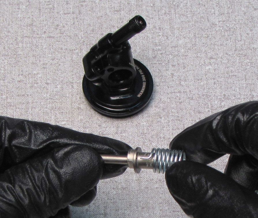
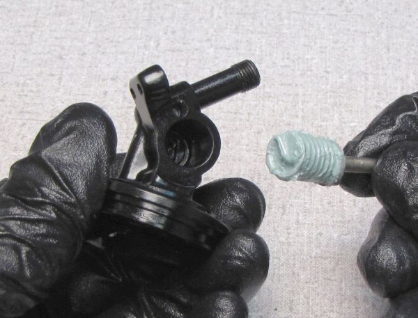
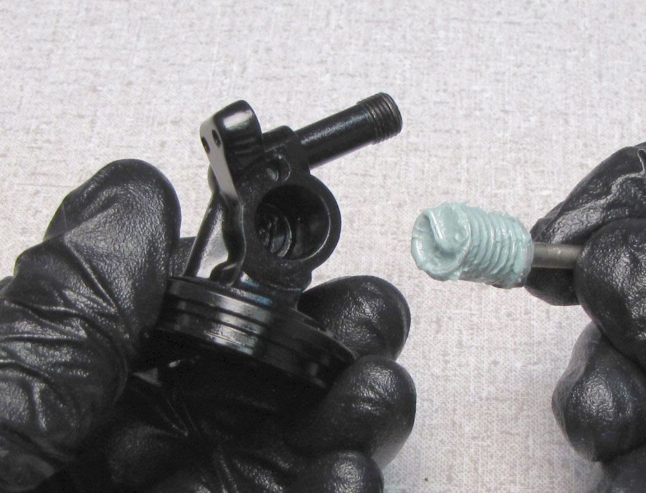
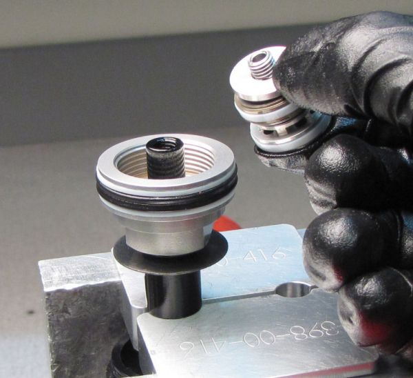
Replace the IFP o-ring with a new greased one from the kit. Reinstall the IFP into the body so the counter-bore on the piston is facing out of the open end of the body. Prepare your IFP depth setting tool by setting the collars 2 inches from the small end of the tool. The normally used larger end of the tool will not fit properly in IsoSturt bodies.


Step 39
Install a new pellet from the kit with the beveled side facing into the body. Reinstall the Pellet Retainer tightening clockwise until just snug with a 5/32" hex wrench.


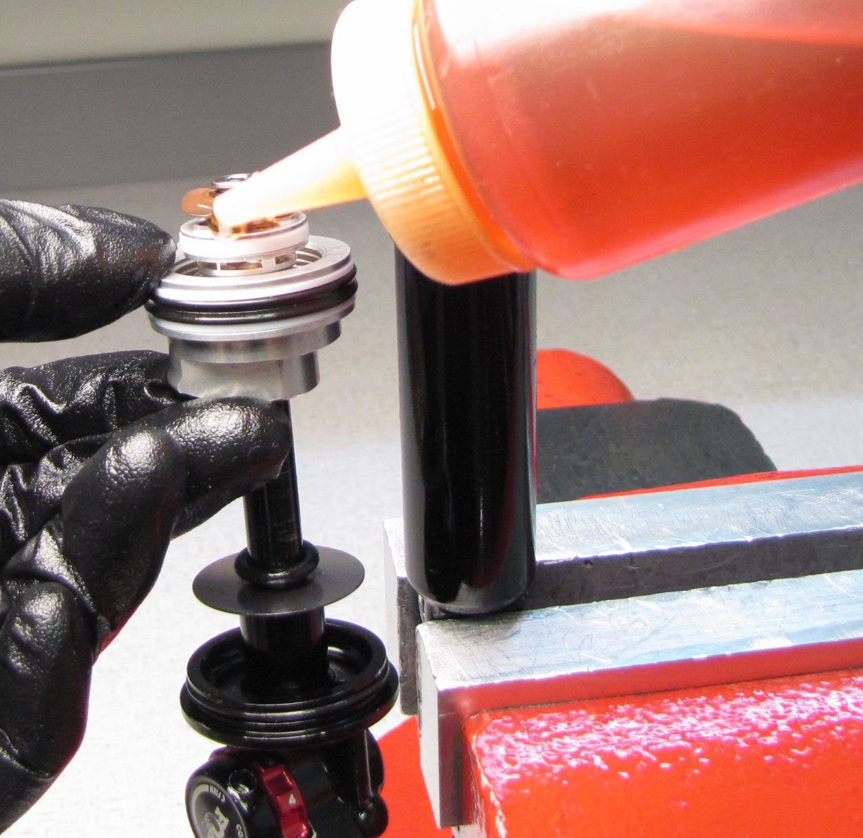
Step 40
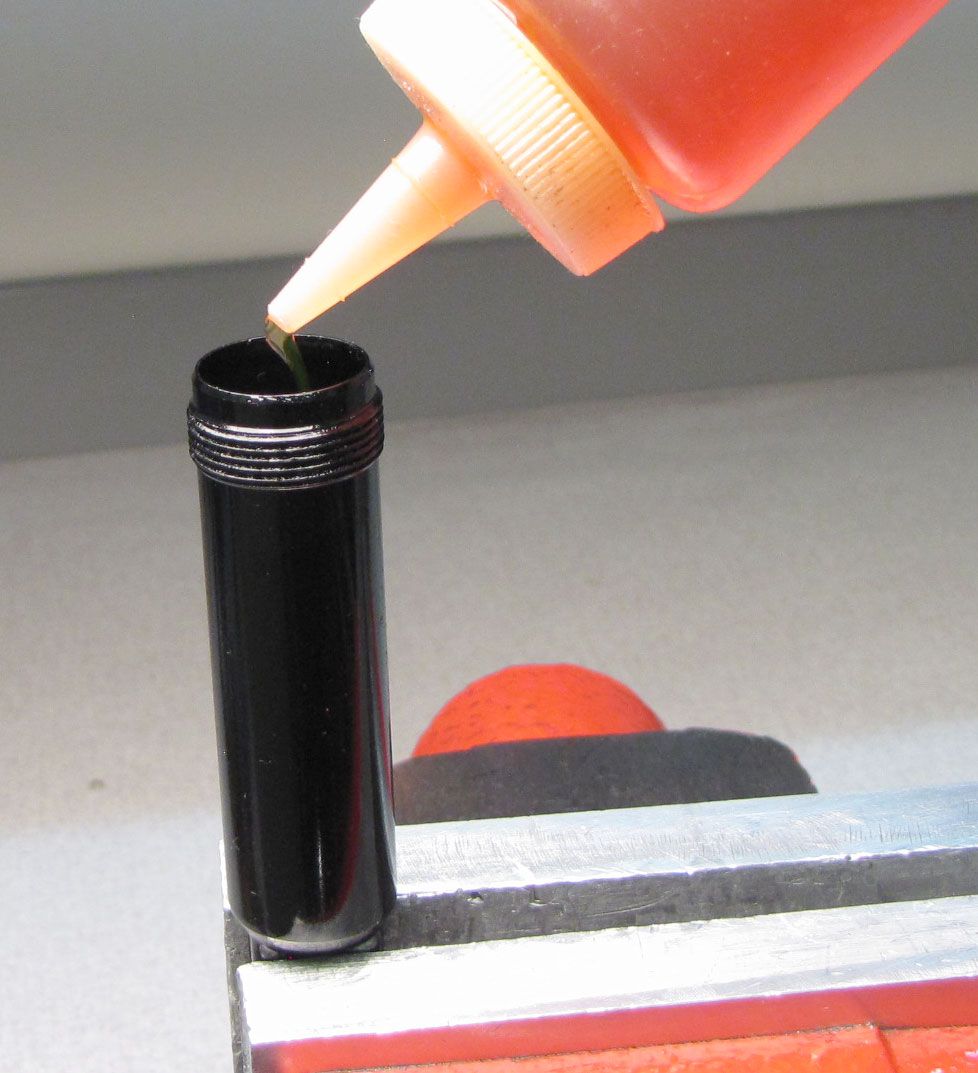
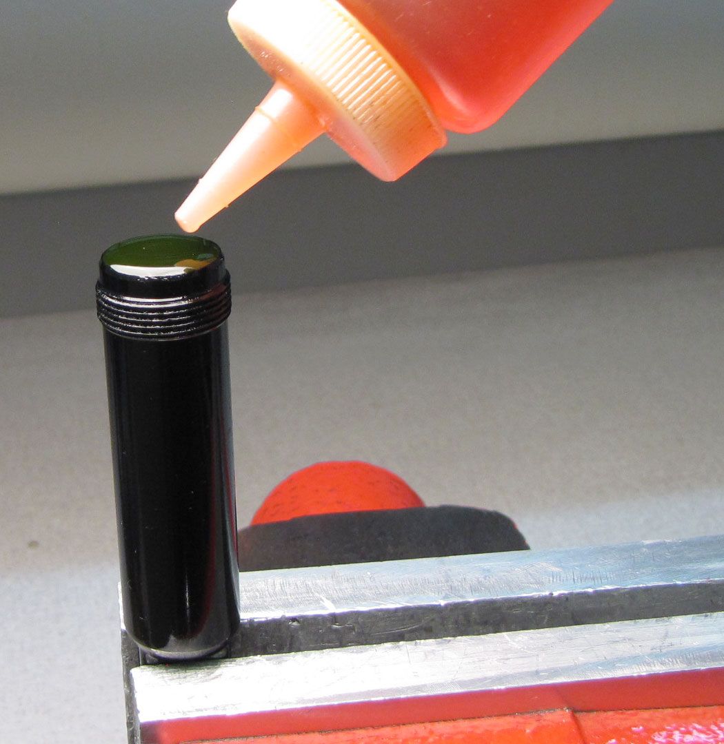
Fill the body with FOX 10wt. red oil. Position the Bearing Assembly as close to the Piston Assembly as possible, then pre-fill the piston with oil.
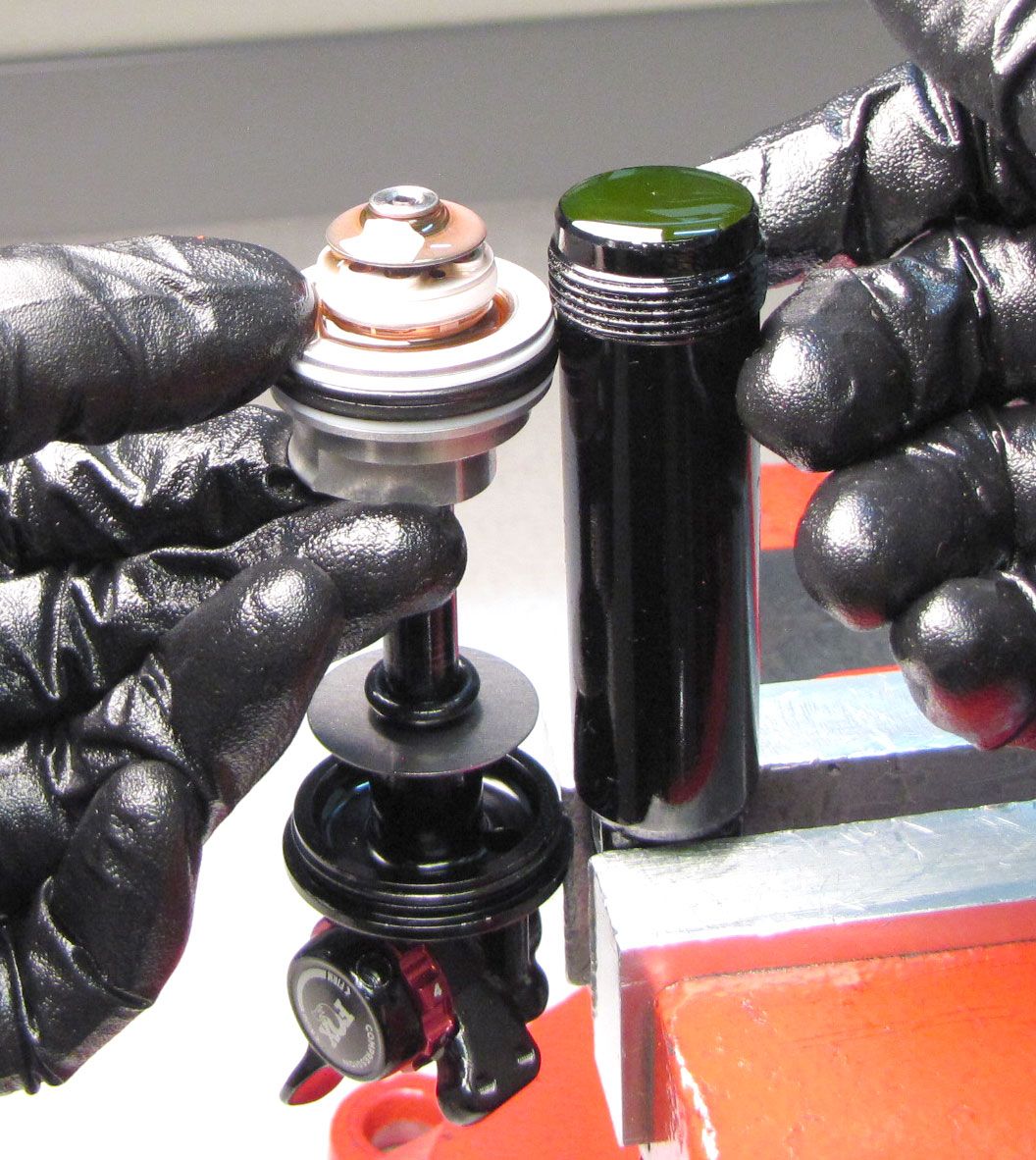
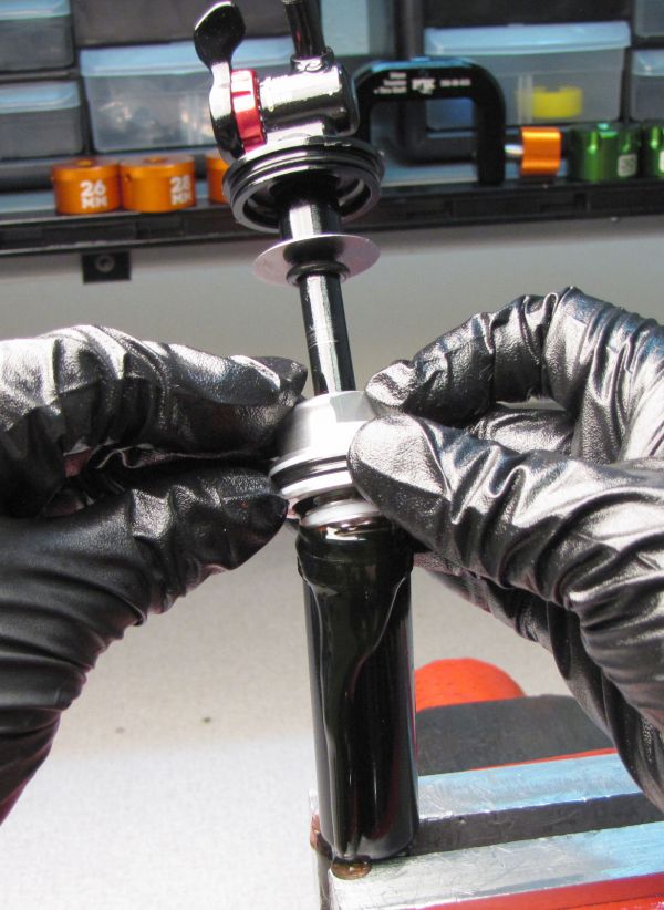
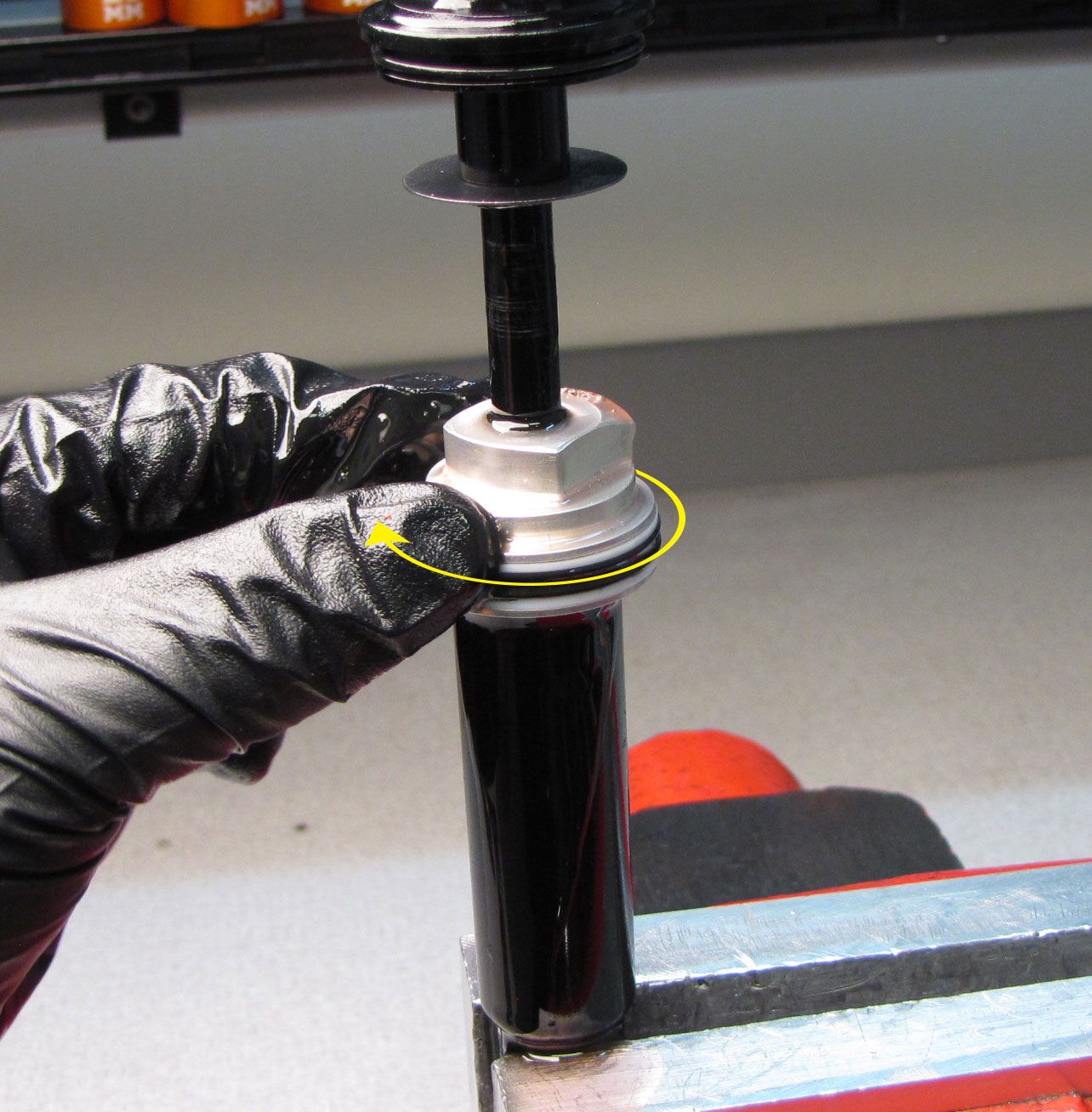
Step 41
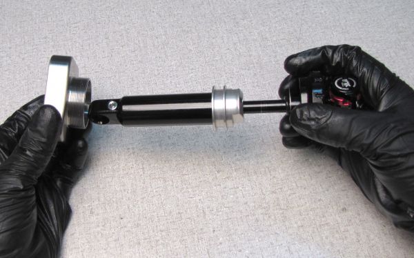
Invert the shaft assembly inserting the piston assembly into the previousely prepared and filled shock body. Thread the bearing assembly onto the body then tighten to 240 in-lb (27.1 Nm) with your 3/4in crow's foot.

Step 42
Reinsert the ball bearing followed by the bleed screw into the bleed hole in the bearing assembly. Tighten the bleed screw to 10-15 in-lb (1.1-1.7 Nm) with a 5/64" hex wrench.


Step 43
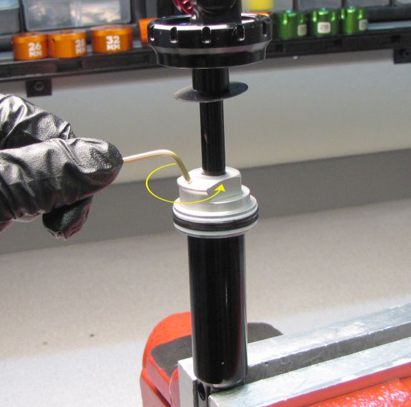
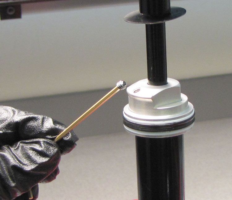
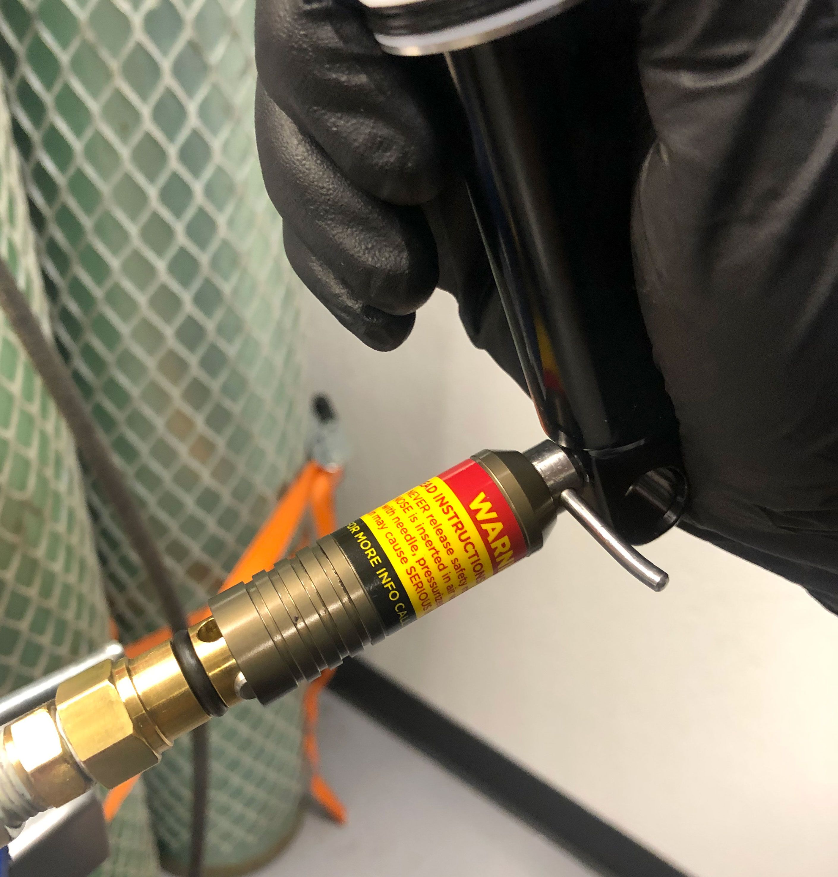
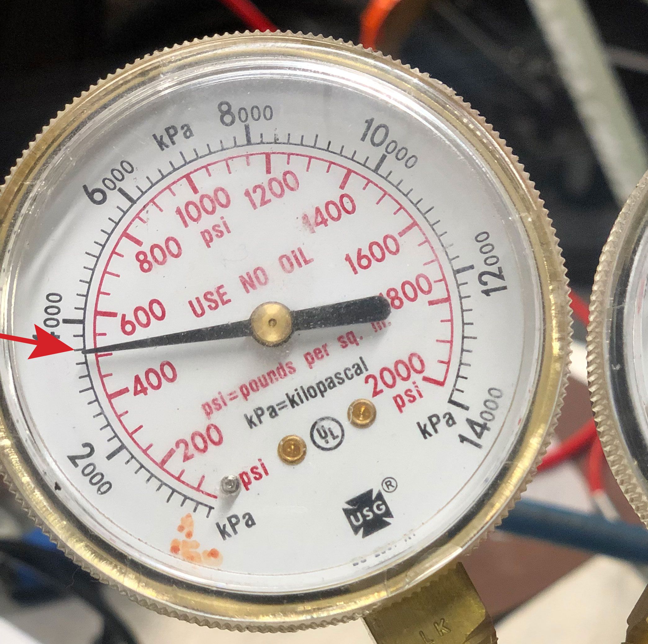
Insert the Nitrogen Fill Pellet Retainer tool (PN: 398-00-374) into the pellet retainer near the end of the body. Use the Pellet Retainer tool to unthread the pellet retainer 1/4 turn. Depress the safety button on the nitrogen fill needle (PN: 802-01-000-KIT), then slide the shock onto the needle by pressing toward the nitrogen fill needle. Charge the IFP chamber to 500 psi. Use the Pellet Retainer tool to gently tighten the pellet retainer by 1/4 turn. Quickly pull the shock straight away from the nitrogen fill needle. A loud pop will be heard. Use a 5/32" hex wrench to tighten the pellet retainer to 14 in-lb (1.6 Nm). Press the Delrin ball into the pellet retainer with your soft-jawed vice.
Step 44
Dyno the damper assembly by itself by using the IsoStrut Threaded Coupler. Thread the Eyelet Collar onto the Threaded Coupler clockwise until hand tight.
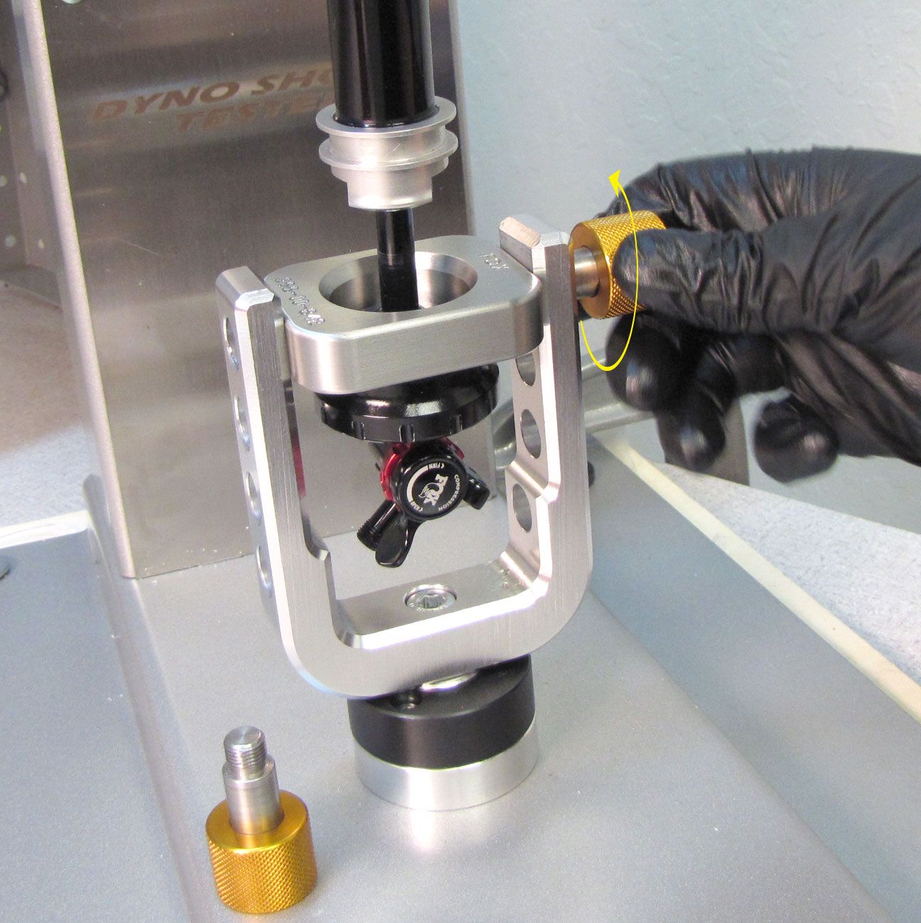
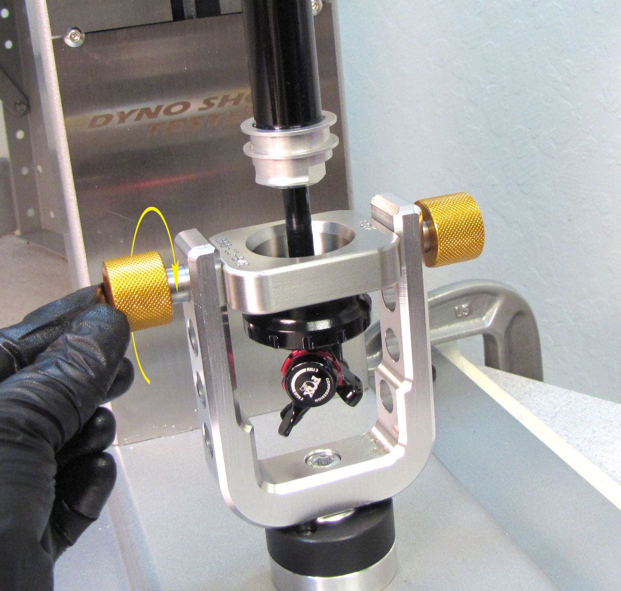
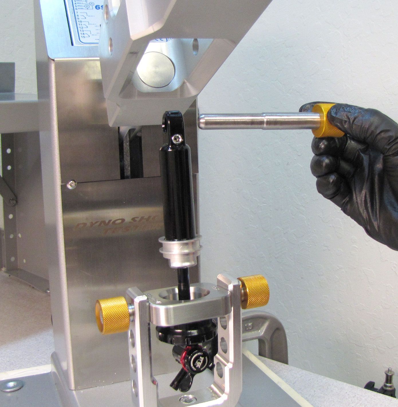
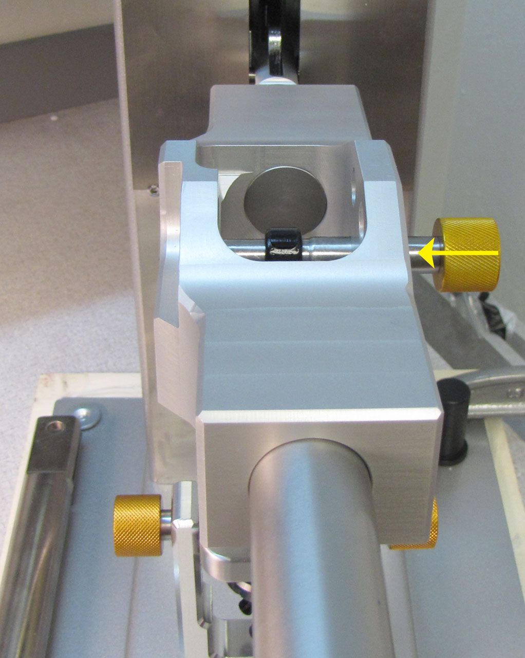
Step 45
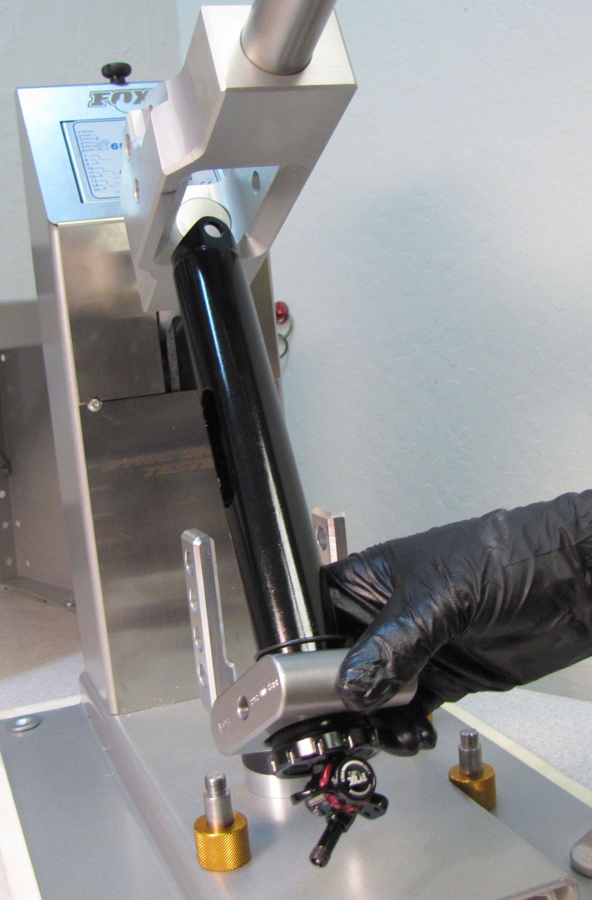
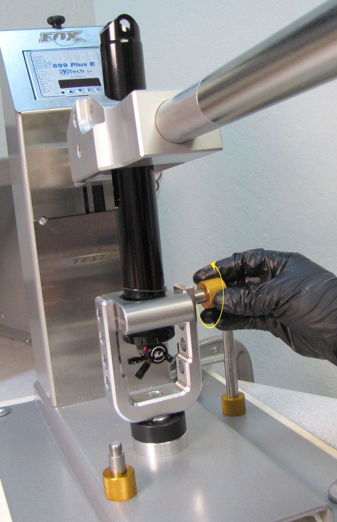
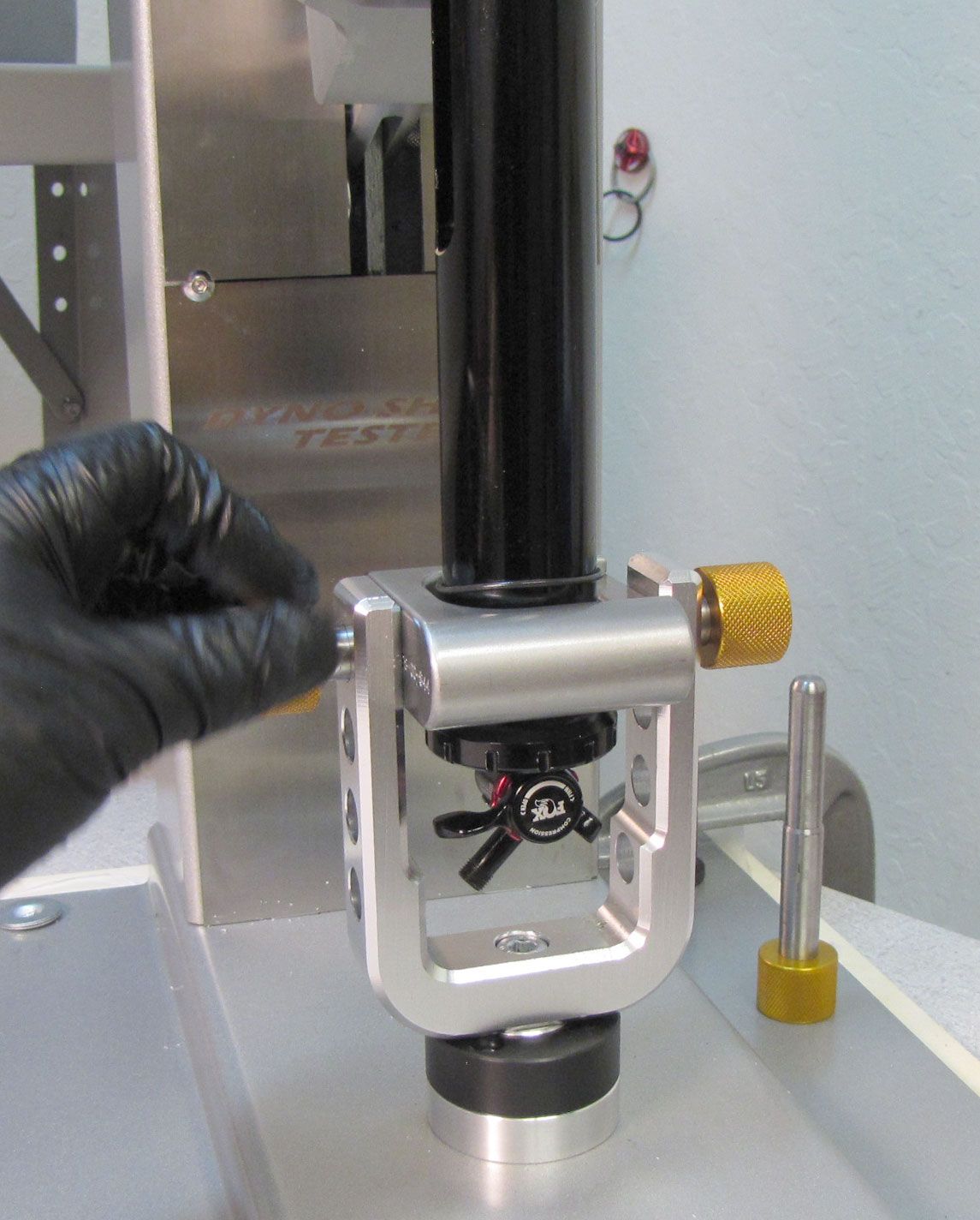
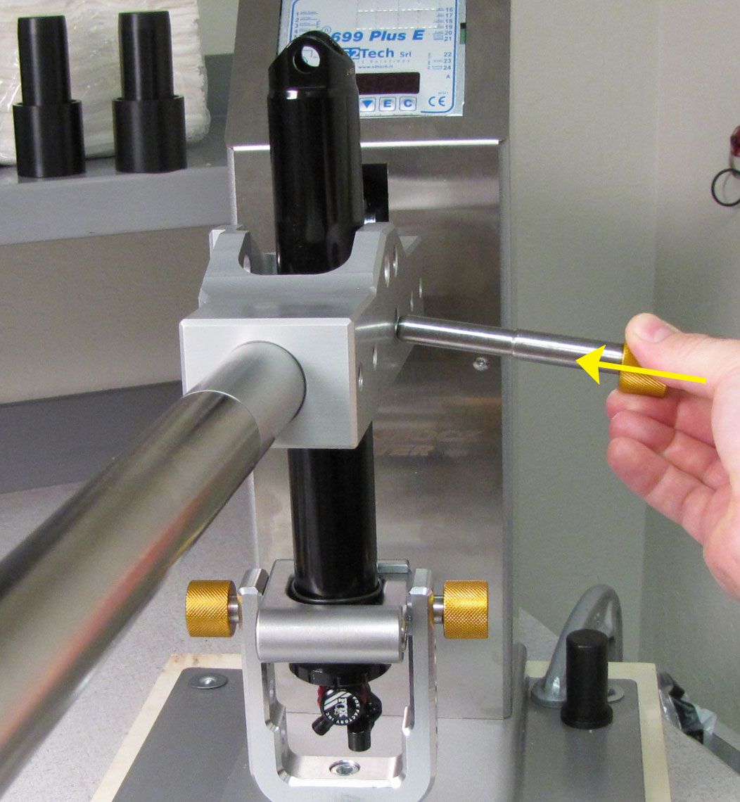
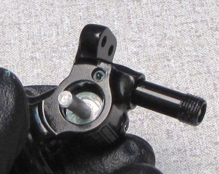
Replace the original Andreani Digital Dyno handle with the IsoStrut specific Dyno Handle. Position your prepared IsoStrut shock in your modified dyno as shown. Thread the two "trunnion" dyno bolts into the IsoStrut Threaded Coupler. Insert the stepped pin into the body eyelet through the dyno handle from the right side, then dyno the shock testing all functions.

Step 46
Remove the IsoStrut Threaded Coupler by unthreading the Eyelet Collar counter-clockwise.

Step 47
Mount the Isostrut Dyno Coupler to the tabs of the IsoStrut Sleeve Assembly as shown. Mate the Inner Coupler with the side of the tabs that have counter-bores. The Outer coupler engages the flat side of the tabs. Make sure the coupler tools are fully seated then clamp in your soft-jawed vise as shown.


Step 48
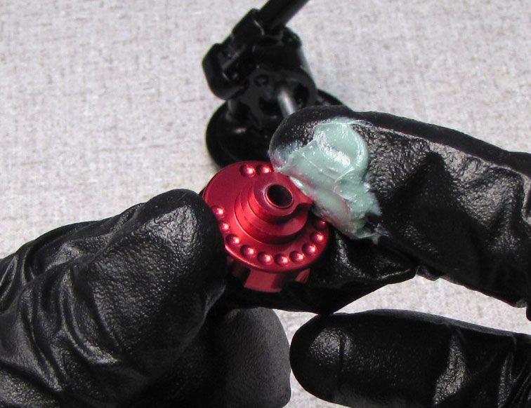
Replace all seals and backup rings on the Neg Plate Subassembly with new ones from the kit. Use only Float Fluid to lubricate the air seals and backup rings on the inside of the Neg Plate Subassembly. Slick Honey can be used on the external o-ring around the outside of the Neg Plate Subassembly.


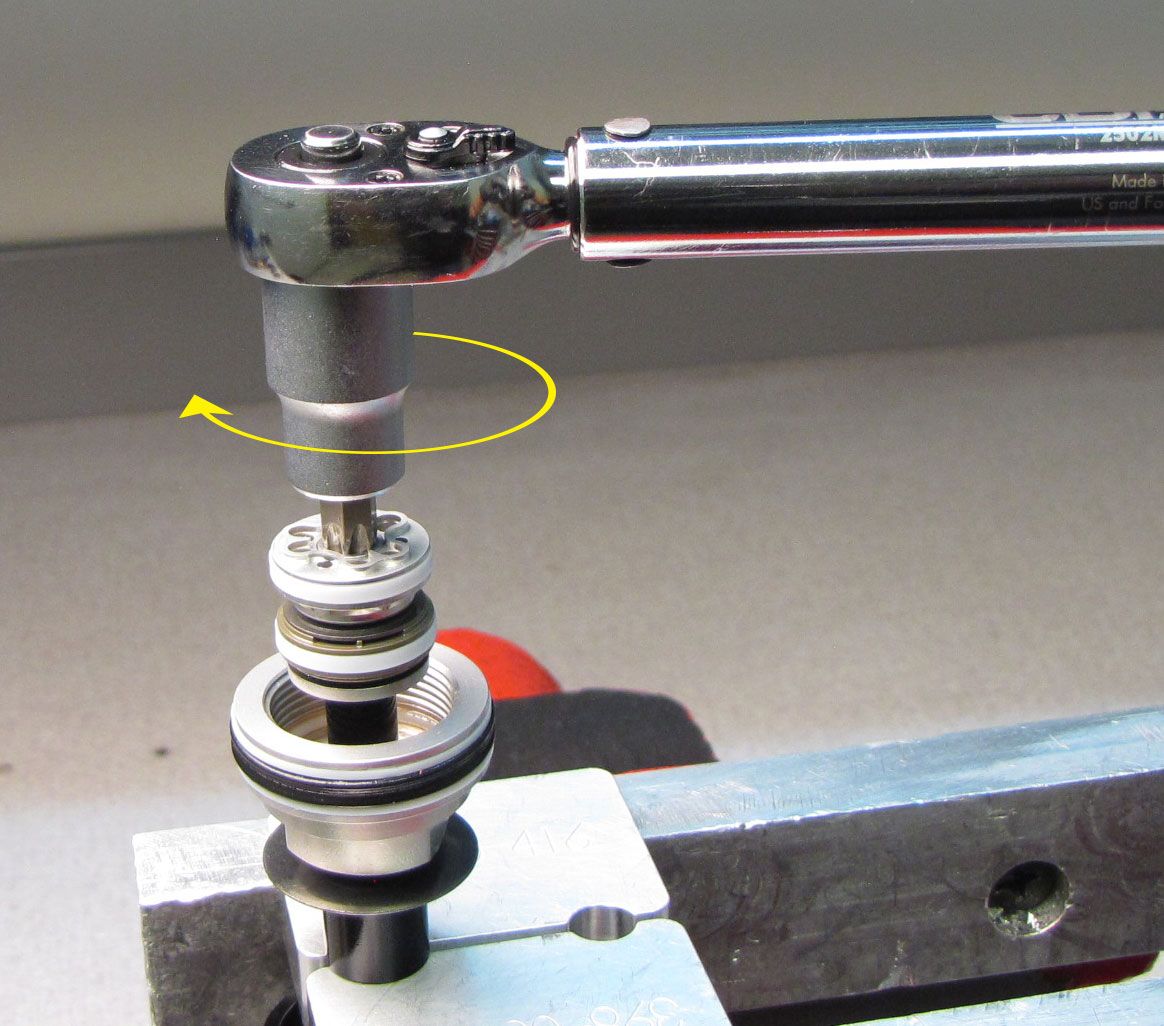
Step 49
Reinstall the Neg Plate Subassembly into the Sleeve Assembly with the wiper facing down and the wrench flats facing up. Insert the Neg Plate tool into the Sleeve Assembly with the hex side facing into the sleeve. Use a 3/8" square drive extension and your ratchet to tighten the Neg Plate Assembly clockwise to 144 in-lb (16.2 Nm) torque.


Step 50
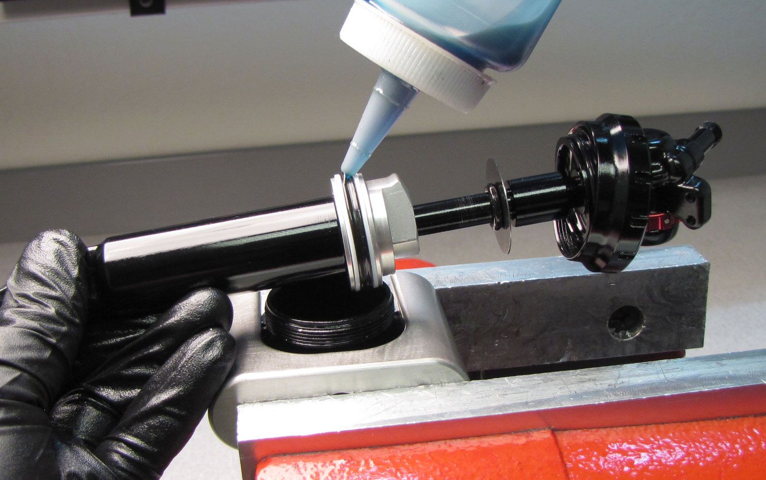
Coat the main air seals with a film of Float Fluid then insert the damper assembly into the Sleeve Assembly. inject 2cc of Float Fluid into the Sleeve Assembly above the Bearing Assembly. Push the Damper Assembly down fully into the Sleeve Assembly.
Step 51
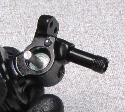
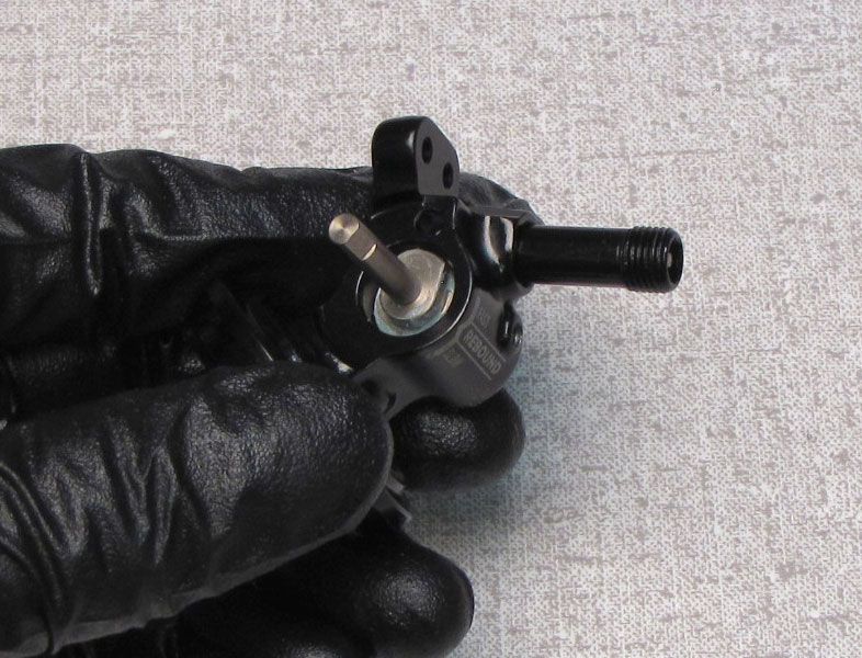
Use the dyno pin to hold the body eyelet in place (aligning the body eyelet with the slot in the Sleeve Assembly) while you thread the Eyelet Collar clockwise onto the Sleeve Assembly with a Race Face 12-spline bottom bracket tool. Tighten to 144 in-lb (16.2 Nm) torque.


Step 52
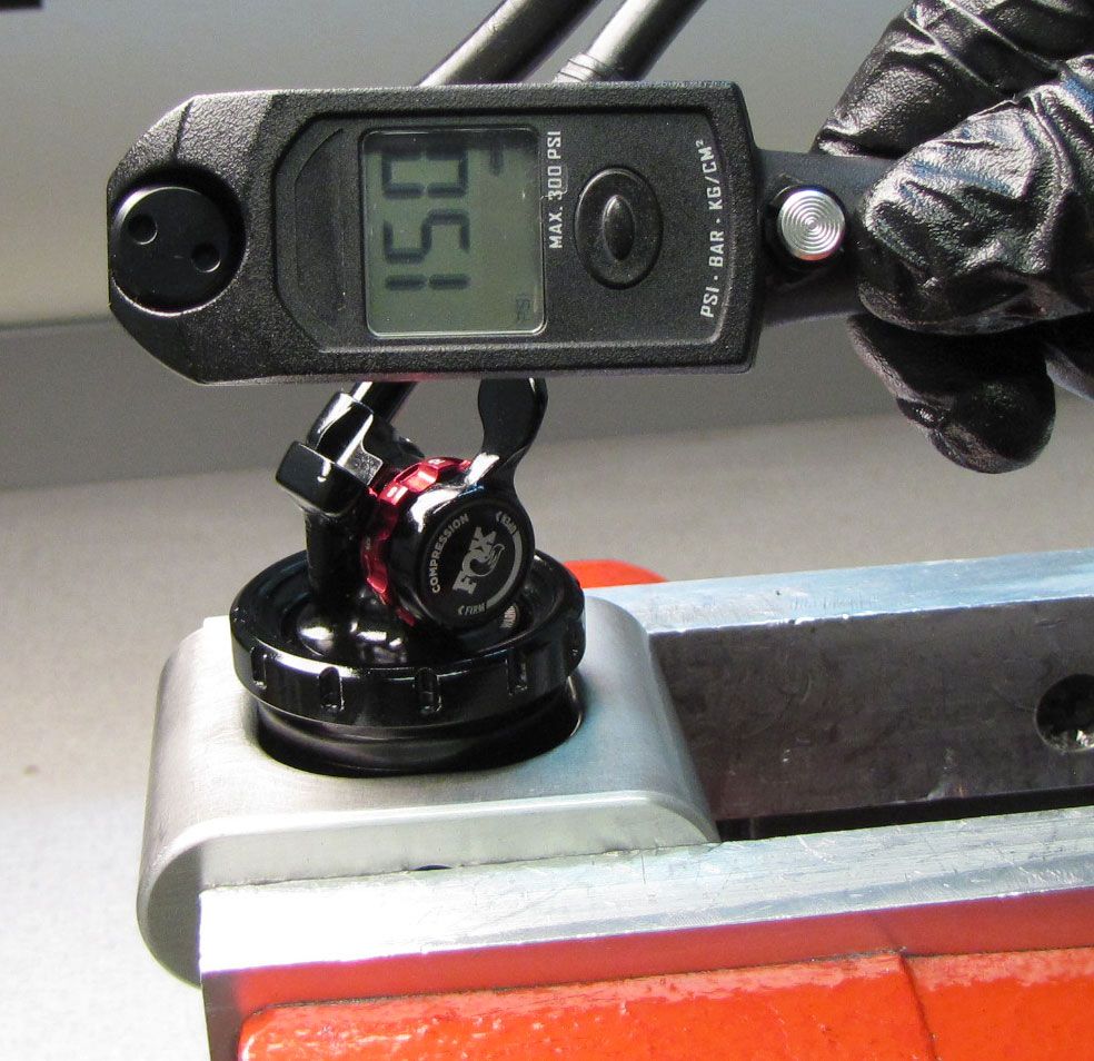
Pressurize the main air chamber to 150 psi to dyno and test all functions of the shock.


Step 53
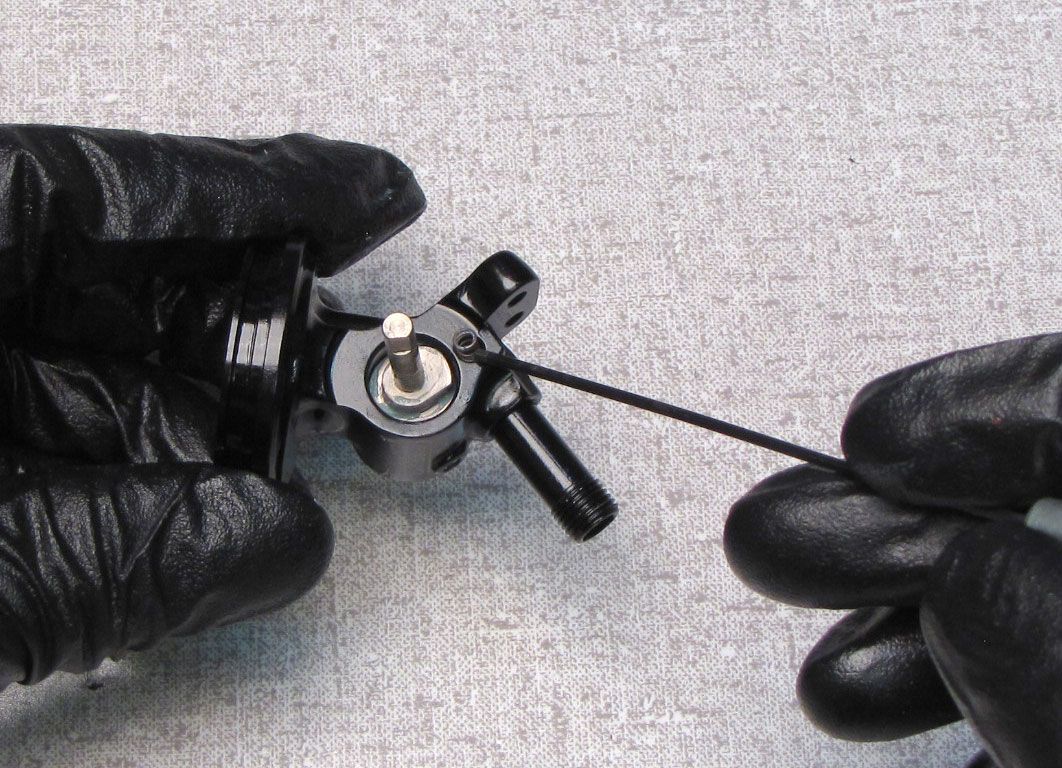
Position your prepared IsoStrut shock in your modified dyno as shown. Thread the two "trunnion" dyno bolts into the IsoStrut Threaded Coupler. Insert the stepped pin into the body eyelet through the dyno handle and the Sleeve Assembly from the right side, then dyno the shock testing all functions. Install the sag indicator o-ring onto the Sleeve Assembly.