BOMBER Z2 Full Rebuild
Required Parts
- 025-03-010 Oil: AM, FOX Bath Oil [32 oz.], 20 WT Gold
- 025-03-023 Oil: Suspension Fluid, 5wt, Teflon Infused, 1.0 US Quart
- 803-00-945 Kit: Dust Wiper, Forx, 34mm, Low Friction, No Flange
- 803-01-430 Seal Kit: Marzocchi Z2 34 Rail Damper Rebuild
Required Tools
- 398-00-681 2002-017 32 Damper-side and ALL 32-34-36-40 Spring-side Removal Tool
- 398-00-702 Tooling: Fork Topcap Socket, 26mm, 3/8 Drive
- 398-00-771 Tooling: Guided Fork Seal Driver, One Piece Seal/Wiper, 34
- 803-00-830 Service Set: Tooling: 2014 RC2, Shaft Clamps
WARNING: Always wear safety glasses and protective gloves during service to prevent potential injury. Failure to wear protective equipment during service may lead to SERIOUS INJURY OR DEATH.
WARNING: FOX products should be serviced by a trained bicycle service technician, in accordance with FOX specifications. If you have any doubt whether or not you can properly service your FOX product, then DO NOT attempt it. Improperly serviced products can fail, causing the rider to lose control resulting in SERIOUS INJURY OR DEATH.
WARNING: Never attempt to modify air volume spacers or air shaft assemblies, as this can damage your fork causing a loss of control of the bicycle leading to SERIOUS INJURY or DEATH.
WARNING: FOX suspension products contain pressurized nitrogen, air, oil, or all 3. Suspension misuse can cause property damage, SERIOUS INJURY OR DEATH. DO NOT puncture, incinerate or crush any portion of a FOX suspension product. DO NOT attempt to disassemble any portion of a FOX suspension product, unless expressly instructed to do so by the applicable FOX technical documentation, and then ONLY while strictly adhering to all FOX instructions and warnings in that instance.
WARNING: Modification, improper service, or use of aftermarket replacement parts with FOX forks and shocks may cause the product to malfunction, resulting in SERIOUS INJURY OR DEATH. DO NOT modify any part of a fork or shock, including the fork brace (lower leg cross brace), crown, steerer, upper and lower leg tubes, or internal parts, except as instructed herein. Any unauthorized modification may void the warranty, and may cause failure or the fork or shock, resulting in SERIOUS INJURY OR DEATH.
NOTE: This procedure guides you through the full rebuild of the BOMBER Z2 fork. While a non-remote version is shown, the procedure is identical for remote versions with the only difference being the installation and removal of the Topcap Interface Parts. BOMBER Z2 Remote Topcap Interface Part Installation can be found here: 2020 Grip Remote Topcap Interface Part Installation »
NOTE: New Z2 forks are now coming with a new bottom nut and crush washer. Please install the new bottom nut (PN: 803-01-819) and the new crush washer (PN: 803-01-818) in place of the original nut found with no crush washer. If a Z2 is being serviced and it already has the new non-serrated bottom nut and new crush washer, only the crush washer needs to be replaced during a rebuild.
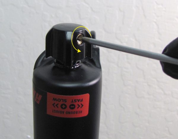
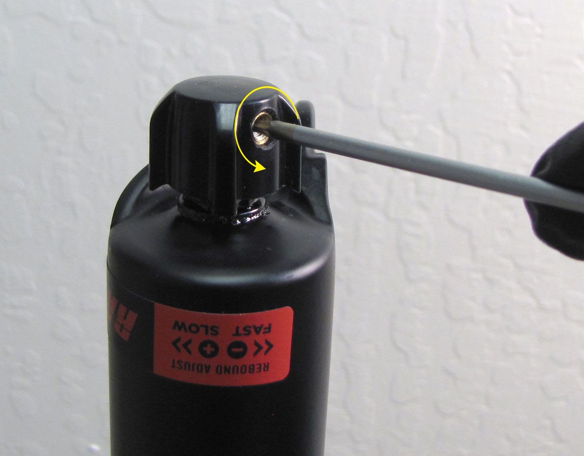
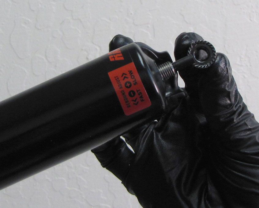
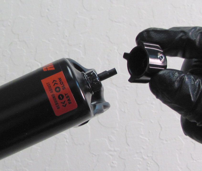
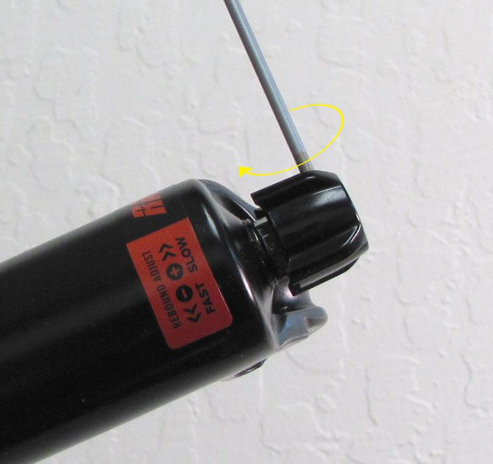
Step 1
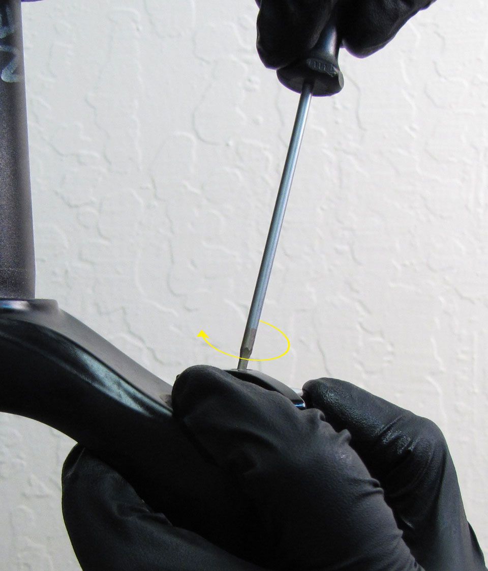
Use a 2mm hex wrench to unthread (counter-clockwise) the set screw in the black rebound knob. Remove the knob and set it aside.
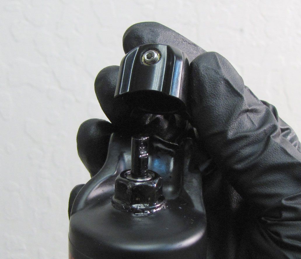

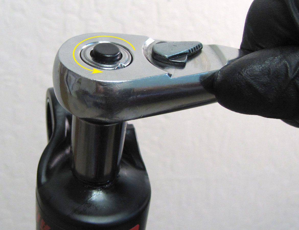
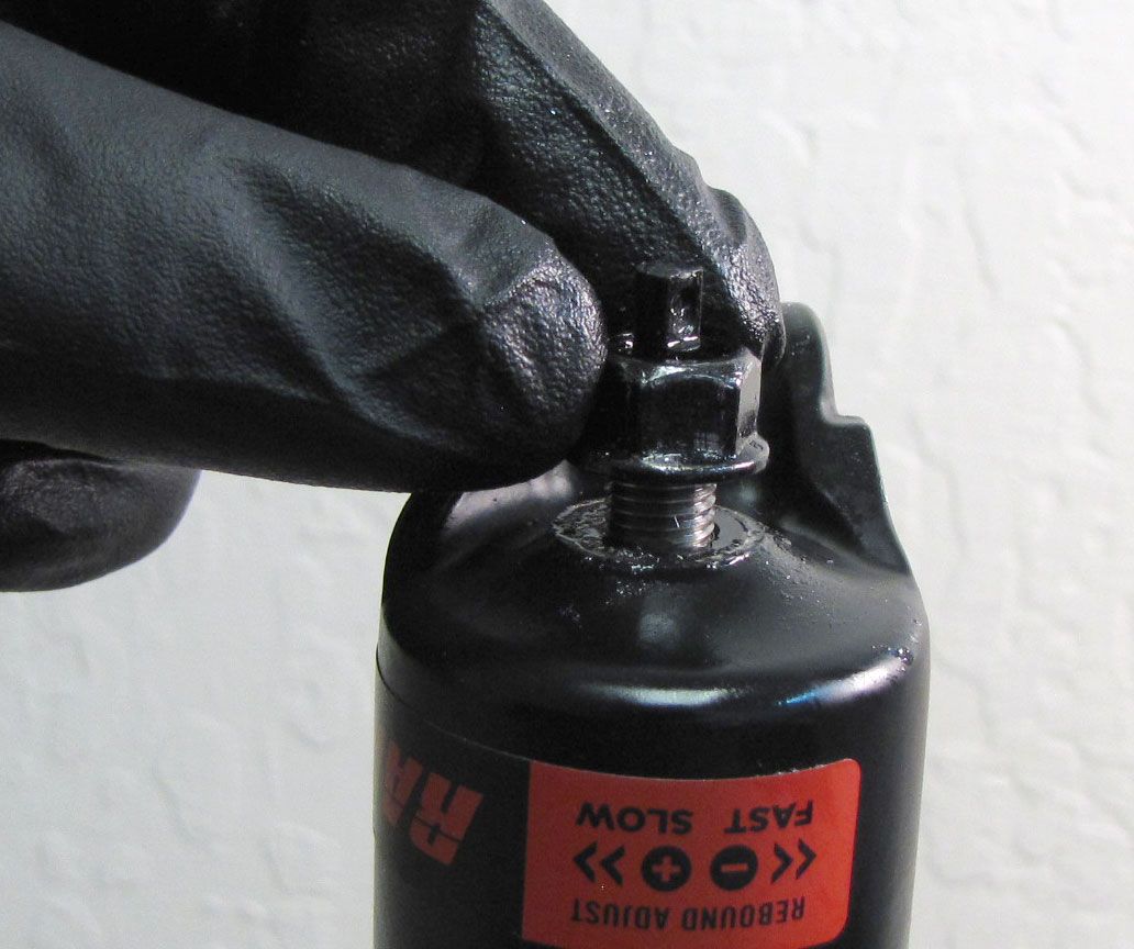
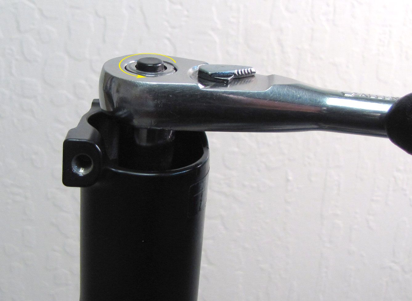
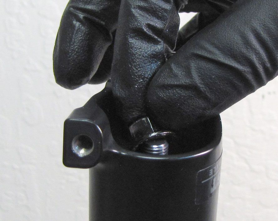
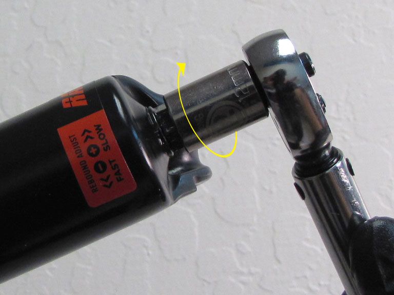
Step 2
Unthread and remove the bottom nuts by turning counter-clockwise with a 12mm socket. Z2 forks do not have crushwashers under the bottom nuts.


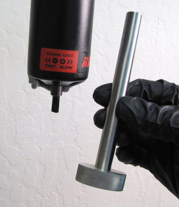
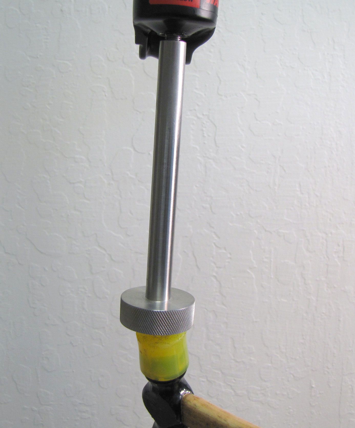
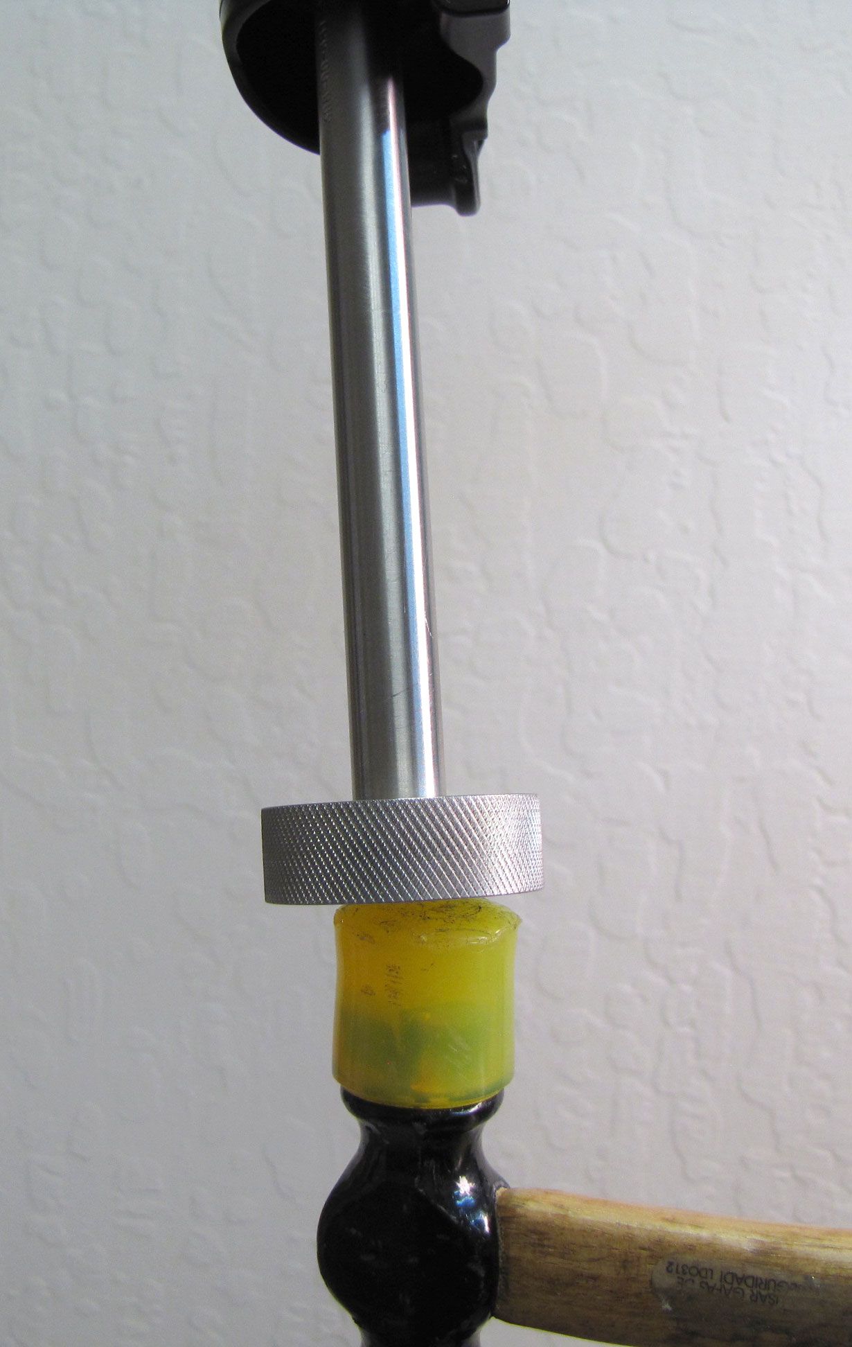
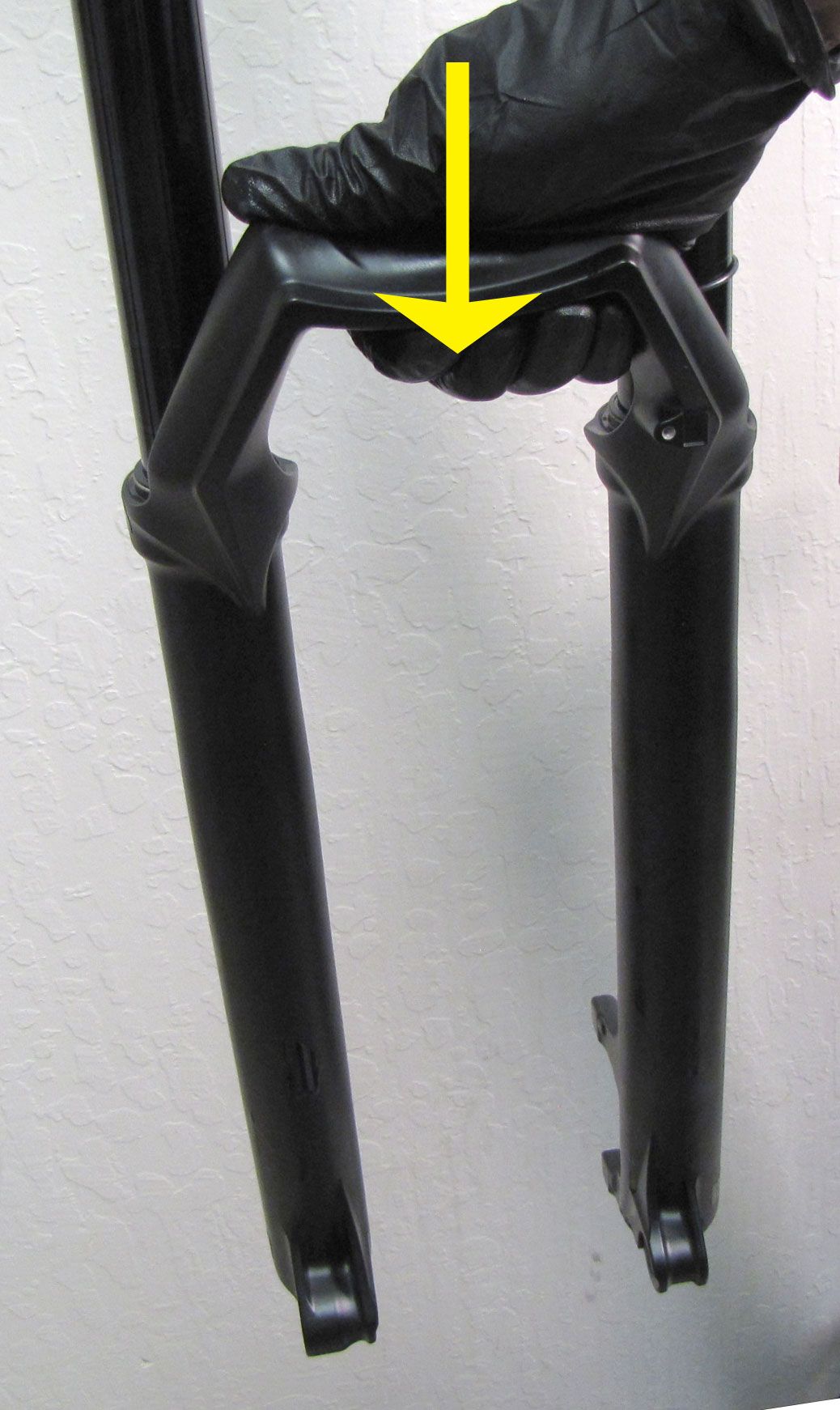
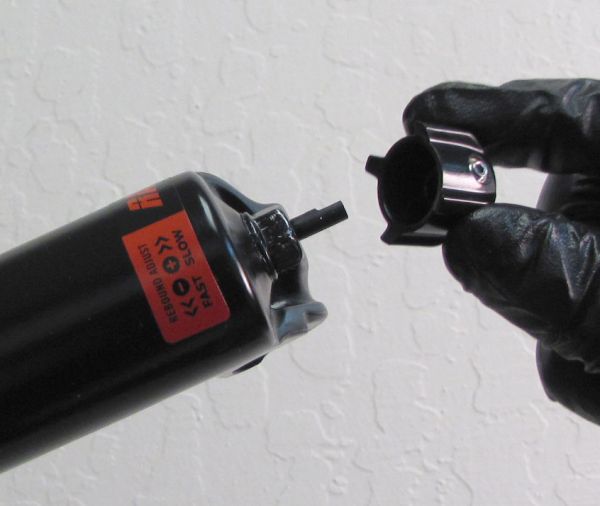
Step 3
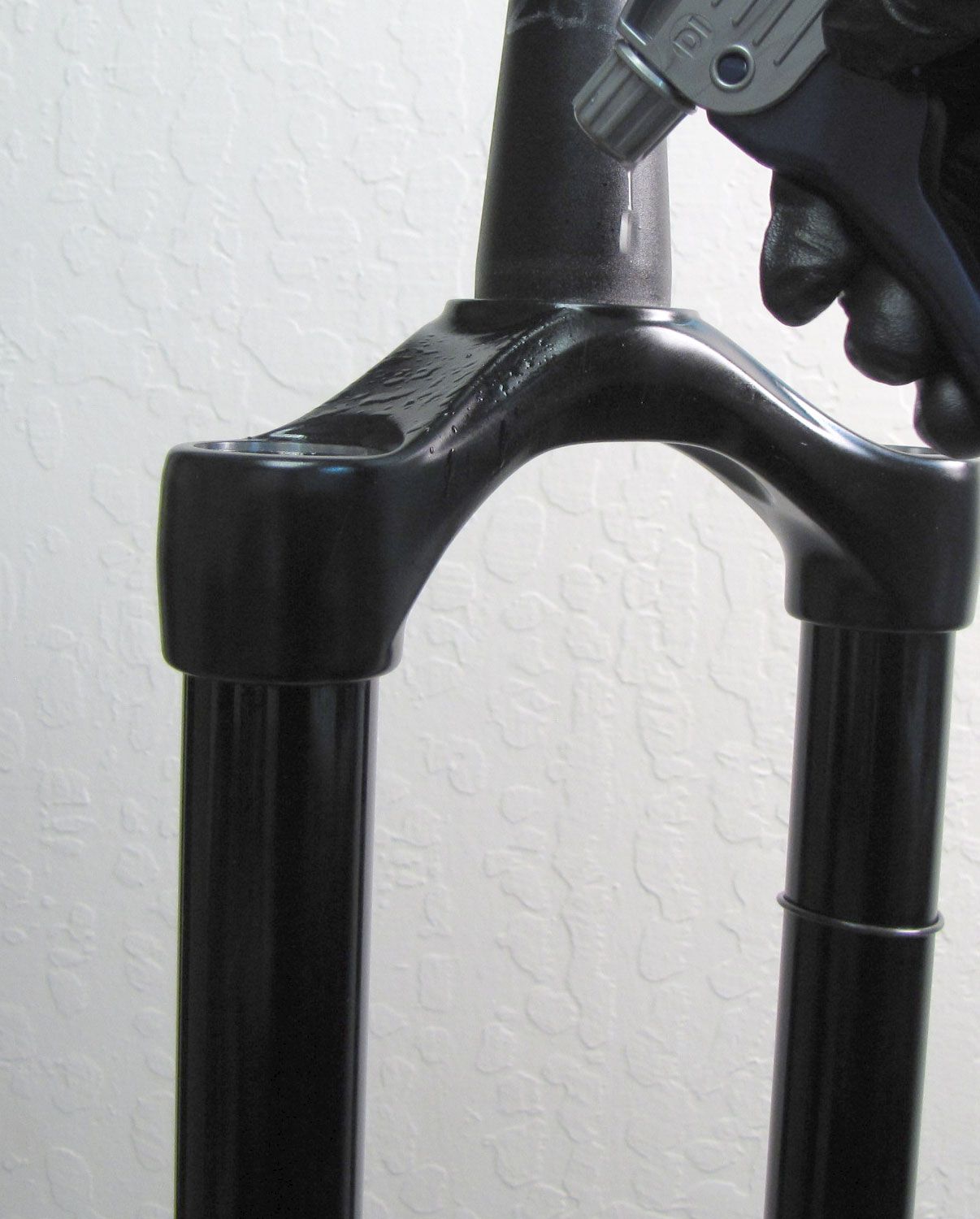
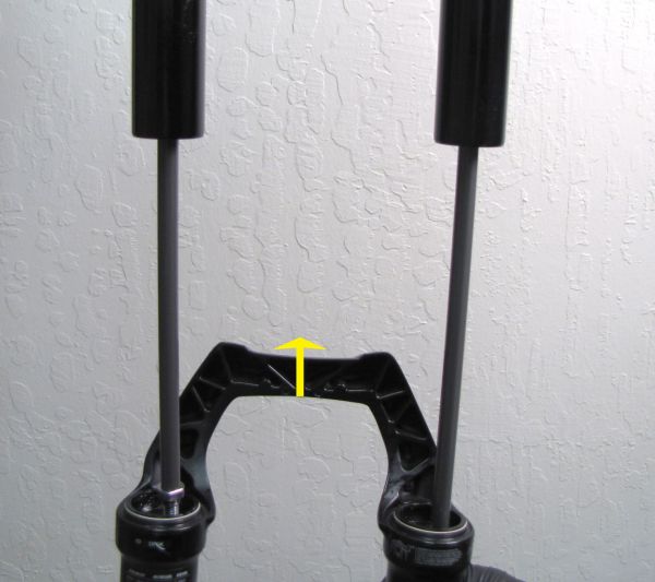
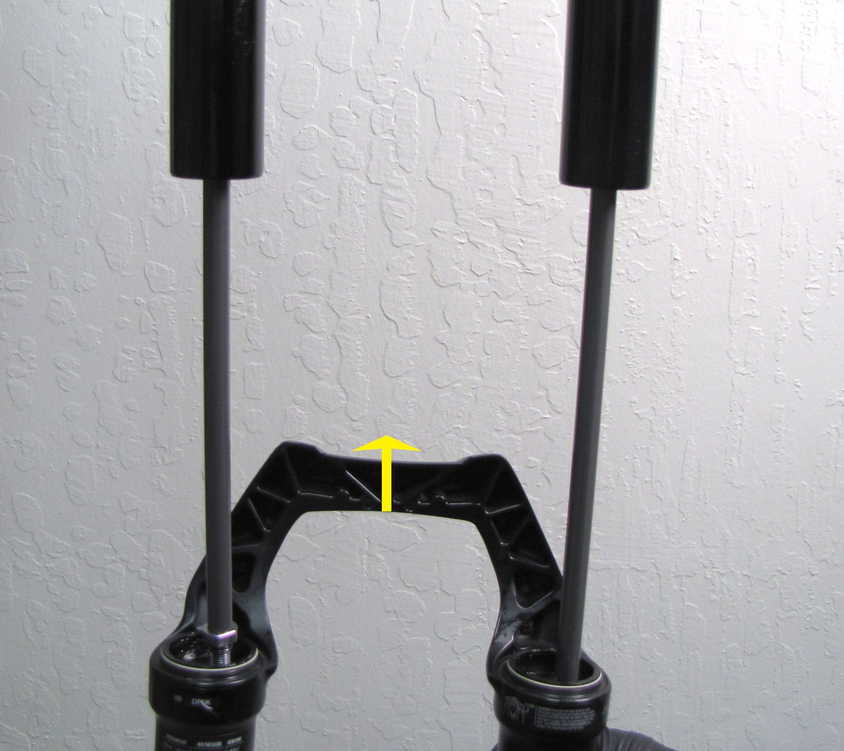
Use Damper Removal Tool 398-00-681 to dislodge both shafts from the lowers. Make sure that you have approximately half of the available threads engaged with your tool before striking with your mallet. Remove the damper removal tool, then bring the fork upright over an oil basin to drain. After oil stops draining from the lowers, pull the lowers off of the upper tubes and set them aside.


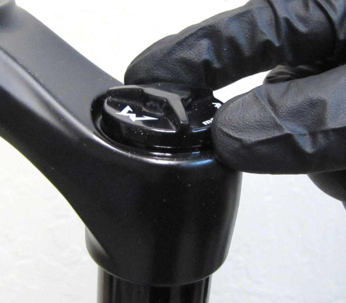
Step 4
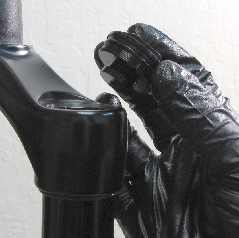
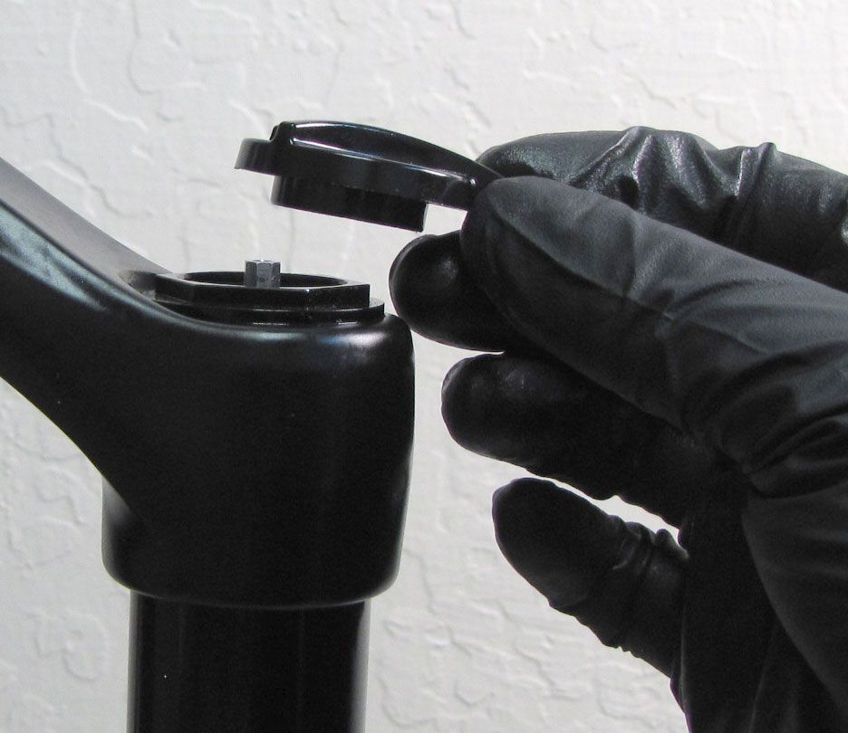
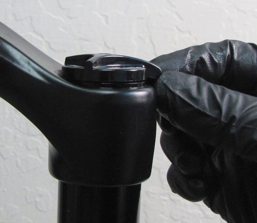
Remove the black Air Cap by turning it counter-clockwise. Release the air pressure by depressing the air valve core with a blunt tool.

Step 5
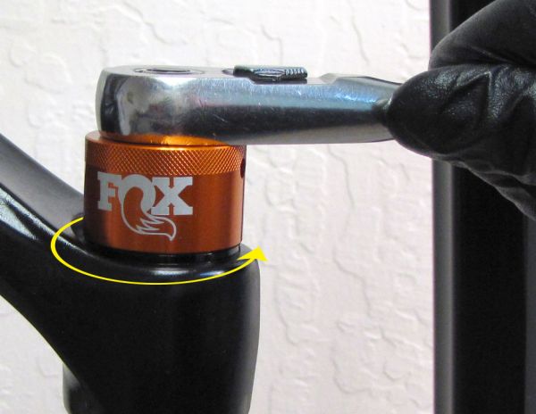
Unthread the air-side topcap assembly counter-clockwise with a 6-point chamfer-less 26mm socket (PN: 398-00-702). Replace the topcap o-ring with a new greased one from the kit then set aside in a clean area.
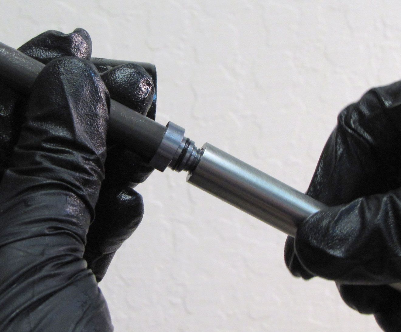
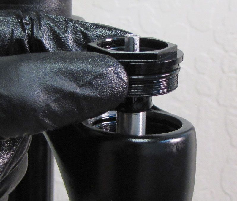
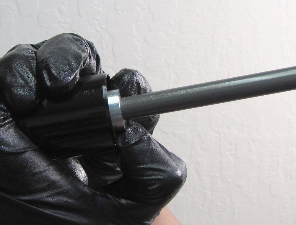
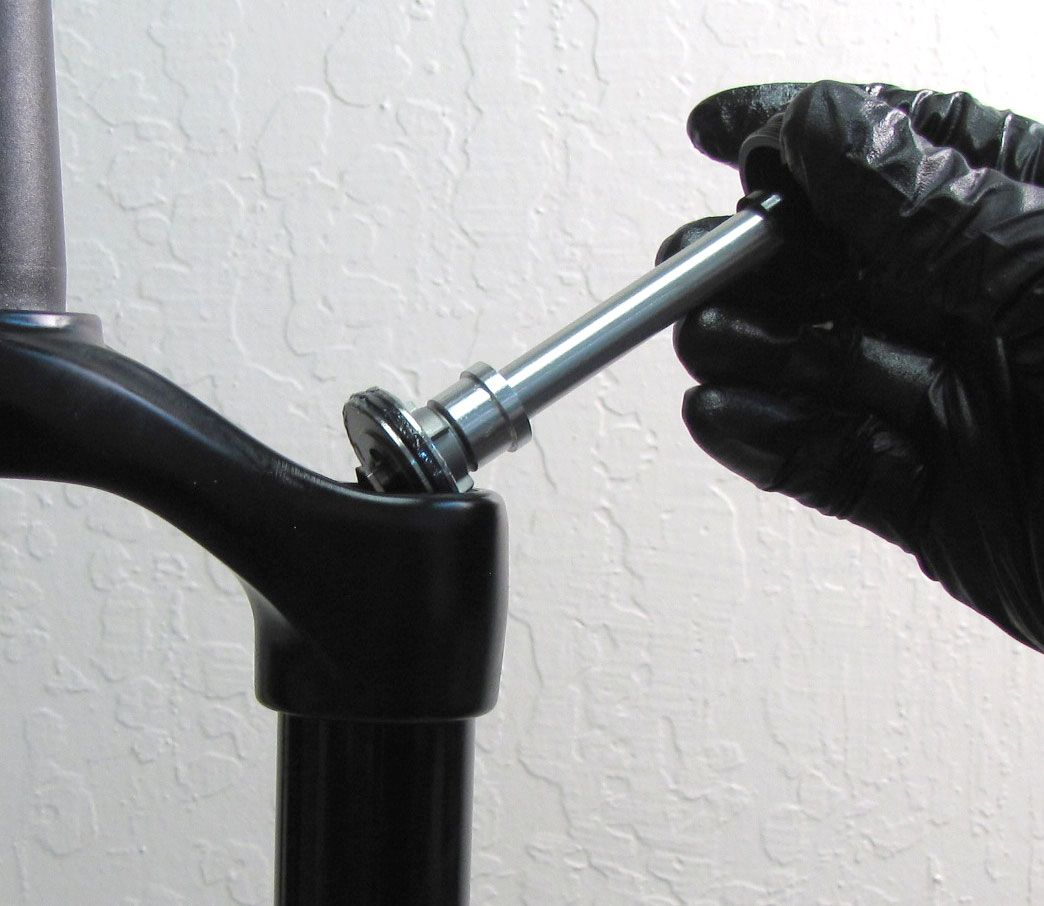
Step 6
Remove the retaining ring from the bottom of the air-side upper tube. Use the damper removal tool (PN: 398-00-681) to pull the Air Shaft Assembly out of the bottom of the upper tube. Remove the tool from the Air Shaft Assembly.


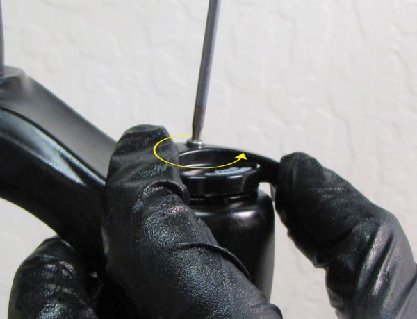
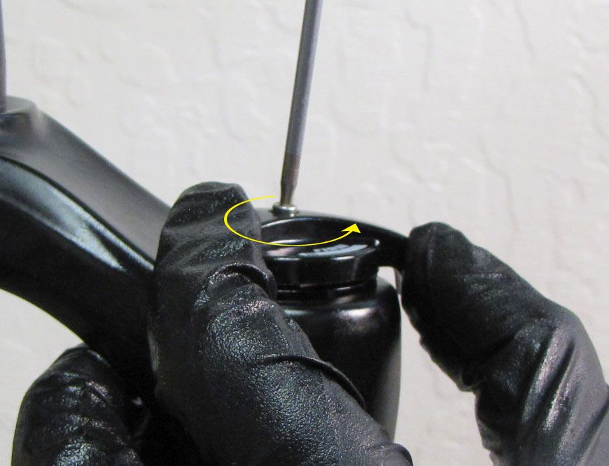
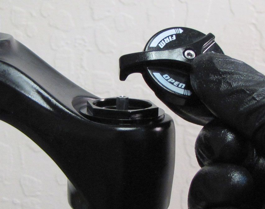
Step 7
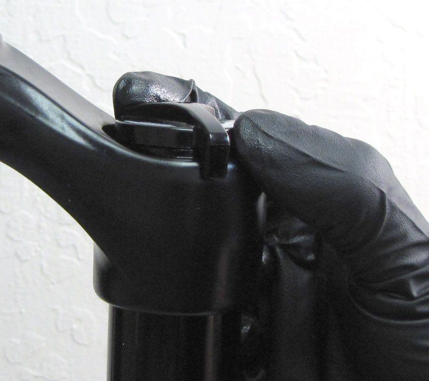
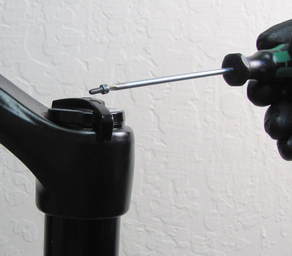
Hold the Rail Compression Knob from turning while you unthread its screw counter-clockwise with a 2mm hex wrench. Set the knob and screw aside in a clean area.
Step 8
Unthread the damper-side topcap assembly counter-clockwise with a 6-point chamfer-less 26mm socket. Lift the Topcap Assembly out of the upper tube. Pour out any damper oil from the upper tube.


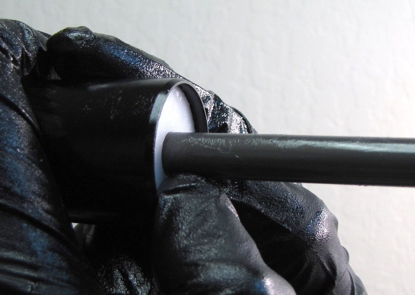
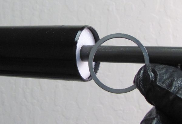
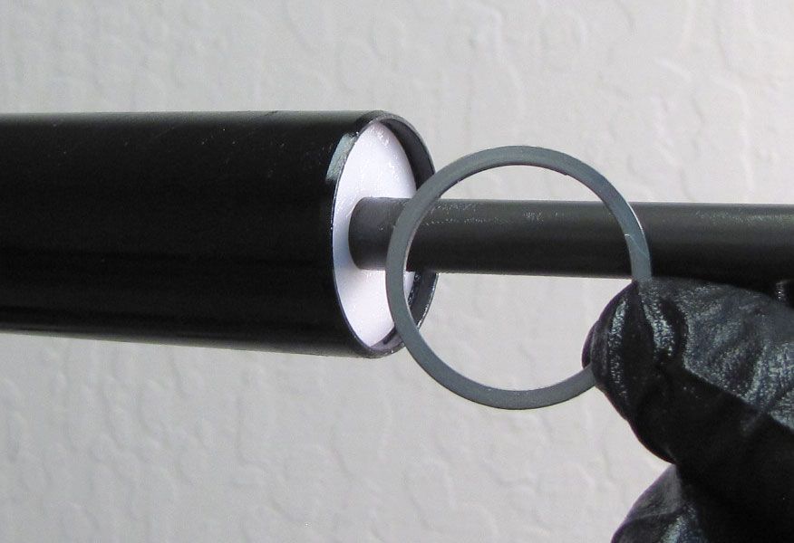
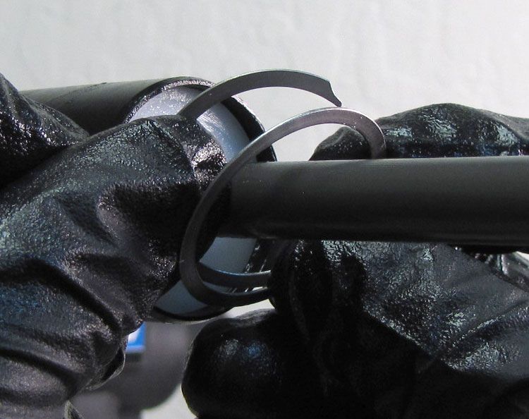
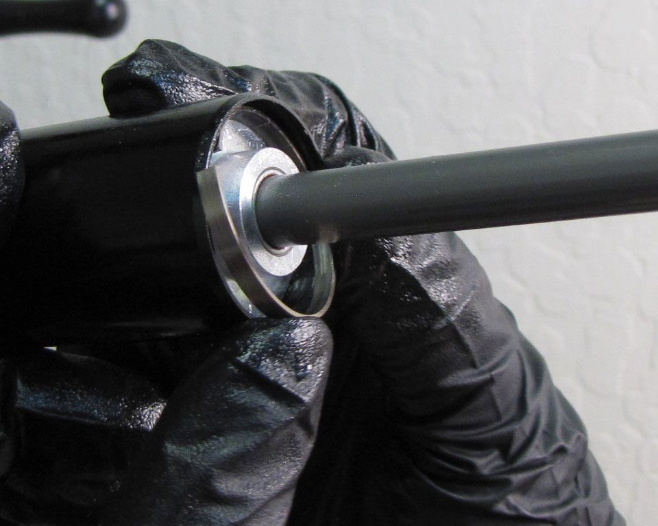
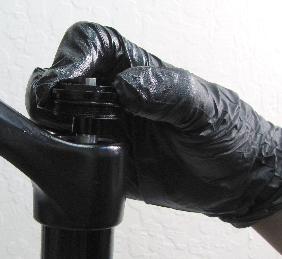
Step 9
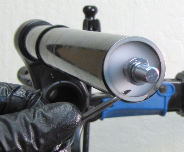
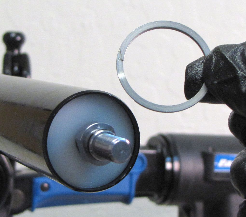
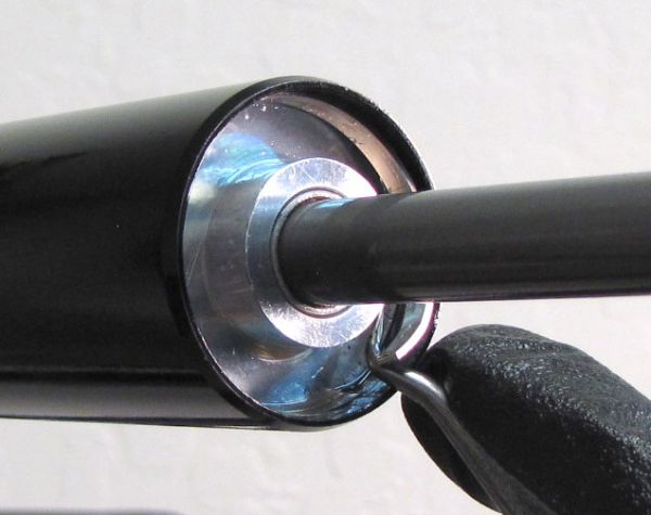
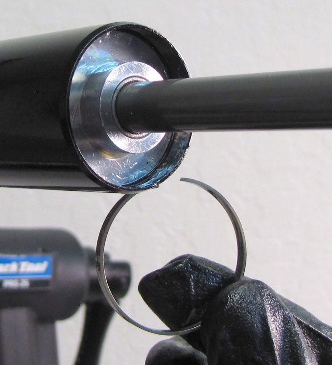
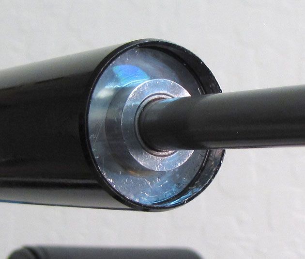
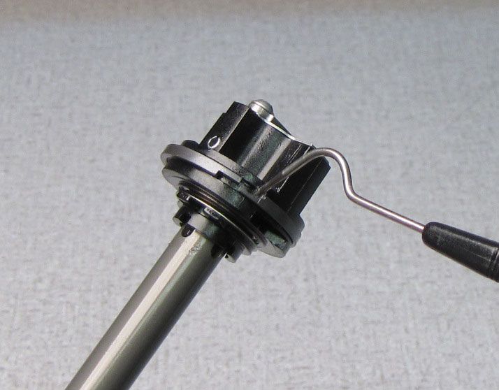
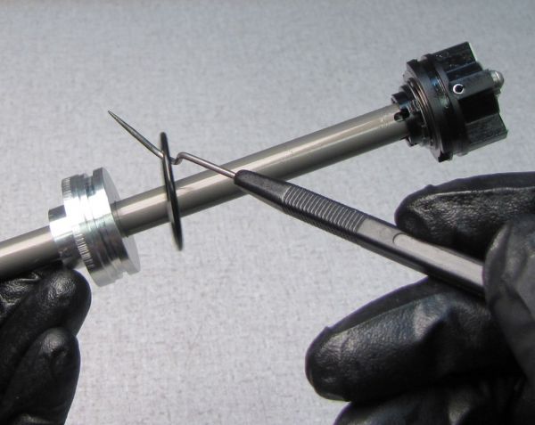
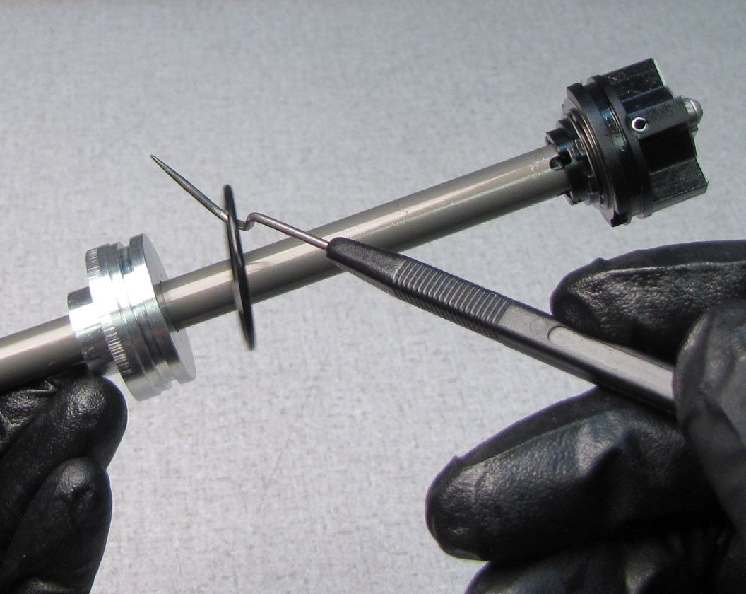
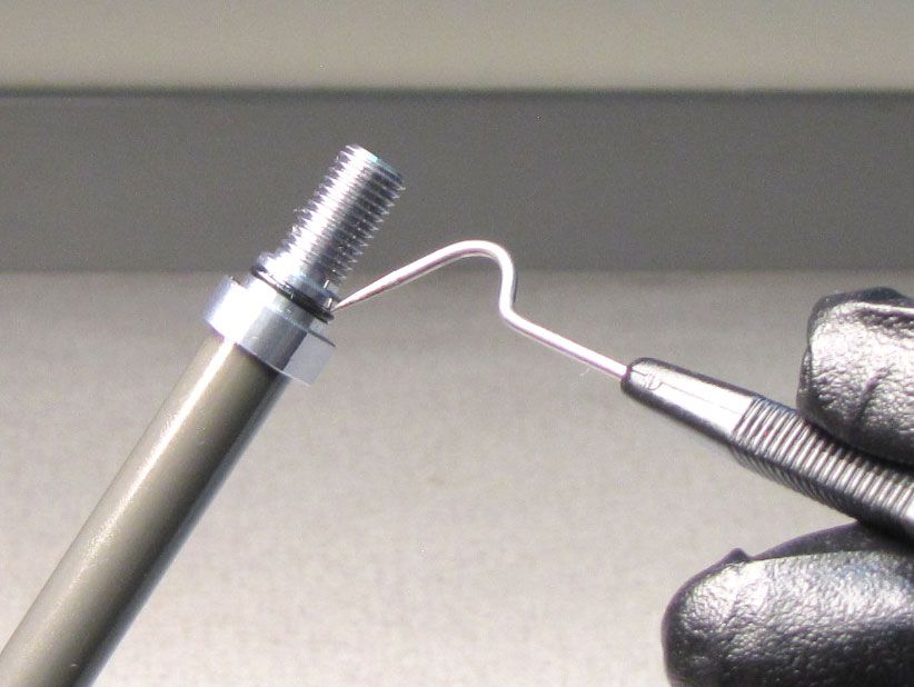
Remove the retaining ring from the bottom of the damper-side upper tube.
Never remove the retaining ring from the middle of the shaft as the edges of the ring may scratch the shaft. Always remove the retaining ring from the shaft by pulling it past the end of the shaft.


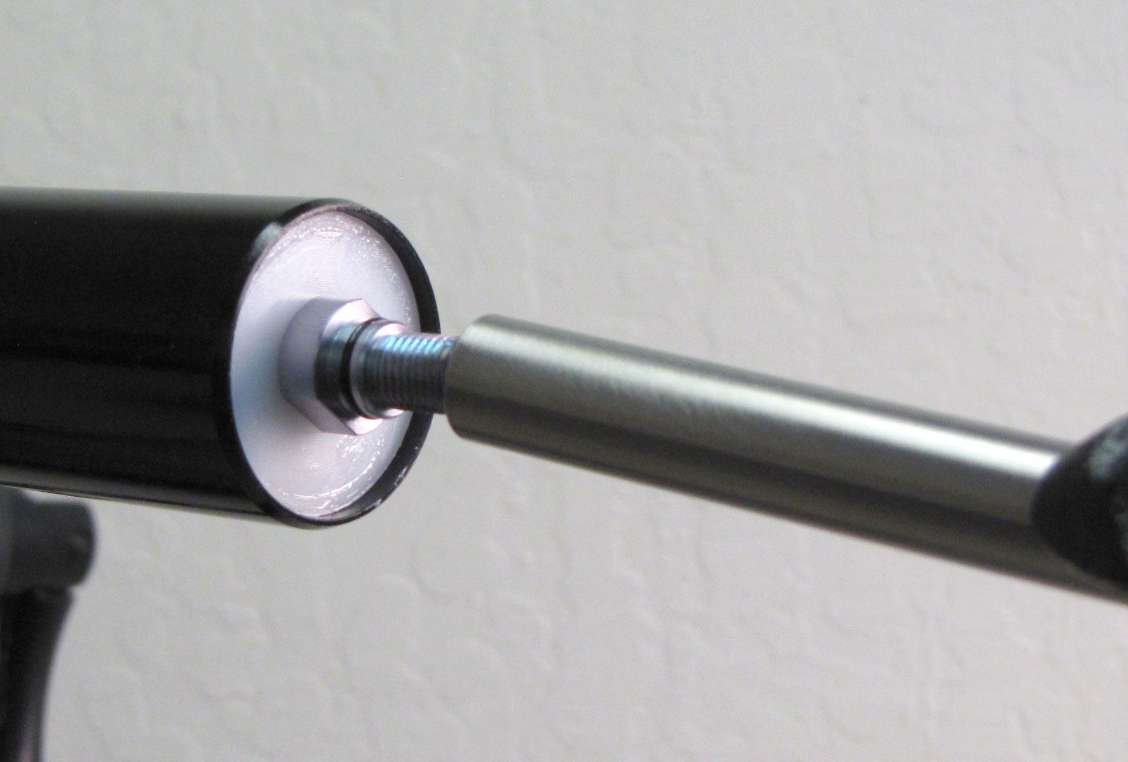
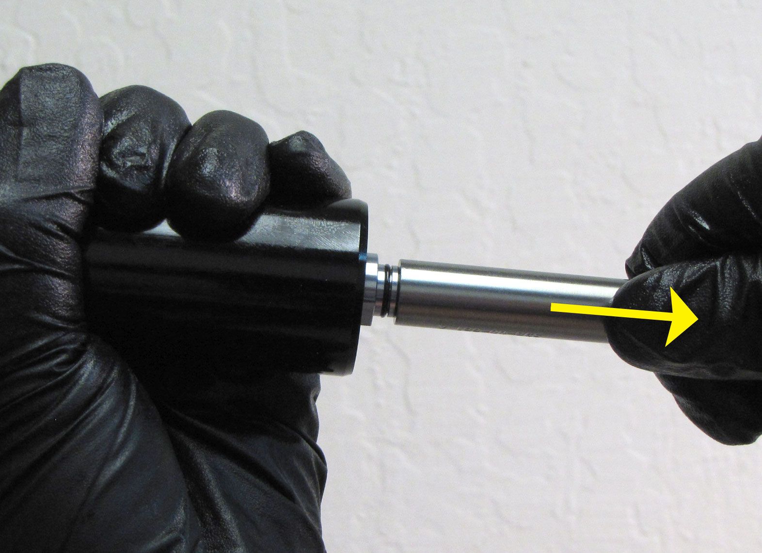
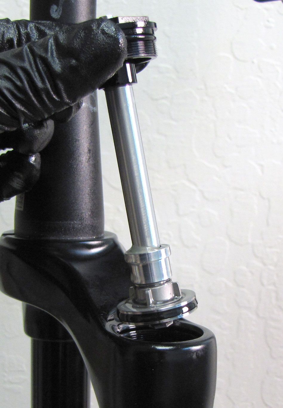
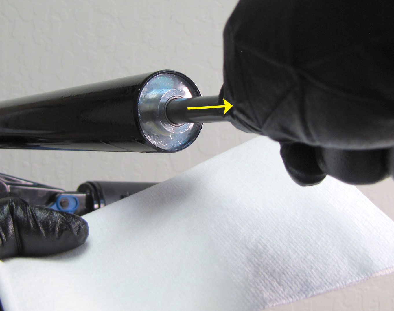
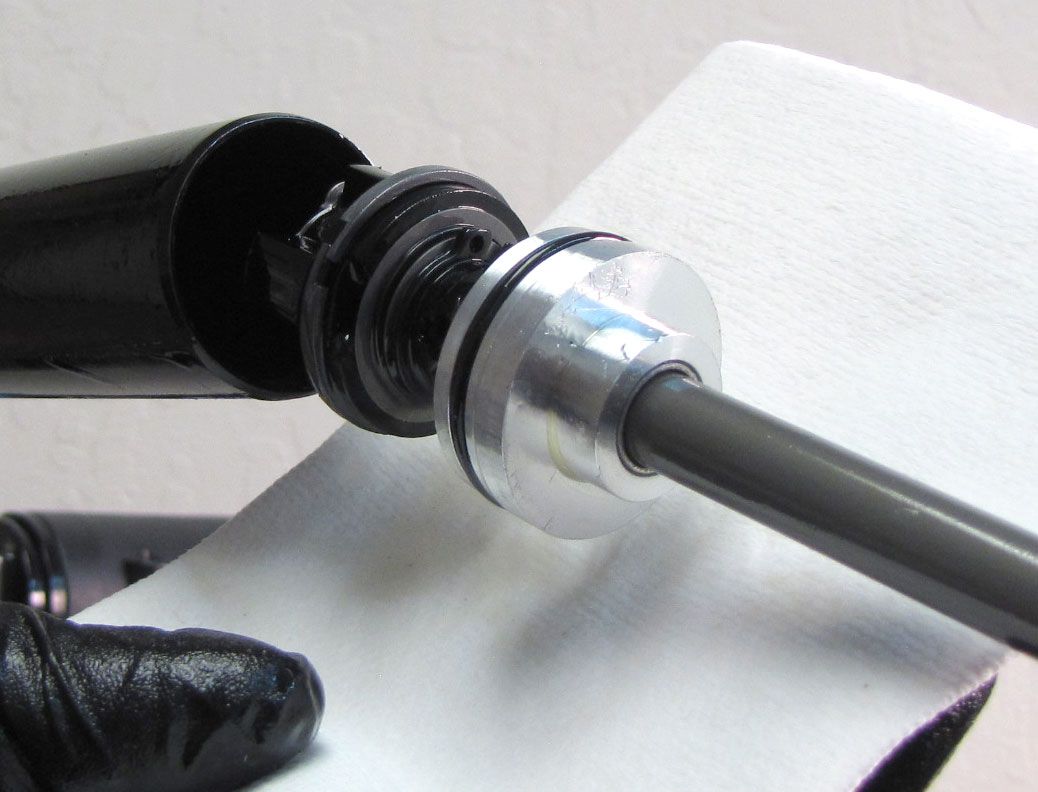
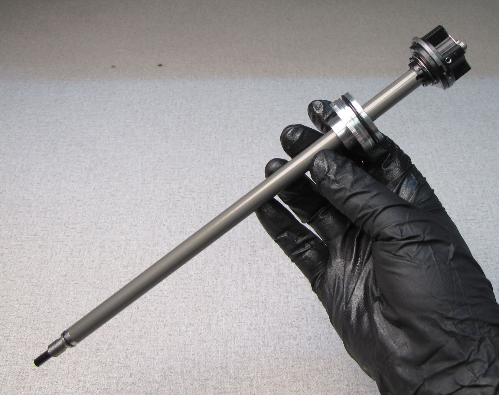
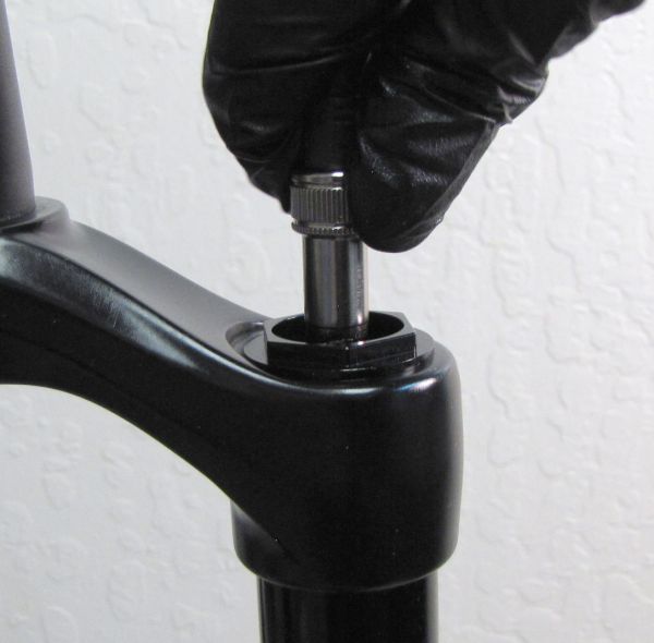
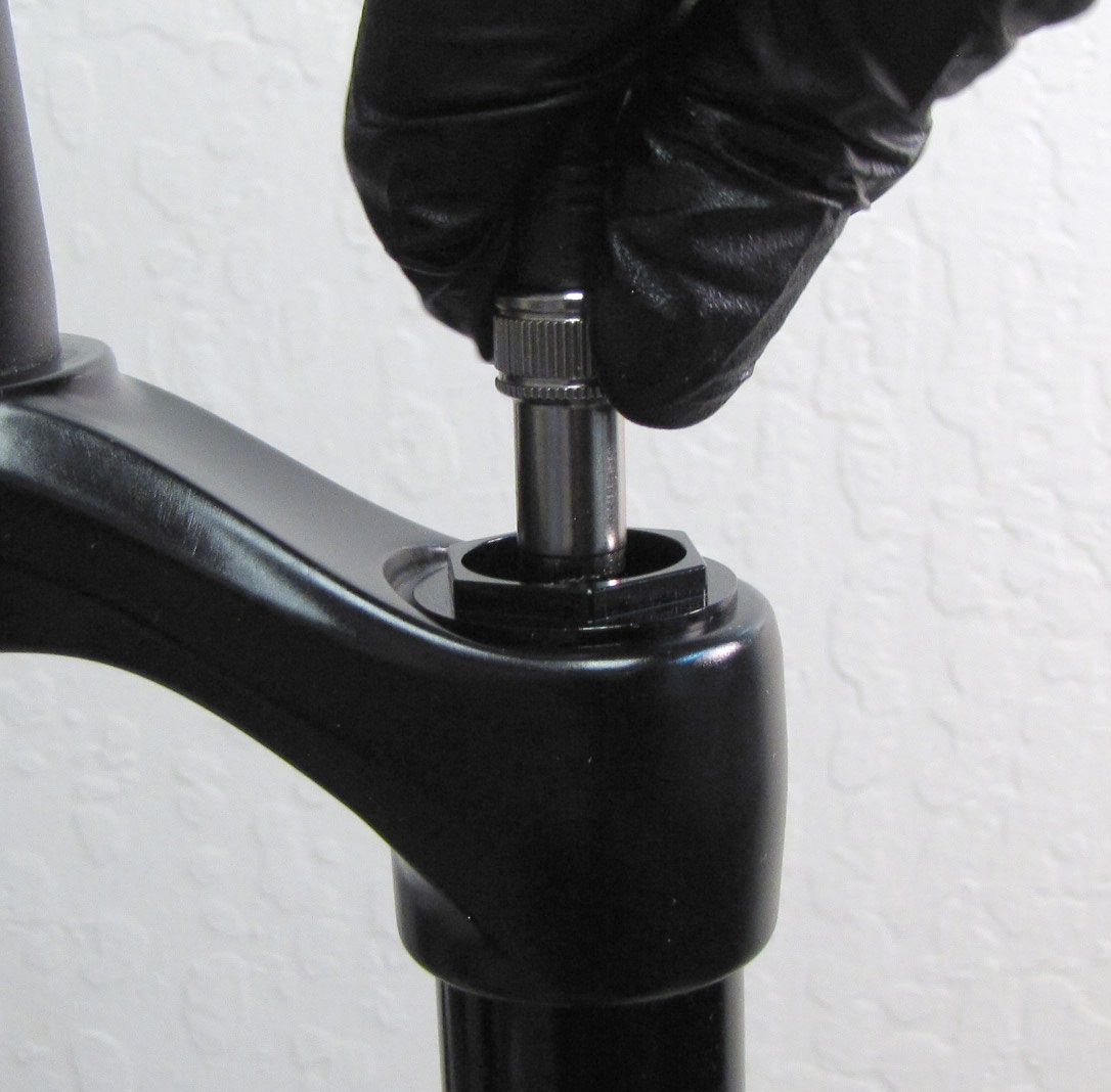
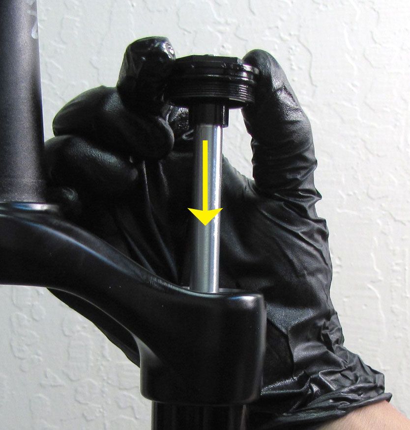
Step 10
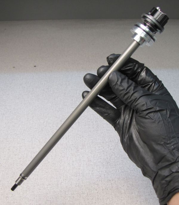
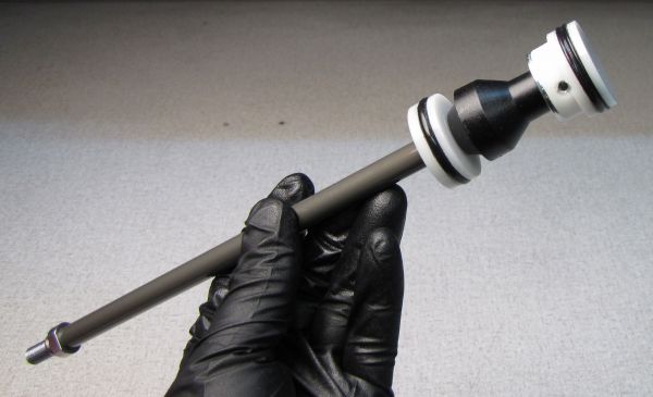
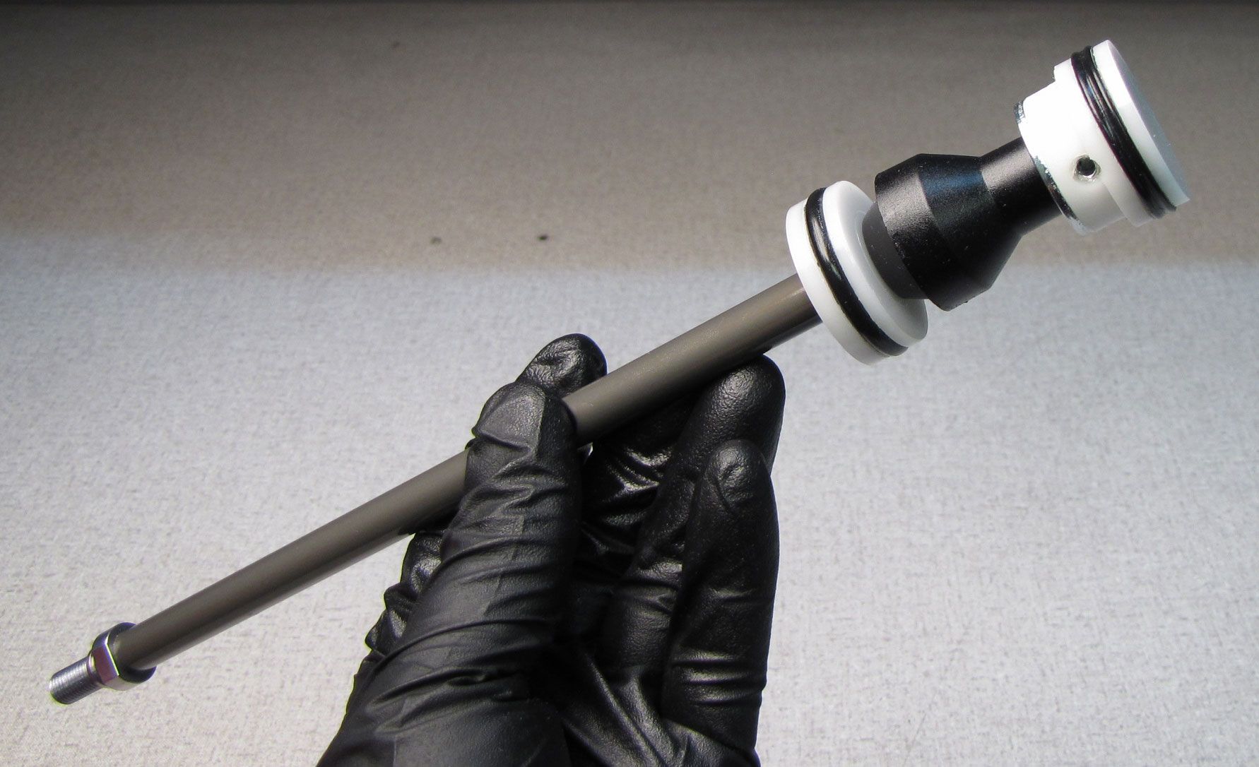
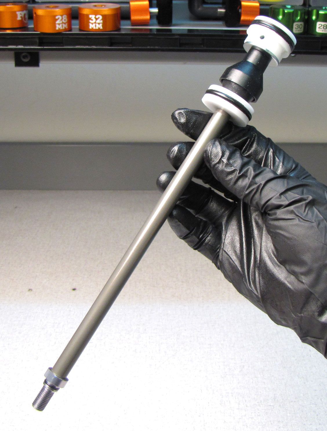
Pull the Damper Shaft Assembly out from the end of the upper tube. Set the Damper Shaft Assembly aside in a clean area.
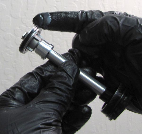
Step 11
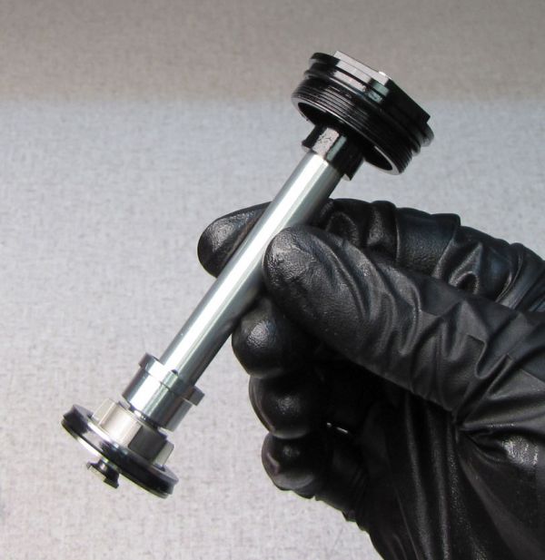
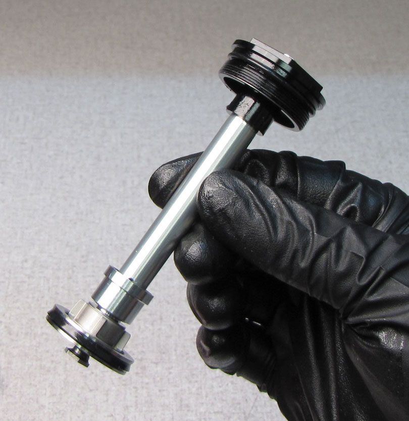
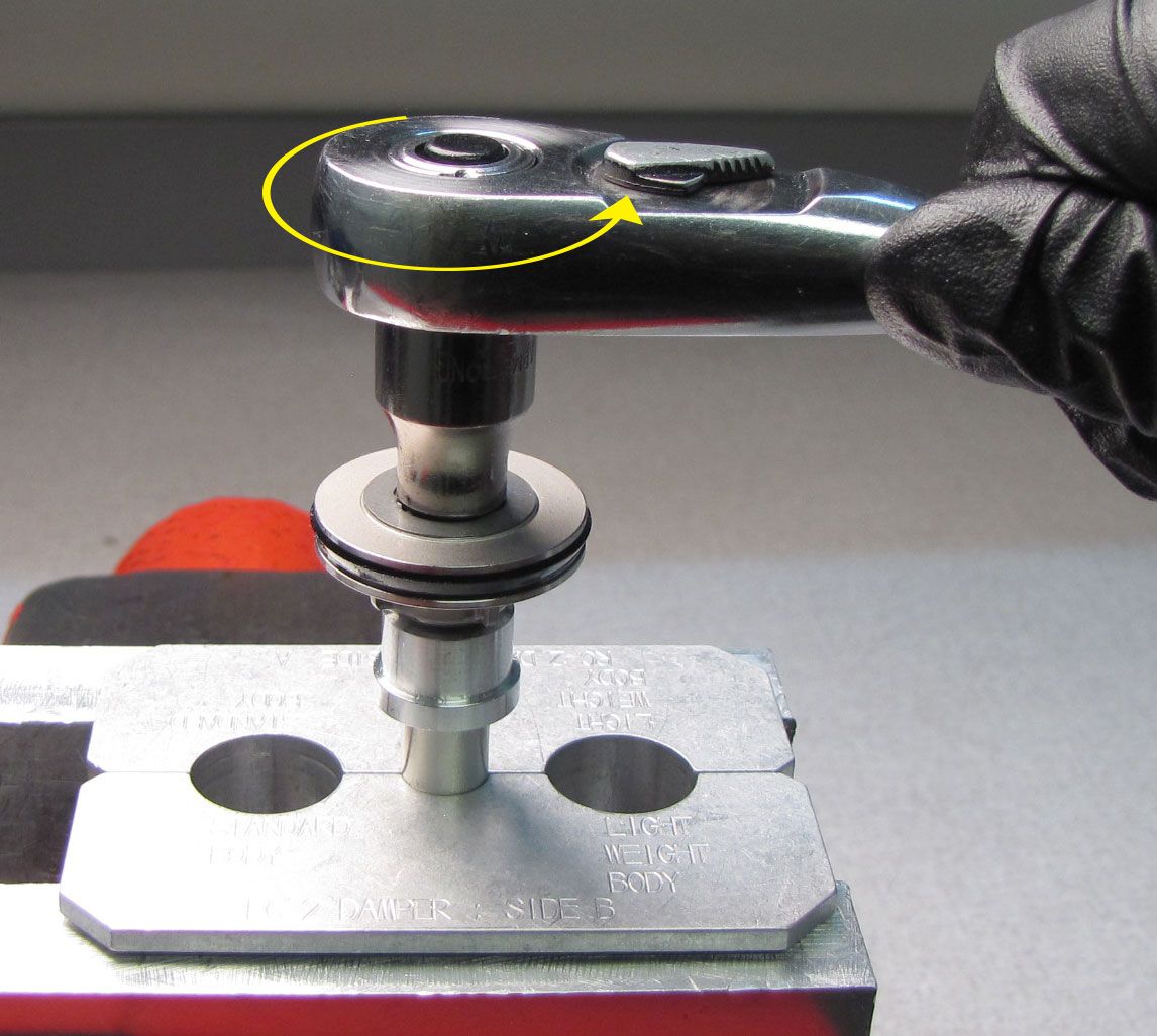
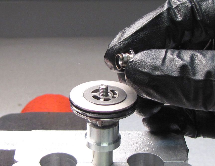
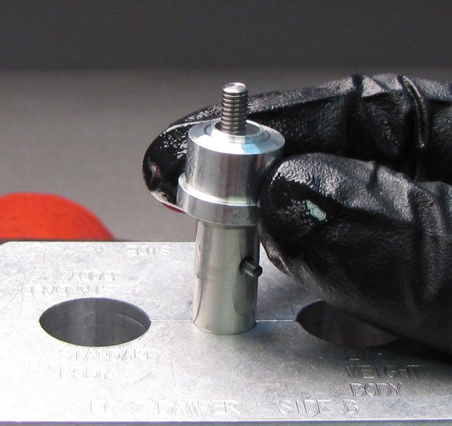
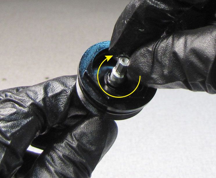
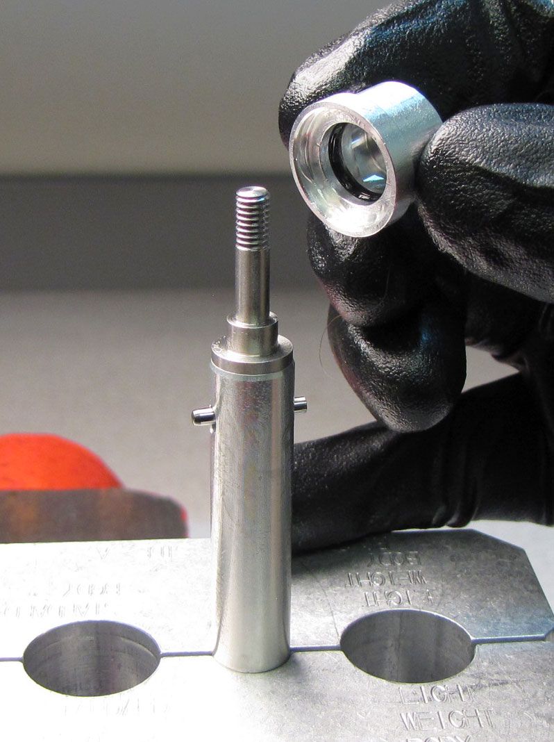
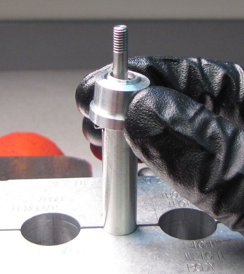
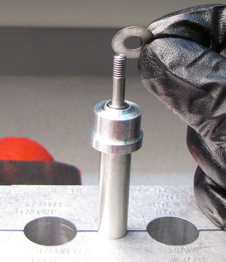
Invert the Rail Topcap Assembly and carefully clamp it in your shaft clamps (PN: 803-00-830 shown but other 10mm shaft clamps will work). Unthread the Piston Nut counter-clockwise with an 8mm socket. Remove the Piston Nut and Check Spring.
Step 12
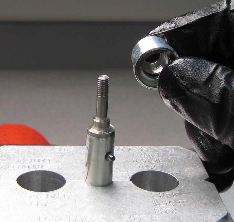
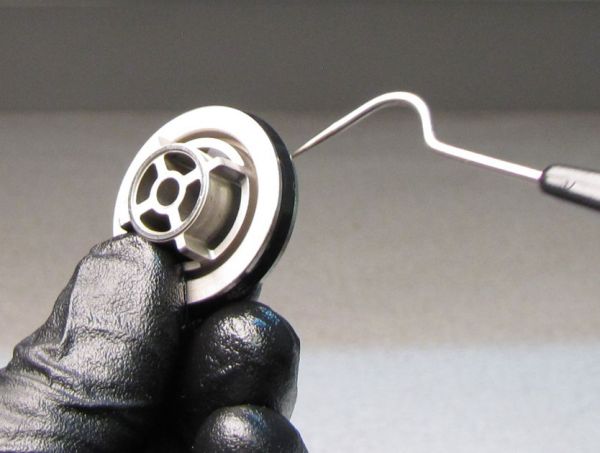
Remove the Check Shim followed by the Compression Piston and Compression Valving.


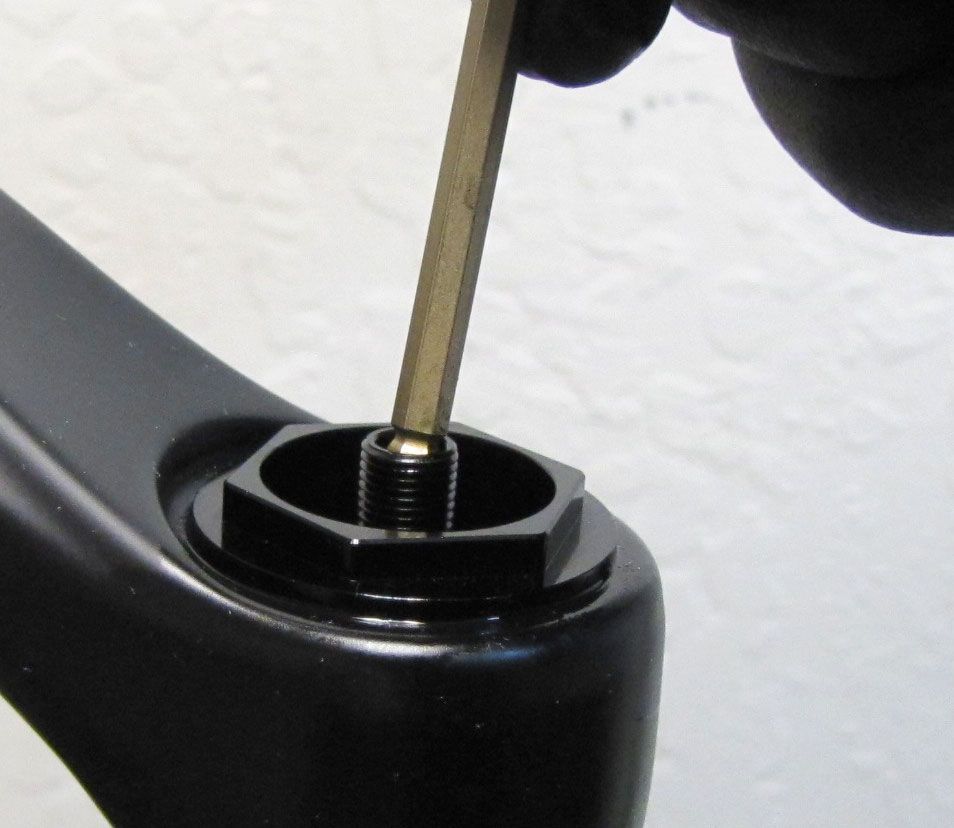
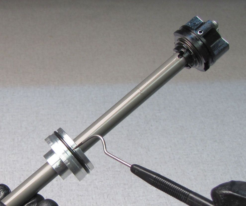
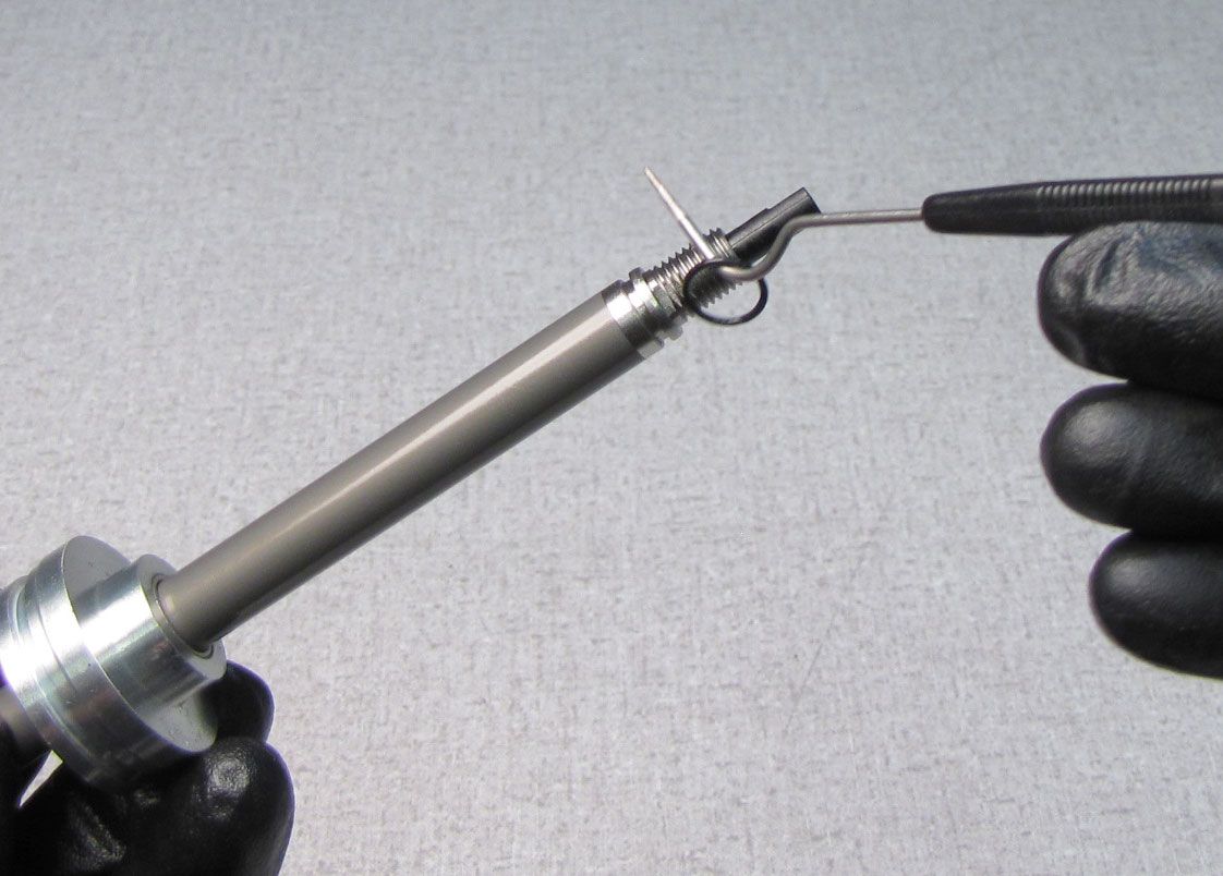
Step 13
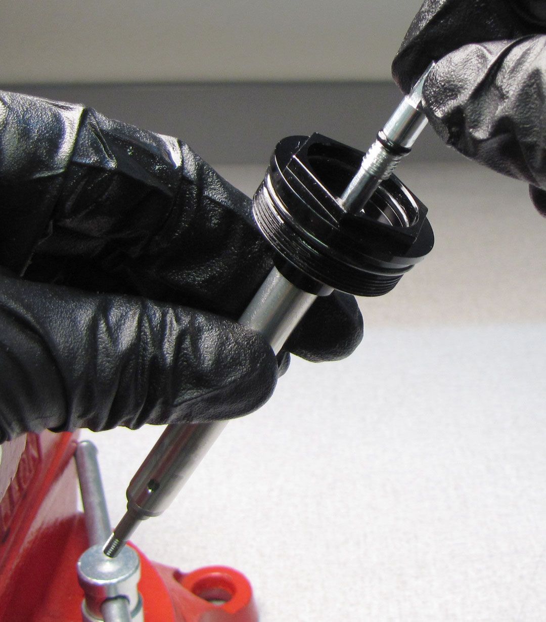
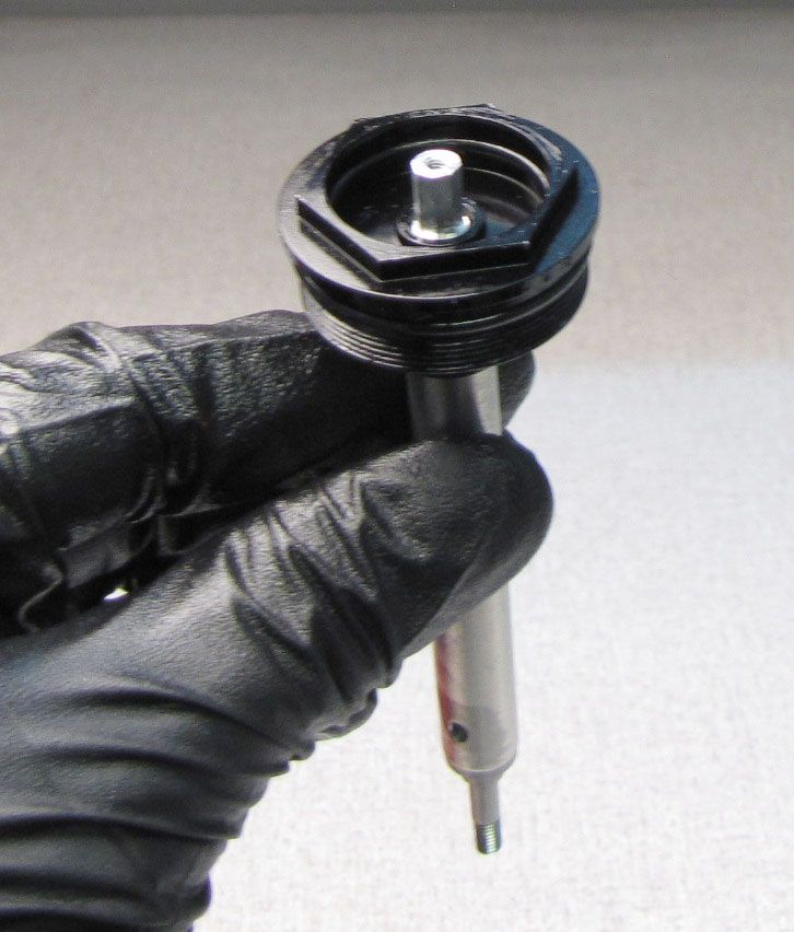
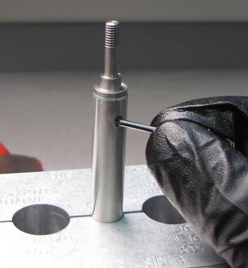
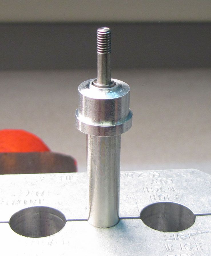
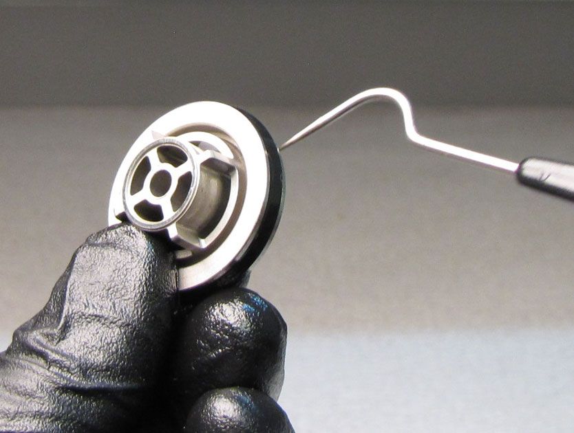
Remove the Preload Hat then remove the Pin through the shaft.


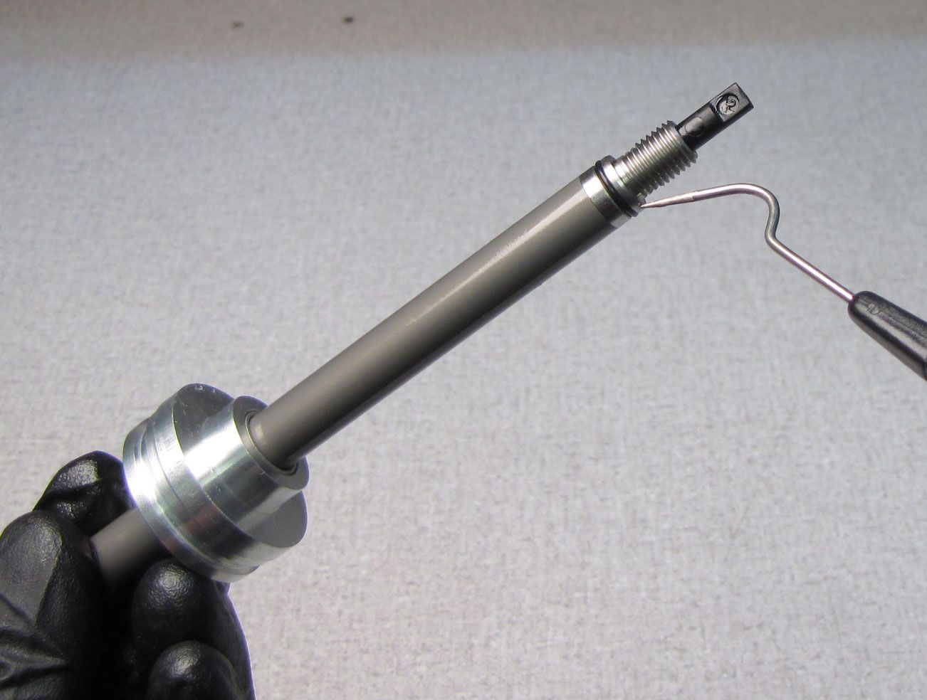
Step 14
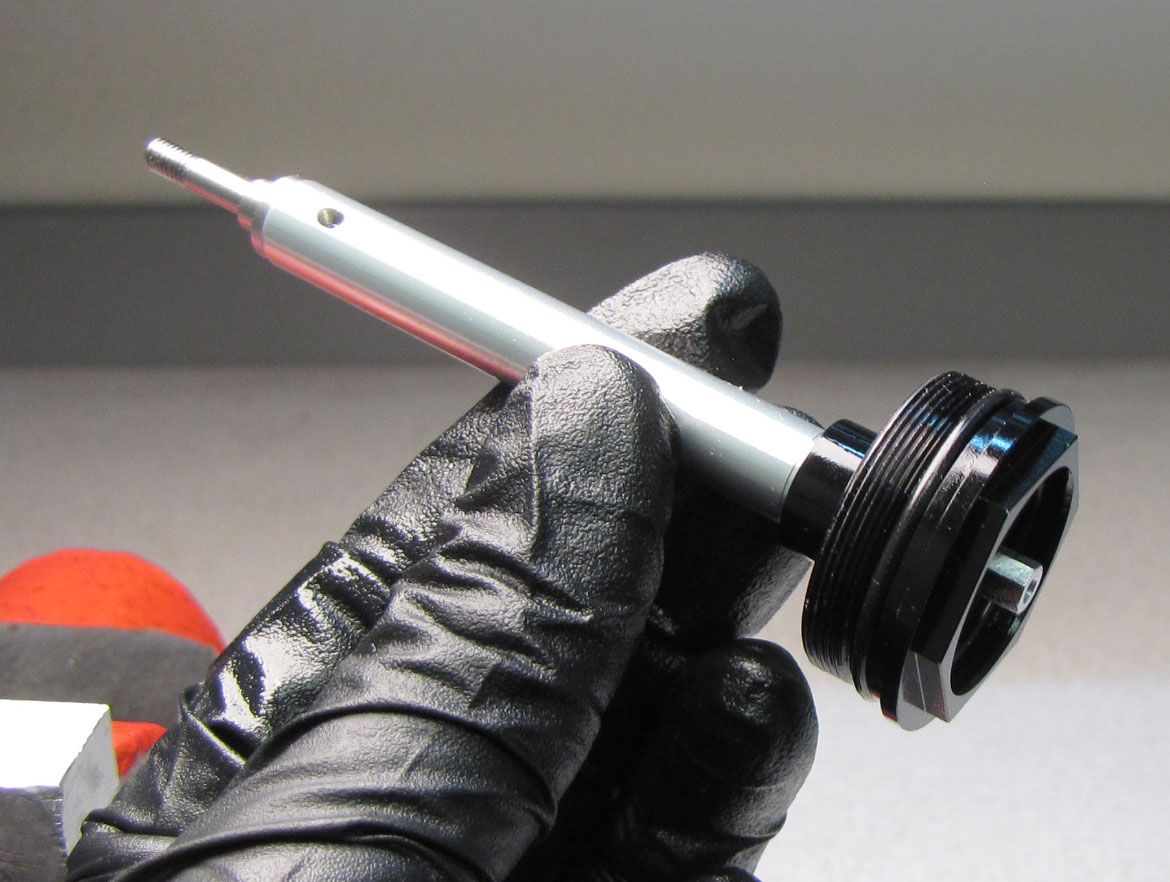
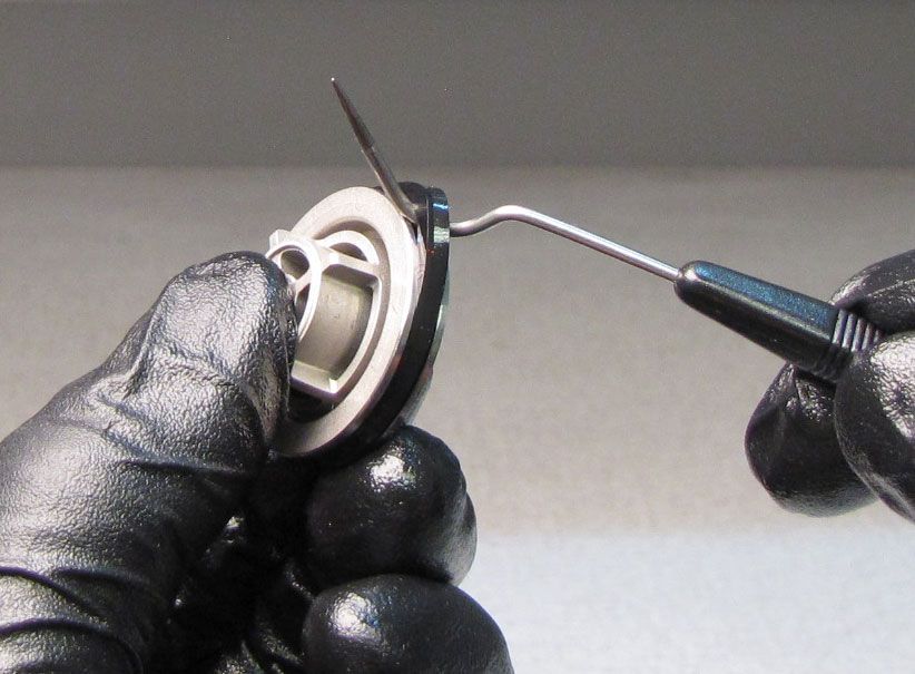
Remove the Topcap Assembly from your shaft clamps. Unthread the Compression Needle counter-clockwise, then pull up to remove.

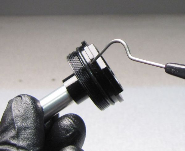
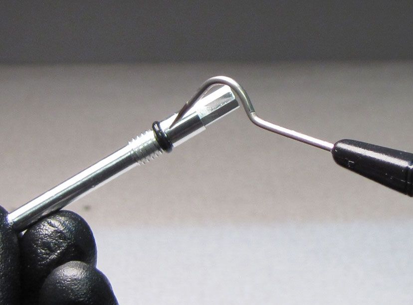
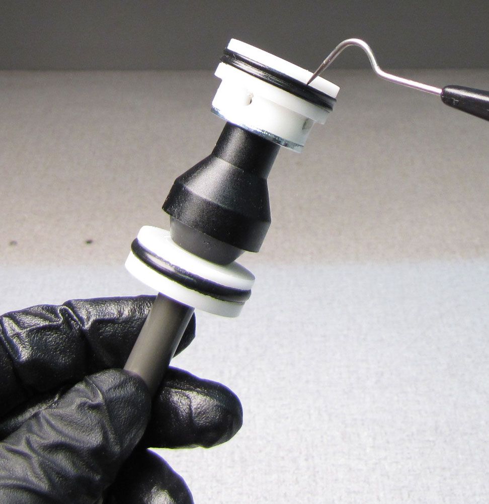
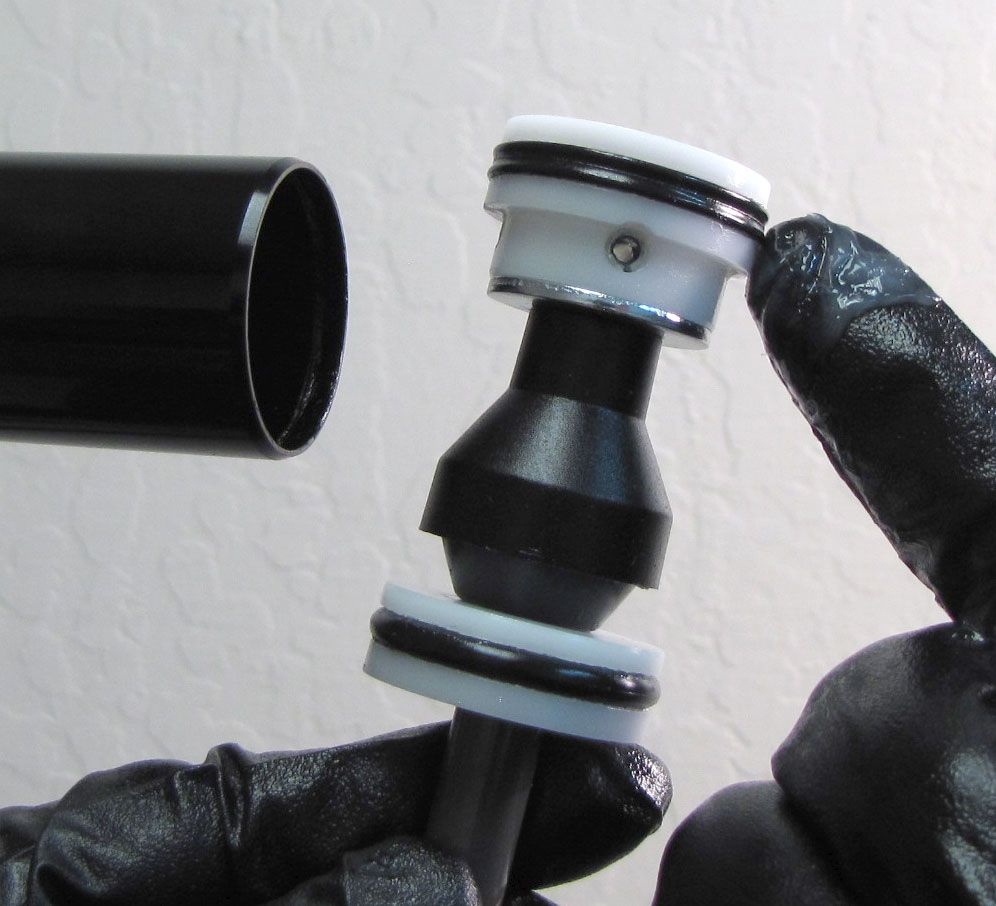
Step 15
Replace the o-rings on the Topcap and Compression Needle with new greased ones from the kit. While a metal seal pick is shown pointing at the seals to be replaced, a plastic seal pick is recommended to prevent damage to the seal glands.

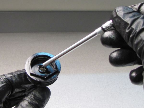
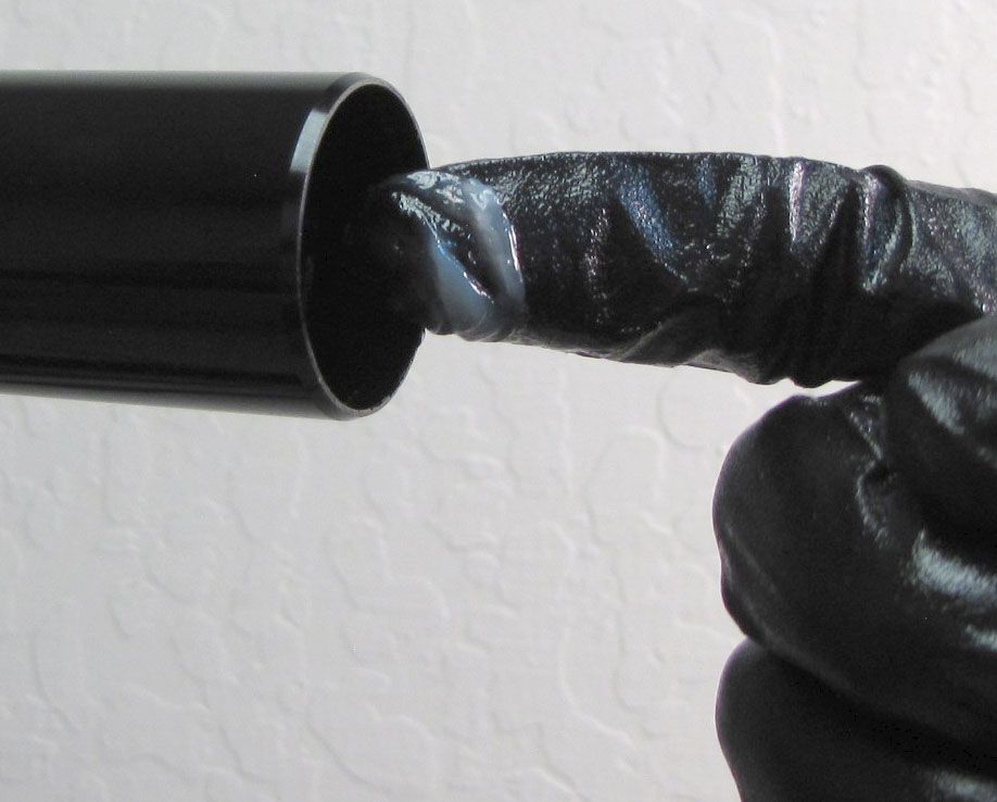
Step 16
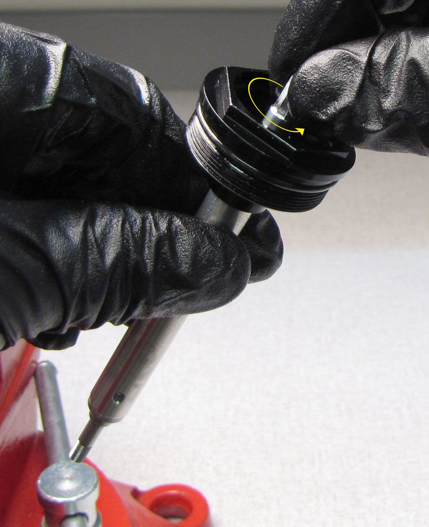
Dip the Compression Needle up to the threads in FOX 5wt. Teflon infused oil. Reinstall the Compression Needle into the Topcap by threading it in clockwise.


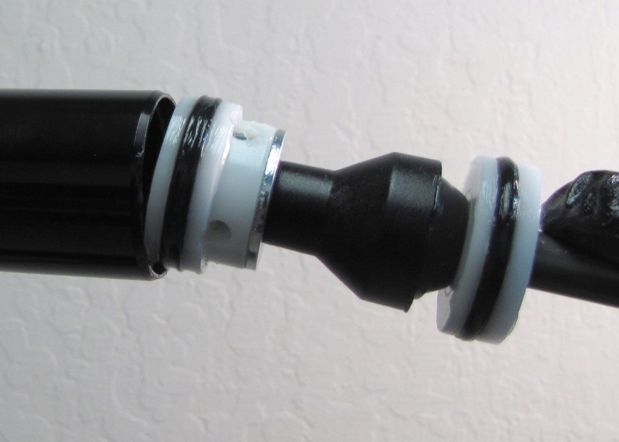
Step 17
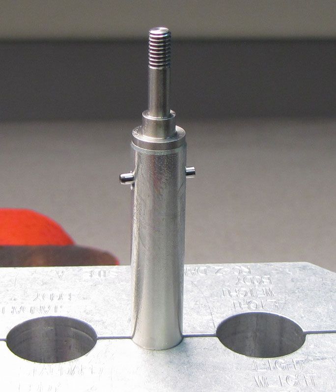
Invert the Rail Topcap Assembly and carefully clamp it in your shaft clamps (PN: 803-00-830 shown but other 10mm shaft clamps will work). Reinsert the Pin through the Shaft. Replace the o-ring inside the Preload Hat with a new greased one from the kit. Reinstall the Preload Hat onto the Shaft.

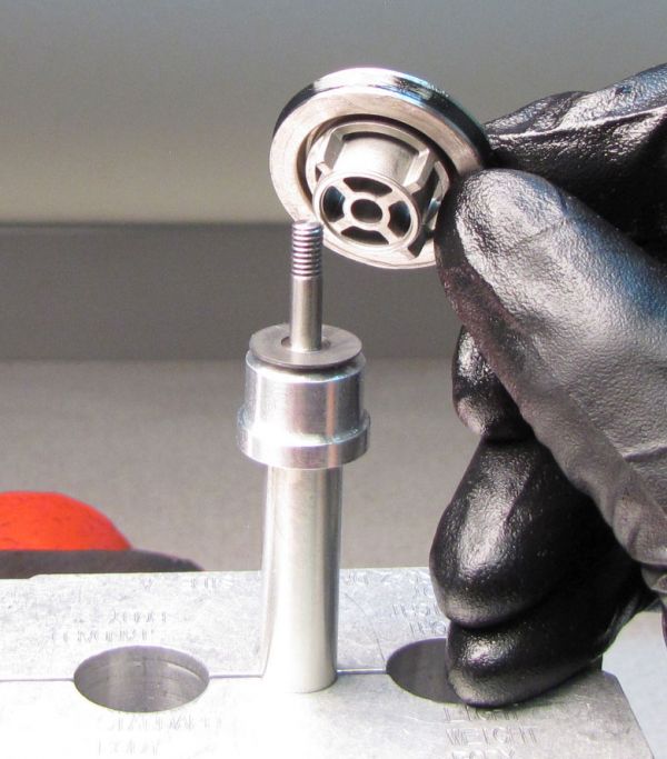
Step 18
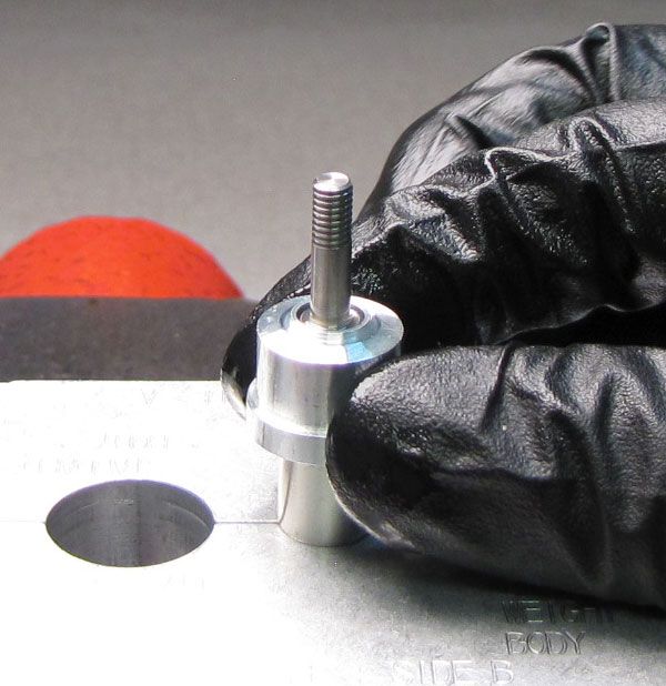
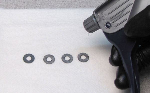
Clean and inspect the Compression Valving shims for any damage. Replace if necesarry. Orient the Compression Valving in its original order then reinstall onto the Compression Piston Stud.


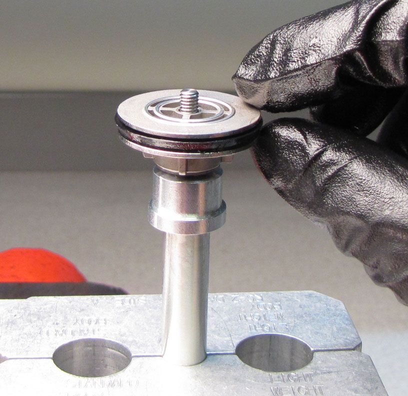
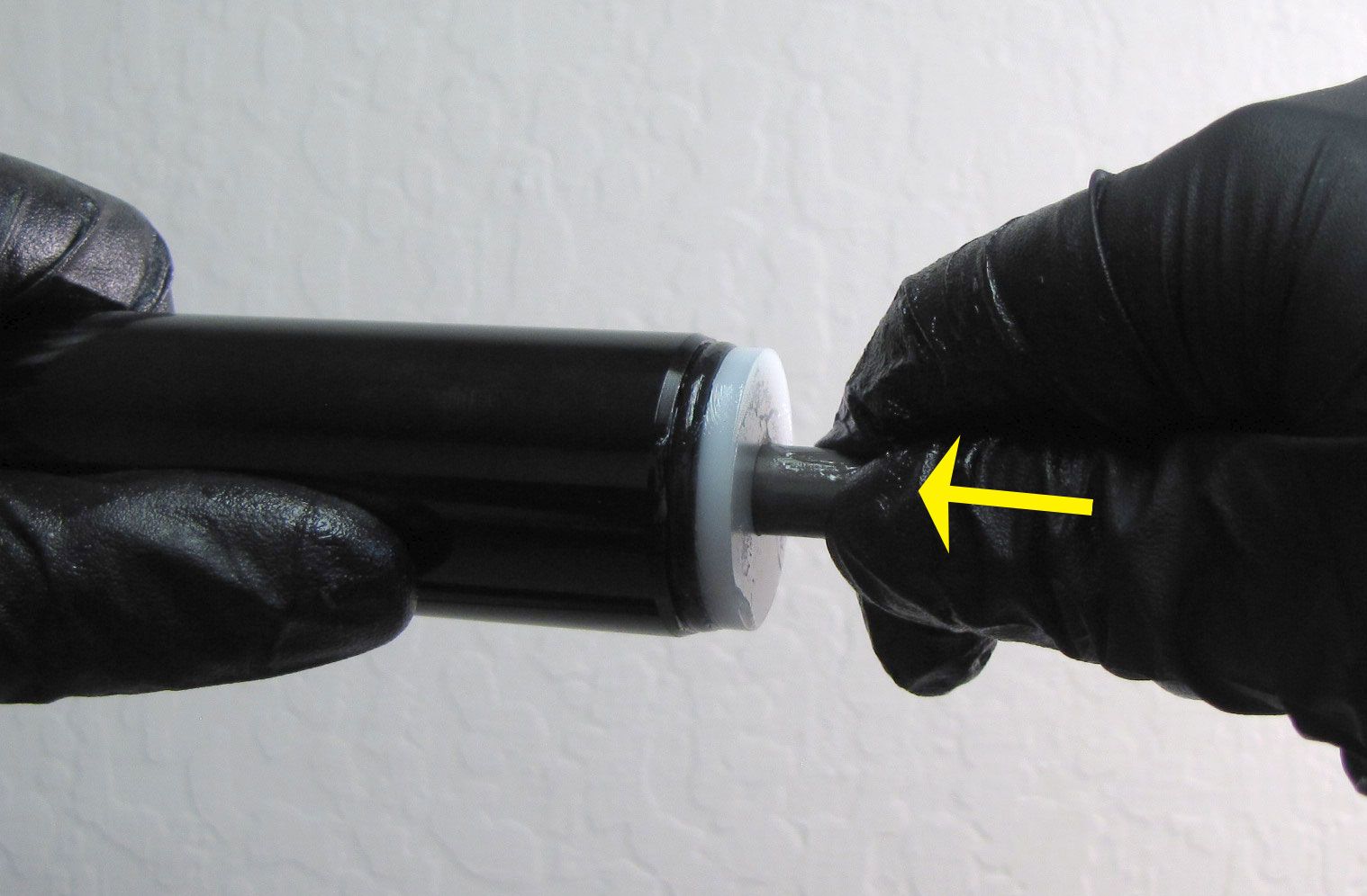
Step 19
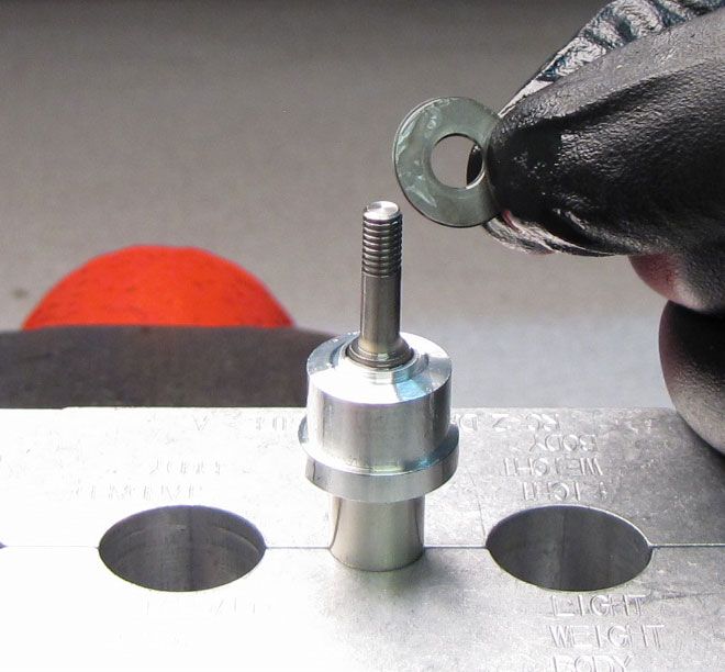
Replace the U-cup seal on the Compression Piston with a new greased one from the kit. Make sure that the U-cup seal lip is oriented as shown.
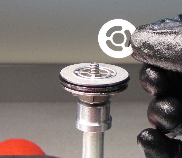
Step 20
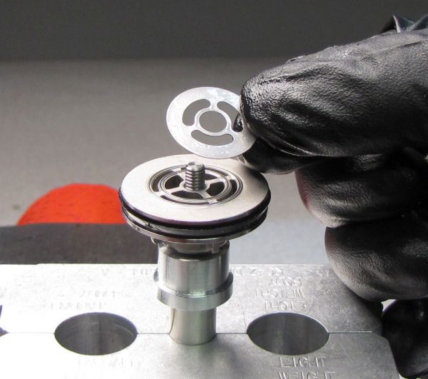
Reinstall the Compression Piston onto the Piston Stud as shown. Reinstall the Check Shim on top of the Compression Piston.


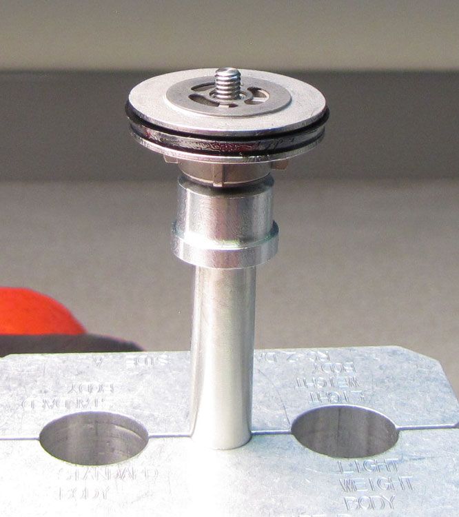
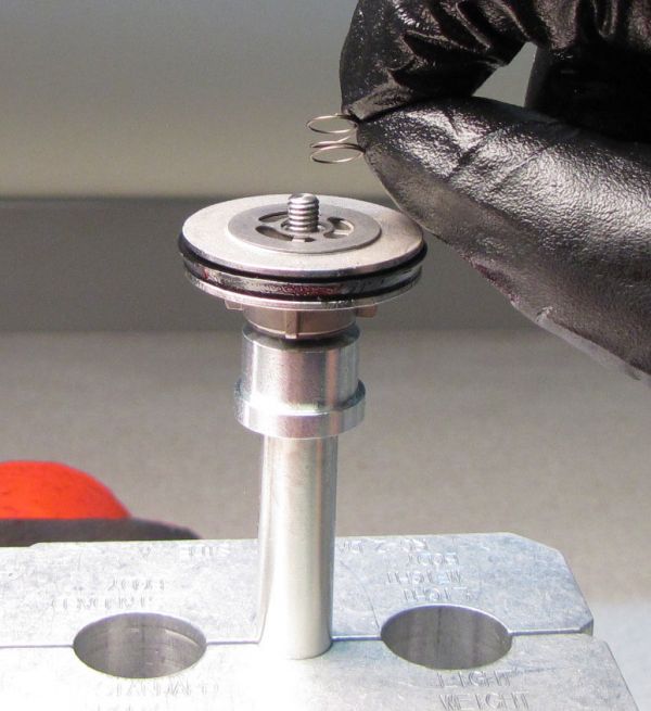
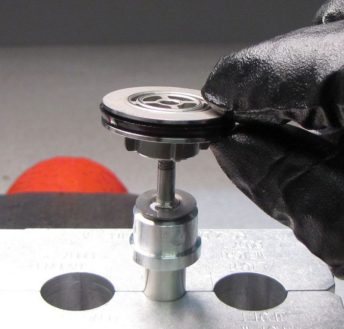
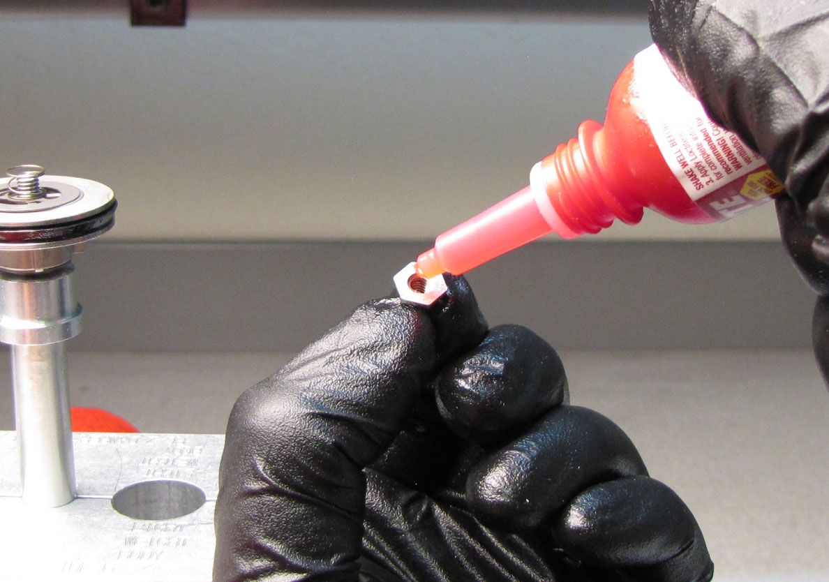
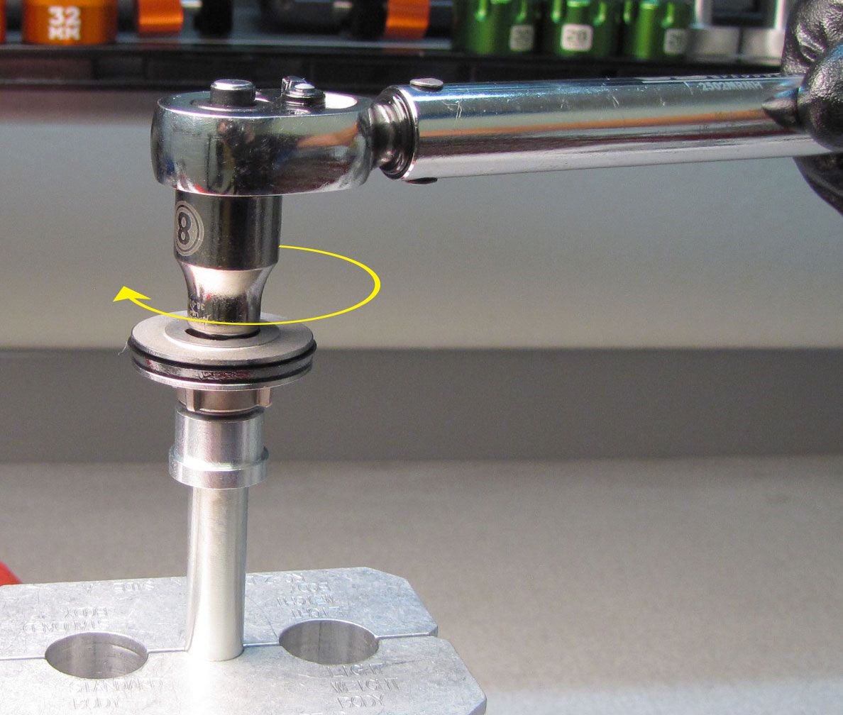
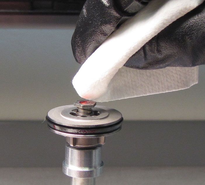
Step 21
Reinstall the Check Spring, then apply 1-2 drops of Red Loctite 263 to the Piston Nut threads. Reinstall the Piston Nut tightening clockwise to 16 in-lb (1.8 Nm) torque with an 8mm socket. Verify that the Check Shim is not pinched and can spin freely after Piston Nut tightening. Clean off any excess Locitite.


Step 22
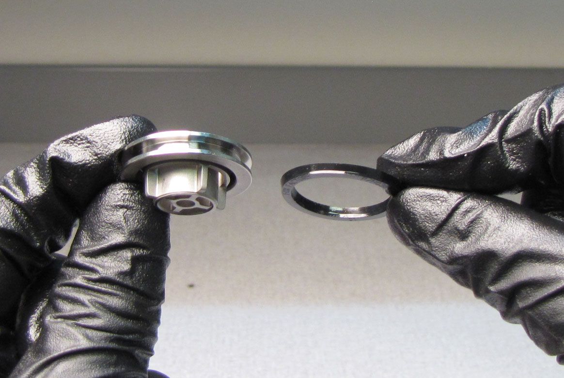
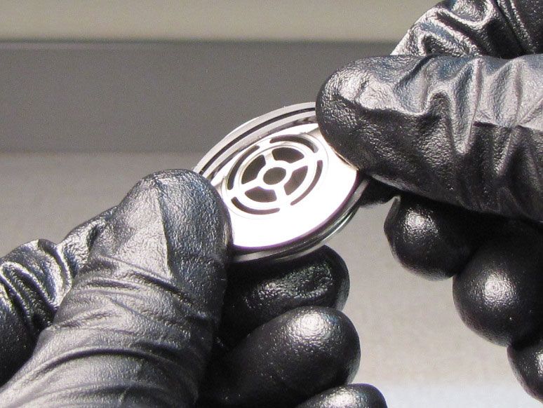
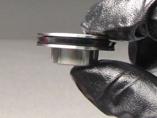
Replace the glide ring on the Rebound Piston with a new one from the kit.


Step 23
Replace the o-ring on the outside of the Sealhead as well as the Base Stud with new greased ones from the kit.
Step 24
Replace the Quad-ring seal on the Air Piston, the o-ring on the outside of the Neg Plate Subassembly, and the o-ring on the Base Stud with new greased ones from the kit.


Step 25
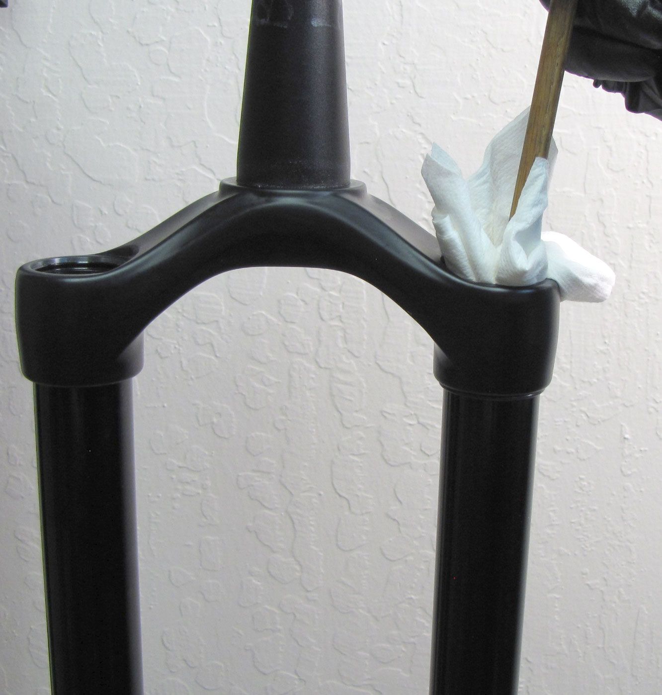
Clean the inside of the upper tubes with Isopropyl Alcohol then dry with a lint-free paper-towel.
Step 26
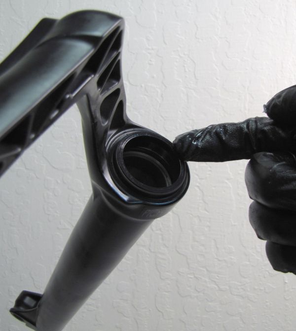
Coat the Air Piston, Neg Plate Subassembly, and the air shaft between the two with a thin film of Slick Honey. Coat the first few inches of the inside of the air-side upper tube with a thin film of Slick Honey. Reinstall the Air Shaft Assembly into the bottom of the air-side upper tube.

Step 27
Reinstall the Retaining Ring into the bottom of the Air-Side upper tube. Pull on the Air Shaft Assembly to verify that the Retaining Ring is fully seated.


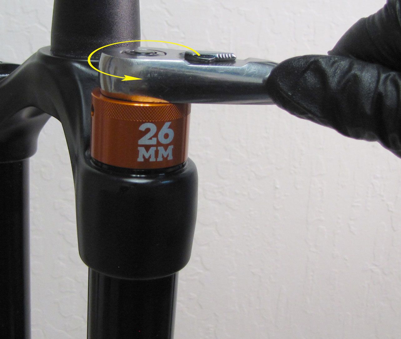
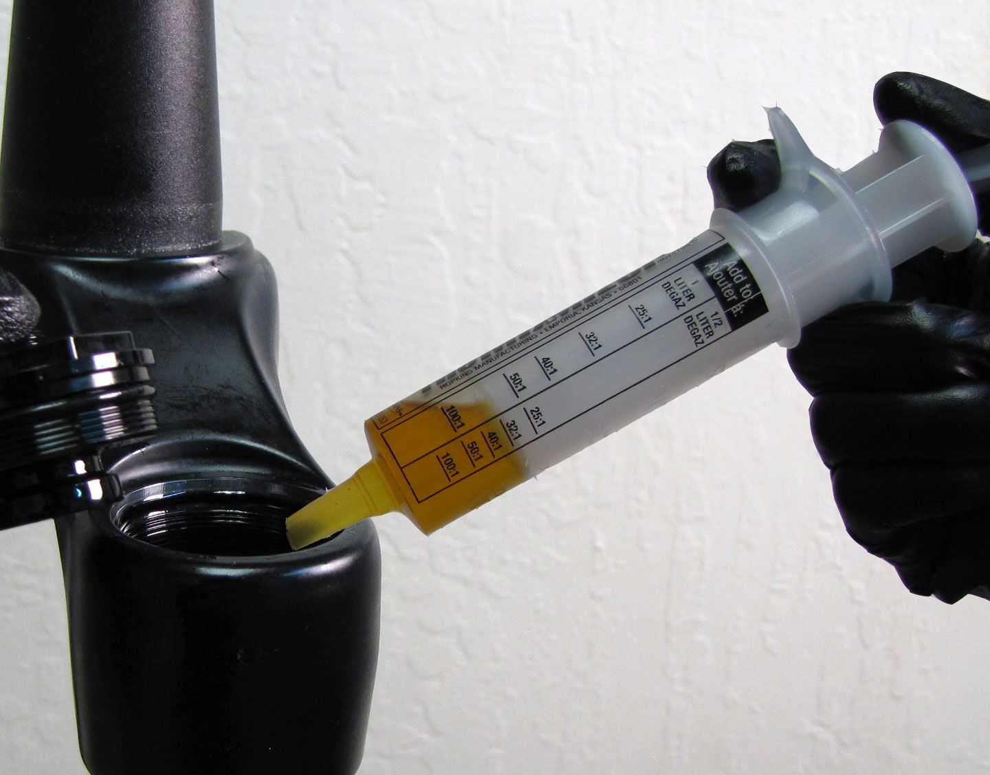
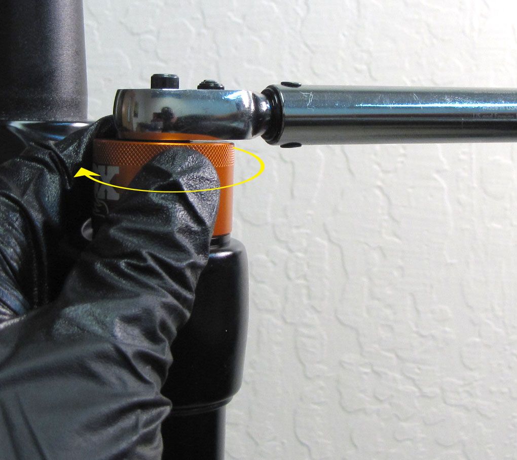
Step 28
With the fork upright, inject 3cc of FOX 20wt. gold oil into the Air-Side upper tube. Reinstall the Air-Side Topcap Assembly, tightening clockwise to 220 in-lb (24.8 Nm) torque with a 26mm 6-point chamfer-less socket.
Step 29
The air spring must be fully extended before reinstalling the lower legs. Add air pressure to your desired setting using a FOX high pressure pump. Reinstall the black Air Cap.


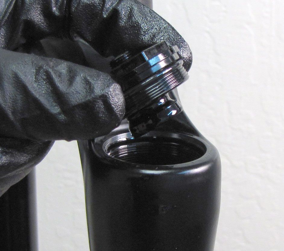
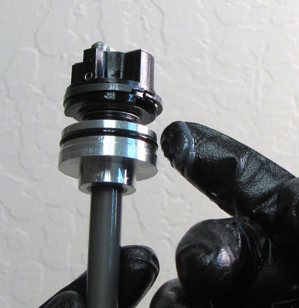
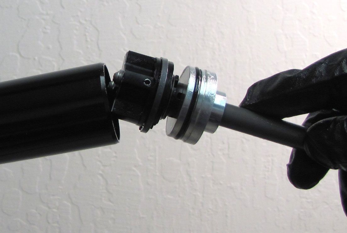
Step 30
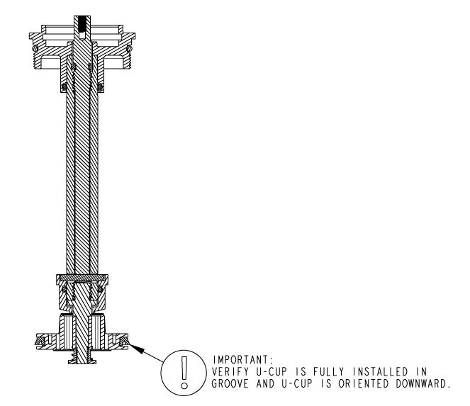
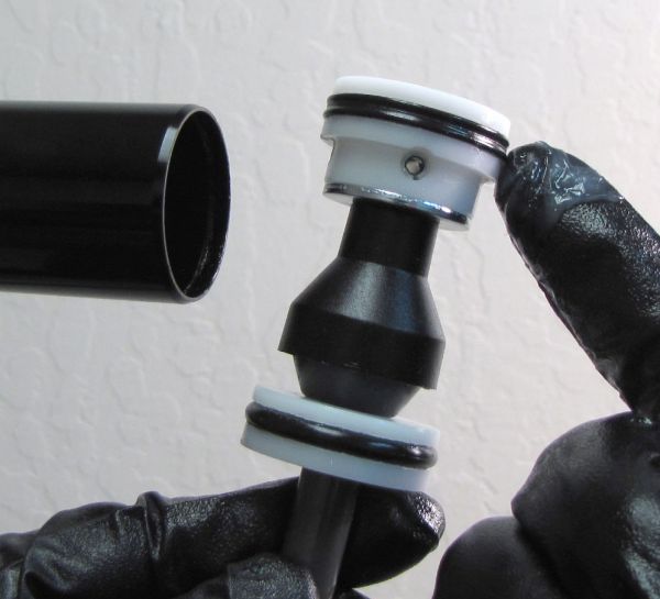
Coat the Sealhead of the Damper Shaft Assembly with a thin film of Slick Honey then reinstall into the bottom of the Damper-Side upper tube. Seat the Sealhead fully into the upper tube, then reinstall the Hoopster style retaining ring (make sure to install the retaining ring from the end of the Damper Shaft assembly to prevent scratching the shaft. Verify the retaining ring is fully seated by pully on the Damper Shaft Assembly.


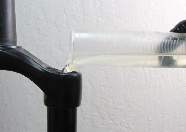
Step 31
With the fork upright, pour the appropriate amount of FOX 5wt. Teflon Infused oil into the Damper-Side upper tube.
| Chassis Type | Damper Oil Volume |
| Standard Chassis | 157cc |
| E-Bike+ Chassis | 135cc |

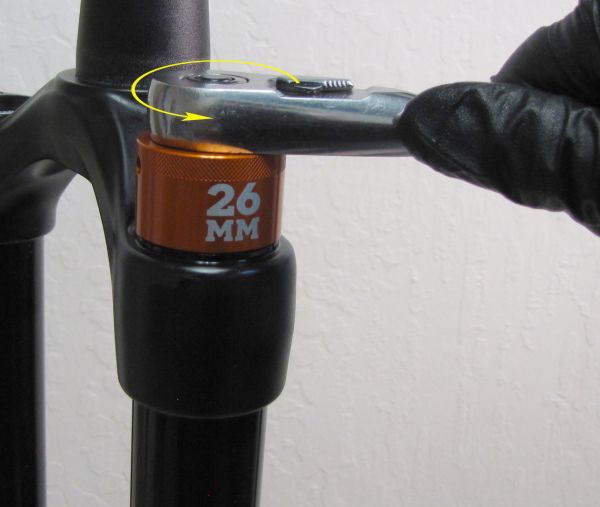
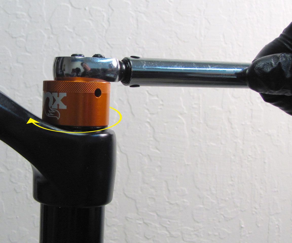
Step 32
Coat the Topcap Assembly u-cup seal with a thin film of Slick Honey then reinstall the Topcap Assembly into the Damper-Side upper tube. Tighten clockwise to 220 in-lb (24.8 Nm) torque with a 26mm 6-point chamfer-less socket.


Step 33
Use the Compression Lever as a wrench to turn the Compression Needle fully clockwise until it comes to a gentle stop. Remove the Compression Lever, then reinstall it as close to the back of the crown as possible (in the fully locked out position). Hold the Compression Lever from turning while you reinstall the screw, tightening clockwise to 11 in-lb (1.2 Nm) torque with a 2mm hex wrench.
Step 34
Replace the Dust Wipers and Foam Rings using steps 7-11 of the standard Dust Wiper and Foam Ring replacement procedures as shown here »

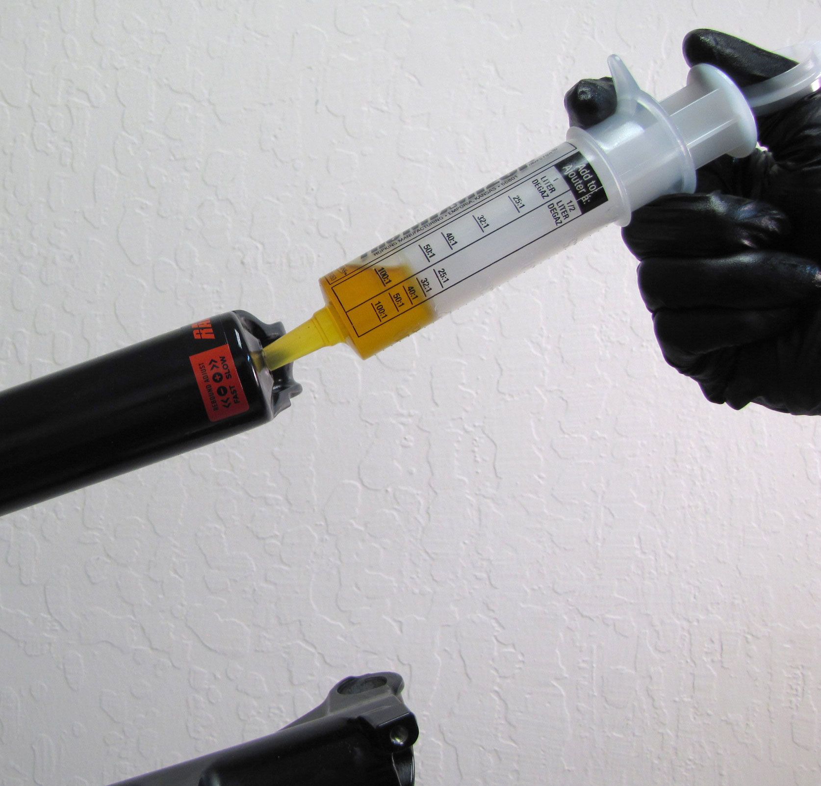
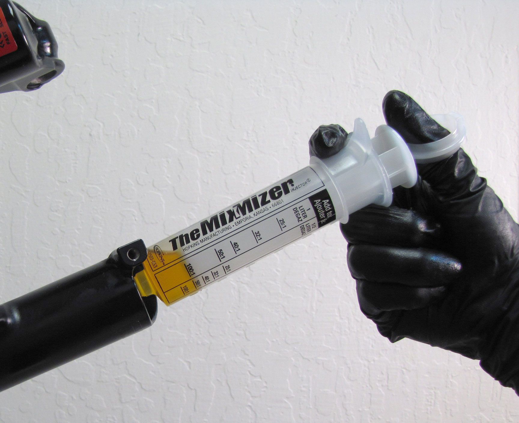
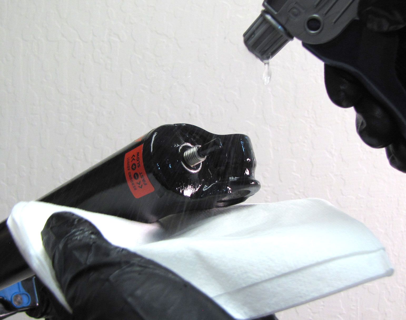
Step 35
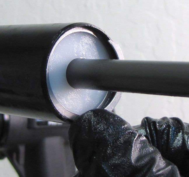
Install the Lower Leg Assembly onto the upper tubes. Inject 10cc of FOX 20wt. Gold oil into each leg through the bottom hole.

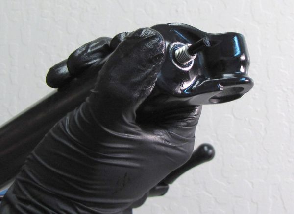
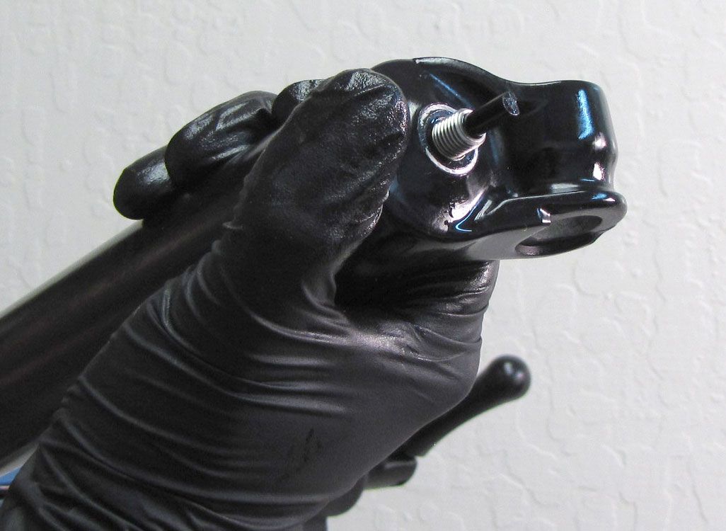
Step 36
Push the Lower Leg Assembly fully onto the Upper Tubes until the Base Studs of the Damper and Air Shaft protrude through the bottom holes in the lowers. Clean any oil off of the shaft threads with Isopropyl alcohol and a lint-free paper towel.
Note: New Z2 forks are now coming with a new bottom nut and crush washer. Please install the new bottom nut (PN: 803-01-819) and the new crush washer (PN: 803-01-818)
Reinstall the Bottom Nuts tightening clockwise to 50 in-lb (5.7 Nm) with a 12mm socket.
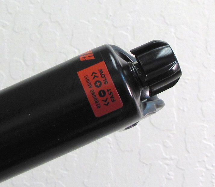
Step 37
Reinstall the black Rebound Knob, making sure to align the set screw with the flat spot on the Rebound Needle. Tighten the set screw clockwise to 5 in-lb (0.6 Nm) torque with a 2mm hex wrench.
NOTE: Cycle the fork through its travel multiple times to purge any air out of the damper before testing all fork functions.