Marzocchi BOMBER Z1 Air to Coil Conversion (Coil Kit Installation)
Required Parts
- 820-03-656-KIT Service Set: Spring Kit, Soft, 2021 Marzocchi Bomber Z1 Coil (PURPLE)
- 820-03-657-KIT Service Set: Spring Kit, Medium, 2021 Marzocchi Bomber Z1 Coil (BLUE)
- 820-03-658-KIT Service Set: Spring Kit, Firm, 2021 Marzocchi Bomber Z1 Coil (GREEN)
- 820-03-659-KIT Service Set: Spring Kit, Extra Firm, 2021 Marzocchi Bomber Z1 Coil (YELLOW)
- 820-03-664-KIT Service Set: 2021 Marzocchi Bomber Z1 Coil, Plunger Shaft and Topcap Kit, 27.5, 180mm Max
- 820-03-665-KIT Service Set: 2021 Marzocchi Bomber Z1 Coil, Plunger Shaft and Topcap Kit, 29, 170mm Max
Required Tools
- 398-00-681 2002-017 32 Damper-side and ALL 32-34-36-40 Spring-side Removal Tool
- 398-00-682 2005-017 34-36-40 Damper-side Removal Tool
- 398-00-706 Tooling: Fork Topcap Socket, 32mm V2, 3/8 Drive
WARNING: Always wear safety glasses and protective gloves during service to prevent potential injury. Failure to wear protective equipment during service may lead to SERIOUS INJURY OR DEATH.
WARNING: Marzocchi products should be serviced by a trained bicycle service technician, in accordance with Marzocchi specifications. If you have any doubt whether or not you can properly service your Marzocchi product, then DO NOT attempt it. Improperly serviced products can fail, causing the rider to lose control resulting in SERIOUS INJURY OR DEATH.
WARNING: Never attempt to modify air volume spacers, travel spacers, plunger shaft assemblies or air shaft assemblies, as this can damage your fork causing a loss of control of the bicycle leading to SERIOUS INJURY or DEATH.
WARNING: Marzocchi suspension products contain pressurized nitrogen, air, oil, or all 3. Suspension misuse can cause property damage, SERIOUS INJURY OR DEATH. DO NOT puncture, incinerate or crush any portion of a Marzocchi suspension product. DO NOT attempt to disassemble any portion of a Marzocchi suspension product, unless expressly instructed to do so by the applicable Marzocchi technical documentation, and then ONLY while strictly adhering to all Marzocchi instructions and warnings in that instance.
WARNING: Modification, improper service, or use of aftermarket replacement parts with Marzocchi forks and shocks may cause the product to malfunction, resulting in SERIOUS INJURY OR DEATH. DO NOT modify any part of a fork or shock, including the fork brace (lower leg cross brace), crown, steerer, upper and lower leg tubes, coil springs, or internal parts, except as instructed herein. Any unauthorized modification may void the warranty, and may cause failure or the fork or shock, resulting in SERIOUS INJURY OR DEATH.
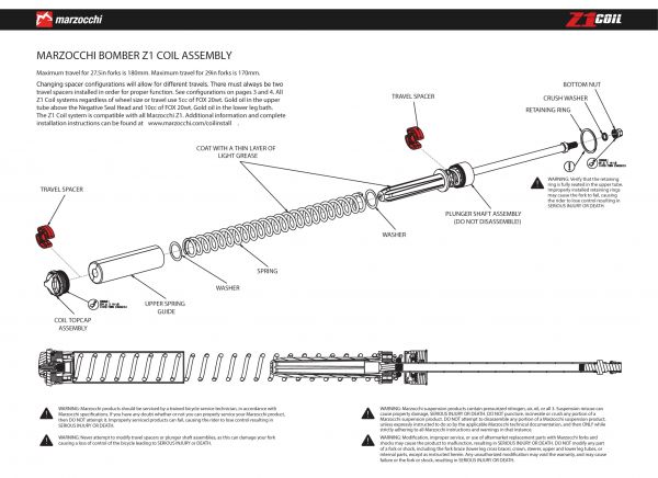
The Z1 Coil Spring Assembly consists of a Coil Topcap Assembly, Spring, Spring Guide, Washers (2), Travel Spacers (2), and Plunger Shaft Assembly.
The Coil Topcap Assembly offers user adjustable spring preload. The Spring is available in four different rates to accommodate different rider weights. Springs are marked with a color code that identifies the spring rate. The Spring Guide must be the same color as the marking on the spring for proper function. Washers must be in position at either ends of the Spring. Two Travel Spacers must be present and installed for proper function. See below for additional Travel Spacer details. The Plunger Shaft Assembly is specific to either 27.5in or 29in forks.
The Purple spring is recommended for riders approximately 120-150 lbs. The Blue spring is recommended for riders approximately 150-180 lbs. The Green spring is recommended for riders approximately 180-210 lbs. The Yellow spring is recommended for riders approximately 210-250 lbs.
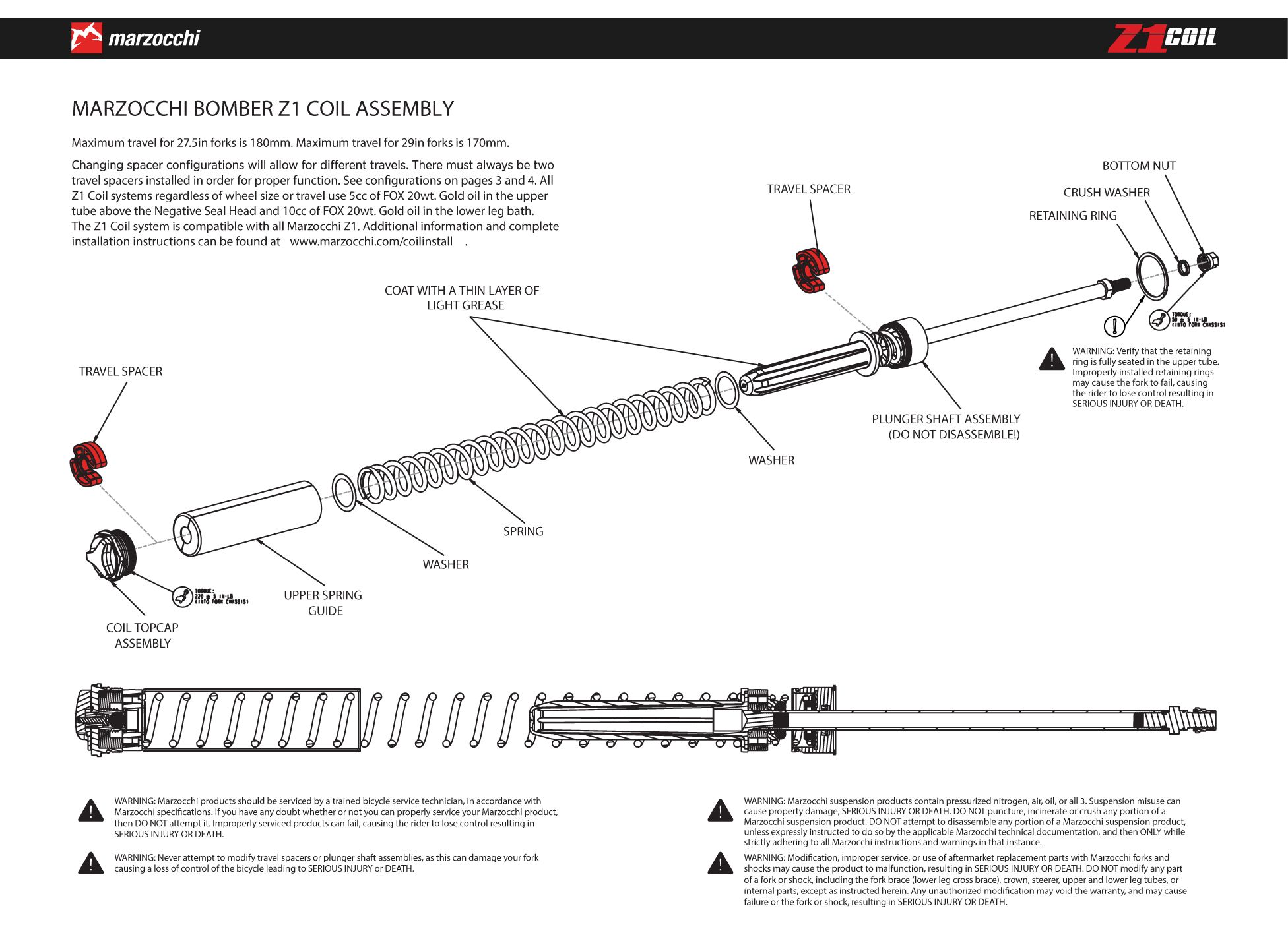
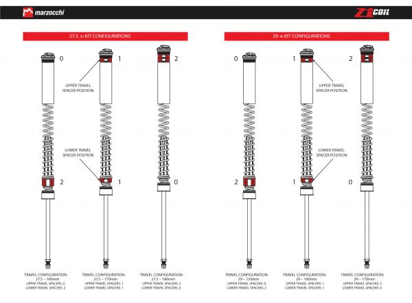
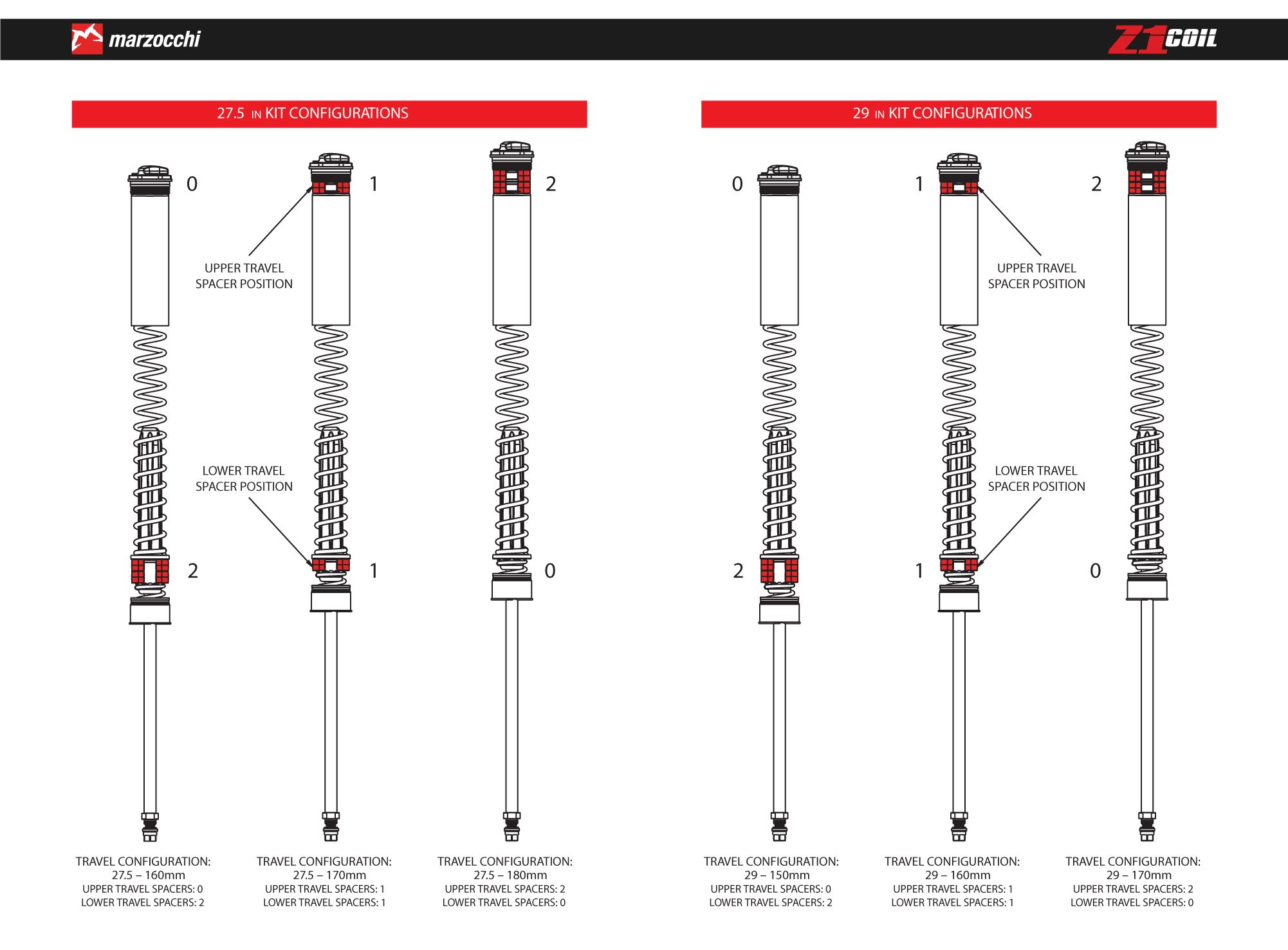
The Z1 Coil Spring Assembly can be configured with Travel Spacers in different locations to achieve different fork travels. There must always be two Travel Spacers installed in order for proper function. See the images below for additional details regarding spacer locations for different travels. 27.5in forks can be configured for 160mm, 170mm, or 180mm of travel. 29in forks can be configured for 150mm, 160mm, or 170mm of travel.
Z1 Air Spring Removal

Step 1
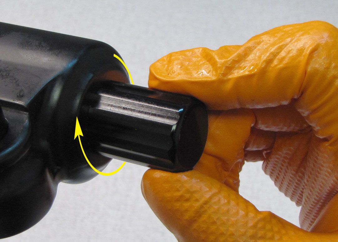
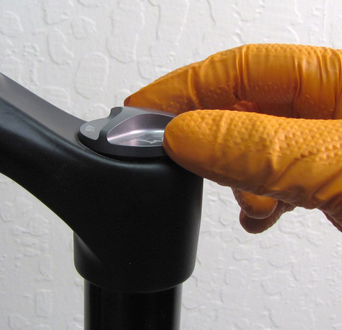
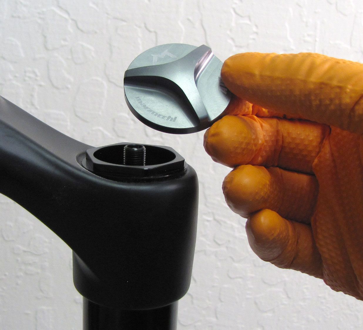
Remove the Air Cap by turning it counter-clockwise. Release the air pressure by depressing the Schrader Valve core.
Step 2
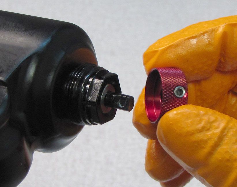
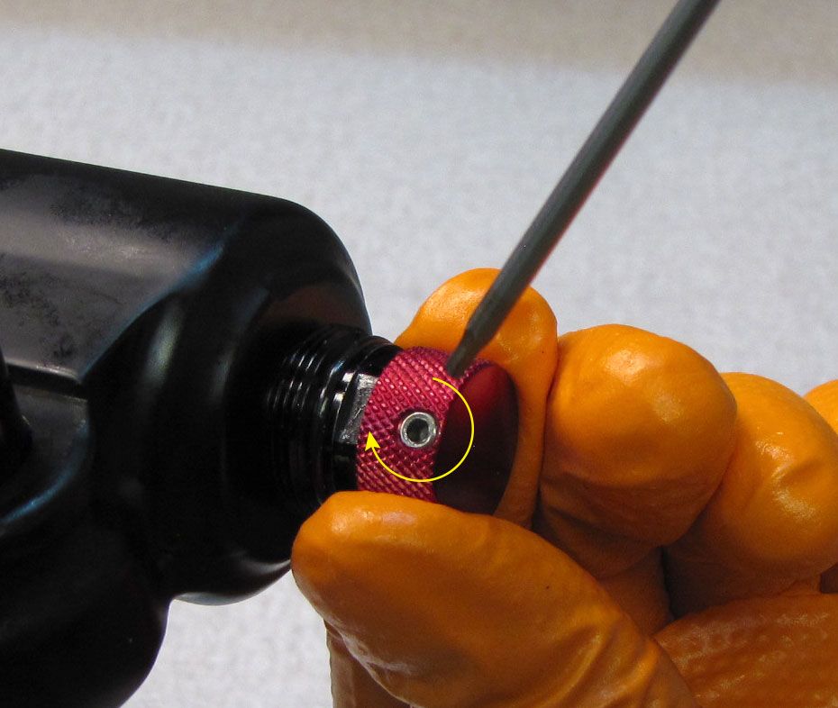
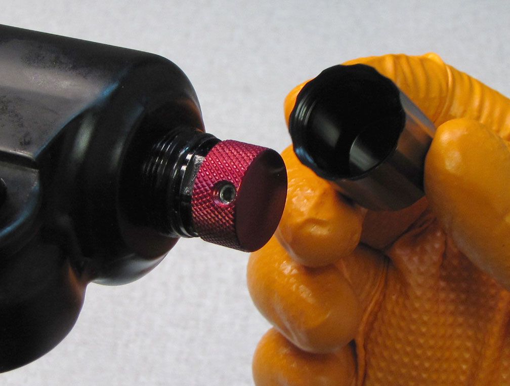
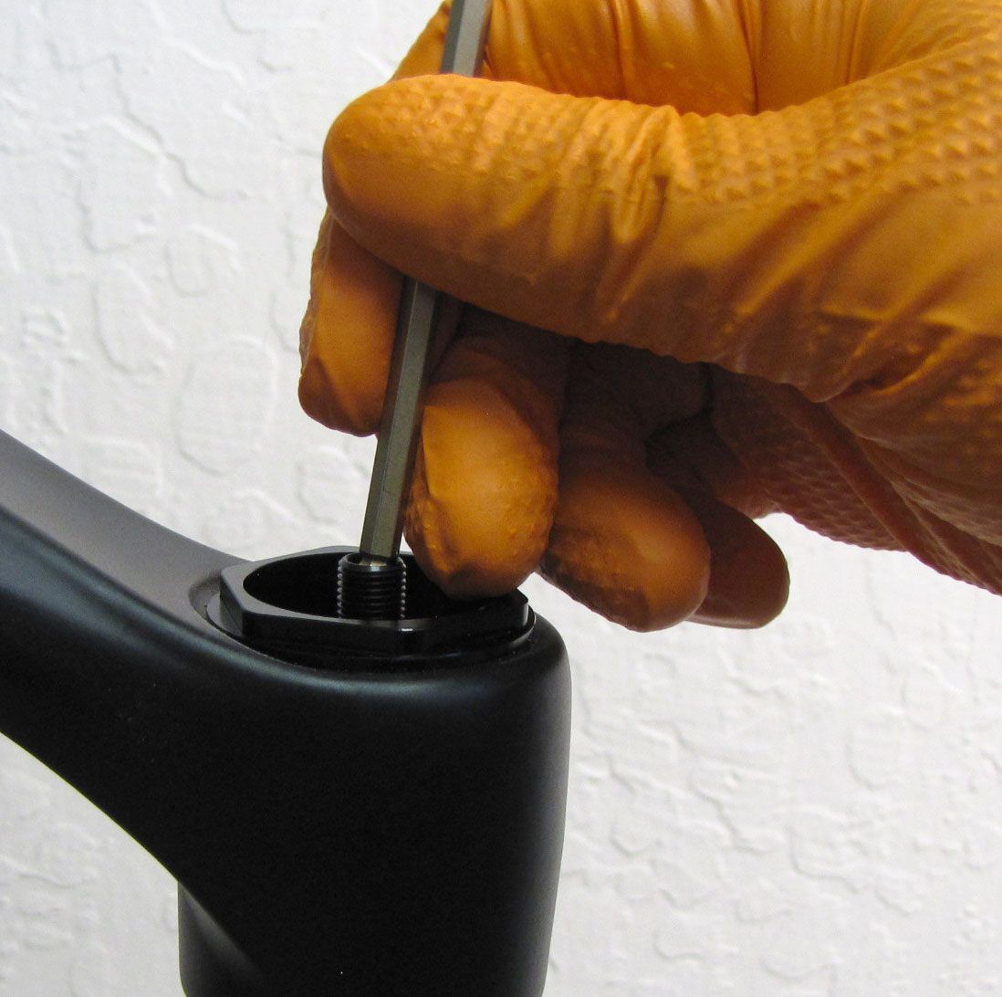
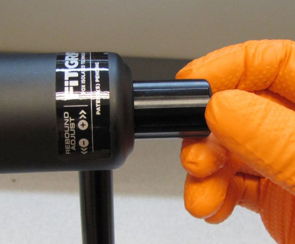
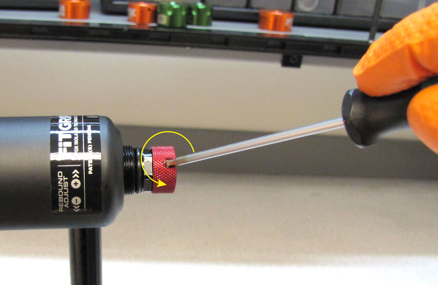
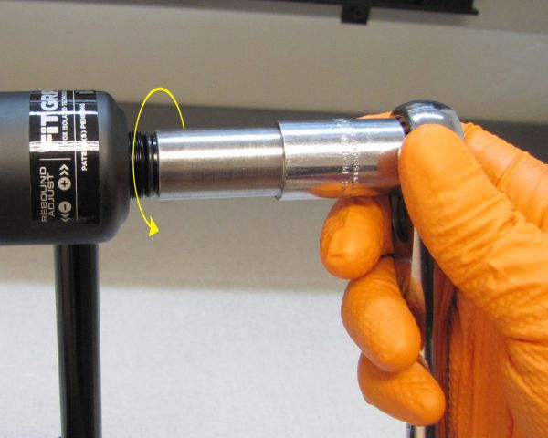
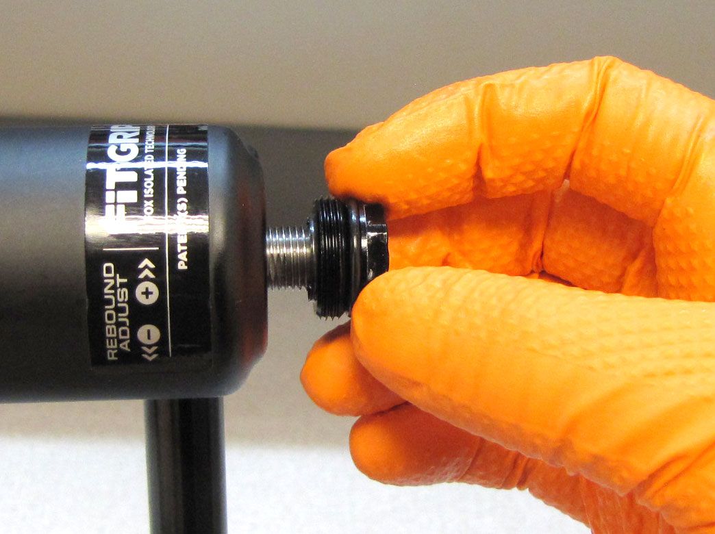
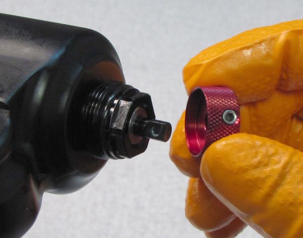
Unthread the black Rebound Knob Cover by turning it counter-clockwise. Remove the red Rebound Knob by turning the 2mm hex screw counter-clockwise with a 2mm hex wrench. You do not need to fully remove the screw from the knob to remove the knob from the fork.

Step 3
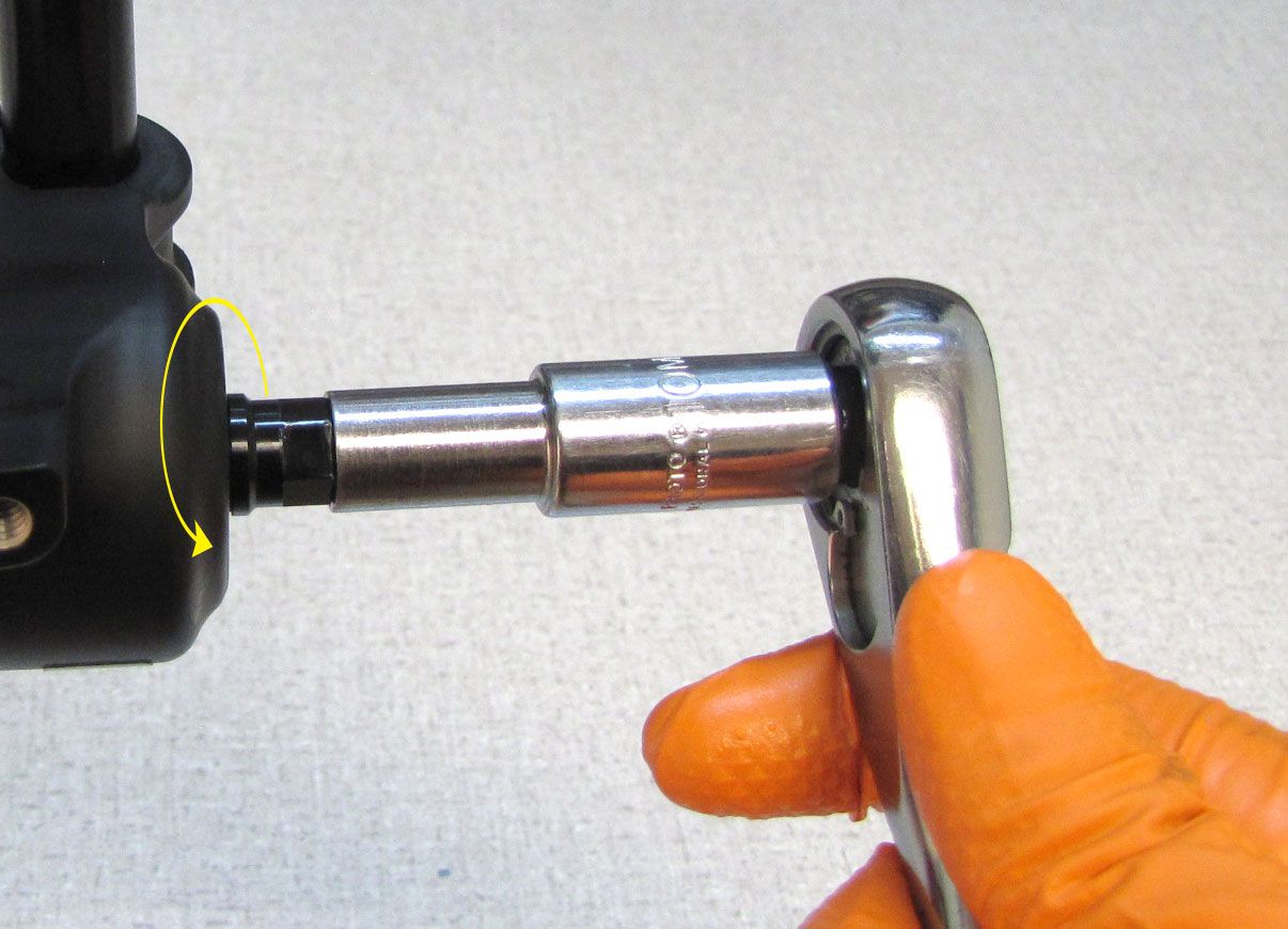
Unthread the damper-side Bottom Nut by turning it counter-clockwise with a 15mm socket. Unthread the spring-side Bottom Nut by turning it counter-clockwise with a 10mm socket. Remove both crush washers.

Step 4
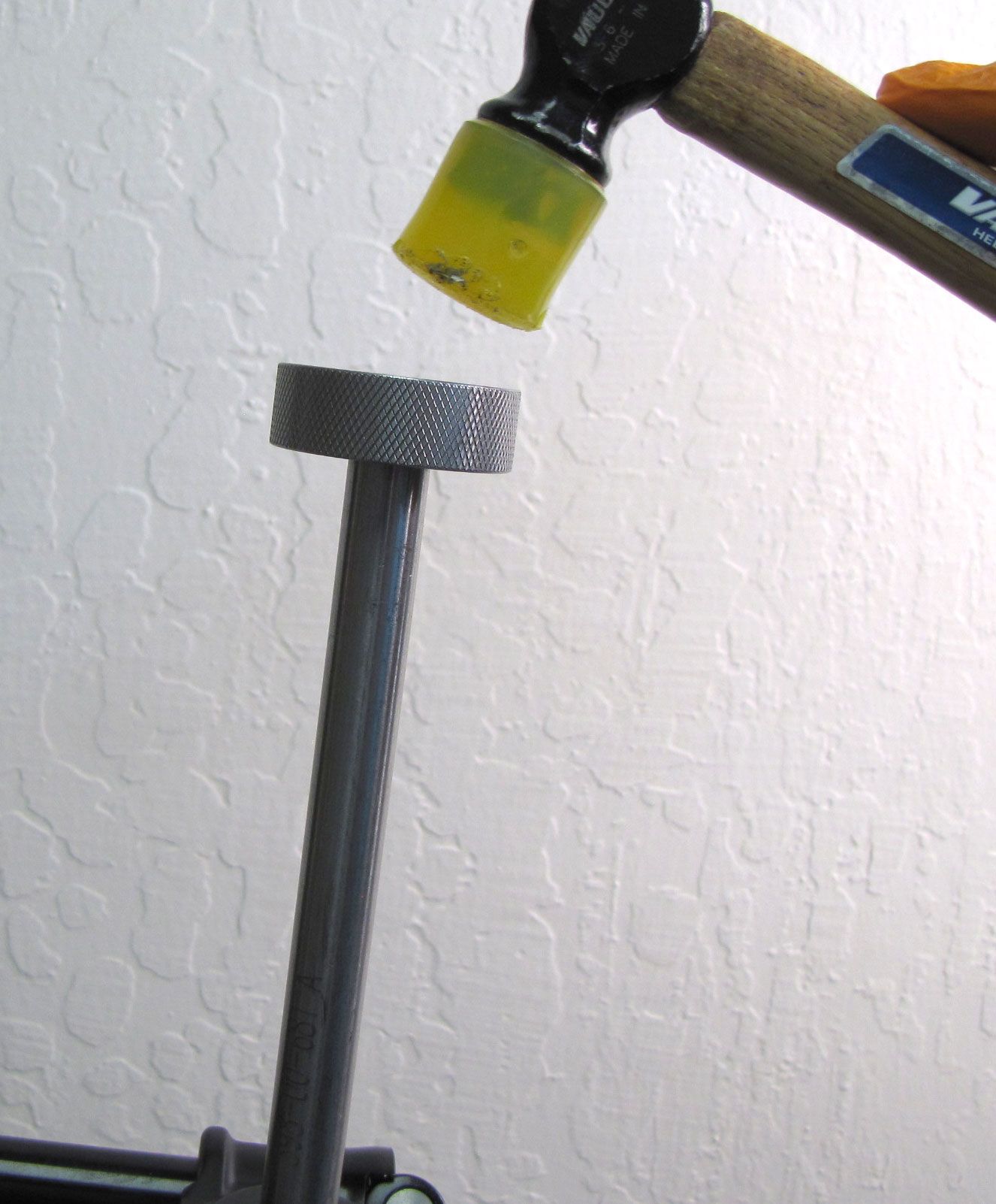
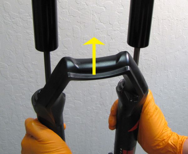
Use Damper Removal Tools 398-00-681 and 398-00-682 to dislodge the shafts from the lowers. Make sure that you have approximately half of the available threads engaged with your tool before striking with your mallet. Remove the damper removal tools, then bring the fork upright over an oil basin to drain. After oil stops draining from the lowers, pull the lowers off of the upper tubes and set them aside.

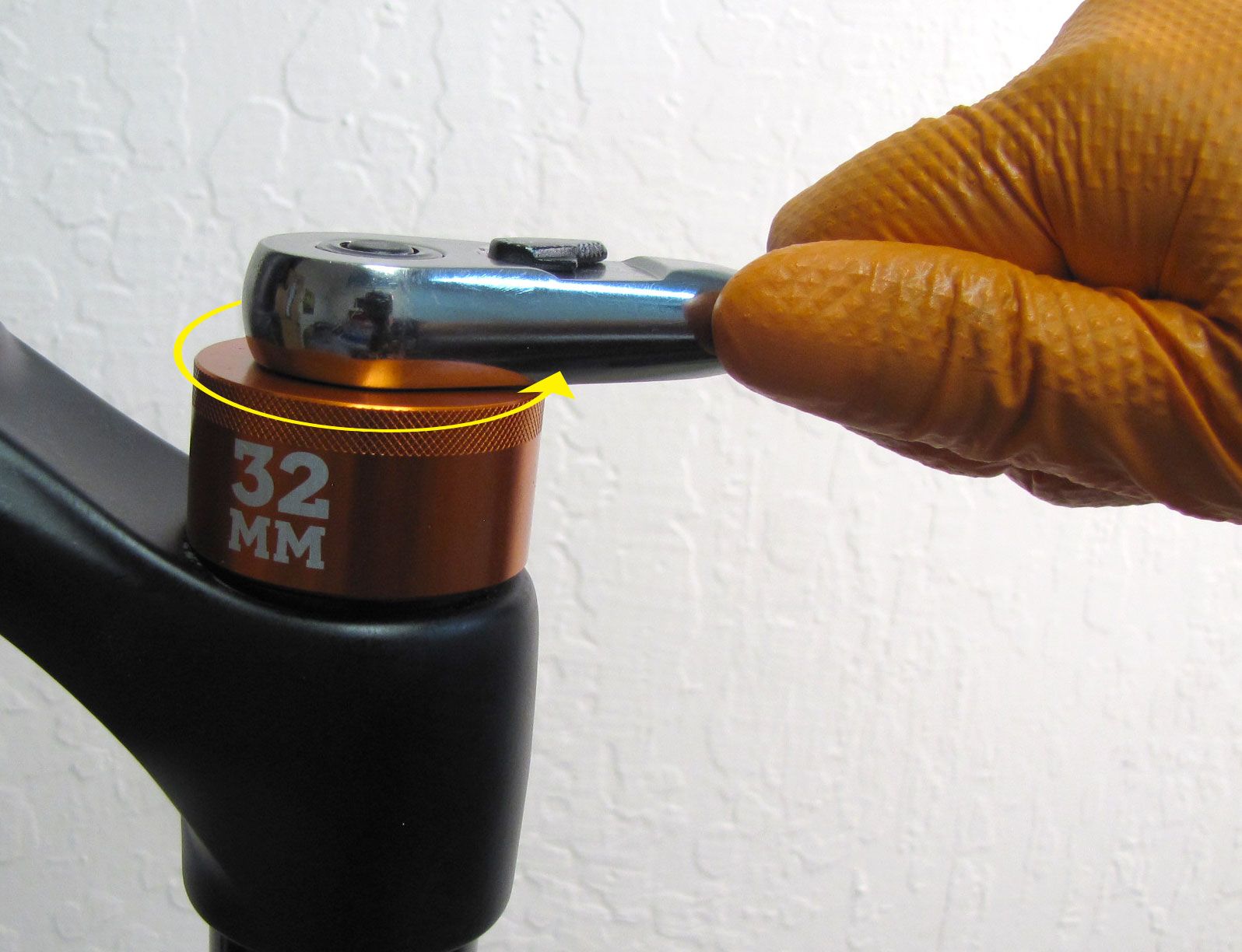
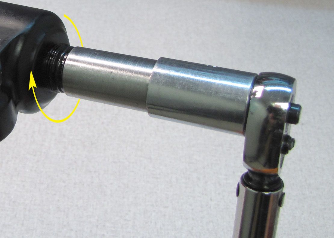
Step 5
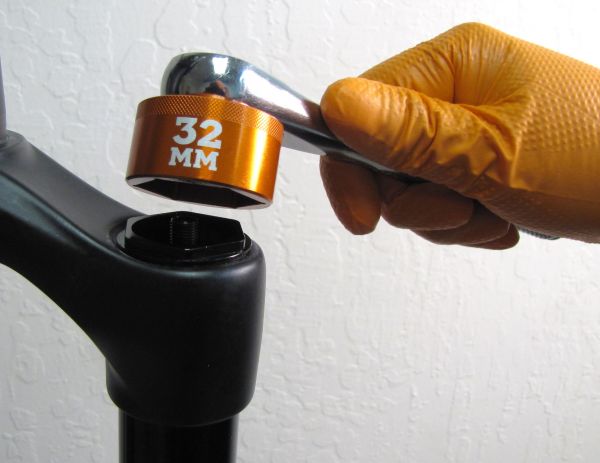
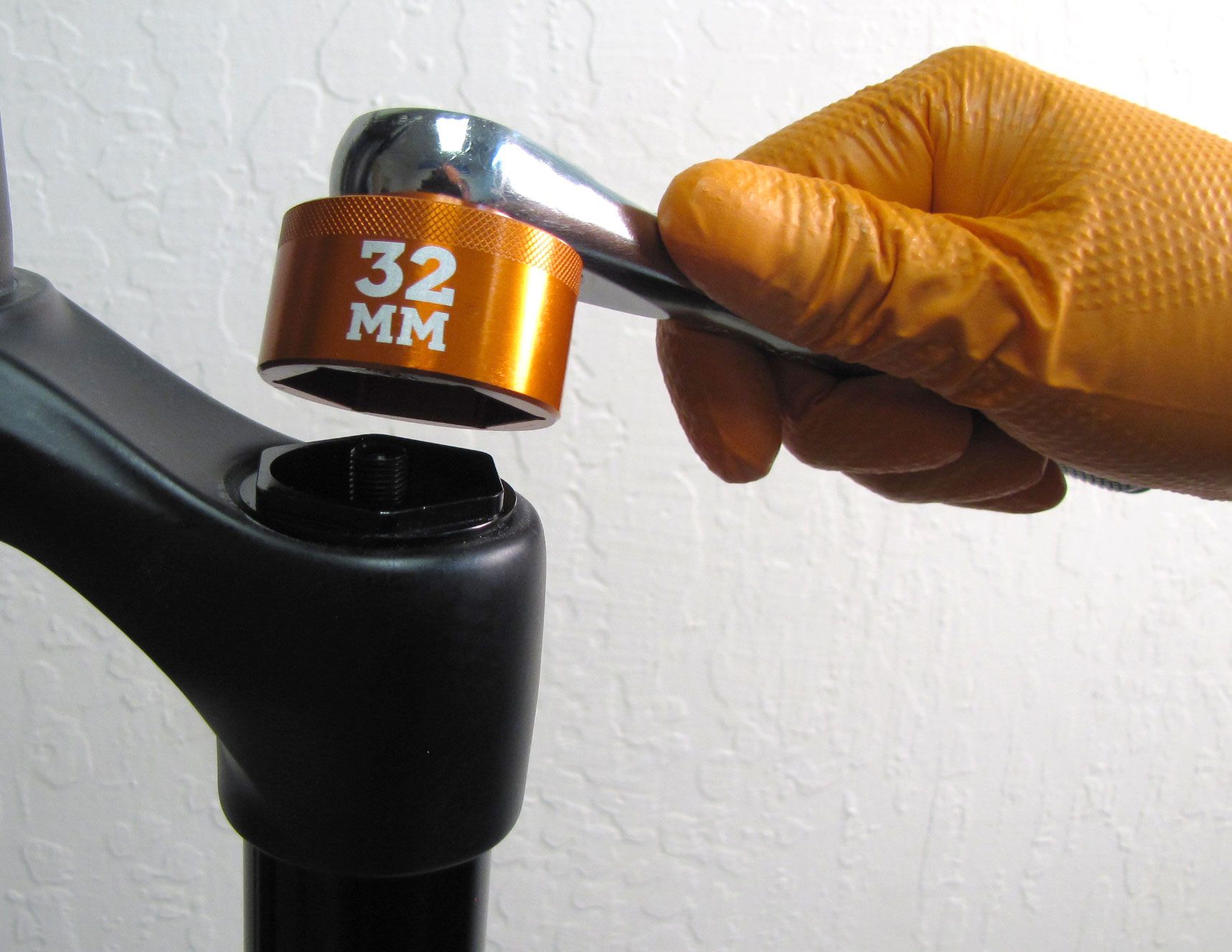
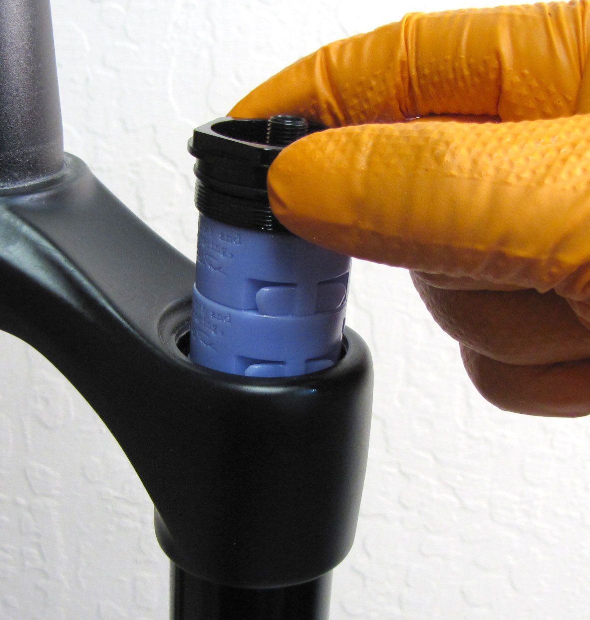
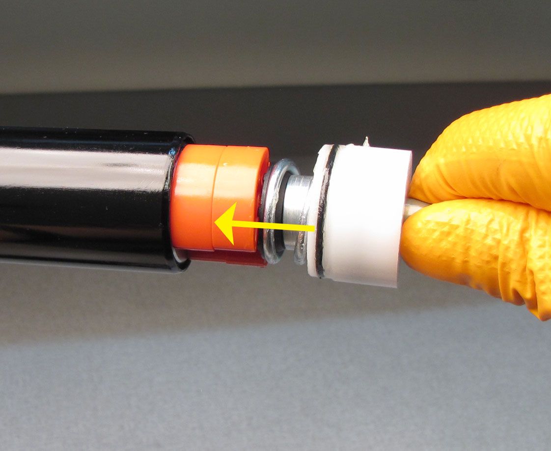
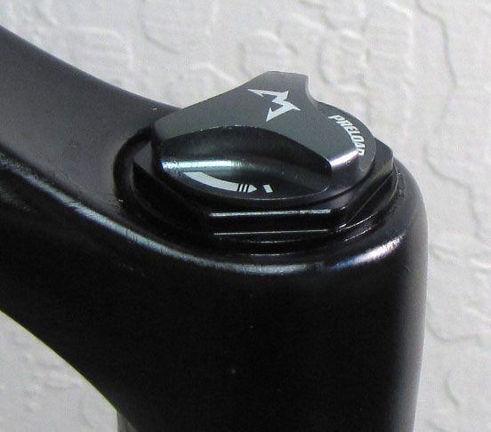
With a chamfer-less 6-point 32mm socket (PN: 398-00-705), unthread the air-side topcap assembly completely by turning it counter-clockwise. Pull straight up to remove the entire topcap assembly from the air-side stanchion tube. Some upward force might be needed to overcome the friction of the stock air volume spacers.


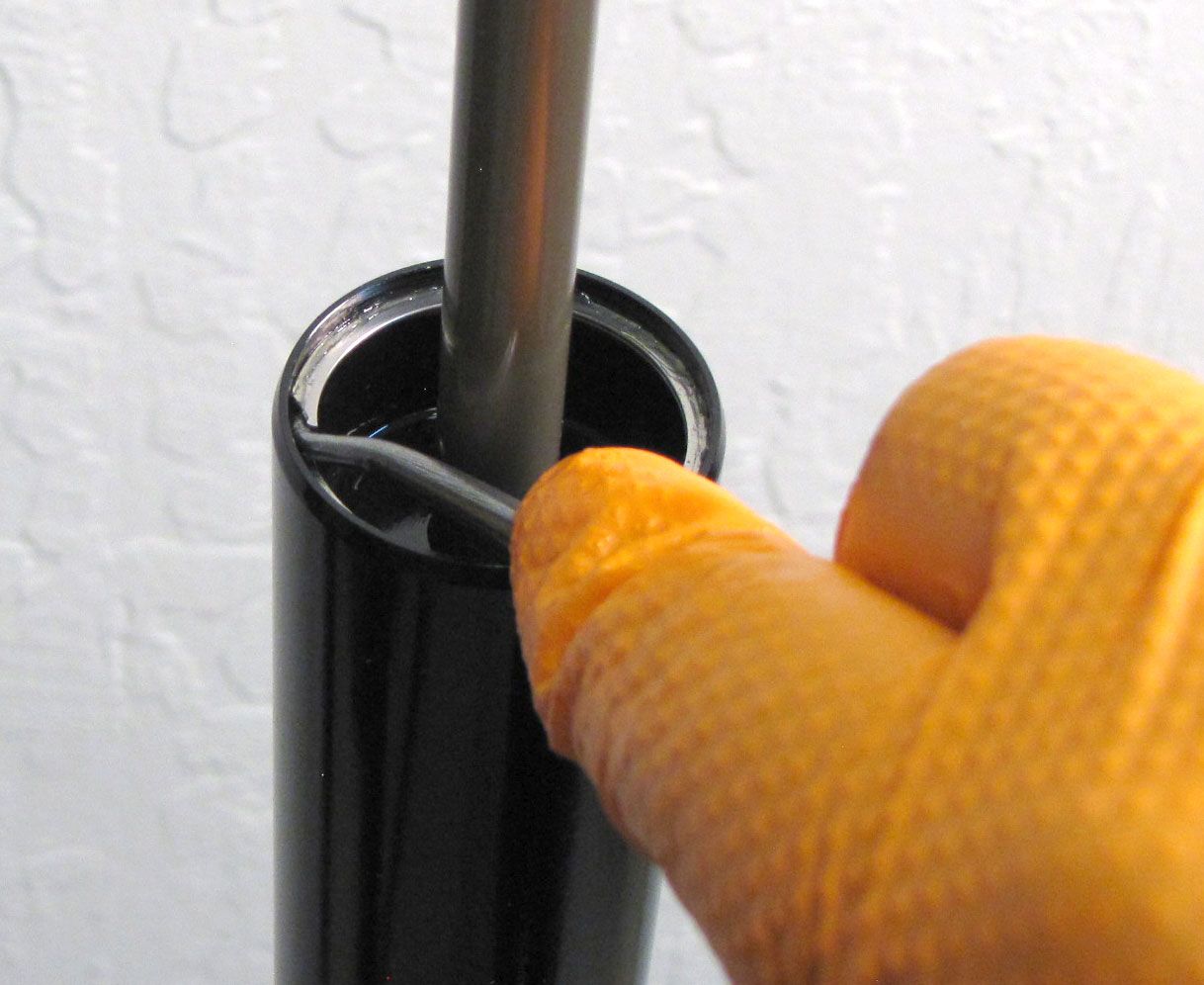
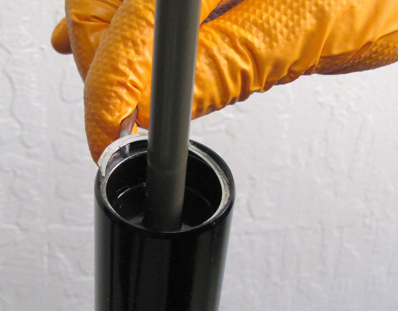
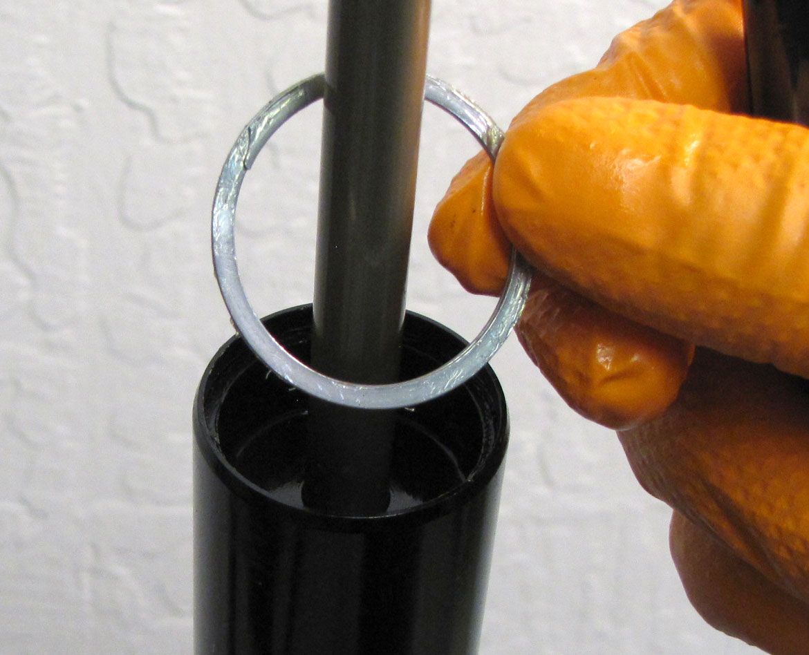
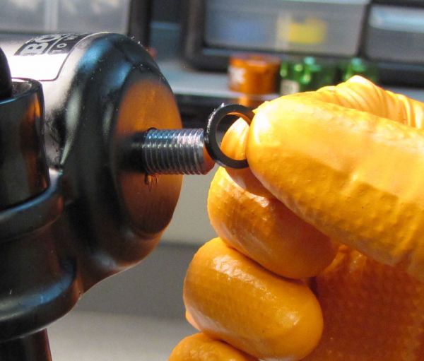
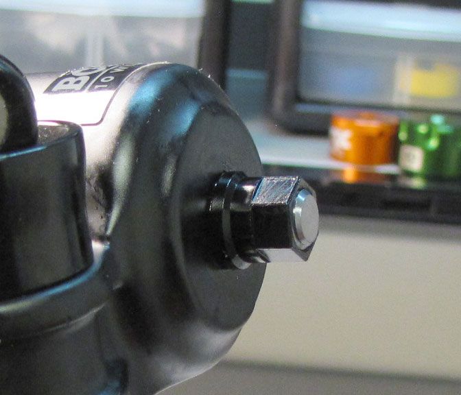
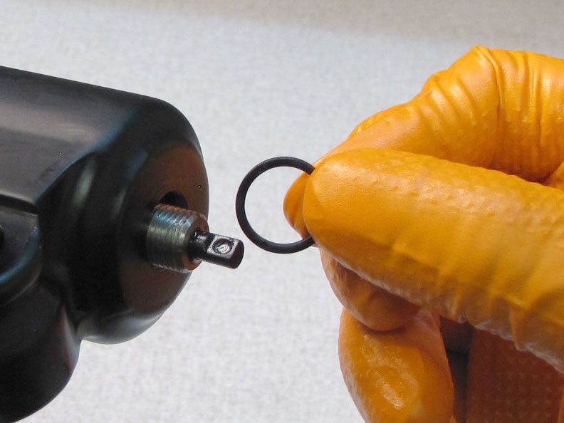
Step 6
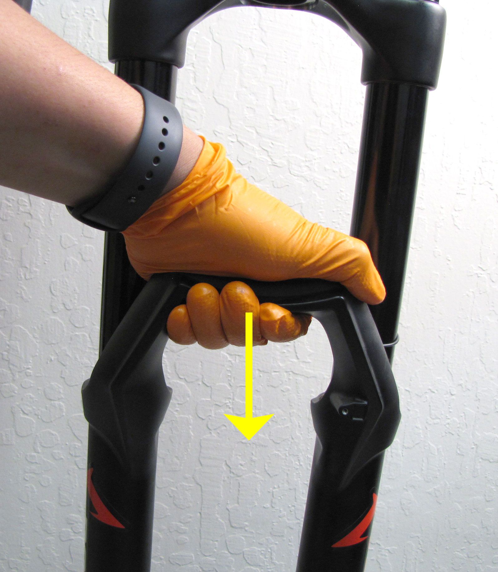
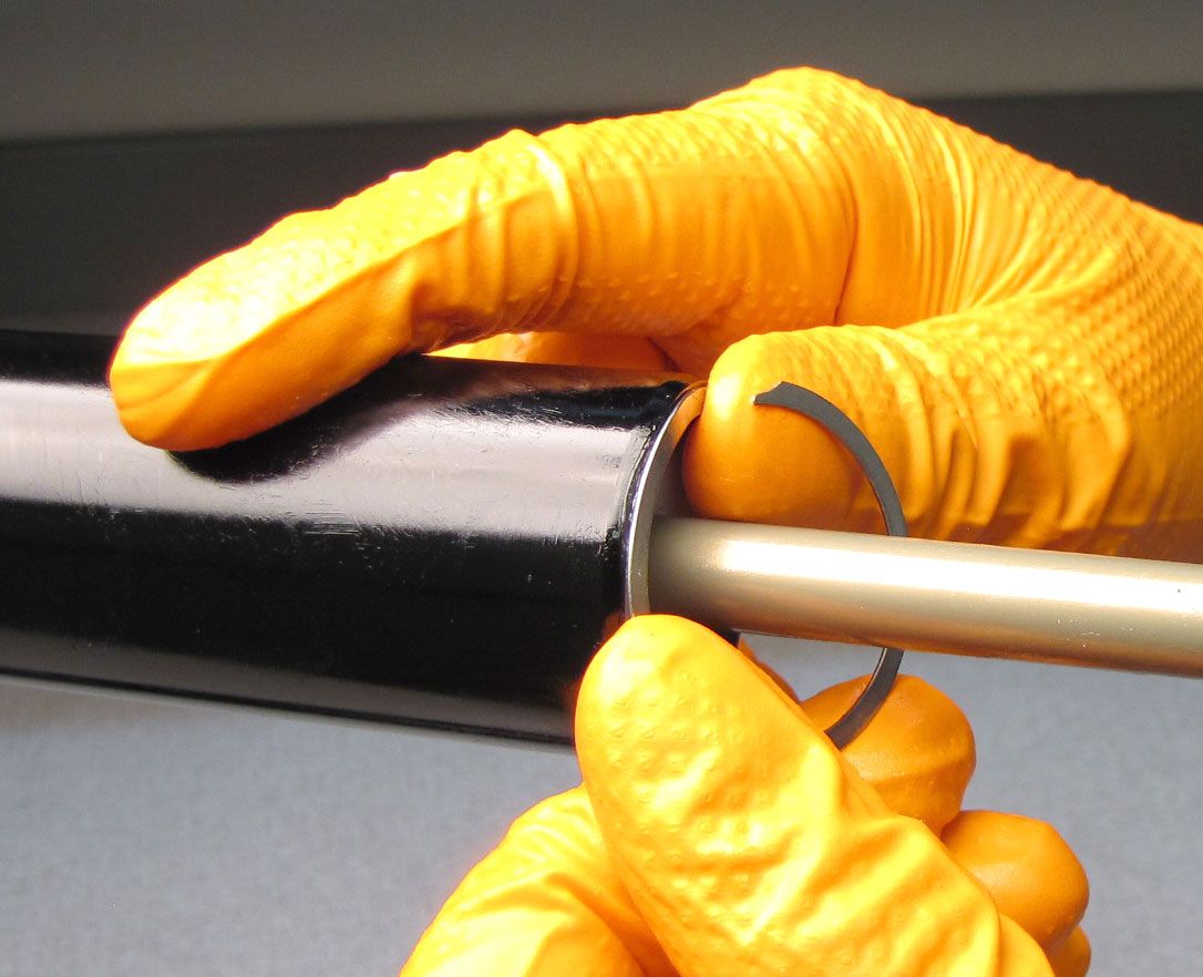
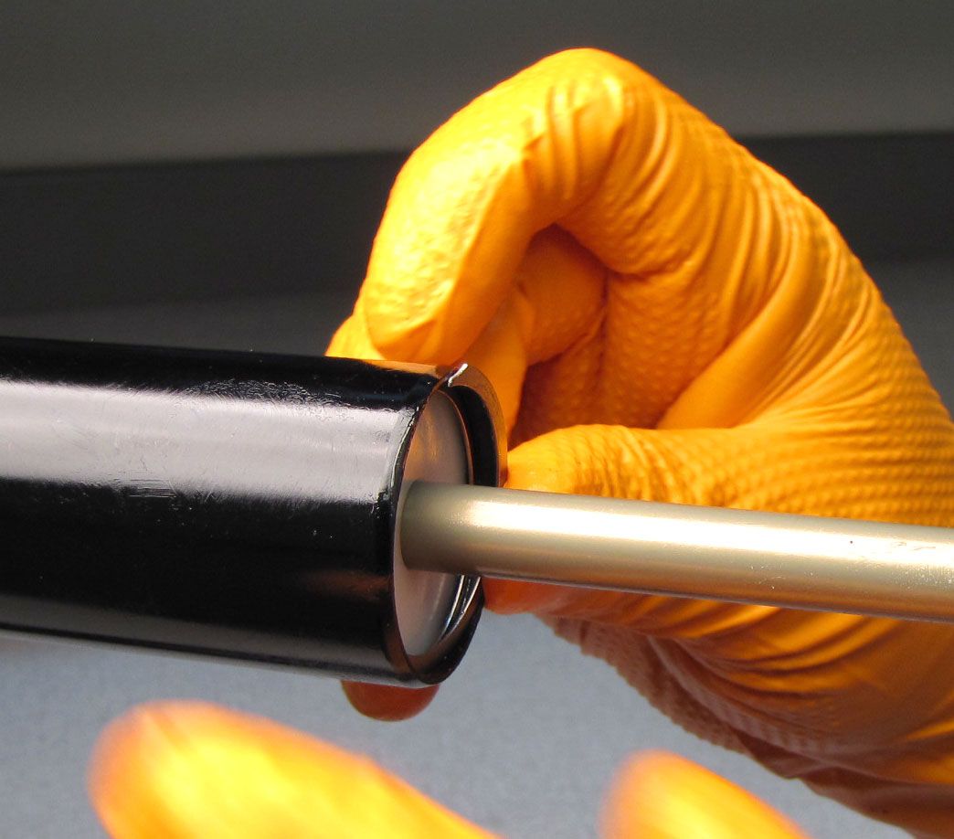
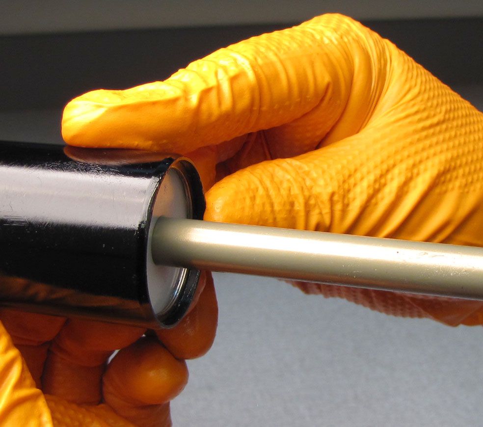
Remove the Retaining Ring from the bottom of the air-side Upper Tube. Take care not to scratch the Air Shaft with the Retaining Ring or Pick tool. Remove the Air Shaft Assembly by pulling it out of the bottom of the air-side Upper Tube.
Z1 Coil Spring Installation and Fork Reasembly
Step 1
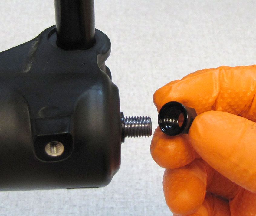
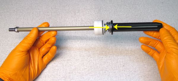
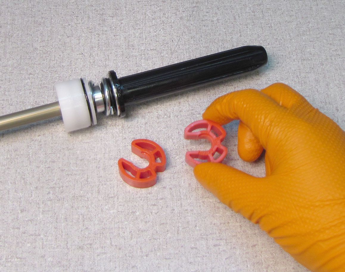
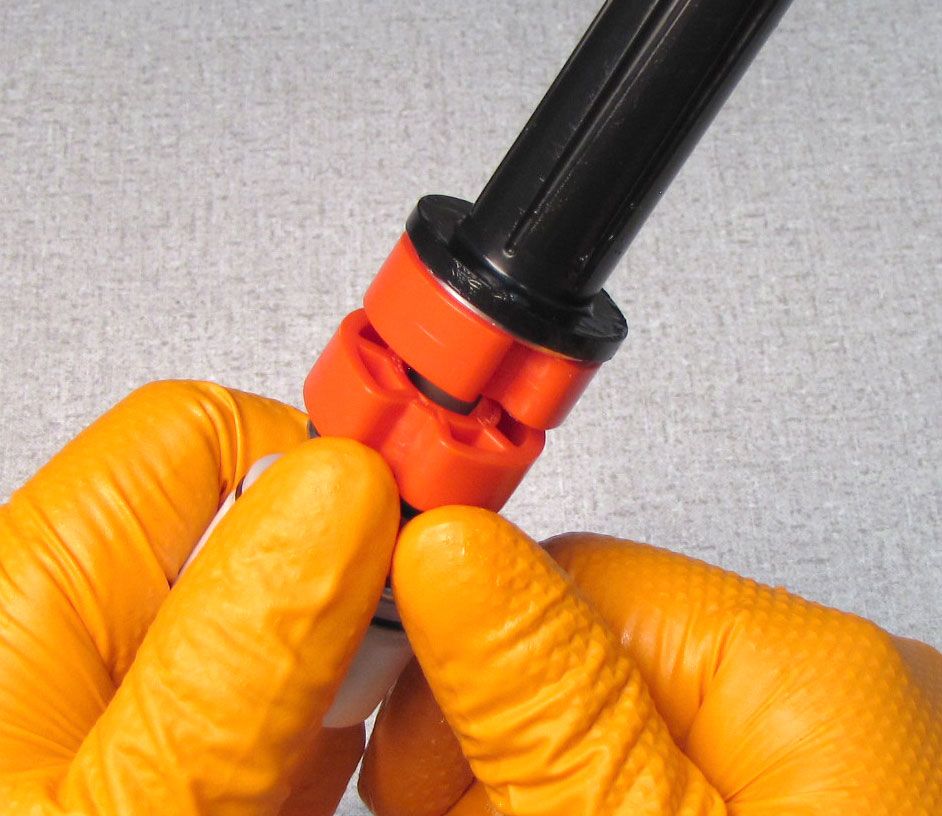
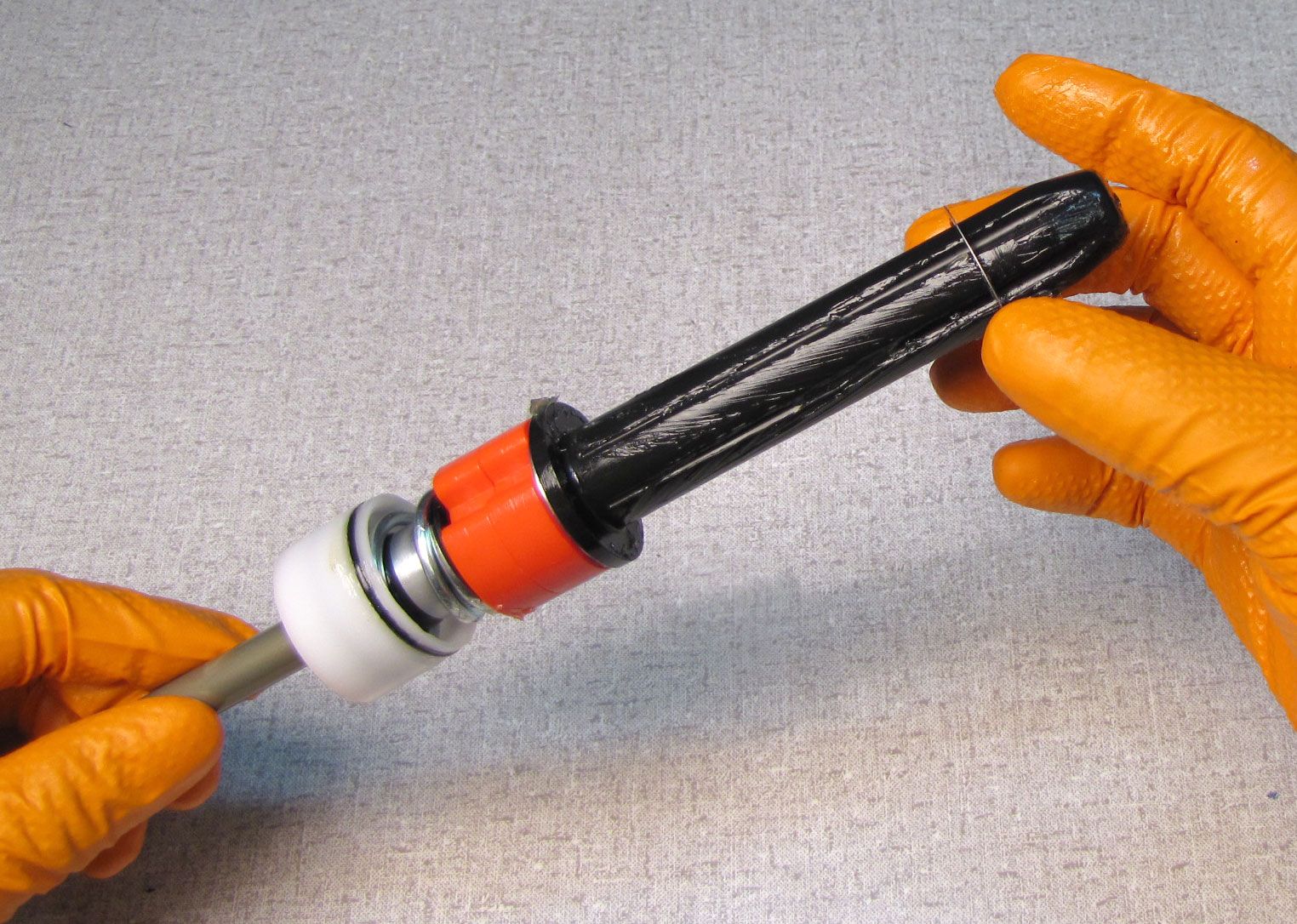
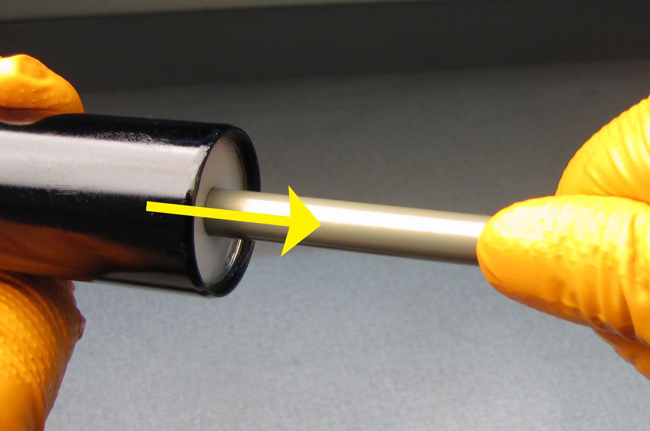
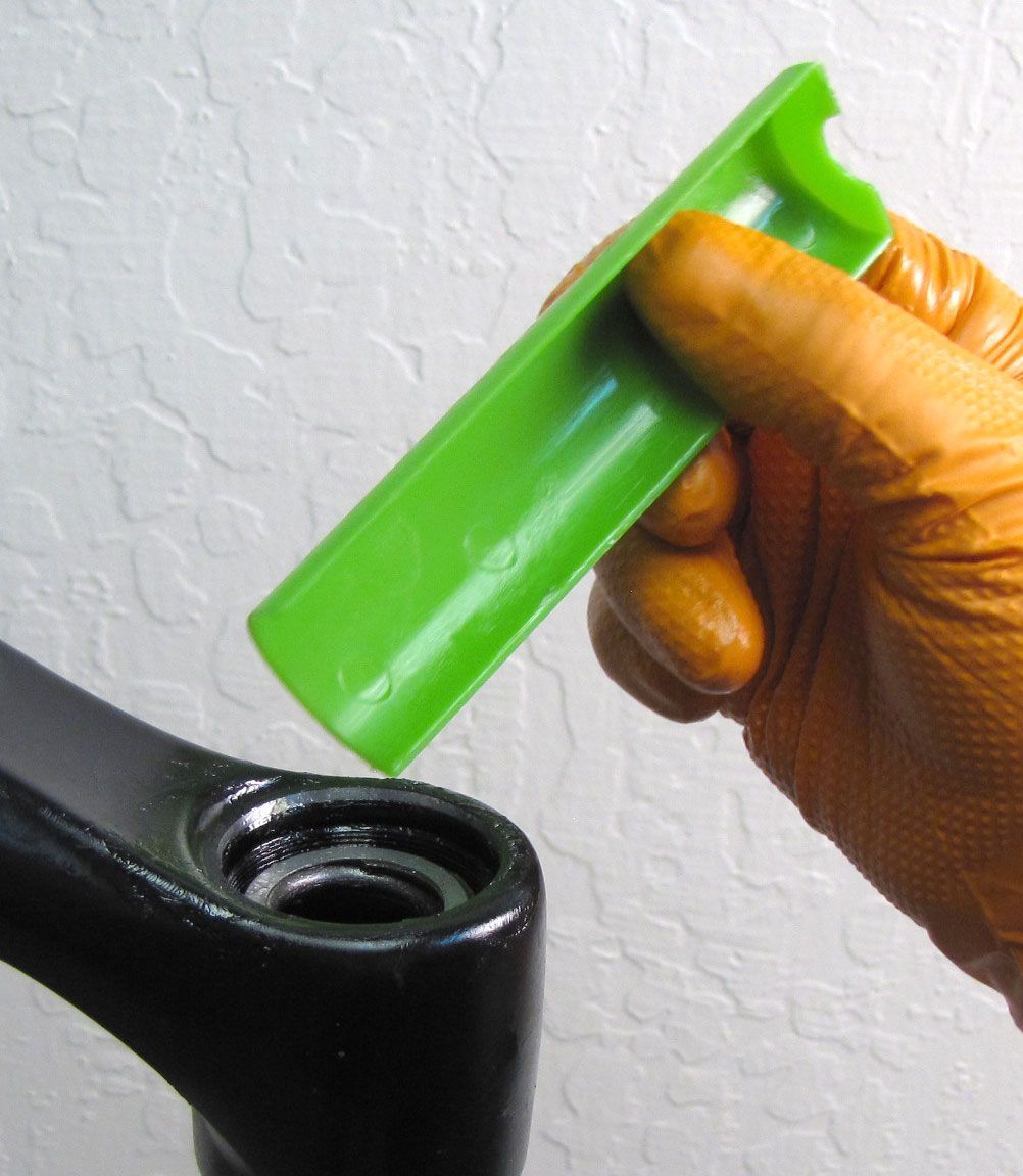
Make sure that the black plastic Spring Guide is firmly assembled onto the Plunger Shaft Assembly by pressing them together as shown.


Step 2
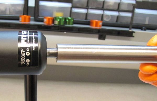
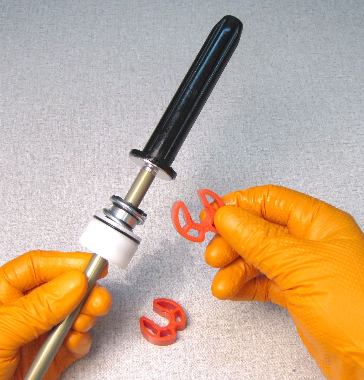
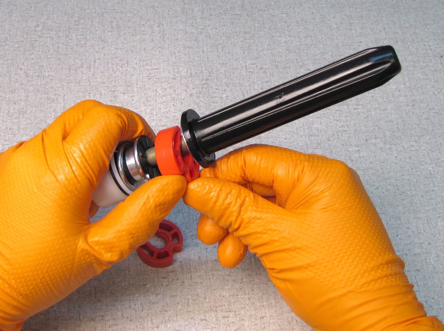
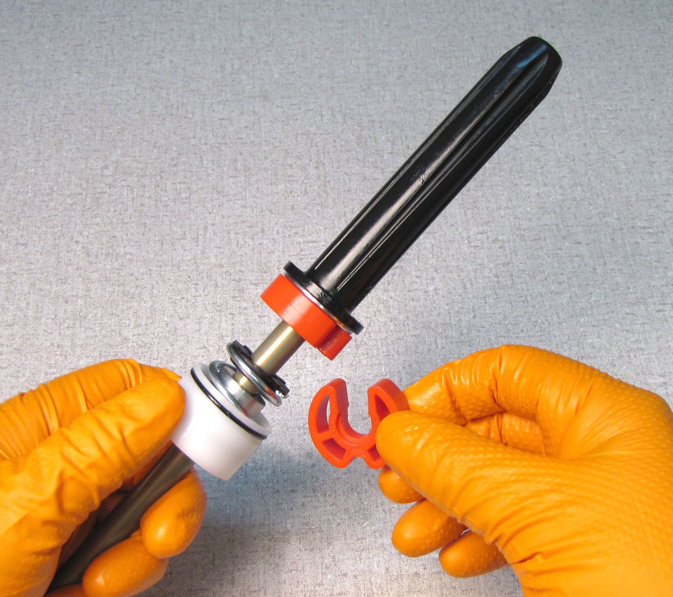
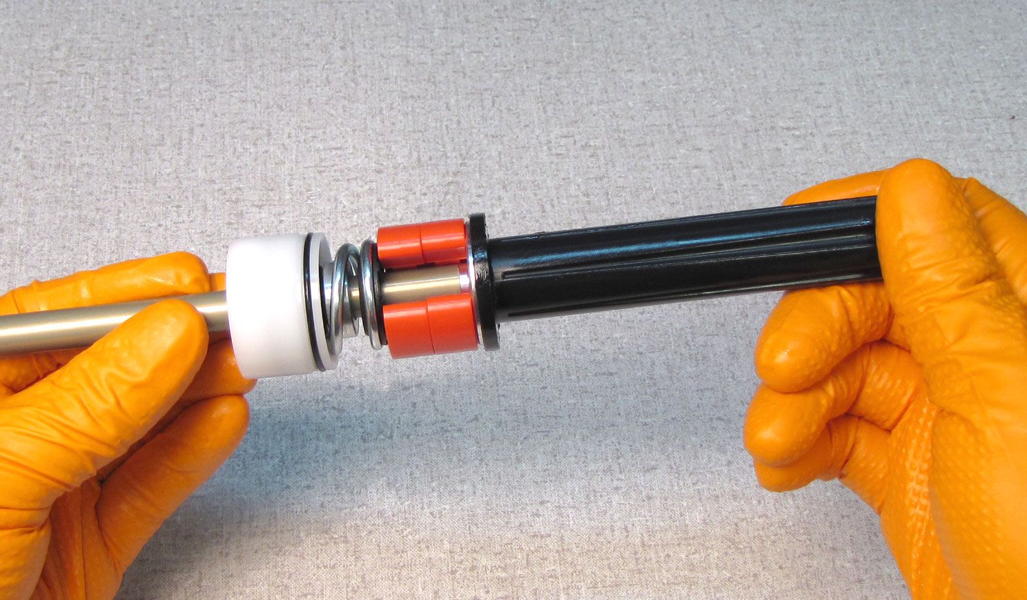
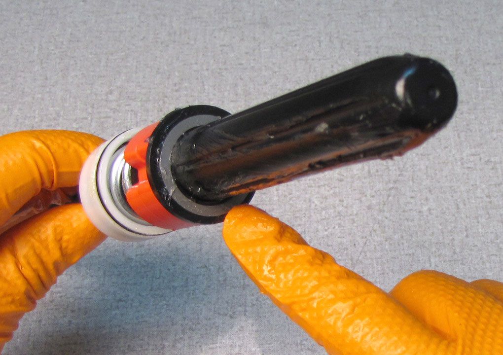
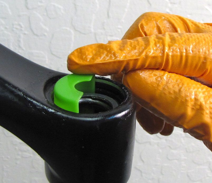
Assemble the Travel Spacers in the appropriate configuration for the travel desired. Travel Spacers located in the "Lower Travel Spacer Position" must be clipped onto the Plunger Shaft Assembly between the Topout Spring and black plastic Spring Guide as shown.
Step 3
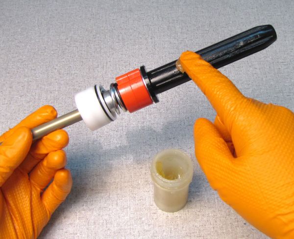
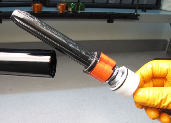
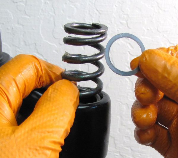
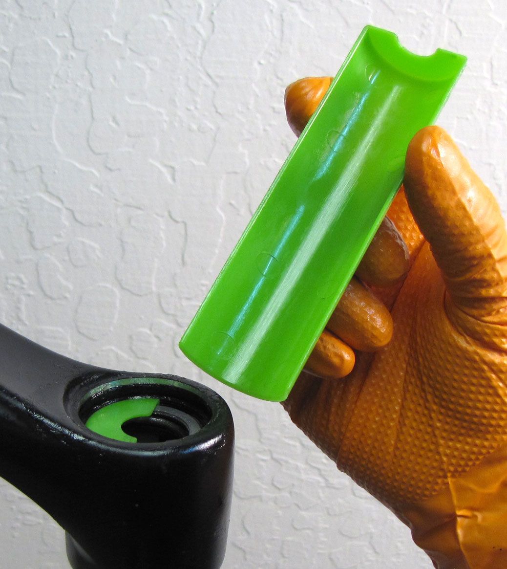
Coat the black plastic Spring Guide with a thin film of light grease like Slick Honey. Install one of the two washers onto the Spring Guide.

Step 4
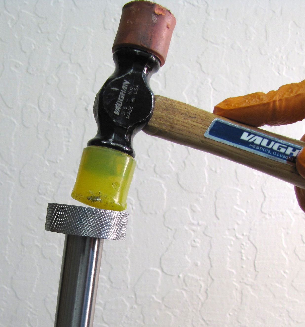
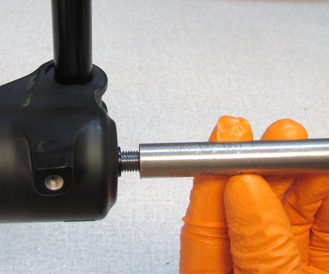
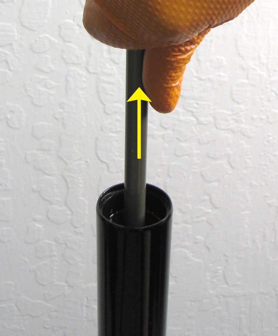
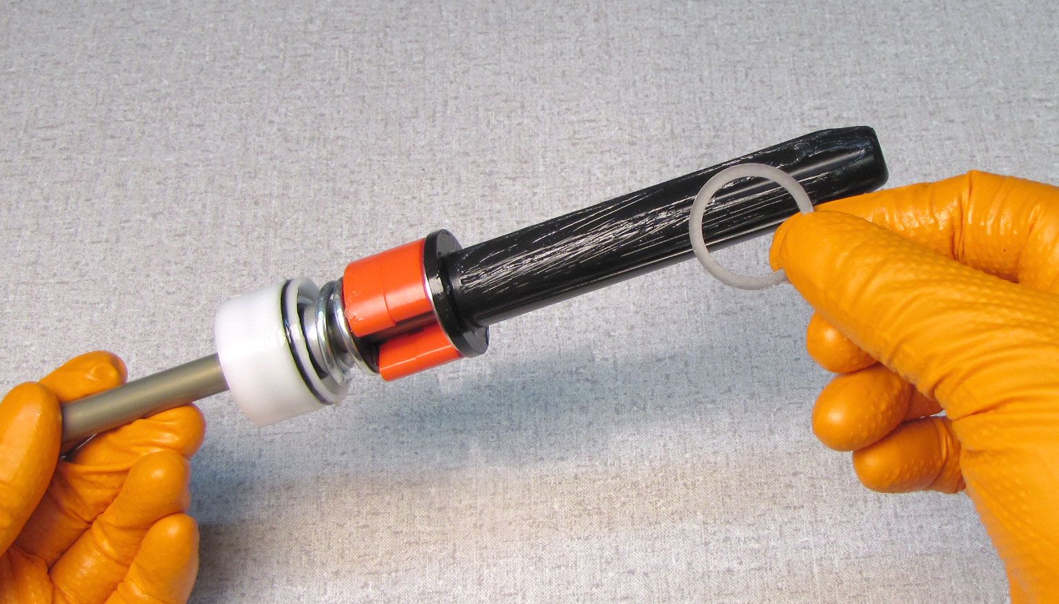
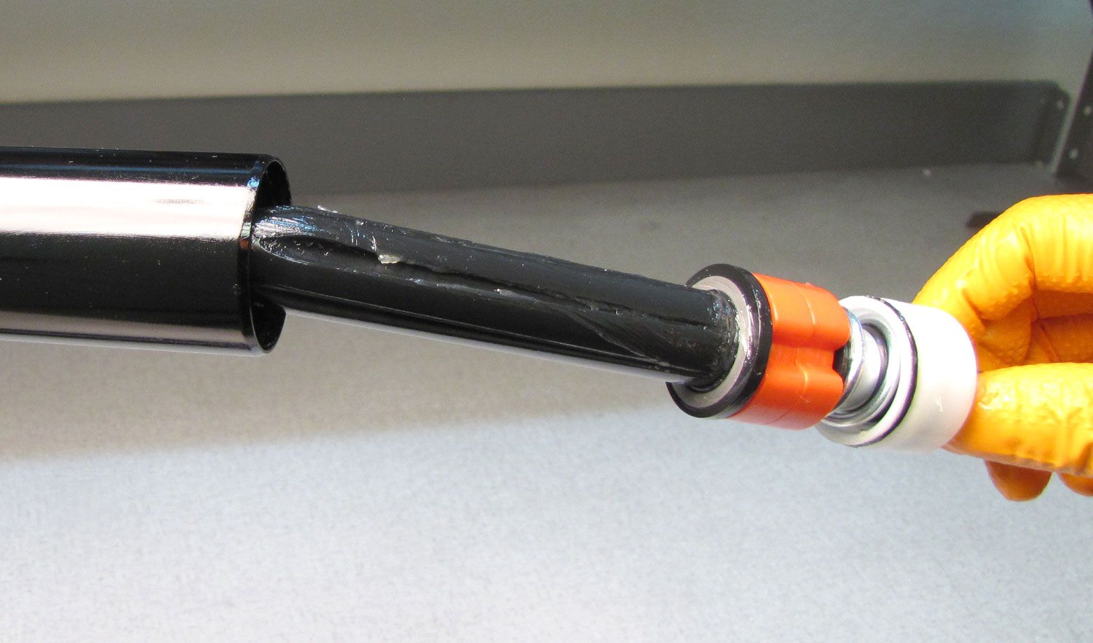
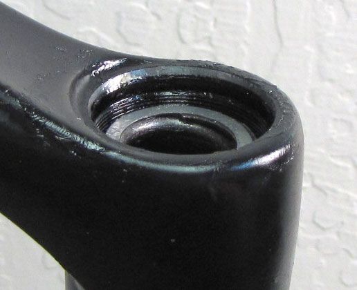
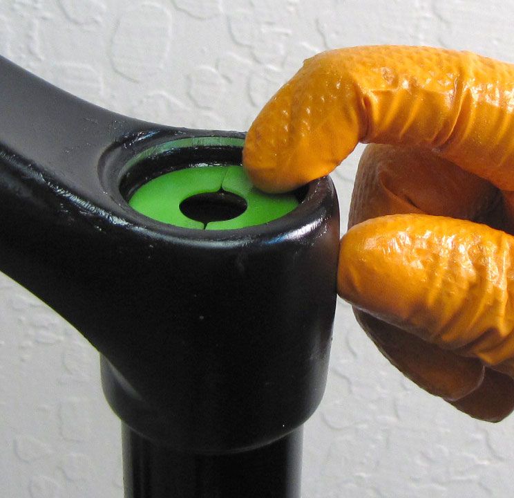
Install the prepared Plunger Shaft Assembly into the bottom of the spring-side Upper Tube. Reinstall the Retaining Ring making sure that it is fully seated in its groove by pulling on the installed Plunger Shaft Assembly.


Step 5
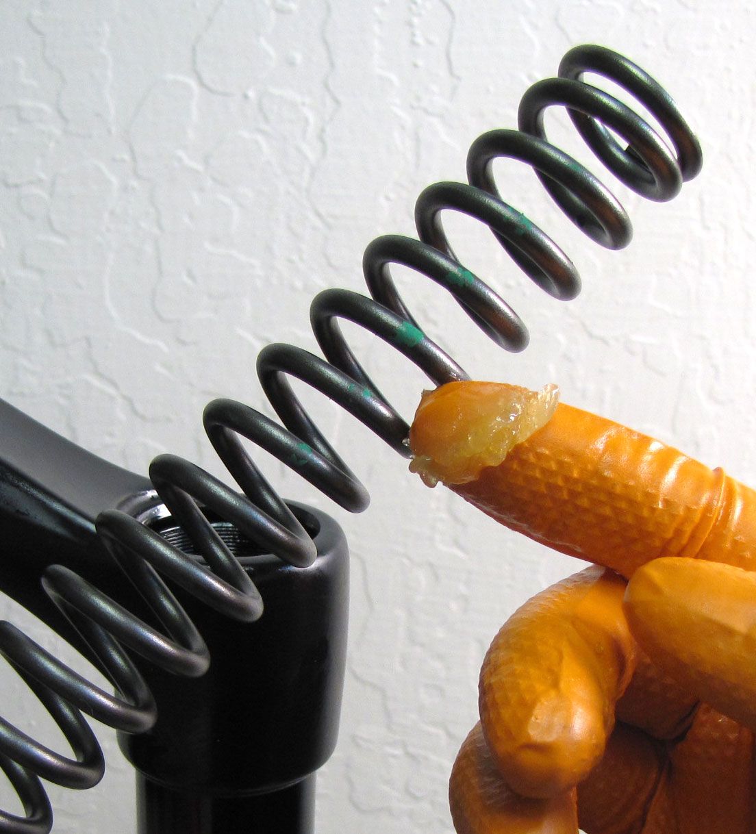
Note the color code of your spring, in this case our spring has a green stripe. Coat the Spring with a thin film of light grease like Slick Honey then install into the Upper Tube making sure to seat the Spring onto the black plastic Spring Guide of the Plunger Shaft Assembly.
Step 6
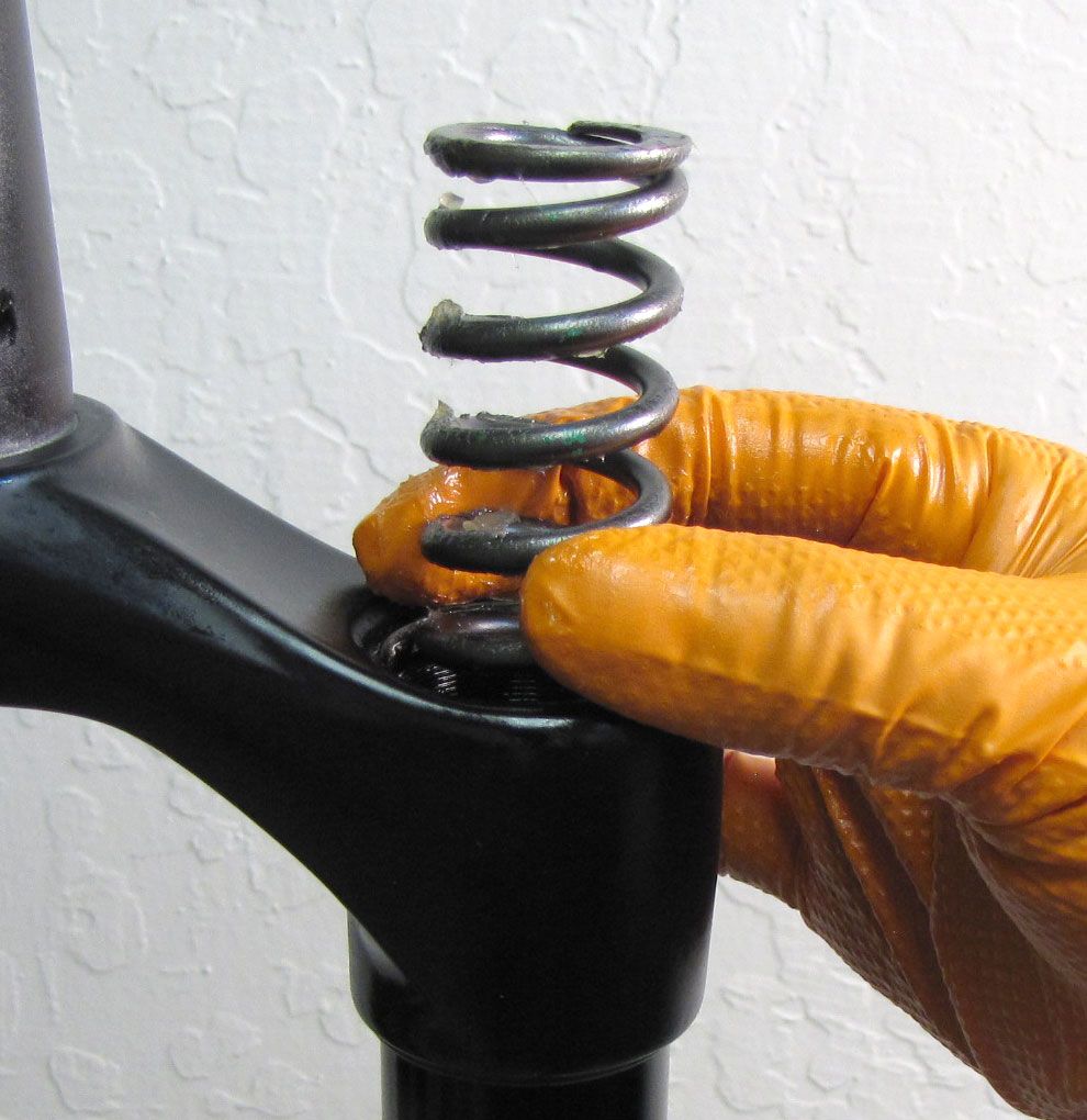
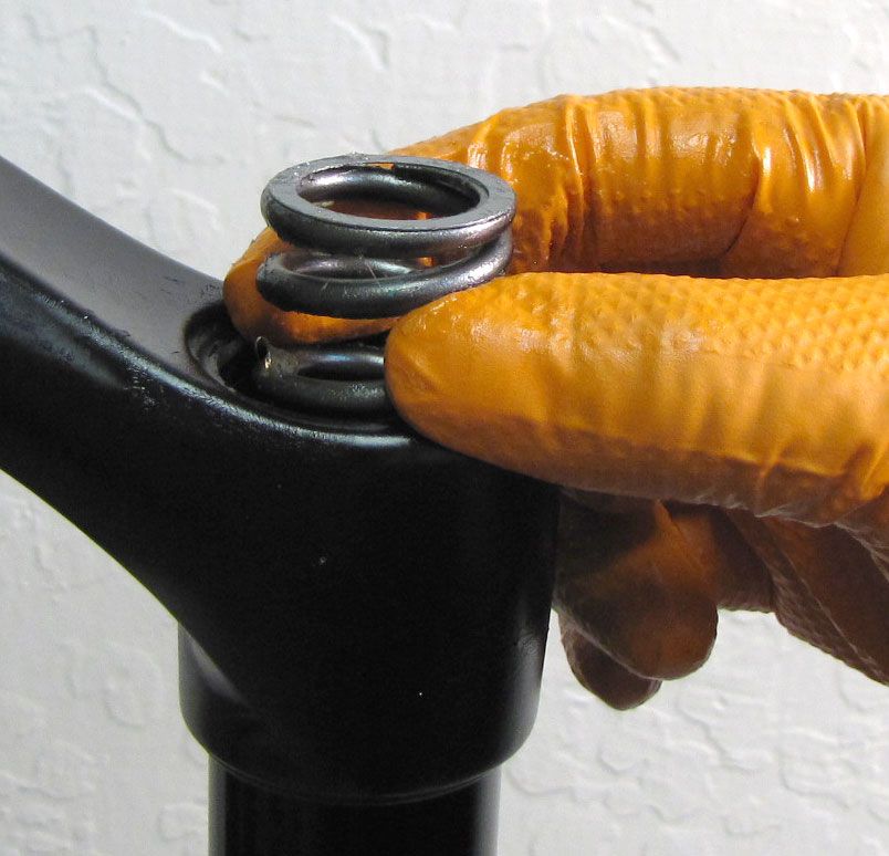
Position the second Washer on the top of the installed Spring.


Step 7
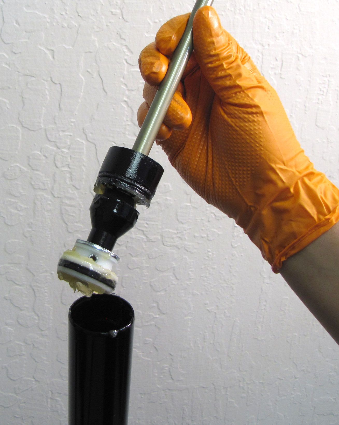
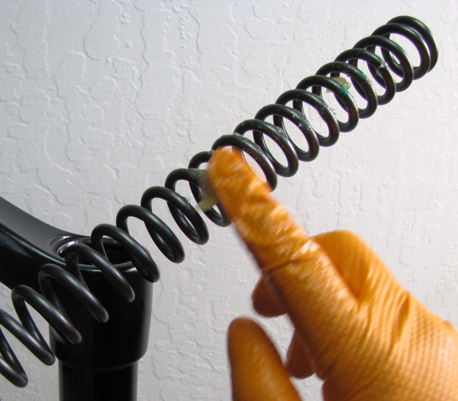
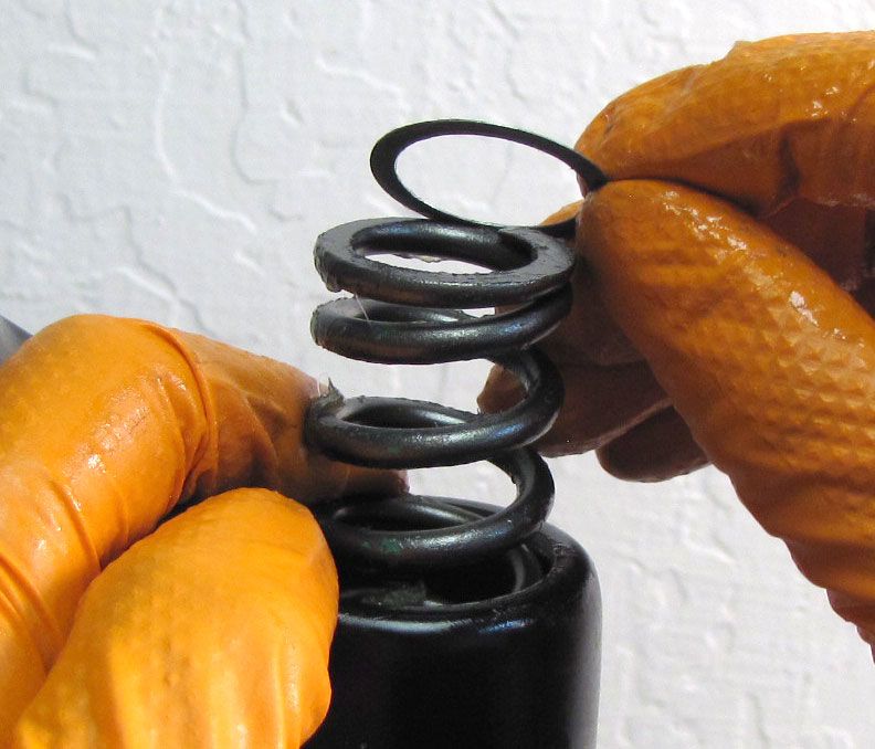
Make sure that your Upper Spring Guide is the same color as the color code on your Spring. Install the Upper Spring Guide over the installed Spring and Washer.
Step 8
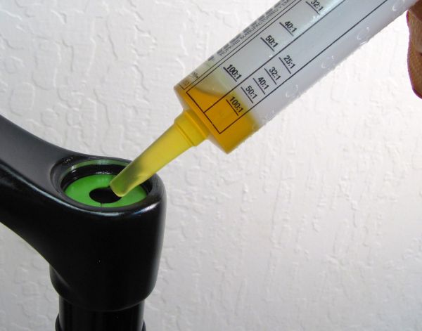
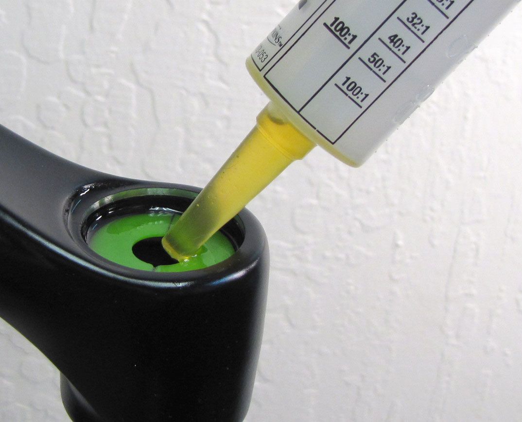
Inject 5cc of FOX 20wt. Gold oil into the Upper Tube with your Spring. Install the new Coil Topcap Assembly tightening clockwise to 220 in-lb (24.8 Nm) torque with your 6-point chamferless 32mm socket.


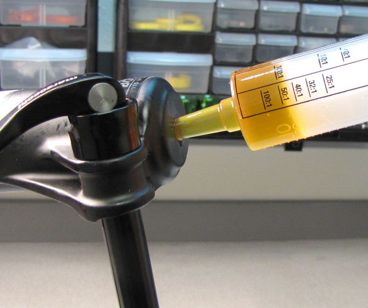
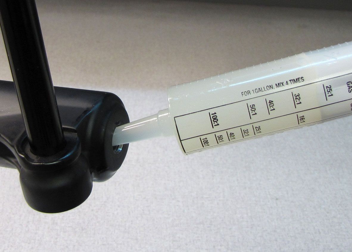
Step 9
Reinstall the Lower Leg Assembly onto the Upper Tubes then invert the fork so the dropouts are higher then the rest of the fork. Inject 10cc of FOX 20wt. Gold oil into the spring-side Lower leg. Inject 40cc of FOX 5wt. Teflon Infused oil into the damper-side Lower Leg.


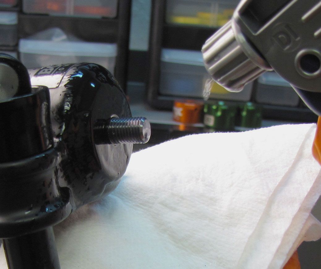
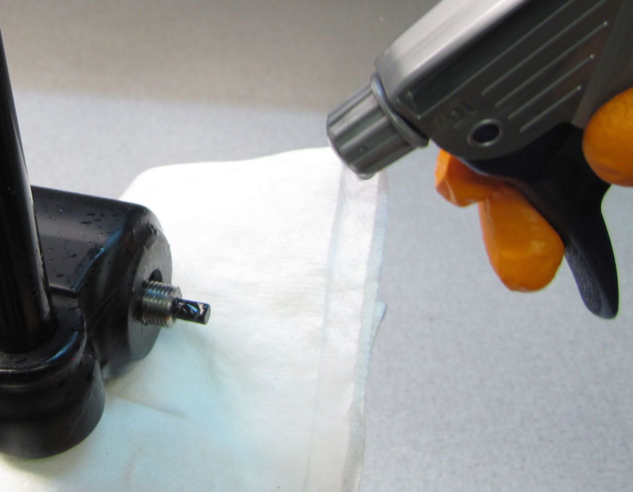
Step 10
Push the Lower Leg Assembly fully onto the Upper Tubes to fully seat the Lower Leg Assembly. Clean the threads of the Plunger Shaft and Damper Assemblies with Isopropyl Alcohol and a lint-free paper towel.


Step 11
Install a new Crush Washer onto each threaded shaft followed by the appropriate Bottom Nut. Tighten the spring-side Bottom Nut clockwise to 50 in-lb (5.7 Nm) torque with a 10mm socket. Tighten the damper-side Bottom Nut clockwise to 150 in-lb (16.9 Nm) torque with a 15mm socket.


Step 12
Use a 2mm hex wrench to install the red rebound knob. Make sure that the set screw lines up with the depression in the rebound adjuster shaft. Reinstall the black rebound knob cover. Clean the exterior of your fork.