2021 38mm FLOAT NA2 Air Spring Rebuild
Required Parts
- 803-01-487 Seal Kit: 38 FLOAT NA2 Rebuild
Required Tools
- 398-00-657 Tooling: Bullet, Sealhead To Shaft, FLOAT NA 2
- 398-00-681 2002-017 32 Damper-side and ALL 32-34-36-40 Spring-side Removal Tool
- 398-00-682 2005-017 34-36-40 Damper-side Removal Tool
- 398-00-706 Tooling: Fork Topcap Socket, 32mm V2, 3/8 Drive
- 803-01-324 Kit: Tooling: 2019 Clamps, Grip Damper, Body and Shaft
WARNING: Always wear safety glasses and protective gloves during service to prevent potential injury. Failure to wear protective equipment during service may lead to SERIOUS INJURY OR DEATH.
WARNING: FOX products should be serviced by a trained bicycle service technician, in accordance with FOX specifications. If you have any doubt whether or not you can properly service your FOX product, then DO NOT attempt it. Improperly serviced products can fail, causing the rider to lose control resulting in SERIOUS INJURY OR DEATH.
WARNING: Never attempt to modify air volume spacers or air shaft assemblies, as this can damage your fork causing a loss of control of the bicycle leading to SERIOUS INJURY or DEATH.
WARNING: FOX suspension products contain pressurized nitrogen, air, oil, or all 3. Suspension misuse can cause property damage, SERIOUS INJURY OR DEATH. DO NOT puncture, incinerate or crush any portion of a FOX suspension product. DO NOT attempt to disassemble any portion of a FOX suspension product, unless expressly instructed to do so by the applicable FOX technical documentation, and then ONLY while strictly adhering to all FOX instructions and warnings in that instance.
WARNING: Modification, improper service, or use of aftermarket replacement parts with FOX forks and shocks may cause the product to malfunction, resulting in SERIOUS INJURY OR DEATH. DO NOT modify any part of a fork or shock, including the fork brace (lower leg cross brace), crown, steerer, upper and lower leg tubes, or internal parts, except as instructed herein. Any unauthorized modification may void the warranty, and may cause failure or the fork or shock, resulting in SERIOUS INJURY OR DEATH.
NOTE: To adjust travel on a 2021 38mm fork you must replace the entire Air Shaft Assembly with Inner Air Sleeve.
| Part | Description |
| 820-02-568-KIT | Service Set: Air Shaft Assy, 2021, 38, 180mm, FLOAT NA 2, Inner Air Sleeve, 1.214 Bore |
| 820-02-569-KIT | Service Set: Air Shaft Assy, 2021, 38, 170mm, FLOAT NA 2, Inner Air Sleeve, 1.214 Bore |
| 820-02-570-KIT | Service Set: Air Shaft Assy, 2021, 38, 160mm, FLOAT NA 2, Inner Air Sleeve, 1.214 Bore |
| 820-02-589-KIT | Service Set: Air Shaft Assy, 2021, 38, 150mm, FLOAT NA 2, Inner Air Sleeve, 1.214 Bore |

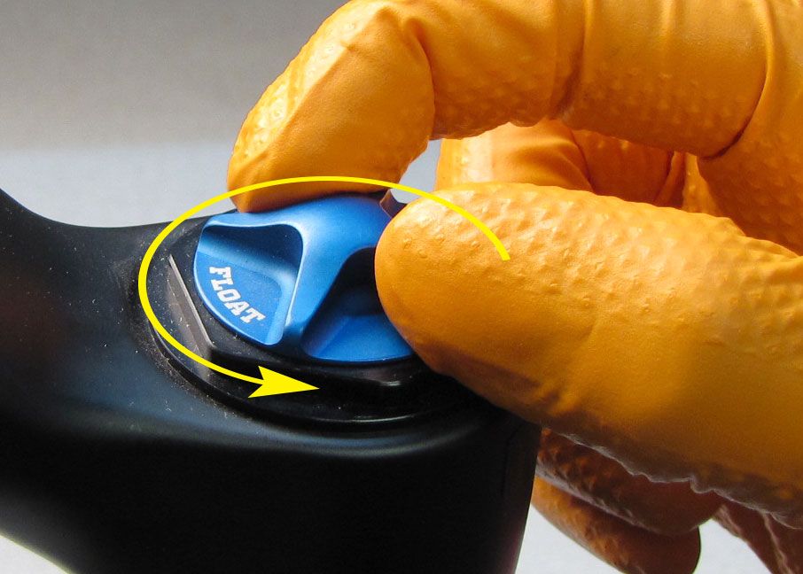
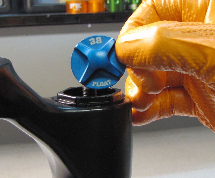
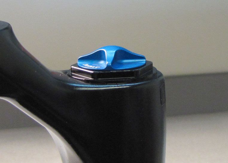
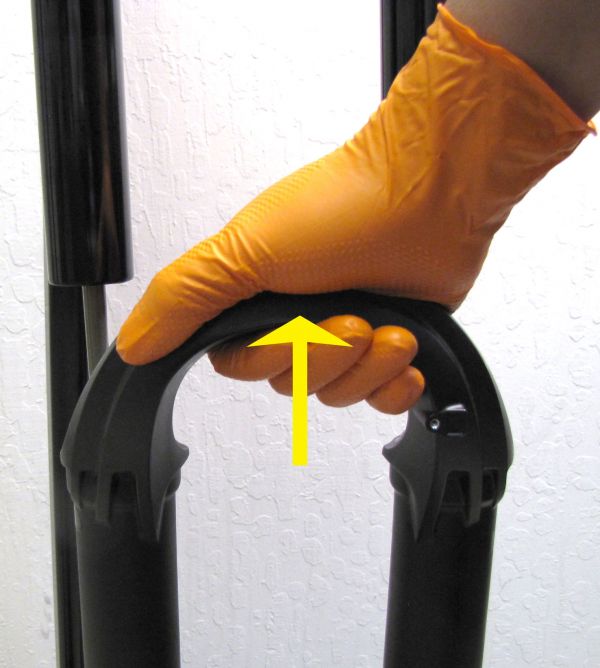
Step 1
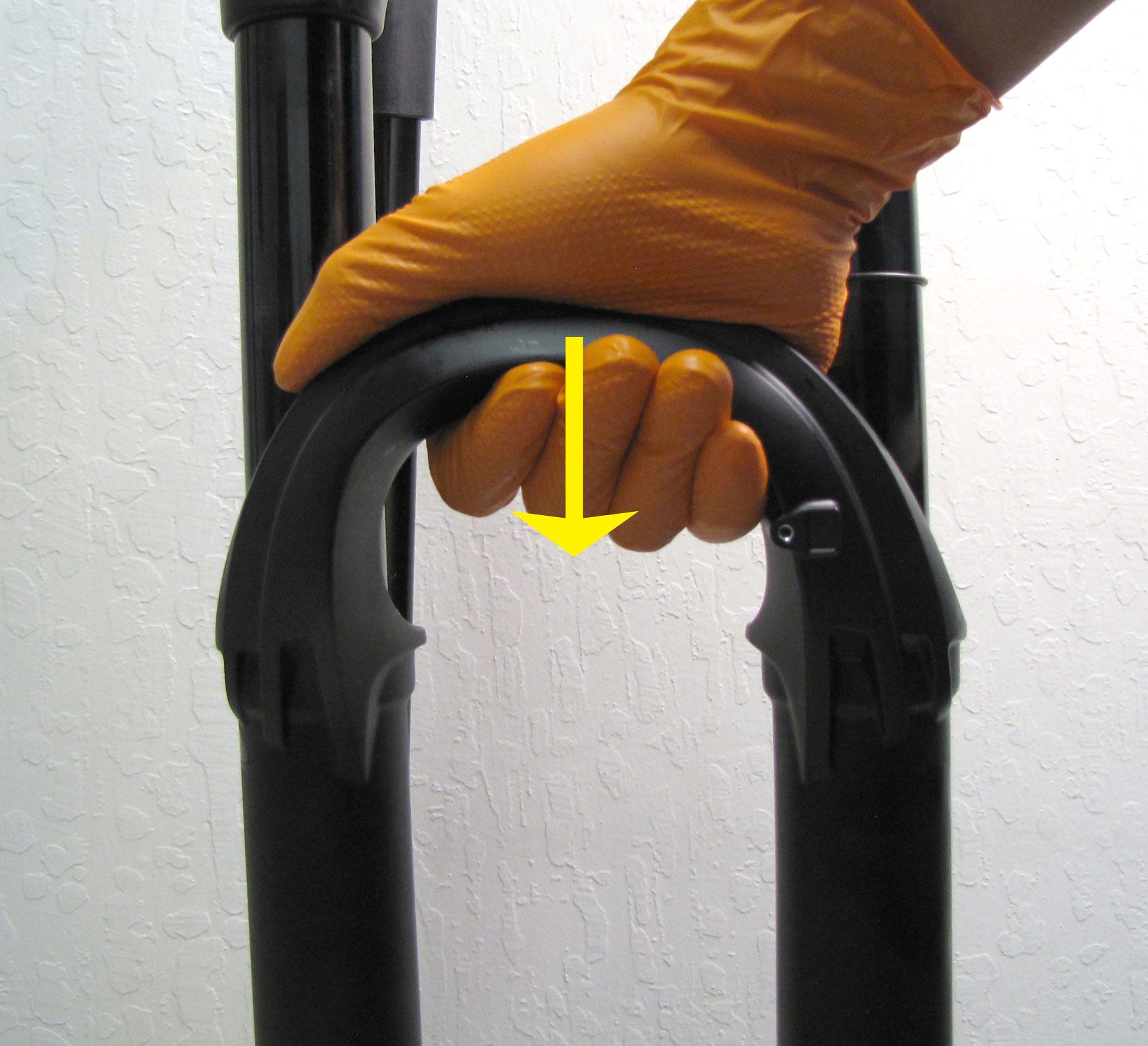
Remove the blue air cap then use a shock pump to slowly release the air pressure while you hold the lower leg arch down.


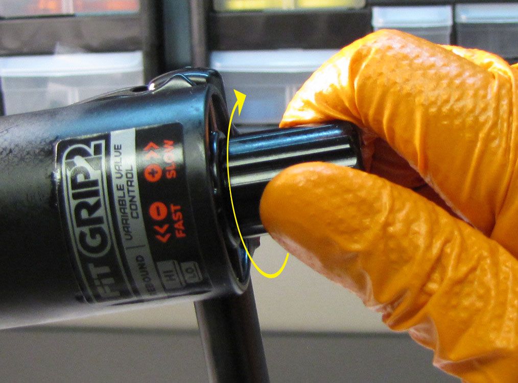
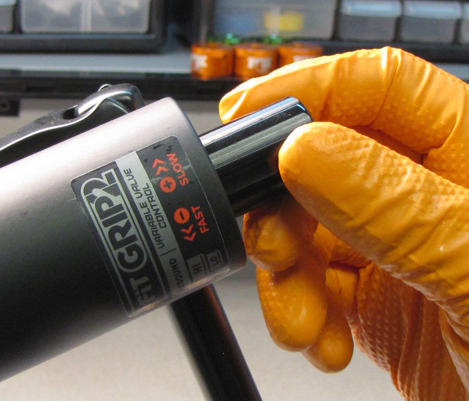
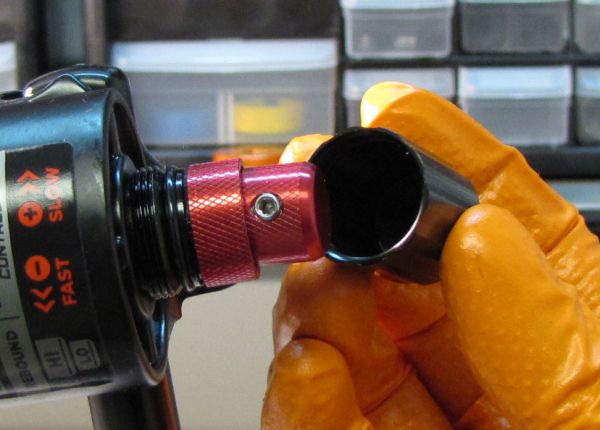
Step 2
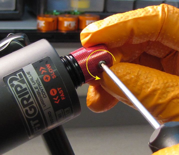
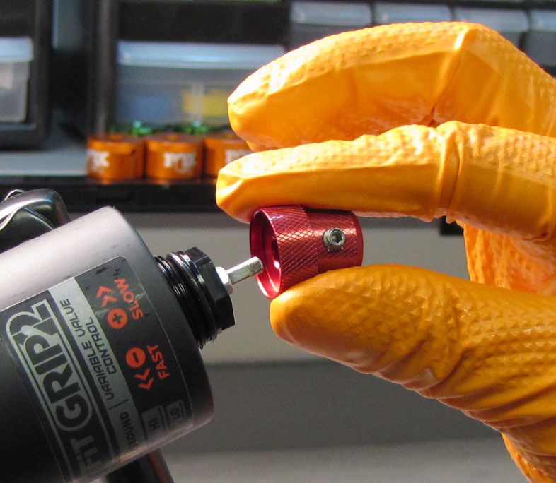
With the fork slightly inverted (the bottom of the fork up past horizontal), remove the black cover, then use a 2mm hex wrench to remove the red rebound knobs.


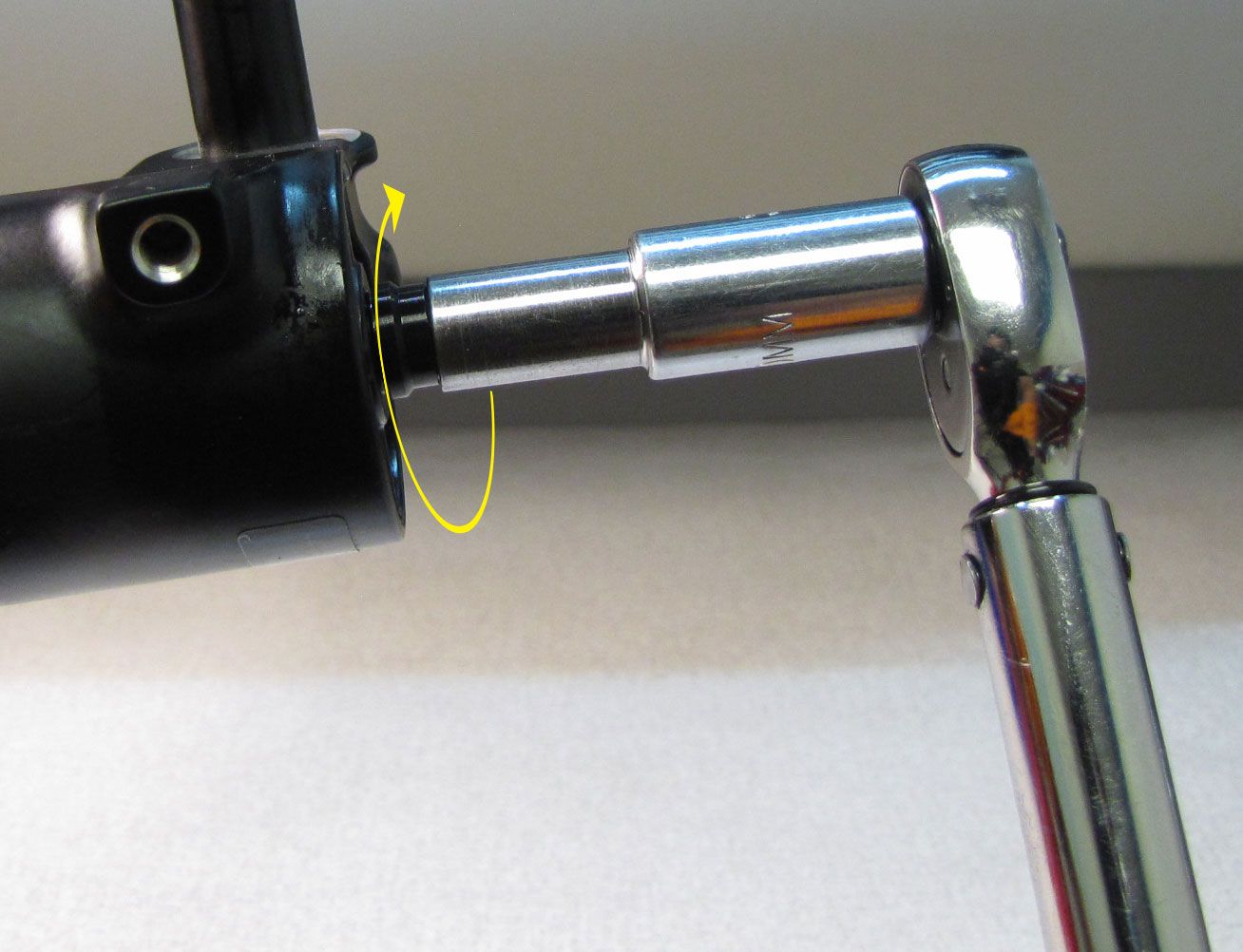
Step 3
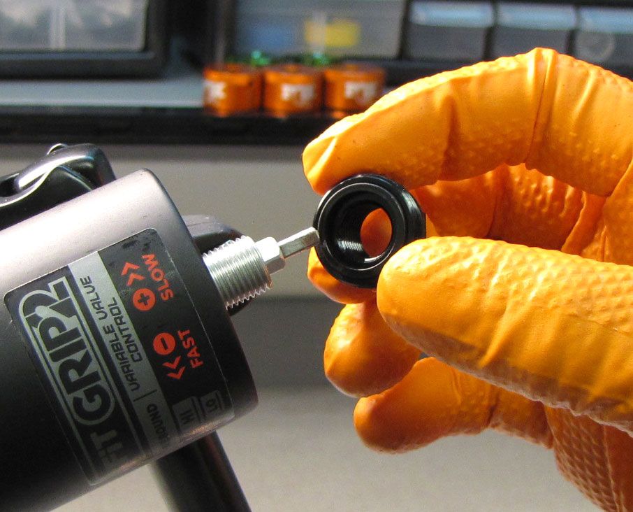
Use a 15mm socket to remove the damper side bottom nut. Make sure to remove and discard the original crushwasher which may be stuck to the bottom nut.

Step 4
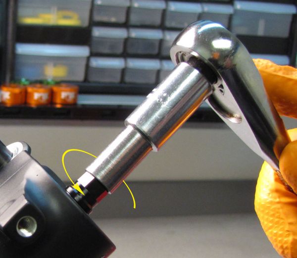
Use a 10mm socket to unthread and remove the air side bottom nut. Remove and discard the original crushwasher.

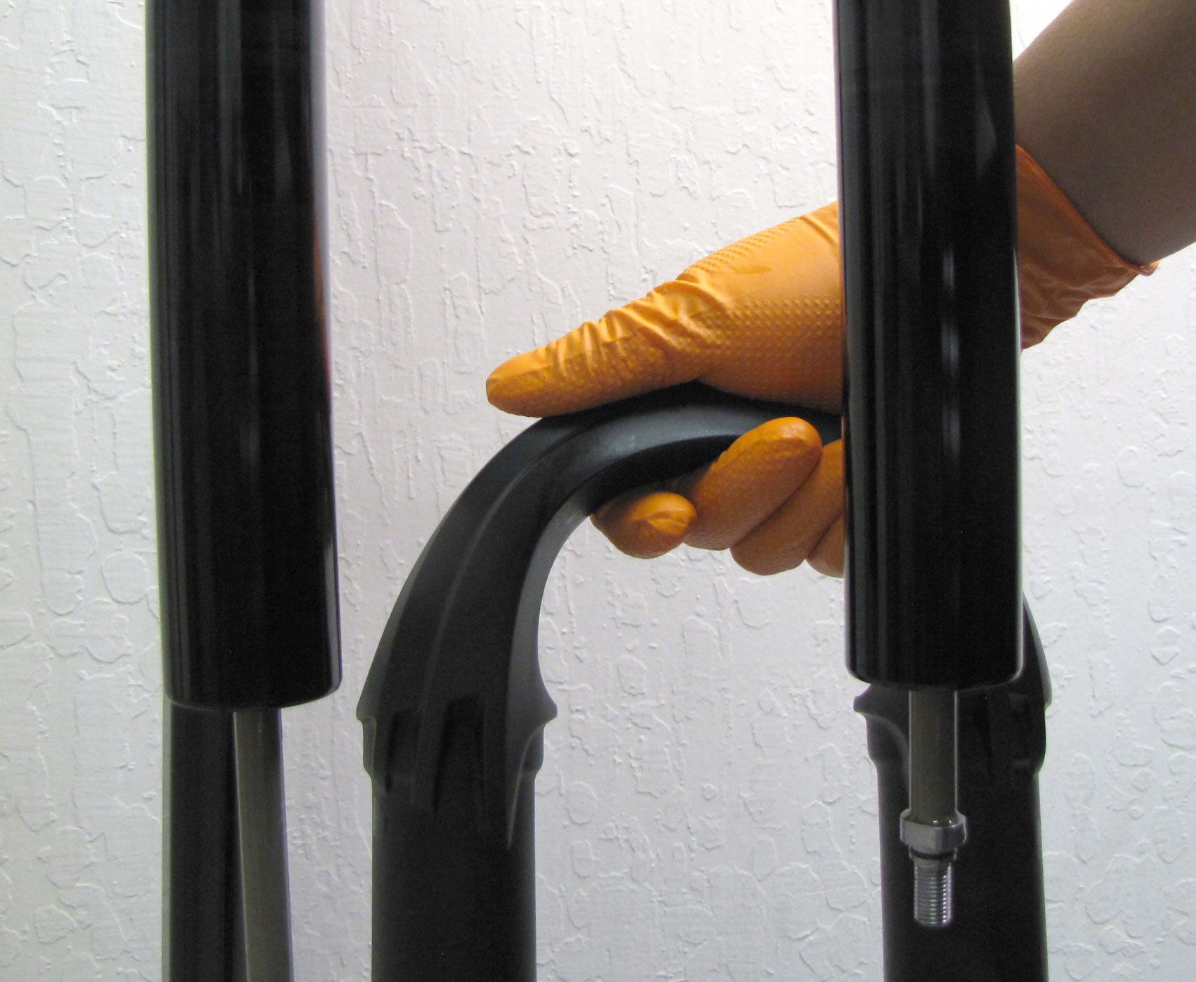
Step 5
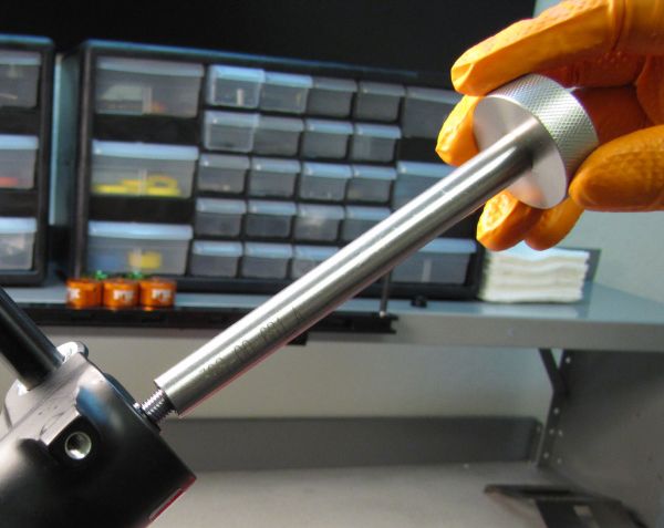
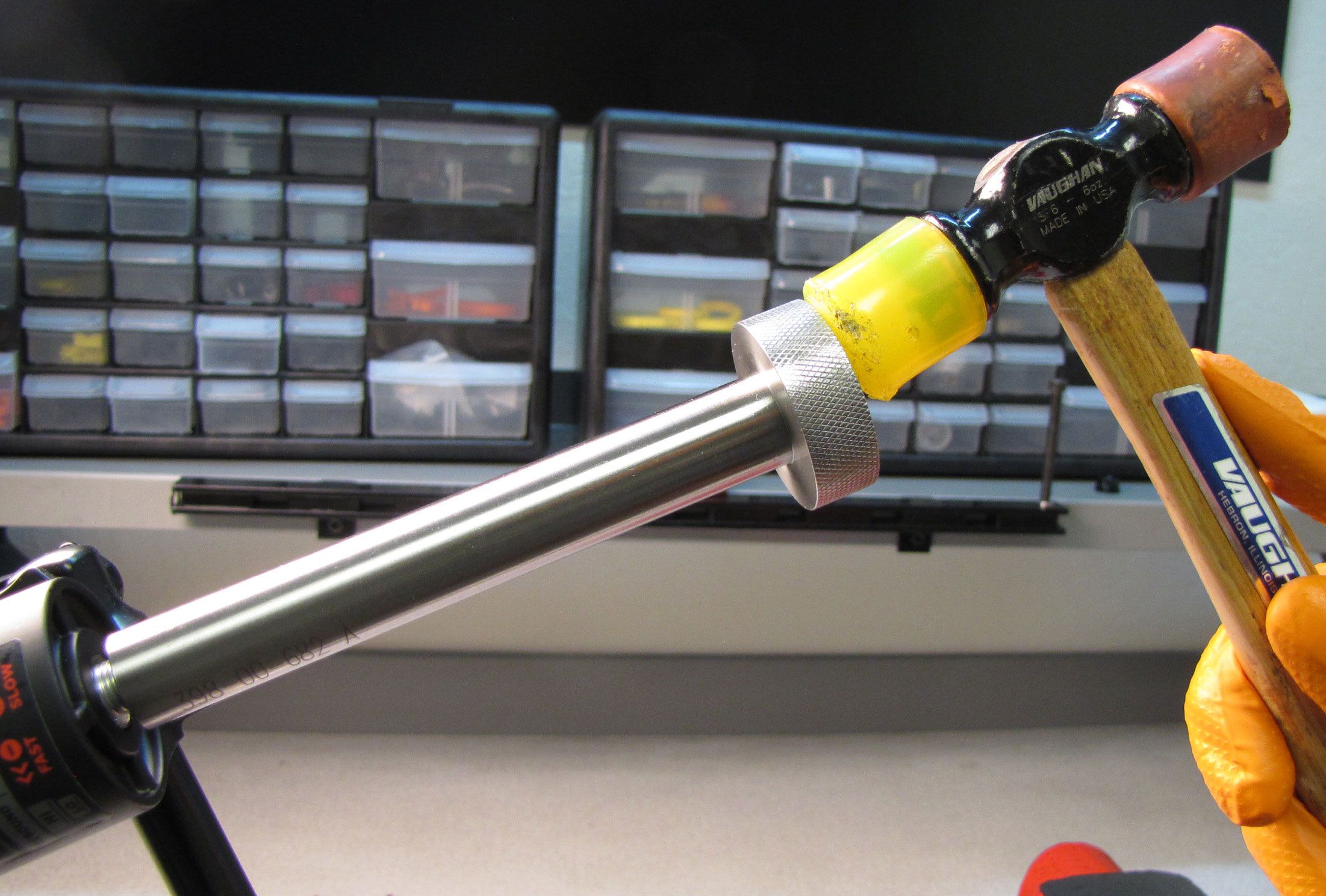
Use Damper Removal Tools 398-00-681 and 398-00-682 to dislodge the shafts from the lowers. Make sure that you have approximately half of the available threads engaged with your tool before striking with your mallet. Remove the damper removal tools, then bring the fork upright over an oil basin to drain. After oil stops draining from the lowers, pull the lowers off of the upper tubes and set them aside.


WARNING: Please verify that all air has been released from the air chamber by pushing down on the Schrader valve core. Failure to release all air pressure before further disassembly may cause parts to eject causing SEVERE INJURY OR DEATH.
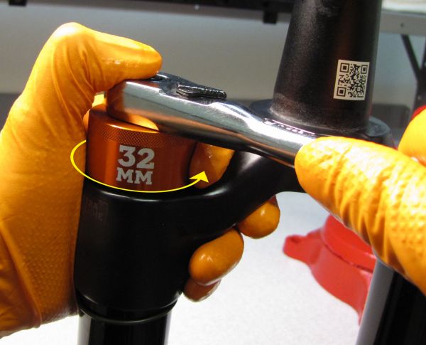
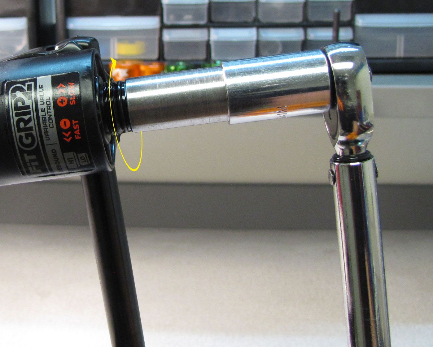
Step 6
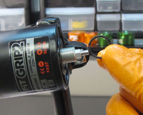
With a chamfer-less 6-point 32mm socket (PN: 398-00-705), unthread the topcap assembly completely. Pull straight up to remove the entire topcap assembly from the left side stanchion tube. Some upward force might be needed to overcome the friction of the stock air volume spacers.

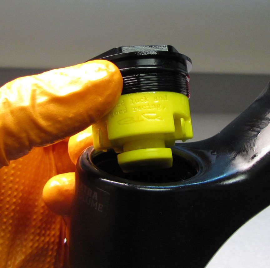
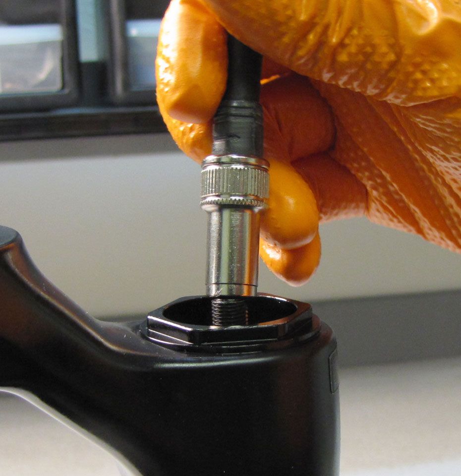
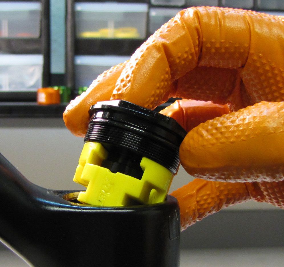
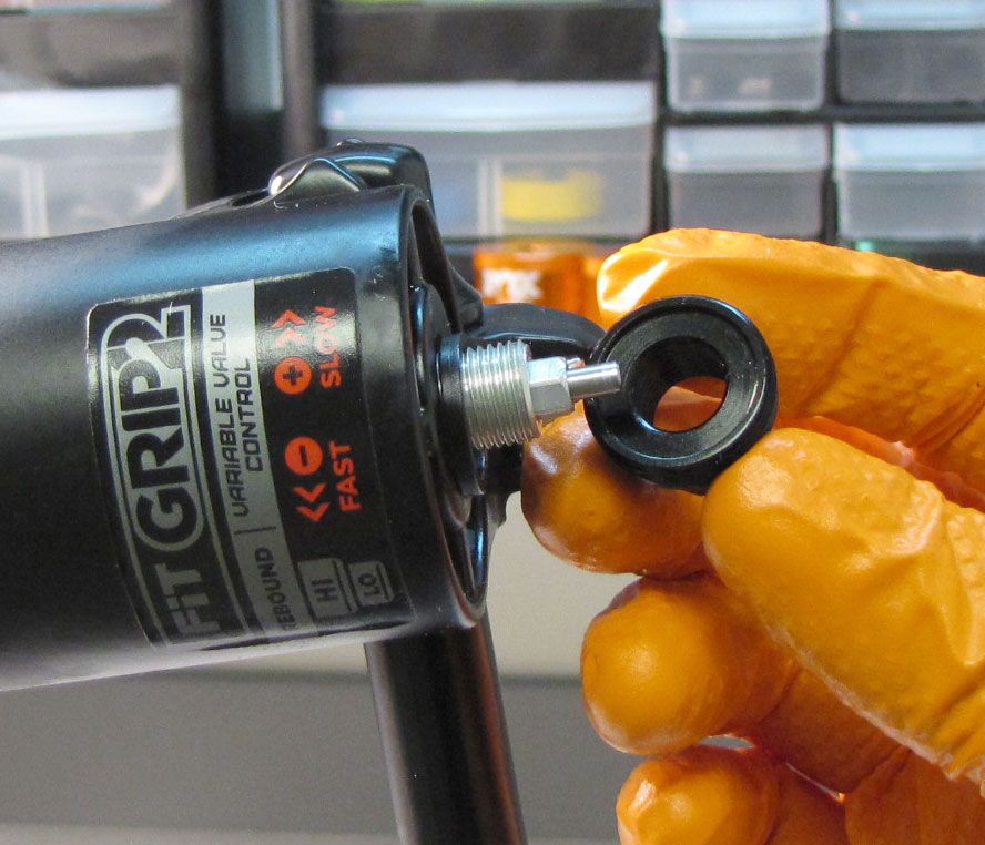
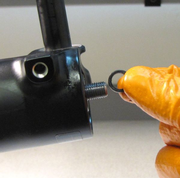
Step 7
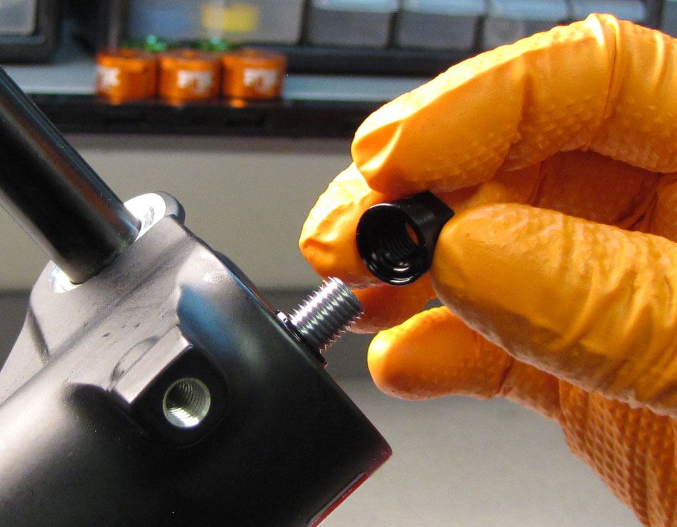
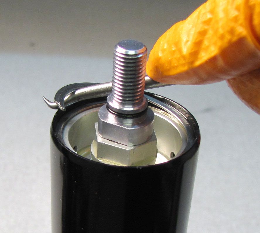
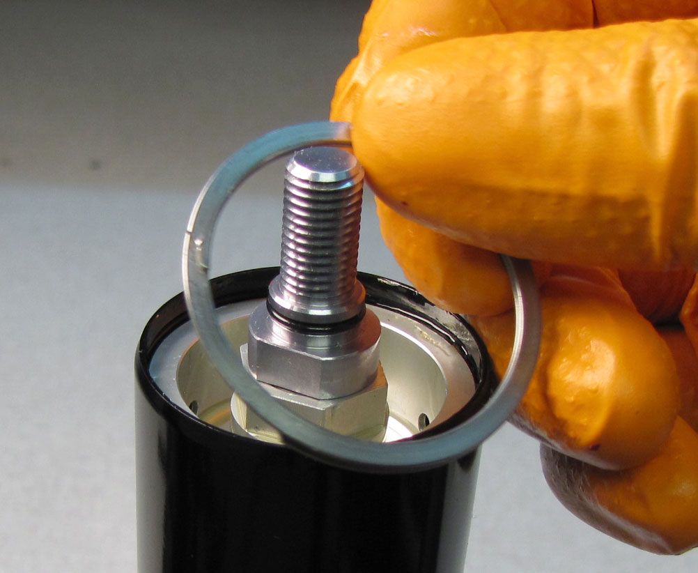
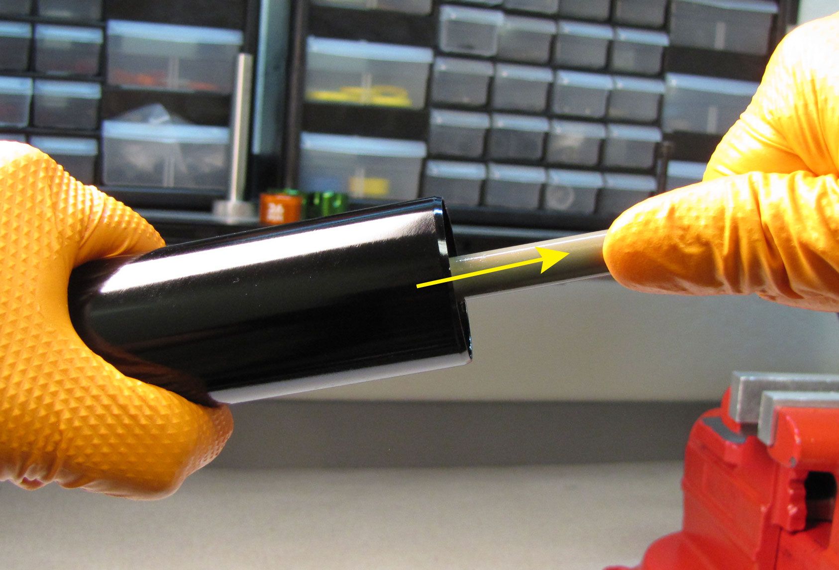
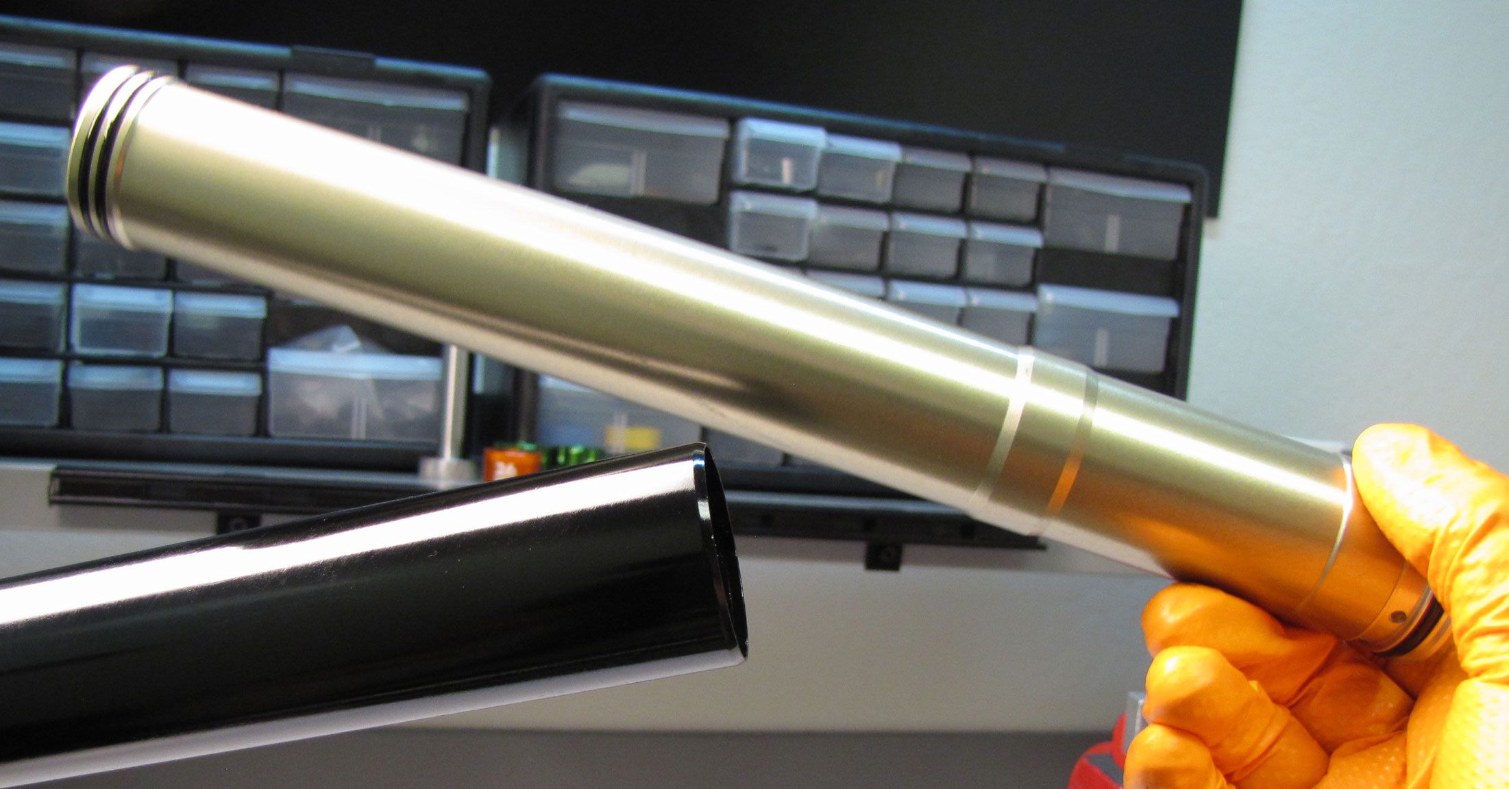
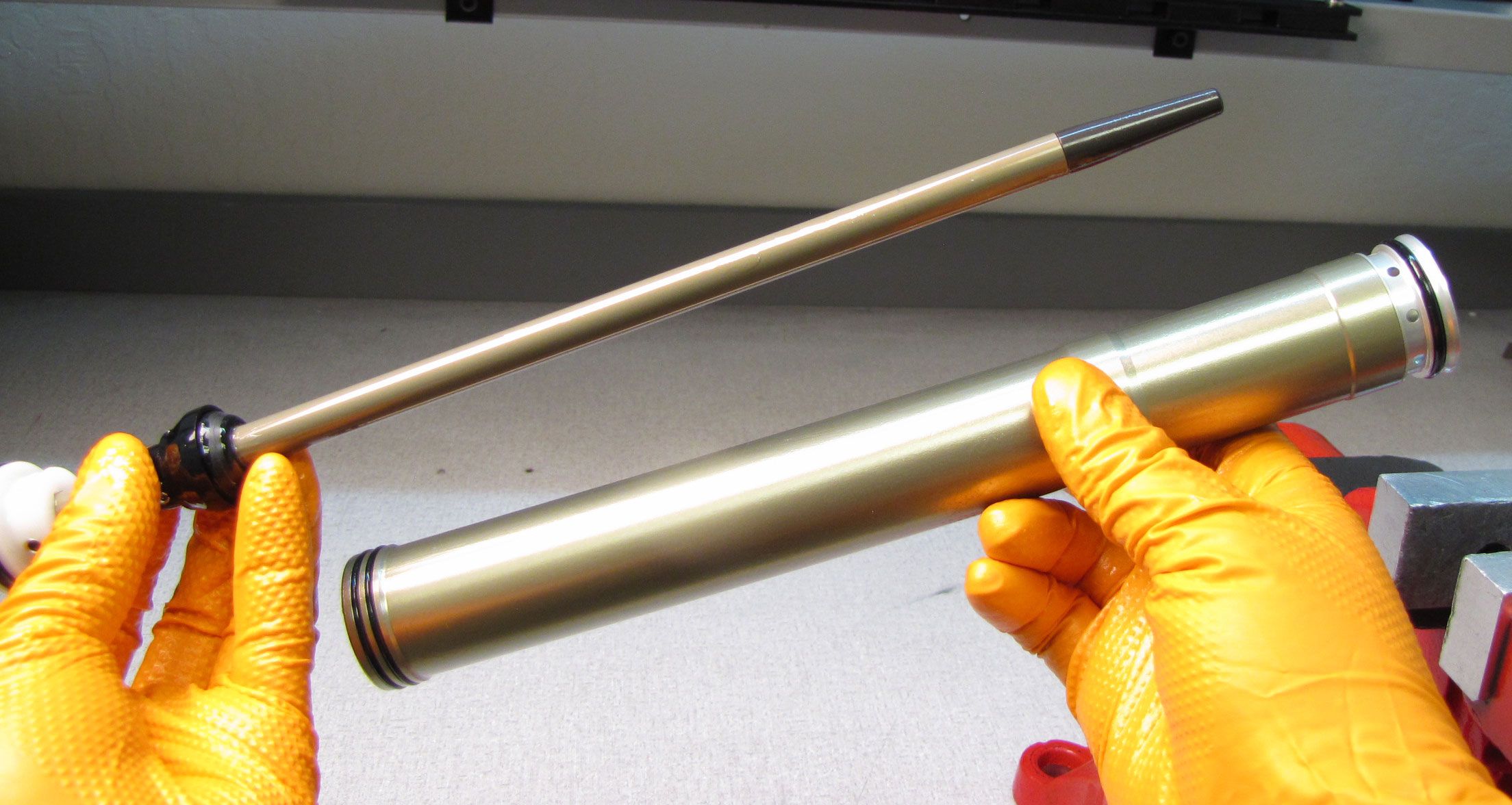
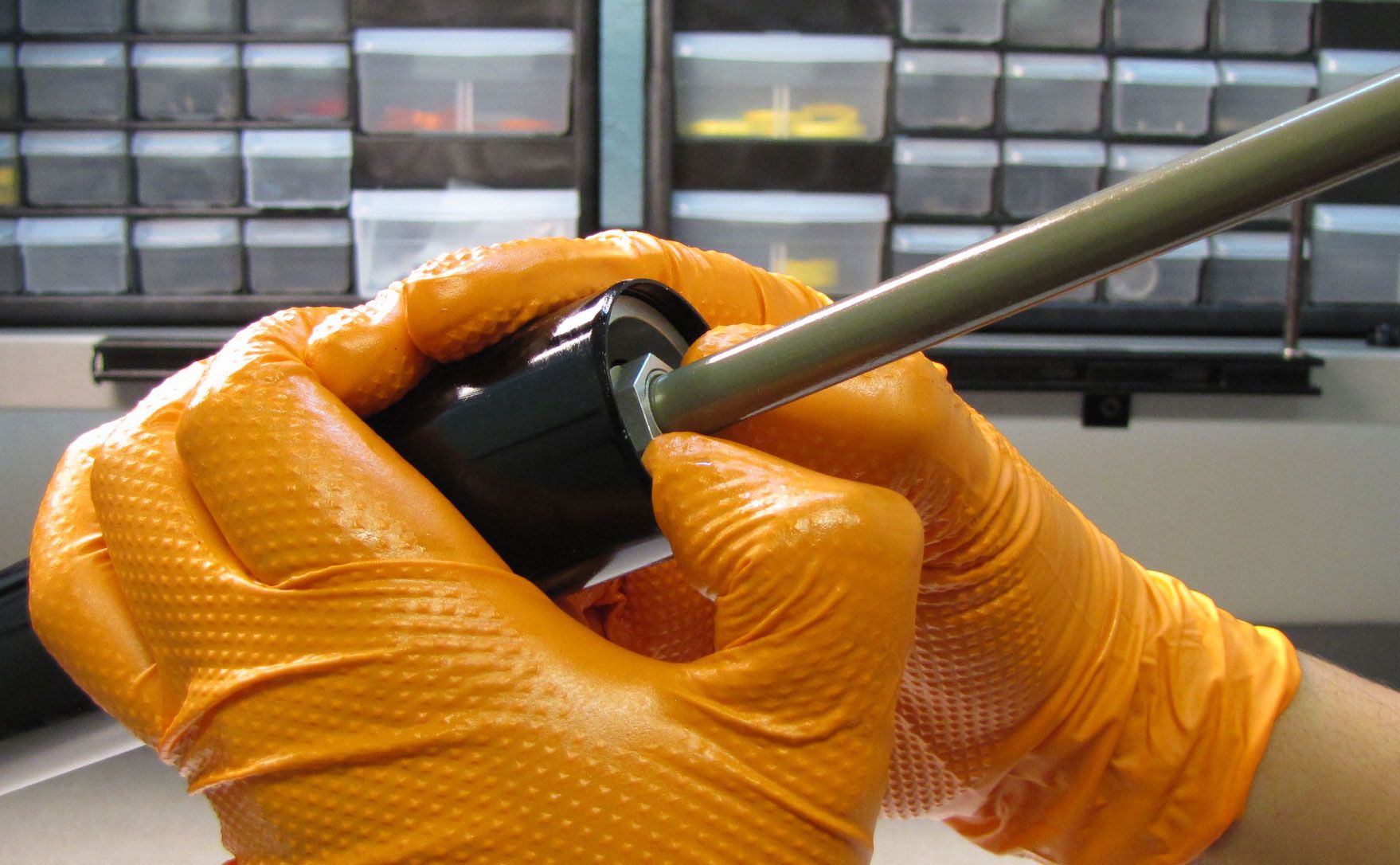
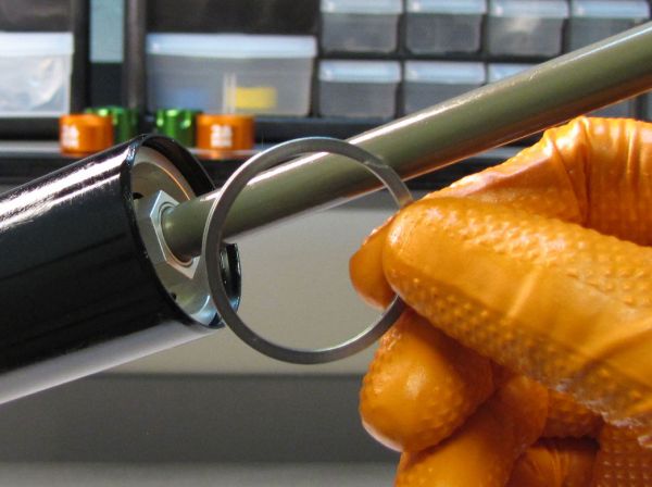
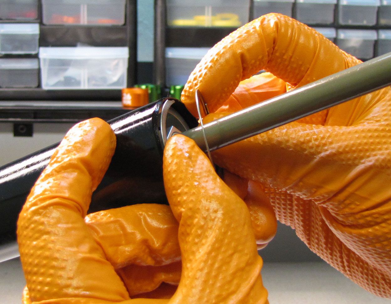
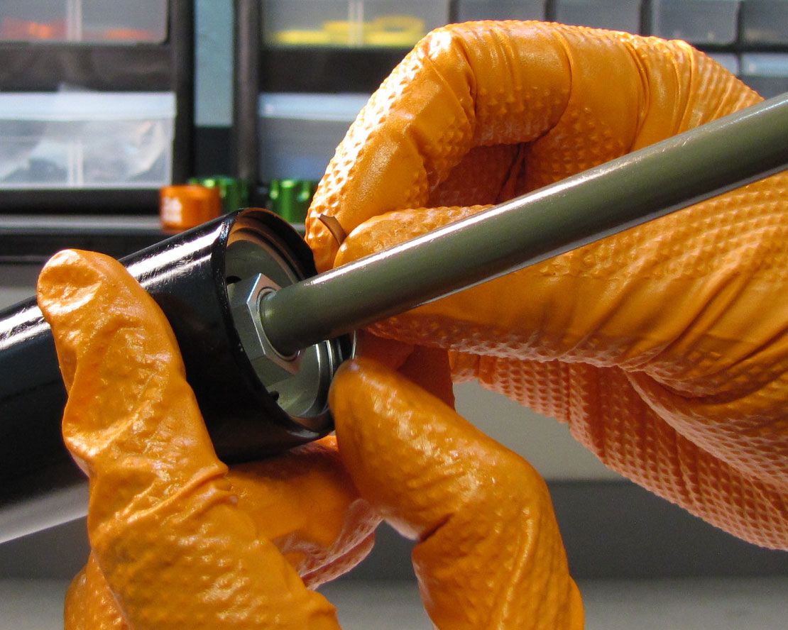
Remove the retaining ring from the bottom of the air side upper tube. Thread the damper removal tool (PN: 398-00-681) onto the air shaft and pull out from the upper tube to remove the air shaft assembly with inner air sleeve .


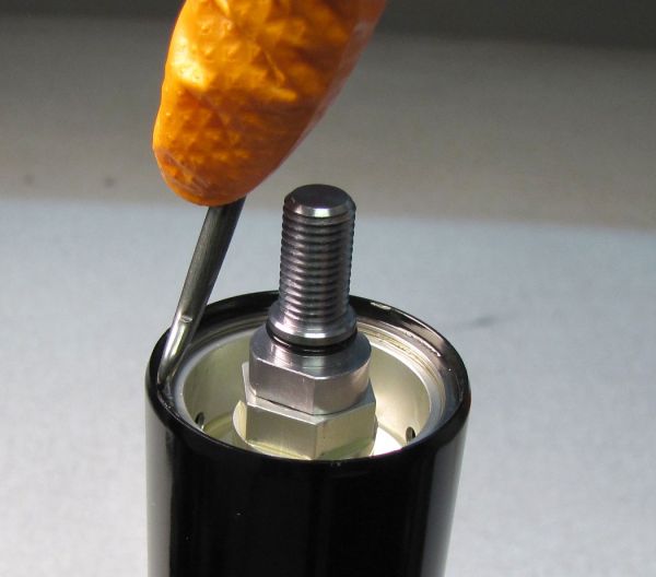
Step 8
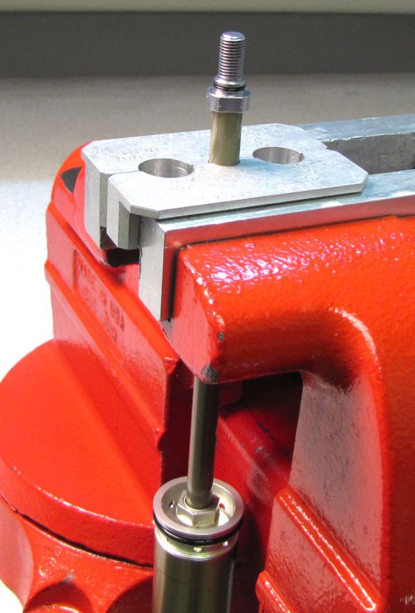
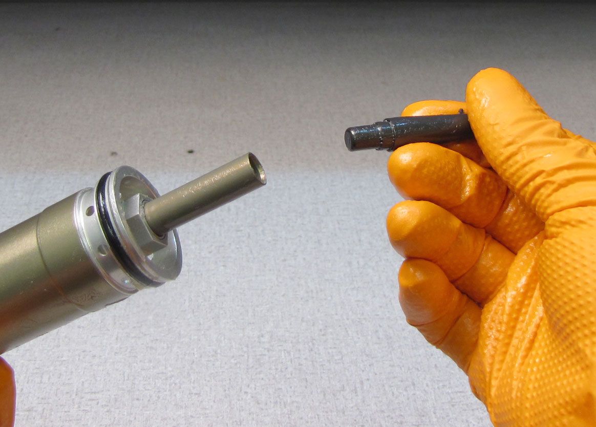
Clean the shaft with Isopropyl alcohol then clamp it in your 10mm shaft clamps (PN: 803-01-324) with the base stud at the top. Carefully apply heat to the shaft at the base stud with a propane torch for 5-10 seconds to break down the Loctite. Be careful as the base stud may be hot! Unthread the base stud counter-clockwise with a 12mm wrench, then lift up to remove.

Step 9
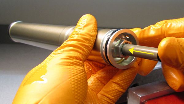
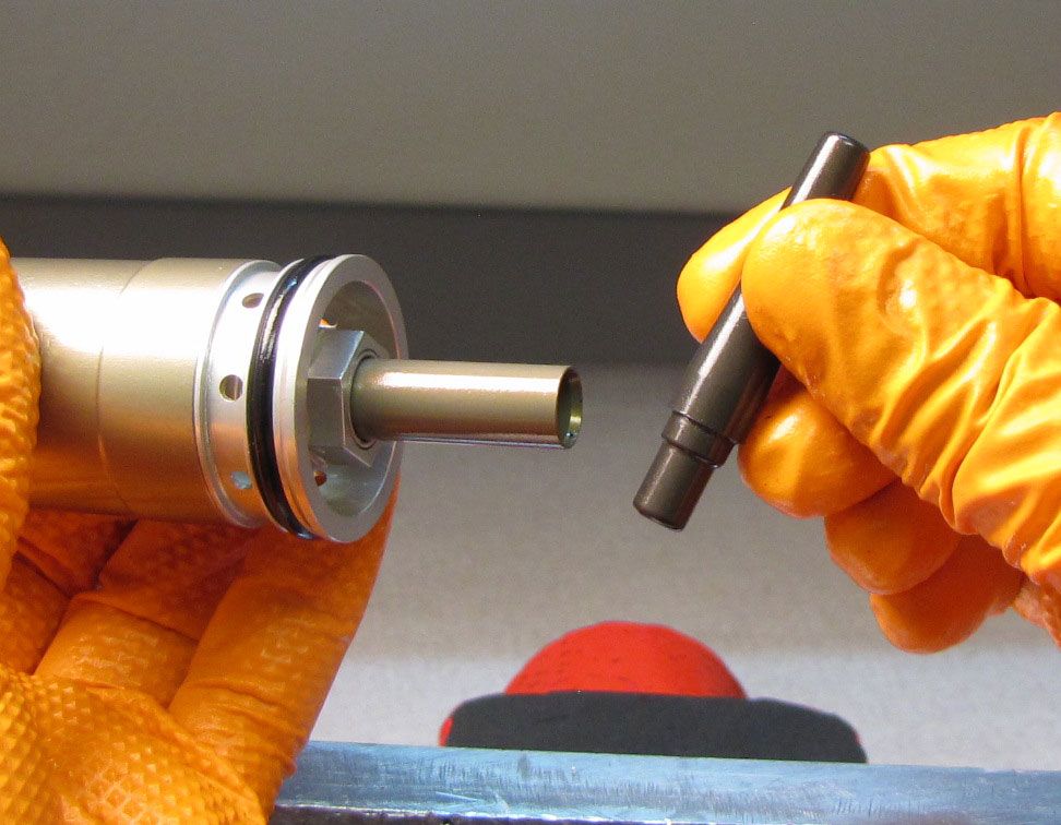
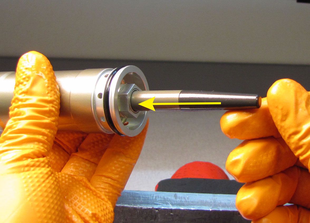
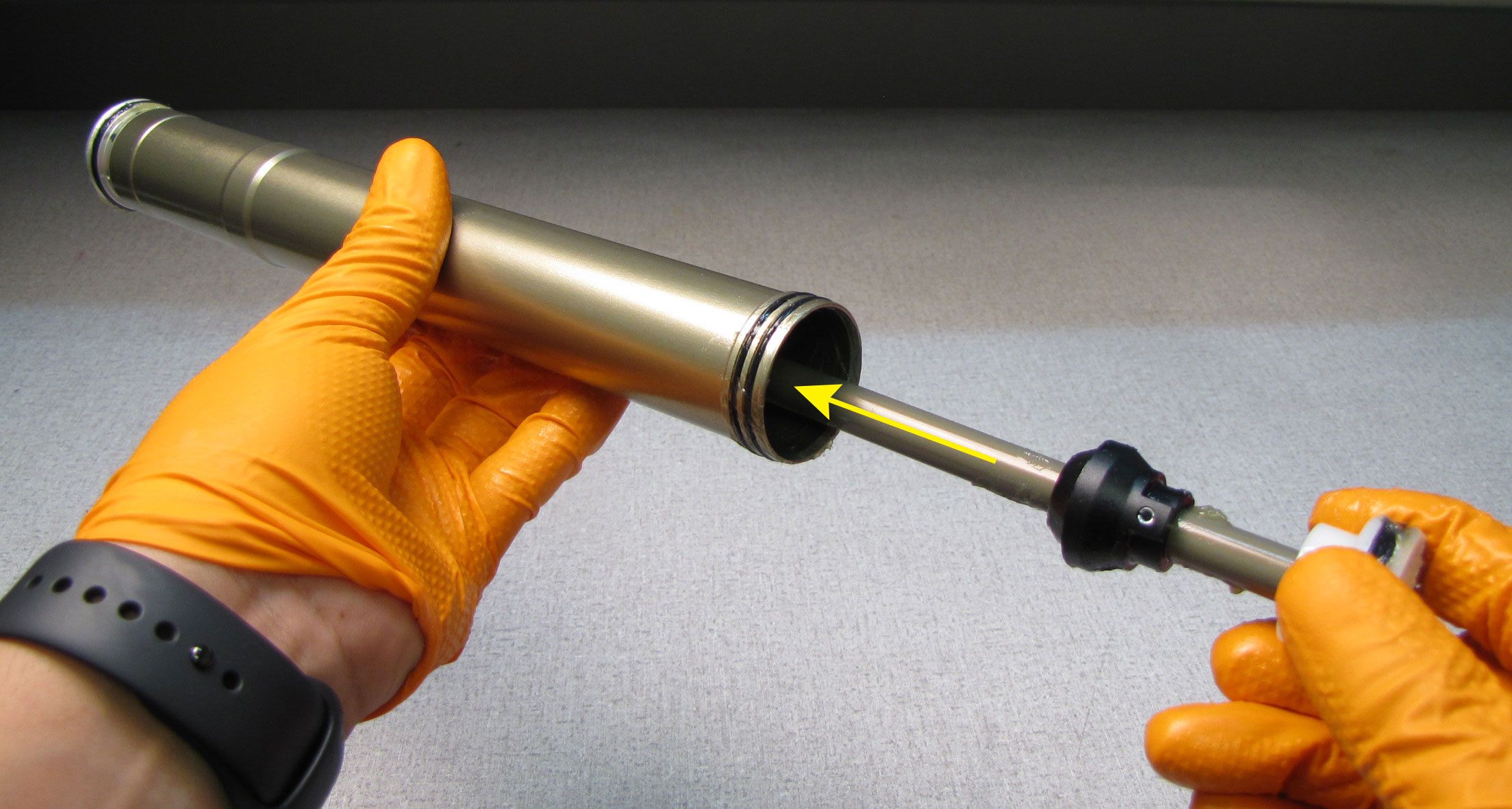
Remove the air shaft assembly from the shaft clamps then push the shaft into the neg plate. Use the bullet tool (PN: 398-00-657) to push the shaft through the neg plate. Pull the air shaft out of the inner air sleeve.


Step 10
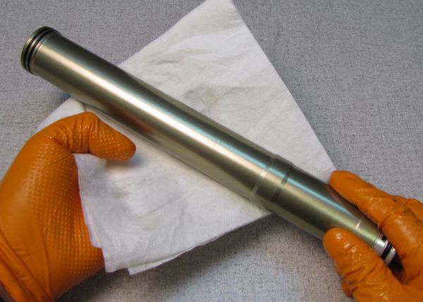
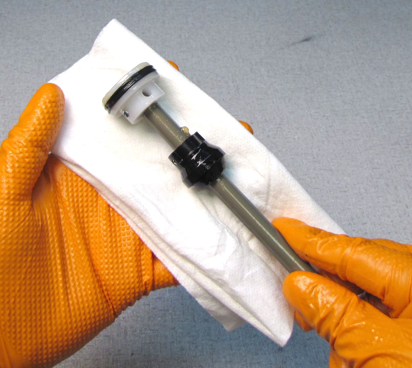
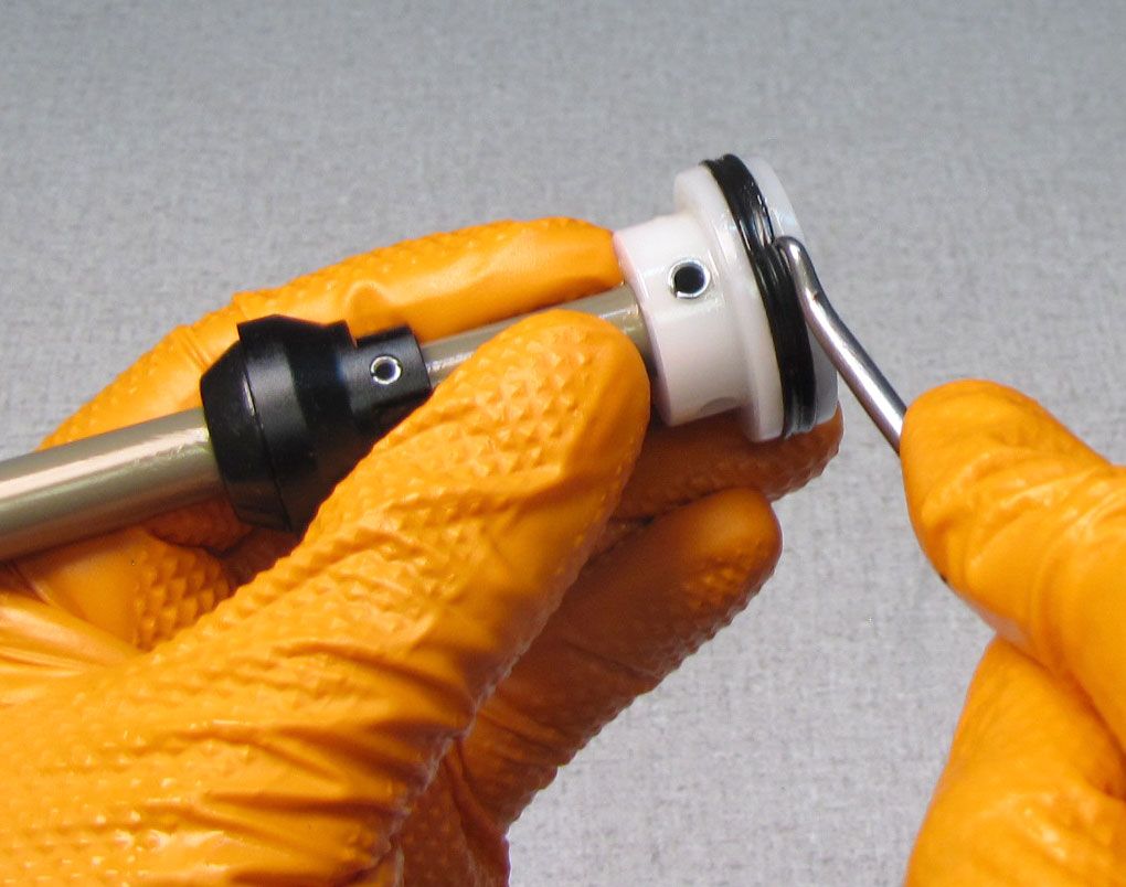
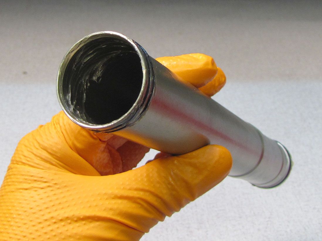
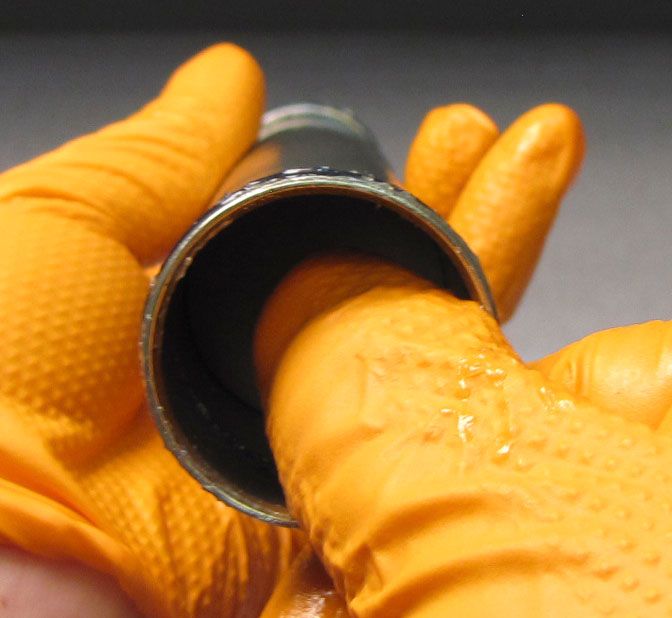
Clean the inner air sleeve with Isopropyl alcohol and a lint-free paper towel. Replace the two o-rings on the outside of the top end of the inner air sleeve with new greased ones from the kit. Replace the o-ring on the outside of the neg plate as well as the quad-ring and u-cup inside the neg plate with new greased ones from the kit. Make sure to orient the u-cup seal with the lips opening toward the hex of the neg plate.


Step 11
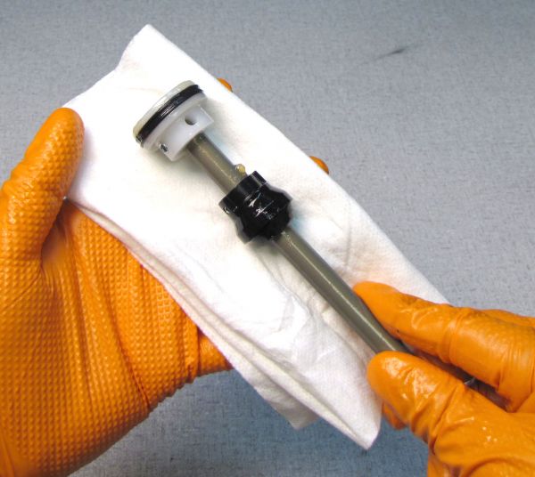
Clean the air shaft assembly with Isopropyl alcohol and a lint-free paper towel. Replace the air piston seal with a new greased one from the kit.

Step 12
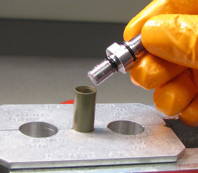
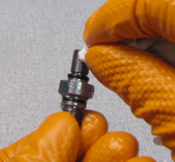
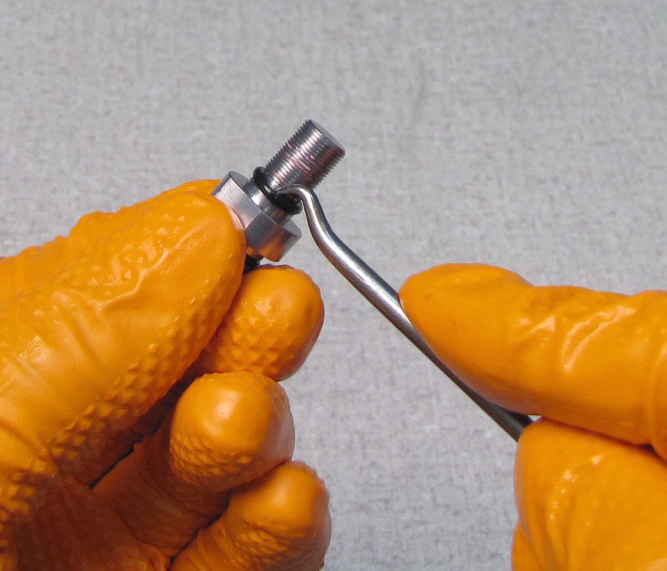
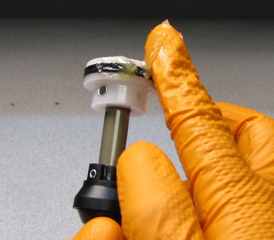
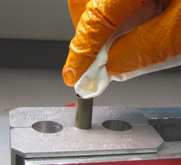
Clean any Loctite residue from the threads of the base stud. Replace both o-rings on the base stud with new greased ones from the kit.


Step 13
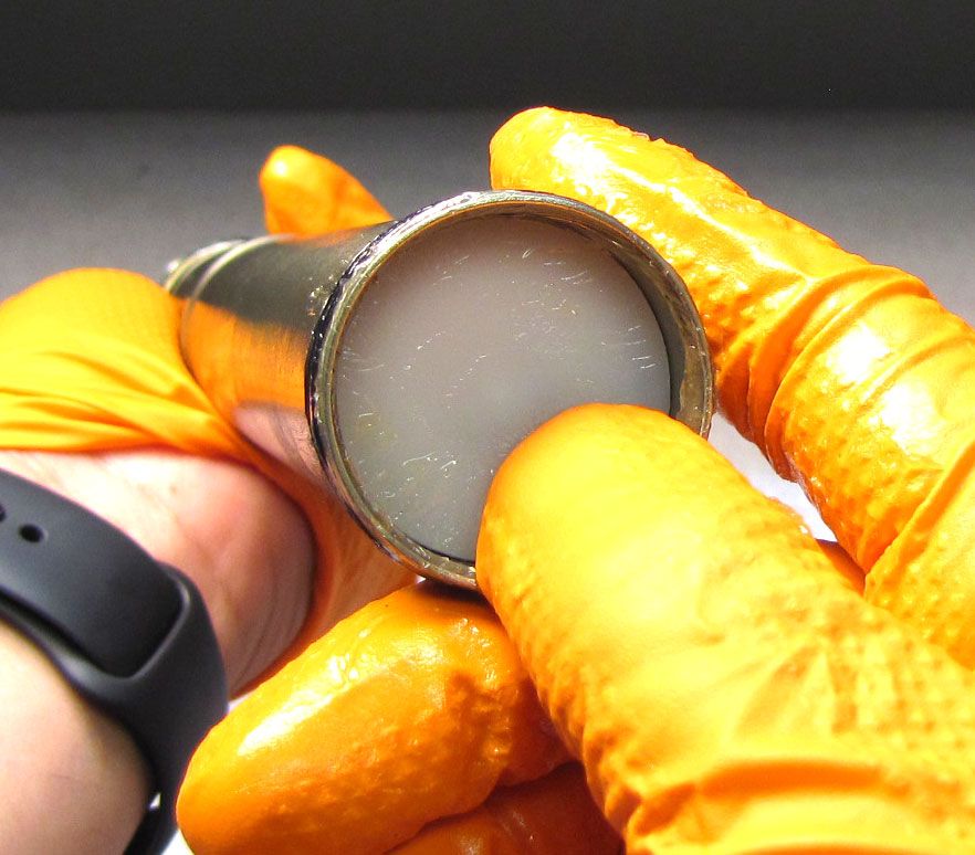
Coat the piston and air shaft with a thin film of Slick Honey. Coat the inside of the neg plate with a thin film of Slick Honey. Apply a thin film of Slick Honey to the inside of the inner air sleeve. Install the bullet tool into the end of the shaft then coat it in a thin film of Slick Honey.


Step 14
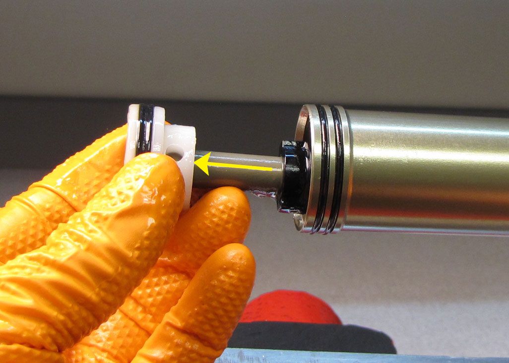
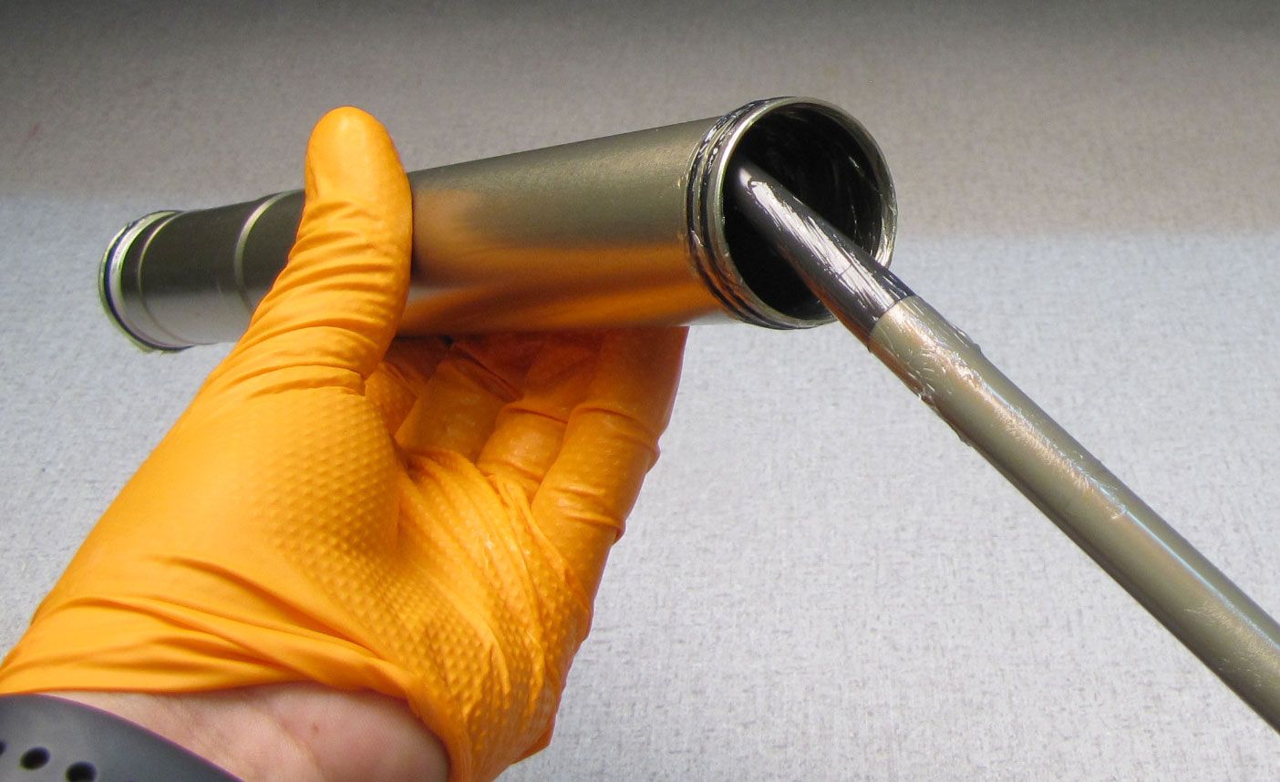
Install the air shaft with bullet first into the open end of the inner air sleeve. Push the piston into the inner air sleeve until the shaft protrudes from the neg plate. Remove the bullet tool.
Step 15
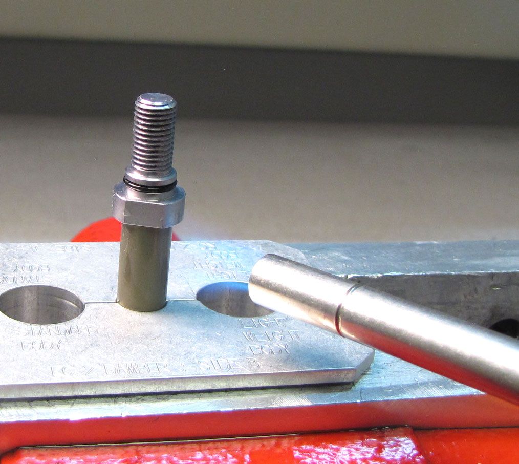
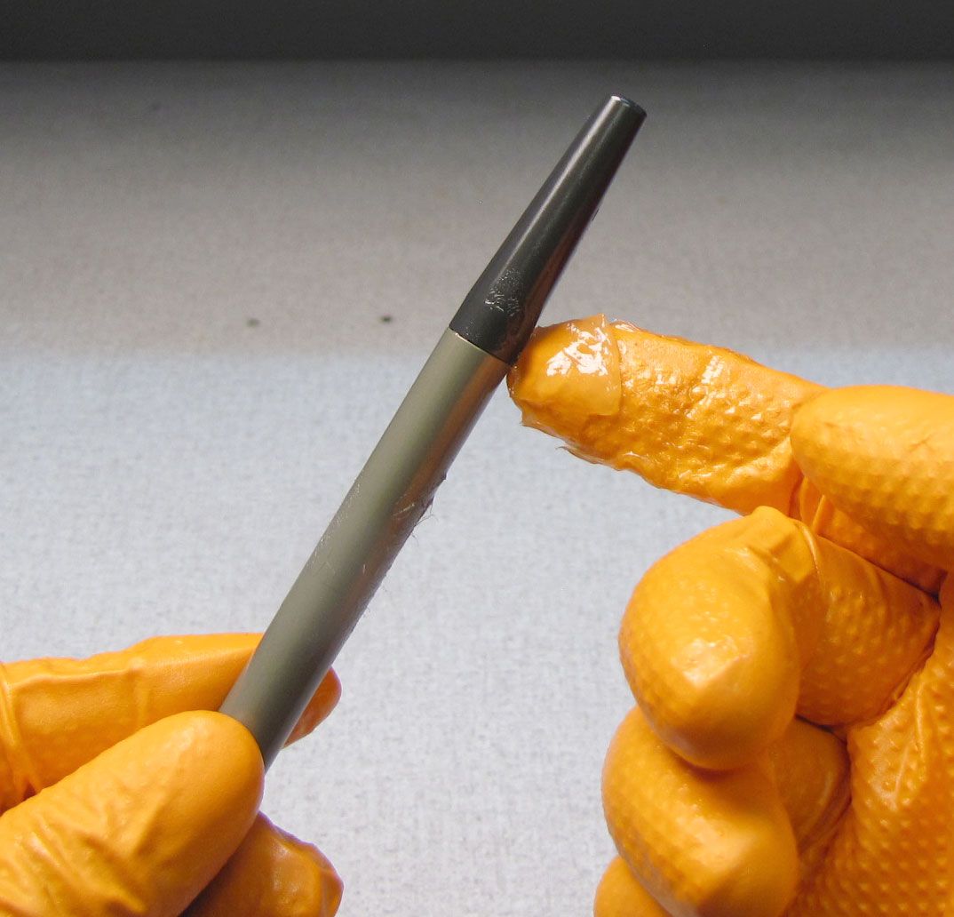
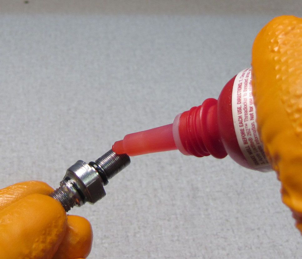
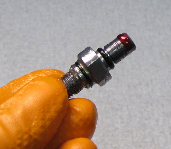
Clean any Slick Honey or Loctite from the inside of the shaft. Apply 1-2 drops of red Loctite 263 to the smaller diameter threads of the base stud taking care not to get any Loctite on the o-ring.

Step 16
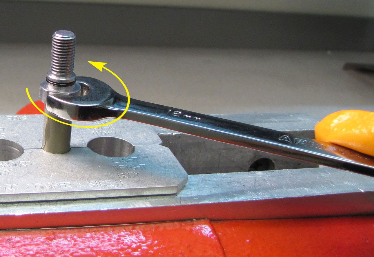
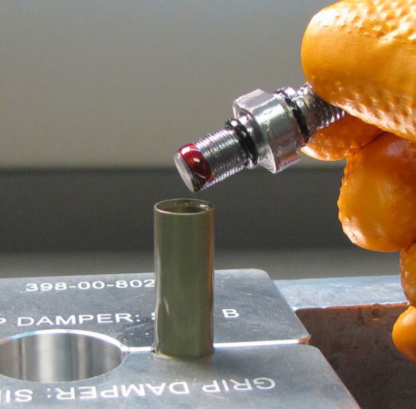
Reinstall the base stud into the shaft, tightening clockwise to 40 in-lb (4.5 Nm) with a 12mm crow's foot.


Step 17
Coat all o-rings on the outside of the inner air sleeve with a thick film of Slick Honey. Reinstall the inner air sleeve into the bottom of the air-side upper tube.

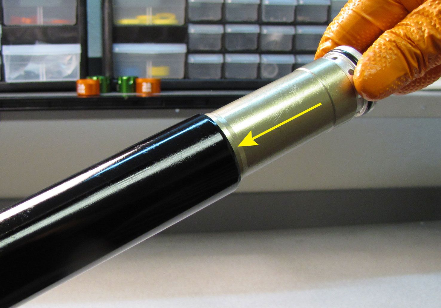
Step 18
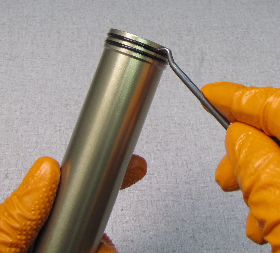
Reinstall the retaining ring into the bottom of the air-side upper tube. Pull on the air shaft to test for proper installation of the retaining ring.


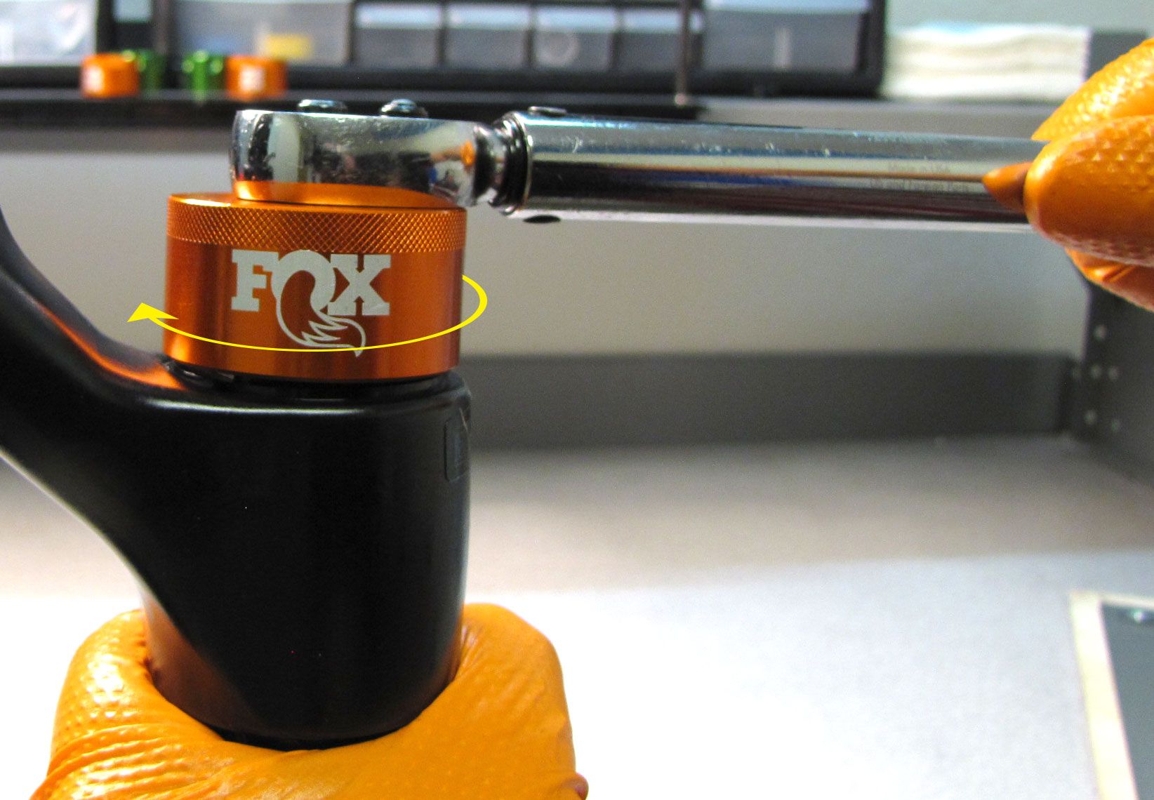
Step 19
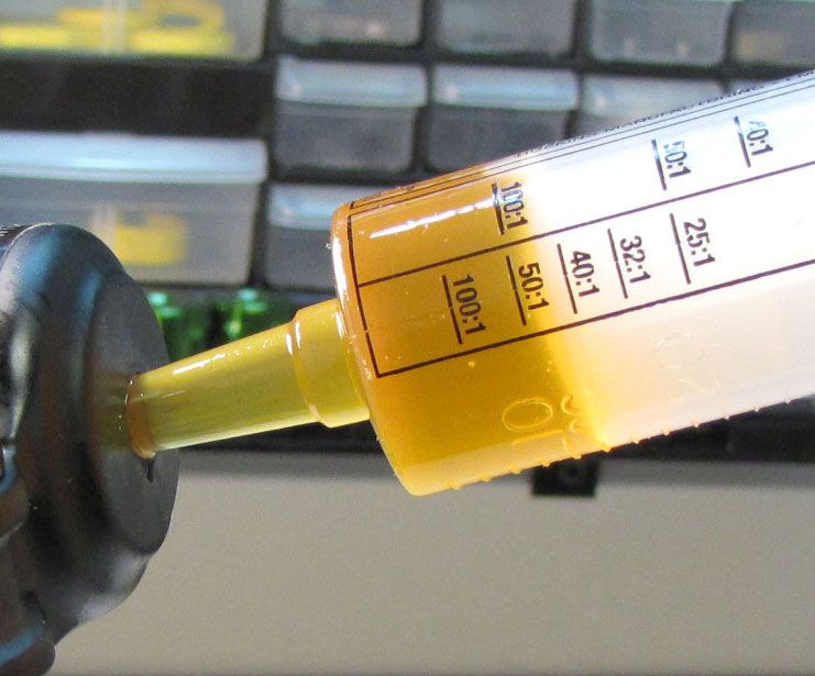
Add 3cc of FOX 20wt. Gold oil into the air-side upper tube. Reinstall the topcap tightening clockwise to 220 in-lb (24.8 Nm) torque with your chamfer-less 6-point 32mm socket.


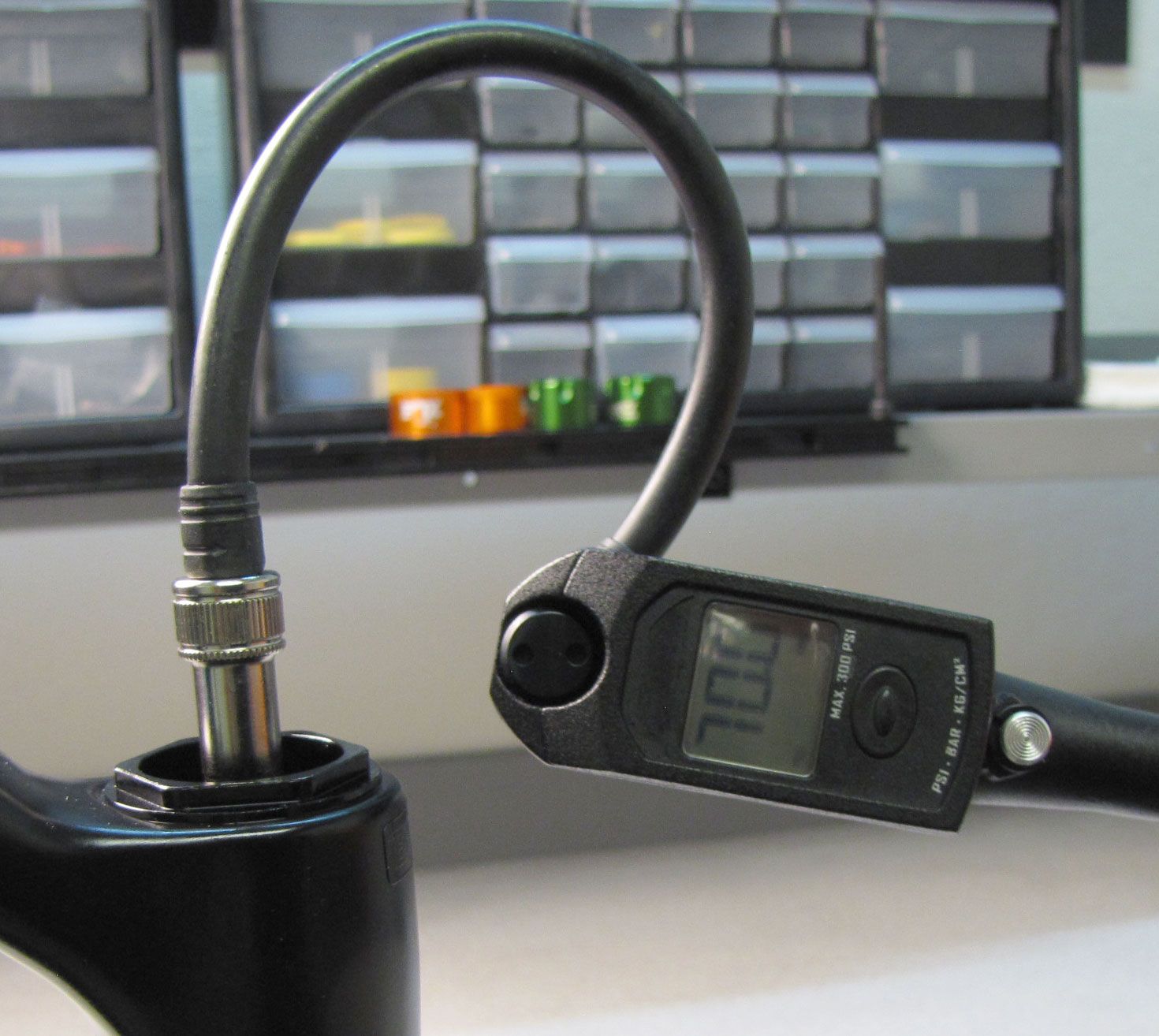
Step 20
Add air to your desired pressure then reinstall the blue air cap.

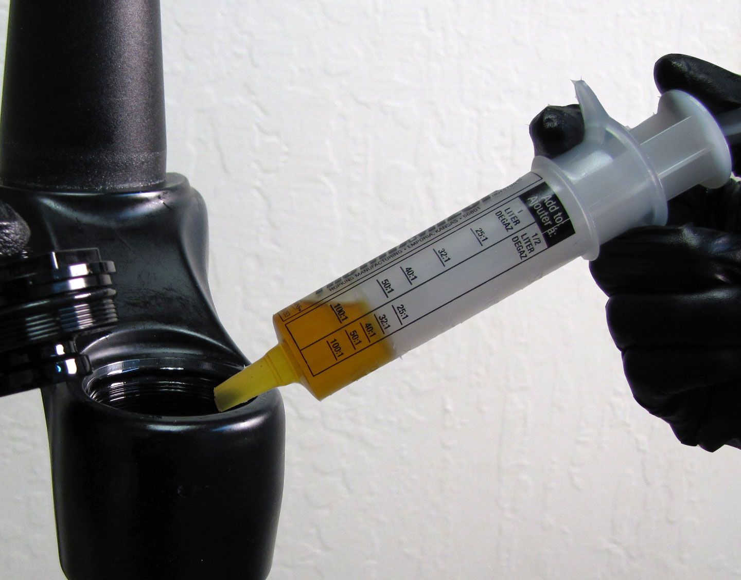
Step 21
Reinstall the lower legs onto the upper tubes. Inject 20cc of FOX 20wt. Gold oil into the spring-side lower leg.
For Grip/Grip2: Inject 40cc of FOX 5wt. Teflon infused Oil into the damper-side lower leg.
For FIT4: Inject 15cc of FOX 20wt. Gold Oil into the damper-side lower leg.
Clean any oil off of the exposed shaft threads.


Step 22
Install a new damper-side crush washer followed by the bottom nut. Make sure to align the crush washer with the bottom nut before tightening. Tighten clockwise to 80 in-lb (9.0 Nm) torque with a 15mm socket.

Step 23
Install a new spring-side crush washer followed by the bottom nut. Make sure to align the crush washer with the bottom nut before tightening. Tighten clockwise to 50 in-lb (5.7 Nm) torque with a 10mm socket.


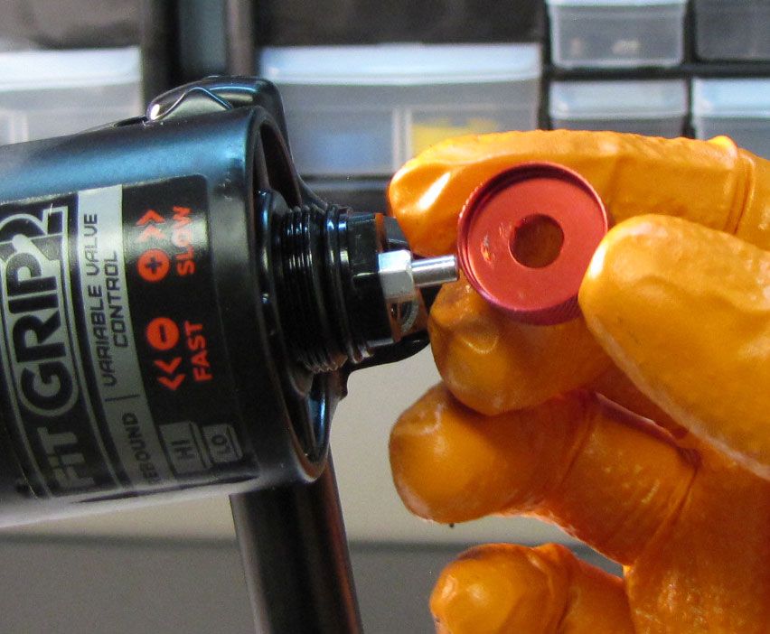
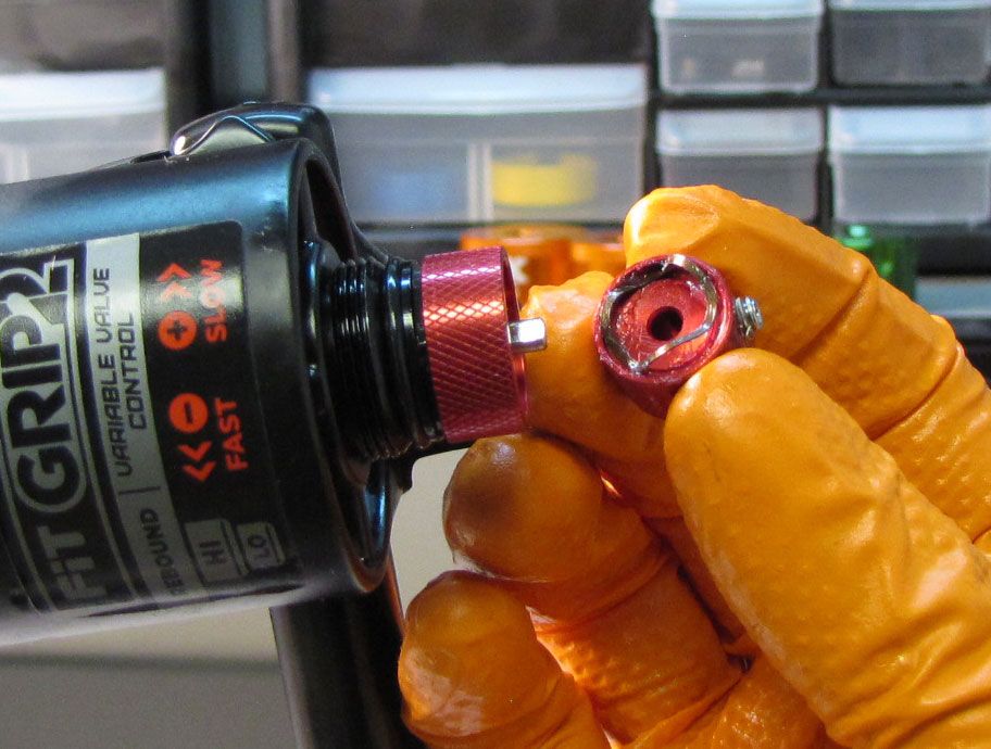
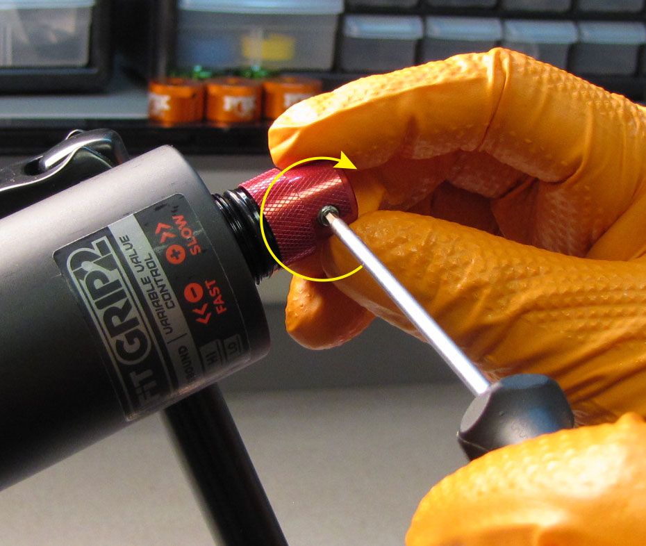
Step 24
Install the larger High-Speed Rebound (HSR) knob with its thinner rim facing toward the bottom nut. Coat the wave spring with a thin film of Slick Honey then install the smaller Low-Speed Rebound (LSR) knob with the wave spring between the two knobs. Put slight pressure on the LSR knob so that there is a bit of preload on the wave spring. Align the set screw with the flat on the LSR needle then tighten clockwise to 8 in-lb (0.9 Nm) torque with a 2mm hex wrench. Test that both knobs turn freely without binding.
Step 25
Replace the black rebound knob cover and clean the exterior of your fork.