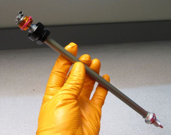
2021 GRIP2 VVC Rebuild
Required Parts
- 803-01-494 Seal Kit: 2021 F-S Grip2 VVC 34/36/38/40
Required Tools
- 398-00-682 2005-017 34-36-40 Damper-side Removal Tool
- 398-00-707 Tooling: Fork Topcap Socket, 28mm V2, 3/8 Drive
- 803-01-324 Kit: Tooling: 2019 Clamps, Grip Damper, Body and Shaft
WARNING: Always wear safety glasses and protective gloves during service to prevent potential injury. Failure to wear protective equipment during service may lead to SERIOUS INJURY OR DEATH.
Before installing a new GRIP or GRIP2 cartridge into the fork, remove the red tape covering the cartridge tube vents.

WARNING: FOX products should be serviced by a trained bicycle service technician, in accordance with FOX specifications. If you have any doubt whether or not you can properly service your FOX product, then DO NOT attempt it. Improperly serviced products can fail, causing the rider to lose control resulting in SERIOUS INJURY OR DEATH.
WARNING: FOX suspension products contain pressurized nitrogen, air, oil, or all 3. Suspension misuse can cause property damage, SERIOUS INJURY OR DEATH. DO NOT puncture, incinerate or crush any portion of a FOX suspension product. DO NOT attempt to disassemble any portion of a FOX suspension product, unless expressly instructed to do so by the applicable FOX technical documentation, and then ONLY while strictly adhering to all FOX instructions and warnings in that instance.
WARNING: Modification, improper service, or use of aftermarket replacement parts with FOX forks and shocks may cause the product to malfunction, resulting in SERIOUS INJURY OR DEATH. DO NOT modify any part of a fork or shock, including the fork brace (lower leg cross brace), crown, steerer, upper and lower leg tubes, or internal parts, except as instructed herein. Any unauthorized modification may void the warranty, and may cause failure or the fork or shock, resulting in SERIOUS INJURY OR DEATH.
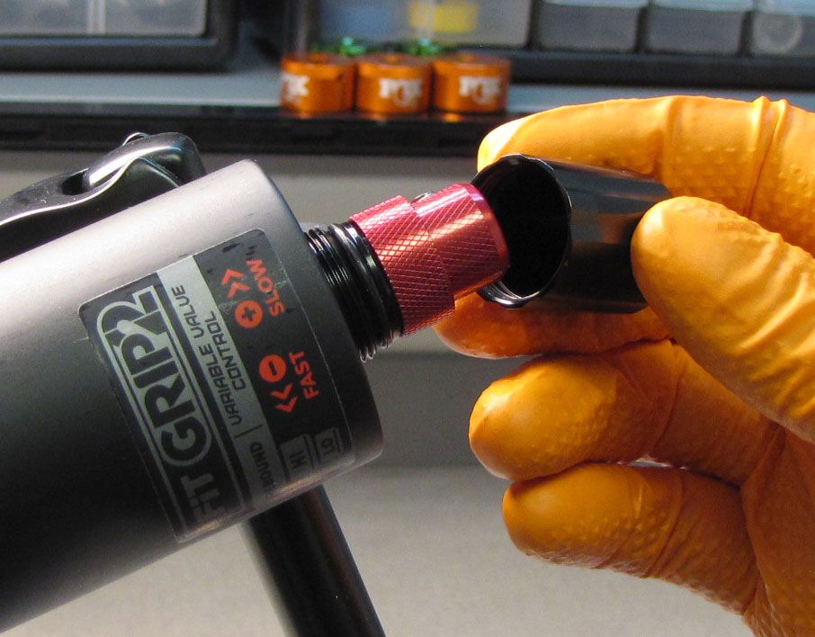
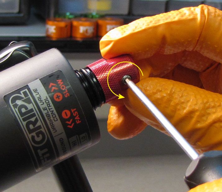
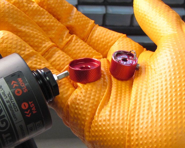
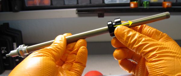
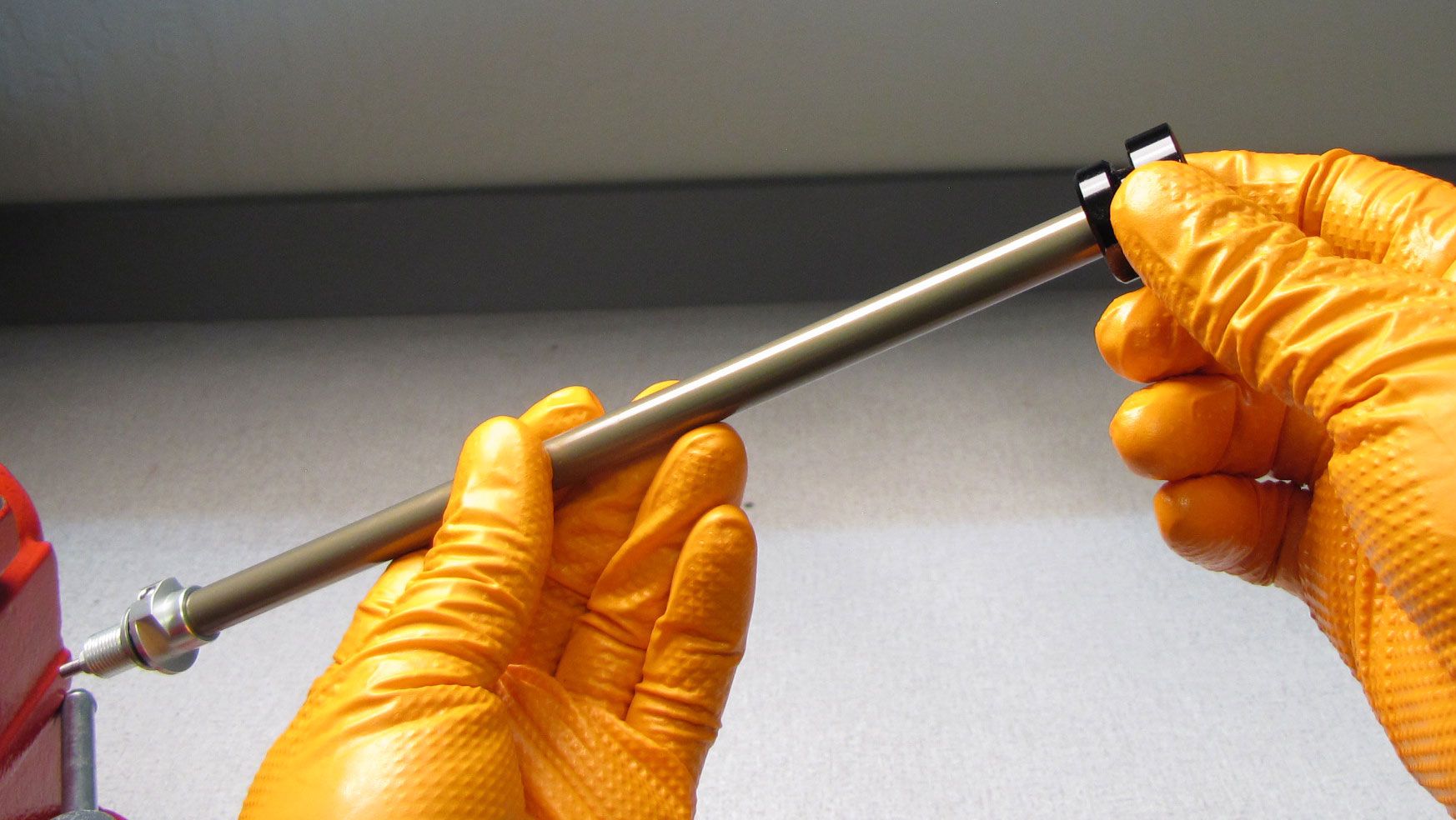
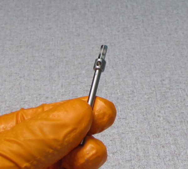
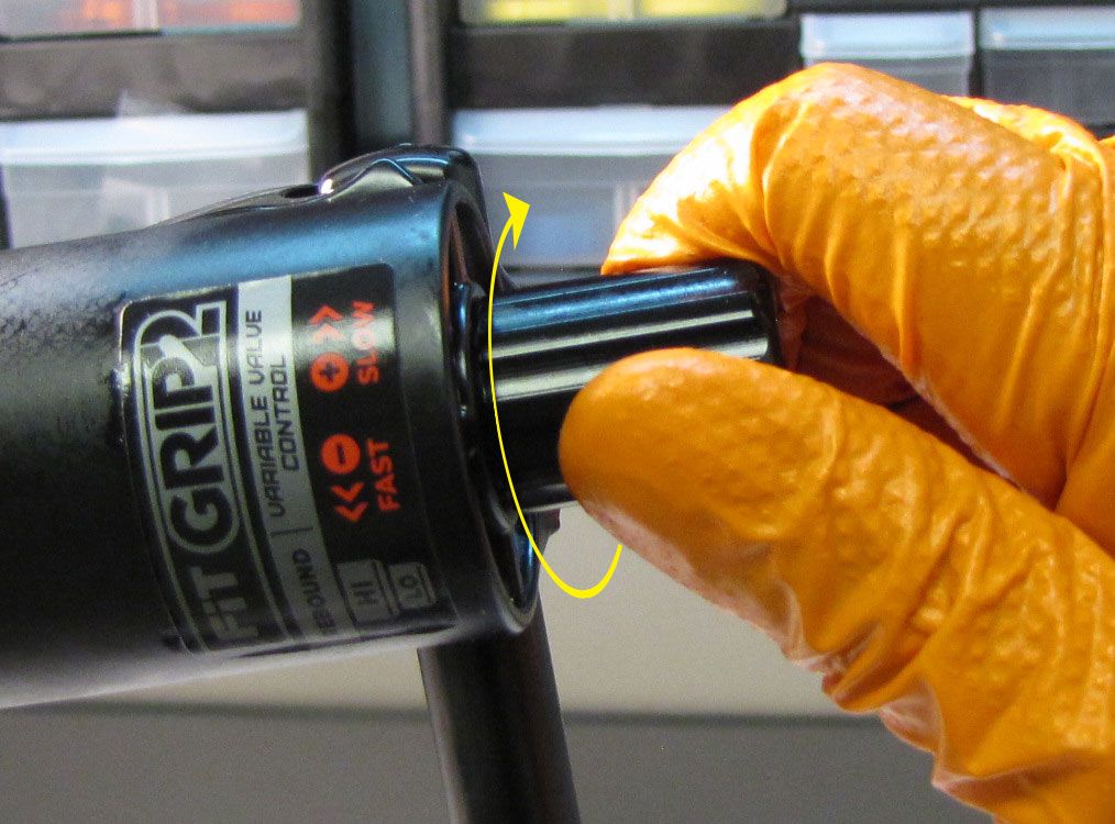
Step 1
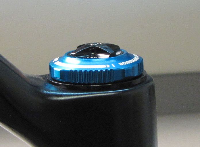
With the fork slightly inverted (the bottom of the fork up past horizontal), remove the black cover, then use a 2mm hex wrench to remove the red rebound knobs.


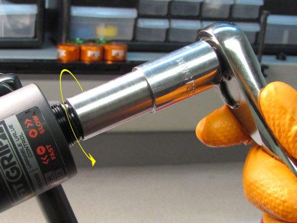
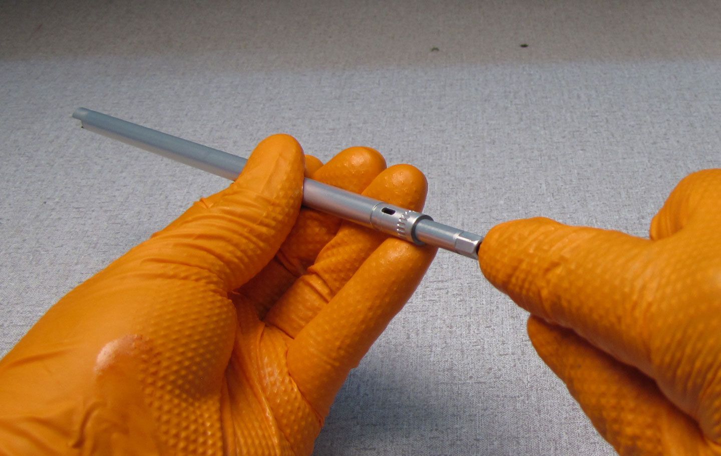
Step 2
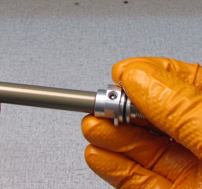
Use a 15mm socket to remove the damper side bottom nut. Make sure to remove and discard the orginal crushwasher which may be stuck to the bottom nut.

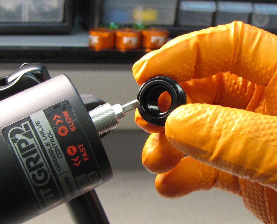
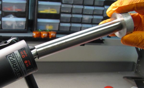
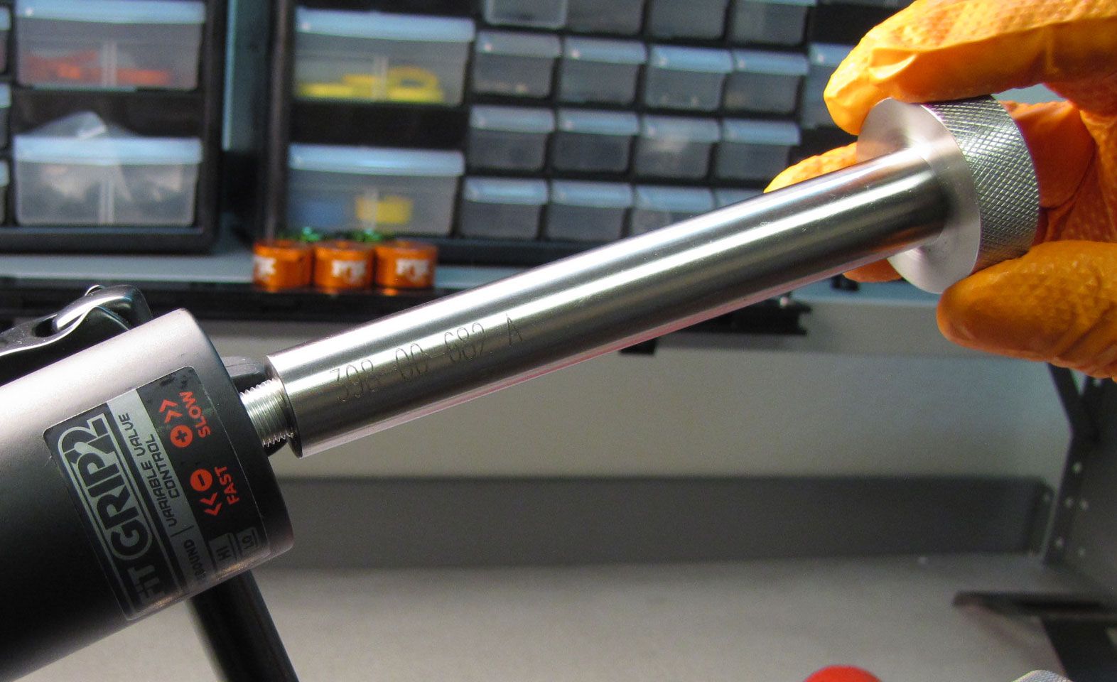
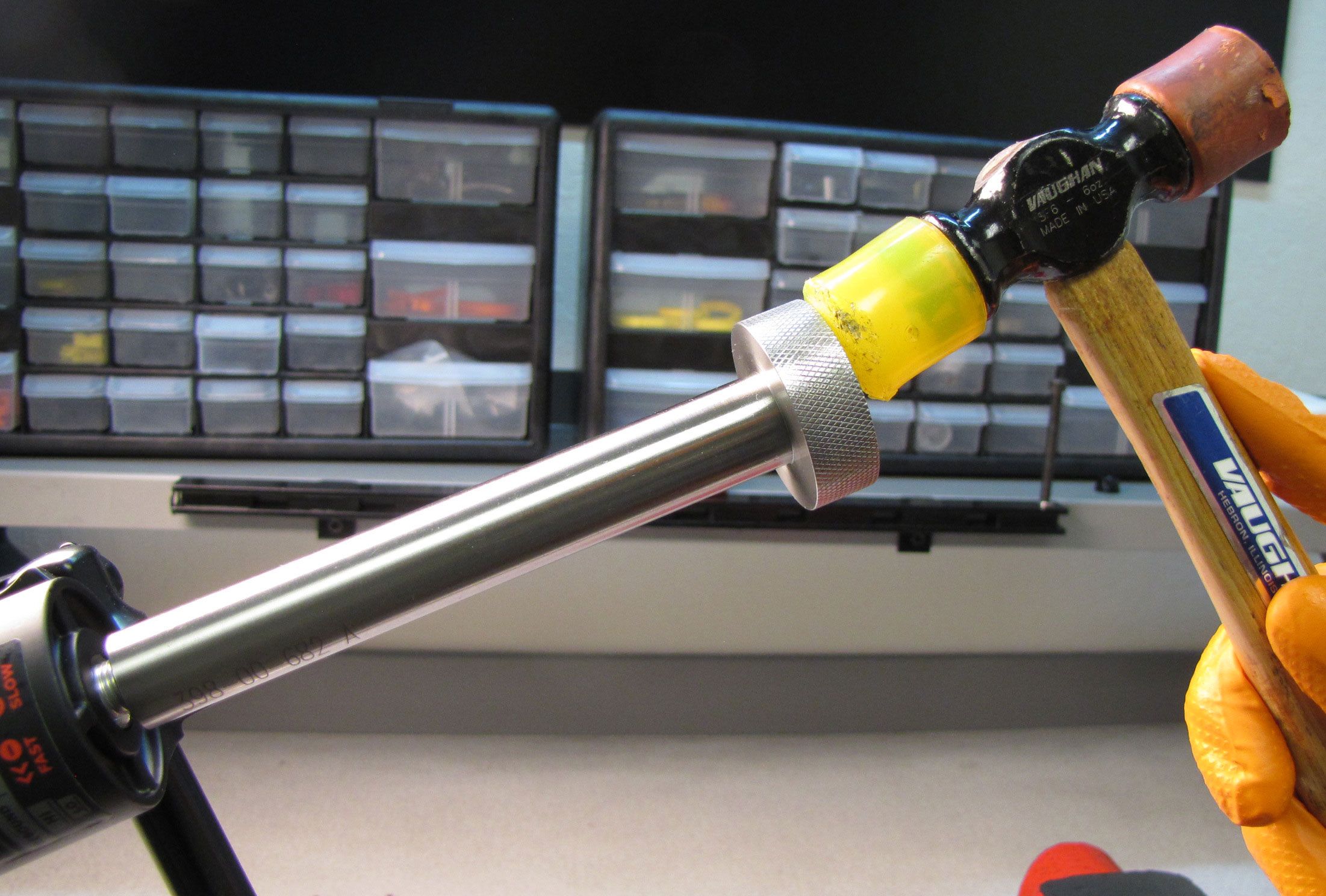
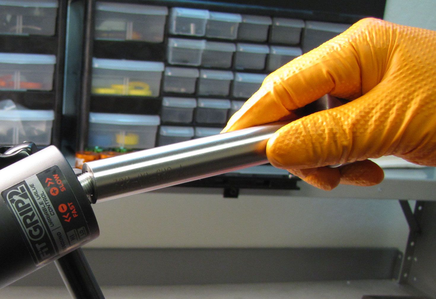
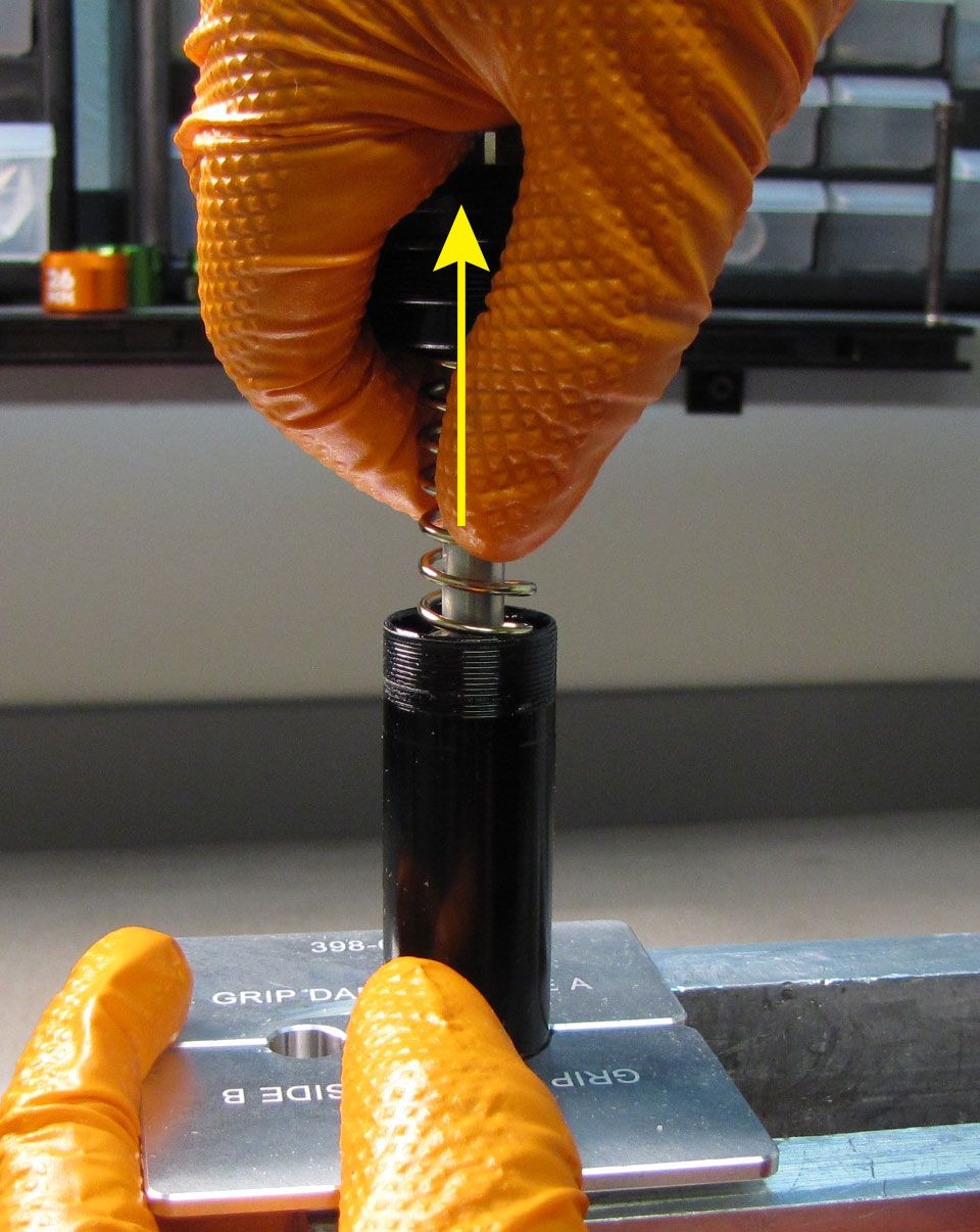
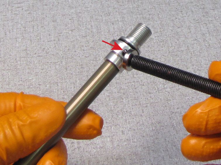
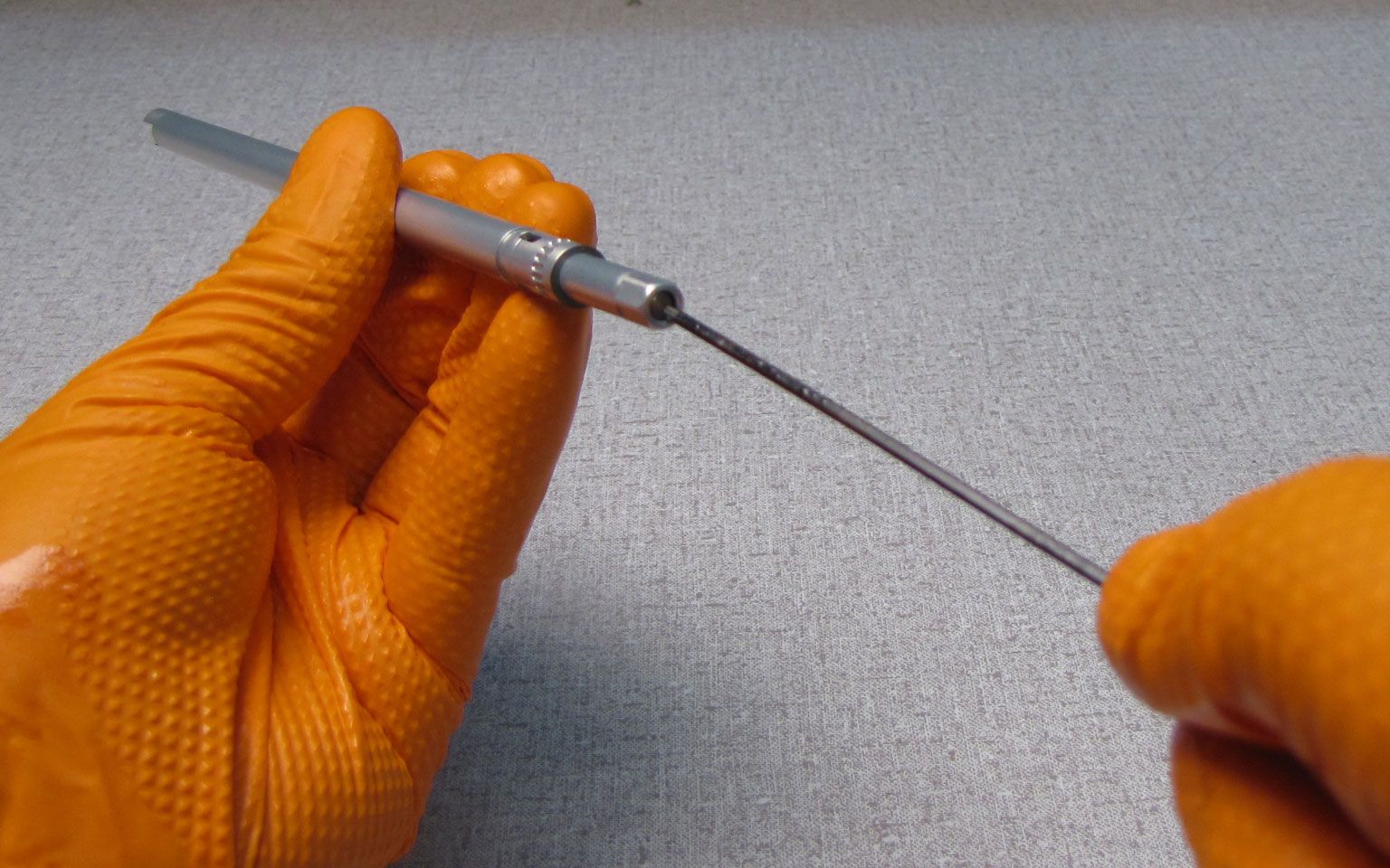
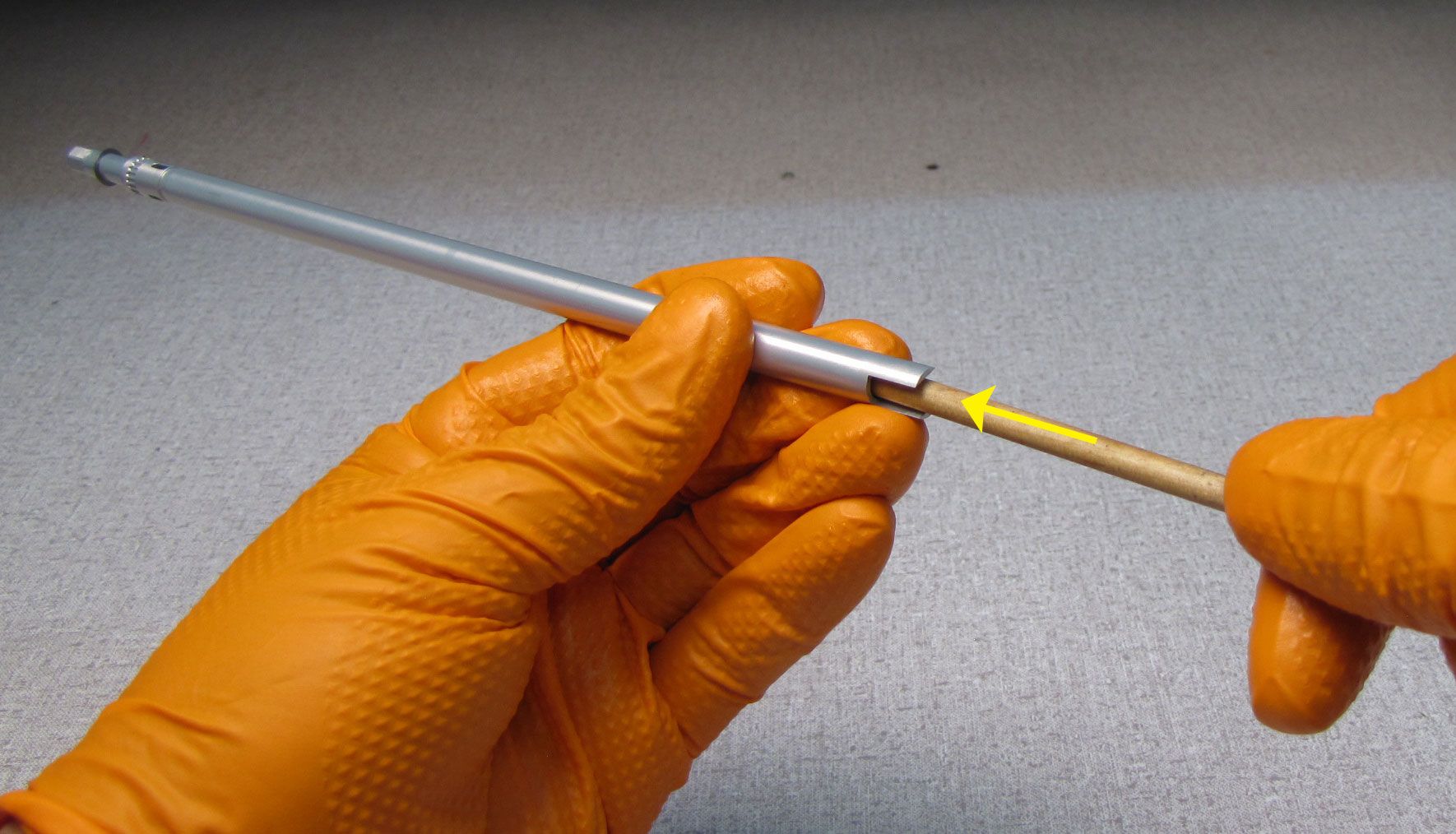
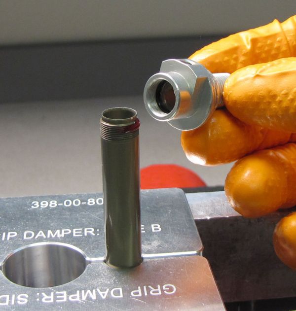
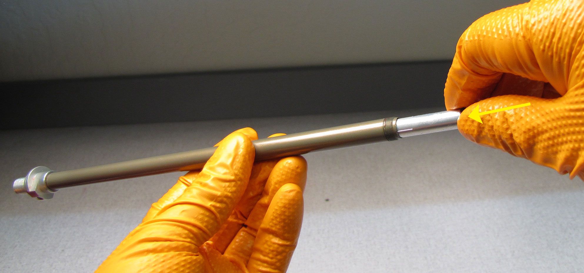
Step 3
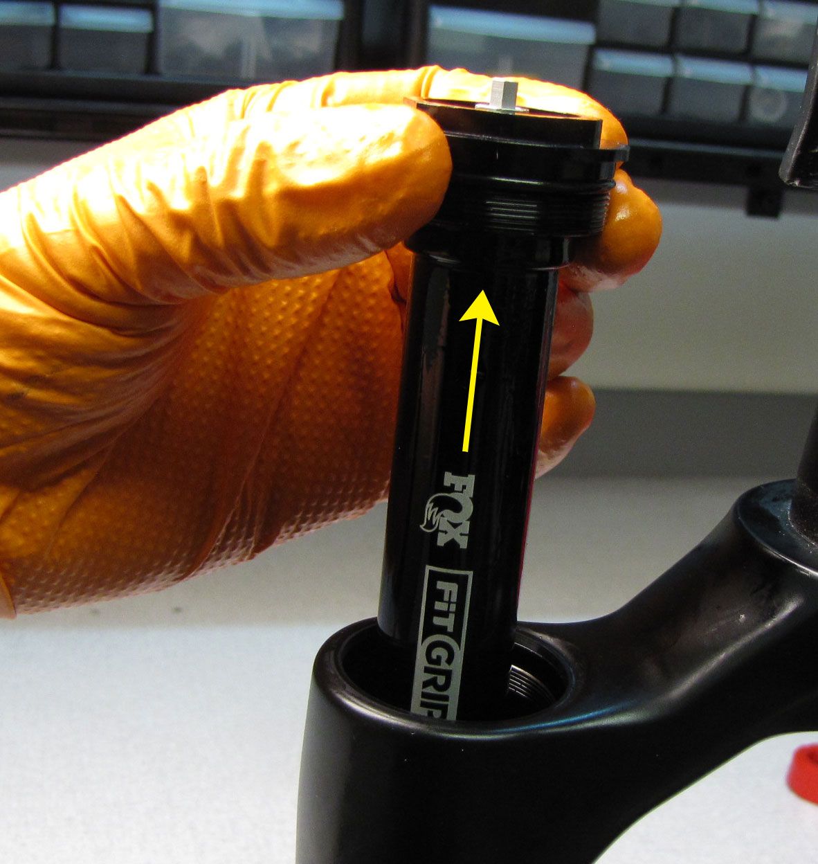
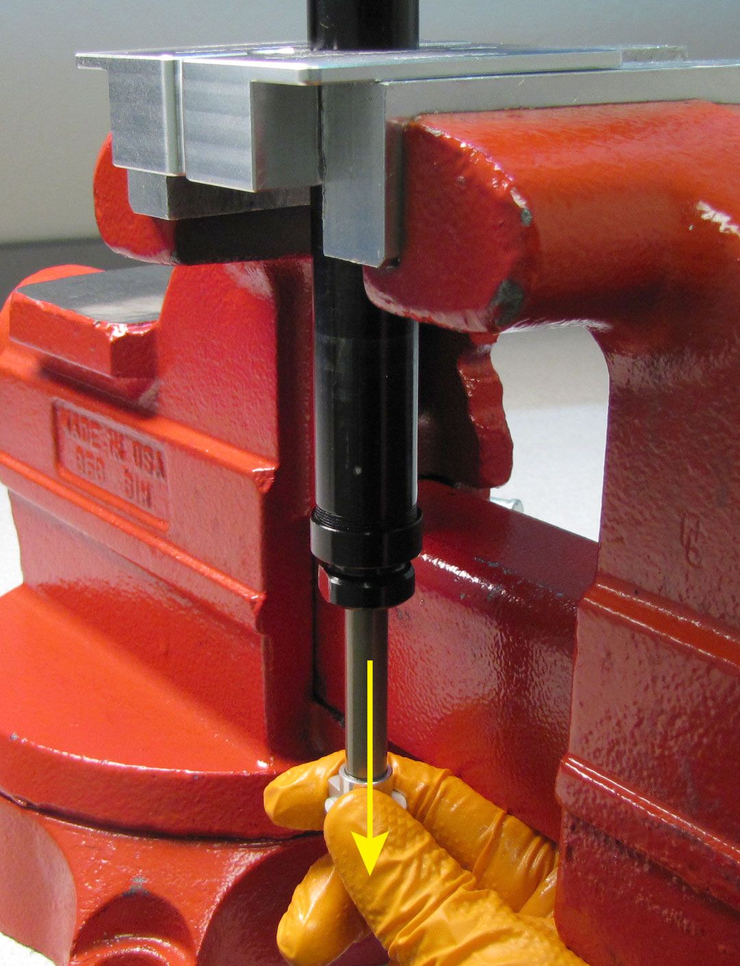
Use Damper Removal Tool 398-00-682 to dislodge the shaft from the lowers. Make sure that you have approximately half of the available threads engaged with your tool before striking with your mallet. Remove the damper removal tool, then bring the fork upright over an oil basin to drain.
Step 4
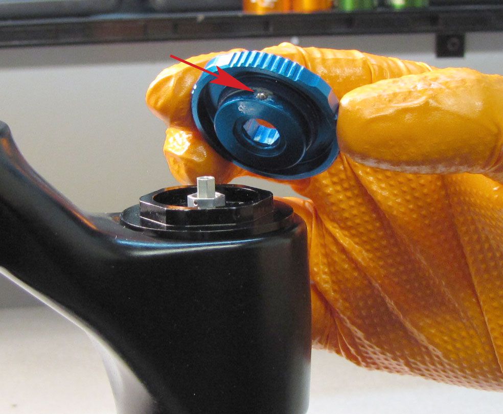
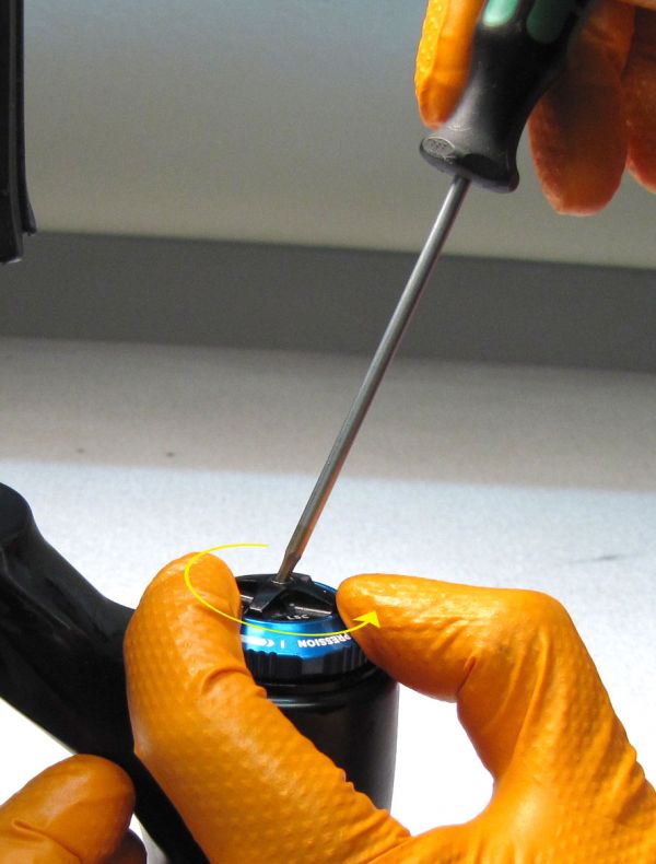
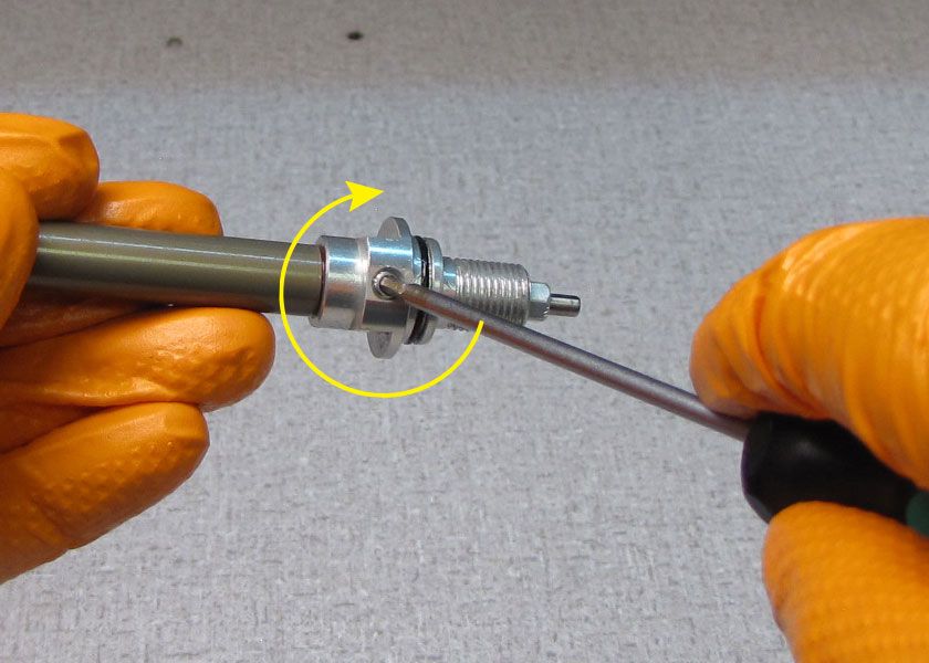
Hold the black Low-Speed Compression (LSC) knob from turning while you unthread the screw counter-clockwise with a 2mm hex wrench. Carefully lift off the knobs together keeping track of the detent ball and spring for the High-Speed Compression (HSC) knob.

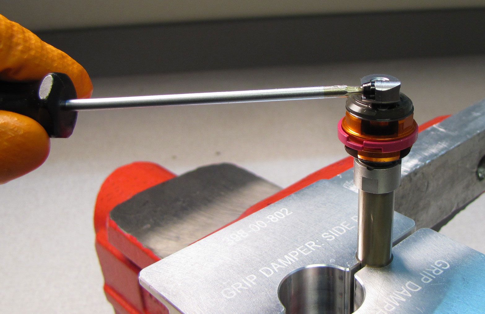
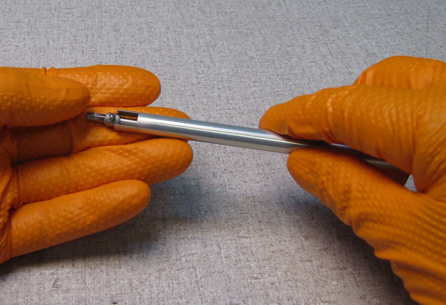
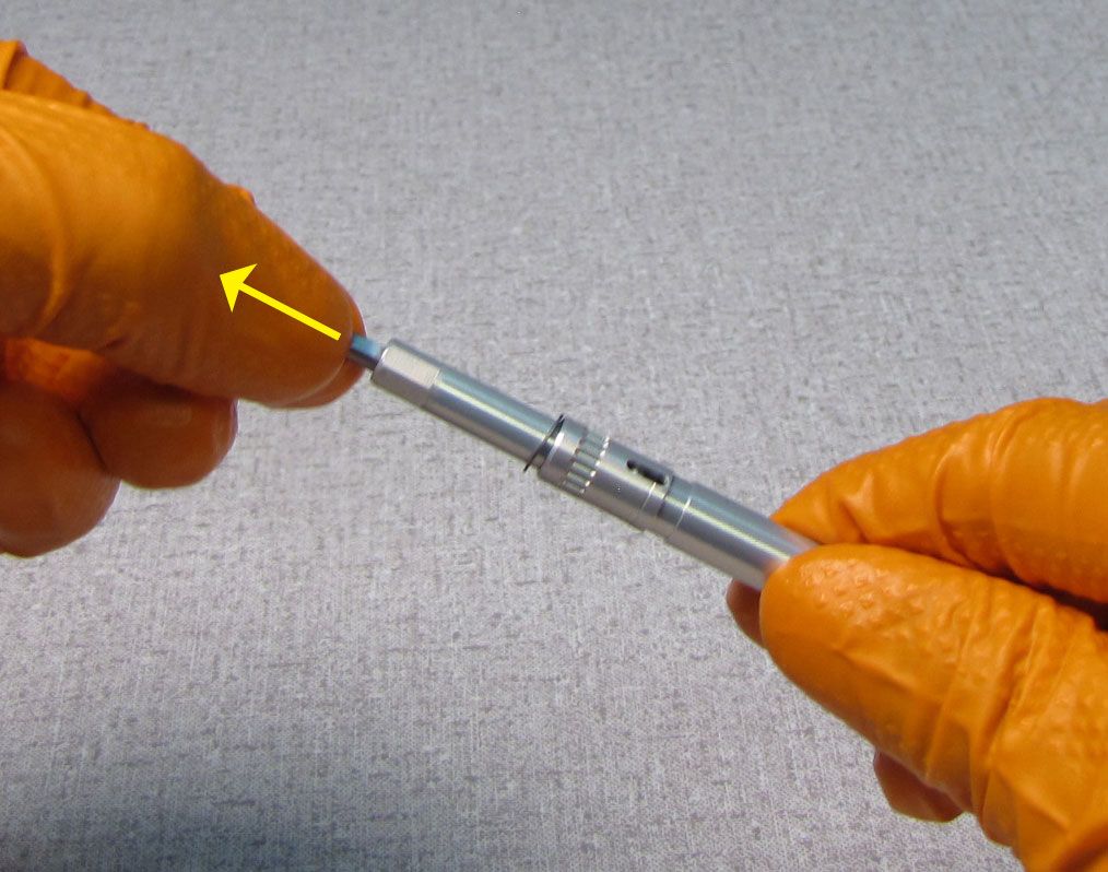
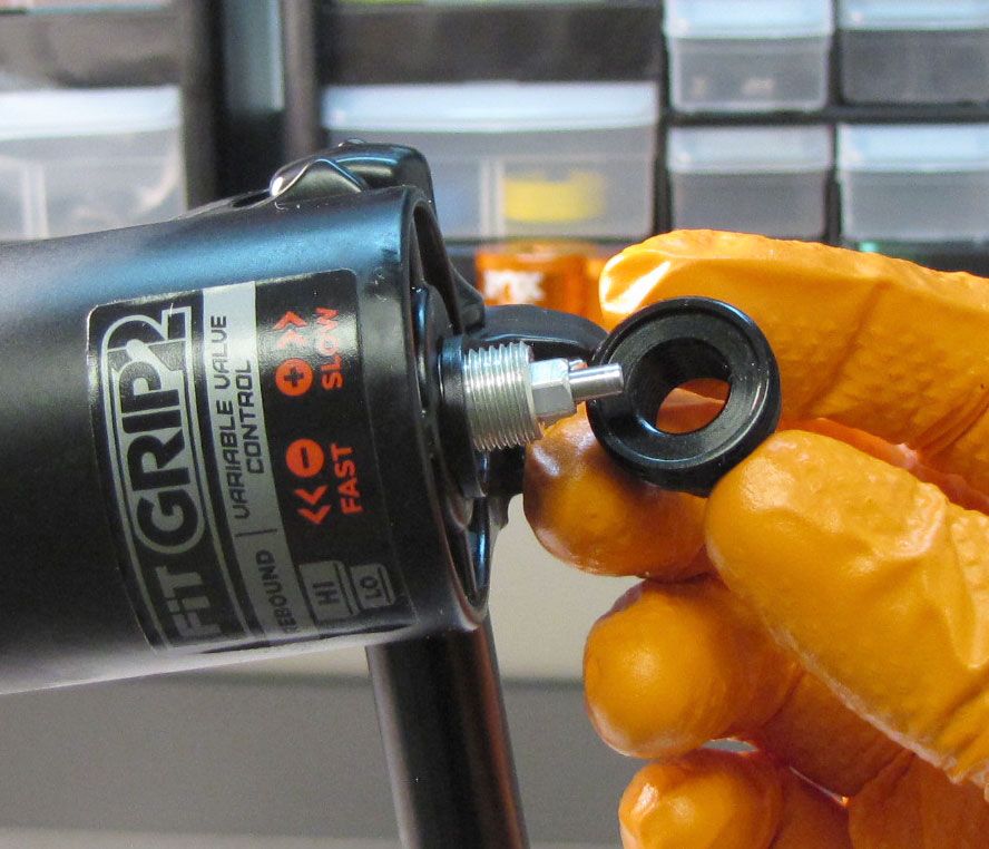
Step 5
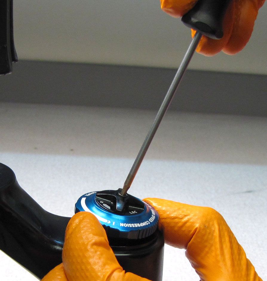
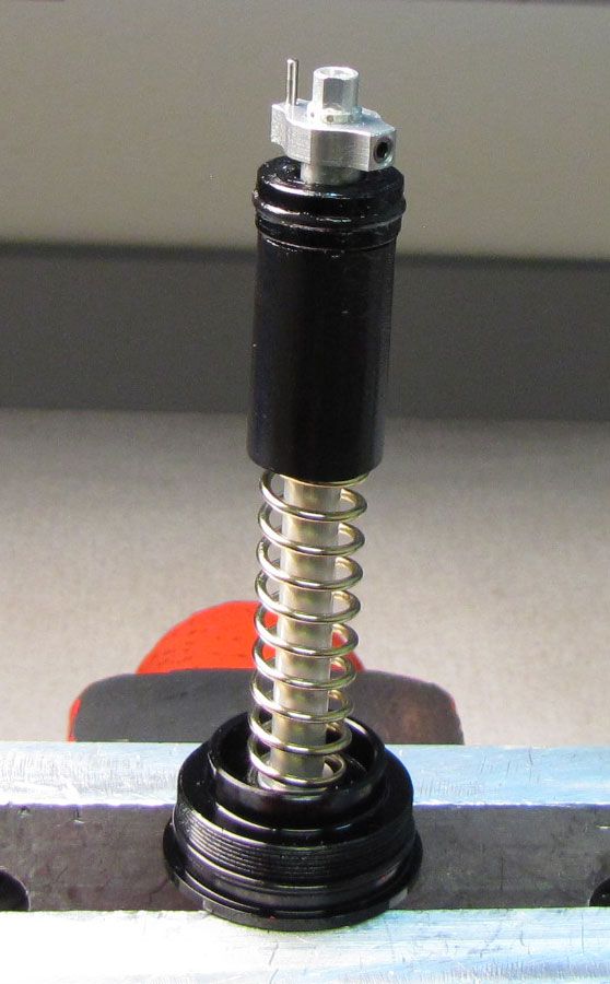
Unthread the damper topcap counter-clockwise with a 6-point chamfer-less 28mm socket (PN: 398-00-704). Lift up to remove the damper from the upper tube.

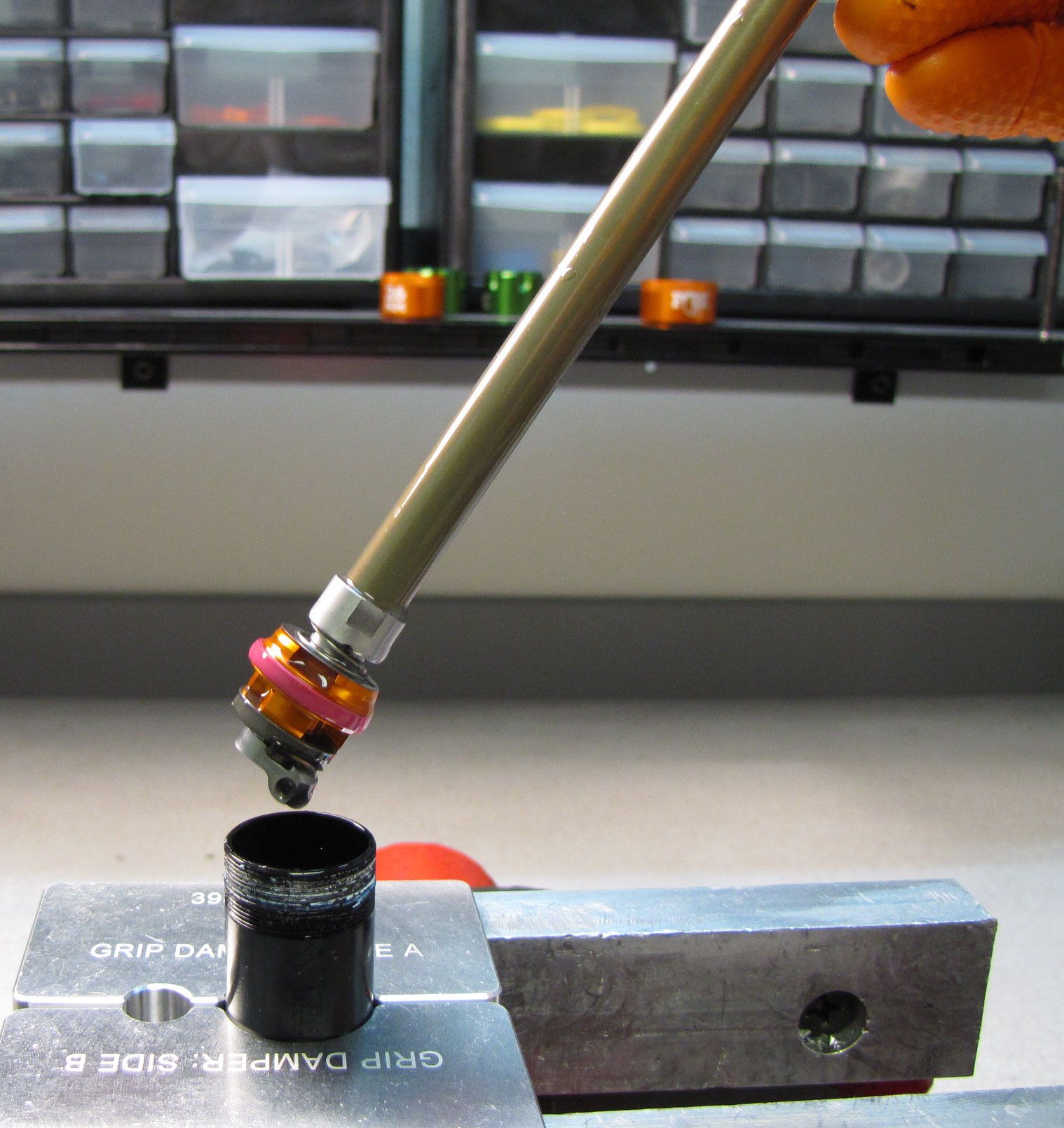
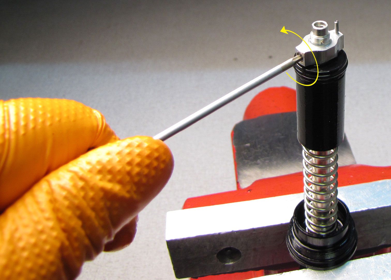
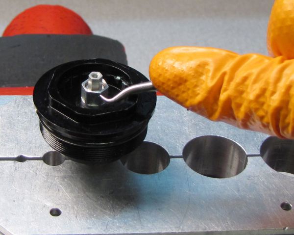
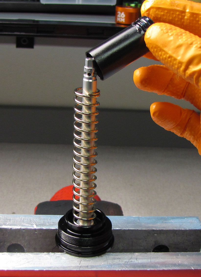
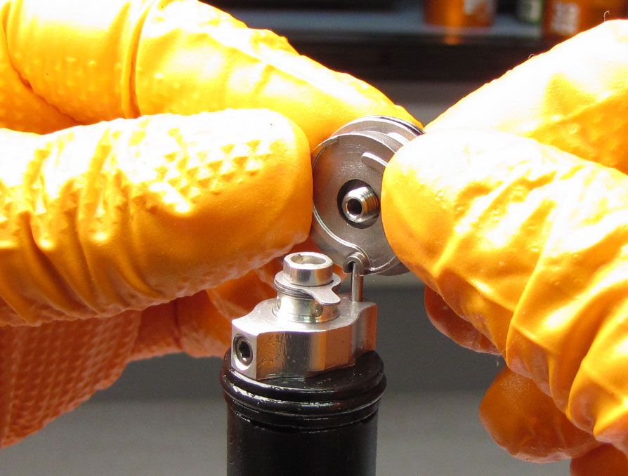
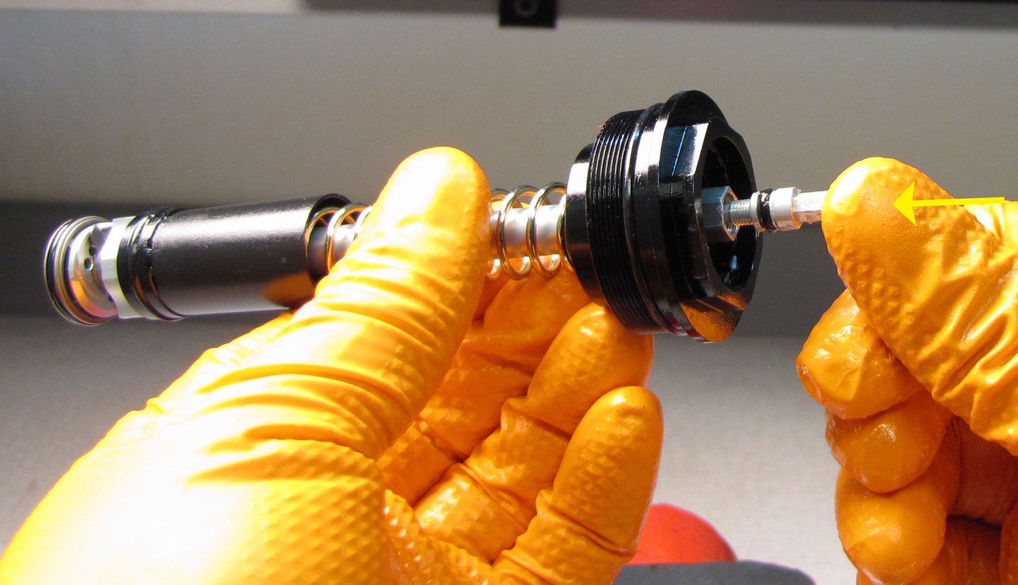
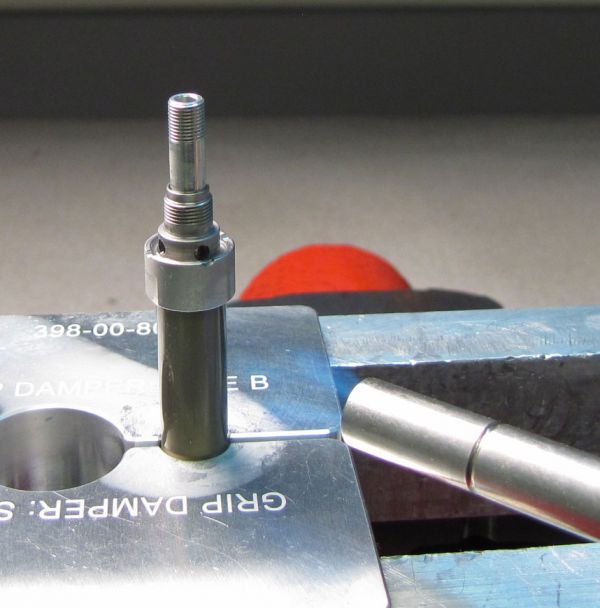
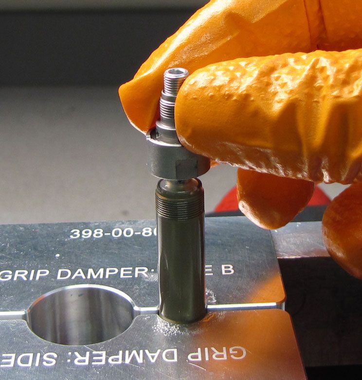
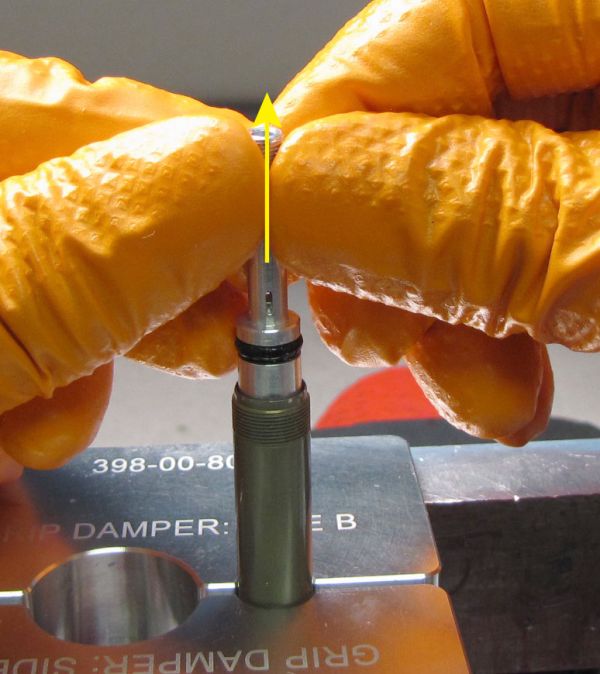
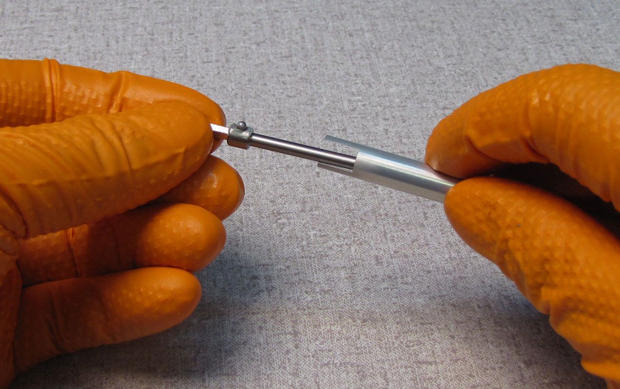
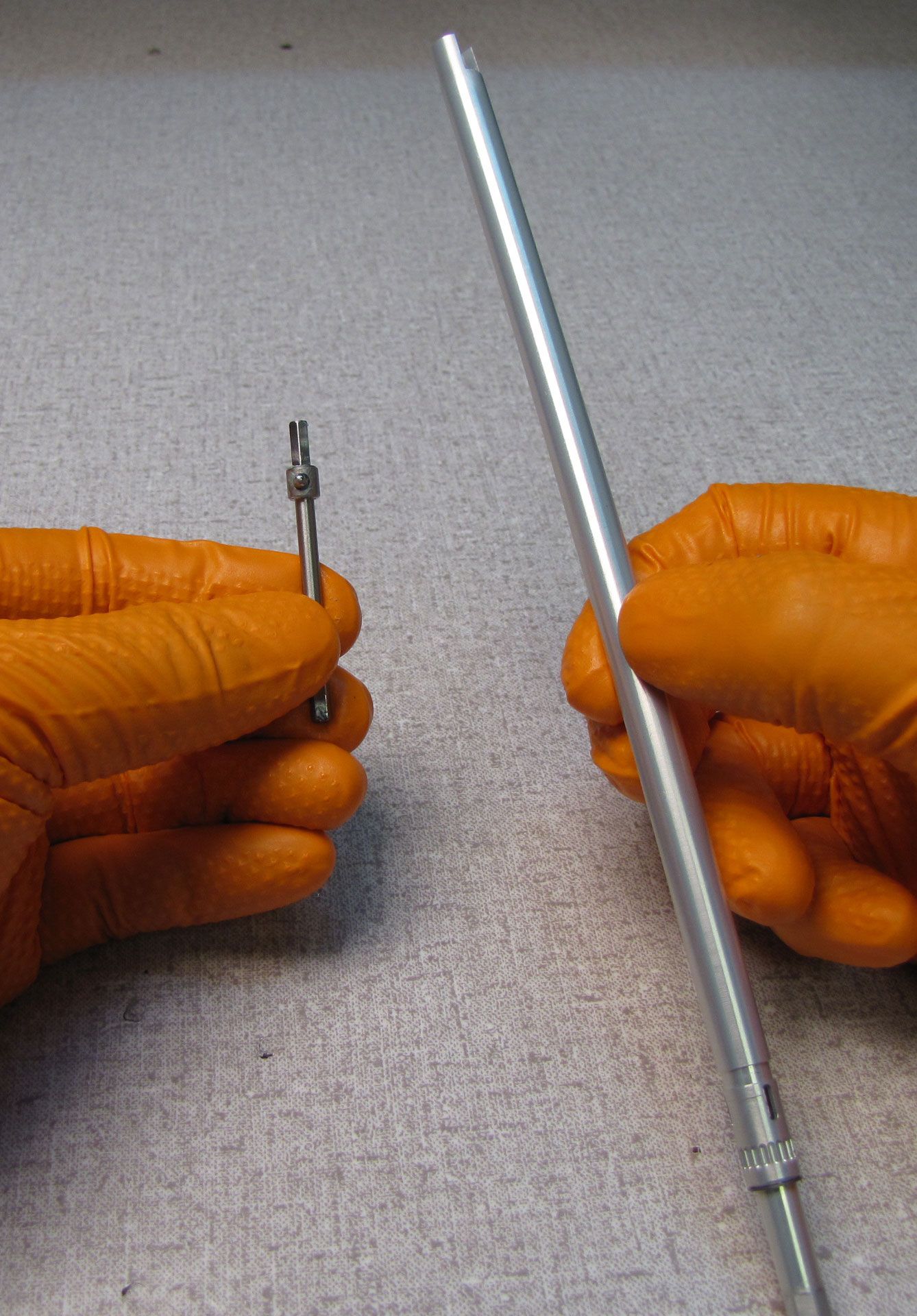
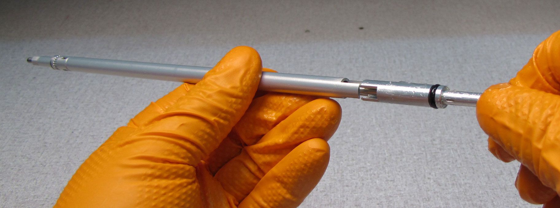
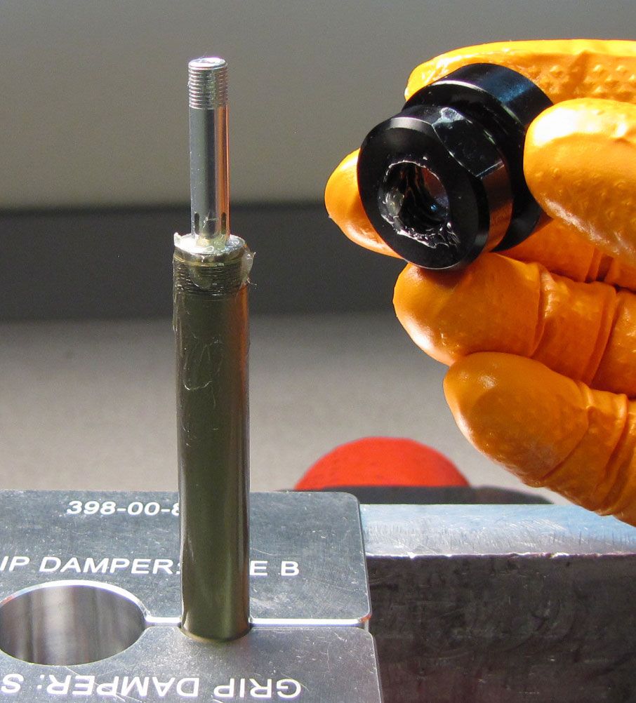
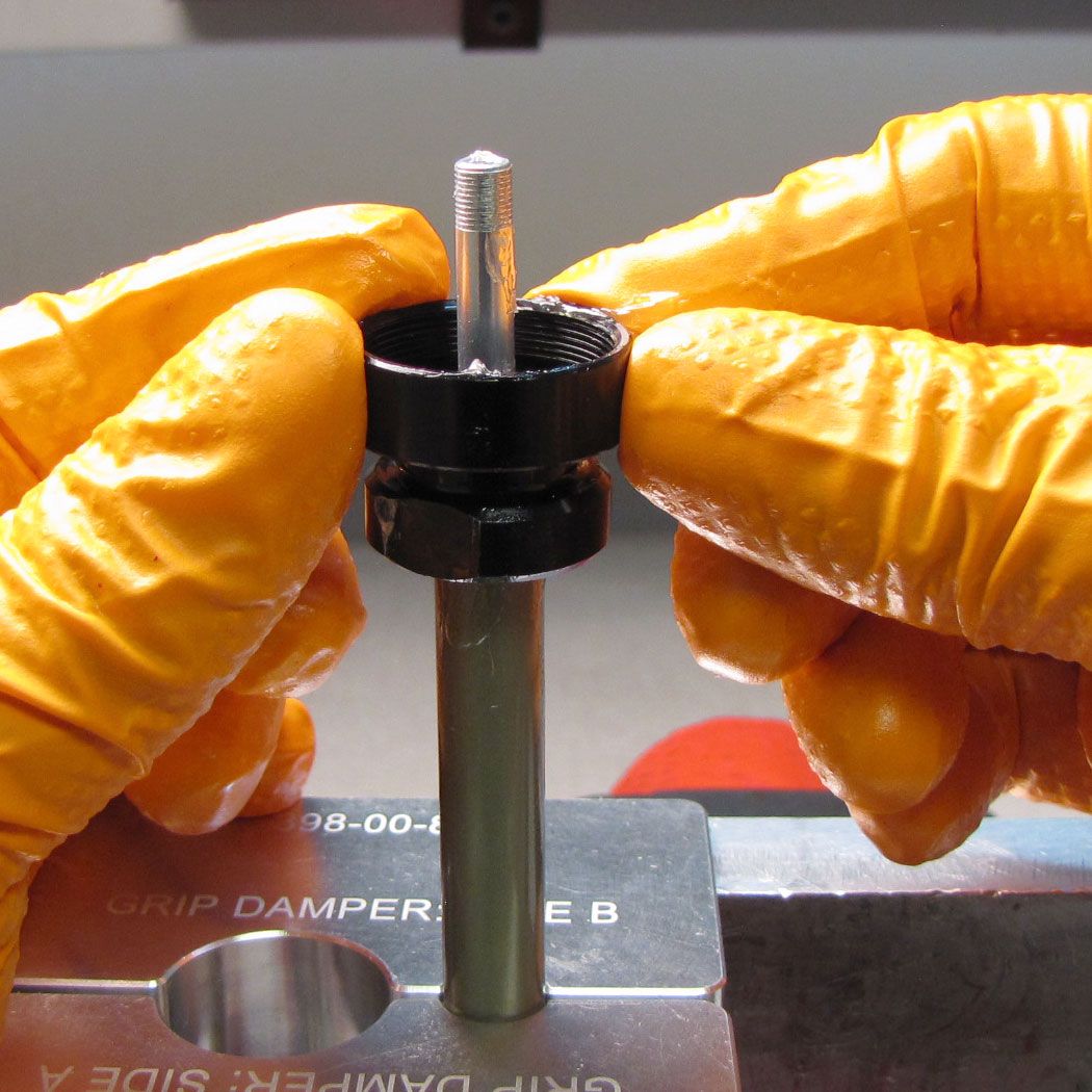
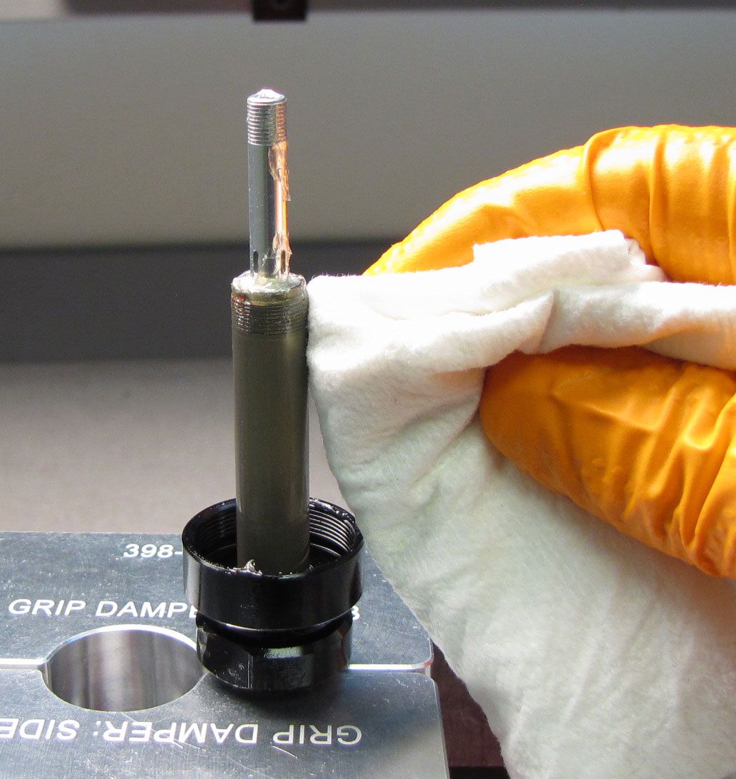
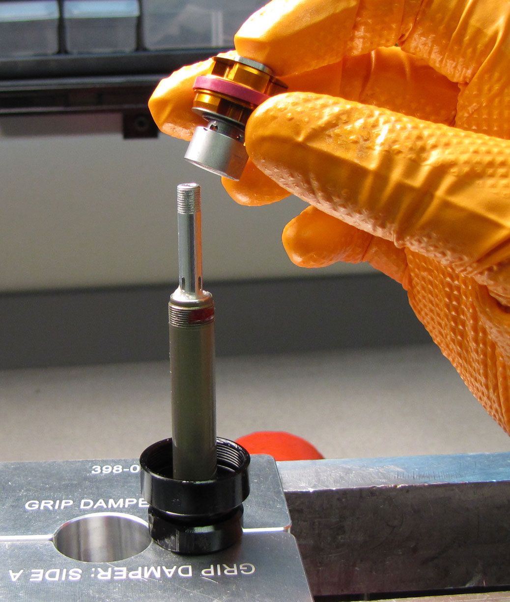
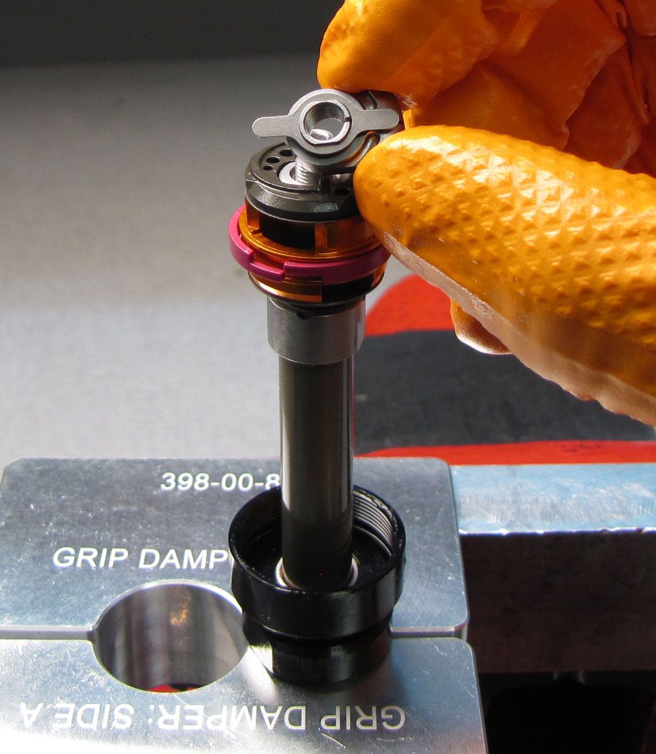
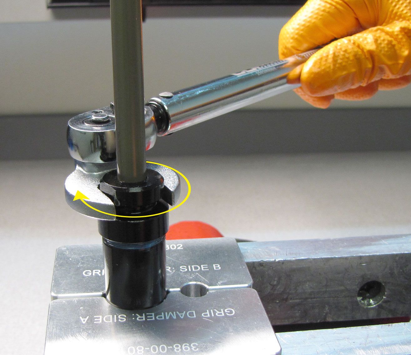
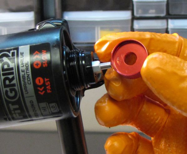
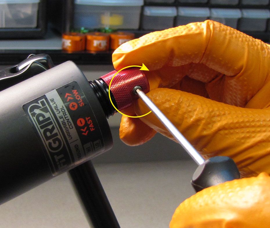
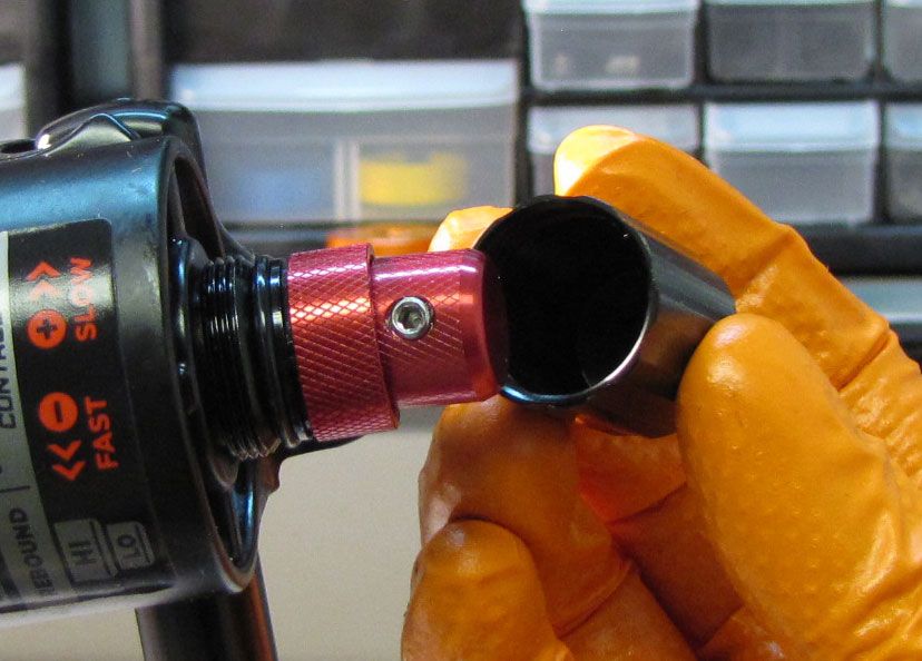
Step 6
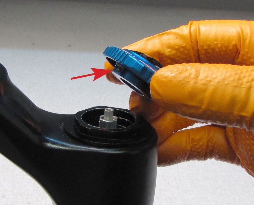
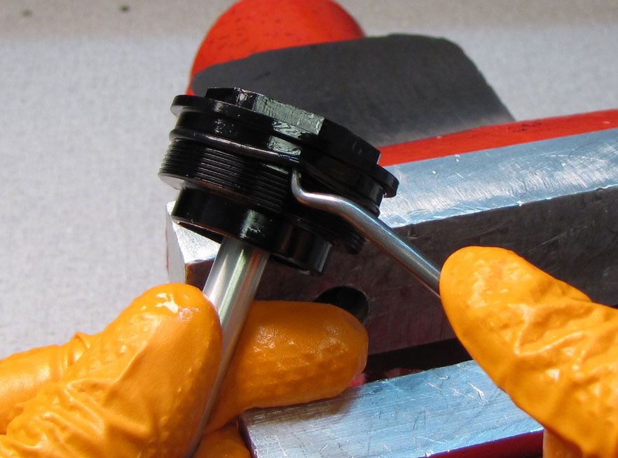
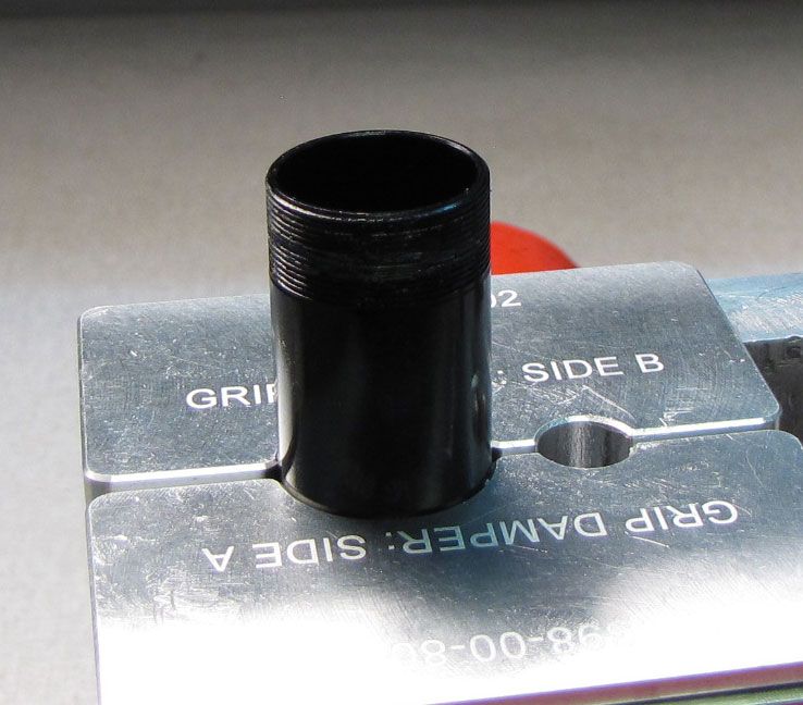
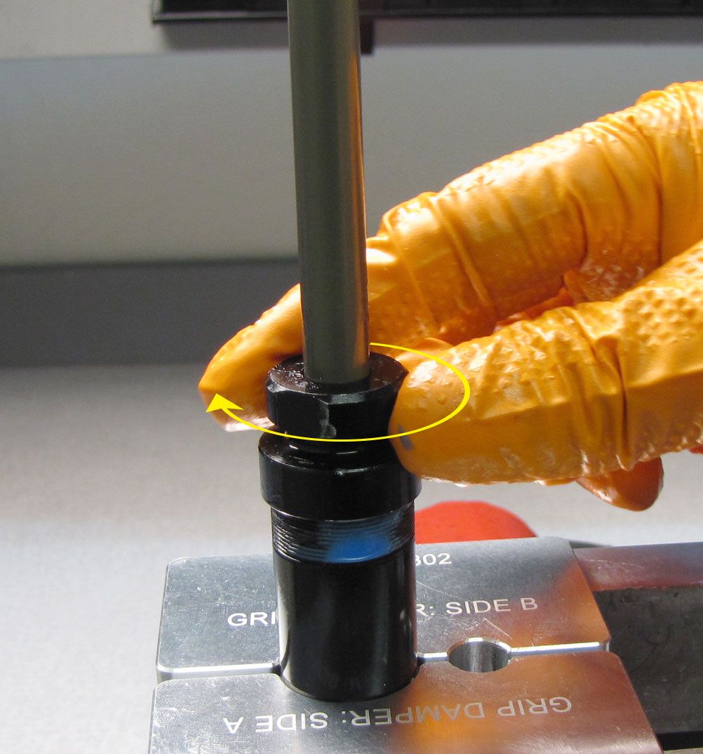
Clean the damper with Isopropyl alcohol and a lint-free paper towel then clamp the body in the middle of its length in your Grip Shaft Clamps (PN: 803-01-324). Unthread the topcap from the body counter-clockwise with your 6-point chamfer-less 28mm socket. Lift the topcap assembly up and out of the cartridge body.


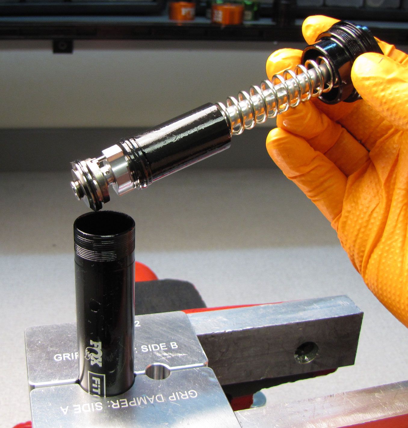
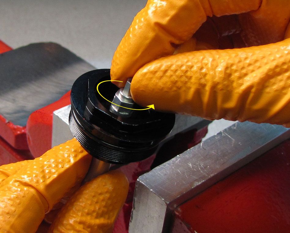
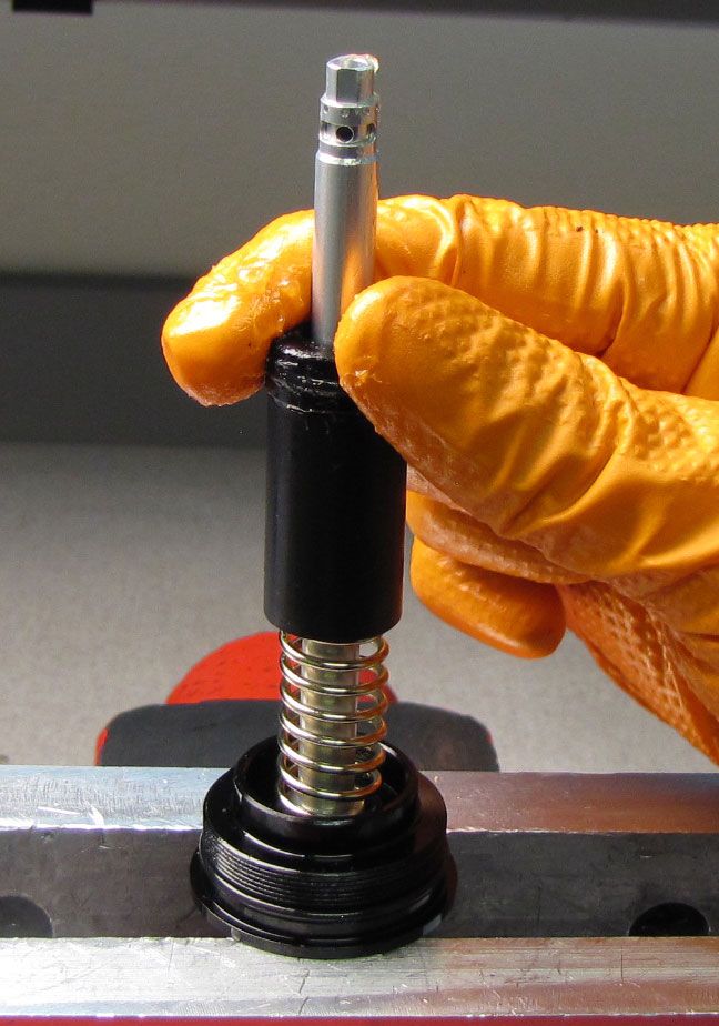
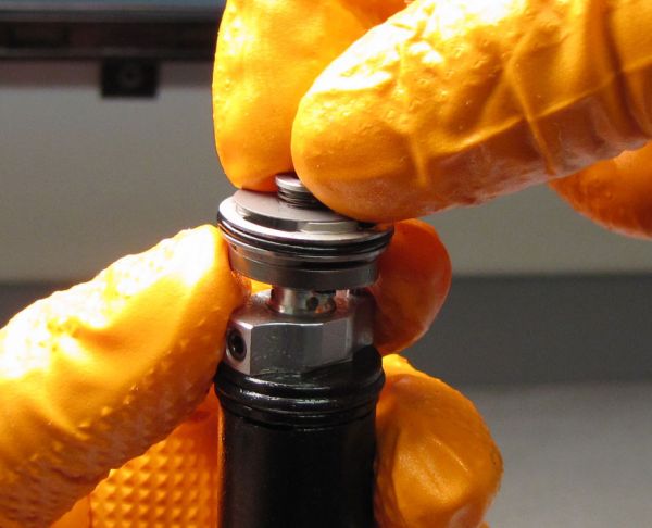
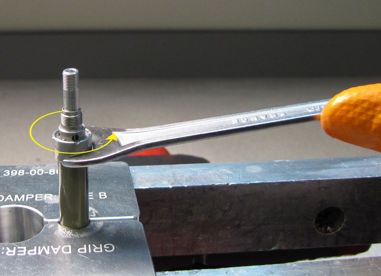
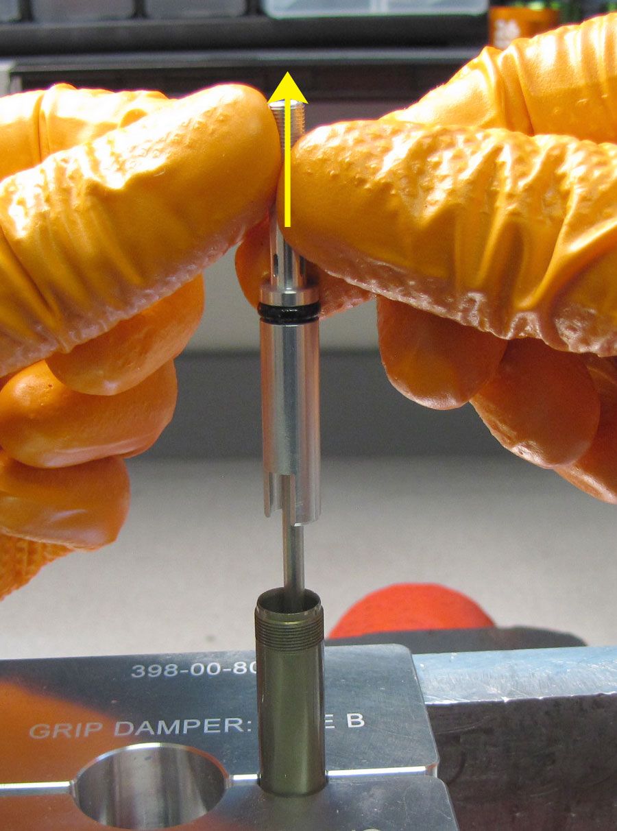
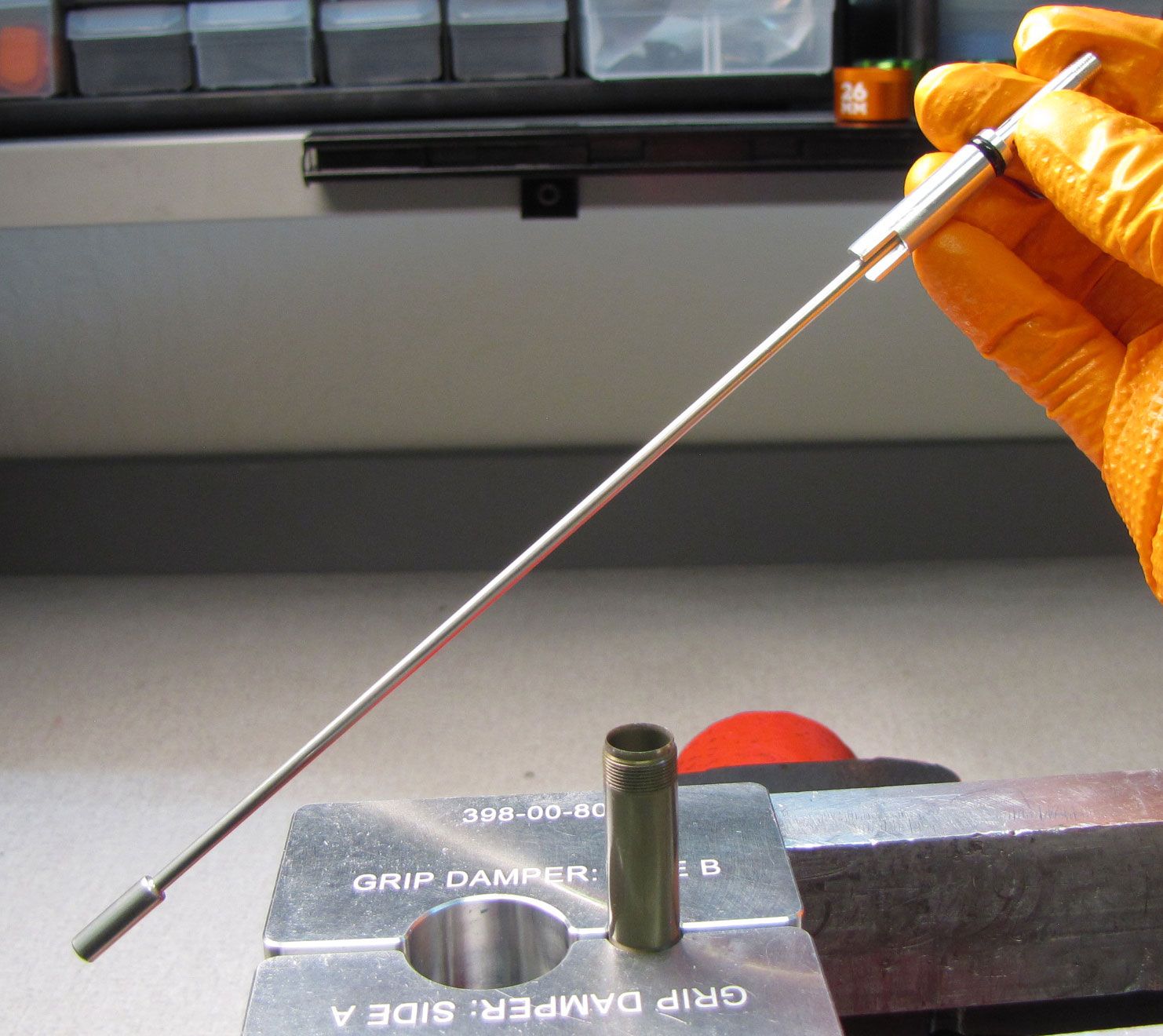
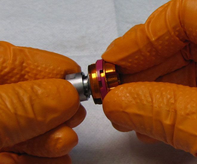
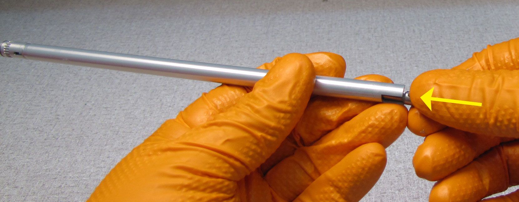
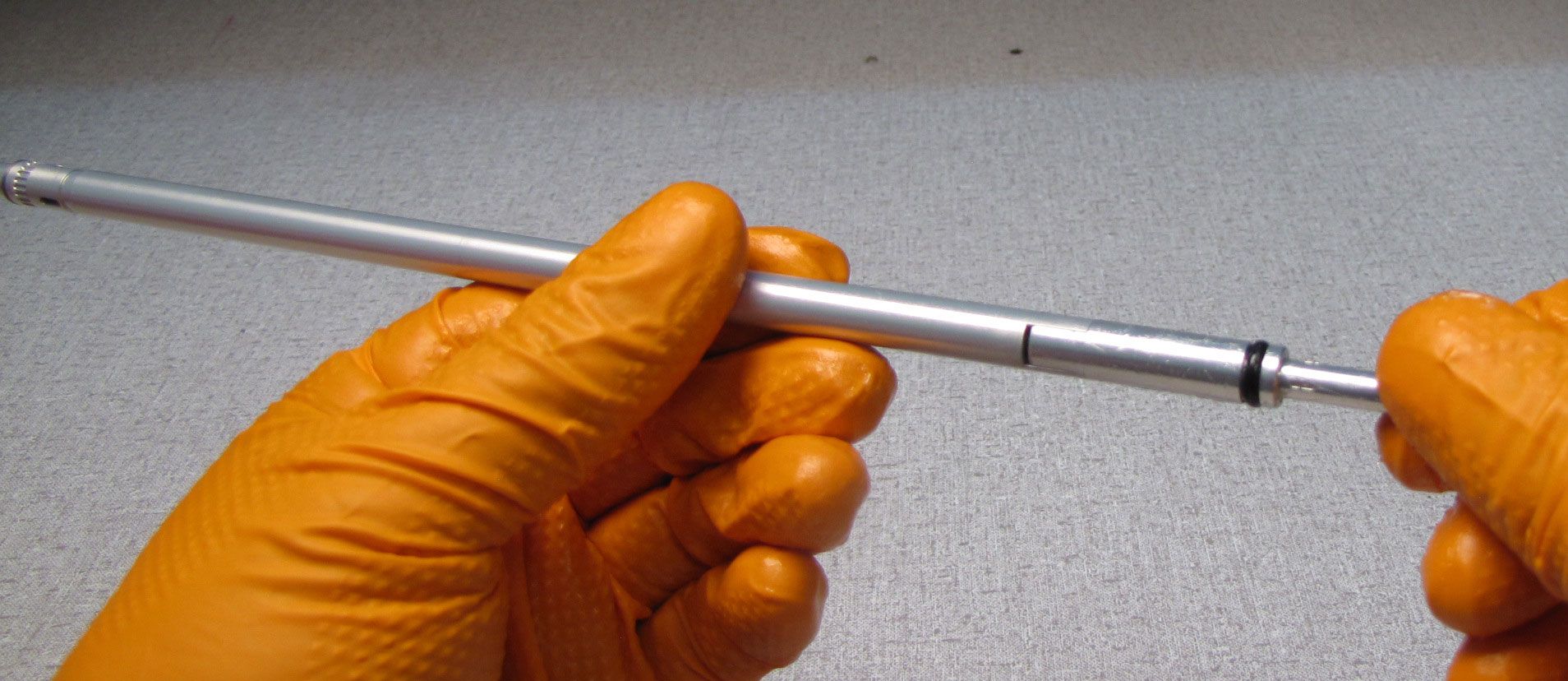
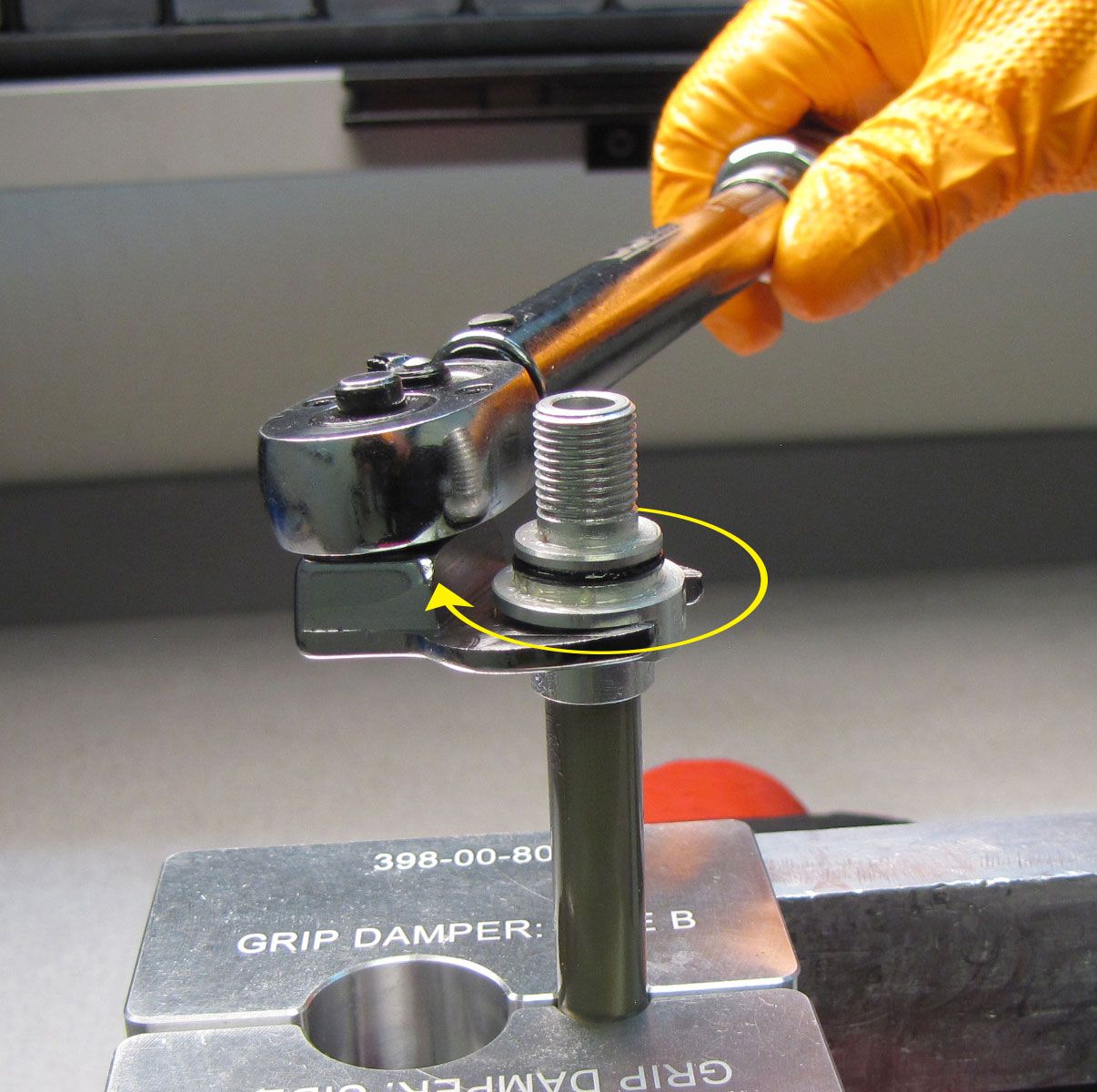
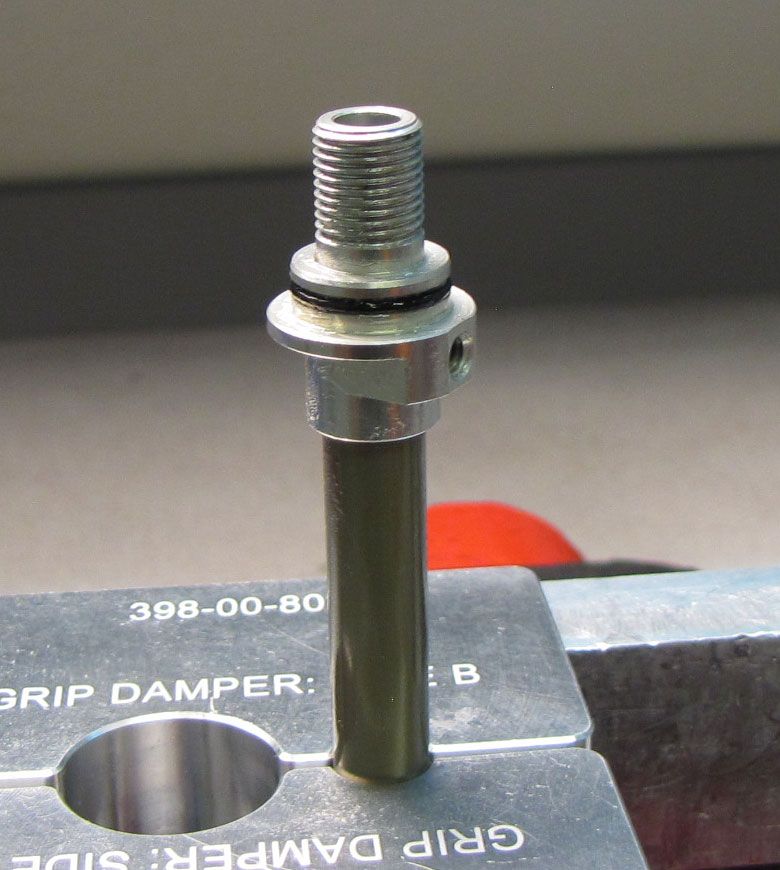
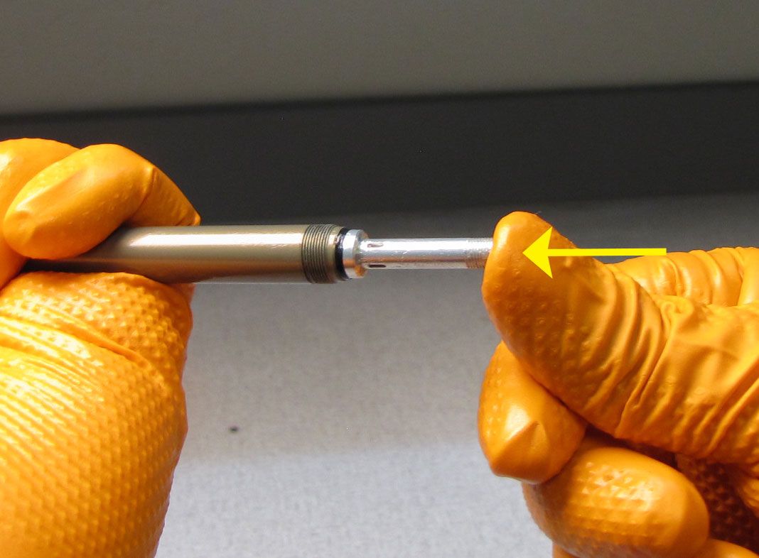
Step 7
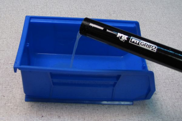
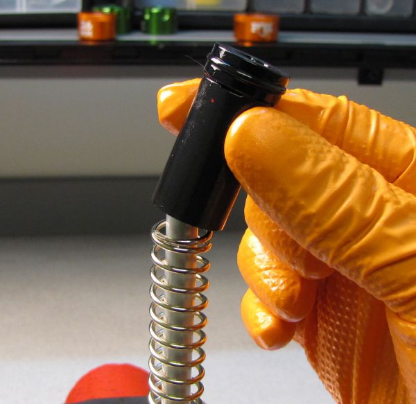
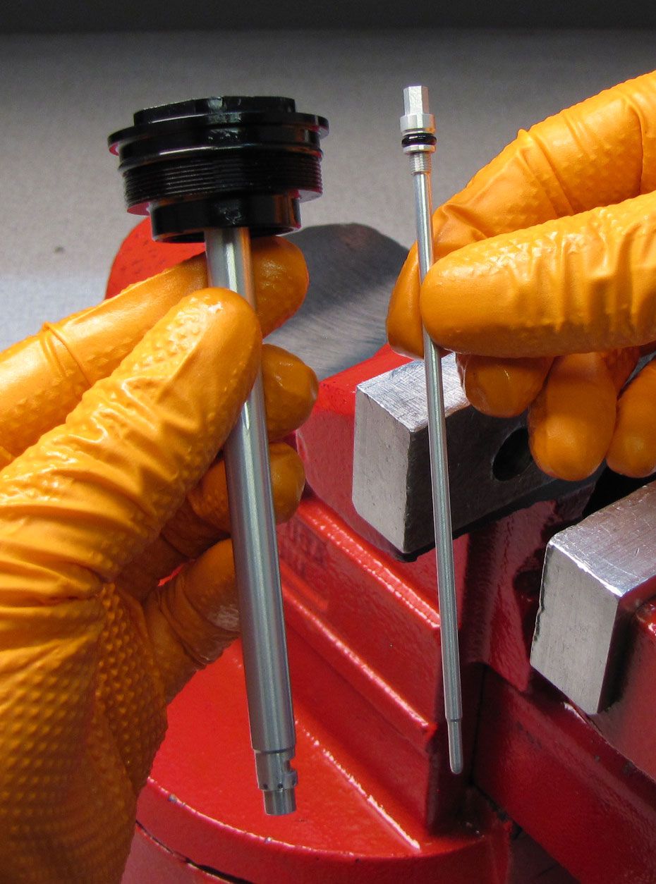
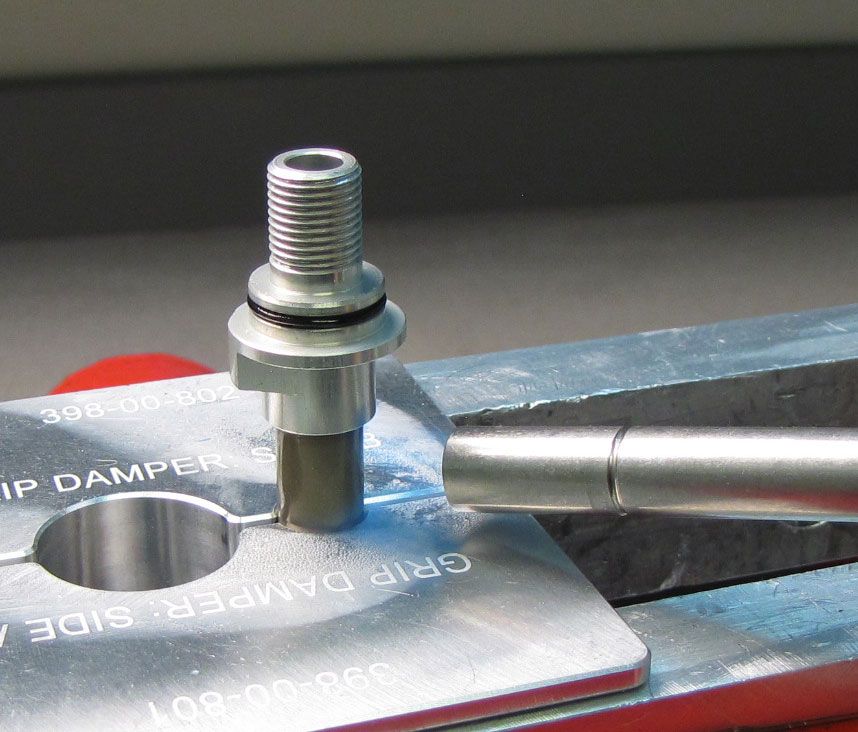
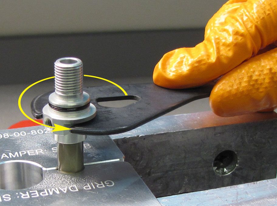
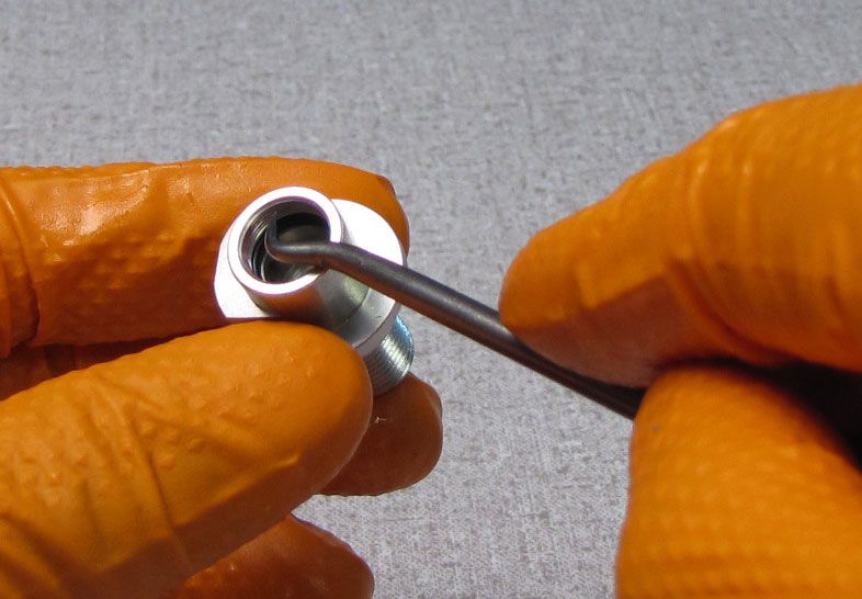
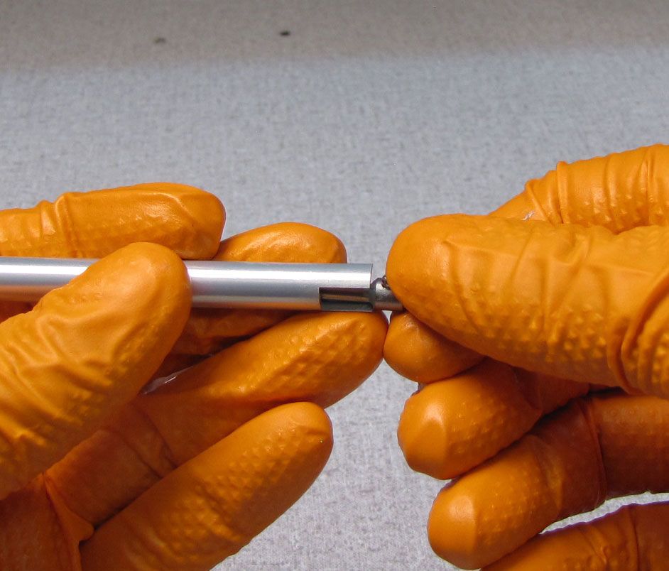
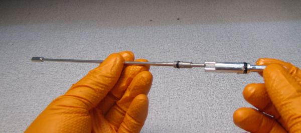
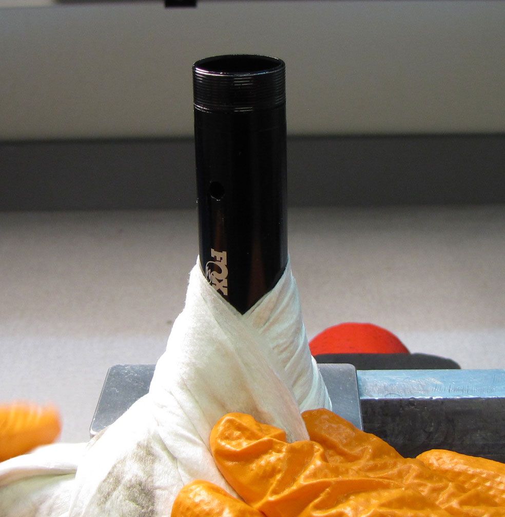
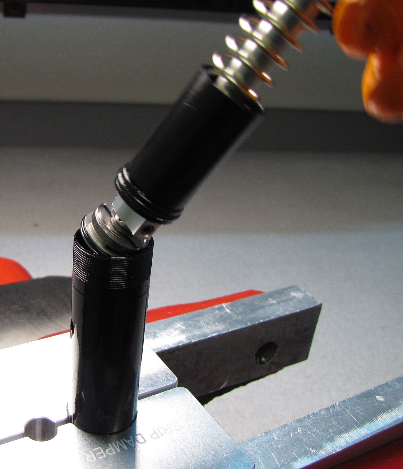
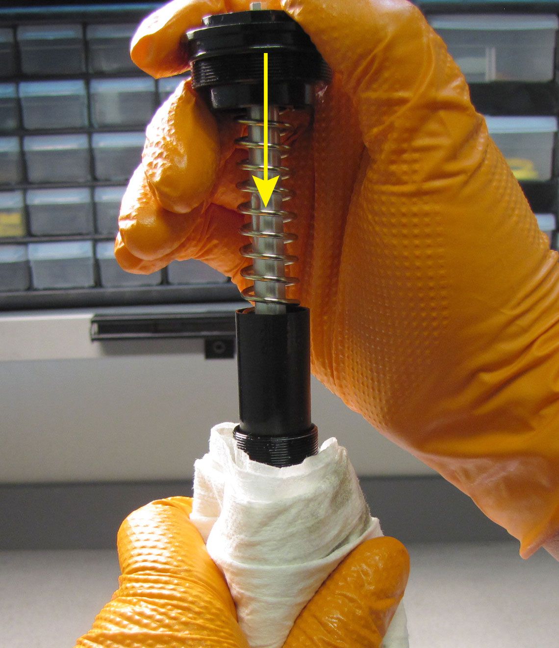
Remove the cartridge from the clamps and invert over your waste oil basin. Drain all oil from the cartridge then clamp it in your shaft clamps with the base stud facing up. Unthread the sealhead counter-clockwise from the cartridge body with a 20mm wrench. Lift the damper shaft assembly up to remove it from the cartridge body.


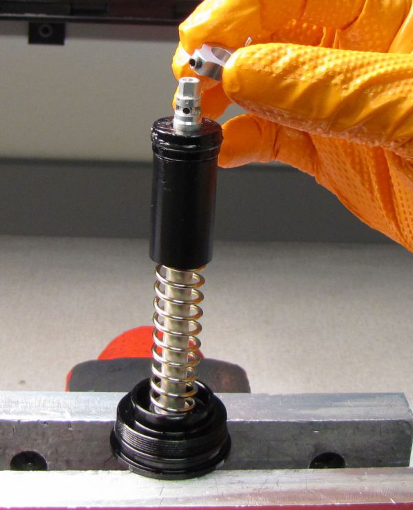
Step 8
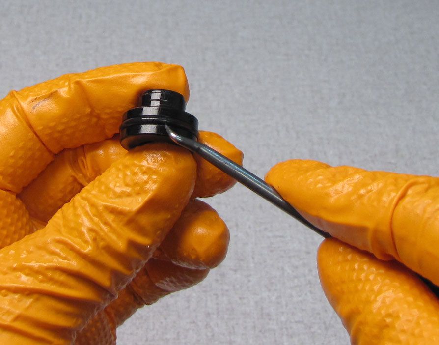
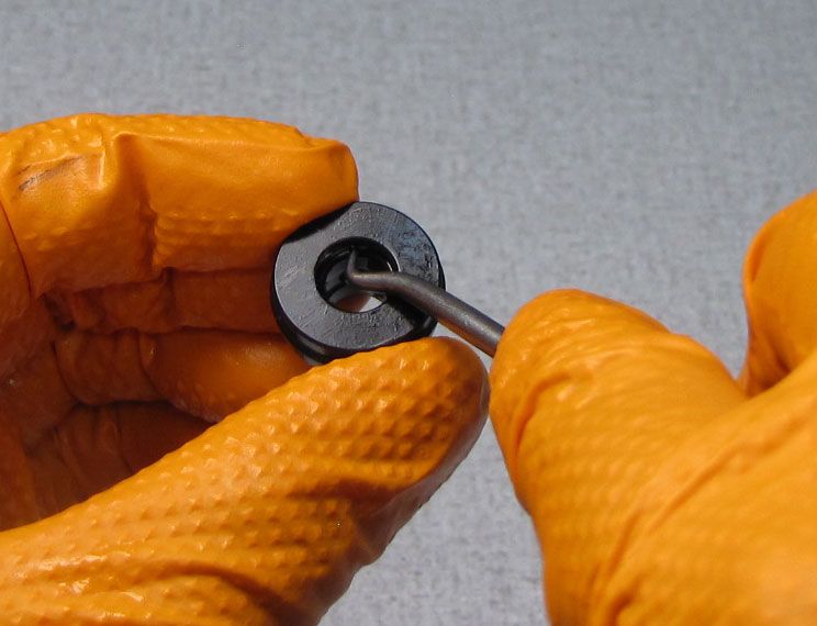
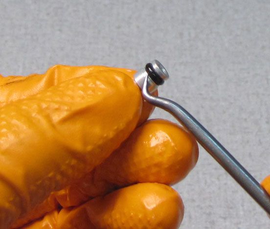
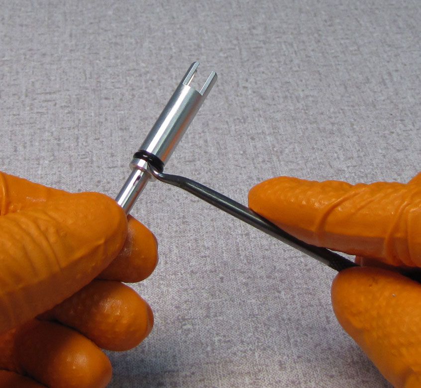
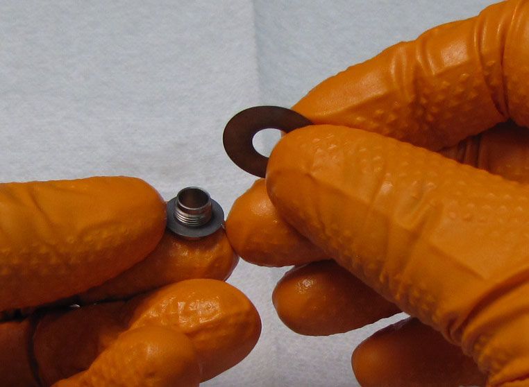
Invert the topcap assembly and gently clamp the topcap wrench-flats in your soft-jawed vise. Take care to clamp only tightly enough to hold the part without causing any damage. Unthread the piston bolt by turning it counter-clockwise with a 3mm hex wrench. Remove the piston and the compression valving and set them aside. Replace the Compression Piston o-ring with a new greased one from the kit.

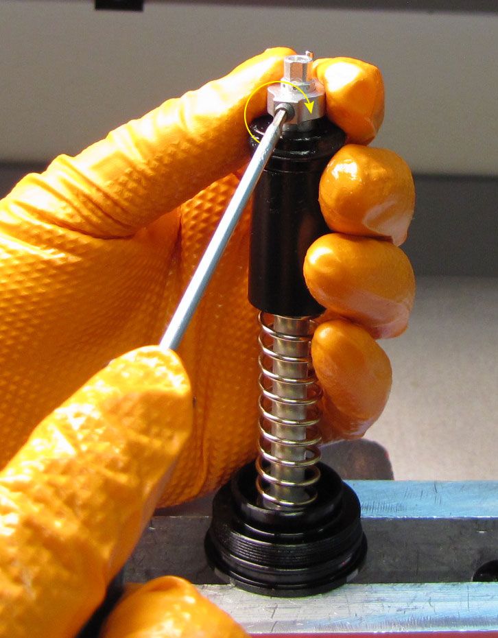
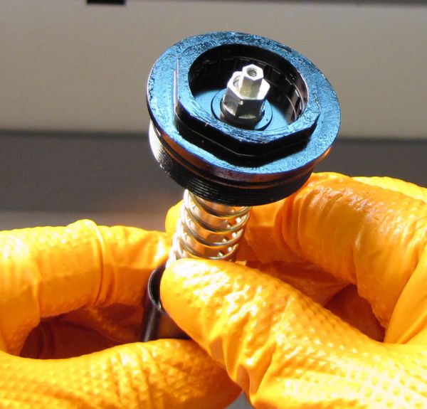
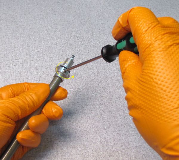
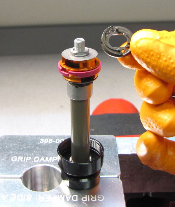
Step 9
Loosen the set screw in the Valve Loader by turning it counter-clockwise with a 2mm hex wrench. Lift the Valve Loader up to remove it.
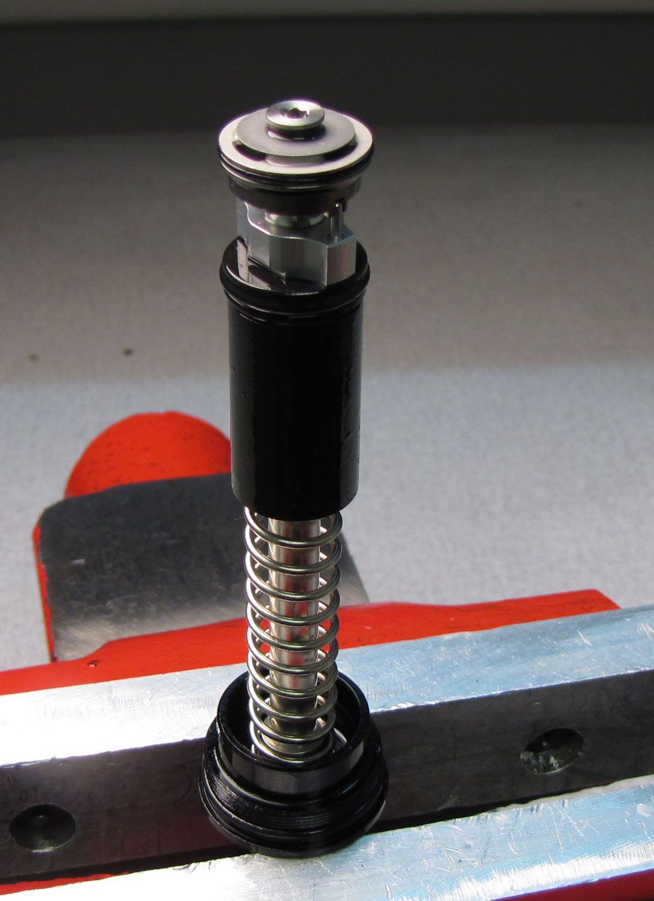
Step 10
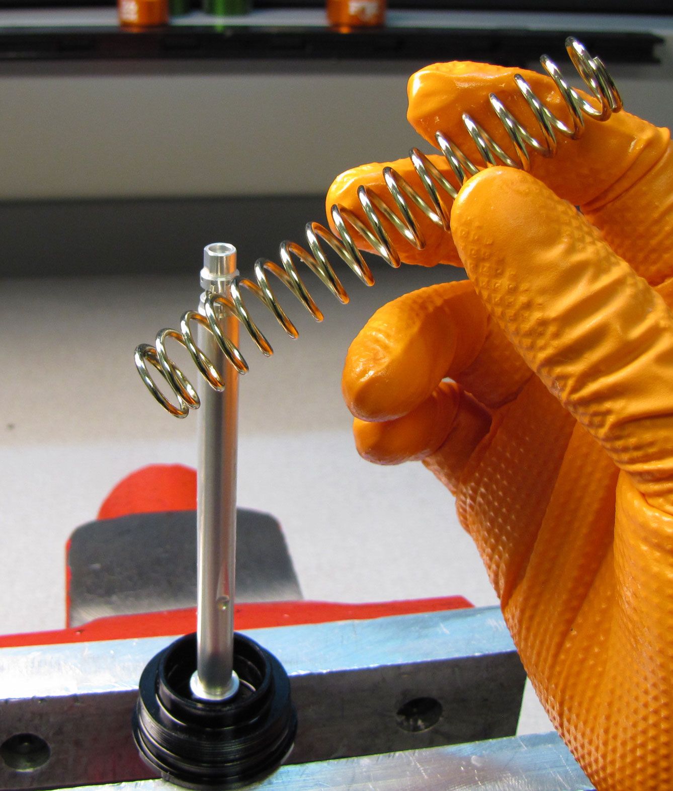
Remove the Spring Isolator with IFP and IFP Spring by pulling them up and off the shaft.

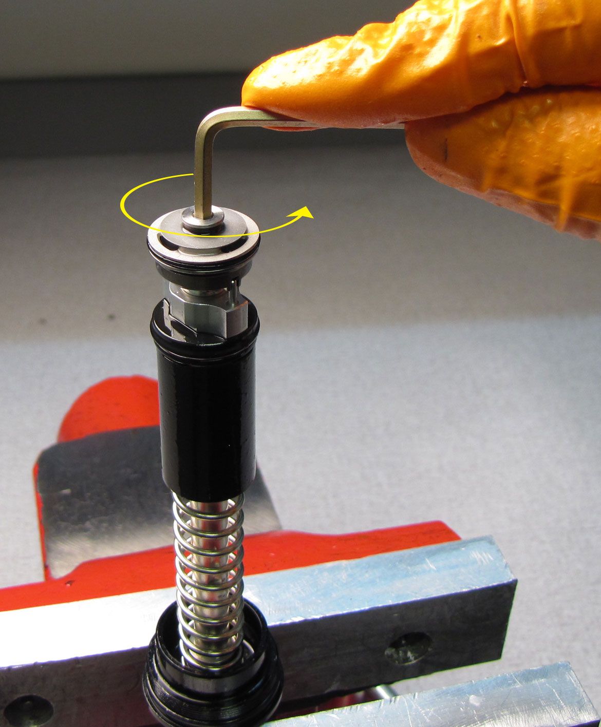
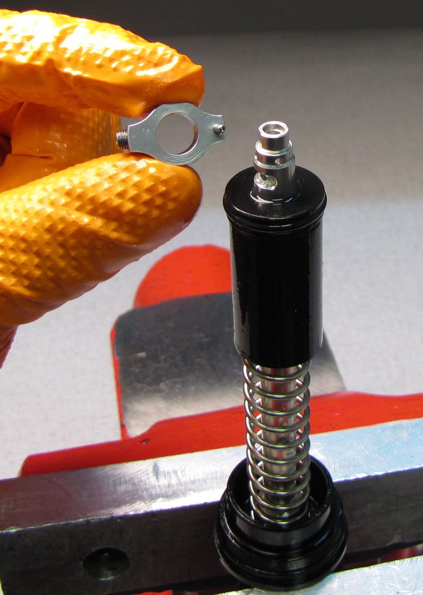
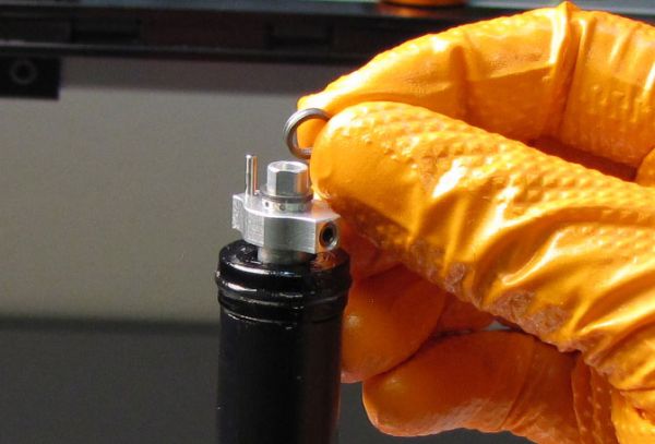
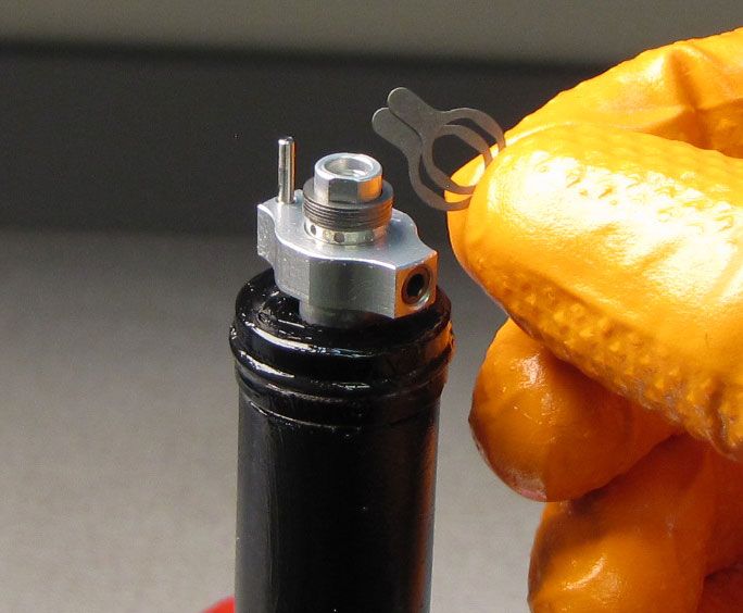
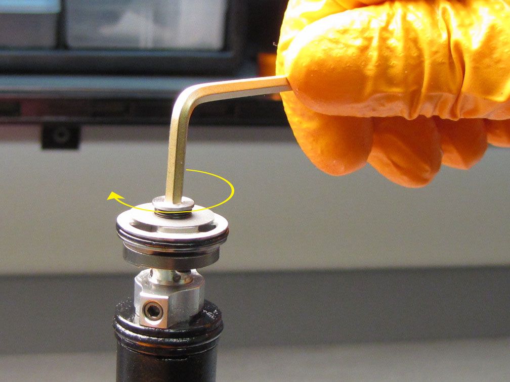
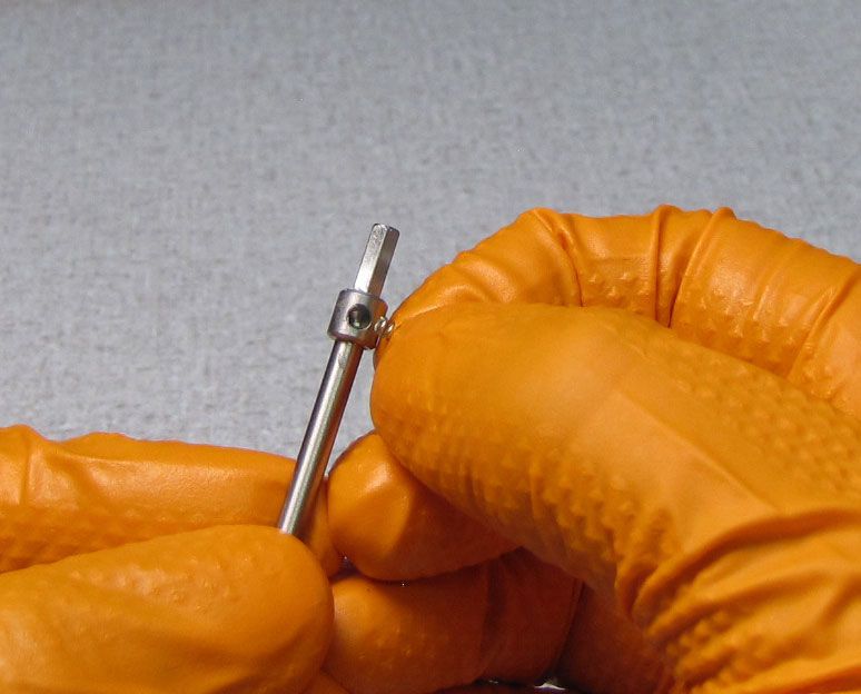
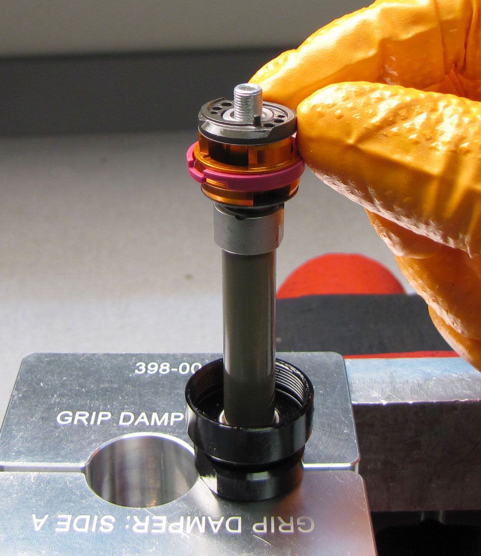
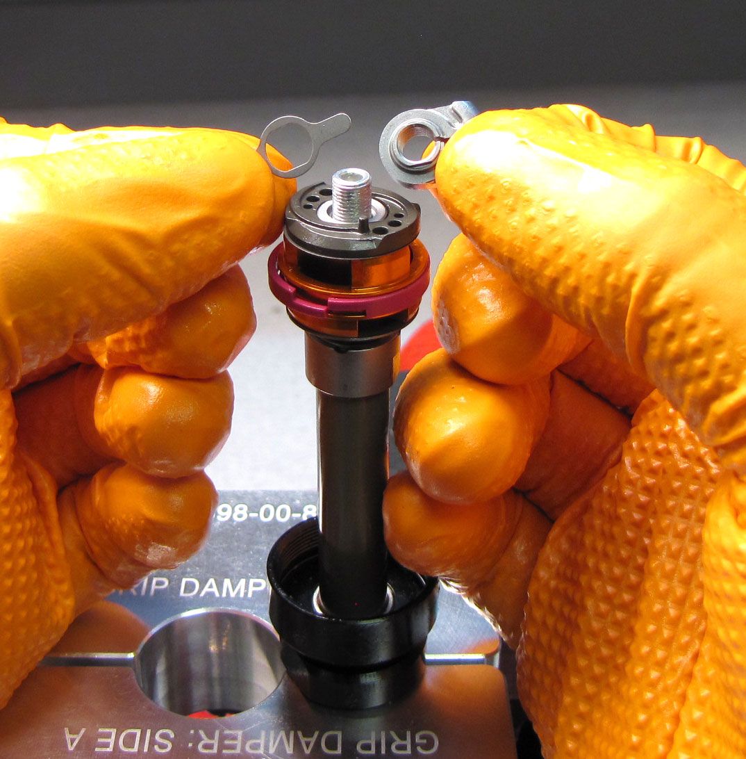
Step 11
Invert the Topcap assembly and clamp in your shaft clamps. Remove the wire retaining ring from within the HSC shaft. Turn the LSC coupler counter-clockwise to unthread the LSC needle. After unthreading, lift up to remove the LSC needle.


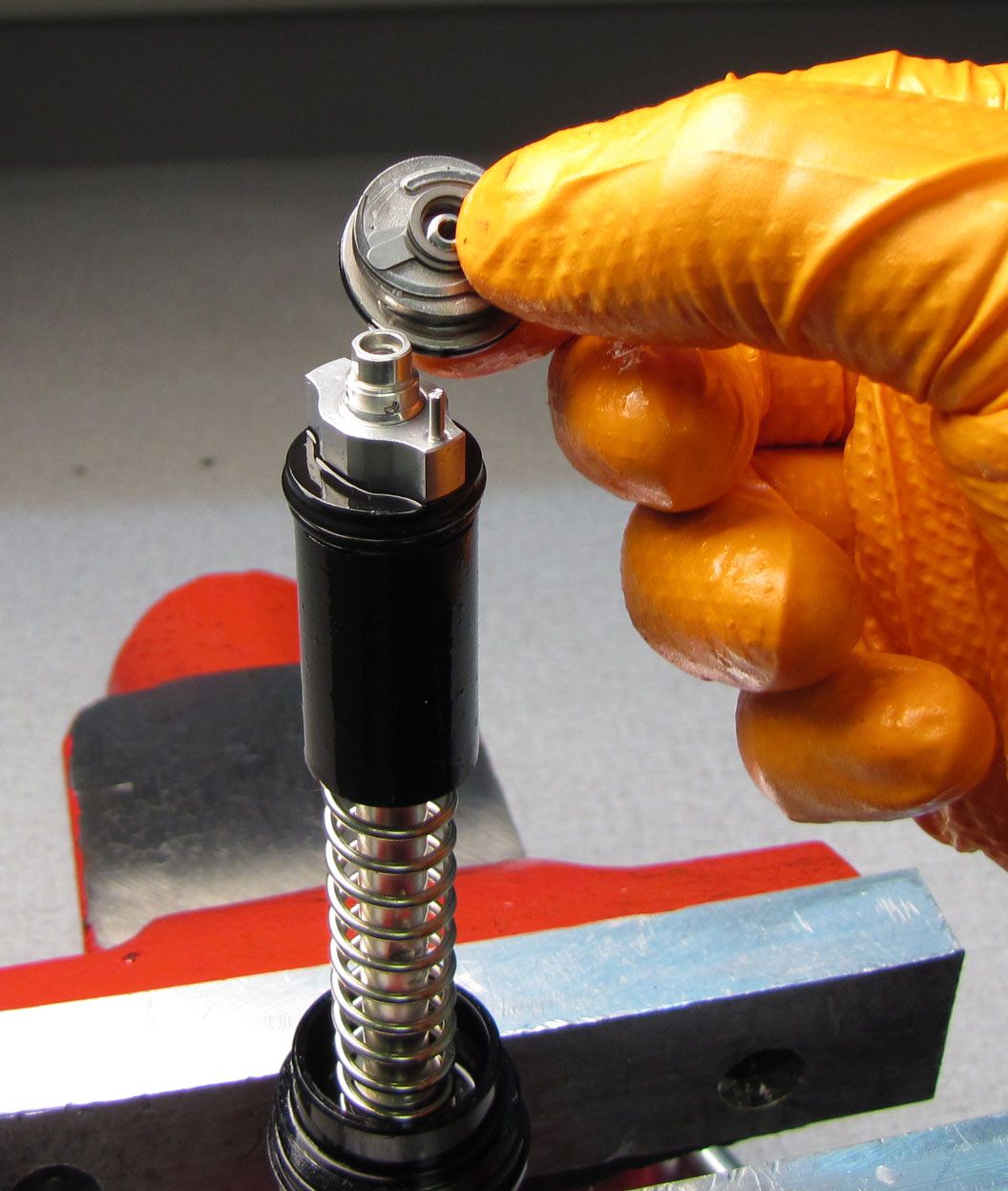
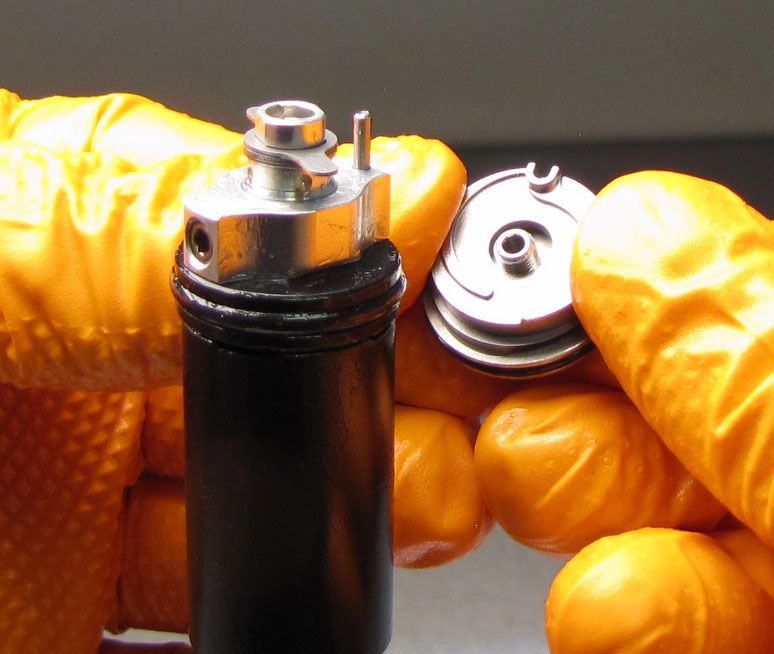
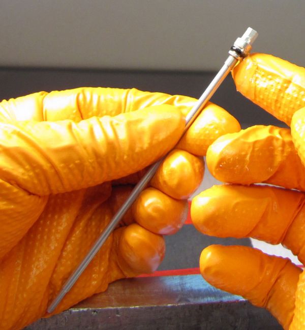
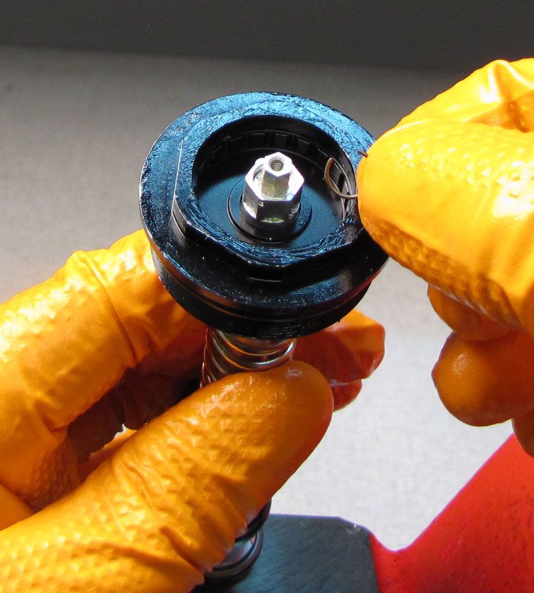
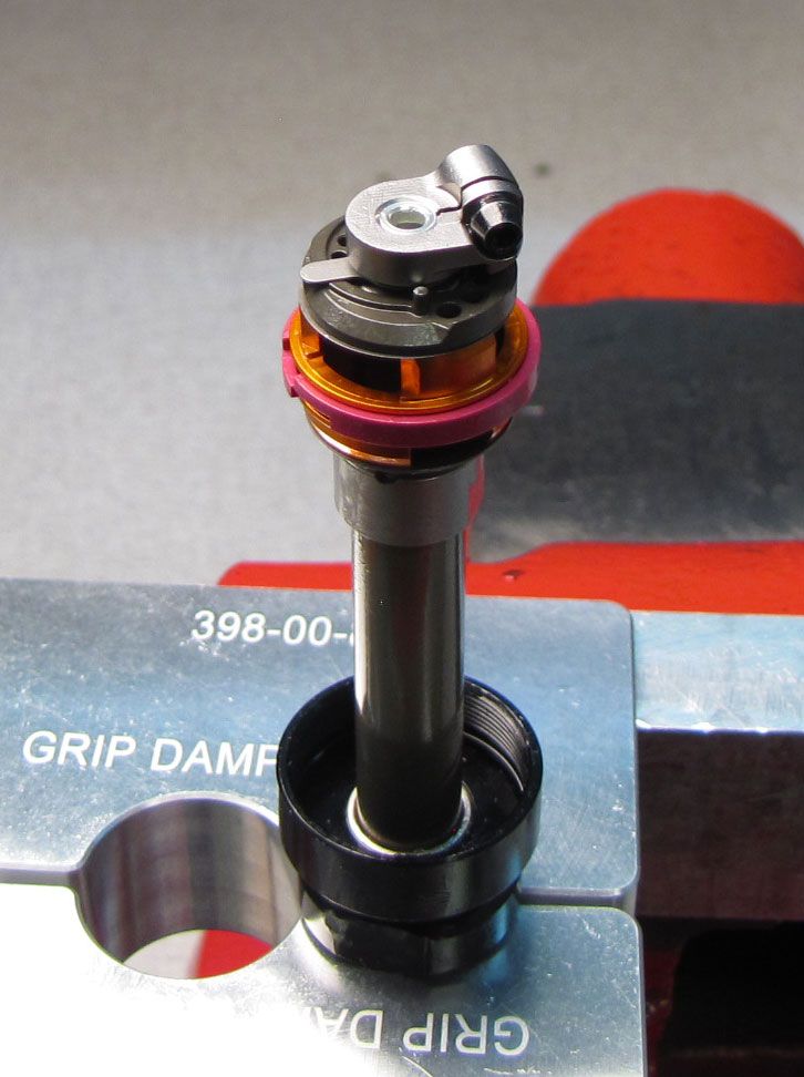
Step 12
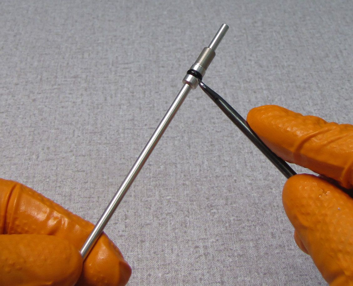
Replace all o-rings within the Topcap assembly with new greased ones from the kit. Separate the IFP from the Spring Isolator to access the IFP o-rings for replacement.


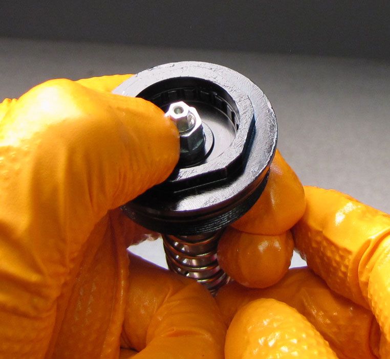
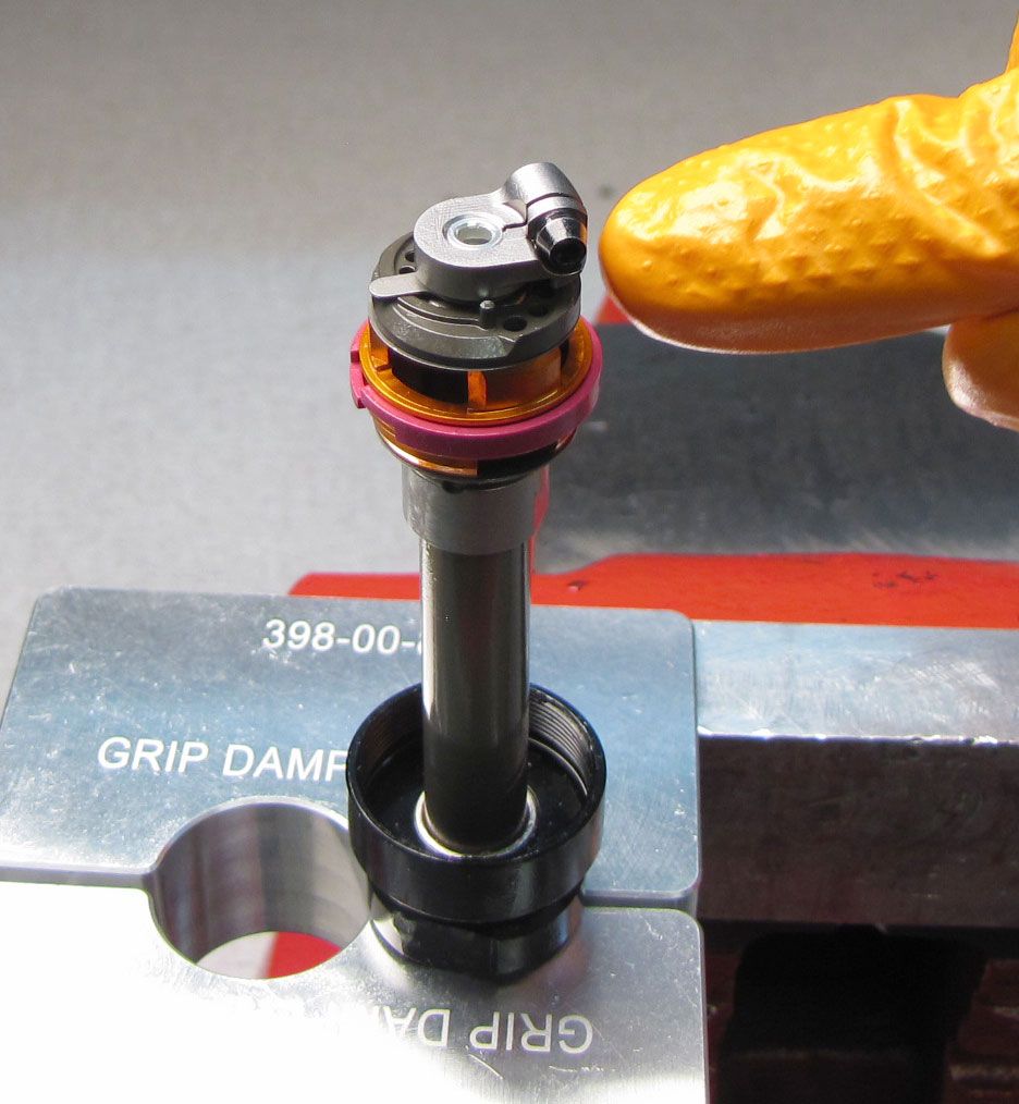
Step 13
Invert the Topcap assembly and reclamp carefully in your soft-jawed vise as shown. Reinstall the IFP spring. Reinstall the IFP into the Spring Isolator then reinstall them both onto the shaft. Push down to engage the IFP with the IFP spring.


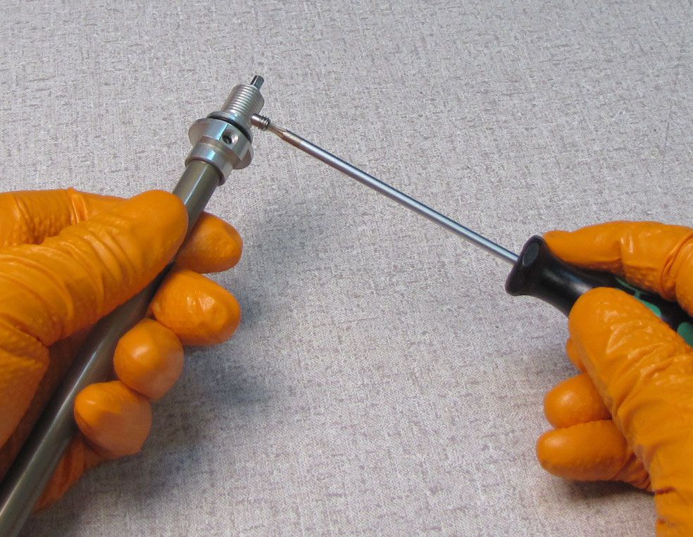
Step 14
Reinstall the Valve Loader onto the shaft. Apply blue Loctite 243 to the set screw threads. Align the screw with the hole in the shaft then tighten clockwise to 2.5 in-lb (0.3 Nm) torque with your 2mm hex wrench.

Step 15
Reinstall the Compression Valving. Install the 0.3mm thick valves onto the shaft first, then make sure that the ramped surface of the HSC Plate is facing down toward the Leaf Springs.

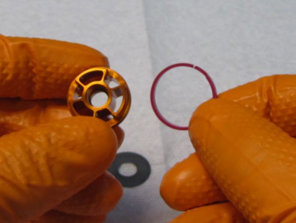
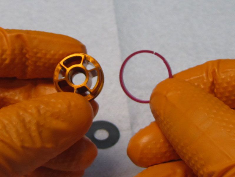
Step 16
Reinstall the rest of the Compression Valving followed by the Compression Piston, Check Valve, Check Spring, and Piston Bolt. Tighten the Piston Bolt clockwise to 17 in-lb (1.9 Nm) torque with your 3mm hex wrench. Take care not to pinch any valves, then test for check valve lift after assembly.


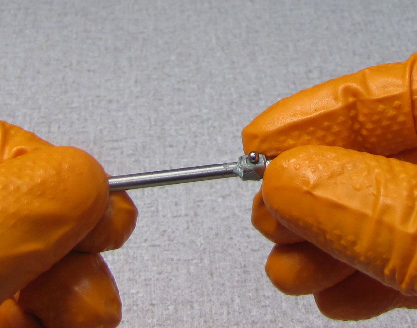
Step 17
Coat the LSC Coupler o-ring with a thin film of Slick Honey. Reinstall the LSC Needle with LSC coupler by threading it clockwise into the shaft.


Step 18
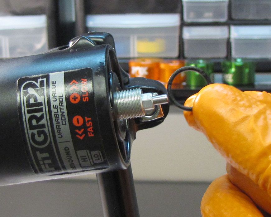
Reinstall the wire retaining ring then verify proper installation by pulling on the LSC Coupler.


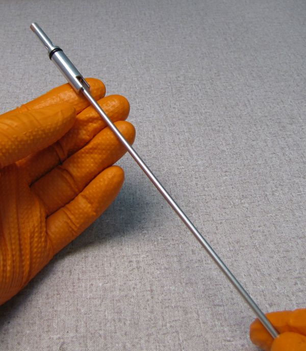
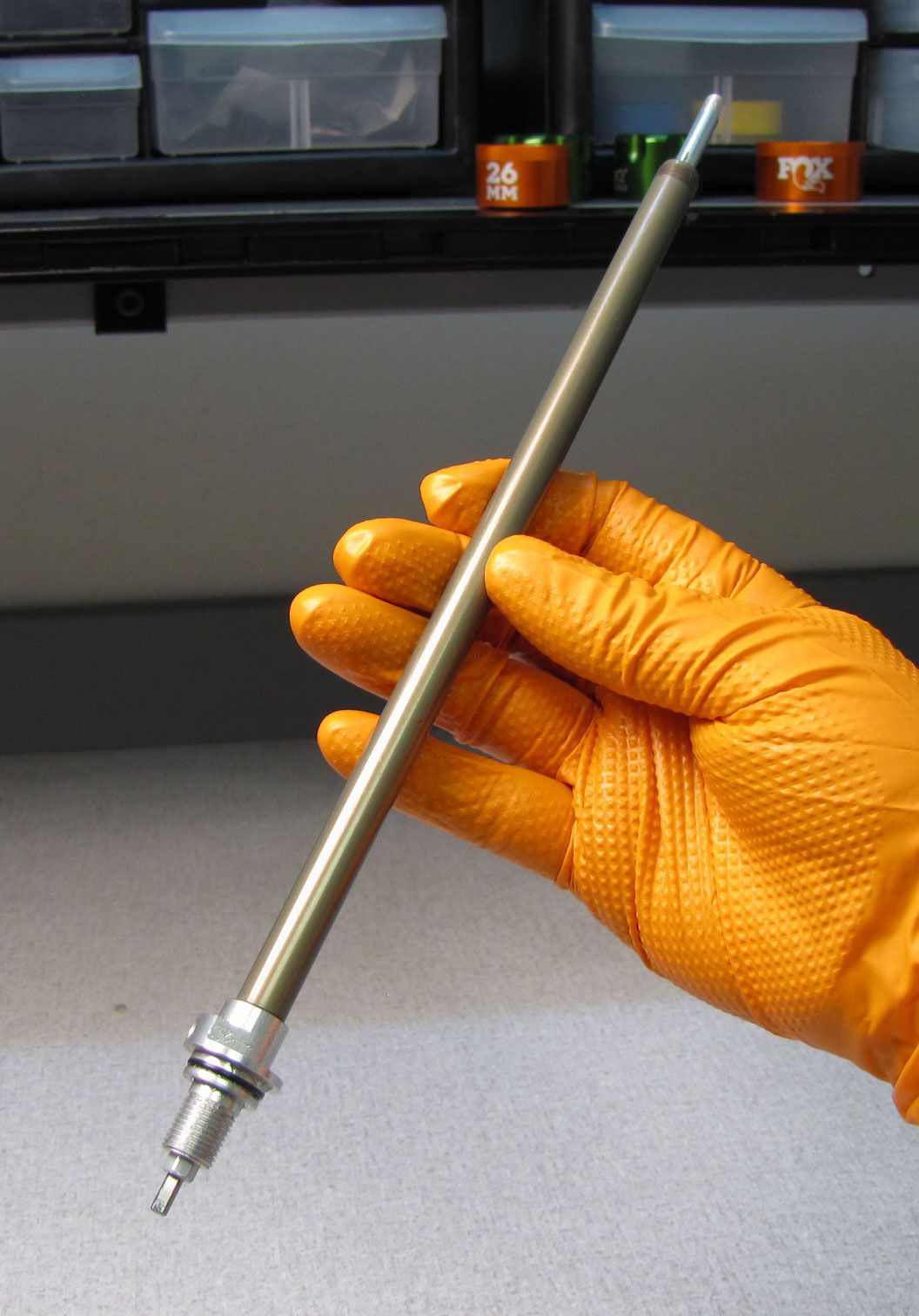
Step 19
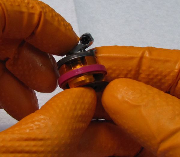
Clean the Damper Shaft Assembly with Isopropyl alcohol and a lint-free paper towel then clamp in your shaft clamps with the Rebound Piston Assembly at the top. Unthread the screw in the HSR nut counter-clockwise with a 2mm hex wrench. Unthread the Rebound Piston Assembly by turning it counter-clockwise with a 15mm cone wrench.


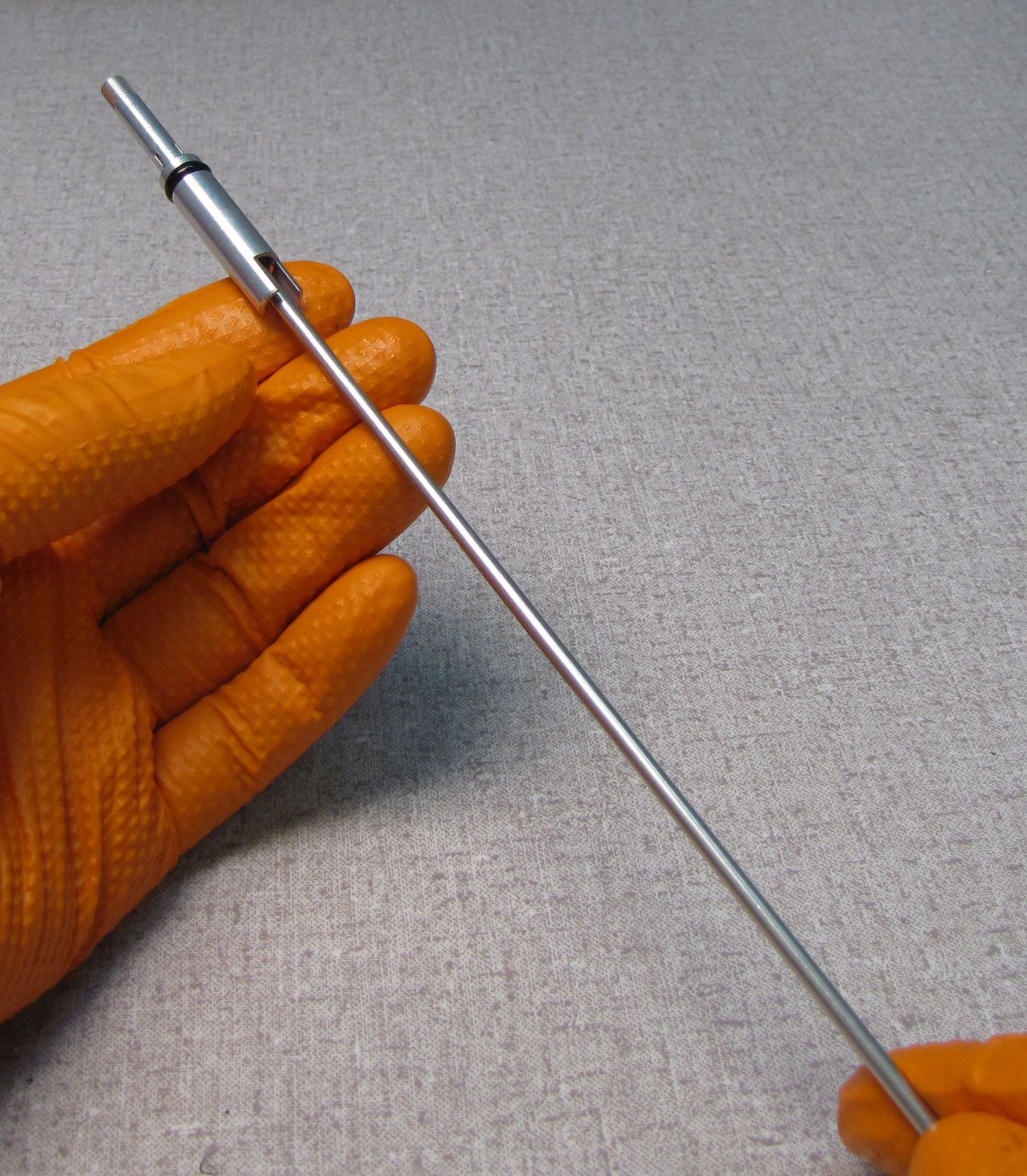
Step 20
Heat the Piston Stud with a propane torch for 3-5 seconds to break down the red Loctite. Unthread the Piston Stud counter-clockwise with a 12mm wrench. Be careful as the Piston Stud may be hot.


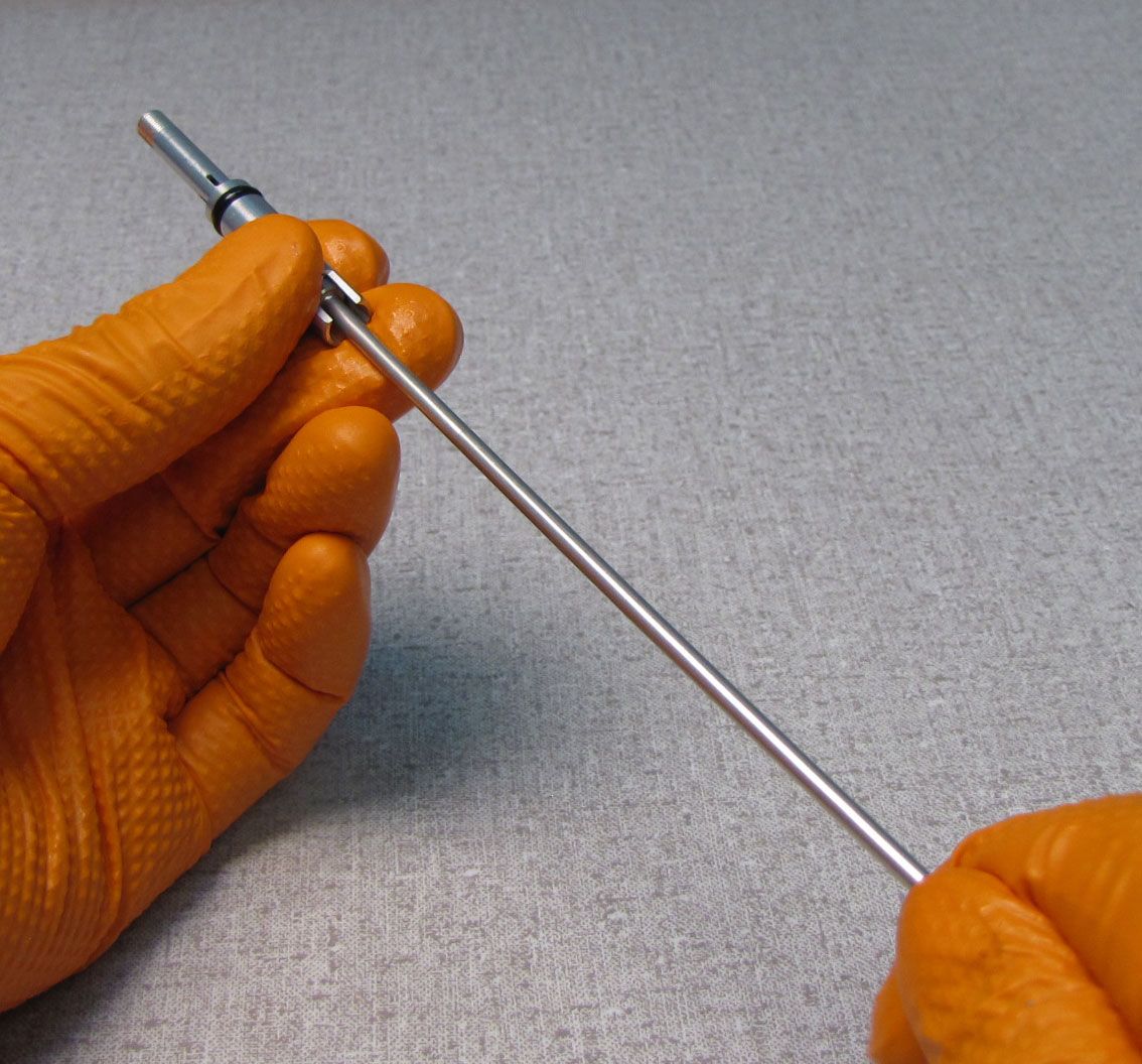
Step 21
Lift out the HSR Adjuster with LSC Needle.

Step 22
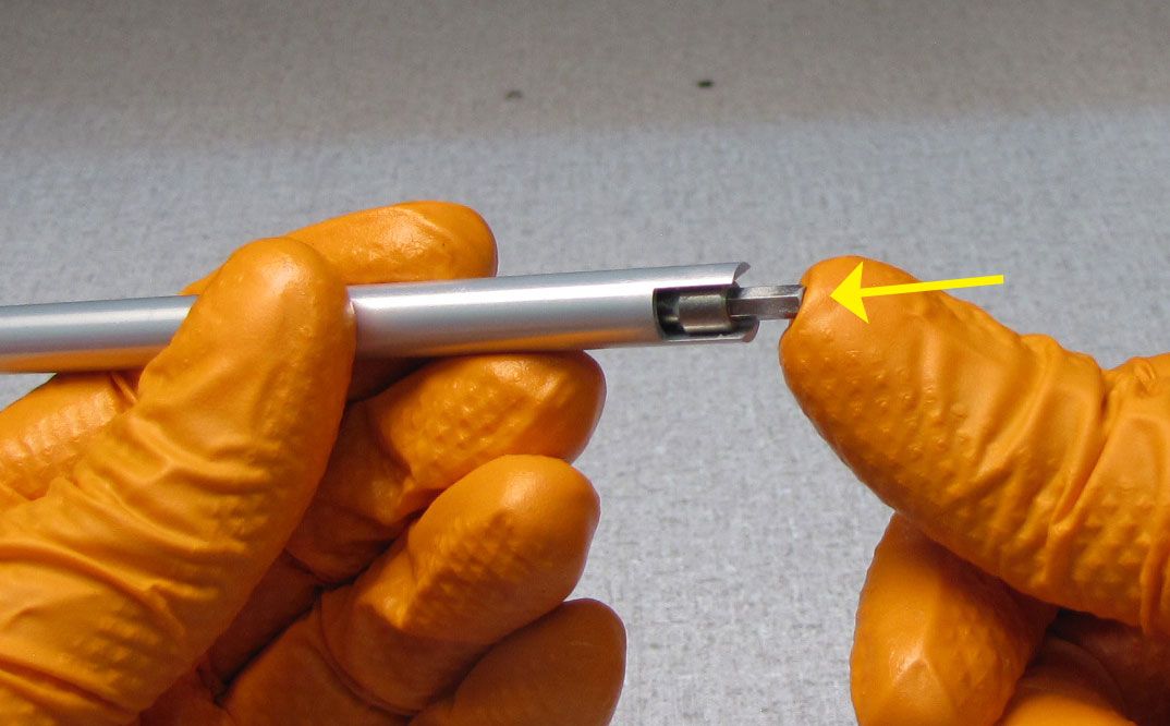
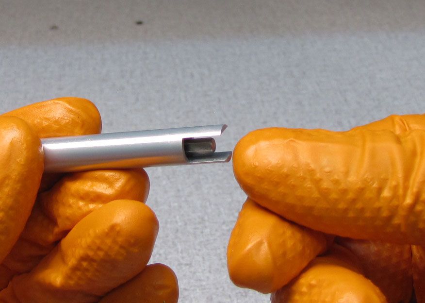
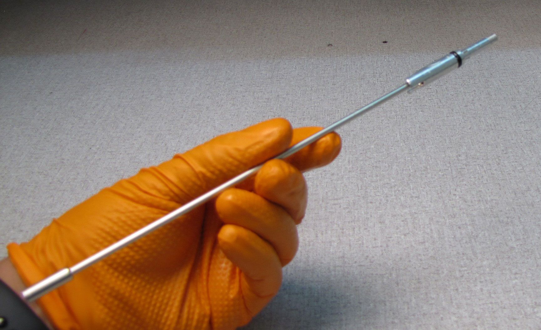
Remove the Sealhead assembly from the shaft.


Step 23
Unthread the set screw in the Base Stud counter-clockwise, then remove the detent ball and spring with a magnet. Remove the HSR Shaft.


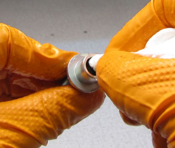
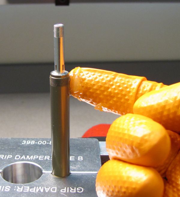
Step 24
Clean the shaft with Isopropyl alcohol and a lint-free paper towel then clamp in your shaft clamps with the Base Stud at the top. Carefully apply heat to the Base Stud with a propane torch to break down the Loctite. Unthread the Base Stud with a 1/2" wrench. Be careful as the Base Stud may be hot.
Step 25
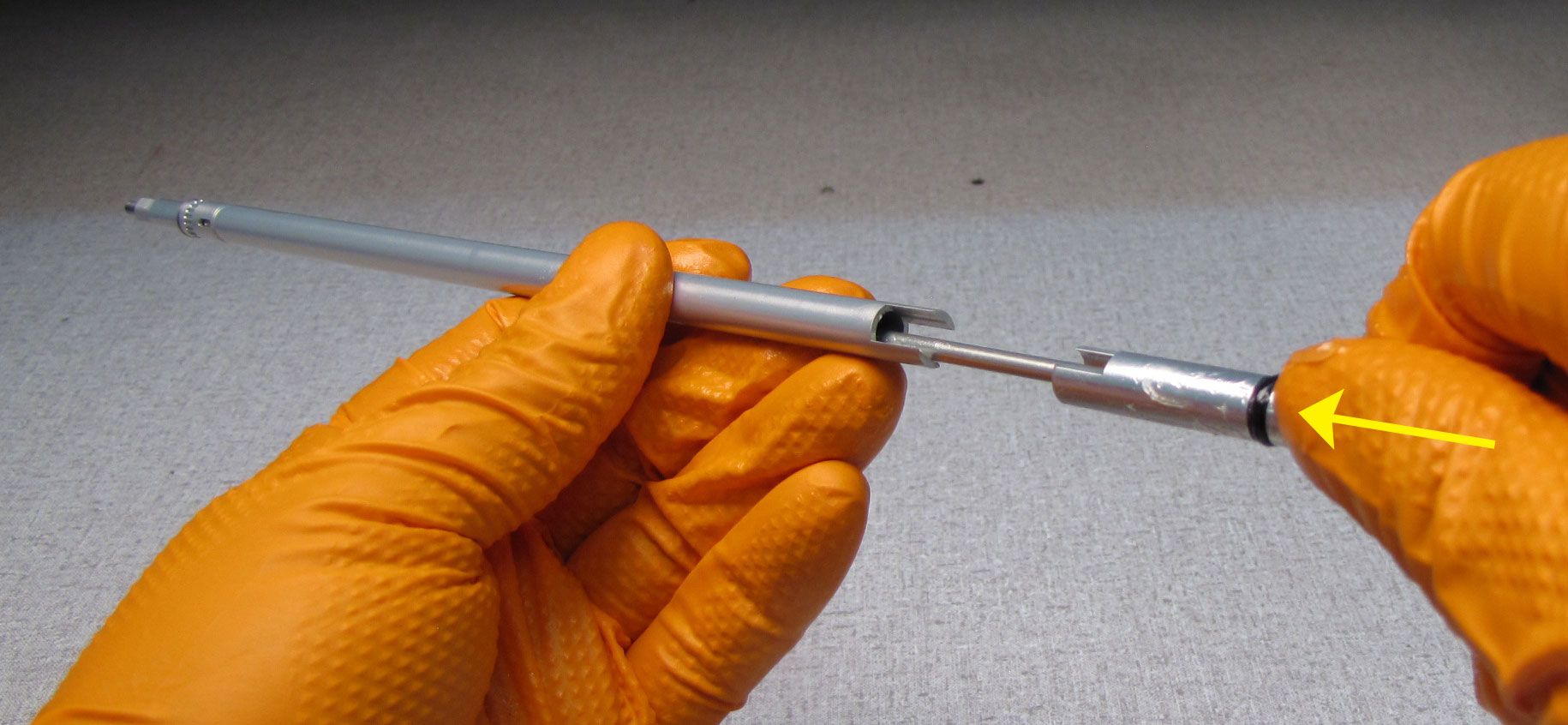
Use a long thin tool (1.5mm hex wrench shown) to push the LSR Coupler out of the HSR Shaft. Take care not to lose the detent ball and spring.

Step 26
Unthread the HSR Adjuster counter-clockwise from the LSR Needle.


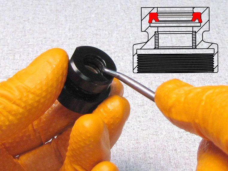
Step 27
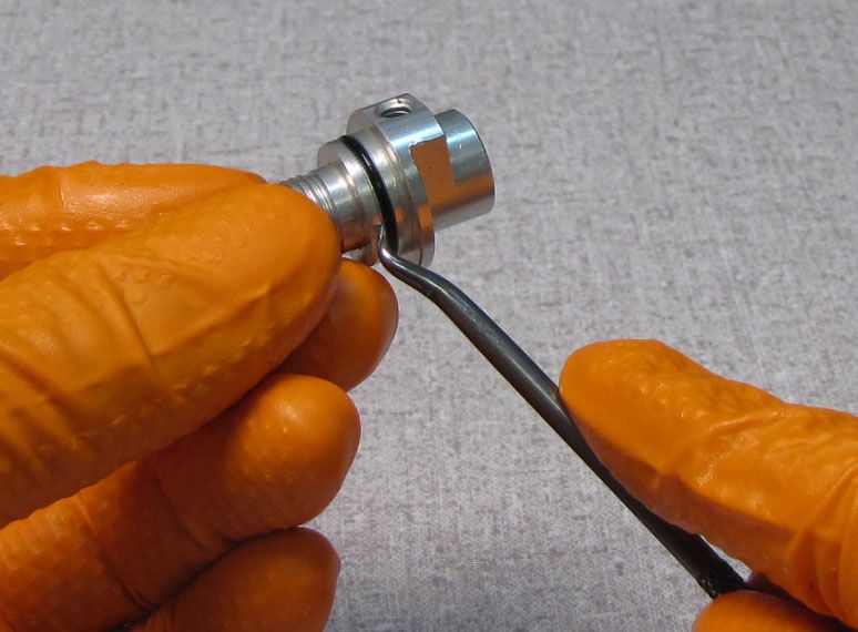
Replace all o-rings and seals on all Damper Shaft components with new greased ones from the kit as shown.
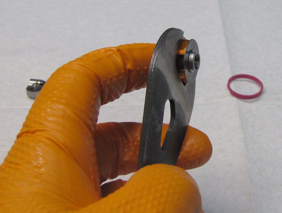
Step 28
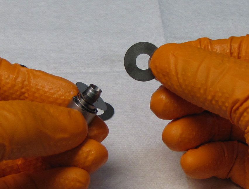
Hold the Rebound Piston with a 15mm cone wrench while you unthread the Valve Stud counter-clockwise with a 7mm wrench. Clean the Rebound Piston Assembly components with Isopropyl alcohol and a lint-free paper towel.


Step 29
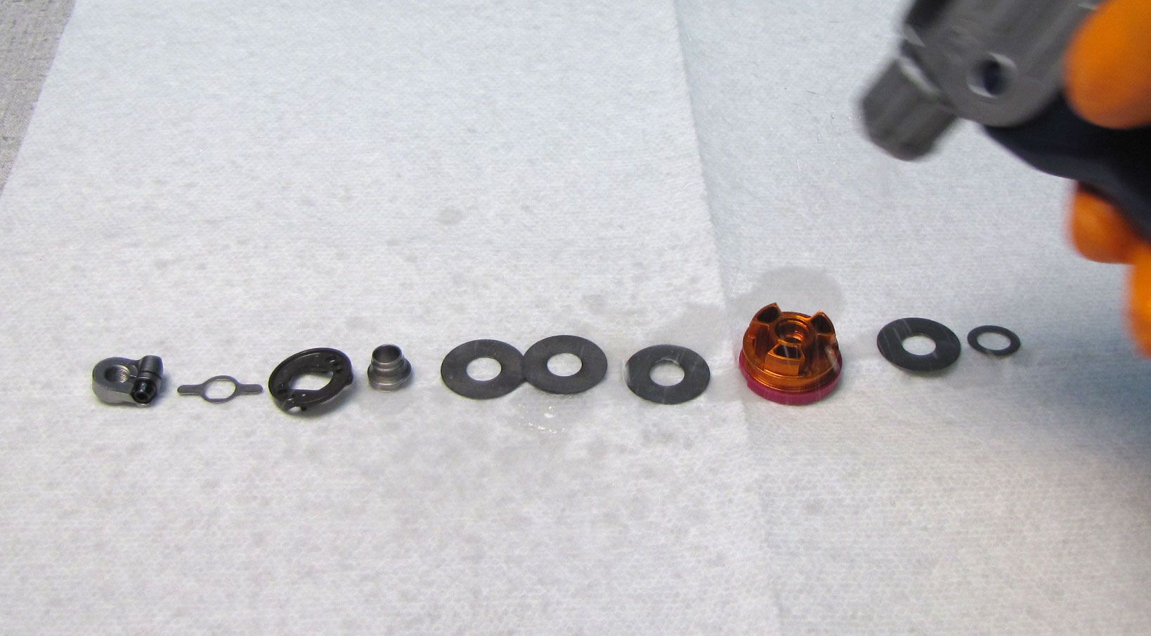
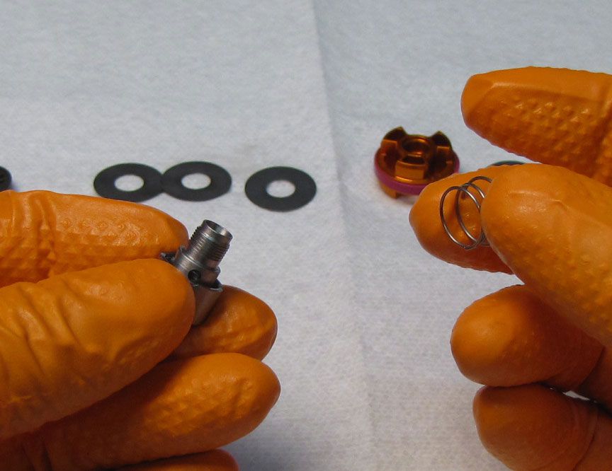
Replace the pink Glide Ring with a new greased one from the kit. Reassemble the Rebound Valving Assembly keeping parts in order according to the drawings. Tighten the assembly to 30 in-lb (3.4 Nm) torque with 12mm and 7mm wrenches. Take care not to pinch any valves while tightening the assembly.

Step 30
Reinstall the detent spring and ball into the hole in the LSR coupler. Use grease to help retain the parts during installation.


Step 31
Reinstall the LSR coupler with detent parts into the open end of the HSR shaft taking care to capture the detent parts within the shaft as shown. Use a blunt tool to push the LSR coupler into the shaft until the non-hex end is sticking out of the adjuster end of the HSR shaft.
Step 32
Insert the smaller end of the LSR needle into the HSR adjuster. Insert the end of the LSR needle with female hex feature into the open end of the HSR shaft. Engage the HSR adjuster with the HSR shaft.


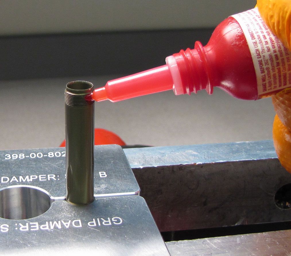
Step 33
Clean any Loctite residue out of the internal threads of the Base Stud. Clamp the shaft in your shaft clamps, then apply 1-2 drops of Red Loctite 263 to the shaft threads. Take care not to get Loctite on the o-ring within the Base Stud.

Step 34
Reinstall the Base Stud tightening clockwise to 40 in-lb (4.5 Nm) torque with a 1/2" crows foot.

Step 35
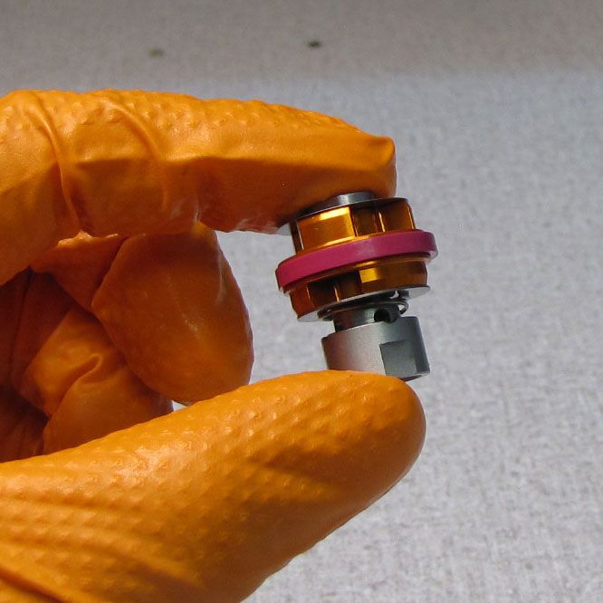
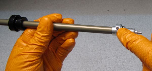
Insert the prepared HSR shaft assembly into the Damper Shaft as shown.

Step 36
Coat the shaft threads with a thin film of Slick Honey. Install the rebuilt Sealhead assembly onto the shaft as shown. Remove any Slick Honey from the shaft threads with Isopropyl alcohol and a lint-free paper towel.


Step 37
Apply 1-2 drops of Red Loctite 263 to the shaft threads. Reinstall the Rebound Piston Assembly onto the shaft tightening clockwise to 40 in-lb (4.5 Nm) torque with a 12mm crows foot.


Step 38
Reinstall the HSR Plate with its ramps and pins facing up. Reinstall the Leaf Spring onto the HSR Nut then reinstall the HSR Nut onto the HSR Adjuster without tightening down the nut fully or tightening the fixing screw.


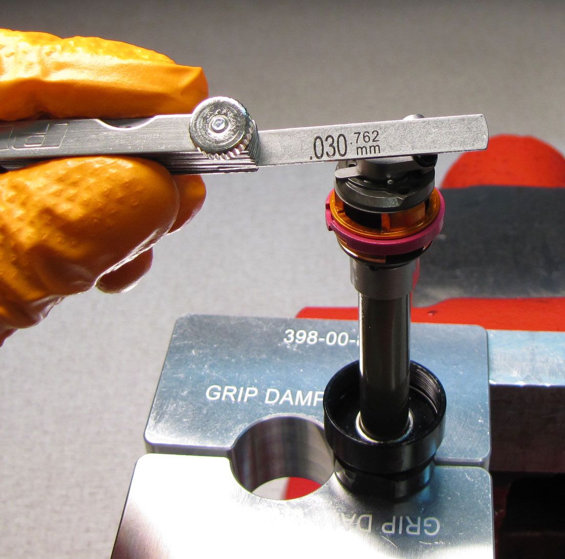
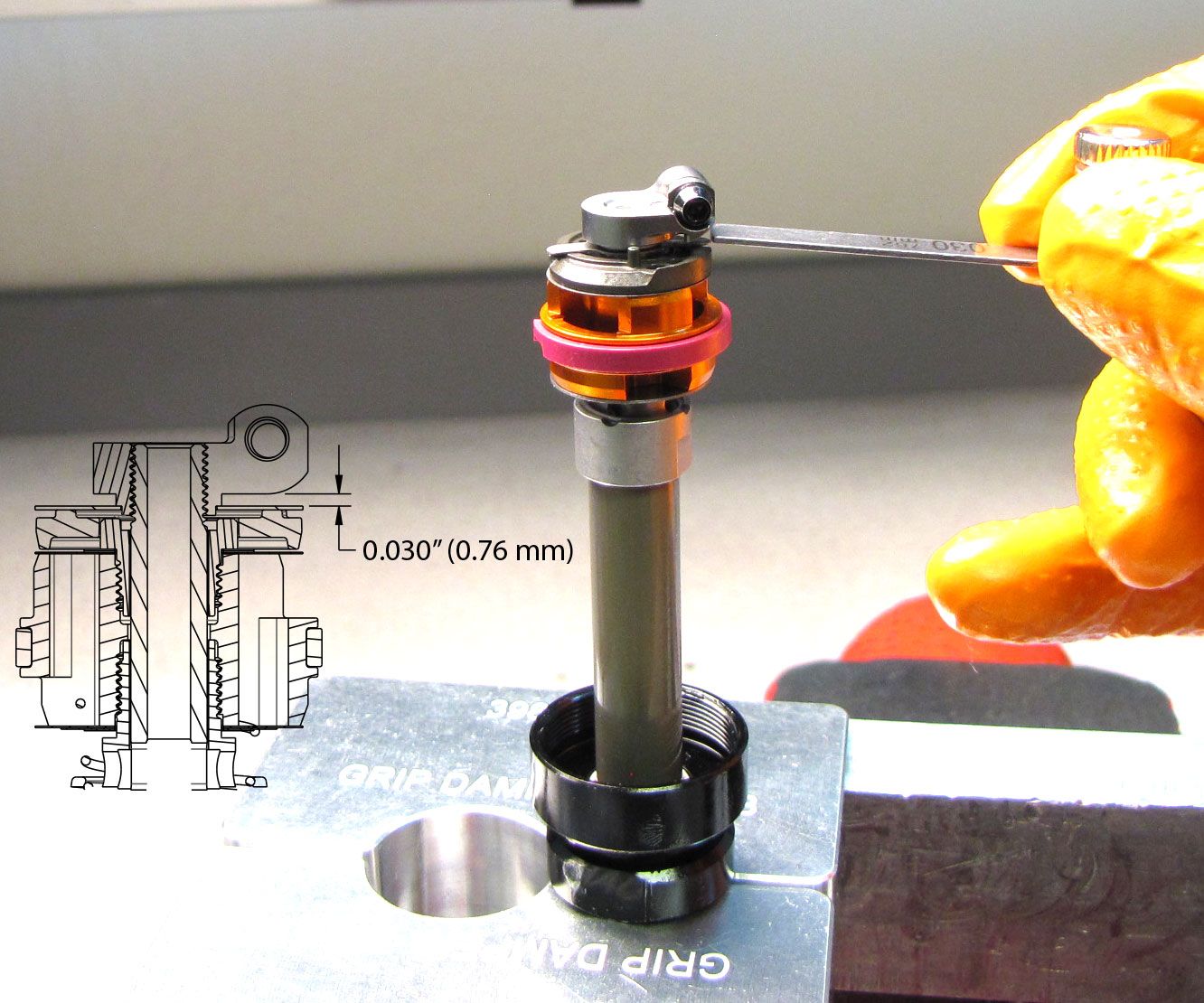
Step 39
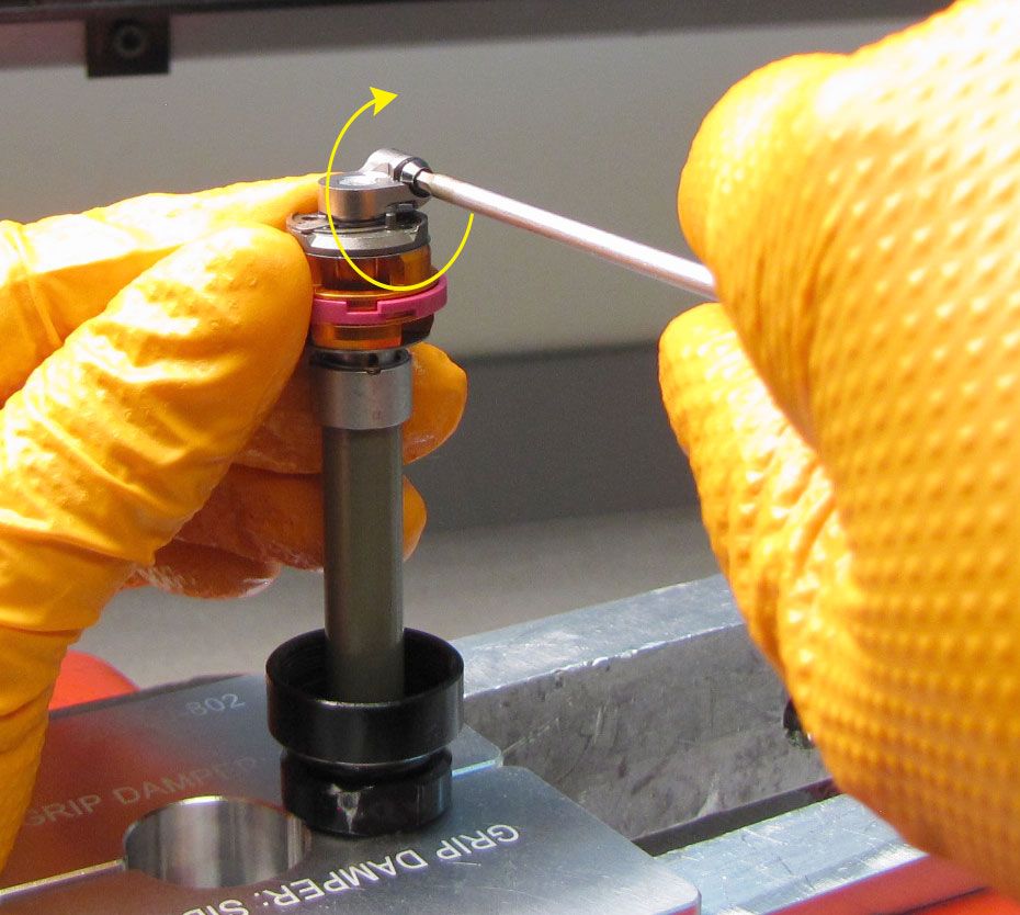
Position the Leaf Spring in the approximate middle of it's adjustment range. Insert a 0.030" (0.76 mm) thick shim into the space between the HSR Nut and the Leaf Spring. Hold the HSR Nut against the Piston Assembly then tighten clockwise to 2 in-lb (0.23 Nm) torque with your 10mm wrench. Rotate the HSR Shaft counter-clockwise 4 clicks (approximately 72 degrees of rotation). Tighten the HSR Nut screw clockwise to 8 in-lb (0.9 Nm) torque with a 2mm hex wrench.
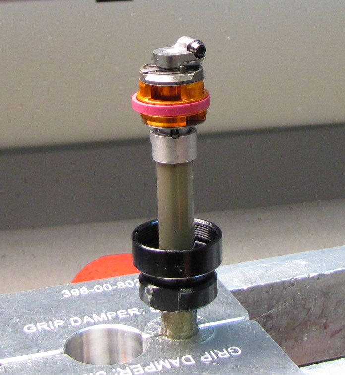
Step 40
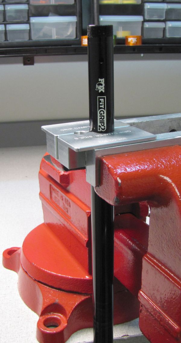
Reinstall the detent ball and spring into the Base Stud. Tighten the set screw clockwise with a 2mm hex wrench until it is flush with the Base Stud.


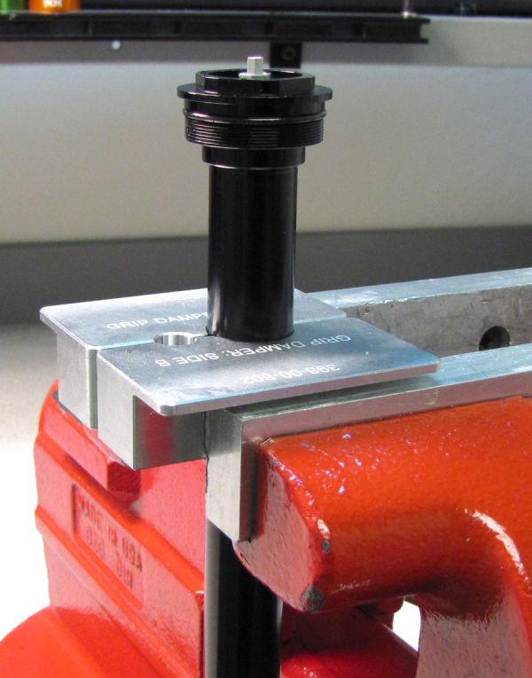
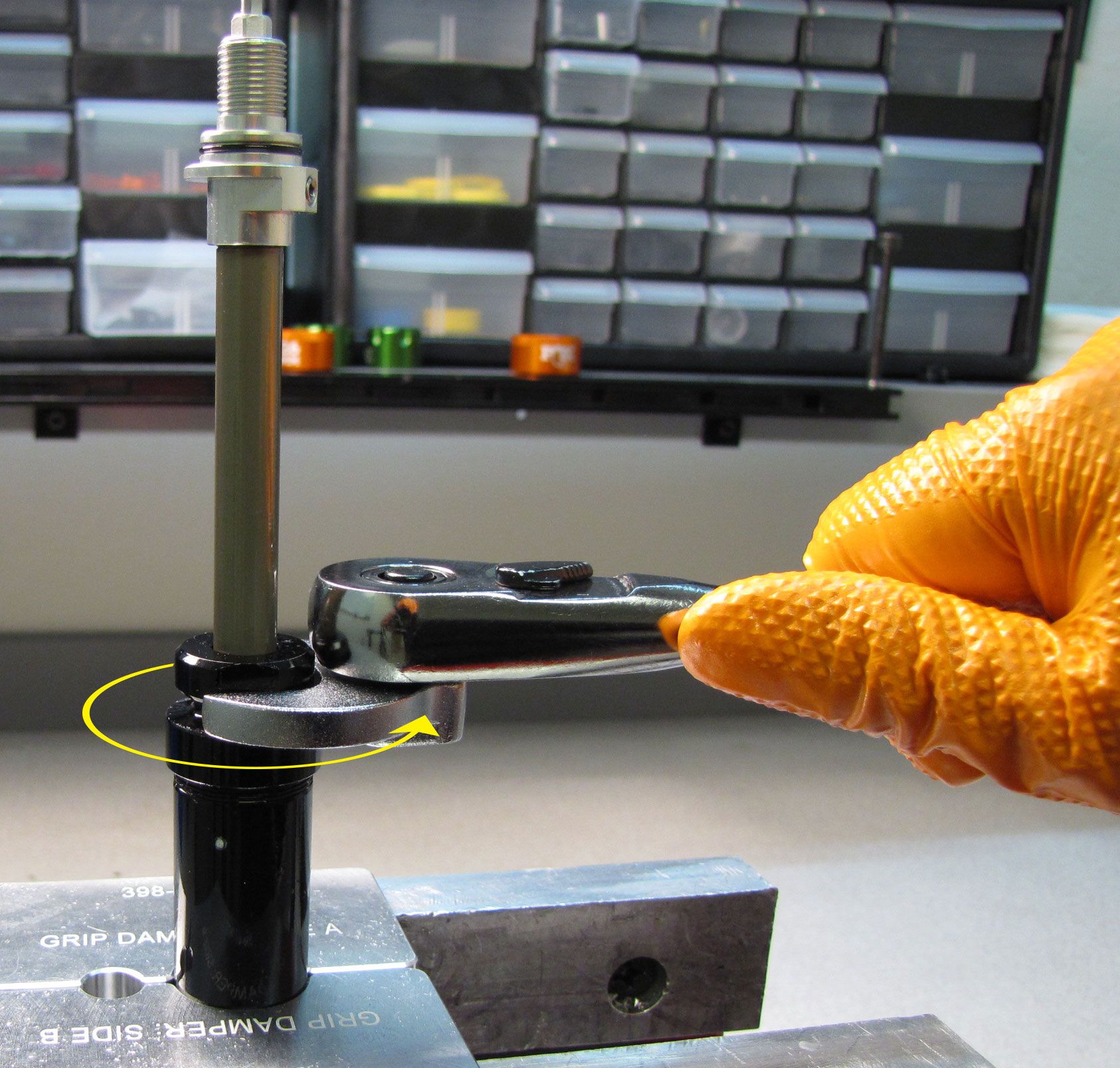
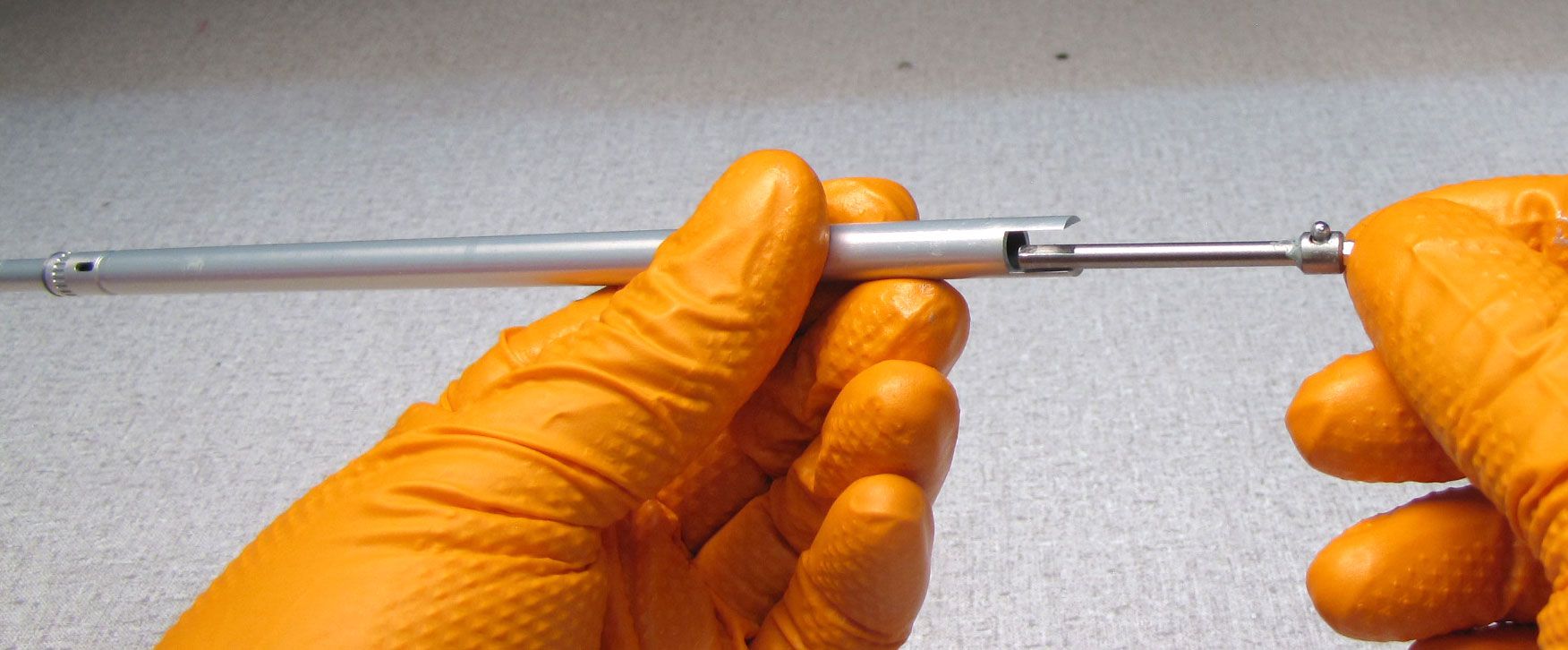
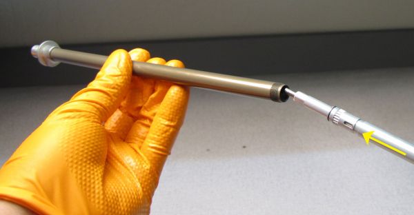
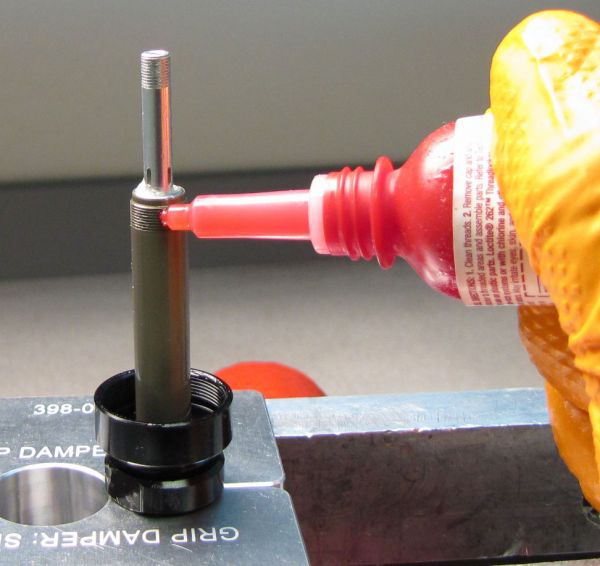
Step 41
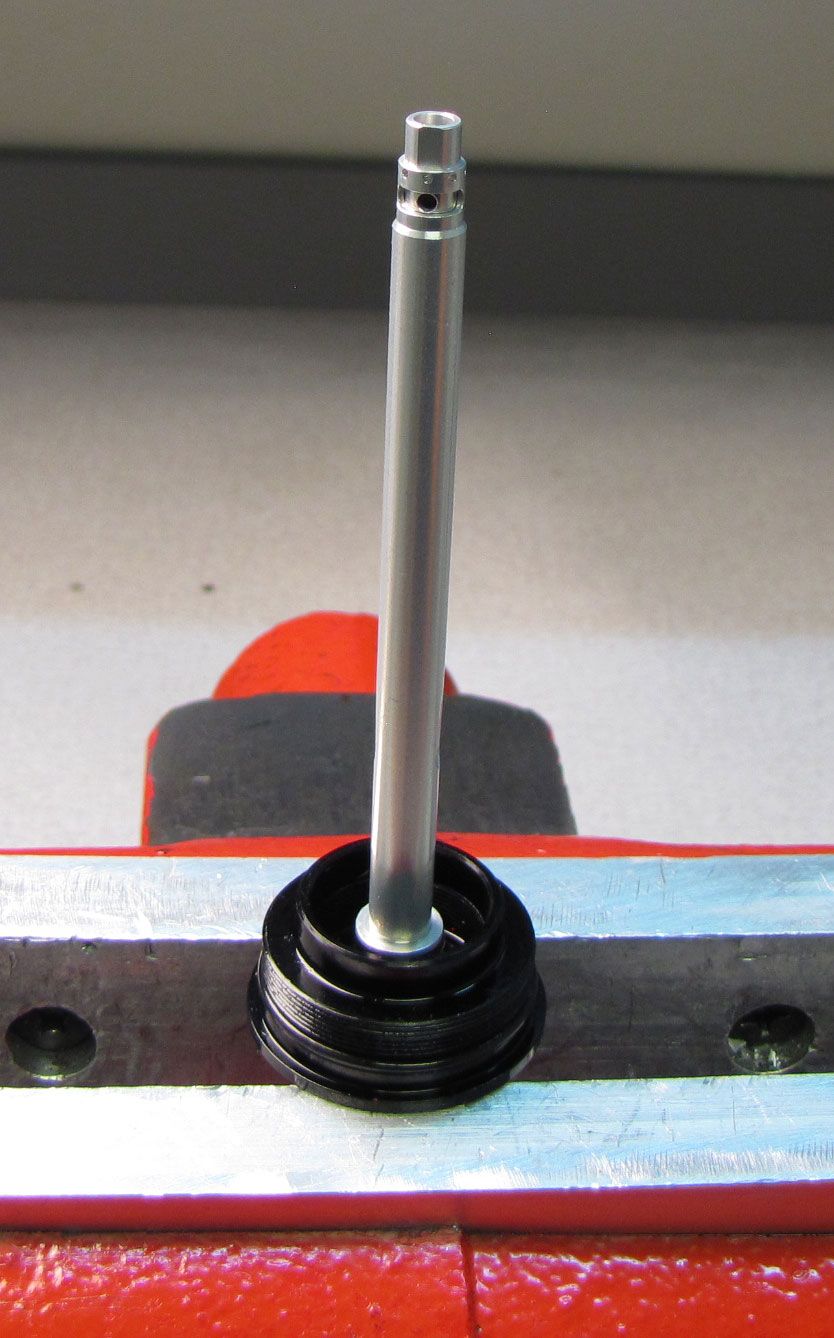
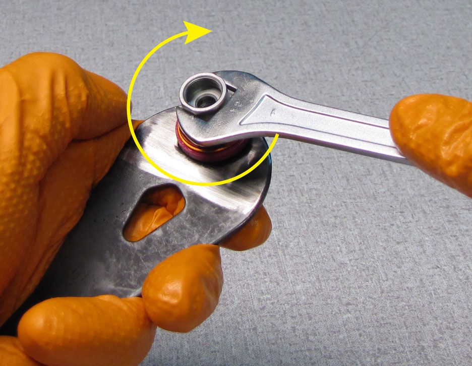
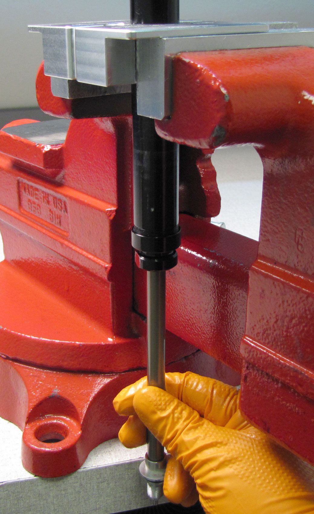
Clamp the Pressure Tube in your shaft clamps with the GRIP2 laser etched end facing down. Apply 1-2 drops of blue Loctite 243 to the threads of the Pressure Tube. Take care not to get Loctite on the o-ring within the Sealhead Assembly. Reinstall the Damper Shaft Assembly tightening the Sealhead clockwise to 150 in-lb (16.9 Nm) torque with a 20mm crows foot.


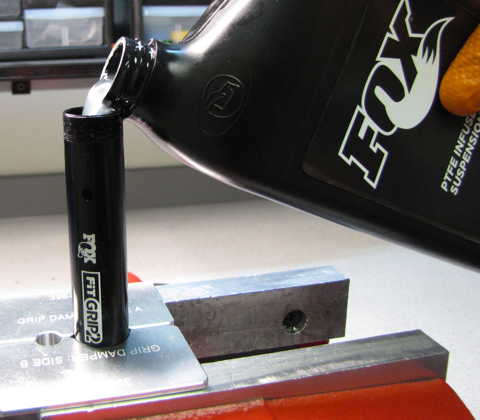
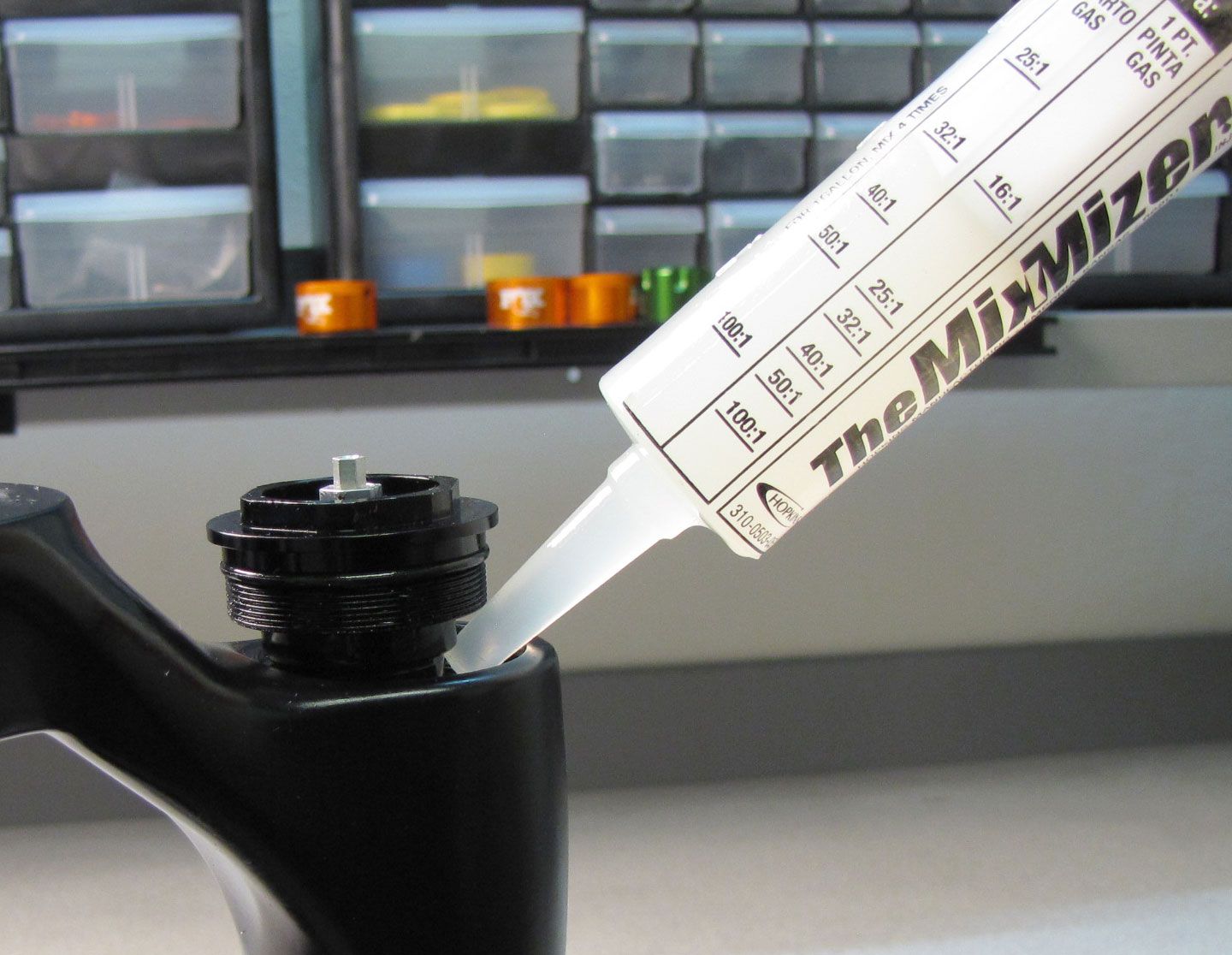
Step 42
Invert the Pressure Tube then reclamp with the open end up. Fill the Pressure Tube approximately 1/2 way with FOX 5wt. Teflon infused oil. Stroke the Damper Shaft ~5 times then fully extend the Damper Shaft. Fill the Pressure Tube with FOX 5wt. Teflon infused oil up to the level of the bleed holes.


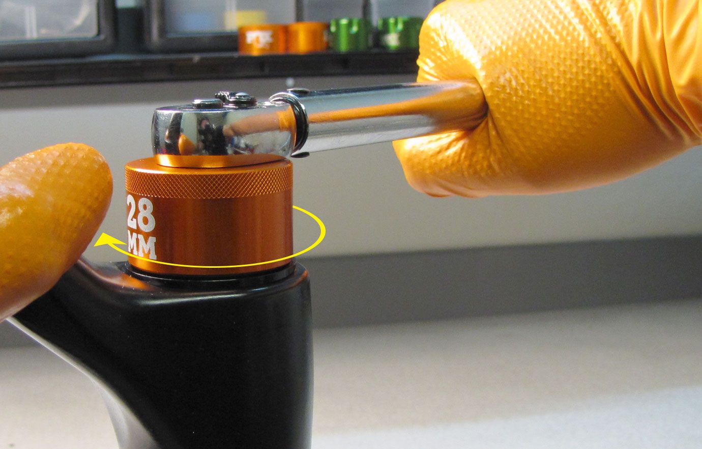
Step 43
Wrap the Pressure Tube in a lint-free paper towel to catch oil as it overflows during Topcap installation. Set the HSC and LSC to full open by turning both compression adjusters fully counter-clockwise. The Topcap Assembly must be installed directly in line with the Pressure Tube to ensure that the O-ring is not pinched. Slowly push the Topcap Assembly into the Pressure Tube. Clean off any oil from the topcap threads. Apply 1-2 drops of blue Loctite 243 to the topcap threads. Tighten the Topcap Assembly clockwise to 150 in-lb (16.9 Nm) torque with your 28mm socket.


Step 44
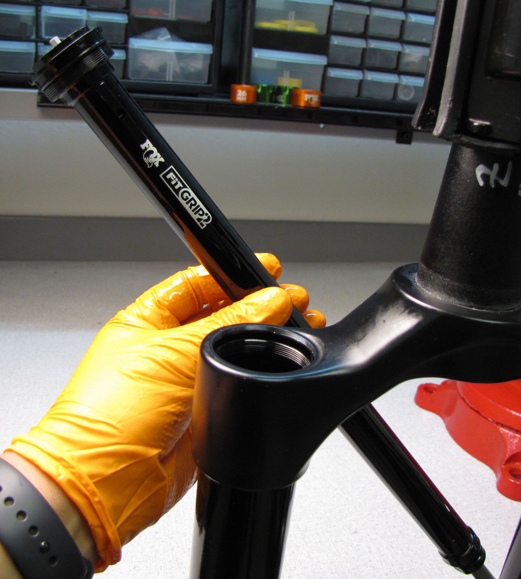
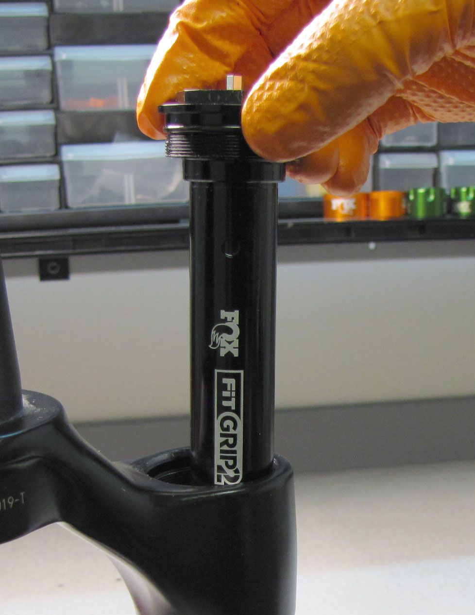
Reinstall the rebuilt damper cartridge into the Damper-Side Upper Tube. Install a new damper-side crush washer followed by the bottom nut. Make sure to align the crush washer with the bottom nut before tightening. Tighten clockwise to 80 in-lb (9.0 Nm) torque with a 15mm socket.

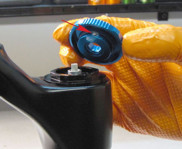
Step 45
Install the larger High-Speed Rebound (HSR) knob with its thinner rim facing toward the bottom nut. Coat the wave spring with a thin film of Slick Honey then install the smaller Low-Speed Rebound (LSR) knob with the wave spring between the two knobs. Put slight pressure on the LSR knob so that there is a bit of preload on the wave spring. Align the set screw with the flat on the LSR needle then tighten clockwise to 8 in-lb (0.9 Nm) torque with a 2mm hex wrench. Test that both knobs turn freely without binding.


Step 46
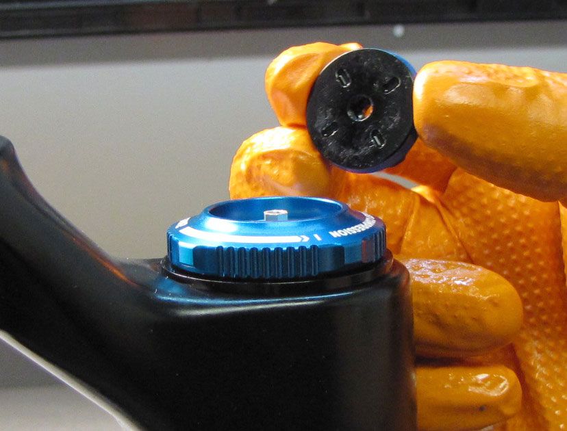
Replace the black Rebound Knob Cover.

Step 47
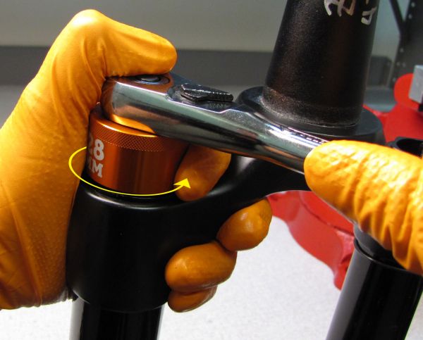
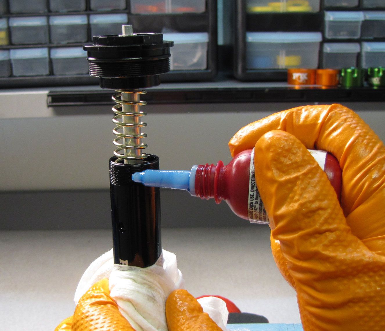
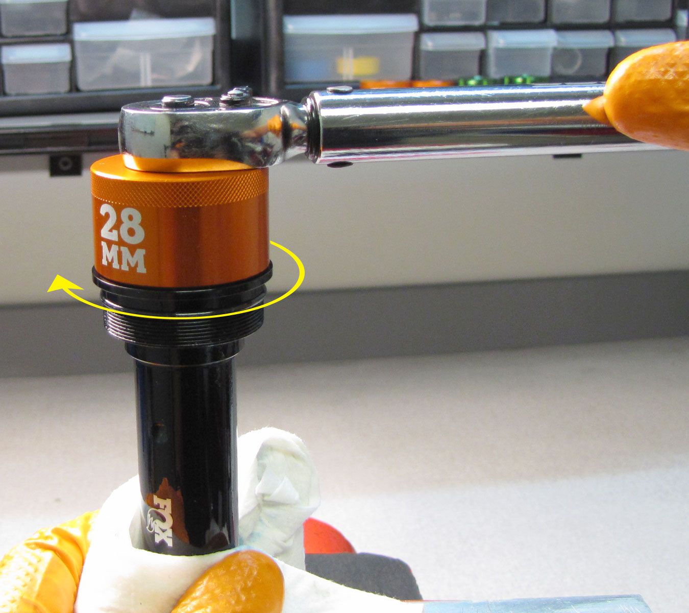
Inject 40cc of FOX 5wt. Teflon infused Oil (50cc for 40mm forks) into the Damper-Side Upper Tube. Complete reinstallation of the Topcap tightening clockwise to 220 in-lb (24.8 Nm) torque with your chamfer-less 6-point 28mm socket.
Step 48
Verify that the both detent ball and spring sets are present within the HSC knob. Reinstall the HSC knob followed by the LSC knob. Hold both knobs from turning while you tighten the screw clockwise to 4 in-lb (0.45 Nm) torque with a 2mm hex wrench. Test all functions of the fork, then clean the exterior of your fork.