2021+ FLOAT X2 Travel Adjustment
WARNING: Always wear safety glasses and protective gloves during service to prevent potential injury. Failure to wear protective equipment during service may lead to SERIOUS INJURY OR DEATH.

The following steps guide you through the process of changing travel on the 2021 FLOAT X2 shock. Make sure that the travel change being made is appropriate for the bike application before use.
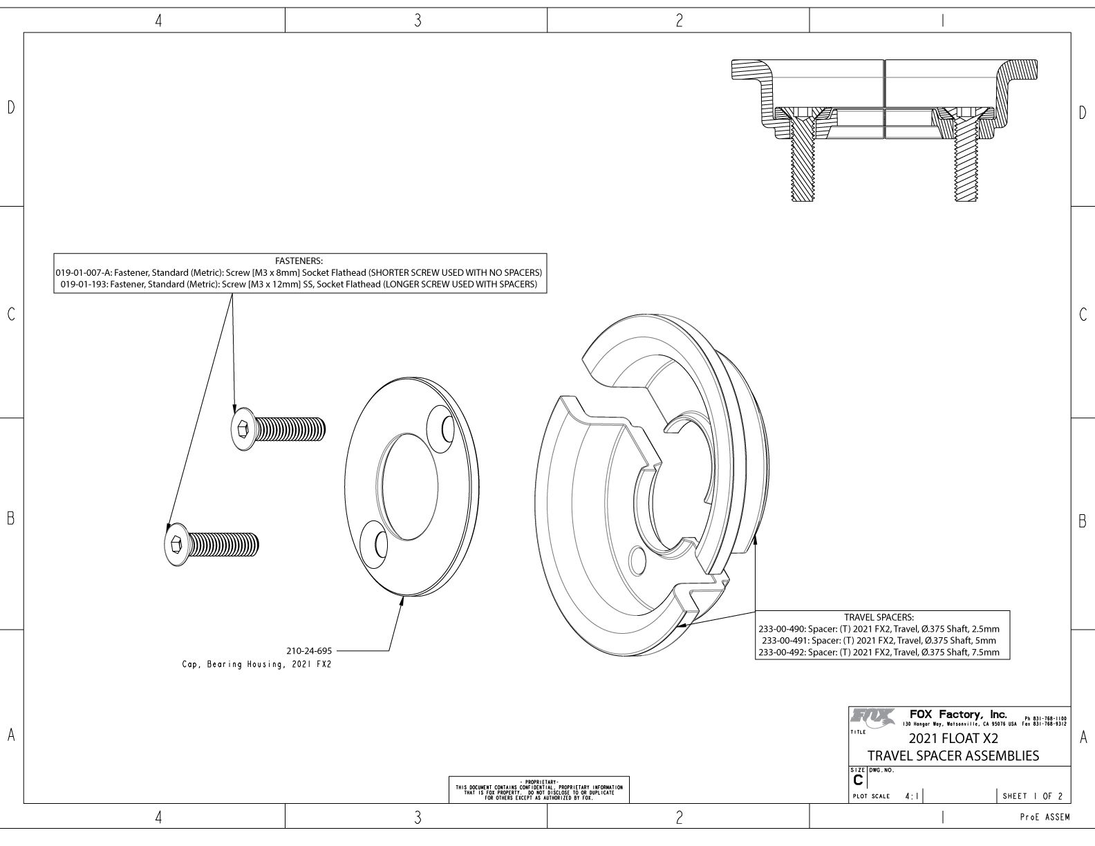
FLOAT X2 Travel Spacers are available in 2.5mm (233-00-490), 5.0mm (233-00-491), and 7.5mm (233-00-492) sizes. FLOAT X2 Travel Spacers are NOT stackable. Please order the appropriate spacers for the travel reduction desired. FLOAT X2 Travel Spacers must be used in pairs.
There are two different screws used with the 2021 FLOAT X2 Bearing Housing for different spacer configurations.
| Part Number | Description | Application |
| 019-01-007-A | Fastener, Standard (Metric): Screw [M3 x 8mm] Socket Flathead | Used with NO spacers |
| 019-01-193 | Fastener, Standard (Metric): Screw [M3 x 12mm] SS, Socket Flathead | Used WITH spacers |
WARNING: FOX products should be serviced by a trained bicycle service technician, in accordance with FOX specifications. If you have any doubt whether or not you can properly service your FOX product, then DO NOT attempt it. Improperly serviced products can fail, causing the rider to lose control resulting in SERIOUS INJURY OR DEATH.
WARNING: FOX suspension products contain pressurized nitrogen, air, oil, or all 3. Suspension misuse can cause property damage, SERIOUS INJURY OR DEATH. DO NOT puncture, incinerate or crush any portion of a FOX suspension product. DO NOT attempt to disassemble any portion of a FOX suspension product, unless expressly instructed to do so by the applicable FOX technical documentation, and then ONLY while strictly adhering to all FOX instructions and warnings in that instance.
WARNING: Modification, improper service, or use of aftermarket replacement parts with FOX forks and shocks may cause the product to malfunction, resulting in SERIOUS INJURY OR DEATH. DO NOT modify any part of a fork or shock, including the fork brace (lower leg cross brace), crown, steerer, upper and lower leg tubes, or internal parts, except as instructed herein. Any unauthorized modification may void the warranty, and may cause failure or the fork or shock, resulting in SERIOUS INJURY OR DEATH.
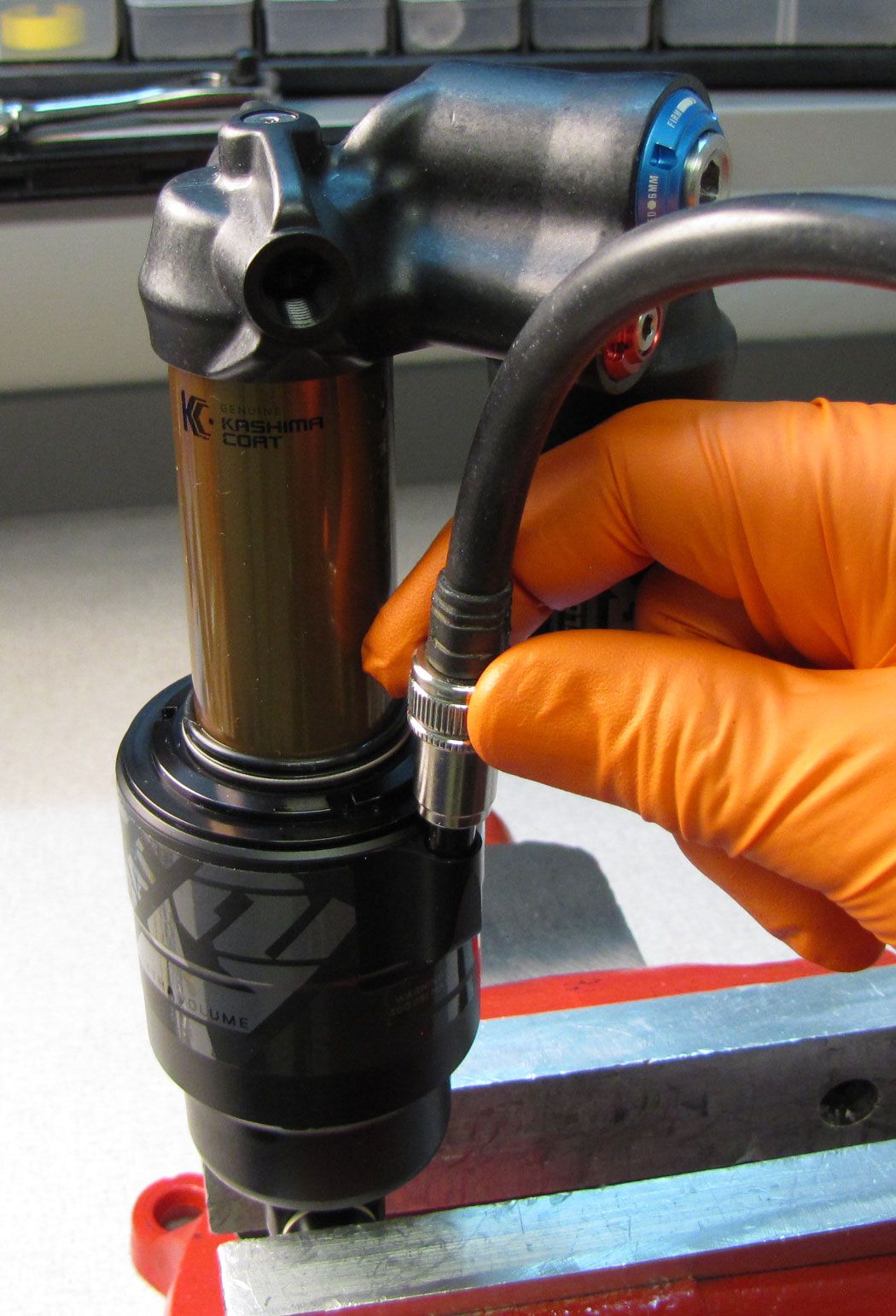
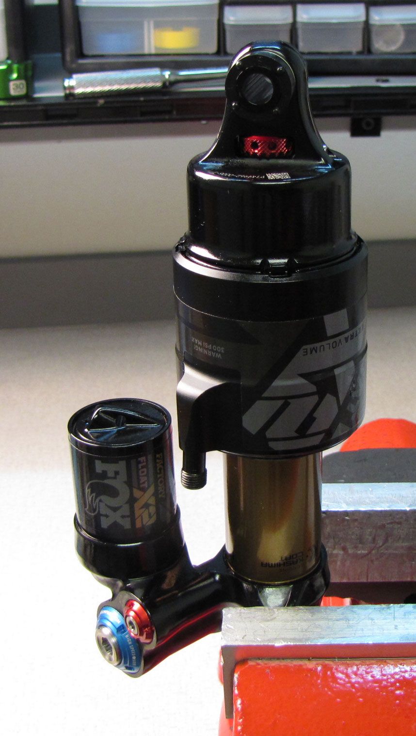
Step 1
Remove the black air cap and thread on your FOX shock pump. Slowly release all air from the main air chamber with your pump, then remove the pump. Verify that all air has been released by depressing the Schrader valve.

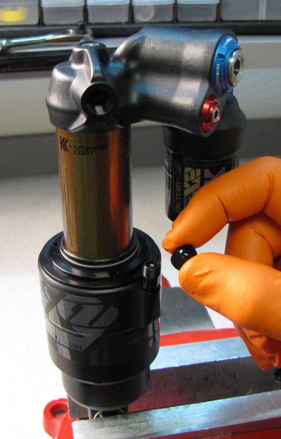
WARNING: Please verify that all air has been released from the air chamber by pushing down on the Schrader valve core. Failure to release all air pressure before further disassembly may cause parts to eject causing SEVERE INJURY OR DEATH.
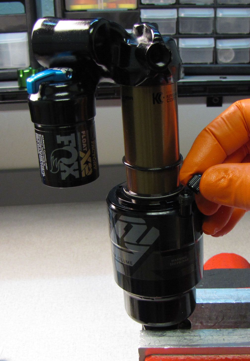
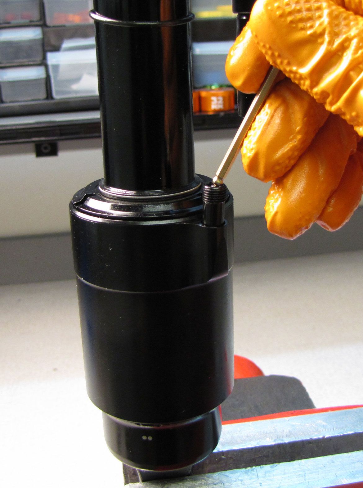
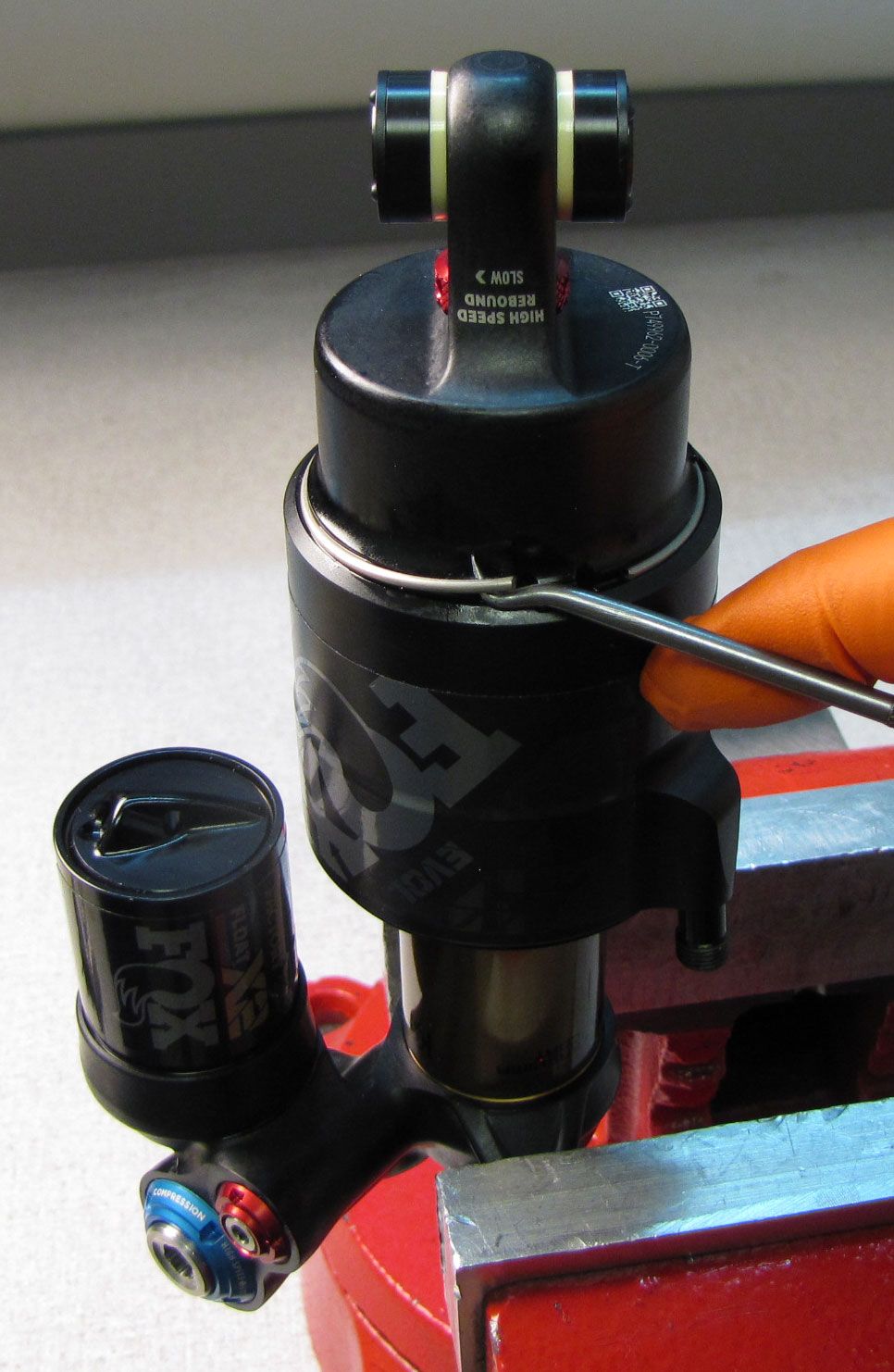
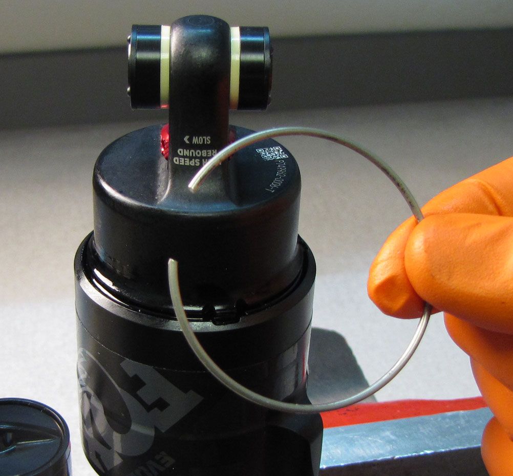
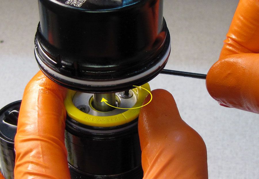
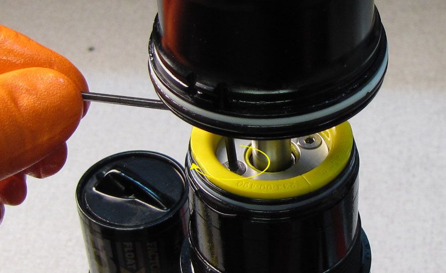
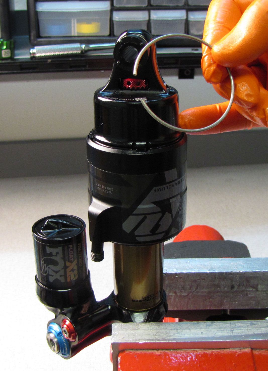
Step 2
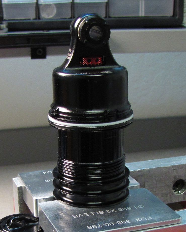
Rotate the wire retaining ring to align the opening in the ring with the tab on eyelet. Use a pick to remove the ring.

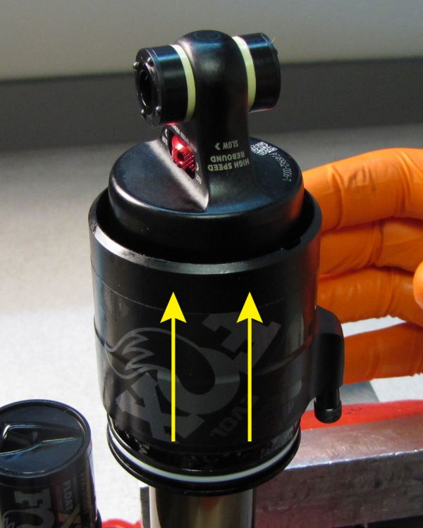
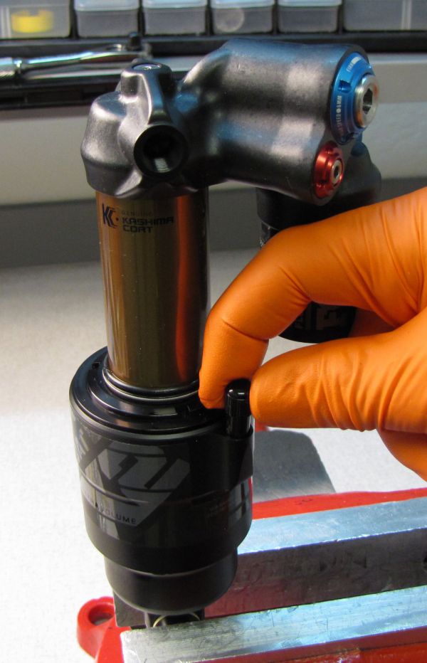
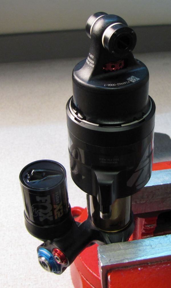
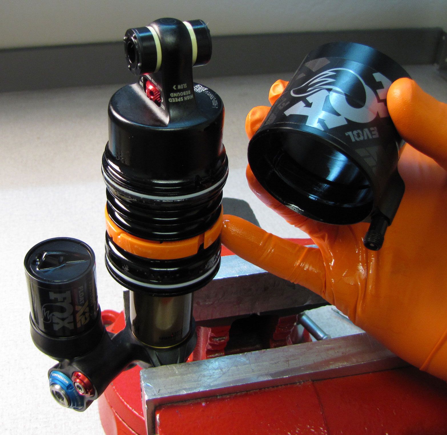
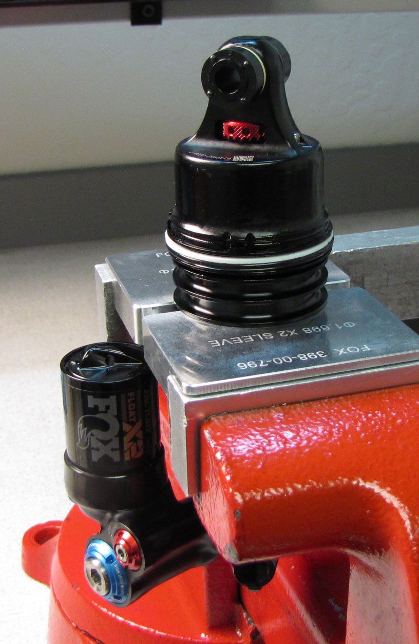
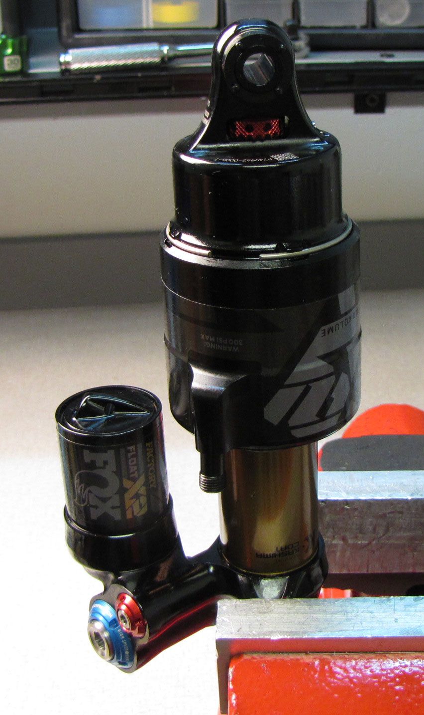
Step 3
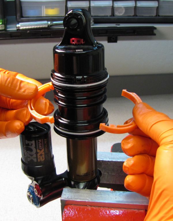
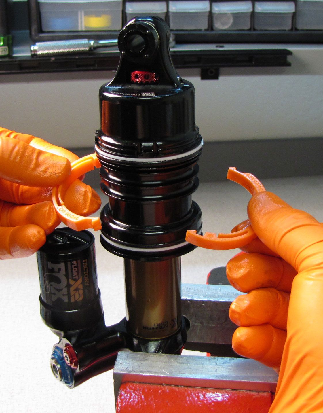
Slide the outer air sleeve away from the negative air sealhead to remove.

DO NOT clamp the FLOAT X2 Inner Air Sleeve below the externally threaded area. Only use the FLOAT X2 Air Sleeve Clamps (PN: 803-01-690 REV A) to clamp the FLOAT X2 Inner Air Sleeve between the ribs.

WARNING: Using the 2019 FLOAT X2 Air Sleeve Clamps (803-01-318 REV A) can cause damage to the inner air sleeve on certain size 2021 and later FLOAT X2 shocks. Please use only the 803-01-690 REV A Air Sleeve Clamps as they've been modified to fit all sizes of all FLOAT X2 shocks for all model years. Failure to use the correct clamp may cause the product to malfunction, resulting in SEVERE INJURY OR DEATH.

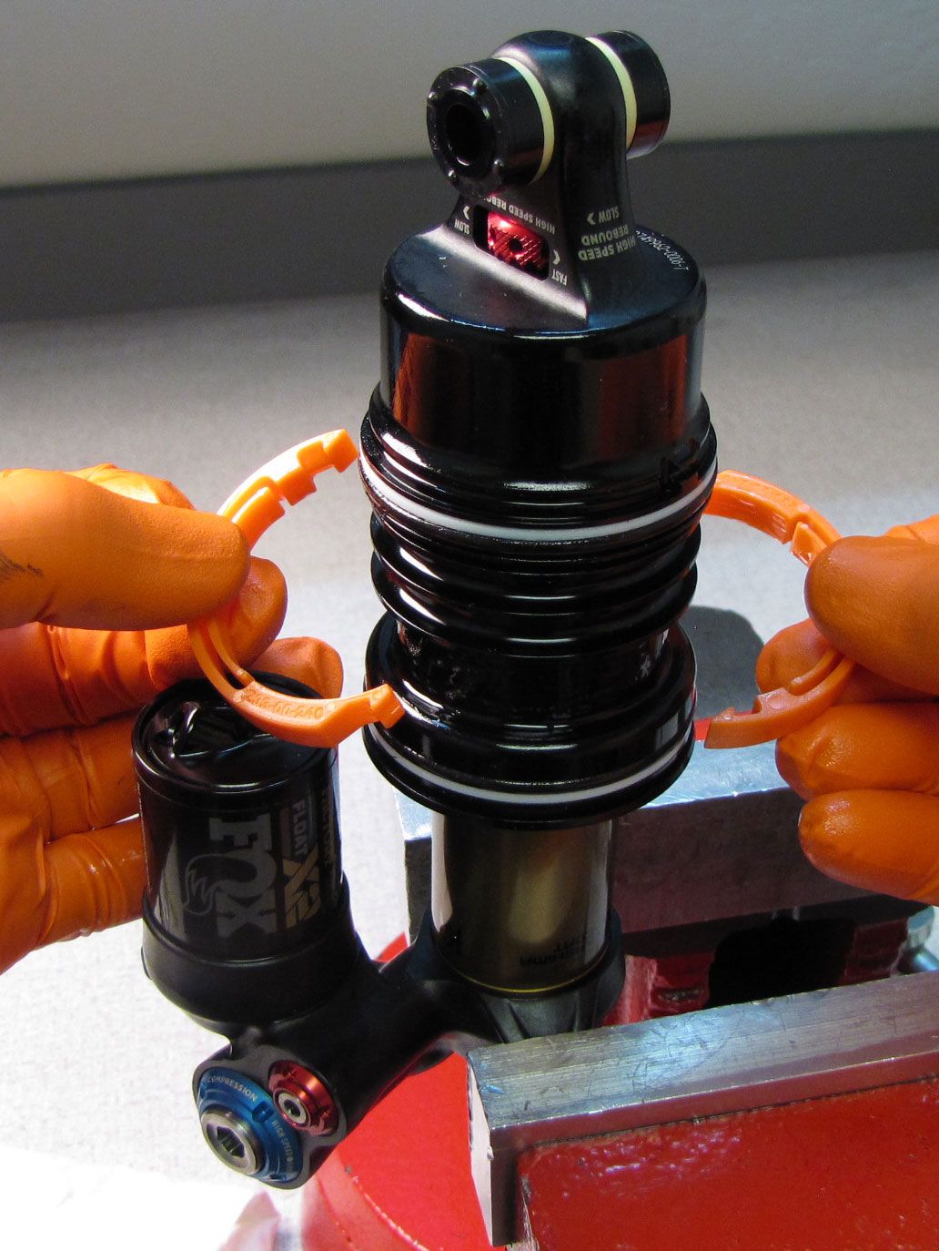
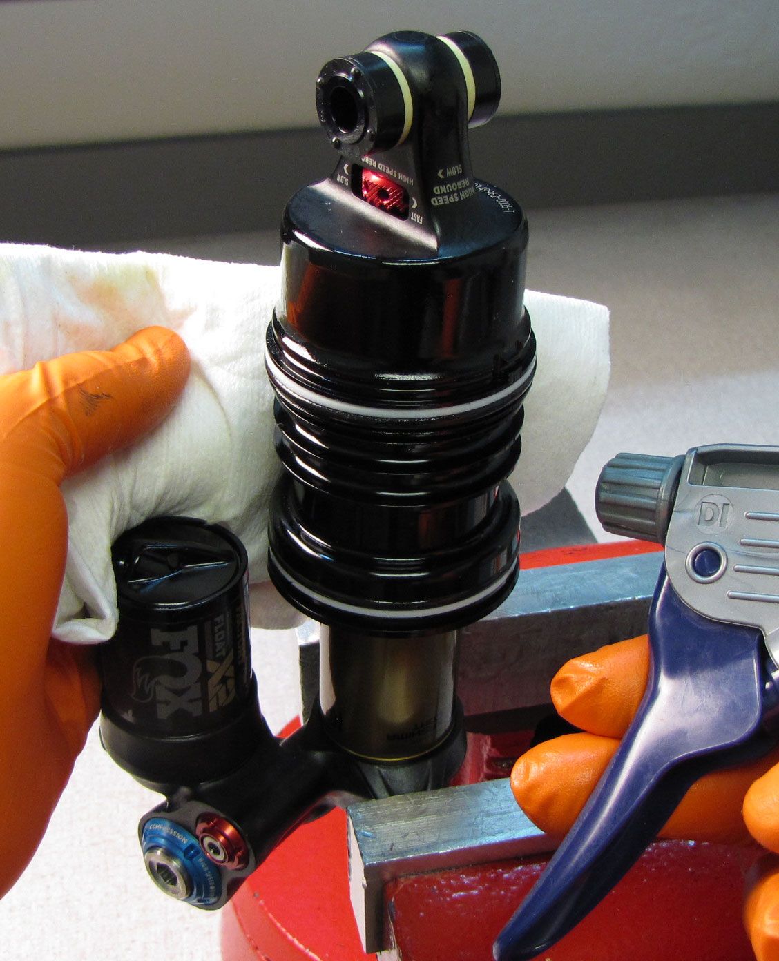
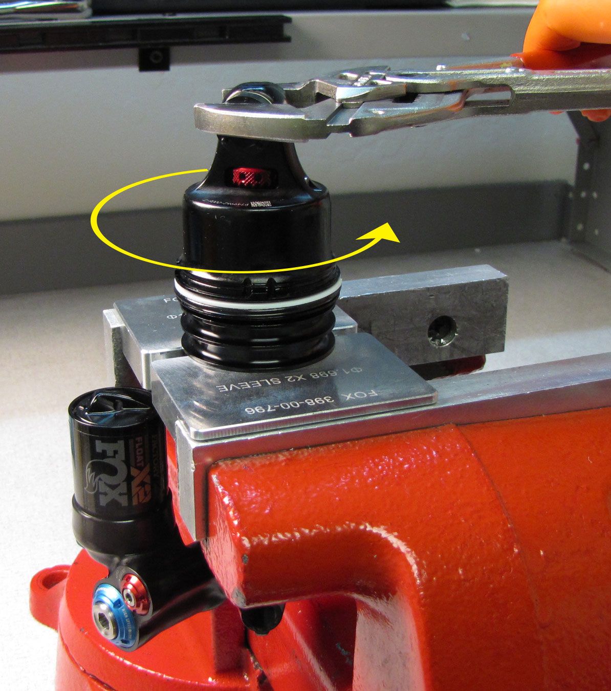
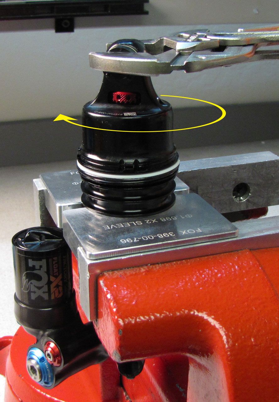
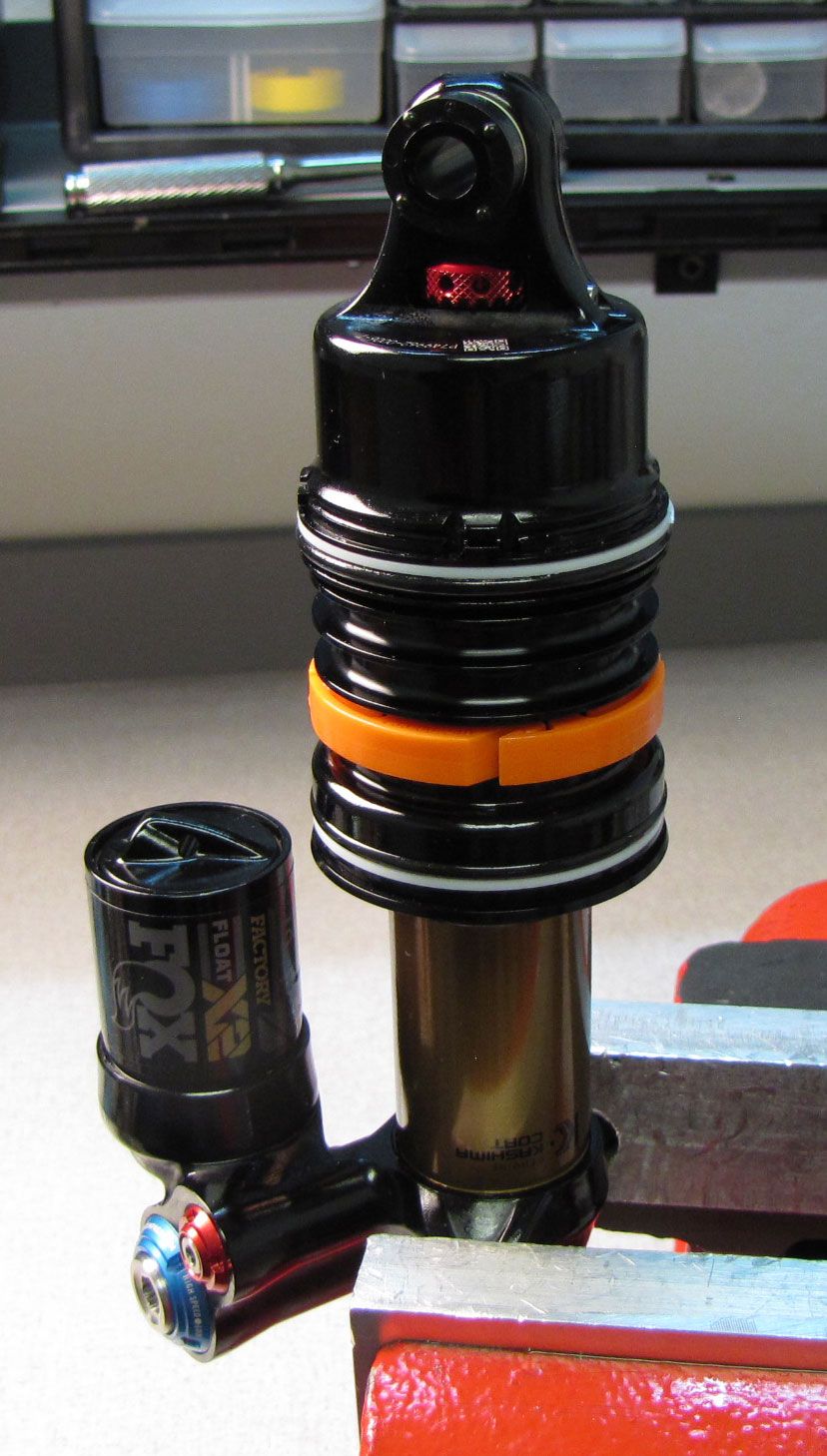
Step 4
Remove any Air Volume Spacers if present. Clean the inner air sleeve with Isopropyl alcohol and lint-free paper towels. Use the X2 air sleeve clamps (PN: 803-01-690) to hold the inner air sleeve while you unthread the shaft eyelet counter-clockwise with Knipex pliers or the eyelet torque tool (PN: 398-00-280).
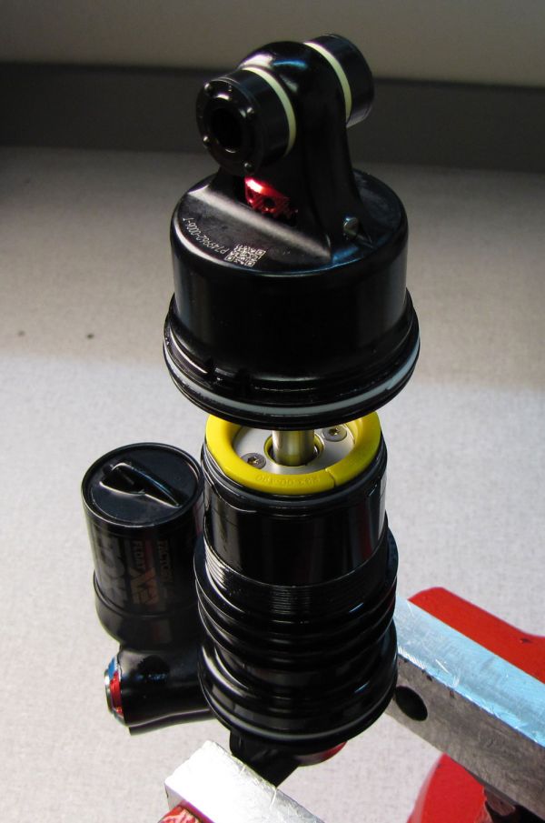
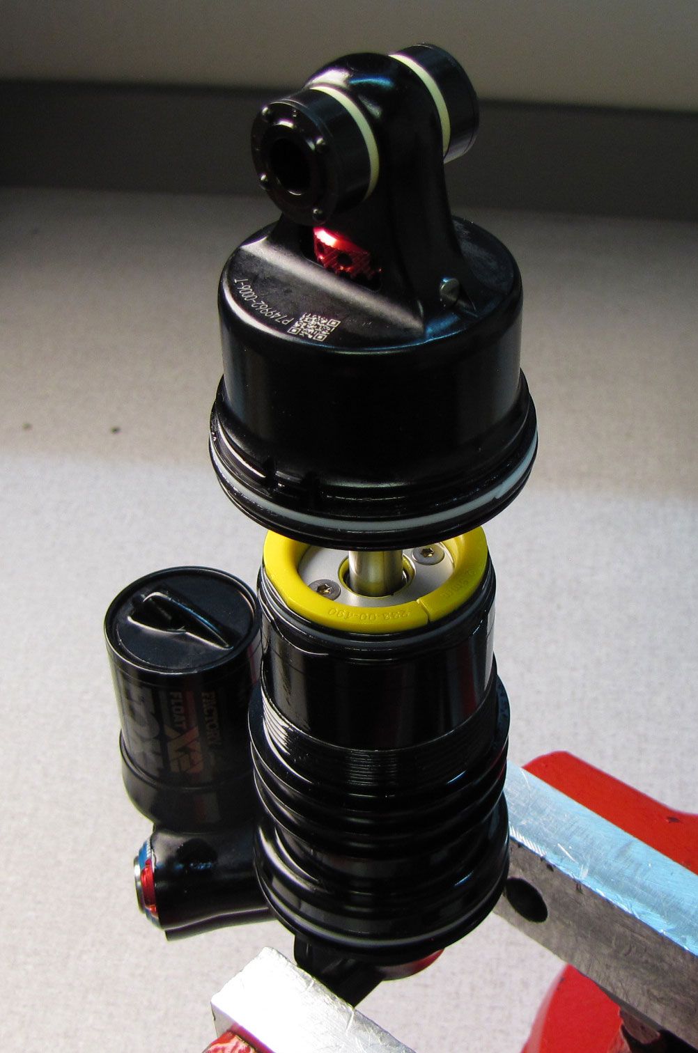
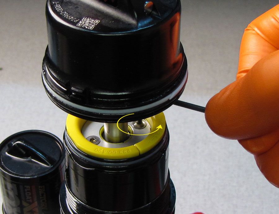
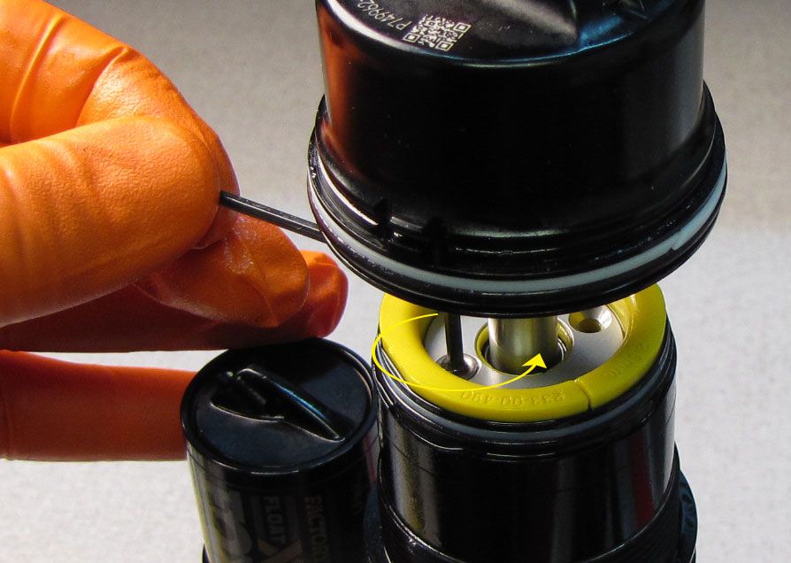
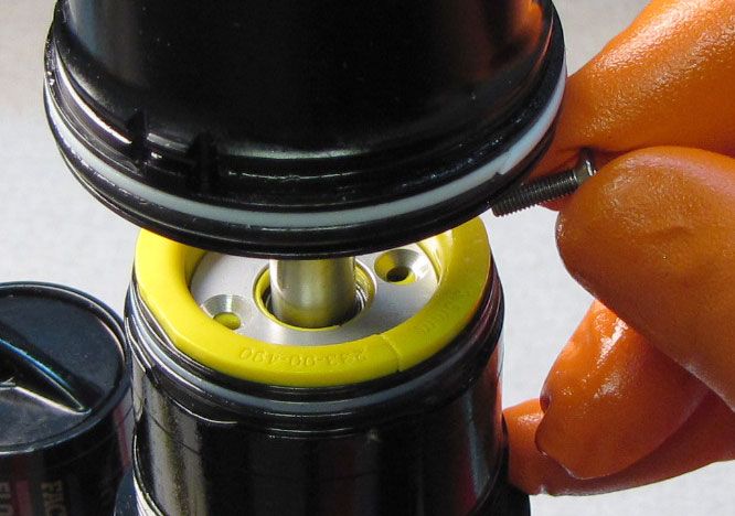
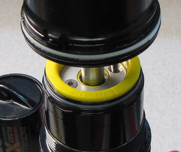
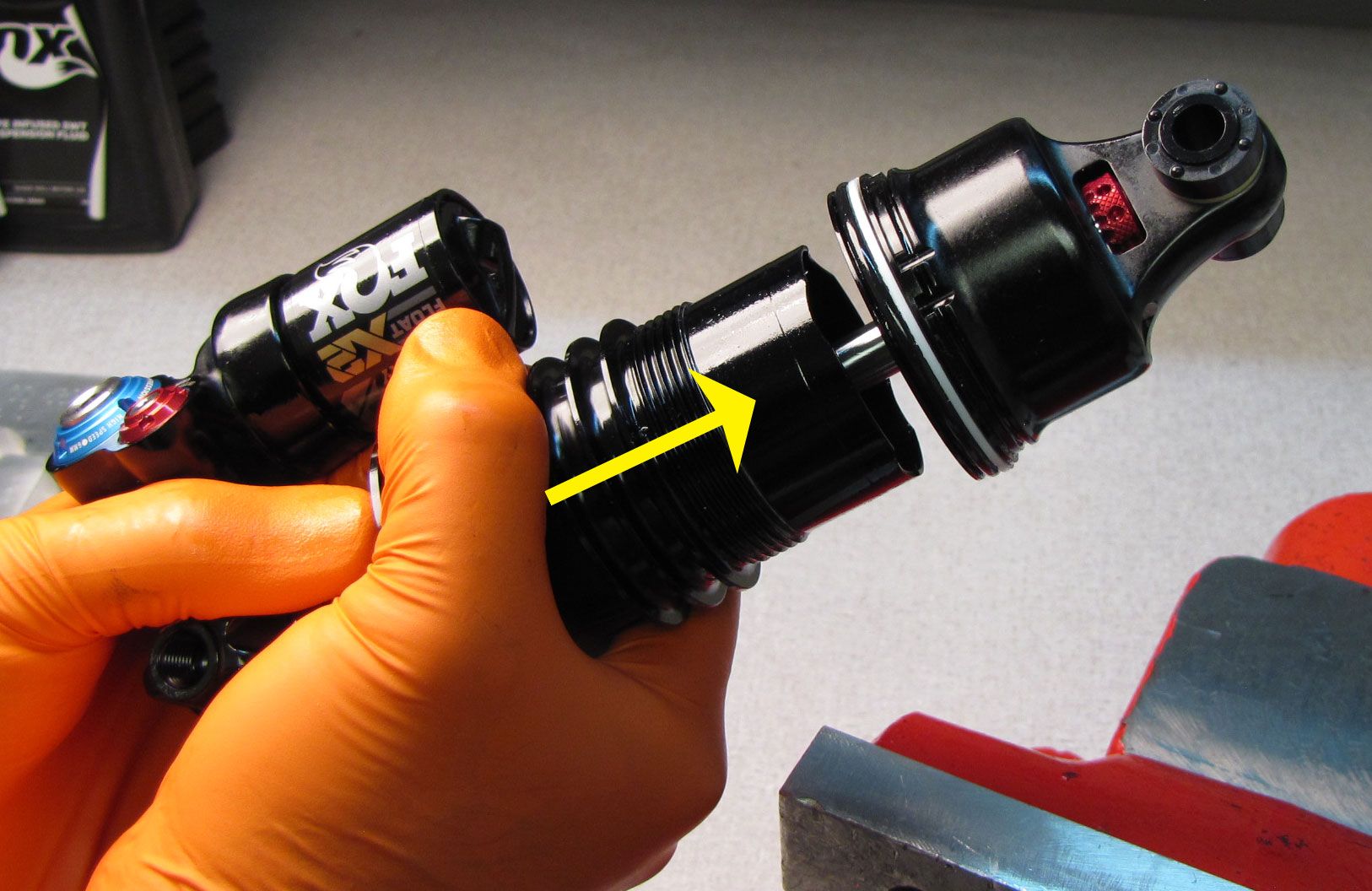
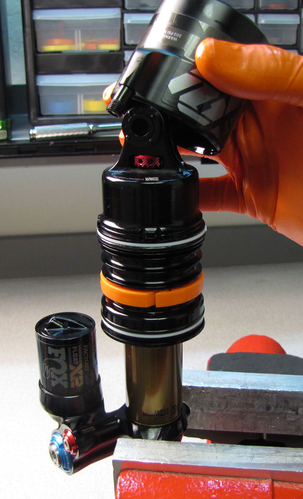
Step 5
Separate the Inner Air Sleeve from the Shaft Eyelet to expose the Bearing Housing. Unthread the two screws in the Bearing Housing Cap counter-clockwise with a 2mm hex wrench. Lift up on the Bearing Housing Cap to reveal any Travel Spacers if present.
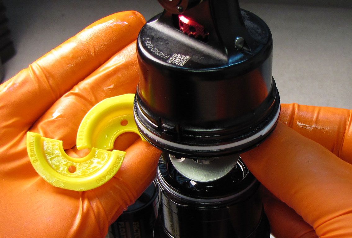

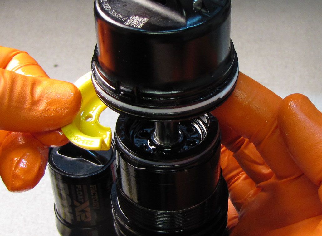
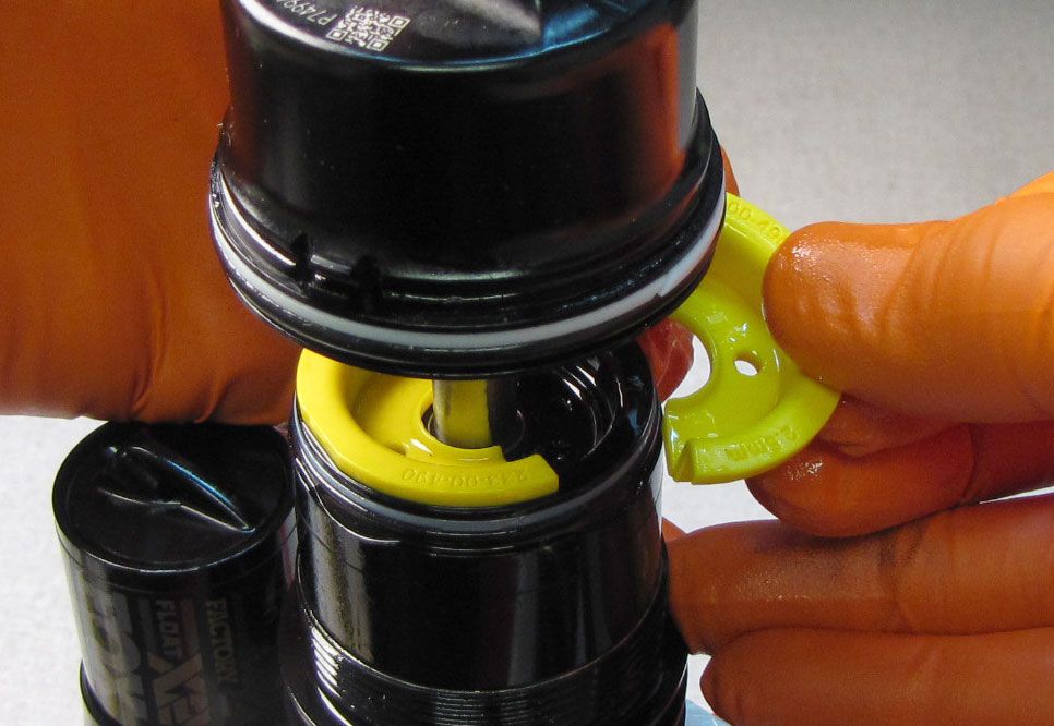
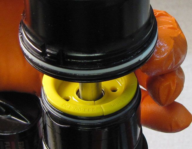
Step 6
Hold the Bearing Housing Cap up to remove or add Travel Spacer pairs as desired. Make sure that the travel you are configuring the shock for is appropriate for the intended bike application. Position the Travel Spacers so their center through-holes are aligned with the threaded holes in the Bearing Assembly and the raised rim is facing up away from the Bearing Housing. (Note: The same Travel Spacers found in this shock are being reinstalled resulting in no actual travel change. This procedure is for demonstration purposes only).

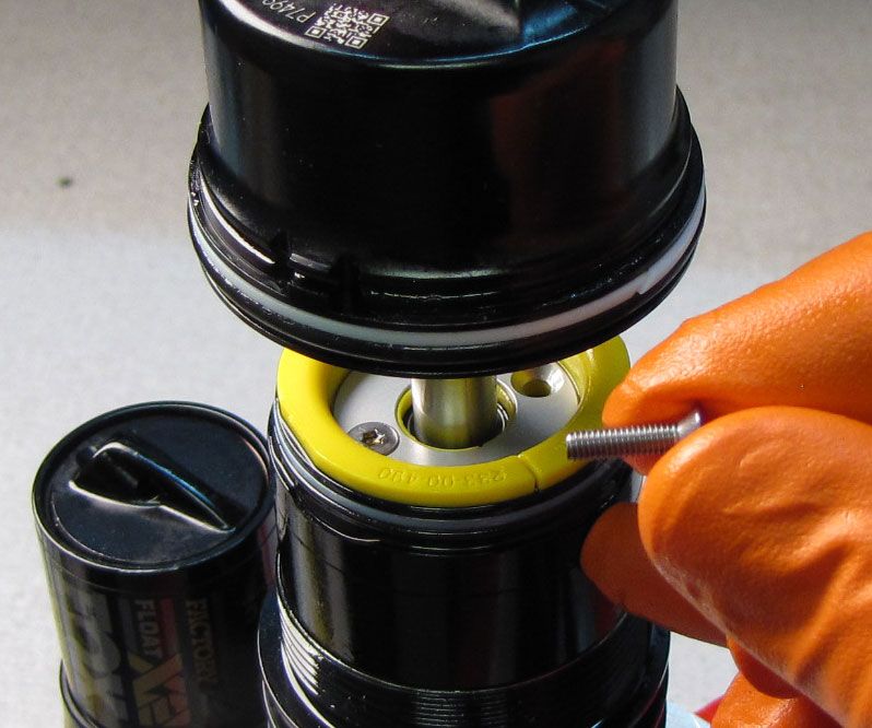
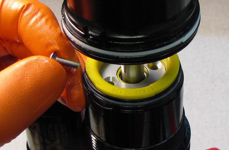
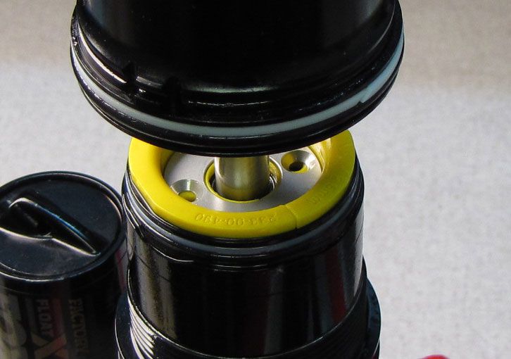
Step 7
Reposition the Bearing Housing Cap on top of the Bearing Housing and any Travel Spacers present, making sure to align the through-holes with the threaded holes of the Bearing Housing. Reinstall the two screws, tightening clockwise to 10 in-lb (1.1 Nm) torque with a 2mm hex wrench.

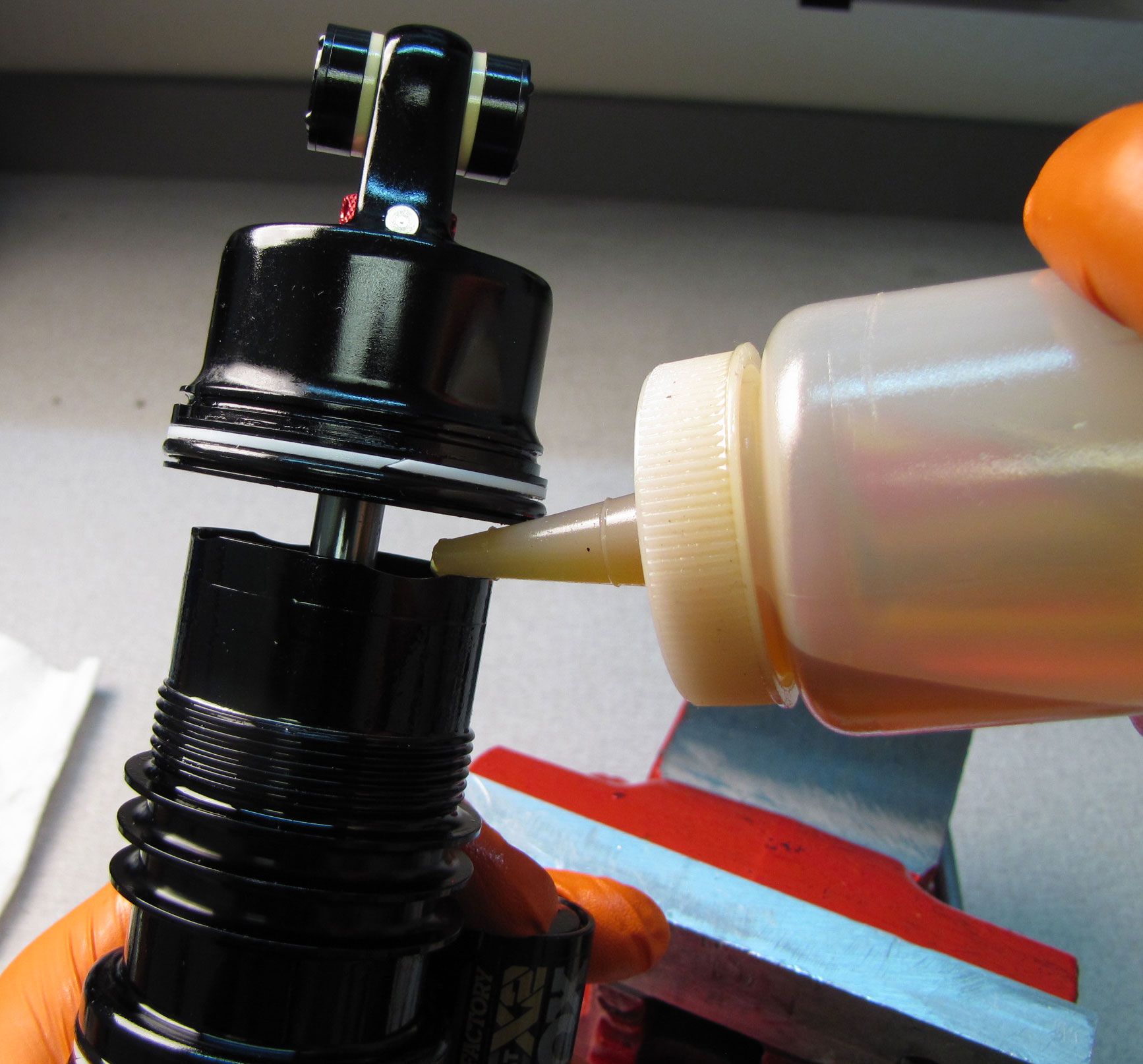
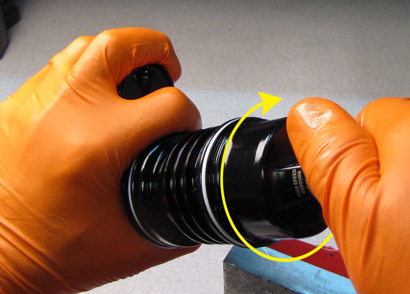
Step 8
Replace any 20wt. Gold oil lost during disassembly (up to 2cc) then thread the Shaft Eyelet clockwise onto the Inner Air Sleeve. Clean the inner air sleeve with Isopropyl alcohol and lint-free paper towels. Use the X2 air sleeve clamps (PN: 803-01-690) to hold the inner air sleeve while you thread the shaft eyelet clockwise with Knipex pliers or the eyelet torque tool (PN: 398-00-280). Tighten to 180 in-lb (20.3 Nm) torque.
Step 9
Replace any Air Volume Spacers that were present. Coat the air seals in a thin film of Slick Honey then reinstall the outer air sleeve with the air valve side first. Rotate the outer air sleeve until the tab on the eyelet aligns with the notch in the outer sleeve. Slide the outer air sleeve all the way to the negative air sealhead to engage the air seals. Reinstall the wire retaining ring making sure that it is fully seated in its groove.
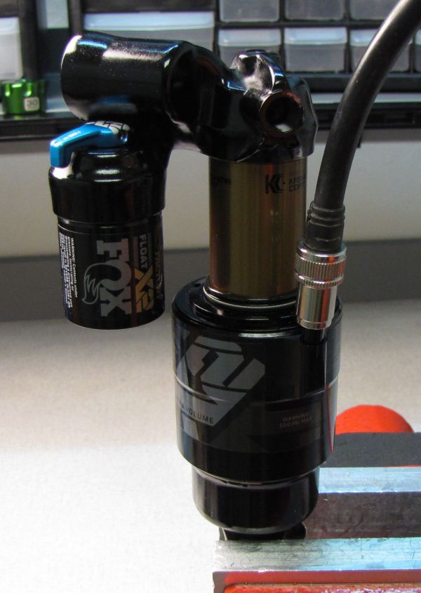
Step 10
Attach your shock pump then add air while you slowly cycle your shock through 25% of its travel 10 times as you reach your desired pressure. Reinstall the black air cap.