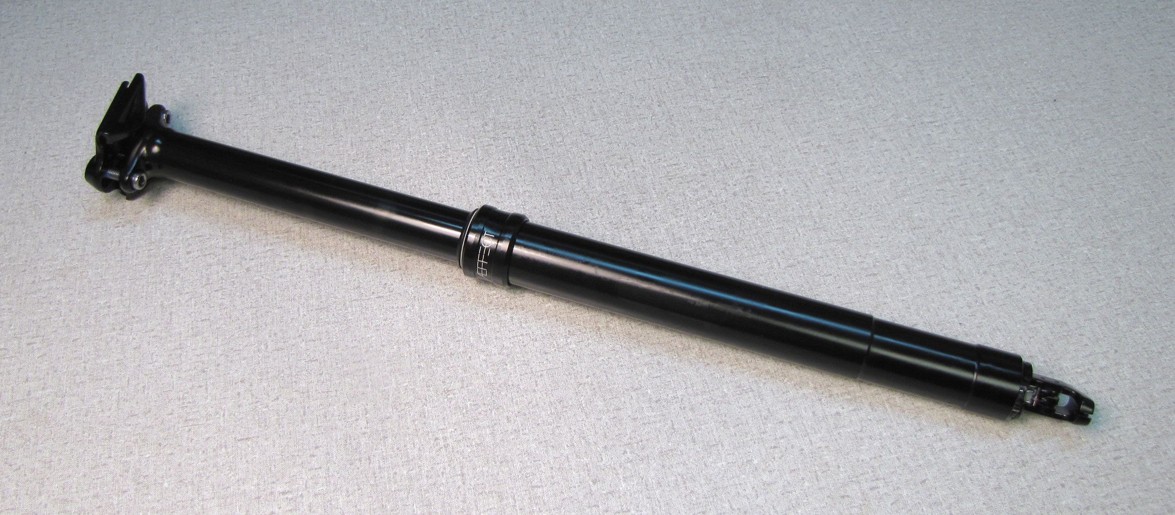
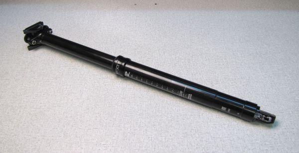
Aeffect R Seatpost Rebuild with Cartridge Replacement (150mm-170mm Drops)
WARNING: Always wear safety glasses and protective gloves during service to prevent potential injury. Failure to wear protective equipment during service may lead to SERIOUS INJURY OR DEATH.
WARNING: Race Face products should be serviced by a trained bicycle service technician, in accordance with Race Face specifications. If you have any doubt whether or not you can properly service your Race Face product, then DO NOT attempt it. Improperly serviced products can fail, causing the rider to lose control resulting in SERIOUS INJURY OR DEATH.
WARNING: Race Face seatpost products contain pressurized nitrogen, air, oil, or all 3. Seatpost misuse can cause property damage, SERIOUS INJURY OR DEATH. DO NOT puncture, incinerate or crush any portion of a Race Face seatpost product. DO NOT attempt to disassemble any portion of a Race Face seatpost product, unless expressly instructed to do so by the applicable Race Face technical documentation, and then ONLY while strictly adhering to all Race Face instructions and warnings in that instance.
WARNING: Modification, improper service, or use of aftermarket replacement parts with Race Face seatposts may cause the product to malfunction, resulting in SERIOUS INJURY OR DEATH. DO NOT modify any part of a seatpost, including internal parts, except as instructed herein. Any unauthorized modification may void the warranty, and may cause failure or the seatpost, resulting in SERIOUS INJURY OR DEATH.
Replacement Parts:
|
Item |
Description |
|
D50098X100 |
AEFFECT R DP CARTRIGE KIT 100mm |
|
D50098X125 |
AEFFECT R DP CARTRIGE KIT 125mm |
|
D50098X150 |
AEFFECT R DP CARTRIGE KIT 150mm |
|
D50098X170 |
AEFFECT R DP CARTRIGE KIT 170mm |
|
D50099 |
AEFFECT R DP CABLE HEAD & PINCH BARREL |
|
D50102 |
AEFFECT R DP BUSHING/MIDCAP/PIN KIT |
|
D50103 |
AEFFECT R DP ACTUATOR ASSEMBLY |
|
D50161 |
HEAD SPARE KIT,125MM,AEFFECTDROPPER |
|
D50162 |
HEAD SPARE KIT,150MM,AEFFECTDROPPER |
|
D50163 |
HEAD BOLT KIT,AEFFECTDROPPER |
|
D50164 |
REMOTE KIT,AEFFECTDROPPER |
|
D50165 |
CABLE STOP BARREL,AEFFECTDROPPER |
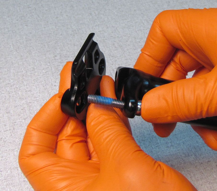
Step 1
Remove the Saddle Clamps by unthreading the two Saddle Bolts counter-clockwise with a 5mm hex wrench. Set aside the Saddle Clamps, Nuts, and Bolts.


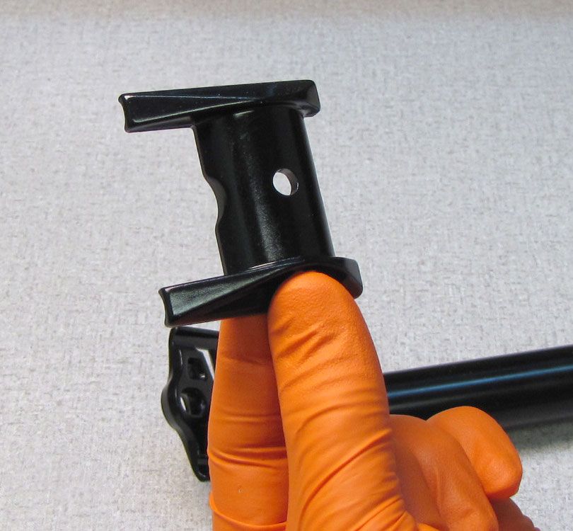
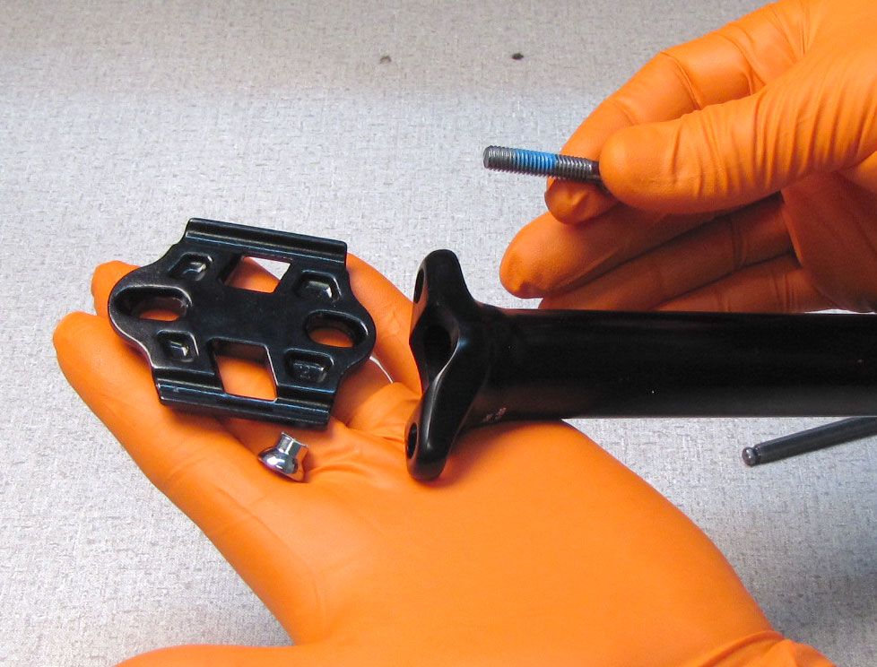
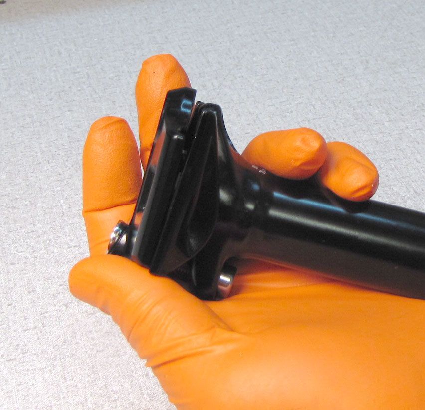
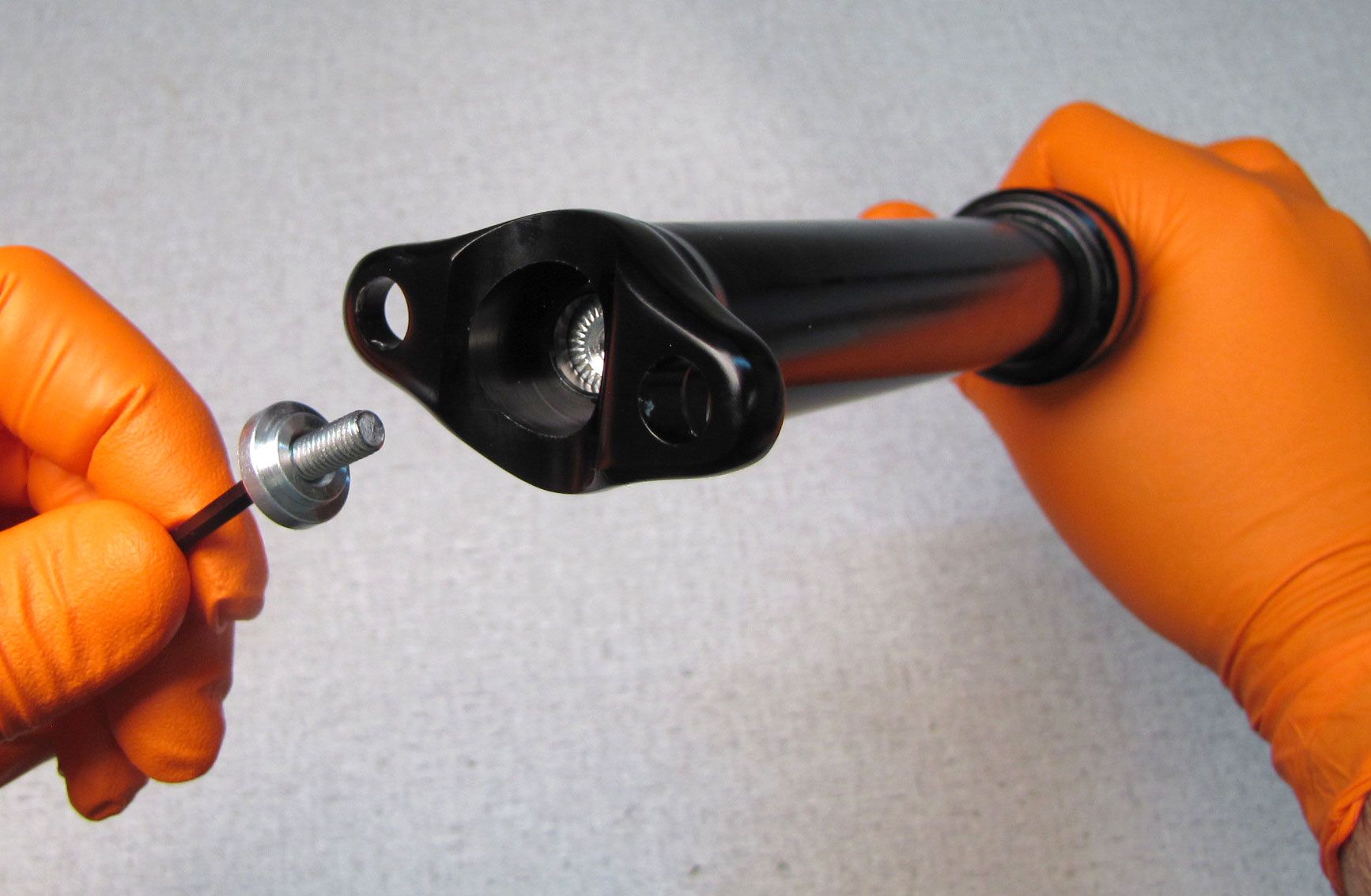
Step 2
Unthread the bolt within the head of ths seatpost counter-clockwise with a 3mm hex wrench. Set aside the bolt and washer.


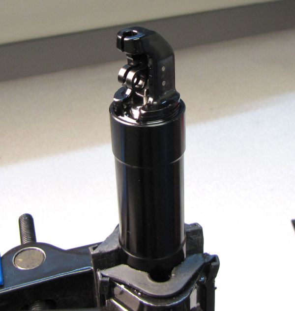
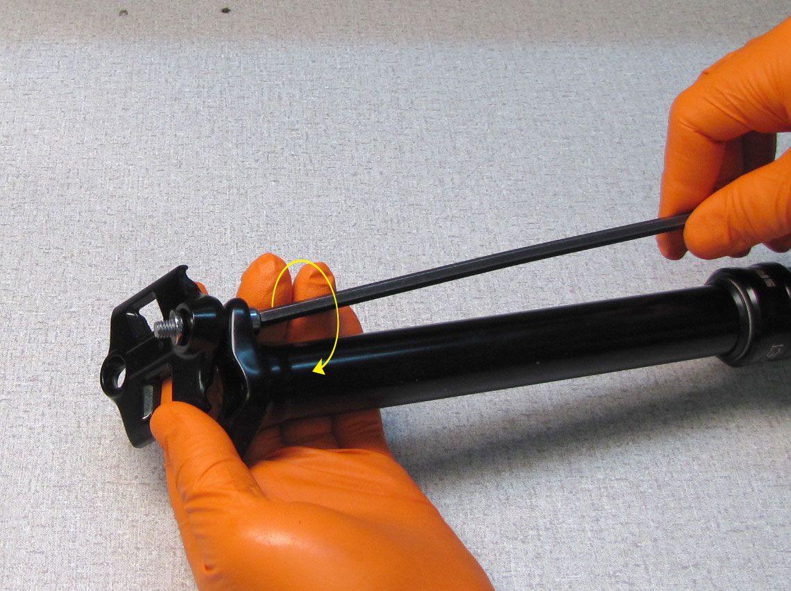
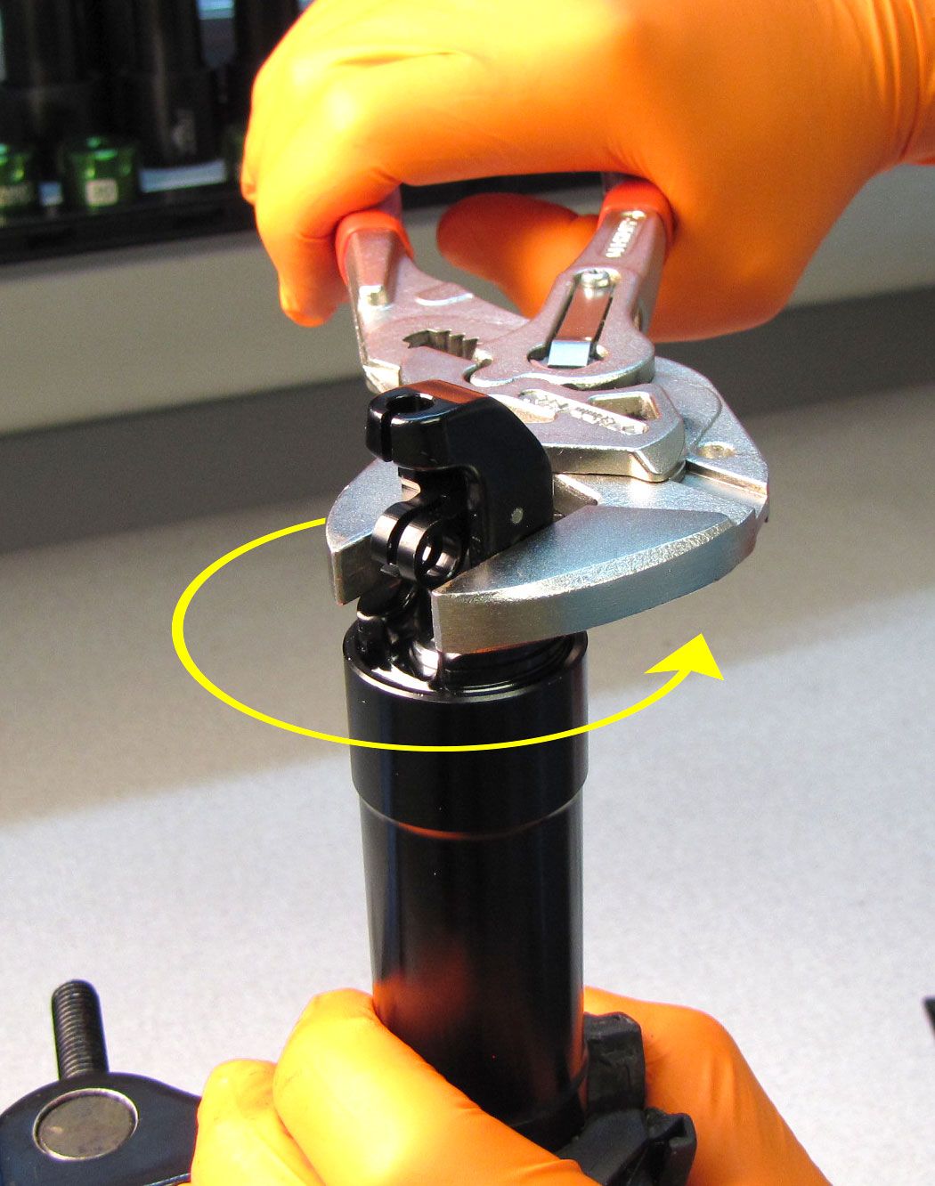
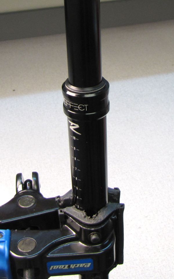
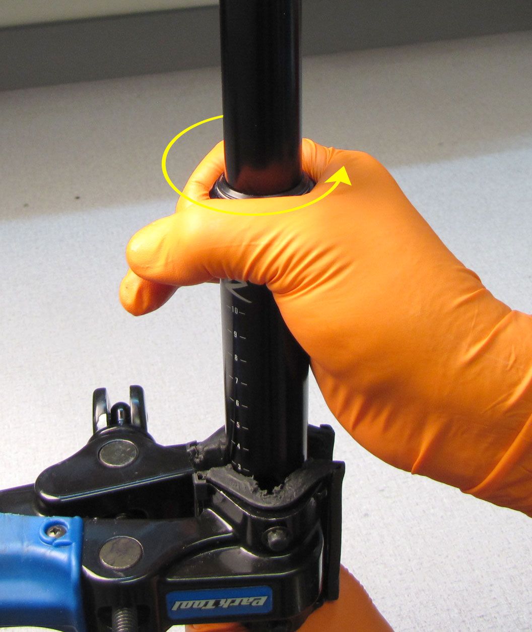
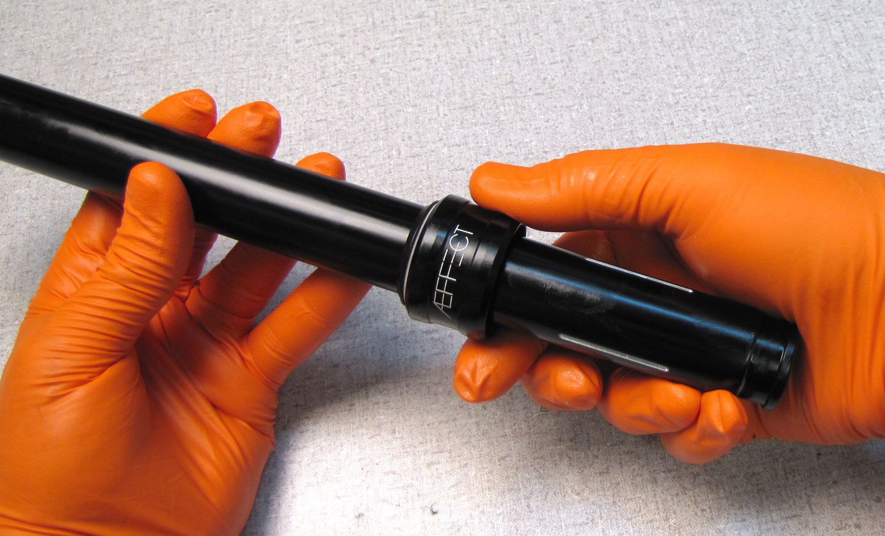
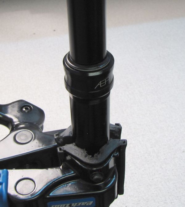
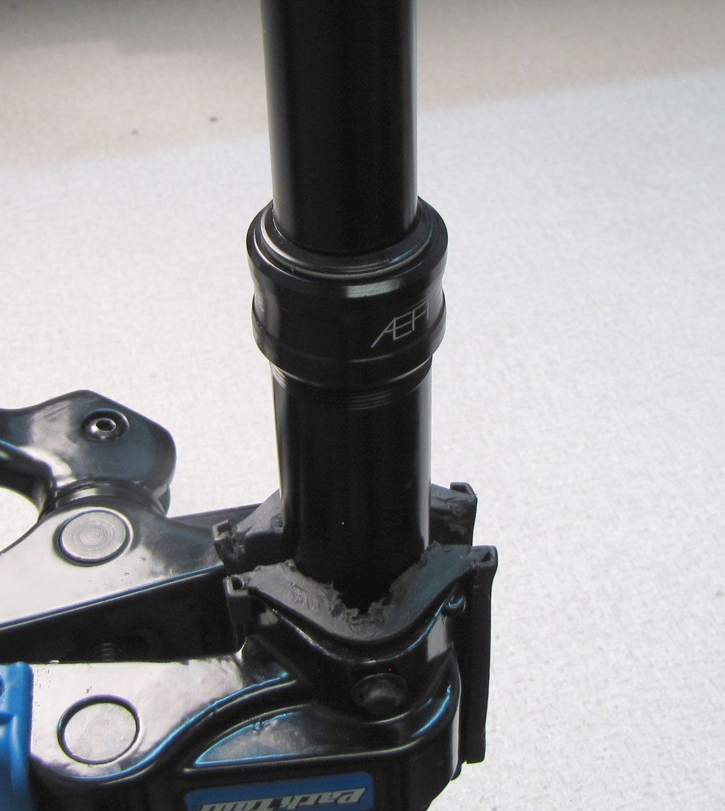
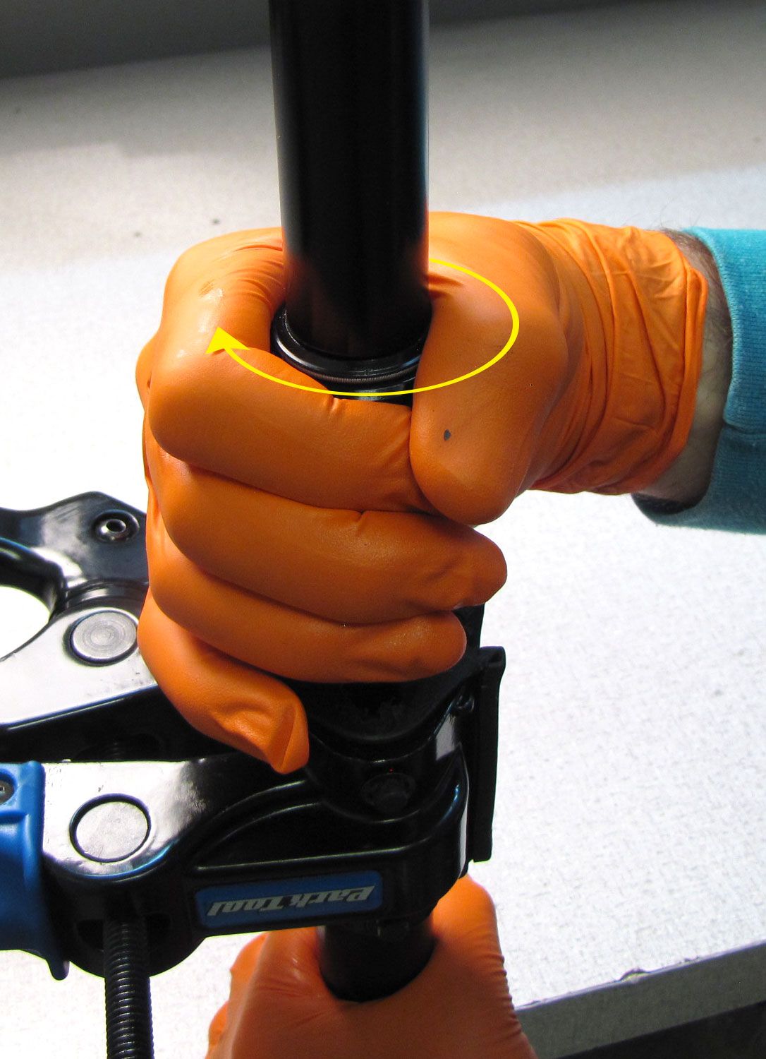
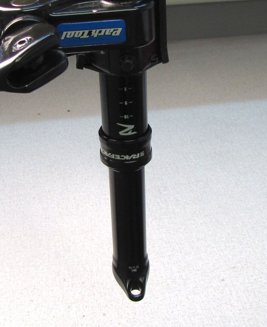
Step 3
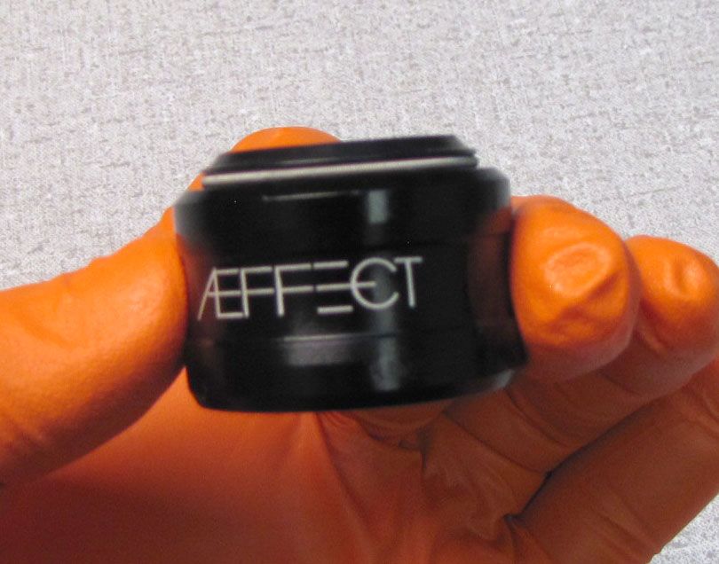
Carefully clamp the outer post in a clean bicycle work stand then unthread the Actuator Assembly counter-clockwise with smooth-jawes parallel pliers (Knipex). Pull the Actuator Assembly up out of the outer post.


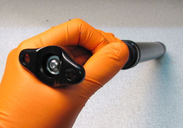
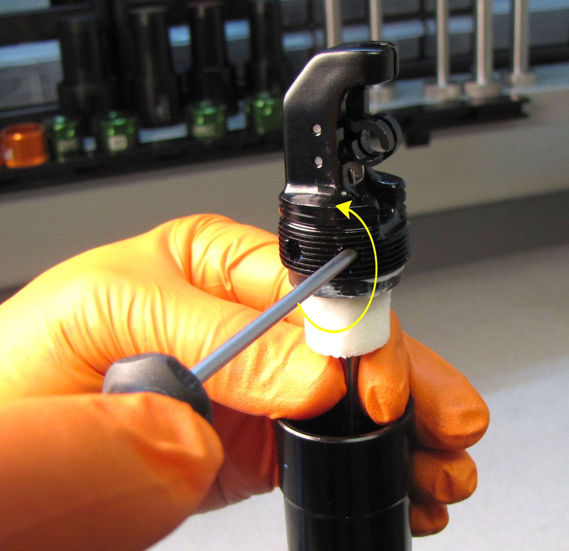
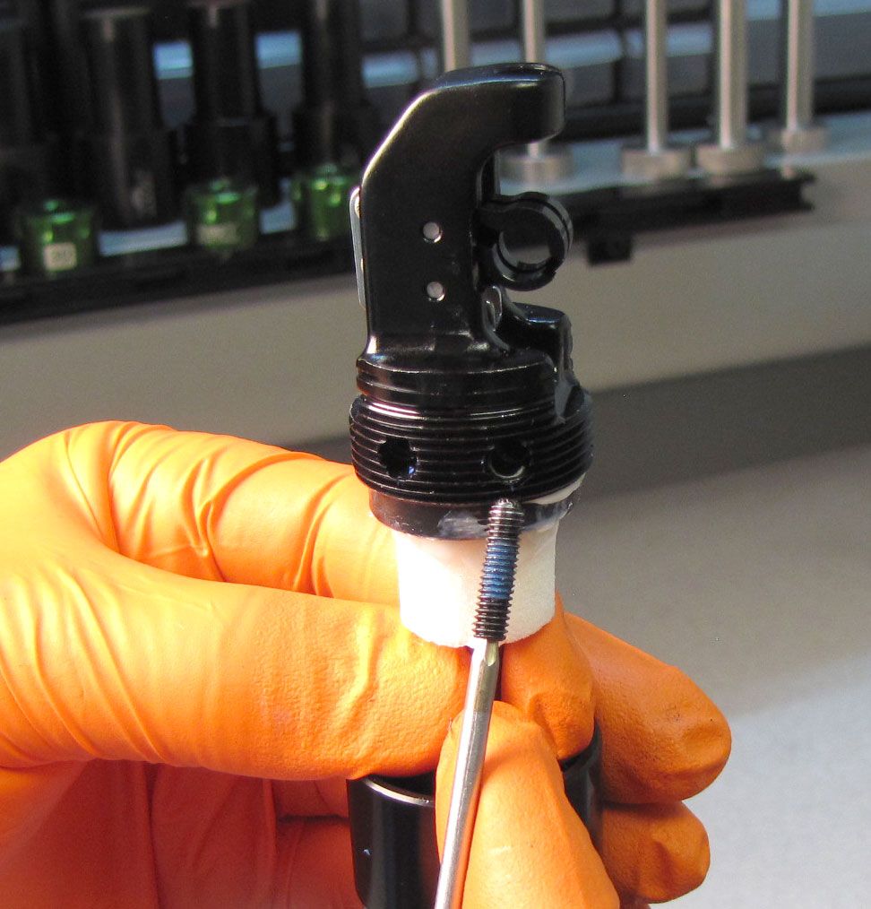
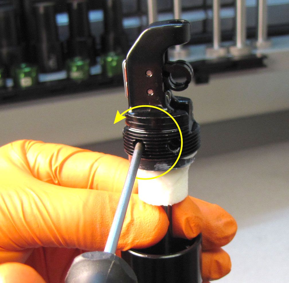
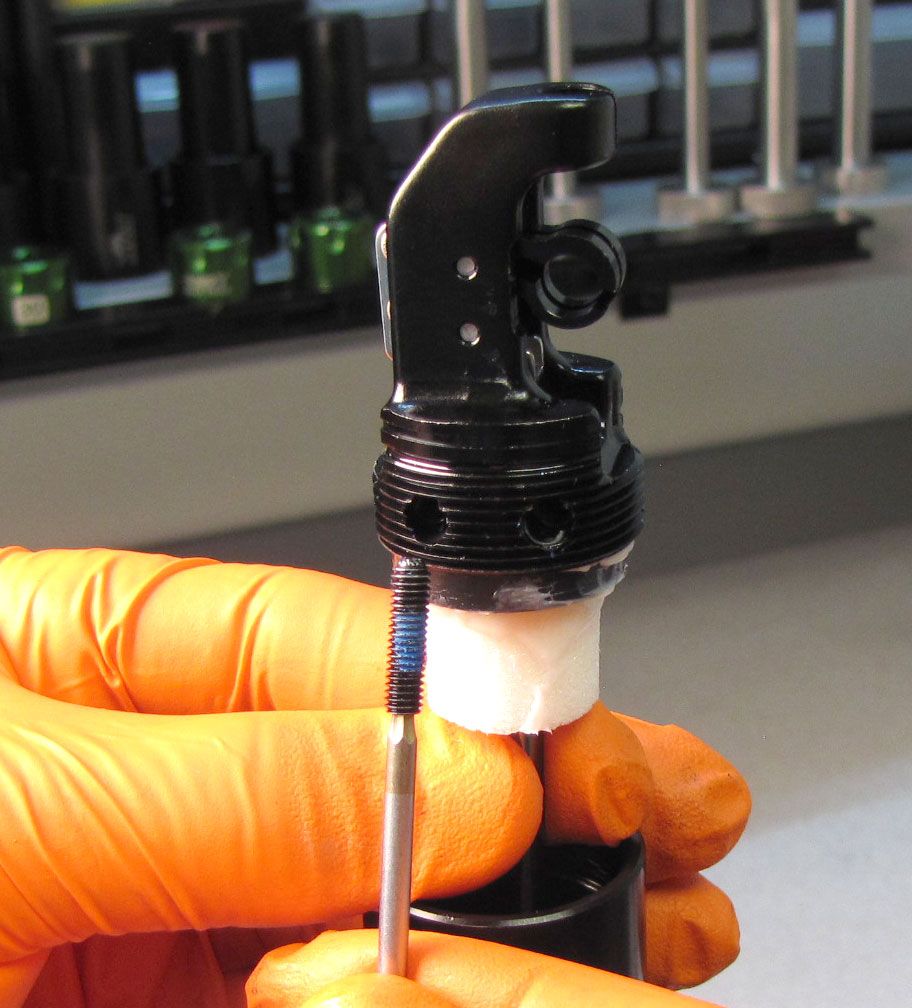
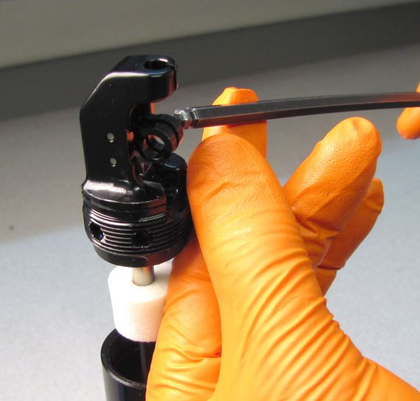
Step 4
Unthread the 2 set screws that retain the Actuator Assembly by turning them counter-clockwise with a 2mm hex wrench. Set the screws and Actuator Assembly aside.
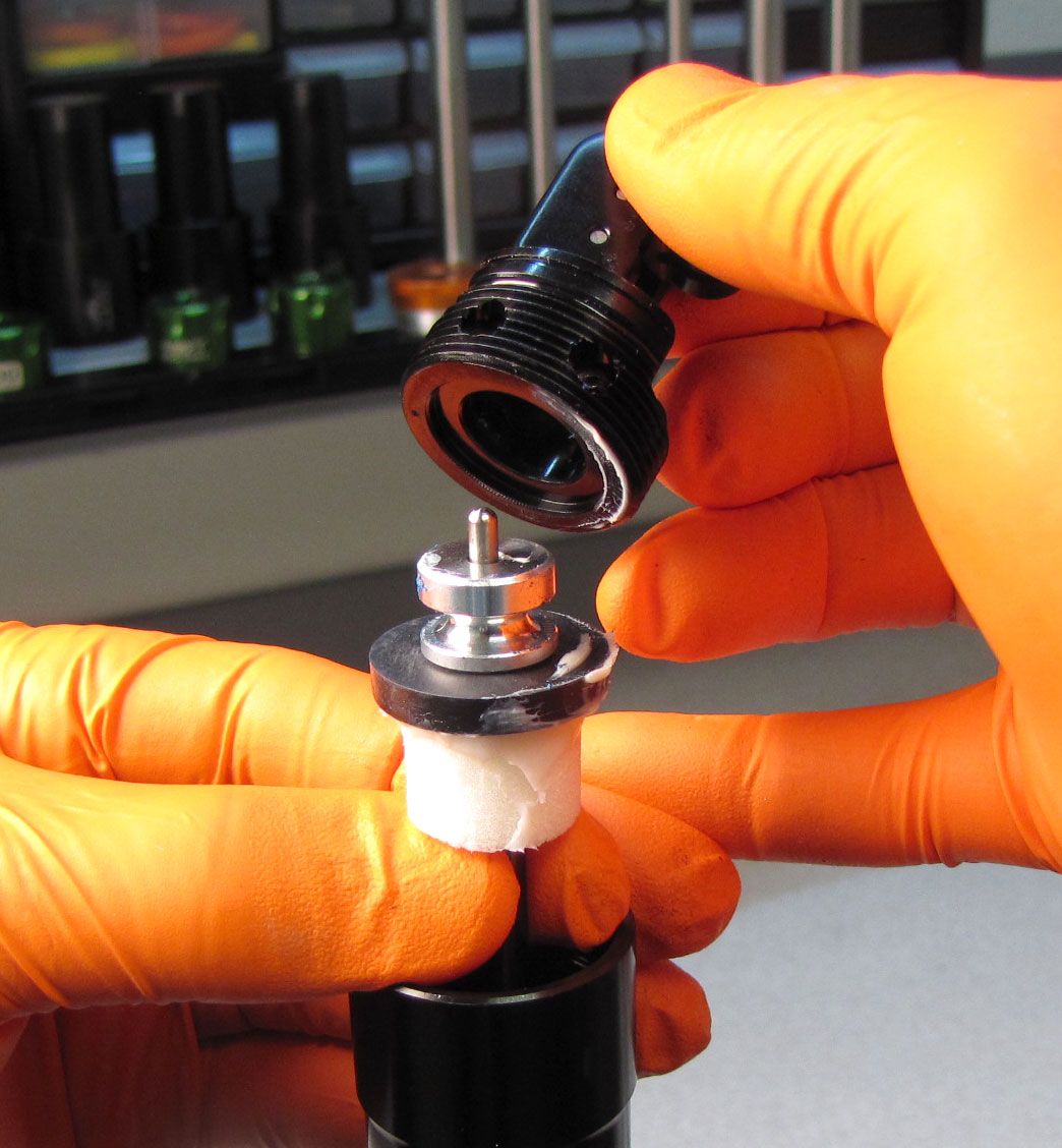

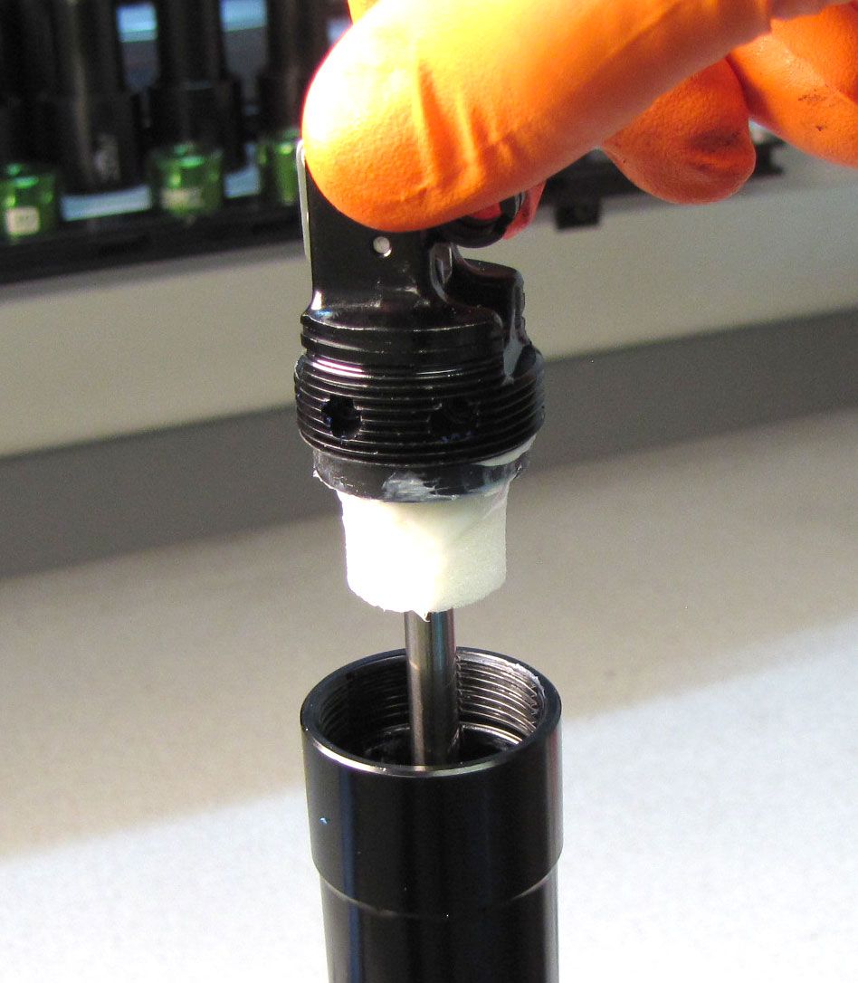
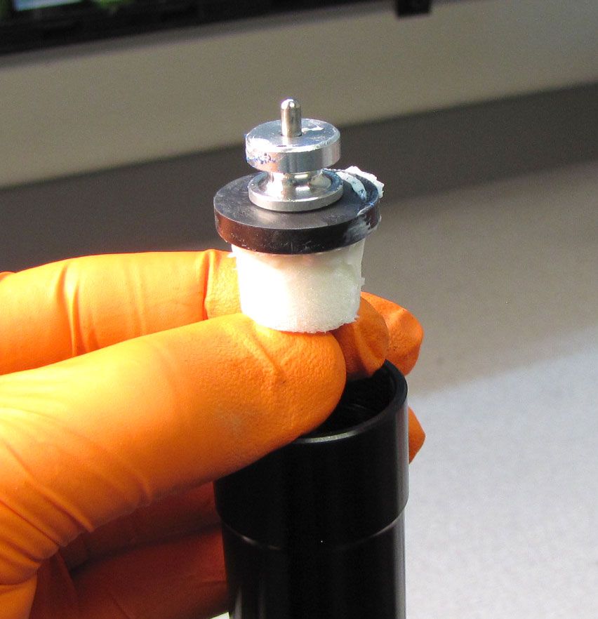
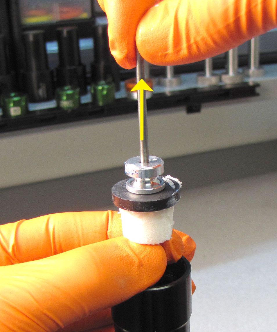
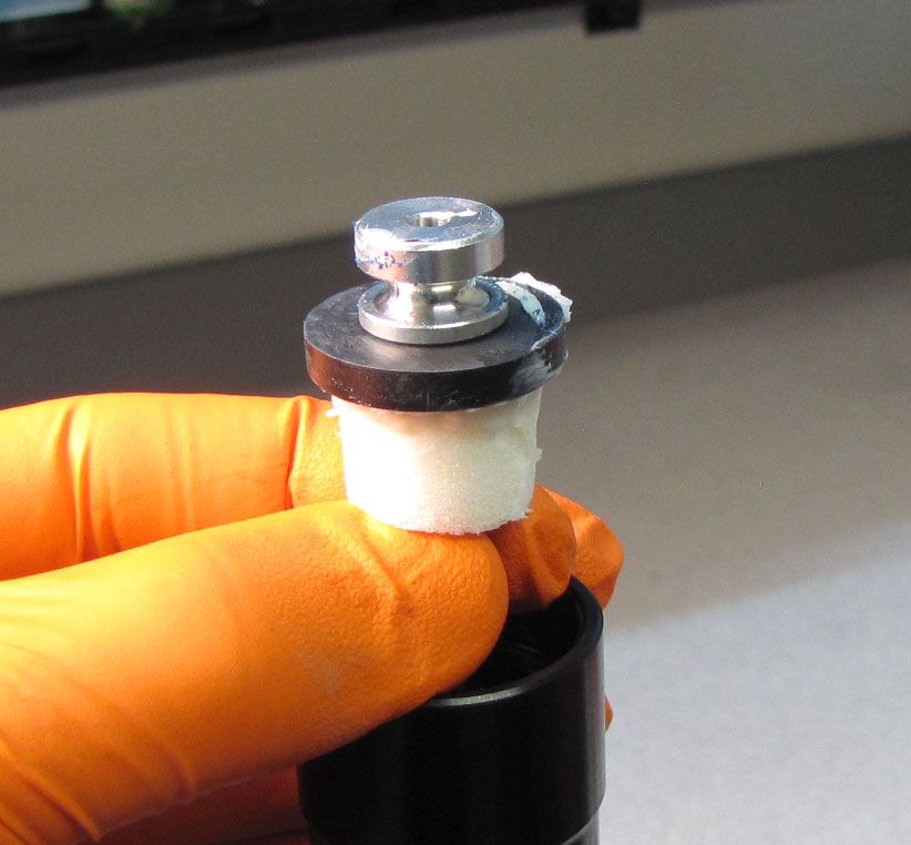
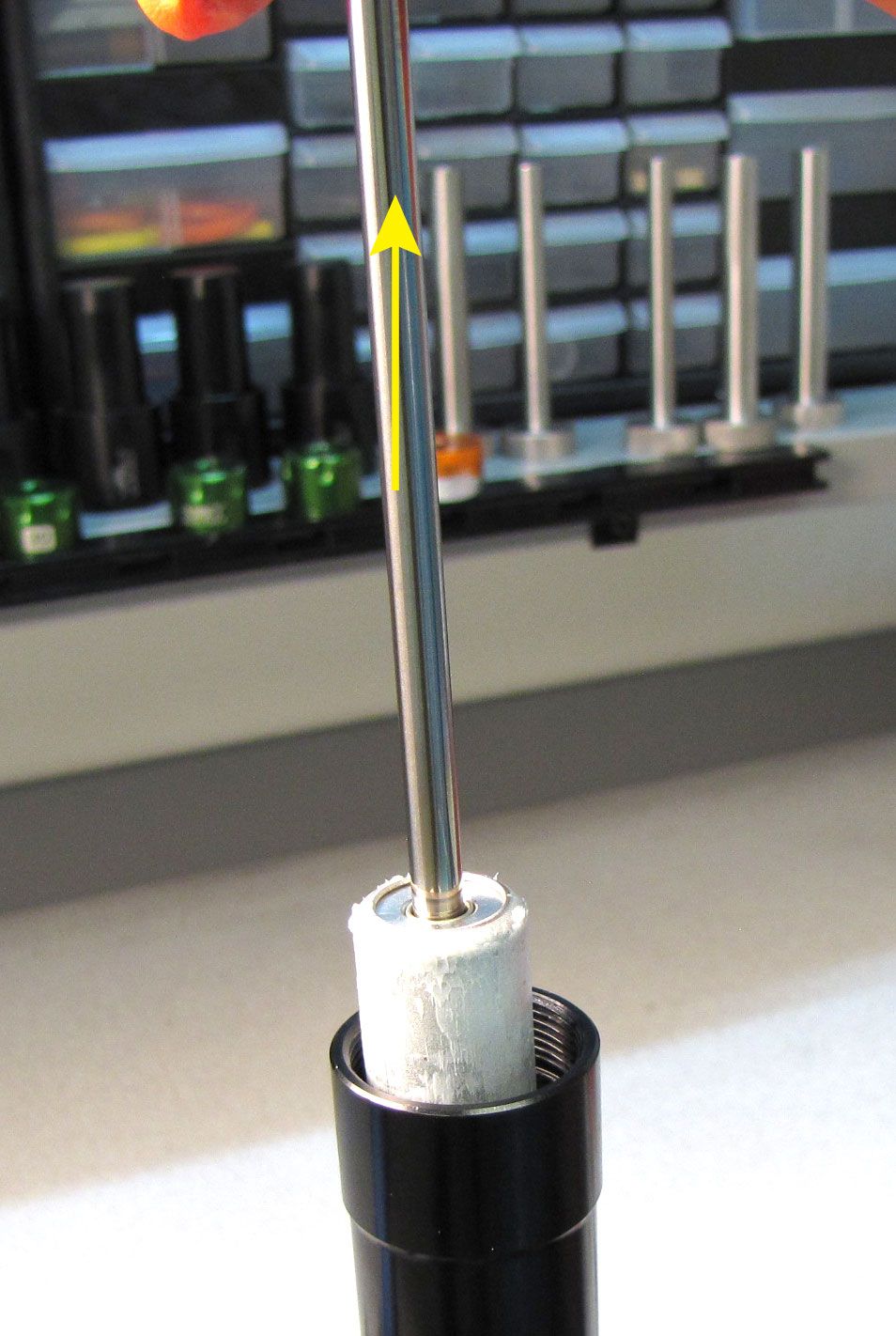
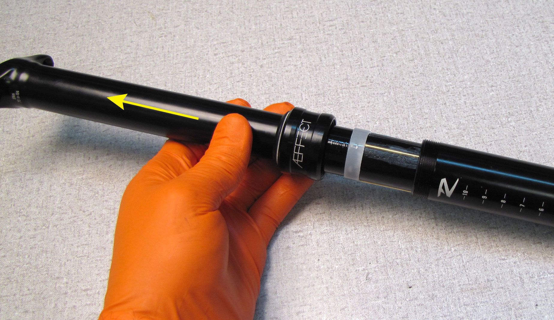
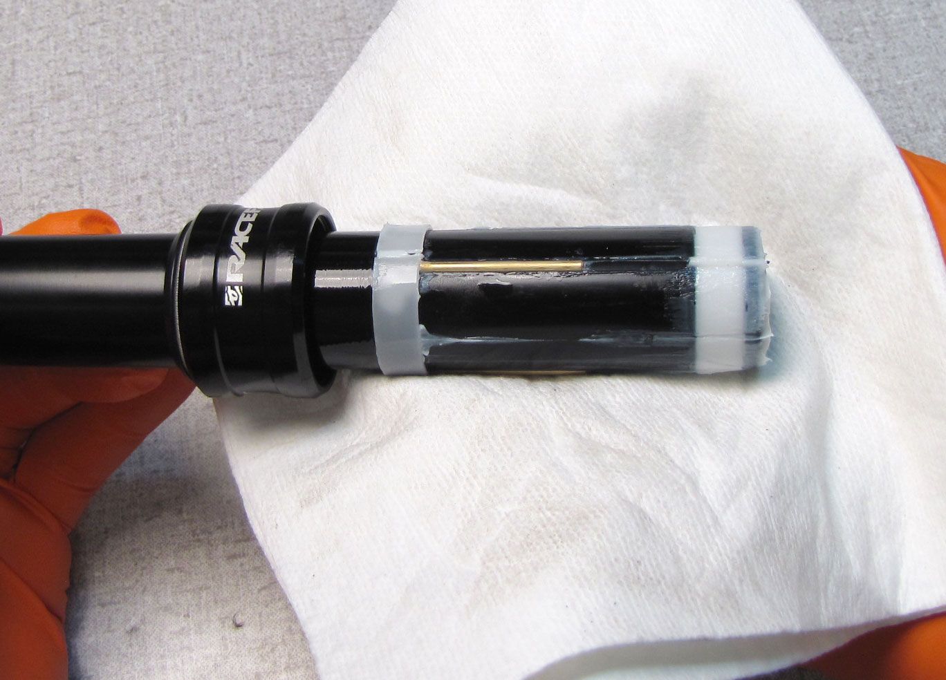
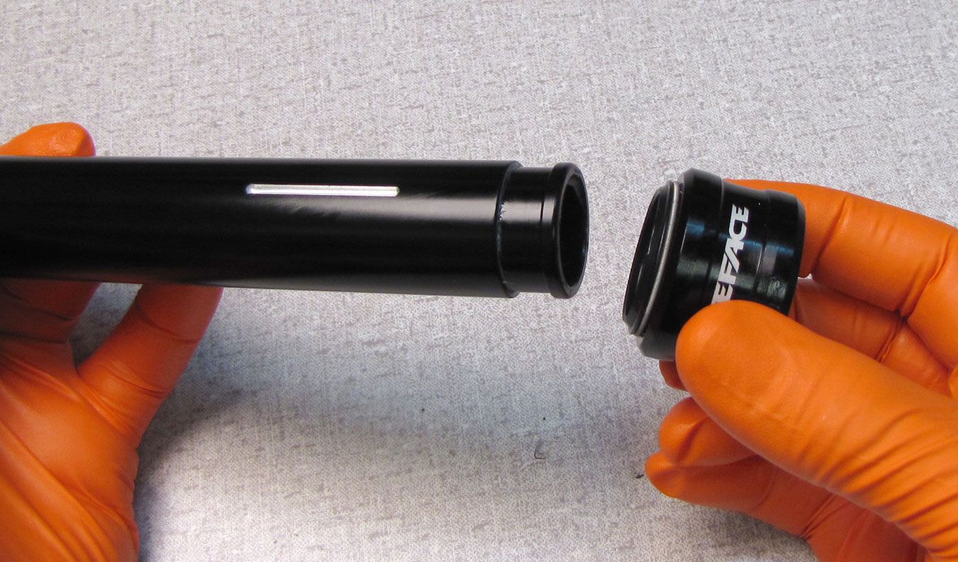
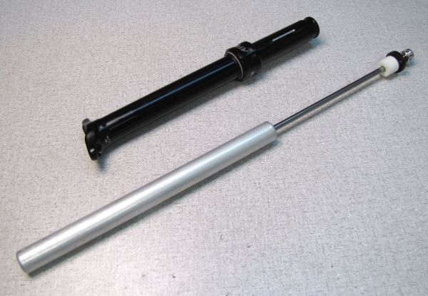
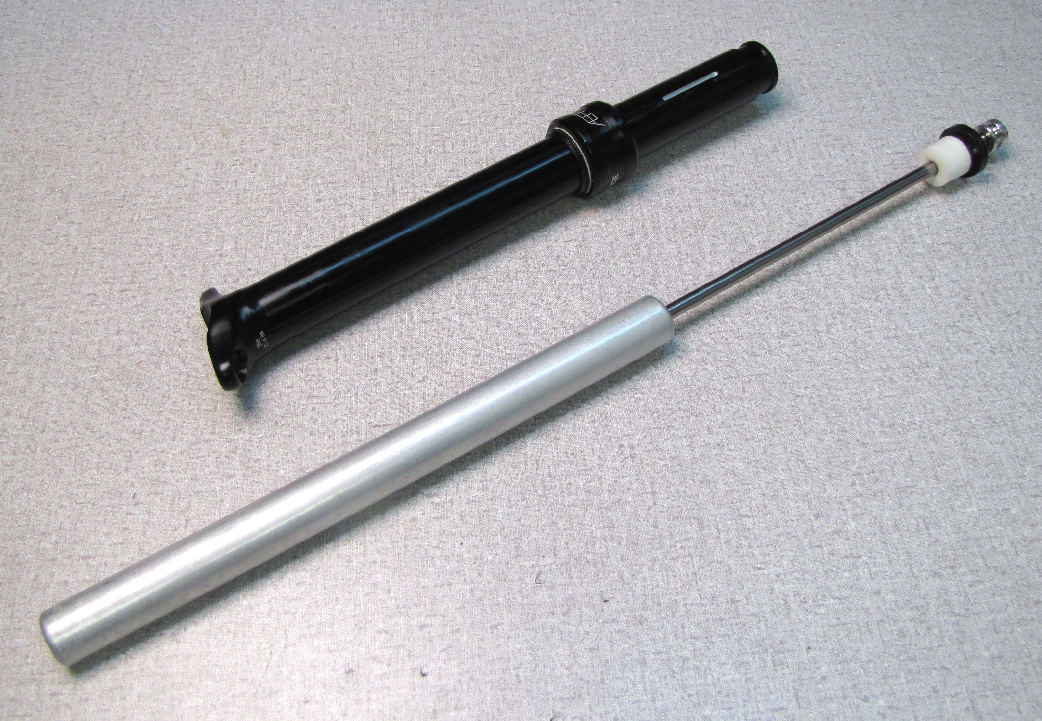
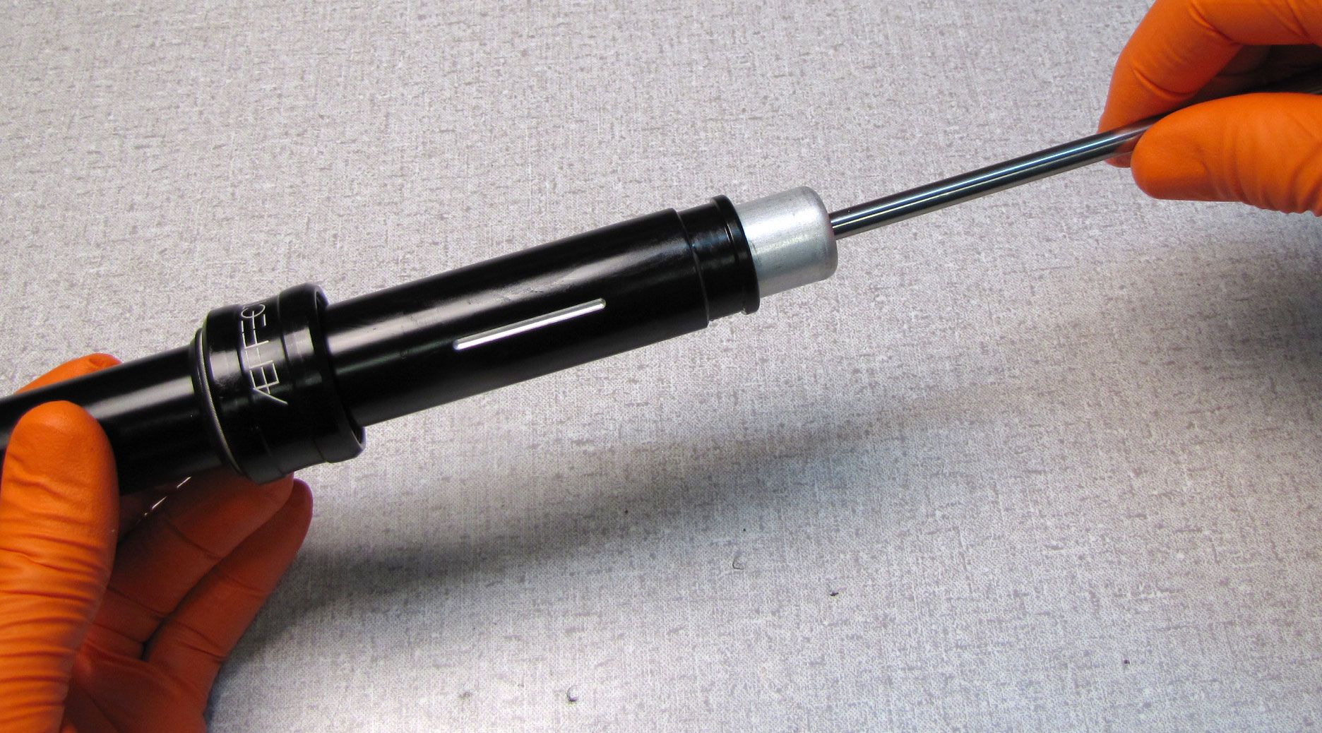
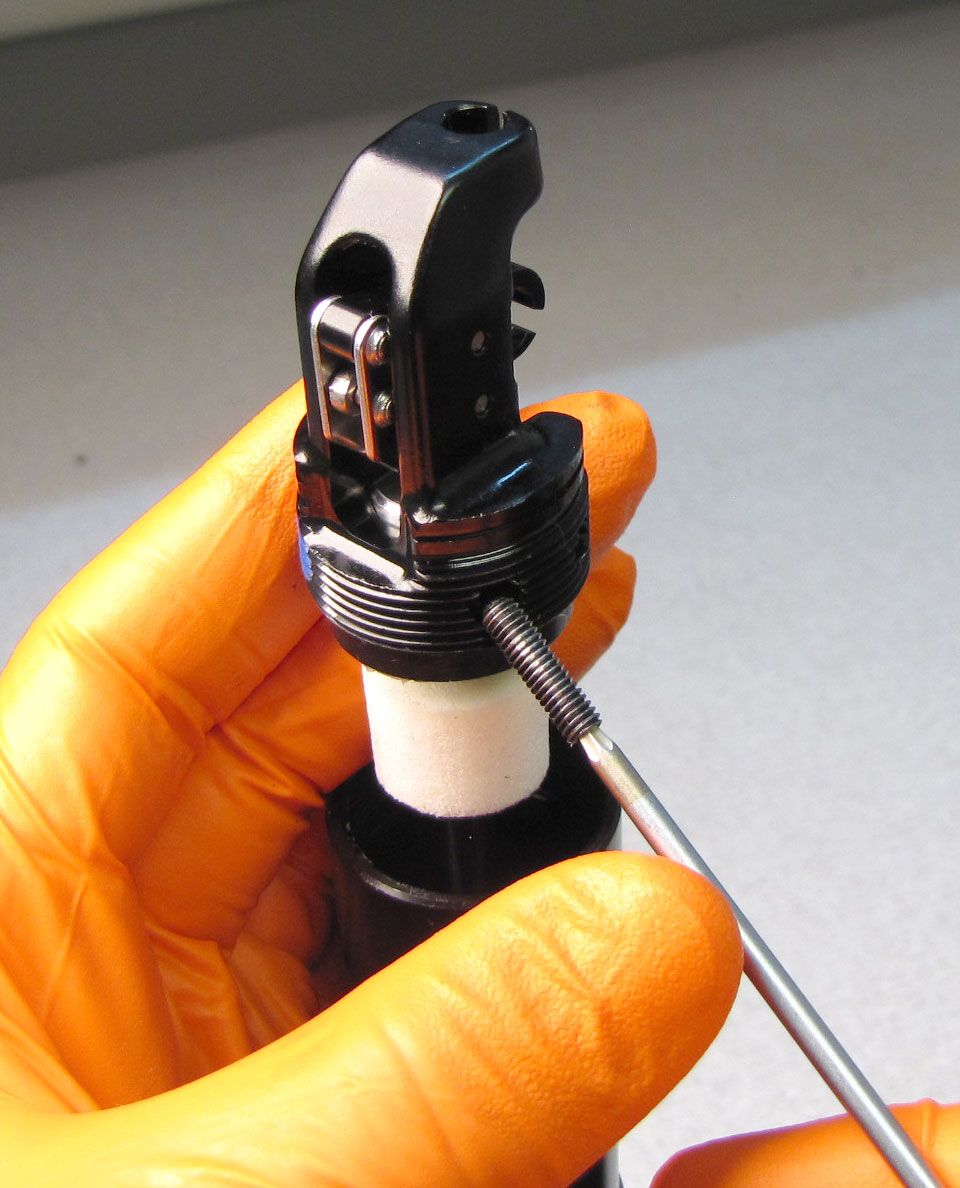
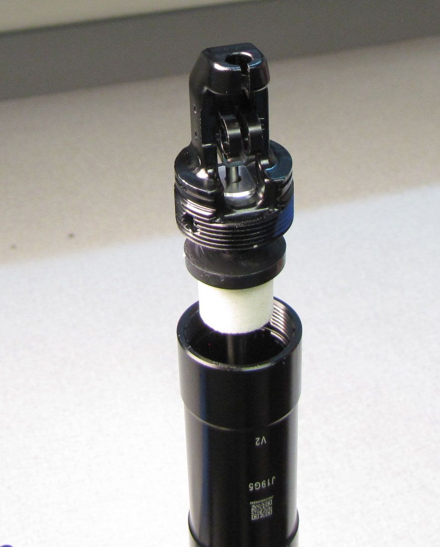
Step 5
Remove the Push Rod by pulling it up and out of the Cartridge Shaft. Note the orientation of the rod's rounded and squared ends. Remove the Cartridge from the seatpost by pulling it up.

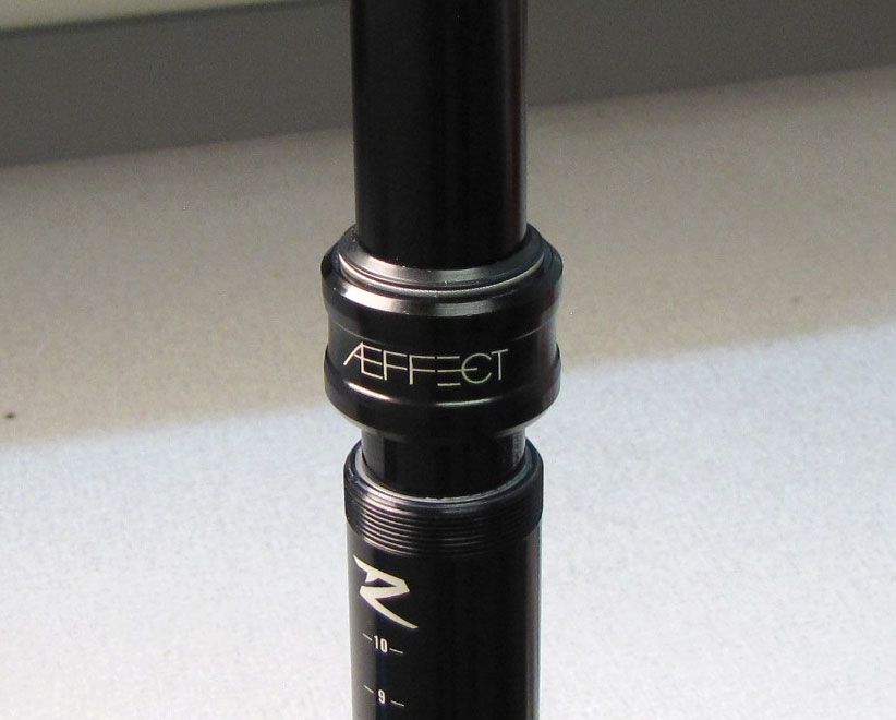
Step 6
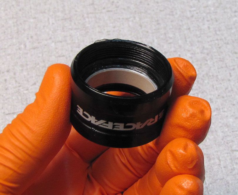
Invert the seatpost in your work stand then unthread the Lower Post Collar counter-clockwise by hand.

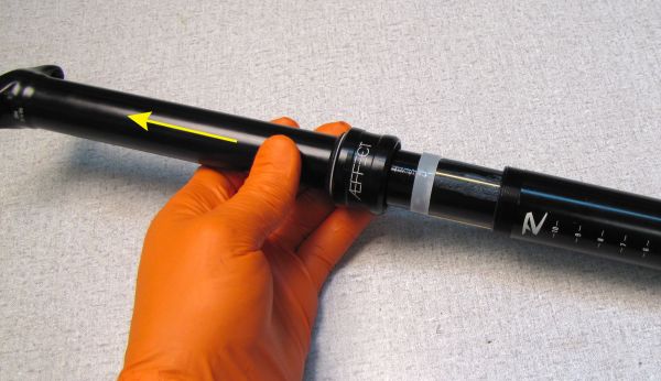
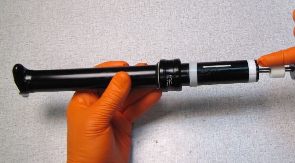
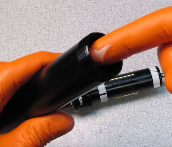
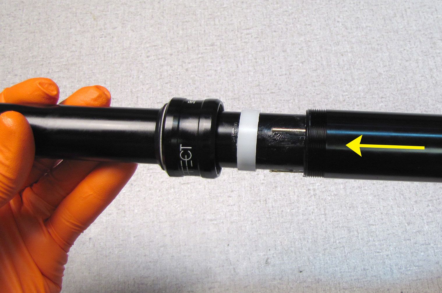
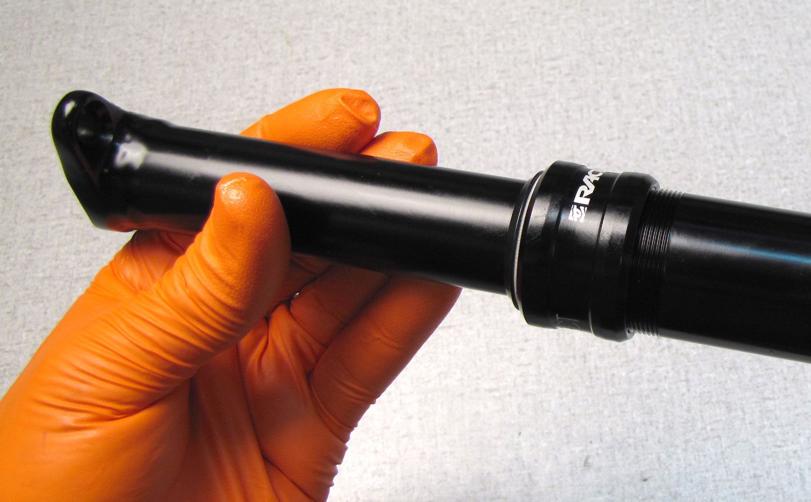
Step 7
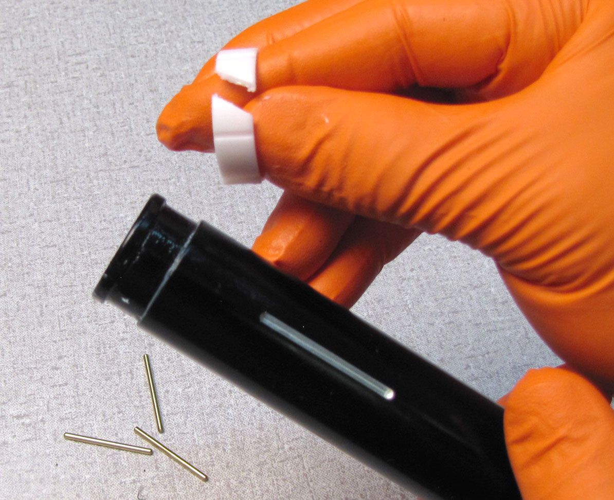
Separate the Upper and Lower posts over your work bench in case any of the brass index pins fall out during disassembly.


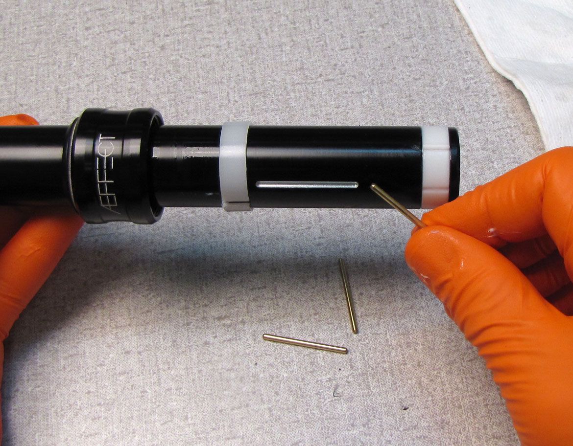
Step 8
Clean off any old grease then remove the index pins and bushings.
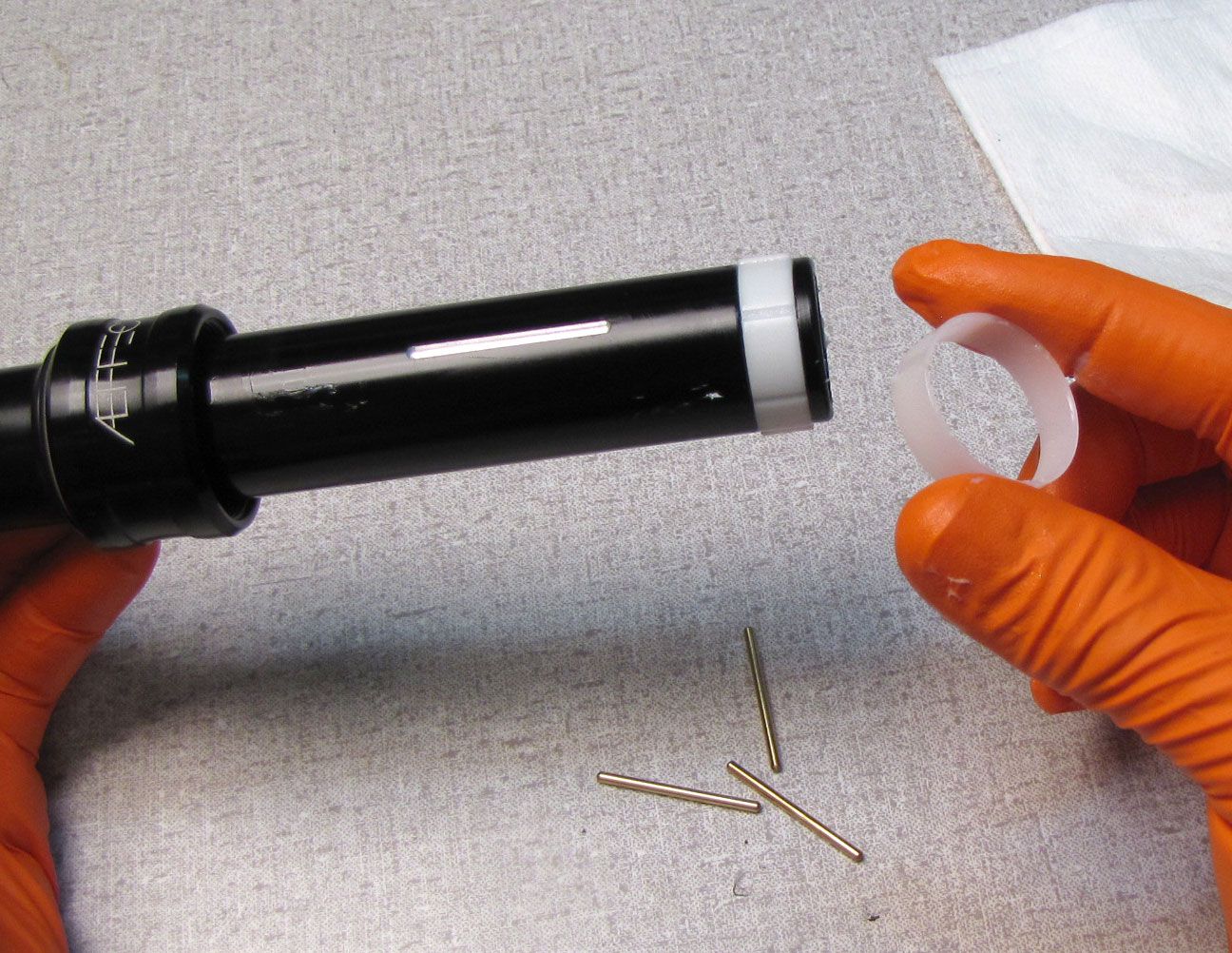
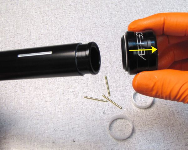
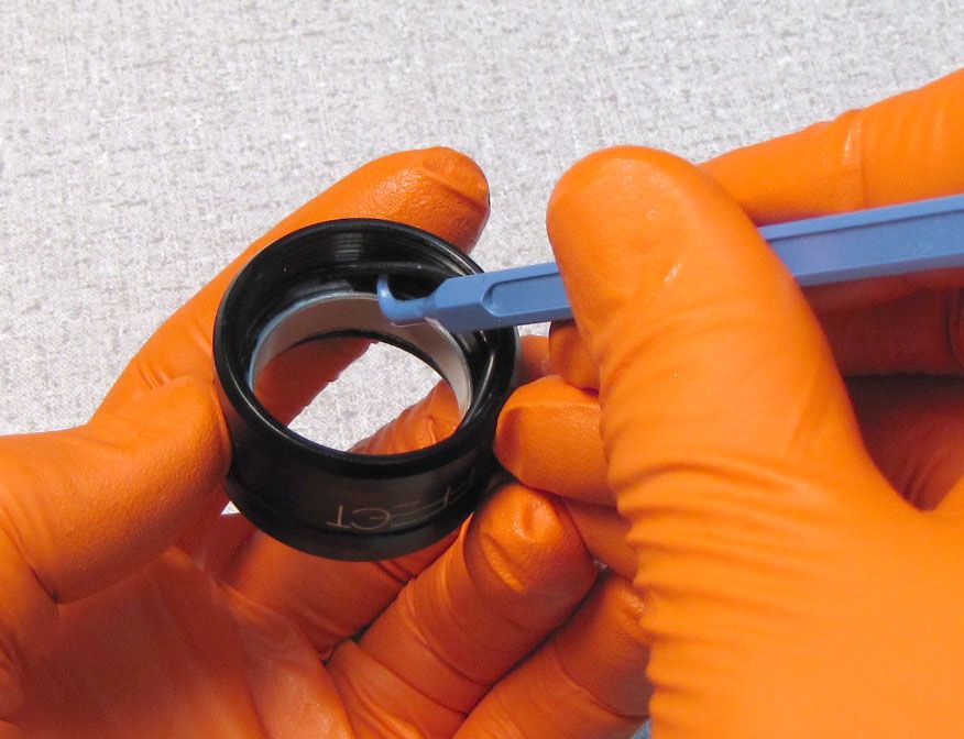
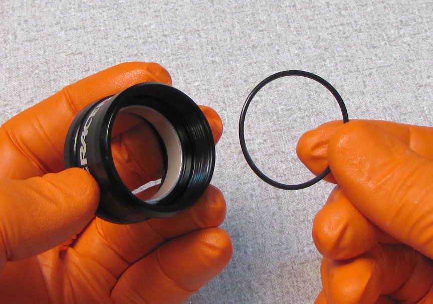
Step 9
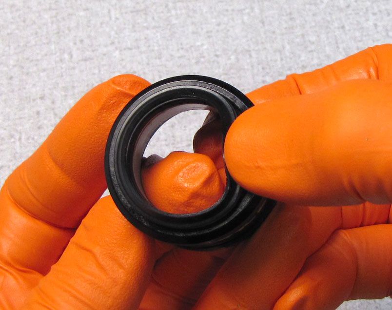
Remove the Lower Post Collar then remove the wiper seal and o-ring.

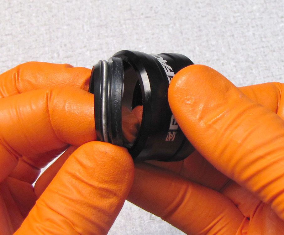
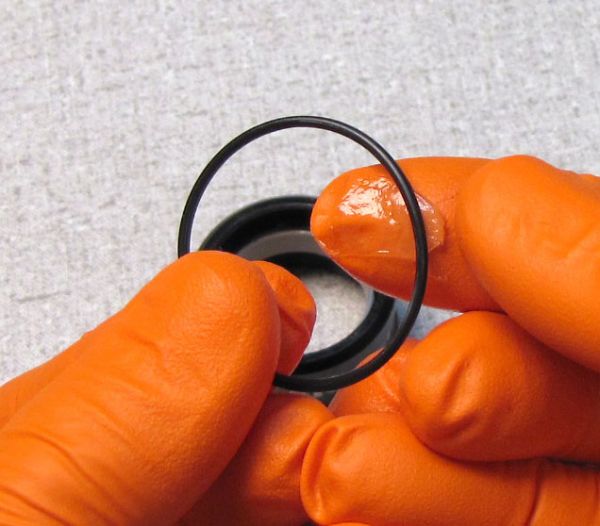
Step 10
Coat the new o-ring with Slick Honey then install it into it's groove. Install the new Wiper seal as shown.

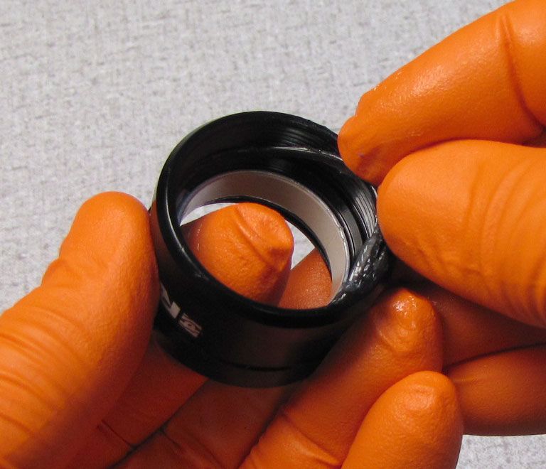

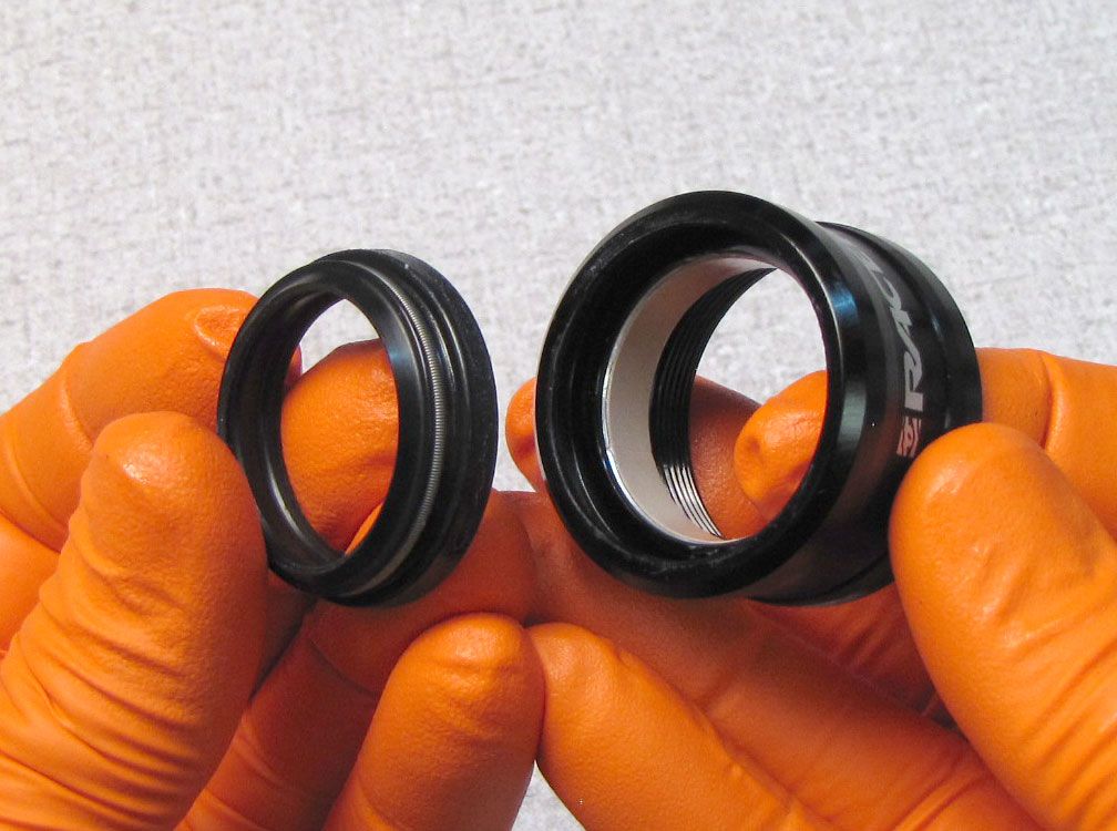
Step 11
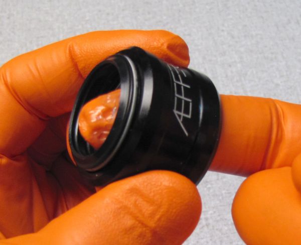
Coat the inside of the Wiper seal with a thin film of Slick Honey then reinstall the Lower Post Collar onto the Upper Post as shown.

Step 12
Install the Cartridge Assembly into the Upper Post as shown. Reinstall the Screw and Washer into the top of the post, tightening clockwise to 35 in-lb (4 Nm) with a 3mm hex wrench.

Step 13
Fill the Index Pin grooves in the Upper Post with Slick Honey to retain the brass Index Pins during assembly. Install the Upper Bushing.


Step 14
Install the Lower Bushing so it's protruding rib is aligned with the Index pin groove oriented toward the front of the seatpost. Install the brass Index Pins.


Step 15
Apply a thin film of Slick Honey to the inside of the Outer Post. Align the front internal groove of the Outer Post with the protrusion on the Lower Bushing and front index pin. Insert the Upper Post Assembly into the Lower Post.


Step 16
Clamp the Lower Post into your clean bike work stand then tighten the Lower Post Collar clockwise until hand tight.

Step 17
Invert the seatpost in your work stand then reinstall the Push Rod with it's flat end first into the Cartridge Shaft. The rounded end should be visible when installed.

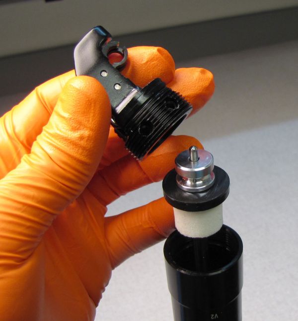
Step 18
Reinstall the Actuator Assembly onto the shaft end. Reinstall the 2 set screws tightening clockwise to 13 in-lb (1.5 Nm) torque with a 2mm hex wrench.

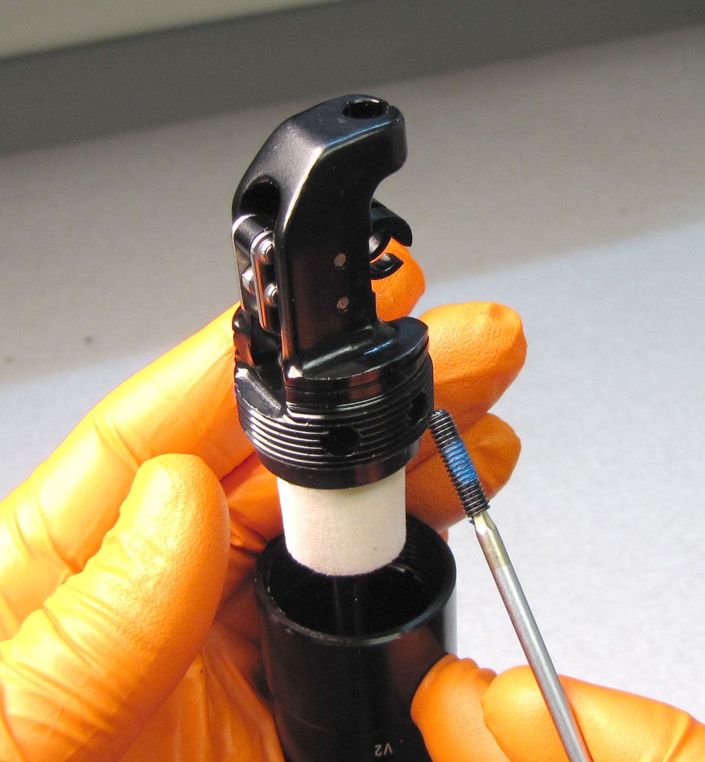

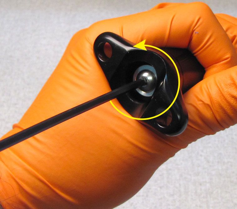
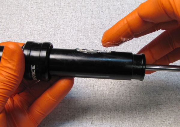
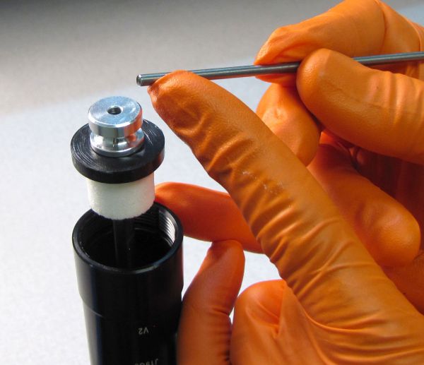
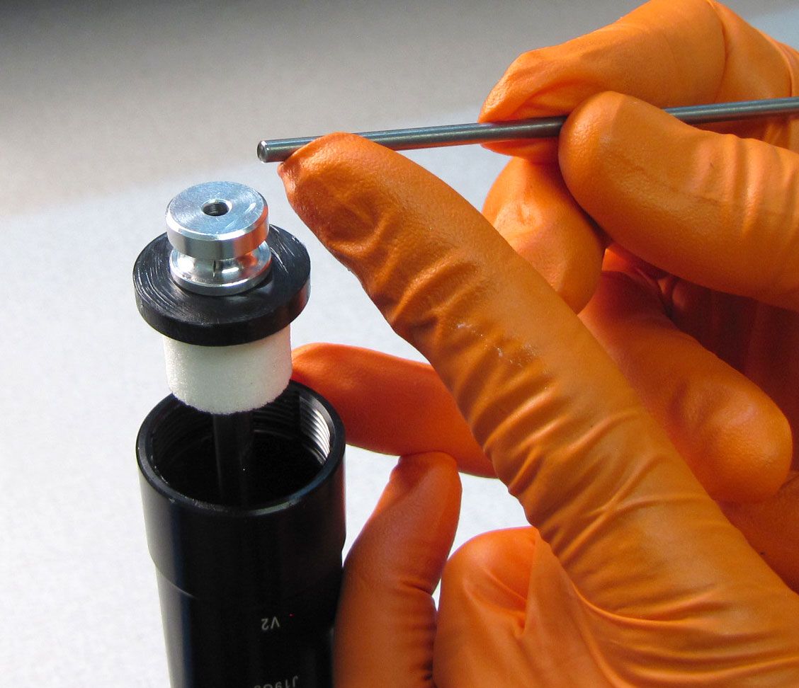
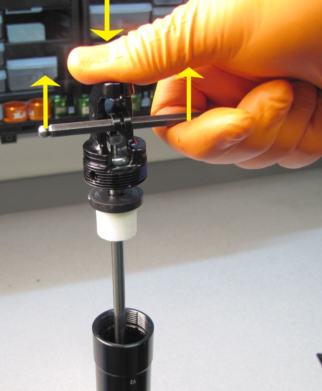
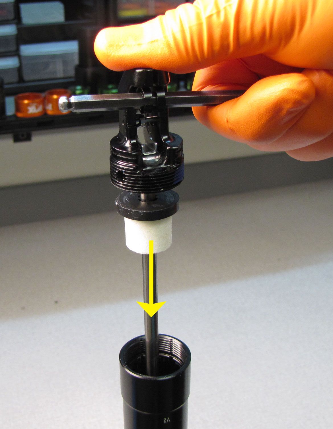
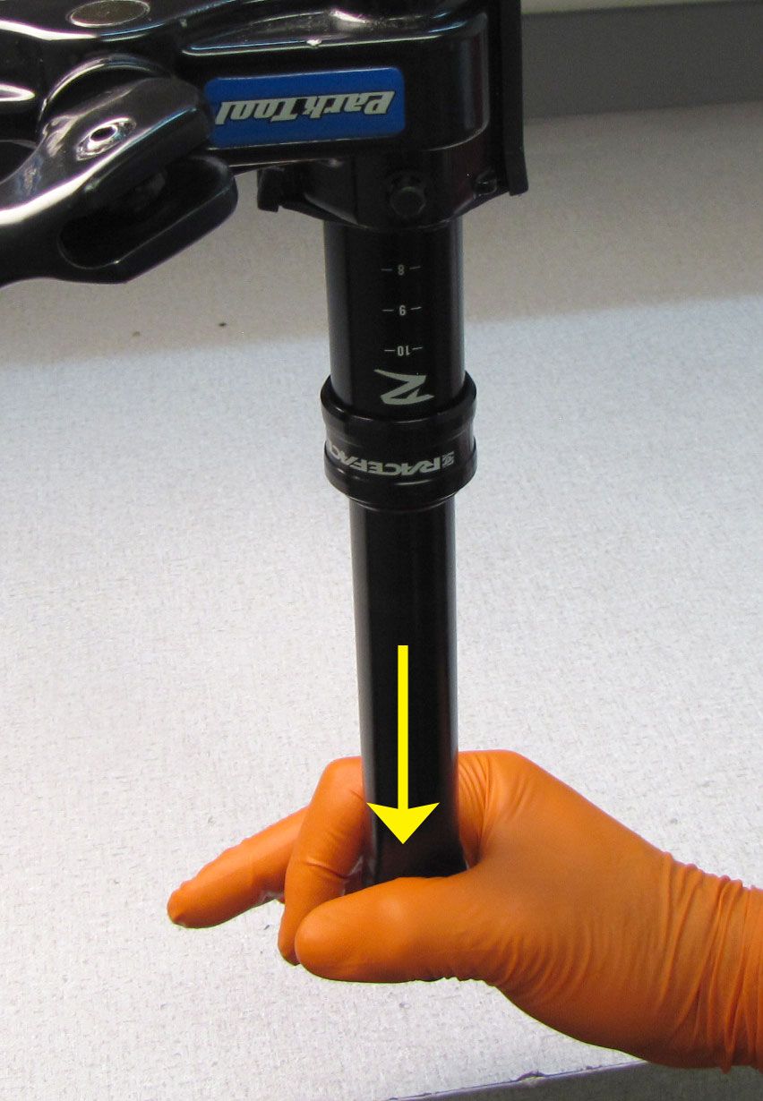
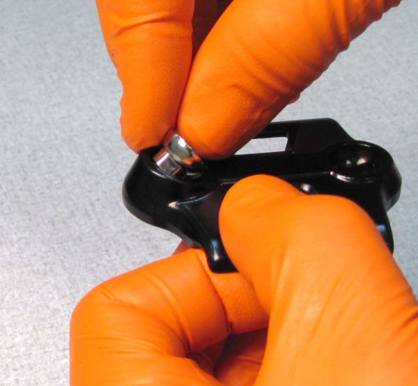
Step 19
Insert a 5mm hex wrench into the Actuator Assembly where the cable barrel would rest. Actuate the post by pulling up on the wrench while pushing down on the Actuator Assembly. This allows for the seatpost cartridge to compress. Compress the seatpost cartridge approximately 20mm by pushing down on the shaft while actuating the post as shown.


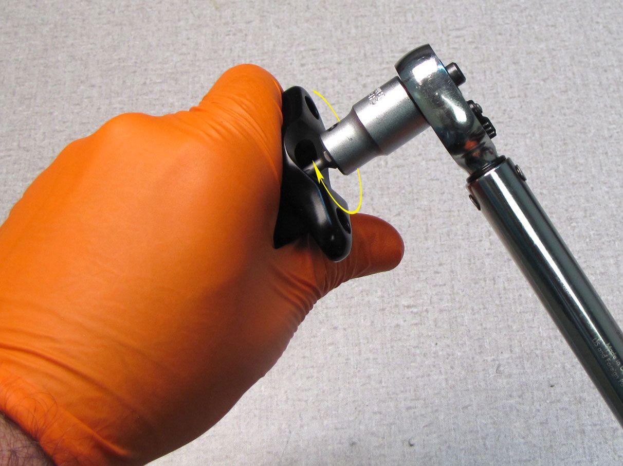
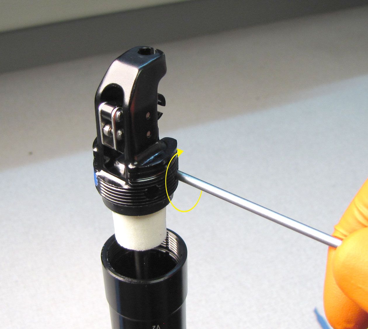
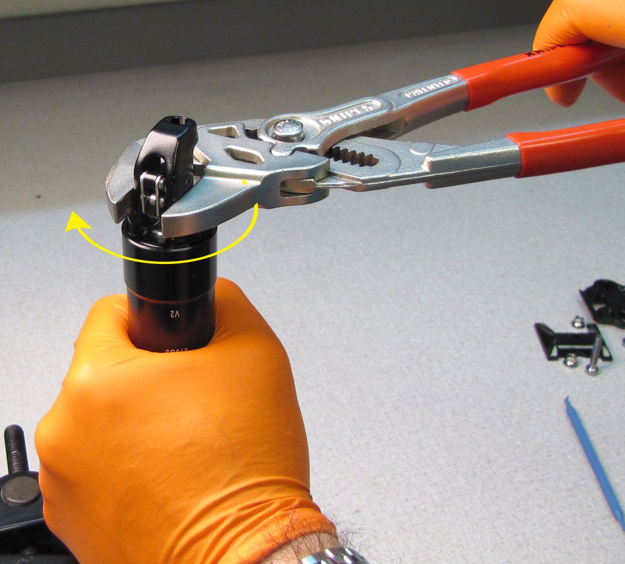
Step 20
Pull down on the Upper Post to bring the Actuator Assembly to the end of the Outer Post. Invert the seatpost in your work stand then thread the Actuator Assembly into the Outer Post by turning it clockwise to 70 in-lb (8 Nm) torque with smooth-jawed parallel pliers (Knipex).


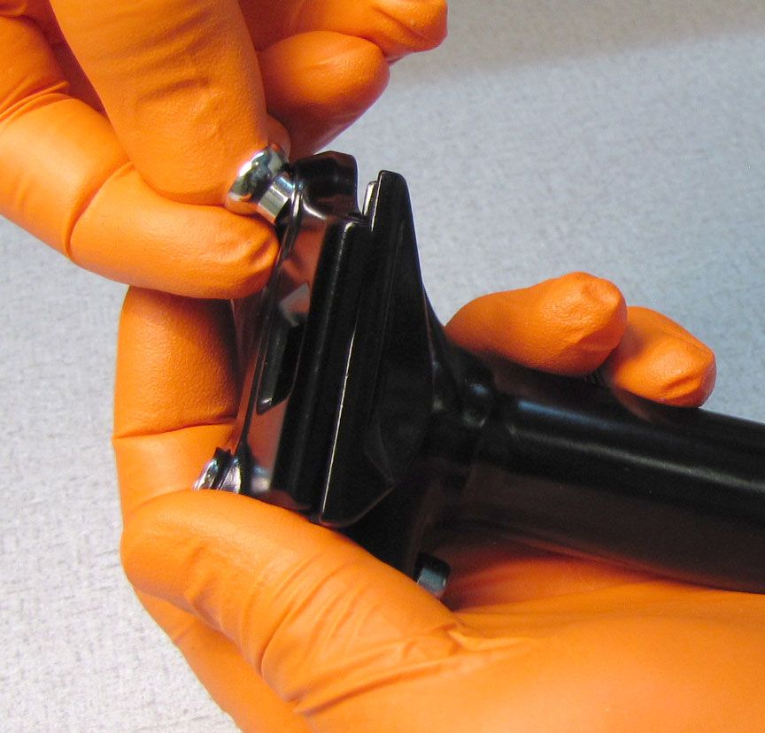
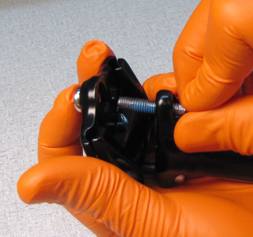
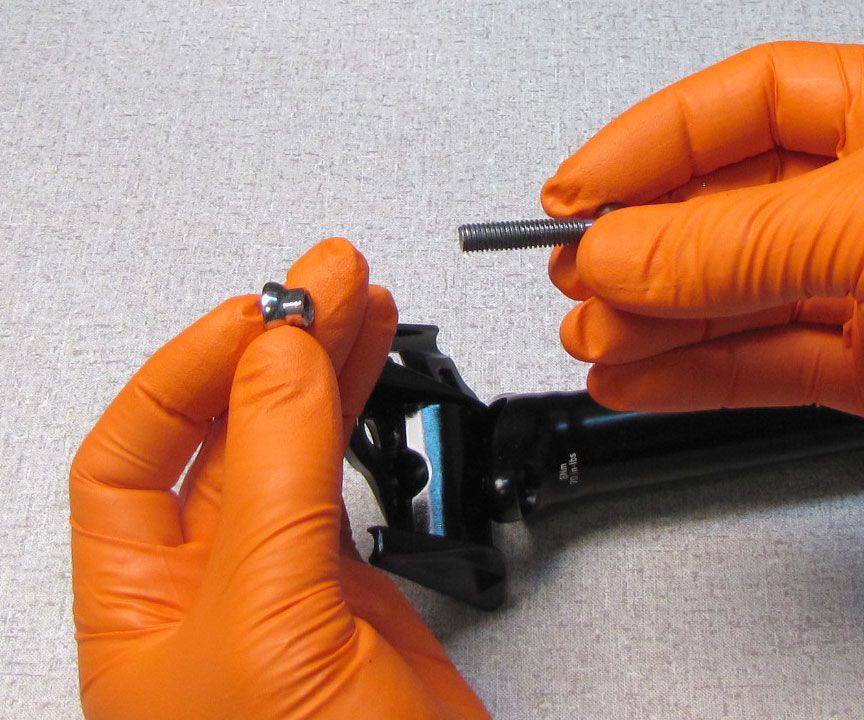
Step 21
Reinstall the Saddle Nuts into the Upper Saddle Clamp as shown. Orient the Upper Saddle clamp so it's arrow faces the front of the post. Orient the Lower Saddle clamp so the longer rail supports are facing the rear of the post. Reinstall the bolts, threading them in clockwise. Test the post for proper function then clean the exterior.