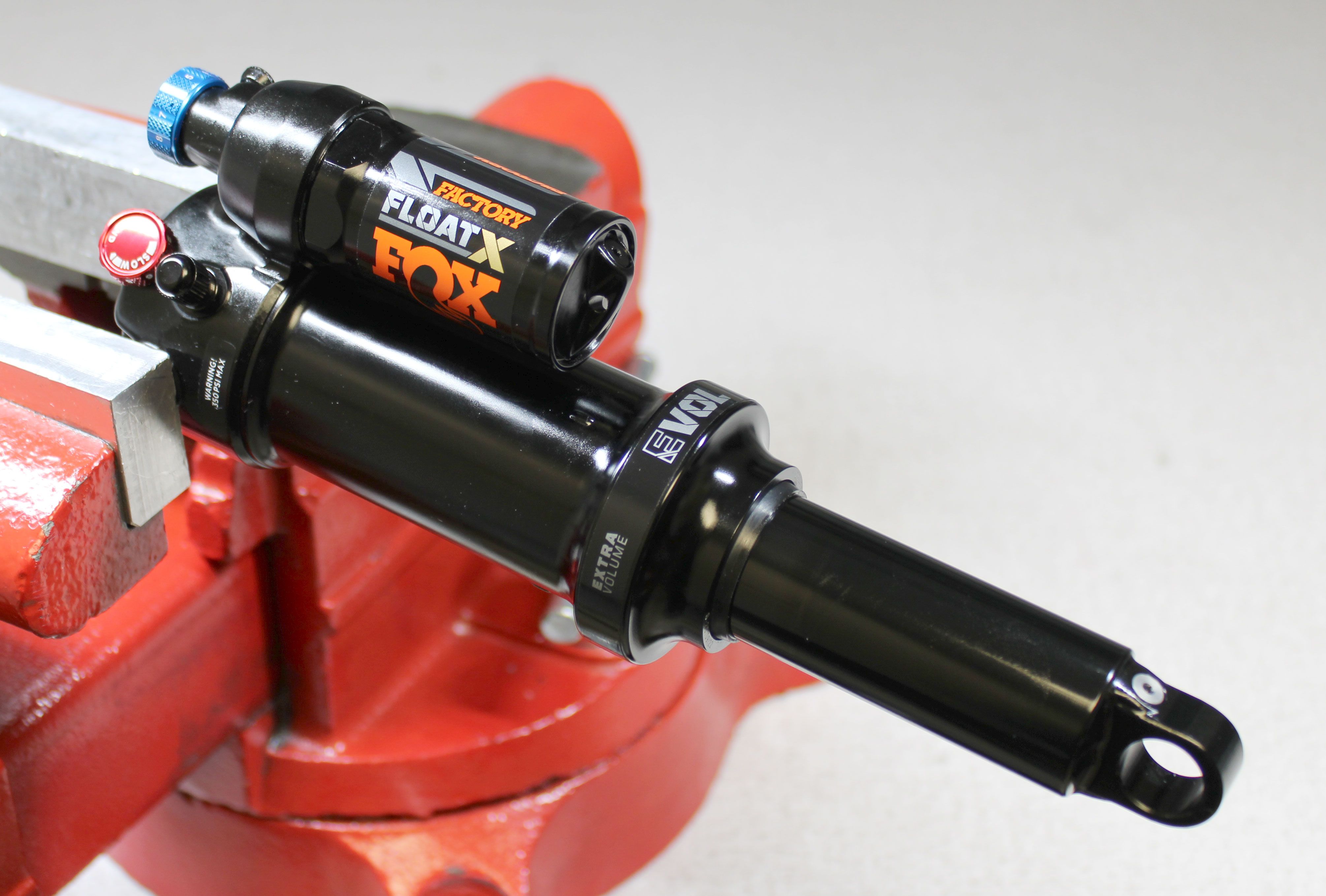
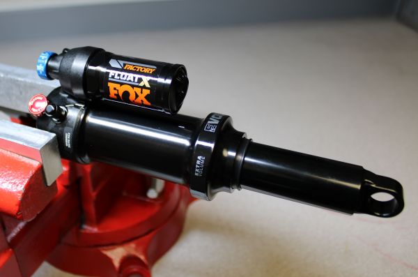
2022 FLOAT X Rebuild
Required Parts
- 025-03-063 Oil: Suspension Fluid, 4 WT, 1.0 Liter Bottle
- 803-01-727 Seal Kit: 2022 Float X Air Sleeve
- 803-04-008 Seal Kit: 2024 FLOAT X Rebuild
Required Tools
- 398-00-280 Tooling: Eyelet Torque Tool
- 398-00-558 Tooling: Pin Spanner Wrench
- 398-00-951 Tooling: Torque Fixture, 54mm Trunnion Eyelet, Tall
- 803-00-805 Kit: Shaft Clamps, Shocks, CTD 9mm, 3/8in, 1/2in, 5/8in
- 803-01-691 Kit: Tooling, .210-36 Vacuum Oil Fill, 2022 Shock, Andreani Thread, with O-ring
- 803-01-692 Kit: Tooling, Rear Shock, Air Fill Adaptor, MY 2022, with O-ring
WARNING: Always wear safety glasses and protective gloves during service to prevent potential injury. Failure to wear protective equipment during service may lead to SERIOUS INJURY OR DEATH.
NOTE: As many assemblies are shared between the FLOAT X and DHX shocks, some images in this rebuild procedure may show a DHX shock. Please follow all instructions in this rebuild as they are for FLOAT X shocks.
WARNING: Never attempt to pull apart, open, disassemble, or service a FOX shock that is in a “stuck down” condition. A “stuck down” condition results from a failure of the dynamic air seal, resulting with the negative chamber retaining a higher pressure than the positive chamber. To test whether the shock is in fact “stuck down”:
- Remove the air cap, connect your FOX high-pressure pump to the Schrader valve, then slowly release all air pressure from the positive chamber of the shock.
- If the shock body retracts into the air sleeve near bottom-out after the air is released from the positive chamber, attach a FOX high-pressure pump and pressurize the shock to 250 psi (17 bar).
- If the shock does not fully extend, it is in a “stuck down” condition.
- Any attempt to service FOX air shocks in the “stuck down” condition can lead to SERIOUS INJURY OR DEATH. Contact FOX or an Authorized Service Center for repair.
WARNING: FOX products should be serviced by a qualified bicycle service technician, in accordance with FOX specifications. If you have any doubt whether or not you can properly service your FOX product, then DO NOT attempt it. Improperly serviced products can fail, causing the rider to lose control resulting in SERIOUS INJURY OR DEATH.
WARNING: Modification, improper service, or use of aftermarket replacement parts with FOX forks, shocks, and seatposts may cause the product to malfunction, resulting in SERIOUS INJURY OR DEATH. DO NOT modify any part of a fork, shock, or seatpost including the fork brace (lower leg cross brace), crown, steerer, upper and lower leg tubes, or internal parts, except as instructed herein. Any unauthorized modification may void the warranty, and may cause failure or the fork or shock, resulting in SERIOUS INJURY OR DEATH.
WARNING: FOX products contain pressurized nitrogen, air, oil, or all 3. Misuse can cause property damage, SERIOUS INJURY OR DEATH. DO NOT puncture, incinerate or crush any portion of a FOX product. DO NOT attempt to disassemble any portion of a FOX product, unless expressly instructed to do so by the applicable FOX technical documentation, and then ONLY while strictly adhering to all FOX insturctions and warnings in that instance.
NOTE: Only use FLOAT X specific volume spacers in FLOAT X shocks. Usage of volume spacers intended for other products may cause internal damage that could require replacement of the eyelet assembly or other components.
NOTE: Do not overtighten the air valve core when reinstalling into the eyelet if it has been removed. Thread the air valve core in clockwise until the plunger of the air valve core is 0.010"-0.040" below the level of the Schrader valve housing.
Disassembly
Step 1
Remove the black air cap and thread on your FOX shock pump. Slowly release all air from the main air chamber with your pump, then remove the pump. Verify that all air has been released by depressing the Schrader valve.

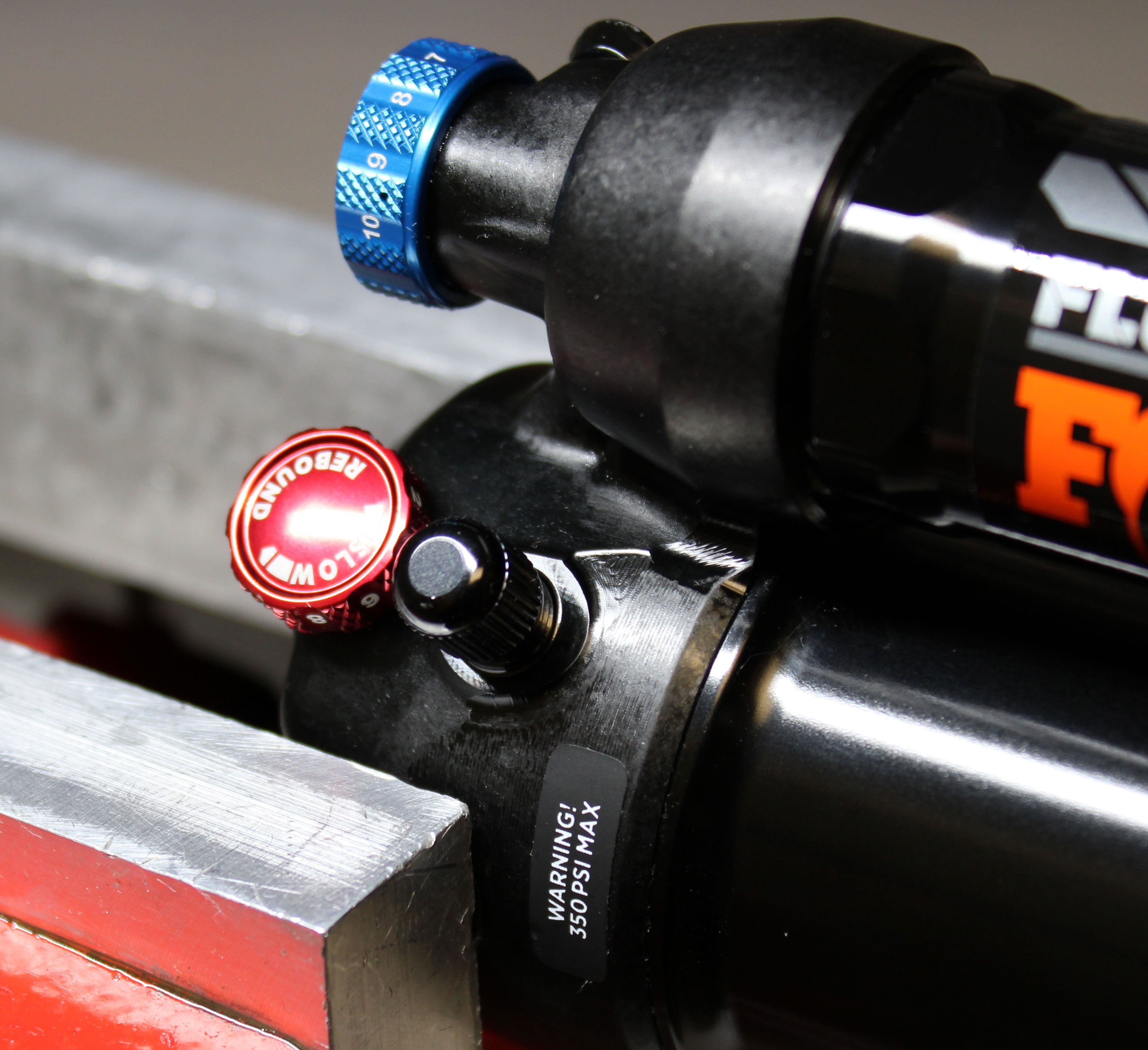
WARNING: Please verify that all air has been released from the air chamber by pushing down on the Schrader valve core. Failure to release all air pressure before further disassembly may cause parts to eject causing SEVERE INJURY OR DEATH.
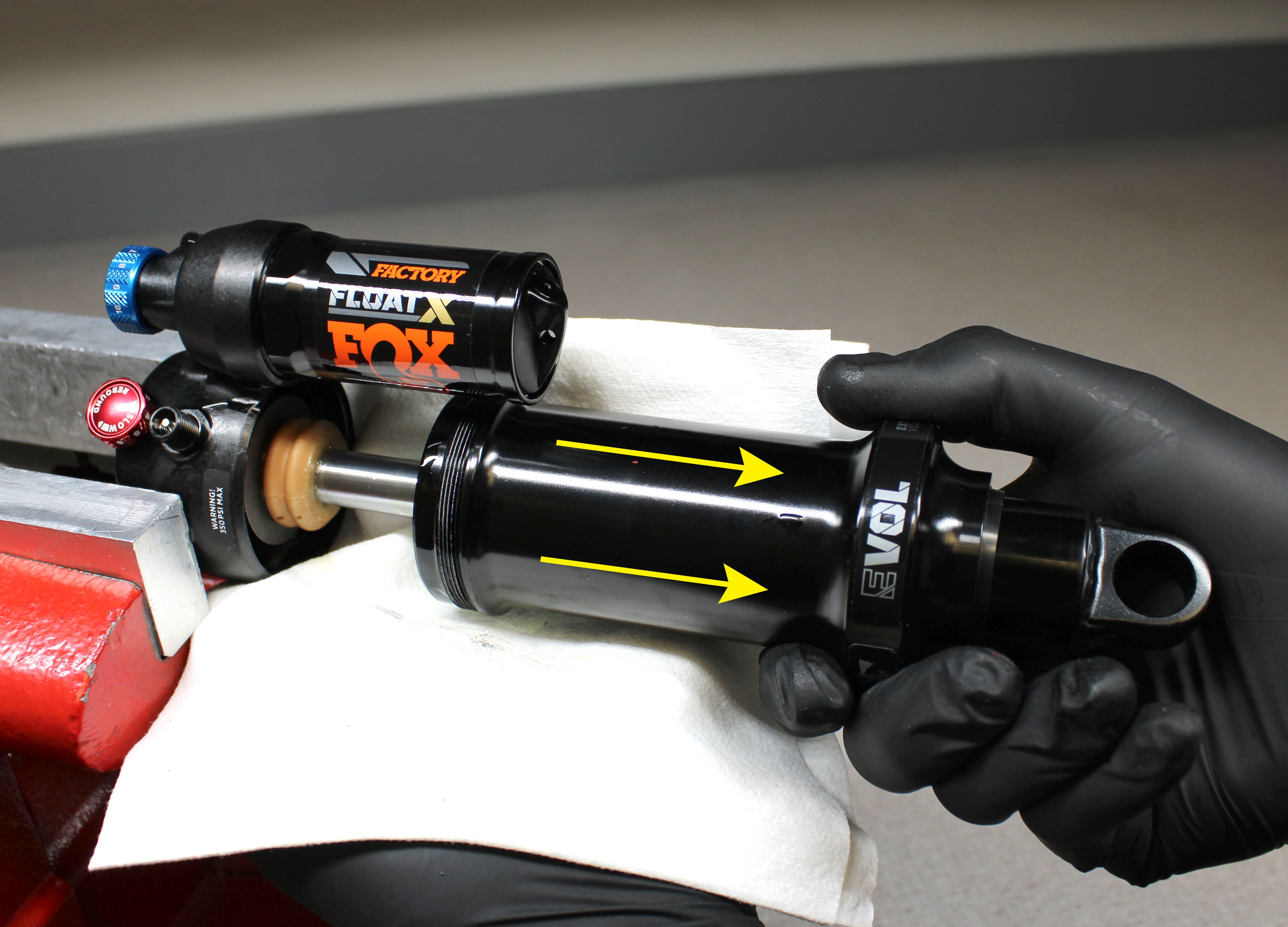
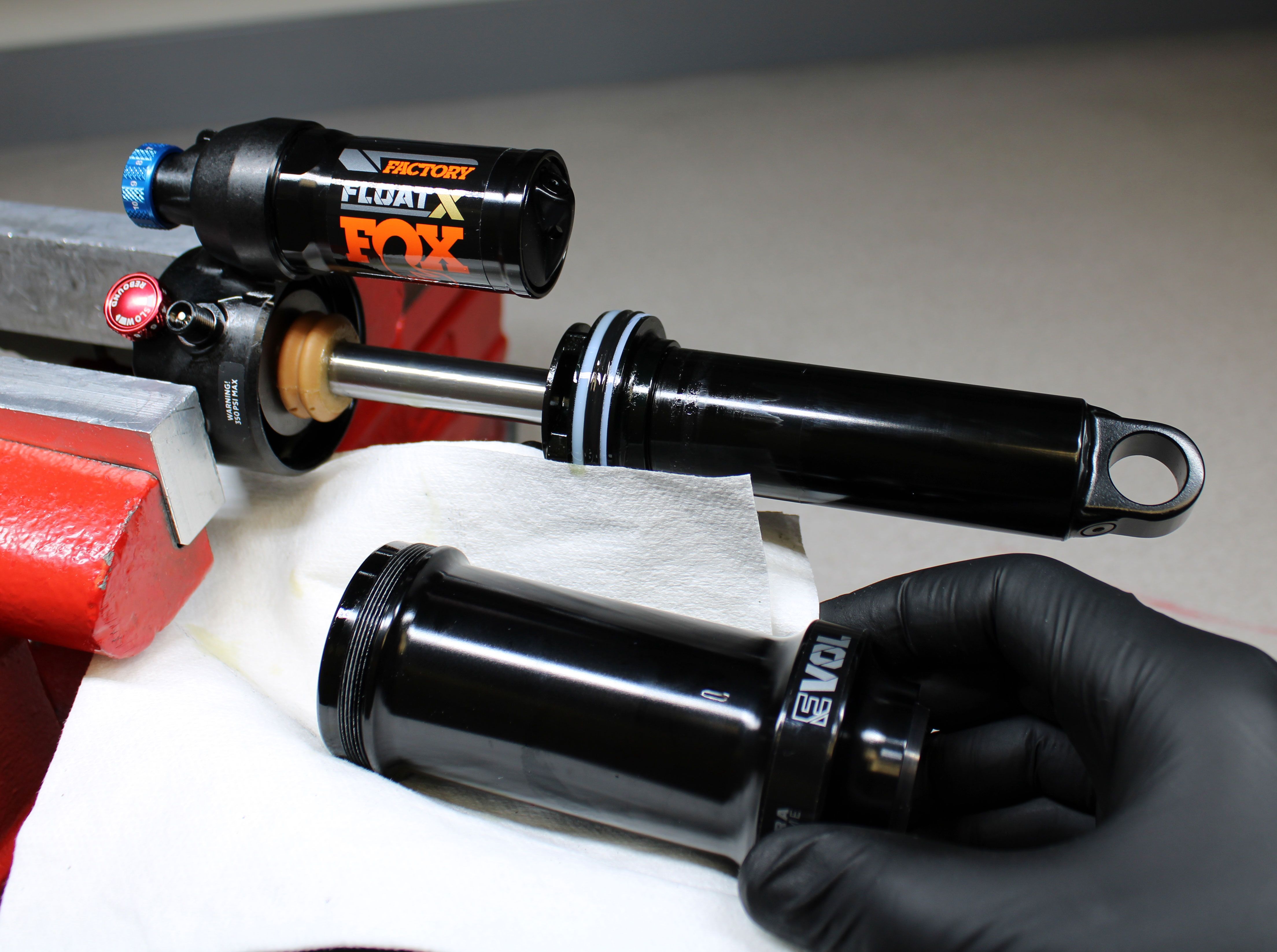
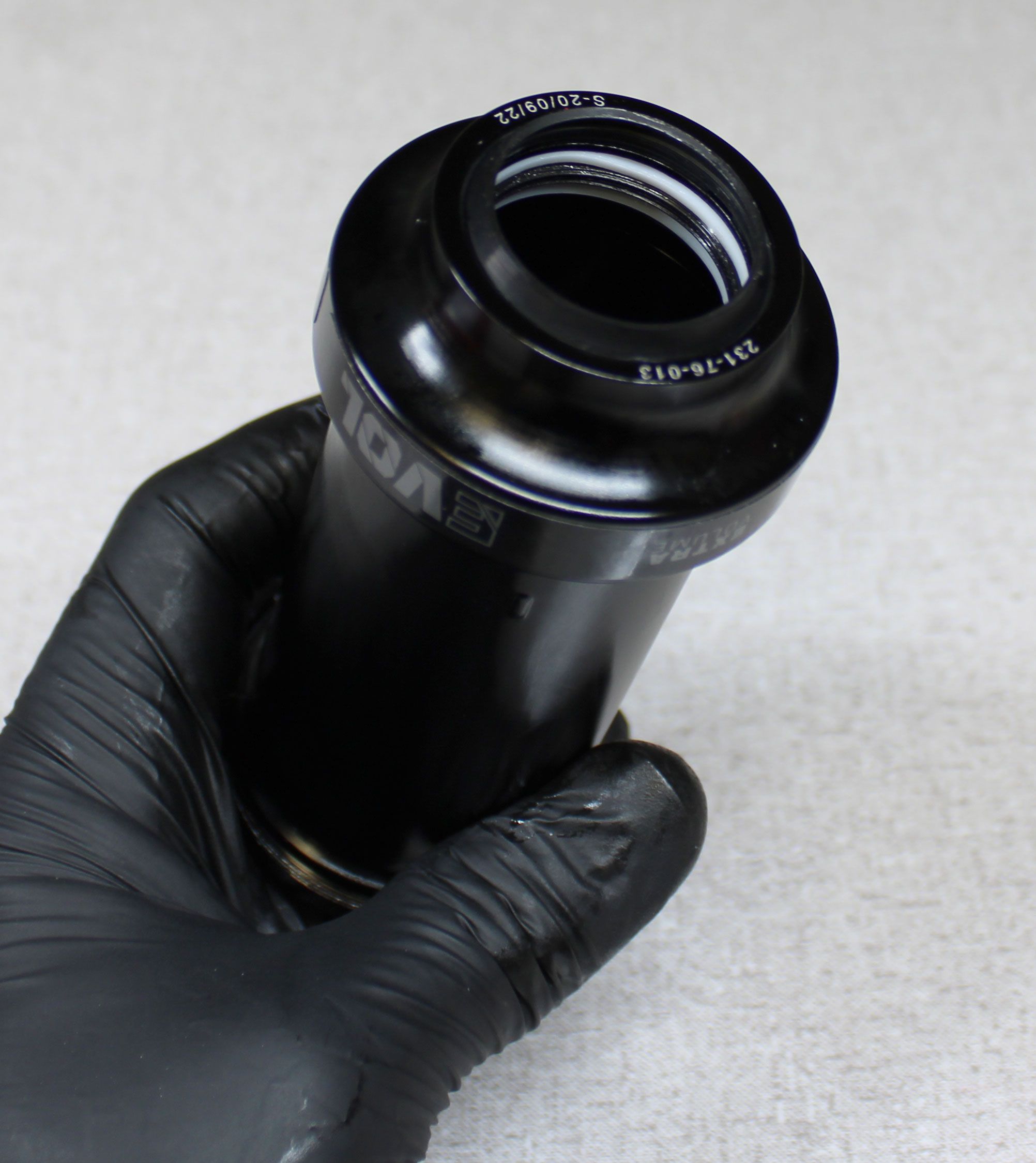
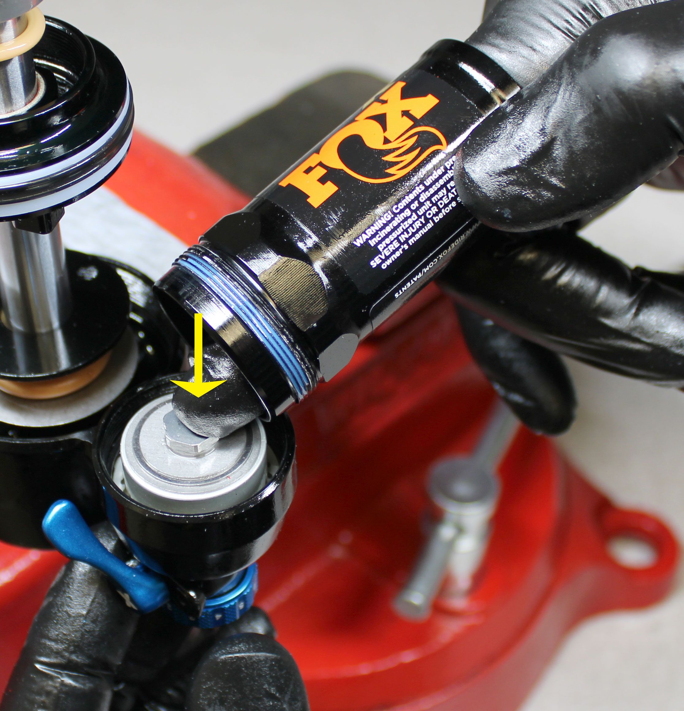
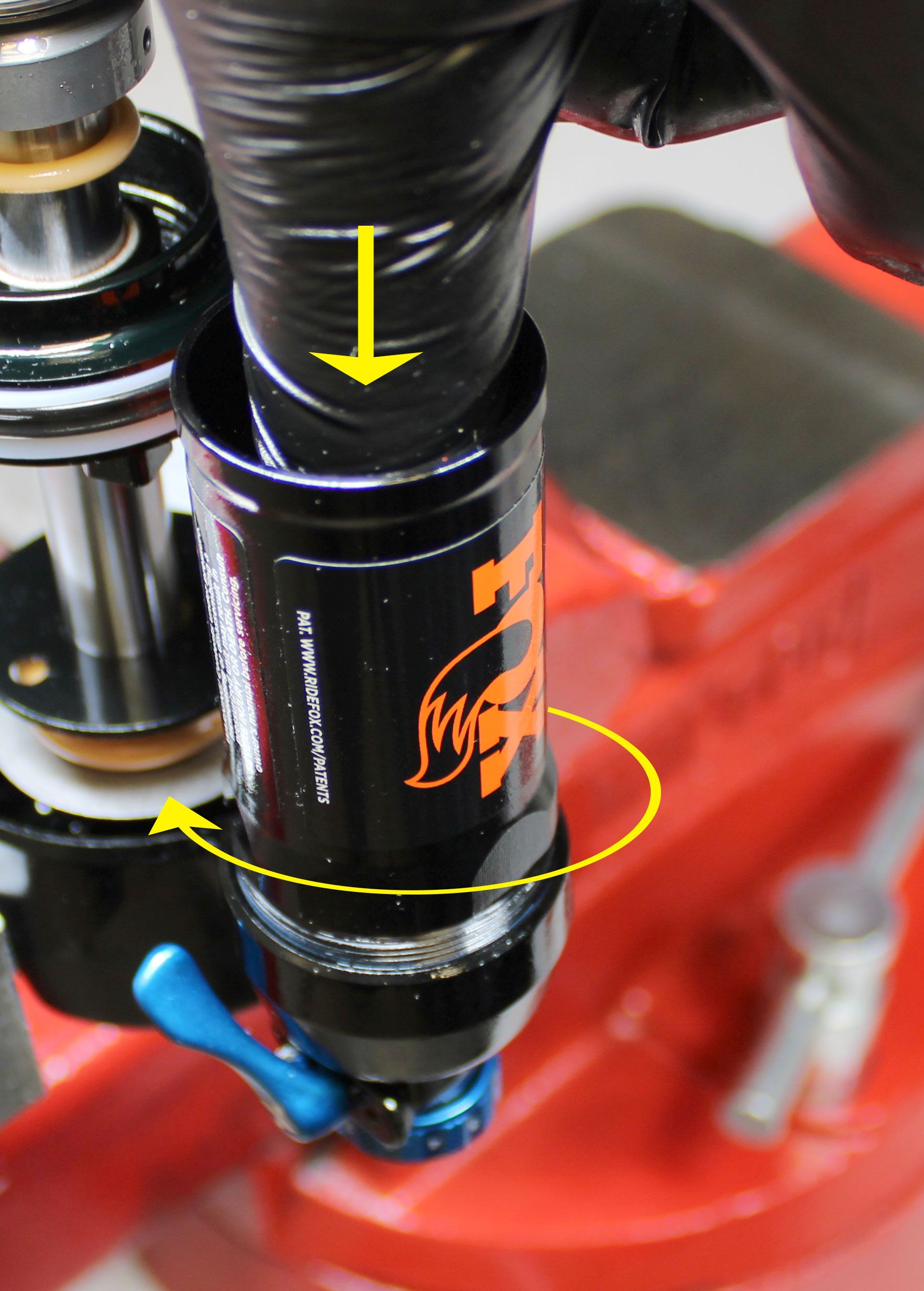
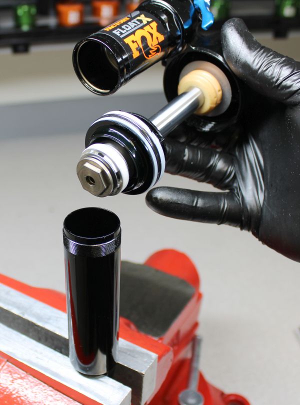
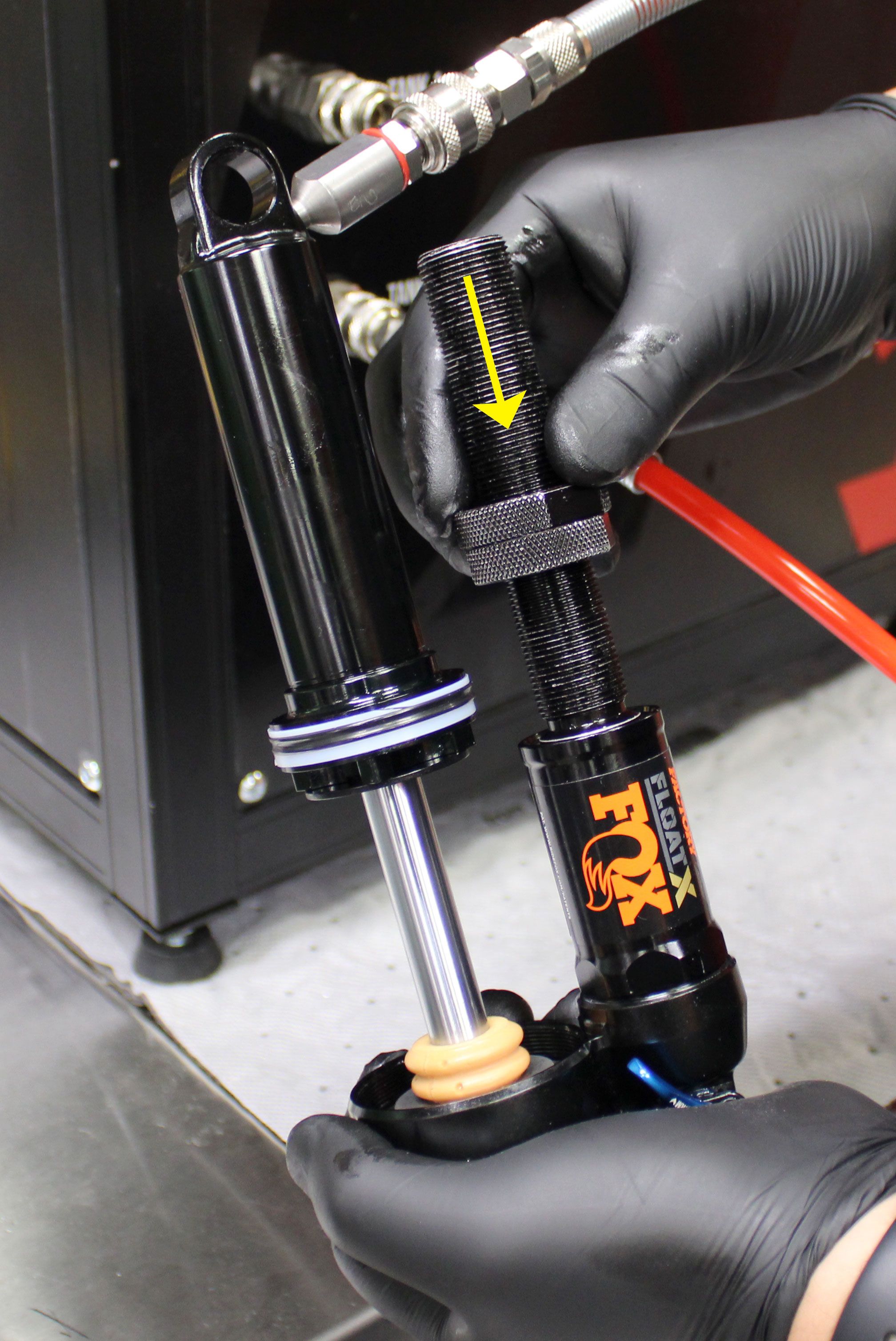
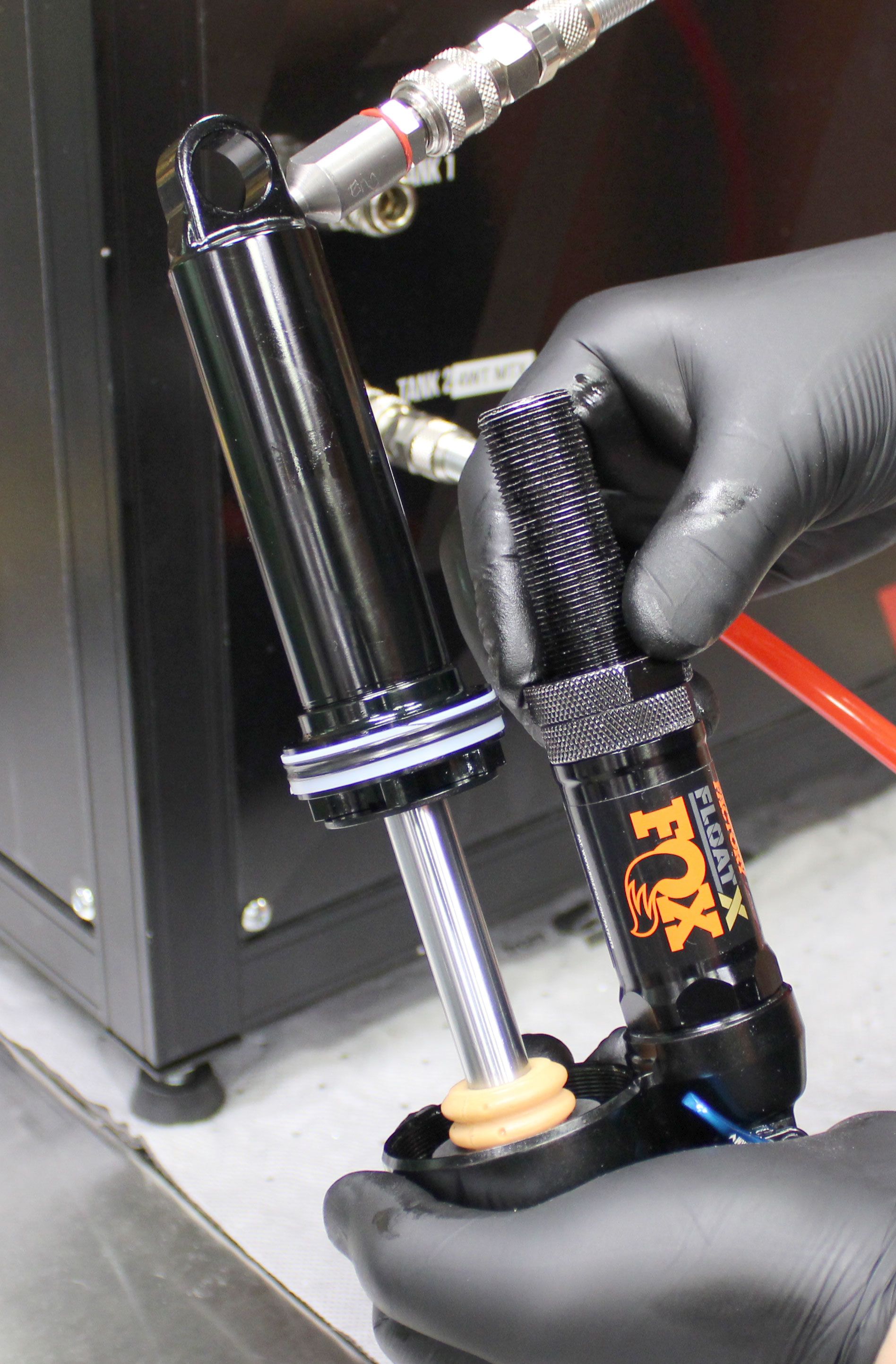
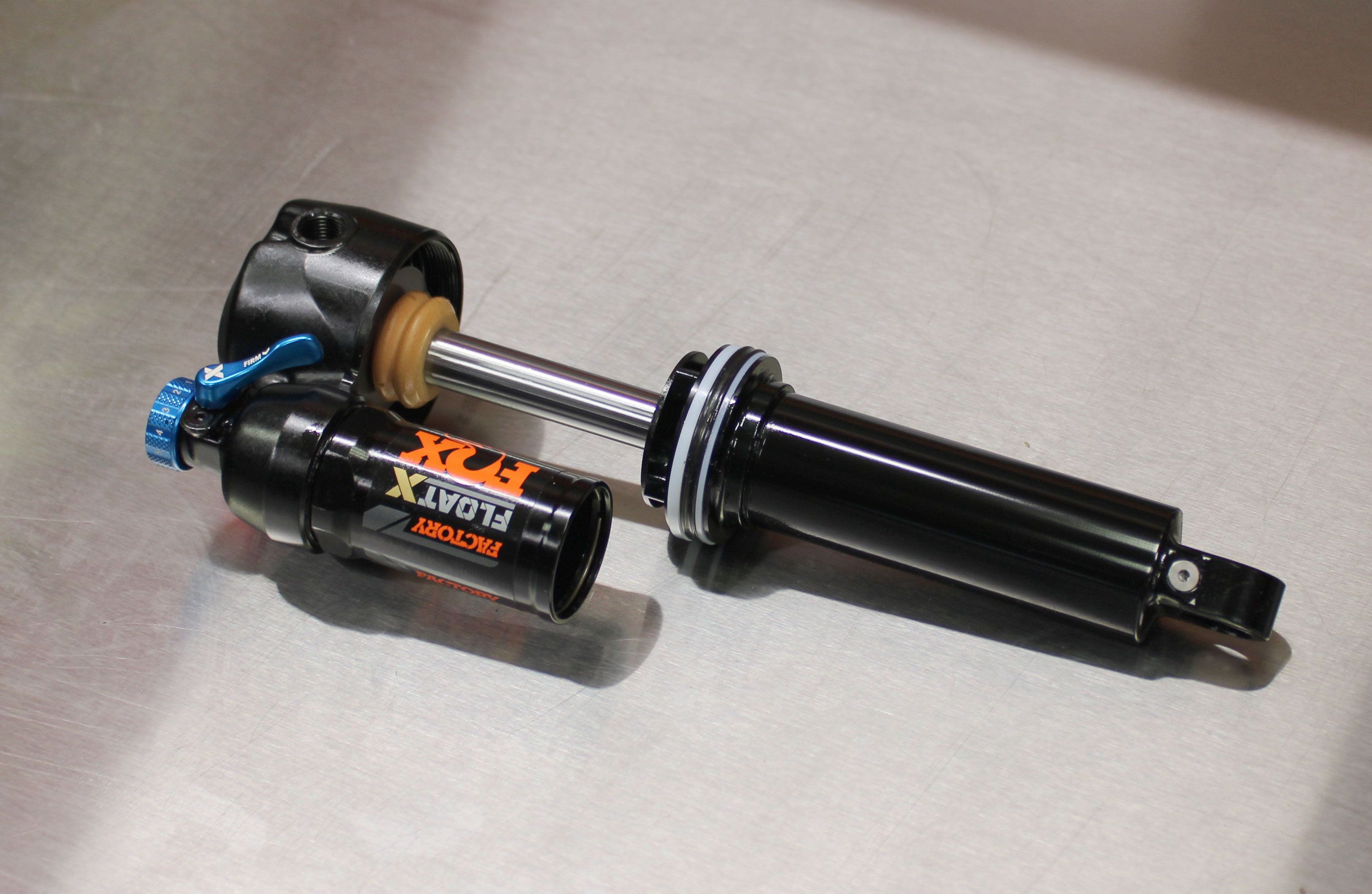
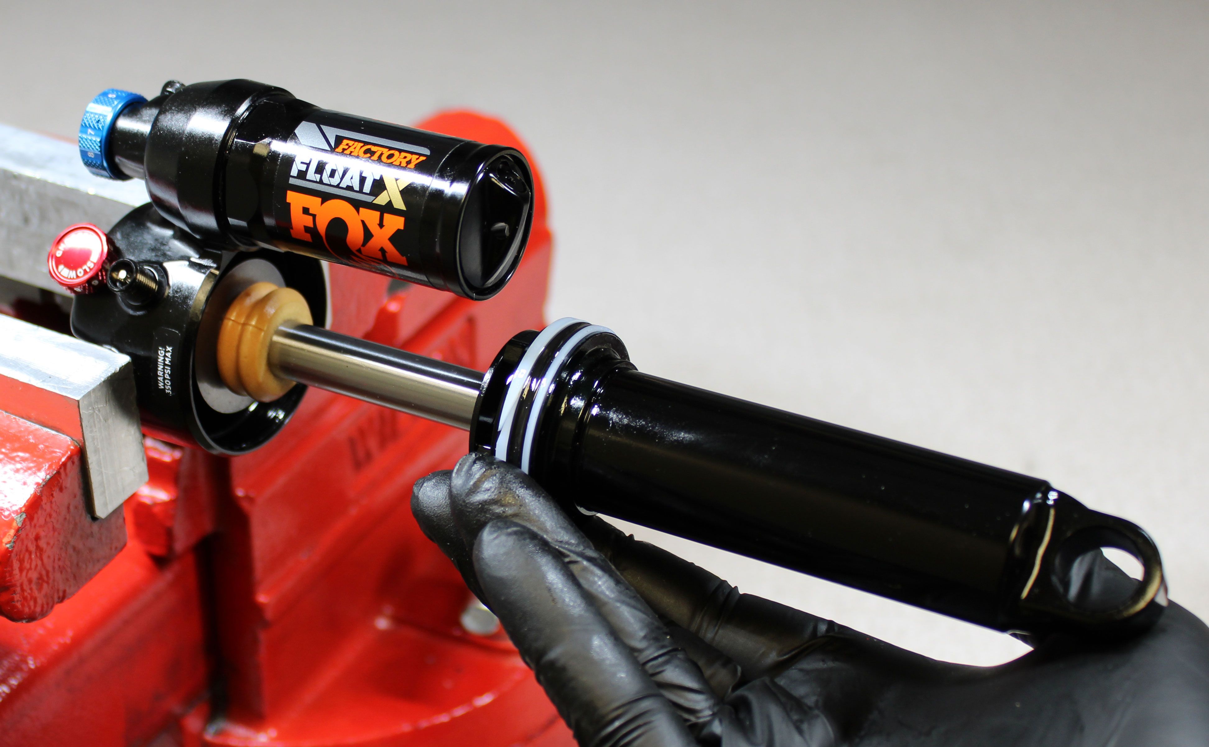
Step 2
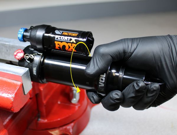
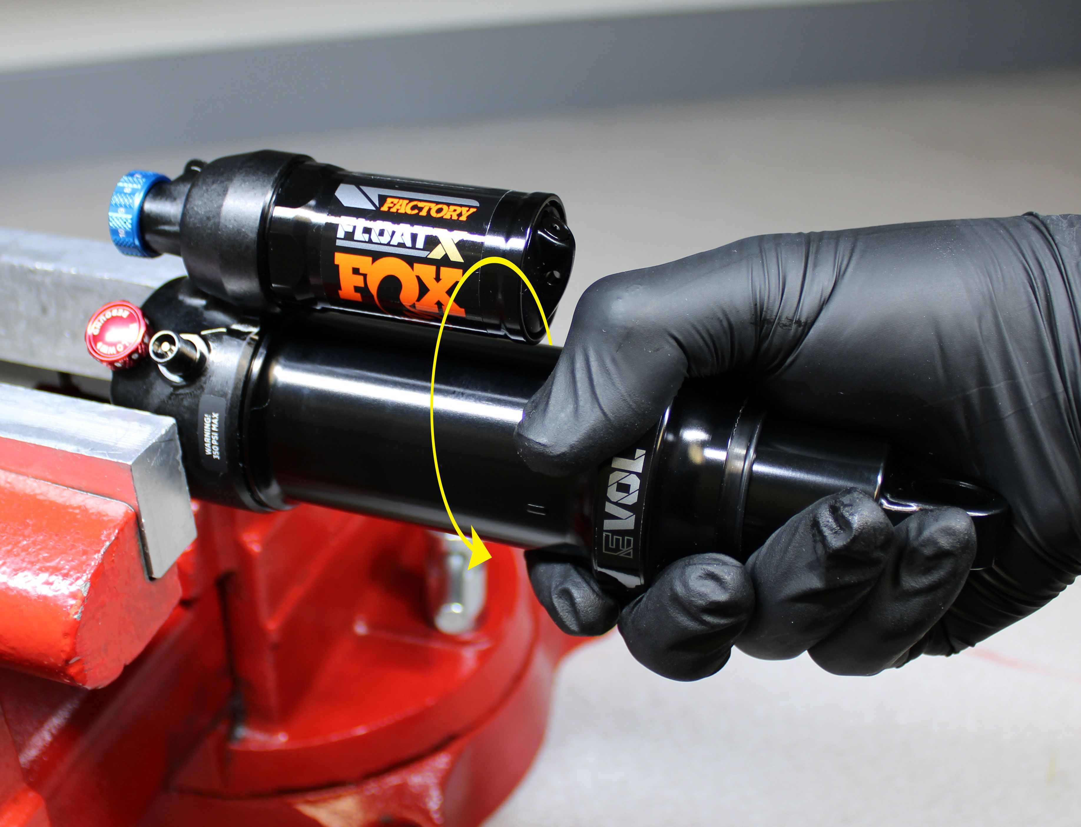
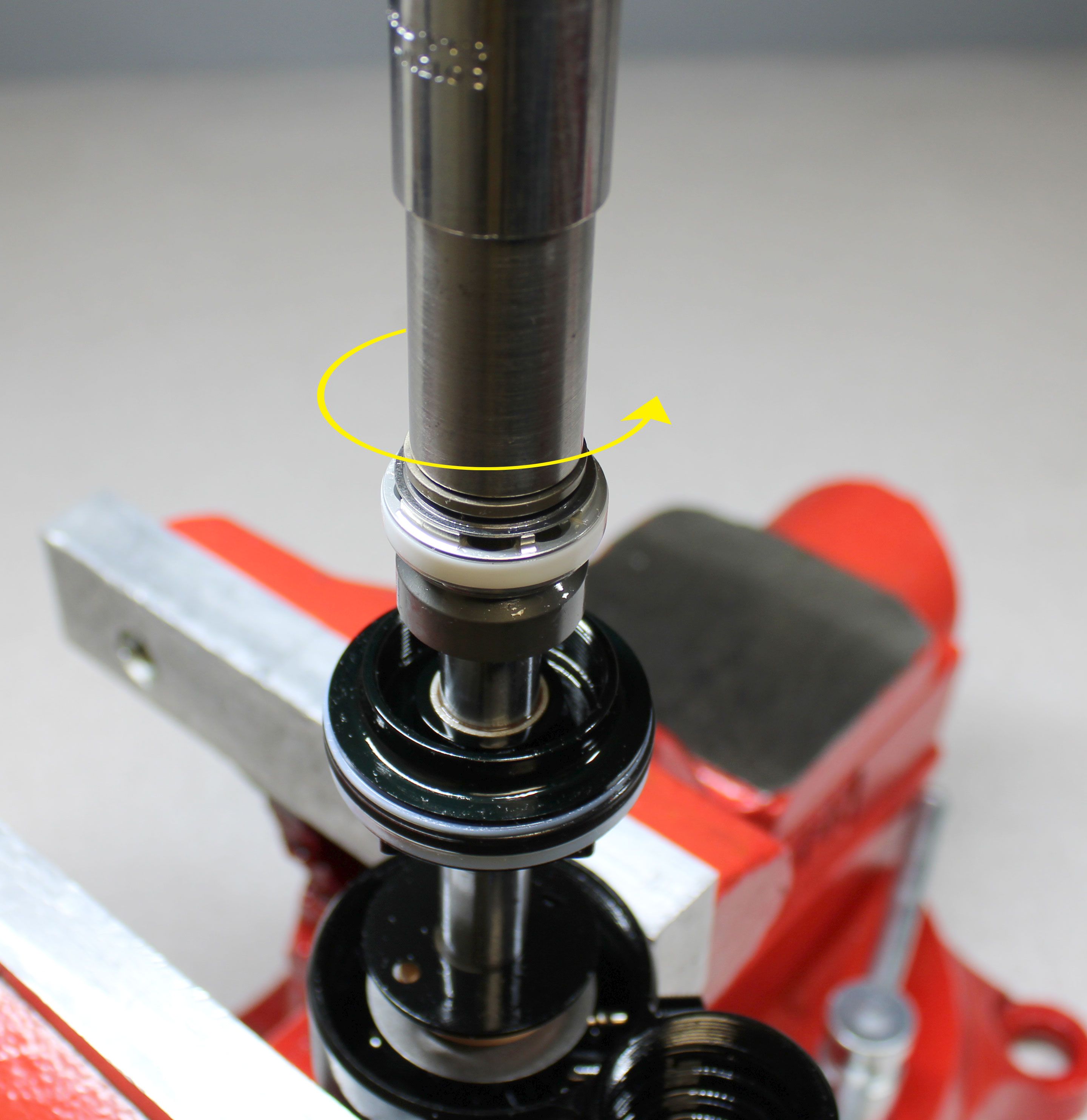
Unthread and remove the air sleeve from the eyelet by turning it counter-clockwise.
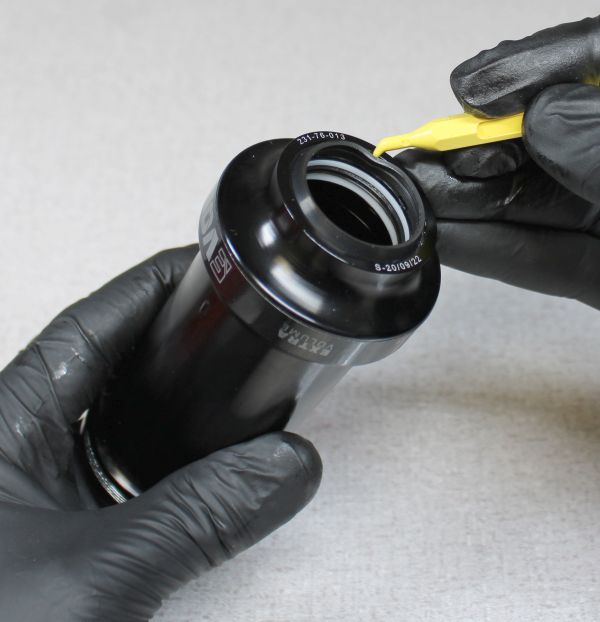
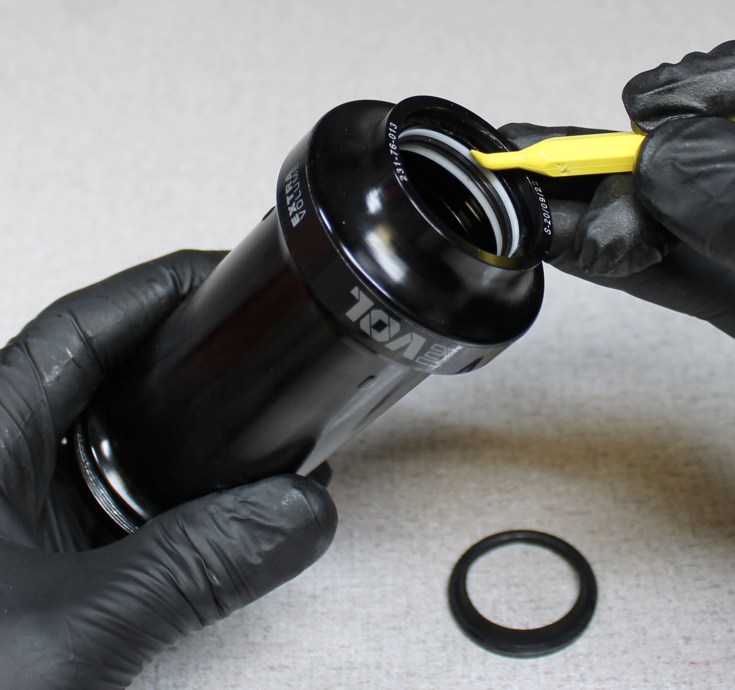
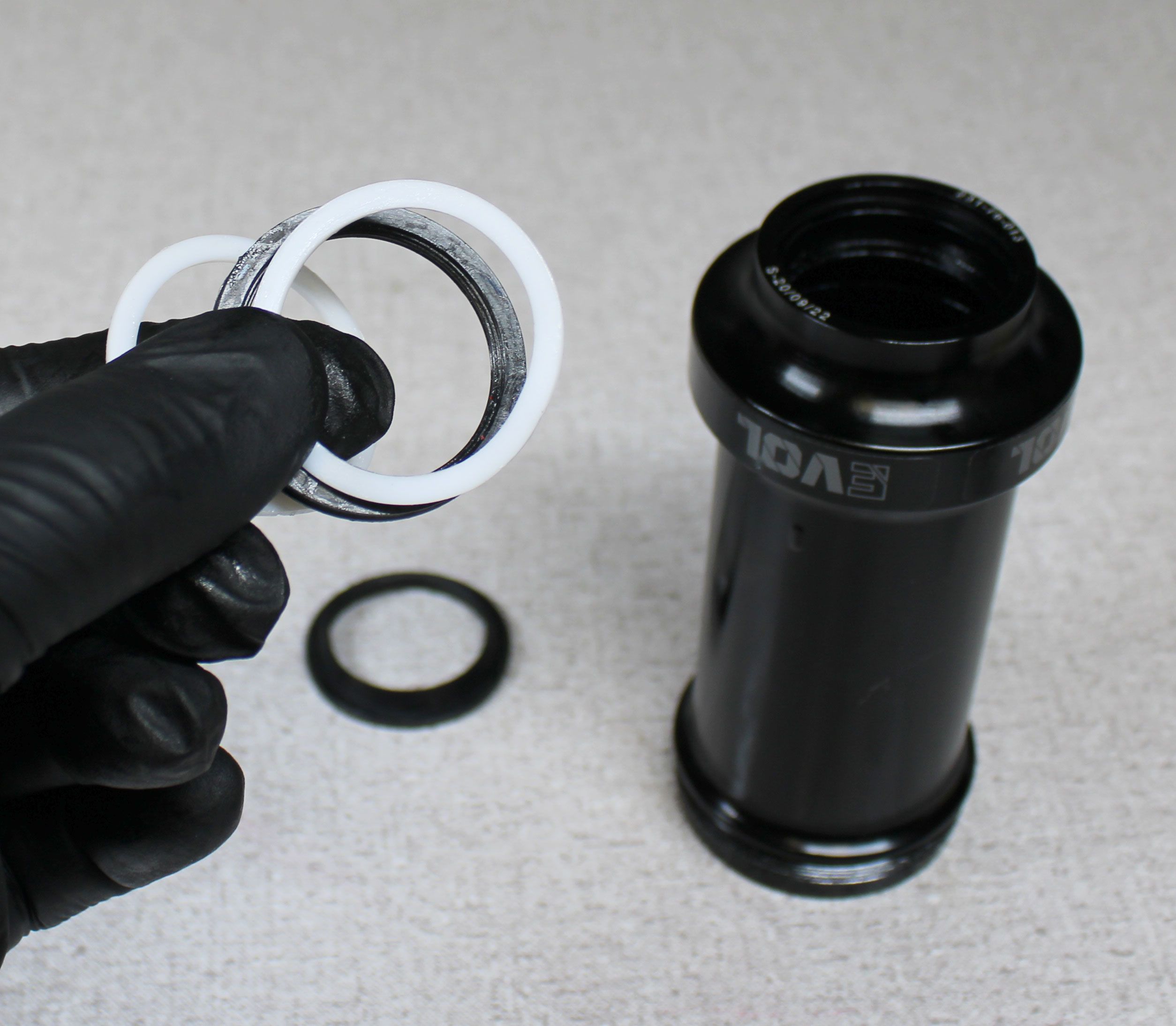
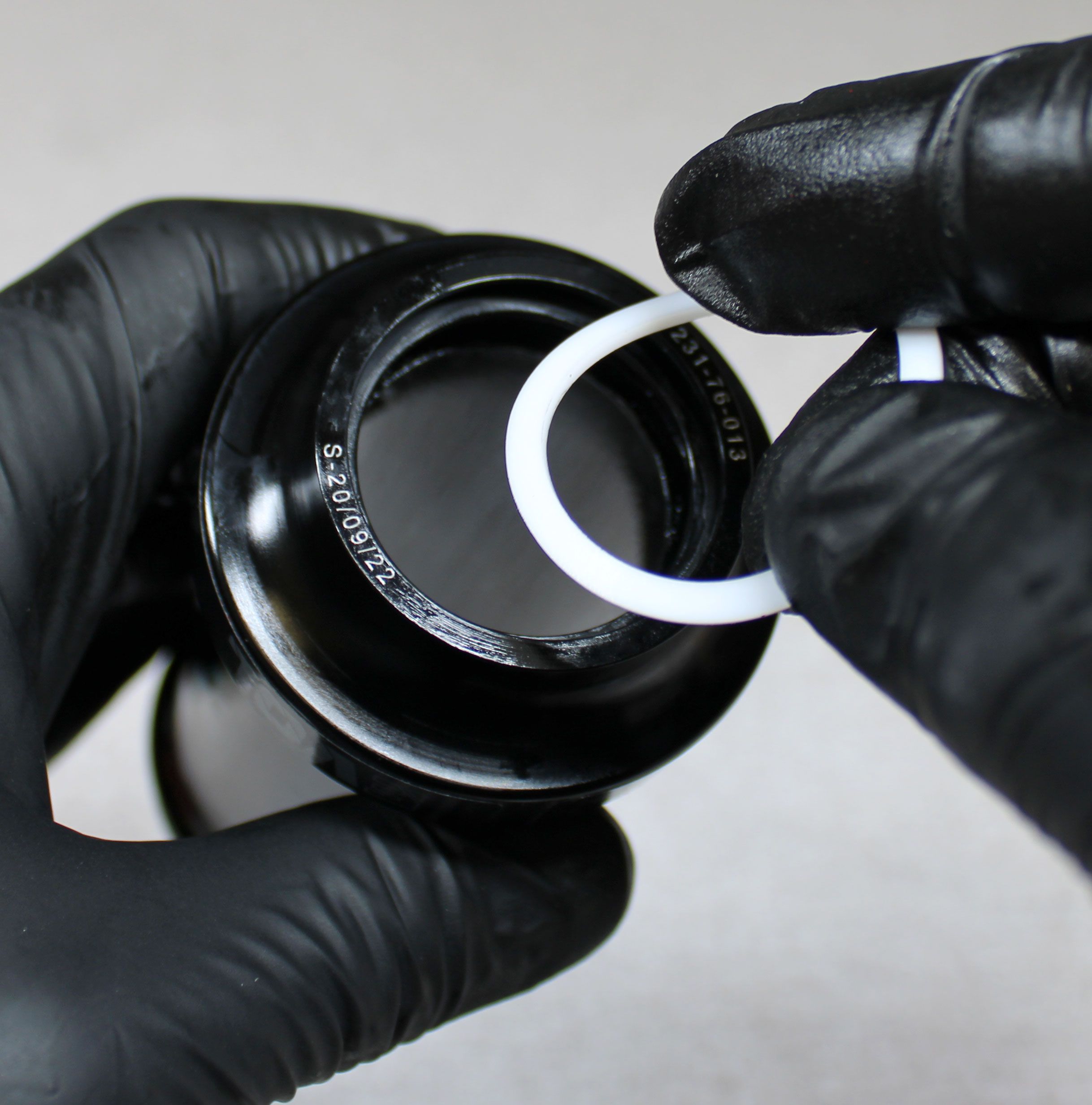
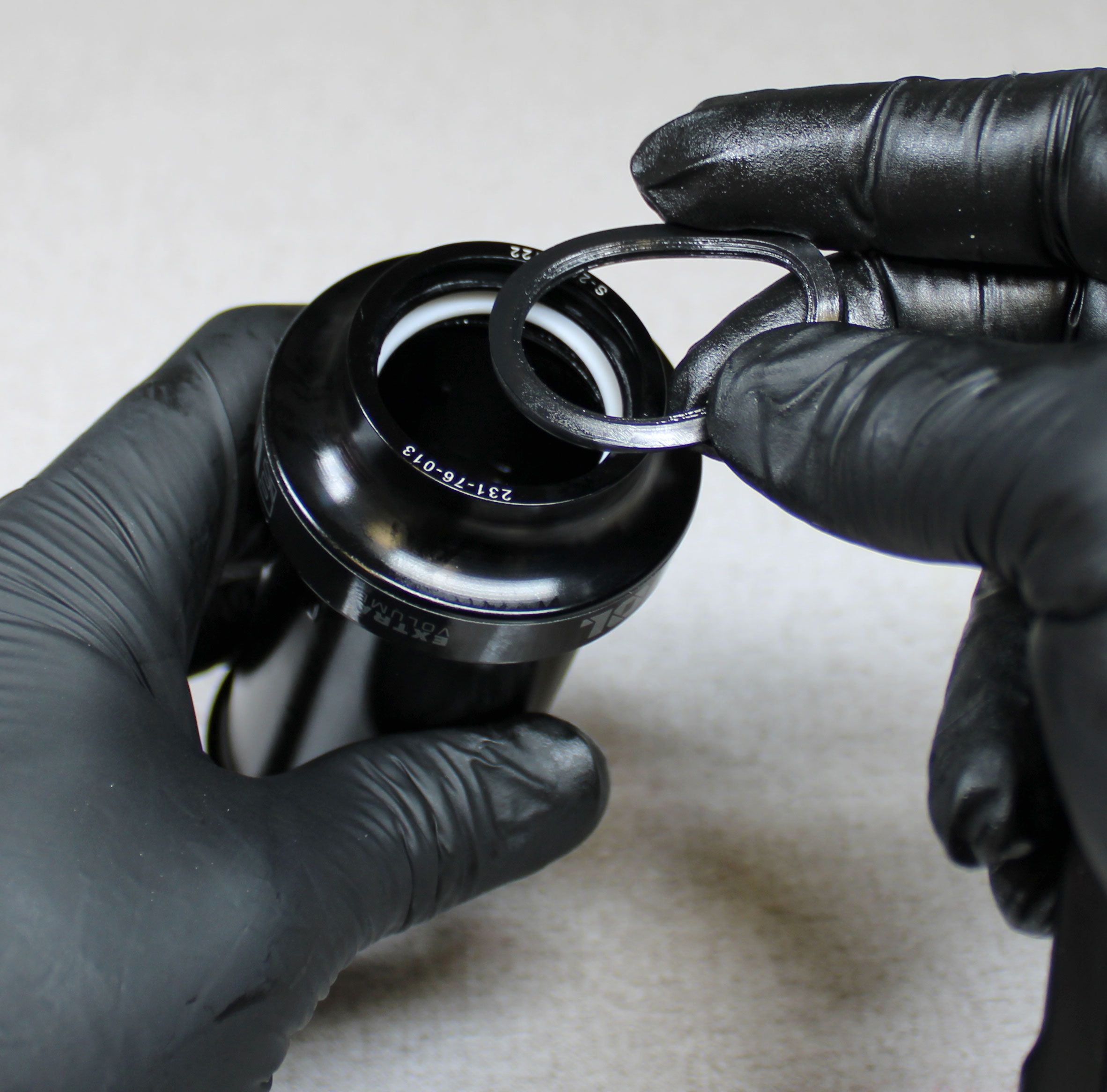
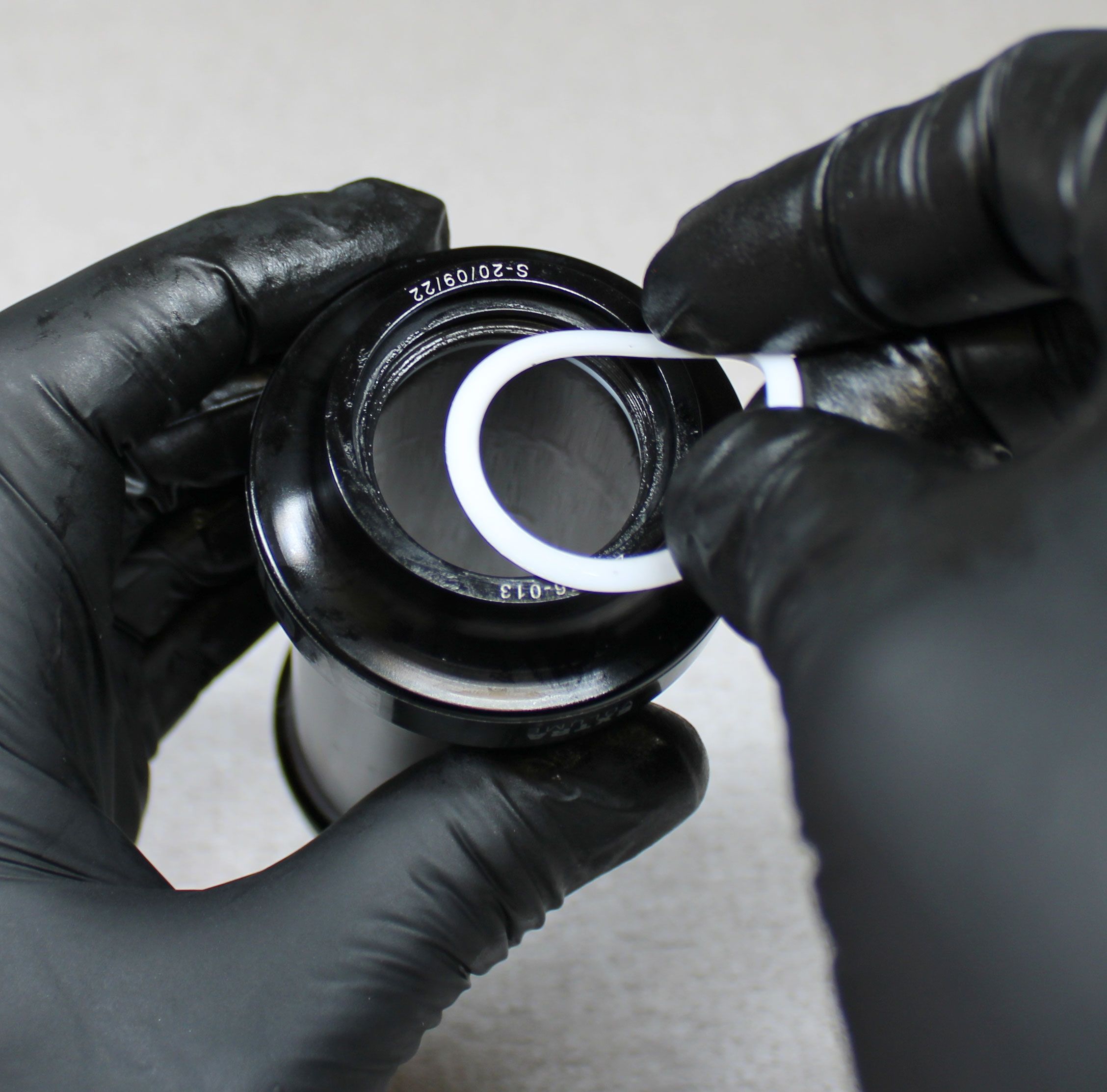
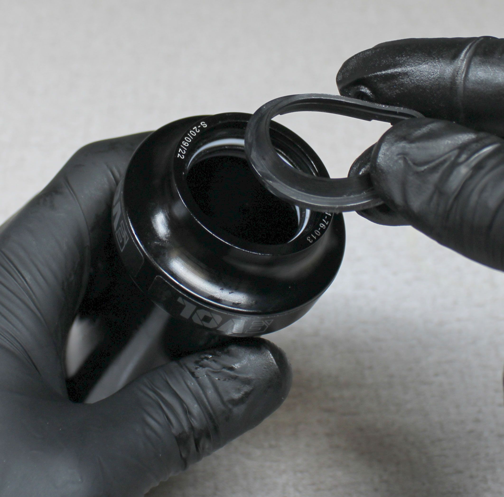
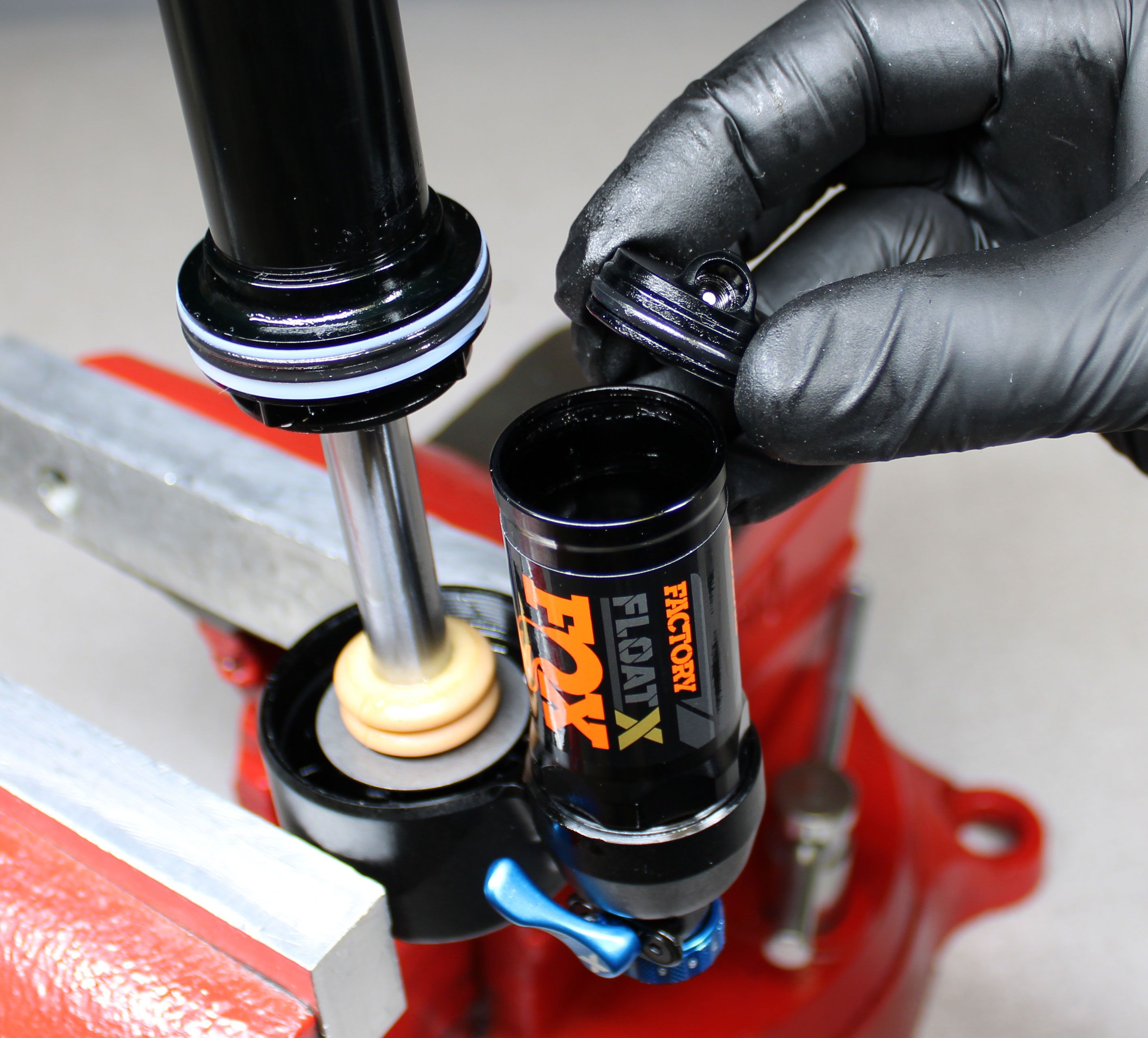
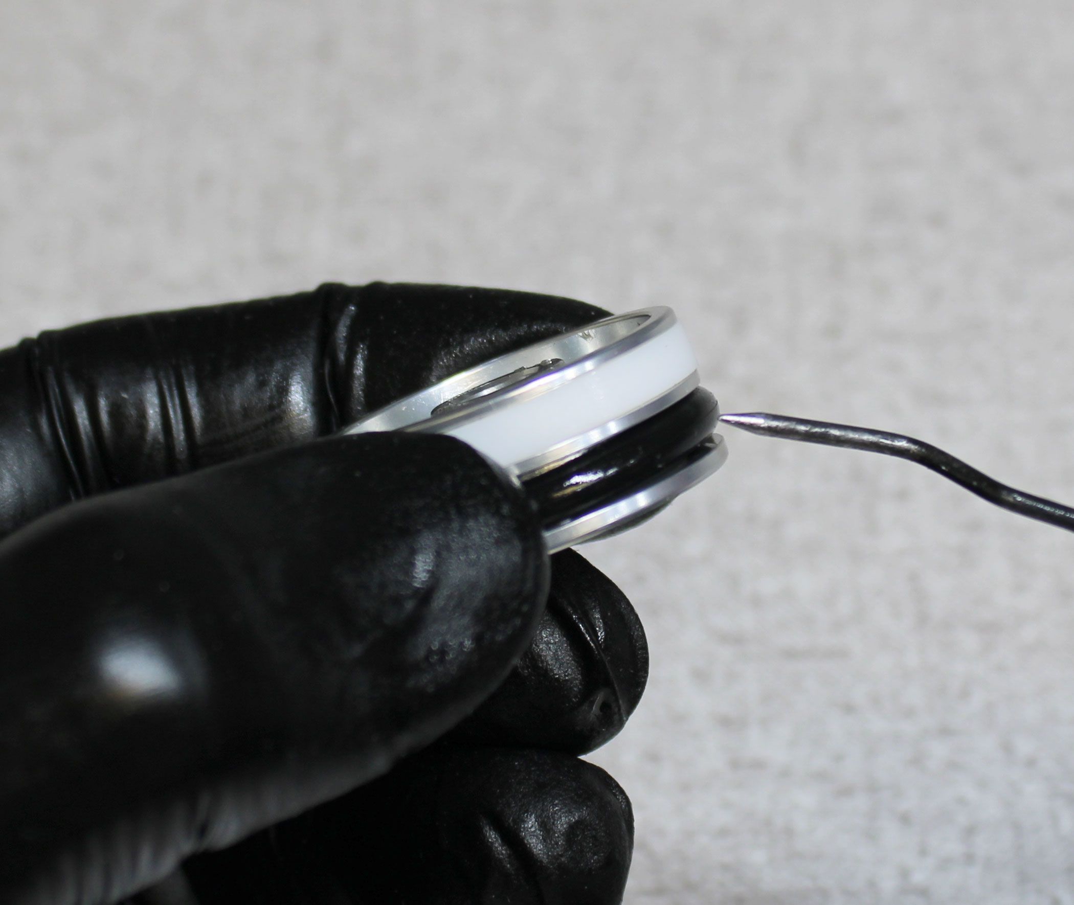
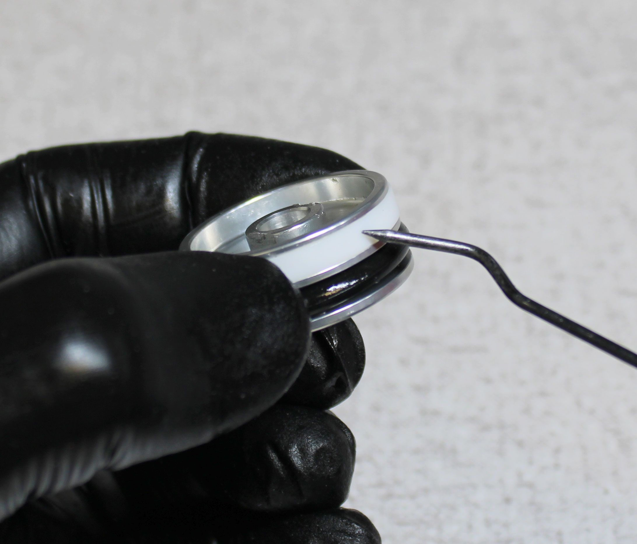
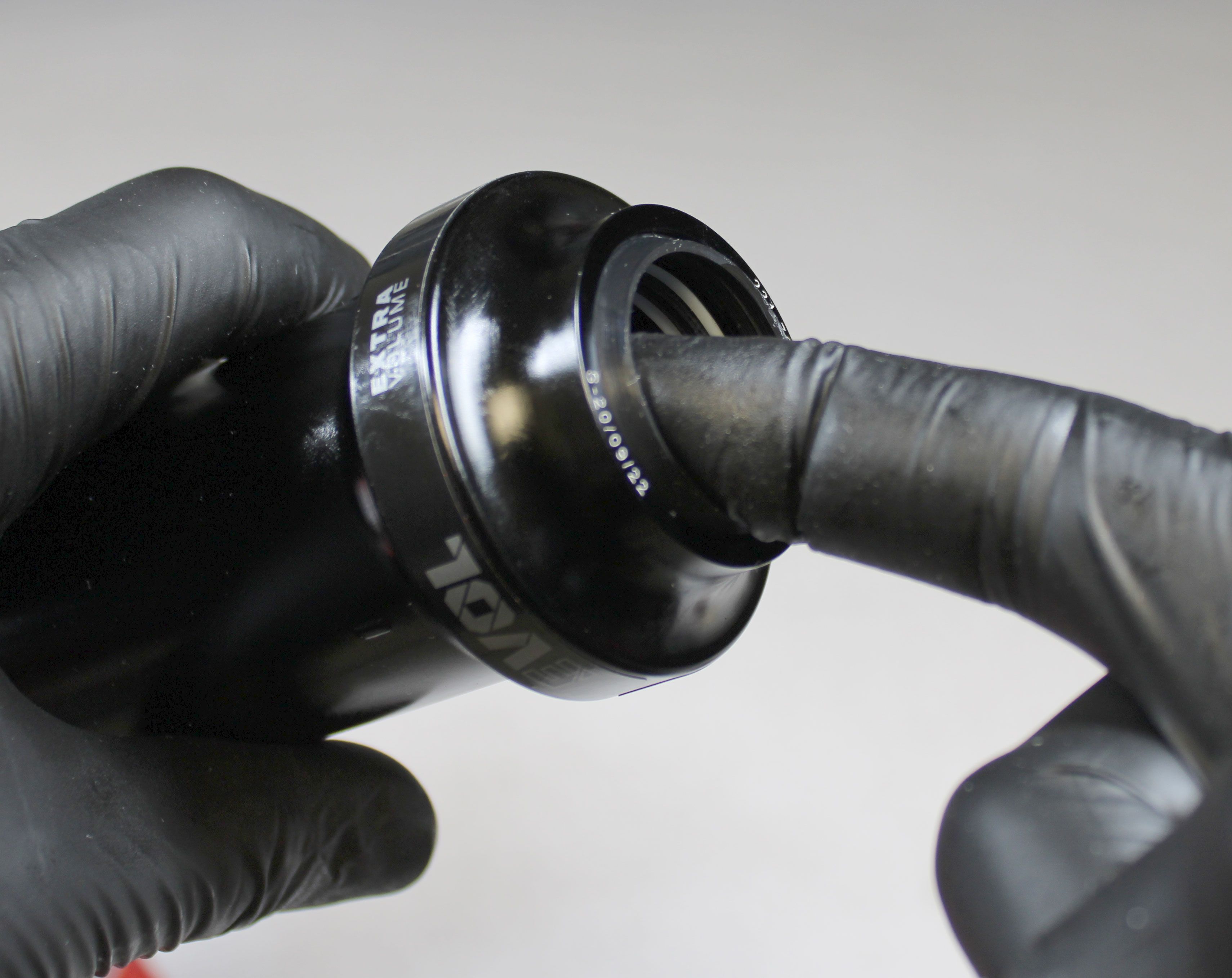
Step 3
Replace the seals in the end of the air sleeve with new greased ones from the rebuild kit as shown. Set aside in a clean area once complete.

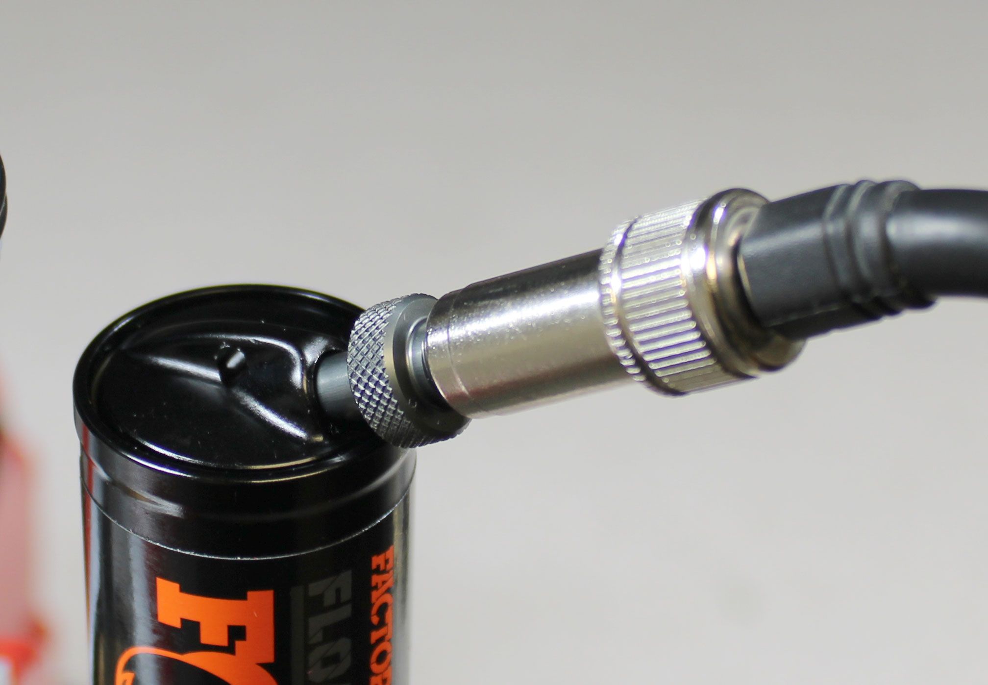
Step 4
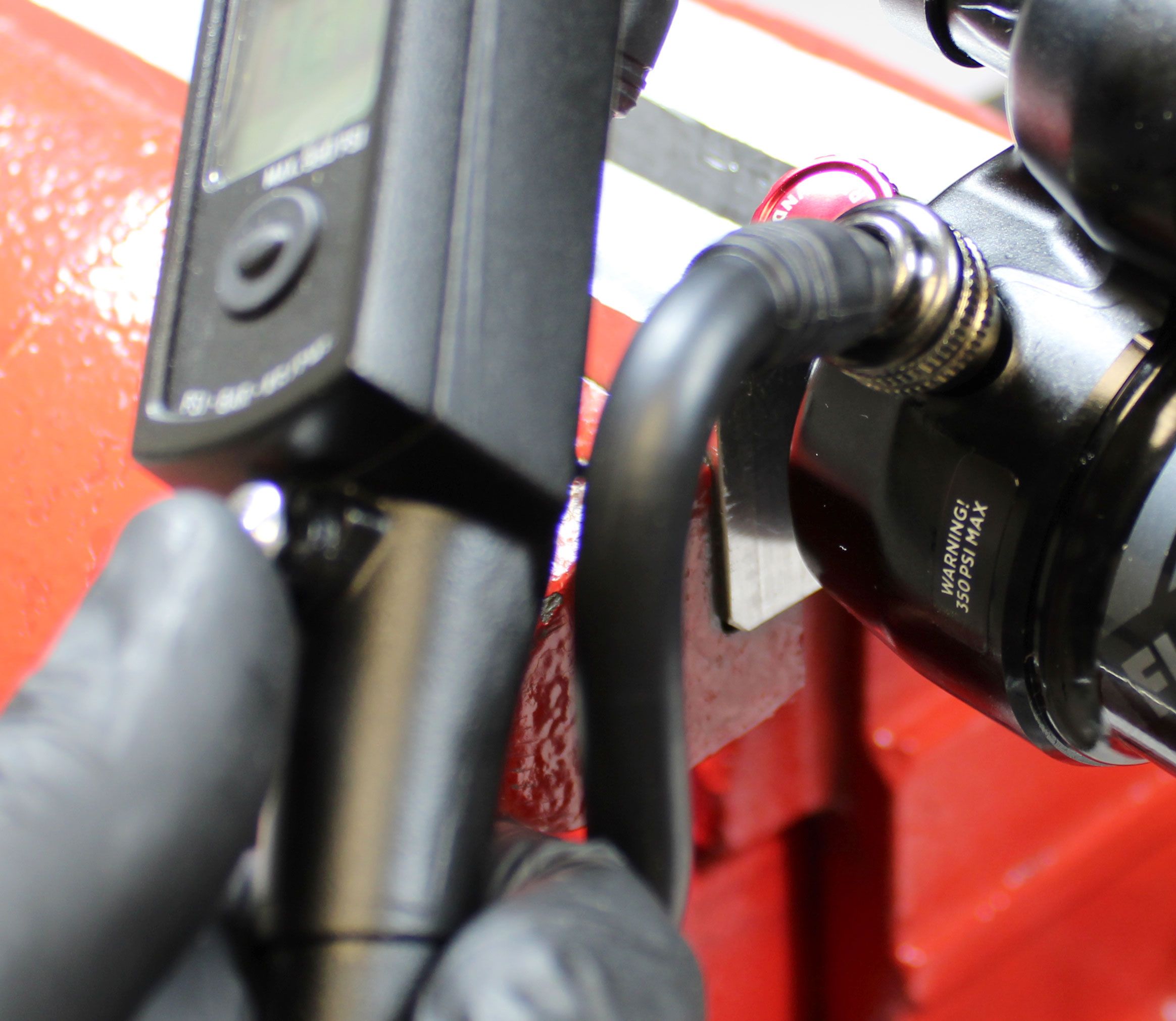
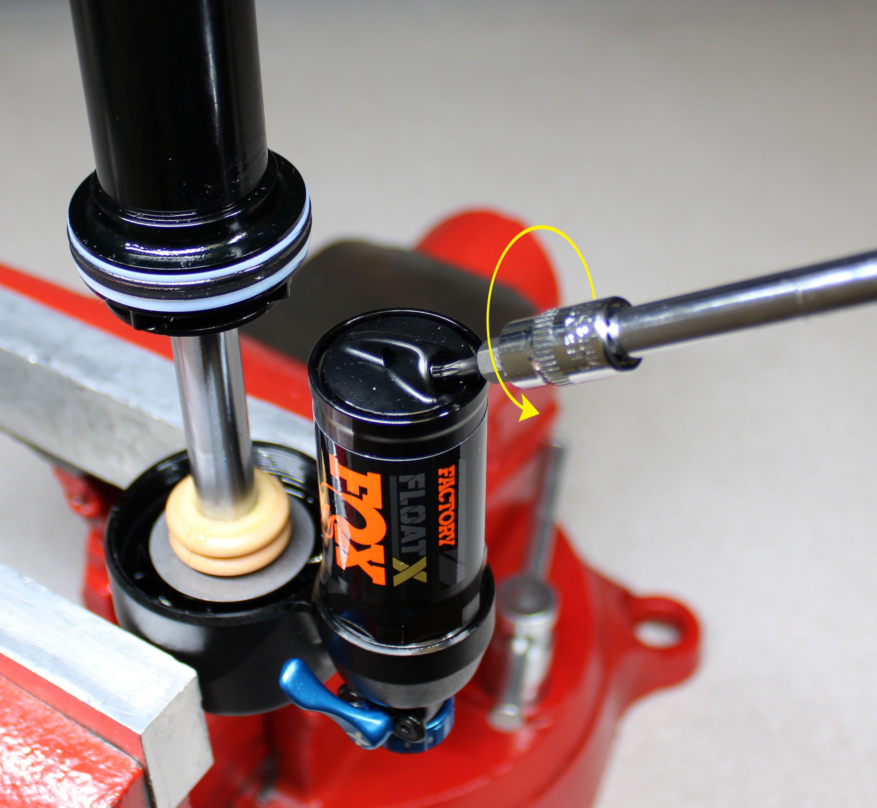
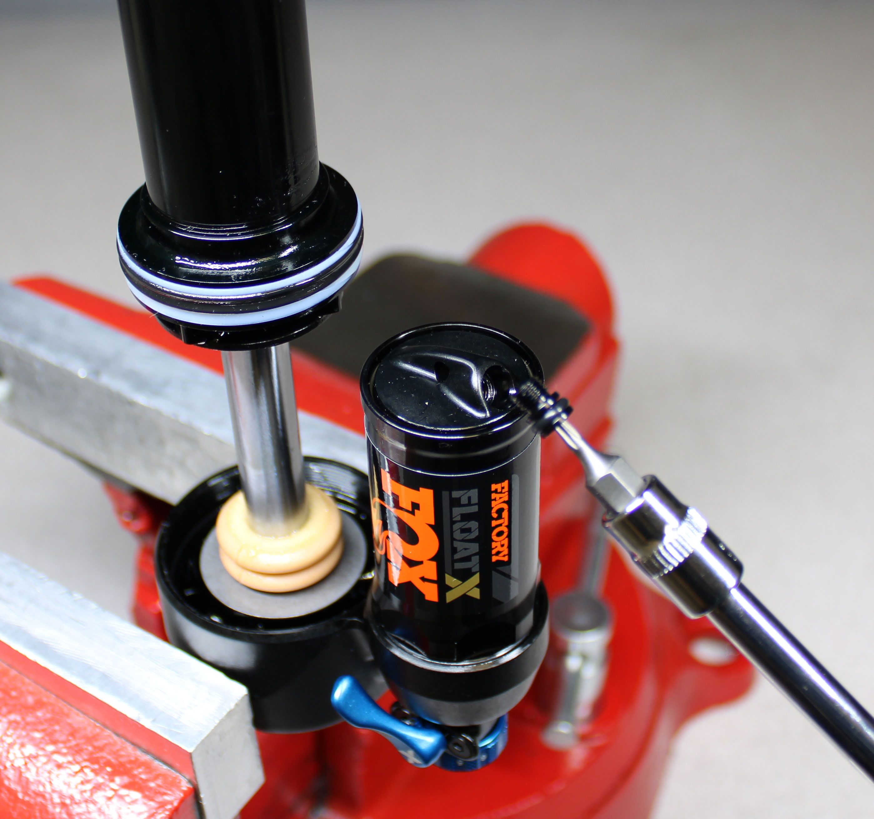
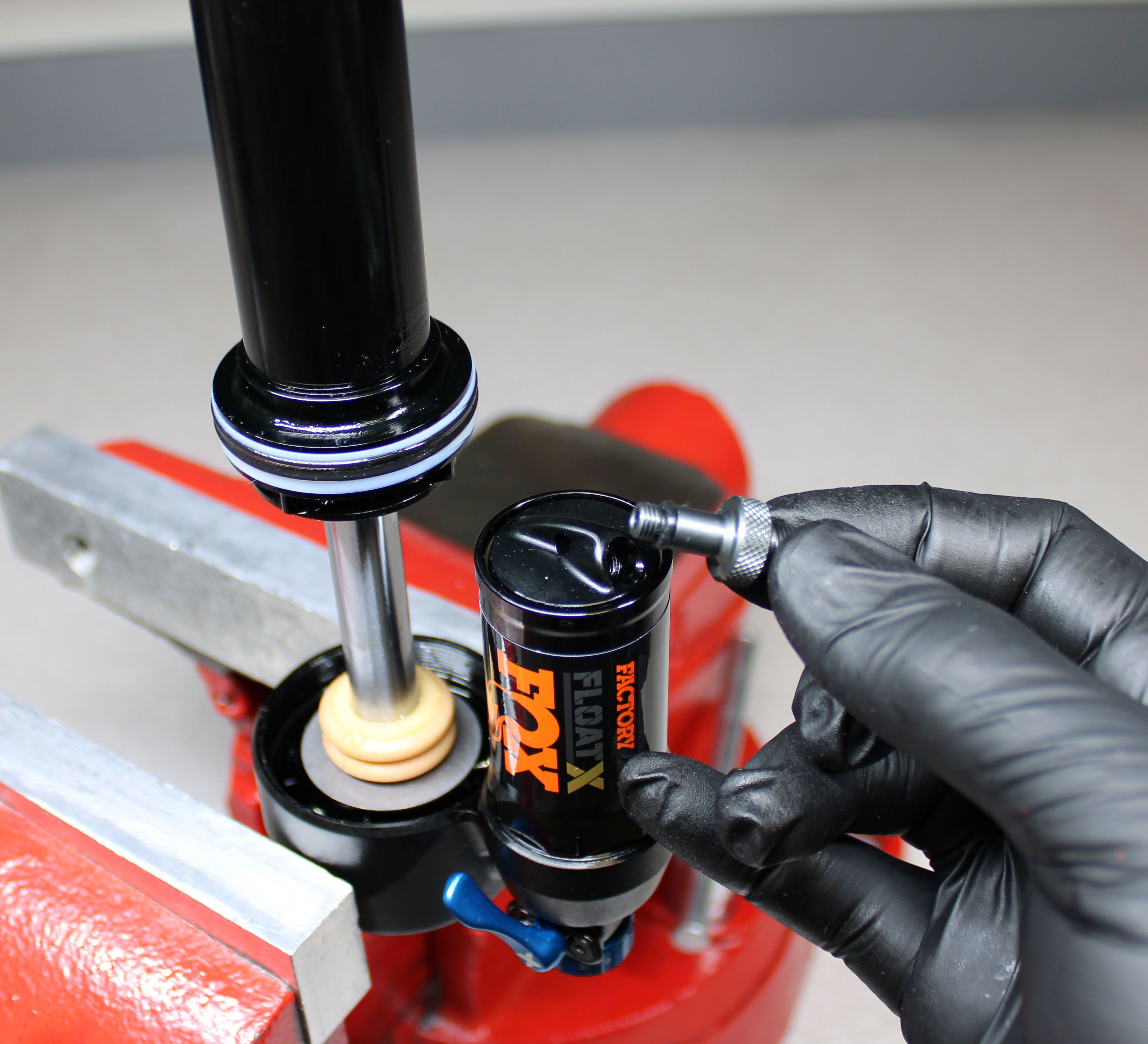
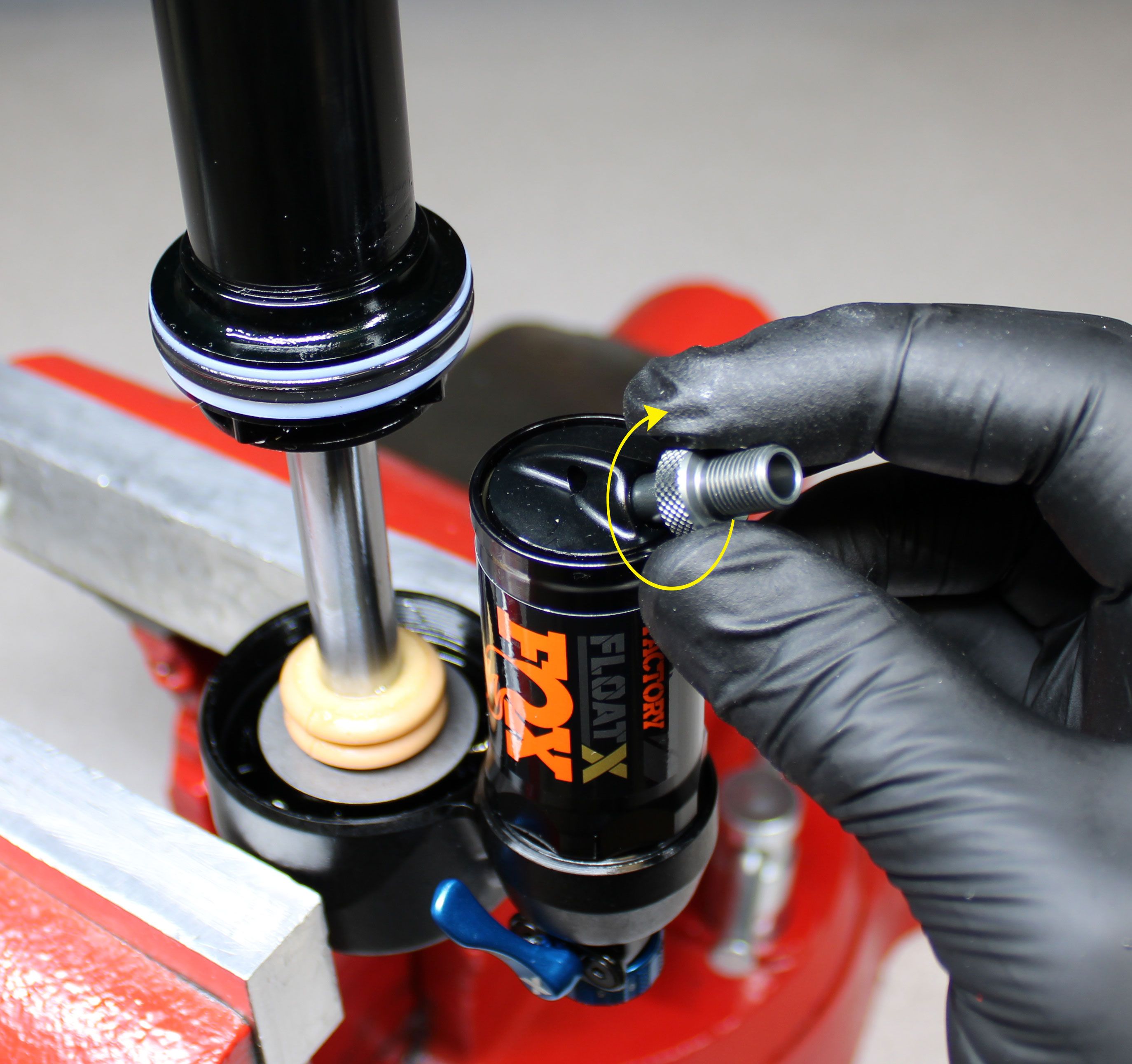
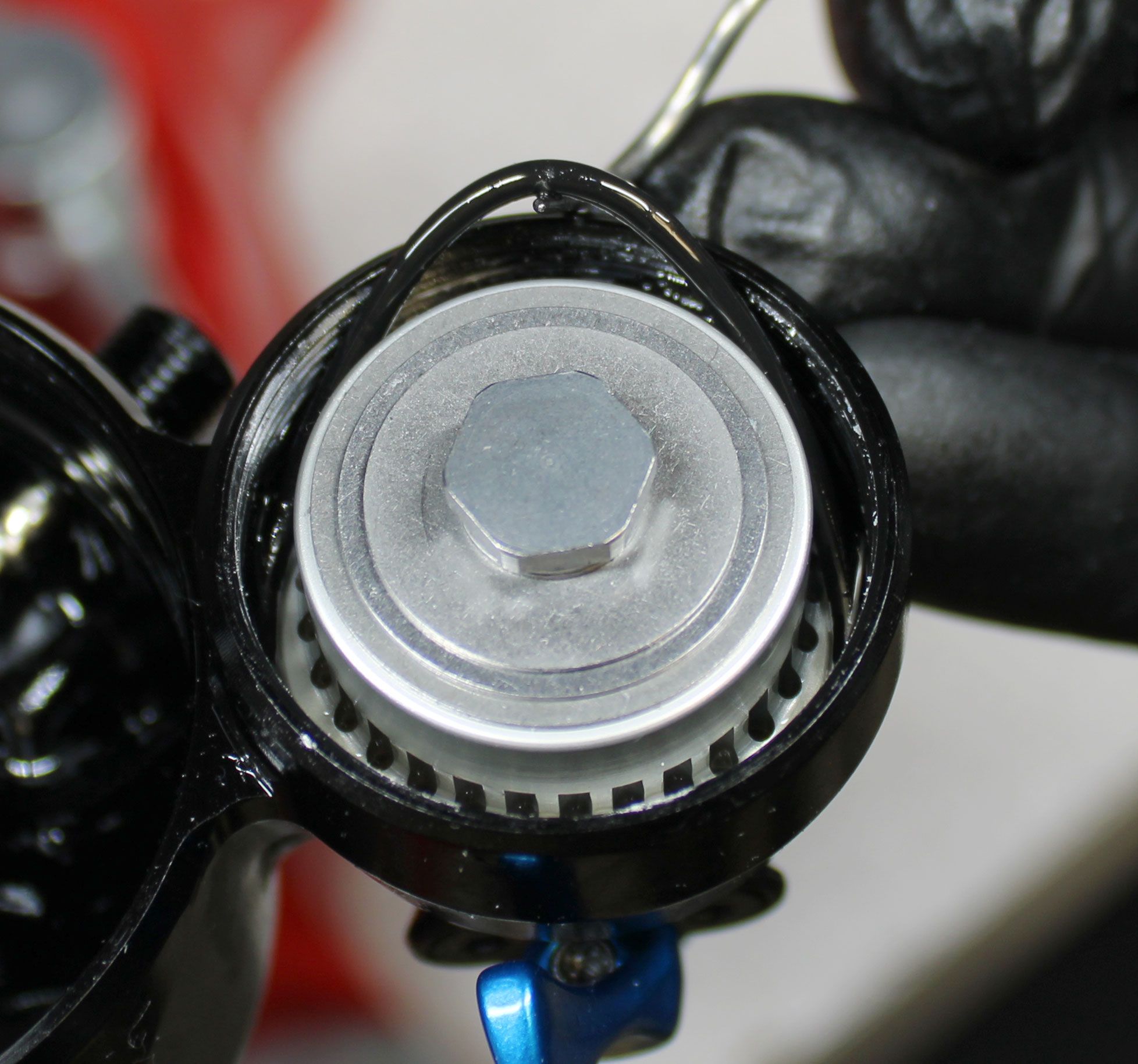
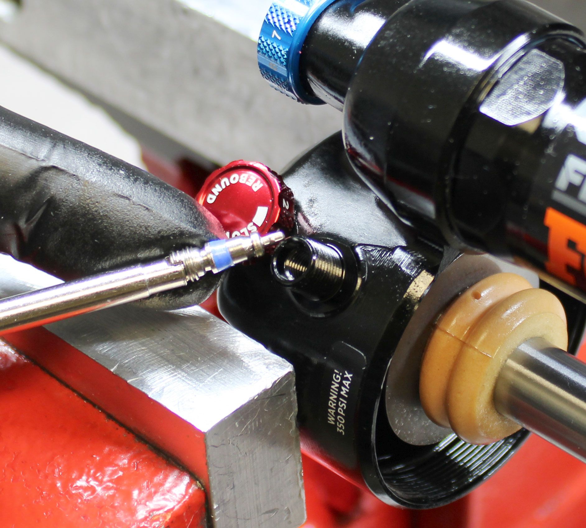
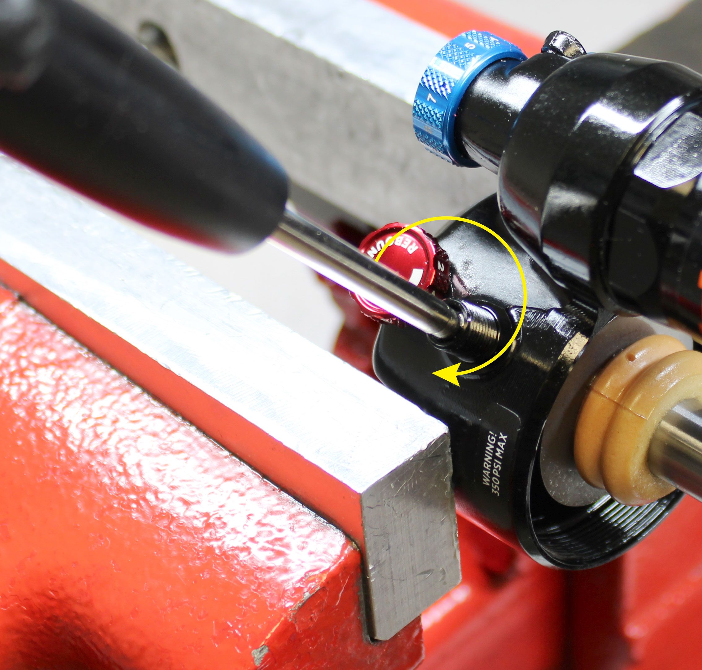
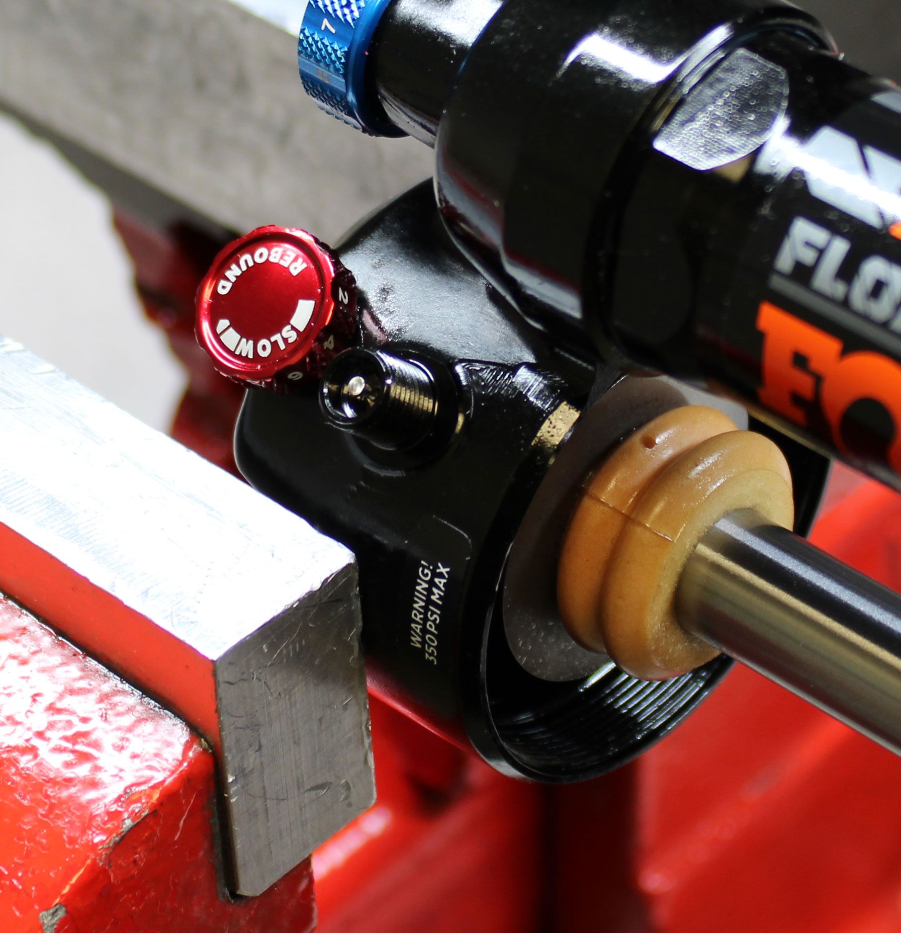
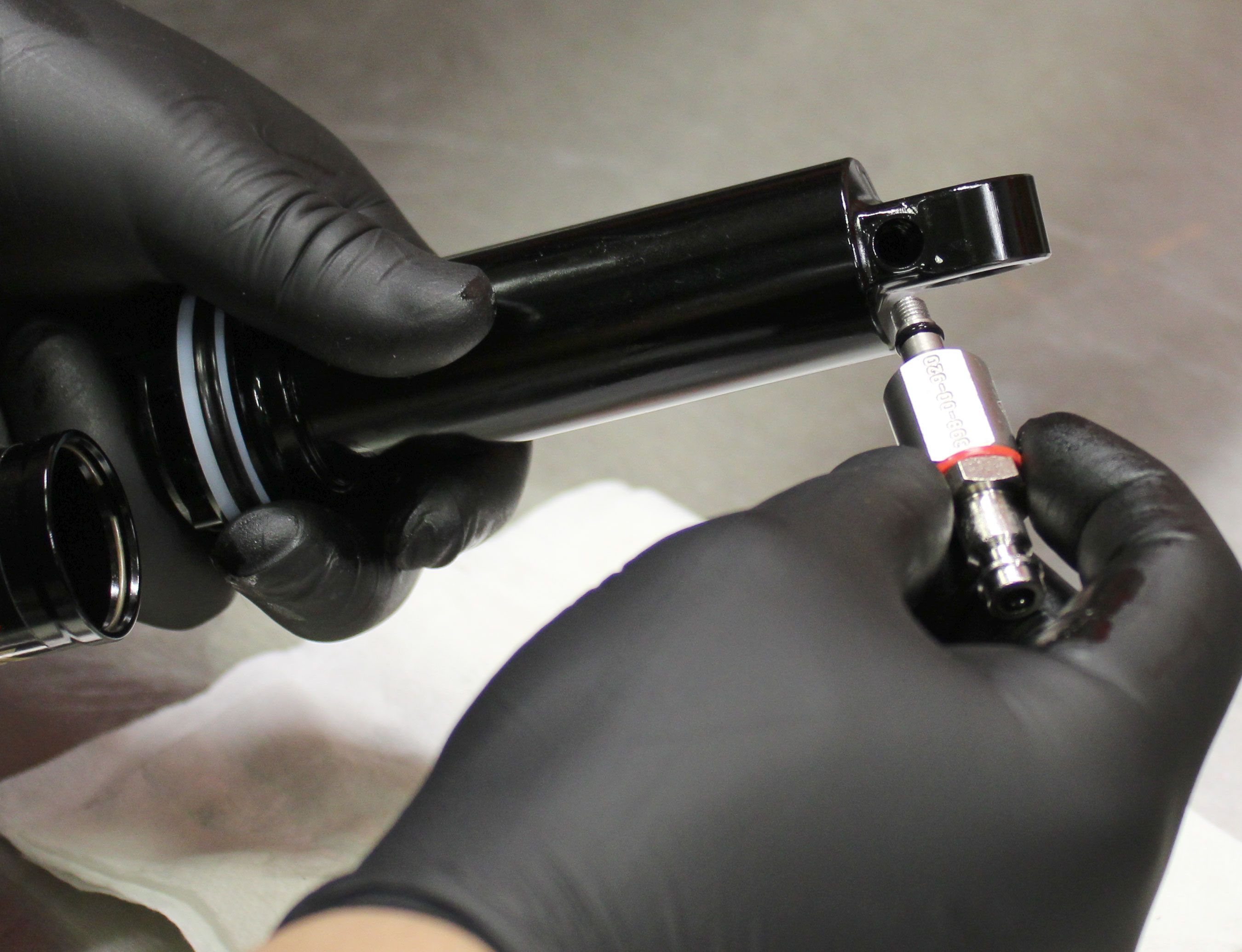
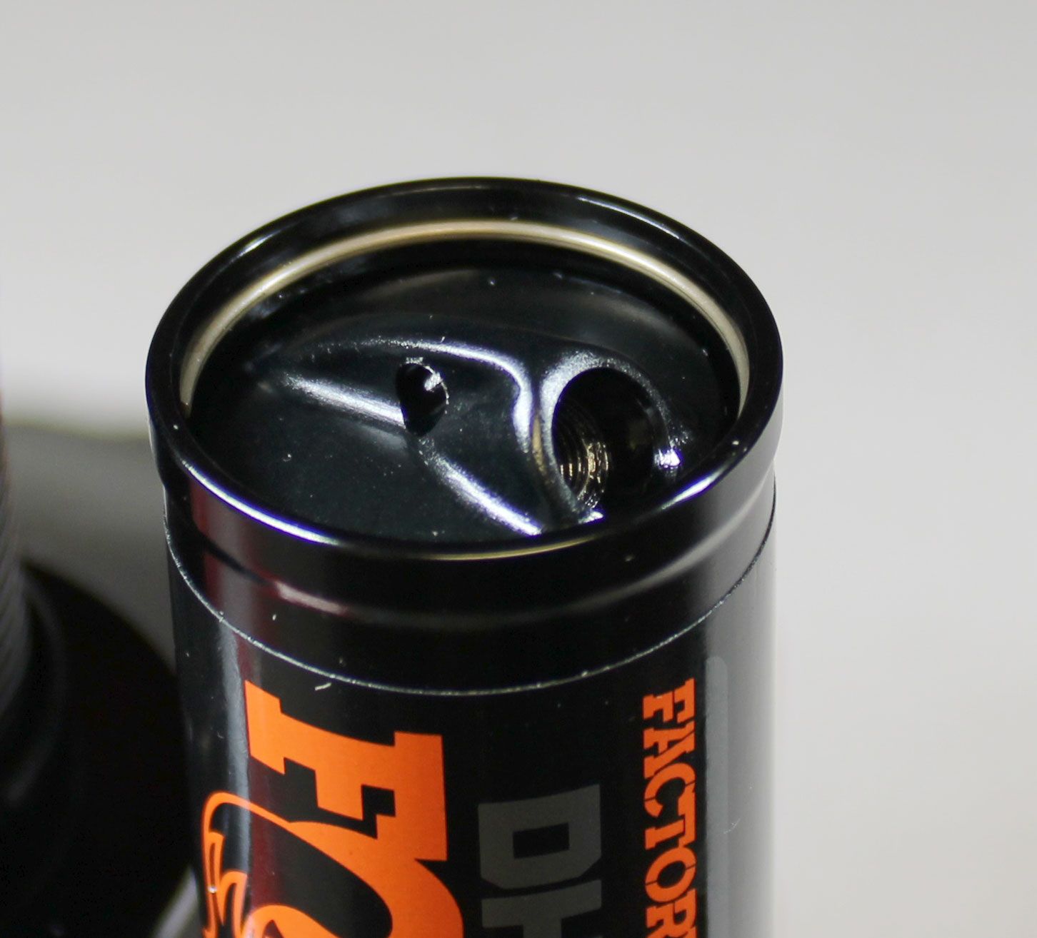
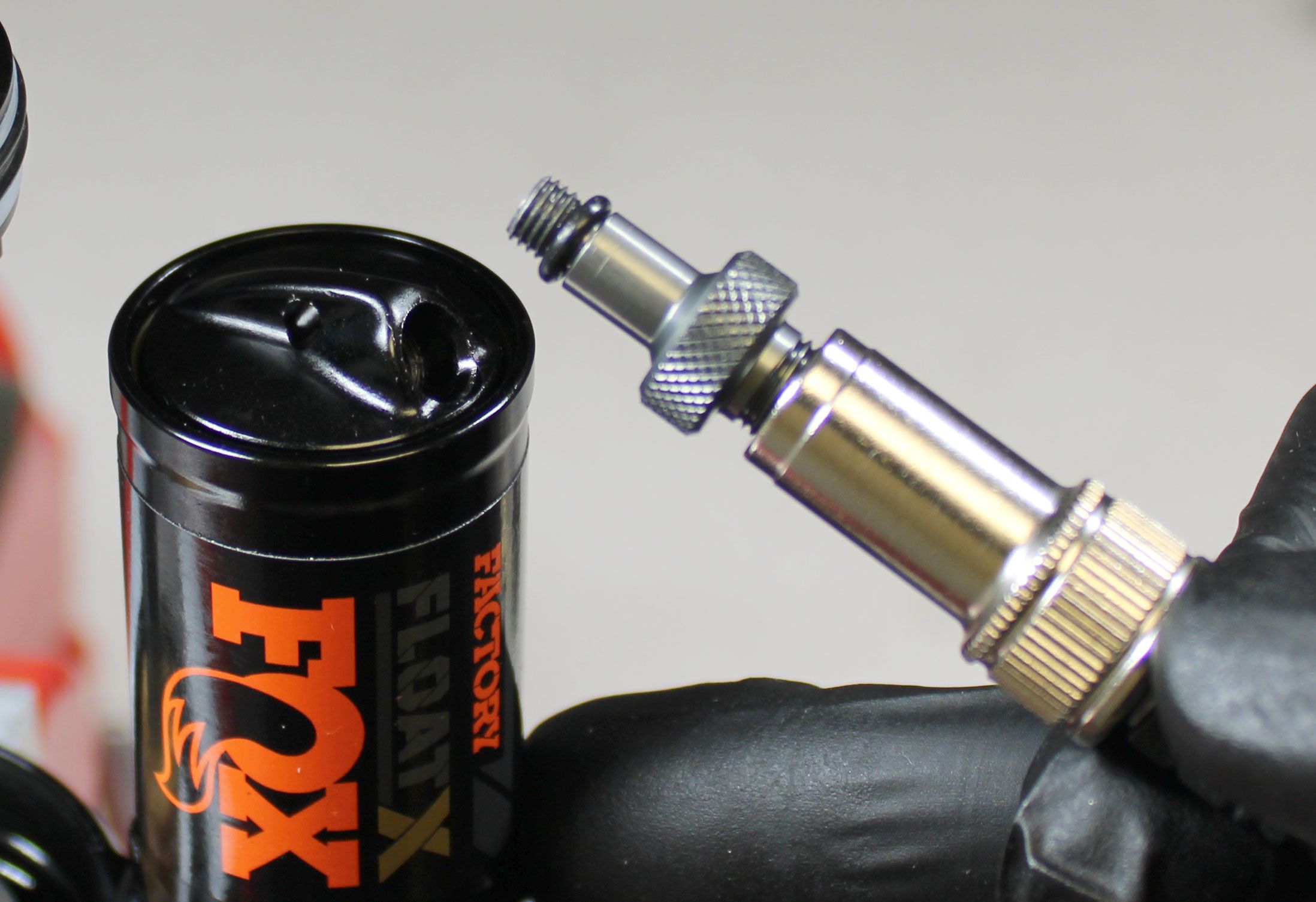
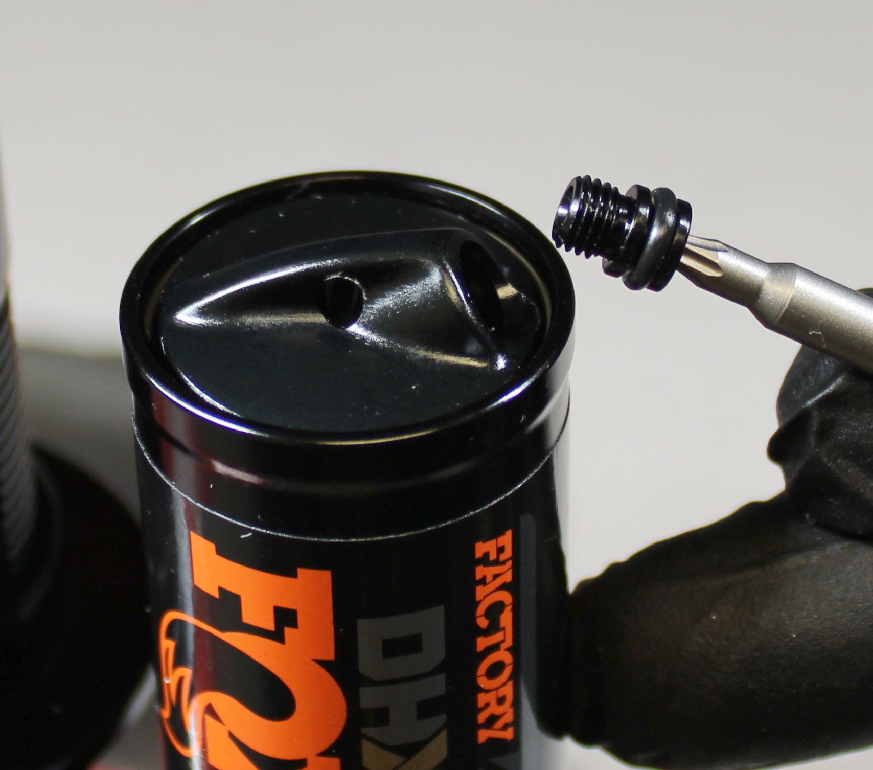
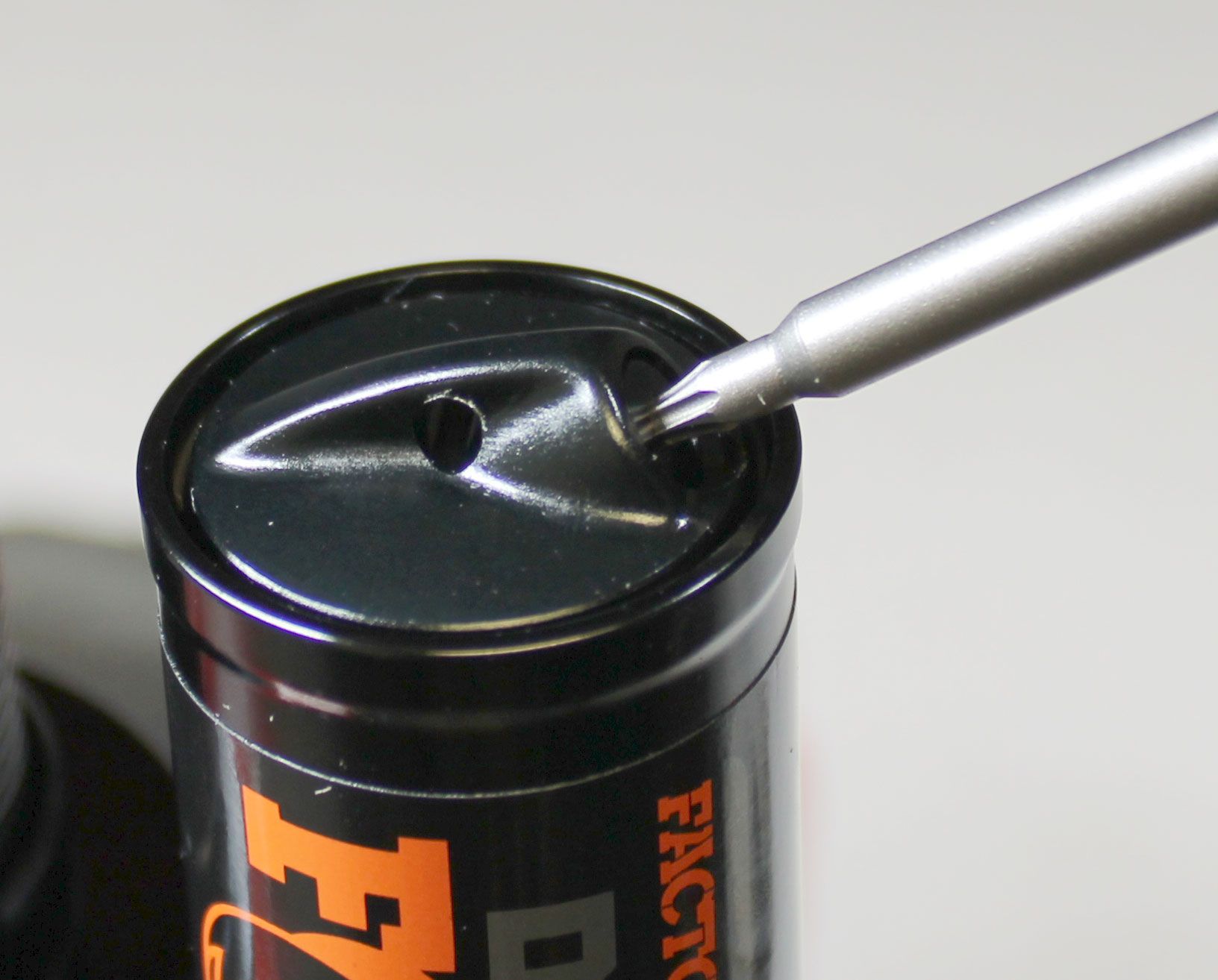
Unthread the Air Fill Cap counter-clockwise with a T8 Torx driver then set it aside. Thread the MY22 Air Fill Adaptor (PN: 803-01-692) clockwise into the Reservoir End Cap fully to release the IFP pressure (if attached to a FOX high-pressure pump, use the pump to bleed out all air from the reservoir). Remove the Air Fill Adaptor by unthreading it counter-clockwise.
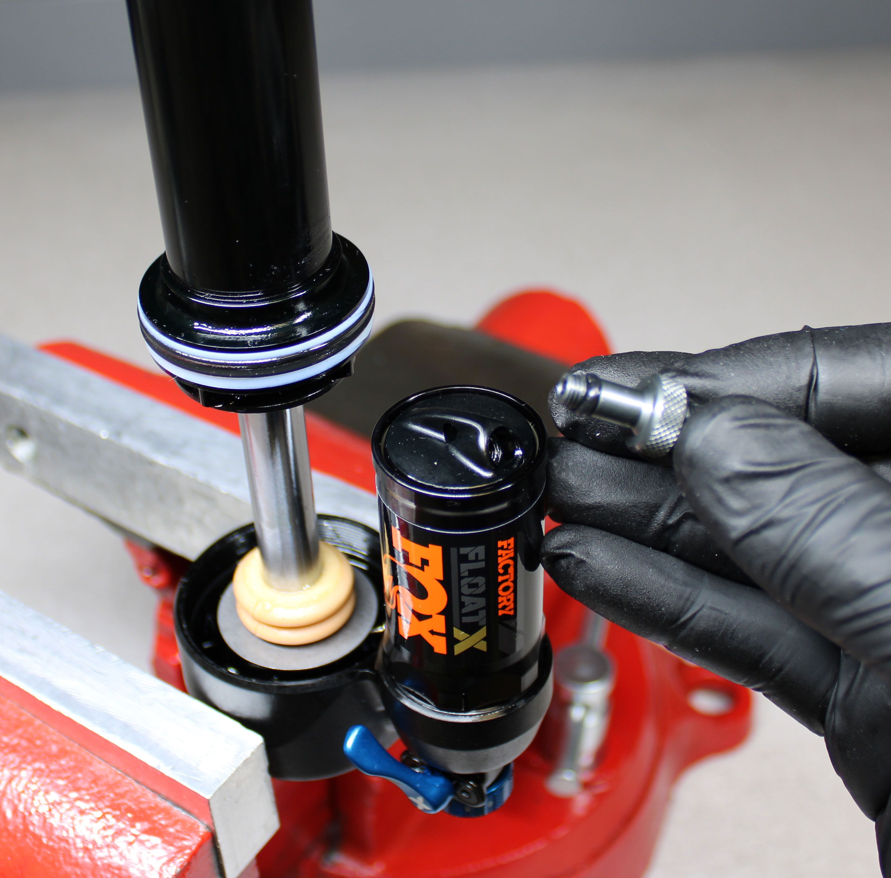

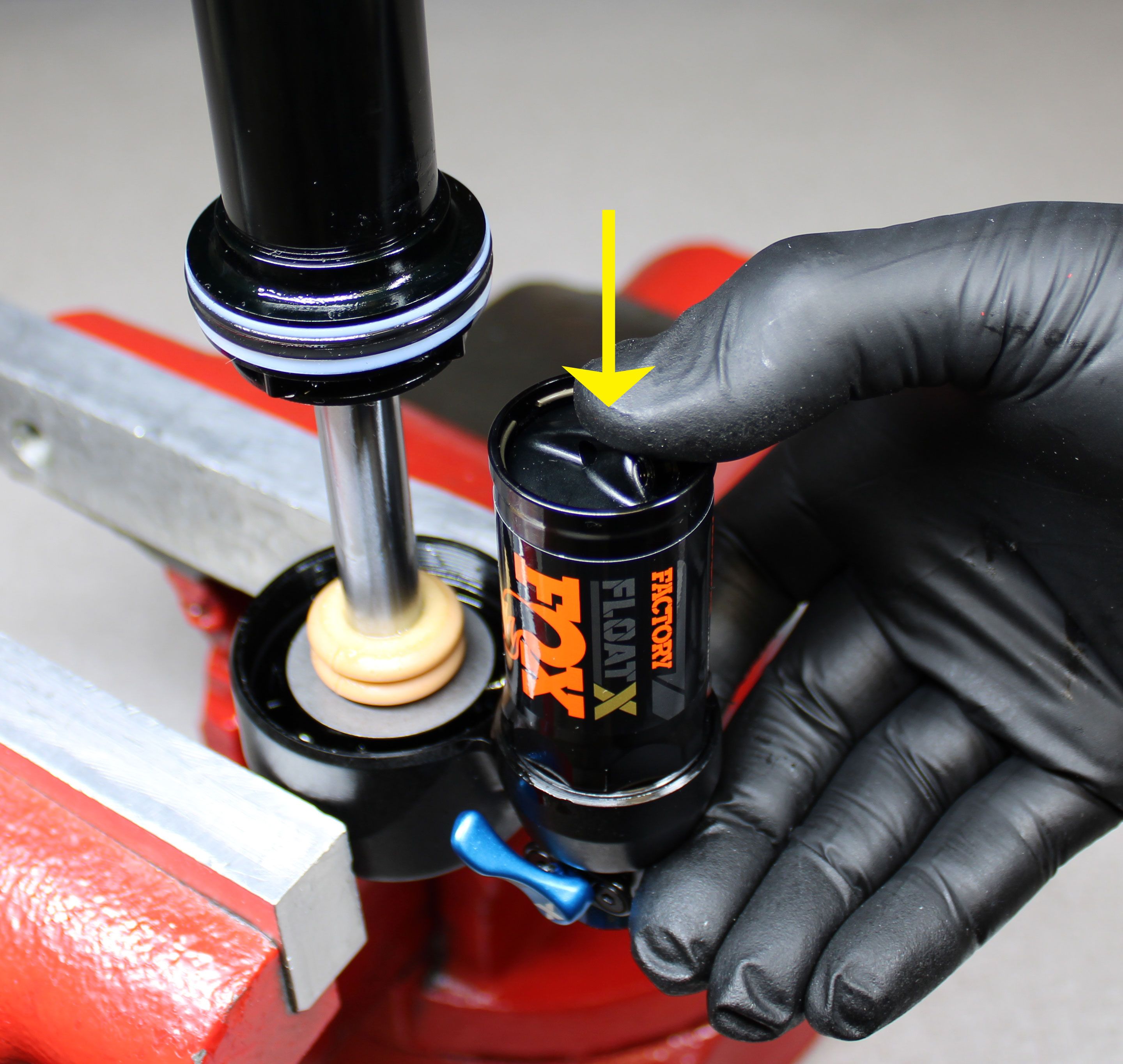
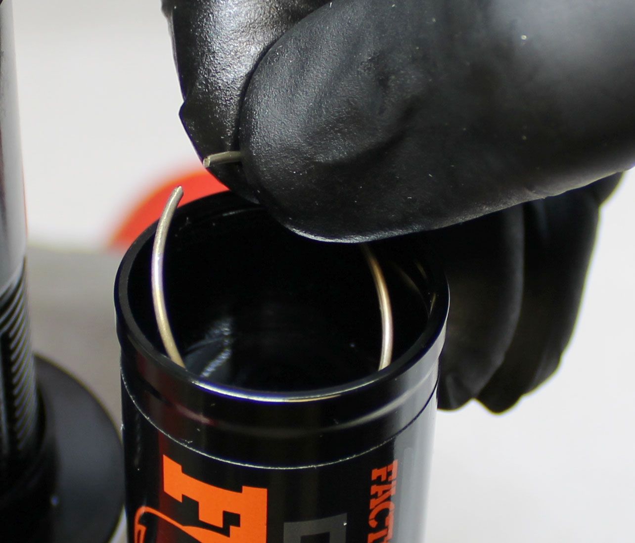
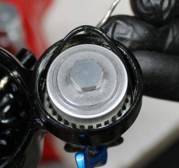
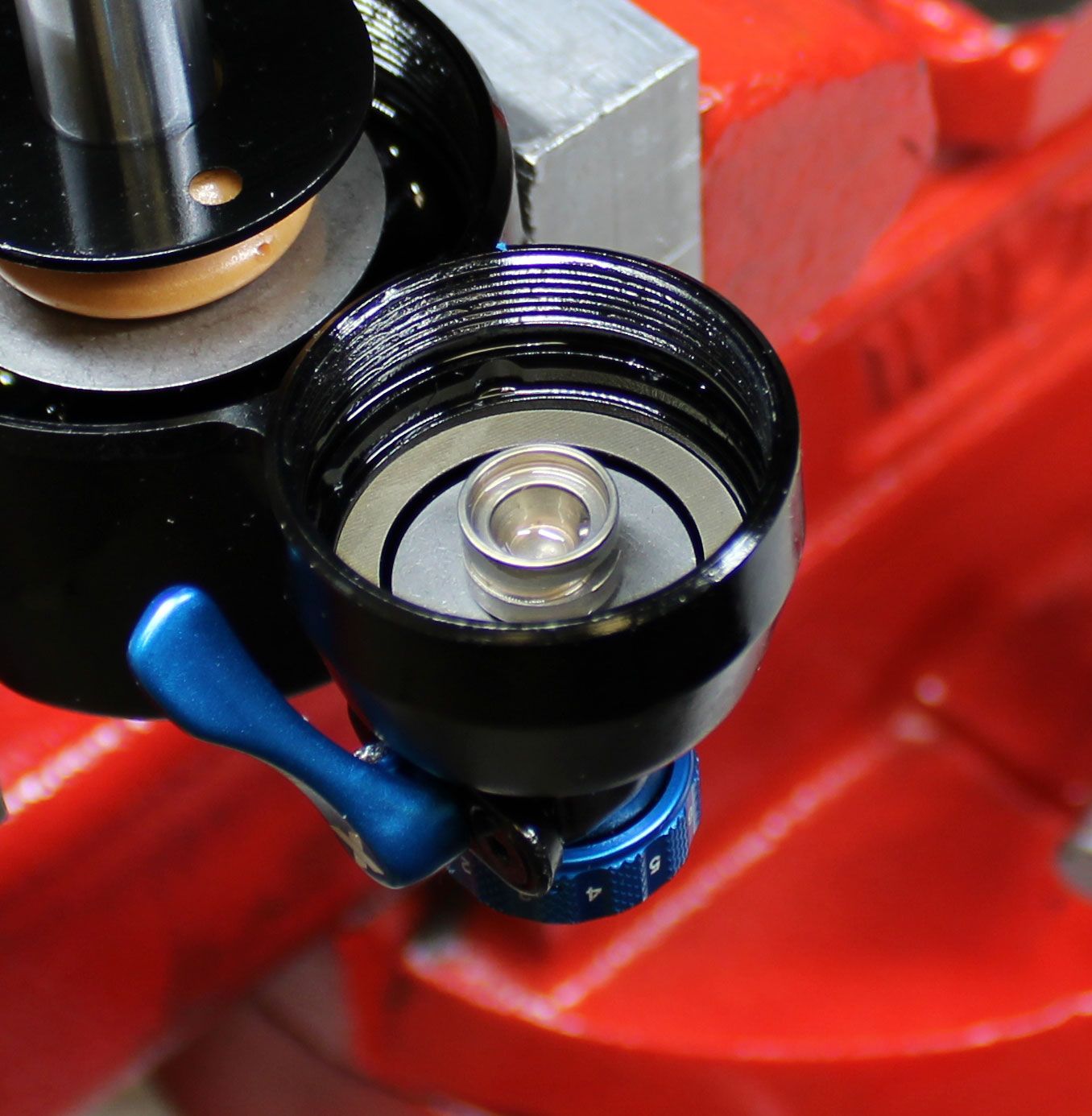
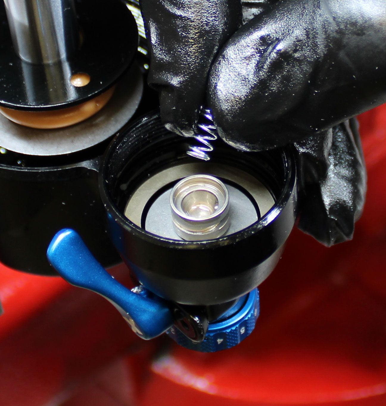
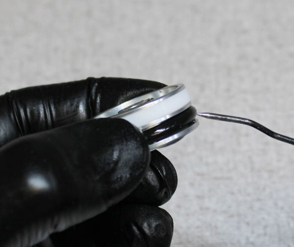
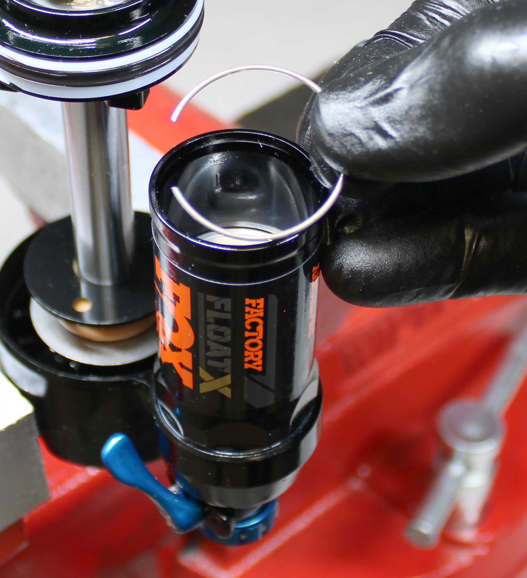
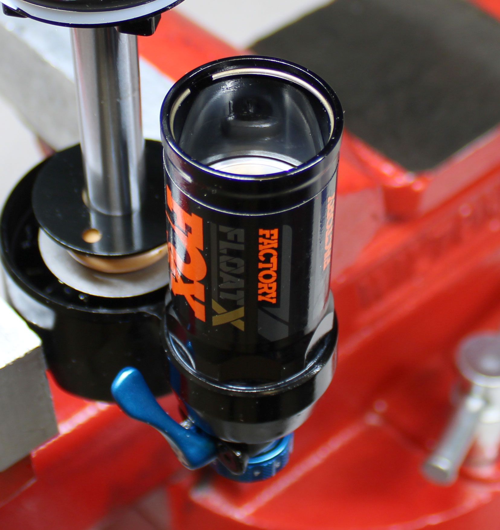
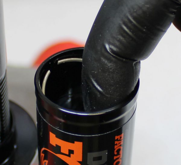
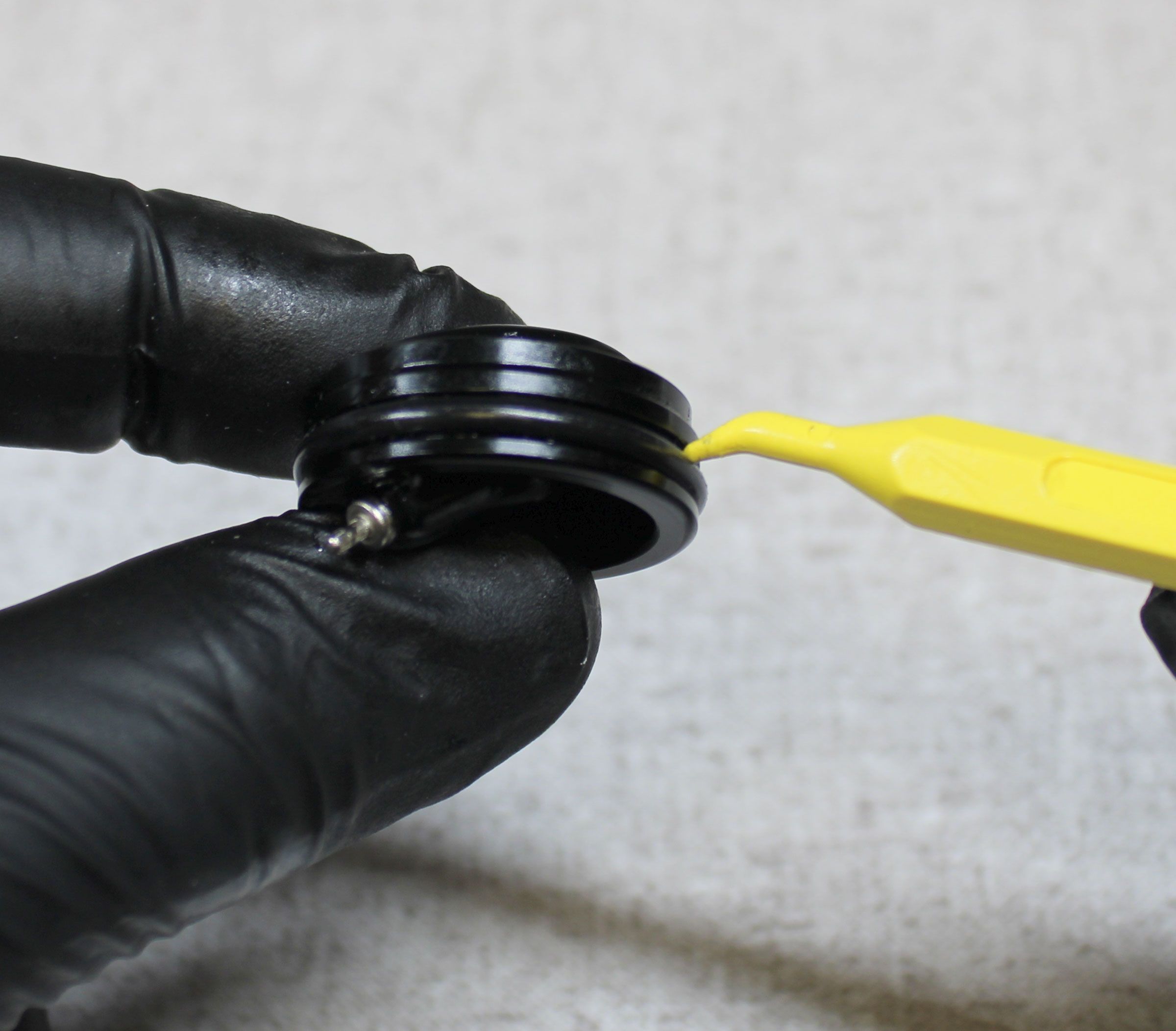
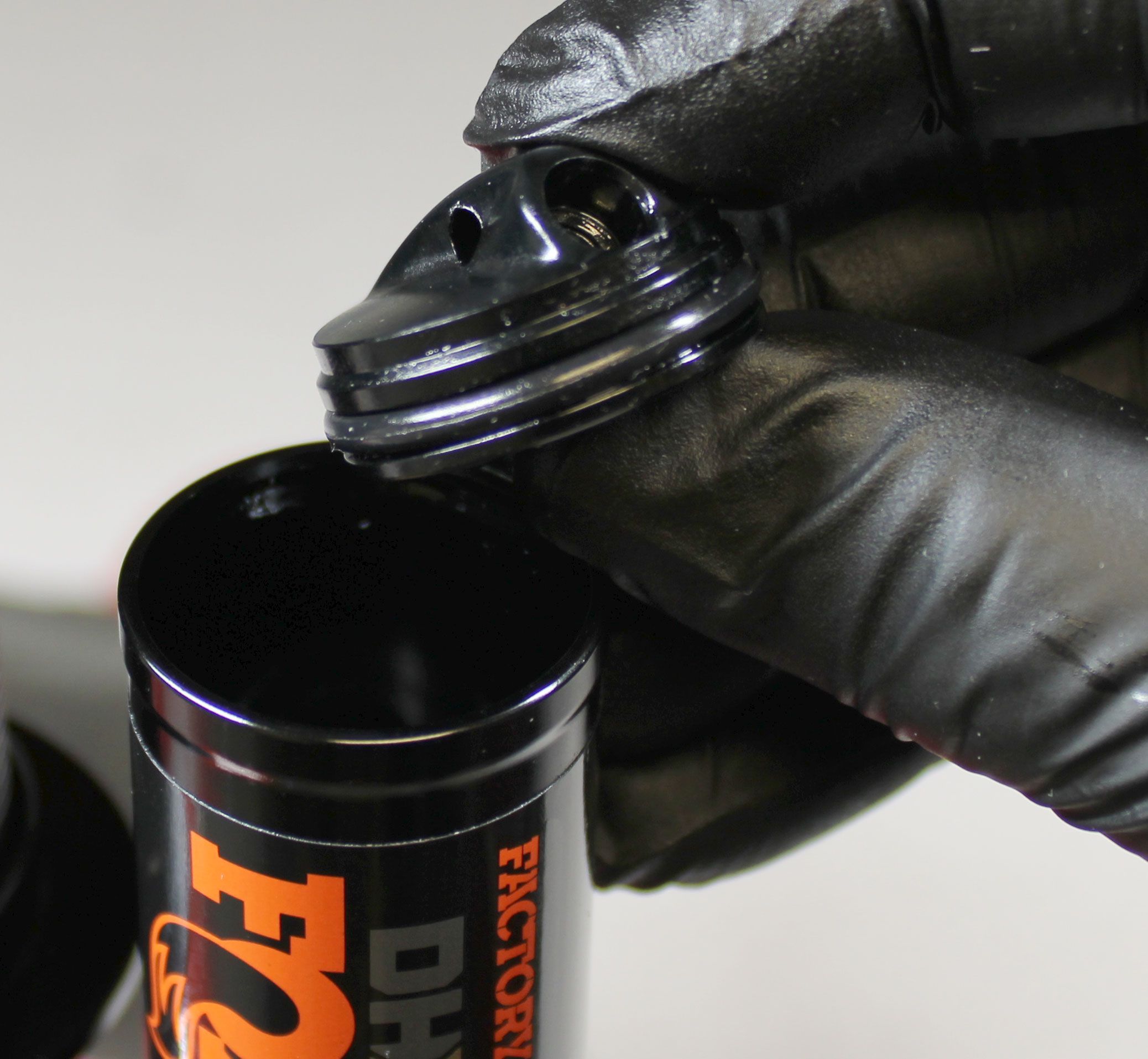
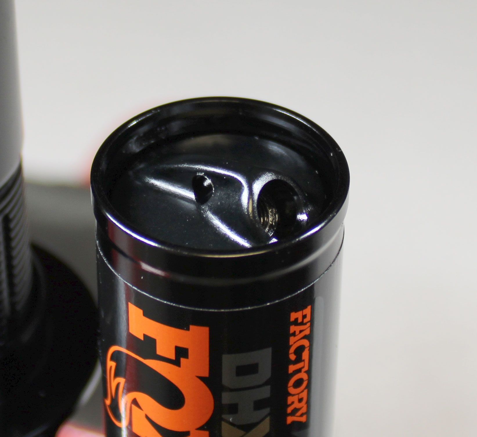
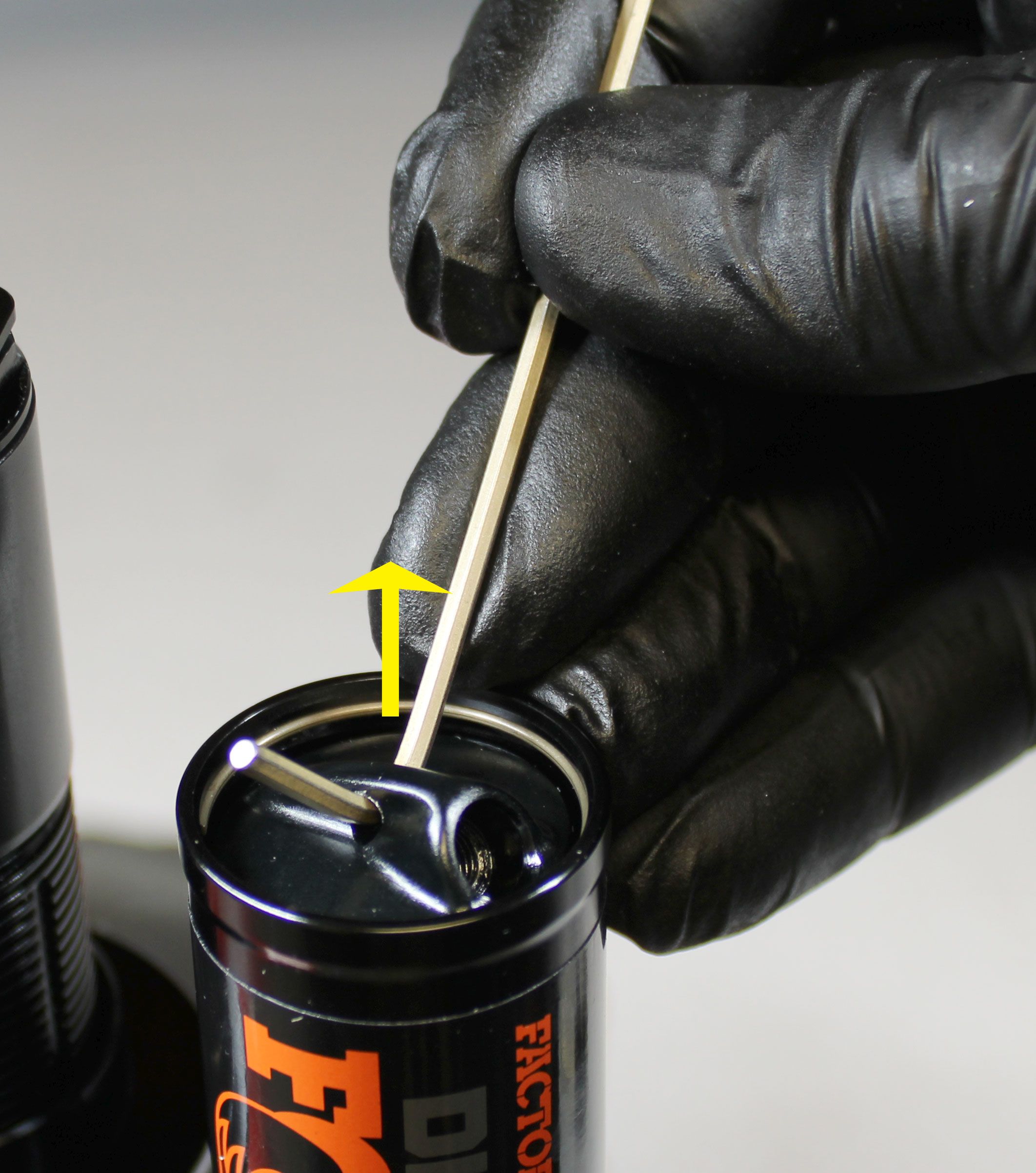
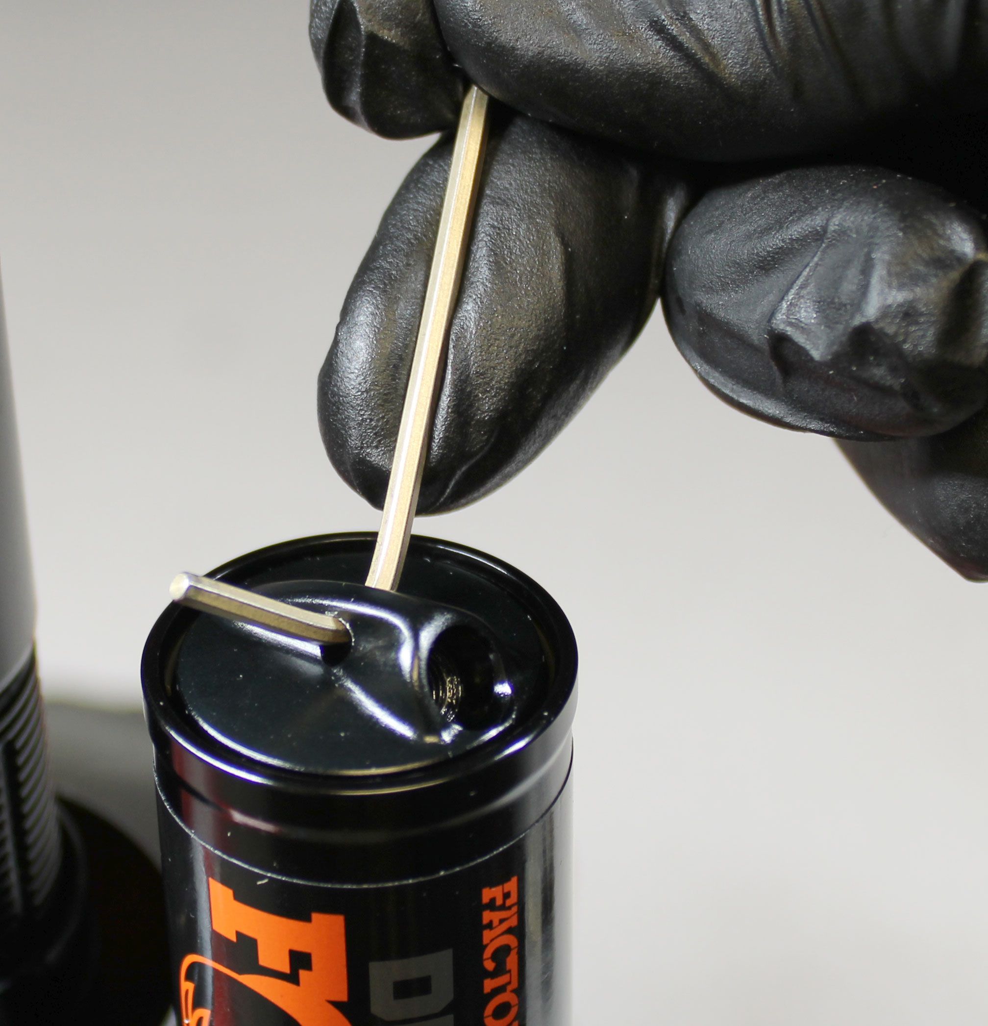
Step 5
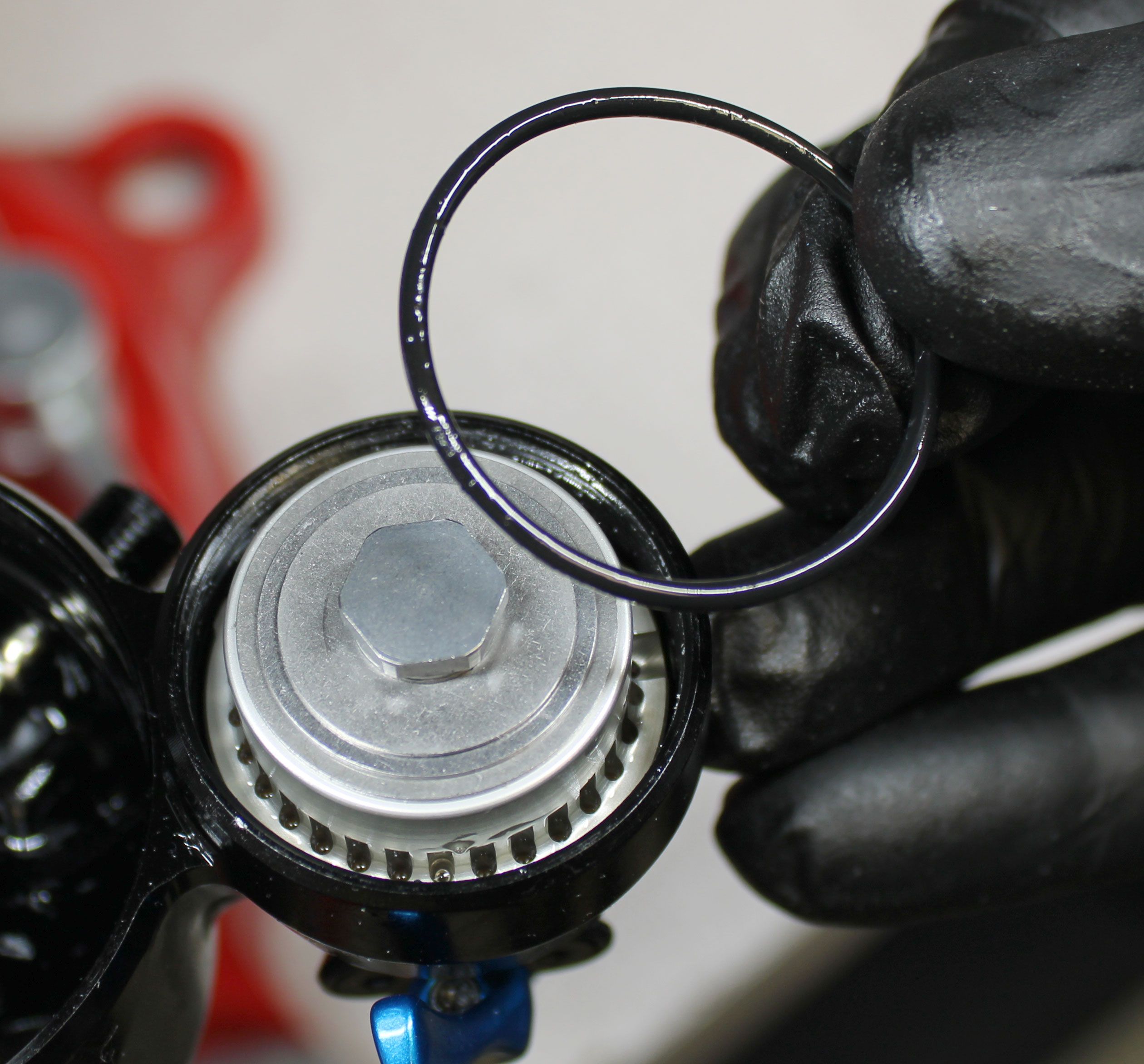
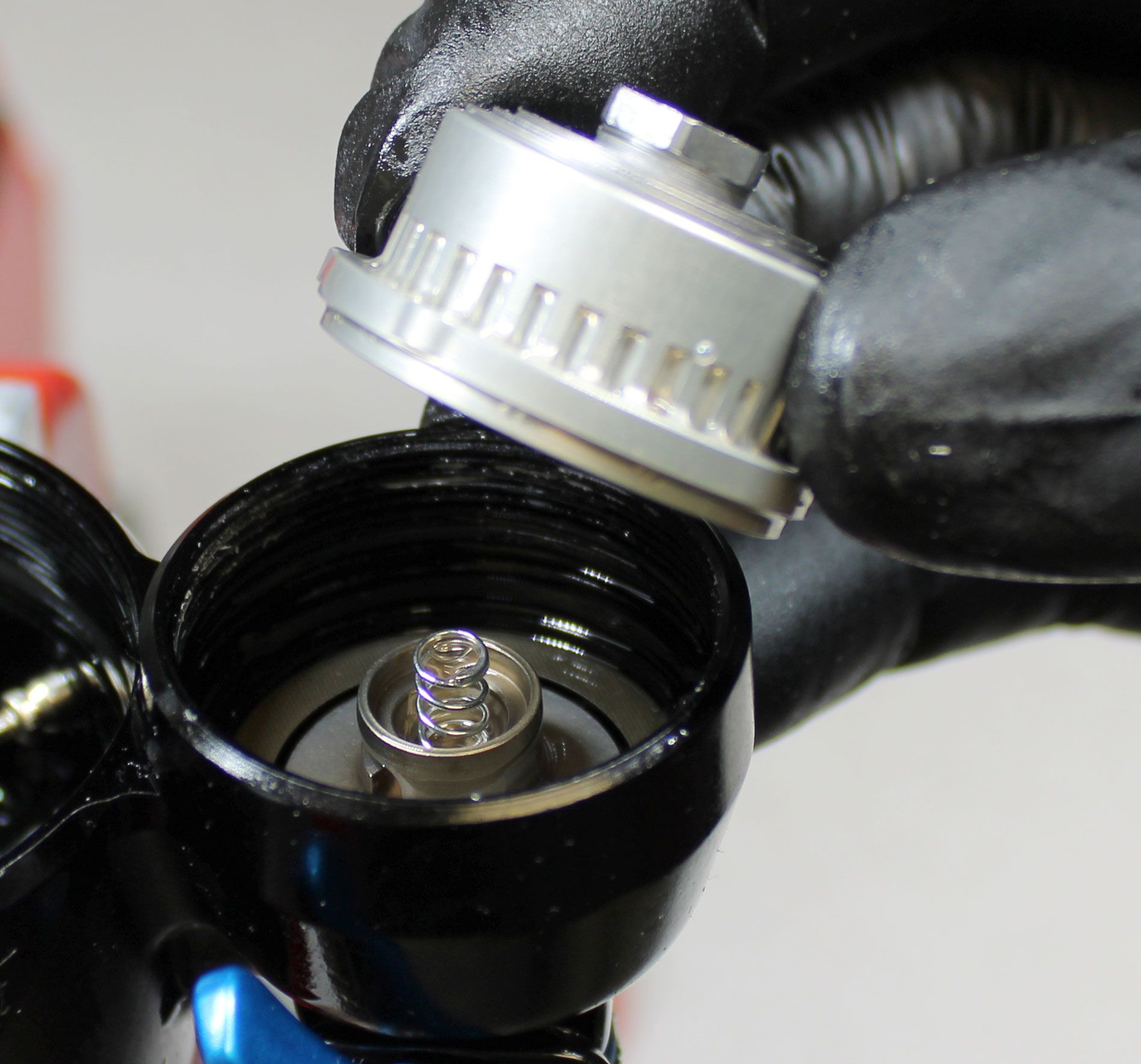
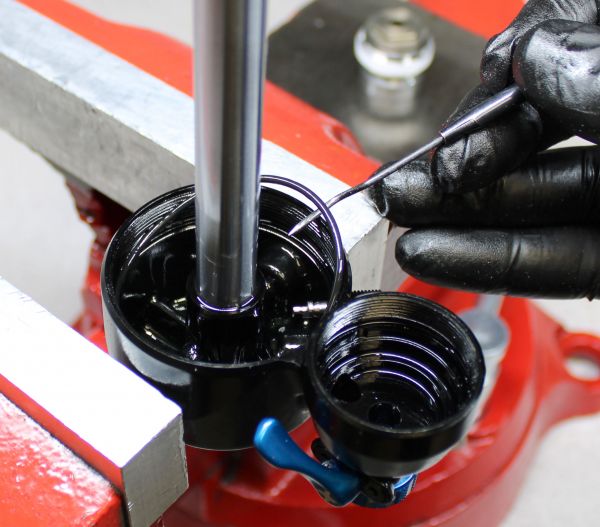
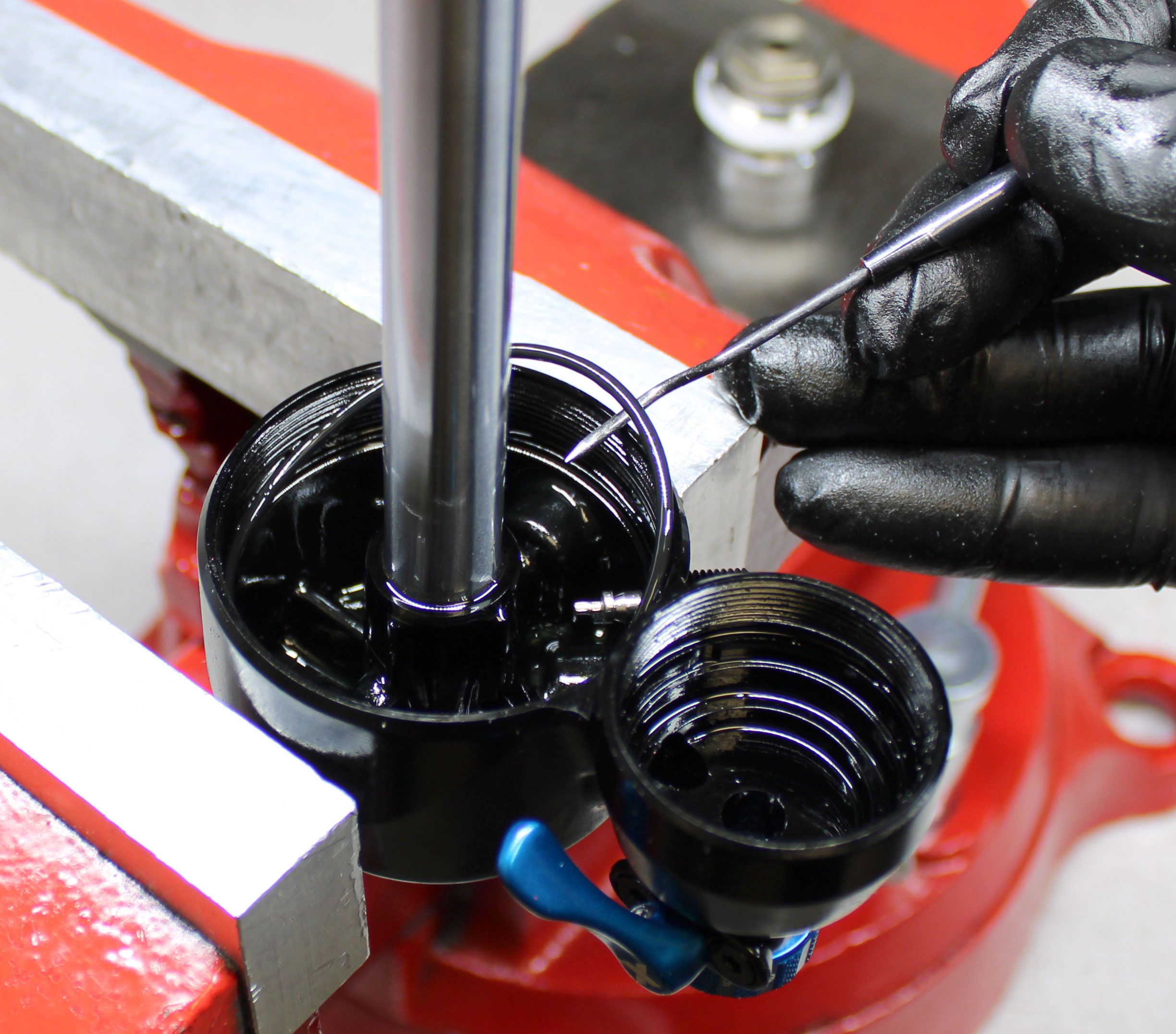
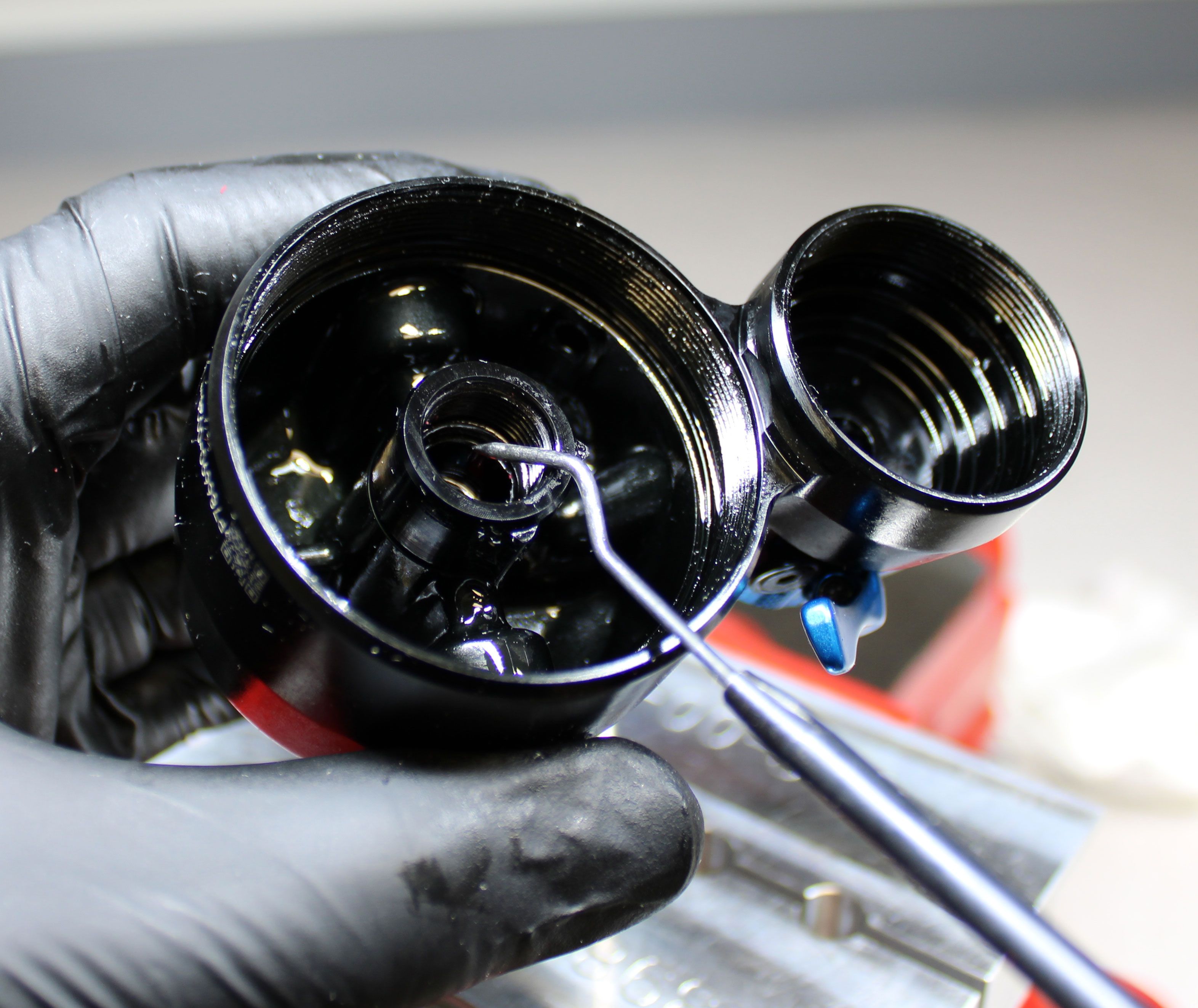
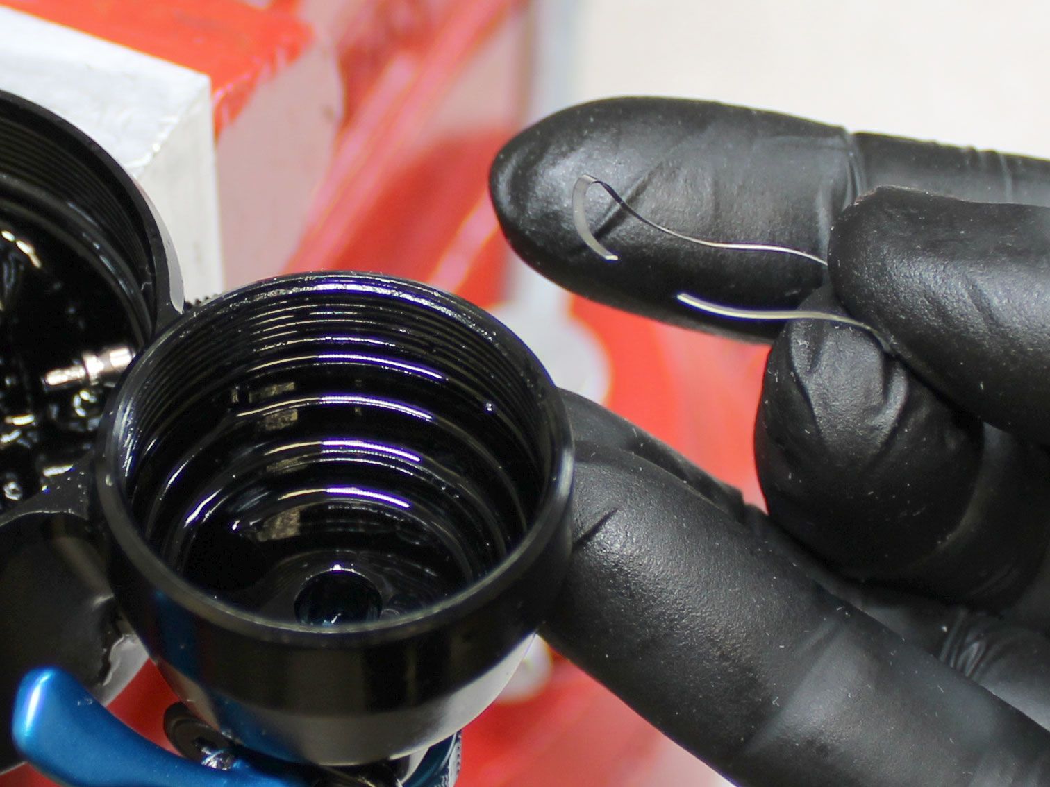
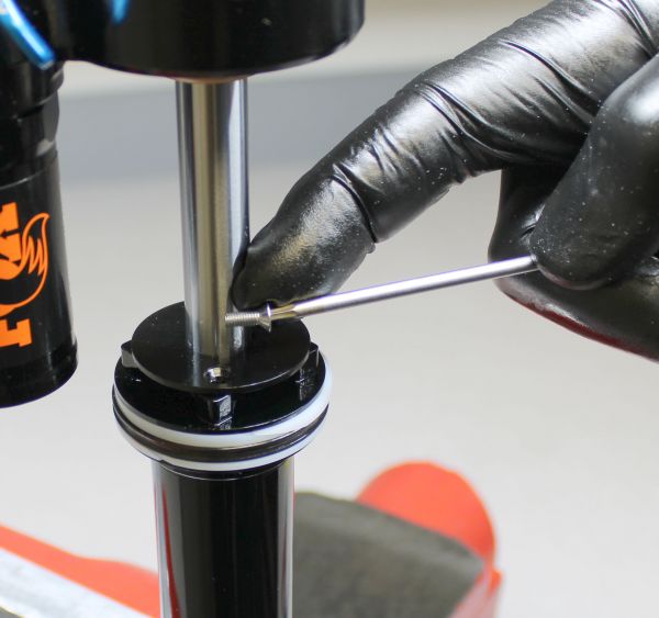
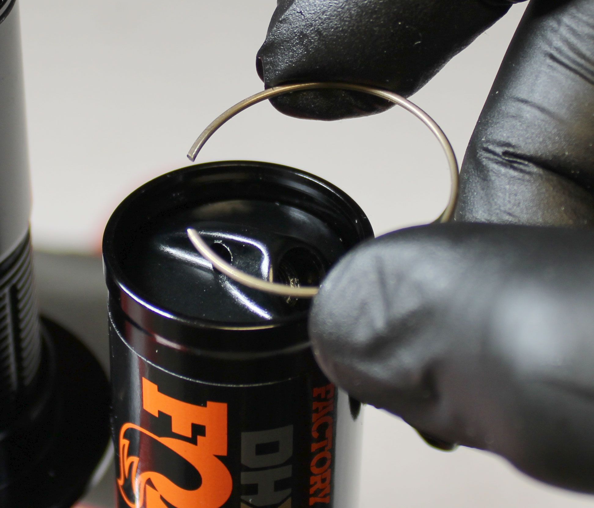
Push the Reservoir End Cap into the Reservoir to gain access to the wire retaining ring. Remove the wire retaining ring by pushing the center of the ring down which will cause the ends of the ring to pop up. Be careful not to scratch the IFP bore while removing or installing this ring. Use a small hex wrench to lift the Reservoir End Cap out from the Reservoir.

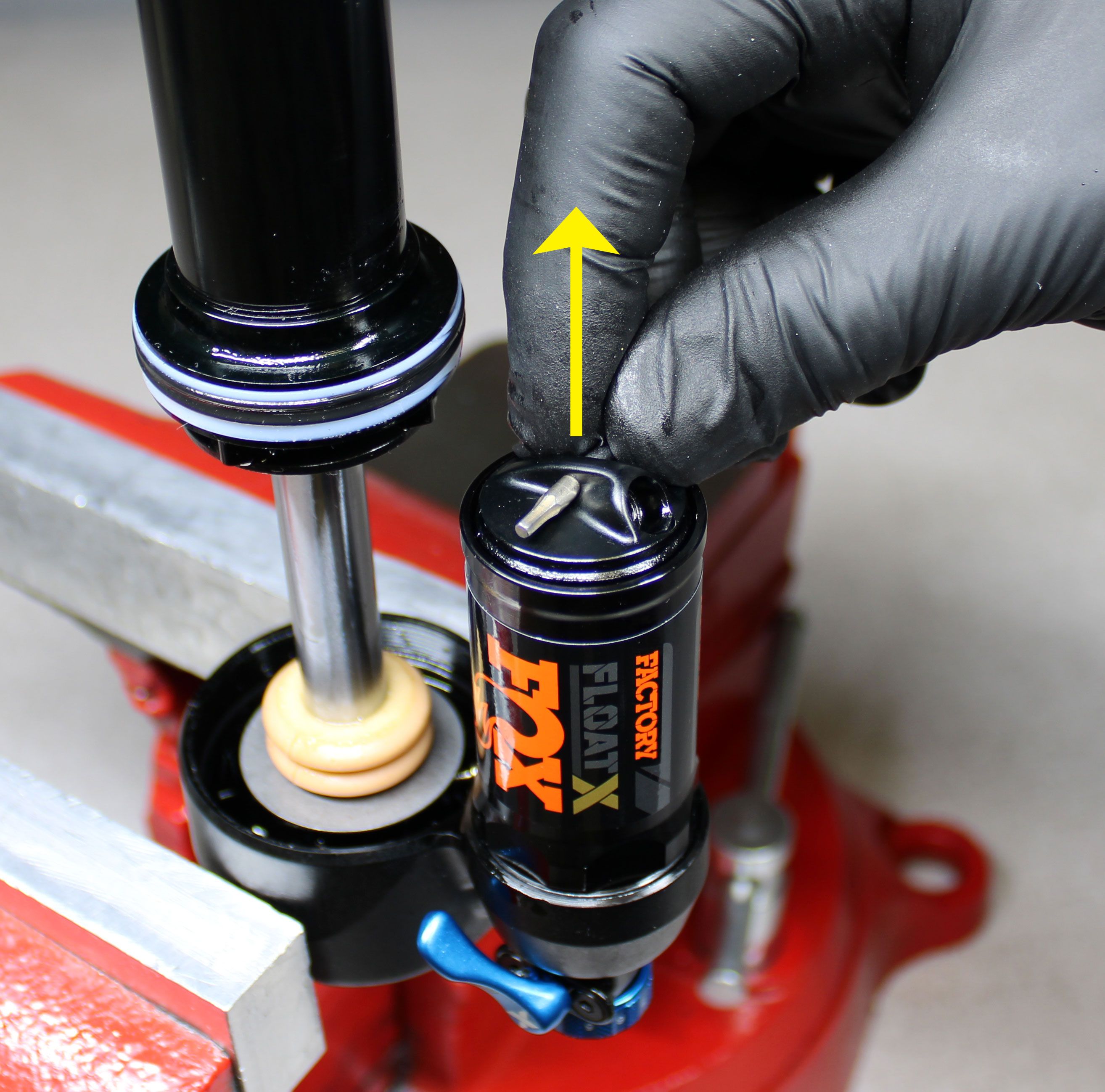
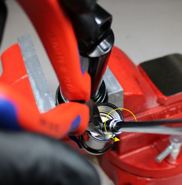
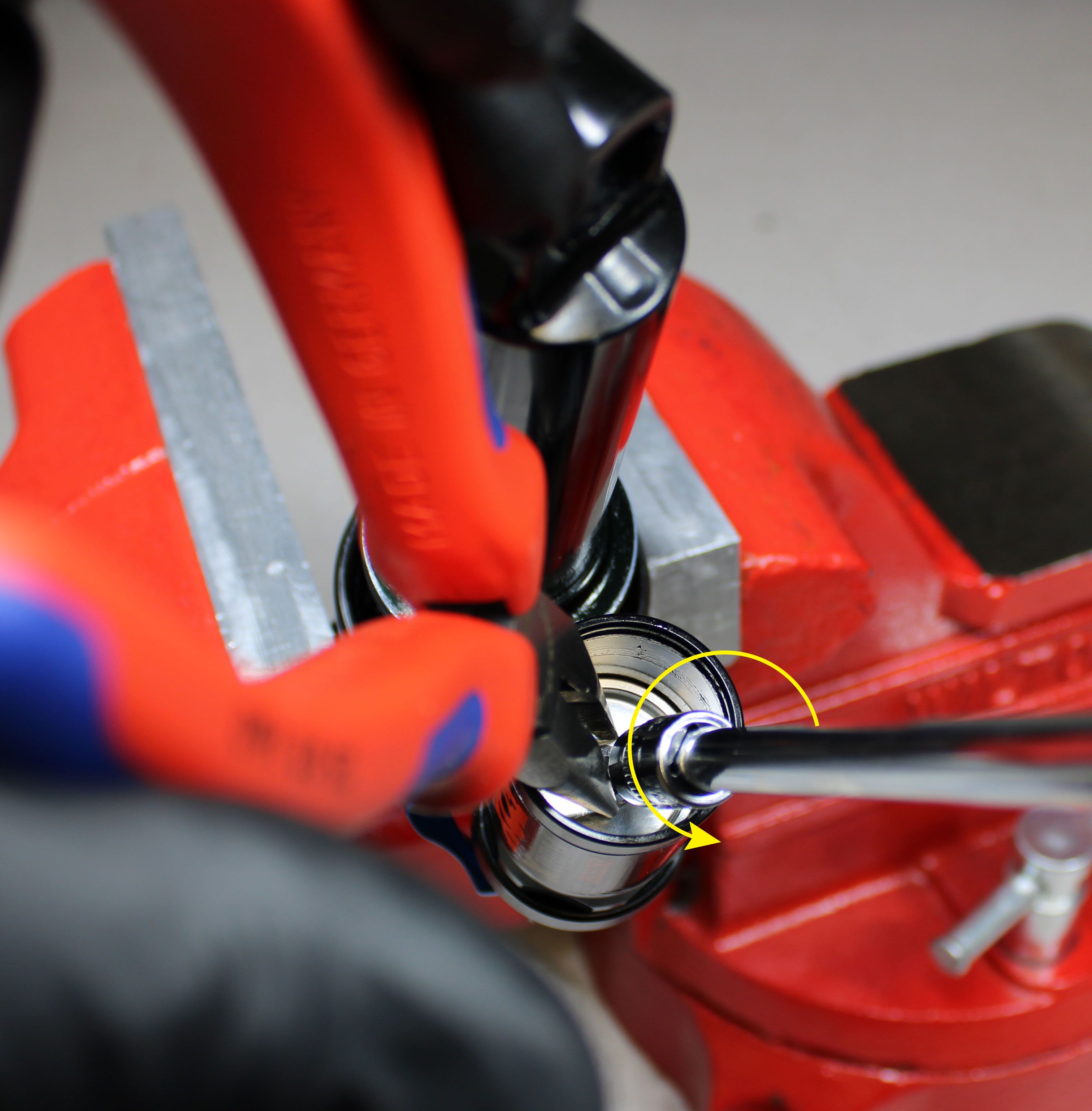
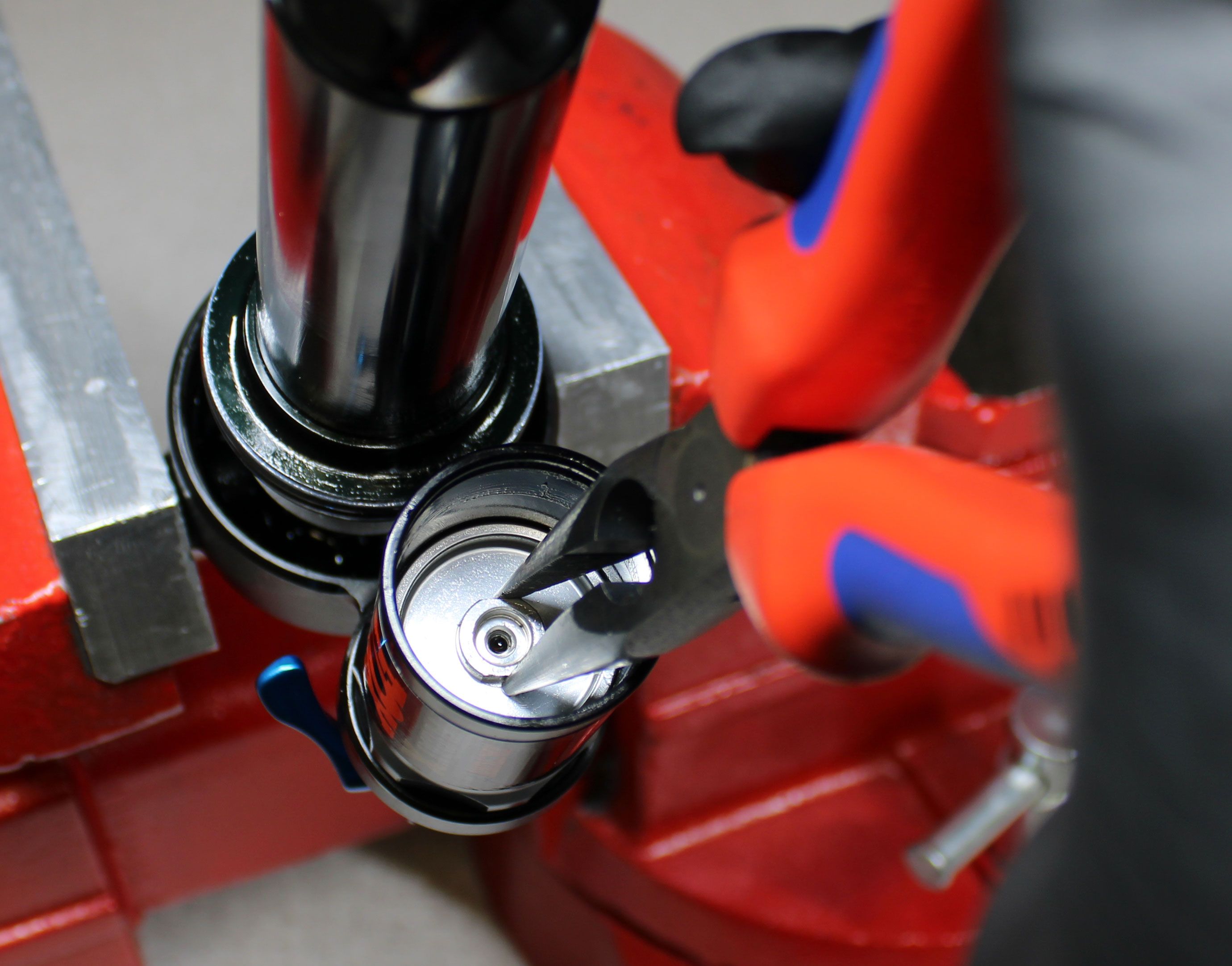
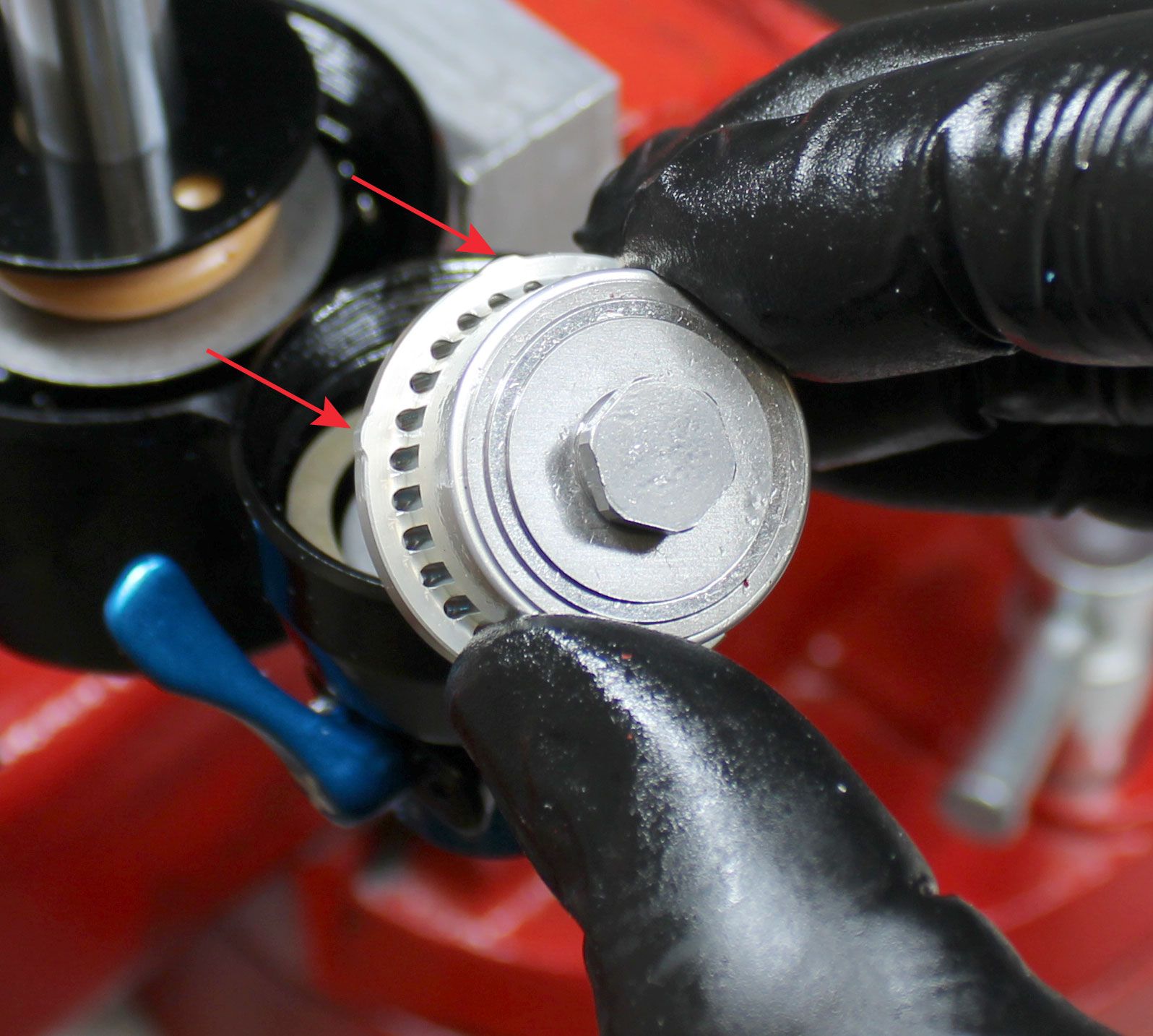
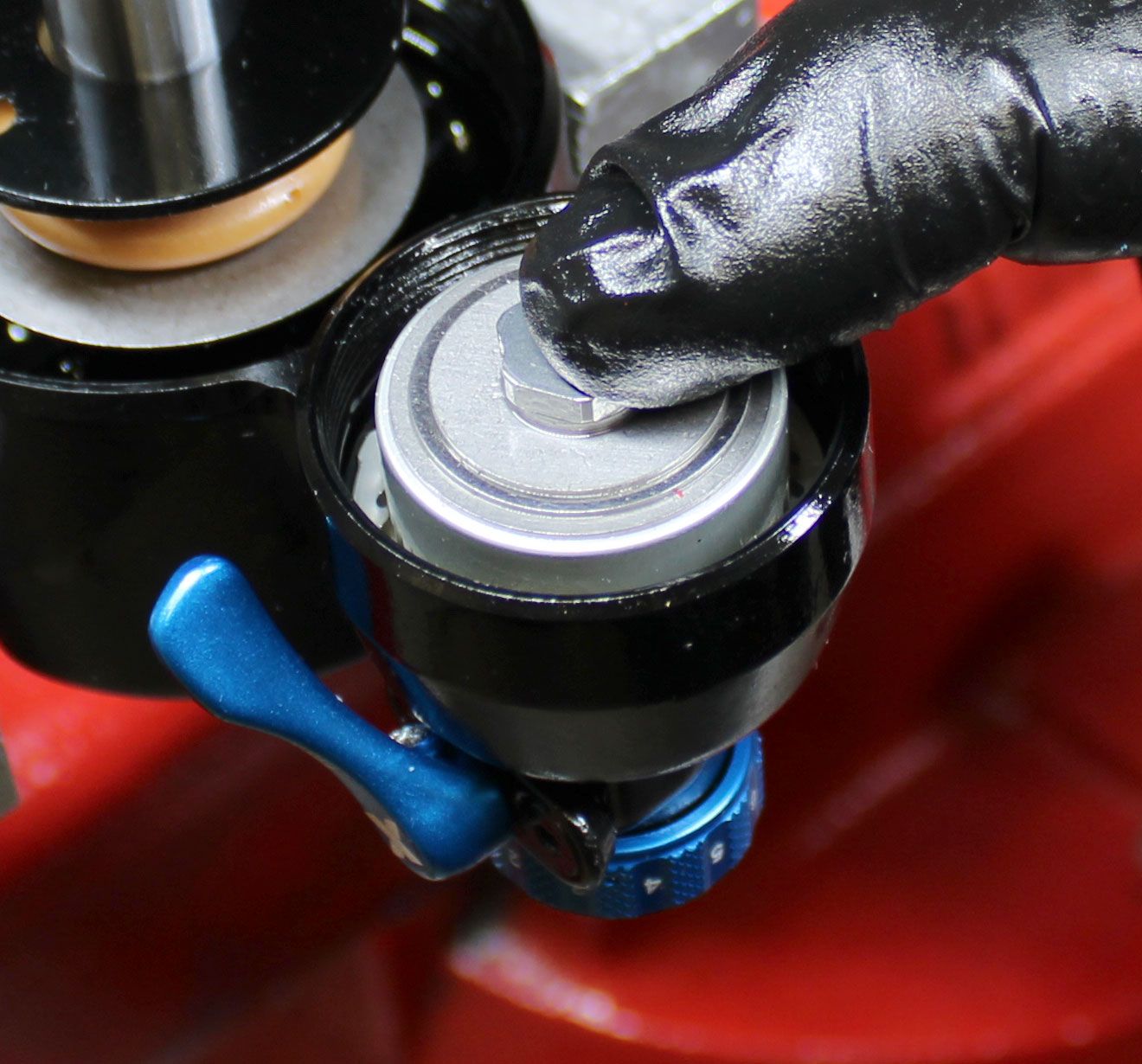
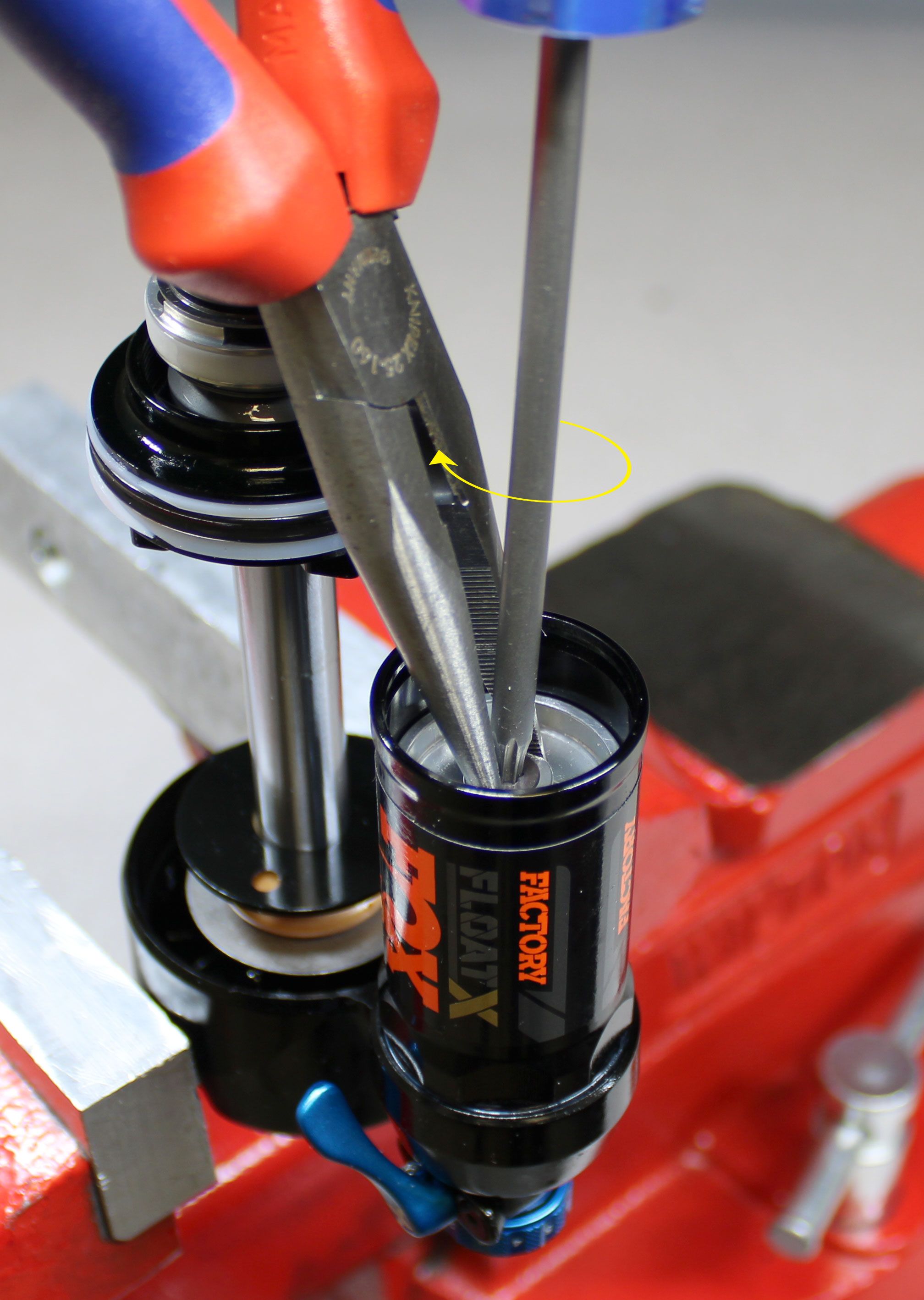
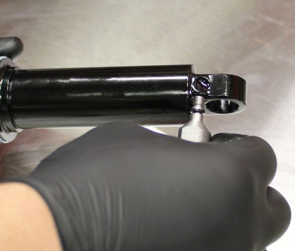
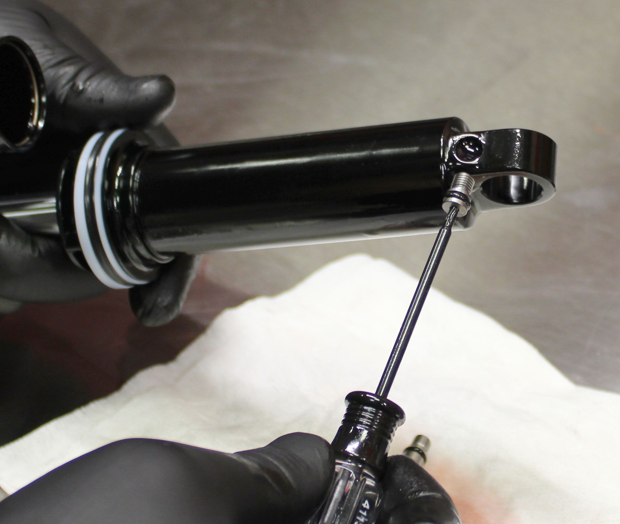
Step 6
Hold the flats of the IFP with needle-nosed pliers while you unthread the IFP bleed screw counter-clockwise with a T15 Torx driver. Remove the bleed screw then remove the IFP by pulling up with needle-nosed pliers.
Step 7
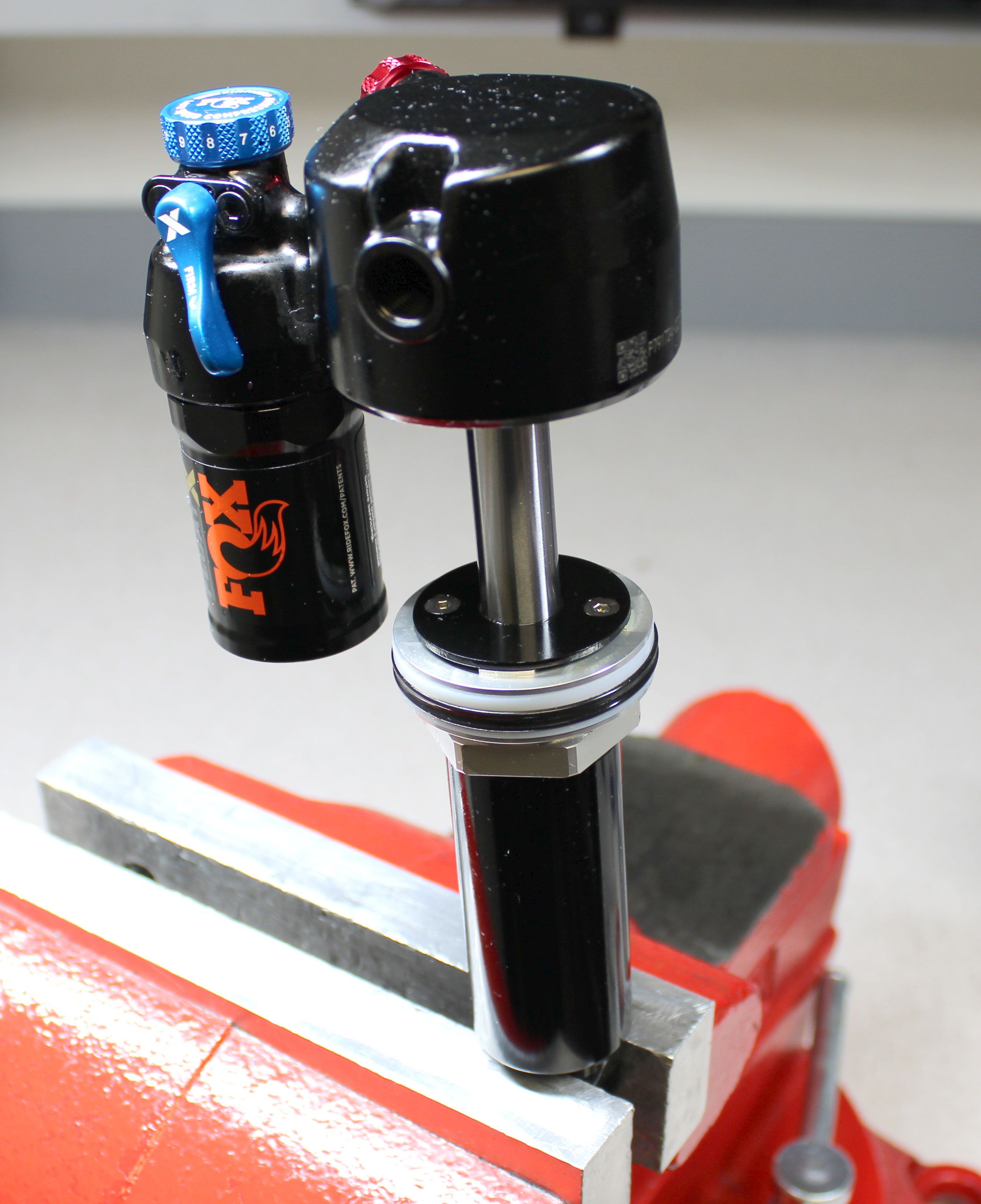
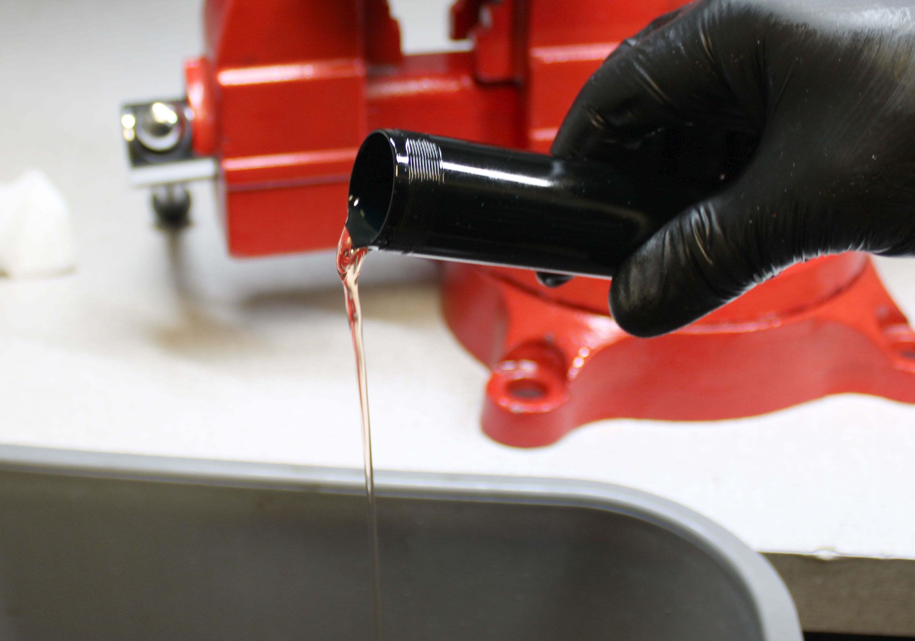
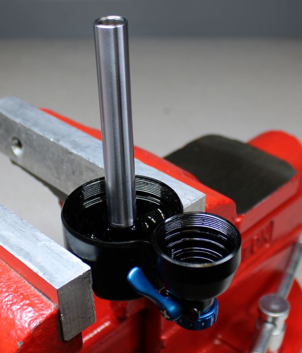
Pour out any oil from the reservoir into your waste oil basin. Clamp the body eyelet in your soft jawed vise.


Step 8
37.5mm through 45mm travel FLOAT X shocks use a different bearing housing assembly than 47.5mm-75mm travel FLOAT X shocks.
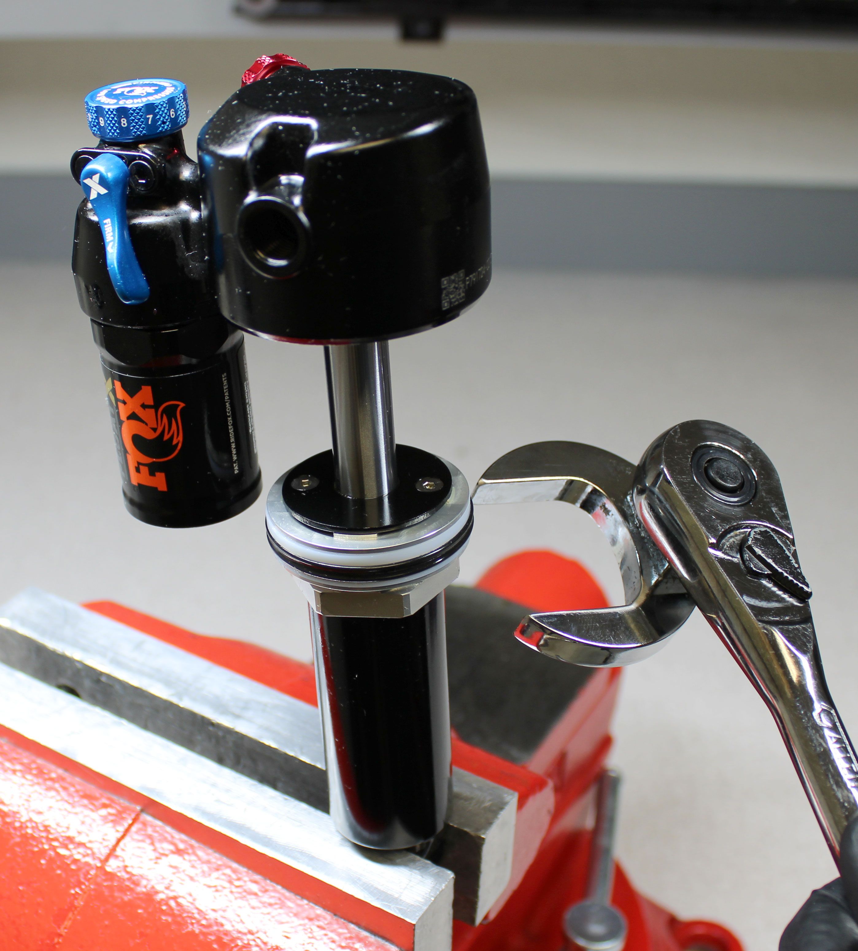
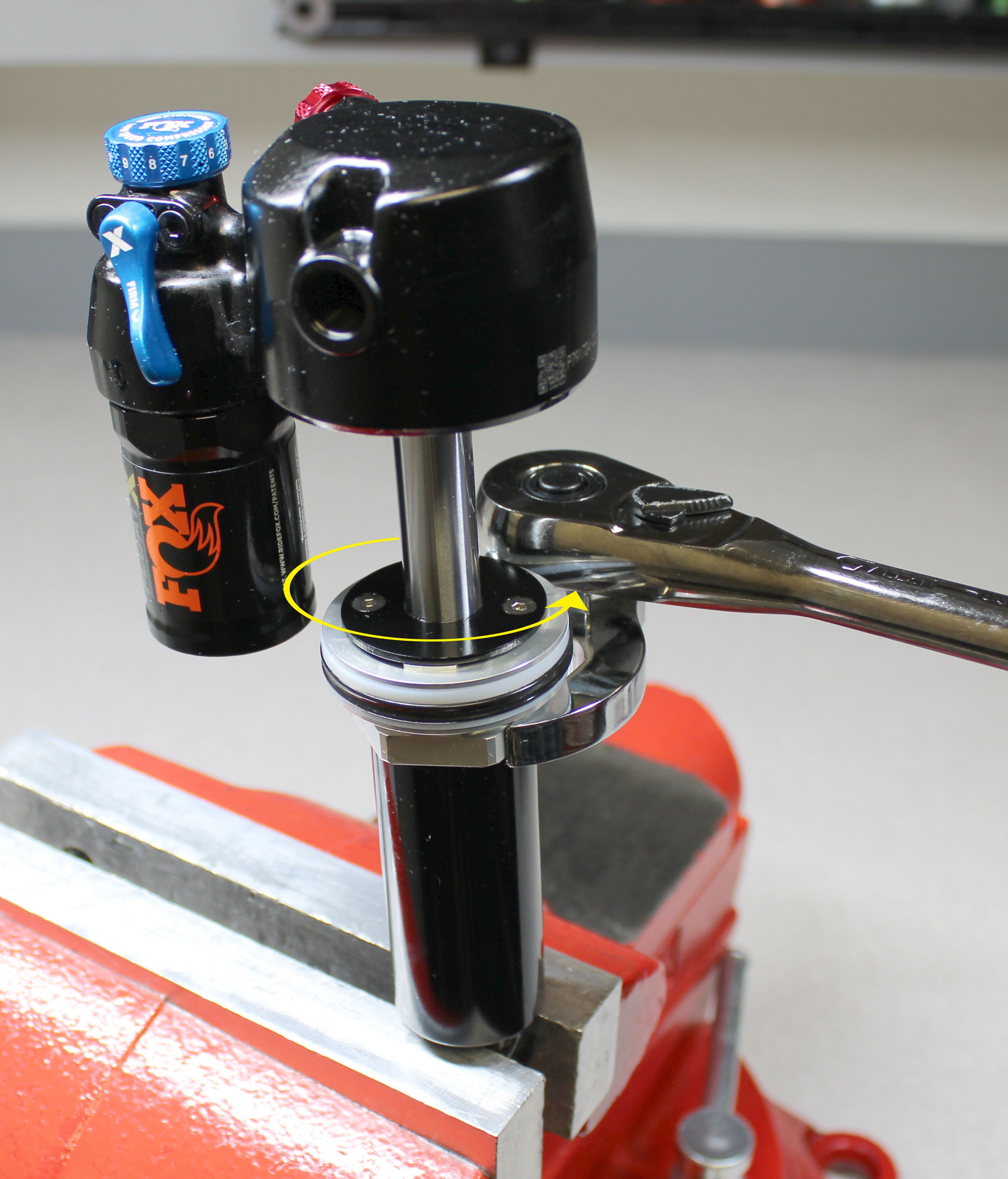
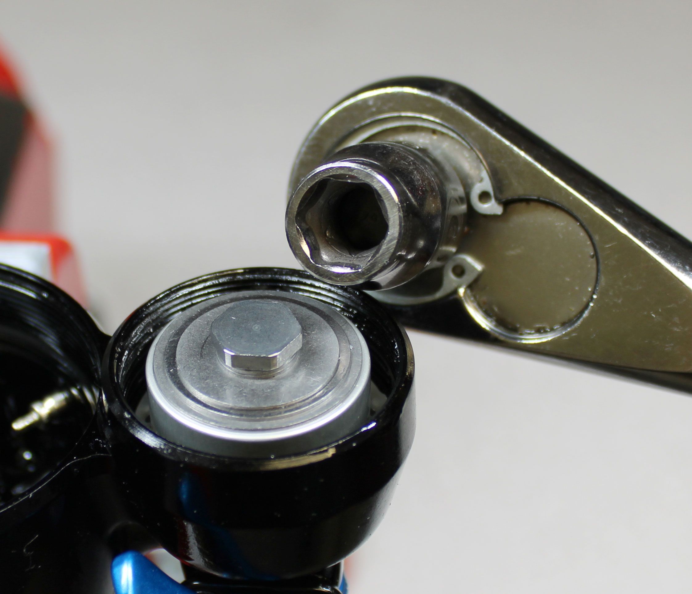
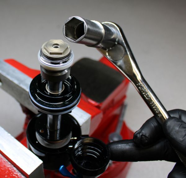
For 37.5mm-45mm travels: Use a 32mm wrench to unthread the bearing housing counter-clockwise.

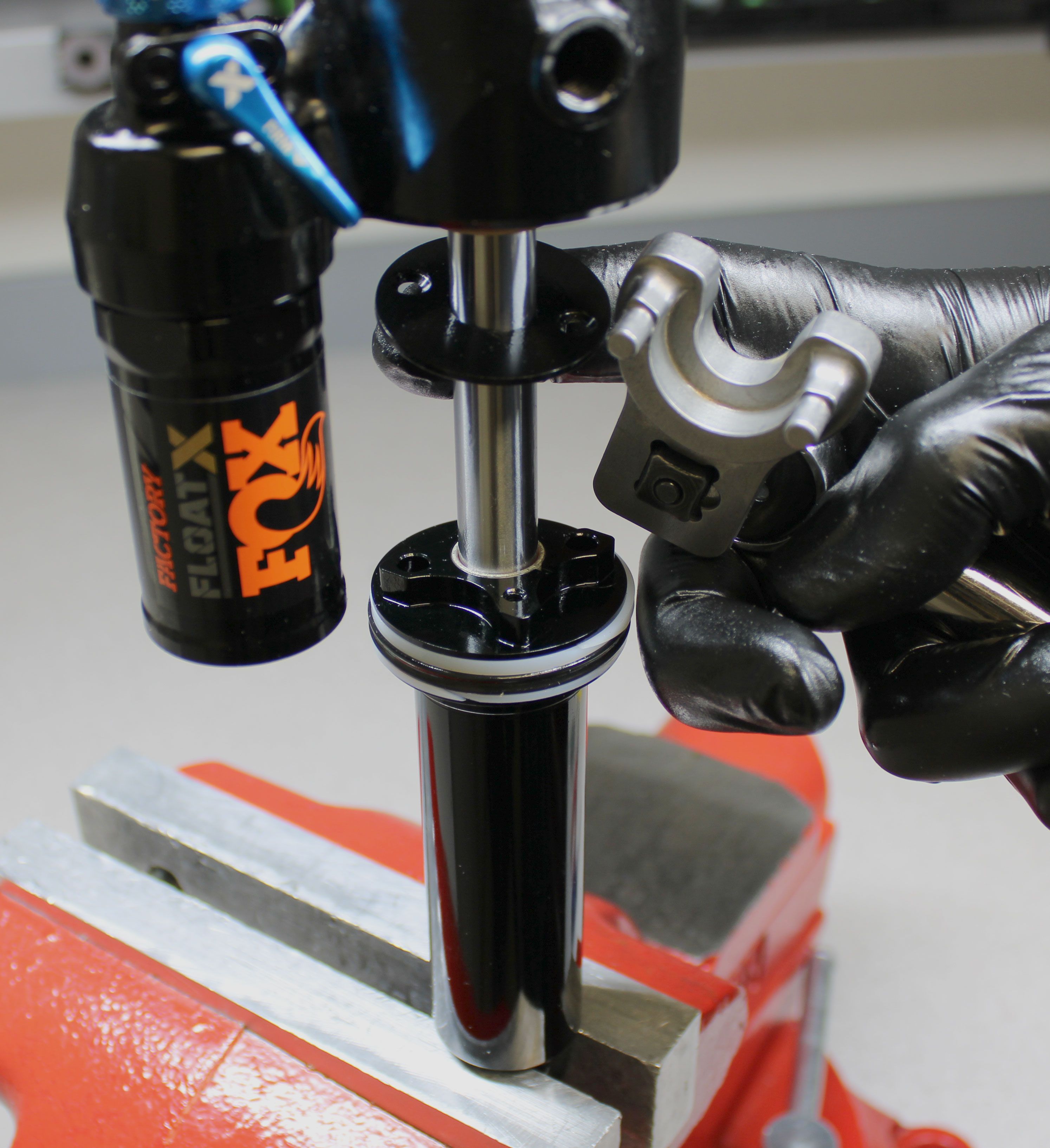
Step 9
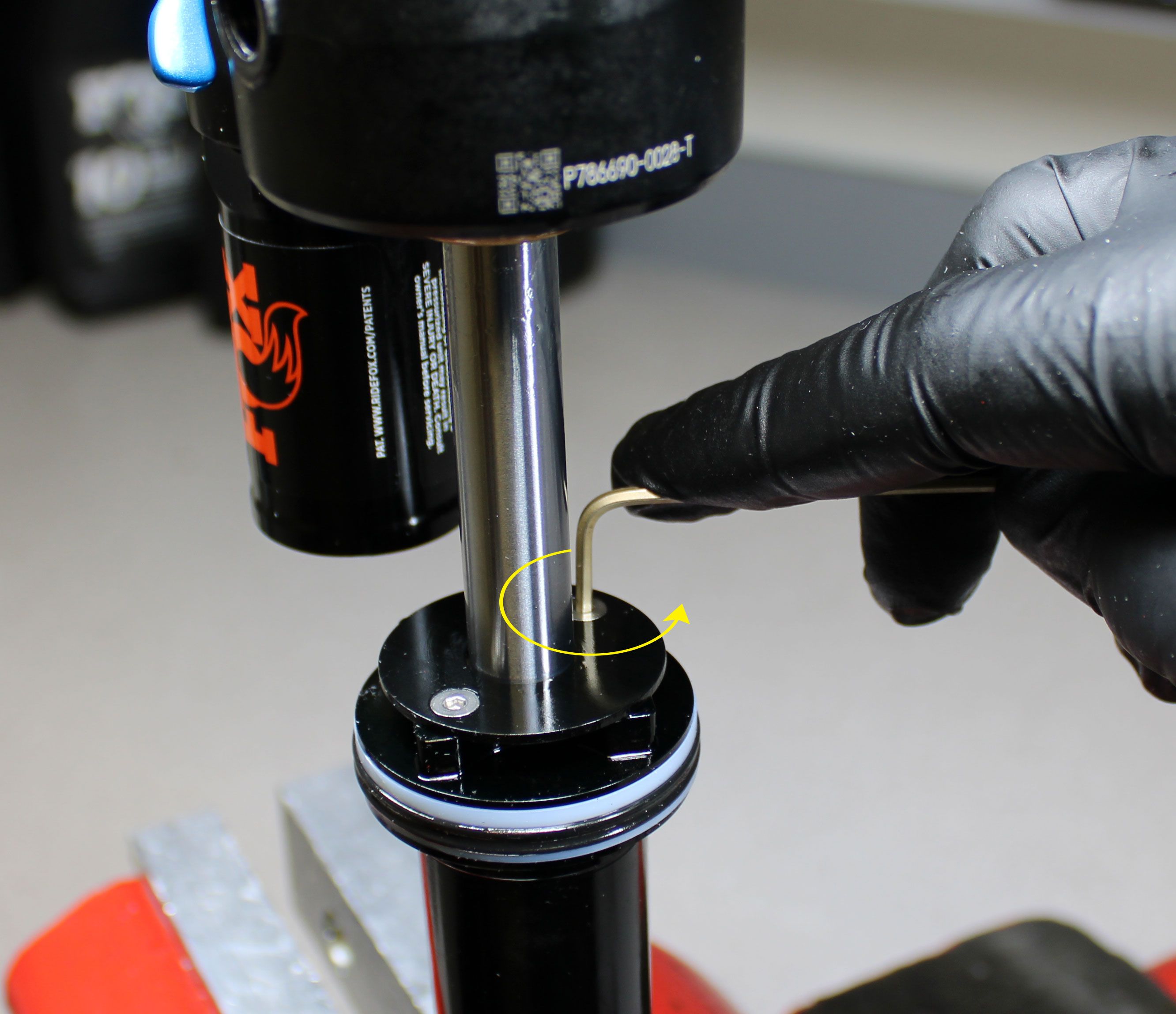
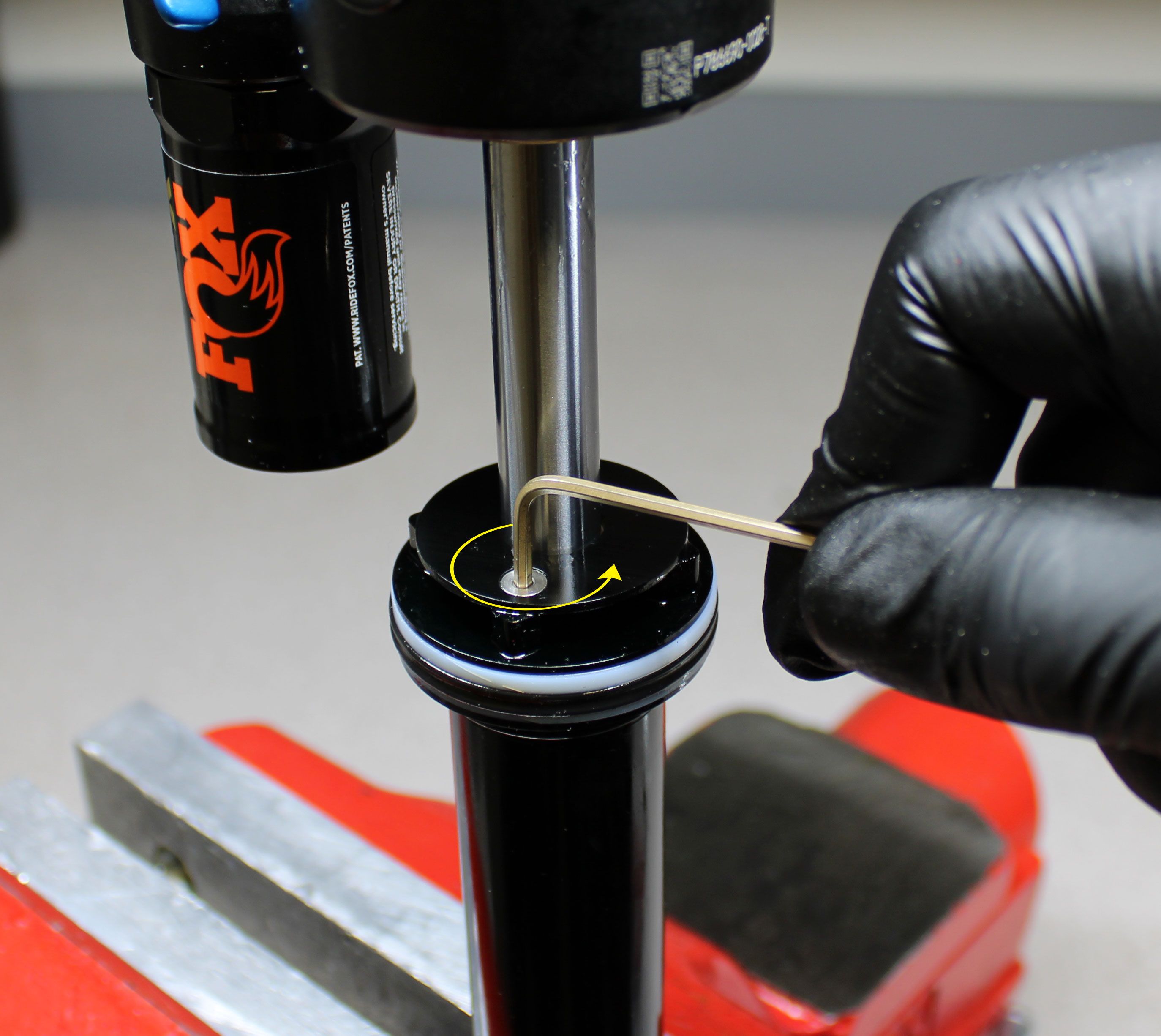
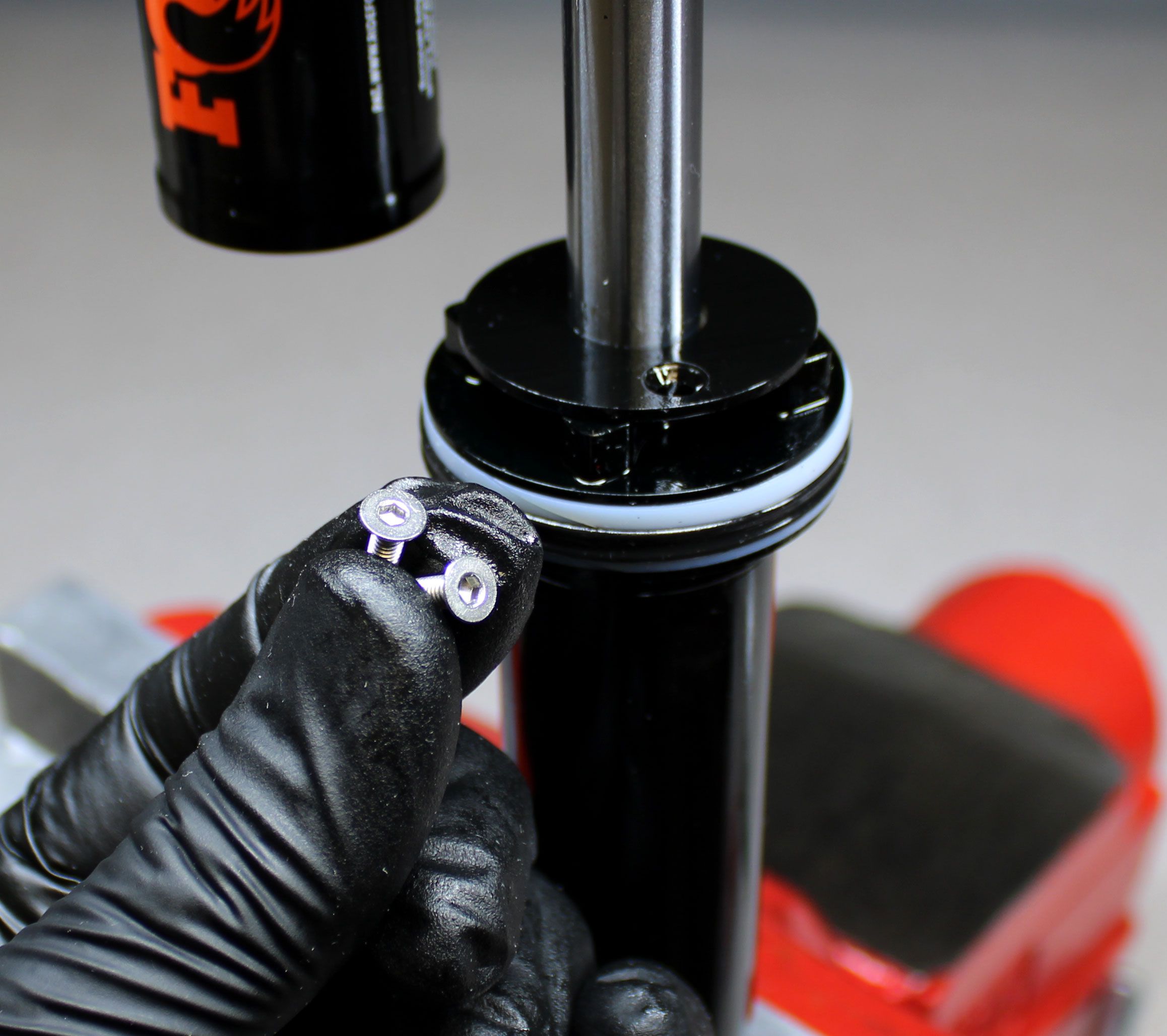
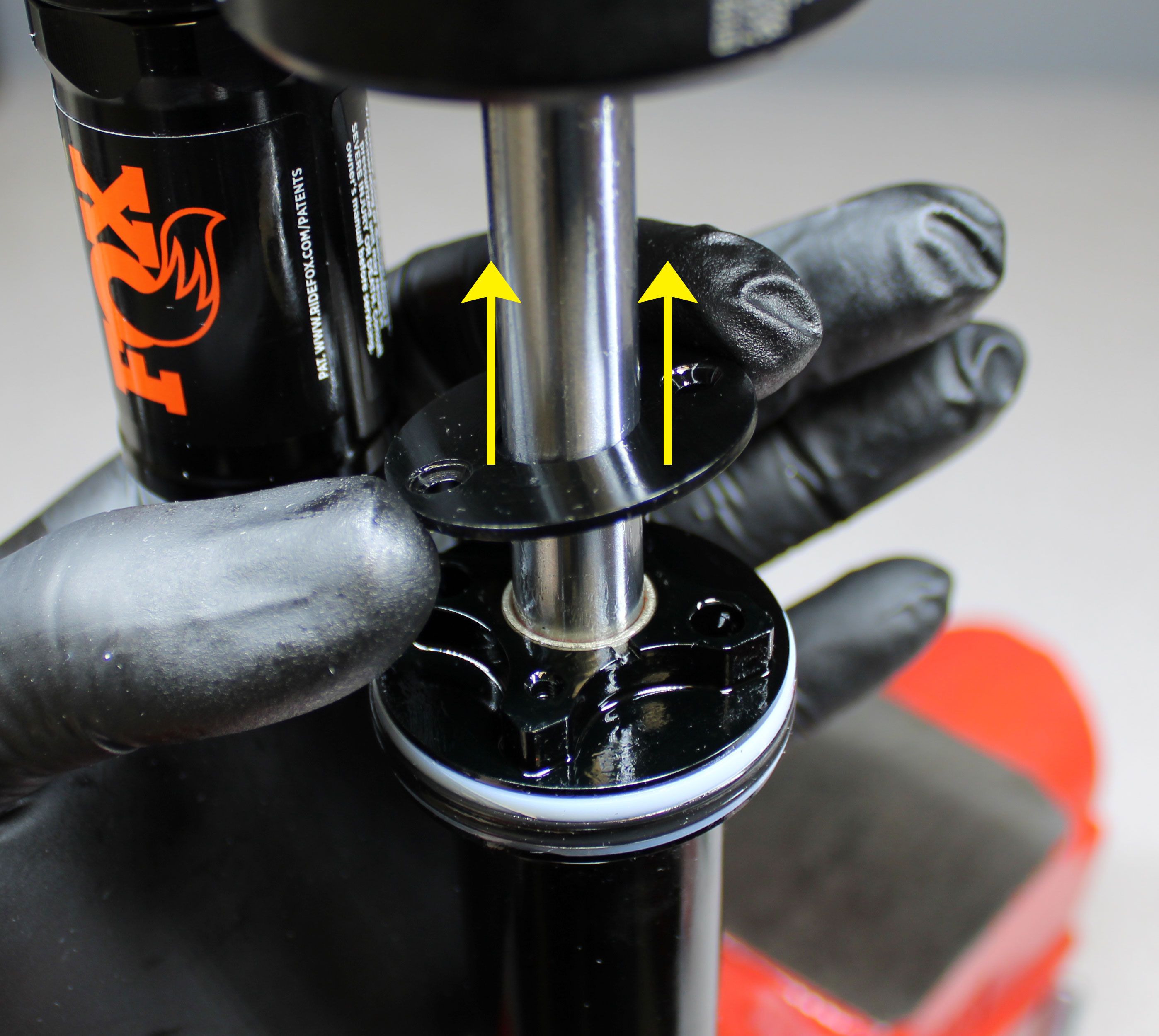
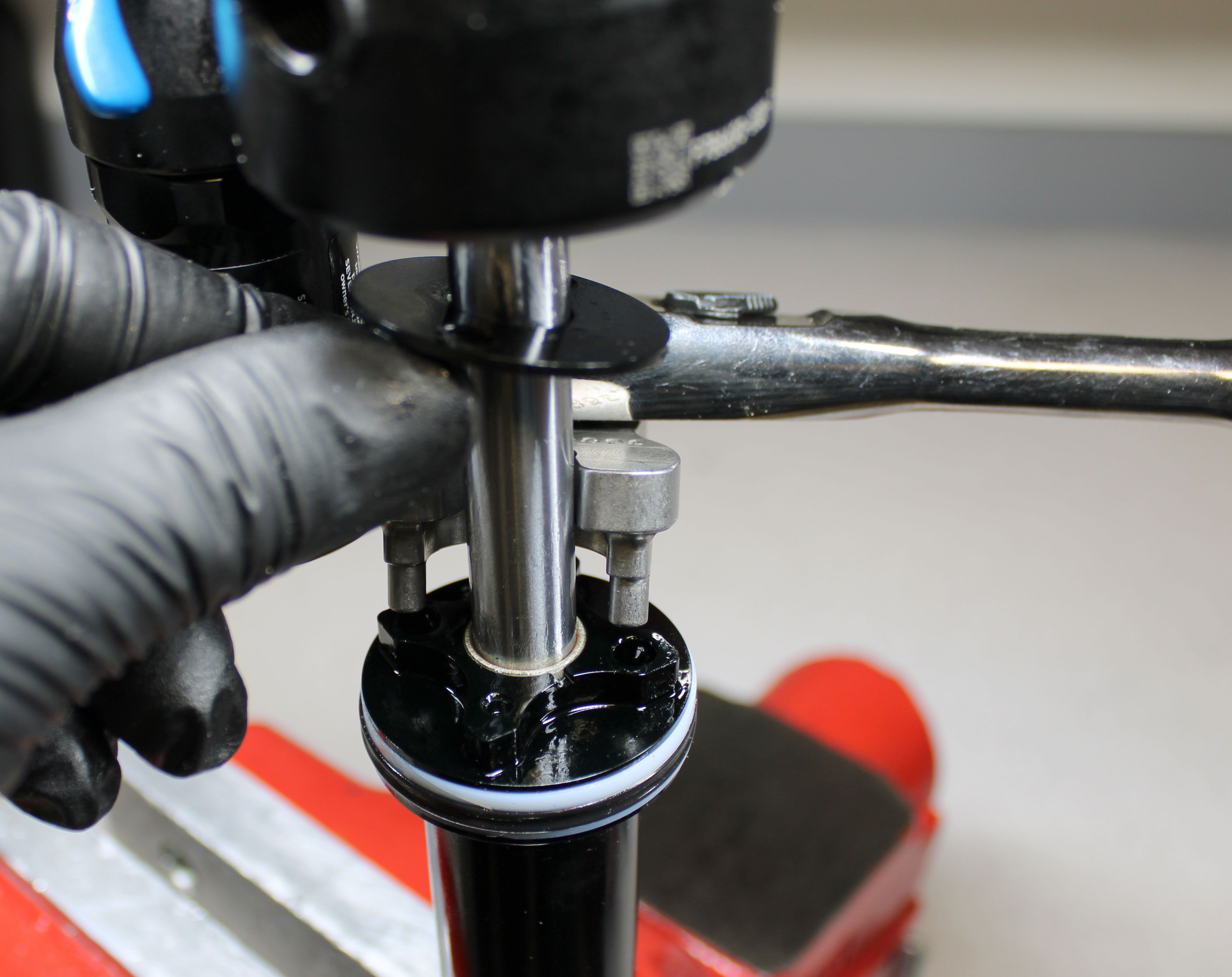
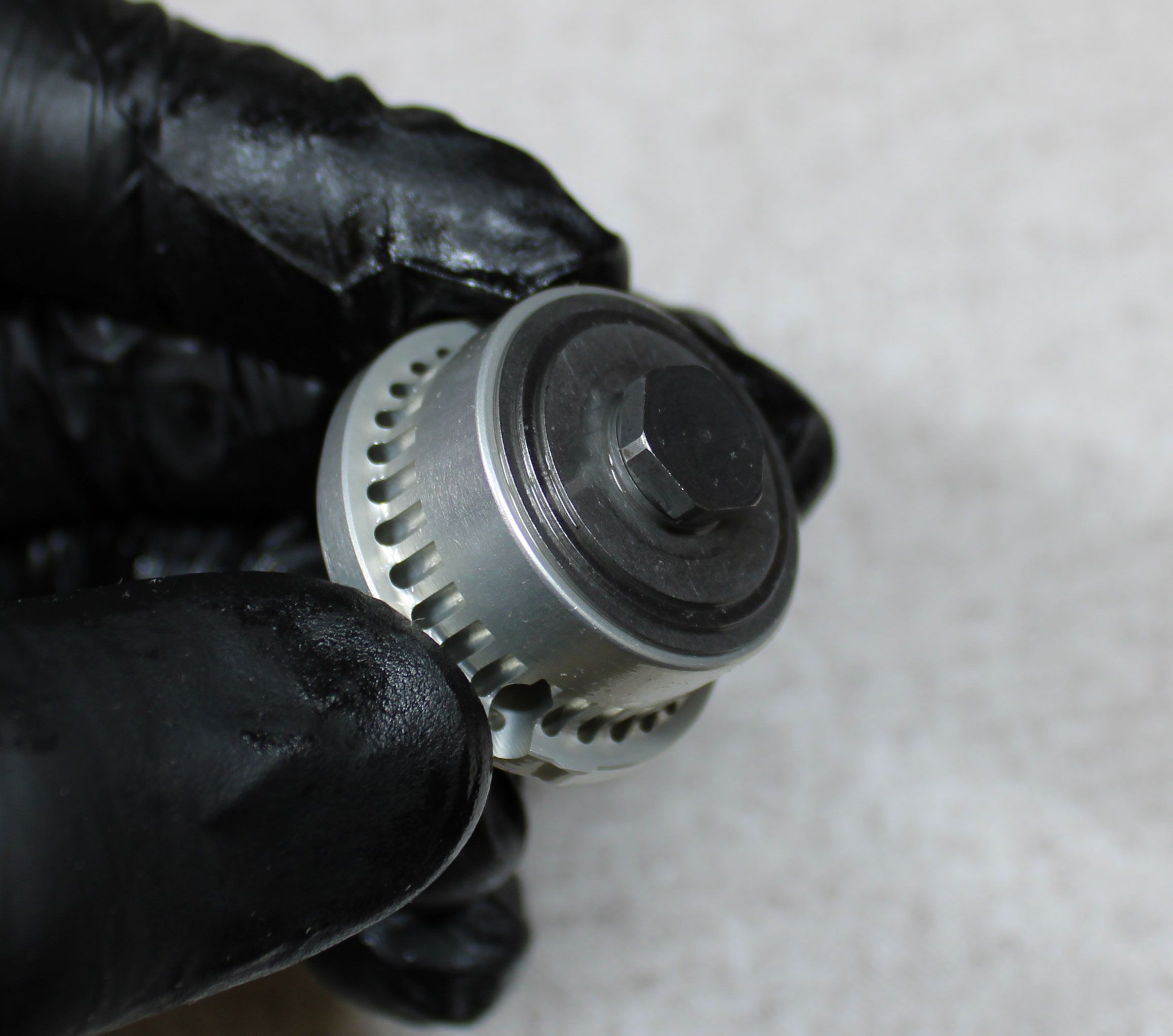
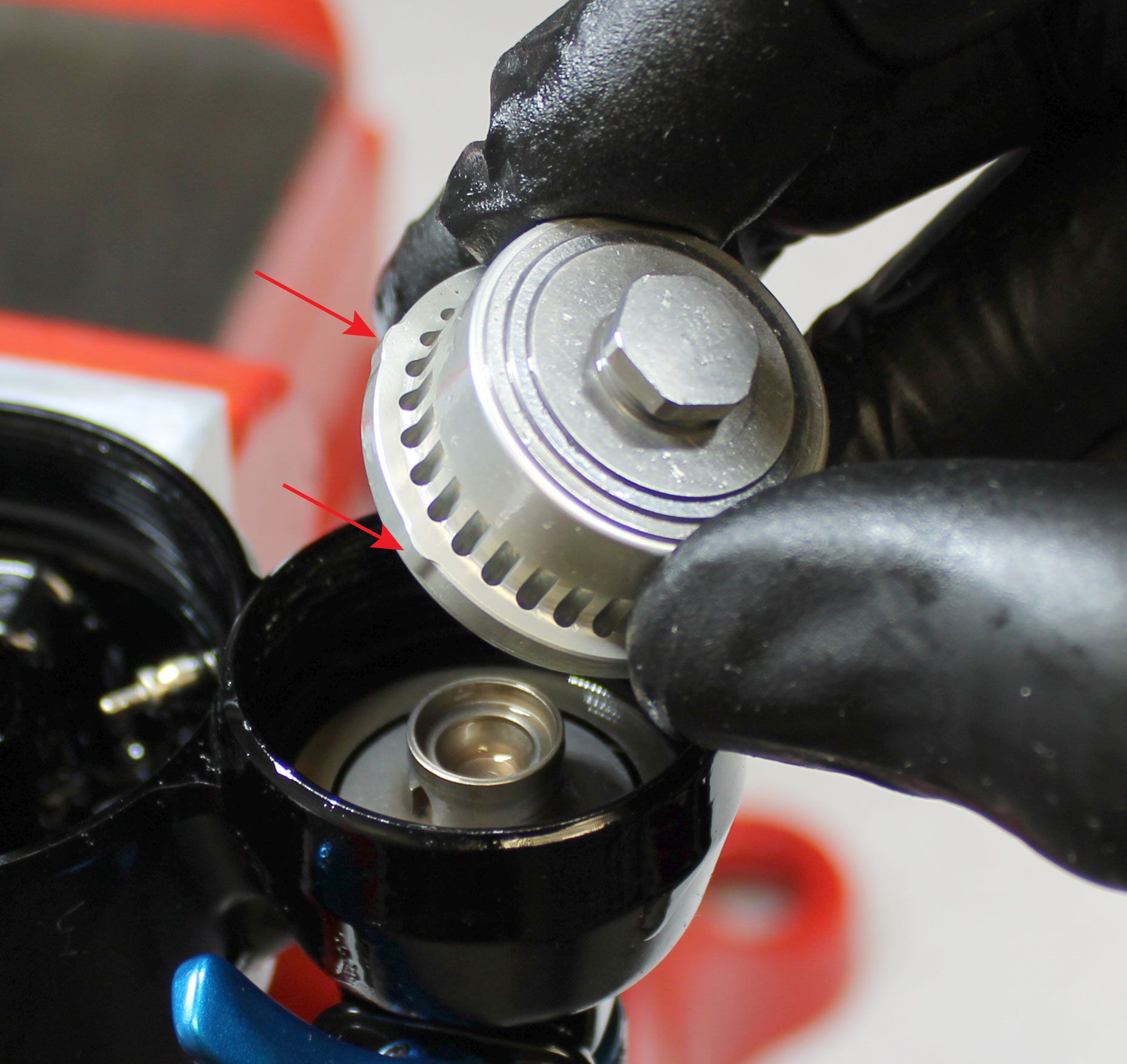
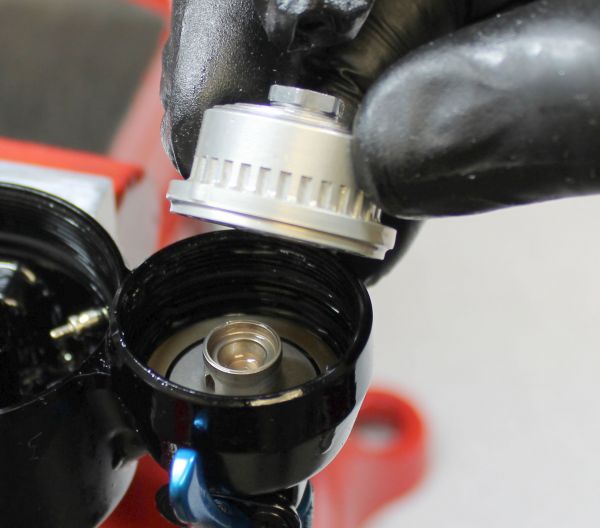
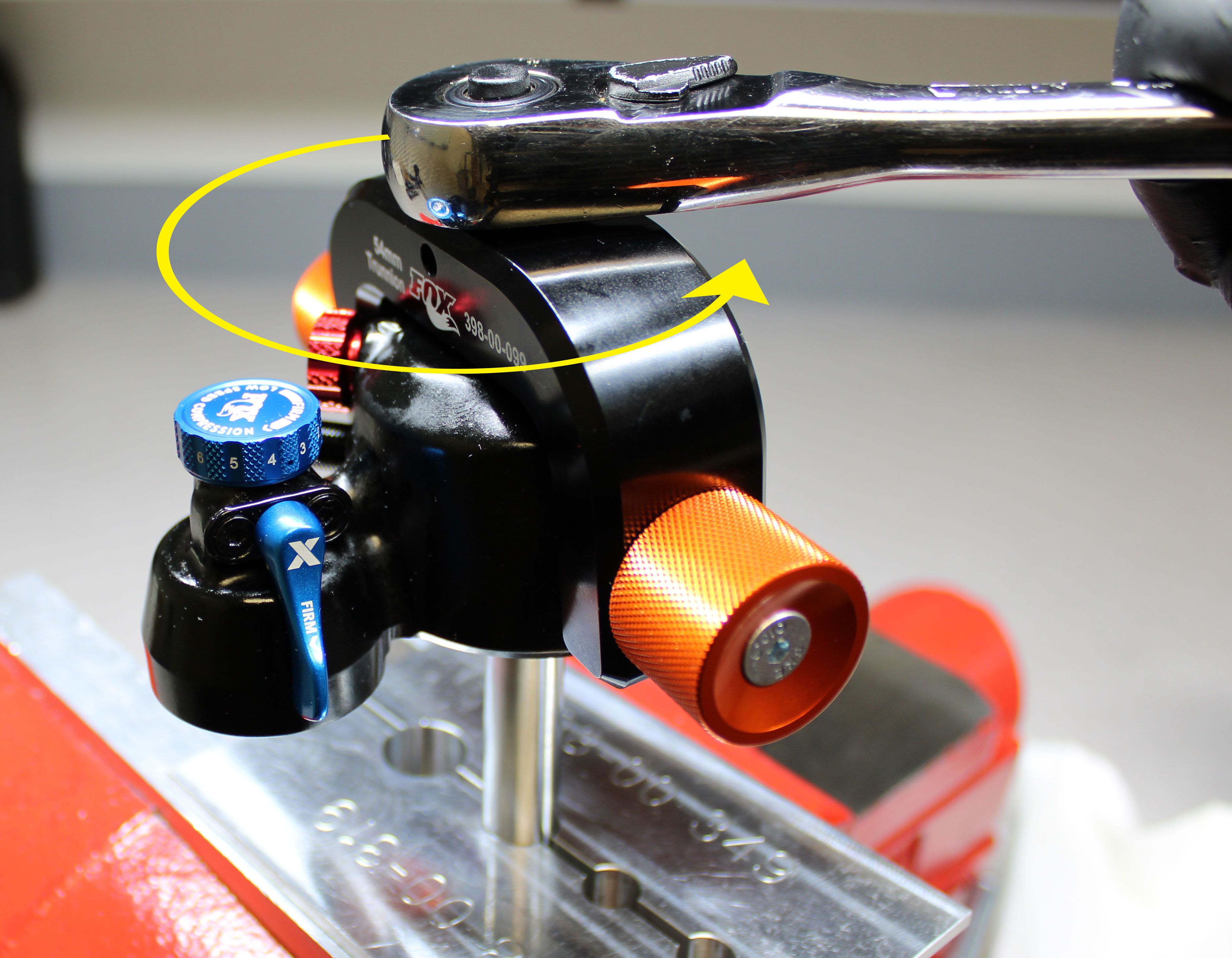
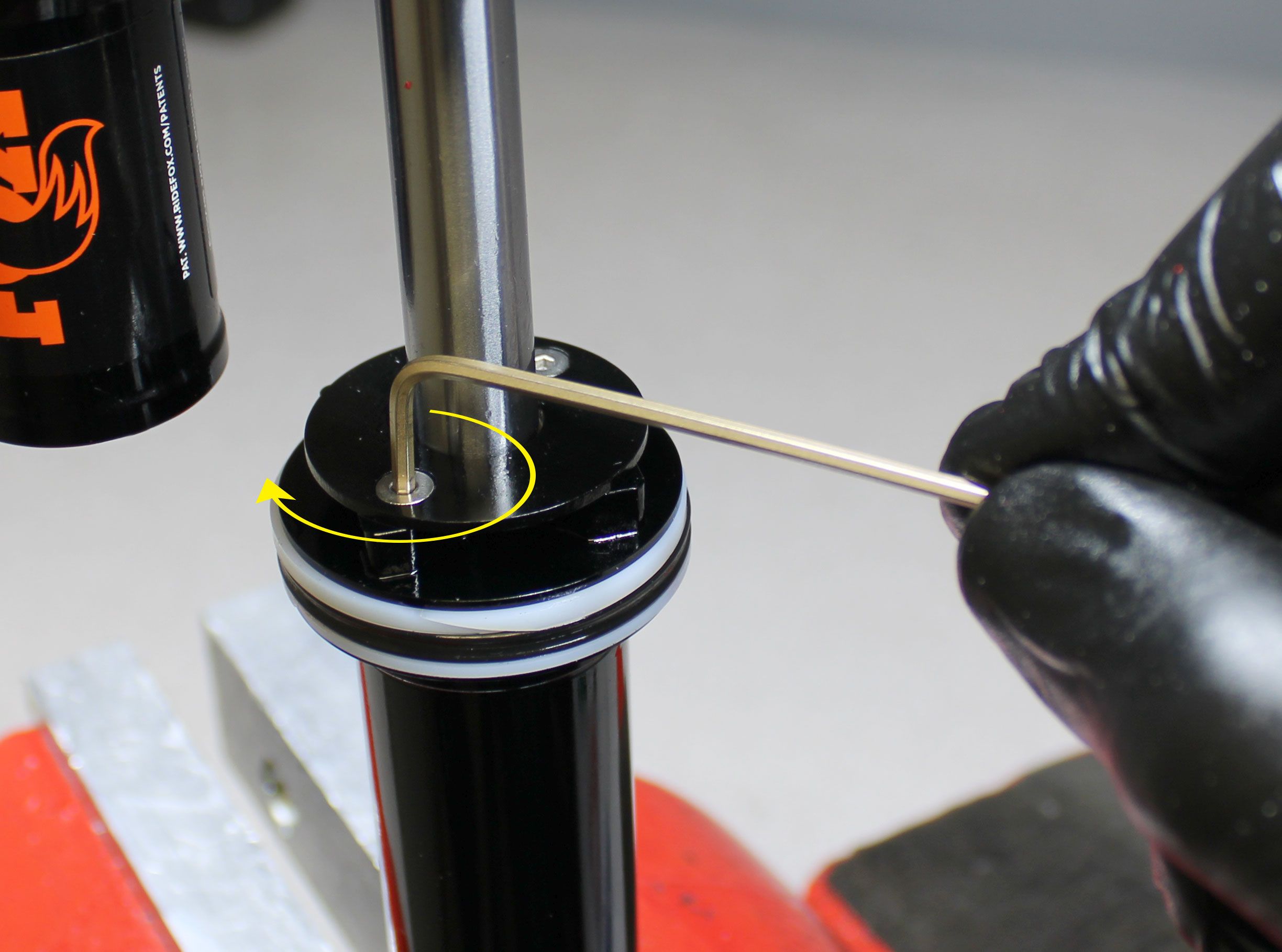
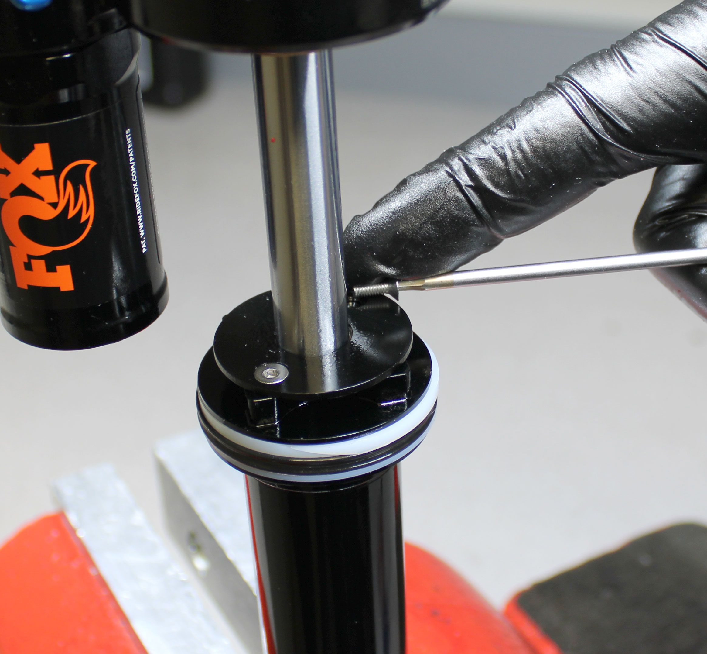
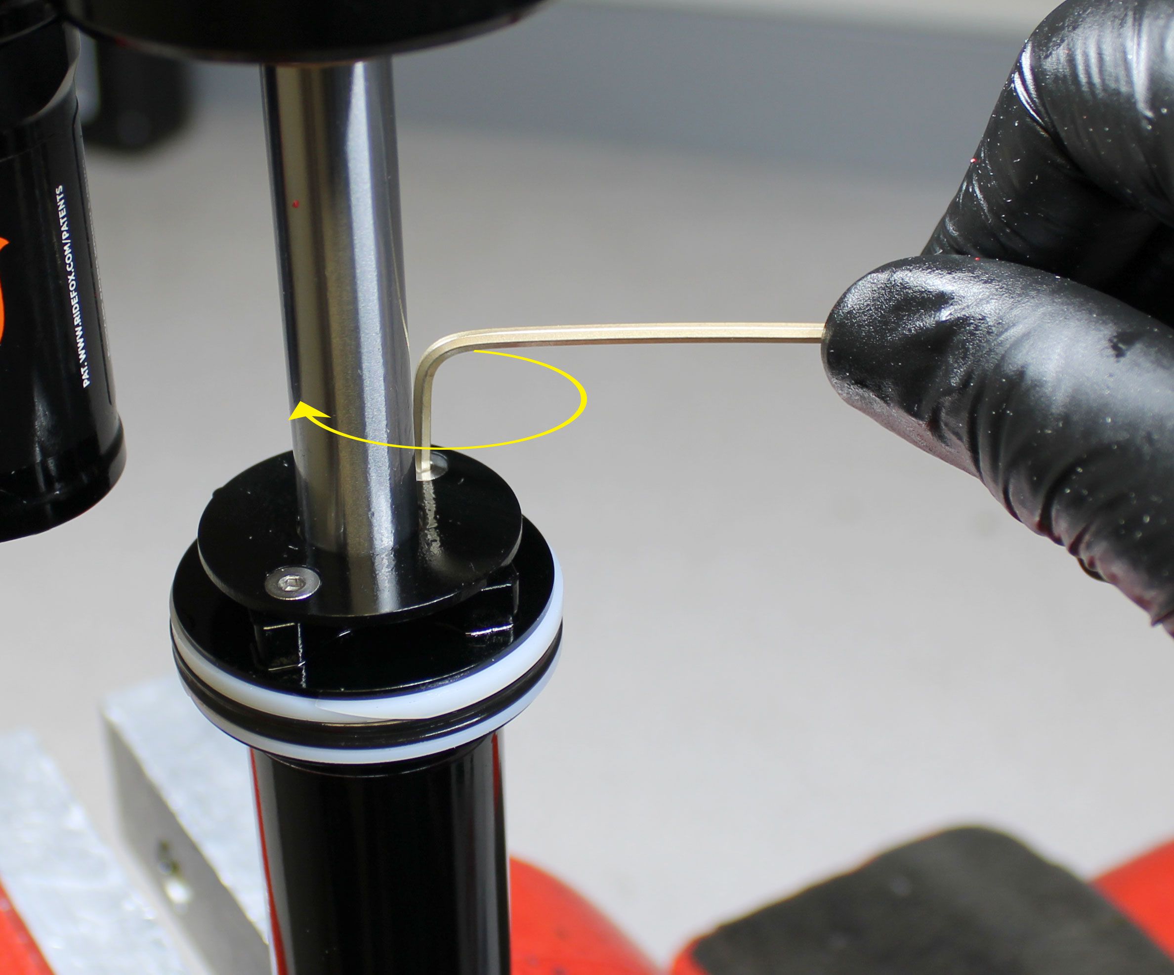
For 47.5mm-75mm travels: Remove the bearing housing cap and any travel spacers (if present) by unthreading counter-clockwise and removing the two screws with a 2mm hex wrench. Lift the bearing housing cap to expose the pin spanner holes in the bearing assembly.
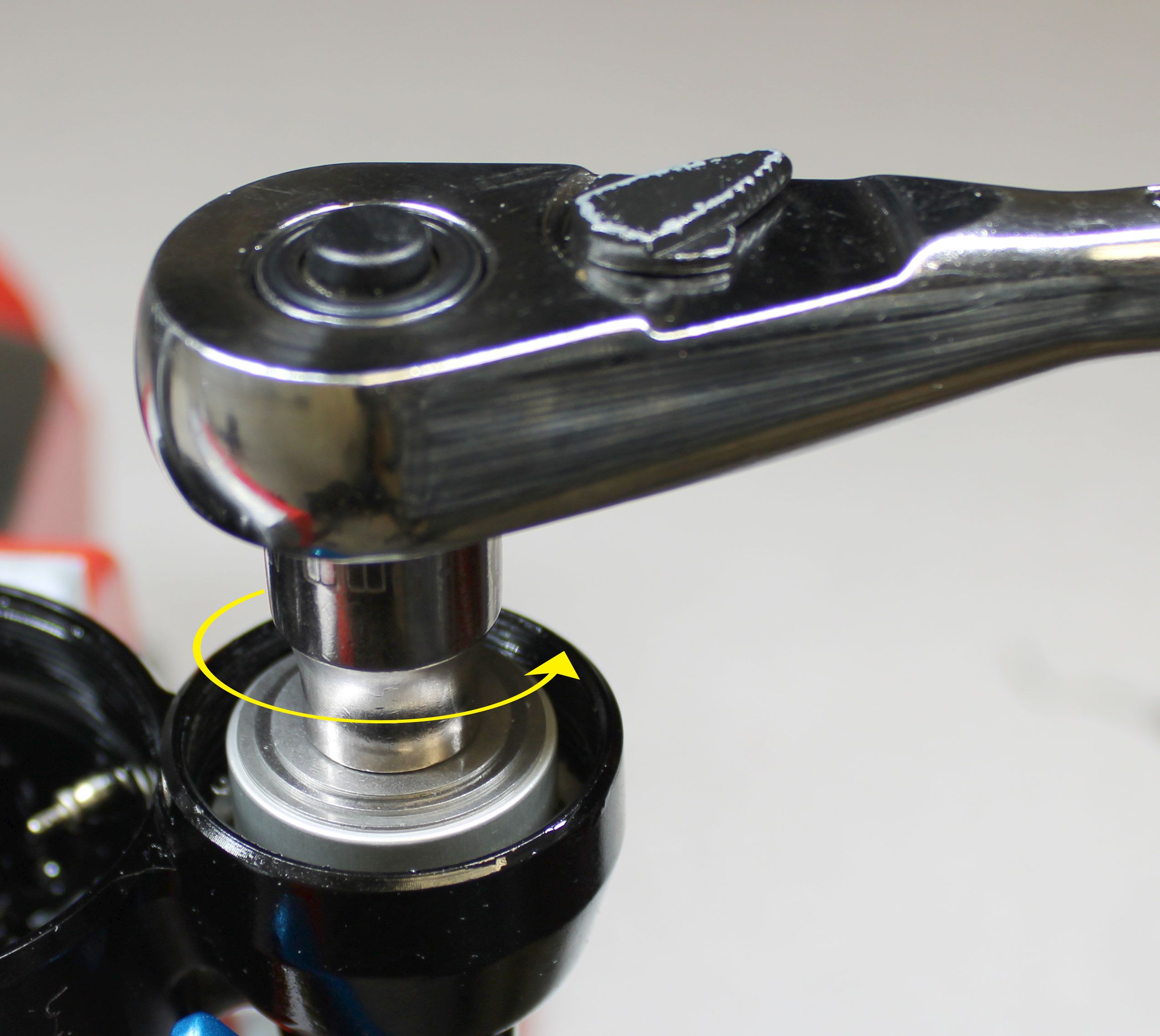
Use the Pin Spanner Wrench (PN: 398-00-558) to unthread the bearing housing assembly counter-clockwise.

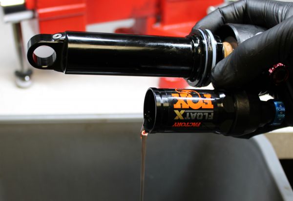
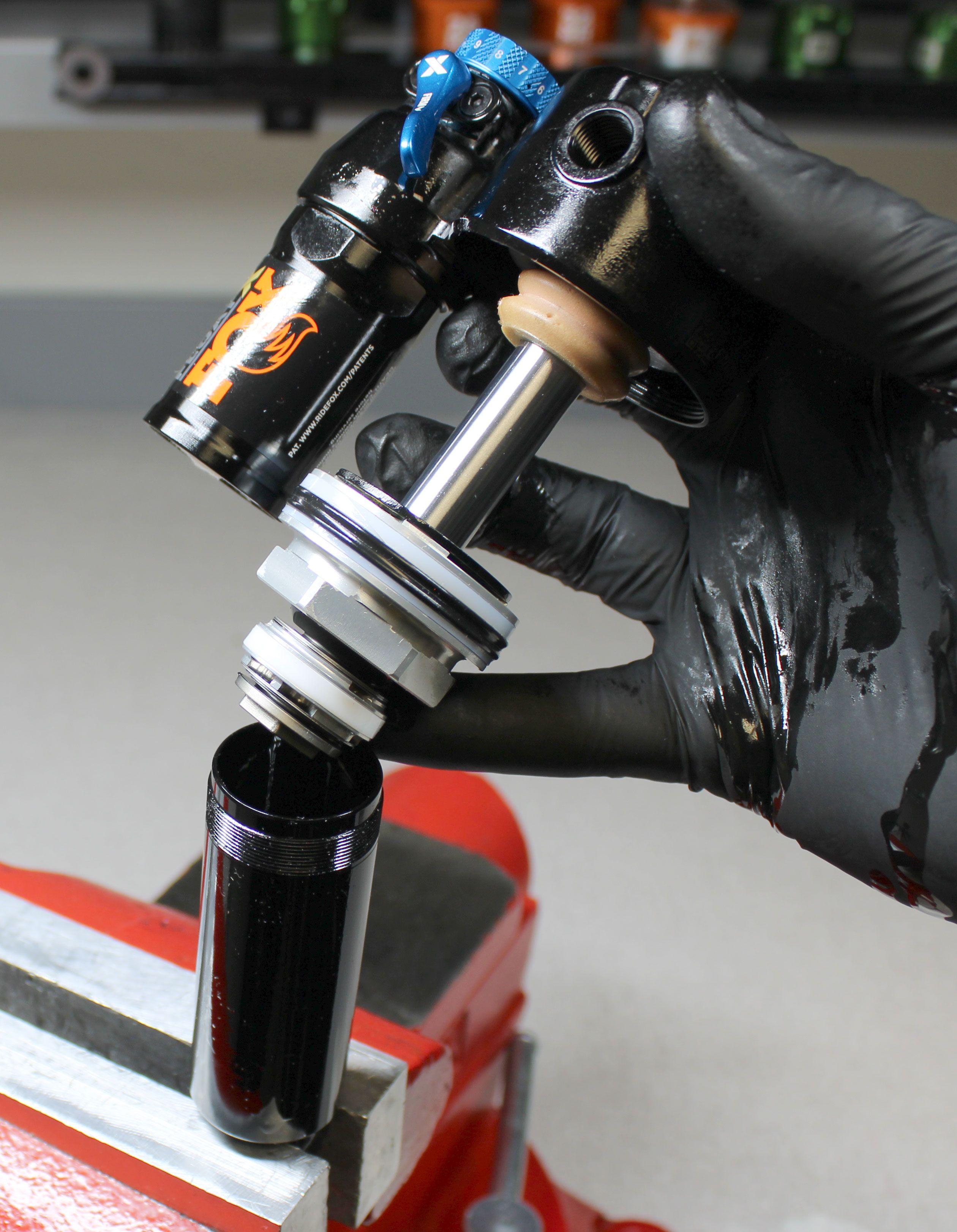
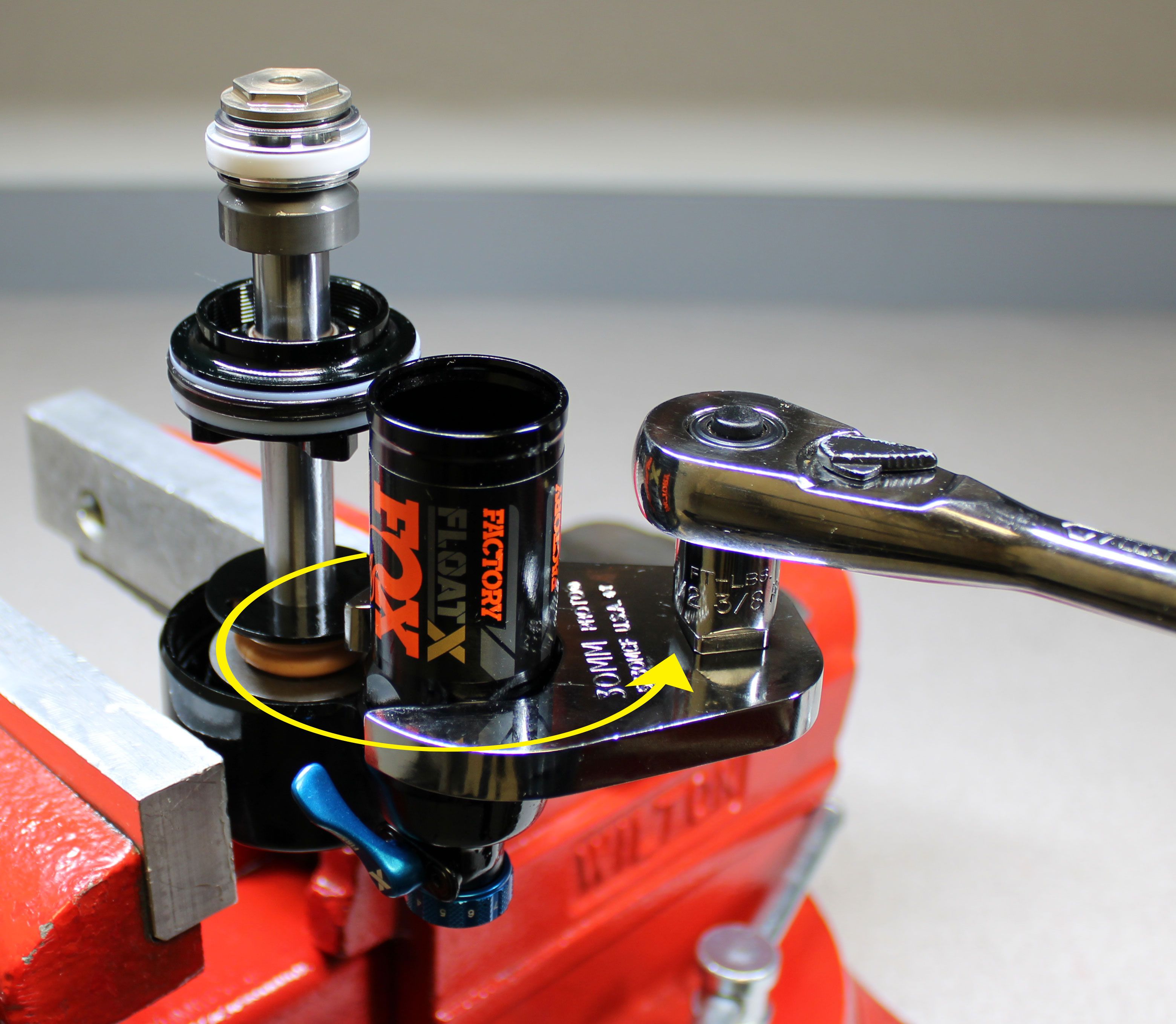
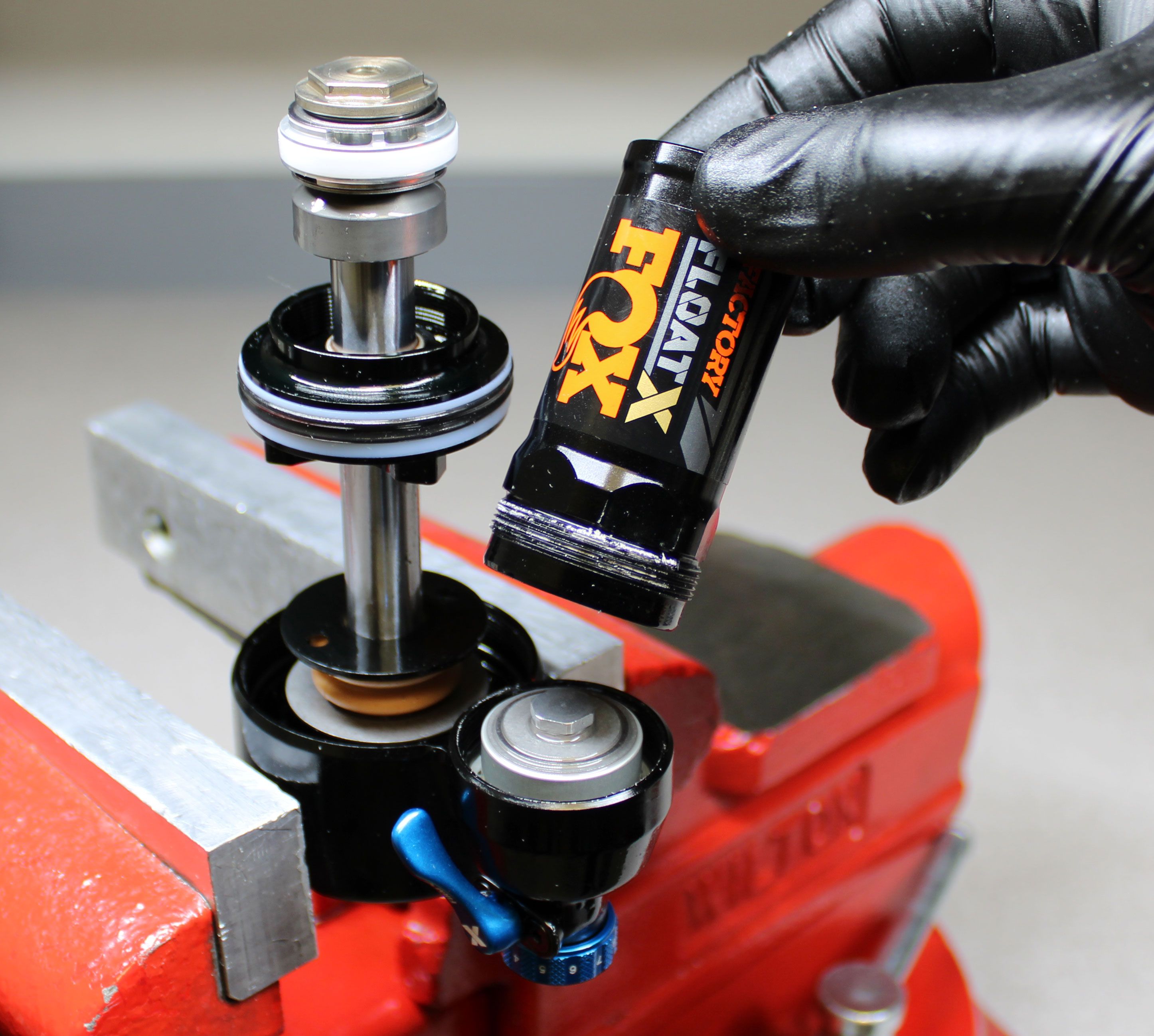
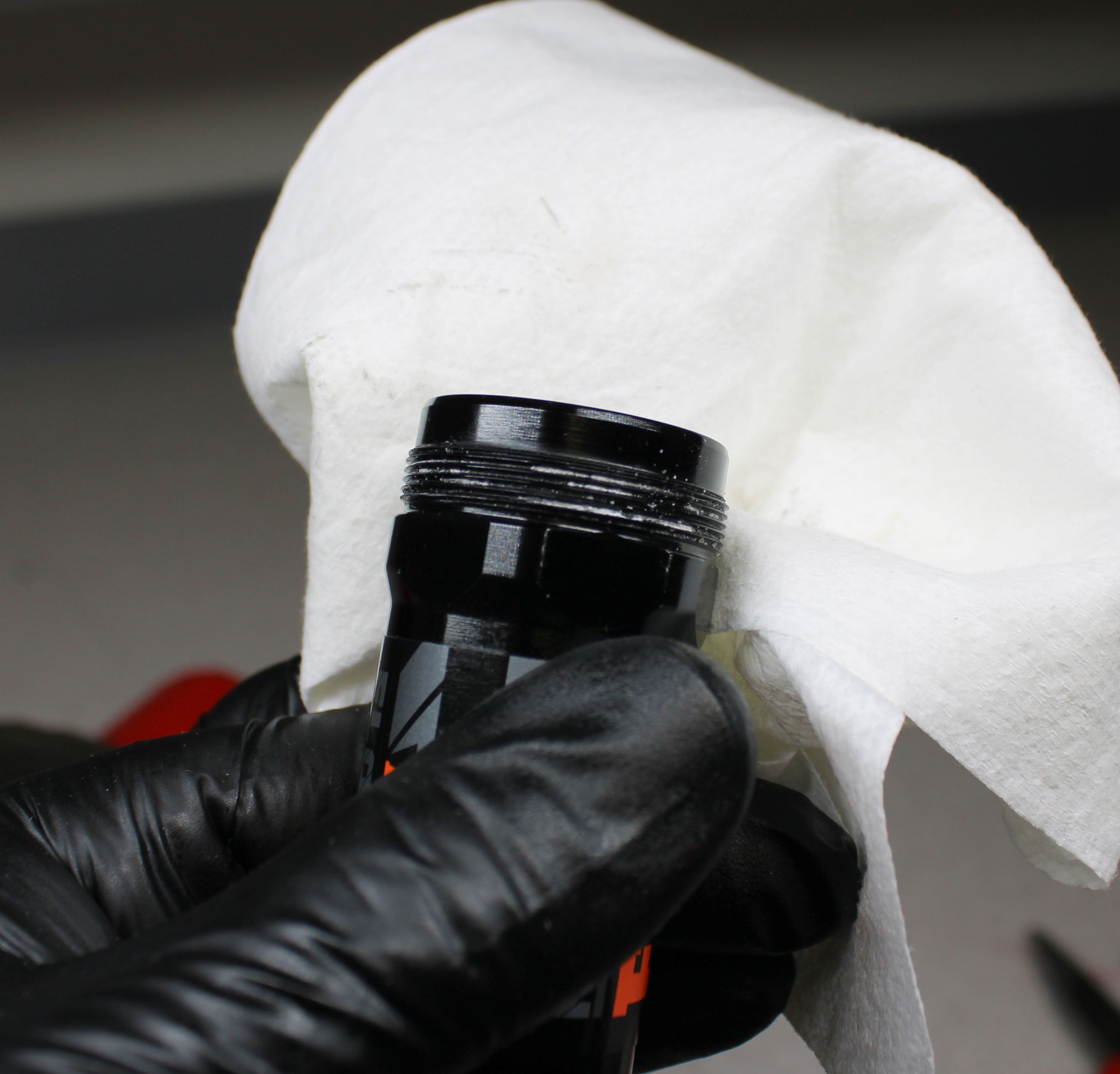
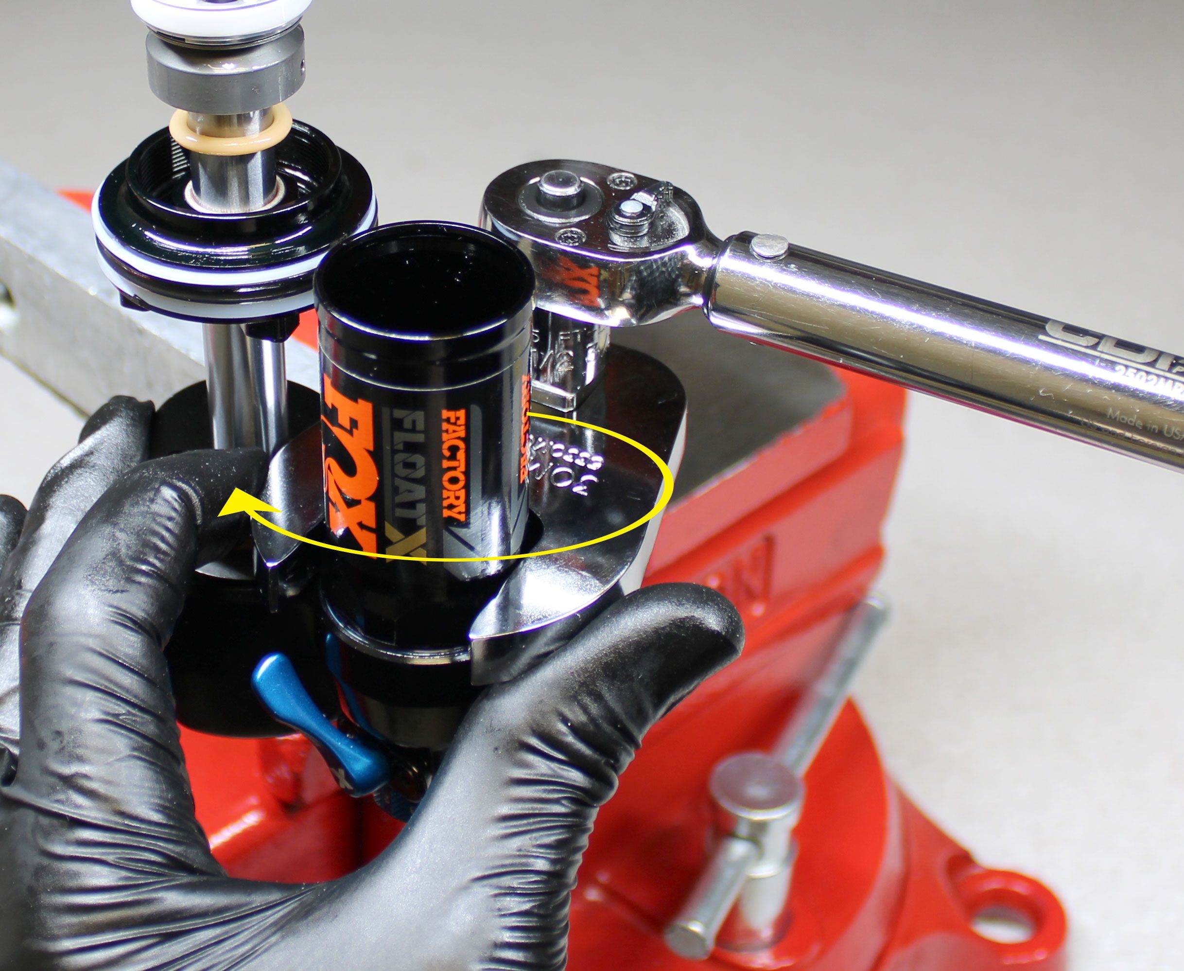
Step 10
Pour the oil from the body into your waste oil basin. Clamp the adjuster eyelet in your soft jawed vise then remove the reservoir by unthreading it counter-clockwise with a 30mm wrench. Clean the Loctite residue from the reservoir and eyelet threads.
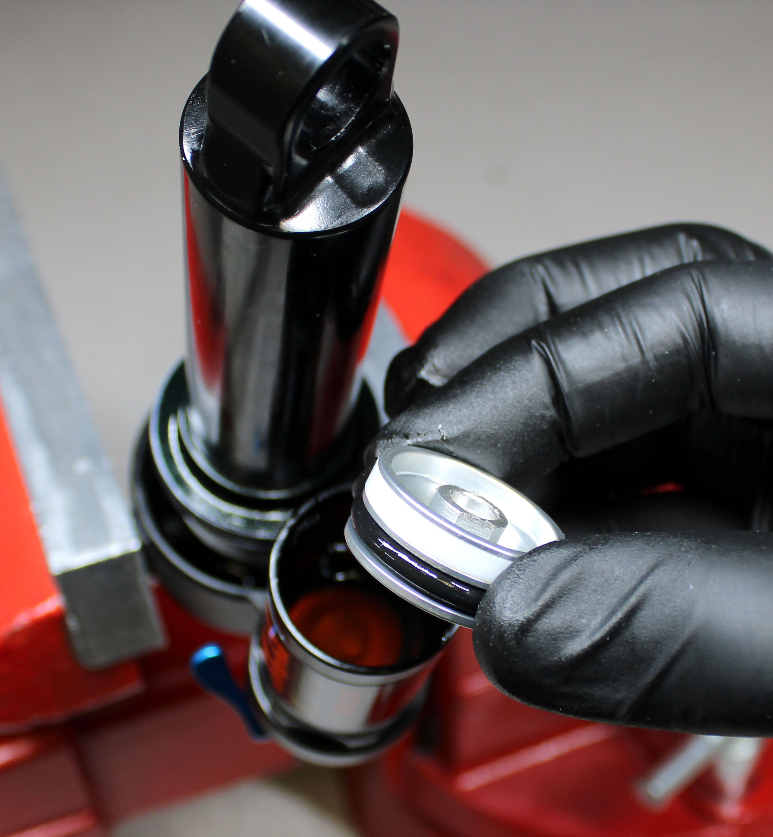
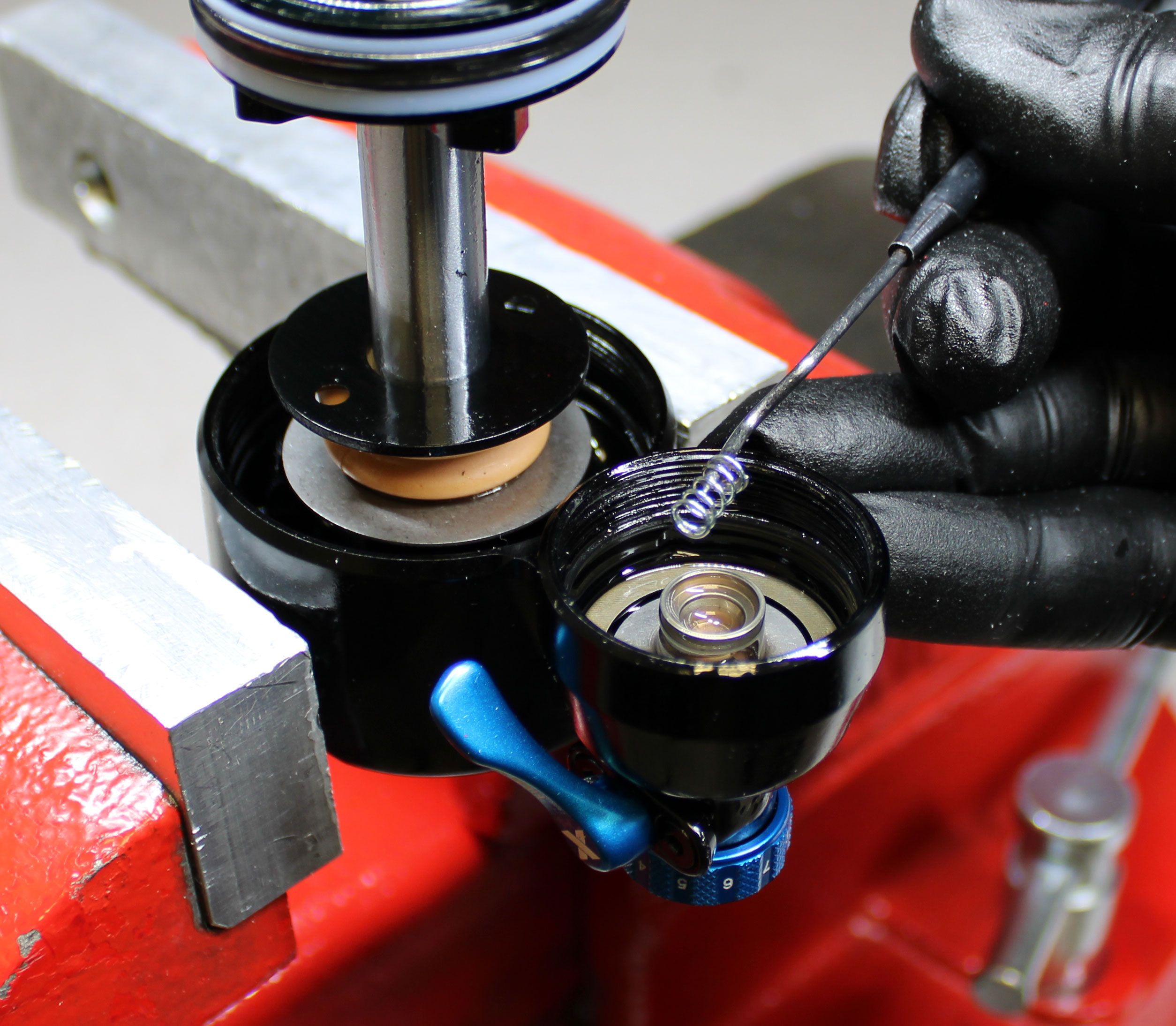
Step 11
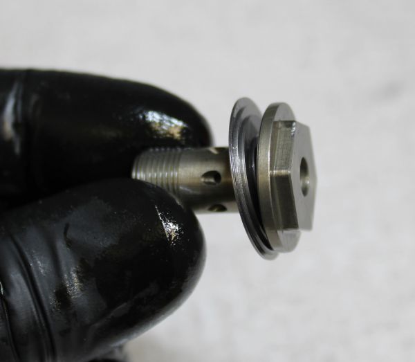
Remove the o-ring from the reservoir then remove the base valve piston. Remove the adjuster shaft spring.

Step 12
Further disassembly of the base valve piston is only needed if inspecting or changing valving. If needed, temporarily reinstall the base valve piston into the reservoir making sure to align the tabs of the piston with the notches in the wall of the reservoir. Unthread the base valve bolt counter-clockwise with a 9mm socket.

Step 13
Inspect the base valve shims and replace any that are damaged or worn. Reinstall the base valve bolt into the piston taking care not to pinch any shims. temporarily reinstall the base valve piston into the reservoir making sure to align the tabs of the piston with the notches in the wall of the reservoir. Tighten the base valve bolt clockwise to 60 in-lb (6.8 Nm).

Step 14
Remove the base valve piston, check shim, adjuster shaft, wave spring, and lockout plate spring from the reservoir.

Step 15
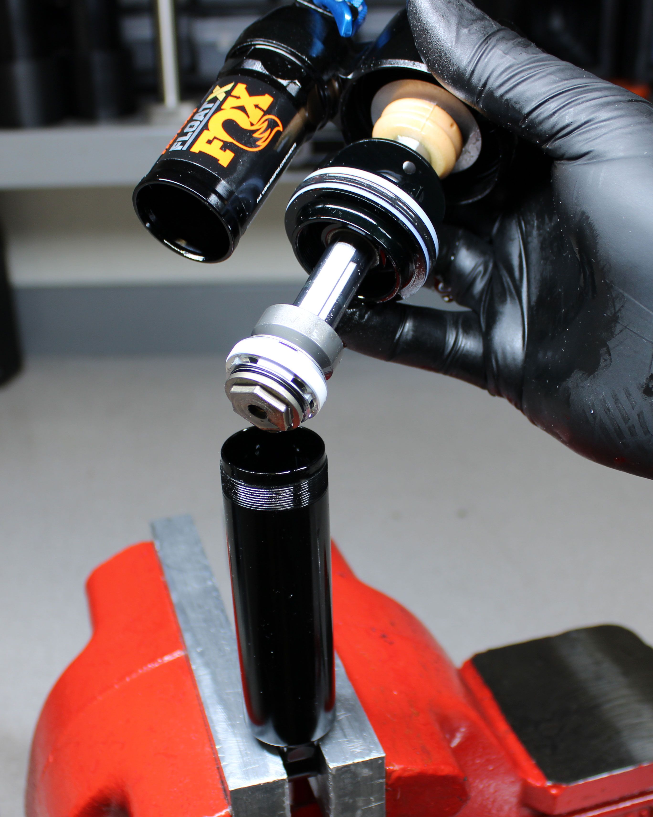
Unthread the piston bolt counter-clockwise with a chamfer-less 15mm socket. Remove the entire main piston valving assembly then remove the topout o-ring.


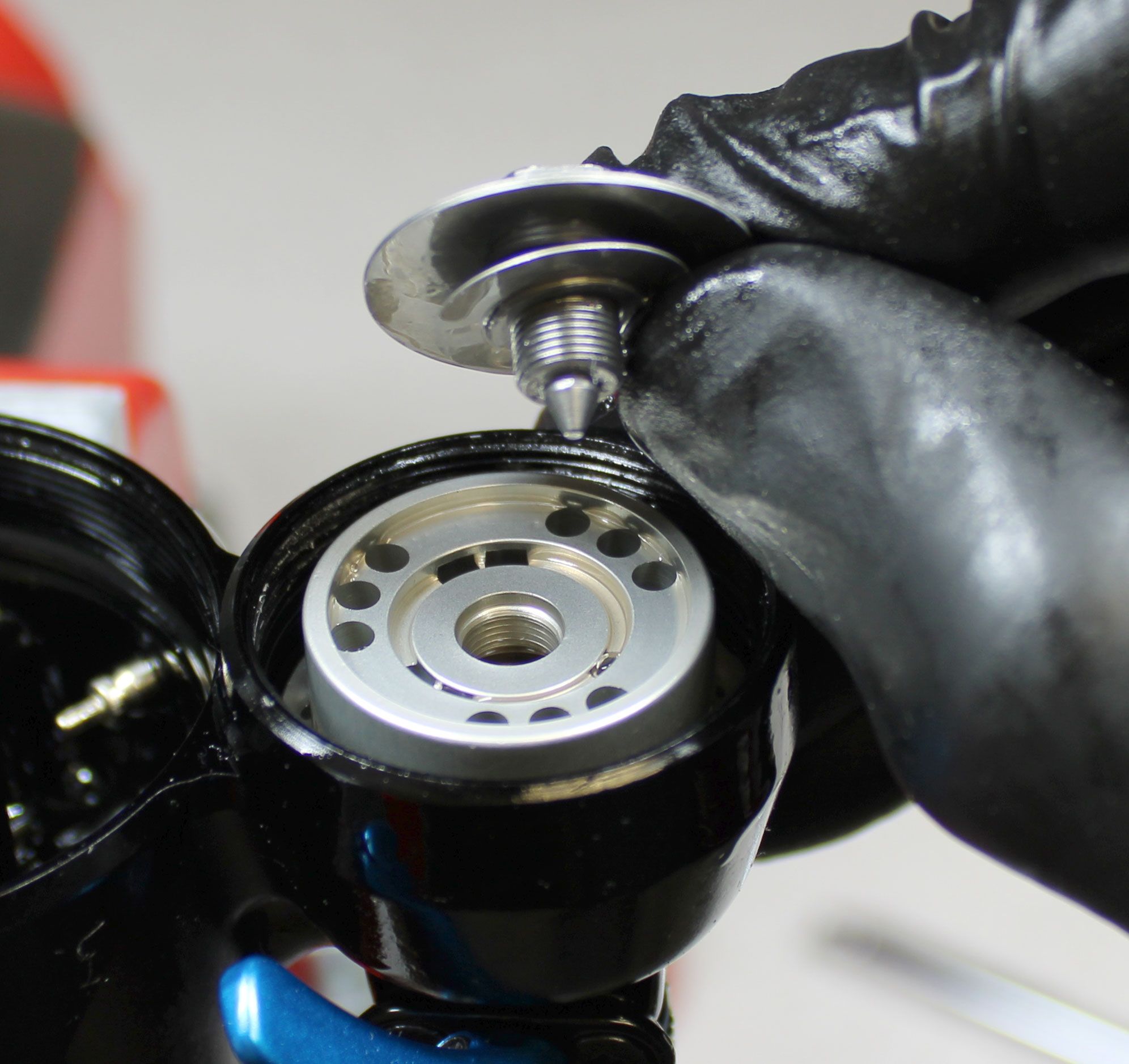
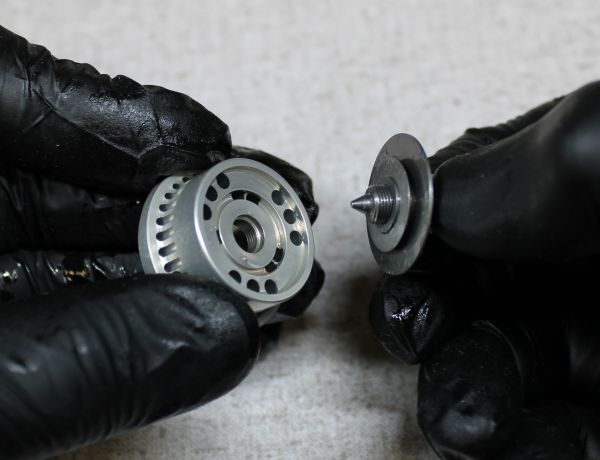
Step 16
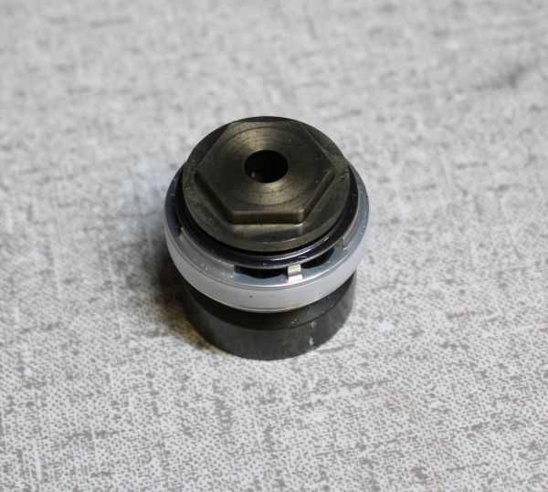
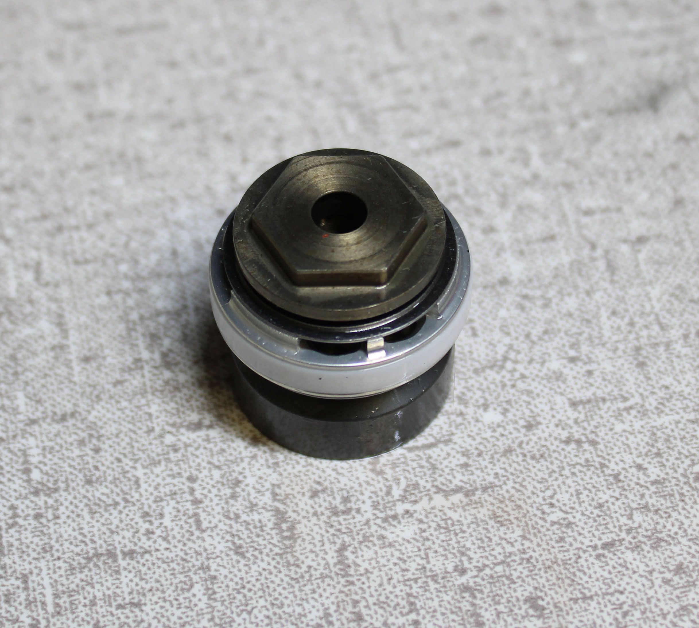
Remove the bearing housing assembly followed by the bearing housing cap, bottom out bumper, and bottom out plate. Some shocks may use an o-ring as the bottom out bumper. In shock that use an o-ring as the bottom out bumper, a bottom out spacer is required in addition to the plate and o-ring. Remove any shaft travel spacers if present.
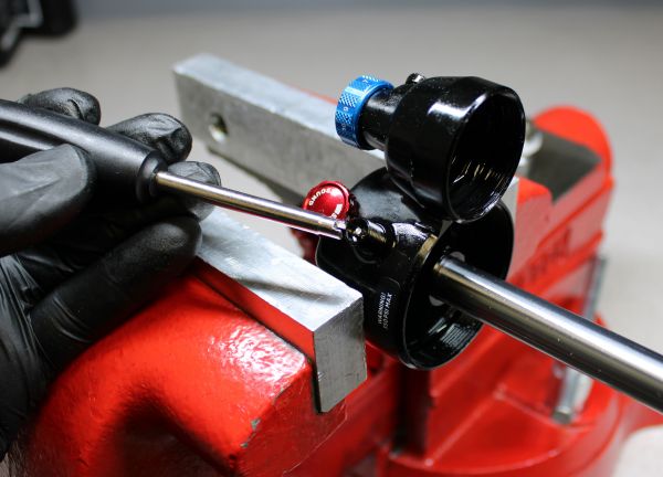
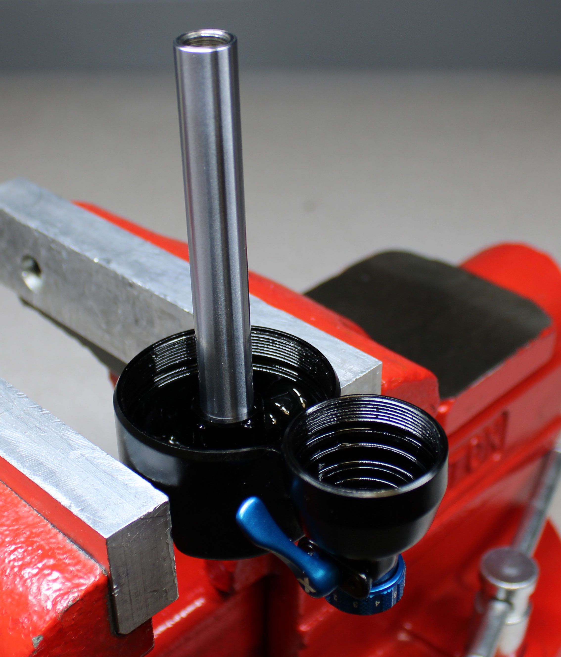
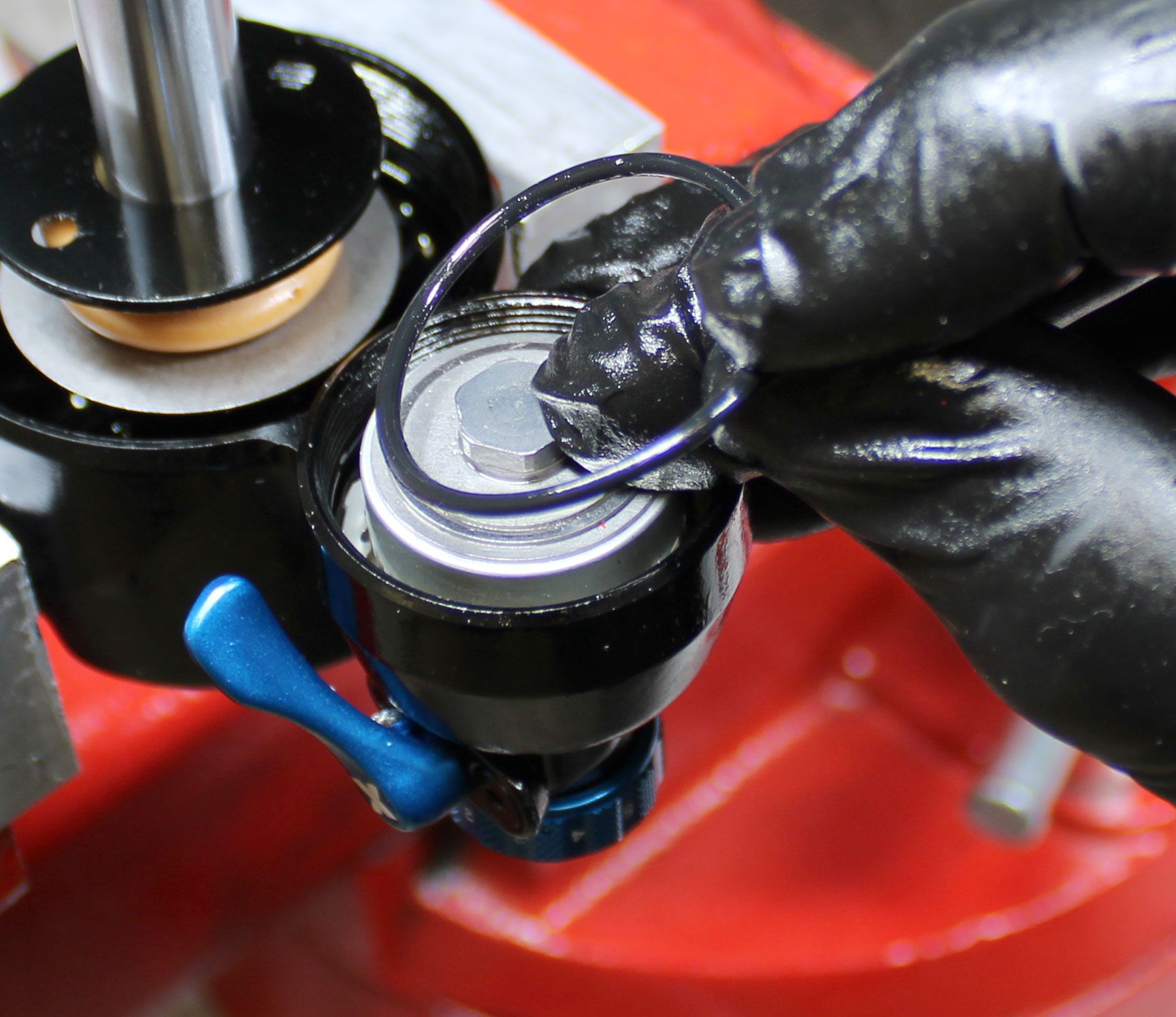
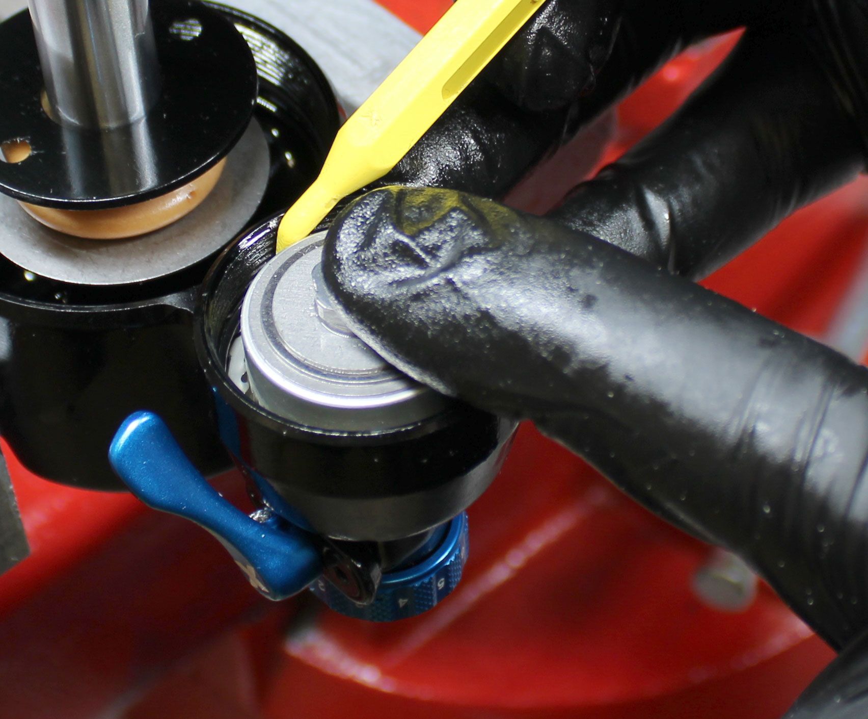
Step 17
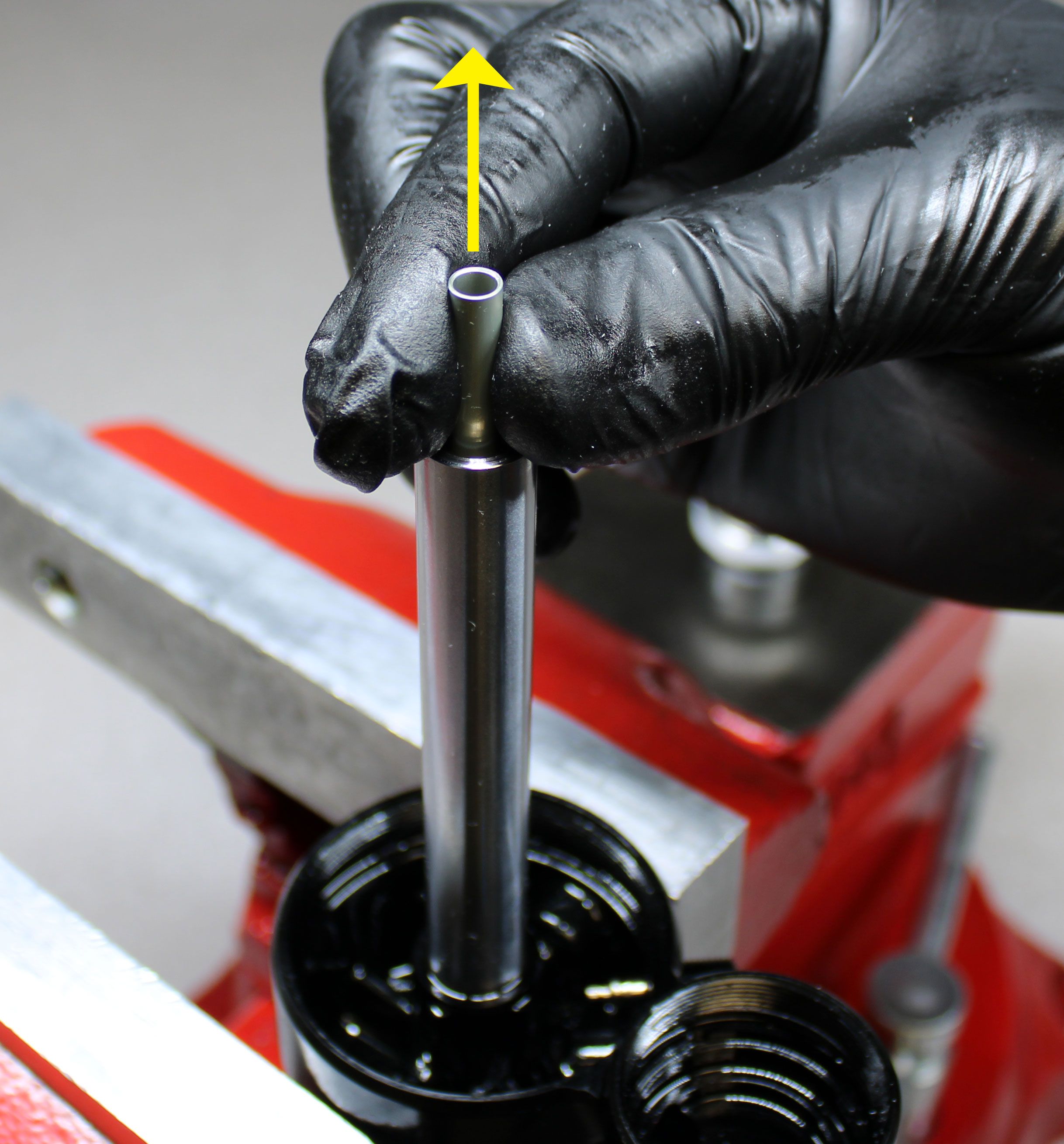
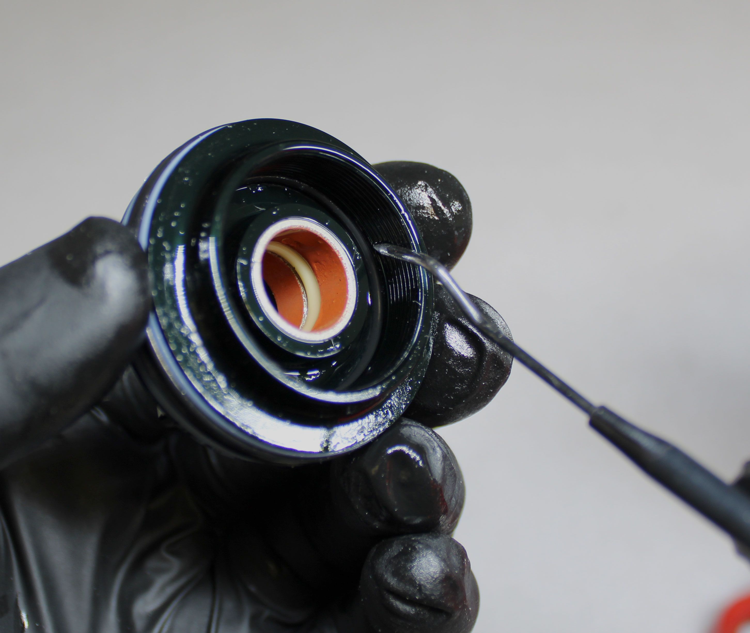
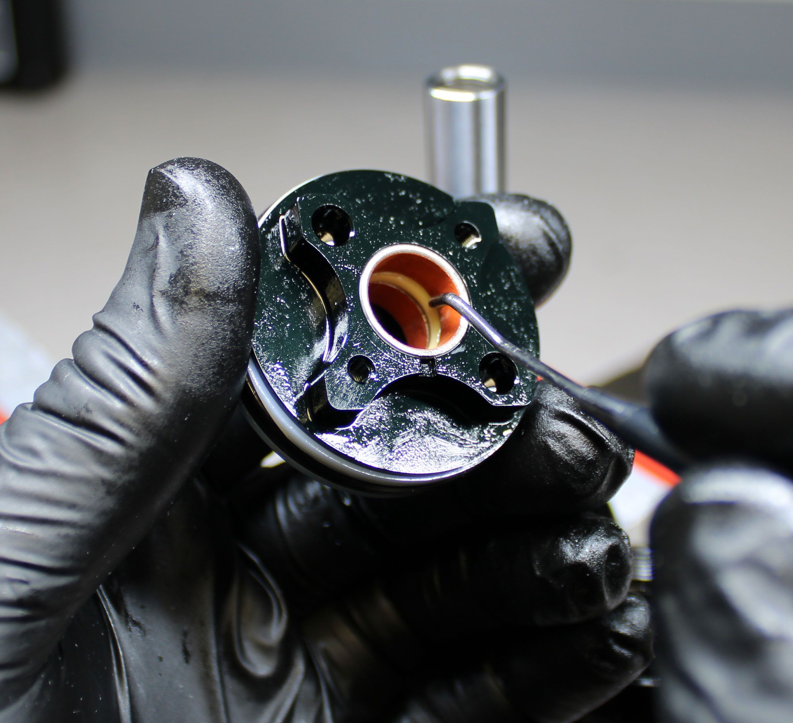
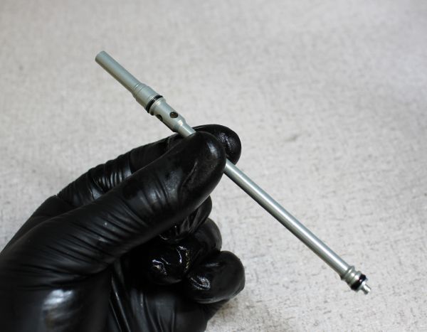
Remove the air sleeve o-ring within the eyelet. Remove the rebound rod by pulling it up out of the shaft. Verify that the 1.5mm ball bearing is in place at the end of the rebound rod.
Step 18
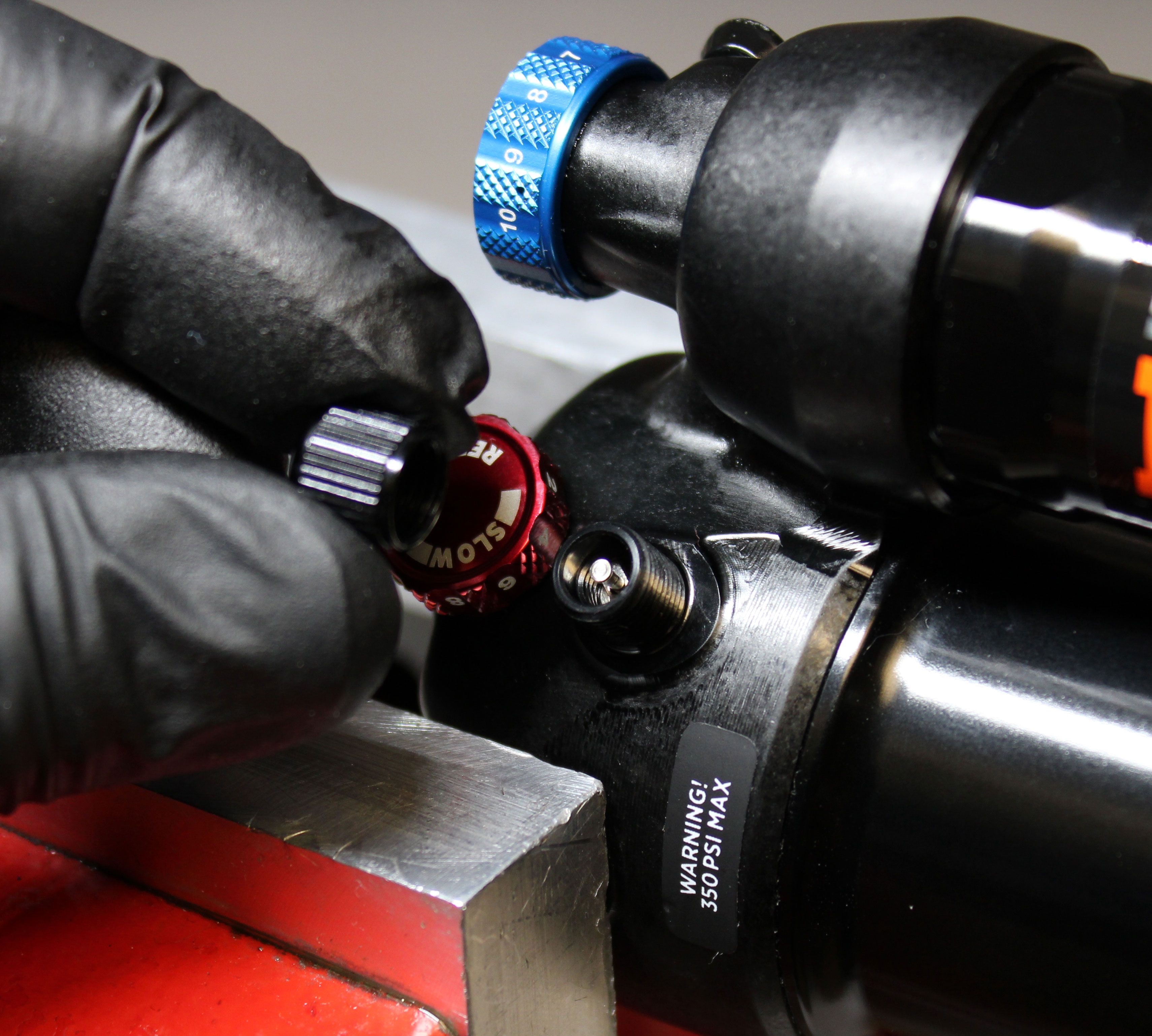
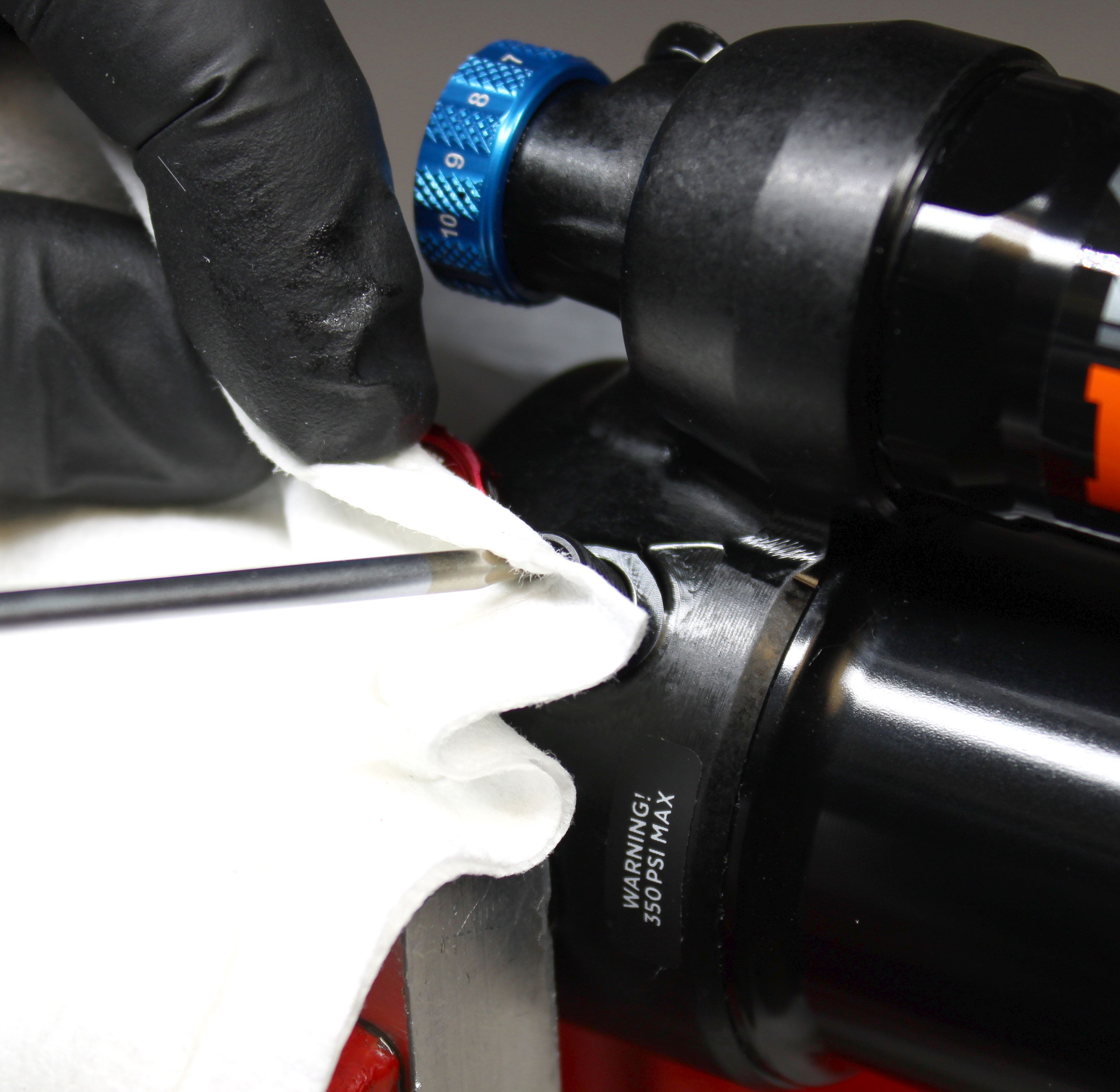
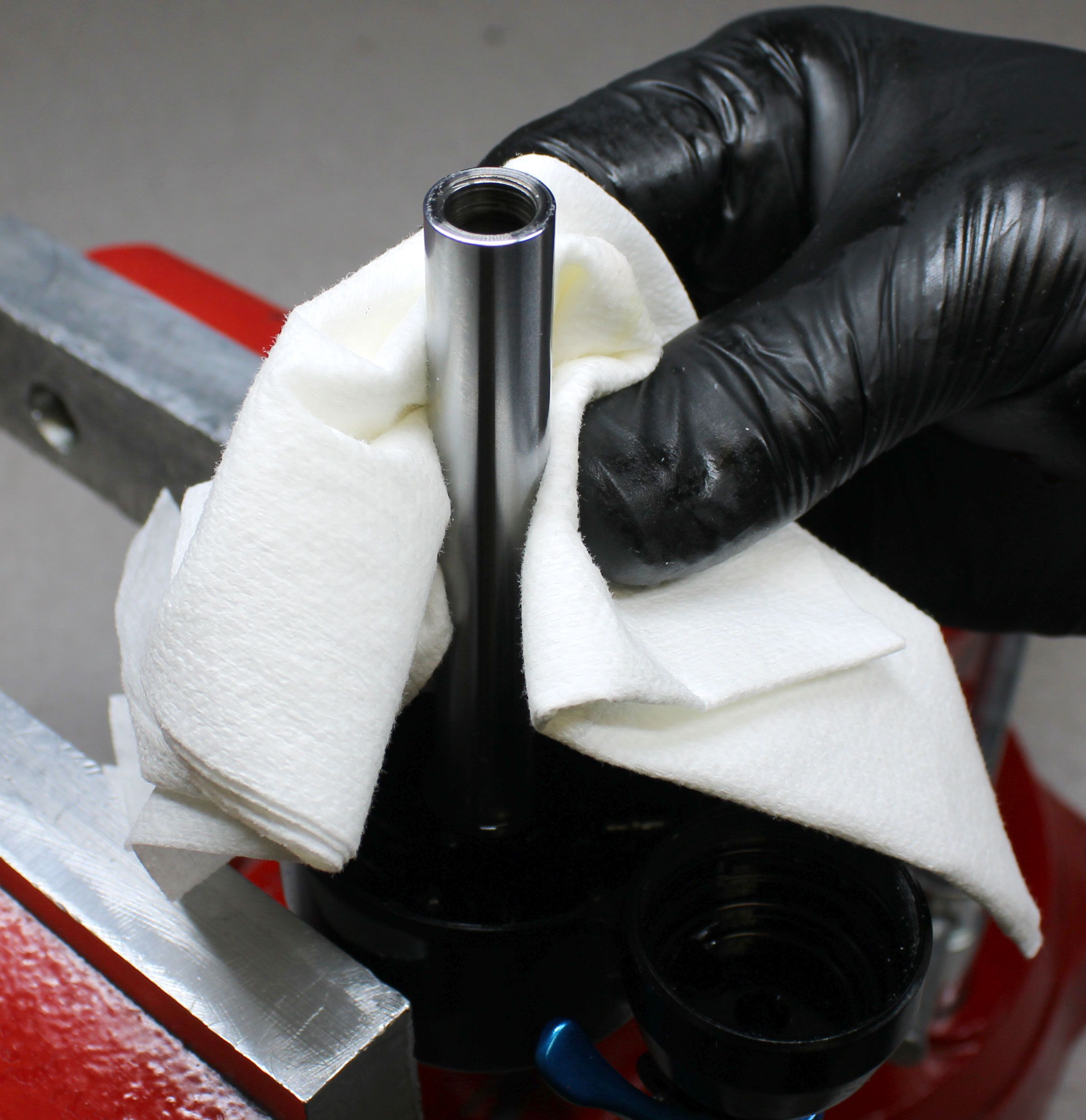
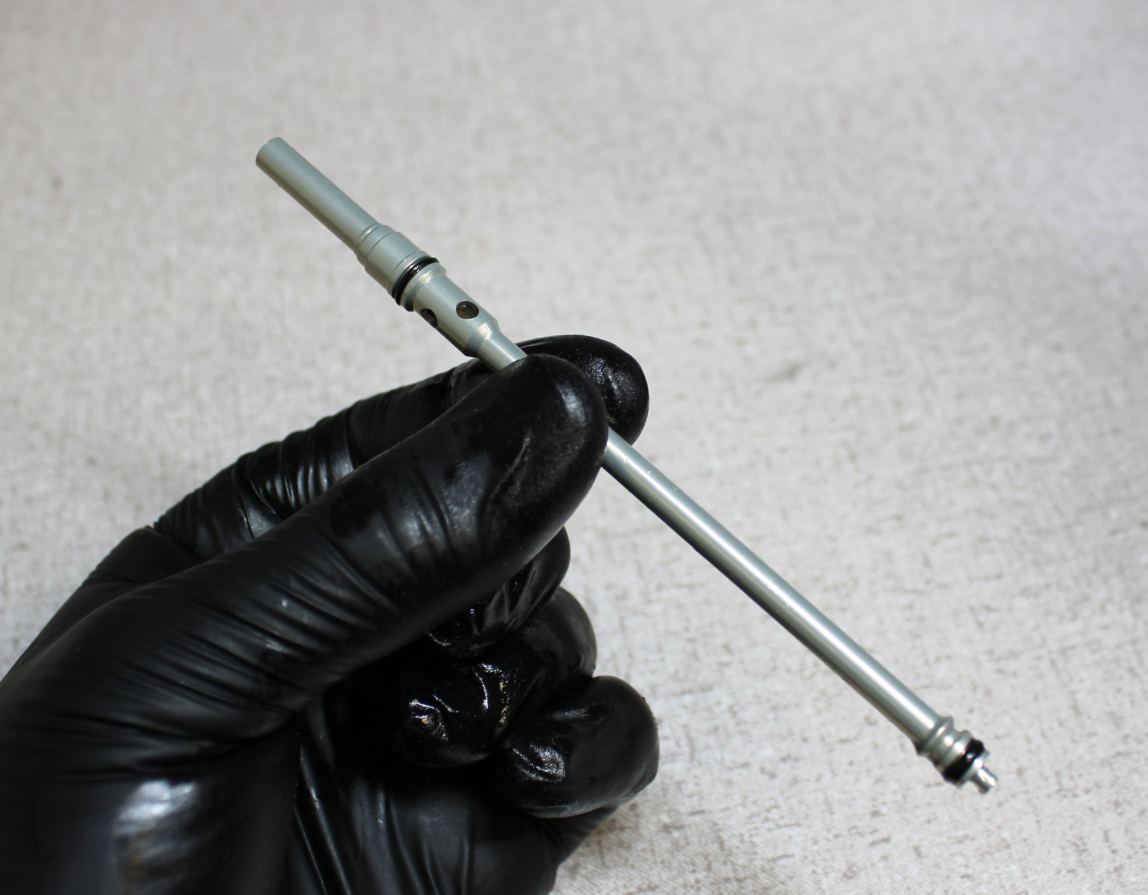
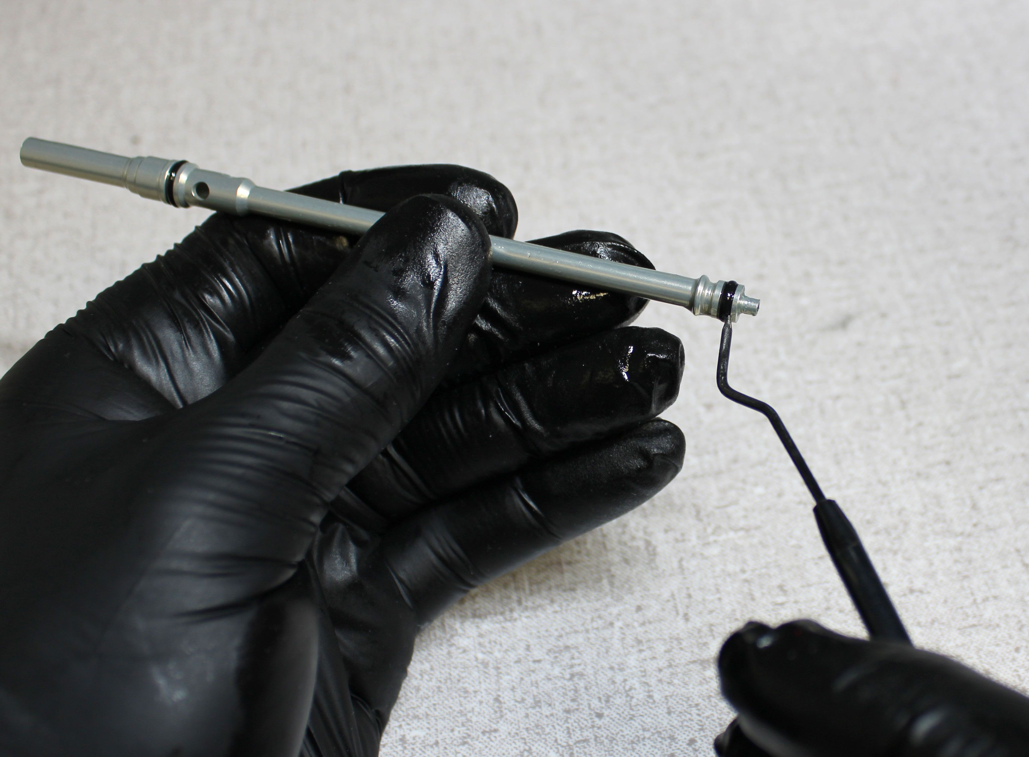
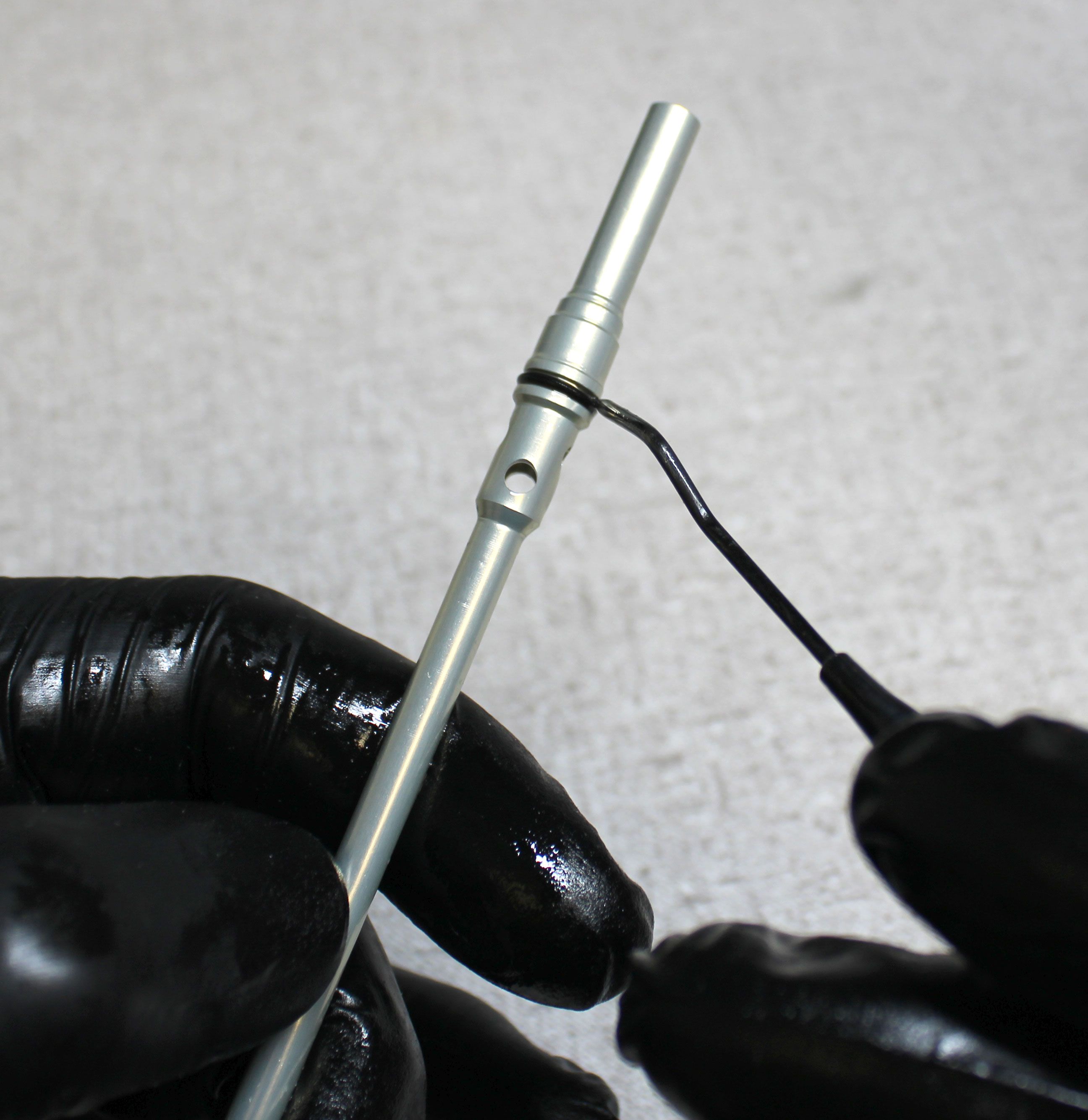
Remove the Schrader valve core by unthreading it counter-clockwise with a Schrader core removal tool. Then clean the shaft with isopropyl alcohol and a lint-free paper towel.
Step 19
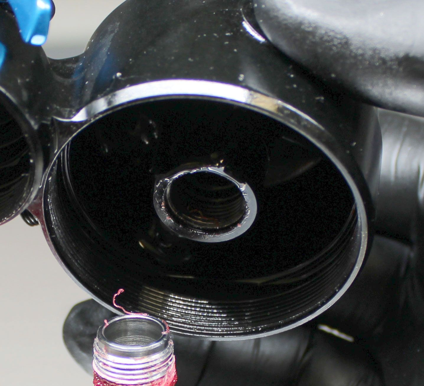
Clamp the shaft in your shaft clamps then heat the area of the eyelet at the shaft to break down the Loctite. Unthread the eyelet counter-clockwise from the shaft using an eyelet torque tool. Be careful as the eyelet and shaft can be hot after using your torch to break down the Loctite.

Step 20
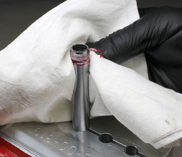
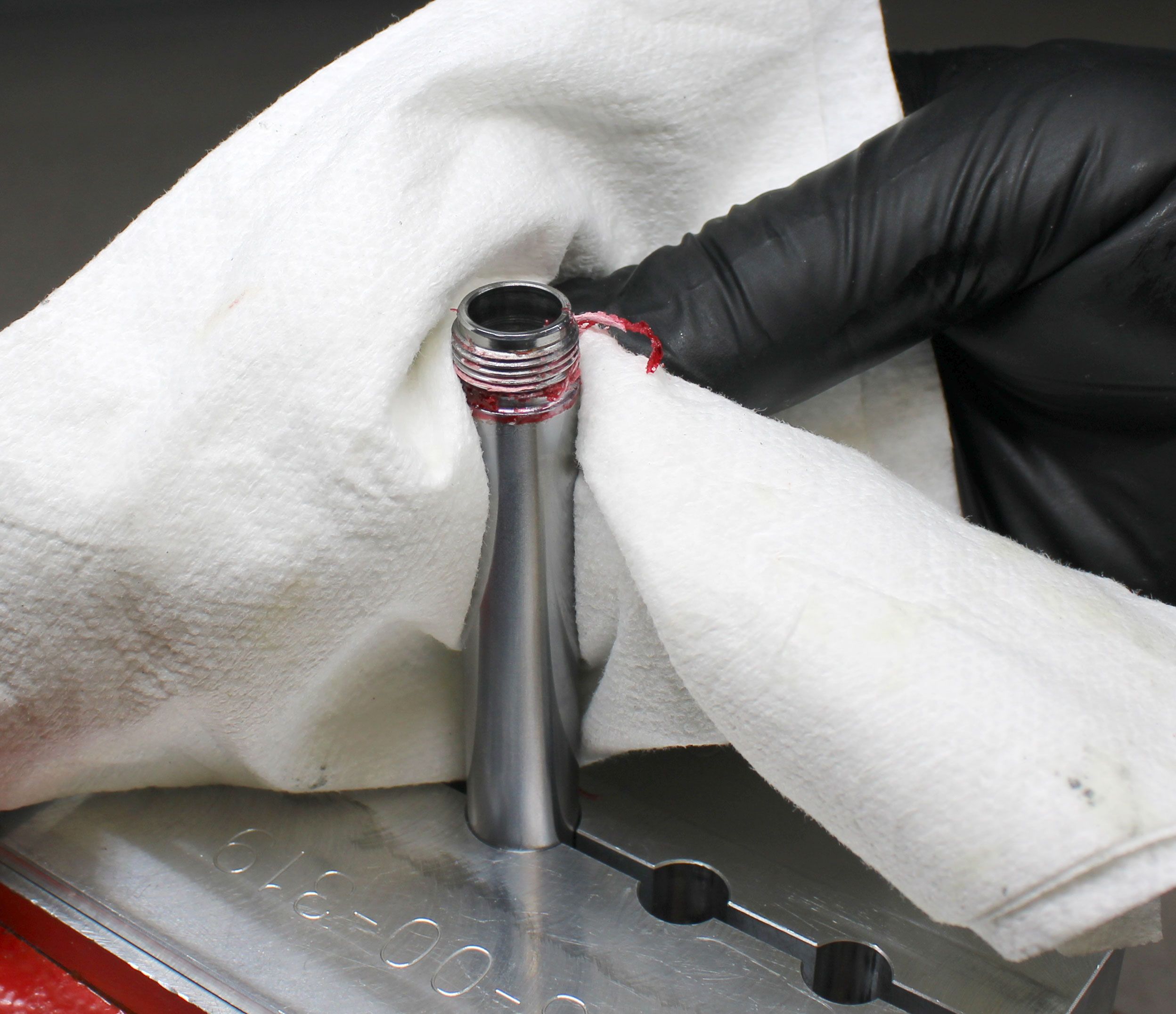
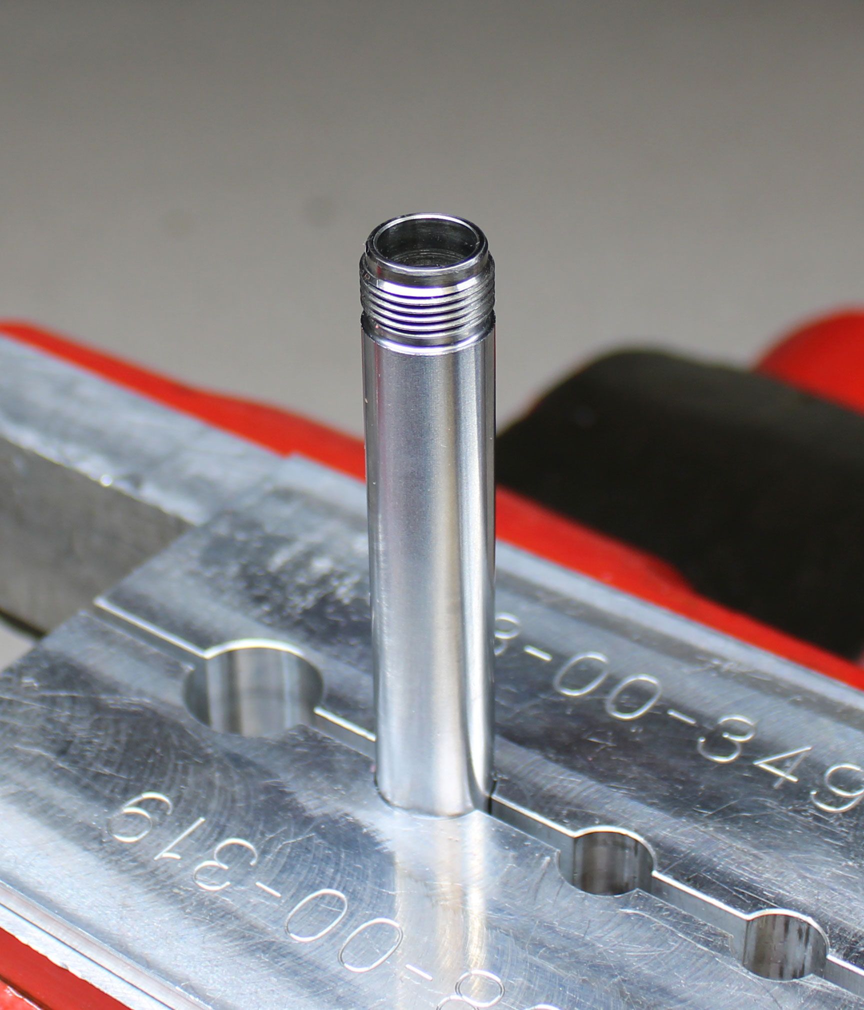
Clean the Loctite residue from the shaft and eyelet threads.
General Reassembly

Step 1
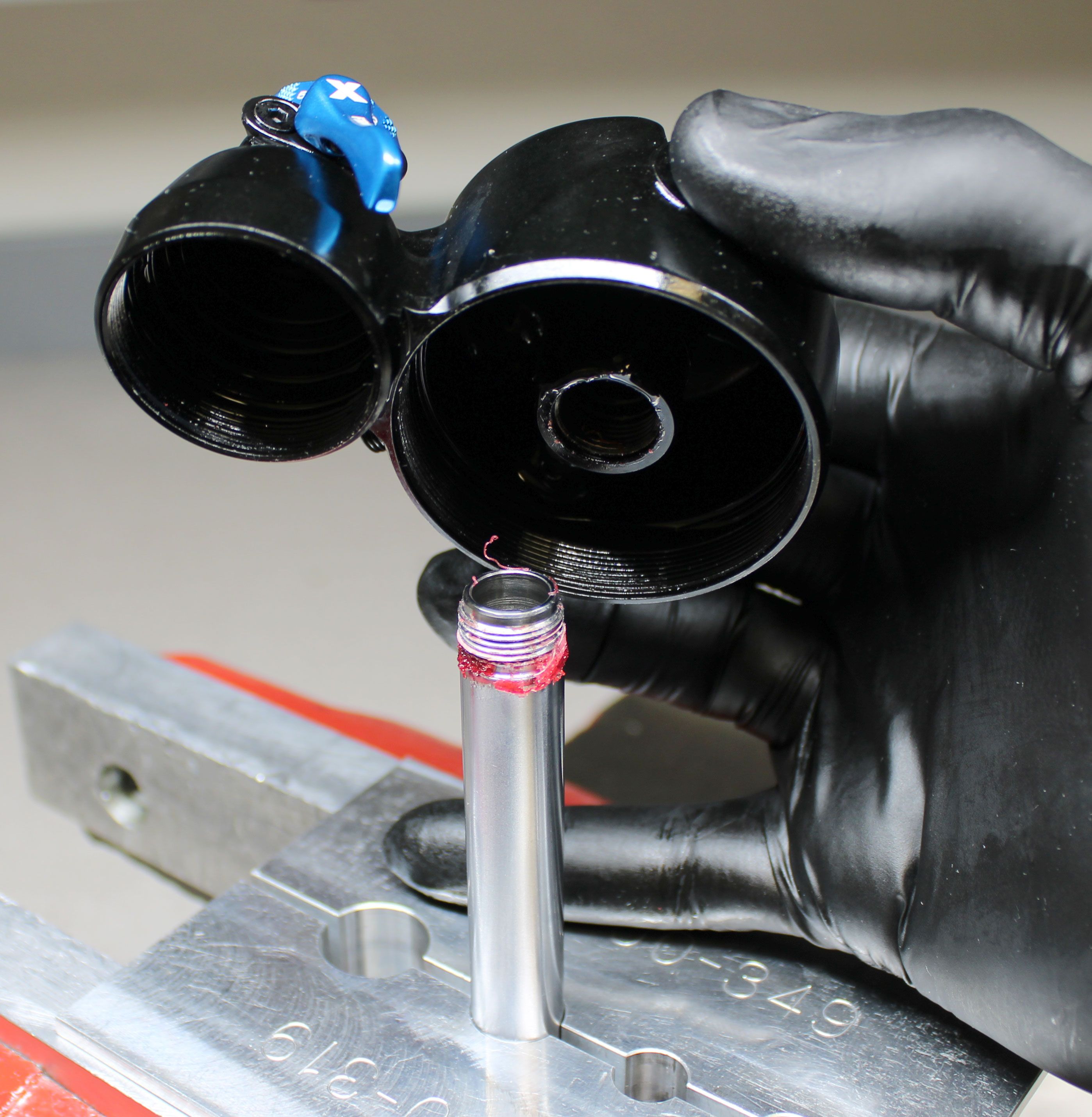
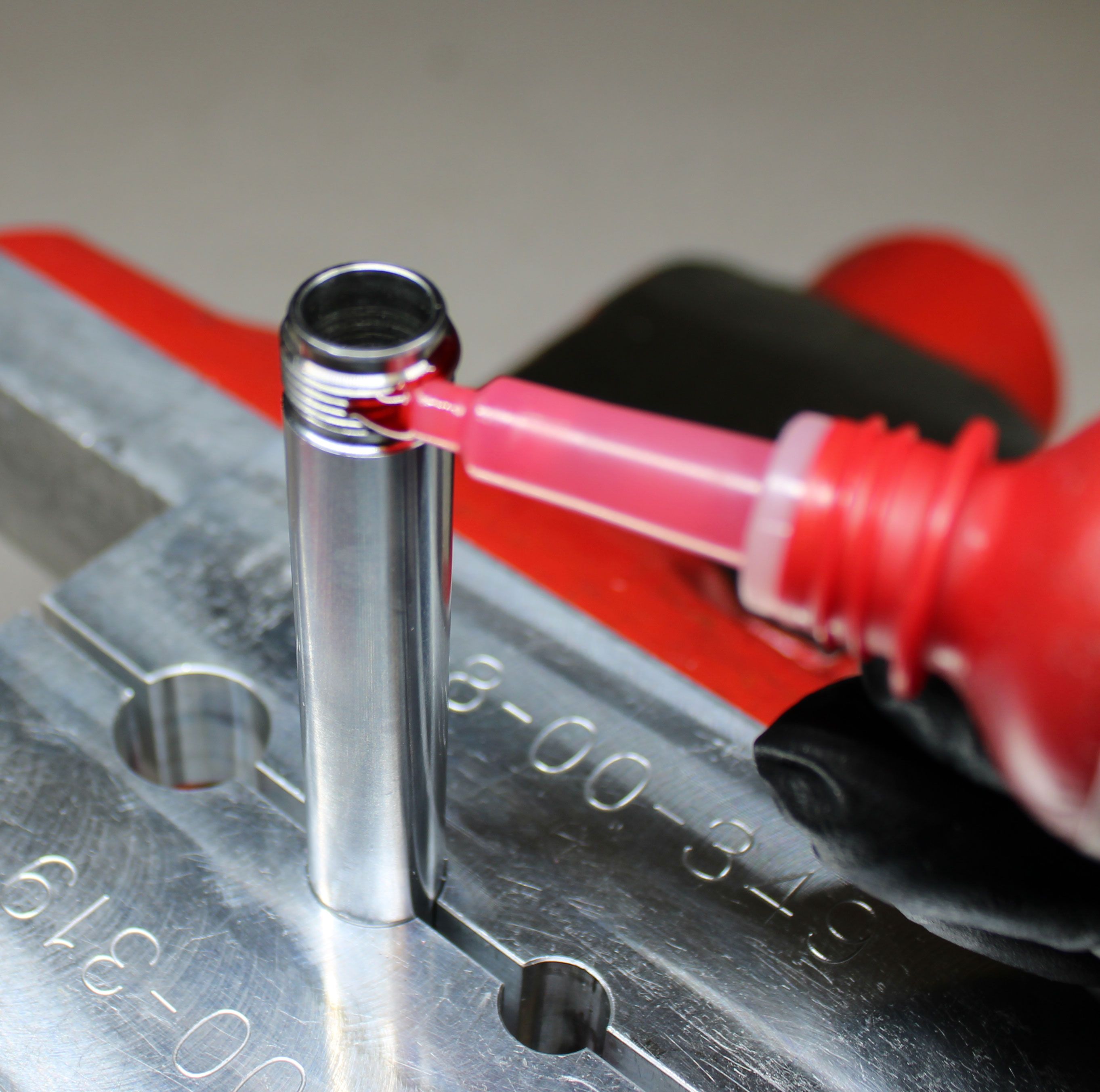
Replace the shaft o-ring within the eyelet with a new greased one from the kit. Apply red Loctite 277 to the first 2-3 threads of the shaft. Reinstall the eyelet tightening clockwise to 110 in-lb (12.4 Nm) torque.
Step 2
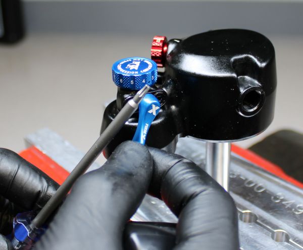
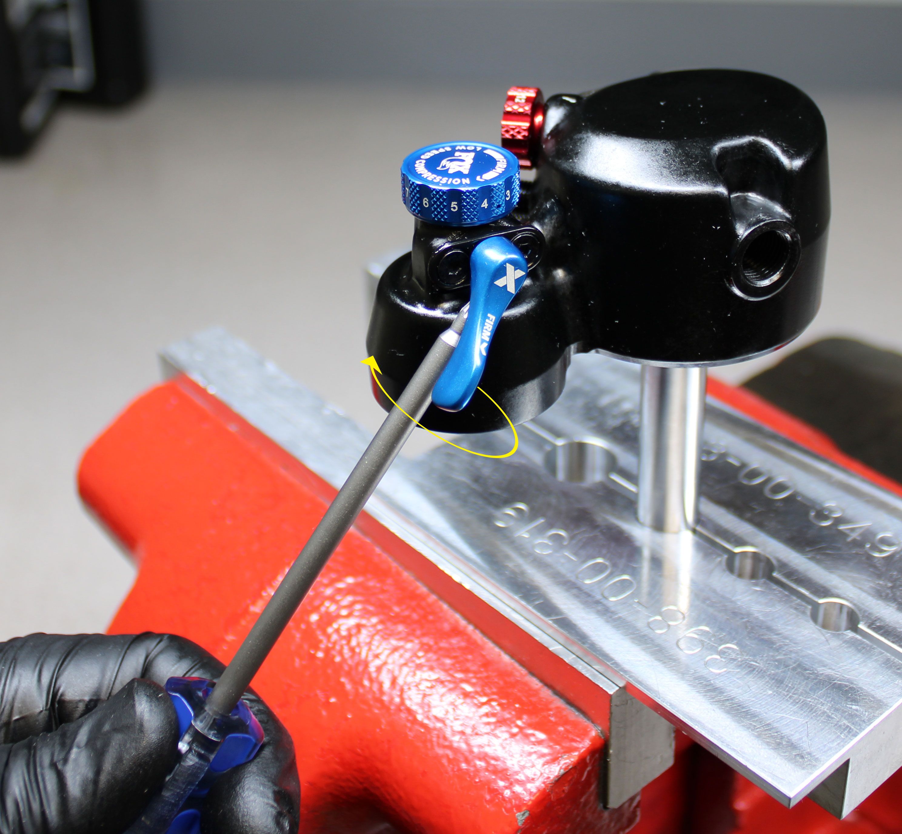
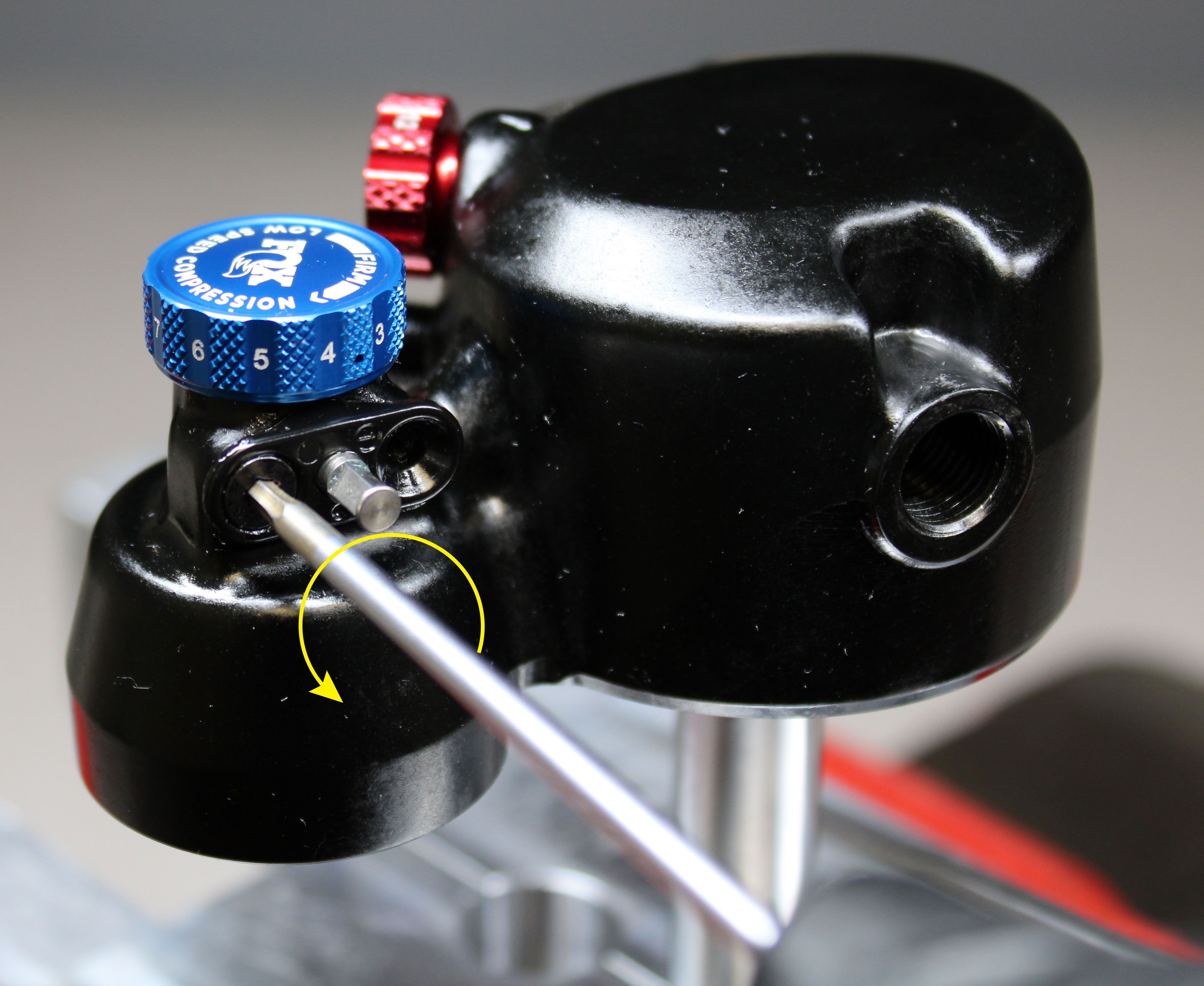
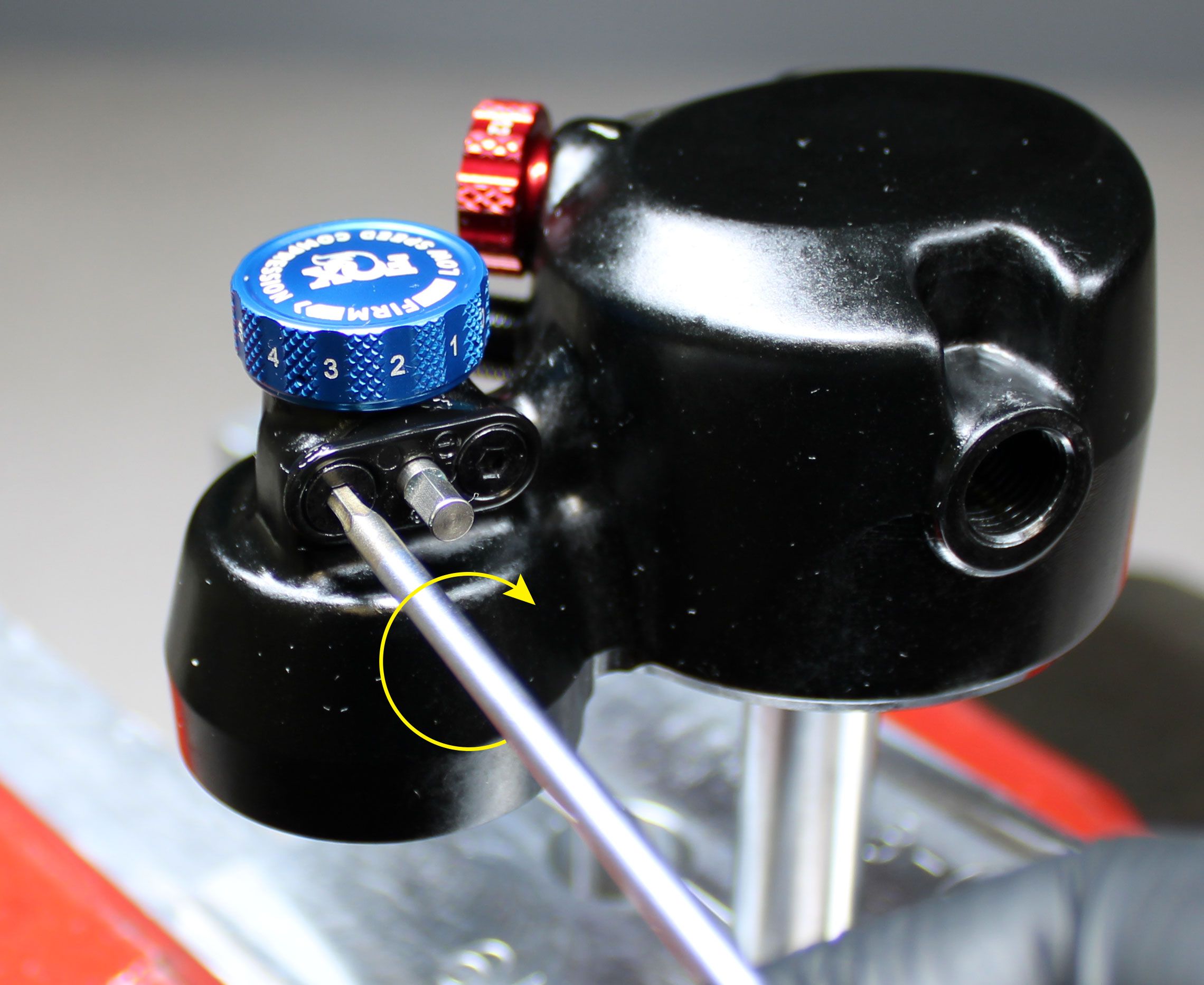
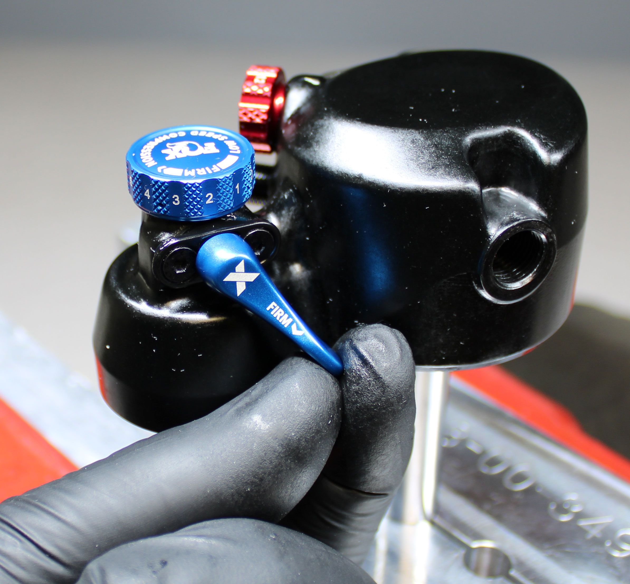
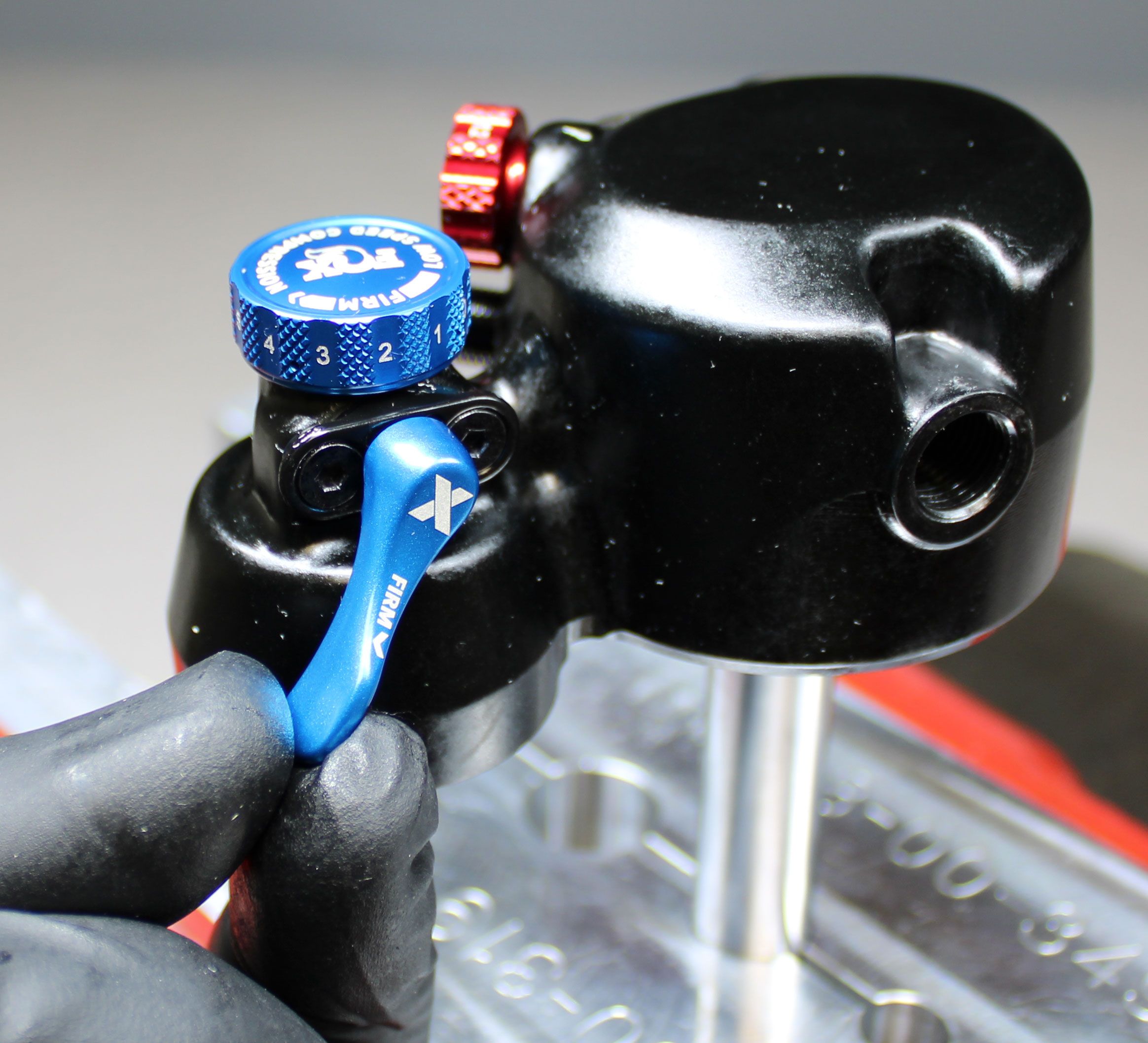
You do not need to remove the 2 Pos Lever, P-S No Lever, or Remote cable hangar assemblies during a standard full rebuild. The following steps show removal of the 2 Pos Lever Assembly but the procedure is the same for the P-S No Lever Assembly.
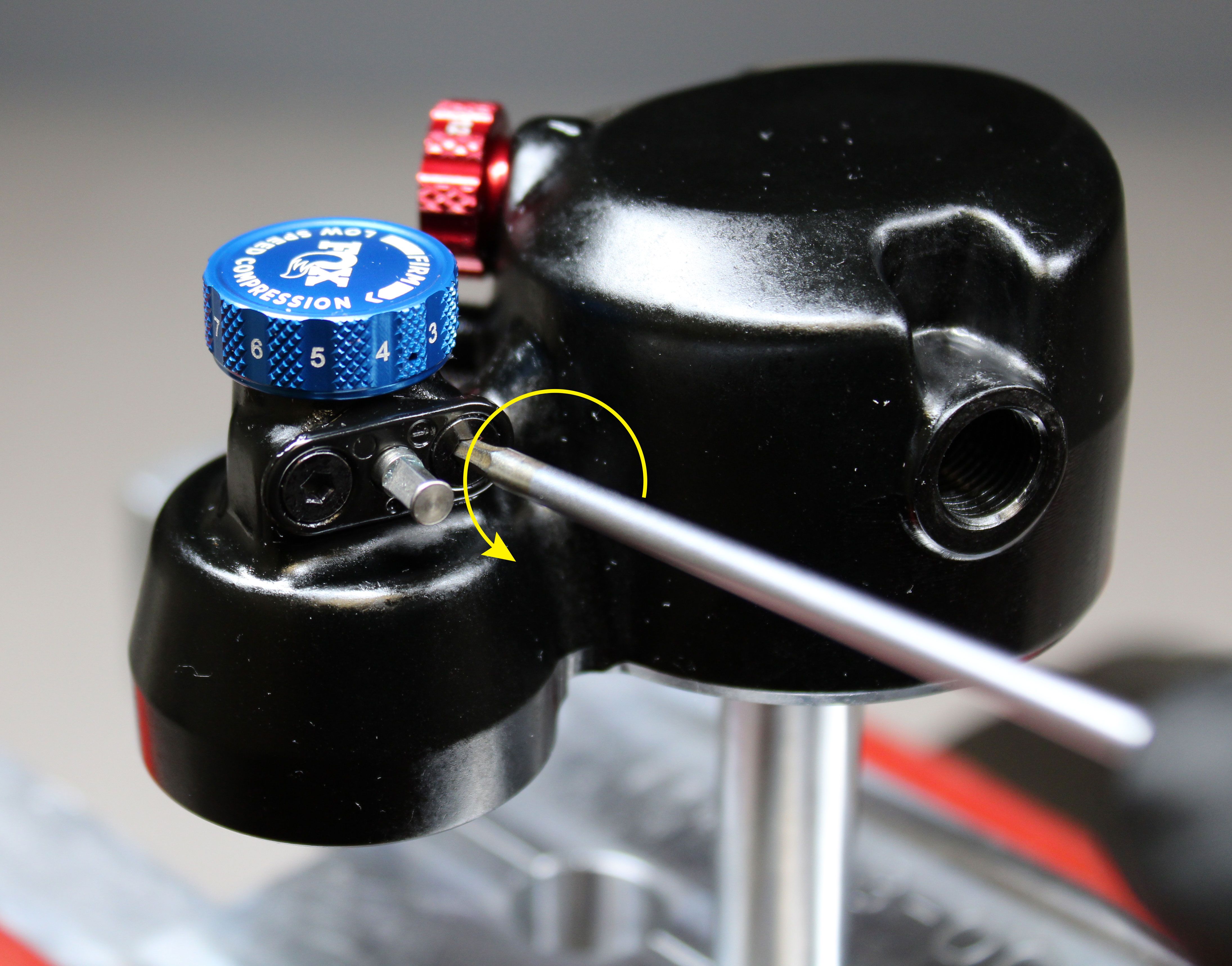
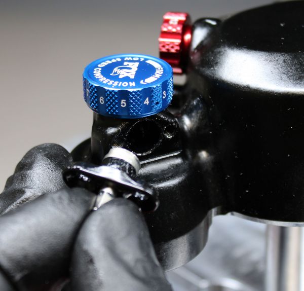
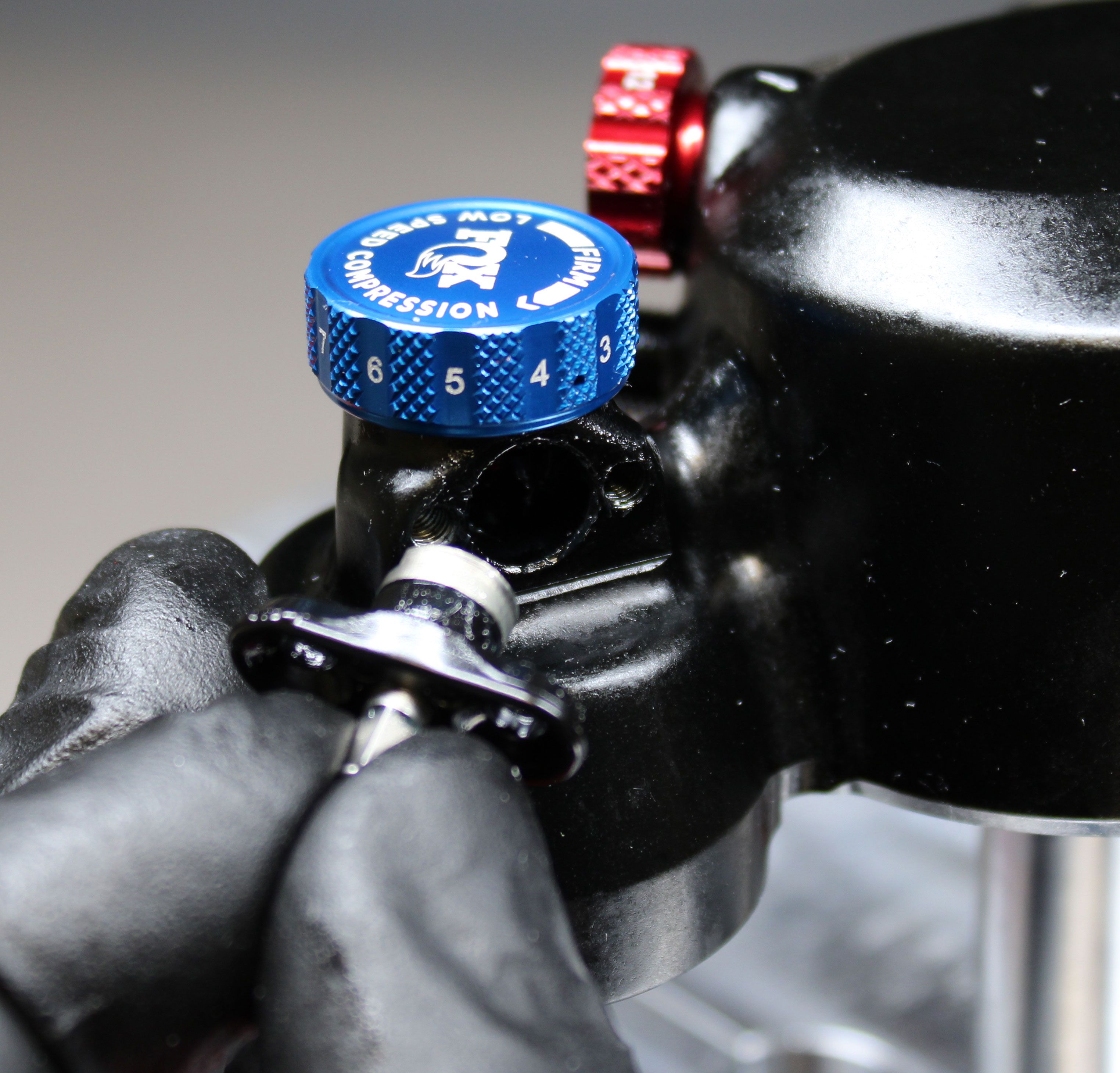
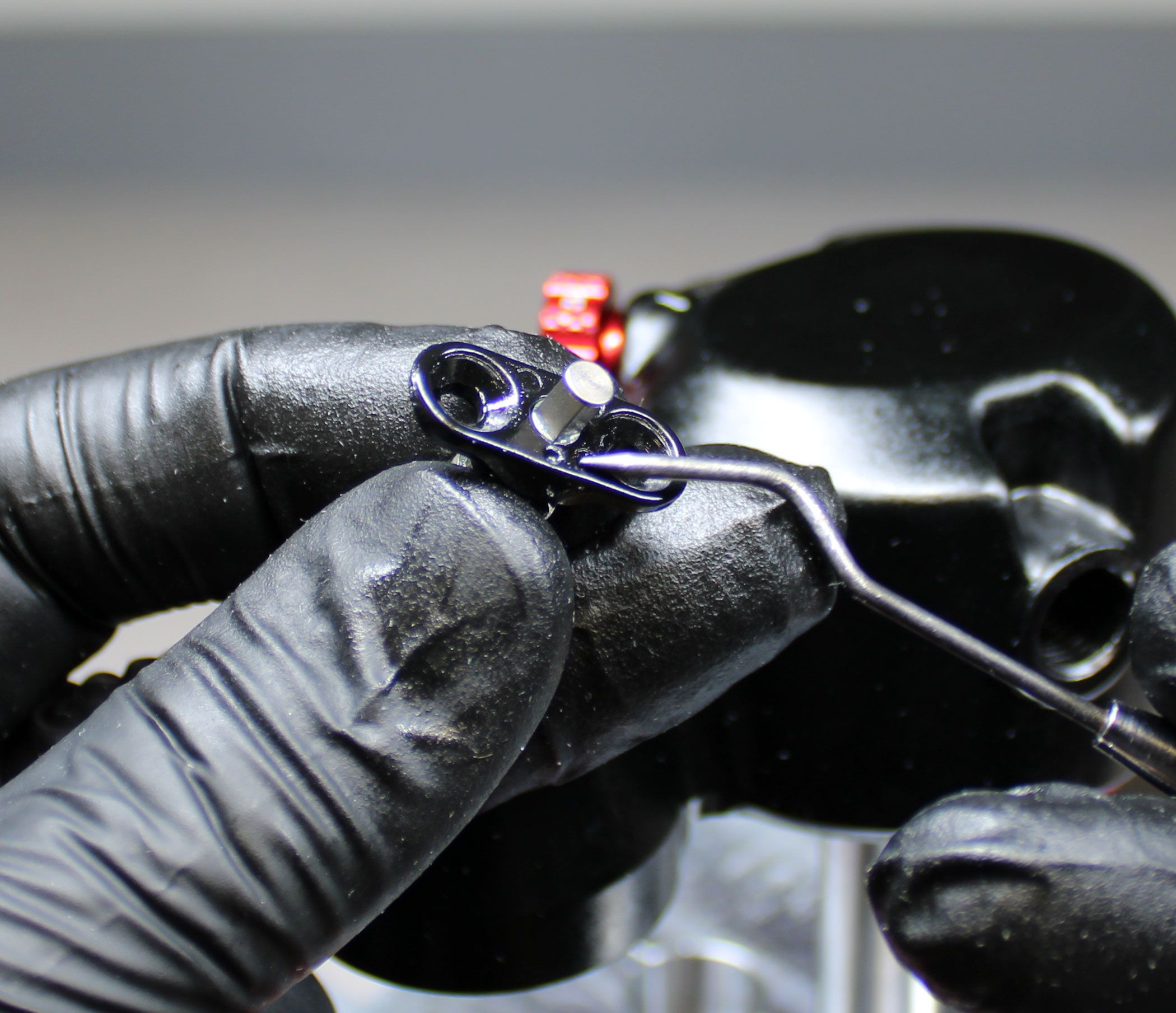
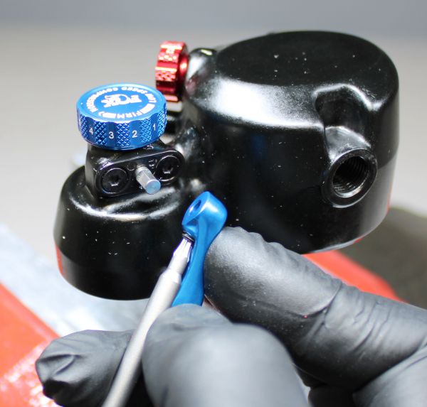
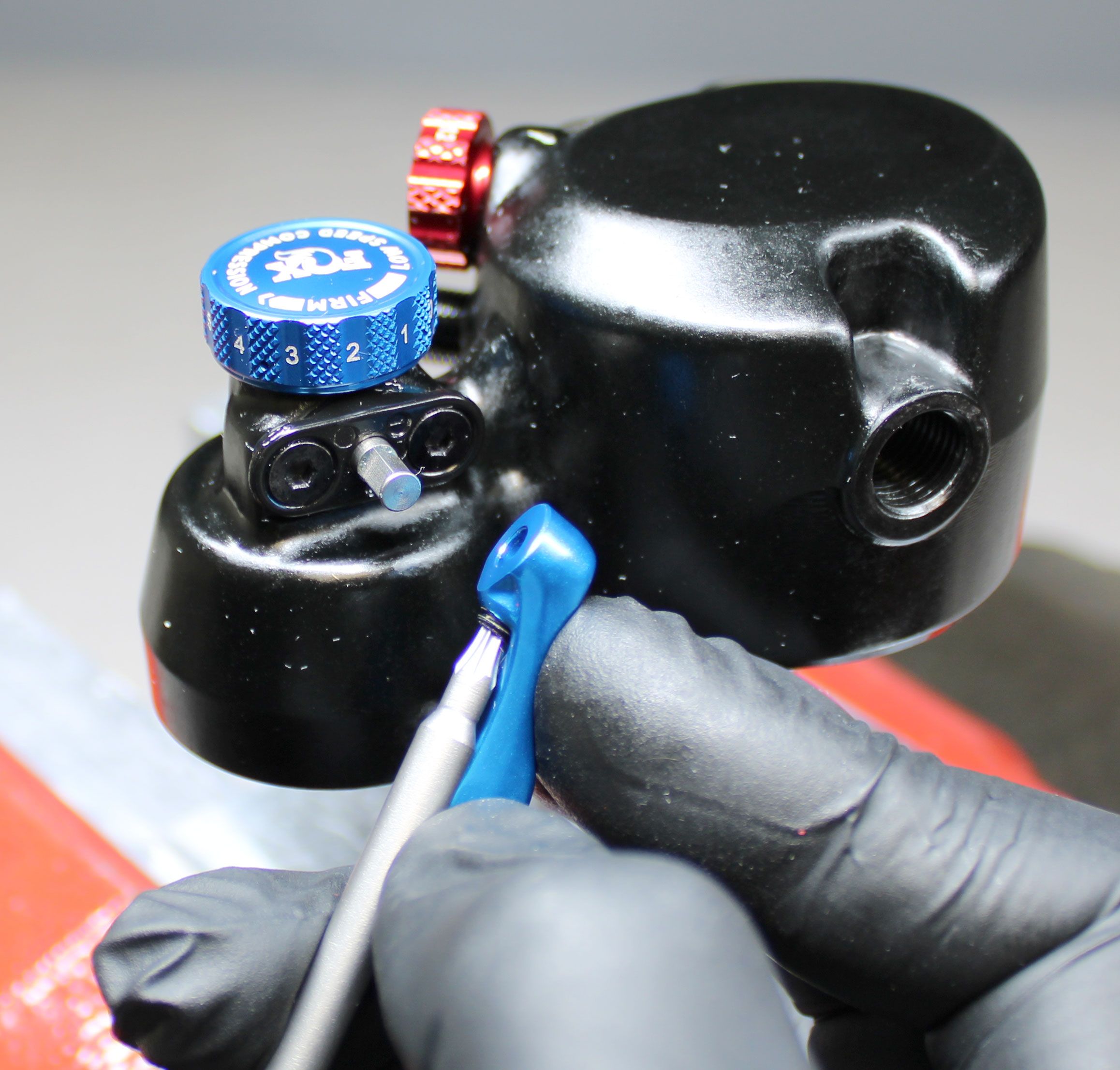
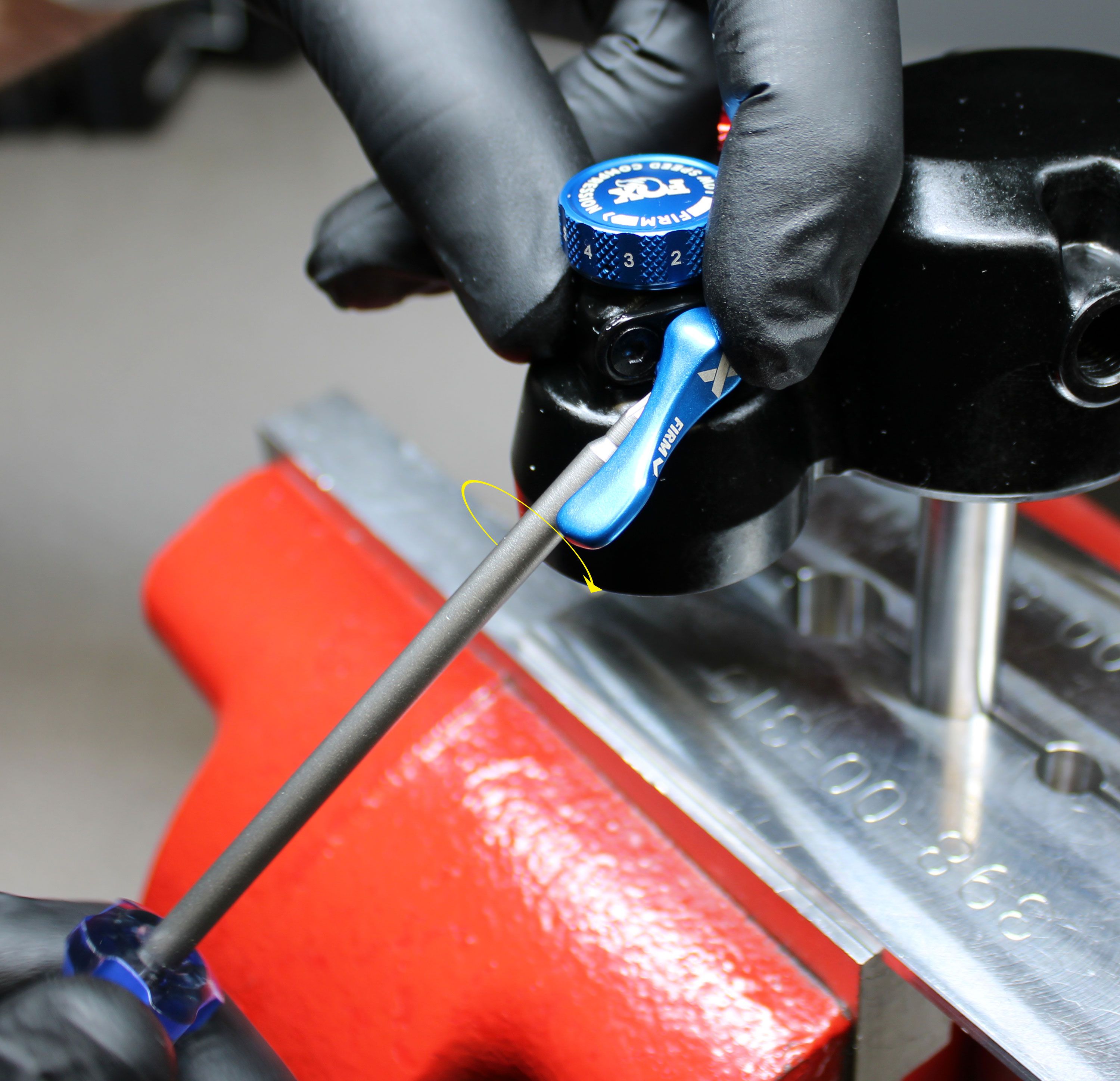
Use a T8 Torx driver to unthread the lever set screw counter-clockwise without fully removing it from the lever. Remove the lever and set it aside. Remove the two 2mm screws by unthreading them counter-clockwise.

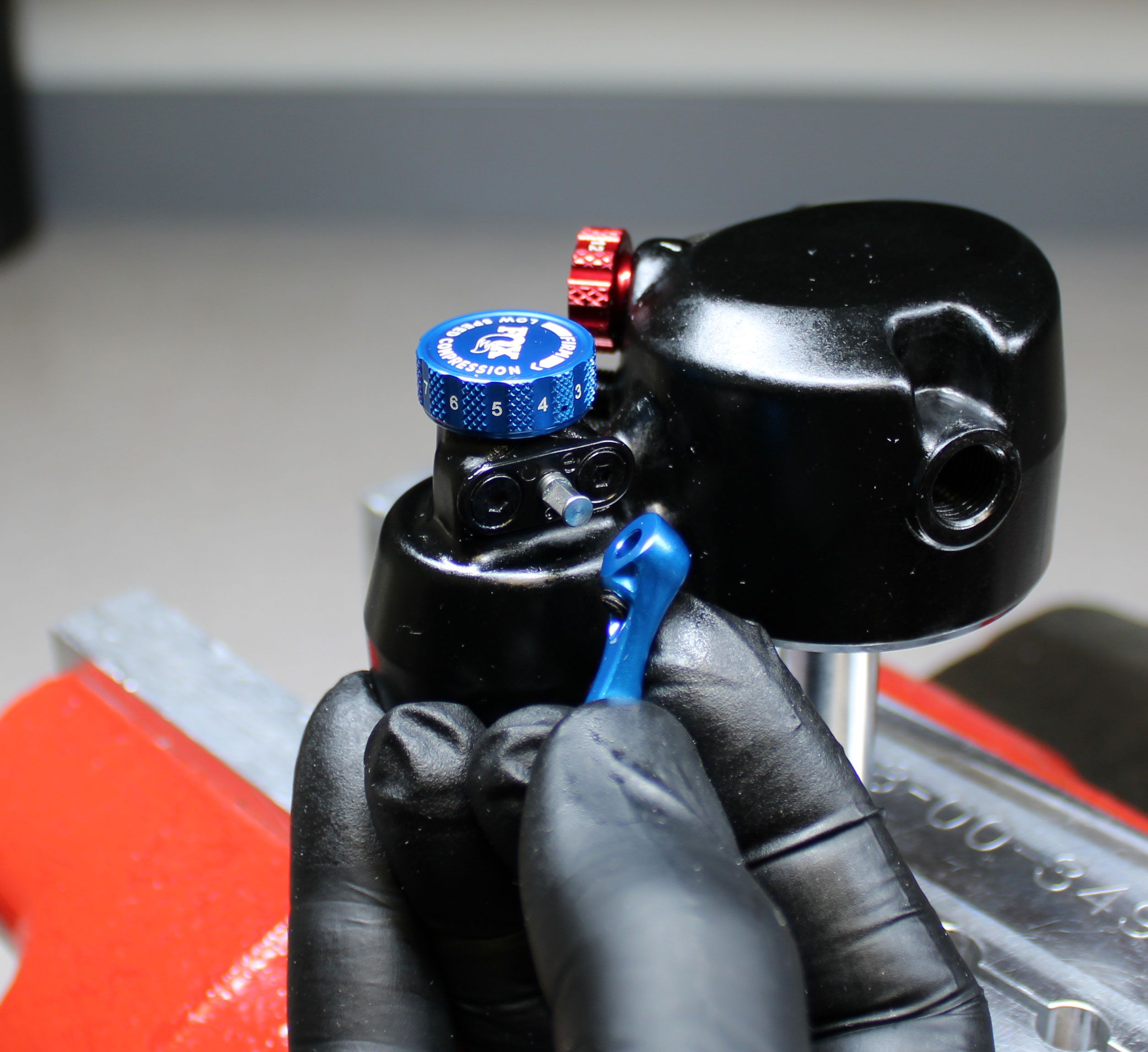
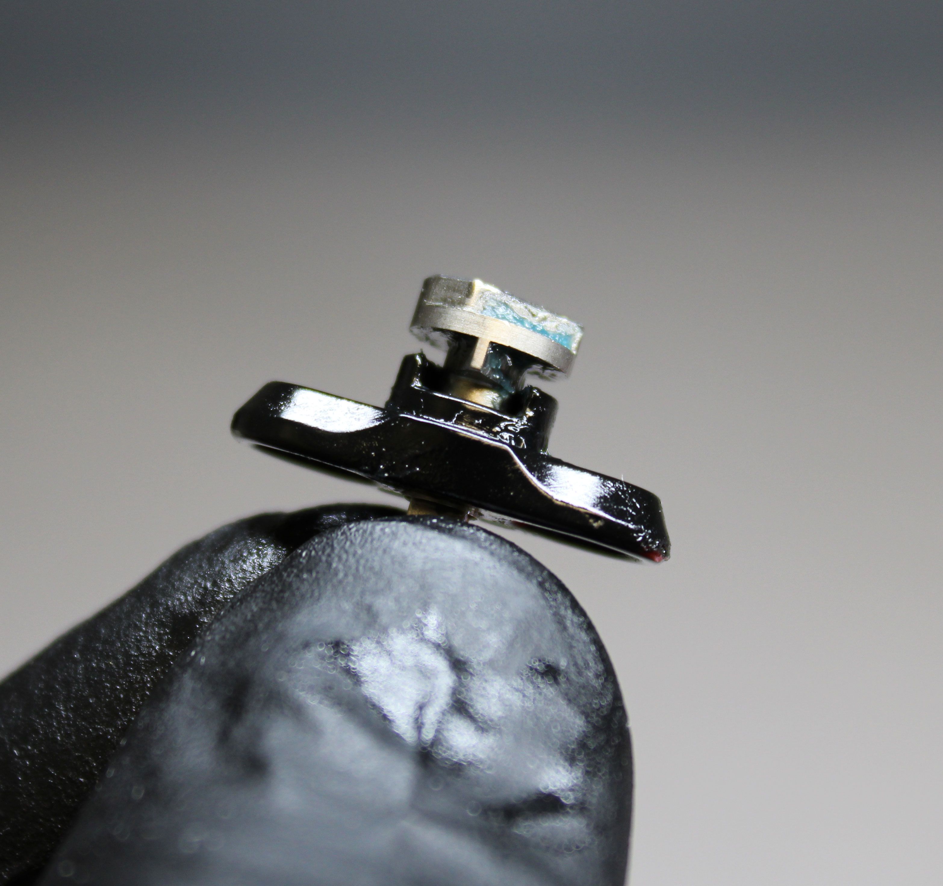
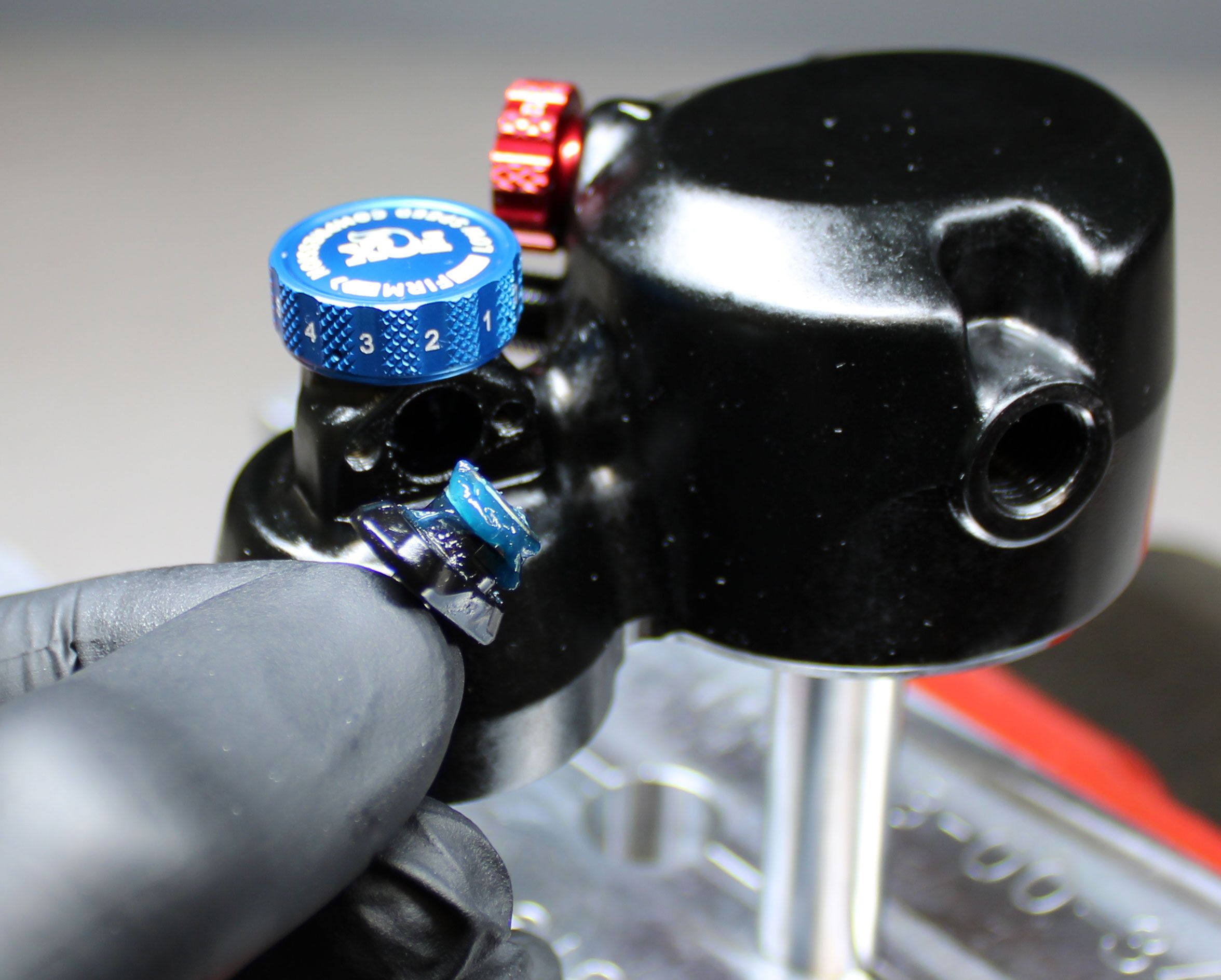
Step 3
Remove the cam and hold down by pulling them out of the eyelet. Clean and inspect the parts, then apply a thick layer of Ultraplex LT2 or Stay Lube SL3125 Blue waterproof grease to the cam (Ultraplex LT2 blue waterproof grease shown). Note the dimple on the cam hold down and orient it toward the reservoir. Reinstall the cam and hold down then reinstall the two 2mm screws tightening clockwise to 11 in-lb (1.2 Nm) torque.
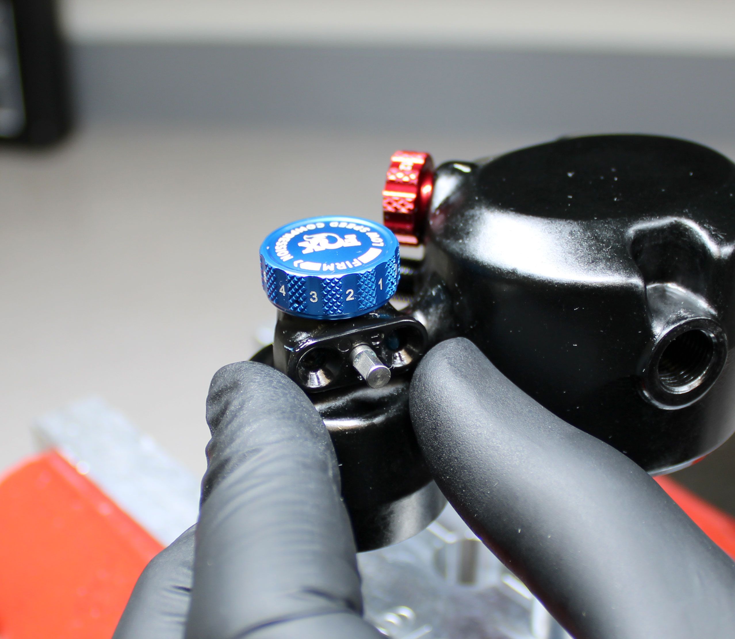
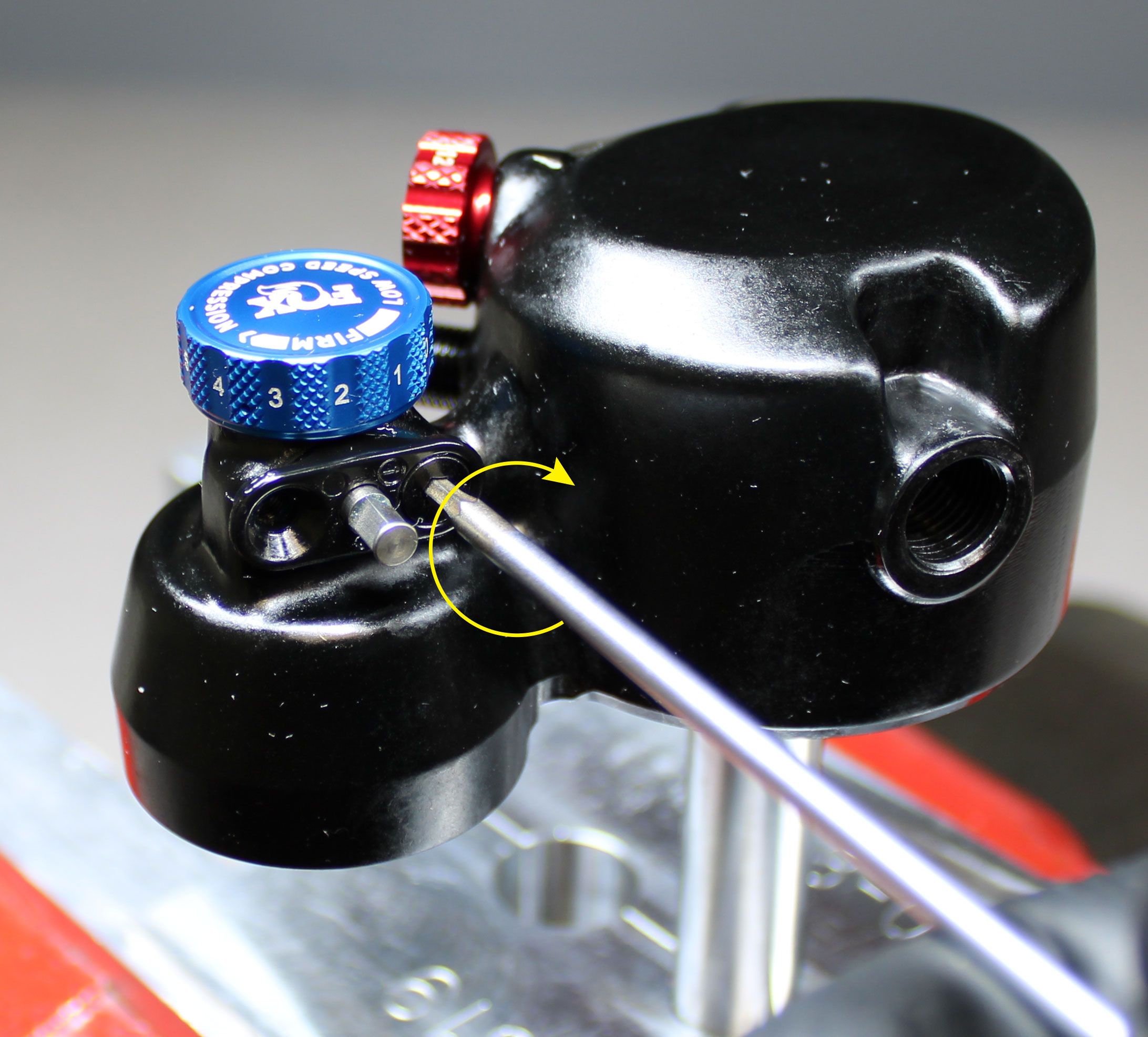
Step 4
Reinstall the lever by tightening the set screw clockwise to 8 in-lb (0.9 Nm) torque once aligned with the flat of the cam oriented toward the reservoir. Check that the lever functions properly.
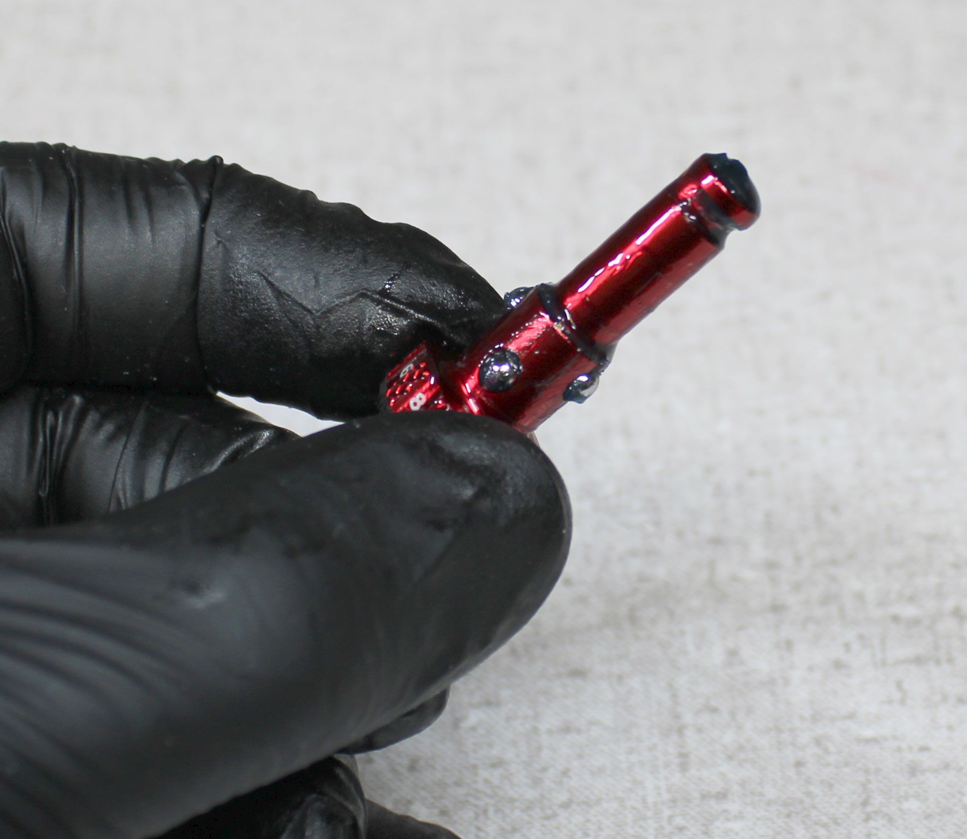
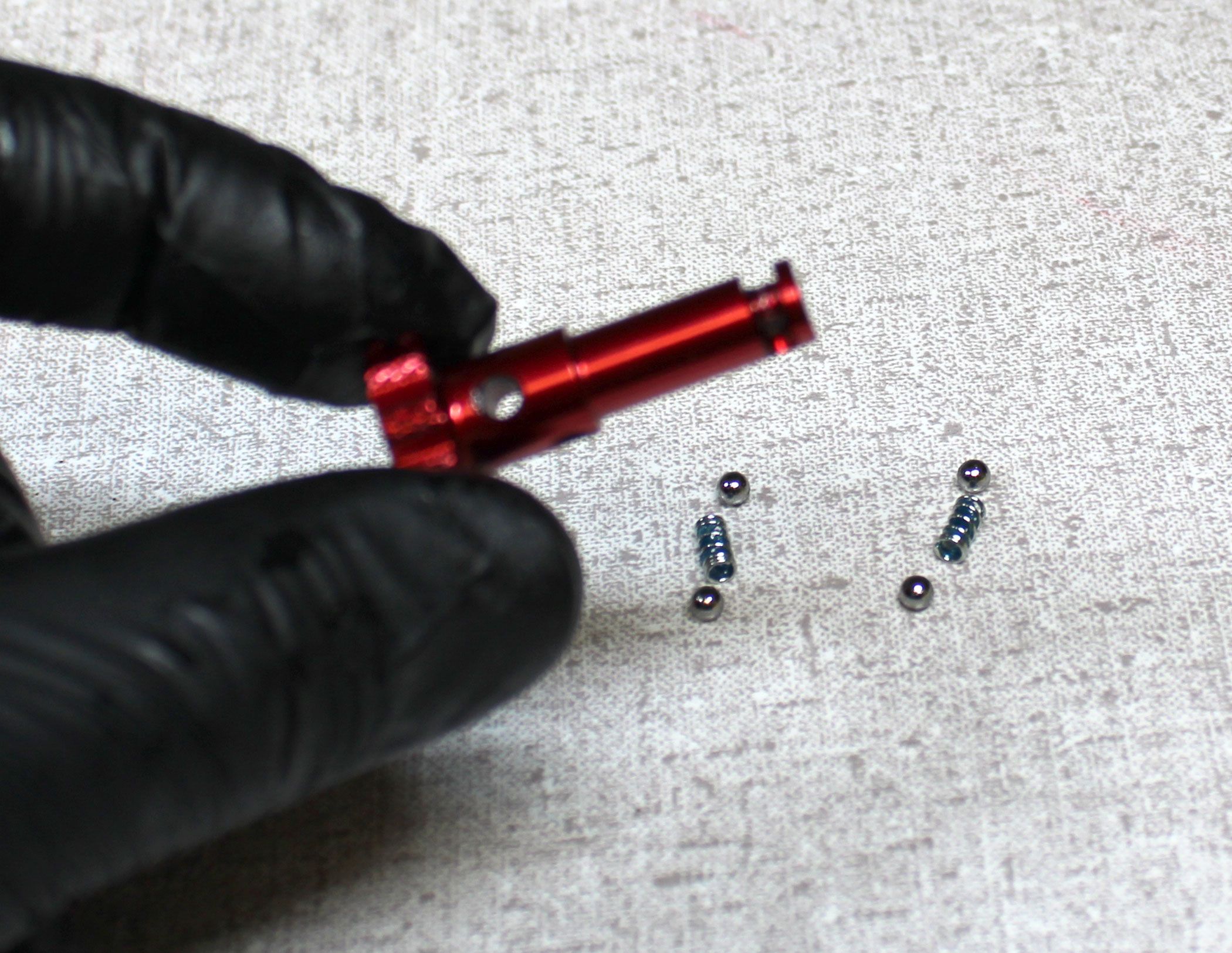
Step 5
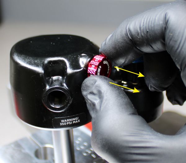
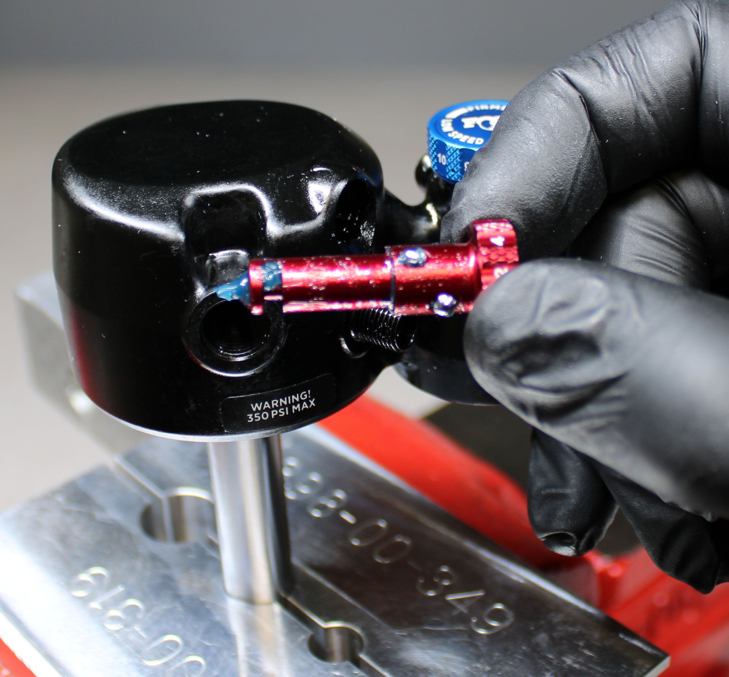
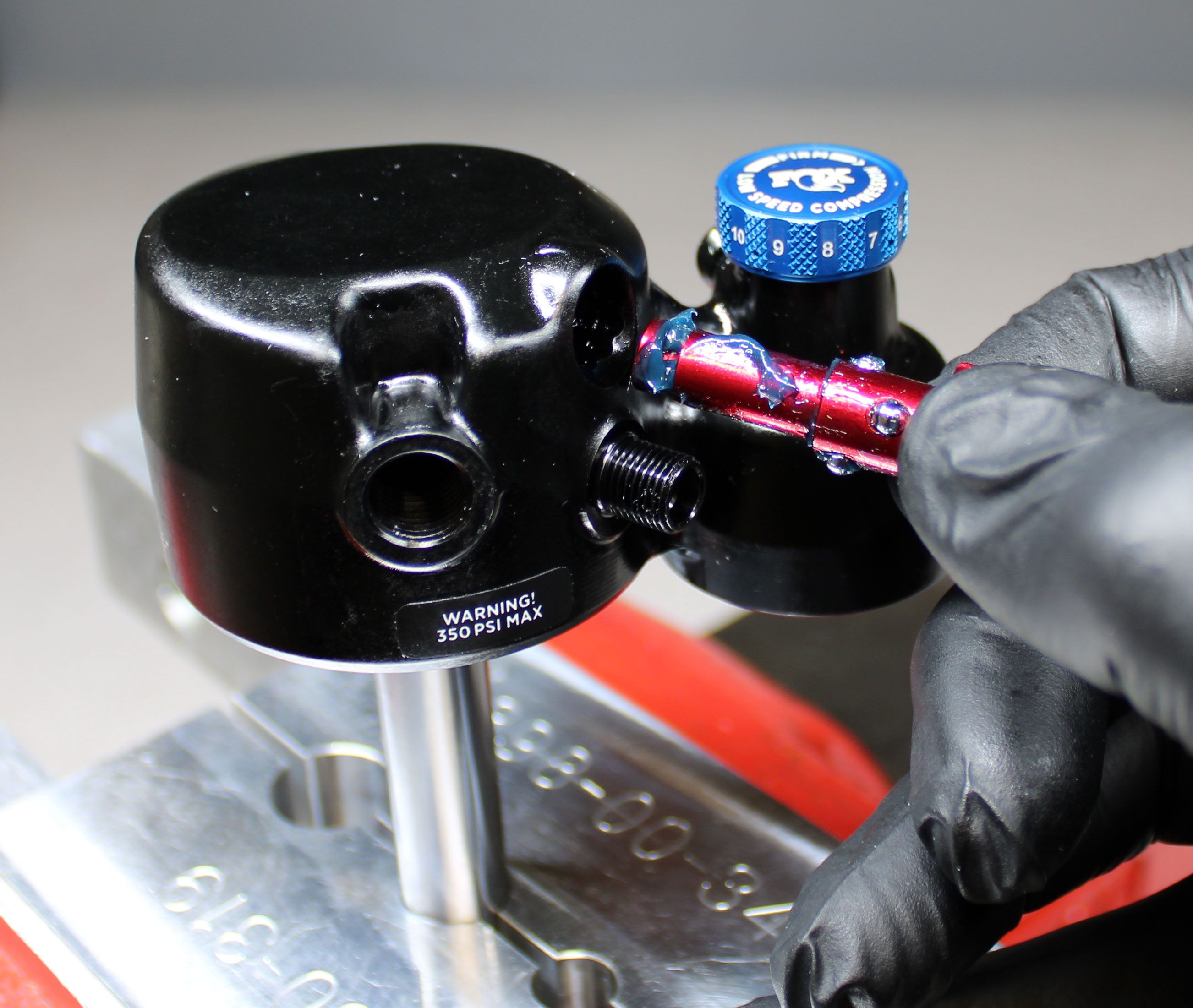
With the rebound rod removed you may remove the red rebound knob if needed to clean and regrease the detent mechanism. Remove the rebound knob by slowly pulling it out from the eyelet taking care not to lose any of the 4 0.125" diameter balls. Remove the detent balls and springs from the rebound knob, then clean the knob.

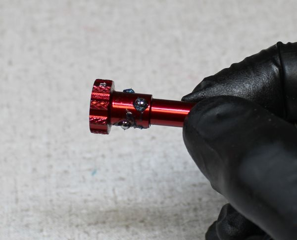
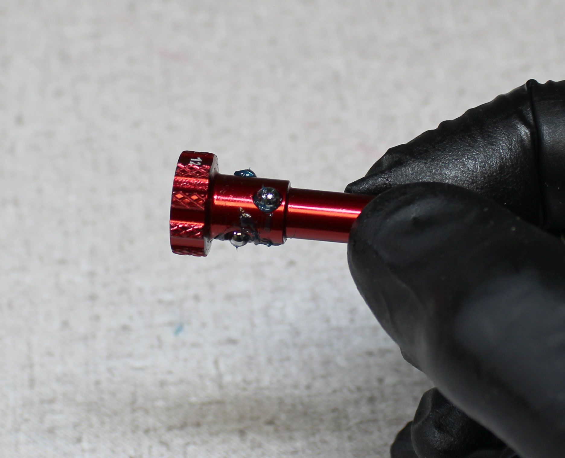
Step 6
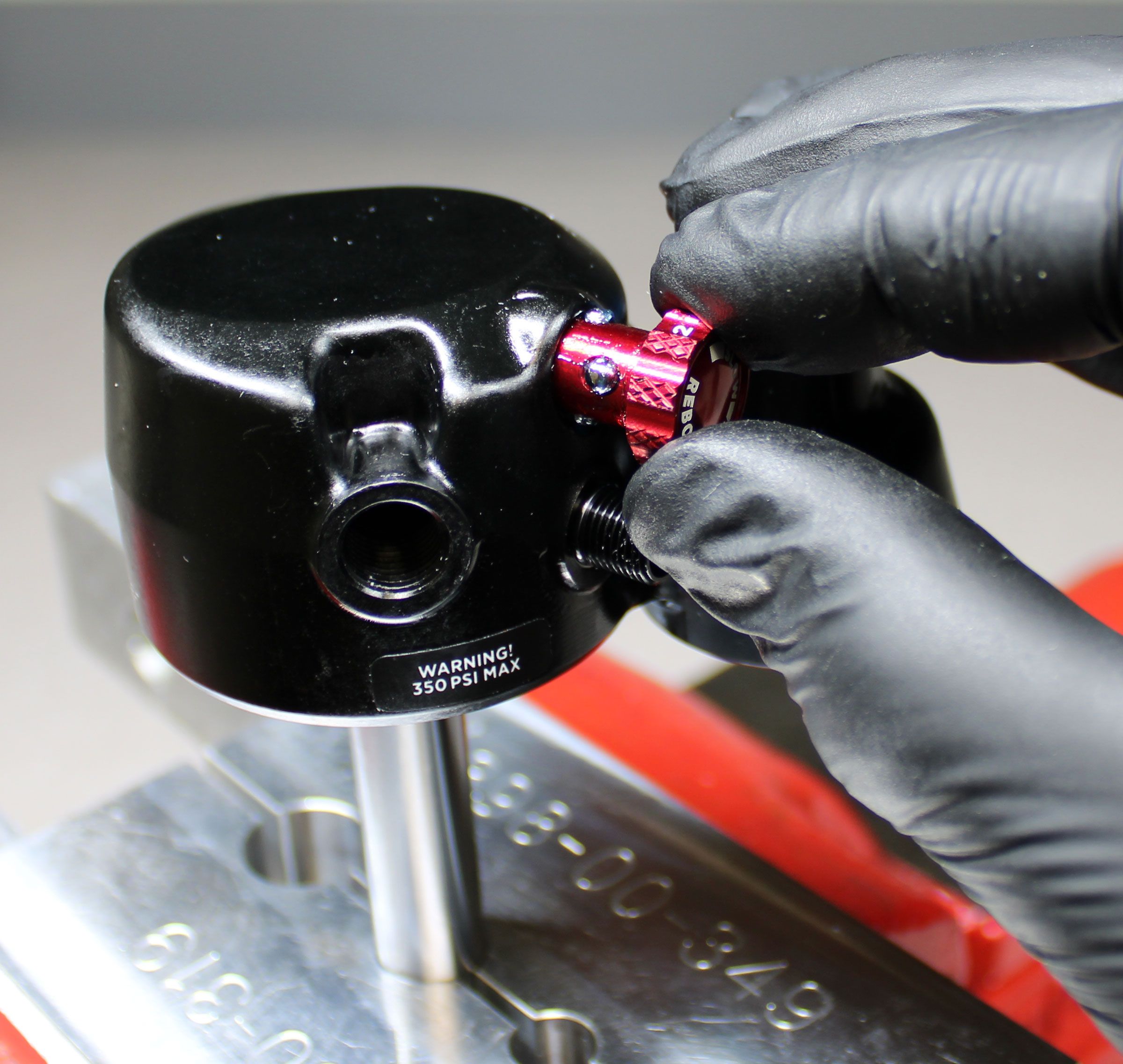
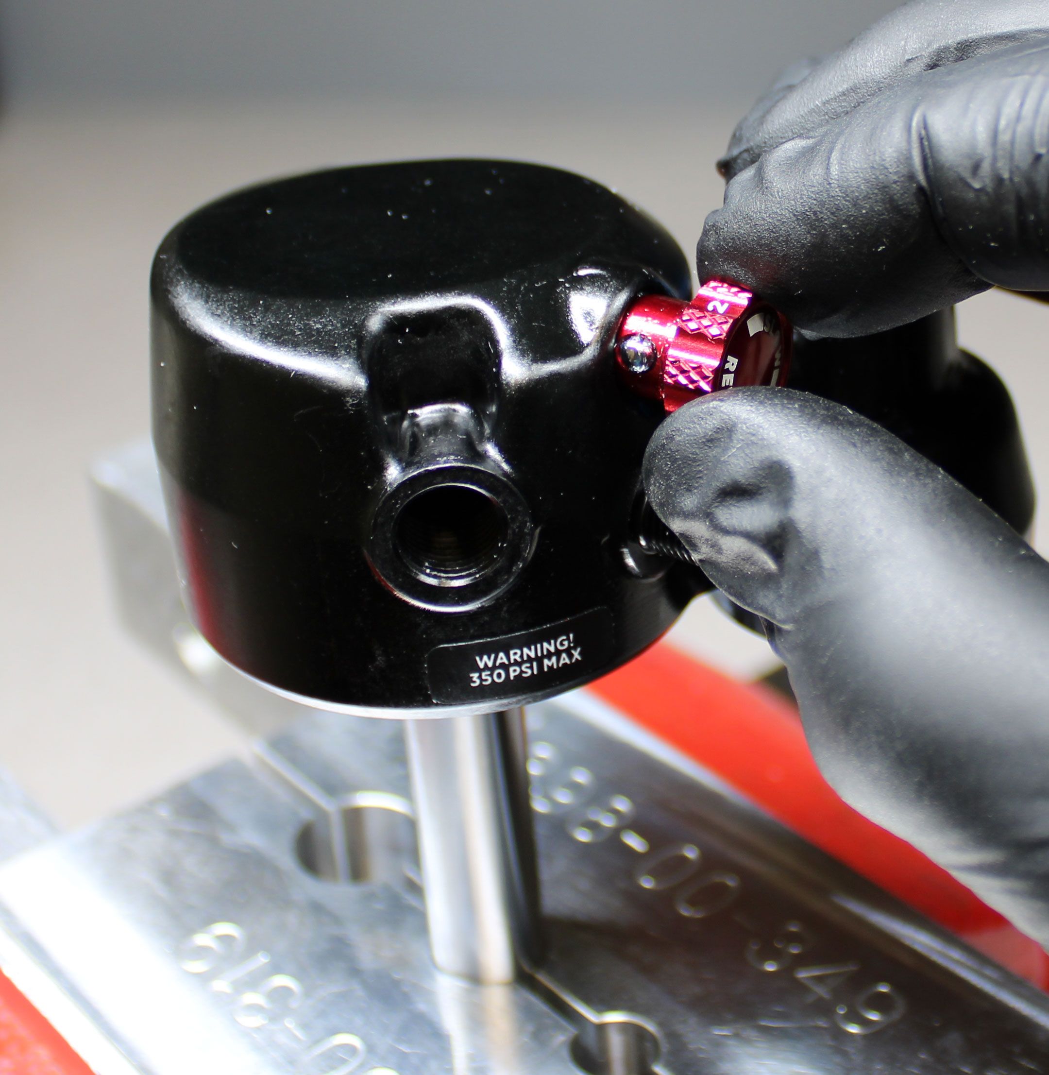
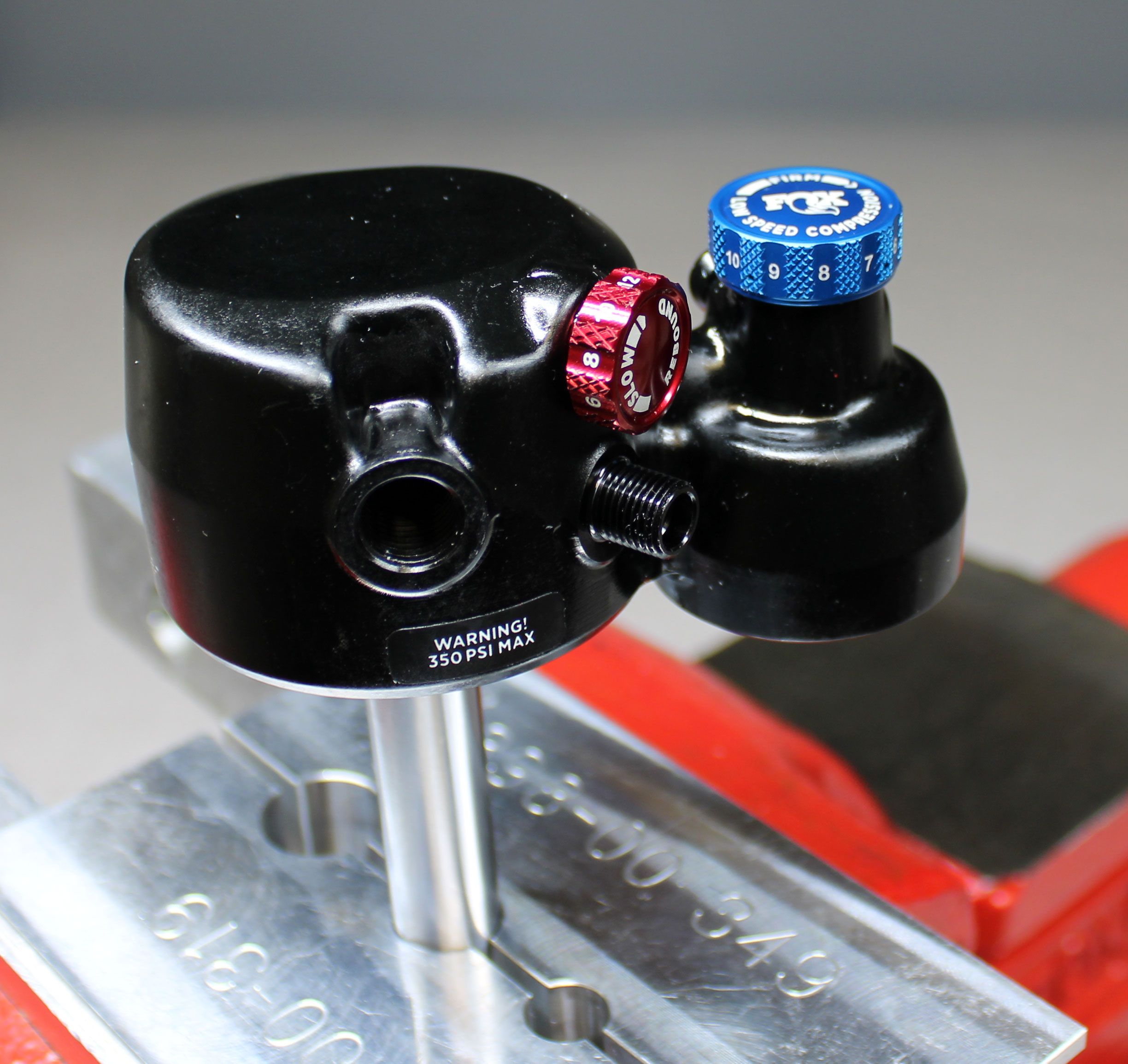
Coat the rebound knob in a thick layer of Ultraplex LT2 or Stay Lube SL3125 Blue waterproof grease (Ultraplex LT2 shown). Reinstall the detent springs into the holes. Reinstall the detent balls to either end of each spring. Slowly reinsert the rebound knob with detent balls and springs into the eyelet taking care to squeeze the detent balls into the eyelet as you insert the rebound knob.
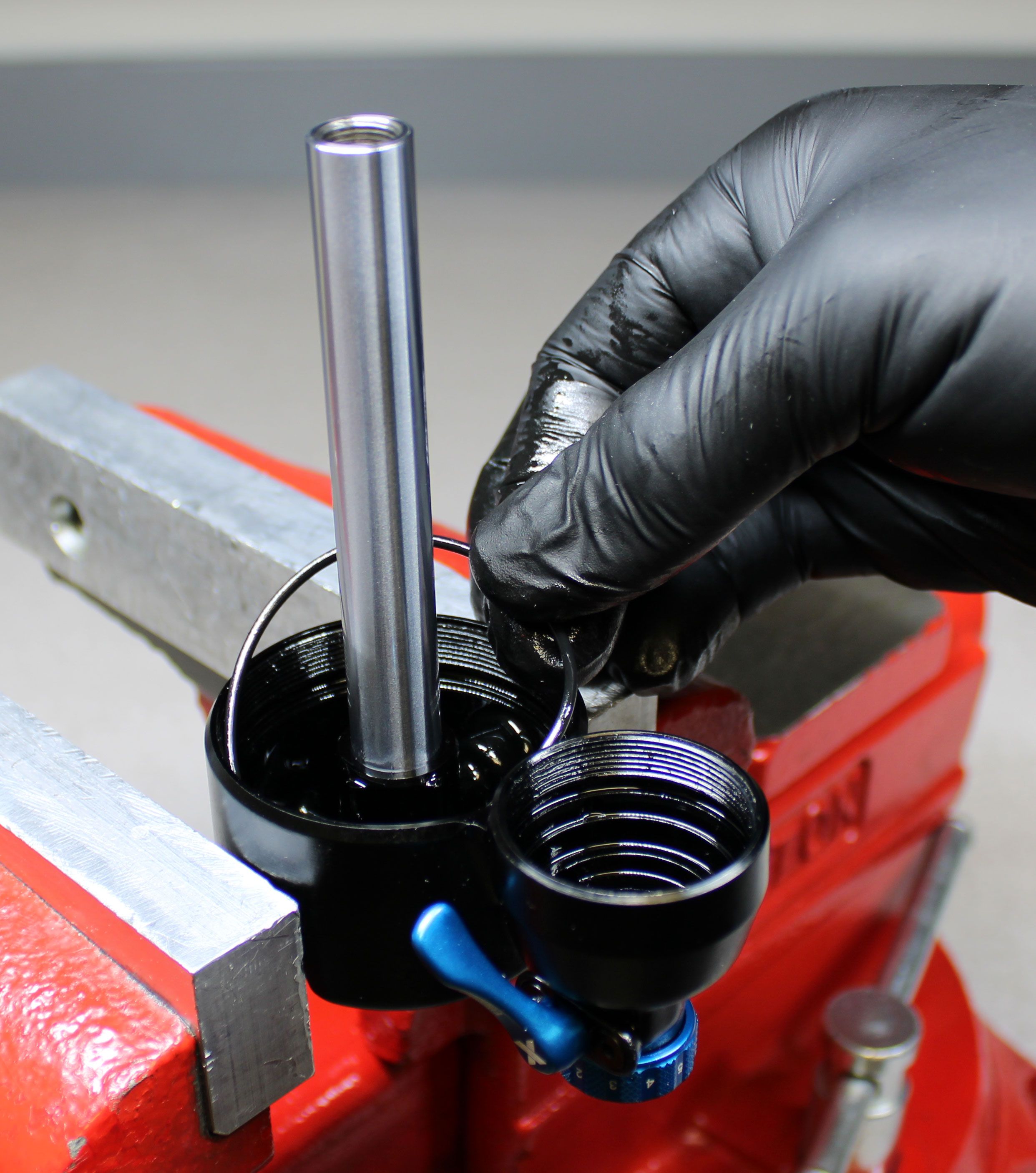
Step 7
Clamp the shaft eyelet in your soft jawed vise then install a new greased air sleeve o-ring from the kit into the eyelet. Reinstall the bottom out plate.
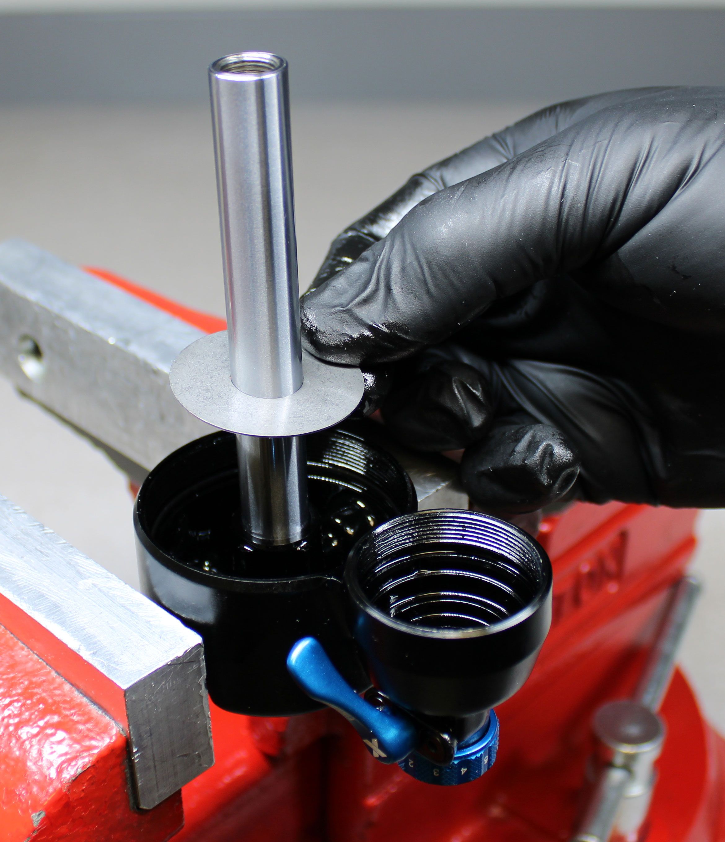
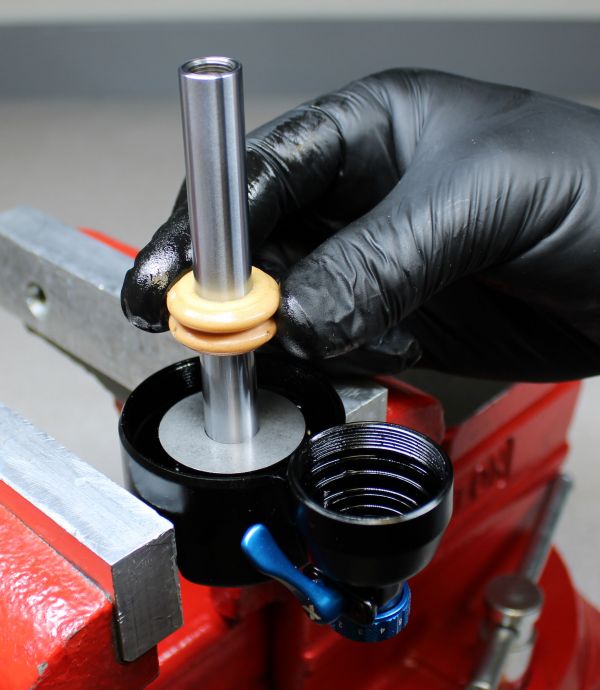
Step 8
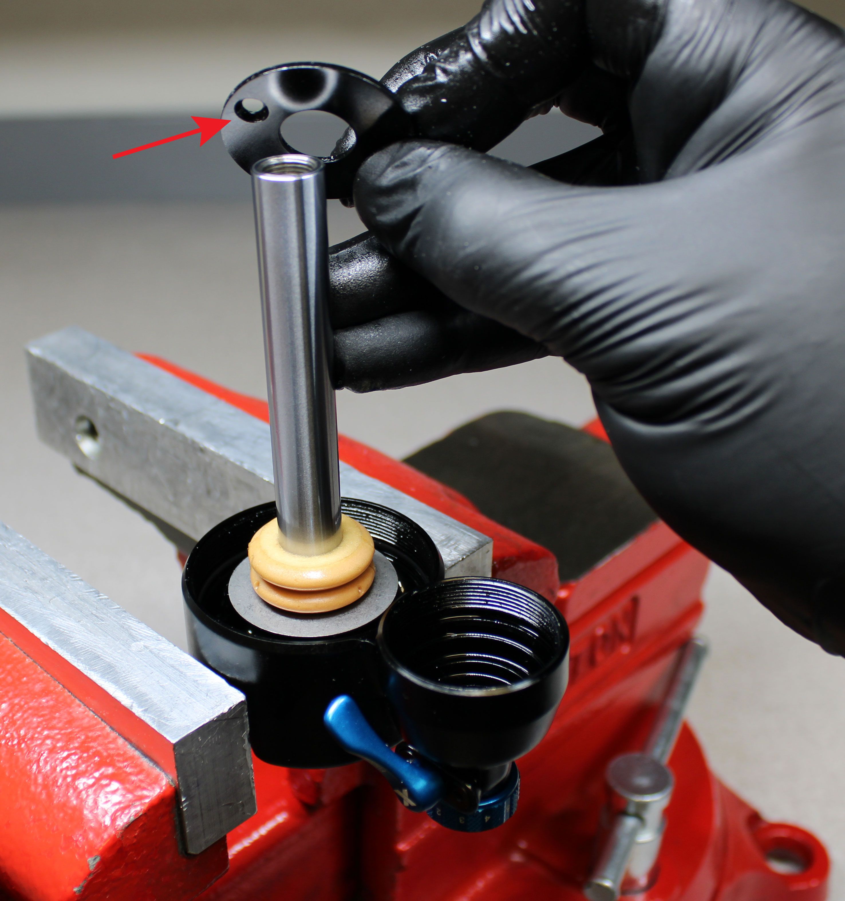
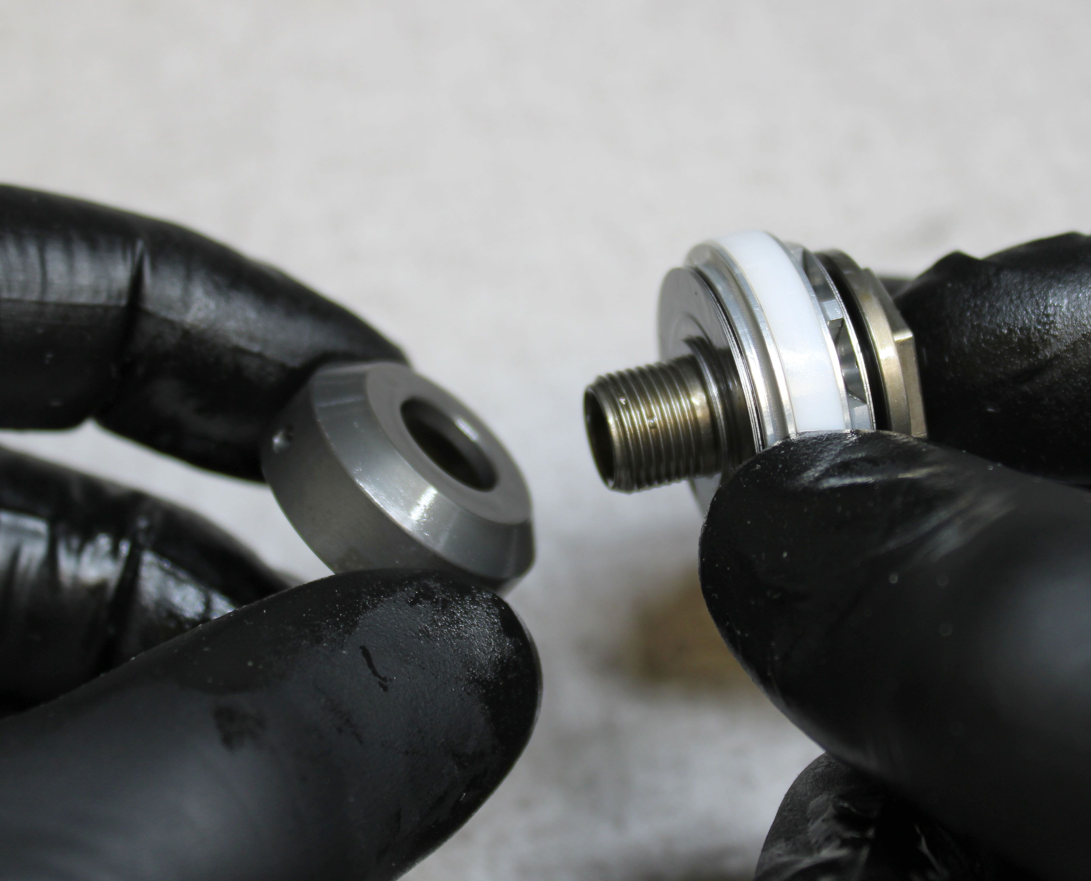
Install a new bottom out bumper from the kit (shown). In some cases this might be an o-ring and spacer, replace the o-ring with a new greased one from the kit. Reinstall the bearing housing cap making sure to orient the counter-bores on the cap toward the eyelet.


Step 9
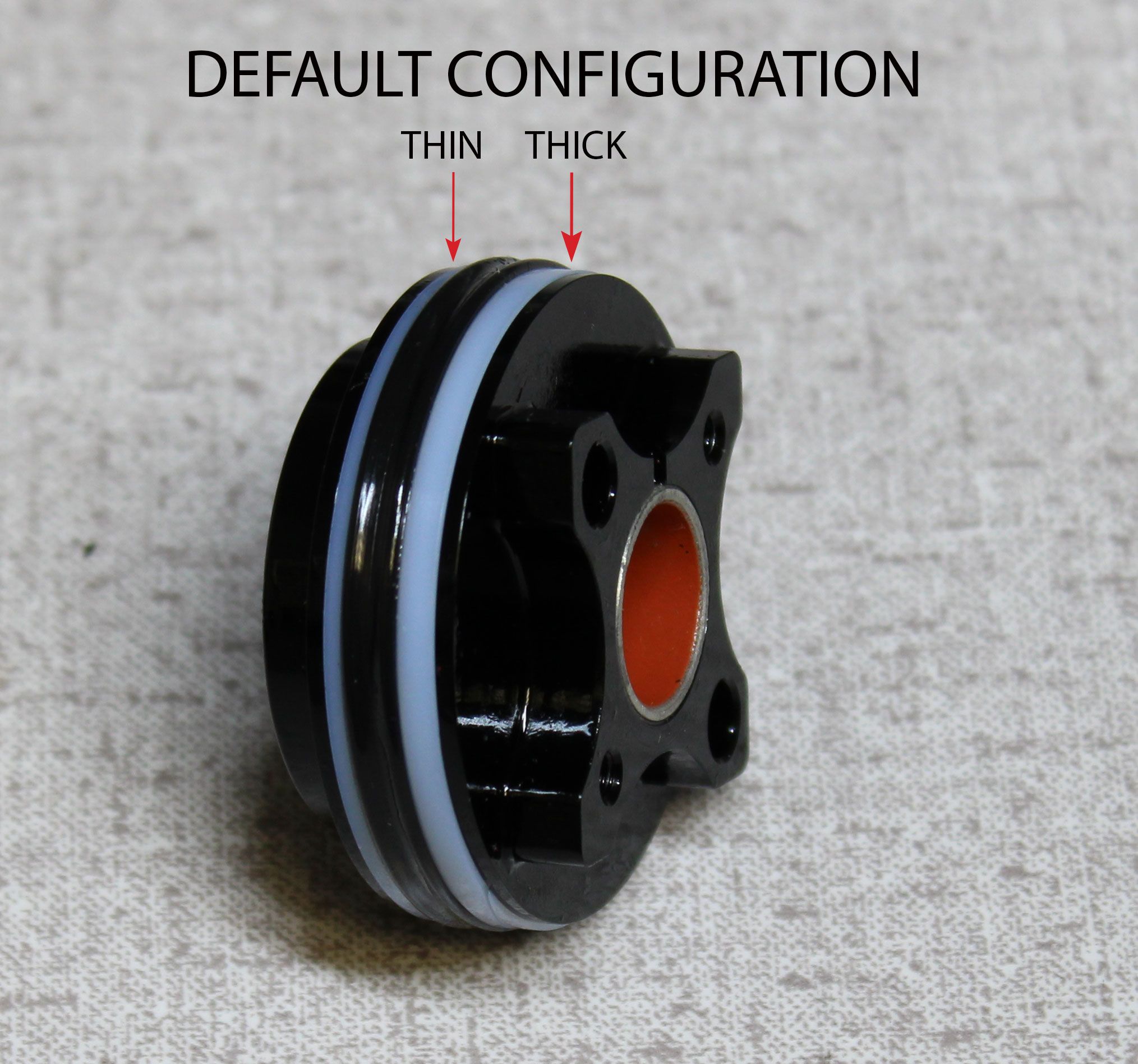
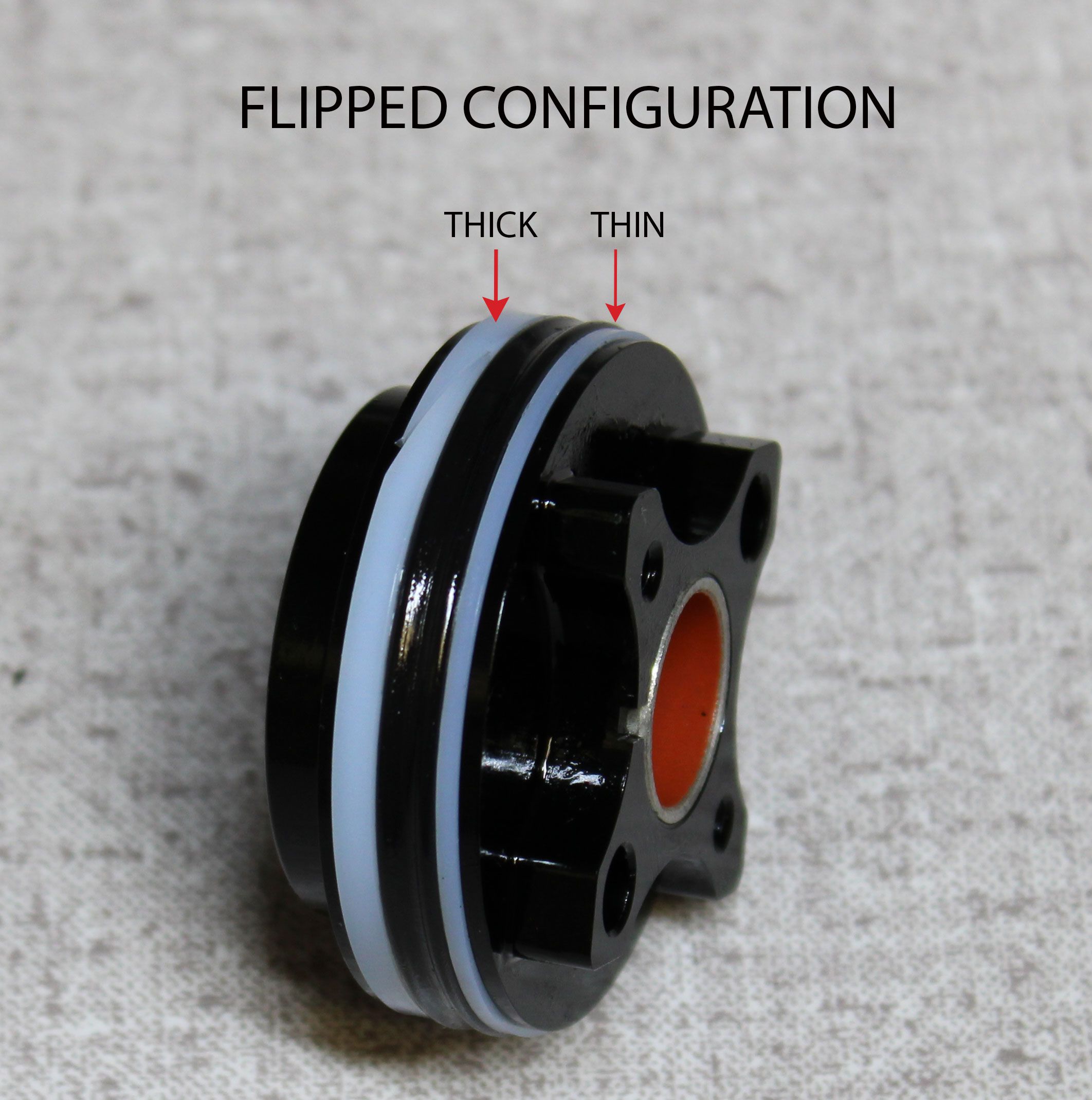
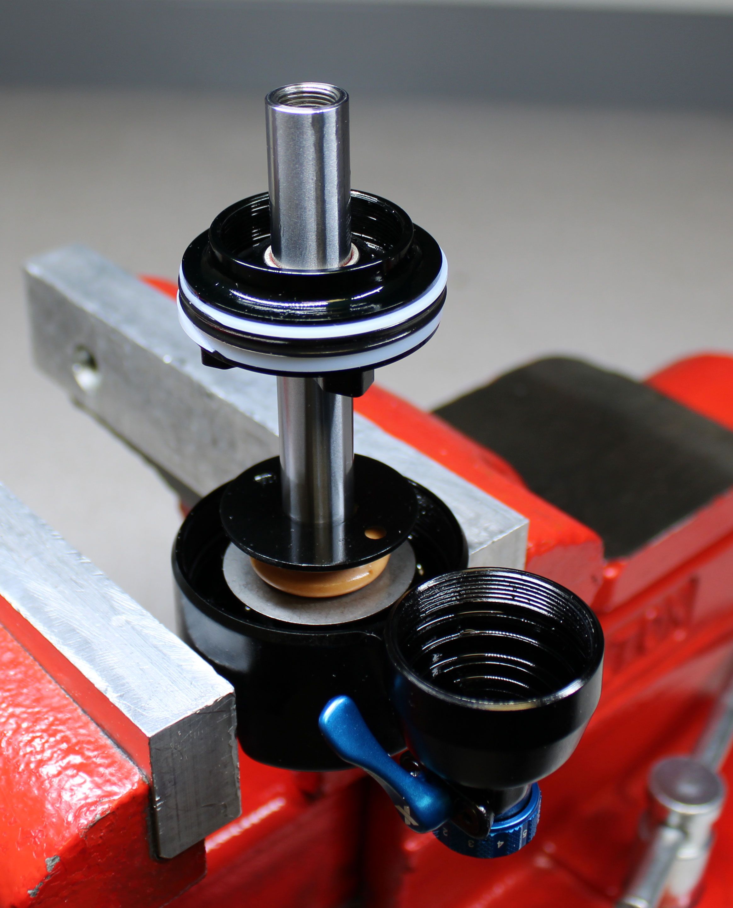
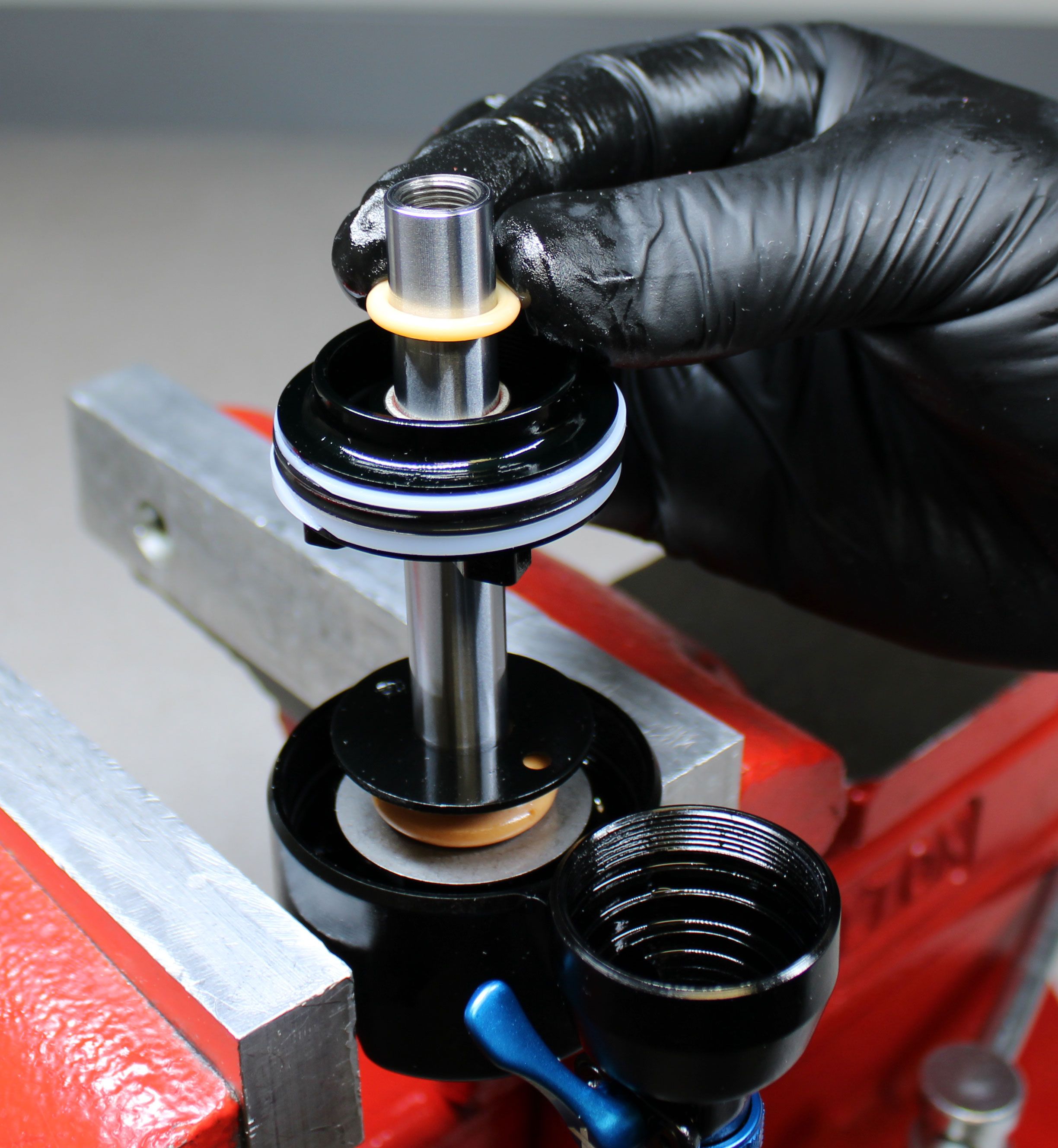
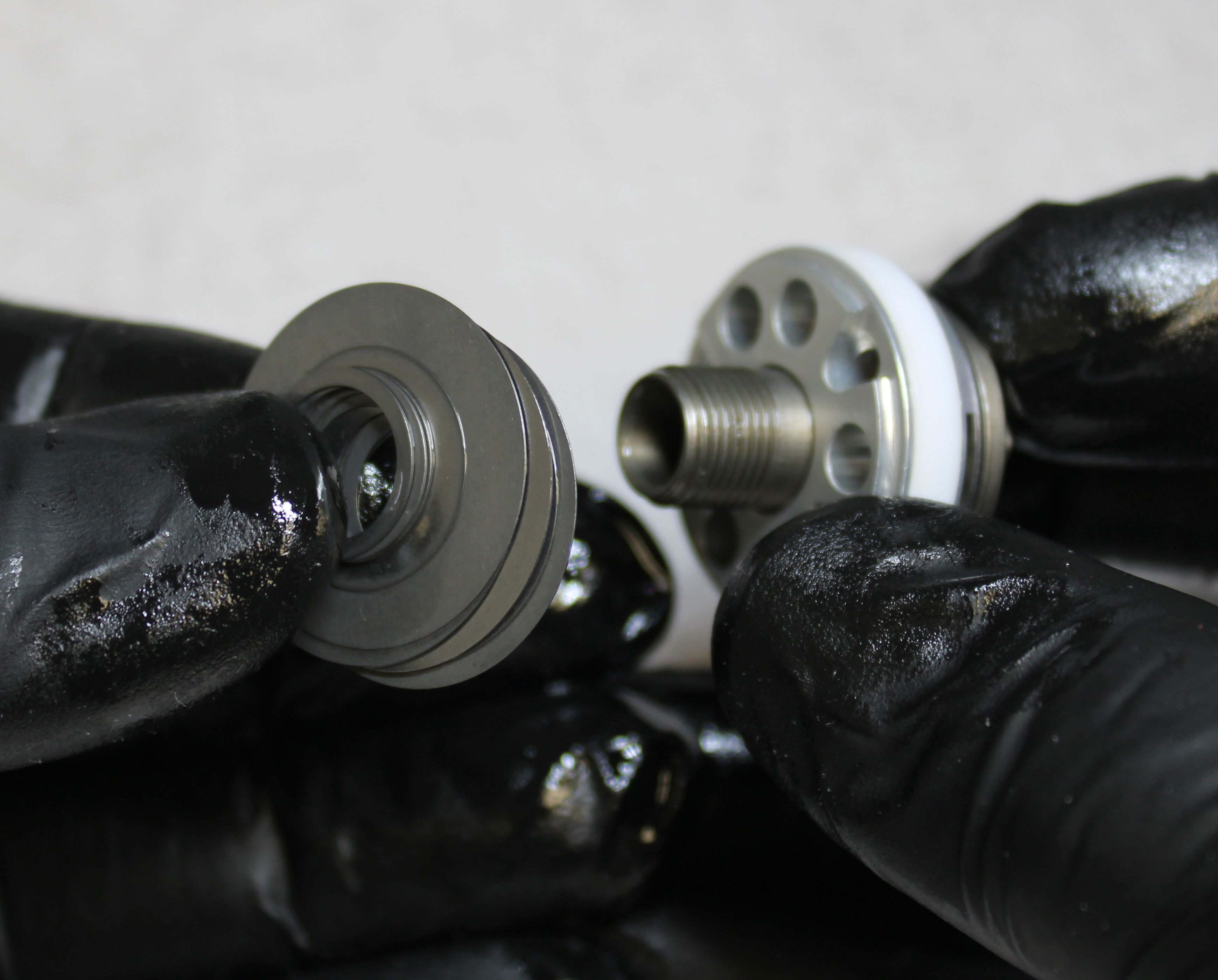
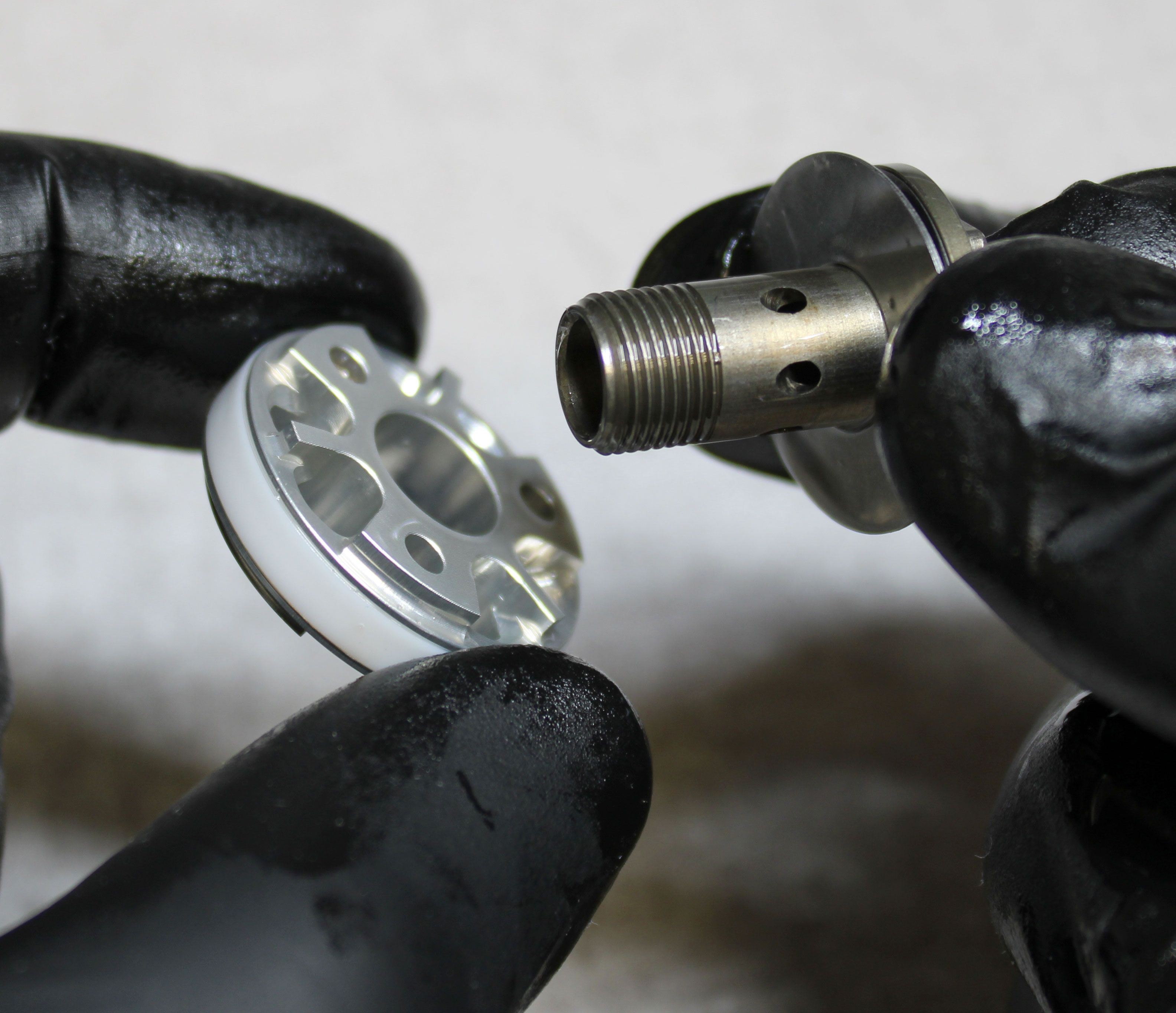
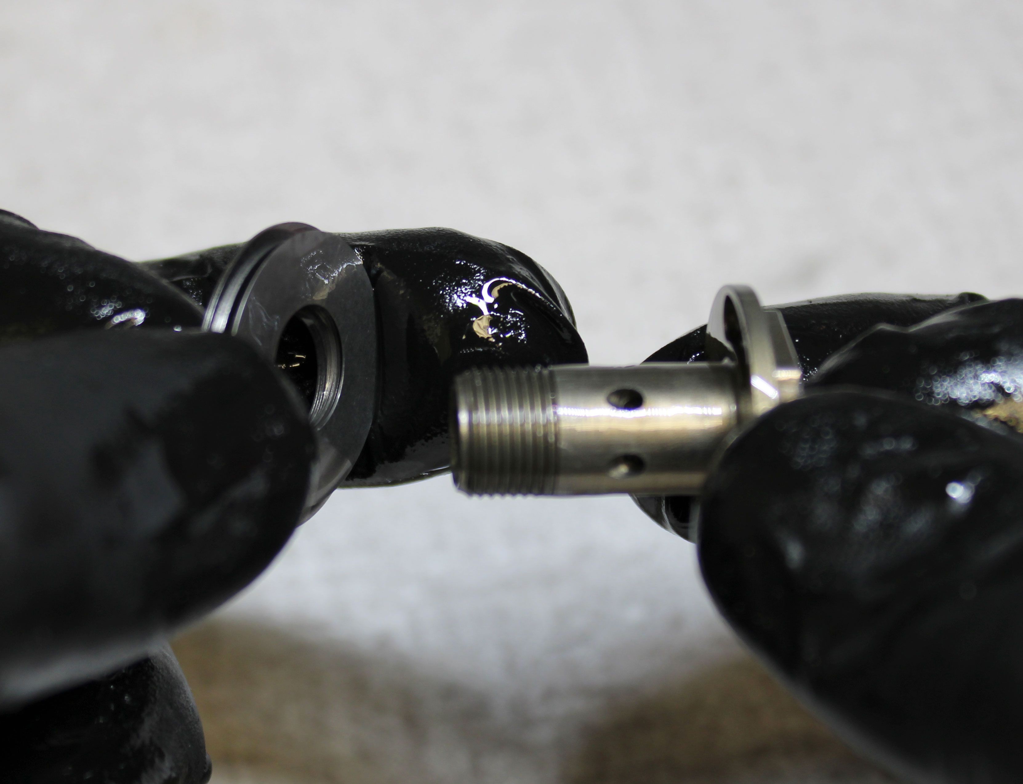
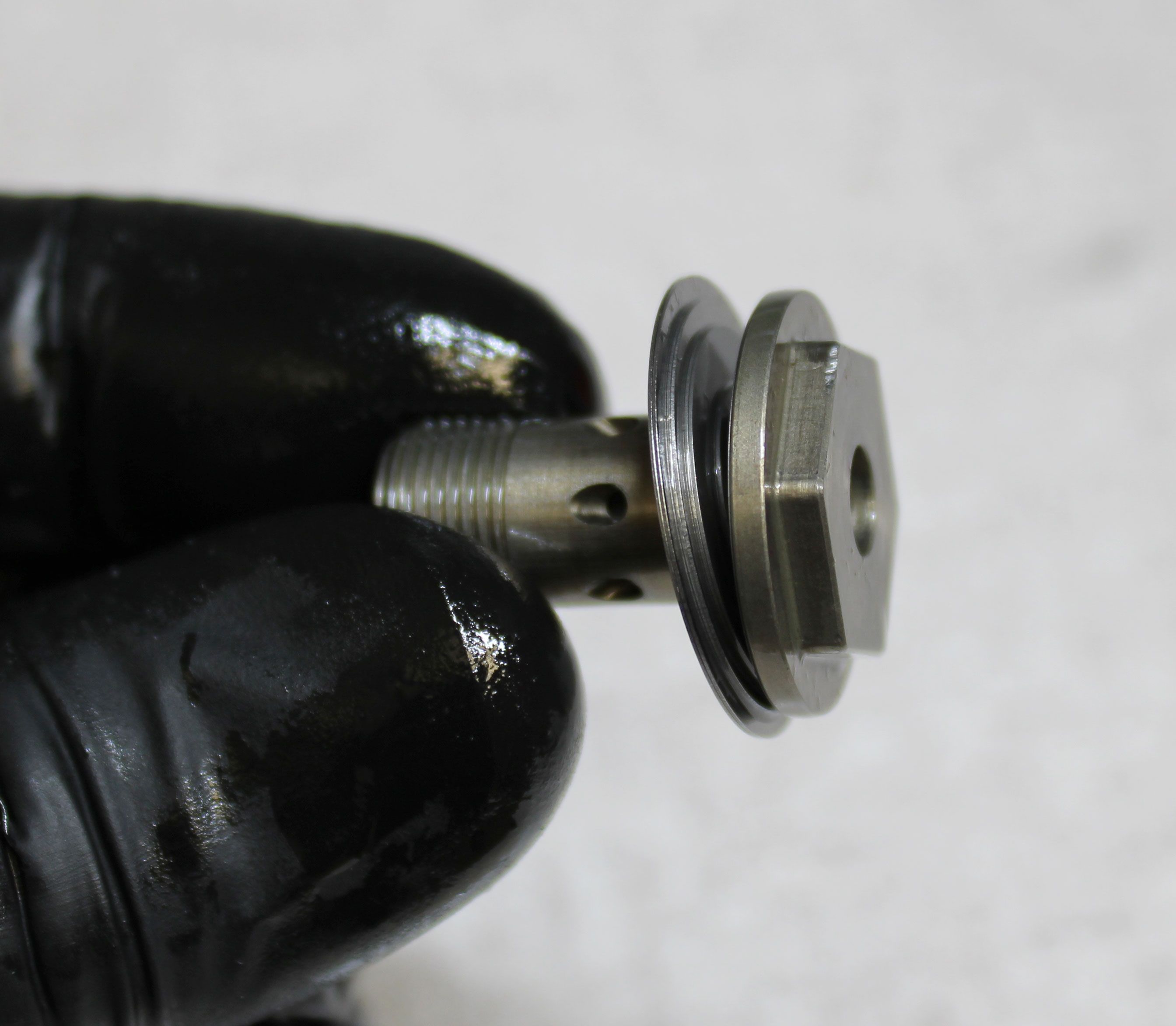
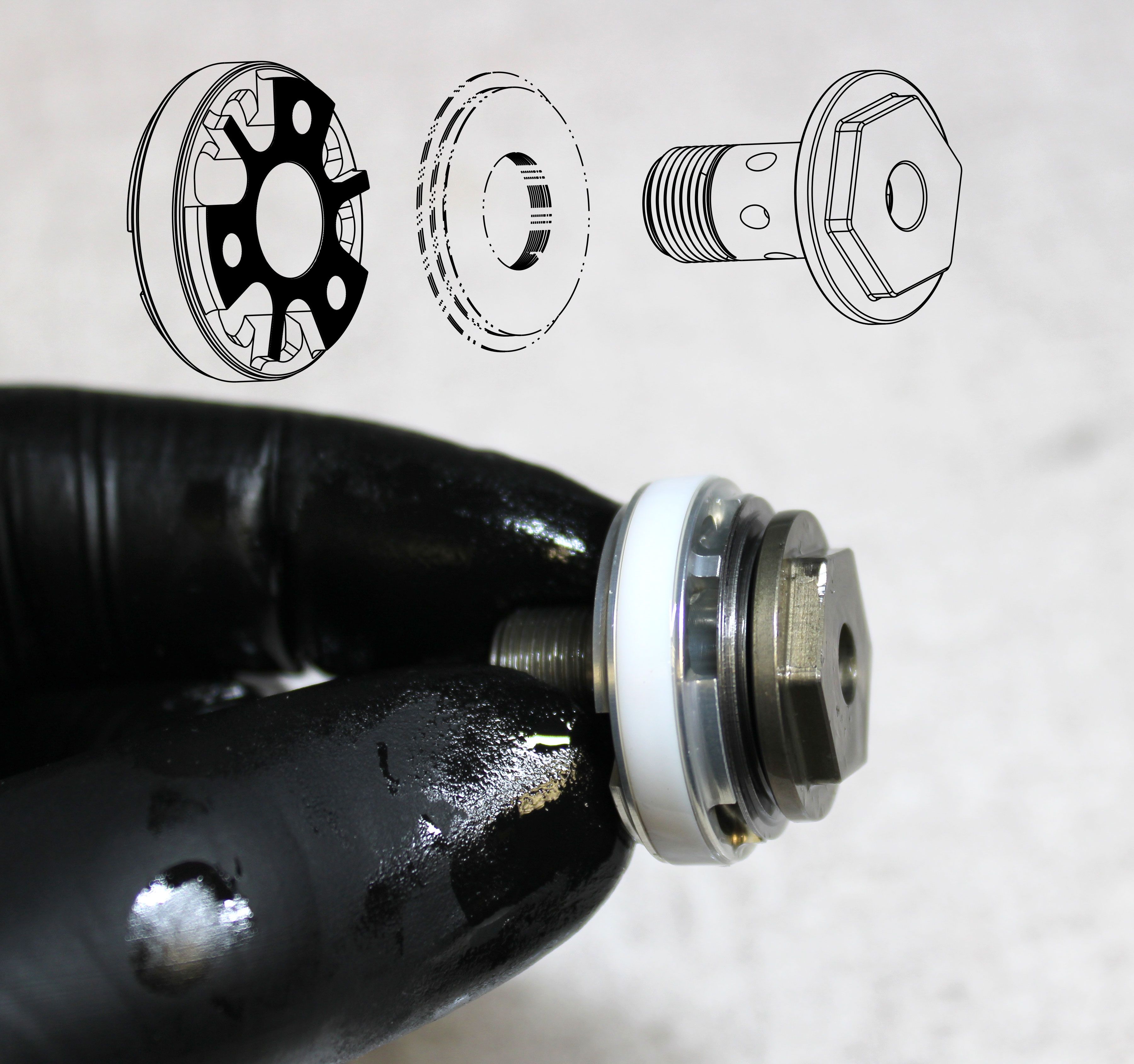
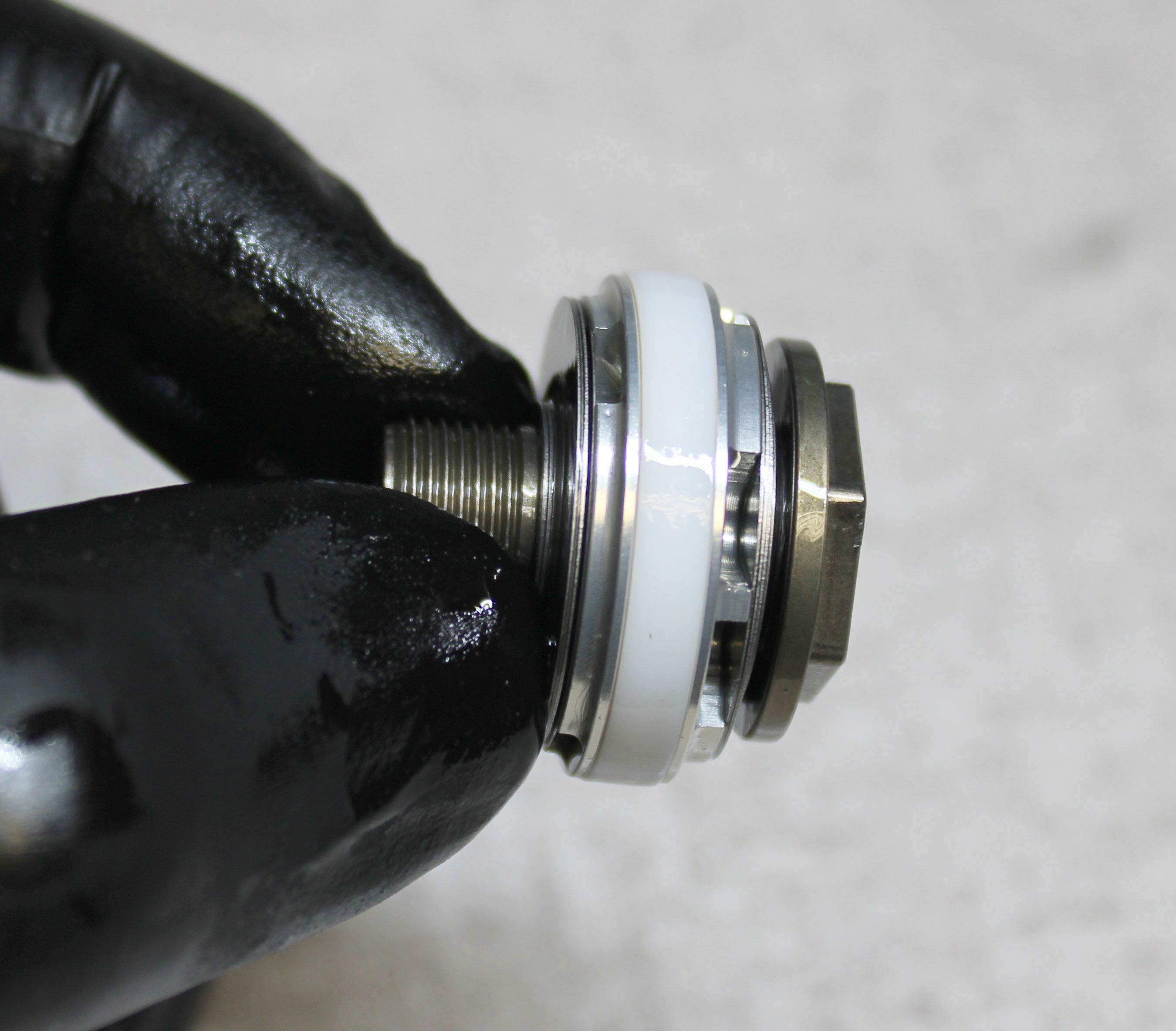
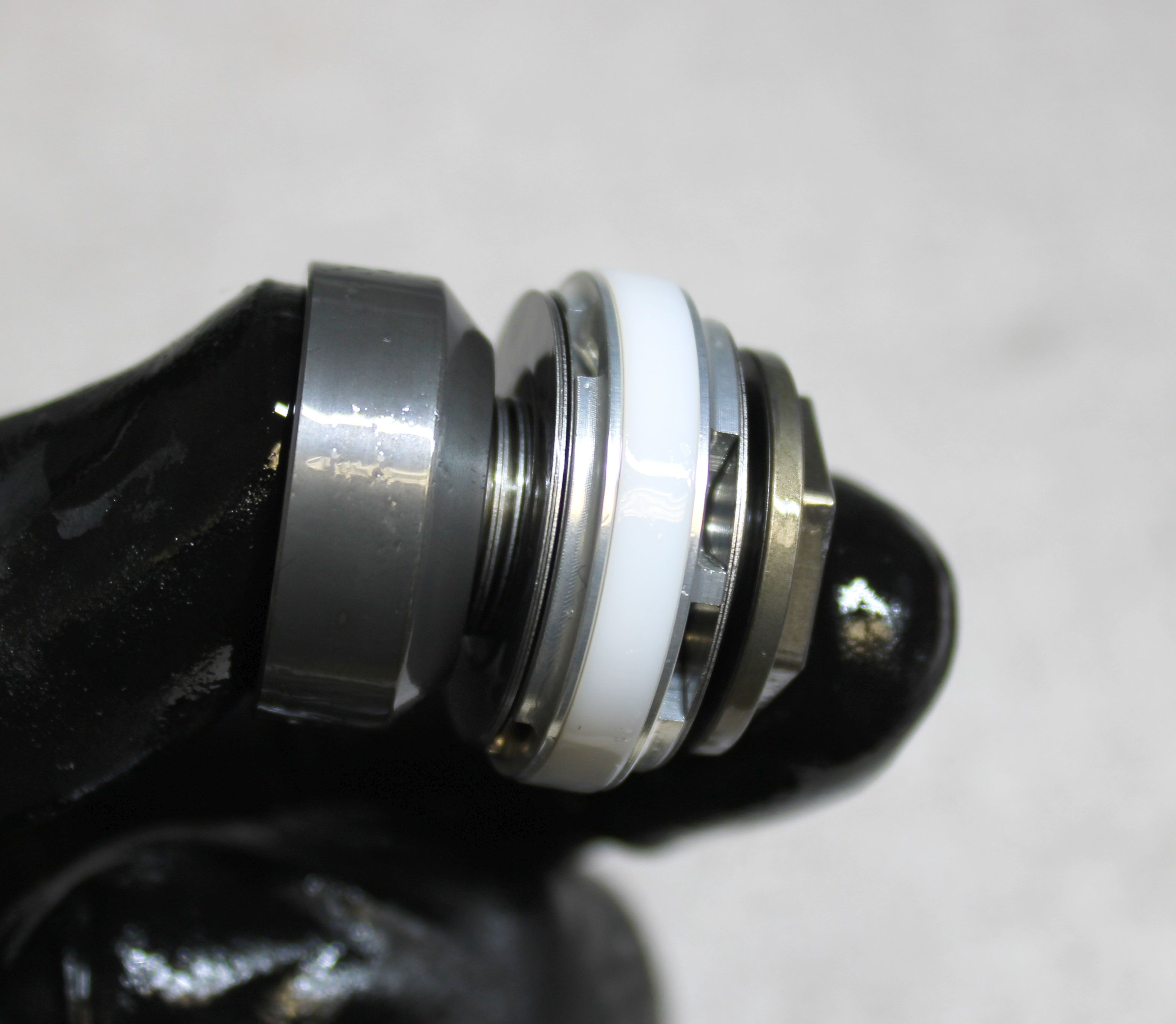
Replace the quad ring and backup rings on the bearing housing assembly. Note the original configuration (default or flipped) of the thick and thin backup rings and replace the new ones in their original configuration. Replace the o-rings within the bearing housing assembly with new greased ones from the kit. Reinstall the bearing housing assembly onto the shaft as shown. Install a new greased topout o-ring from the kit onto the shaft.
Step 10
Remove the topout plate from the valving assembly then remove the compression valving assembly, main piston, and rebound valving assembly. Inspect the shims and replace any with damage.
Step 11
Reinstall the rebound valving assembly onto the piston bolt followed by the main piston. Note the orientation of the main piston as shown. Reinstall the compression valving assembly followed by the topout plate. Make sure that no shims are off center or pinched.
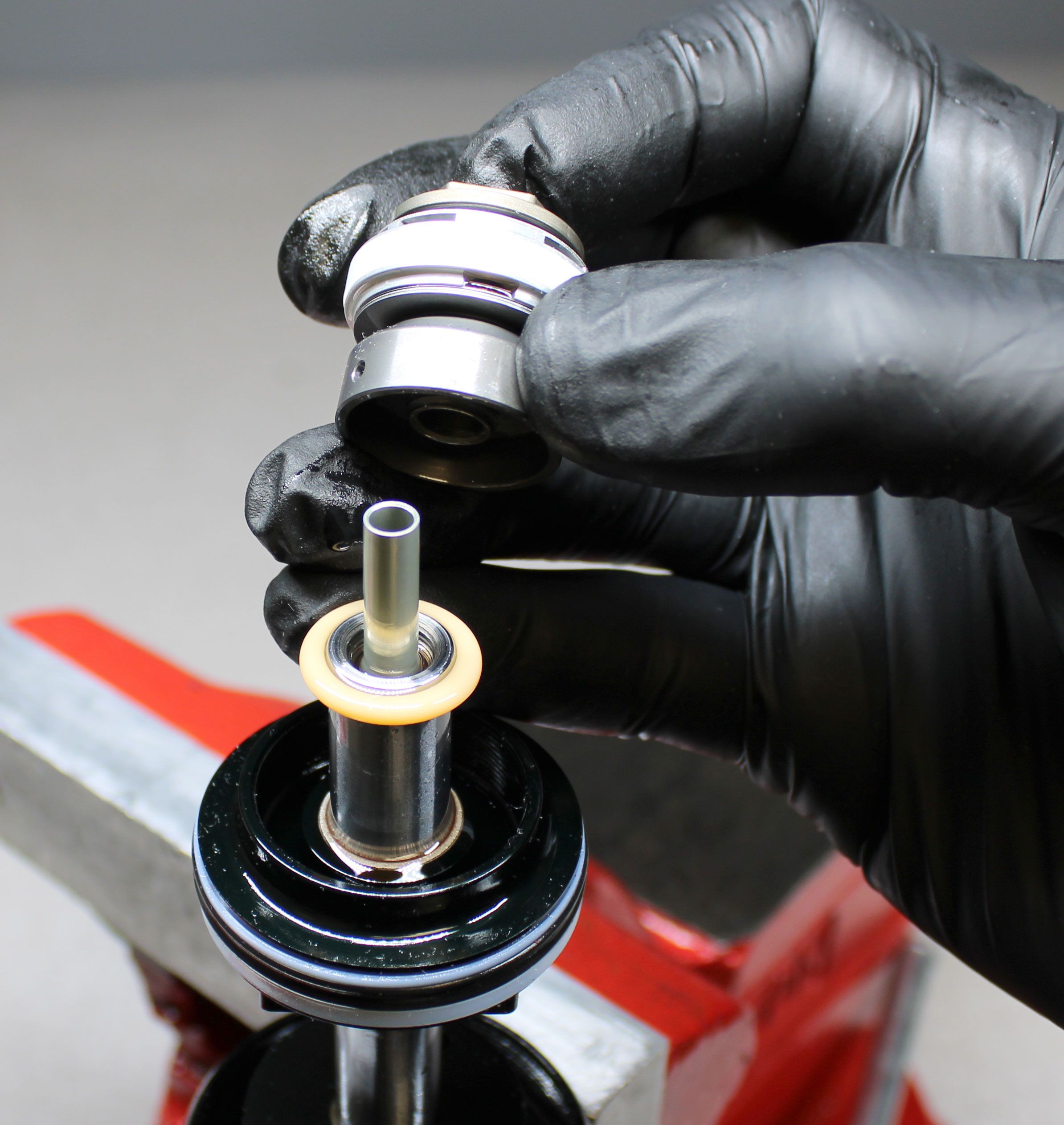
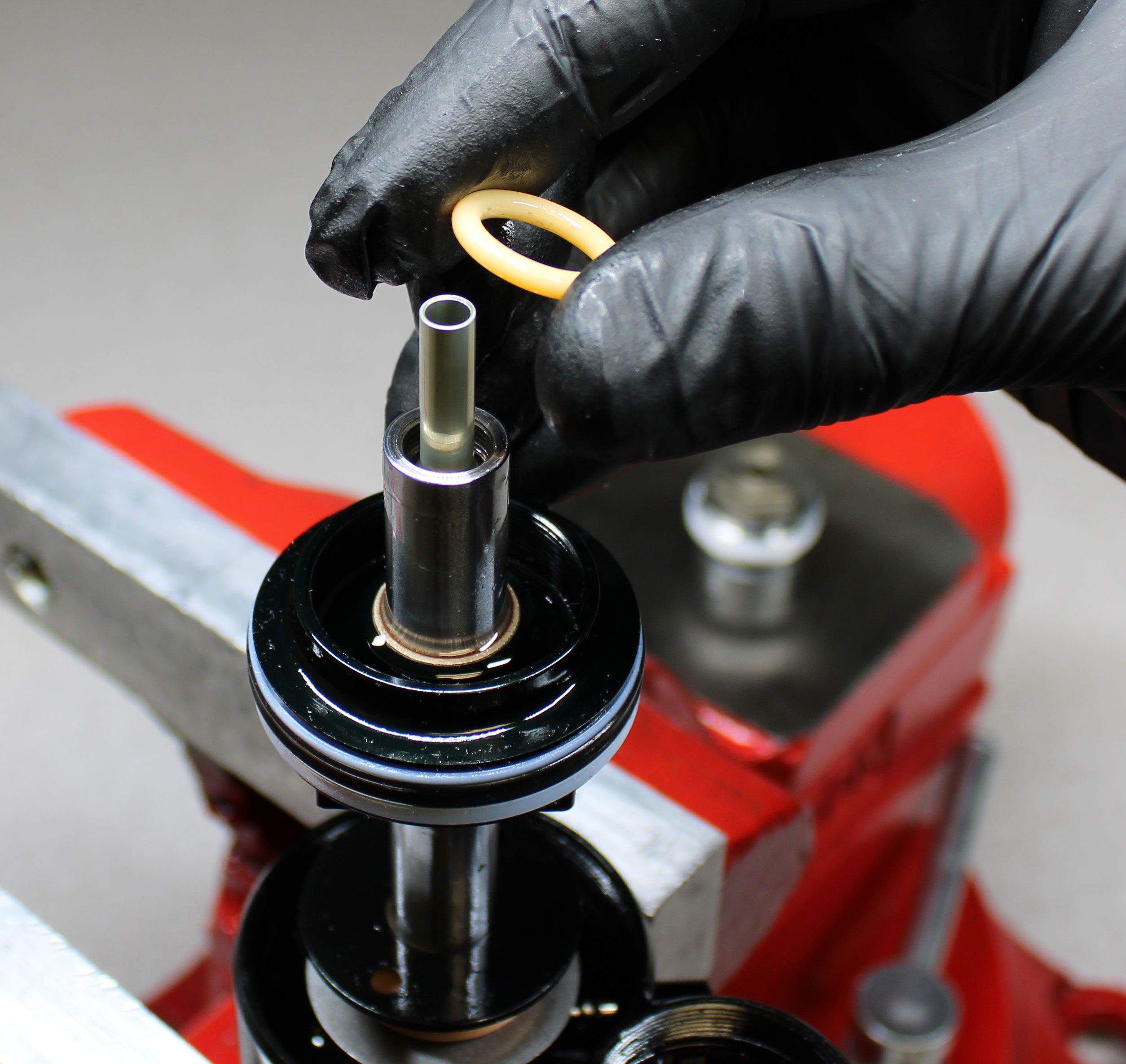
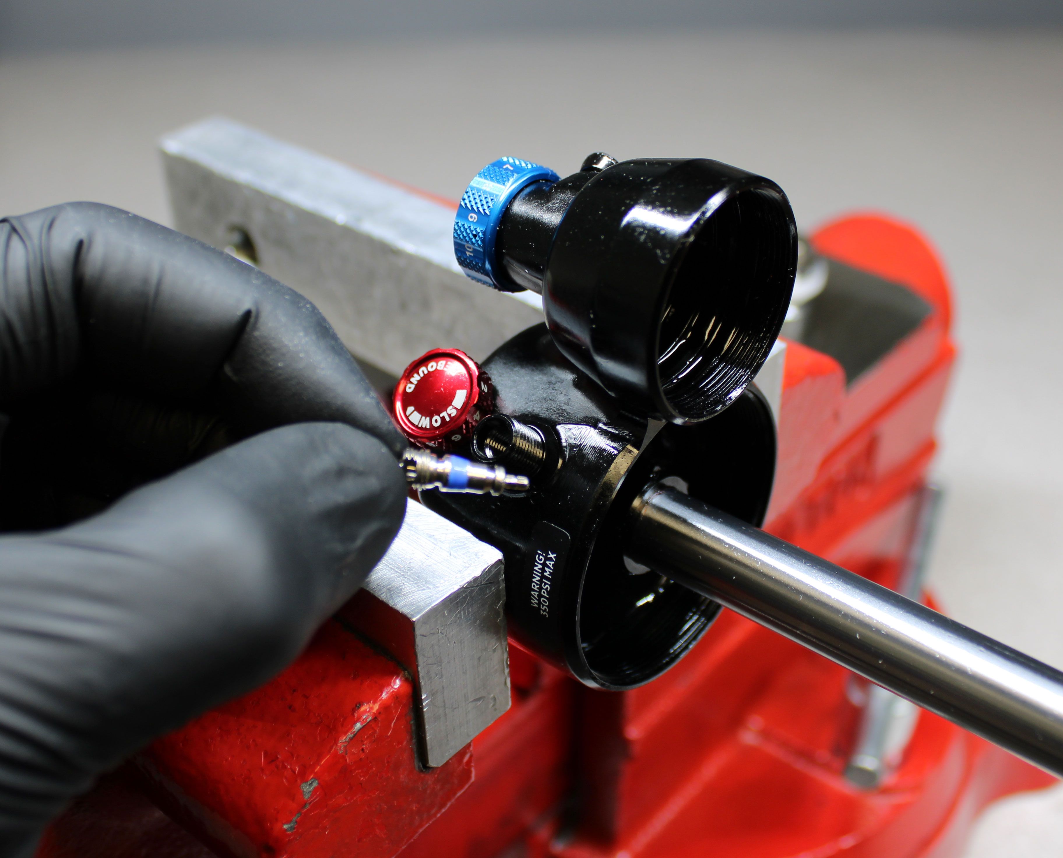
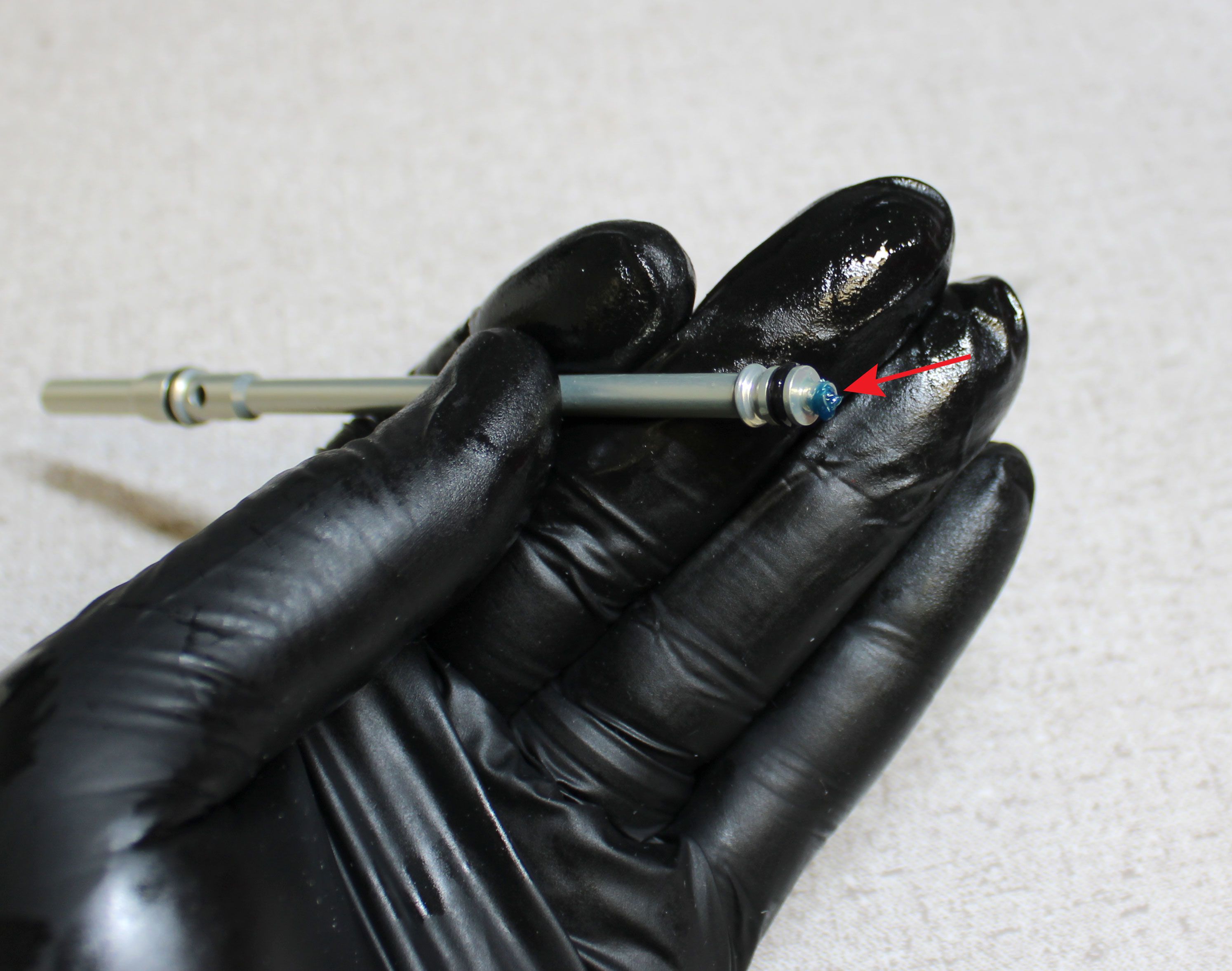
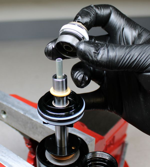
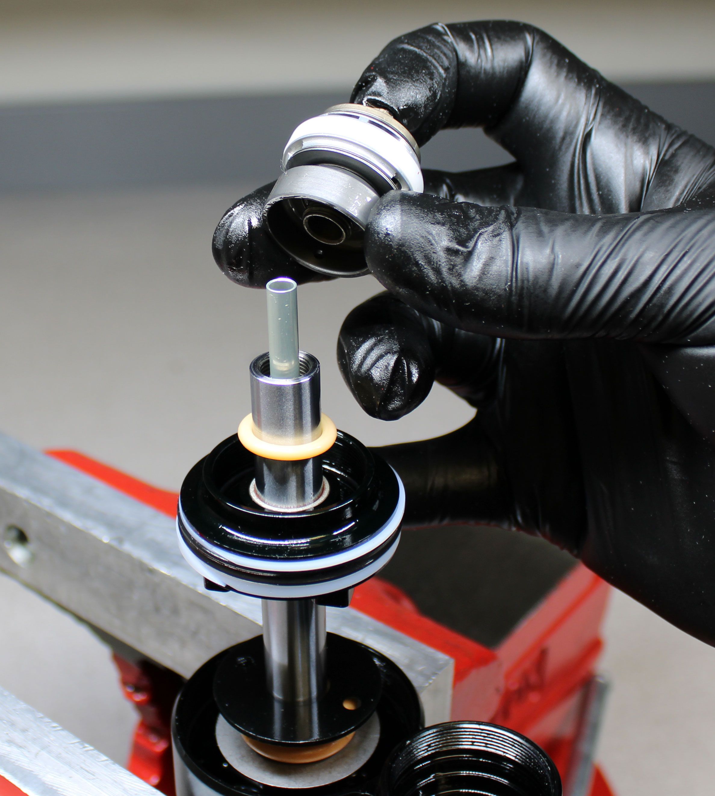
Step 12
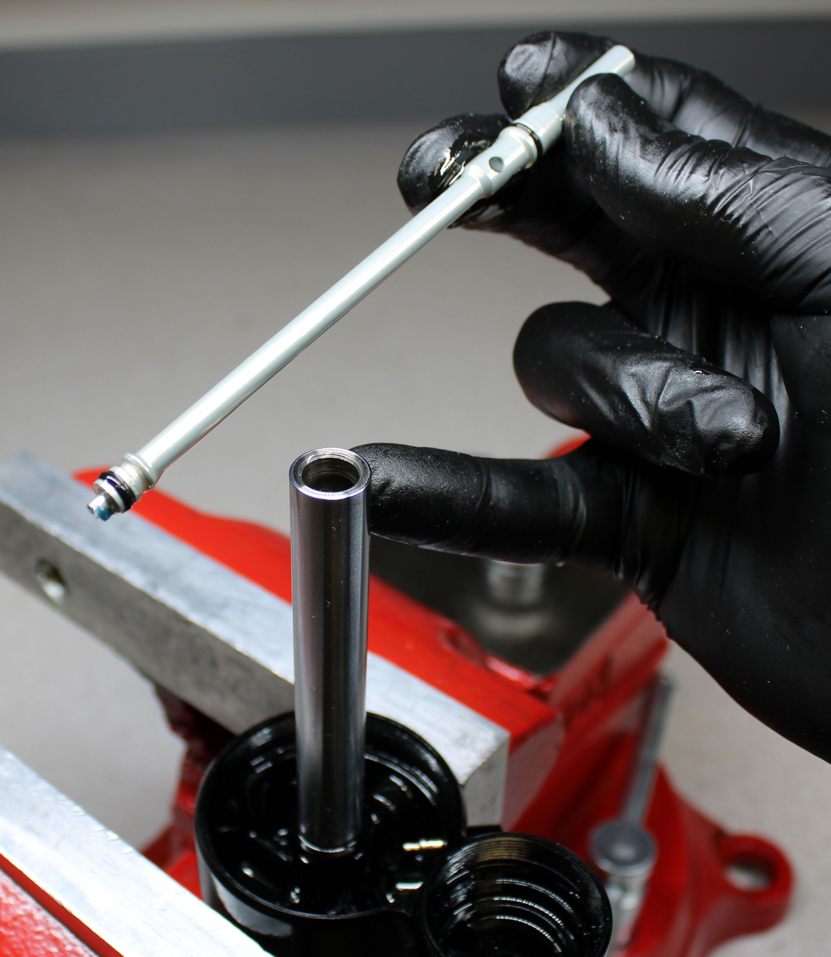
Replace the two o-rings on the rebound rod with new greased ones from the kit as shown. Make sure that the ball is present in the end of the rod. Coat the ball end of the rod with a thick film of Ultraplex LT2 or Stay Lube SL3125 blue waterproof grease.

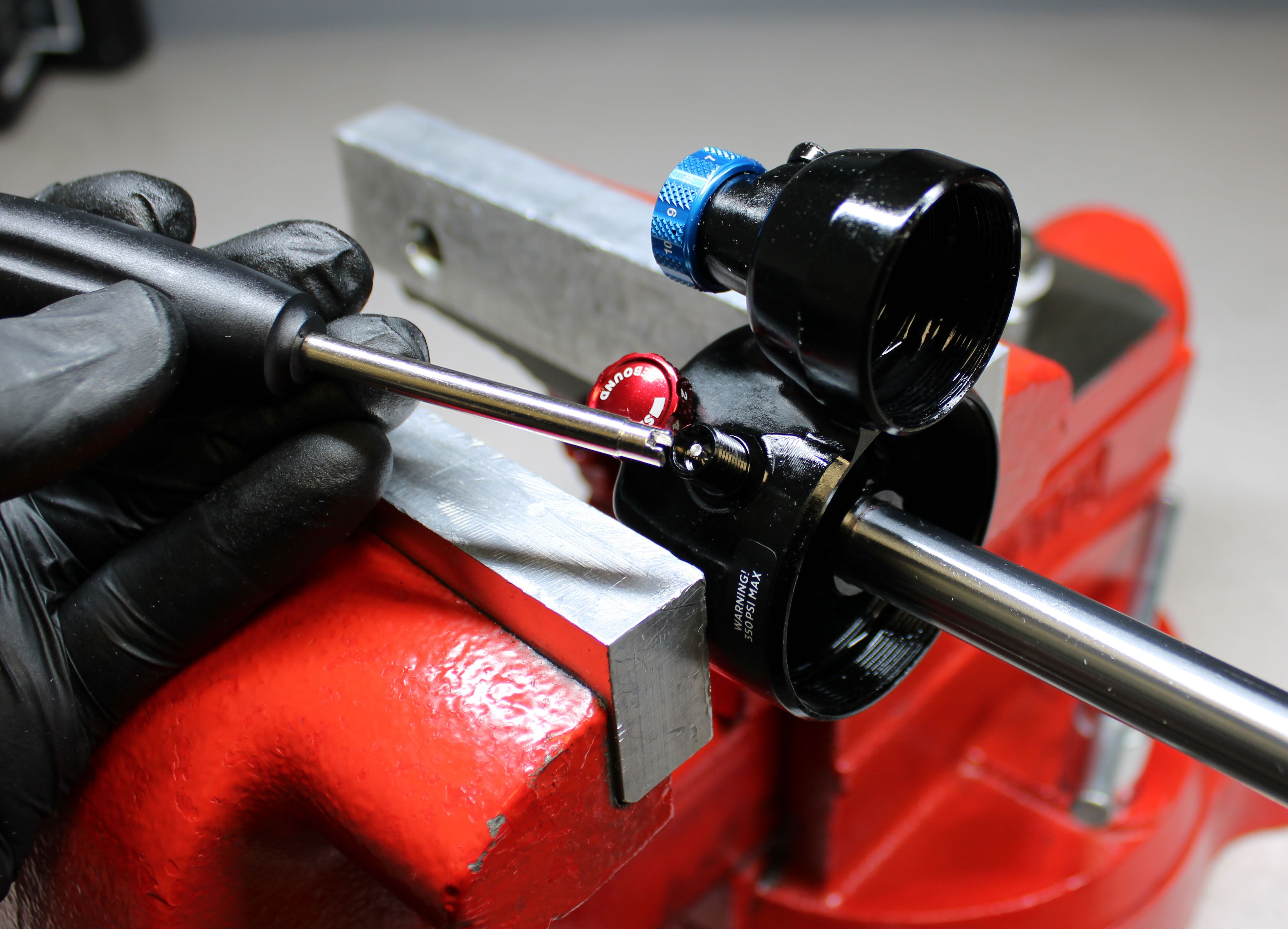
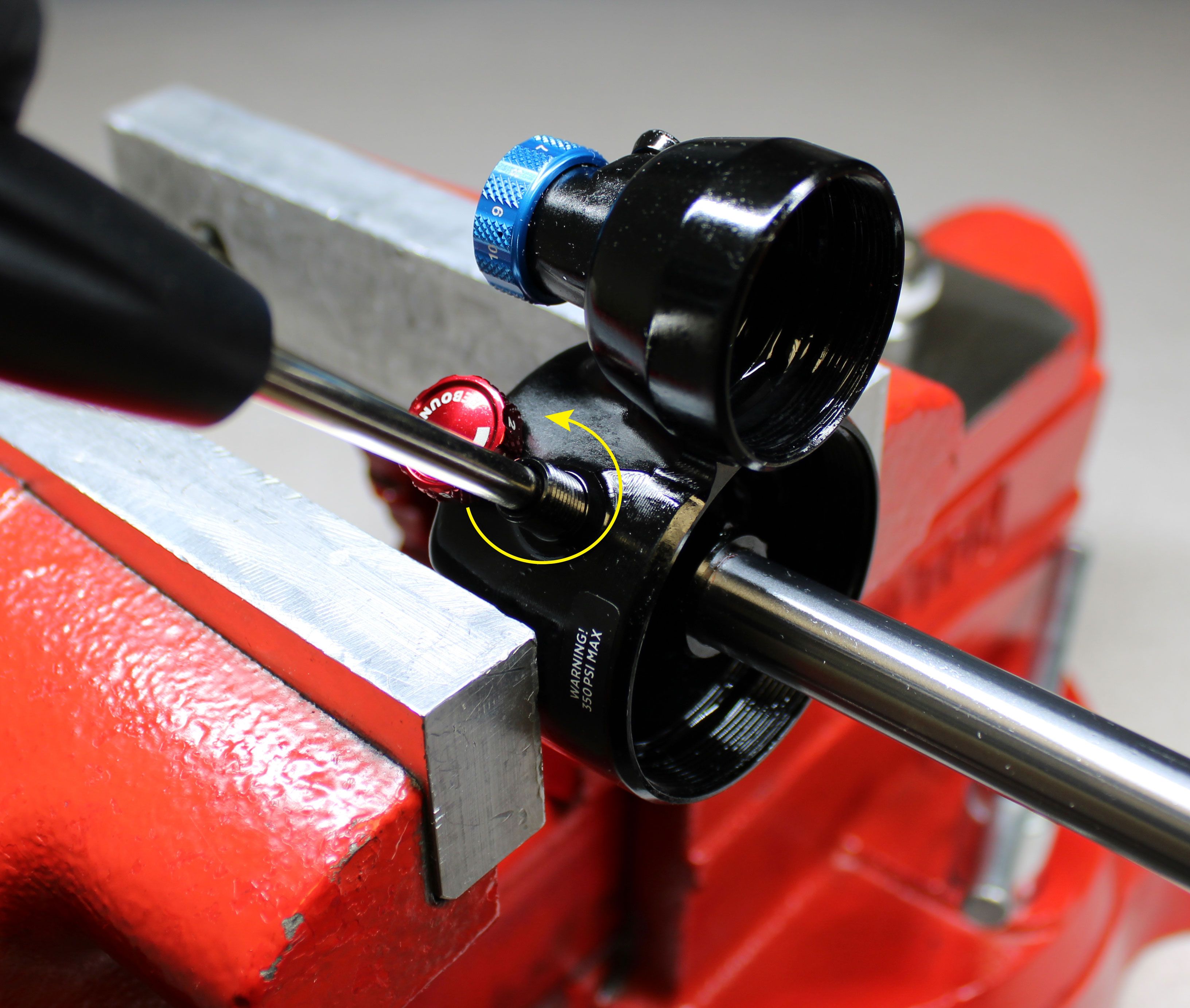
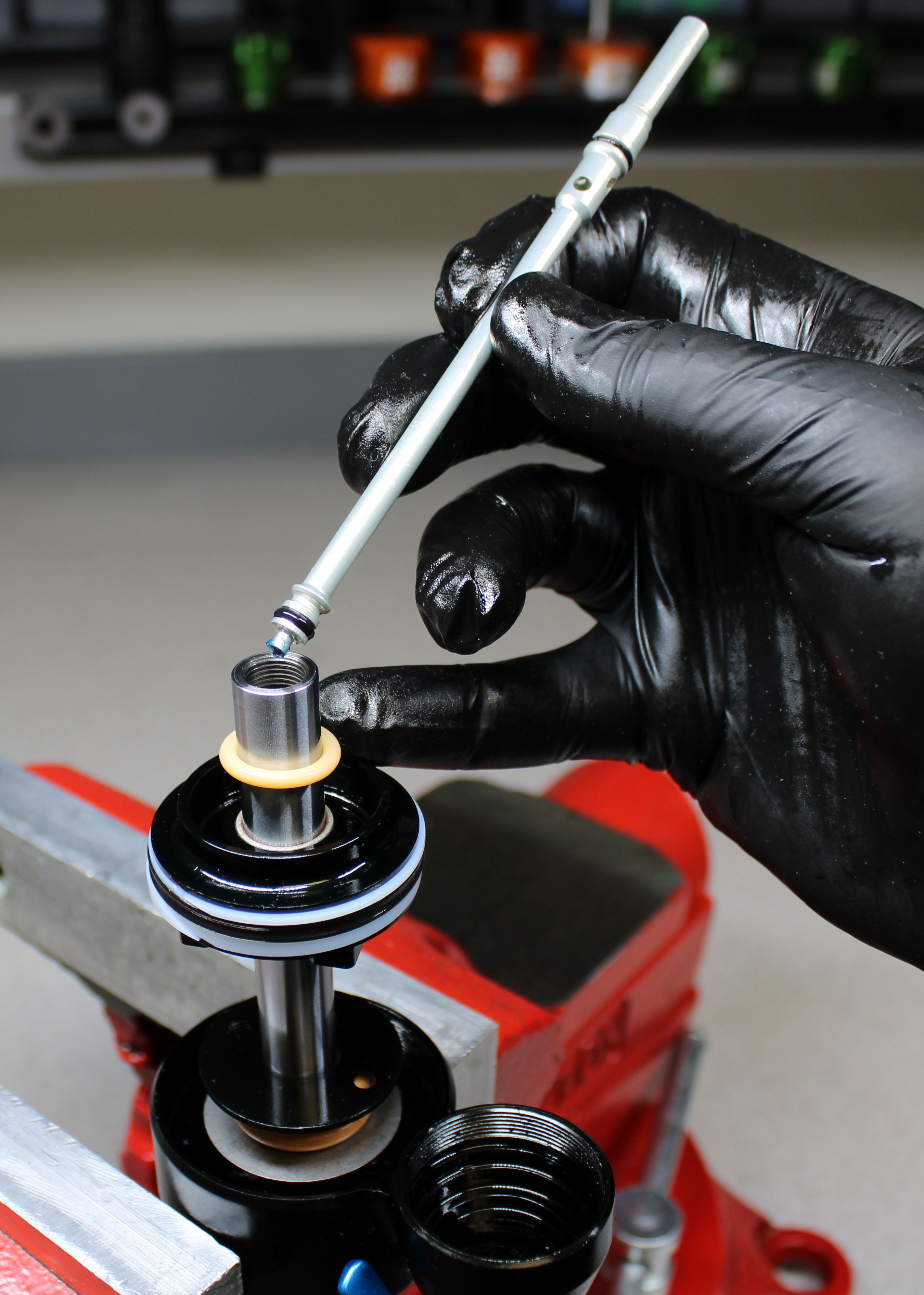
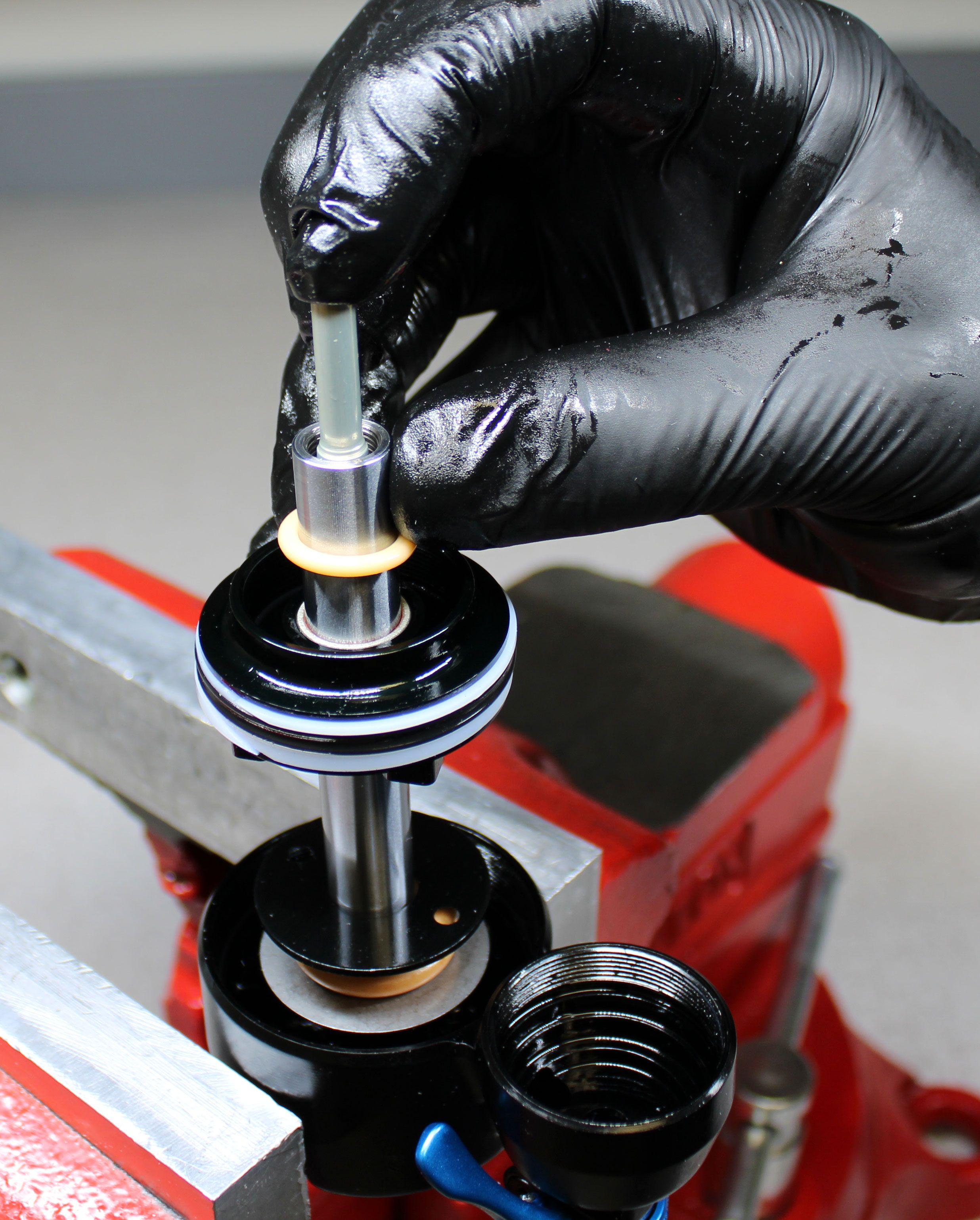
Step 13
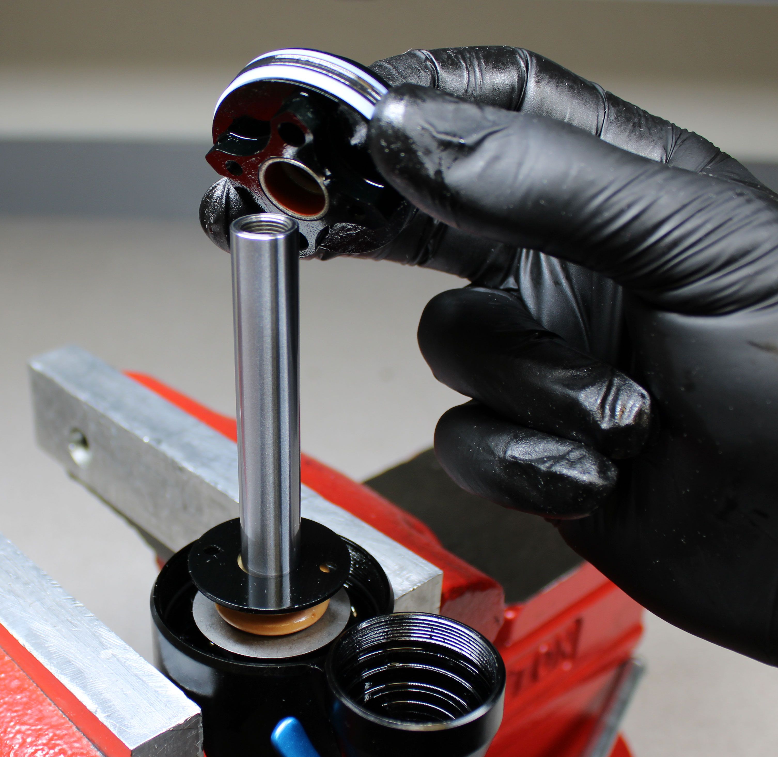
Reinstall the rebound rod into the shaft with the ball end first. Push down on the rebound rod while you turn the red rebound knob counter-clockwise until you feel the stop. This verified that the rebound rod is fully seated in the groove of the rebound knob and that the rod won't be pinched when tightening the piston bolt later.
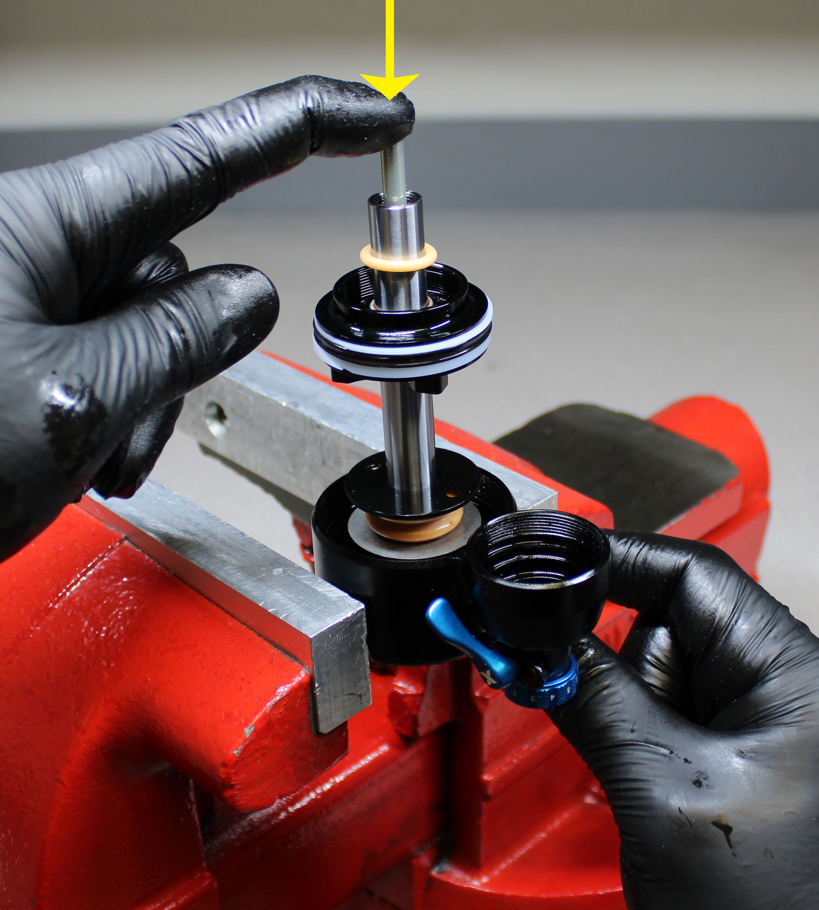
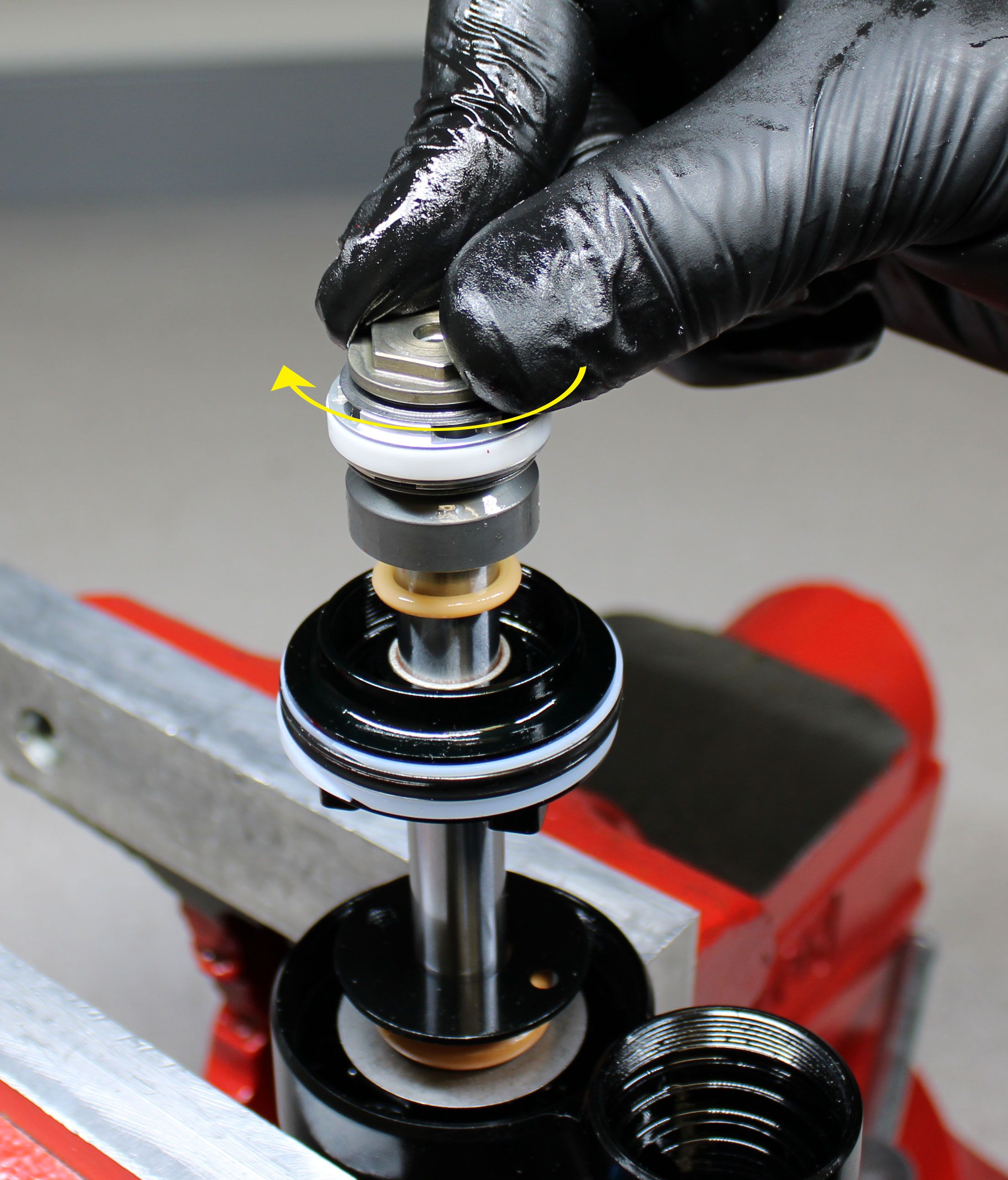
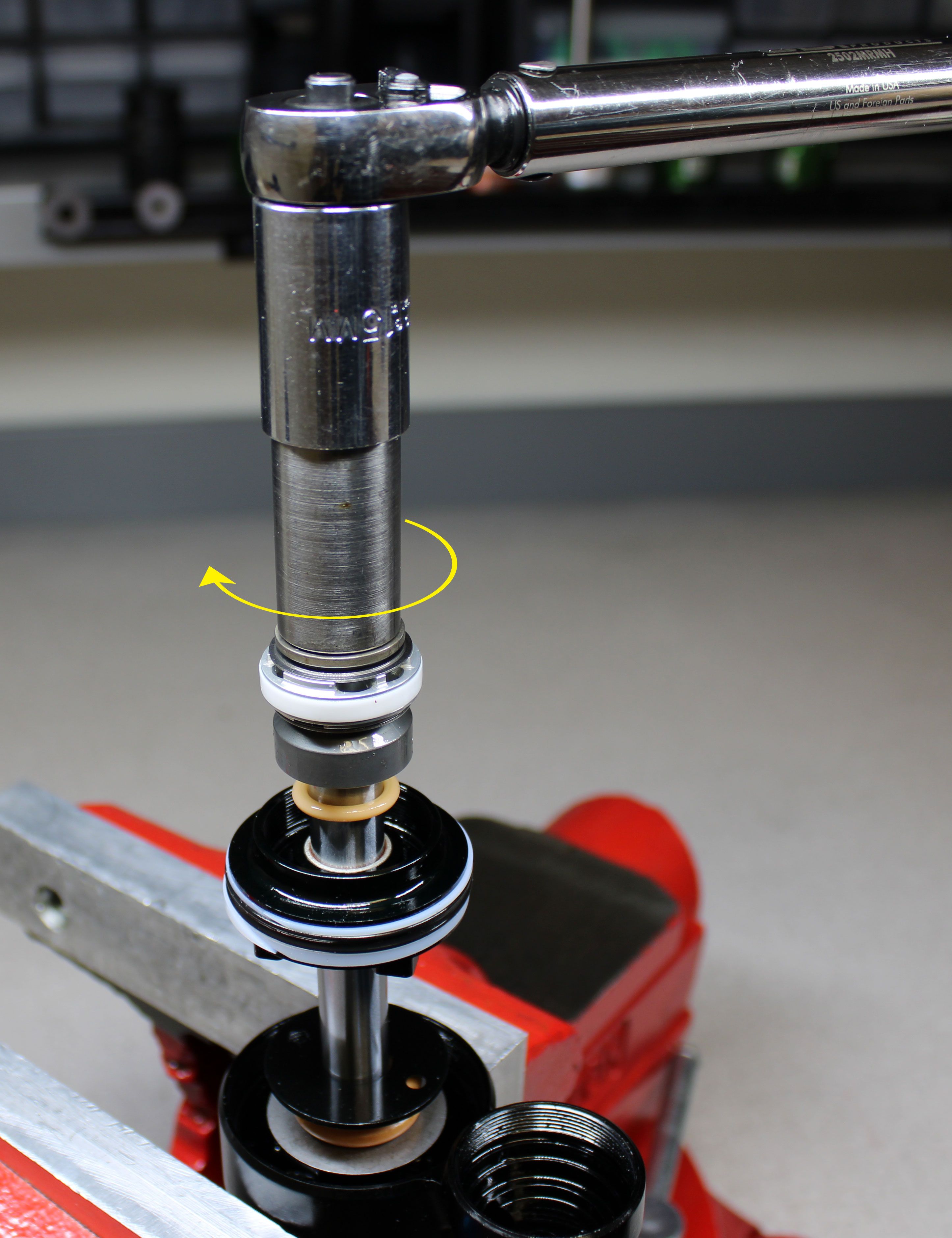
Step 14
Reinstall the main piston assembly onto the shaft taking care not to pinch any shims while threading the piston bolt clockwise. Tighten the piston bolt clockwise to 80 in-lb (9.0 Nm) torque with a 15mm chamfer-less socket.

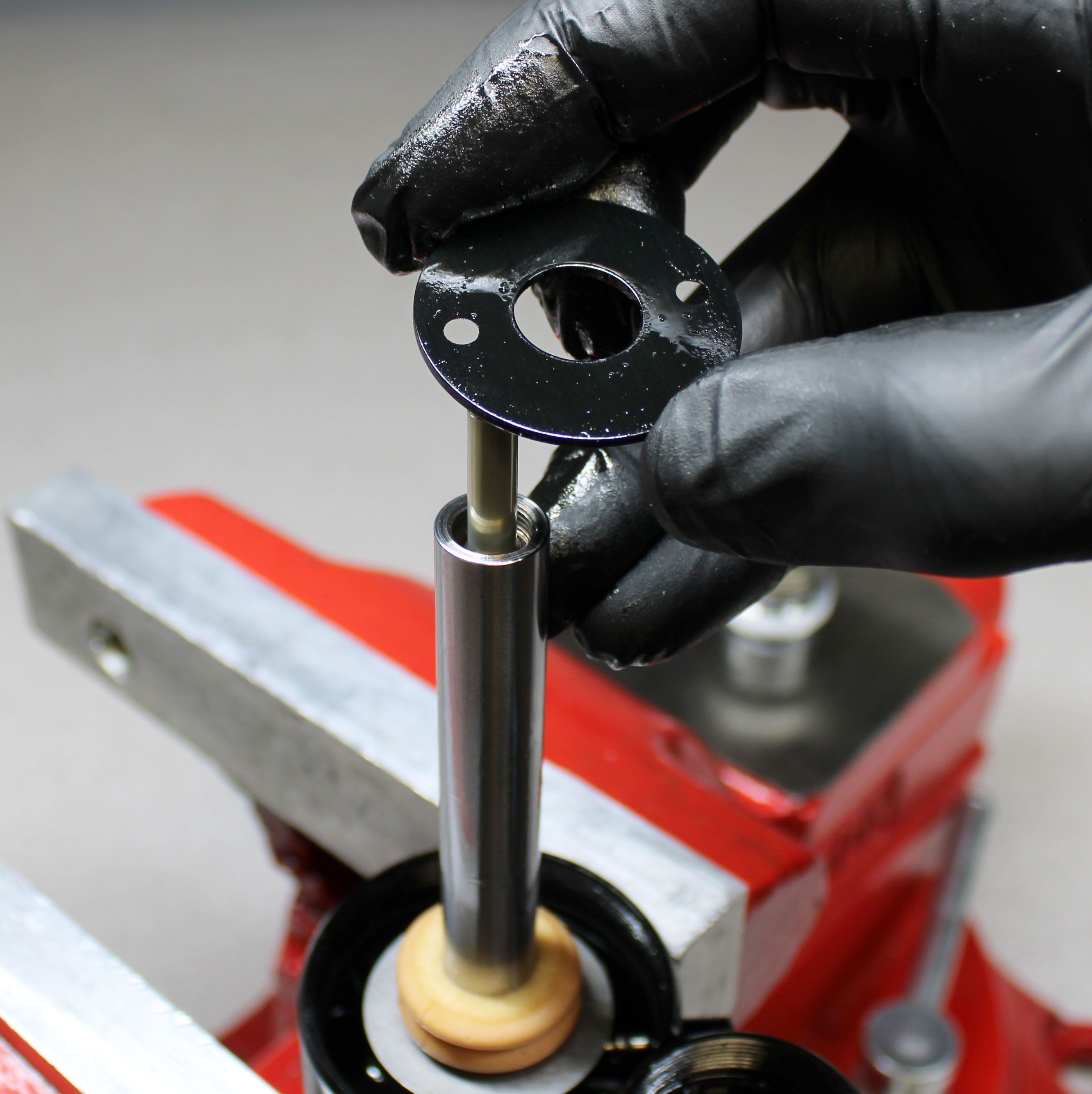
Step 15
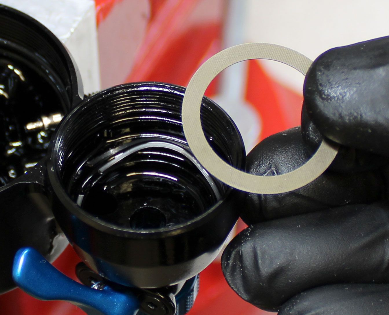
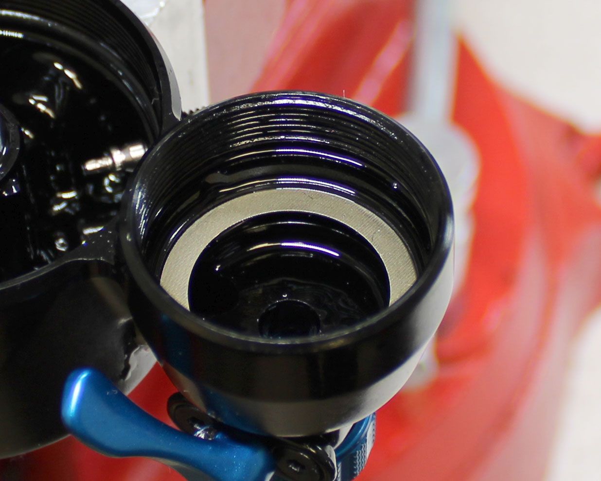
Reinstall the wave spring into the reservoir orienting the split in the spring toward the eyelet. Make sure that the ends of the wave spring are resting against the shoulder in the reservoir and not agains the check shim. Reinstall the check shim.
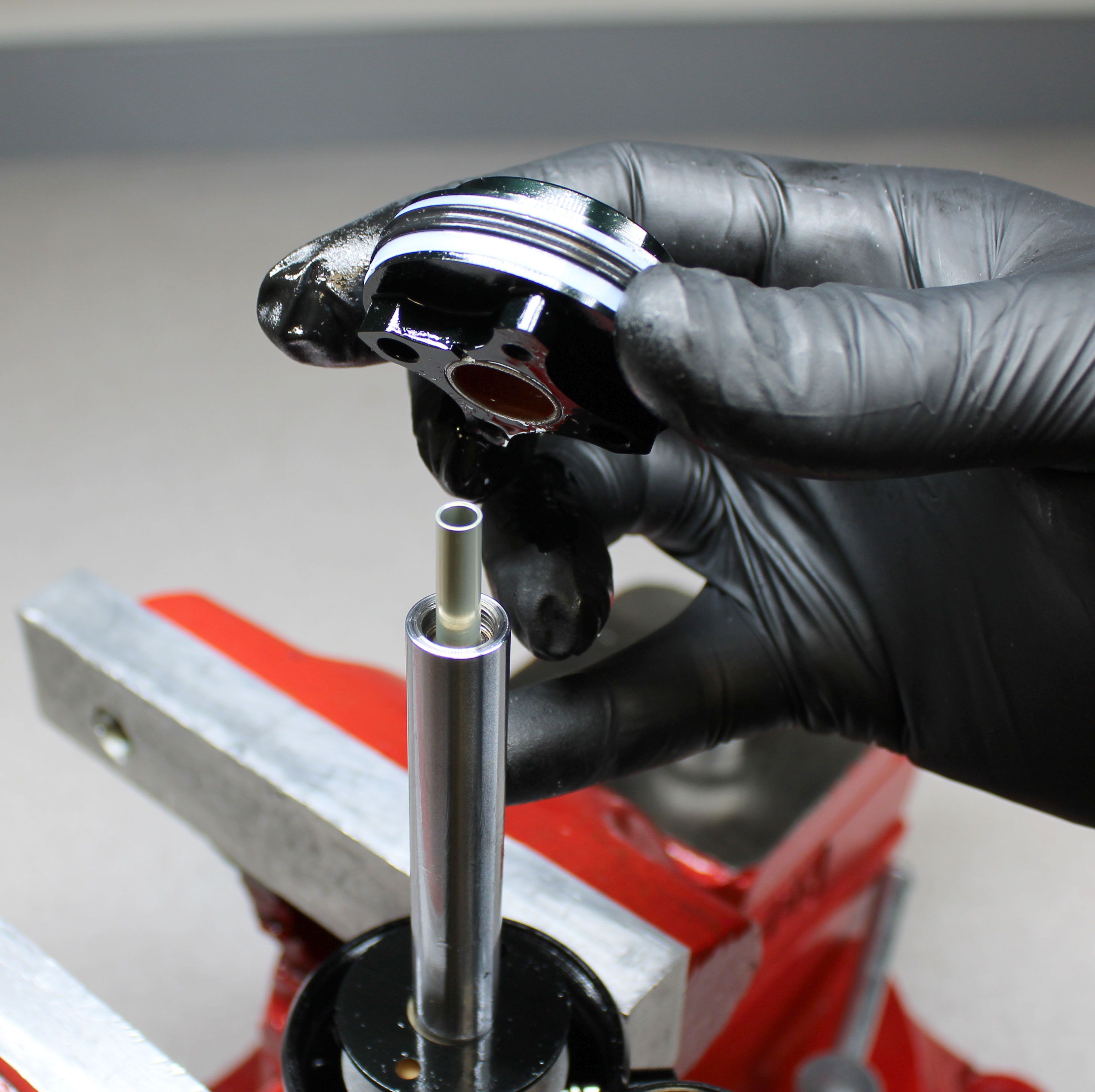
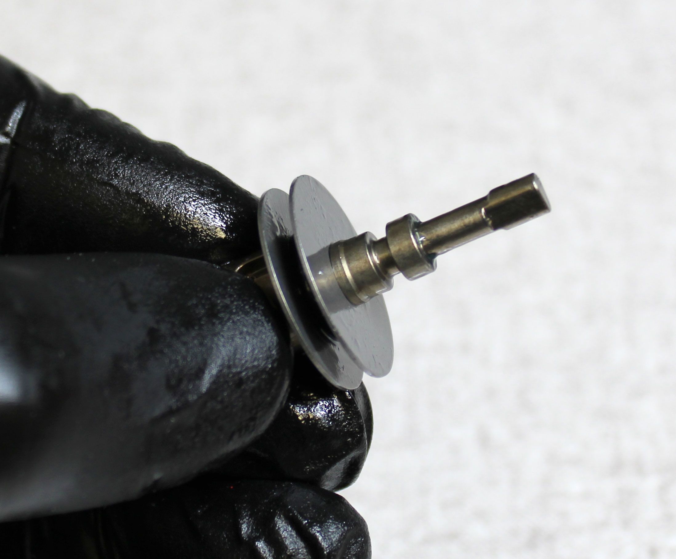
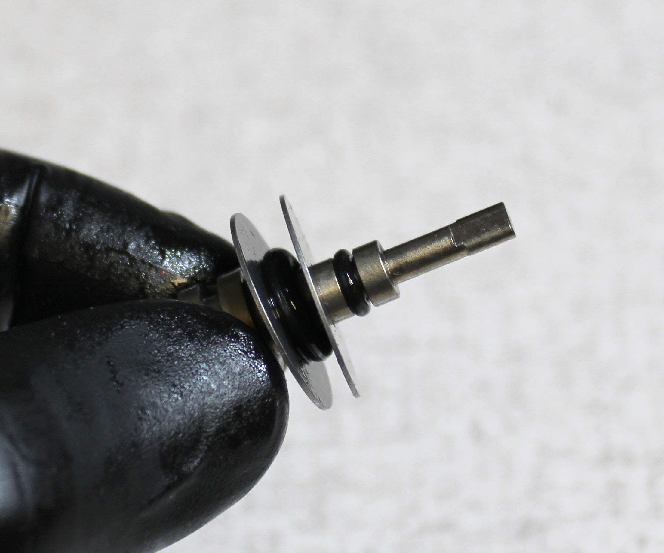
Step 16
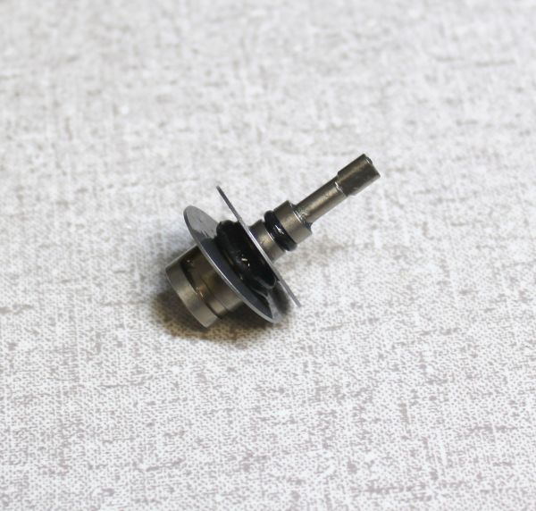
Remove the two o-rings on the adjuster shaft and replace them with new greased ones from the kit as shown.

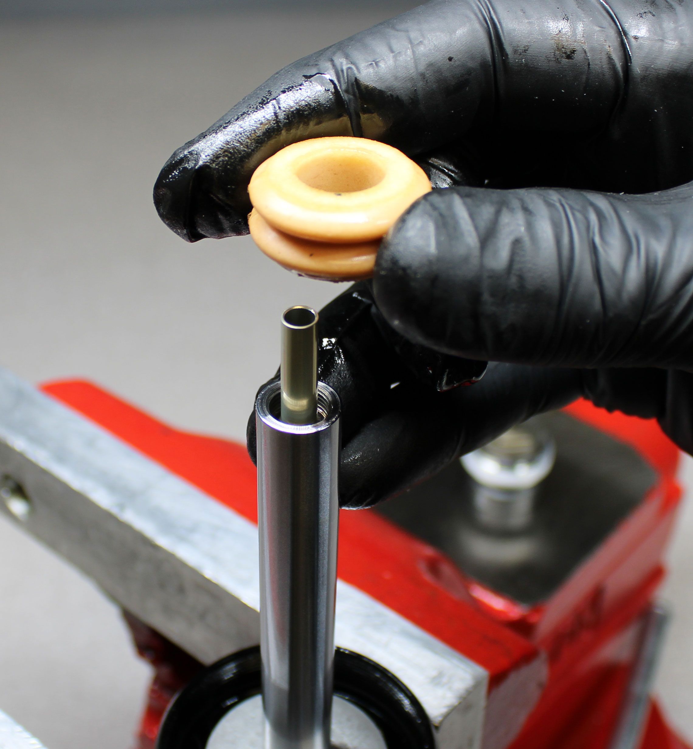
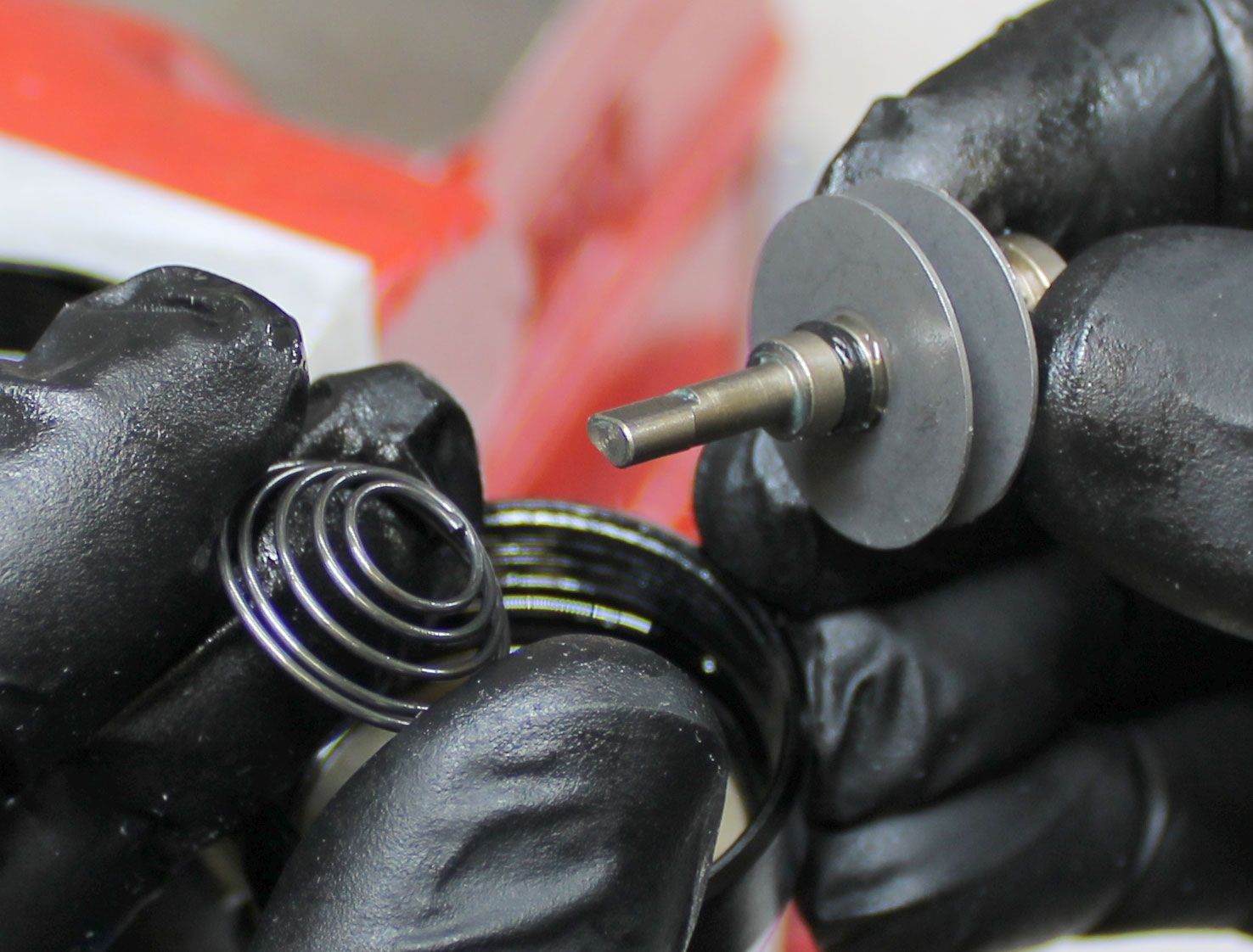
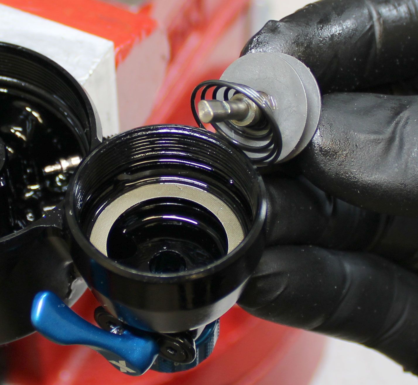
Step 17
Reinstall the lockout plate spring onto the adjuster shaft then reinstall the adjuster shaft with new o-rings into the reservoir making sure to engage the feature on the end of the adjuster shaft with the matching feature on the inside of the LSC knob or P-S cap. Reinstall the adjuster shaft spring.

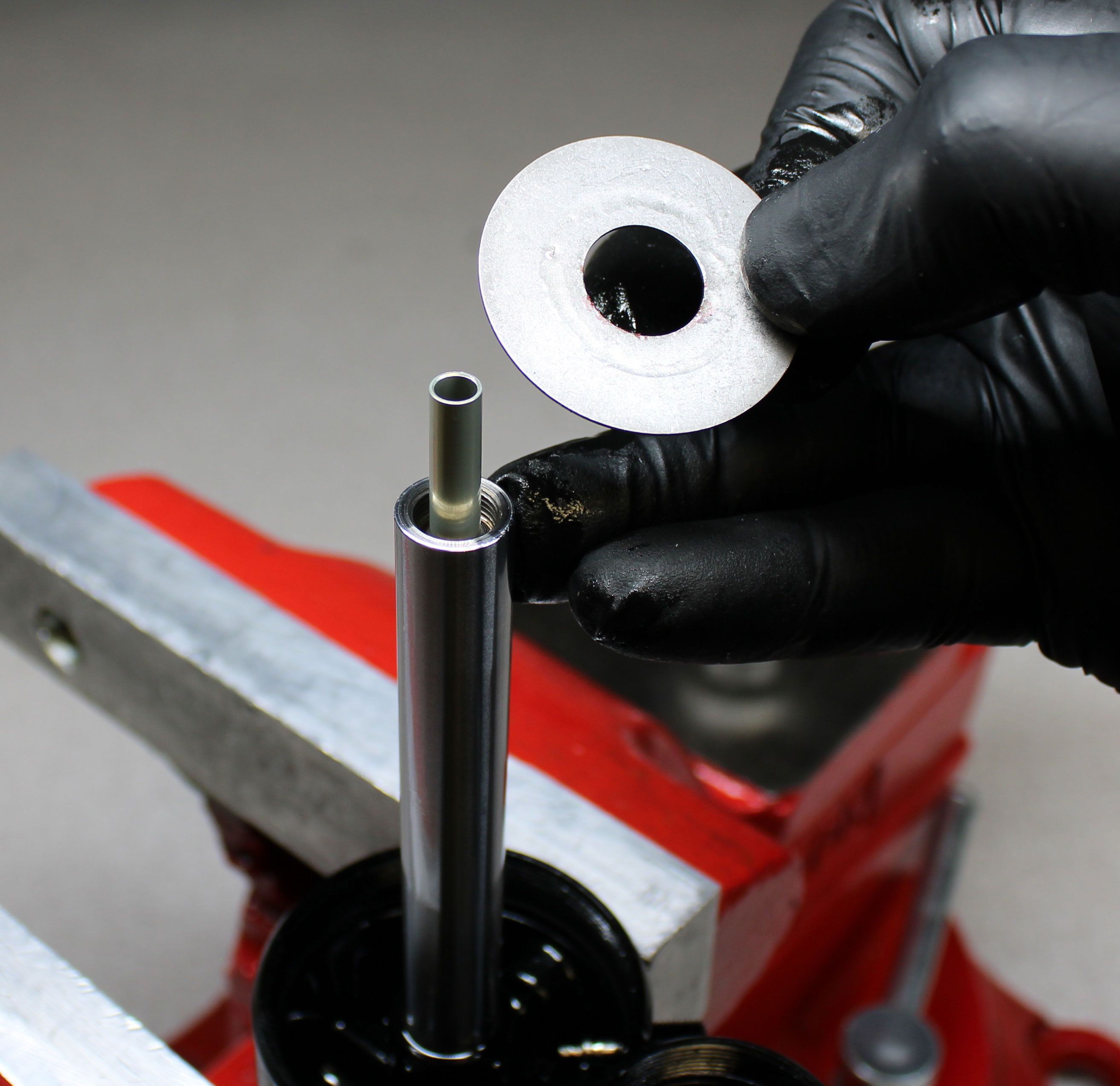
Step 18
Reinstall the rebuilt base valve piston. Orient the tabs on the outside edge of the base valve piston to the notches in the inside wall of the reservoir. The base valve piston will not install correctly if the tabs are not aligned with the notches. Install a new greased reservoir o-ring from the kit into the reservoir while holding the base valve piston down against the springs.
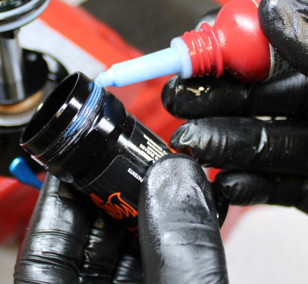
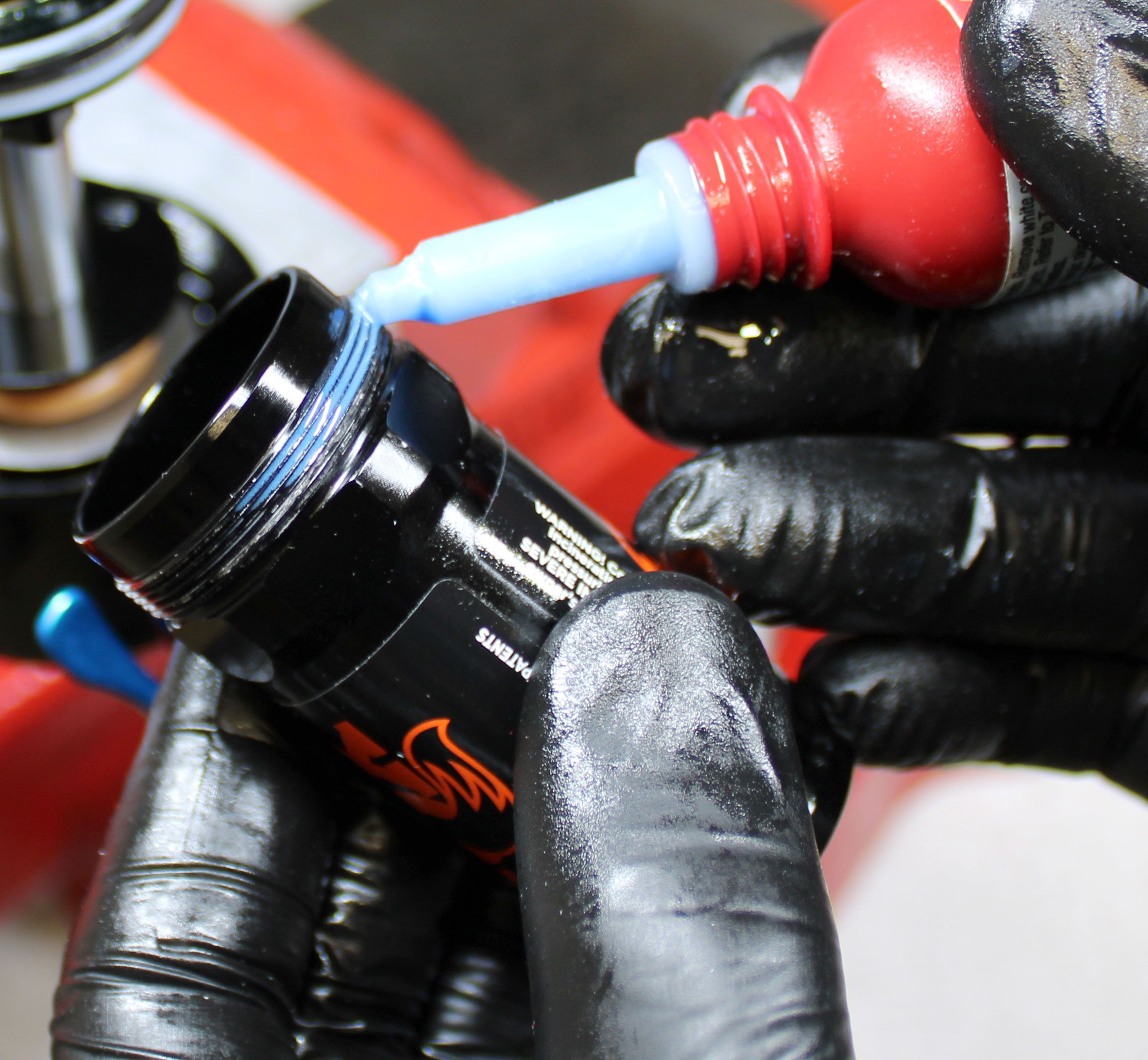
Step 19
Apply blue Loctite 243 to 2 threads covering approximately 90 degrees of rotation. Hold the base valve piston down against the springs while you reinstall the reservoir, tightening clockwise to 240 in-lb (27.1 Nm) torque with your 30mm crowsfoot.
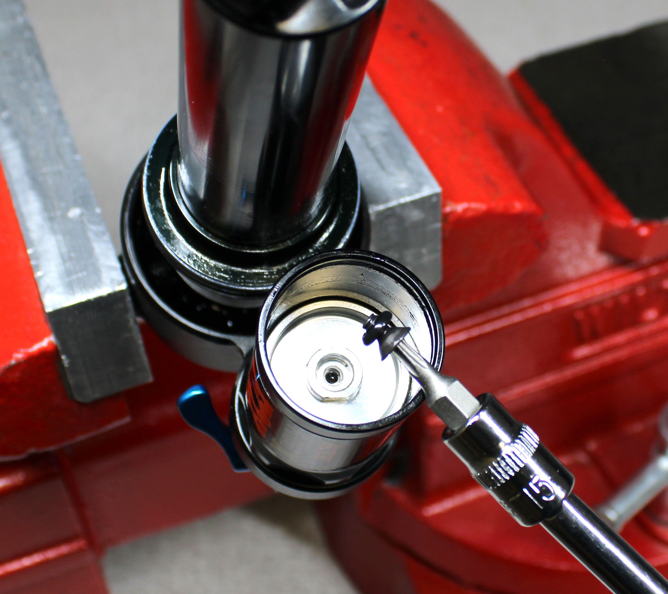
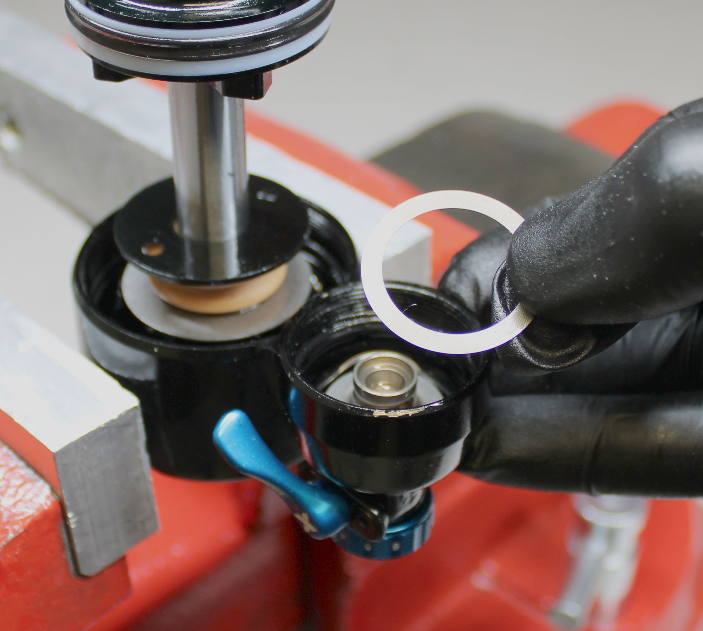
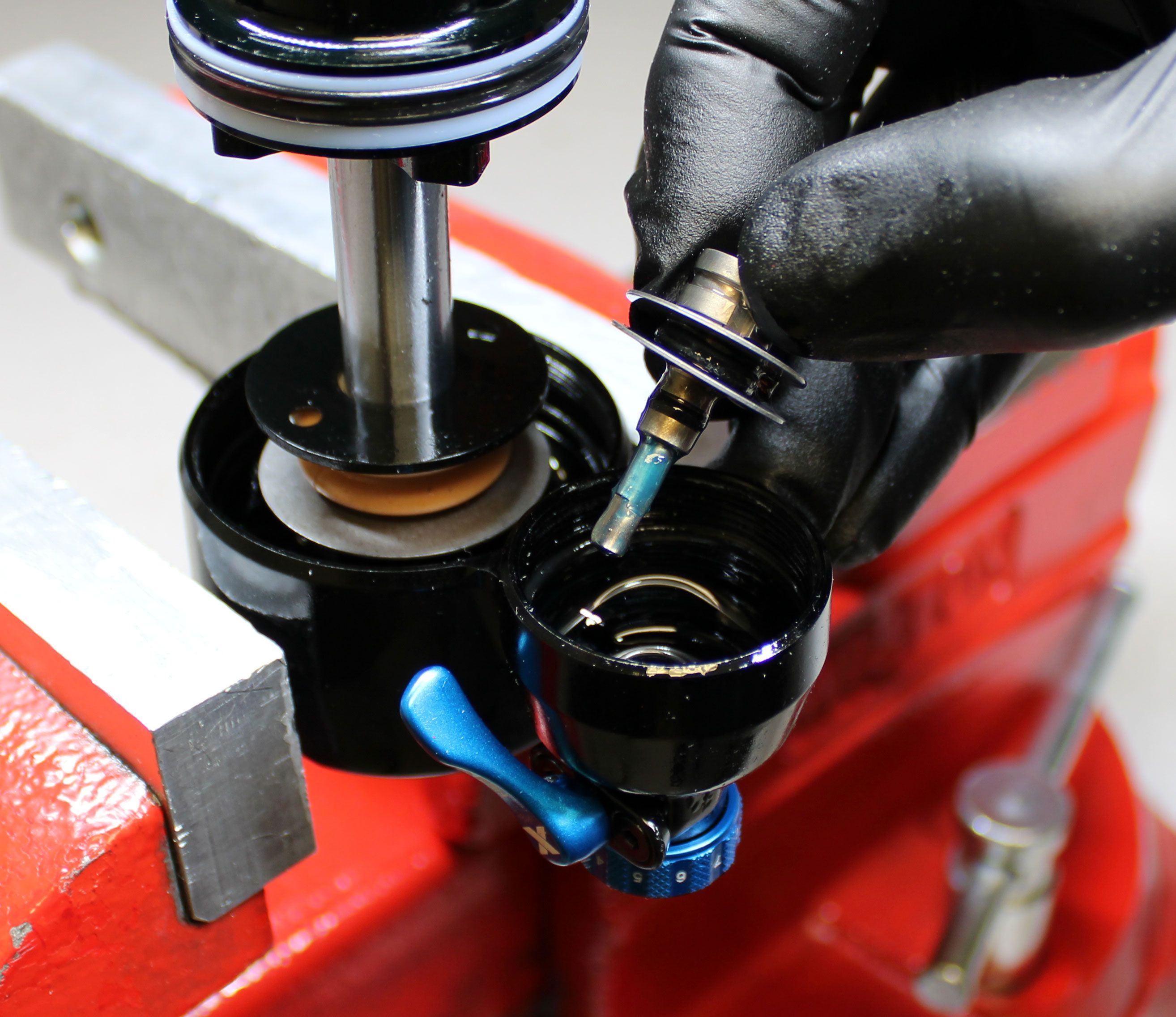
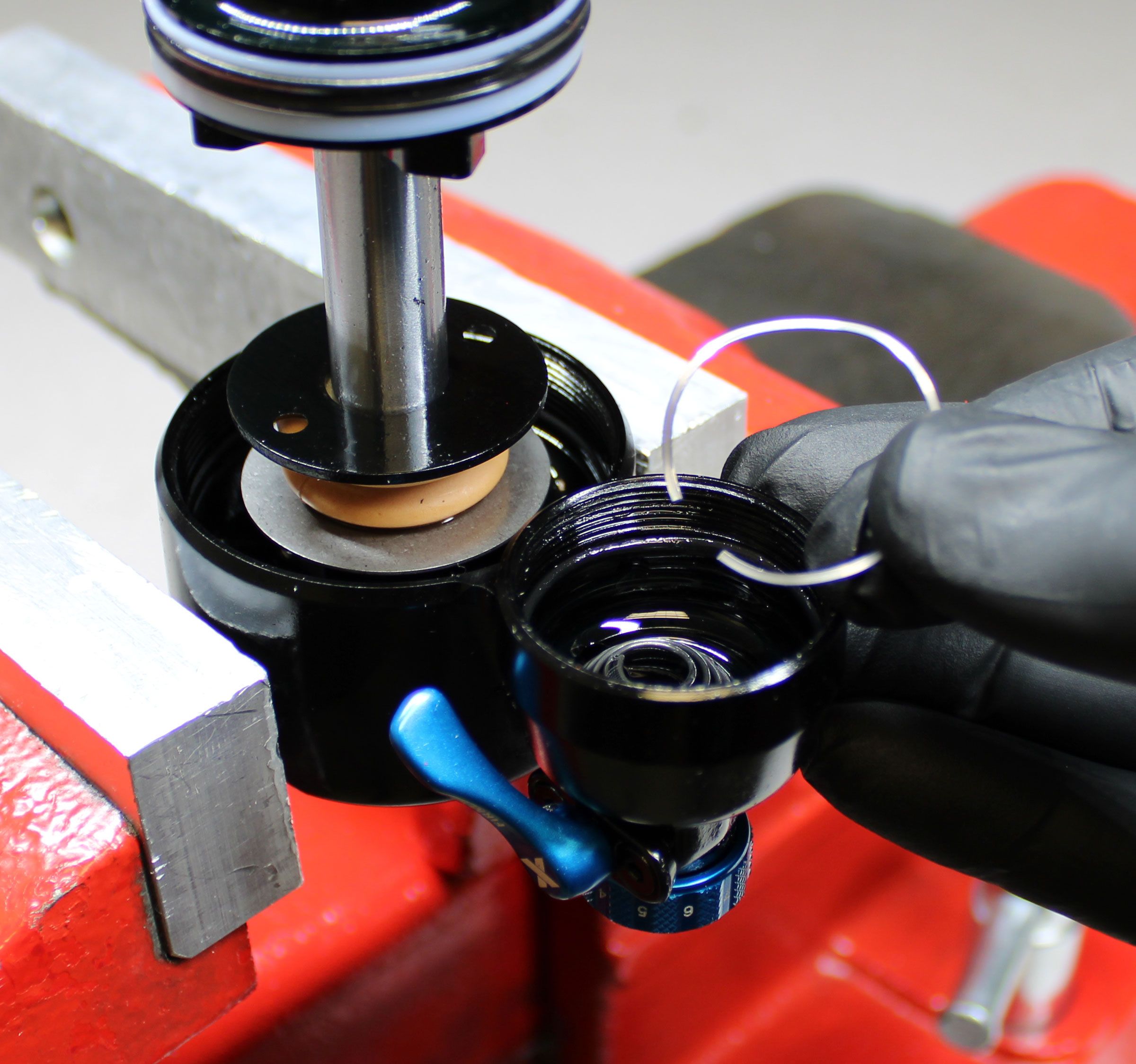
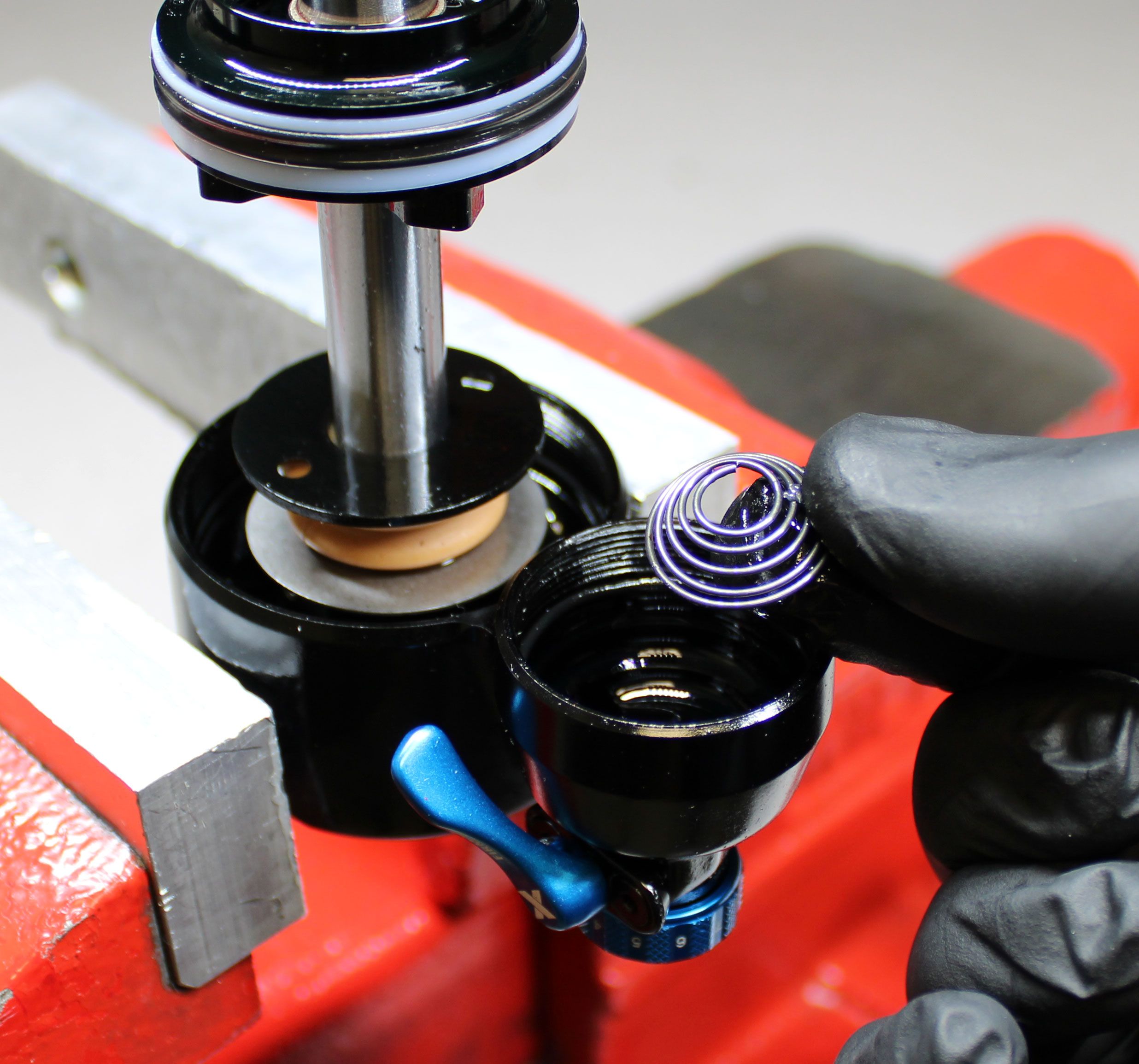
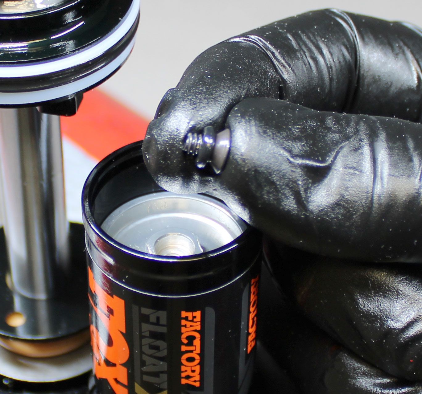
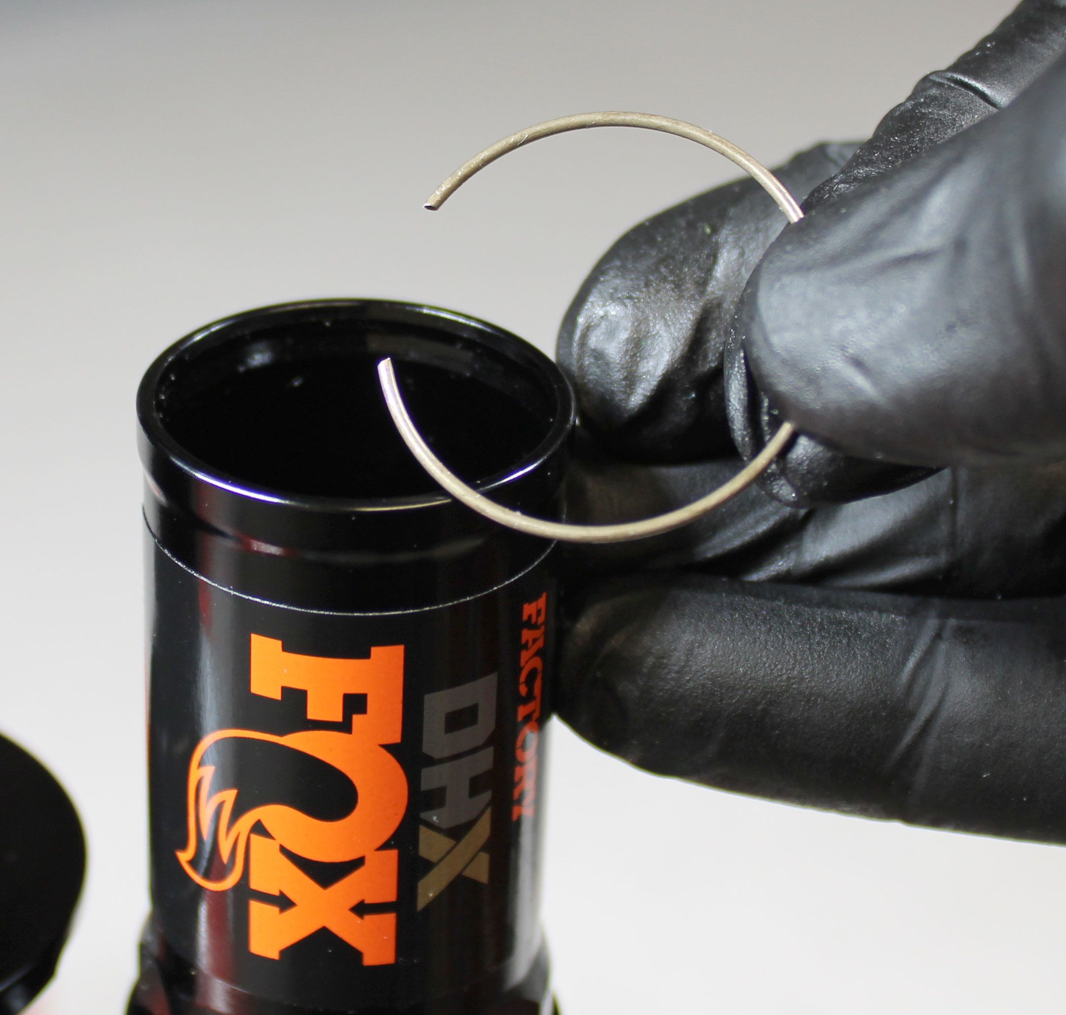
Step 20
Replace the o-ring on the IFP with a new greased one from the kit. Coat the inside wall of the reservoir with a thin film of FOX 4 wt. oil. Reinstall the IFP into the reservoir. Reinstall the bleed screw with new greased o-ring from the kit into the IFP, tightening clockwise to 7in-lb (0.8 Nm) torque while holding the flats of the IFP. Reinstall the wire retaining ring into the groove in the reservoir as shown.
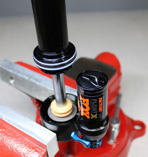
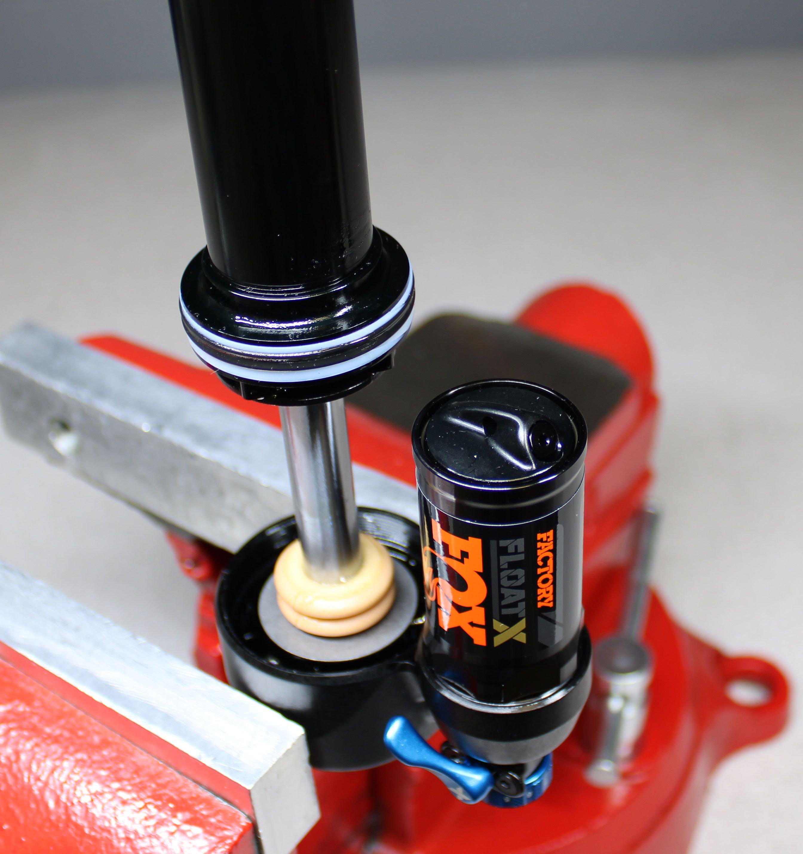
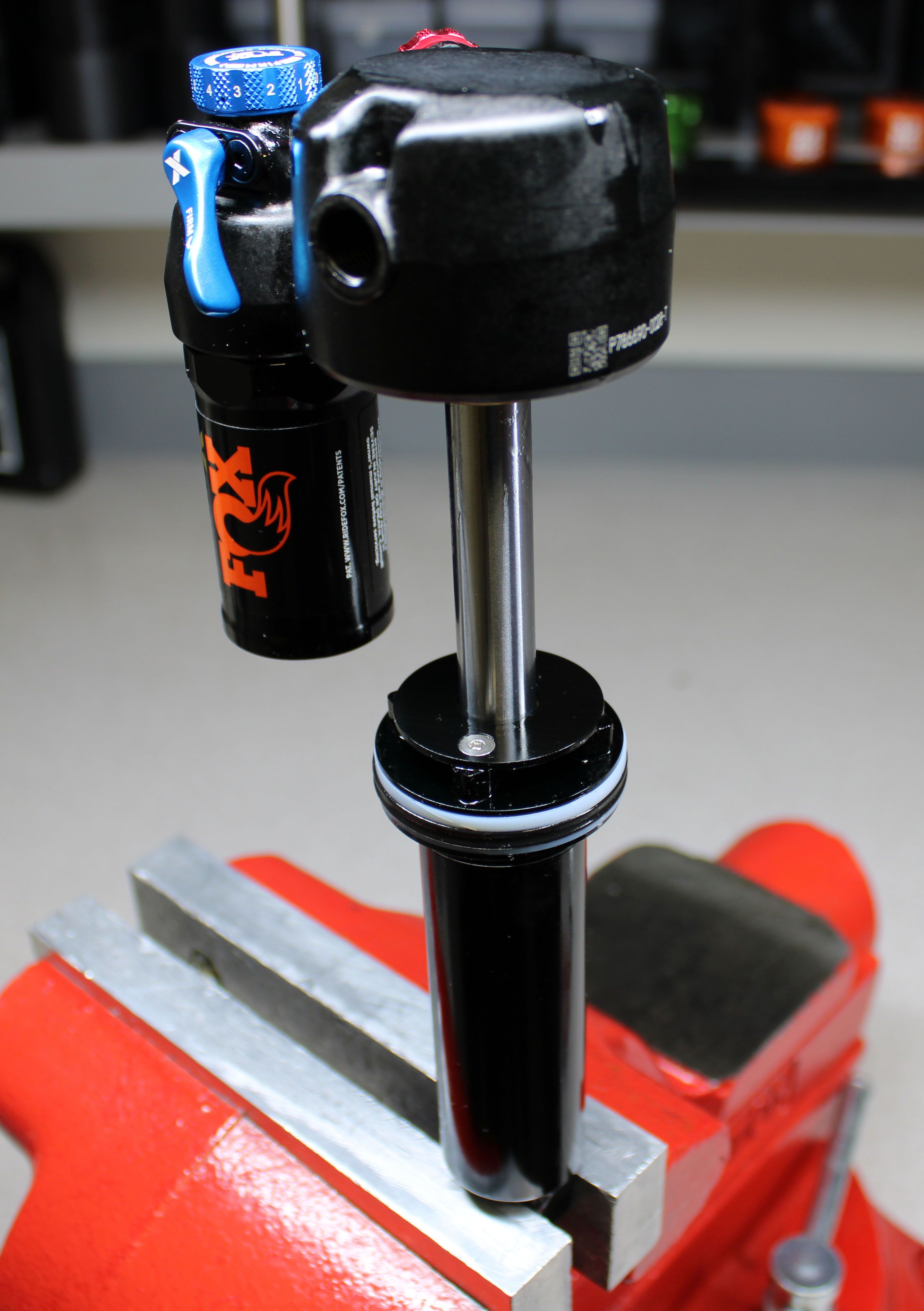
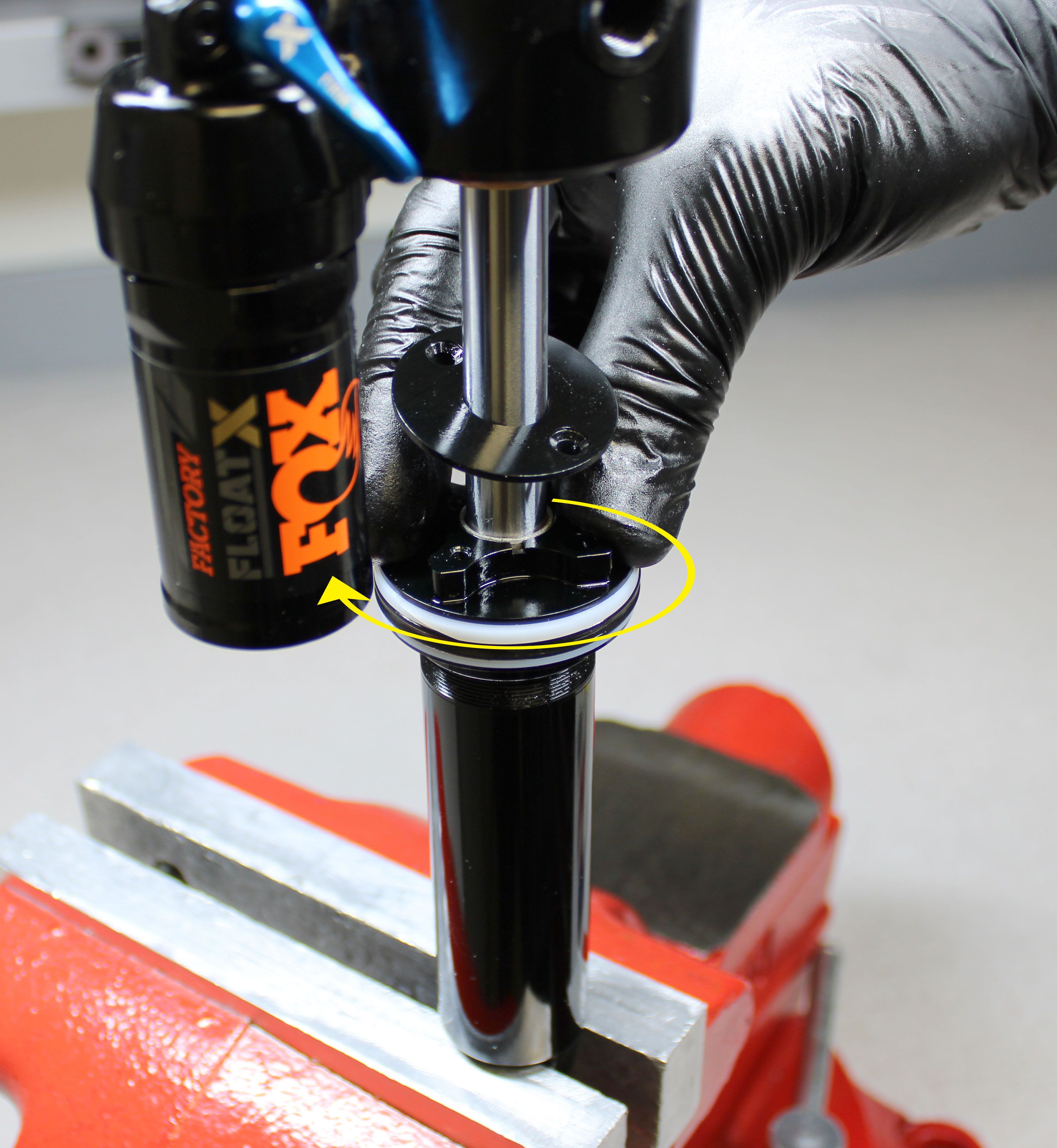
Step 21
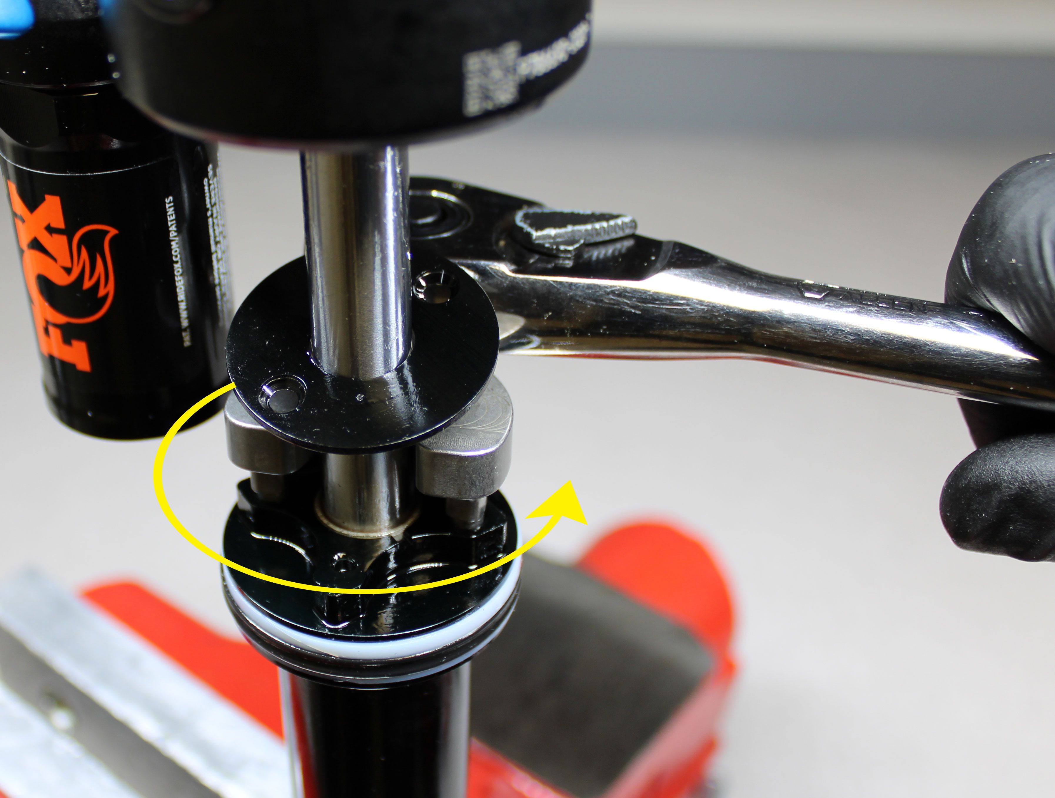
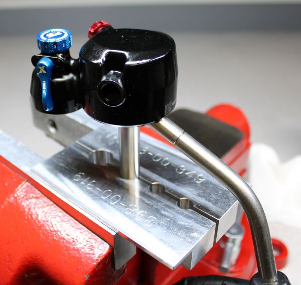
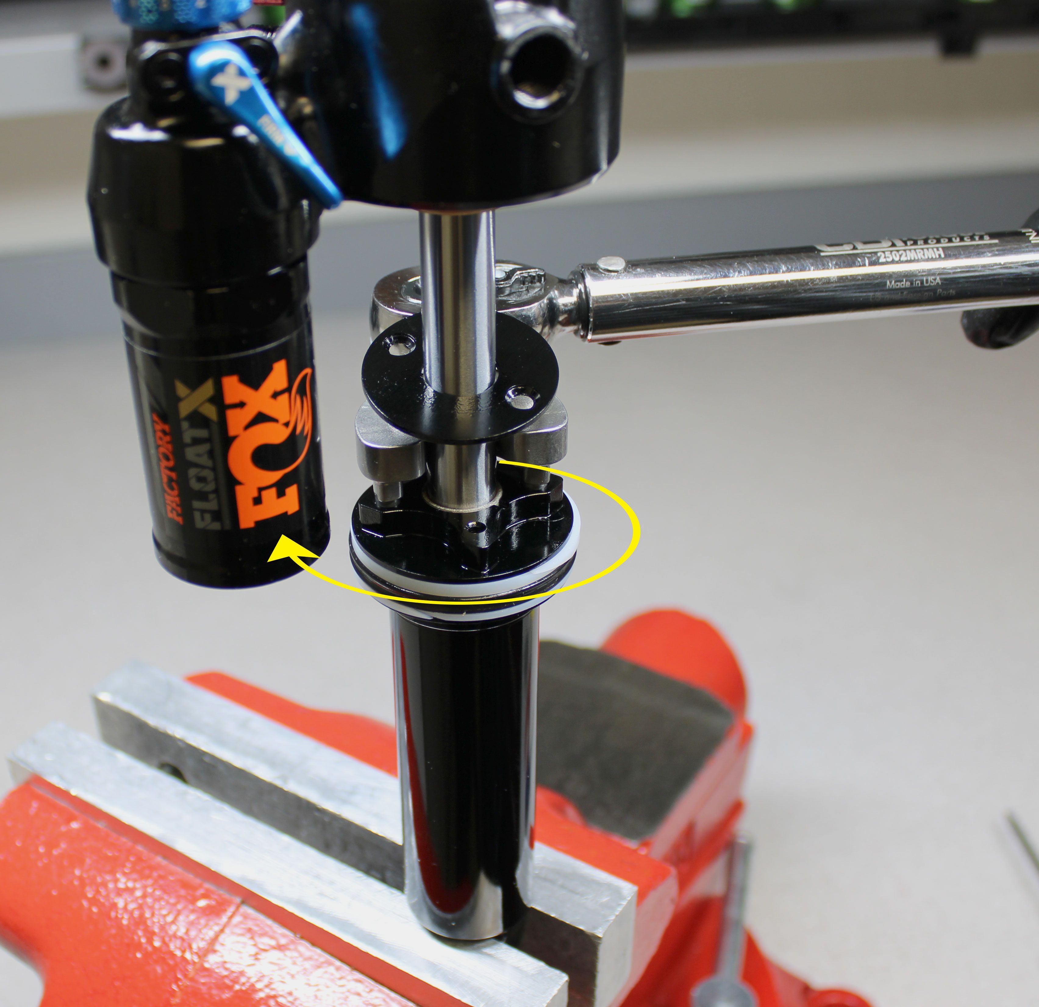
Clamp the body in your soft jawed vise then reinstall the shaft assembly tightening the bearing housing clockwise to 240 in-lb (27.1 Nm) torque.
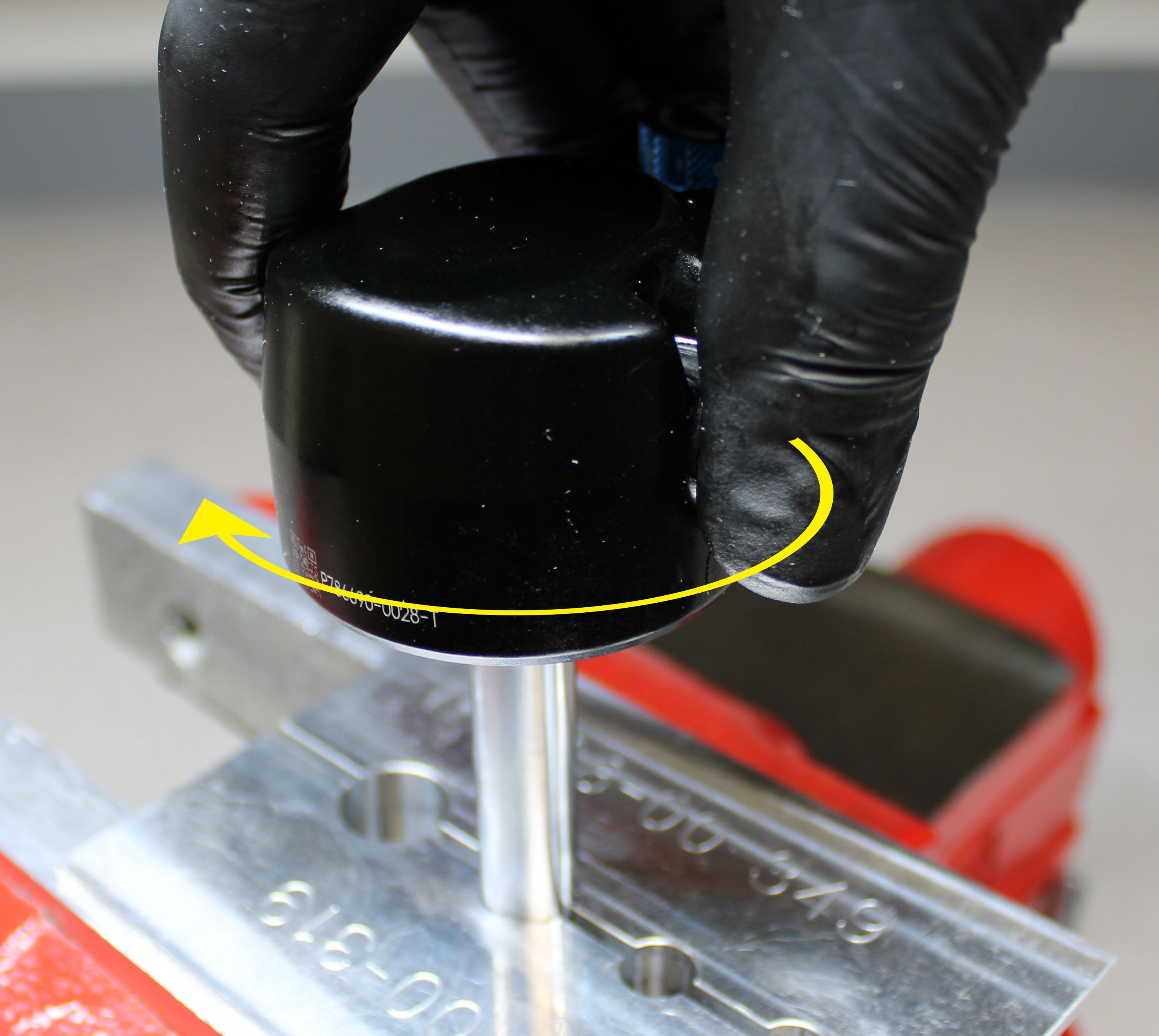
For 37.5mm-45mm travels: Use a 32mm wrench to tighten the bearing housing clockwise.
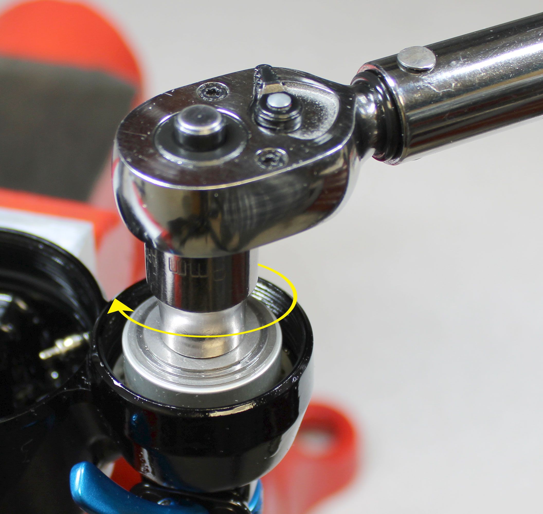
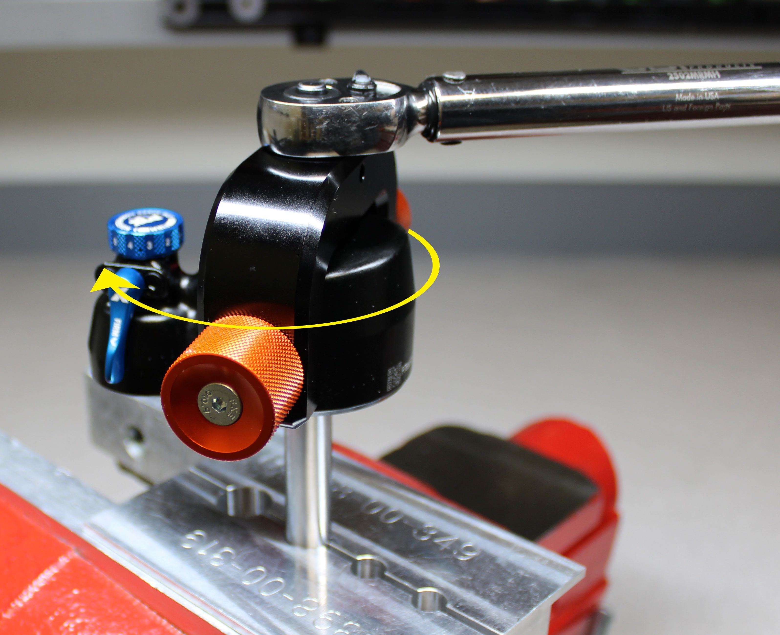
For 47.5mm-75mm travels: use the Pin Spanner Wrench (PN: 398-00-558) to tighten the bearing housing clockwise (shown).

Step 22
Reinstall any travel spacers that were removed earlier. Reinstall the two screws that retain the bearing housing cap (if removed previously). Tighten clockwise to 10 in-lb (1.1 Nm) torque with a 2mm hex wrench.


Step 23
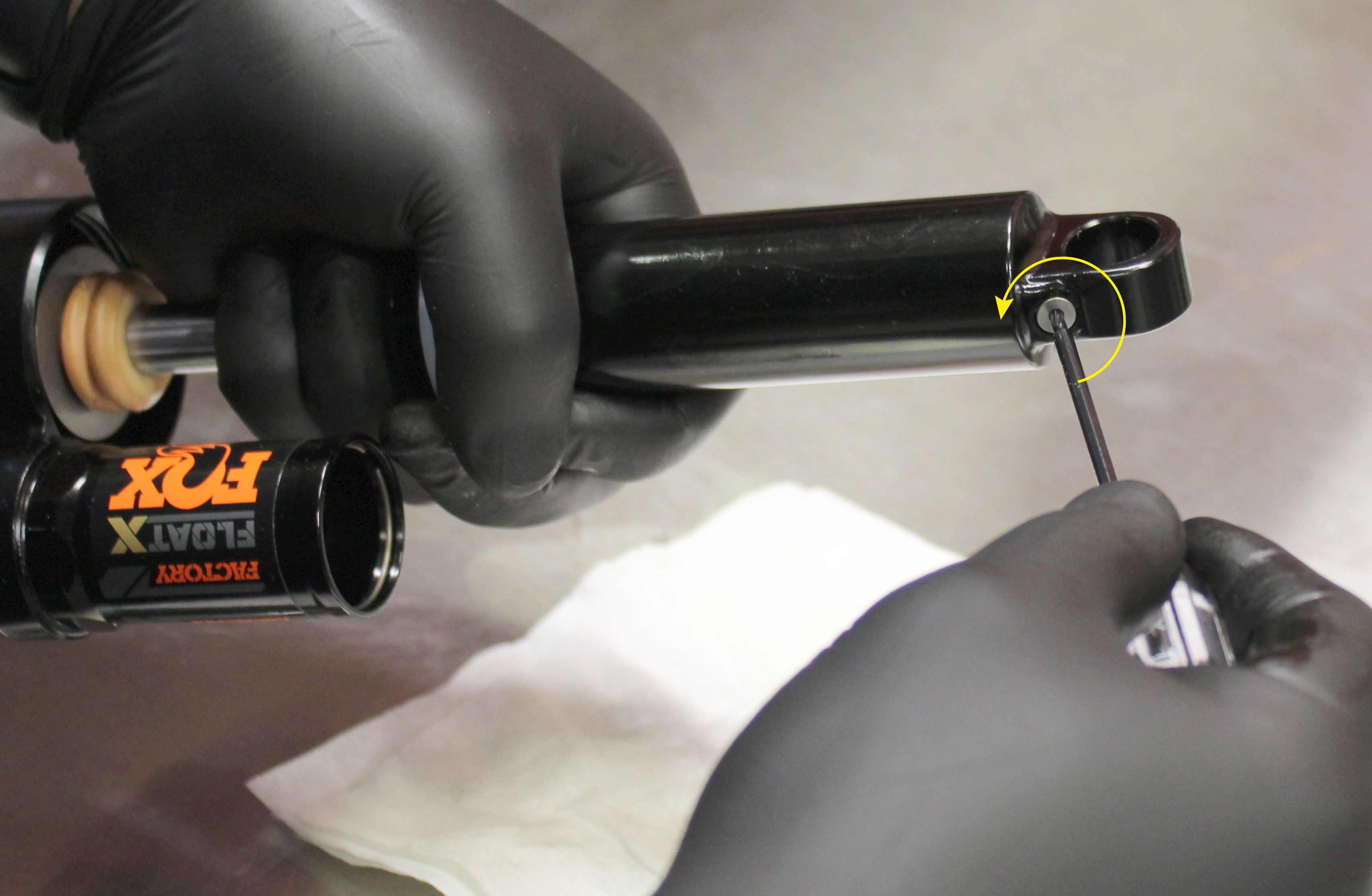
Reinstall the Schrader valve core, tightening clockwise until the valve core depth is 0.010-0.040in below the level of the Schrader valve housing.
Vacuum Bleed/Fill and Final Assembly

Step 1
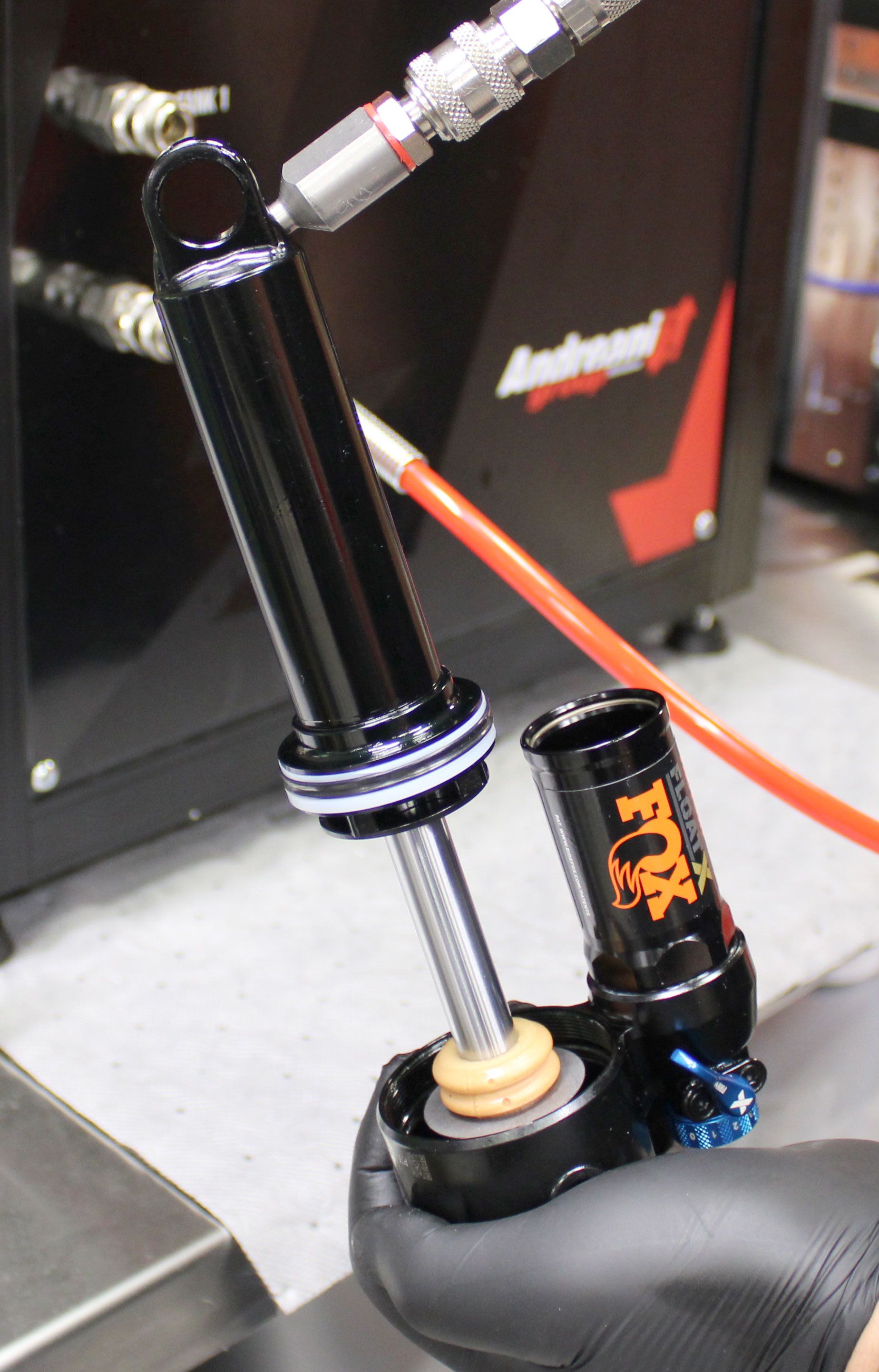
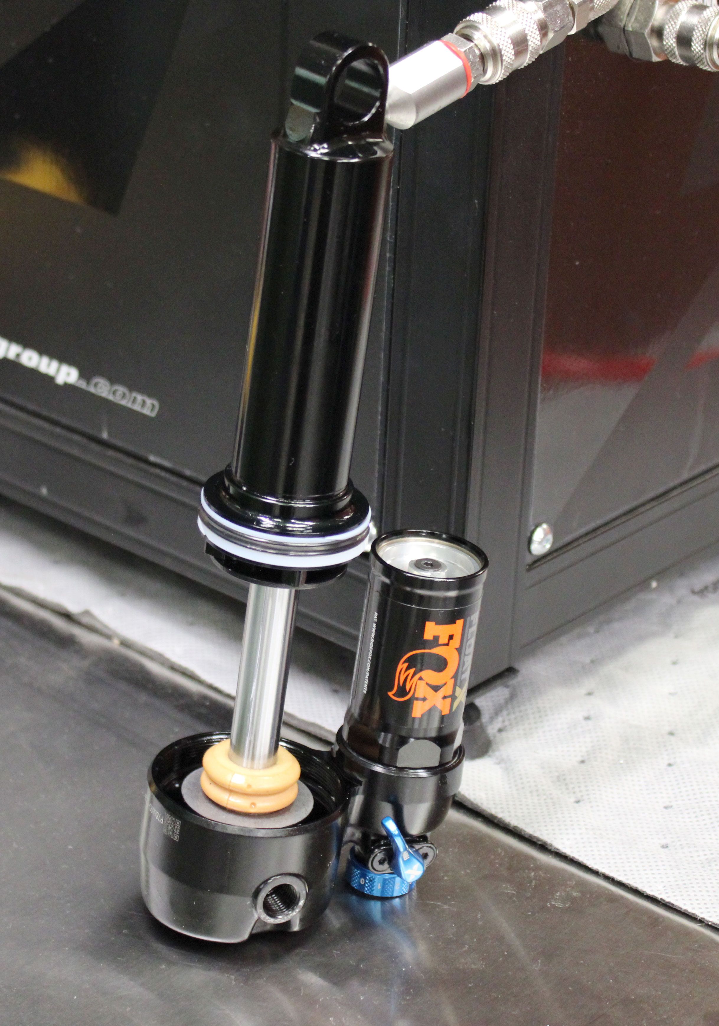
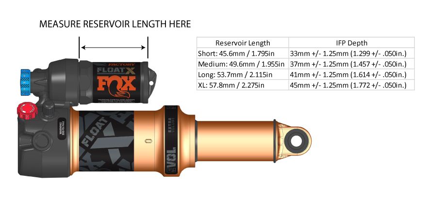
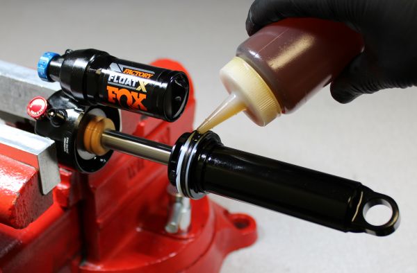
Open all adjuster by turning them fully counter-clockwise. Remove the oil fill plug by turning it counter-clockwise with a T8 Torx driver. Make sure that your vacuum bleed machine is filled with FOX 4wt. oil (PN 025-03-063). Install the vacuum fitting (PN 803-01-691) into the body fill port by turning it clockwise. Cycle the shock by hand while you perform the vacuum cycle. Repeat as necessary to purge all air from the shock. Set the IFP to the appropriate depth based on the length of your reservoir.

Step 2
Orient the oil fill port so it is the highest part of the shock. Remove the vacuum fitting and reinstall the oil fill plug with new greased o-ring from the kit. Tighten clockwise to 8 in-lb (0.9 Nm) torque.

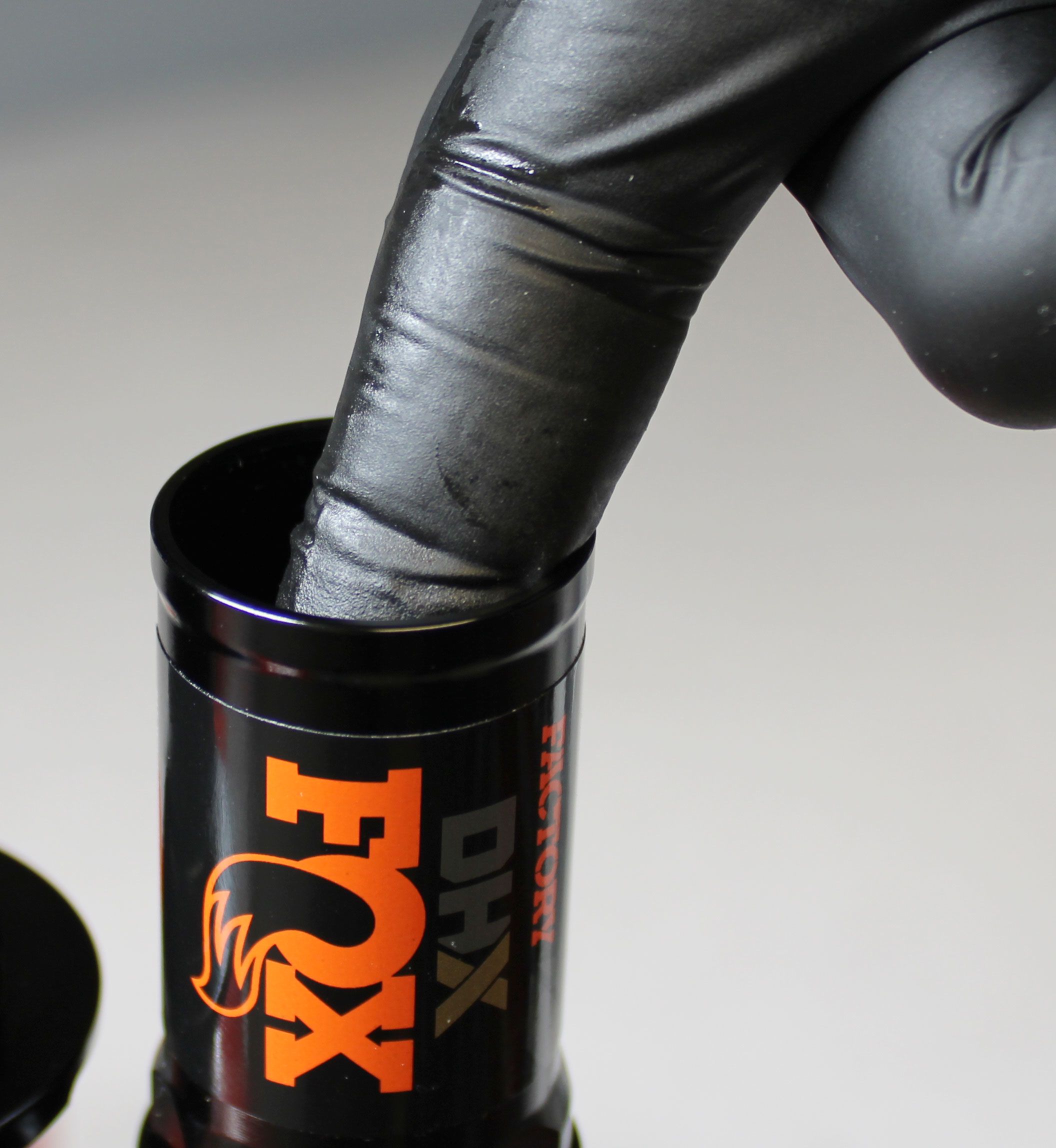
Step 3
Remove the wire retaining ring by pushing the center of the ring down which will cause the ends of the ring to pop up. Be careful not to scratch the IFP bore while removing or installing this ring. Coat the inside of the reservoir with a thin film of FOX 4wt. oil. Replace the o-ring of the reservoir end cap with a new greased one from the kit. Reinstall the reservoir end cap into the reservoir pushing down to allow for installation of the retaining ring.


Step 4
Reinstall the wire ring. Use a small hex wrench to lift the reservoir end cap into place making sure to orient the fill port away from the damper body. Install the air fill adaptor by threading it in clockwise. Set the IFP pressure to 150 psi. Remove the air fill adaptor while still attached to your pump. Reinstall the air fill cap with a new greaswed o-ring from the kit, tightening clockwise to 3 in-lb (0.3 Nm) torque.
Step 5
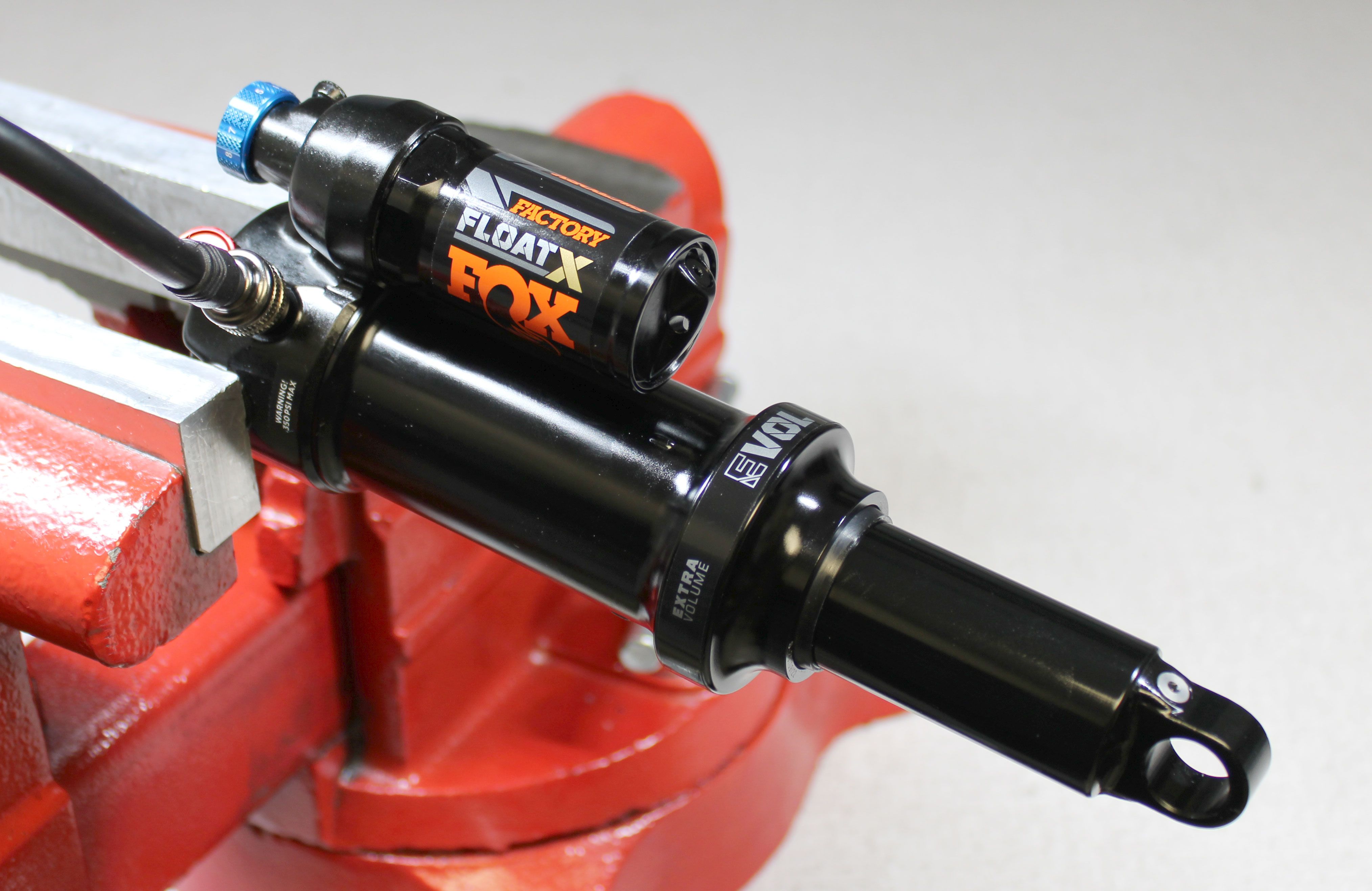
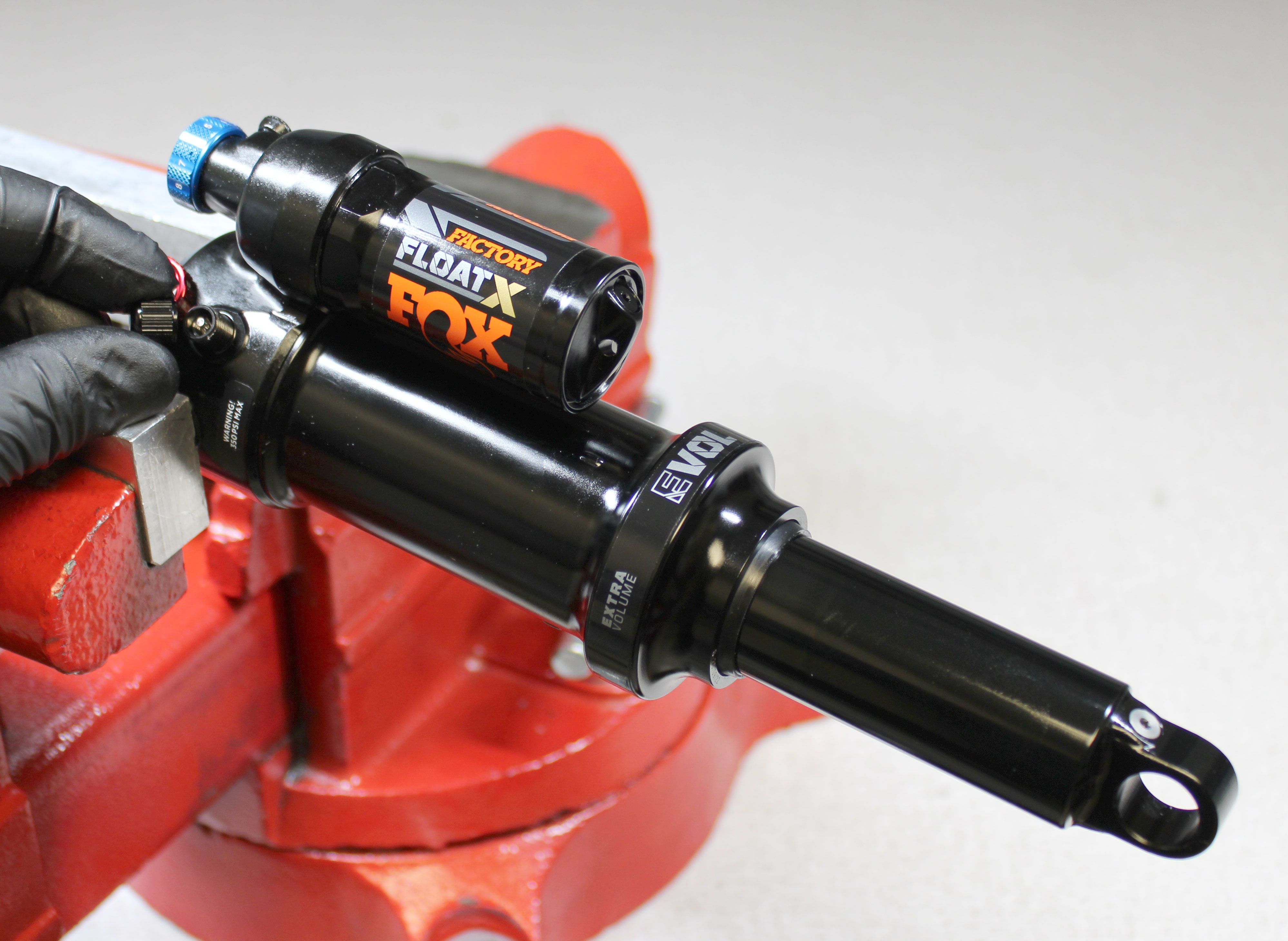
Coat the main air seal and backup rings on the bearing assembly with a thin film of FOX 20wt. gold oil. Coat the seals and backup rings in the end of the air sleeve with a thin film of FOX 20wt. gold oil.

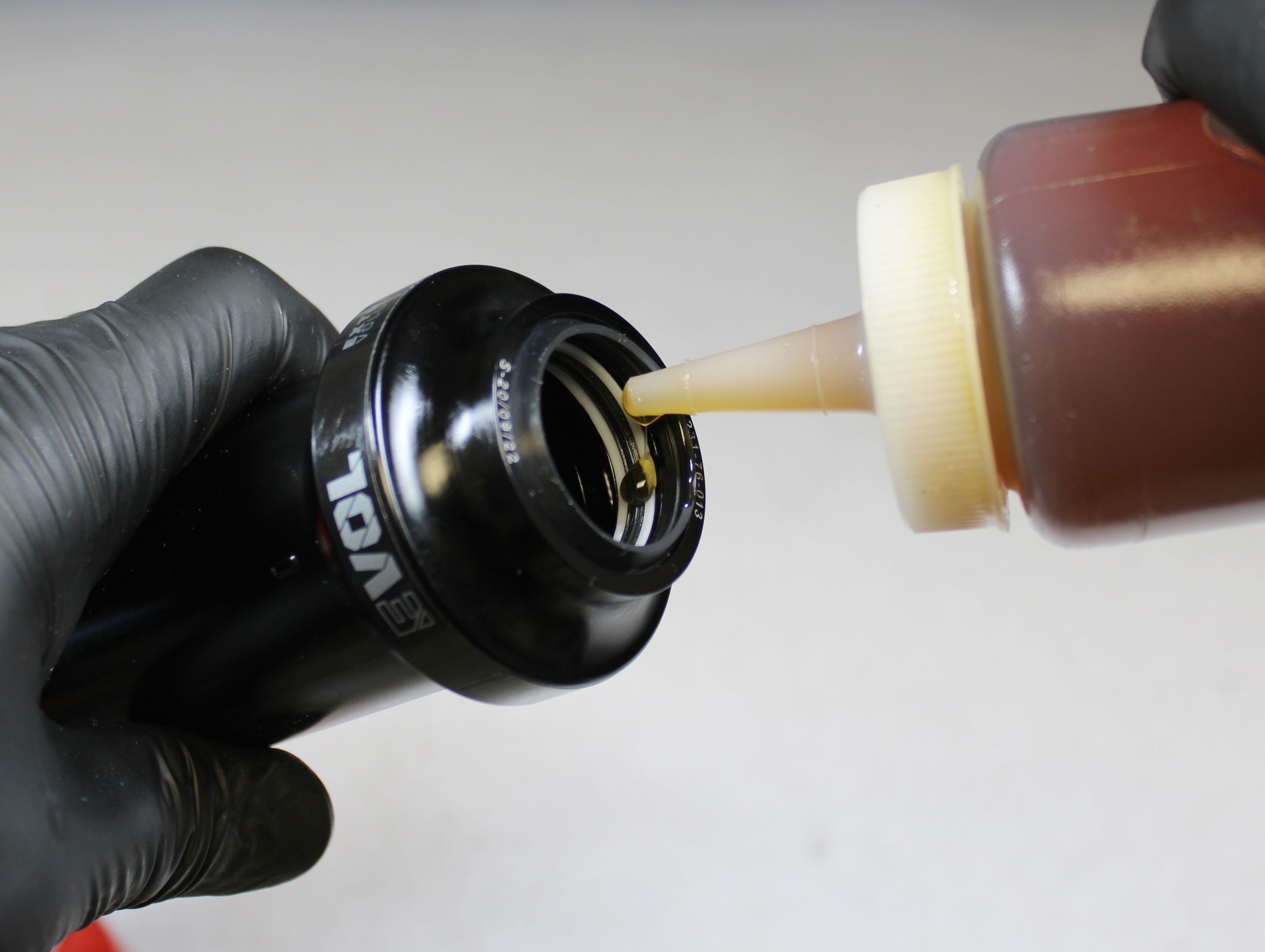
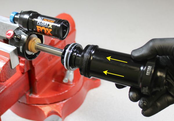
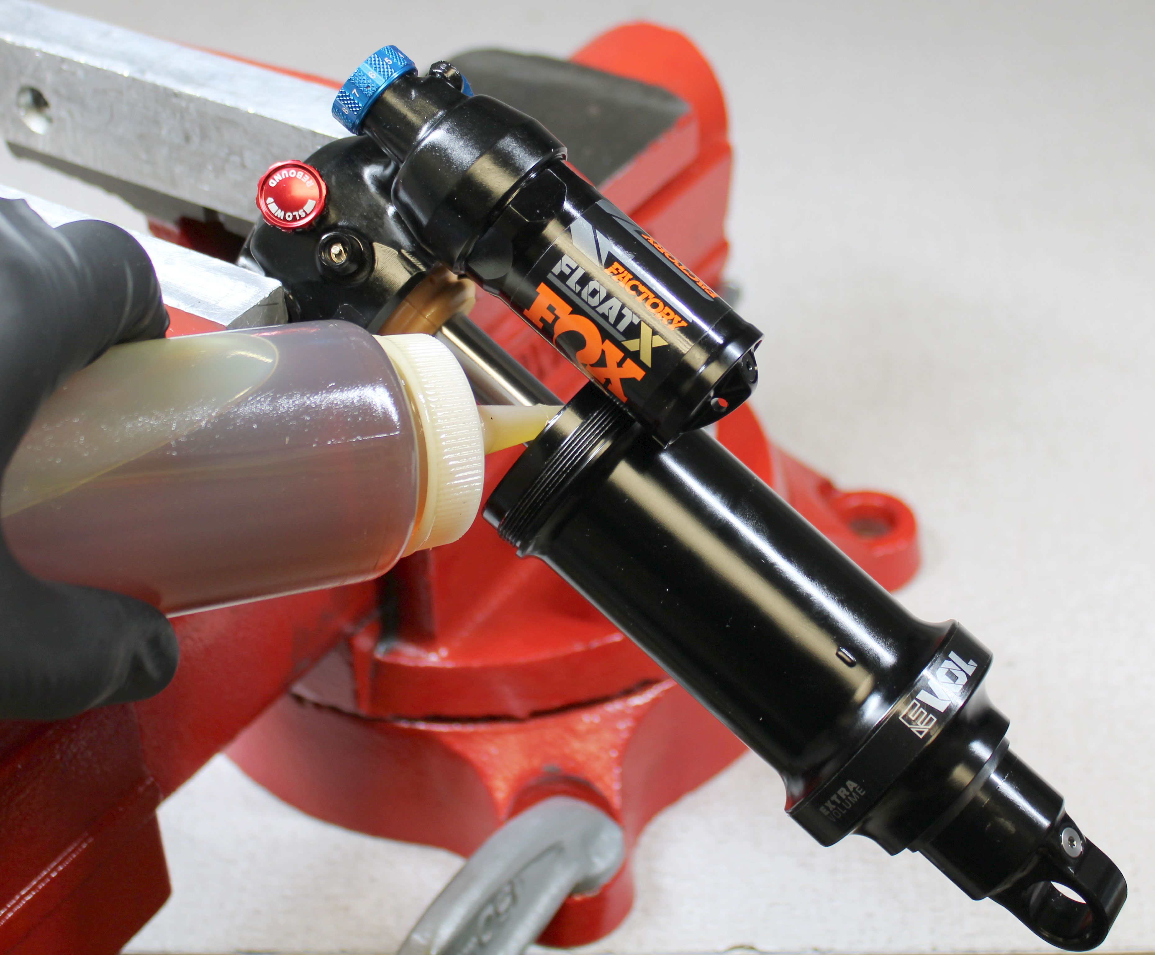
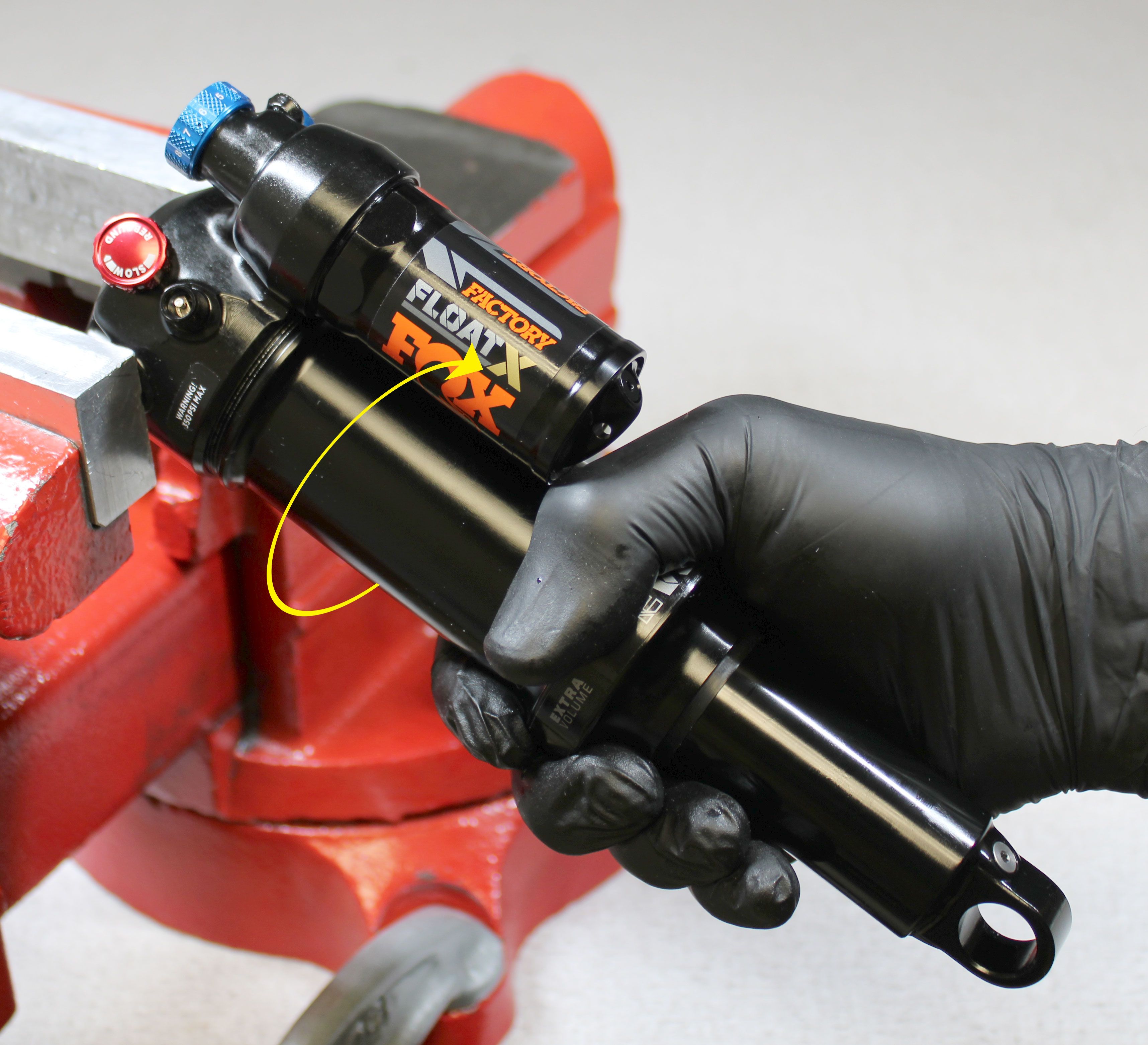
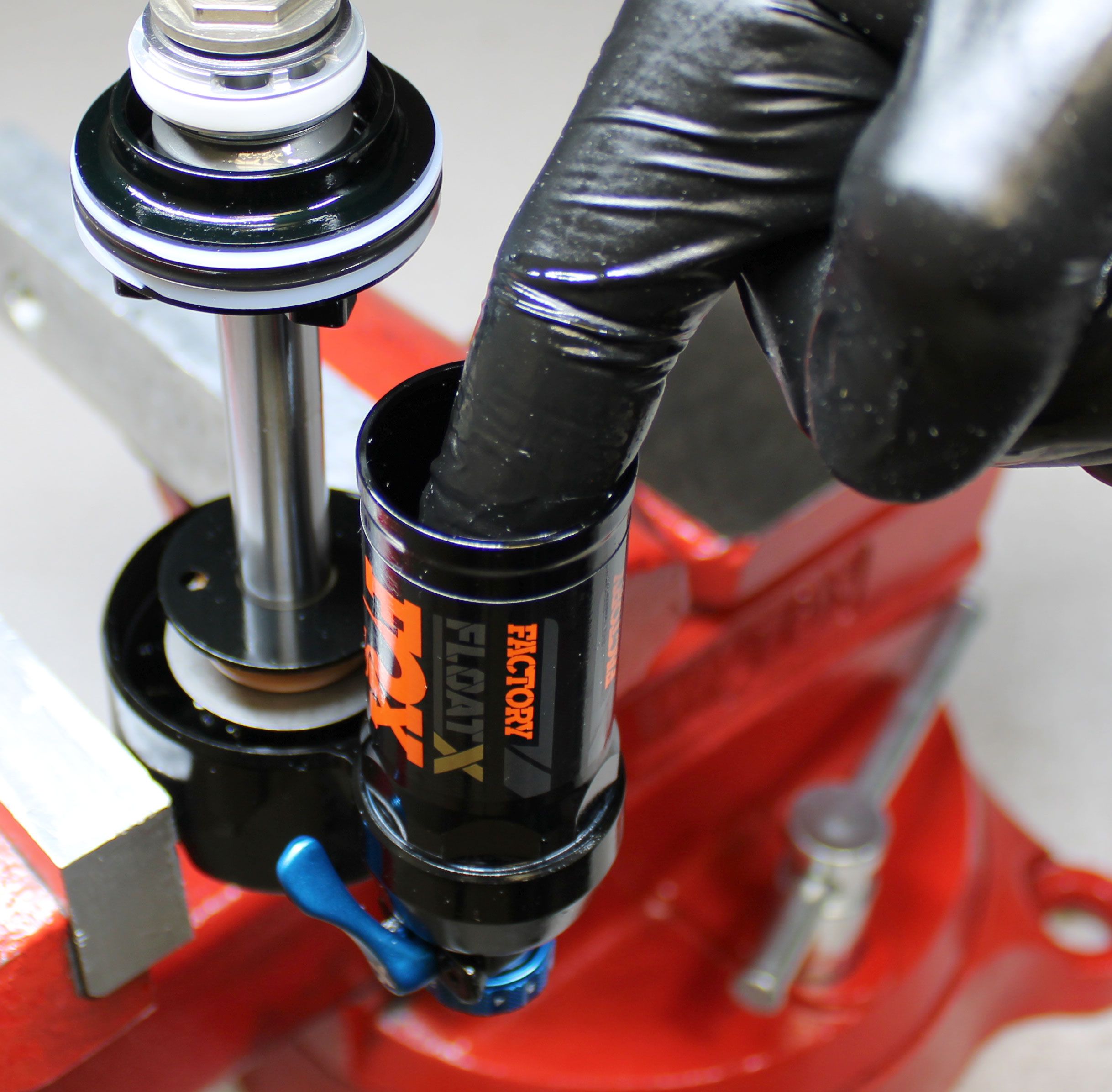
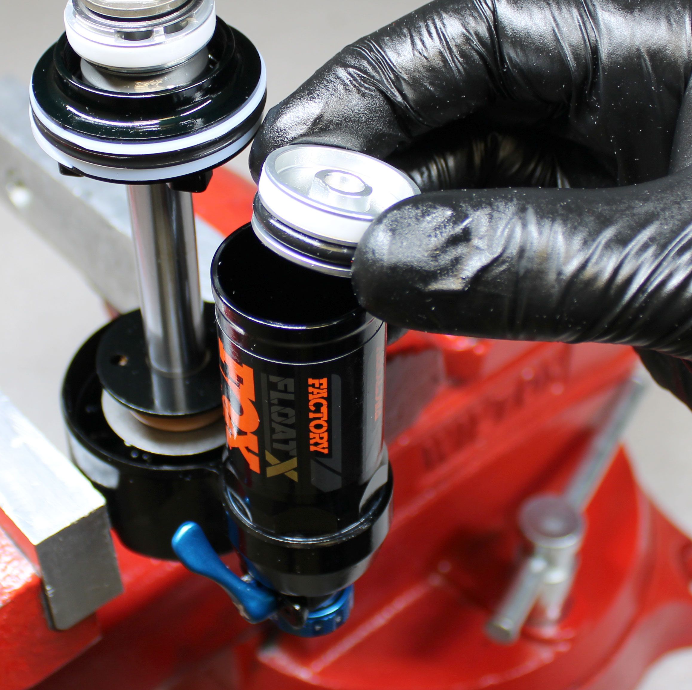
Step 6
Begin to reinstall the air sleeve assembly onto the shock damper. Add 2cc of FOX 20wt. gold oil into the positive air chamber. Push the air sleeve assembly to the eyelet then tighten clockwise until hand tight. Add air to your desired pressure then reinstall the black air cap. Clean the exterior of the shock then dyno test all functions.