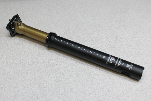
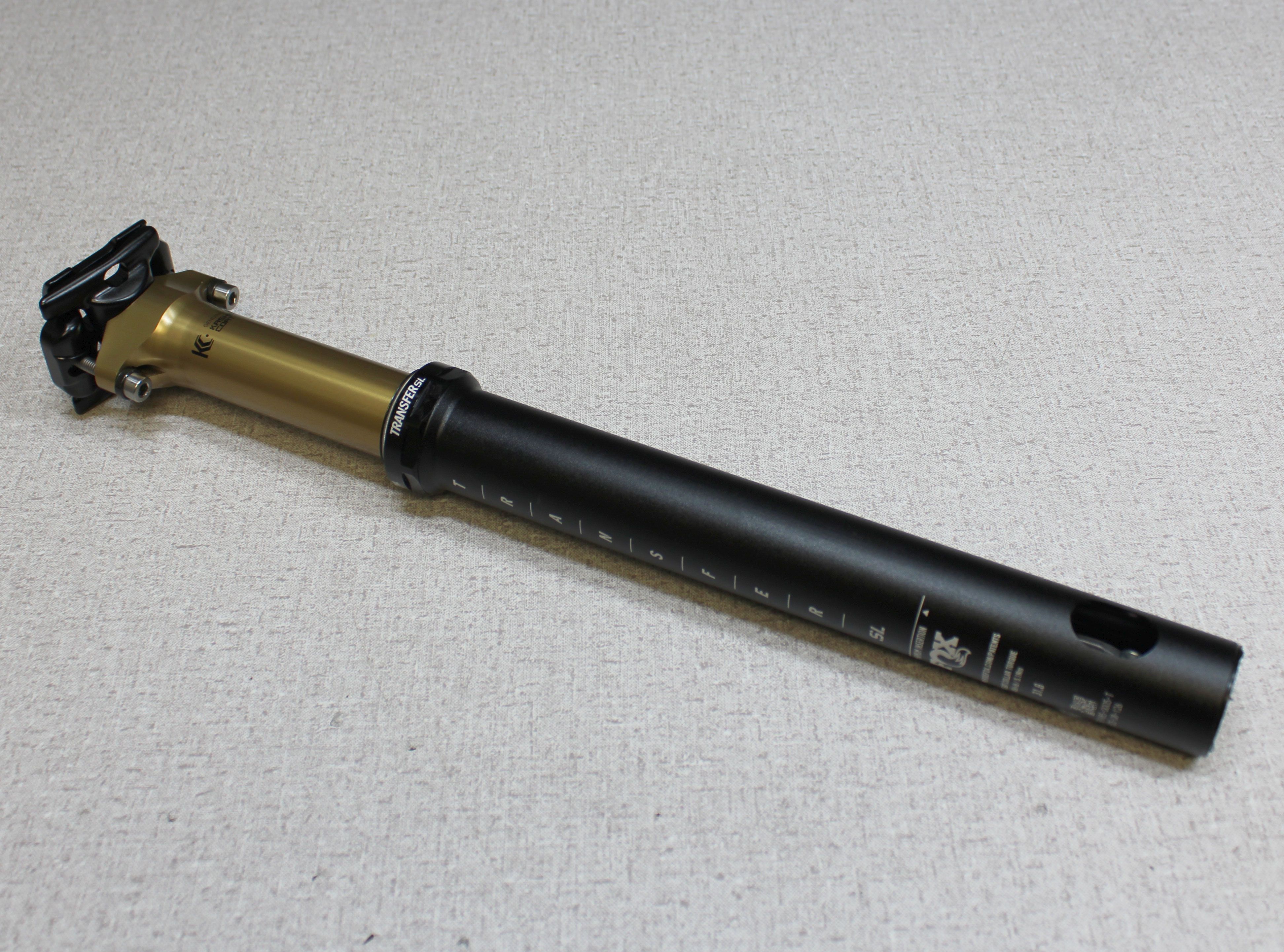
2022 Transfer SL 30.9/31.6mm / Race Face Turbine SL Rebuild
Required Parts
- 803-01-637 Kit: Rebuild, 2022 Transfer SL Seatpost, 30.9 & 31.6
- 803-01-742 Kit: Rebuild, 2022 RaceFace Turbine SL Seatpost, 30.9 & 31.6
Required Tools
- 398-00-838 Tooling: Driver, Retaining Lug, Transfer SL 31.6/ 30.9/ 27.2
- 398-00-894 Service Tool: Sealhead Torque Driver, Transfer SL, 1.47" Flats
- 398-00-916 Tooling: T/O Cap Driver, Transfer SL 31.6/ 30.9/ 27.2
- 398-00-935 Service Tool: Locking Spring Preloader, Transfer SL
- 803-01-500 Kit: Service Tool, 2022 Transfer SL, Upper Bushing Installer
WARNING: Always wear safety glasses and protective gloves during service to prevent potential injury. Failure to wear protective equipment during service may lead to SERIOUS INJURY OR DEATH.
WARNING: FOX products should be serviced by a qualified bicycle service technician, in accordance with FOX specifications. If you have any doubt whether or not you can properly service your FOX product, then DO NOT attempt it. Improperly serviced products can fail, causing the rider to lose control resulting in SERIOUS INJURY OR DEATH.
WARNING: Modification, improper service, or use of aftermarket replacement parts with FOX forks, shocks, and seatposts may cause the product to malfunction, resulting in SERIOUS INJURY OR DEATH. DO NOT modify any part of a fork, shock, or seatpost including the fork brace (lower leg cross brace), crown, steerer, upper and lower leg tubes, or internal parts, except as instructed herein. Any unauthorized modification may void the warranty, and may cause failure or the fork or shock, resulting in SERIOUS INJURY OR DEATH.
WARNING: FOX products contain springs with stored energy and/or pressurized nitrogen, air, oil, or all 3. Misuse can cause property damage, SERIOUS INJURY OR DEATH. DO NOT puncture, incinerate or crush any portion of a FOX product. DO NOT attempt to disassemble any portion of a FOX product, unless expressly instructed to do so by the applicable FOX technical documentation, and then ONLY while strictly adhering to all FOX insturctions and warnings in that instance.
WARNING: Safety glasses MUST be worn during disassembly and reassembly of the Transfer SL seatpost. Transfer SL seatposts contain a highly preloaded spring and this stored energy must be released slowly according to FOX technical instructions to ensure safety during service. Failure to wear safety glasses while servicing the Transfer SL may cause SERIOUS INJURY OR DEATH.
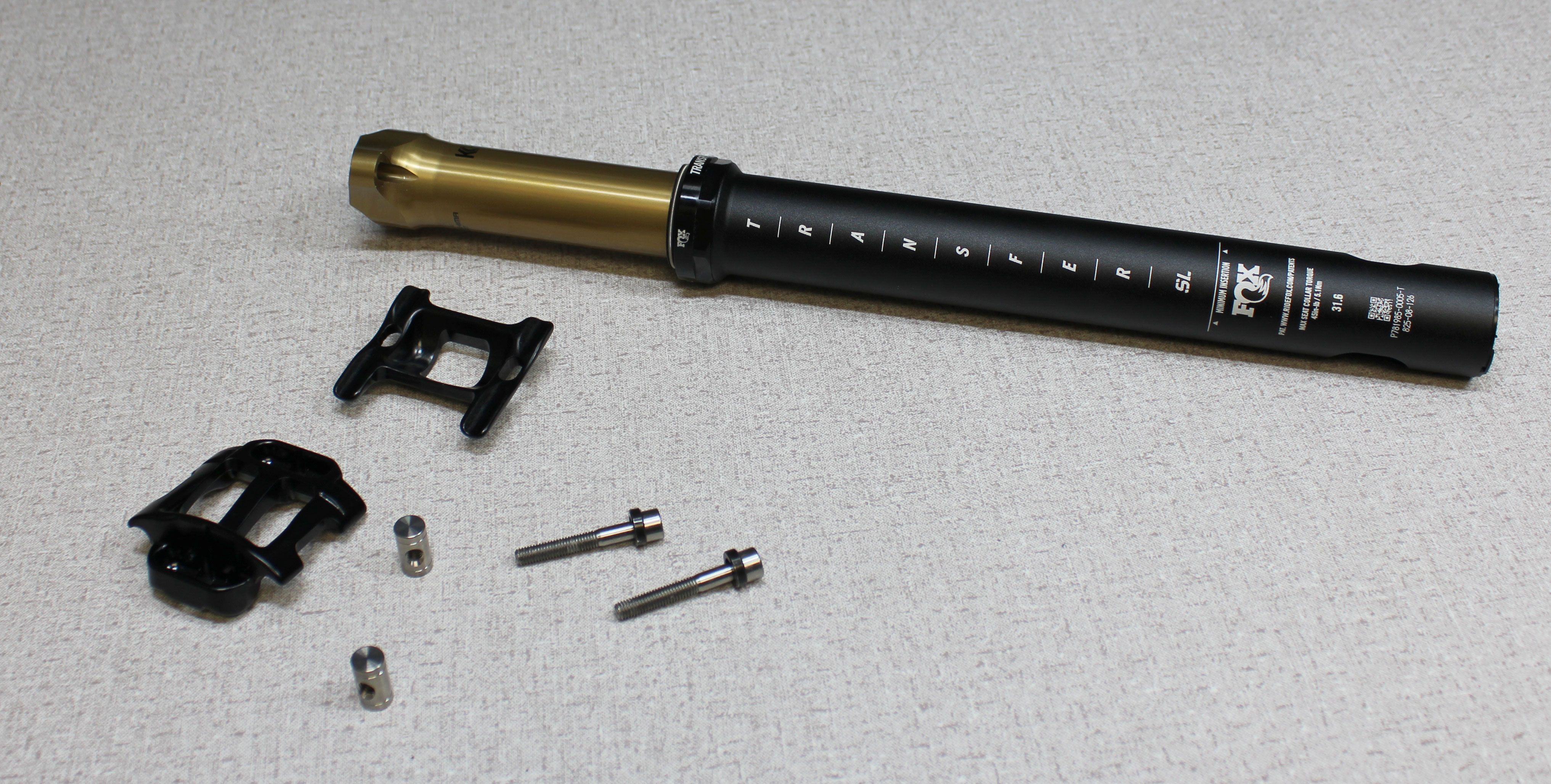
Step 1
Remove the saddle clamps and hardware. Turn the 4mm hex bolts counter-clockwise to remove them from the barrel nuts. Set all clamps and hardware aside.

Step 2
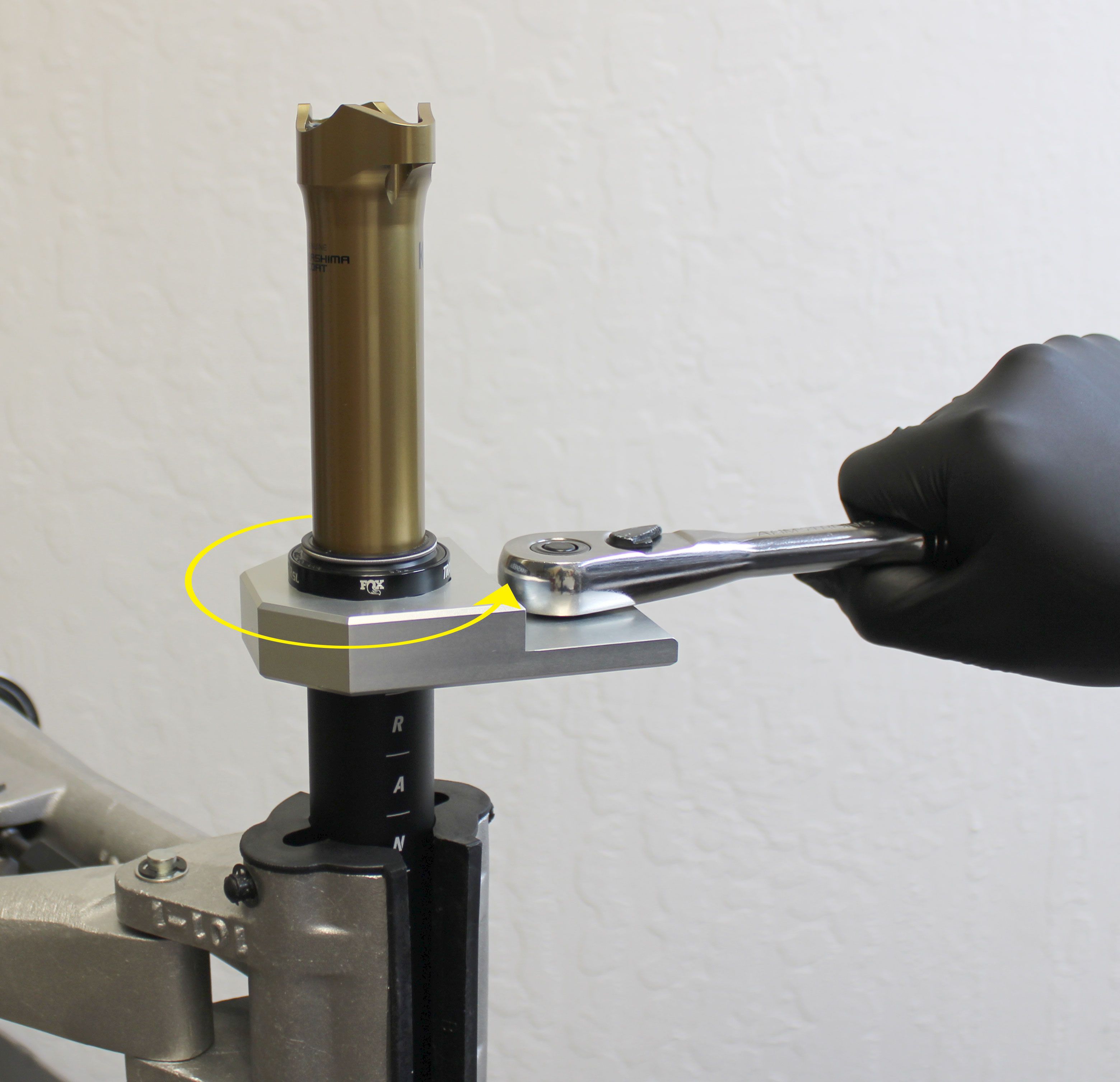
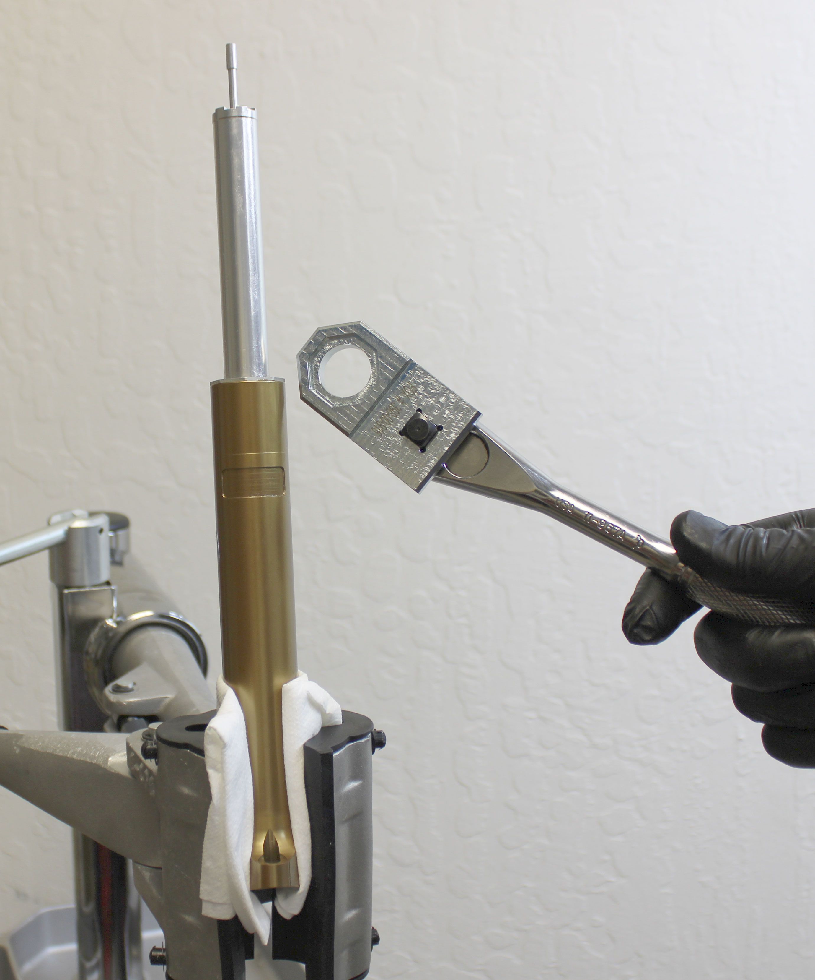
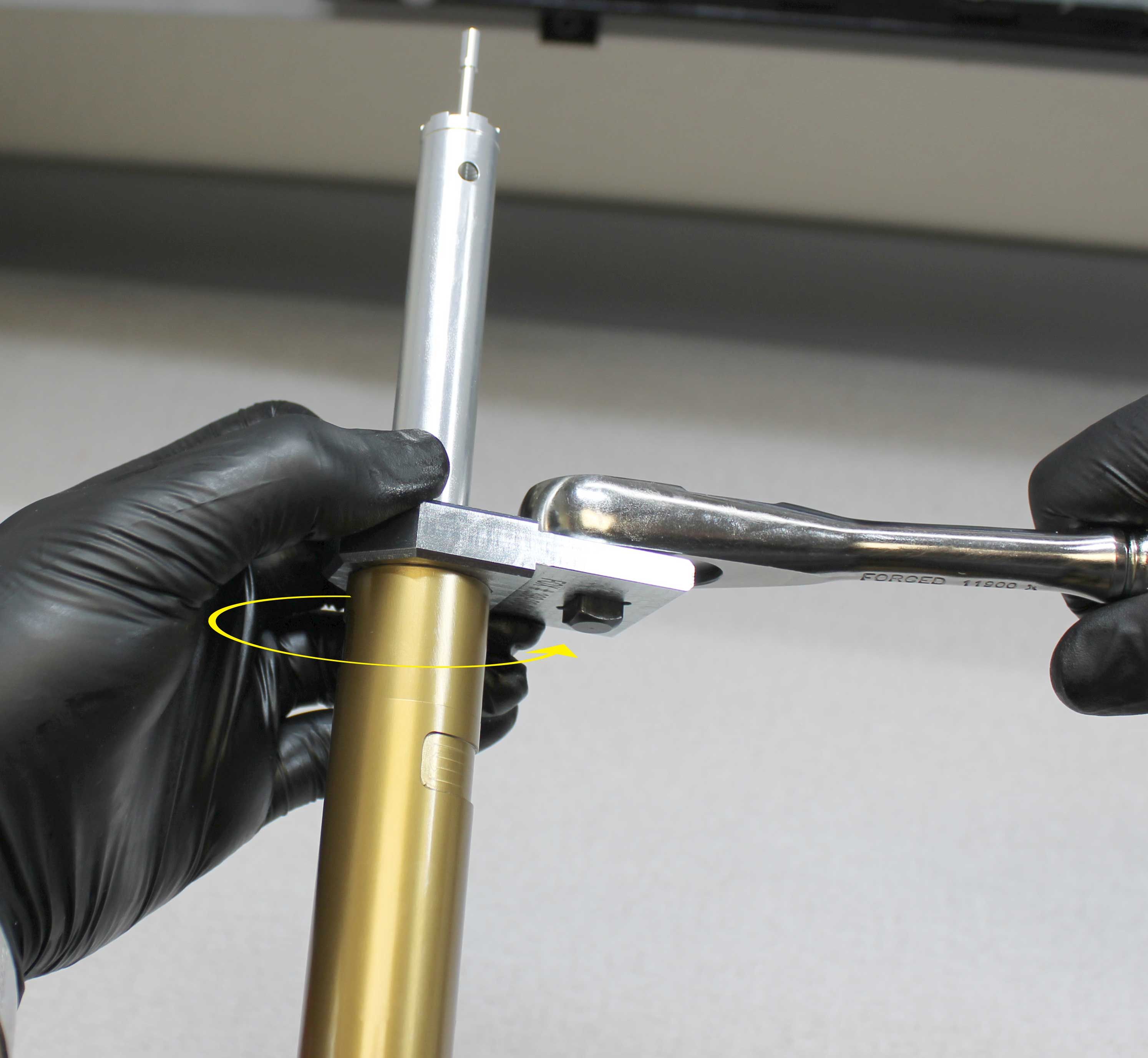
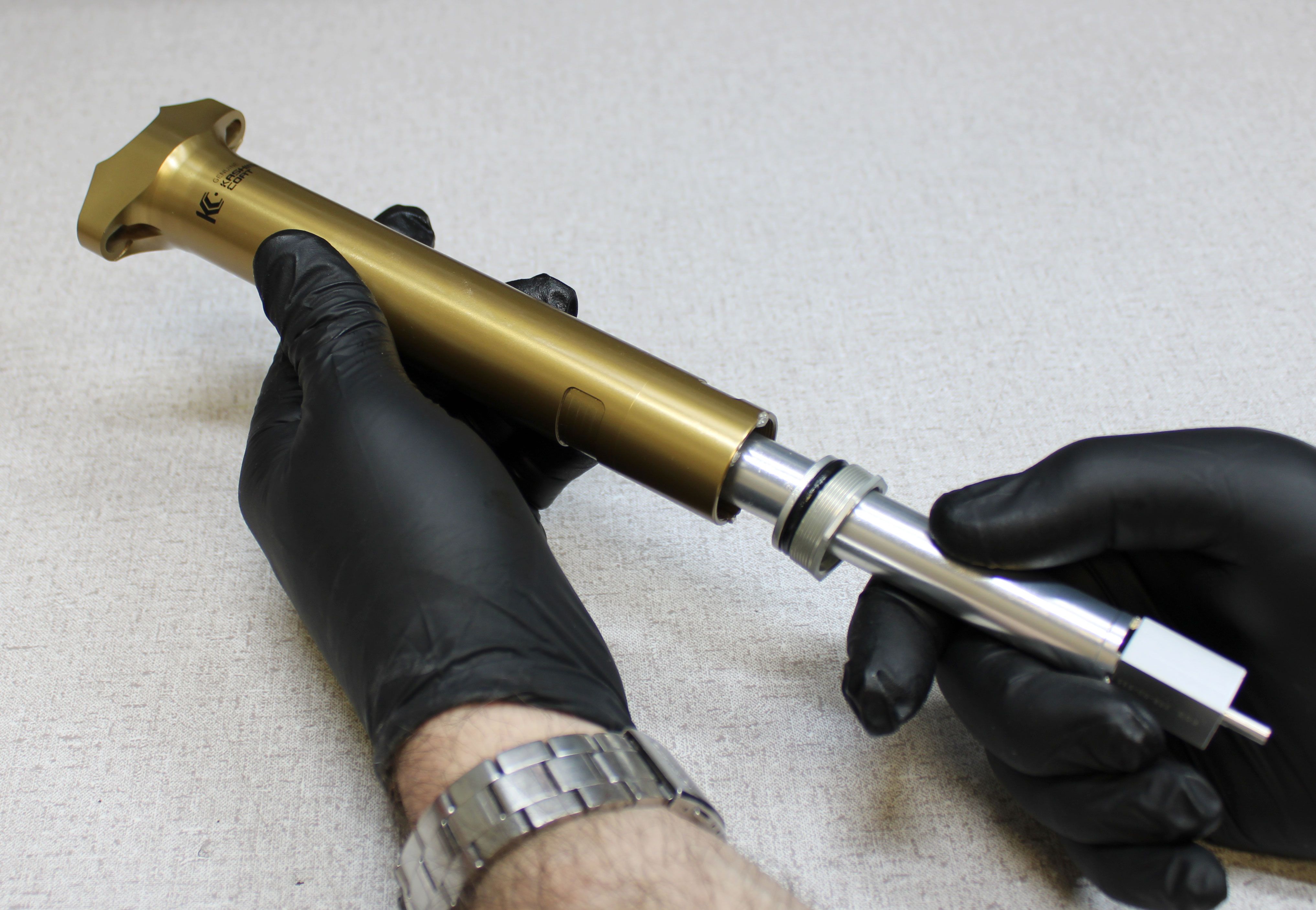
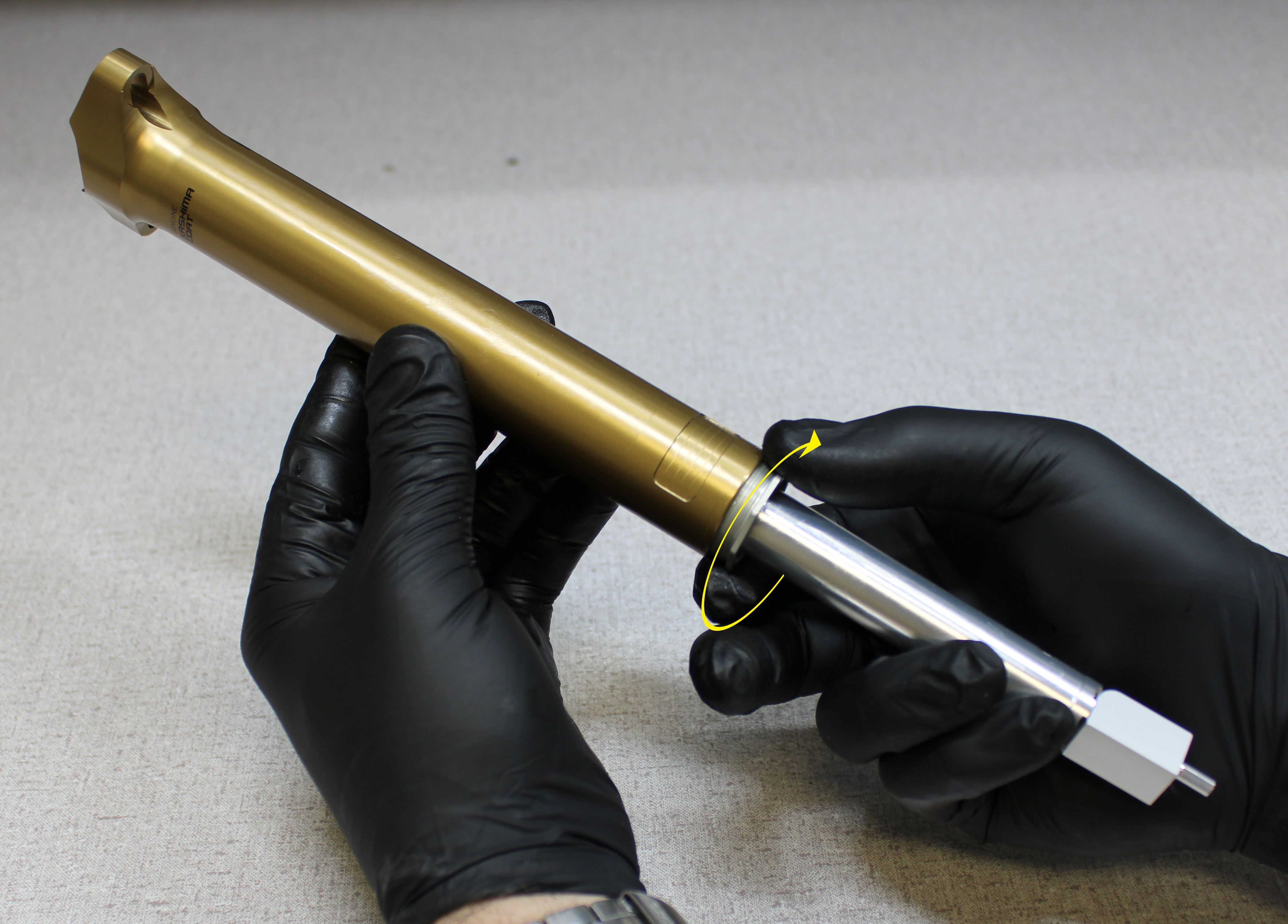
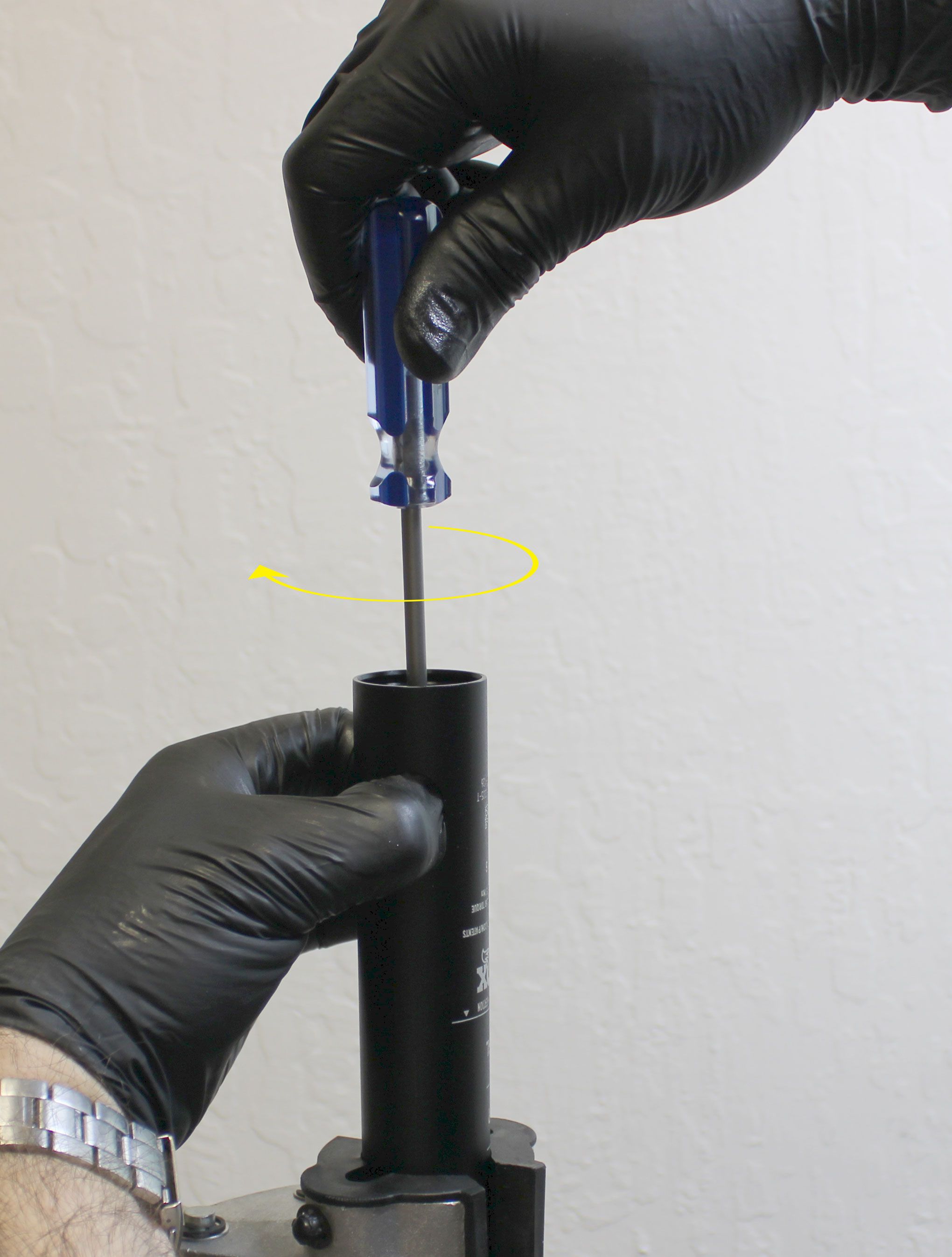
Clean your bike work stand clamps and the exterior of the seatpost to prevent damage during clamping. Insert the seatpost through the sealhead torque driver (PN: 398-00-894) then clamp in your workstand. Unthread the sealhead counter-clockwise from the lower post.

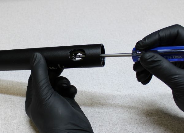
Step 3
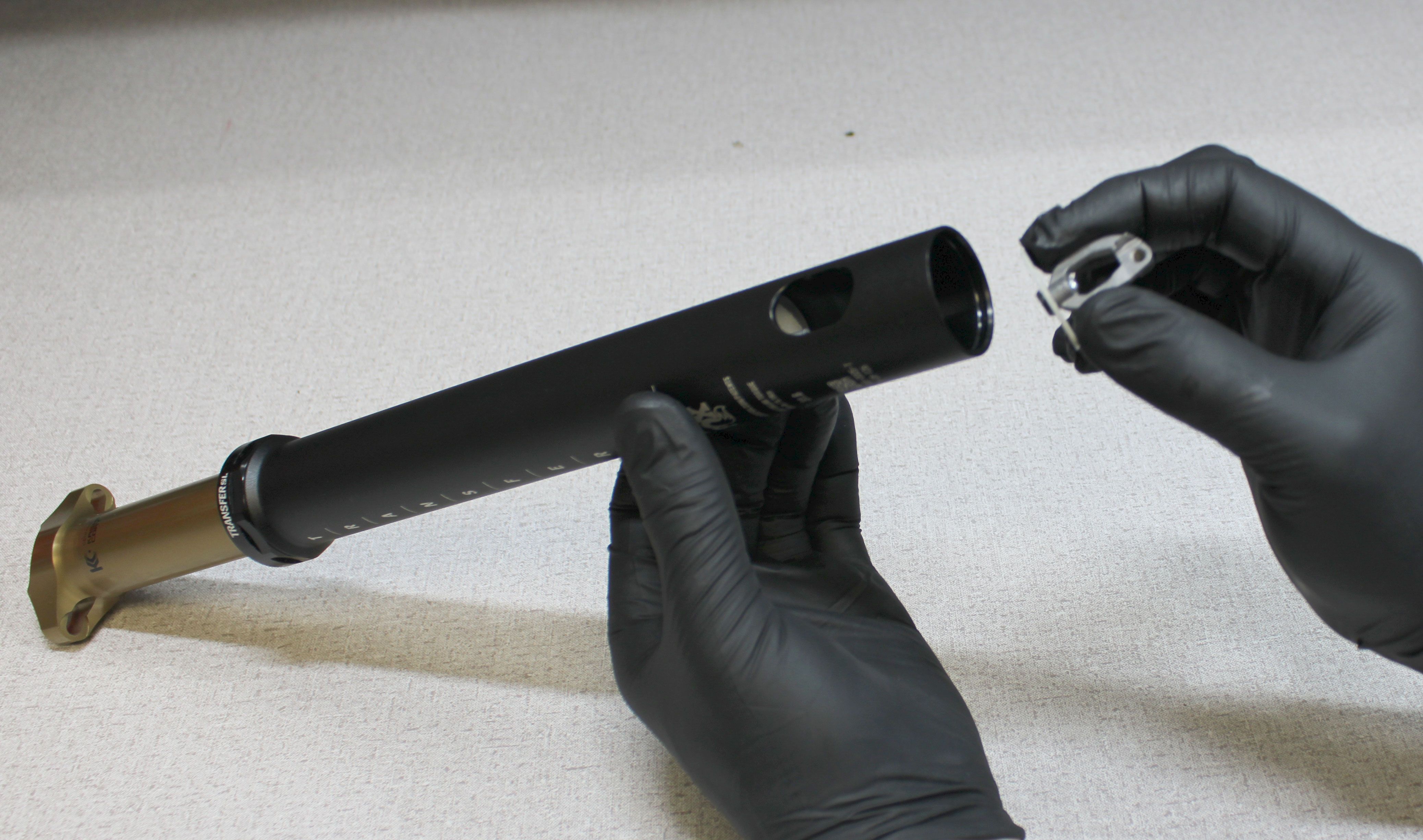
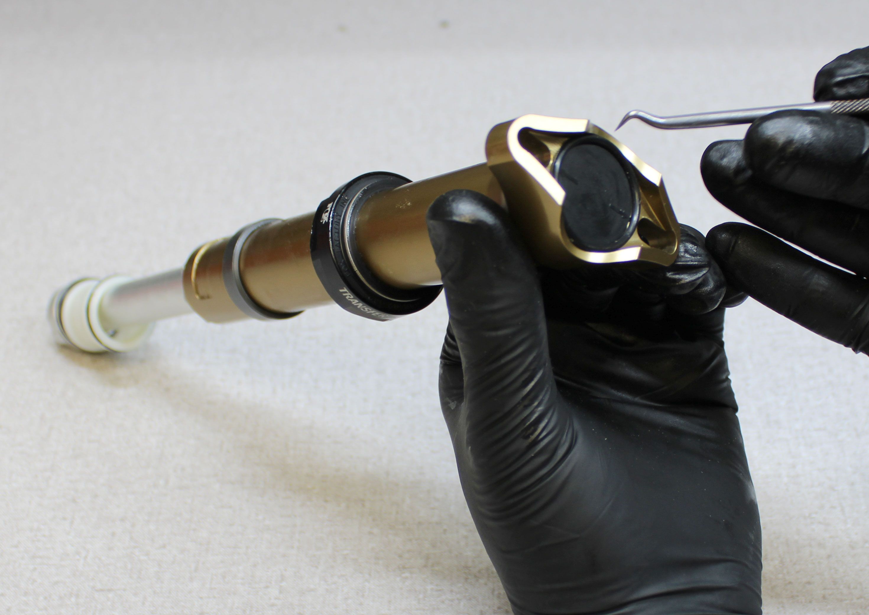
Invert the post in your workstand then remove the end cap by pulling it out with your fingernail. Remove the cable pinch bolt by unthreading it counter-clockwise with a 3mm hex wrench. Set the end cap and cable pinch bolt aside.
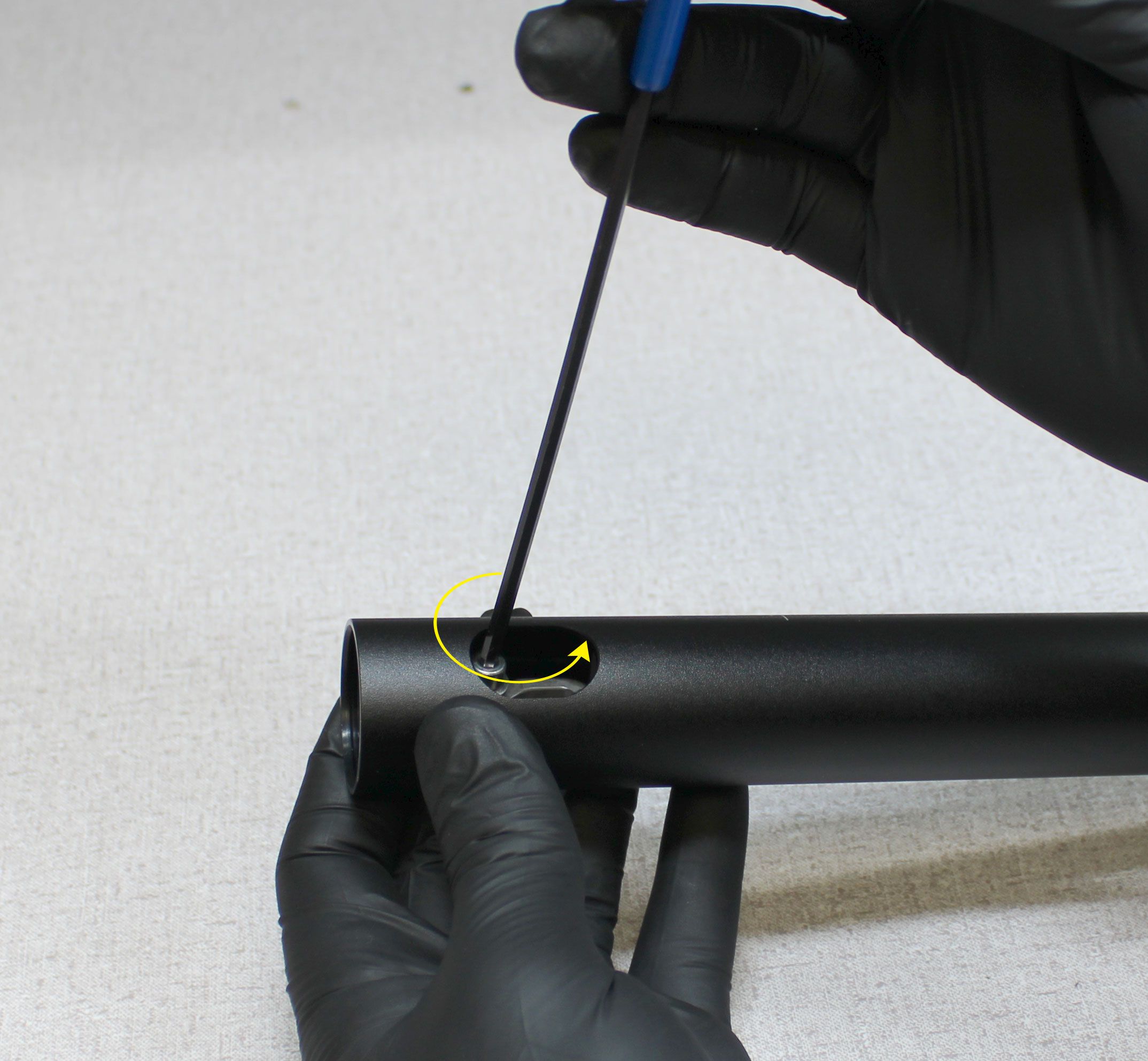
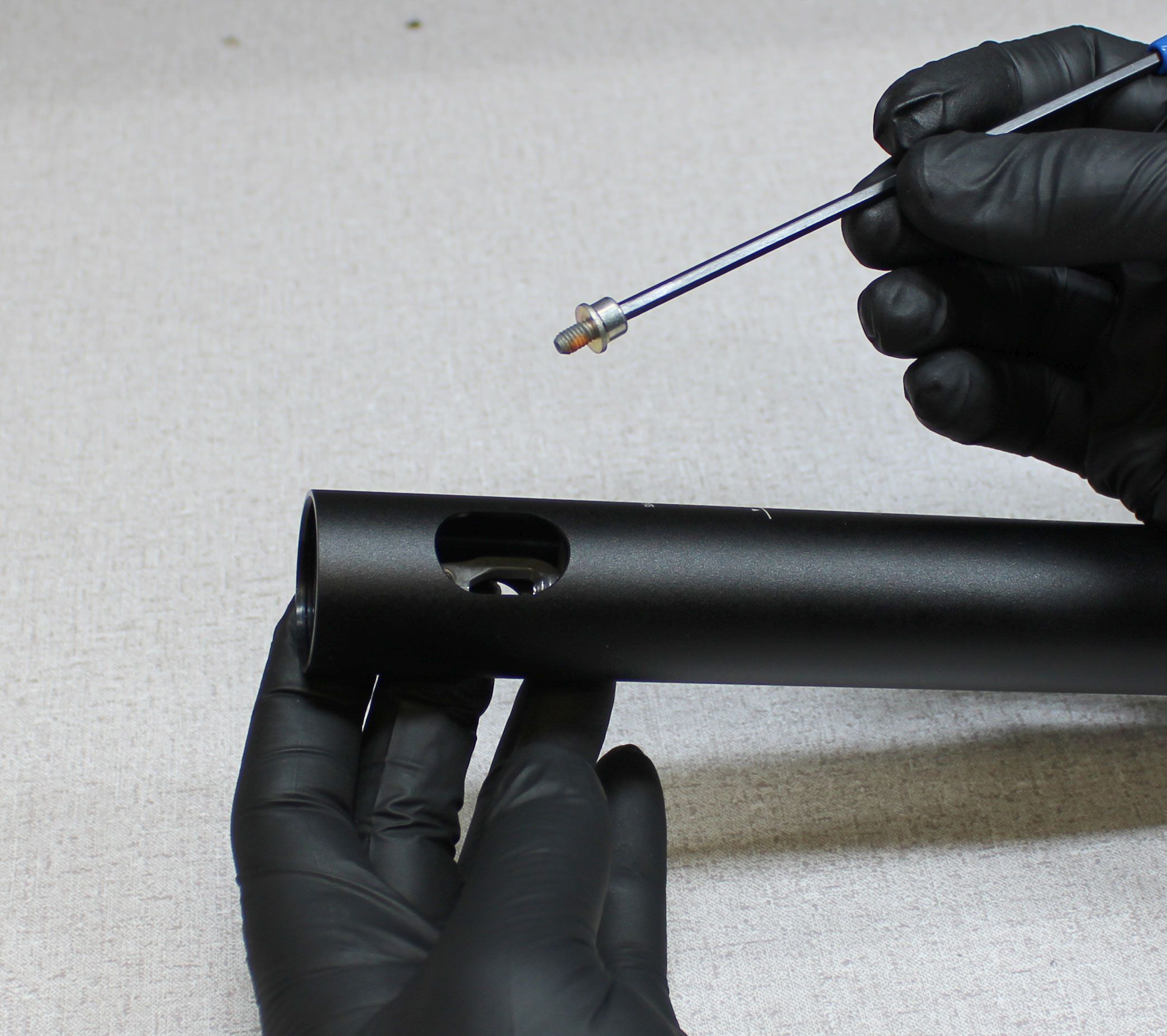
Step 4
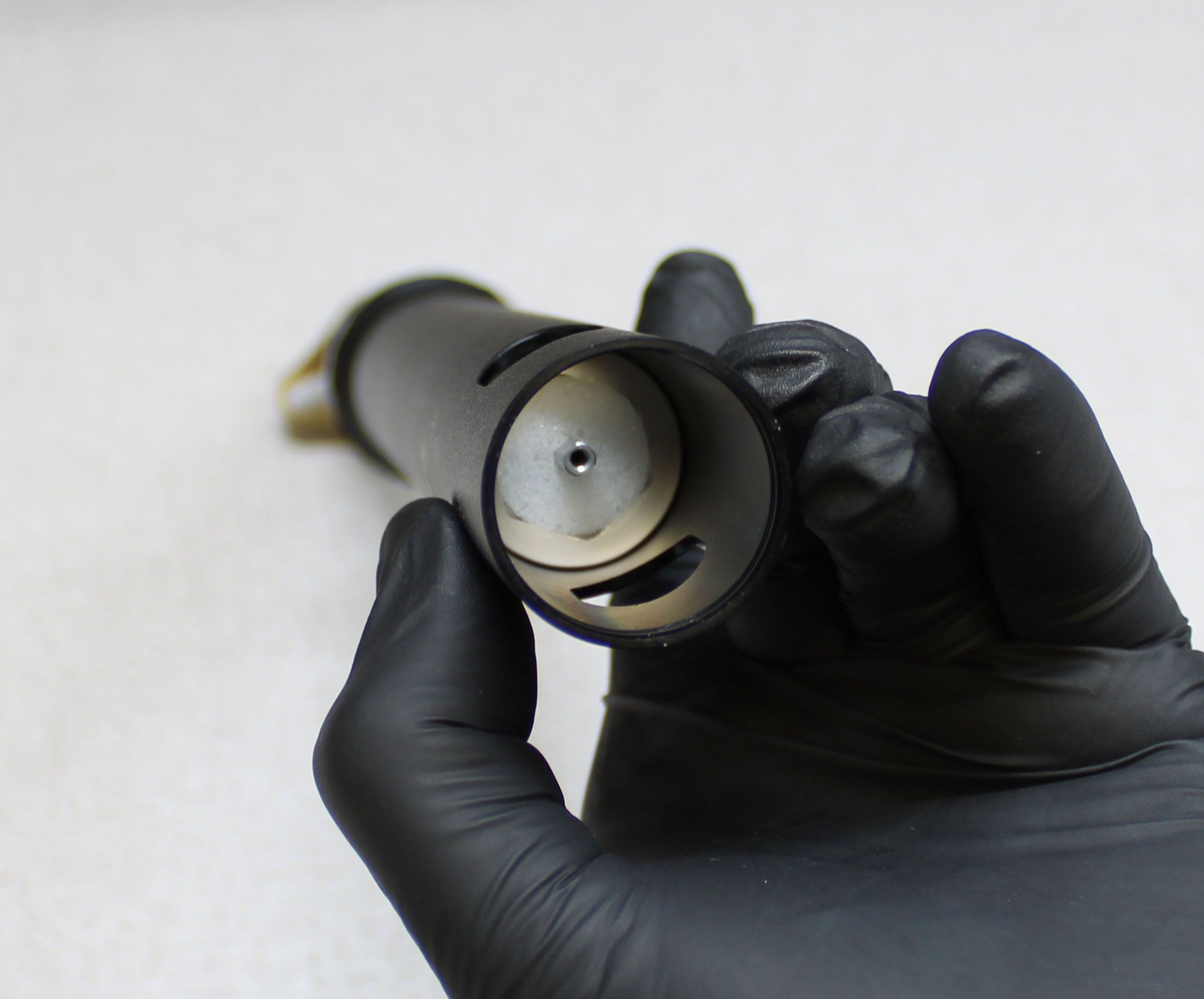
Hold the cable hangar from turning while you unthread the T8 Torx fastener counter-clockwise. Remove the cable hangar and set it aside. Remove the foam debris cover from the lug nut.

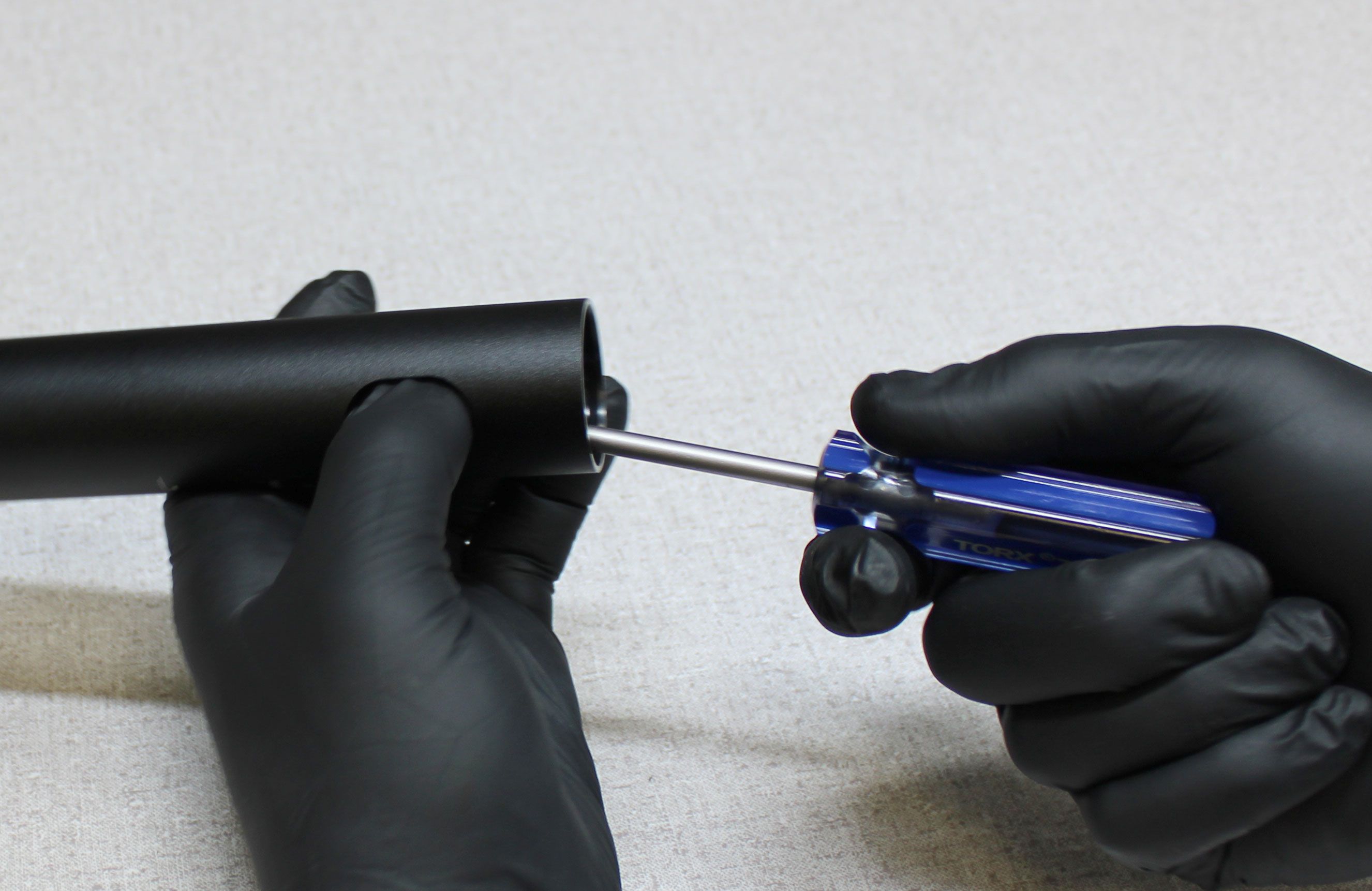
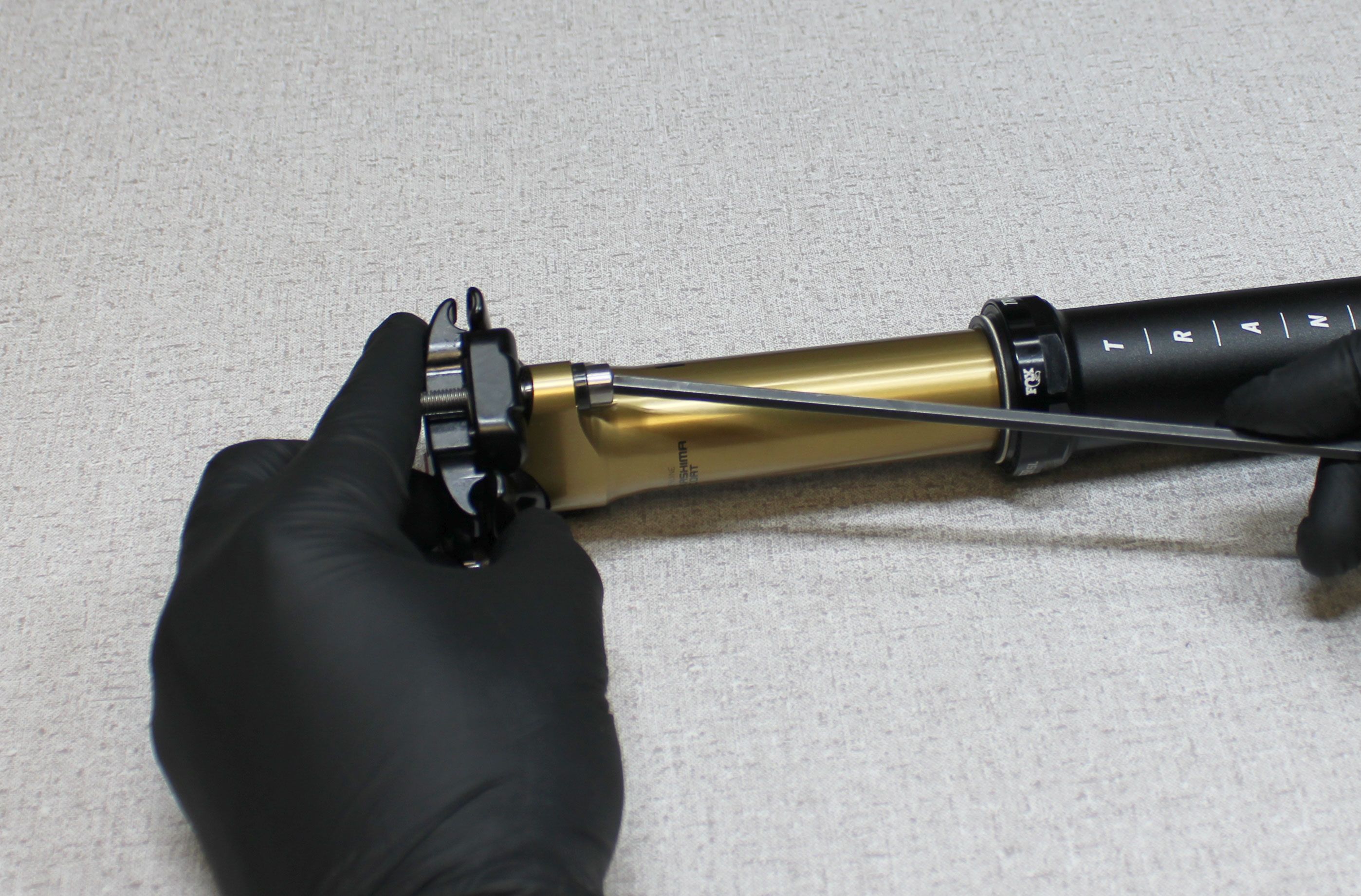
Step 5
Use the retention lug driver (PN: 398-00-838) and an 18mm wrench to unthread the lug nut counter-clockwise. Remove the lug nut and set it aside.

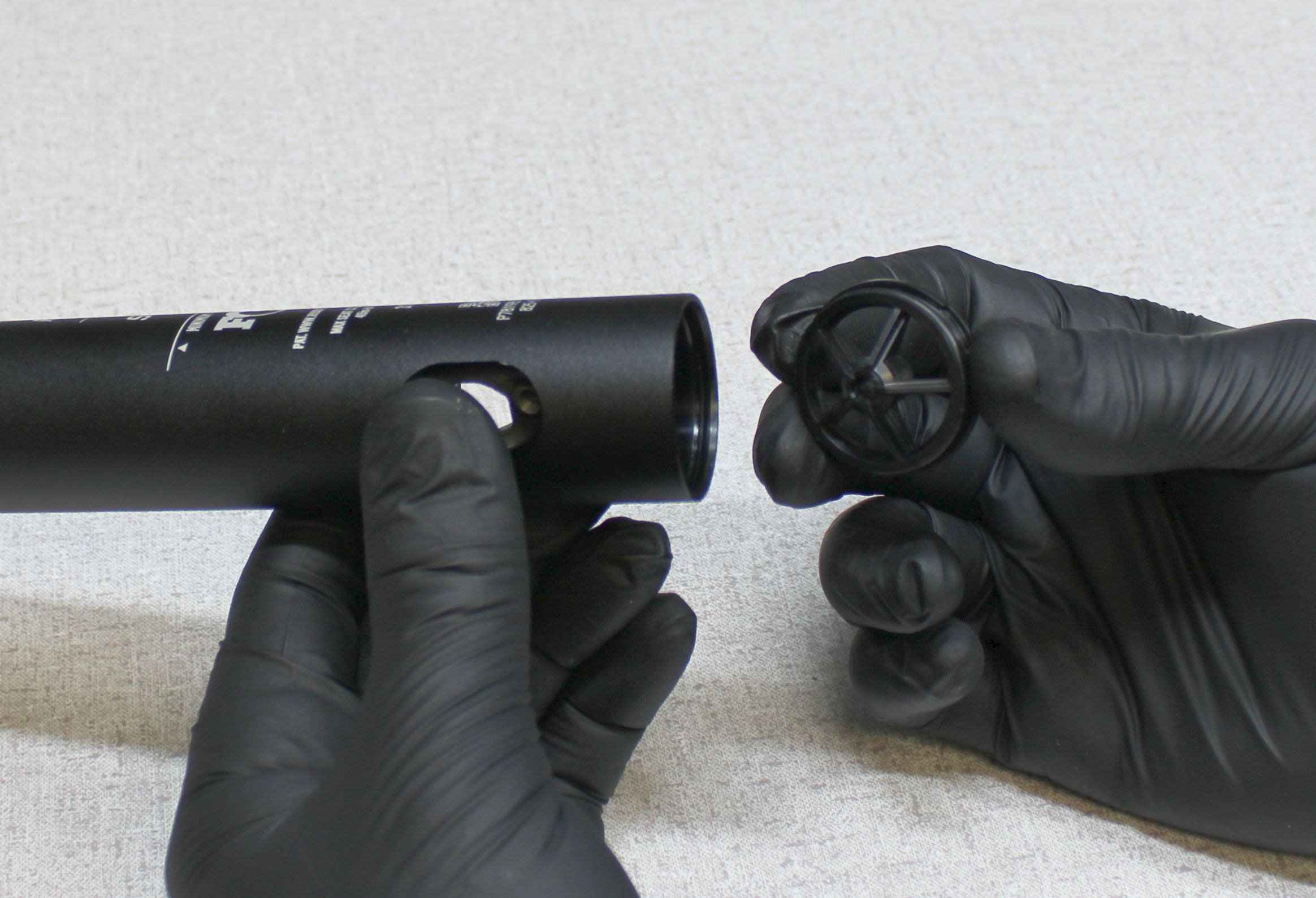
Step 6
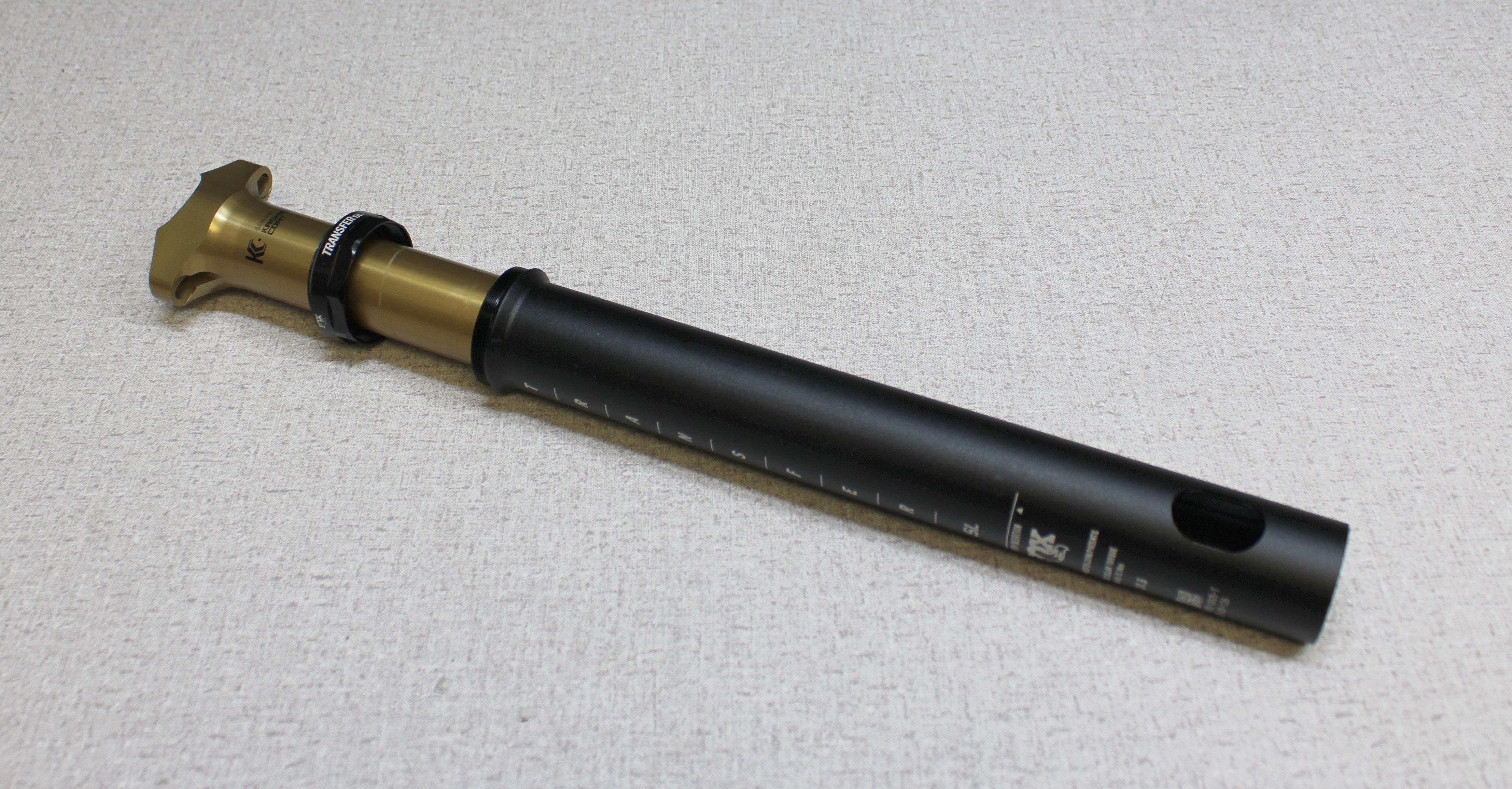
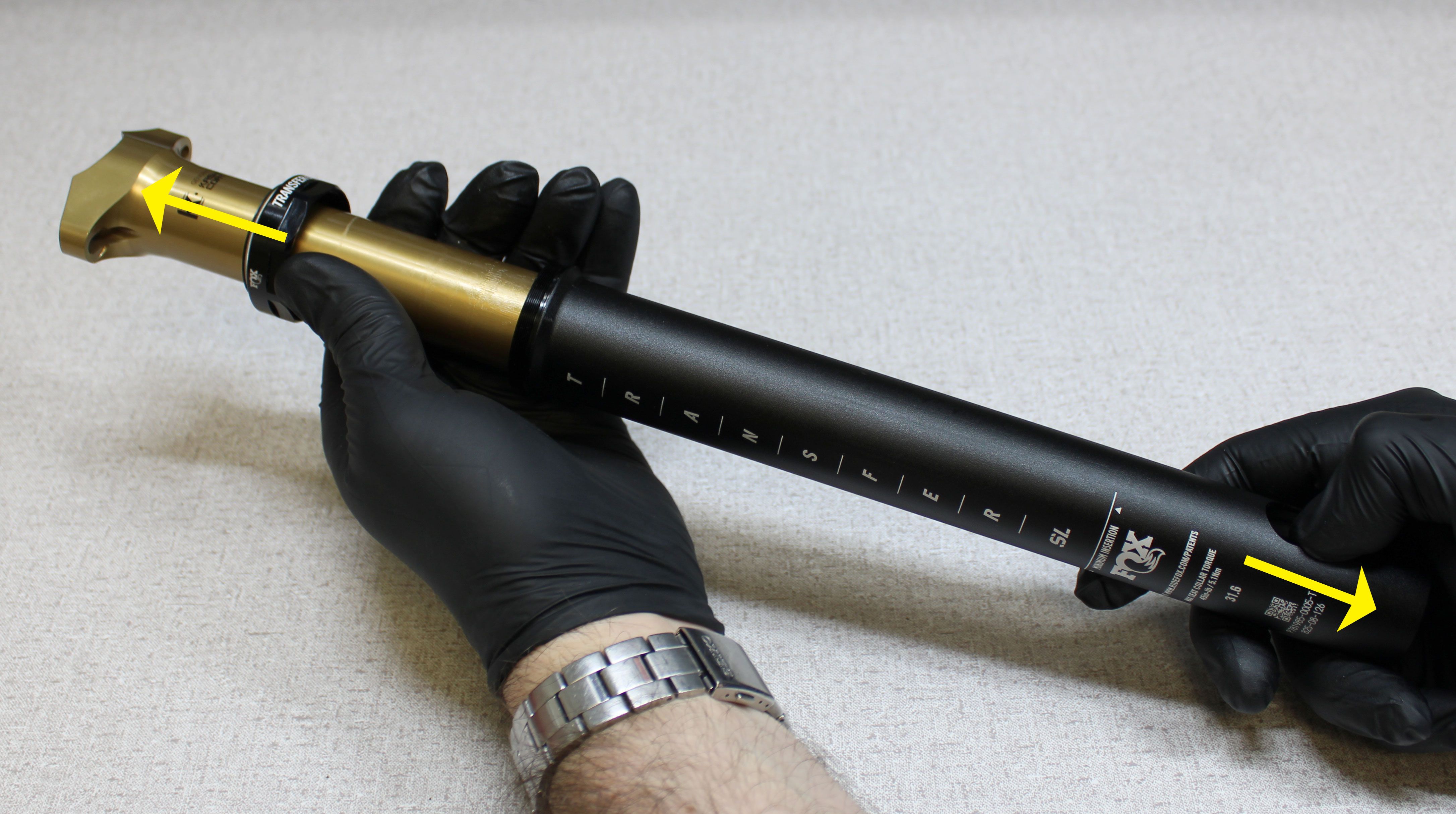
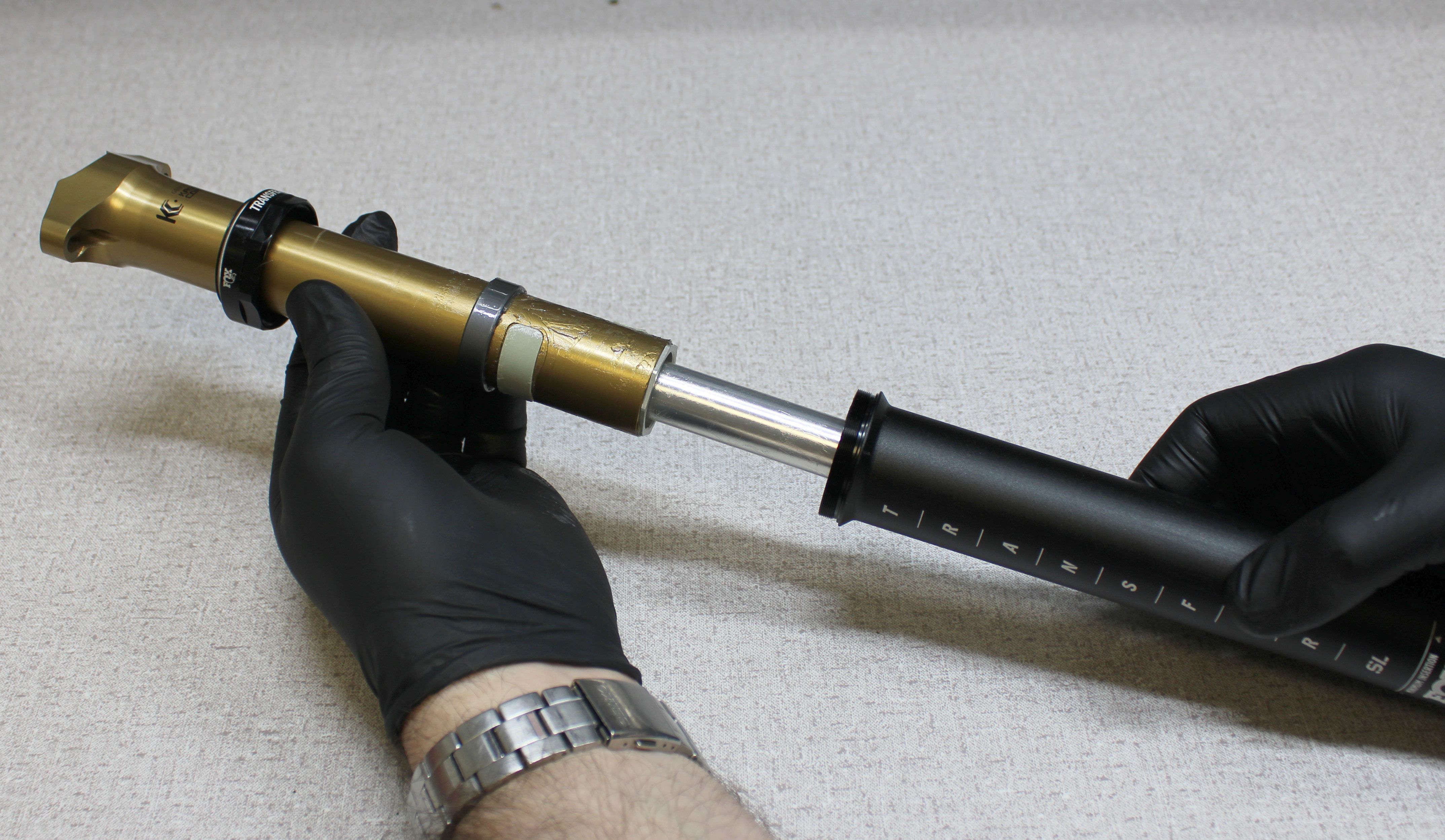
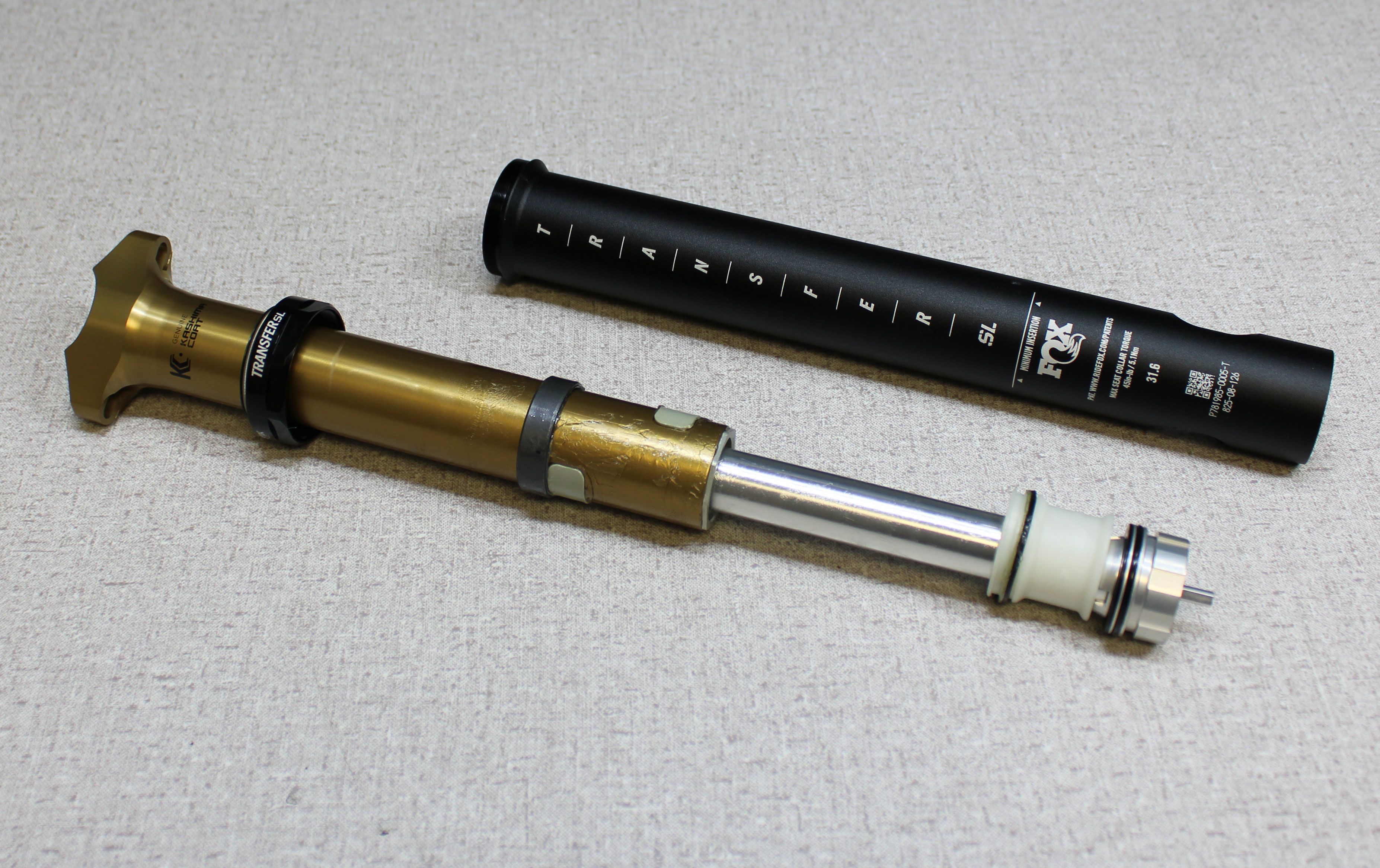
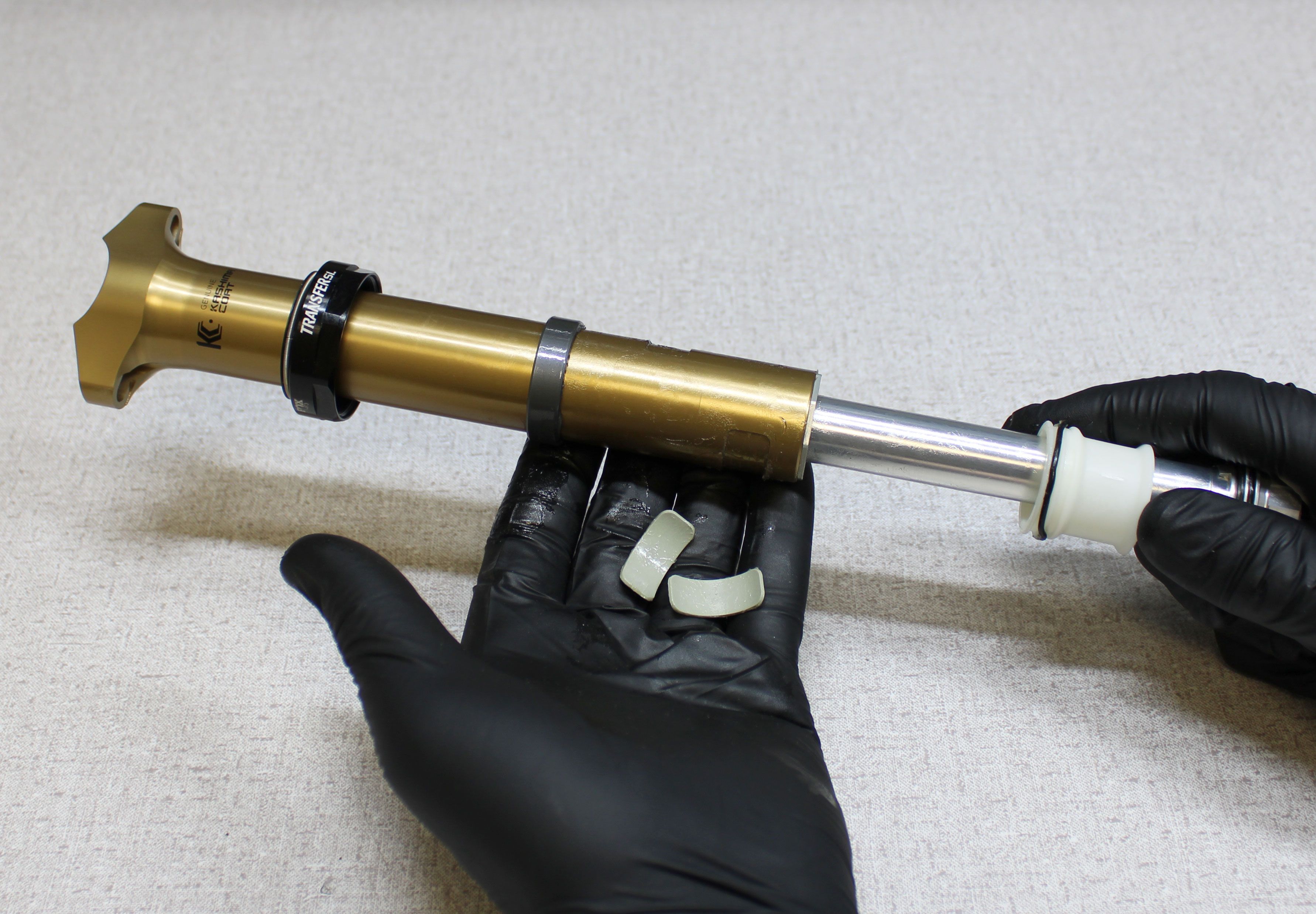
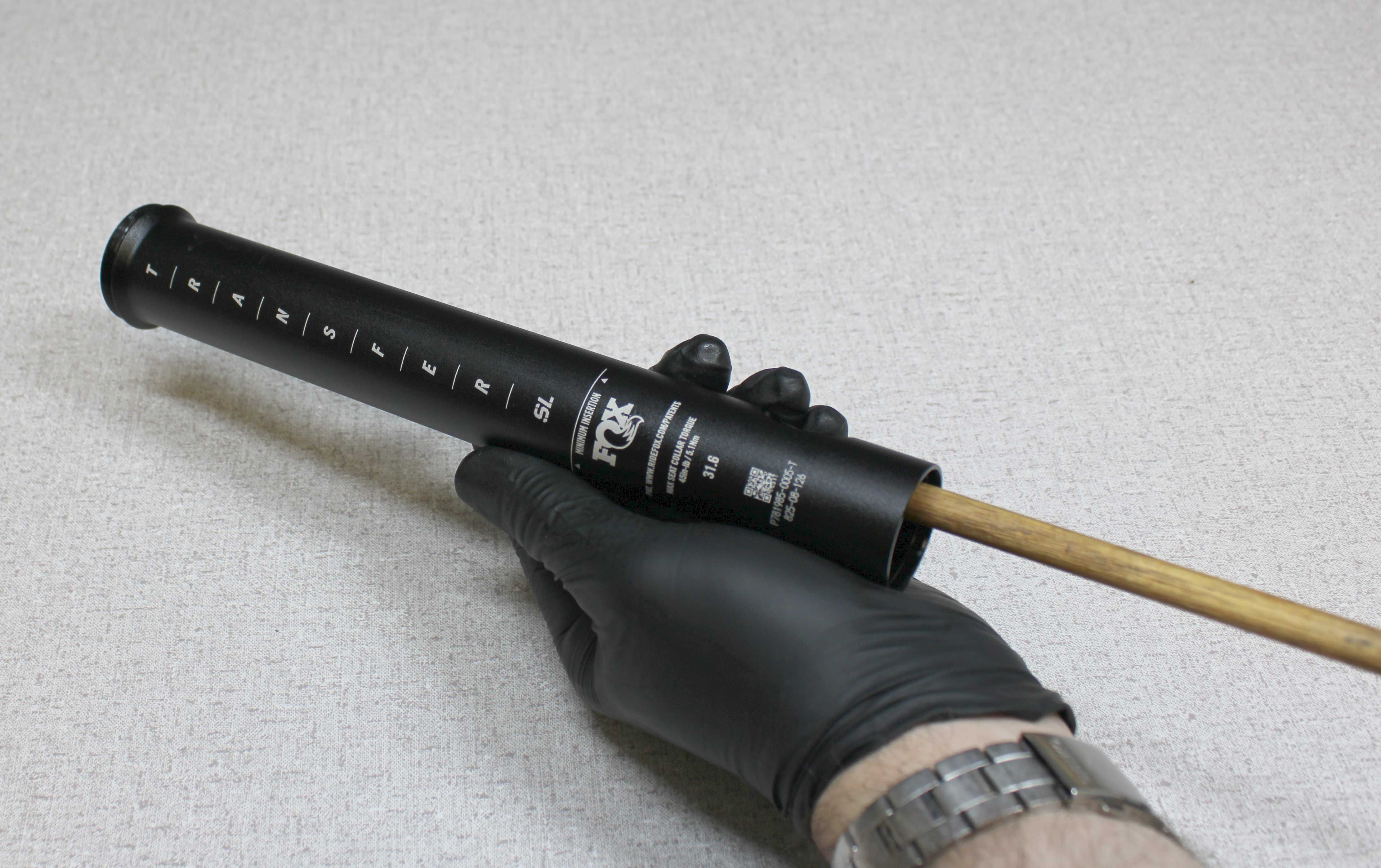
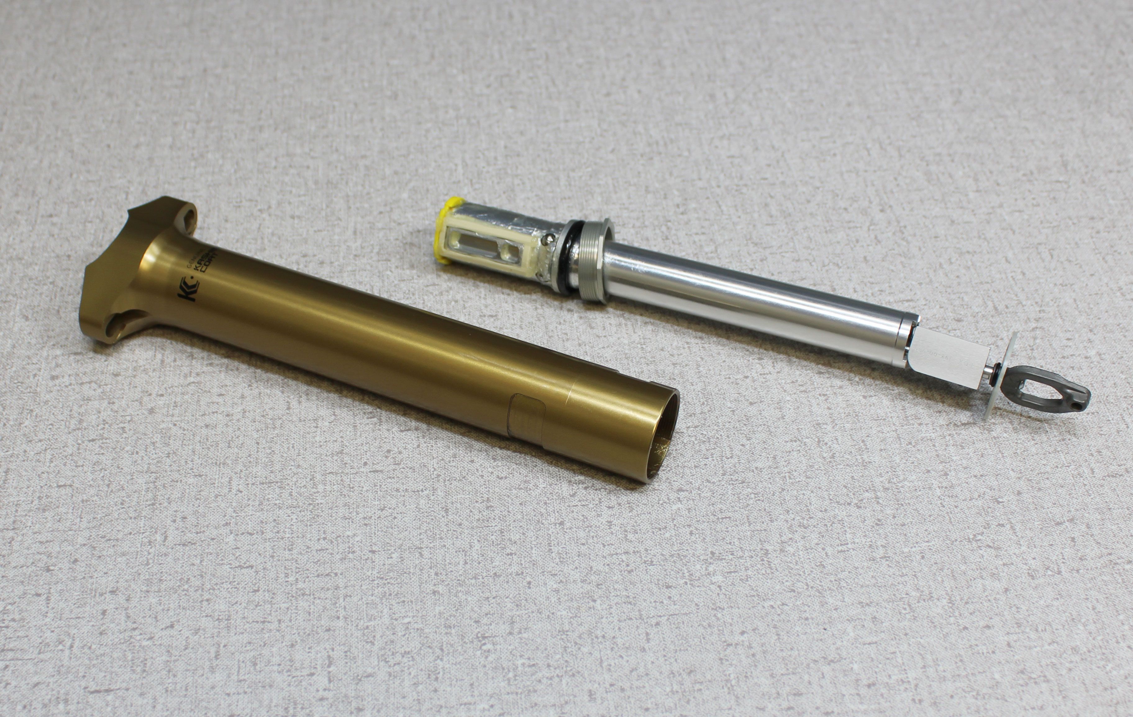
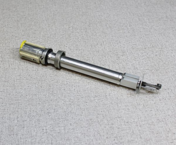
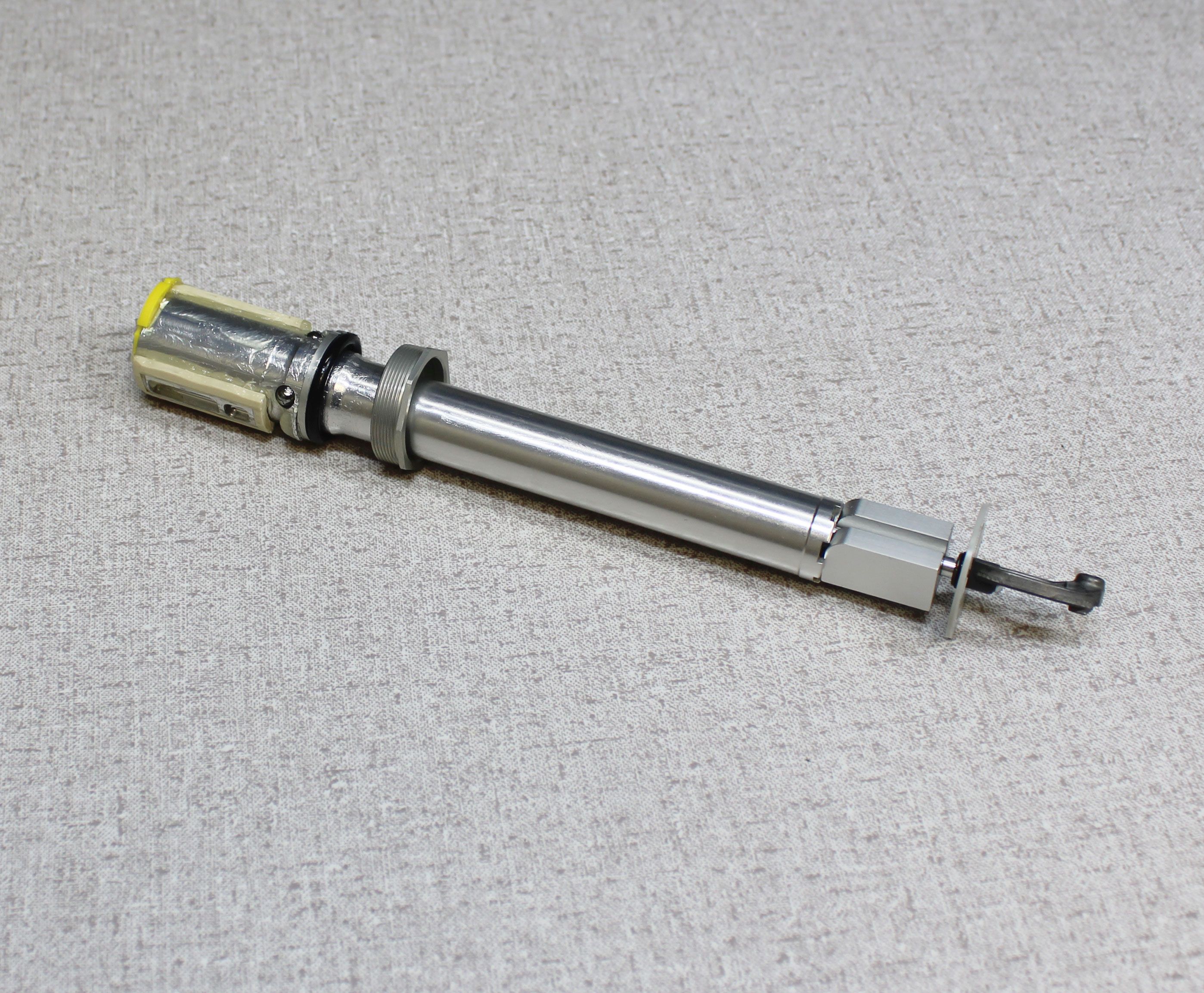
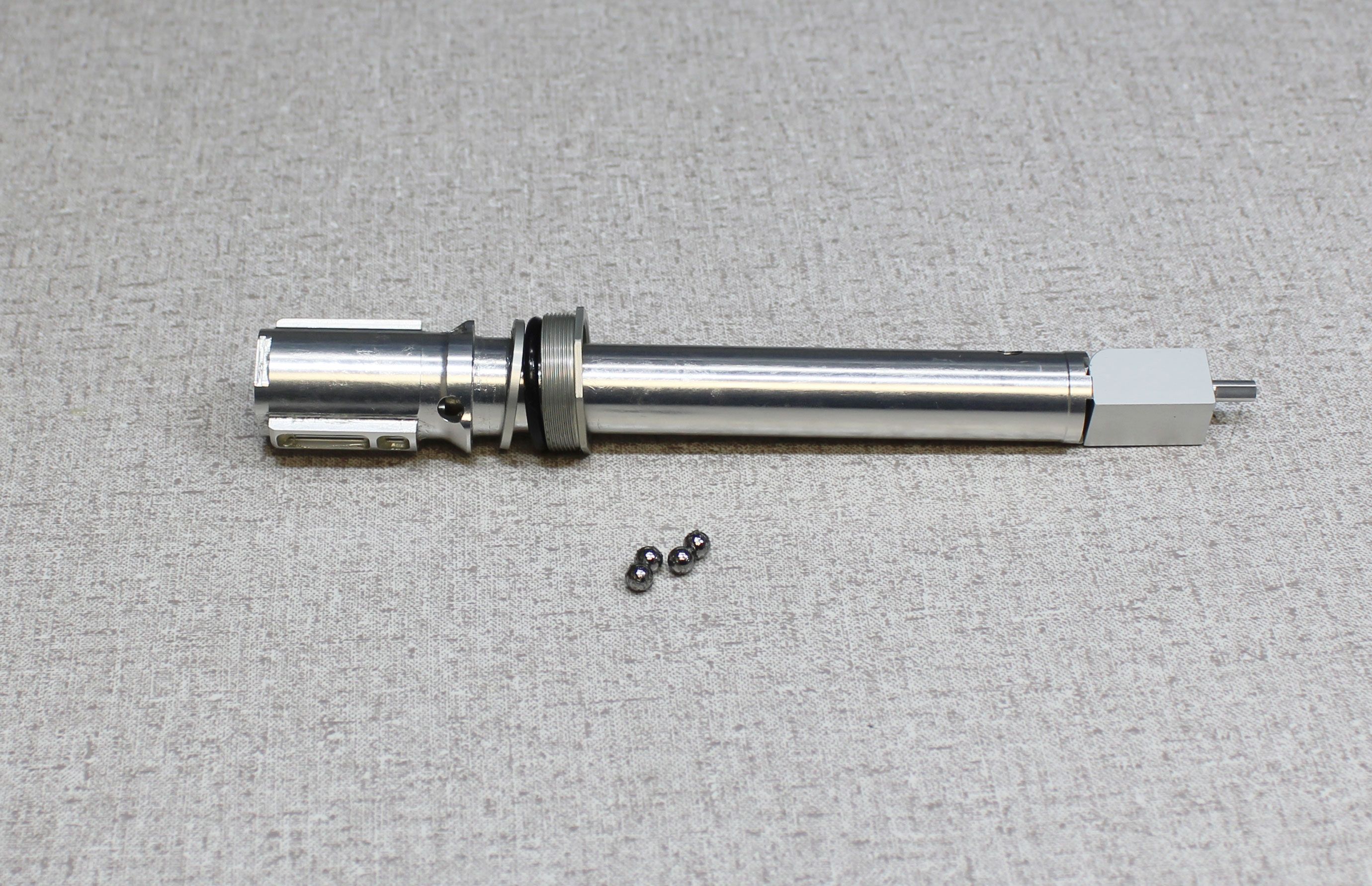
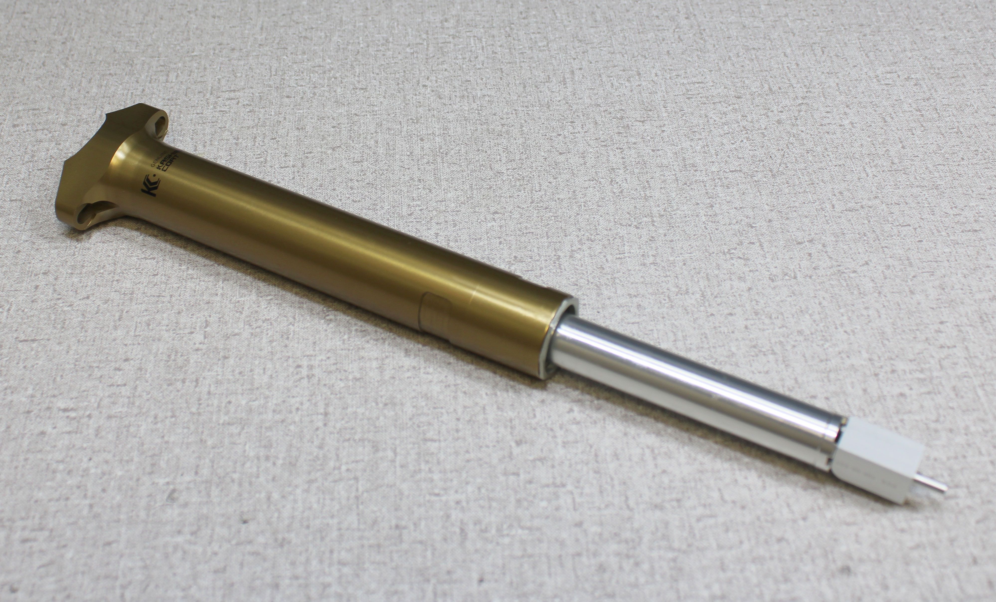
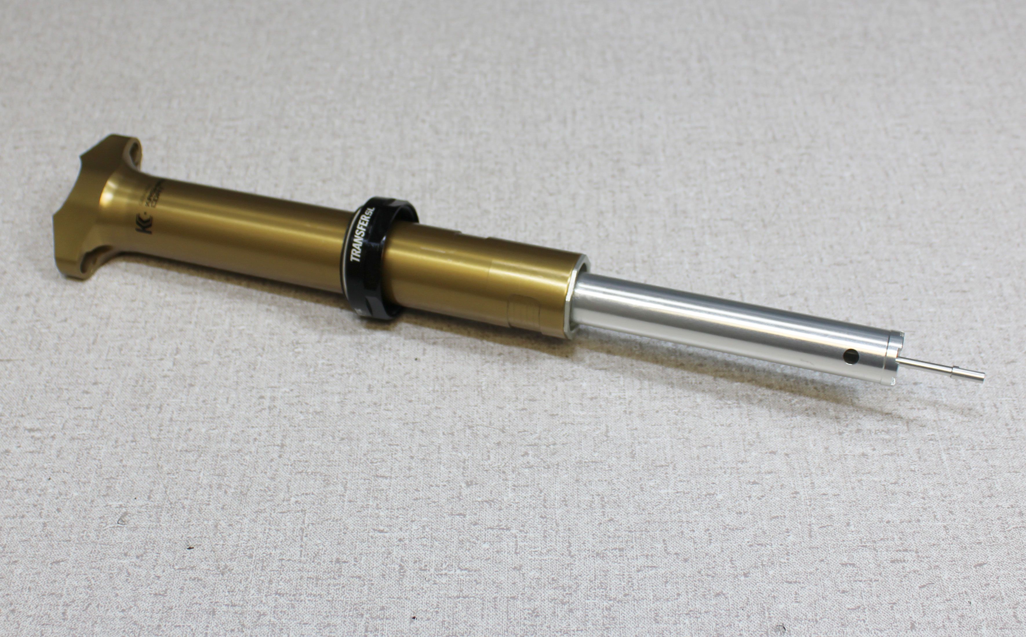
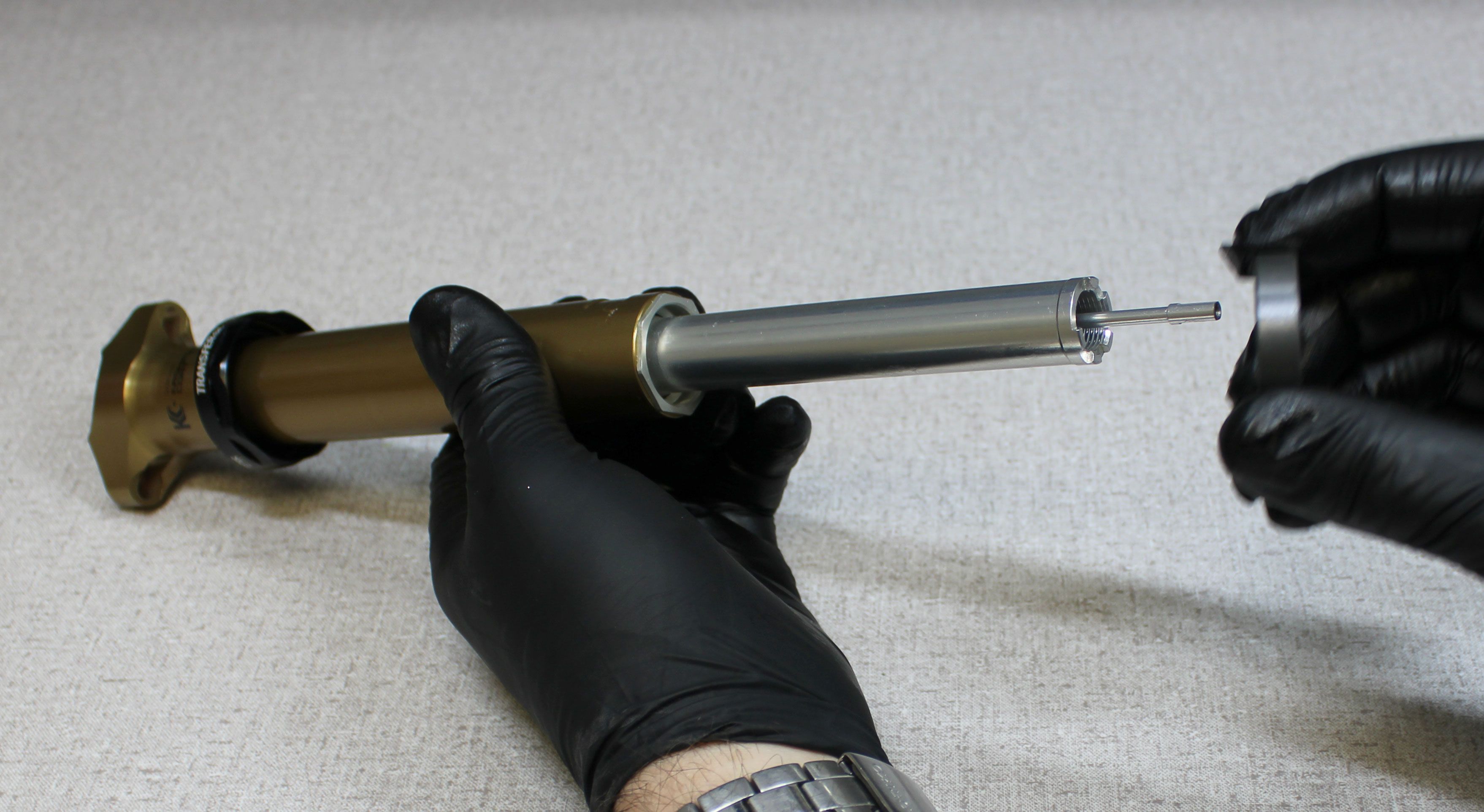
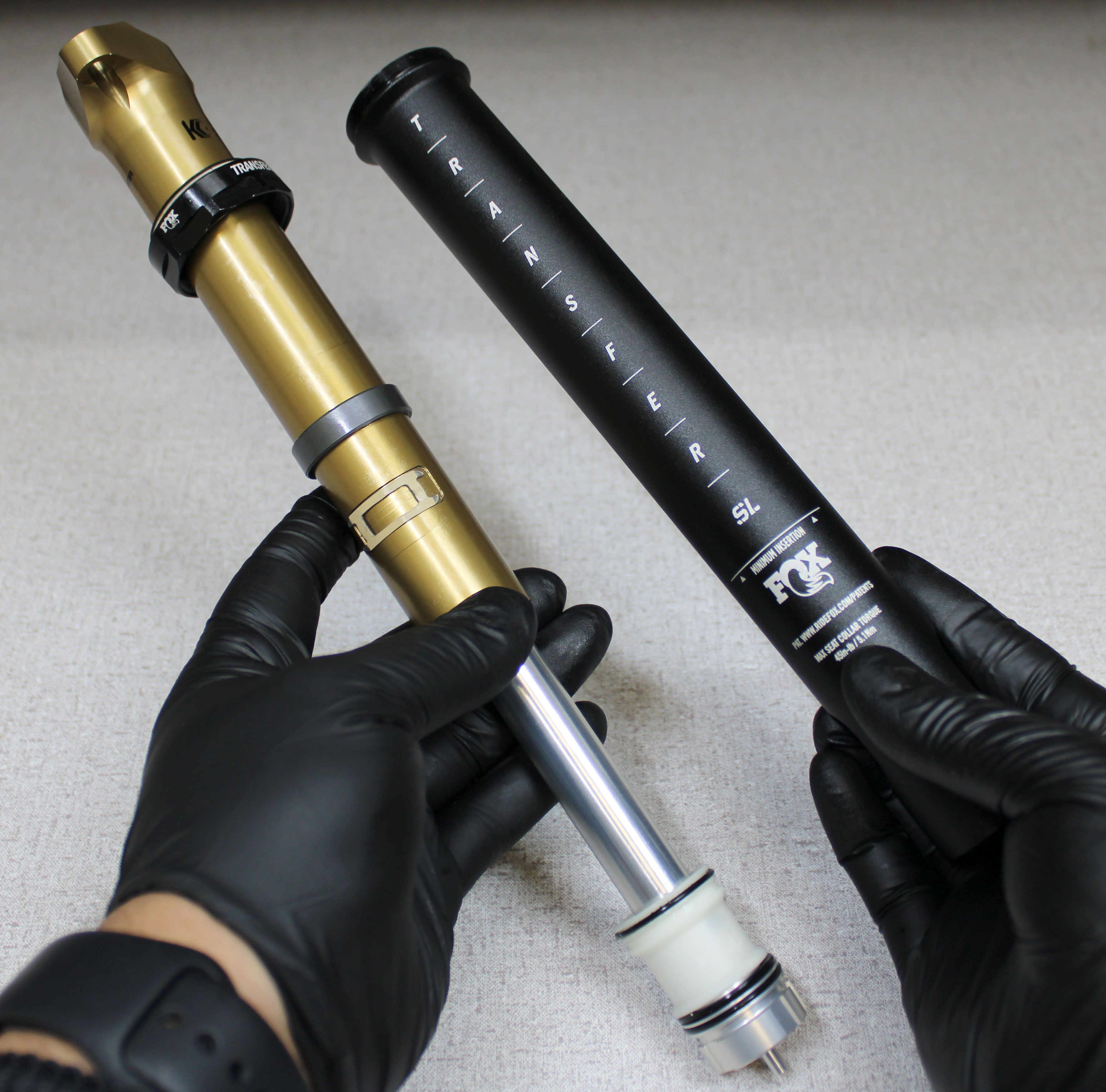
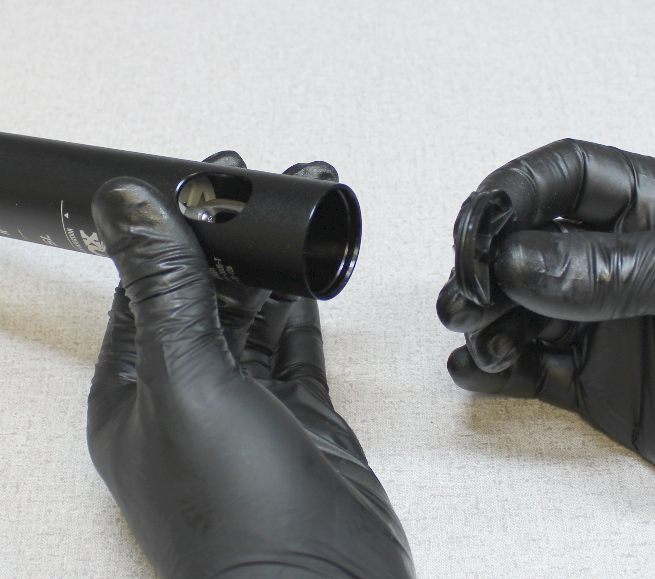
Remove the post from your workstand then separate the upper post from the lower over your workbench. Remove the front and rear bushings. The locking body coupling and bottom out spacer (if present) may be stuck within the lower post. Use a wooden dowel or other blunt tool to push the locking body coupling and bottom out spacer from the lower post.
WARNING: Safety glasses MUST be worn during disassembly and reassembly of the Transfer SL seatpost. Transfer SL seatposts contain a highly preloaded spring and this stored energy must be released slowly according to FOX technical instructions to ensure safety during service. Failure to wear safety glasses while servicing the Transfer SL may cause SERIOUS INJURY OR DEATH.

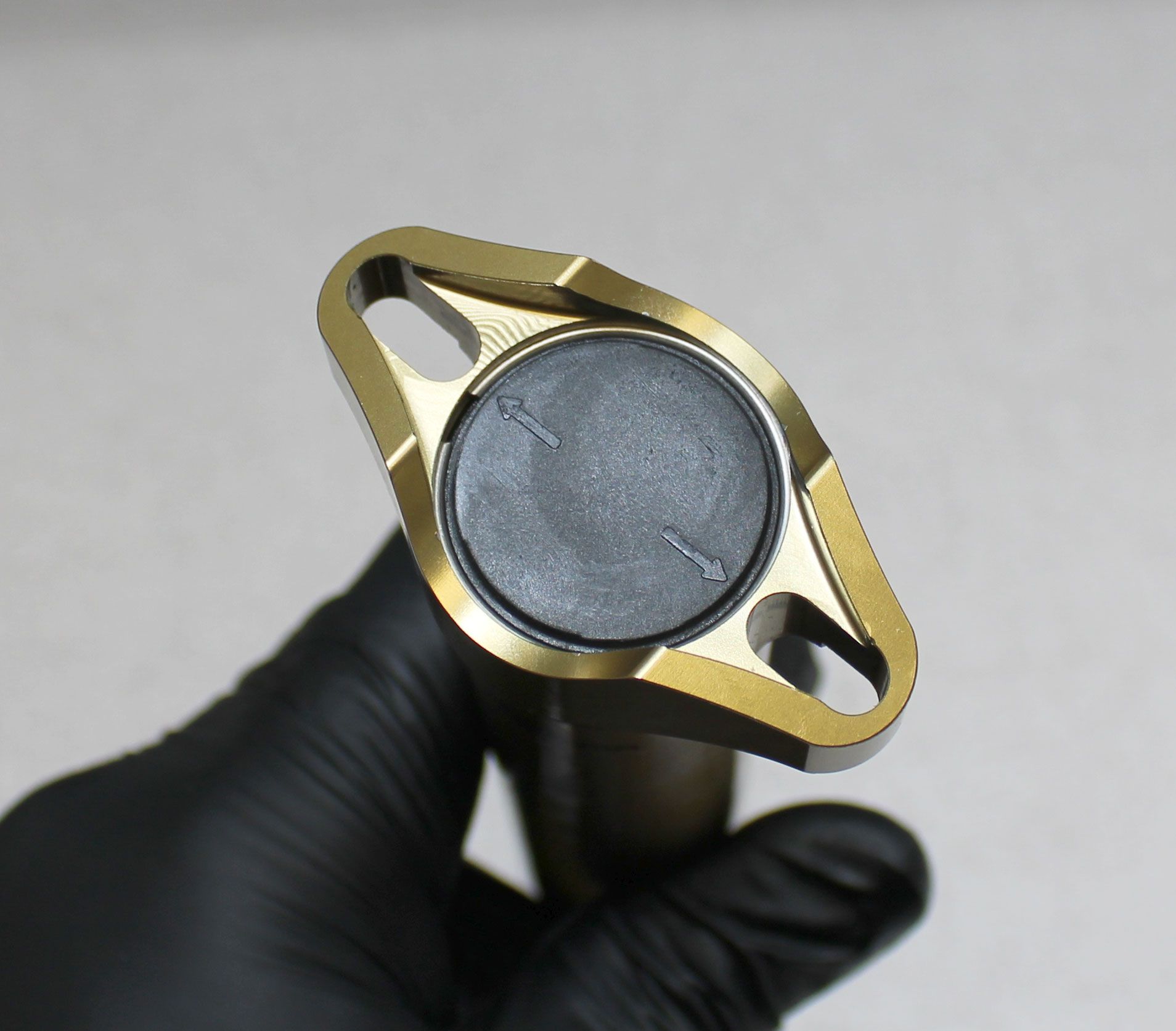
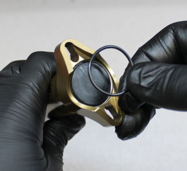
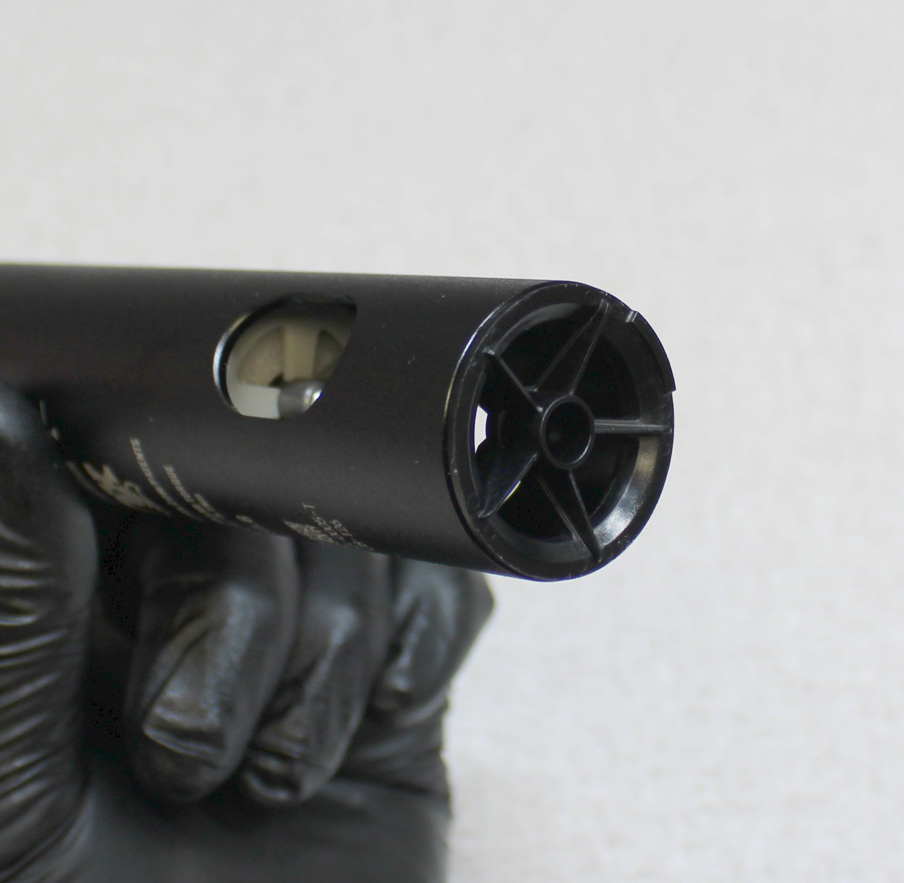
Step 7
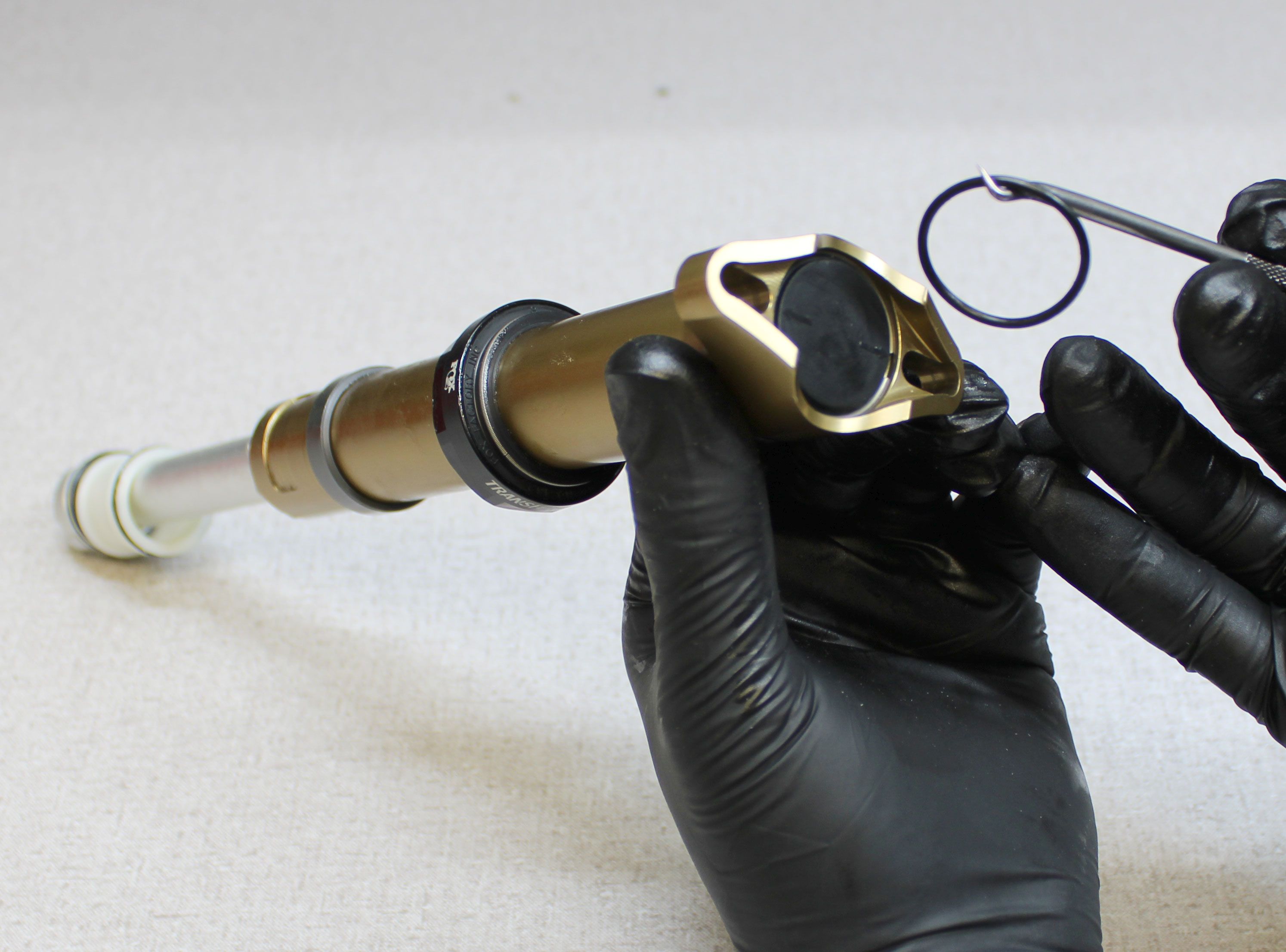
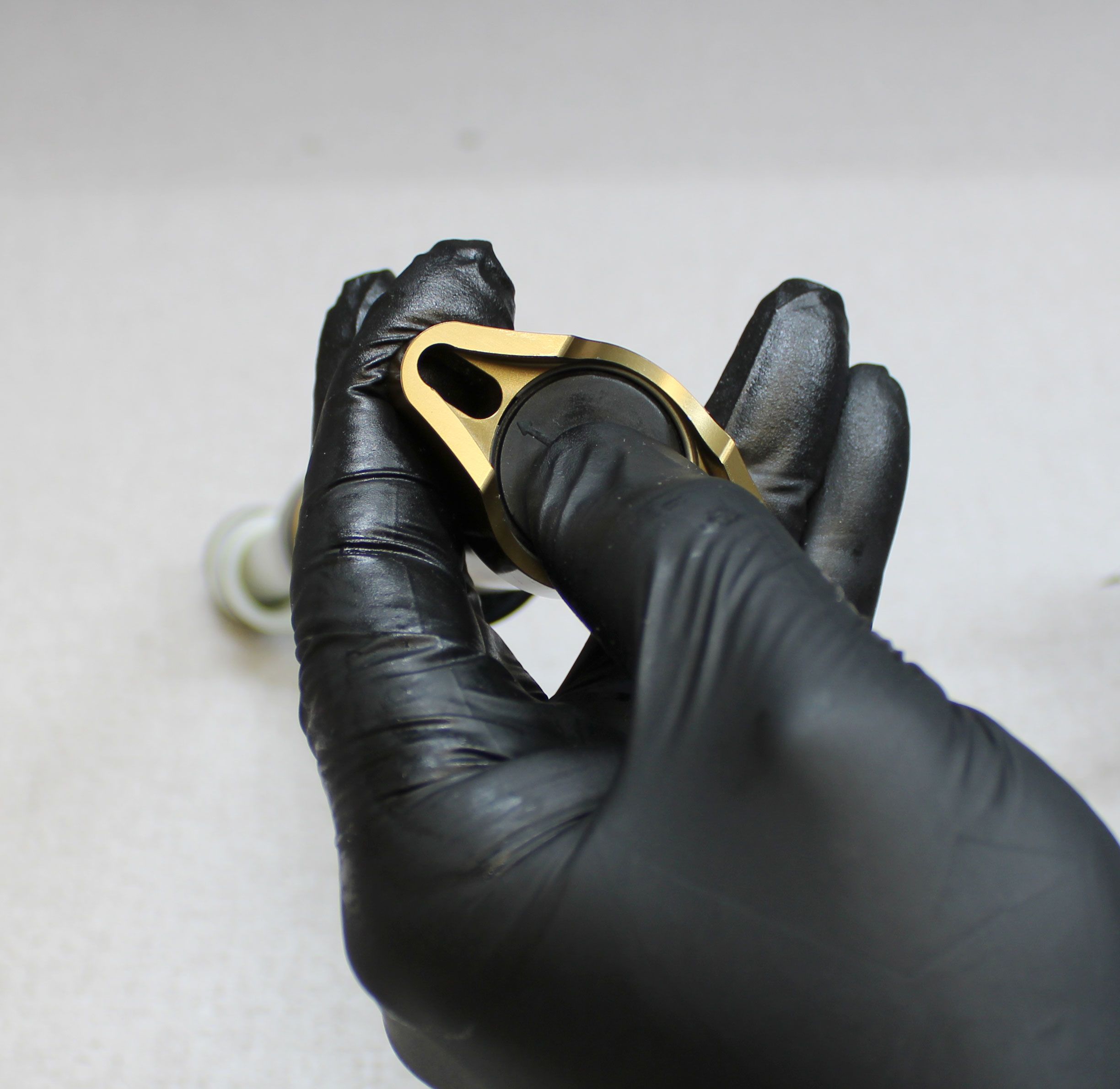
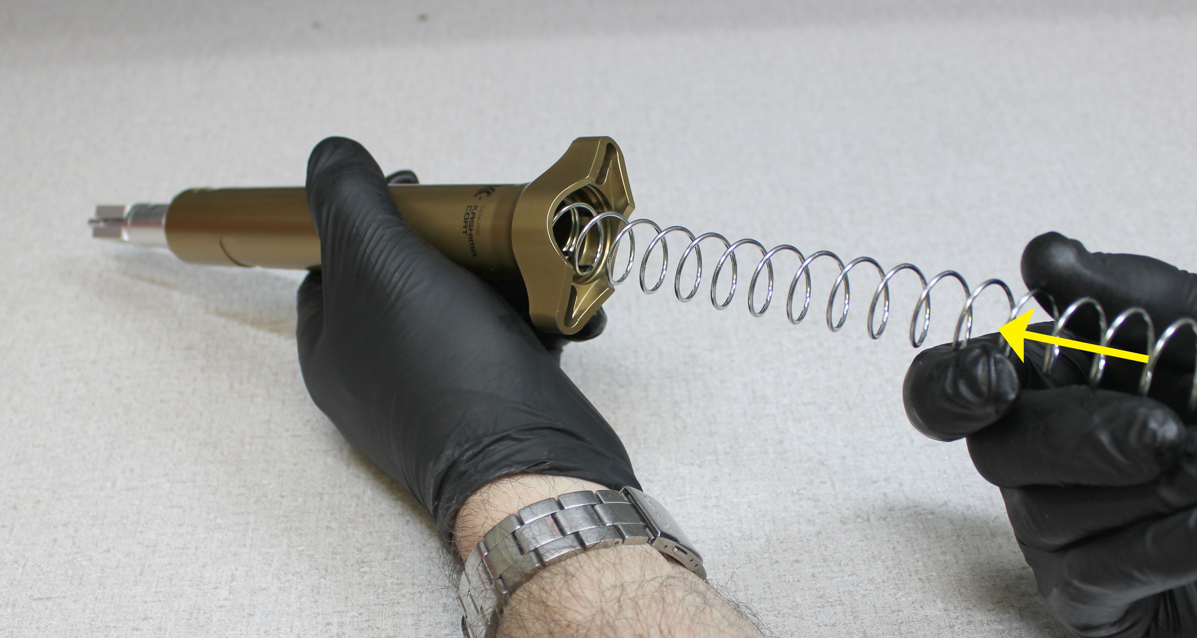
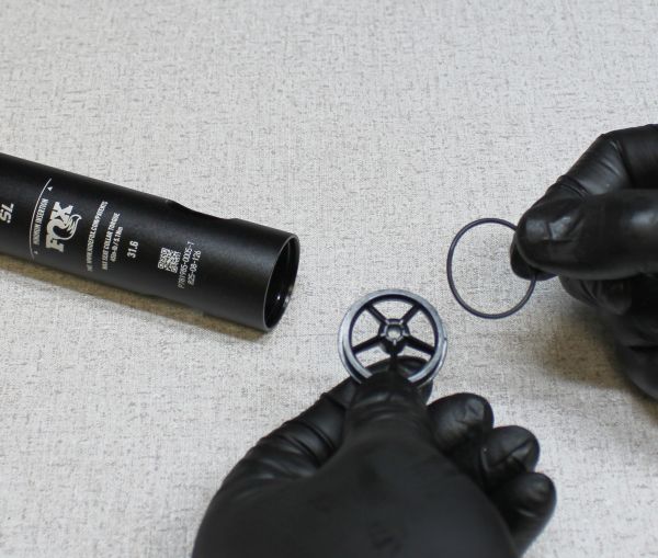
Remove the o-ring at the top of the post. Press the upper spring perch into the upper post while you carefully remove the wire retaining ring. Keep pressure on the upper spring perch as you slowly release the spring preload.
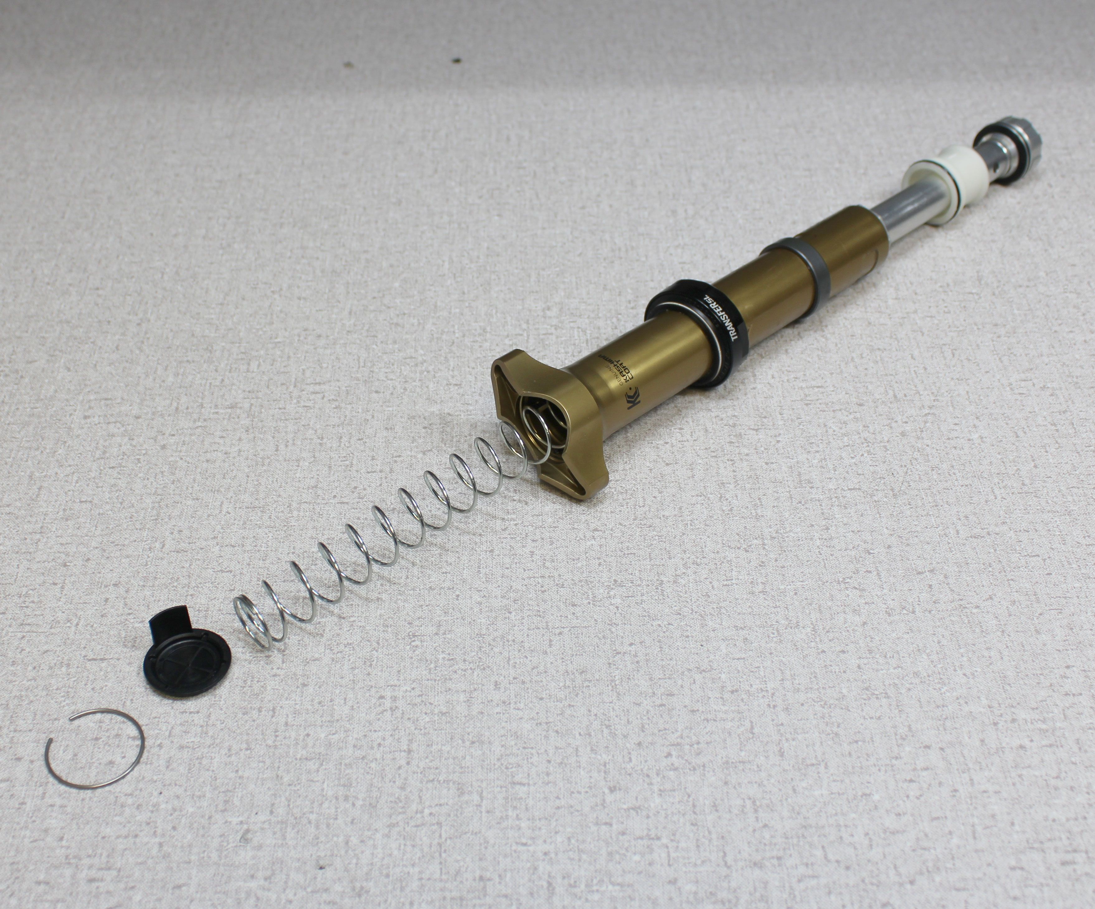
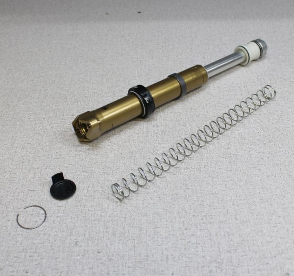
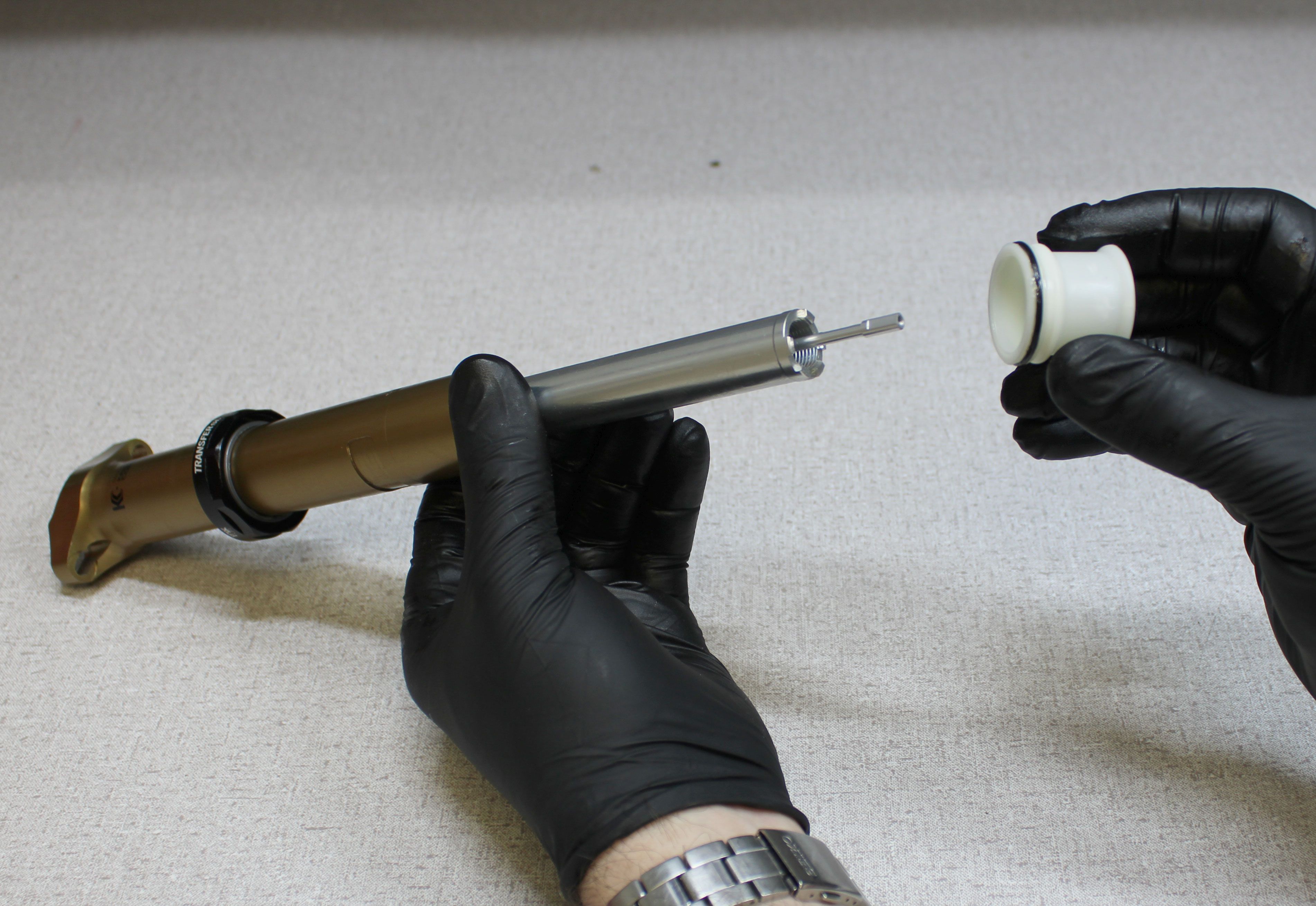
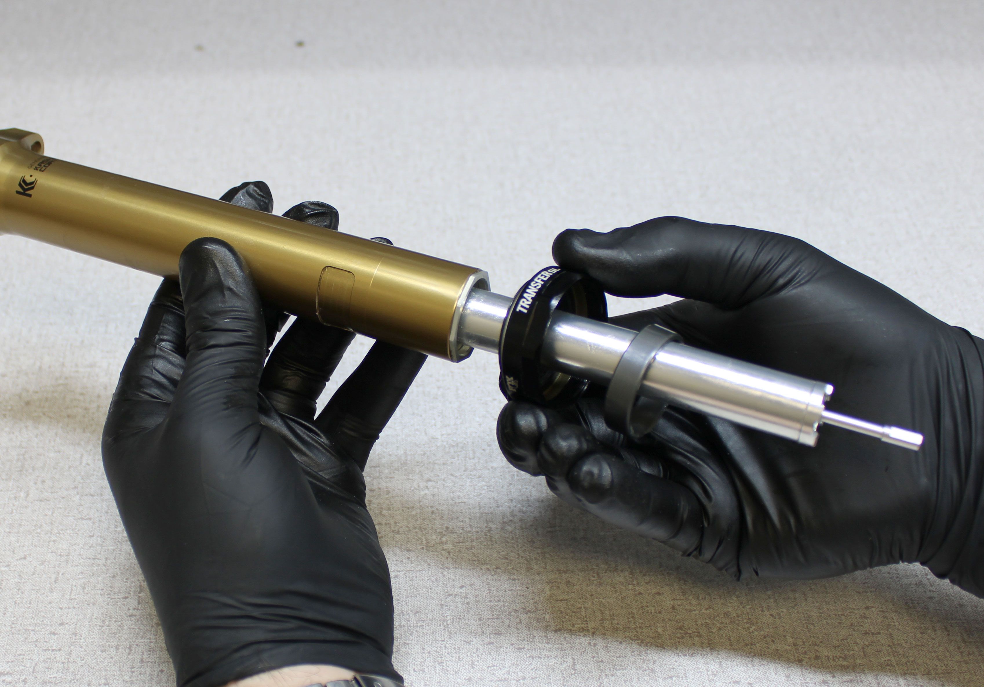
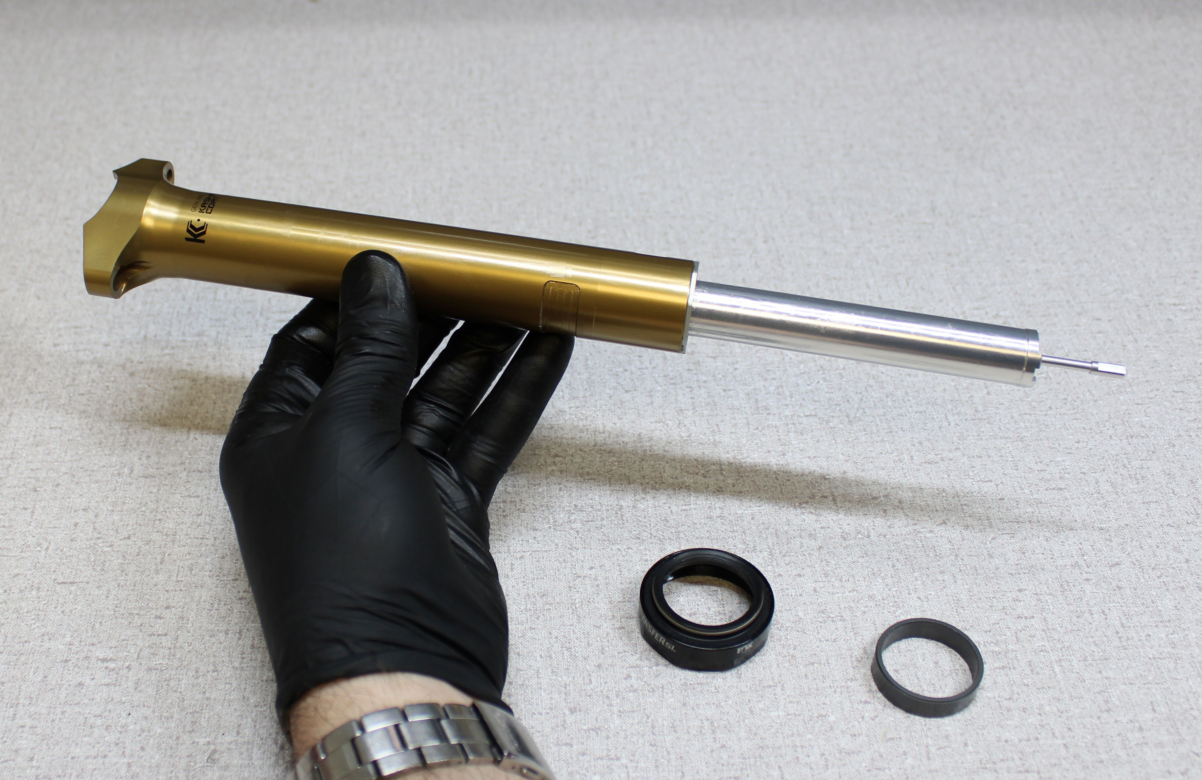
Step 8
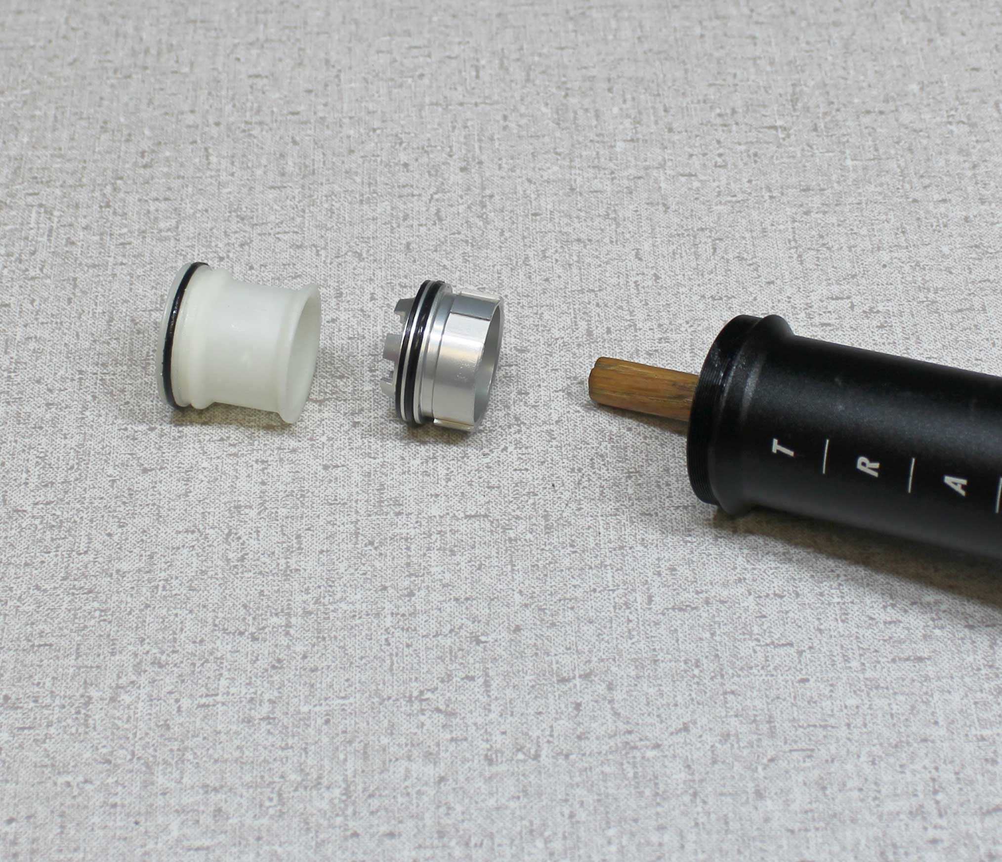
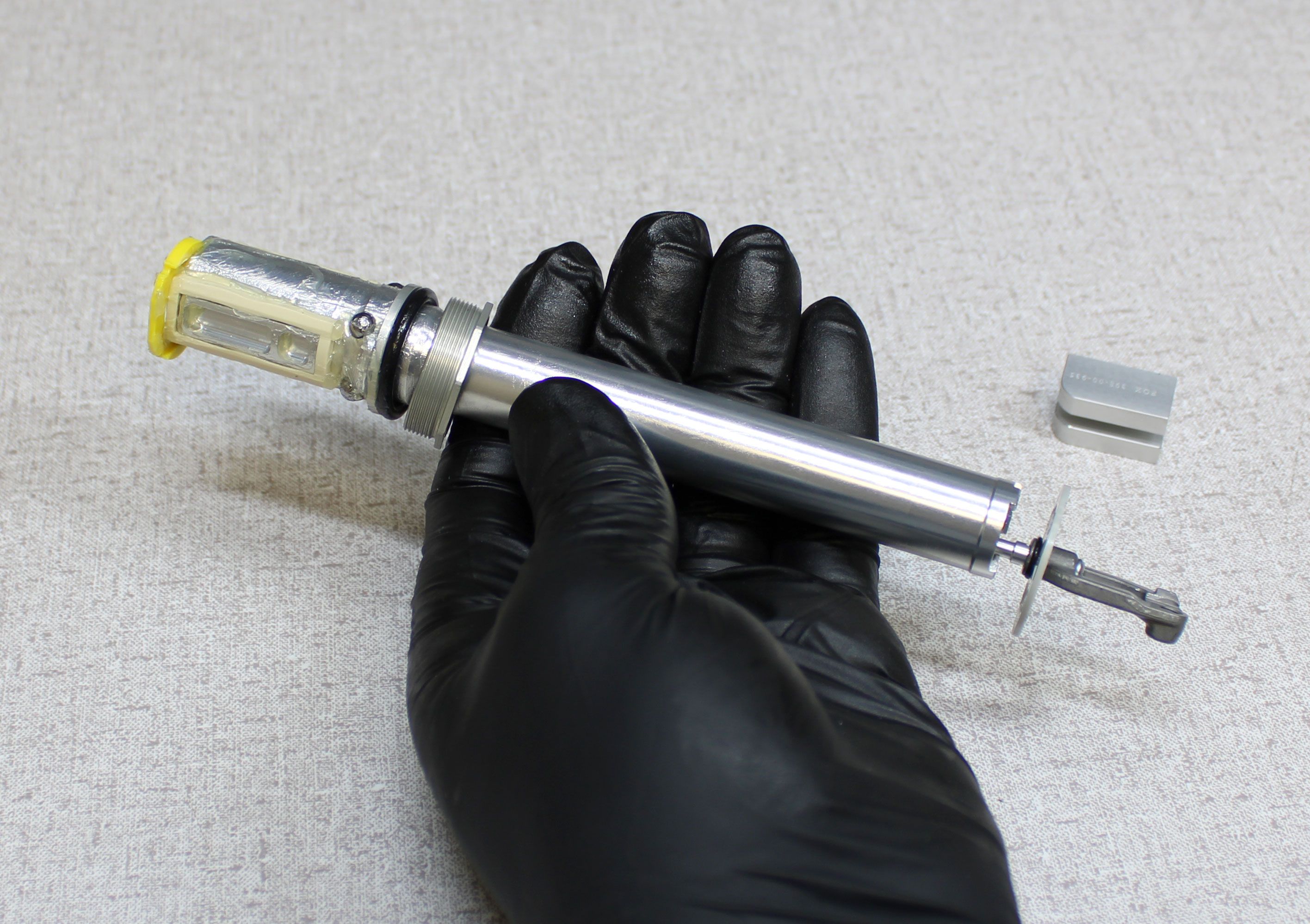
Remove the spring from the upper post. If not found in the lower post, remove the locking body coupling from the locking body then set it aside. If not found in the lower post, remove the bottom out spacer if present. Remove the upper bushing and sealhead assembly.


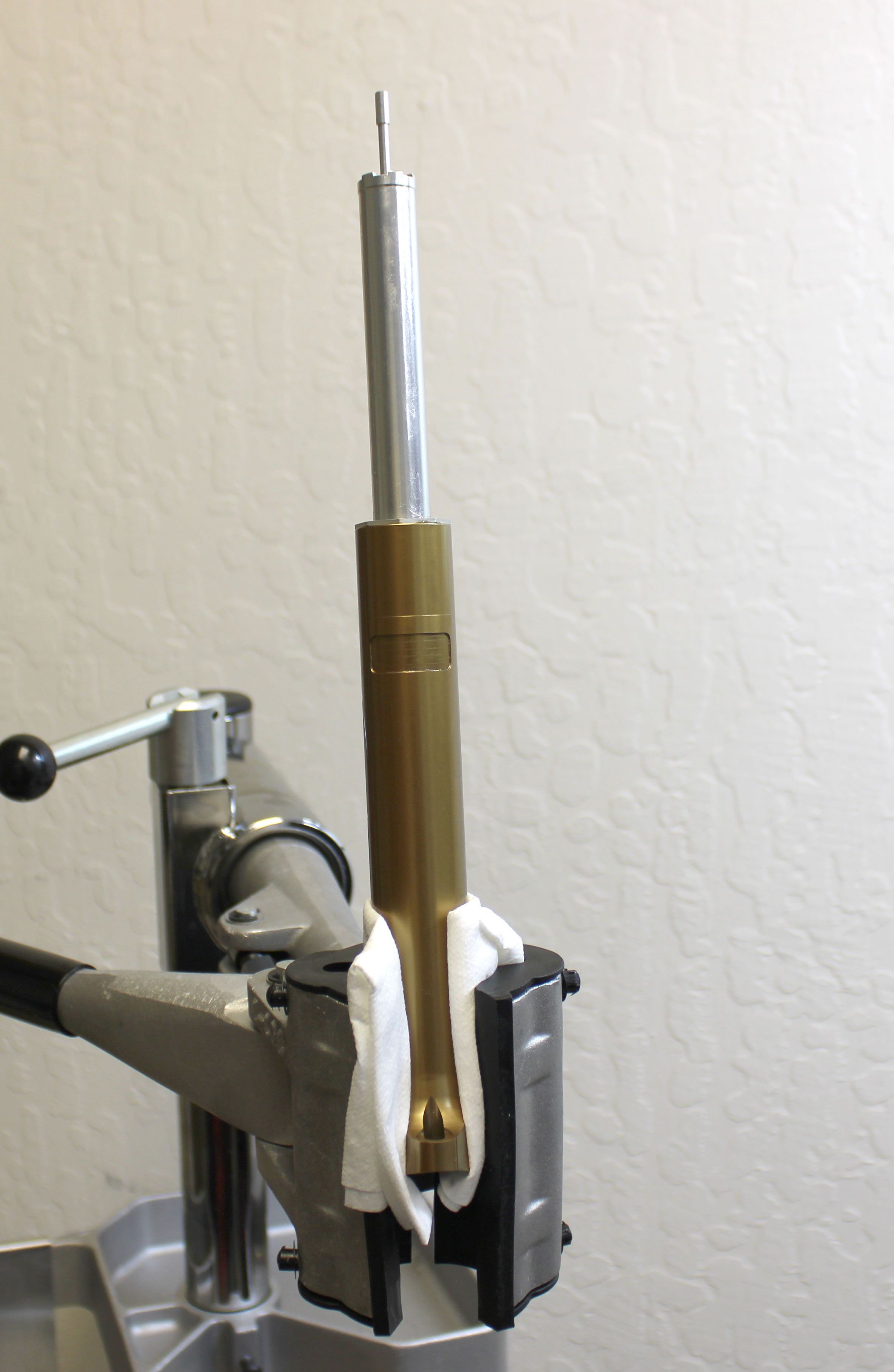
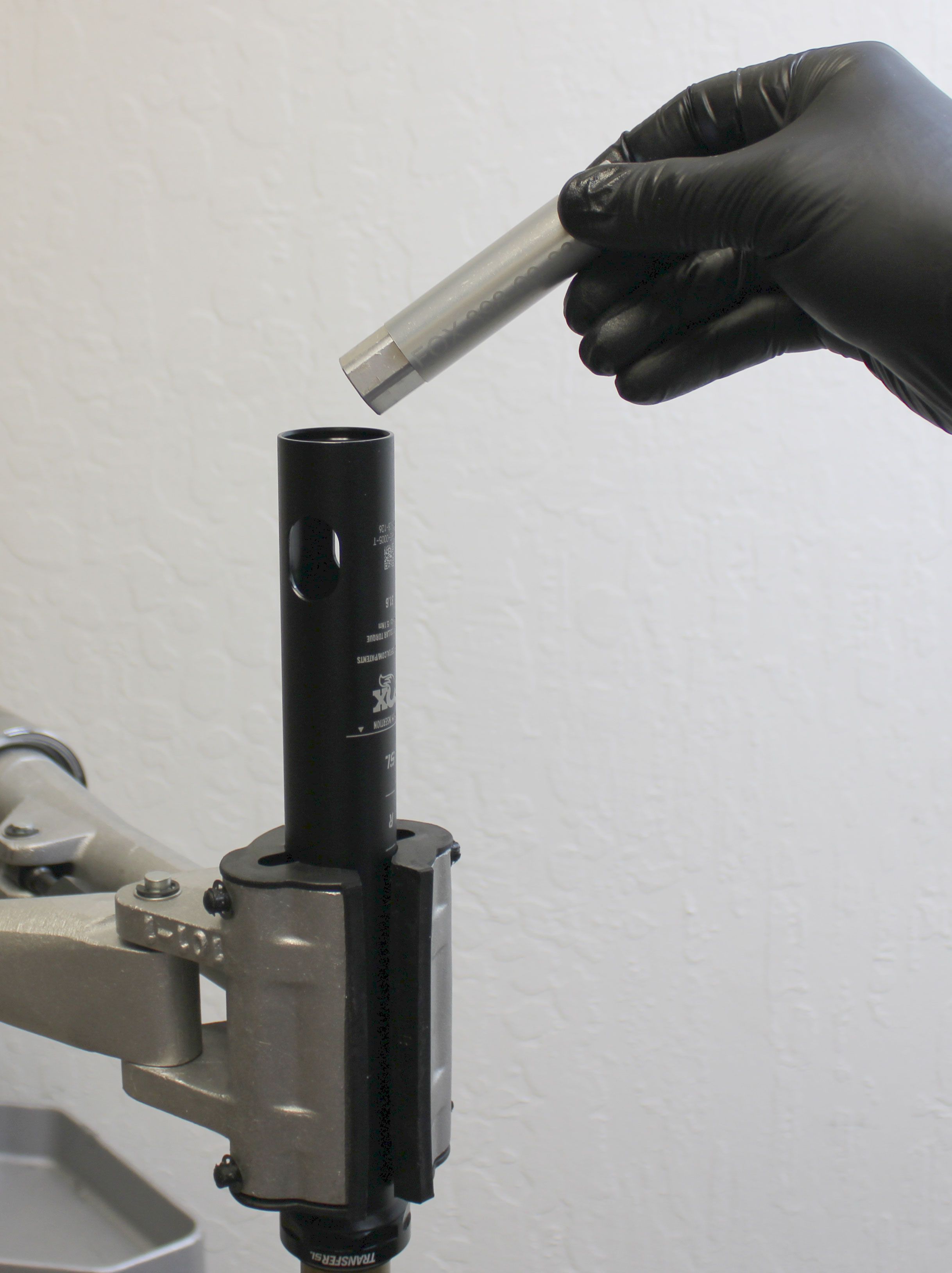
Step 9
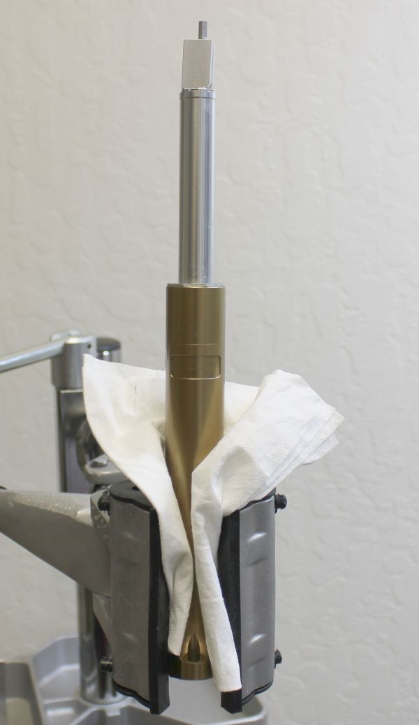
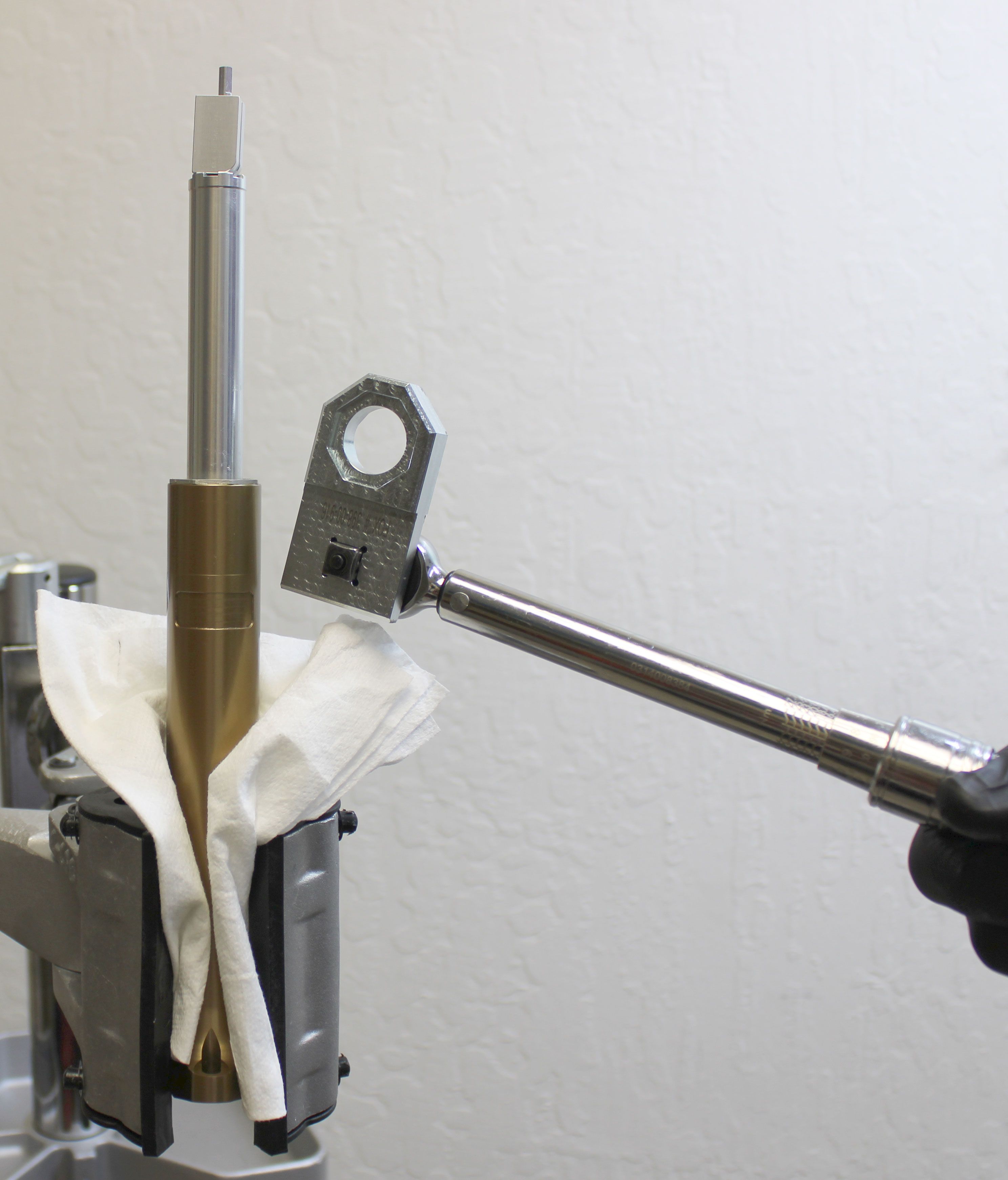
Cover the upper post with a clean lint-free paper towel then lightly clamp it in your workstand as shown with one saddle clamp tab between the clamps to prevent rotation. Use the larger side of the topout cap driver (PN: 398-00-916) held firmly against the topout cap to unthread the topout cap counter-clockwise from the upper post. Failure to hold the topout cap driver tightly against the topout cap can lead to damage if the tool slips.
Step 10
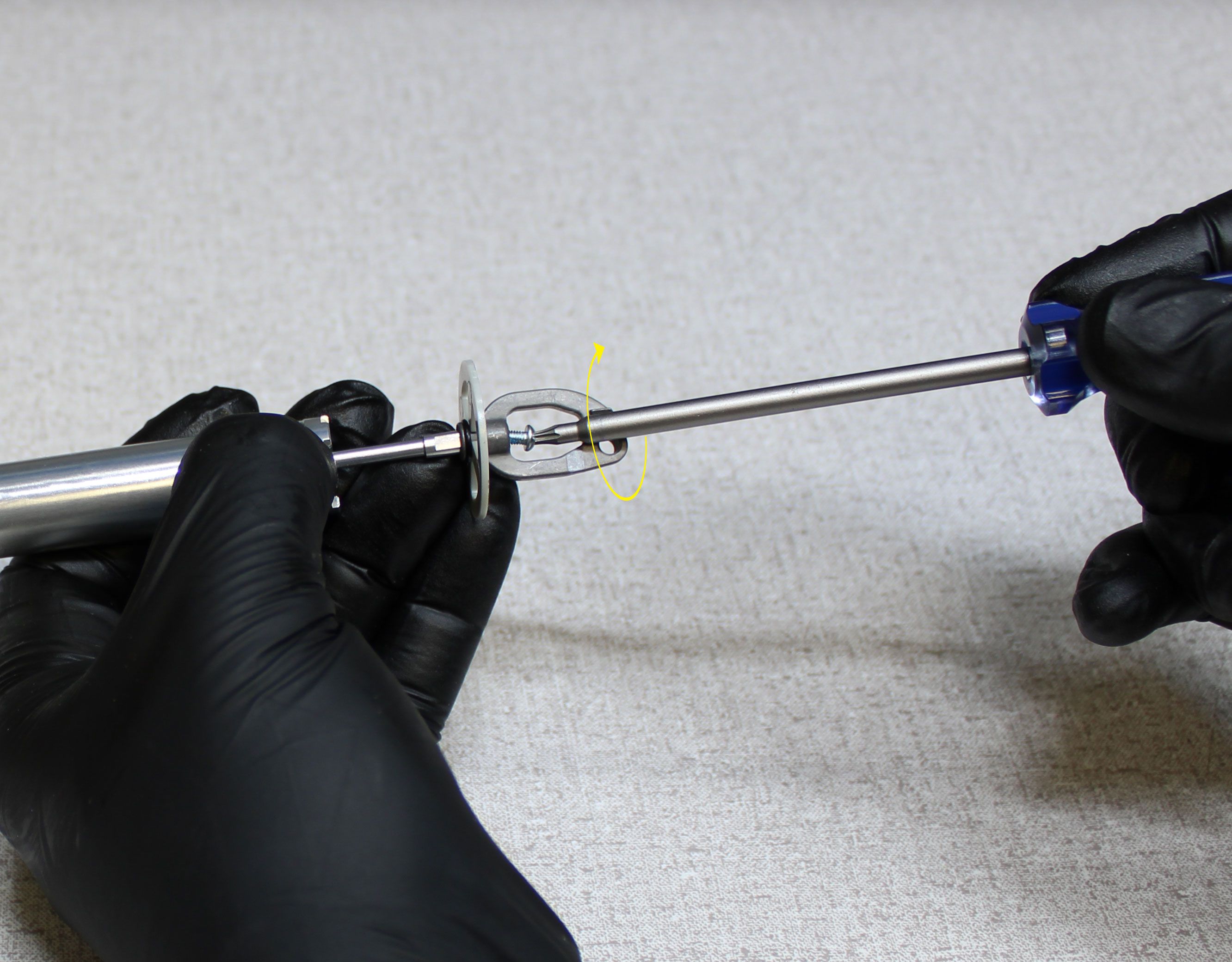
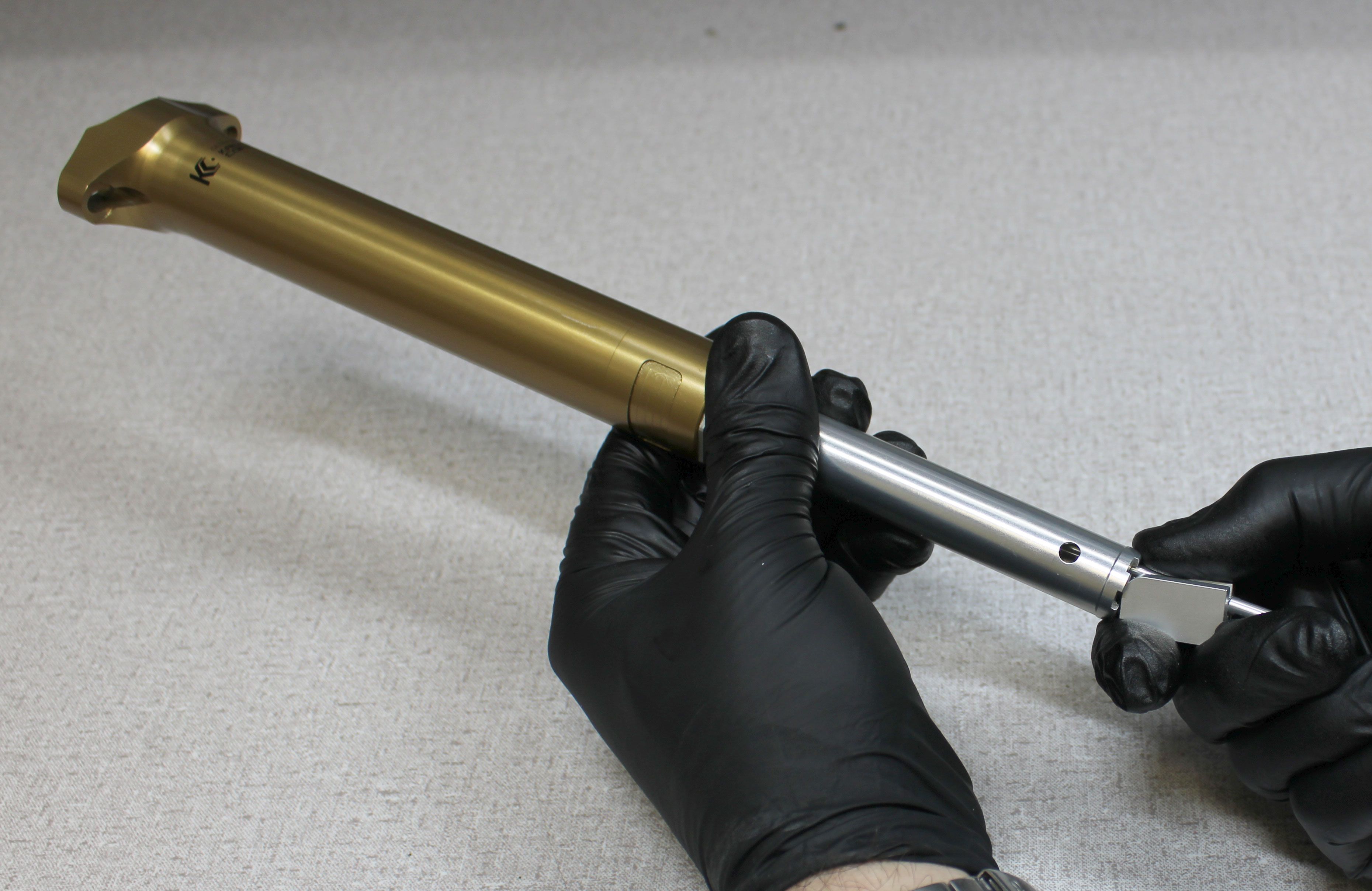
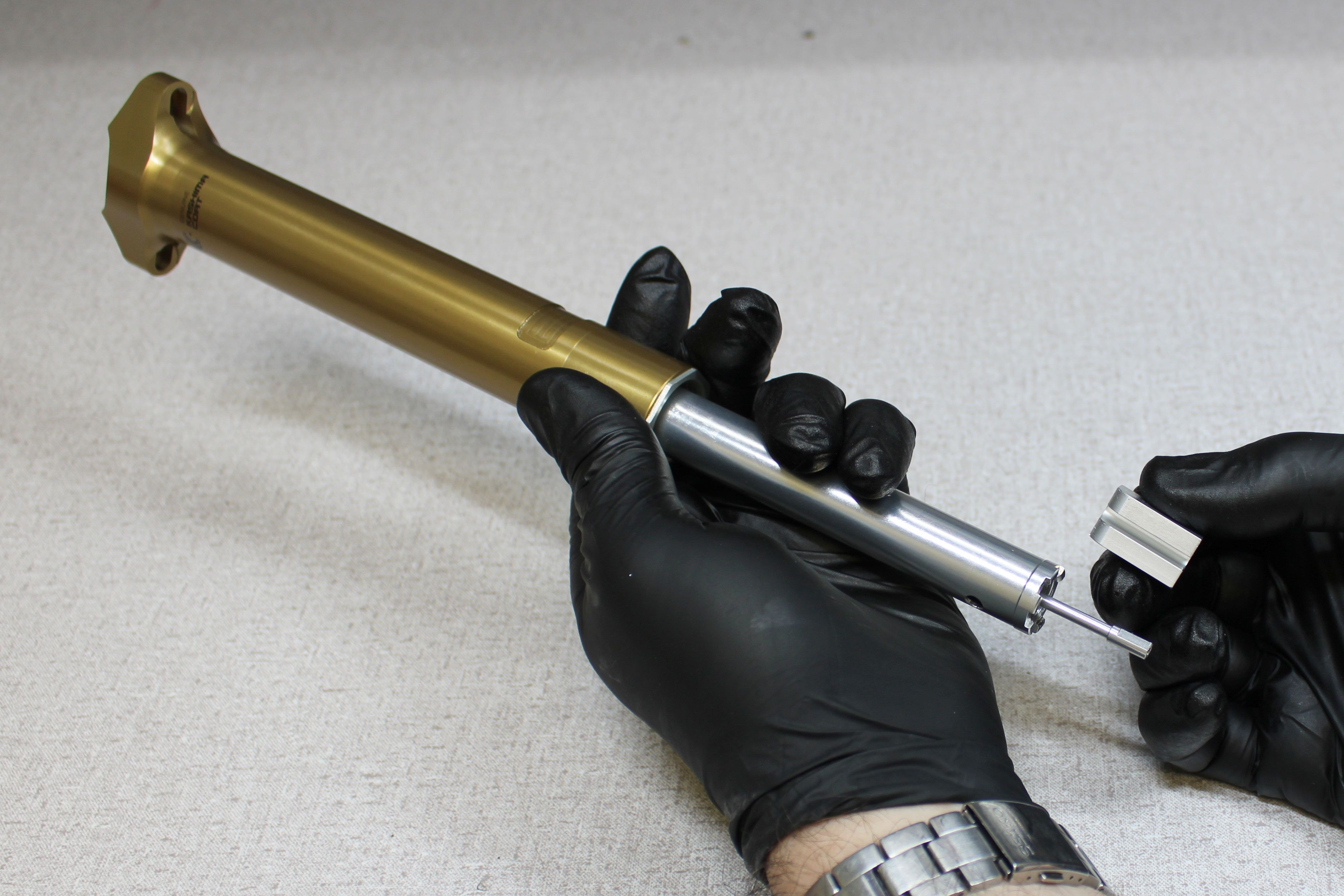
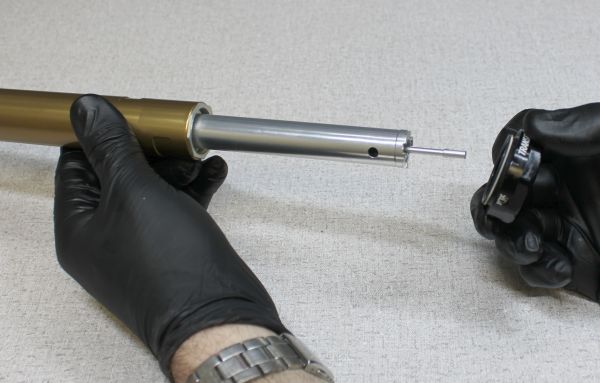
Reinstall the cable hangar onto the end of the pull rod by engaging the flats, holding the cable hangar from turning, then threading the screw clockwise to 6 in-lb torque with a T8 Torx driver. Pull the cable hangar away from the locking body to install the locking spring preloader tool (PN: 398-00-935).


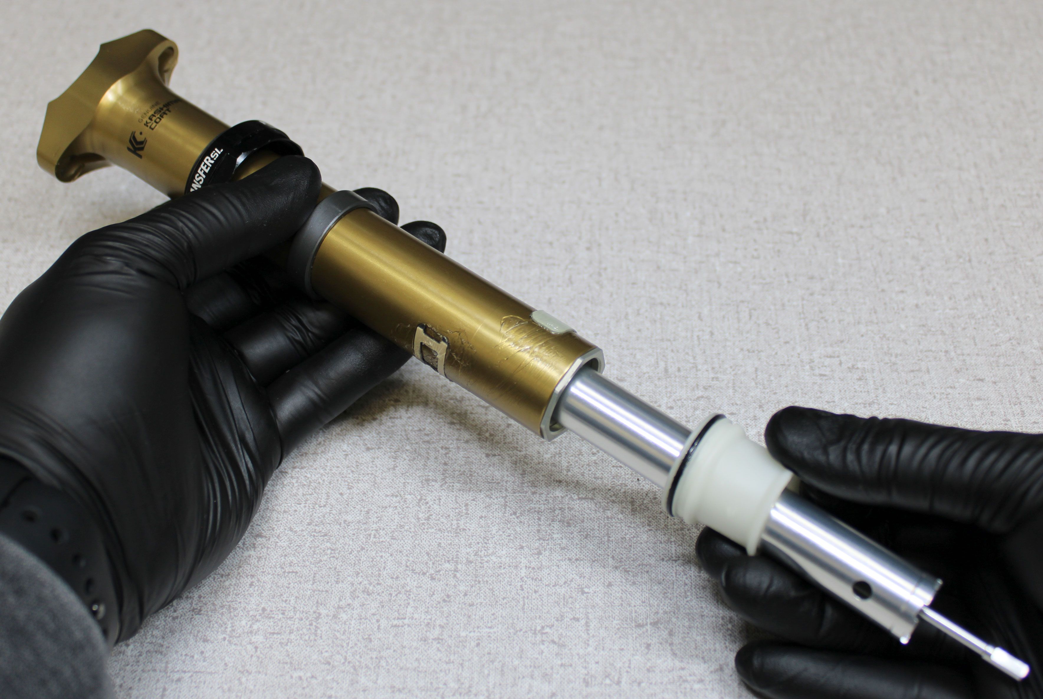
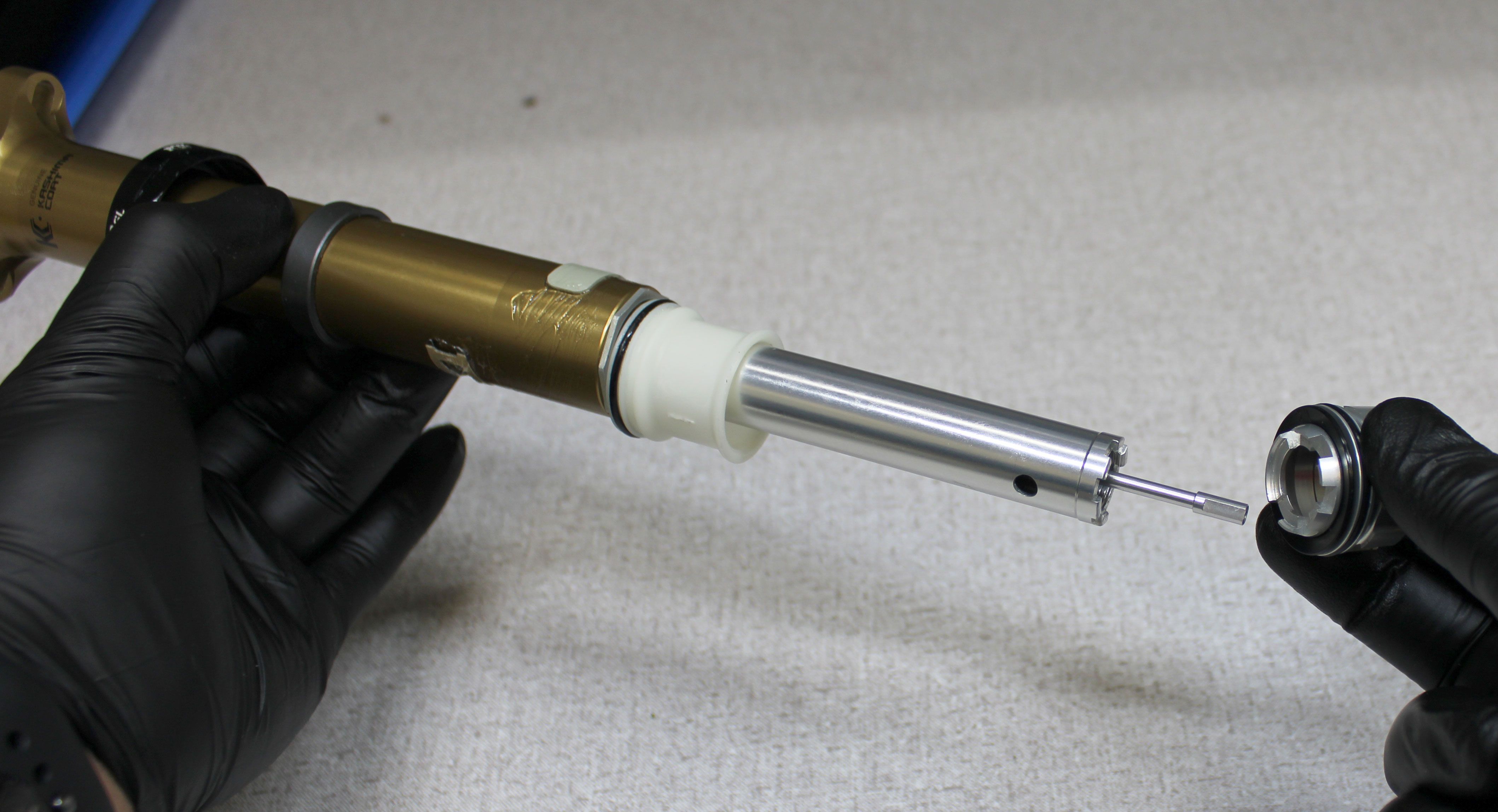
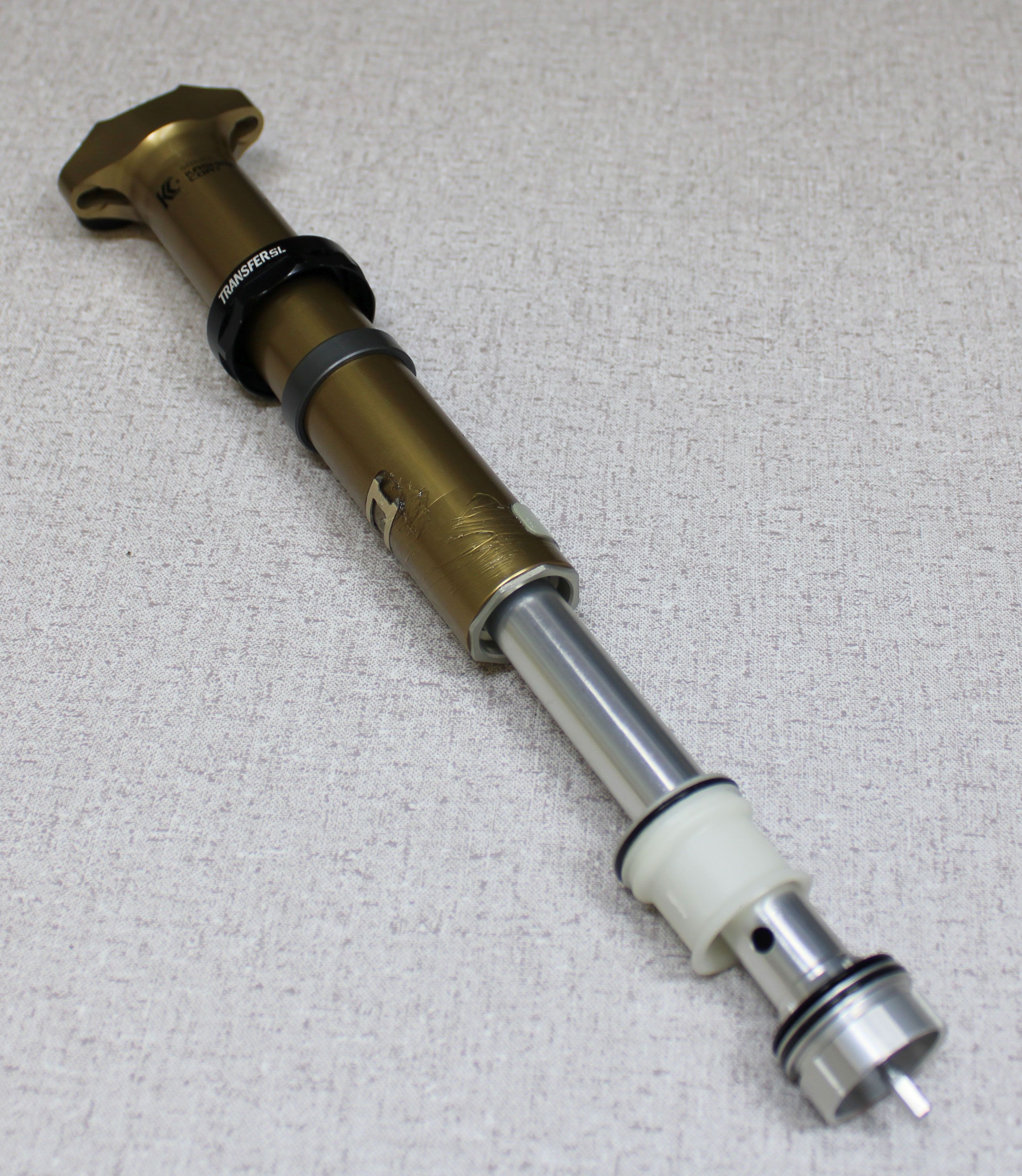
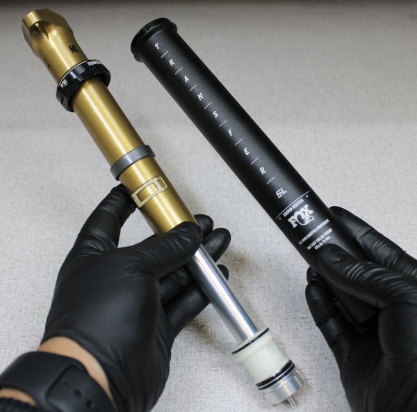
Step 11
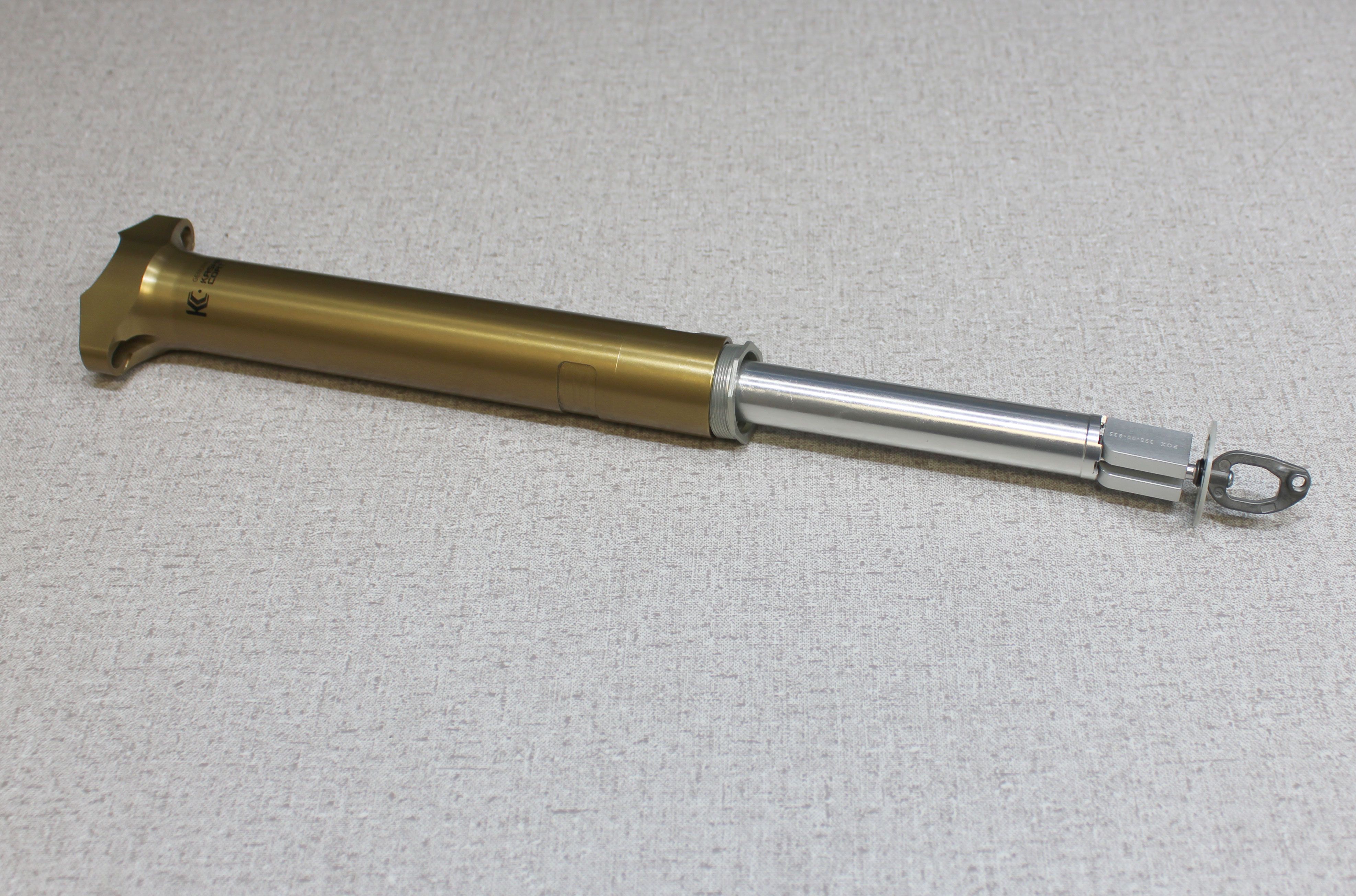
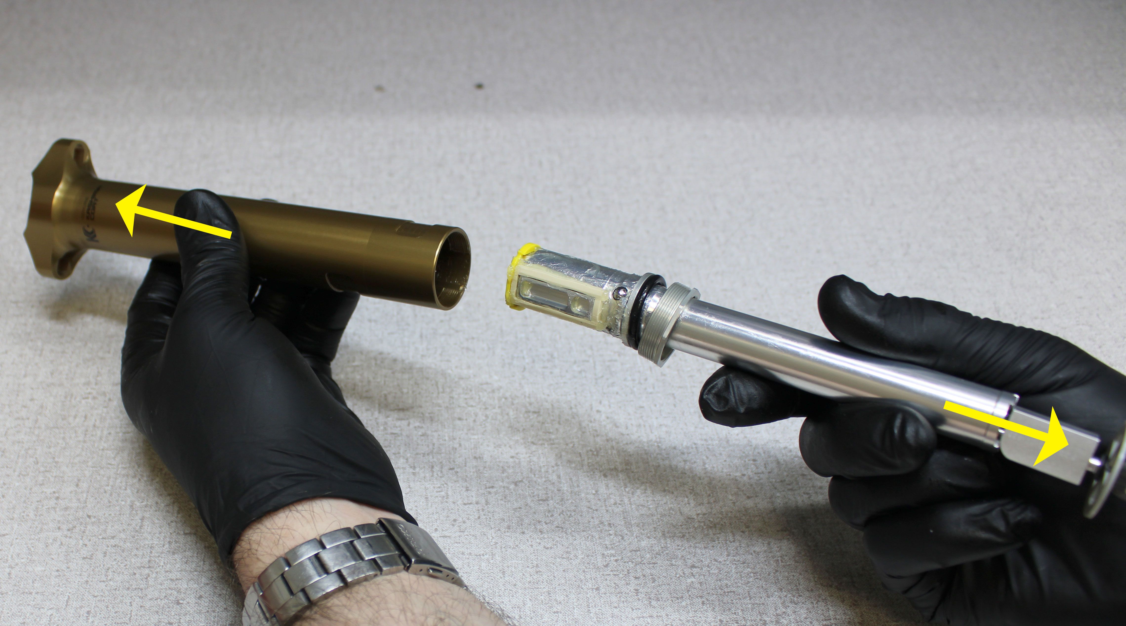
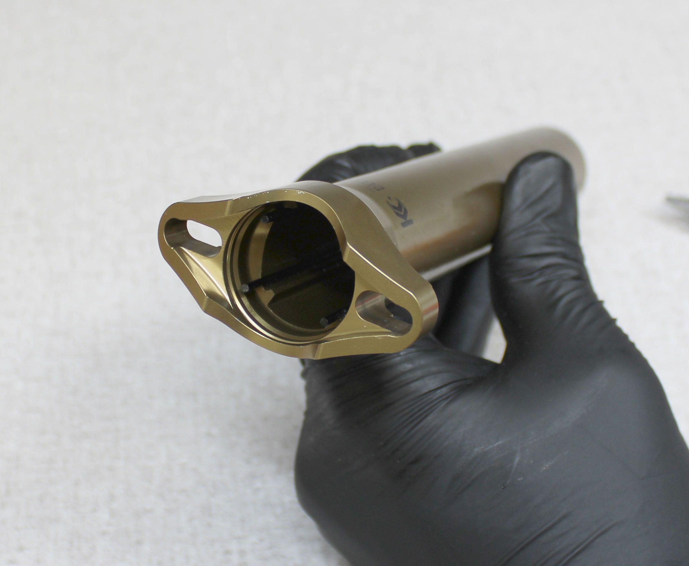
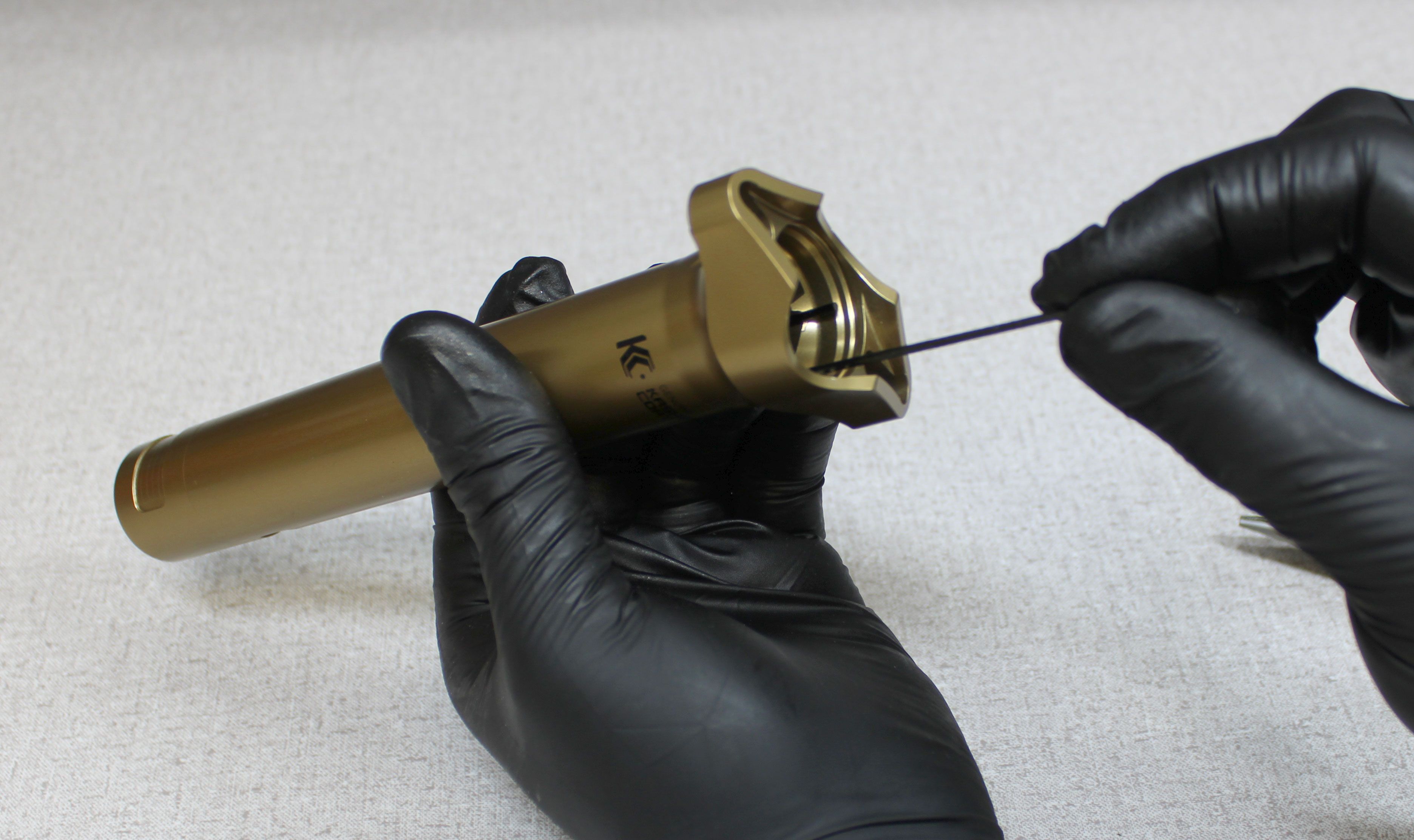
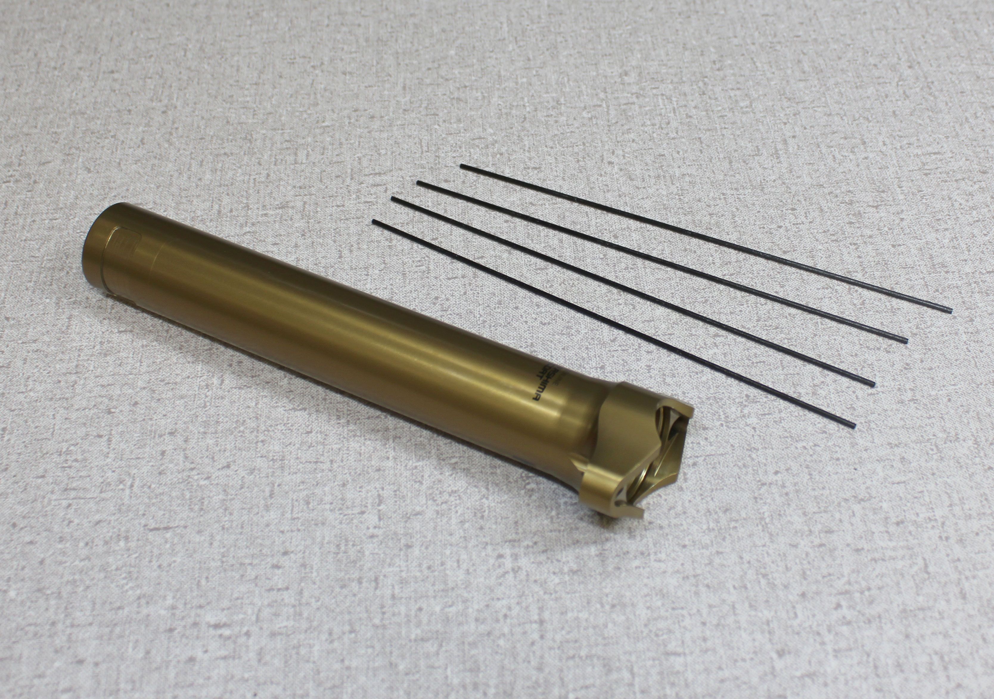
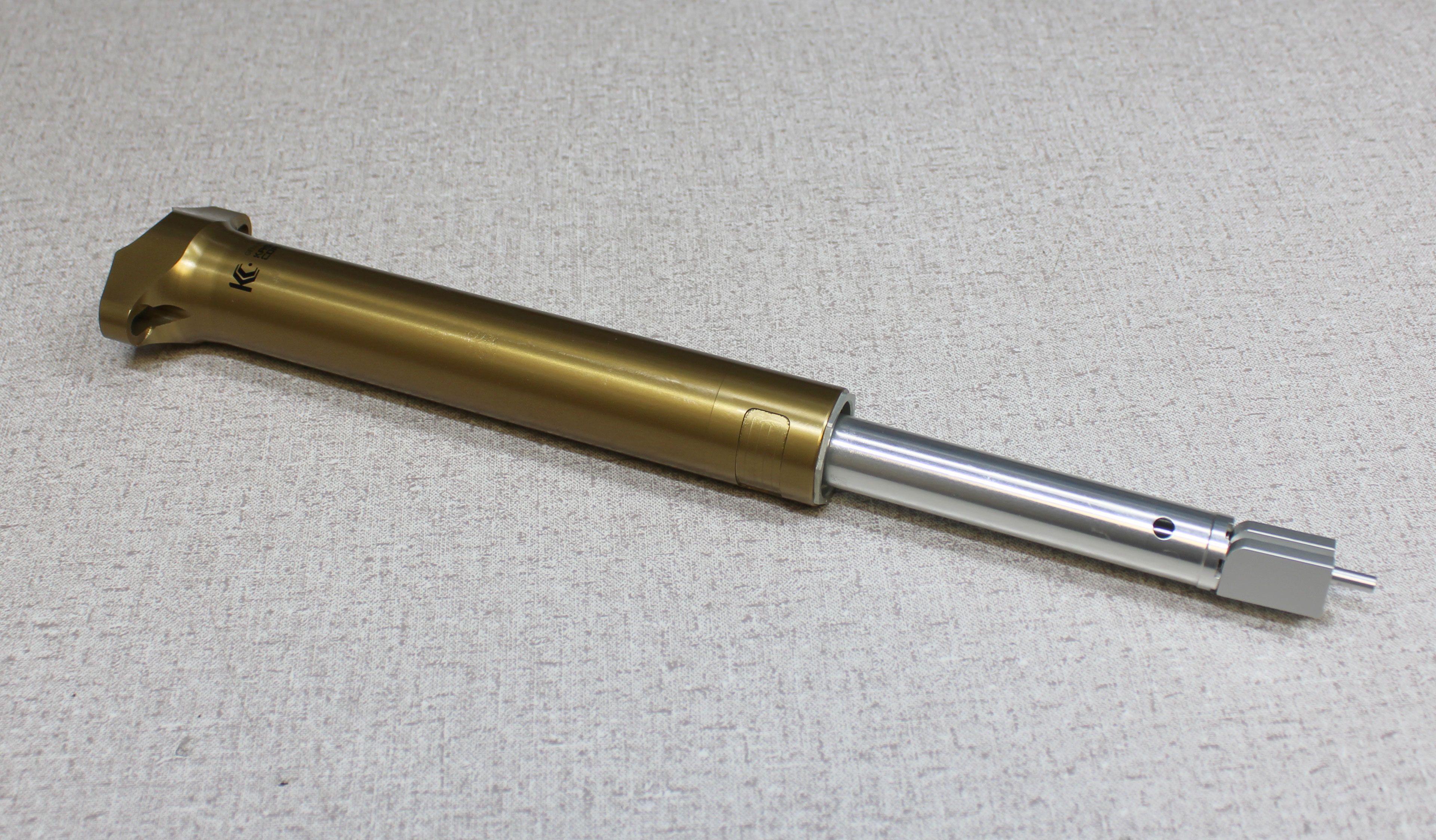
Separate the upper post from the lower post by pulling them apart over your workbench. Note the positions of the 4 carbon spring guides, then remove them.
Step 12
Pull the cable hangar away from the locking body to remove the locking spring preload tool. Remove the lower spring perch and both angular preload bushings.
Step 13
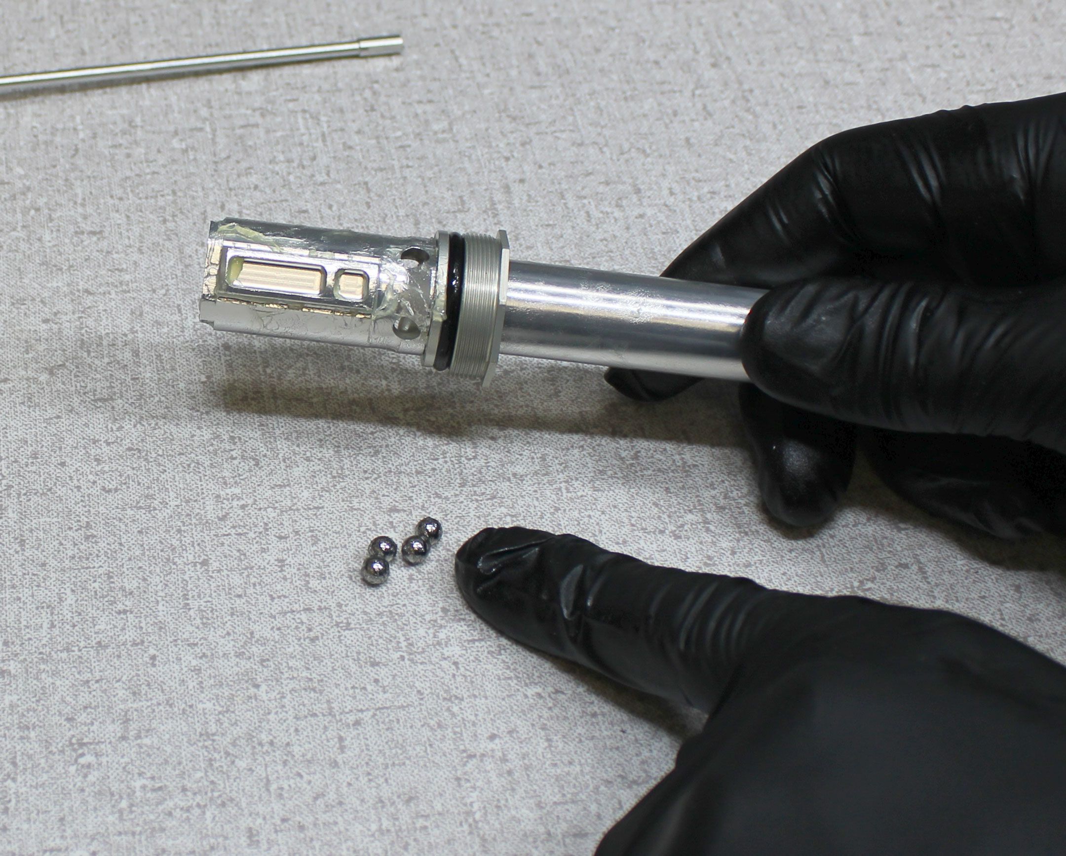
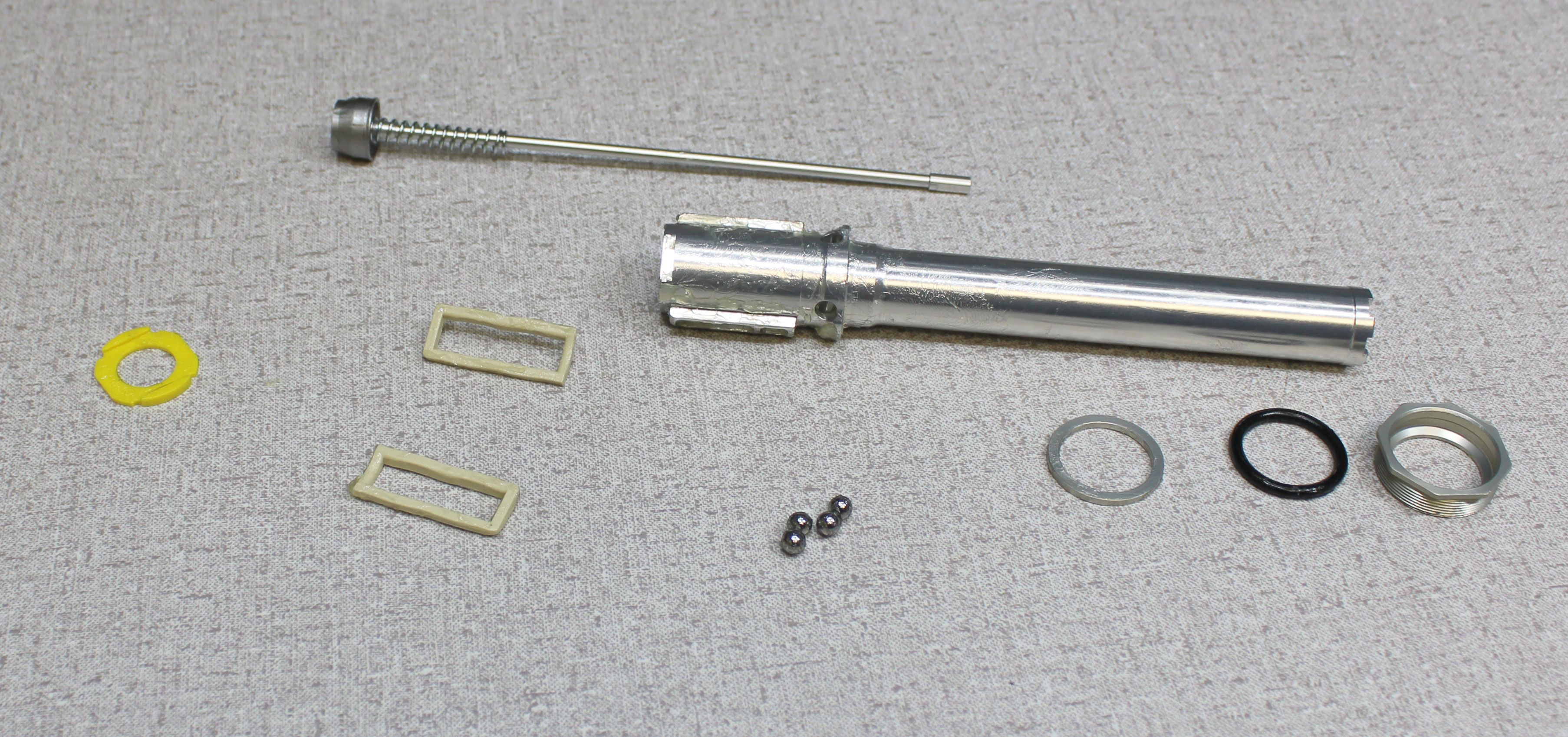
Hold the cable hangar from turning while you unthread the T8 Torx fastener counter-clockwise. Remove the cable hangar and set it aside. Remove the pull rod assembly followed by the 4 locking ball bearings, the topout ring, topout bumper (o-ring), and topout spacer.
Step 14
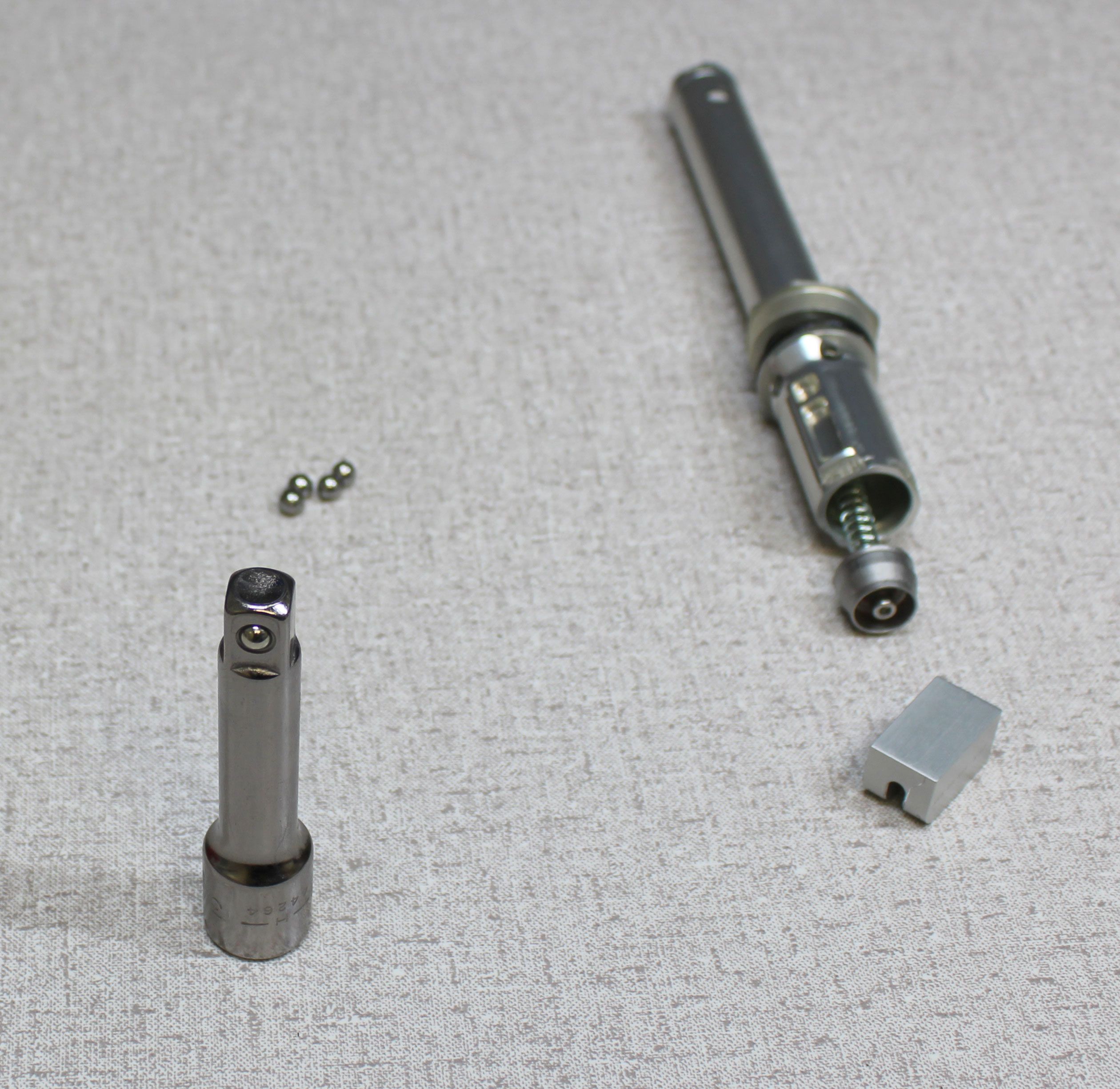
Reinstall the pull rod assembly into the locking body. Reinstall the topout spacer followed by a new greased topout bumper (o-ring) from the kit, then reinstall the top out ring.

Step 15
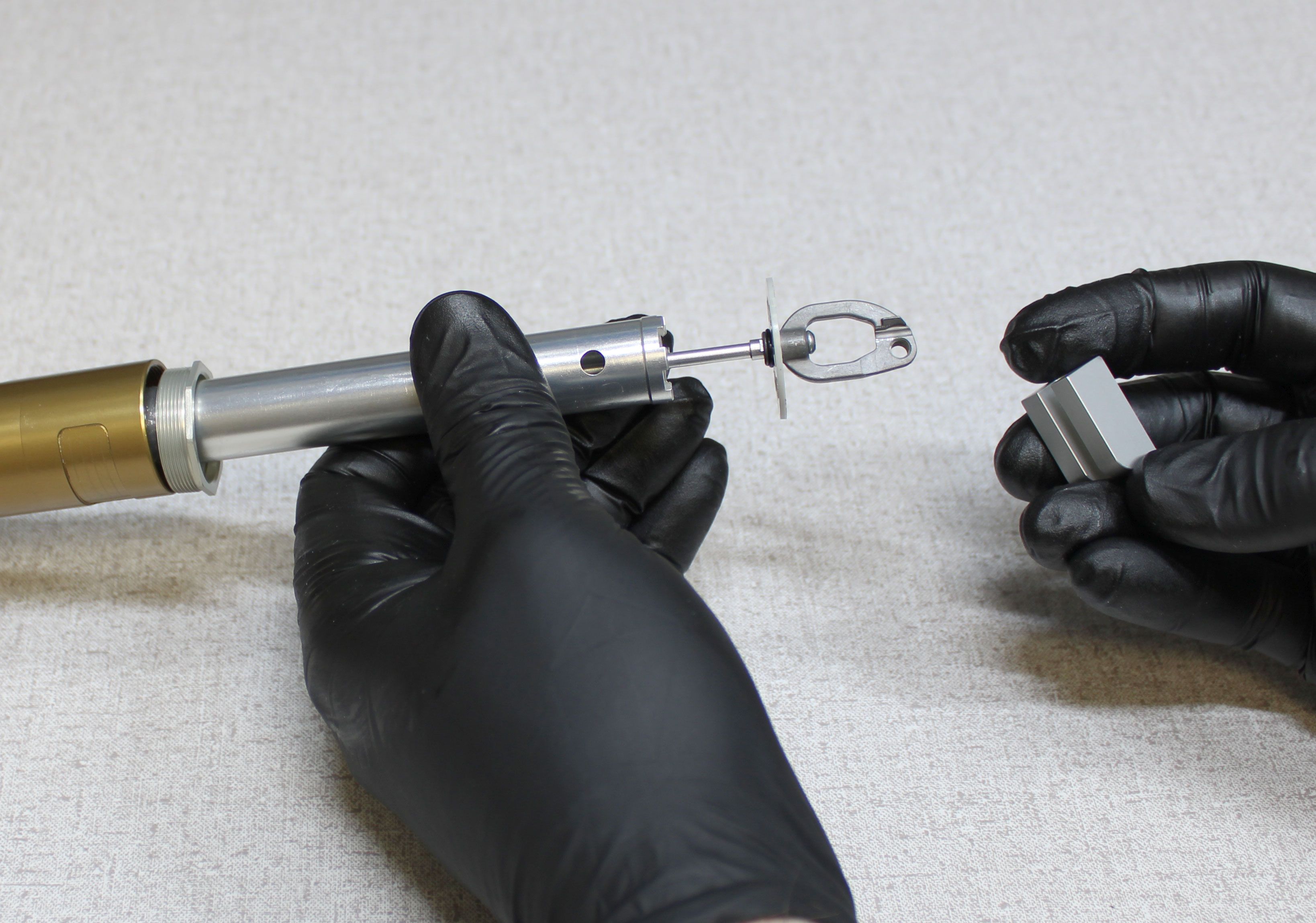
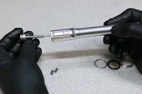
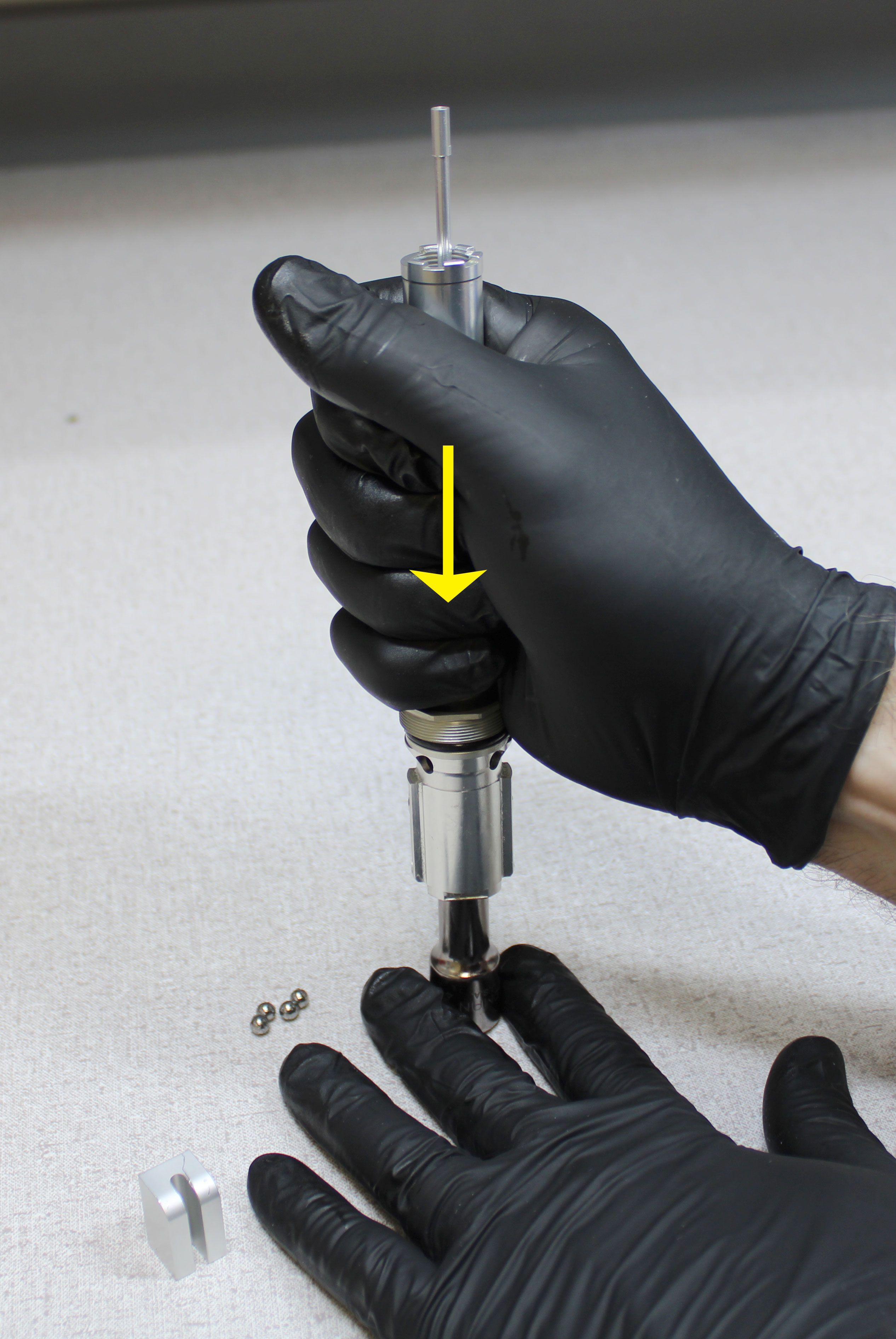
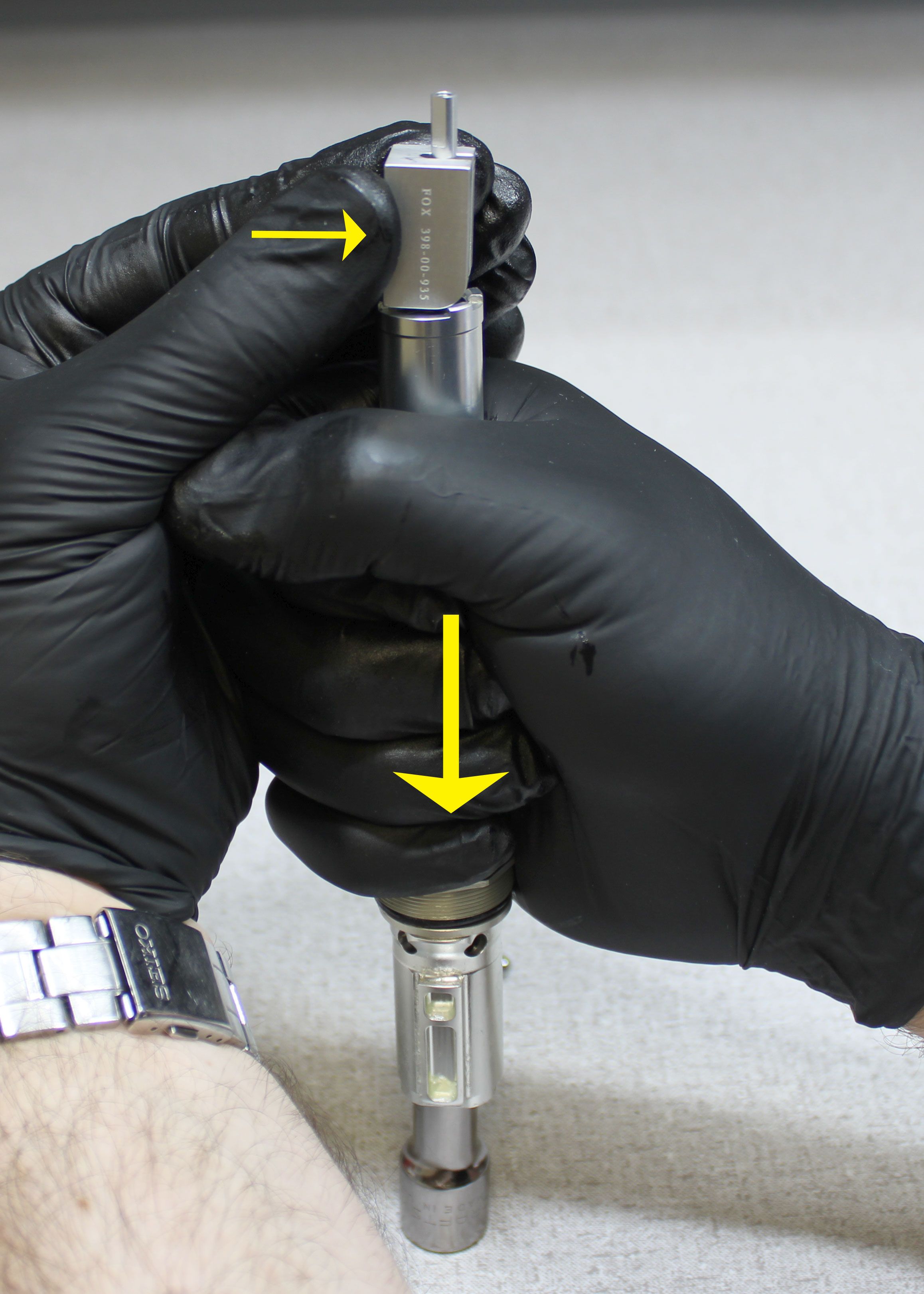
Use a 3/8" square drive extension or similar tool to help you install the preload tool (PN: 398-00-935) to the locking body assembly. Press the upper end of the pullrod within the locking body assembly down onto the adaptor. Hold the locking body and pullrod down against the square drive extension while you install the preload tool as shown.
Step 16
Coat the new angular preload bushings with a thick layer of Ultraplex LT2 waterproof marine grease then install onto the locking body with their tapered ends toward the top of the post as shown. Coat the locking ball bearings and their holes with a thick layer of Ultraplex LT2 waterproof marine grease. Reinstall the 4 locking ball bearings. Reinstall the lower spring perch so the tabs engage with the flats of the locking body as shown.
Step 17
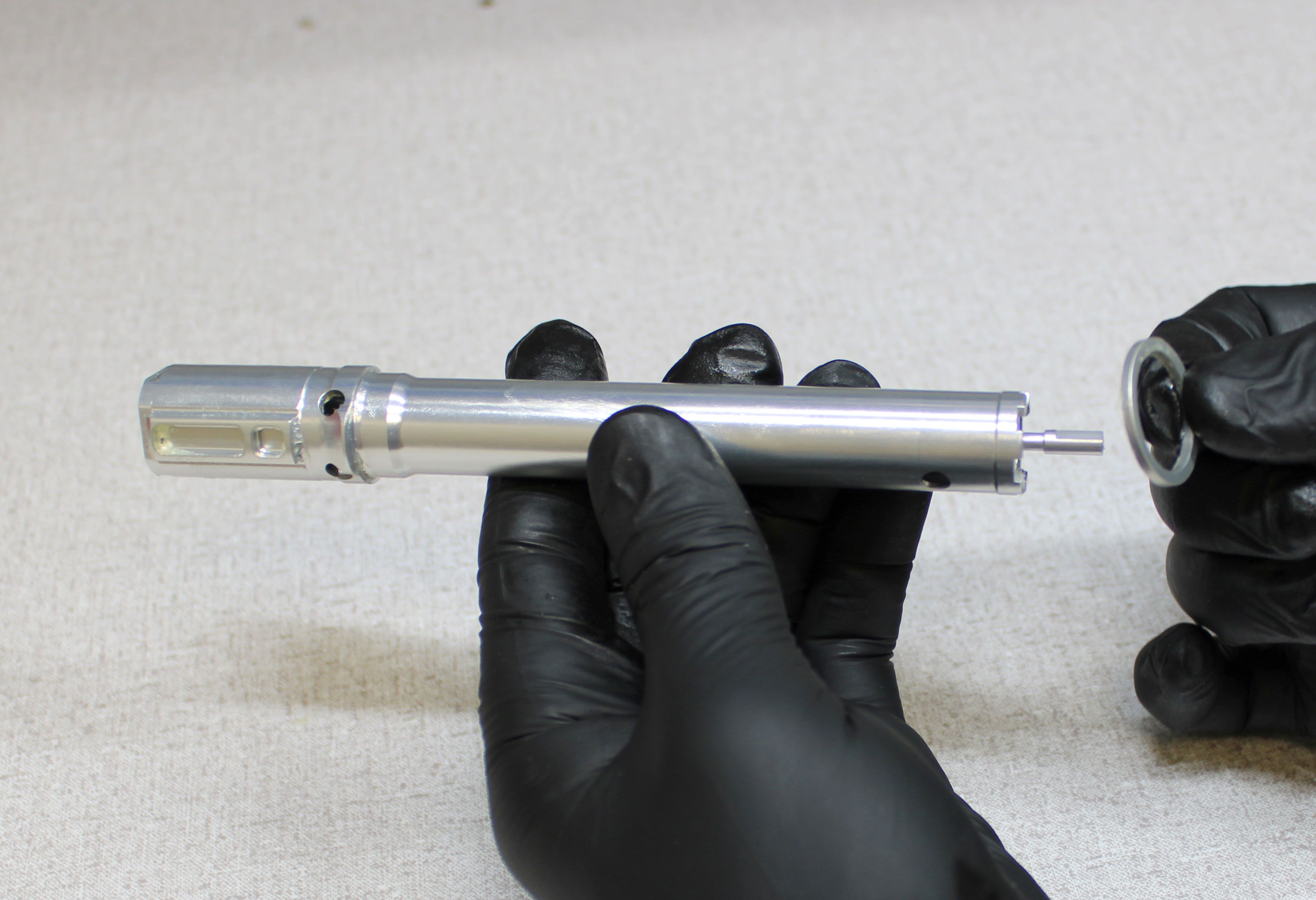
Orient the angular contact bearings on the locking body so the align with the sides of the upper post. Reinsert the locking body assembly into the upper post. Install the topout plate and bumper (o-ring) into the upper post, then thread the topout cap into the upper post clockwise by hand.
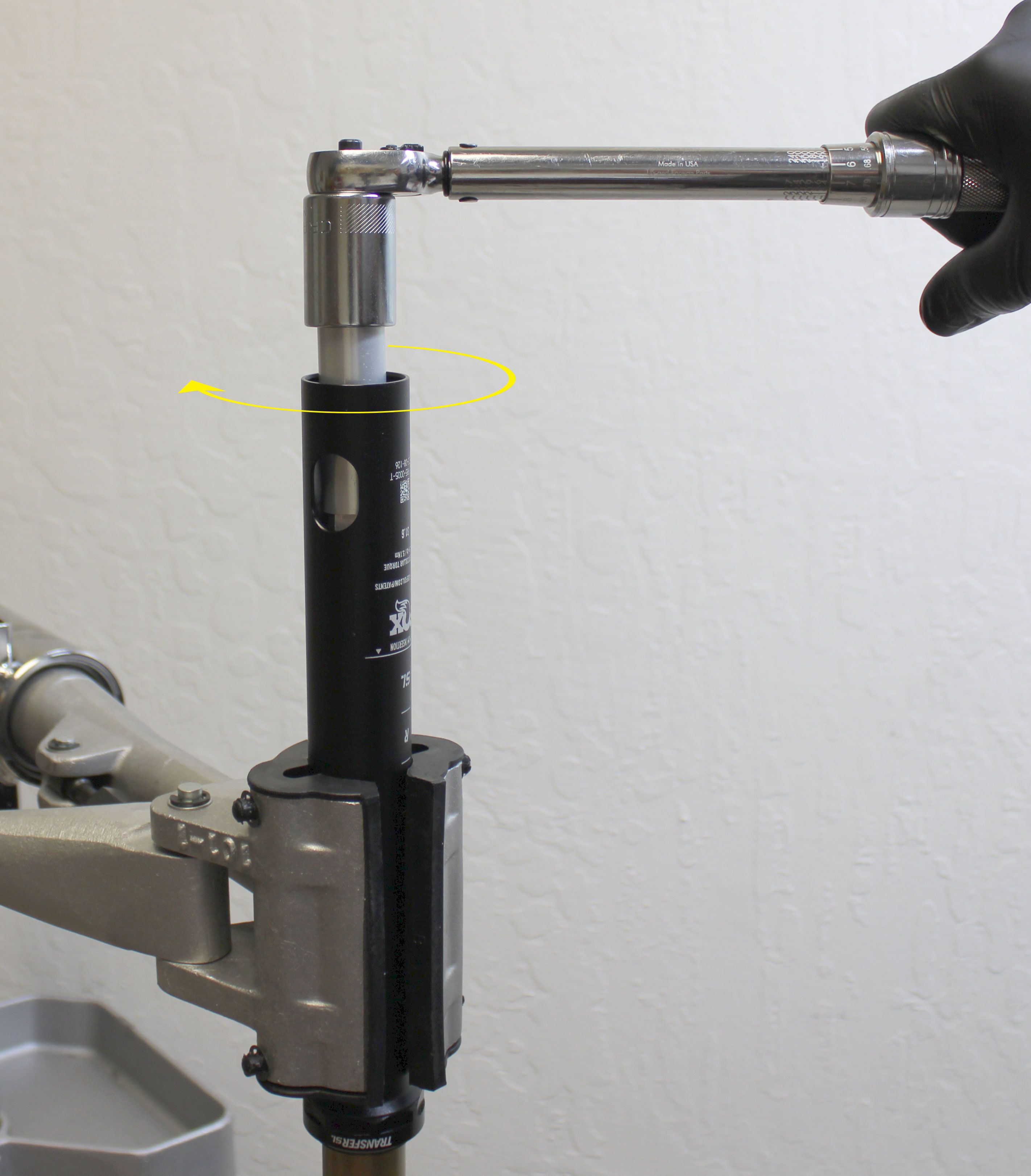
Step 18
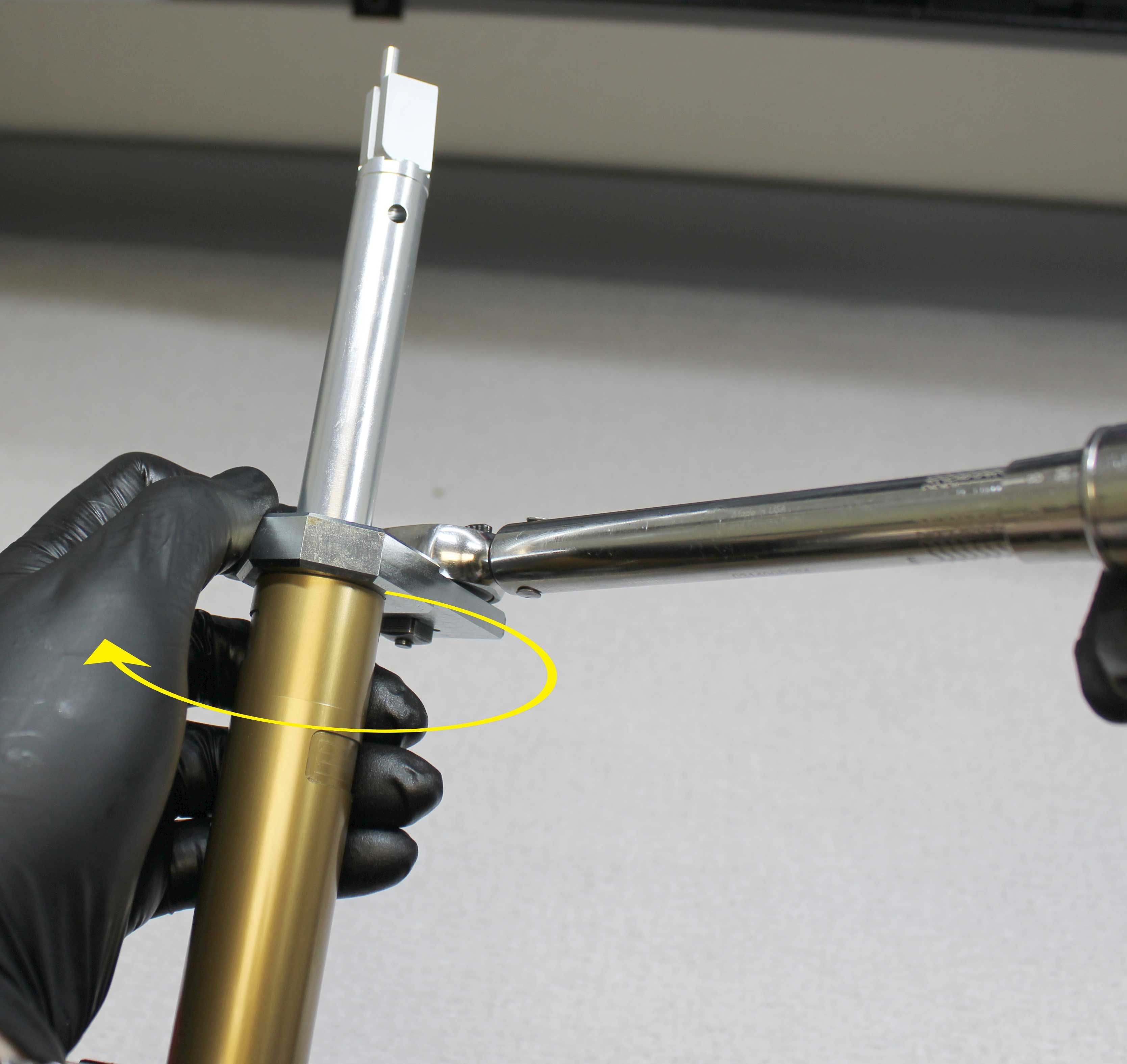
Cover the upper post with a clean lint-free paper towel then lightly clamp it in your workstand as shown with one saddle clamp tab between the clamps to prevent rotation. Use the larger side of the topout cap driver (PN: 398-00-916) held firmly against the topout cap to tighten the topout cap clockwise to 144 in-lb (16.3 Nm) torque. Failure to hold the topout cap driver tightly against the topout cap can lead to damage if the tool slips.


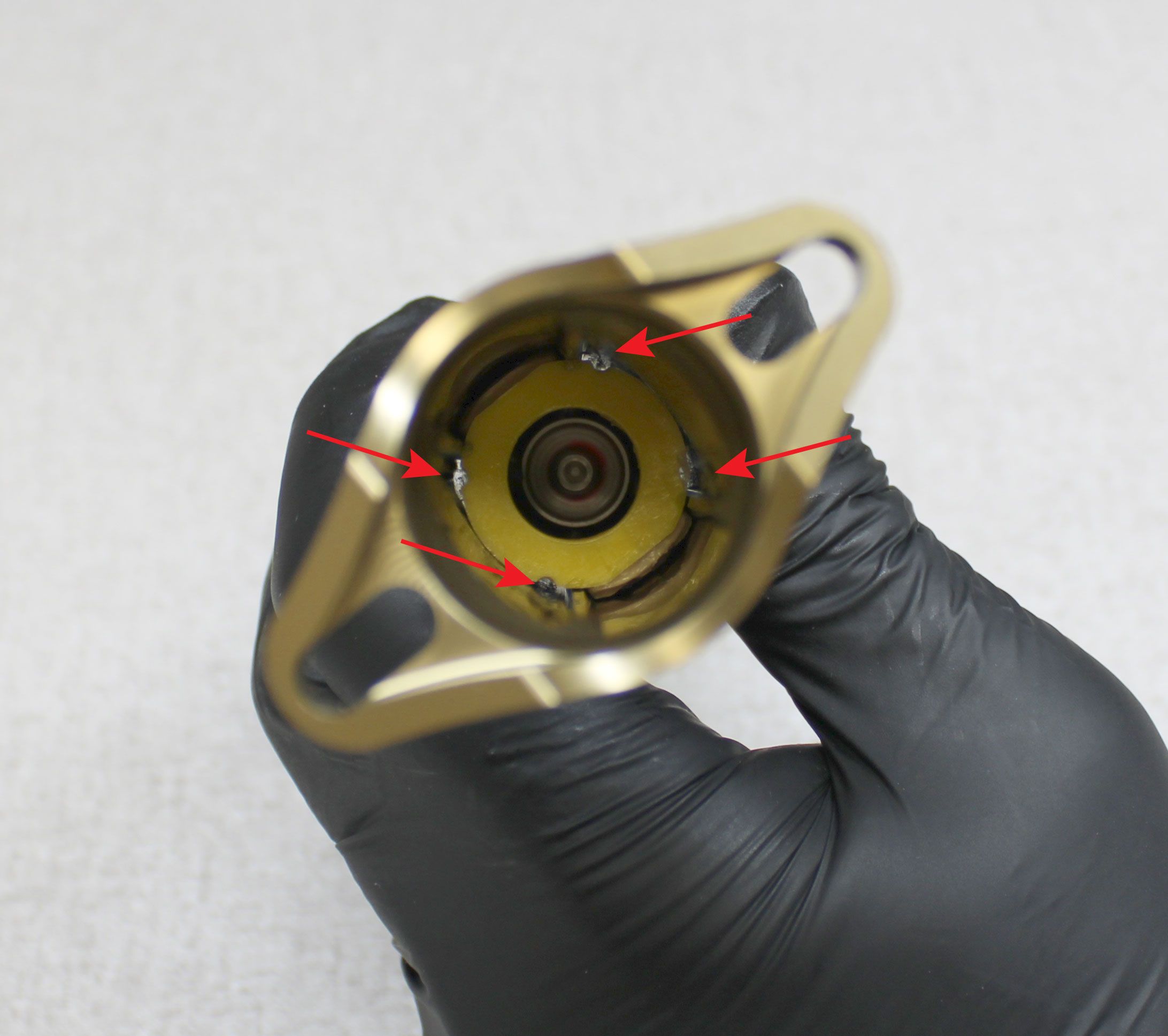
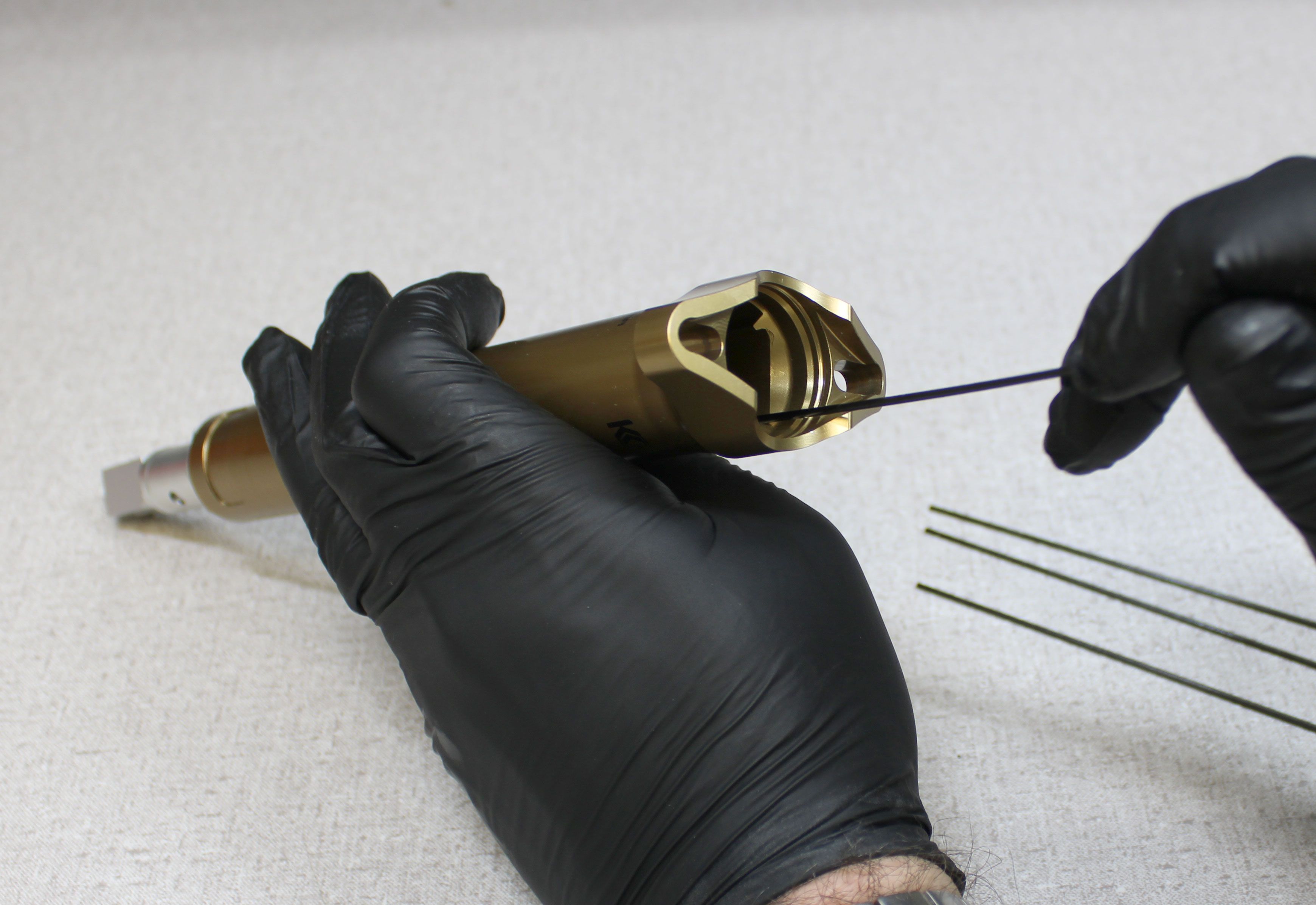
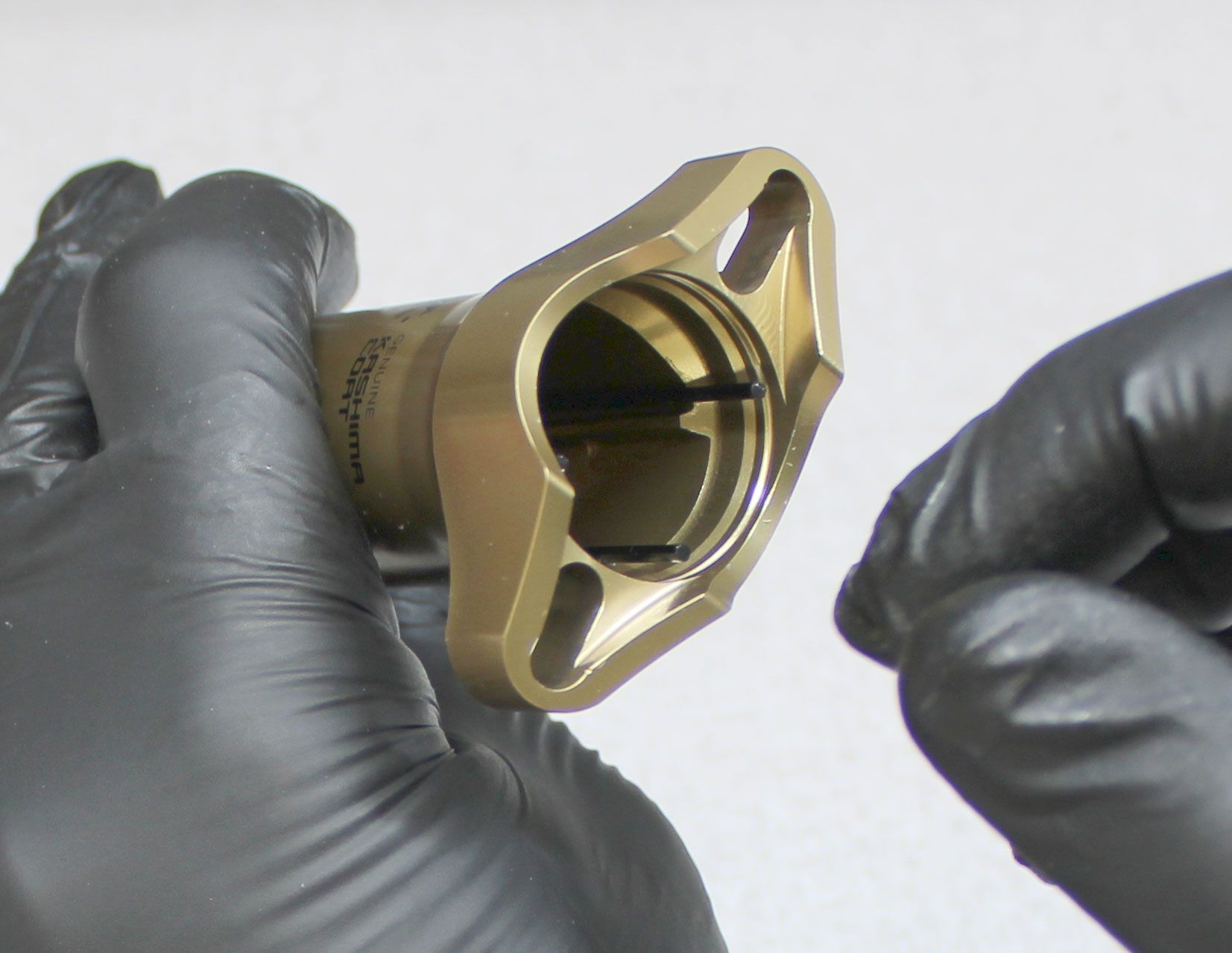
Step 19
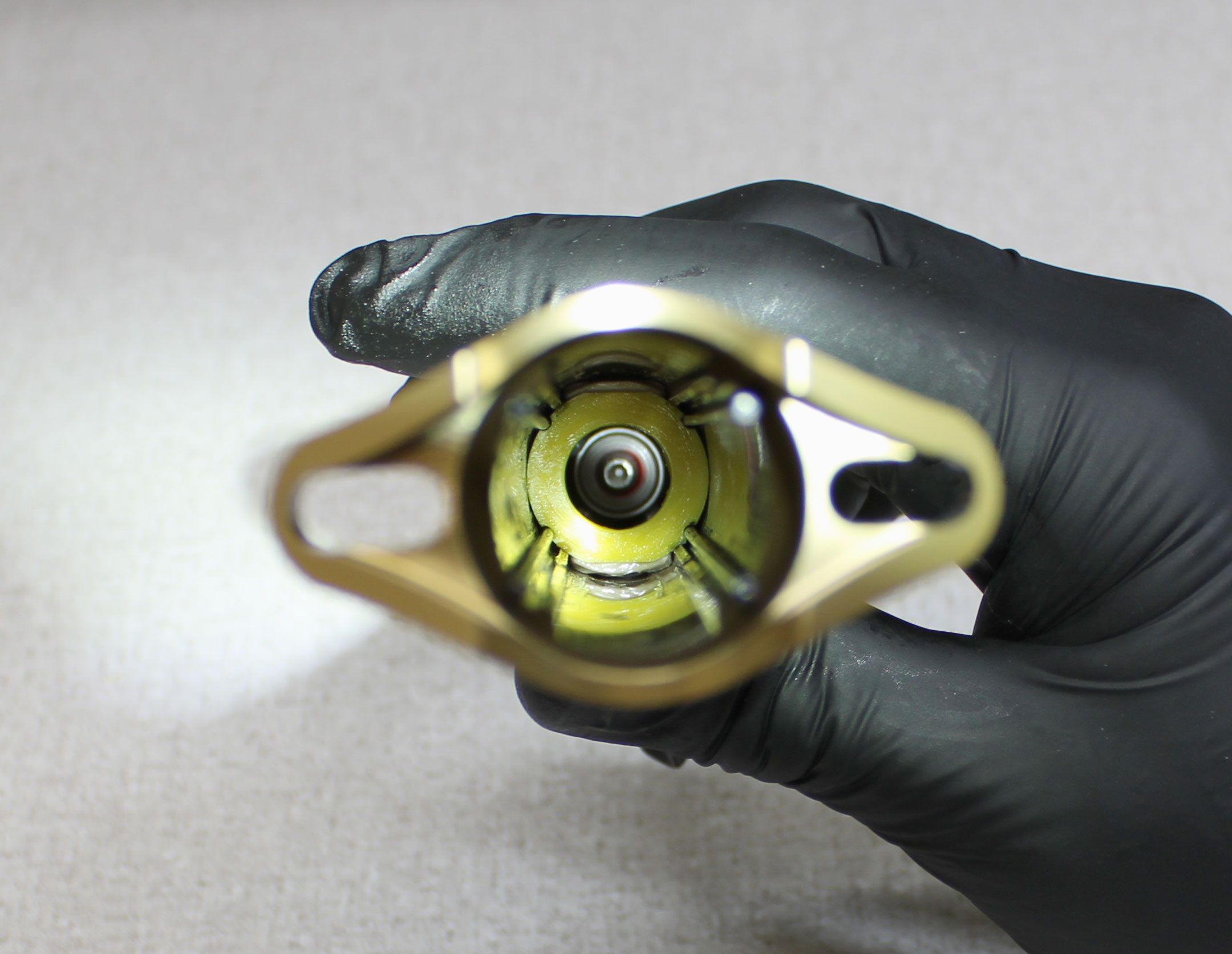
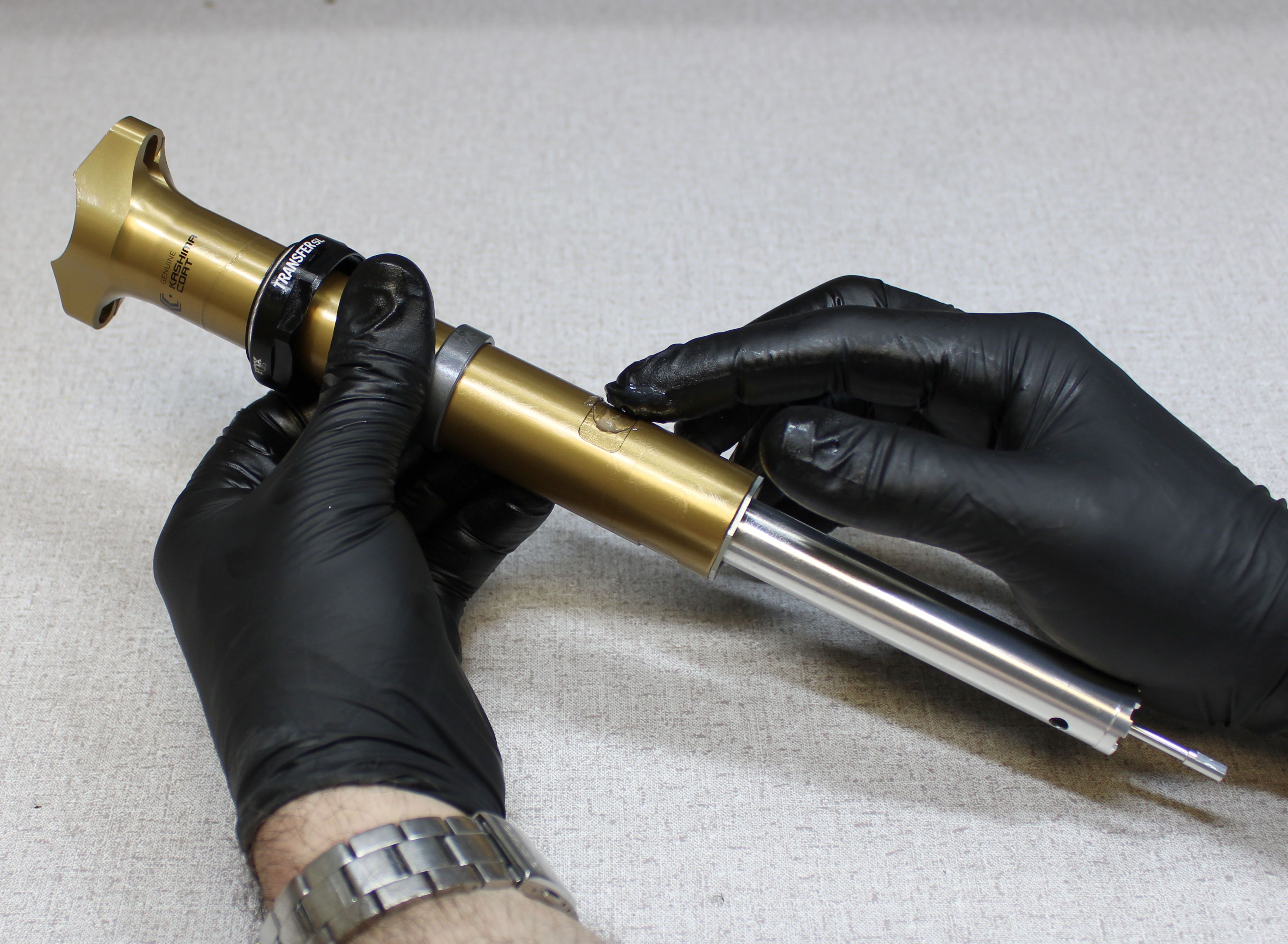
Push the locking body up into the upper post. Coat the new carbon spring guides with a think film of Slick Honey. Install the new spring guides into the upper post so they align with the notches of the lower spring guide as shown.
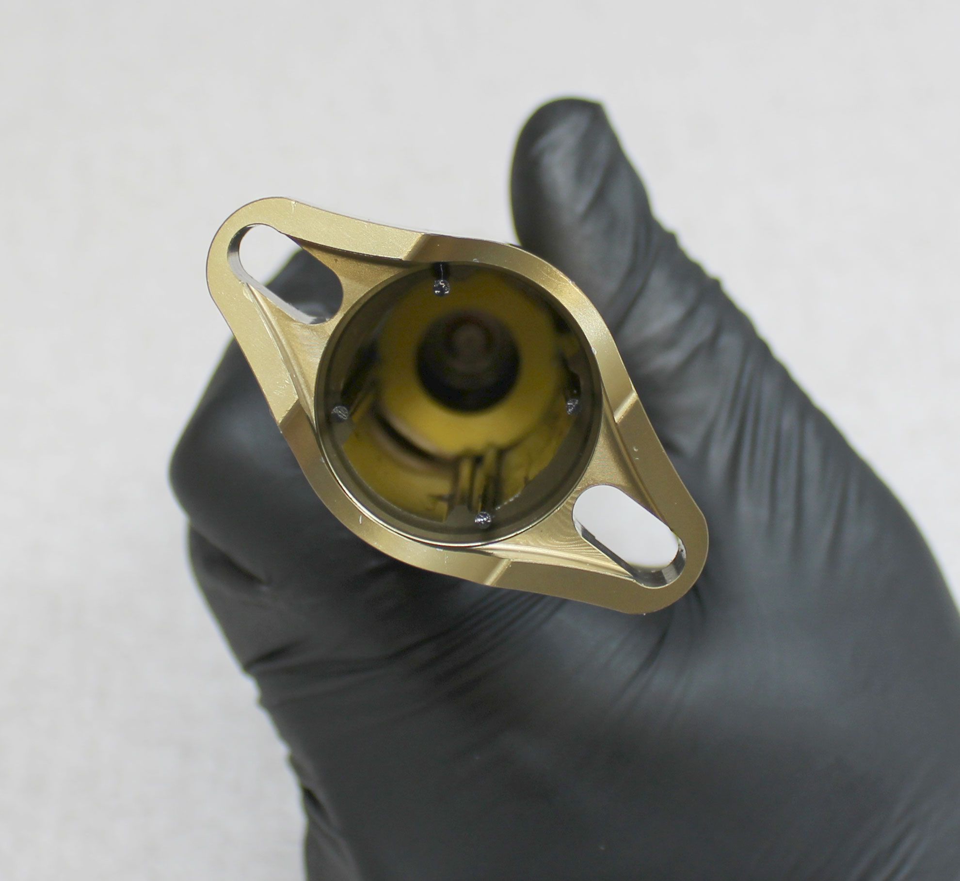

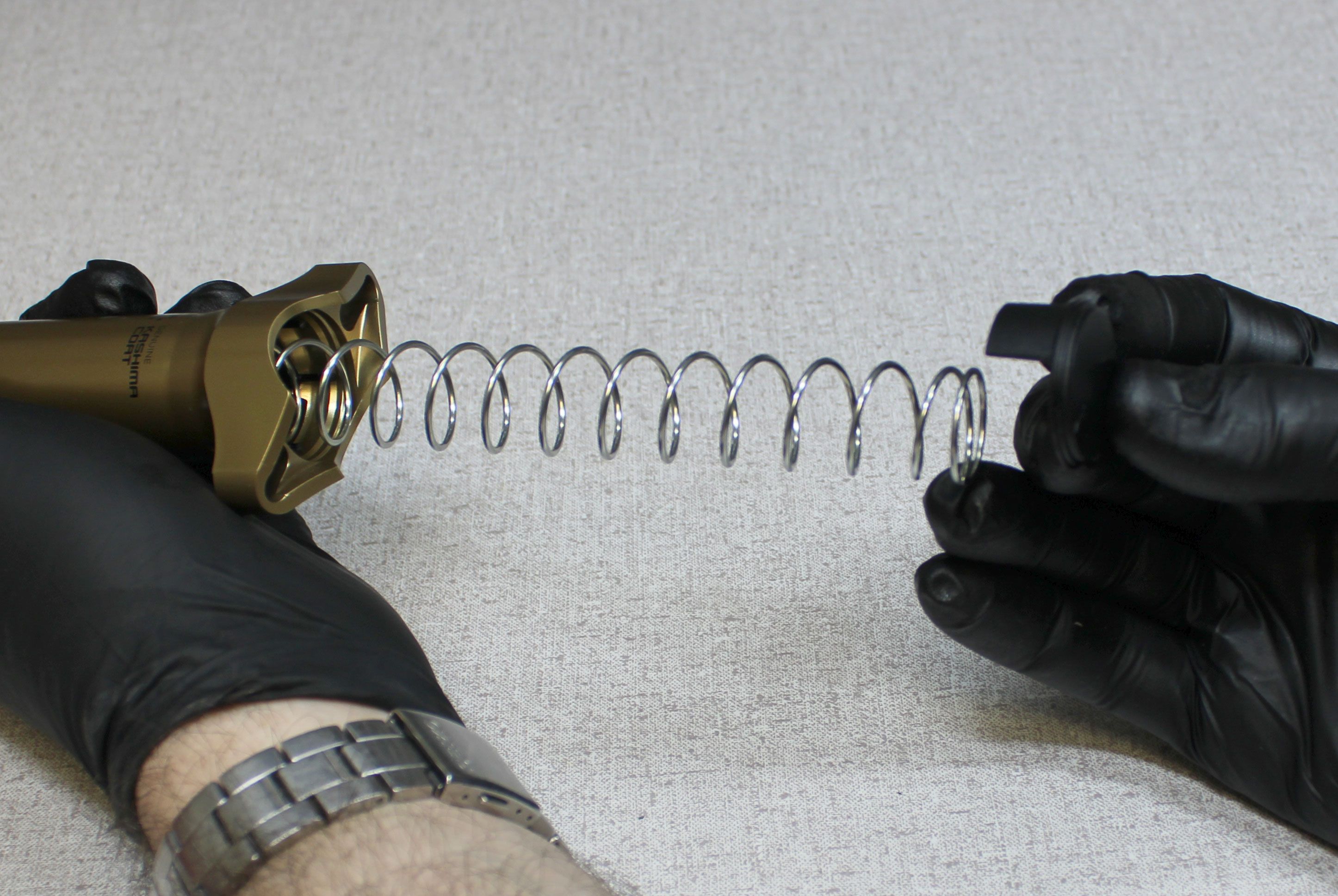
Step 20
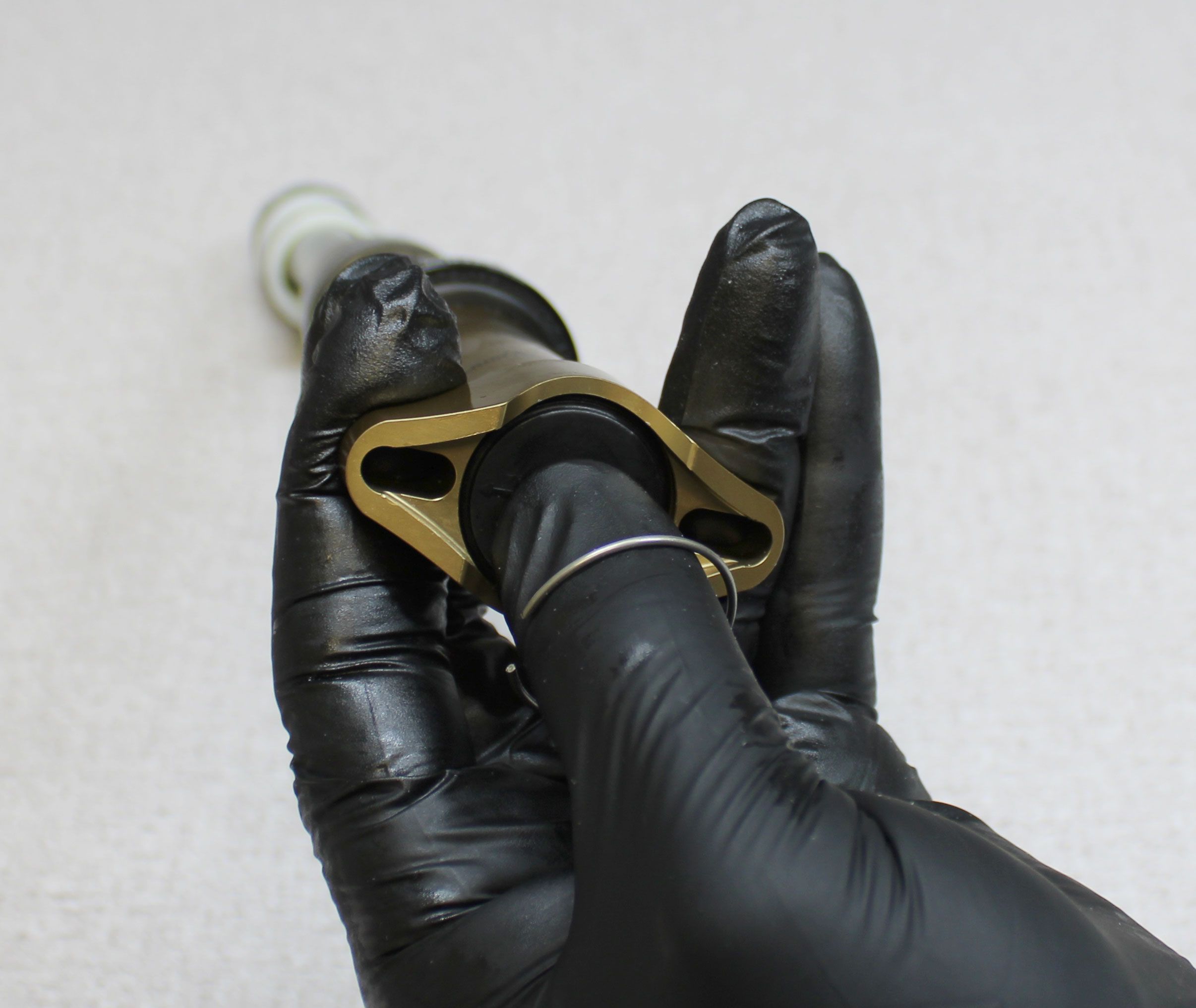
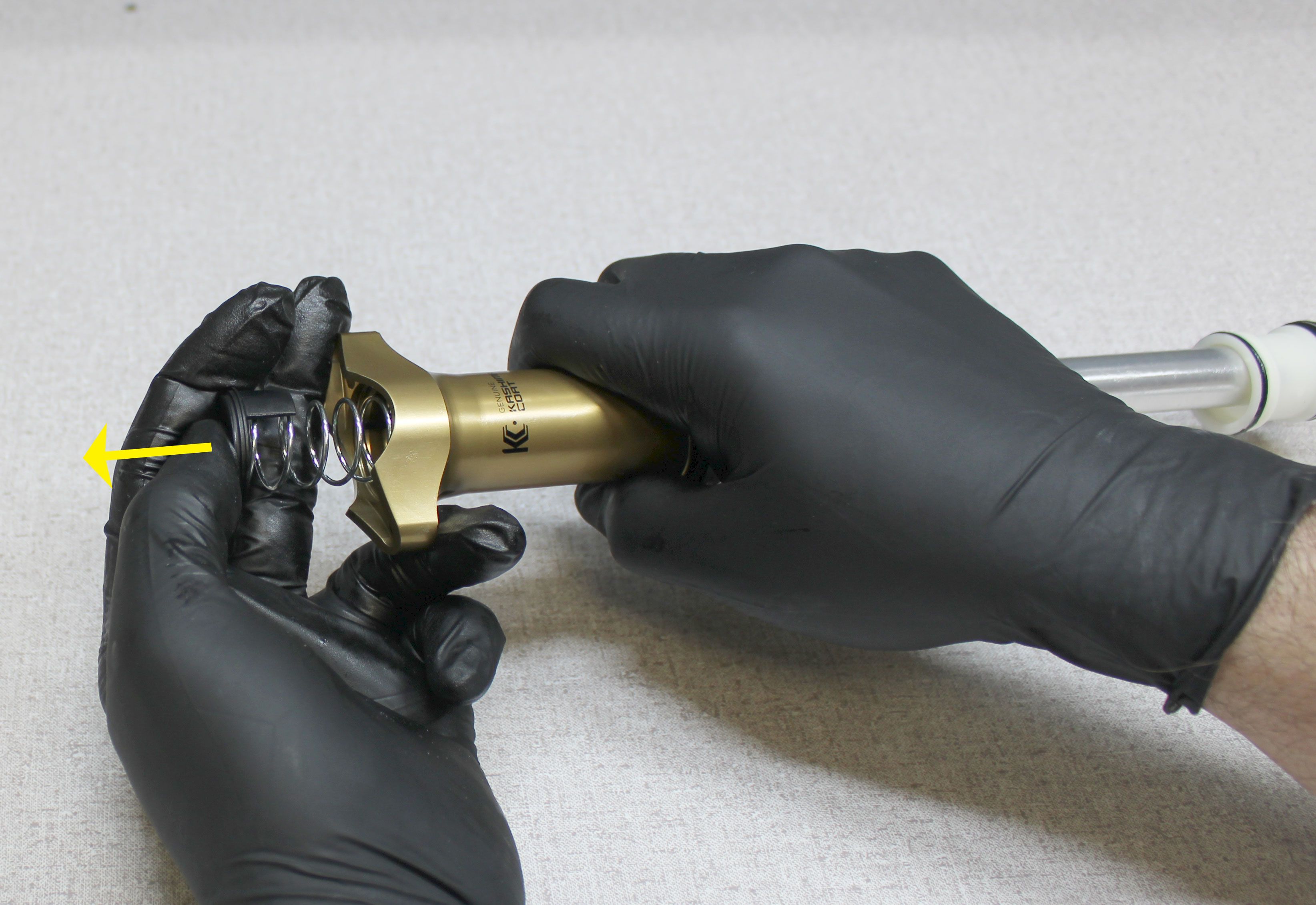
Reinstall the coil spring into the upper post then use it to push the locking body down to its lowest position in the upper post then remove the spring. Reinstall the upper spring perch so that the tab is aligned with a side of the post and the carbon rods seat in the notches of the spring perch. Use the upper spring perch to push the coil spring into the upper post. Hold the spring perch against the installed coil spring while you reinstall the wire retaining ring. Verify that the ring is fully seated in its groove.
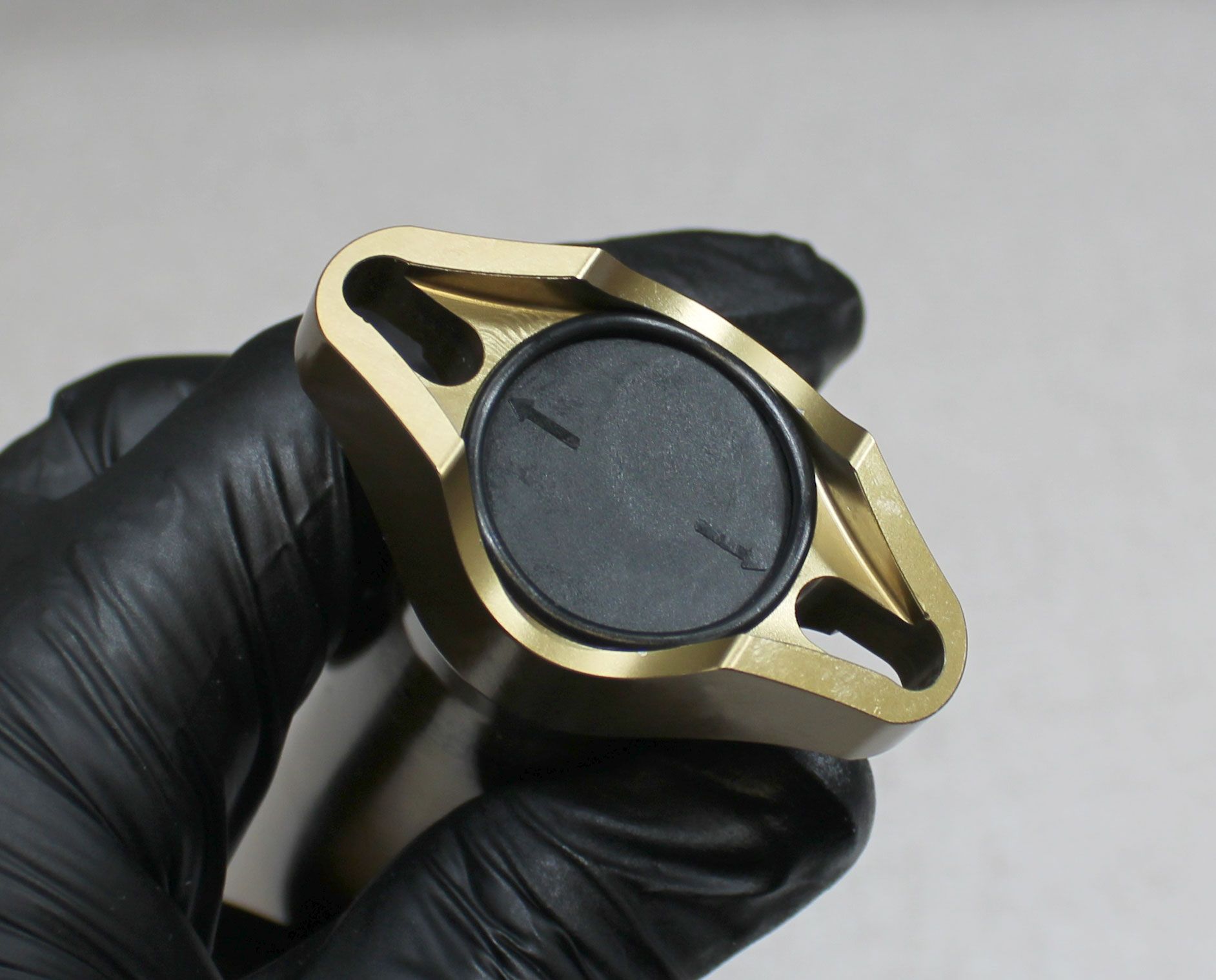
Step 21
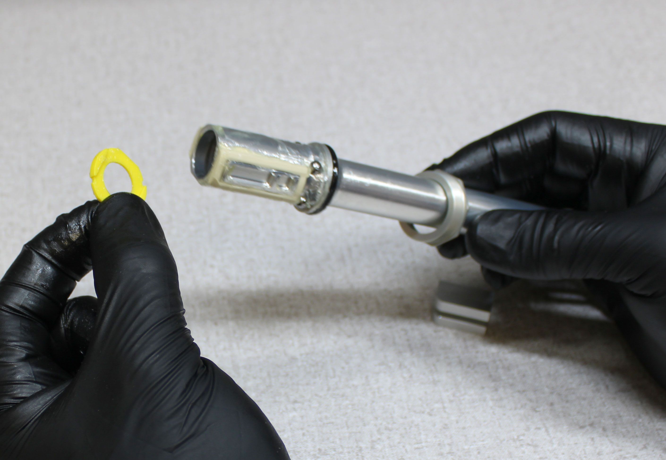
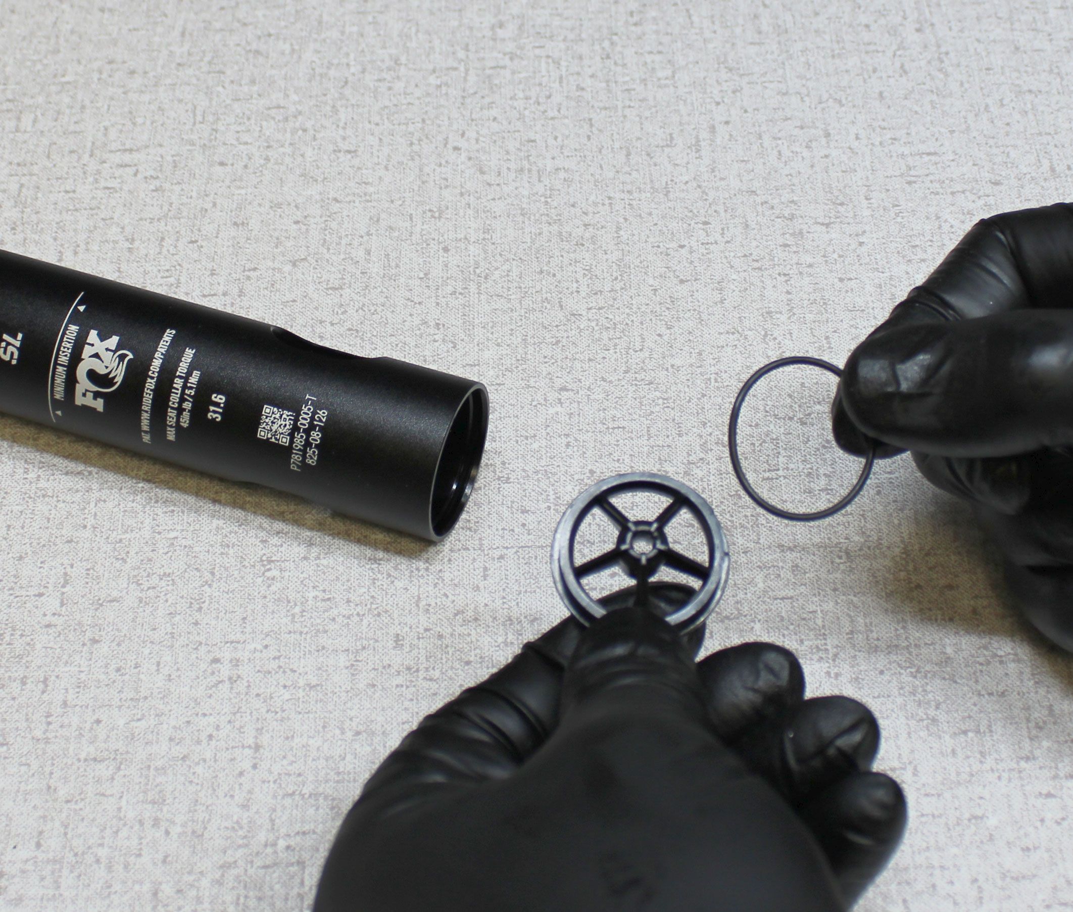
Install a new o-ring from the kit into the groove at the top of the post to prevent dirt intrusion.


Step 22
Remove the locking spring preload tool from the pull rod.
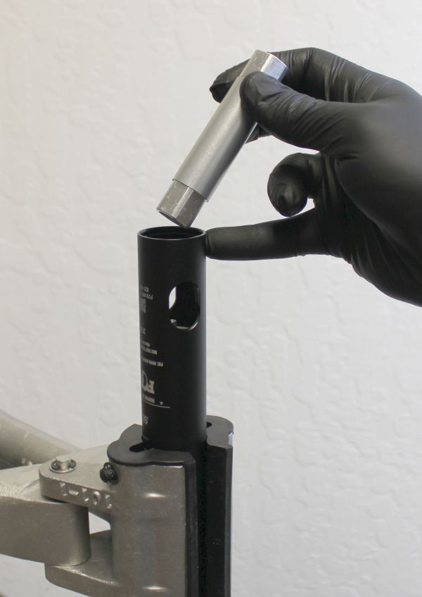
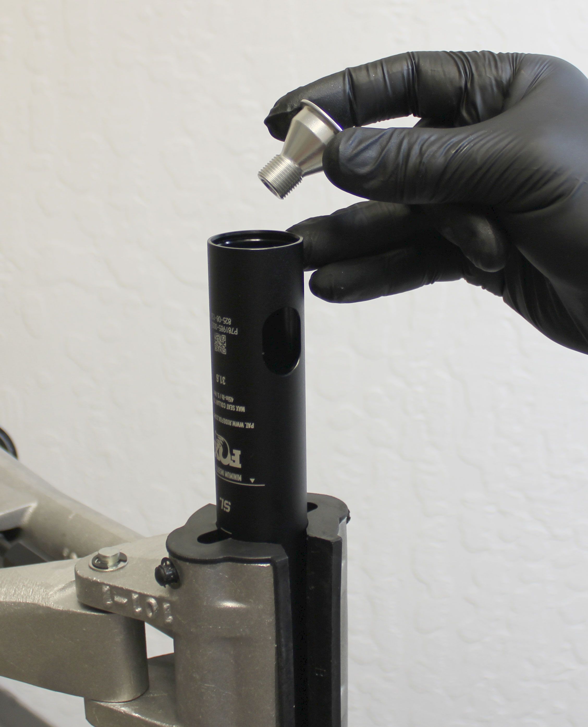
Step 23
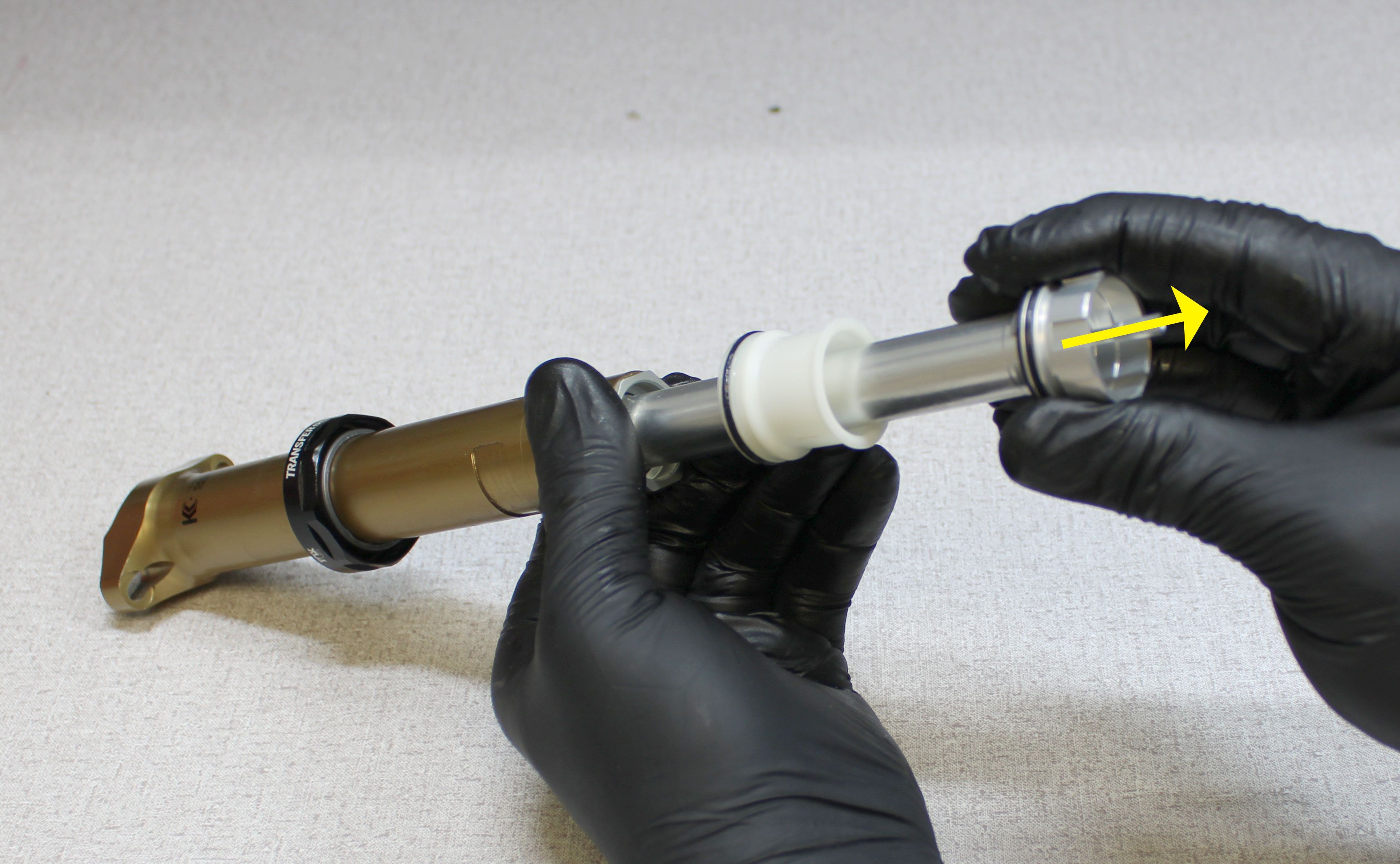
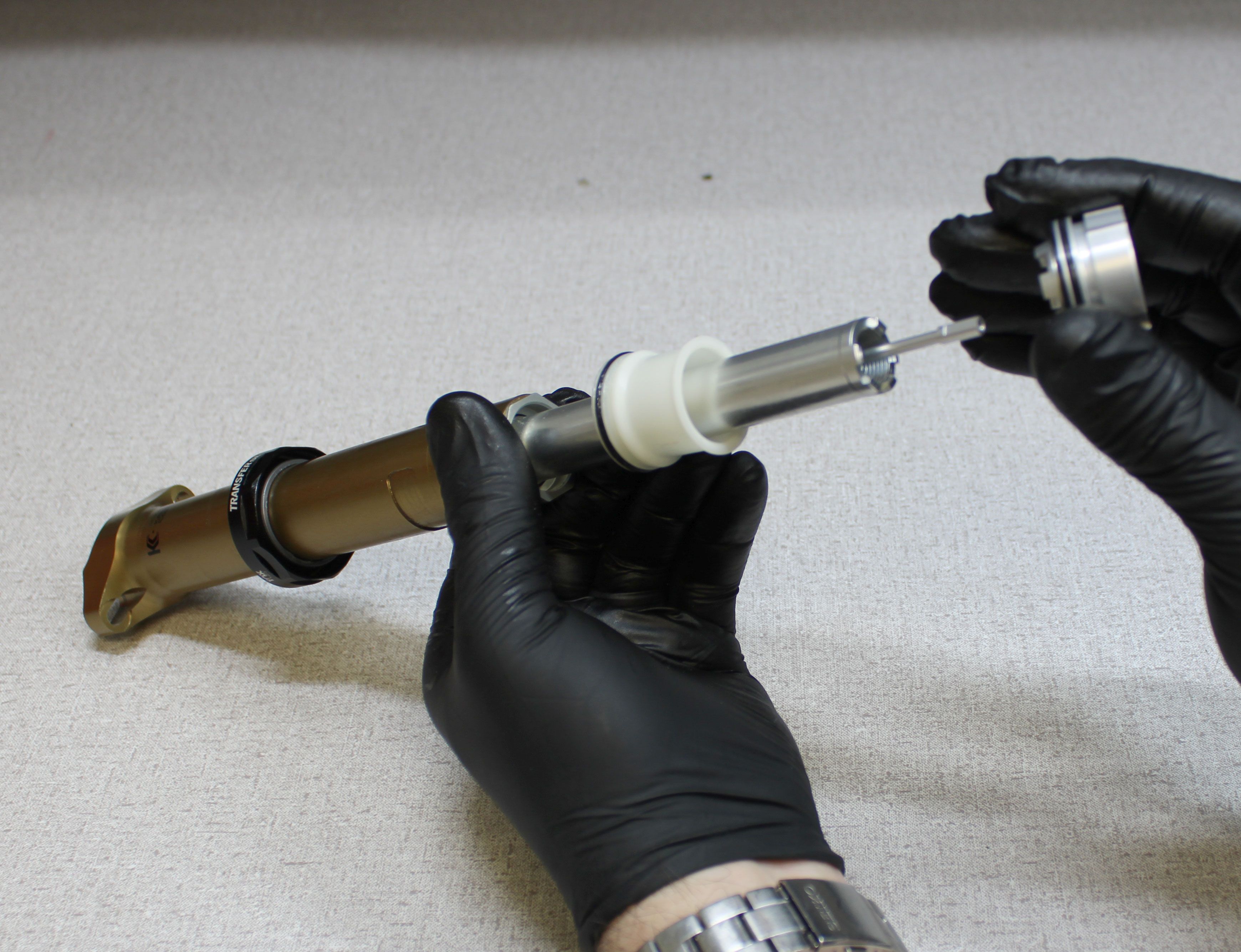
Coat the inner surface of the new wiper in the sealhead with a thin film of Slick Honey. Install the new sealhead onto the upper post as shown. Coat the new upper bushing from the kit with a thin film of Slick Honey then install onto the upper post as shown.
Step 24
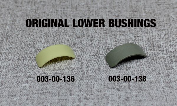
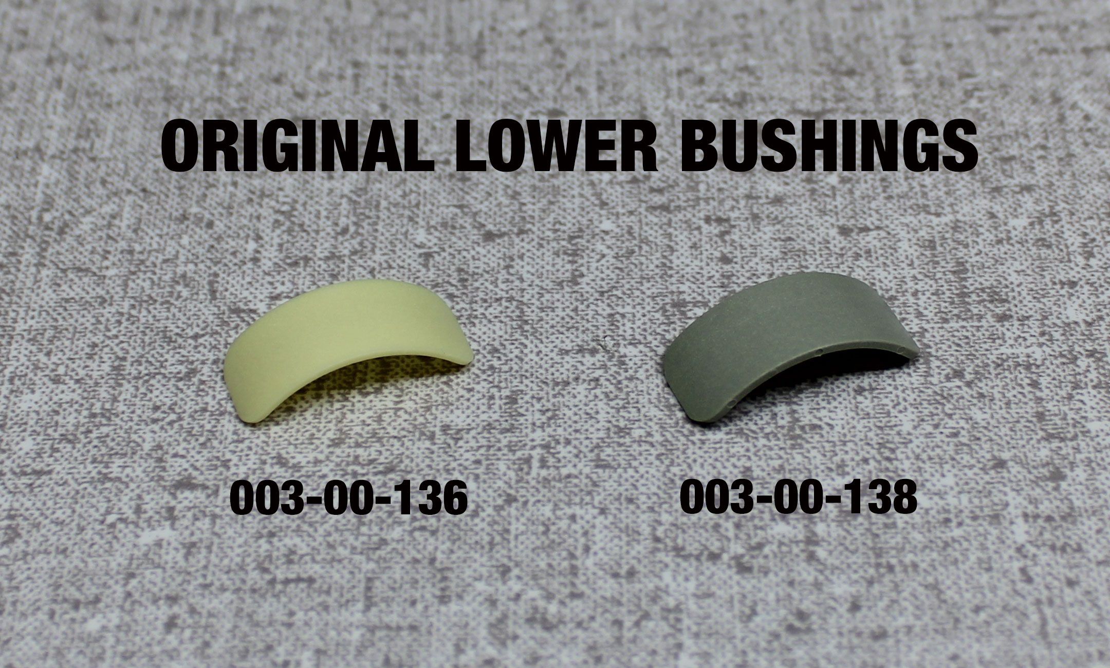
If you have the original version of the 803-01-637 or 803-01-742 seal kits you may continue to utilize the original lower bushings.
Coat the lower bushing pockets with a thin film of Slick Honey. Select the appropriate new lower bushings from the kit by using the table below.
Coat the new bushings with a thin film of Slick Honey then install into the lower bushing pockets in the upper post. Skip to step 27.
| Bushing | Where Used |
| 003-00-136 | 30.9mm Ø |
| 003-00-138 | 31.6mm Ø |

Step 25
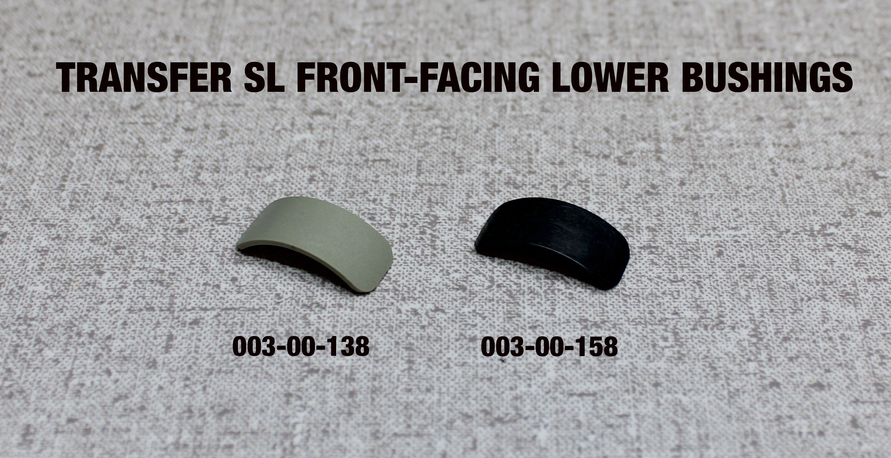
Updated Transfer SL rebuild kits have updated lower bushings. If you have an updated kit please follow the steps below.
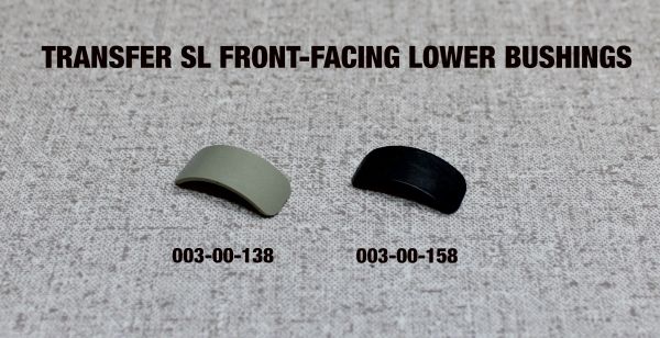
Coat the front-facing lower bushing pocket with a thin film of Slick Honey.
Select the appropriate new front-facing lower bushing from the kit by using the tables below.
Coat the new bushing with a thin film of Slick Honey then install into the pocket in the upper post.
| 003-00-158 (Dark Grey) |
30.9mm Ø/75mm Travel |
| 30.9mm Ø/100mm Travel | |
| 31.6mm Ø/125mm Travel | |
| 31.6mm Ø/150mm Travel |
| 003-00-138 (Light Grey) |
31.6mm Ø/75mm Travel |
| 31.6mm Ø/100mm Travel | |
| 31.6mm Ø/XL 100mm Travel |
Step 26
Coat the rear-facing lower bushing pocket with a thin film of Slick Honey.
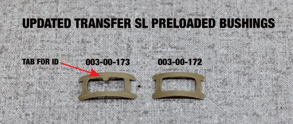
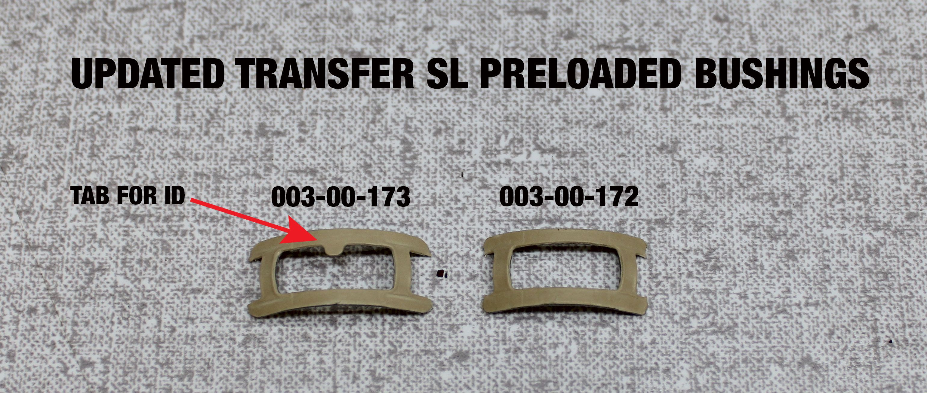
Select the appropriate new rear-facing lower bushing from the kit by using the tables below. Updated preloaded bushings are only to be installed per the table below into the rear-facing lower bushing pockets.
Coat the new preloaded rear-facing lower bushing with a thin film of Slick Honey then install into the pocket in the upper post.
| 003-00-172 (No tab) |
30.9mm Ø/75mm Travel |
| 30.9mm Ø/100mm Travel | |
| 31.6mm Ø/125mm Travel | |
| 31.6mm Ø/150mm Travel |
| 003-00-173 (With tab) |
31.6mm Ø/75mm Travel |
| 31.6mm Ø/100mm Travel | |
| 31.6mm Ø/XL 100mm Travel |
Step 27
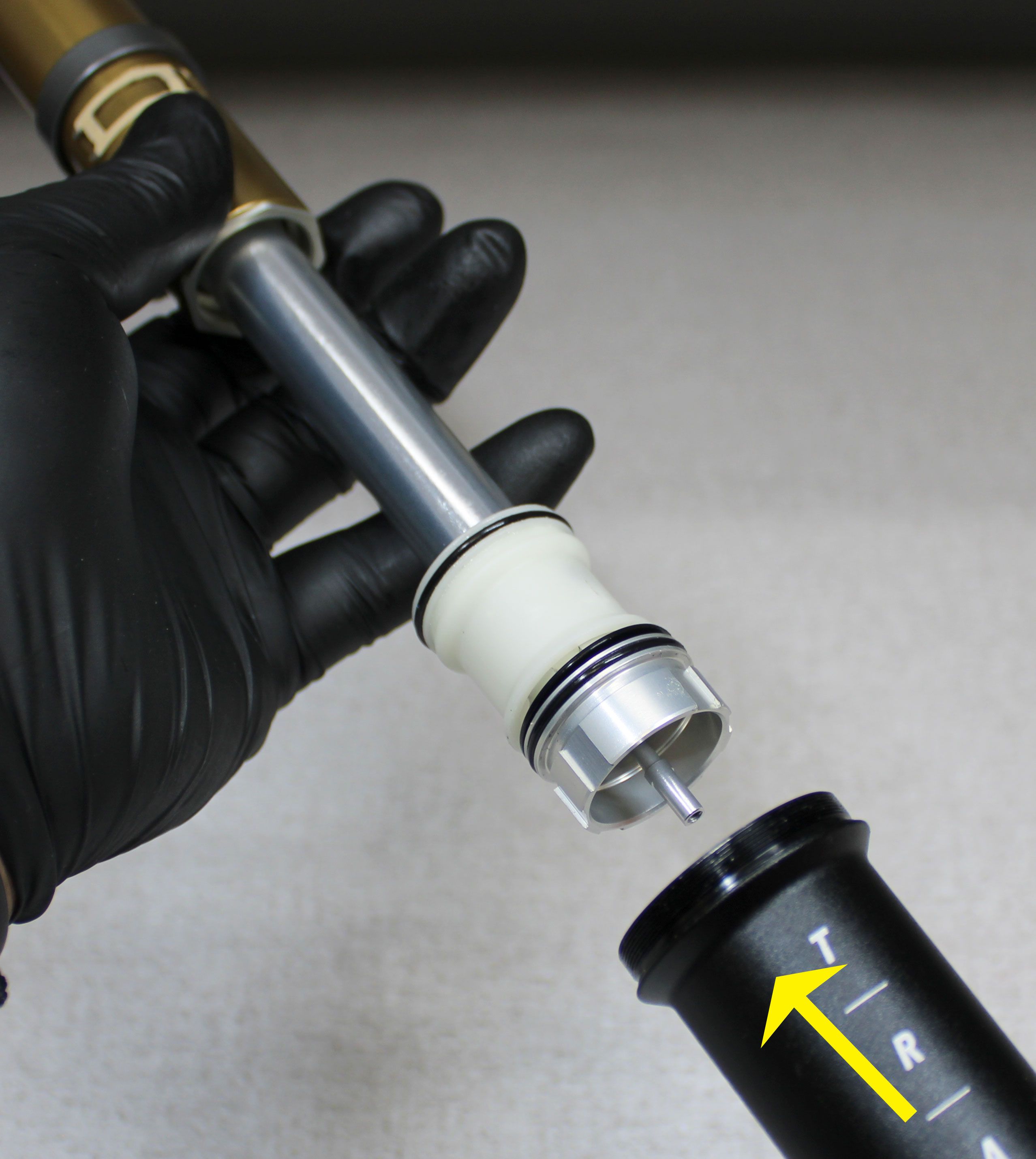
Replace the o-ring on the bottom out spacer (if present) with a new greased o-ring from the kit. o-ring position on the bottom out spacer is determined by lower post diameter. 30.9mm Transfer SL posts have the o-ring in the groove closest to the end of the spacer. 31.6mm Transfer SL posts have the o-ring in the groove furthest from the top of the post. Reinstall the bottom out spacer (if present) with it's o-ring end first onto the upper post. Replace the bumper and o-ring on the locking body coupling with new greased ones from the kit. Reinstall the locking body coupling onto the locking body making sure to engage the one-way key features to ensure that the coupling is fully seated.
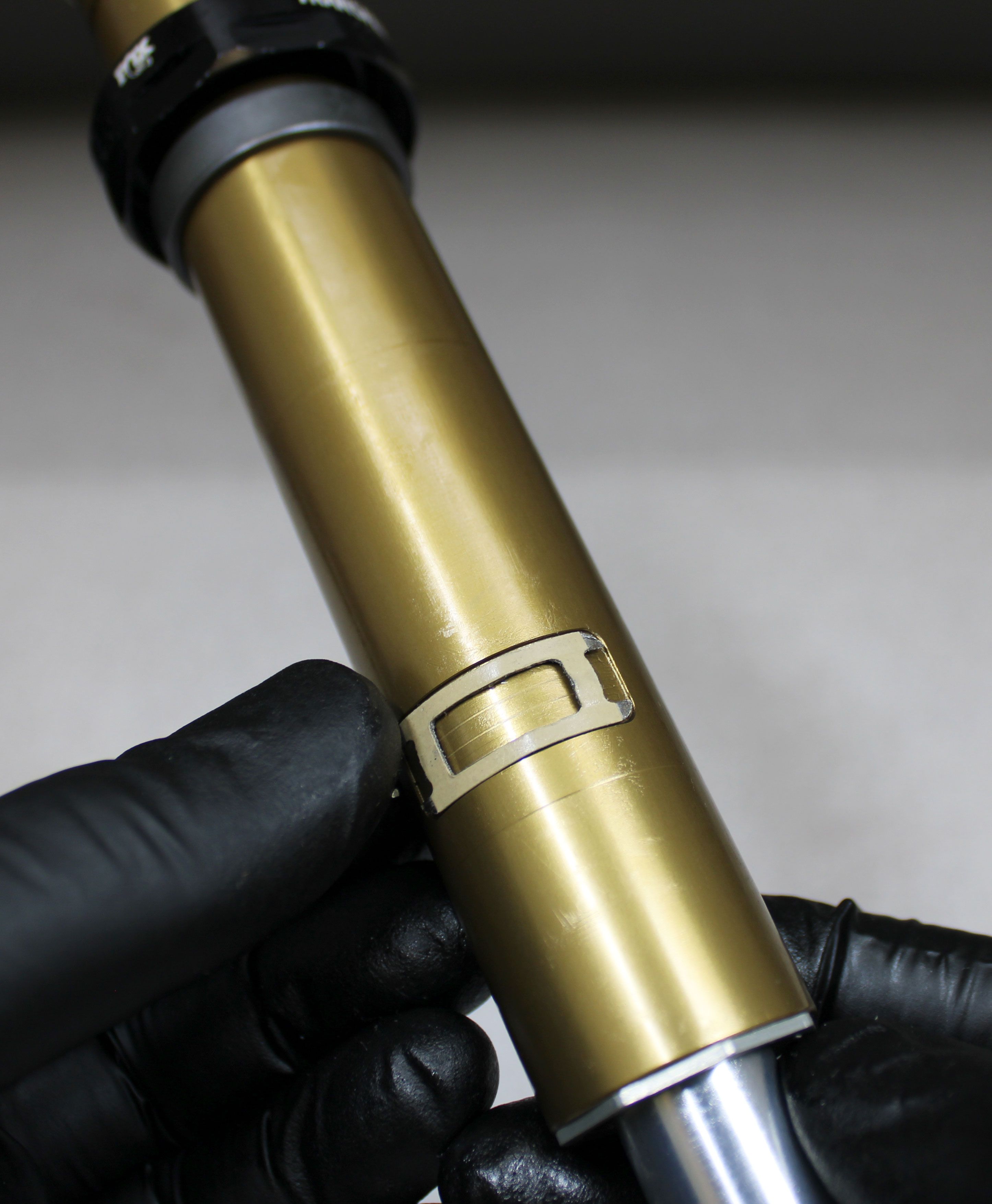
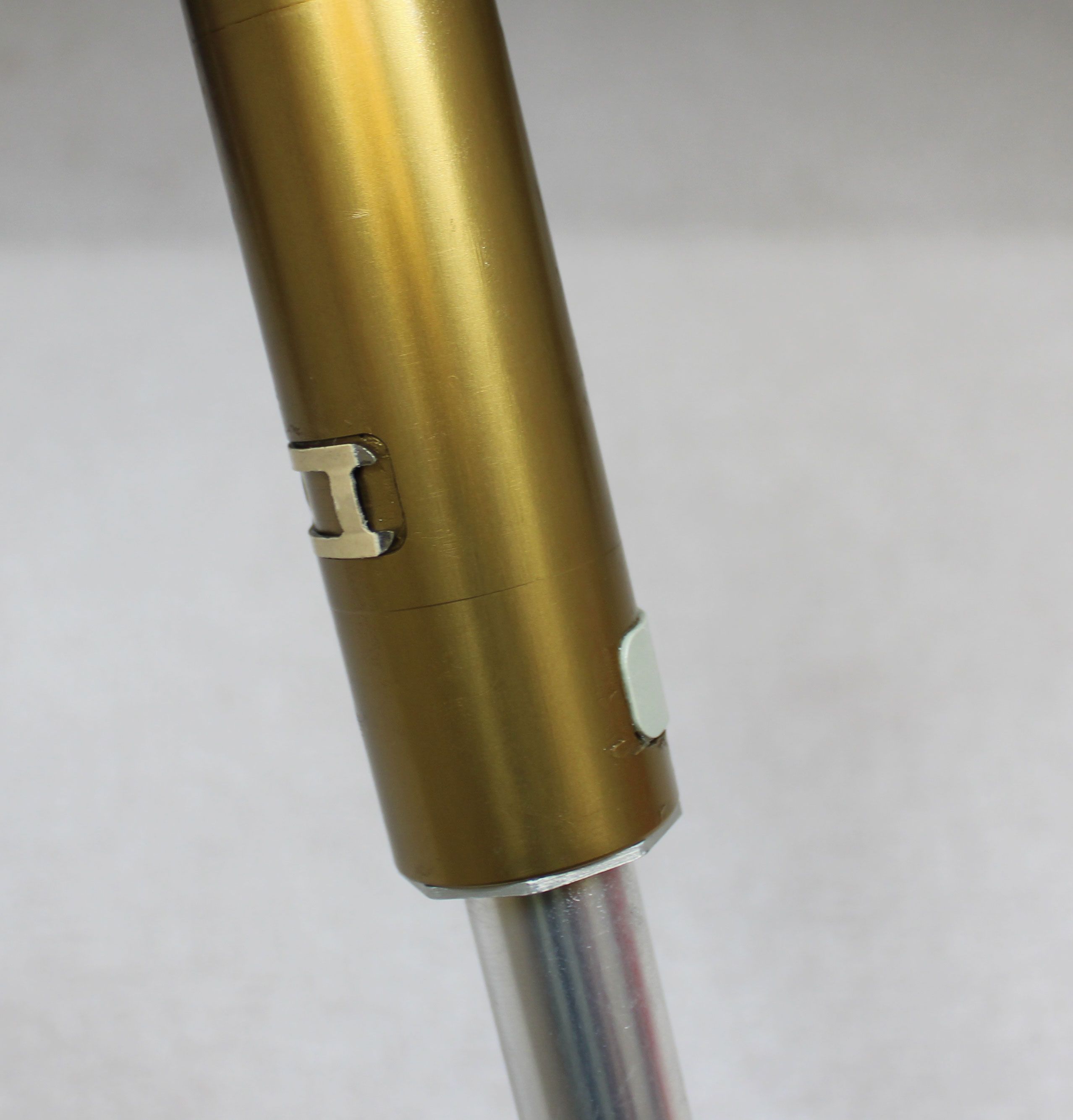
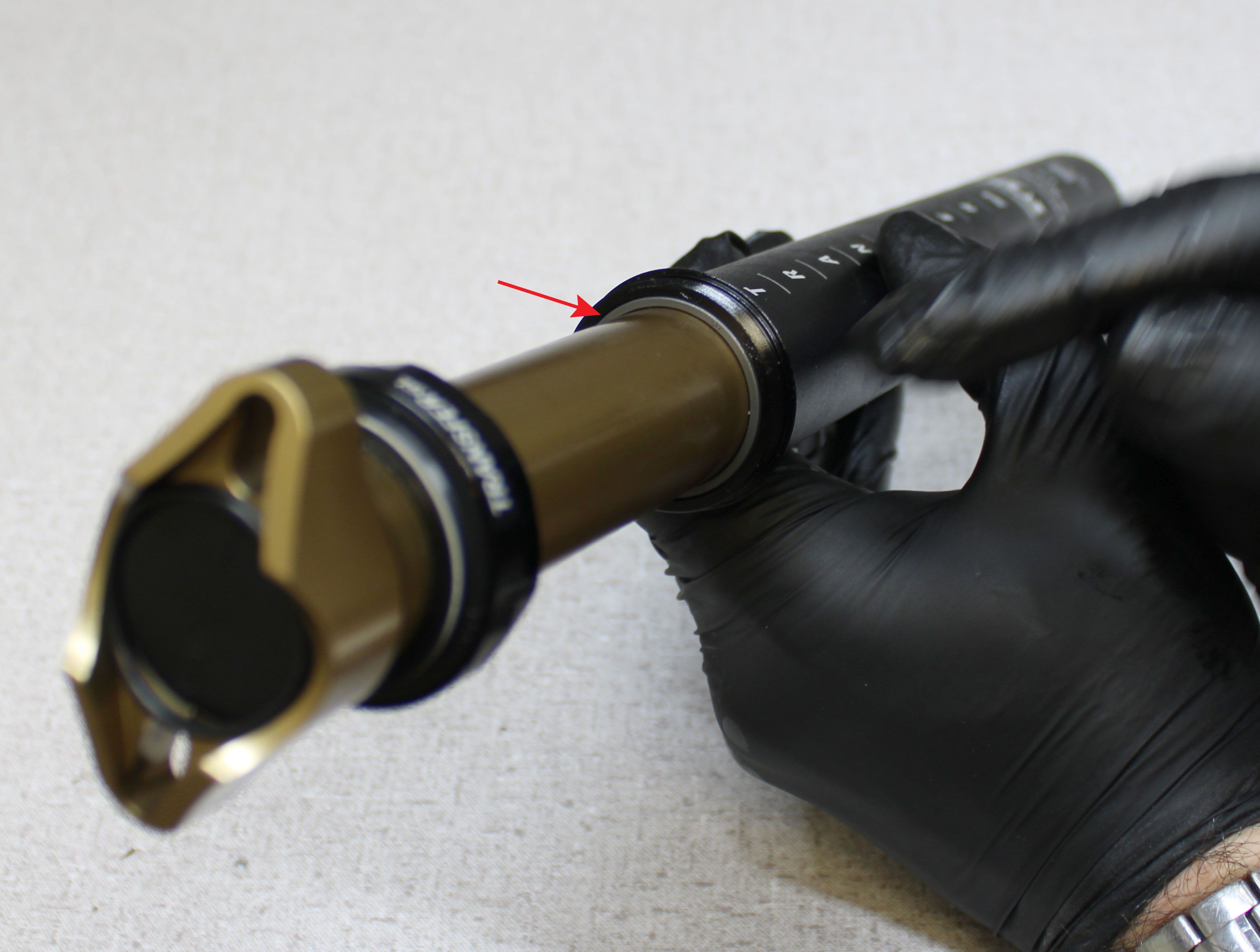
Step 28
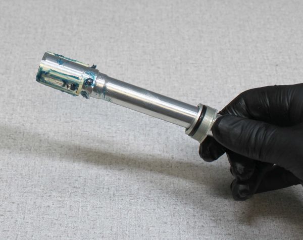
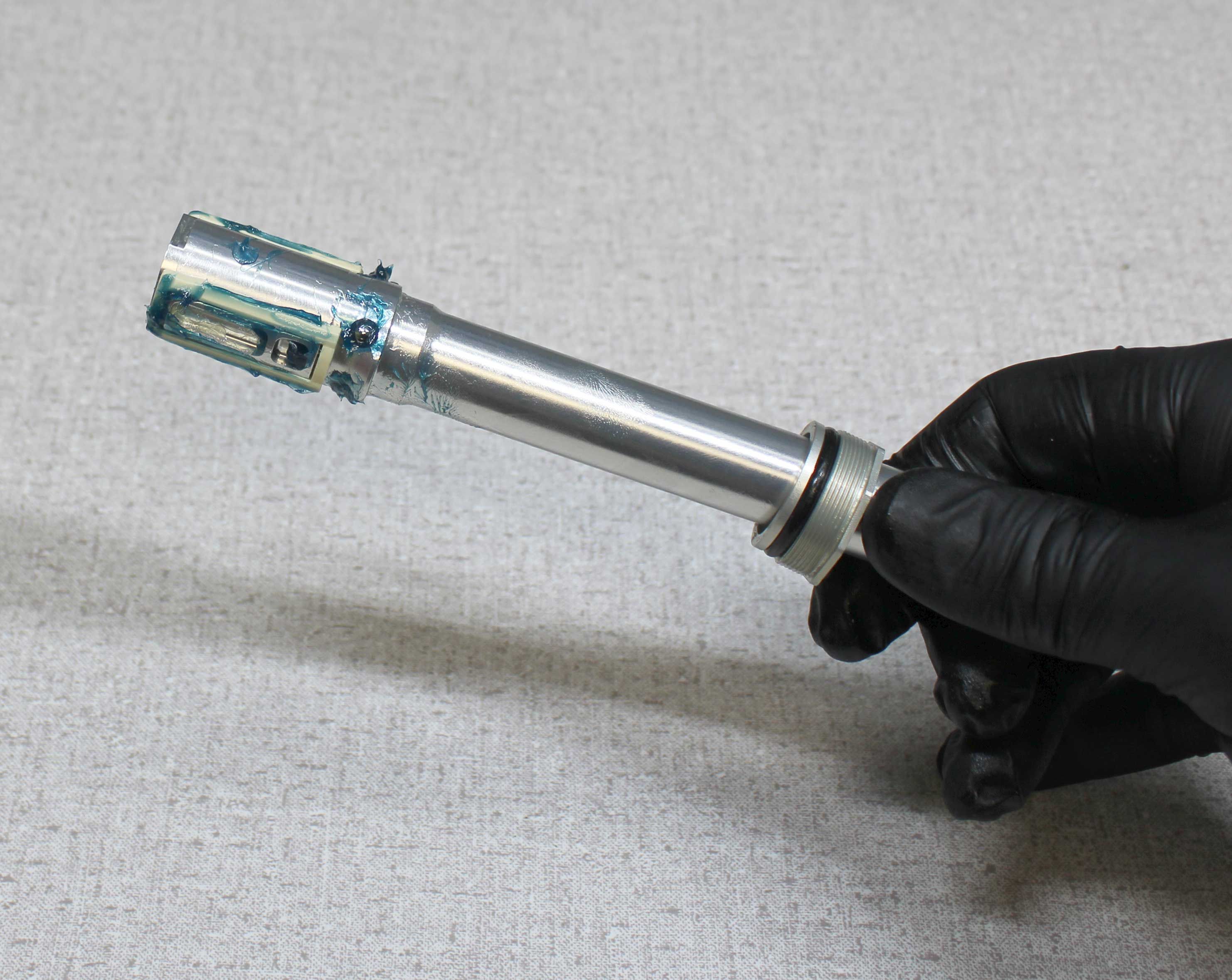
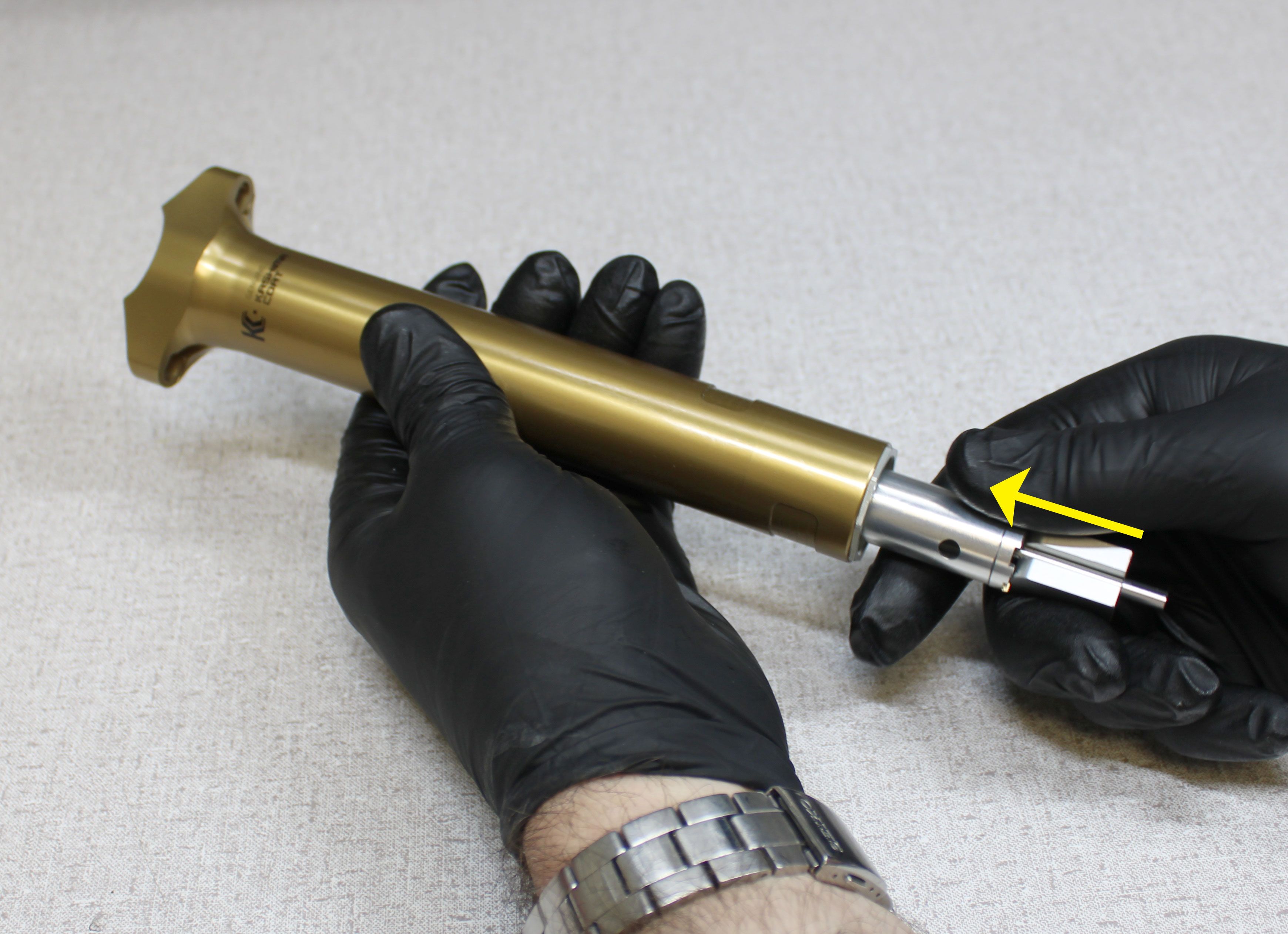
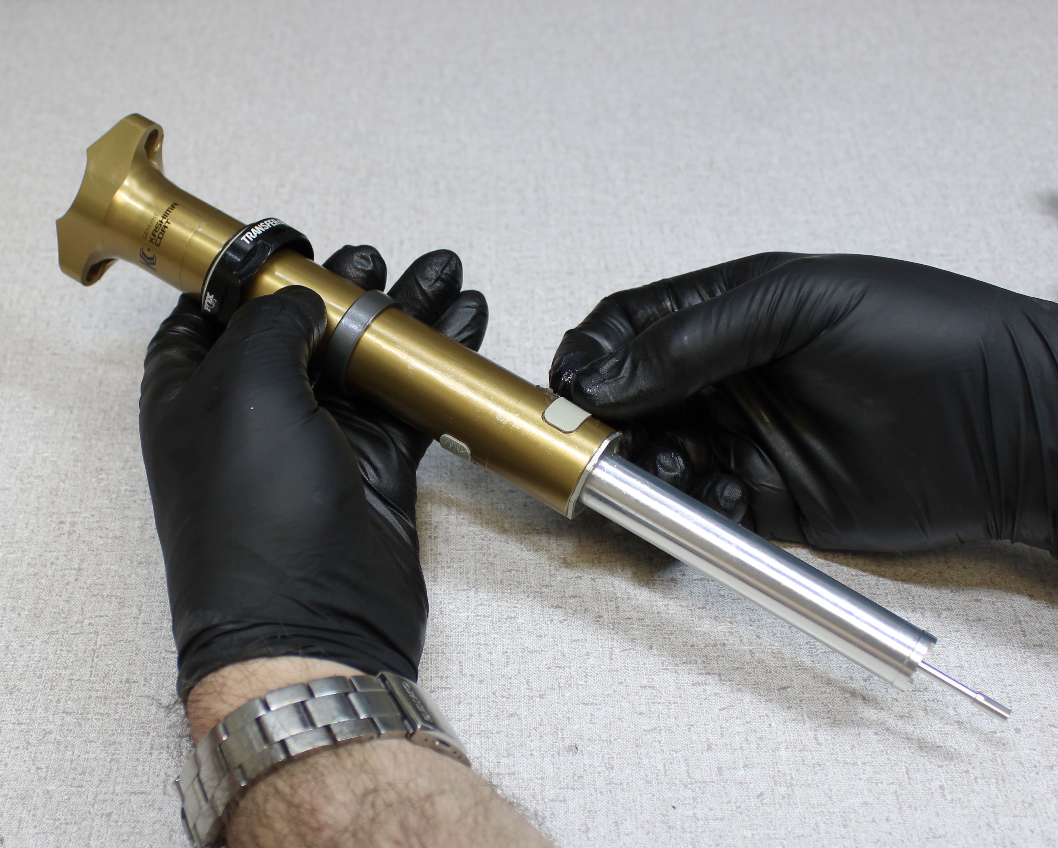
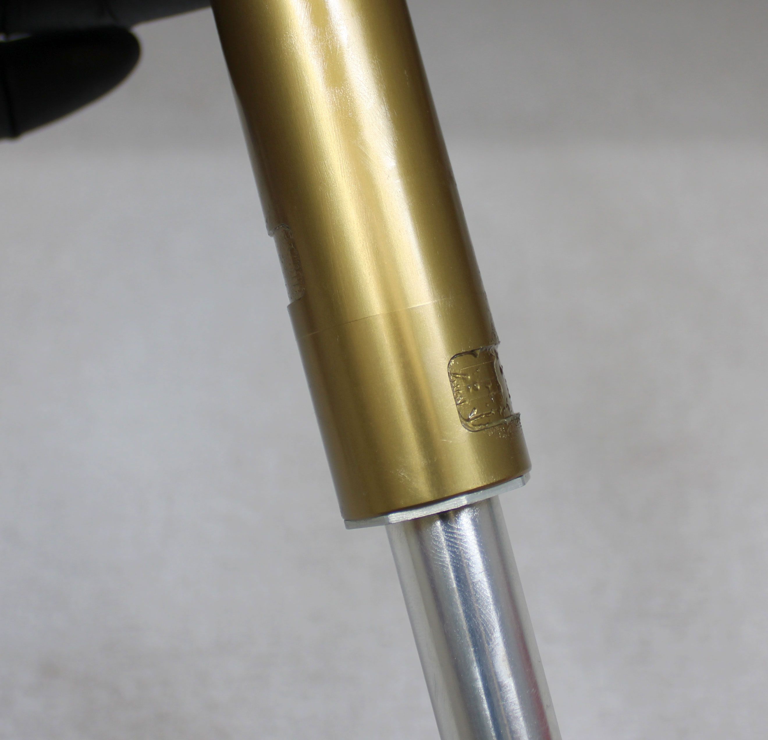
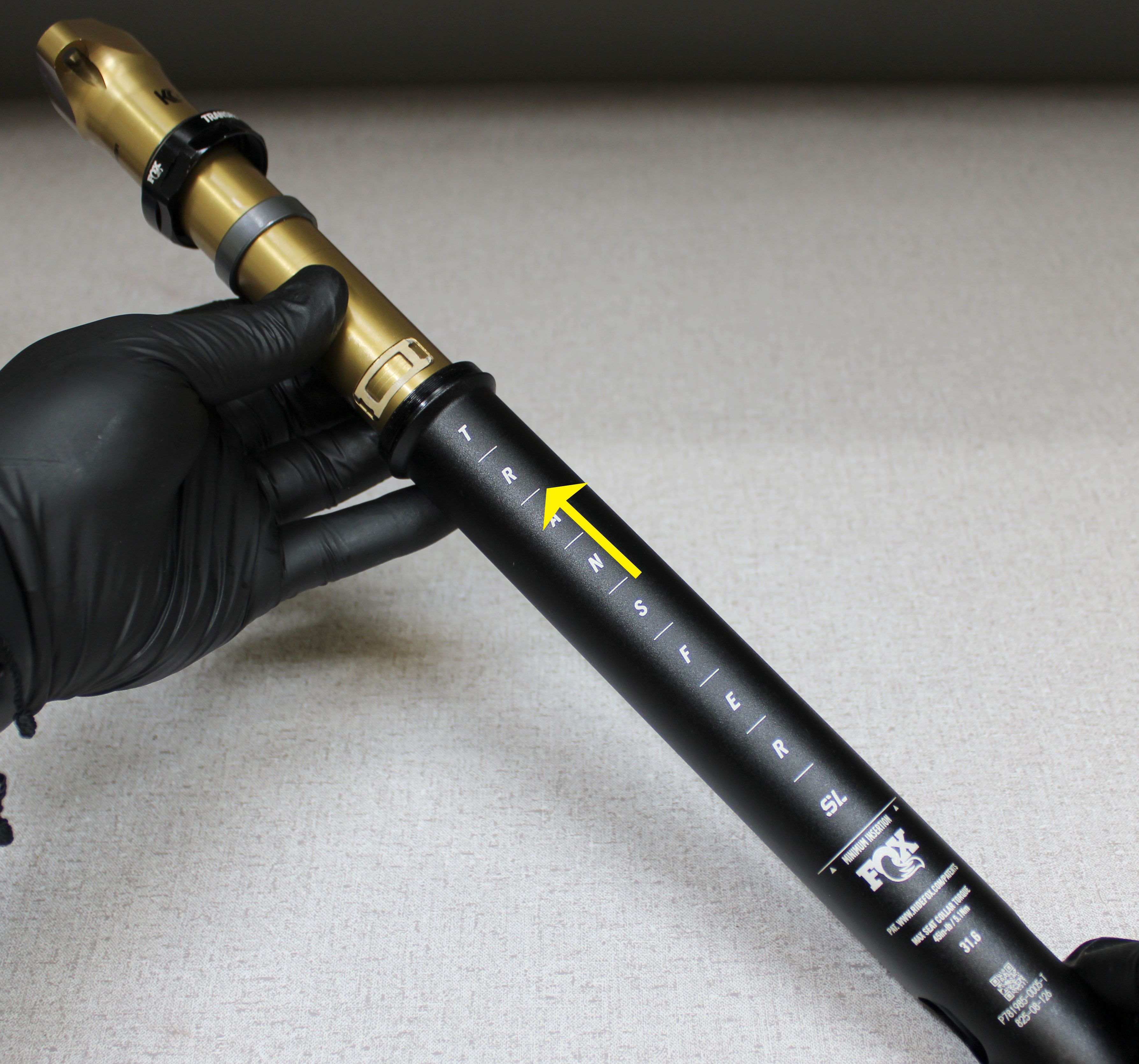
Reinstall the upper post into the lower post making sure to align the top-most lower bushing with the laser-etching on the rear of the lower post.
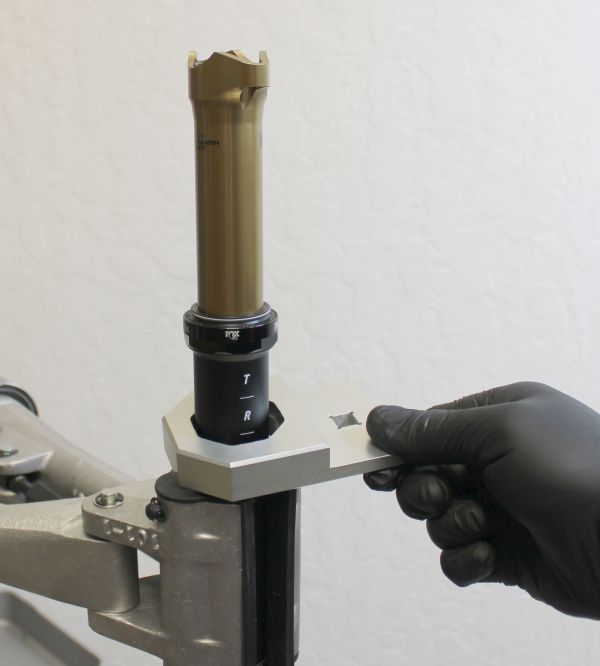
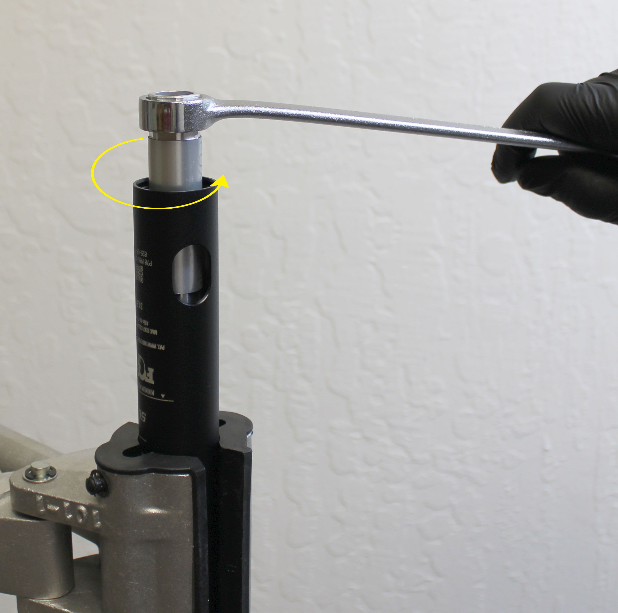
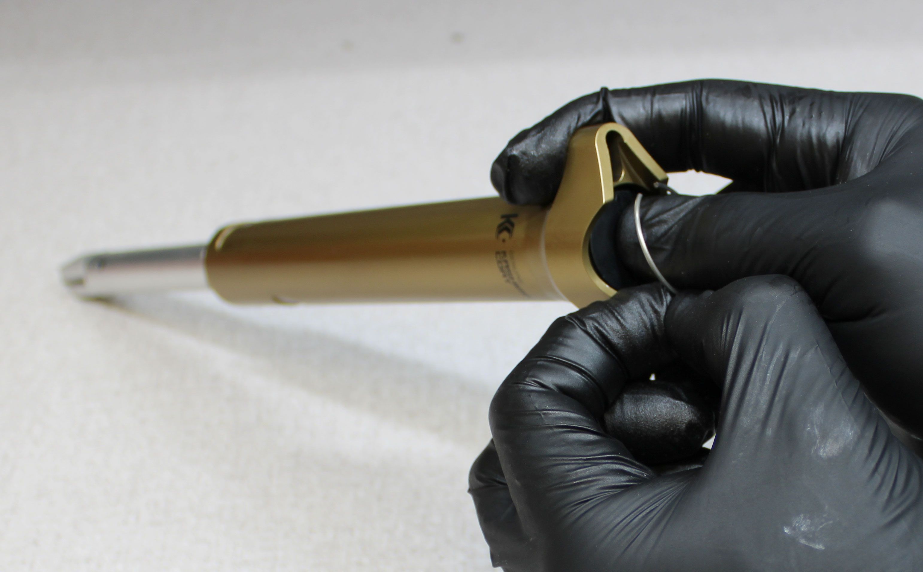
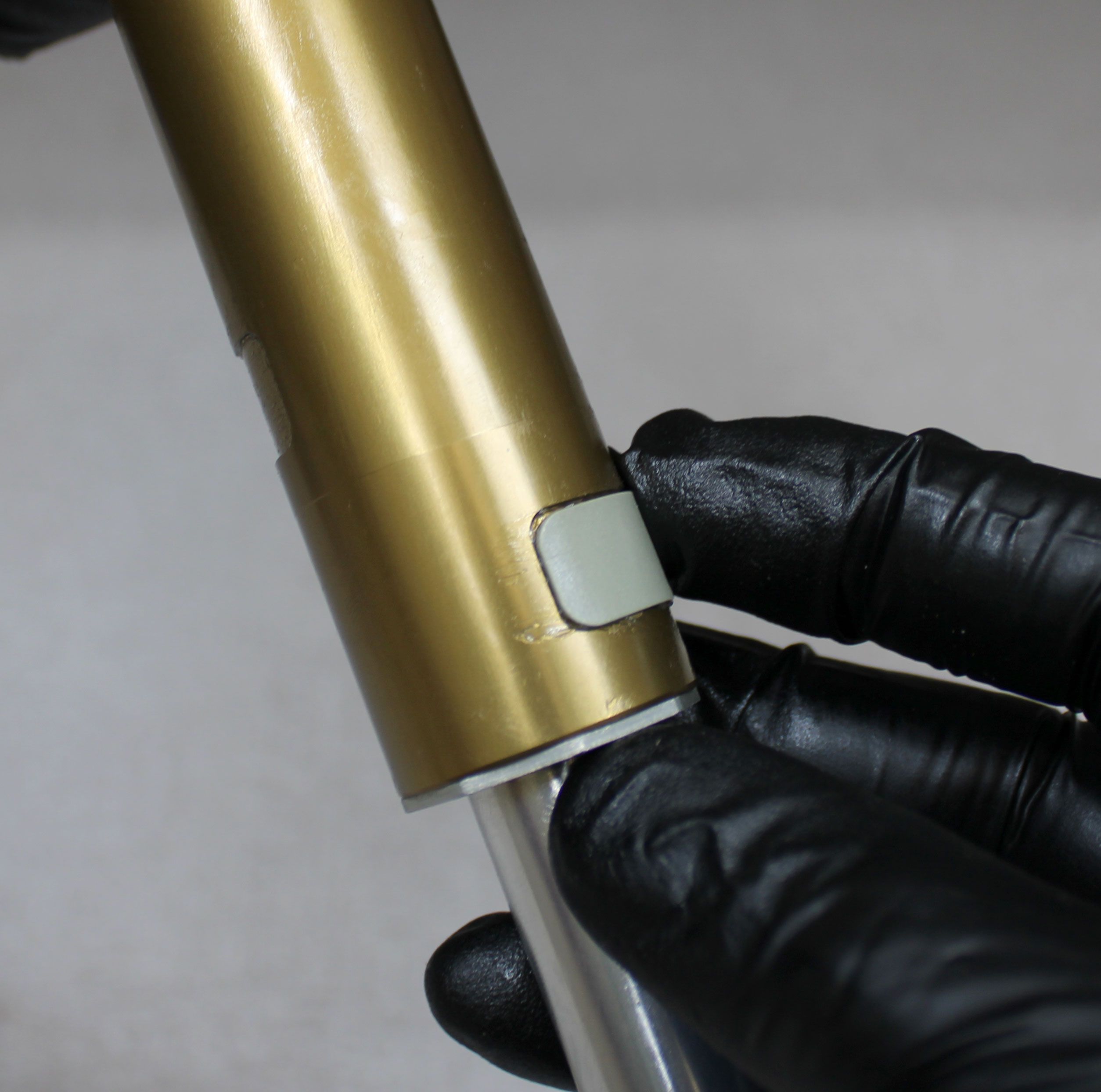
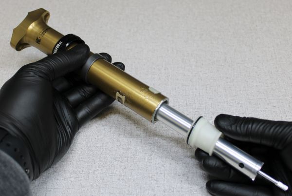
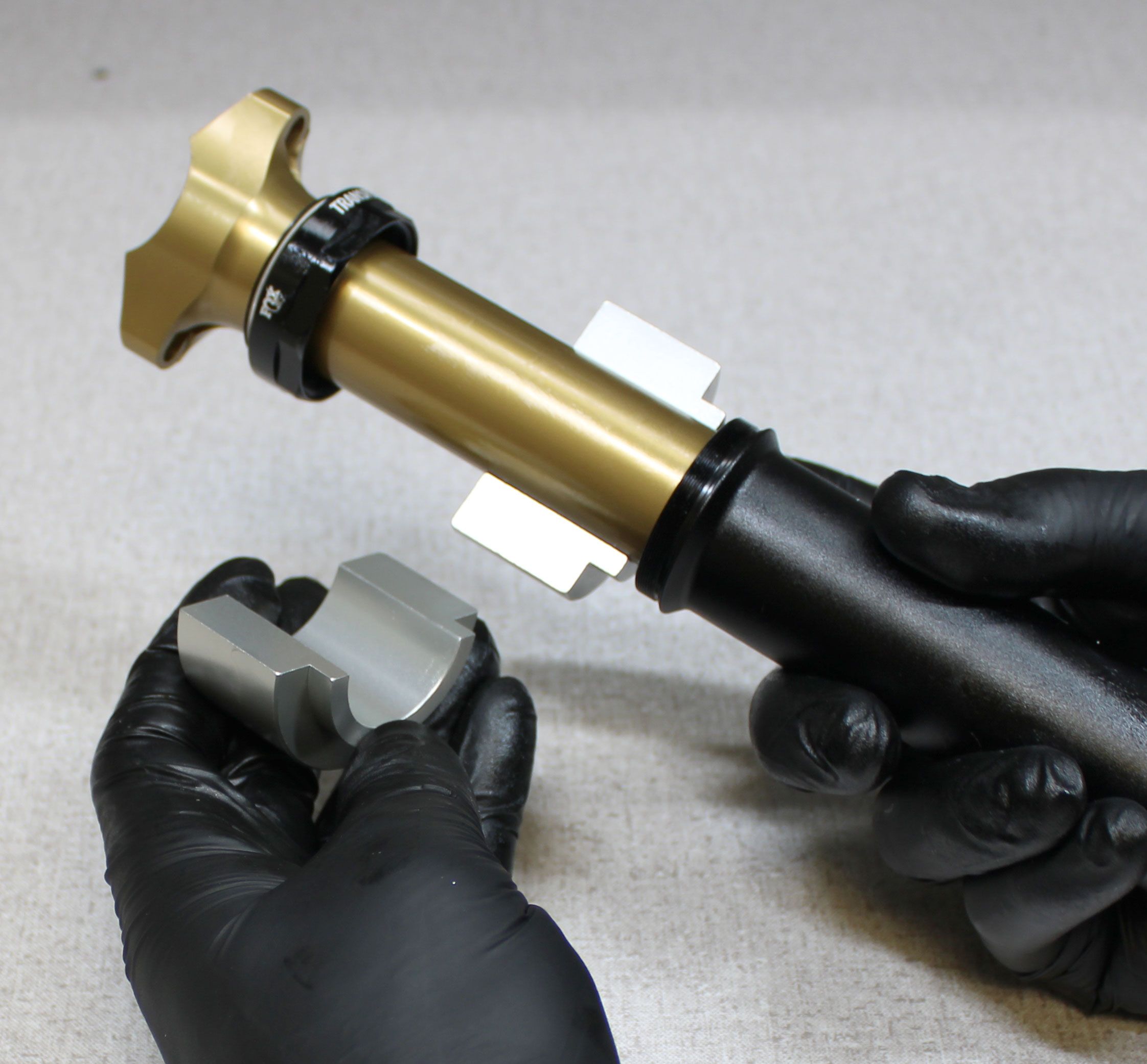
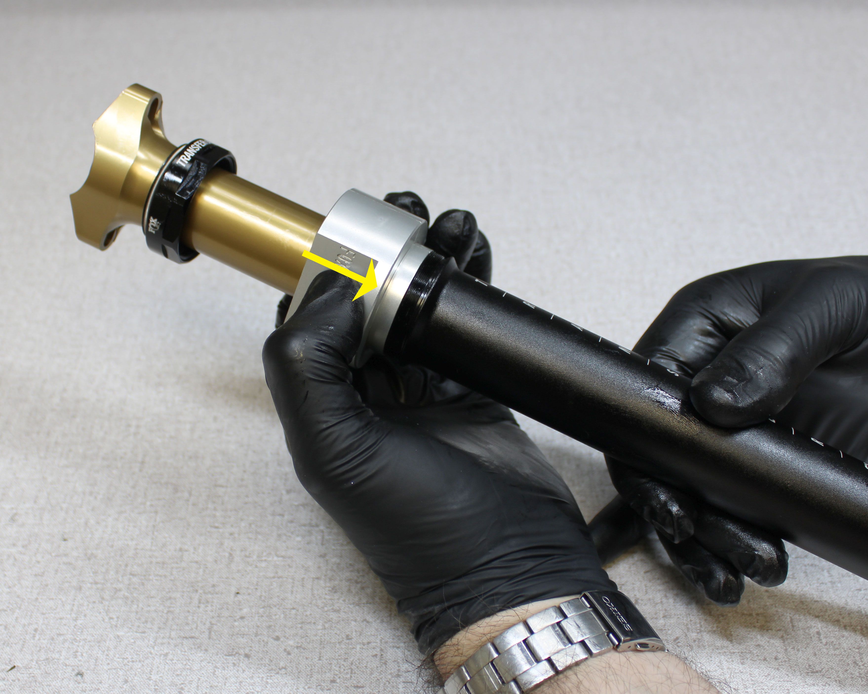
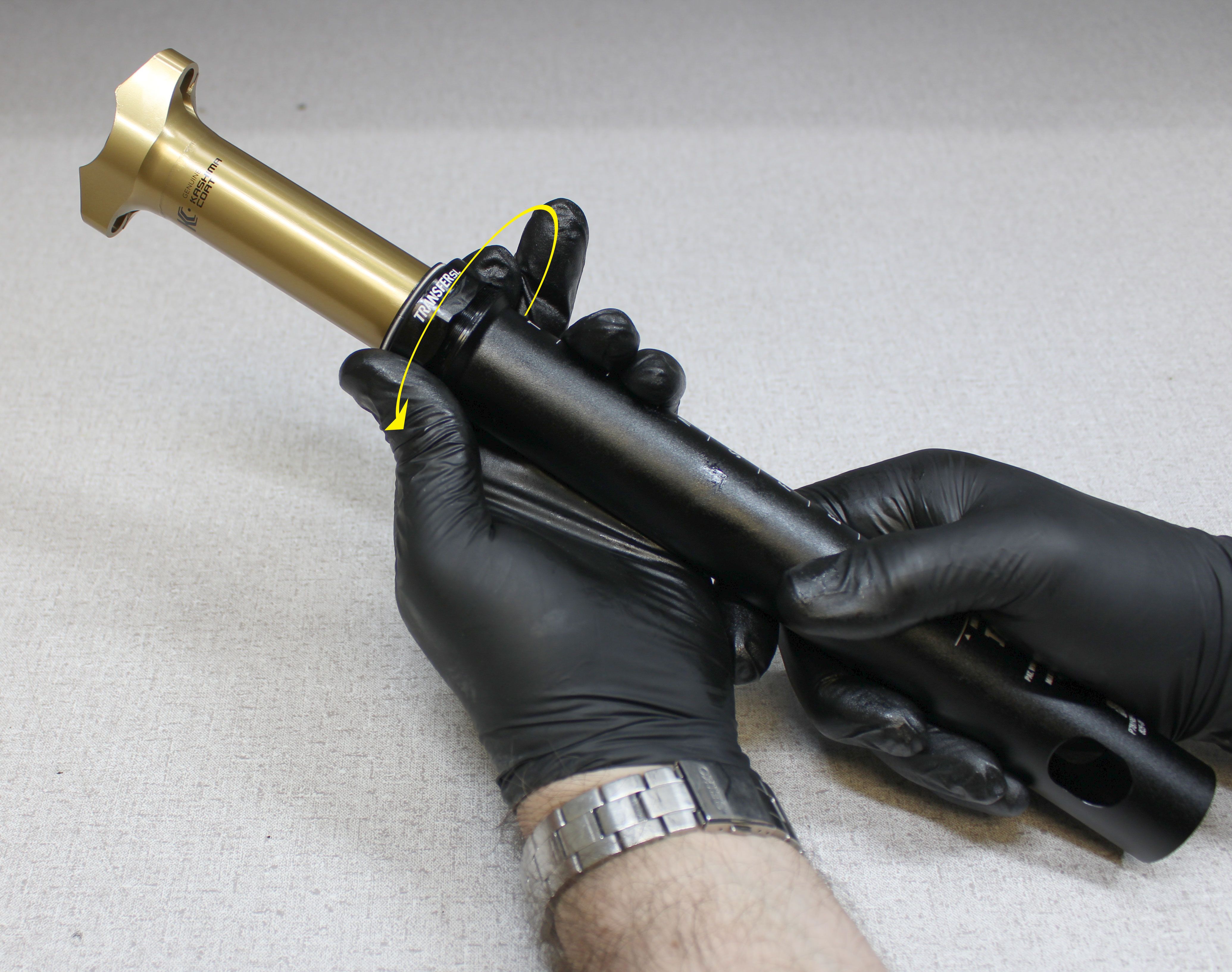
Step 29
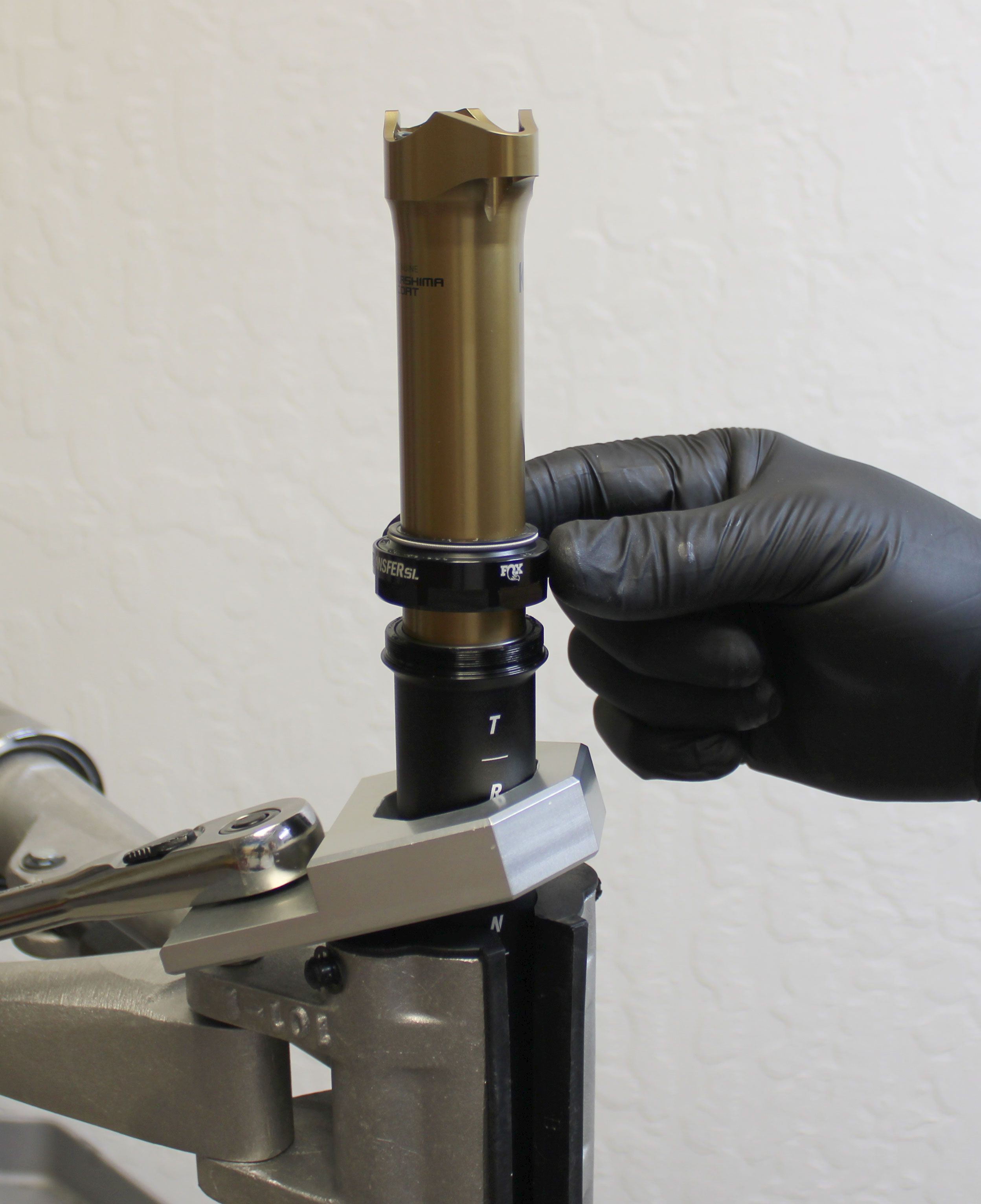
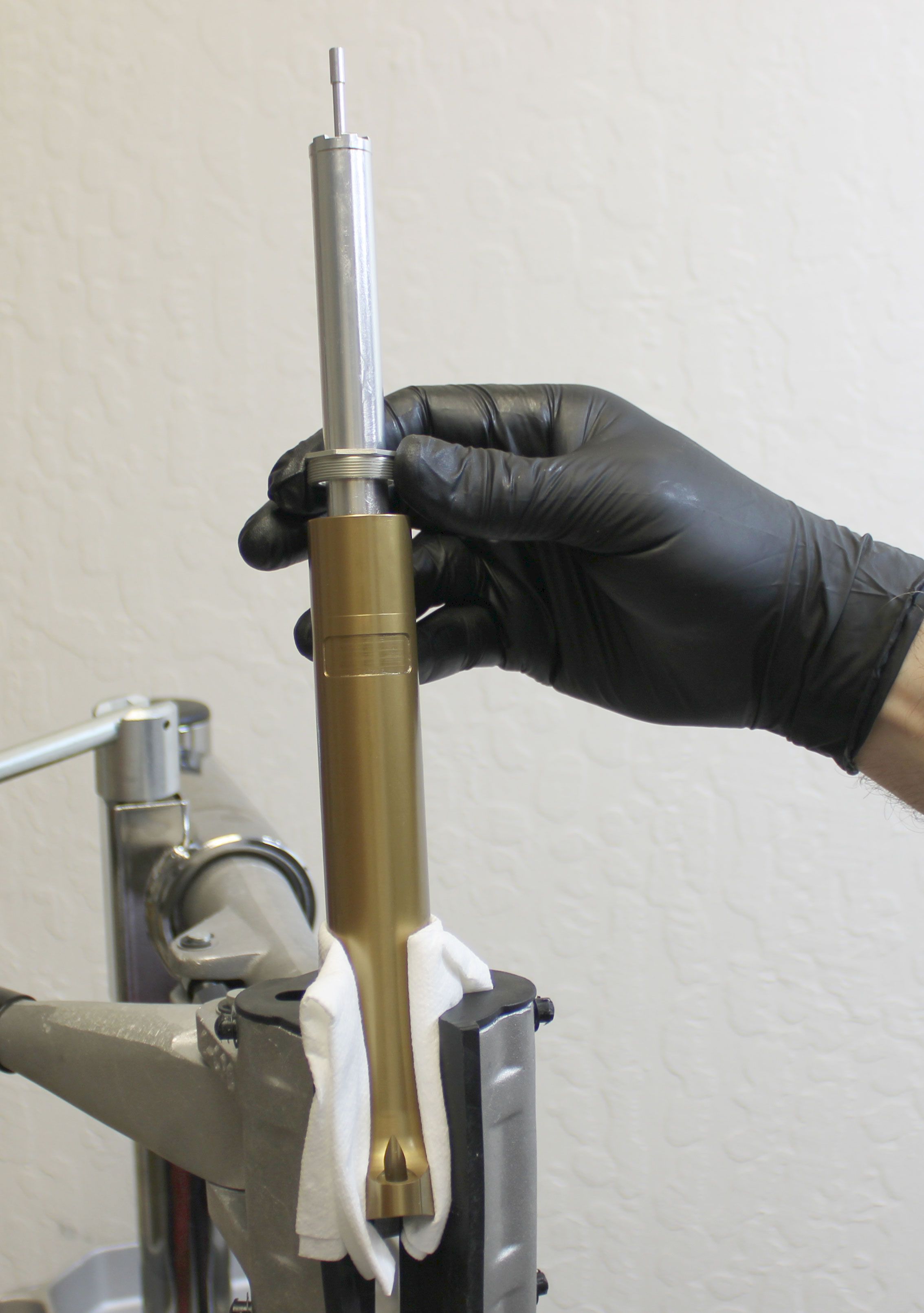
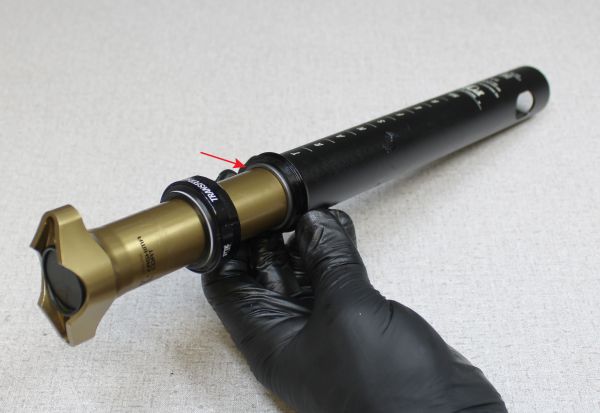
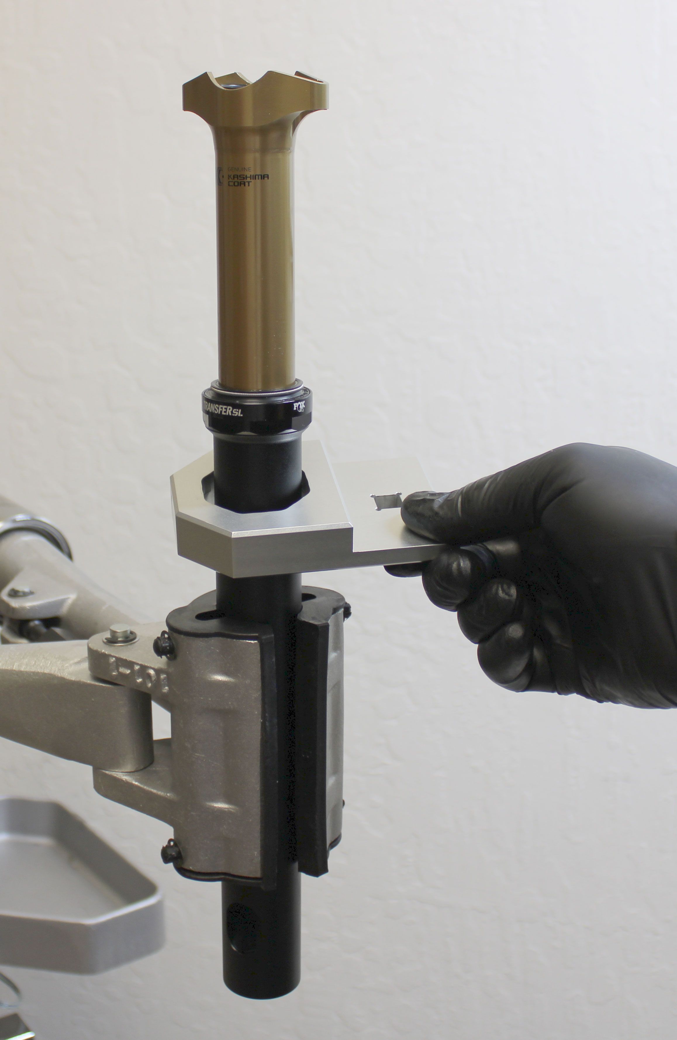
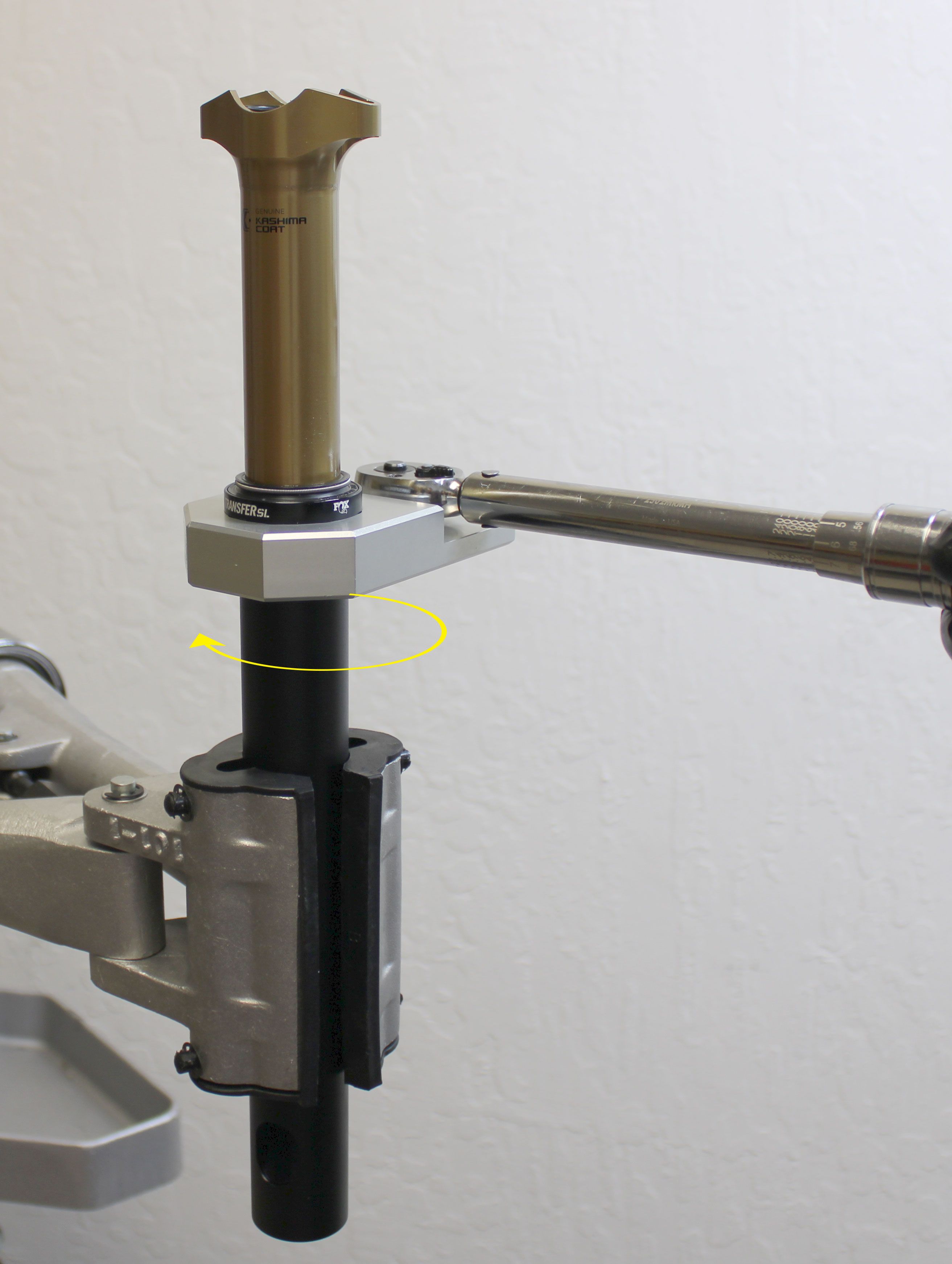
Make sure that the upper bushing is fully seated within the lower post. You can use the upper bushing installer (PN: 803-01-500) or your fingers to seat the upper bushing within the end of the lower post as shown. Tighten the sealhead clockwise onto the lower post by hand. Insert the seatpost through the collar torque driver (PN: 398-00-894) then clamp in your workstand. Tighten the sealhead clockwise to 144 in-lb (16.3 Nm) torque.

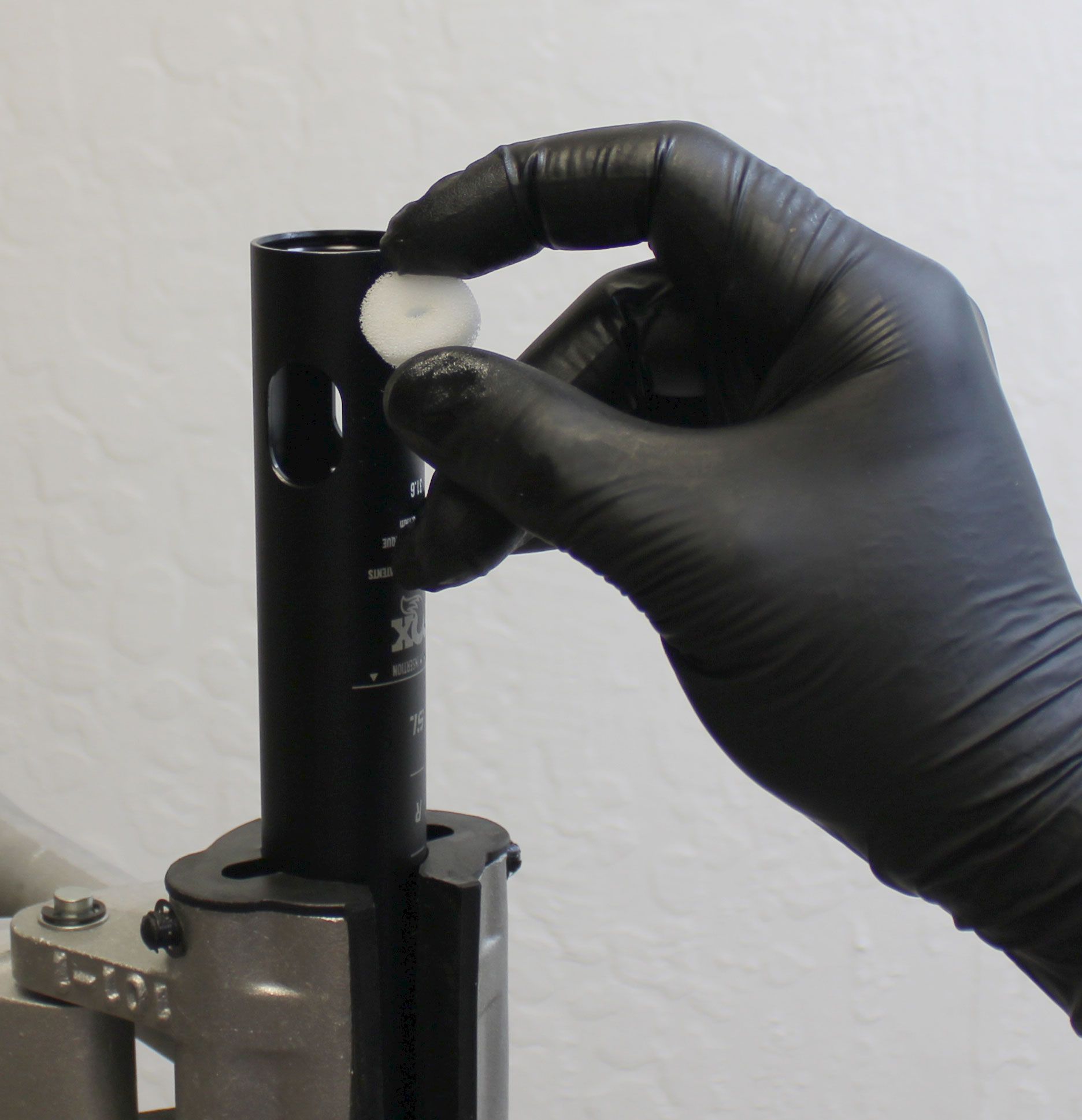
Step 30
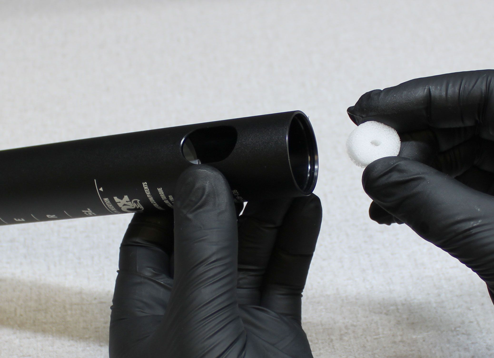
Invert the post in your workstand then reinstall the lug nut. Use the retention lug driver and an 18mm socket to tighten the lug nut clockwise to 144 in-lb (16.3 Nm) torque. Install a new foam debris cover from the kit into the lug nut using a blunt tool to seat it fully.

Step 31
Reinstall the cable hangar making sure to hold it from turning while you tighten the screw clockwise with a T8 Torx driver to 6.7 in-lb (0.8 Nm) torque. Reinstall the cable pinch bolt clockwise into the cable hangar with a 3mm hex wrench. Make sure to install the pinch bolt from the correct side in order to pinch the cable appropriately during seatpost installation.
Step 32
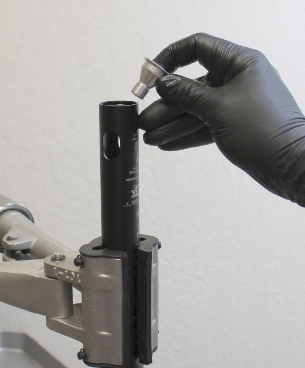
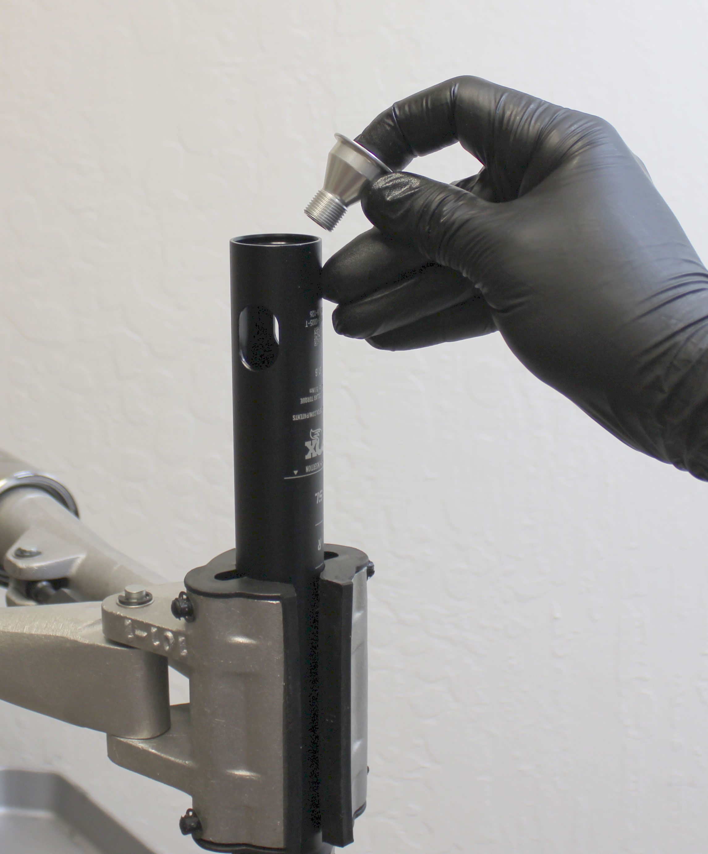
Replace the o-ring on the end cap with a new ungreased one from the kit. Reinstall the end cap into the lower post.

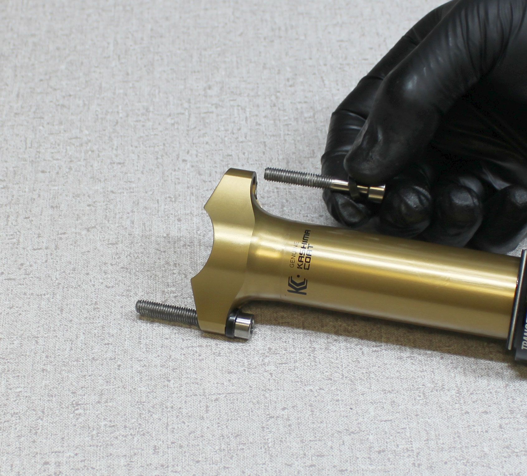
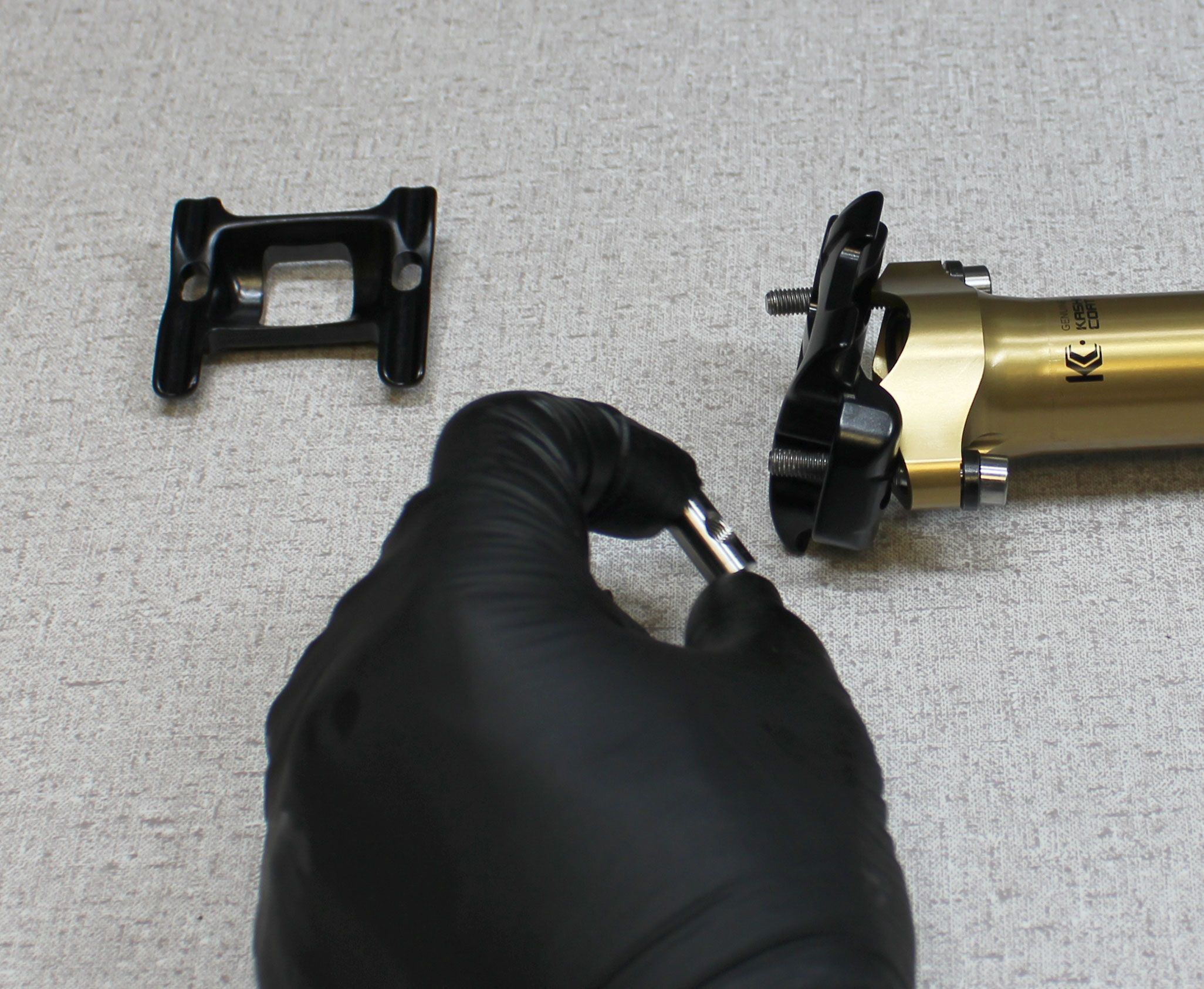
Step 33
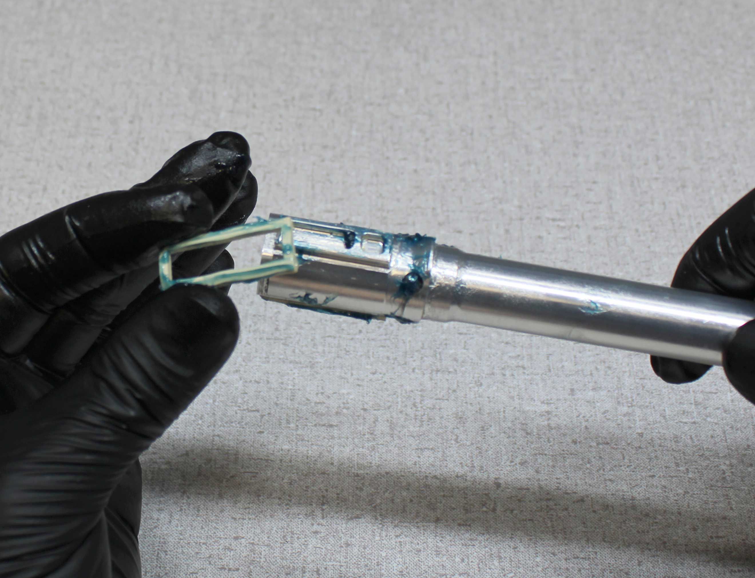
Reinstall the saddle clamps and hardware. Make sure that the spherical washers oriented properly and that the rear of the saddle clamps are oriented toward the rear of the post (indicated by the laser etching on the lower post). Clean the exterior of your seatpost.
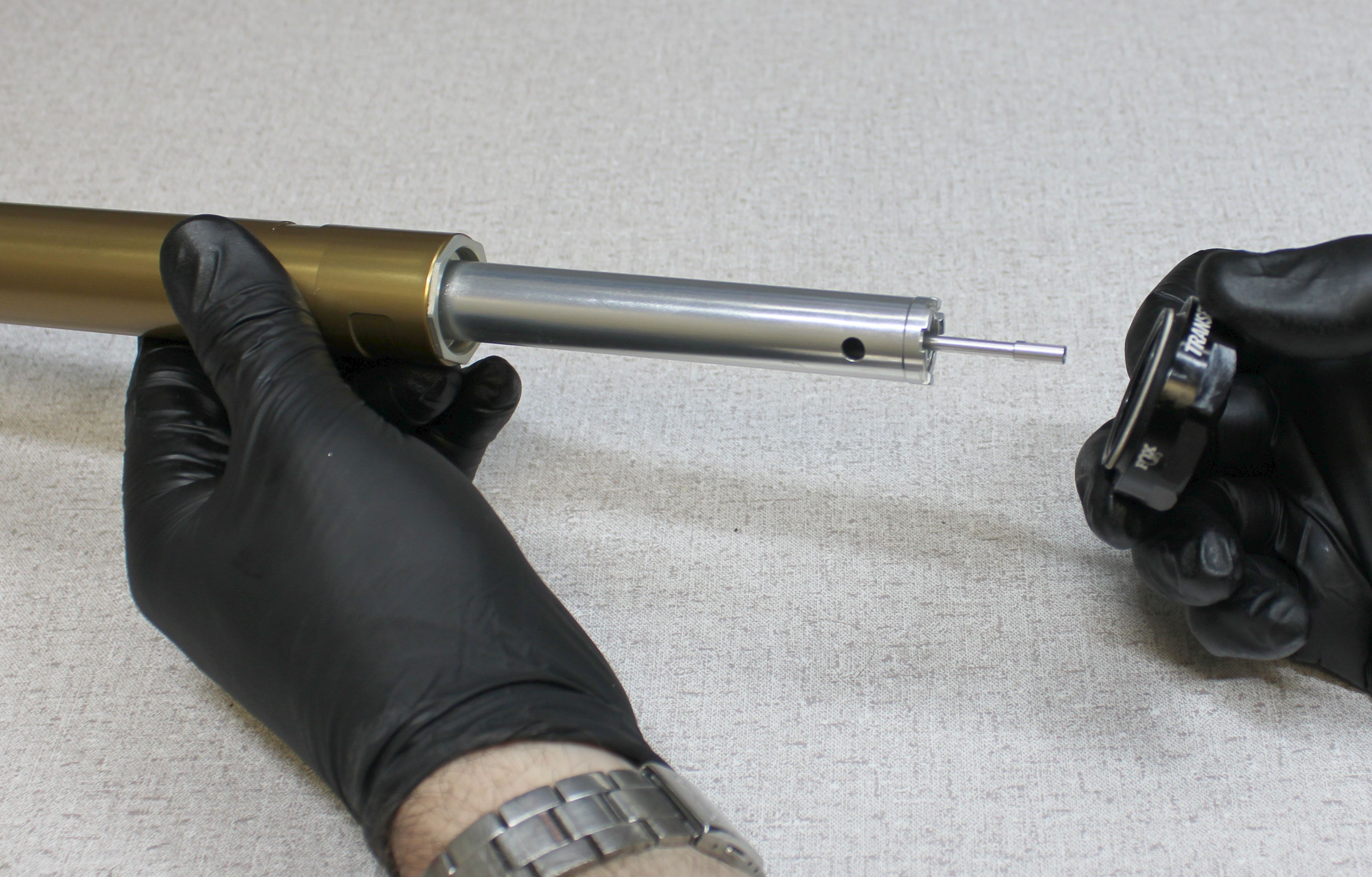
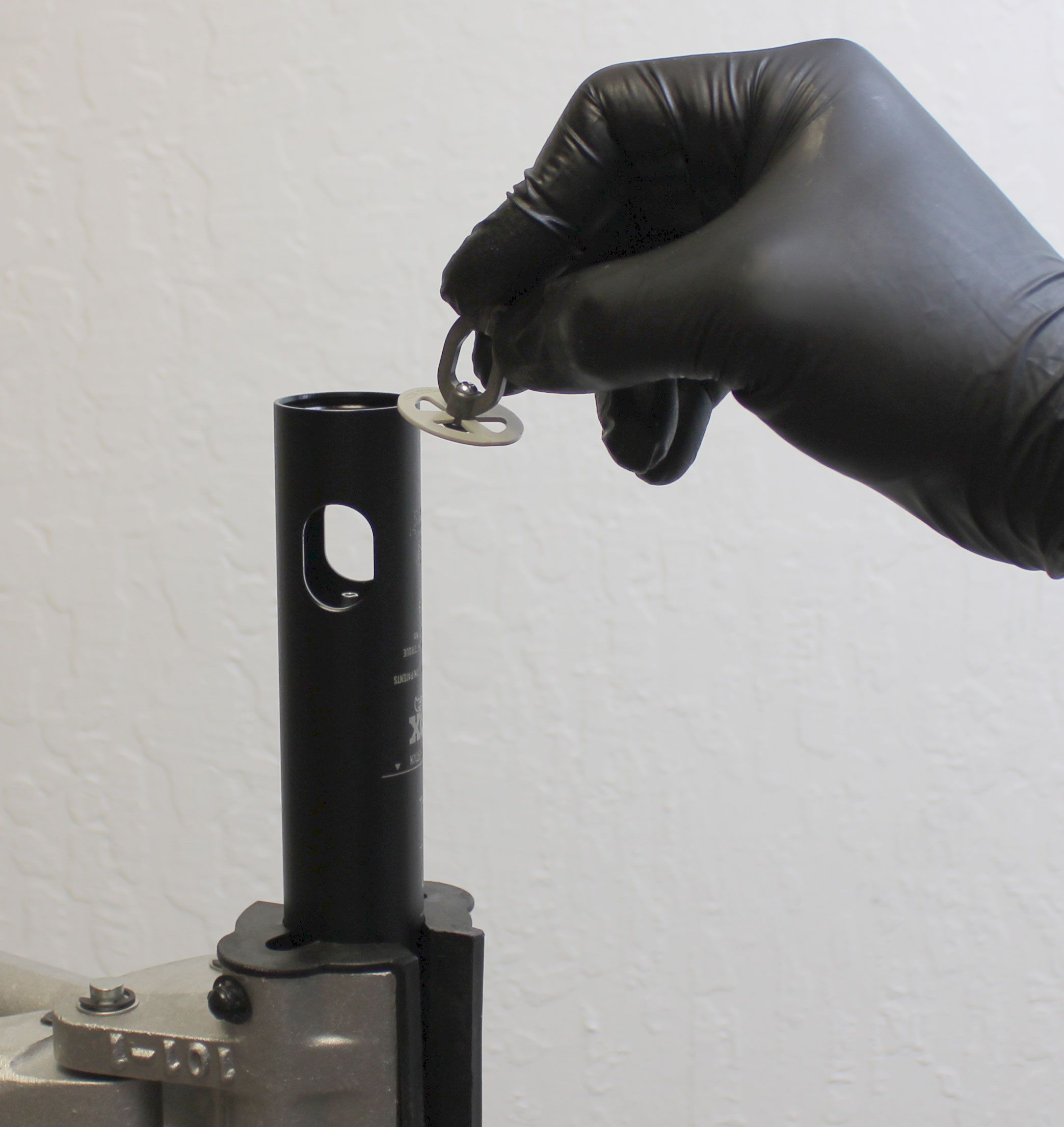
Step 34
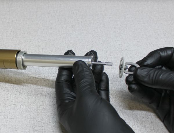
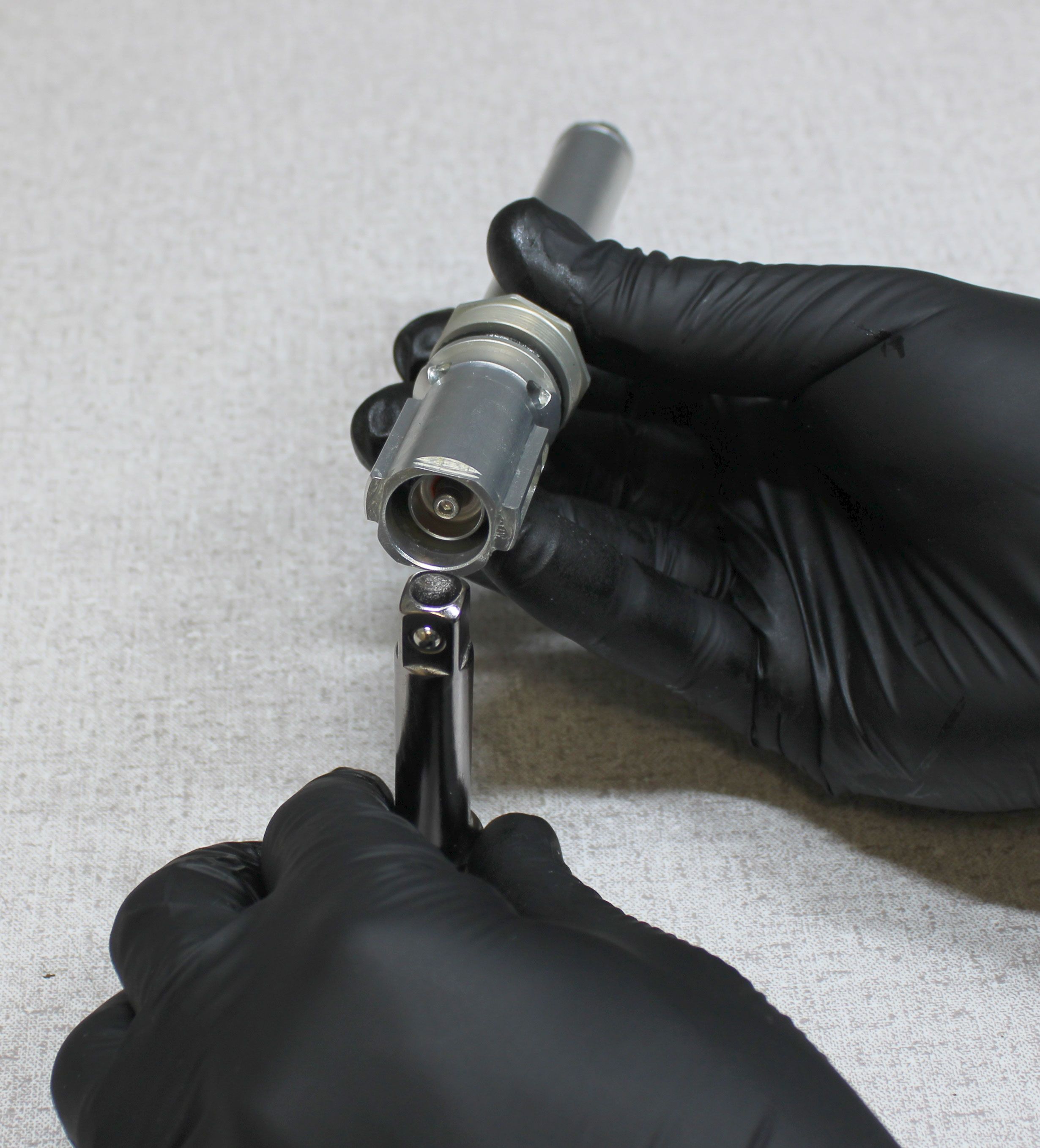
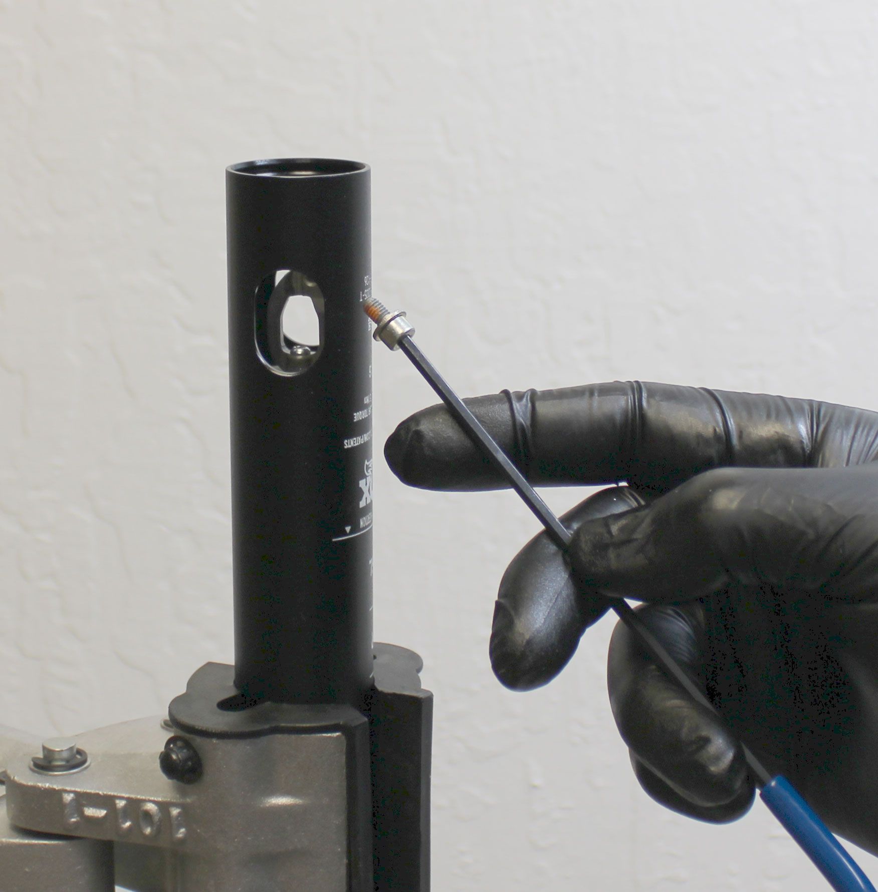
Test the function of the seatpost by actuating the cable hanger with a hex wrench or other similar tool as shown.