2013-2015 FLOAT CTD Dish Rebuild
Required Parts
- 803-00-142 Kit: Rebuild, FLOAT Line Air Sleeve, Special Q-Ring
- 803-00-816 Seal Kit: CTD Boost Valve and Dish Shock Rebuild
Required Tools
- 398-00-227-A Tooling: Piston Tool Weldment [2X Ø.094 on .500 BC]
- 398-00-280 Tooling: Eyelet Torque Tool
- 803-00-805 Kit: Shaft Clamps, Shocks, CTD 9mm, 3/8in, 1/2in, 5/8in
- Nitrogen Fill Station (Tank with Regulator) required for full rebuild .
WARNING: Always wear safety glasses and protective gloves during service to prevent potential injury. Failure to wear protective equipment during service may lead to SERIOUS INJURY OR DEATH.
This service procedure guides you through the rebuild of a FLOAT CTD Boost Valve rear shock. For additional information and complete assembly drawings please visit FLOAT CTD Dish »
Some pictures used below show different models of shocks, but all procedural information is the same. Please use this service procedure for information regarding all FLOAT CTD Dish shocks.
WARNING: FOX products should be serviced by a qualified bicycle service technician, in accordance with FOX specifications. If you have any doubt whether or not you can properly service your FOX product, then DO NOT attempt it. Improperly serviced products can fail, causing the rider to lose control resulting in SERIOUS INJURY OR DEATH.
WARNING: Modification, improper service, or use of aftermarket replacement parts with FOX forks and shocks may cause the product to malfunction, resulting in SERIOUS INJURY OR DEATH. DO NOT modify any part of a fork or shock, including the fork brace (lower leg cross brace), crown, steerer, upper and lower leg tubes, or internal parts, except as instructed herein. Any unauthorized modification may void the warranty, and may cause failure or the fork or shock, resulting in SERIOUS INJURY OR DEATH.
WARNING: FOX suspension products contain pressurized nitrogen, air, oil, or all 3. Suspension misuse can cause property damage, SERIOUS INJURY OR DEATH. DO NOT puncture, incinerate or crush any portion of a FOX suspension product. DO NOT attempt to disassemble any portion of a FOX suspension product, unless expressly instructed to do so by the applicable FOX technical documentation, and then ONLY while strictly adhering to all FOX insturctions and warnings in that instance.
WARNING: Never attempt to pull apart, open, disassemble, or service a FOX shock that is in a "stuck down" condition. A "stuck down" condition results from a failure of the dynamic air seal (located between the positive and negative air chambers within the shock air sleeve), resulting with the negative chamber retaining a higher pressure than the positive chamber. To test whether the shock is in fact "stuck down":
- Remove the air cap and depress the Schrader valve, to completely release air pressure from the positive chamber of the shock.
- If your shock has an EVOL air sleeve, you must release air pressure slowly to stop from inducing a "stuck down" condition.
- If the shock body retracts into the air sleeve near bottom-out after the air is slowly released from the positive chamber, attach a FOX high pressure pump and pressurize the shock to 250 psi/ 17 bar).
- If your shock has an EVOL air sleeve, you must cycle the shock after every 50psi addition while filling.
- If the shock does not fully extend, it is in a "stuck down" condition.
WARNING: Any improper servicing procedure with FOX air shocks in the "stuck down" condition can lead to SERIOUS INJURY OR DEATH. Contact FOX or an Authorized Service Center for repair.
Disassembly
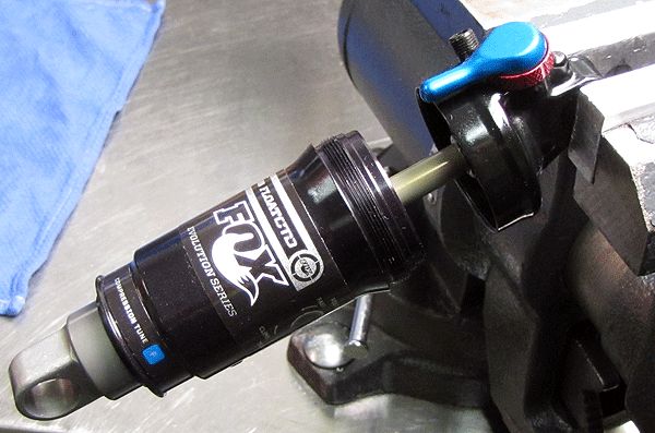
Step 1
Release the air pressure, and remove the air sleeve.

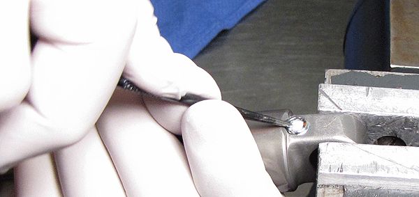
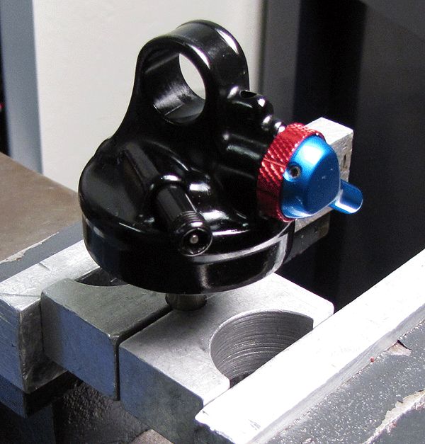
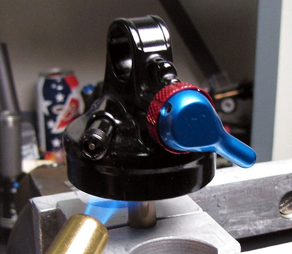
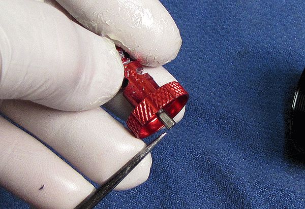
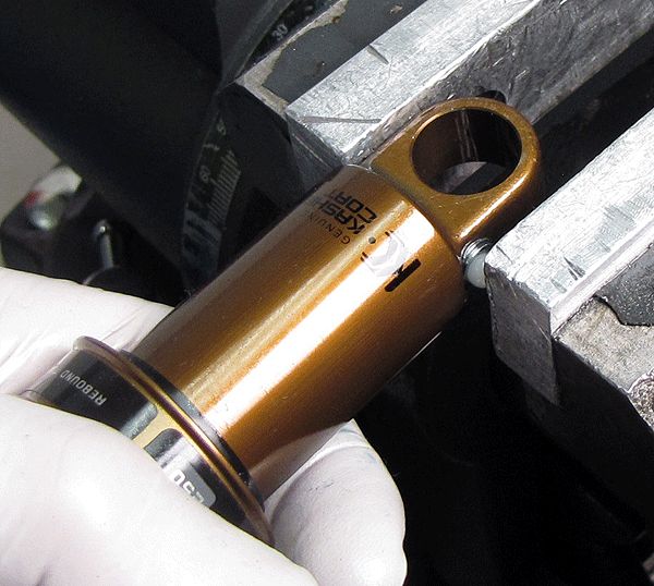
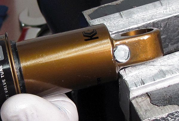
Step 2
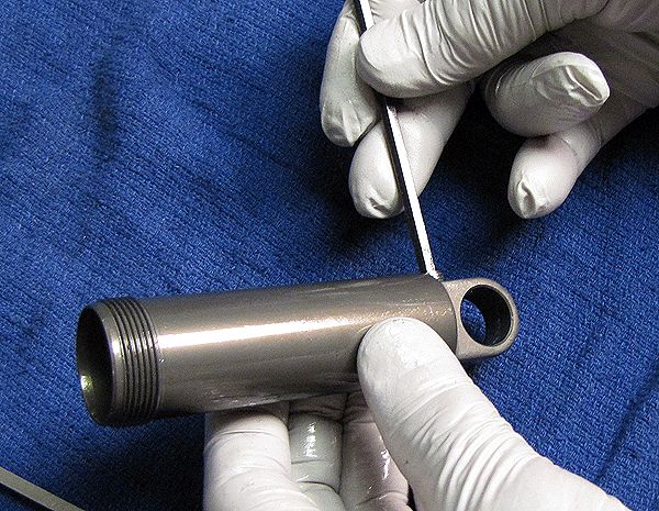
Using a pick tool, remove the delrin ball to access the pellet retainer. Use a 5/32" hex wrench to release the nitrogen pressure and remove the pellet retainer. Remove the pellet with the pick tool.

Step 3
Clamp the shock vertically and use a 5/64" hex to remove the bleed screw. As you first crack the bleed screw, pay attention to the oil quality as it leaks out; foaming indicates aerated oil.

Step 4
Remove the shock from the vice and while inverting it over a clean towel, tap out the bleed screw ball. This can also be accomplished by compressing the shock slightly. Be very careful with this, as oil and the ball bearing may shoot out.


Step 5
Clamp the shock to remove the body cap with a 3/4" wrench.
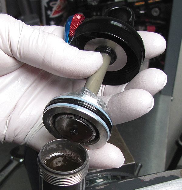

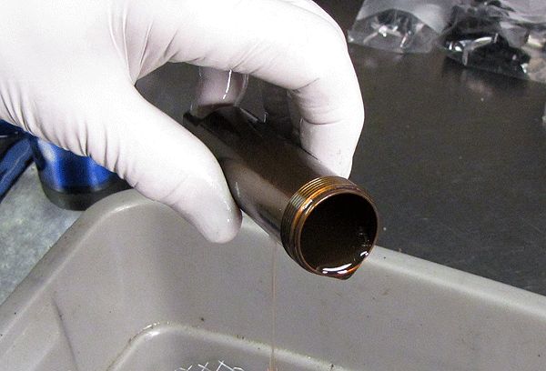
Step 6
Drain the oil from the shock body.
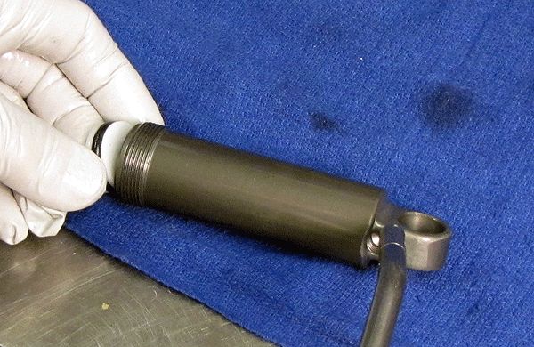
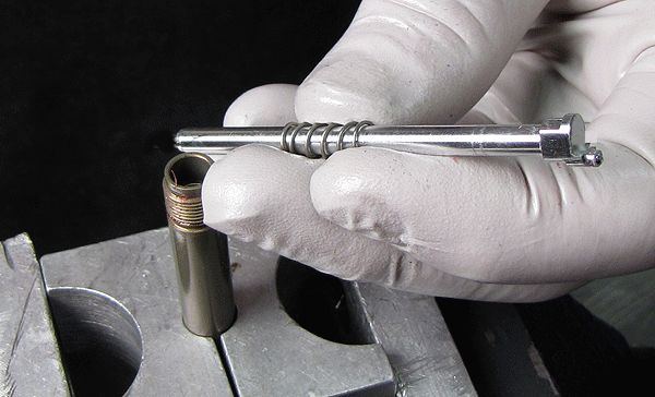
Step 7
Remove the IFP using carefully applied air pressure. Inspect the body ID for damage.

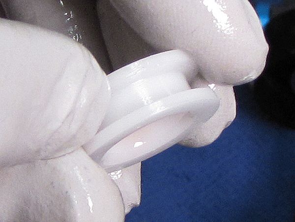
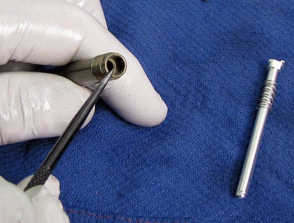
Step 8
Remove the IFP o-ring and inspect the seal gland on the piston for any damage or contamination. Grease the new IFP o-ring before installation.

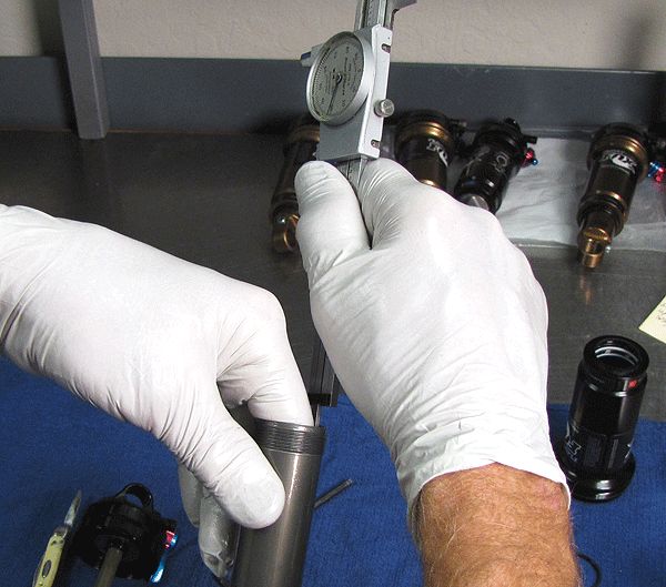
Step 9
Set the IFP to the proper depth for your shock size.
| SIZE | IFP DEPTH |
| 5.500 x 1.000 | 1.450in. |
| 6.000 x 1.250 | 1.670in. |
| 6.500 x 1.500 | 1.880in. |
| 7.250 x 1.750 | 2.100in. |
| 7.500 x 2.000 | 2.310in. |
| 7.875 x 2.000 | 2.310in. |
| 7.875 x 2.250 | 2.500in. |
| 8.500 x 2.500 | 2.740in. |

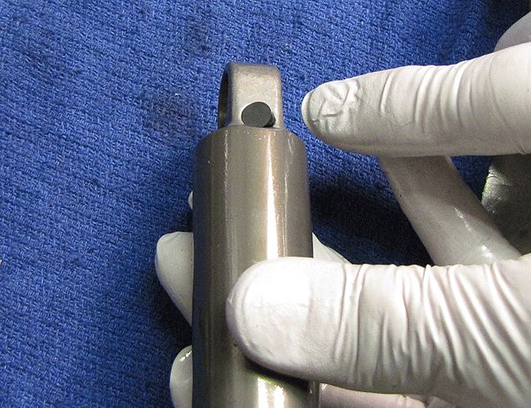
Step 10
Install a new pellet from the service kit, the flat side facing up, and secure with the pellet screw. Prefill the shock body with oil, pouring down its side to minimize possible aeration of the oil. Set the body aside in a vertical position and move on to the topcap, allowing time for trapped air to escape.

Eyelet Assembly
If you are servicing a FLOAT CTD Dish Remote shock, go to the CTD Remote Eyelet section »

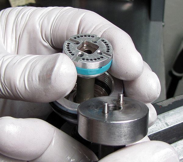
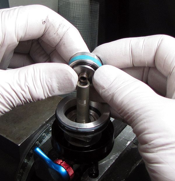
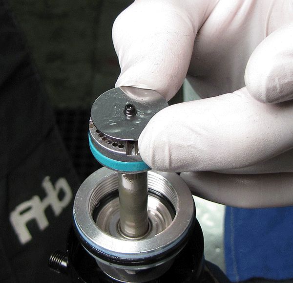
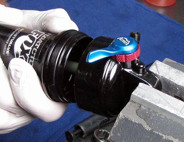
Step 1
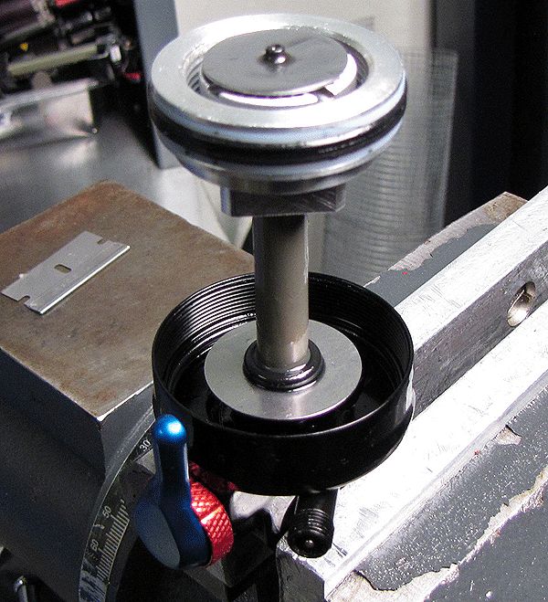
Place the piston/eyelet assembly in the vise as shown, and lift out the lockout plate.
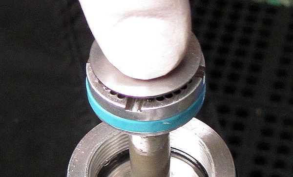
Step 2
Inspect the lockout plate spring to ensure that it is functioning normally, not stuck. Also inspect the plate itself for its overall condition (not bent, corroded, or pitted). Replace damaged parts if necessary.


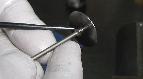
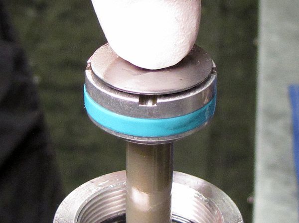
Step 3
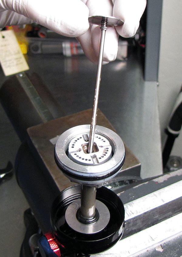
Use the Fox tool PN 398-00-227-A to remove the piston and valve shim stack. Lay these parts out in assembly order on a clean lint-free paper towel.
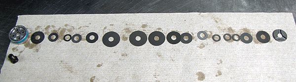

Step 4
Thoroughly clean the valve shims, and inspect each for wear, rust or cracks. Replace these as necessary.


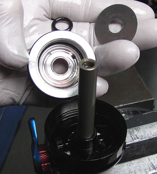
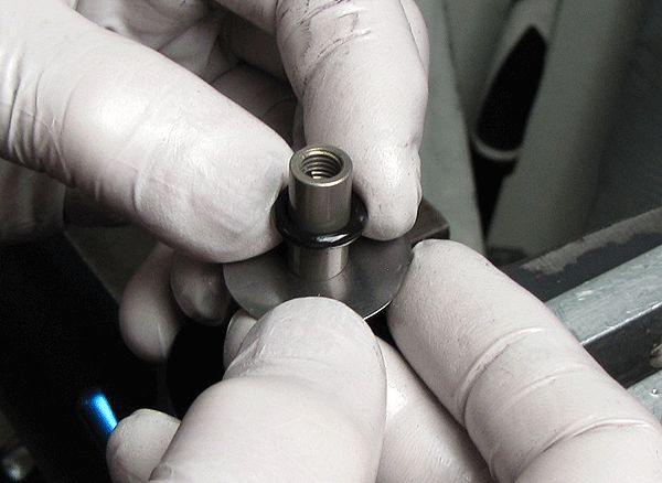
Step 5
Remove the bearing cap, bottom-out o-ring and bottom-out plate. Invert and clamp the eyelet assembly using the appropriate shaft clamps.
Step 6
After applying some heat to break down the red Loctite®, remove the eyelet assembly from the shaft.


Step 7
Remove the rebound and compression rod assembly.


Step 8
Inspect the end of the shaft for any signs of corrosion. If either rod is corroded, replace it with a current varsion of the same part. Replace the shaft o-ring.
Rebound and Compression Knobs and Final Assembly

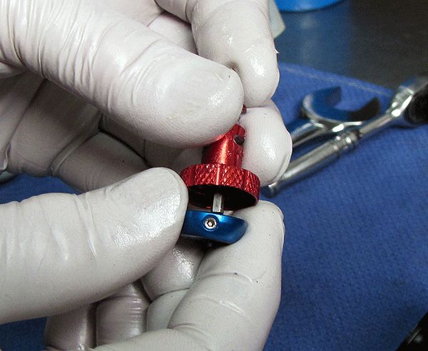
Step 1
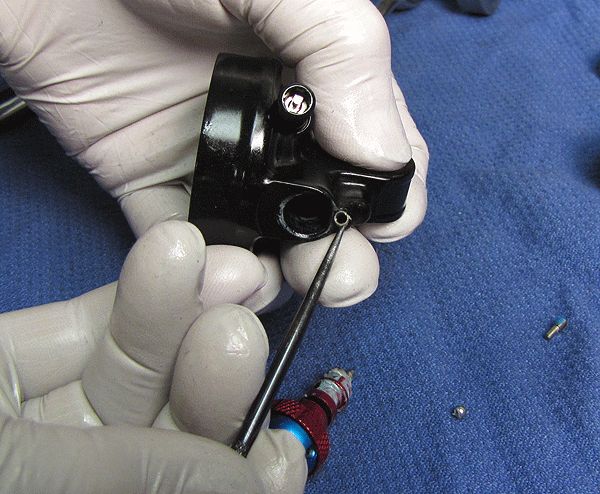
Using a 1.5 mm hex wrench, remove the set screw from the top of the eyelet assembly, allowing the CTD lever cam assembly to be removed. Do not lose the CTD lever detent ball and spring!

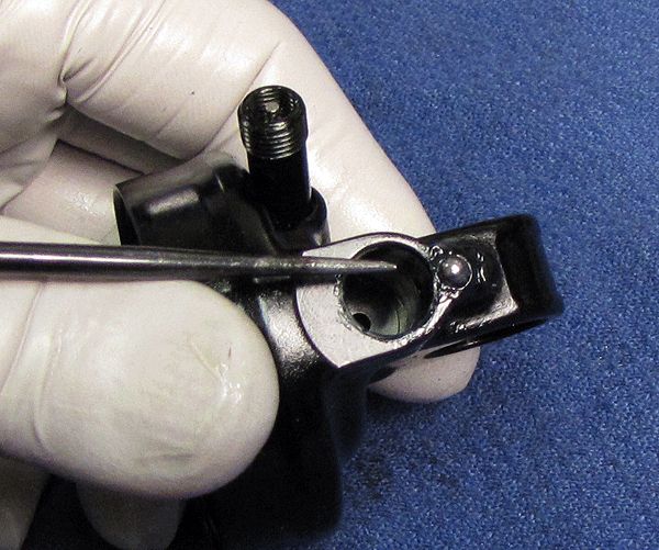
Step 2
Remove the rebound knob detent ball and spring.
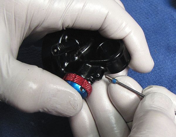
Step 3
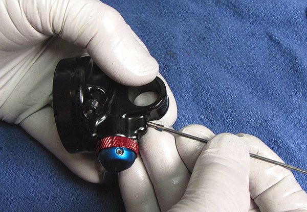
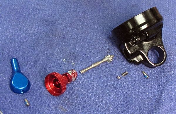
After removing the blue compression knob with the 1.5 mm hex wrench, inspect all parts for any sign of rust, corrosion or wear, replacing damaged parts as necessary. Thoroughly clean and lubricate all parts before reassembly.

Step 4
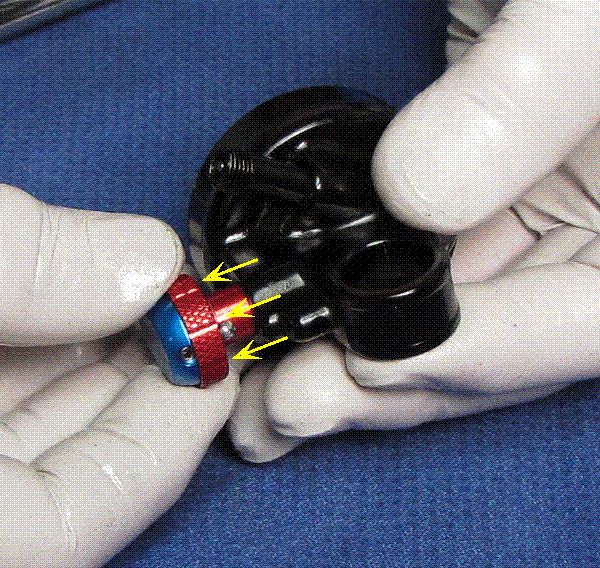
As you reassemble the knobs, align the blue knob set screw with the flat surface on the compression cam.

Step 5
Install the detent spring and ball into the eyelet assembly with a thin film of blue Hi-Temp grease (Sta-Lube SL3125 or similar).

Step 6
Reinstall the set screw with a 1.5 mm hex wrench until lightly seated, then back it out a quarter turn. Make sure the lever assembly can move freely and smoothly.

Step 7
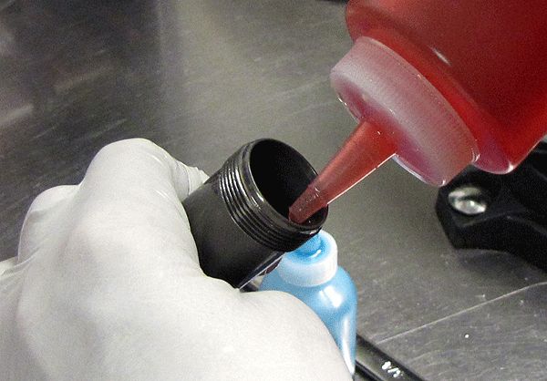
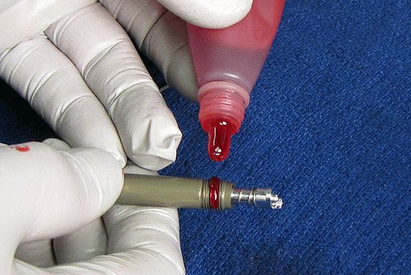
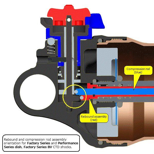
Apply red Loctite® to the eyelet shaft threads. Given the particular shock you are working on and per the graphic diagrams below, as you thread the shaft into the eyelet assembly, be sure the rebound and compression rods are correctly oriented with the rebound and compression cams.


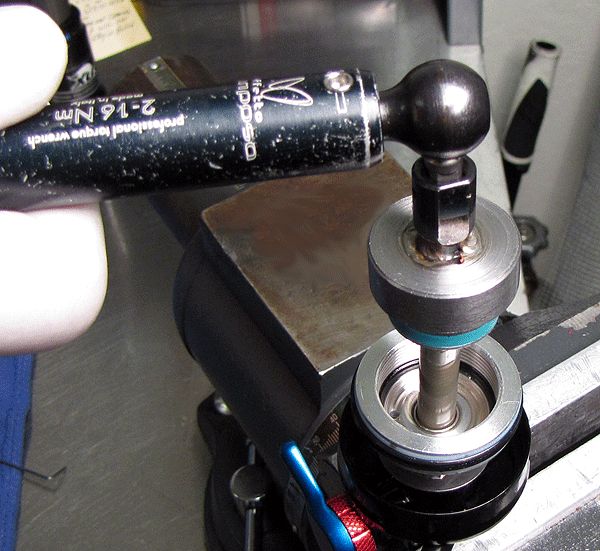
Step 8
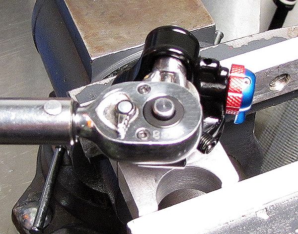
Tighten the eyelet assembly into the shaft to 80 in-lb torque.


Step 9
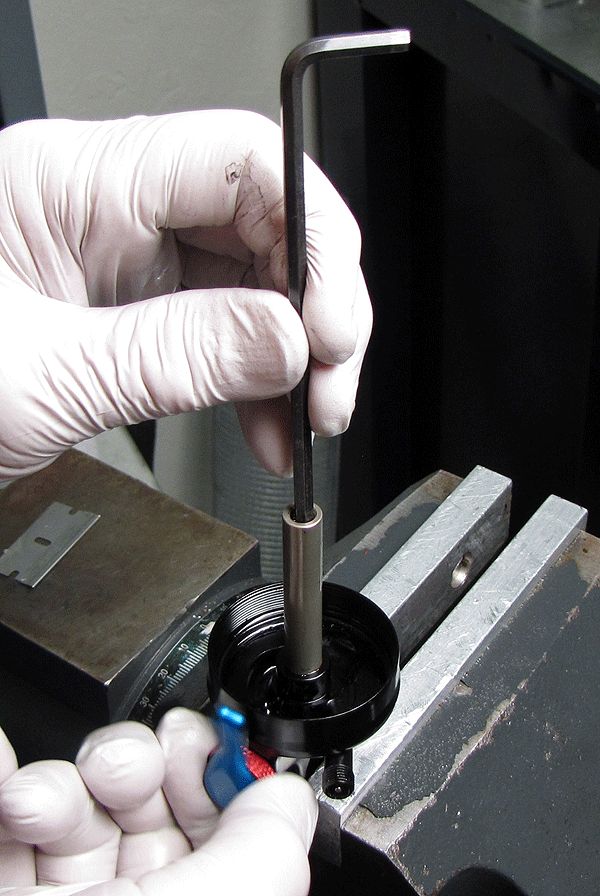
Invert and clamp the eyelet assembly in the vise. Test the rebound knob by activating the knob as you press into the shaft with a hex wrench; the tool should lower and raise as you decrease and increase the rebound.

Step 10
Install the bottom-out plate and the bottom-out bumper.
Step 11
Lightly install the bleed screw into the body bearing without the bleed screw ball, to plug the bleed hole. Install the bearing cap and piston assembly. Tighten the piston assembly to ~75 in-lb torque.


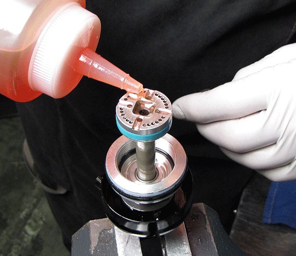
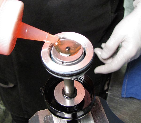
Step 12
Pre-fill the piston ports with some oil to help the bleeding process. Avoid allowing oil to run down the piston bolt hole.
Step 13
Install the lockout plate. Test for proper functionality by gently pressing the lockout plate down as you actuate the CTD compression lever. Two distinct positions should be felt: 1) plate closes against the piston (lockout), and 2) plate raises and separates itself from the piston (open).

Step 14
Make sure the lockout plate is in the open position (plate raised from the piston). Pull the body cap up to surround the piston then top off the body and prime the piston assembly with oil. With the body in one hand and the shaft assembly in the other, join the two in one swift movement.


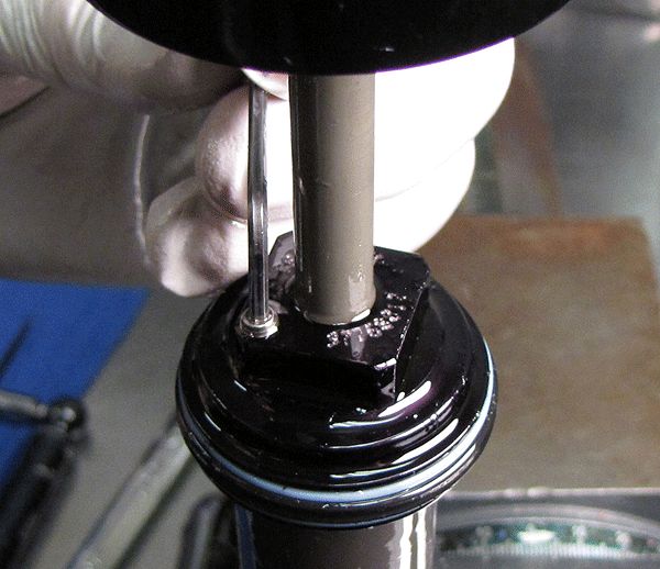
Step 15
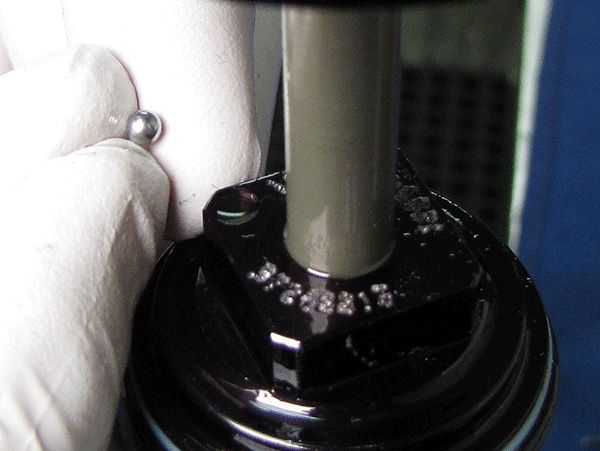
Before threading the body cap to the body, remove the bleed hole screw. Keeping the bleed hole at the high point, hand-tighten the body into the body cap from below, watching for air bubbles escaping the bleed hole. As you thread the two parts together, gently tap the body to help any trapped air to escape.

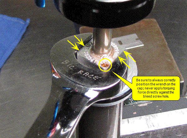
Step 16
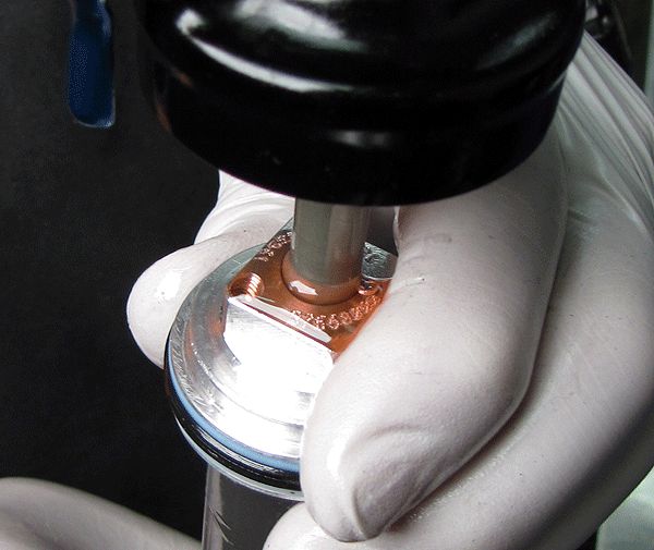
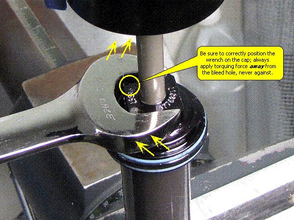
Clamp the shock in the vise by the body eyelet. Tighten the body bearing onto the body, remembering not to apply wrenching force directly on the flat immediately next to the bleed hole.

Step 17
Install the bearing into the bleed hole followed by the bleed screw. Torque to 10-15in-lb (1.1-1.7 Nm).

Step 18
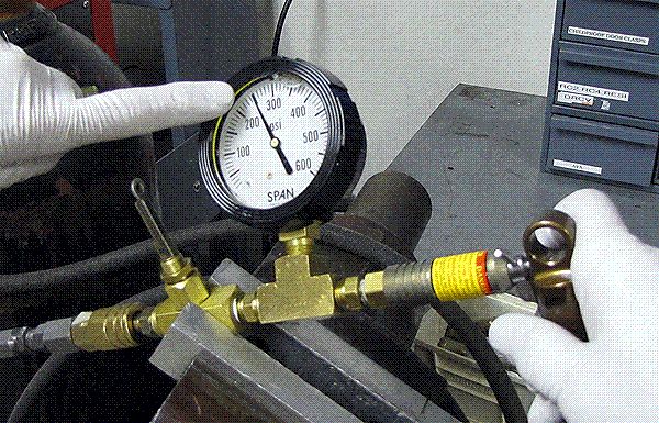
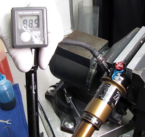
Pressurize the IFP chamber of your shock to 500psi. After pressurizing, dyno-test the shock.


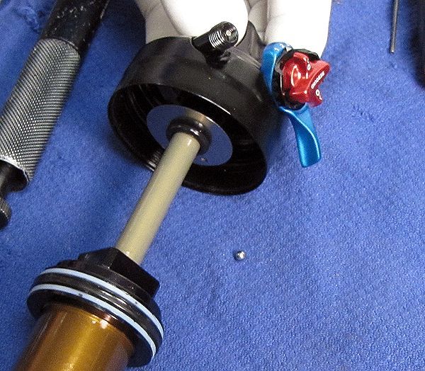
Step 19
Set the shock damper in Descend mode. Coat the air seals with a film of Float Fluid and start the air sleeve installation onto the body. Before threading the air sleeve to the eyelet, inject 2cc of Float Fluid into the main air chamber. Thread the air sleeve to the eyelet and tighten "hand-tight".
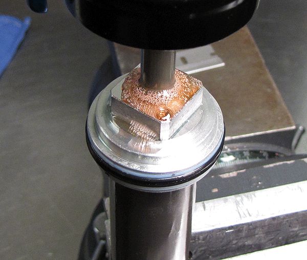
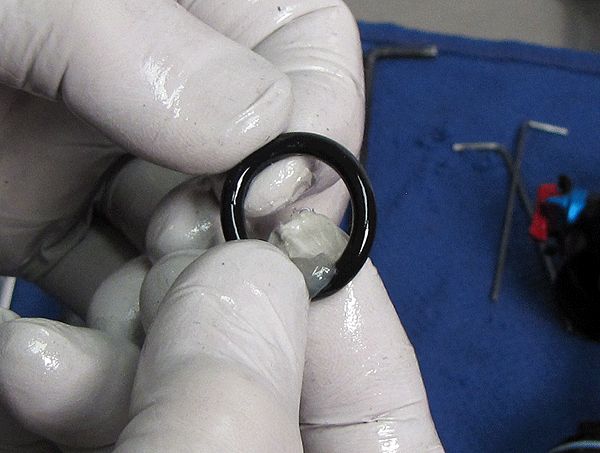
Step 20
Install a new Delrin plug into Pellet Retainer by carefully squeezing it with your vice.

Step 21
Add air pressure to the main air chamber and thoroughly clean the exterior of your shock.
