2010-2015 DHX RC4/RC2 Rebuild
Required Parts
- 024-02-490 Decal: 2014 DHX RC4 Reservoir, Gold (optional)
- 024-02-491 Decal: 2014 Factory DHX RC4 Reservoir, (No Gold) (optional)
- 024-02-492 Decal: 2014 DHX RC2 Reservoir (optional)
- 803-00-828 Seal Kit: DHX RC2/RC4 Damper Rebuild, 0.5in Shaft
Required Tools
- 027-00-006 Pump: Fox HP w/ Bleed, Foldable, 300 psi
- 398-00-280 Tooling: Eyelet Torque Tool
- 803-00-208 Kit: Clamp, Shaft and Body, 2005 DHX
- 803-00-378 Kit: DHX RC4_RC2 Shaft/Resi Clamp Set
- 803-00-463 Kit: Fill Machine Adapter, 04-07 Epic IV, DHX Air, RC2_RC4 Shocks
WARNING: Always wear safety glasses and protective gloves during service to prevent potential injury. Failure to wear protective equipment during service may lead to SERIOUS INJURY OR DEATH.
WARNING: FOX products should be serviced by a qualified bicycle service technician, in accordance with FOX specifications. If you have any doubt whether or not you can properly service your FOX product, then DO NOT attempt it. Improperly serviced products can fail, causing the rider to lose control resulting in SERIOUS INJURY OR DEATH.
Some pictures below show earlier versions of the DHX RC4 however the service procedure will guide you through the rebuild of a 2014 DHX RC4. For specific part information and assembly drawings please visit the Parts List page for 2014 DHX RC4/RC2 »
Disassembly

Step 1
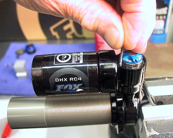
Clean the exterior of the shock before disassembly. Remove the air valve cap and deflate the Air Assist chamber.
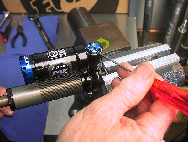
Step 2
Turn out the high speed compression adjuster all the way (counter-clockwise).

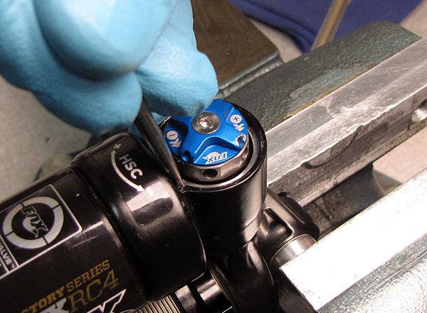
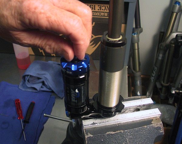
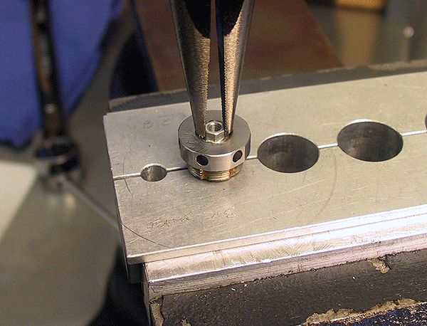
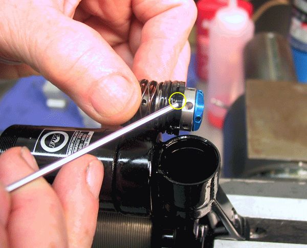
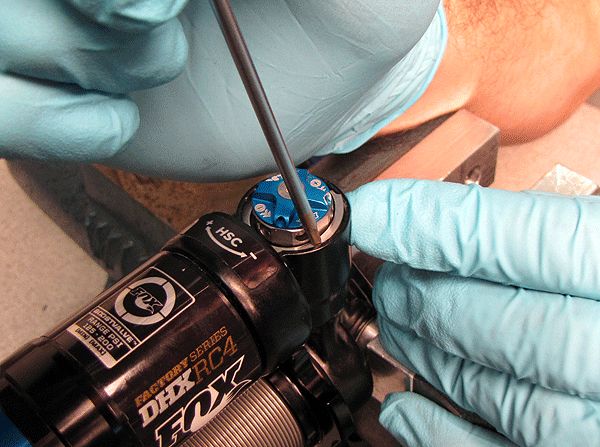
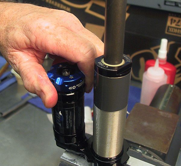
Step 3
Reposition the retaining ring with a pick so the split in the ring is at the 6 o'clock position and a dowel pin hole is exposed.

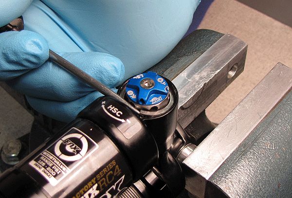
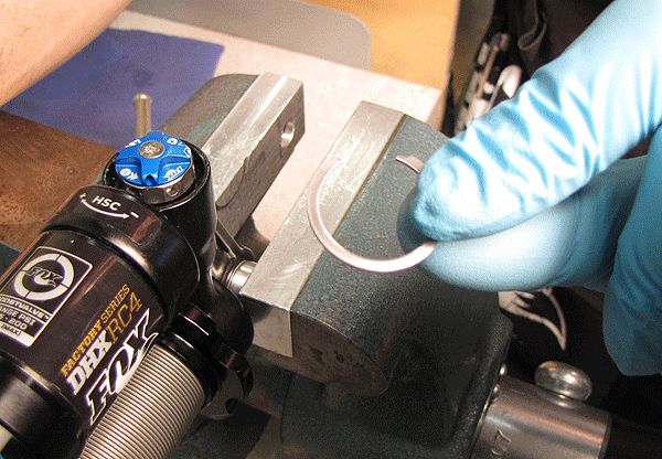
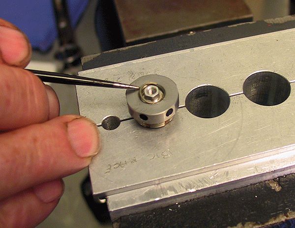
Step 4
Using the pick tool leveraged into a dowel pin hole, get under the snap ring to gently pry it up and remove.

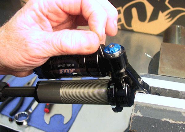
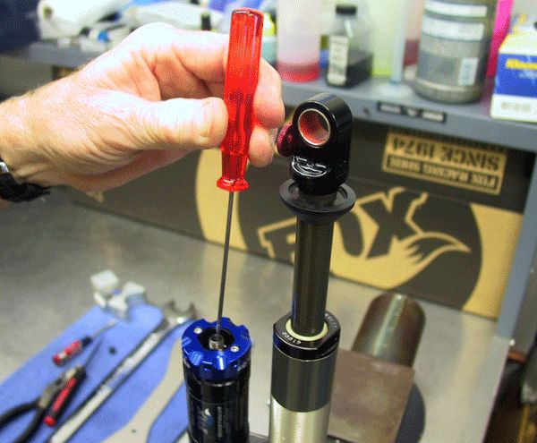
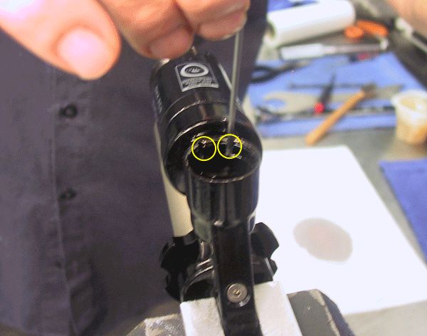
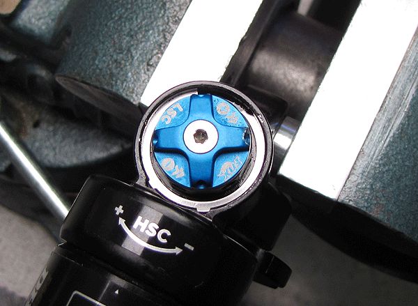
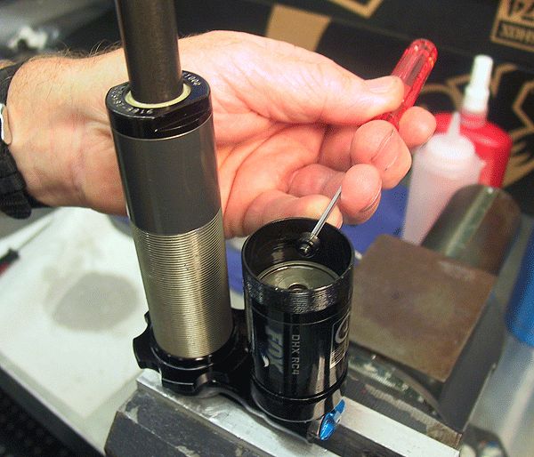
Step 5
Removing the retaining ring exposes two pins that align the DSC valve assembly in the eyelet. These are easily removed with a #1-64 screw, but you can use a pick tool to carefully remove them.


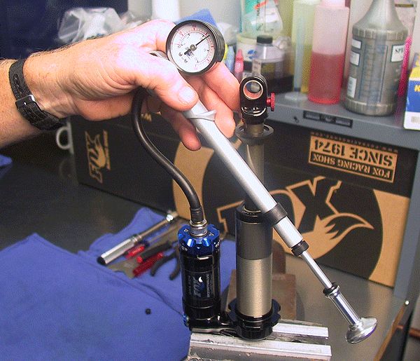
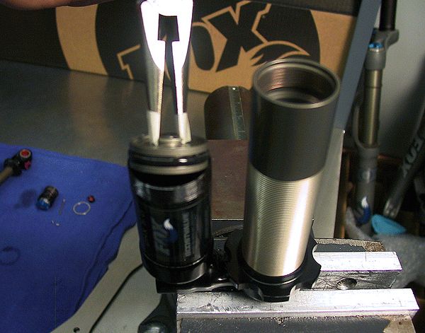
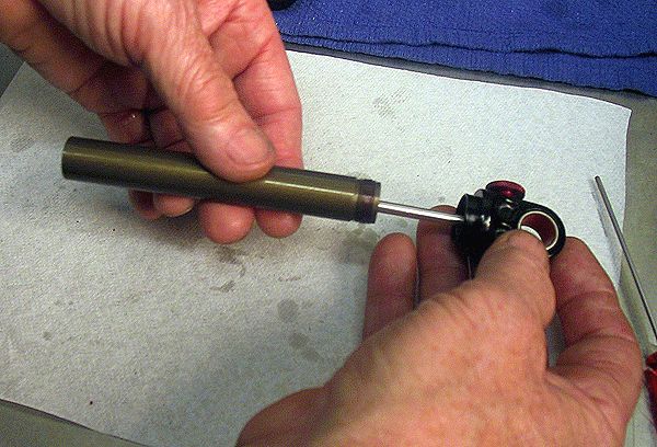
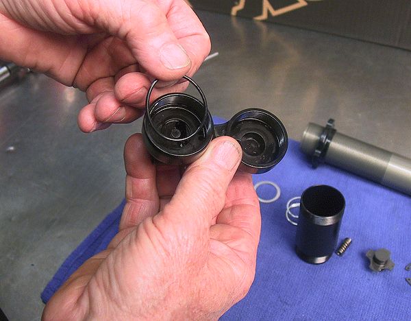
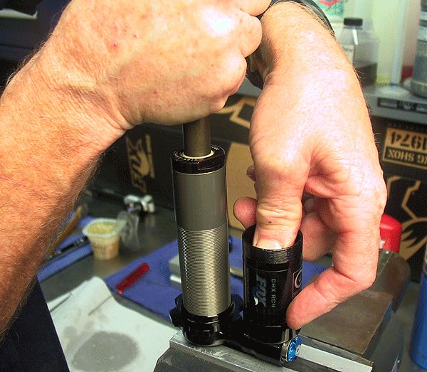
Step 6
With the alignment pins removed, attach a hand pump and slowly apply a little air pressure while holding the shock over a drain basin to dislodge and remove the damping adjust subassembly. Once the DSC assembly has been removed, cycle the shock over your drain to purge most of the oil.
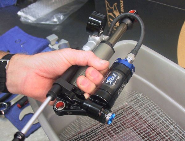
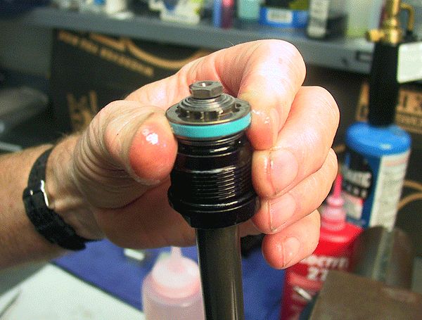
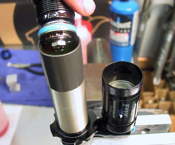
Step 7
Remove the bearing assembly with a 1" wrench and drain the remaining oil from the body.


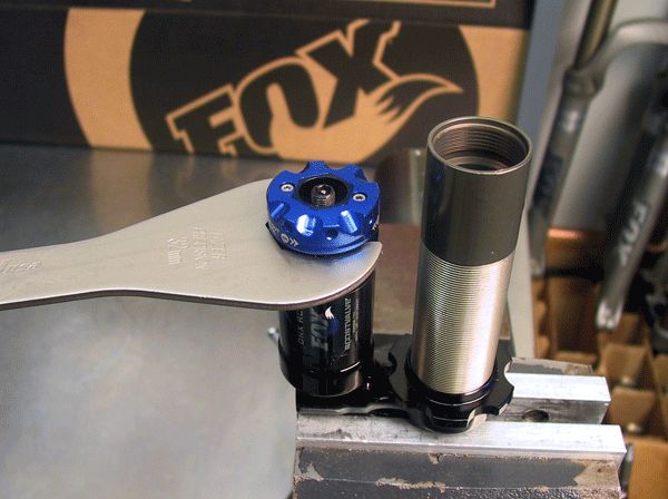
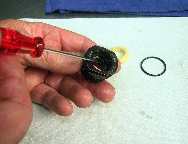
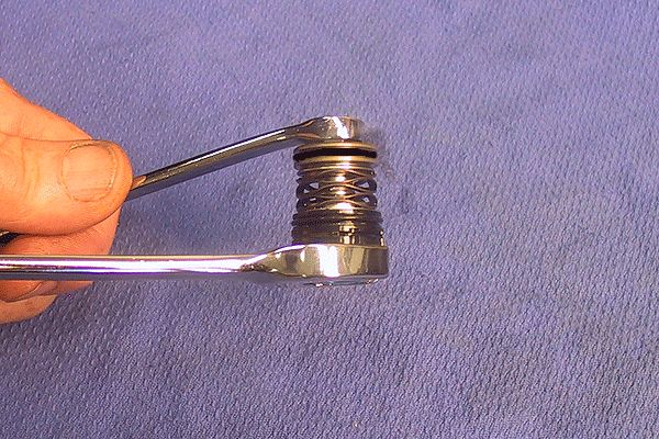
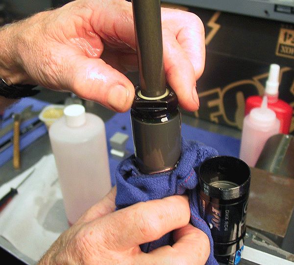
Step 8
Remove the reservoir end cap assembly with a 32 mm headset wrench. The Park Tool 32mm x 36mm HCW15 works well for this application.


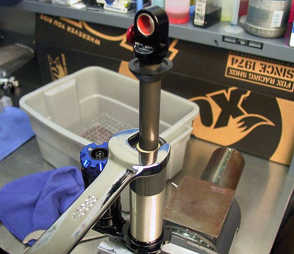
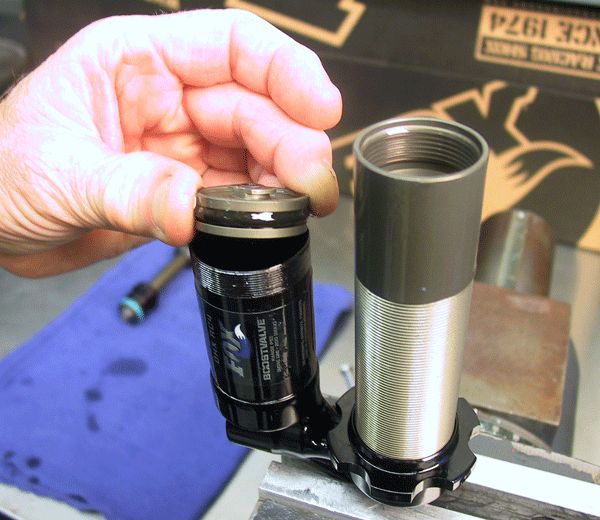
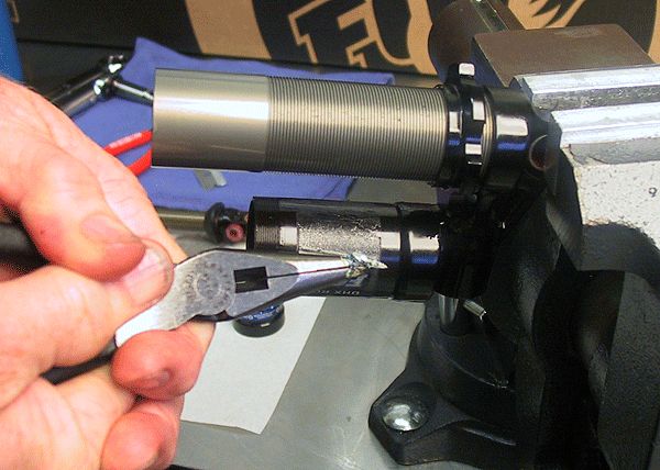
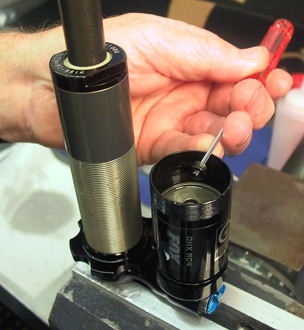
Step 9
With needle nose pliers, grip the internal floating piston (IFP) and lift it straight up to remove. Wrap the plier tips with tape, to help protect the IFP from damage.
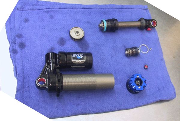
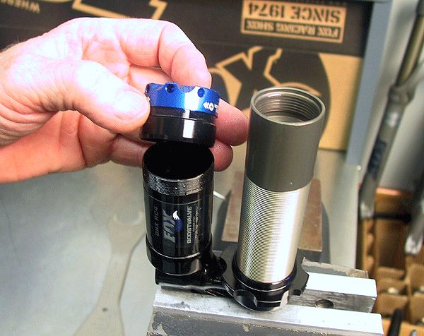
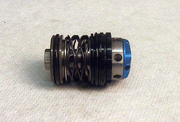
Step 10
The DHX RC4/RC2 is now diassembled into its main subassemblies.

Shaft Assembly Rebuild
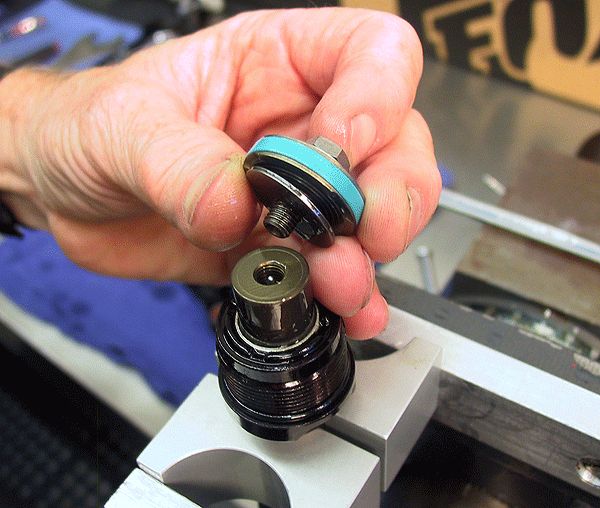
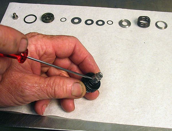
Step 1
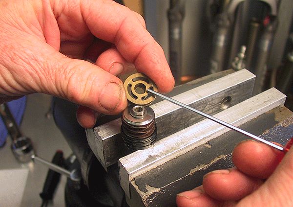
Clamp the shaft in a 1/2" shaft clamp and remove the piston bolt with a 3/8" wrench. Remove the valving assembly and set aside keeping all parts in order.


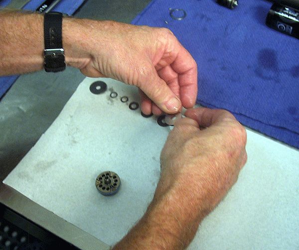
Step 2
Lay out the valve shims in the original order on a fresh lint free paper towel.

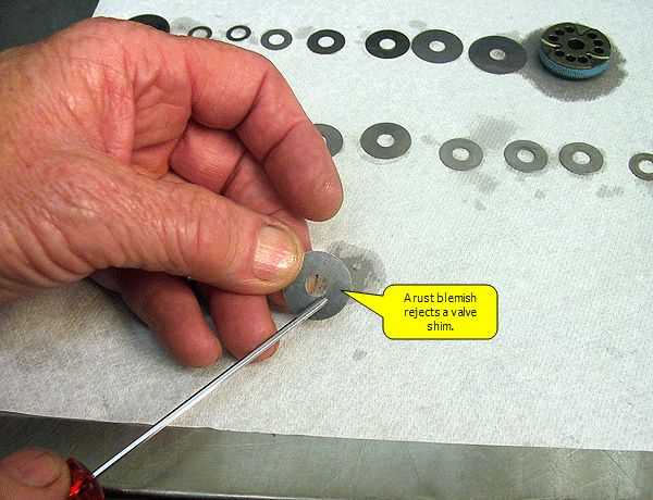
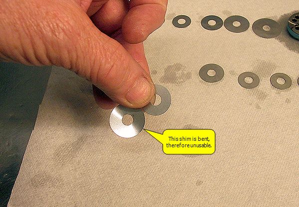
Step 3
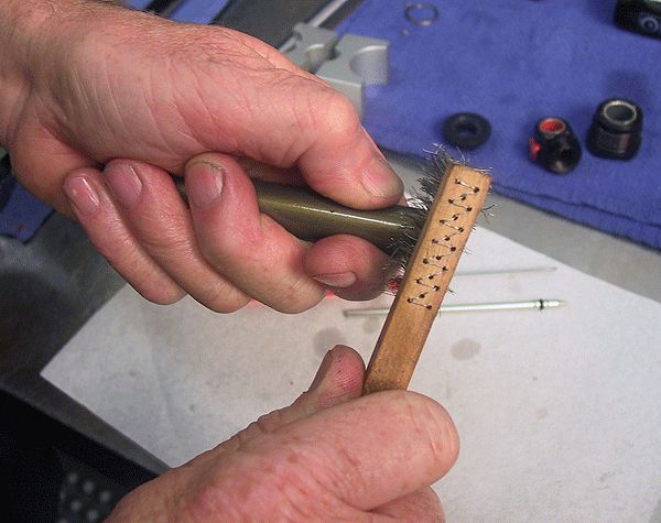
Clean and inspect the shims thoroughly for any pitting, rust blemishes or damage from being bent/over-flexed. Replace any that show wear or damage.

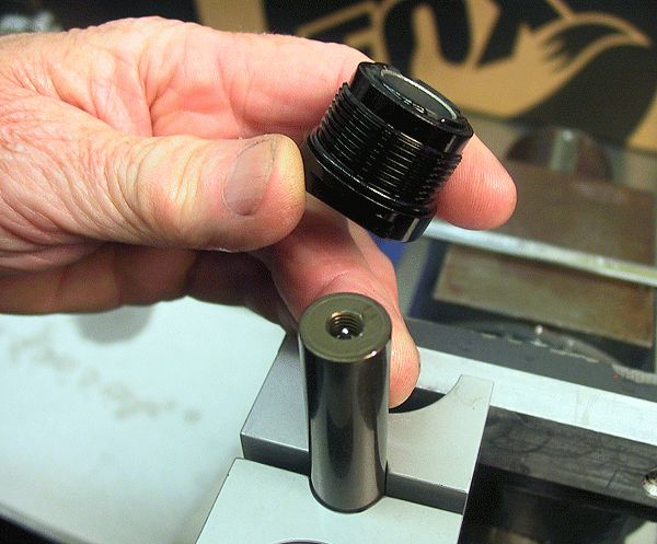
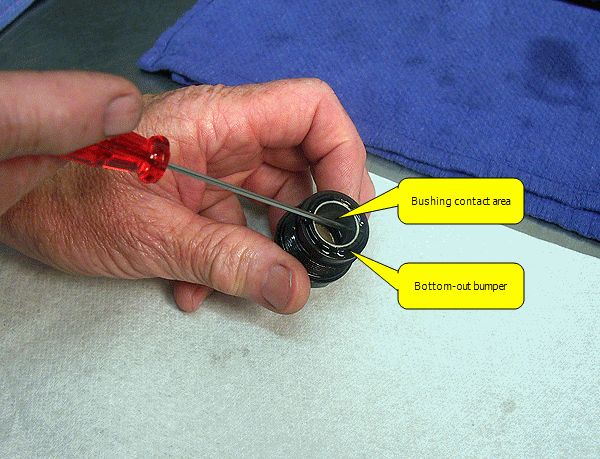
Step 4
Remove the Bearing Assembly from the shaft. Inspect the bushing for signs of excessive wear. Make sure the bottom-out bumper is in good condition.
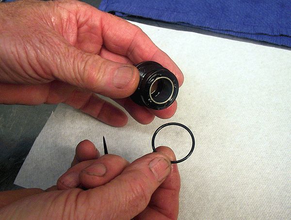
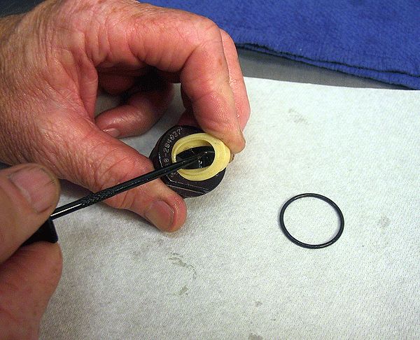
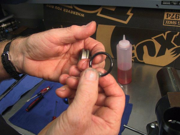
Step 5
Replace and lightly grease the internal and external o-rings and the yellow u-cup seal with Slick Honey.

Step 6
Remove the shaft from the clamps and remove the bottom-out bumper, before inverting and re-securing the shaft back in the clamps. Briefly heat the Shaft Eyelet to break down the red Loctite.


Note: Images show a pre-2014 5/8" shaft assembly. O-ring placement is now in the end of the shaft for 1/2" shaft 2014 DHX RC4/RC2 shocks. The configuration is the same as original DHX 5.0 style shocks and current Van R/RC shocks.

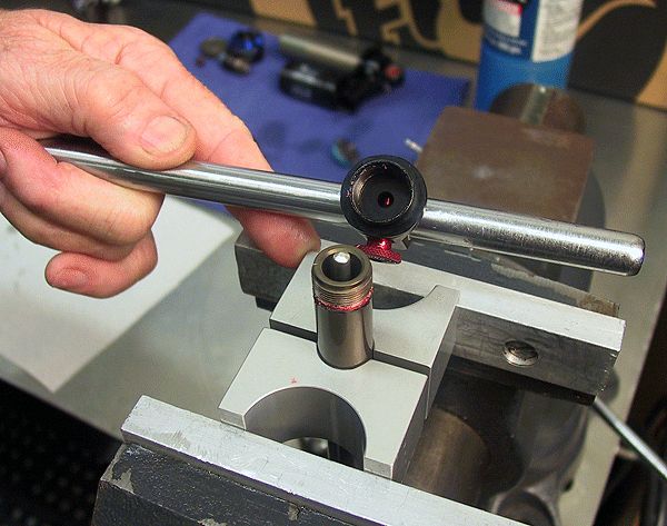
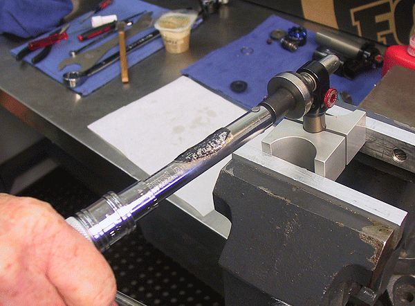
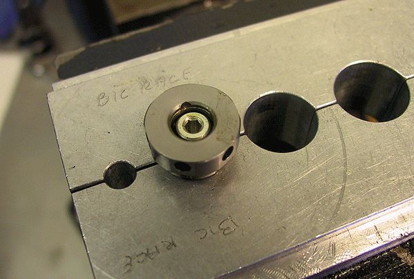
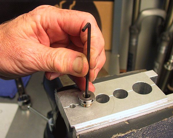
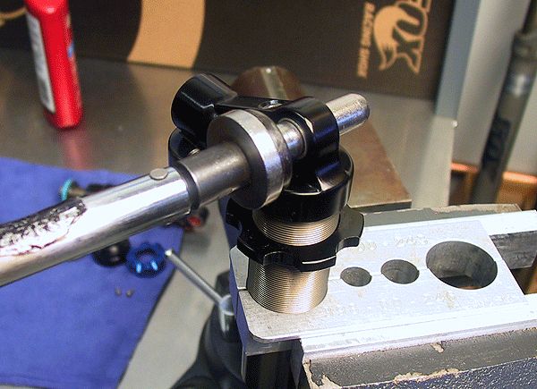
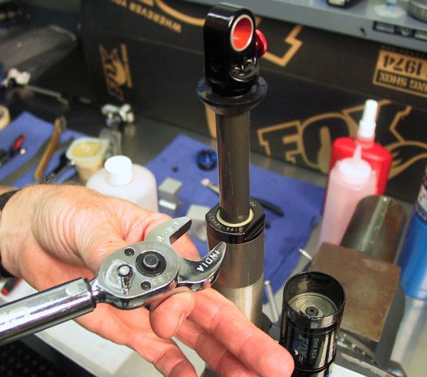
Step 7
Remove the eyelet from the shaft with the aid of a torque bar.

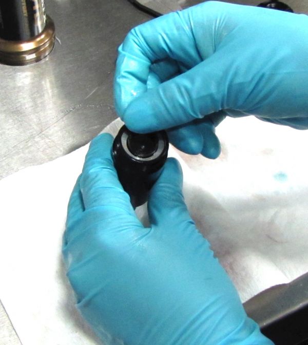
Step 8
Remove the rebound rod and replace the o-ring in the end of the shaft. Clean any Loctite residue from the eyelet and shaft threads.
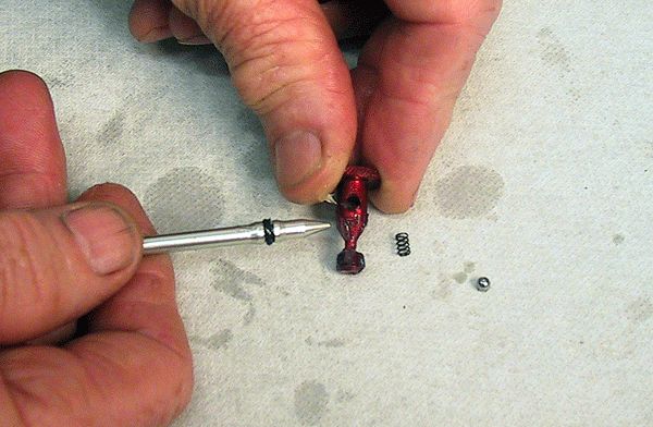
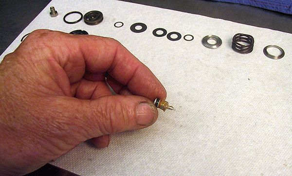
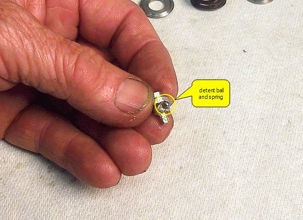
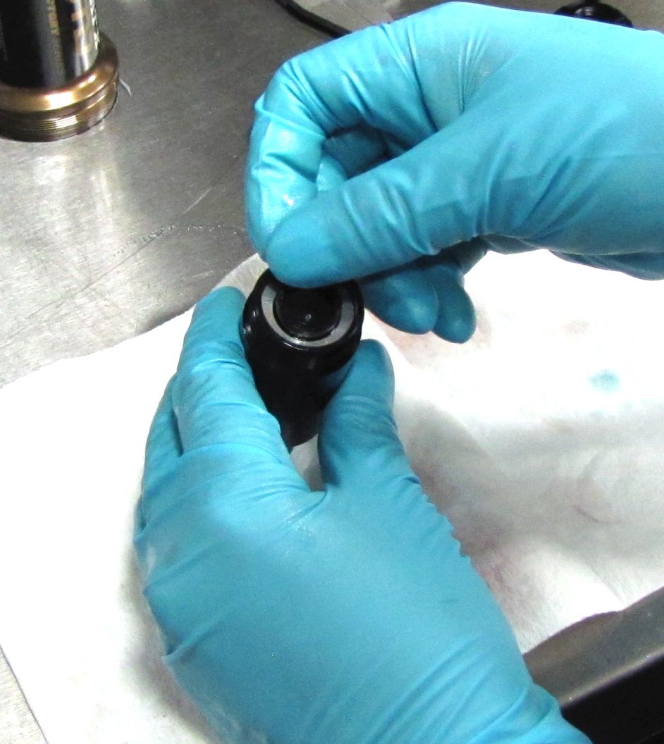
Step 9
Remove the rebound knob from the shaft eyelet assembly, being careful to not lose the detent ball and spring. Inspect the condition of the tapered surface on the knob. This surface comes in contact with the rebound rod as the rebound knob is adjusted, so it must be contaminant-free; only a light film of grease should be present when the knob is installed into the eyelet.

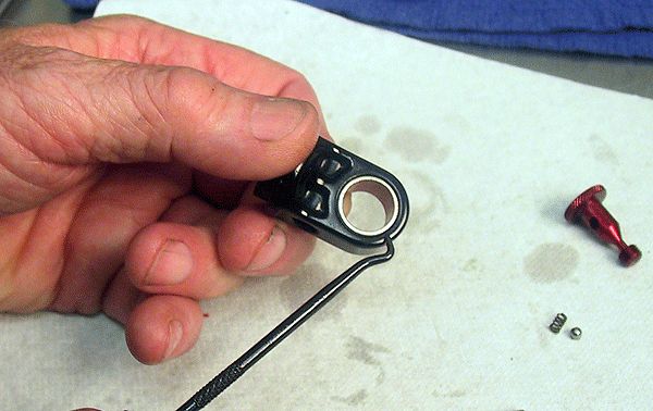
Step 10
Check the overall condition of the eyelet and eyelet bushing. When replacing the bushing, verify that the eyelet hole is round. If the eyelet hole is not round, replace the eyelet.

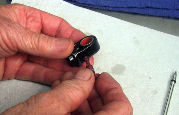
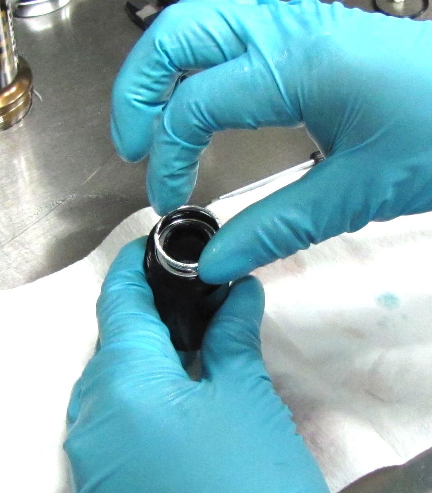
Step 11
Apply a little Slick Honey to the detent ball and spring and place these back into the rebound knob. Next, lightly apply Slick honey to the knob threads and tapered surface, and install the rebound knob into the eyelet assembly.


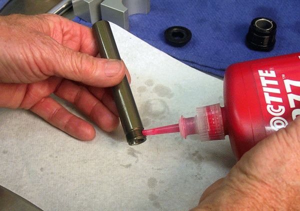
Step 12
Apply a drop of red Loctite 277 to the shaft threads. Install the rebound rod leaving it partially out from the threaded end of the shaft. Thread the eyelet assembly onto the shaft until hand tight.
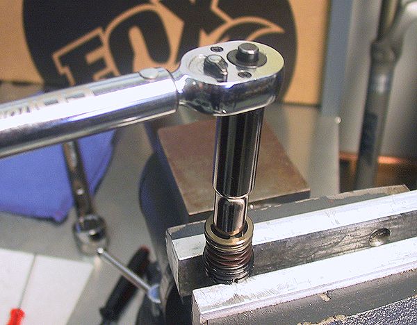
Step 13
Clamp the shaft and tighten the eyelet assembly to the shaft to 110 in-lb (12.4 Nm) torque.

Step 14
Test for normal functioning of the rebound adjust knob and rod, by applying some pressure to the end of the rod inside the shaft as you turn the rebound adjust knob. After testing, be sure to leave the rebound knob all the way out (counter-clockwise).


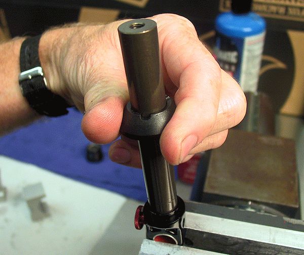
Step 15
Install the bottom out bumper onto the shaft followed by the bearing assembly.
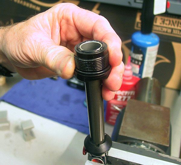
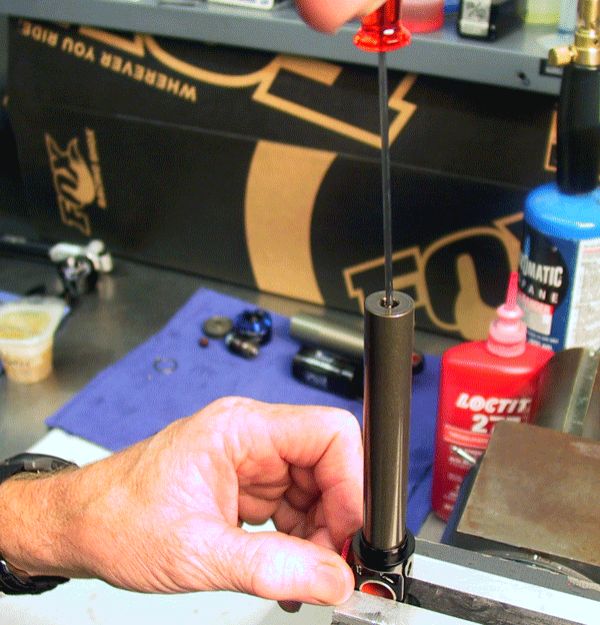
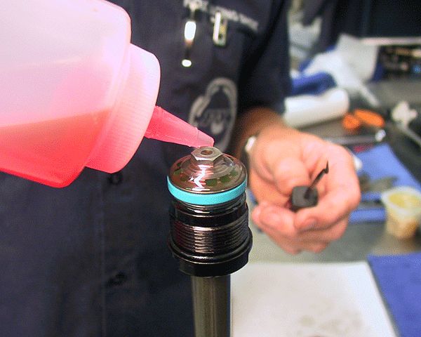
Step 16
Fill the shaft and rebound assembly with oil. Slide the seal head bearing up to the end of the shaft, to seal the bleed hole in the shaft.


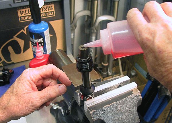
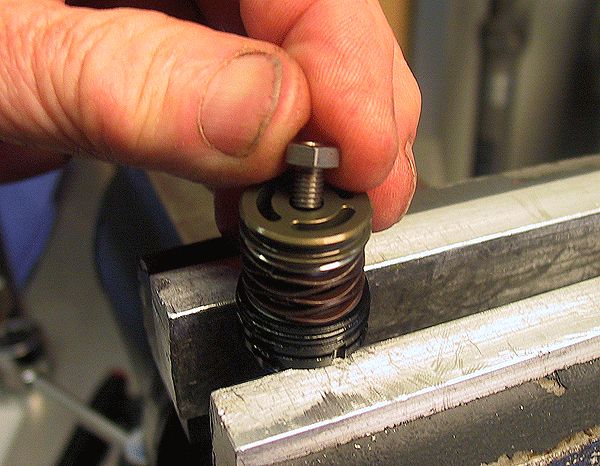
Step 17
Fill the compression holes in the piston with oil, and install the piston onto the shim stack. Invert the piston assembly and install it onto the shaft assembly. Tighten the piston bolt to 75 in-lb (8.5 Nm) torque.
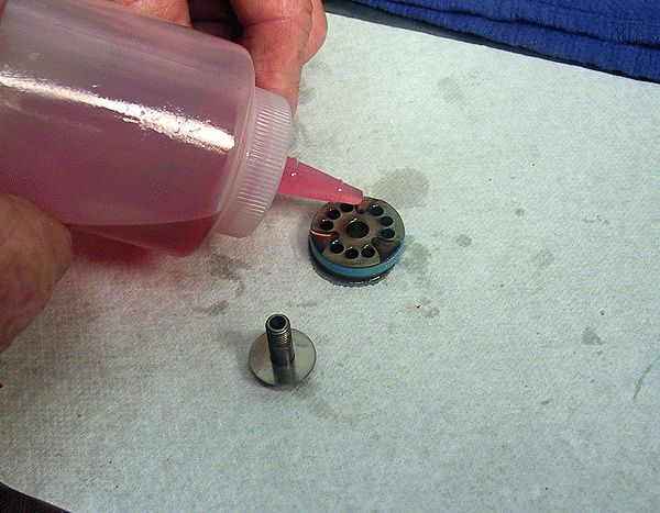
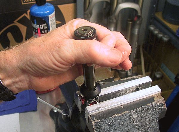
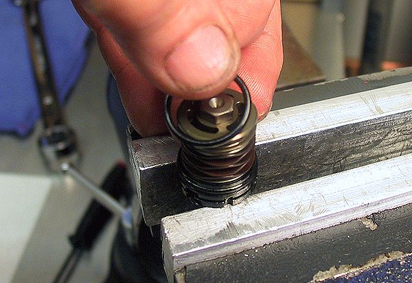
Step 18
Pre-fill every hole in the piston with oil and pop any visible bubbles with a small tool taking care not to damage any shims. Set aside maintaining this vertical position until needed later for final assembly.


DSC Damping Adjust Assembly Rebuild
Images show an RC4 Damping Adjust Assembly. Although some parts are different in the RC2 Damping Adjust Assembly, most of this procedure can be used to service the RC2 Damping Adjust Assembly with some minor changes. Please refer to the assembly drawings on the Parts List page for 2014 DHX RC4/RC2 »
Step 1
Use a 17mm wrench on the HSC adjuster and an 8mm wrench to loosen and remove the piston bolt. Stage all parts on a lint free paper towel in original assembly order during removal.


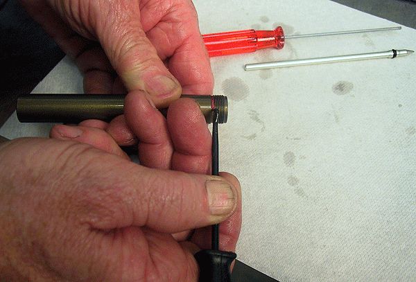
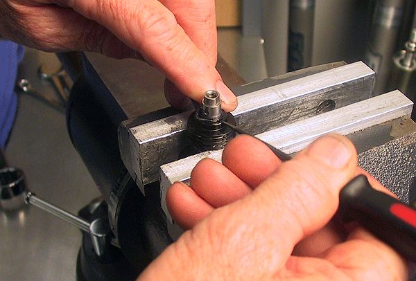
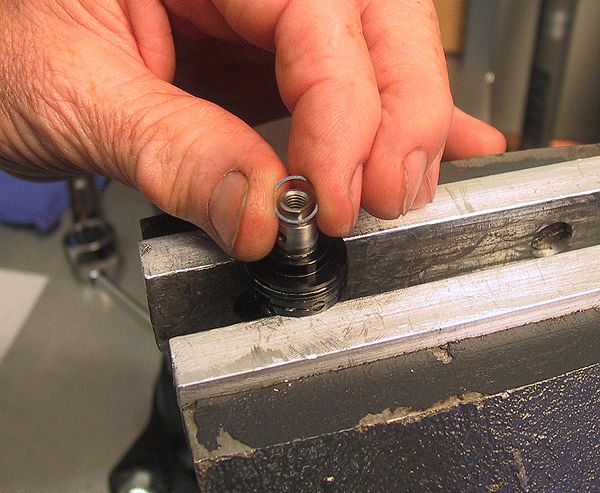
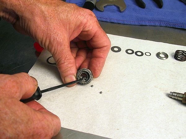
Step 2
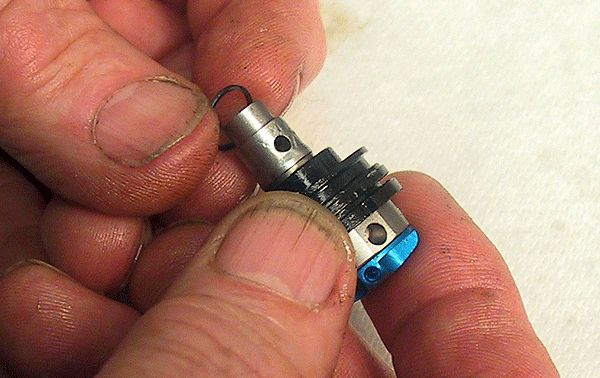
Lightly secure the HSC adjuster in a soft-jawed vise. With a pick tool, remove the retaining ring from the HCS adjuster.
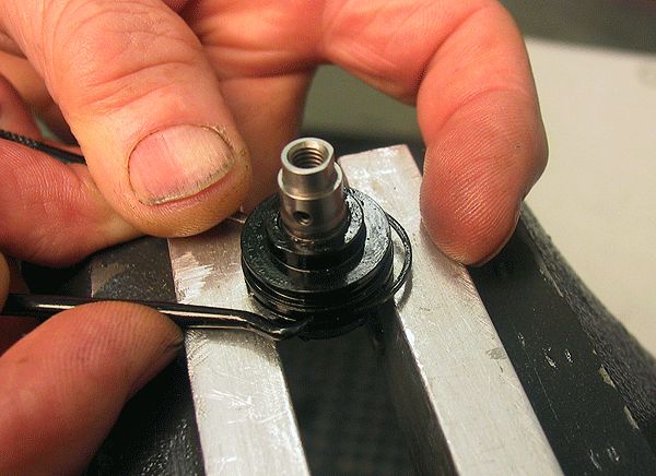
Step 3
Remove the radial spring that secures the detent balls (PN 010-01-012) in the assembly housing. Use two pick tools, as shown below. Be careful as the radial spring wants to eject from the assembly

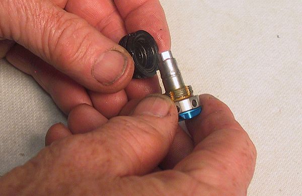
Step 4
With the retaining ring and detent balls removed and set aside, unthread the left-hand threaded shaft clockwise to remove it from the assembly housing.

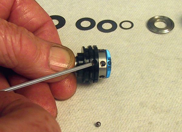
Step 5
Remove the two detent balls from the assembly housing and replace the internal o-ring (PN 029-08-023).


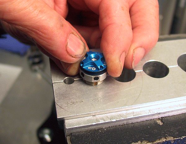
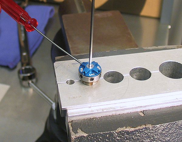
Step 6
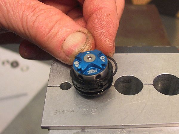
Secure the HSC adjuster subassembly into the clamps as shown. Turn the blue LSC knob in (clockwise) 2 clicks. With a hex driver in one of the 4 holes in the blue LSC knob to stop it from rotating, loosen and remove the low speed compression (LSC) adjust knob screw with a 2mm hex wrench.

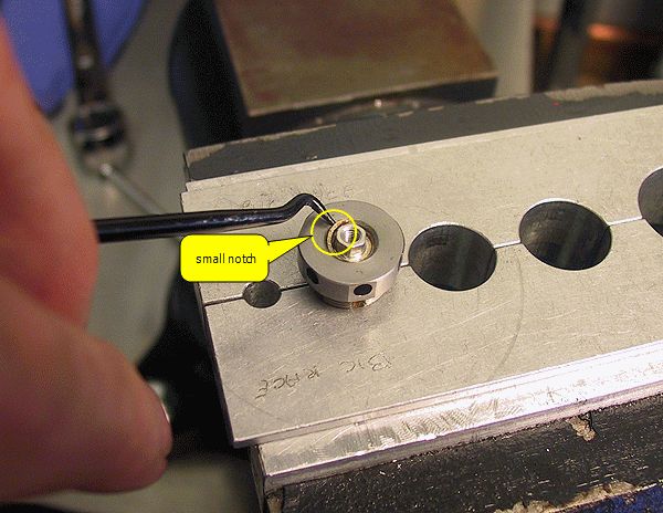
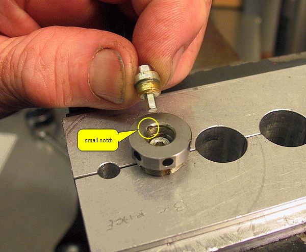
Step 7
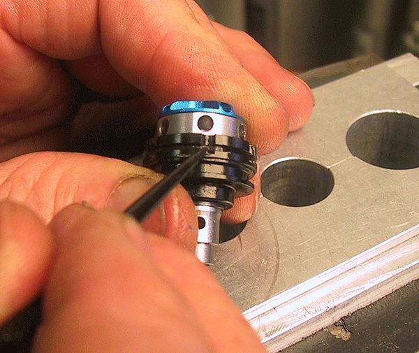
Use the small notch found inside the shaft cavity to help to slip your pick tool behind the retaining ring. Remove the retaining ring.

Step 8
Use the LSC knob without the screw to leverage out the LSC adjuster. Take care not to lose the detent ball and spring that can eject as the LSC adjuster is being removed. Use the LSC adjuster to unthread and remove the LSC needle.


Step 9
When all the parts are clean or replaced and ready for assembly, lightly grease the threads and o-ring of the LSC needle. Insert the needle into the HSC adjuster.
Step 10
Thread in the LSC needle with a hex wrench or the LSC adjuster.


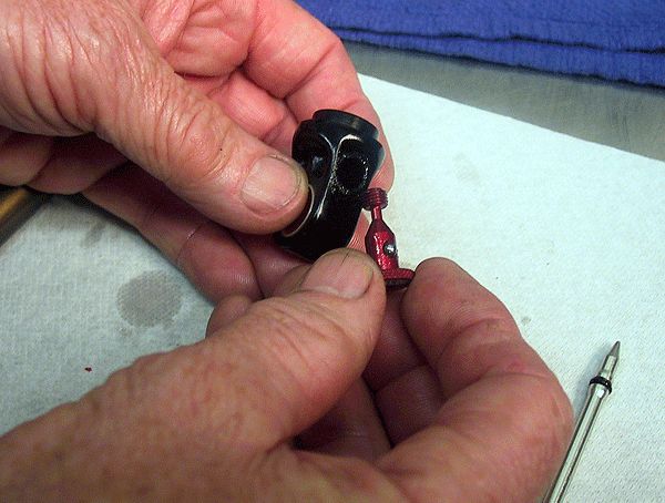
Step 11
Apply a thin film of Slick Honey to the hole in the LSC adjuster followed by the detent spring and ball. Lightly hold the LSC adjuster with needle nose pliers. Gently press the LSC adjuster into the needle, aligning the post with the hex in the needle while also making sure the detent ball clicks home.

Step 12
Install the retaining ring making sure the ring is completely seated. Install the LSC knob. With a hex driver in one of the 4 holes in the blue LSC knob to stop it from rotating, install the set screw and torque to 7 in-lb (0.8 Nm) with a 2mm hex wrench.

Step 13
Thread the left-hand threaded adjuster knob subassembly counter-clockwise into the DSC adjust housing. Install the retaining ring onto the HSC adjuster.
Step 14
Grease the 2 detent balls with Slick Honey and install into the DSC housing. Install the radial spring to secure the detent balls.

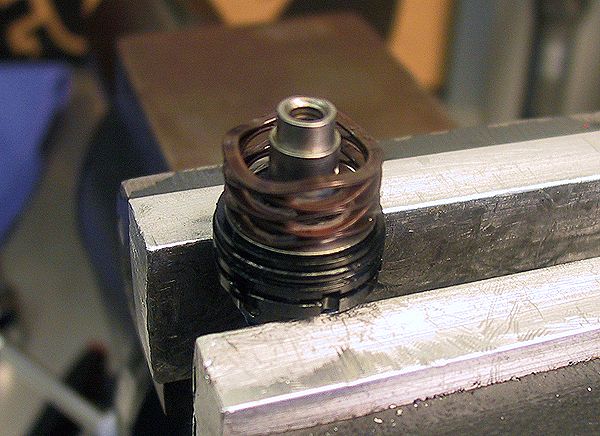
Step 15
With a small tool, rotate the radial spring so that is covers both detent balls but does not cover the two flutes for the dowel pins used in the eyelet assembly.

Step 16
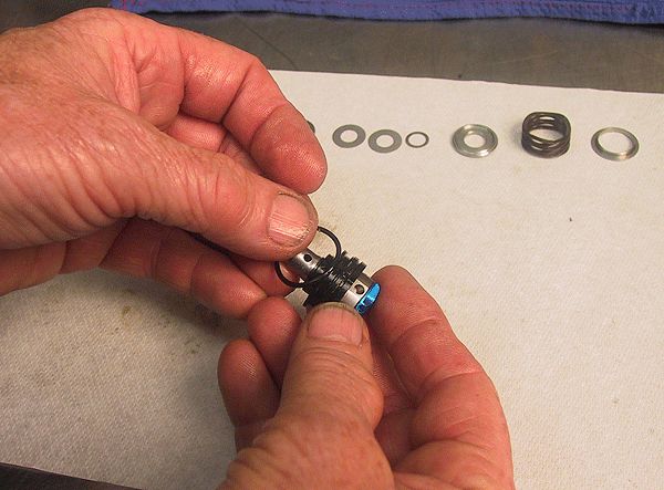
Replace the external o-ring on the DSC housing and grease with Slick Honey. Install the spring guide and wave spring as shown.

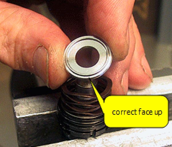
Step 17
Install the HSC shuttle so the side with the thinner raised ring is facing away from the wave spring. Install the remainder of the shim stack in order.


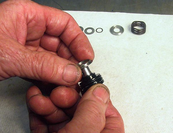
Step 18
Install the DSC piston followed by the piston bolt. Torque to 60 in-lb (6.8 Nm). Coat a new o-ring with Slick Honey and install onto the DSC piston.

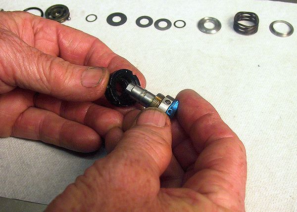
Step 19
The completed DSC damping assembly is now ready to install into the eyelet assembly.

Body and Reservoir Assembly Rebuild

Step 1
Use a torch or heat gun to help remove the reservoir decal. The decal must be removed so the reservoir can properly fit in the clamps or appropriate friction wrench for removal. Use a shop towel and Isopropyl alcohol to remove the decal adhesive residue.


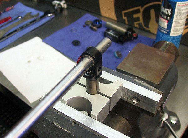
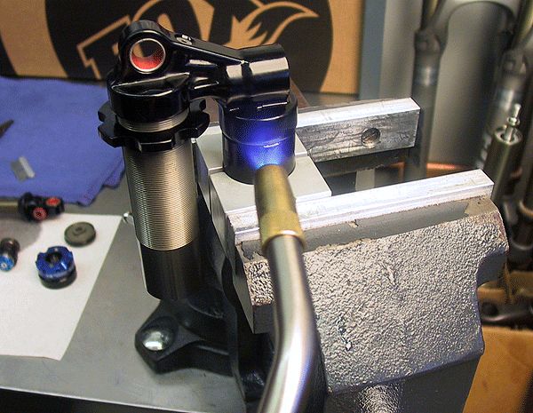
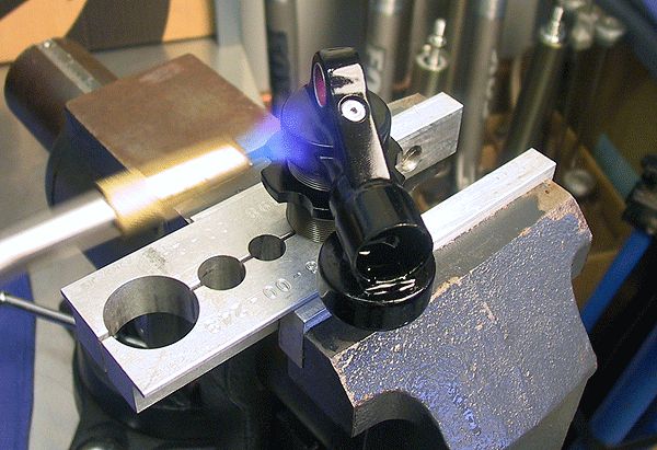
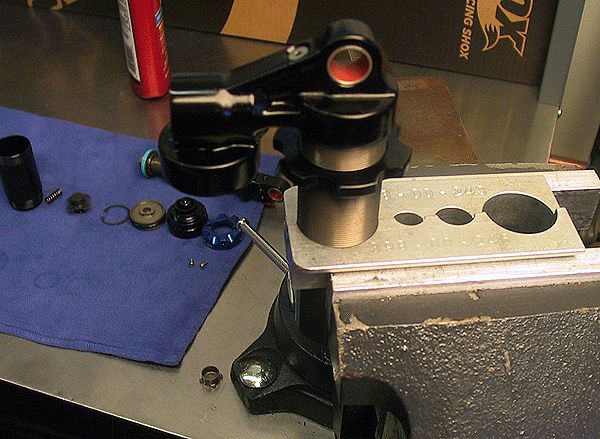
Step 2
Clamp the reservoir in the vise and apply some heat with a torch to break down the Loctite in the eyelet threads. Unthread the eyelet from the reservoir with a torque bar. Caution, the eyelet and reservoir may be hot.
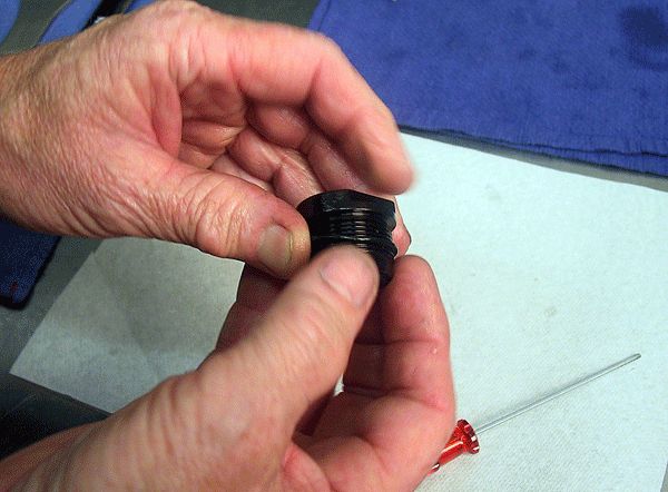
Step 3
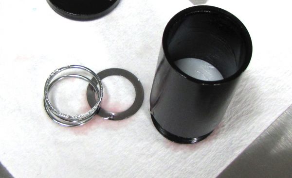
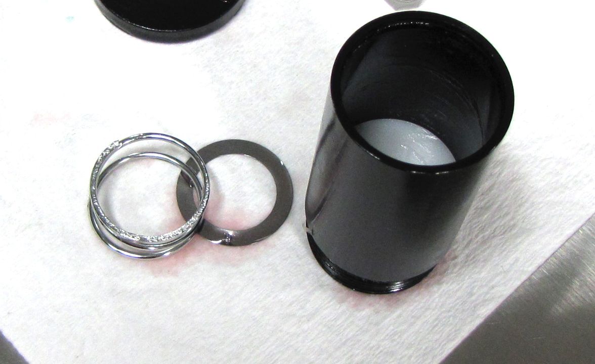
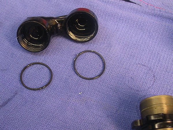
Remove the check valve and spring from the end of the reservoir. Clean and instpect the check shim and spring and set aside. Inspect the reservoir for clean threads and bore.
Step 4
Clamp the shock body in your vise and apply heat with a torch to the eyelet to break down the Loctite. Unthread the eyelet with a torque bar. Caution the eyelet and body may be hot.


Step 5
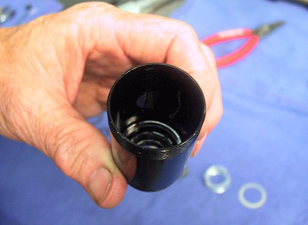
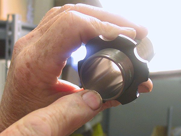
Clean the Loctite from the eyelet and body threads and replace the o-rings. Thoroughly clean the body with Isopropyl alcohol and dry. Inspect the bore for any scratches, nicks, gouges, or other damage and replace if necessary.

Step 6
Inspect the seal glands at both ends of the body for any damage.

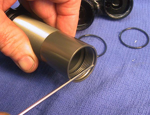

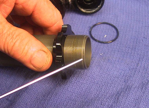
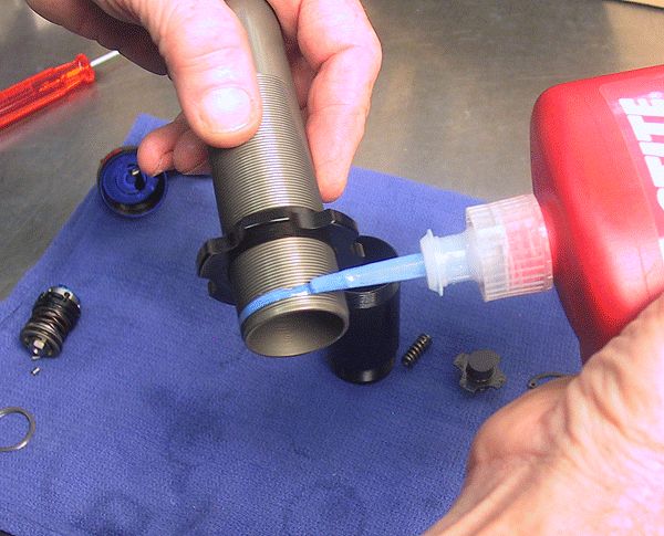
Step 7
Make sure the eyelet o-rings are greased with Slick Honey. Apply some blue Loctite 242 to the body threads as shown. Do not allow Loctite to contact the o-ring gland at the end of the body.

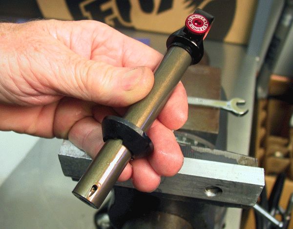
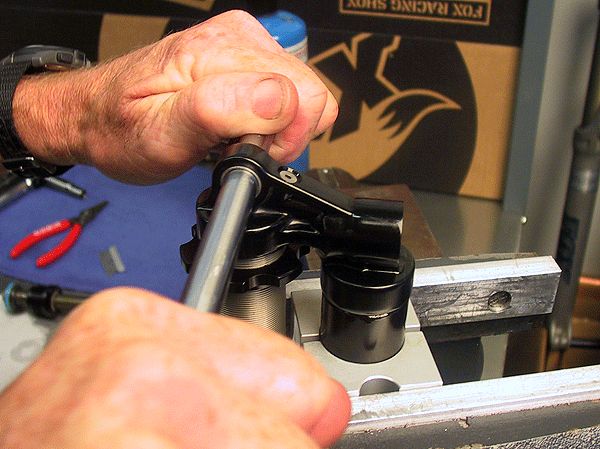
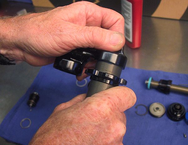
Step 8
Thread the eyelet onto the body by hand, then clamp in the shaft clamps. Torque the eyelet to 35 ft-lb (420 in-lb or 47.5 Nm).
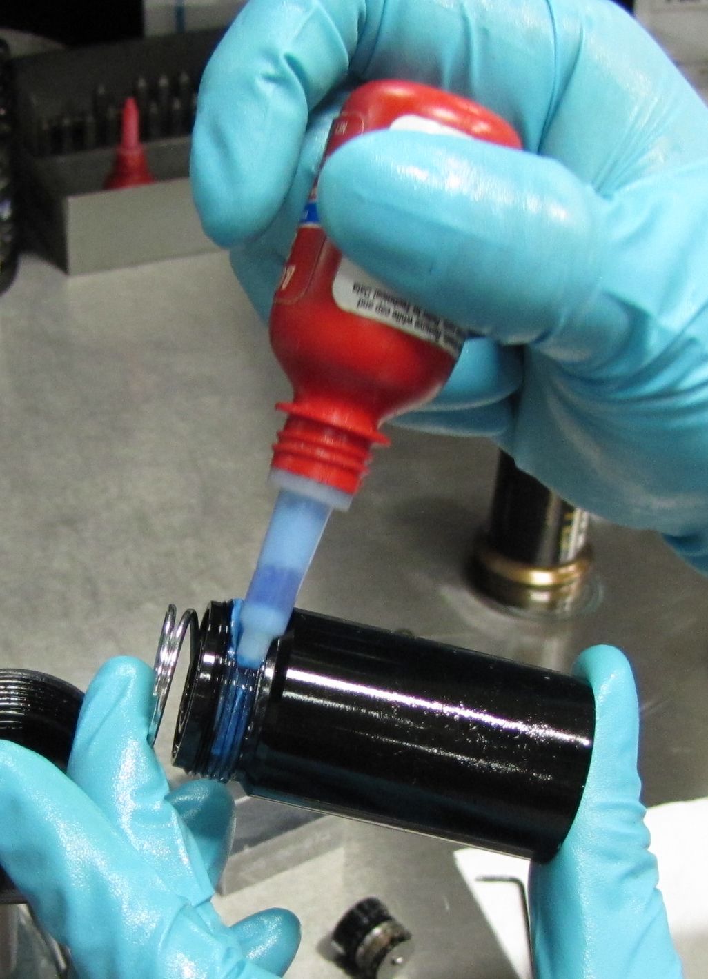
Step 9
Install the check shim and check spring into the reservoir form the eyelet end. Apply some Blue Loctite 242 to the reservoir threads then thread the reservoir into the eyelet assembly.
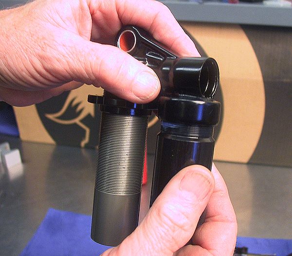

Step 10
Clamp the reservoir in your shaft clamps and torque the eyelet to 35 ft-lb (420 in-lb or 47.5 Nm).
Reassembly

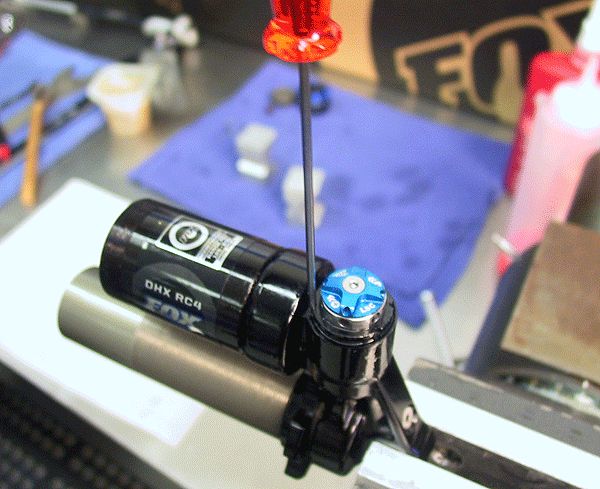
Step 1
Align the two flutes in the DSC housing with the two flutes in the inside of the eyelet assembly. Guide the damping adjuster assembly into the eyelet assembly with a thin driver in the flutes to help keep everything aligned. Press the damping adjuster assembly into the eyelet until it snaps into place.
Step 2
Install the two dowel pins followed by the retaining ring. Make sure that the open section of the retaining ring is oriented opposite the dowel pins


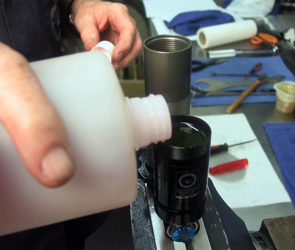
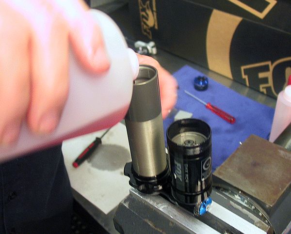
Step 3
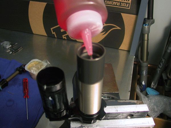
Prefill the body and the reservoir with FOX 10wt. red oil, for preliminary bleeding. Coat the IFP o-ring with Slick Honey before installing it onto the IFP.

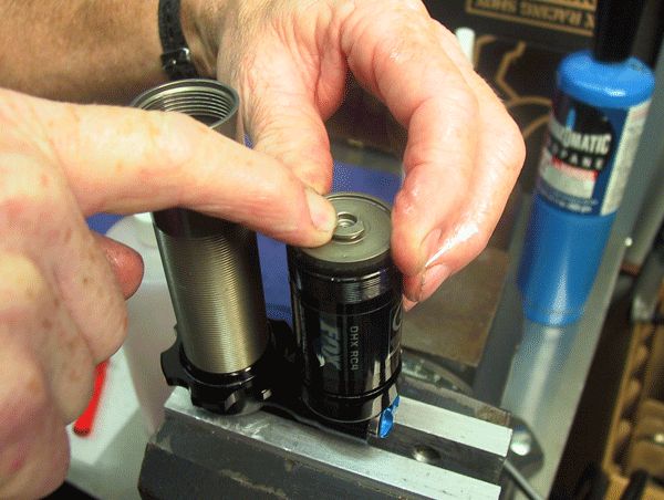
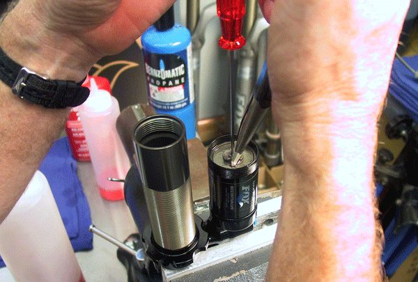
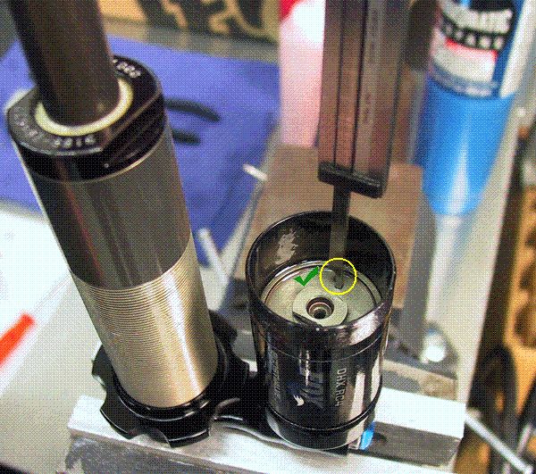
Step 4
With the bleed screw removed, insert the greased IFP into the reservoir chamber. Push it down until oil just starts to come out of the bleed screw hole, then loosely install the bleed screw.
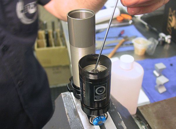
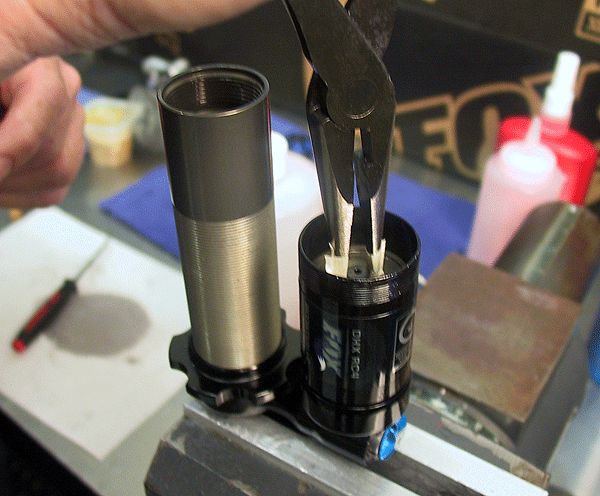
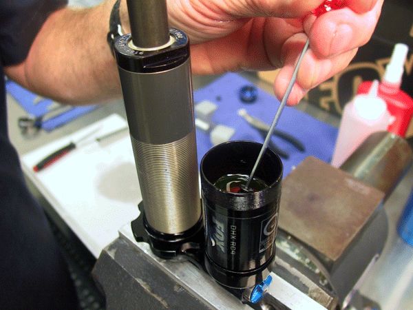
Step 5
Fill the body approximately half way with FOX 10wt. red oil. With needle-nosed pliers, gently grasp the IFP and smoothly push it down while watching for bubbles in the body oil.

.jpg)
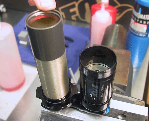
Step 6
Add more oil to the body and pull up on the IFP with your needle-nosed pliers. Pull the IFP all the way up, but not out of the reservoir, then remove the bleed screw.

Step 7
Push the IFP down again until oil just starts to come out of the bleed screw hole. Reinstall the bleed screw and push the IFP all the way down. Repeat step 6 until no air bubbles are found in the body oil.

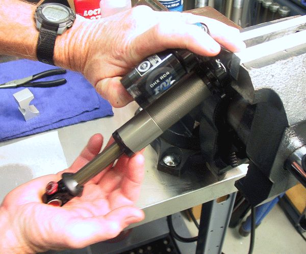
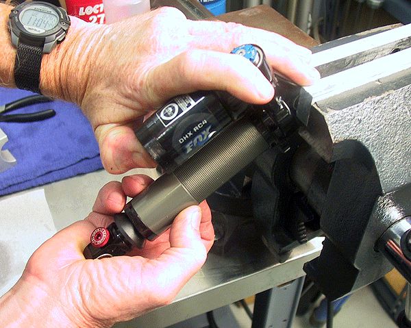
Step 8
Pull the IFP approximately 1/3 of the way up, then add oil to the body as smoothly as possible to prevent aeration of the oil. Smoothly and quickly invert the shaft assembly and install it into the body.


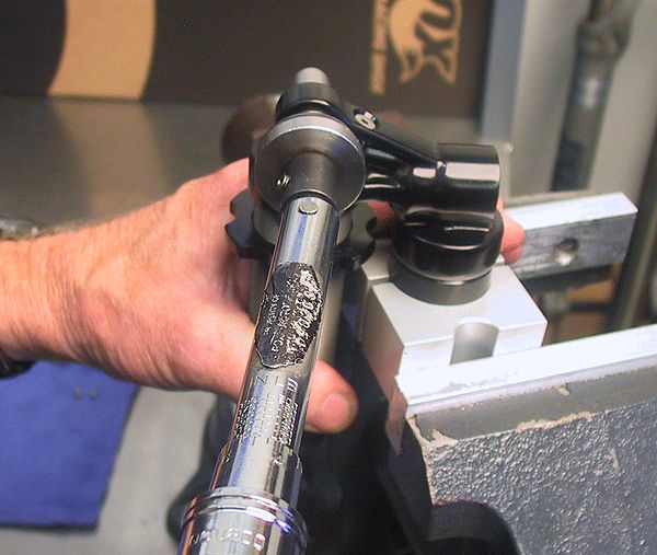
Step 9
Torque the bearing assembly to 35 ft-lb (420 in-lb or 47.5 Nm) with a 1" crows foot.


Step 10
Remove the IFP bleed screw then set IFP depth by measuring from the IFPs flat surface, not the raised rim.
| Size | IFP Depth |
| 10.500 x 3.500 | 1.100in |
| 9.500 x 3.000 | 1.020in |
| 8.750 x 2.750 | 0.980in |
| 8.500 x 2.500 | 0.940in |
| 7.875 x 2.250 | 0.900in |
| 7.875 x 2.000 | 0.860in |
| 7.500 x 2.000 | 0.860in |
Step 11
Install the IFP bleed screw and torque to 7 in-lb (0.8 Nm) while holding the IFP with needle-nosed pliers. Drain any excess oil from the reservoir.


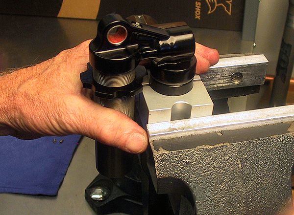
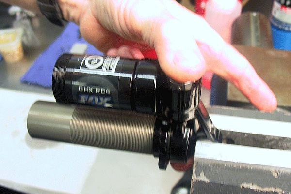
Step 12
Reorient the shock in the vise so the eyelet is higher than the body and the reservoir is on top. Press against the IFP to support it while you compress the shock fully. Reorient the shock in the vise so the shaft is pointing straight up, then push down the IFP while you pull the shaft completely out. If bled properly no air will be felt or heard during this process.


Step 13
Remove the IFP bleed screw to inspect for any trapped air in the IFP reservoir. If air is found, repeat step 12, reset IFP depth as shown in step 10, and reinstall the bleed screw.

Step 14
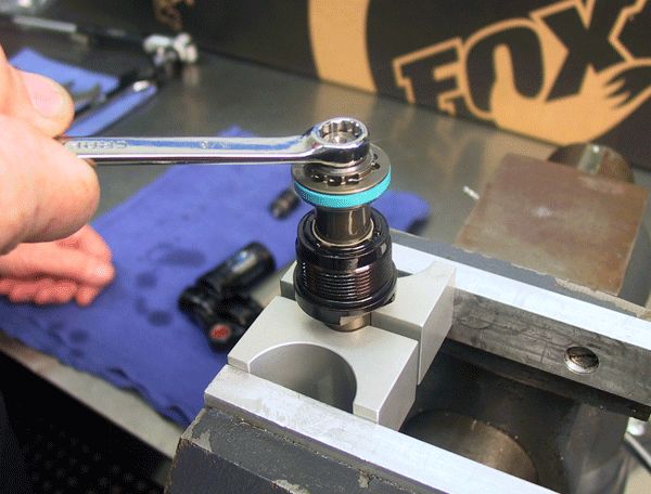
Thread on and torque the reservoir end cap assembly into the reservoir at 25 ft-lb (300 in-lb or 33.9 Nm).


Step 15
Add approximately 160 psi to the Air Assist chamber and reinstall the air valve cap. Dyno test the shock to endure proper function. Thoroughly clean the exterior of the shock.