2013-2017 FIT RC2 Cartridge Rebuild
Required Parts
- 803-00-501 Service Set: Seal Kit, 2011 36 & 40 Inverted RC2 Cartridge
Required Tools
- 398-00-371 Tooling: Sealhead To Shaft Bullet, 10mm
- 398-00-681 2002-017 32 Damper-side and ALL 32-34-36-40 Spring-side Removal Tool
- 398-00-682 2005-017 34-36-40 Damper-side Removal Tool
- 398-00-706 Tooling: Fork Topcap Socket, 32mm V2, 3/8 Drive
- 803-00-084 Kit: Shaft Clamps, FORX, Set #1 (32mm Forx)
- 803-00-147 Kit: Shaft Clamps, FORX, Set #2
- 803-00-276 Service Kit: 2010 RL-RLC Hand Bleeder (FOX FIT Bleeder Tool)
- 803-00-830 Service Set: Tooling: 2014 RC2, Shaft Clamps
Supplies Needed
- 10mm Crows Foot
- 10mm Socket
- 10mm Wrench
- 15mm Socket
- 16mm Socket
- 18mm Cone Wrench
- 2.5mm Hex Wrench
- 21mm Crows Foot
- 21mm Wrench
- 2mm Hex Wrench
- 9mm Socket
- Mallet
- Propane Torch
- Ratchet
- Seal Pick
- Thin 18mm Crows Foot
- Torque Wrench
- Waste Oil Basin
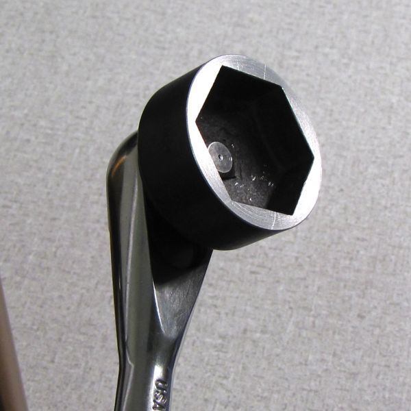
- 32mm 6-point Chamfer-less Box-end Wrench (Available for purchase at RockyMtnAtv.com) Available for purchase at RockyMtnAtv.com
WARNING: Always wear safety glasses and protective gloves during service to prevent potential injury. Failure to wear protective equipment during service may lead to SERIOUS INJURY OR DEATH.
This procedure guides you through the rebuild of an Inverted FIT RC2 cartridge. While some images show an older version of the system, the procedure will be the same for all versions of this cartridge. For additional information and complete assembly drawings for your specific model plese visit the appropriate Parts List page at: All Parts Lists »
WARNING: FOX products should be serviced by a qualified bicycle service technician, in accordance with FOX specifications. If you have any doubt whether or not you can properly service your FOX product, then DO NOT attempt it. Improperly serviced products can fail, causing the rider to lose control resulting in SERIOUS INJURY OR DEATH.
Cartridge Removal
Step 1
Remove the black rebound knob cover if present and turn out all adjusters fully (counter-clockwise). Remove the red rebound knob with a 2mm hex wrench.


Step 2
Remove the bottom nuts with 10mm and 15mm sockets, then remove the crushwashers. Use Damper Removal Tools (398-00-430 and 398-00-601) to free the lowers over a waste oil basin.


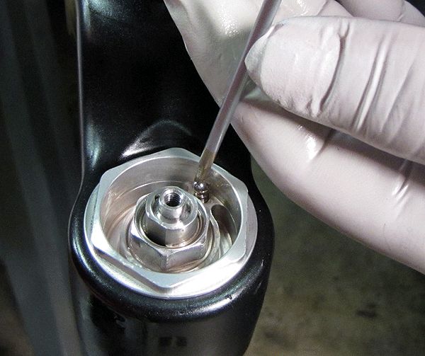
Step 3
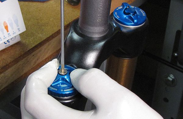
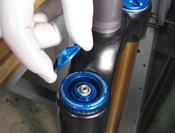
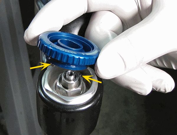
Hold the Low Speed Compression (LSC) knob stationary while you remove the set screw with a 2.5mm hex wrench. Carefully remove the knobs so you don't lose the detent balls and springs underneath.
For 2014 models: Replace the u-cup seals on the knobs at this time.

Step 4
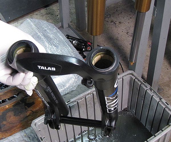
Use a 6-point chamfer-less 32mm socket to remove the cartridge from the CSU.
Disassembly
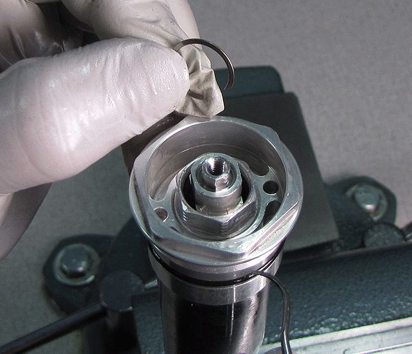
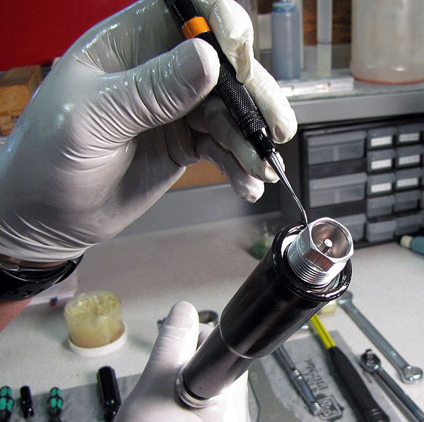
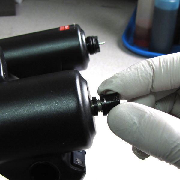
Step 1
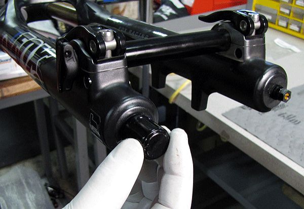
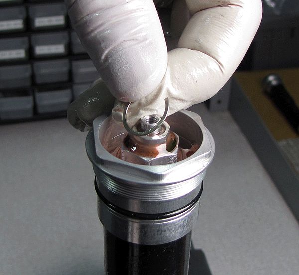
Clamp the cartridge body in shaft your shaft clamps PN: 803-00-084 (PN: 803-00-830 for 2014+ 40 and 2015+ 36 models). Remove the RC2 Adjuster Assembly retaining ring. Keep your finger above the ring while picking it out as it can eject easily.

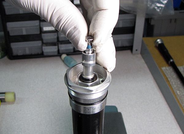
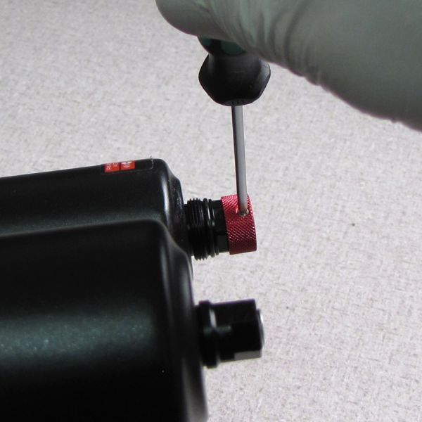
Step 2
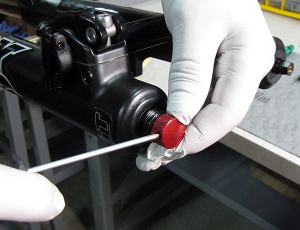
Thread the knob set screw back into the RC2 Adjuster Assembly and pull up to remove the assembly. Invert the cartridge over your waste oil basin and drain the oil by cycling the shaft while repeatedly squeezing the bladder.

Step 3
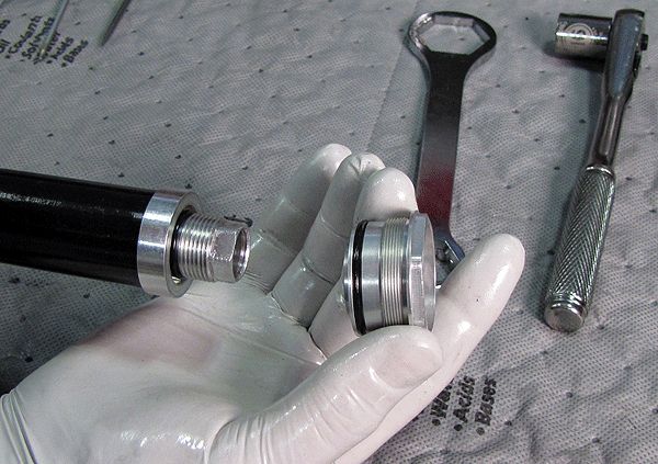
Loosen the seal head assembly with a 18mm wrench, remove the cartridge from your vise and separate the seal head from the cartridge body over a waste oil basin.

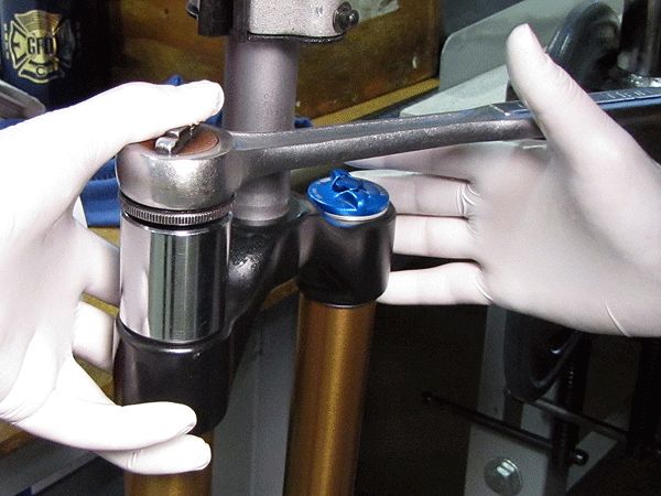
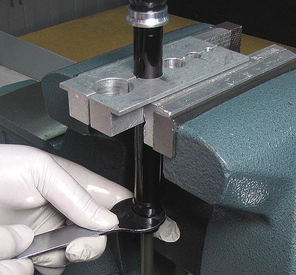
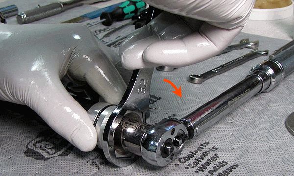
Step 4
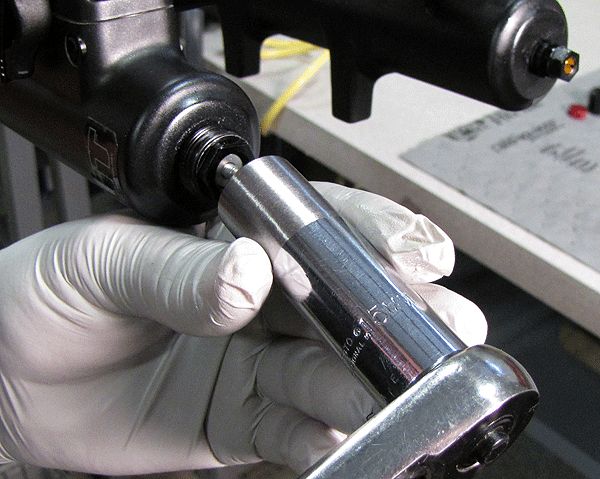
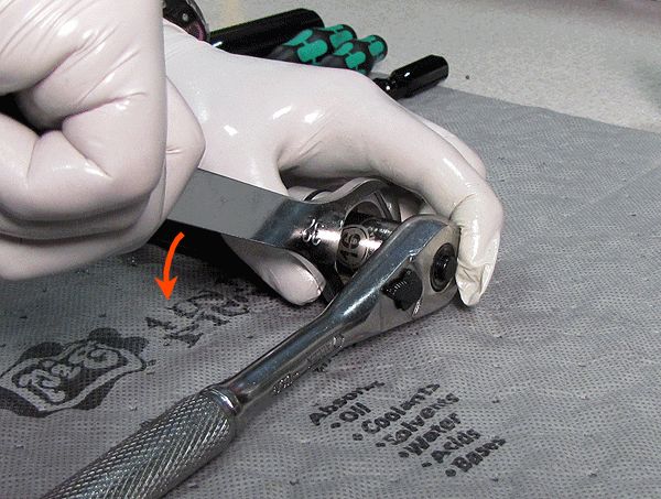
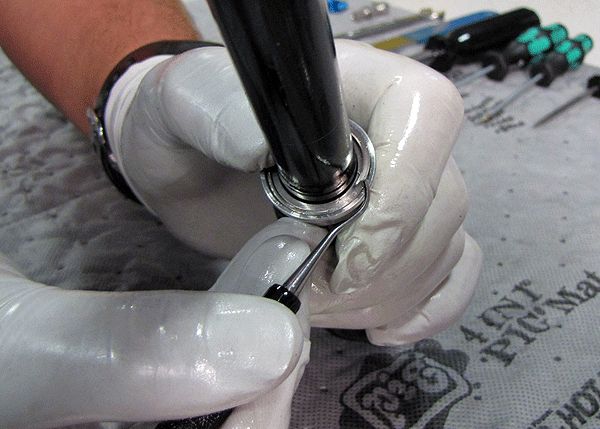
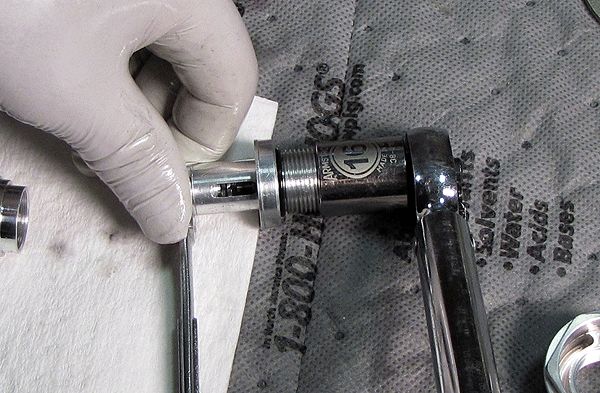
Position a 32mm 6-point chamfer-less box-end wrench on the topcap, and a 16mm socket on the base valve upper stud. Leveraging the socket wrench against the workbench surface, loosen and remove the topcap with the 32mm wrench, as shown. Work slowly and carefull so you don't damage the topcap wrench flats. Remove the upper bladder ring with your thumbs.


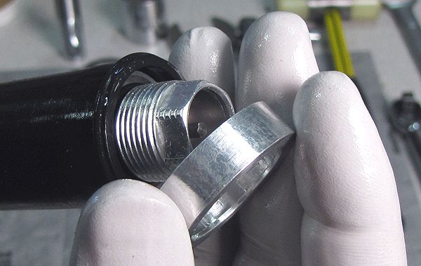
Step 5
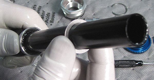
Remove the retaining ring and bladder ring retainer being careful not to scratch the smooth bladder sealing surface on the black cartridge body.
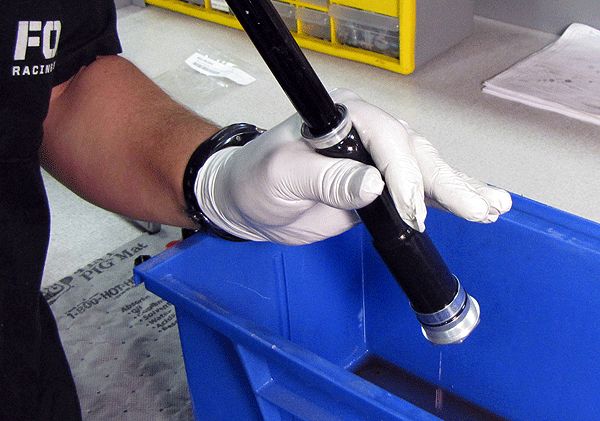
Step 6
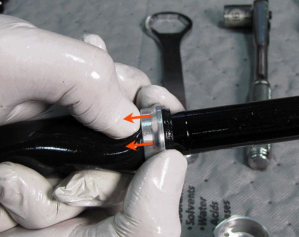
Slide the lower bladder ring up the bladder as shown. This allows the bladder to be removed from the cartridge body. Separate the lower bladder ring from the bladder.


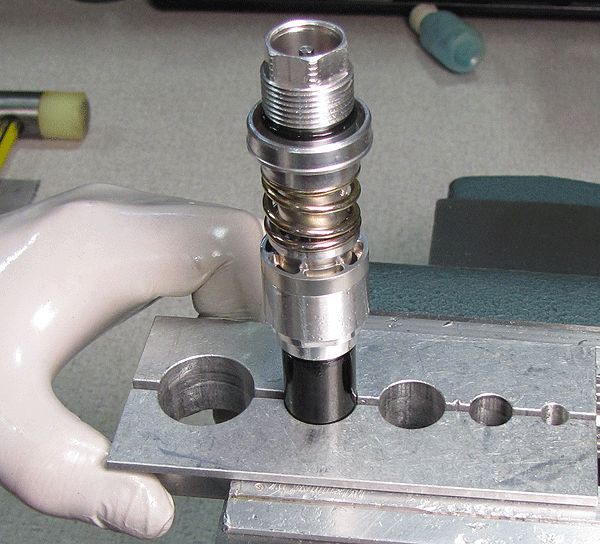
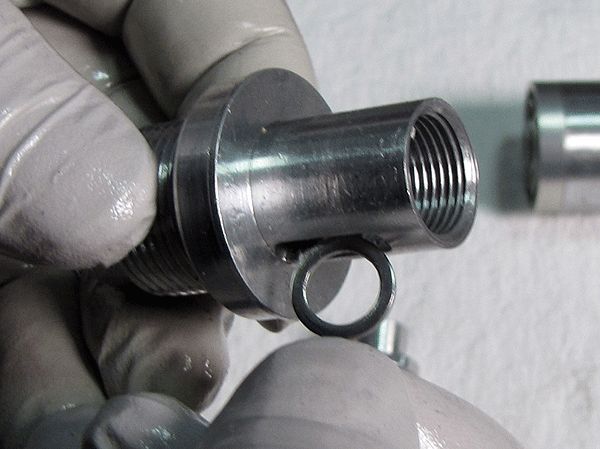
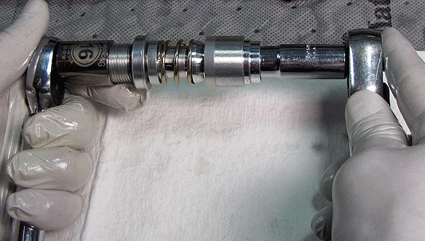
Step 7
Clamp the cartridge body with base valve assembly into the shaft clamps. Use a 21mm wrench on the RC2 coupler to loosen and remove the base valve assembly from the cartridge body.


Rebuilding the Base Valve
Complete rebuilding of the Base Valve Assembly may not be required for all FIT RC2 damper cartridge services. If rebuilding the Base Valve Assembly, replace all o-rings as you go.
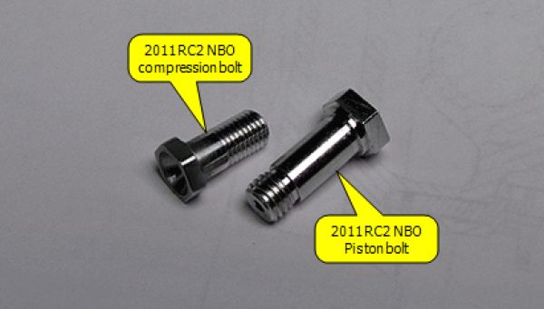
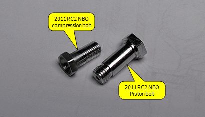
"NBO" = "no bottom-out", and "HBO" = "hydraulic bottom-out". Coil-specific fork models use HBO dampers; air-sprung fork models use NBO dampers.
Base Valve service below is shown using an NBO cartridge.
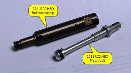

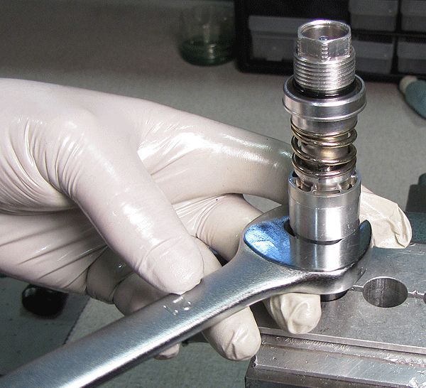
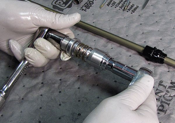
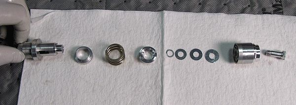
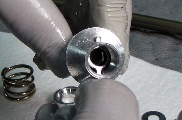
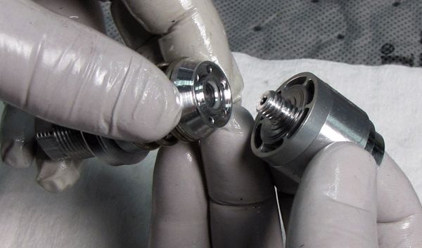
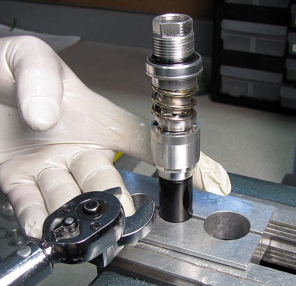
Step 1
Use a 16mm socket on the base valve upper stud and a 10mm socket on the compression bolt (10mm open end wrench on the Bottom Out Cup for HBO models), loosen to dismantle the base valve assembly. Lay the parts out in assembly sequence on a clean lint-free shop towel.

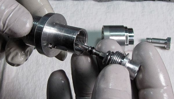
Step 2
Use a 16mm socket and a 10mm wrench to remove the LSC coupler from the RC2 upper stud, then remove the RC2 preload plate from the upper stud.


Step 3
With a pick tool, pull the LSC detent wire spring from the LSC coupler. Remove the LSC adjuster o-ring, then remove the LSC adjuster from the LSC coupler.
Step 4
Install the LSC adjuster into the LSC coupler, then install a greased o-ring onto the LSC adjuster.


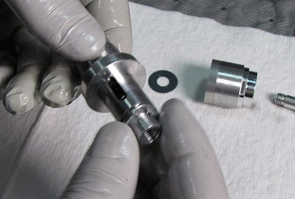
Step 5
Install the LSC detent wire spring onto the LSC coupler, then install the preload plate into the upper stud so its ears protrude from the two slots and the plate lays flat inside the upper stud.

Step 6
Thread the LSC coupler with LSC adjuster into the RC2 upper stud. Use a 16mm socket and a 10mm wrench to torque the assembly to 50 in-lb (5.7 Nm).

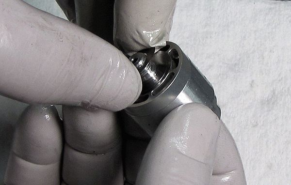
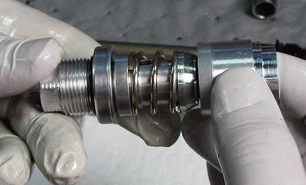
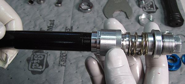
Step 7
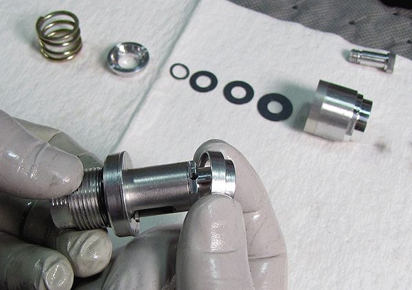
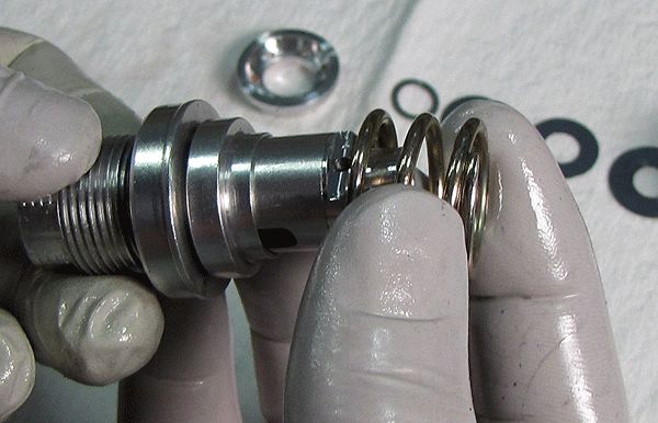
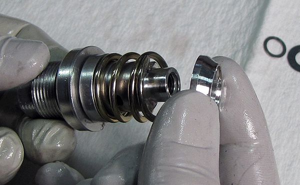
Install the high speed preloader, compression spring, and preload hat into the base valve upper stud subassembly.

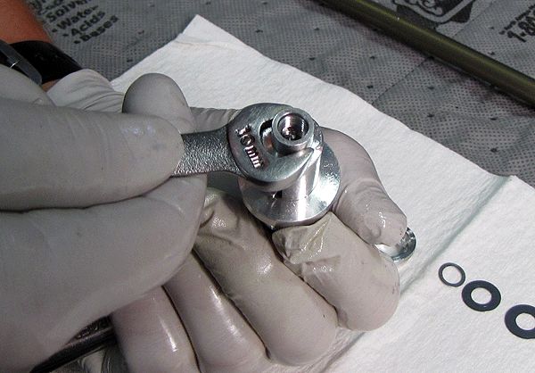
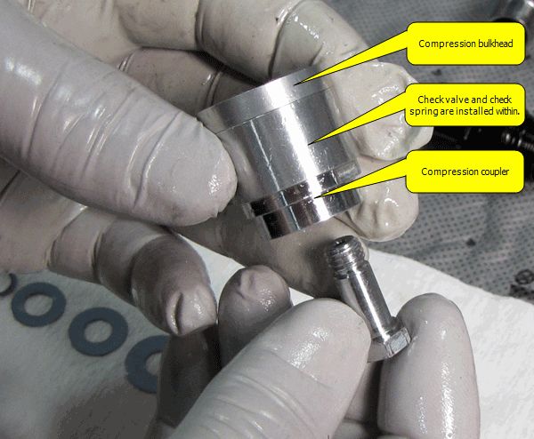
Step 8
Insert the compression bolt (bottom out cup for HBO models) through the compression bulkhead/coupler assembly as shown, then stack the valve shims in their original order. Thread the upper stud assembly to the bulkhead/coupler/bolt assembly. If the check shim or spring inside of the compression bulkhead/coupler assembly are damaged, the base valve assembly should be replaced as those parts are factory assembled and not intended to be disassembled.
Step 9
Use a 16mm socket on the base valve upper stud and a 10mm socket on the compression bolt (10mm open end wrench on the Bottom Out Cup for HBO models) to torque the assembly to 50 in-lb (5.7 Nm).


Step 10
Thread the base valve assembly onto the cartridge body, clamp the cartridge body in your shaft clamps, and torque with a 21mm crows foot to 75 in-lb (8.5 Nm).
Rebuilding the Shaft Assmebly
Complete rebuilding of the Rebound Adjuster Assembly portion of the Shaft Assembly may not be required for all FIT RC2 damper cartridge services. If heat is used to remove the Rebound Adjuster Assembly, it must be rebuilt as the internal o-rings may have been damaged during heating. If rebuilding the Rebound Adjuster Assembly, replace all o-rings as you go.
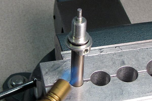
Step 1
Clamp the rebound shaft assembly in your 10mm shaft clamps (PN 803-00-830 or 803-00-147) as shown. Avoid allowing more than two inches of shaft showing above the clamps, to help prevent shaft torsion damage. Apply heat with a propane torch to the shaft end.

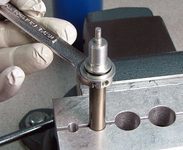
Step 2
Use a 10mm wrench to remove the Rebound Adjuster Assembly from the shaft. Remove any Loctite residue.

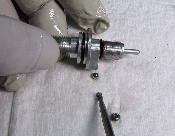
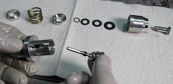
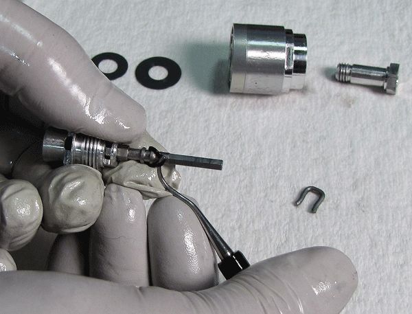
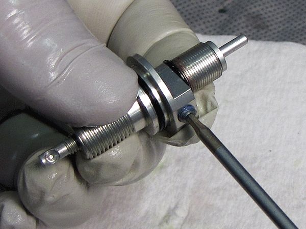
Step 3
Use a 2mm hex wrench to remove the set screw from the rebound adjuster assembly. Remove the detent spring and ball, then unthread the rebound adjuster screw from the lower damper shaft insert.

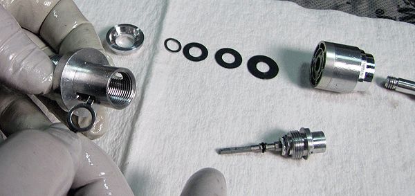
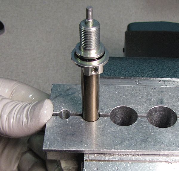
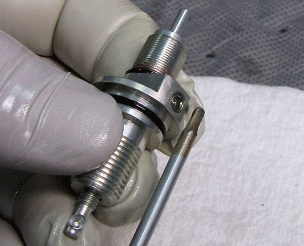
Step 4
Reinstall the rebound adjuster screw with new greased o-rings into the lower damper shaft insert. Grease the detent ball and spring with Slick Honey and insert them into the threaded hole in the side of the lower damper shaft insert (ball first!). Install the set screw until flush with the lower damper shaft insert as shown.


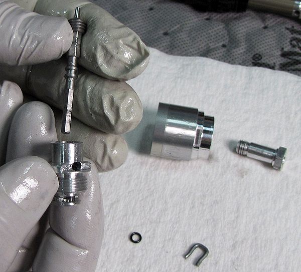
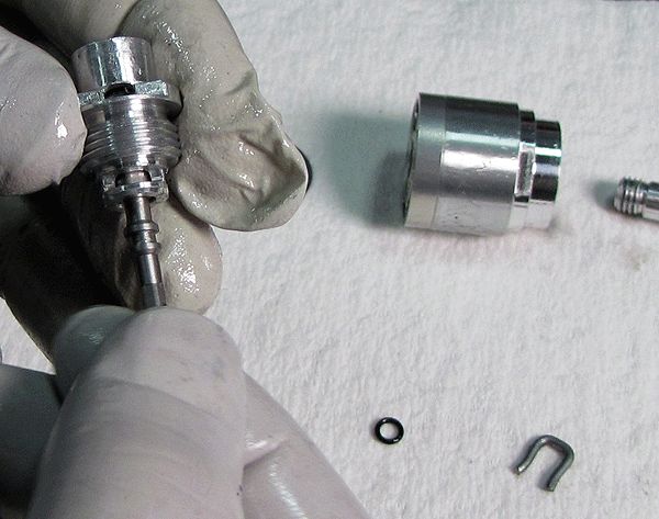
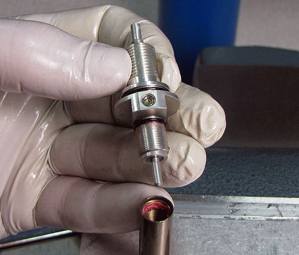
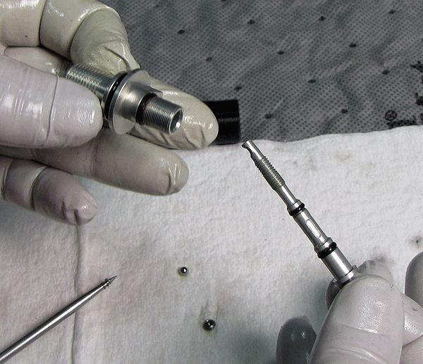
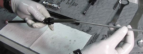
Step 5
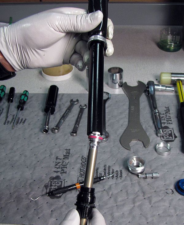
Remove the sealhead assembly from the shaft, then remove the rebound tube, needle, and spring from the inside of the shaft. Replace the o-ring on the rebound needle.

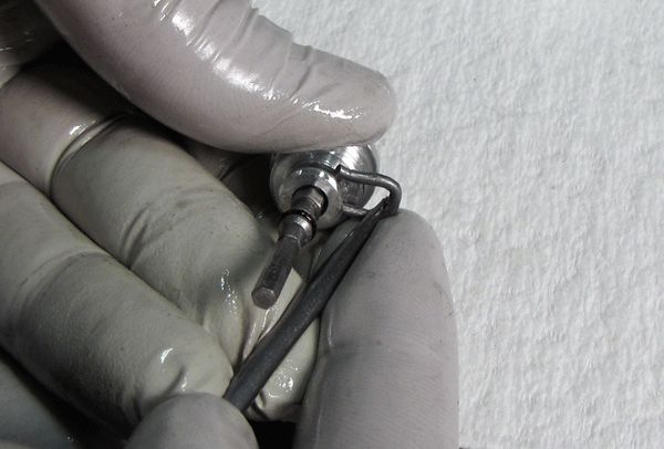
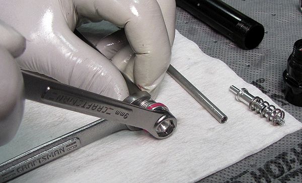
Step 6
Remove the rebound piston assembly from the shaft with a 9mm and 10mm wrench, as shown. Inspect and clean all parts, replace any that are damaged.
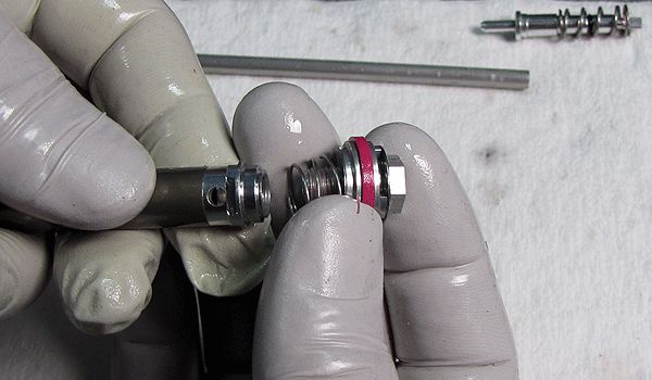

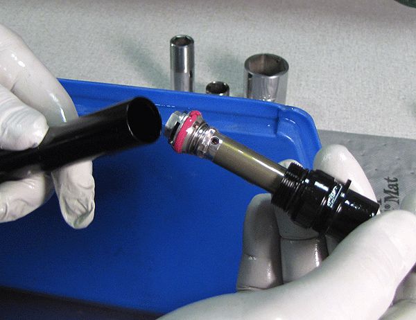
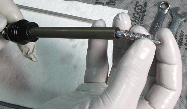
Step 7
Replace the pink glide ring on the piston and reassemble the piston assembly onto the end of the shaft. Before tightening the piston bolt, verify that the check valve is not pinched between the piston and the end of the shaft. It must be free to move away from the piston. Torque the piston bolt to 55 in-lb (6.2 Nm).

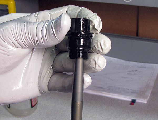
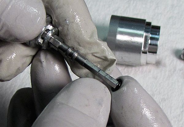
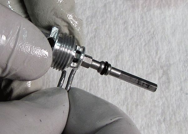
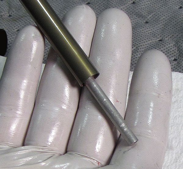
Step 8
Insert the 10mm shaft bullet tool (PN 398-00-371) into the end of the shaft. Grease the tapered portion of the bullet tool with Slick Honey, then install the sealhead assembly, threaded end first onto the shaft over the bullet tool.

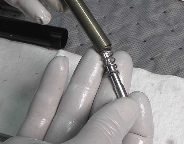
Step 9
Install the rebound spring, needle, and tube into the shaft. The rebound tube is not directional.


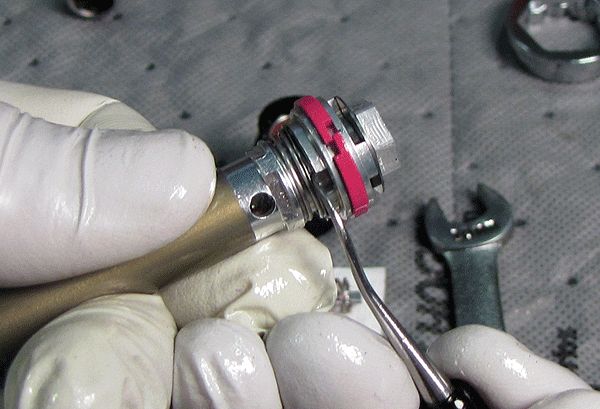
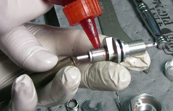
Step 10
Apply a single drop of red Loctite to the rebound adjuster assembly threads, and install the assembly onto the shaft. With a 10mm crows foot, torque the assembly to 25 in-lb (2.8 Nm).

Reassembly

Step 1
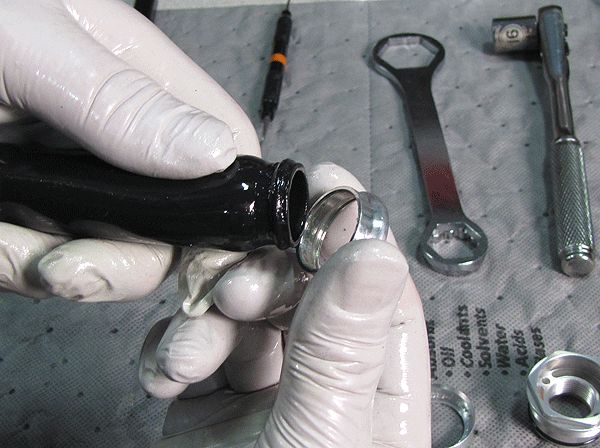
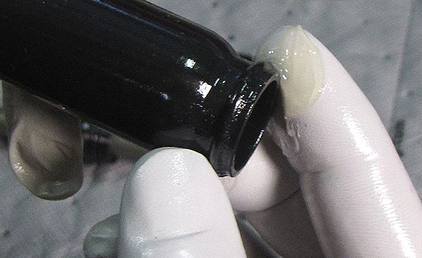
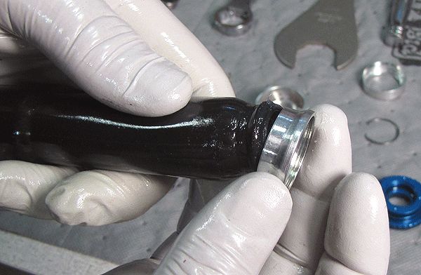
Apply a thin coating of Slick Honey to the inside and outside of the bladder ends, then install the lower bladder ring as shown.

Step 2
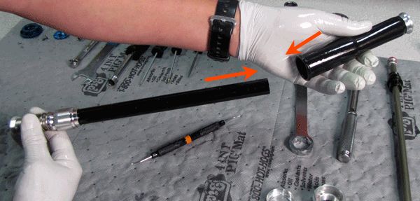
Install the bladder assembly (large end first) onto the cartridge body from the shaft end.

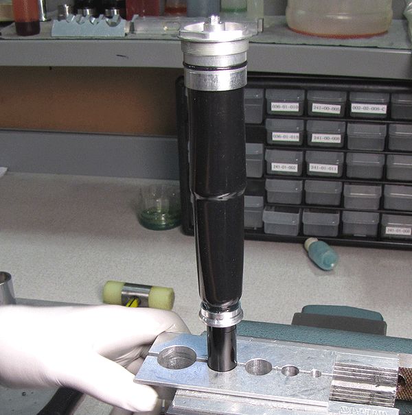
Step 3
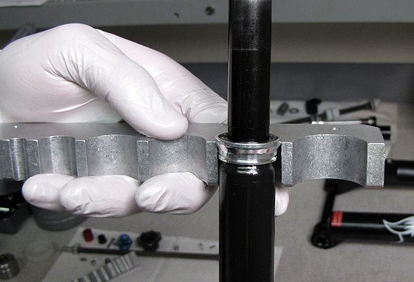
Place the bladder and cartridge body assembly into the second largest hole in the #2 clamps as shown; loosely resting the bladder ring on the clamps, no clamping pressure applied to the bladder ring. While gently tugging the bladder from below, you will seat the bladder in the bladder ring deep enough to install the bladder retainer and retaining ring.


Step 4
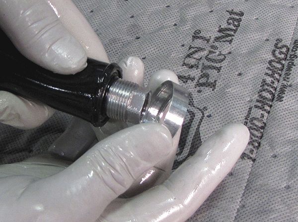
Install the shaft assembly into the cartridge body, threading in the sealhead by hand. Clamp the cartridge body in your shaft clamps and torque the sealhead to 75 in-lb (8.5 Nm) with a thin 18mm crows foot.
Step 5
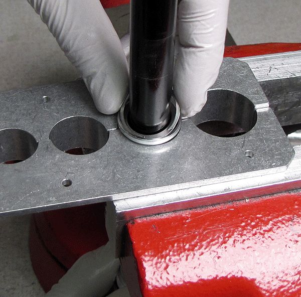
Slide the bladder up past its seat on the base valve, then install the upper bladder ring. Thread the topcap down by hand to position the bladder and upper bladder ring in their proper position.


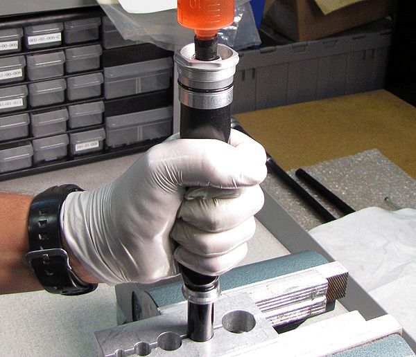
Step 6
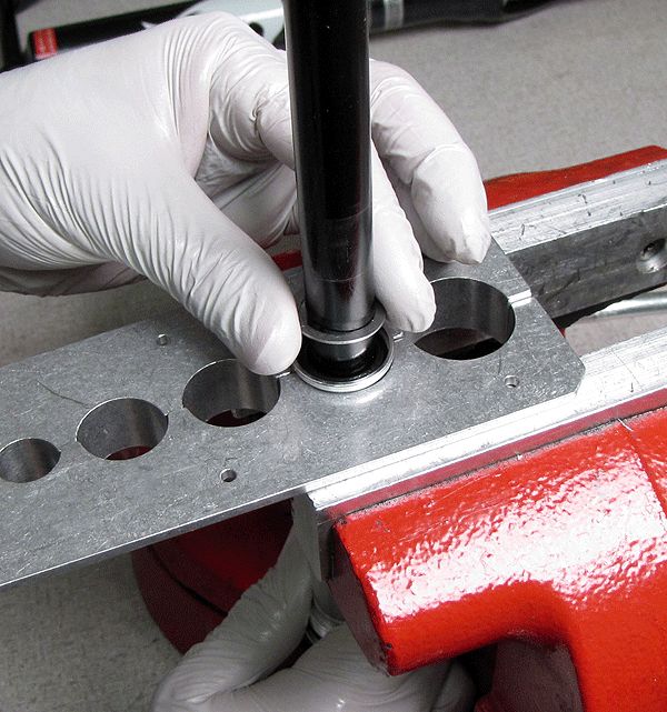
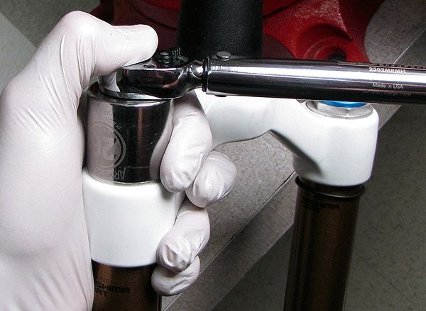
Position a 32mm 6-point chamfer-less box-end wrench on the topcap, and a torque wrench set to 150 in-lb (16.9 Nm) with a 16mm socket on the base valve upper stud. Leveraging the torque wrench against the workbench surface, tighten the topcap with the 32mm wrench until the torque wrench clicks, as shown. Work slowly and carefull so you don't damage the topcap wrench flats.

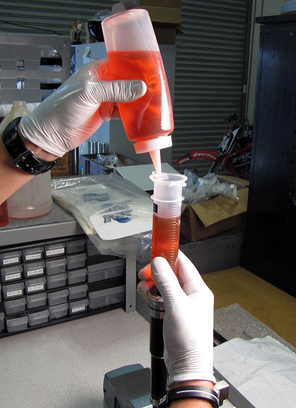
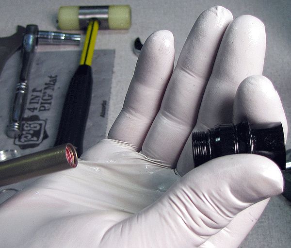
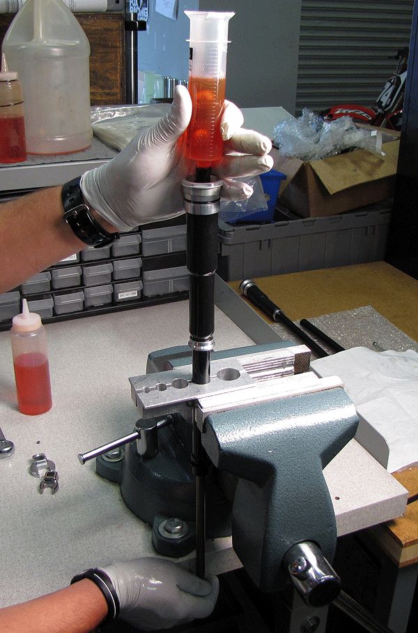
Step 7
Clamp the damper cartridge in the vise, and firmly place the Fox bleed syringe (PN 803-00-276) into the RC2 adjuster opening in the topcap. In some cases sealing between the bleed syringe and topcap can be improved by first inserting the piece of rubber tubing into the topcap and then inserting the syringe into the tubing. Longer pieces of clear tubing can help you see air bubbles as they enter the syring, just be sure to stabilize the syringe as necesarry to avoid spilling oil. Fill the syringe with FOX 10wt. red oil.


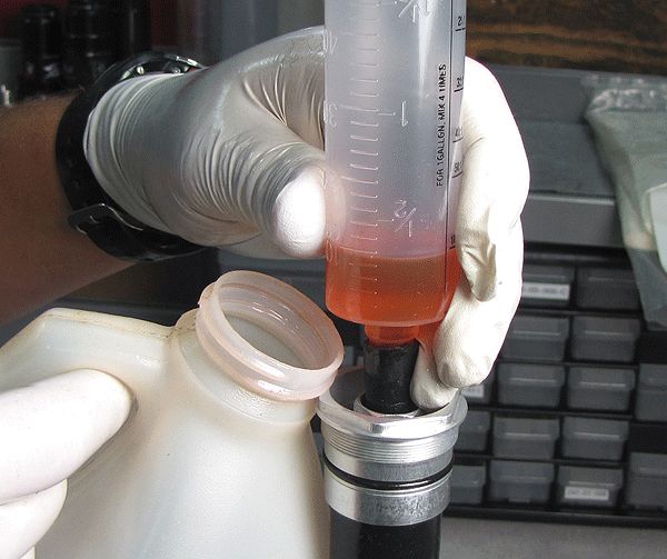
Step 8
Slowly cycle the shaft while squeezing the bladder to force any trapped air out into your syringe. Do not release your squeeze on the bladder or cycle the shaft down until any air bubbles in your syringe have risen to the surface. Do not suck bubbles back into the cartridge. Periodically add oil to your syringe so you do not let the syringe go dry as the cartridge ingests oil.

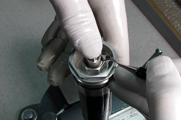
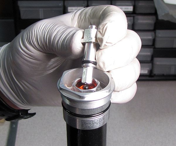
Step 9
When you're certain that all trapped air is purged, remove the syringe. Install the RC2 adjuster assembly into the topcap displacing some oil to prevent trapping any air.
Step 10
Install the RC2 adjuster assembly retaining ring, then drain any oil from the topcap and clean with isopropyl alcohol. Test the cartridge for full functionallity before going any further.

Cartridge Installation
Step 1
Install the cartridge into the damper-side upper tube and torque to 220 in-lb (24.8 Nm) with a 6-point chamfer-less 32mm socket.


Step 2
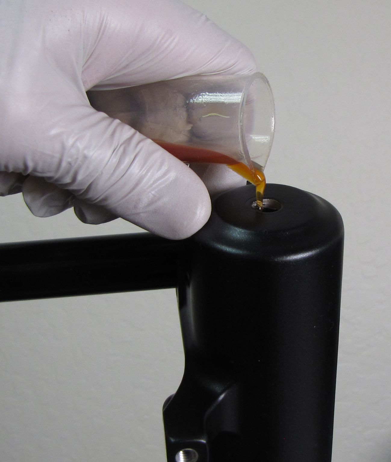
Install the lower leg assembly onto the upper tubes, then pour in the appropriate amount of FOX 20wt. Gold bath oil.
| Damper Side Bath Oil (RC2 only) | |
| All 36mm Forks | 40cc |
| All 40mm Forks | 50cc |
| Spring Side Bath Oil | |
| All 36mm VAN | 40cc |
| 2011-2014 36 FLOAT | 40cc |
| 2015+ 36 FLOAT | 10cc |
| 2011-2013 36mm TALAS | 15cc |
| 2014 TALAS 5 | 40cc |
| All 40mm Forks | 50cc |
Additional information regarding updating from 10wt. Green oil to the new 20wt. Gold oil can be found at: http://www.ridefox.com/help.php?m=bike&id=452 »

Step 3
Install a new crushwasher on each side followed by the appropriate bottom nut. Torque both bottom nuts to 50in-lb (5.7 Nm).
Step 4
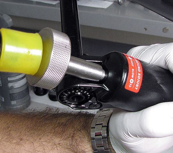
Use a 2mm hex wrench to install the red rebound knob. Make sure that the set screw lines up with the depression in the rebound adjuster shaft. Install the black rebound knob cover if present. Thoroughly clean the exterior of your fork.
