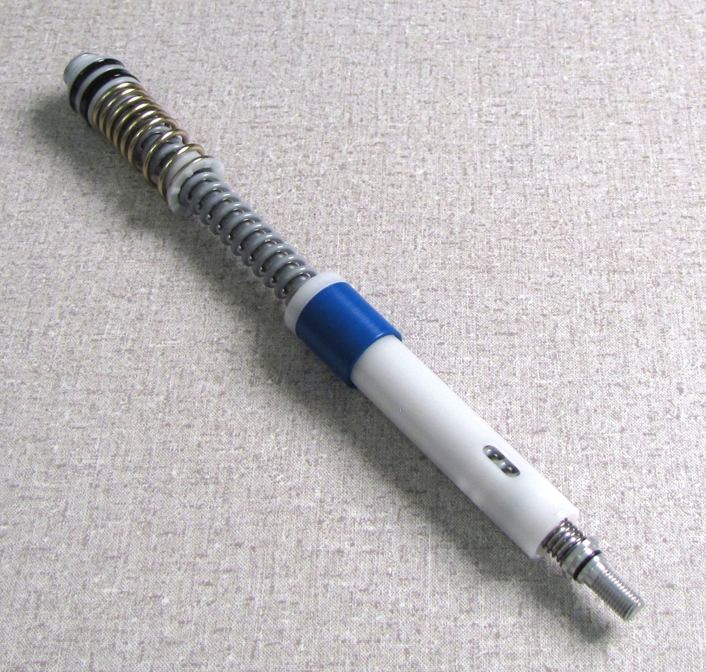
2014-2017 TALAS 5: Adjusting Total Travel and Modifying Travel Adjustment Range
Required Parts
- 036-01-071 Seals: U-Cup, Scraper, TALAS 5
- 036-01-080 Seal, Air Piston, TALAS 5
- 234-23-010 Spring Hardware: (T) Shuttle Bumper, TALAS 5, Full Travel (0.400" TLG)
- 234-23-011 Spring Hardware: (T) Shuttle Bumper, TALAS 5, 10mm Shorter (0.900
- 234-23-012 Spring Hardware: (T) Shuttle Bumper, TALAS 5, 20mm Shorter (1.390" TLG)
- 234-23-013 Spring Hardware: (T) Shuttle Bumper, TALAS 5, 30mm Shorter (1.880" TLG)
- 241-01-002-C Fastener, Custom: Crush Washer, Plastic
Required Tools
- 398-00-681 2002-017 32 Damper-side and ALL 32-34-36-40 Spring-side Removal Tool
- 398-00-702 Tooling: Fork Topcap Socket, 26mm, 3/8 Drive
- 398-00-706 Tooling: Fork Topcap Socket, 32mm V2, 3/8 Drive
- 398-00-707 Tooling: Fork Topcap Socket, 28mm V2, 3/8 Drive
WARNING: Always wear safety glasses and protective gloves during service to prevent potential injury. Failure to wear protective equipment during service may lead to SERIOUS INJURY OR DEATH.
WARNING: FOX products should be serviced by a qualified bicycle service technician, in accordance with FOX specifications. If you have any doubt whether or not you can properly service your FOX product, then DO NOT attempt it. Improperly serviced products can fail, causing the rider to lose control resulting in SERIOUS INJURY OR DEATH.
Modifying Travel Adjustment Range
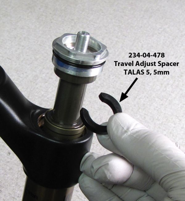
You can reduce the travel adjustment range of the TALAS 5 cartridge in 5mm increments by installing TALAS 5 Travel Adjust Spacers (PN: 234-04-478). You cannot increase the travel adjust range on stock forks unless Travel Adjust Spacers are present from the factory. If present, any Travel Adjust Spacers can be removed to increase the travel adjustment range by 5mm per spacer. You may add as many spacers as you would like to reduce travel adjustment range until there is no change between long and short travel modes.
32mm and 34mm TALAS 5 forks come stock with a 30mm travel adjustment range*.
36mm TALAS 5 forks come stock with a 40mm travel adjustment range*.

*Some OE forks may come stock with Travel Adjust Spacers and have custom travel adjustment ranges.
You do not need to release air pressure, drain bath oil, or completely remove the TALAS 5 cartridge from the fork to modify the travel adjustment range.
If modifying travel adjustment range and adjusting total travel at the same time, you can add travel adjust spacers at any time once the TALAS 5 cartridge has been removed from the fork. Please use the instructions for Adjusting Total Travel »

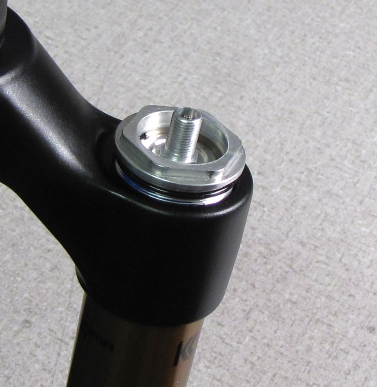
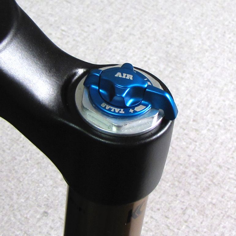
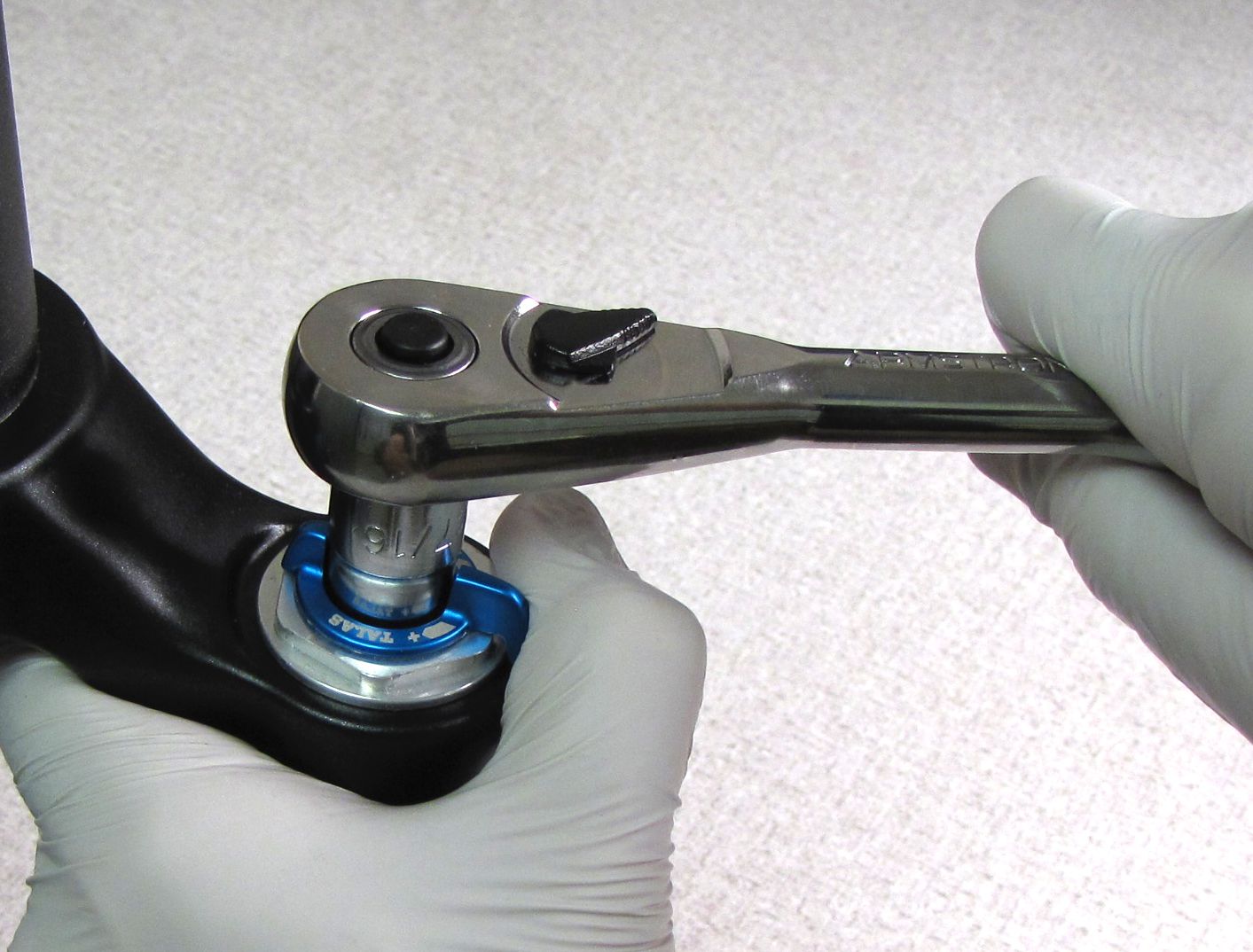
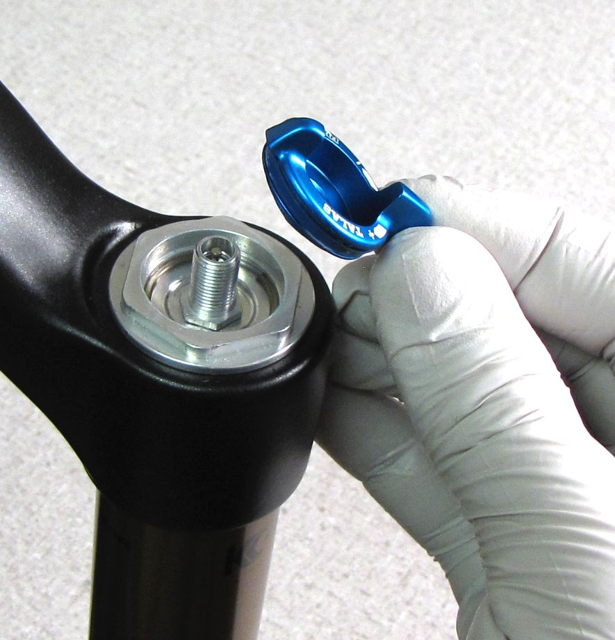
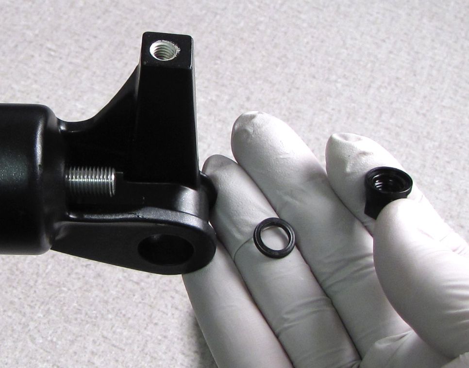
Step 1
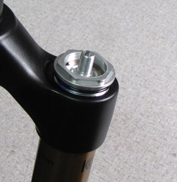
Set the fork to the long travel mode. Remove the blue air cap. While holding the lever away from the counter-clockwise hard stop, remove the nut with a 7/16" socket. Remove the lever.


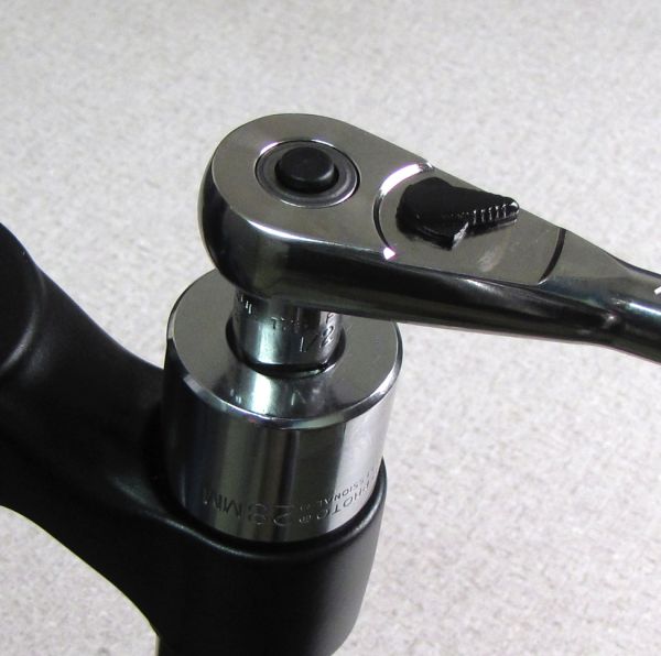
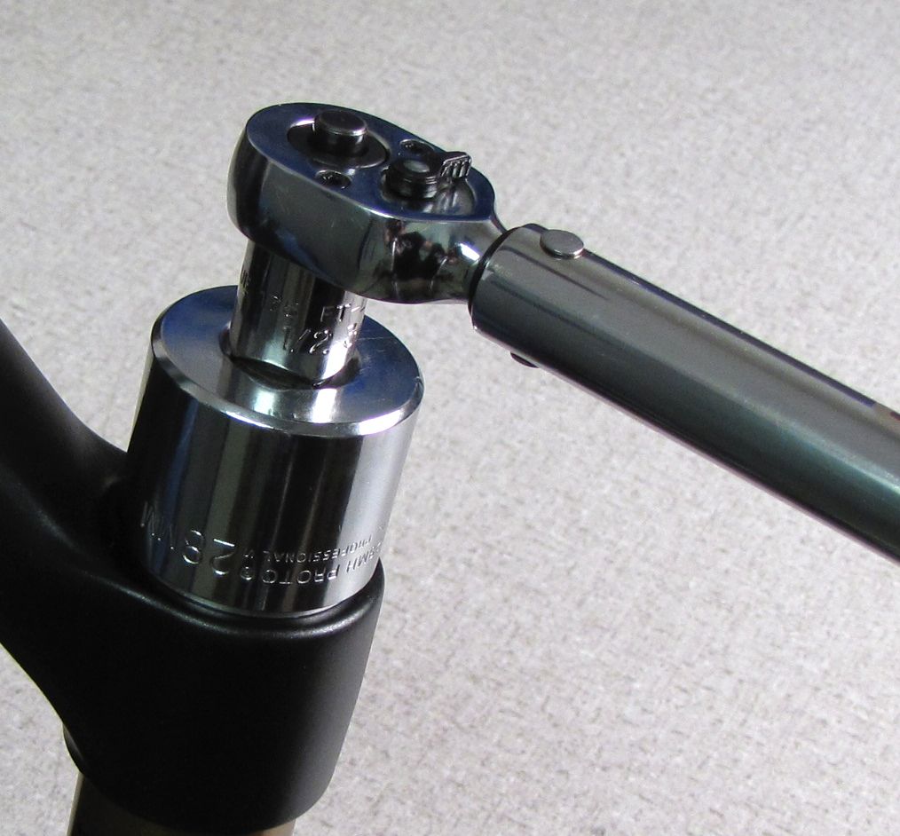
Step 2
Use a 6-point Chamfer-less socket to unthread the topcap from the fork crown.
32mm Forks: 26mm socket
34mm Forks: 28mm socket
36mm Forks: 32mm socket

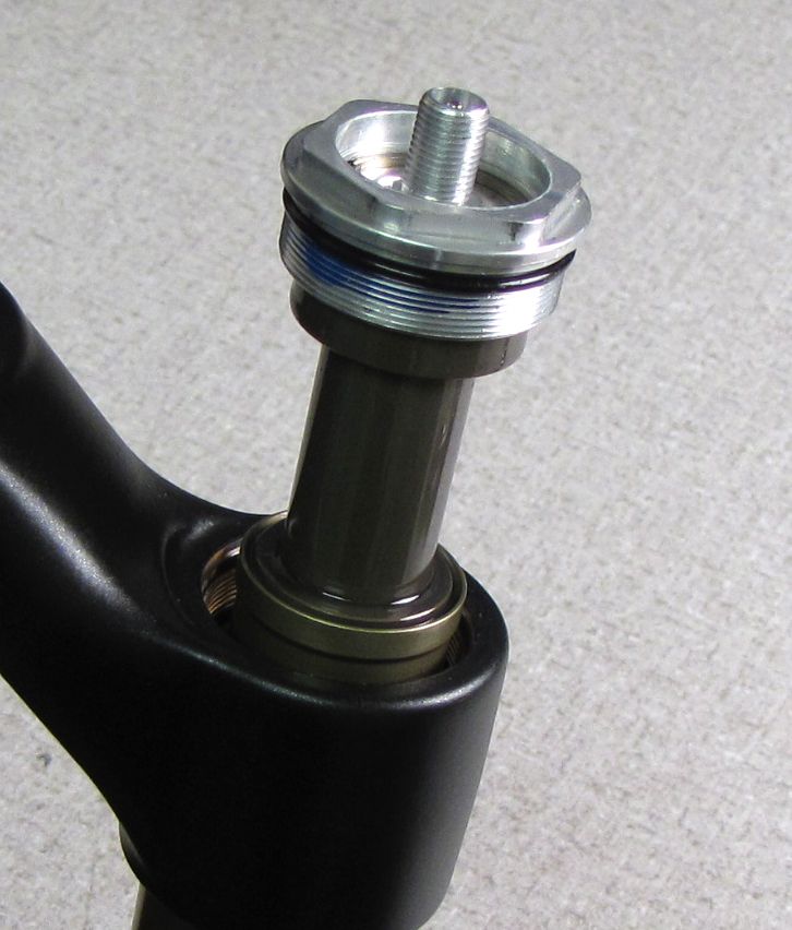
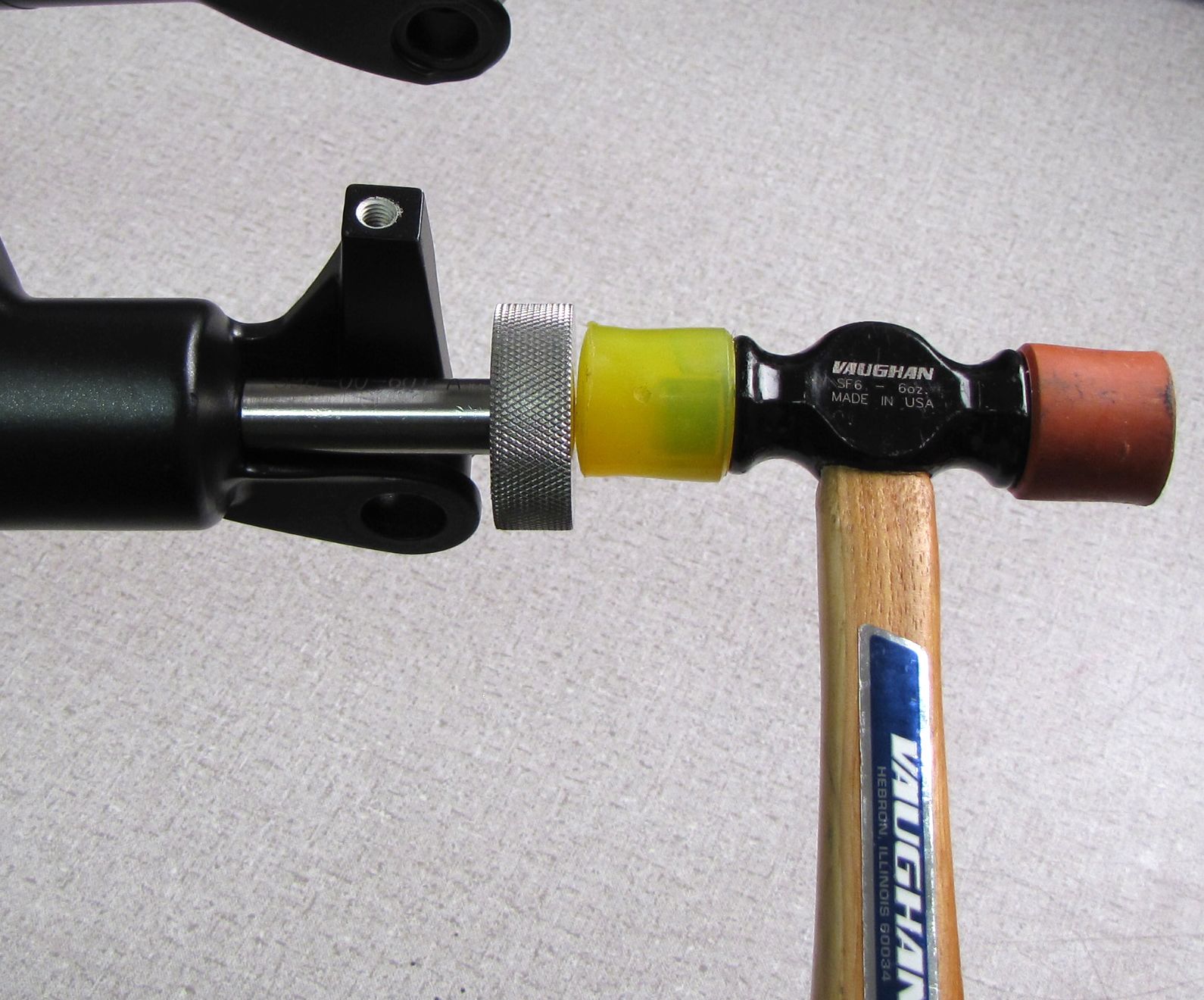
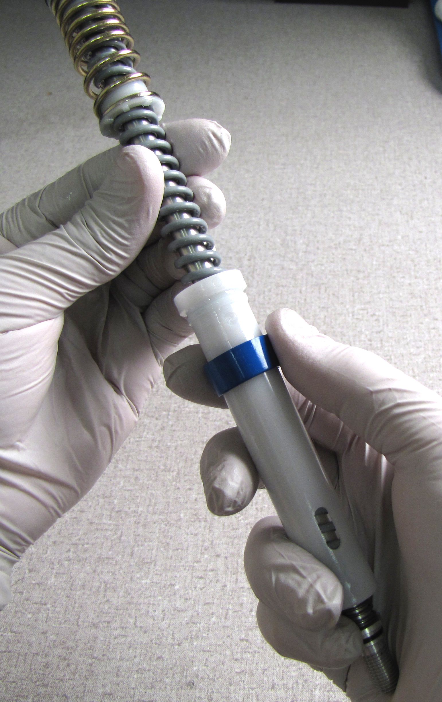
Step 3
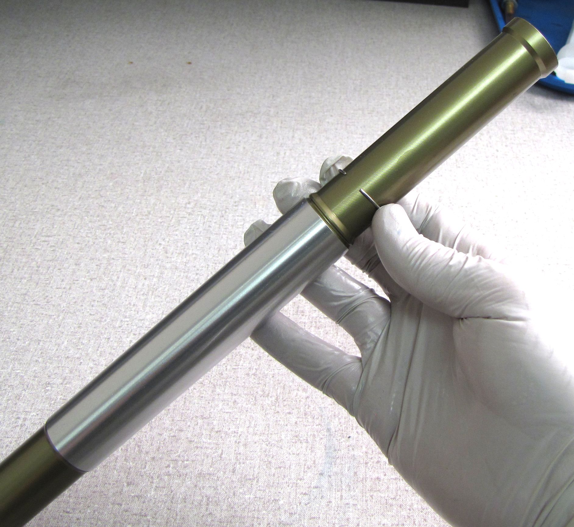
Use one Travel Adjust Spacer for every 5mm you would like to reduce your travel adjustment range. Install the Travel Adjust Spacers by snapping them onto the outer travel tube (the space between the topcap and the cartridge tube) as shown.


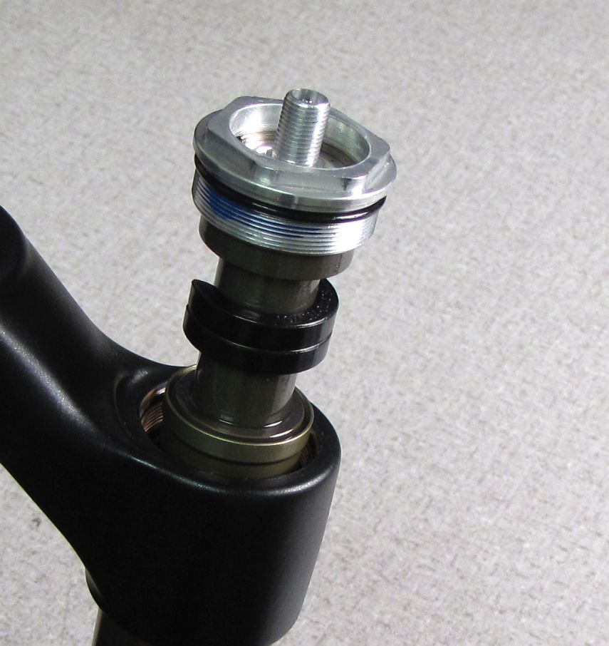

Step 4
Thread the topcap back into the fork crown and torque to 220 in-lb (24.8 Nm) using your 6-point chamfer-less topcap socket.

Step 5
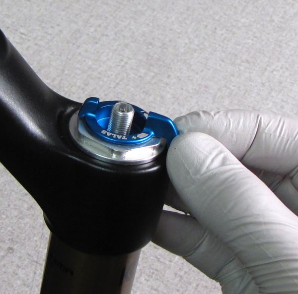
With the TALAS set to the Long-Travel position (fully clockwise) install the lever so it is oriented toward the riders 10 o'clock. Install the tank valve nut with a 7/16" socket to 25 in-lb (2.8 Nm) torque while holding the lever away from the full clockwise hard stop. Replace the blue air cap and thoroughly clean the exterior of your fork.

Adjusting Total Travel
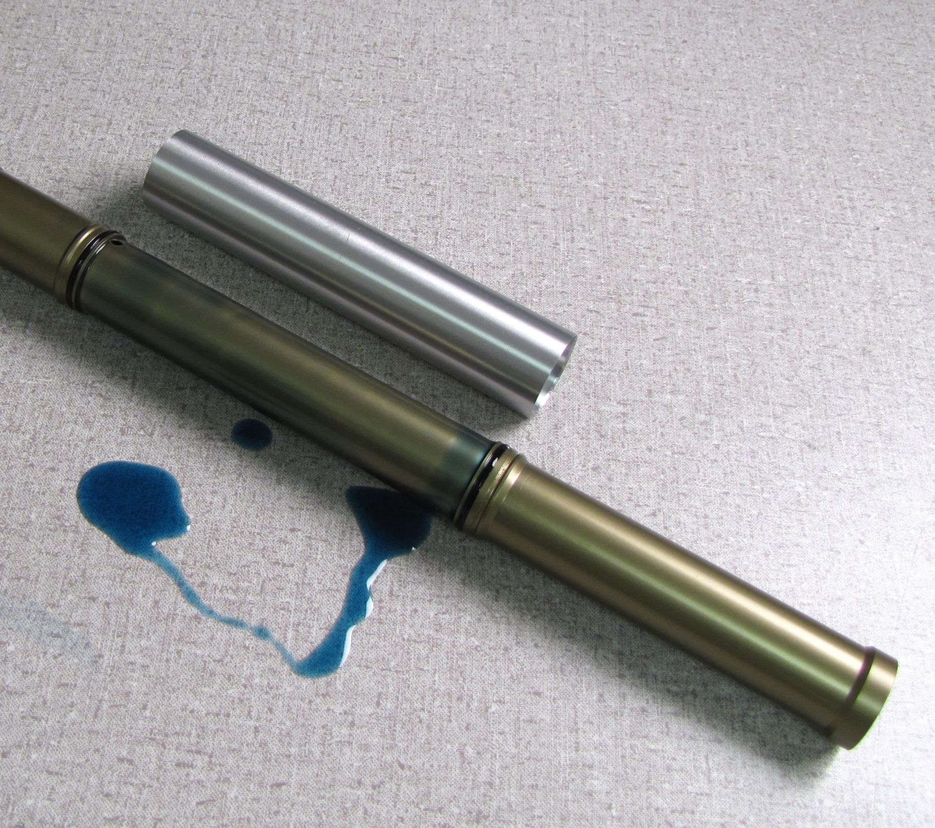
You will need to drain the bath oil and completely remove the TALAS 5 cartridge from the fork to adjust the total travel.
You can reduce the total travel of the TALAS 5 system using replacement shuttle bumpers. All TALAS 5 forks can be reduced in travel, but you should never attempt to increase travel by replacing TALAS 5 shuttle bumpers without first verifying that your damper cartridge is long enough to handle an increase in travel. You can verify your cartridge length by contacting FOX or the nearest Authorized International Distributor and providing your forks serial number, and 4-digit product code.
4 different shuttle bumpers are available for TALAS 5 forks. Please consult the chart below to verify that your fork doesn't already contain the shuttle bumper that you are attempting to install.
| Stock Shuttle Bumper by Fork Model | |||||||
| 120mm Travel | 130mm Travel | 140mm Travel | 150mm Travel | 160mm Travel | 170mm Travel | 180mm Travel | |
| 32mm: 26/27.5 | 234-23-011 | 234-23-010 | |||||
| 32mm: 29 | 234-23-013 | 234-23-012 | |||||
| 34mm: 26/27.5 | 234-23-011 | 234-23-010 | |||||
| 34mm: 29 | 234-23-012 | 234-23-011 | |||||
| 36mm-160: 26 | 234-23-010 | ||||||
| 36mm-180: 26 | 234-23-011 | 234-23-010 | |||||

| Travel Achieved by Shuttle Bumpers | ||||
| 234-23-013 | 234-23-012 | 234-23-011 | 234-23-010 | |
| 32mm: 26/27.5 | 120mm | 130mm | 140mm | 150mm |
| 32mm: 29 | 120mm | 130mm | Do Not Use | Do Not Use |
| 34mm: 26/27.5 | 130mm | 140mm | 150mm | 160mm |
| 34mm: 29 | 130mm | 140mm | 150mm | Do Not Use |
| 36mm-160: 26 | 130mm | 140mm | 150mm | 160mm |
| 36mm-180: 26 | 150mm | 160mm | 170mm | 180mm |

Step 1
Remove the blue air cap. While holding the lever away from the counter-clockwise hard stop, remove the nut with a 7/16" socket. Remove the lever.

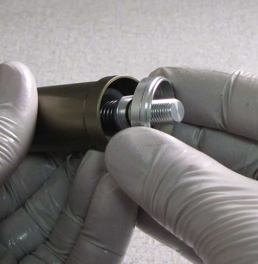
Step 2
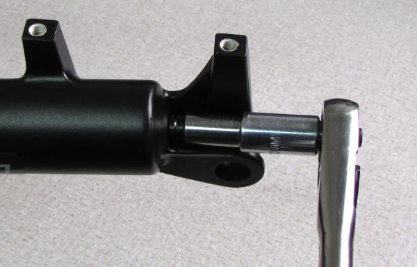
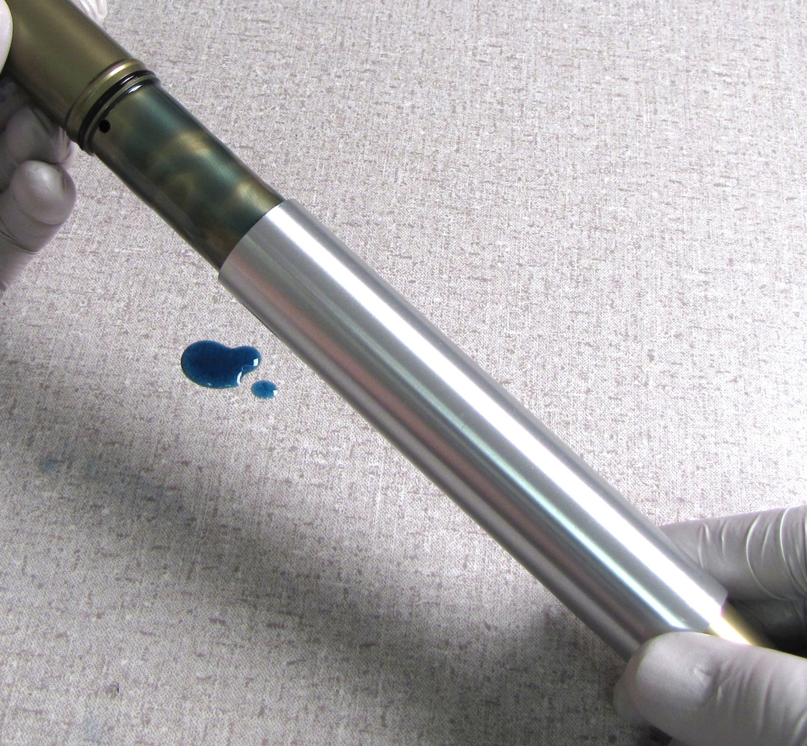
Use a 10mm socket to remove the bottom nut. Remove the crush washer and use Damper Removal Tool 398-00-601 to free the cartridge from the lowers. Drain the oil into your waste oil basin.


Step 3
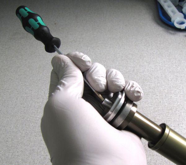
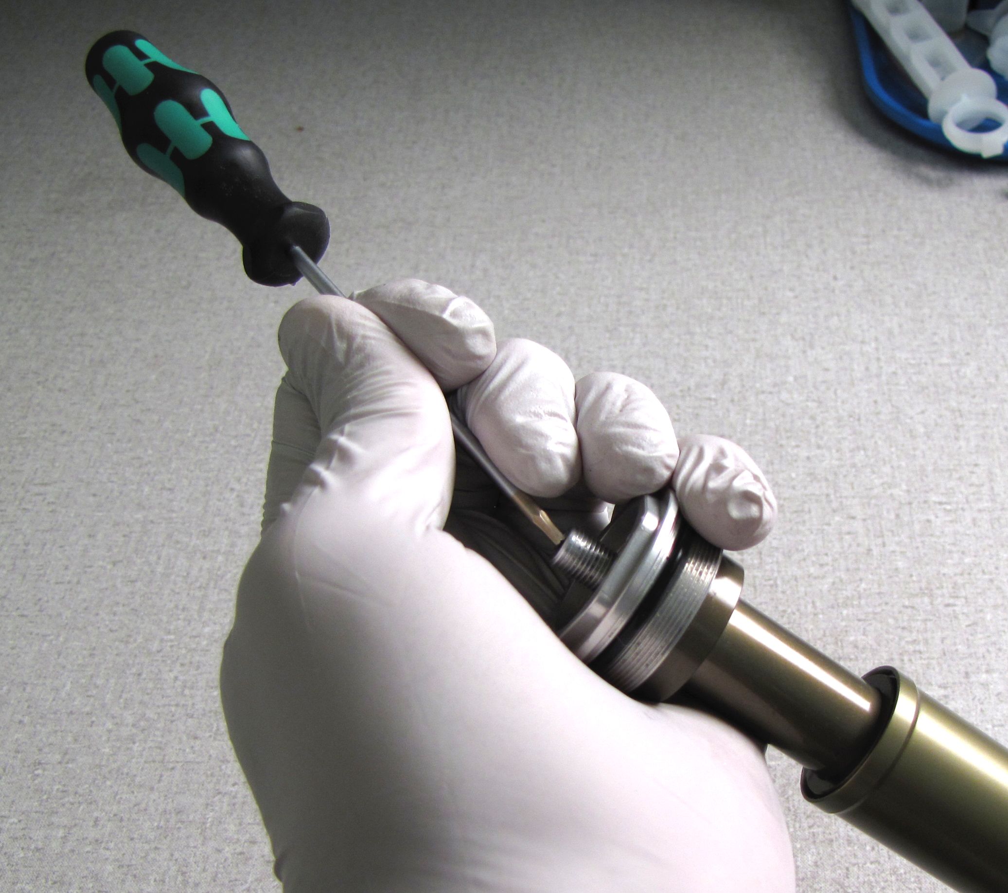
Use a 6-point Chamfer-less socket to remove the cartridge from the fork crown.
32mm Forks: 26mm socket
34mm Forks: 28mm socket
36mm Forks: 32mm socket


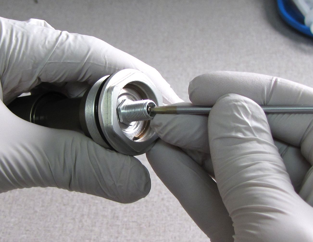
WARNING: Please verify that all air has been released from the air chamber by pushing down on the Schrader valve core. Failure to release all air pressure before further disassembly may cause parts to eject causing SEVERE INJURY OR DEATH.
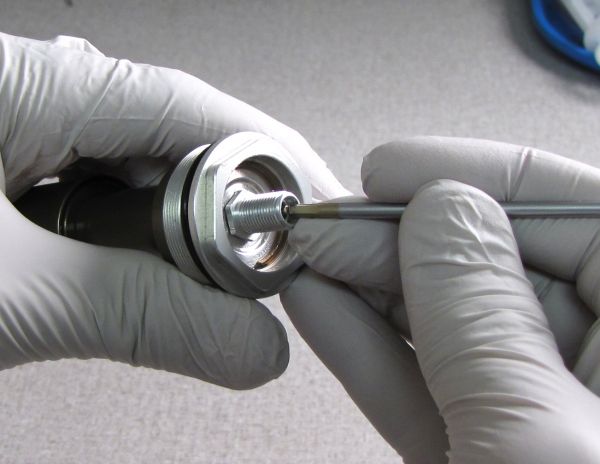
Step 4
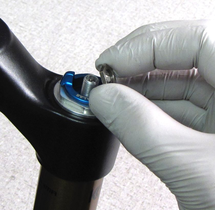
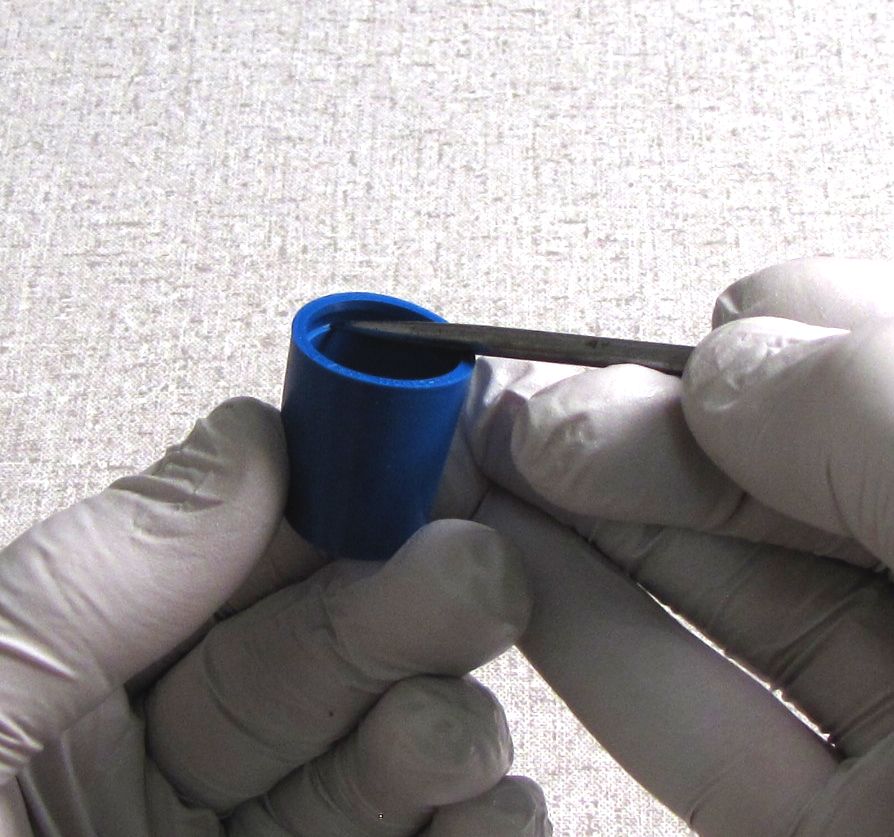
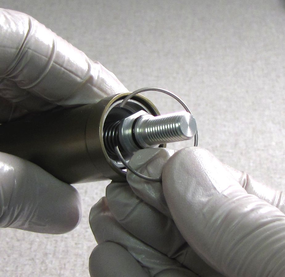
Release the air pressure from the cartridge, then remove the wire retaining ring with a shim or pick tool without damaging the inside surface of the cartridge tube.
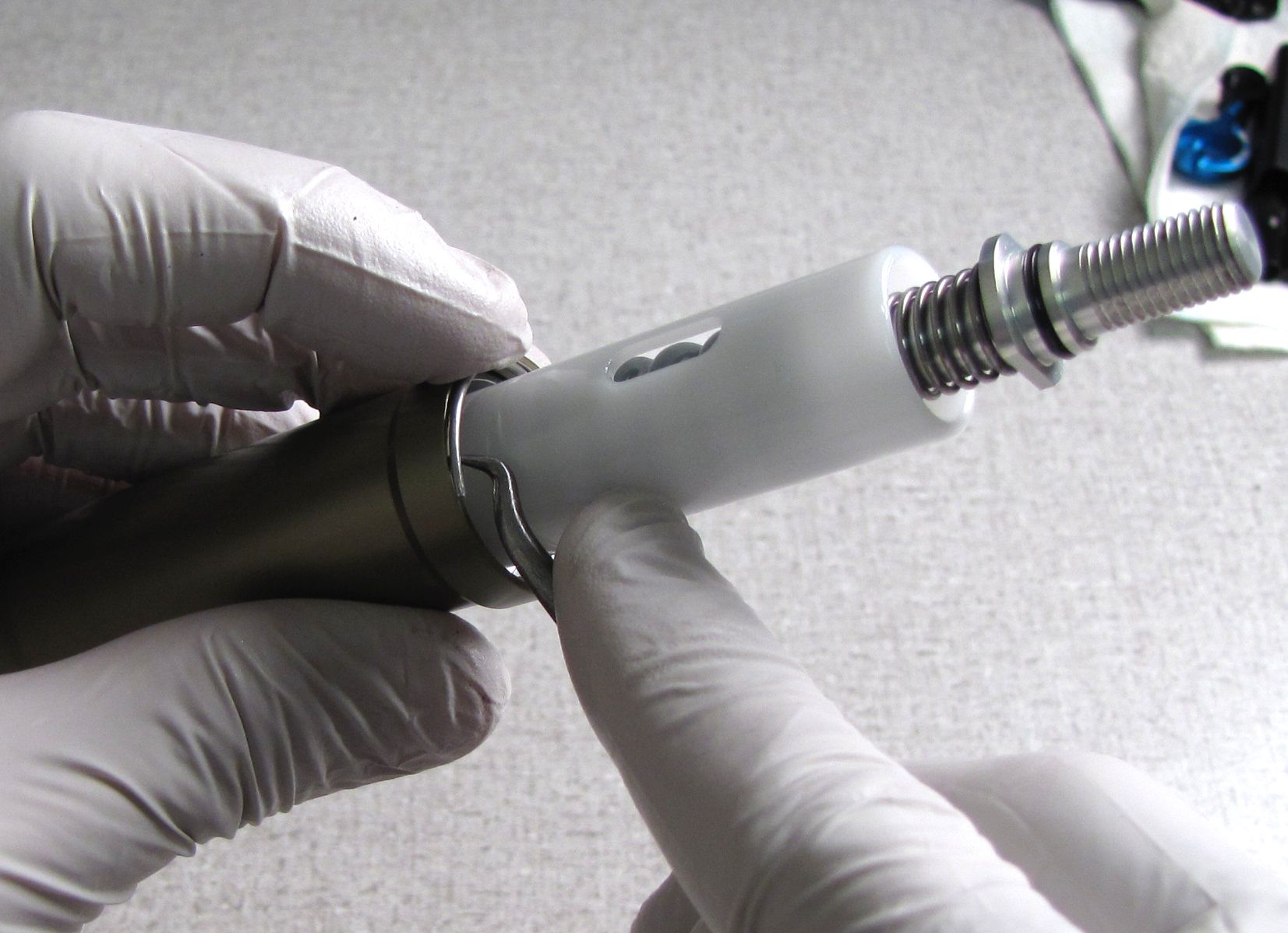
Step 5
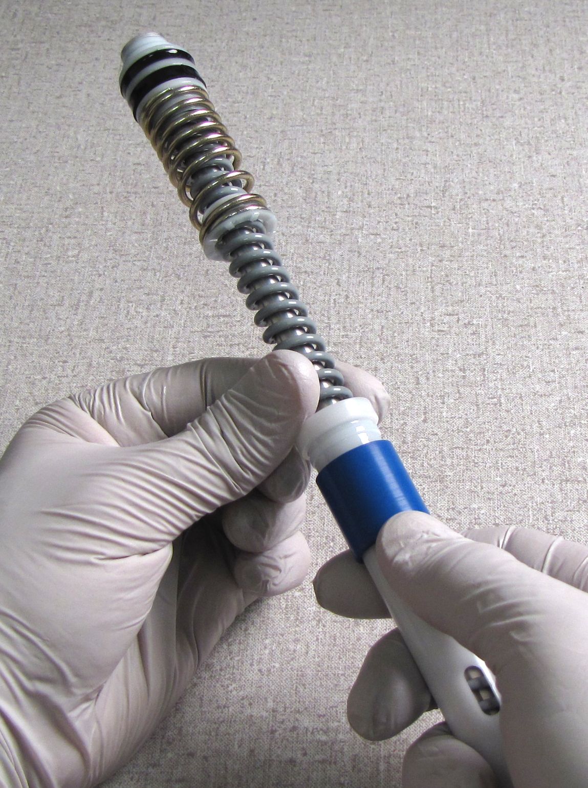
Hold the air valve core down with a small tool while you remove the air shaft assembly and negative plate from the cartridge tube by pulling down.

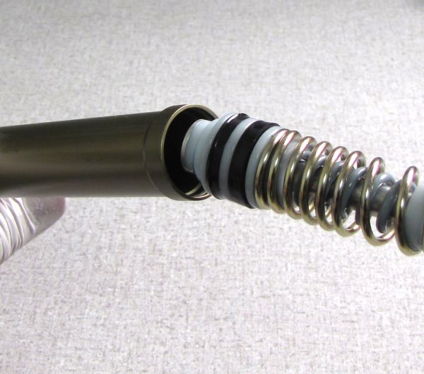
Step 6
Remove the negative plate followed by the original shuttle bumper. Remove the shuttle bumper by pulling it down and off of the white shutte. The rib on the white shuttle will fit into the groove on the inside of the shuttle bumper.

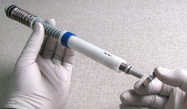
Step 7
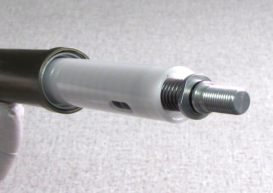
Remove the wire retaining ring that secures the XV (Extra-Volume) sleeve to the cartridge tube. Remove the XV sleeve by sliding it down and off the cartridge tube. Clean the XV sleeve and cartridge tube of any Float Fluid and replace the two o-rings with new ones coated with a thin film of Slick Honey. Reinstall the XV sleeve followed by the wire retaining ring.

Step 8
Make sure that the new bumper selected is appropriate for the fork you are working on by consulting the chart at the beginning of this section: Adjusting Total Travel »
Install the new shuttle bumper onto the shuttle with its grooved end first. Engage the rib of the shuttle with the groove on the inside of the shuttle bumper.
Do not use more than the specified amount of FLOAT Fluid for your specific model of TALAS 5 cartridge.
TALAS 5 cartridges have shipped both with and without XV sleeves. Pay careful attention to the Float Fluid volume chart.
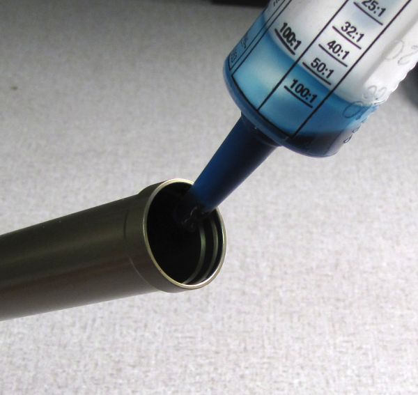
Step 9
Inject the appropriate amount of Float Fluid for your fork into the Cartridge Tube while rotating the tube to coat the entire inner surface.
| Fork Family | Wheel Size | Float Fluid Volume (With XV Sleeve) | Float Fluid Volume (No XV Sleeve) |
| 32mm | 26/27.5 | 15cc | 5cc |
| 32mm | 29 | 17cc | 7cc |
| 34mm | 26/27.5/29 | 15cc | 5cc |
| 36mm 160 | 26 | 15cc | 5cc |
| 36mm 180 | 26 | 5cc | N/A |

Step 10
Coat the air piston seals and topout/negative springs with Float Fluid then install the Air Shaft assembly into the Cartridge Tube. Holding the air valve open during this step can assist in Air Shaft Assembly installation. Install the negative plate and wire retaining ring. Pull on the air shaft to verify that the wire retaining ring is properly seated.

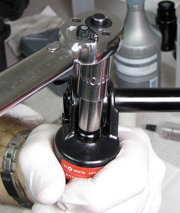
Step 11
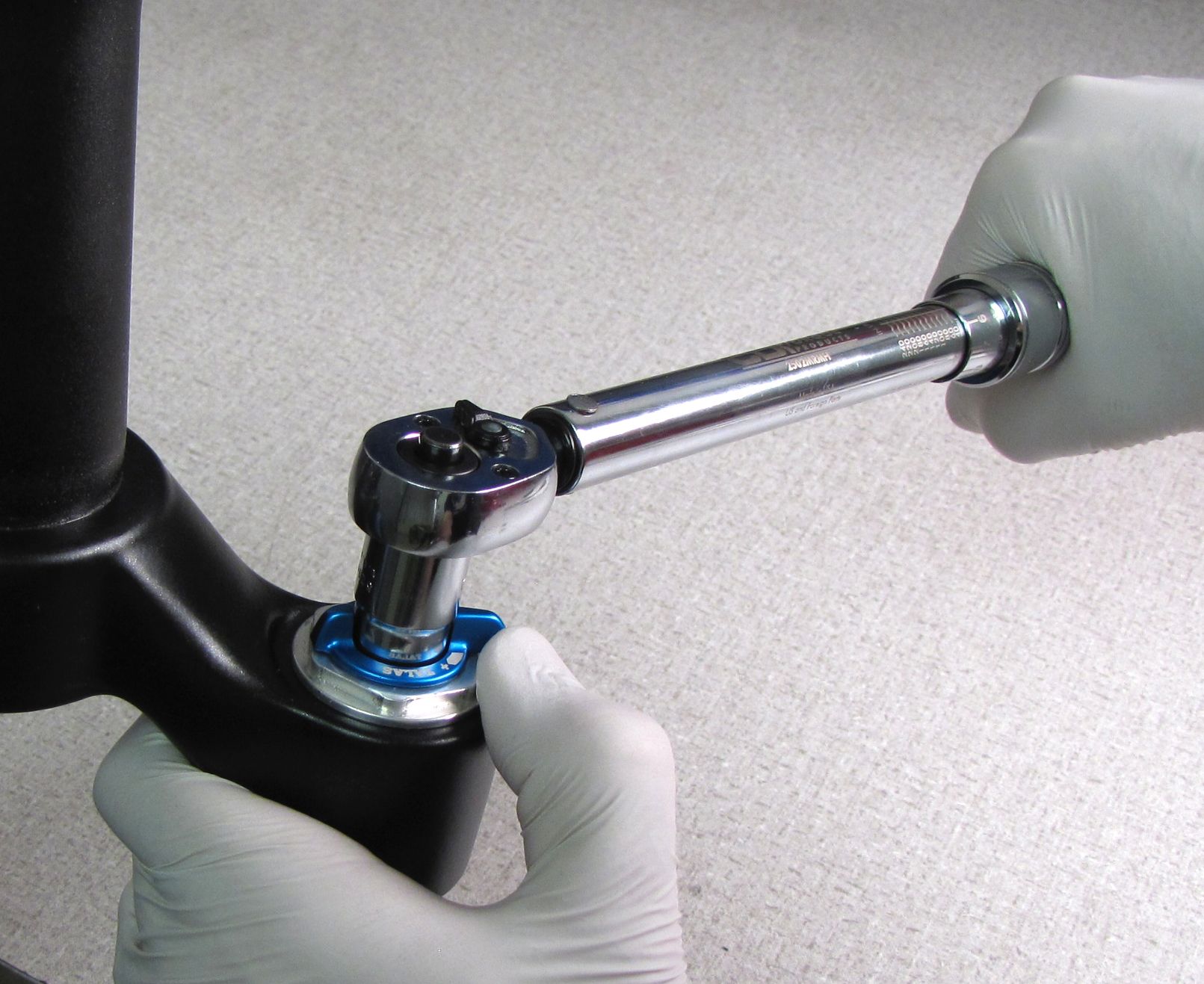
Add 135psi to the TALAS 5 cartridge, then install into the fork crown and torque to 220 in-lb (24.8 Nm) with your 6-point Chamfer-less topcap socket.


Step 12
With the TALAS set to the Long-Travel position (fully clockwise) install the lever so it is oriented toward the riders 10 o'clock. Install the tank valve nut with a 7/16" socket to 25 in-lb (2.8 Nm) torque while holding the lever away from the full clockwise hard stop.


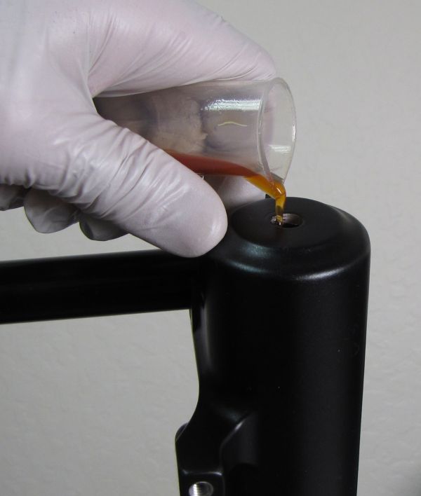
Step 13
Invert the fork and pour in the appropriate amount of FOX 20wt. Gold bath oil.
| Fork | TALAS-side Bath Oil Volume |
| All 32mm/34mm | 30cc |
| All 36mm | 40cc |

Step 14
Install a new crush washer followed by the bottom nut. Torque to 50 in-lb (5.7 Nm) with your 10mm socket.


Step 15
Replace the blue air cap and thouroughly clean the exterior of your fork.
