2022 FLOAT X/DHX LSC Upgrade
Required Parts
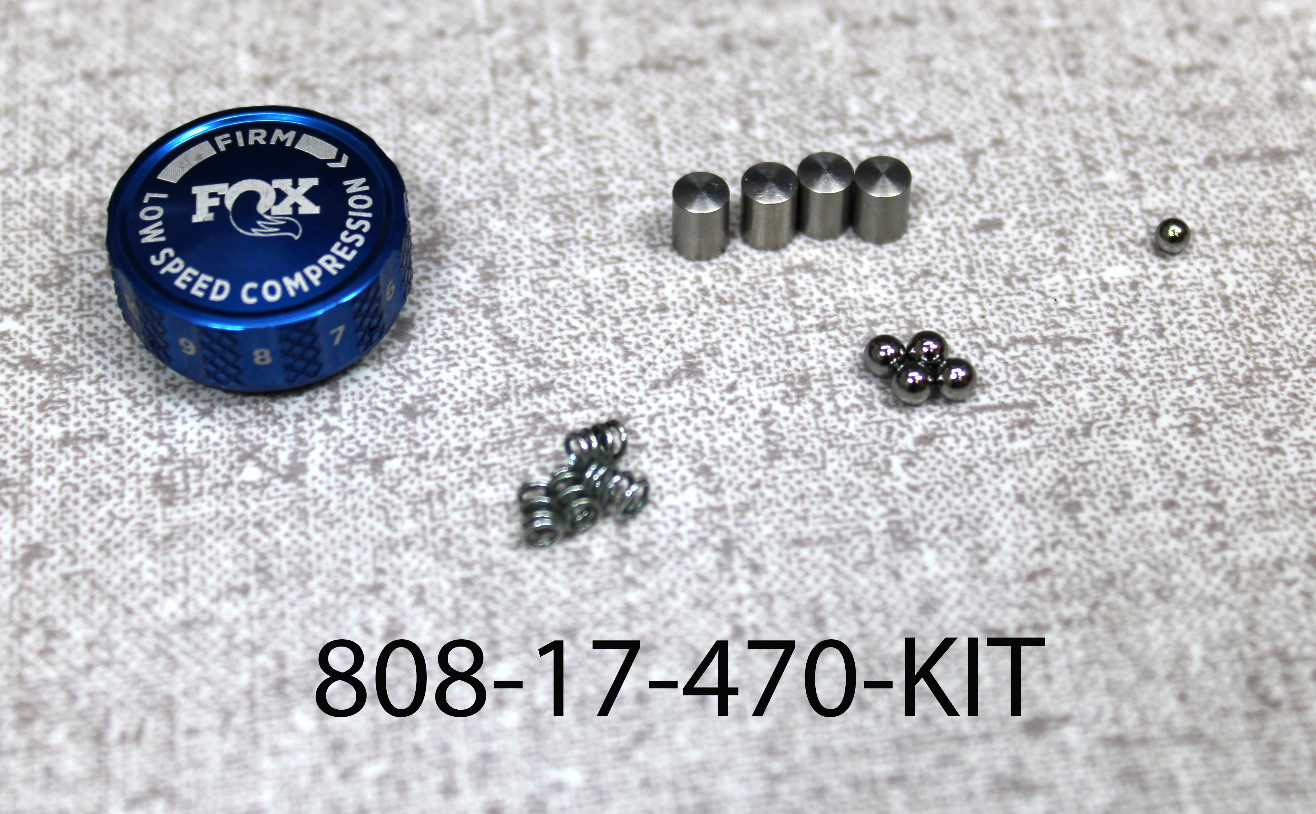
- 808-17-470-KIT Service Set: Eyelet Sub Assy: LSC, 2022 FLOAT X & DHX
Required Tools
WARNING: Always wear safety glasses and protective gloves during service to prevent potential injury. Failure to wear protective equipment during service may lead to SERIOUS INJURY OR DEATH.
The following procedure guides you through the installation of the Low-Speed Compression adjuster to 2022 and later Performance Series FLOAT X and DHX shocks.
WARNING: FOX products should be serviced by a trained bicycle service technician, in accordance with FOX specifications. If you have any doubt whether or not you can properly service your FOX product, then DO NOT attempt it. Improperly serviced products can fail, causing the rider to lose control resulting in SERIOUS INJURY OR DEATH.
WARNING: FOX suspension products contain pressurized nitrogen, air, oil, or all 3. Suspension misuse can cause property damage, SERIOUS INJURY OR DEATH. DO NOT puncture, incinerate or crush any portion of a FOX suspension product. DO NOT attempt to disassemble any portion of a FOX suspension product, unless expressly instructed to do so by the applicable FOX technical documentation, and then ONLY while strictly adhering to all FOX instructions and warnings in that instance.
WARNING: Modification, improper service, or use of aftermarket replacement parts with FOX forks and shocks may cause the product to malfunction, resulting in SERIOUS INJURY OR DEATH. DO NOT modify any part of a fork or shock, including the fork brace (lower leg cross brace), crown, steerer, upper and lower leg tubes, or internal parts, except as instructed herein. Any unauthorized modification may void the warranty, and may cause failure or the fork or shock, resulting in SERIOUS INJURY OR DEATH.

Step 1
Make sure that you have the Eyelet Sub Assy: LSC, 2022 FLOAT X & DHX (PN 808-17-470-KIT) in stock before removing the Performance Series Adjuster Cover.

Step 2
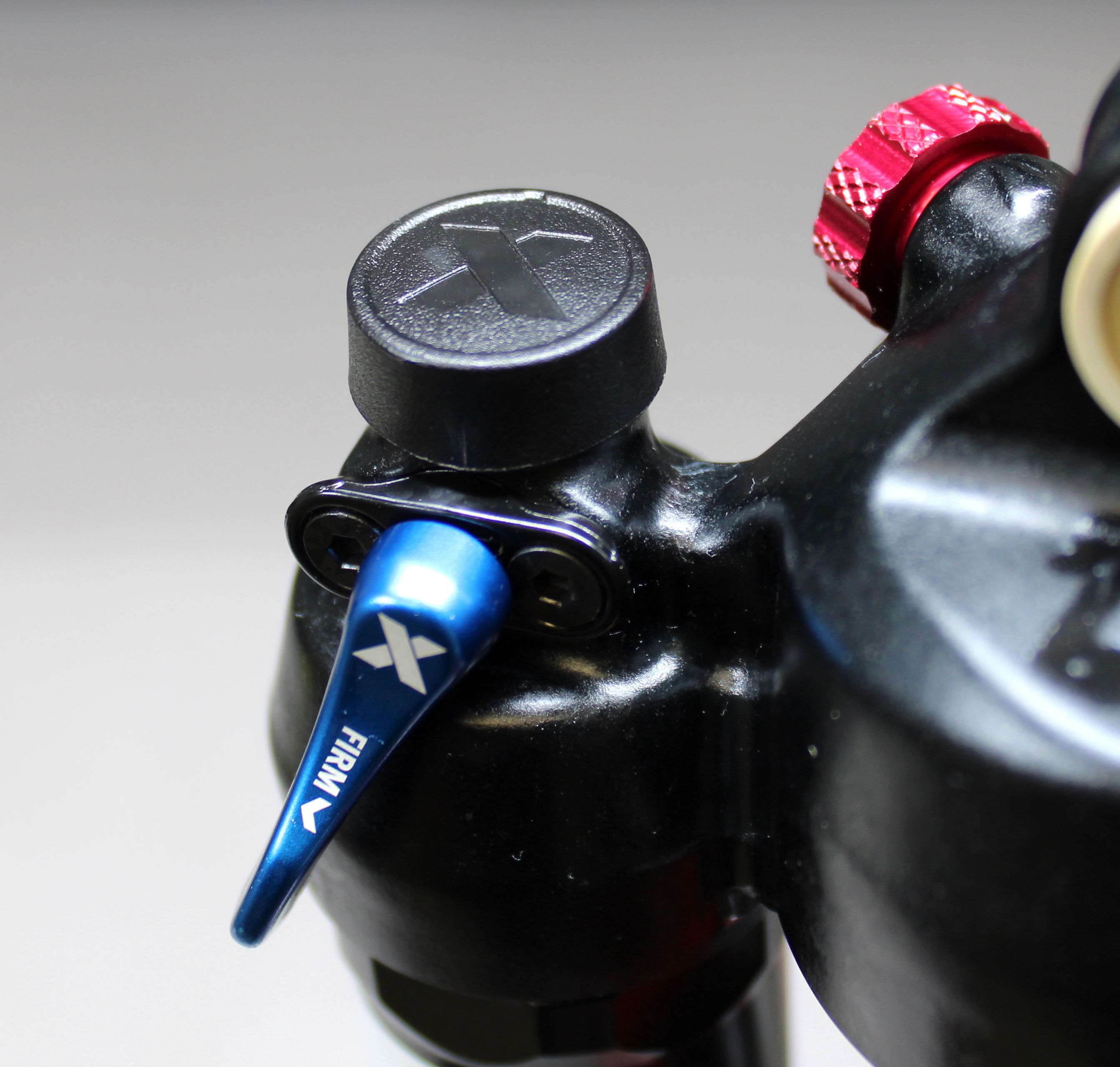
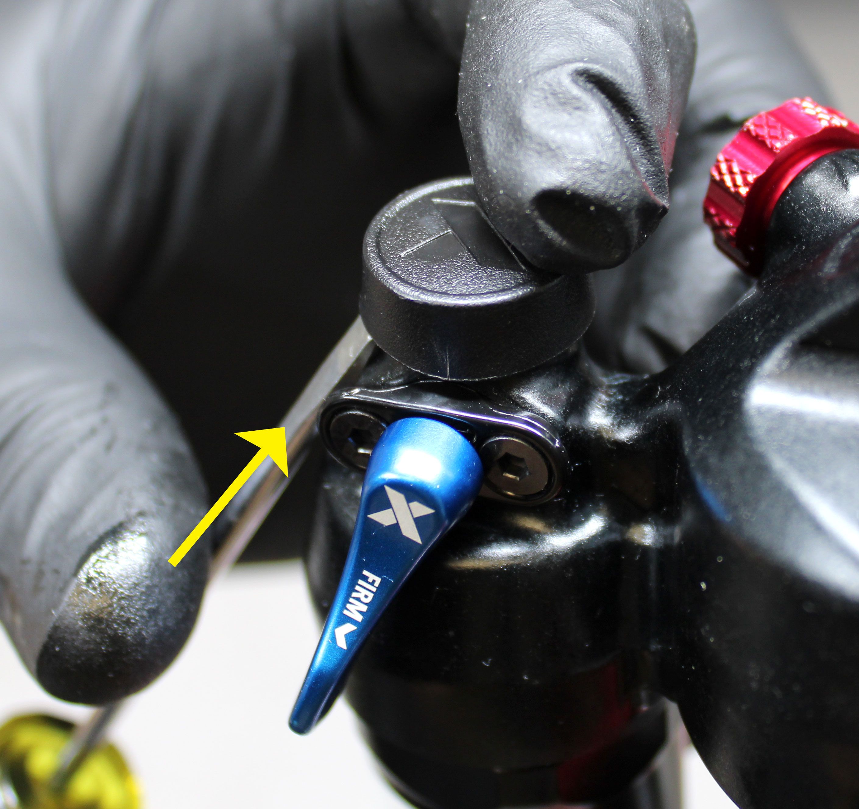
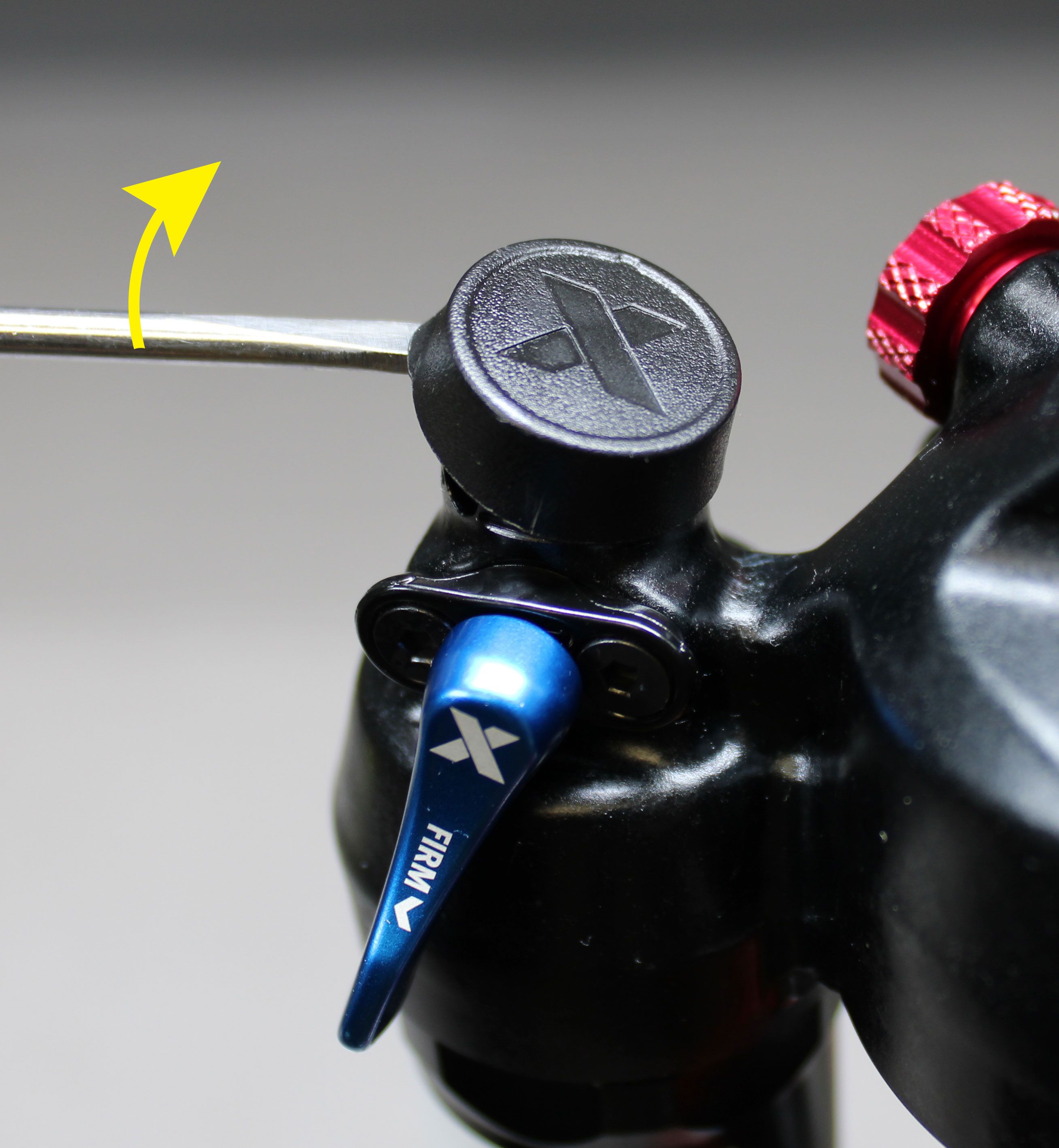
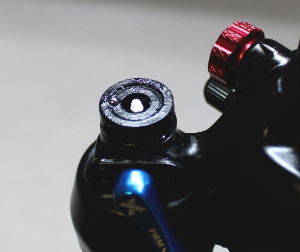
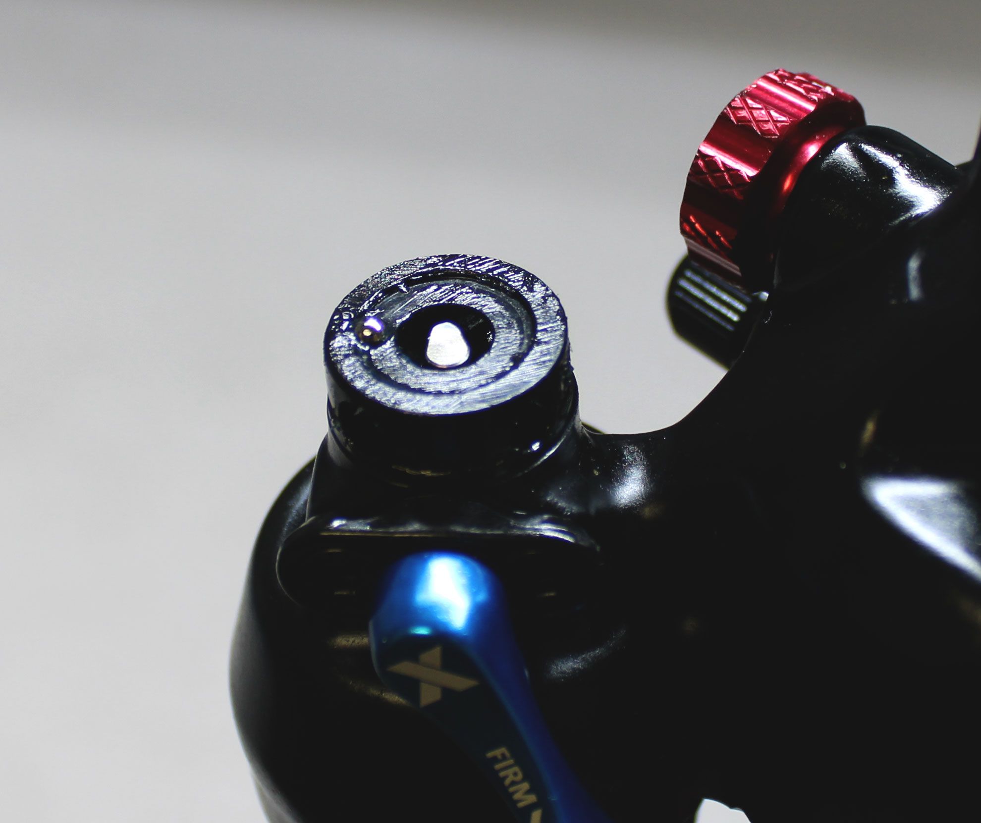
Use a small flat screwdriver or similar tool to carefully lift up the Performance Series Asjuster Cover. The cover may be damaged during removal and will likely not be able to be reused. Clean any debris from the adjuster area after removing the cover.

Step 3
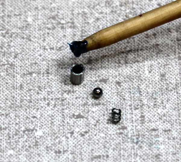
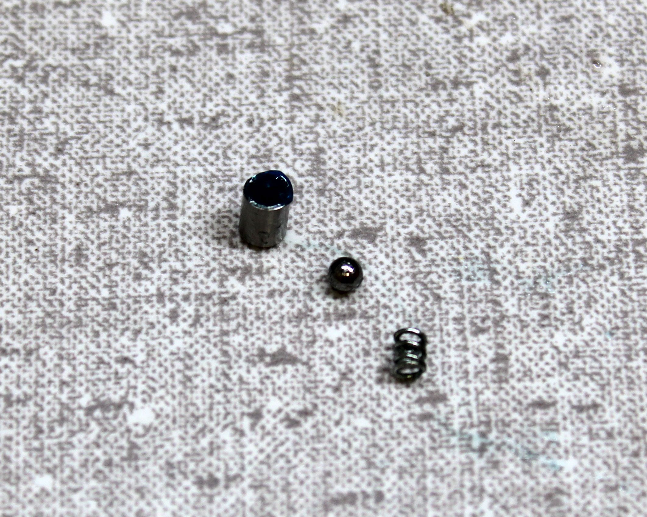
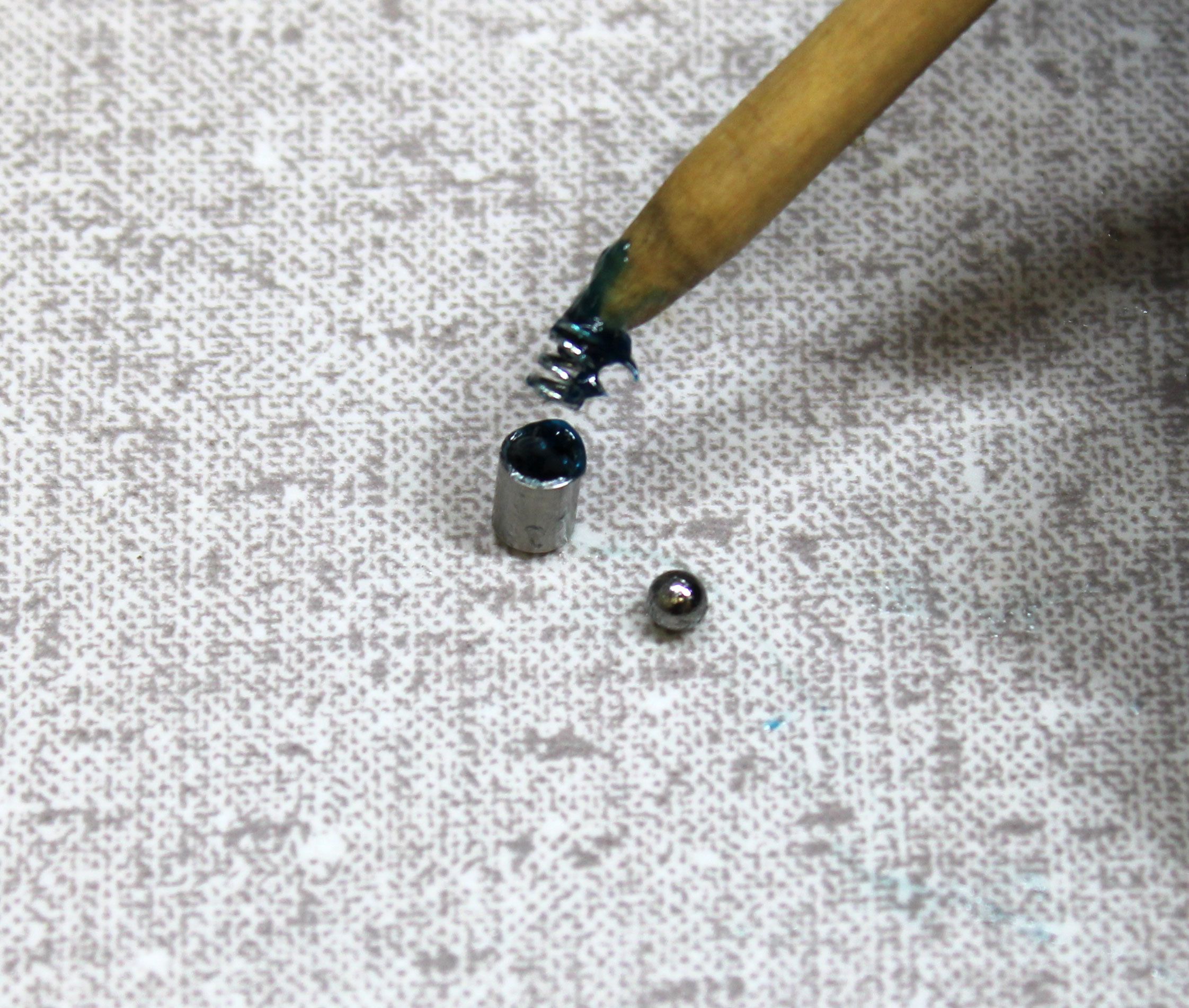
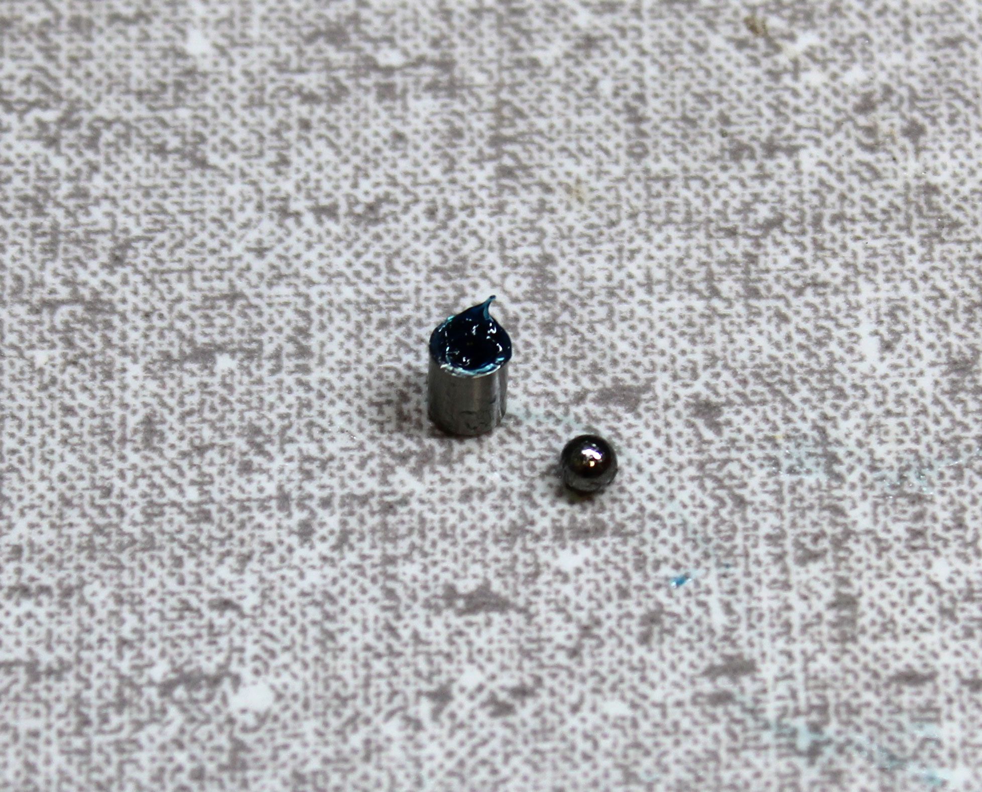
Prepare the 4 Detent Housings by filling them with Ultraplex LT2 or Stay Lube SL3125 Blue waterproof grease. Coat the 4 Detent Springs with the same blue waterproof grease. Coat the 4 larger (0.1094" diameter) balls with the same blue waterproof grease. Place one greased spring into each greased Detent Housing followed by the greased detent ball.

Step 4
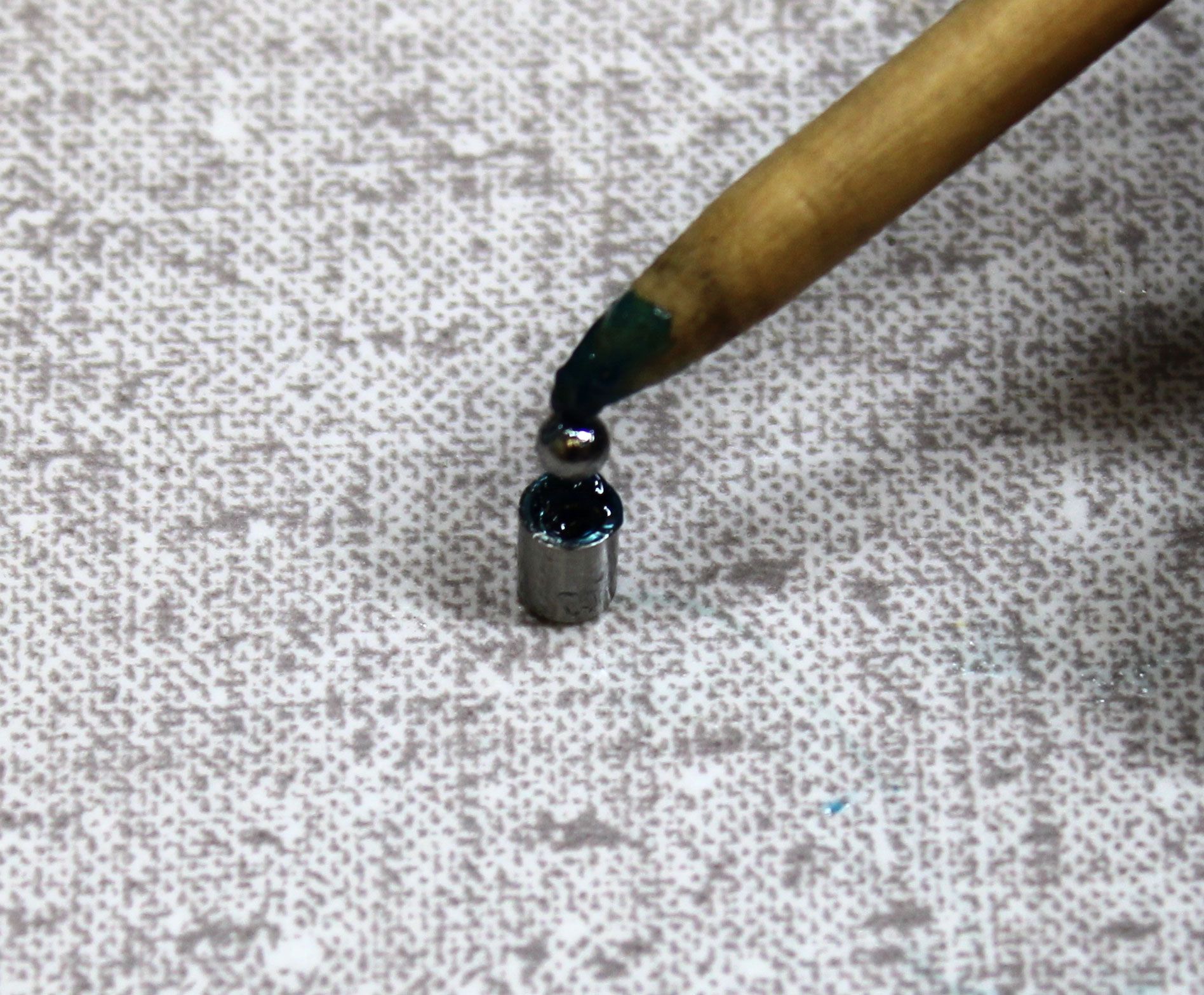
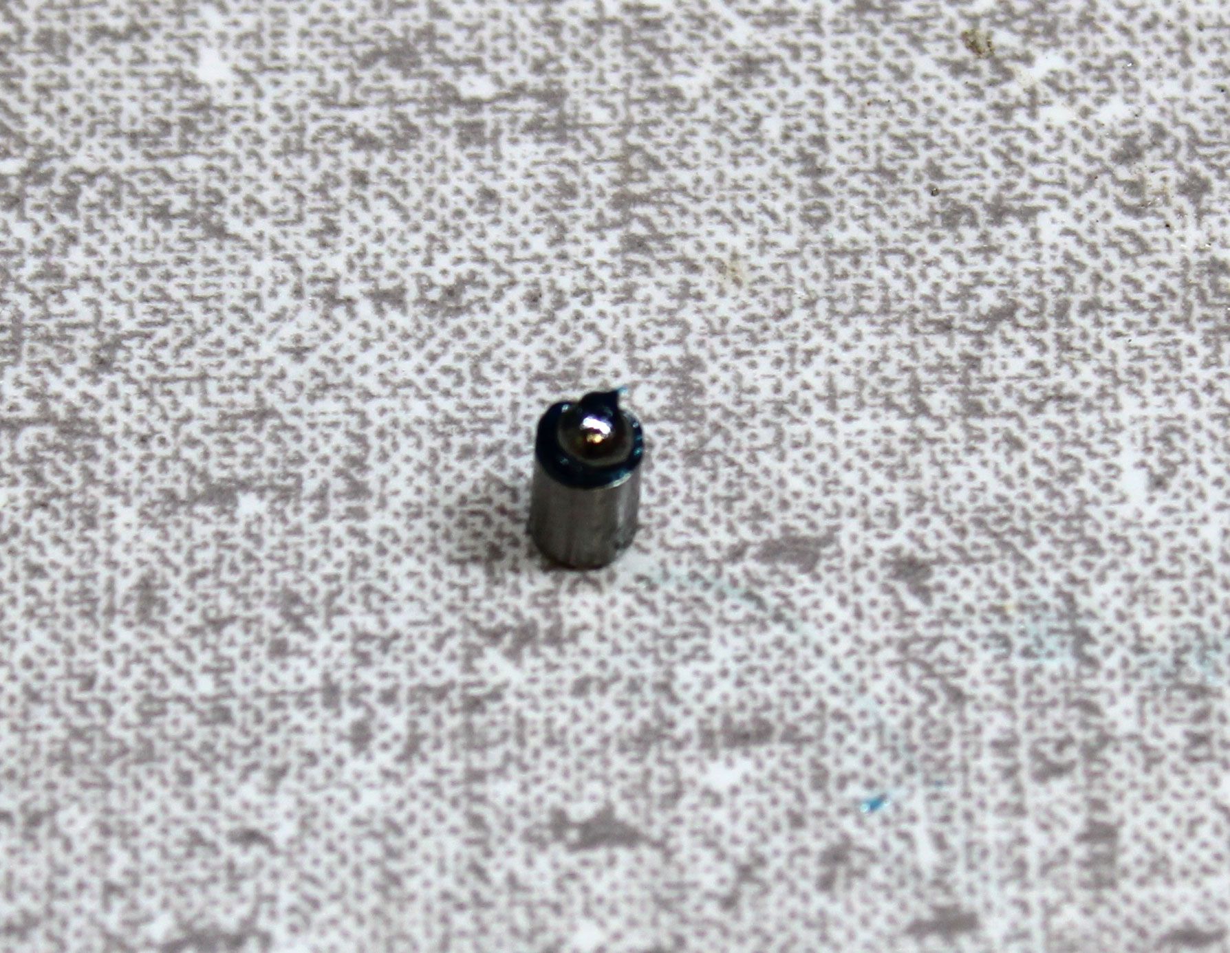
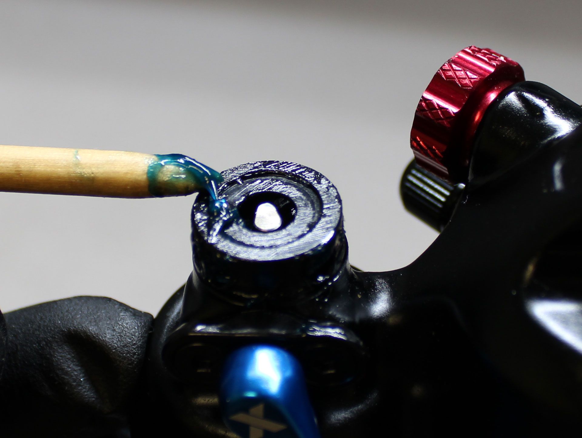
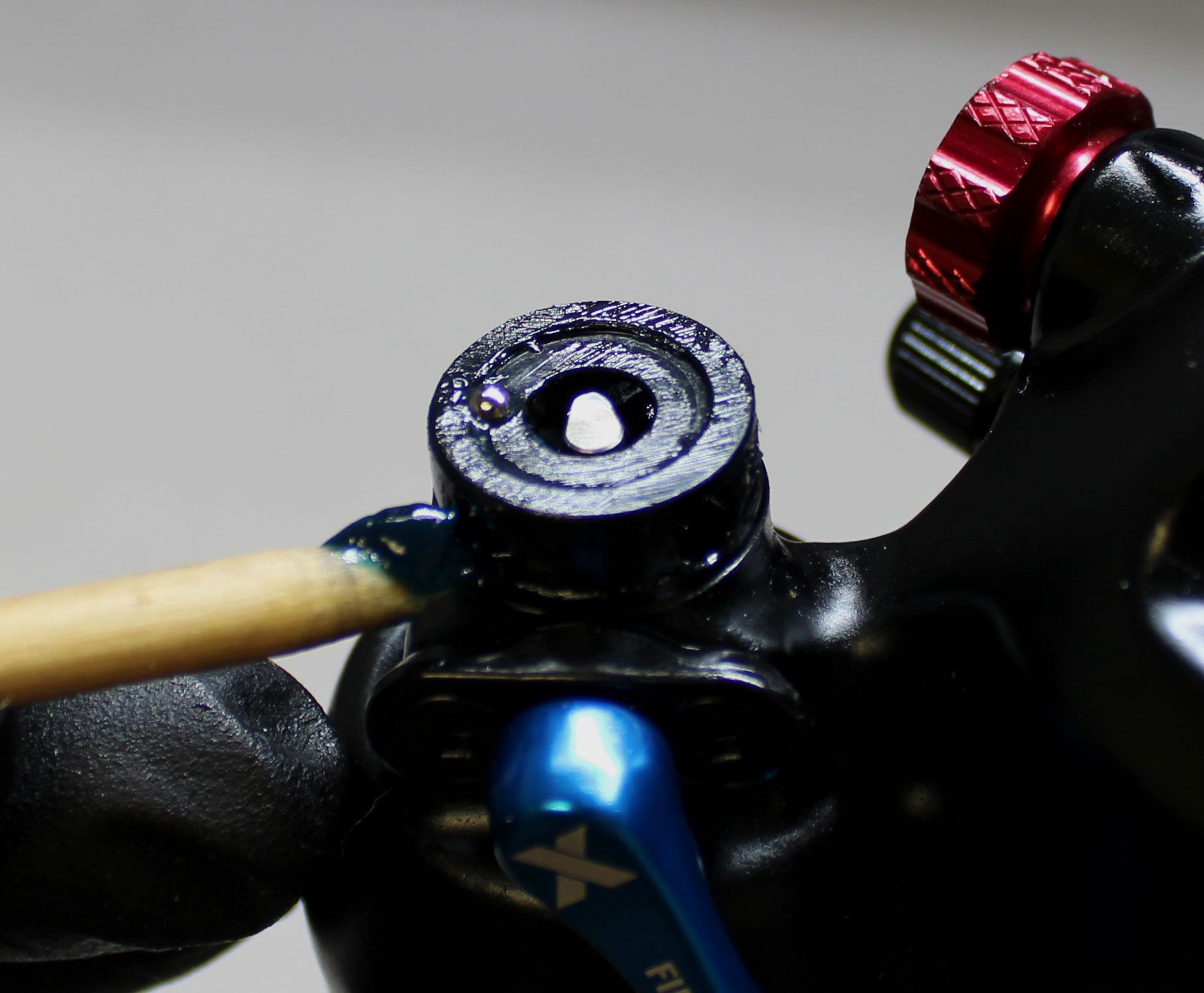
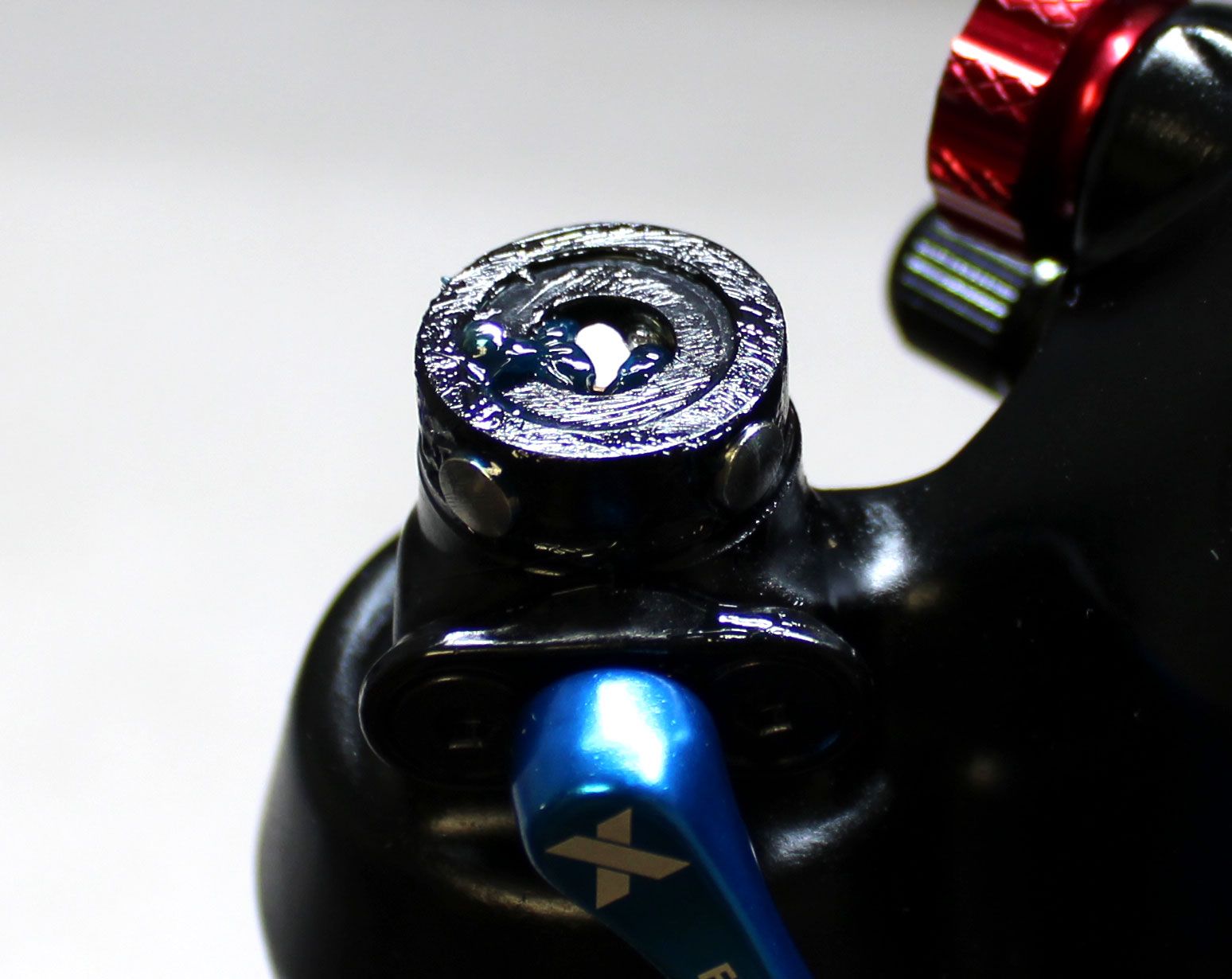
All FLOAT X and DHX shocks have a smaller ball (0.0938" diamter) positioned at the top of the adjuster area. This ball comes in the 808-17-470-KIT but you can also reuse the original ball as there is no difference. Coat the ball bearing, the adjuster area, and detent holes in the eyelet with a thick film of Ultraplex LT2 or Stay Lube SL3125 Blue waterproof grease.
Step 5
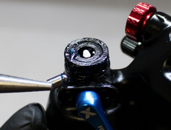
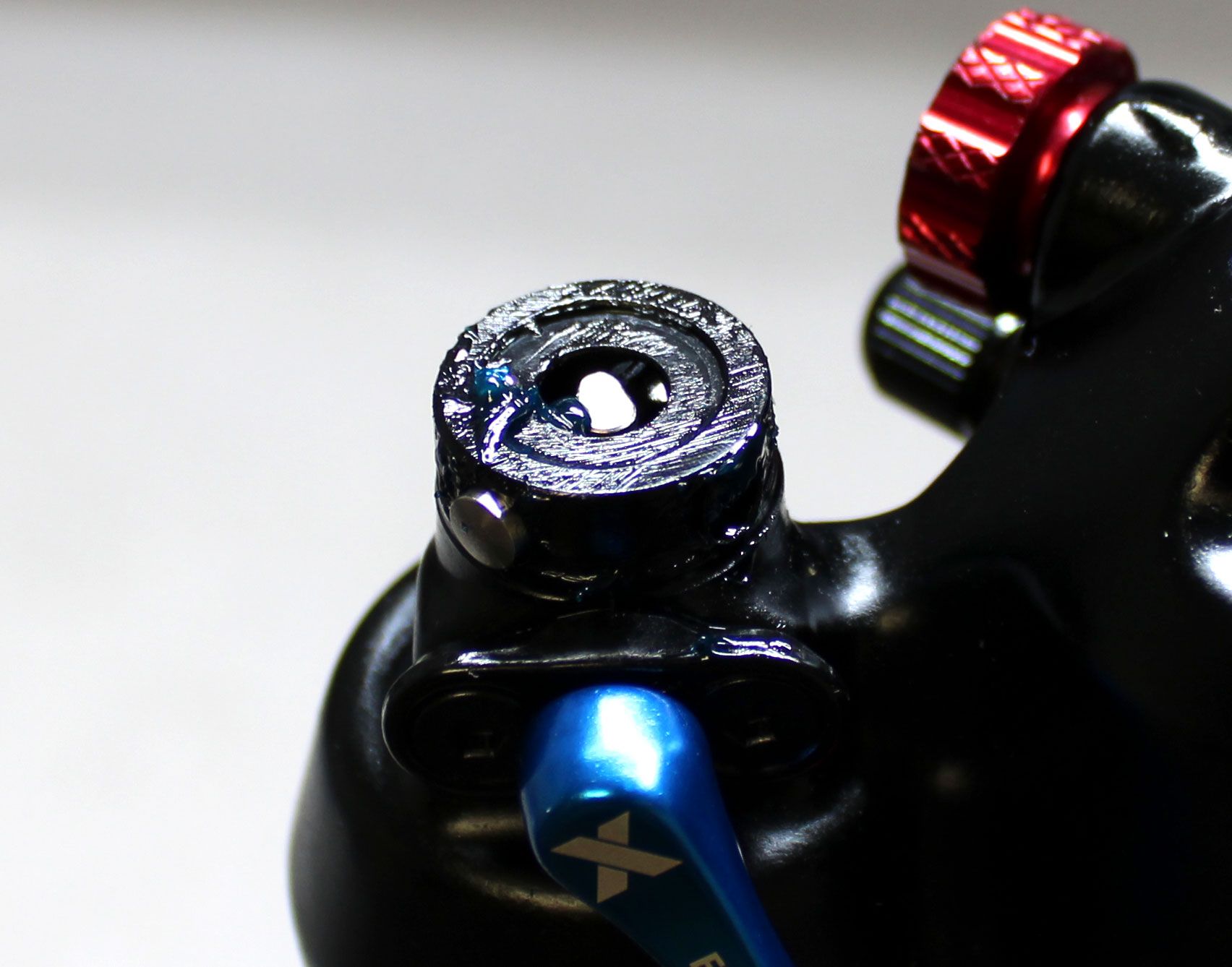
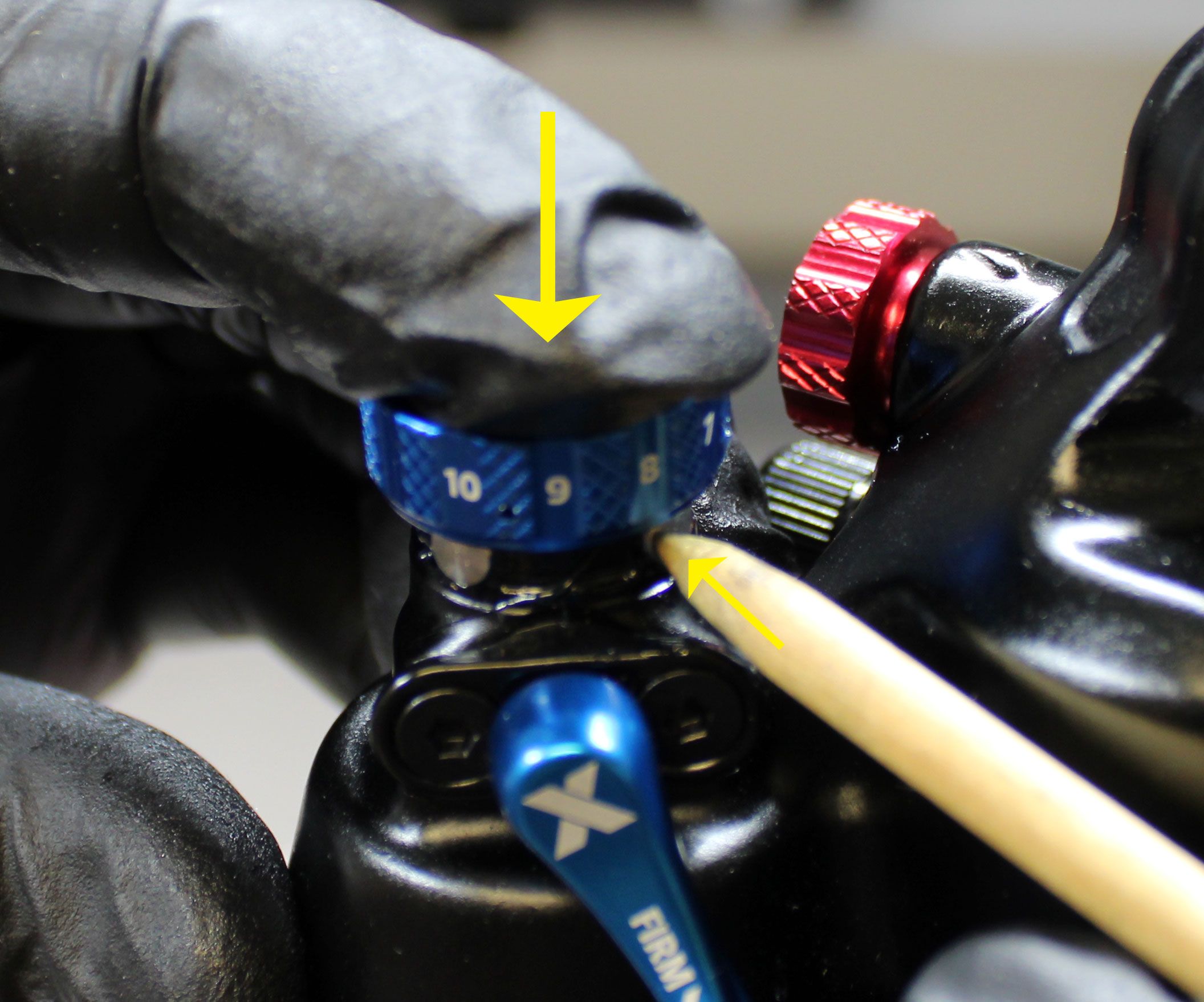
Insert the 4 prepared Detent Housing Assemblies, ball bearing end first, into the 4 detent holes in the adjuster area of the eyelet. If set too deep into the eyelet holes, the Detent Housing Assemblies may prevent installation of the LSC knob. You may need to create space for the knob between the Detent Housing Assemblies and the LSC adjuster shaft by slightly pushing the Detent Housing Assemblies back out a small amount with a thin pick or 1.5mm hex wrench.


Step 6
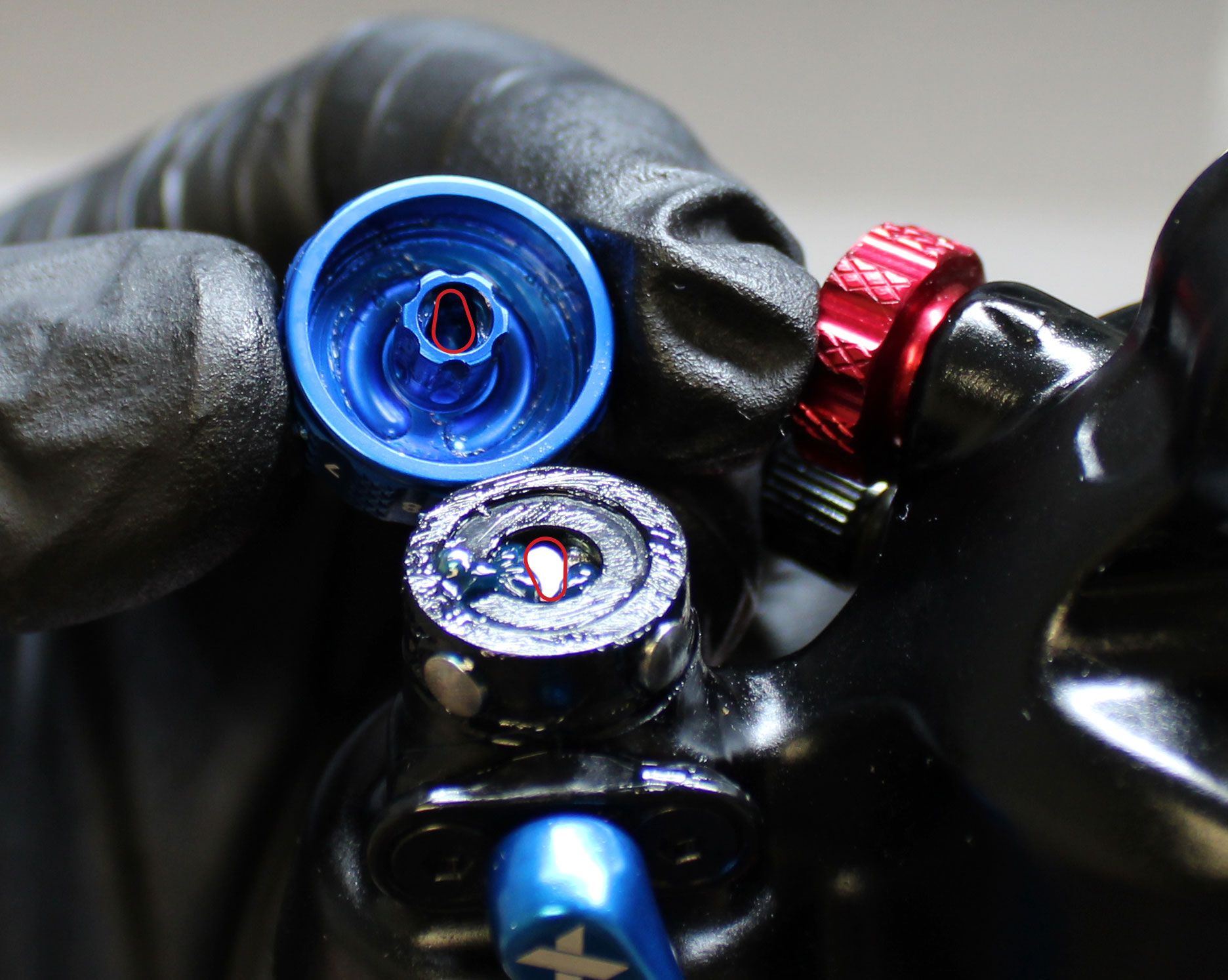
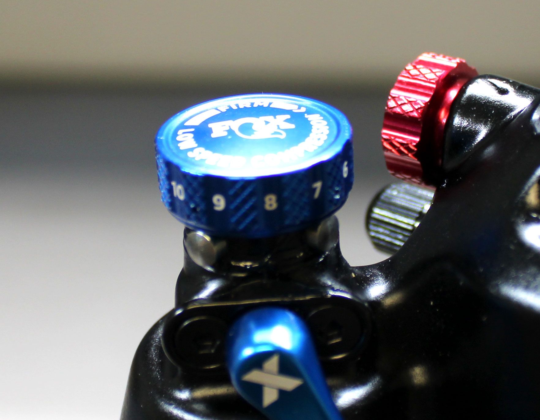
Note the shape of the LSC adjuster and the matching shape on the inside of the LSC knob. These must be aligned during installation as these can only interface in one orientation. Align the knob with the adjuster then begin installation by putting the knob on top of the adjuster area.
Step 7
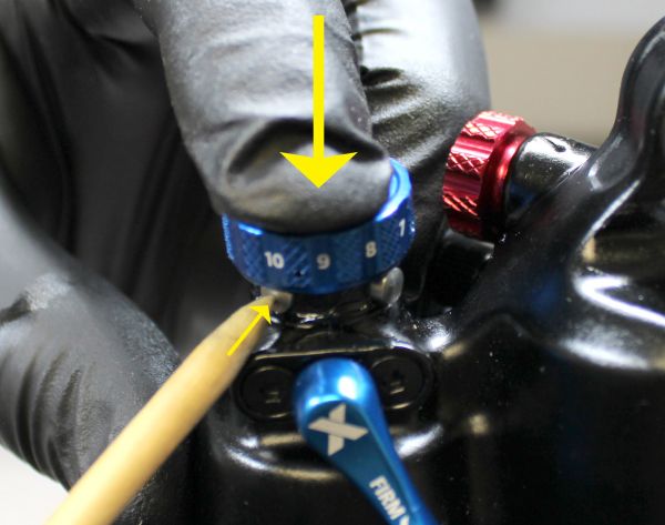
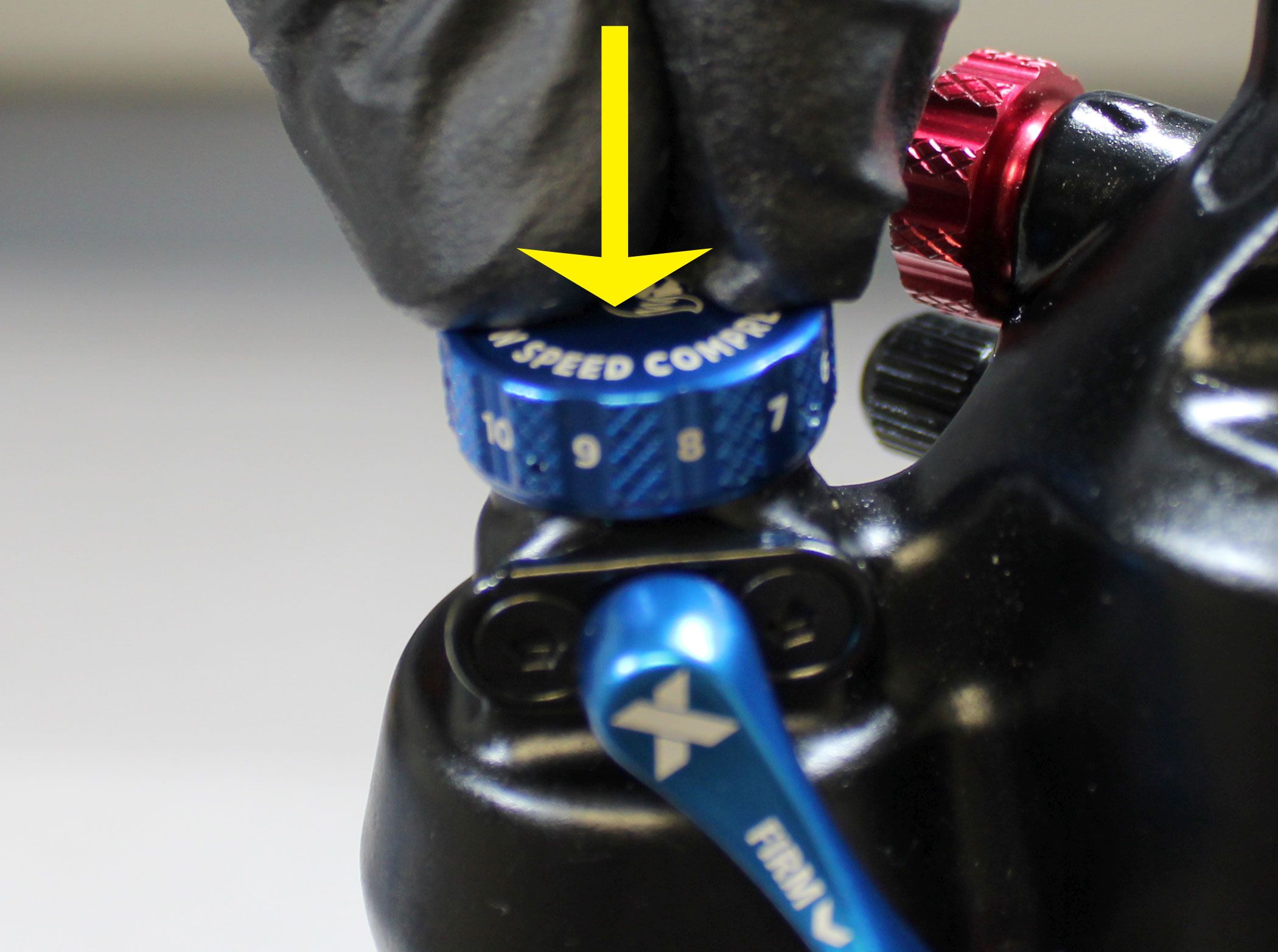
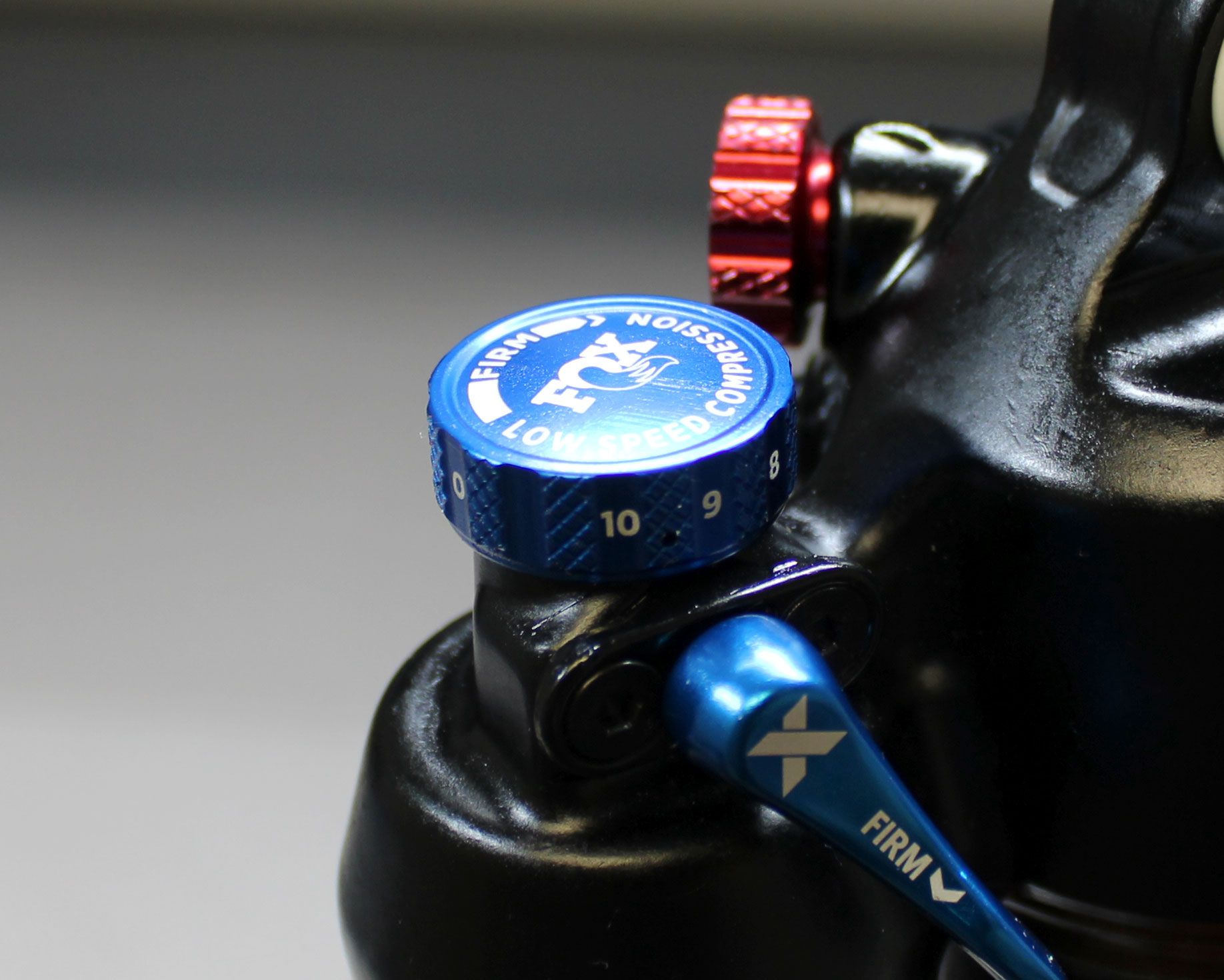
Press down on the LSC knob with constant pressure while pressing the Detent Housings in until they are captured by the LSC knob. Once one Detent Housing is captured, while maintaining downward pressure on the knob, move the next adjacent Detent Housing and press that in. By maintaining constant downward pressure on the LSC knob, you should be able to slowly work around all 4 Detent Housings until they are all captured by the LSC knob. Once all Detent Housings are in place, the LSC knob should fully seat downward against the eyelet.
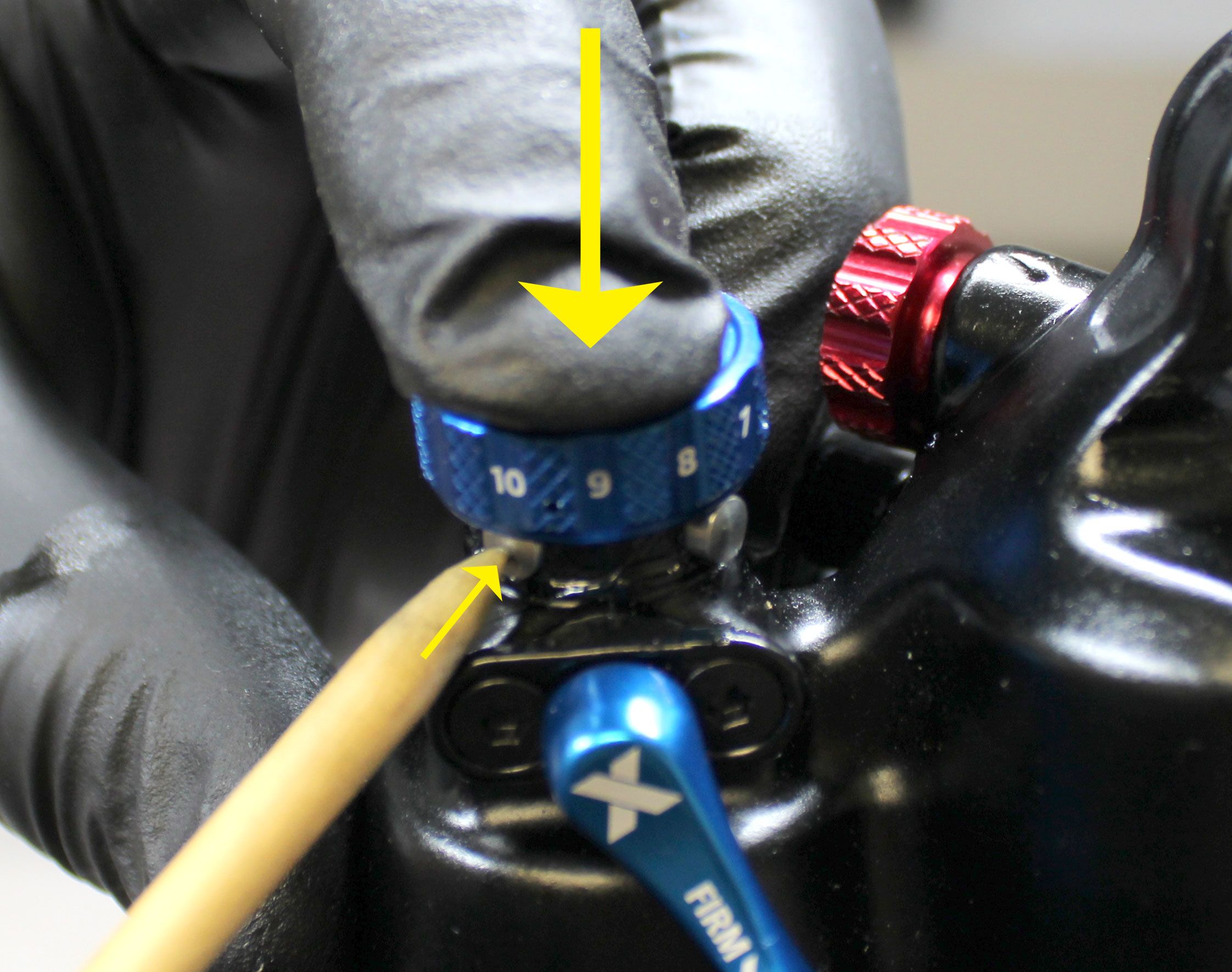
NOTE: This step requires some skill and may take a number of attempts to complete. Please do not force any parts if they do not feel like they are going together properly.