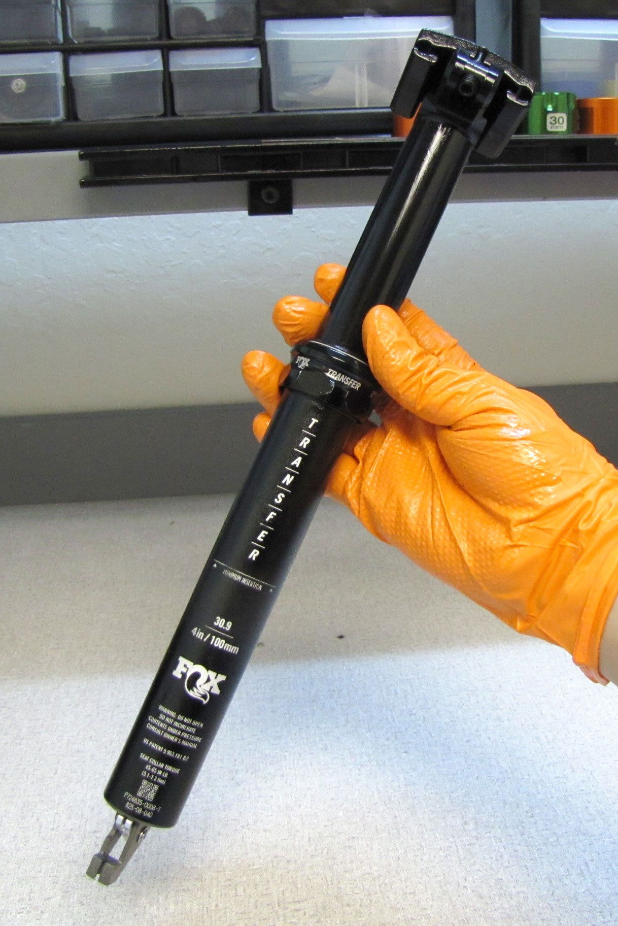
2021+ Transfer Seatpost Rebuild
Required Parts
- 025-03-035 Oil: AM, FOX 1.5wt Synthetic Oil [16 oz.], Clear
- 803-01-497 Seal Kit: MY21 Transfer Seatpost, Rebuild
Required Tools
- 398-00-700 ***OPTIONAL*** Service Tool, Internal Spool Valve Compressor Knob, Transfer
- 398-00-735 Service Tool: Open Valve, Nitrogen Fill, Transfer
- 398-00-738 Service Tool: Bullet, 8mm Shaft, Transfer
- 398-00-740 Service Tool: Push Rod, Delrin, Transfer
- 398-00-749 Service tooling: Trek Thru Shaft IFP removal tool
- 398-00-871 Service Tool: 2021 Transfer, IFP Height, 100
- 398-00-872 Service Tool: 2021 Transfer, IFP Height, 125
- 398-00-873 Service Tool: 2021 Transfer, IFP Height, 150
- 398-00-874 Service Tool: 2021 Transfer, IFP Height, 175
- 398-00-875 Service Tool: 2021 Transfer, IFP Height, 200
- 398-00-896 Service Tool: Seat Post Collar Torque Driver, Transfer 37mm
- 803-00-147 Kit: Shaft Clamps, 07 FORX, Set #2 (32 X Body, 36, 40 Forx)
- 803-01-496 Kit: Service Tool, 2021 Transfer Internal, Upper Bushing Installer
- 803-01-595 Service Tool: Gas Fill, 100-200mm Transfer, Assy
- 803-01-917 Kit: Service Tool, 2023 Transfer, Wiper Installer
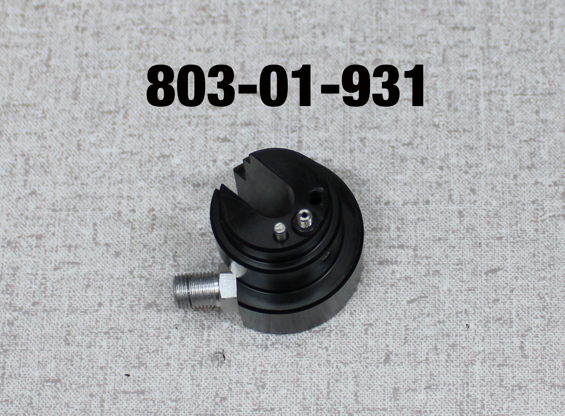
- 803-01-931 Service Tool: Gas Fill, Transfer, Compact, Assy
- Nitrogen Fill Station (Tank with Regulator) required for full rebuild .
WARNING: Always wear safety glasses and protective gloves during service to prevent potential injury. Failure to wear protective equipment during service may lead to SERIOUS INJURY OR DEATH.
WARNING: FOX products should be serviced by a qualified bicycle service technician, in accordance with FOX specifications. If you have any doubt whether or not you can properly service your FOX product, then DO NOT attempt it. Improperly serviced products can fail, causing the rider to lose control resulting in SERIOUS INJURY OR DEATH.
WARNING: Modification, improper service, or use of aftermarket replacement parts with FOX forks, shocks, and seatposts may cause the product to malfunction, resulting in SERIOUS INJURY OR DEATH. DO NOT modify any part of a fork, shock, or seatpost including the fork brace (lower leg cross brace), crown, steerer, upper and lower leg tubes, or internal parts, except as instructed herein. Any unauthorized modification may void the warranty, and may cause failure or the fork or shock, resulting in SERIOUS INJURY OR DEATH.
WARNING: FOX products contain pressurized nitrogen, air, oil, or all 3. Misuse can cause property damage, SERIOUS INJURY OR DEATH. DO NOT puncture, incinerate or crush any portion of a FOX product. DO NOT attempt to disassemble any portion of a FOX product, unless expressly instructed to do so by the applicable FOX technical documentation, and then ONLY while strictly adhering to all FOX insturctions and warnings in that instance.

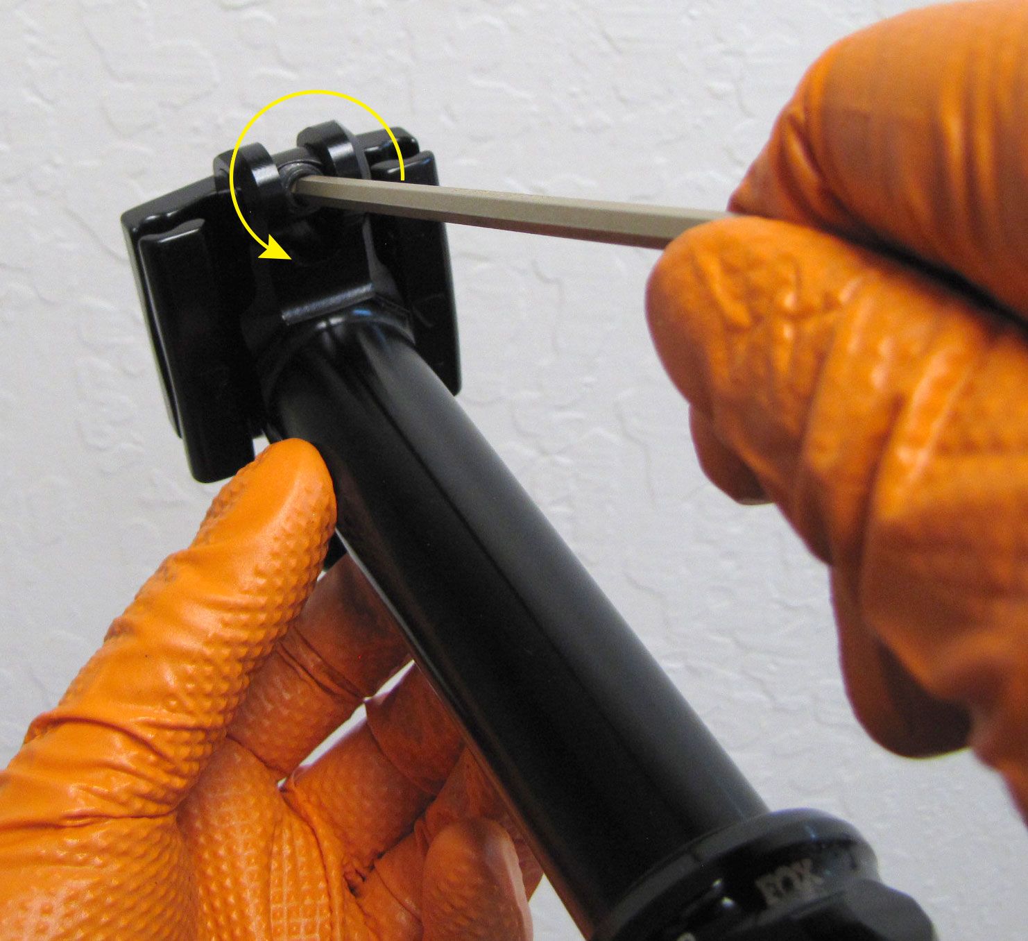
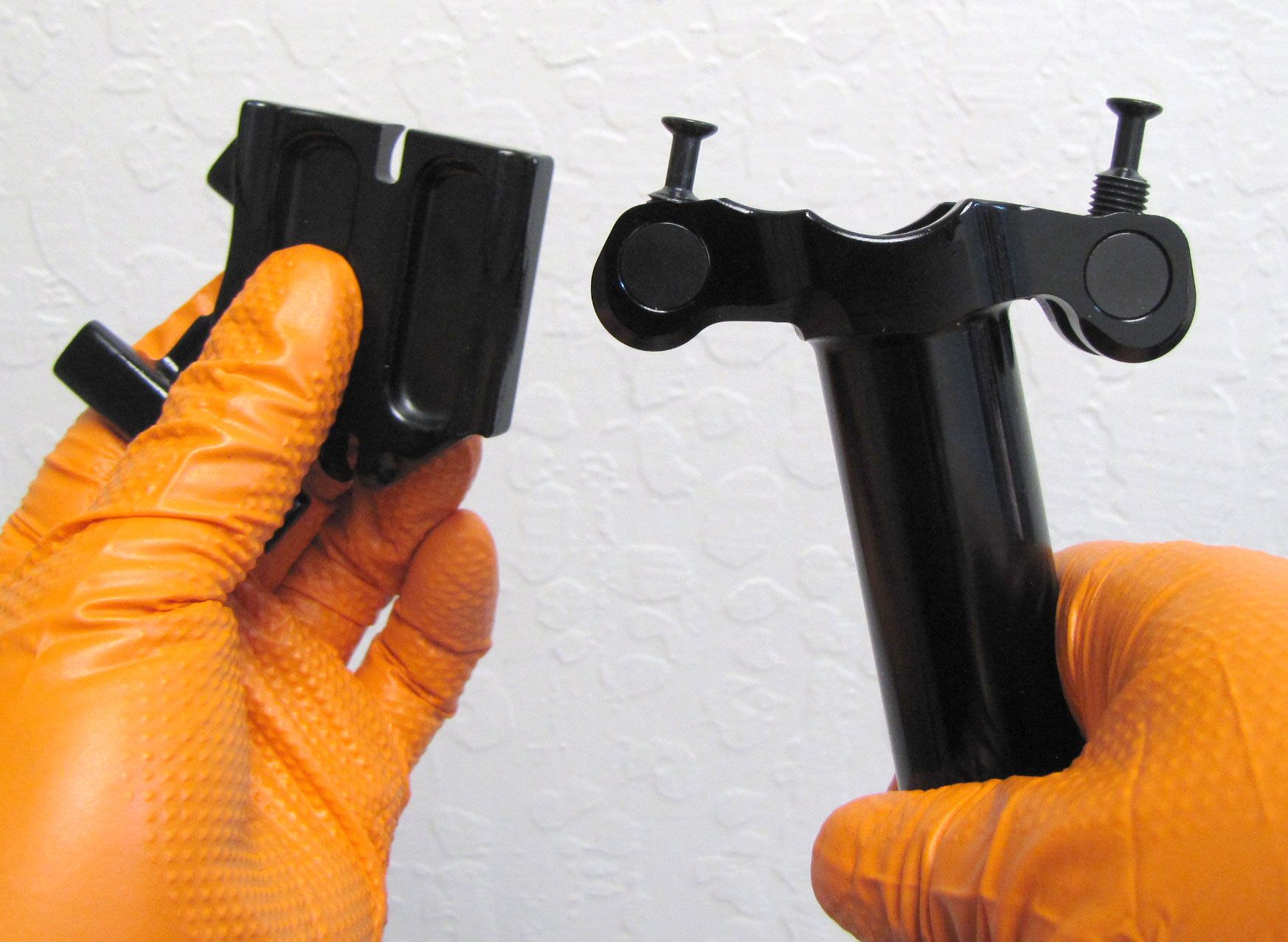
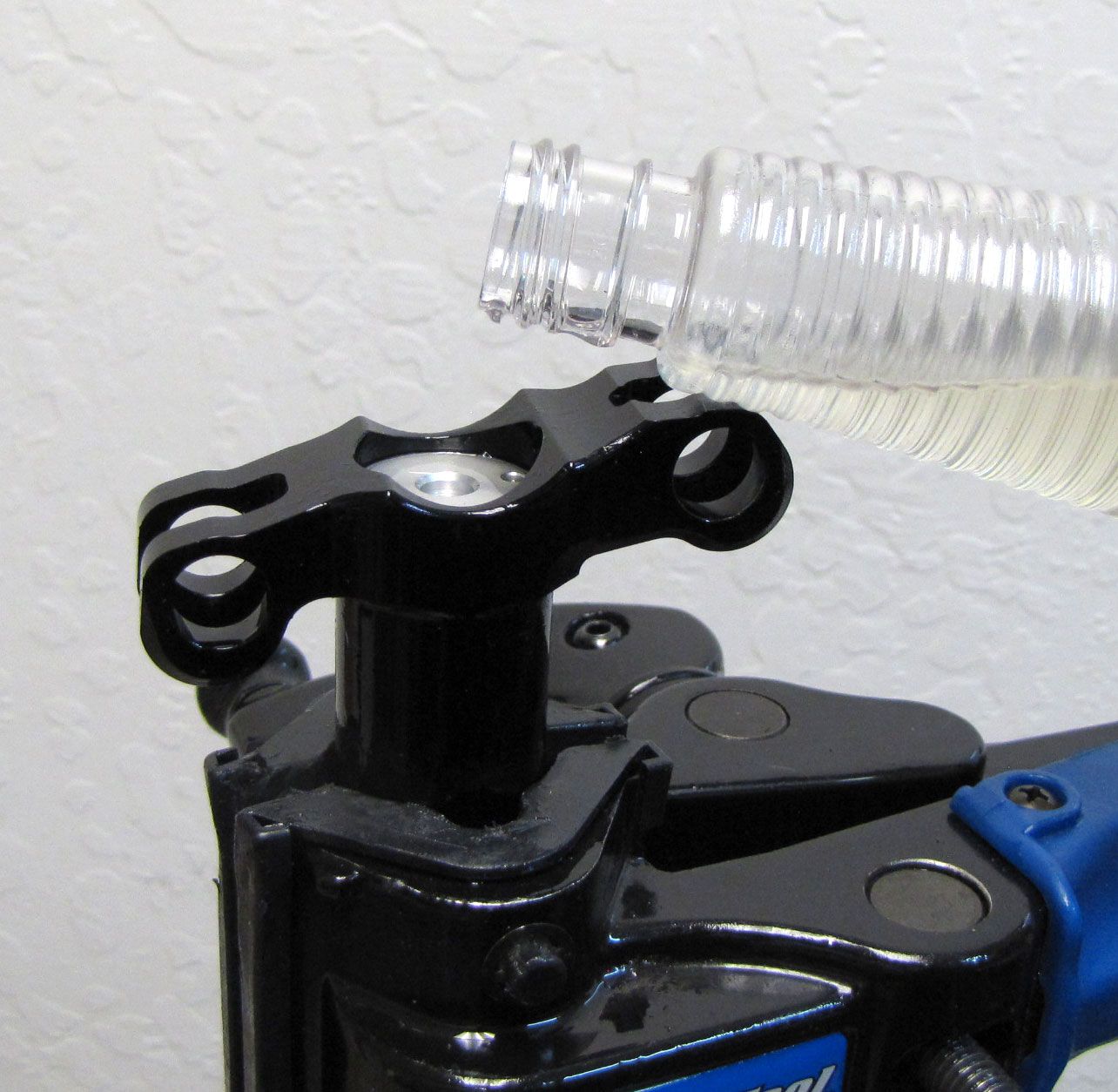
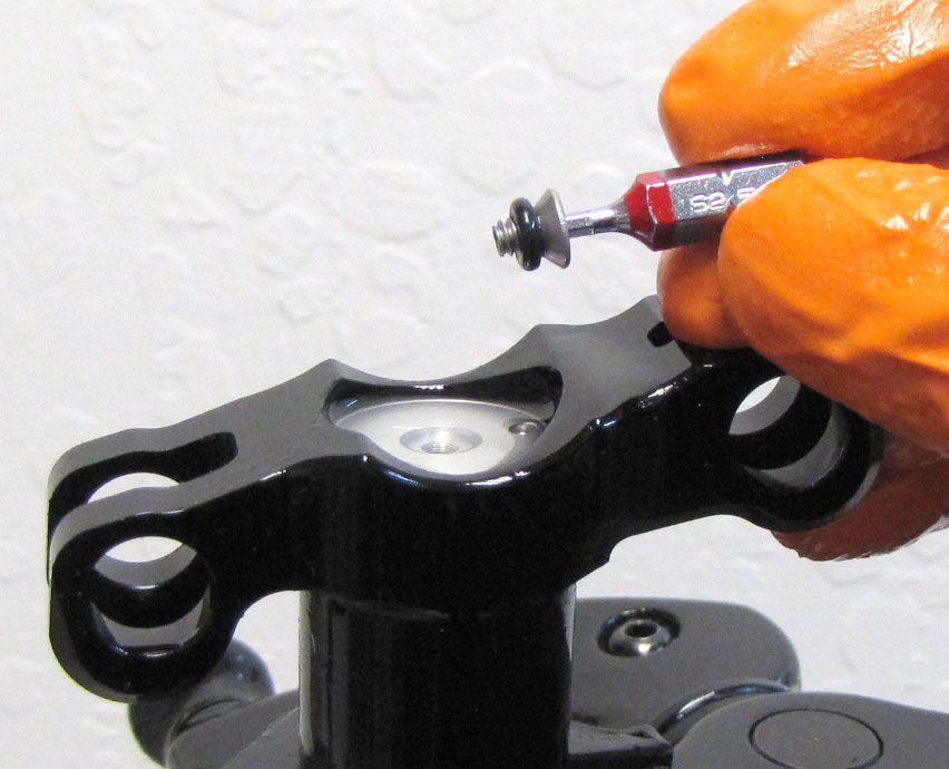
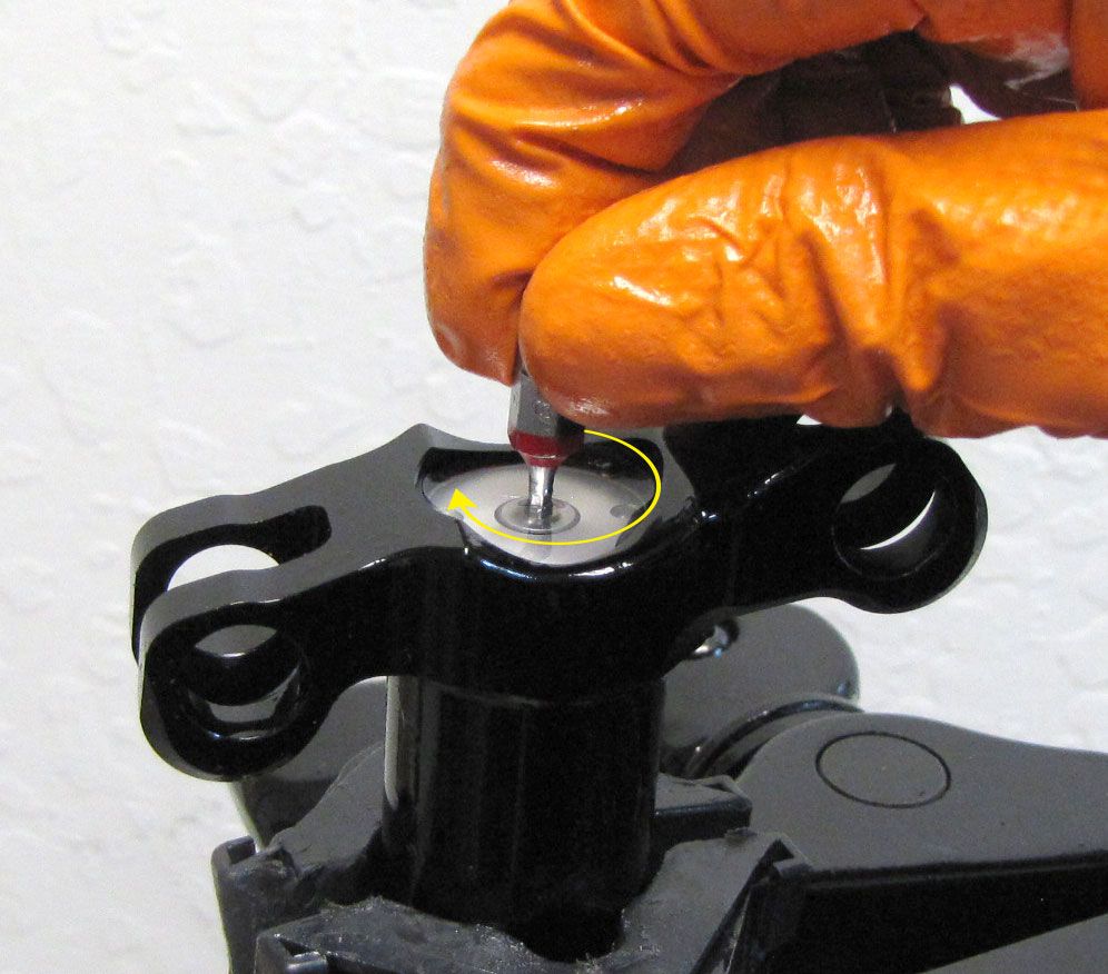
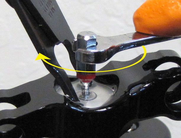
Step 1
Remove the Saddle Clamps and hardware. Turn the 4mm hex bolts counter-clockwise to remove them from the Barrel Nuts. Set all clamps and hardware aside.
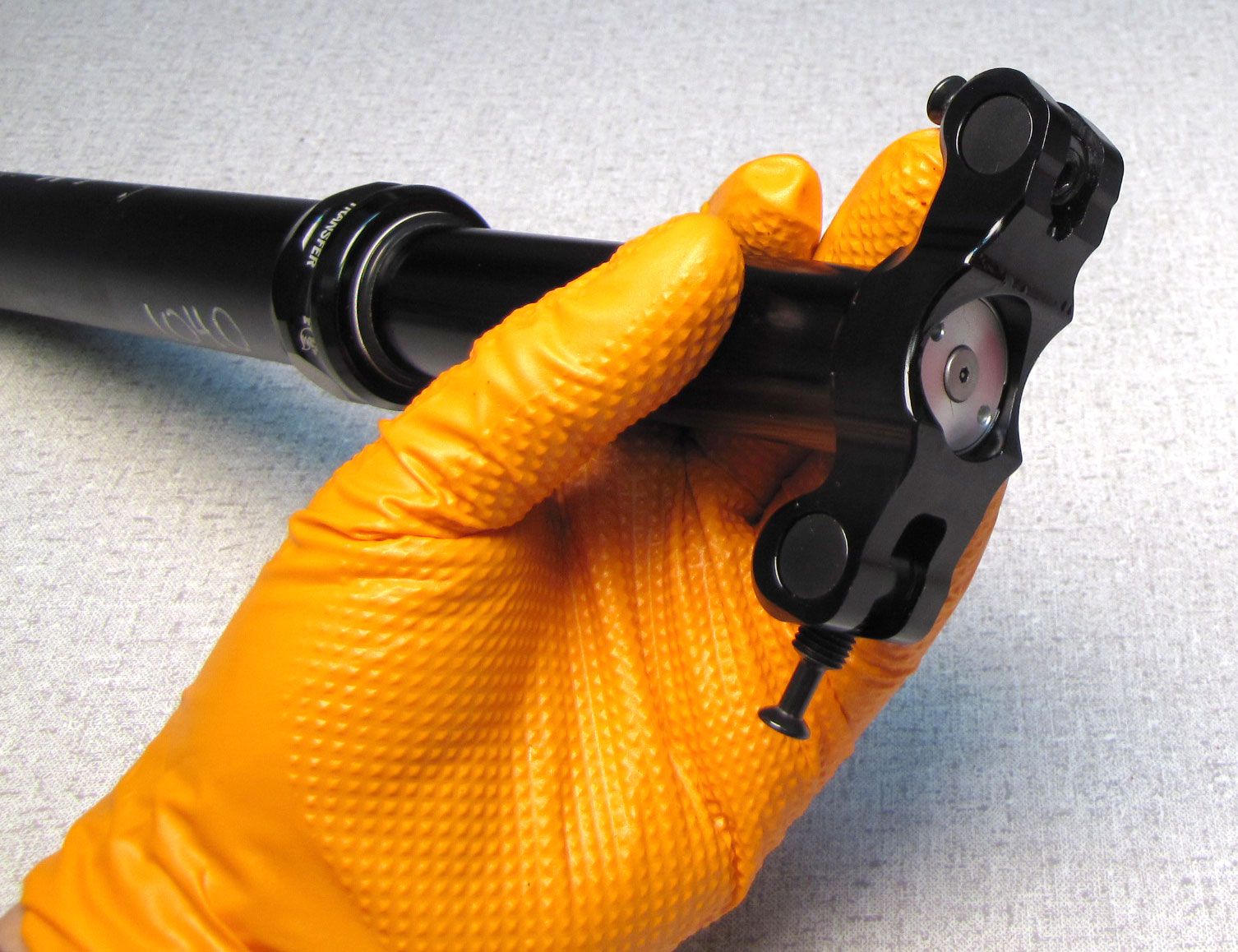
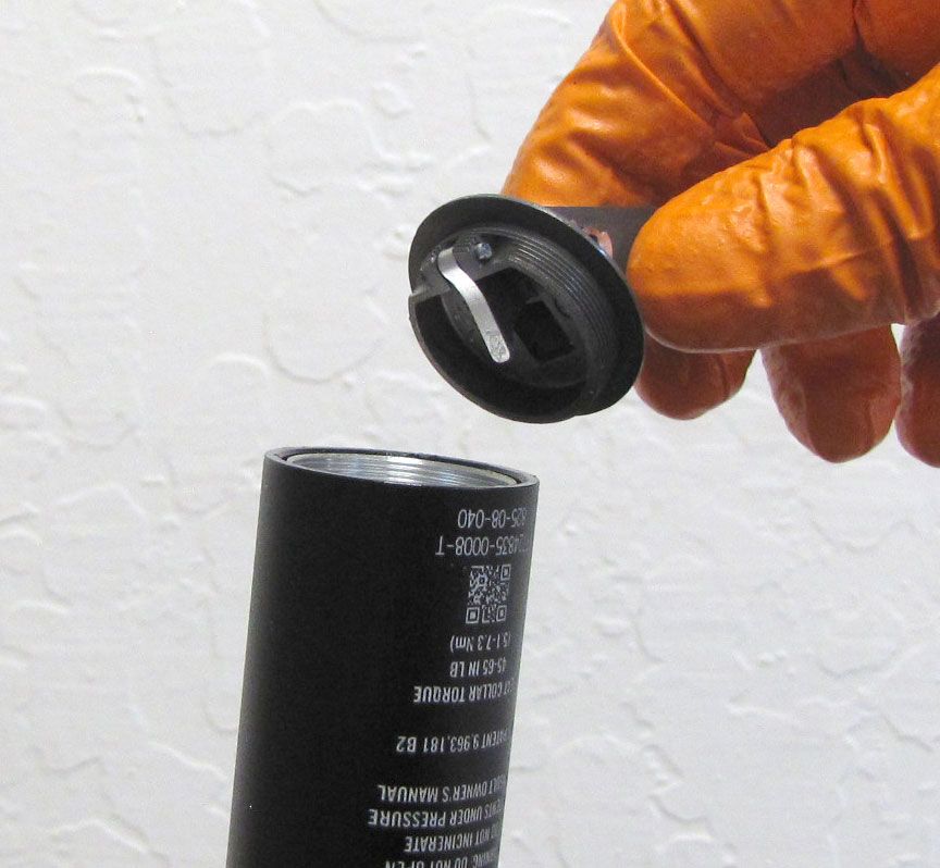
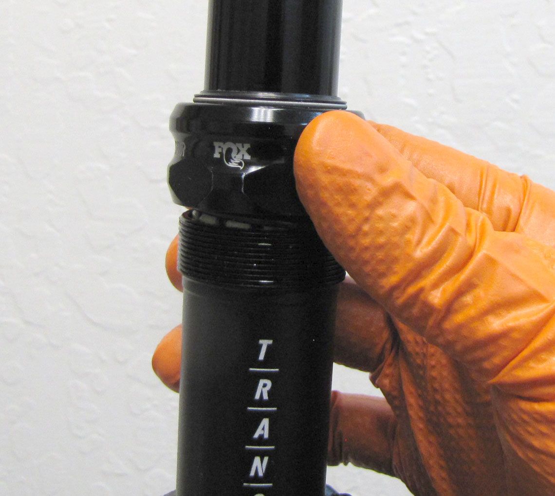
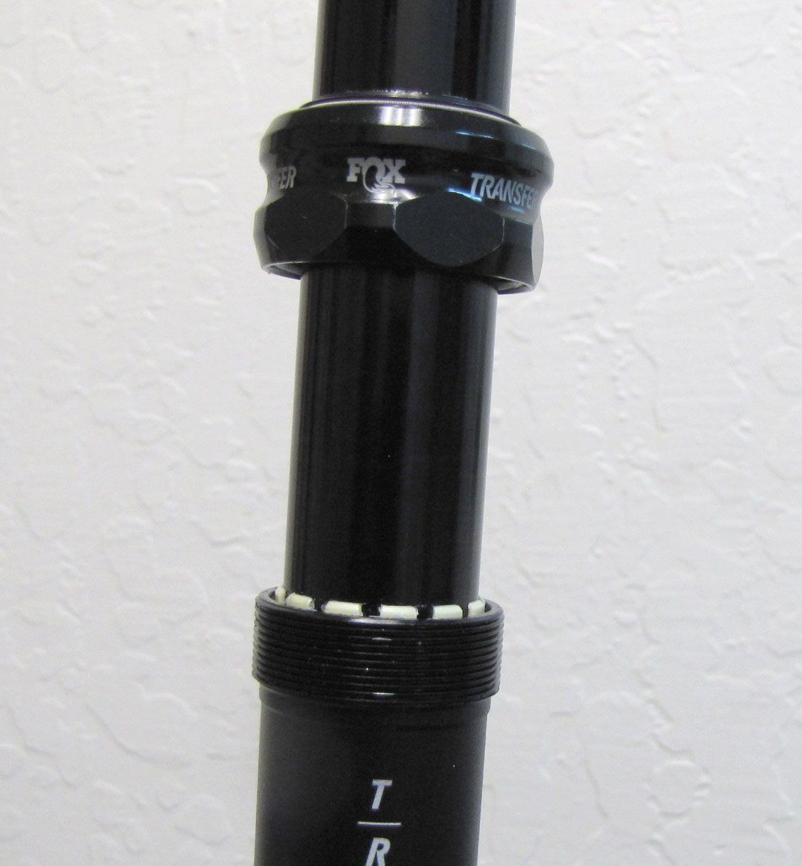
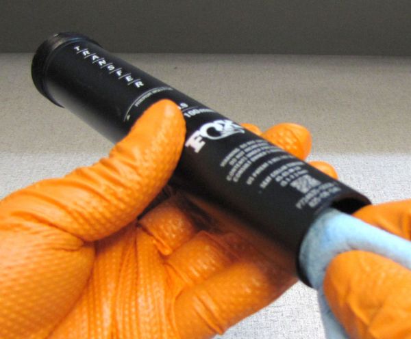
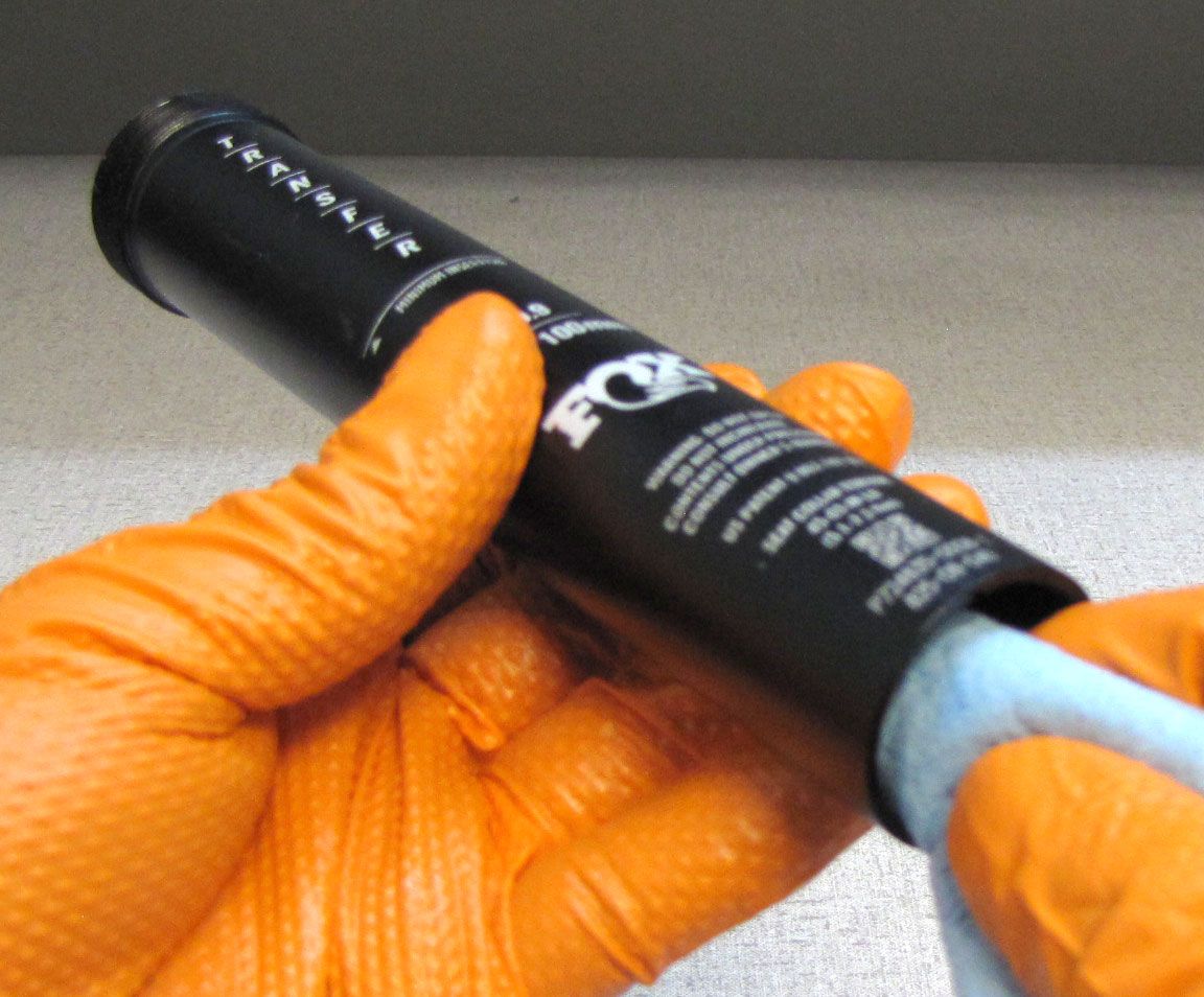
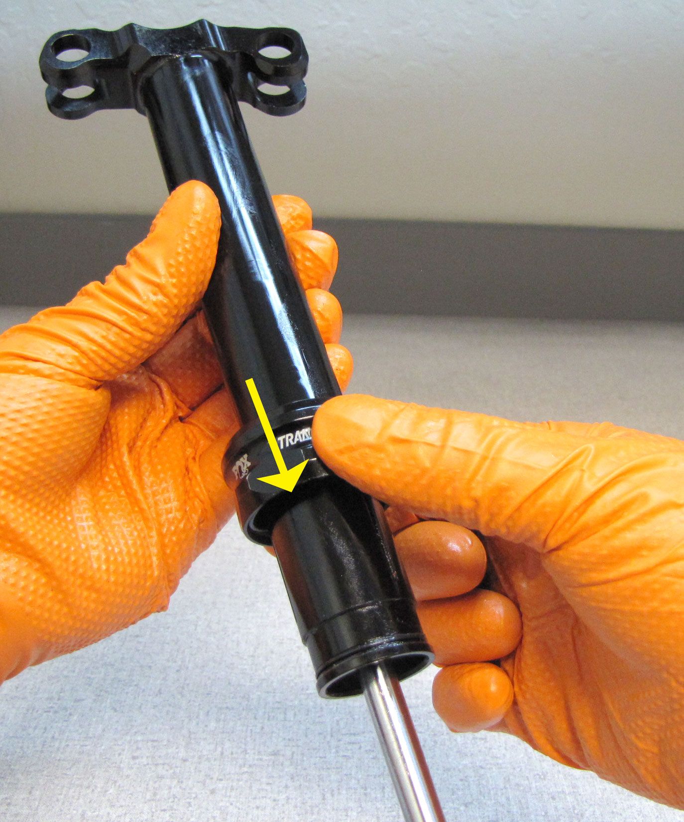
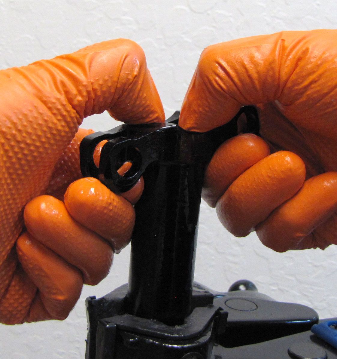
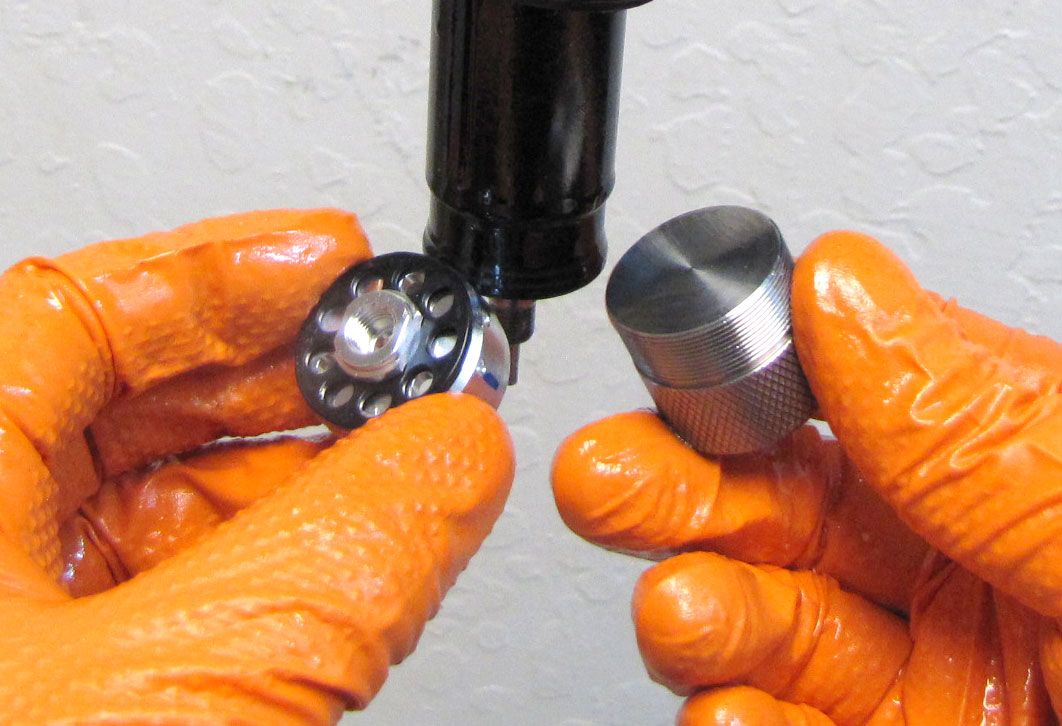
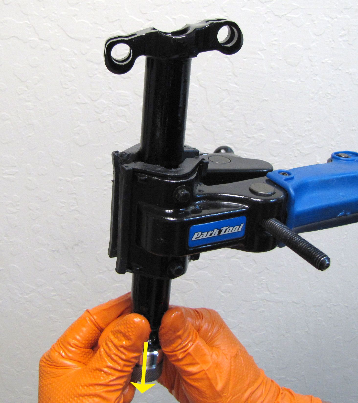
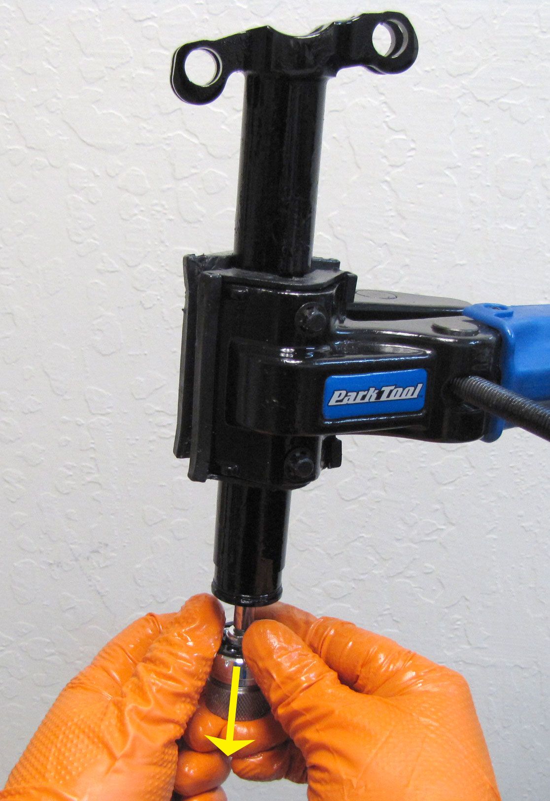
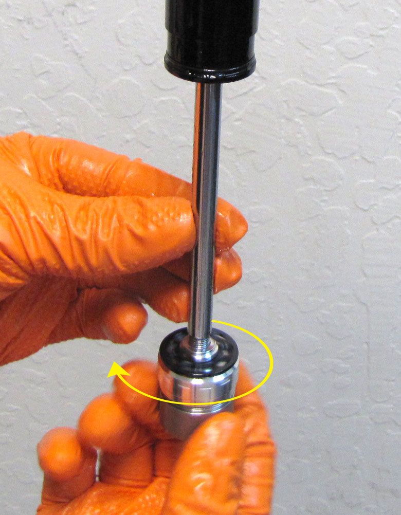
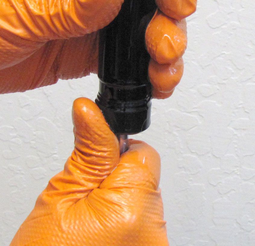
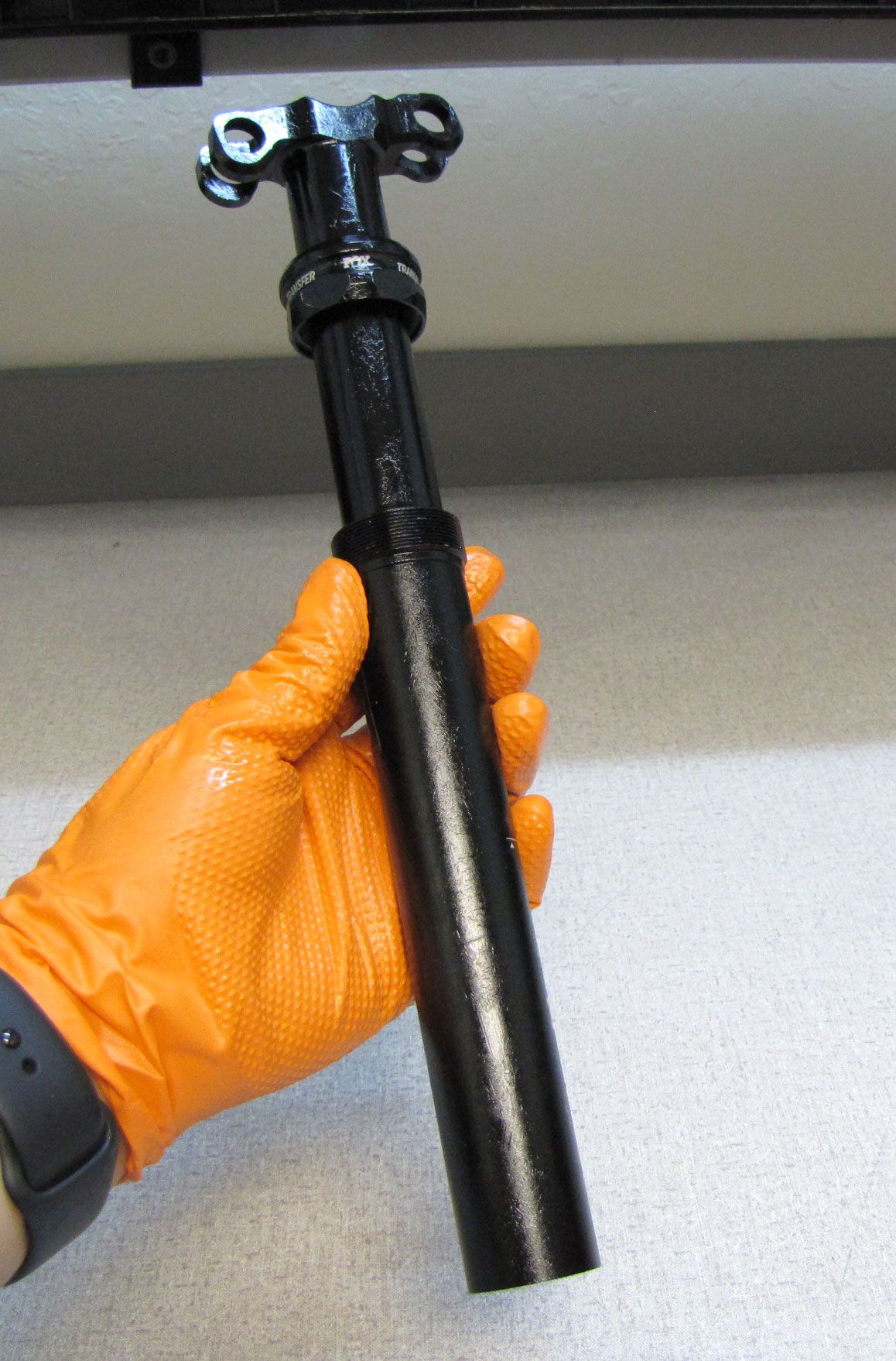
Step 2
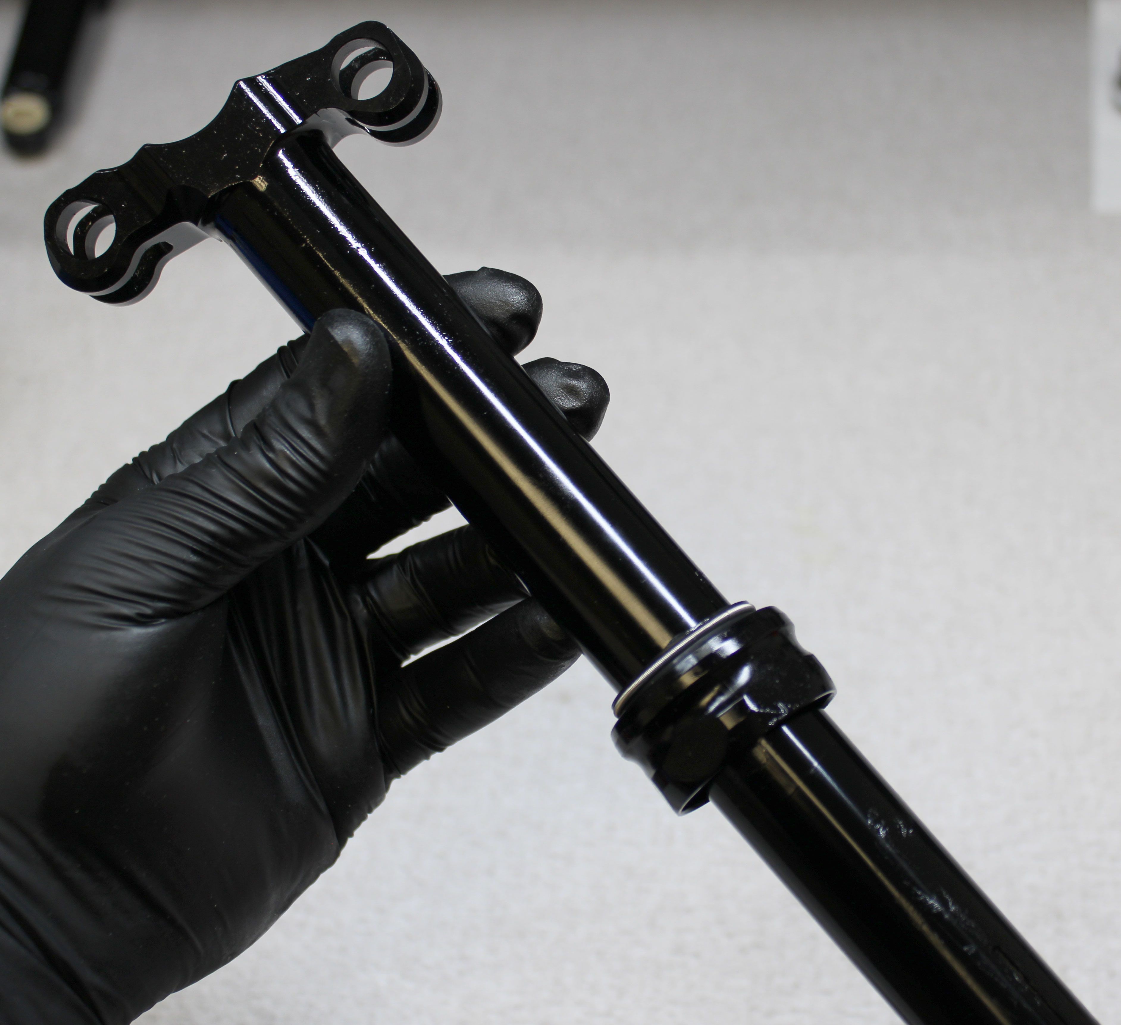
Clean your bike work stand clamps and the exterior of the seatpost to prevent damage during clamping. Clamp the seatpost in your workstand, then unthread the Bottom Cap counter clockwise while holding it by it's thickest section to remove it from the lower post.
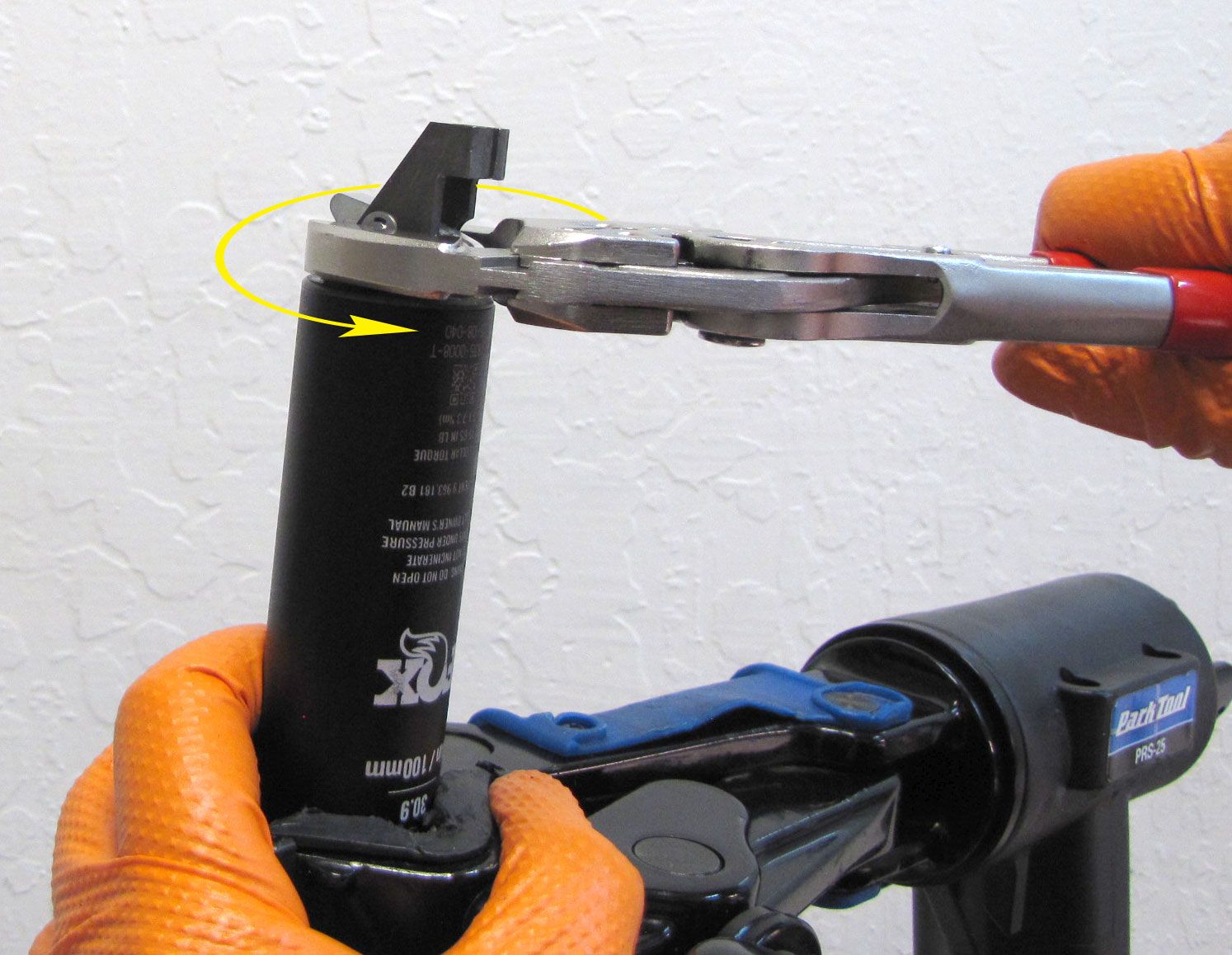
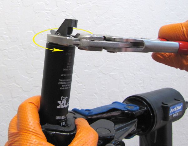
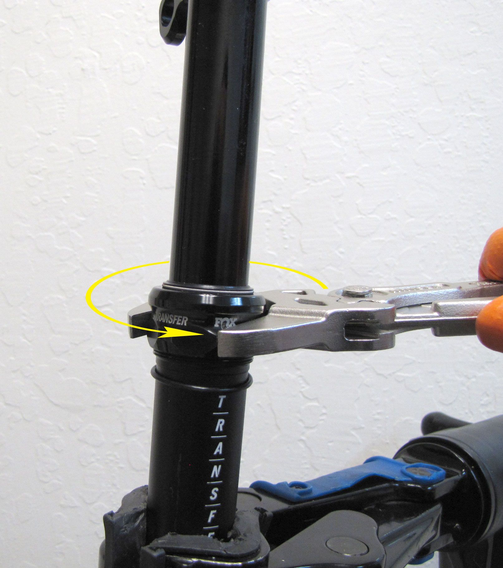
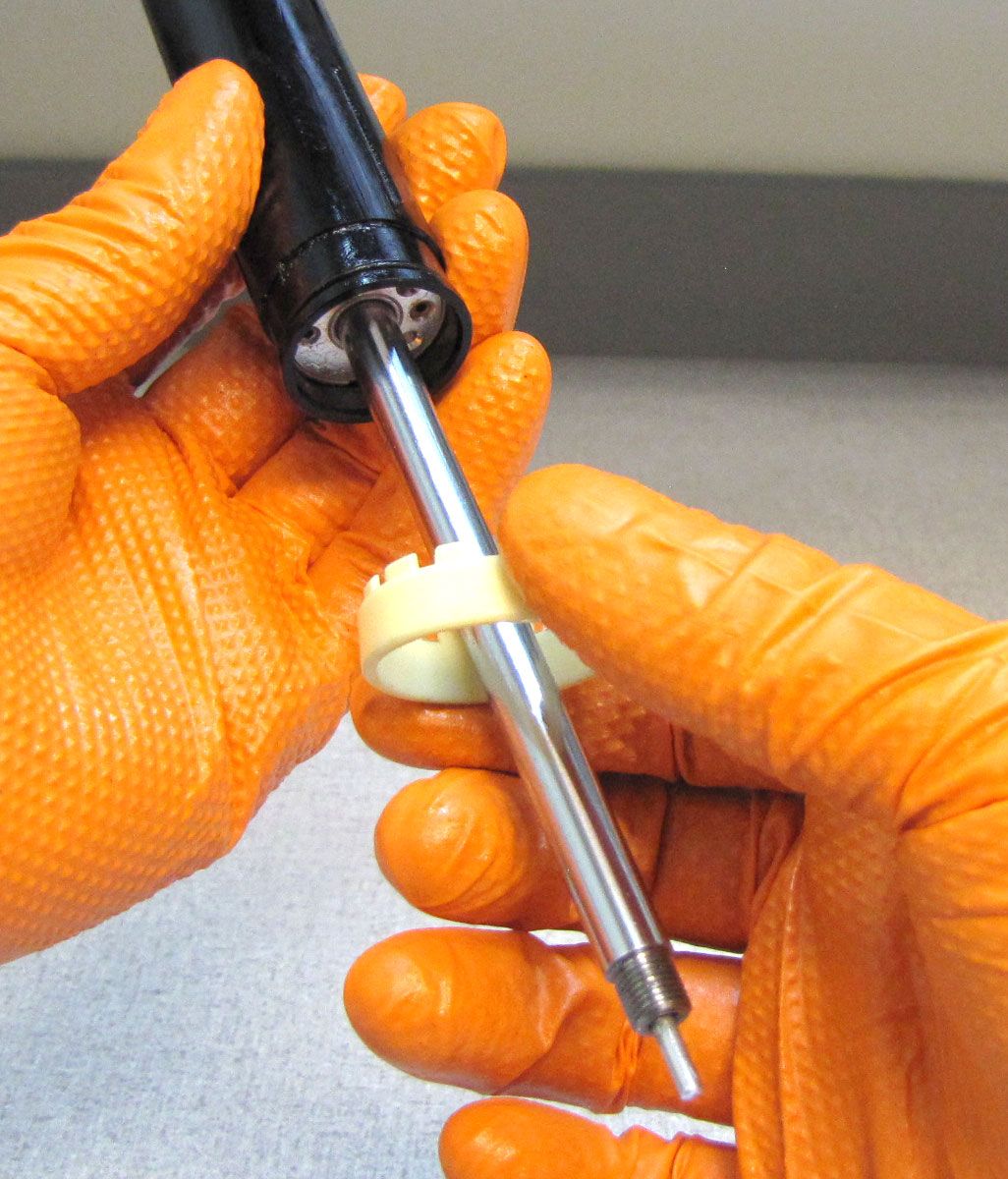
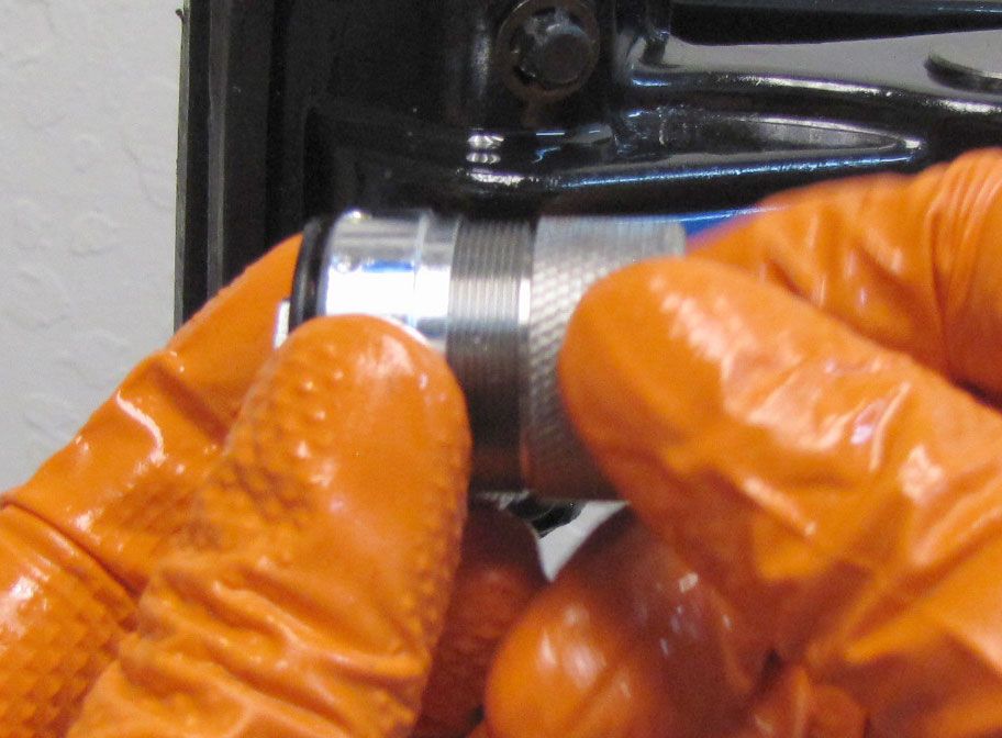
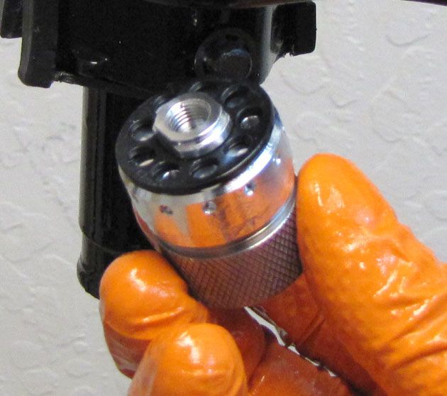
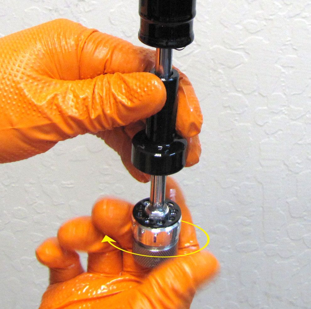
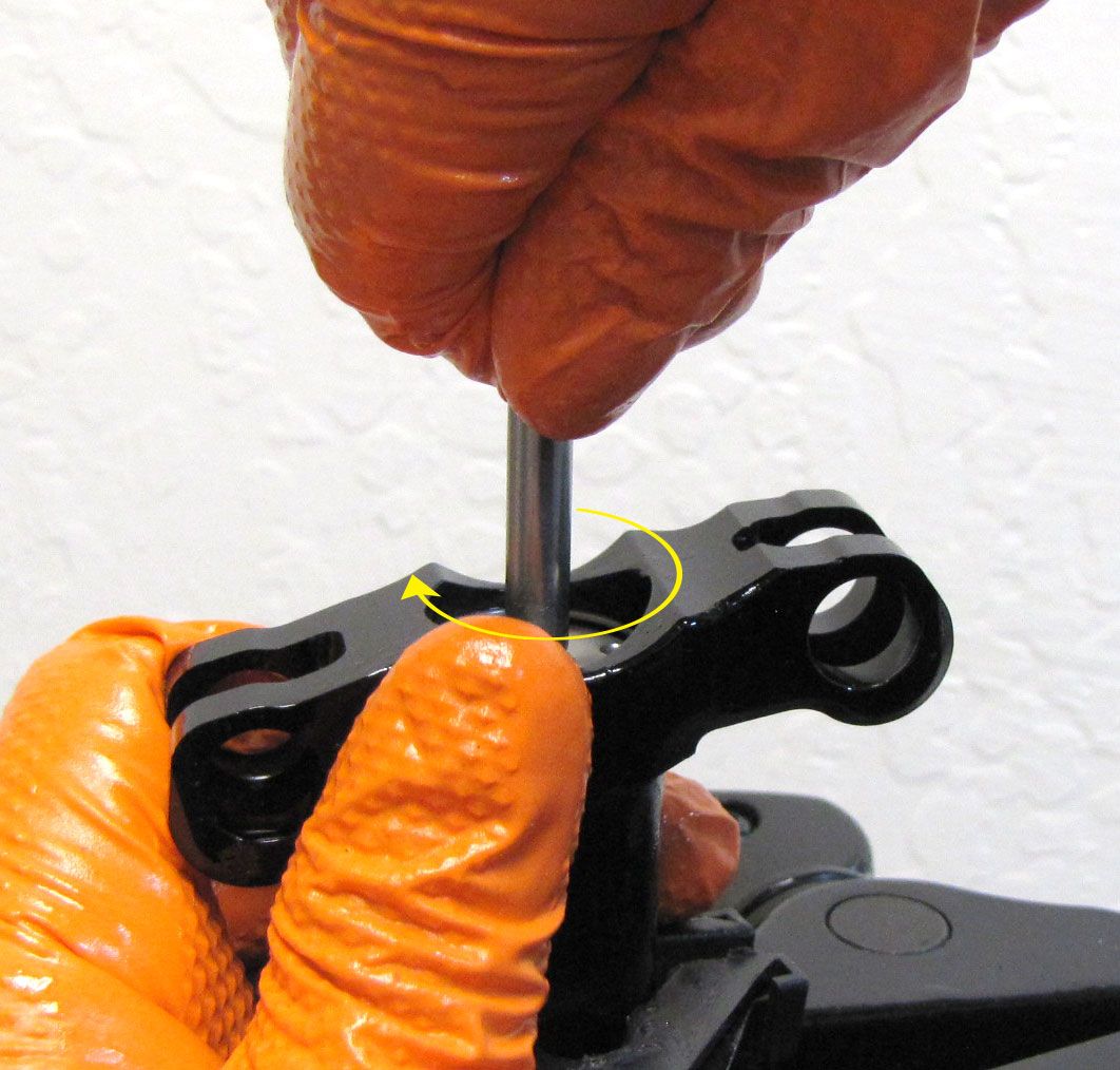
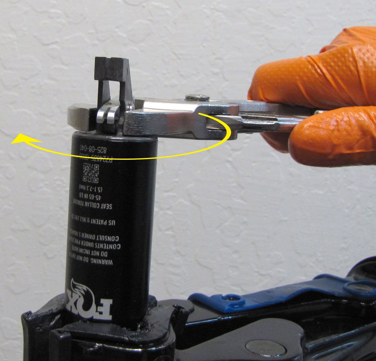
Step 3
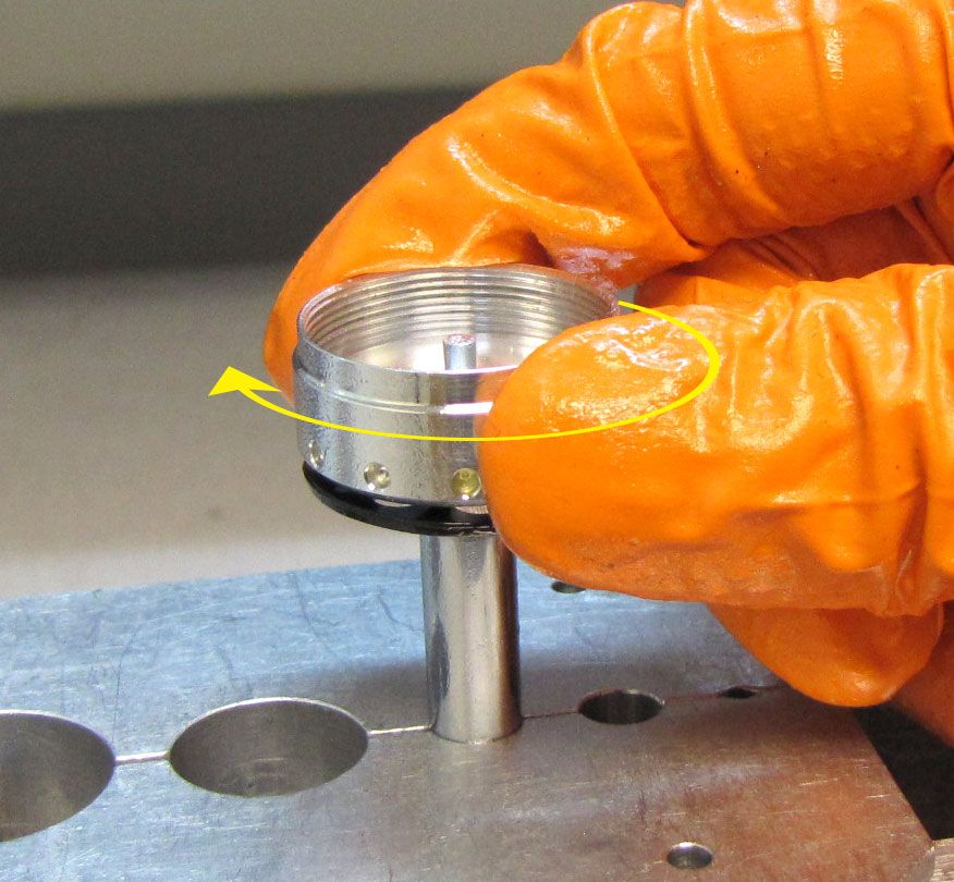
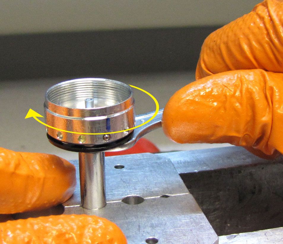
Unthread the Lower Post Collar by turning it counter-clockwise when viewed from the top of the seatpost. You may use Knipex smooth-jawed parallel pliers but the FOX tool (PN: 398-00-896) will assist in applying proper torque at a later step (tool not shown as procedure was shot before tooling arrived. Images will be updated).

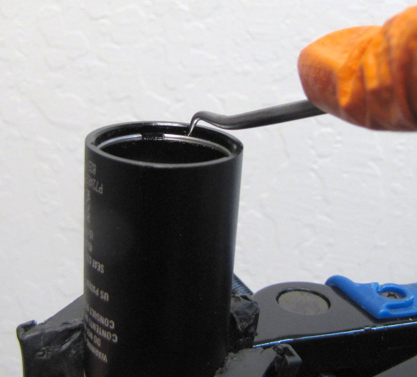
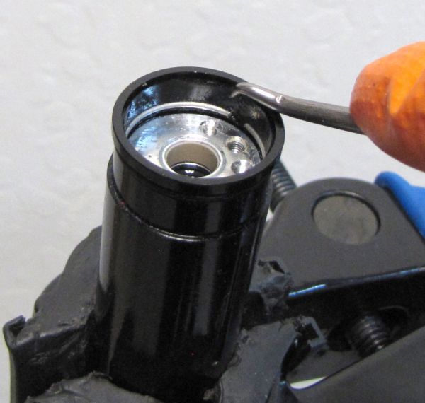
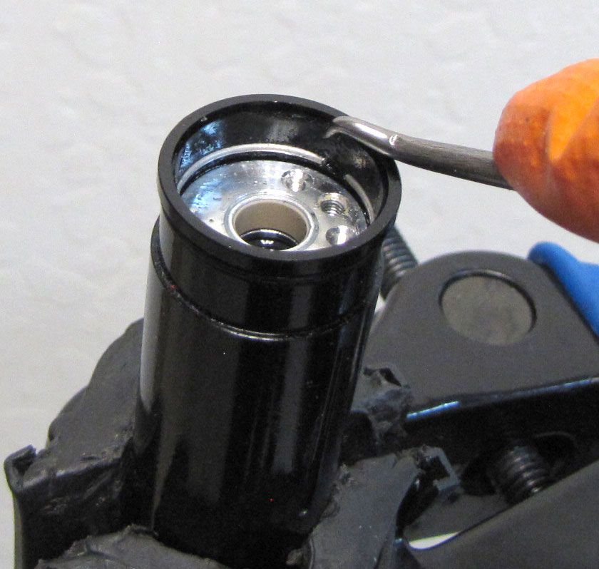
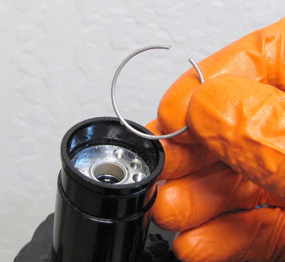
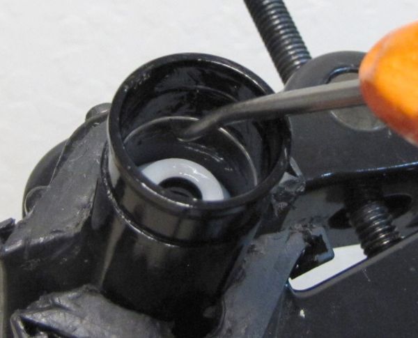
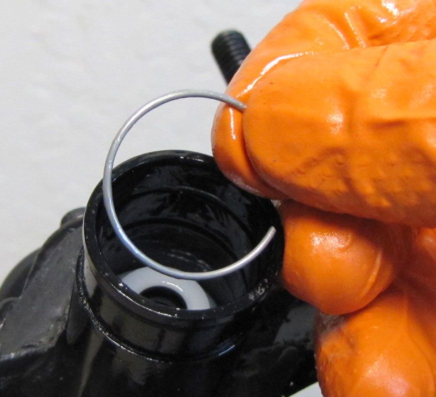
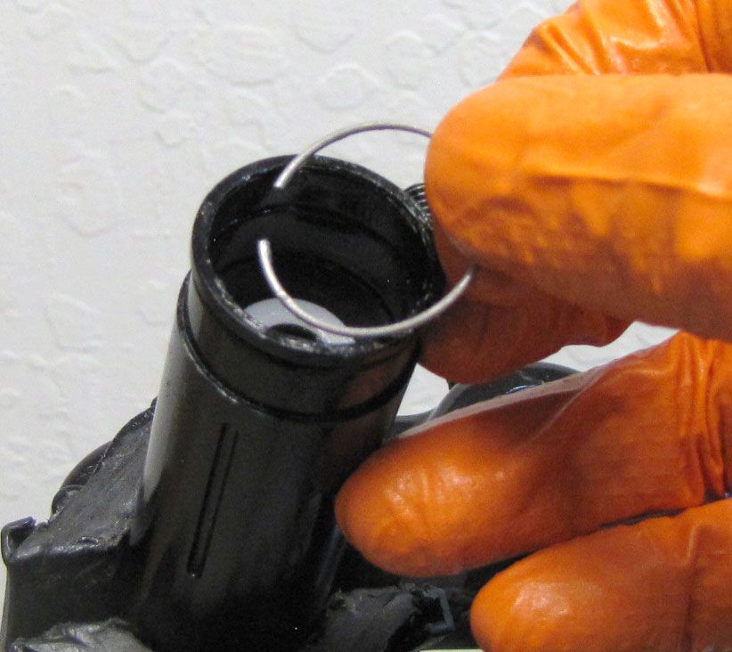
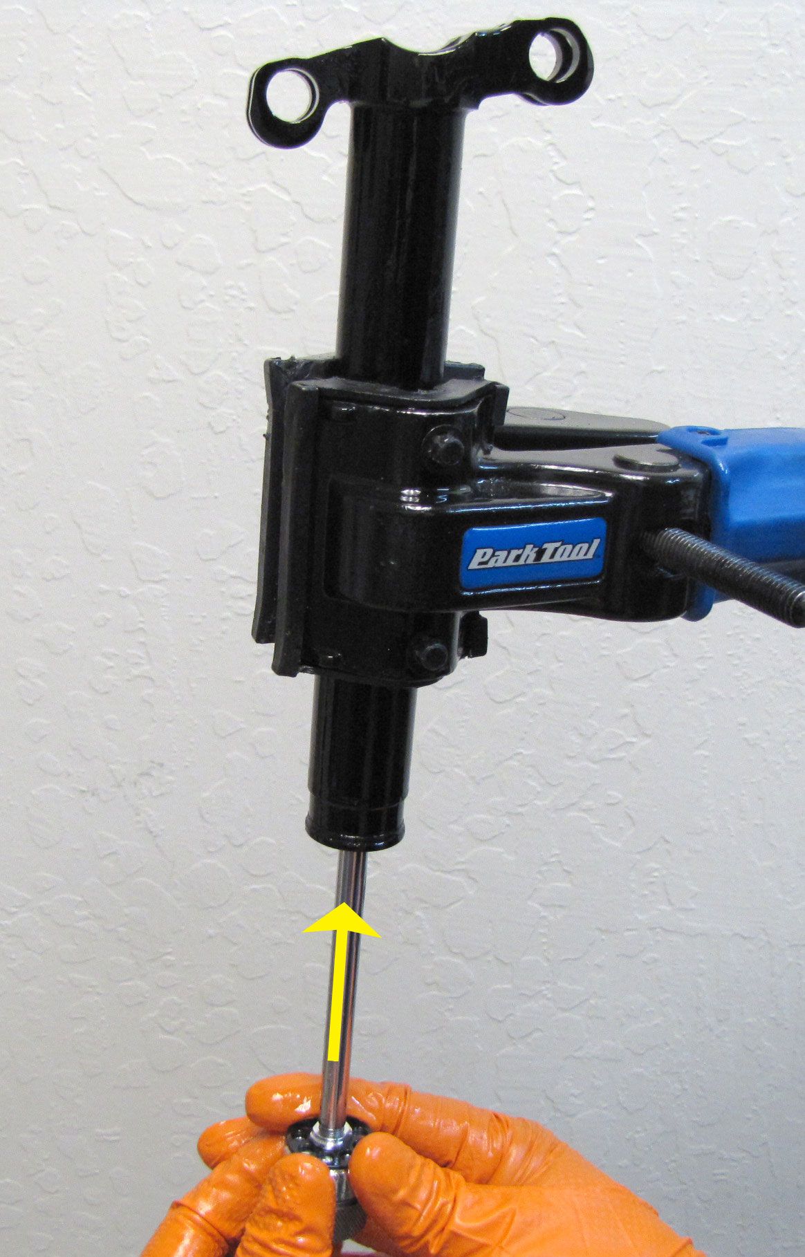
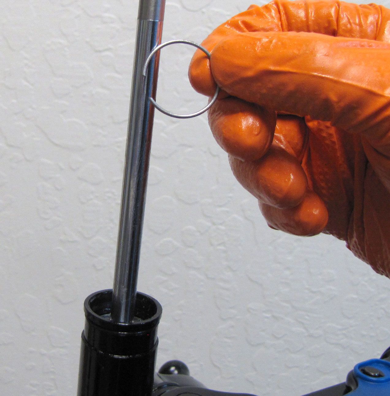
Step 4
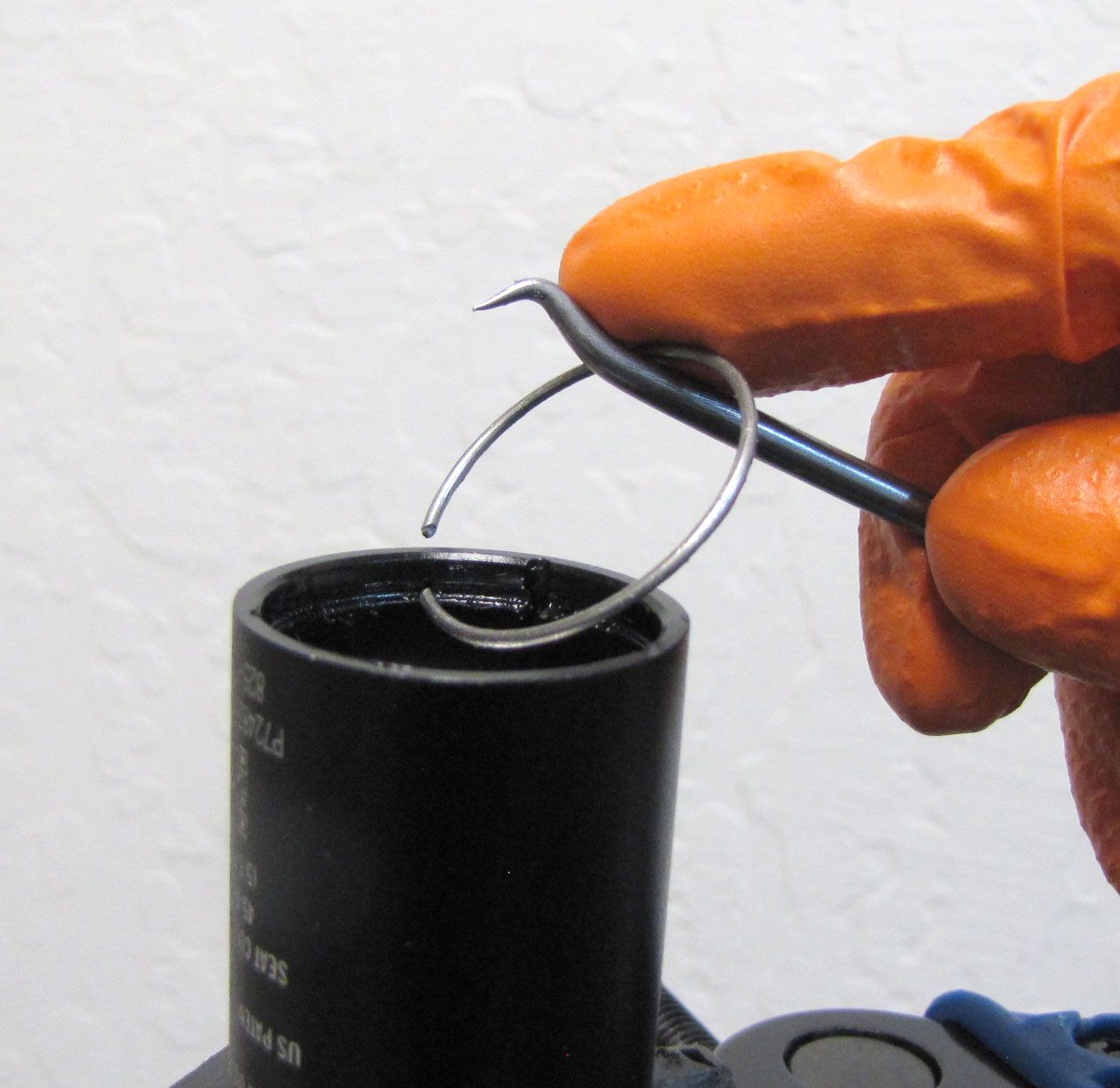
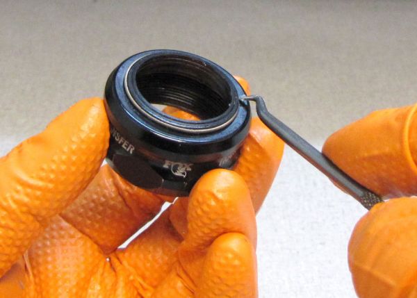
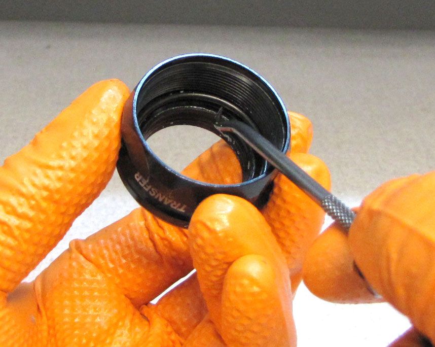
Remove the wire retaining ring from within the lower post and set it aside.
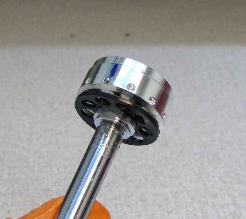
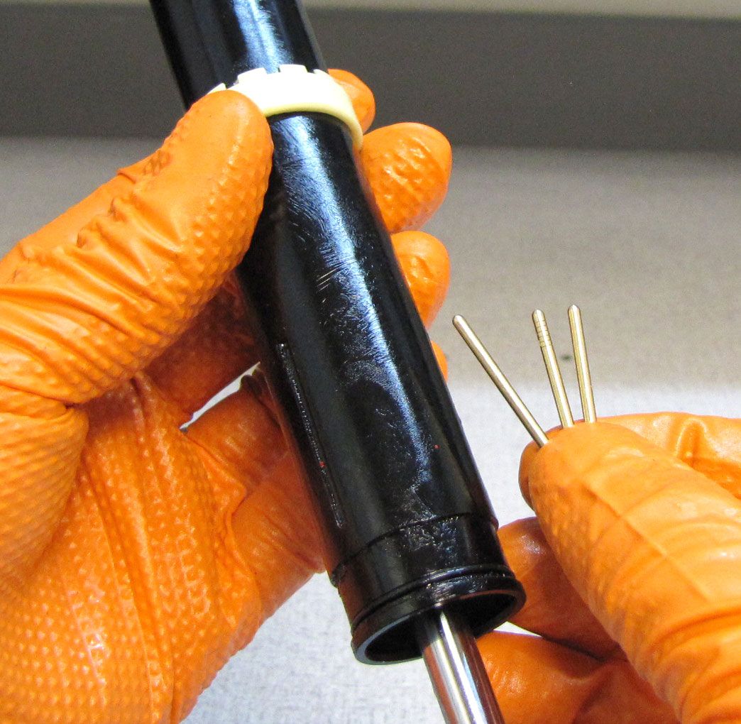
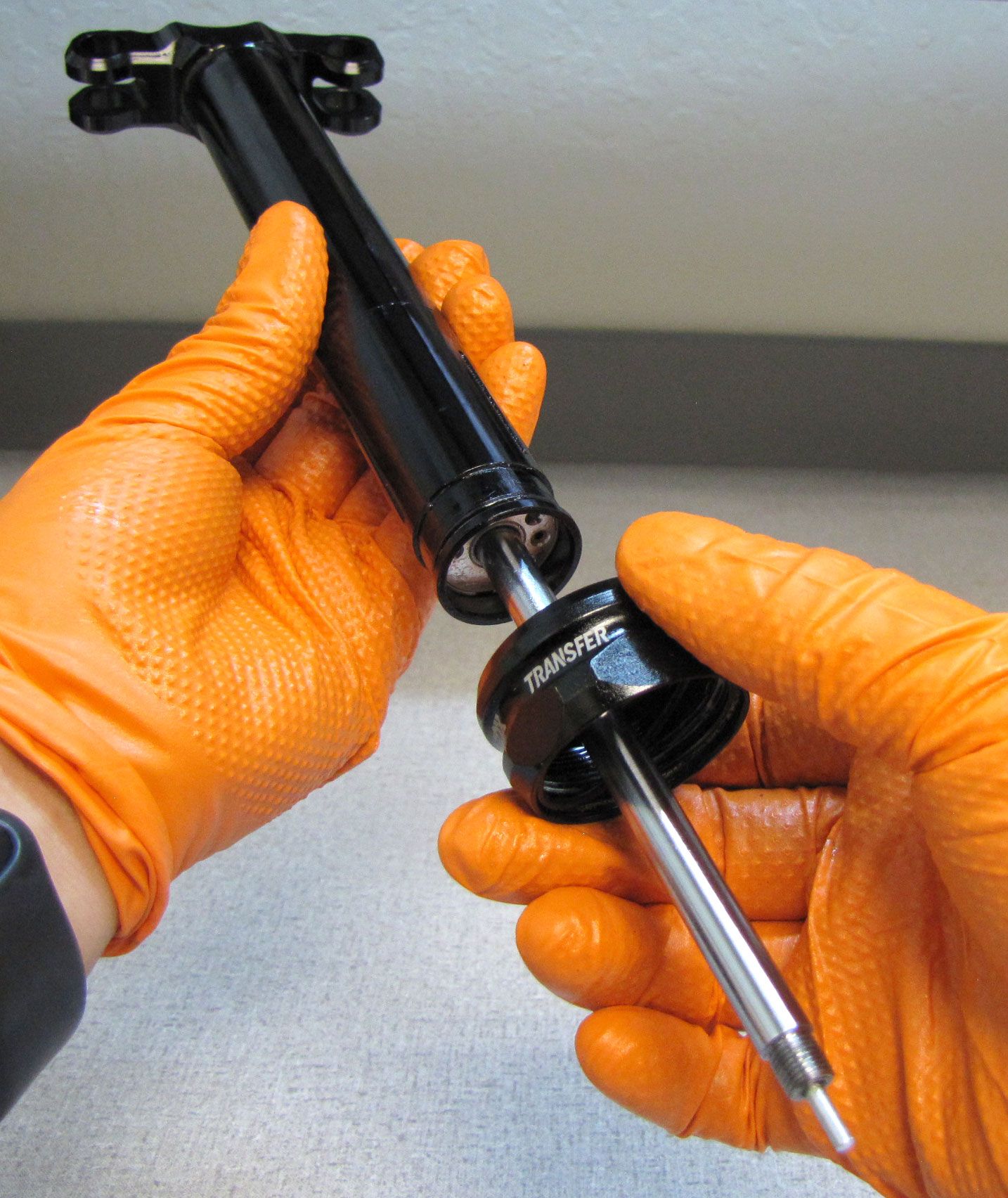
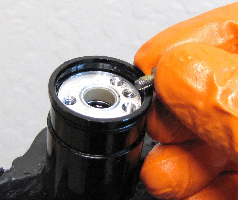
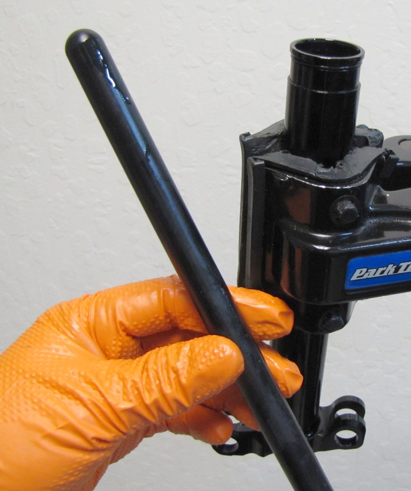
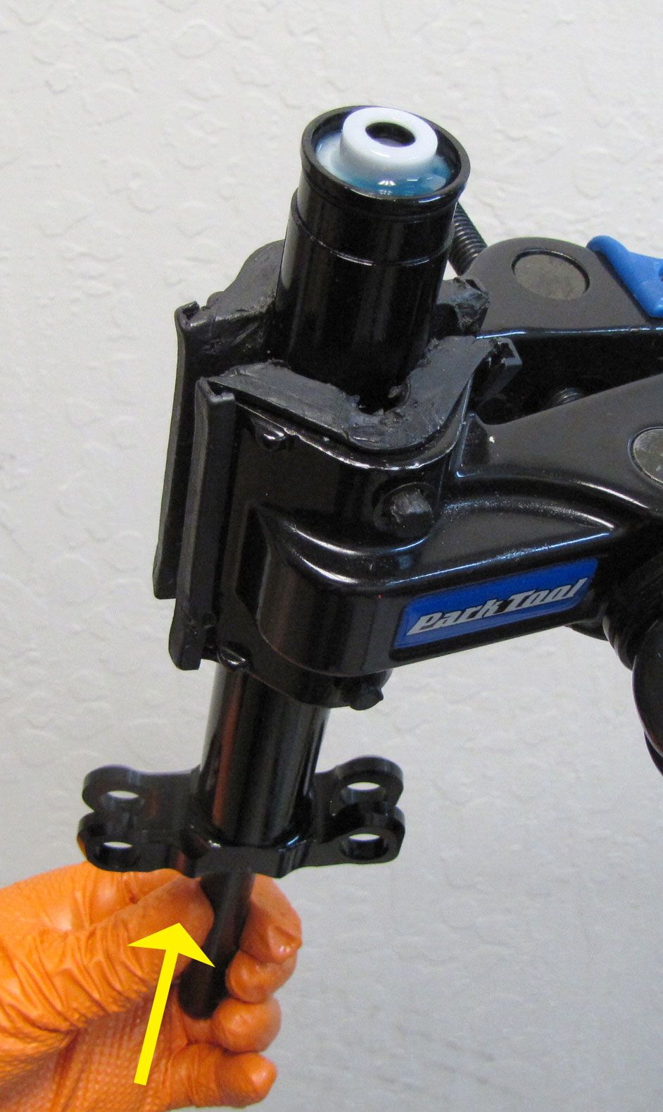
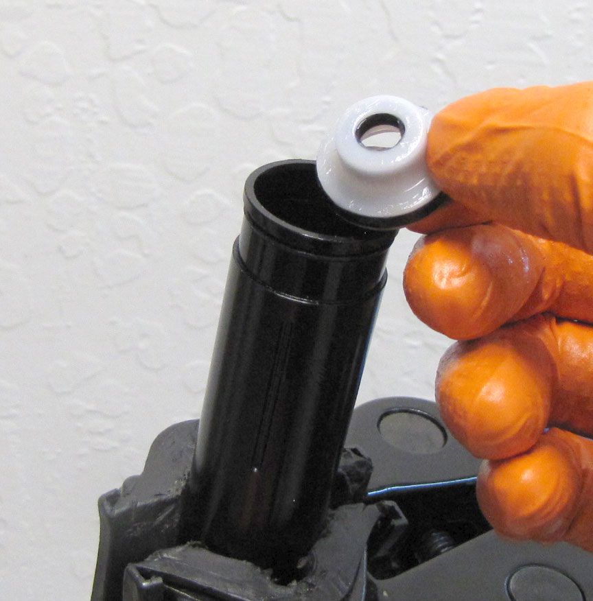
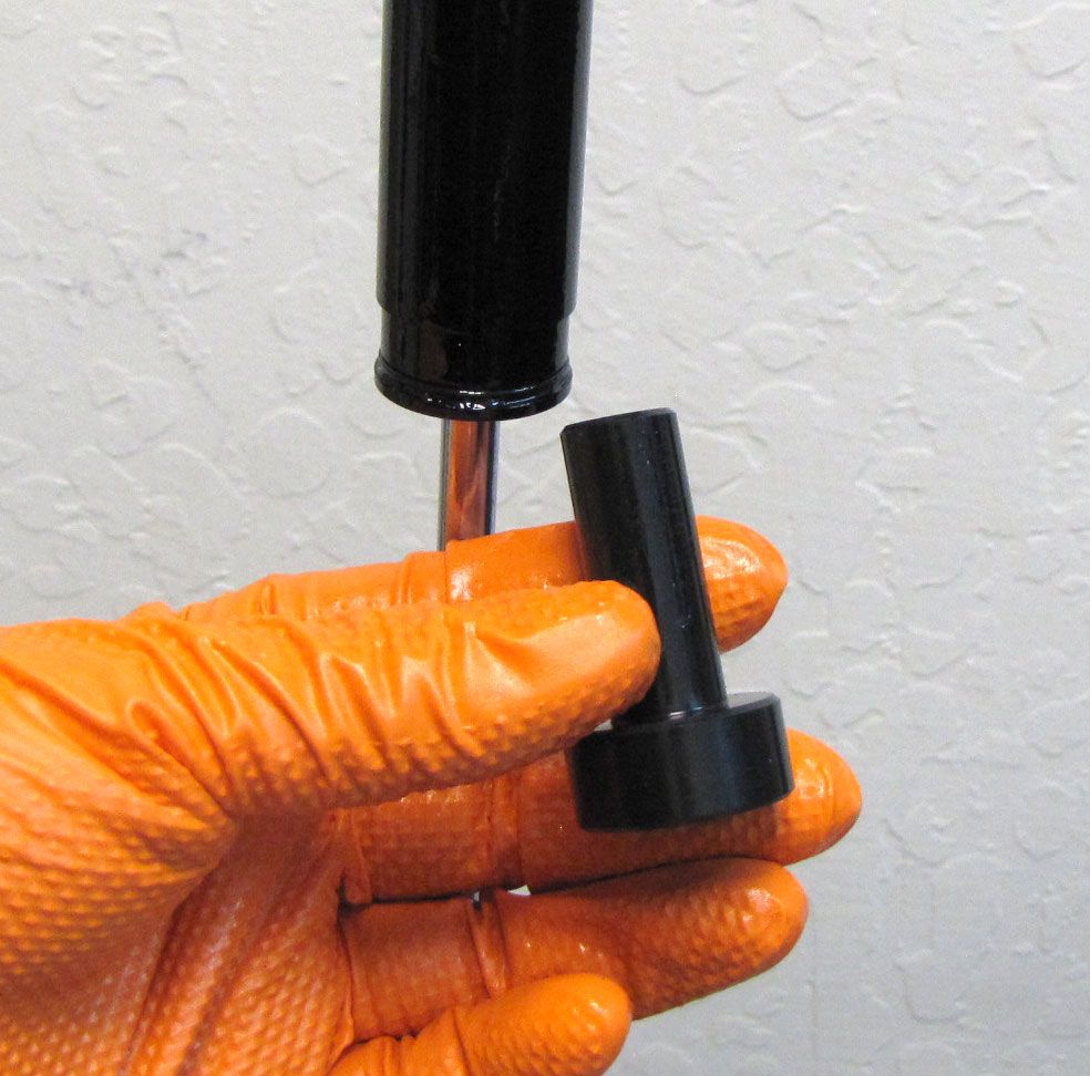
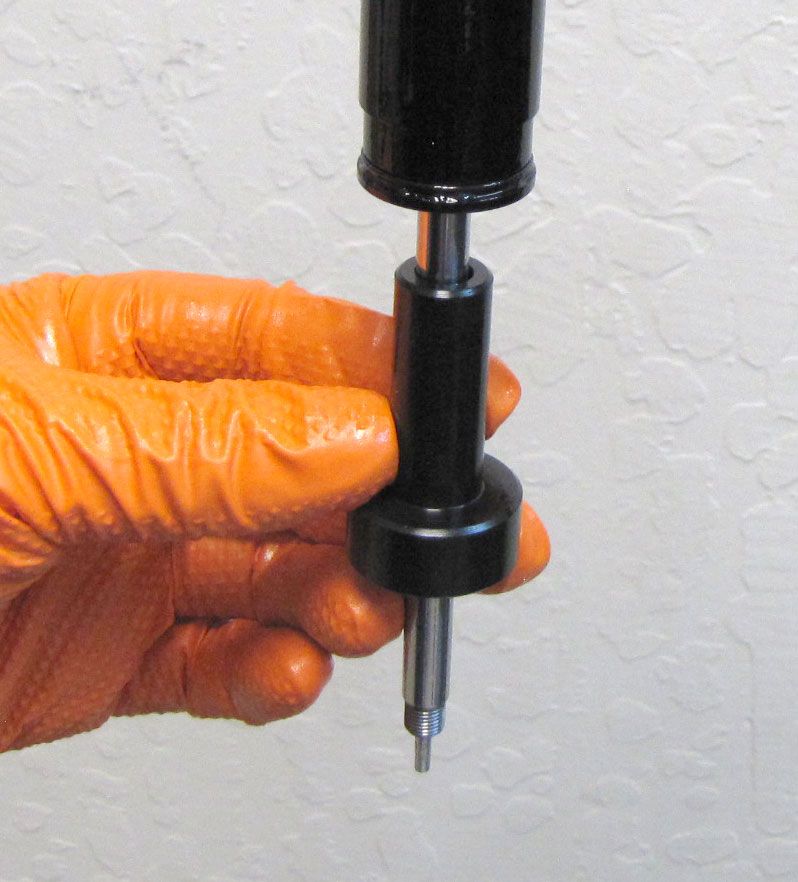
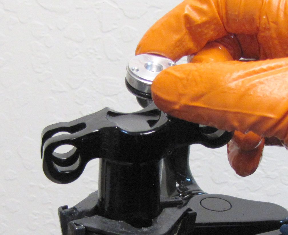
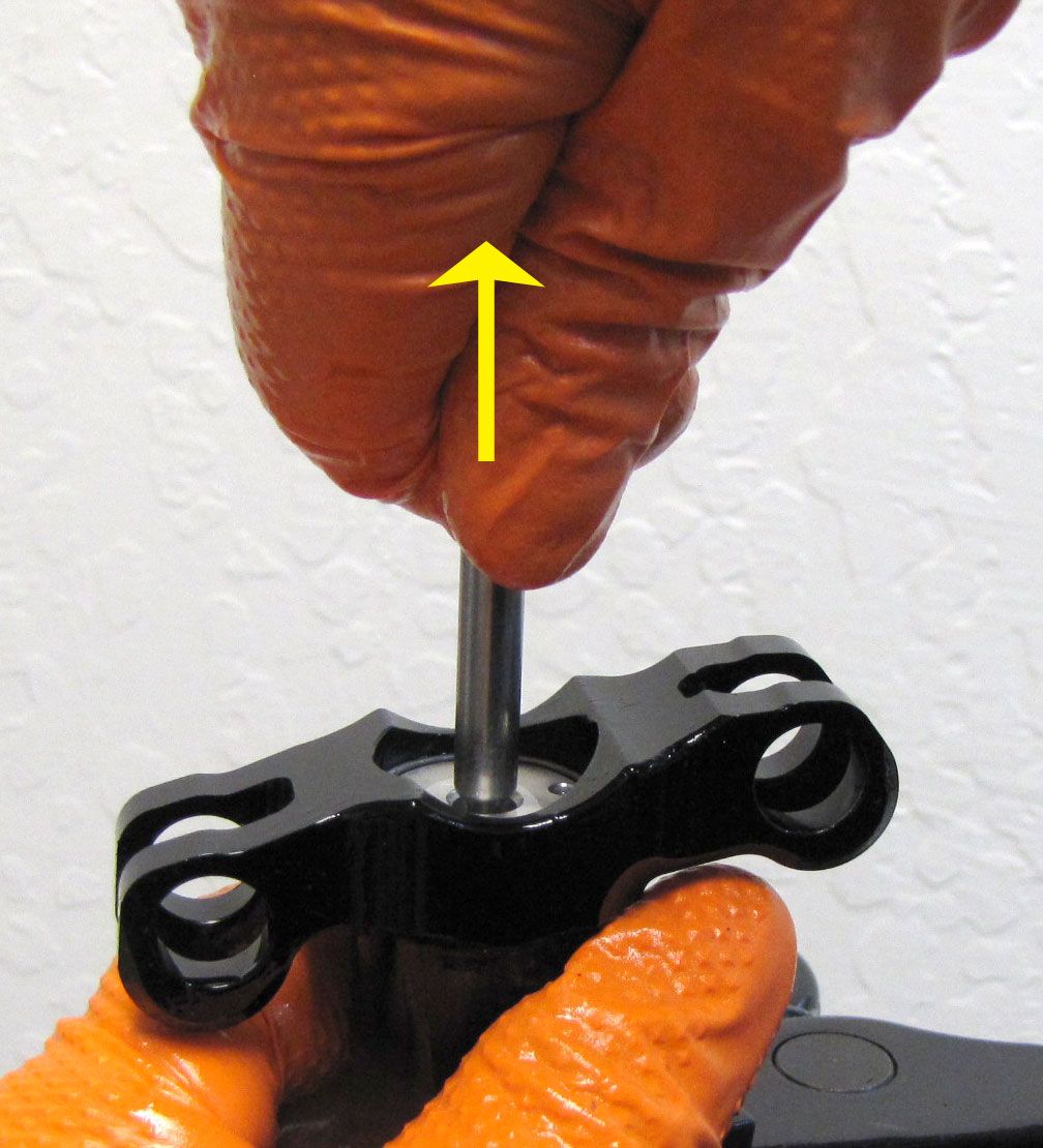
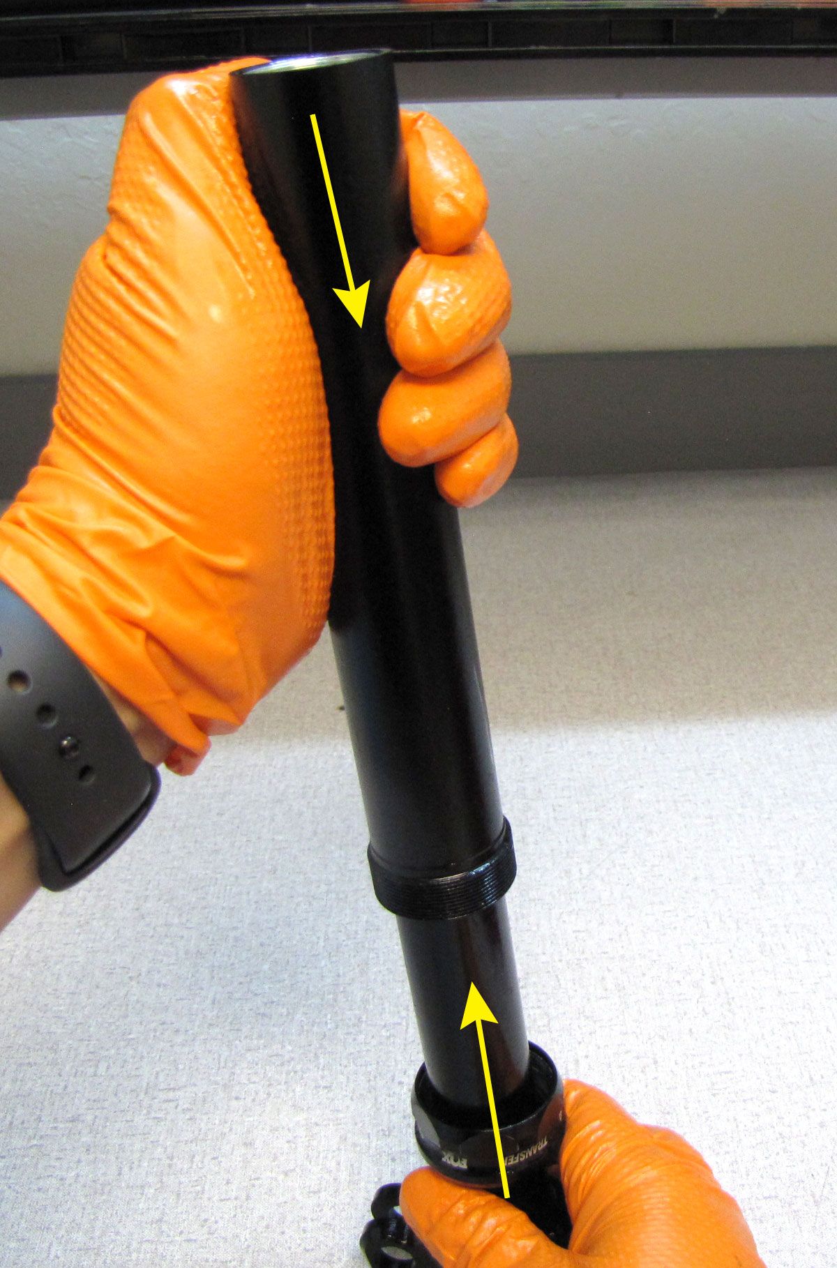
Step 5
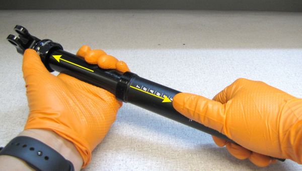
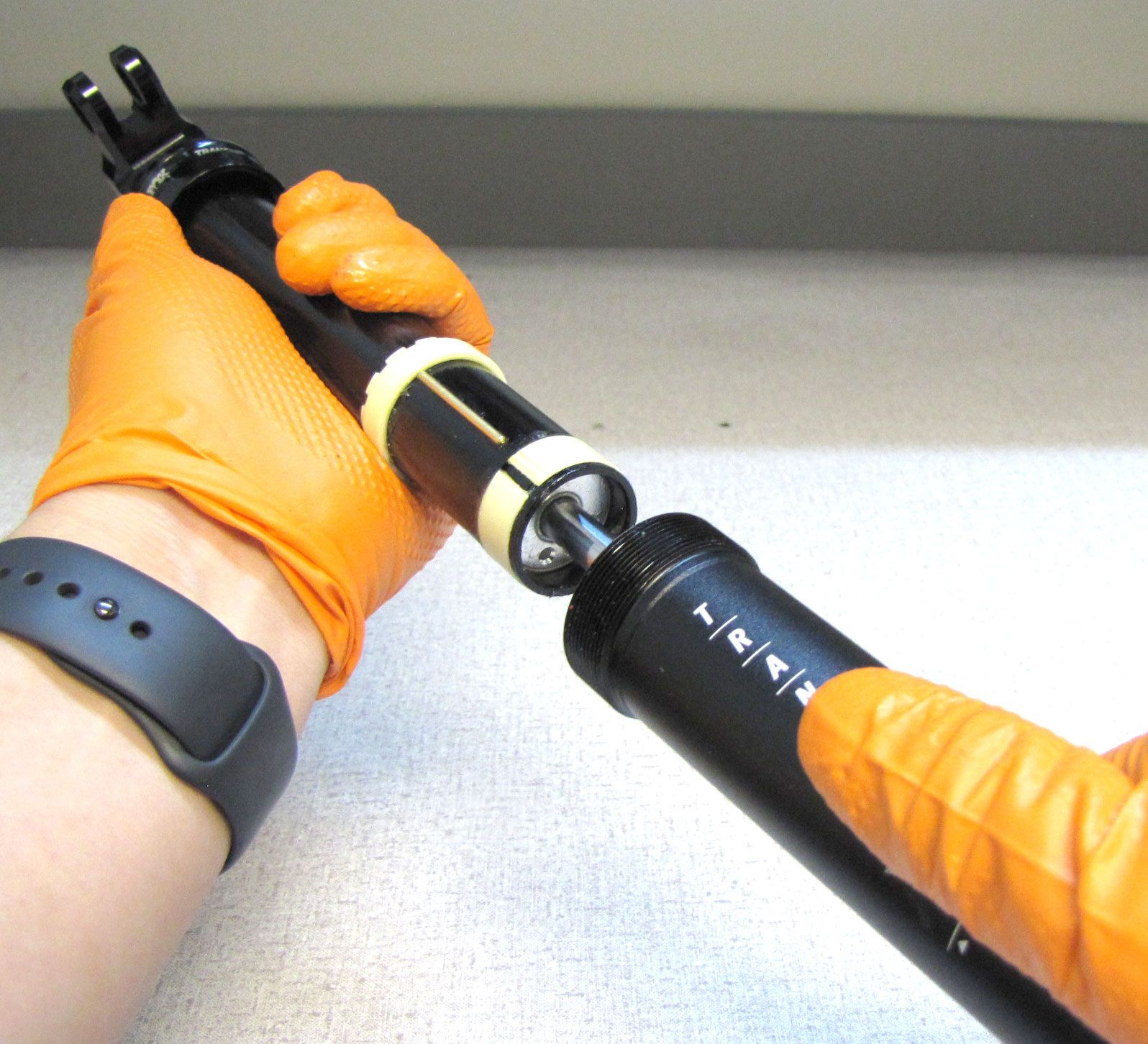
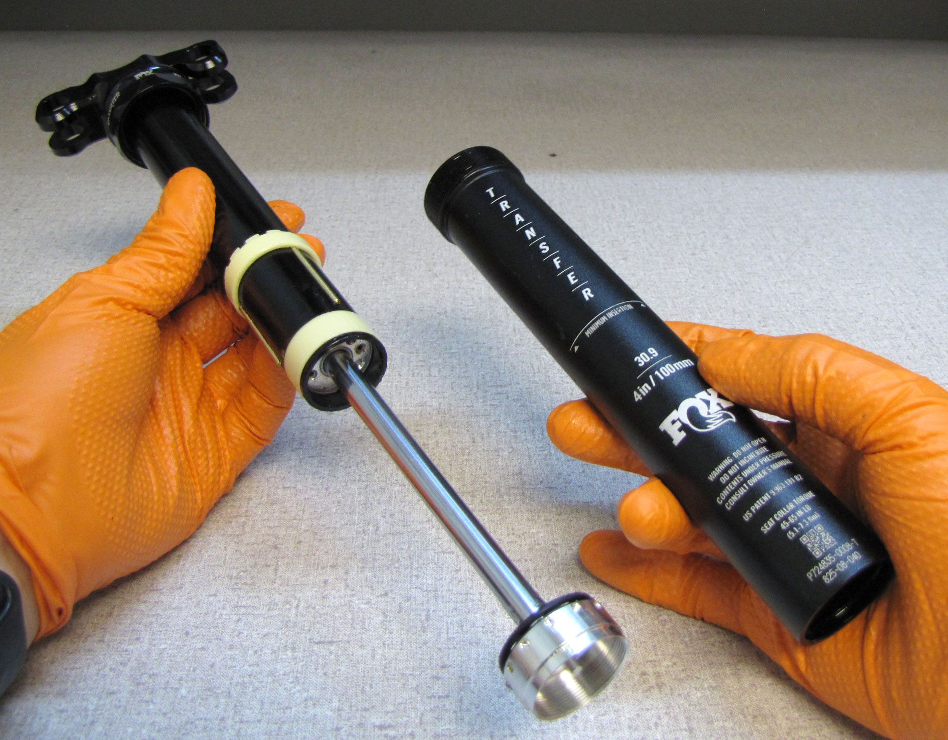
Separate the Upper Post Assembly from the Lower Post taking care not to lose the Index Pins and ball bearing as parts may fall out during separation.

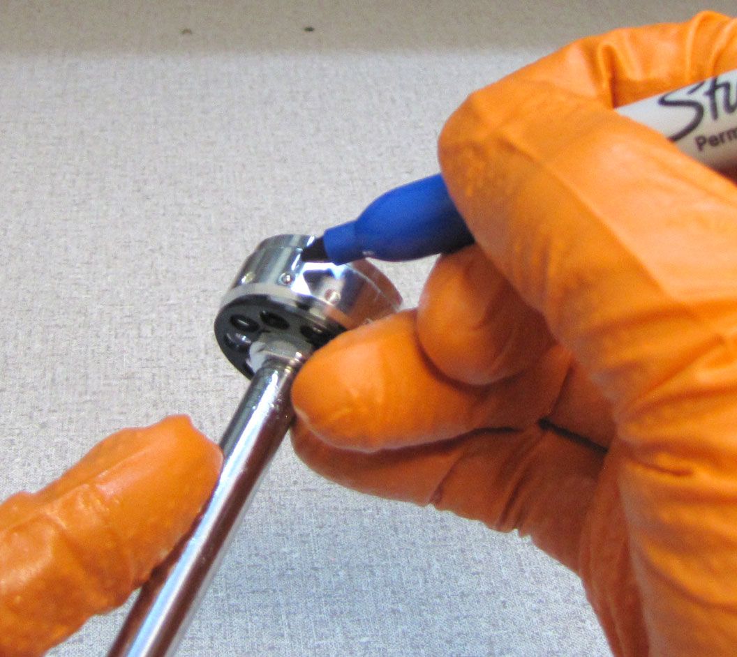
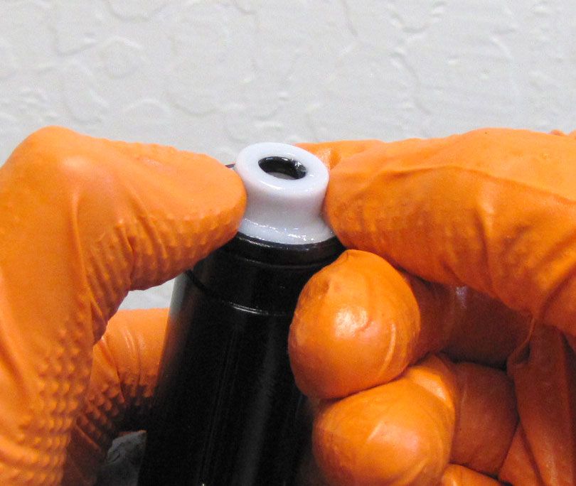
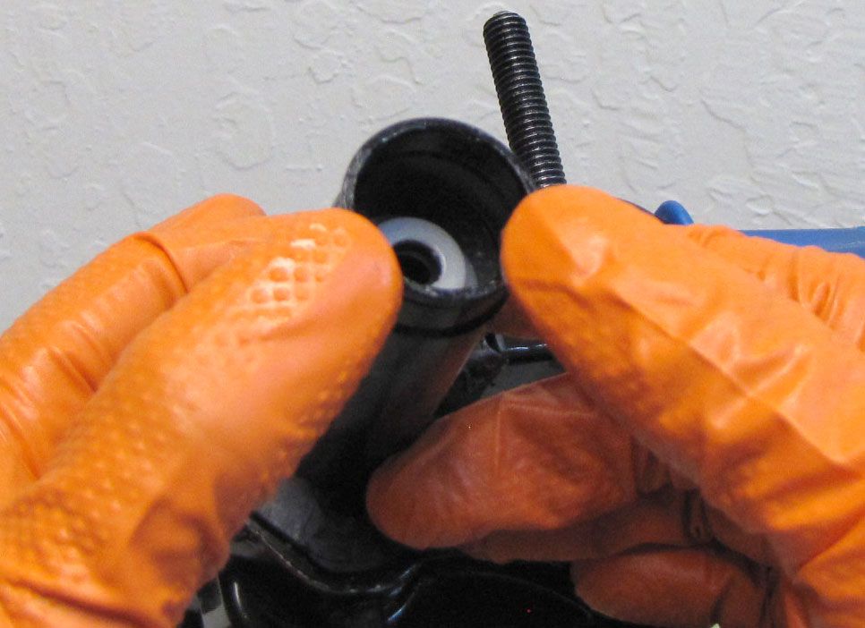
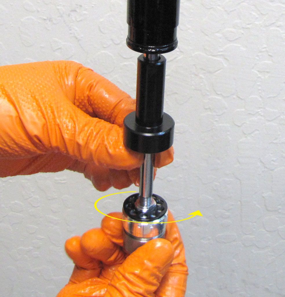
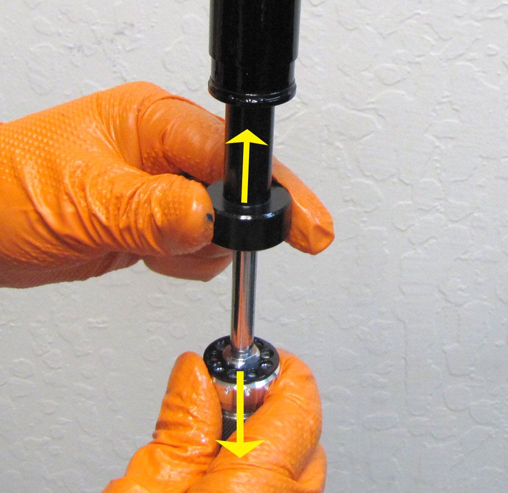
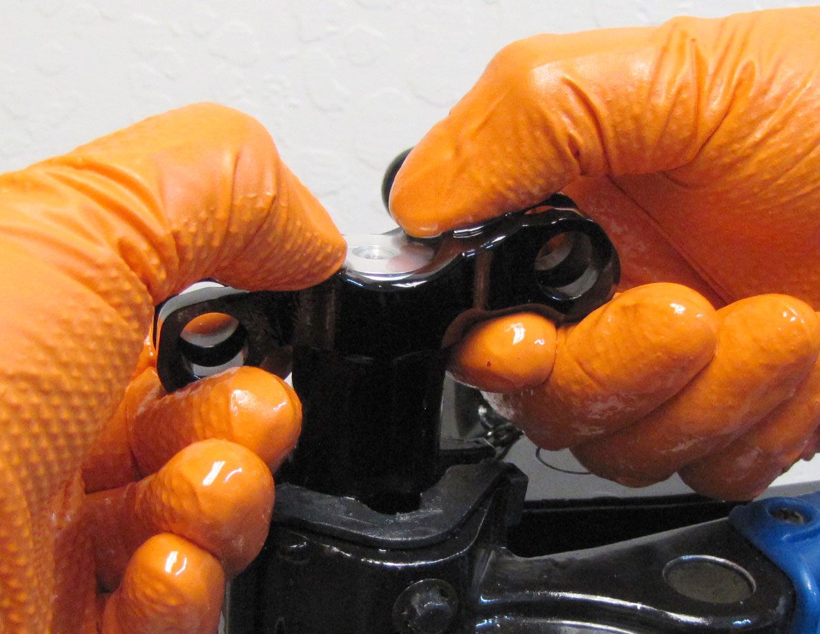
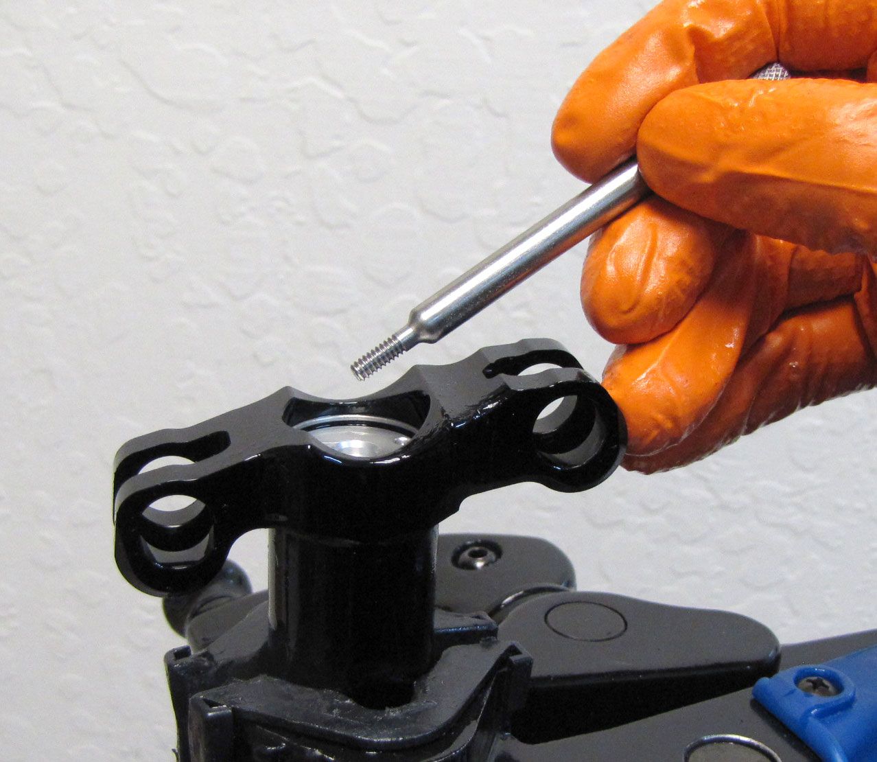
Step 6
Take note of the position of the ball bearing and mark the anti-rotation hole that the ball bearing was found in.
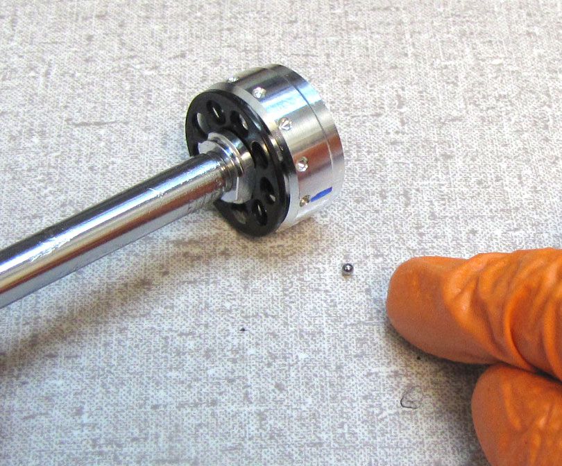
If you use a Sharpie or other marker to make this mark, take care not to remove the mark as you clean parts throughout the rebuild. A scribed line is also an option for marking the position of the ball bearing.
Remove the 2mm ball bearing and set it aside in a protected location as it is small and easy to lose.

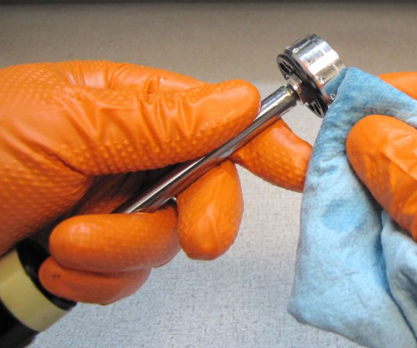
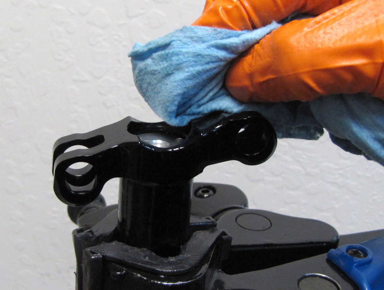
Step 7
Clean the Lower Post with Ispropyl alcohol and a lint-free paper towel taking care not to leave any paper towel residue inside the Lower Post.

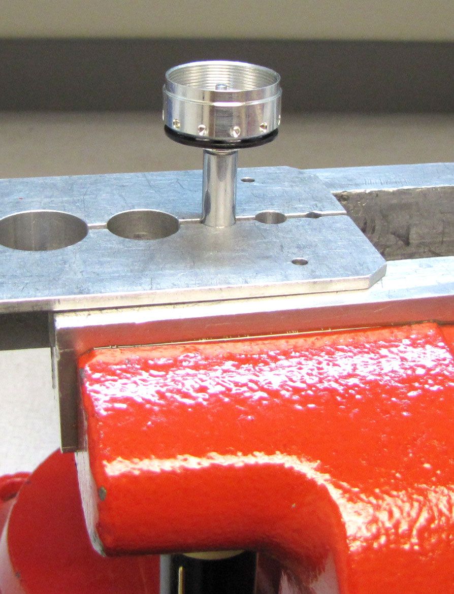
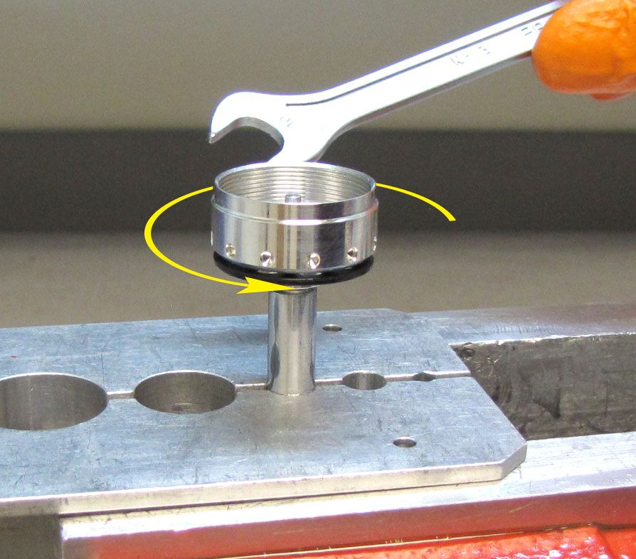
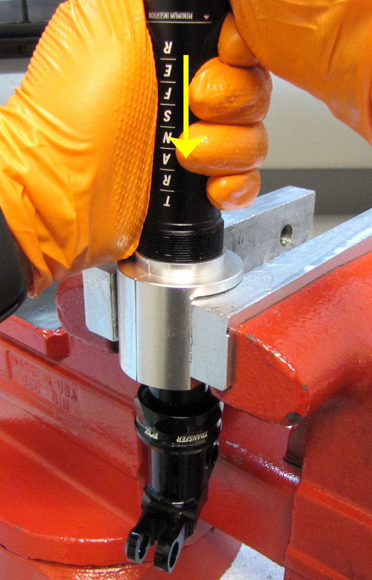
Step 8
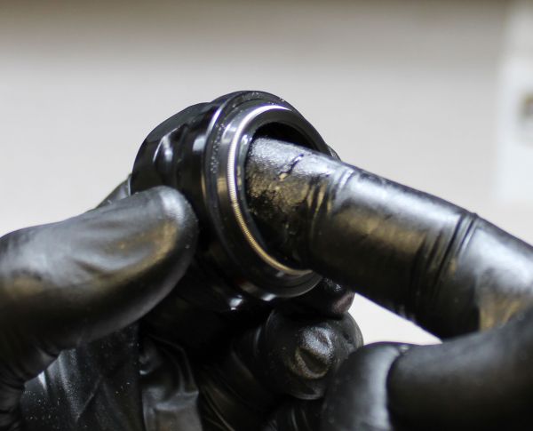
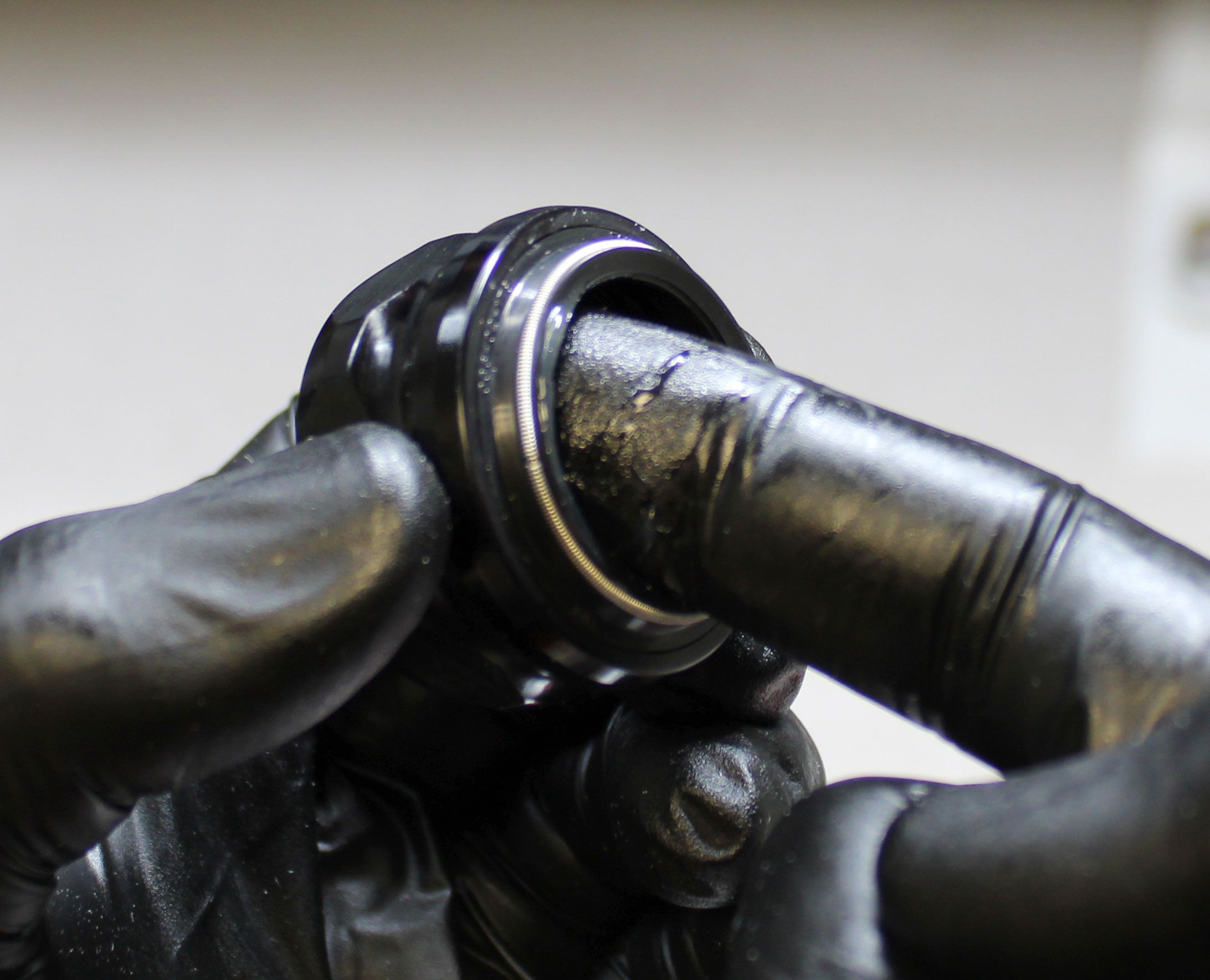
Carefully clamp the Shaft in your shaft clamps (PN: 803-00-147) using proper shaft clamp techniques to prevent damage to the sealing surface, then unthread the Shaft Lug counter clockwise with a 10mm wrench to remove it. Remove the original bottom out bumper.
Step 9
Remove the Lower Bushing, o-ring under the Lower Bushing, Index Pins, Upper Bushing, and Lower Post Collar. (Note: an early down-rev Upper Bushing is shown. MY21 production Transfer seatposts will have a smooth-rimmed Upper Bushing without the castellation).


Step 10
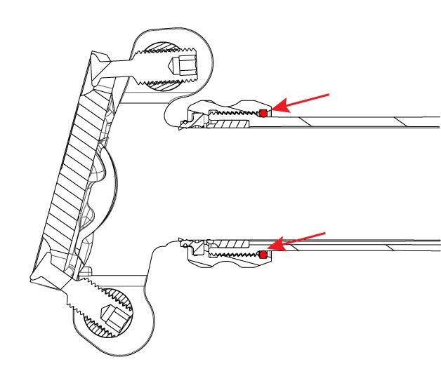
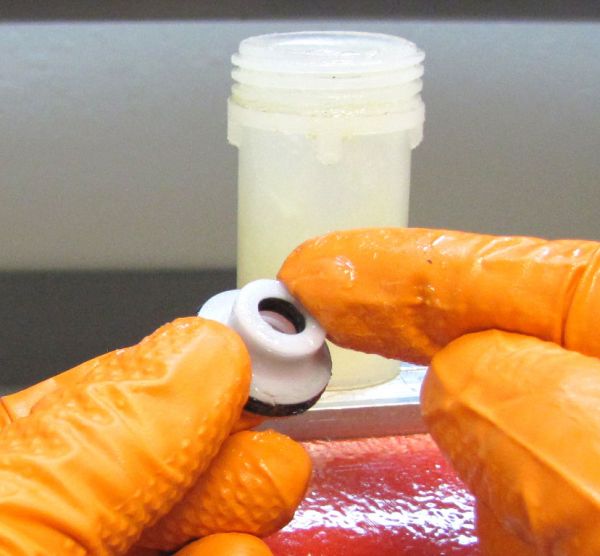
Replace the wiper and o-ring in the collar assembly with the new ones from the kit.
Note that the o-ring was moved from it's original position during disassembly. The correct o-ring position is noted in the drawing.


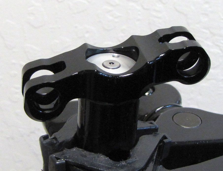
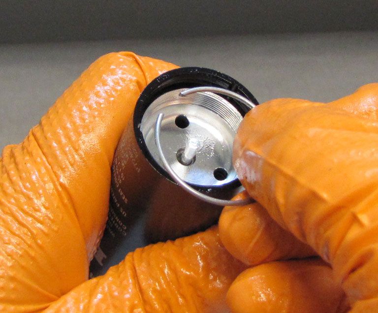
Step 11
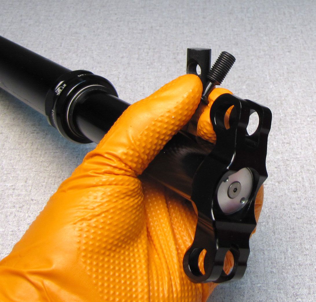
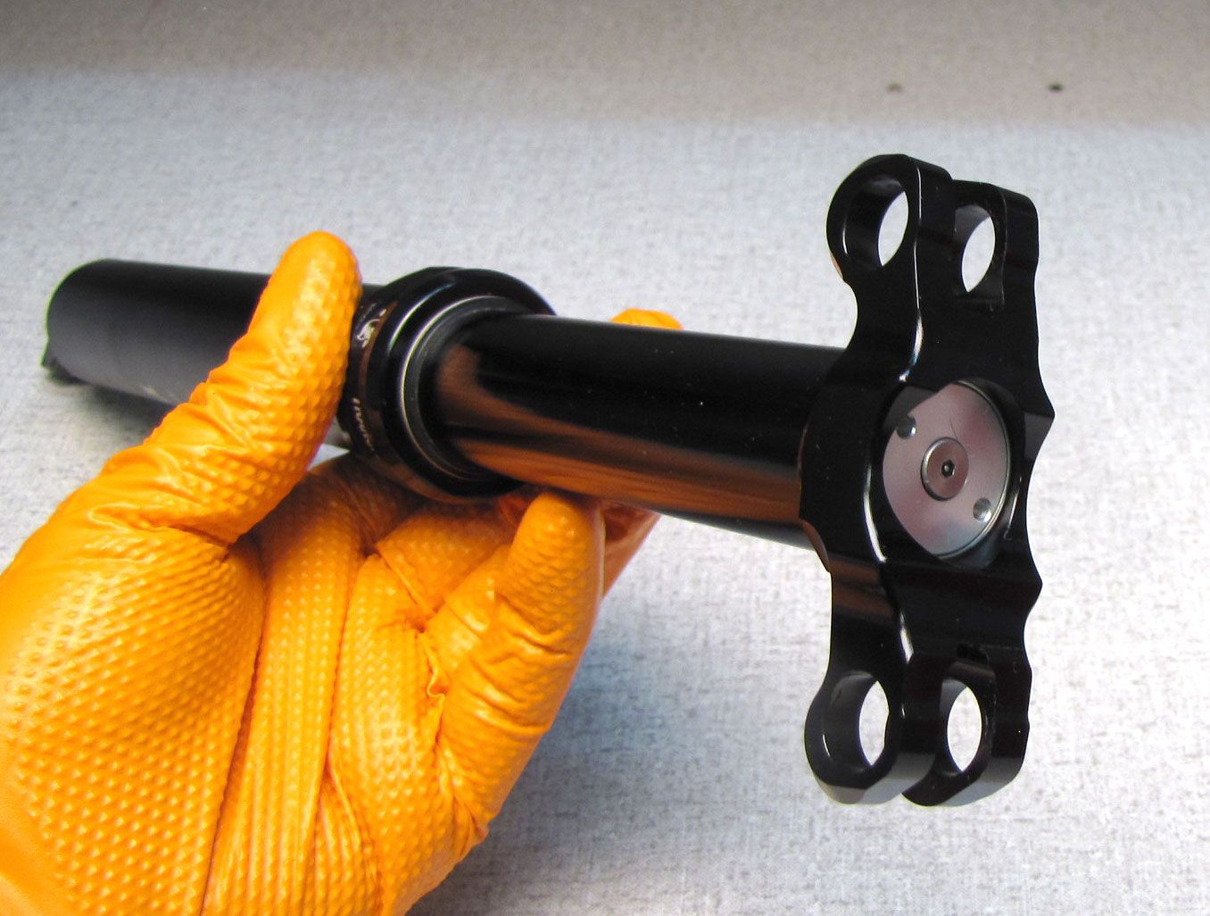
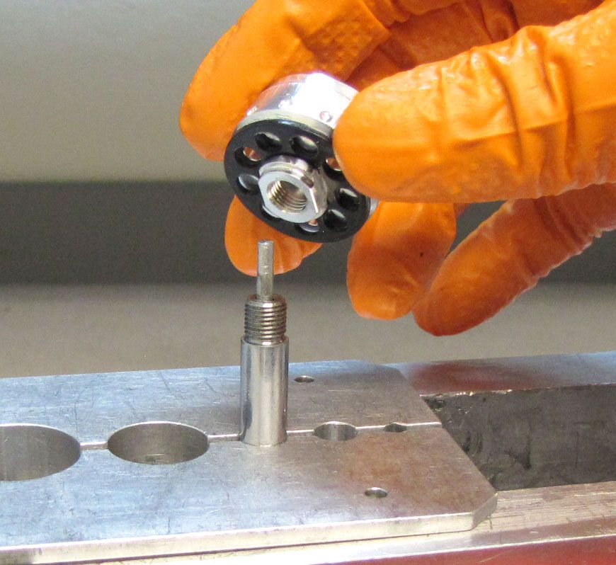
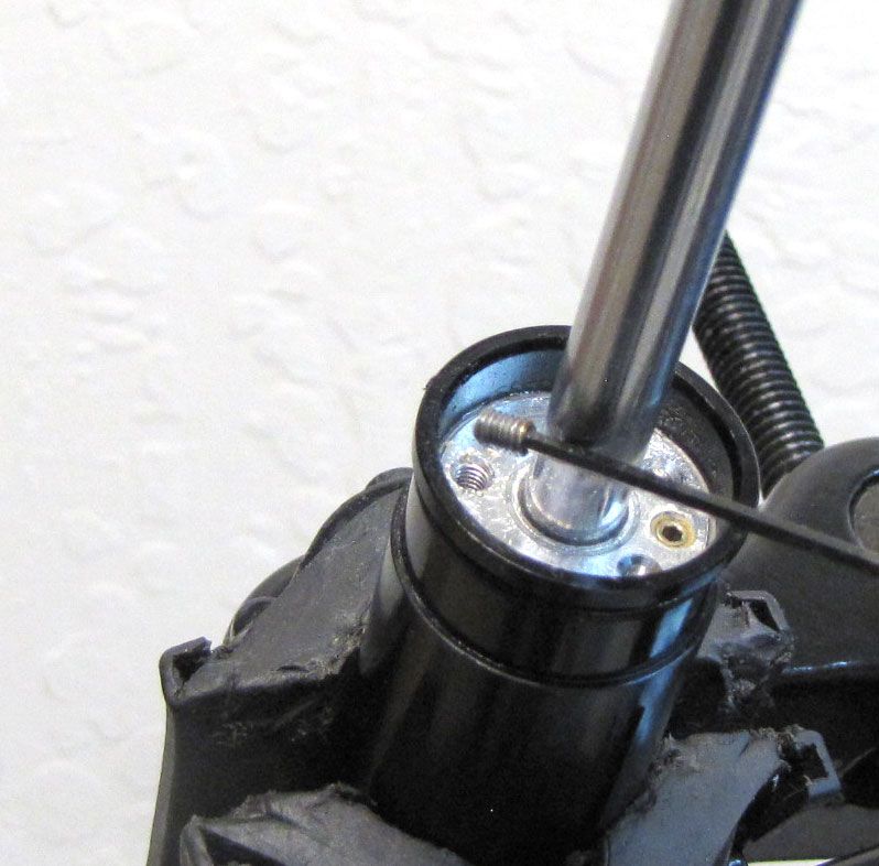
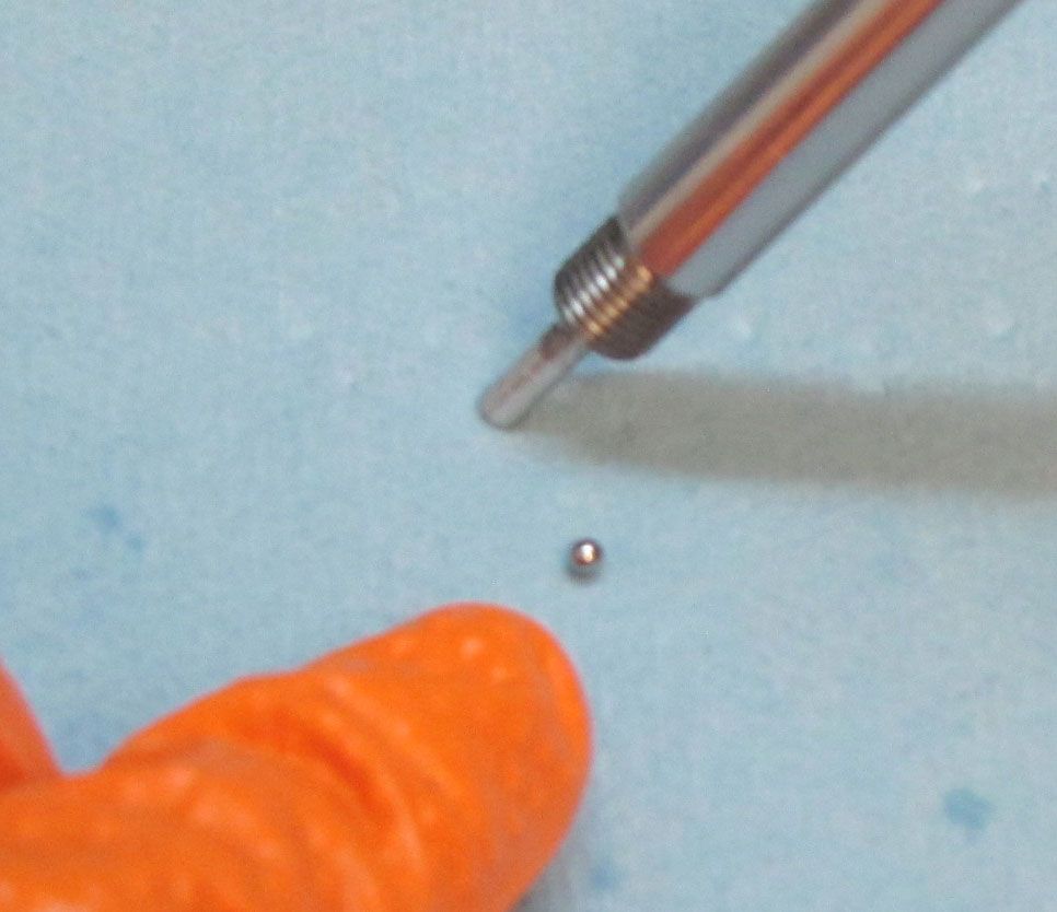
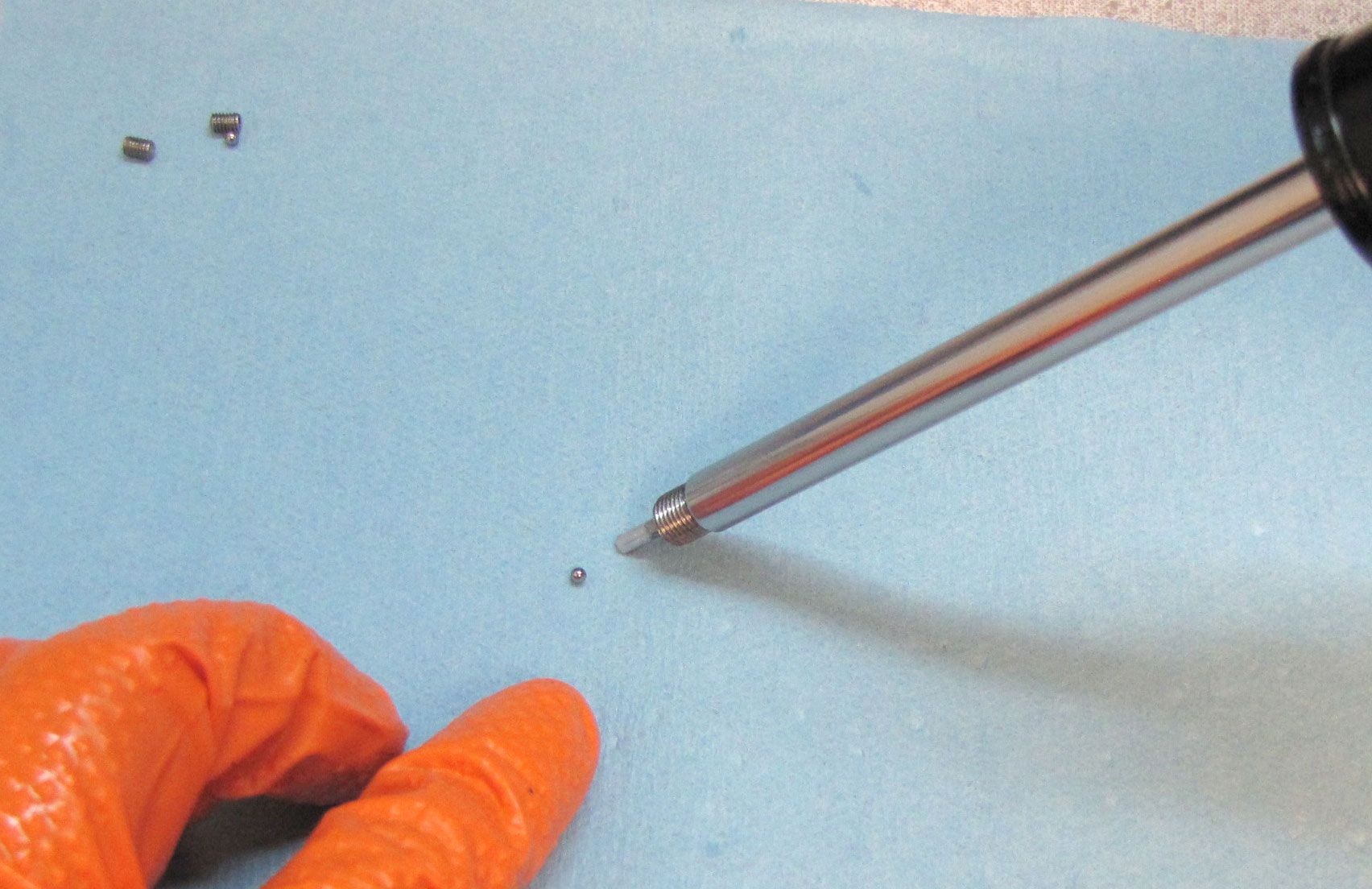
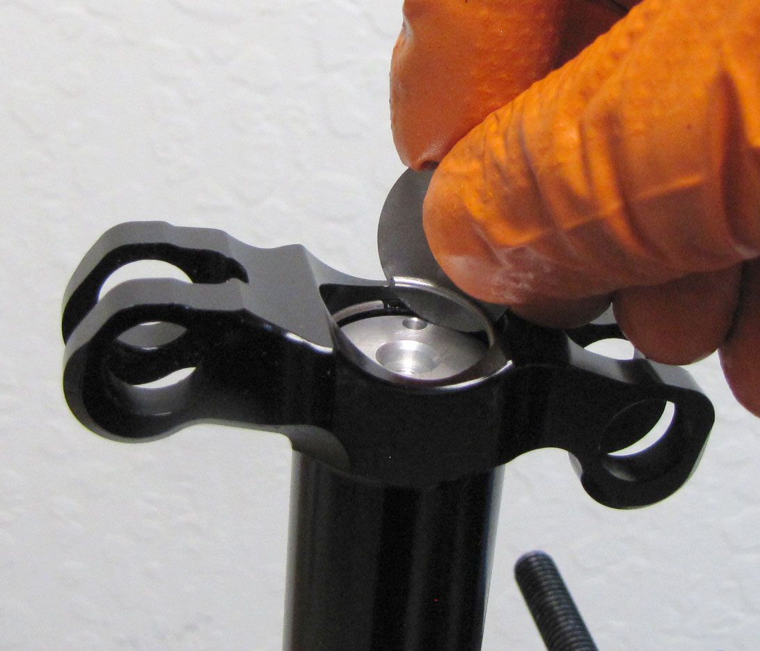
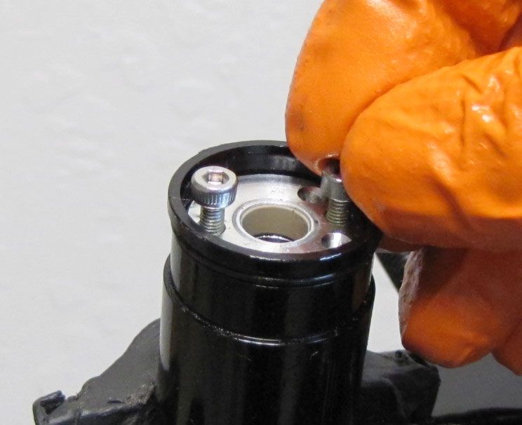
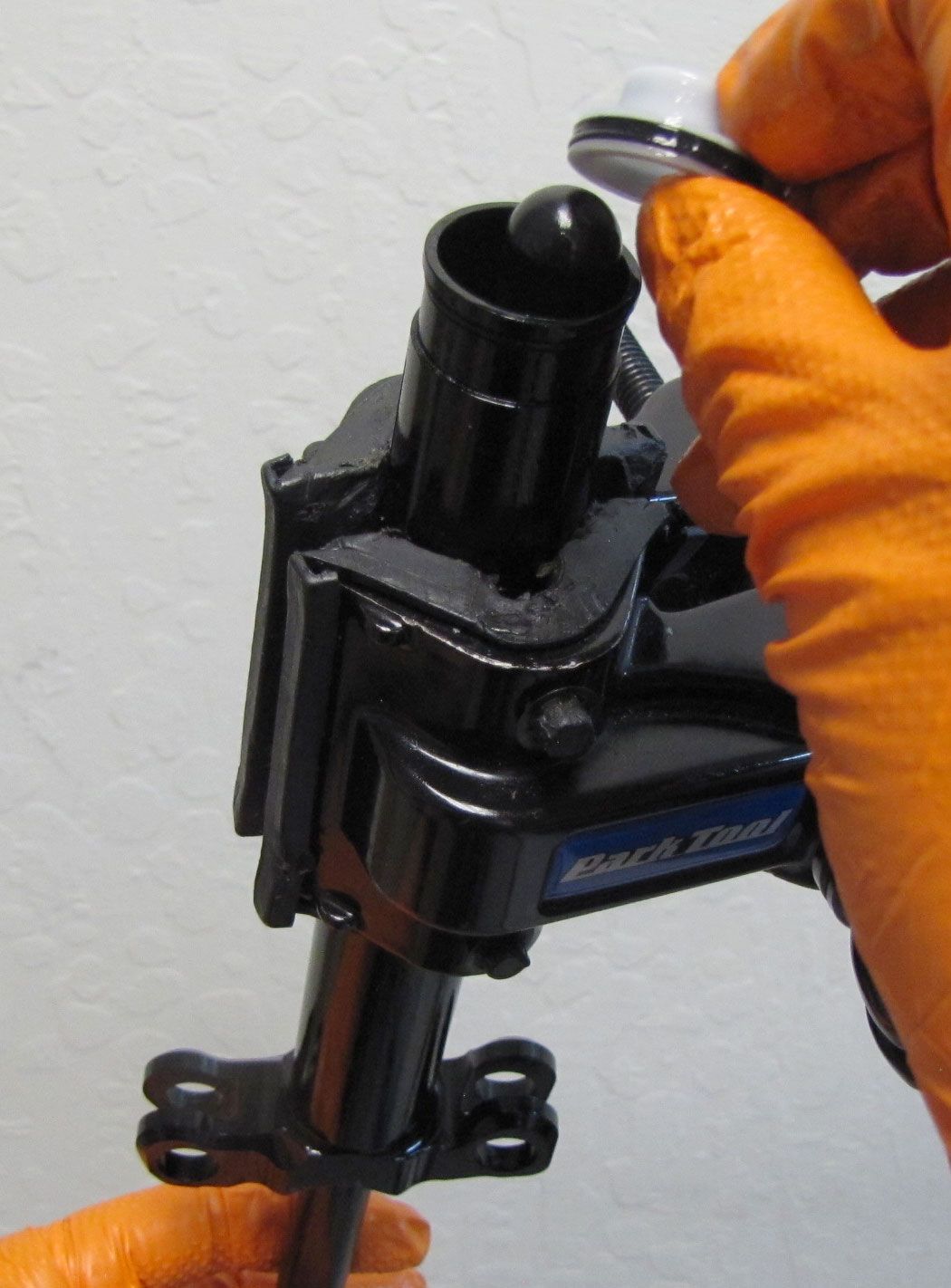
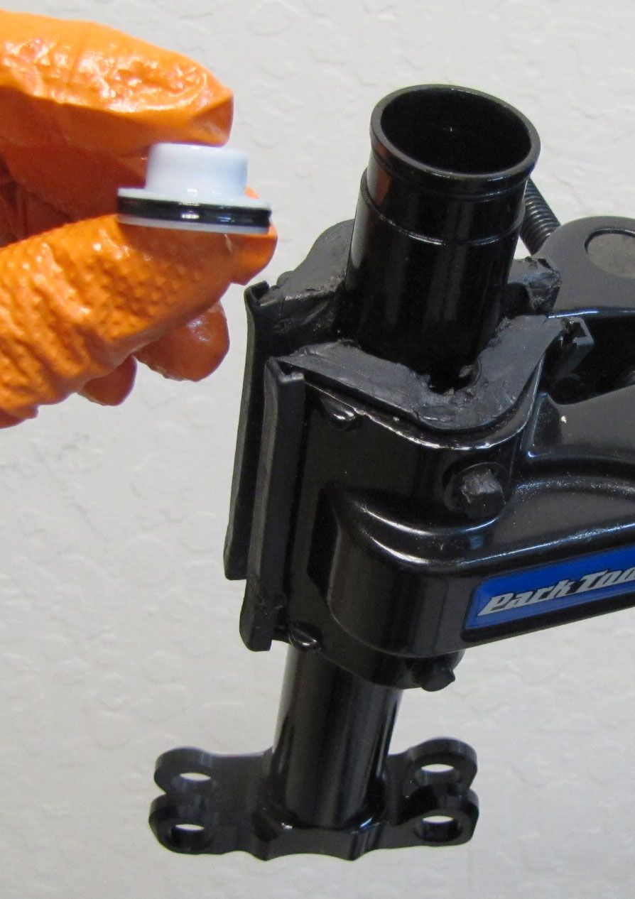
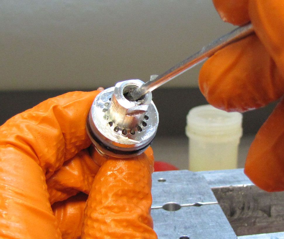
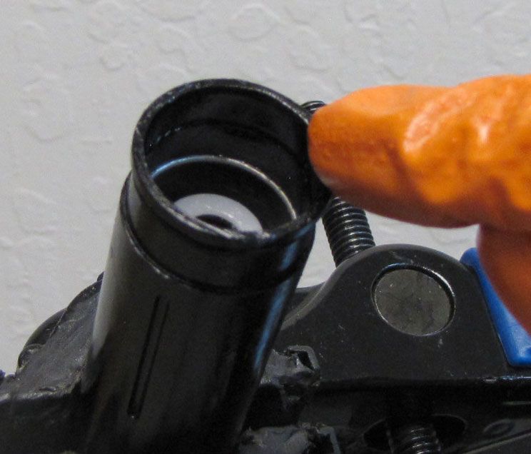
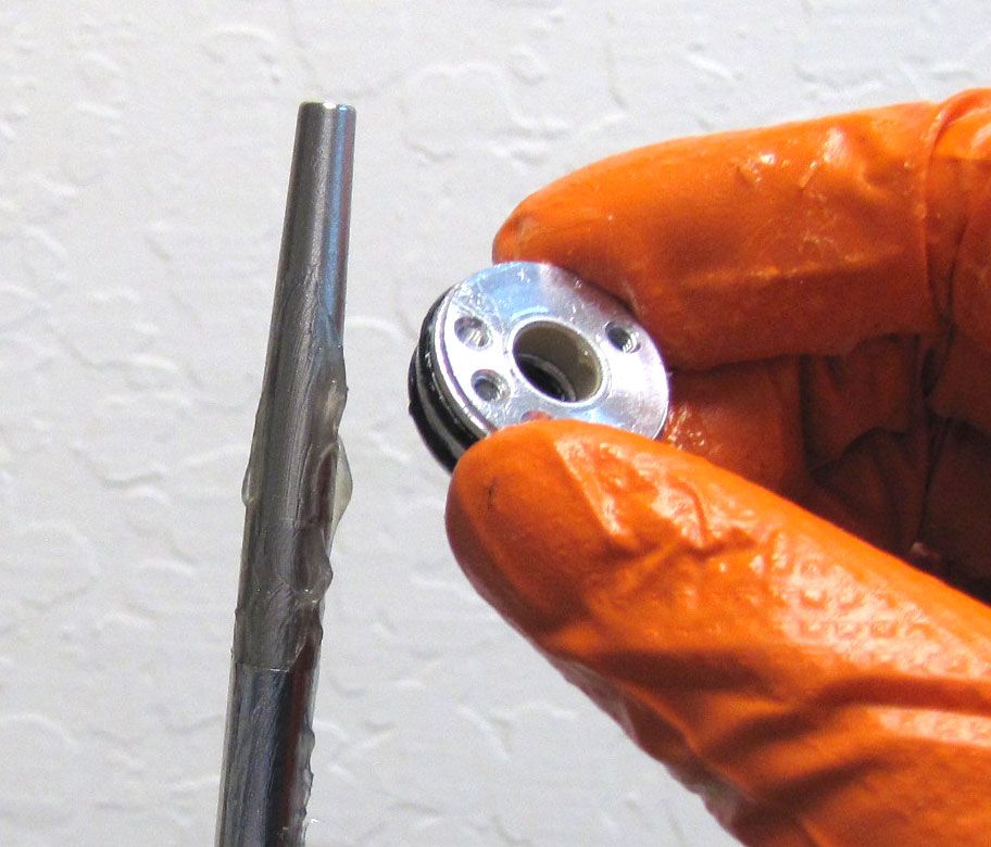
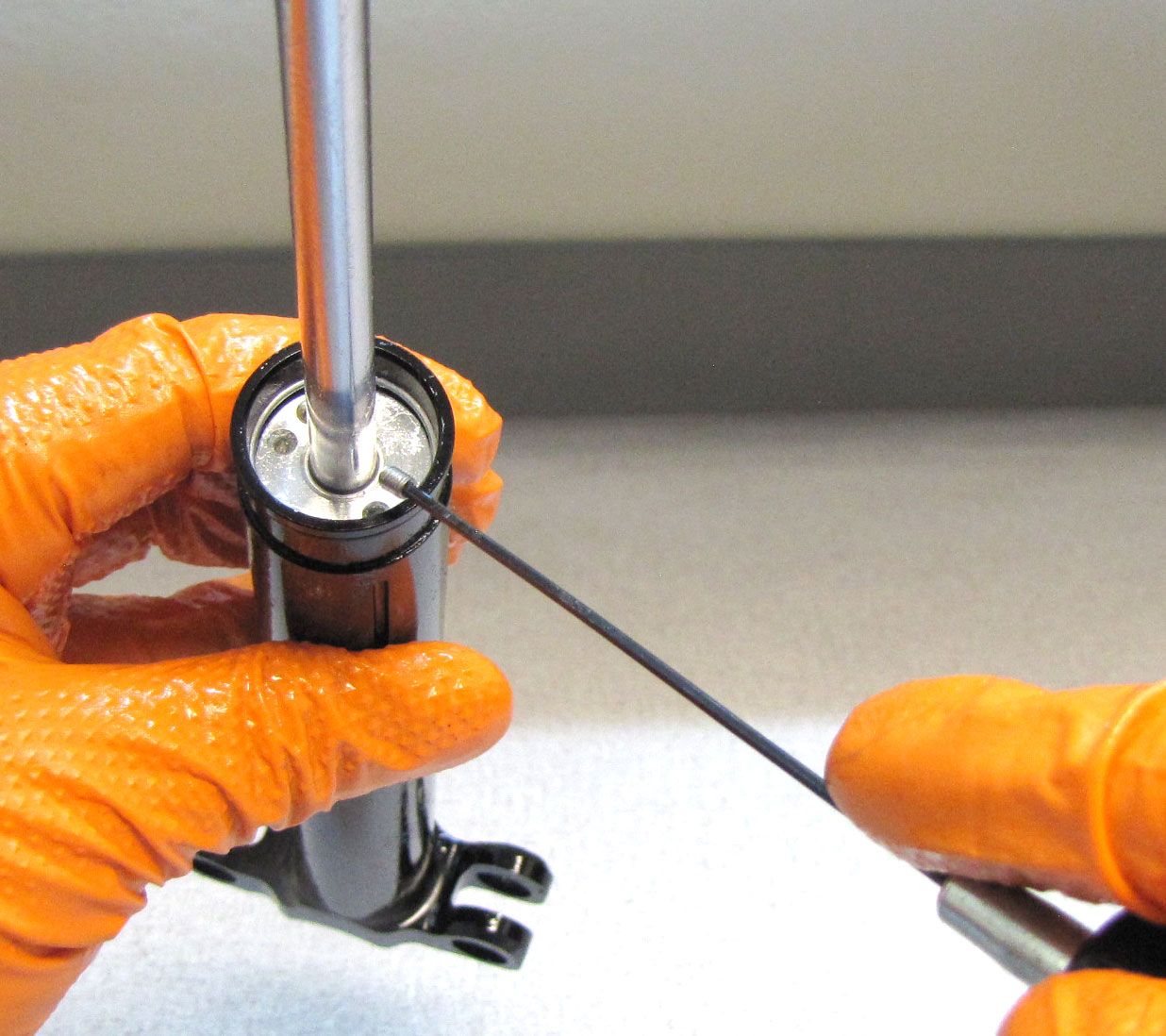
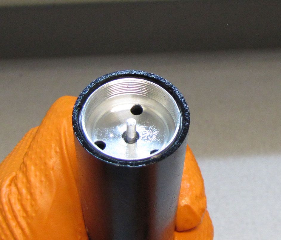
Clamp the Upper Post in your bike work stand, then slowly unthread the bleed screw to release IFP pressure. Remove the screw from the Sealhead with a 1.5mm hex wrench. The bleed screw is the M3 screw that is farthest from the two blind holes in the Sealhead. Make sure that all pressure is released before moving on to the next step. Remove the 0.083" ball bearing from beneath the bleed screw. A magnet may be necessary for removal.
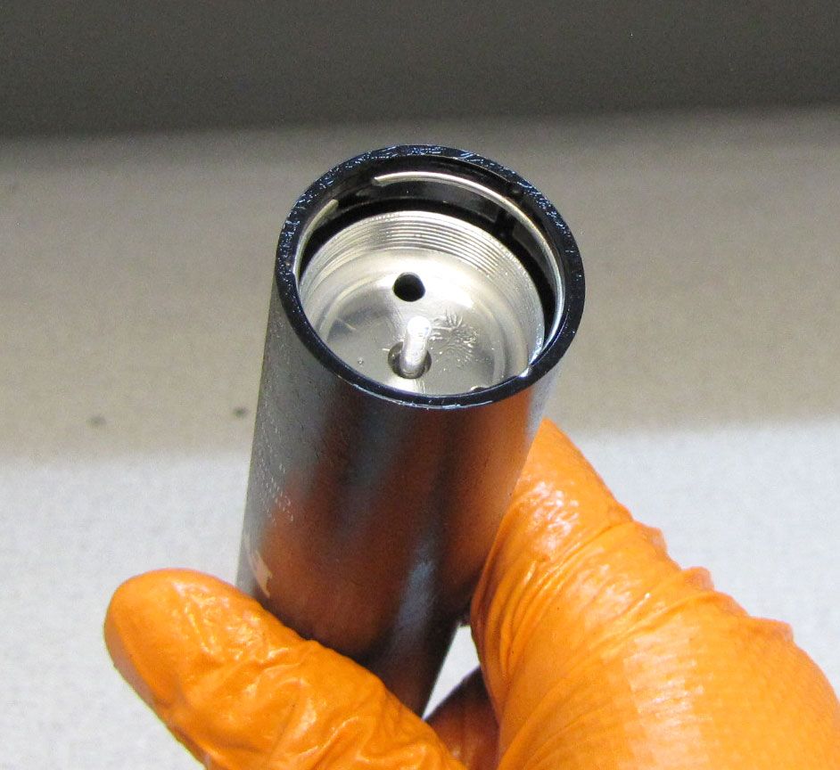
Step 12
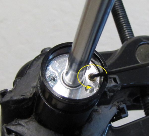
Remove the fill screw from the Sealhead with a 1.5mm hex wrench. The fill screw is the M3 screw closest to the blind holes in the Sealhead. Remove the 0.083" ball bearing from beneath the bleed screw.


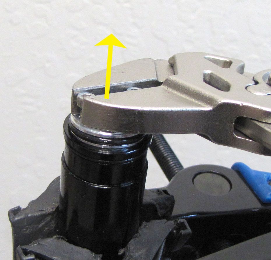
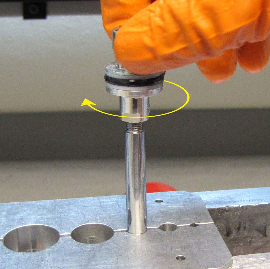
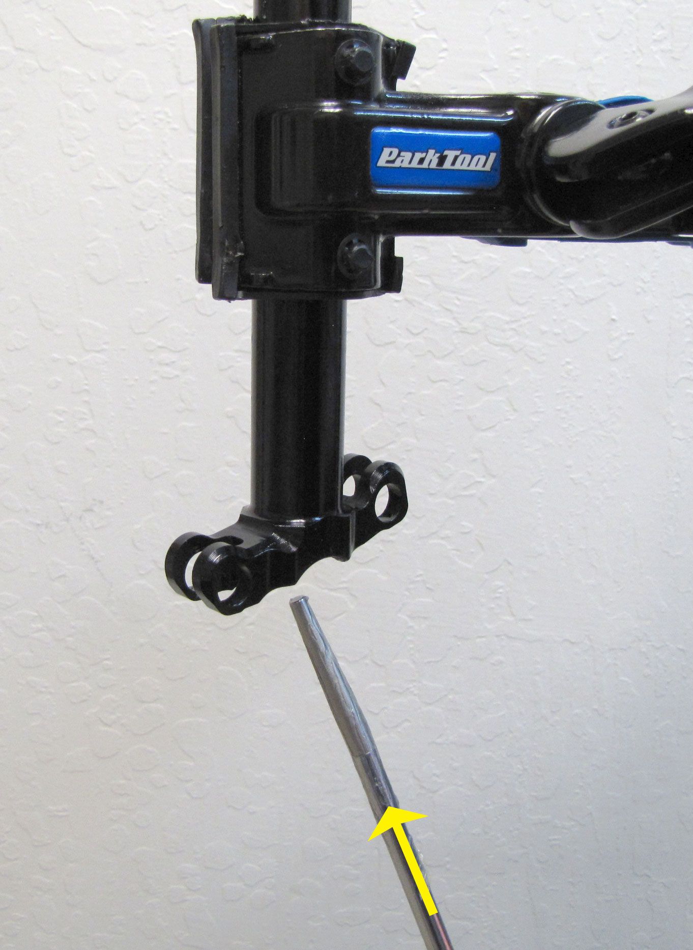
Step 13
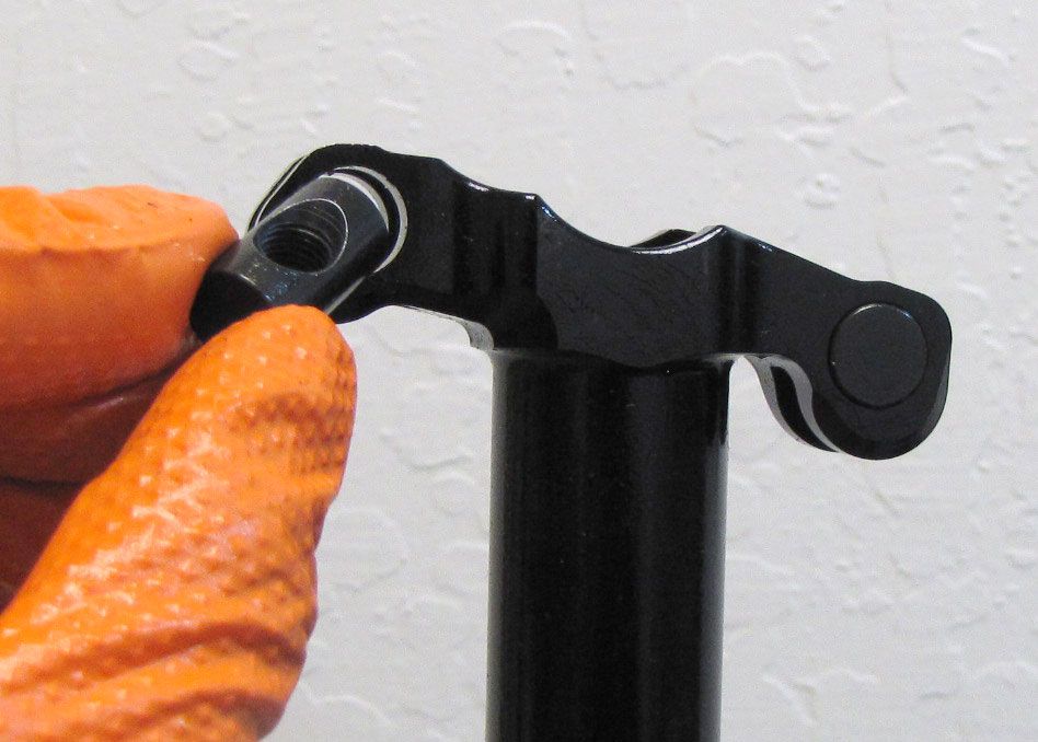
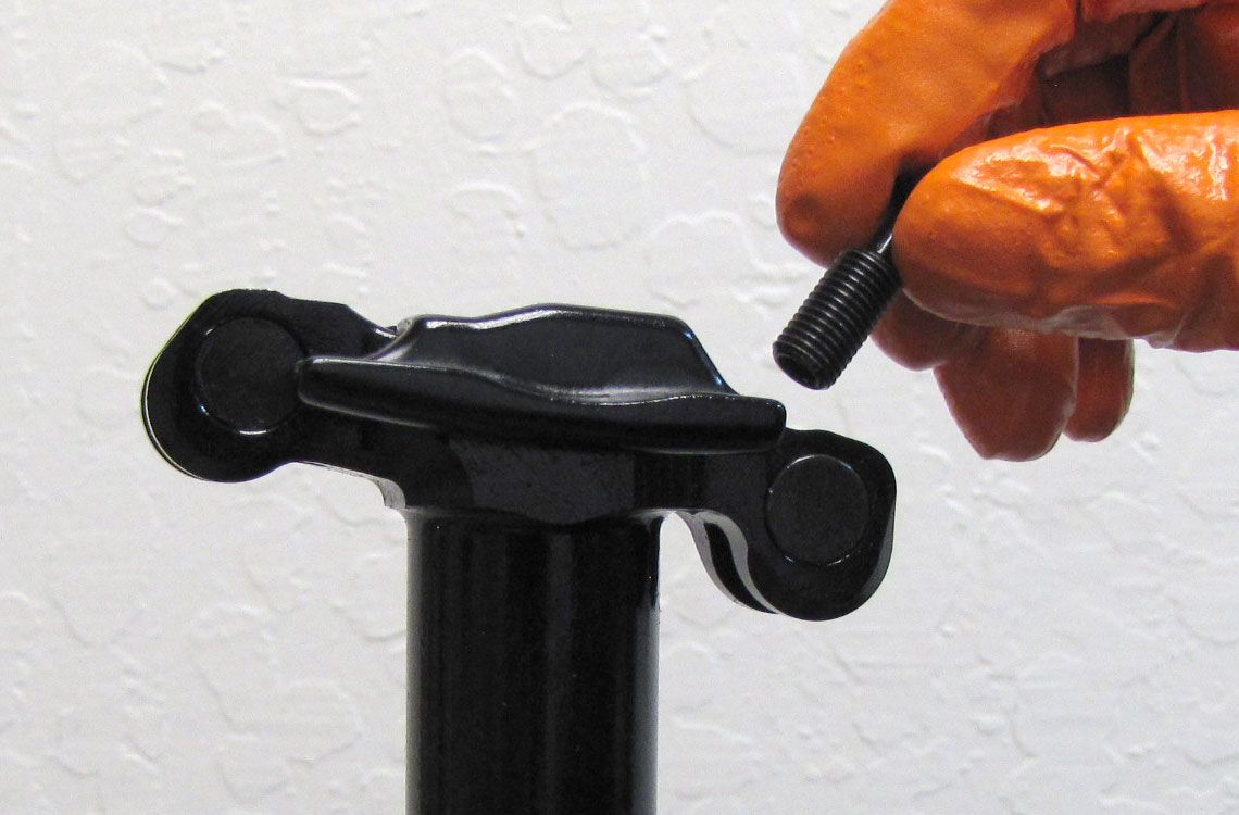
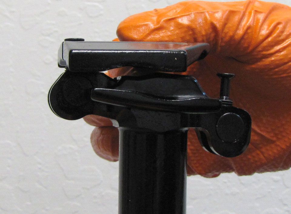
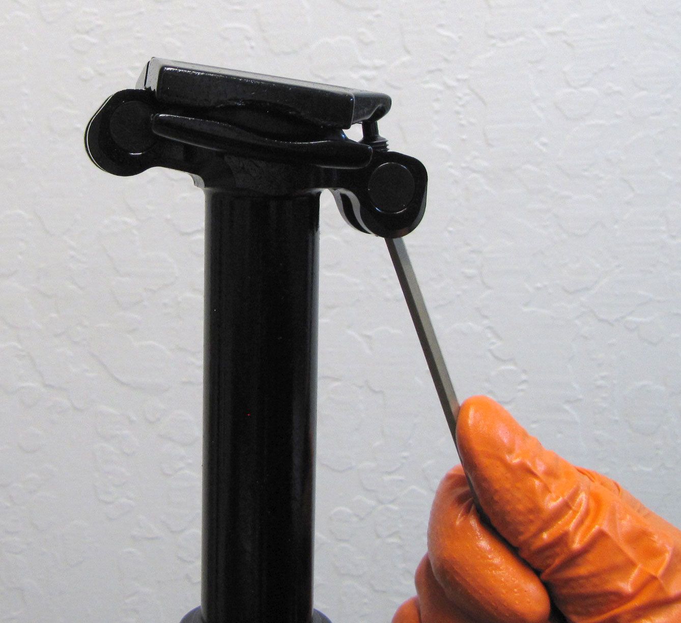
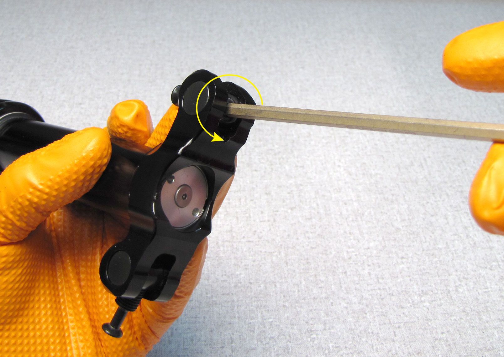
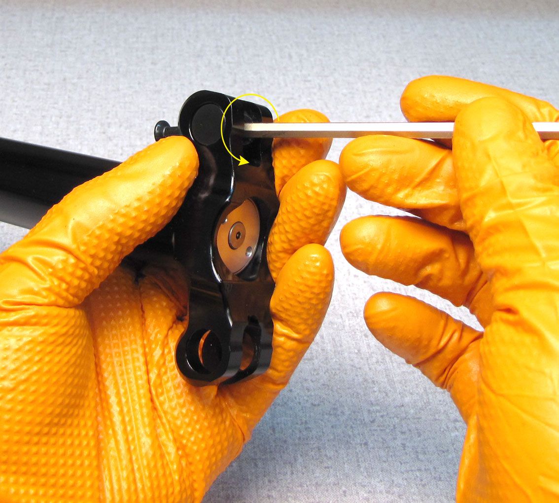
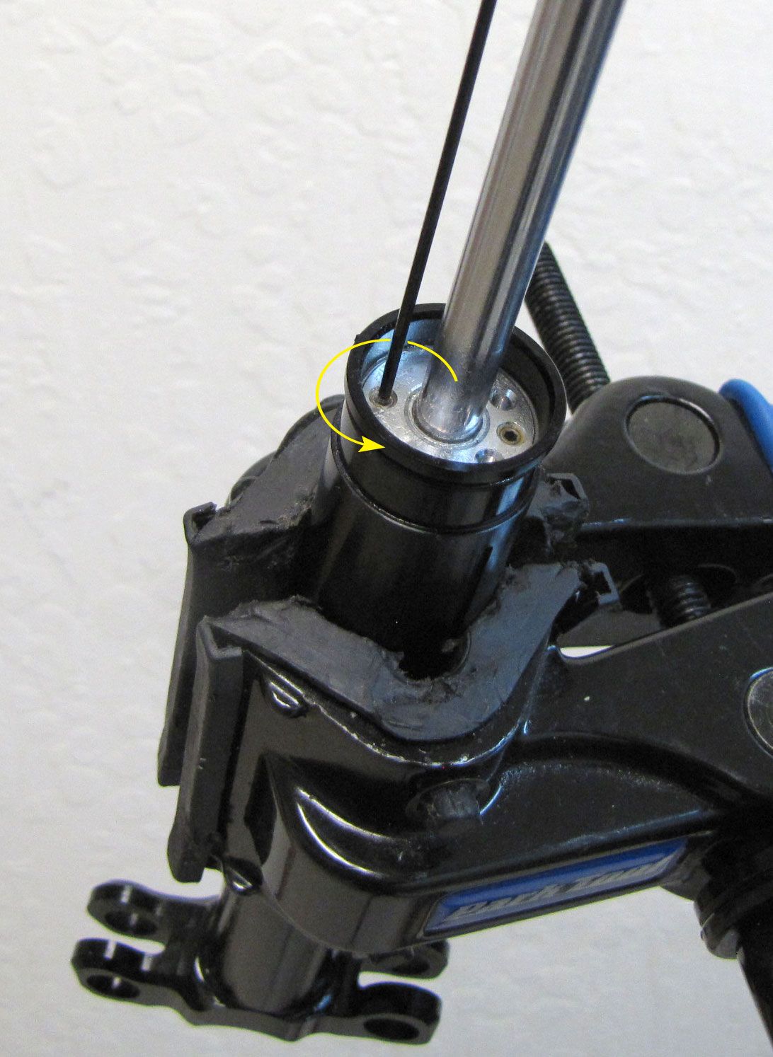
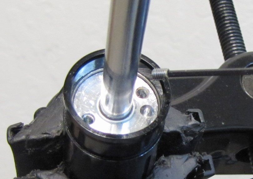
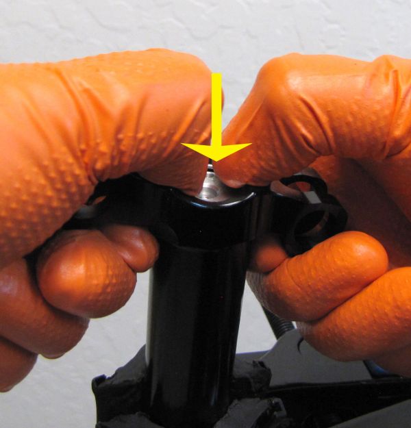
With the Upper Post clamped vertically in your bike work stand unthread (counter-clockwise) and remove the Anti-Tamper screw with a 5/64 Anti-Tamper Hex wrench. You may need to hold the Top Cap Assy from turning with a pin spanner.
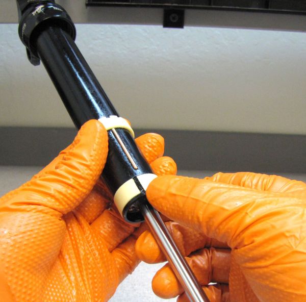
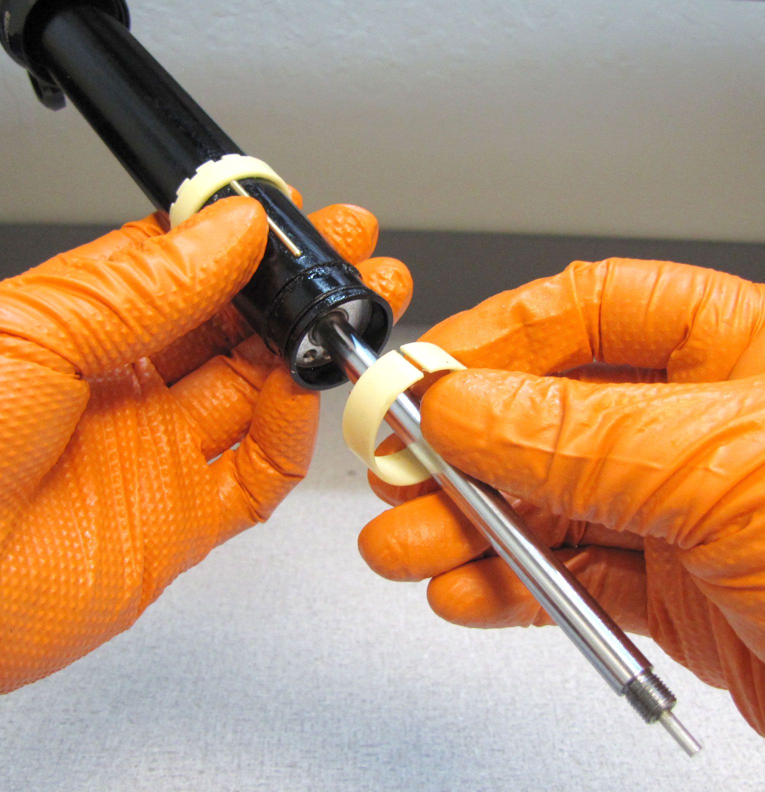
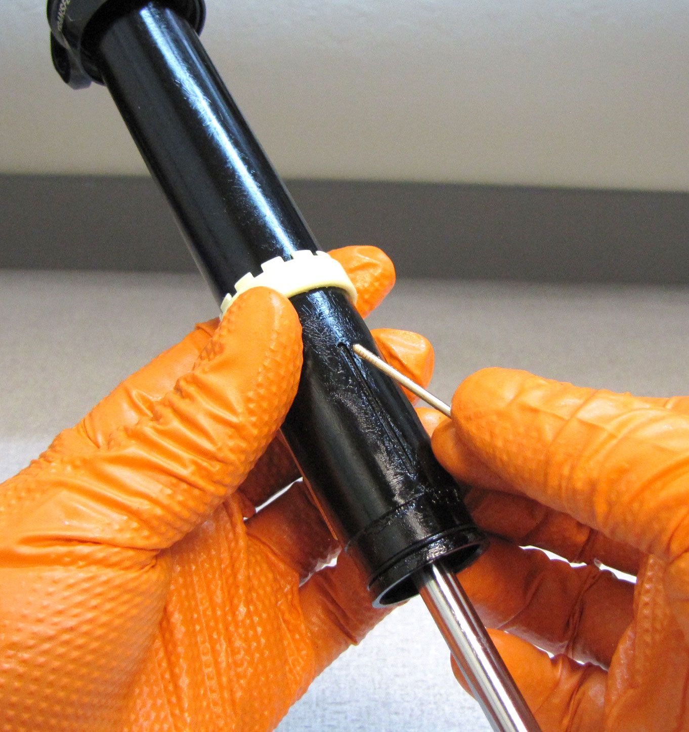
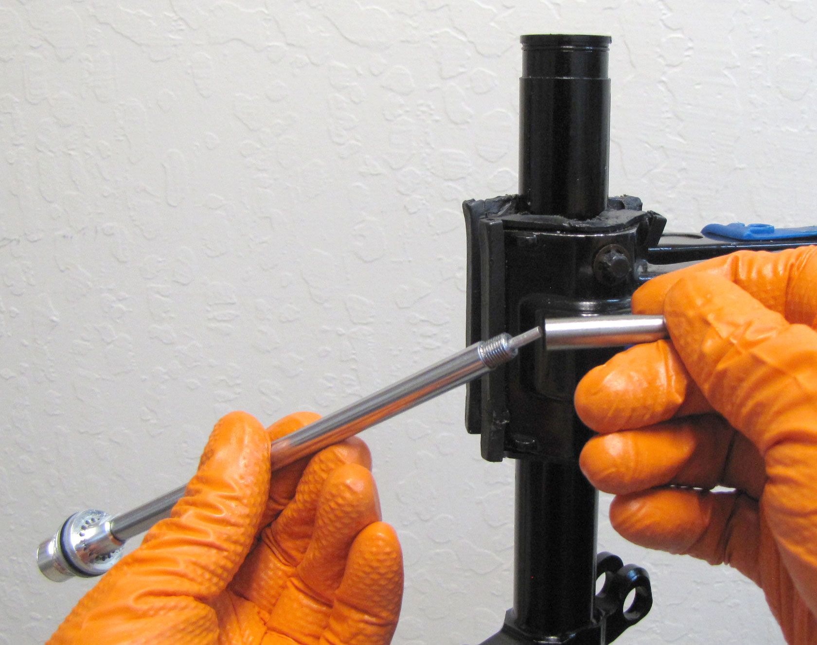
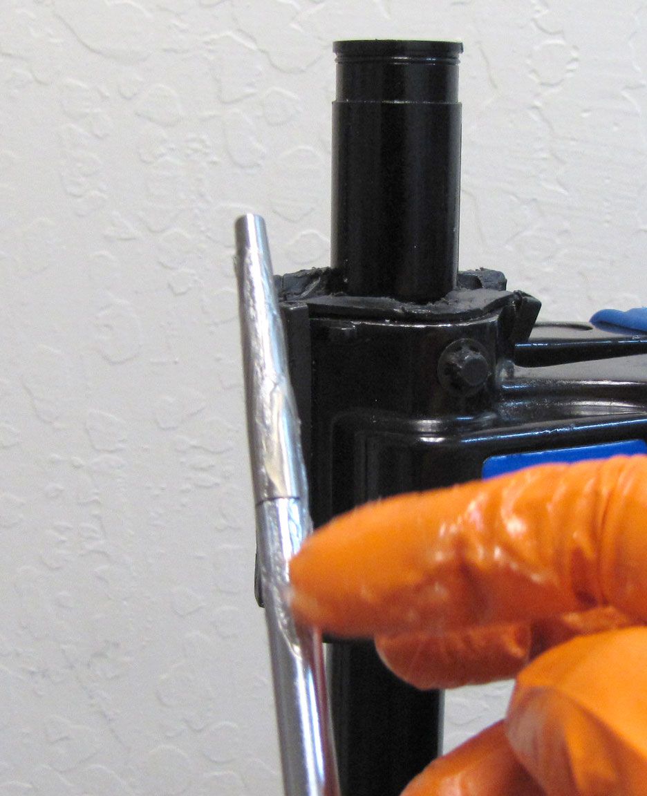
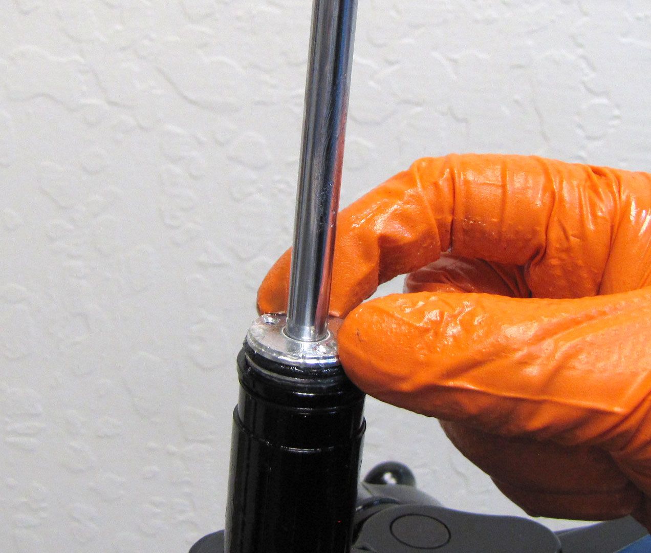
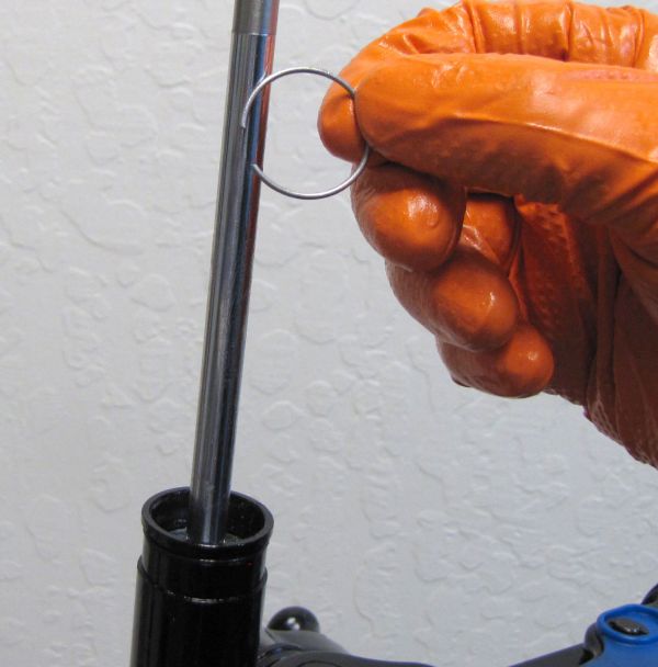
Step 14
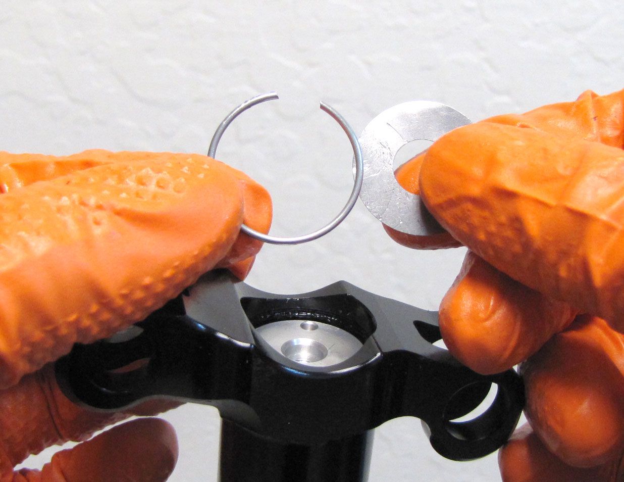
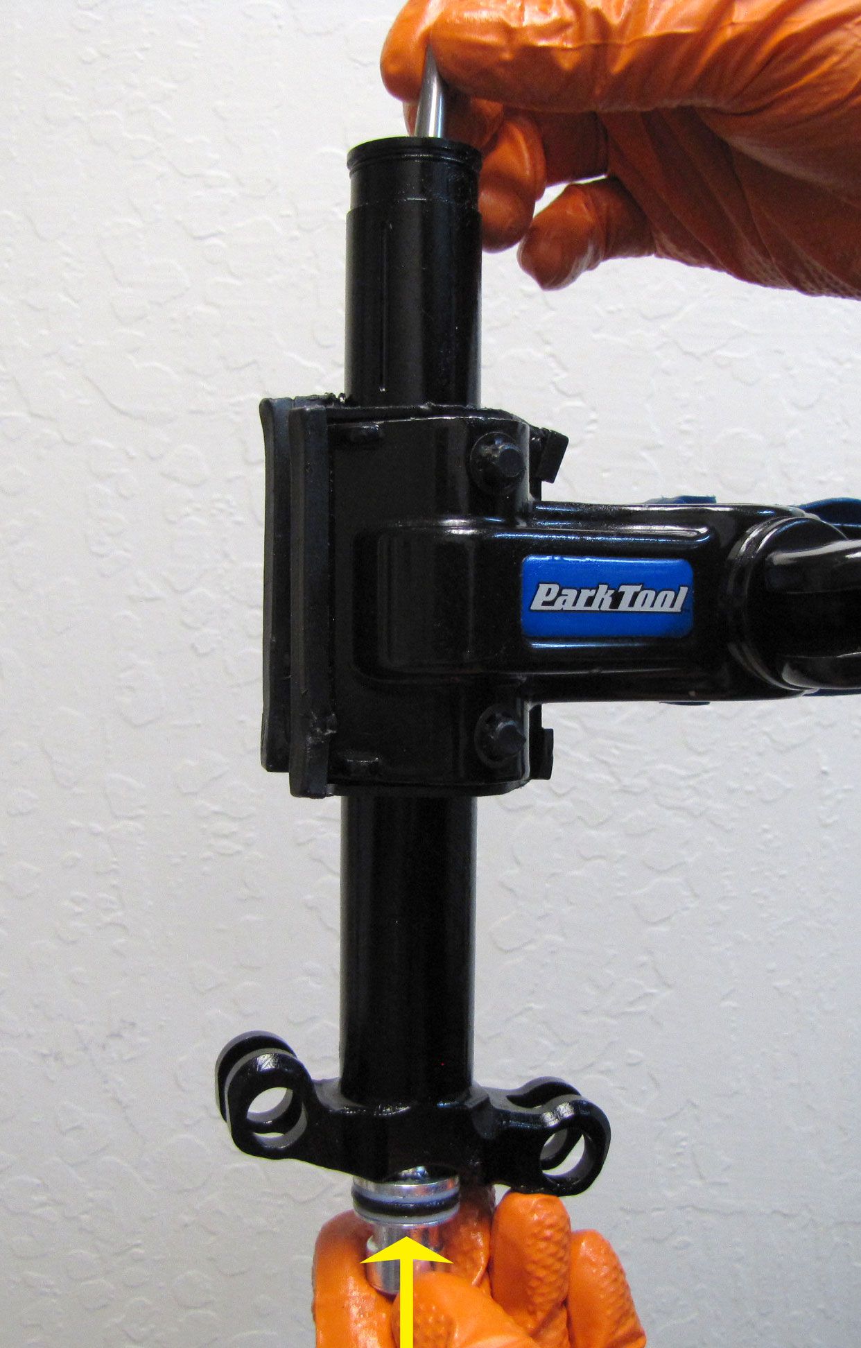
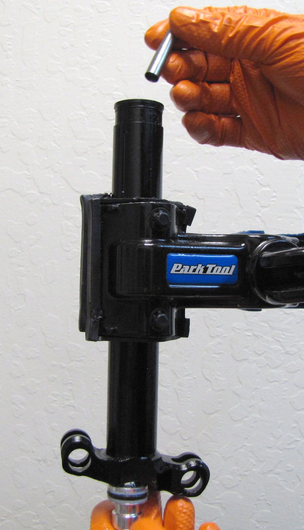
Slowly press the Top Cap Assy down into the Upper Post to make room to access the wire retaining ring. Oil may spray out at this point. It is recommended to cover the post with a lint-free paper towel before doing this step. No paper towel is shown in order to illustrate the step more clearly. Use a shim to remove the wire retaining ring. Set the ring aside.

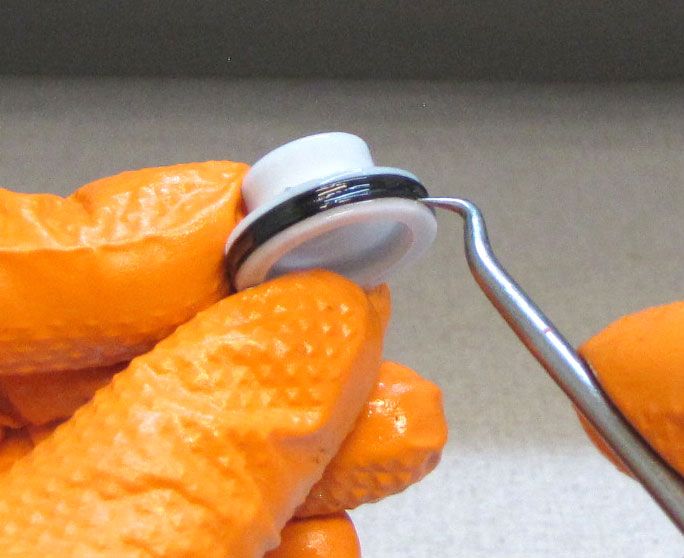
Step 15
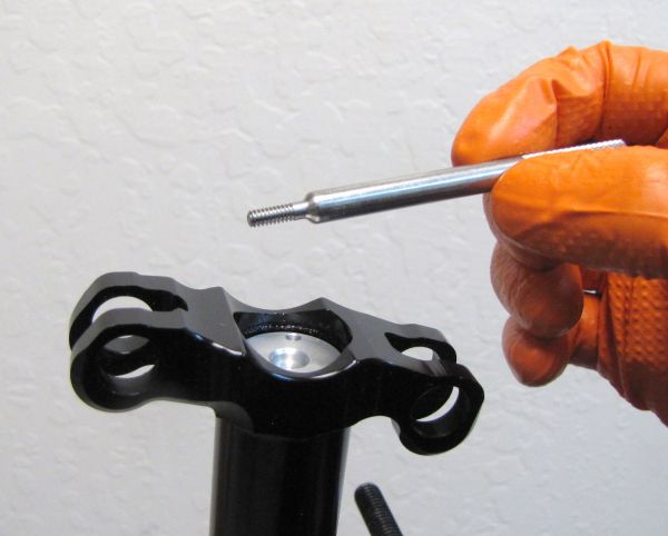
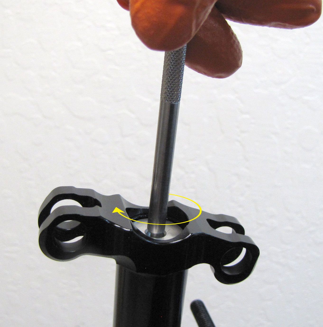
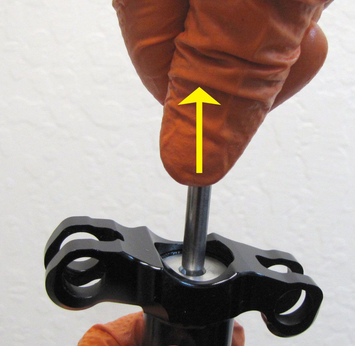
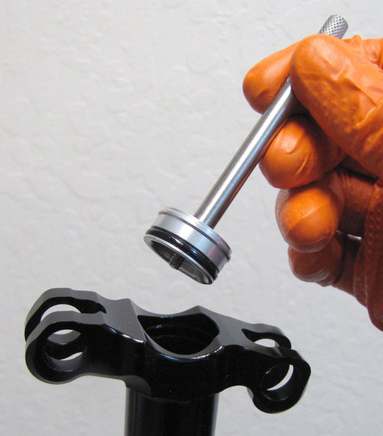
Thread the Trek Thru Shaft IFP Removal Tool (PN: 398-00-749) clockwise into the Top Cap Assy and pull up to remove. Replace the o-ring on the Top Cap Assy with a new greased one from the kit then set aside.

Step 16
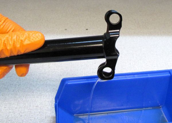
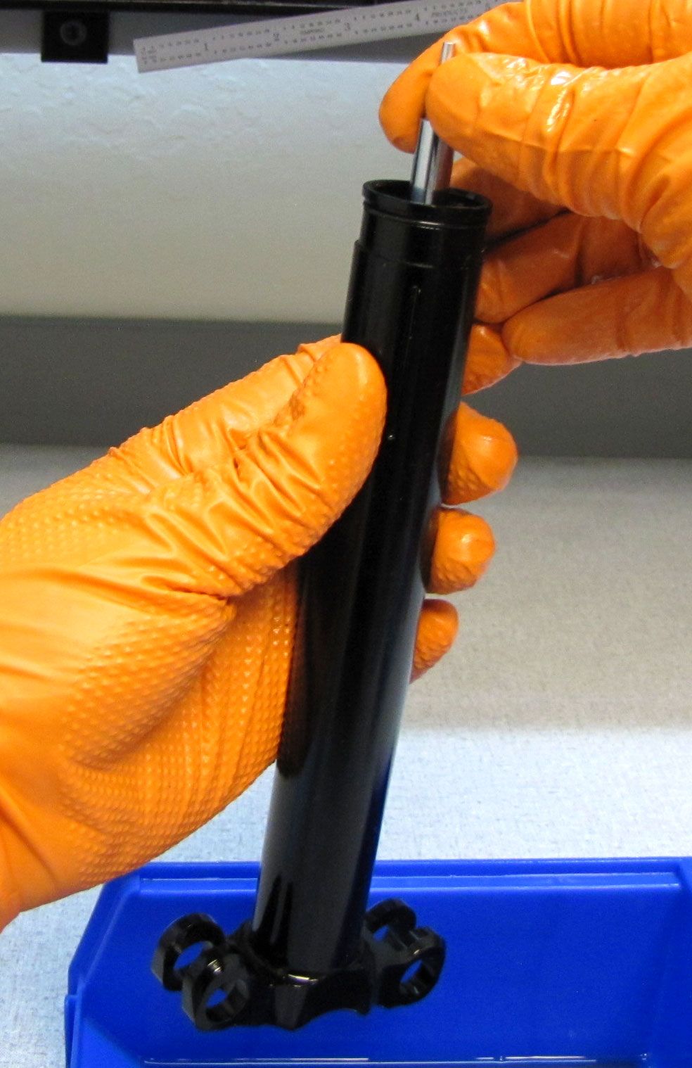
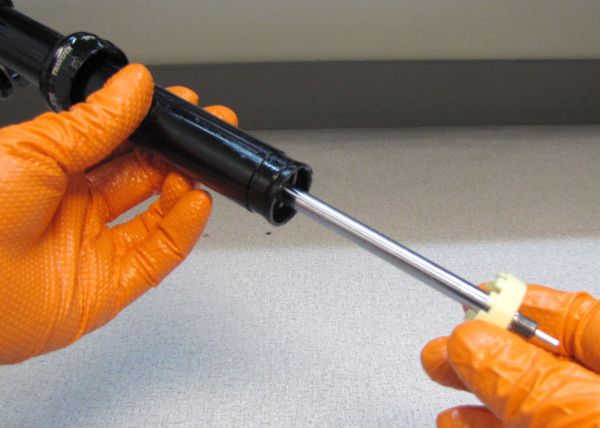
Pour the oil out through the top of the post into your waste oil basin. Push the Piston Assembly out through the top of the Upper Post with a wooden or plastic dowel.

Step 17
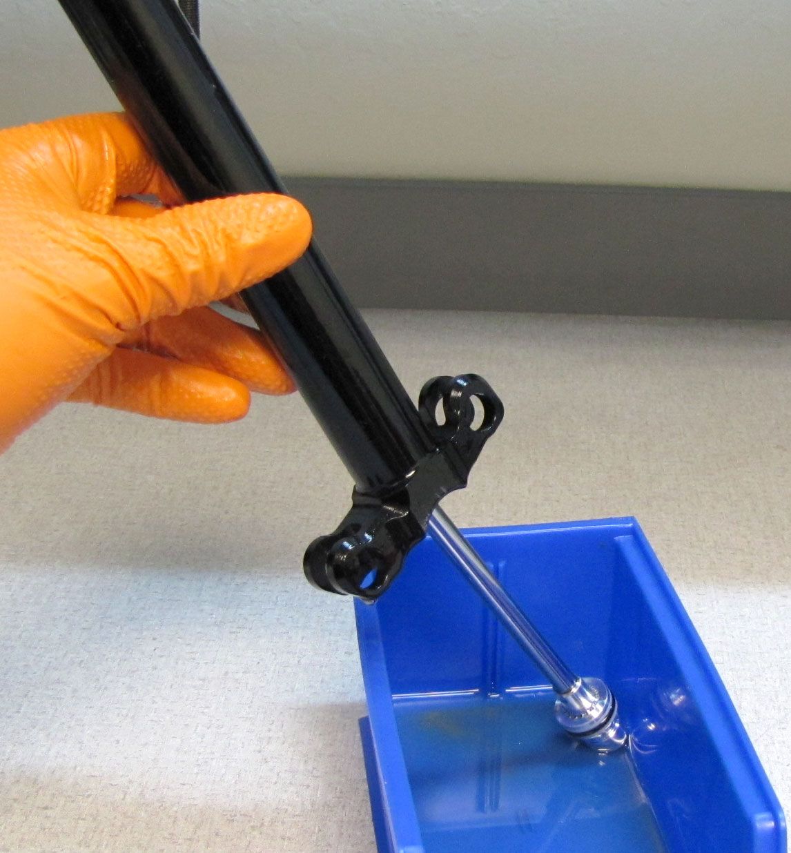
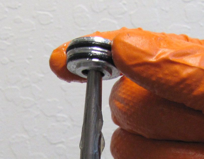
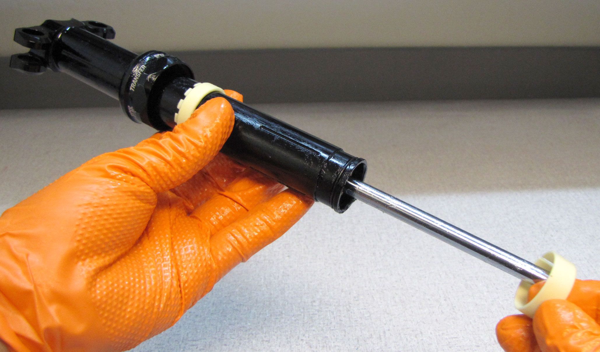
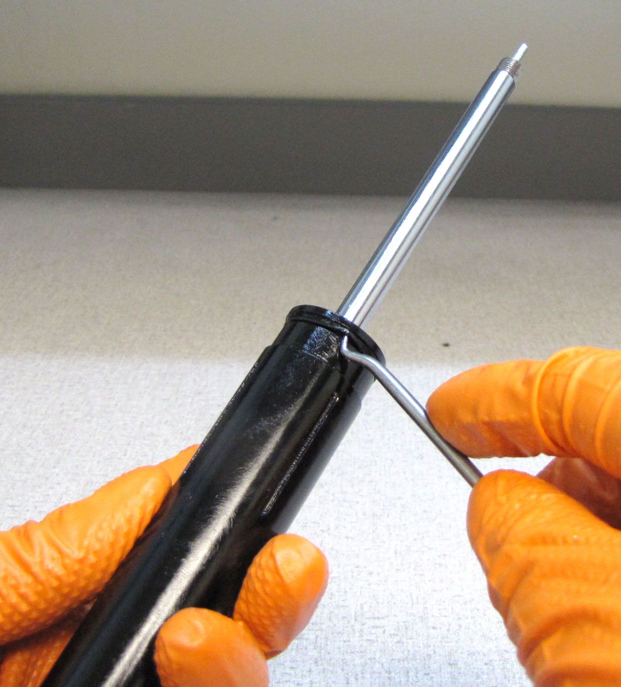
Clamp the Upper Post in your bike work stand with the bottom end facing up. Push the Sealhead in to make room to access the wire retaining ring. Remove the wire retaining ring. Set the ring aside.

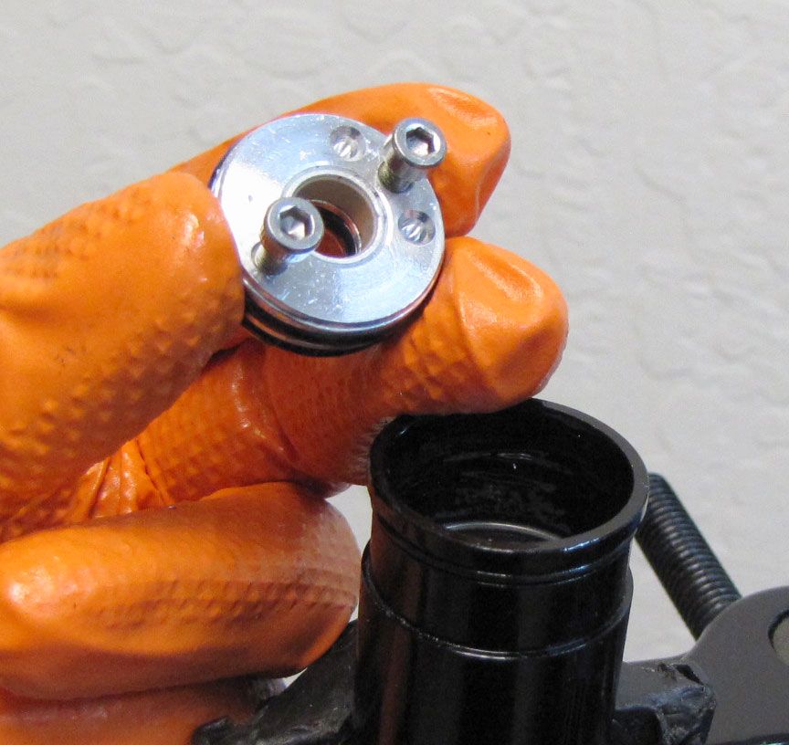
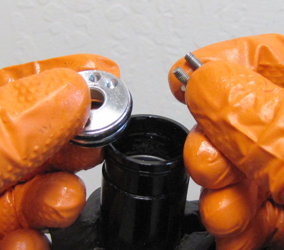
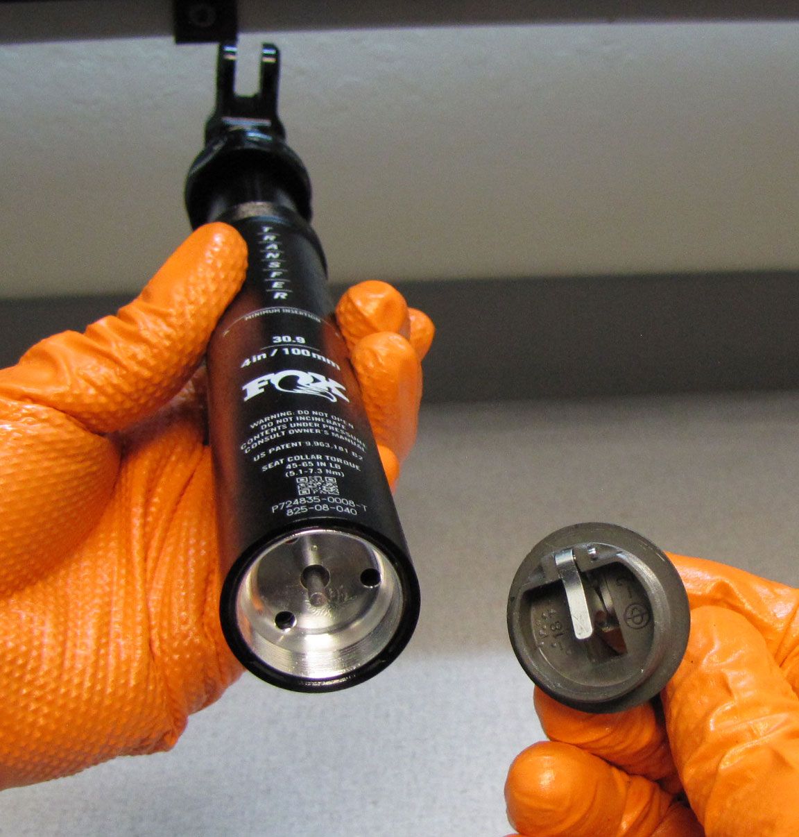
Step 18
Thread an M3 screw into both the fill and bleed ports of the Sealhead. Screw 019-01-083 may be used for this. Lift up on both screws to remove the Sealhead from the Upper Post. Replace the Sealhead o-rings with new greased ones from the kit.
Step 19
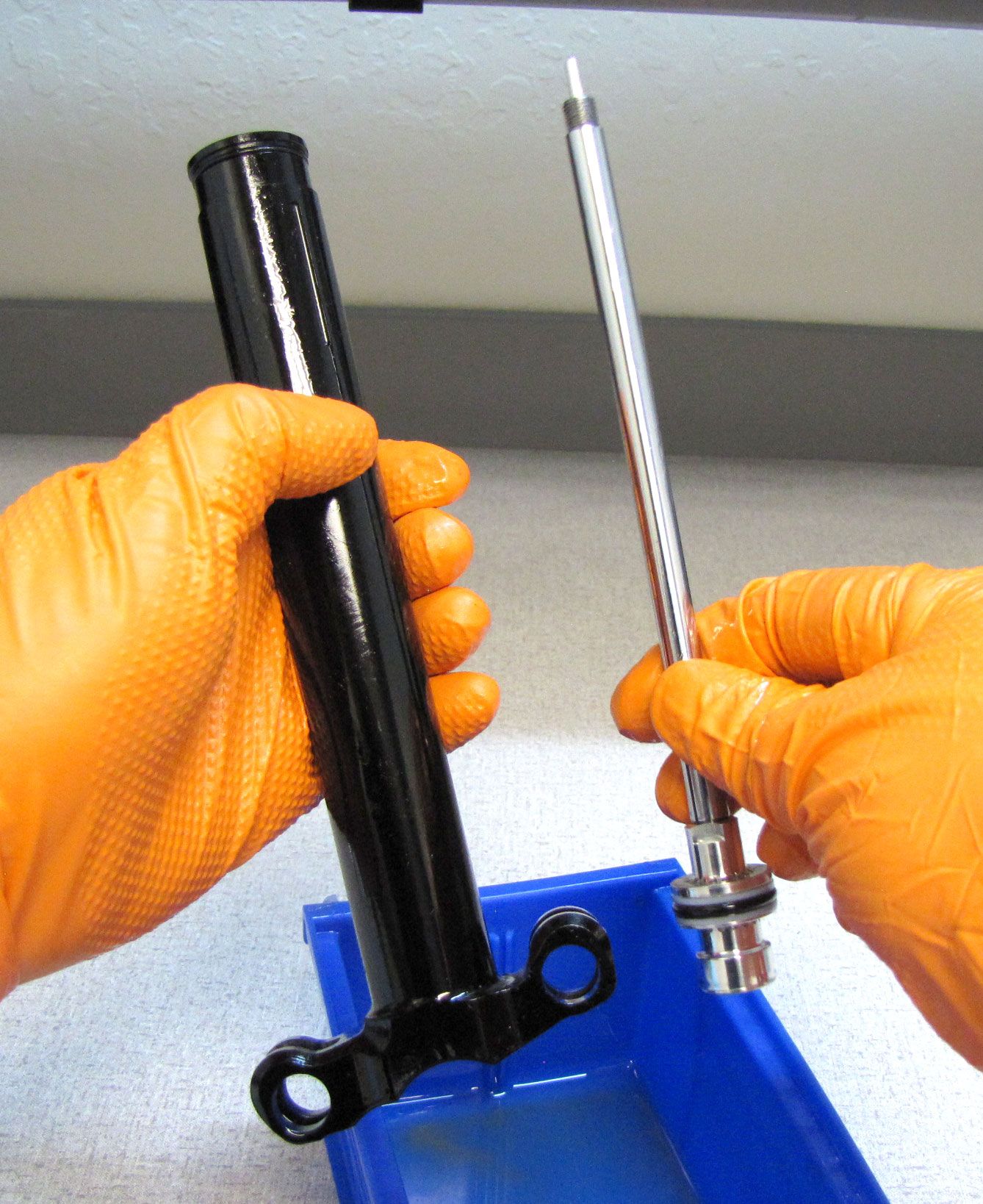
Remove the wire retaining ring from beneath the Sealhead. Insert the Delrin Push Rod (PN: 398-00-740) into the top of the Upper Post, then push the IFP out through the bottom. Replace both IFP seals with new greased ones from the kit.

Step 20
Clean the Upepr Post with Ispropyl alcohol and a lint-free paper towel taking care not to leave any paper towel residue inside the Upper Post.

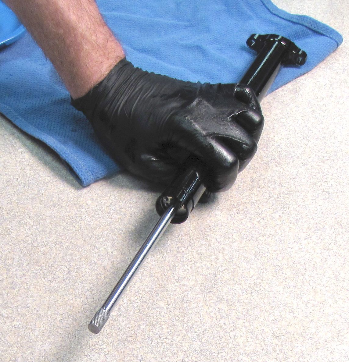
Step 21
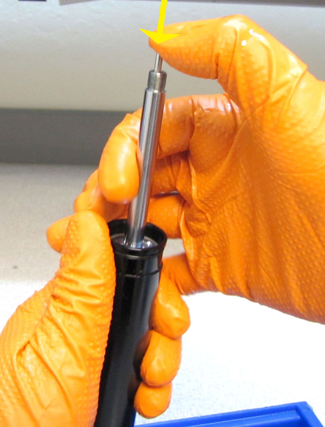
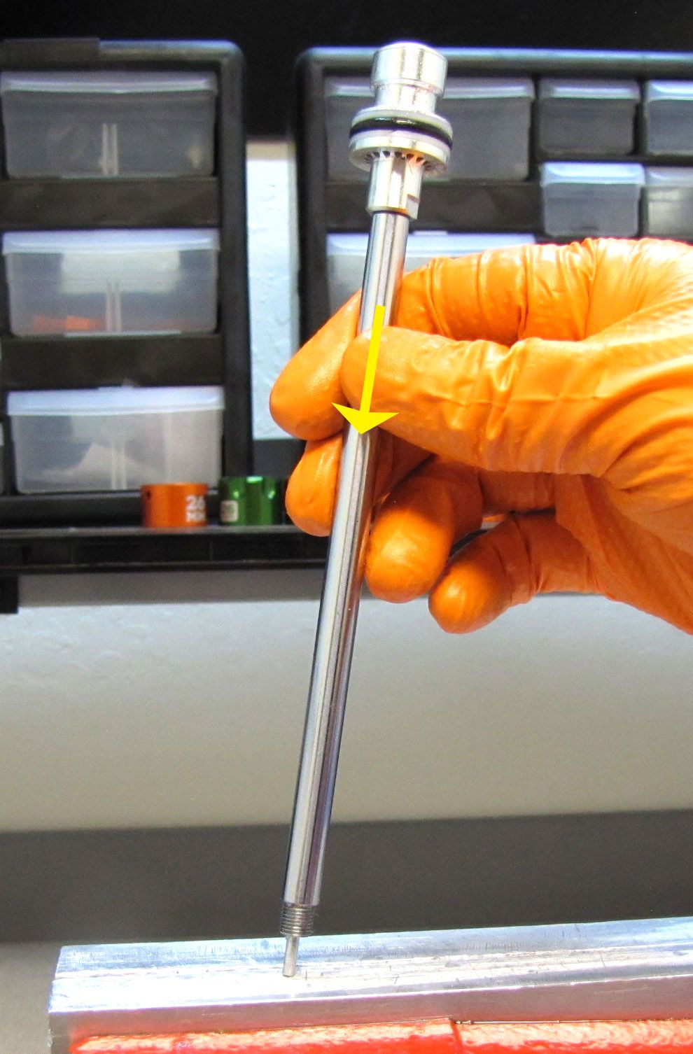
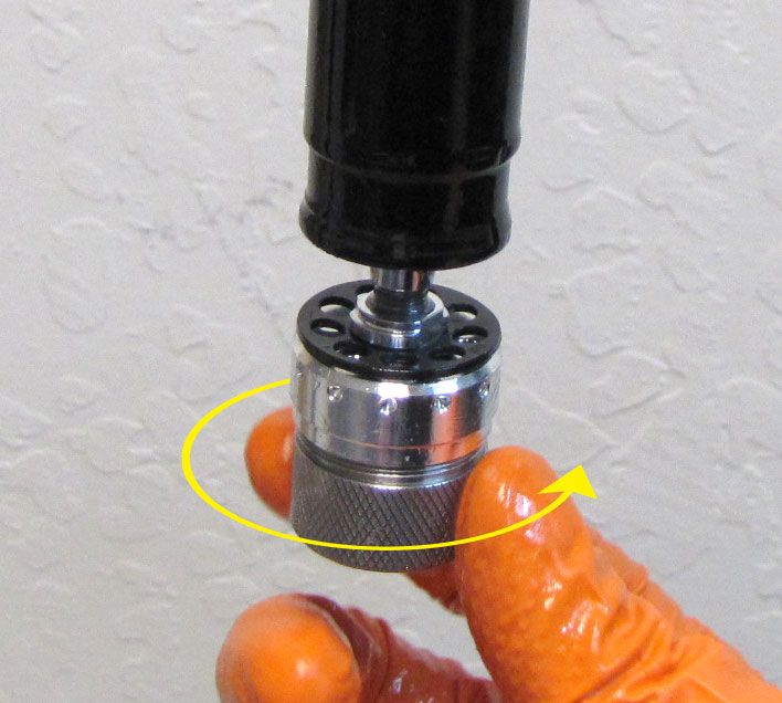
Remove the Push Rod from the Shaft. Clamp the shaft in your shaft clamps, then unthread the Main Piston Assembly counter-clockwise with a 9mm wrench.

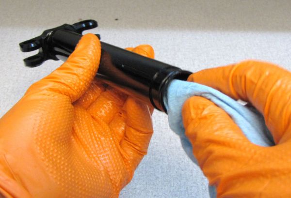
Step 22
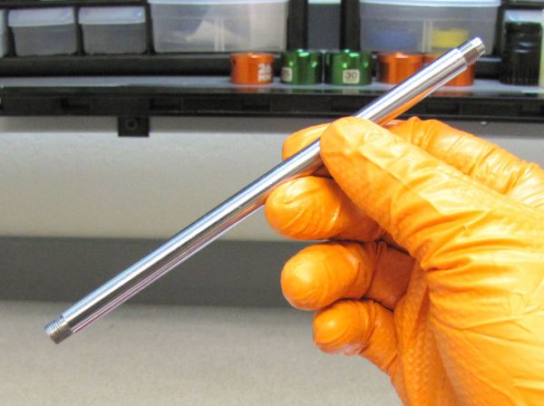
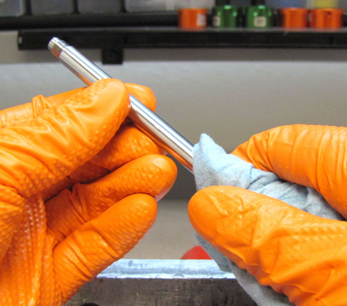
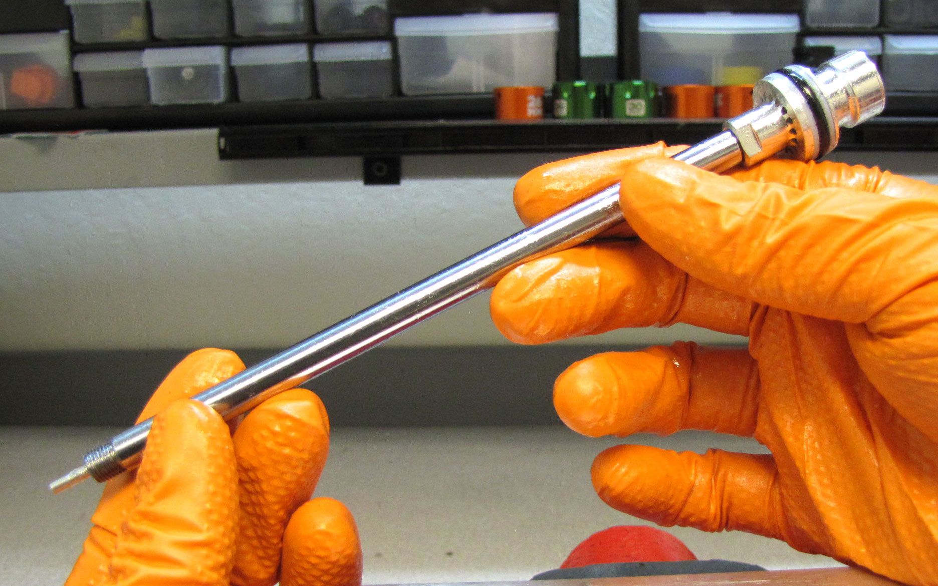
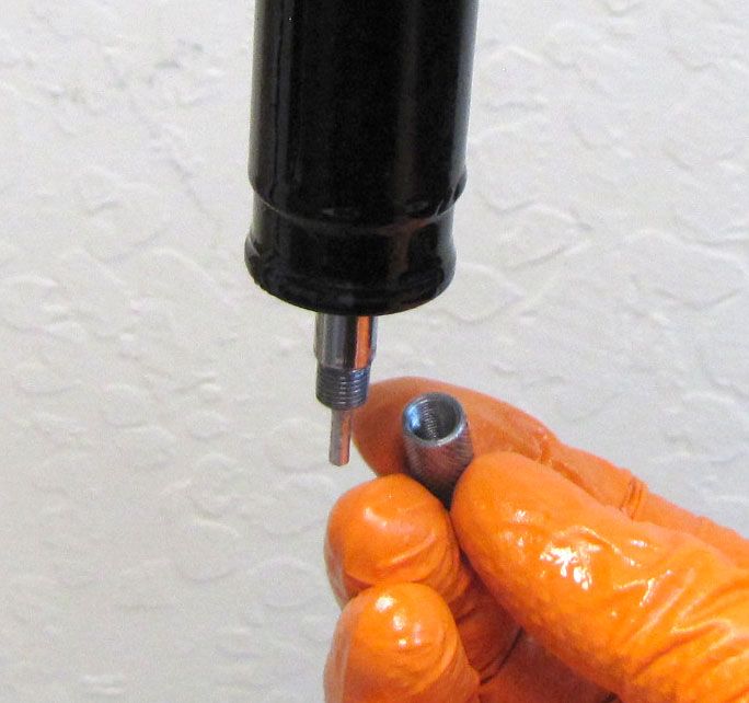
Clean the Shaft with Isopropyl alcohol and a lint-free paper towel. Clamp the cleaned shaft in your clamps with the smaller diameter unthreaded portion of the shaft facing up.
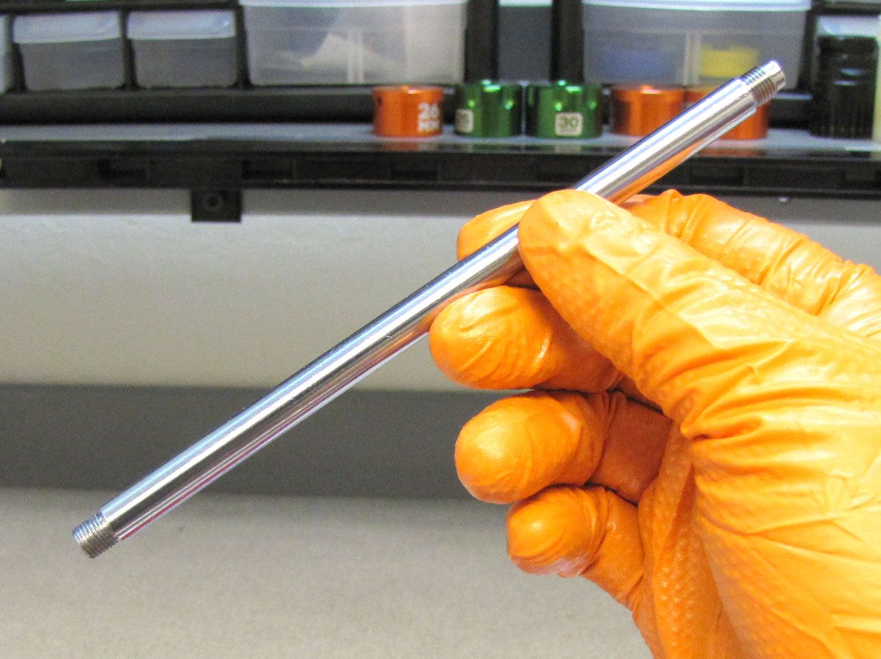
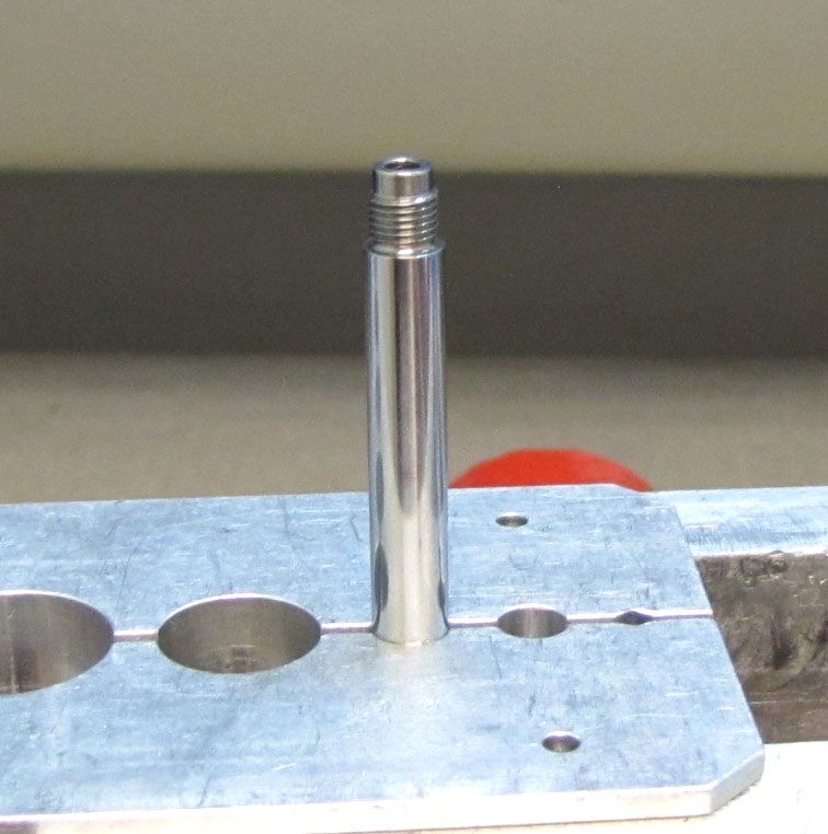

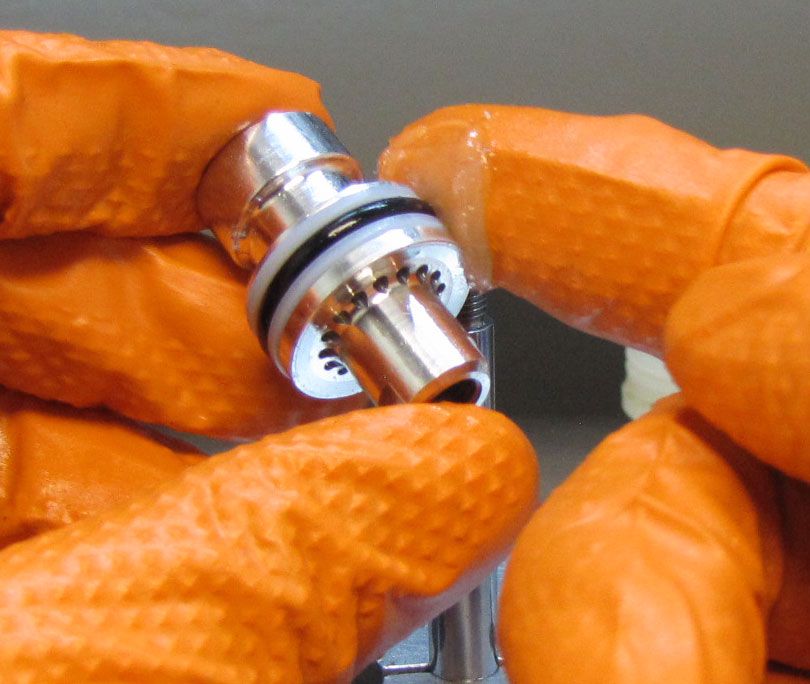
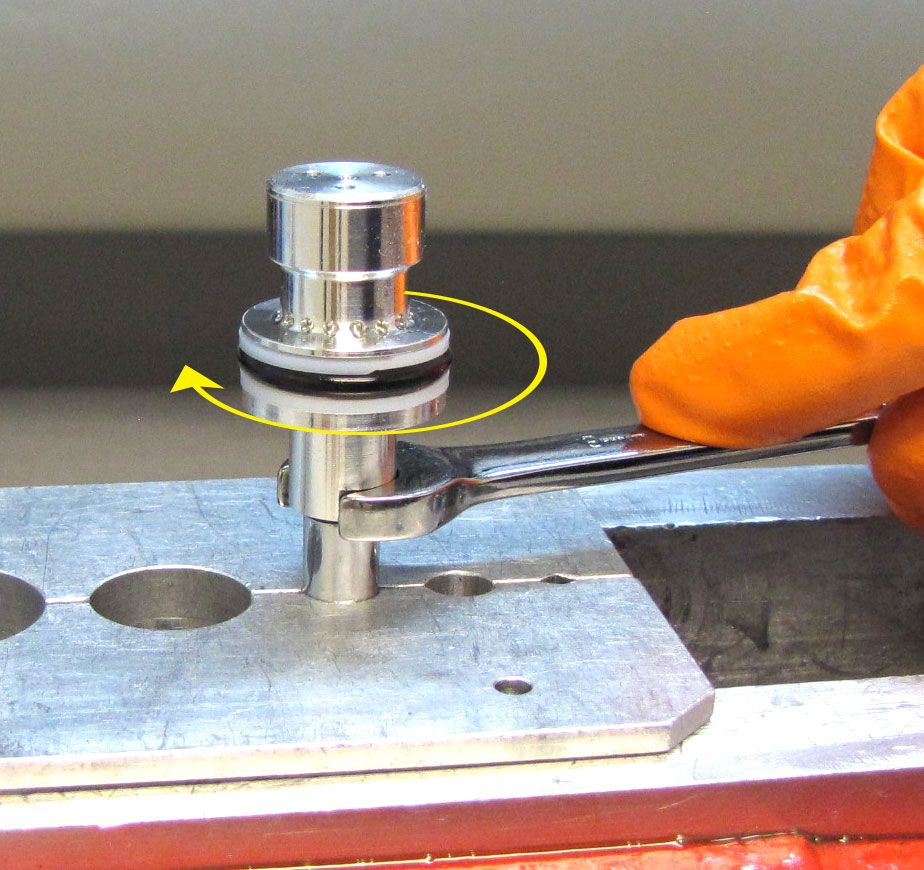
Step 23
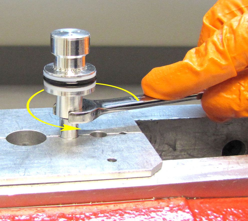
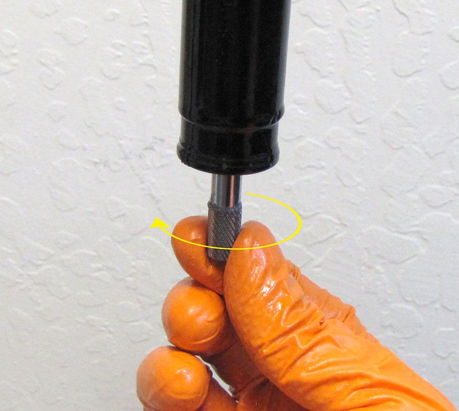
Coat the seals of the new Main Piston Assembly (in rebuild kit) with a thin film of Slick Honey. Thread the new Main Piston Assembly onto the shaft clockwise then tighten to 40 in-lb (4.5 Nm) torque. (Note: while a wrench is shown, please use a crow's foot to tighten the Piston Assembly to proper torque).

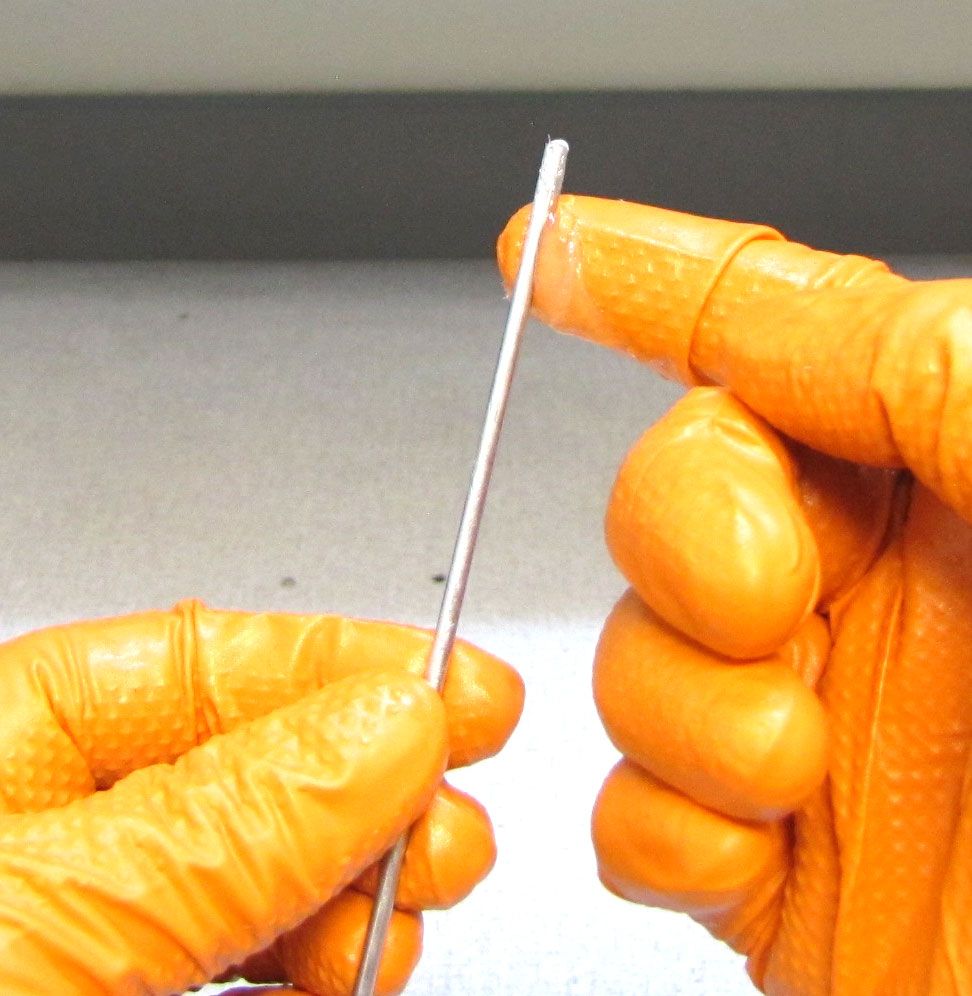
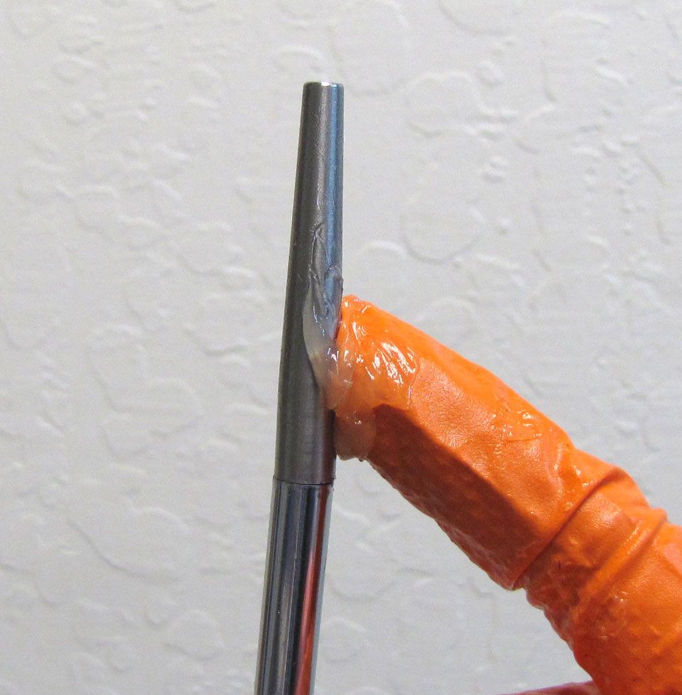
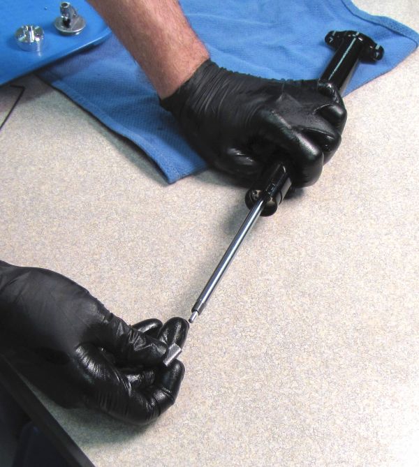
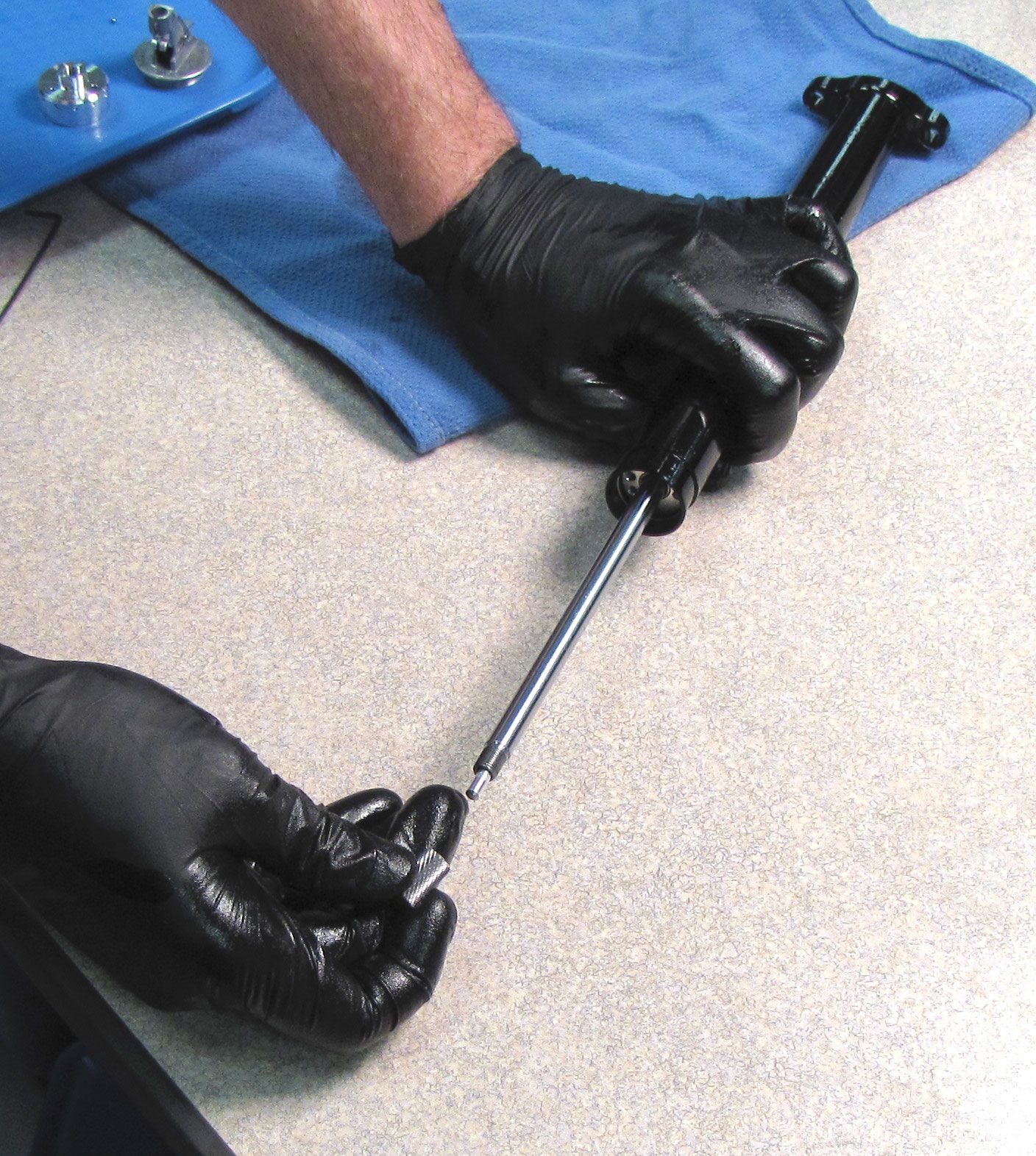
Step 24
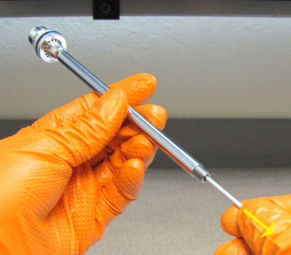
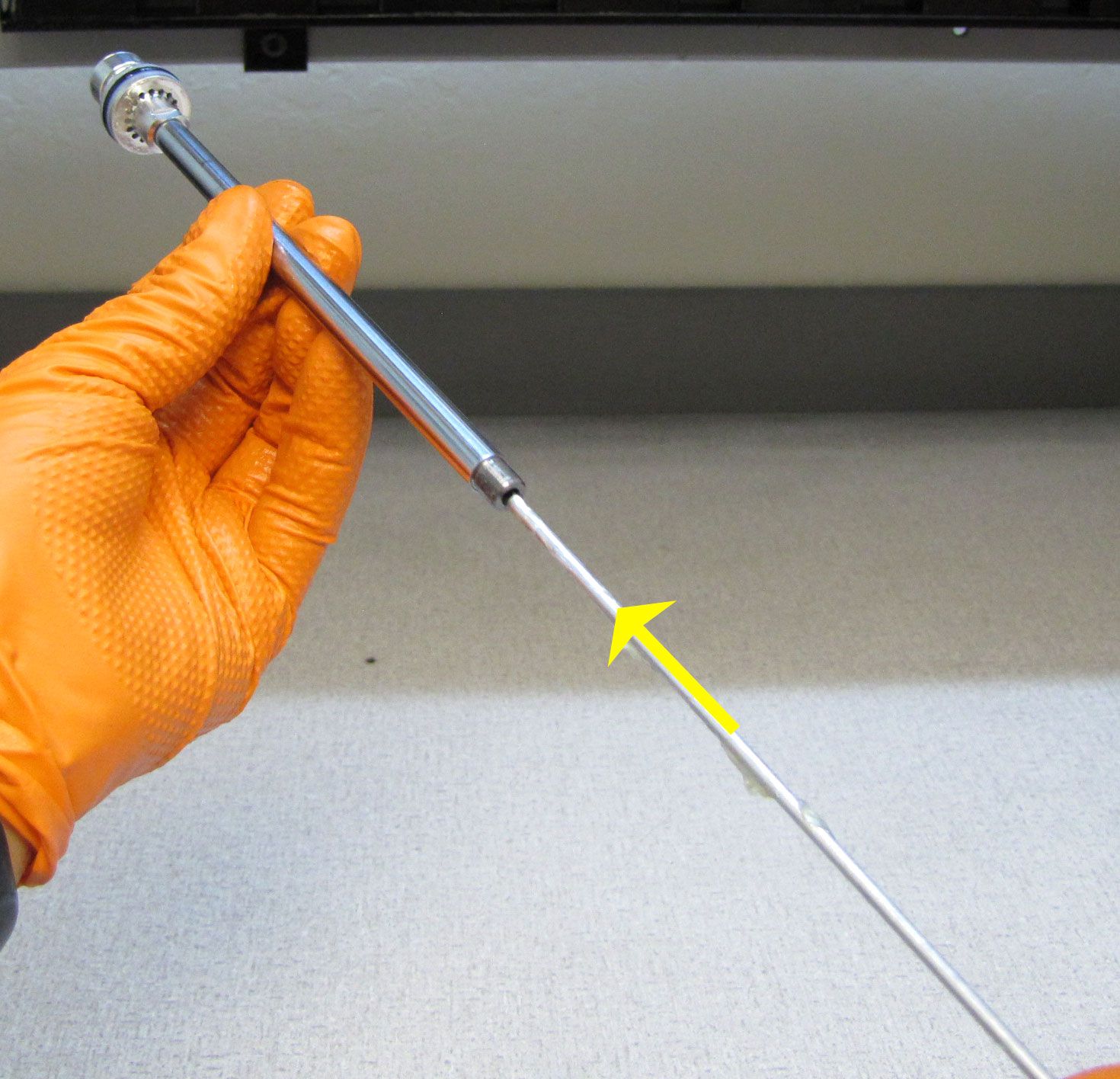
Coat the Push Rod with a thin film of Slick Honey then reinstall it into the shaft as shown. Cycle the Push Rod against your work surface to check that it moves and returns smoothly after actuation.
Step 25
Coat the IFP with a thin film of Slick Honey then reinstall into the bottom of the Upper Post as shown. Reinstall the first wire retaining ring as shown.


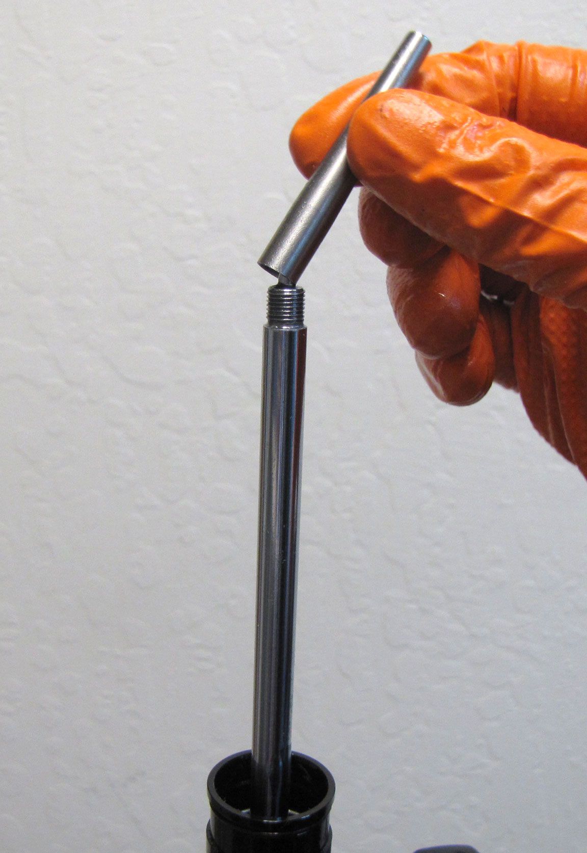
Step 26
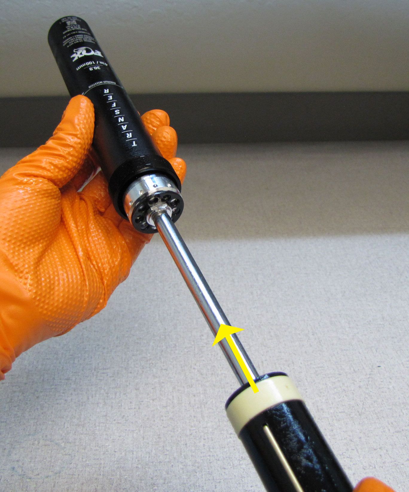
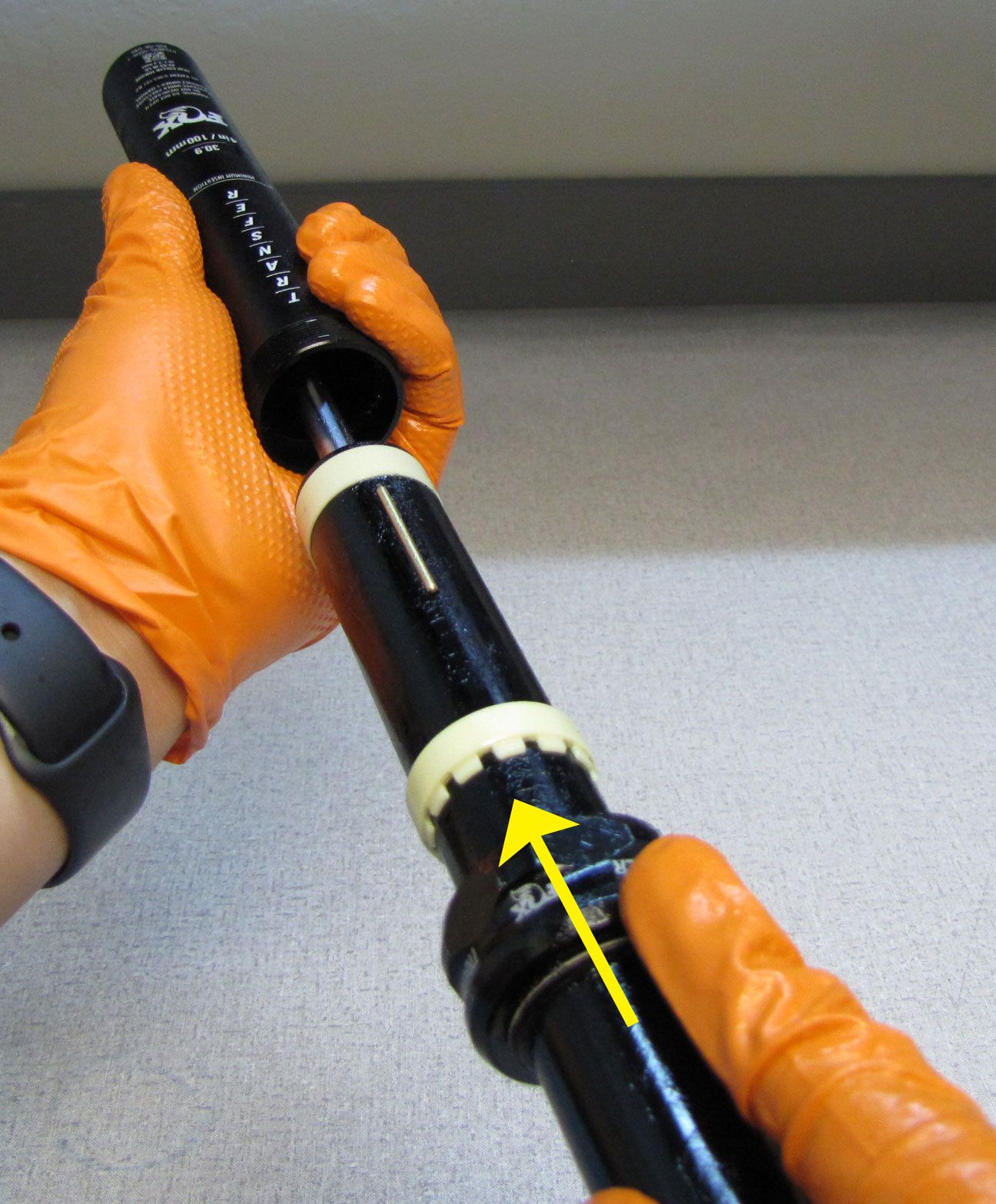
Install the Transfer Bullet Tool (PN: 398-00-738) onto the Shaft of the Piston Assembly then coat with a film of Slick Honey. Reinstall the Piston Assembly into the Upper Post through the top of the post as shown.

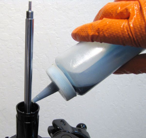
Step 27
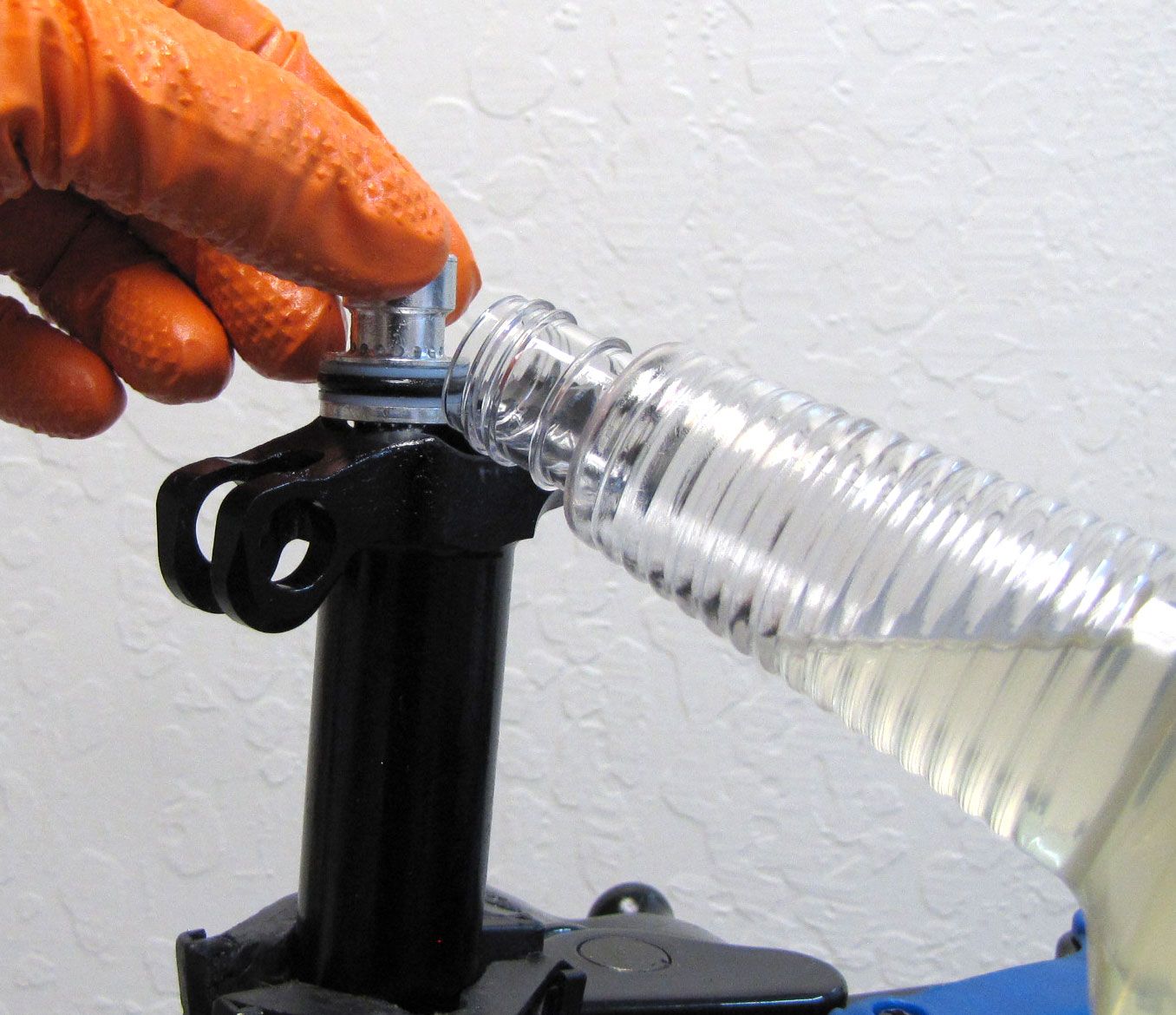
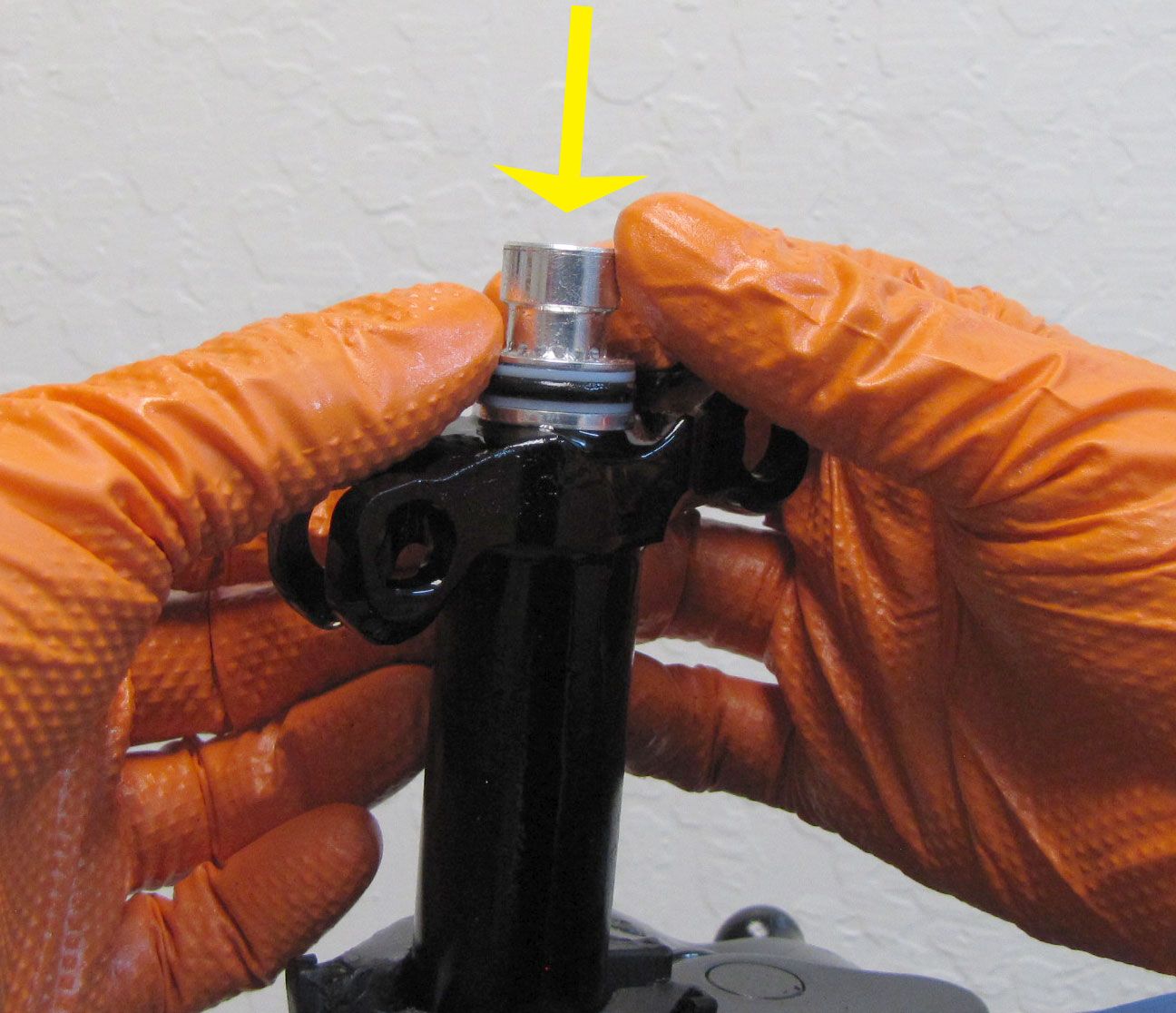
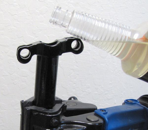
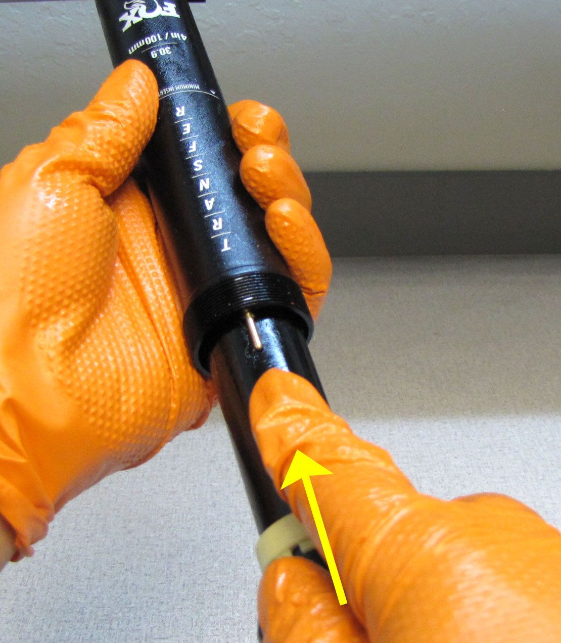
Invert the Upper Post so the it is upright. Lift the Main Piston Assembly out of the top of the Upper Post just enough to allow you to fill the Upper Post with FOX 1.5wt. Clear oil. Slowly push the Main Piston Assembly into the top of the Upper Post.

Step 28
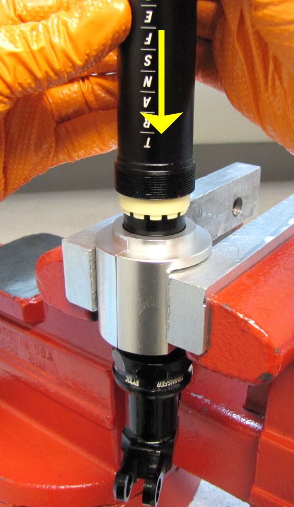
Install the Spool Valve Compressor tool (PN: 398-00-700) into the Shaft Lug by threading it in clockwise. Temporarily reinstall the Shaft Lug onto the end of the shaft by threading it on clockwise. You may also use the Open Valve tool (398-00-735) in place of the Shaft Lug and Spool Valve Compressor as an option.
Step 29
Pour FOX 1.5wt oil into the Upper Post above the Piston Assembly until full. Keep the post vertical and slowly cycle the Shaft fully up and down 5-7 times while watching for bubbles at the top of the Upper Post.


Step 30
When no new bubbles appear while cycling the Shaft, fully extend the Shaft and remove the Open Valve tool or Shaft Lug with the Internal Spool Valve Compressor tool. Install the appropriate IFP Height tool for your post, then reinstall the Shaft Lug with the Internal Spool Valve Compressor tool.
| 398-00-871 | 2021 Transfer, IFP Height, 100 |
| 398-00-872 | 2021 Transfer, IFP Height, 125 |
| 398-00-873 | 2021 Transfer, IFP Height, 150 |
| 398-00-874 | 2021 Transfer, IFP Height, 175 |
| 398-00-875 | 2021 Transfer, IFP Height, 200 |

Step 31
Hold the Shaft at full extention while you insert the IFP tool up into the bottom of the Upper Post until it bottoms out. Remove the Shaft Lug with the Internal Spool Valve Compressor tool and the IFP tool.

Step 32
Reinstall the Top Cap Assy into the top of the Upper Post, then press it down to seat. Oil will spray out at this point. It is recommended to cover the post with a lint-free paper towel before doing this step. Install the wire retaining ring above the Top Cap Assy, then thread in the Trek Thru Shaft IFP Removal Tool and pull up to seat the Cap. Remove the tool.


Step 33
Make sure that the Top Cap is topped off with oil. Hold the Top Cap Assy with your pin spanner white tightening the Anti-Tamper screw with a 5/64" hex wrench clockwise to 11 in-lb (1.2 Nm).
Step 34
Add 0.5-1cc of Float Fluid to the IFP chamber. Install the 8mm Shaft Bullet tool onto the shaft and coat it with a thin film of Slick Honey.


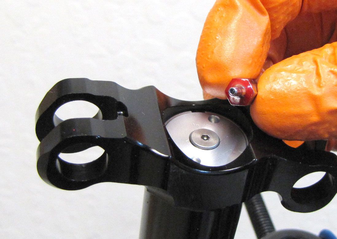
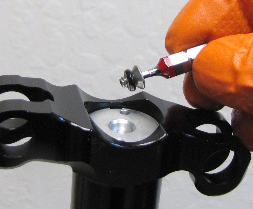
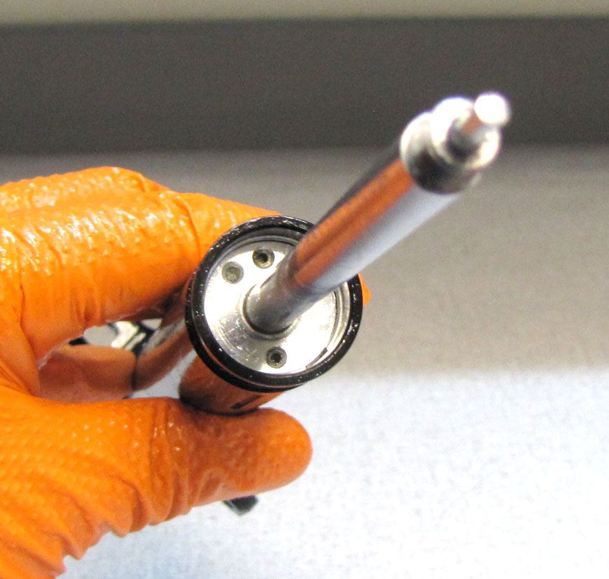
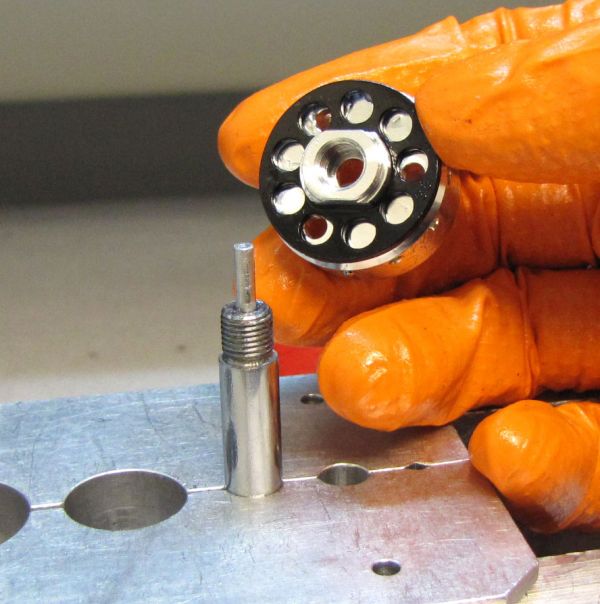
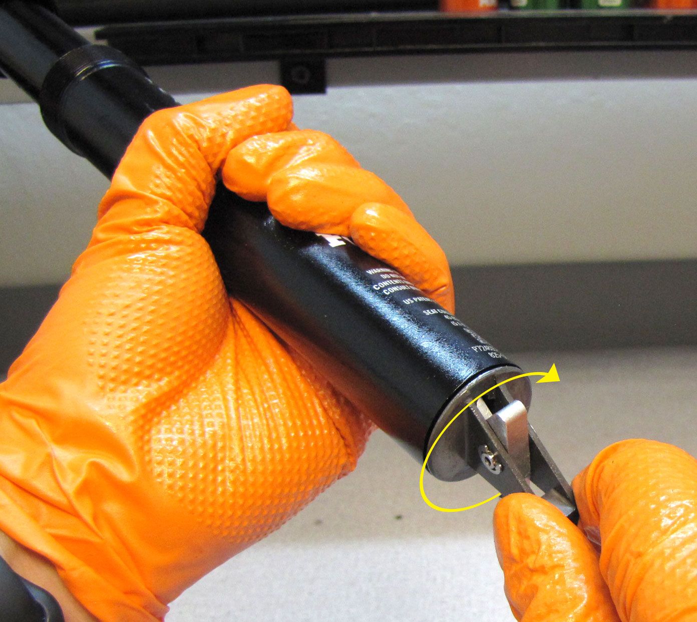
Step 35
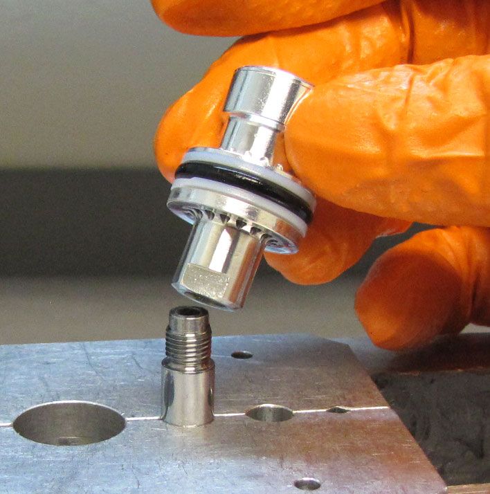
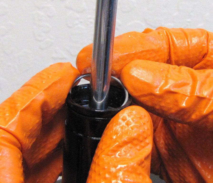
Remove the setscrew from the fill hole by unthreading counter-clockwise with a 1.5mm hex wrench. Remove the ball bearing with a magnet. Coat the Sealhead with a thin film of Slick Honey then reinstall the Sealhead onto the Shaft with its flat side facing up as shown. Remove the Bullet tool, then push the Sealhead into the Upper Post as far as it will go.
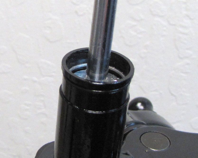
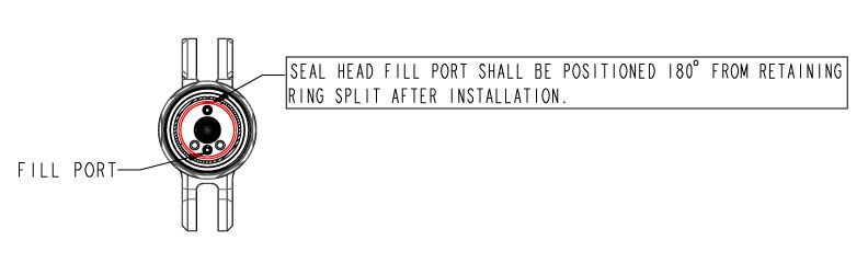
Step 36
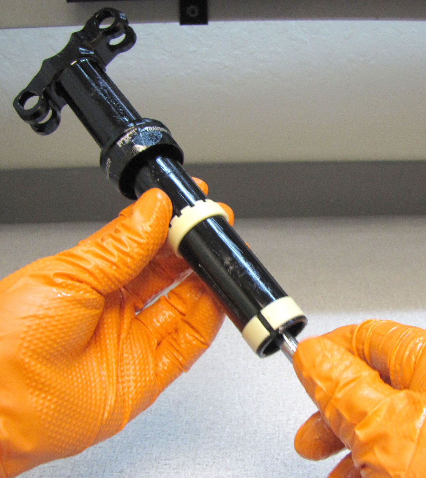
Reinstall the wire retaining ring into the bottom of the Upper Post making sure to orient the split in the ring so it is positioned 180Ëš degrees from the Fill Port.

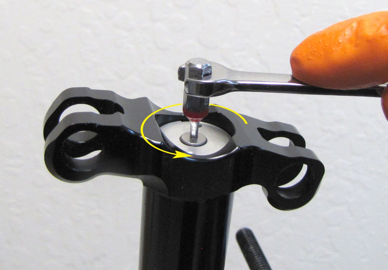
Step 37
Install the 2mm ball bearing into the bleed hole, apply blue Loctite 242 onto the M3 set screw, then install the set screw. Install an M3 screw in the fill port and hold it to prevent Sealhead rotation while you tighten to 3 in-lb (0.3 Nm) torque with a 1.5mm hex wrench. The bleed screw is the M3 screw that is farthest from the blind holes in the Sealhead.
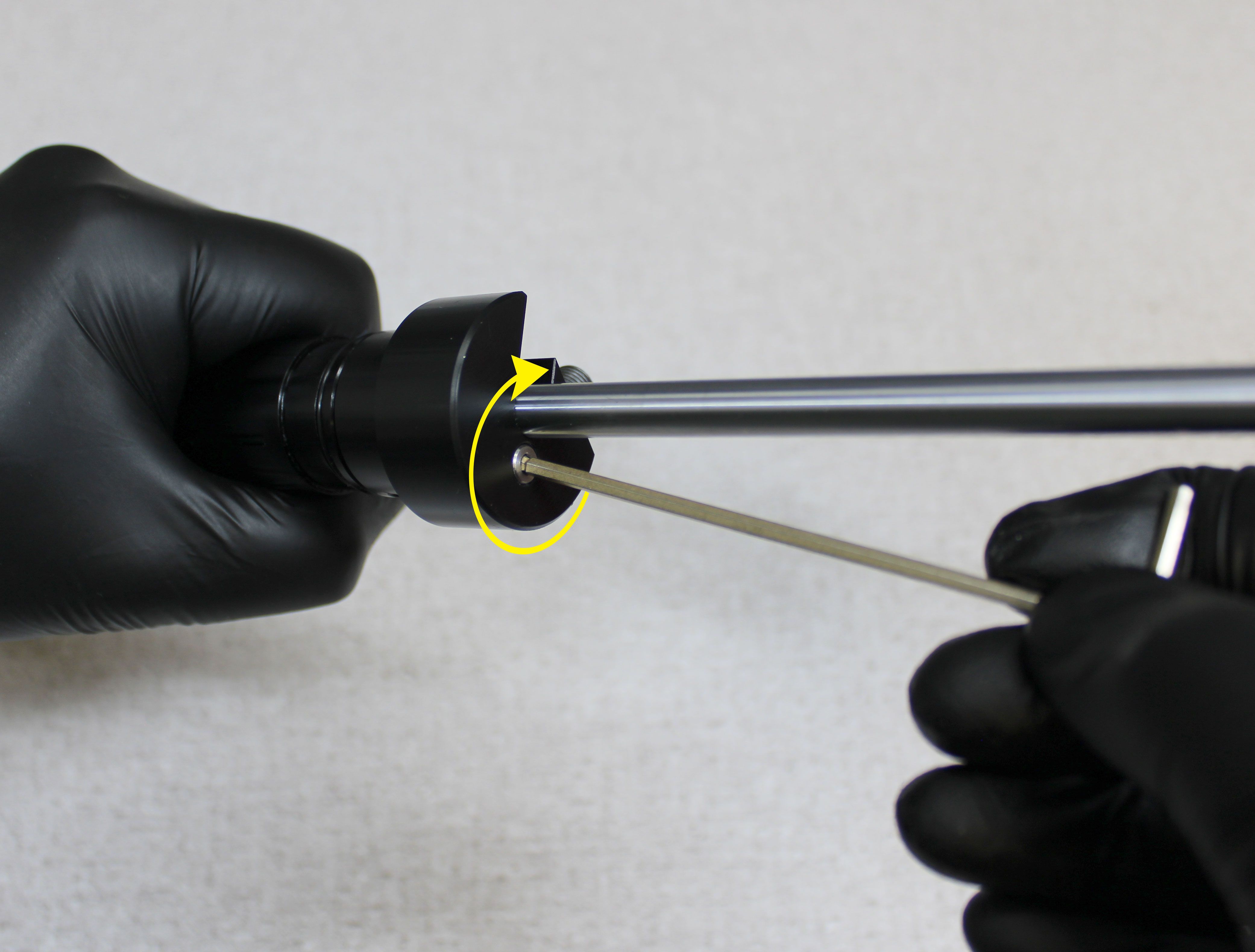
Step 38
Install the Nitrogen Fill Open Valve tool (PN: 398-00-735) onto the end of the Shaft.

Step 39
There are two styles of fill tool that can be used with the Transfer seatpost.
Instructions for using the original style of fill tool (803-01-595) start at step 40.
Skip to step 41 for instructions on using the new compact fill tool (PN: 803-01-931).
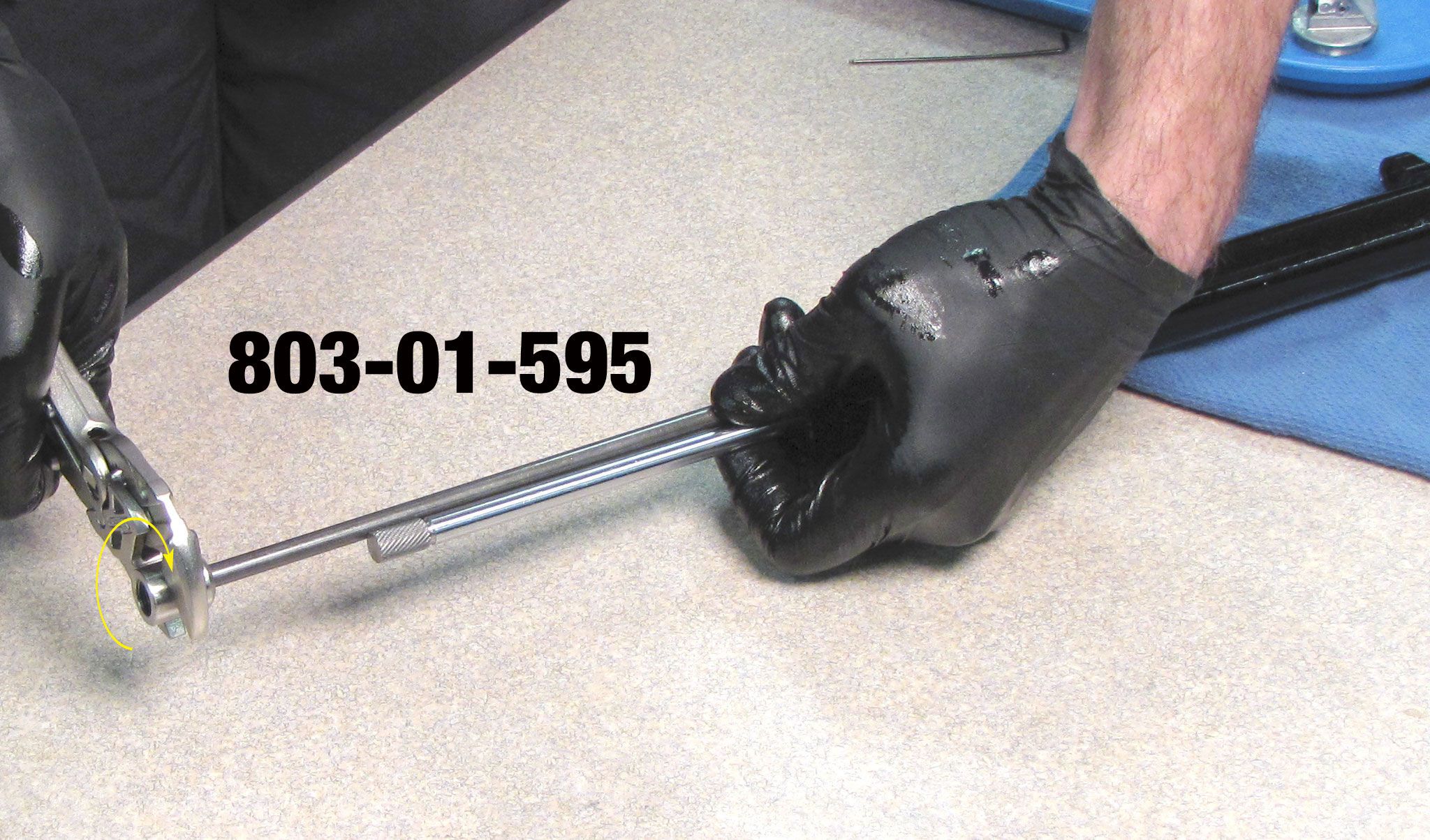

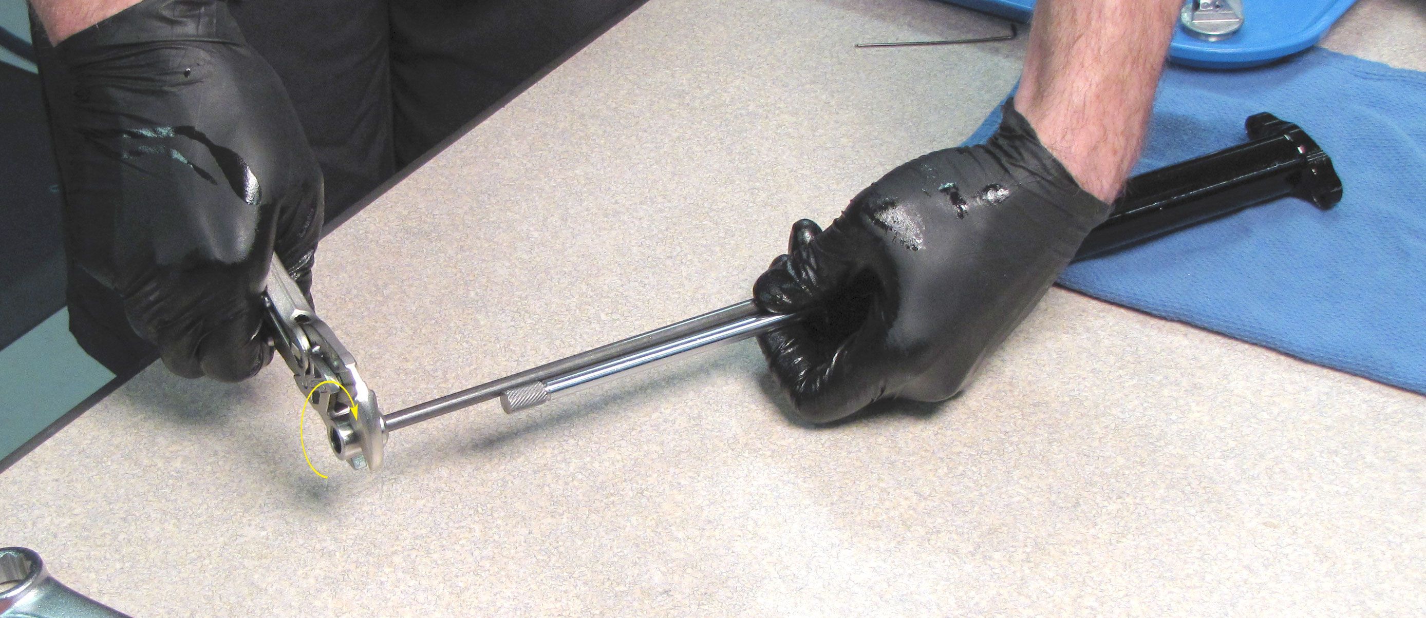
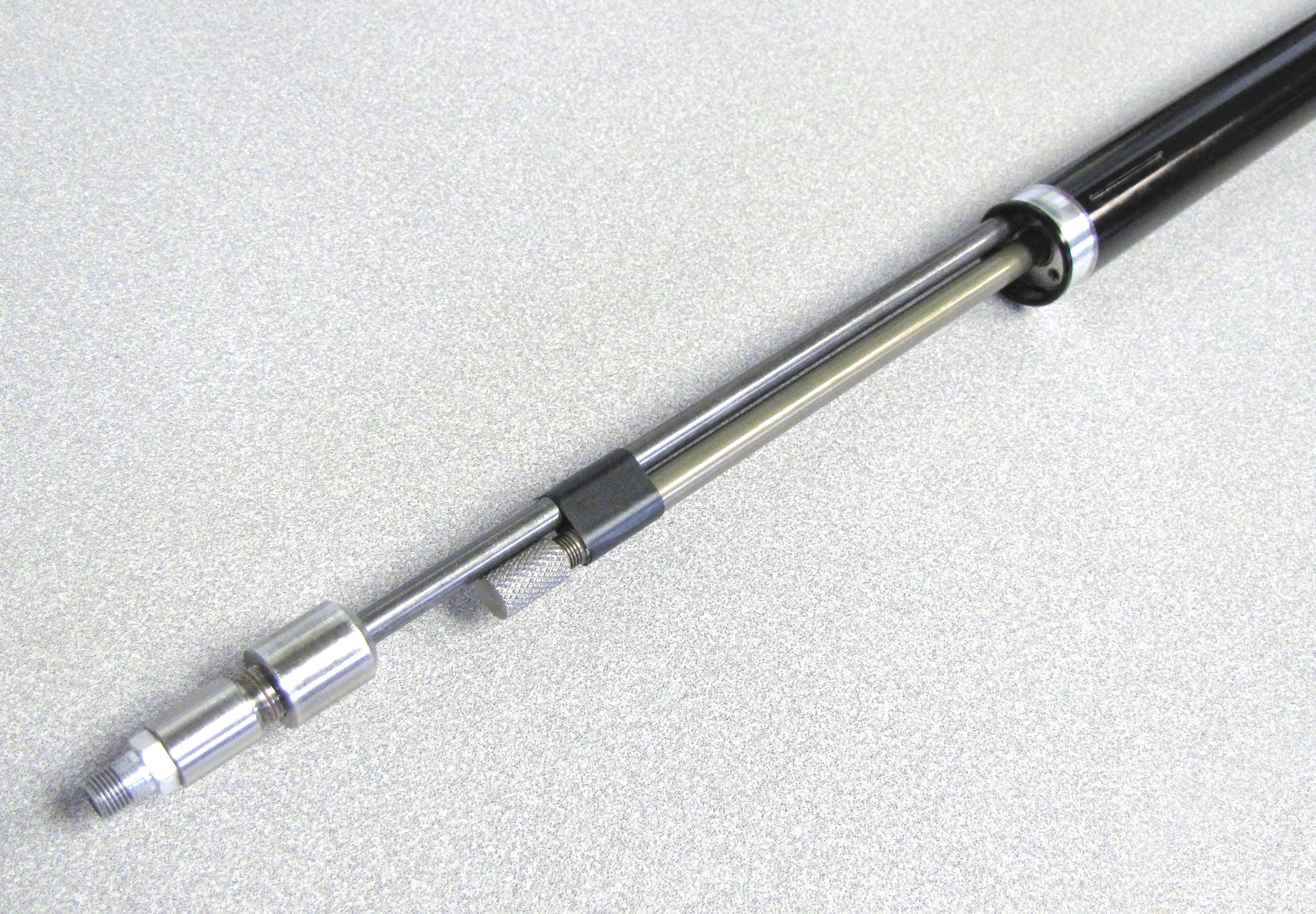
Step 40
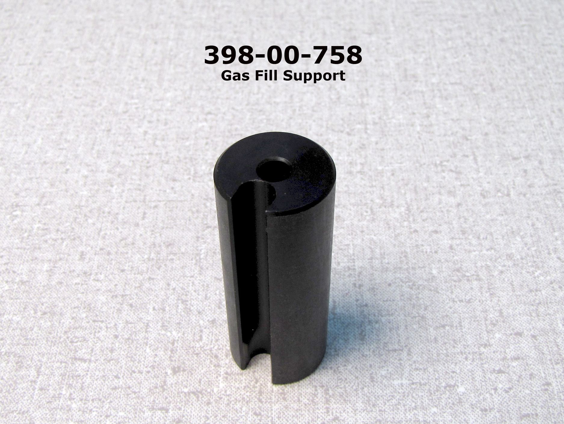
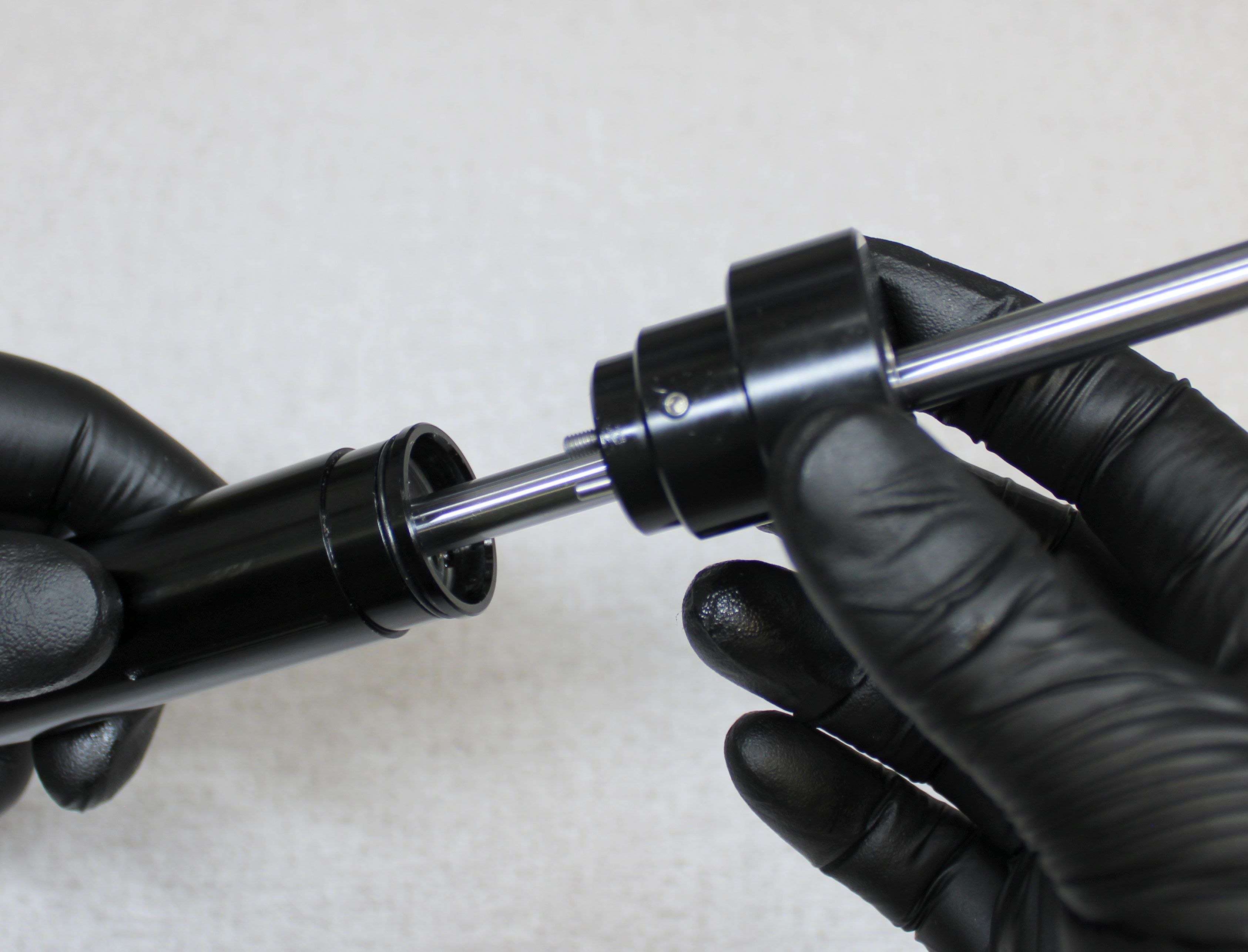
Install the Gas Fill Assembly (PN: 803-01-595) into the fill port. Be careful not to scratch the shaft as you install and use the Gas Fill Assembly. Hold the Shaft to help you tighten the Gas Fill Assembly into the fill port fully. Use the Gas Fill Support Tool (PN: 398-00-758) or wrap a small piece of tape around the Shaft and Gas Fill Assembly to add support and prevent damage to the Gas Fill Assembly.
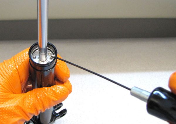
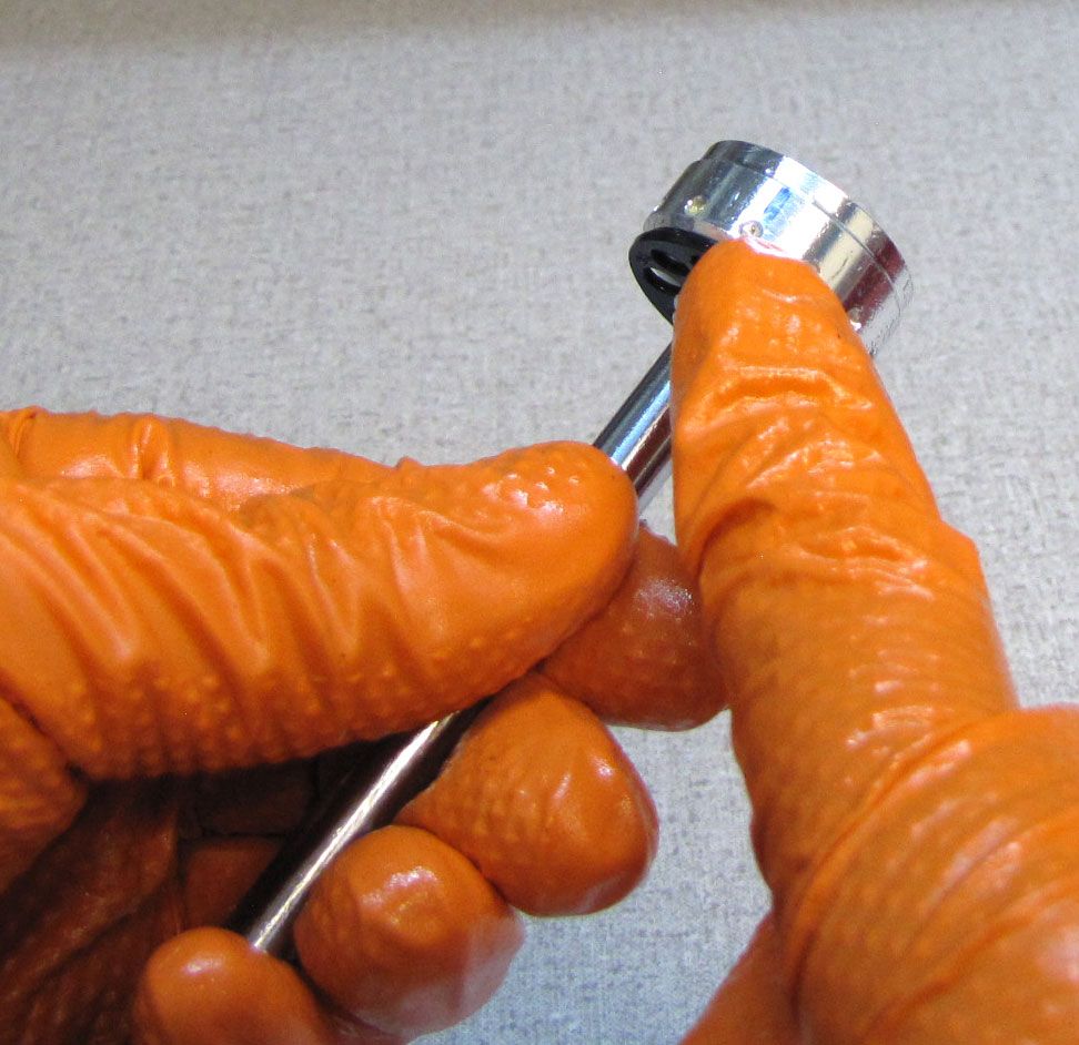
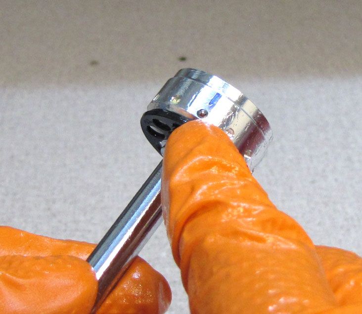
Step 41
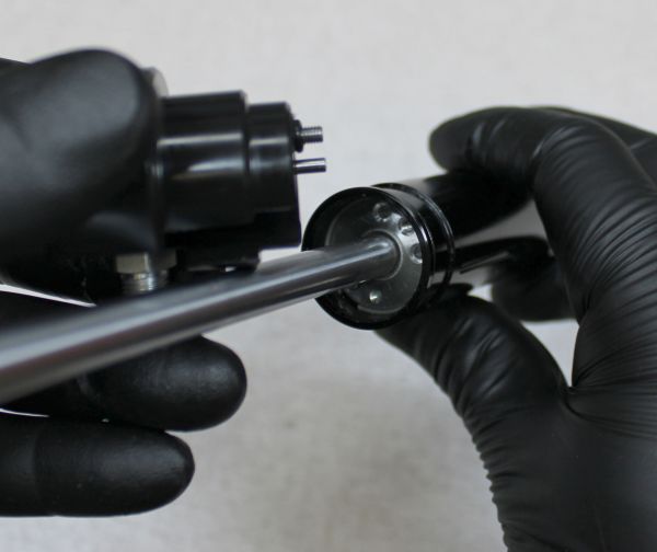
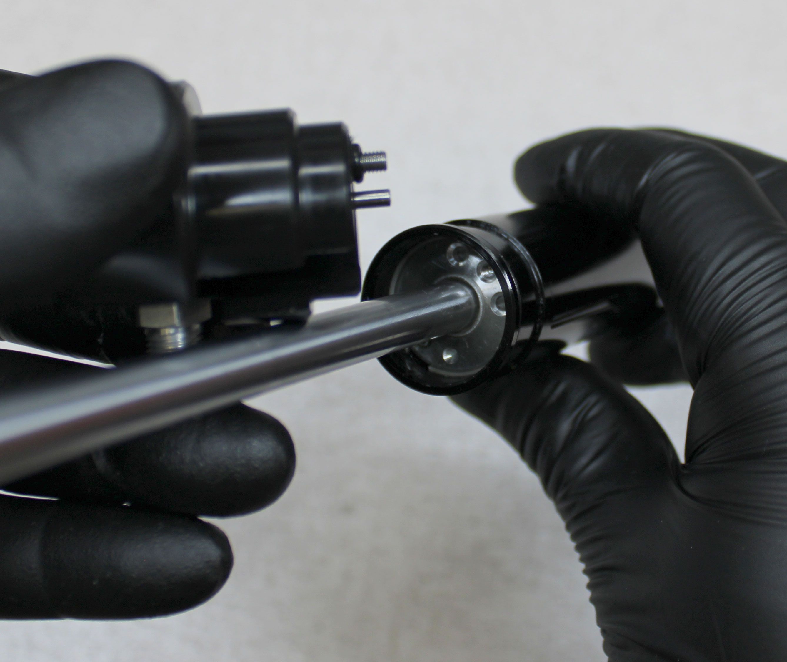
Slide the compact fill tool (PN: 803-01-931) over the shaft making sure to align the pin with the blind hole in the sealhead. Note, the gap in the tool should be centered over the bleed hole in the sealhead. Use a 2.5mm hex wrench to tighten the fill tool bolt clockwise until snug. Do not exceed 1 in-lb torque.
While the original style of fill tool is shown, follow the next steps with either fill tool to complete the gas fill of the Transfer seatpost.
NOTE: Either style of gas fill assembly (Original 803-01-595 or the new compact version 803-01-931) can be used with a High Pressure Shock Pump if needed. The following steps show the use of a Nitrogen system which is the prefered method.
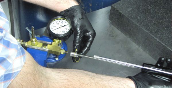
Step 42
Install the Gas Fill Assembly onto your Nitrogen system, then support the seatpost so it does not rely on the Gas Fill Assembly. The Gas Fill Assembly can be damaged if used to support the weight of the seatpost.
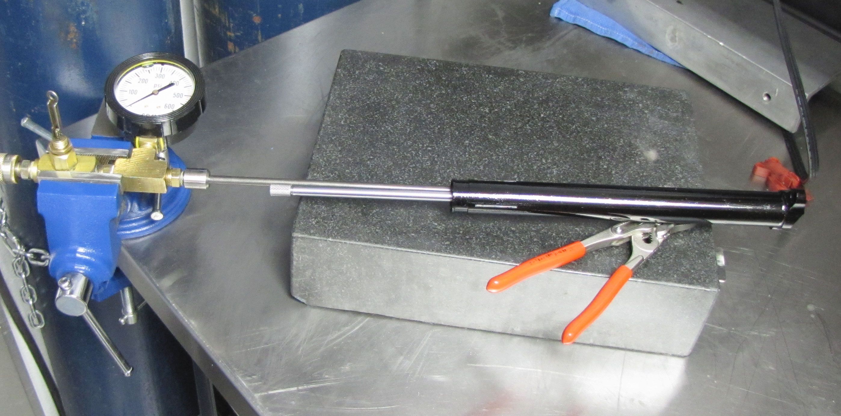
The Transfer IFP chamber must be filled to 325psi/22.4 bar very slowly so you do not damage the Nitrogen fill check system within the Sealhead. Charging the IFP chamber too quickly can damage the Sealhead assembly.
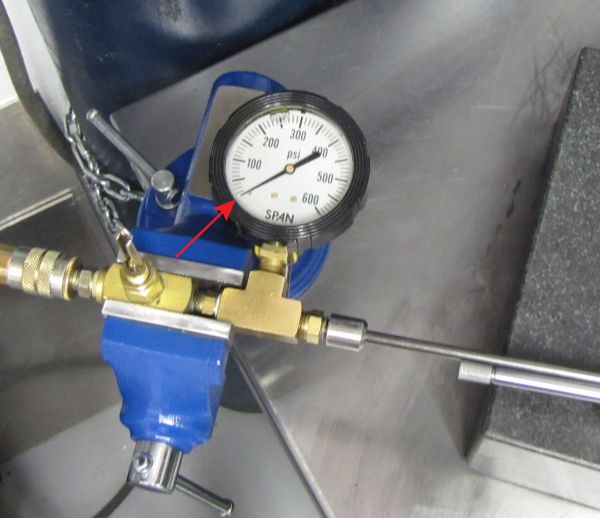
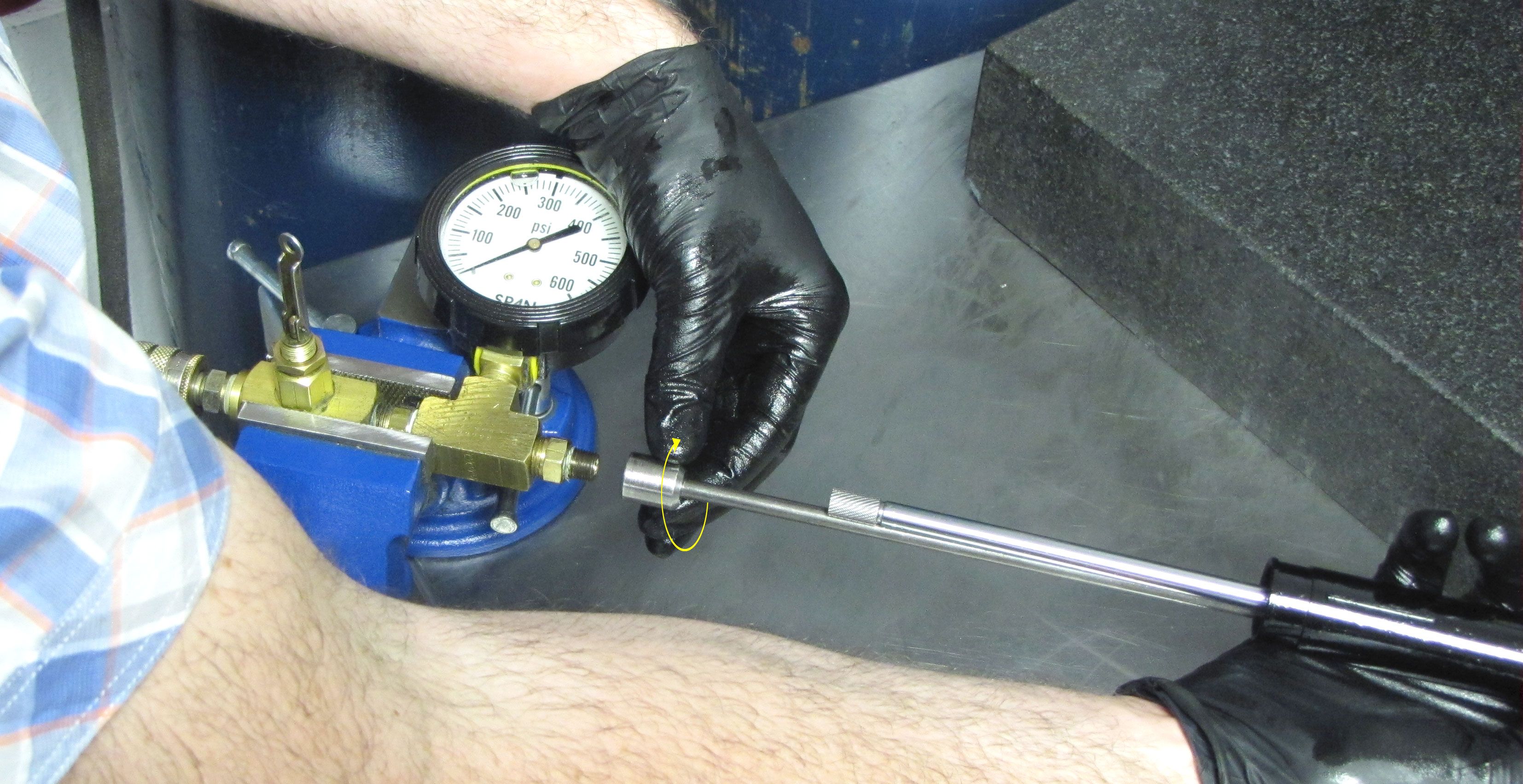
Step 43
Set your regulator to 0psi (0 bar) and slowly increase pressure over the course of 30 seconds until you reach 325 psi.

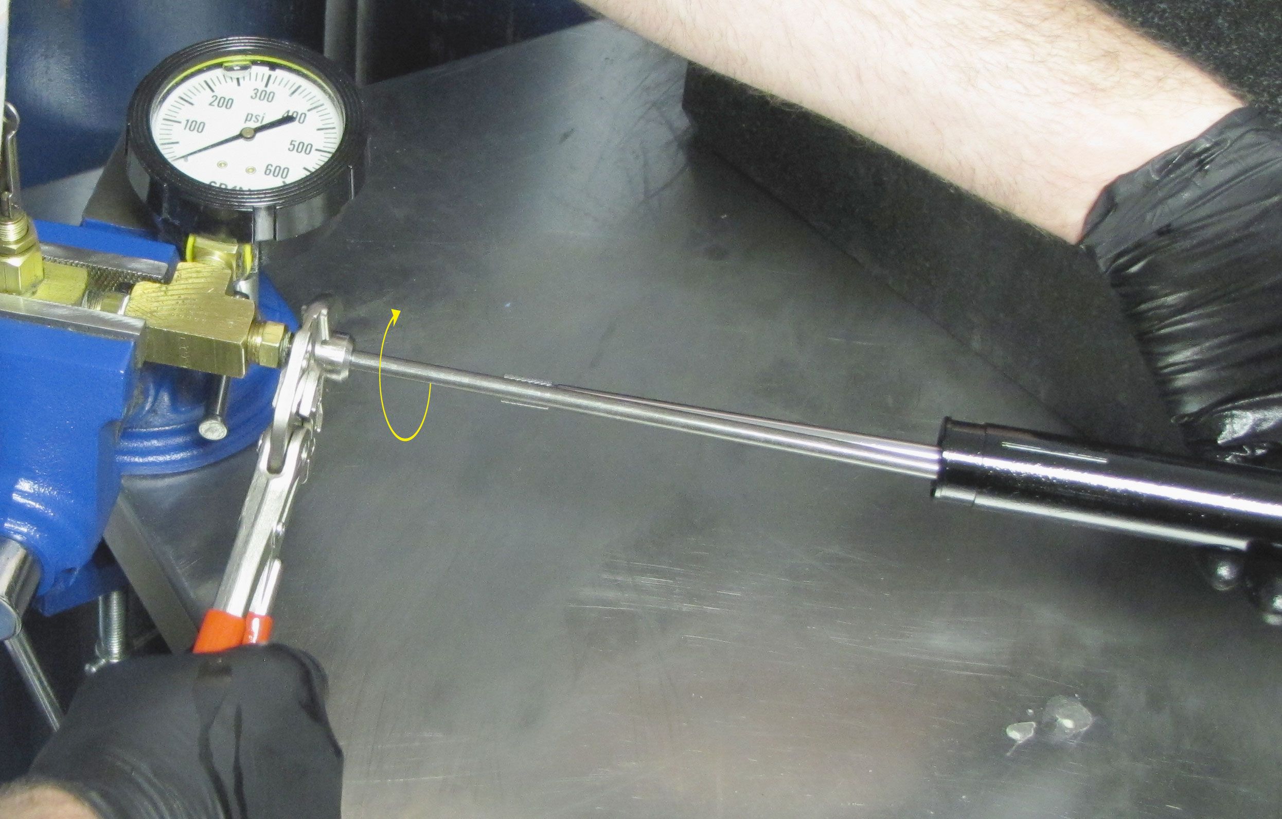
Step 44
Remove the tape (if present) and Gas Fill Assembly from the Sealhead. Remove the Nitrogen Fill Open Valve tool. Install the 2mm ball bearing into the fill hole, apply blue Loctite 242 onto the M3 set screw, then install the set screw. Tighten to 3 in-lb (0.3 Nm) torque with a 1.5mm hex wrench. Check that both the fill and bleed screws are properly tightened to 8 in-lb (0.9 Nm) torque.

Step 45
Apply a thin film of Slick Honey to the inside of the new Wiper from the kit. Install the Lower Post Collar onto the Upper Post as shown taking care not to damage the wiper seal lip on the edge of the post near the Lower Bushing position.
Step 46
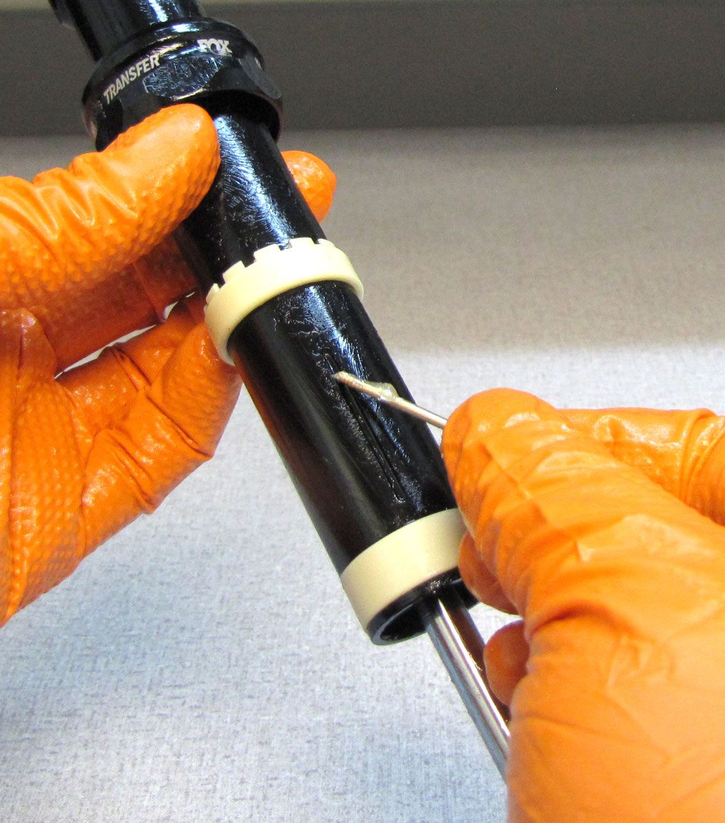
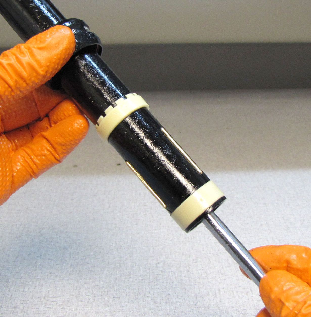
Install the new Upper Bushing from the kit with its "crown-shaped" portion oriented toward the top of the post. Install the new o-ring from the kit onto the upper post followed by the new Lower Bushing. Do not use sharp tools for installation, the pick is shown to indicate the o-ring position.

Step 47
Install the new bottom out bumper from the kit onto the Shaft lug then thread the Shaft Lug onto the Shaft clockwise. Clamp the Shaft, then tighten the Shaft Lug onto the Shaft to 30 in-lb (3.4 Nm) torque with your 10mm wrench.


Step 48
Fill the Index Pin slots with Slick Honey, then install the Index Pins.
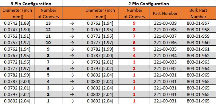
In some cases, the rear-most oriented index pin can bind between the upper and lower posts when excessive seatpost clamping force is used. This can cause unwanted friction and in some cases can prevent the post from fully extending. FOX and Race Face now approve the usage of only two index pins in place of three. The rear-most of the three index pins should be omitted, and the remaining two should be exchanged for slightly larger pins to prevent inappropriate rotational play. Use the conversion chart below to select replacement pins when switching from 3 pins to 2 pins. Index pins are available individually or in bulk bags of 6 pins each.

Step 49
Install the anti-rotation 2mm ball bearing into the pocket on the Shaft Lug that you marked during disassembly. The marked pocket should align with the saddle clamp and the Index Pin that is farthest from the other two.

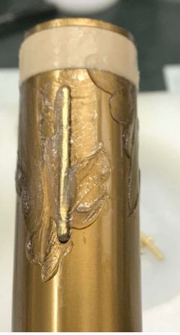
Step 50
Align the anti-rotation ball bearing with the groove in the inside of the Lower Post that is inline with the laser etching on the back of the Lower Post. Slowly feed the Upper Post Assembly into the Lower Post.
Note: Increased force may be required to install the upper post into the lower post as the lower bushing is energized by the o-ring.
Step 51
Loosely position the Upper Post upside down in the Upper Bushing Installer (PN: 803-01-496) so the Upper Bushing rests on the tool. Push the Lower Post down against the tool to install the Upper Bushing. (Note: Early versions of the Upper Bushing and Upper Bushing Installer are shown. The procedure will be identical for the new smooth-rimmed Upper Bushing without castellation and the new 2021 Transfer Upper Bushing Installer {PN: 803-01-496}).


Step 52
Reinstall the wire retaining ring into the bottom of the Lower Post. Compress the seatpost slightly to seat the Shaft Lug against the retaining ring.

Step 53
Thread the Bottom Cap into the end of the Lower Post. Tighten the Bottom Cap clockwise using its thickest part to 40 in-lb (4.5 Nm) torque.

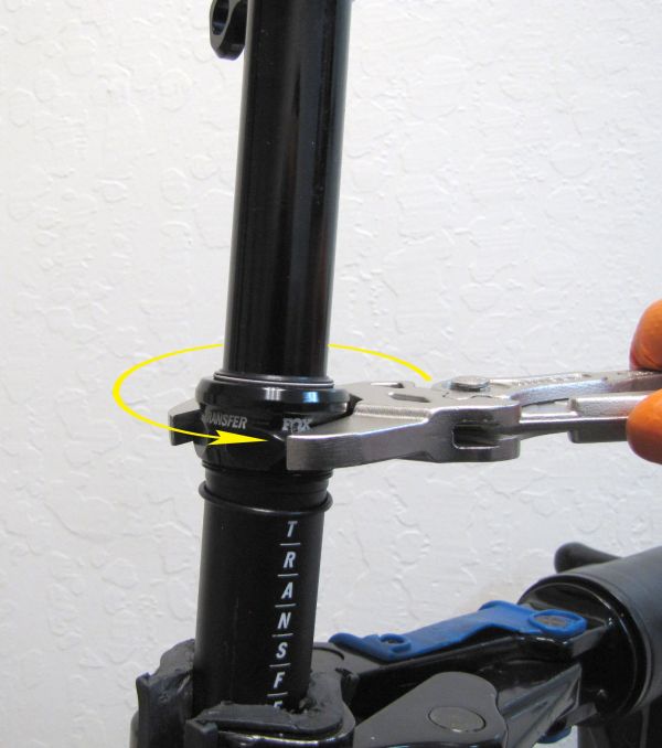
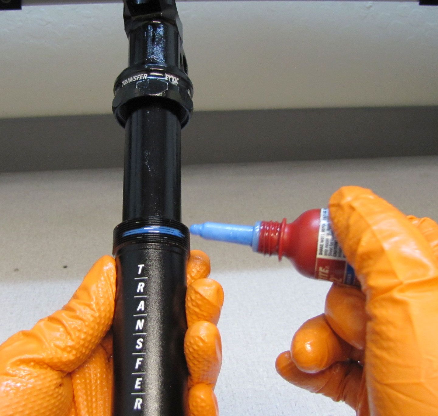
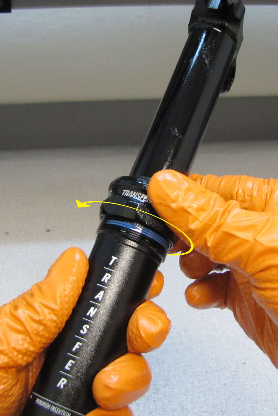
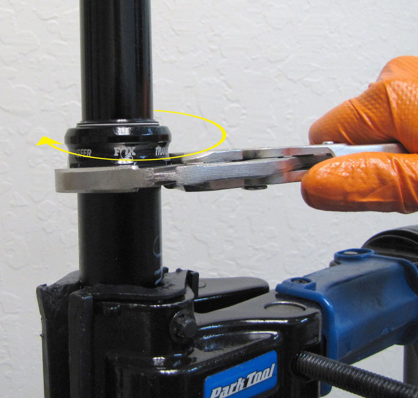
Step 54
Apply a Blue Loctite 242 to the Lower Post threads then reinstall the Lower Post Collar tightening clockwise (when viewed from the top of the post) to 80 in-lb (9.0 Nm) torque.

Step 55
Reinstall the Barrel Nuts into the post head followed by the Saddle Clamp Bolts. Reinstall the Saddle Clamps making sure all arrows face the front of the post.