2015-2017 36 FLOAT NA Service Procedure
Required Parts
- 241-01-011 Fastener, Custom: Crush Washer, Plastic, 13mm
- 803-00-588 Seal Kit: 36 FLOAT NA Rebuild
Required Tools
- 398-00-681 2002-017 32 Damper-side and ALL 32-34-36-40 Spring-side Removal Tool
- 398-00-682 2005-017 34-36-40 Damper-side Removal Tool
- 803-01-324 Kit: Tooling: 2019 Clamps, Grip Damper, Body and Shaft
Sections
WARNING: Always wear safety glasses and protective gloves during service to prevent potential injury. Failure to wear protective equipment during service may lead to SERIOUS INJURY OR DEATH.
WARNING: FOX products should be serviced by a qualified bicycle service technician, in accordance with FOX specifications. If you have any doubt whether or not you can properly service your FOX product, then DO NOT attempt it. Improperly serviced products can fail, causing the rider to lose control resulting in SERIOUS INJURY OR DEATH.
Disassembly
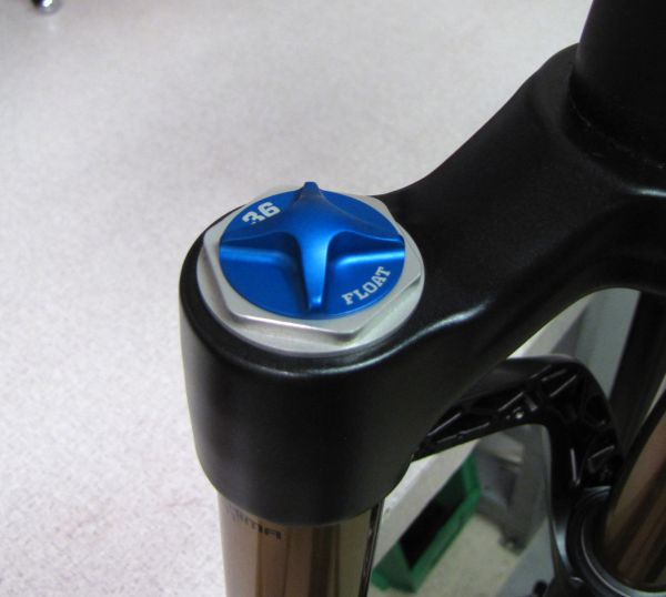
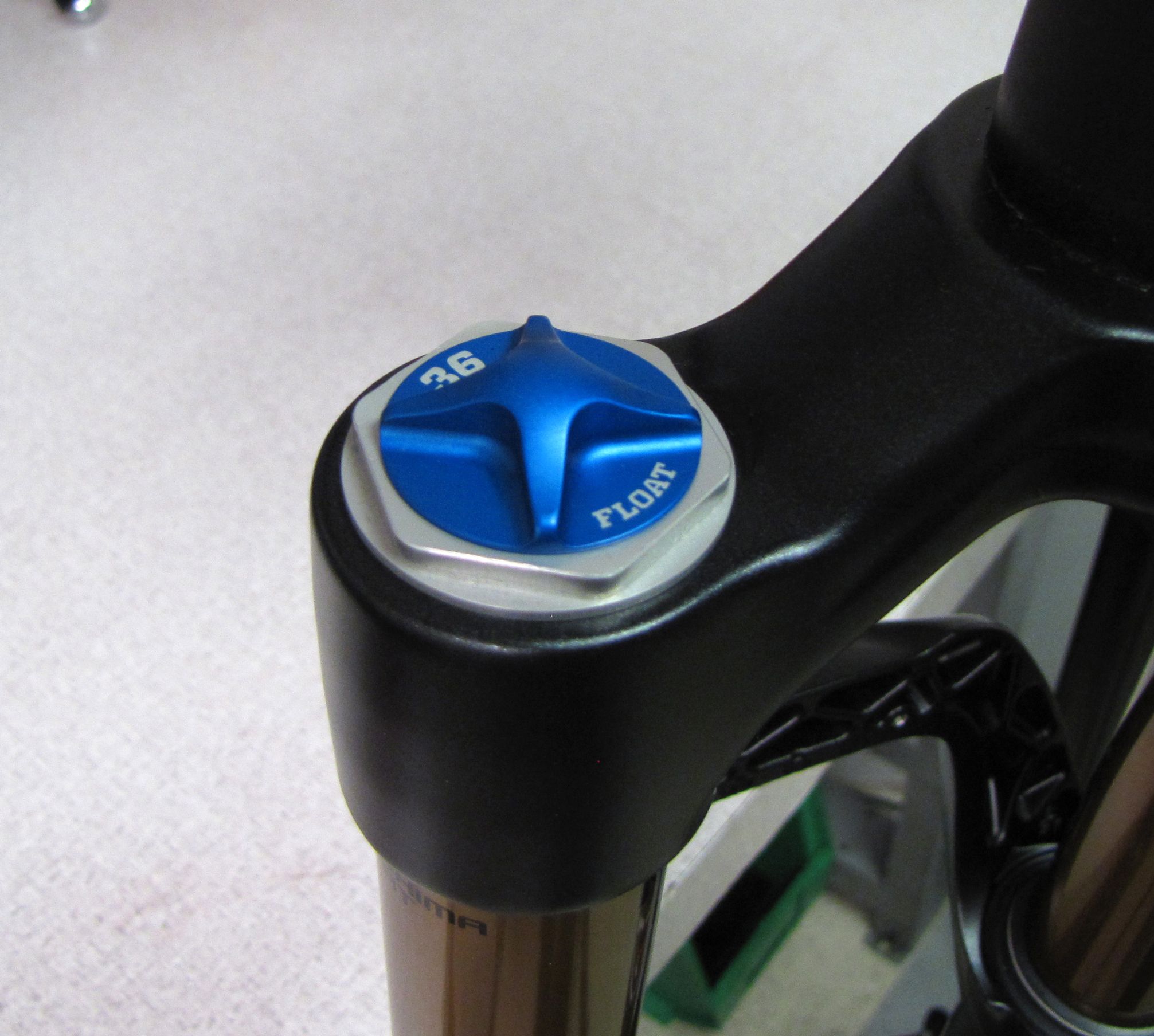
Step 1
Remove the blue air cap and release the air pressure.
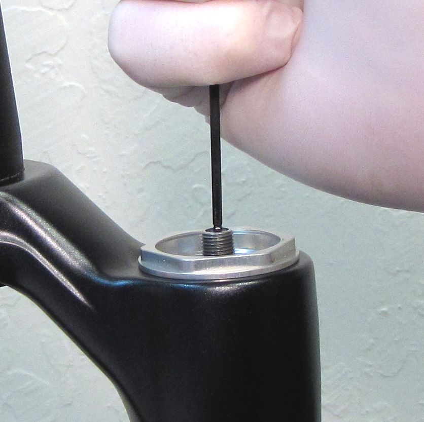
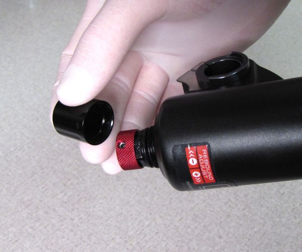
Step 2
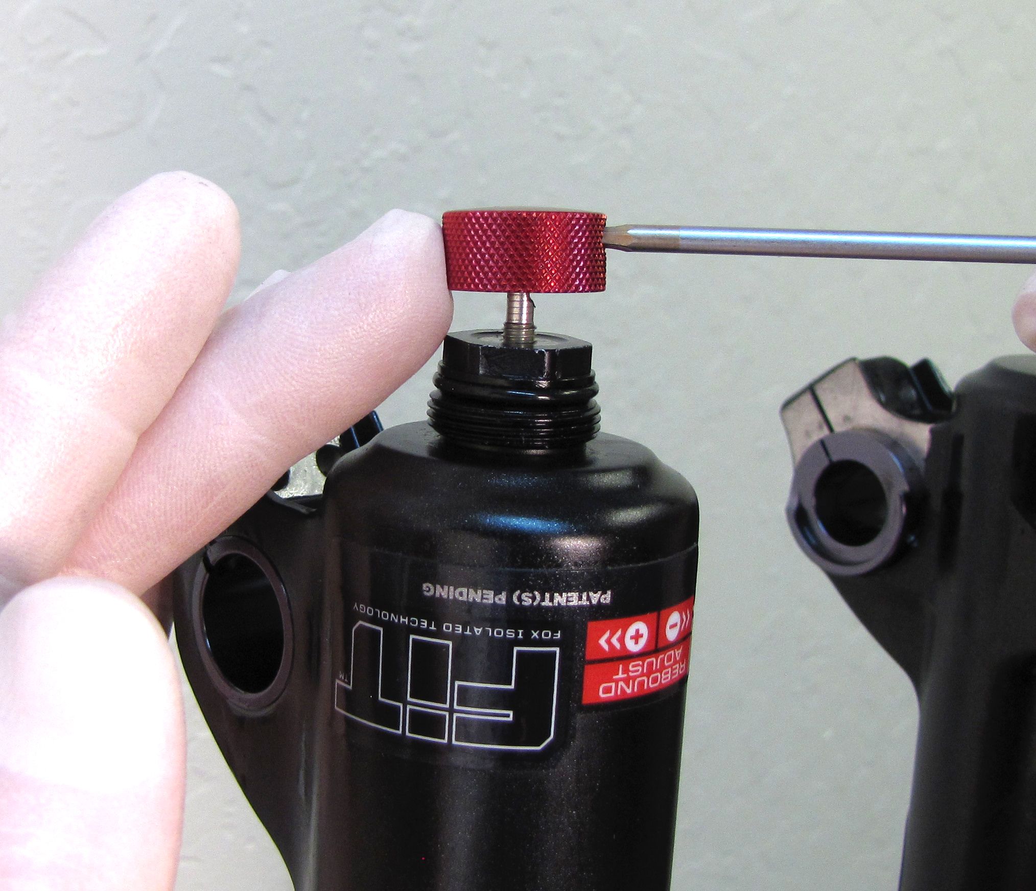
Remove the black rebound knob cover, then use a 2mm hex wrench to remove the red rebound knob.

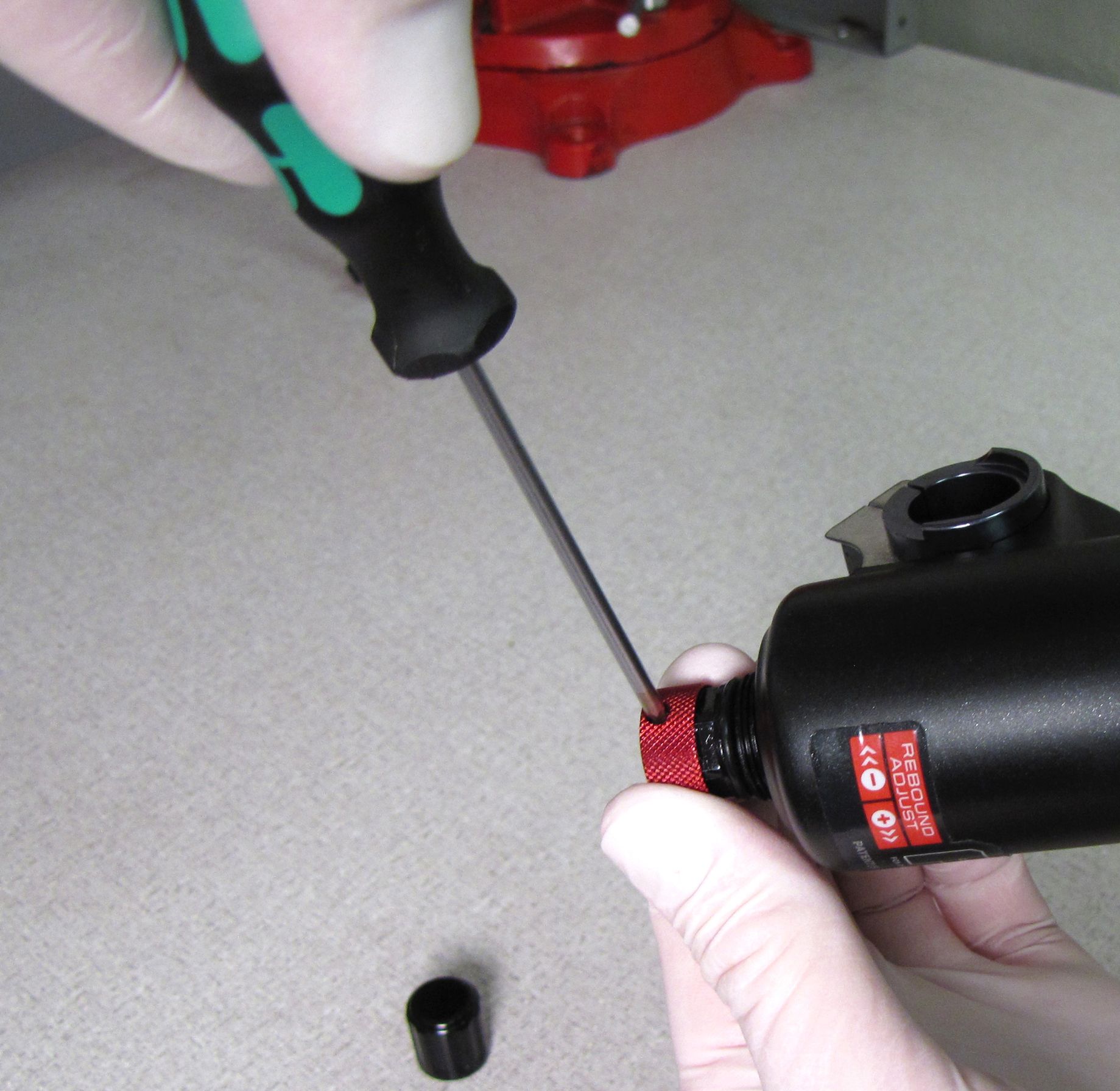
Step 3
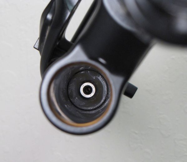
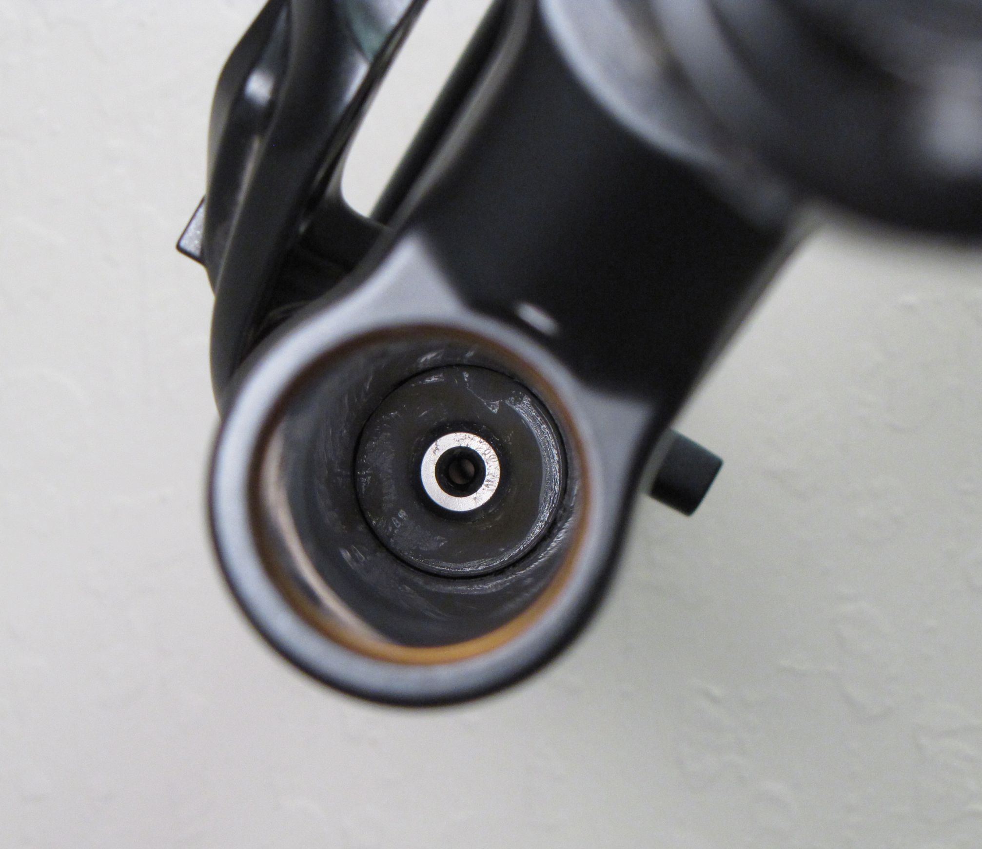
With the fork slightly inverted (the bottom of the fork up past horizontal) remove the bottom nuts with 10mm and 15mm sockets. Remove the crush washers.
Step 4
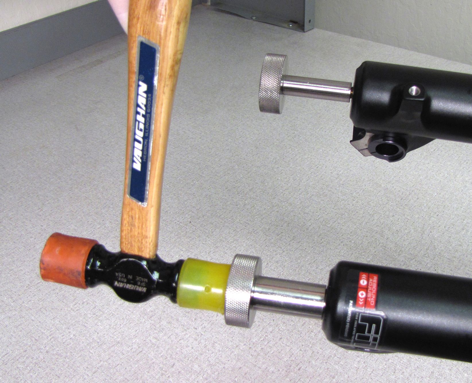
Use Damper Removal Tools 398-00-430 and 398-00-601 to dislodge the shafts from the lowers. Make sure that you have approximately half of the available threads engaged with your tool before striking with your mallet. Bring fork upright over an oil basin to drain.


WARNING: Please verify that all air has been released from the air chamber by pushing down on the Schrader valve core. Failure to release all air pressure before further disassembly may cause parts to eject causing SEVERE INJURY OR DEATH.
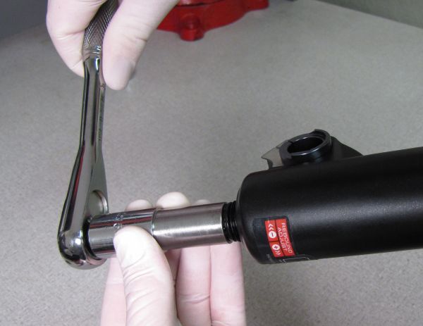
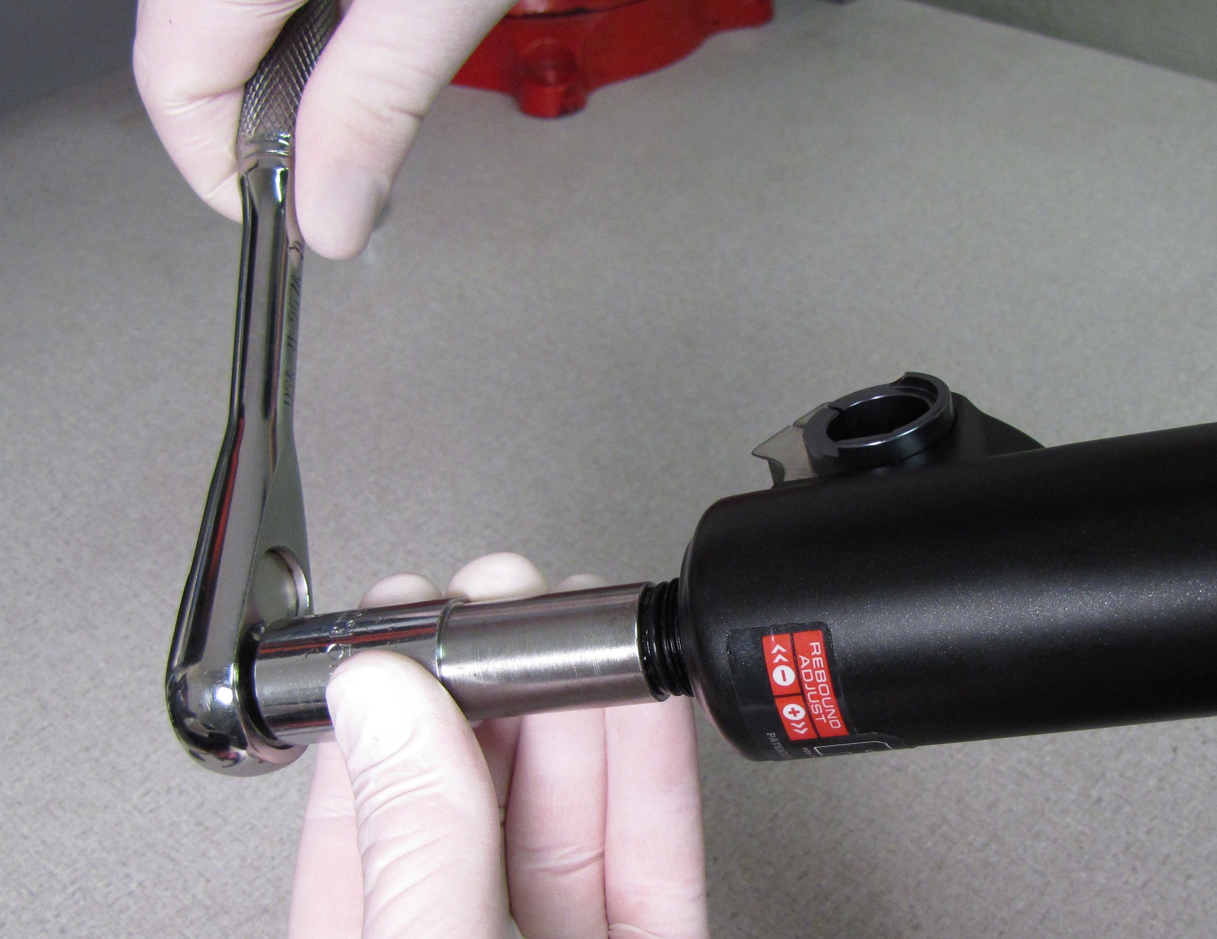
Step 5
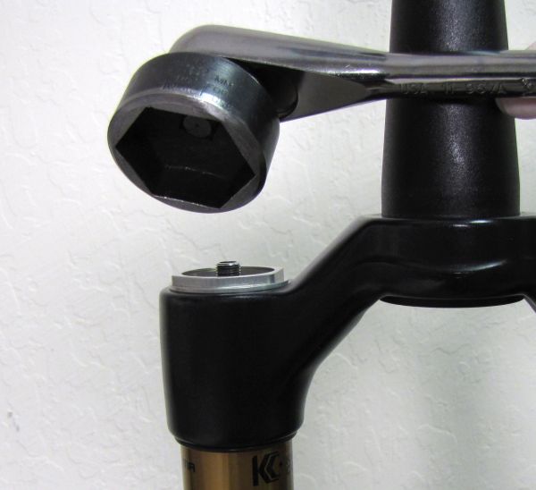
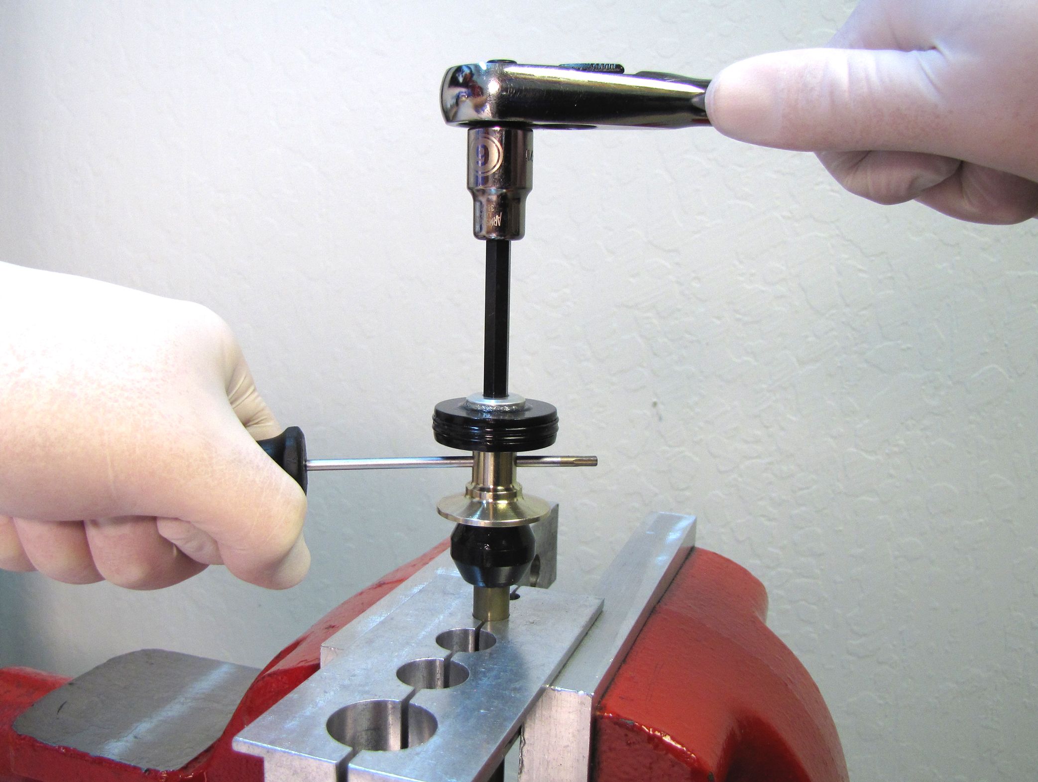
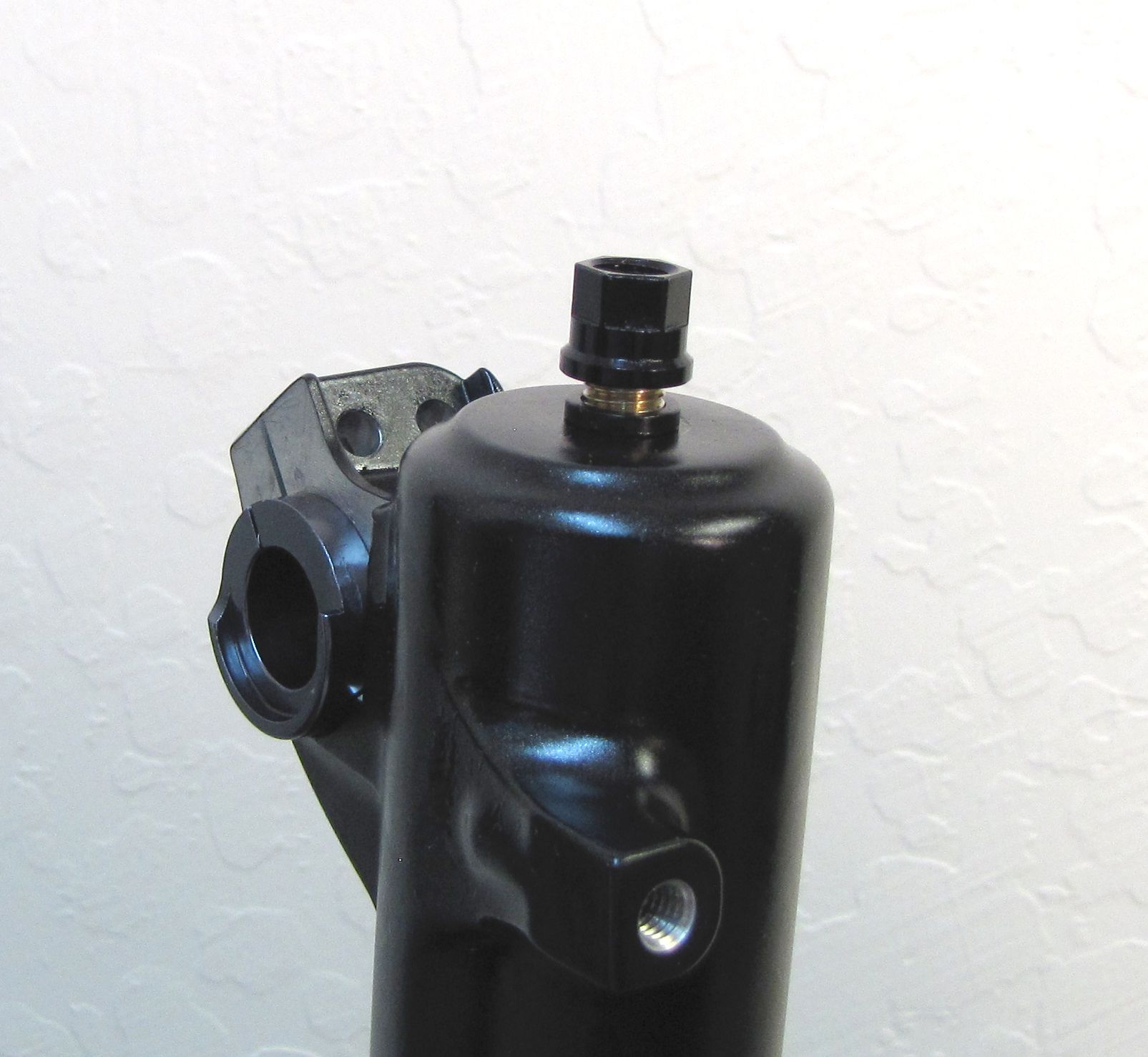
With a chamfer-less 6-point 32mm socket, unthread the topcap assembly completely.

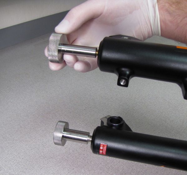
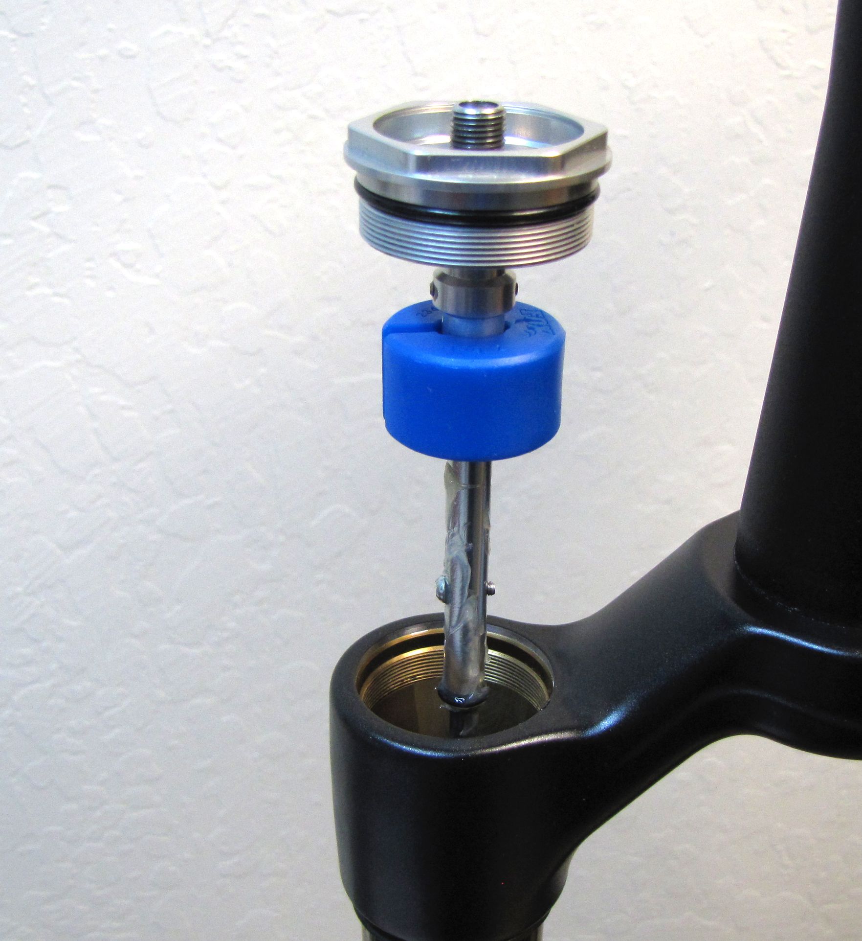
Step 6
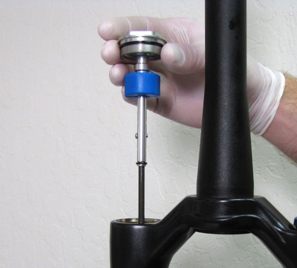
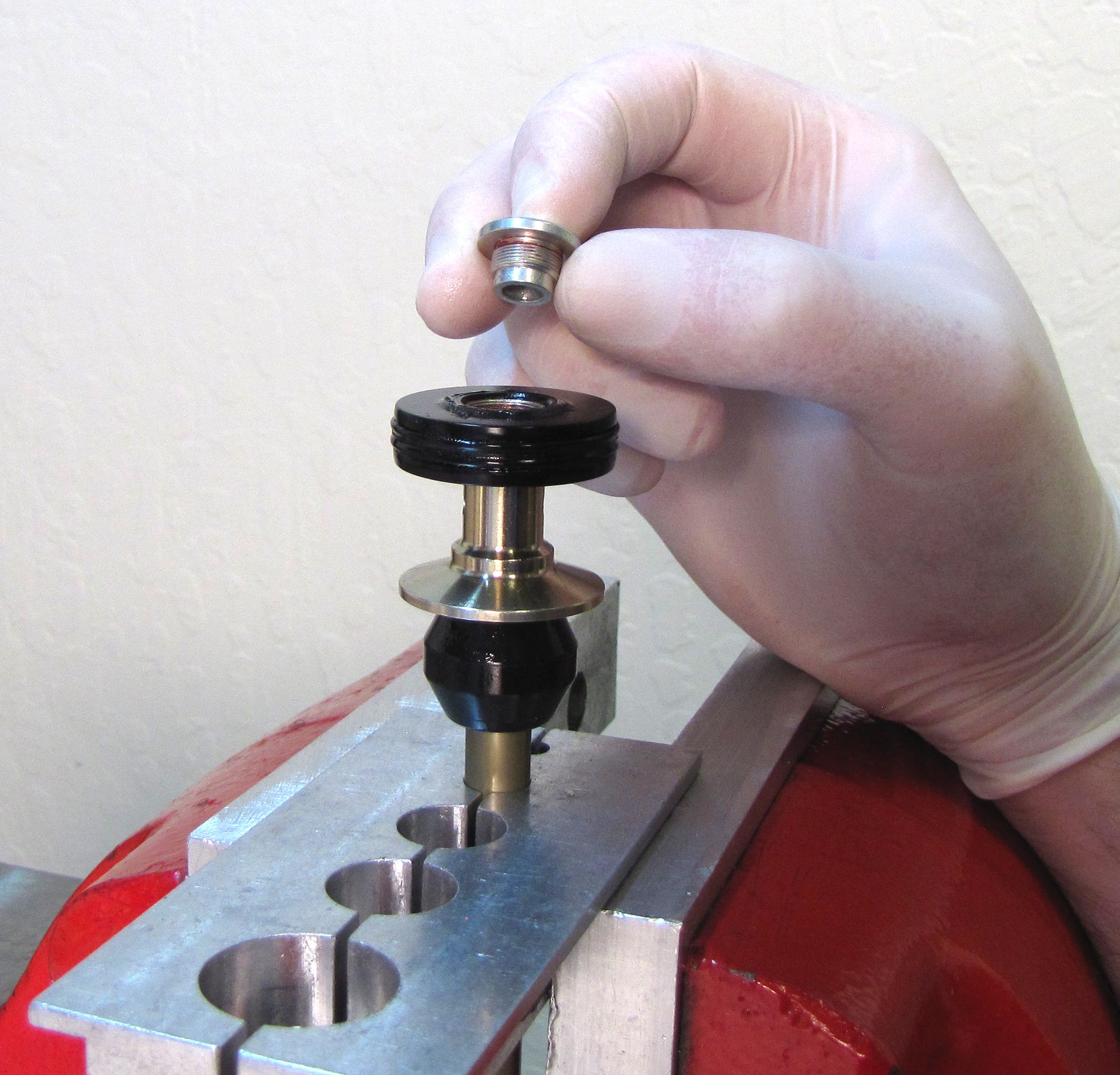
Pull straight up to remove the entire topcap assembly from the left side upper tube. Do not allow the transfer shaft to come in contact with the inside of the upper tube.

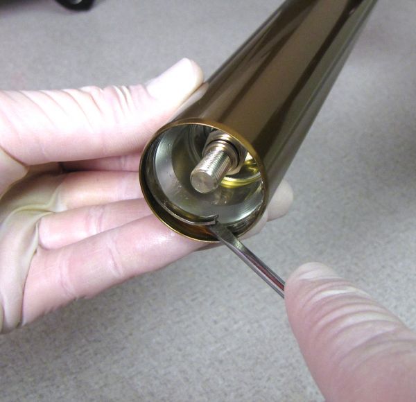
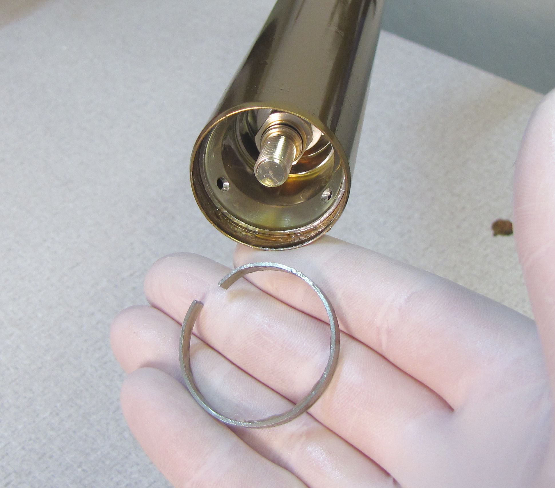
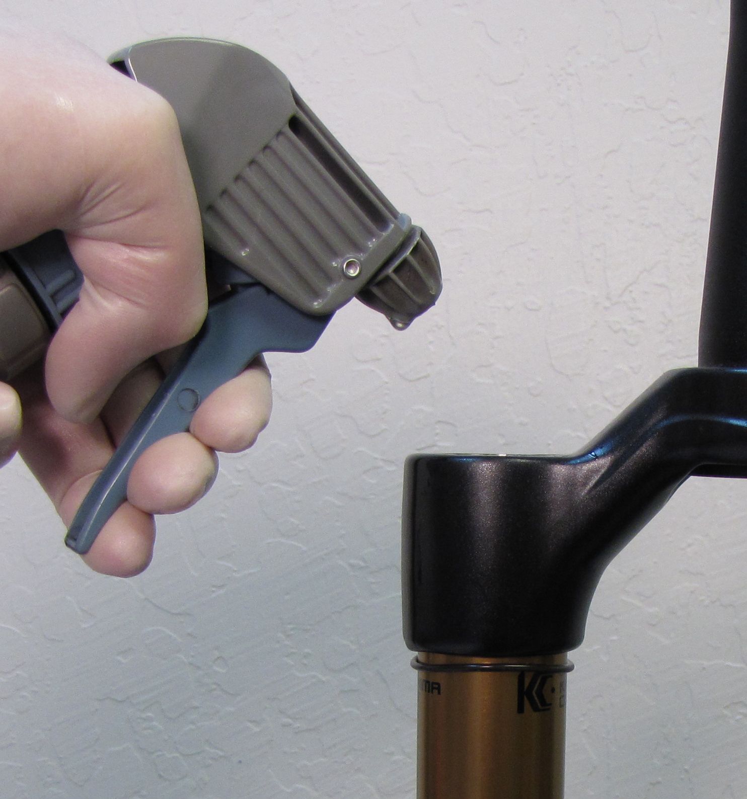
Step 7
With the shaft compressed, remove the retaining ring. Thread damper removal tool (PN: 398-00-601) on to the air shaft. Pull on the damper removal tool to remove the air shaft from the upper tube.


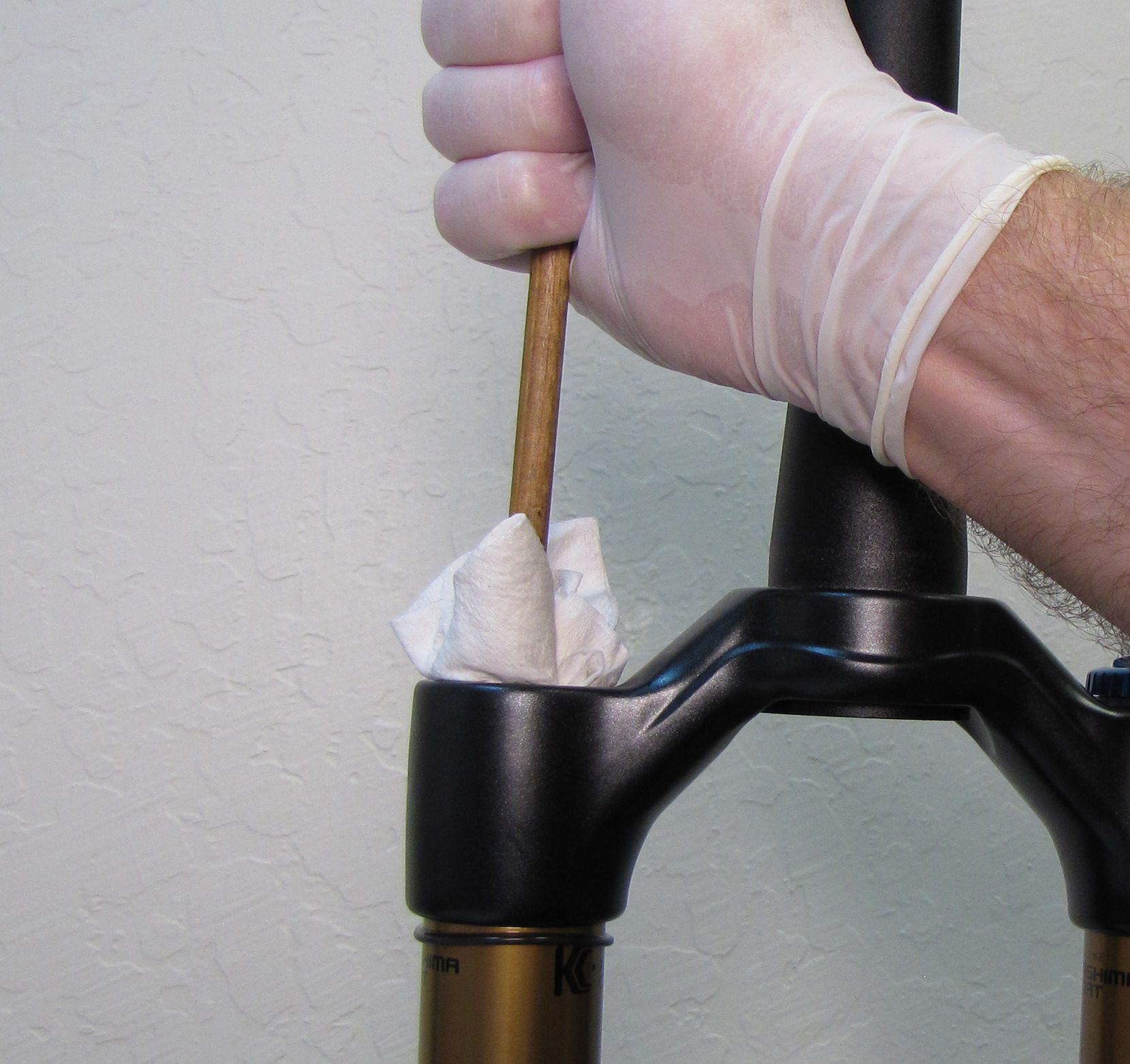
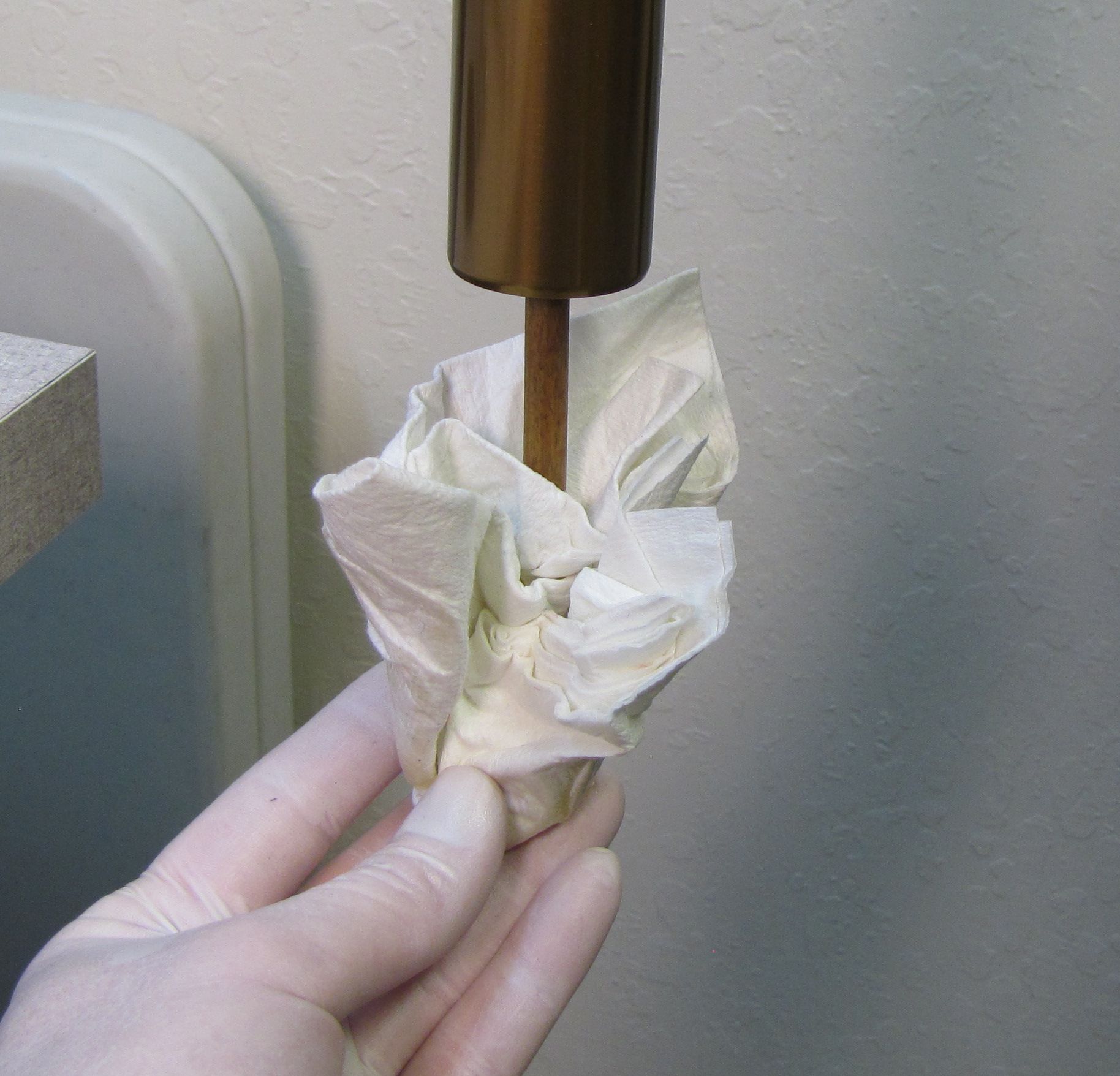
Step 8
Spray Isopropyl alcohol into the air side upper tube. Push a lint free paper towel through the tube using a non marring dowel. Repeat this process until the inside of the upper tube is free of debris.
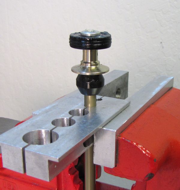
Step 9
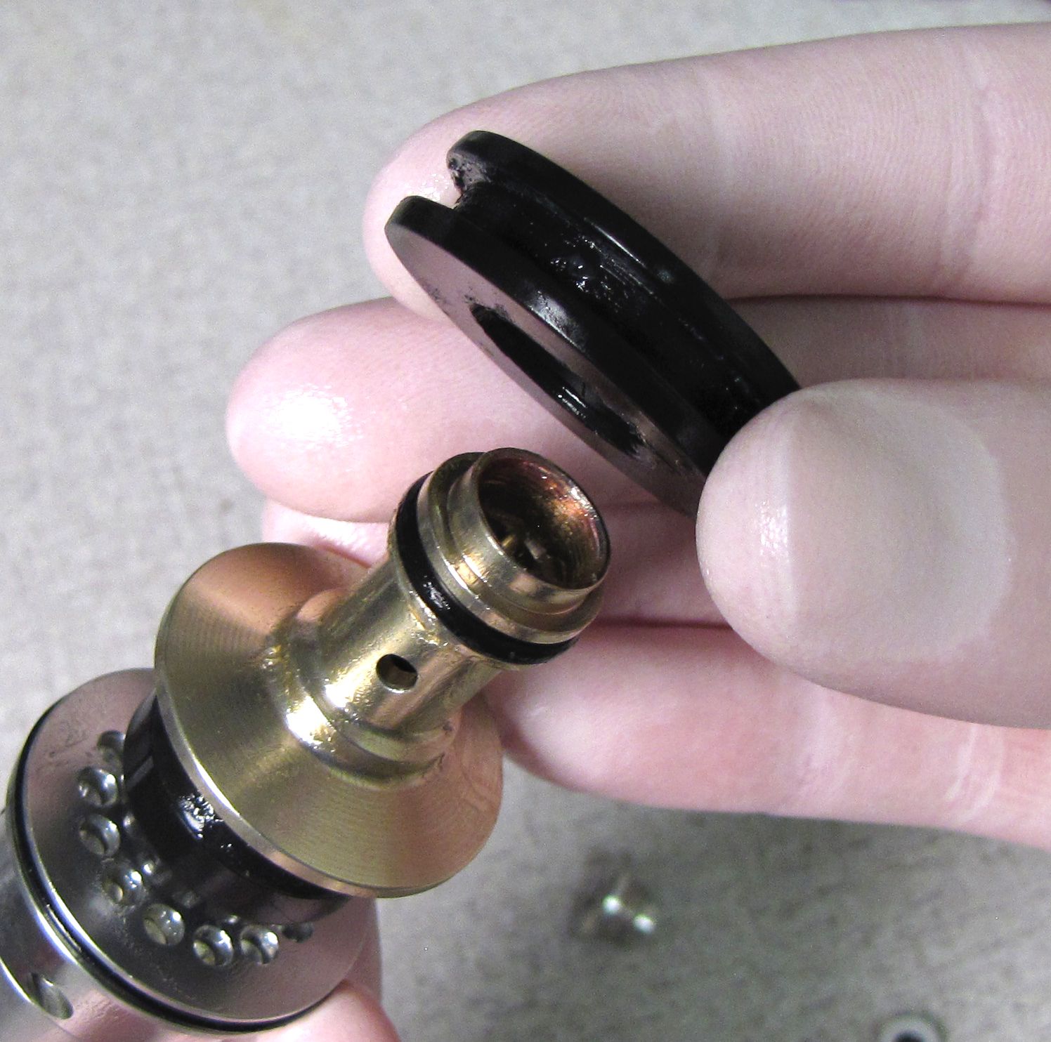
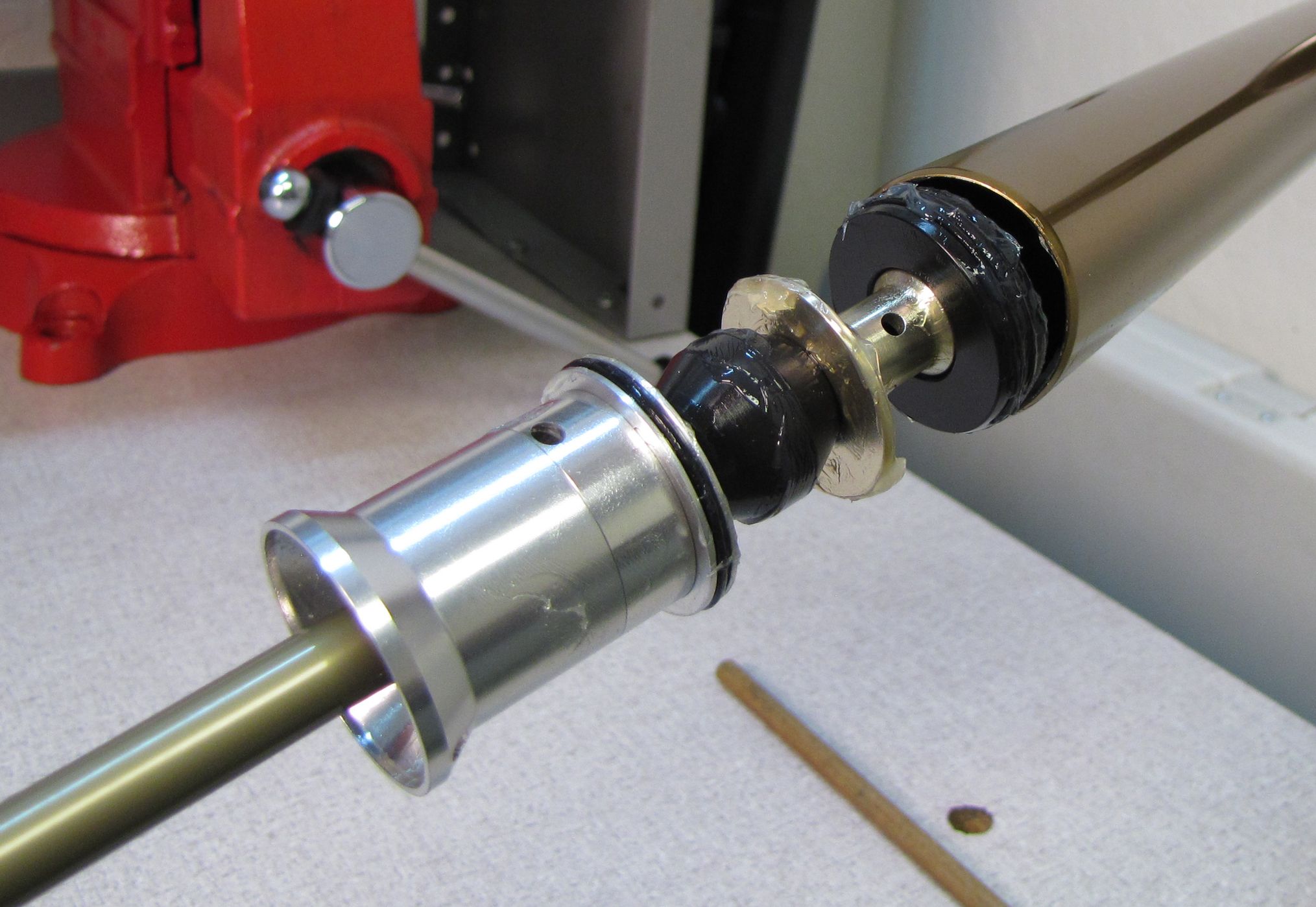
Clean your shaft clamps (PN: 803-01-324) and Air Shaft Assembly with Isopropyl alcohol. Clamp the air shaft, below the Topout Bumper, then insert a 2.5mm hex wrench through the hole in the Piston Base. Hold the piston base stationary, then use a 6mm hex wrench to unthread and remove the piston bolt.

Step 10
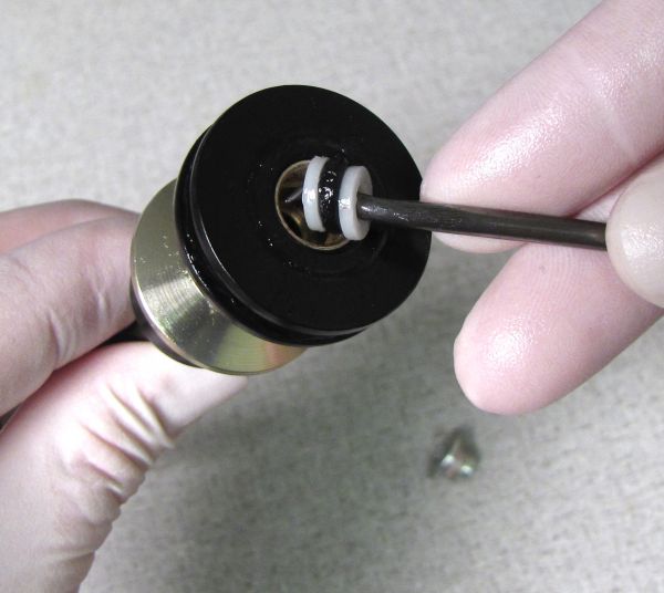
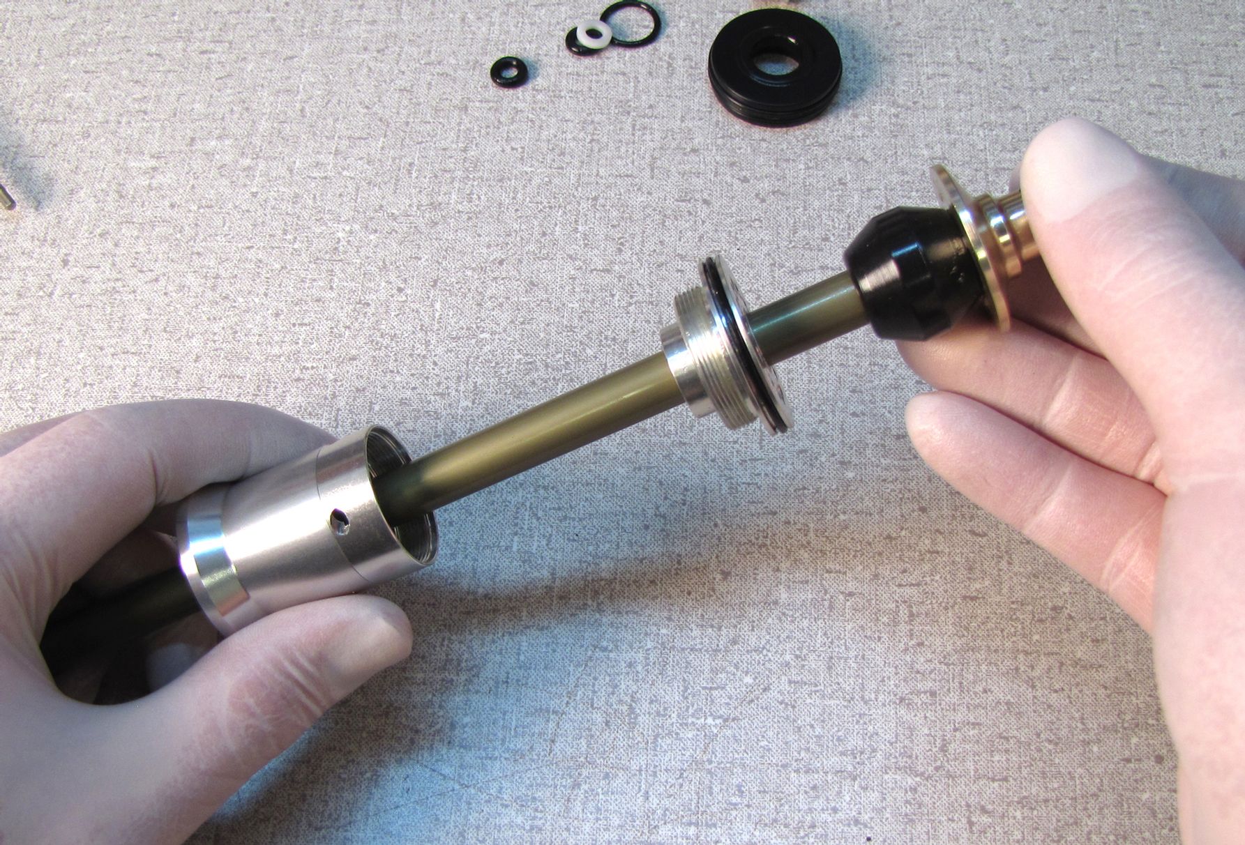
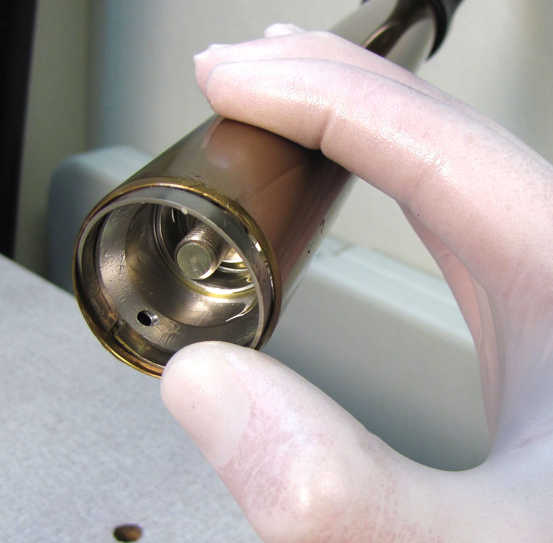
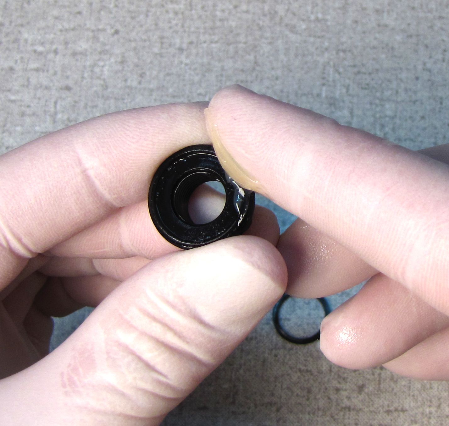
Remove the Piston Seal from the FLOAT Piston, then remove the transfer shaft bushings and seal from inside the Piston Base. Pull up on the piston to remove it, then remove the piston base o-ring.


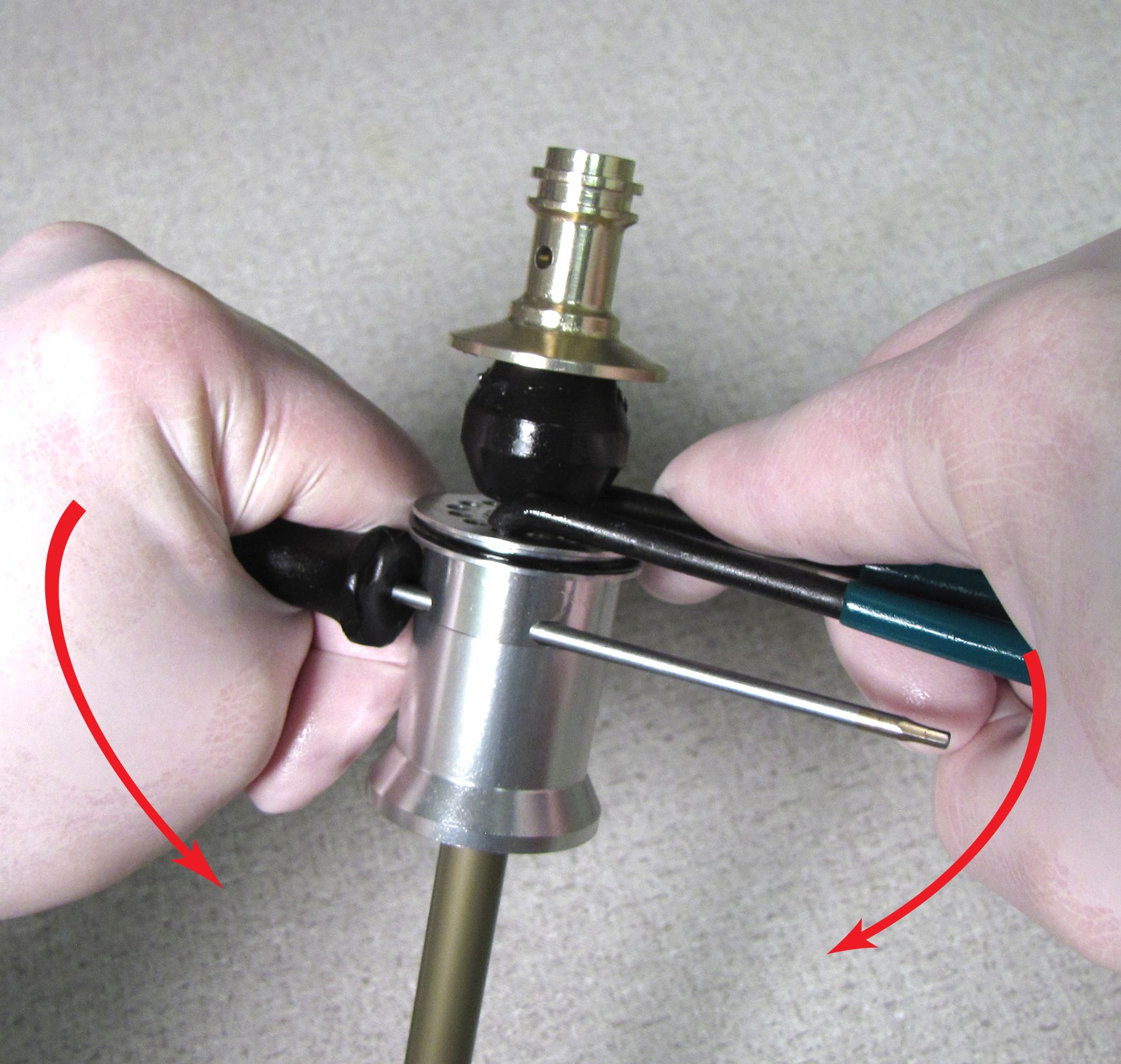
Step 11
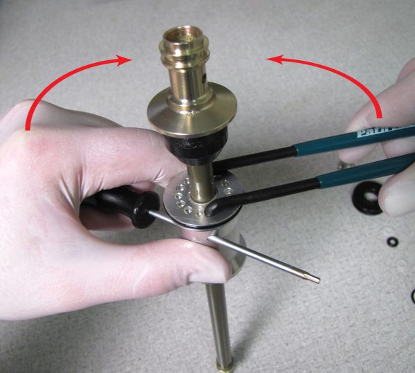
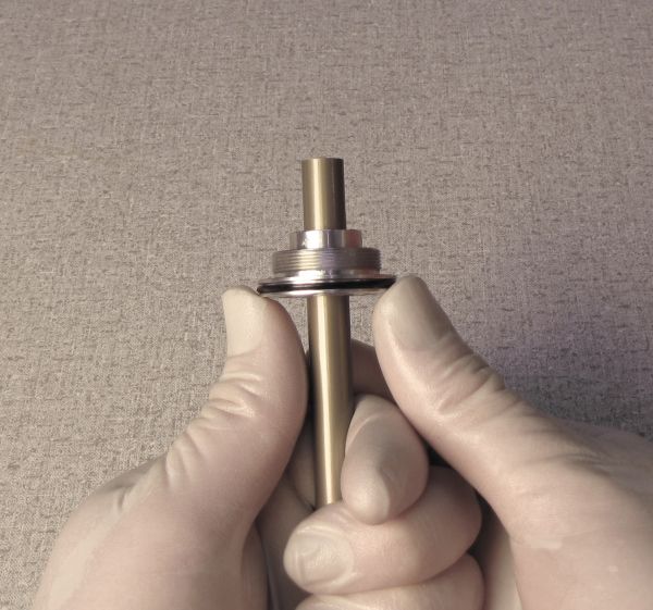
Insert the pins (3mm Ø) of your pin spanner into opposing holes in the top of the Neg Plate Assembly. Insert a 2.5mm hex wrench through the hole in the Neg Plate Spacer or Neg Plate Tube (whichever is closest to the Neg Plate Assembly).
Unthread and remove the Neg Plate Tube and any attached Neg Plate Spacers if present.


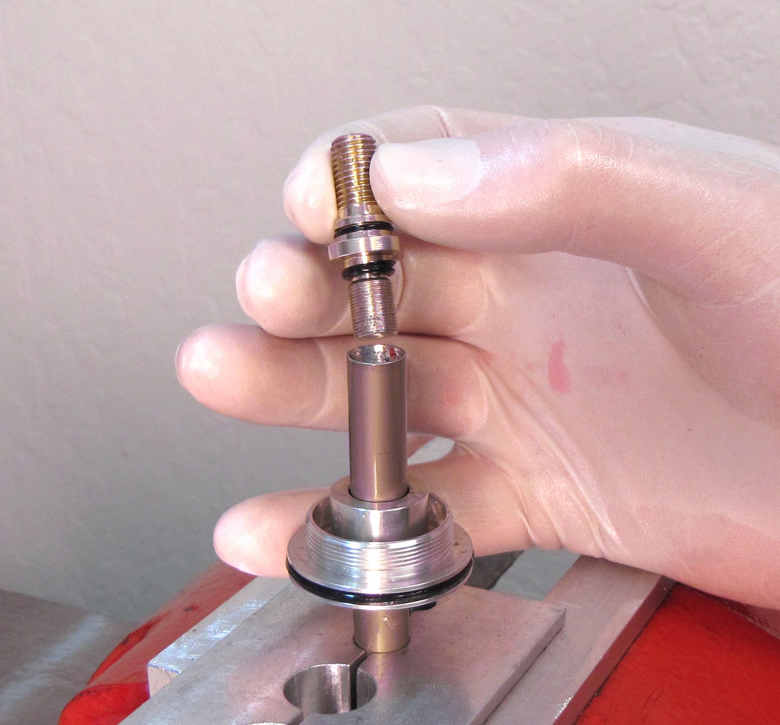
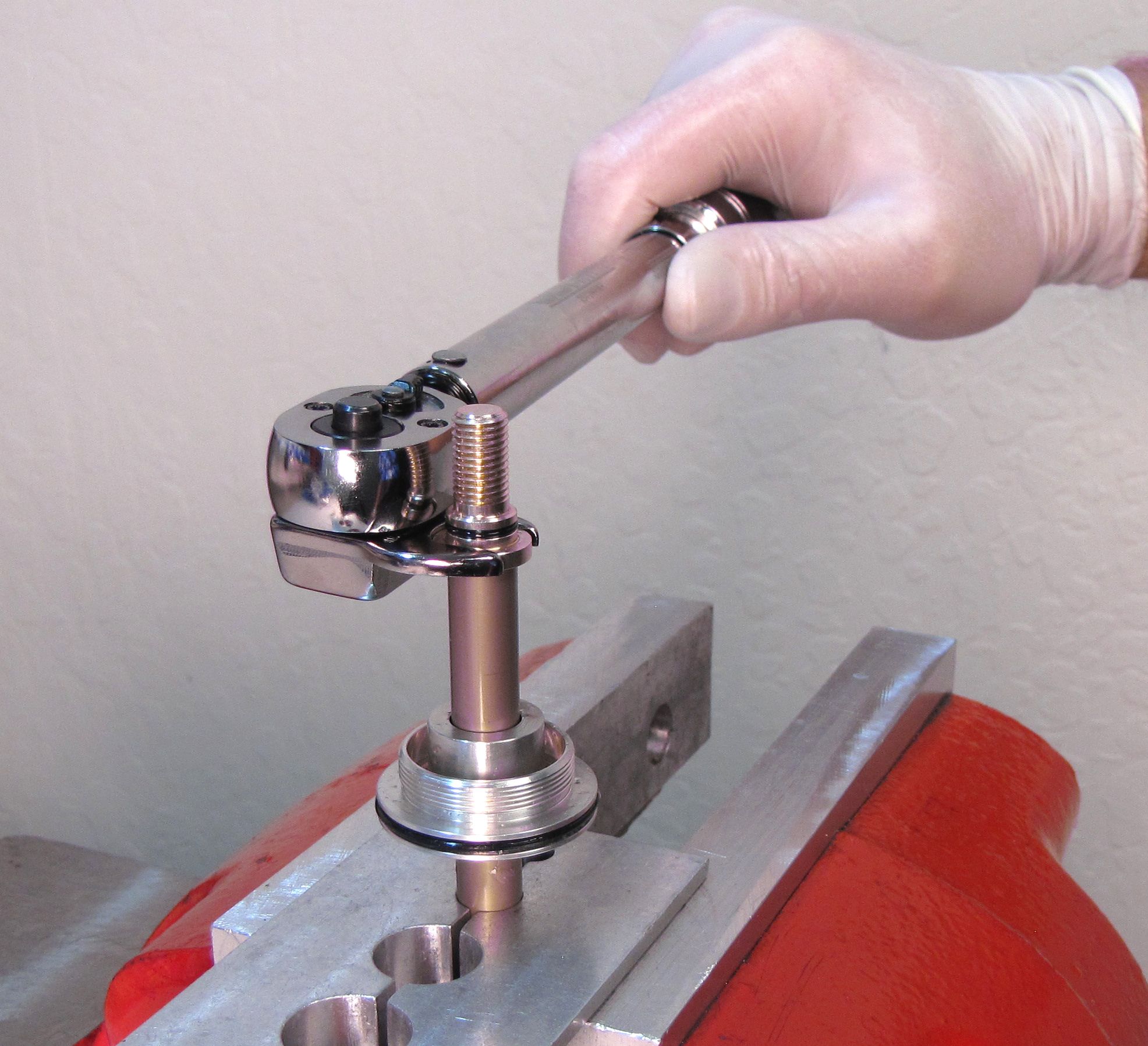
Step 12
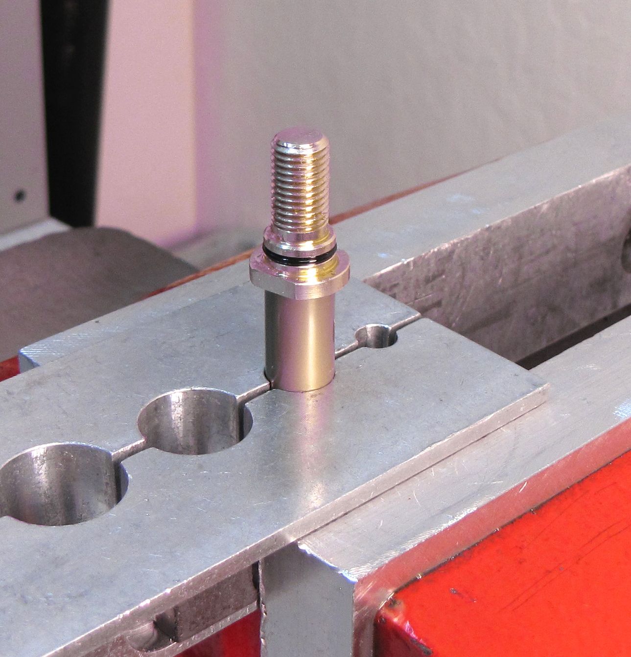
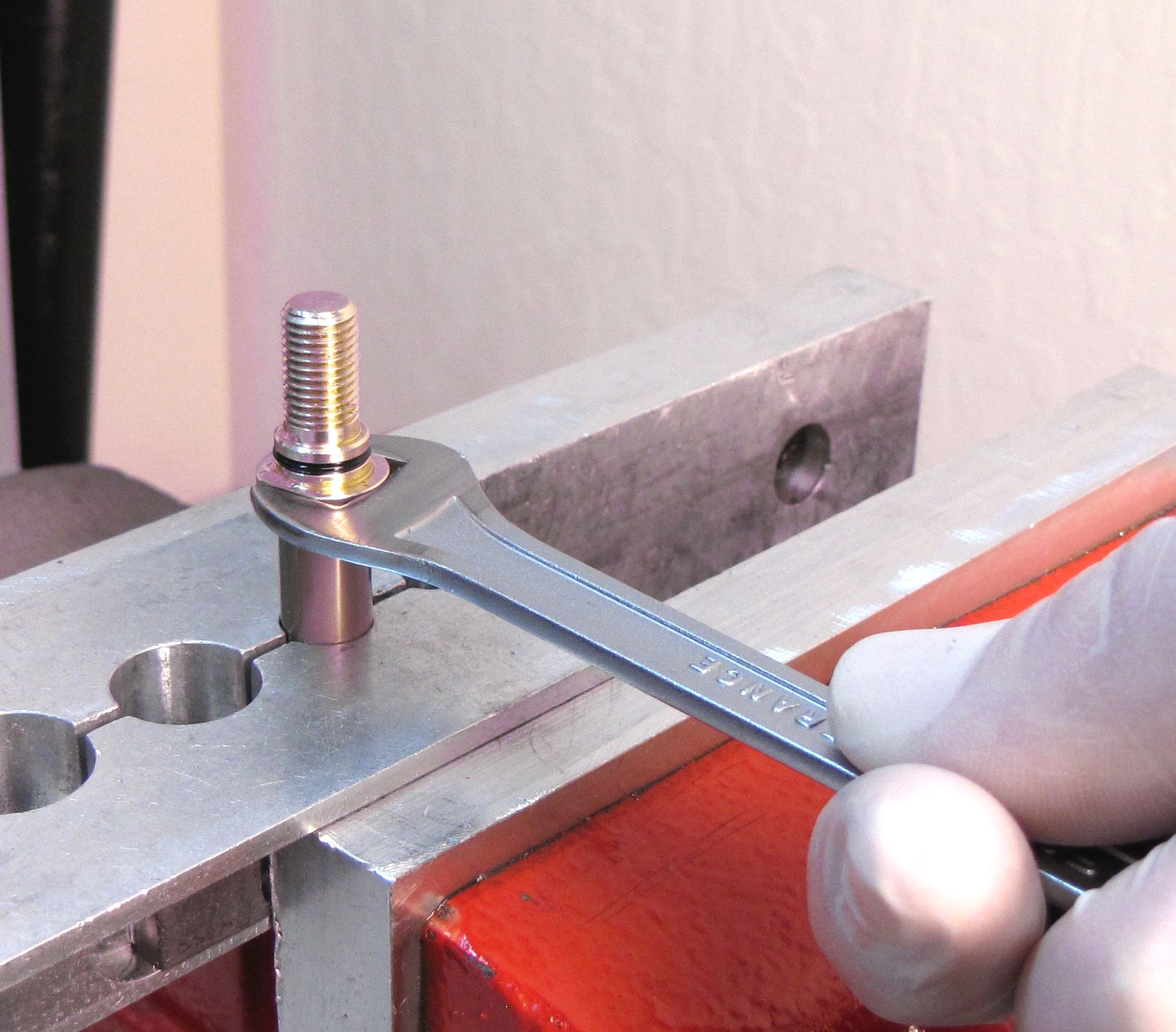
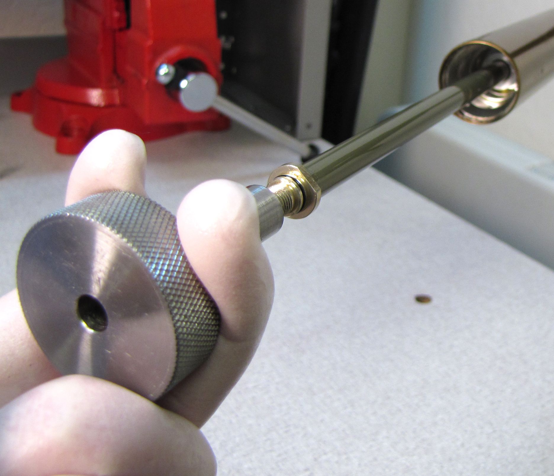
Clean your shaft clamp (PN: 803-01-324) and Air Shaft Assembly with Isopropyl alcohol. Carefully clamp the Piston Shaft, then use a 12mm wrench to remove the Base Stud from the Piston Shaft.
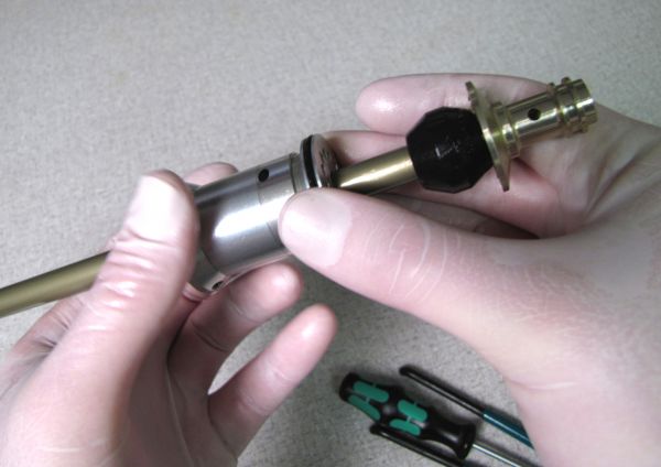
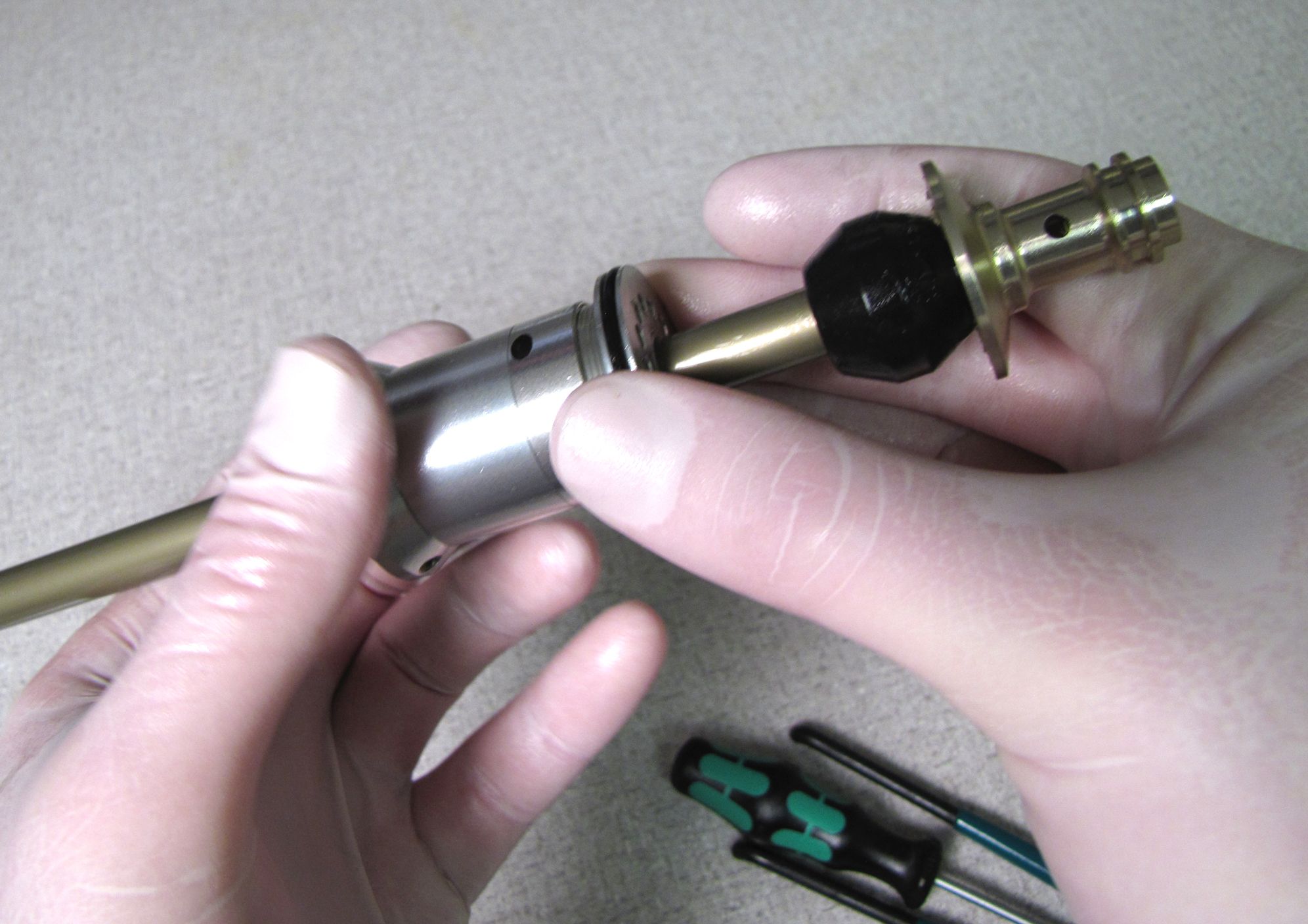
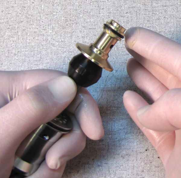
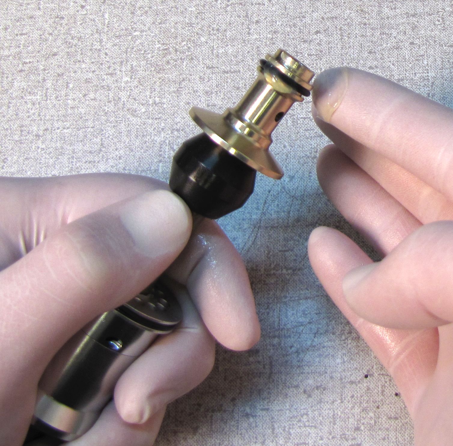
Step 13
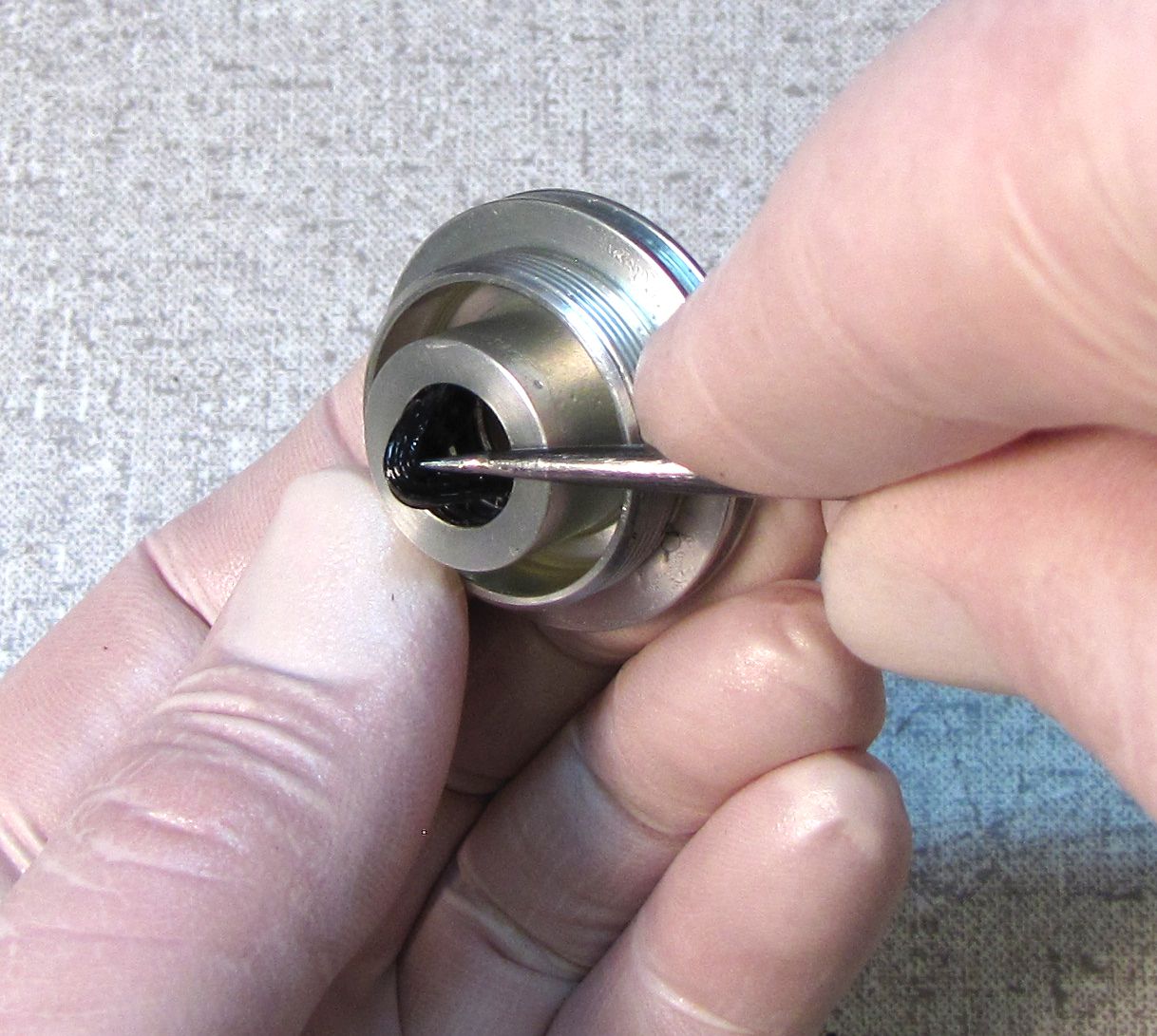
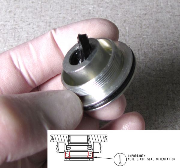
Push the Negative Plate Assembly off the Piston Shaft. Be careful not to leverage your pick on any part of the Negative Plate Assembly while using it to remove the U-cup seal and then the o-ring from within the Negative Plate Assembly. Remove the outer o-ring.


Reassembly
Step 1
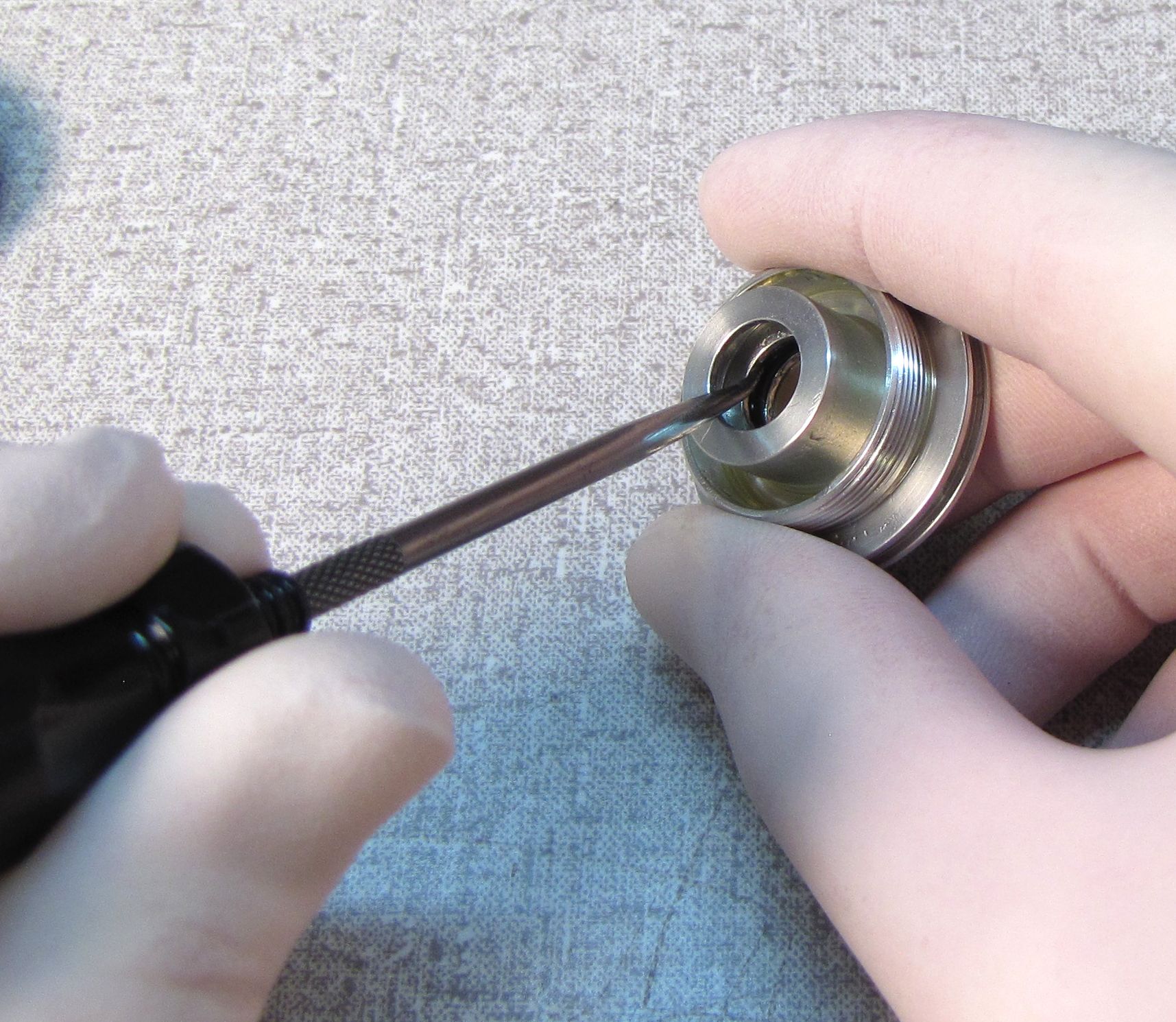
Coat the new O-Ring and U-Cup seal with Slick Honey. Install the O-ring followed by the U-cup Seal (U-cup lip oriented away from pin spanner holes) through the bottom of the Neg Plate Assembly. Install a new greased o-ring on the outside of the Negative Plate Assembly.


Step 2
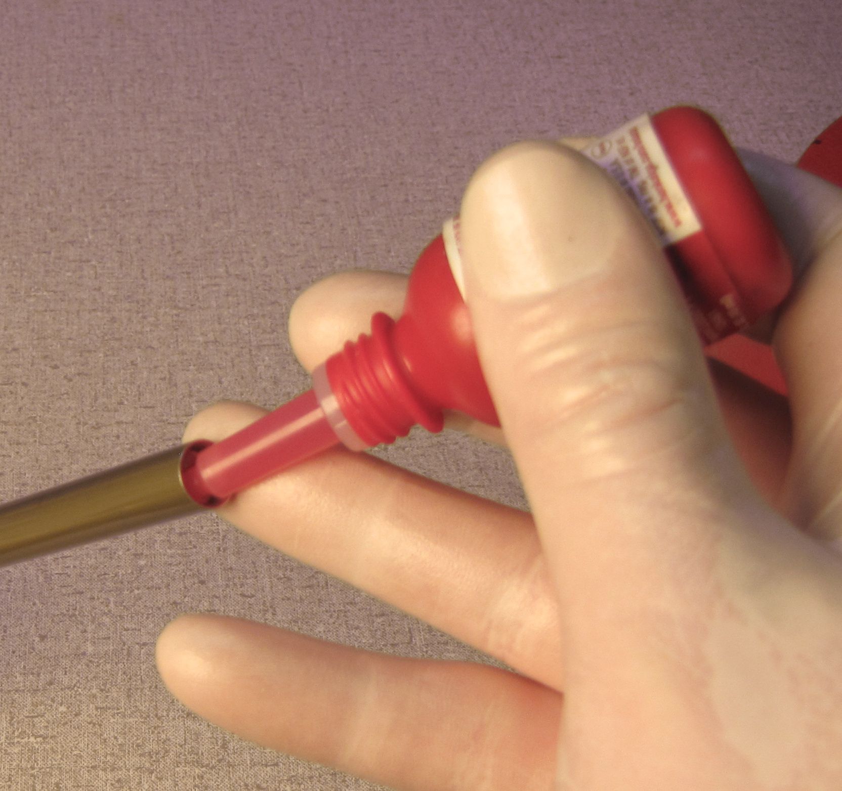
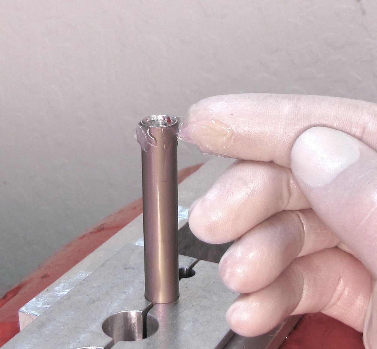
Place 1 to 2 drops of Red Loctite 262 on the internal threads of the Piston Shaft, making sure not to get any Loctite on the smooth portion of the shaft before the internal threads. Coat the outside of the Piston Shaft with a thin film of Slick Honey.
Step 3
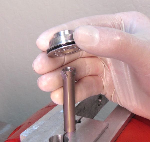
Carefully slide the Negative Plate Assembly onto the Piston Shaft with the treaded side up. Install your Base Stud and torque to 50in-lb (5.7 Nm) with a 12mm crows foot.

Step 4
Thread the Neg Plate Tube and any attached Neg Plate Spacers to the Neg Plate Assembly.
Insert the pins (3mm Ø) of your pin spanner into opposing holes in the top of the Neg Plate Assembly. Insert a 2.5mm hex wrench through the hole in the Neg Plate Spacer or Neg Plate Tube (whichever is closest to the Neg Plate Assembly).
Tighten to 75in-lb (8.5 Nm) torque.
Step 5
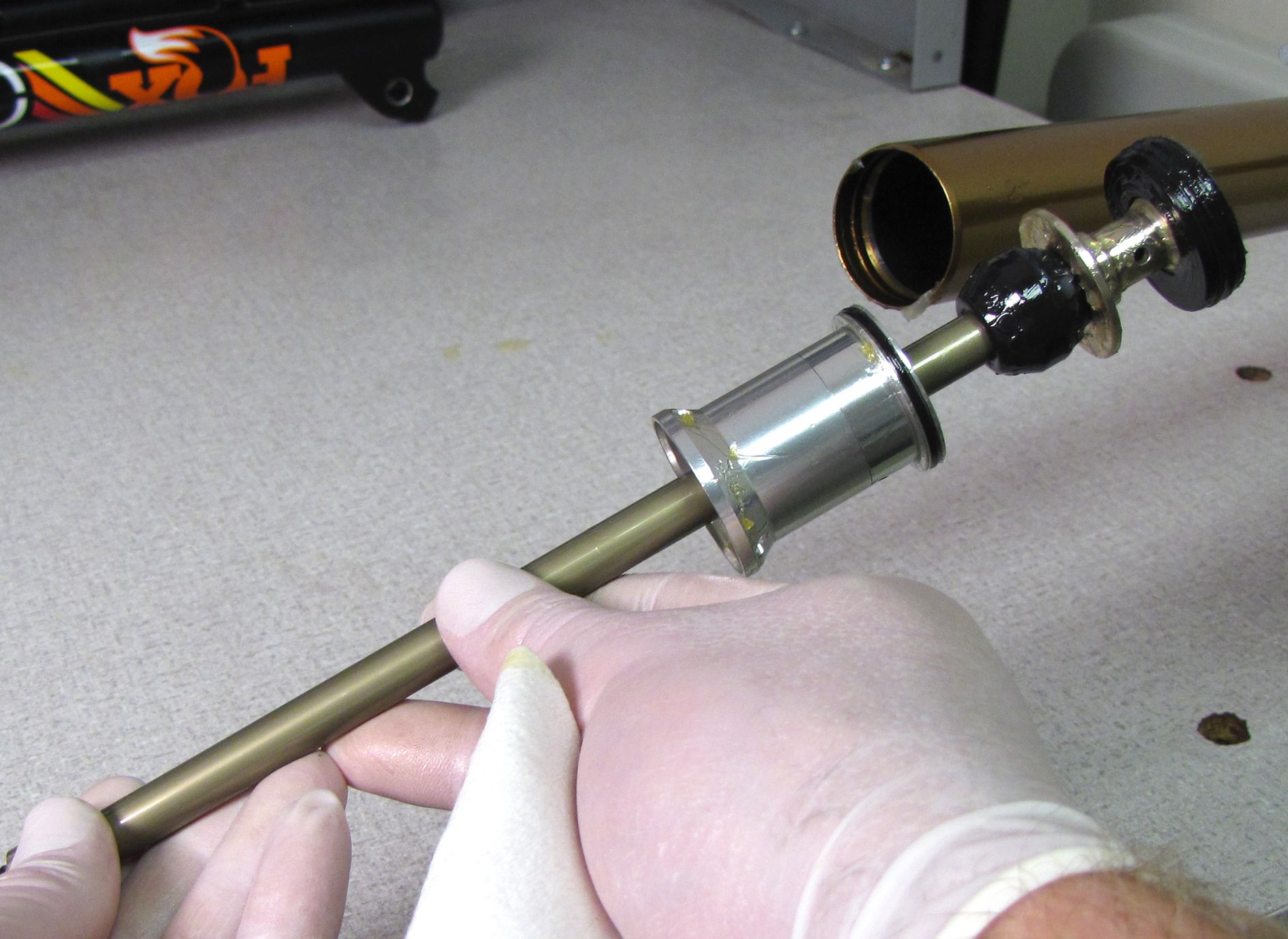
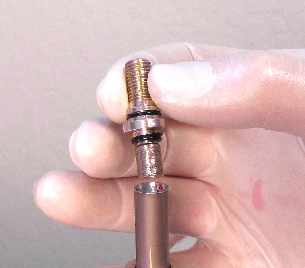
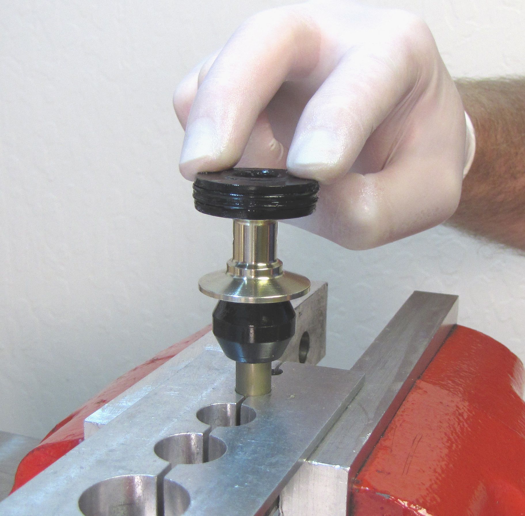
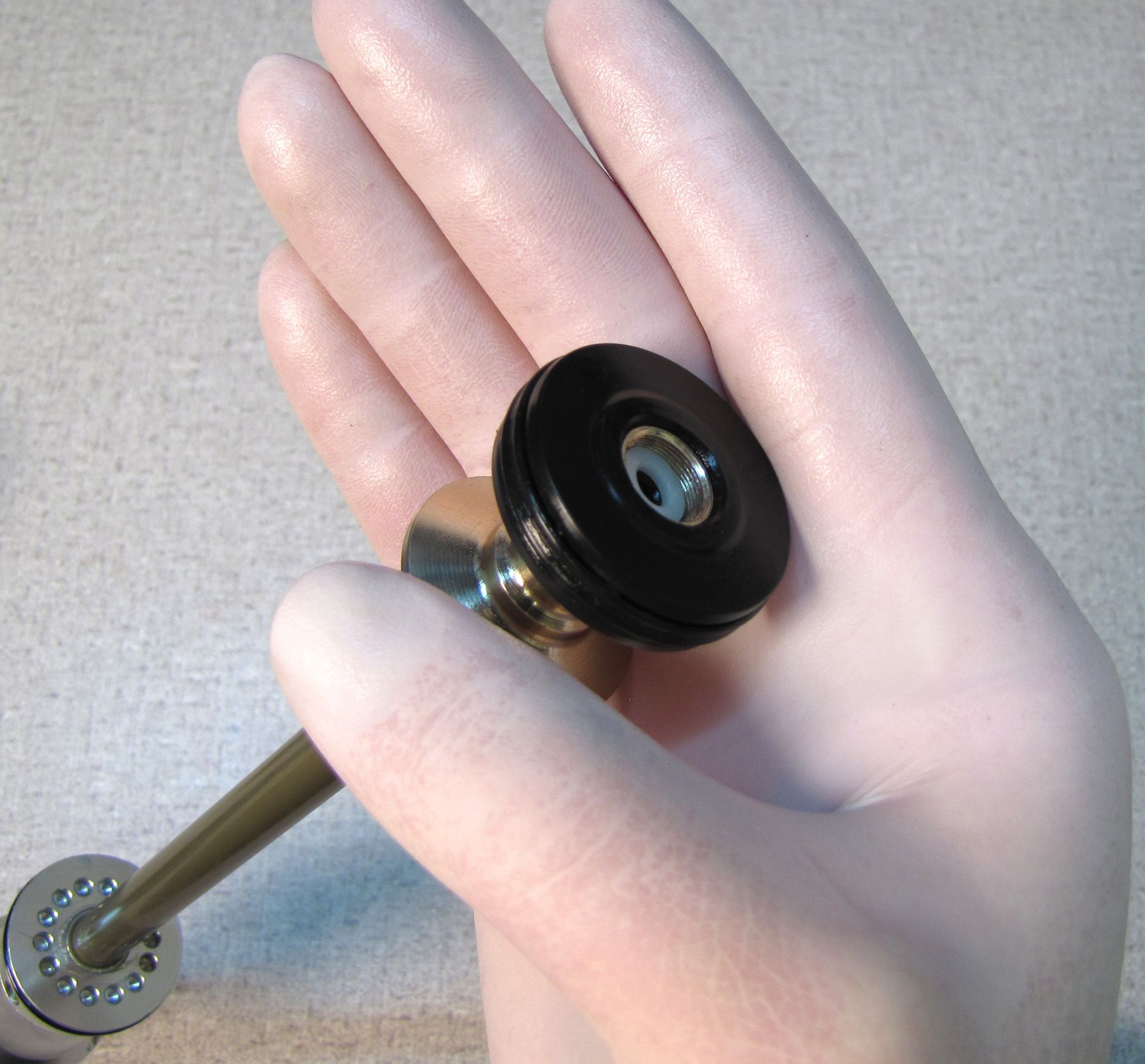
Clamp the Air Shaft Assembly just below the black Top Out Bumper.
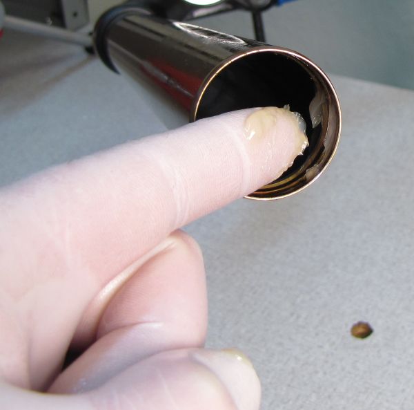
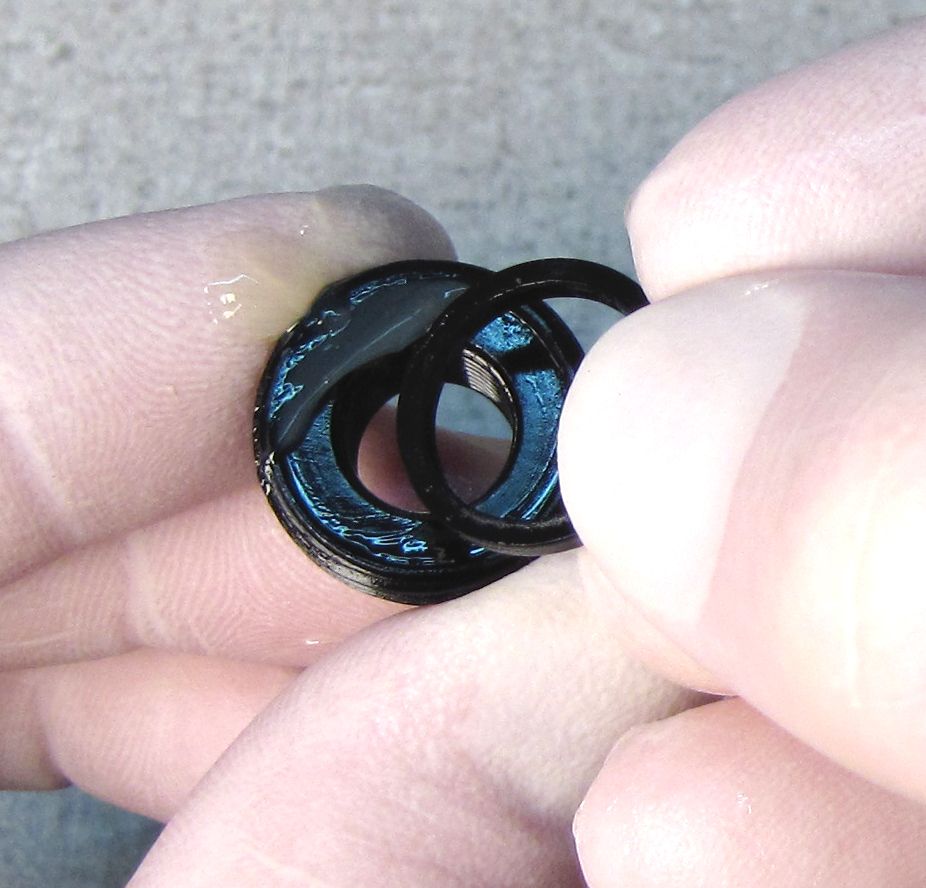
Install a new greased piston base o-ring and Piston Seal, making sure that the Piston Seal is not twisted. Install the FLOAT Piston onto the piston base so the surface with the raised feature faces away from the Piston Base.
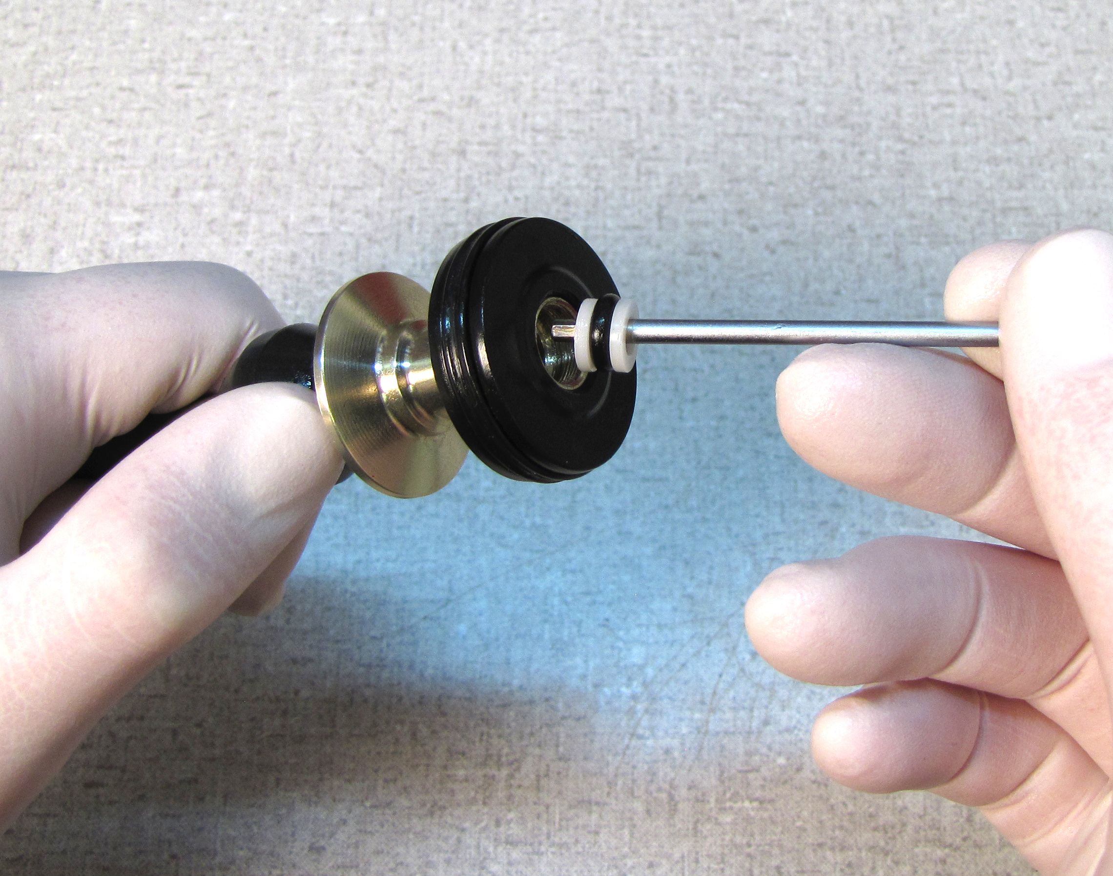
Install a new greased transfer shaft bushing, o-ring, then second transfer shaft bushing with a blunt tool as shown.

Step 6
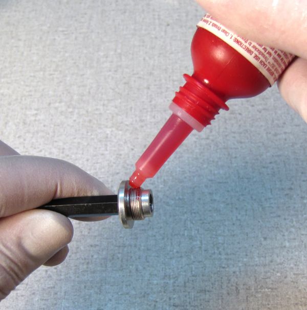
Place 1 to 2 drops of Red Loctite 262 onto the threads of the Piston Bolt. Insert a 2.5mm wrench through the Piston Base to hold it stationary, while using a 6mm hex bit and torque wrench to tighten the Piston Bolt to 50in-lb (5.7 Nm) torque.

Step 7
Coat the first 2 inches (50mm) of the inside of the air side upper tube with a thin film of Slick Honey. Grease the Piston and Piston Shaft above the Negative Plate with Slick Honey.
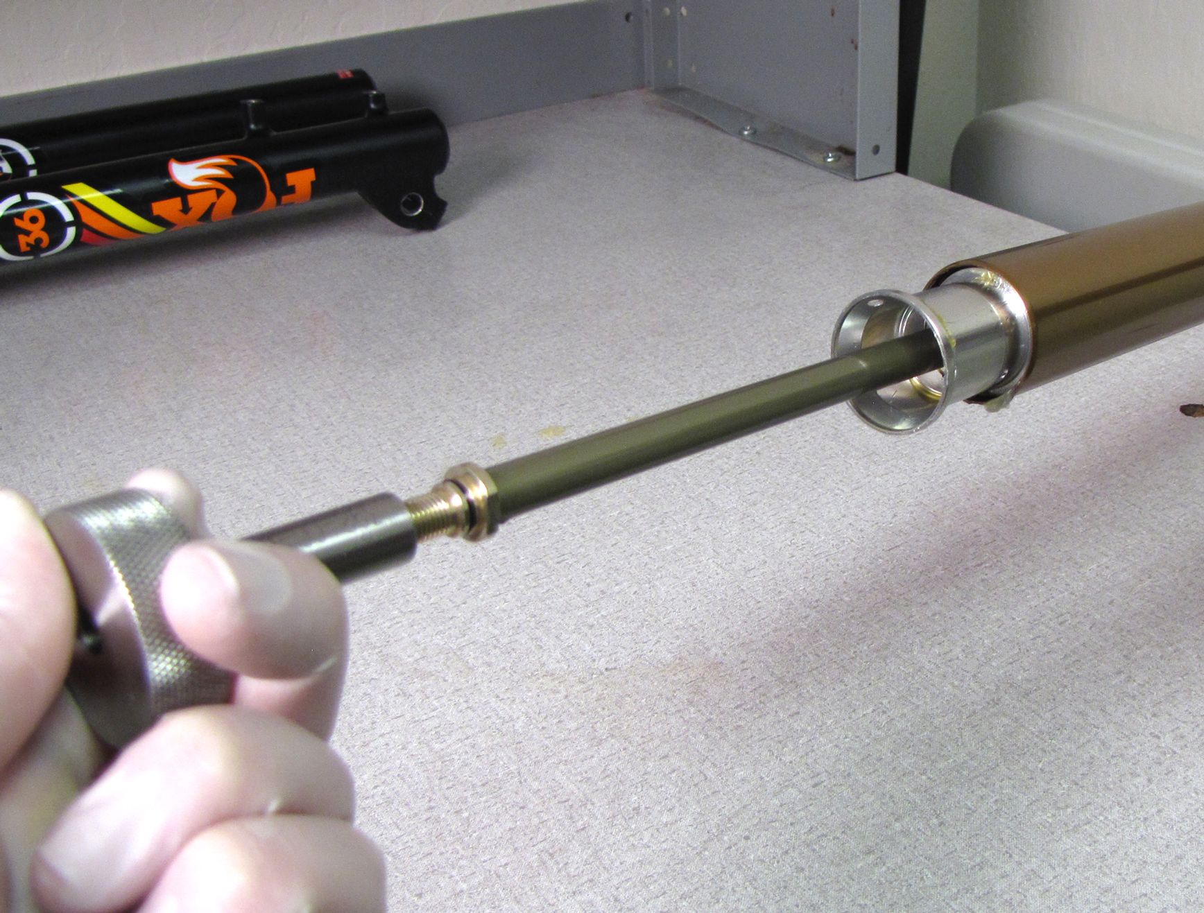
Insert the Air Shaft Assembly into the upper tube, seating the Negative Plate Tube fully into the upper tube to expose the retaining ring groove. Install the retaining ring.
Thread the damper removal tool (PN: 398-00-601) onto the air shaft, then pull on the tool to verify proper retaining ring installation.

Note: Make sure that the Shaft is fully extended before installing the Topcap Assembly.
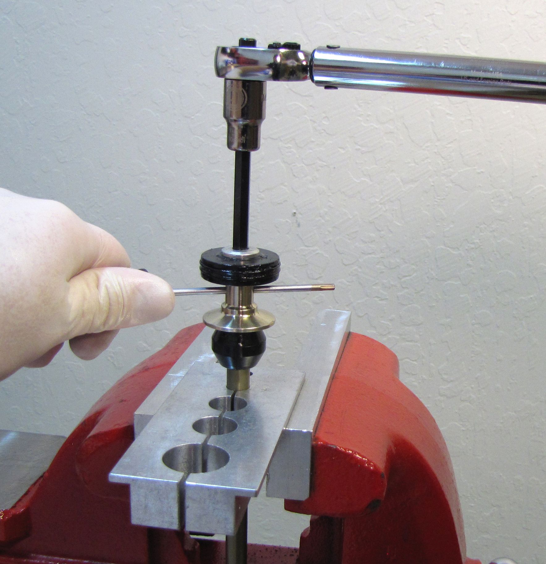
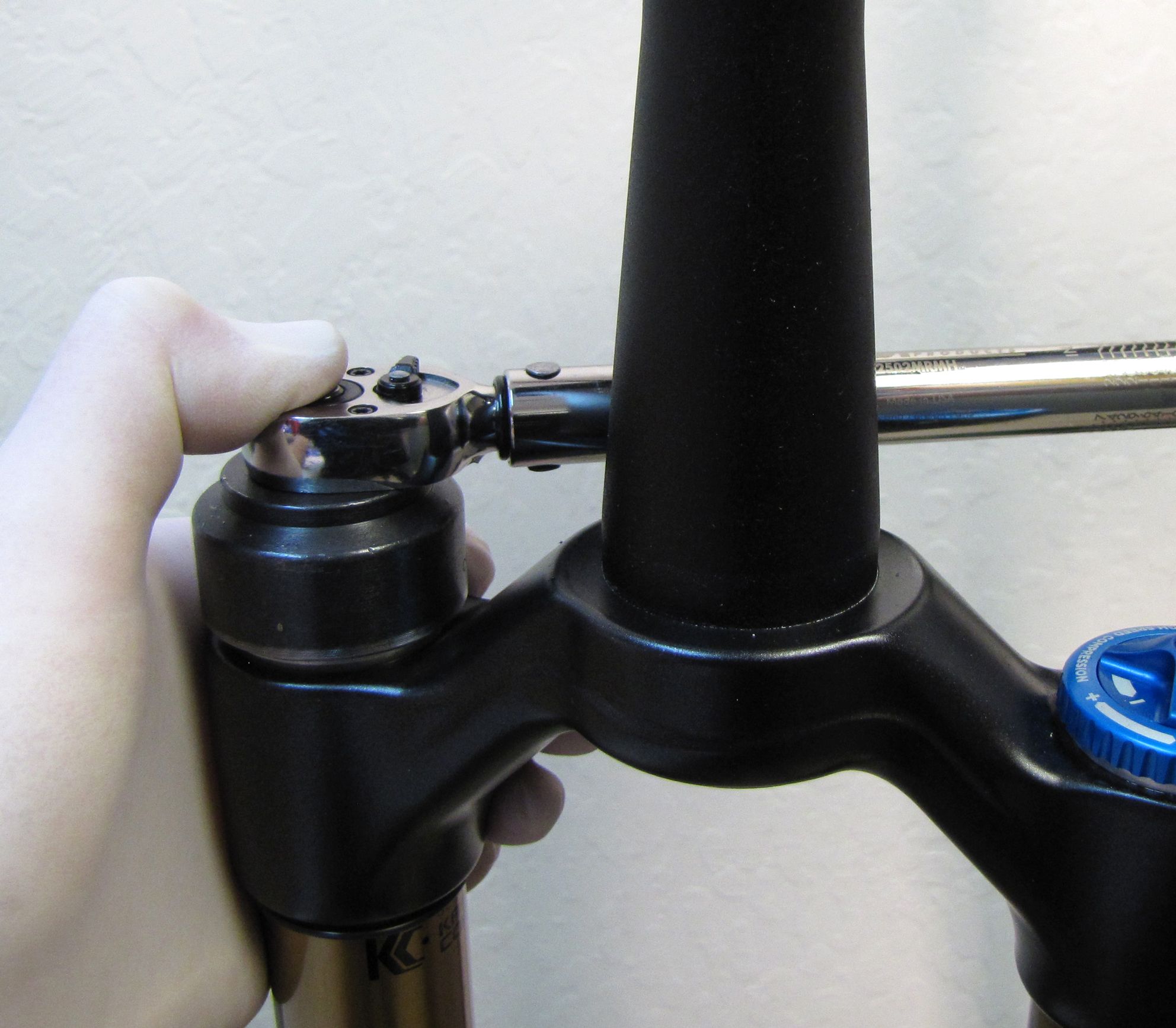
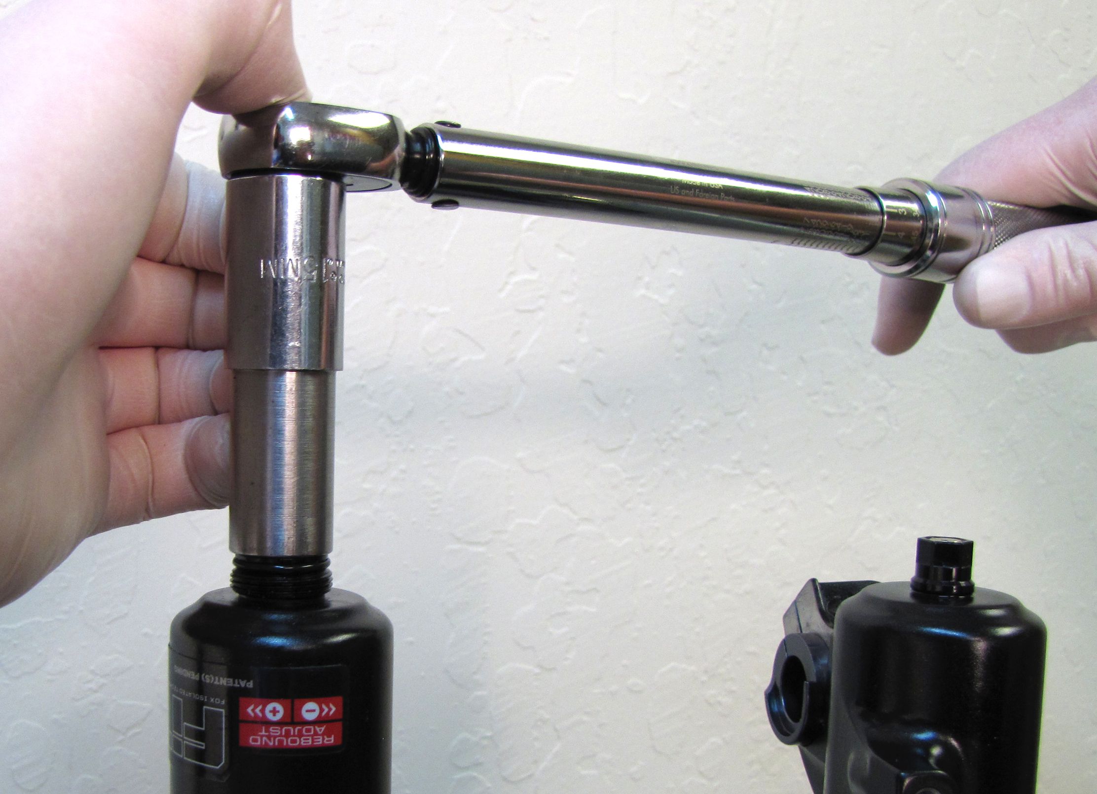
Step 8
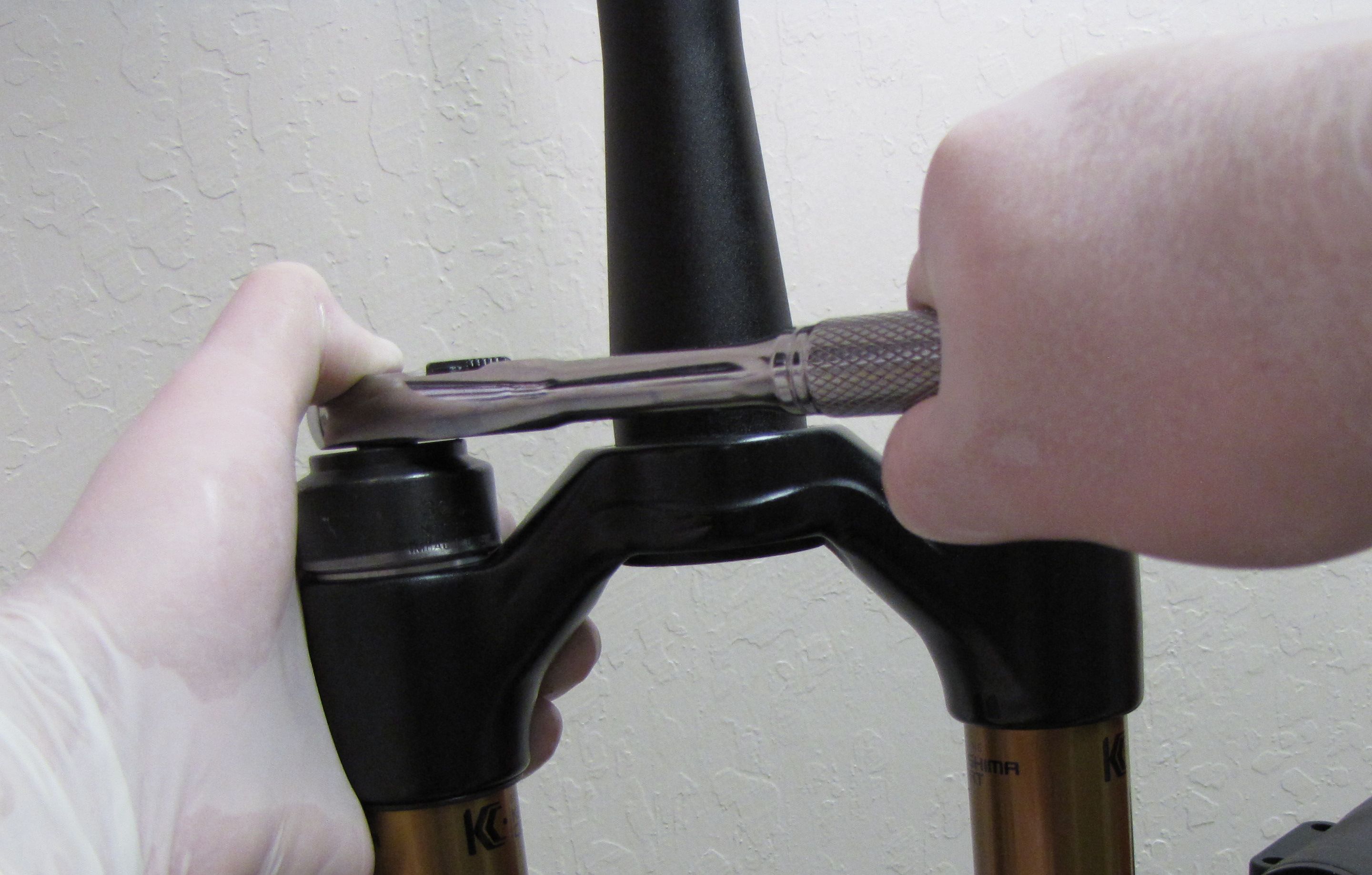
Coat the Transfer Shaft with a thin film of Slick Honey. Insert the Transfer Shaft into the center of the Piston Bolt. Use a chamfer-less 6-point 32mm socket to tighten the Topcap to 220in-lb (24.8 Nm) torque.
Pressurize the air chamber to 50psi before installing the lower legs. Reinstall the blue air cap.

Step 9
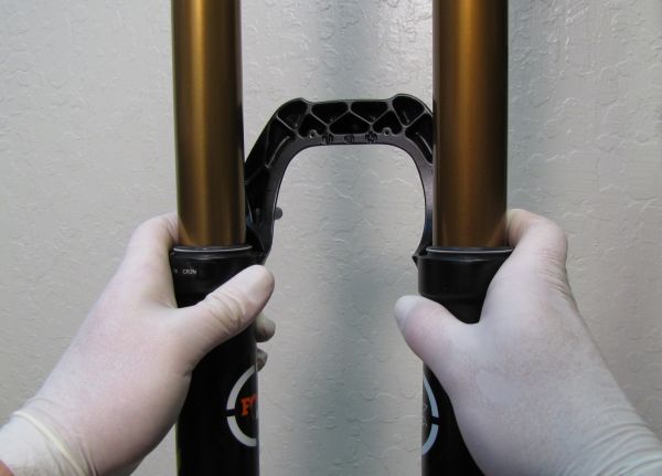
Install the Lower Leg Assembly onto the upper tubes.

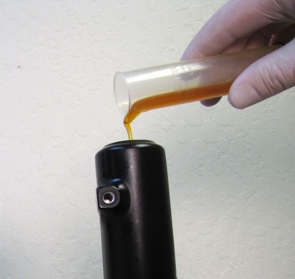
Step 10
Pour the approprate amount of FOX 20wt. Gold oil into each leg through the bottom hole.
| Fork Travel | Spring-Side Bath Oil | Damper-Side Bath Oil |
| up to 160mm | 10cc | 30cc |
| 170mm-180mm | 10cc | 40cc |
Clean any bath oil from the threaded shaft ends.


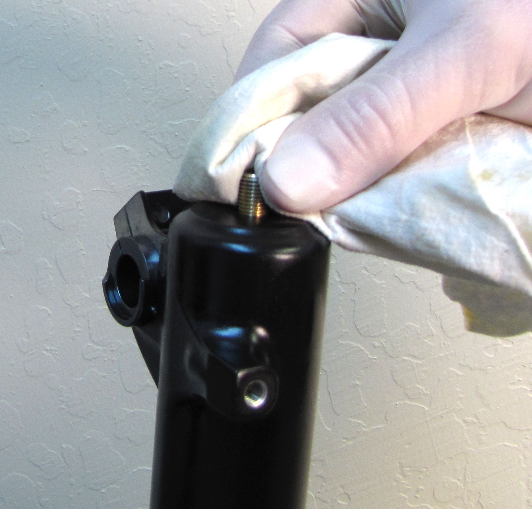
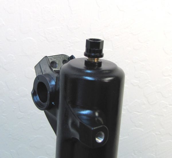
Step 11
Install a new crushwasher on each side followed by the appropriate bottom nut. Torque both bottom nuts to 50in-lb (5.7 Nm).

Step 12
Use a 2mm hex wrench to install the red rebound knob. Make sure that the set screw lines up with the depression in the rebound adjuster shaft. Install the black rebound knob cover.
Clean the exterior of your fork.

Step 13
After assembly you must compress the fork 3-5mm very slowly until you feel the chamber pressures equalize.
