2016+ 32mm/34mm FLOAT Internally Adjusting Fork Travel
Required Tools
- 398-00-681 2002-017 32 Damper-side and ALL 32-34-36-40 Spring-side Removal Tool
- 398-00-682 2005-017 34-36-40 Damper-side Removal Tool (needed only for 34mm forks)
- 398-00-702 Tooling: Fork Topcap Socket, 26mm, 3/8 Drive
Sections
WARNING: Always wear safety glasses and protective gloves during service to prevent potential injury. Failure to wear protective equipment during service may lead to SERIOUS INJURY OR DEATH.
WARNING: Some damper and spring combinations are not possible. DO NOT attempt to extend travel on a 32mm or 34mm FLOAT fork without first contacting FOX directly to verify that the damper and chassis of the fork can handle the new longer travel. Failure to do so may lead to an unapproved combination of parts that could fail, causing a loss of control of the bicycle leading to SERIOUS INJURY or DEATH.
32mm FLOAT
2016 32mm FLOAT forks can be travel adjusted by replacing the air shaft assembly. 32mm forks can be reduced in travel as low as 80mm. Certain 32mm forks may have travel extended only if they were built with a damper and chassis that can be extended safely to the new longer travel. Please contact FOX directly before extending travel on any fork to verify that the stock components of the fork can handle the new longer travel.
32mm forks may be built with two different upper tube bore diameters, 1.110" and 1.117". The upper tubes with the larger 1.117" bore diameter have slightly thinner walls to save weight in certain applications. Make sure to select the appropriate replacement air shaft assembly with a piston diameter that matches the bore of your upper tube.
The chart below lists 32mm FLOAT air shaft assemblies for 2016+ forks with their bore diameter.
| FLOAT NA2 Air Shaft Assemblies | ||
| Part | Description | For use with UT bore diameter |
| 820-02-388-KIT | Air Shaft Assy, 32, 26in & 27.5in 100mm, FLOAT NA 2, 1.110" Bore | 1.110" bore |
| 820-02-389-KIT | Air Shaft Assy, 32, 26in & 27.5in 110mm, 29in 80mm, FLOAT NA 2, 1.110" Bore | 1.110" bore |
| 820-02-390-KIT | Air Shaft Assy, 32, 26in & 27.5in 120mm, 29in 90mm, FLOAT NA 2, 1.110" Bore | 1.110" bore |
| 820-02-391-KIT | Air Shaft Assy, 32, 29in 100mm, FLOAT NA 2, 1.110" Bore | 1.110" bore |
| 820-02-392-KIT | Air Shaft Assy, 32, 29in 110mm, FLOAT NA 2, 1.110" Bore | 1.110" bore |
| 820-02-393-KIT | Air Shaft Assy, 32, 29in 120mm, FLOAT NA 2, 1.110" Bore | 1.110" bore |
| 820-02-339-KIT | Air Shaft Assy, 32, 26in & 27.5 130mm, FLOAT NA 2, 1.110" Bore | 1.110" bore |
| 820-02-340-KIT | Air Shaft Assy, 32, 26in & 27.5 140mm, FLOAT NA 2, 1.110" Bore | 1.110" bore |
| 820-02-341-KIT | Air Shaft Assy, 32, 26in & 27.5 150mm, FLOAT NA 2, 1.110" Bore | 1.110" bore |
| 820-02-342-KIT | Air Shaft Assy, 32, 29in 130mm, FLOAT NA 2, 1.110" Bore | 1.110" bore |
| 820-02-394-KIT | Air Shaft Assy, 32, 80mm, FLOAT NA 2, 1.117" Bore | 1.117" bore |
| 820-02-395-KIT | Air Shaft Assy, 32, 90mm, FLOAT NA 2, 1.117" Bore | 1.117" bore |
| 820-02-396-KIT | Air Shaft Assy, 32, 100mm, FLOAT NA 2, 1.117" Bore | 1.117" bore |
| 820-02-398-KIT | Air Shaft Assy, 32, 26in 120mm, FLOAT NA 2, 1.117" Bore | 1.117" bore |
You can determine your bore diameter by contacting FOX directly with your forks serial number (located under the crown on the base of the steertube) or 4 digit ID code.
When adjusting travel, you will change your air spring compression ratio. To tune your new air spring to feel the same as the original at a different travel, you may need to add or remove air volume spacers from the topcap. You can find instructions for changing air volume spacers in 32mm and 34mm forks by clicking: 2016 32mm/34mm FLOAT Air Spring Tuning with Air Volume Spacers ». The chart below lists recommended air volume spacers by upper tube bore, wheel size, and travel. The maximum number of spacers is listed in parenthesis for each configuration. Never exceed the listed maximum amount of air volume spacers.
| Travel | 1.117" Bore | 1.110" Bore | |
| 26/27.5 | 29 | 26/27.5/29 | |
| 80 | 33cc + 3 (5) | 48cc + 3 (5) | 33cc + 3 (5) |
| 90 | 33cc + 2 (4) | 48cc + 2 (4) | 33cc + 2 (4) |
| 100 | 33cc + 2 (4) | 48cc + 2 (4) | 33cc + 2 (4) |
| 110 | 22cc + 2 (4) | 22cc + 2 (4) | |
| 120 | 22cc + 1 (4) | 22cc + 1 (4) | |
| 130 | 3 (6) | ||
| 140 | 2 (5) | ||
| 150 | 1 (4) | ||
34mm FLOAT
2016 34mm FLOAT forks can be travel adjusted by replacing the air shaft assembly. 34mm forks can be reduced in travel as low as 110mm. 2016 27.5in 34mm forks may have travel extended up to 160mm. While 2016 29in 34mm forks may have travel extended up to 140mm, forks starting at 120 or below will need a new damper to acheive greater than 120 travel. All 2016 34mm forks share the same upper tube bore diameter.
The chart below lists 34mm FLOAT air shaft assemblies for 2016+ forks.
| FLOAT NA2 Air Shaft Assemblies | |
| Part | Description |
| 820-02-400-KIT | Service Set: Air Shaft Assy, 34, 110mm, FLOAT NA 2, 1.214" Bore |
| 820-02-401-KIT | Service Set: Air Shaft Assy, 34, 120mm, FLOAT NA 2, 1.214" Bore |
| 820-02-363-KIT | Service Set: Air Shaft Assy, 34, 130mm, FLOAT NA 2, 1.214" Bore |
| 820-02-364-KIT | Service Set: Air Shaft Assy, 34, 140mm, FLOAT NA 2, 1.214" Bore |
| 820-02-365-KIT | Service Set: Air Shaft Assy, 34, 150mm, FLOAT NA 2, 1.214" Bore 27.5 ONLY |
| 820-02-366-KIT | Service Set: Air Shaft Assy, 34, 160mm, FLOAT NA 2, 1.214" Bore 27.5 ONLY |
When adjusting travel, you will change your air spring compression ratio. To tune your new air spring to feel the same as the original at a different travel, you may need to add or remove air volume spacers from the topcap. You can find instructions for changing air volume spacers in 32mm and 34mm forks by clicking: 2016 32mm/34mm FLOAT Air Spring Tuning with Air Volume Spacers ». The chart below lists recommended air volume spacers by travel. The maximum number of spacers is listed in parenthesis for each configuration. Never exceed the listed maximum amount of air volume spacers.
| Travel | 34mm Air Volume Spacers (Max) |
| 110 | 6 (7) |
| 120 | 5 (6) |
| 130 | 3 (6) |
| 140 | 2 (5) |
| 150 (27.5 Only) | 2 (5) |
| 160 (27.5 Only) | 1 (4) |
WARNING: FOX products should be serviced by a trained bicycle service technician, in accordance with FOX specifications. If you have any doubt whether or not you can properly service your FOX product, then DO NOT attempt it. Improperly serviced products can fail, causing the rider to lose control resulting in SERIOUS INJURY OR DEATH.
WARNING: Never attempt to modify air volume spacers or air shaft assemblies, as this can damage your fork causing a loss of control of the bicycle leading to SERIOUS INJURY or DEATH.
WARNING: FOX suspension products contain pressurized nitrogen, air, oil, or all 3. Suspension misuse can cause property damage, SERIOUS INJURY OR DEATH. DO NOT puncture, incinerate or crush any portion of a FOX suspension product. DO NOT attempt to disassemble any portion of a FOX suspension product, unless expressly instructed to do so by the applicable FOX technical documentation, and then ONLY while strictly adhering to all FOX instructions and warnings in that instance.
WARNING: Modification, improper service, or use of aftermarket replacement parts with FOX forks and shocks may cause the product to malfunction, resulting in SERIOUS INJURY OR DEATH. DO NOT modify any part of a fork or shock, including the fork brace (lower leg cross brace), crown, steerer, upper and lower leg tubes, or internal parts, except as instructed herein. Any unauthorized modification may void the warranty, and may cause failure or the fork or shock, resulting in SERIOUS INJURY OR DEATH.

Step 1
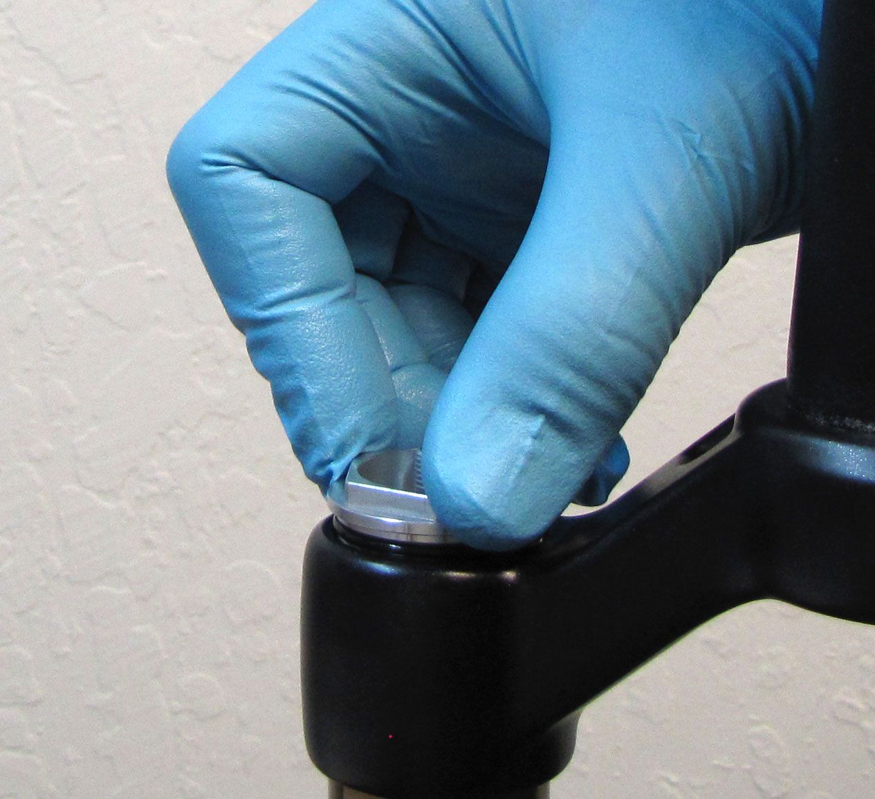
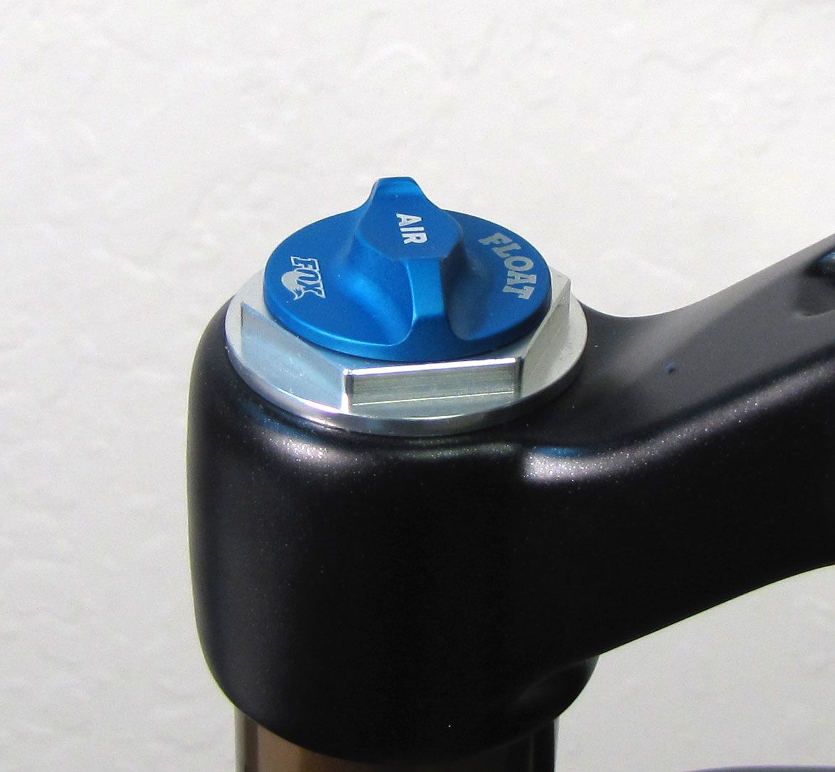
Remove the blue air cap and cover the air valve with a rag as you release the air pressure.

WARNING: Please verify that all air has been released from the air chamber by pushing down on the Schrader valve core. Failure to release all air pressure before further disassembly may cause parts to eject causing SEVERE INJURY OR DEATH.
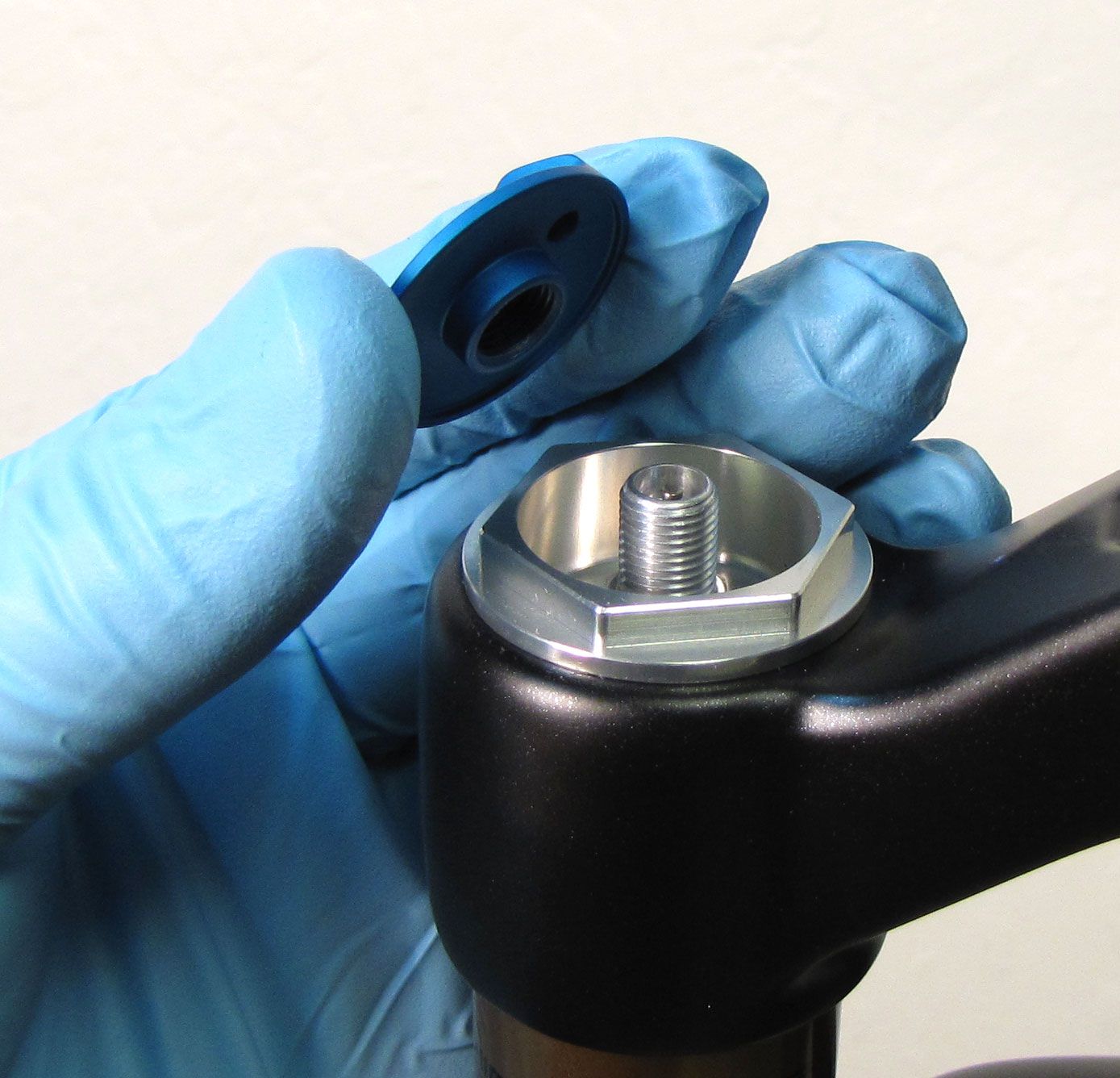
Step 2
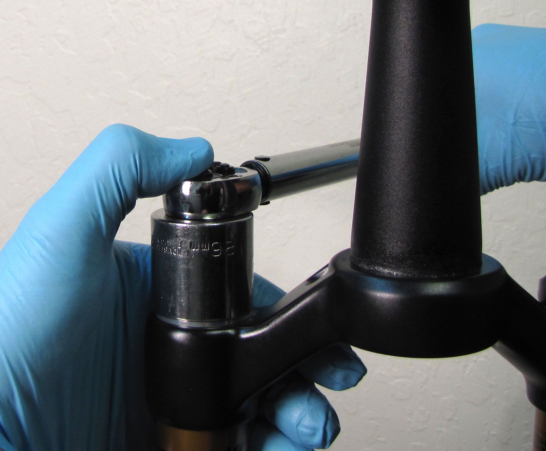
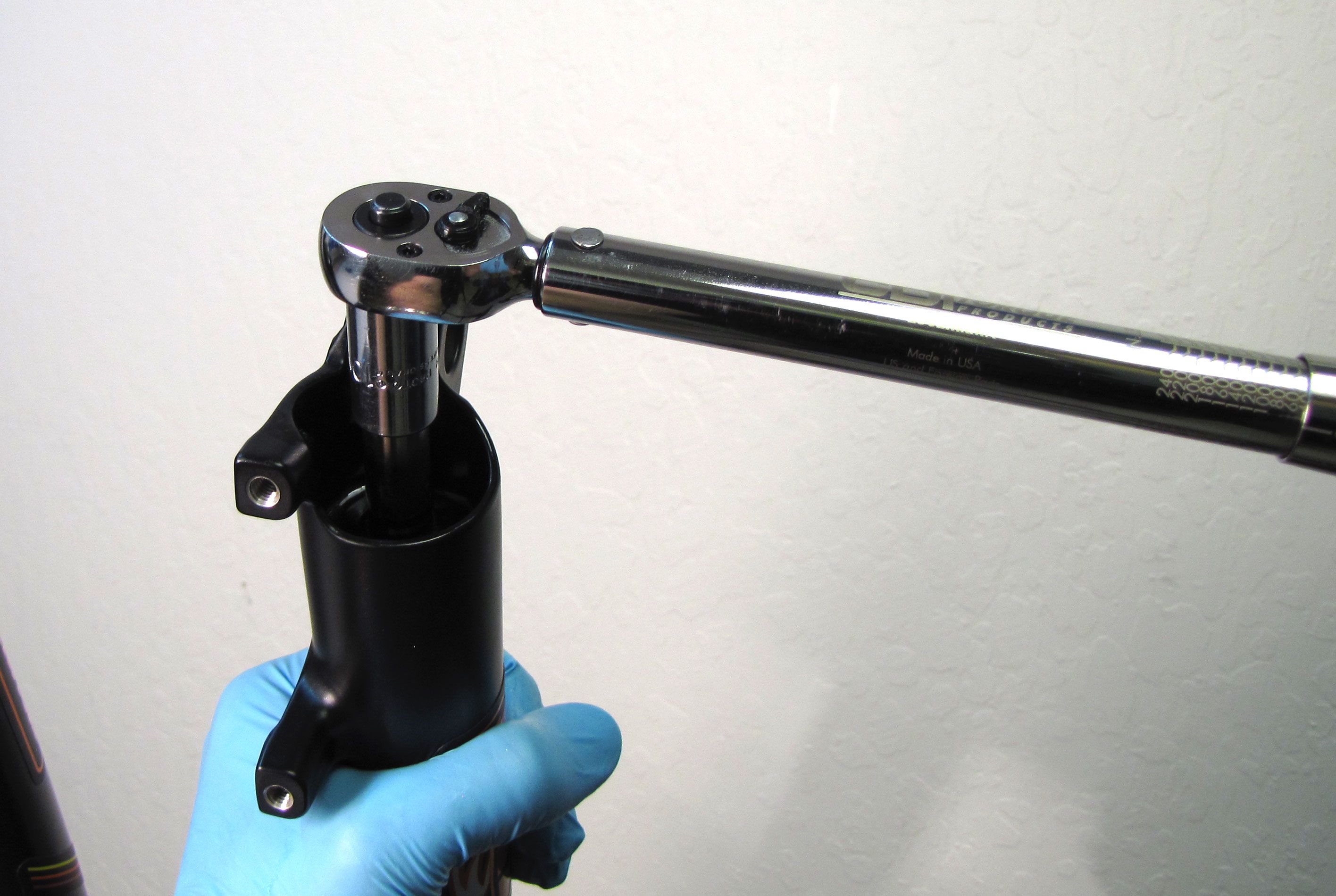
With a chamfer-less 6-point 26mm socket (PN: 398-00-602), unthread the topcap assembly completely (counter-clockwise). Pull straight up to remove the entire topcap assembly from the left side upper tube. Some upward force might be needed to overcome the friction of the stock air volume spacer.

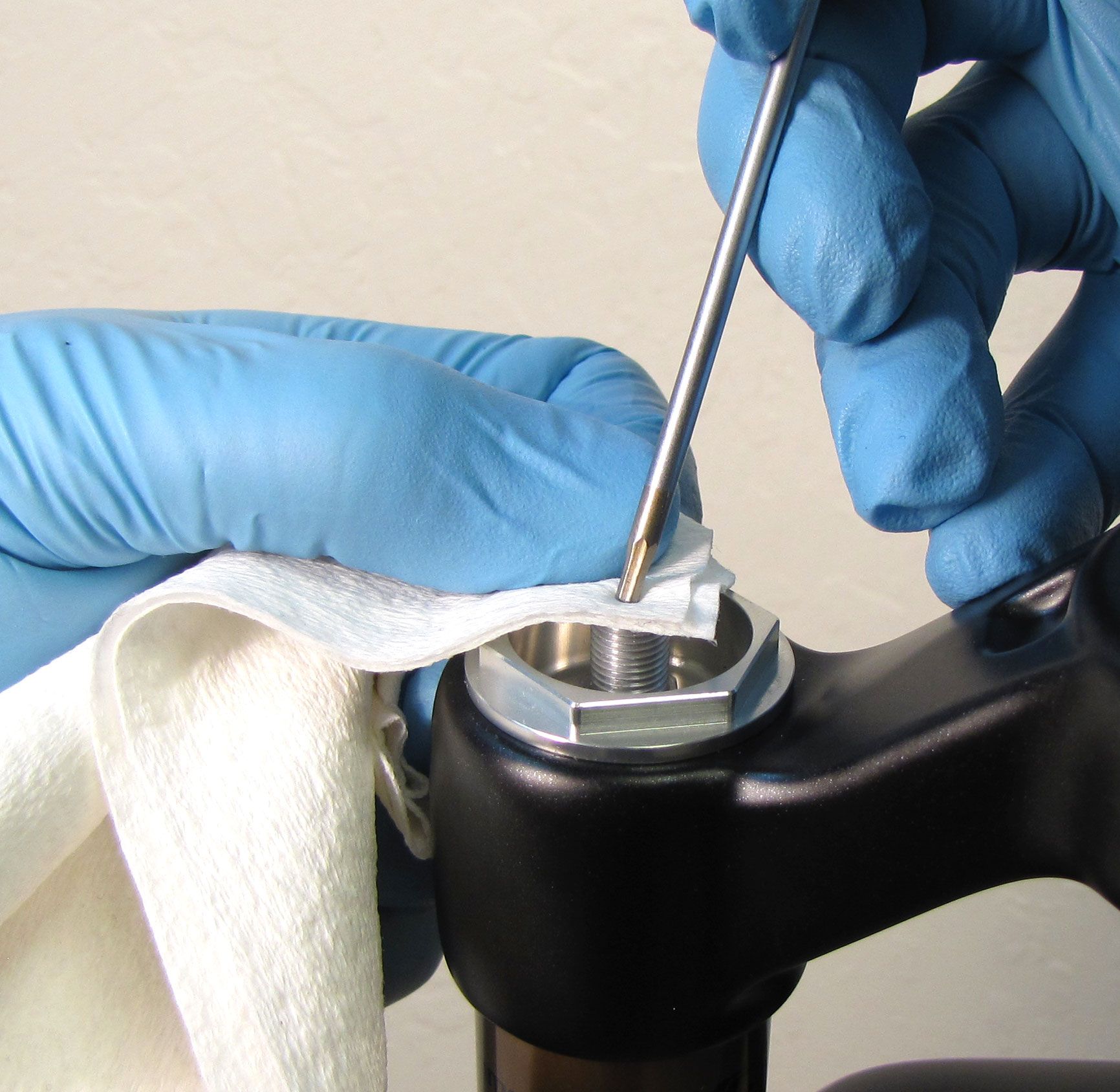
Step 3
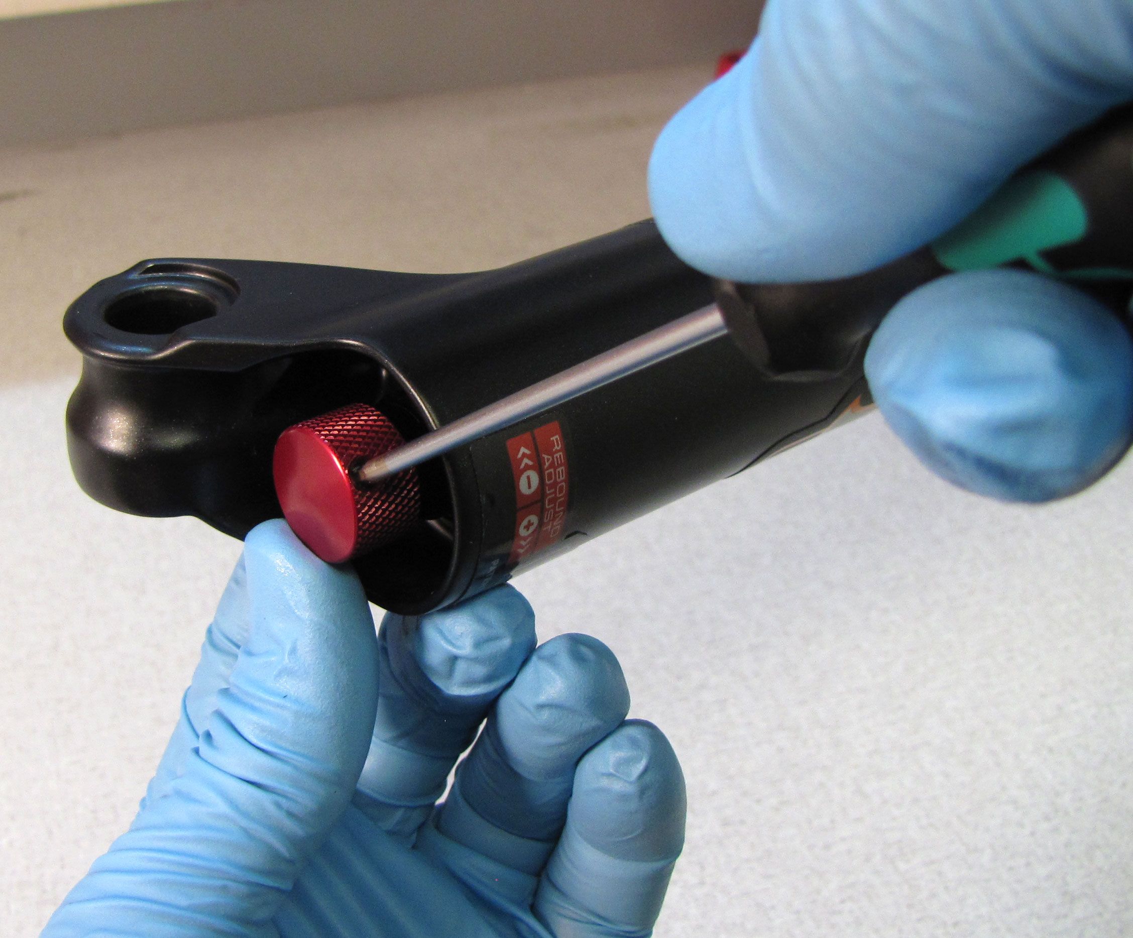
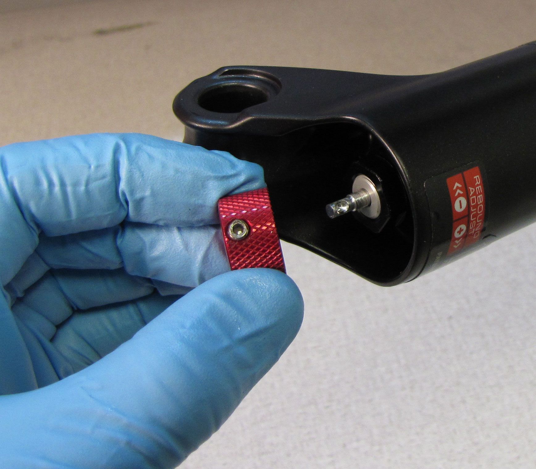
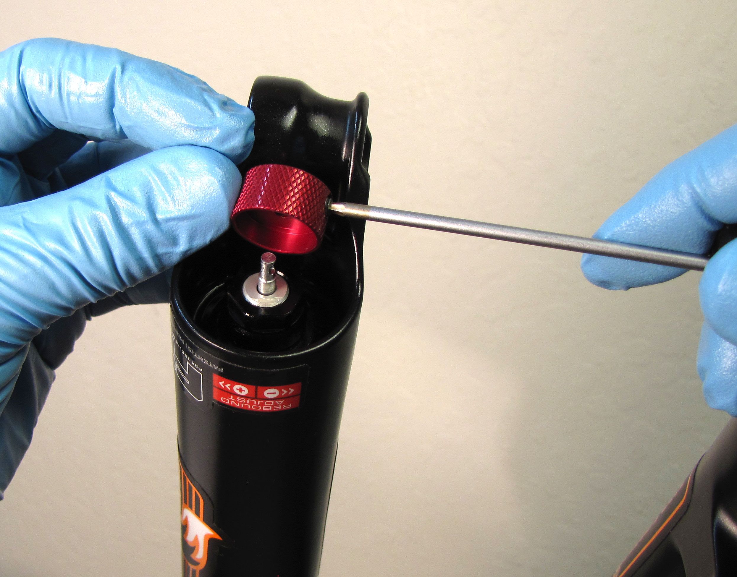
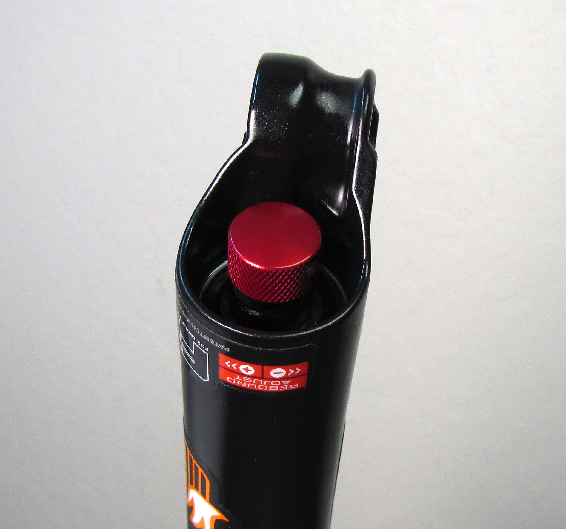
Use a 2mm hex wrench to unthread the set screw in the red rebound knob. Remove the knob and set it aside.
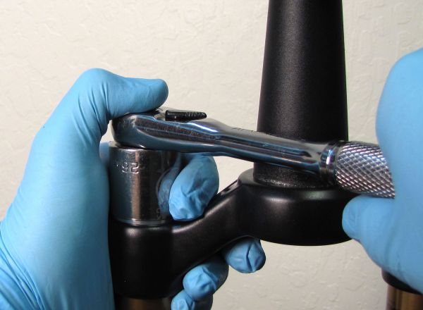
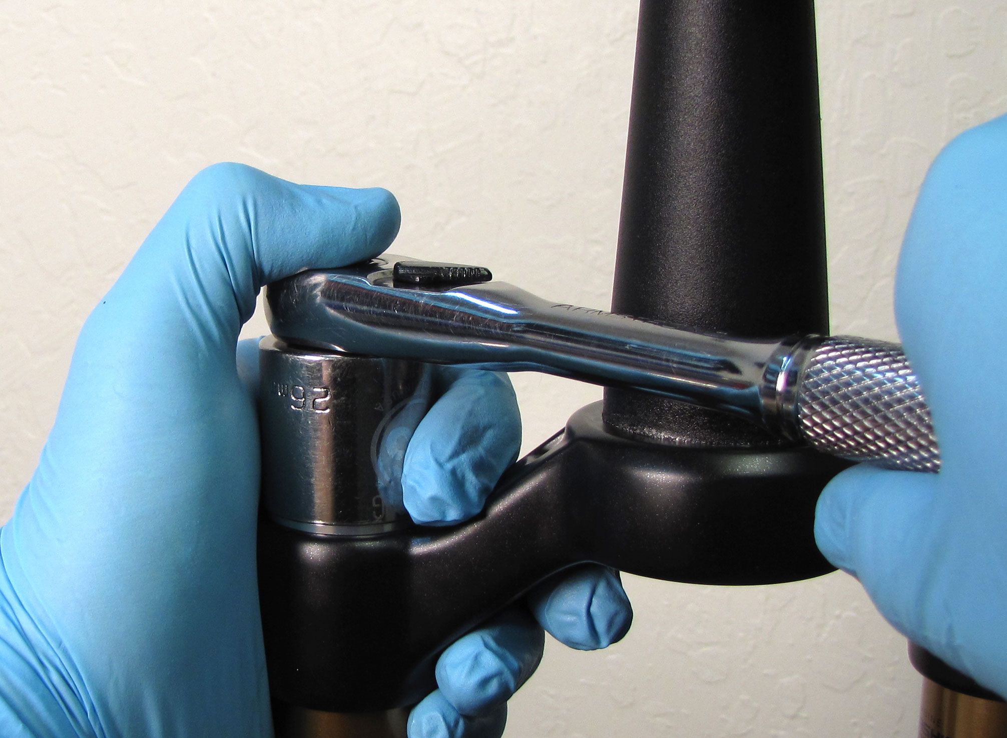
Step 4
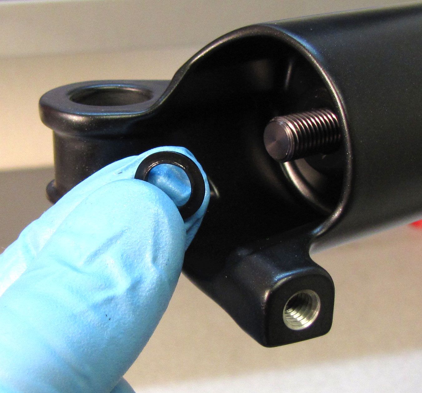
Use a 10mm socket to unthread and remove the air side bottom nut. Remove and discard the original crushwasher.
Note: You may need a custom 10mm socket that has been reduced in outer diameter to clear certain Step-Cast lower leg castings.

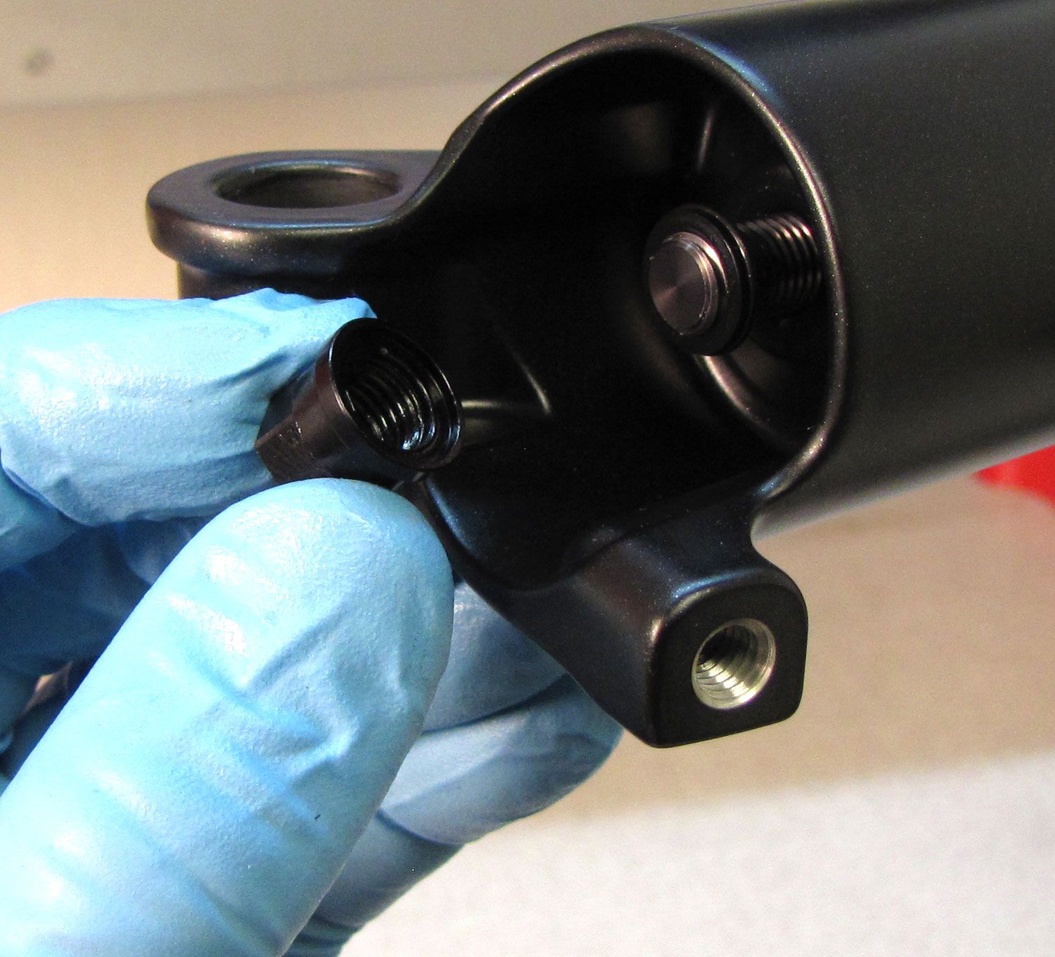
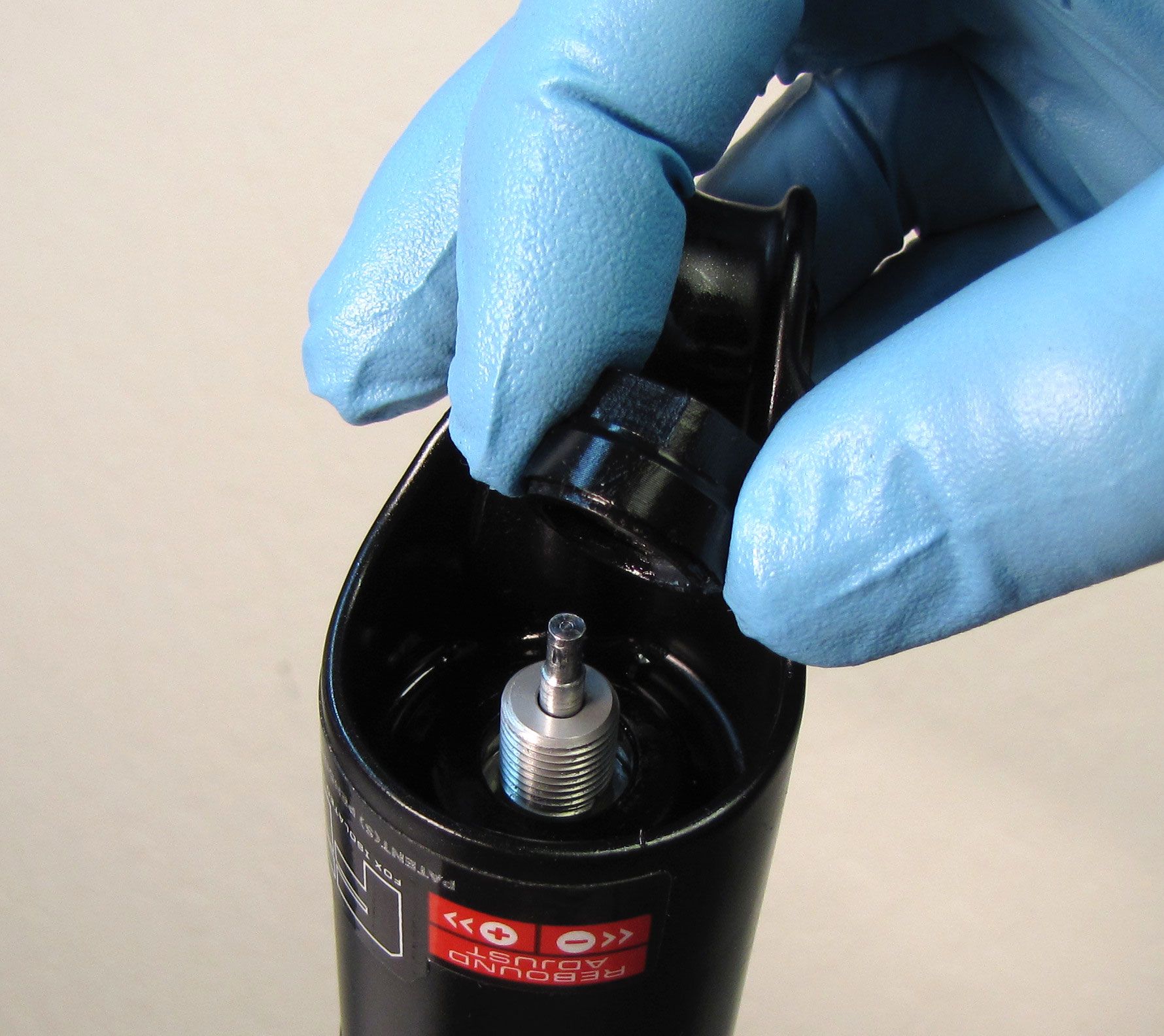
Step 5
32mm: Use a 10mm socket to remove the damper side bottom nut. Remove and discard the original crushwasher.
Note: You may need a custom 10mm socket that has been reduced in outer diameter to clear certain Step-Cast lower leg castings.
34mm: Use a 15mm socket to remove the damper side bottom nut. Make sure to remove and discard the orginal crushwasher which may be stuck to the bottom nut.


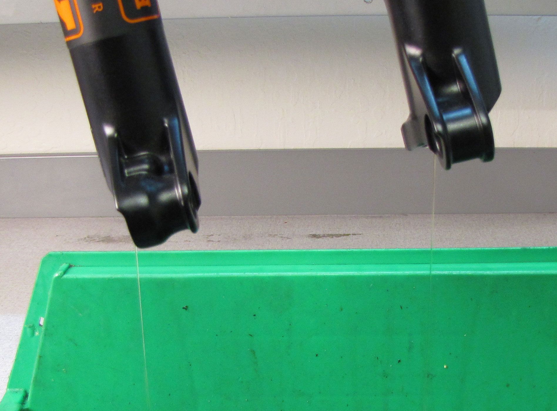
Step 6
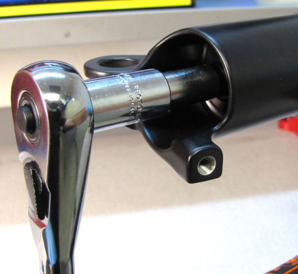
Use Damper Removal Tools 398-00-681 and 398-00-682 to dislodge the shafts from the lowers. Make sure that you have approximately half of the available threads engaged with your tool before striking with your mallet. Remove the damper removal tools, then bring the fork upright over an oil basin to drain. After oil stops draining from the lowers, pull the lowers off of the upper tubes and set them aside.
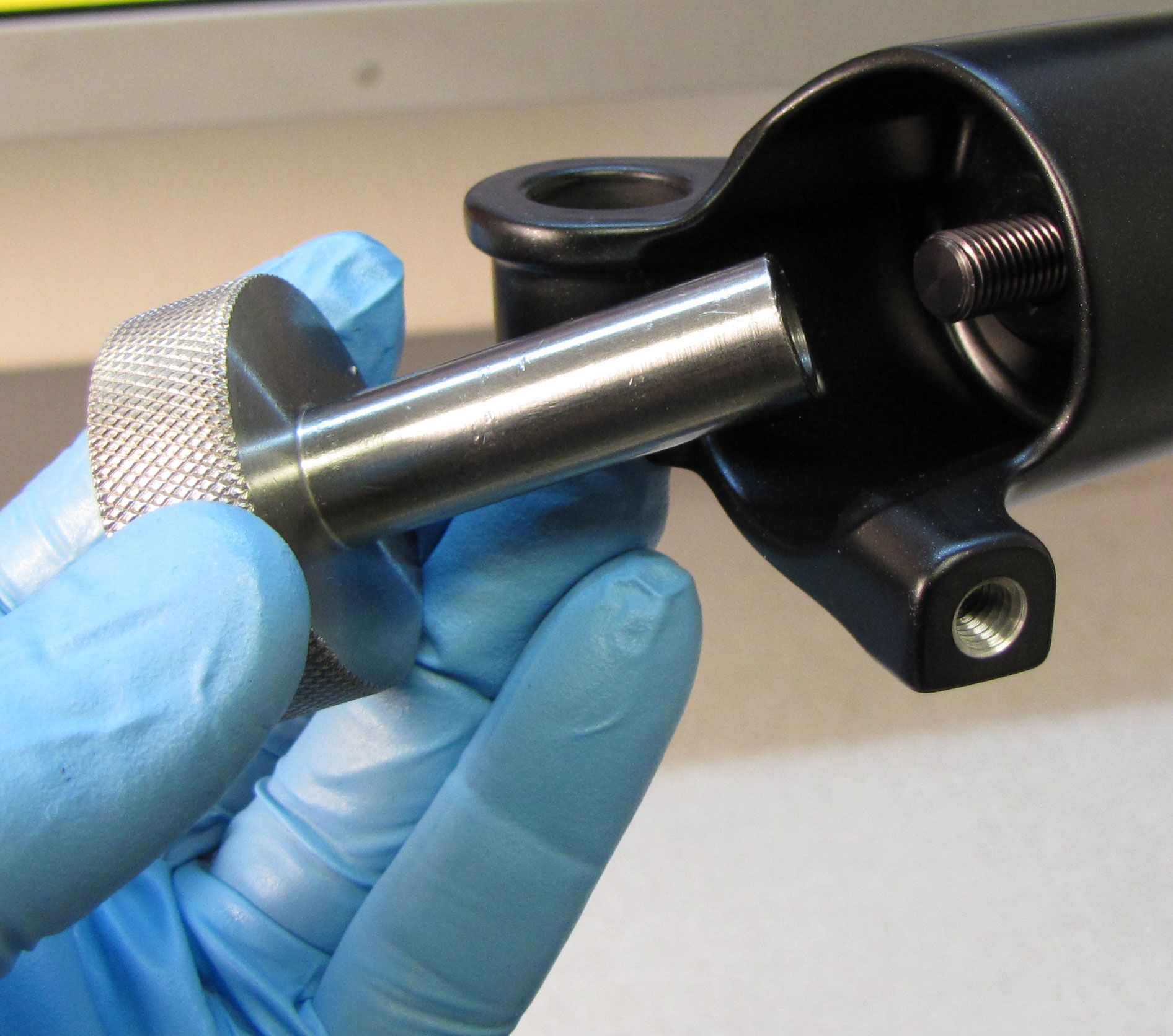


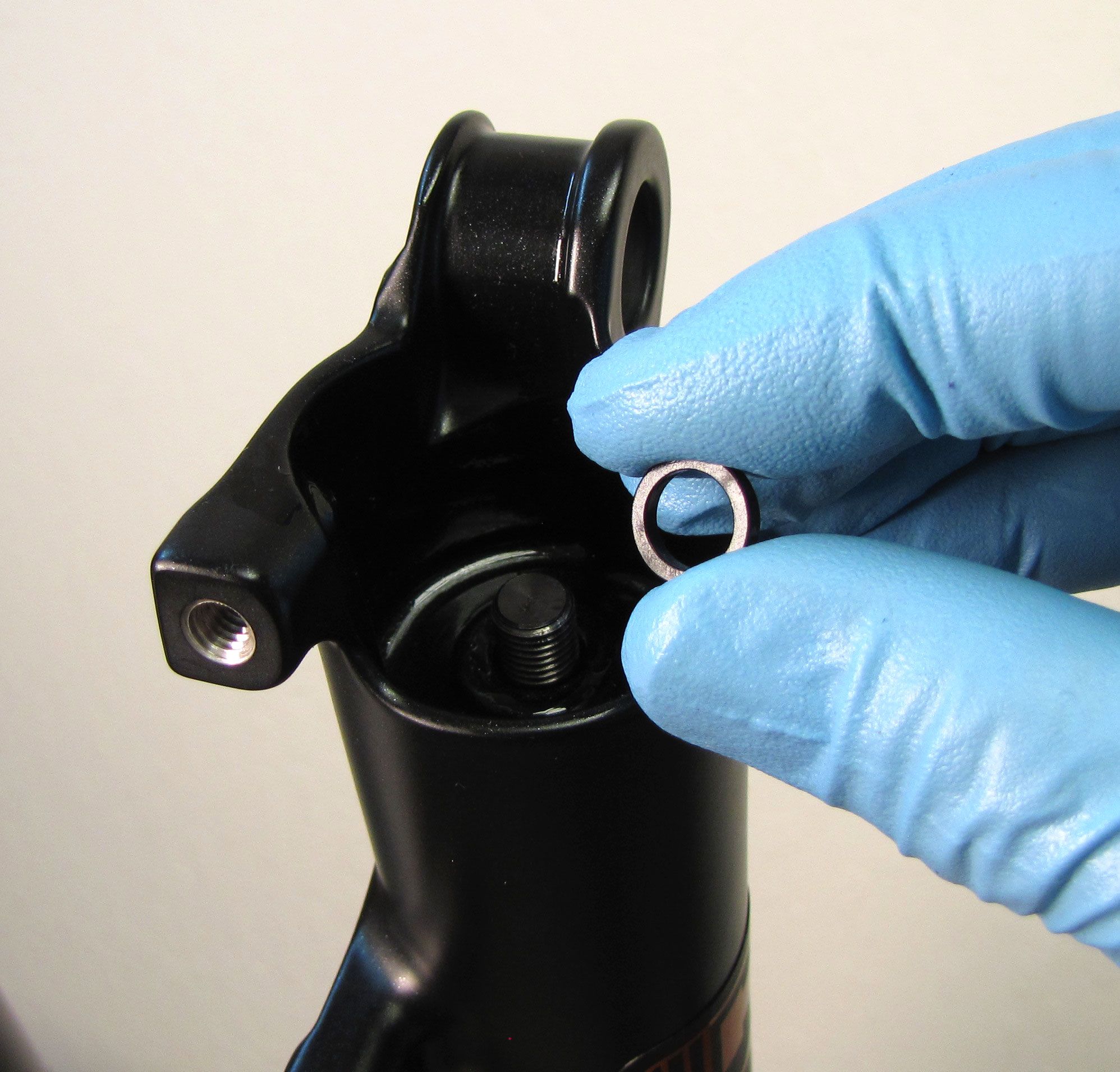
Step 7
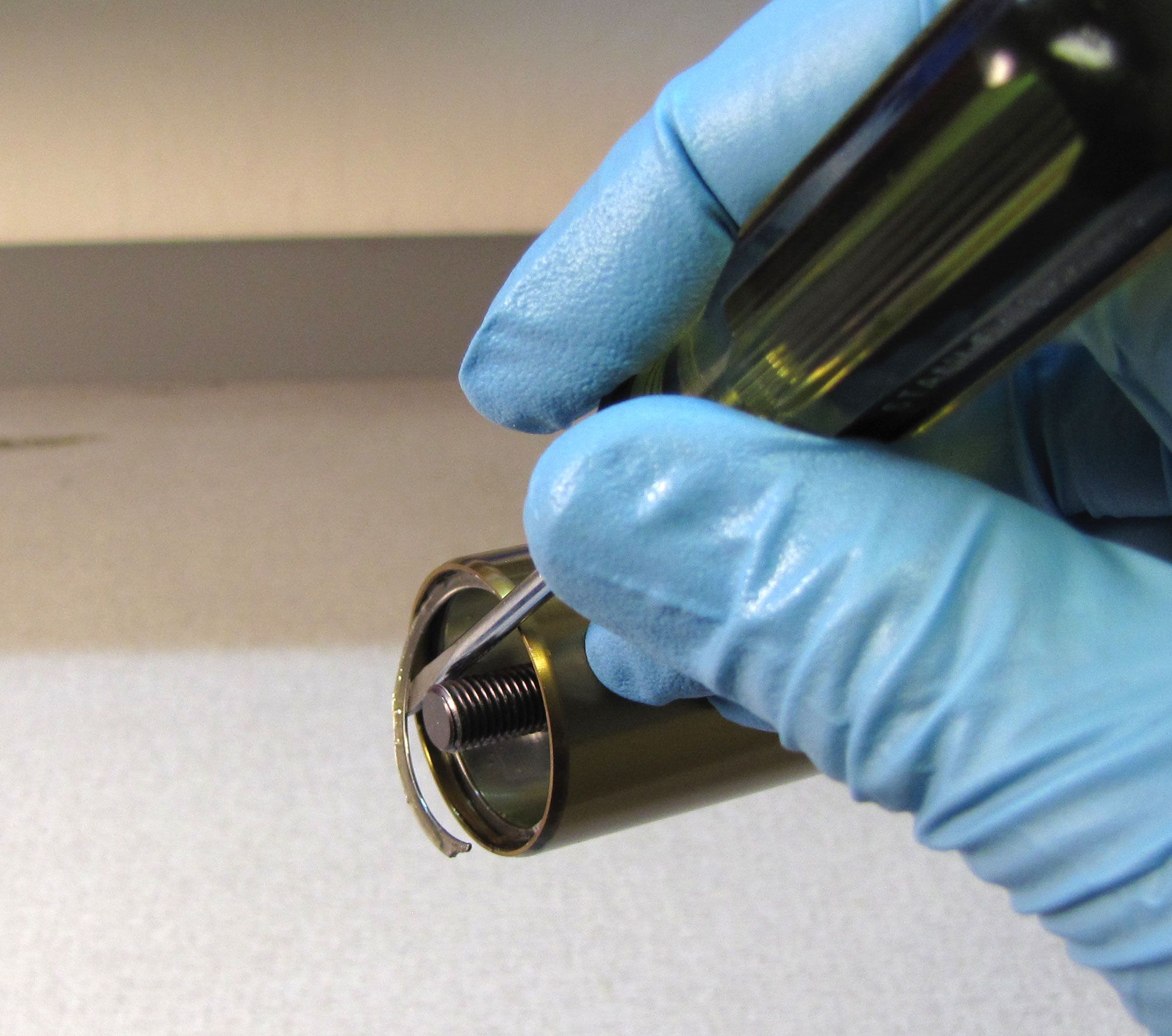
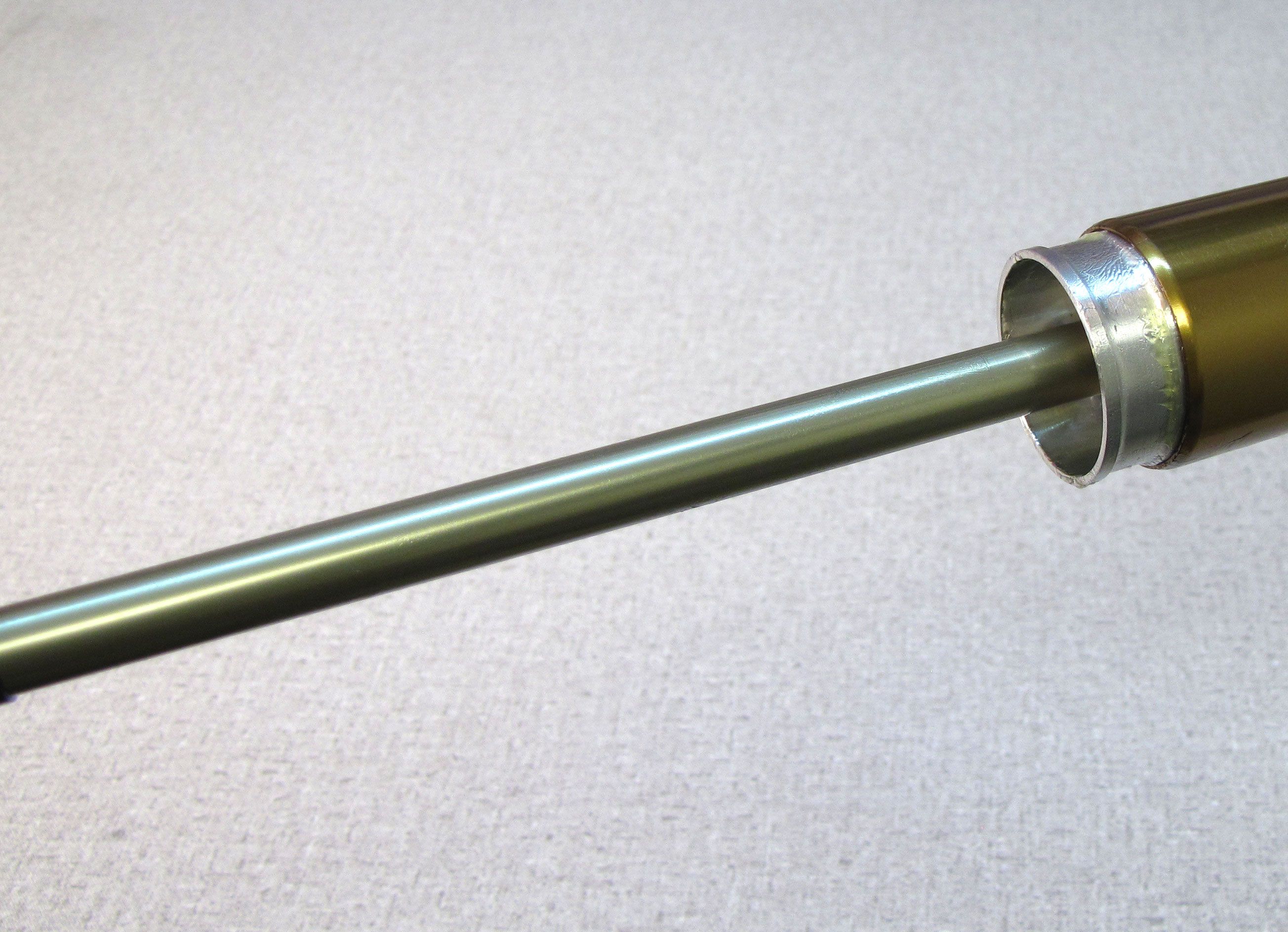
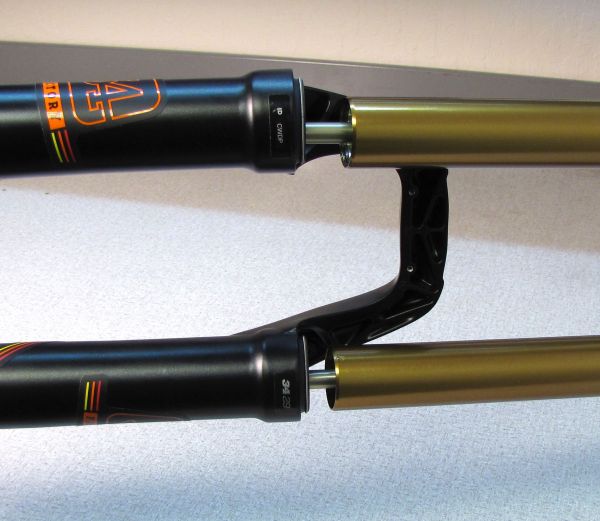
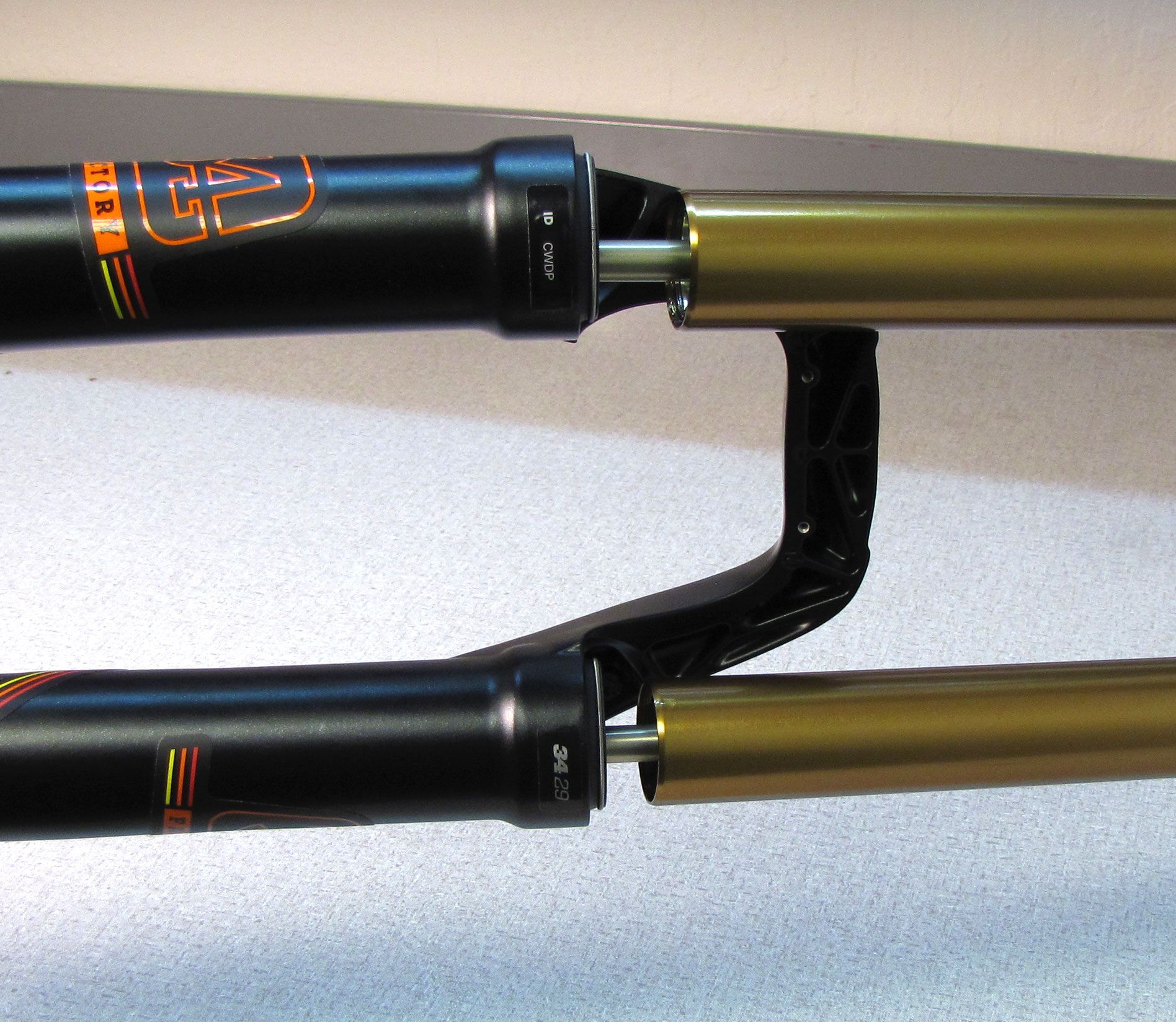
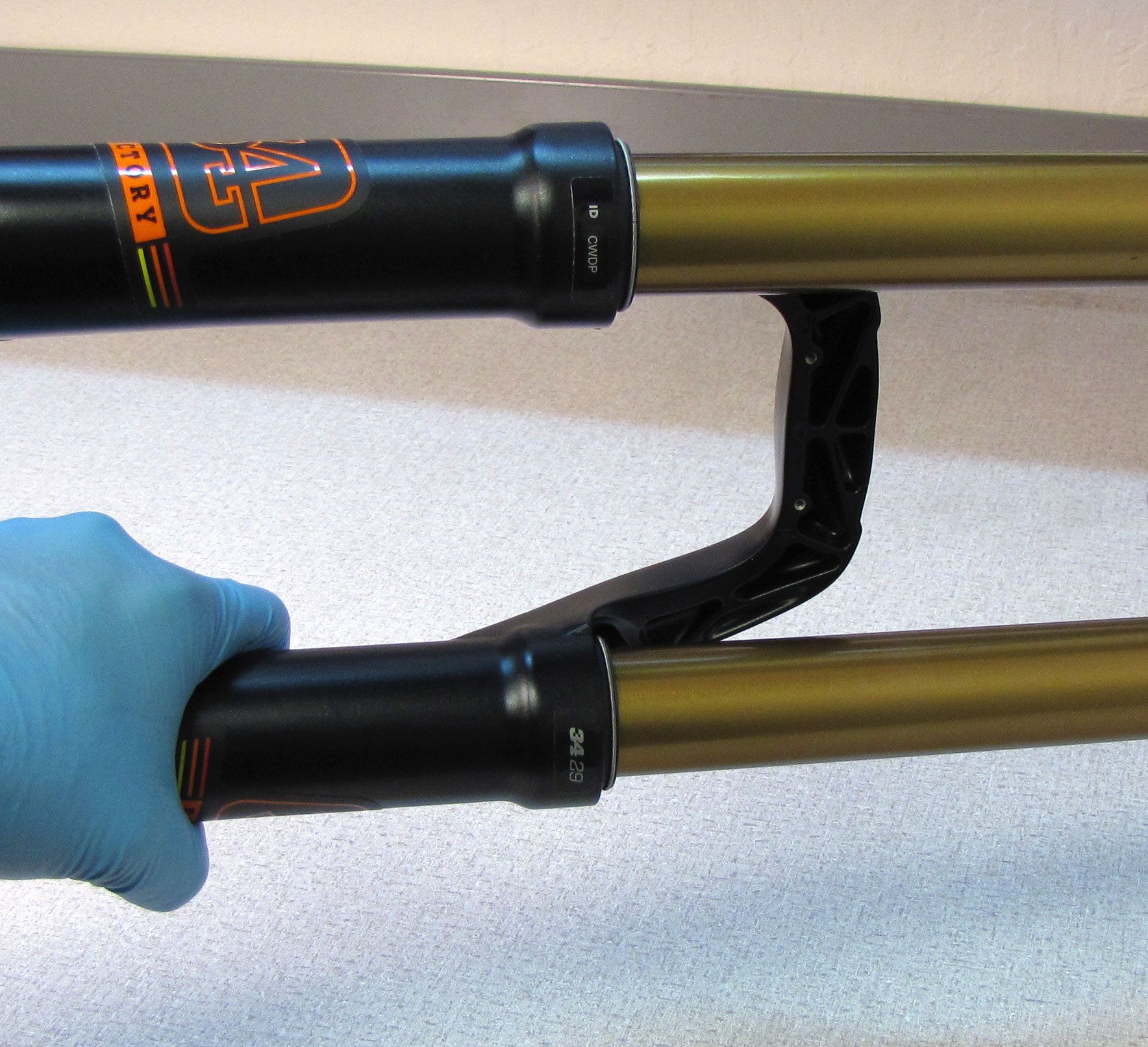
Remove the retaining ring from the bottom of the air side upper tube. 32mm forks use a double wound flat retaining ring. 34mm forks use a single wound Hoopster style retaining ring.
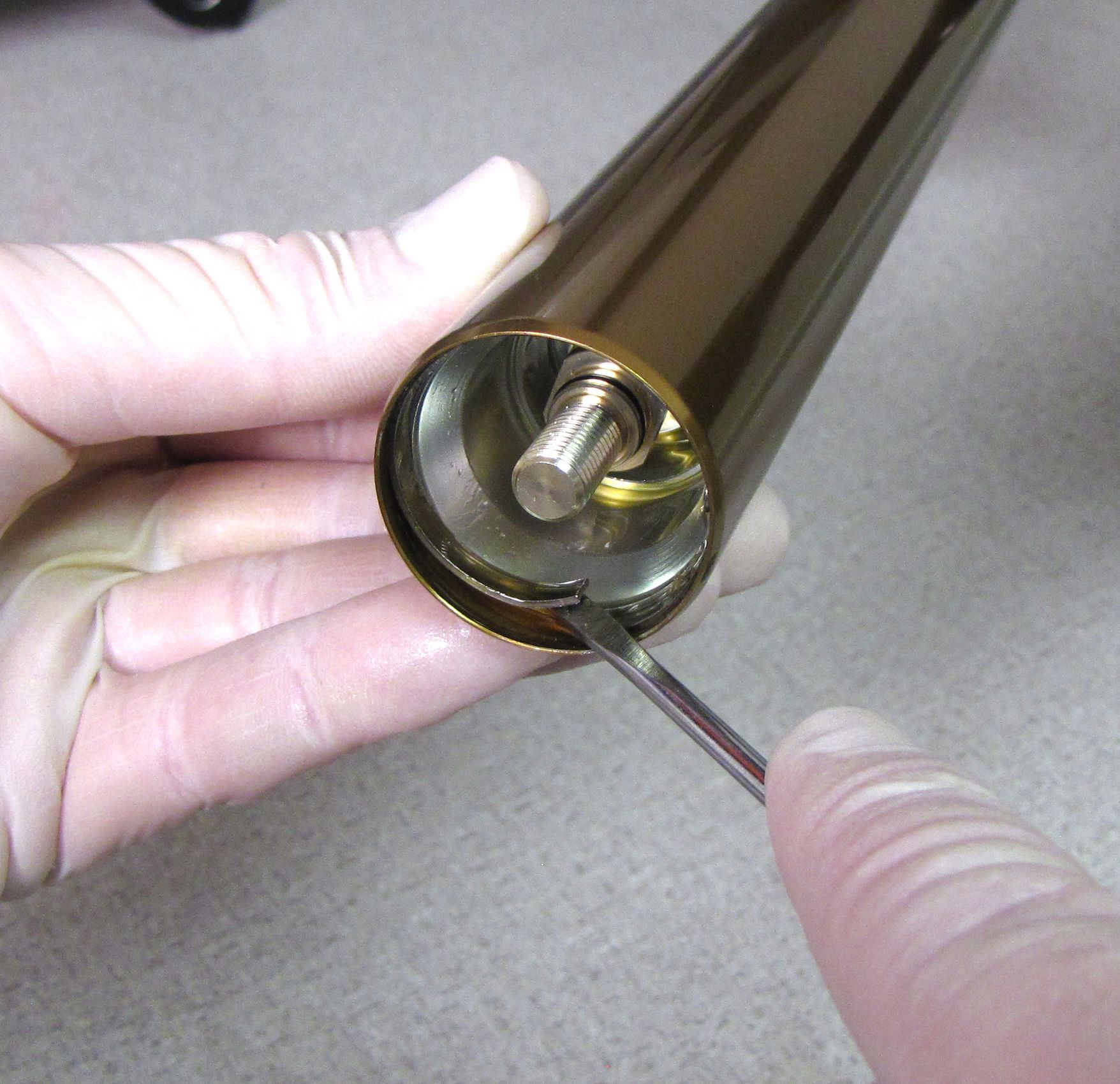
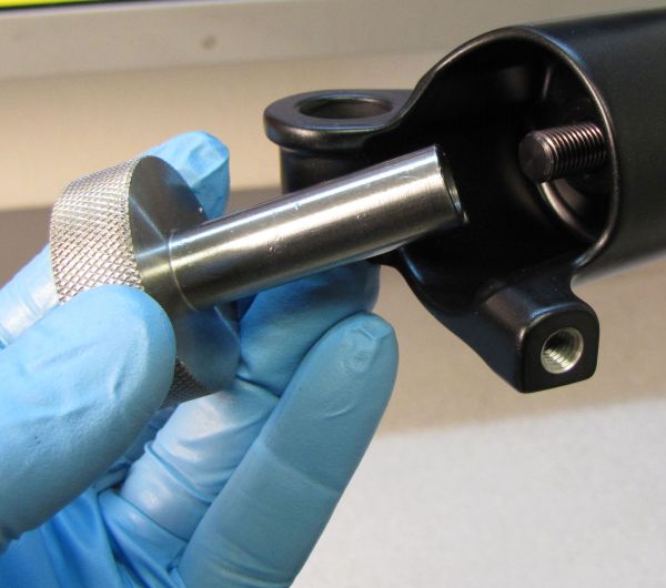
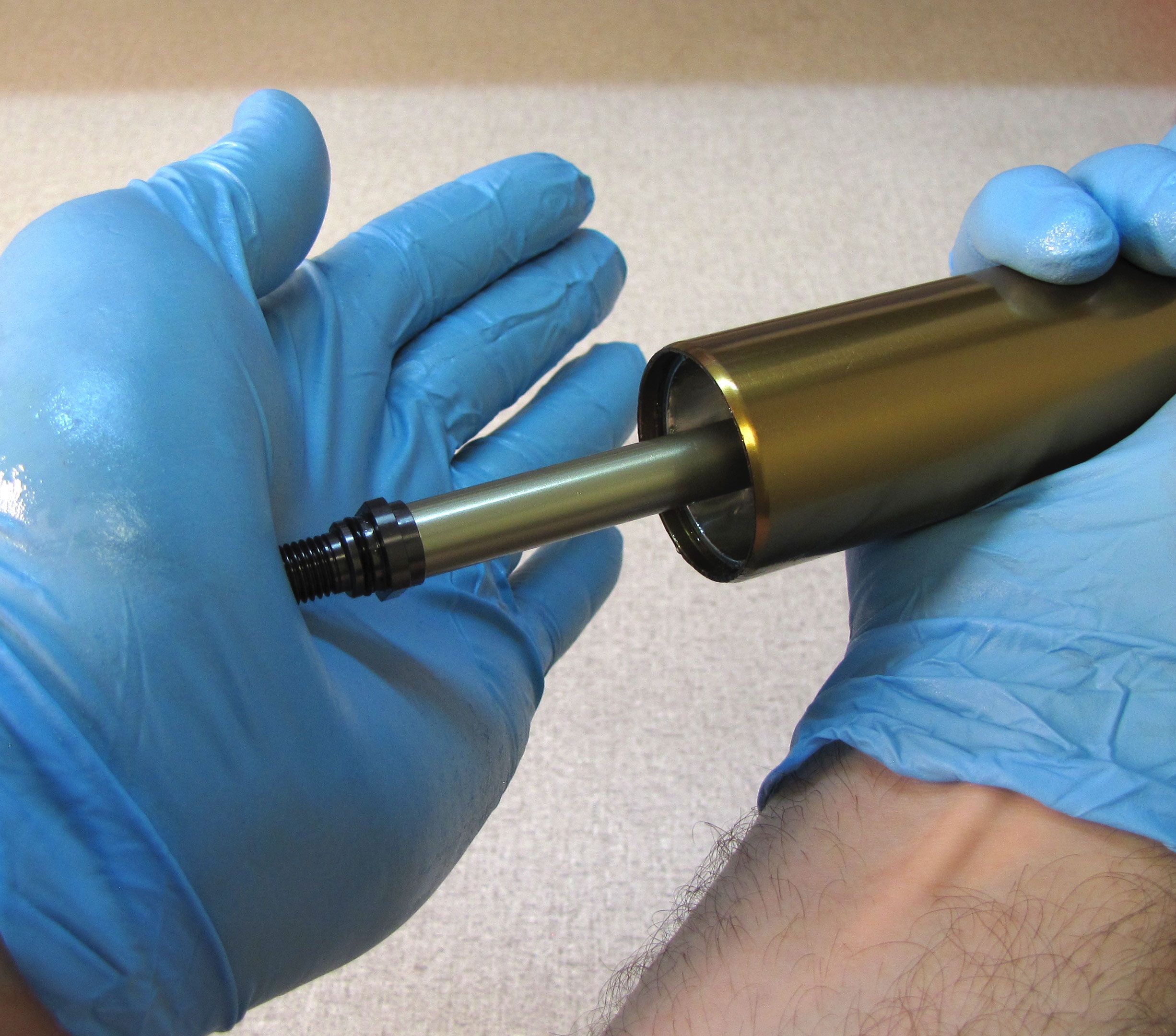
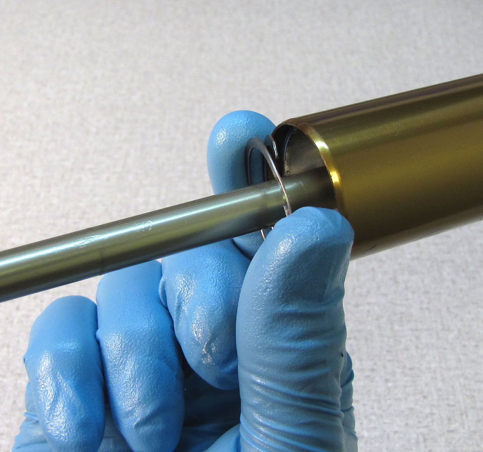
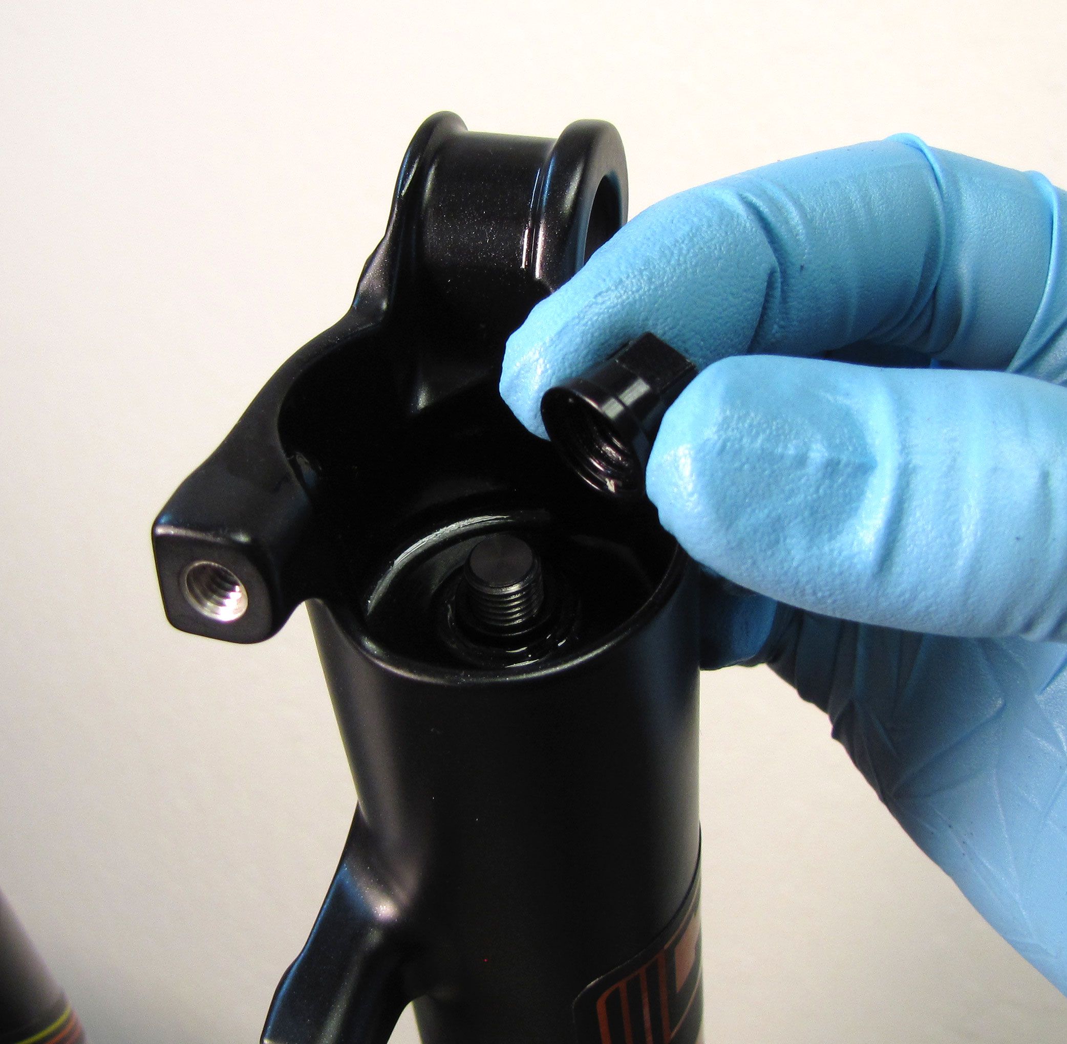
Step 8
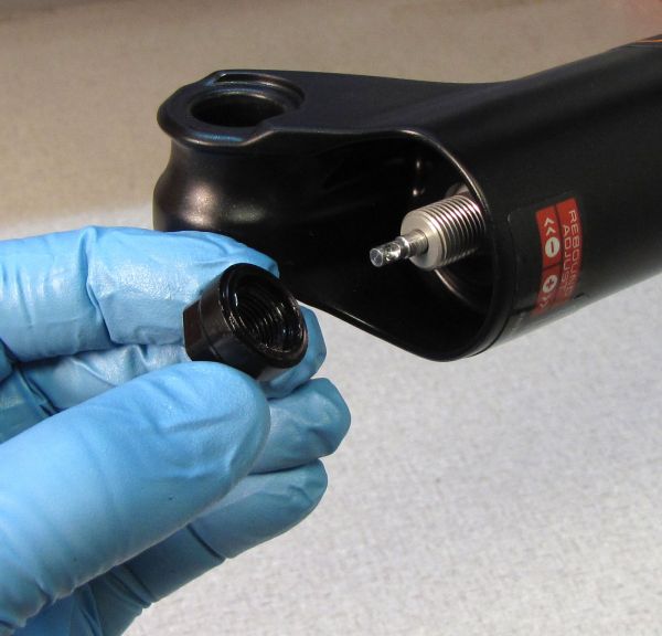
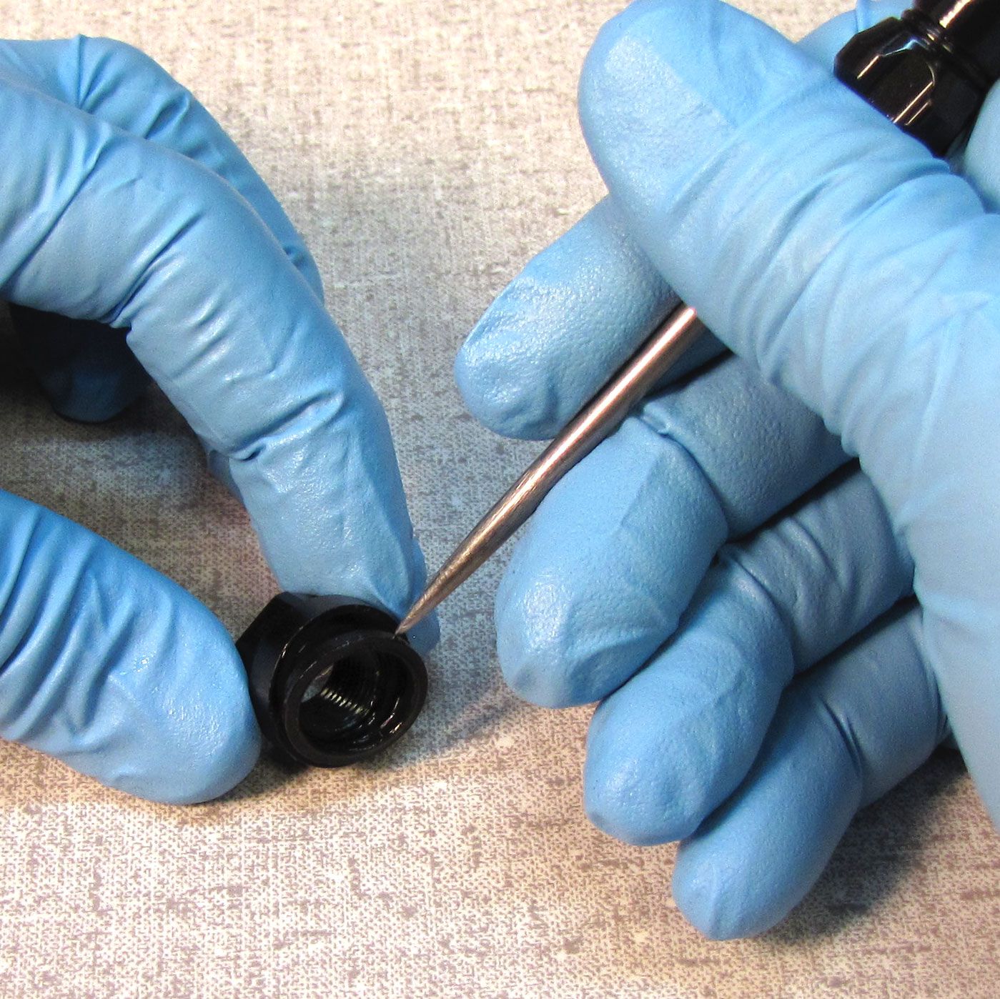
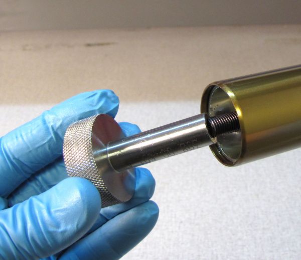
Thread the damper removal tool (PN: 398-00-681) onto the air shaft and pull out from the upper tube to remove the air shaft assembly.

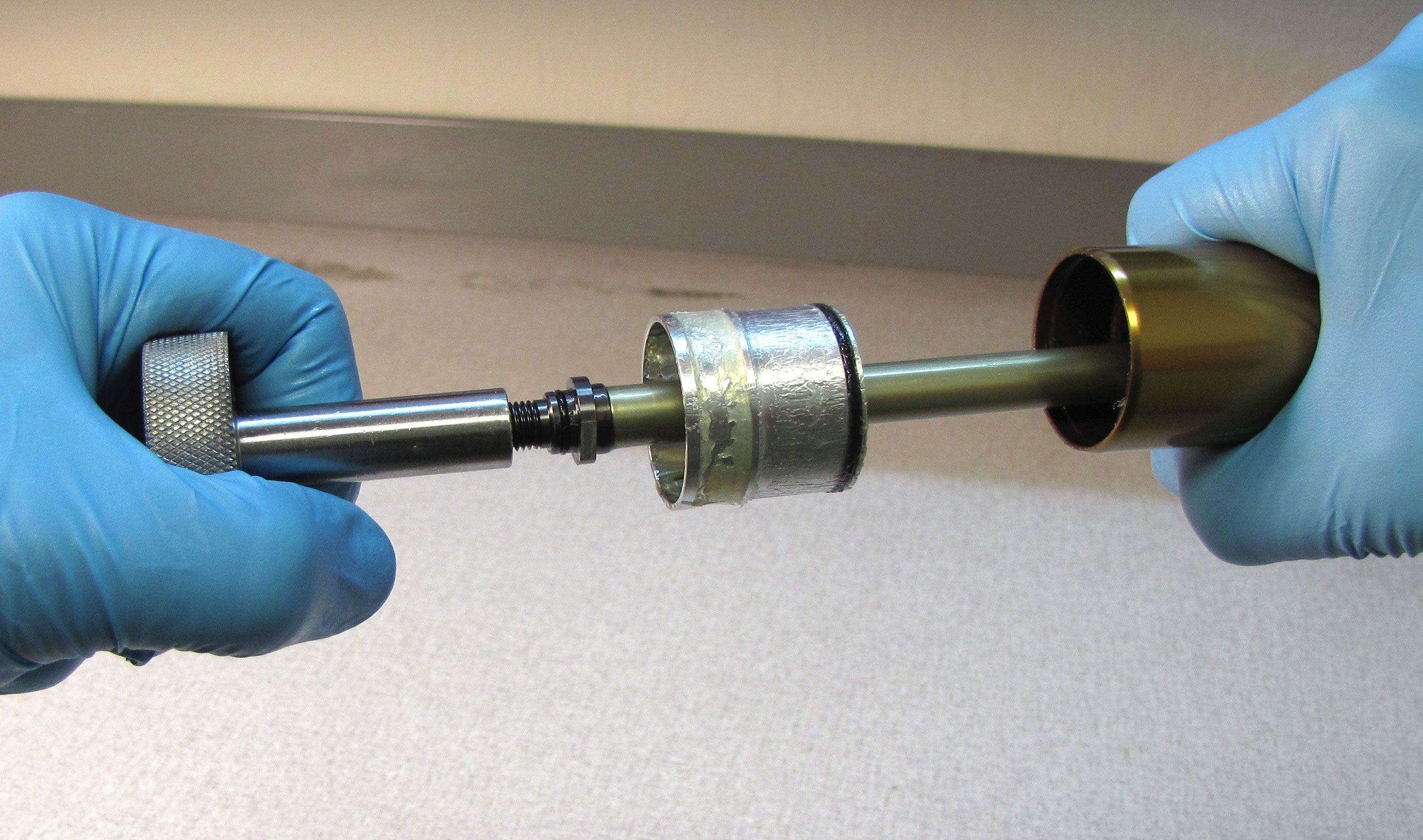
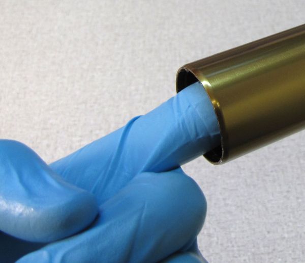
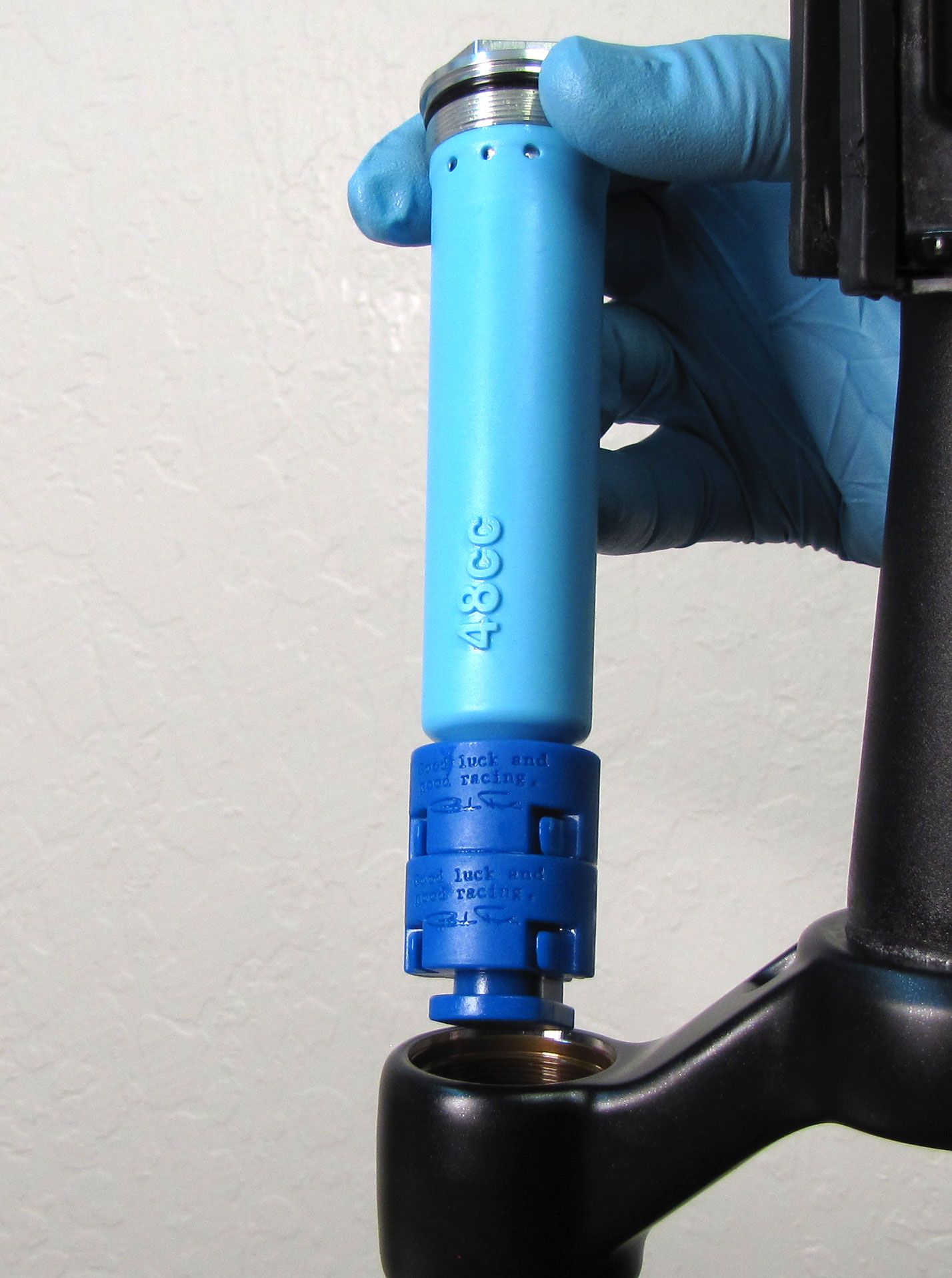
Step 9
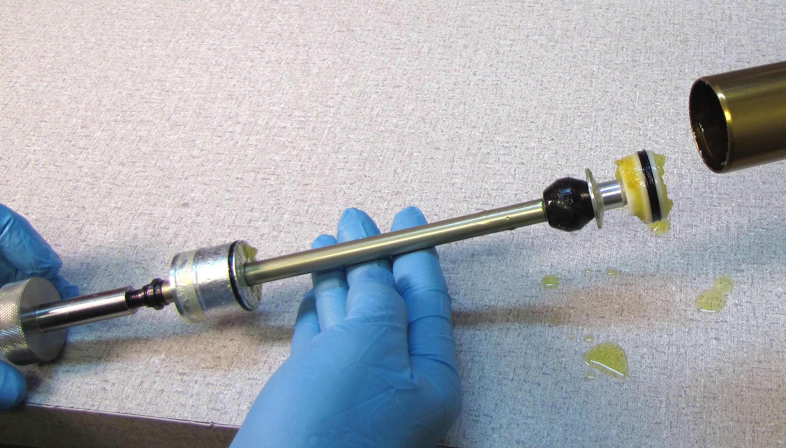
Apply a thin film of Slick Honey to the inside of the upper tube. Apply a thick film of Slick Honey to the new air shaft assembly in the areas of the piston, neg plate, and shaft above the neg plate.


Step 10
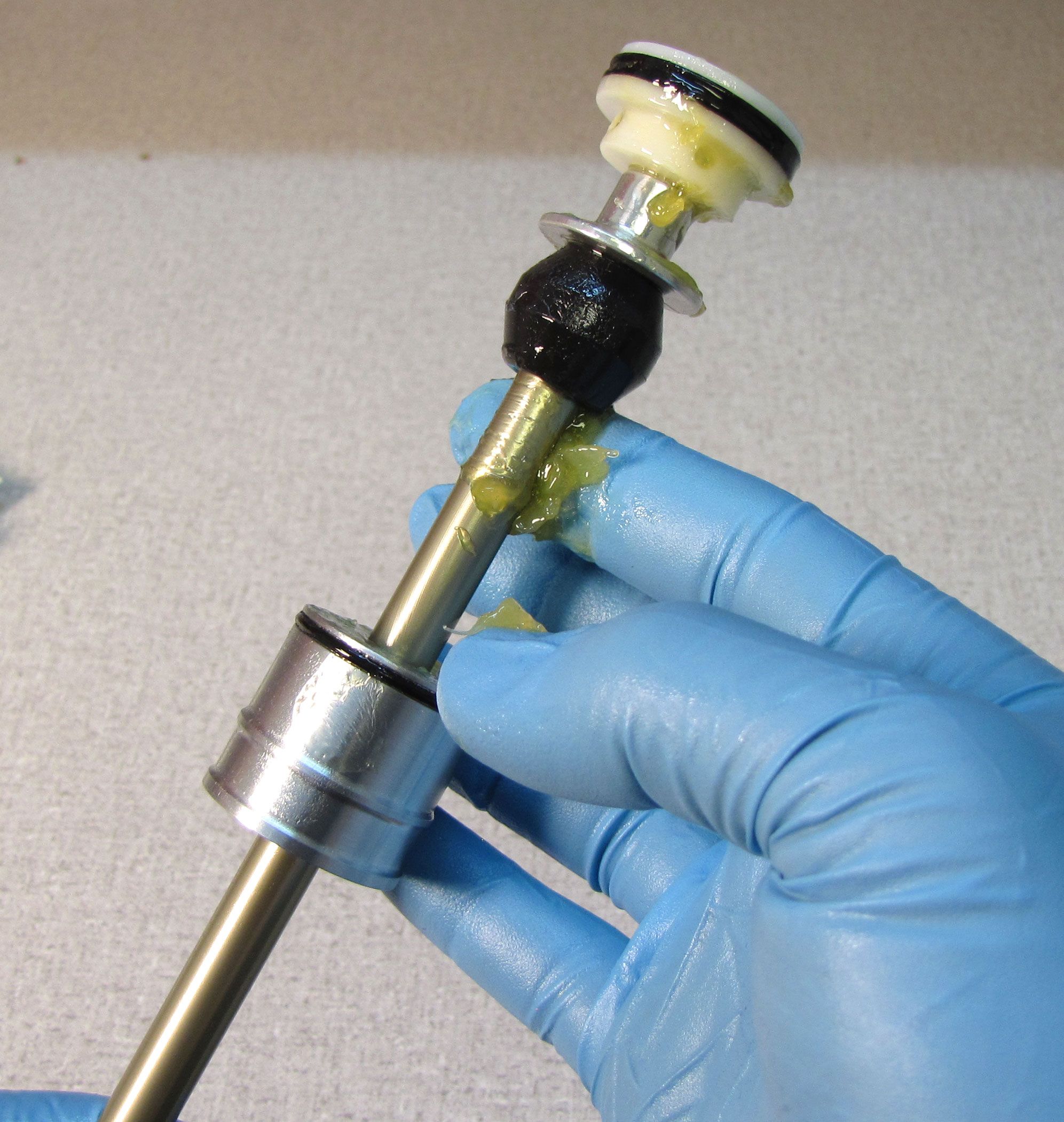
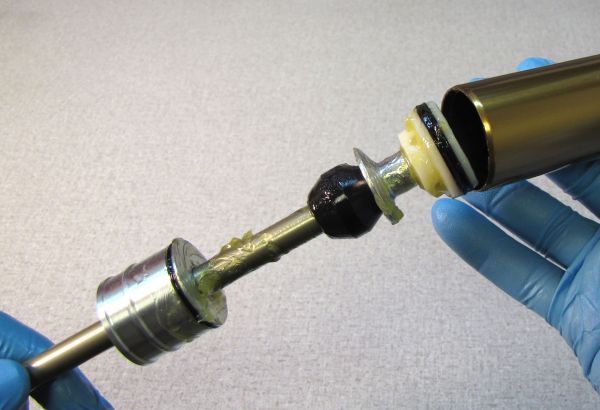
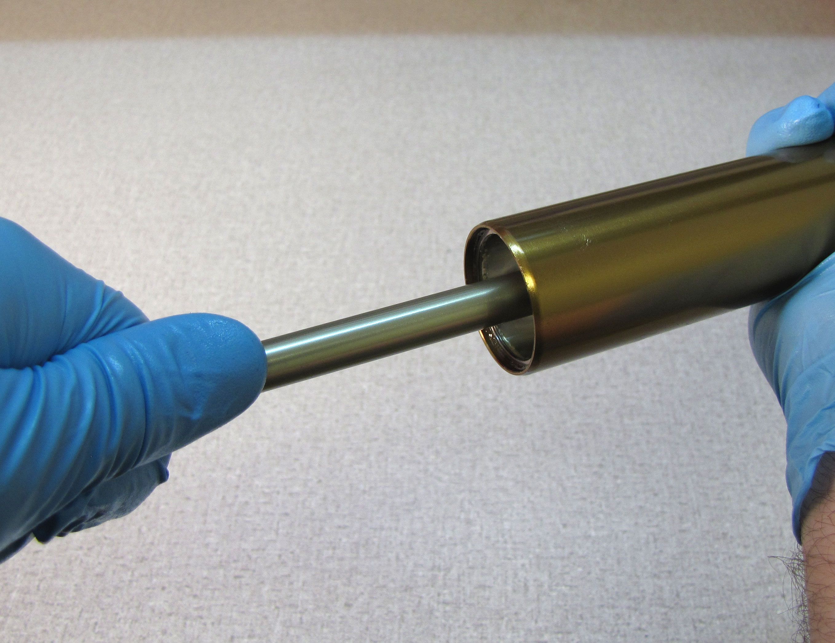
Insert the air shaft assembly into the end of the upper tube. Push the air shaft assembly into the upper tube far enough to allow you to start the neg plate into the upper tube. Push the shaft into the upper tube to pull the neg plate into its installed position.


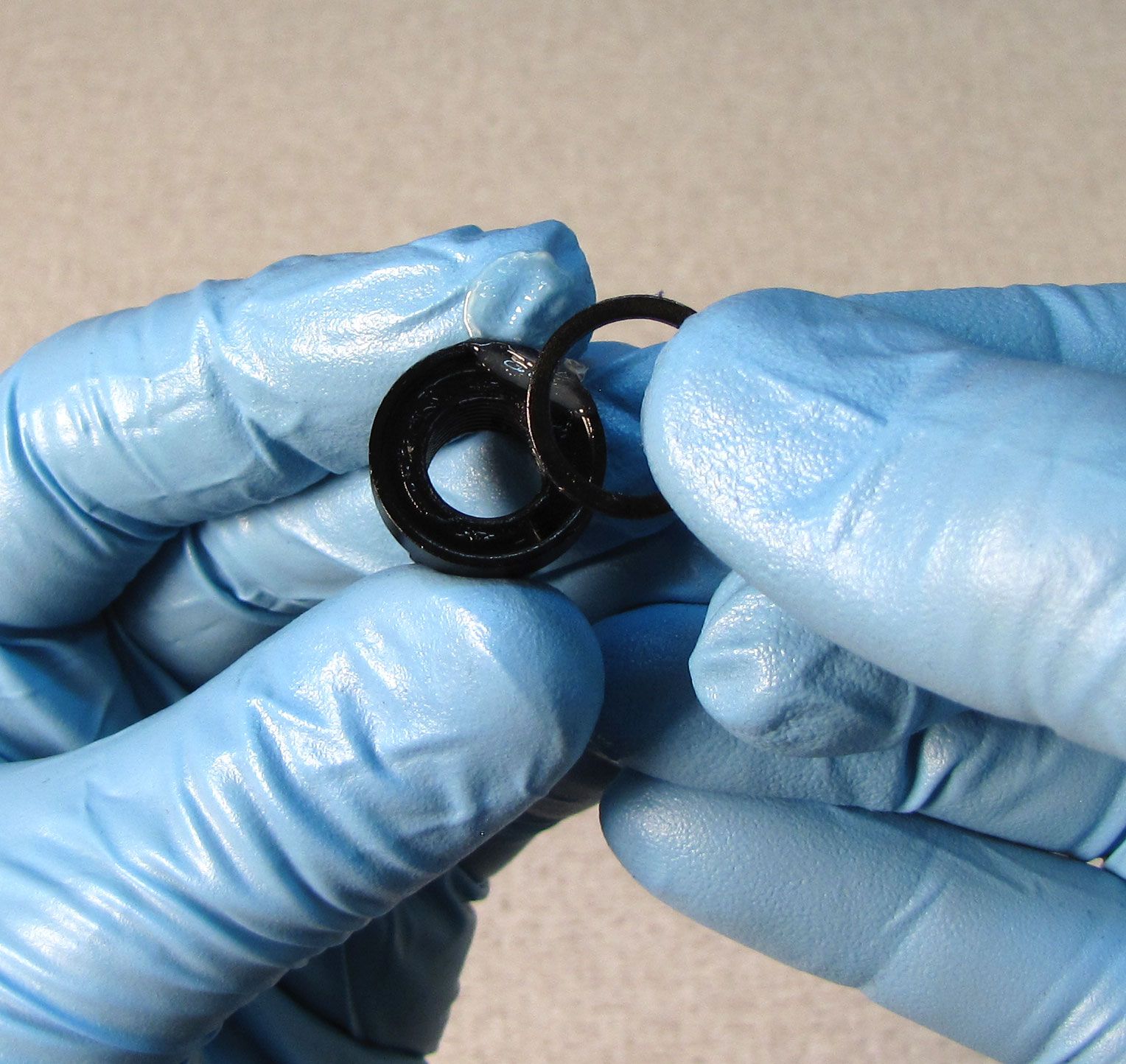
Step 11
Replace the retaining ring making sure it is fully seated in its groove by pulling on the air shaft. (32mm version shown)

Step 12
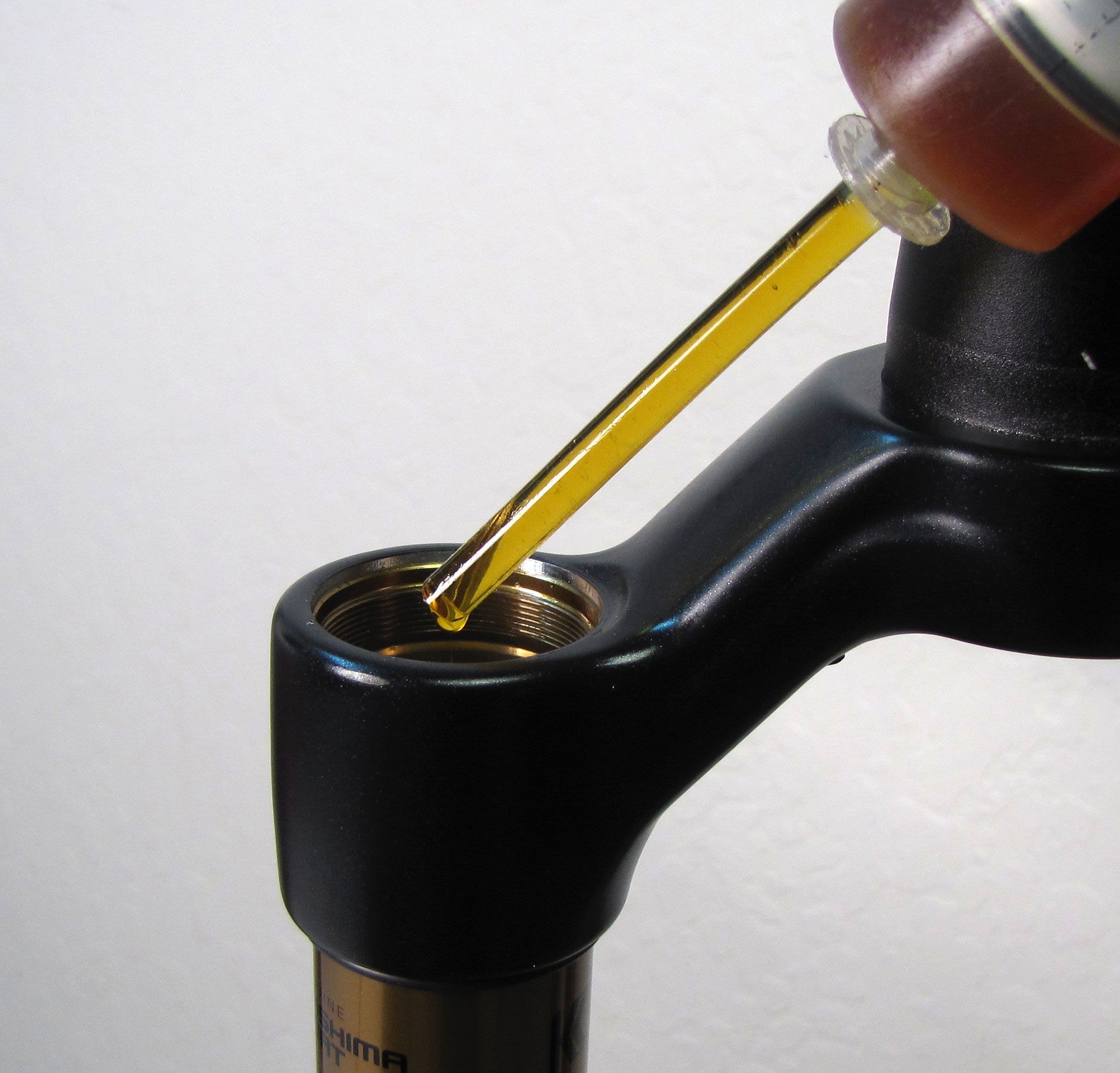
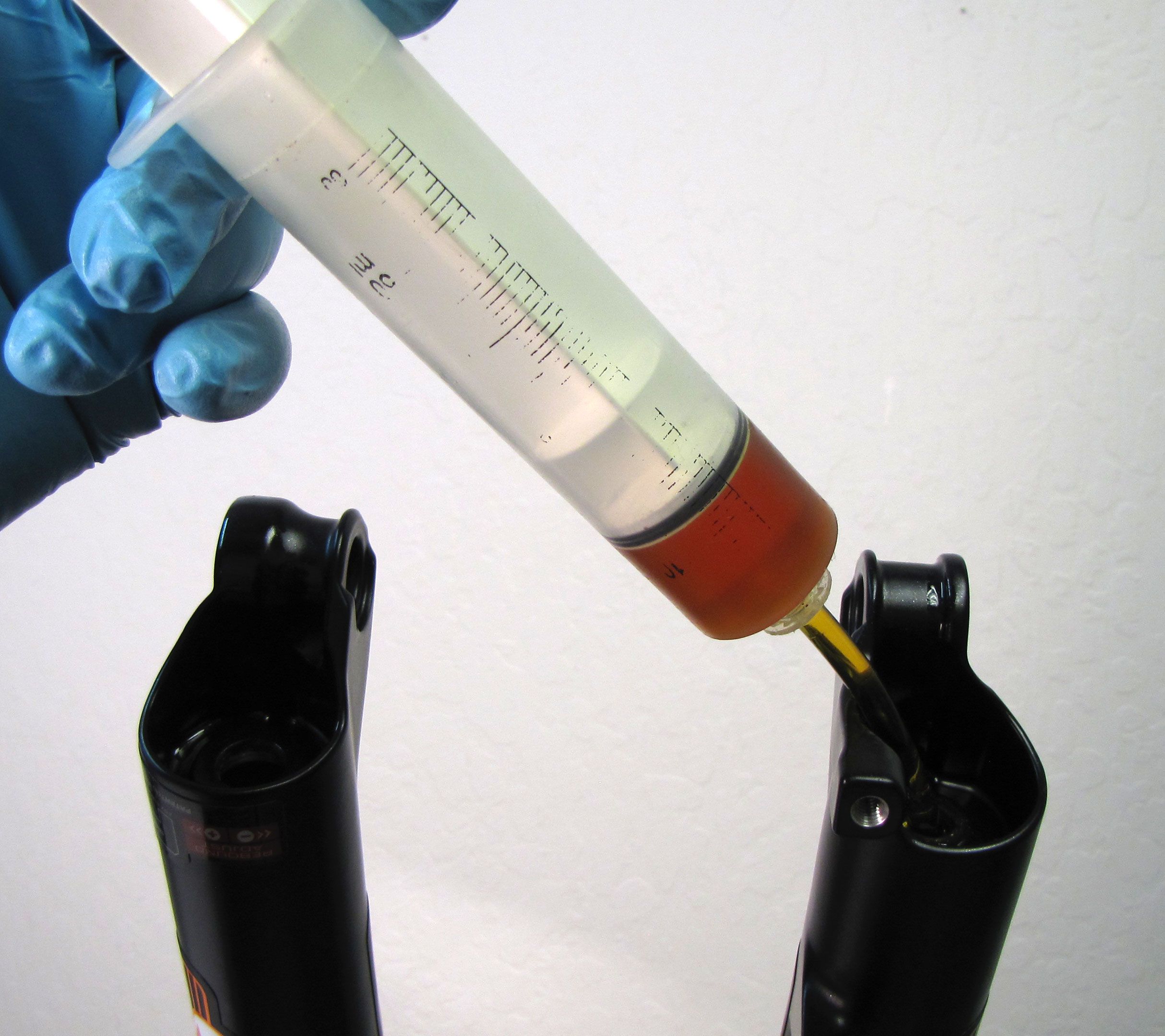
Inject 3cc of FOX 20wt. Gold oil into the main air chamber through the top of the upper tube. Reinstall the topcap into the fork crown and tighten clockwise to 220 in-lb (24.8 Nm) torque with your 6-point chamfer-less 26mm socket.

Step 13
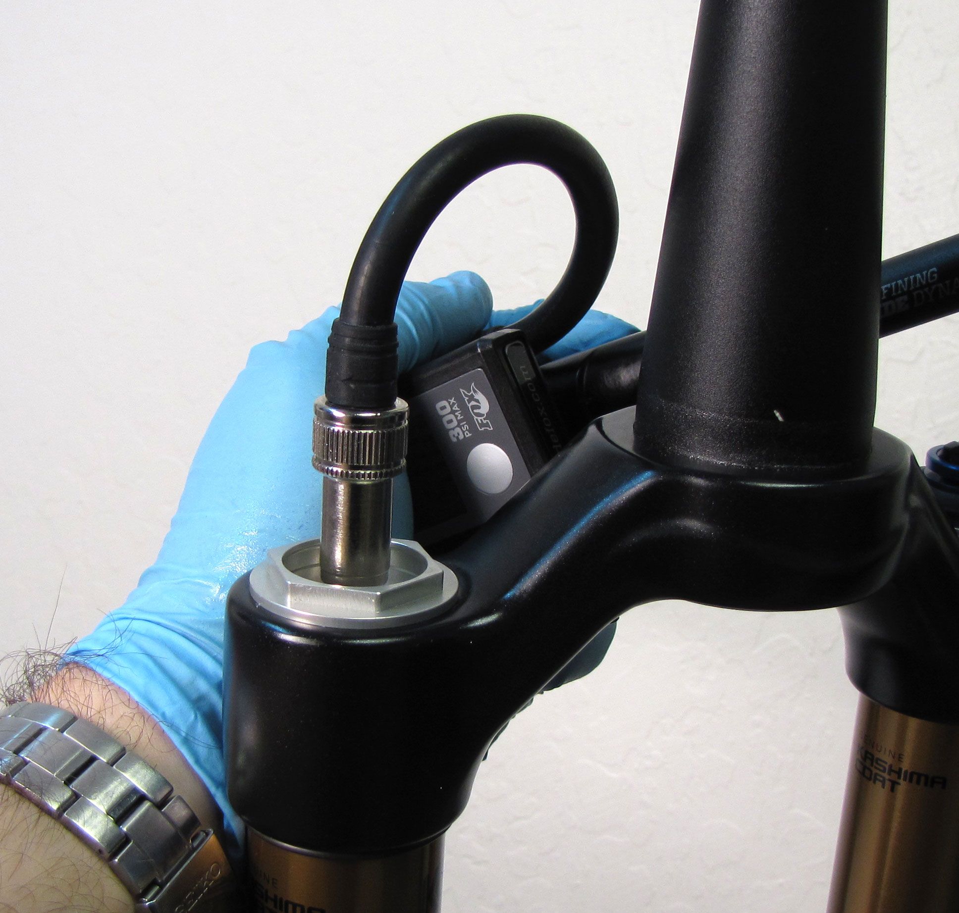
Add air pressure to your desired setting using a FOX high pressure pump. See the Setting Fork Air Pressure section for more information. Reinstall the blue air cap.
Step 14
Install the Lower Leg Assembly onto the upper tubes. Inject the approprate amount of FOX 20wt. Gold oil into each leg through the bottom hole.
| Air Side Bath Volume | 20wt. Gold Oil |
| 32mm FLOAT 80mm-120mm | 25cc |
| 32mm FLOAT 130mm-150mm | 10cc |
| 34mm FLOAT 110mm-120mm | 25cc |
| 34mm FLOAT 130mm-160mm | 10cc |
| Damper Side Bath Volume | 20wt. Gold Oil |
| All 32mm/34mm FIT4 | 15cc |
| 32mm TerraLogic | 30cc |
| 32mm iRD | 20cc |


Step 15
Install a new crushwasher on each side followed by the appropriate bottom nut. Torque both bottom nuts to 50in-lb (5.7 Nm).

Step 16
Use a 2mm hex wrench to install the red rebound knob. Make sure that the set screw lines up with the depression in the rebound adjuster shaft. Clean the exterior of your fork.
Step 17
After assembly you must compress the fork 3-5mm very slowly until you feel the chamber pressures equalize.
