2018 Trek Thru Shaft Shock Rebuild
Required Parts
- 803-01-157 Seal Kit: Trek Thru Shaft (TSS), Spring and Damper Rebuild
Required Tools
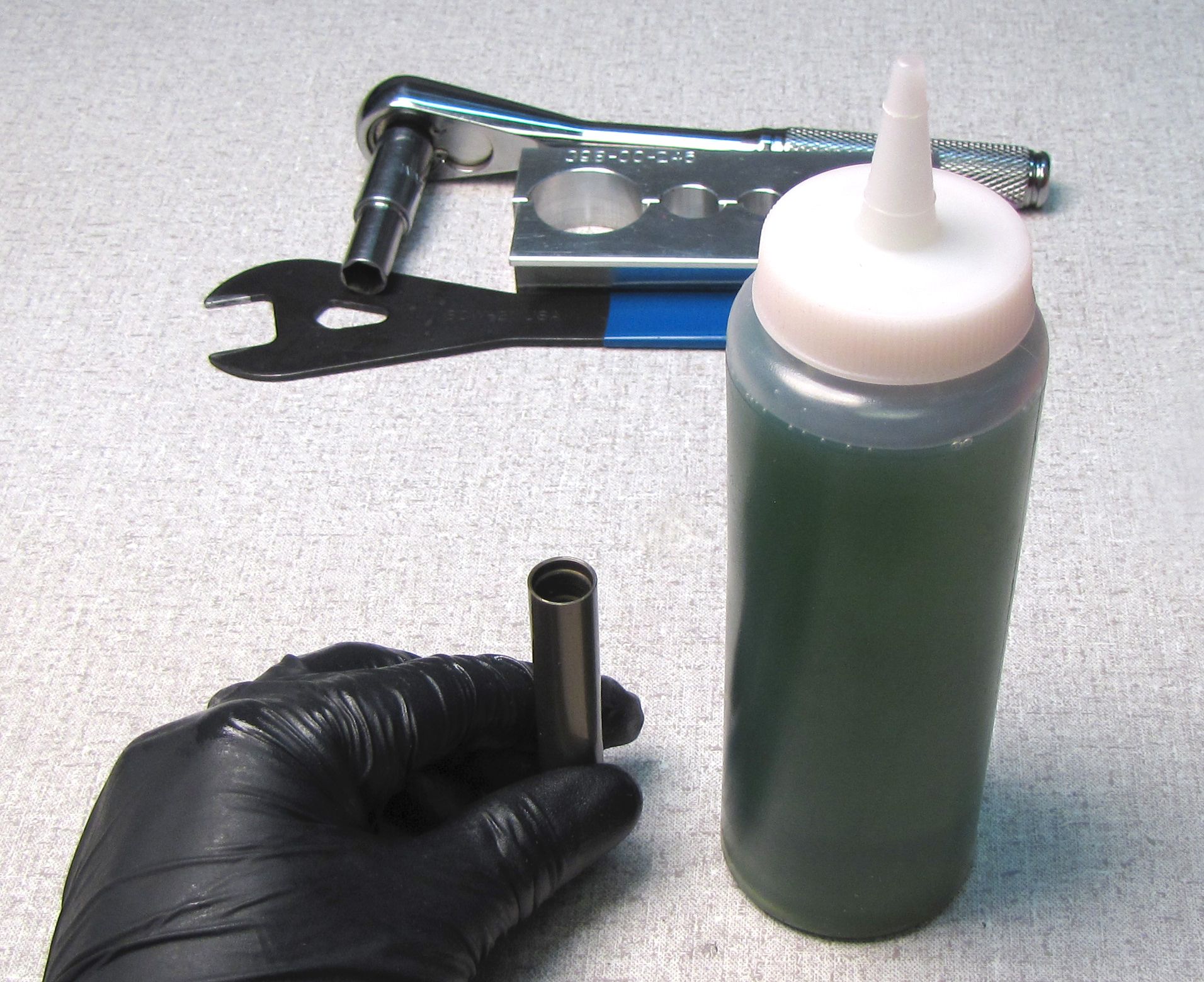
- 398-00-614 Tooling: 2015 Trek RG Valve Stack Transfer Tool
- 398-00-748 Service tooling: Trek Thru Shaft IFP Bleed Screw torque tool
- 398-00-749 Service tooling: Trek Thru Shaft IFP removal tool
- 398-00-951 Tooling: Torque Fixture, 54mm Trunnion Eyelet, Tall
- 803-00-208 or 803-00-805 Kit: Clamp, Shaft and Body, 2005 DHX or Kit: Shaft Clamps, Shocks, CTD 9mm, 3/8in, 1/2in, 5/8in
Sections
WARNING: Always wear safety glasses and protective gloves during service to prevent potential injury. Failure to wear protective equipment during service may lead to SERIOUS INJURY OR DEATH.
WARNING: FOX products should be serviced by a trained bicycle service technician, in accordance with FOX specifications. If you have any doubt whether or not you can properly service your FOX product, then DO NOT attempt it. Improperly serviced products can fail, causing the rider to lose control resulting in SERIOUS INJURY OR DEATH.
WARNING: FOX suspension products contain pressurized nitrogen, air, oil, or all 3. Suspension misuse can cause property damage, SERIOUS INJURY OR DEATH. DO NOT puncture, incinerate or crush any portion of a FOX suspension product. DO NOT attempt to disassemble any portion of a FOX suspension product, unless expressly instructed to do so by the applicable FOX technical documentation, and then ONLY while strictly adhering to all FOX instructions and warnings in that instance.
WARNING: Modification, improper service, or use of aftermarket replacement parts with FOX forks and shocks may cause the product to malfunction, resulting in SERIOUS INJURY OR DEATH. DO NOT modify any part of a fork or shock, including the fork brace (lower leg cross brace), crown, steerer, upper and lower leg tubes, or internal parts, except as instructed herein. Any unauthorized modification may void the warranty, and may cause failure or the fork or shock, resulting in SERIOUS INJURY OR DEATH.
Disassembly
Step 1
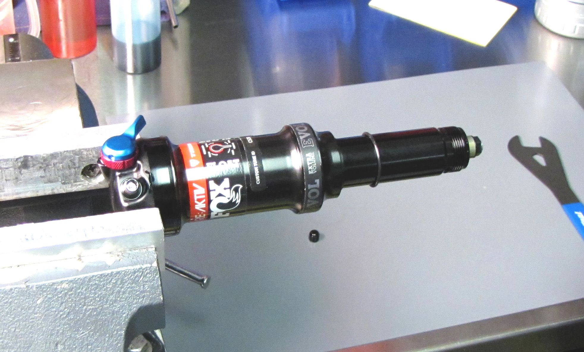
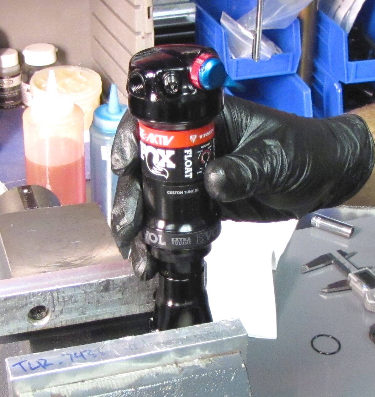
Locate the flats on the front and back of the Clevis on the end of the body. Carefully clamp the flats of the Clevis in your soft-jawed vise.


Step 2
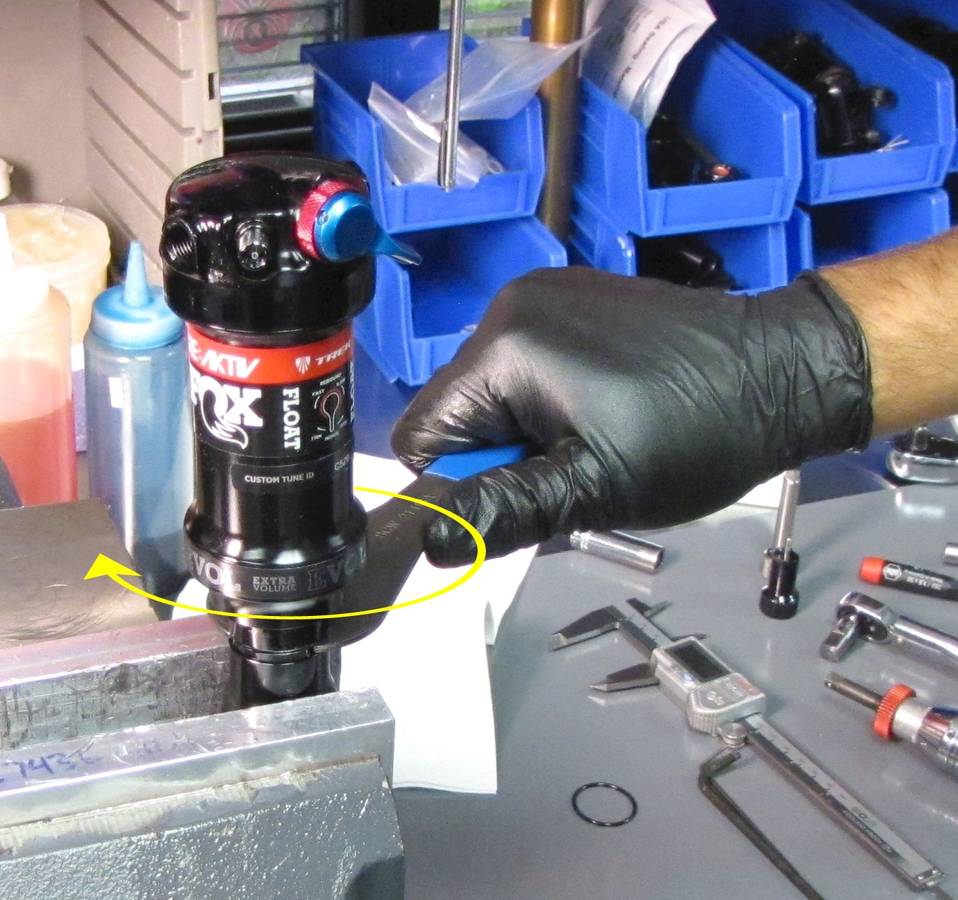
Use a 21mm cone wrench or thinned 21mm crow's foot to unthread the body counter-clockwise from the Clevis.
Step 3
Gently clamp the eyelet in your soft-jawed vise so the mounting bolt areas are the only portions of the eyelet contacting the vise. Remove the black air cap and thread on our shock pump. Slowly release all air from the main air chamber with your pump. Remove the pump. Verify that all air has been released by depressing the Schrader valve with a lint-free towel covering the valve to prevent any oil spray.
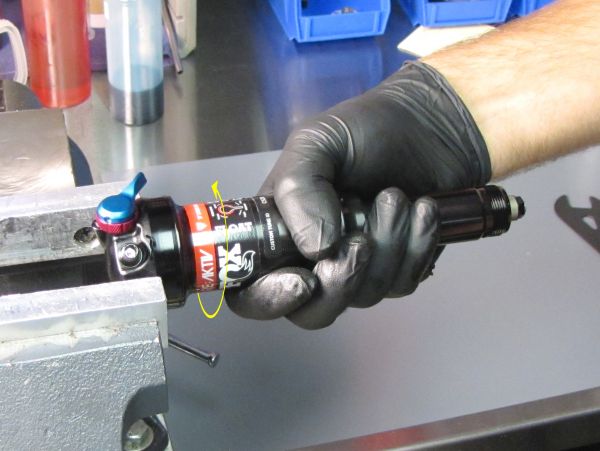
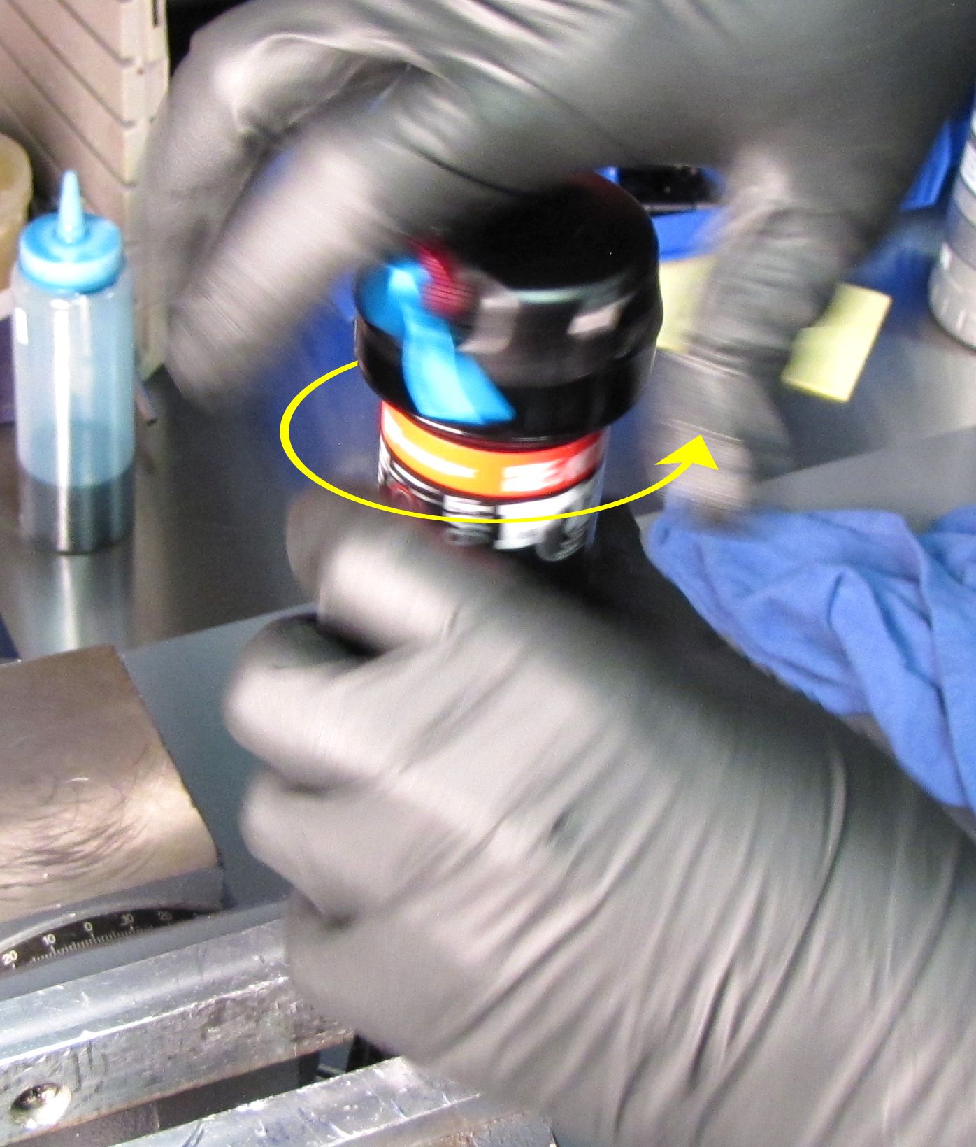
Step 4
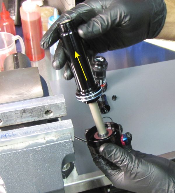
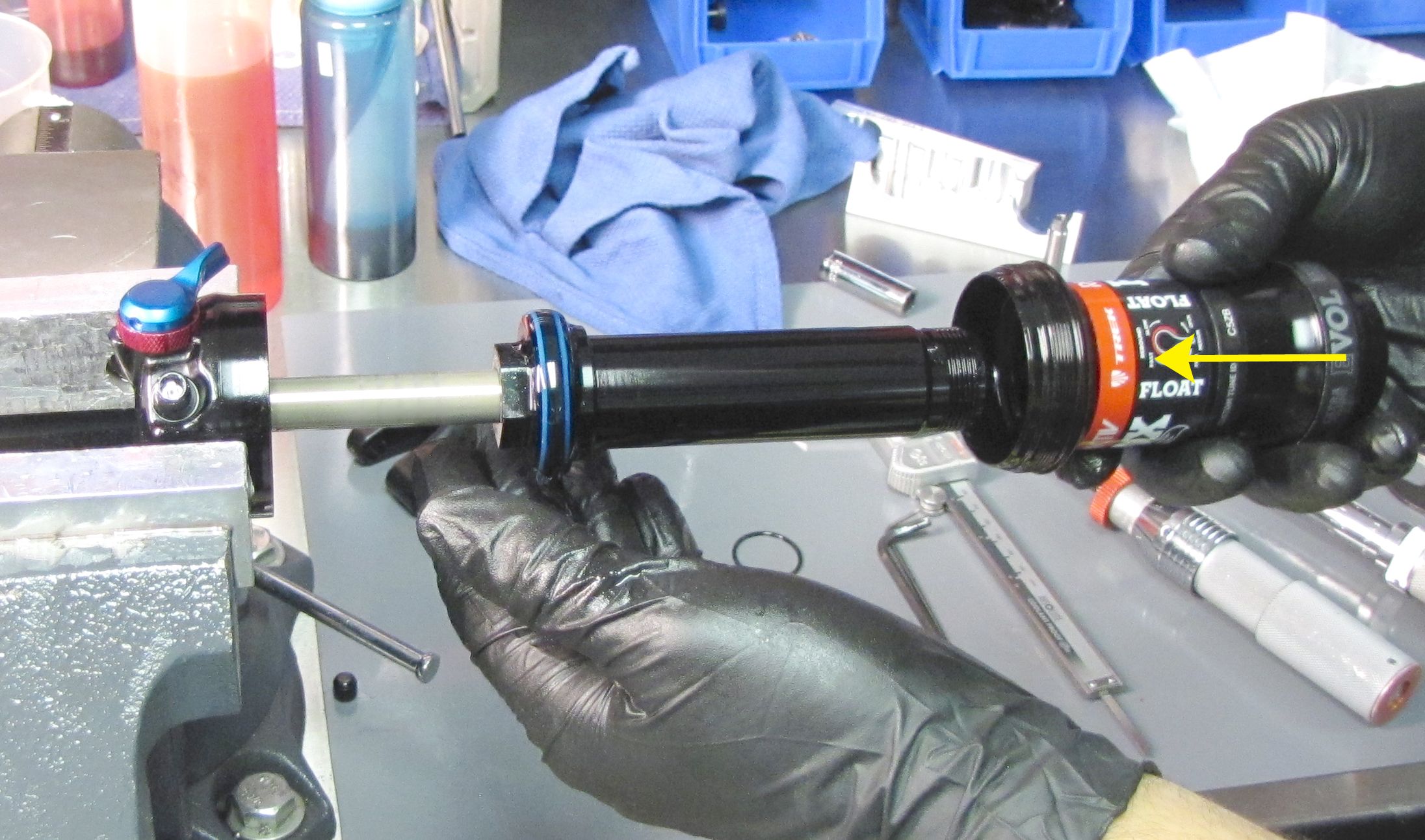
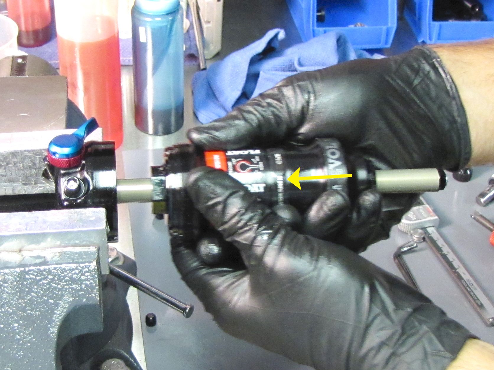
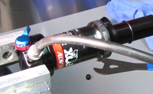
Unthread the air sleeve from the eyelet by turning it counter-clockwise. Remove the air sleeve after unthreading by pulling it away from the shock.


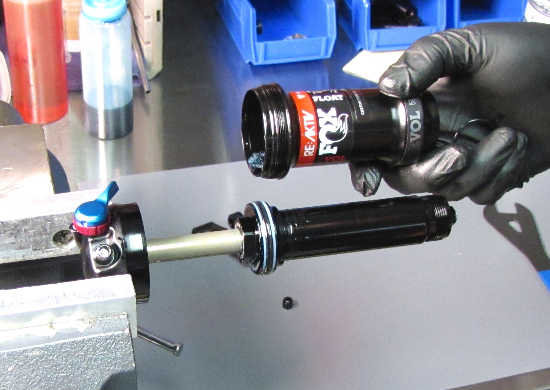
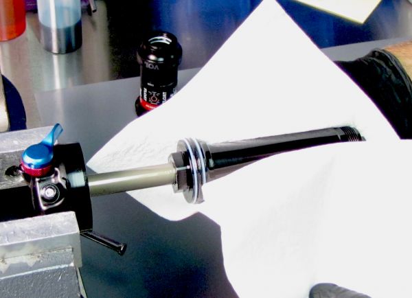
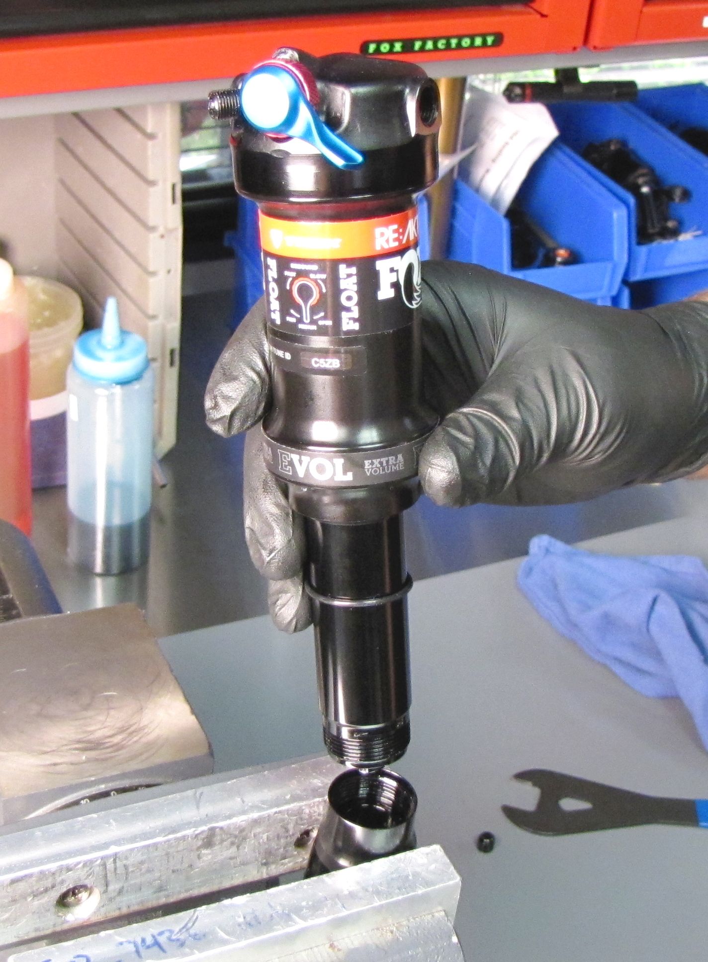
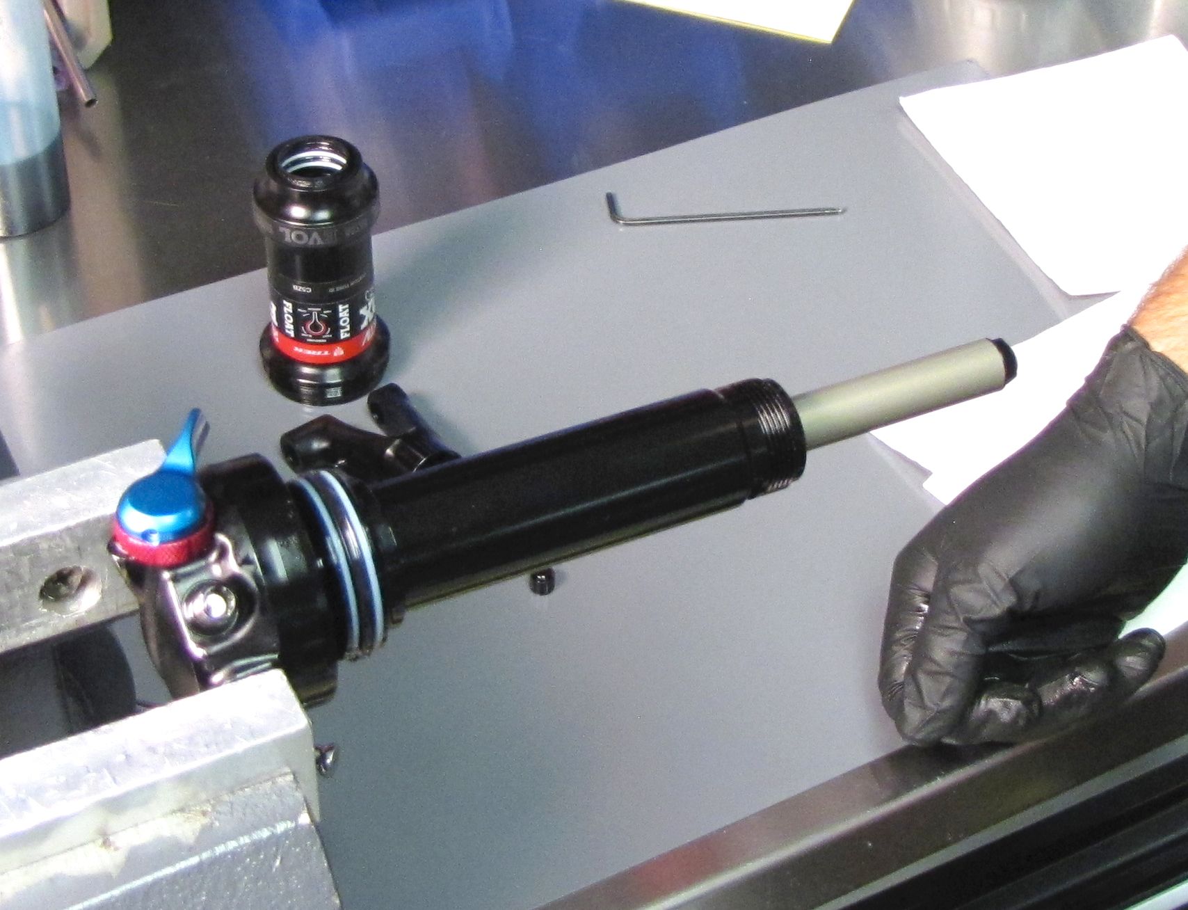
Step 5
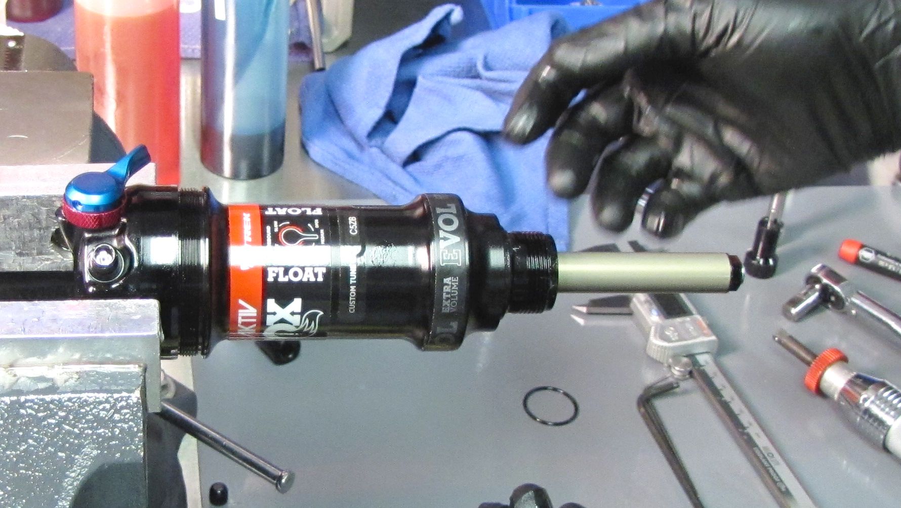
Clean the shock damper with a lint-free paper towel and isopropyl alcohol. Push the body up the shaft toward the eyelet.

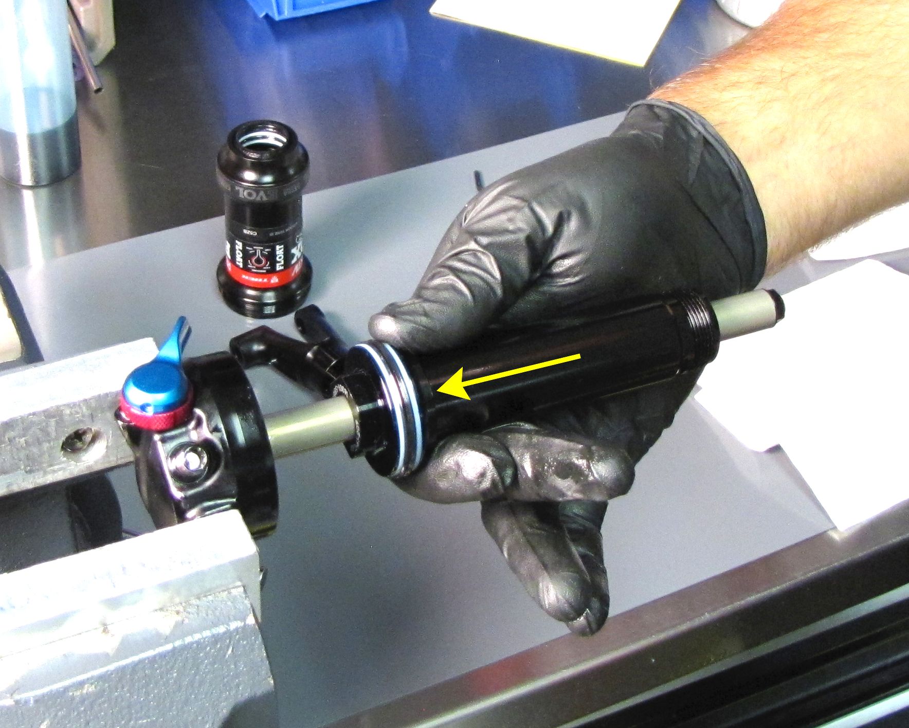

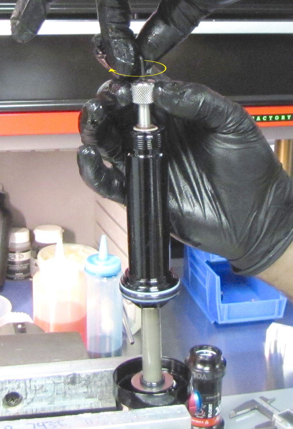
Step 6
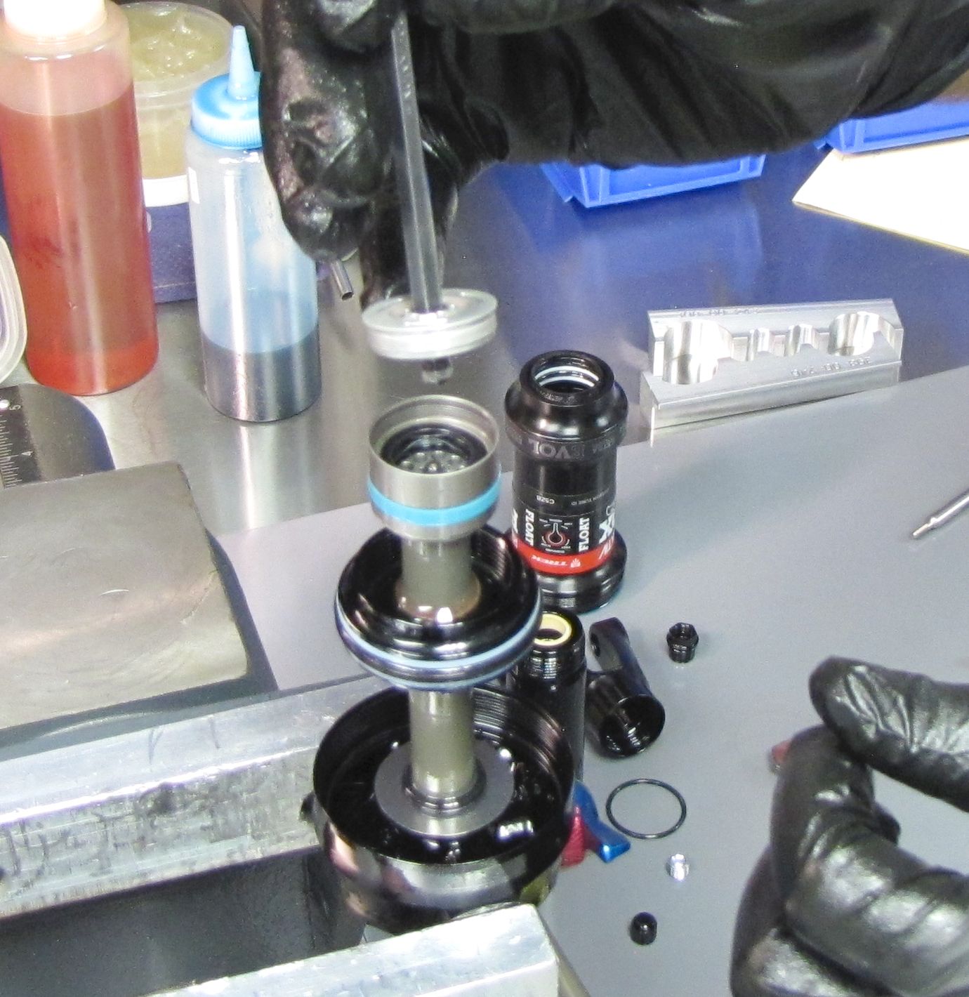
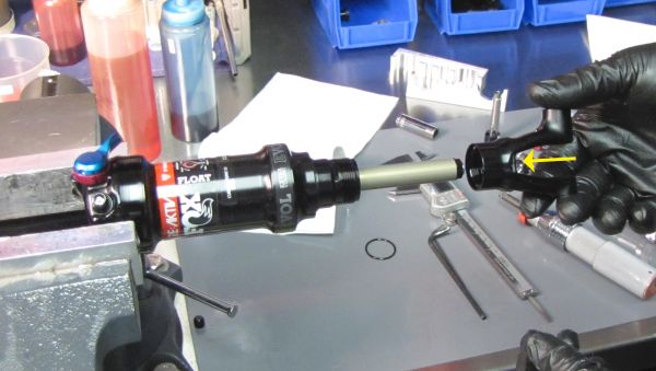
Clamp the Slave Shaft in your shaft clamps (PN: 803-00-208 or 803-00-805). Slowly unthread the End Cap counter-clockwise with a 10mm socket while holding downward pressure to prevent the IFP spring from popping up and out. Lift it up to remove. Replace the o-ring on the end cap with a new greased once from the kit. Set the IFP spring aside.

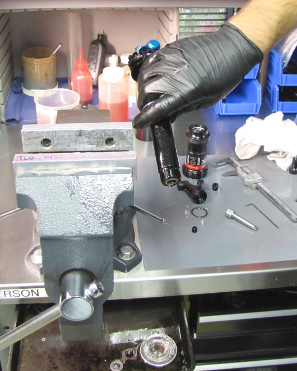
Step 7
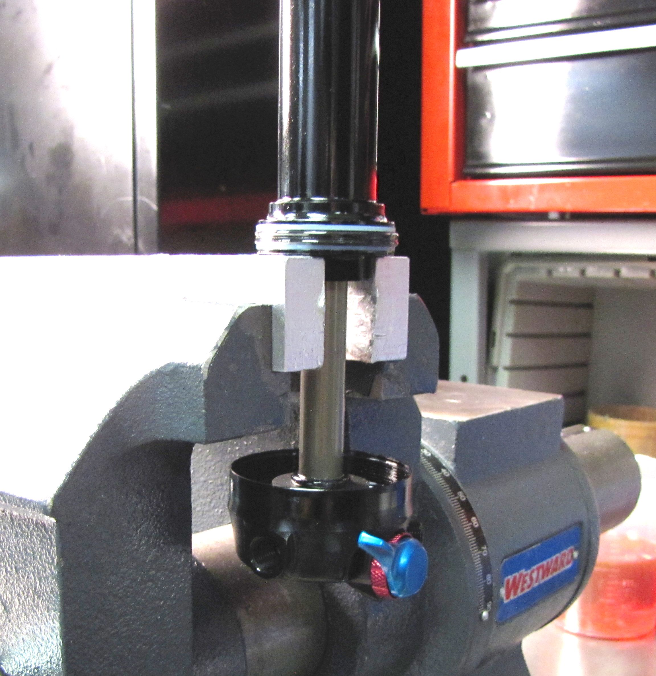
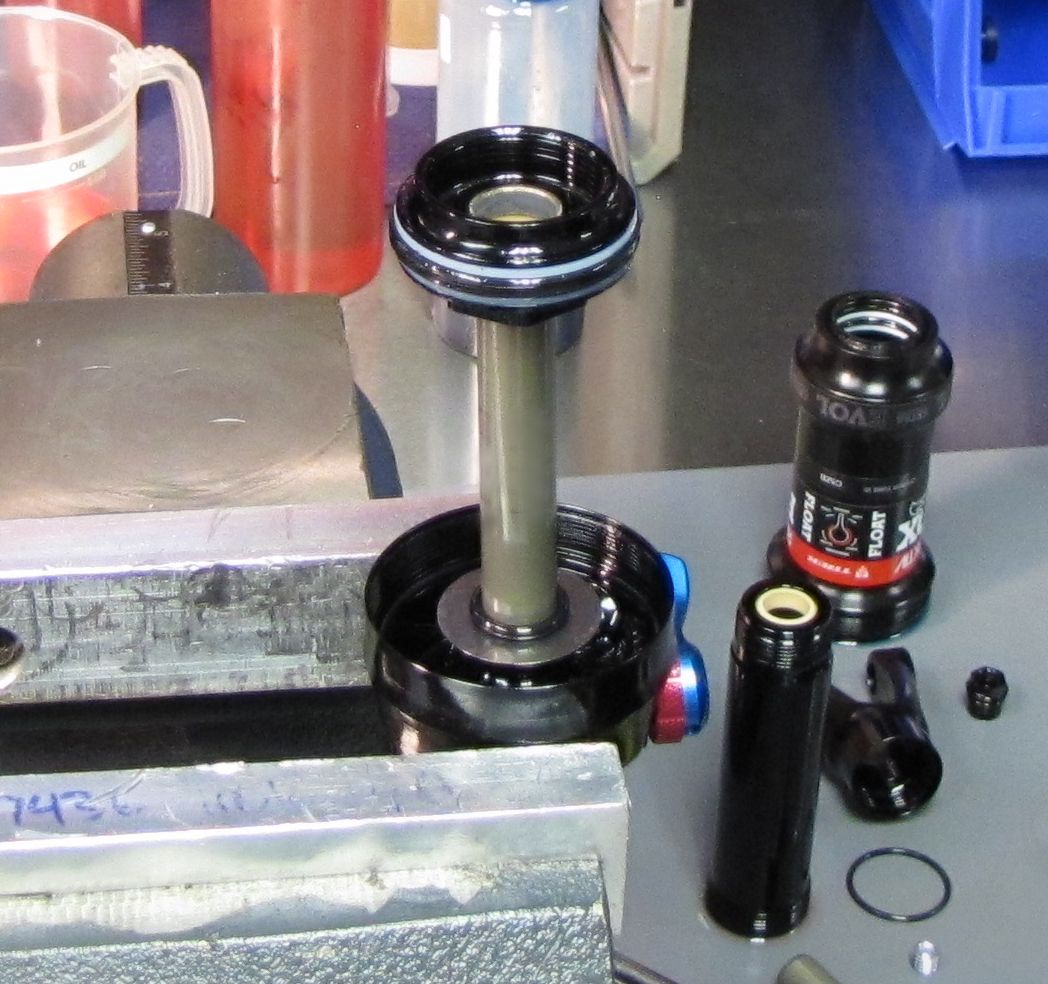
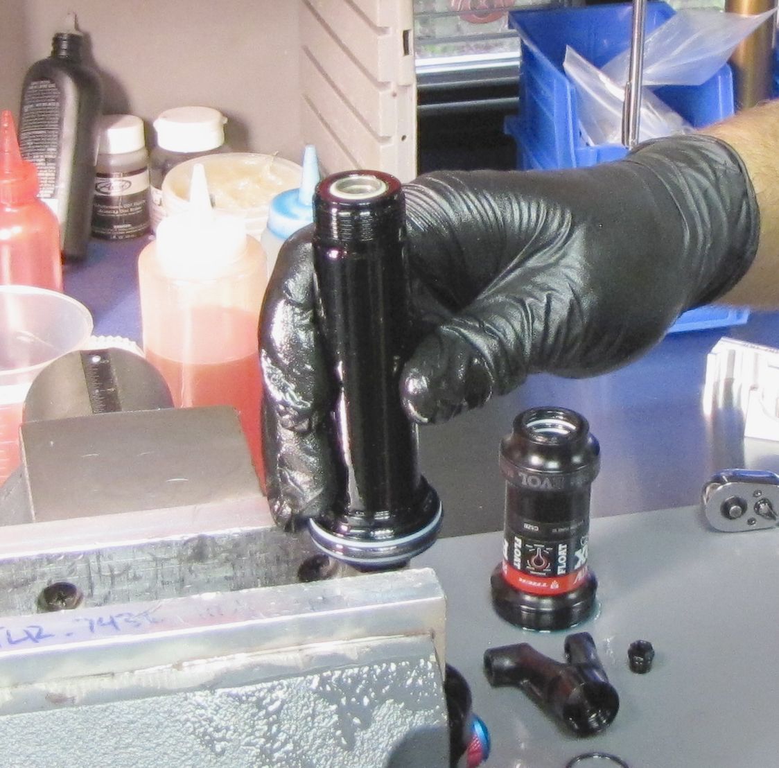
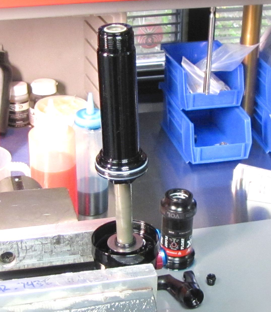
Remove the shock from the shaft clamps and fully extend the damper by pulling the body away from the eyelet. Position the shock in your soft-jawed vise with the body facing up and the wrench flats of the bearing housing clamped securely. Make sure that no portion of the shock is contacting the vise beneath the jaws.

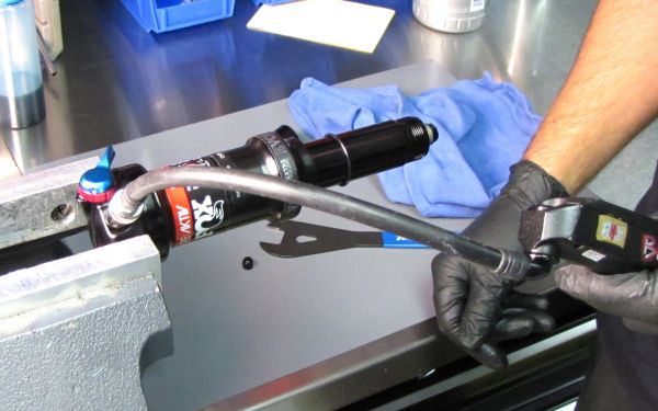
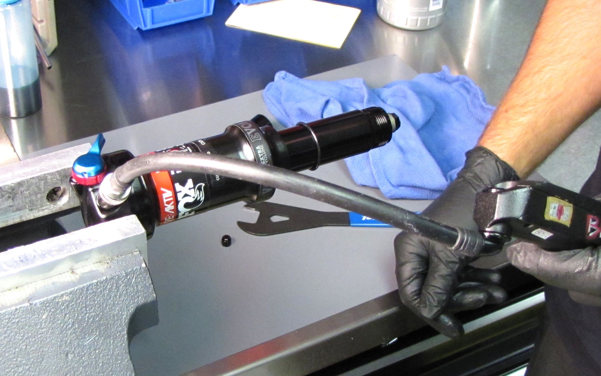
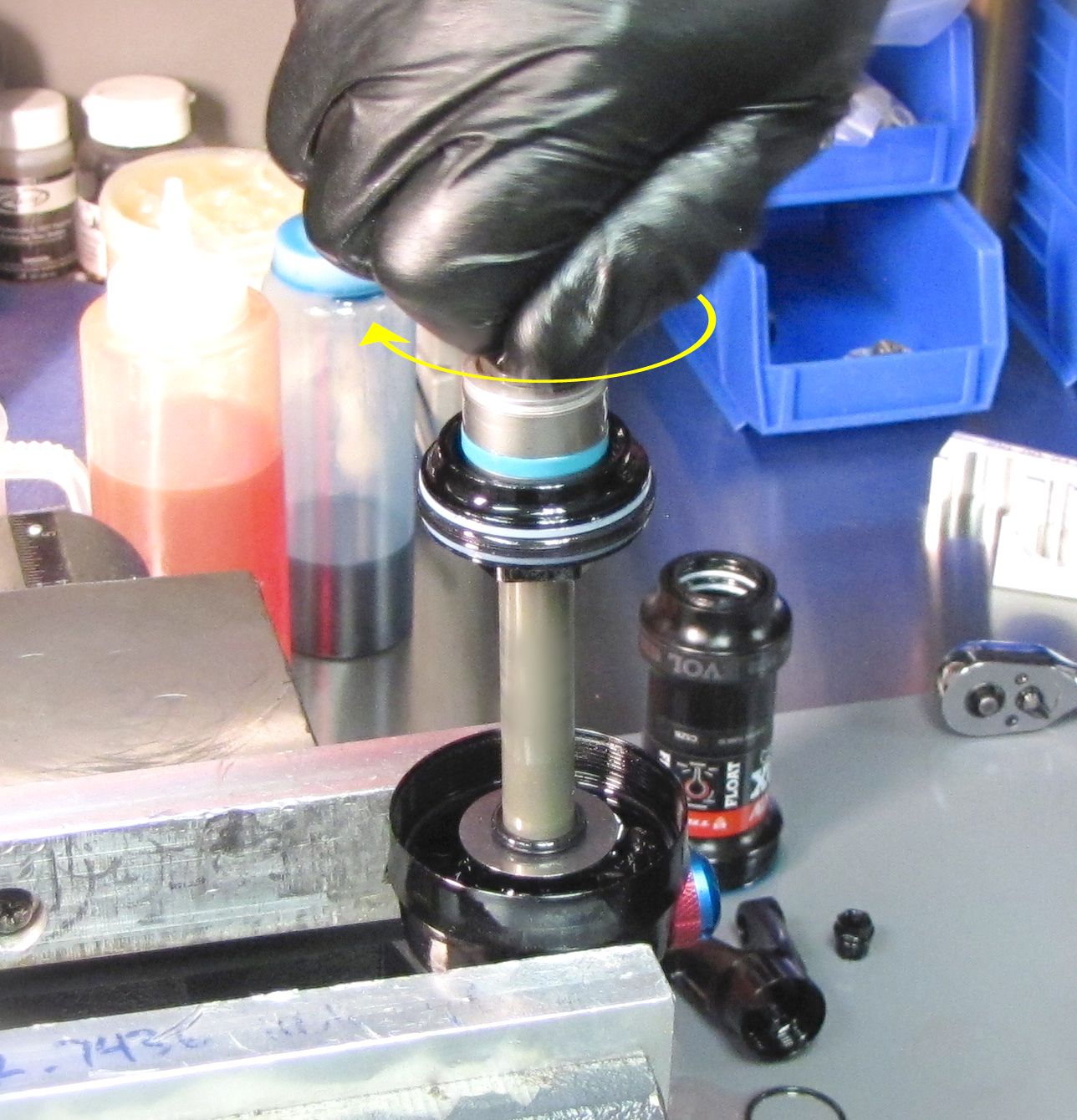
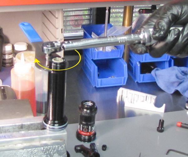
Step 8
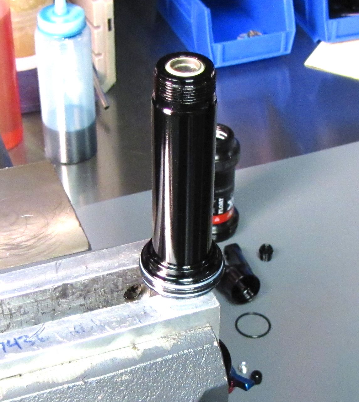
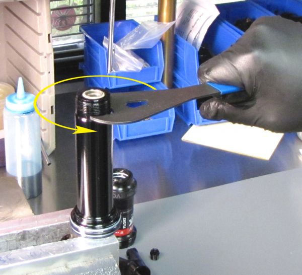
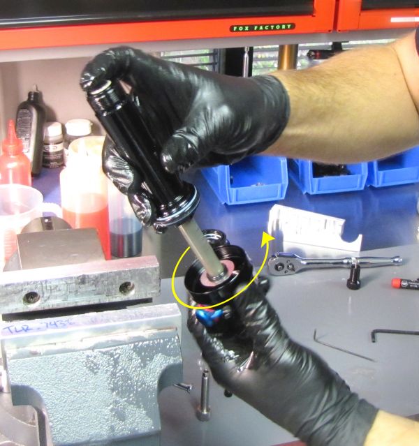
Use a 21mm cone wrench or thinned crow's foot to begin to unthread the body counter-clockwise from the bearing housing. Once loose, remove the shock from the vise and continue unthreading the body from the bearing housing over your waste oil drain.

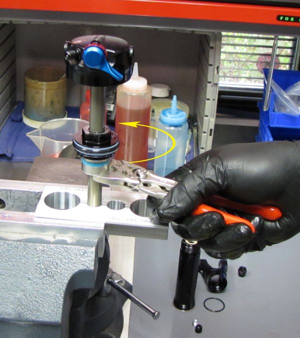
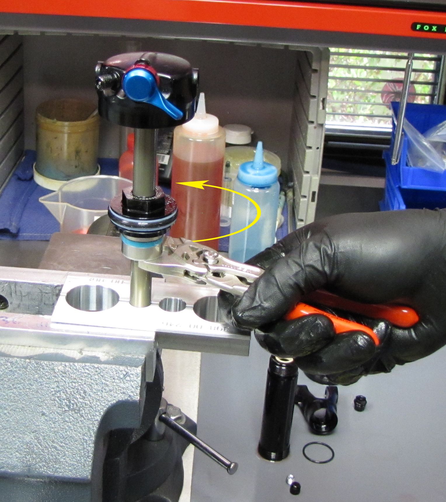
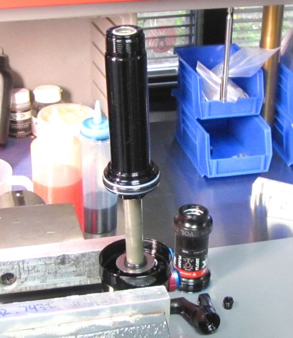
Step 9
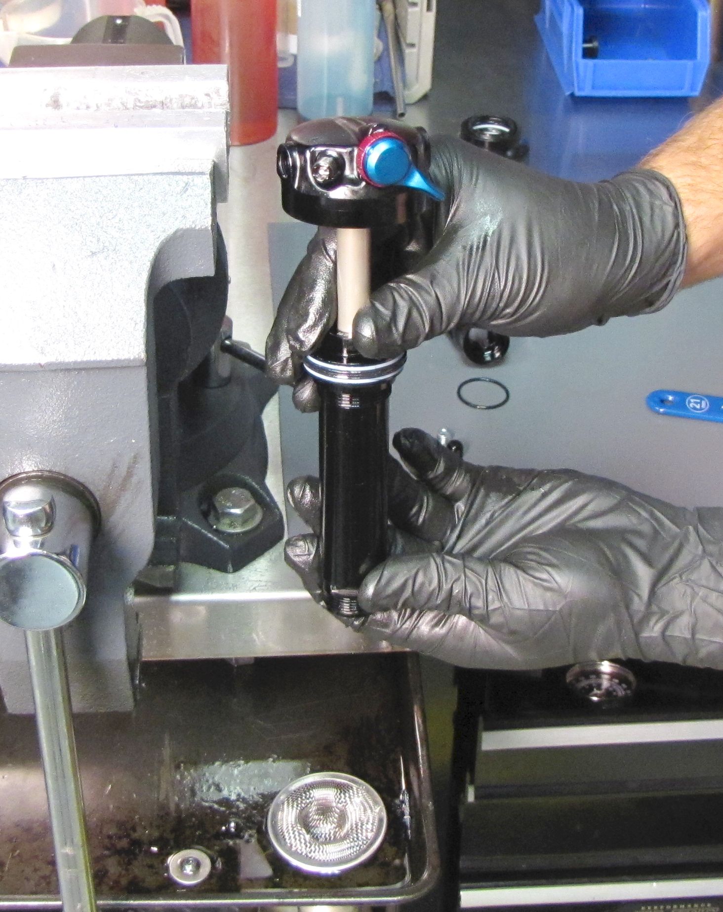
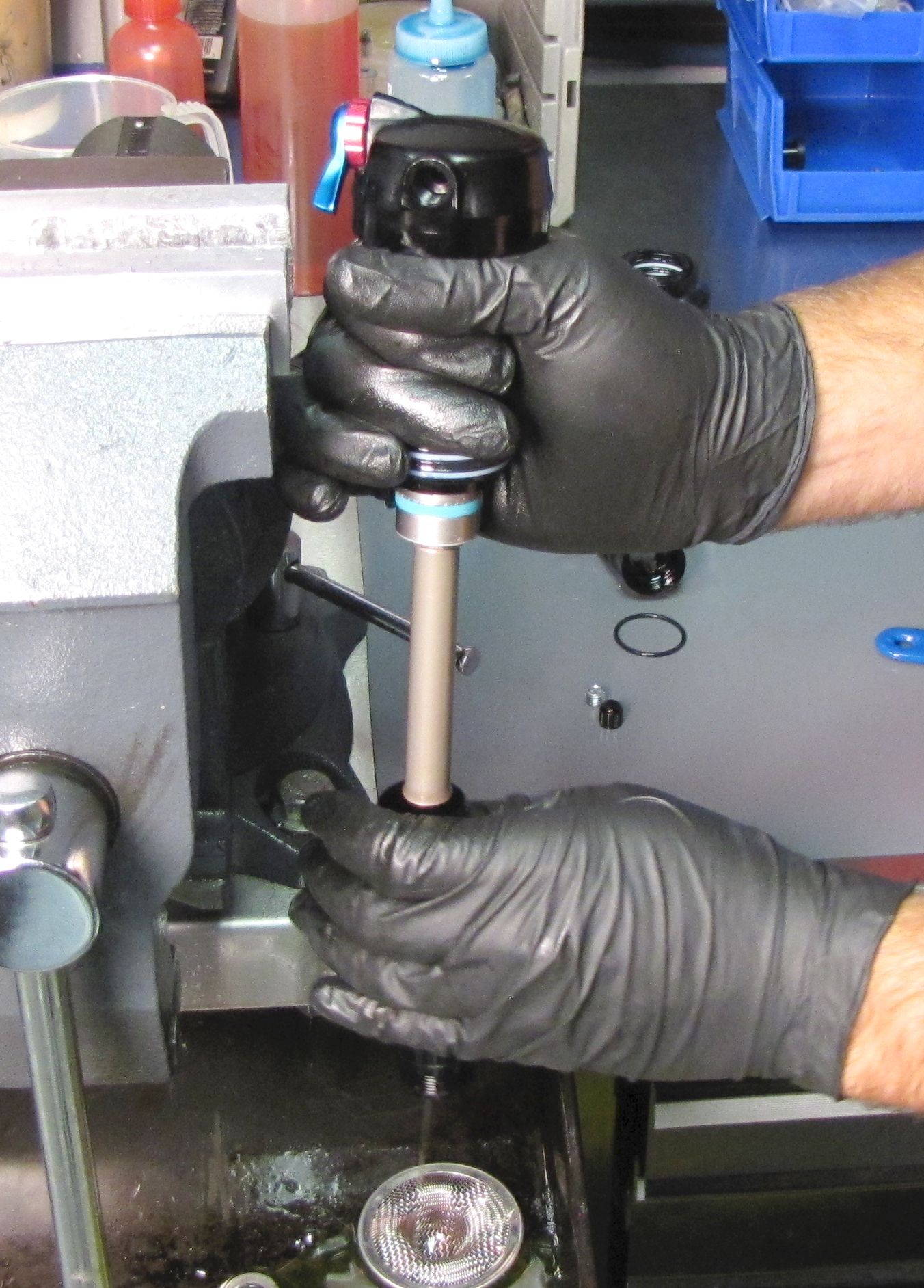
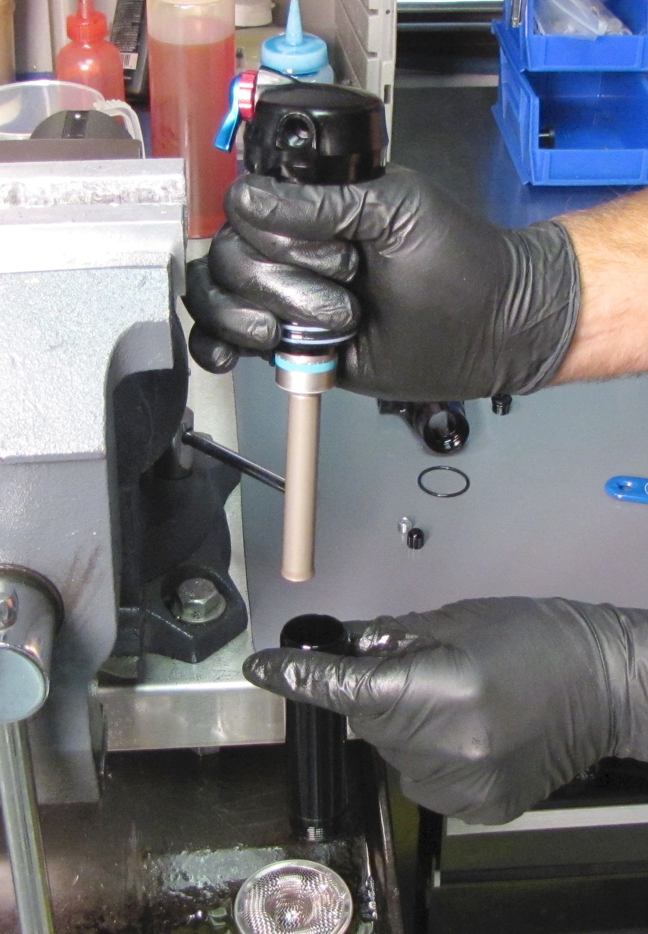
Clamp the slave shaft in your 1/2" shaft clamps with the eyelet at the top. Unthread the rebound check bolt with the damper from the slave shaft by turning the 5/8" (15.88mm) nut beneath the valve housing cap counter-clockwise.
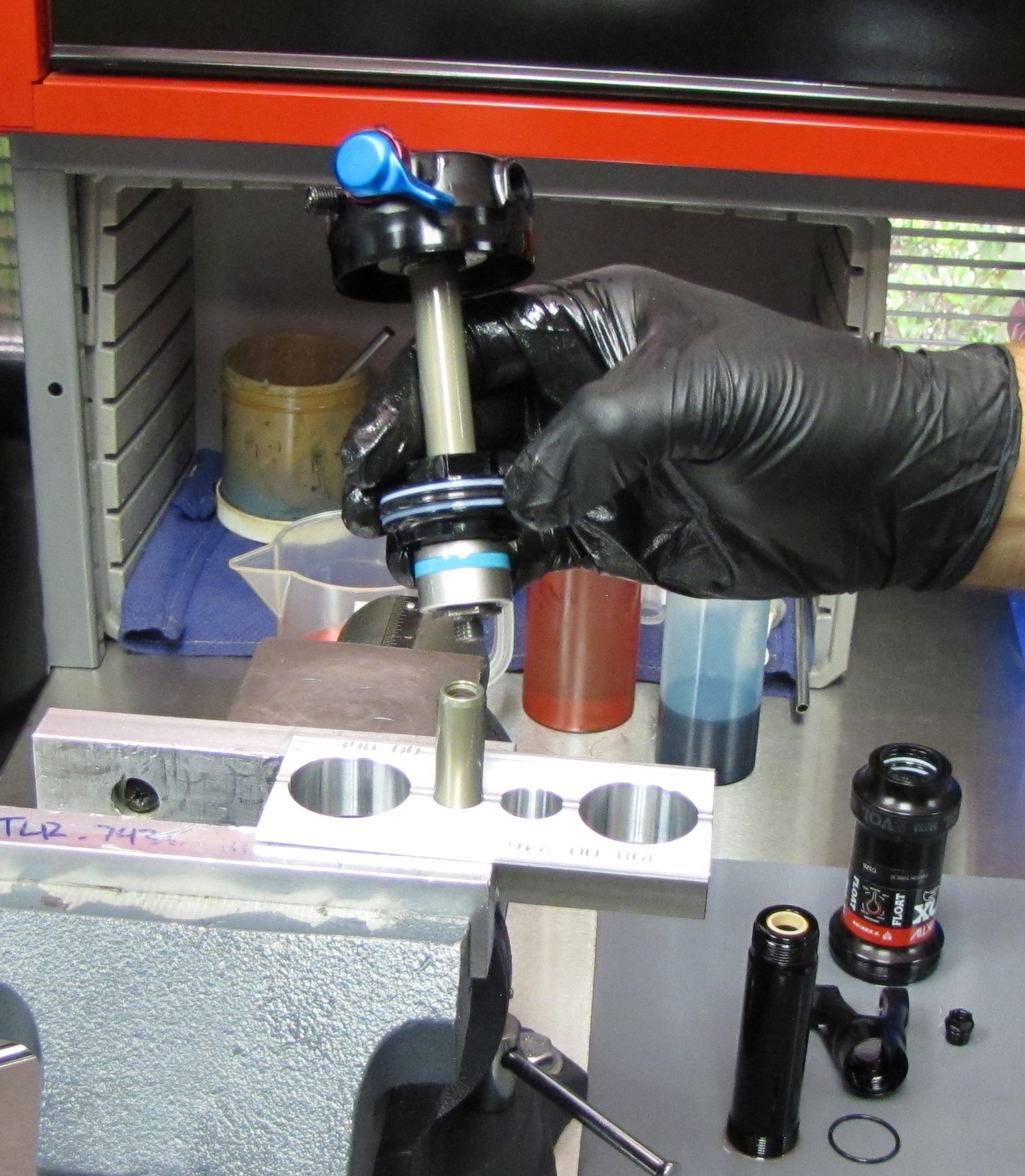
Step 10
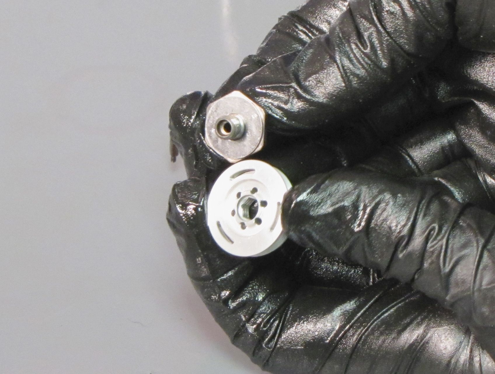
Unthread the IFP jet insert counter-clockwise with a 4mm hex wrench and lift it out to remove. Set the IFP jet insert aside.
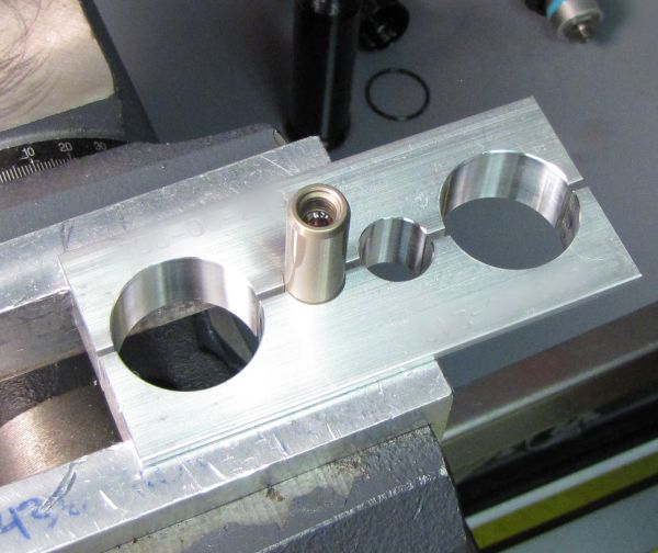
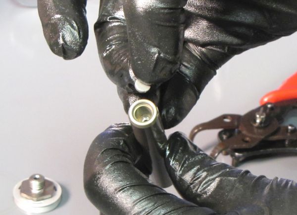
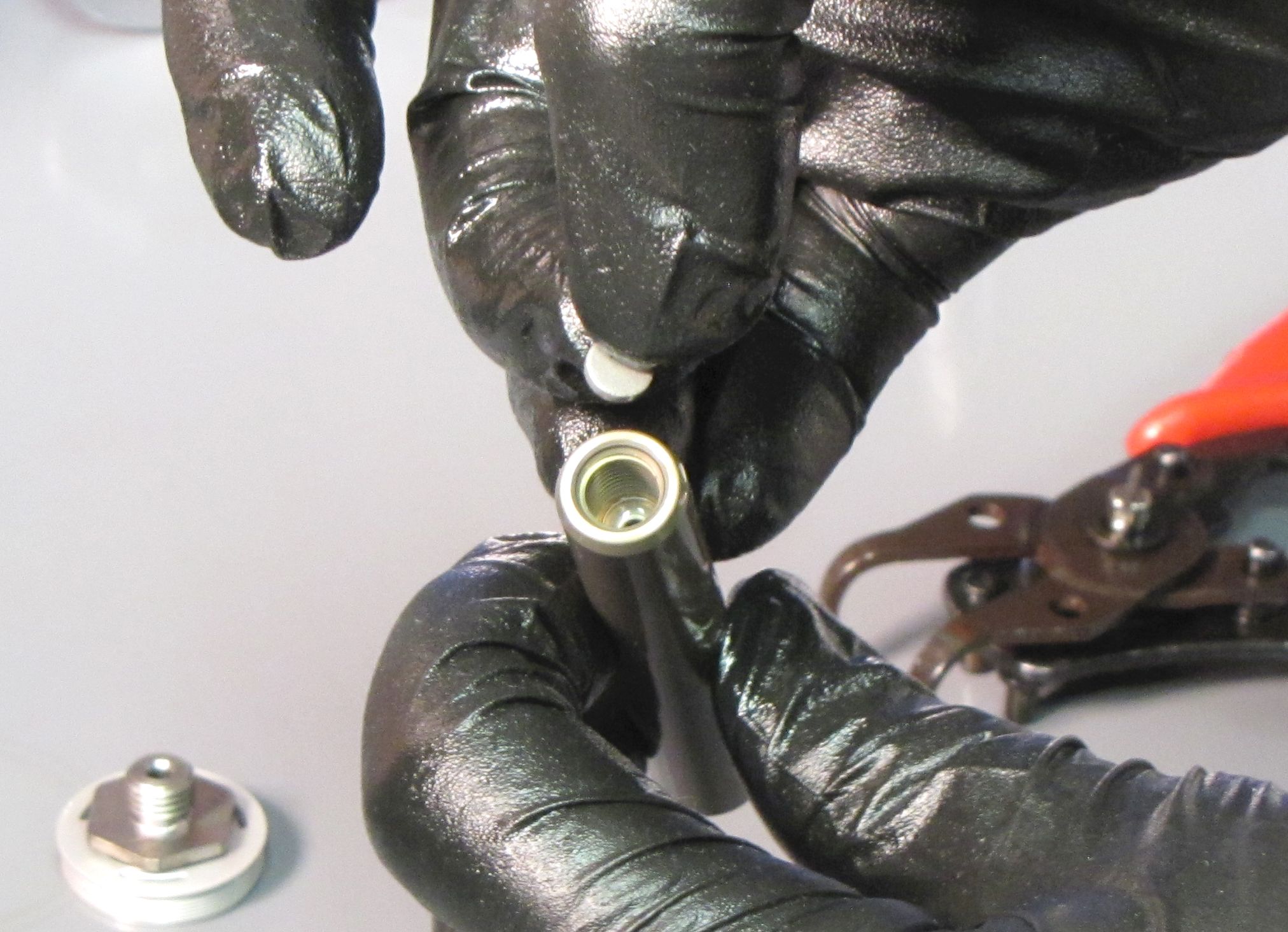
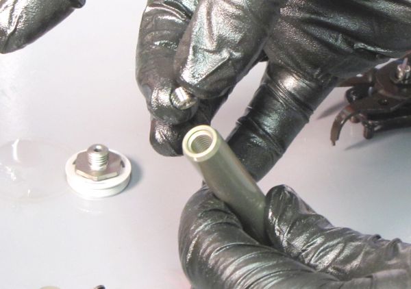
Step 11
Remove the slave shaft from the shaft clamps and invert it over your work bench. Tap the slave shaft against the bench to allow the filter disc to drop out.

Step 12
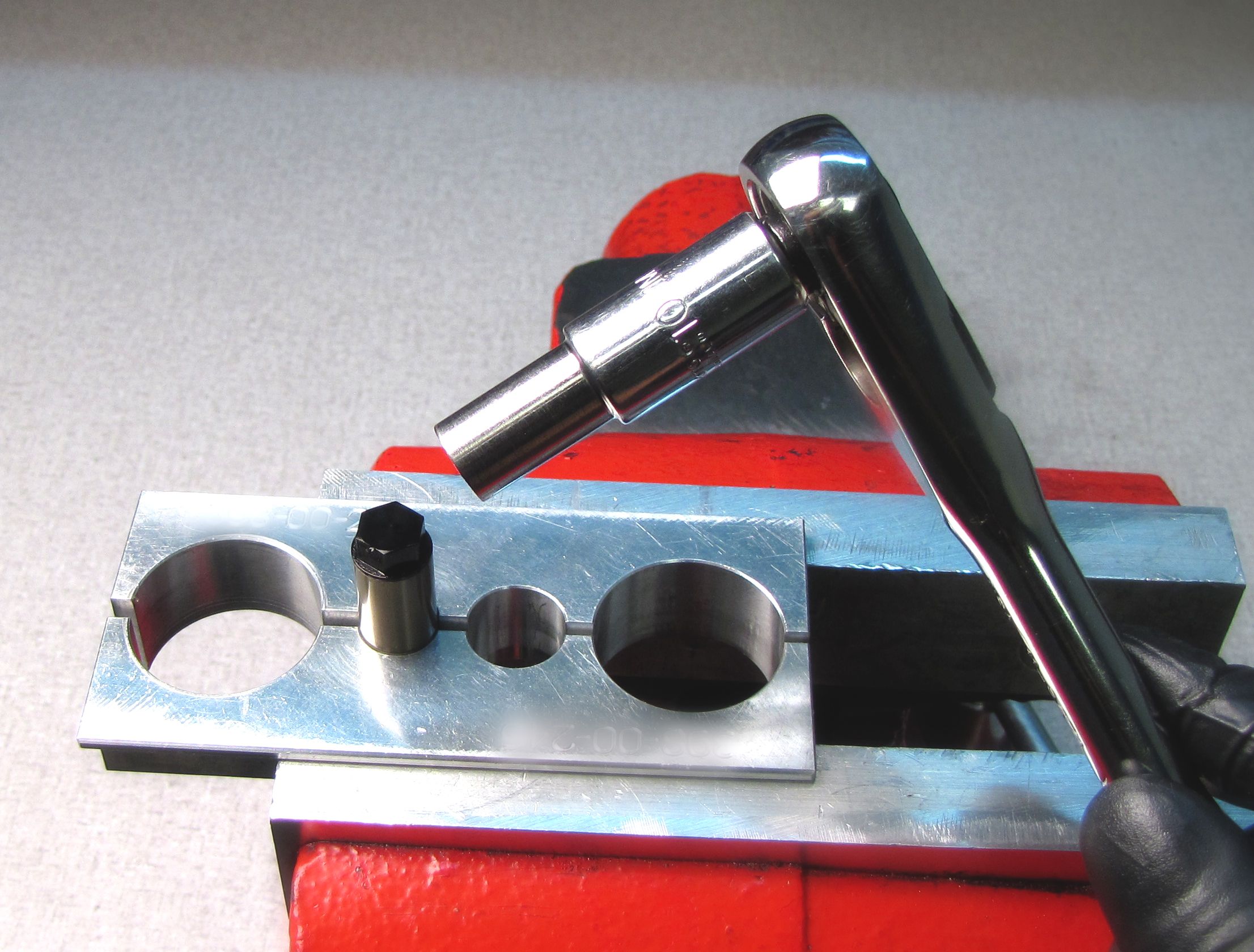
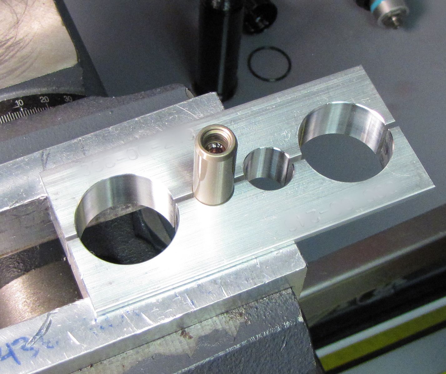
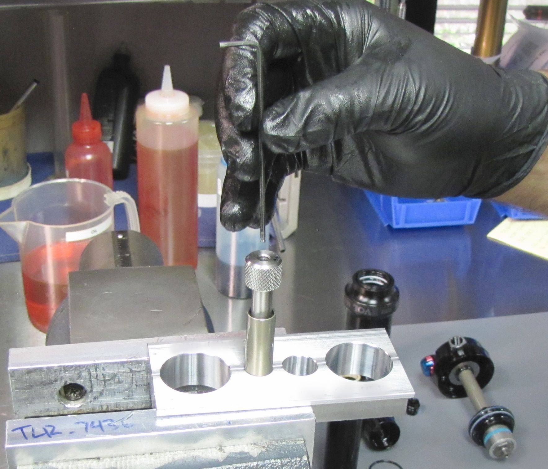
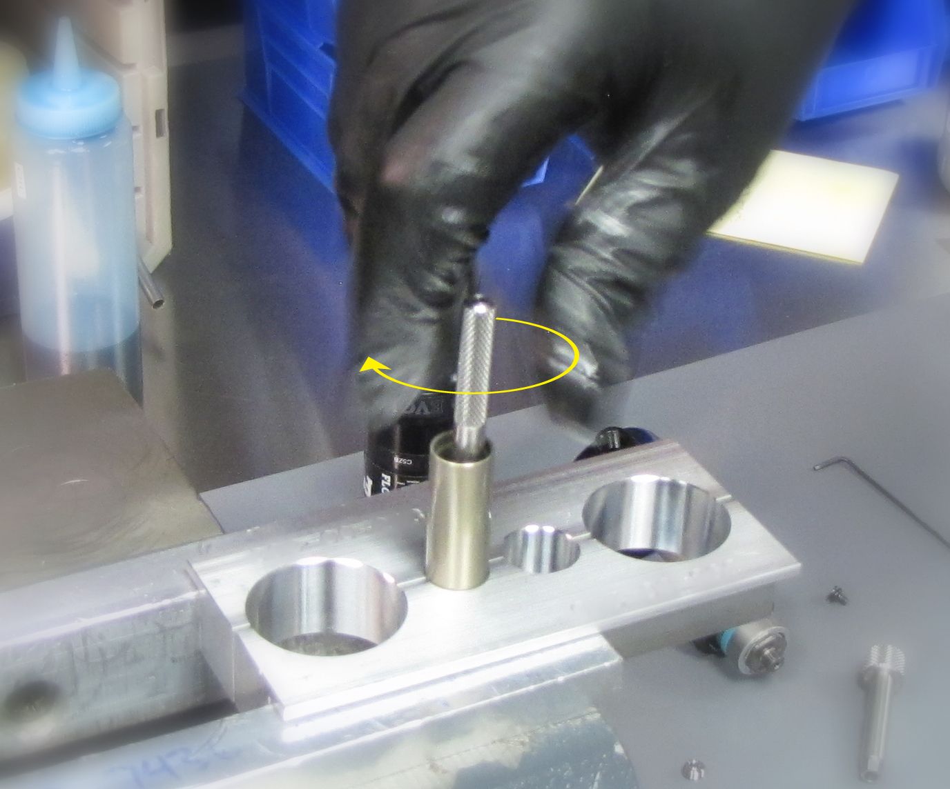
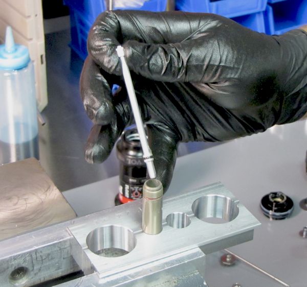
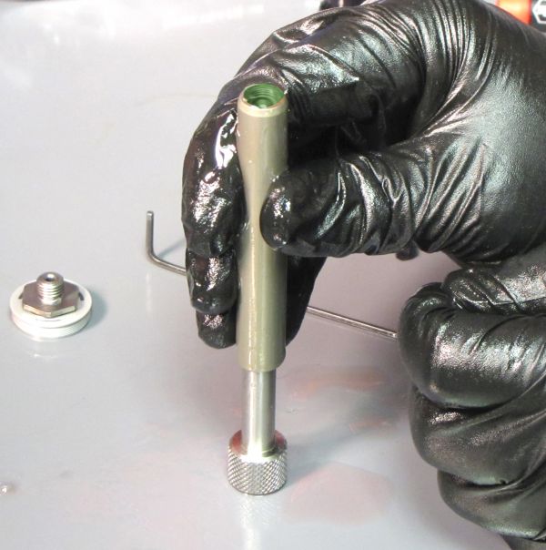
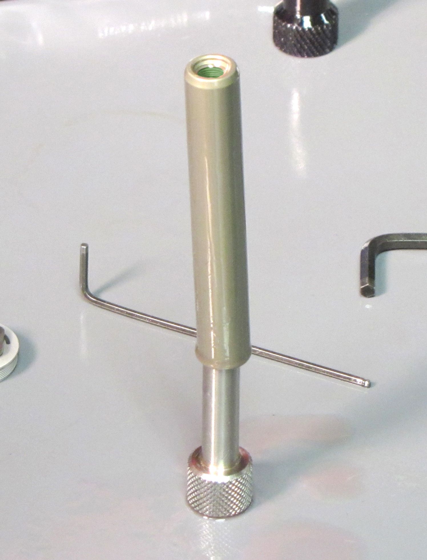
Invert the slave shaft and clamp it in your shaft clamps so the end with the OD bevel faces down. Insert the IFP bleed screw torque tool (PN: 398-00-748) into the shaft engaging its male hex within the female hex of the IFP.

Step 13
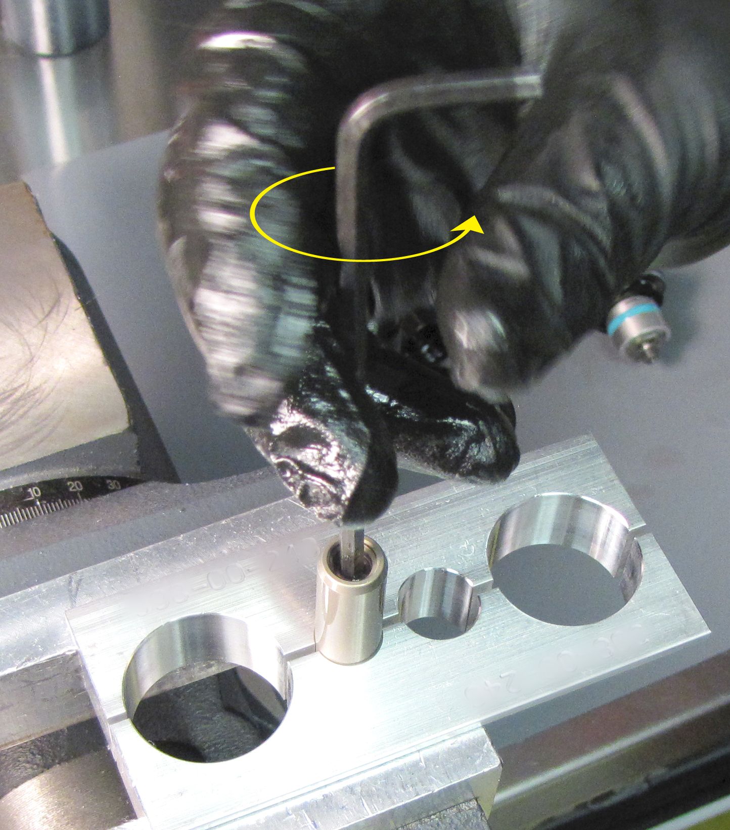
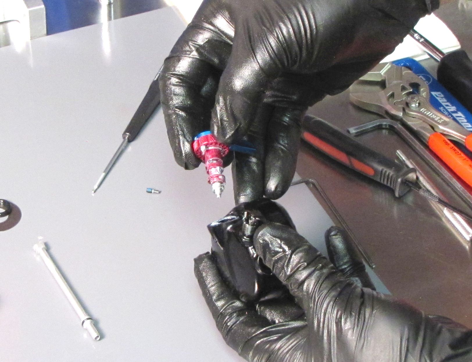
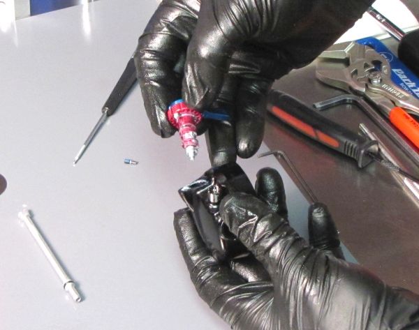
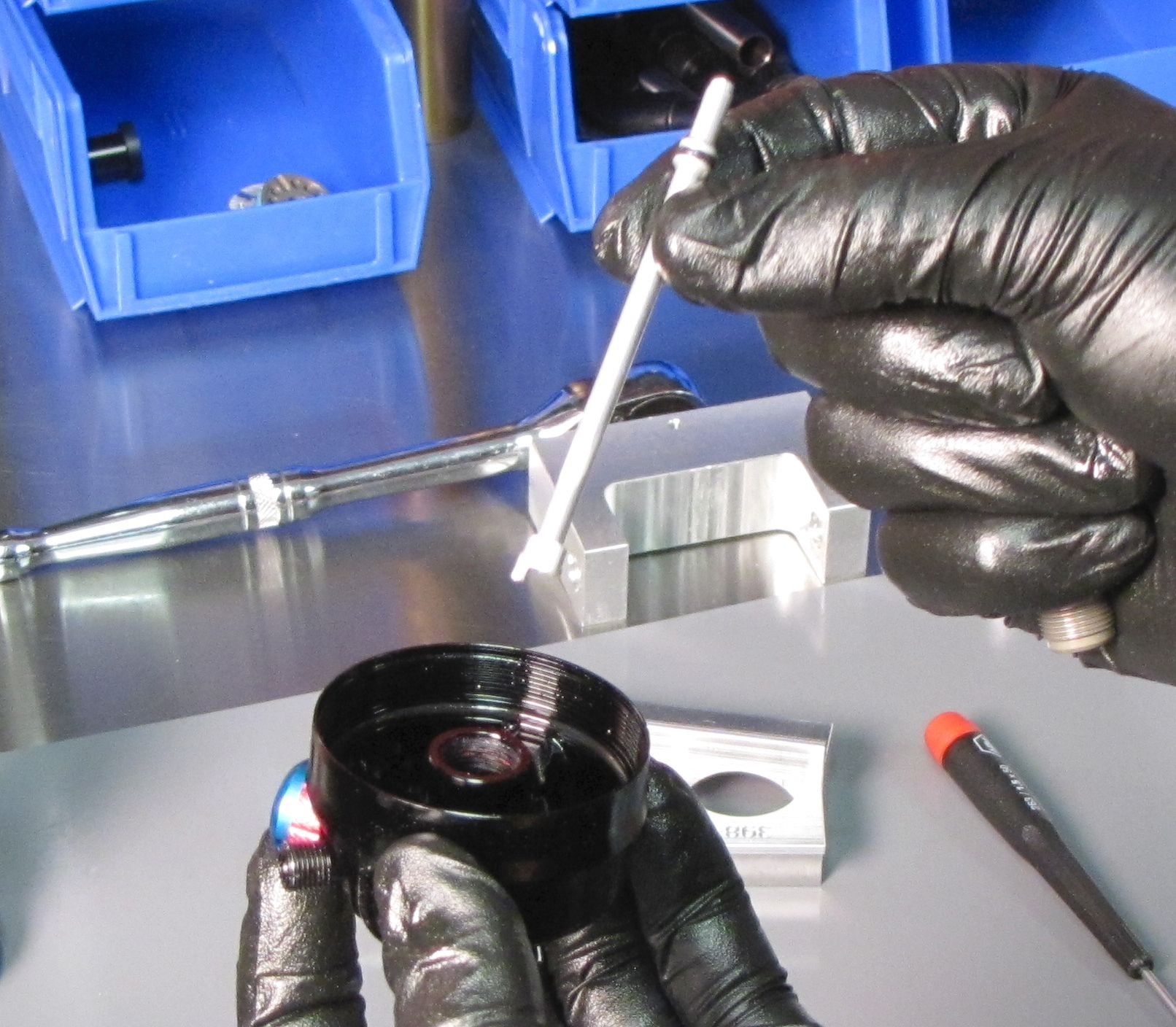
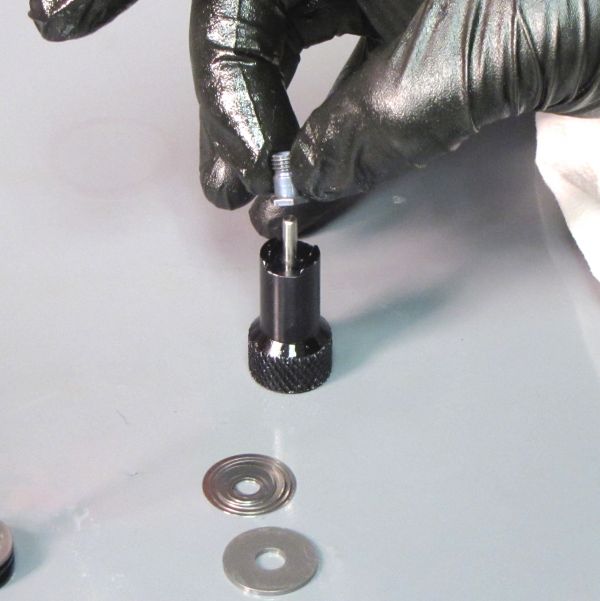
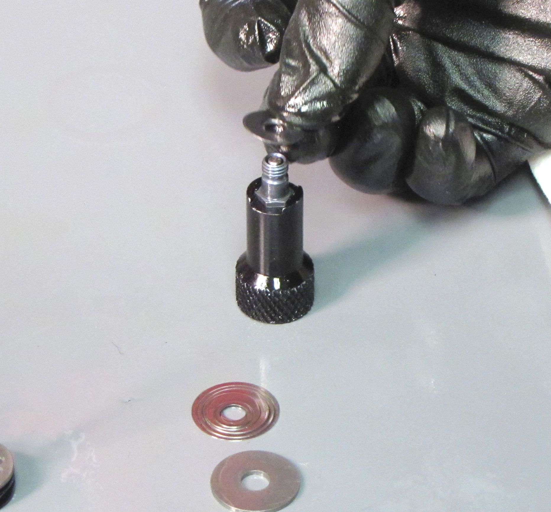
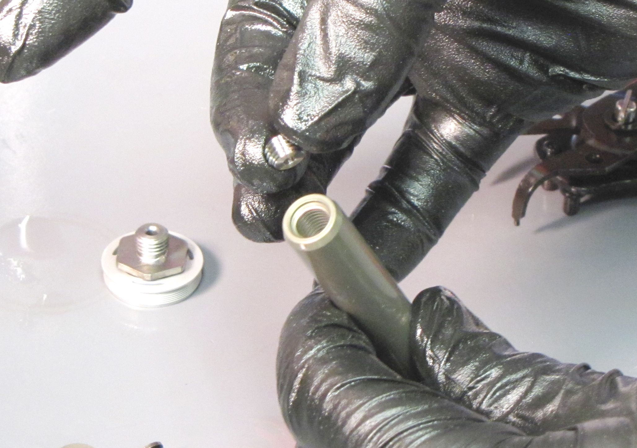
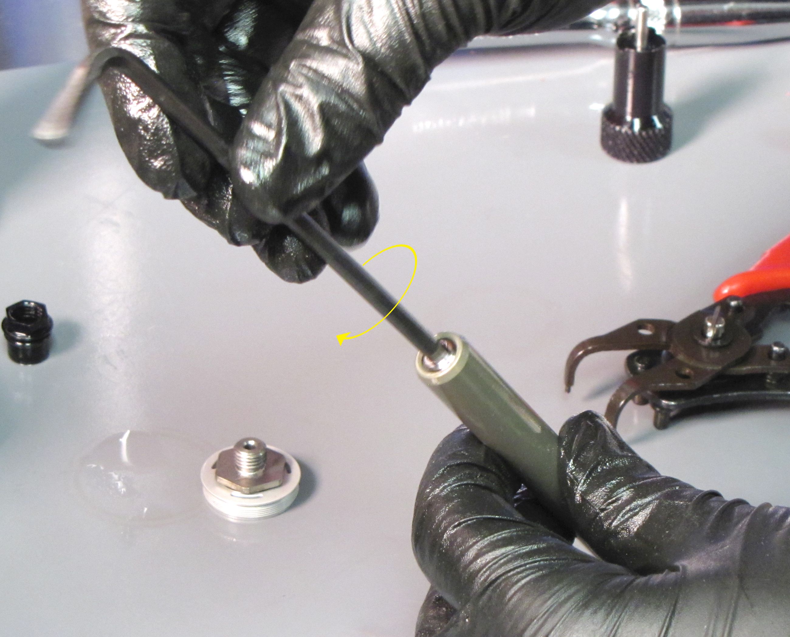
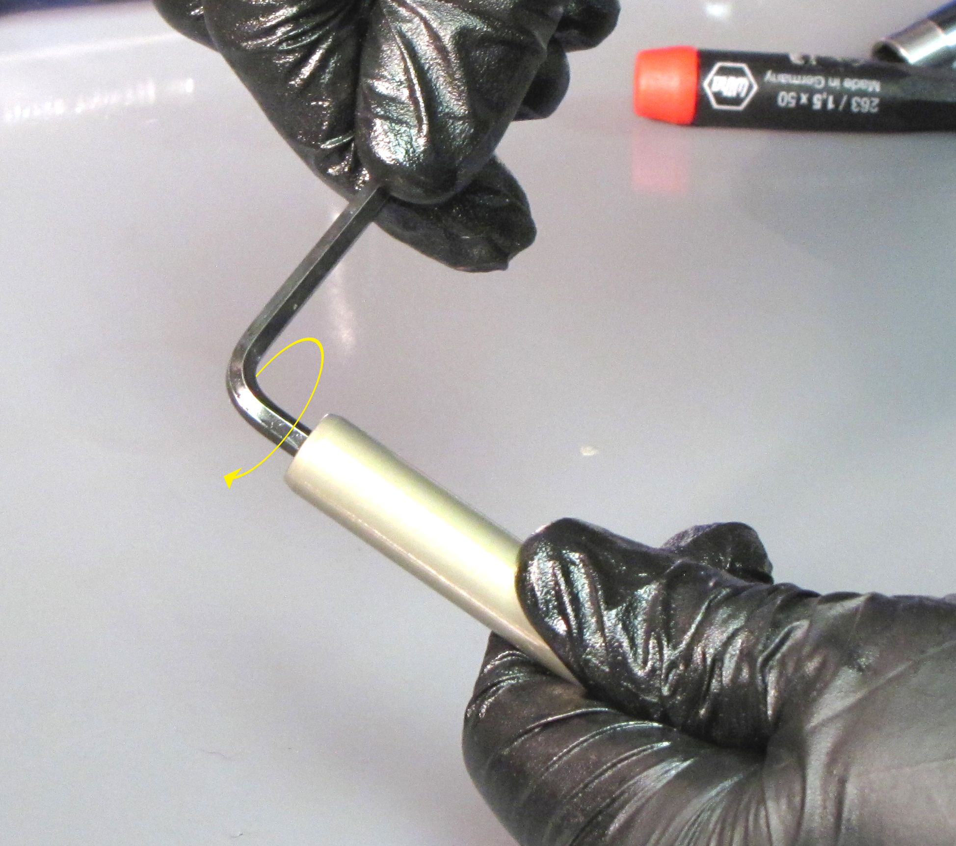
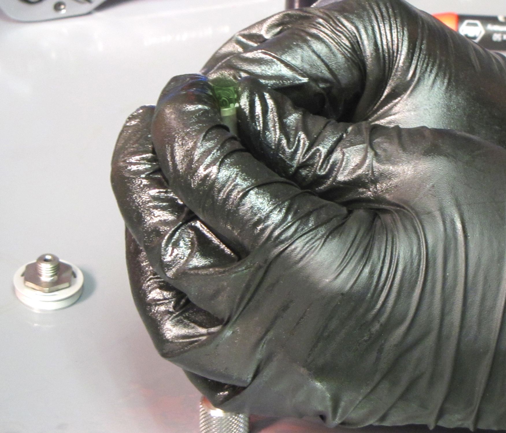
Insert a 2mm hex wrench through the IFP bleed screw torque tool and into the IFP bleed screw. Hold the IFP bleed screw torque tool stationary while you unthread the IFP bleed screw counter-clockwise. Remove the IFP bleed screw torque tool and the bleed screw. Replace the o-ring on the bleed screw with a new greased one from the kit.
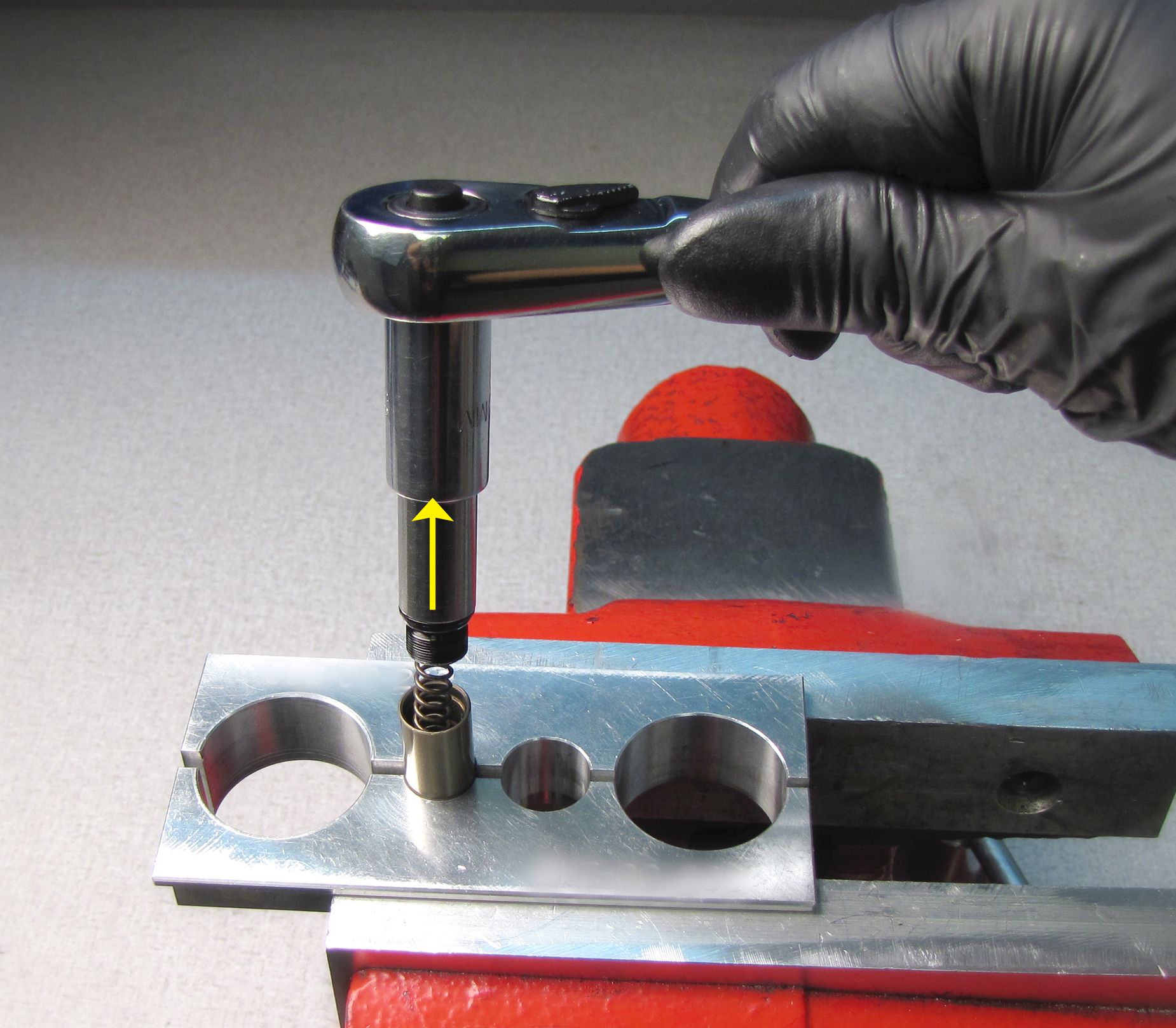
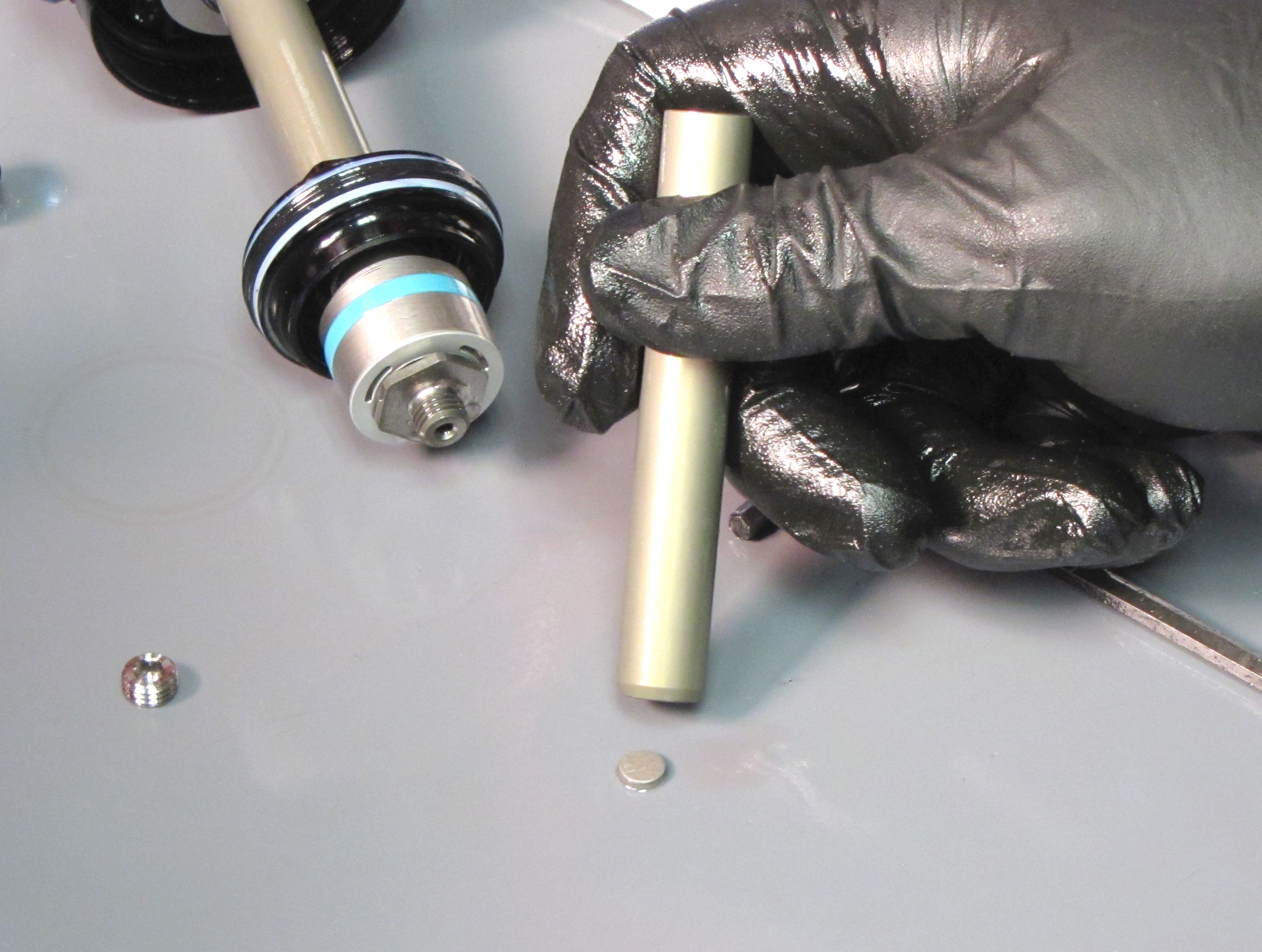
Step 14
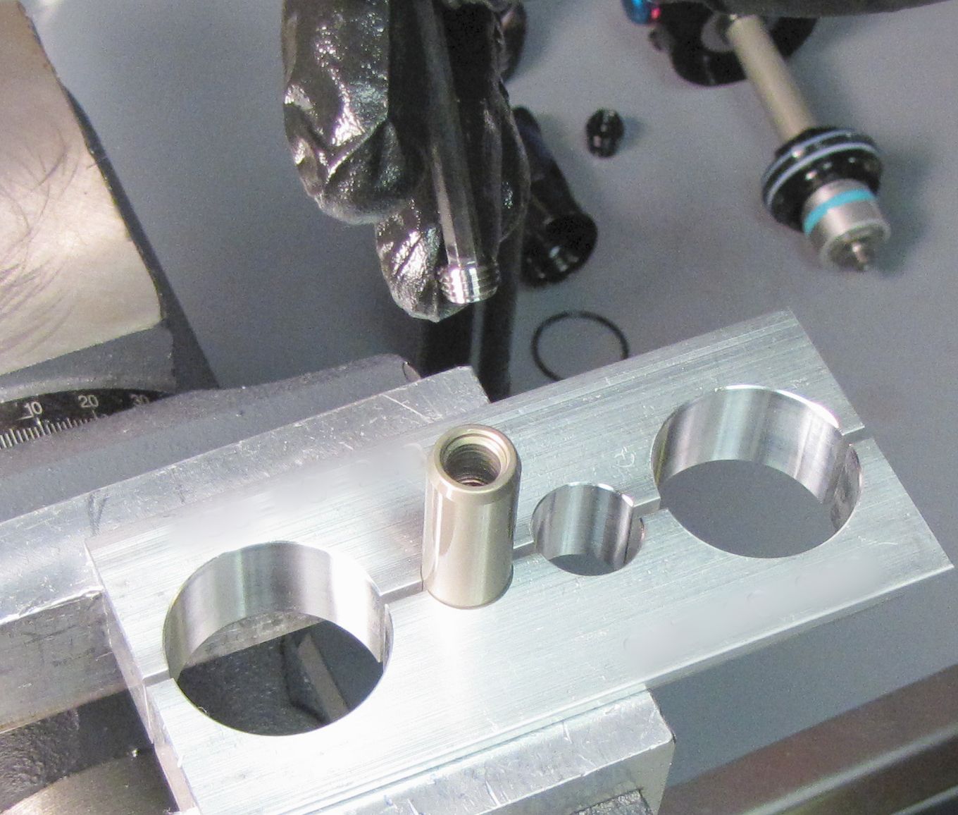
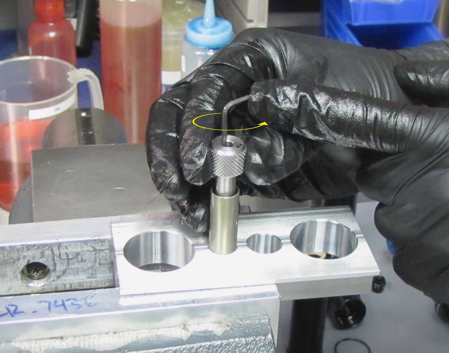
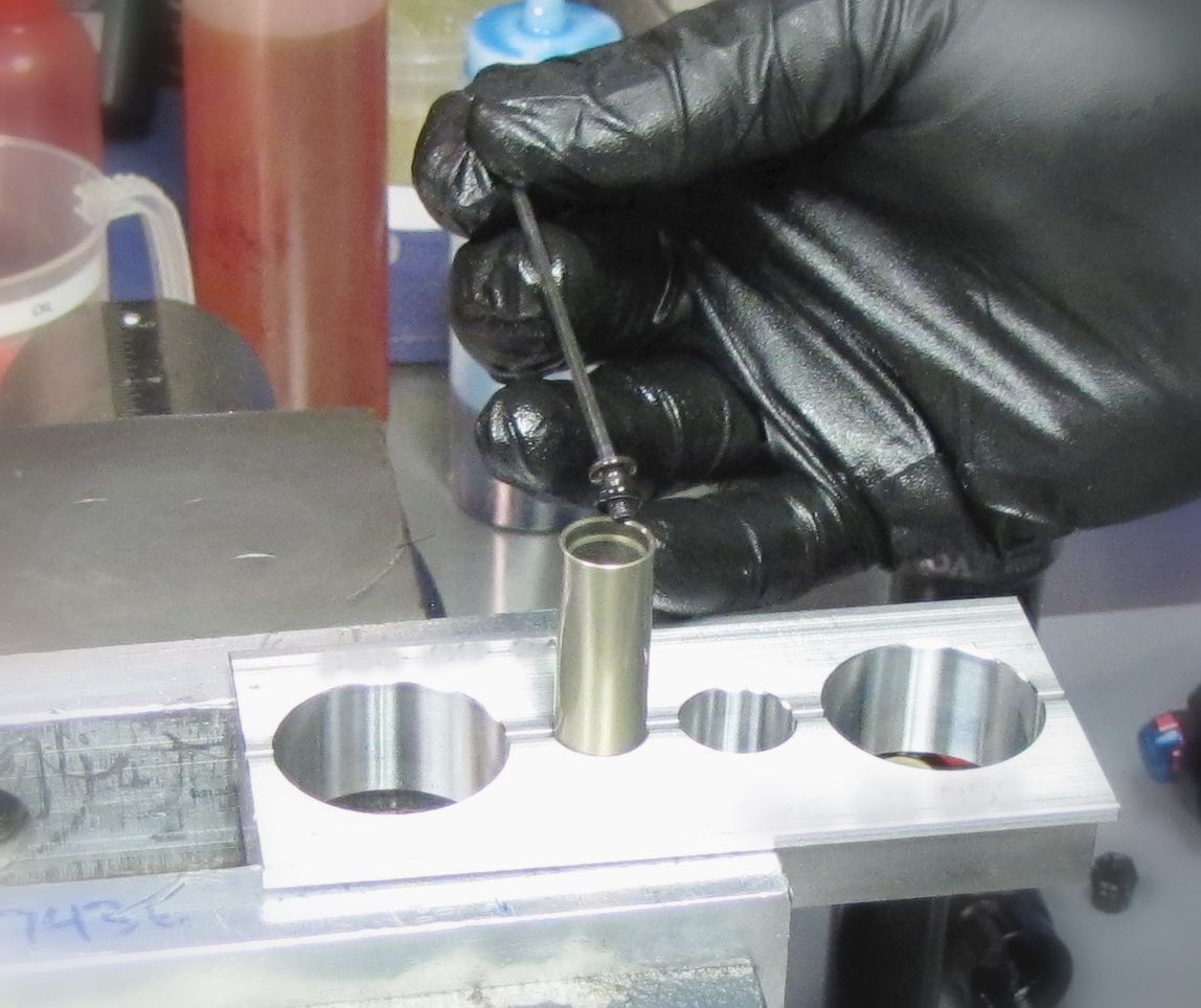
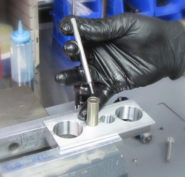
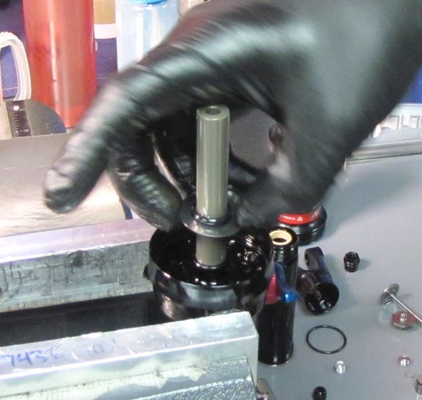
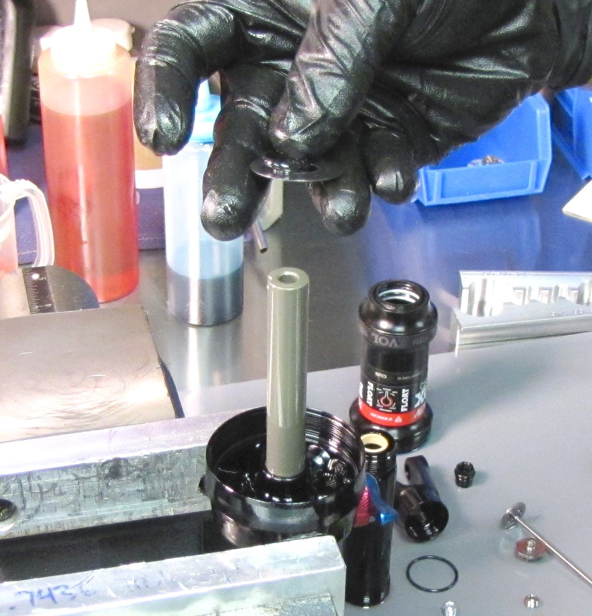
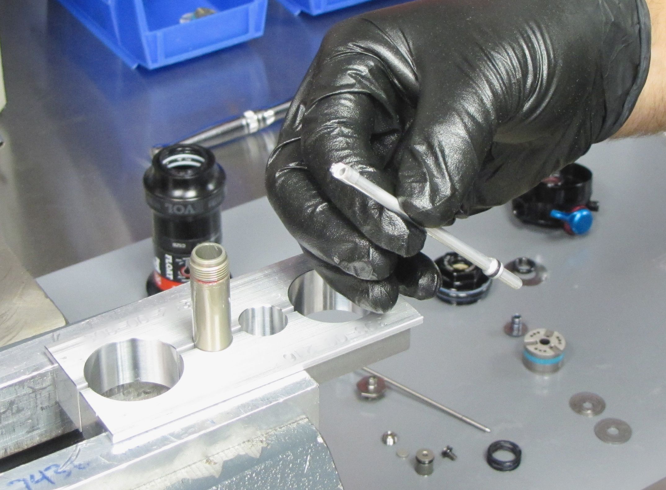
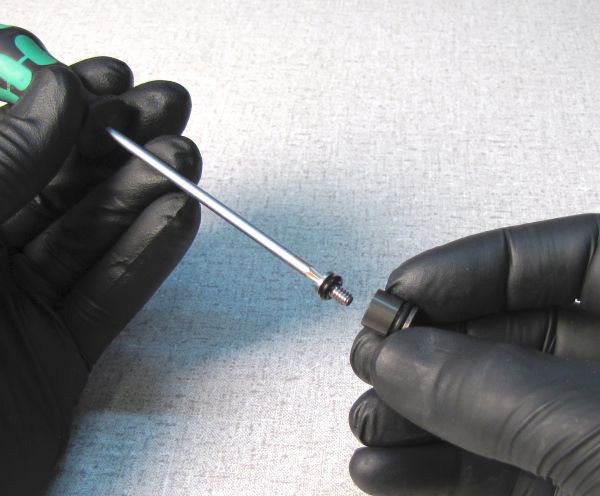
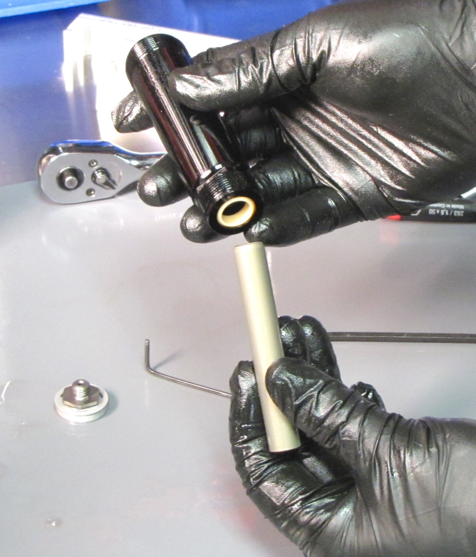
Insert the IFP removal tool (PN: 398-00-749) into the shaft, then thread it clockwise into the bleed hole of the IFP. Pull up to remove the IFP. Replace the o-ring on the IFP with a new greased one from the kit.


Step 15
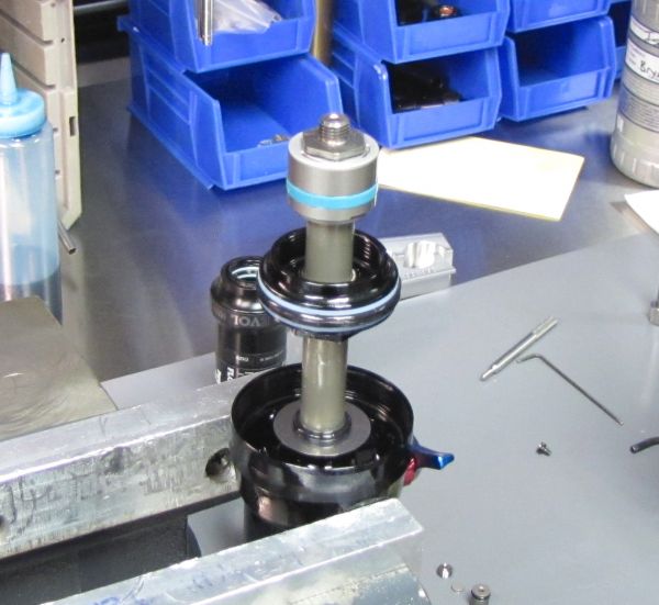
Gently clamp the eyelet in your soft-jawed vise so the mounting bolt areas are the only portions of the eyelet contacting the vise.

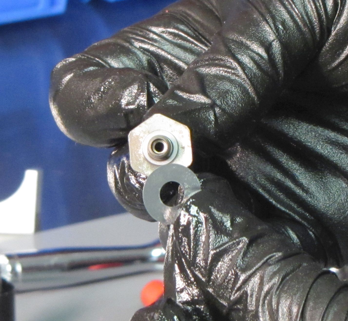
Step 16
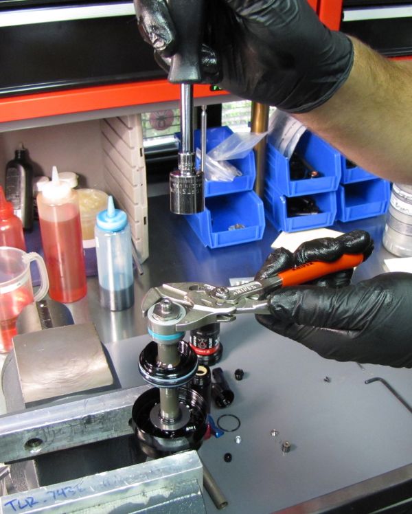
Lightly squeeze the outside of the RG valve housing with smooth jawed pliers to prevent the valve housing cap from unthreading. Remove the rebound check bolt by unthreading it counter-clockwise with a 5/8" socket. Set aside the valves found underneath the rebound check bolt.


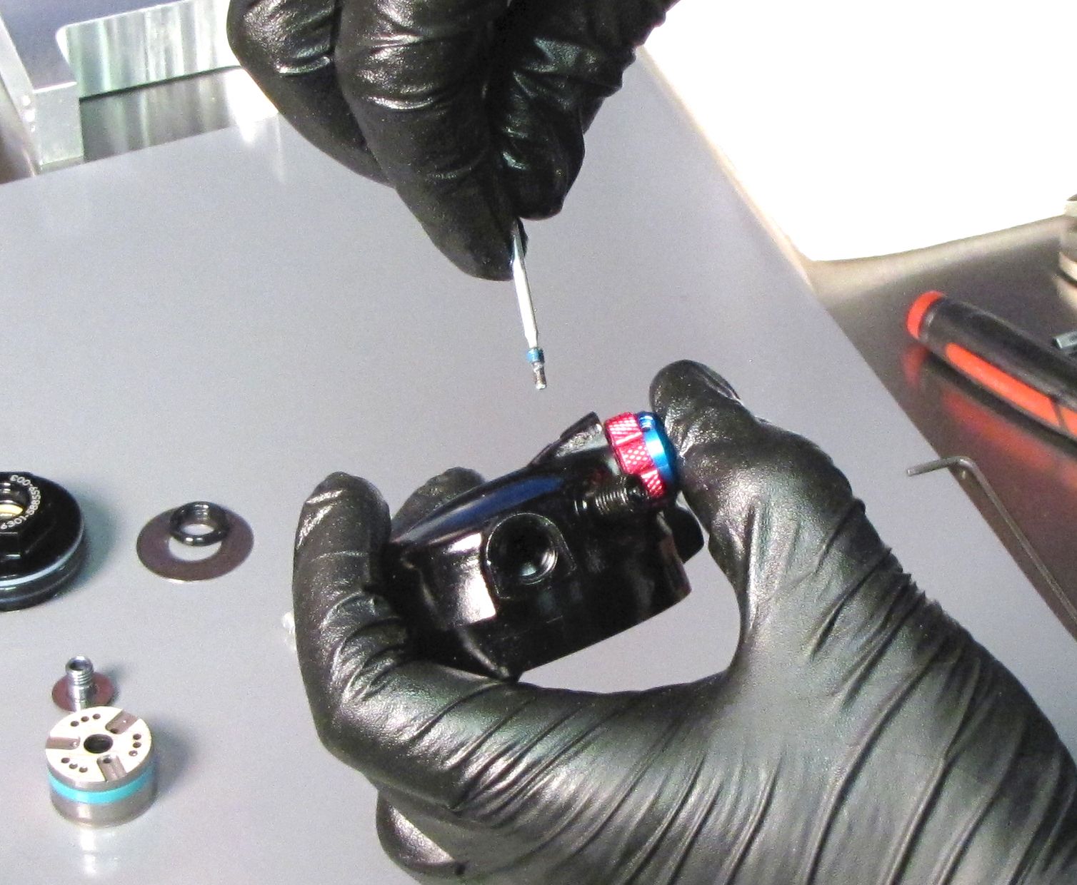
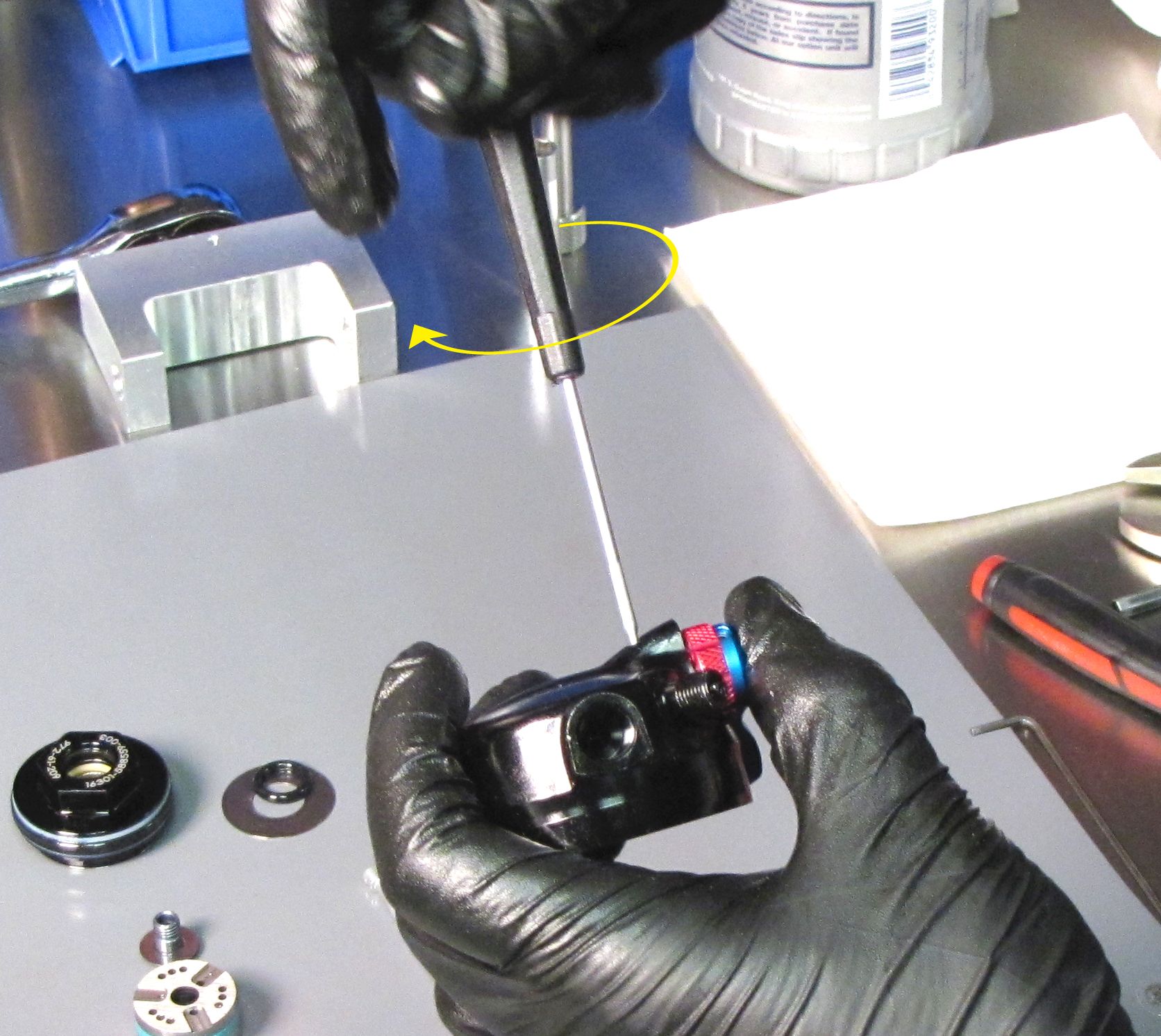
Step 17
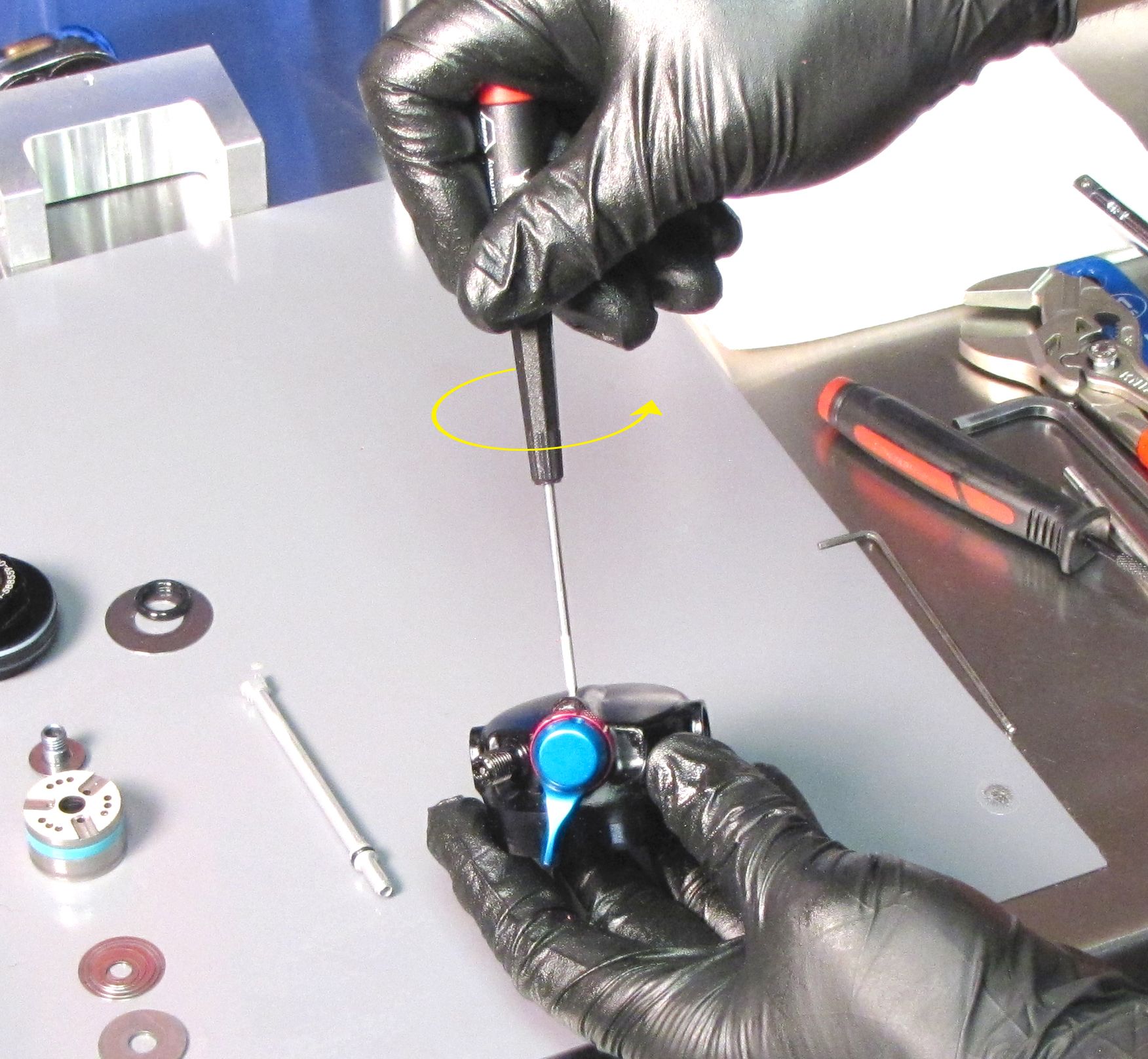
Insert a 5mm hex wrench into the valve housing cap. Turn the 5mm counter-clockwise to unthread then lift to remove the valve housing cap.
Step 18
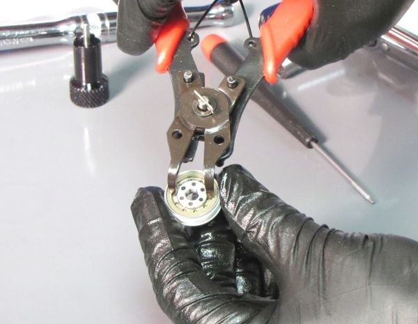
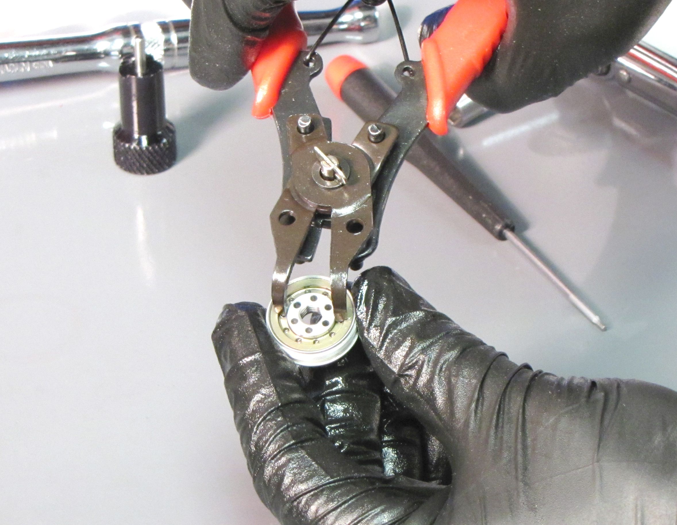
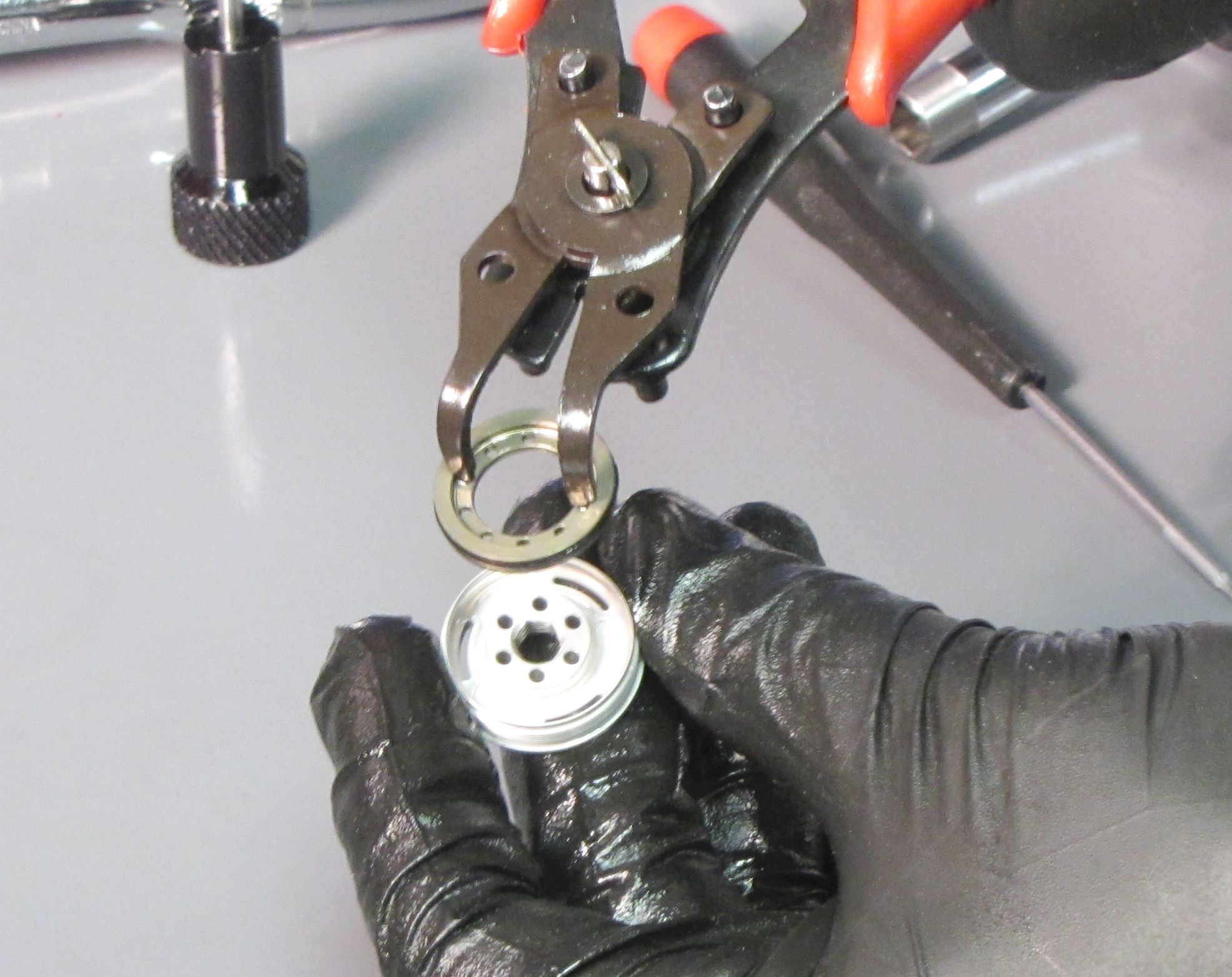
Use fine snap-ring pliers to hold the inner Blowoff Piston Valve as you separate it from the outer Valving Housing Cap. Separate the ring shim from the Blowoff Piston Valve if necessary. Replace the o-ring on the Blowoff Piston Valve with a greased one from the rebuild kit.
Step 19
Install the ring shim into the Valve Housing Cap. Carefully install the Blowoff Piston Valve into the Valve Housing Cap without pinching the new o-ring. Press the parts together to seat them fully.
Step 20
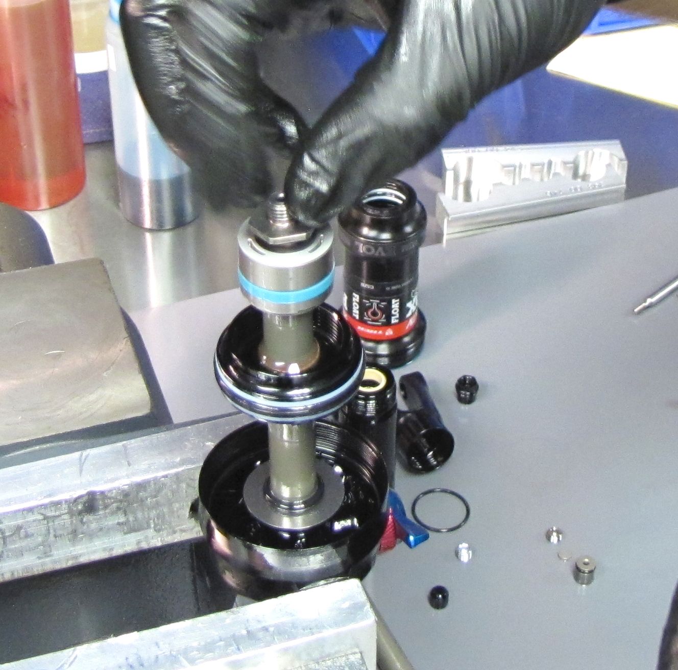
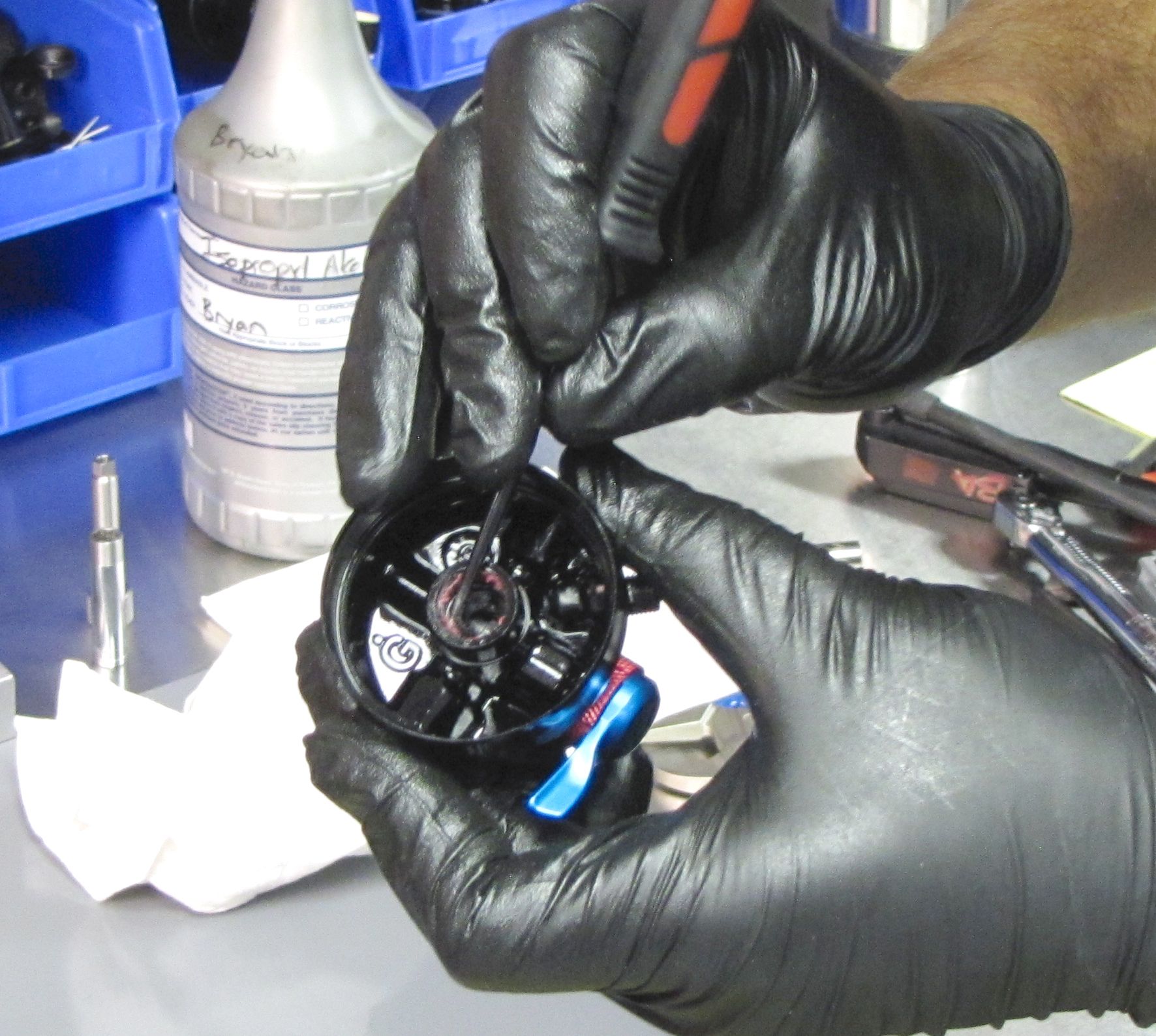
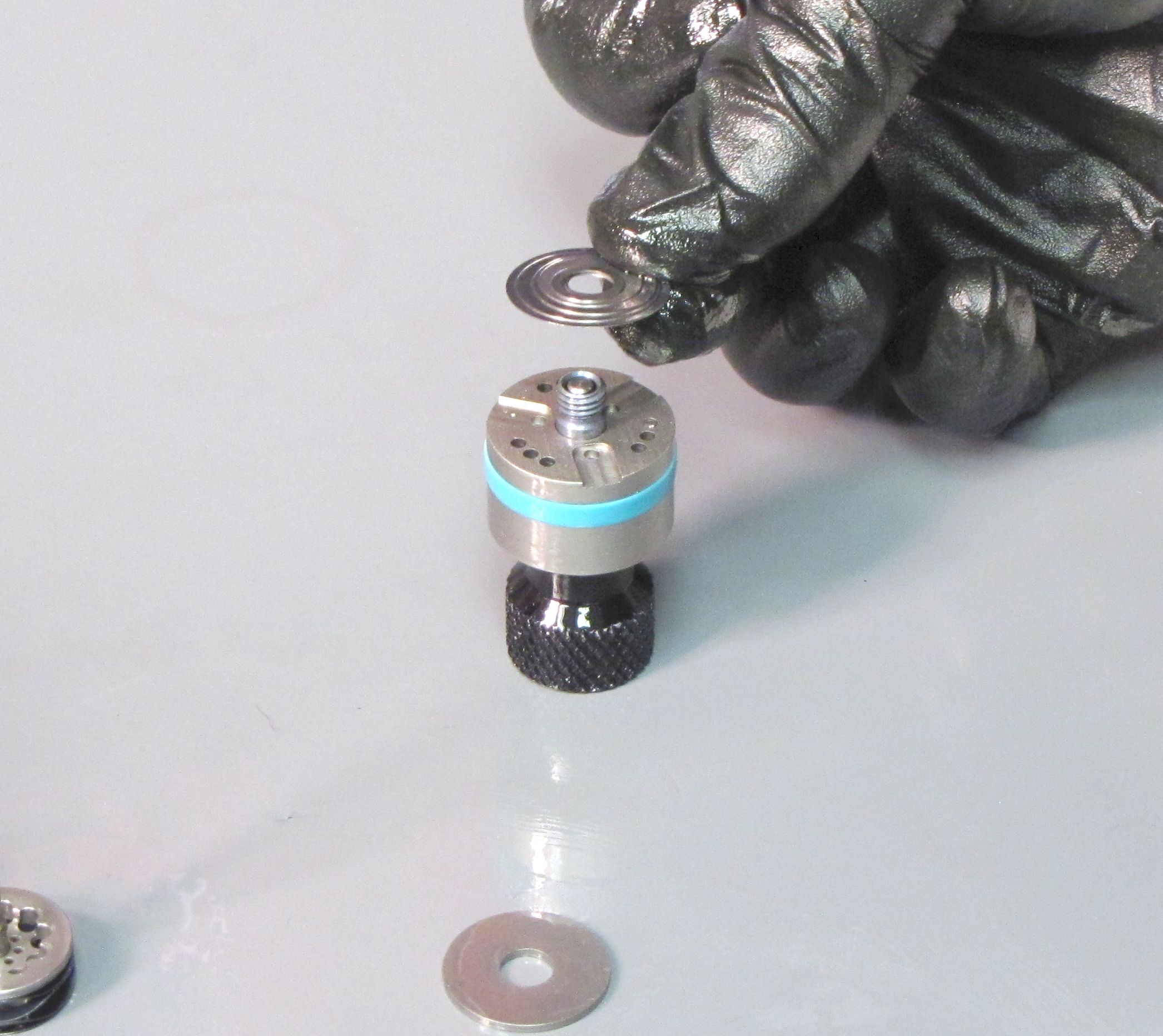
Remove the wave spring from within the RG valve housing. Grab the screw in the center of the open RG valve housing and pull straight up to remove the adjuster rod and spring perch.

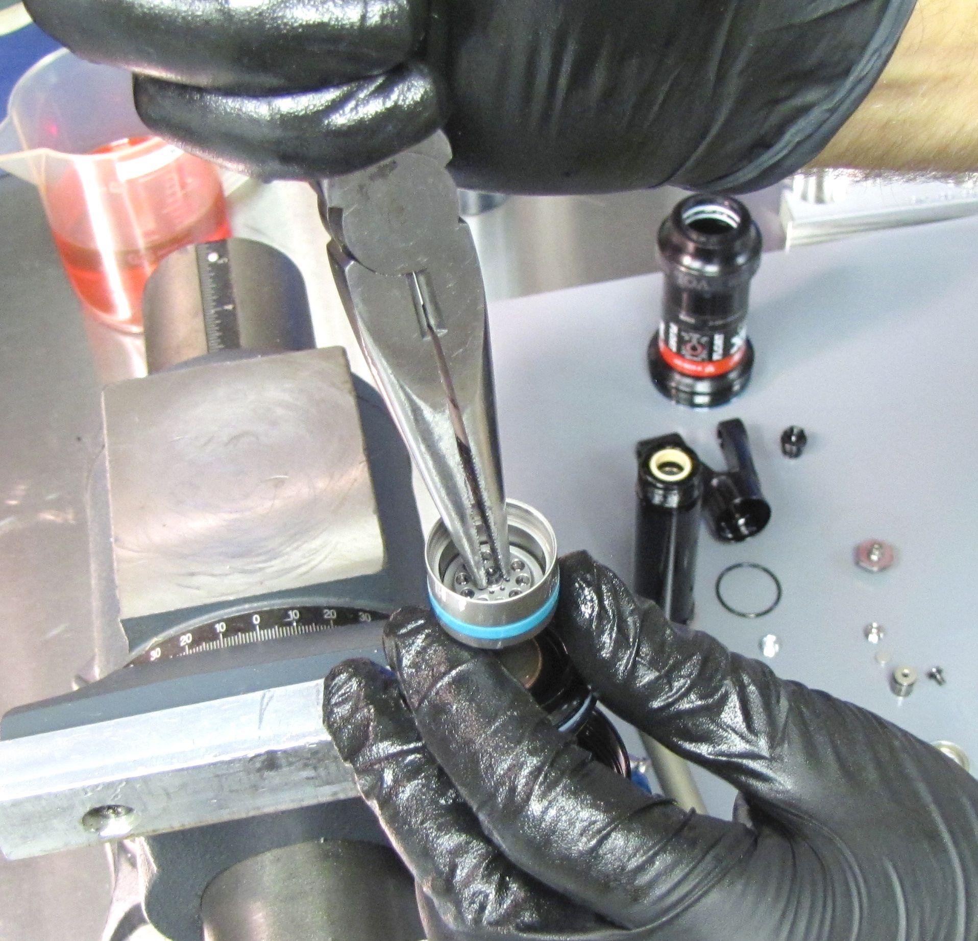
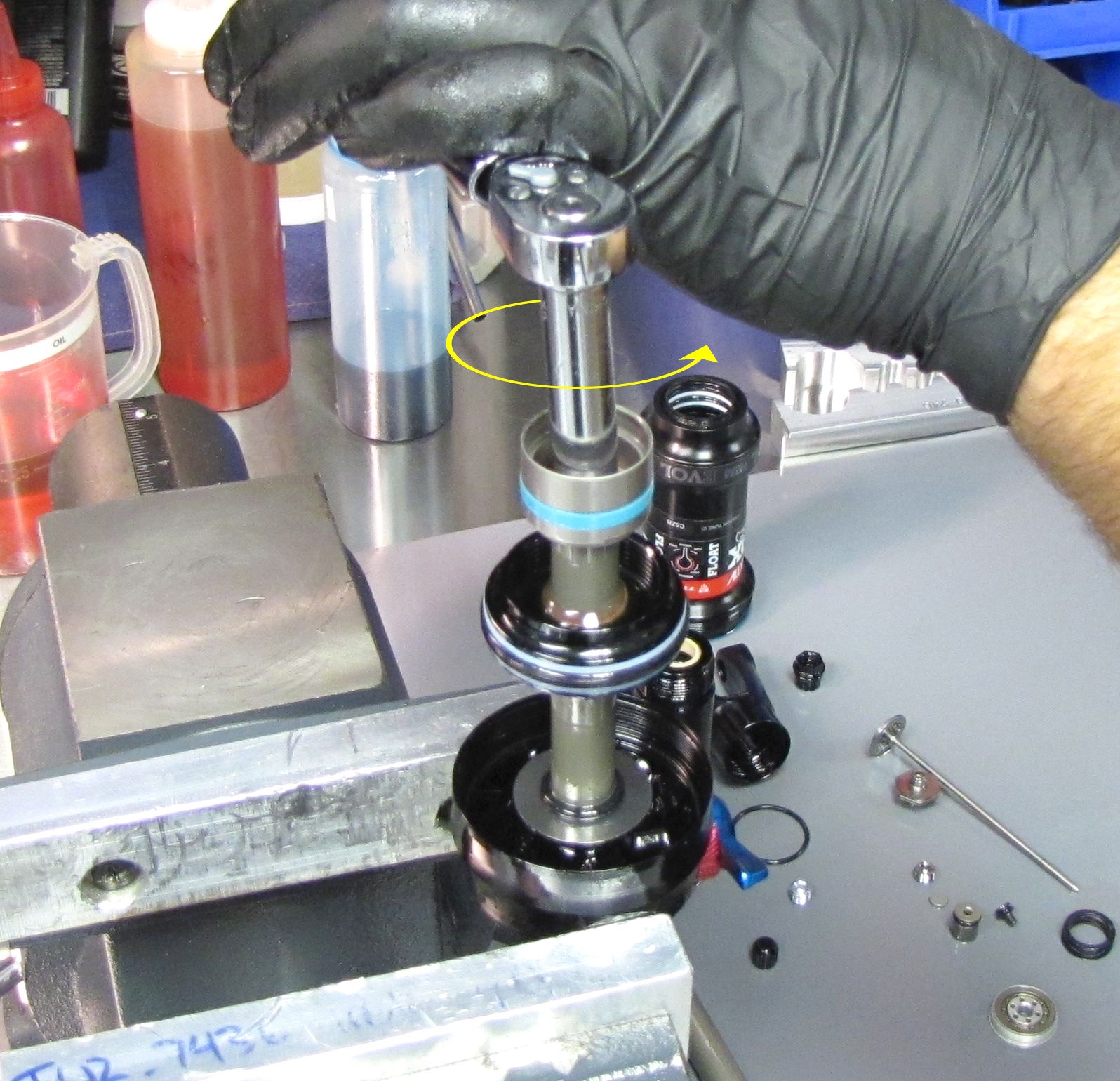
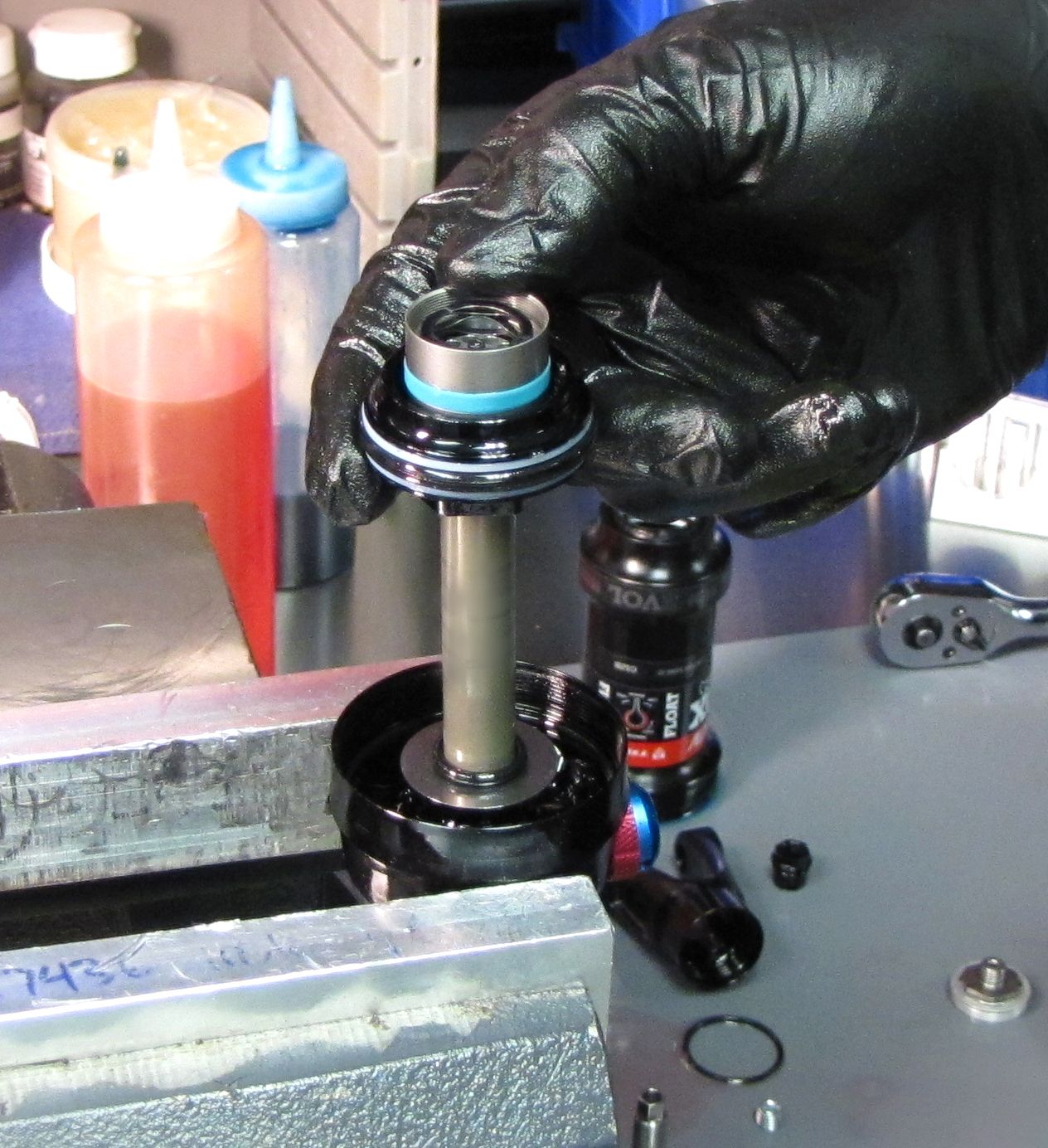
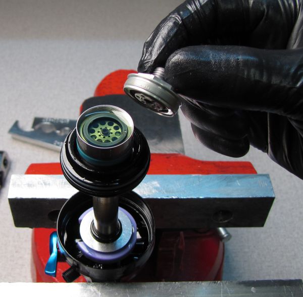
Step 21
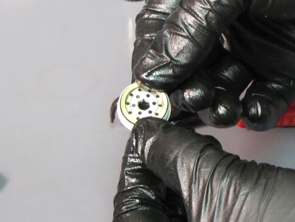
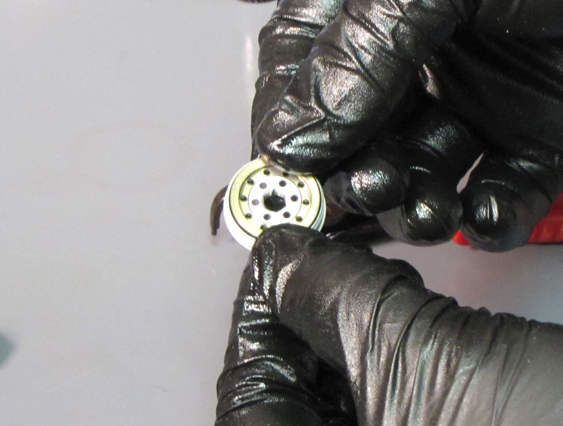
Unthread the piston bolt counter-clockwise with an 8mm socket. Remove the piston bolt, valve housing, and any valves, keeping them in order. Replace the glide ring and o-ring on the valve housing with new ones from the kit.

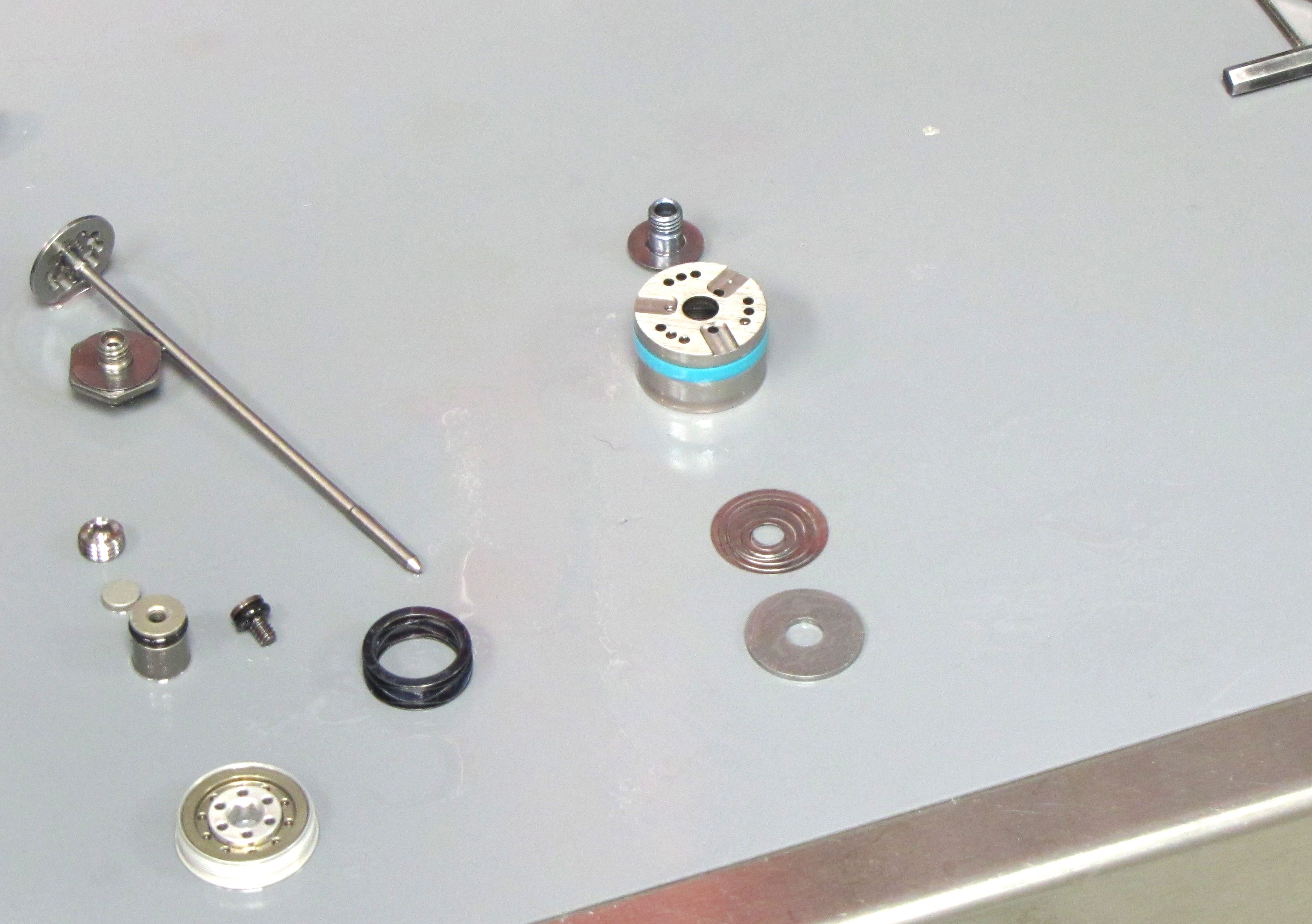
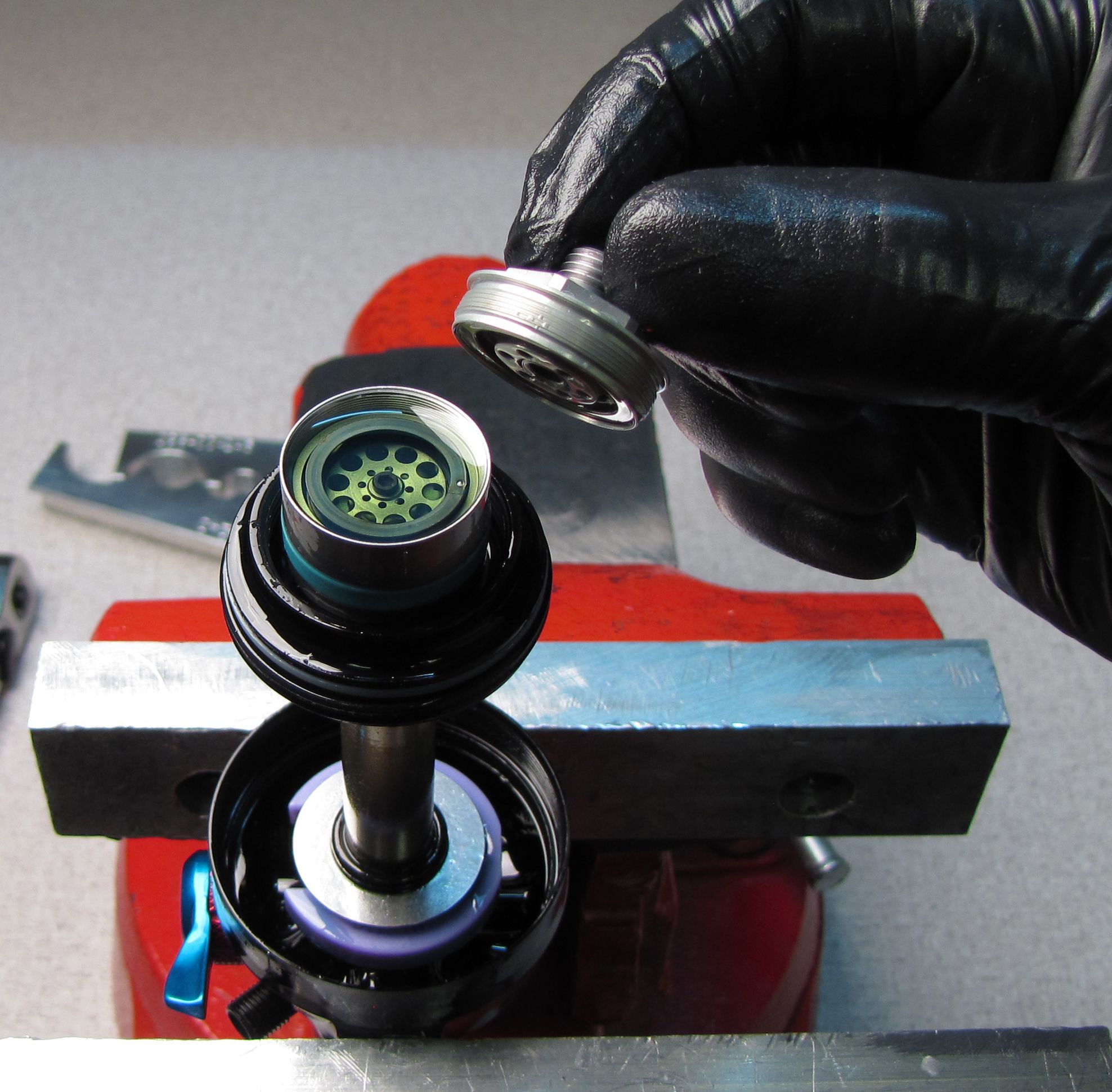
Step 22
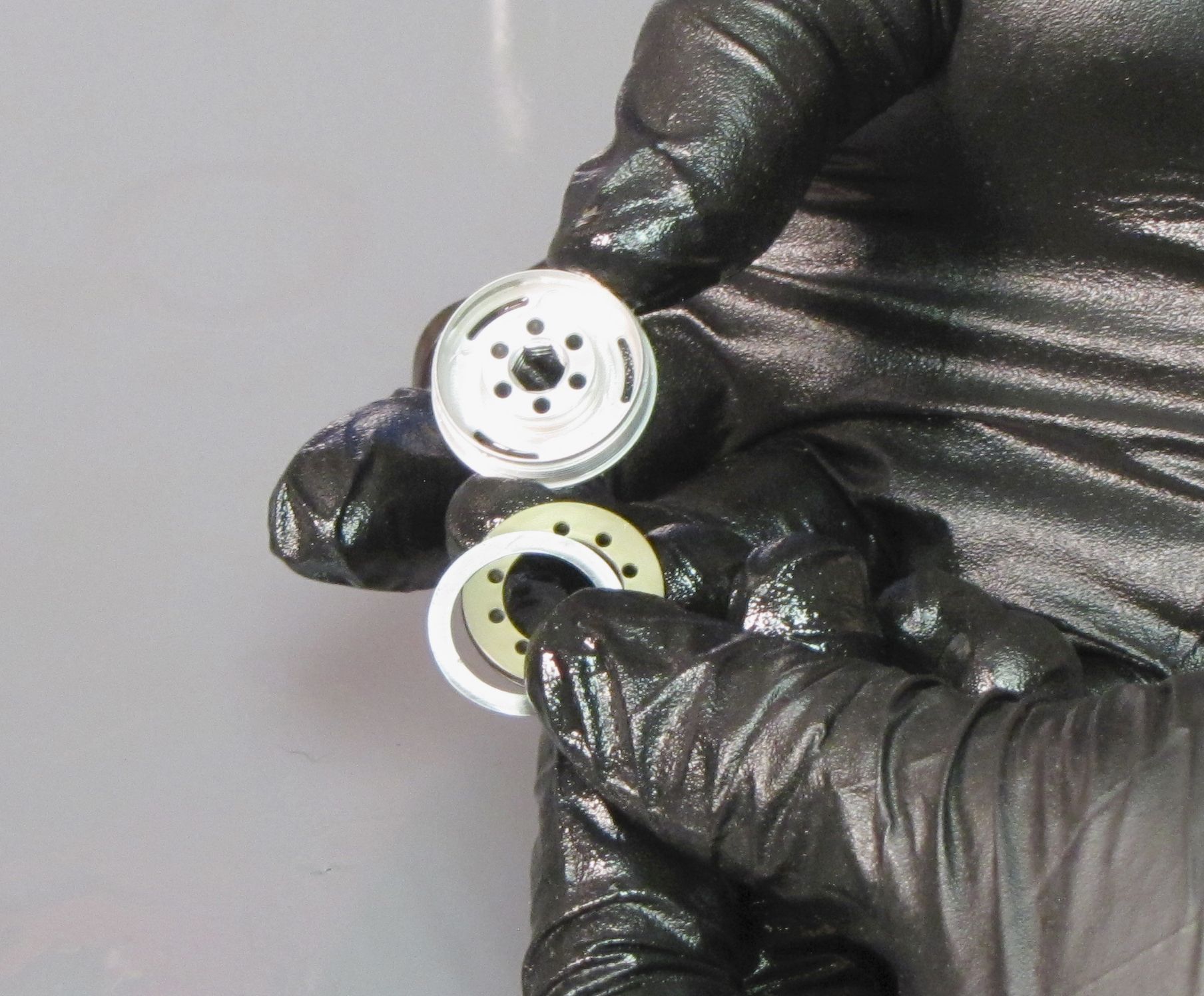
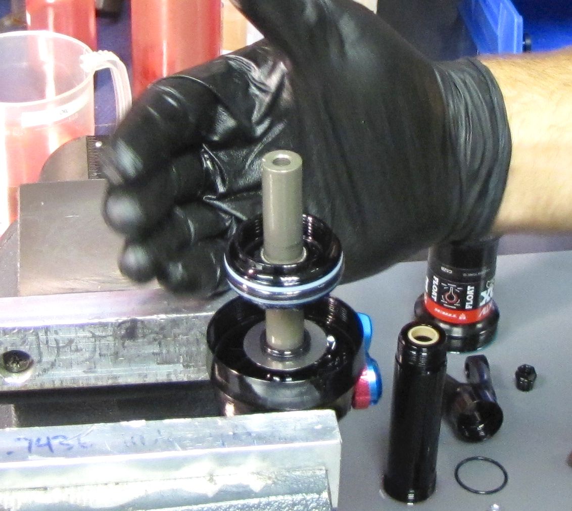
Remove the bearing assembly by pulling it up off of the shaft. Replace all seals with new greased ones from the kit.

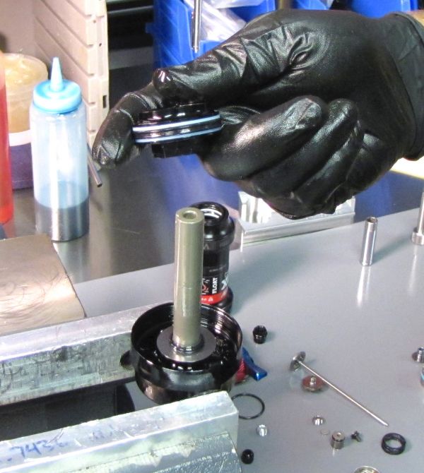
Step 23
Remove the bottom out plate and o-ring by pulling them up off of the shaft.

Step 24
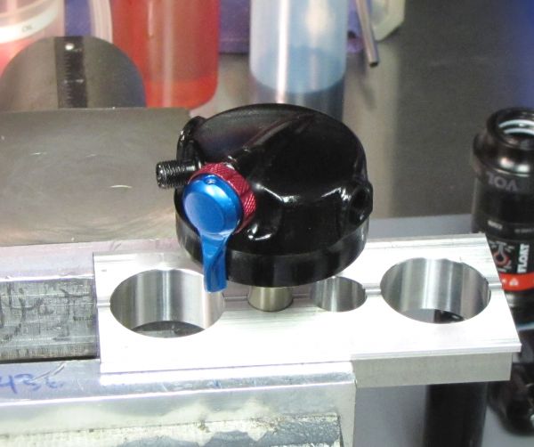
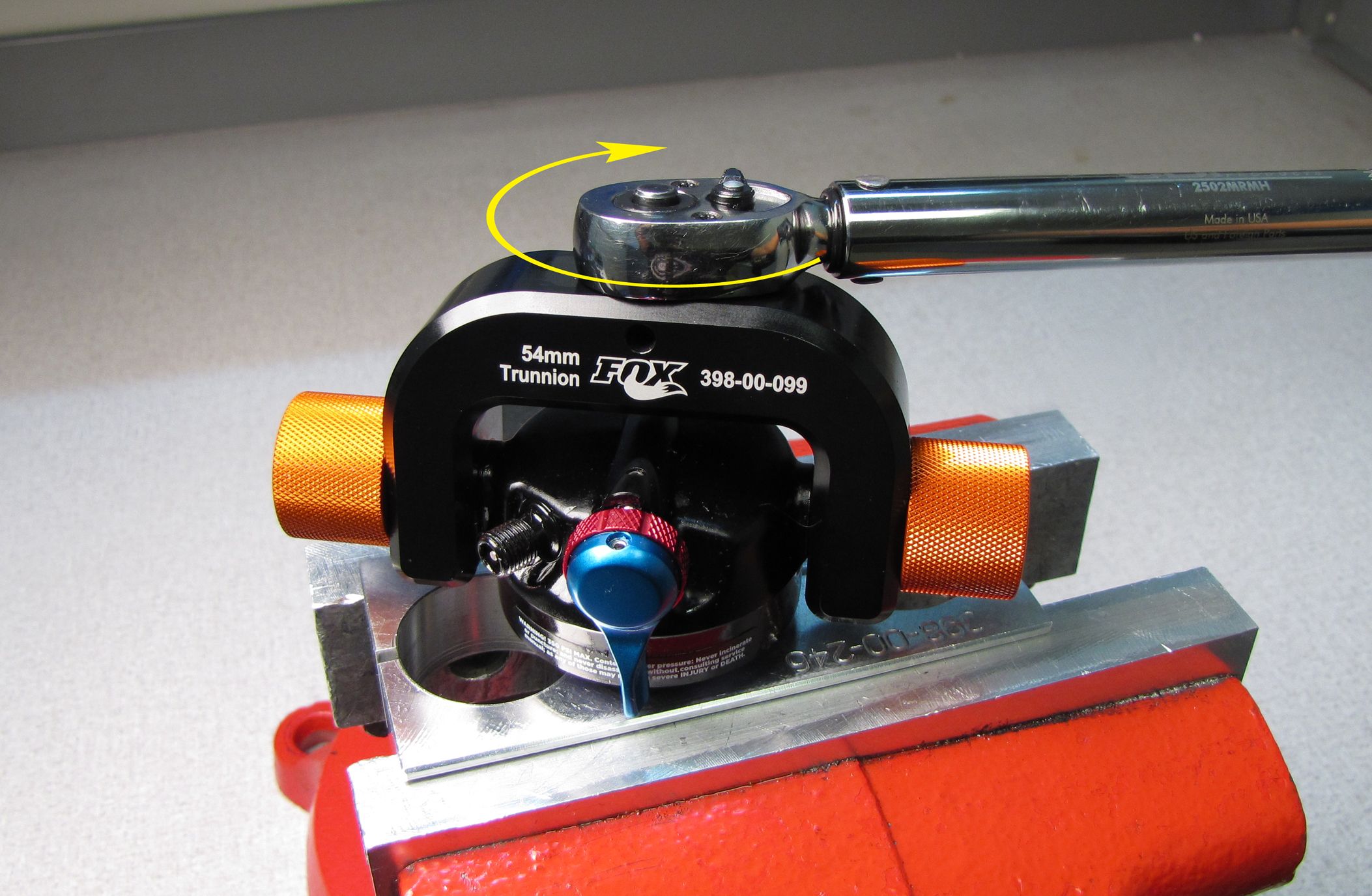
Clamp the shaft in your shaft clamps with the eyelet at the top. Unthread the eyelet from the shaft by turning it counter-clockwise with the Trunnion eyelet torque tool (PN: 398-00-099).


Step 25
Lift out the rebound adjuster rod and replace both its outer o-ring and inner square-cut o-ring with new greased ones from the kit. Clean the Loctite residue off of the shaft threads.


Step 26
Clean the Loctite residue from within the shaft boss on the inside of the eyelet. Replace the air sleeve o-ring within the eyelet with a new greased one from the kit.
NOTE: The following steps show removal and replacement of the adjuster knobs and cam. You do not need to remove the adjuster knobs and cam to replace seals within the shock. Removal of the adjuster knobs and cam is only needed to clean and lubricate these parts and can be skipped if no grit or resistance is felt when making adjustments.

Step 27
Unthread counter-clockwise and remove the set screw from the top of the eyelet with a 1.5mm hex wrench. This will allow for the removal of the adjuster knobs and cam. Make sure not to lose the rebound detent ball and spring which may stick to the back of the rebound knob or remain in the small hole in the eyelet just above the bore for the adjusters and cam.
Step 28
Clean the adjuster knobs and cam then lubricate them with waterproof grease such as Sta-Lube SL3125 from CRC Industries. Affix the detent ball to the back side of the rebound knob or to the detent spring in the small hole in the eyelet above the bore for the adjusters and cam with a small amount of grease. Insert the adjuster knobs and cam making sure to capture the detent ball. Hold the adjusters in place as you reinstall the 1.5mm set screw, tightening clockwise until the screw contacts the cam, then back it out 1/4 turn.

Reassembly

Step 1
Make sure that the very small ball bearing is present in the raised portion of the rebound metering rod. Insert the rebound metering rod into the eyelet with the raised portion containing the small ball bearing oriented toward the front of the eyelet.

Step 2
Apply a small drop of red Loctite 277 to the shaft threads, then install the shaft over the rebound metering rod and into the eyelet threading it in clockwise by hand.
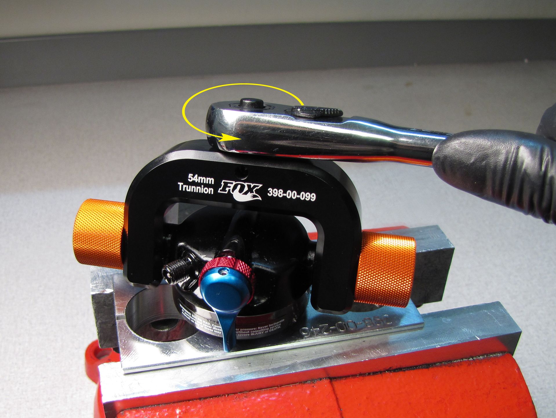
Step 3
Clamp the shaft in your shaft clamps then tighten the eyelet to the shaft clockwise tightening to 85 in-lb (9.6 Nm) with the Trunnion eyelet torque tool.

Step 4
Remove the shock from the clamps and gently clamp the eyelet in your soft-jawed vise so the mounting bolt areas are the only portions of the eyelet contacting the vise. Reinstall the bottom out plate followed by a new bottom out o-ring from the kit.


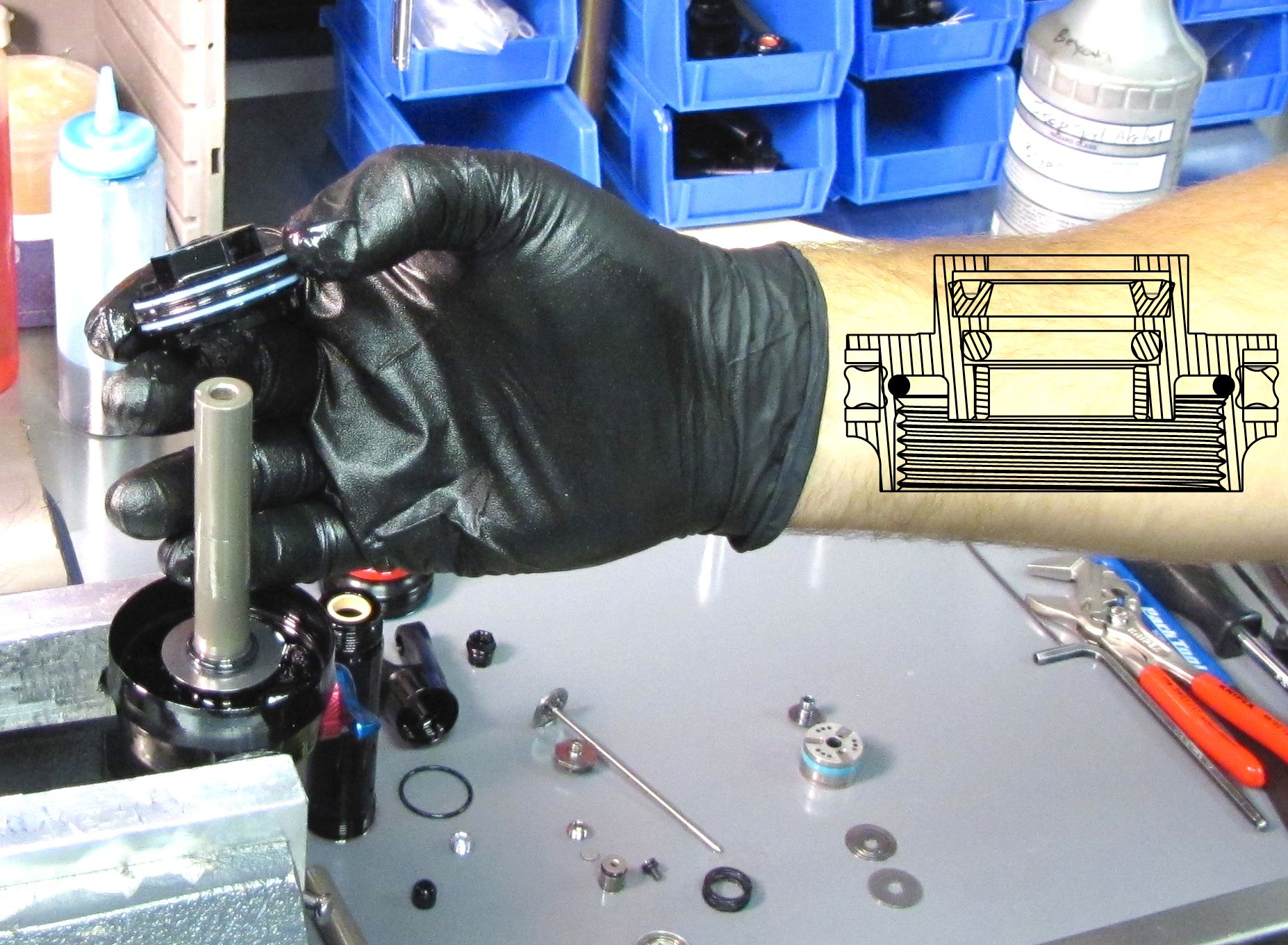
Step 5
Carefully reinstall the rebuilt bearing assembly onto the shaft taking care not to damage the u-cup seal.
Step 6
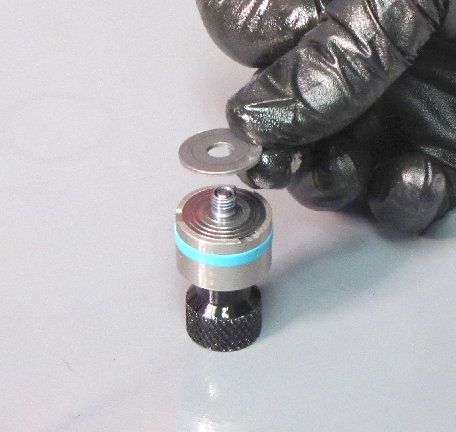
Set the Trek RG Valve Stack Transfer Tool (PN: 398-00-614) on your work bench. Install the piston bolt onto the tool followed by the rebound valves. Install the valve housing onto the tool next followed by the compression valves and topout plate.


Step 7
Invert the loaded Trek RG Valve Stack Transfer Tool onto the shaft then turn the tool clockwise to begin threading the piston bolt into the shaft. Remove the tool then tighten the piston bolt clockwise with an 8mm socket tightening to 60 in-lb (6.8 Nm).

Step 8
Carefully install the adjuster rod assembly being careful not to damage the o-ring inside the shaft that the rod goes through. Set the blue lever to Open Mode (fully counter-clockwise) while gently pushing the rod assembly as far into the Valve Housing as possible.


Step 9
Install the new wave spring from the kit into the valve housing.

Step 10
Reinstall the valves onto the rebound check bolt without pinching them then thread the bolt with valves into the valve housing cap assembly clockwise.

Step 11
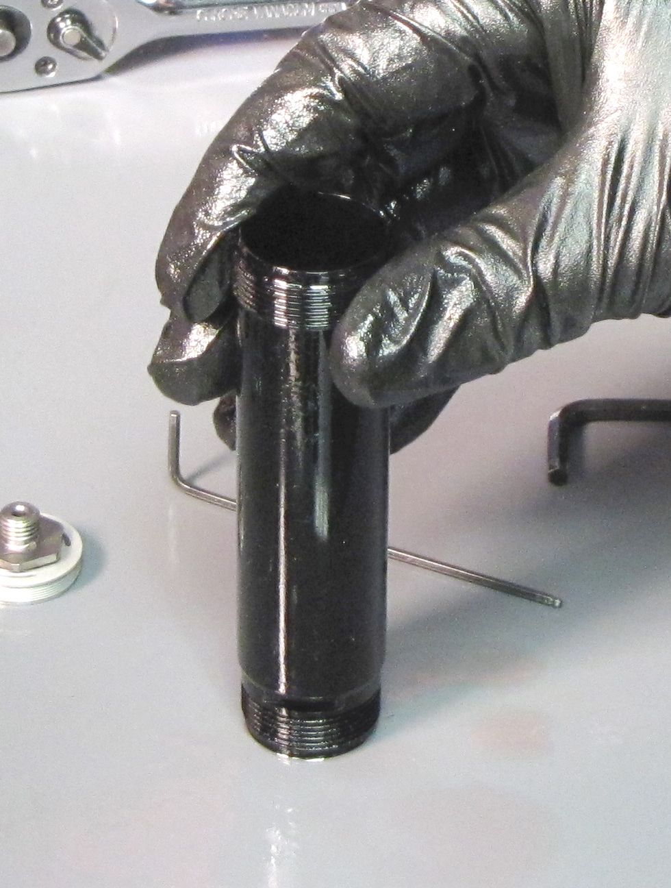
Drop the new filter disc from the kit into the end of the slave shaft with the OD bevel.
Step 12
Insert the IFP jet into the slave shaft on top of the filter disc. Turn it clockwise with your 4mm hex wrench to thread it in, tightening until snug.
Step 13
Loosely install the IFP bleed screw into the IFP. This screw should be tightened enough to prevent oil leakage, but still loose enough to remove without the IFP bleed screw torque tool.


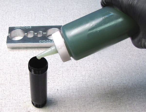
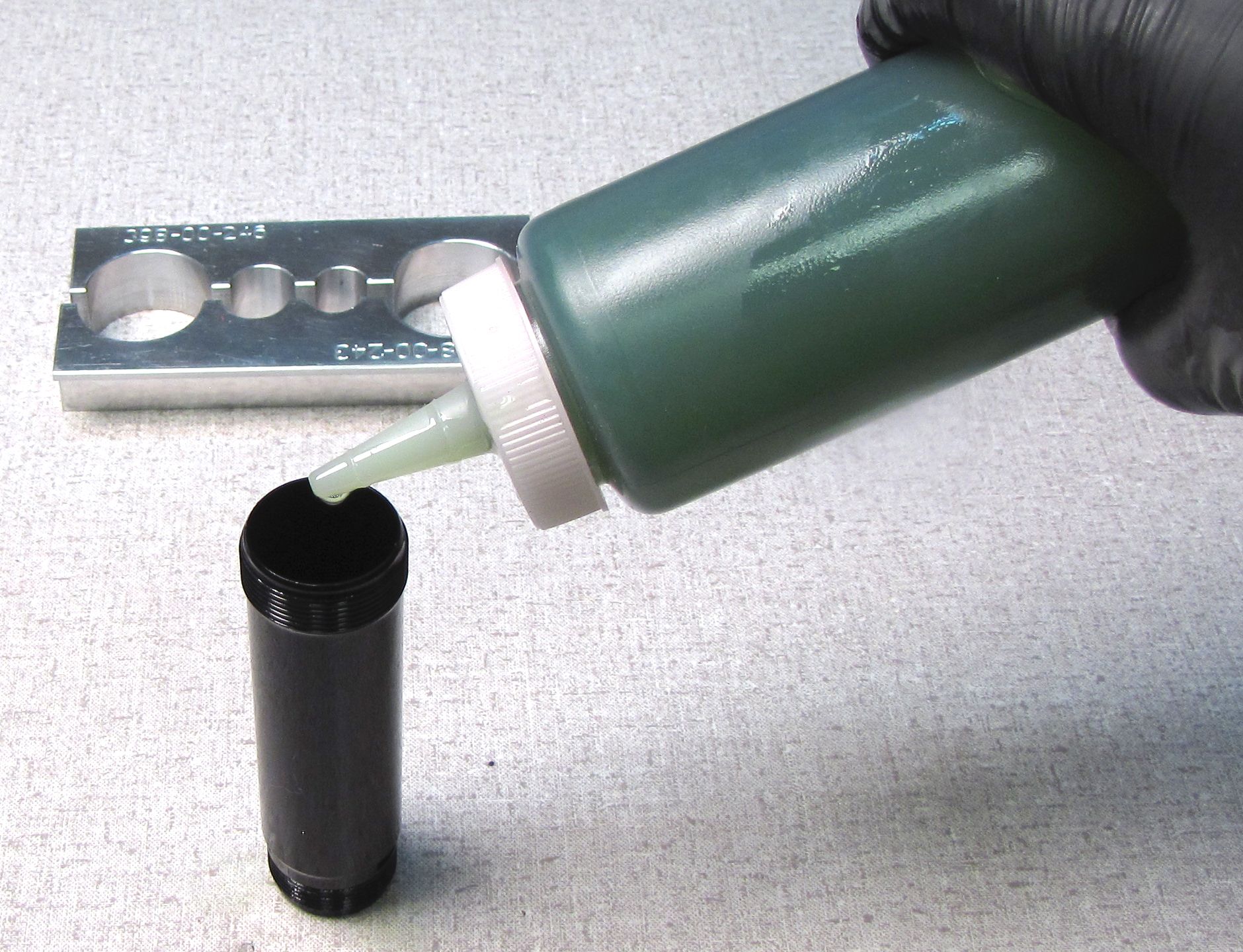
Step 14
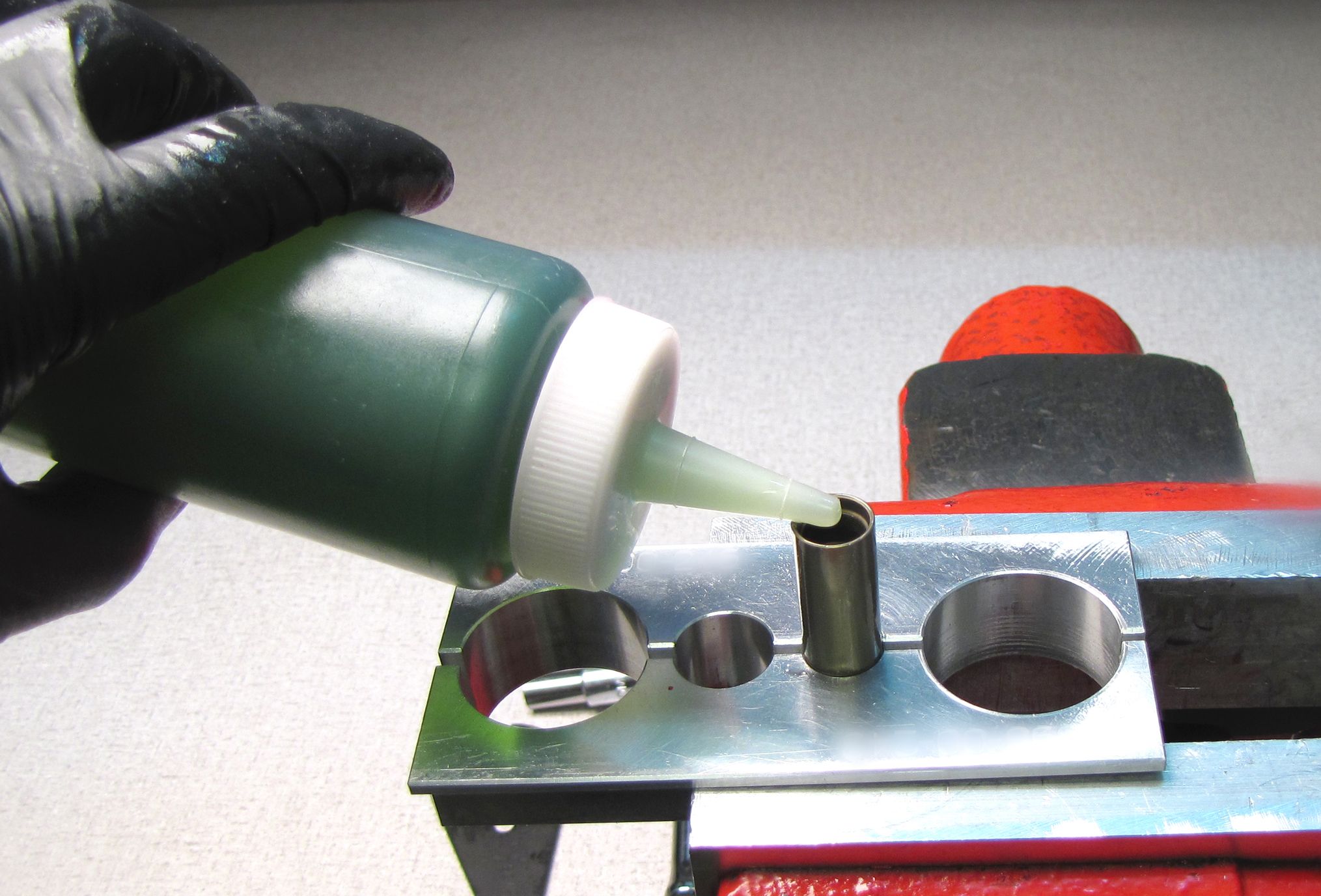
Hold the slave shaft with the IFP jet and filter disc at the bottom, then add FOX 10wt. Green oil (PN: 025-03-008) to the open end until full.
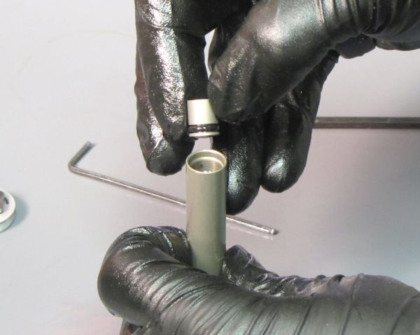
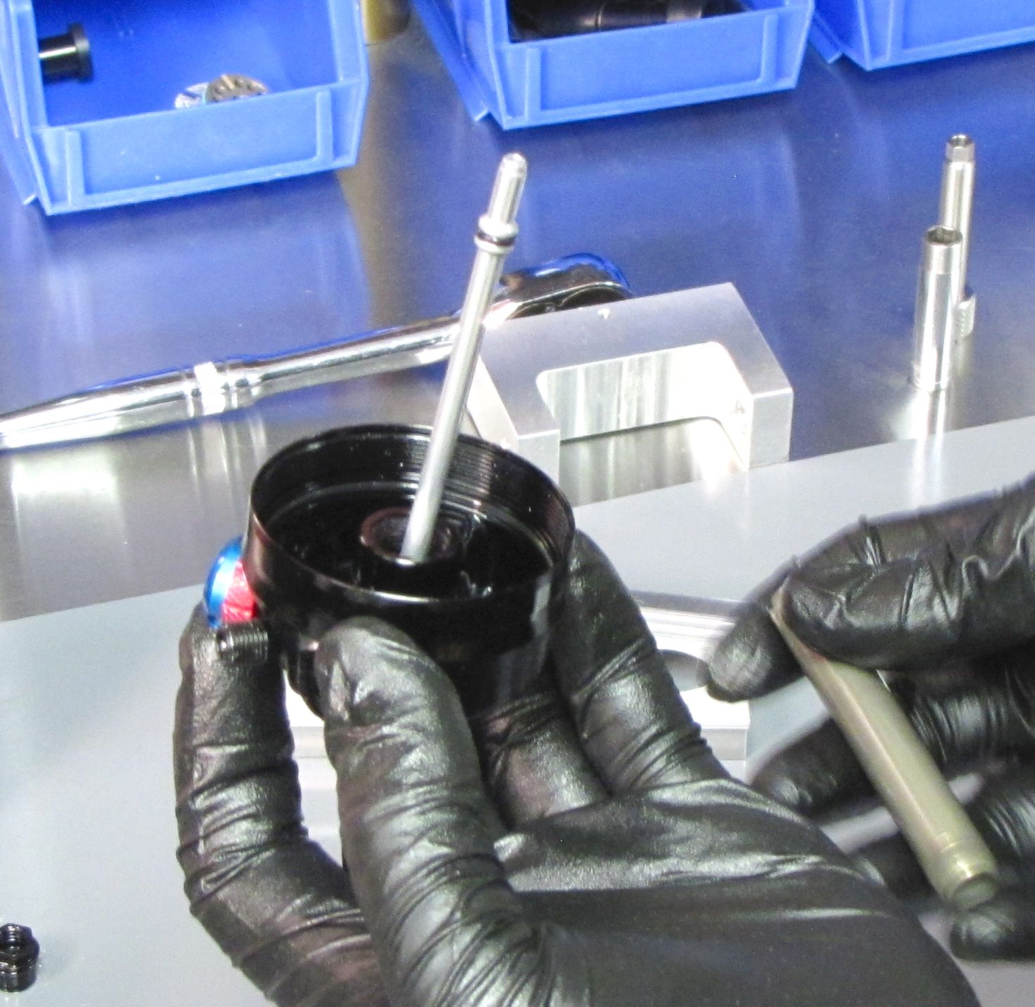
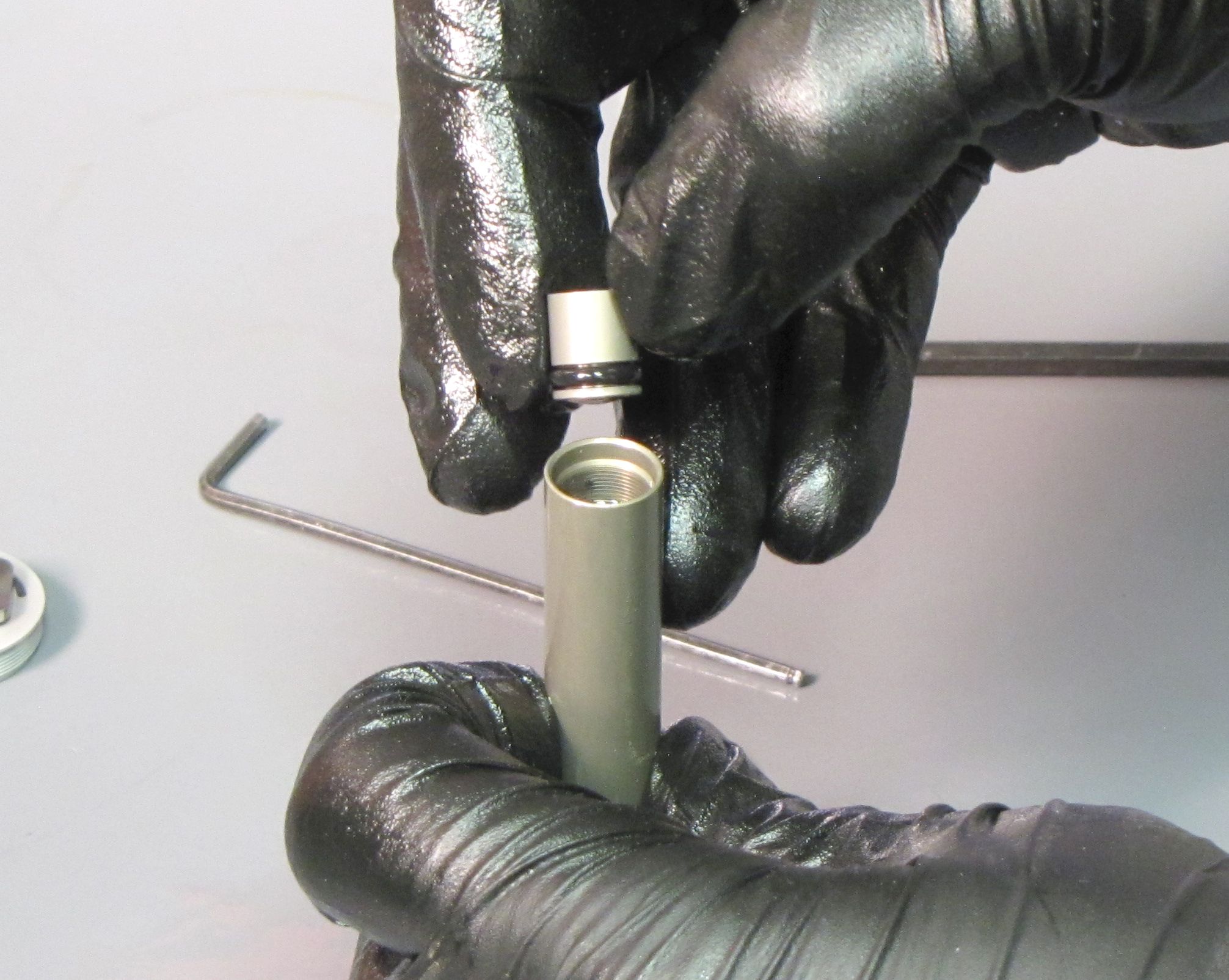
Step 15
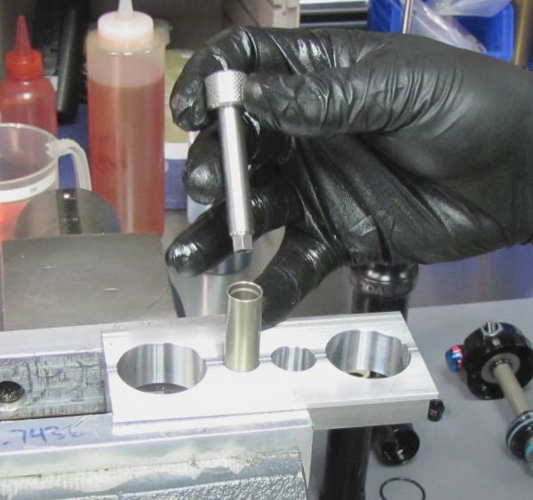
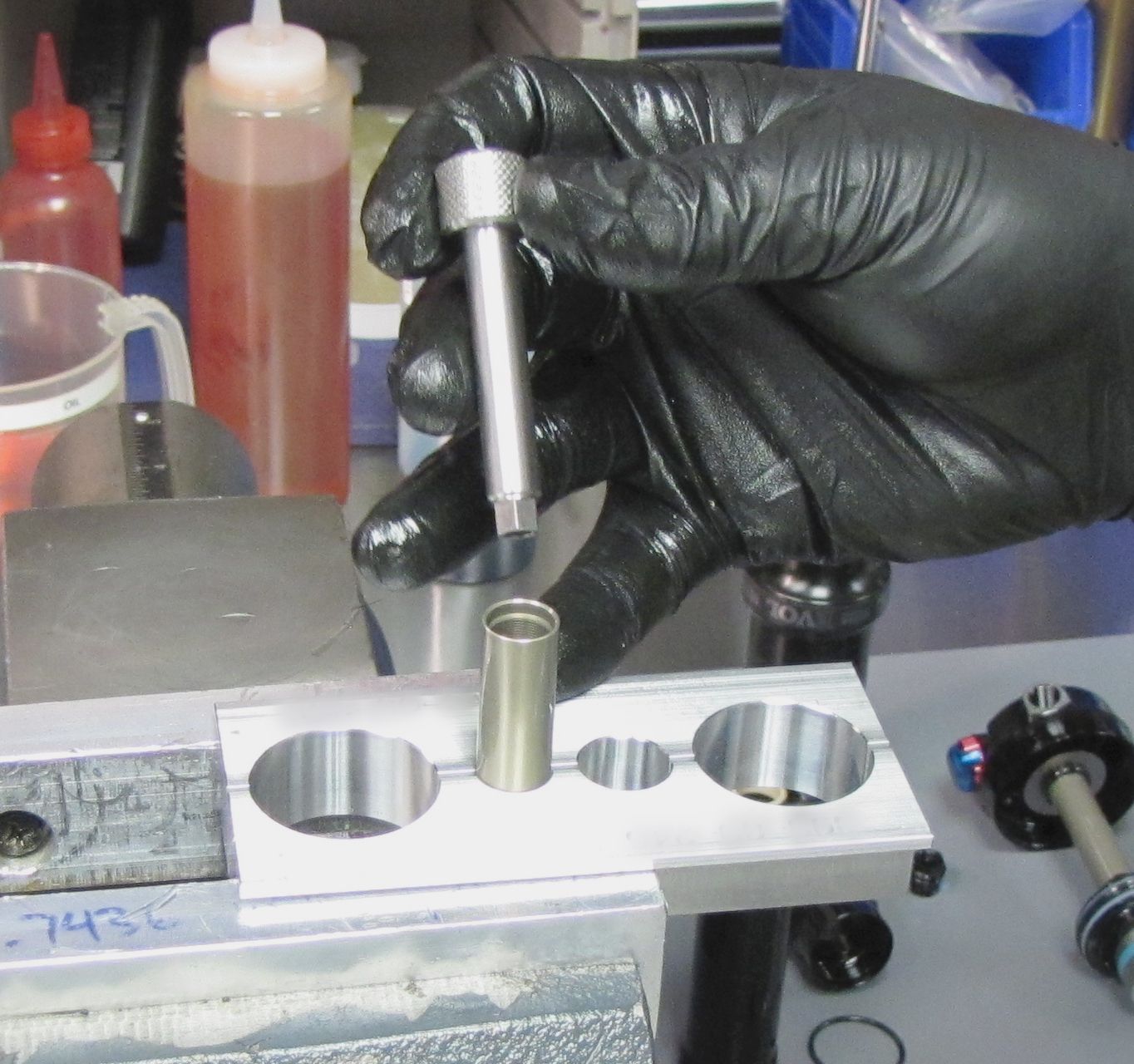
Slowly install the IFP into the slave shaft with the IFP's hex feature facing up.
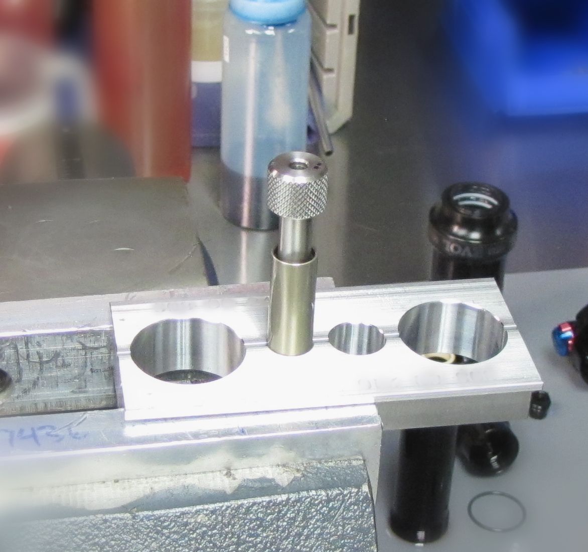
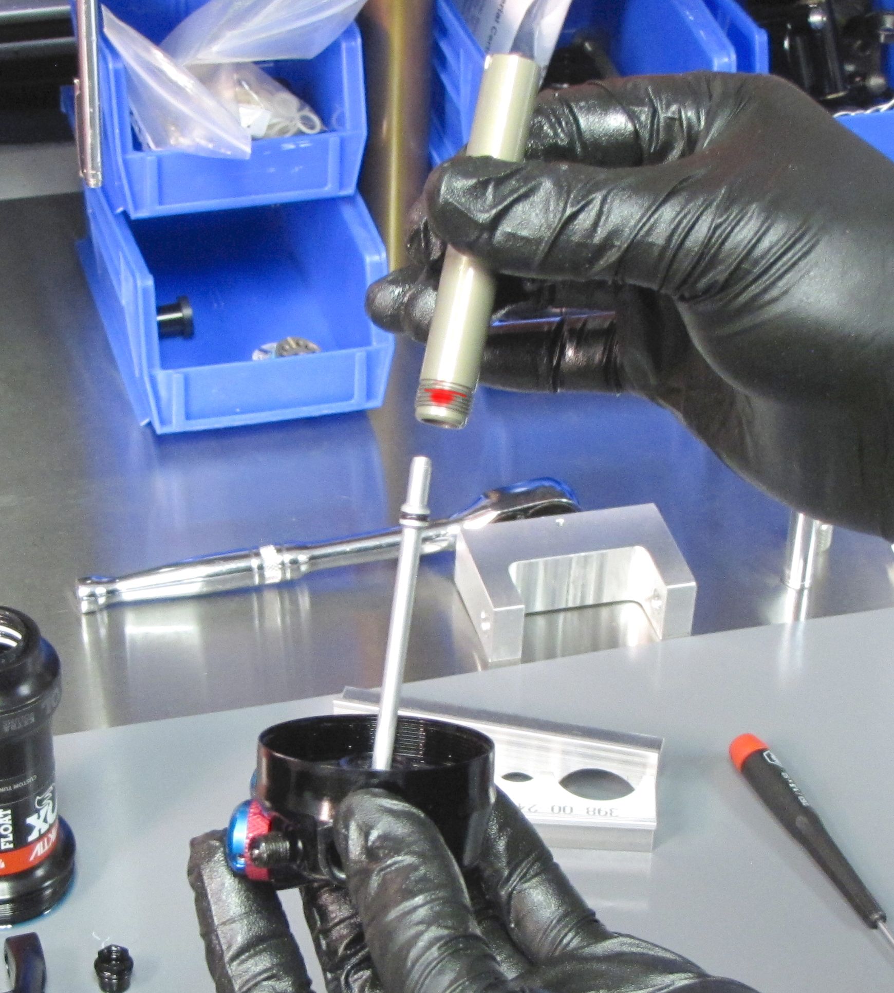
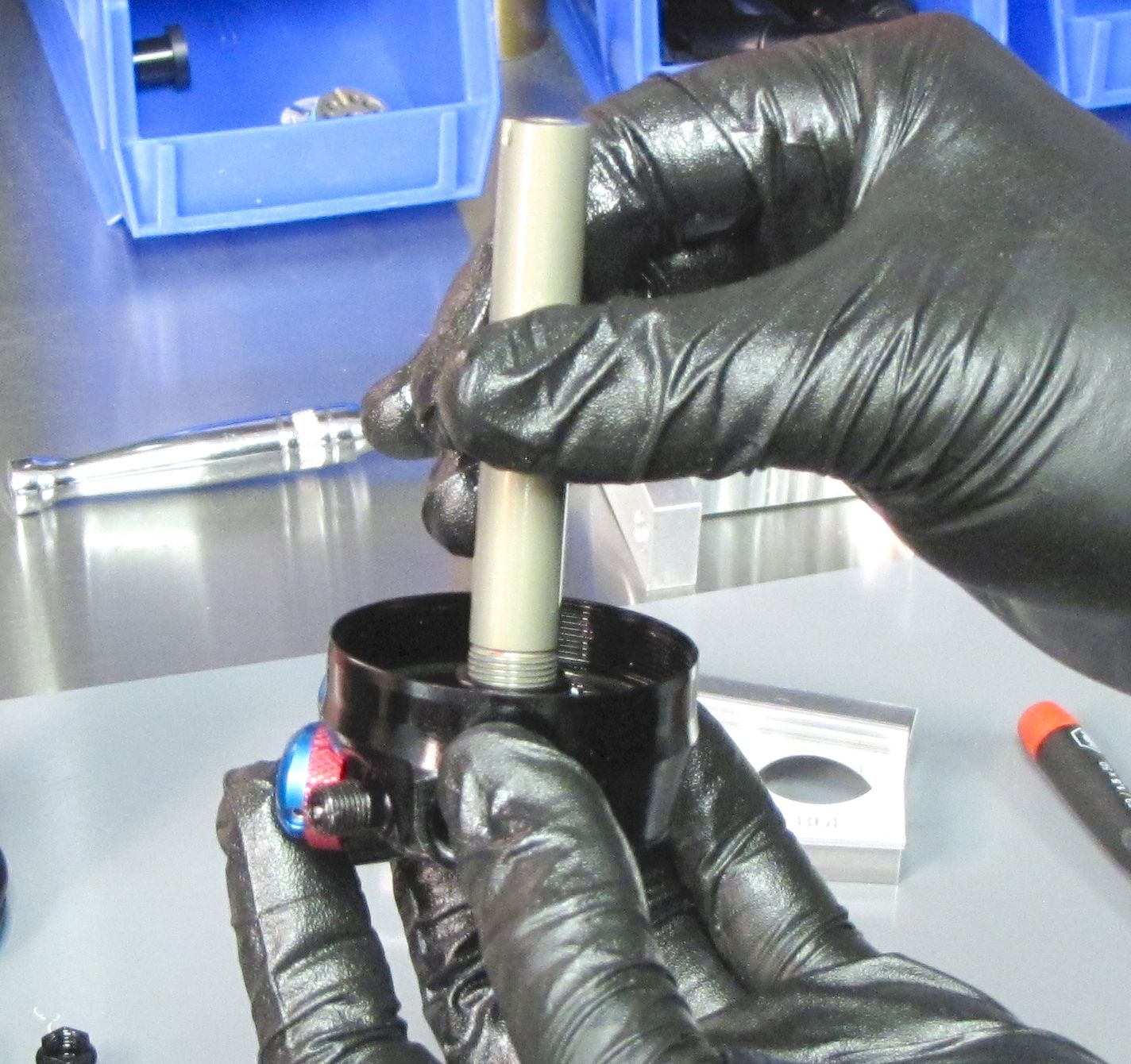
Step 16
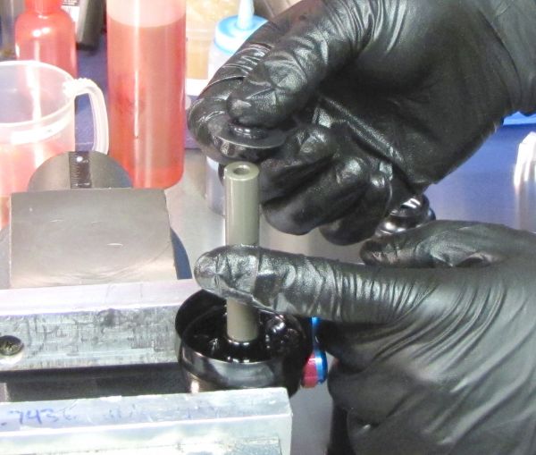
Invert the slave shaft and position it onto the IFP bleed screw torque tool. Slowly press the slave shaft down onto the IFP bleed screw torque tool until approximately 1.5" (~38mm) of the tool is still visible. Keep in mind that oil will be pushed through the filter disc and out of the top of the slave shaft.


Step 17
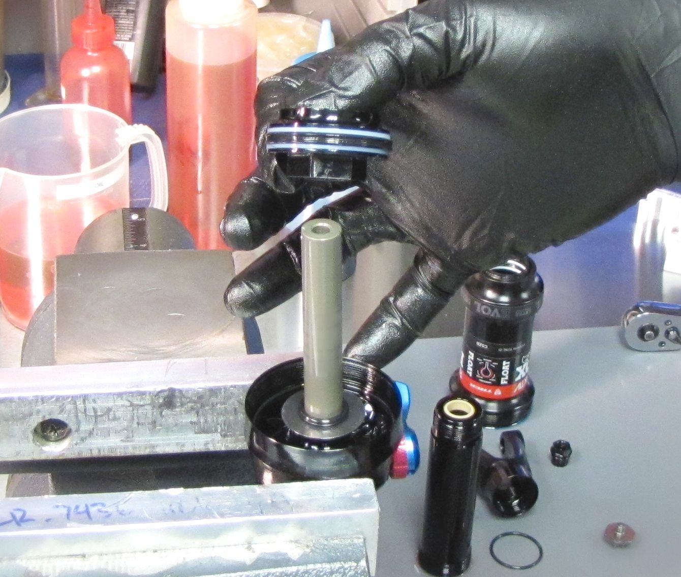
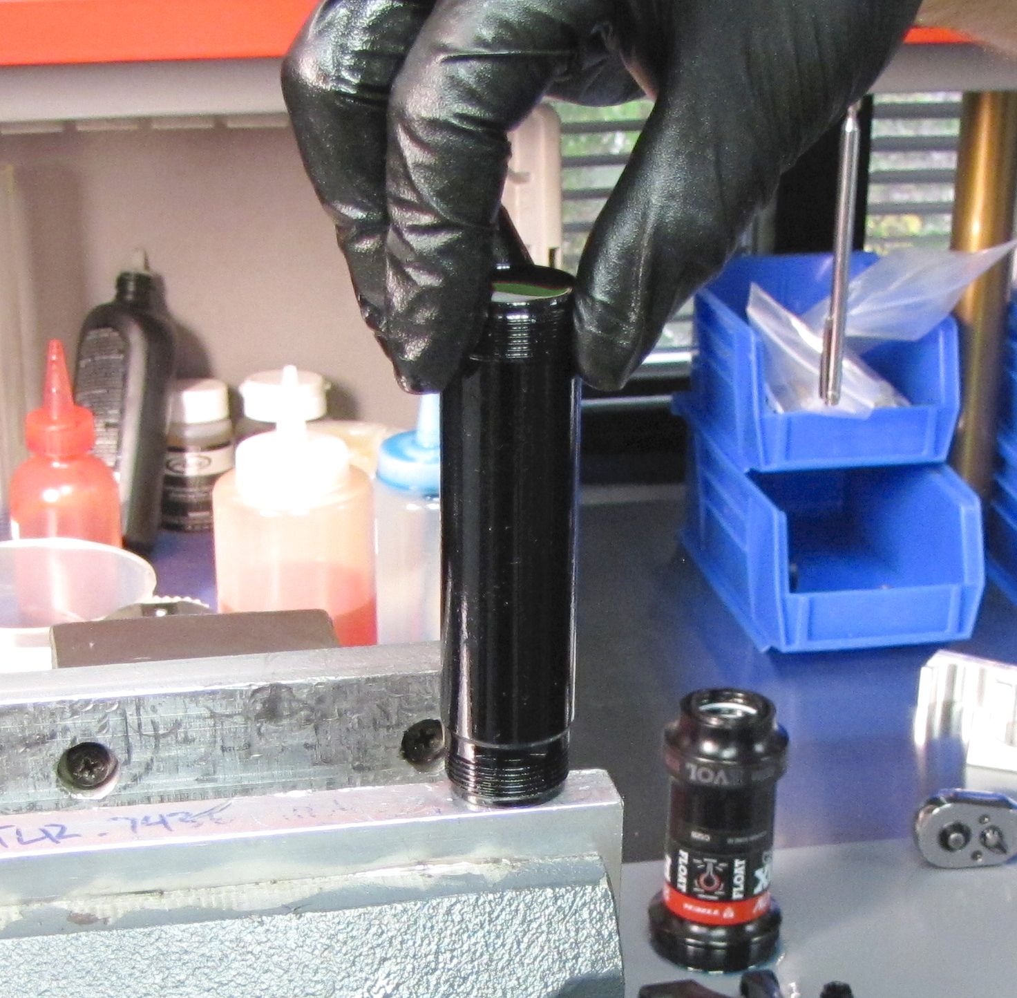
Insert the bevelled end of the slaft shaft into the body through the u-cup in the yoke end of the body. Once inserted, rest the slave shaft on your bench and push the body down until it fully covers the shaft.
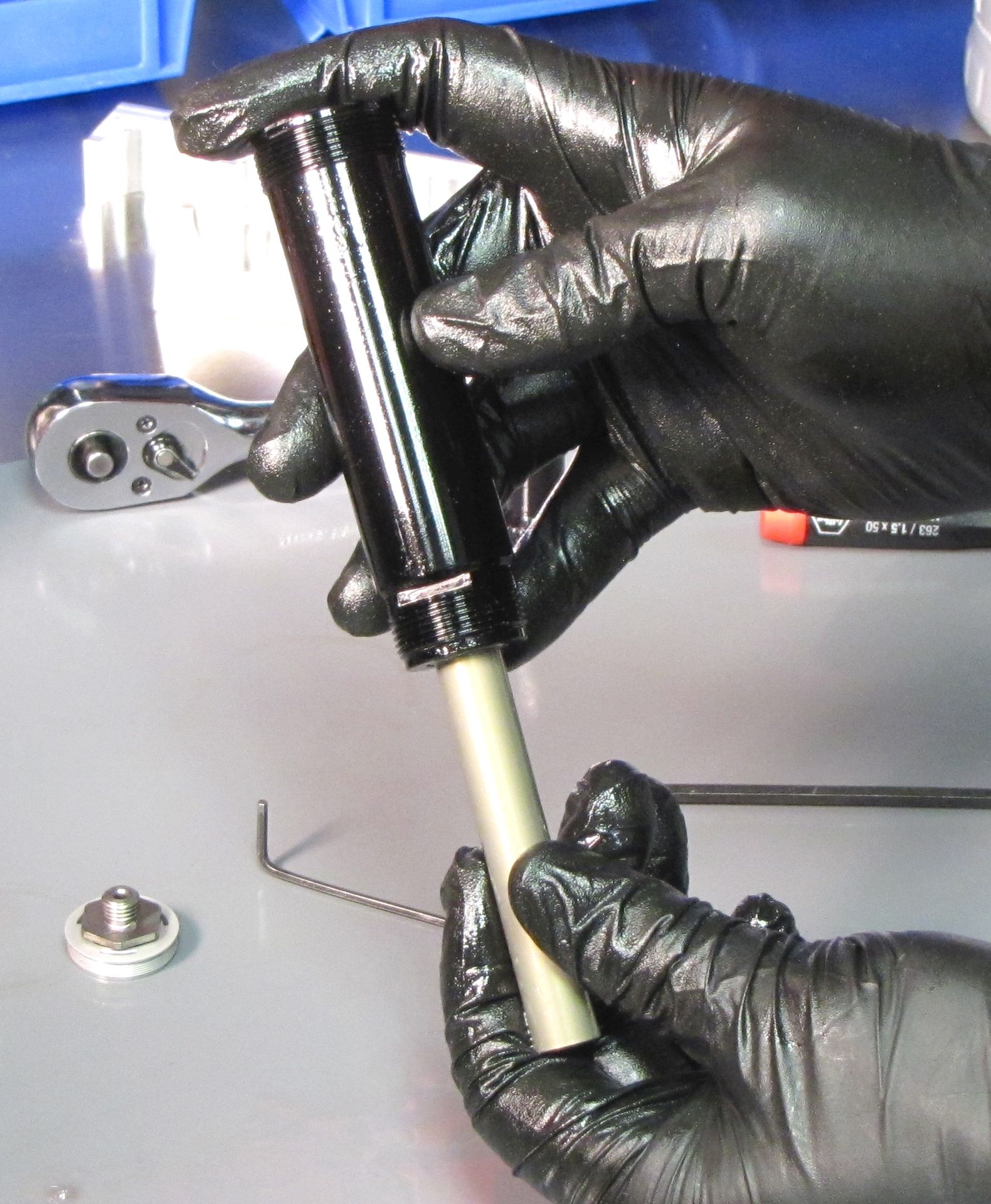

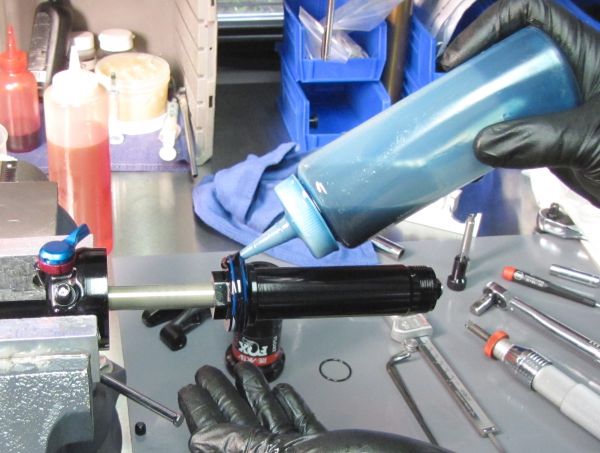
Step 18
Fill the body completely with FOX 10wt. Green oil.

Step 19
Pull the bearing assembly up against the piston assembly. Fill the valve housing with FOX 10wt. Green oil.

Step 20
Install the rebuilt valve housing cap onto the valve housing, threading it in clockwise until hand tight.

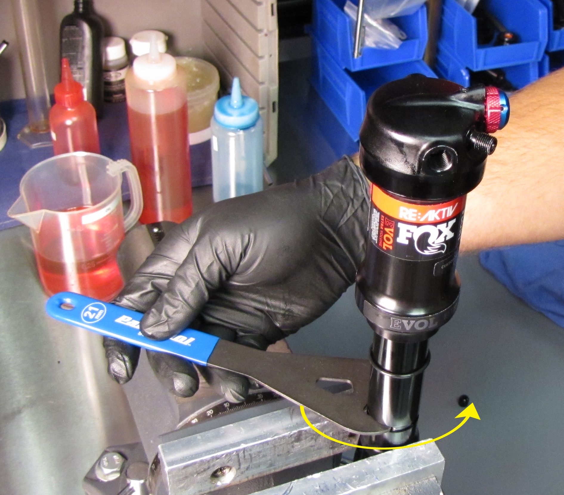
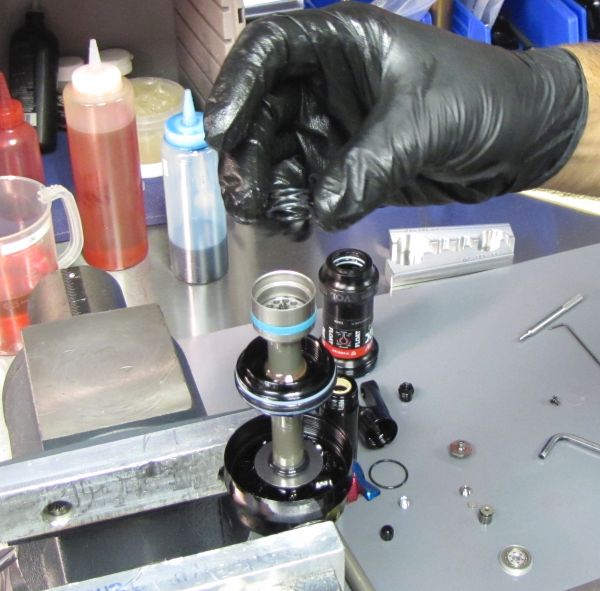
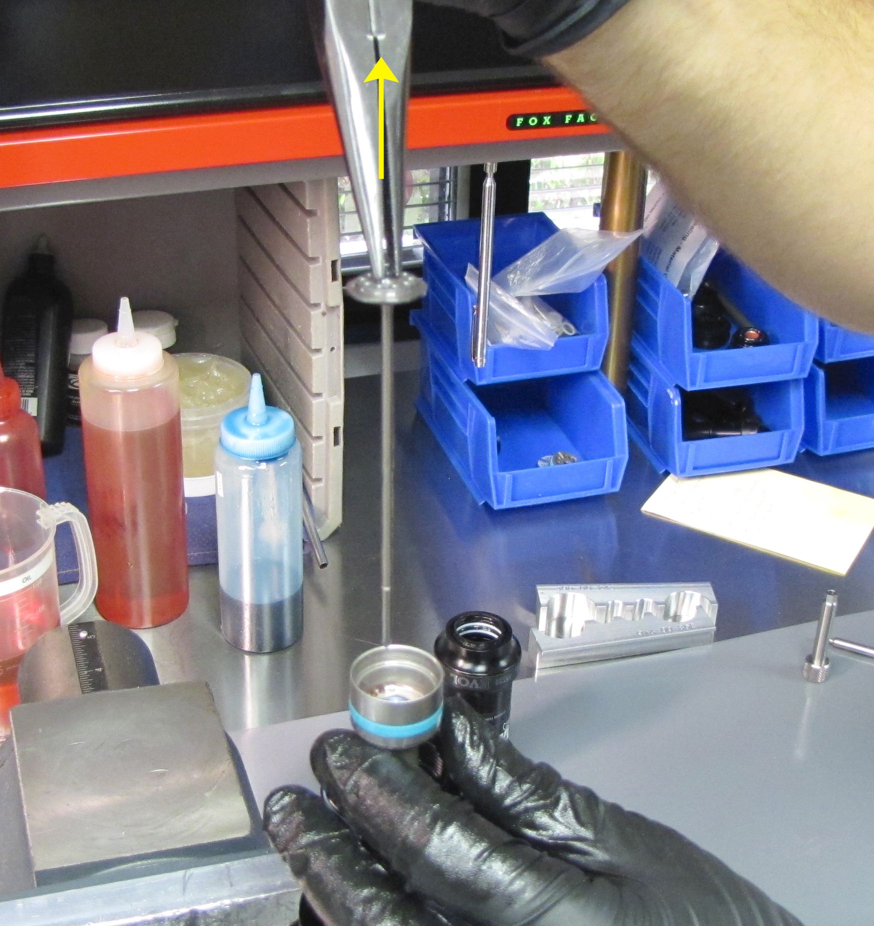
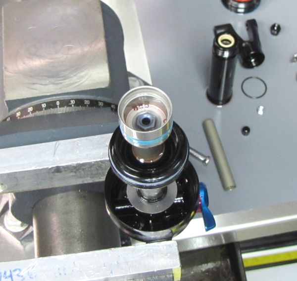
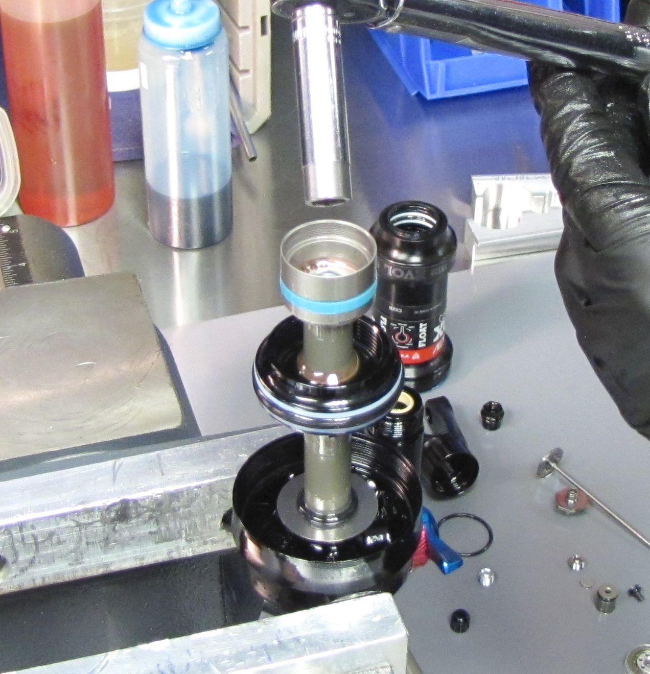
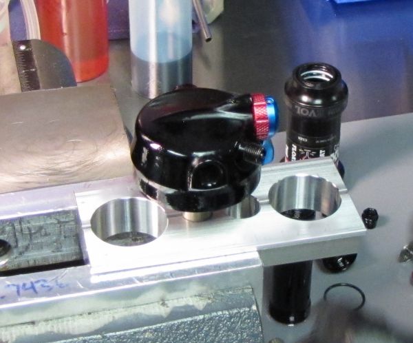
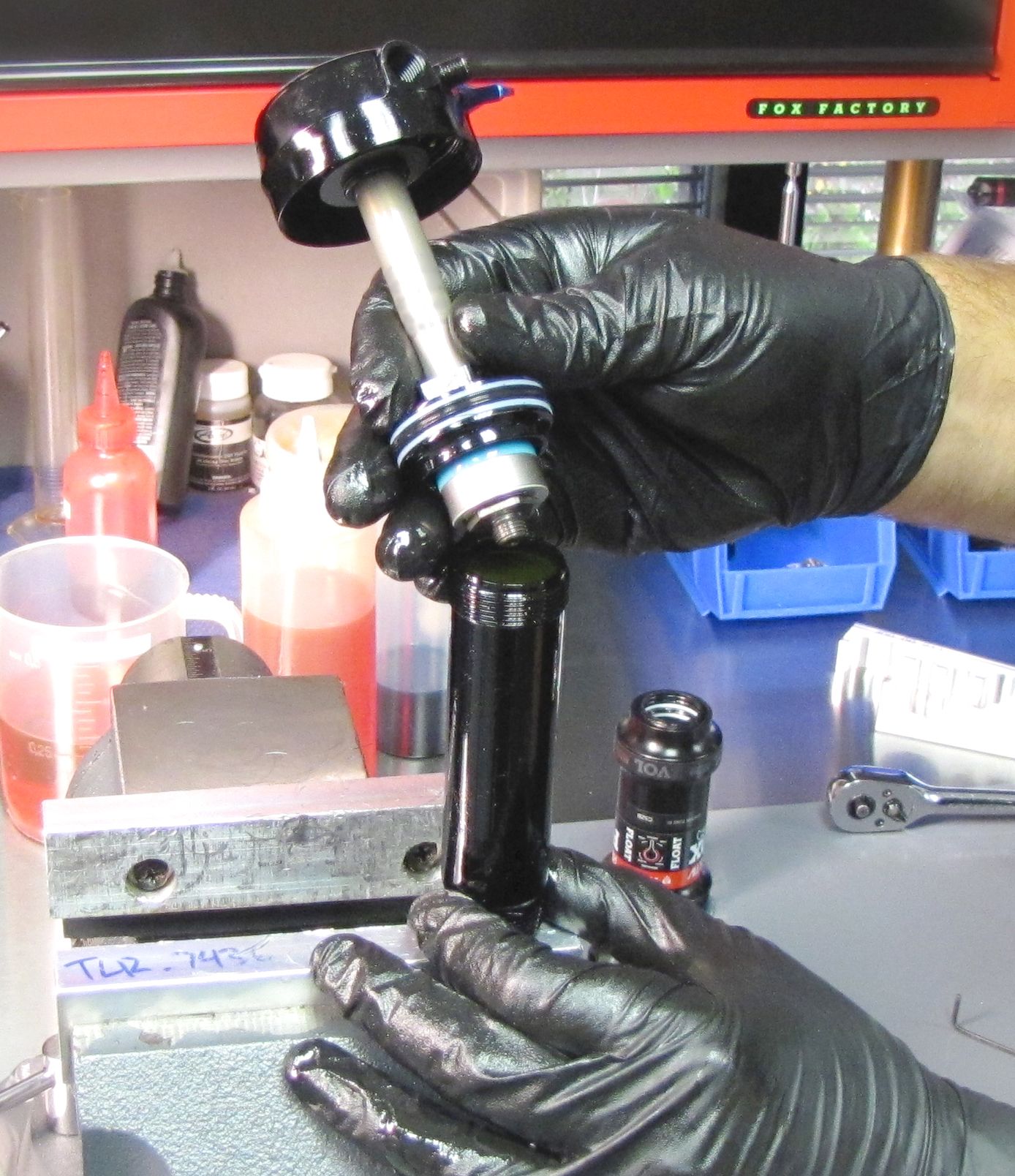
Step 21
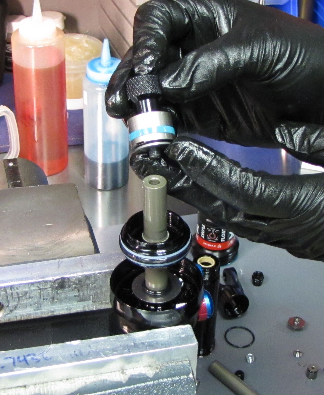
Rest the oil filled body with slave shaft against your workbench or the top of your vise jaws as shown. This will prevent the slave shaft from being pushed out of the body as the piston assembly displaces oil within the body. Slowly insert the valving assembly into the oil-filled body, then thread the bearing assembly clockwise to the body while watching for clean bubble-free oil coming out through the threads at the bottom of the bearing assembly.
Step 22
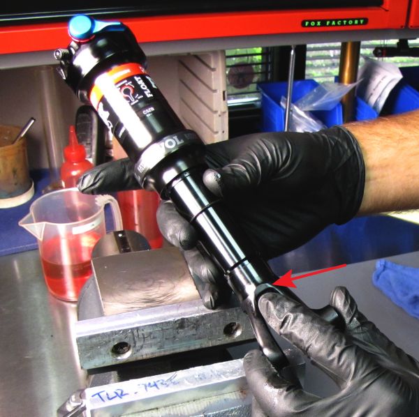
Position the shock in your soft-jawed vise with the body facing up and the wrench flats of the bearing housing clamped securely. Make sure that no portion of the shock is contacting the vise beneath the jaws.

Step 23
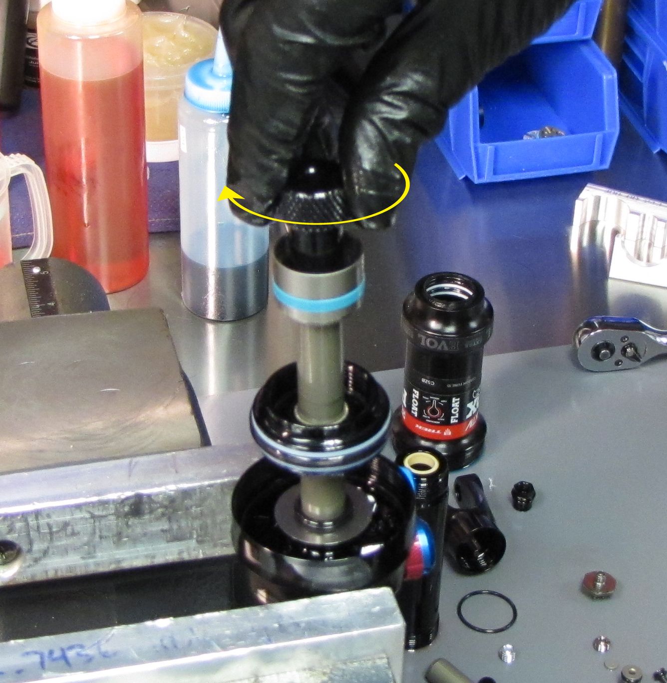
Use a 21mm Park Tool cone wrench or thinned crow's foot with your torque wrench to thread the body clockwise to the bearing assembly, tightening to 180 in-lb (20.3 Nm) torque.

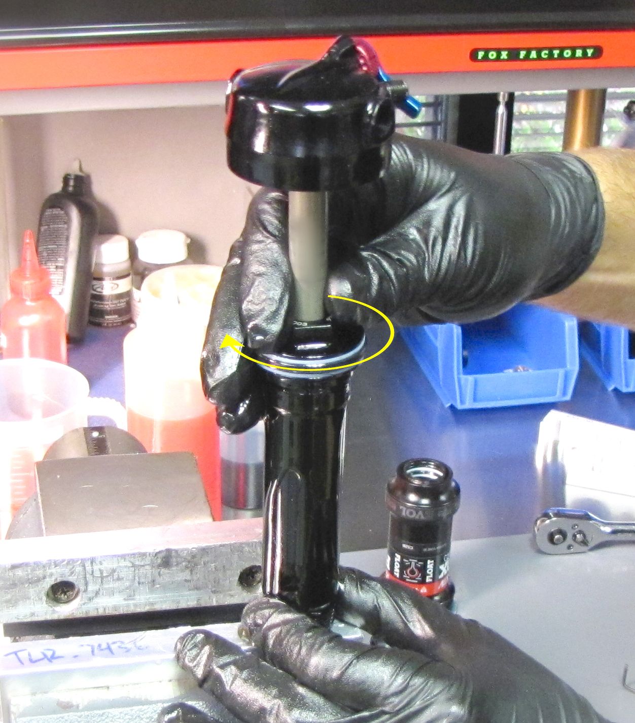
Step 24
Hold the body still and rotate the eyelet and shaft clockwise to thread the slave shaft on to the rebound check bolt until the slave shaft is flush with the yellow wiper in the end of the body.

Step 25
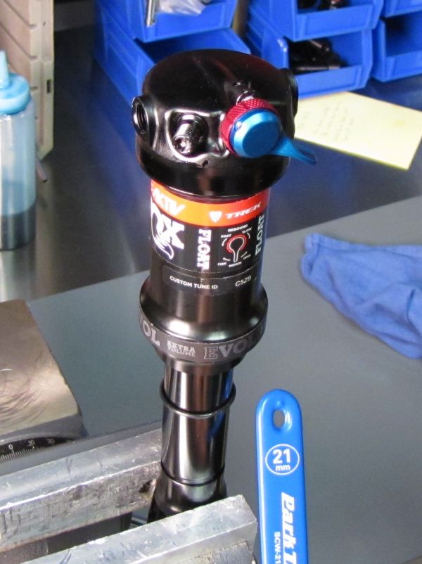
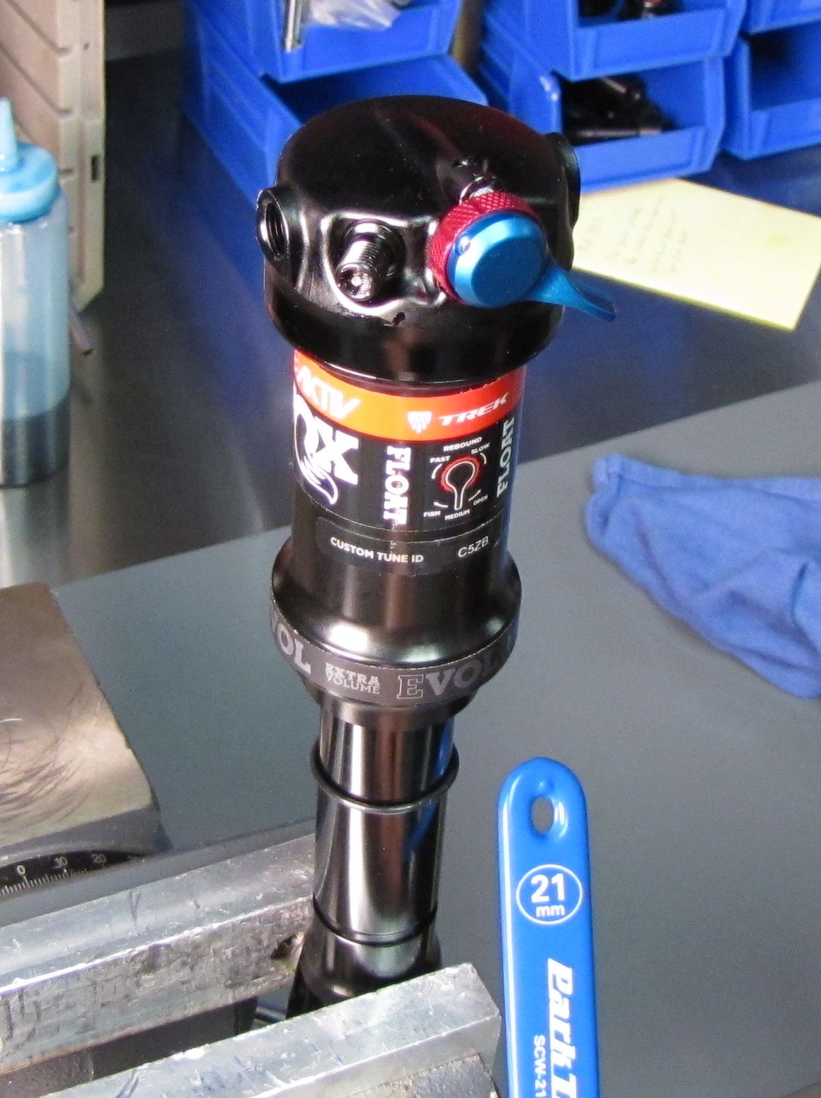
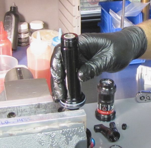
Gently clamp the eyelet in your soft-jawed vise so the mounting bolt areas are the only portions of the eyelet contacting the vise and the body is at the top.
Step 26
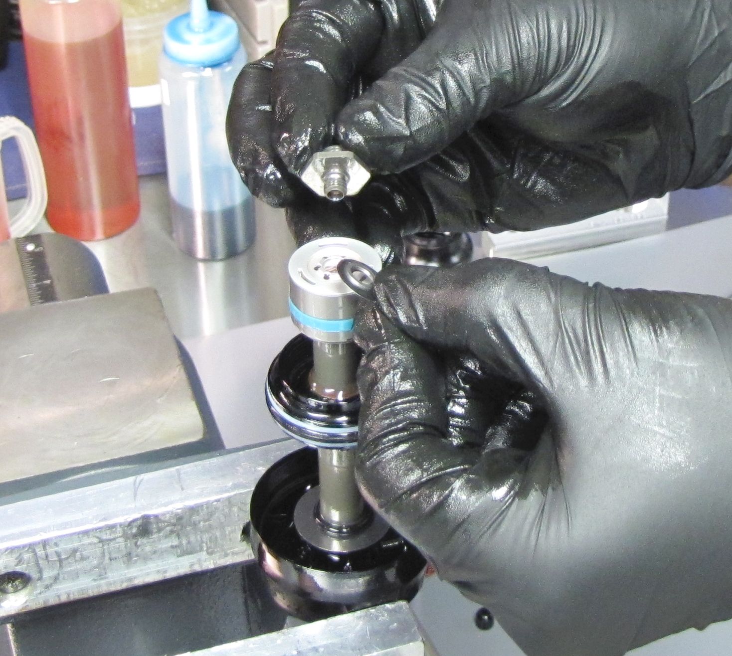
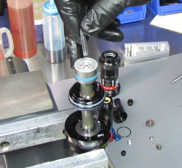
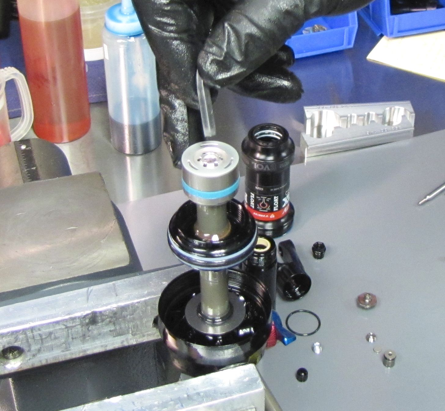
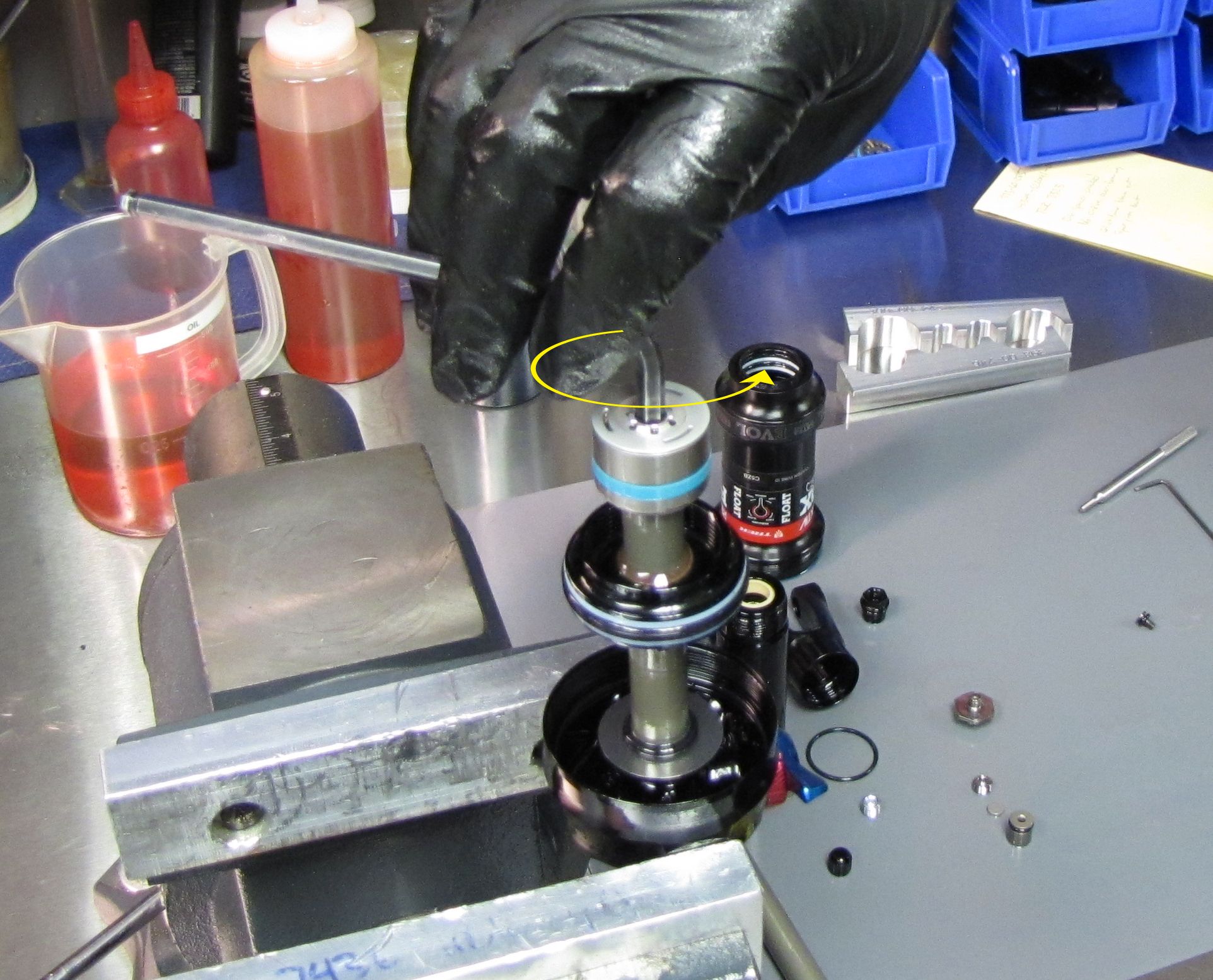
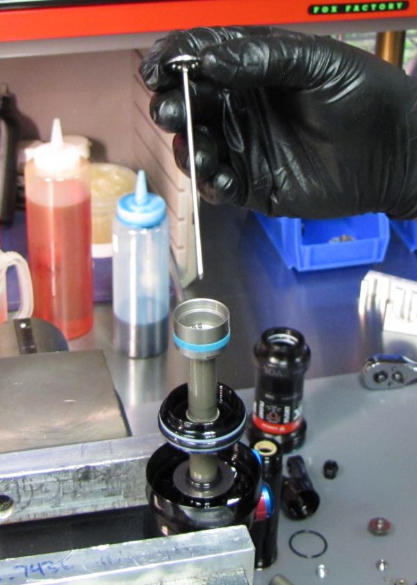
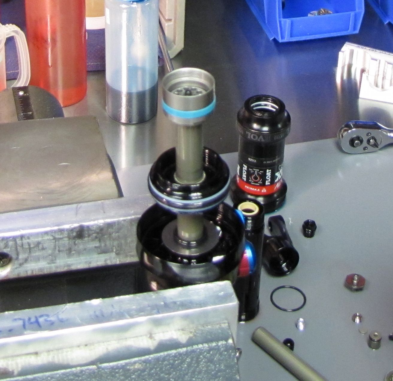
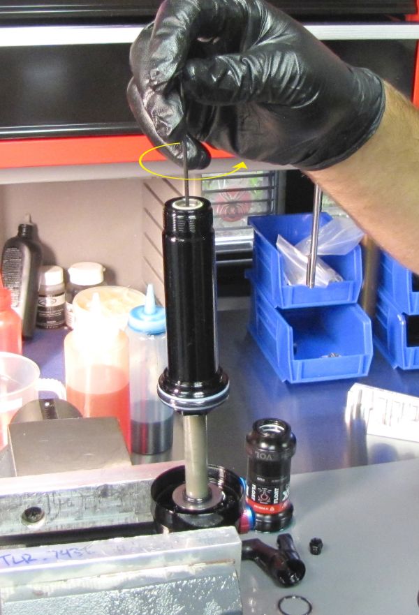
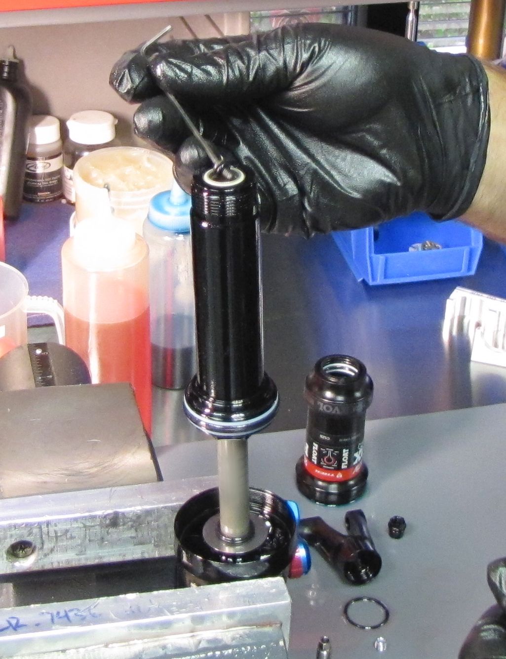
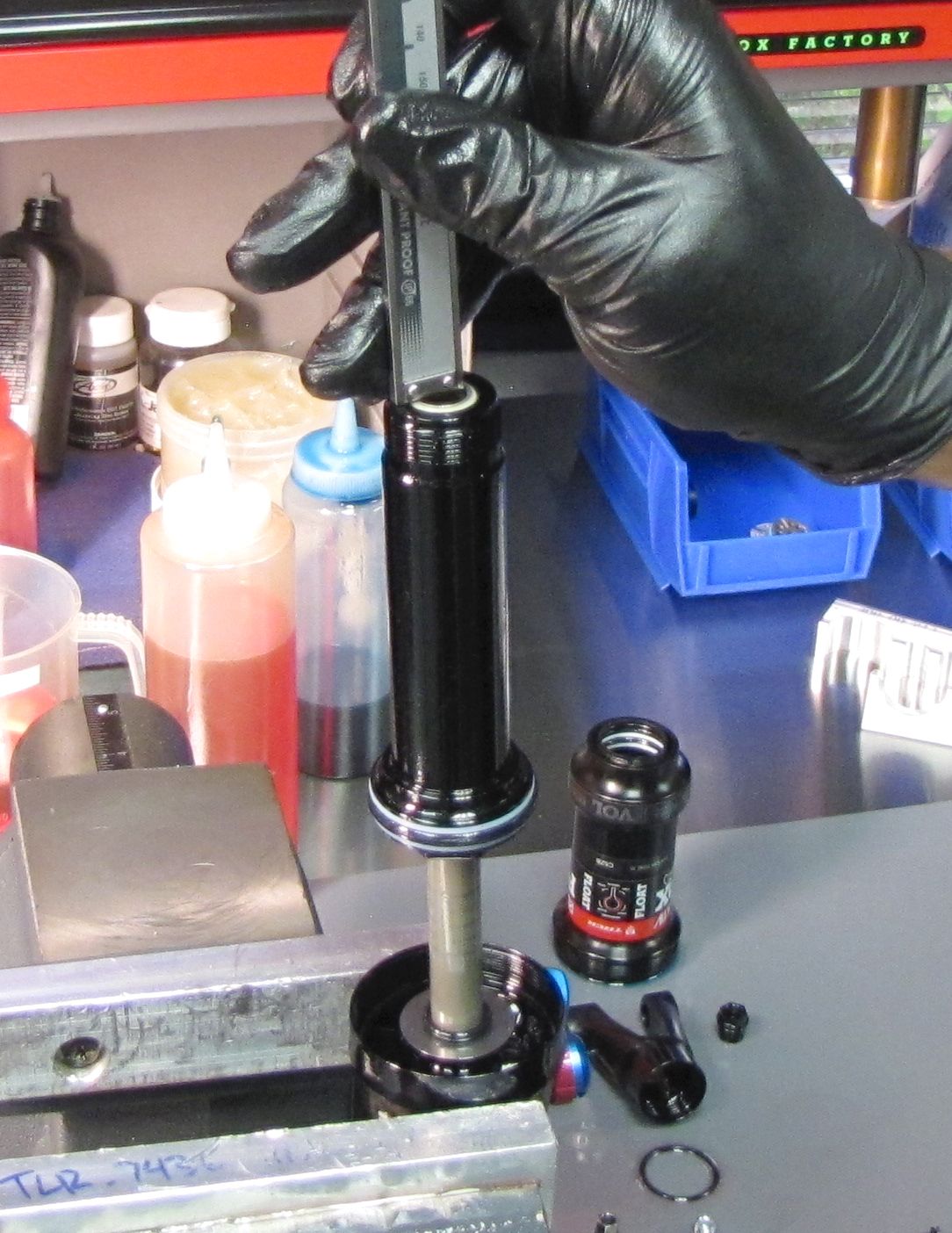
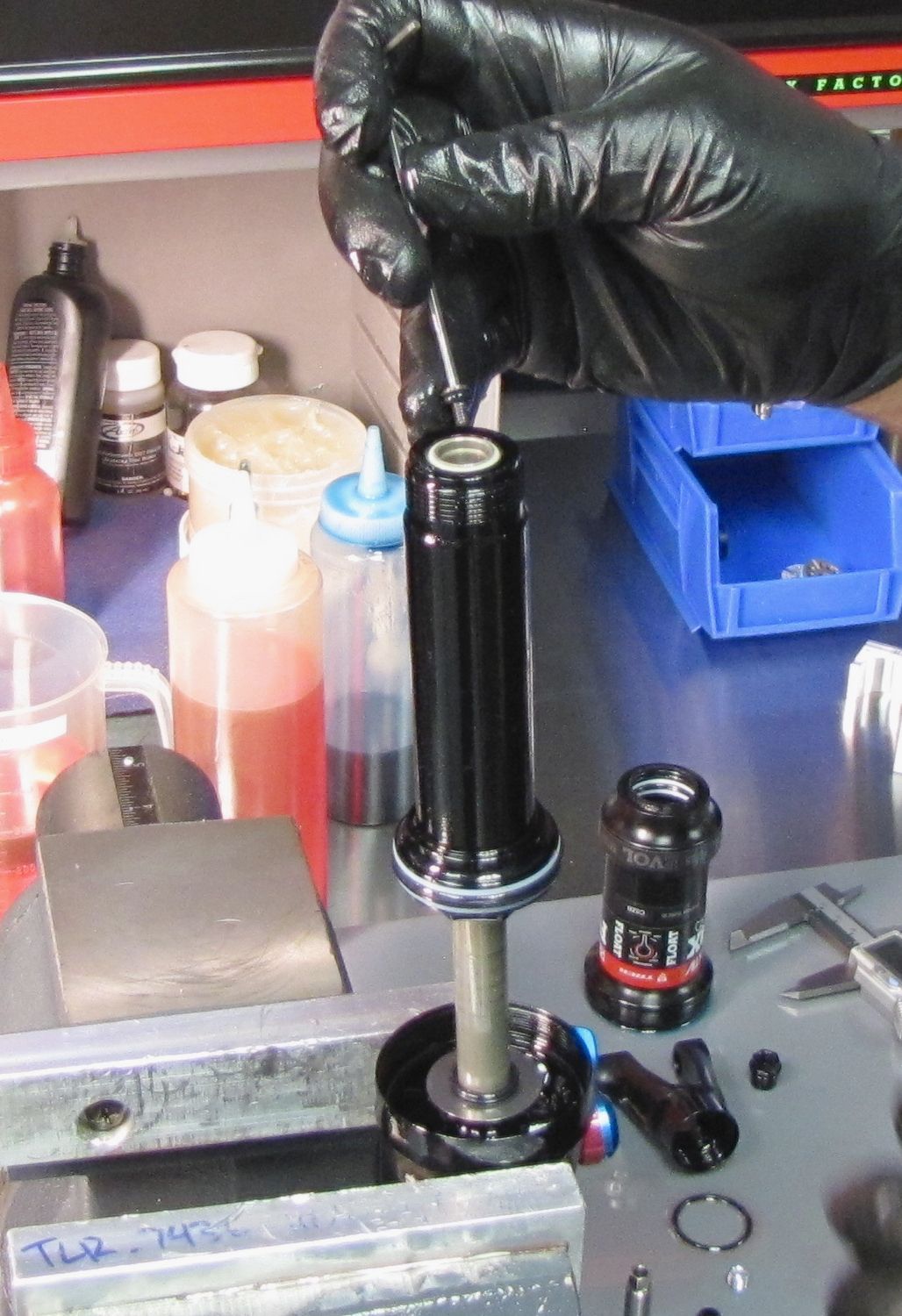
Unthread the IFP bleed screw counter-clockwise with a 2mm hex wrench. Lift the screw out with the wrench or a magnet.


Step 27
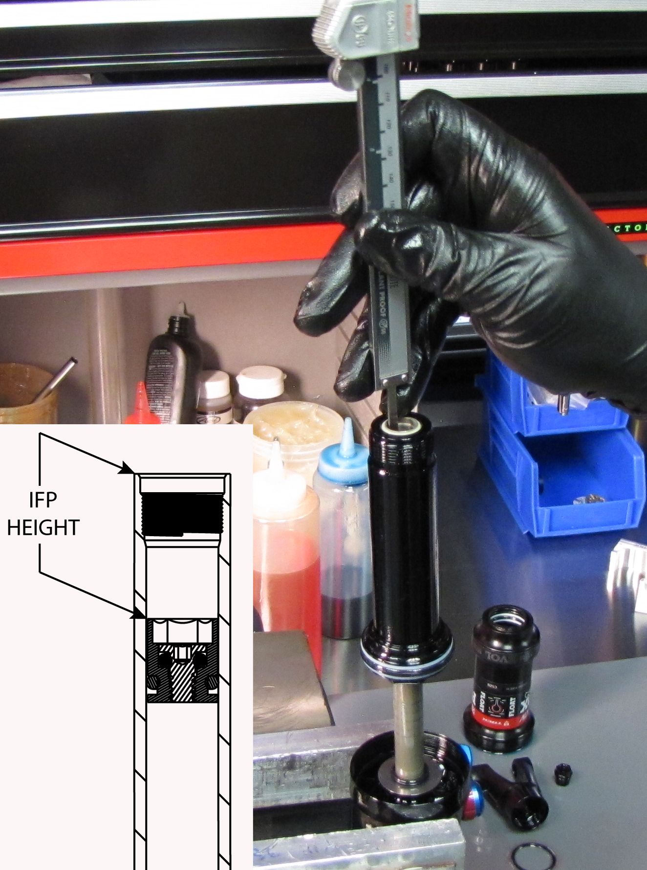
Push the IFP down to the specified IFP depth with your calipers.
| Bike Model | IFP Depth |
| EX130 | 1.050 +/- 0.050in |
| Remedy/Slash | 1.290 +/- 0.050in |

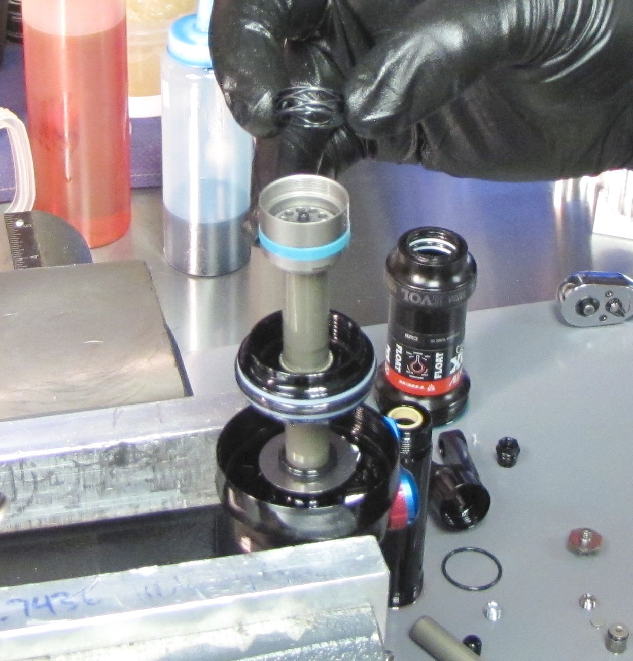
Step 28
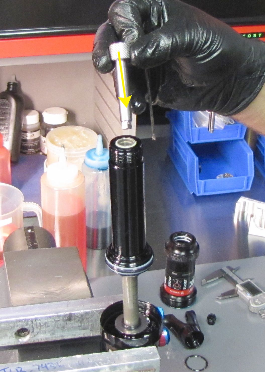
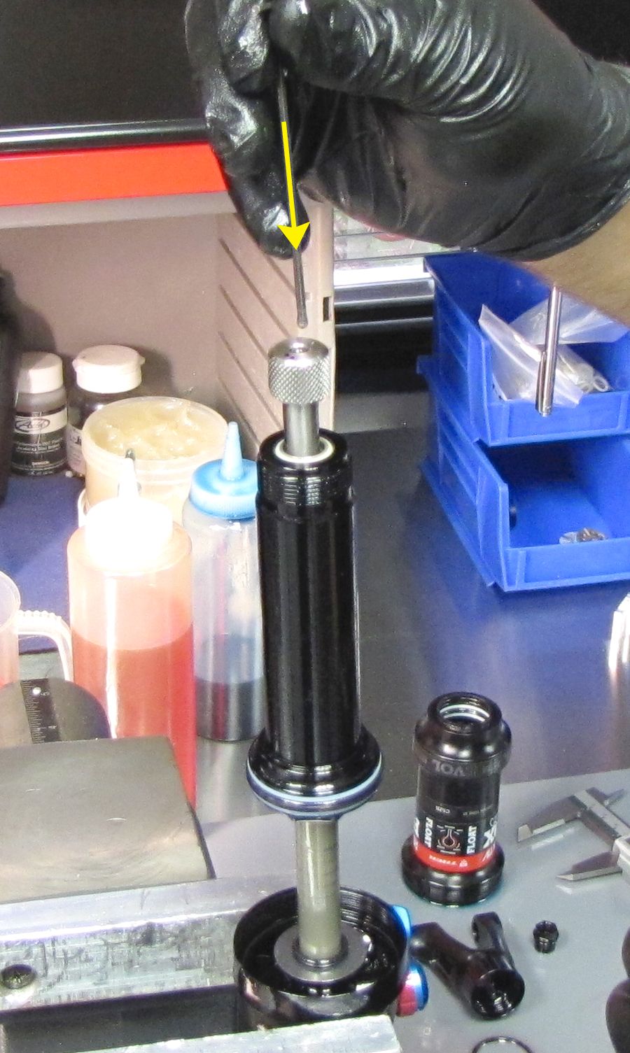
Insert the IFP bleed screw into the shaft and begin threading it clockwise into the IFP with your 2mm hex wrench. Remove the hex wrench and insert the IFP bleed screw torque tool engaging its hex feature with the hex of the IFP. Insert your 2mm hex wrench through the IFP bleed screw torque tool engaging the hex of the bleed screw. Hold the IFP bleed screw torque tool stationary while you tighten the IFP bleed screw clockwise until hand tight.
Step 29
Invert the shock over your waste oil basin to drain out excess oil from within the slave shaft.

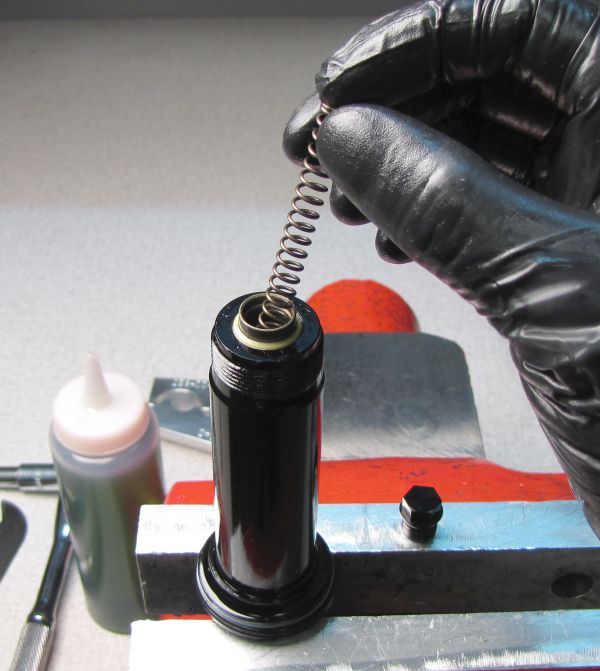
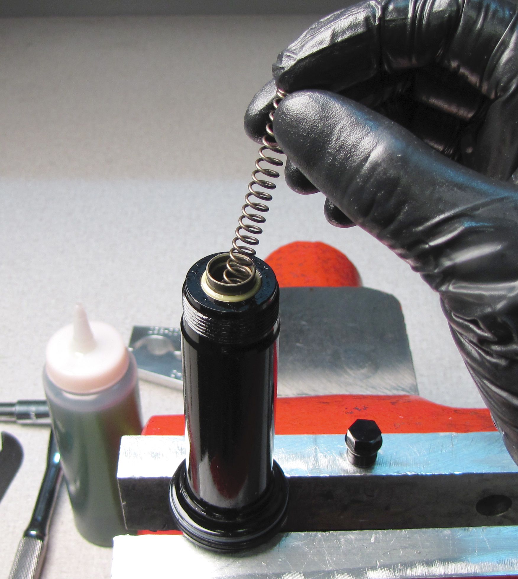
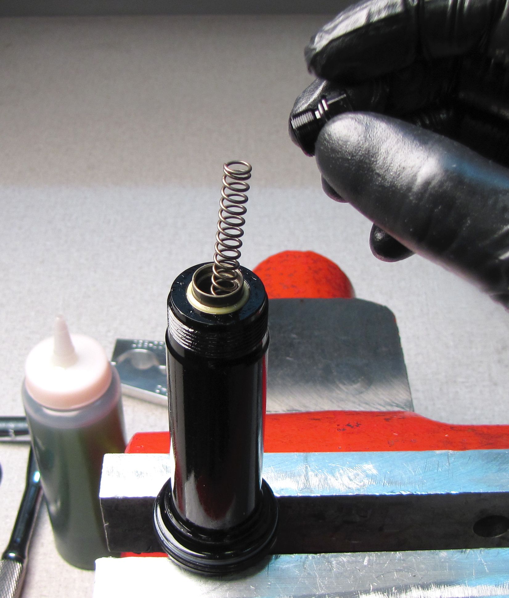
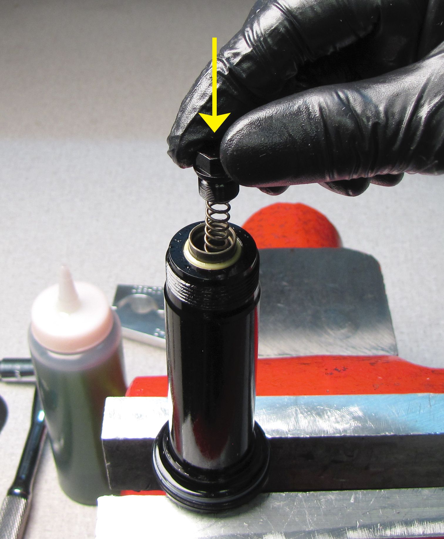
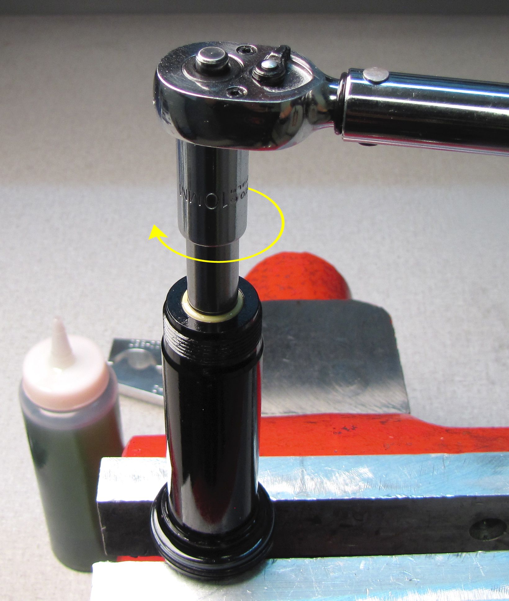
Step 30
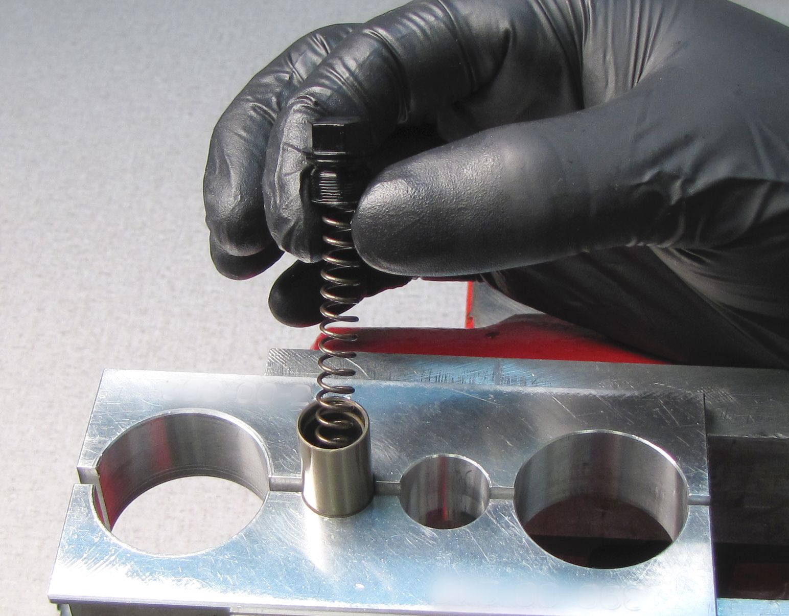
Insert the IFP spring, then use the end cap to compress the spring. Thread the slave shaft end cap clockwise into the slave shaft tightening to 22in-lb (2.5 Nm) with a 10mm socket.
Note: End Cap torque is critical. Only install the End Cap using a torque wrench!
Step 31
Apply a thin film of Float Fluid to the main air seals on the bearing assembly and the seals in the end of the air sleeve. Slide the air sleeve onto the shock damper, then thread it to the eyelet clockwise until hand tight.


Step 32
Install a new travel indicator o-ring from the kit onto the body. Slide the clevis over the slave shaft, then begin threading it clockwise onto the shock body. Carefully clamp the flats of the Clevis in your soft-jawed vise. Tighten to 180 in-lb with your 21mm cone wrench or thinned crows foot.

Step 33
Attach your shock pump then add air while you slowly cycle your shock through 25% of its travel 10 times as you reach your desired pressure. Reinstall the black air cap. Clean the exterior of your shock and dyno test it to verify proper function.

