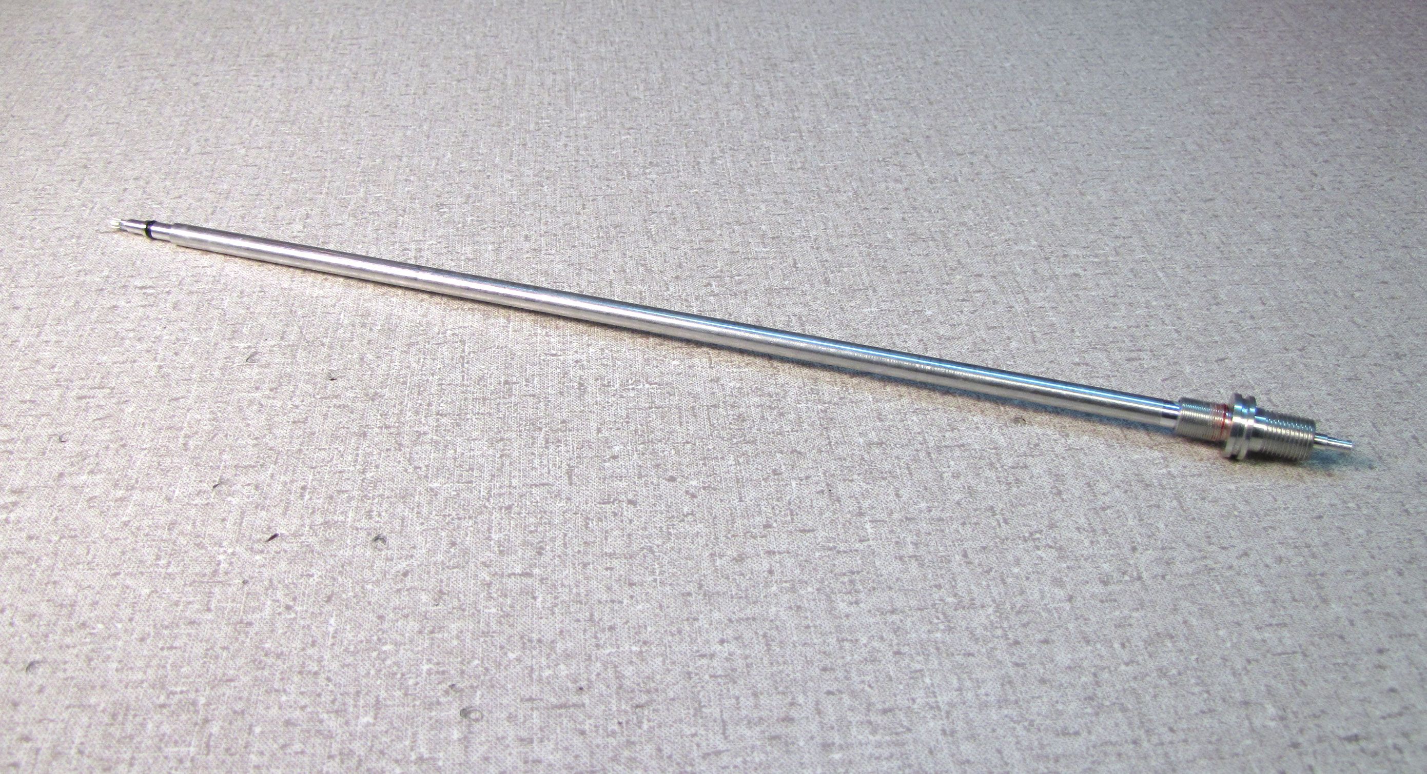
2016-2018 36mm/40mm P-S/P-Se FIT4 LSC (RC) Damper Cartridge Rebuild
Required Parts
- 803-00-961 Seal Kit: 36 & 40 FIT4 Cartridge Rebuild
Required Tools
- 398-00-320 Tool: 8mm Shaft Bullet, 32 FIT Cartridge
- 398-00-371 Tooling: Sealhead To Shaft Bullet, 10mm
- 398-00-682 2005-017 34-36-40 Damper-side Removal Tool
- 398-00-707 Tooling: Fork Topcap Socket, 28mm V2, 3/8 Drive
- 803-00-147 Kit: Shaft Clamps, 07 FORX, Set #2 (32 X Body, 36, 40 Forx) (For 8mm Shafts)
- 803-00-276 Service Kit: Hand Bleed, Syringe and Tube, 2010 32 Fit RL-RLC Cartridge
- 803-00-830 Service Set: Tooling: 2014 RC2, Shaft Clamps (For 10mm Shafts)
WARNING: Always wear safety glasses and protective gloves during service to prevent potential injury. Failure to wear protective equipment during service may lead to SERIOUS INJURY OR DEATH.
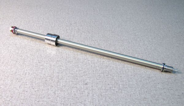
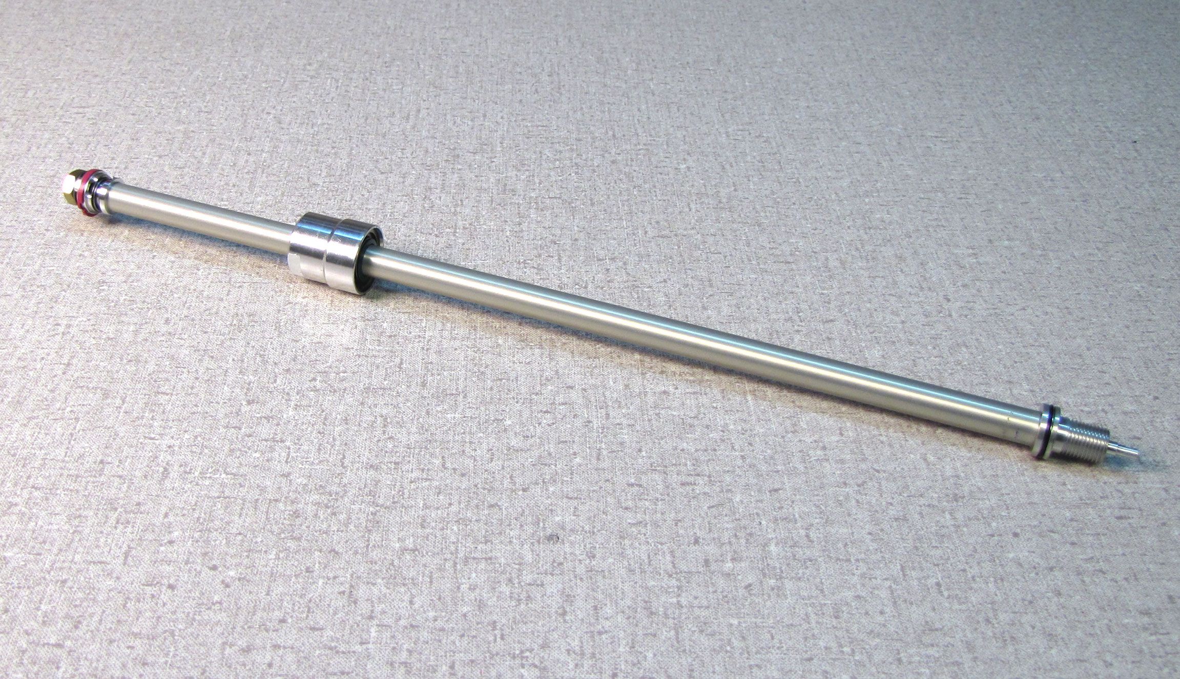
The following procedure guides you through the rebuild of the 36mm/40mm P-S/P-Se FIT4 LSC damper cartridge.
Additional information and part drawings can be found here: All Partlists »
WARNING: FOX products should be serviced by a trained bicycle service technician, in accordance with FOX specifications. If you have any doubt whether or not you can properly service your FOX product, then DO NOT attempt it. Improperly serviced products can fail, causing the rider to lose control resulting in SERIOUS INJURY OR DEATH.
WARNING: FOX suspension products contain pressurized nitrogen, air, oil, or all 3. Suspension misuse can cause property damage, SERIOUS INJURY OR DEATH. DO NOT puncture, incinerate or crush any portion of a FOX suspension product. DO NOT attempt to disassemble any portion of a FOX suspension product, unless expressly instructed to do so by the applicable FOX technical documentation, and then ONLY while strictly adhering to all FOX instructions and warnings in that instance.
WARNING: Modification, improper service, or use of aftermarket replacement parts with FOX forks and shocks may cause the product to malfunction, resulting in SERIOUS INJURY OR DEATH. DO NOT modify any part of a fork or shock, including the fork brace (lower leg cross brace), crown, steerer, upper and lower leg tubes, or internal parts, except as instructed herein. Any unauthorized modification may void the warranty, and may cause failure or the fork or shock, resulting in SERIOUS INJURY OR DEATH.

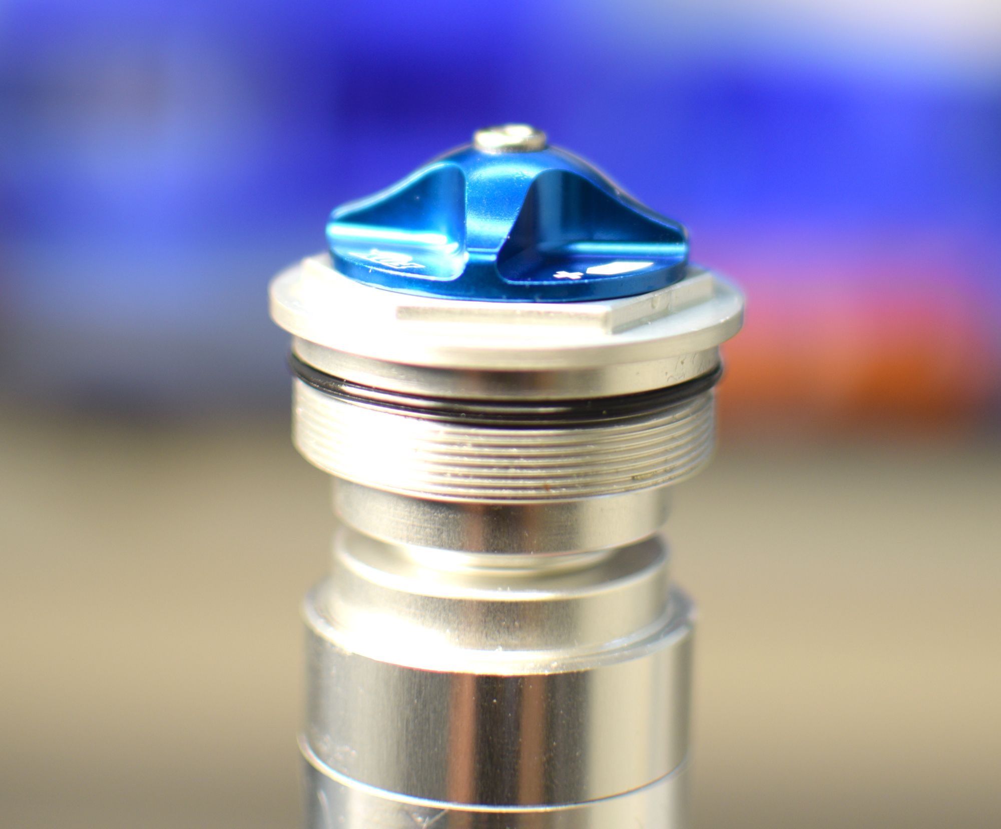
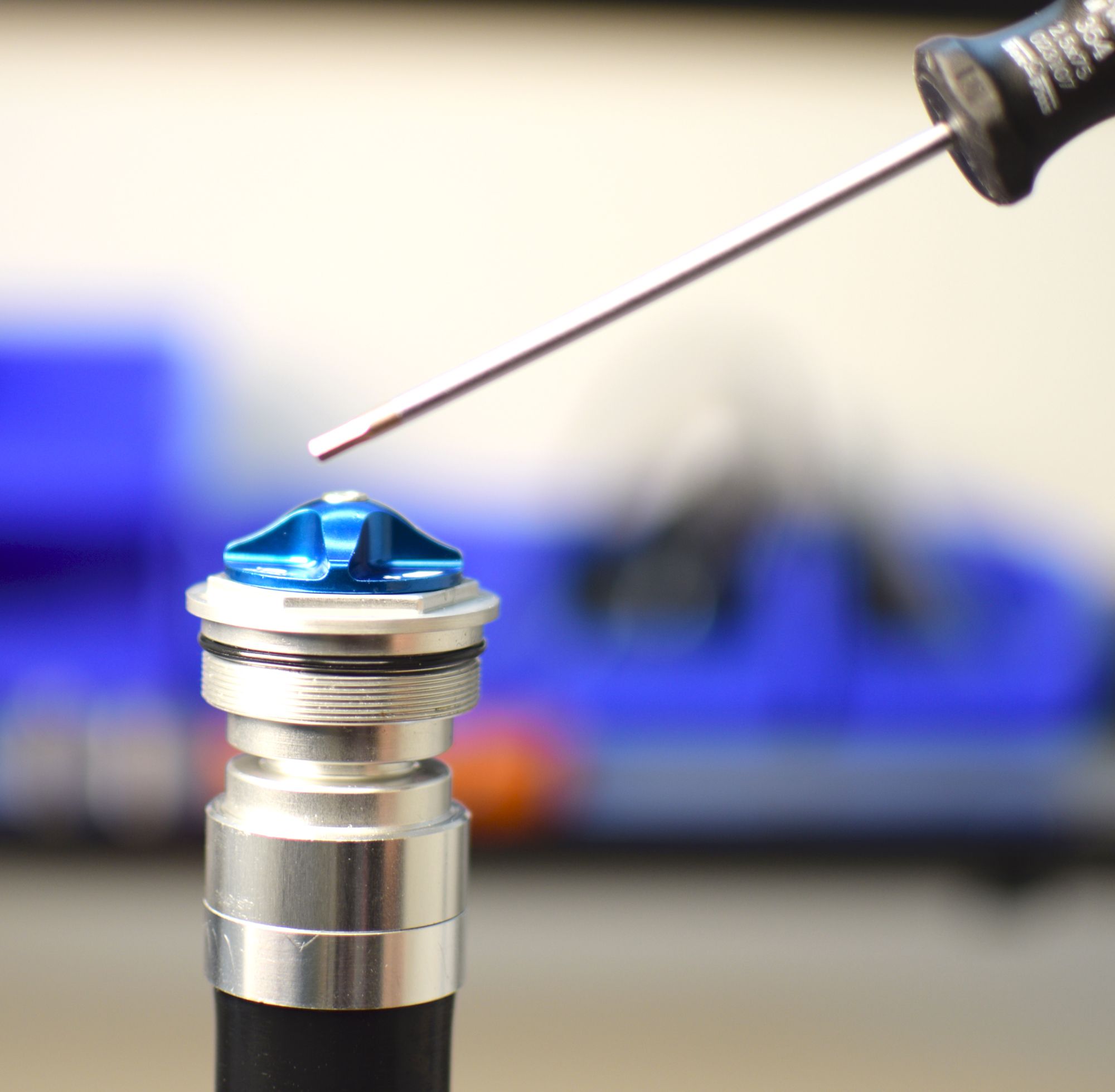
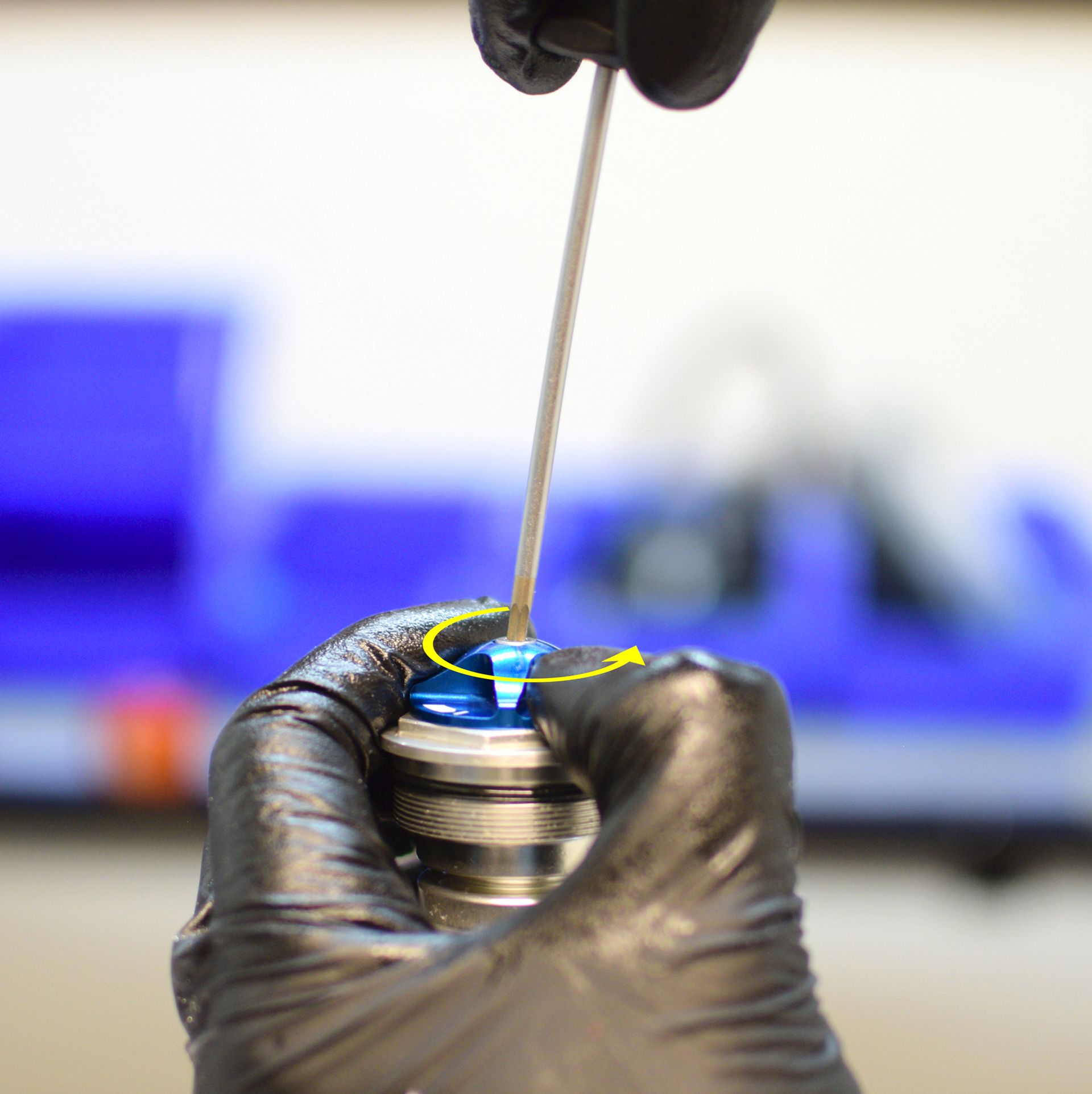
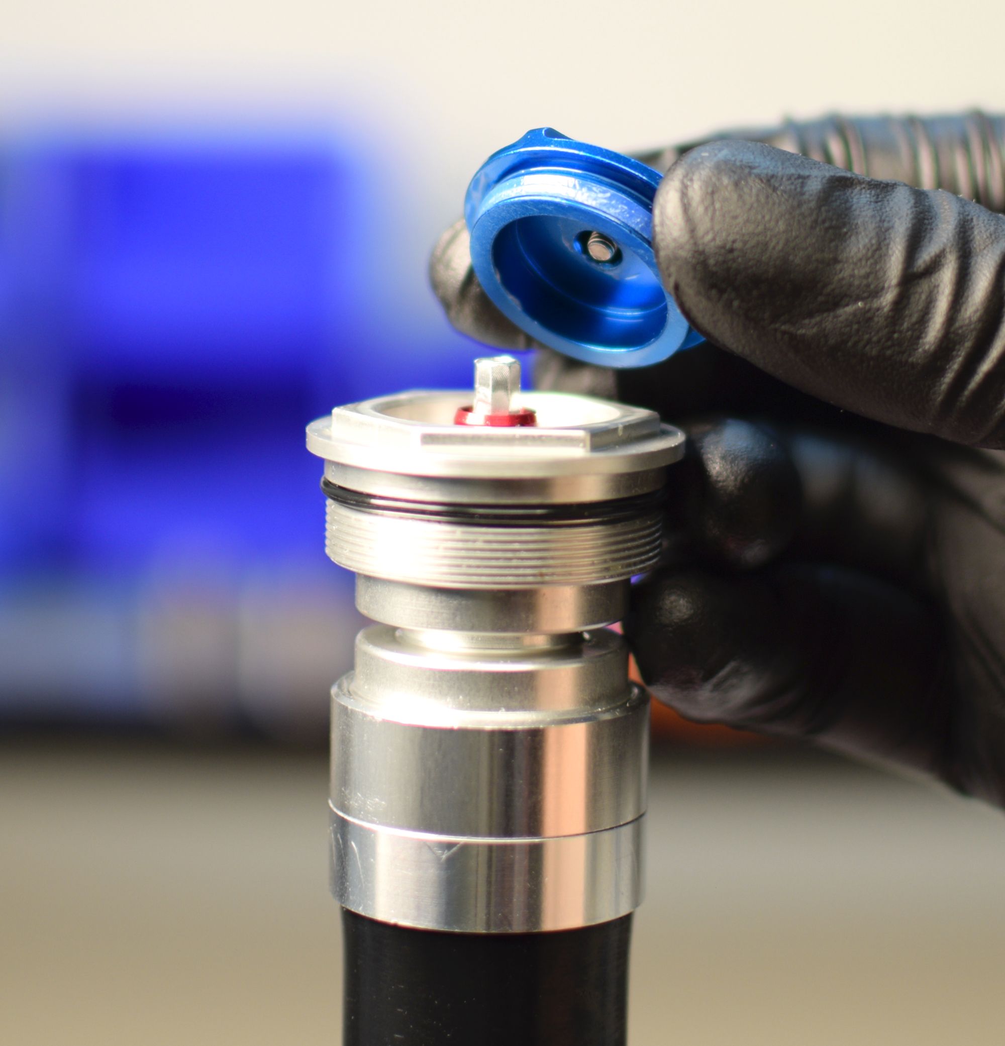
Step 1
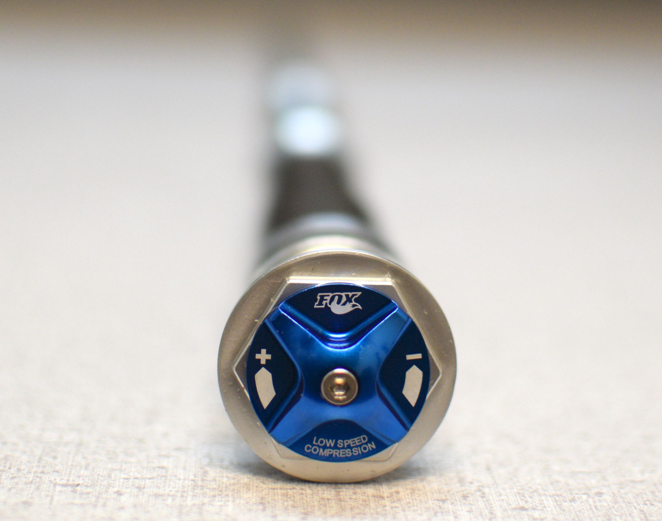
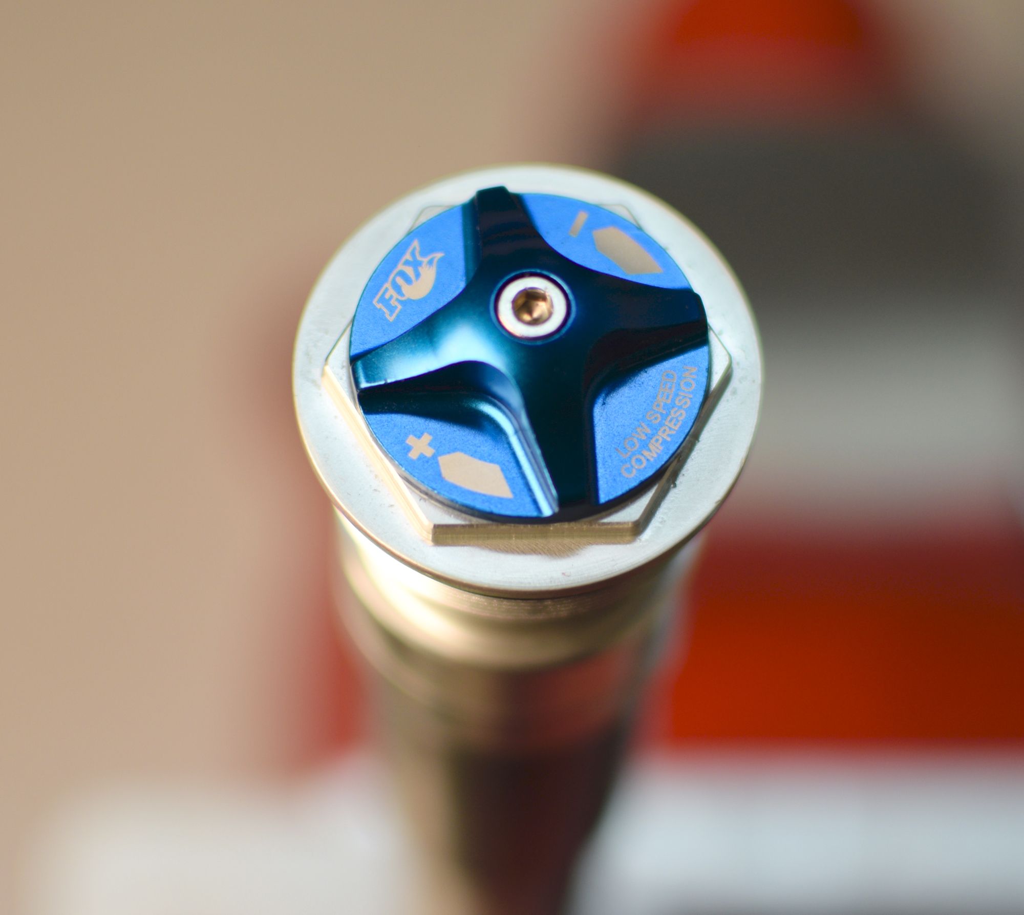
Hold the Low Speed Compression (LSC) knob while you unthread the set screw counter-clockwise with a 2.5mm hex wrench. Lift up on the knob with set screw to remove both, then set them aside.


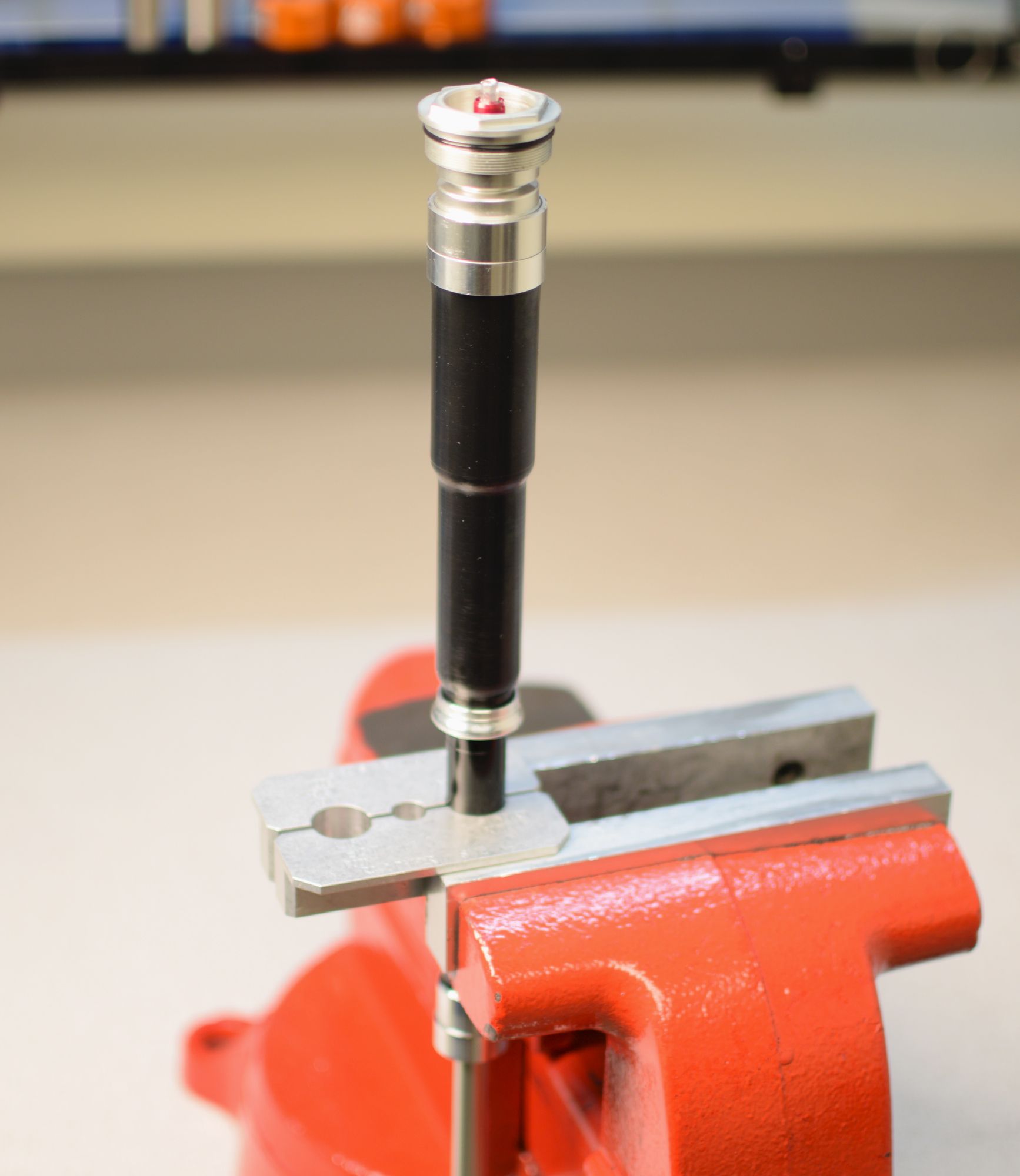
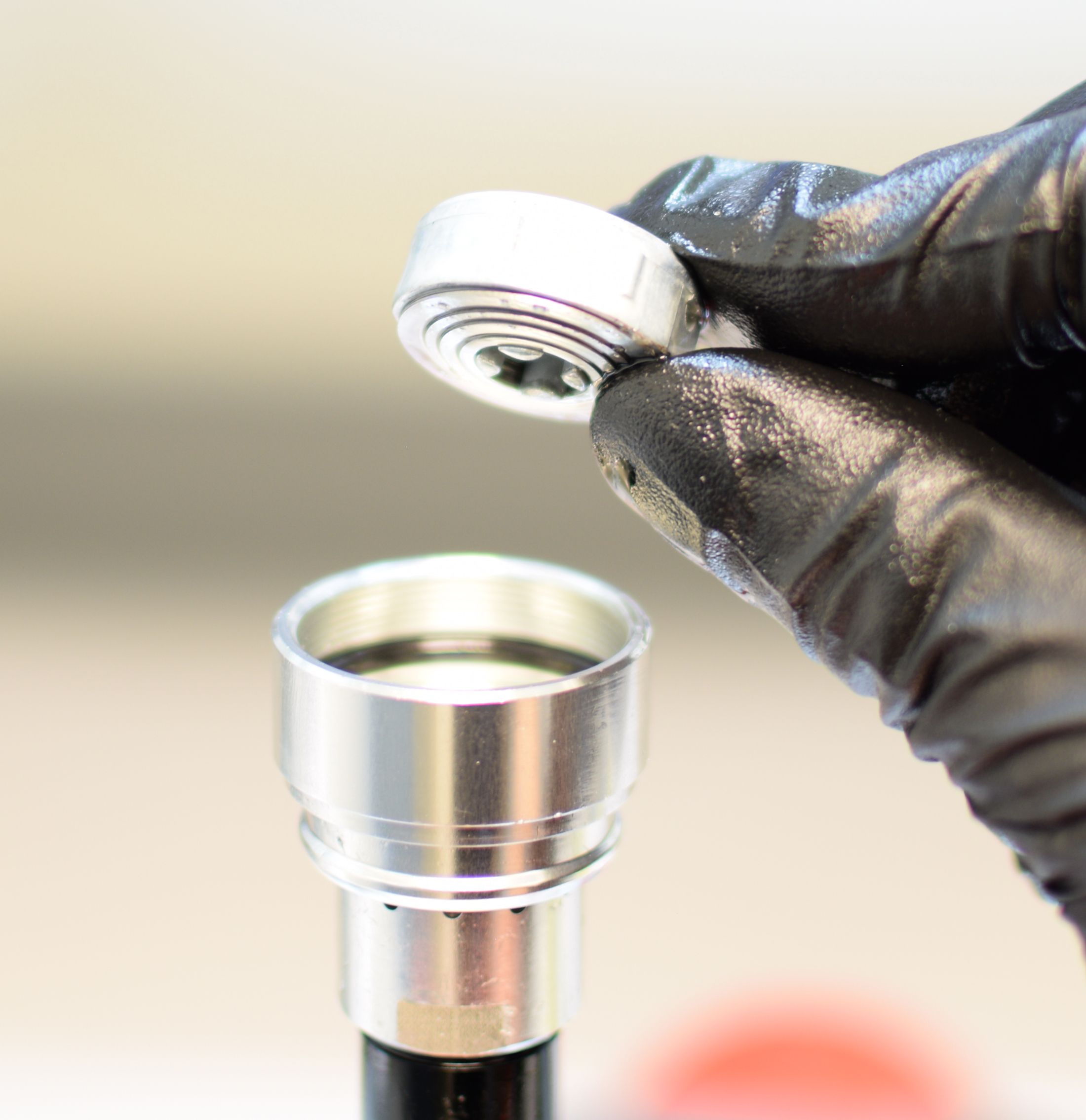
Step 2
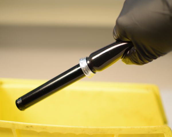
Clean the cartridge body with Isopropyl alcohol and dry it. Carefully clamp the cartridge body in your shaft clamps and loosen the sealhead counter-clockwise no more than 1 turn. Remove the cartridge from the clamps and continue unthreading the sealhead over your oil drain. Remove the damper shaft assembly from the cartridge body and drain the oil.
Step 3
Squeeze the bladder with the open end of the cartridge body above your oil drain to purge most of the remaining oil from the damper.


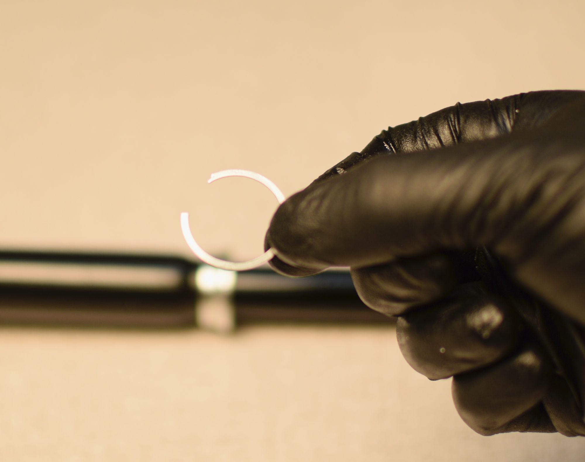
Step 4
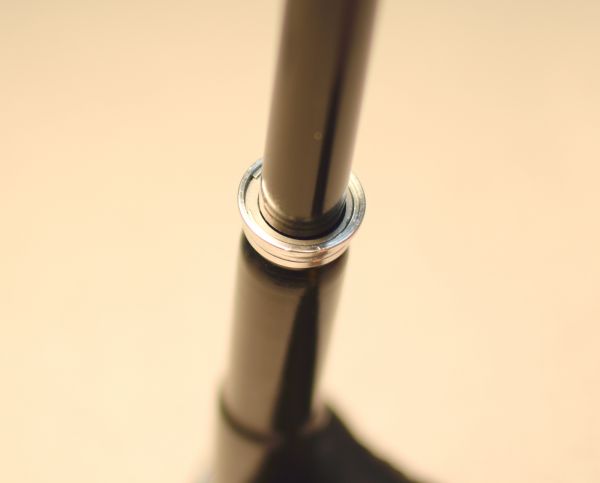
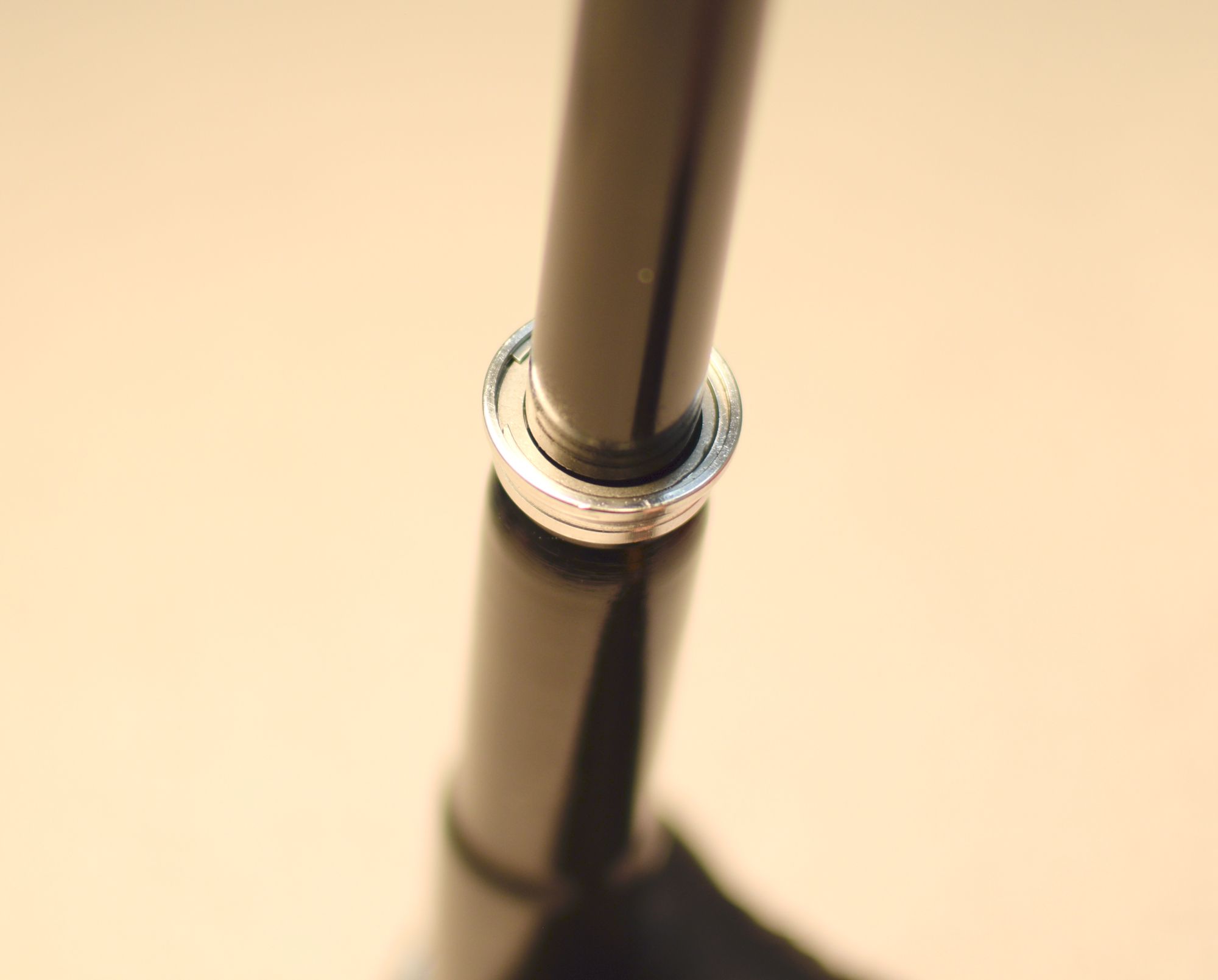
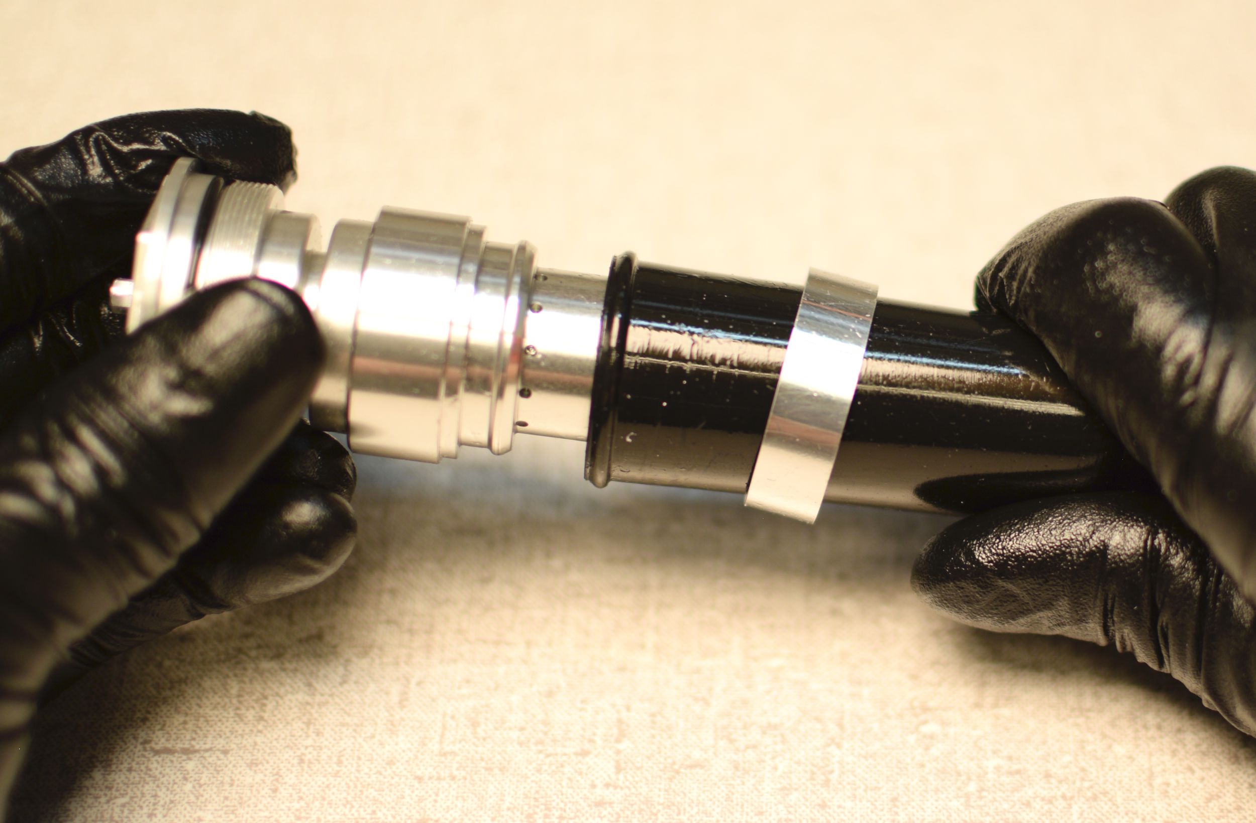
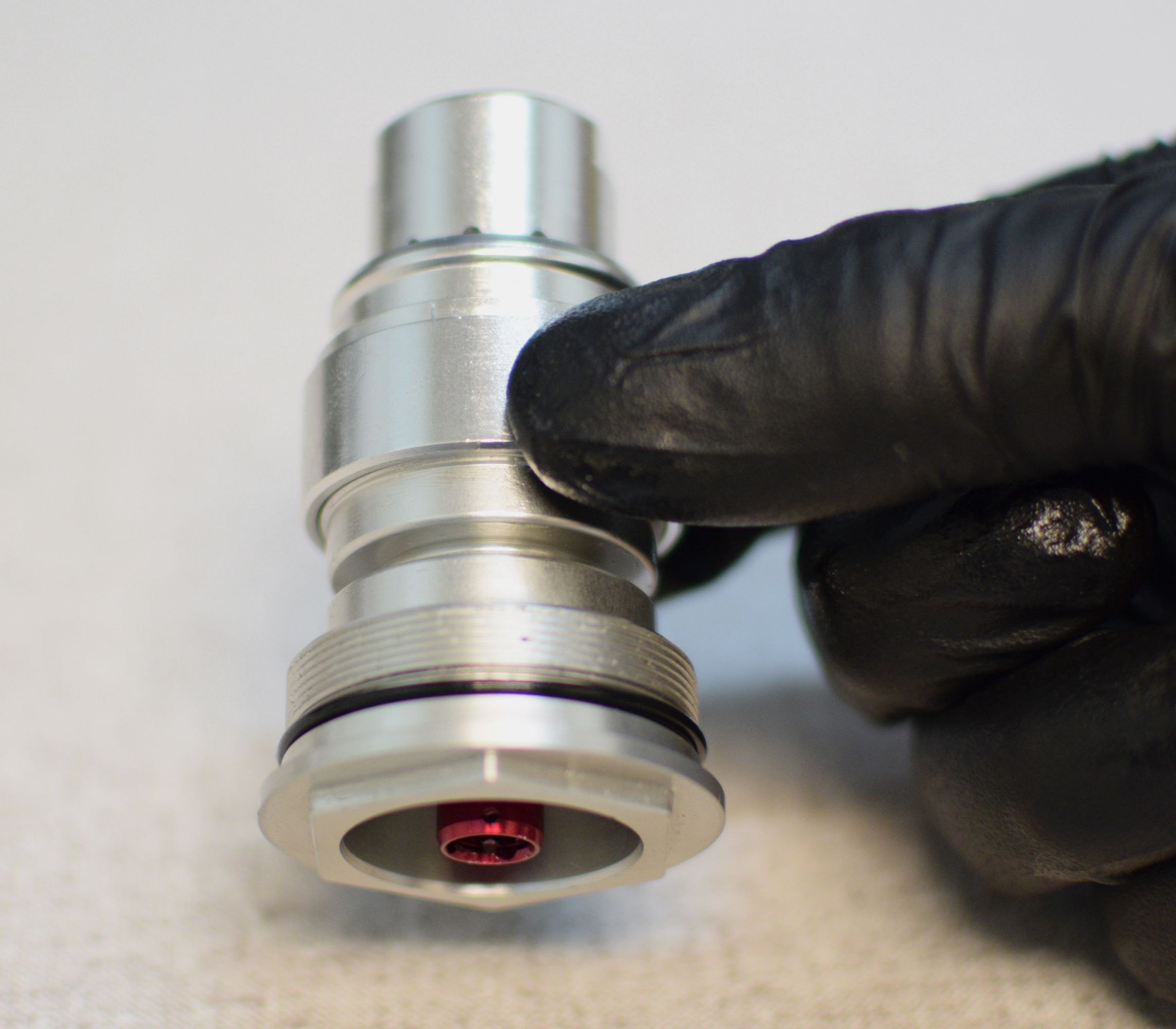
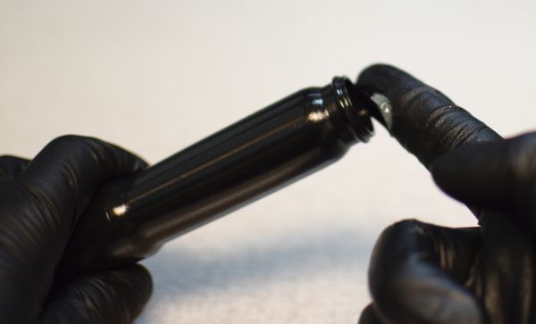
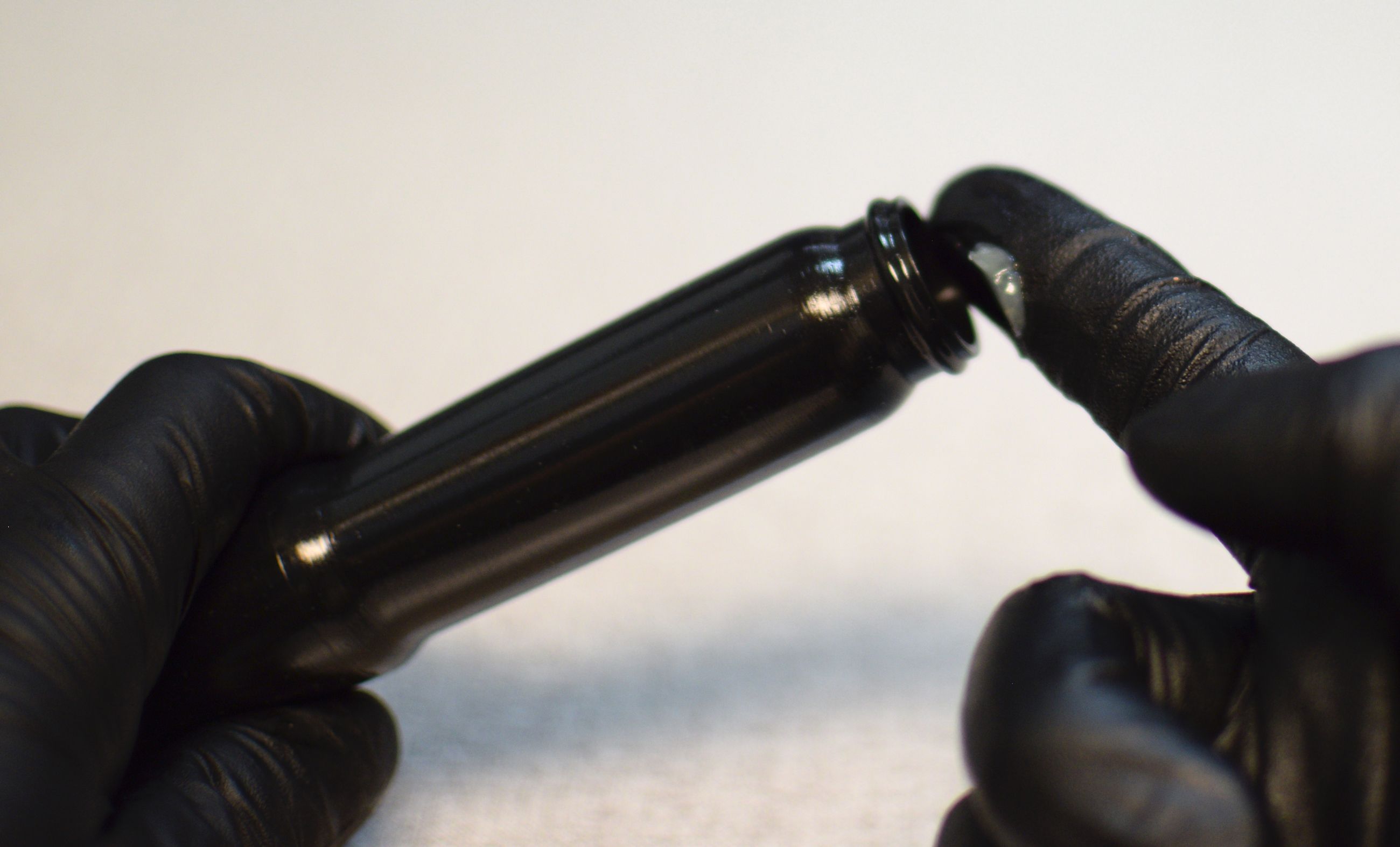
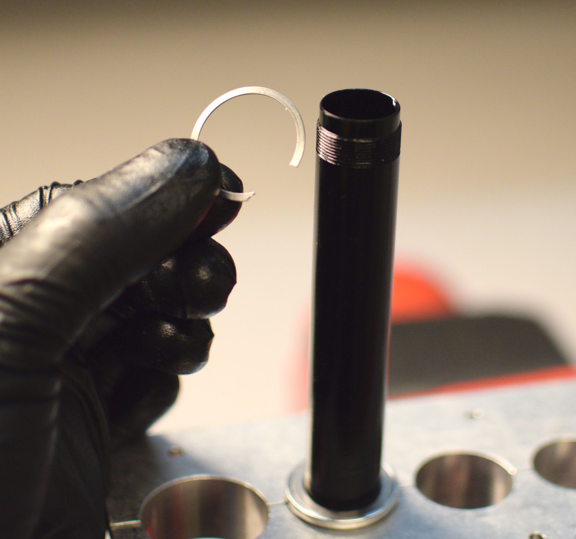
Remove the retaining ring and bladder ring retainer being careful not to scratch the smooth bladder sealing surface on the black cartridge body.


Step 5
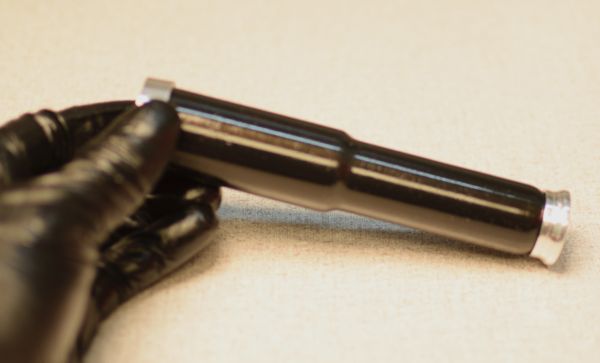
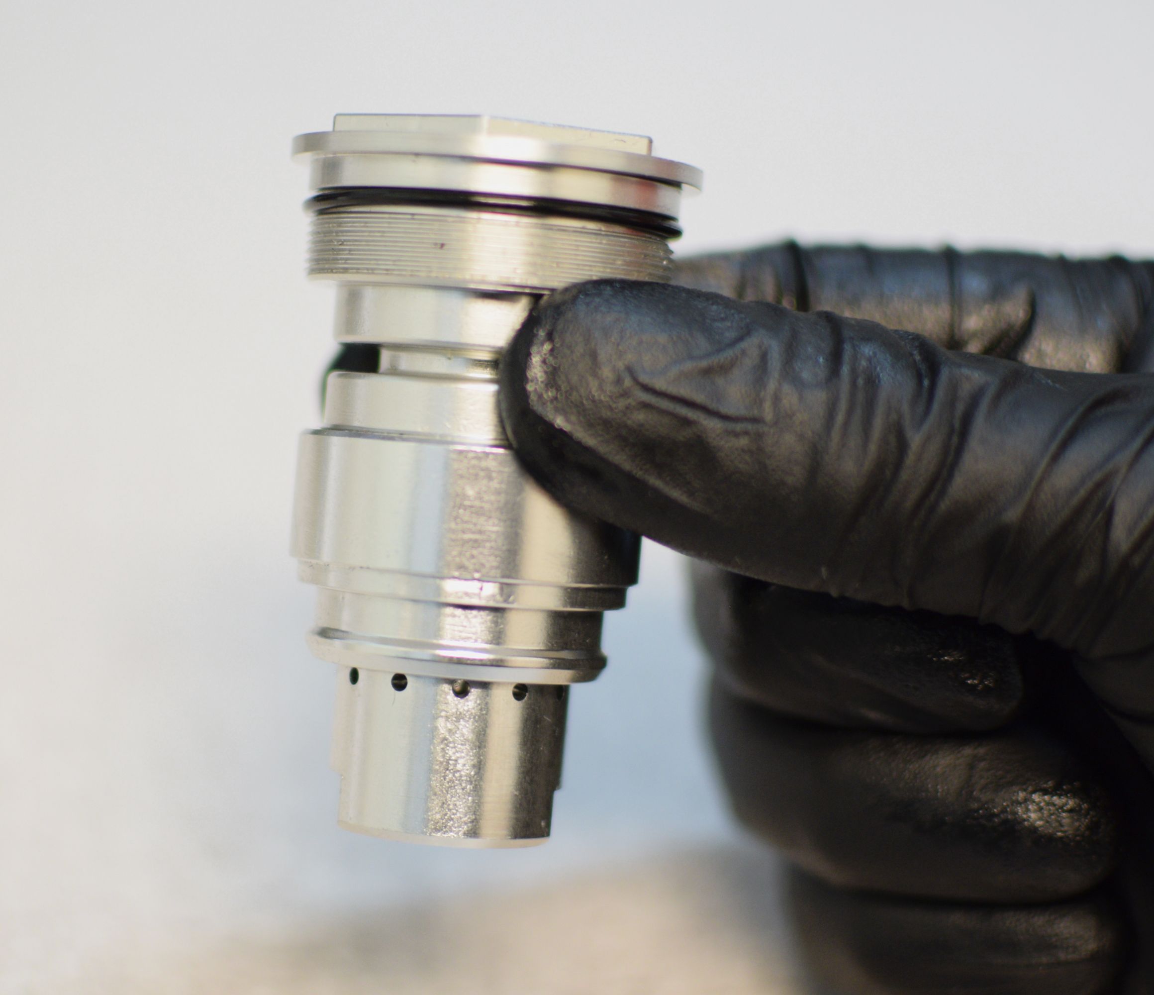
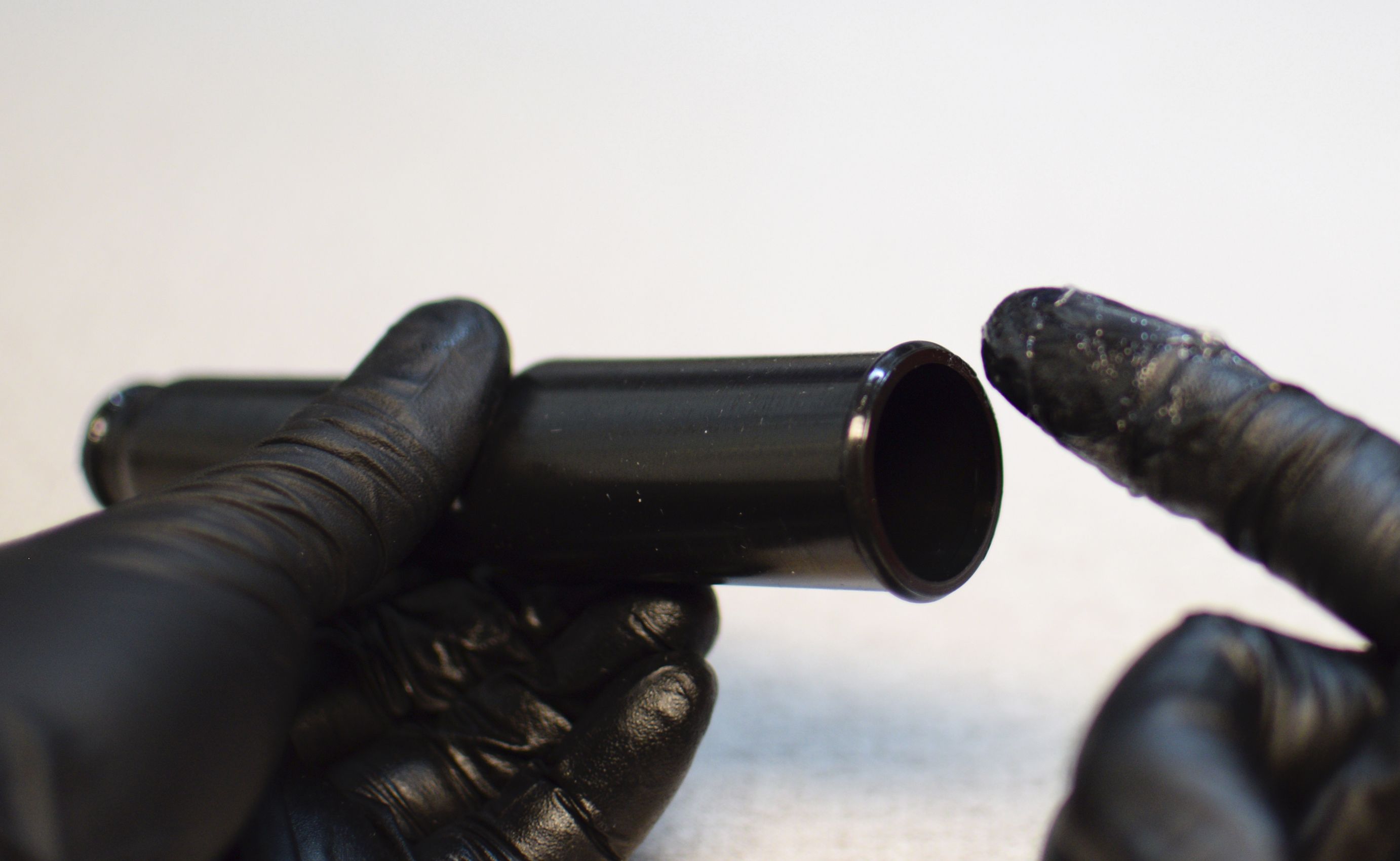
Slide the upper bladder ring away from the topcap to release the bladder. Slide the bladder with both bladder rings off the end of the cartridge body.


Step 6
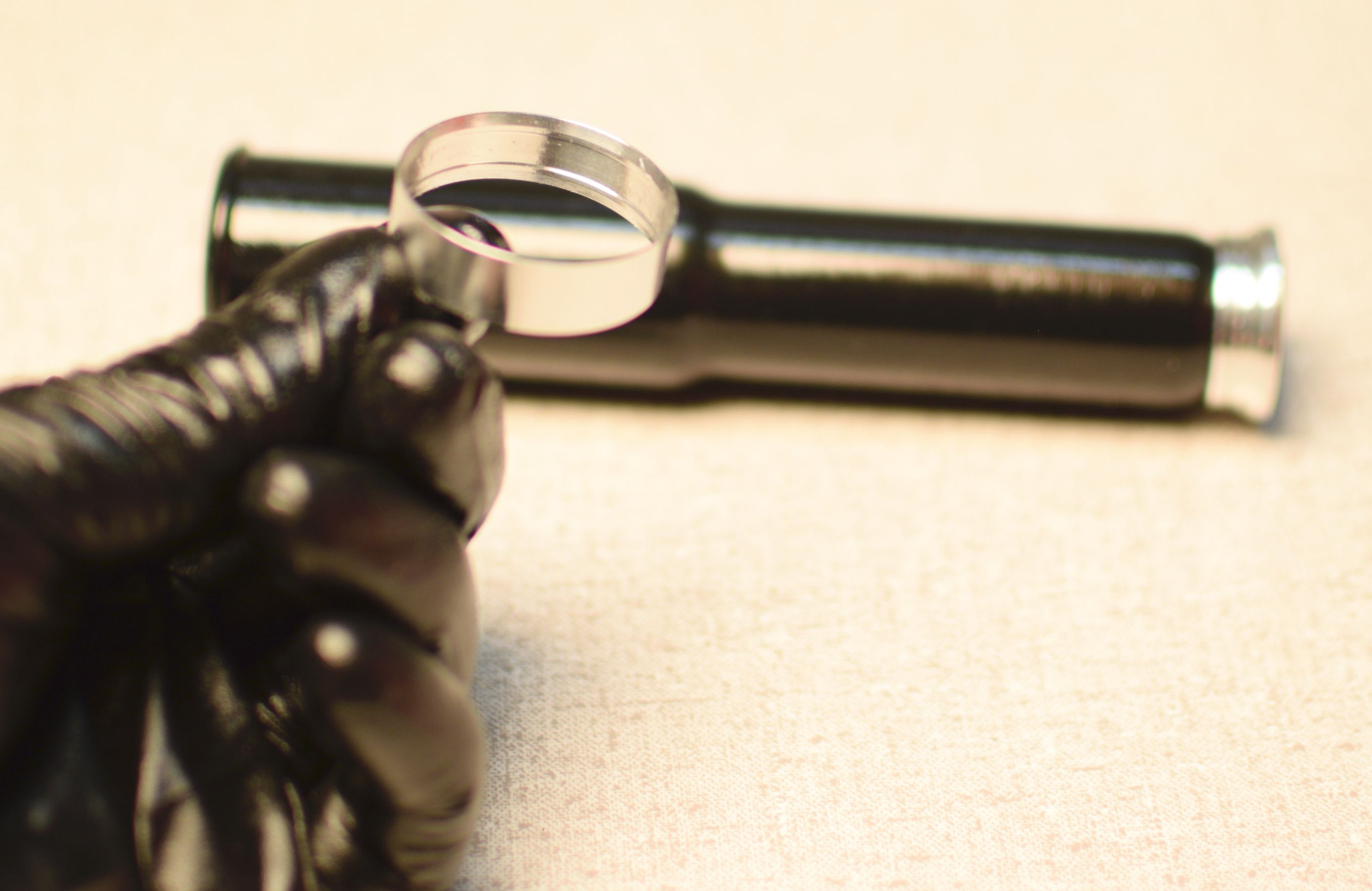
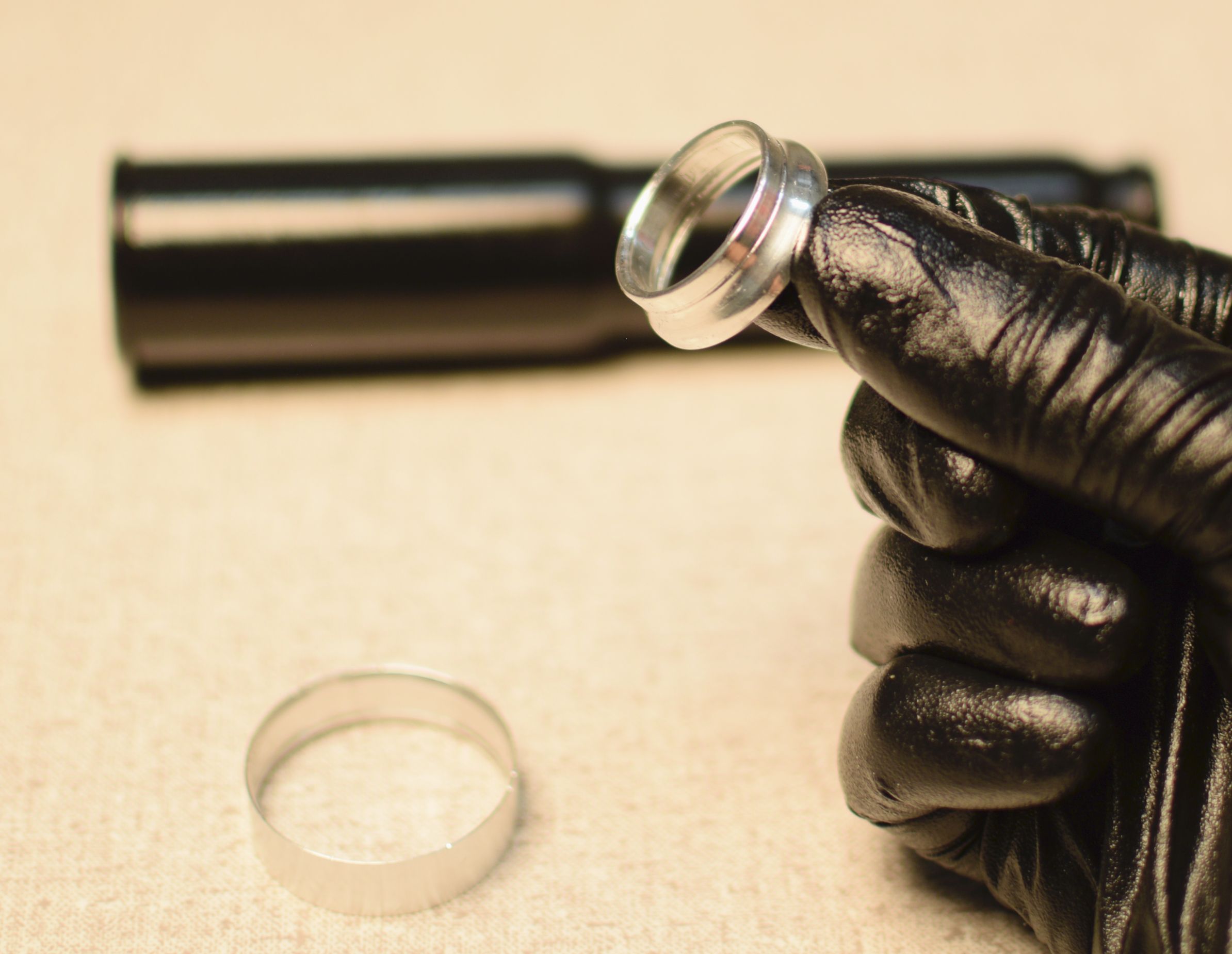
Remove the bladder rings from the bladder.

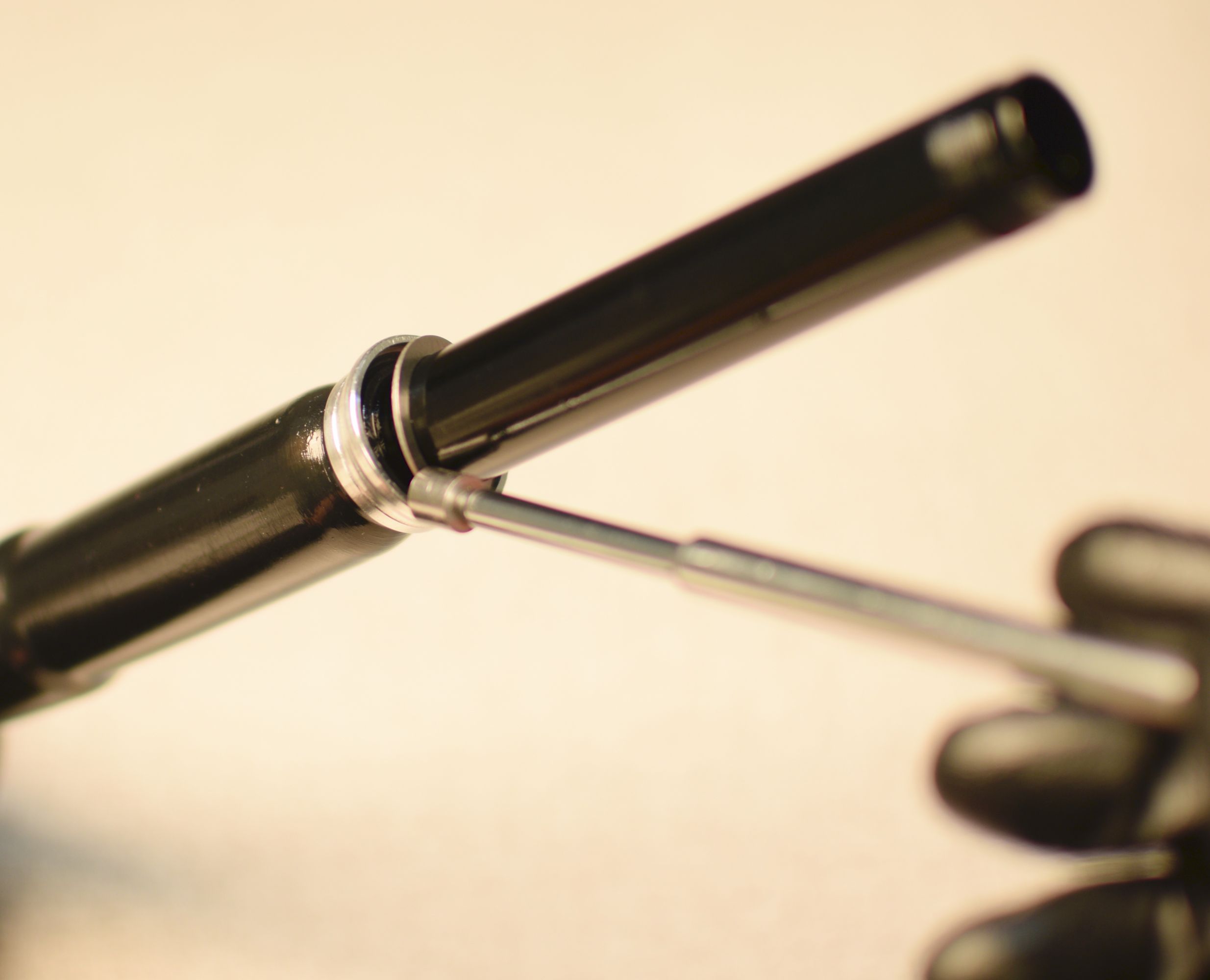
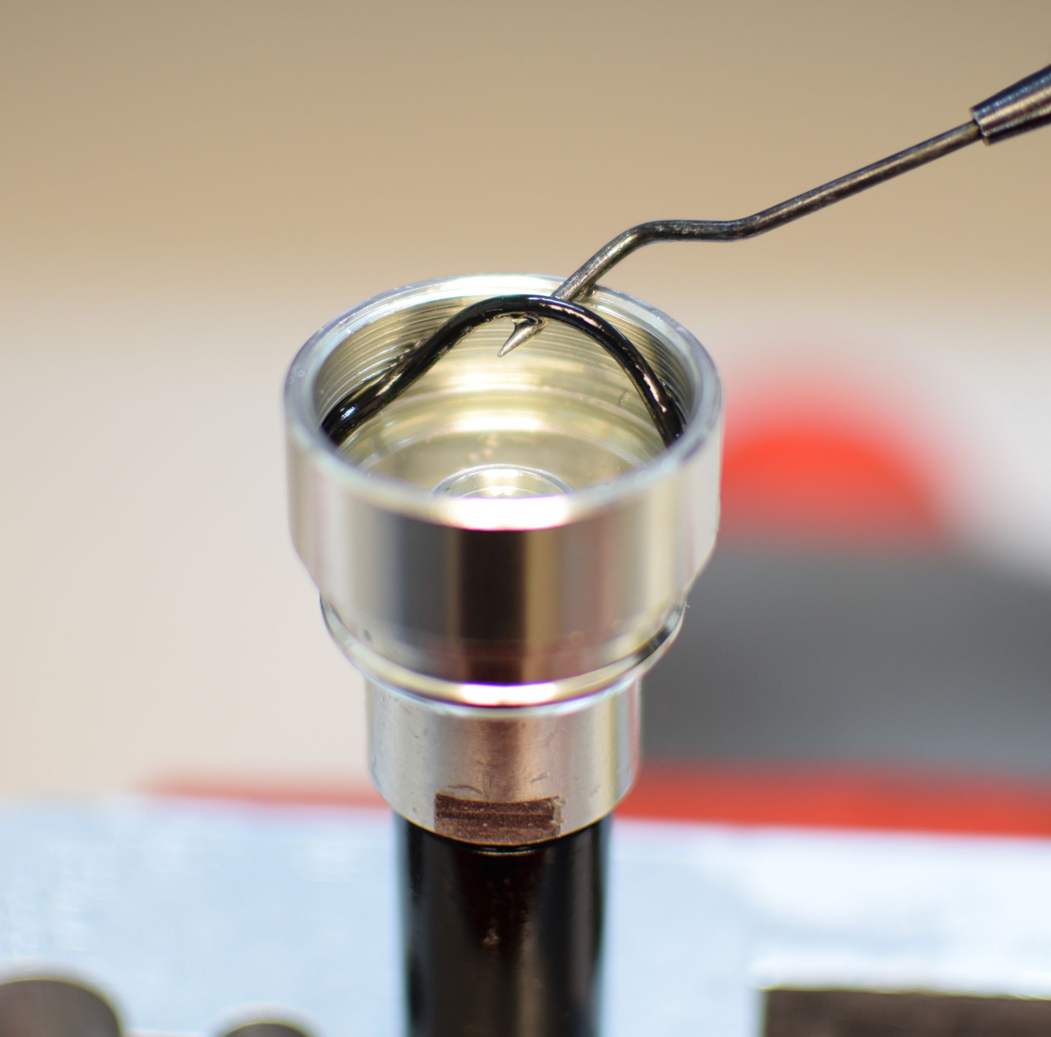
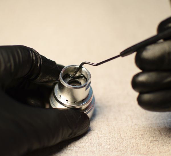
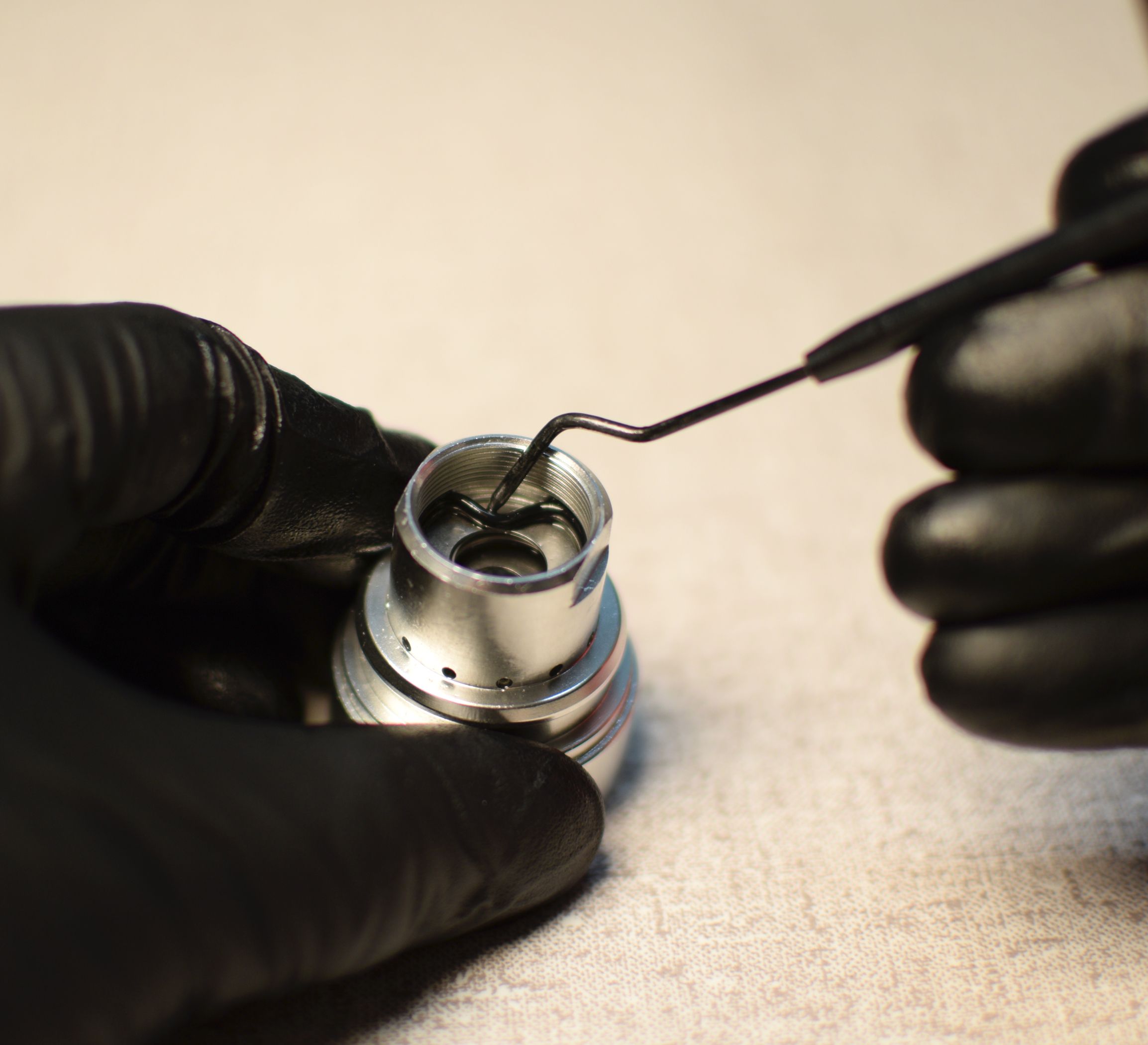
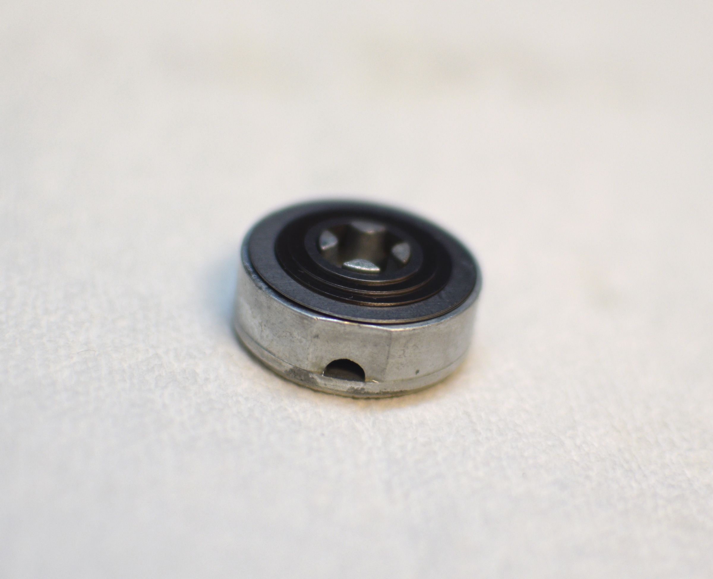
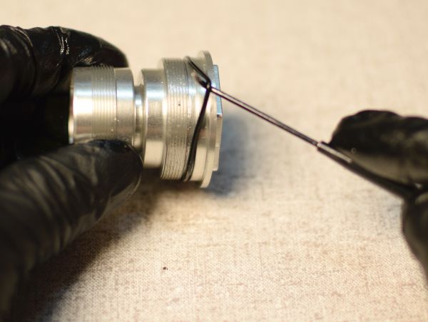
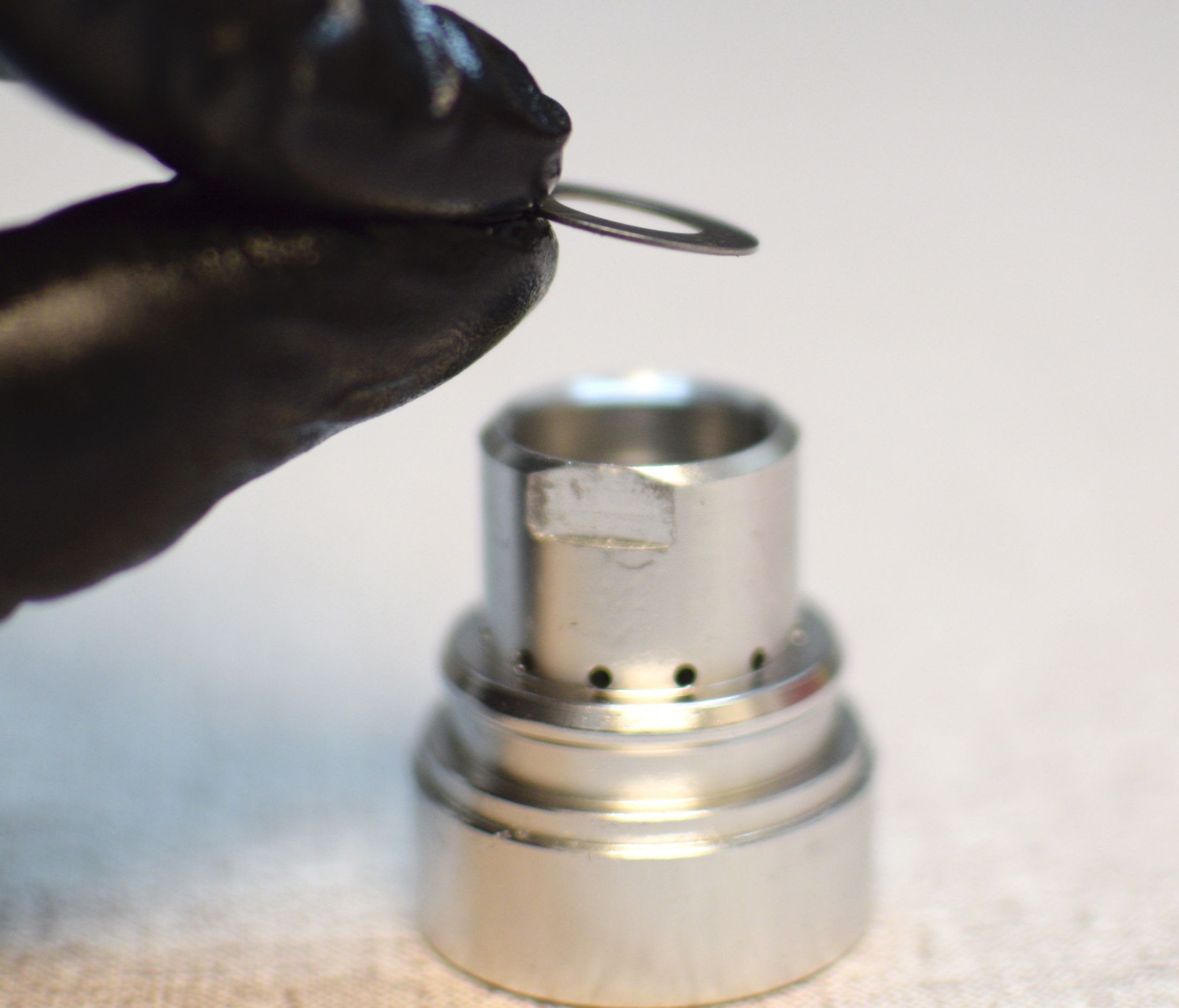
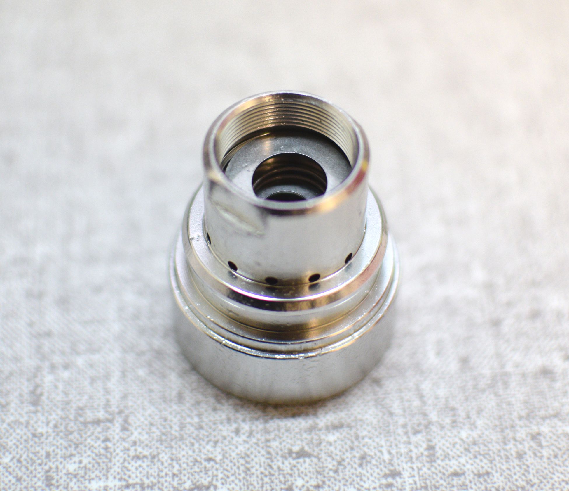
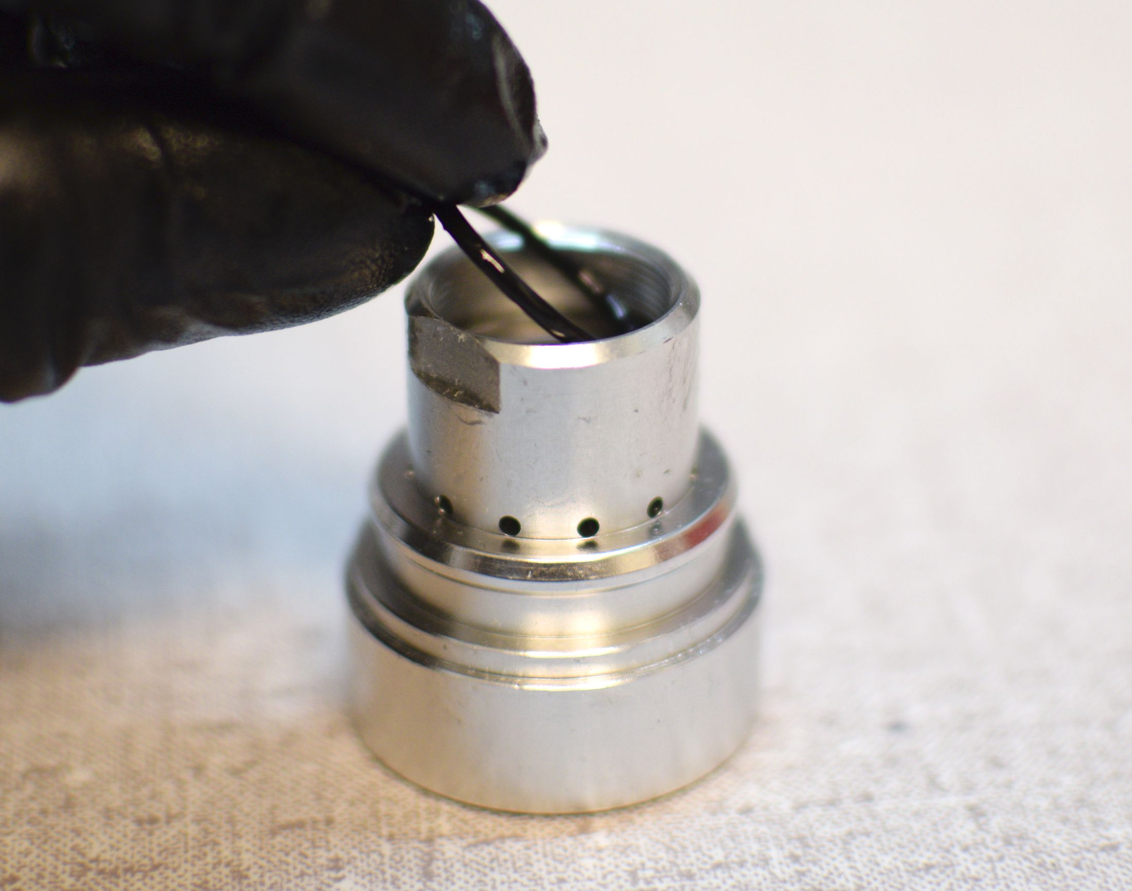
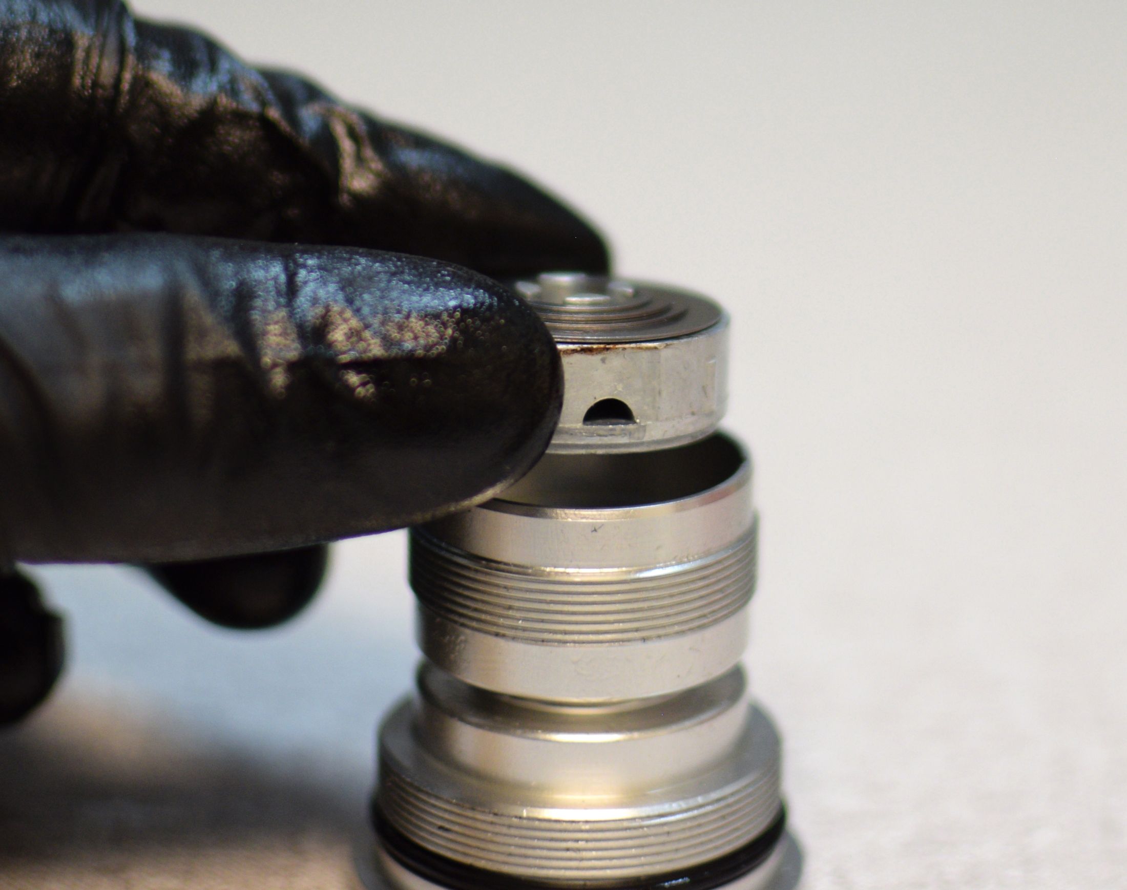
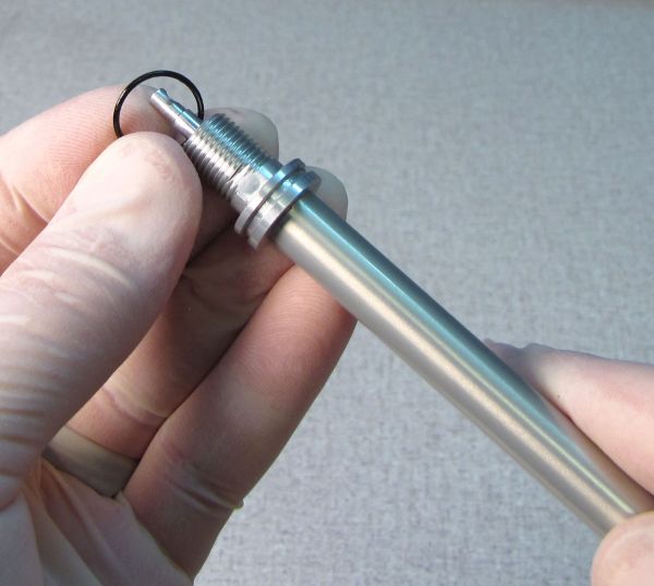
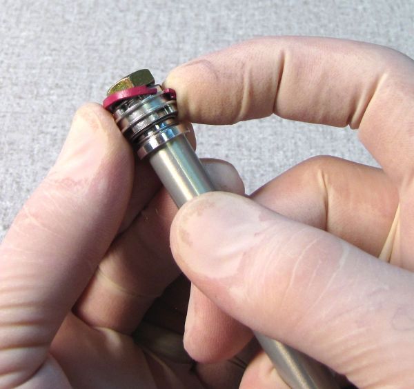
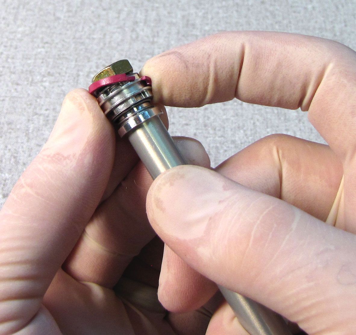
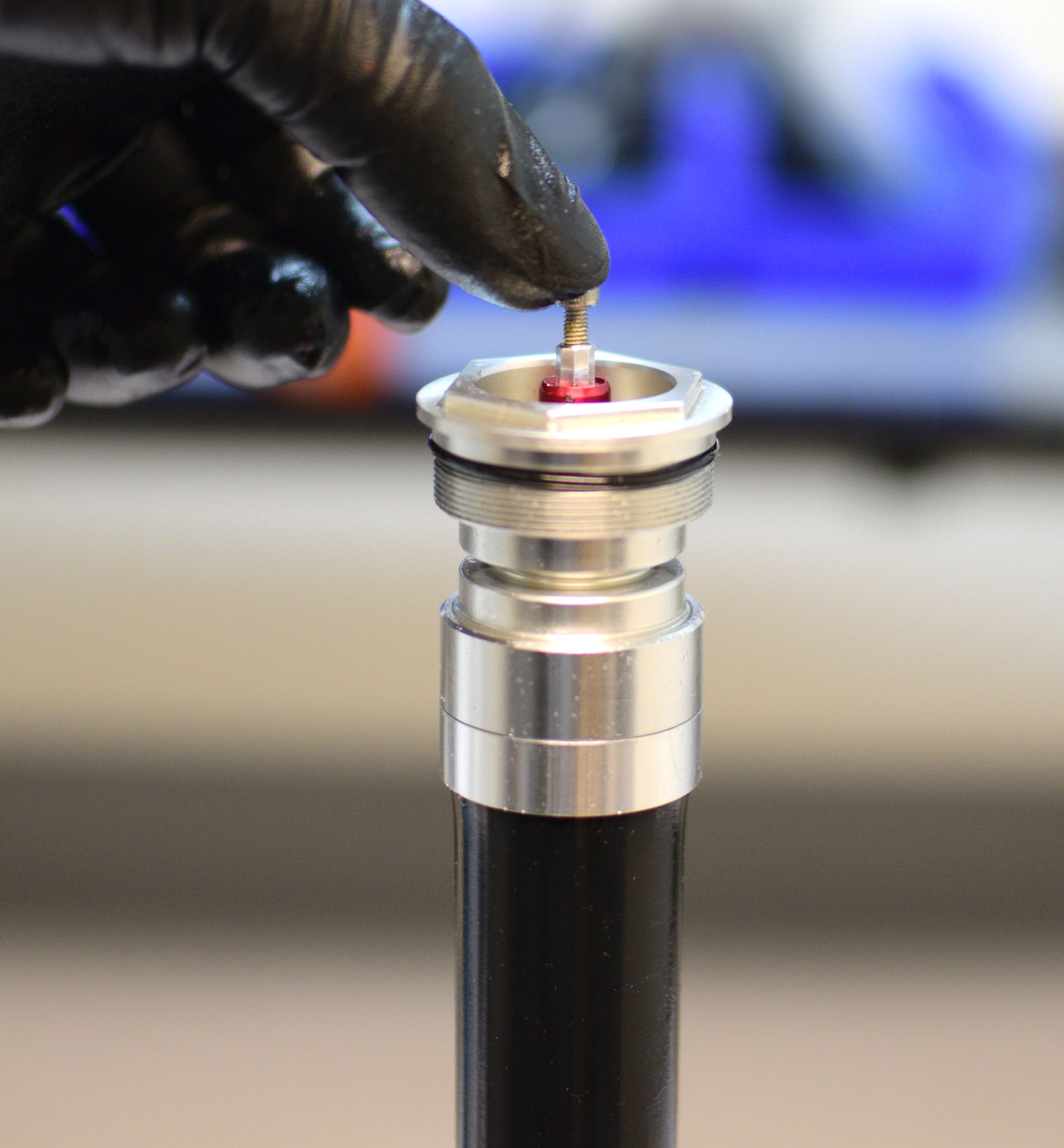
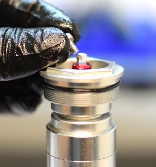
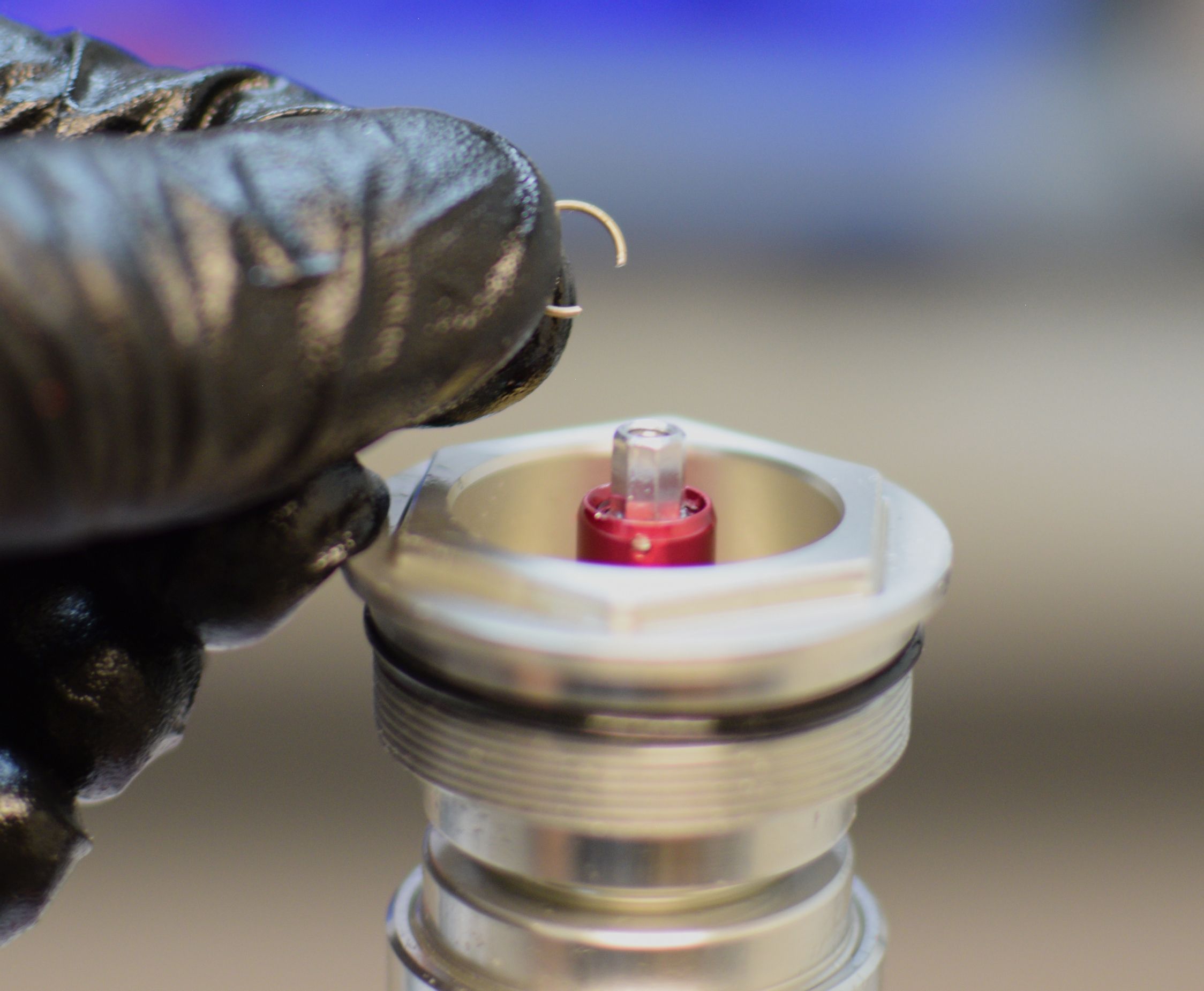
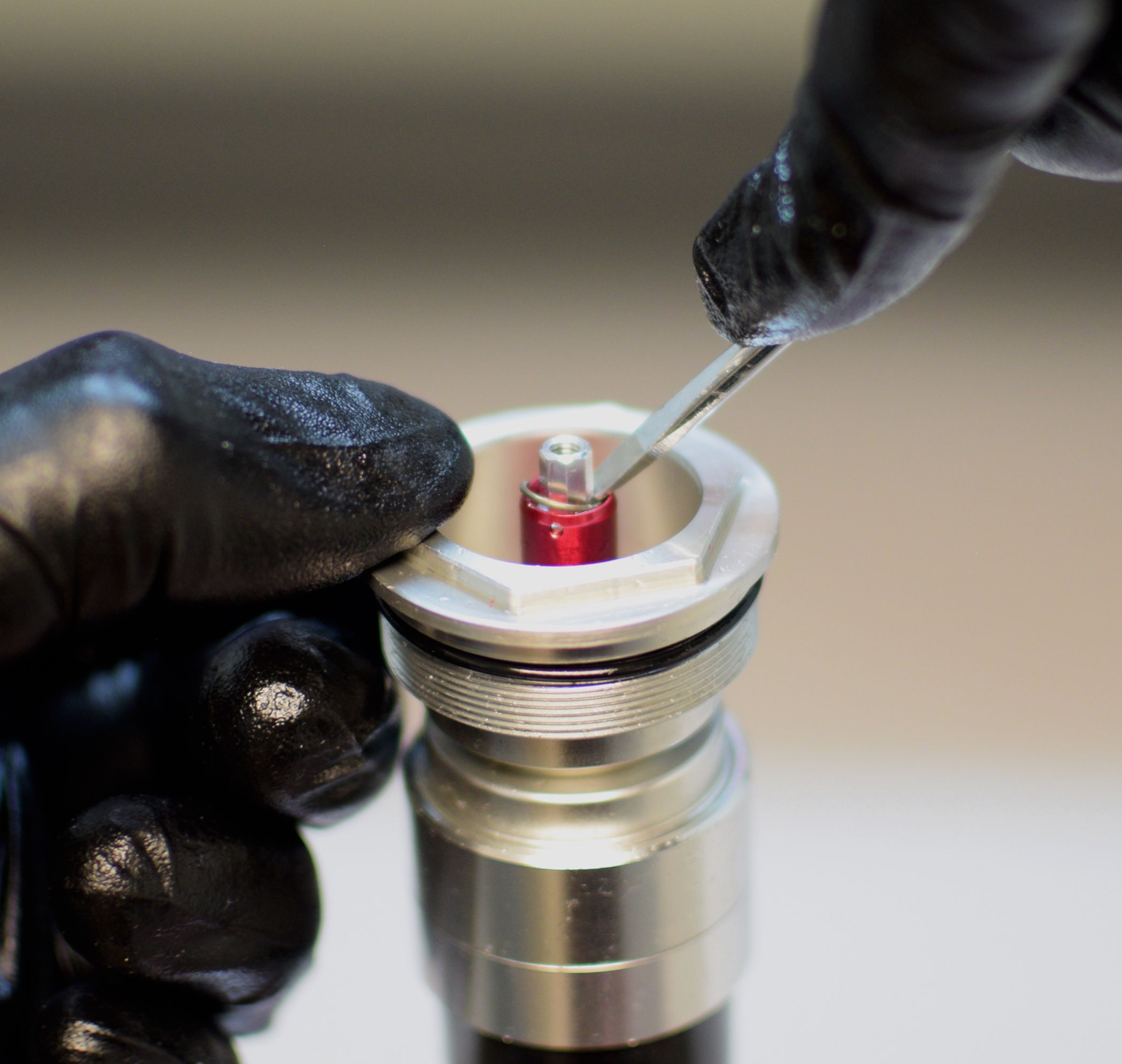
Step 7
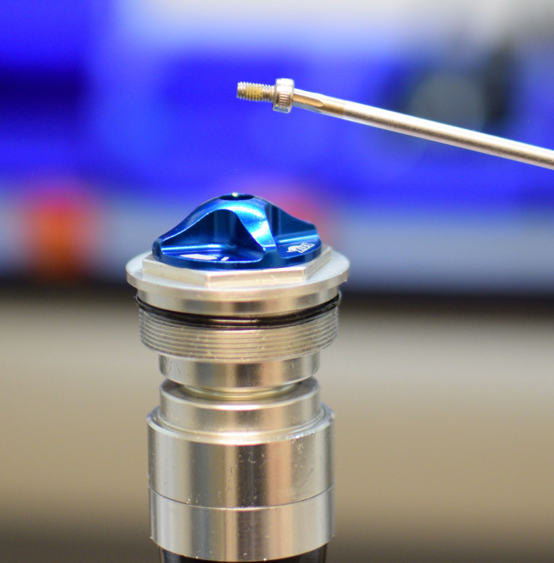
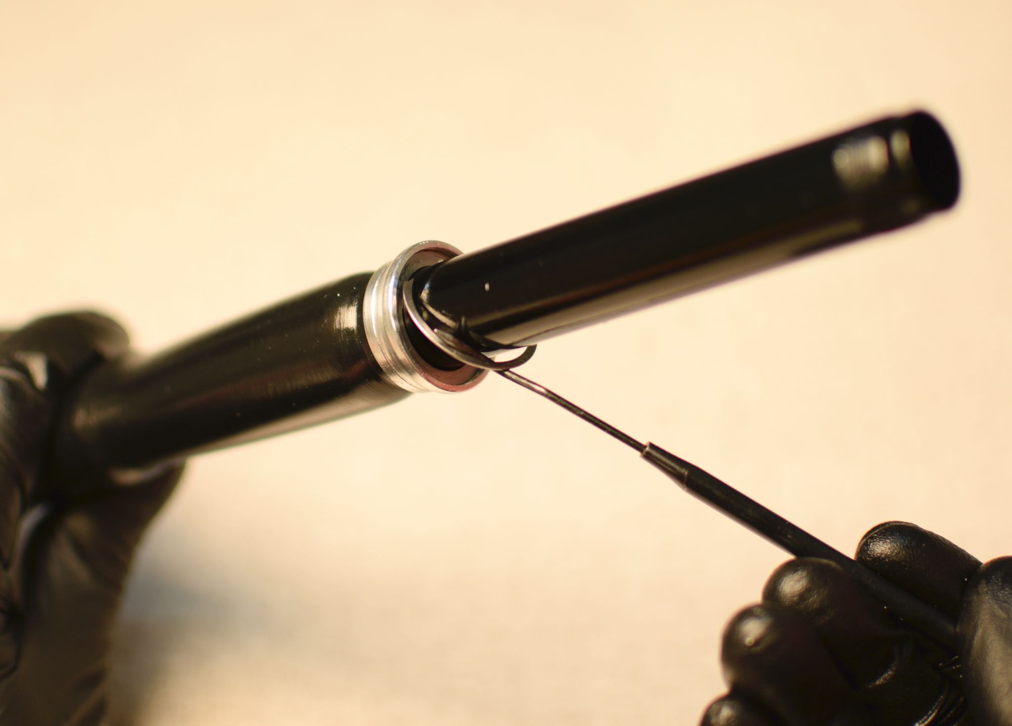
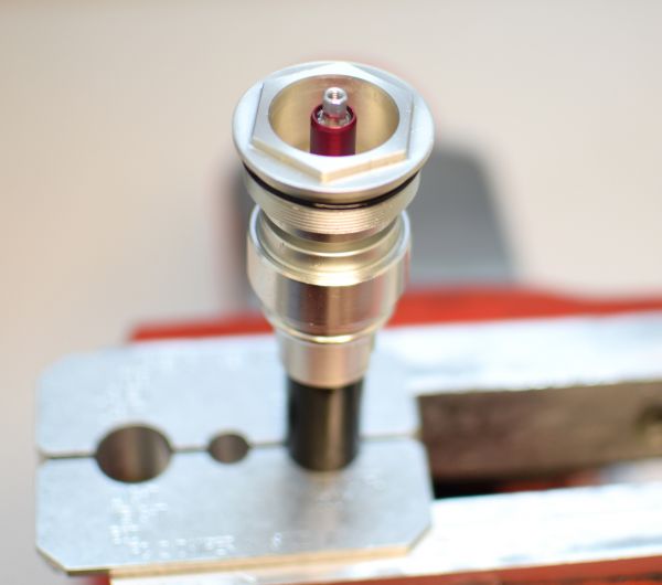
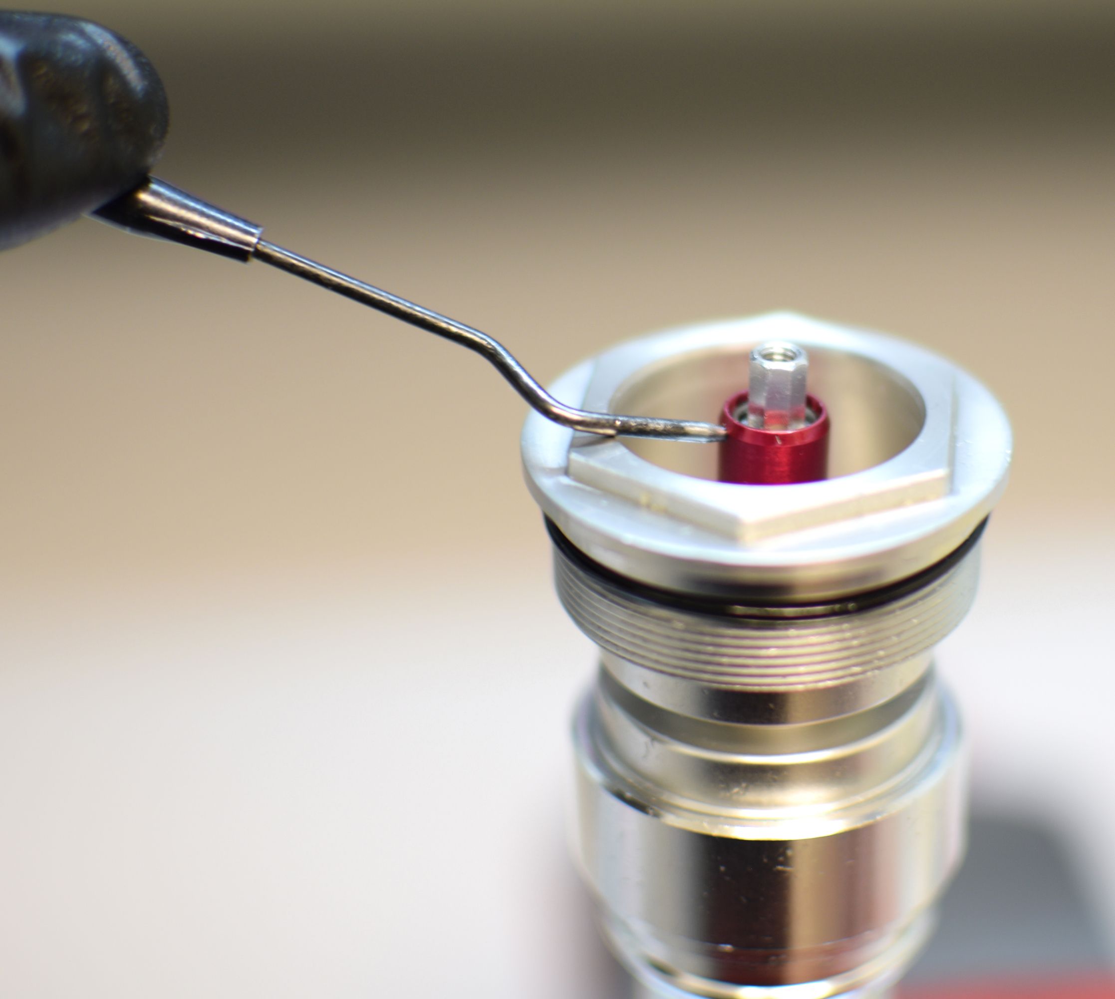
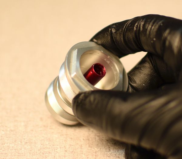
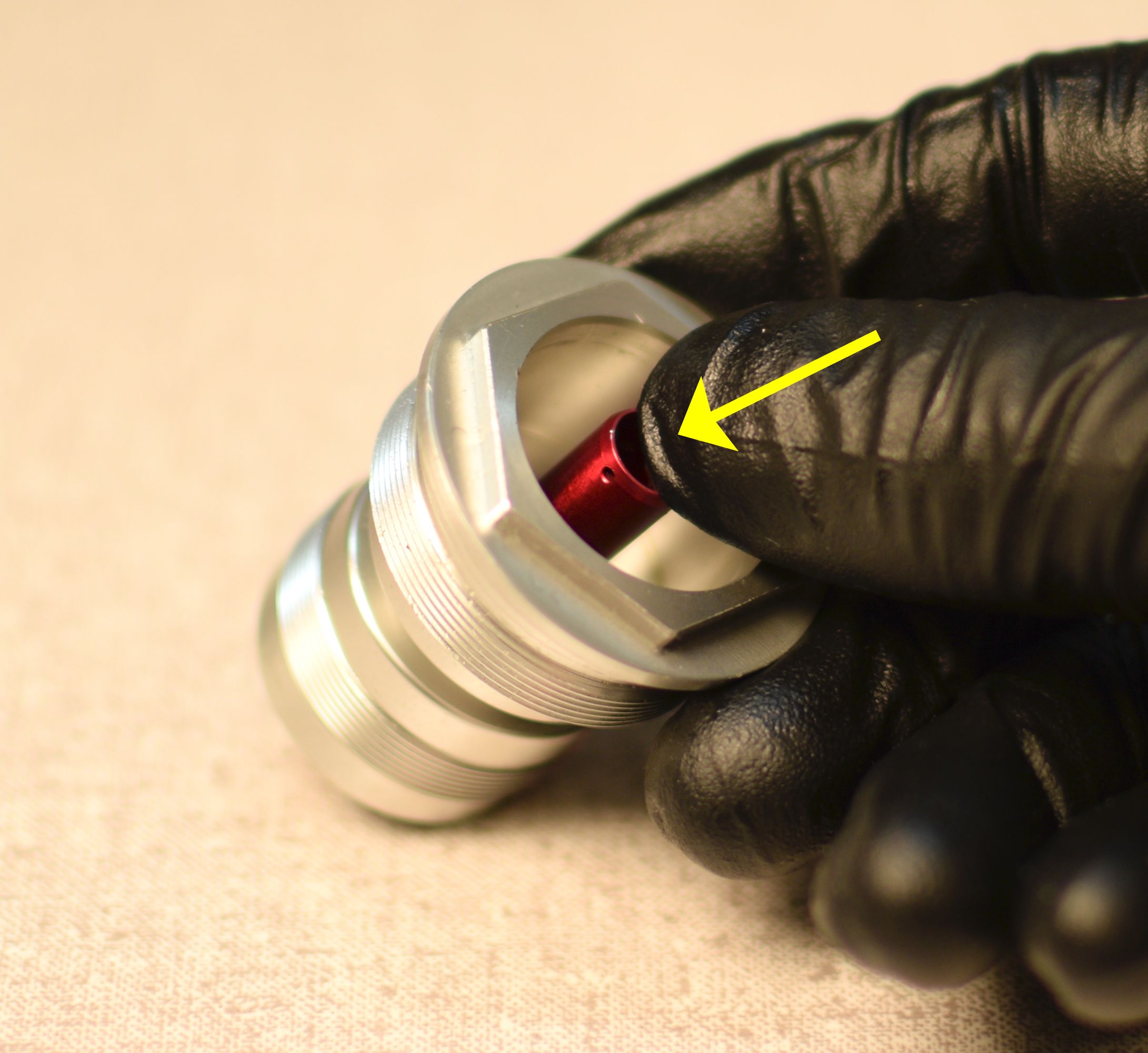
Remove the small wire retaining ring from within the compression selector shaft. Insert a pick into the hole on the side to help start removal of the ring.


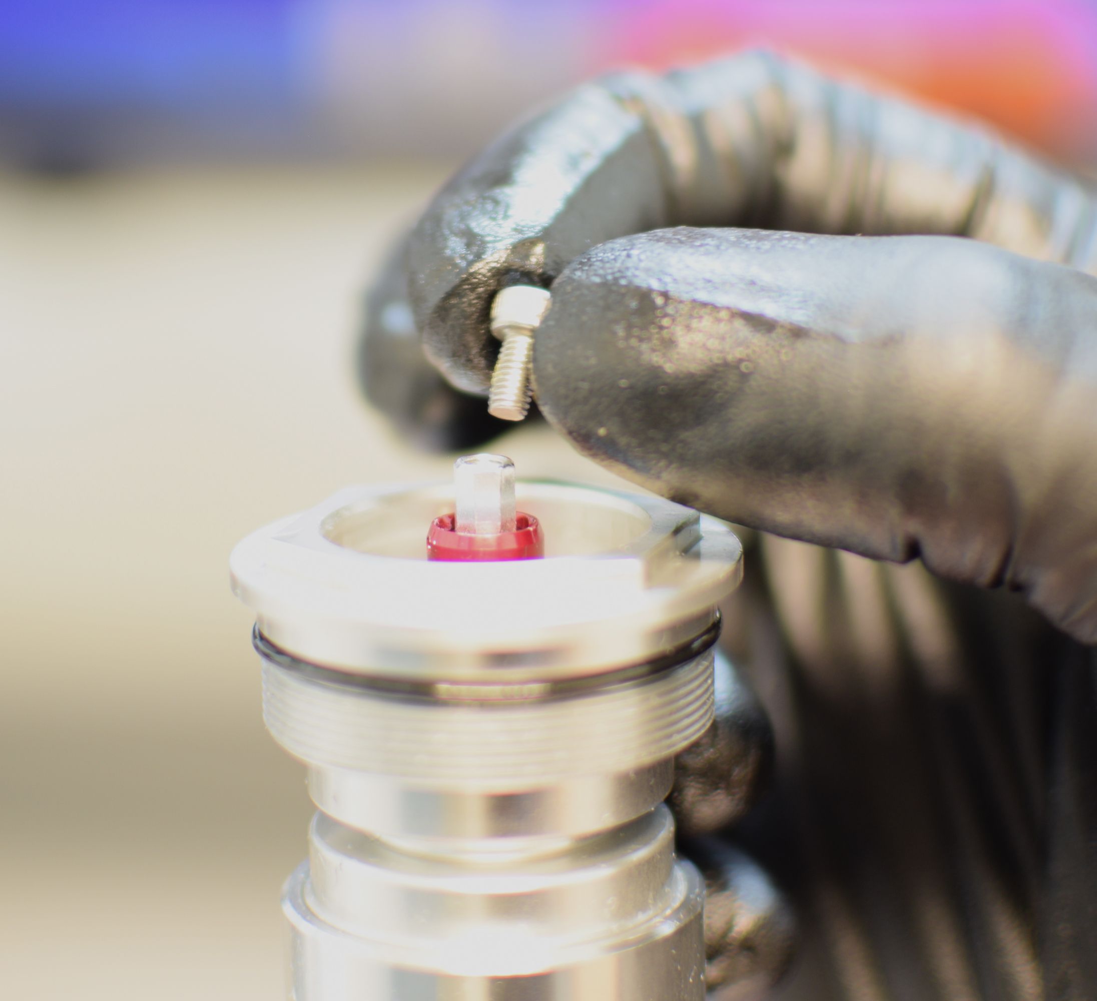
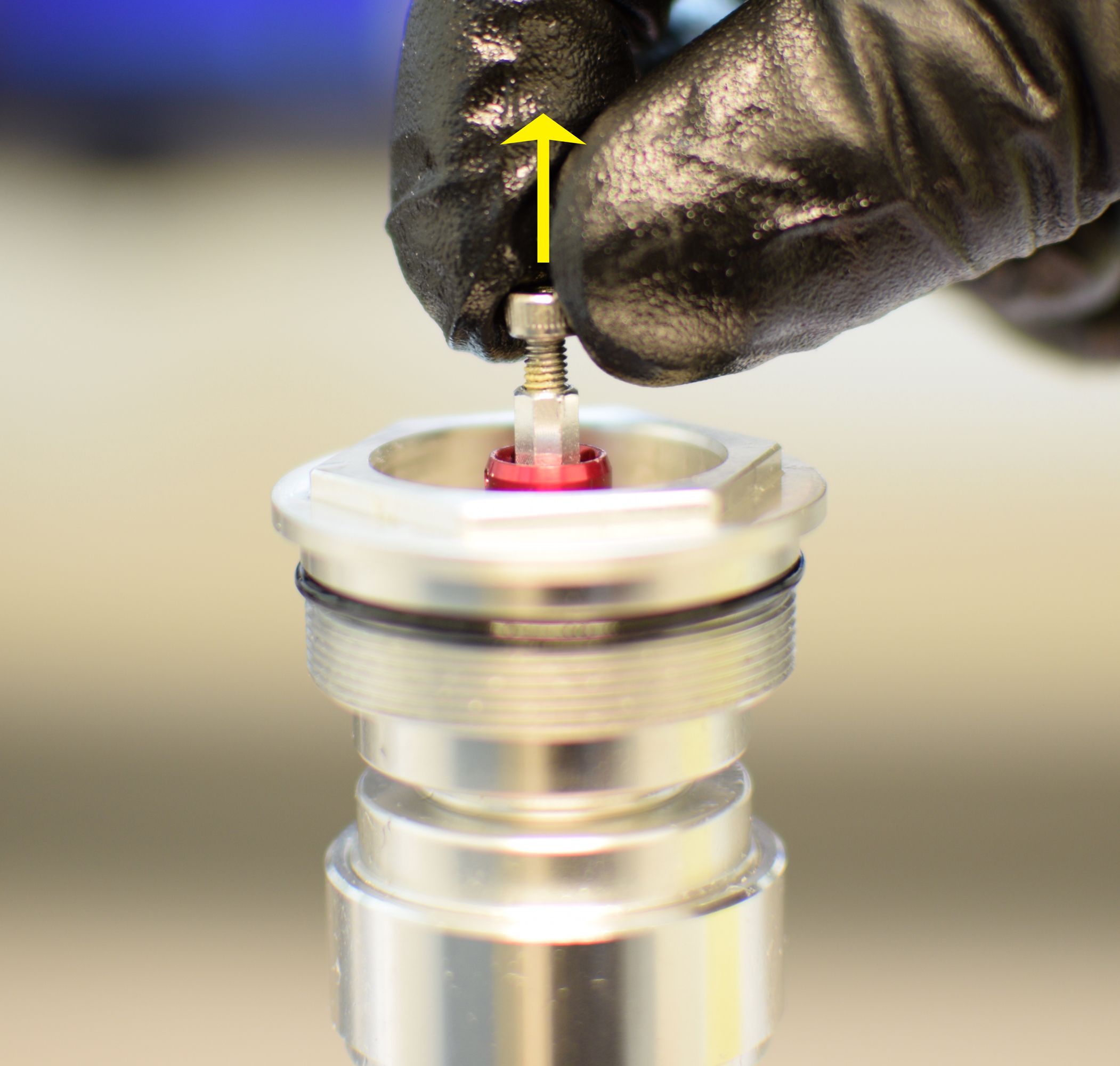
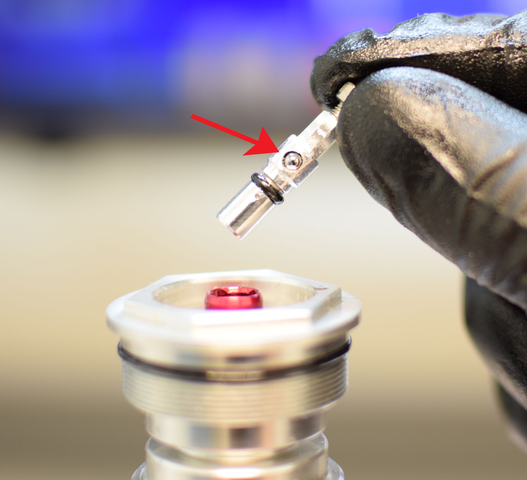
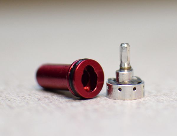
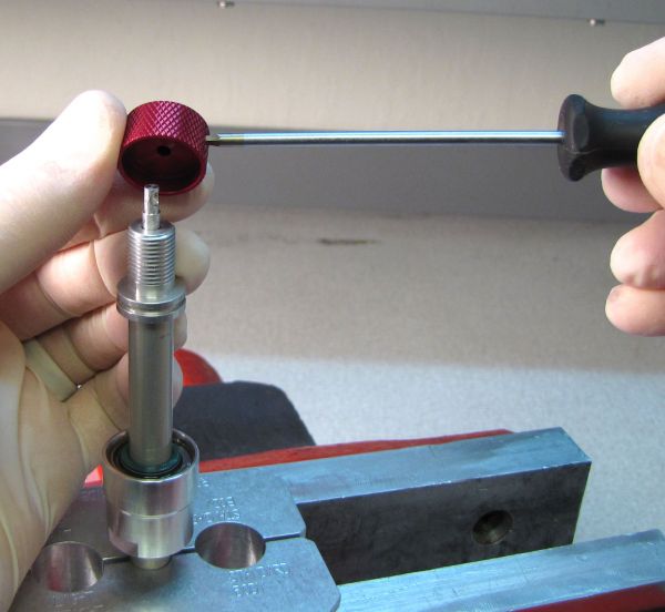
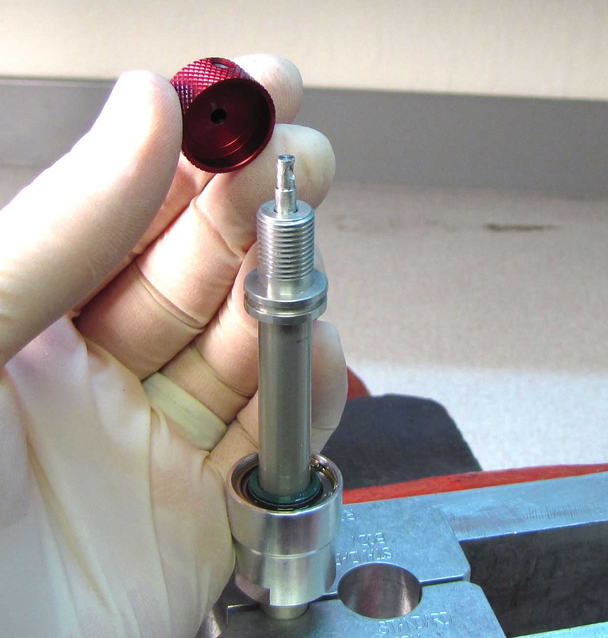
Step 8
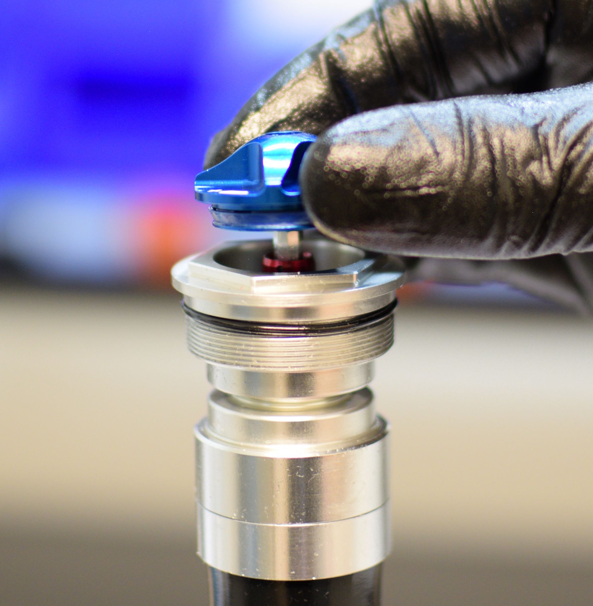
Thread the set screw for the LSC knob back into the compression adjust coupler. Pull up on the screw to remove the compression adjust coupler, taking care not to lose the detent ball and spring that are inserted into the side of the coupler.
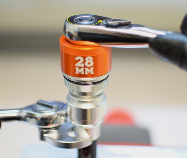
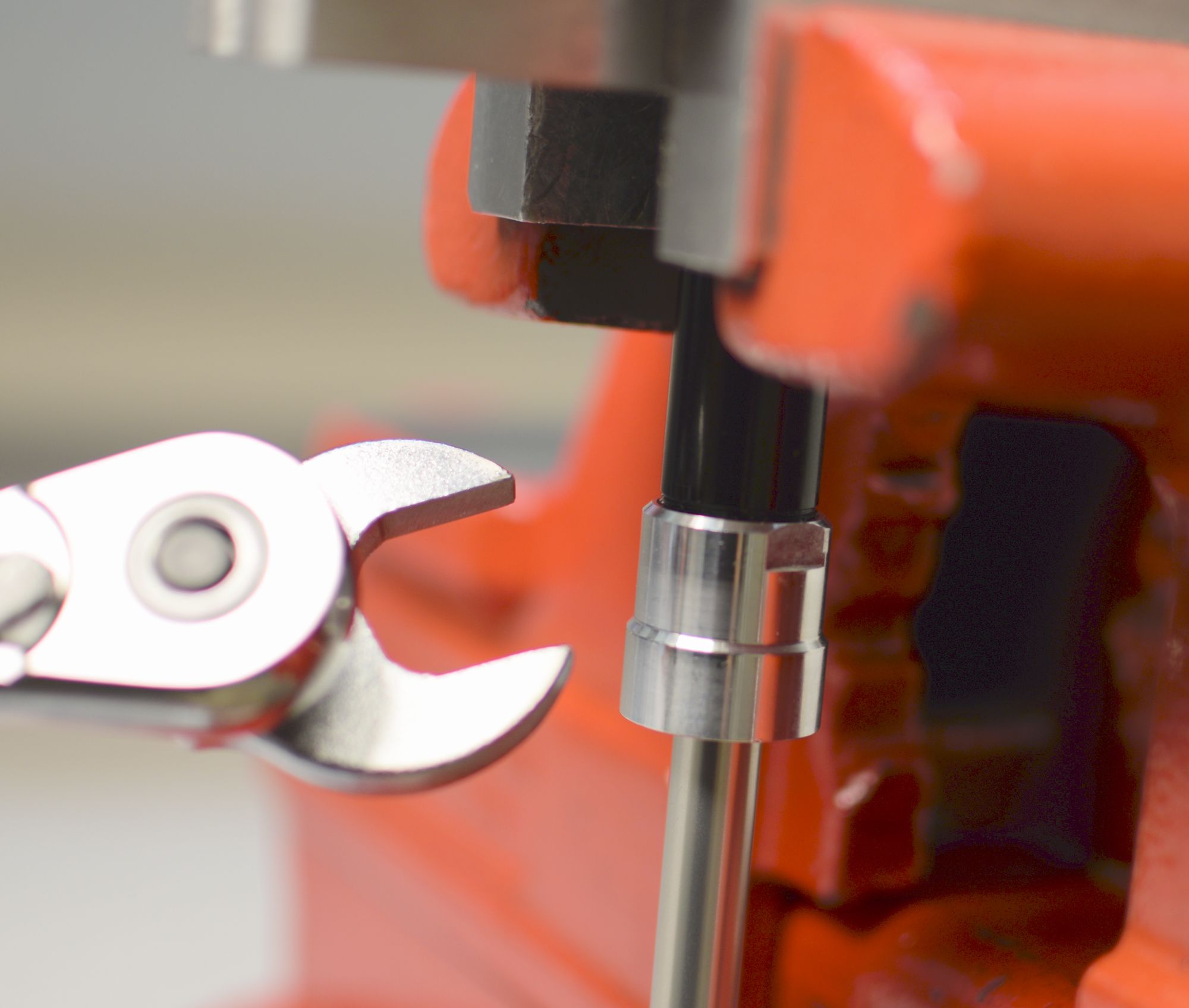
Step 9
Hold the compression clamp from turning with a 19mm wrench while you unthread the topcap counter-clockwise with a chamfer-less 6-point 28mm socket (PN: 398-00-704). Remove the topcap body from the compression clamp and set it aside.


Step 10
Remove the lockout selector with compression adjust needle from the compression clamp. Remove the compression piston with compression valving and set aside. Replace the o-ring inside the compression clamp with a new greased one from the kit.
Step 11
Unthread the compression clamp from the cartridge body counter-clockwise.


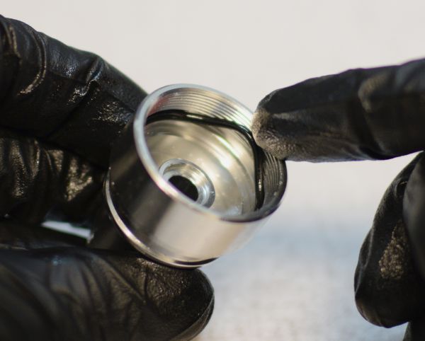
Step 12
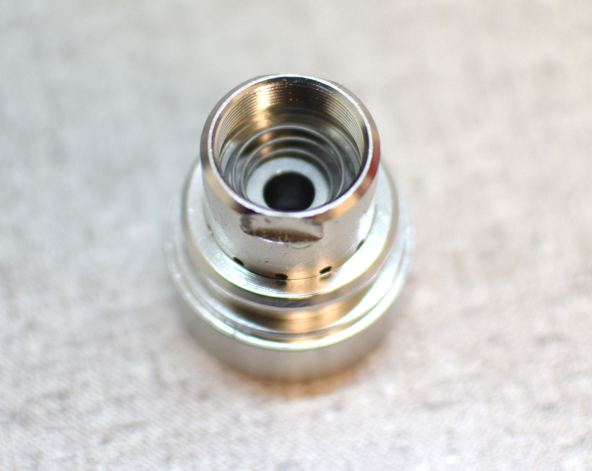
Remove the o-ring from within the bottom of the compression clamp. Remove the check shim and spring and set them aside.
Step 13
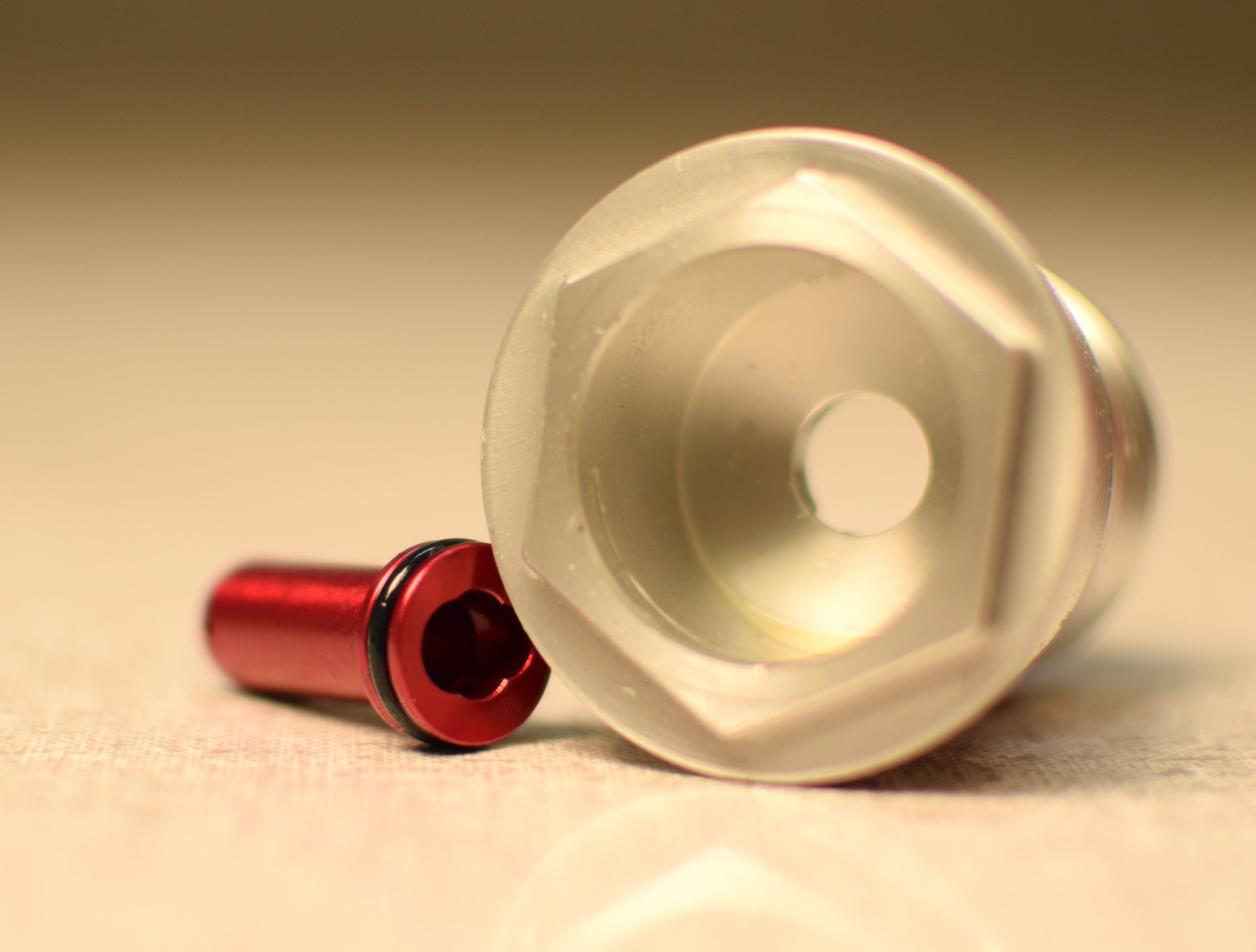
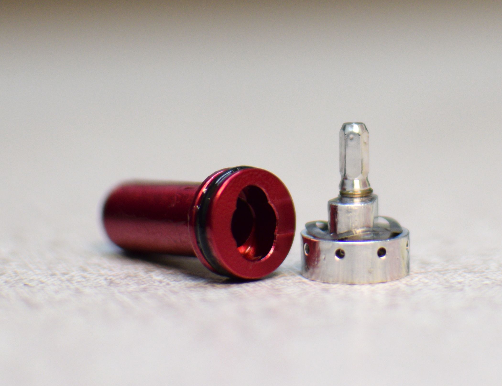
Push the compression selector shaft out through the bottom of the topcap. Replace the o-ring on the compression selector shaft with a new greased one from the kit.


Step 14
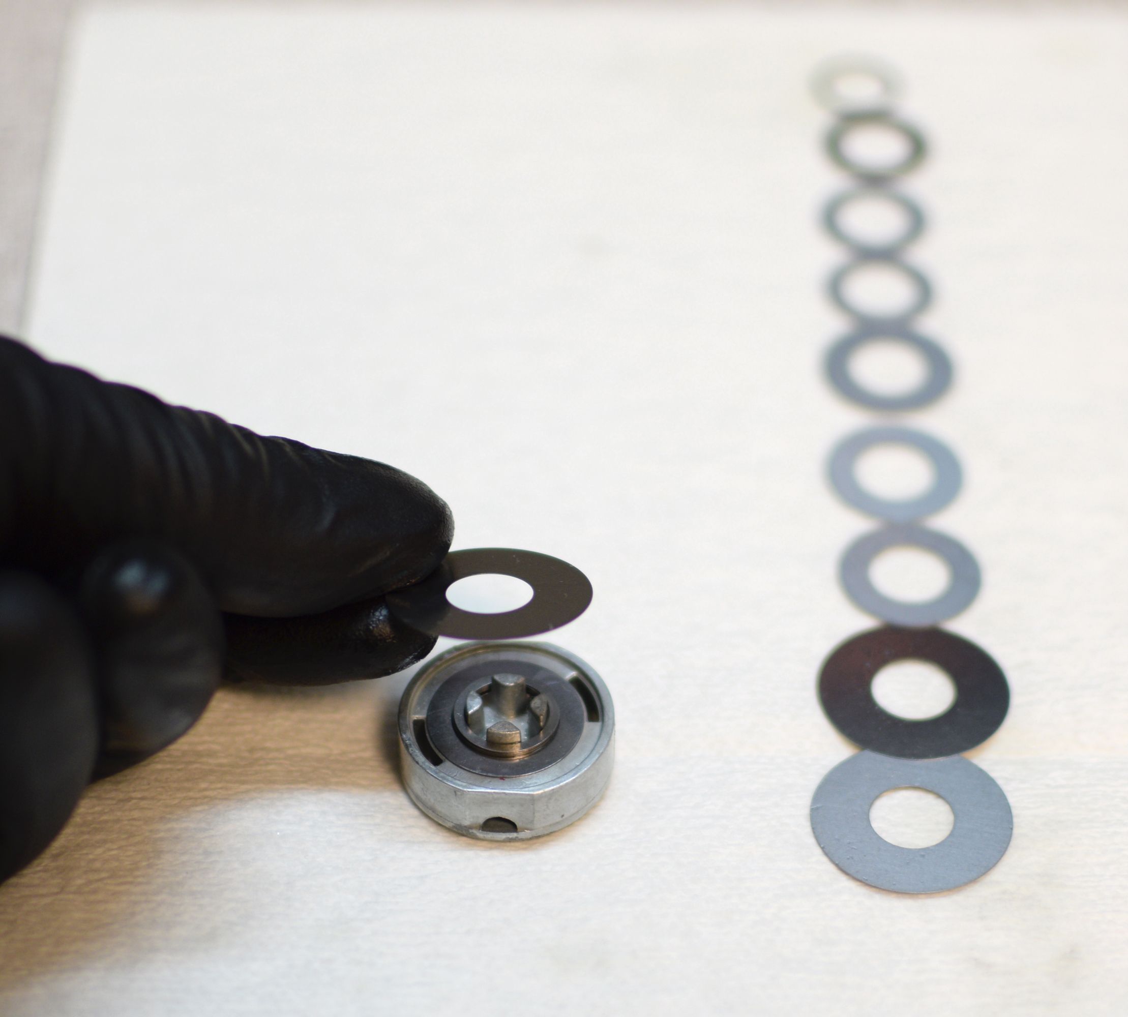
Inspect the compression valving and replace any worn or damaged shims. Prepare the compression valving in its original order then position it on the compression piston.
Step 15
Replace the o-ring on the outside of the topcap body with a new greased one from the kit. Clean the topcap body inside and out.

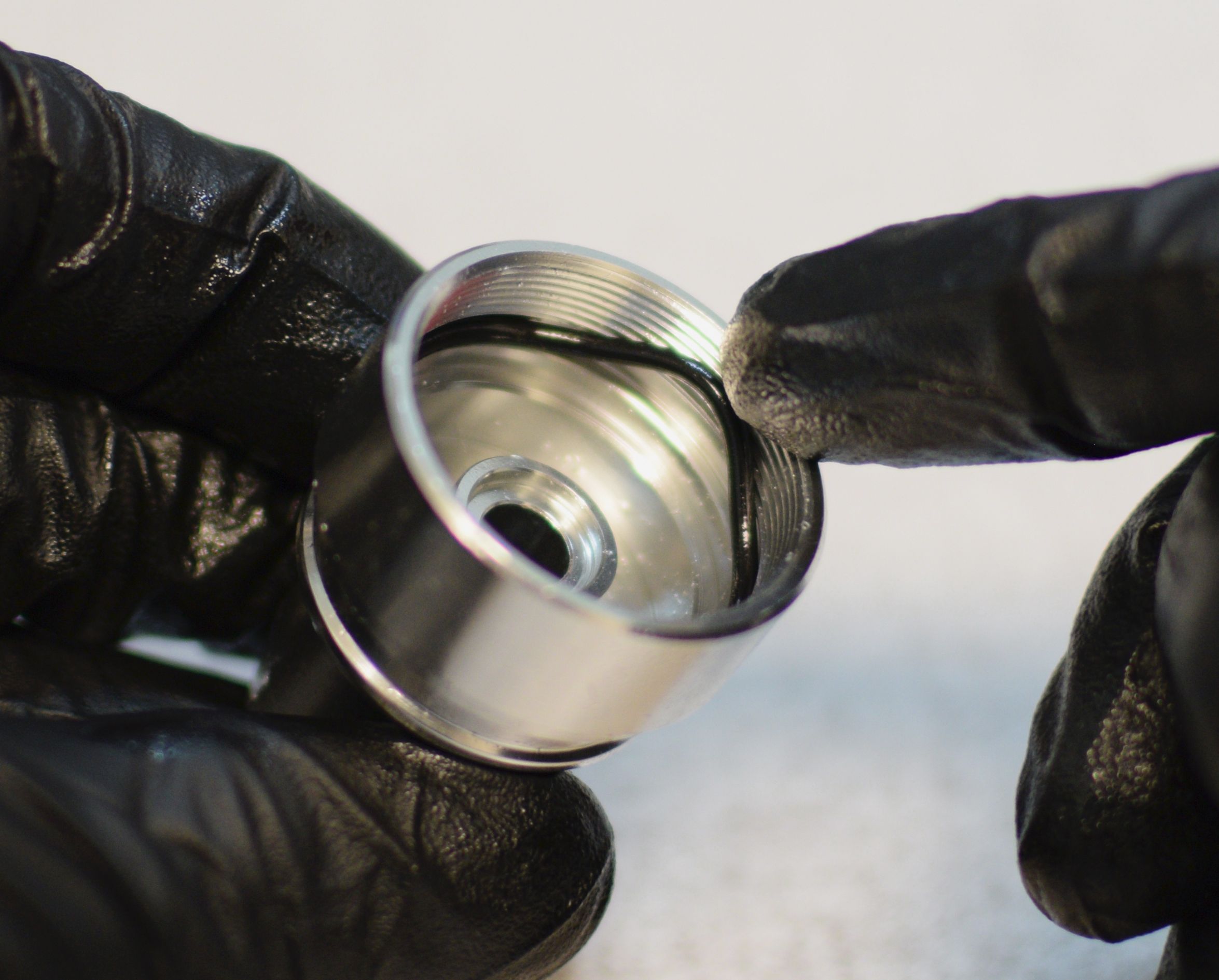
Step 16
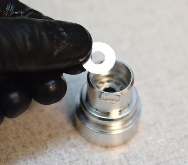
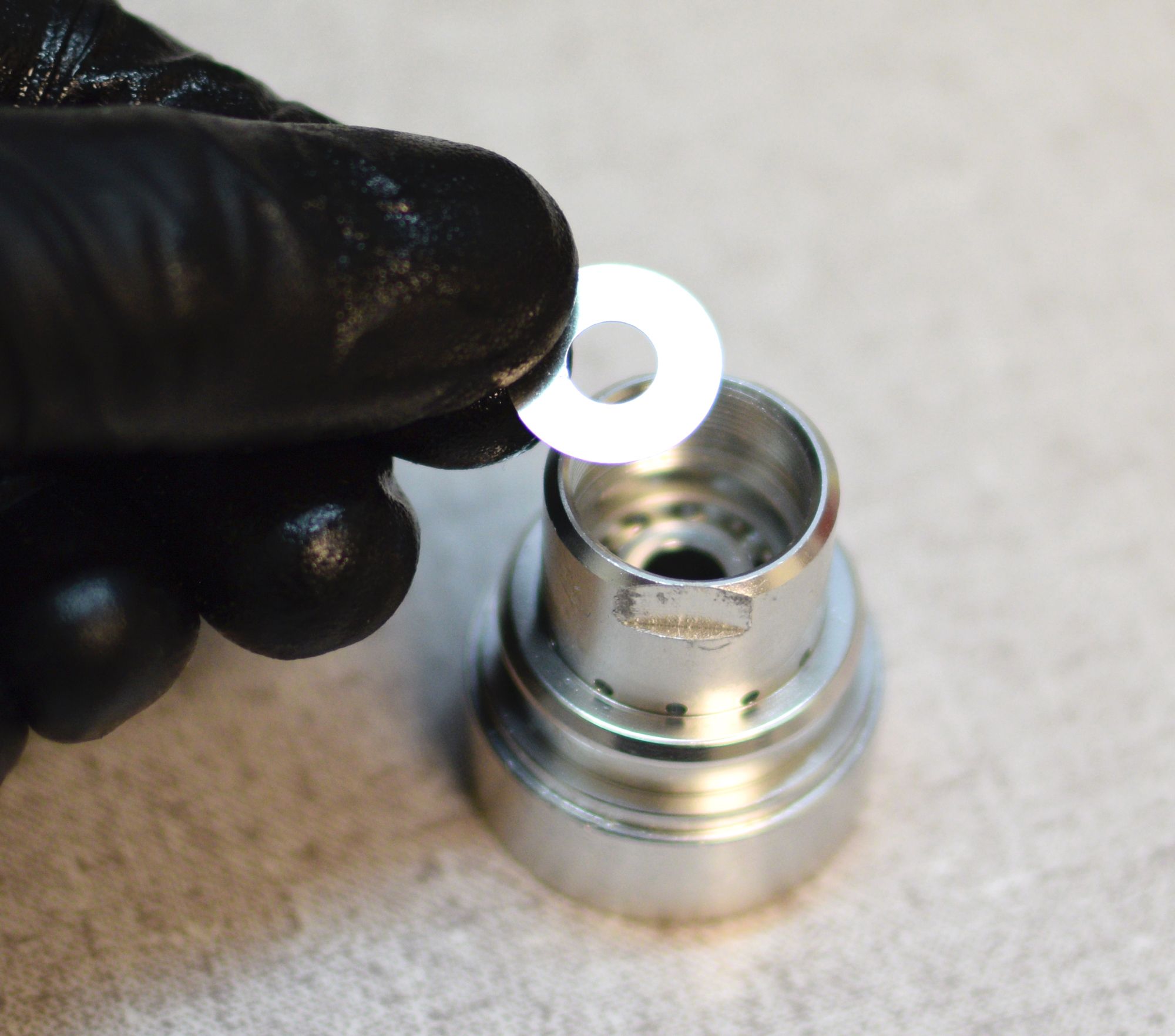
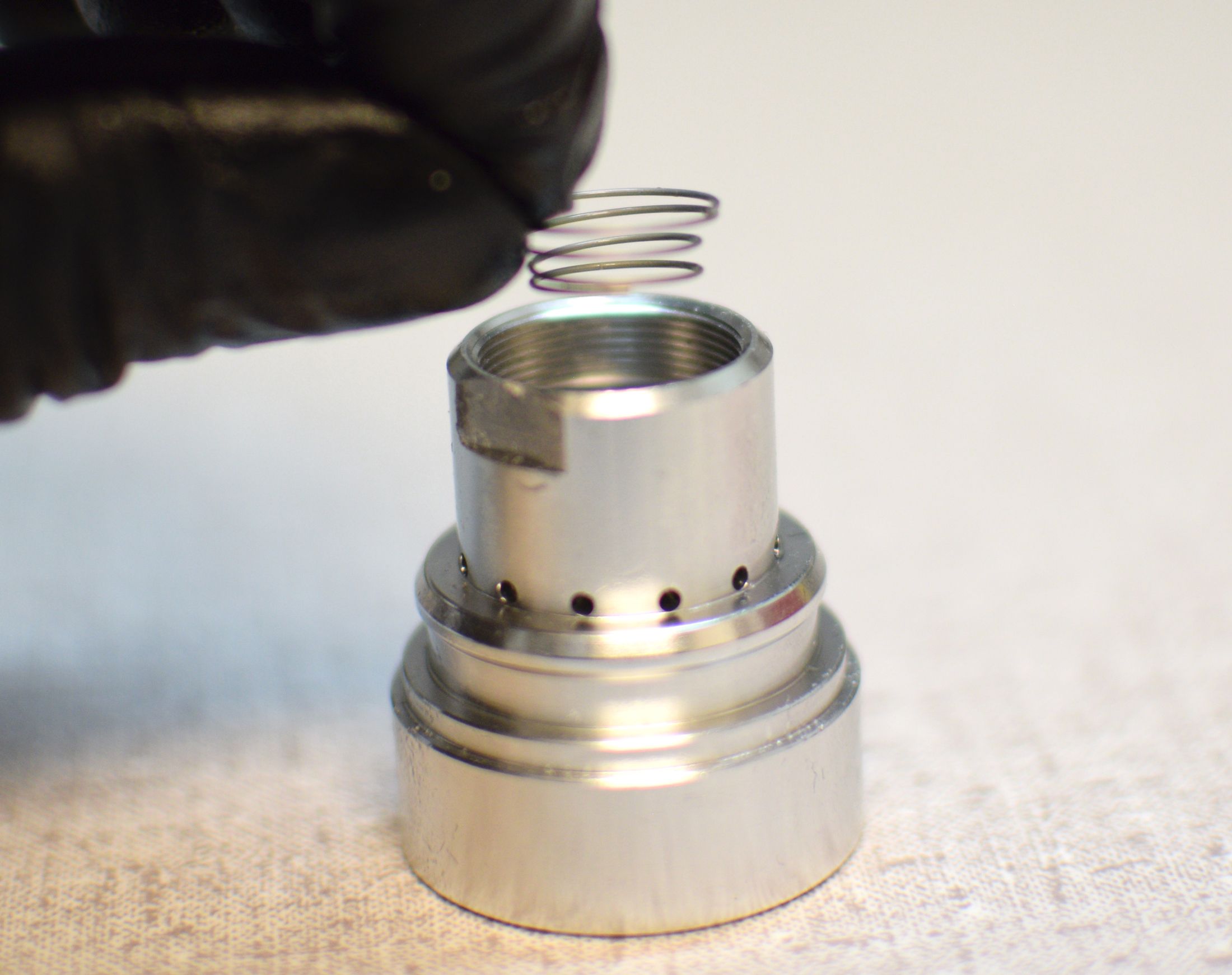
Reinstall the check shim into the bottom of the compression clamp. Install the conical spring with its small end toward the check shim. Reinstall the ring shim followed by a new greased o-ring from the kit.
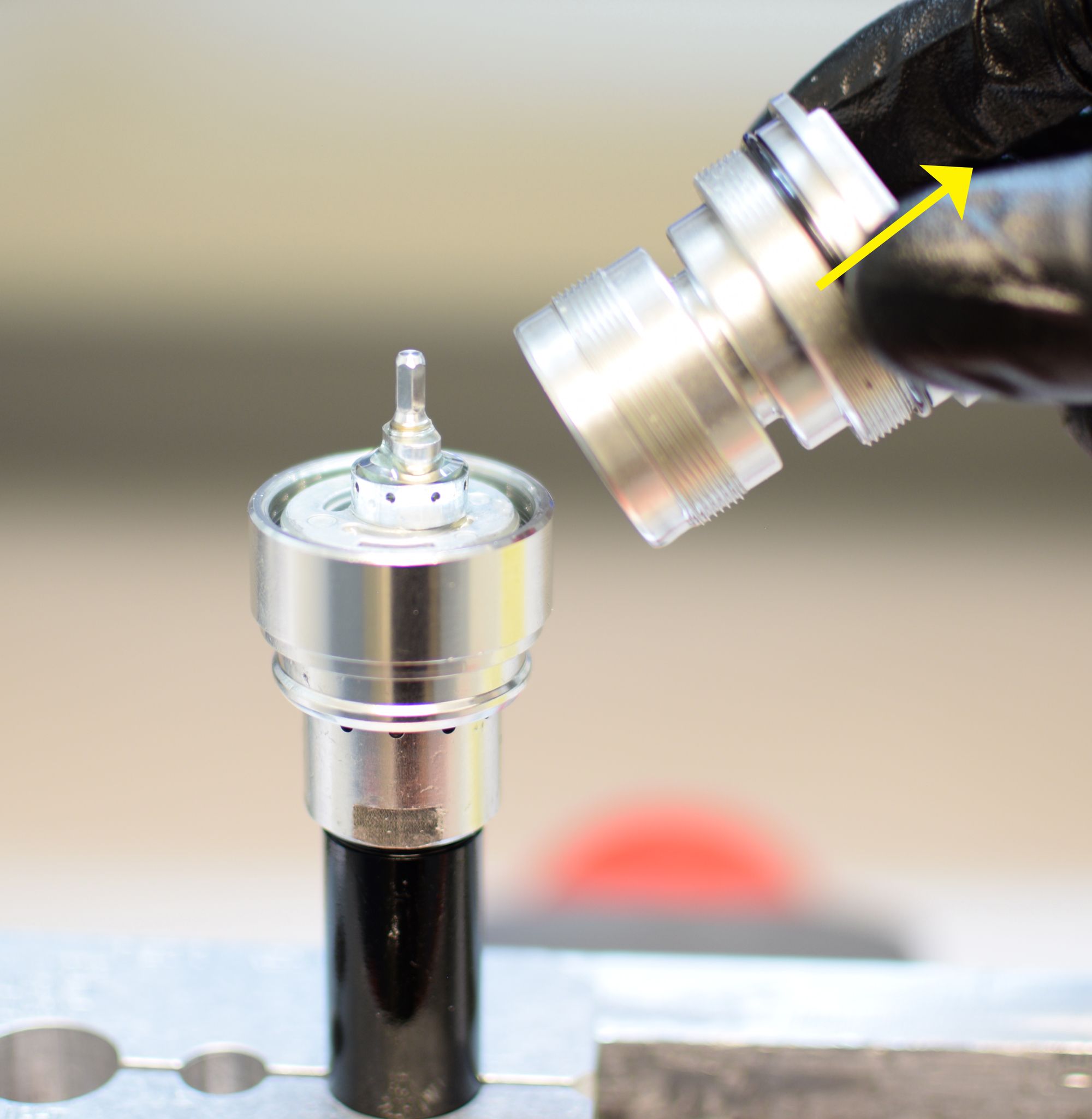
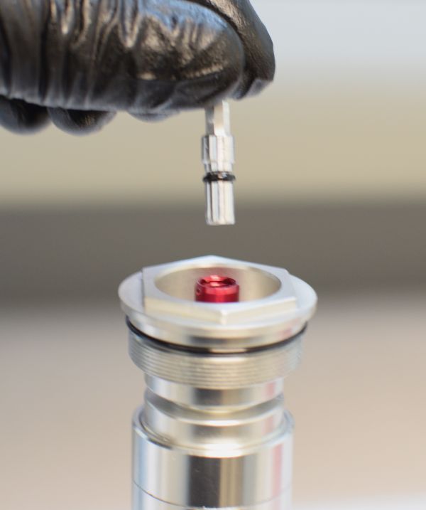
Step 17
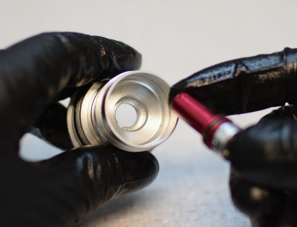
Insert the lockout selector with wave spring into the compression selector shaft engaging the lobed features so they mate properly as shown.

Step 18
Install the combined lockout selector and compression selector shaft into the topcap body.


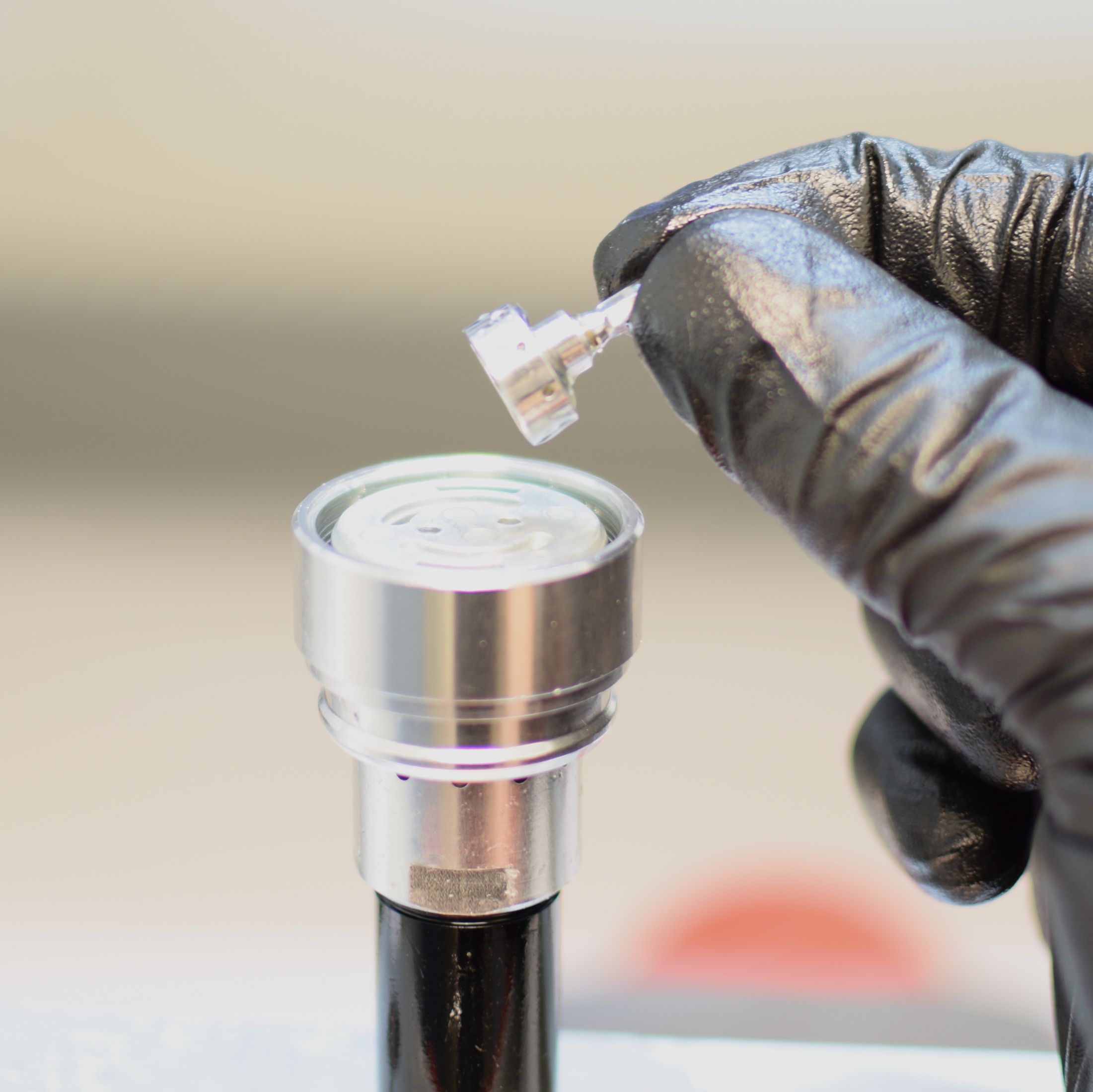
Step 19
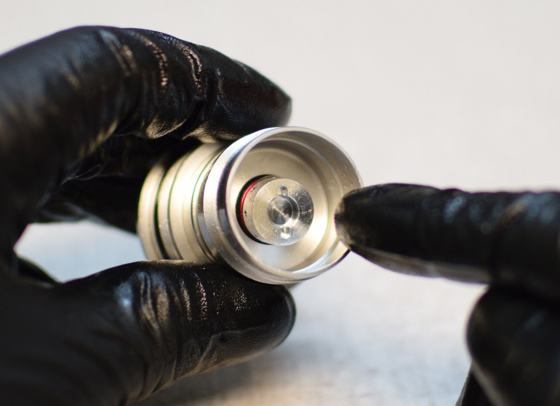
Align the protrusion on the outside of the compression piston with the notch in the wall of the topcap body. Install the compress piston with valving into the topcap with the valving facing away from the topcap as shown.

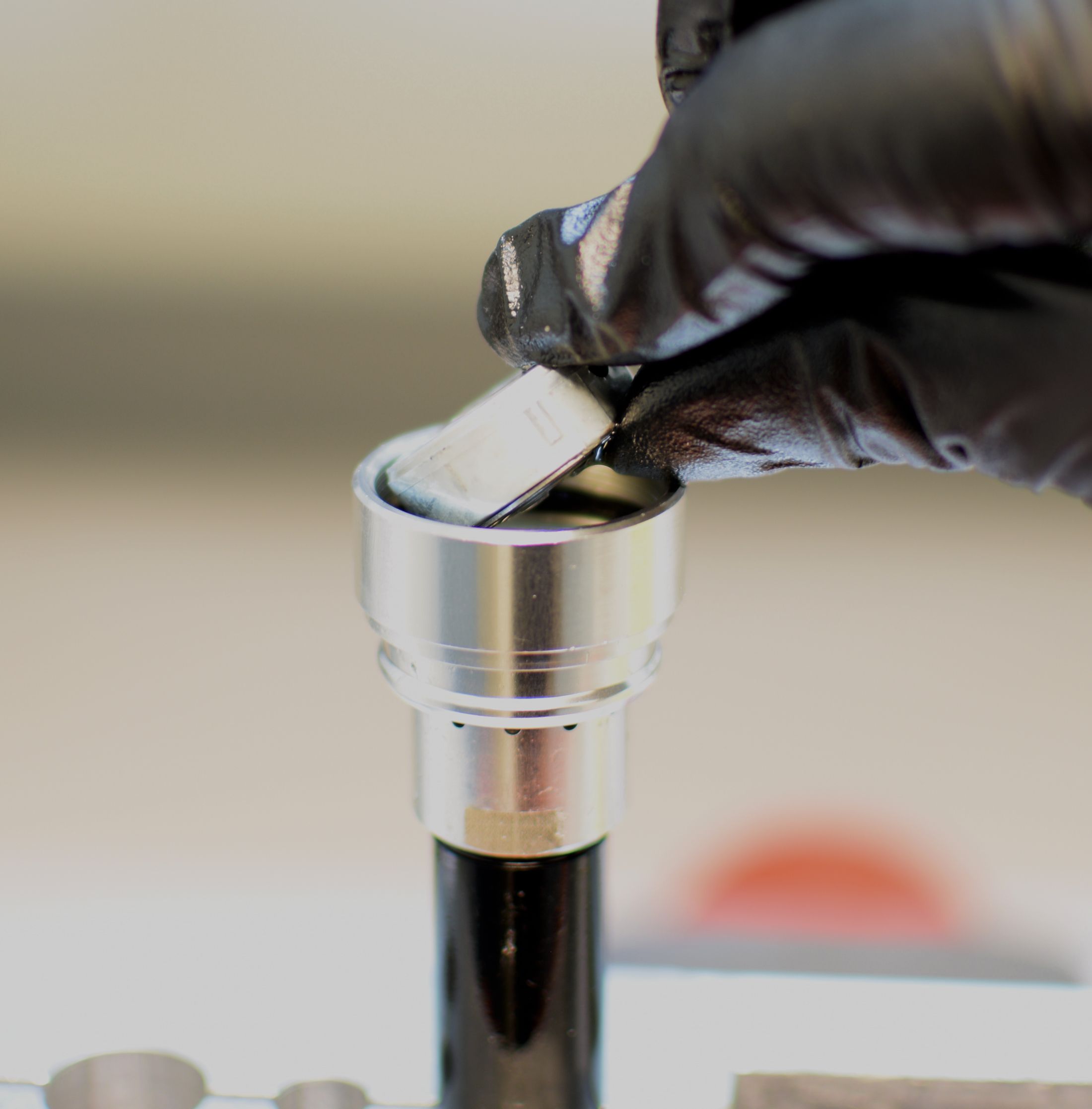
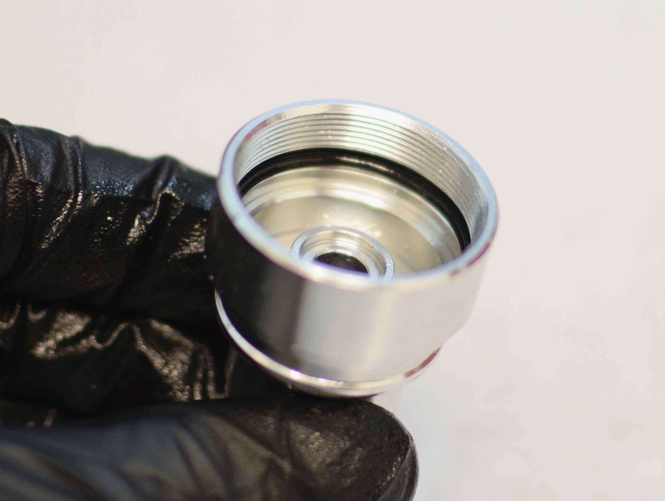
Step 20
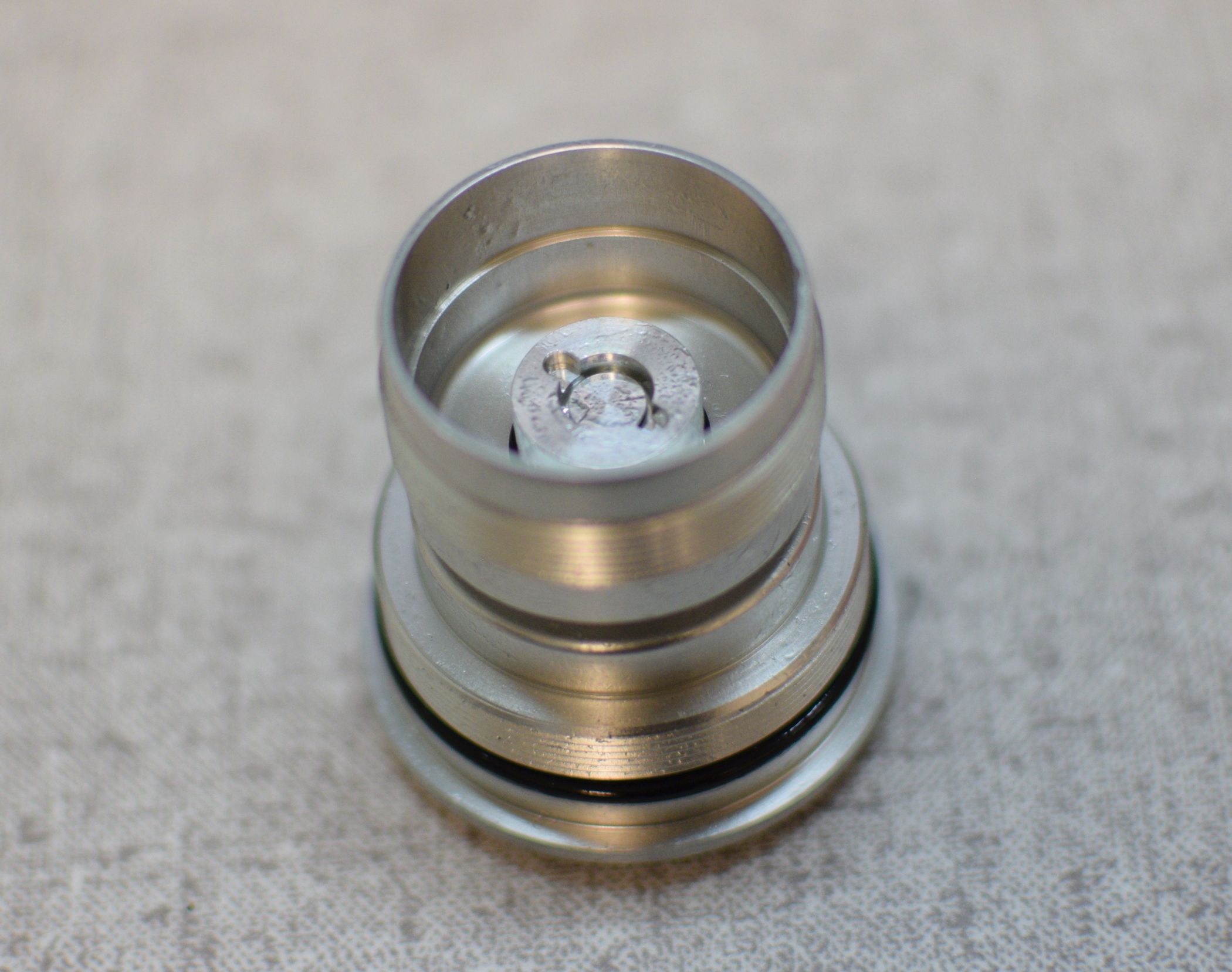
Install a new greased o-ring from the kit into the large end of the compression clamp. Install the compression clamp onto the topcap body, threading them together clockwise by hand.


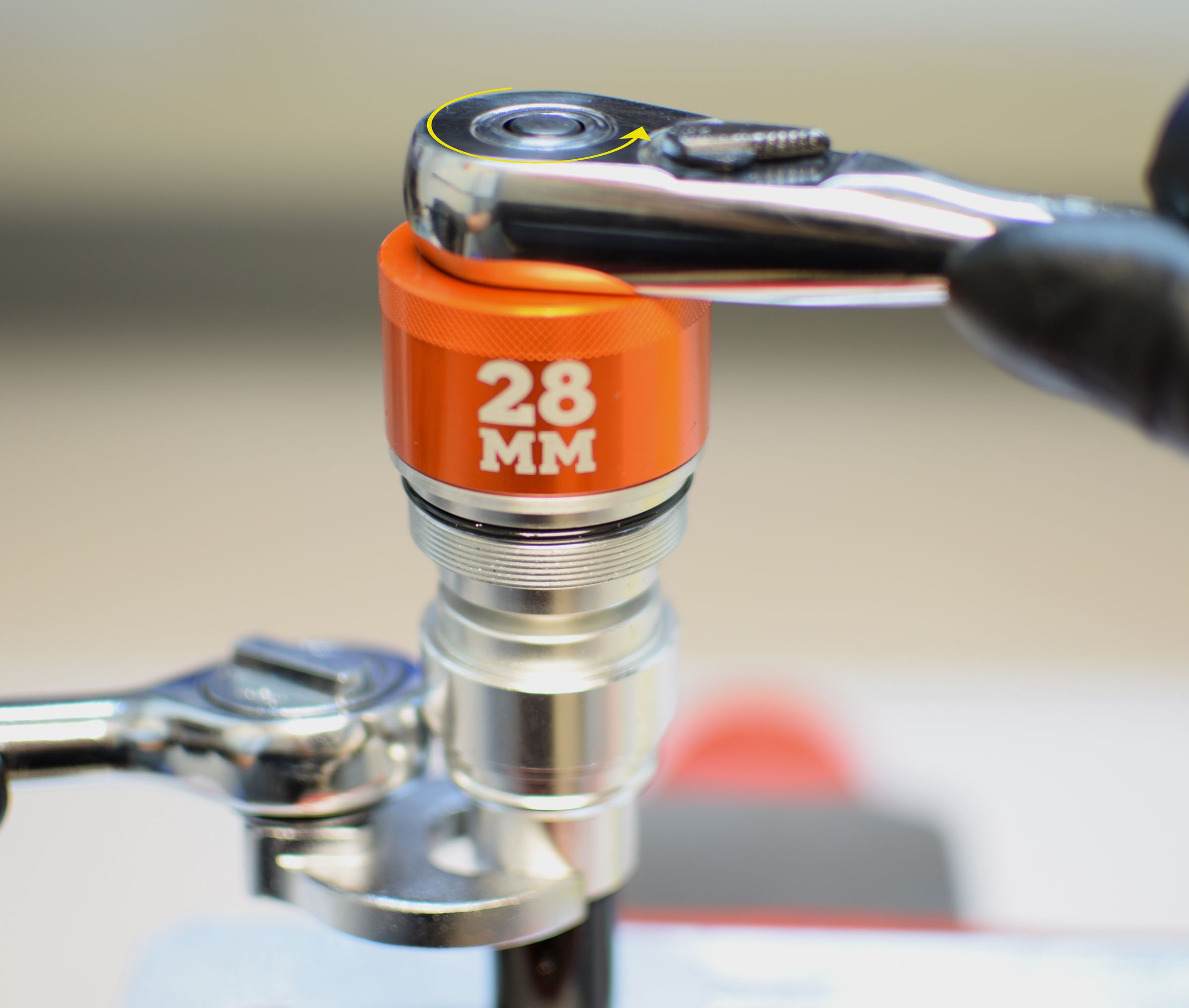
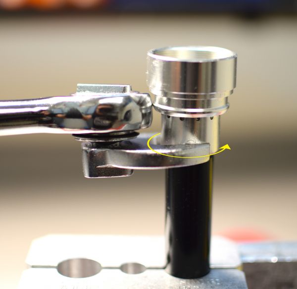
Step 21
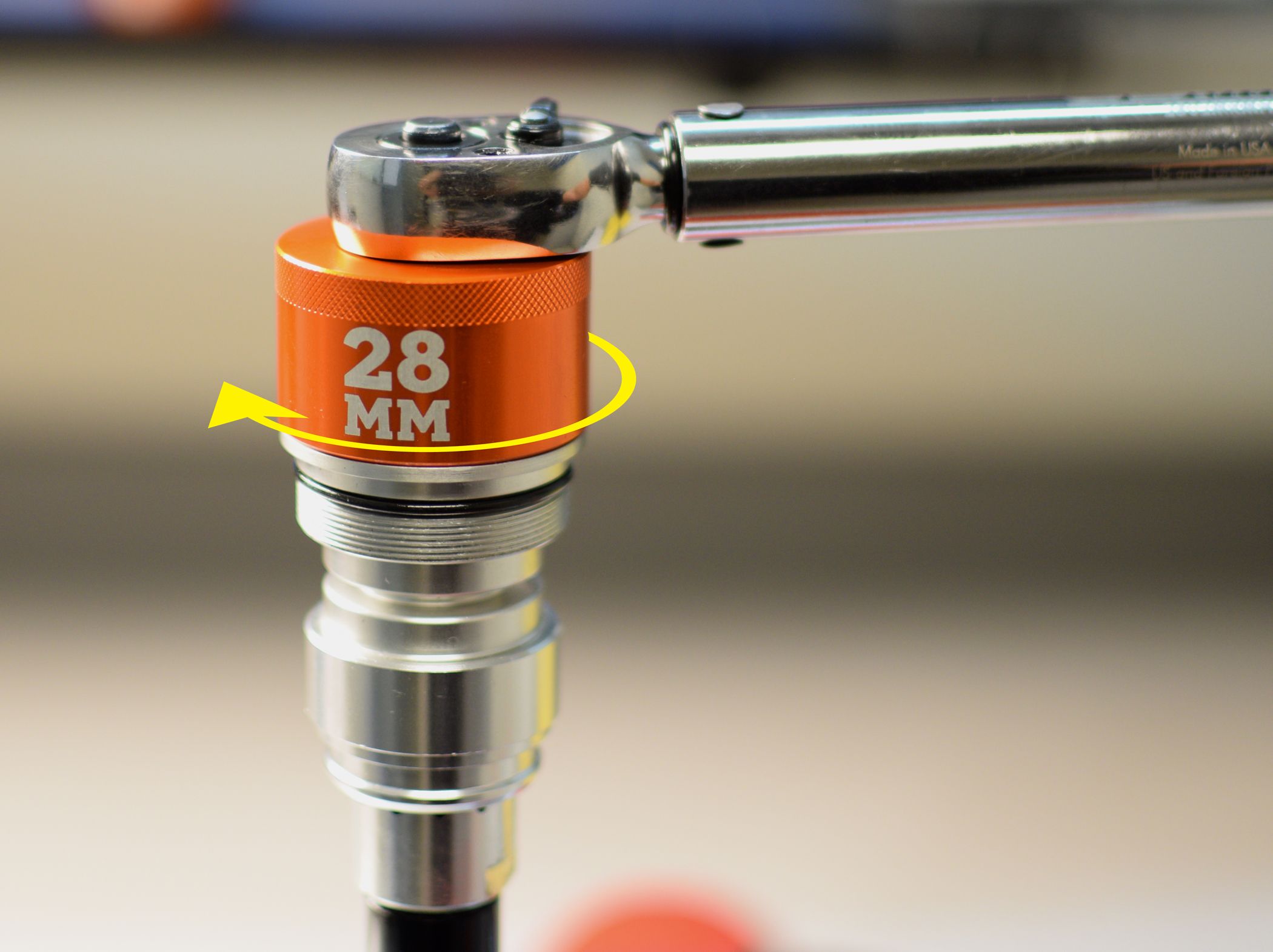
Carefully clamp the cartridge body in your clamps, taking care to avoid damaging the bladder sealing surface near the middle of the body. Thread the topcap assembly onto the cartridge body clockwise, then tighten with your 6-point chamfer-less 28mm socket to 75 in-lb (8.5 Nm) torque.


Step 22
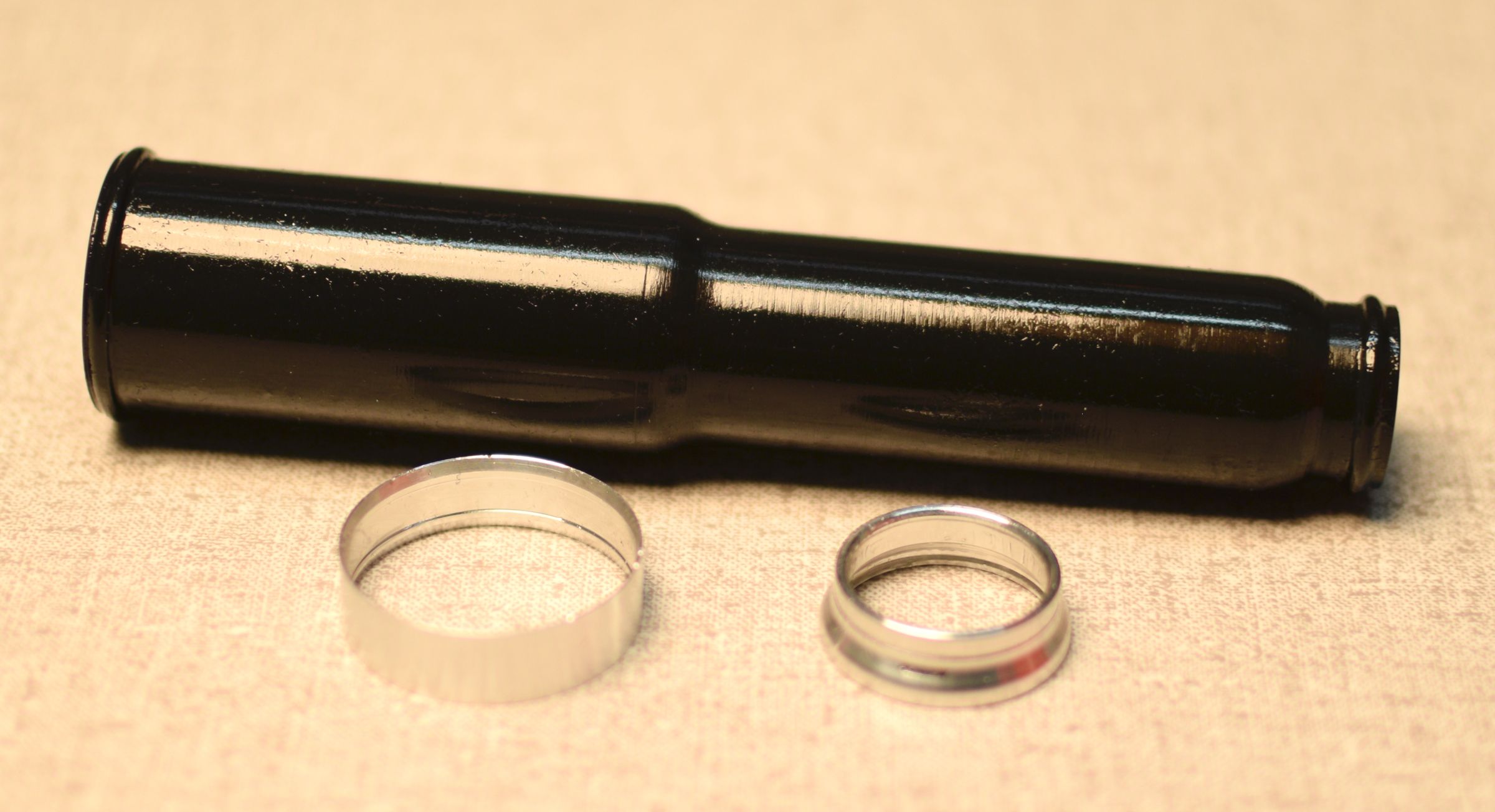
Apply a thin coating of Slick Honey to the inside and outside of the bladder ends, then install the upper and lower bladder rings as shown. Note the orientation of the lower bladder ring.


Step 23
Install the bladder assembly with its large end first over the open end of the cartridge body.


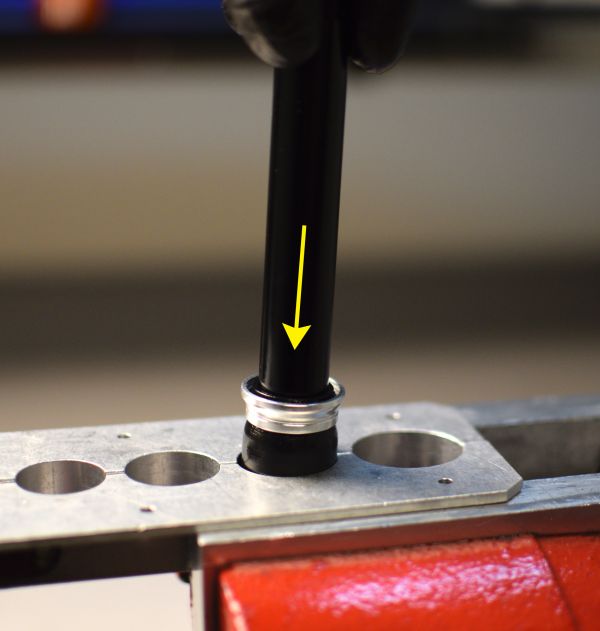
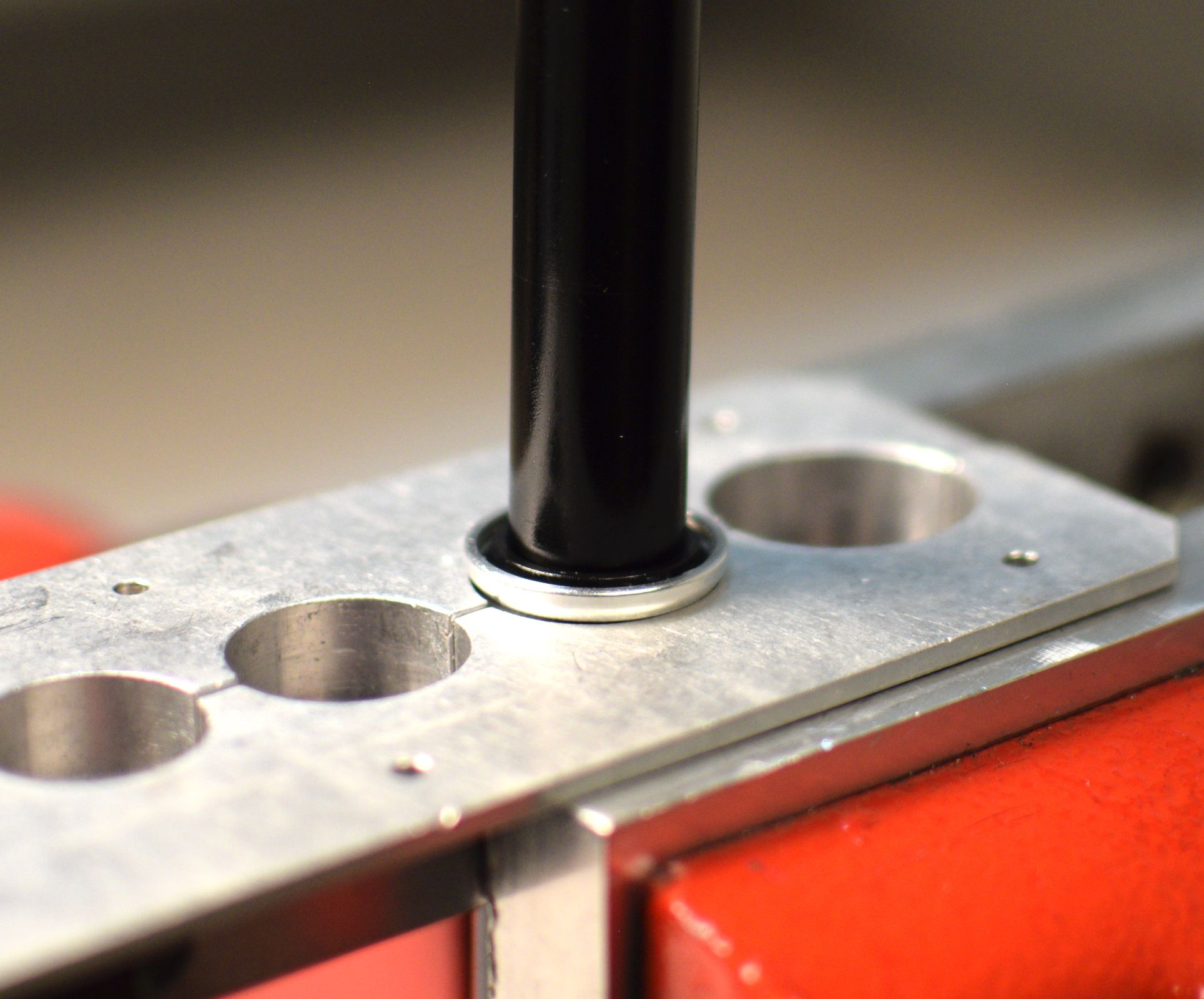
Step 24
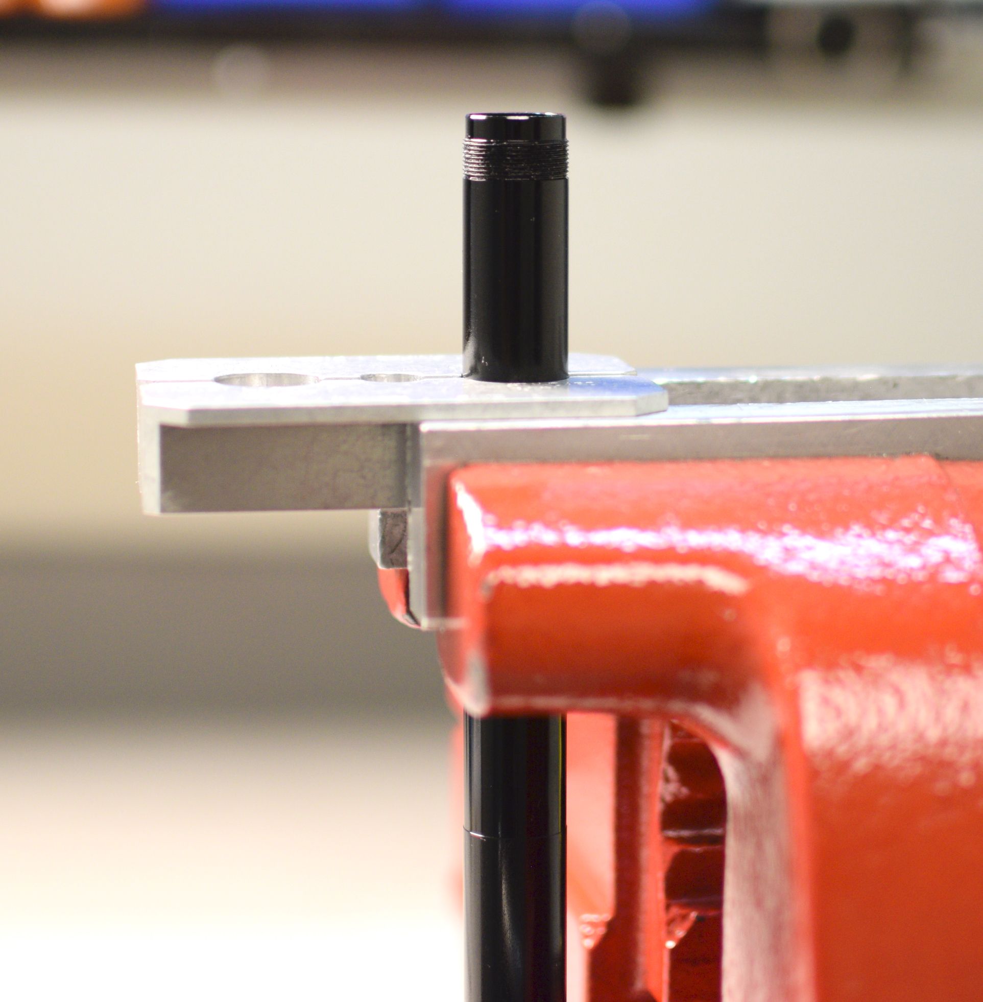
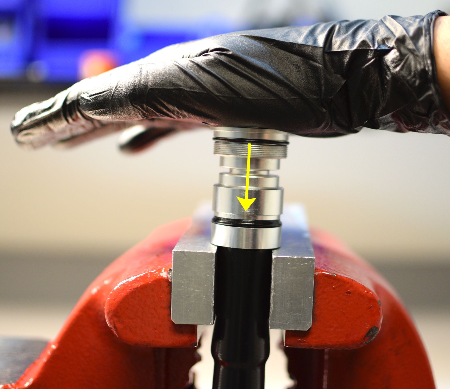
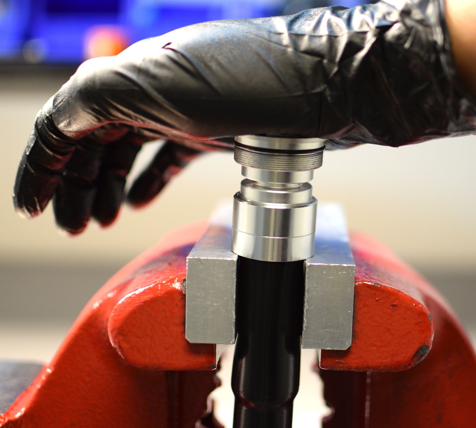
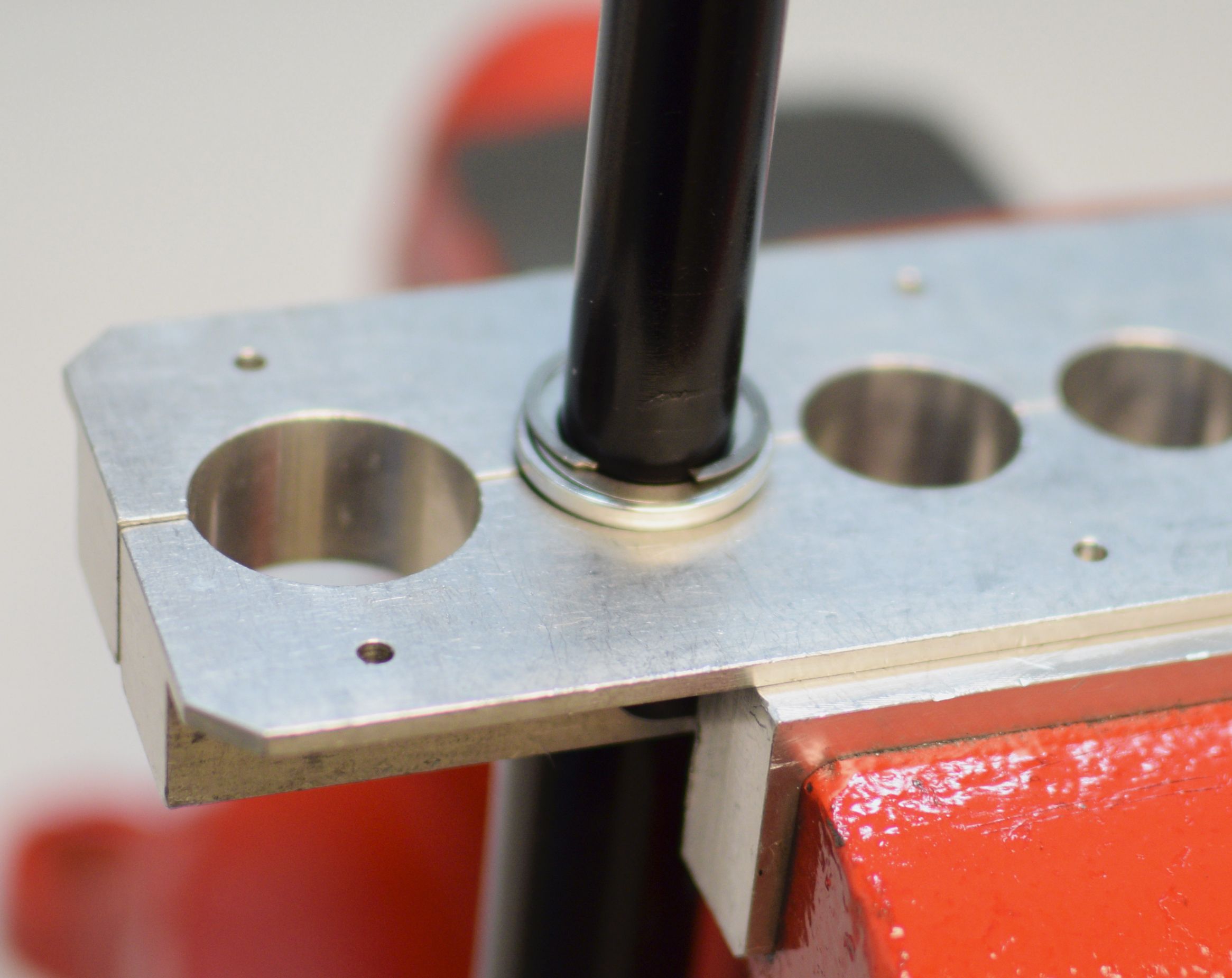
Seat the large end of the bladder onto the compression clamp then slide the upper bladder ring toward the topcap. Carefully rest the upper bladder ring on your soft-jawed vise without pinching the bladder. Press down on the topcap to seat the upper bladder ring.

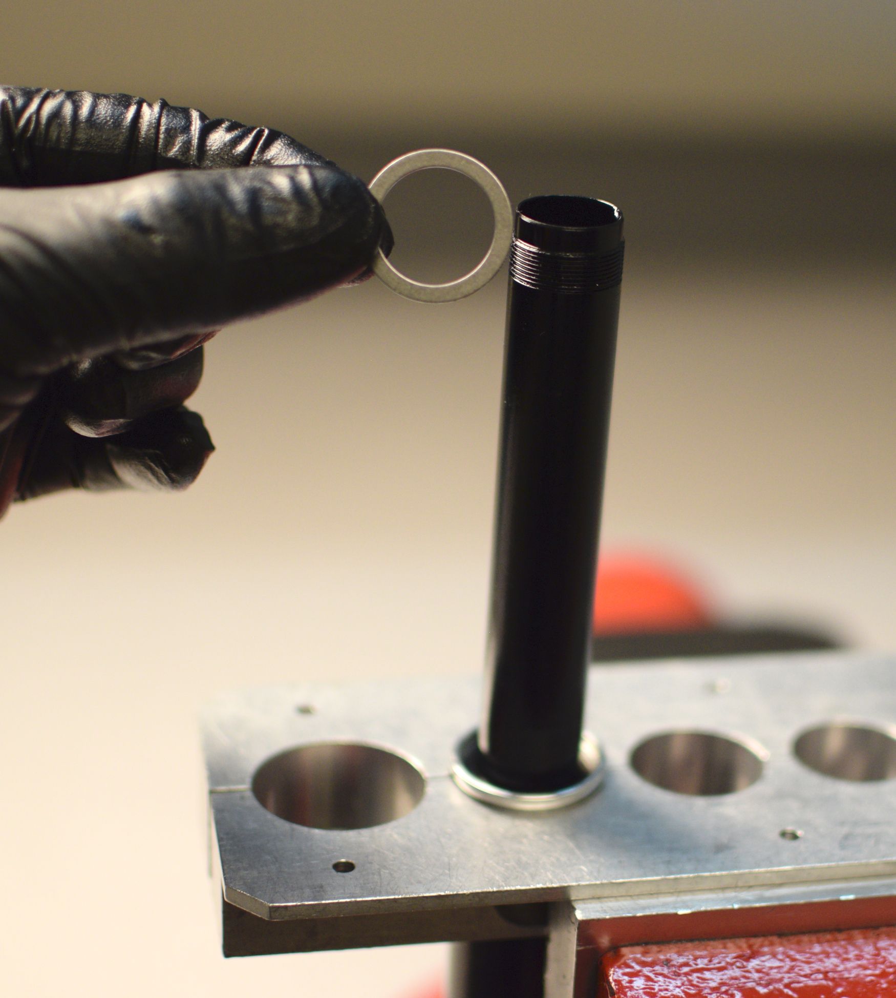
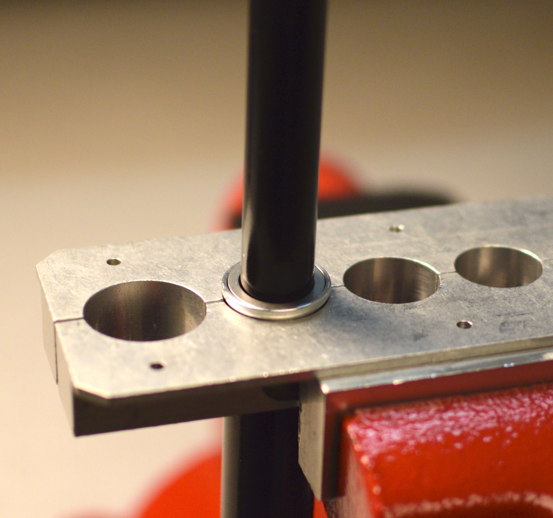
Step 25
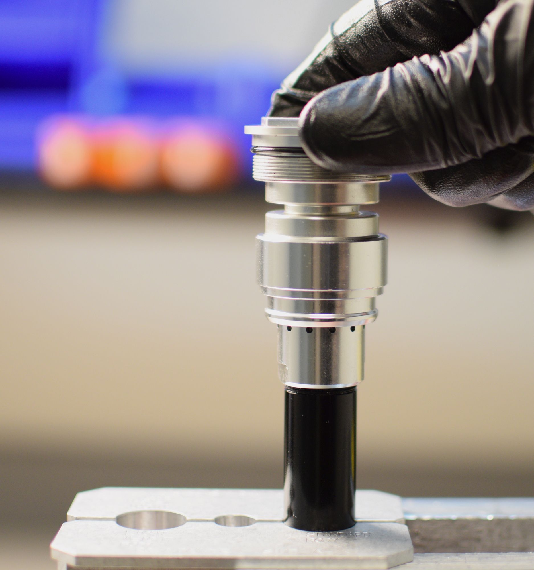
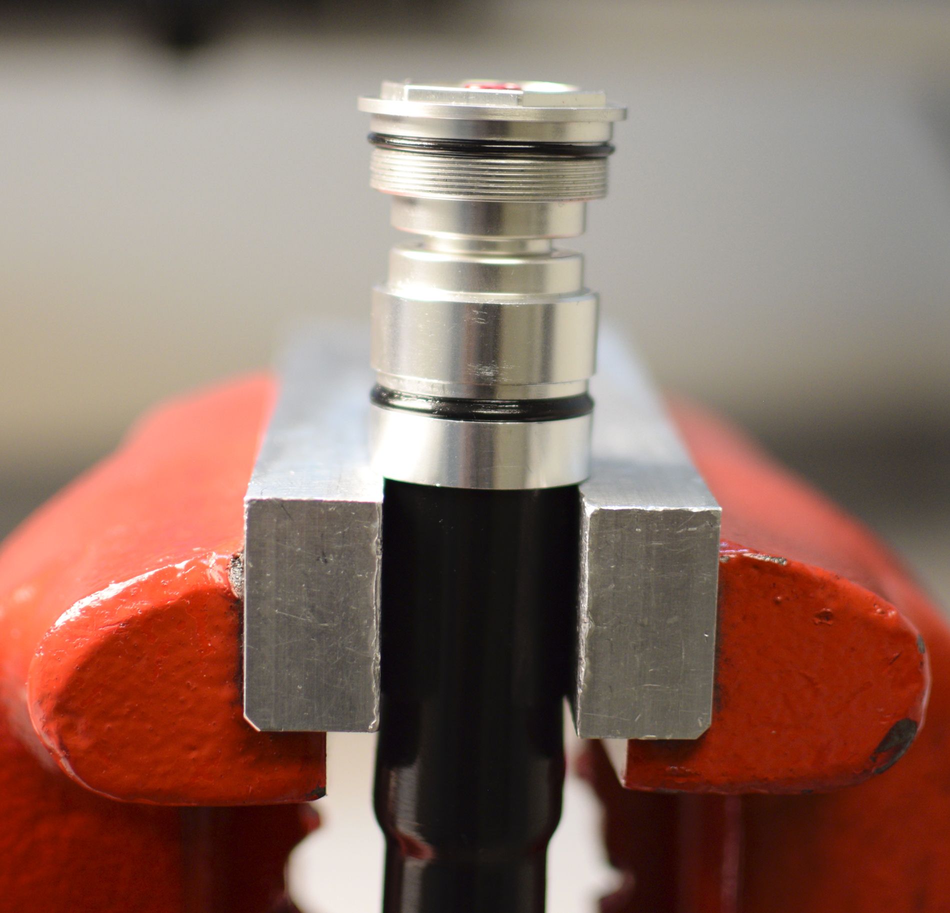
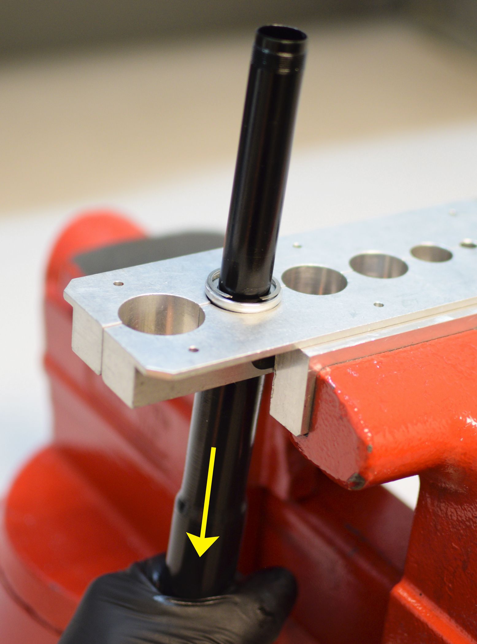
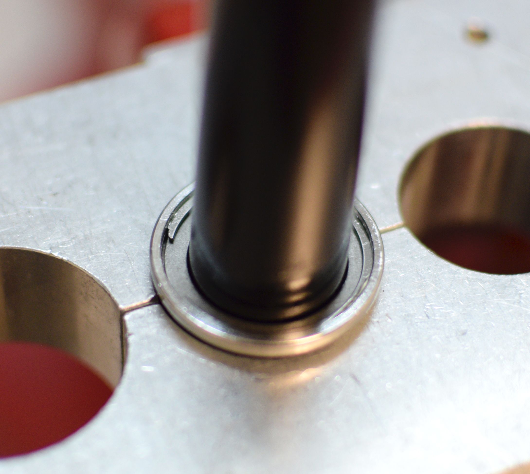
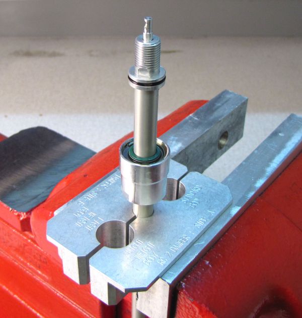
Invert the cartridge body and clamp loosely as shown in the second largest hole of your shaft clamps (PN: 803-00-147) without applying any clamping pressure to the bladder. Pull down on the topcap to seat the bladder in the lower bladder ring. Install the bladder retainer and retaining ring while holding downward pressure on the topcap.

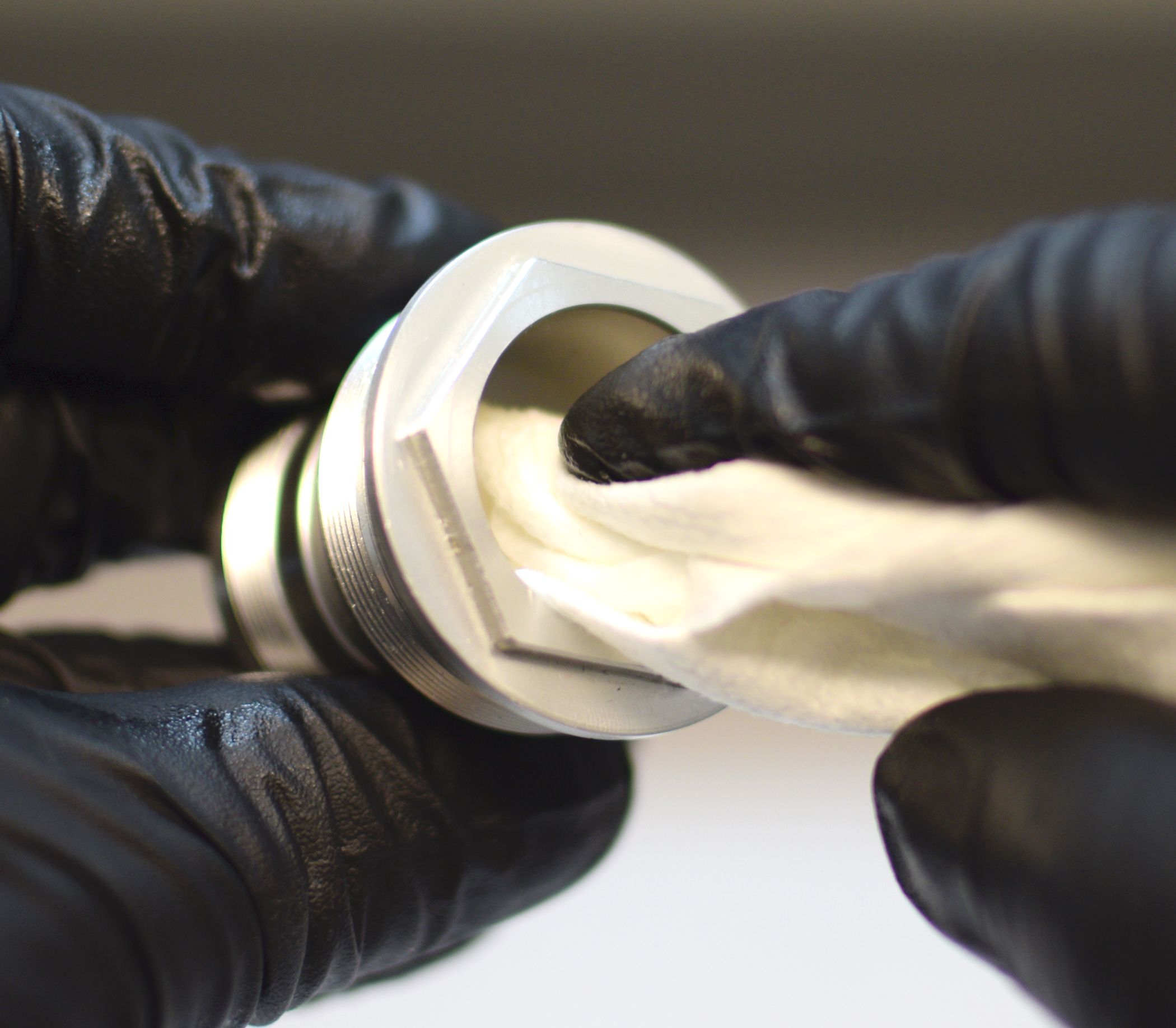
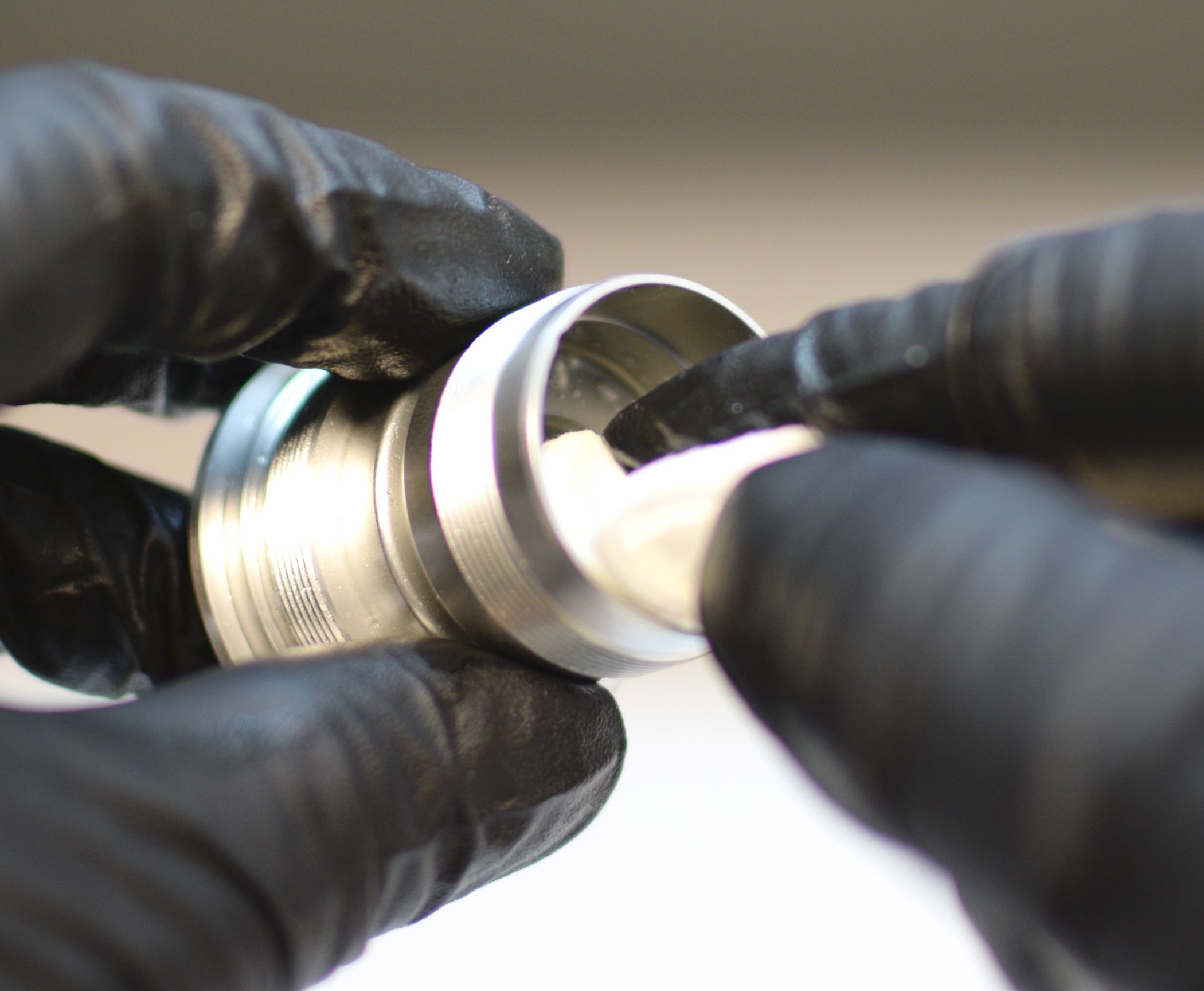
Step 26
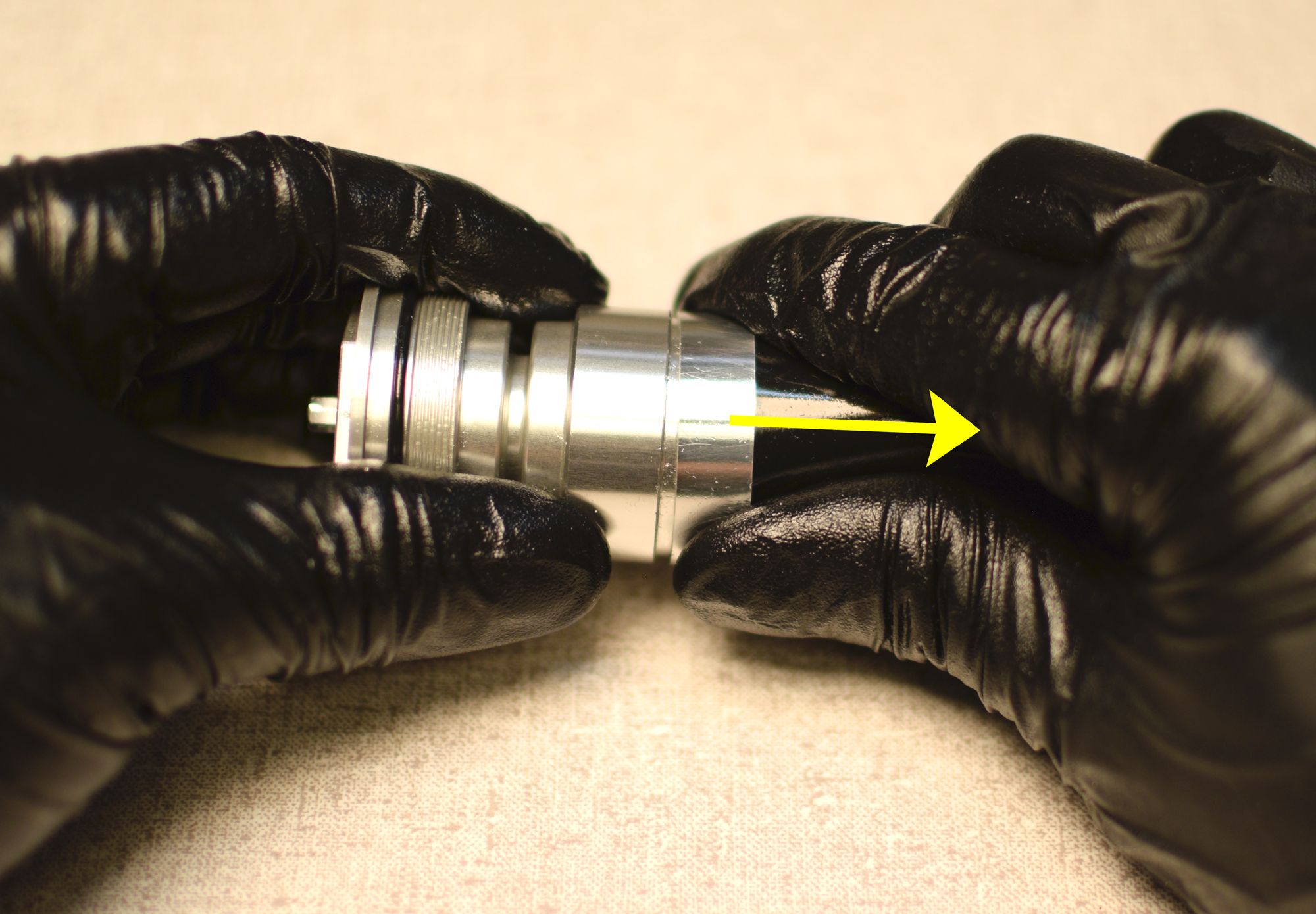
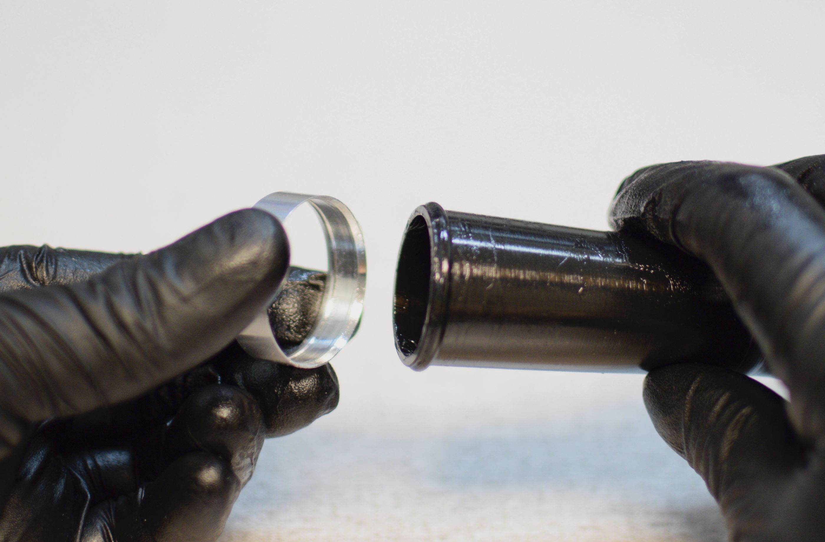
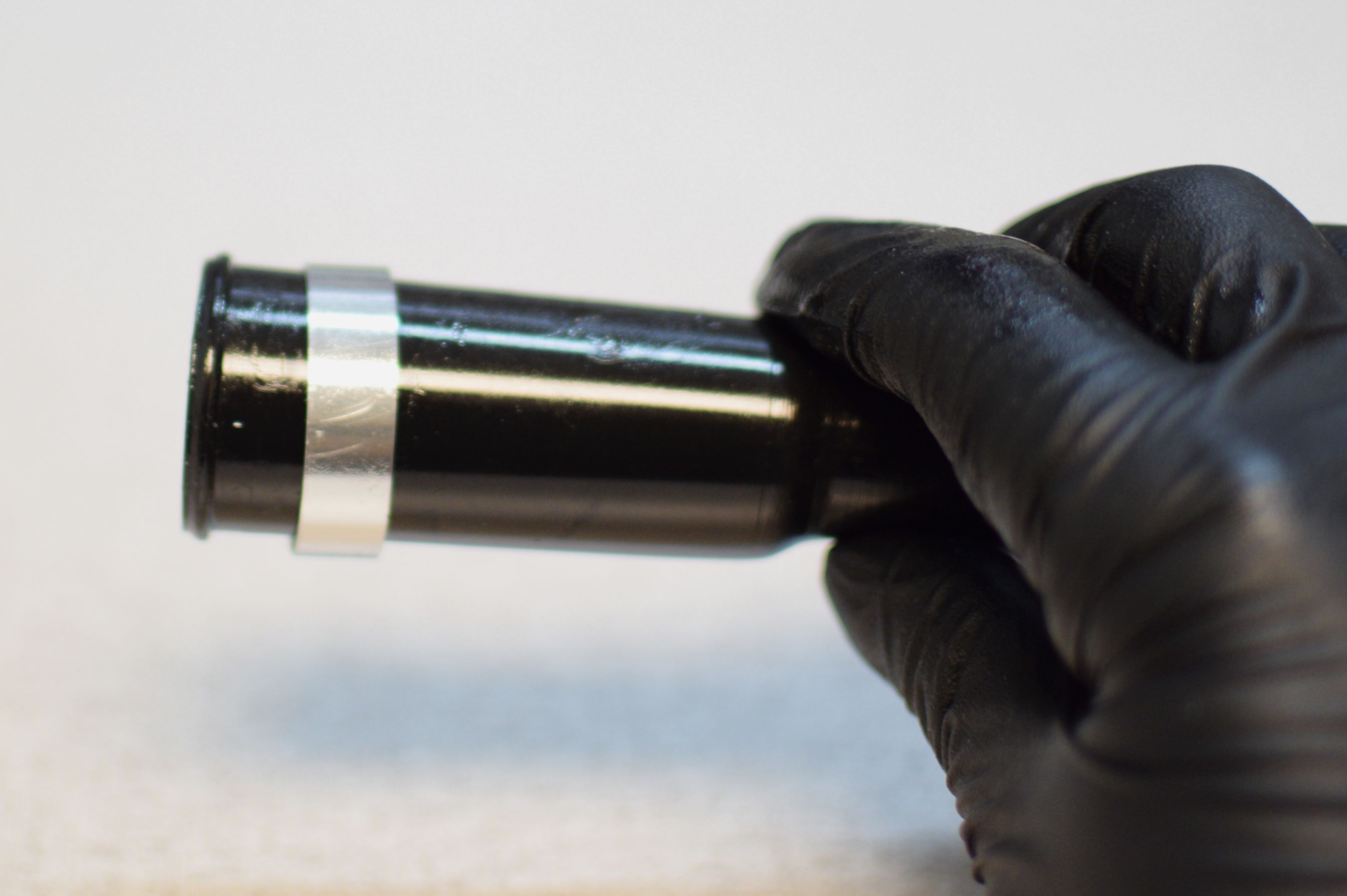
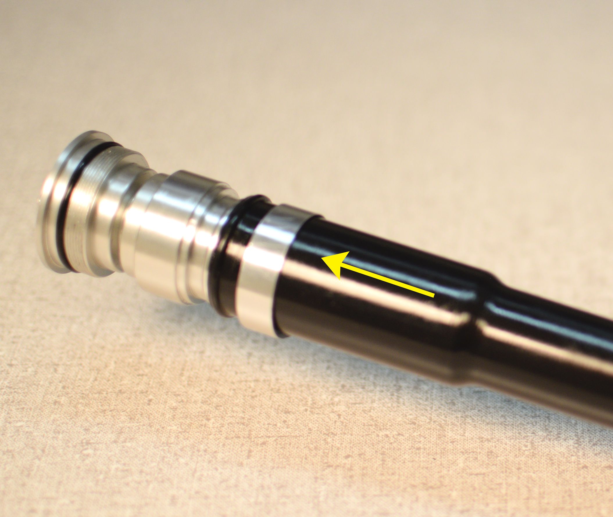
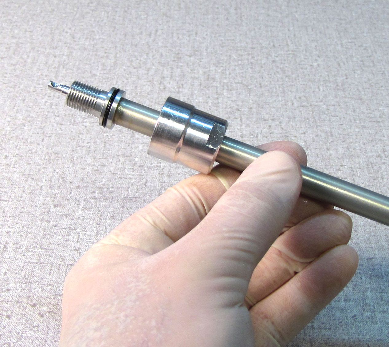
Slide the sealhead toward the rebound adjuster (listed as the base stud in the technical drawings), leaving about 1 inch (25mm) space between the sealhead and rebound adjuster. Clean the shaft with isopropyl alcohol and a lint-free paper towel.

Step 27
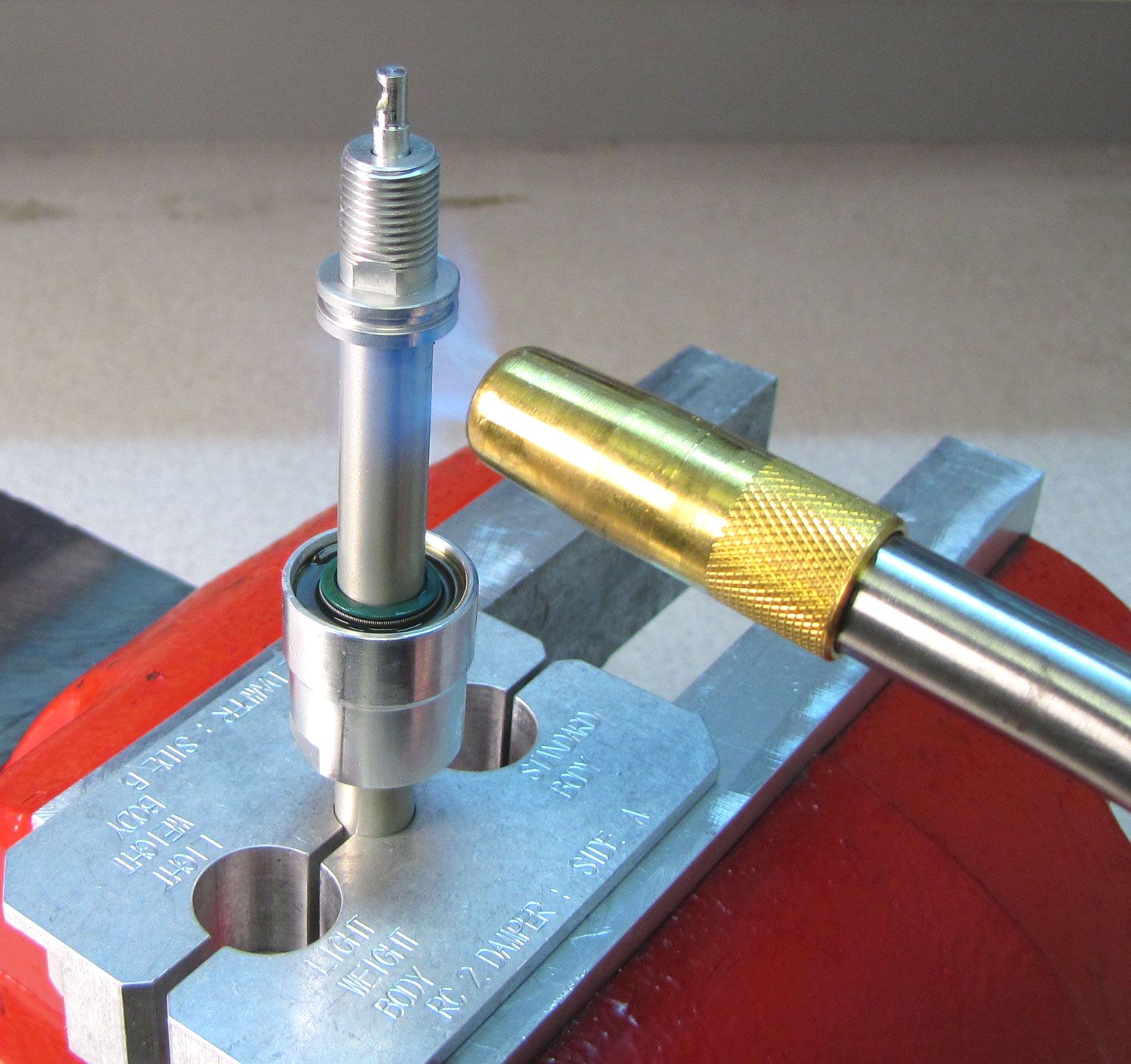
Clamp the shaft in your shaft clamps (PN: 803-00-830 for 10mm shafts or PN: 803-00-174 for 8mm shafts) and remove and discard the o-ring from the rebound adjuster.


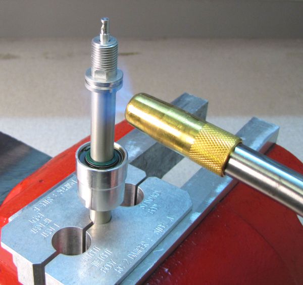
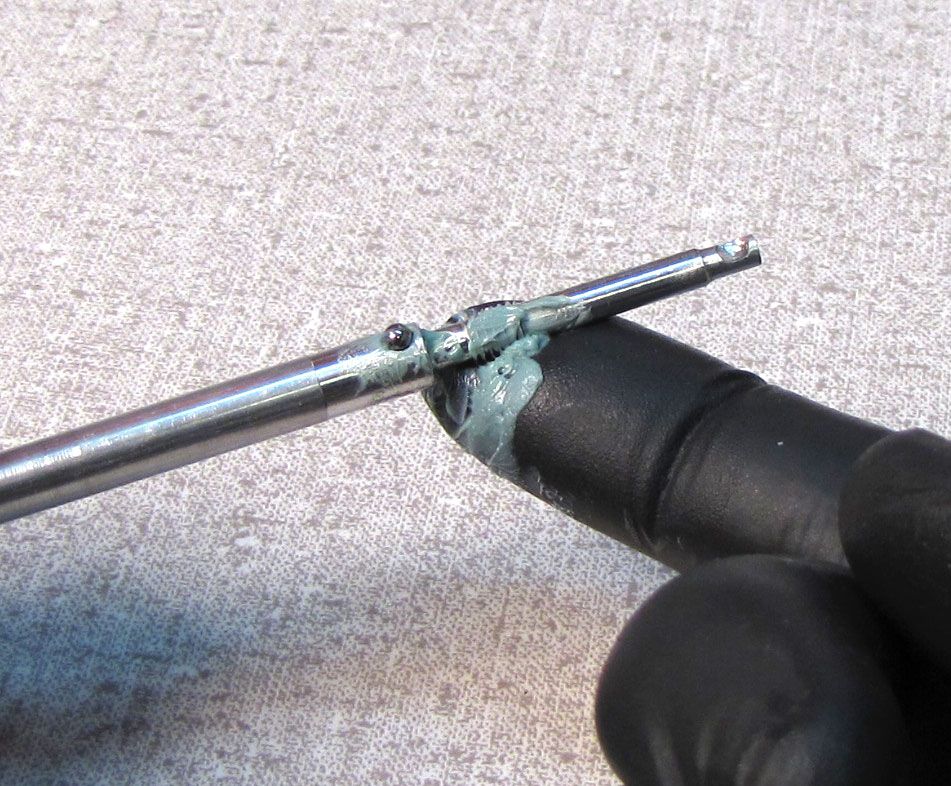
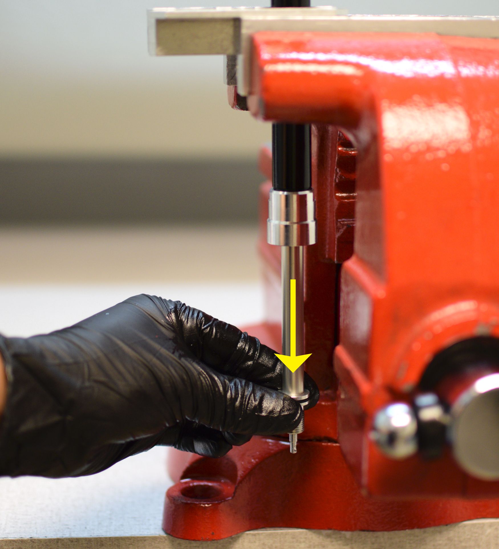
Step 28
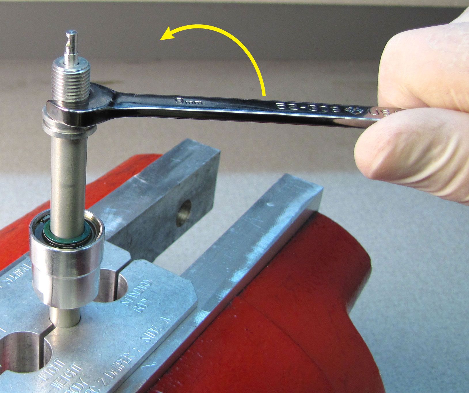
Carefully apply heat to the shaft at the rebound adjuster with a propane torch for 5-10 seconds to break down the Loctite. Unthread the rebound adjuster counter-clockwise with a 9mm wrench.

Step 29
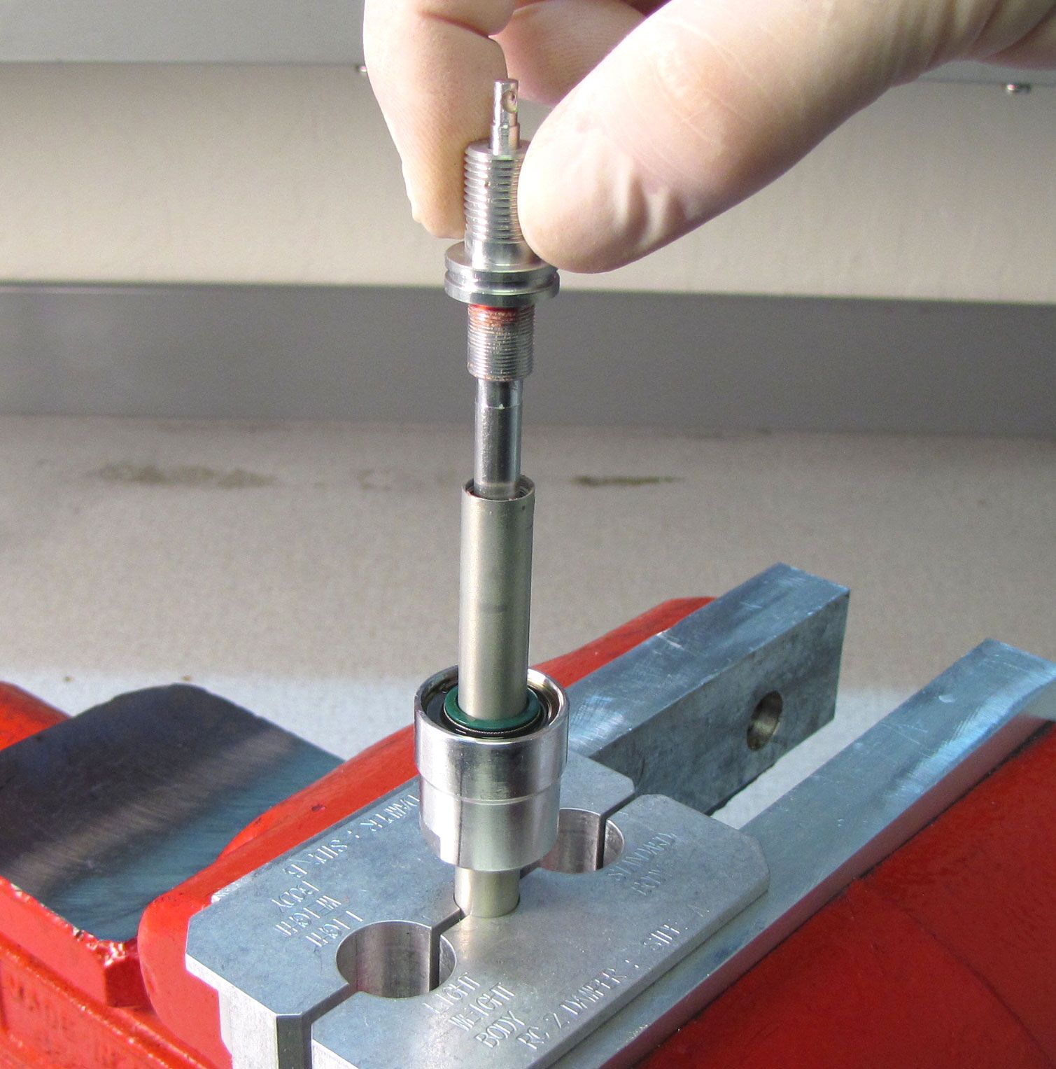
Lift the rebound adjuster with rebound needle straight up and out of the shaft. Replace the o-ring at the fluted end of the needle with a new greased one from the kit.

Step 30
Slowly unthread the rebound adjuster (counter-clockwise) from the rebound needle. After a few turns you will be able to see the rebound detent ball. Hold the needle with the rebound detent ball pointing up as you slowly unthread the rebound adjuster fully.


Step 31
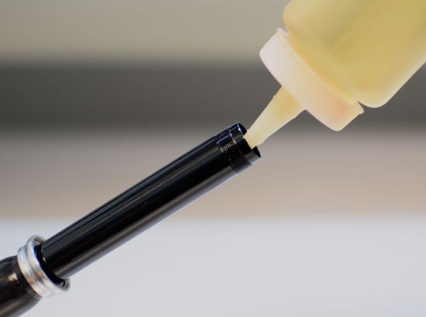
Coat the threads of the rebound needle with waterproof grease such as Sta-Lube SL3125. While holding the rebound needle with the detent ball facing up, thread the rebound adjuster clockwise onto the needle. Thread the adjuster fully onto the needle, then back it off 1/4 turn.
Step 32
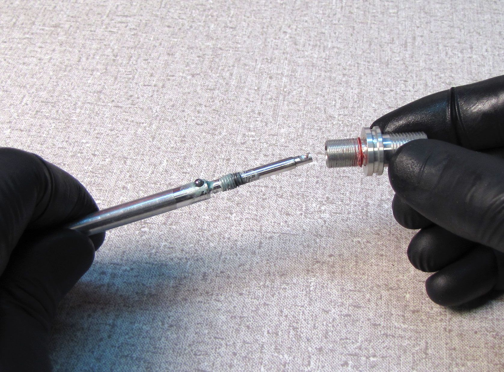
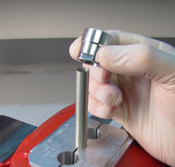
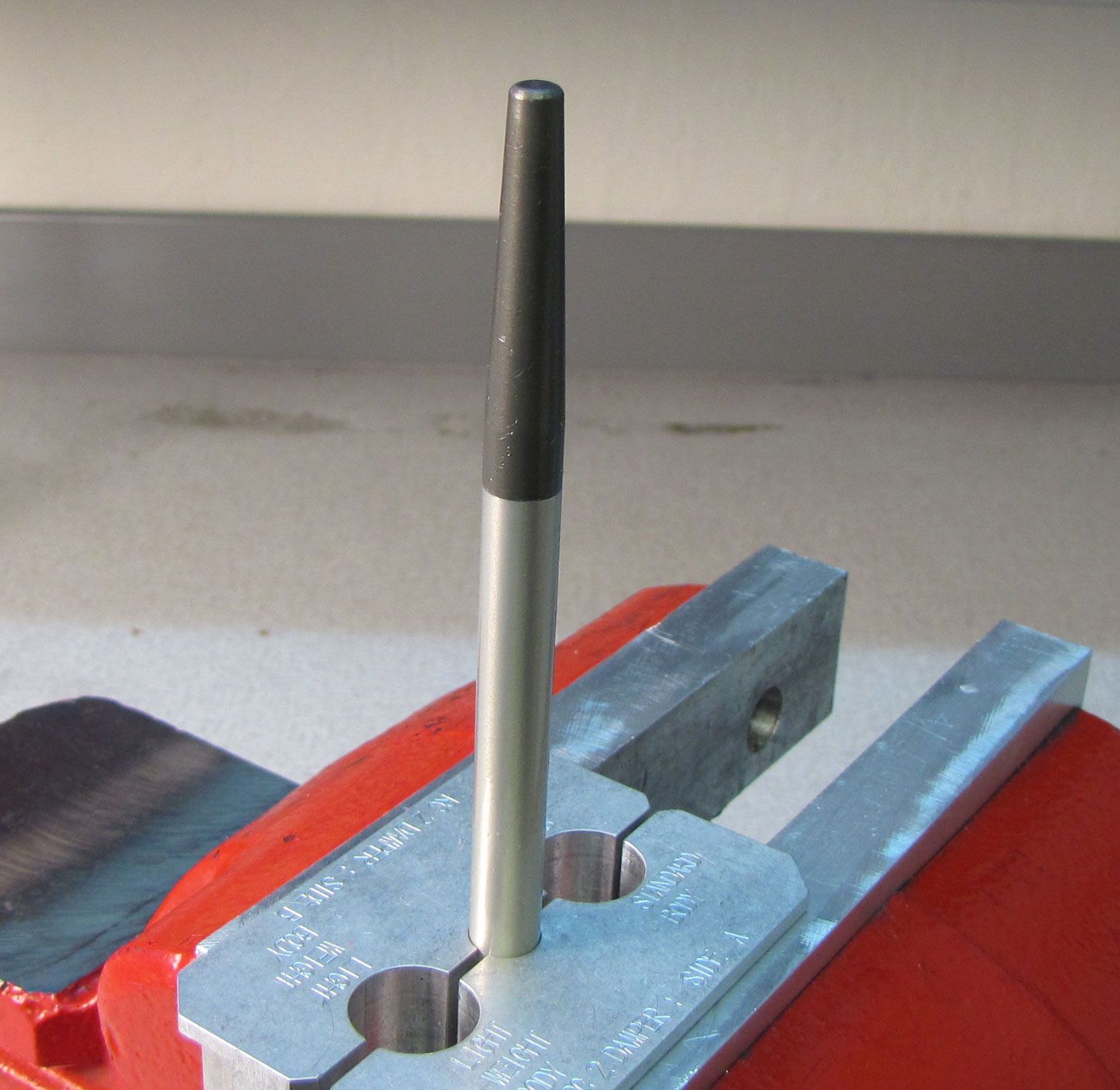
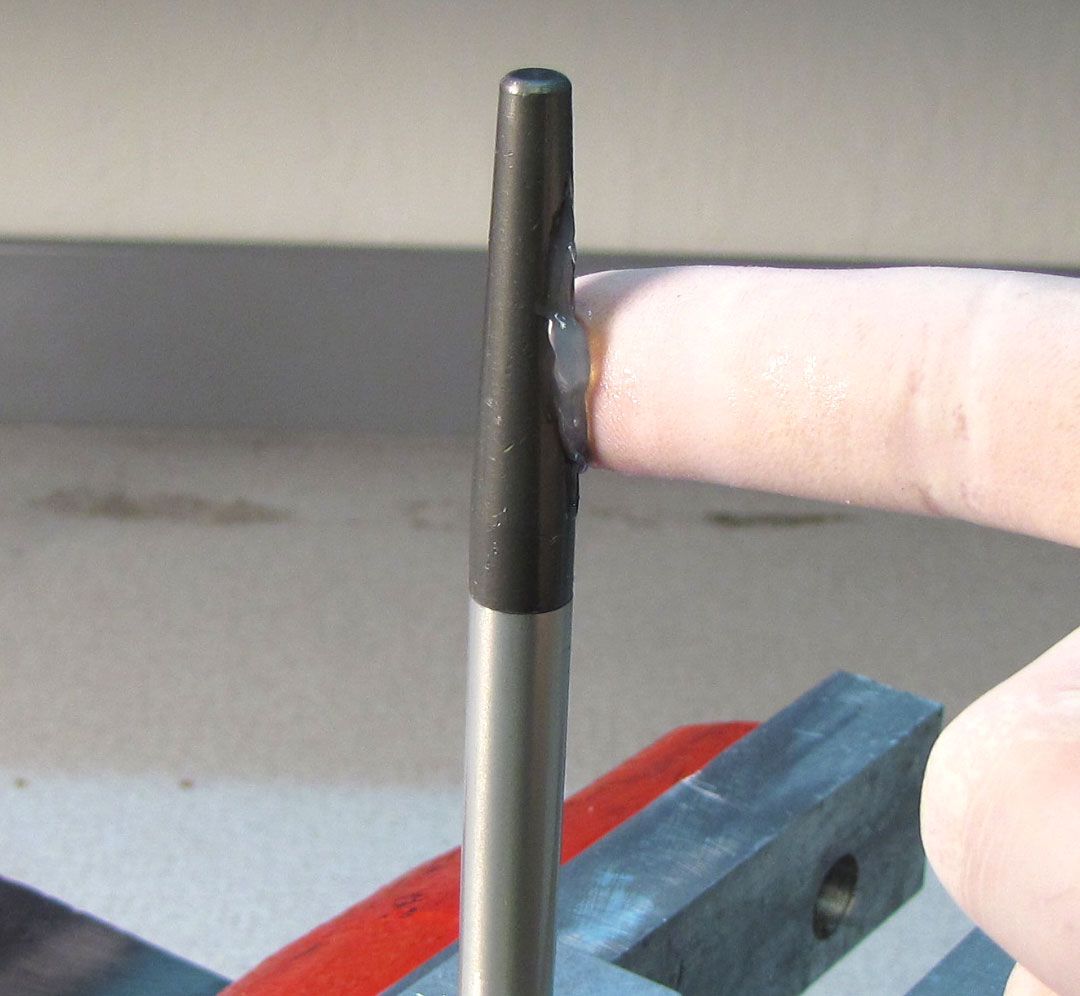
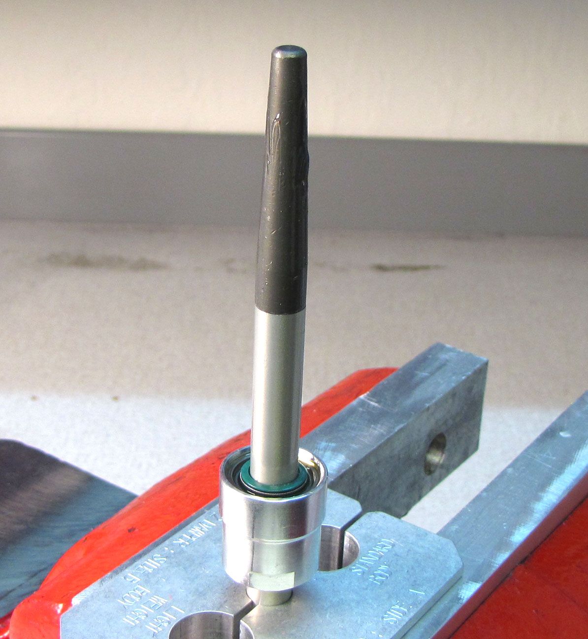
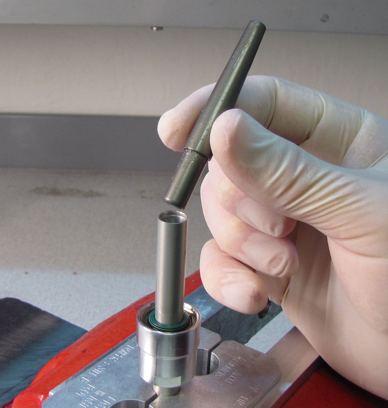
Remove and discard the original sealhead. Install the 10mm bullet tool (PN: 398-00-371 for 10mm shafts or PN: 398-00-320 for 8mm shafts) into the shaft, then coat the bullet with a film of Slick Honey.

Step 33
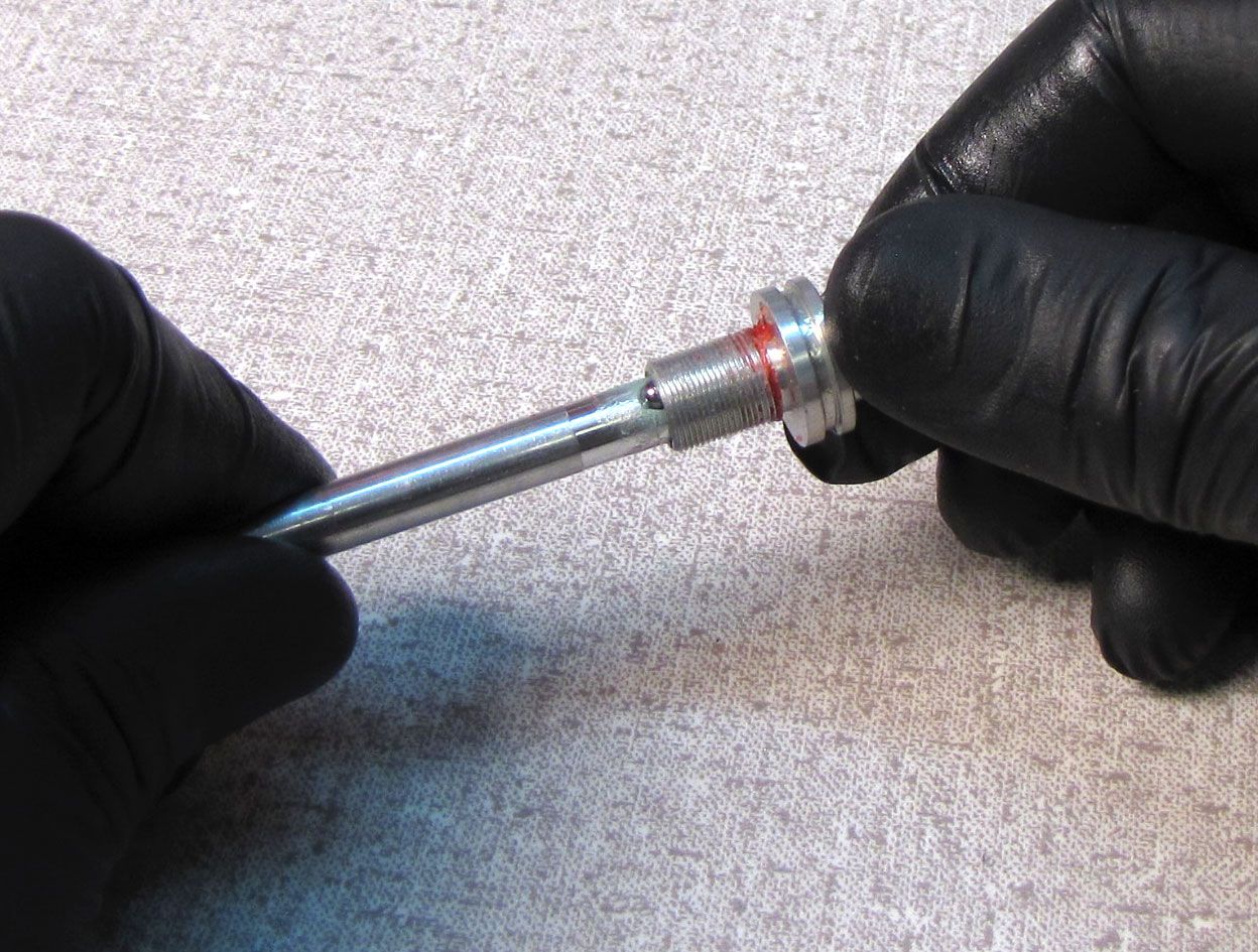
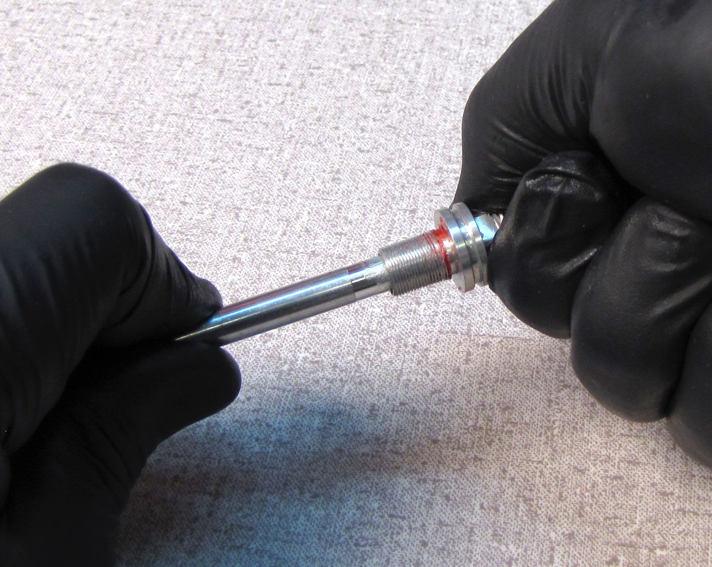
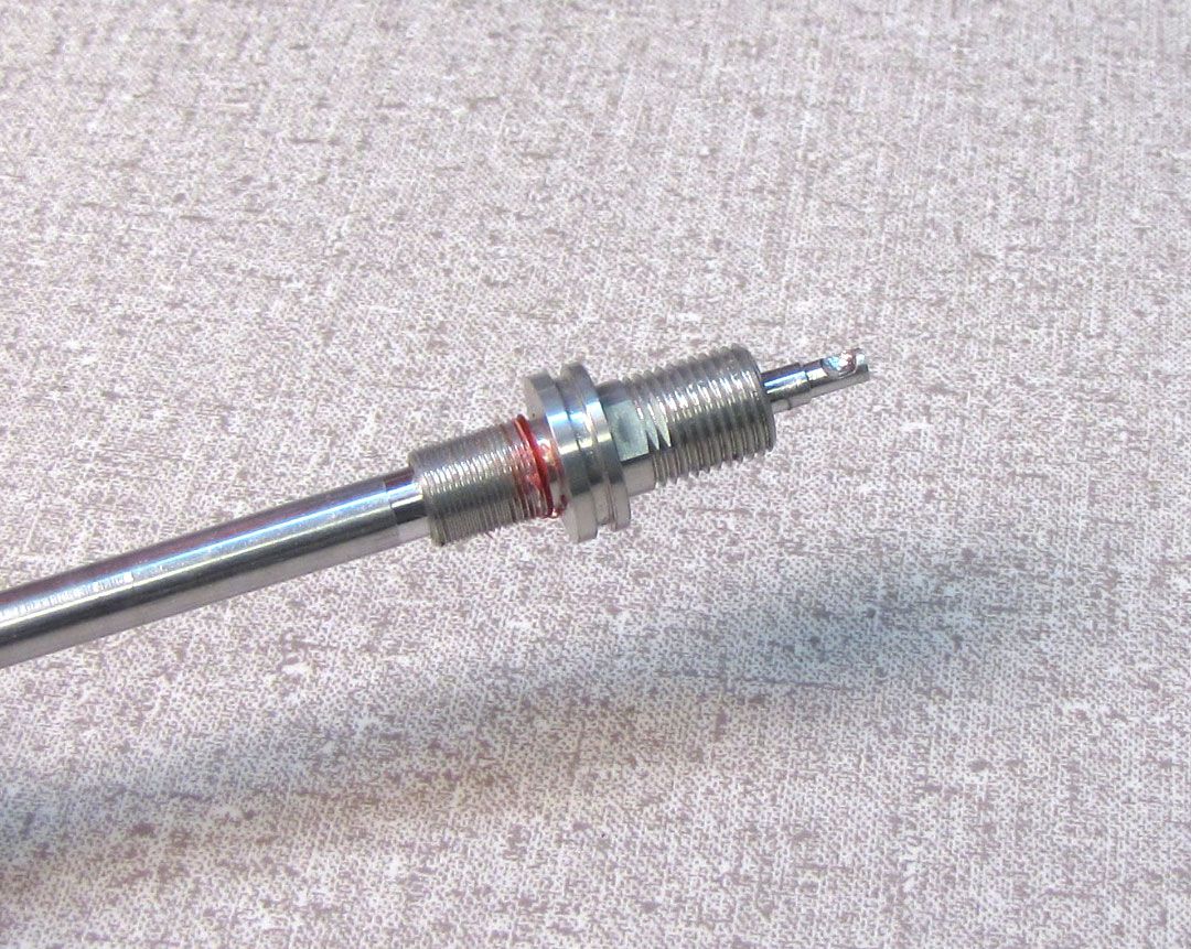
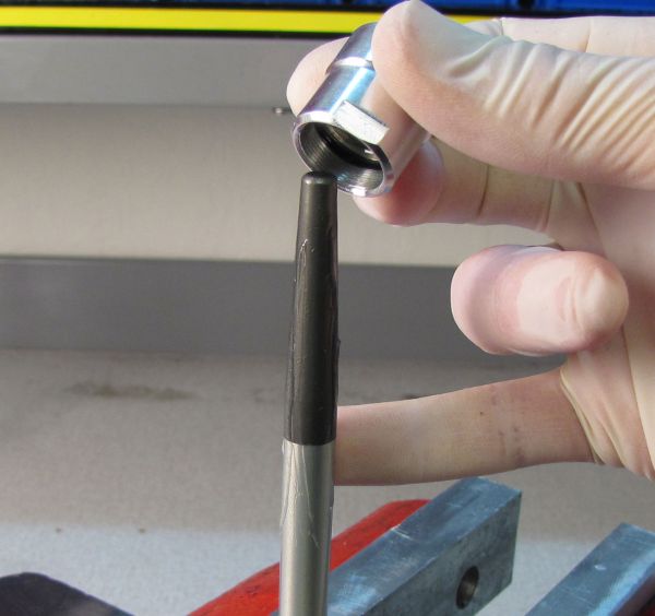
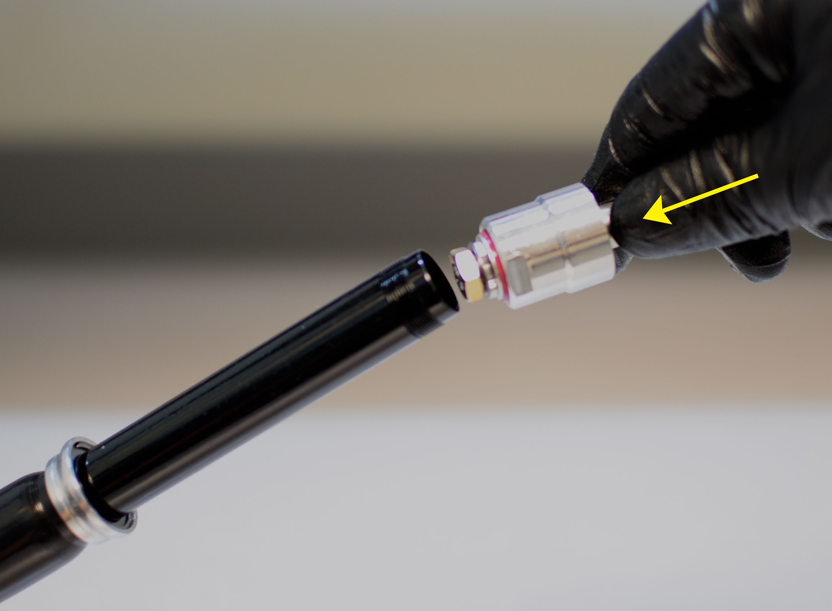
Install the new sealhead from the kit onto the shaft with its threaded end first. Remove the bullet tool.


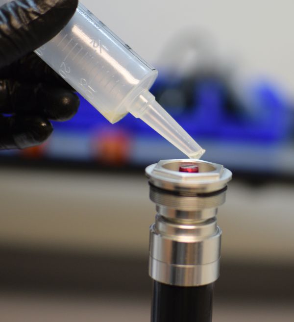
Step 34
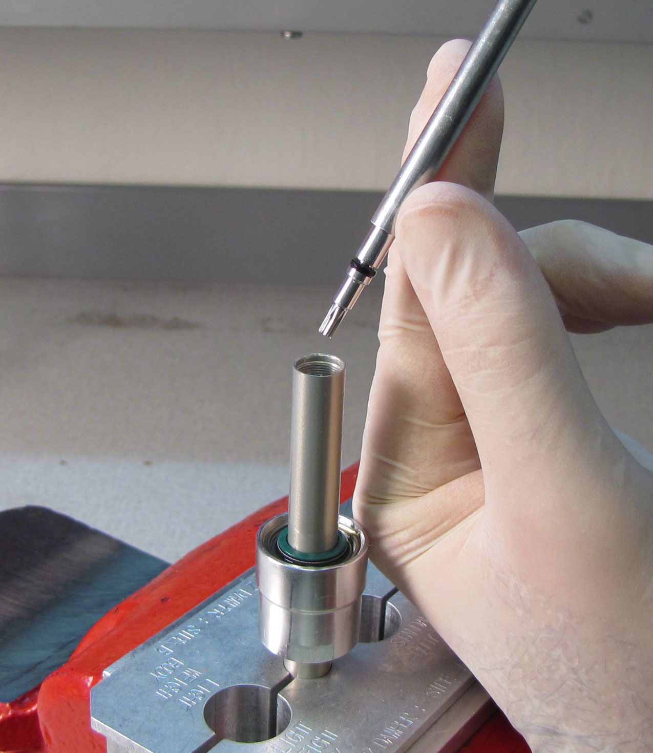
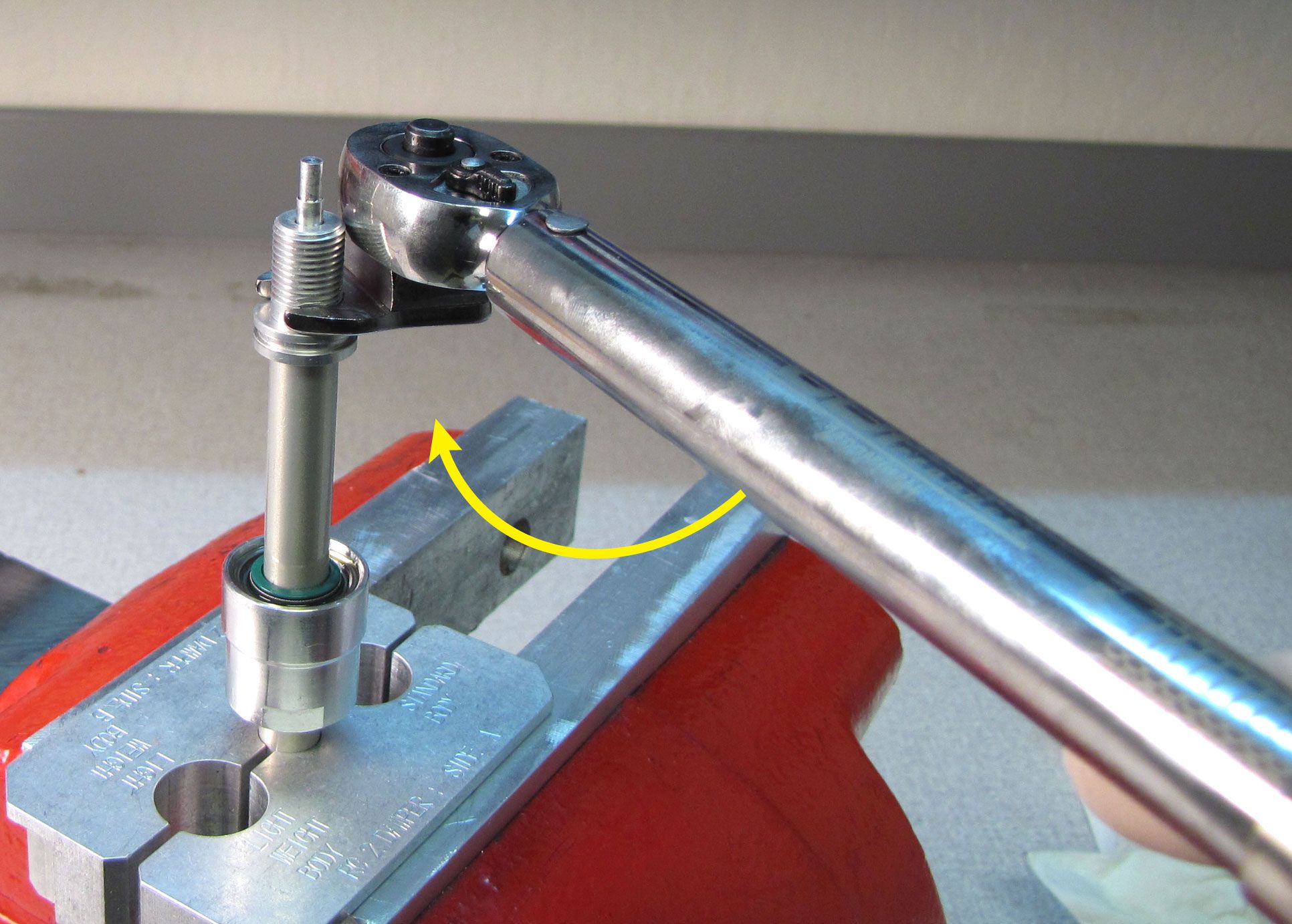
Drop the rebound needle and adjuster assembly into the shaft, then apply a drop of Loctite 262 to the rebound adjuster threads. Tighten the rebound adjuster to the shaft to 30 in-lb (3.4 Nm) torque with a 9mm crows foot.

Step 35
Temporarily reinstall the rebound knob with your 2mm hex wrench making sure to allign the set screw with the detent in the rebound needle. Turn the rebound adjuster counter-clockwise to its full open position. Remove the rebound knob.


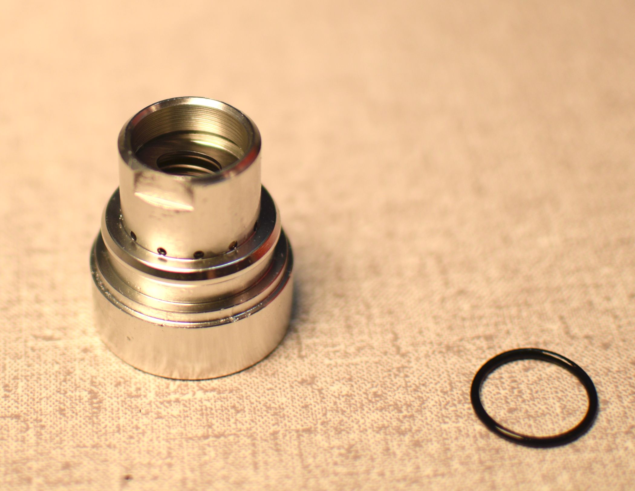
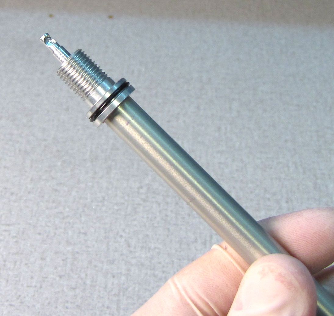
Step 36
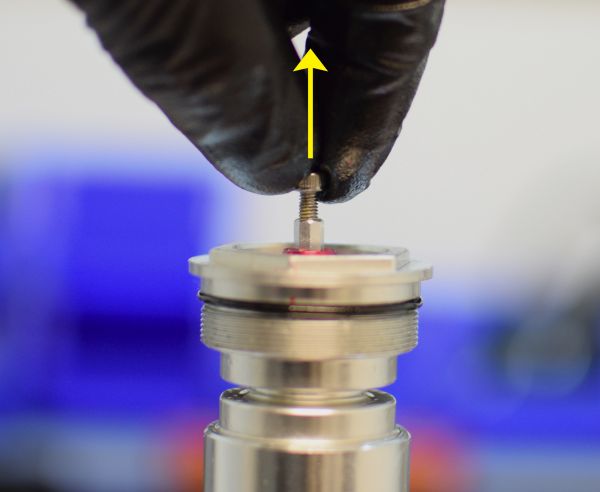
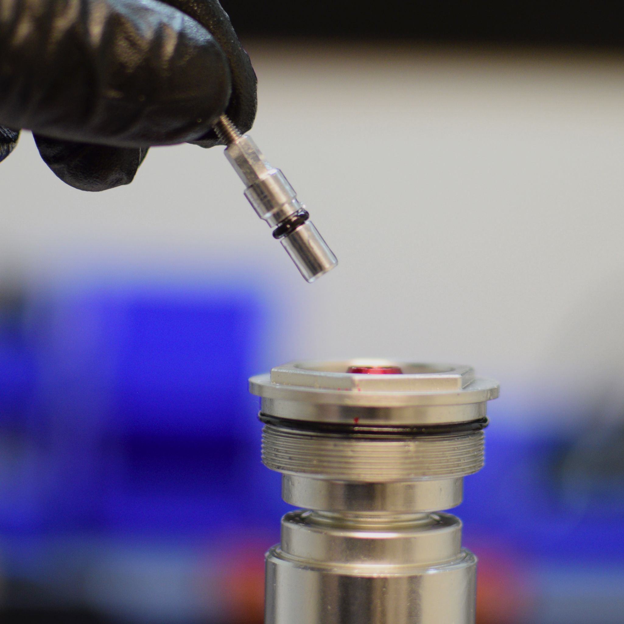
Install a new greased o-ring from the kit onto the rebound adjuster.

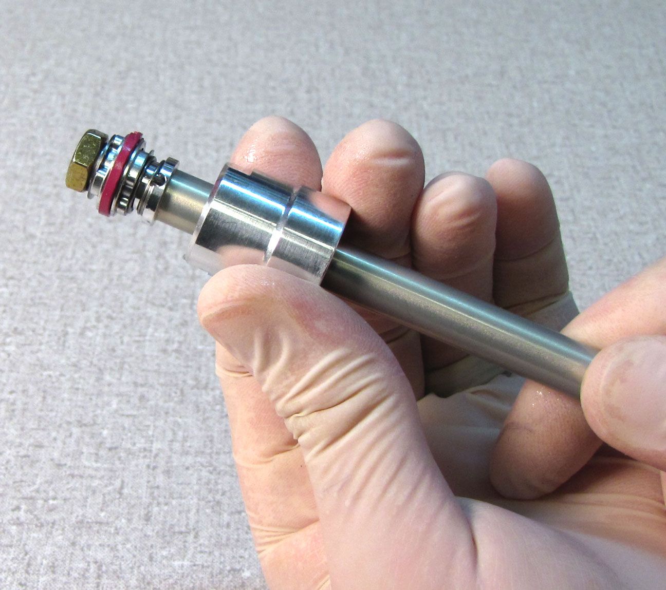
Step 37
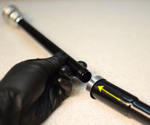
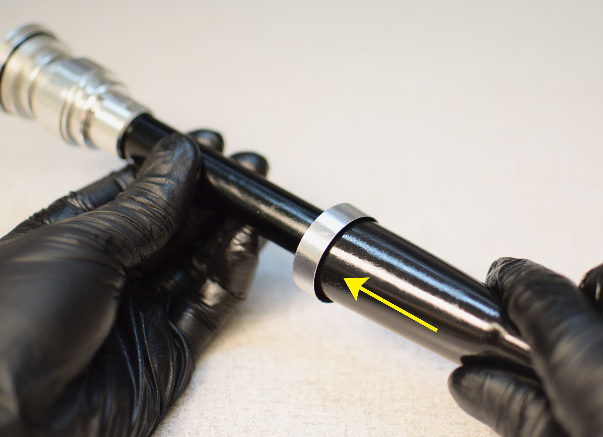
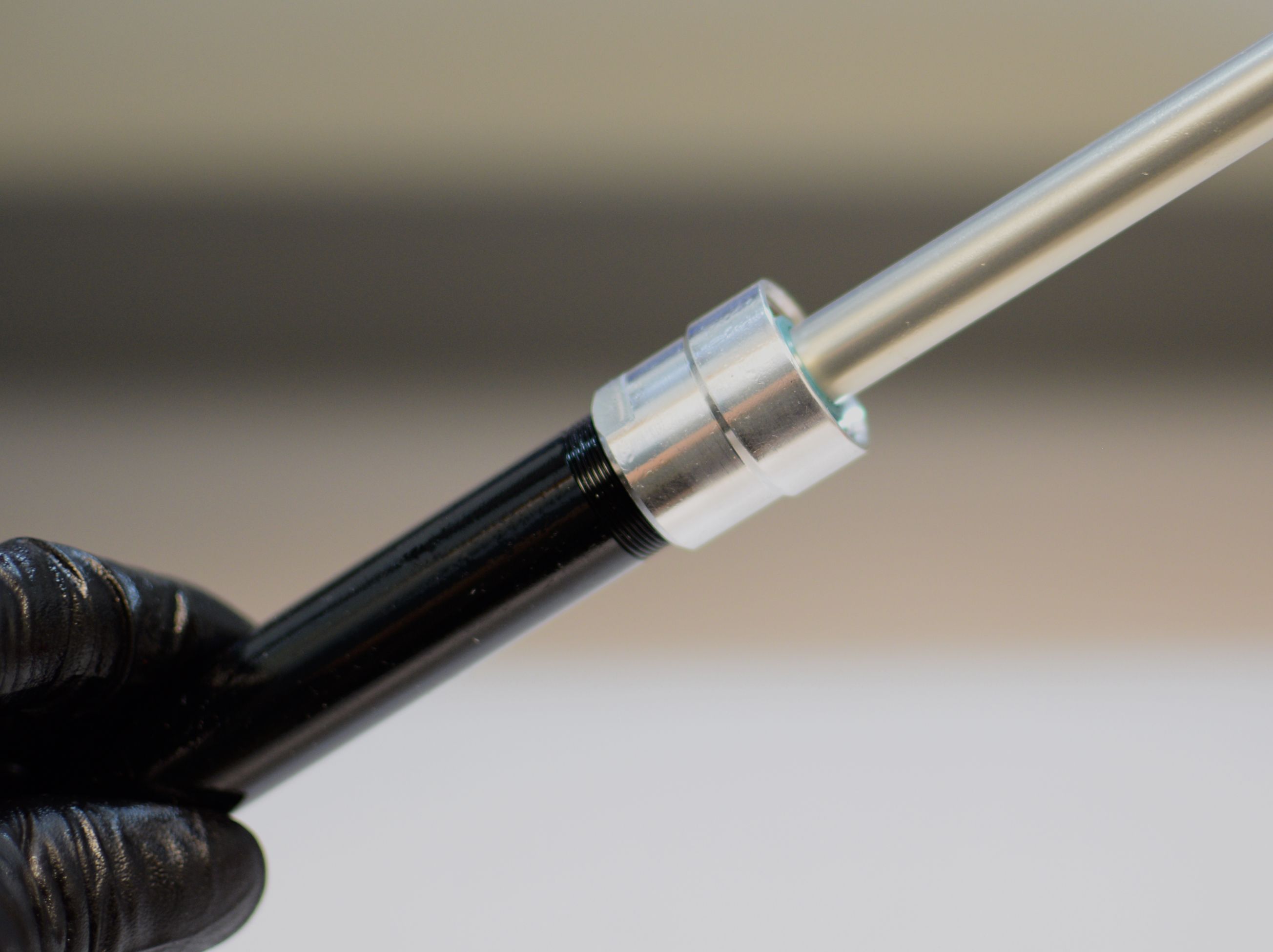
Remove and replace the pink piston glide ring with a new one from the kit. The new glide ring will appear larger than the old one, but will compress once inside the cartridge body. Slide the sealhead all the way toward the rebound piston end.

Step 38
Reinstall the compression adjust coupler into the compression selector shaft, then invert the cartridge so the open end of the body faces up. Carefully rest the topcap in your inverted topcap socket.

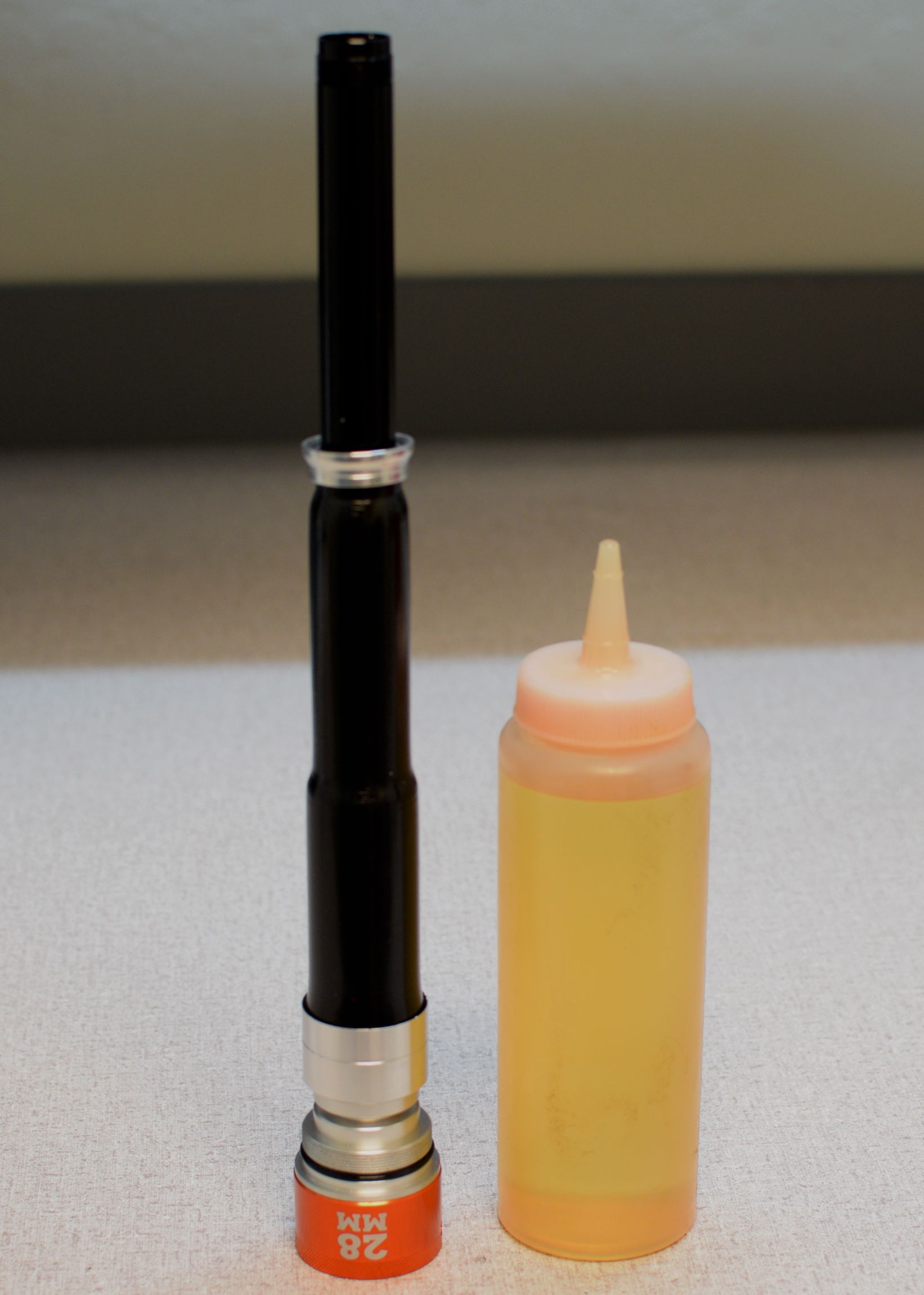

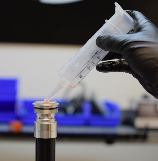
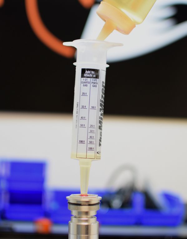
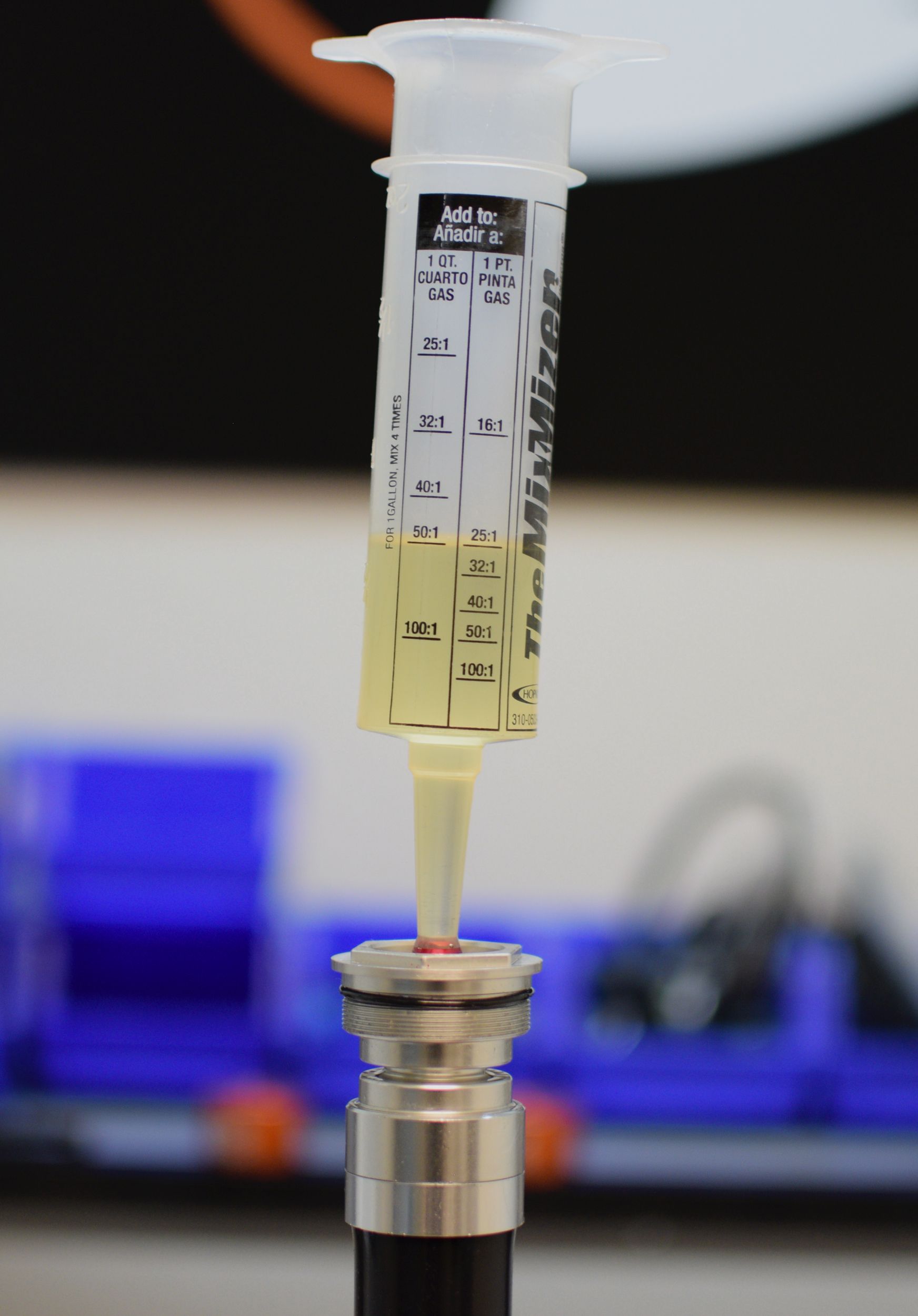
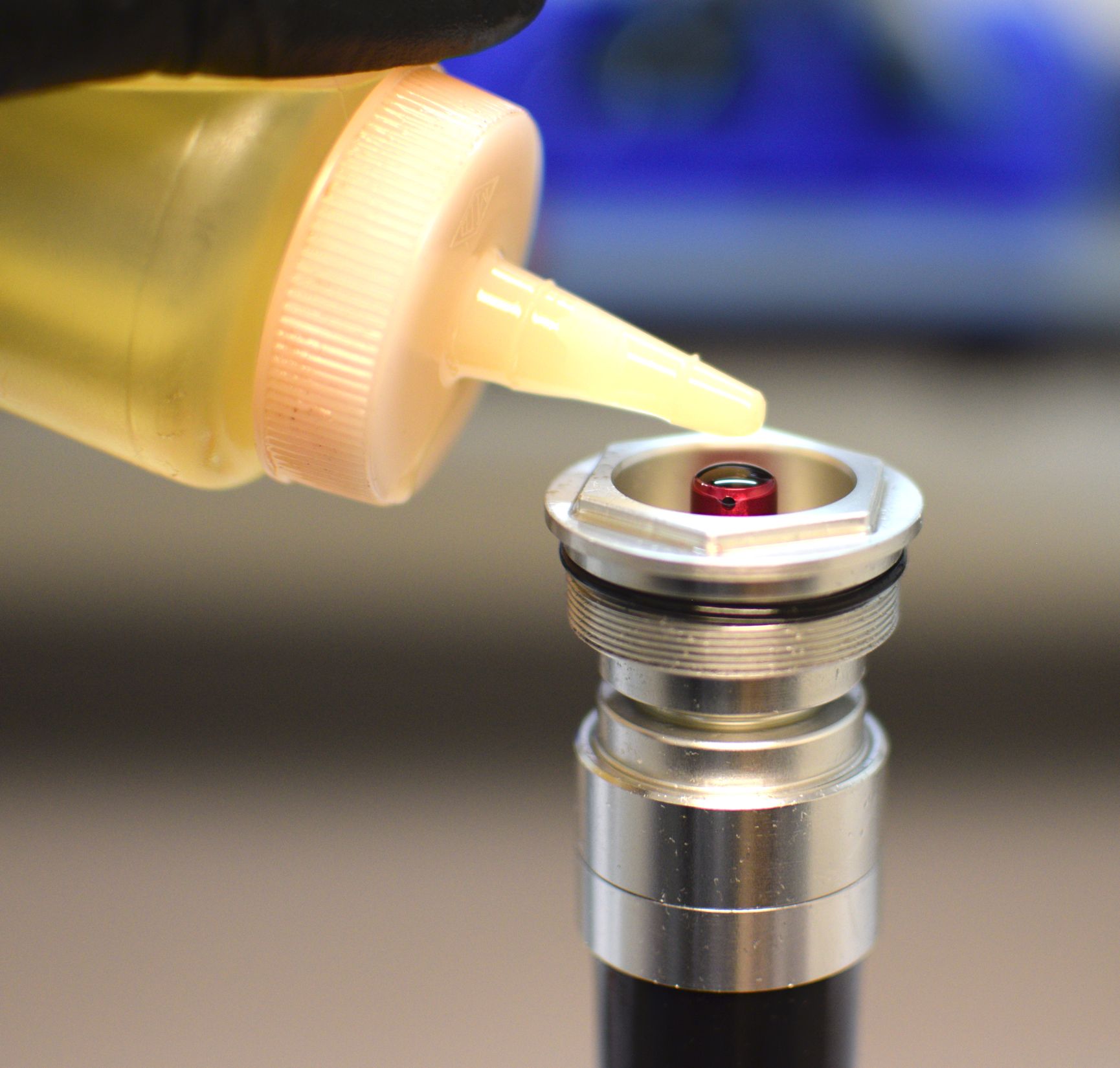
Step 39
Add FOX 5wt. Teflon infused oil to the cartridge body so the oil level is approximately 2 inches from the end of the body. Squeeze the bladder to purge out air and ingest oil. Add oil and continue squeezing until most of the air is purged and no more oil can be added.
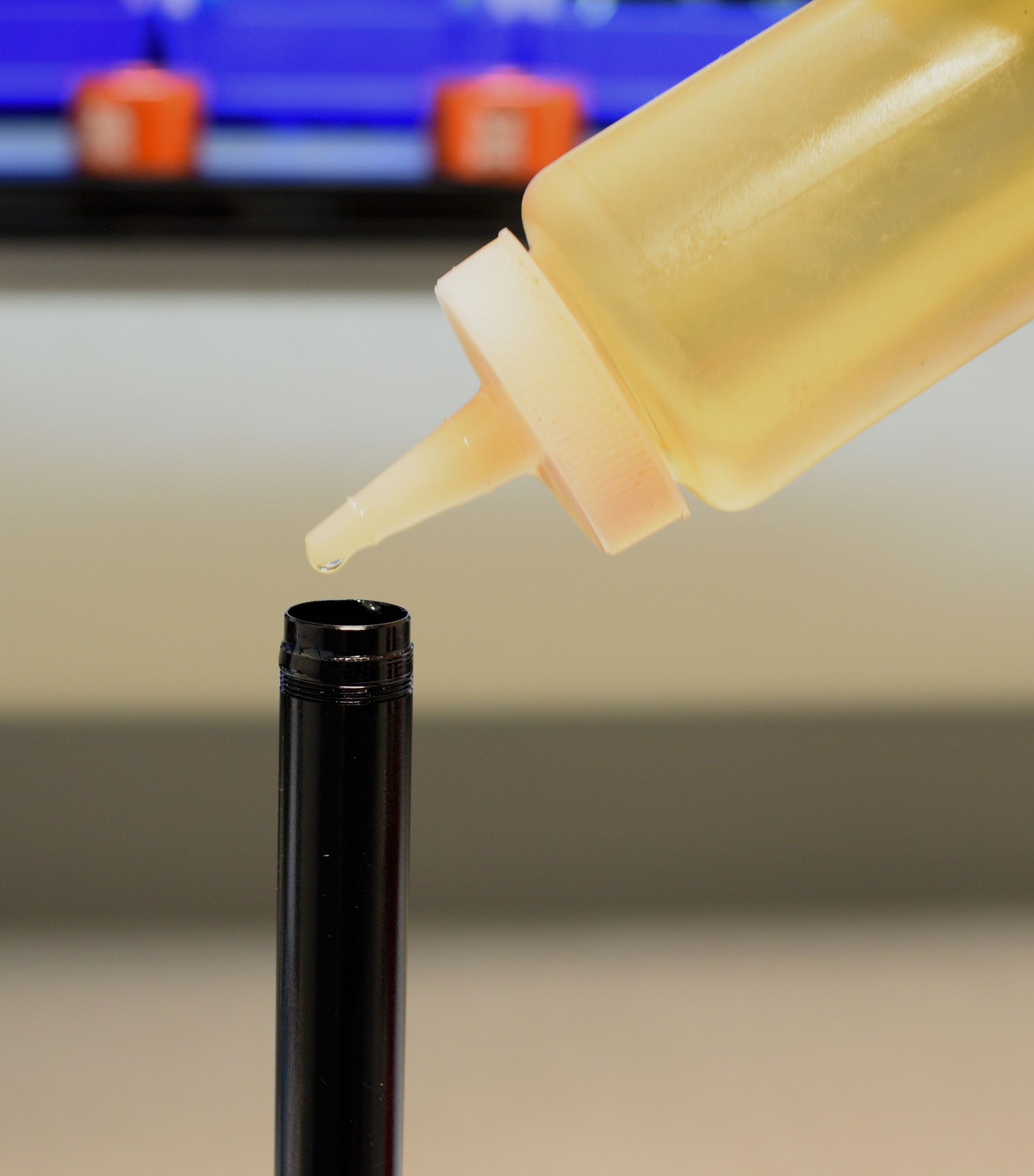
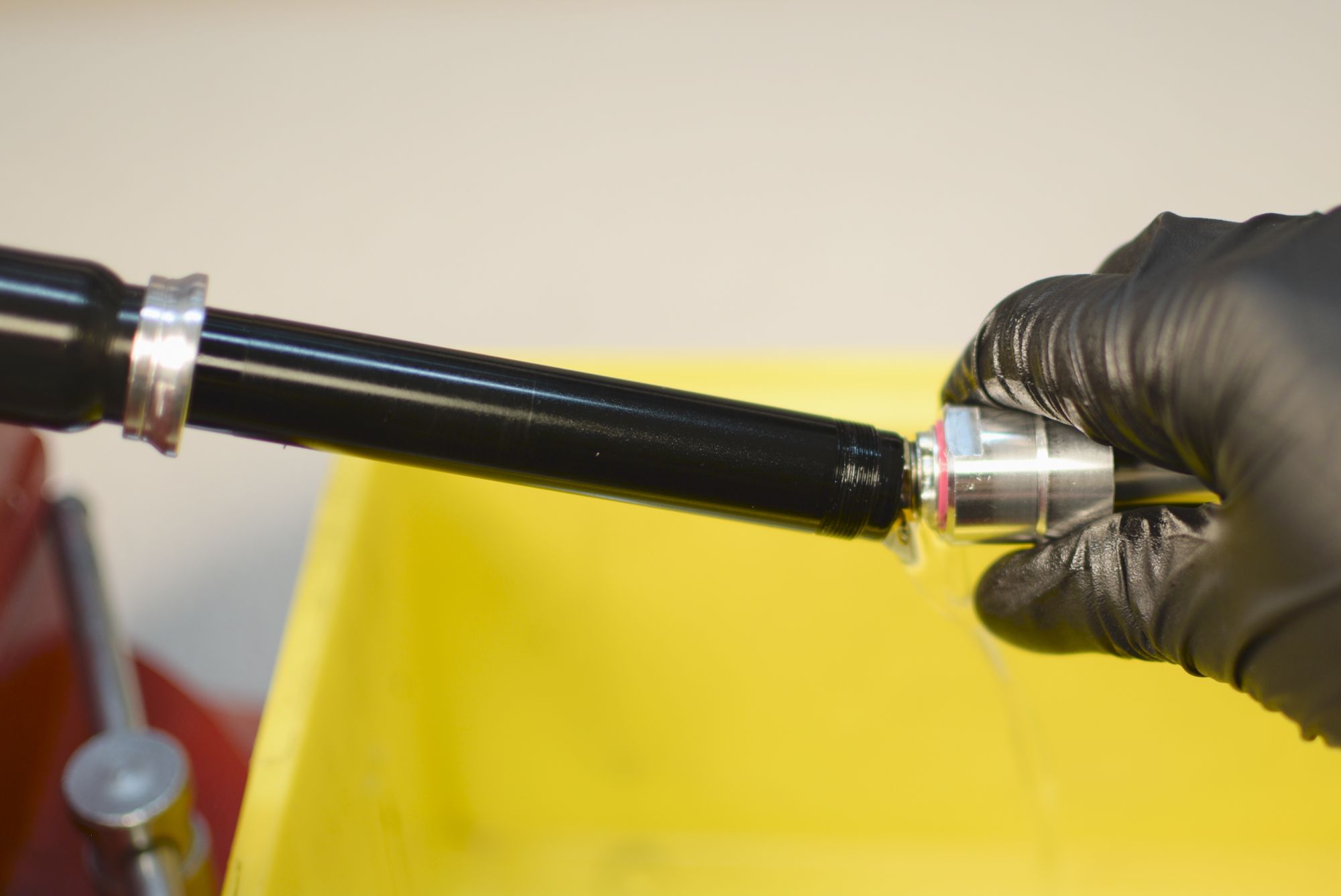
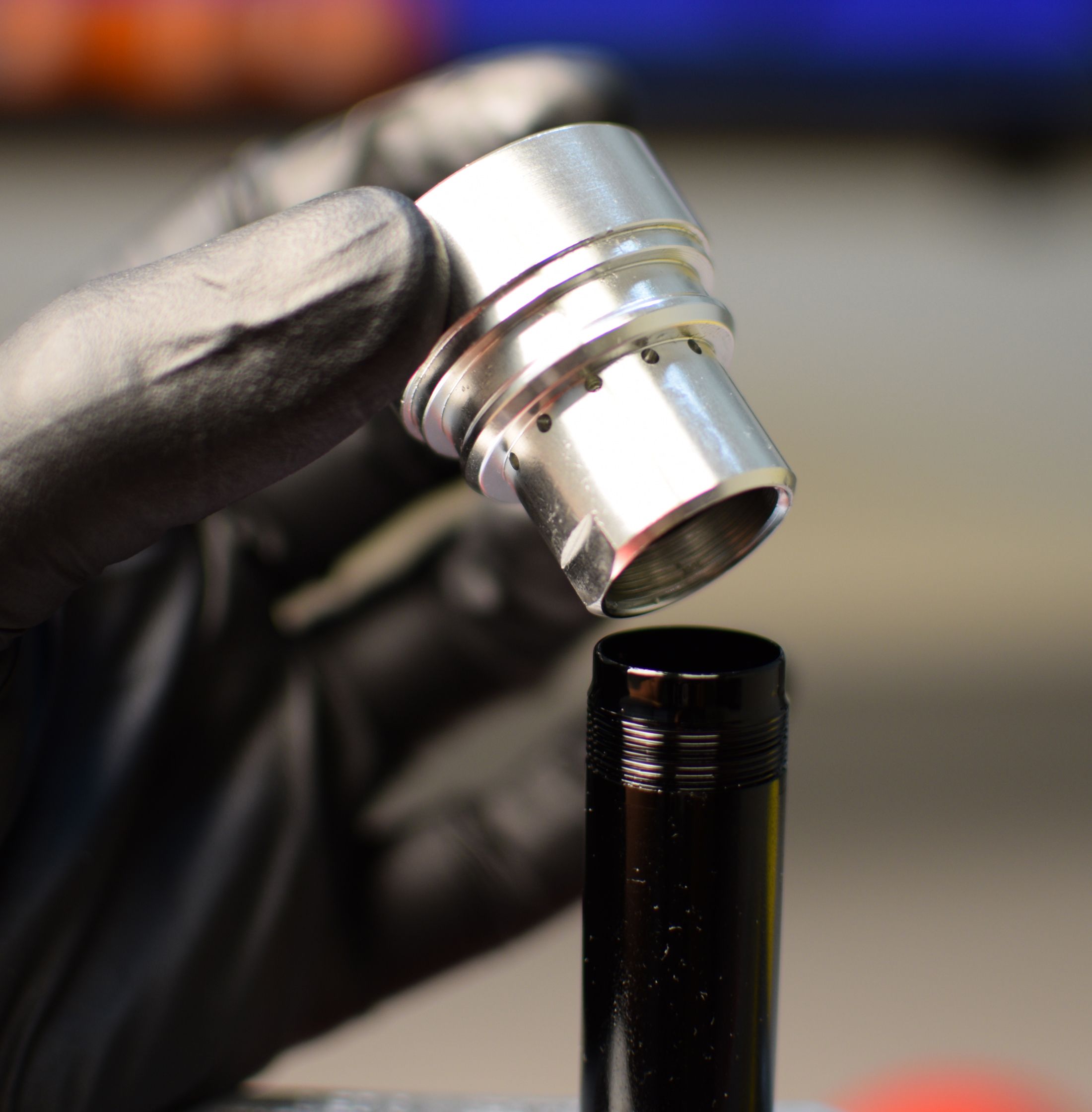
Step 40
Top off the cartridge body with oil then install the shaft assembly threading the sealhead onto the cartridge body until hand tight.


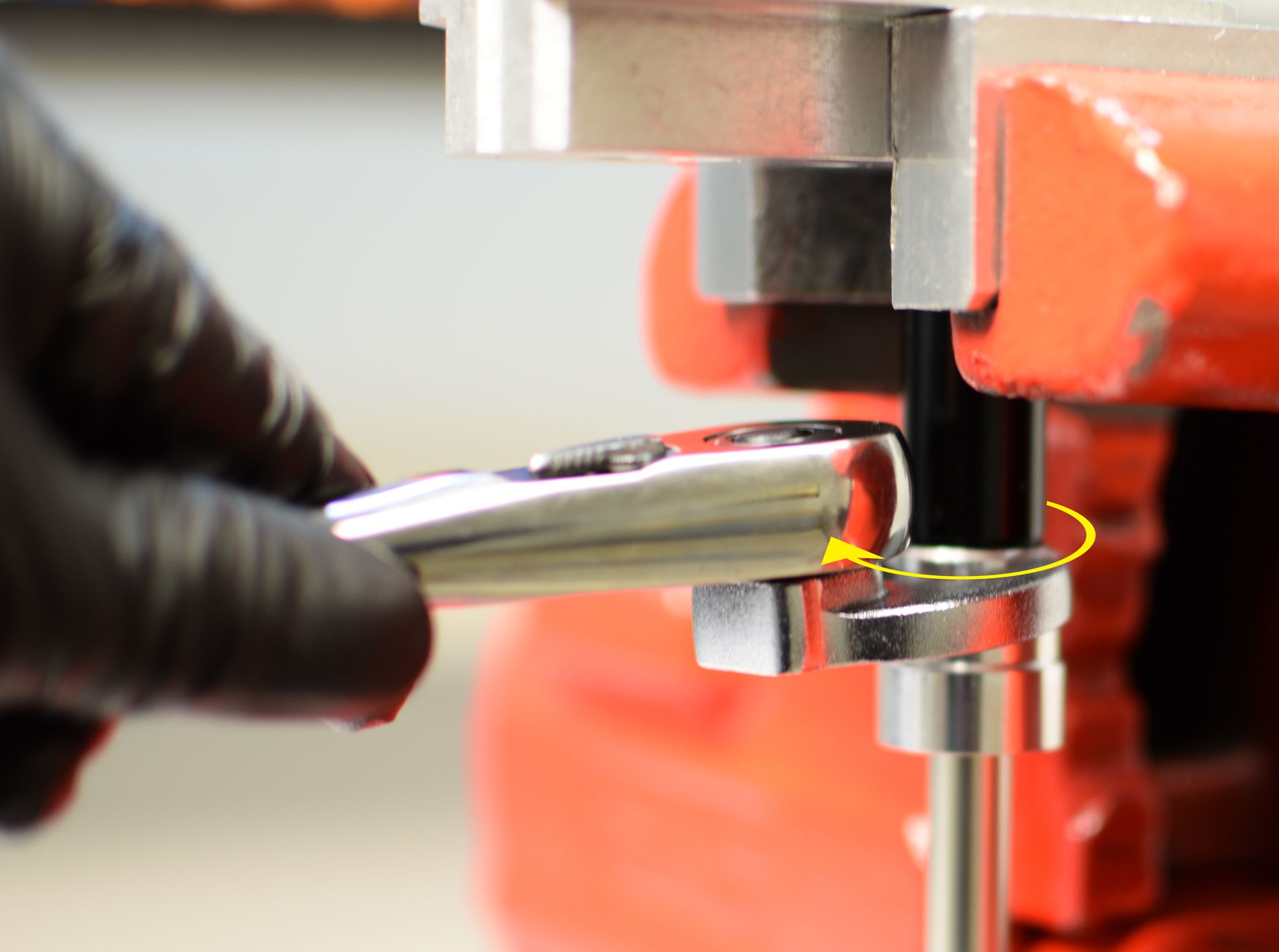
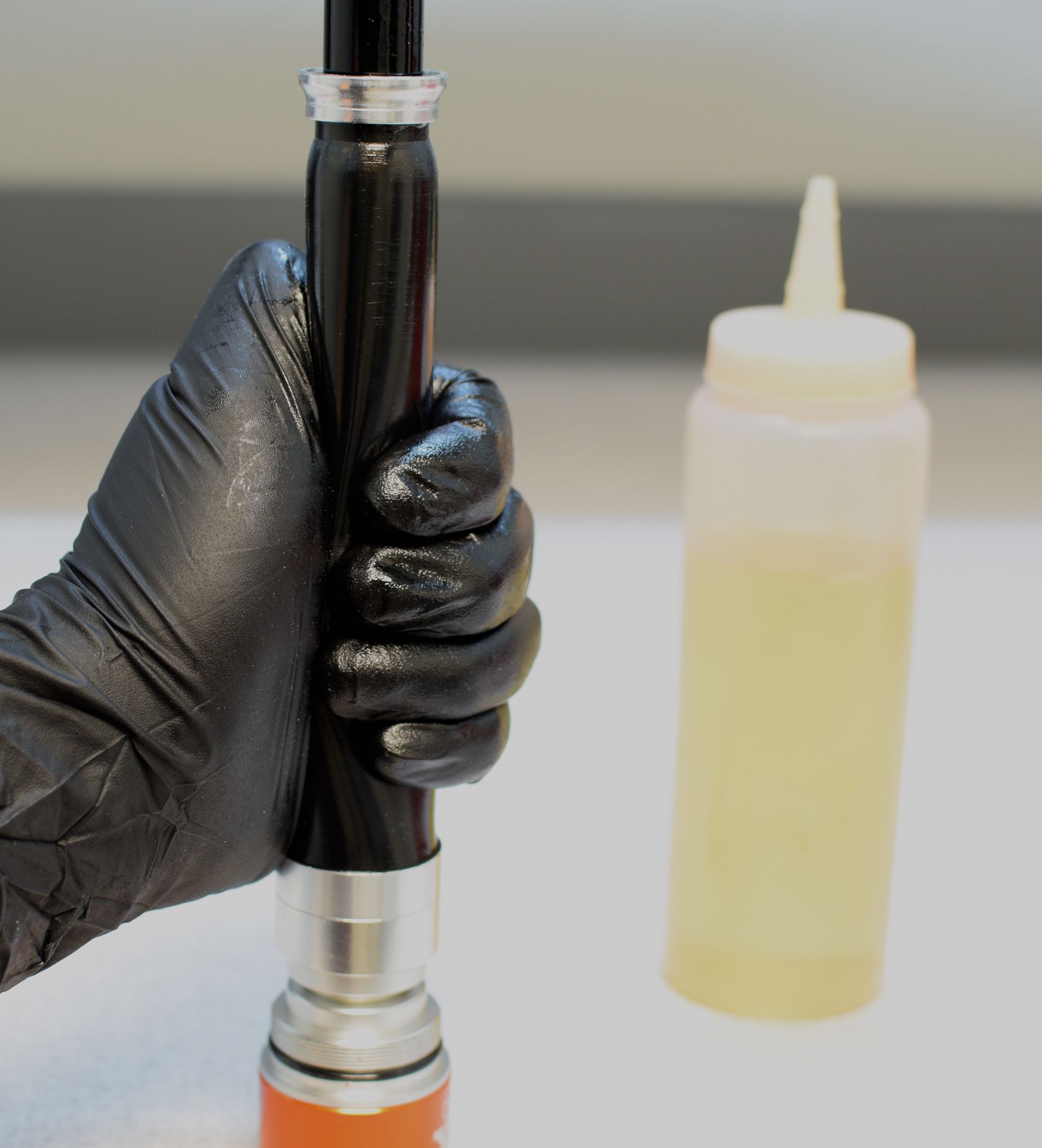
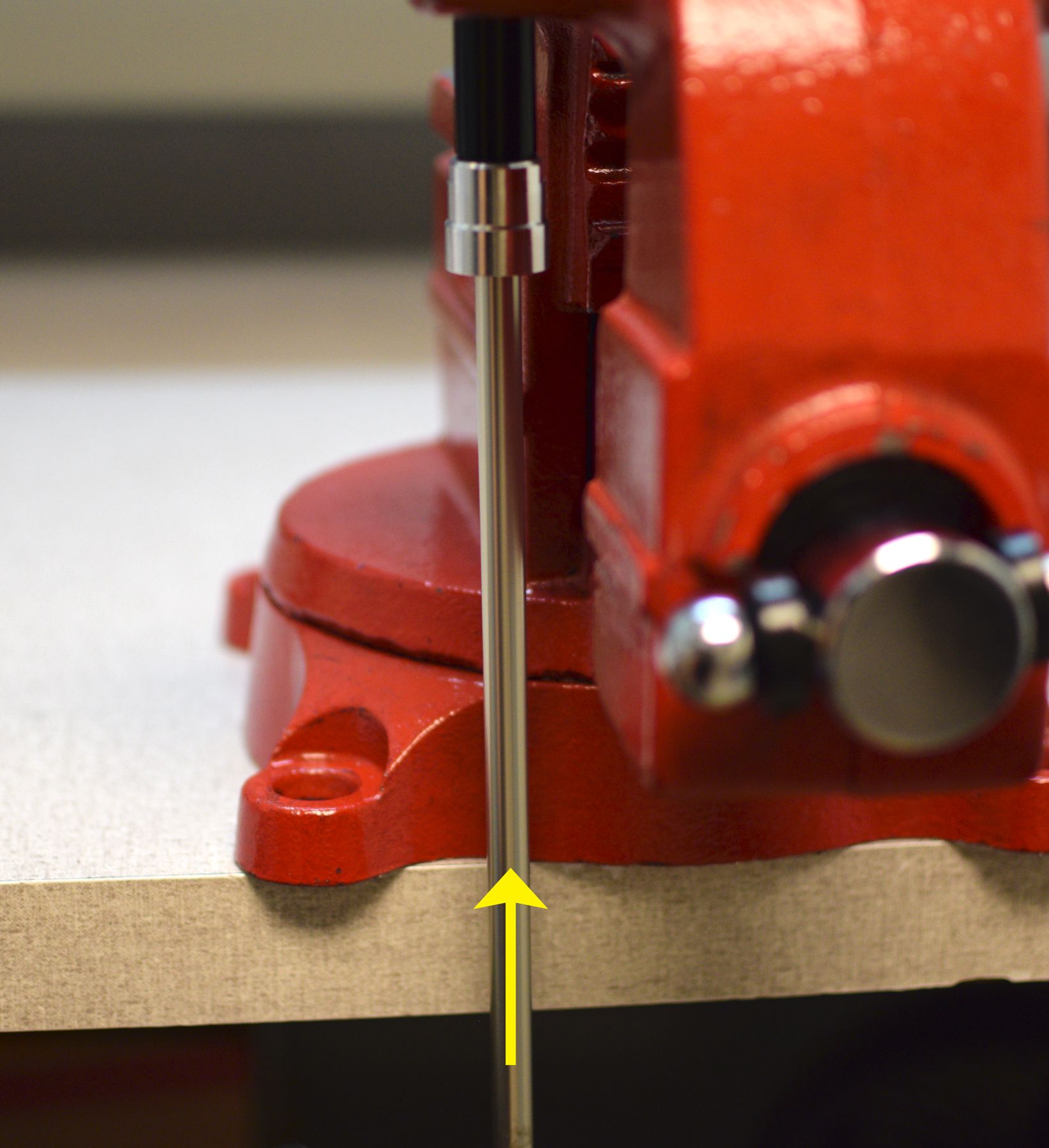
Step 41
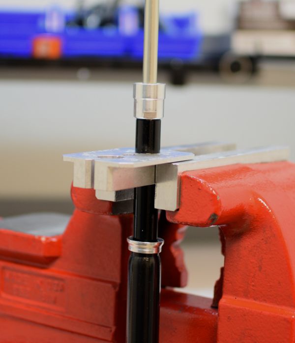
Gently clamp the cartridge body in your shaft clamps, then tighten the sealhead clockwise to 55 in-lb (6.2 Nm) with your 19mm crow's foot.


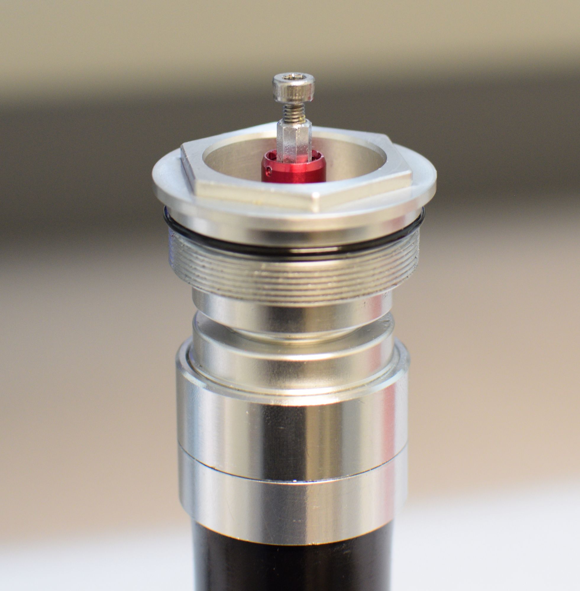
Step 42
Invert the cartridge in your shaft clamps, then remove the compression adjust coupler by pulling up on the bolt.

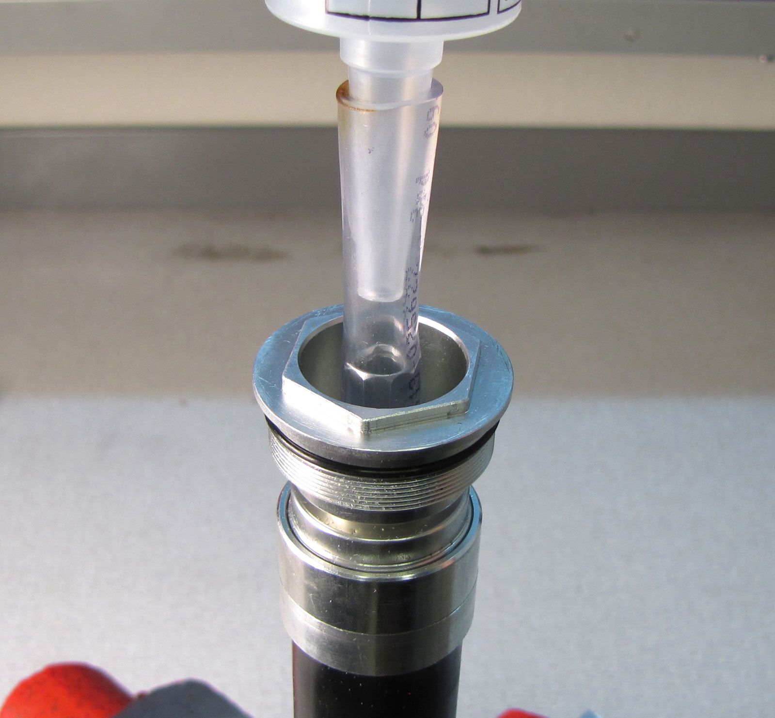
Step 43
Remove the plunger from the FOX bleeder syringe. Install the FOX bleeder syringe into the compression selector shaft. Depending on the condition of the tip of your syringe you may need to install a piece of vinyl tubing with an internal diameter of 5/16 inches (~8mm) onto the compression selector shaft followed by the FOX bleeder syringe. Make sure that the syringe fits tightly and makes a complete seal.

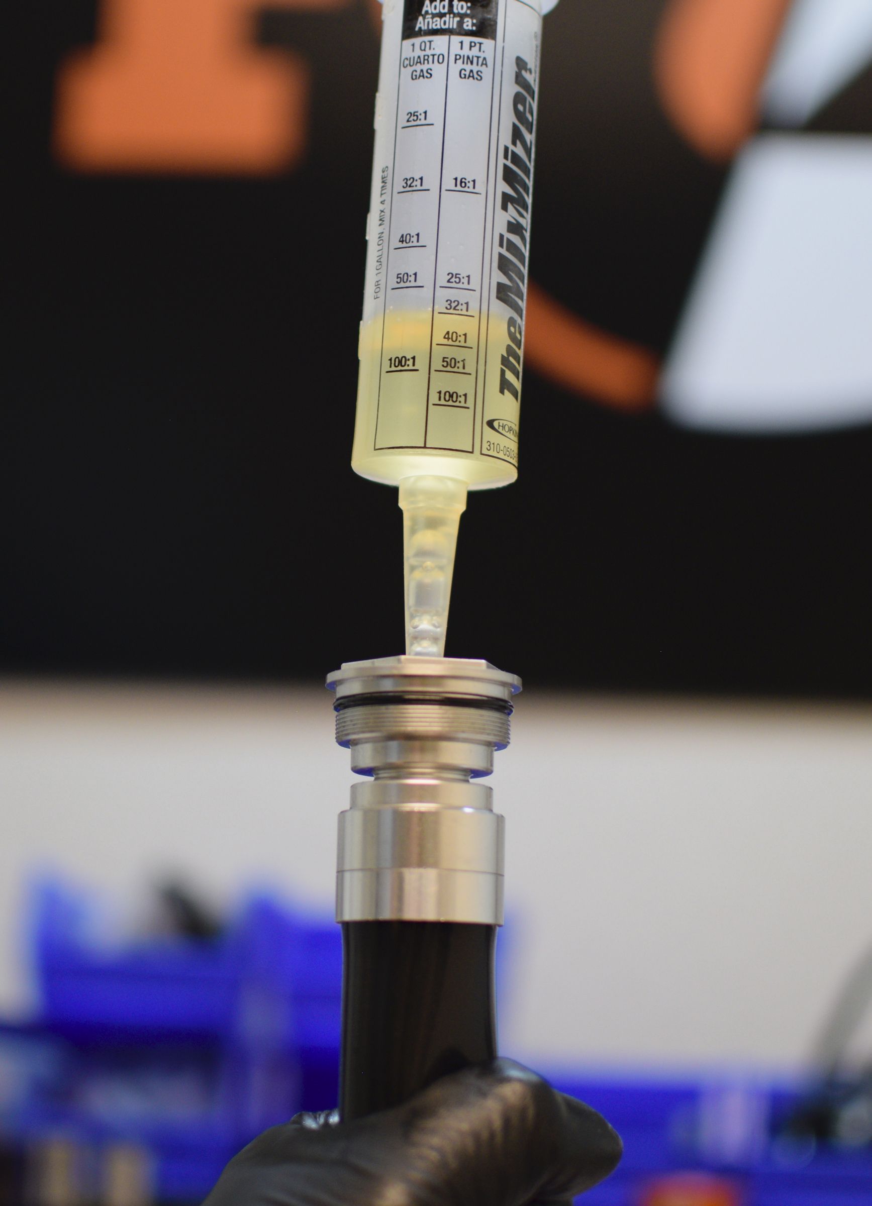
Step 44
Add FOX 5wt. teflon infused oil to the syringe. Slowly cycle the shaft up while squeezing the bladder to force any trapped air out into your syringe. Do not release your squeeze on the bladder or cycle the shaft down until all air bubbles in your syringe have risen to the surface. Do not suck bubbles back into the cartridge. Periodically add oil to your syringe so you do not let the syringe go dry as the cartridge ingests oil. Repeat this step until all air trapped in the cartridge is bled out.


Step 45
With the cartridge fully extended, remove the bleed syringe and top off the compression selector shaft with FOX 5wt. teflon infused oil.


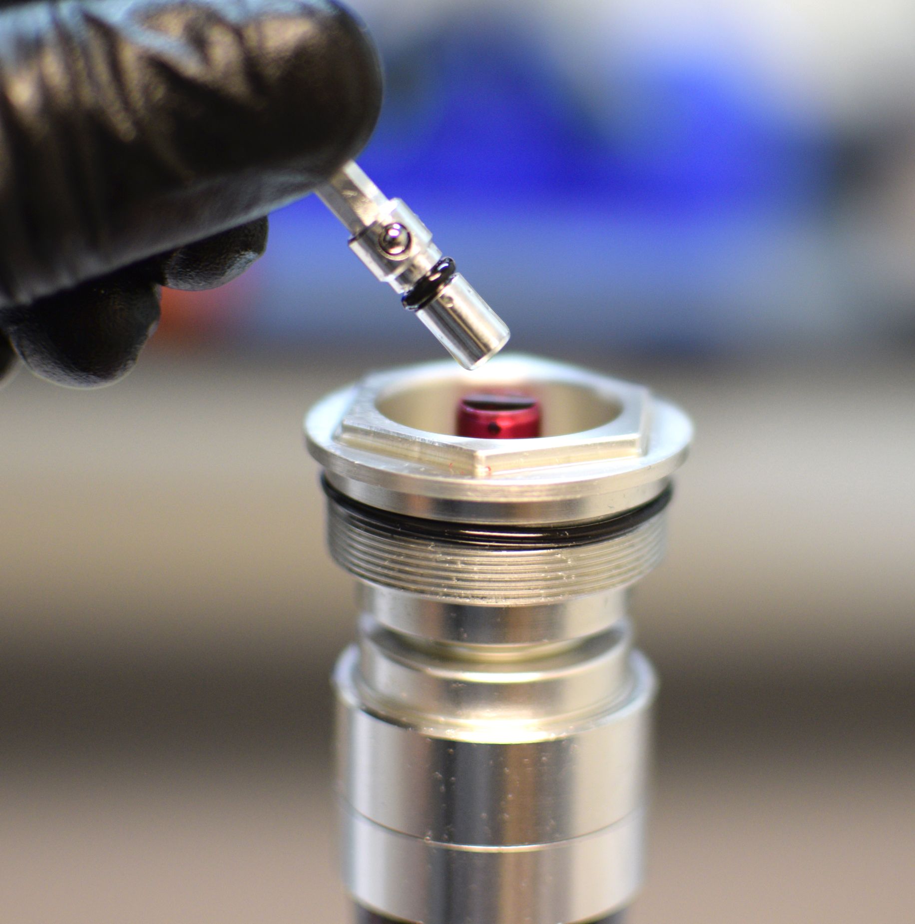
Step 46
Replace the o-ring on the compression adjust coupler with a new greased one from the kit. Reinstall the compression adjust coupler into the compression selector shaft making sure to include the detent ball and spring. Use grease if needed to help retain the detent parts during installation.
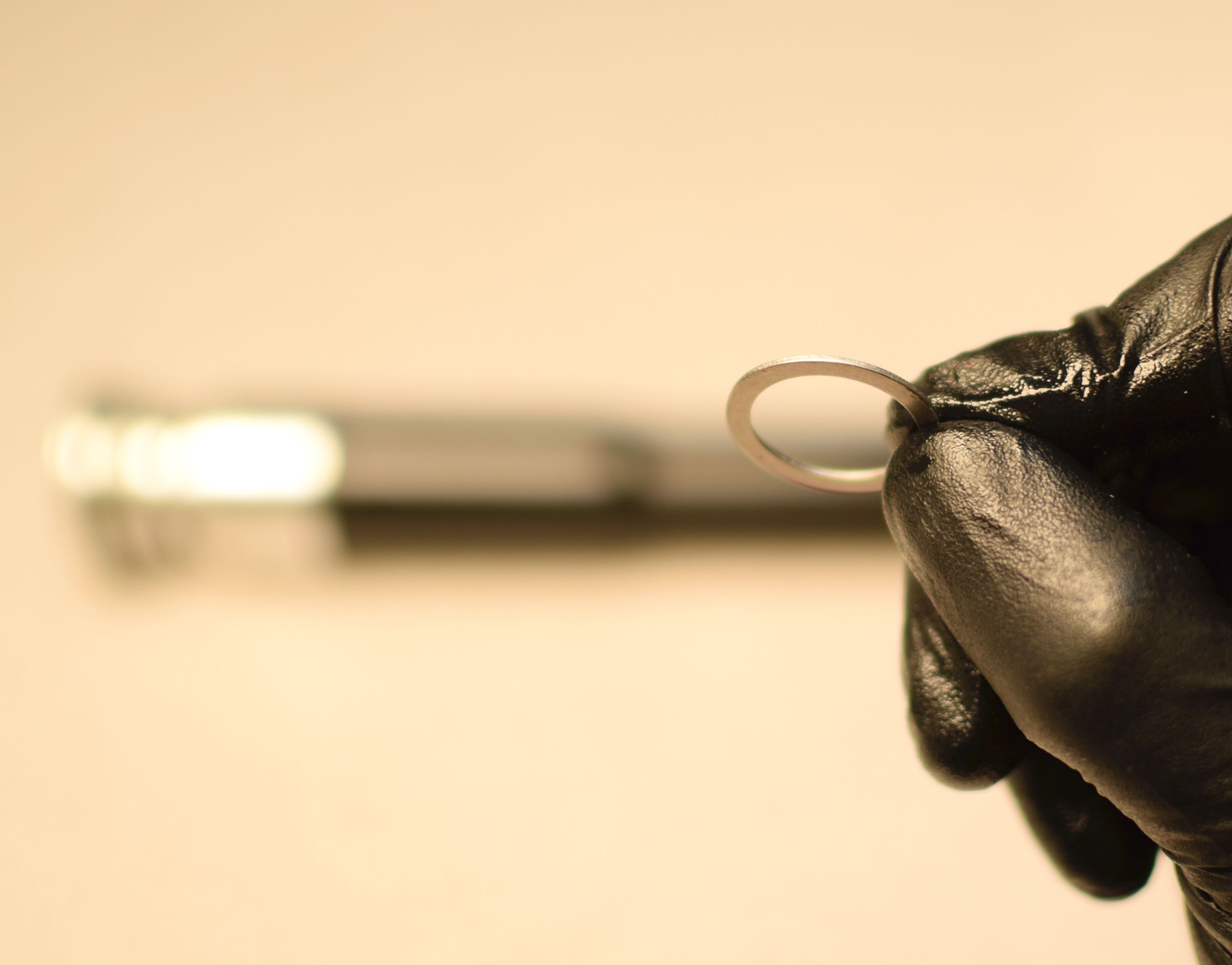
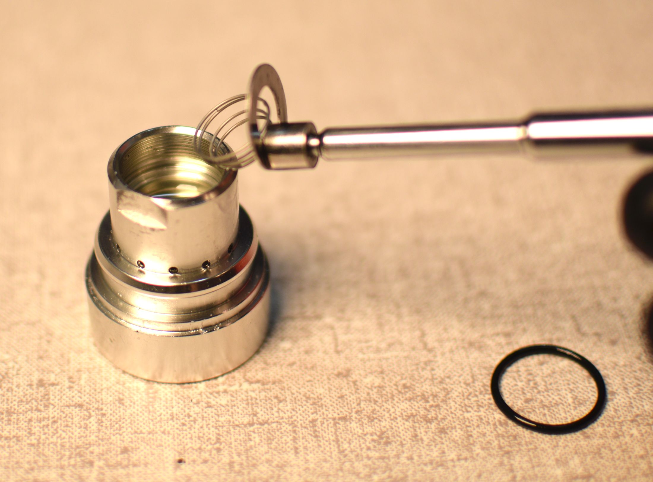
Step 47
Remove the set screw from the compression adjust coupler, then reinstall the wire retaining ring. Make sure to seat the retaining ring fully.


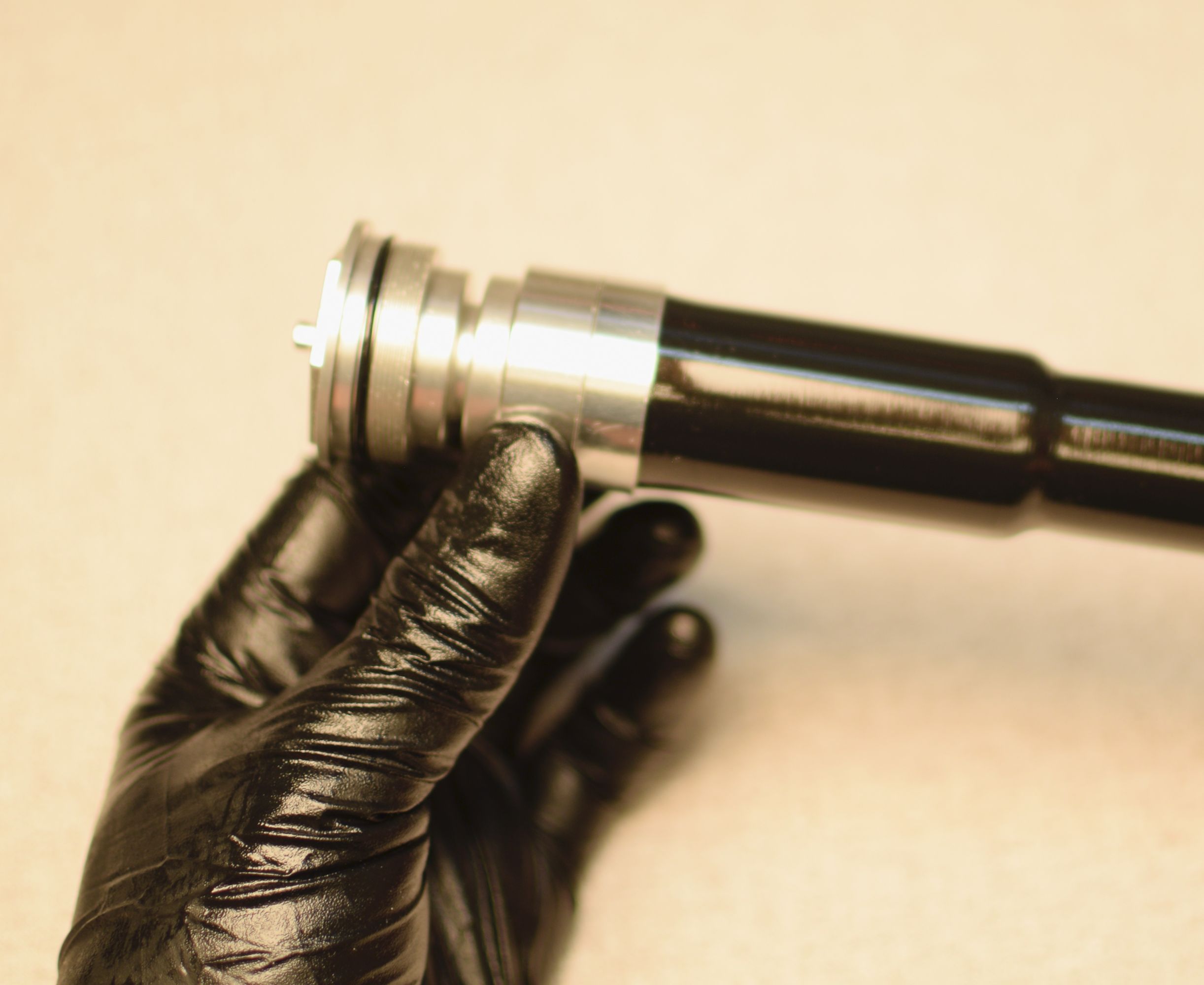
Step 48
Test damper functions then reinstall the damper cartridge into the fork chassis tightening the topcap to 220 in-lb (24.8 Nm) torque. Reinstall the LSC knob, then hold the knob from turning while you tighten the set screw to 11 in-lb (1.2 Nm) torque.