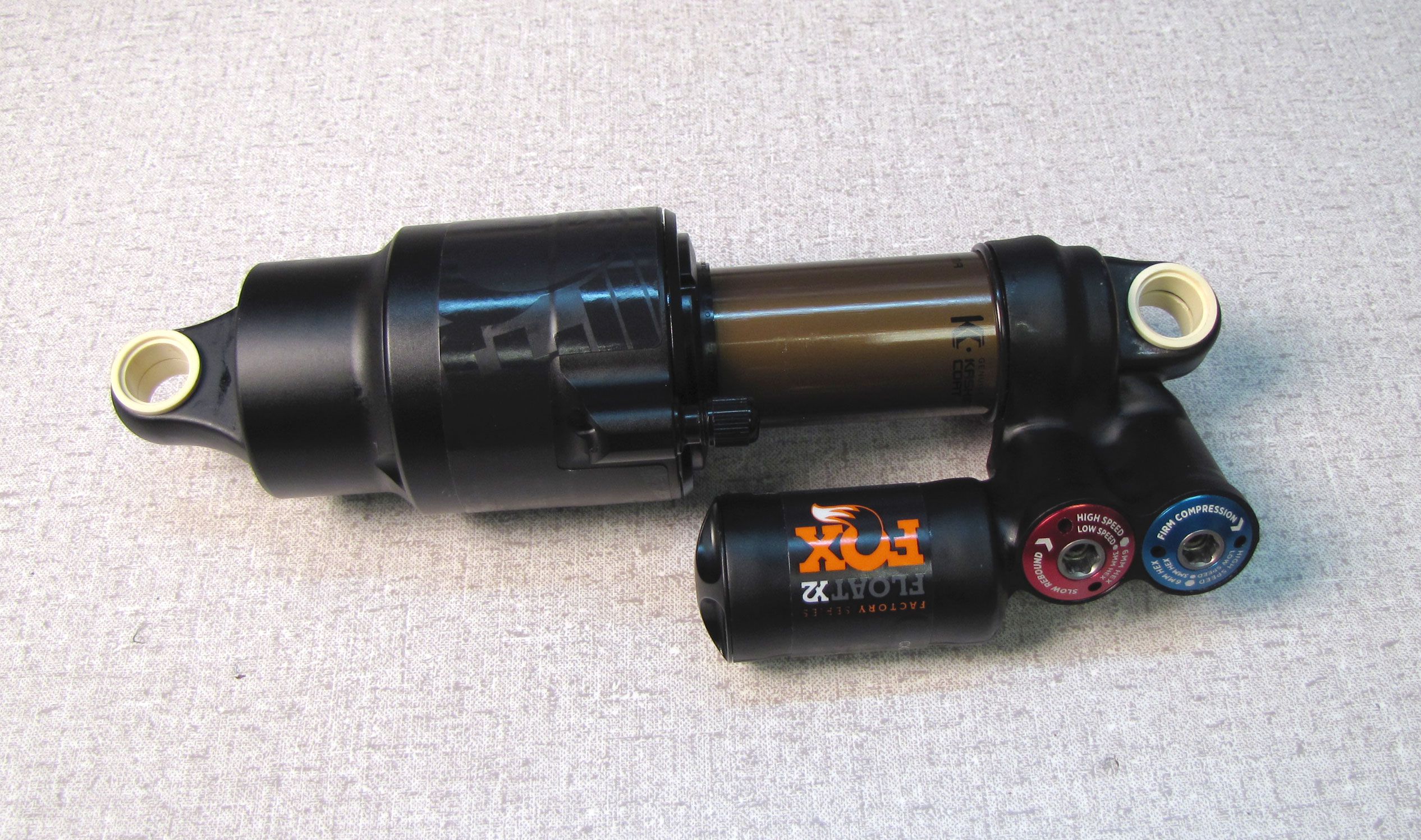
2019-2020 FLOAT X2 Rebuild
Required Parts
- 803-01-317 Seal Kit: FLOAT X2 Spring and Damper Rebuild 2019
Required Tools
- 027-00-013 Pump: Fox Digital HP w/ Bleed, Foldable, Replaceable Battery, 300 psi
- 398-00-280 Tooling: Eyelet Torque Tool
- 398-00-419 Tooling: 2016 Float X2, Negative Air Seal
- 398-00-797 Tooling: Float X2 Steel Shaft, Bullet Tool
- 803-00-463 Kit: Fill Machine Adapter, 04-07 Epic IV, DHX Air, RC2_RC4 Shocks
- 803-00-566 Kit: Bike IFP Depth Setting Tool Set
- 803-00-967 Kit: Tooling: Shaft Clamps, FLOAT X2, 9mm Shaft
- 803-00-969 Kit: Tooling: Clamps, FLOAT X2, Body--------- ---------(Only needed if replacing the outer body)
- 803-01-318 Kit: Tooling: Clamps, 2019 FLOAT X2, Air Sleeve
Sections
WARNING: Always wear safety glasses and protective gloves during service to prevent potential injury. Failure to wear protective equipment during service may lead to SERIOUS INJURY OR DEATH.
WARNING: FOX products should be serviced by a trained bicycle service technician, in accordance with FOX specifications. If you have any doubt whether or not you can properly service your FOX product, then DO NOT attempt it. Improperly serviced products can fail, causing the rider to lose control resulting in SERIOUS INJURY OR DEATH.
WARNING: Never attempt to modify air volume spacers, as this can damage your shock causing a loss of control of the bicycle leading to SERIOUS INJURY or DEATH.
WARNING: FOX suspension products contain pressurized nitrogen, air, oil, or all 3. Suspension misuse can cause property damage, SERIOUS INJURY OR DEATH. DO NOT puncture, incinerate or crush any portion of a FOX suspension product. DO NOT attempt to disassemble any portion of a FOX suspension product, unless expressly instructed to do so by the applicable FOX technical documentation, and then ONLY while strictly adhering to all FOX instructions and warnings in that instance.
WARNING: Modification, improper service, or use of aftermarket replacement parts with FOX forks and shocks may cause the product to malfunction, resulting in SERIOUS INJURY OR DEATH. DO NOT modify any part of a fork or shock, including the fork brace (lower leg cross brace), crown, steerer, upper and lower leg tubes, or internal parts, except as instructed herein. Any unauthorized modification may void the warranty, and may cause failure or the fork or shock, resulting in SERIOUS INJURY OR DEATH.
The Damping Adjuster Cartridge Assemblies should be considered non-rebuildable as they are difficult to dissassemble and reassemble. The Damping Adjuster Cartridge Assemblies do not need to be removed from the shock to perform a full rebuild. If damaged, please replace as complete assemblies.
For instructions guiding you through the removal and reinstallation of the X2 Damping Adjuster Cartridge Assemblies please go to: X2 Damping Adjuster Cartridge Assembly Removal/Installation »
For information regarding the X2 2-Position Lever please go to: FLOAT X2 and DHX2 2-Position Lever Upgrade »
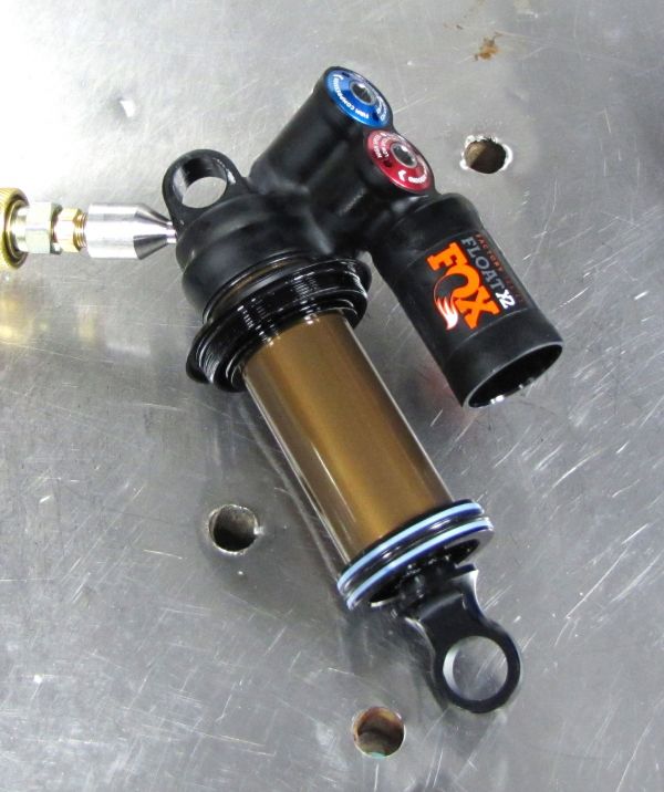
The following procedure guides you through the full rebuild of the FLOAT X2 shock.
Complete part information and technical drawings for the 2019 FLOAT X2 shocks can be found by clicking: FLOAT X2 Part Information »

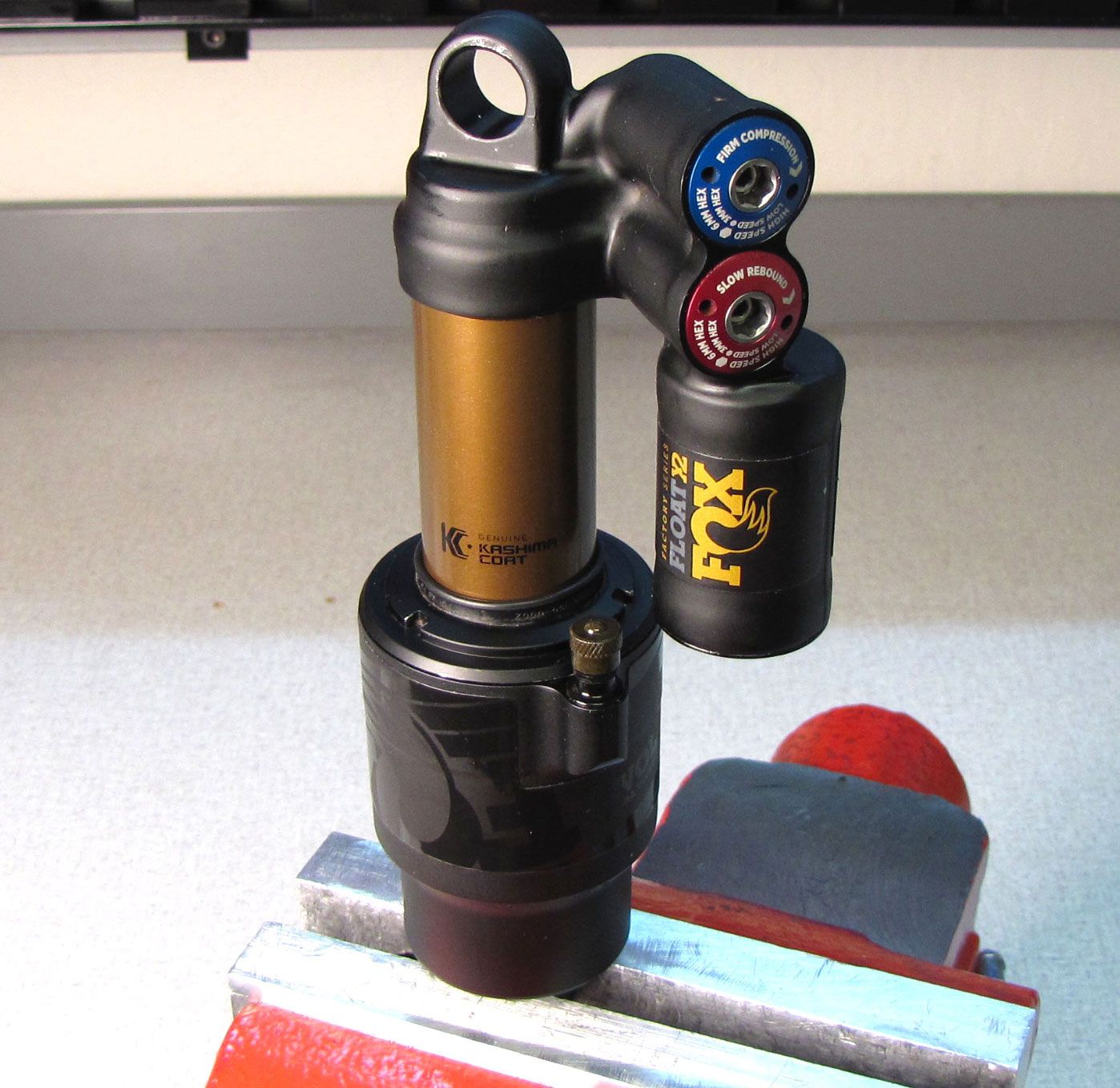
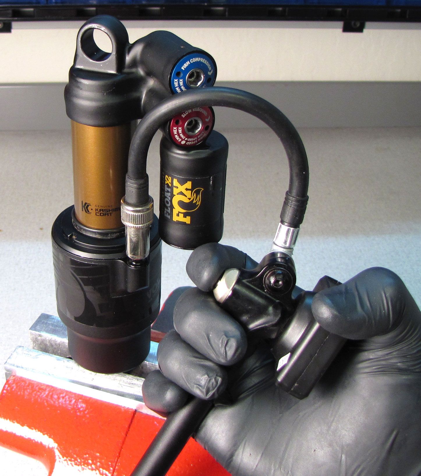
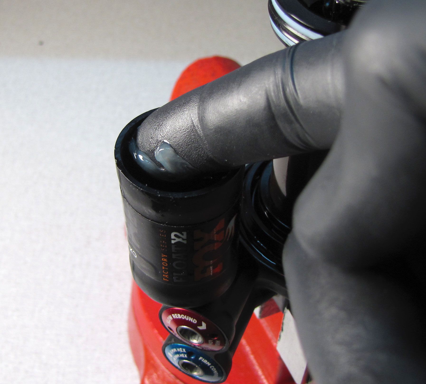
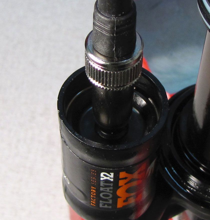
Step 1
Set all rebound and compression adjusters to their lowest setting (fully counter-clockwise).
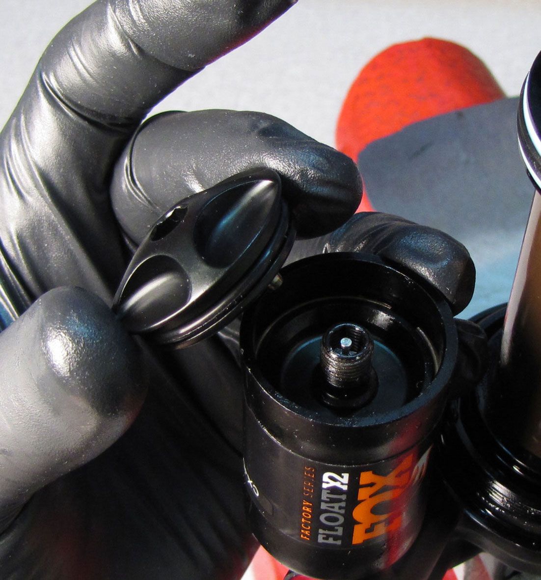
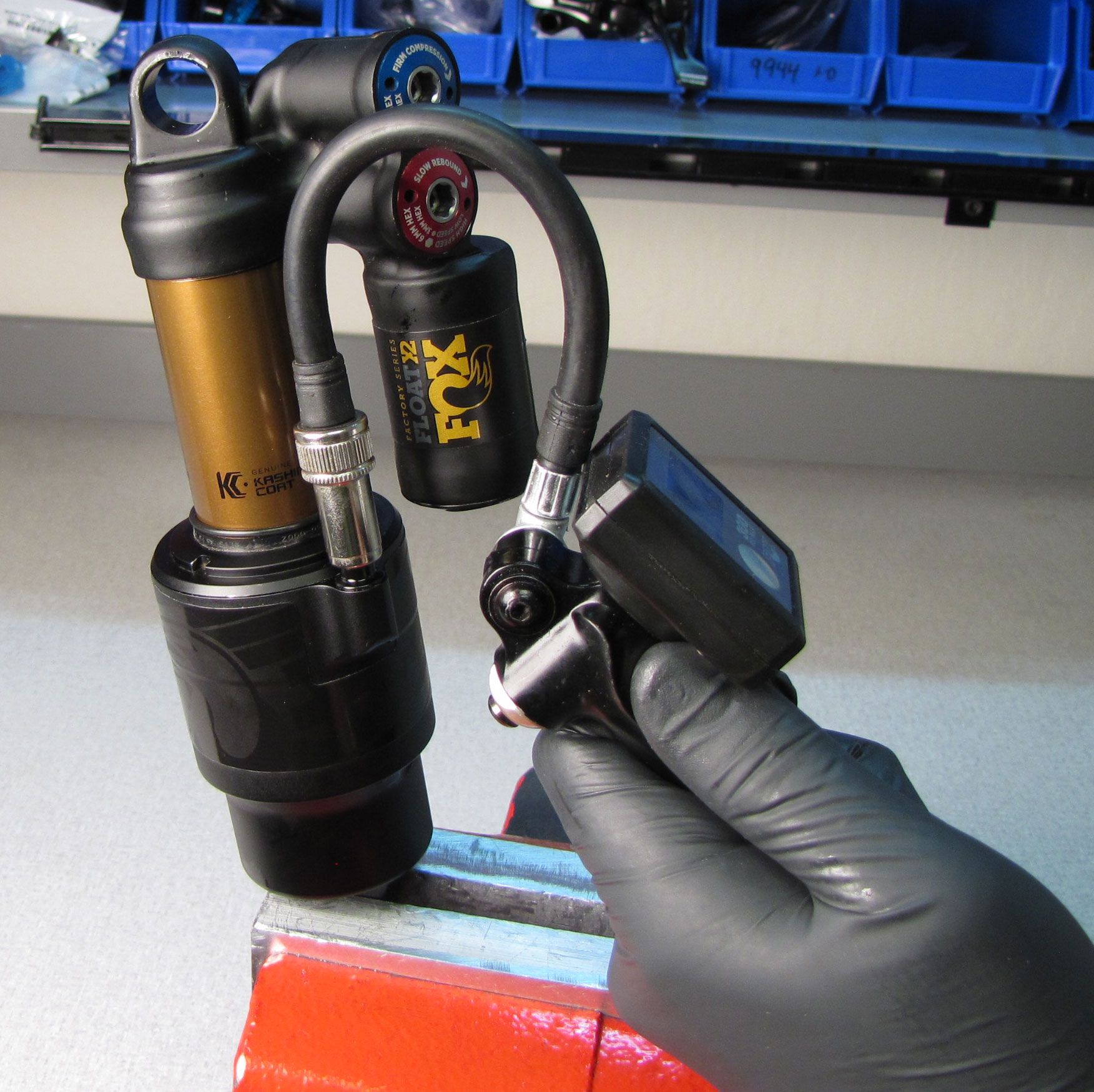
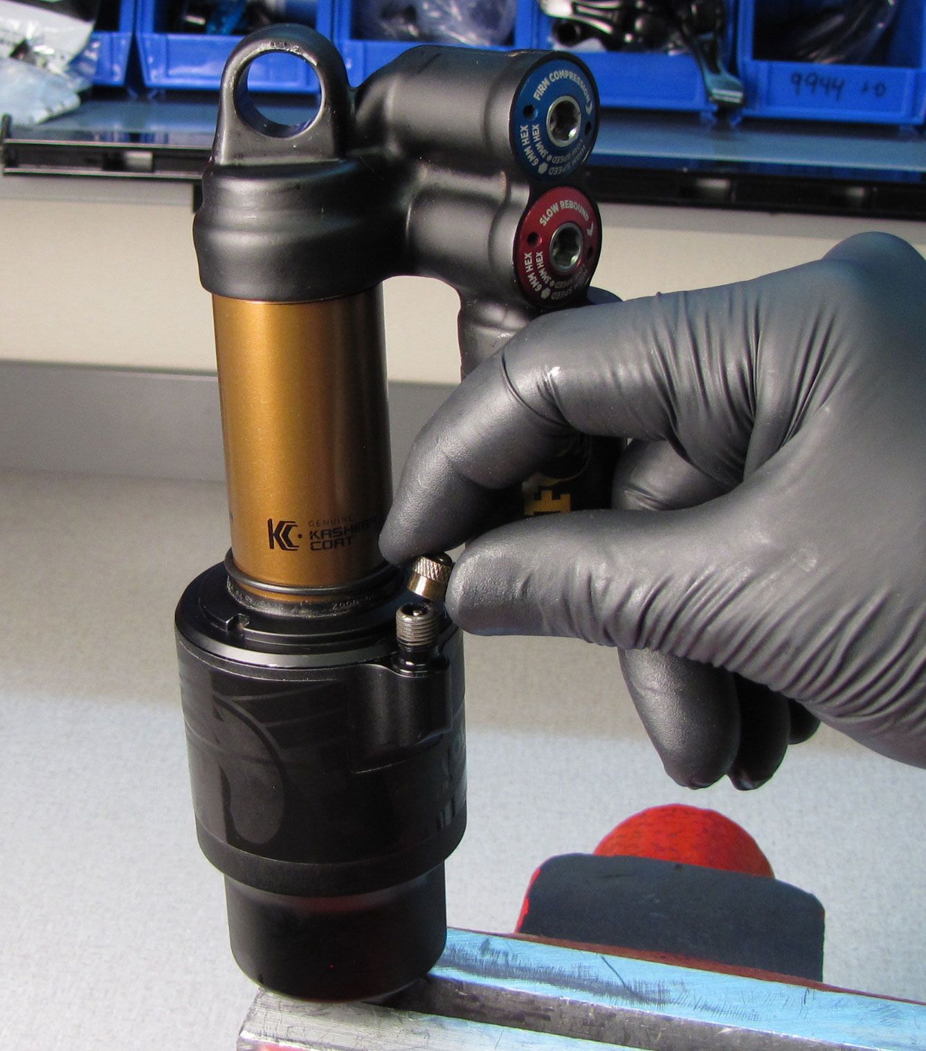
Clamp your shocks non-adjuster eyelet in a soft-jawed vice. Remove the black air cap and thread on your FOX shock pump. Slowly release all air from the main air chamber with your pump, then remove the pump. Verify that all air has been released by depressing the Schrader valve with a lint-free towel covering the valve to prevent any oil spray.

WARNING: Please verify that all air has been released from the air chamber by pushing down on the Schrader valve core. Failure to release all air pressure before further disassembly may cause parts to eject causing SEVERE INJURY OR DEATH.
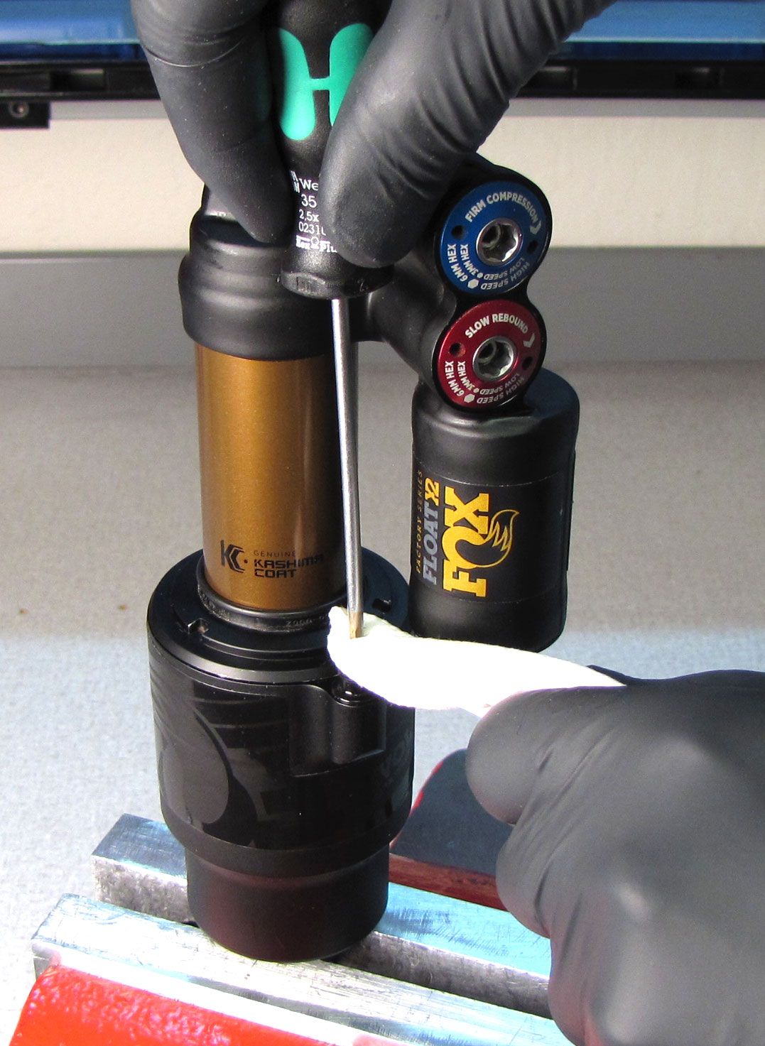
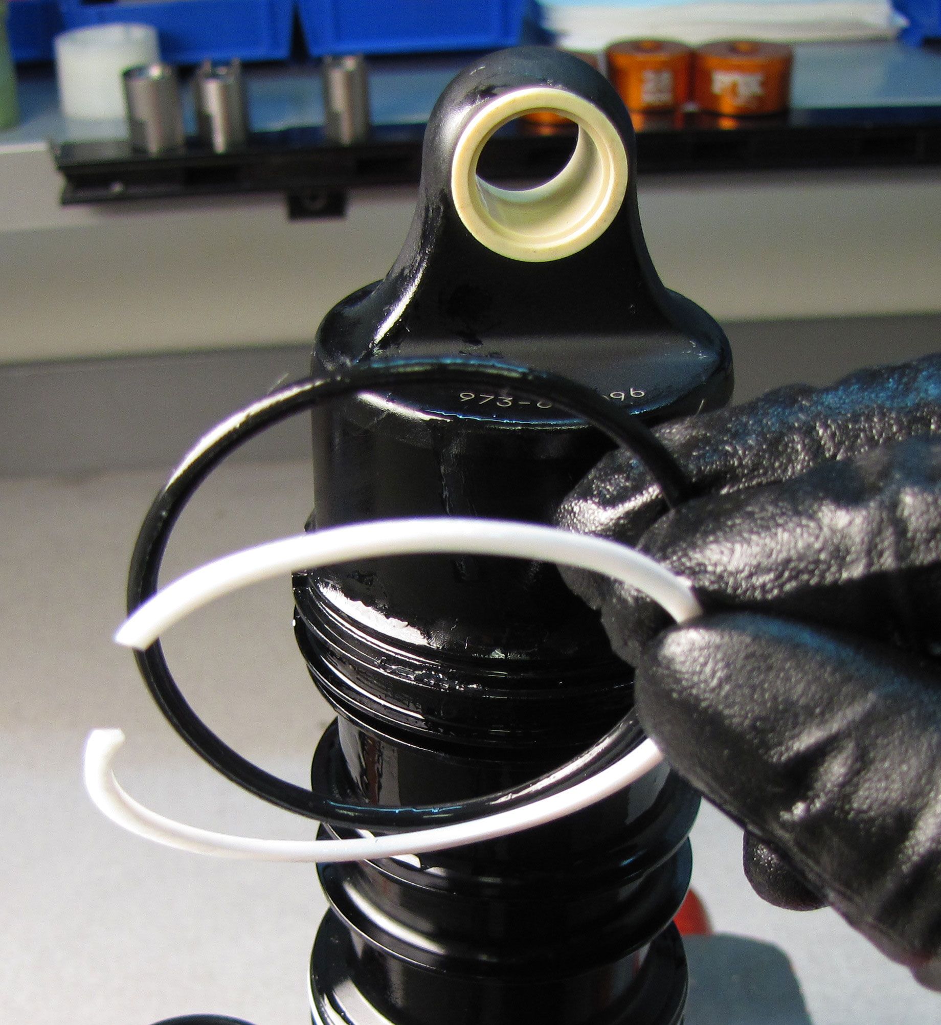
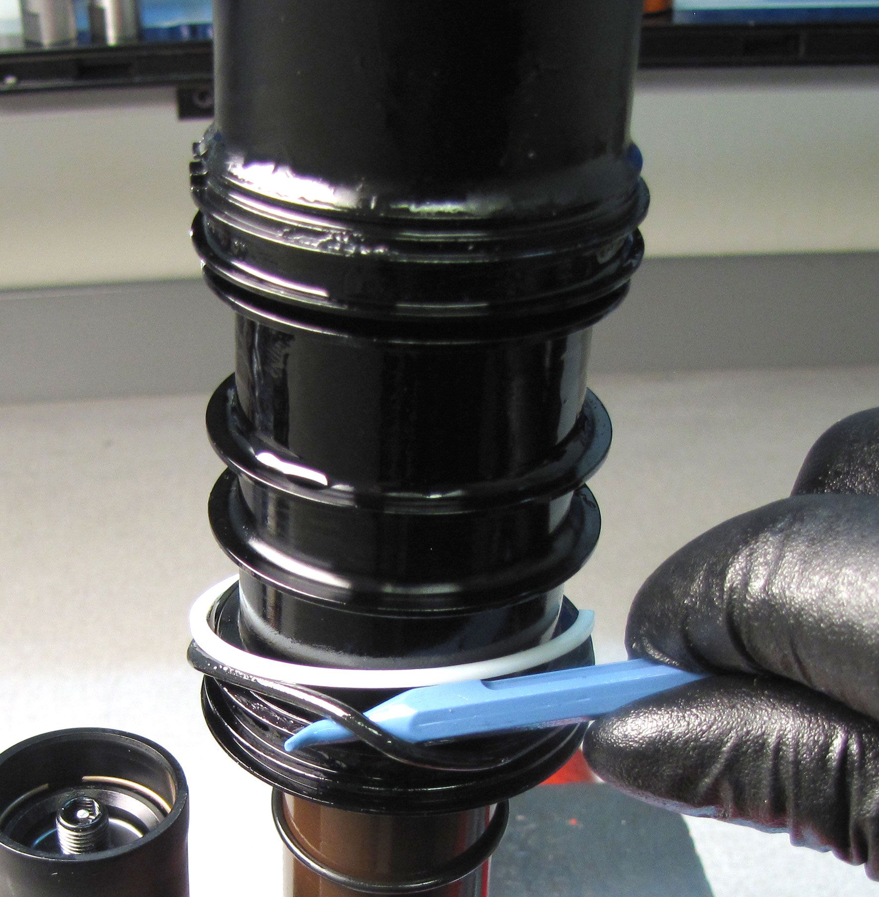
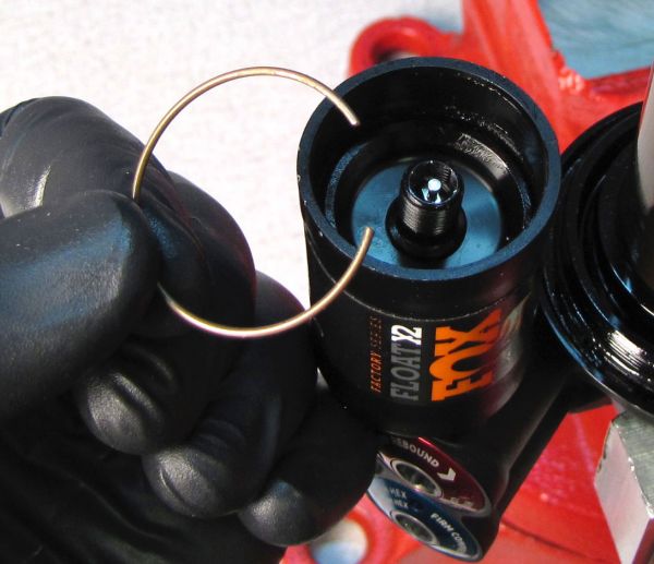
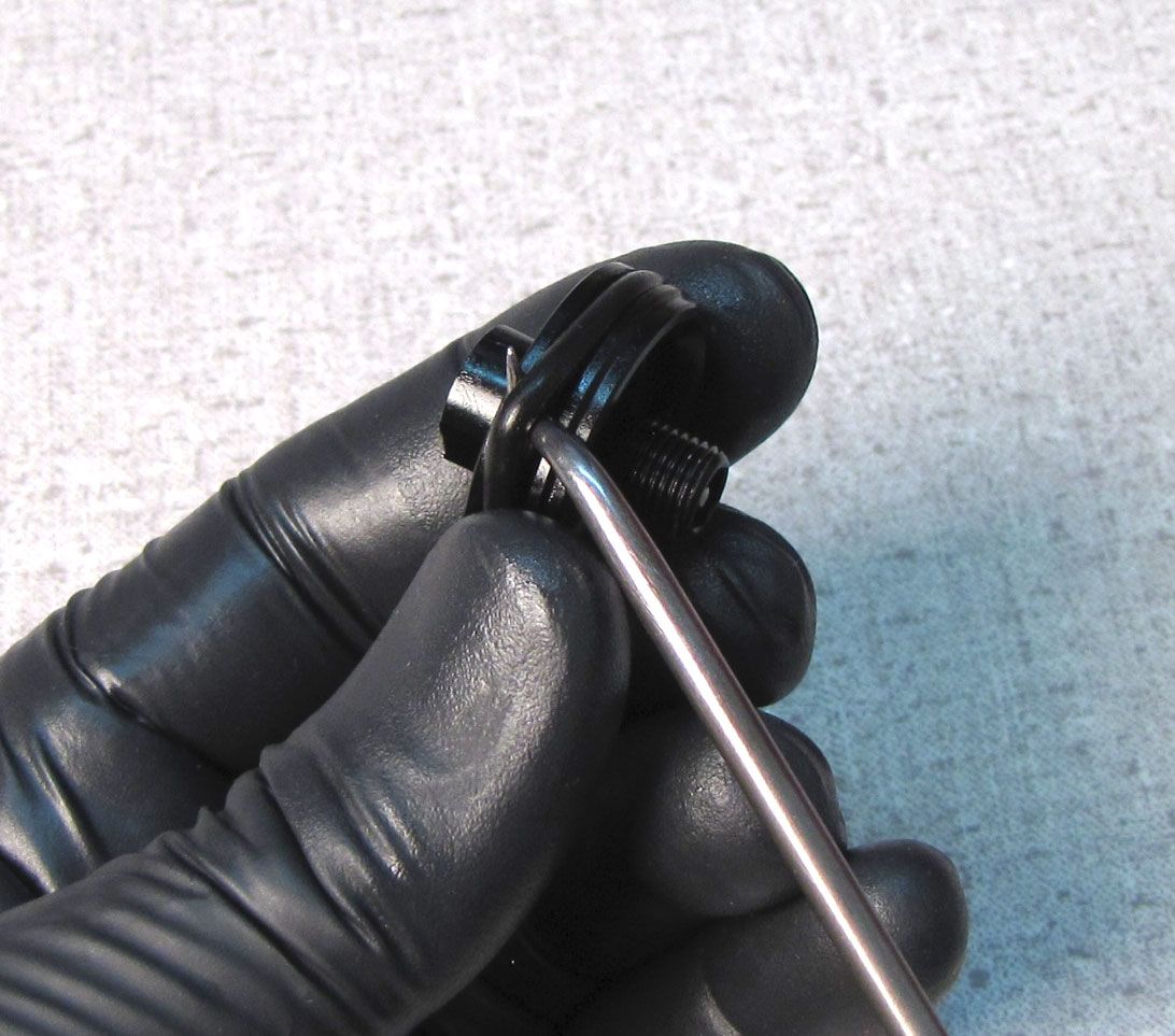
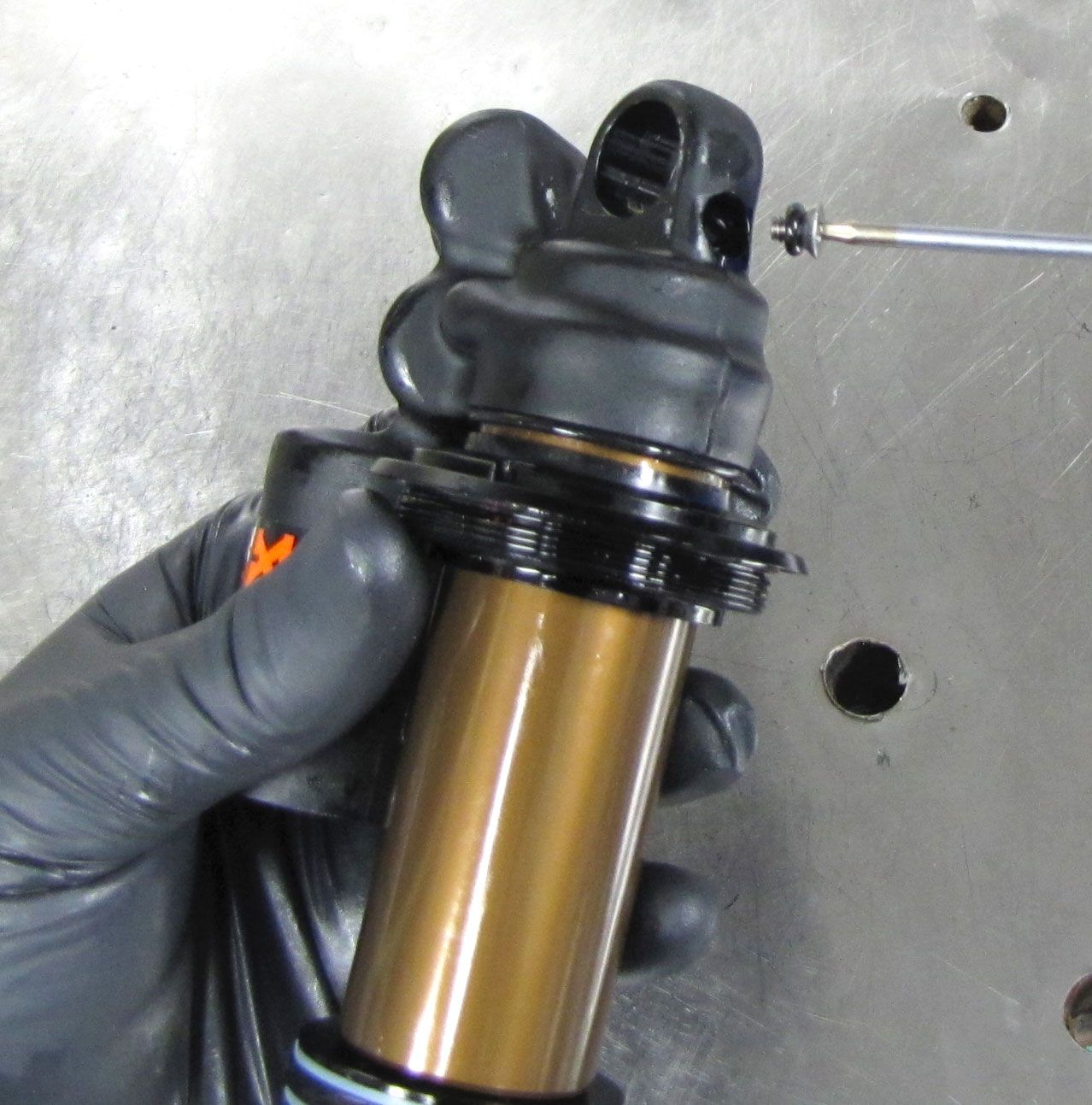
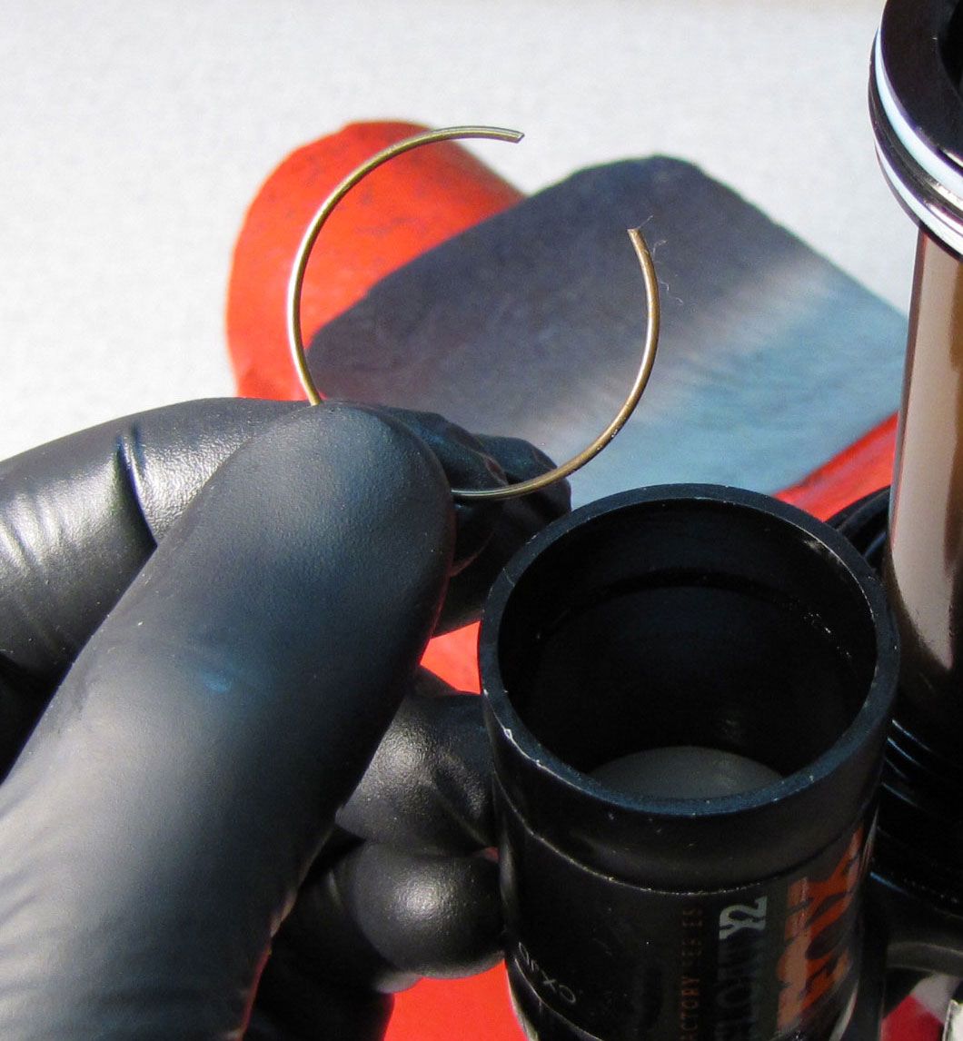
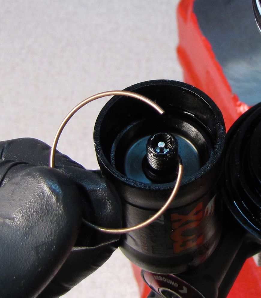
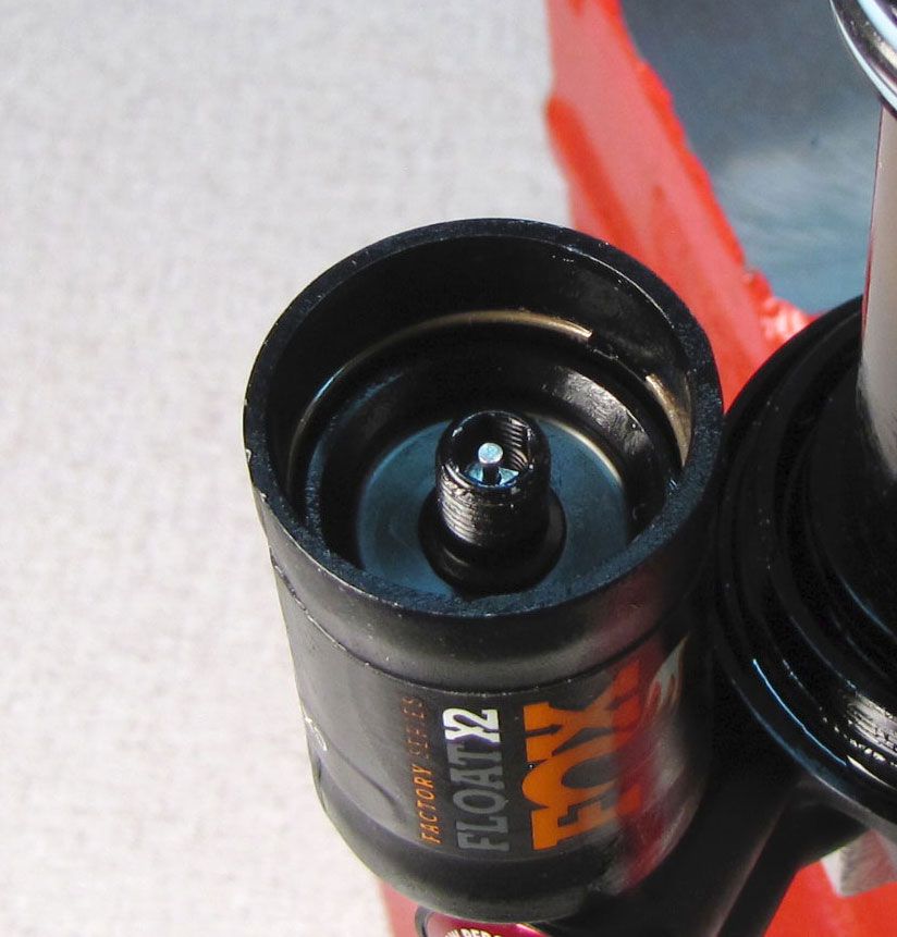
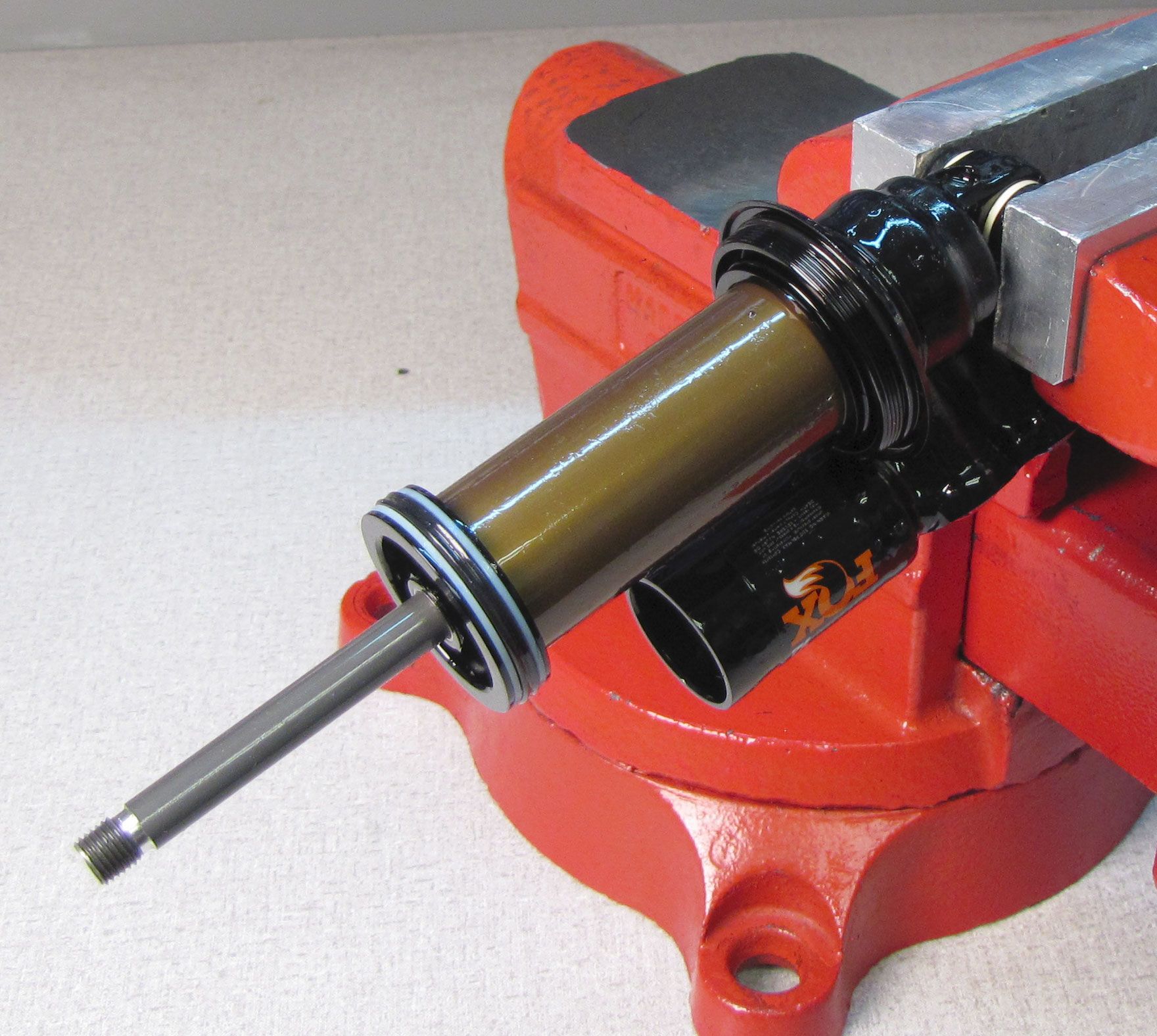
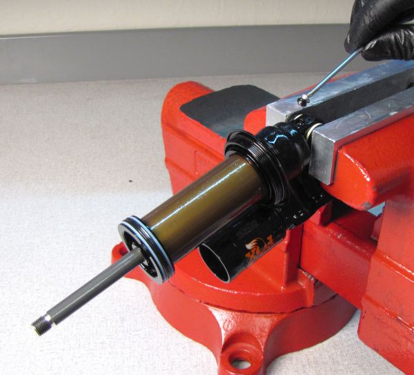
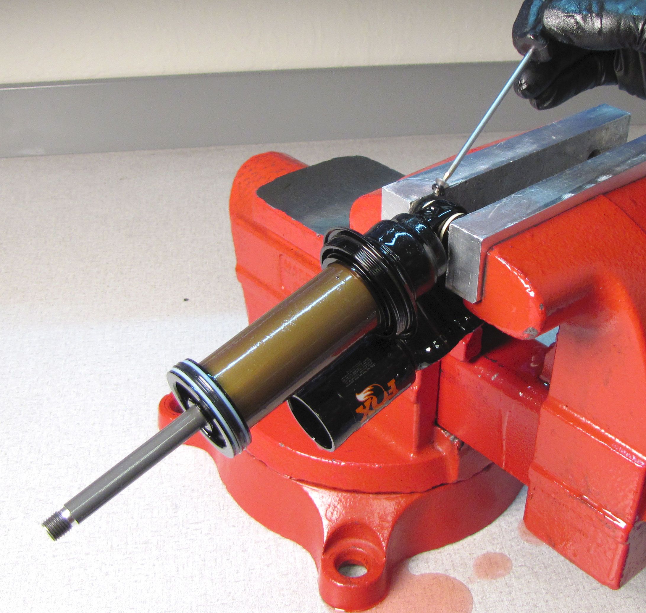
Step 2
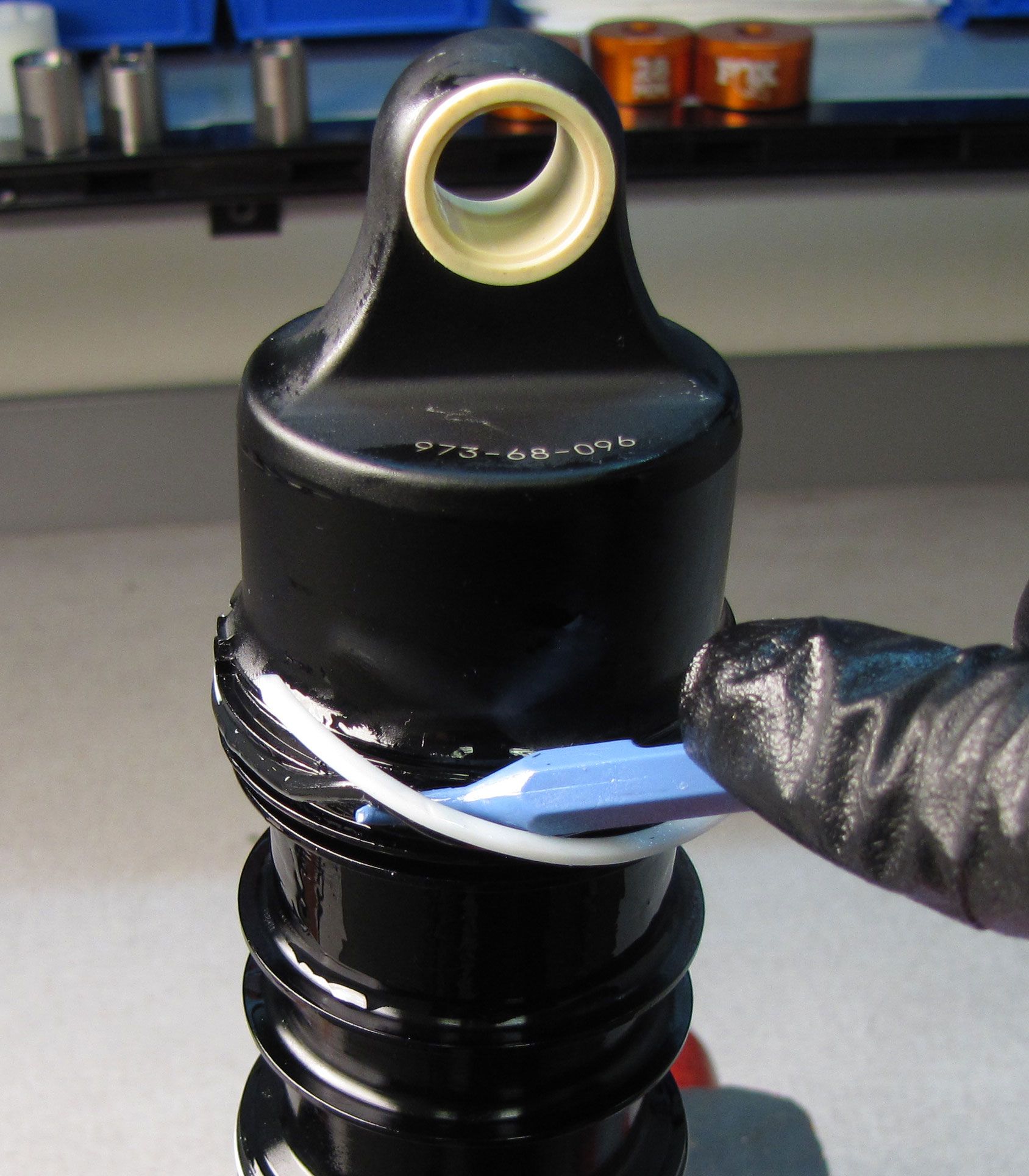
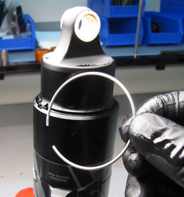
Rotate wire retaining ring to align opening with tab on eyelet. Use a pick to remove the ring.

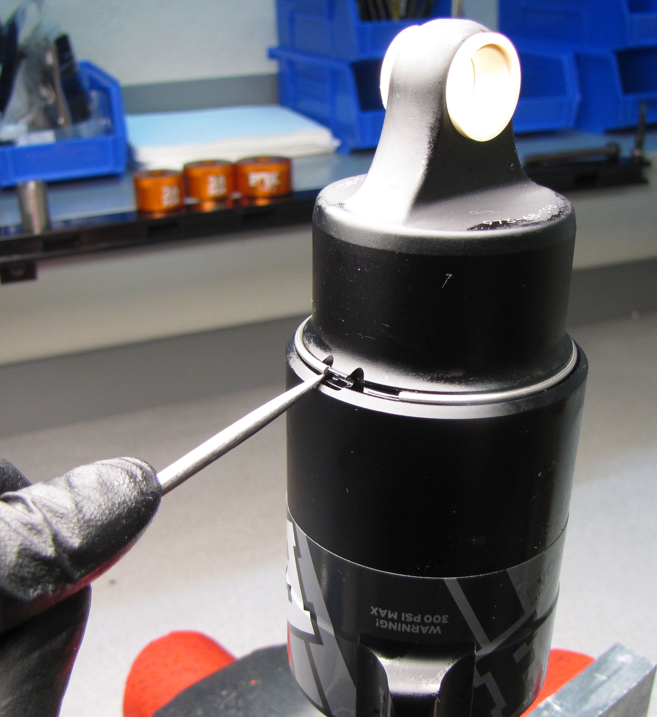
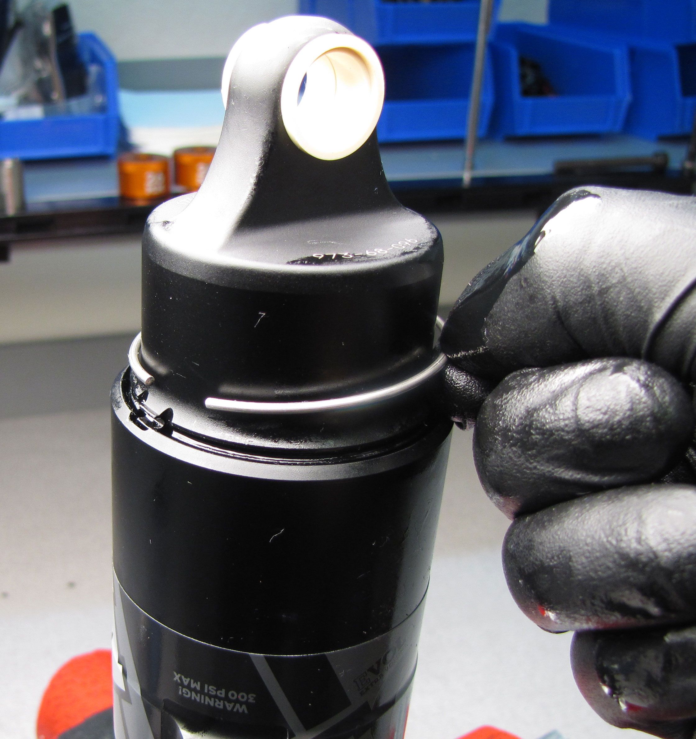

You may rotate the adjuster eyelet independantly of the non-adjuster eyelet at any time to help create air valve to piggyback clearance.
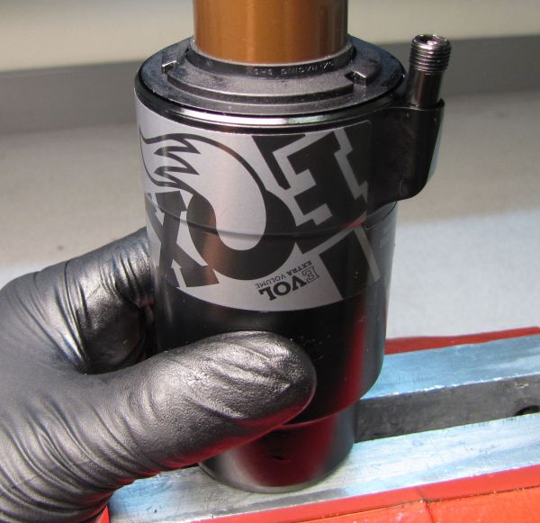
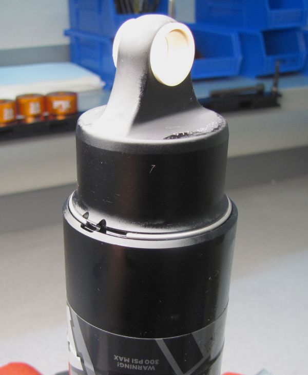
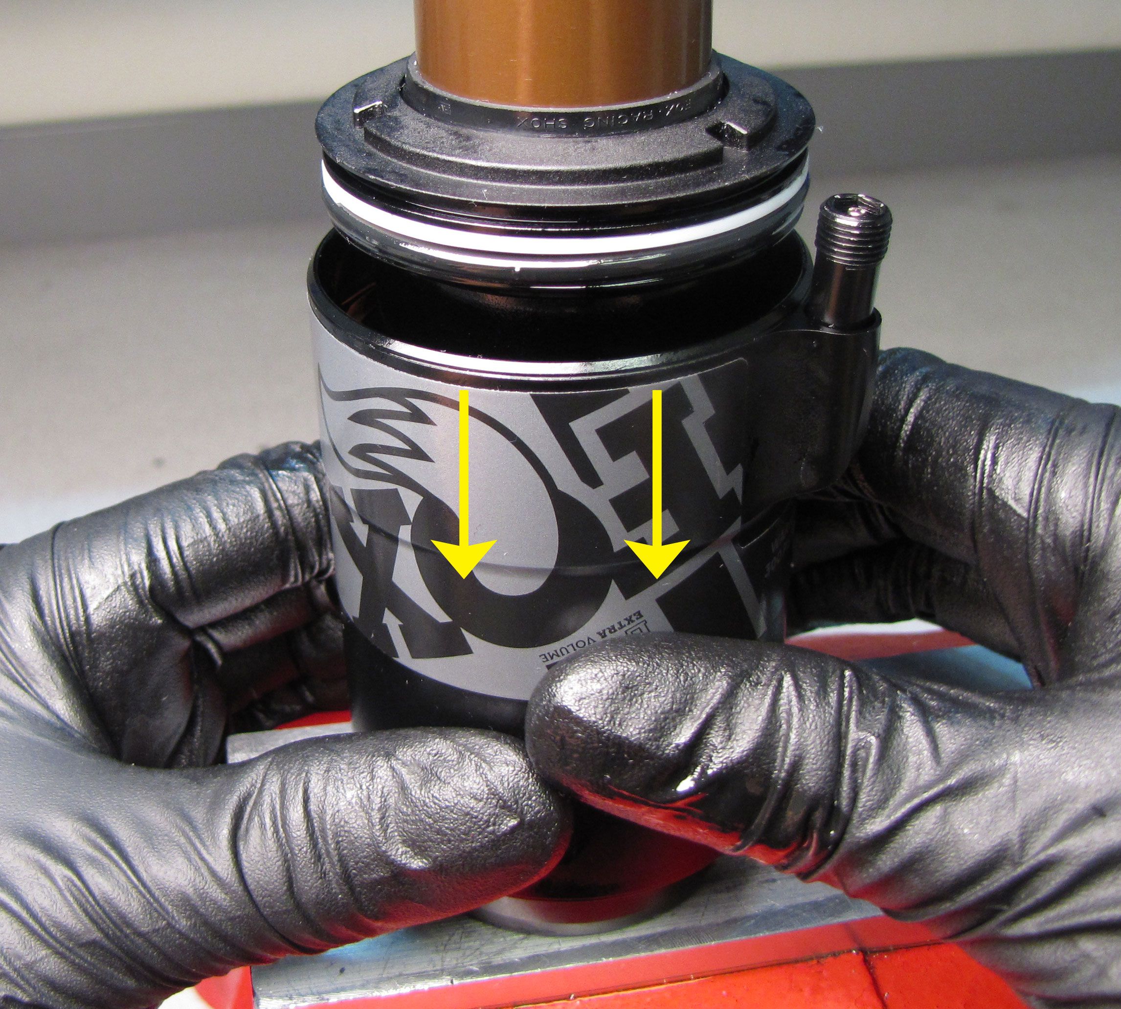
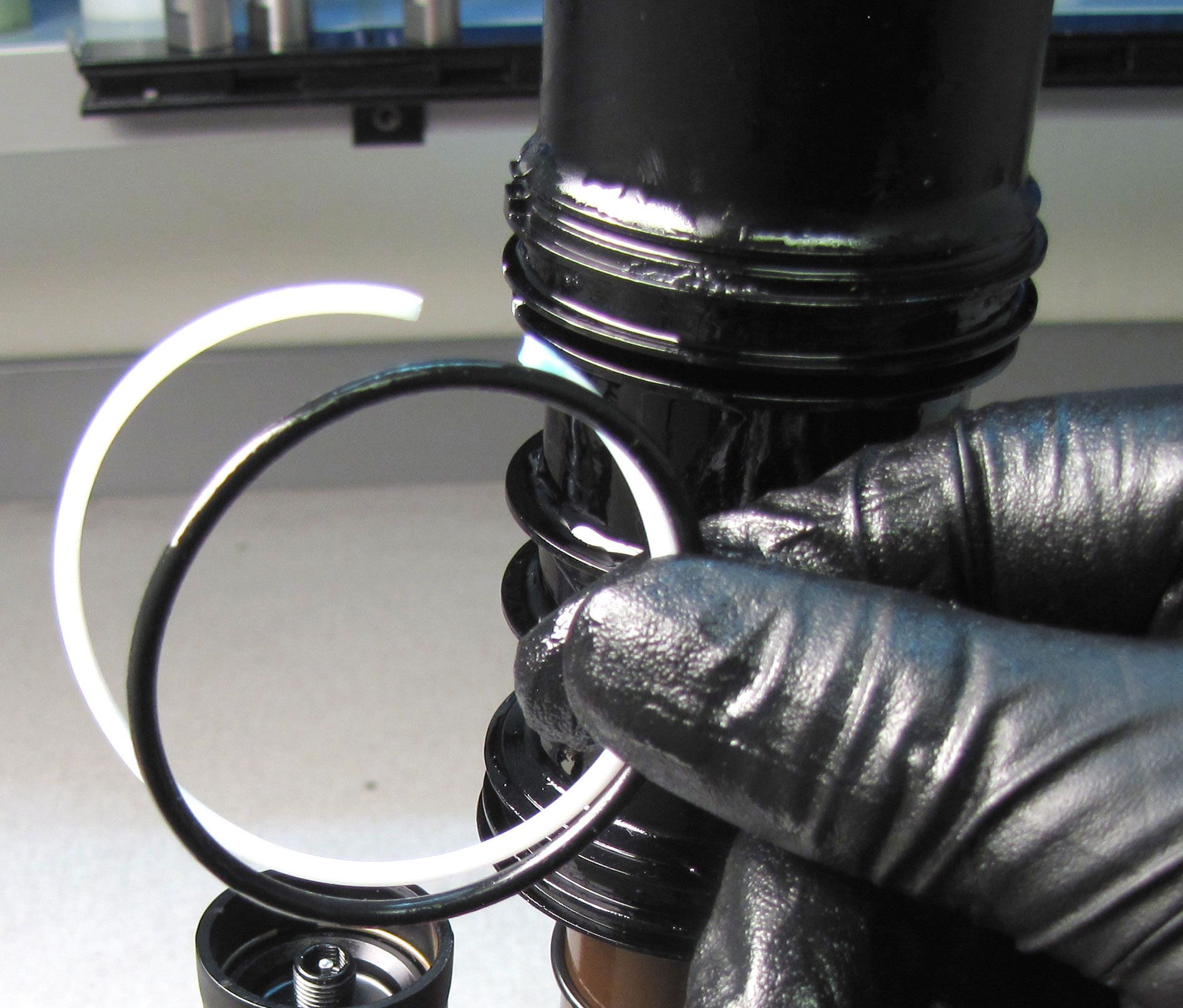
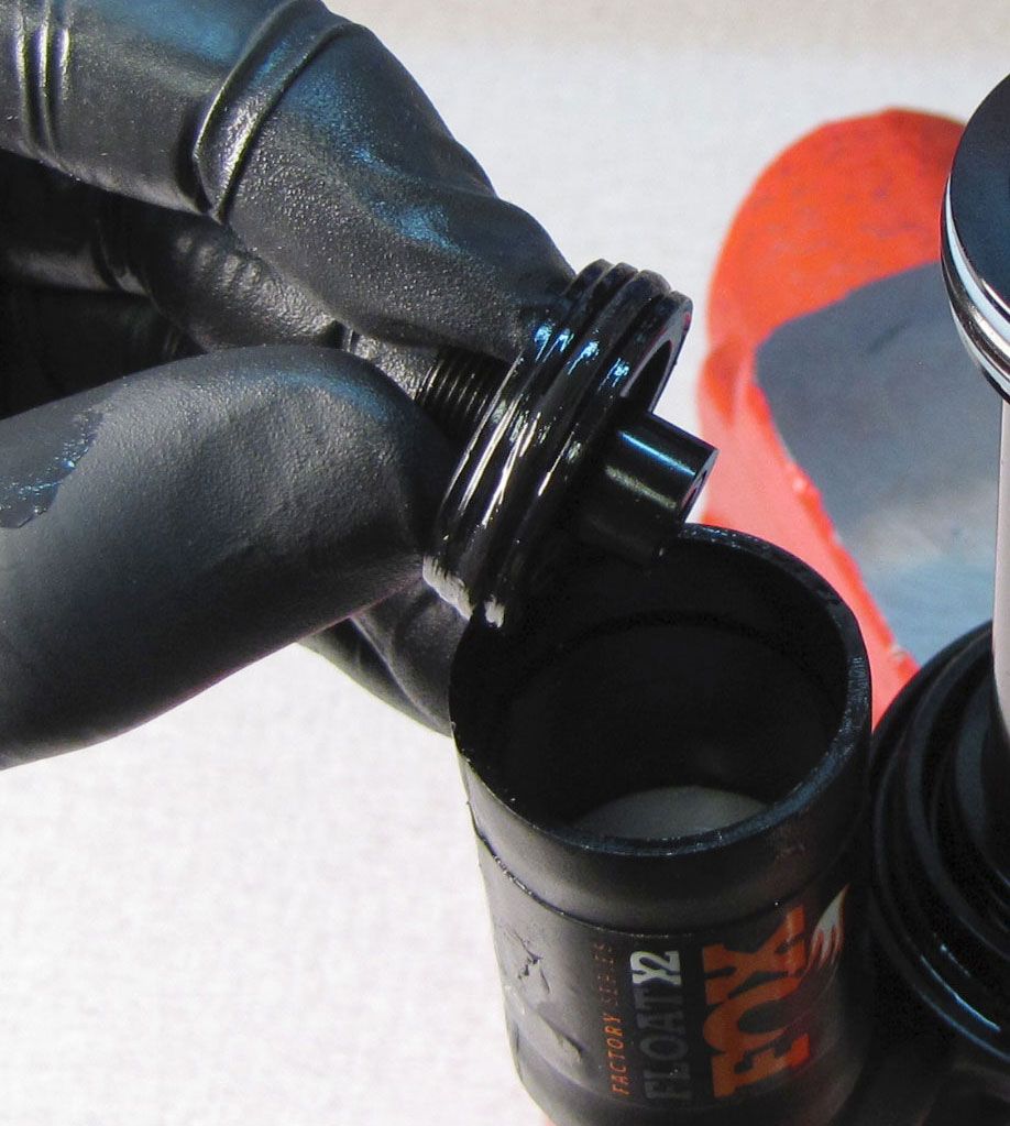
Step 3
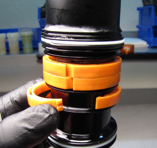
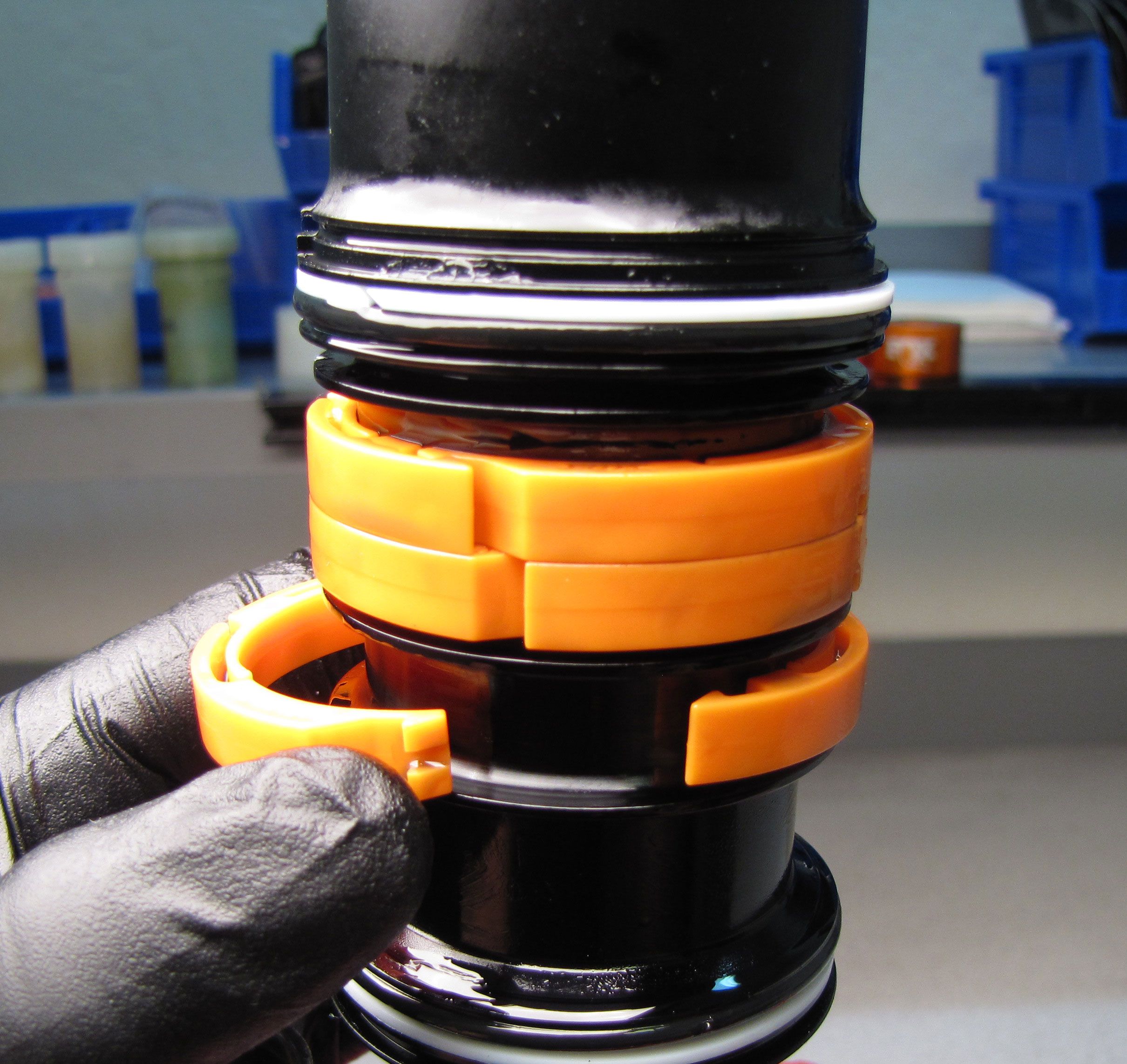
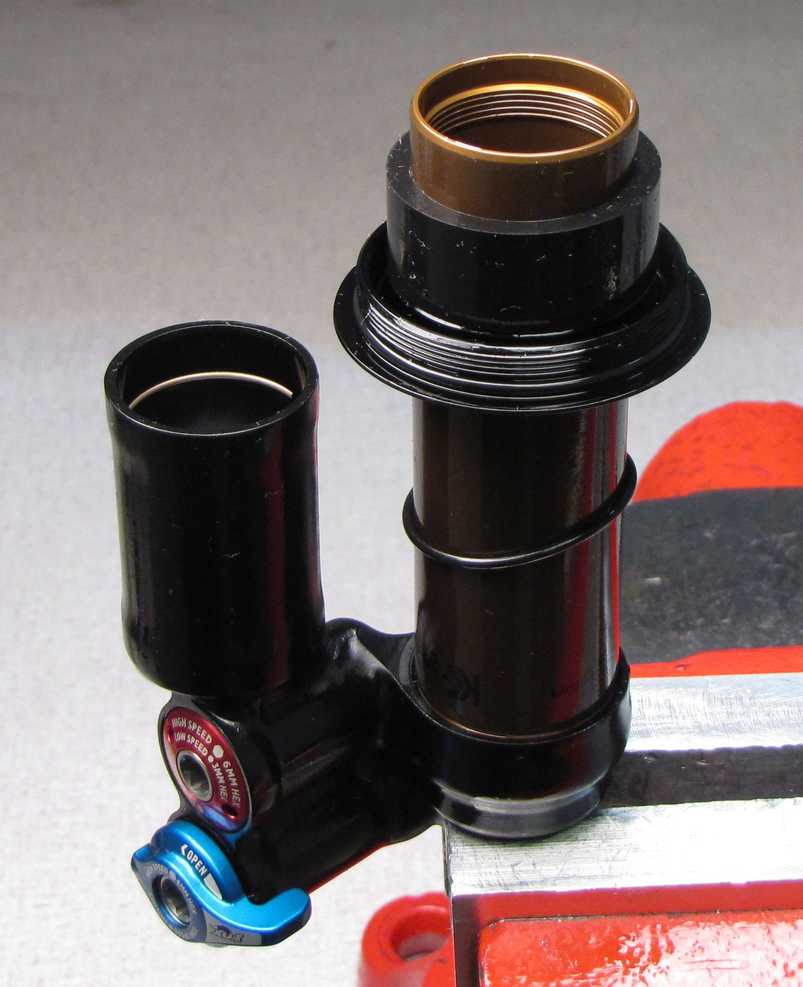
Slide the outer air sleeve away from the negative air sealhead to remove.

Step 4
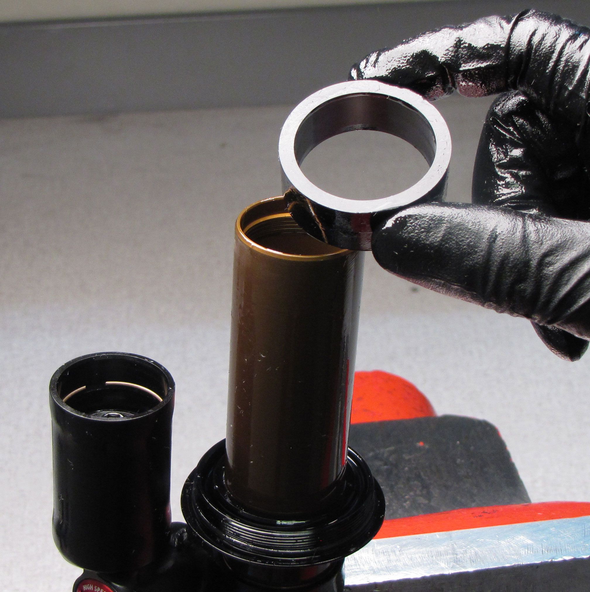
Remove any volume spacers from the inner air sleeve.

Step 5
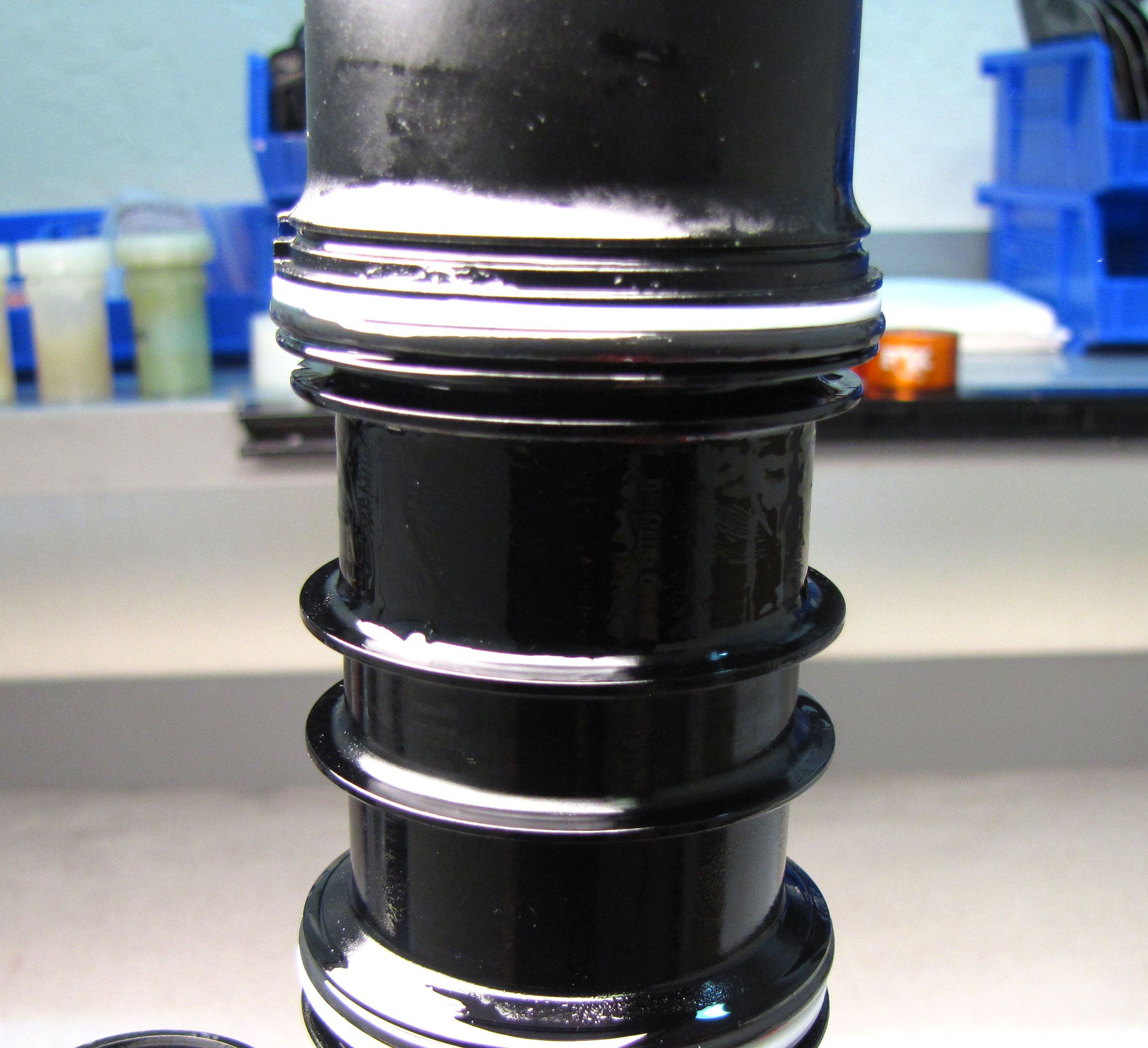
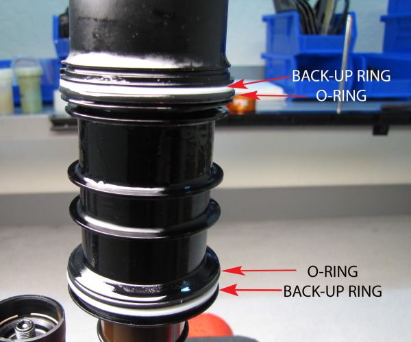
Remove the back-up rings and o-rings from the inner air sleeve and the negative air sealhead.
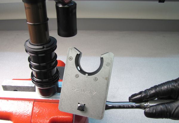
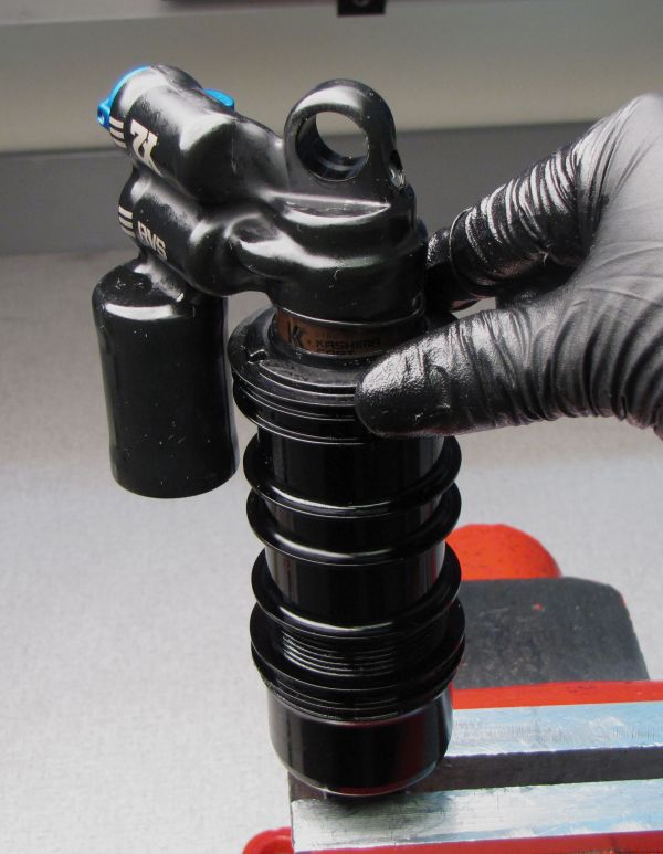
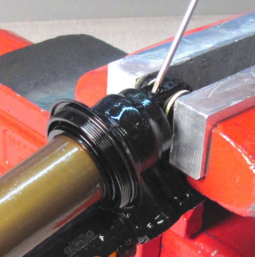
Step 6
With the non-adjuster eyelet clamped in your soft-jawed vise, carefully engage the prongs of the negative air sealhead tool (PN: 398-00-419) with the notches of the negative air sealhead. Do not scratch the outer body with your tool. Maintain downward pressure on the negative air sealhead tool to keep it engaged while you turn it counter-clockwise to unthread.

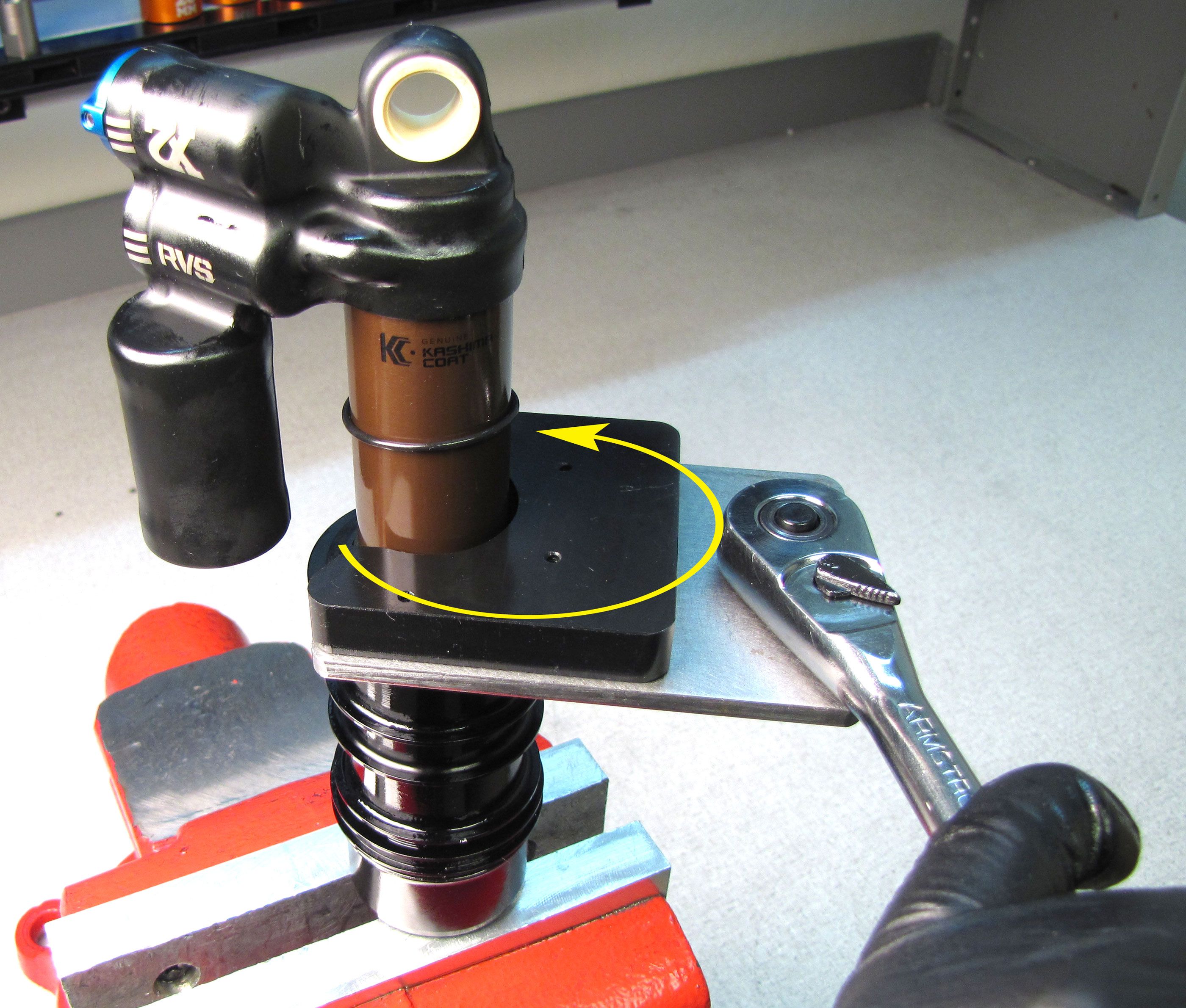
DO NOT clamp the 2019 FLOAT X2 Inner Air Sleeve below the externally threaded area. Only use the 2019 FLOAT X2 Air Sleeve Clamps (PN: 803-01-318) to clamp the 2019 FLOAT X2 Inner Air Sleeve between the ribs.

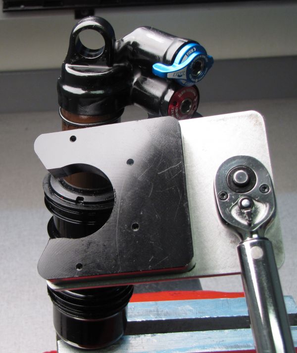
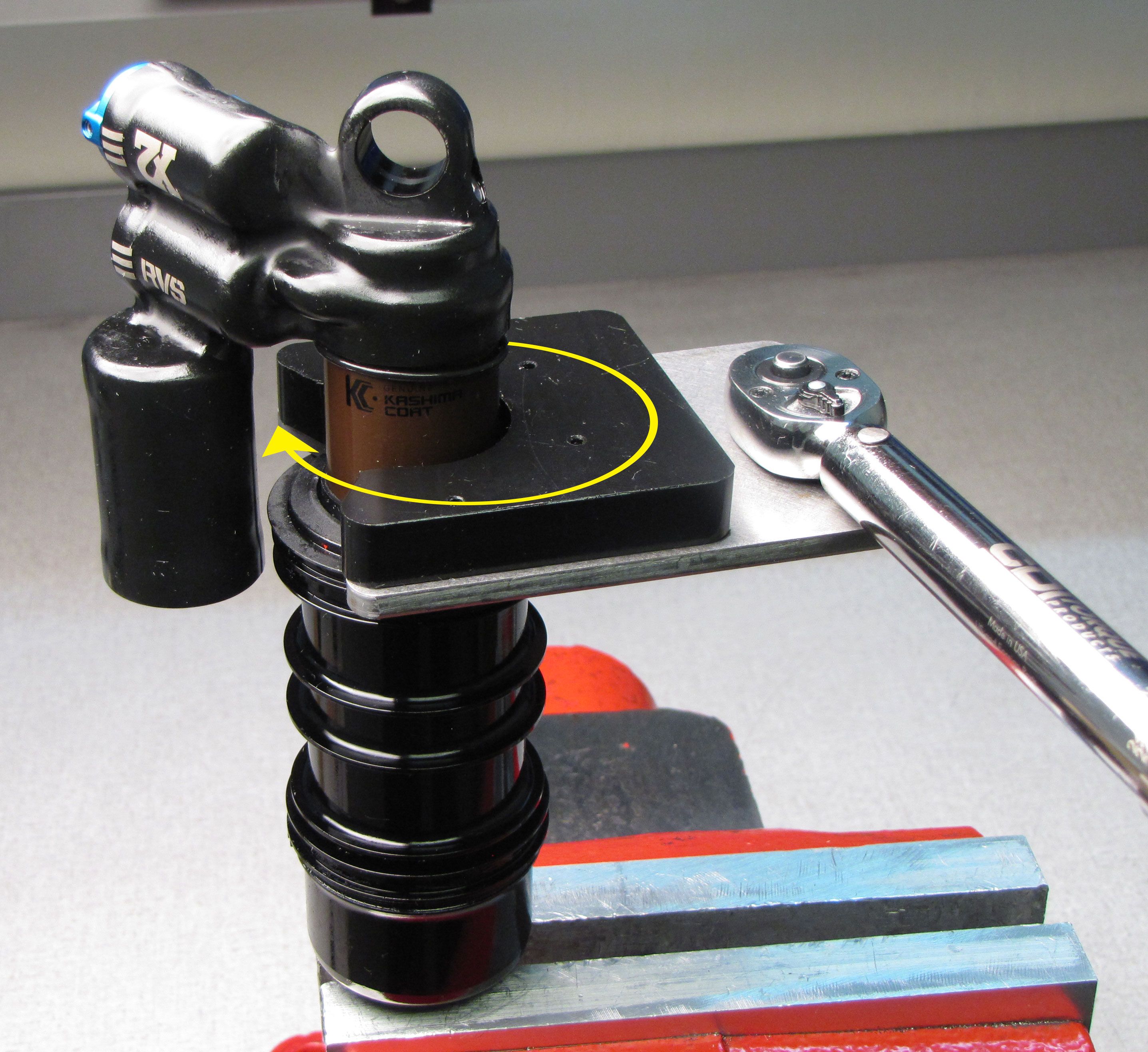
Step 7
You will need to separate either the negative air sealhead from the inner air sleeve or separate the inner air sleeve from the shaft eyelet. Use the X2 air sleeve clamps (PN: 803-01-318) to hold the inner air sleeve while you remove either the negative air sealhead with the sealhead tool (PN: 398-00-419) or the shaft eyelet with Knipex pliers or the eyelet torque tool (PN: 398-00-280).


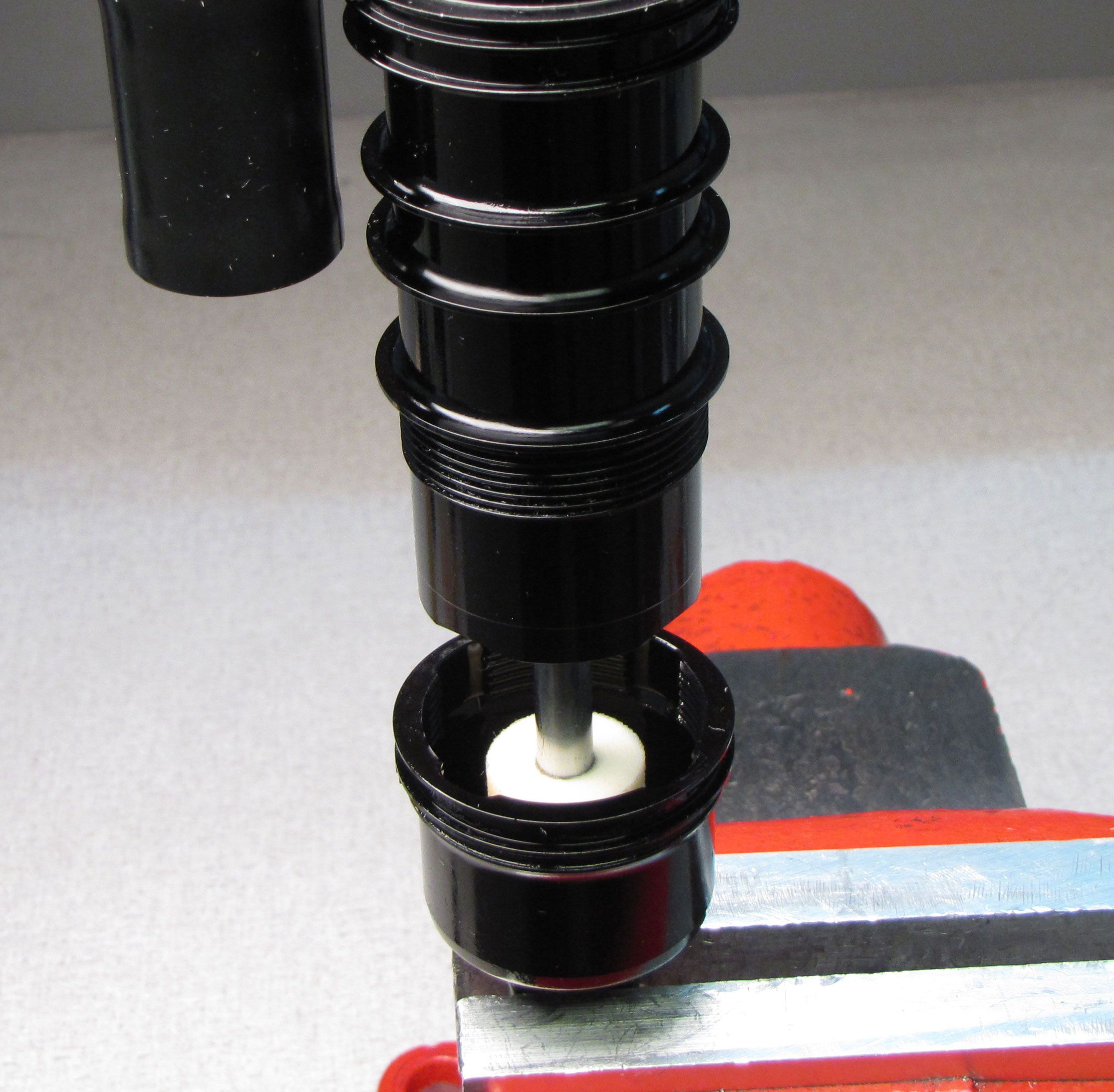
Step 8
Clean the exposed shaft with Isopropyl alcohol then dry it with a lint-free paper towel. Invert the shock, then carefully clamp the shaft in your clamps (PN: 803-00-967). Unthread the non-adjuster eyelet counter-clockwise to remove. Remove the bottom out spacer and bottom out bumper. Remove the travel and volume spacer if present.


Step 9
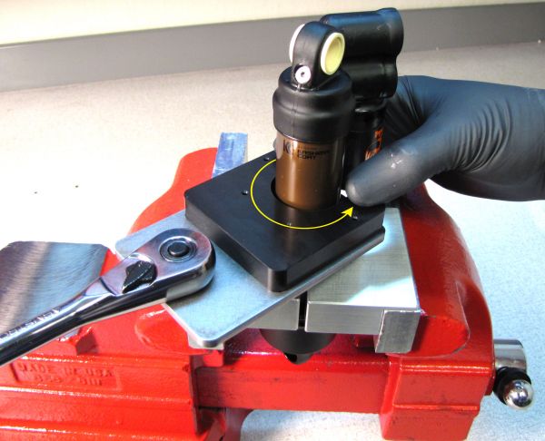
Clean the inner air sleeve with Isopropyl alcohol then dry with a lint-free paper towel. Carefully clamp the inner air sleeve in your clamps (PN: 803-00-968). Carefully engage the prongs of the negative air sealhead tool (PN: 398-00-419) with the notches of the negative air sealhead. Do not scratch the outer body with your tool. Maintain downward pressure on the negative air sealhead tool to keep it engaged while you turn it counter-clockwise to unthread. Slide the neg air sealhead up toward the adjuster eyelet once unthreaded.

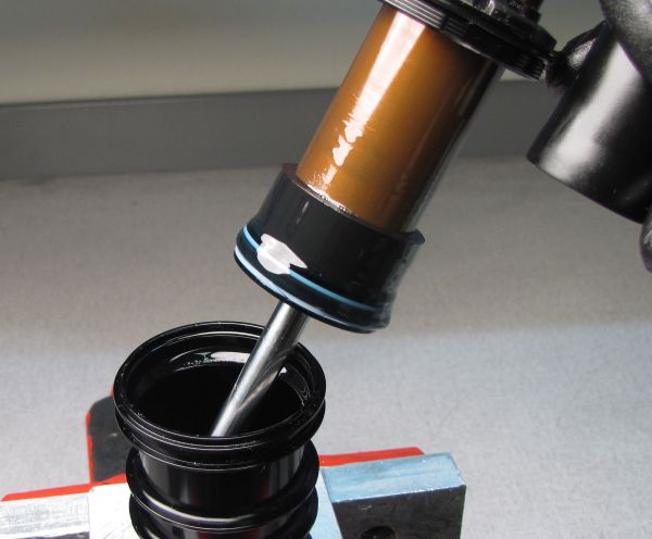
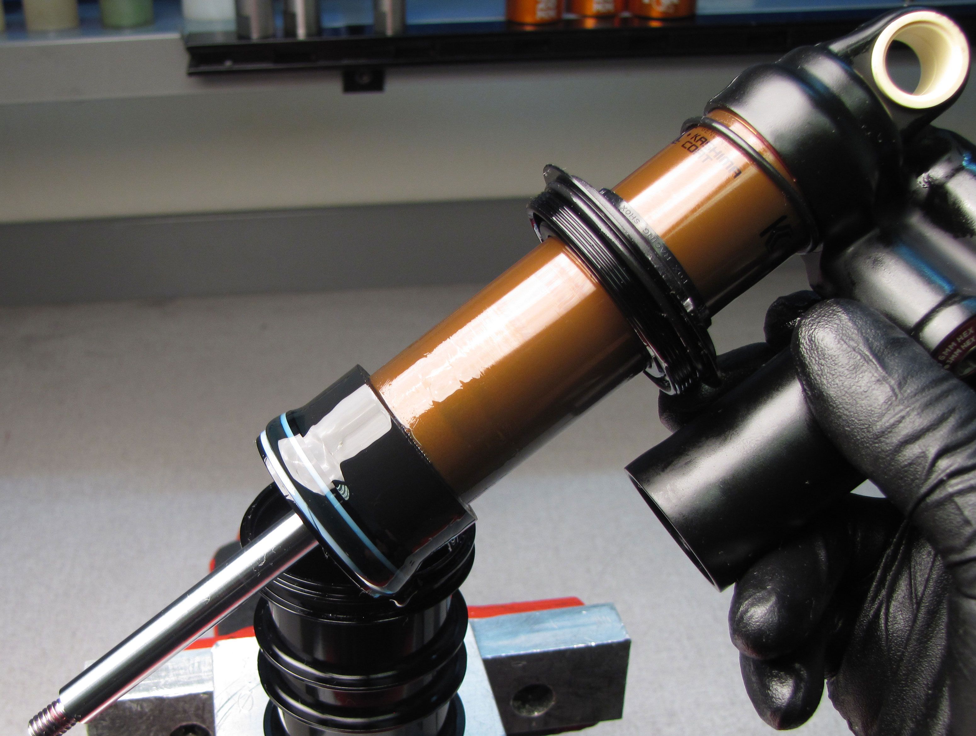
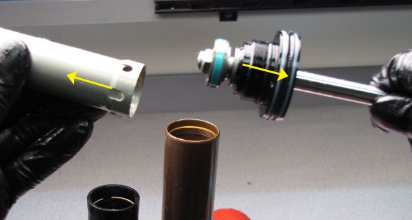
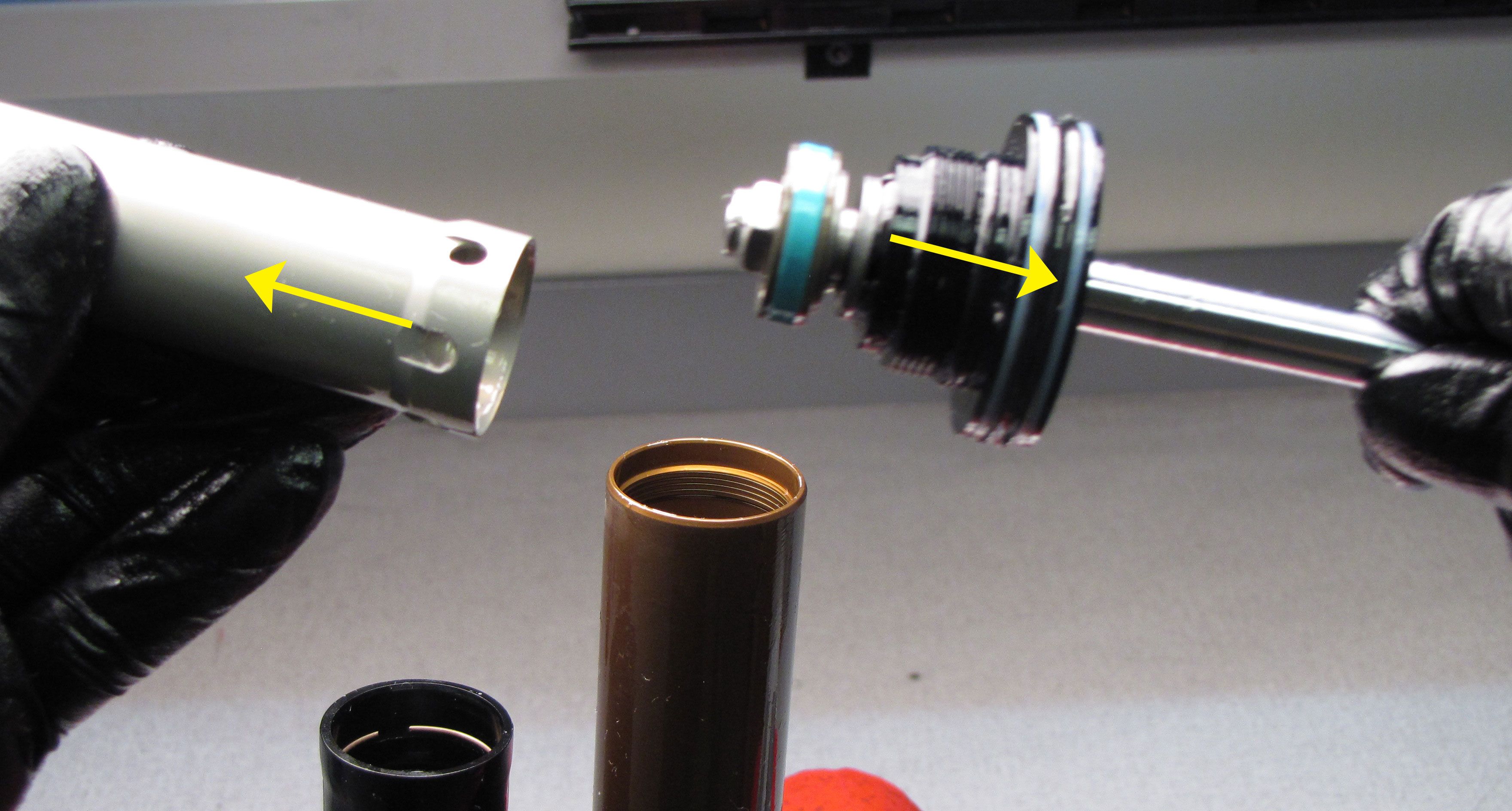
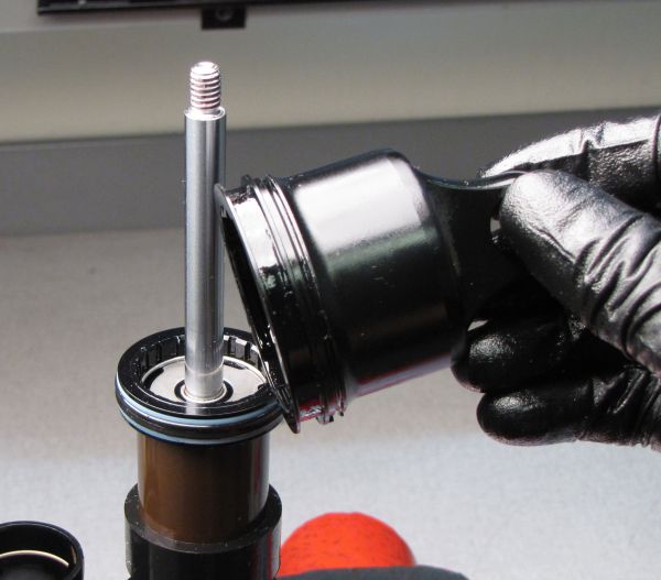
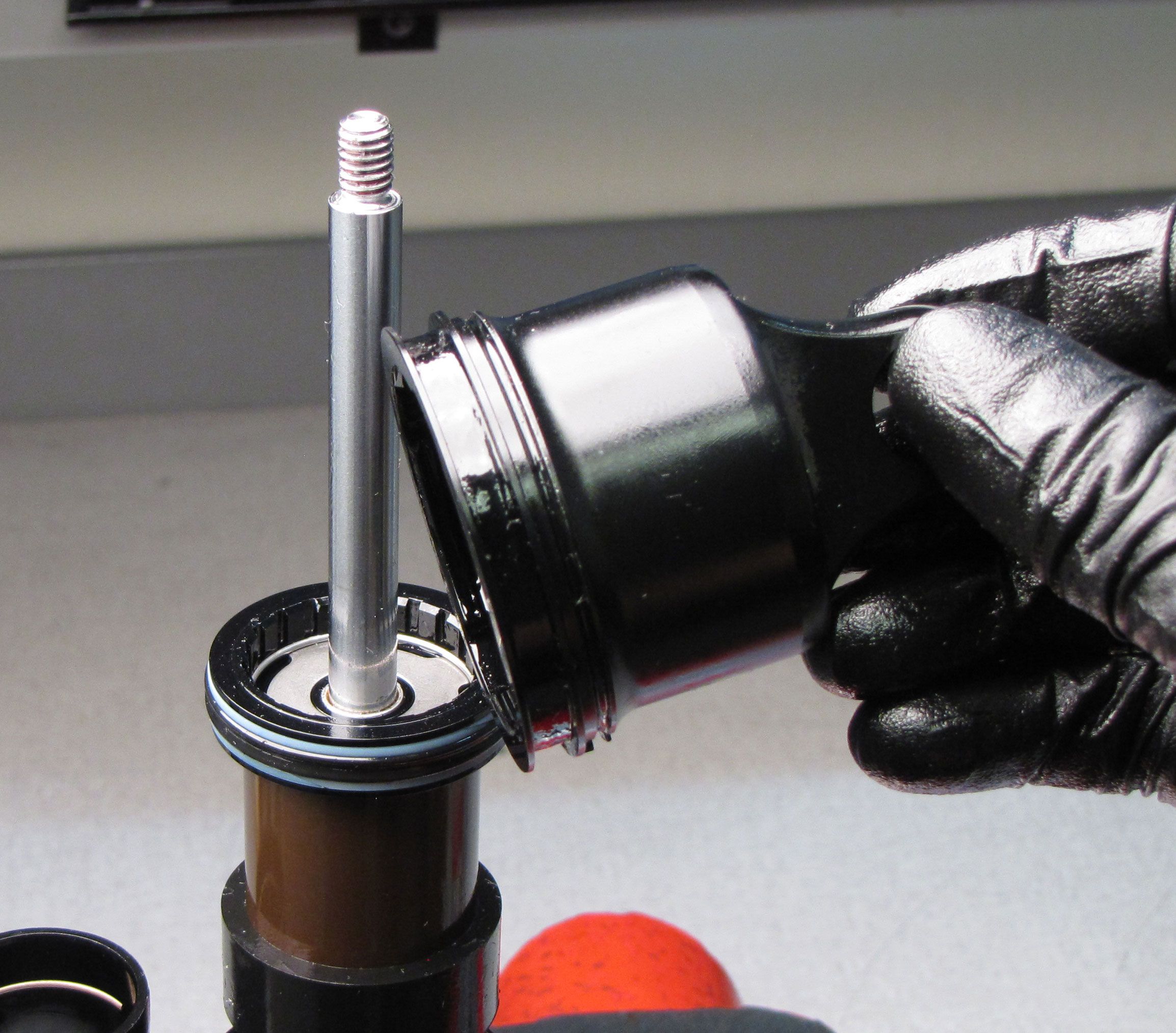
Step 10
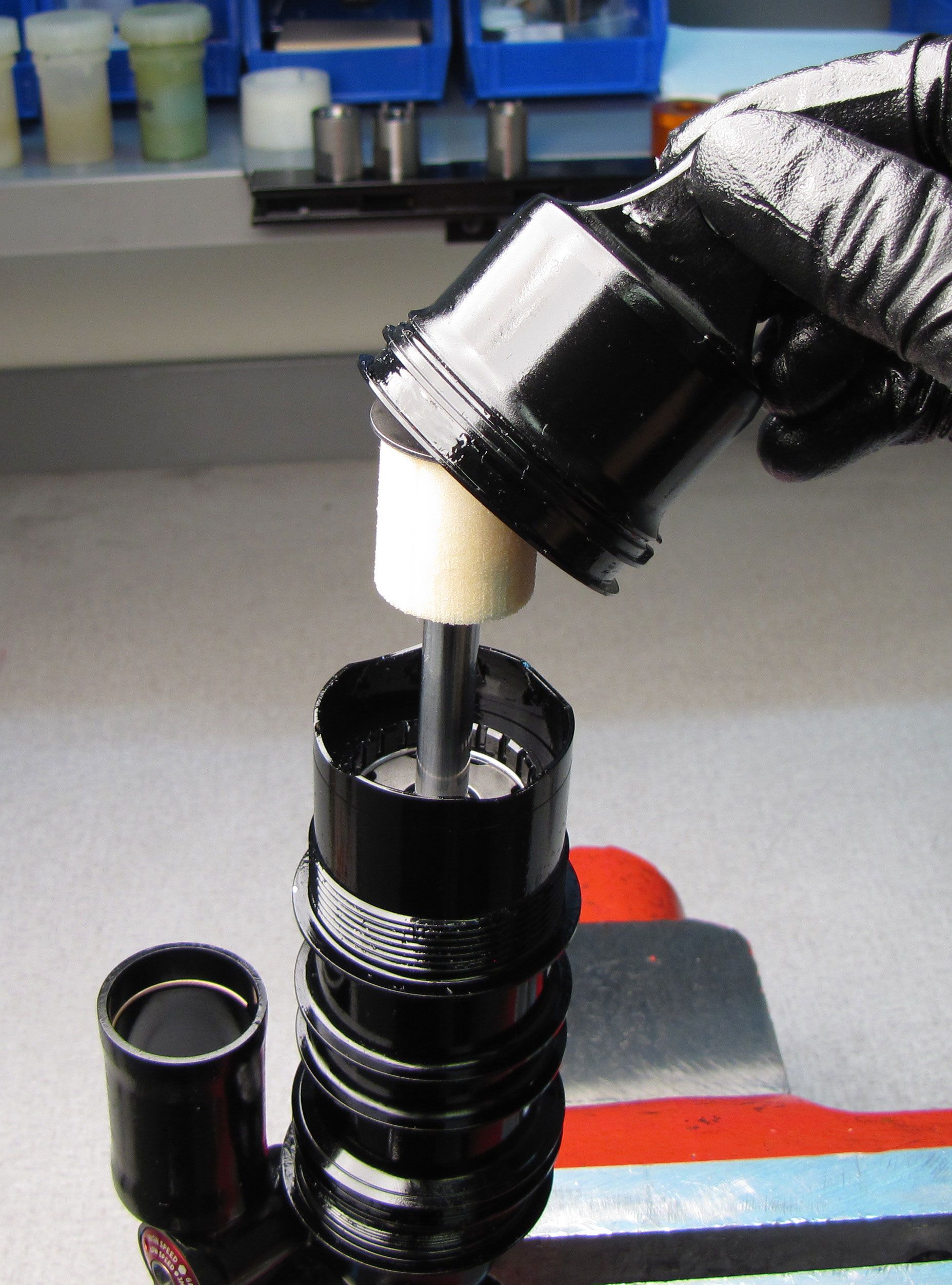
Lift the damper assembly out of the inner air sleeve to separate. Clean the damper assembly and inner air sleeve.

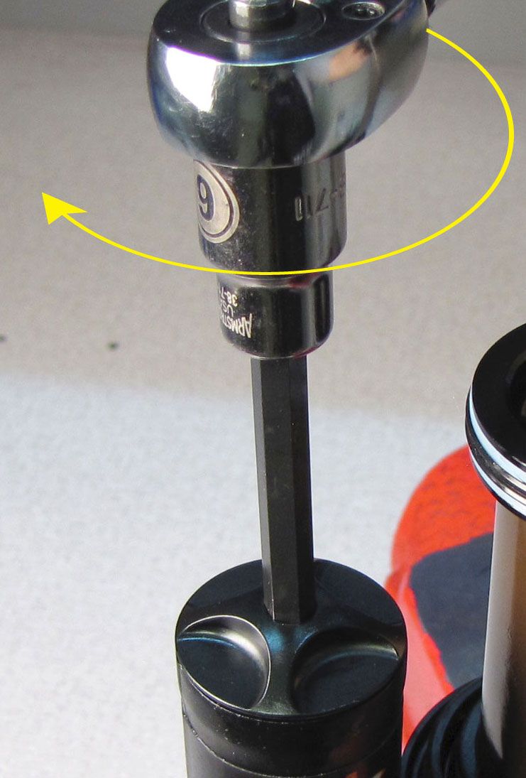
Step 11
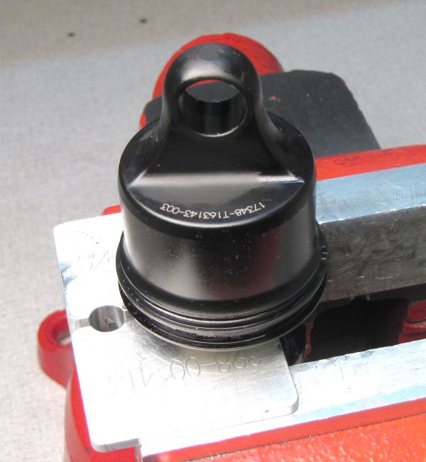
Unthread (counter-clockwise) the reservoir end cap assembly from the reservoir with a 6mm hex wrench. Remove the reservoir end cap assembly and replace its o-ring with a new one from the kit.


Step 12
Release the nitrogen charge by depressing the Schrader valve within the reservoir.

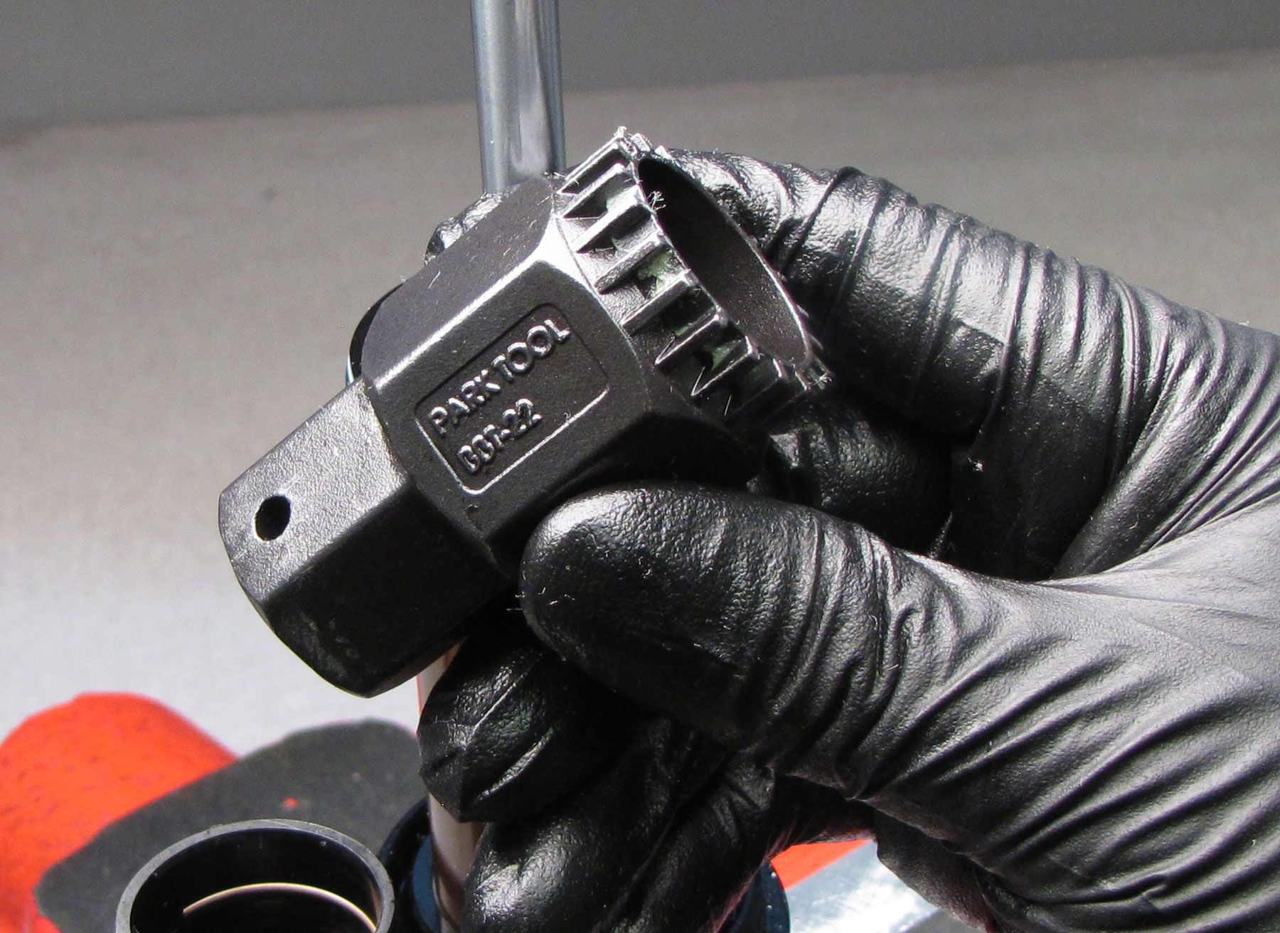
Step 13
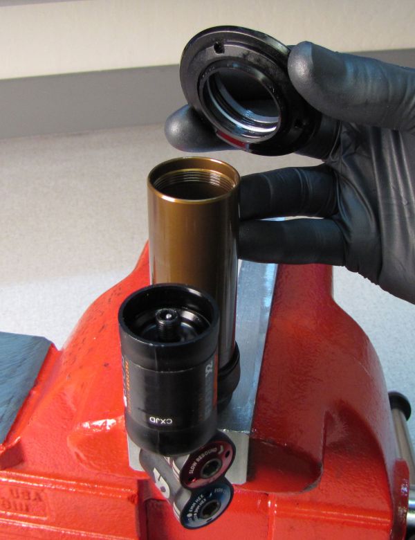
Use a 20 tooth bottom bracket tool such as the Park Tool BBT-22 to unthread (counter-clockwise) the bearing assembly from the body. Remove the bearing assembly and inner body from the outer body by pulling up. Drain the inner body over a waste oil basin.


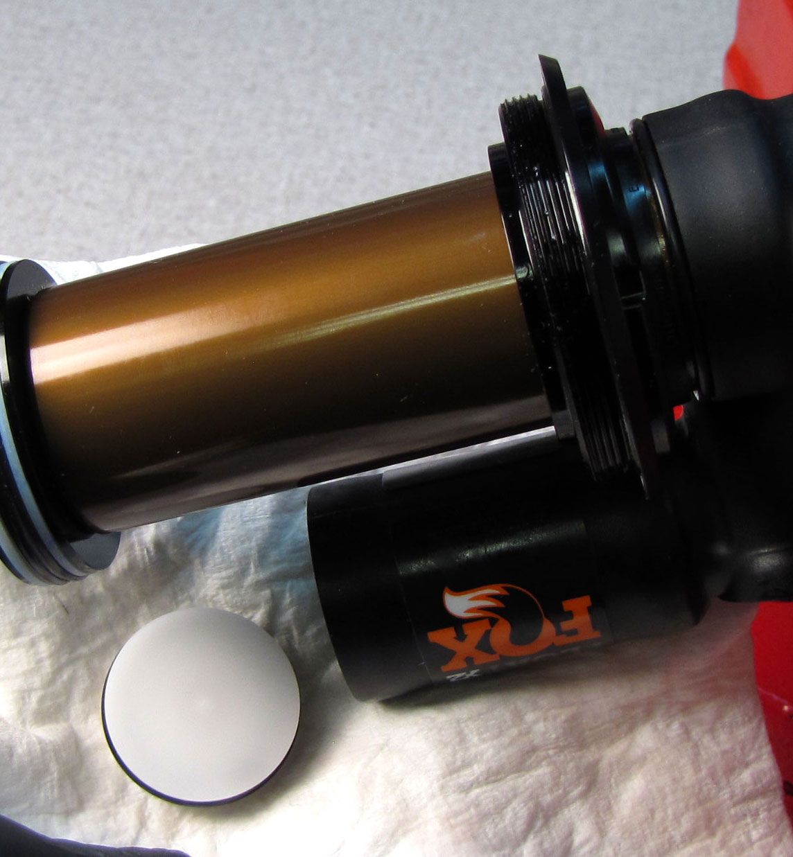
Step 14
Remove the negative volume spacer if present (Negative Volume spacer PN: 233-00-391 shown. A 30x3mm o-ring may be the negative volume spacer in some shocks. Remove the neg air sealhead and replace all its seals and backup rings with new greased ones from the kit. Inspect the outer body for any scratches or damage and replace if necesarry.
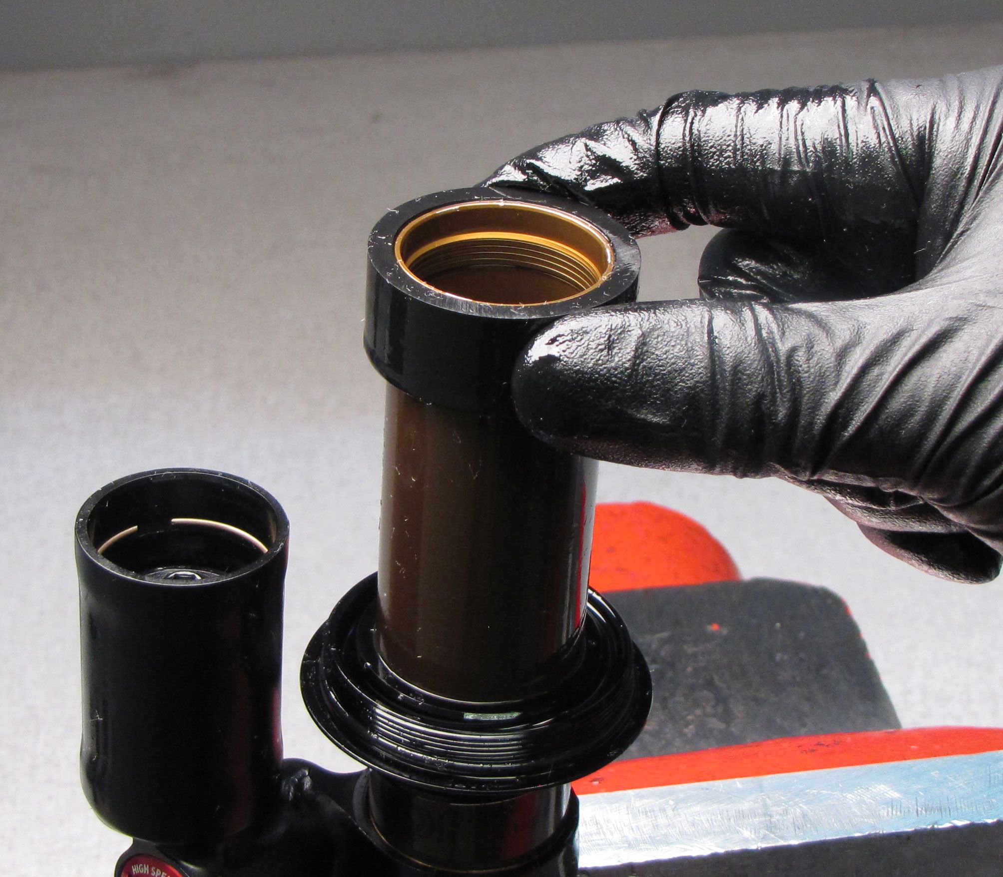
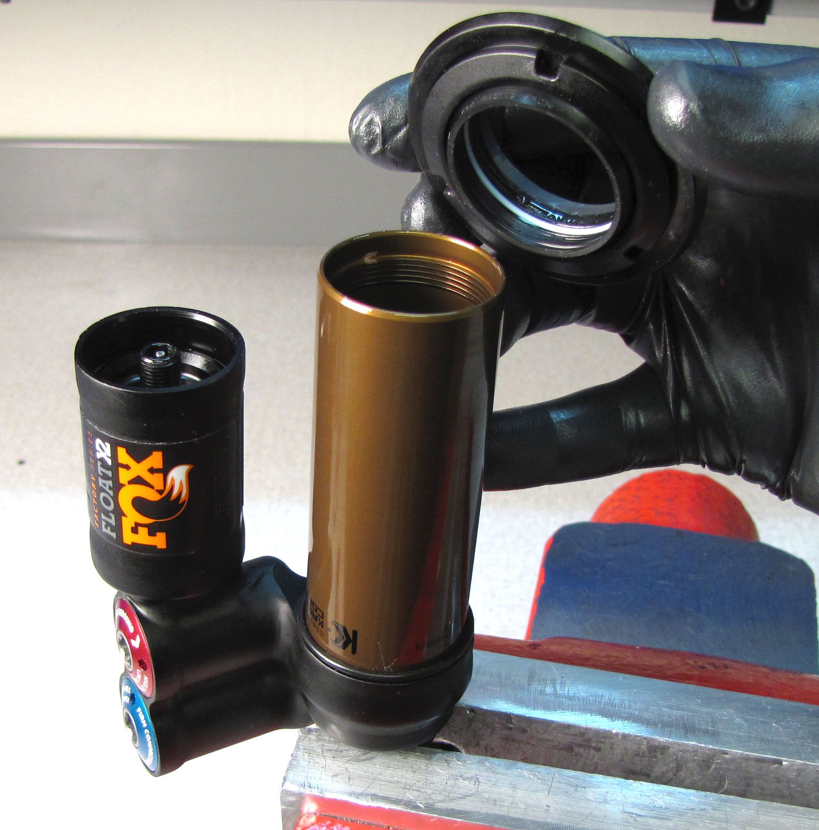
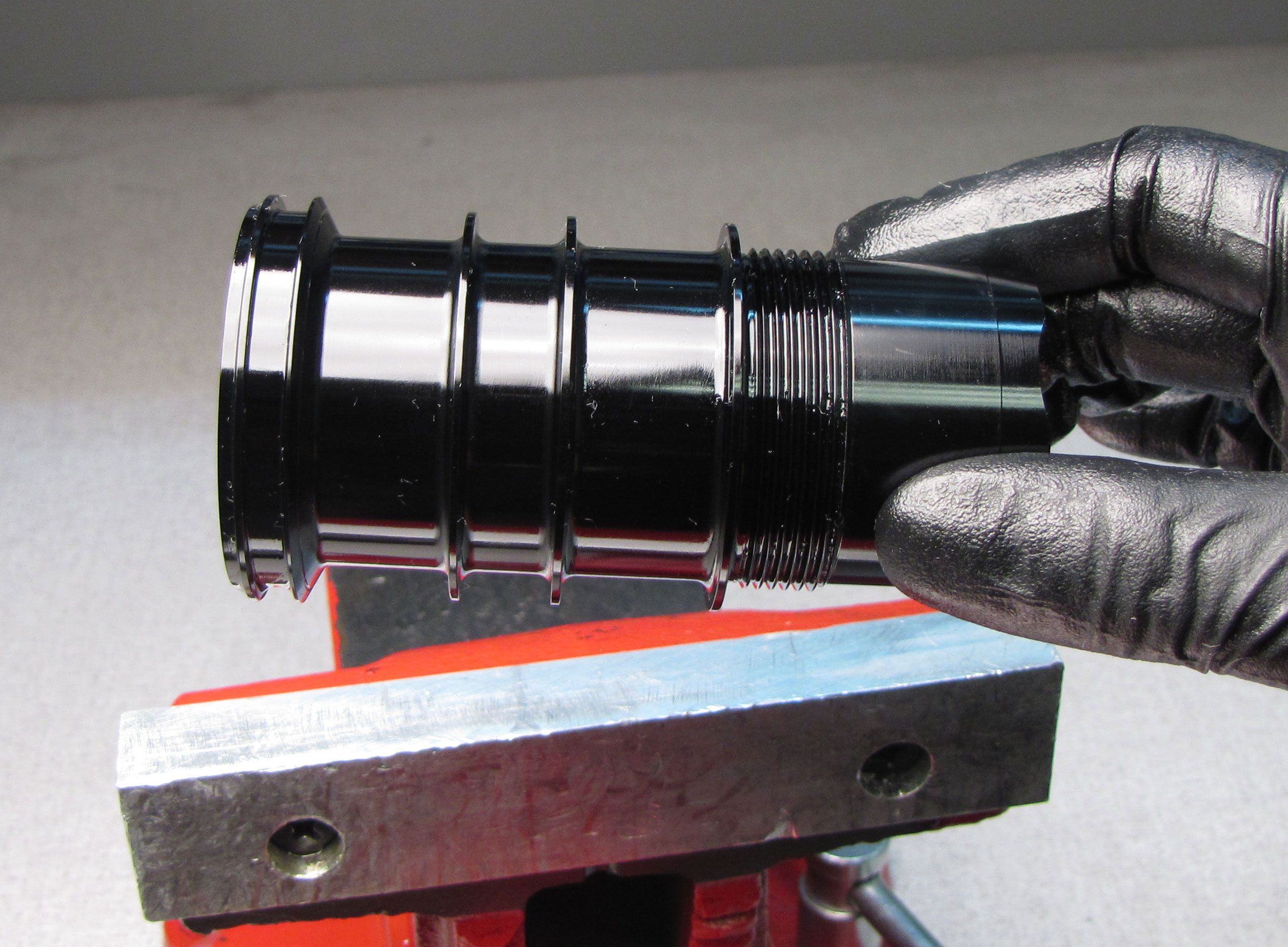
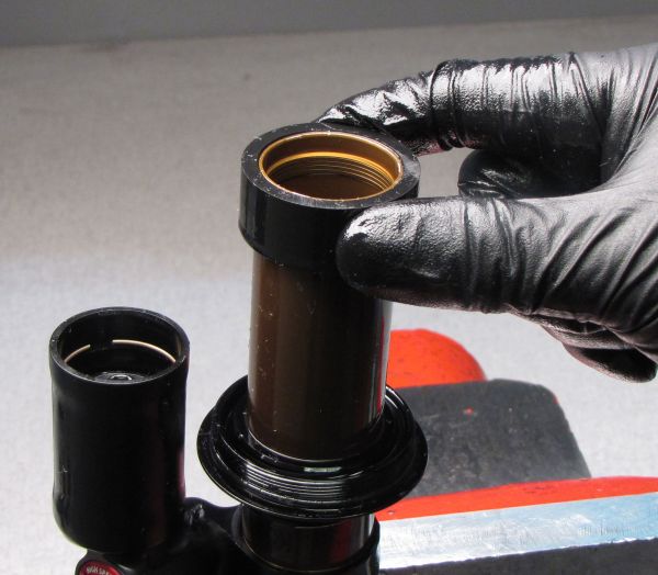
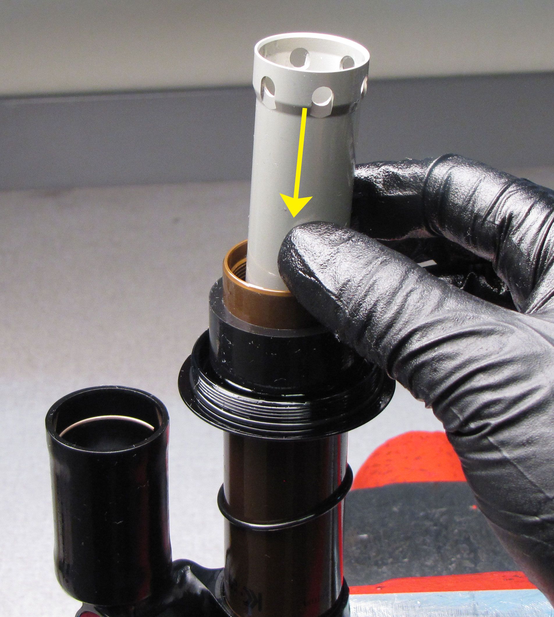
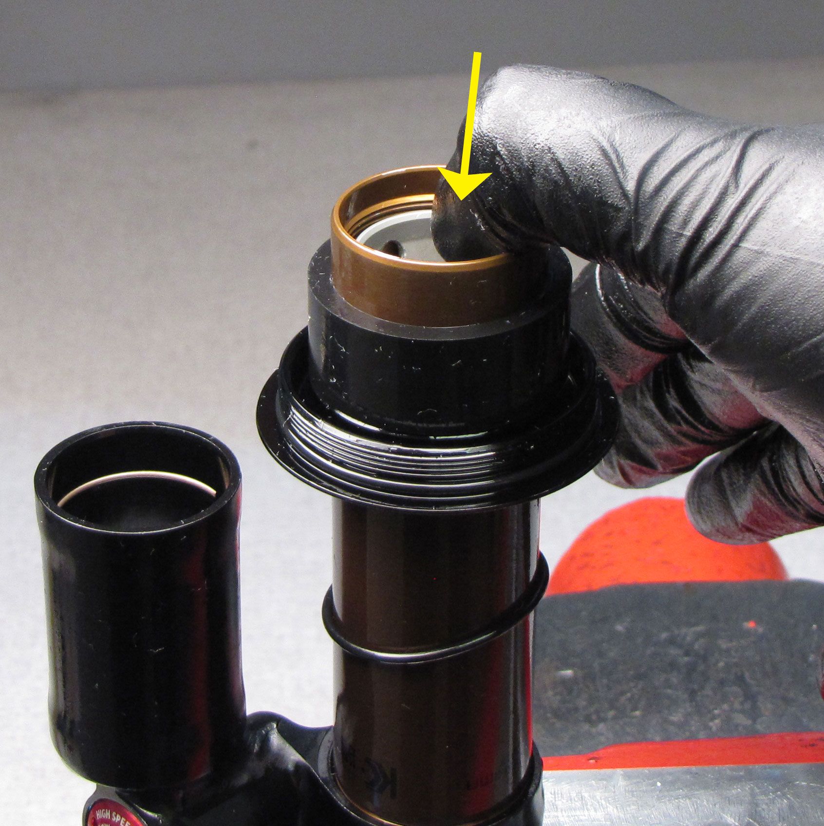
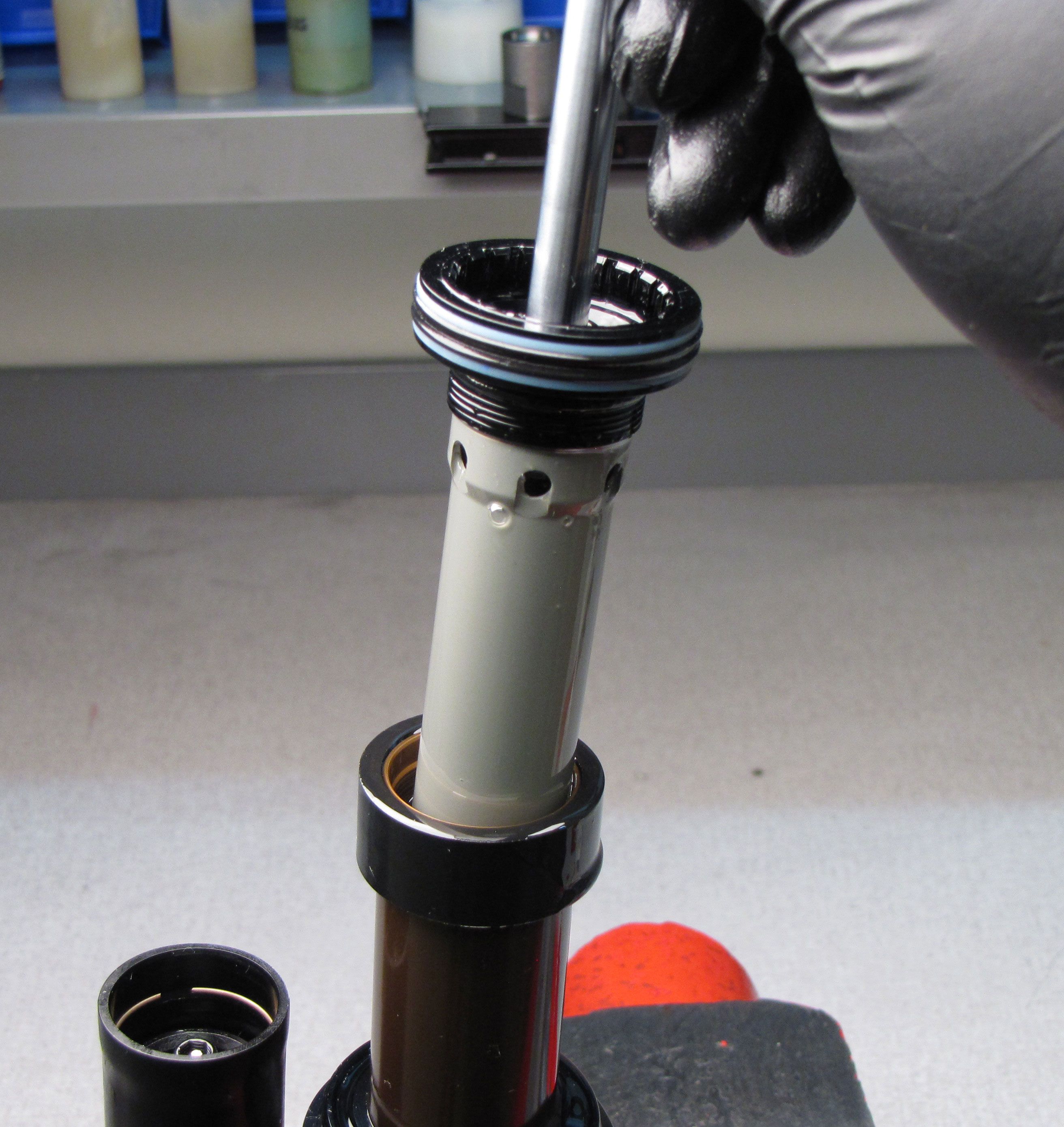
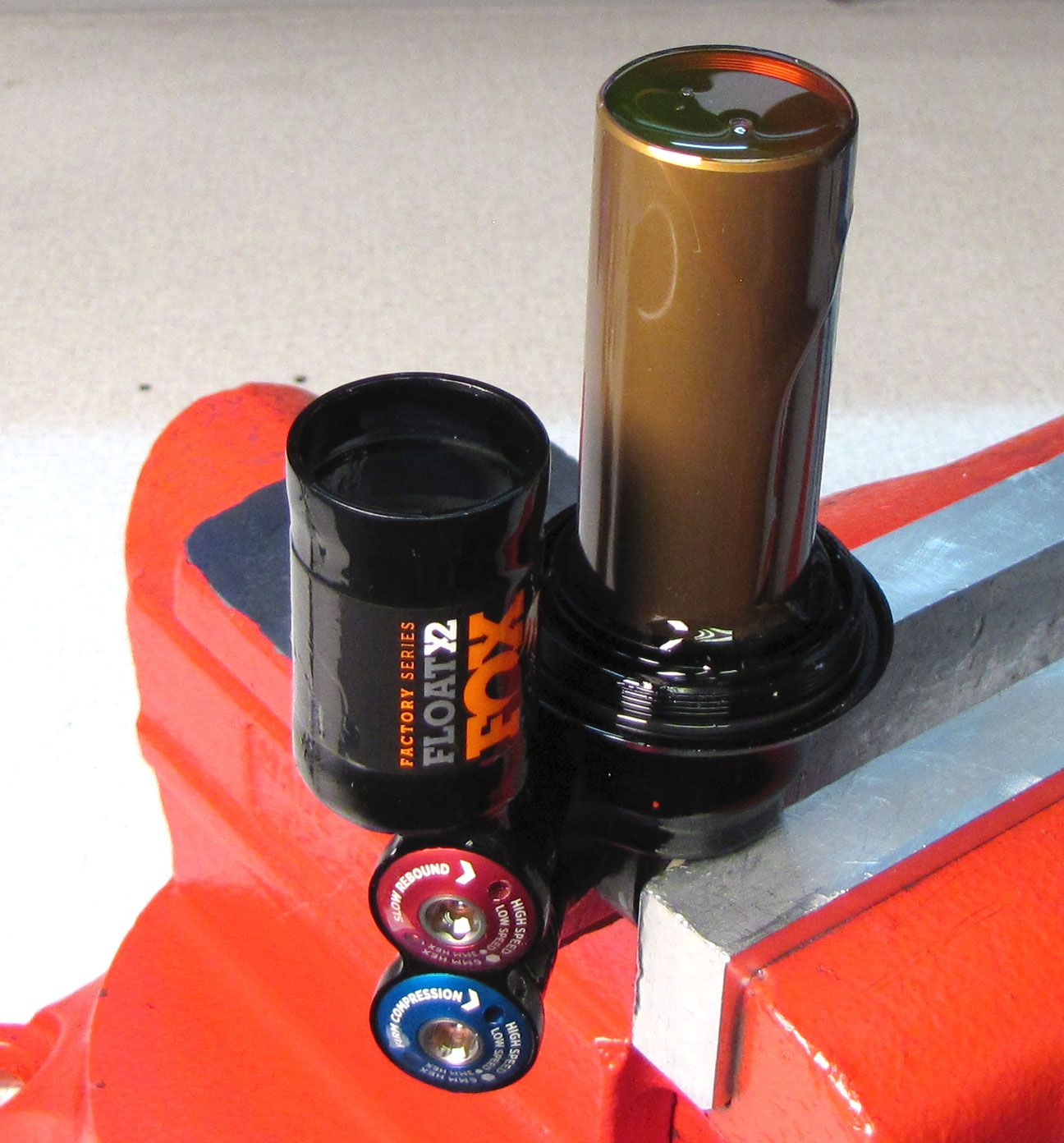
Step 15
Pull up on the inner body to remove it from the bearing assembly. This part can be tight on the bearing assembly and can require significant force to remove. Do not bend the shaft while removing the inner body.

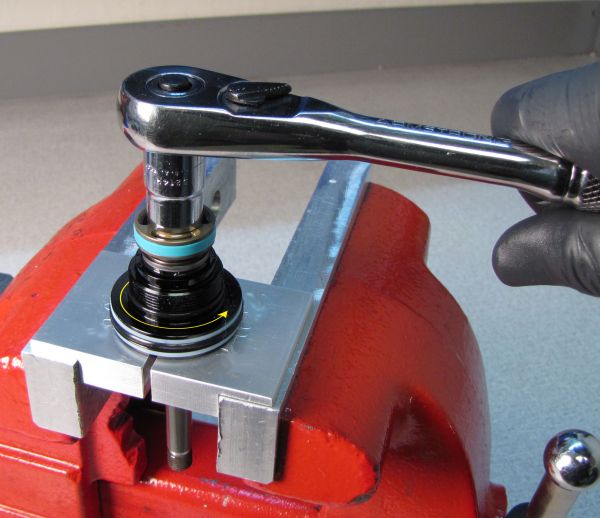
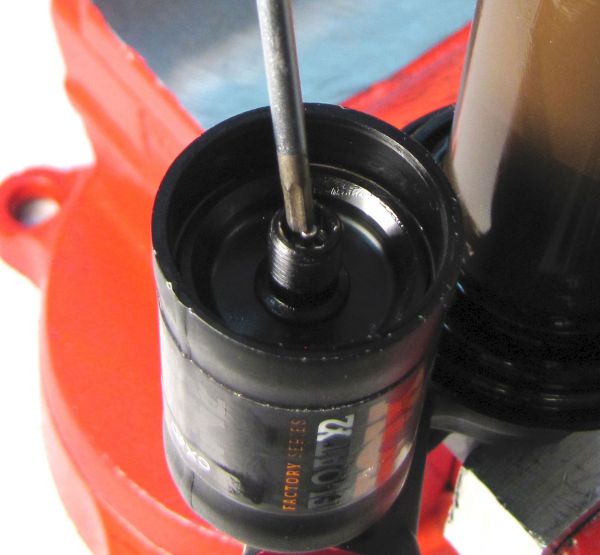
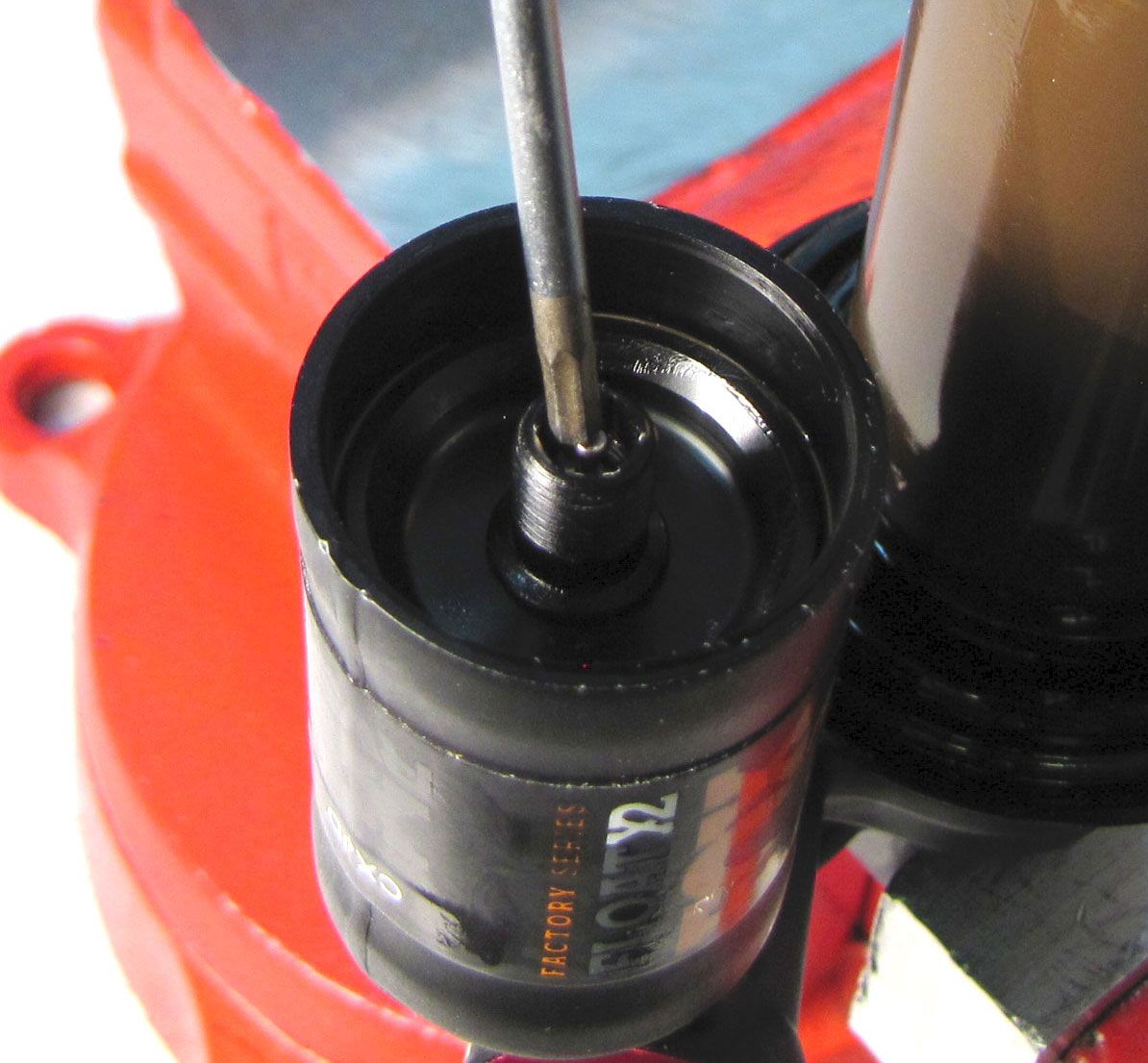
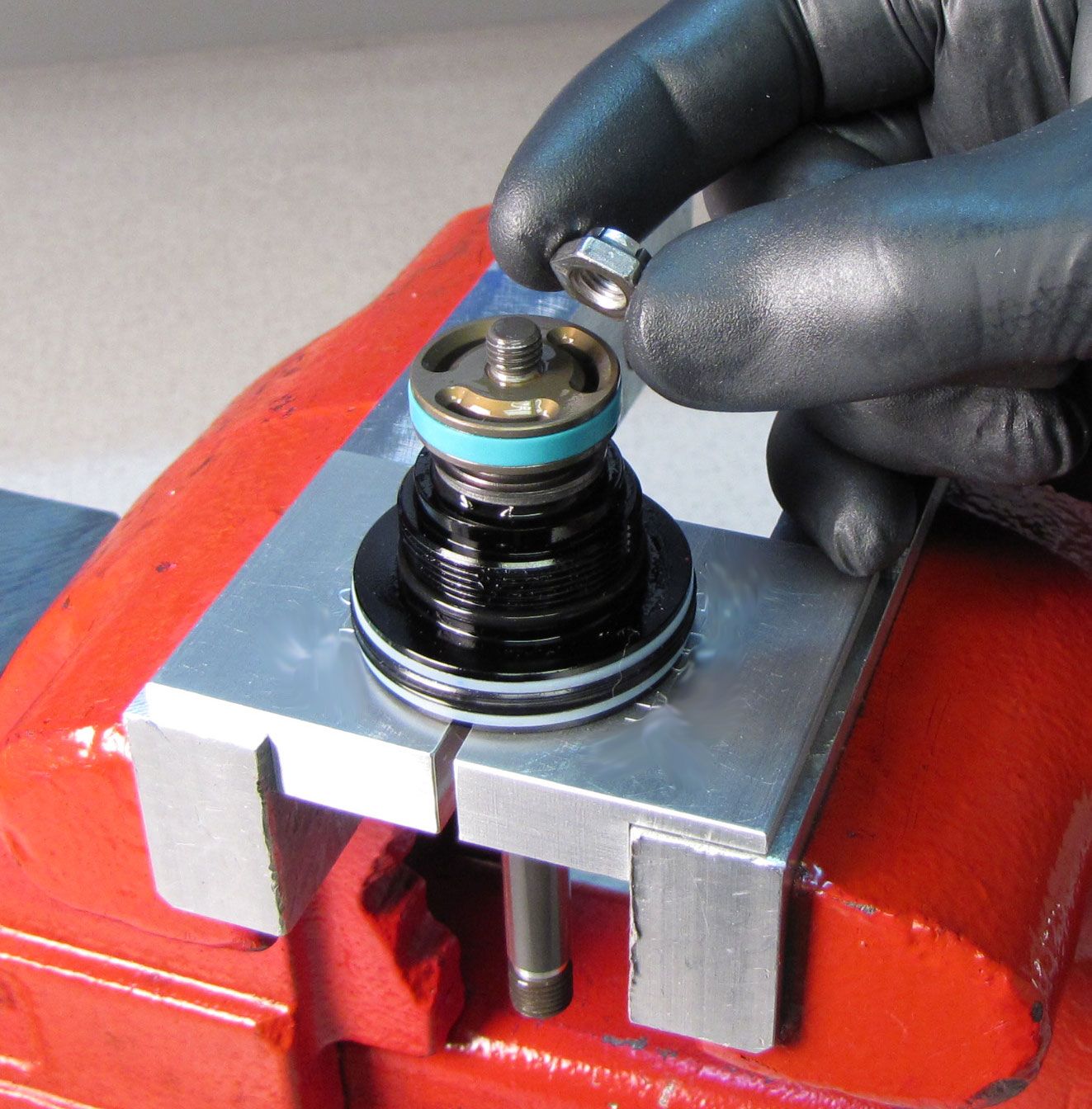
Step 16
Clamp the shaft in the X2 shaft clamps (PN: 803-00-967) then use an 11mm socket to unthread (counter-clockwise) and remove the piston nut. Remove the piston and valving assembly keeping all parts in their original order. Inspect the shims and replace any that are damaged. Replace the blue glide ring and o-ring on the piston with new ones from the kit.

Step 17
Reinstall the valving assembly, piston, and piston nut. Tighten the nut clockwise to 80 in-lb (9.0 Nm).


Step 18
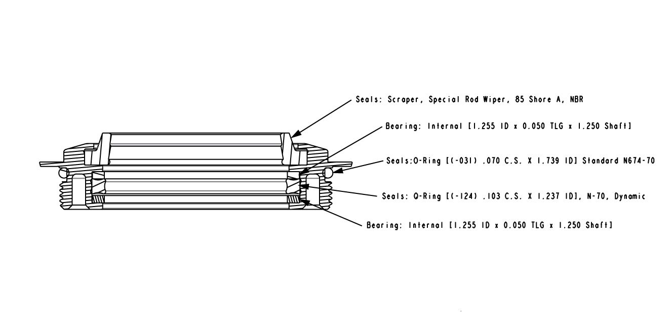
Remove the bearing assembly and replace all seals and backup rings with new greased ones from the kit.

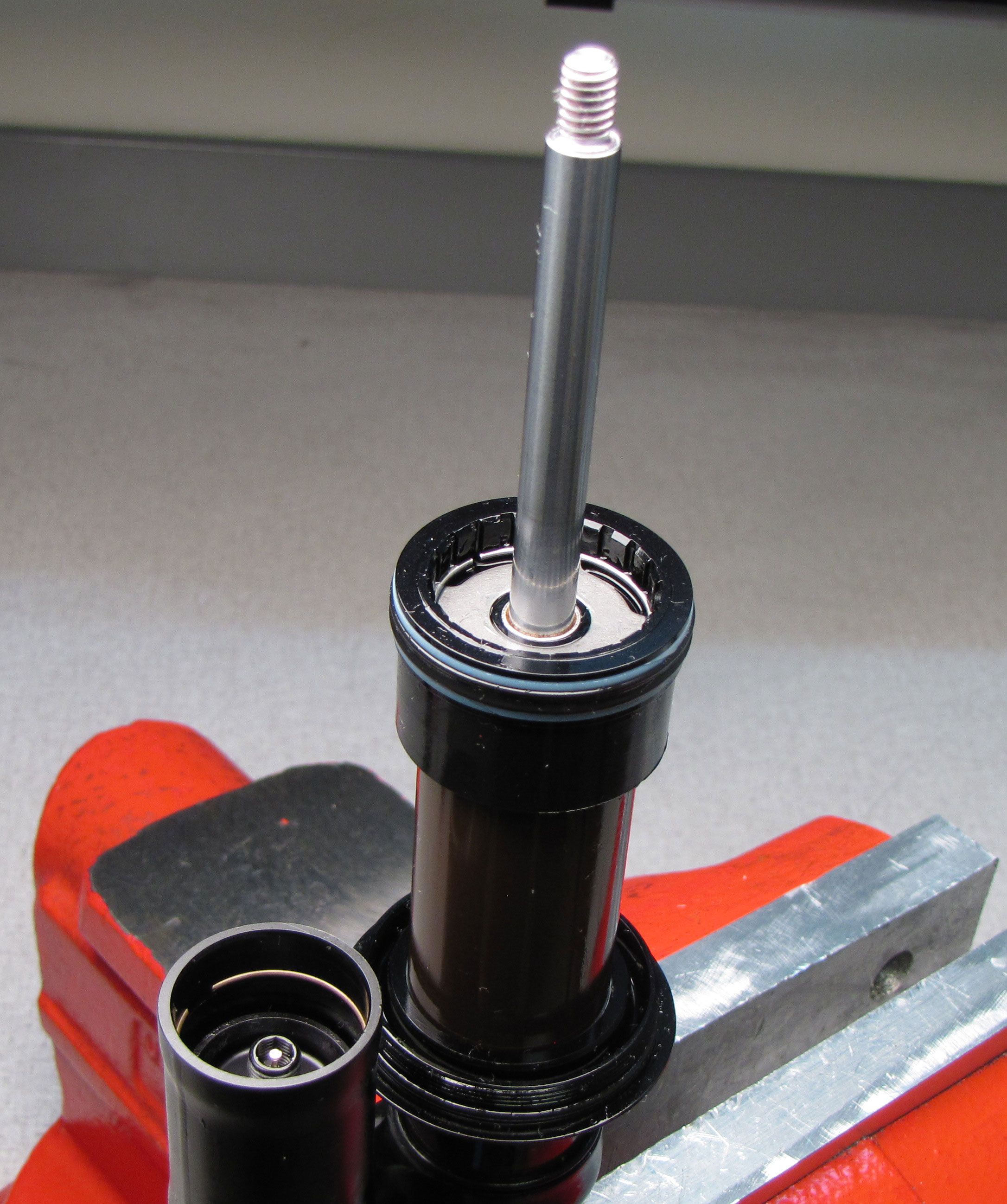
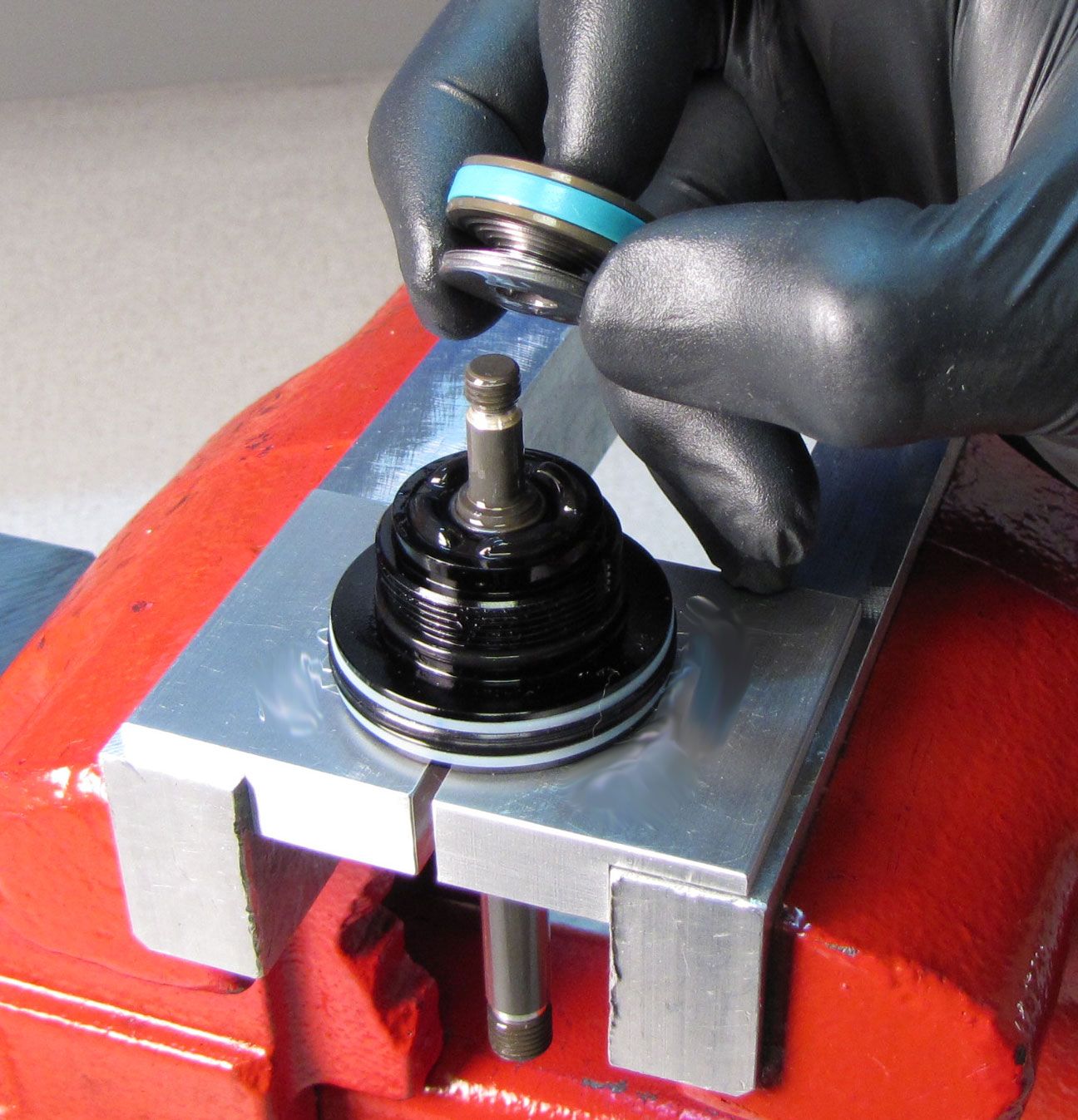
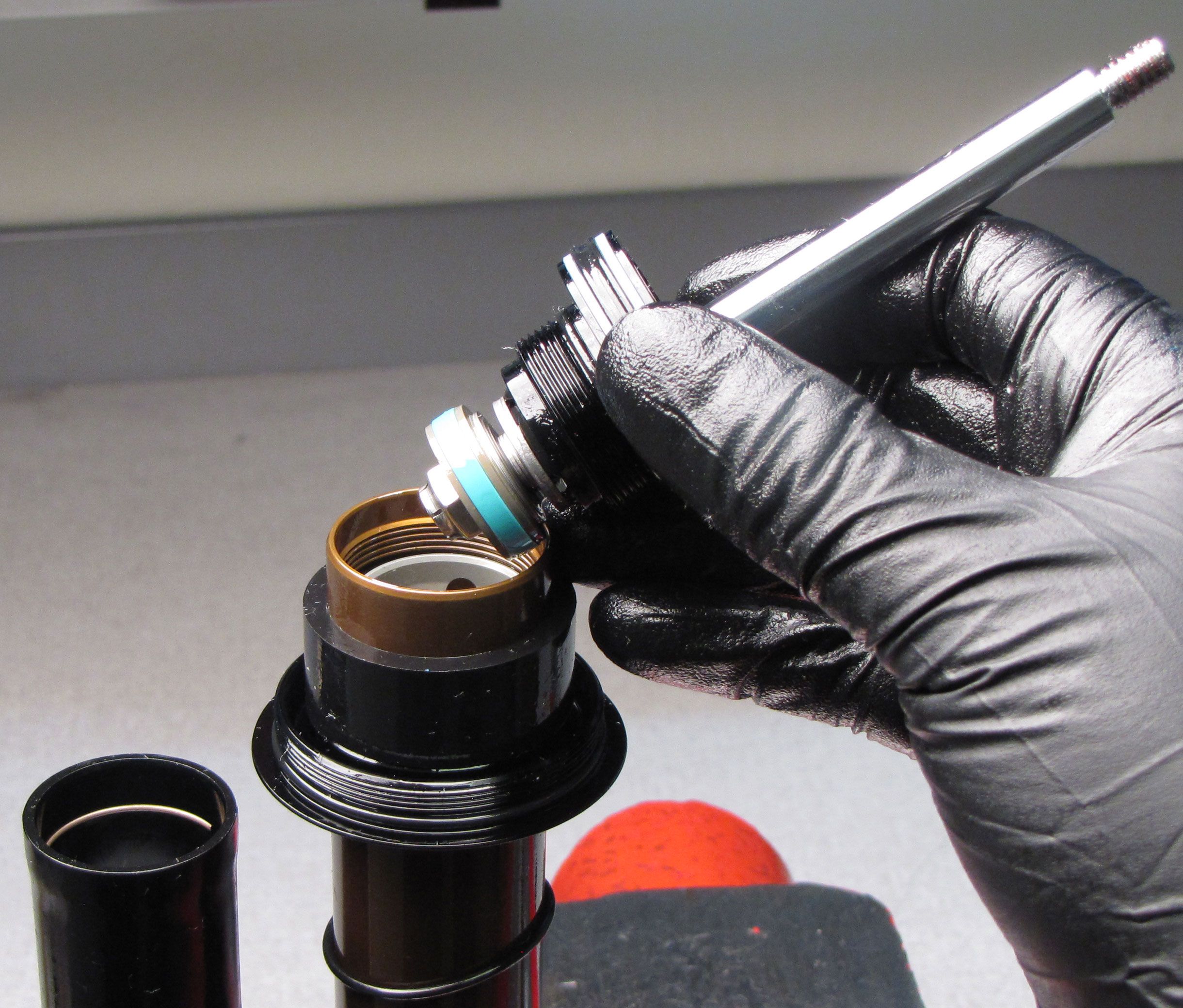
Step 19
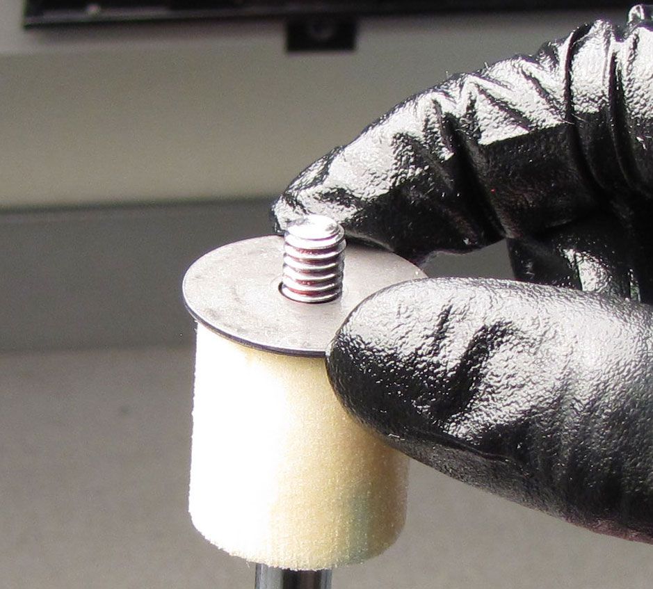
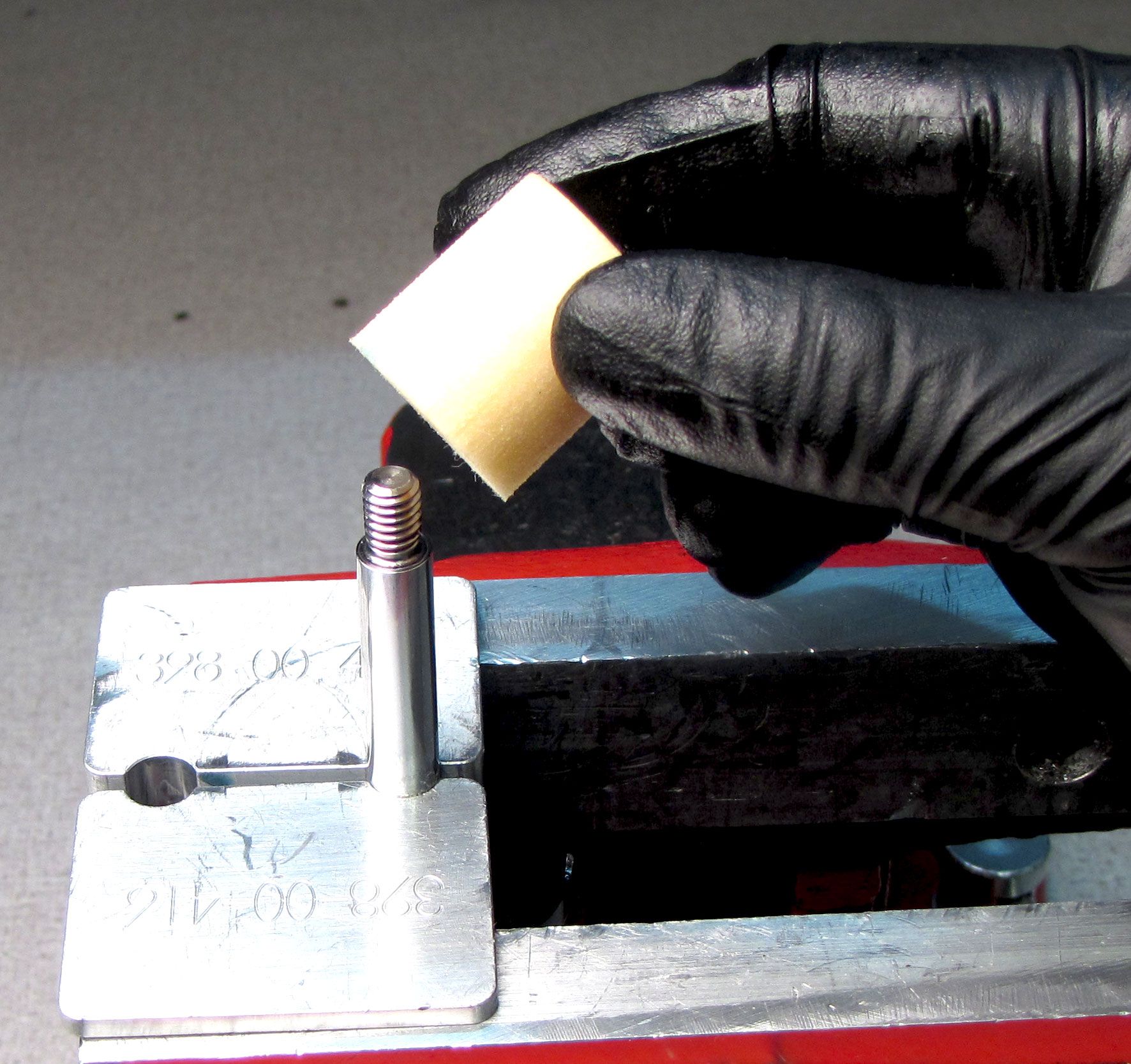
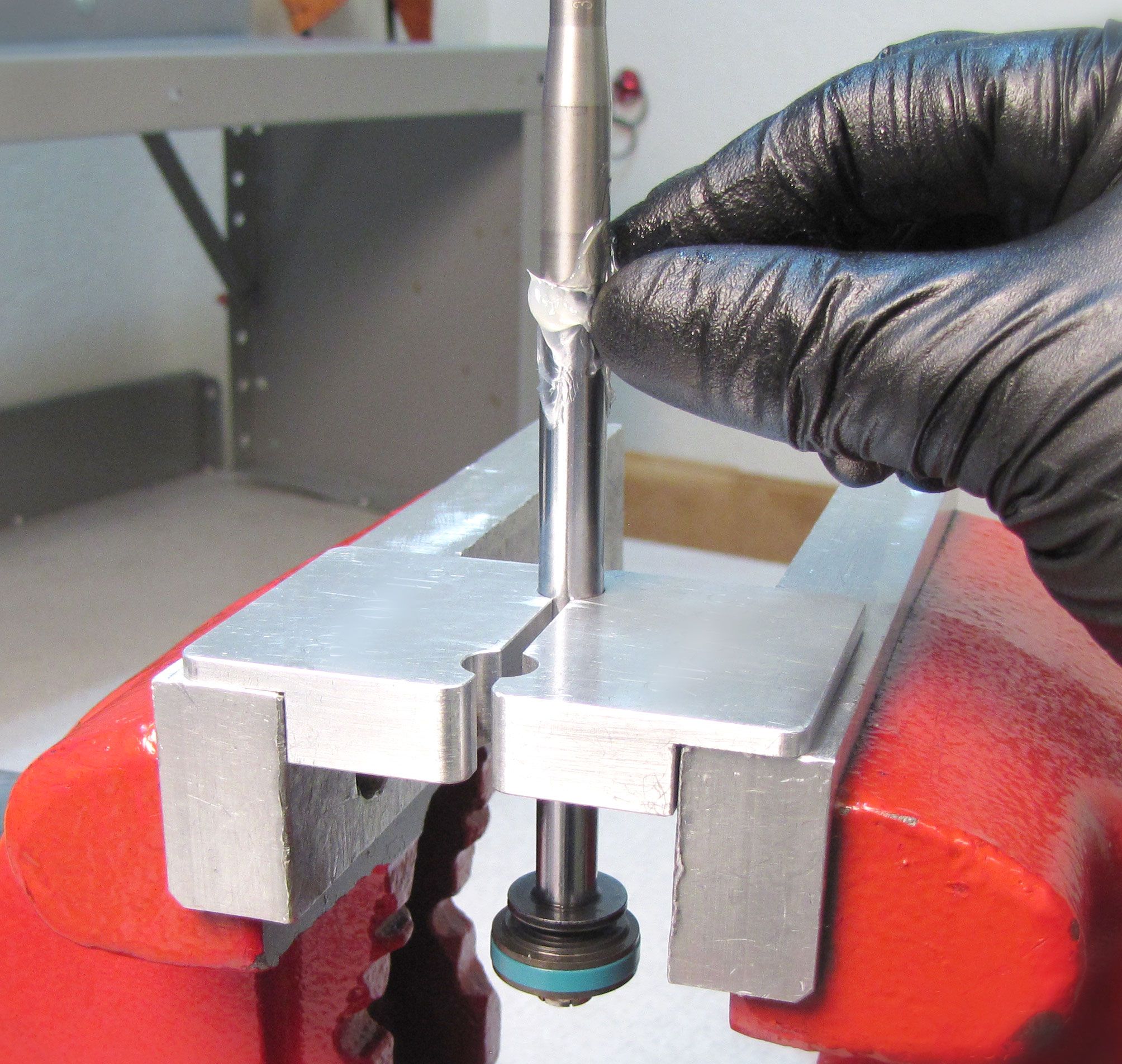
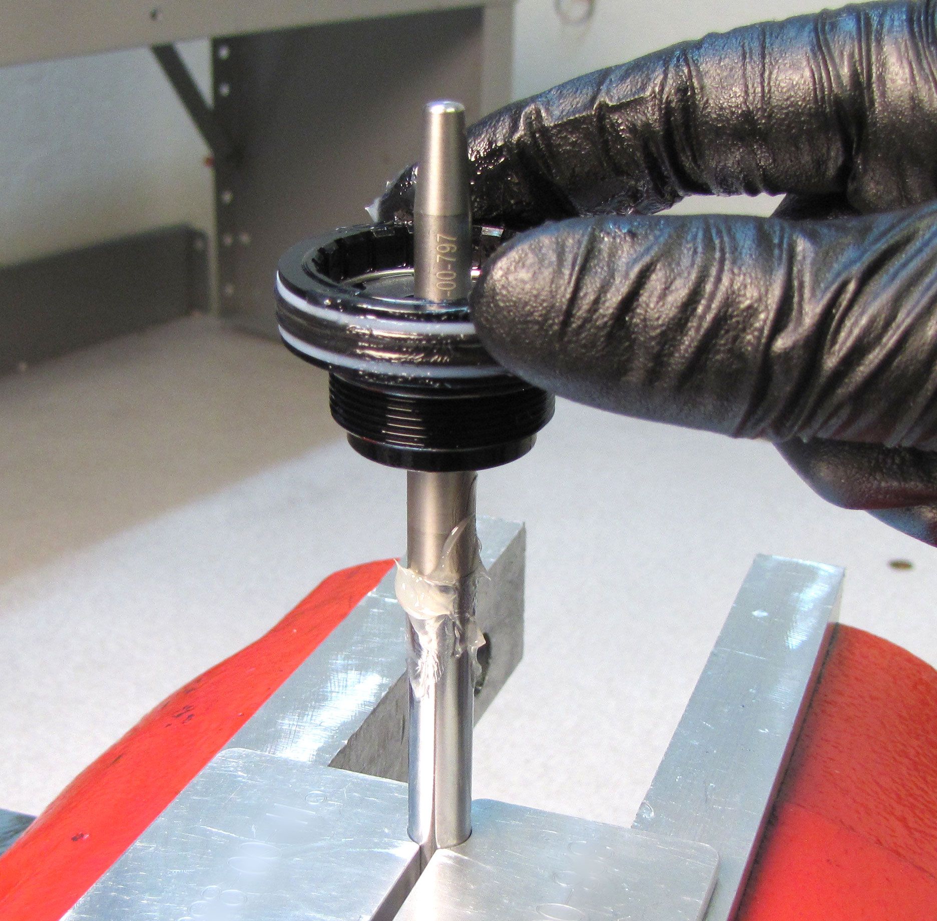
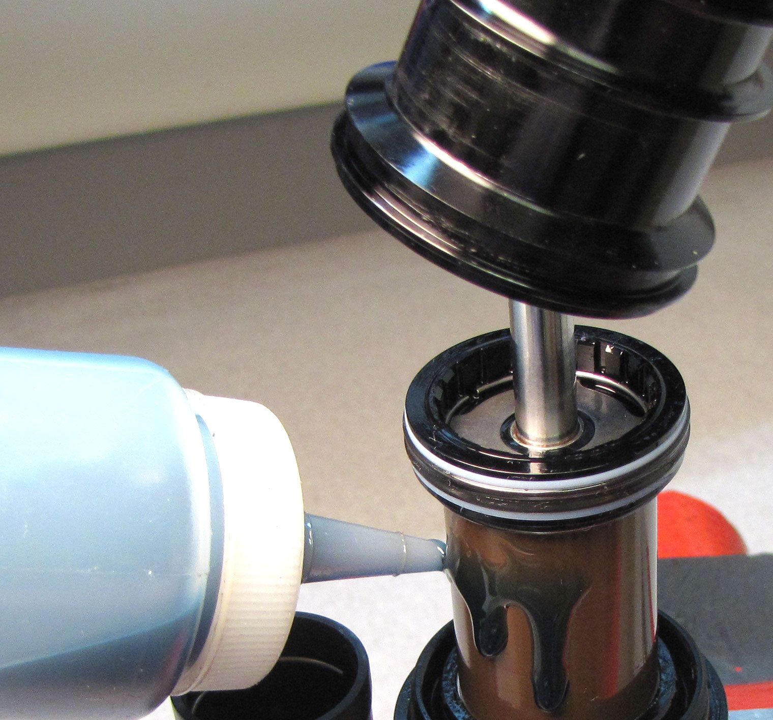
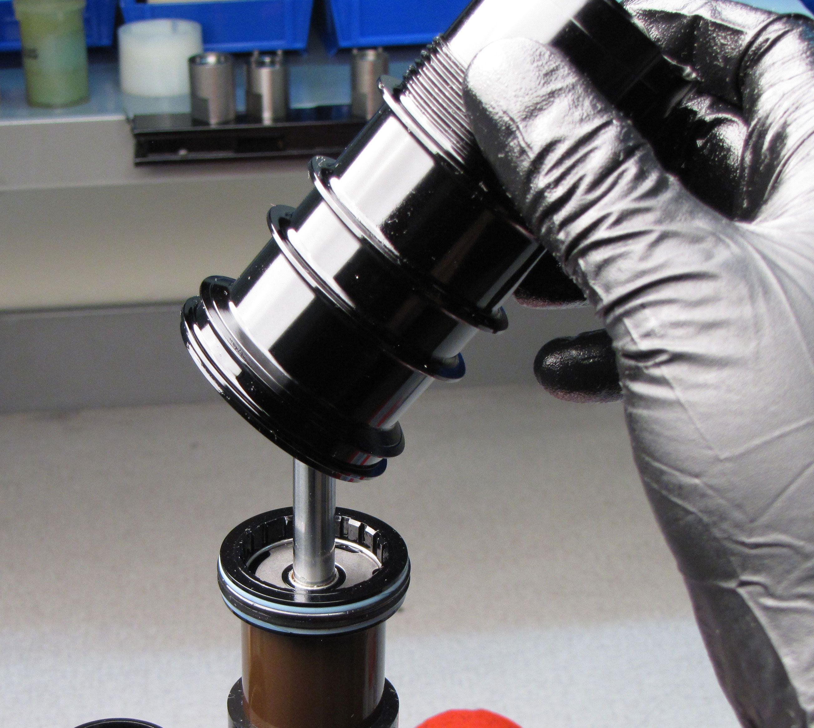
Install the X2 bullet (PN: 398-00-797) onto the shaft and apply a thin film of Slick Honey to the taper of the bullet. Install the rebuilt bearing assembly onto the shaft as shown. Remove the bullet tool.

Step 20
Install the rebuilt neg air sealhead assembly onto the outer body with the wiper lip oriented toward the adjuster eyelet. Be careful not to fold the wiper lips in or displace the glide band within the bearing assembly during installation. Reinstall the negative volume spacer if present.
| Eye-to-eye | Neg Volume Spacer |
| All Imperial Sizes | None |
| Sizes 210/230/250 | 233-00-391 (shown) |
| Sizes 185/205/225 | 30x3mm o-ring |

Step 21
Install the inner body into the outer body.

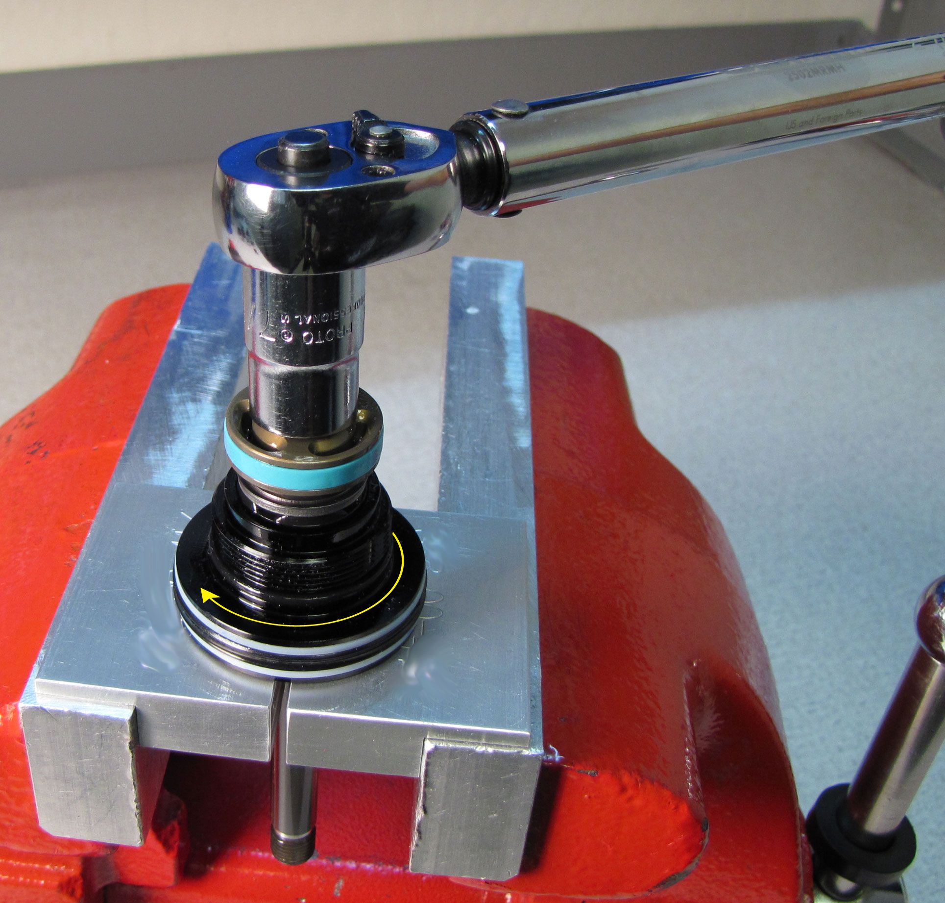
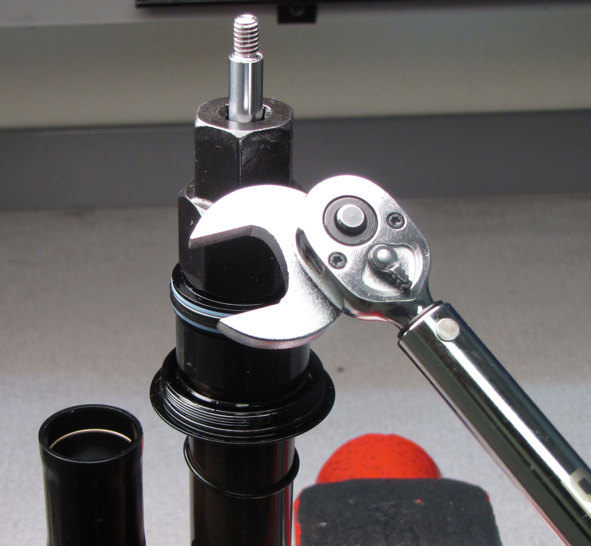
Step 22
Thread the bearing assembly to the outer body, then use the 20 tooth BB tool to tighten (clockwise) the bearing assembly to 145 in-lb (16.3 Nm).


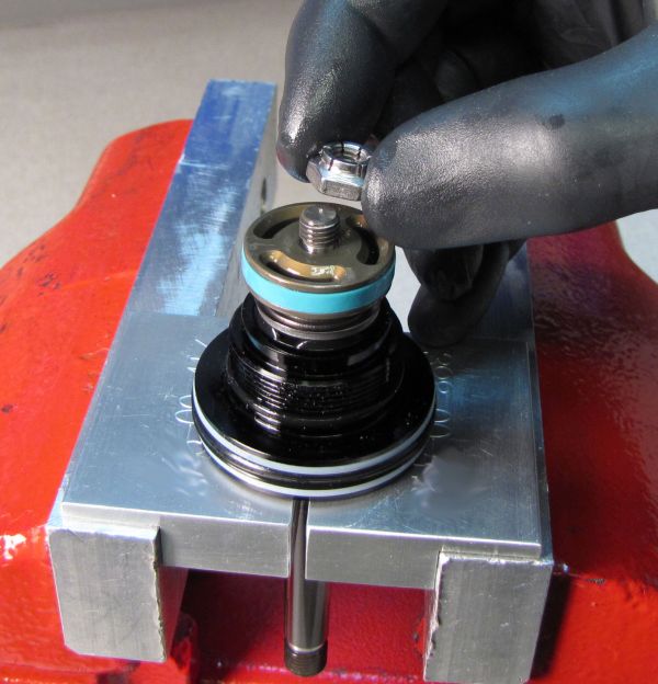
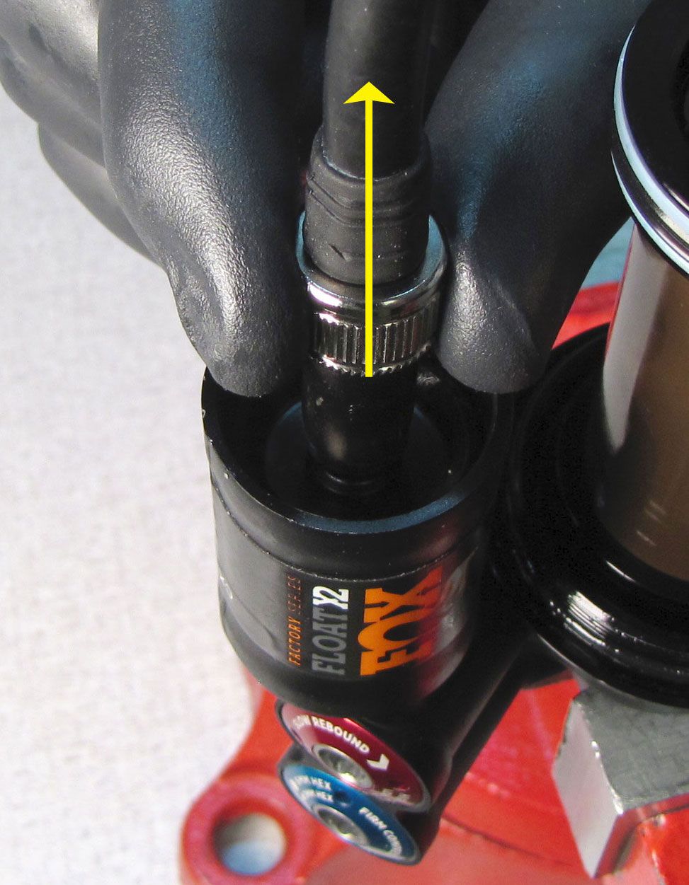
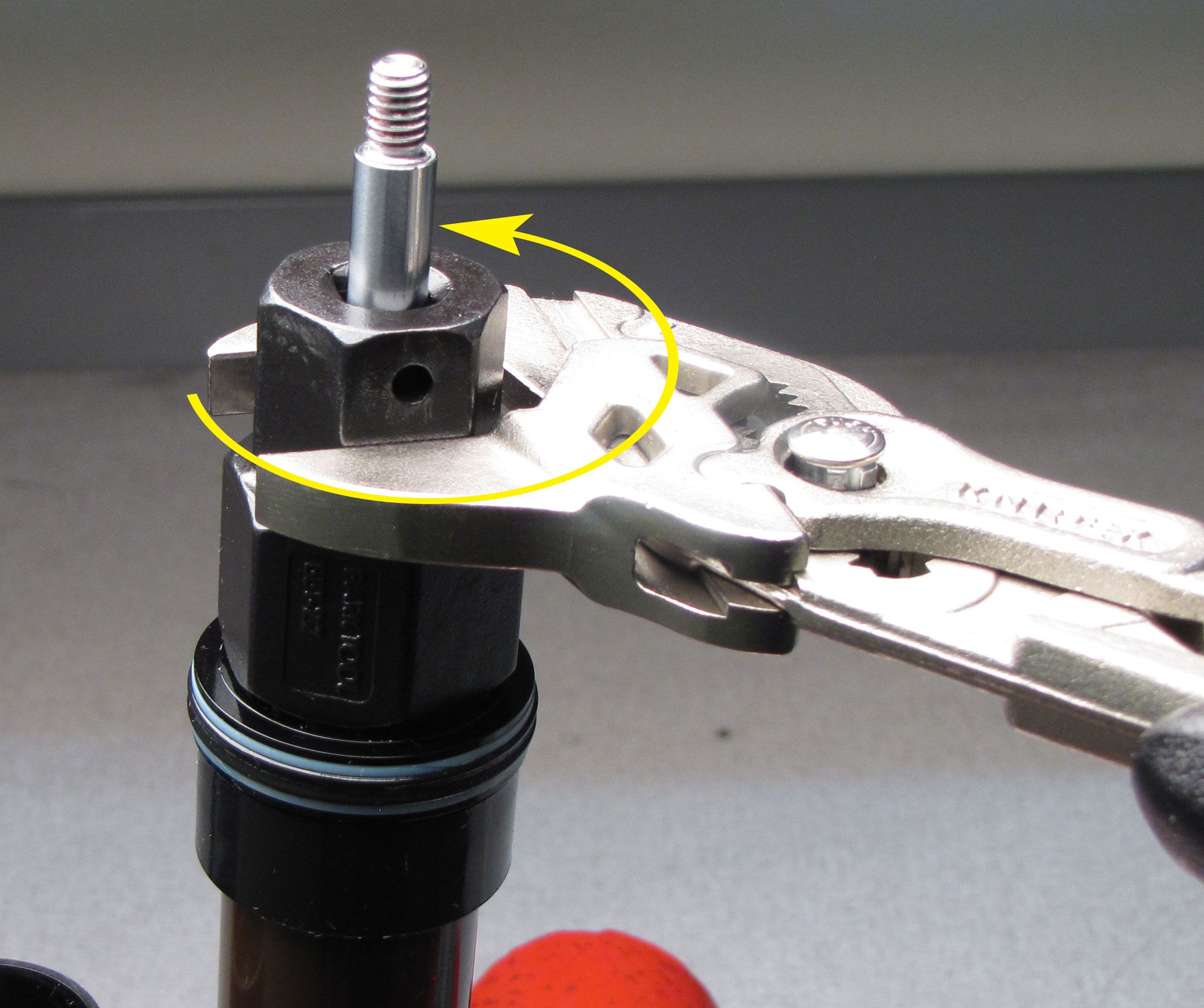
Step 23
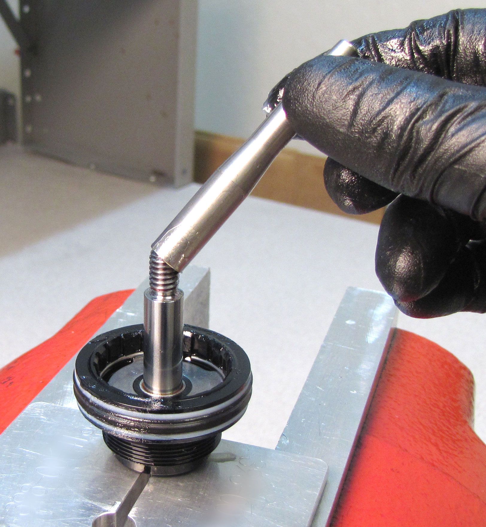
Temporarily install a the shaft eyelet onto the shaft, tightening (clockwise) until just snug. This will prevent the shaft from being sucked into the damper during the vacuum cycle later.


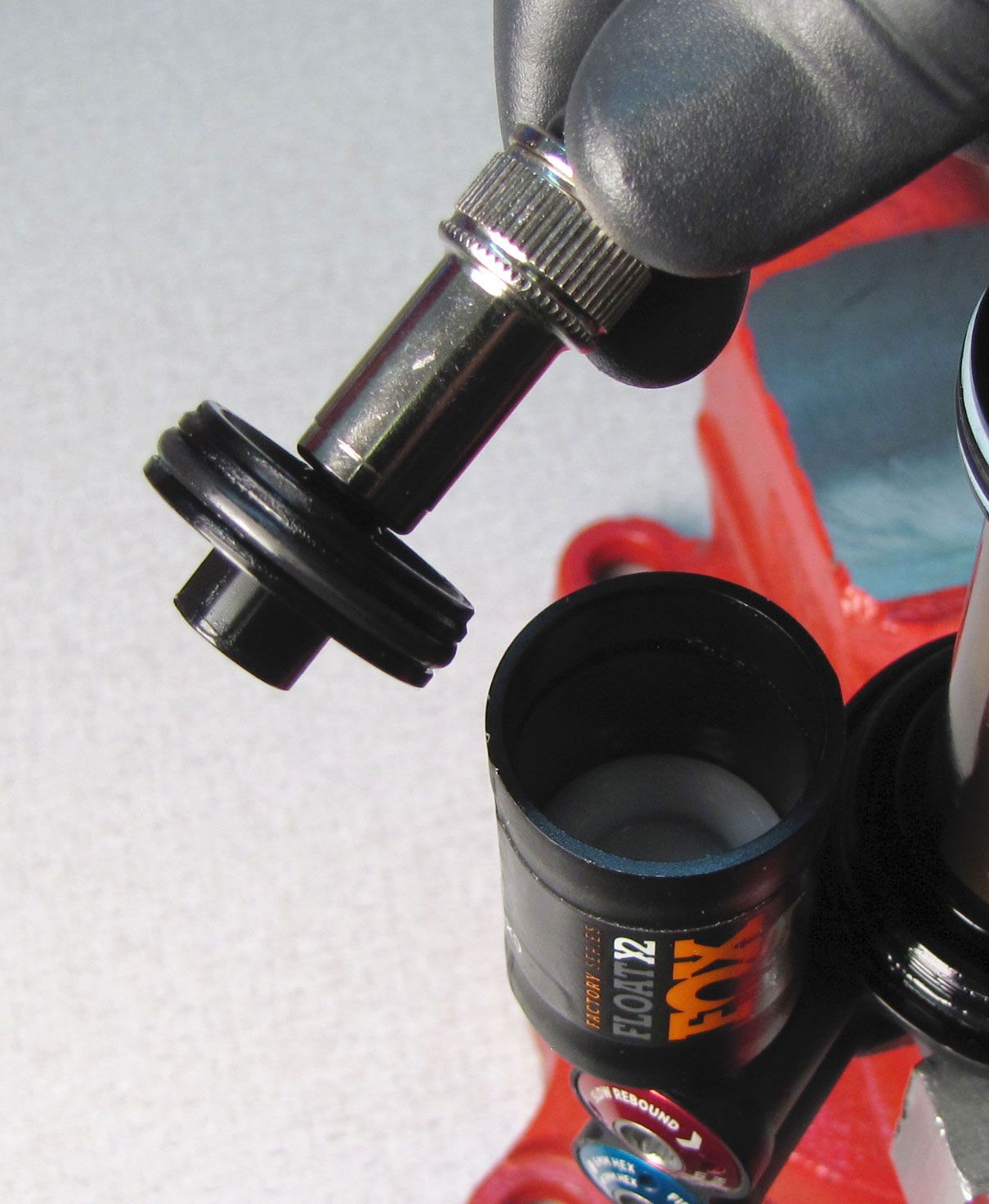
Step 24
Remove the wire retaining ring from inside the reservoir. Thread your shock pump onto the Schrader valve of the reservoir end cap, then use your pump to pull the cap out of the reservoir. Replace the o-ring on the reservior end cap with a new greased one from the kit, then set aside. Fill the ring groove on the inner wall of the reservoir with slick honey to help prevent damage to the IFP during removal.


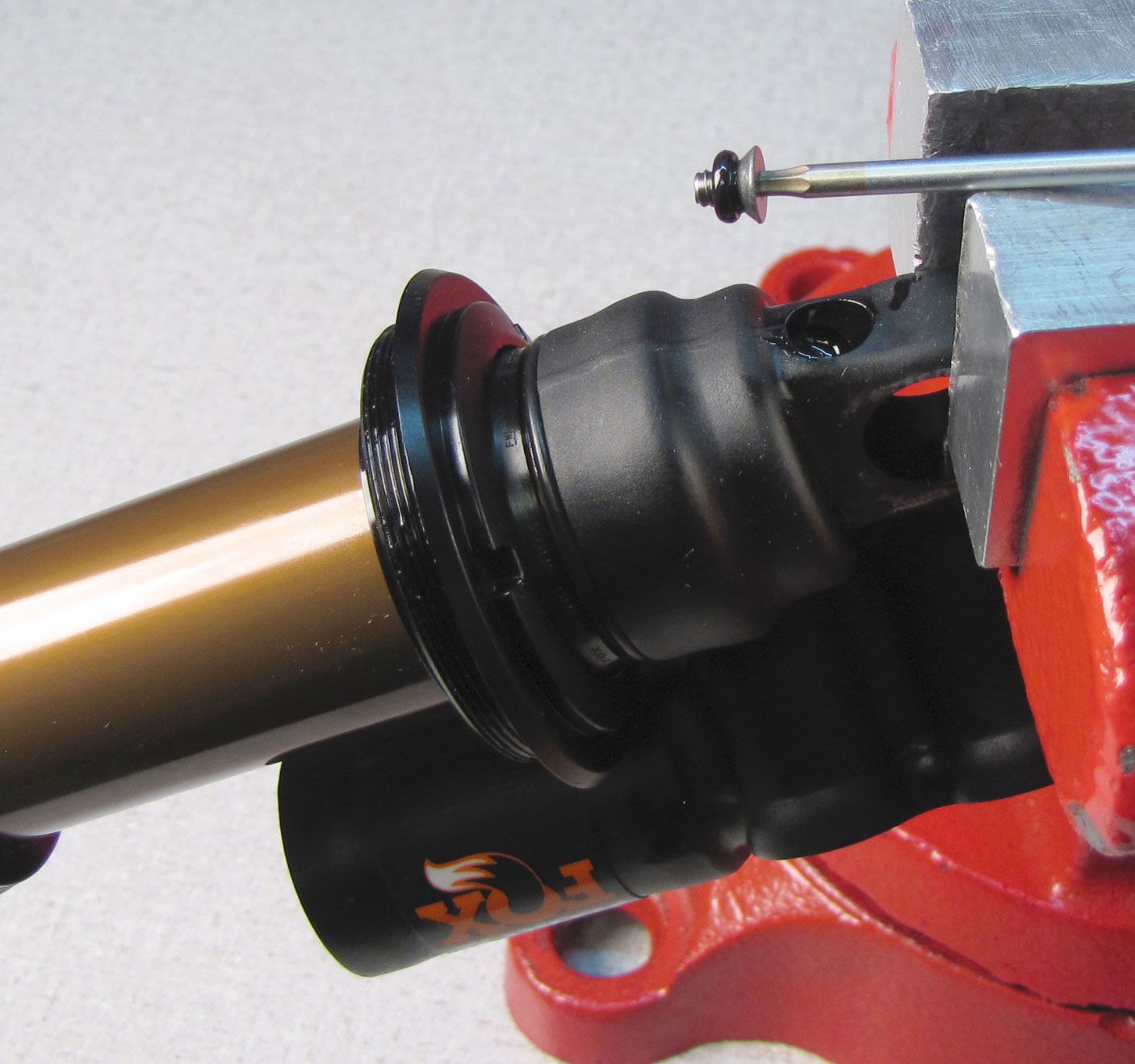
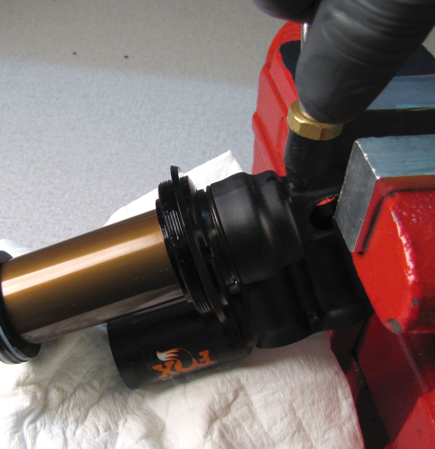
Step 25
Unthread and remove the set screw and o-ring from the back of the adjuster eyelet with a 2mm hex wrench. Cover the reservoir with a lint-free paper towel and inject compressed air into the port on the back of the adjuster eyelet to blow out the IFP.
Step 26
Replace the o-ring on the IFP with a new greased one from the kit. Reinstall the IFP into the reservoir with the counterbore facing the open end of the reservoir. Replace the wire retaining ring to retain the IFP during the oil fill steps later.

While FOX recommends using the Andreani vacuum bleeder, the FLOAT X2 shock can be hand bled if needed.
For hand bleed info please skip to Optional Hand Bleed Instructions » after completing step 27.
NOTE: Images in step 28 show a 2017-2018 FLOAT X2 with DHX2 eyelet temporarily installed for vacuum bleeding. The procedure is identical for the 2019 FLOAT X2 except the FLOAT X2 shaft eyelet must be used in place of the temporary DHX2 eyelet used in 2017-2018 FLOAT X2 shock rebuilds.
Step 27
Thread the Fill Machine Adapter (803-00-463) from the Andreani machine into the port on the back of the adjuster eyelet. Vacuum the shock, then fill with FOX R3 5wt oil. Set the IFP to the appropriate depth using your IFP depth setting tool (803-00-566). Reinstall the set screw with a new greased o-ring from the kit and tighten to 14 in-lb (1.6 Nm).
| Shock Size | IFP Height (+/-0.050in) |
| All | 1.343in +/- 0.020in |


Step 28
Remove the wire ring from within the reservoir, then grease and reinstall the reservoir end cap followed by the wire retaining ring.

Step 29
Fill the IFP chamber to 125 psi (8.6 bar) with your shock pump, then install the reservoir end cap, tightening to 30 in-lb (3.4 Nm) with your 6mm hex wrench.

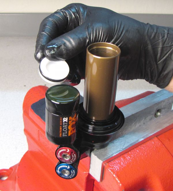
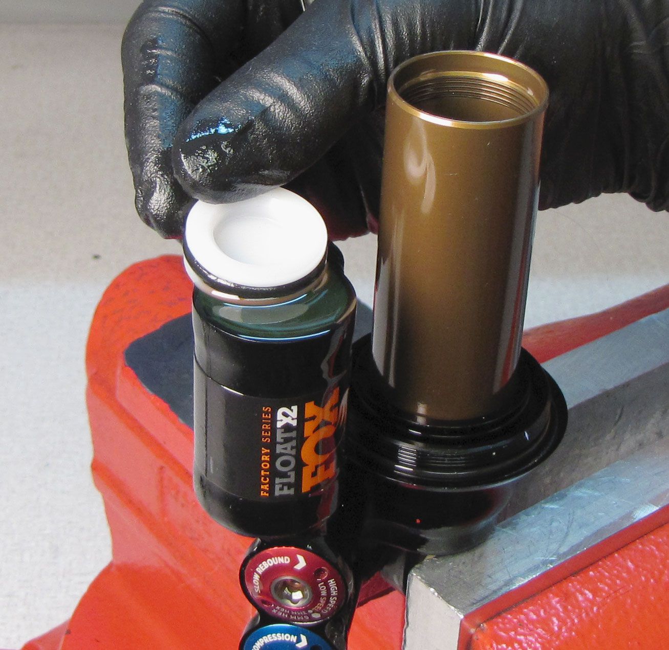
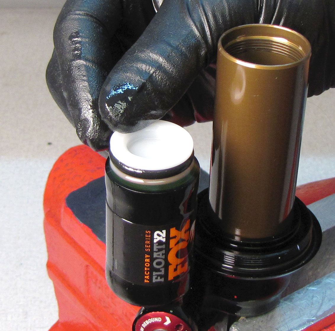
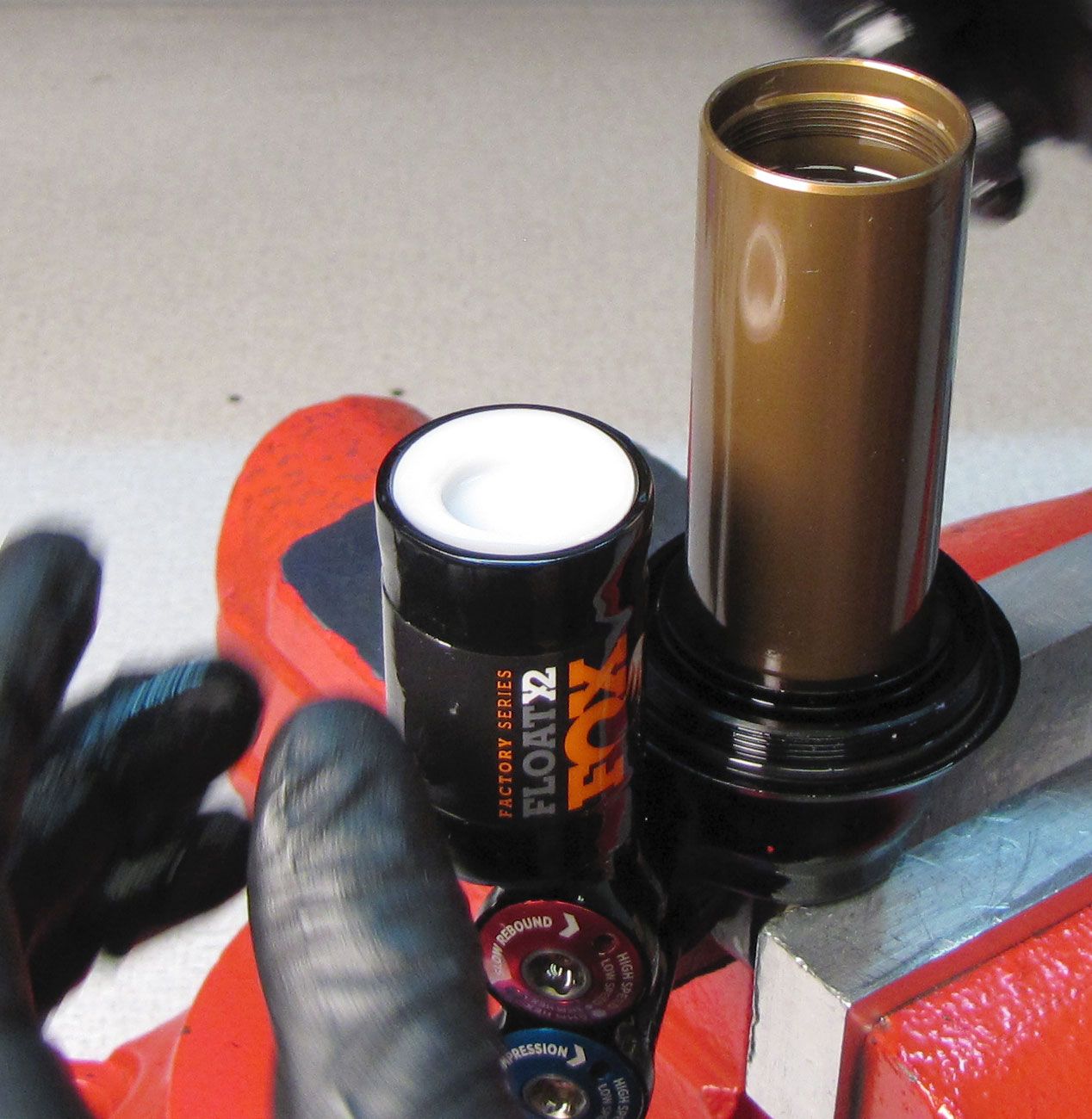
Step 30
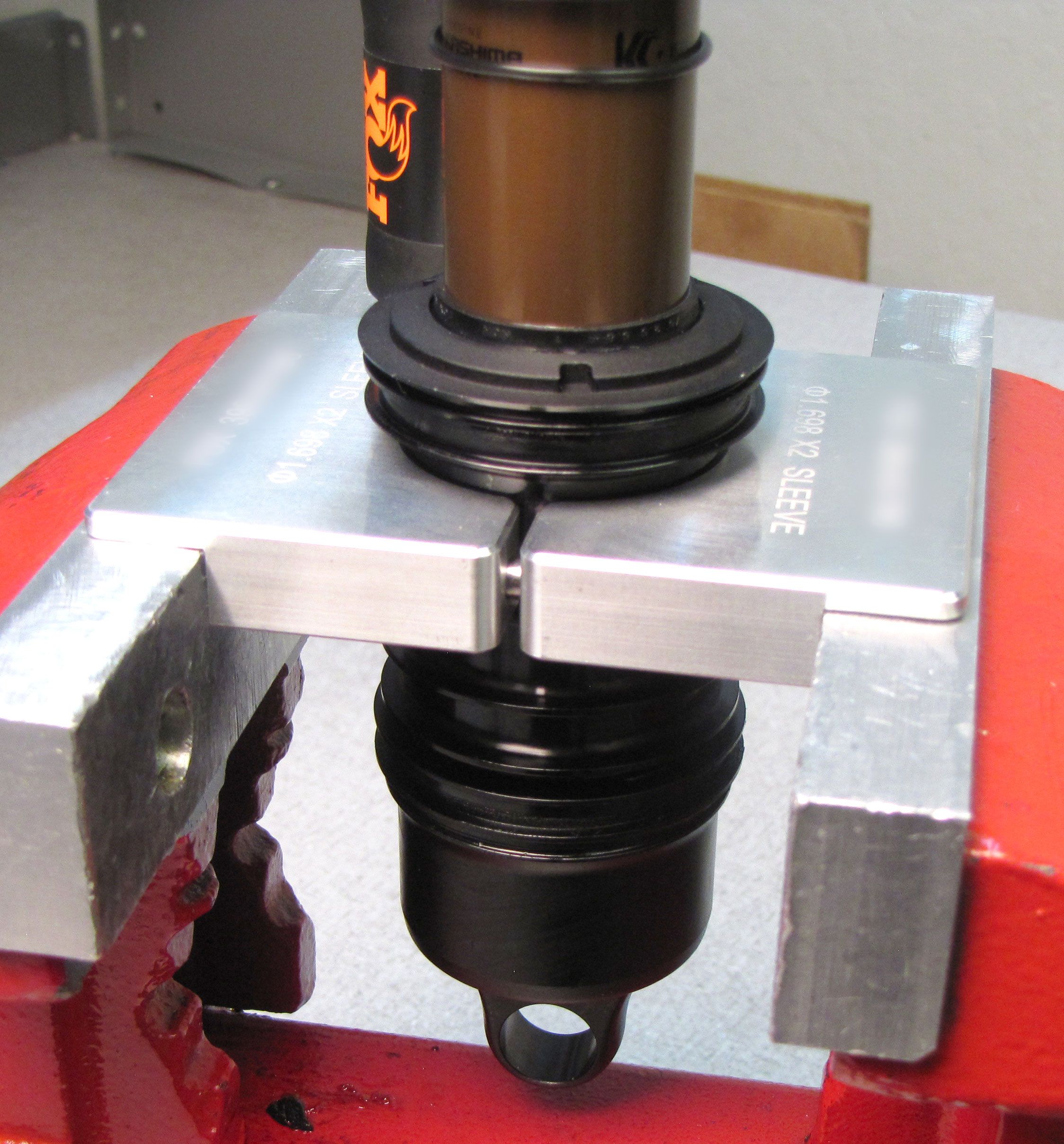
Unthread (counter-clockwise) and remove the shaft eyelet from the shaft. Coat the main air seals on the bearing assembly with Float Fluid. Add 1cc of Float Fluid to the body on the negative side of the bearing assembly then install the inner air sleeve onto the shock with the large end oriented toward the adjuster eyelet.

Step 31
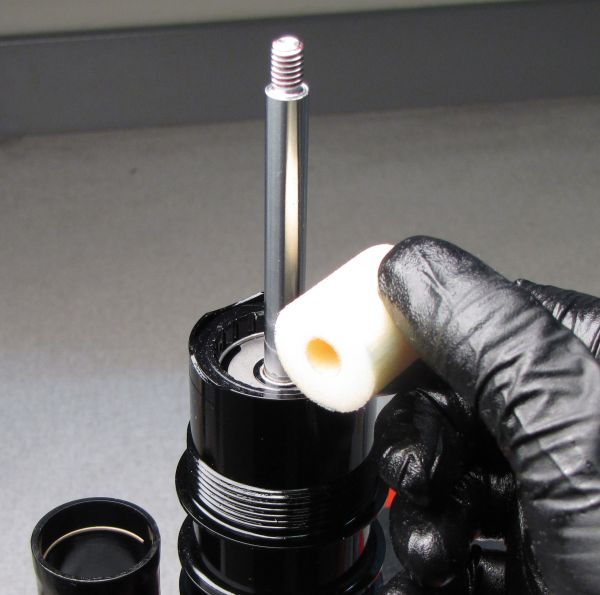
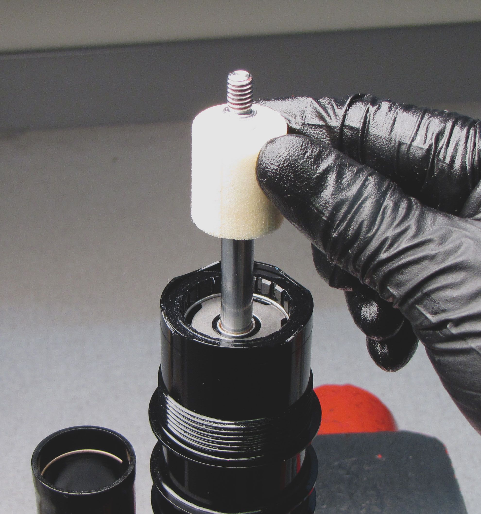
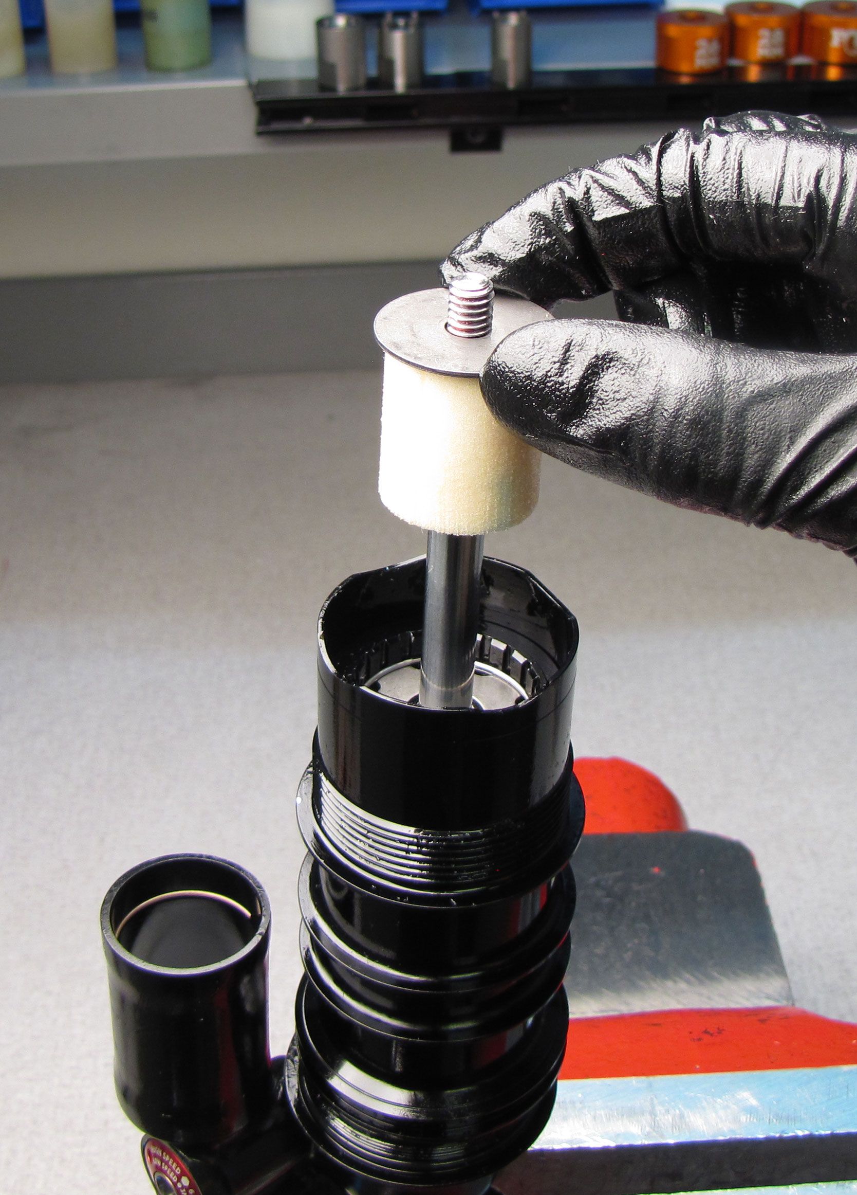
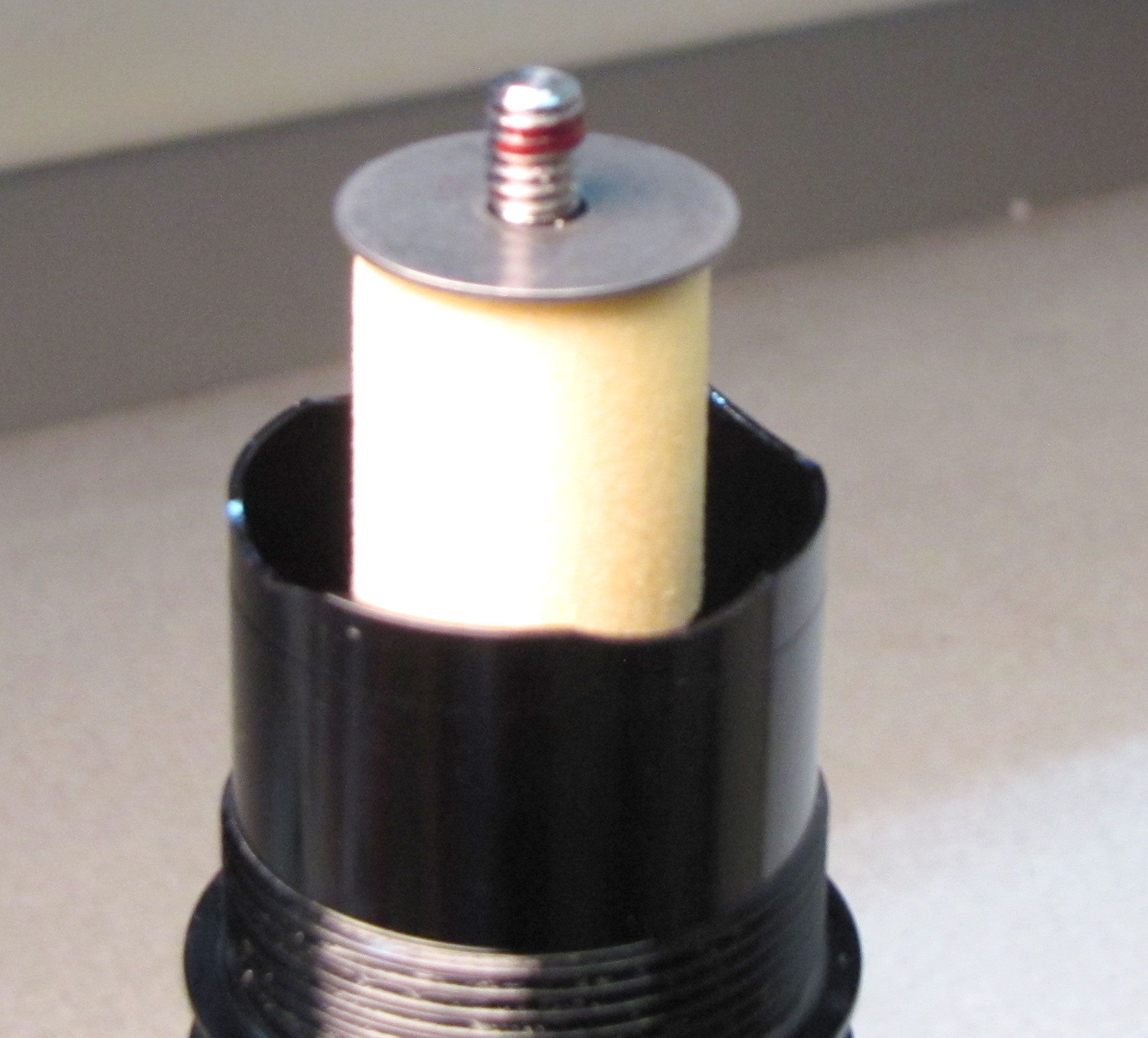
Install a new bottom out bumper from the kit followed by the travel and volume spacer if present. Then reinstall the bottom out plate. Apply one drop of red Loctite to the shaft threads then reinstall the shaft eyelet.


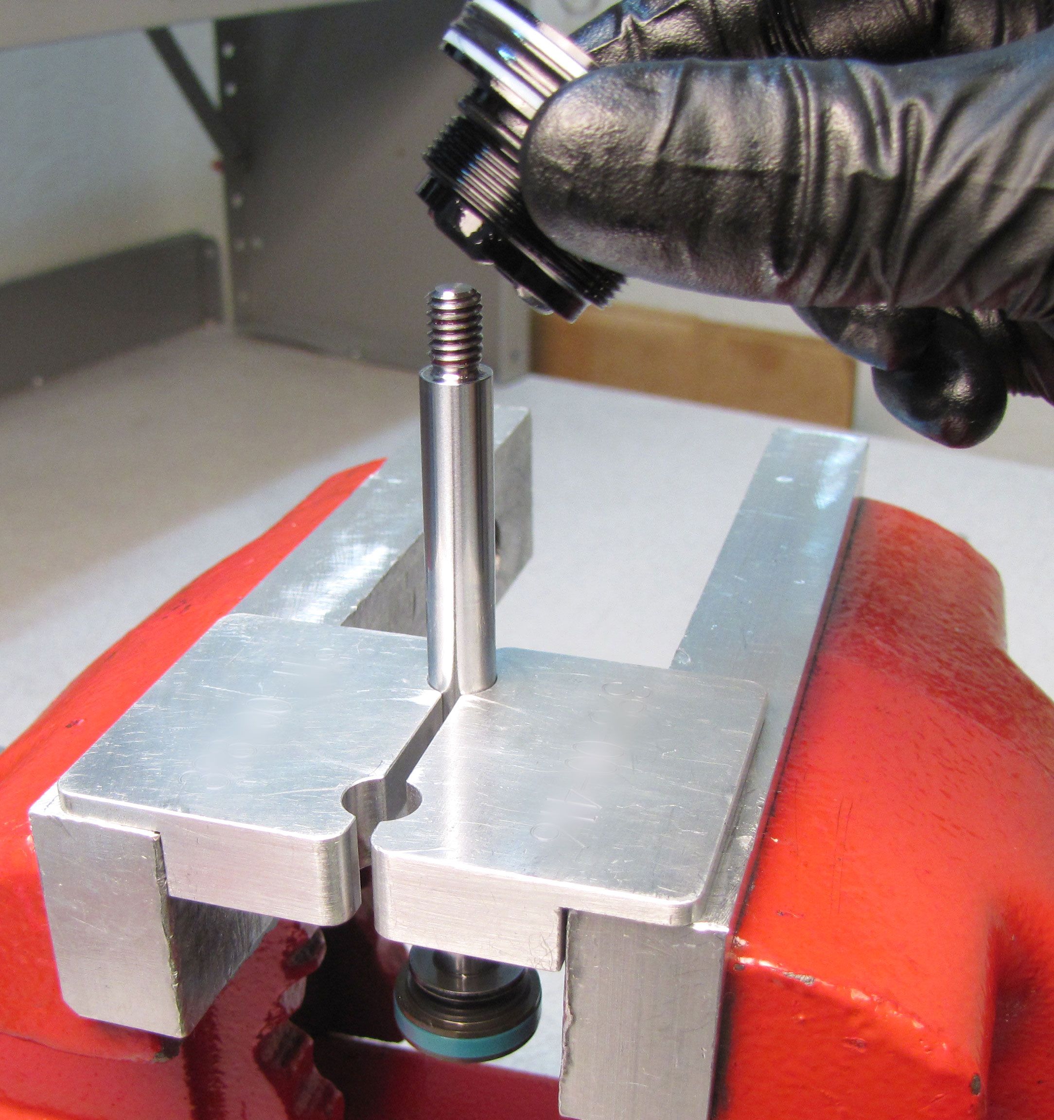
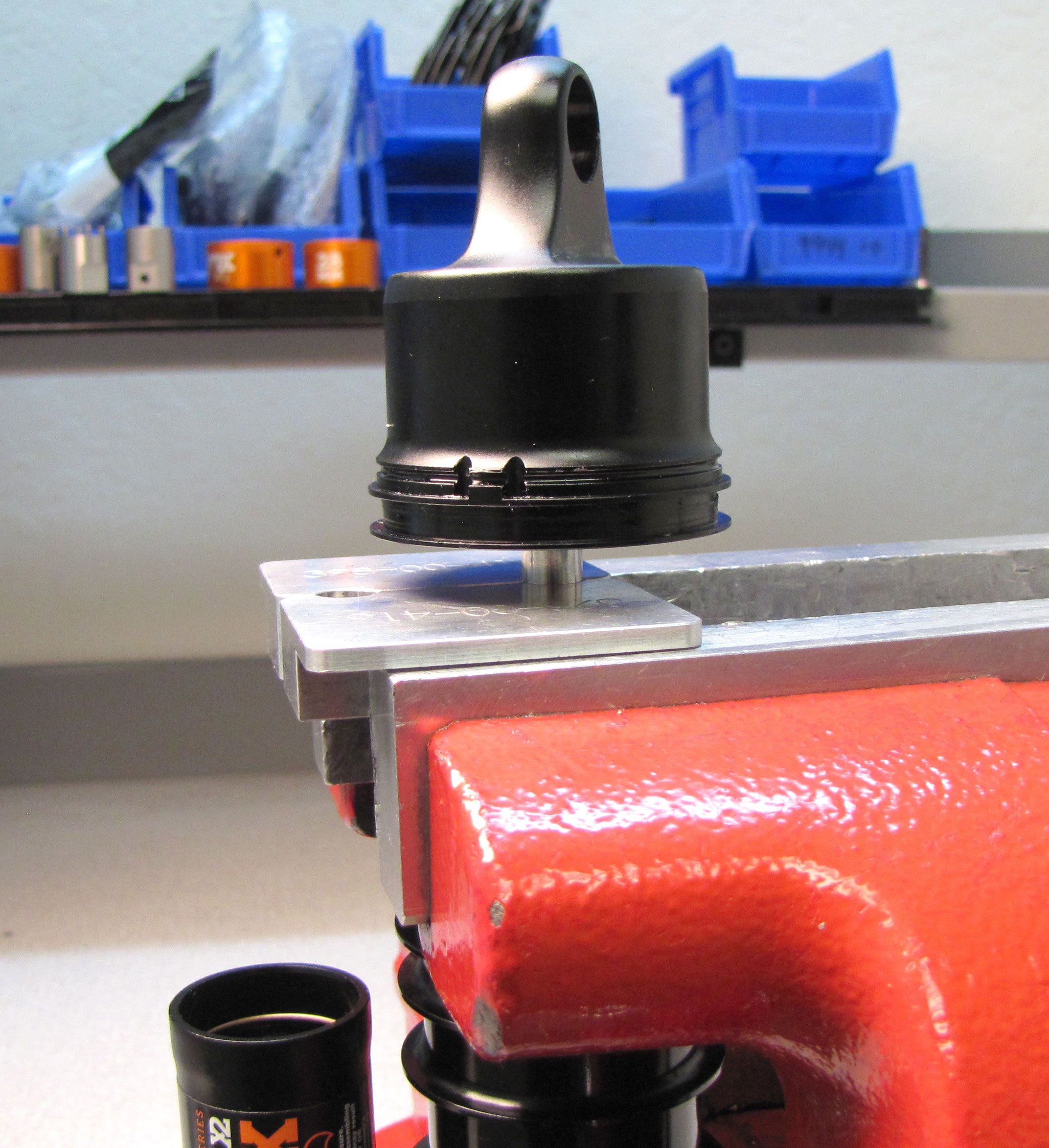
Step 32
Clean the shaft with isopropyl alcohol and a lint-free paper towel, then clamp the shaft in the X2 specific 9mm shaft clamps. Make sure to leave enough space between the eyelet and the shaft clamps to allow the eyelet to thread fully onto the shaft without interference. Do not let any portion of the shock touch the vice below the clamps.

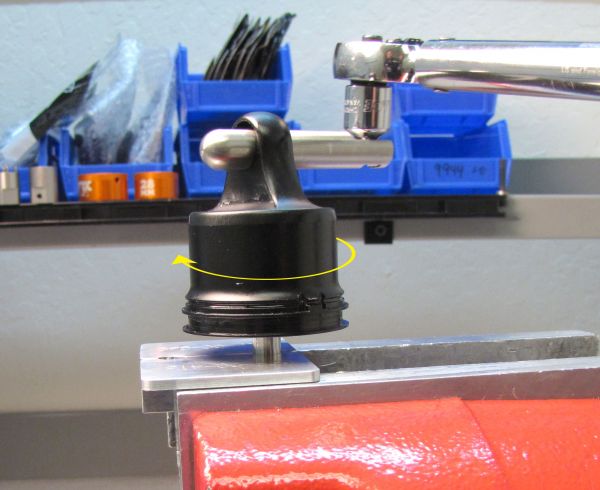
Step 33
Tighten the eyelet clockwise to 90 in-lb (10.2 Nm) with your eyelet torque tool (398-00-280).

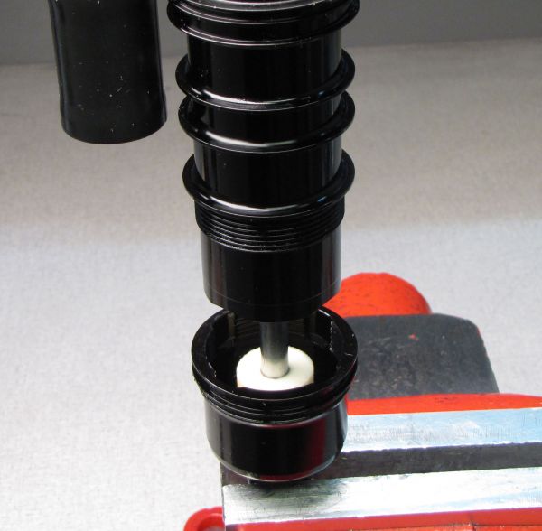
Step 34
Invert the shock and clamp the shaft eyelet in your soft-jawed vise. Apply 2cc of Float Fluid to the main air chamber in the open area shown.
Step 35
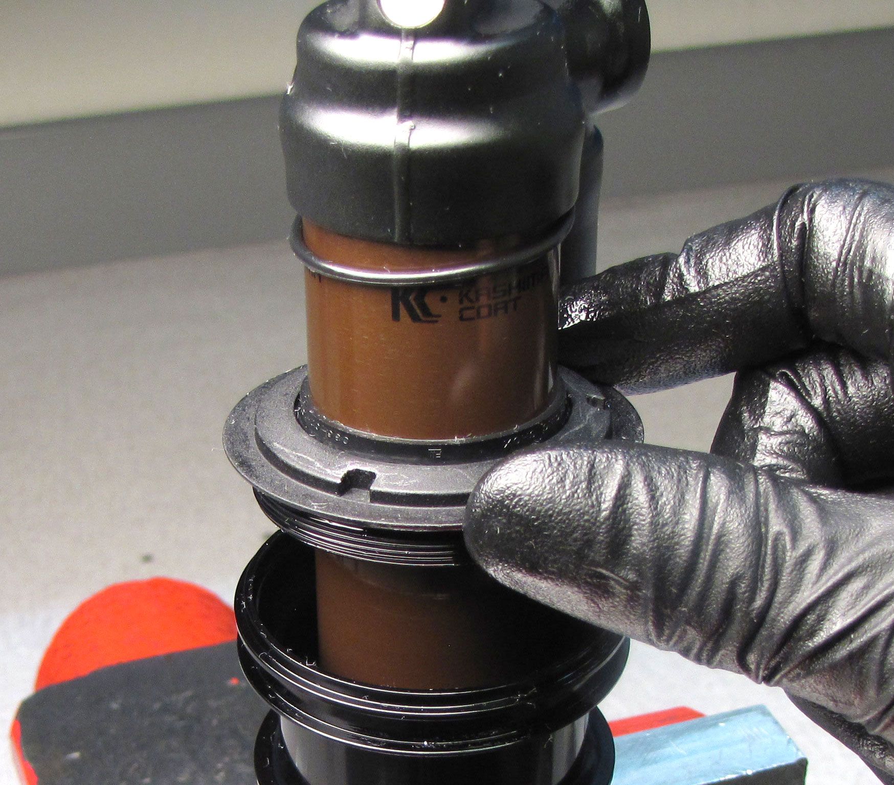
Slide the inner air sleeve toward the non-adjuster eyelet then thread them together until snug. Slide the neg air sealhead to the inner air sleeve and thread them together until snug.

Step 36
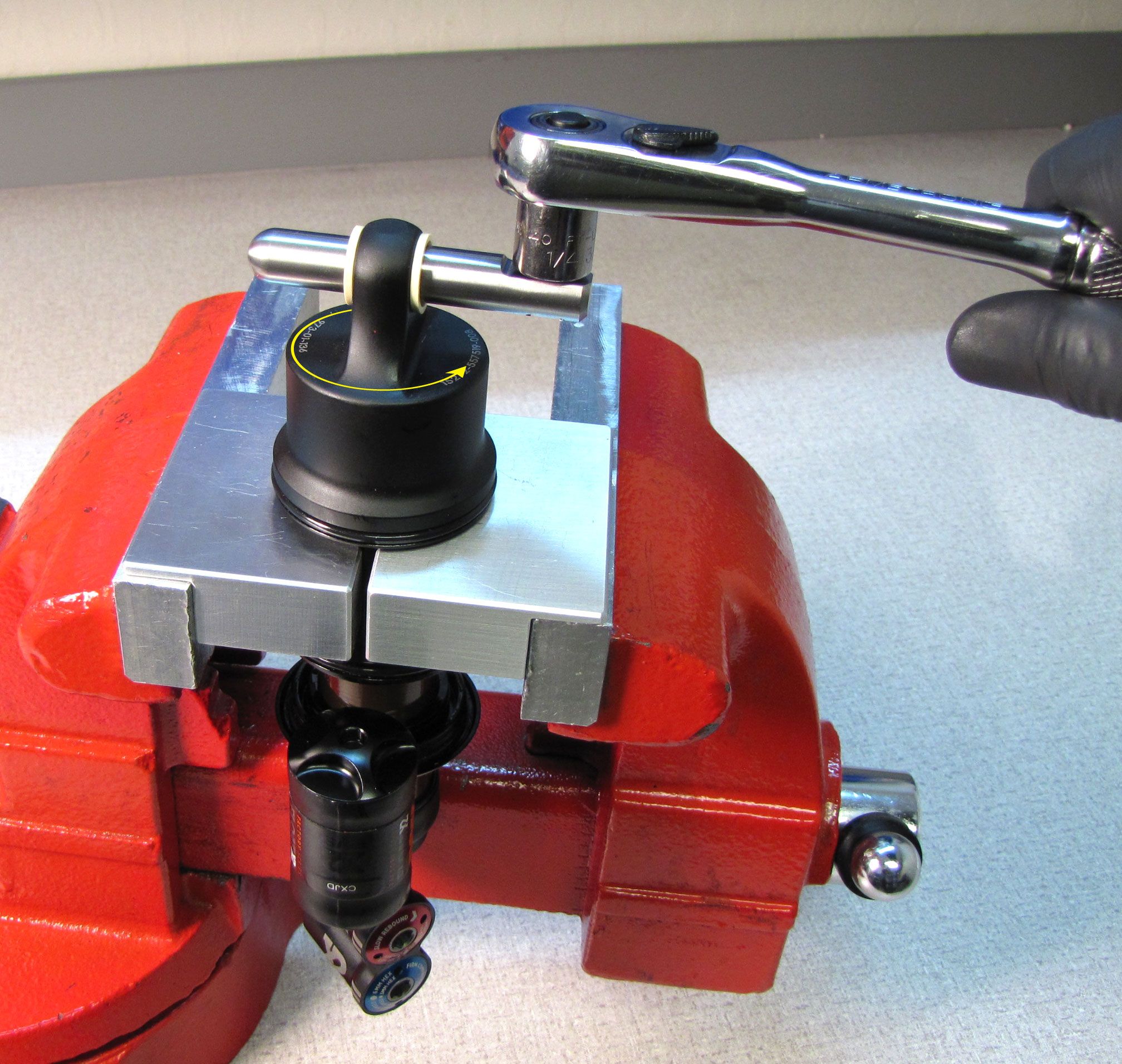
Engage all three prongs of the Negative Air Sealhead tool with the notches in the neg air sealhead. Do not scratch the body against the tool or vice. Carefully tighten clockwise to 180 in-lb (20.3 Nm) torque.

Step 37
Install new greased o-rings and back-up rings from the kit onto the shaft eyelet and inner air sleeve. Make sure the o-rings and back-up rings are installed in the indicated positions.


Step 38
Reinstall volume spacers if present. Do not exceed the maximum number of volume spacers allowed for your shock travel as listed in the table below.
| Shock Size | Maximum Spacer Quantity |
| 7.875 x 2.000 | 2 |
| 7.875 x 2.250 | 2 |
| 8.5 x 2.25 (Enduro) | 4 |
| 8.500 x 2.500 | 3 |
| 8.750 x 2.750 | 3 |
| 9.500 x 3.000 | 4 |
| 10.500 x 3.500 | 5 |
| 185, 50 | 2 |
| 185, 55 | 2 |
| 205, 60 | 3 |
| 205, 62.5 | 3 |
| 205, 65 | 3 |
| 210, 50 | 4 |
| 210, 55 | 4 |
| 225, 70 | 4 |
| 225, 75 | 4 |
| 230, 57.5 | 5 |
| 230, 60 | 5 |
| 230, 65 | 5 |
| 250, 70 | 6 |
| 250, 75 | 6 |

Step 39
Install the outer air sleeve with the air valve side first. Rotate the outer air sleeve until the tab on the eyelet aligns with the notch in the outer sleeve. Slide the outer air sleeve all the way to the negative air sealhead to engage the air seals. Reinstall the wire retaining ring making sure that it is fully seated in its groove.


Step 40
Attach your shock pump then add air while you slowly cycle your shock through 25% of its travel 10 times as you reach your desired pressure. Reinstall the black air cap.
You can find additional information regarding setting air pressure by going to: Using the EVOL Air Sleeve »
Dyno test all functions of the shock to verify proper performance, then clean the exterior of the shock.
If you have performed a vacuum bleed with the Andreani machine, you do not need to continue with the hand bleed steps below. The hand bleeding instructions below show some images of a pre-2019 FLOAT X2 shock. The bleeding instructions are identical for the 2019 FLOAT X2. If you intend to perform the hand bleed shown below, you must start with your shock as configured in step 27
Optional Hand Bleed Instructions

Step 1
Reinstall the bleed screw in the back of the eyelet with a 2mm hex and tighten clockwise to 14 in-lb (1.6 Nm). Unthread (counter-clockwise) and remove the shaft eyelet from the shaft. Use a 20 tooth bottom bracket tool such as the Park Tool BBT-22 to unthread (counter-clockwise) the bearing assembly from the body. Remove the bearing assembly and inner body from the outer body by pulling up.

Step 2
Add FOX R3 5wt. oil to the main body. The oil will slowly transfer into the piggy-back reservoir through the eyelet. Stop adding oil once it has reached the level of the retaining ring groove on the inside of the reservoir.
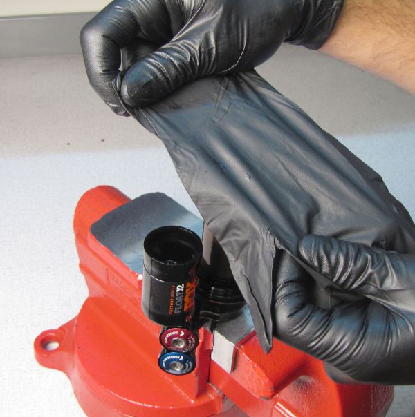
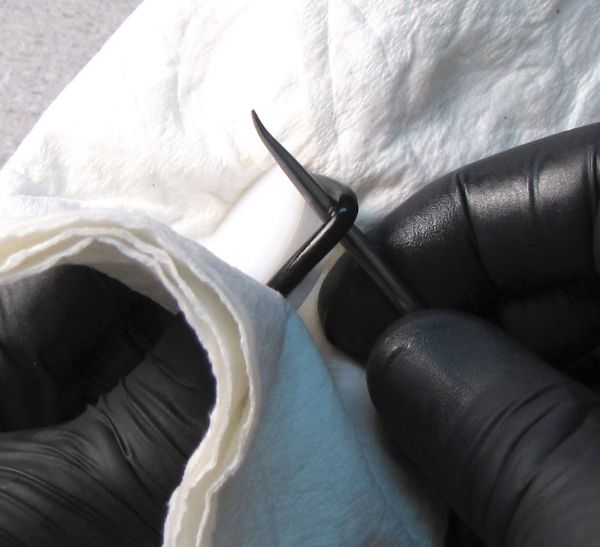
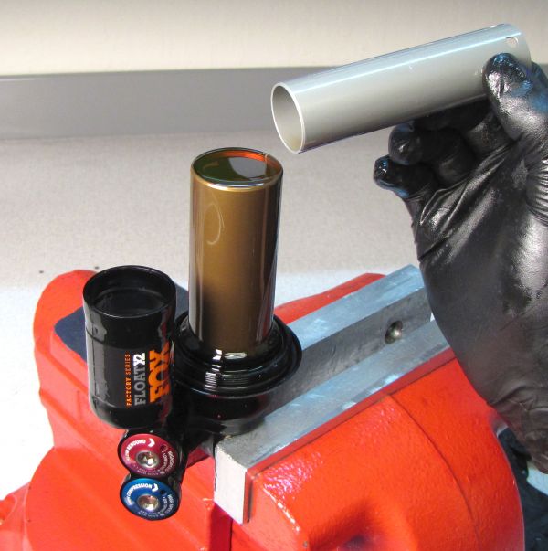
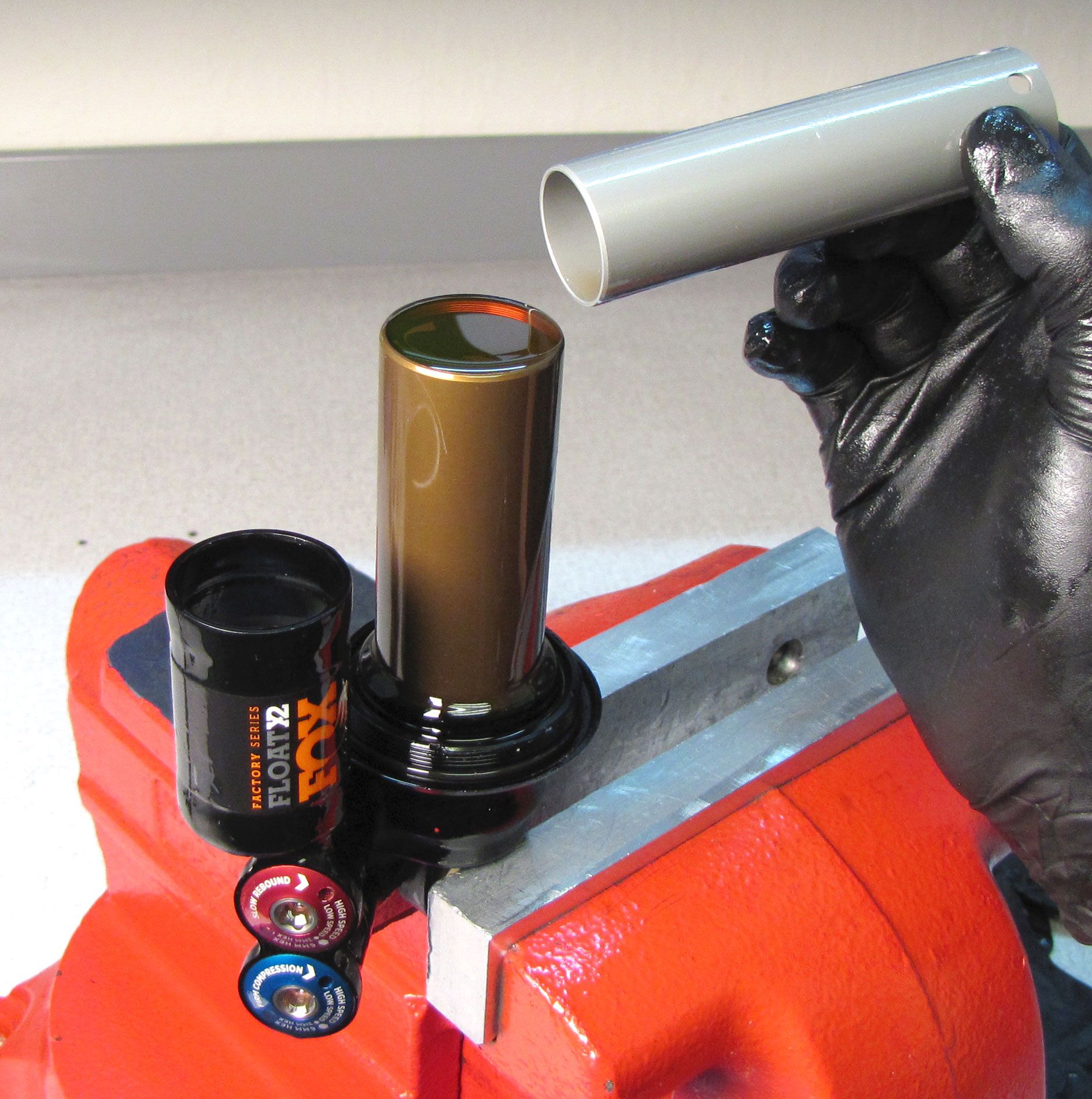
Step 3
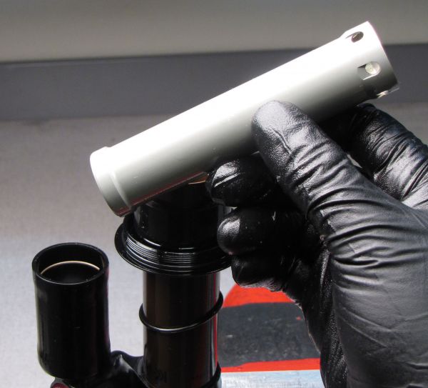
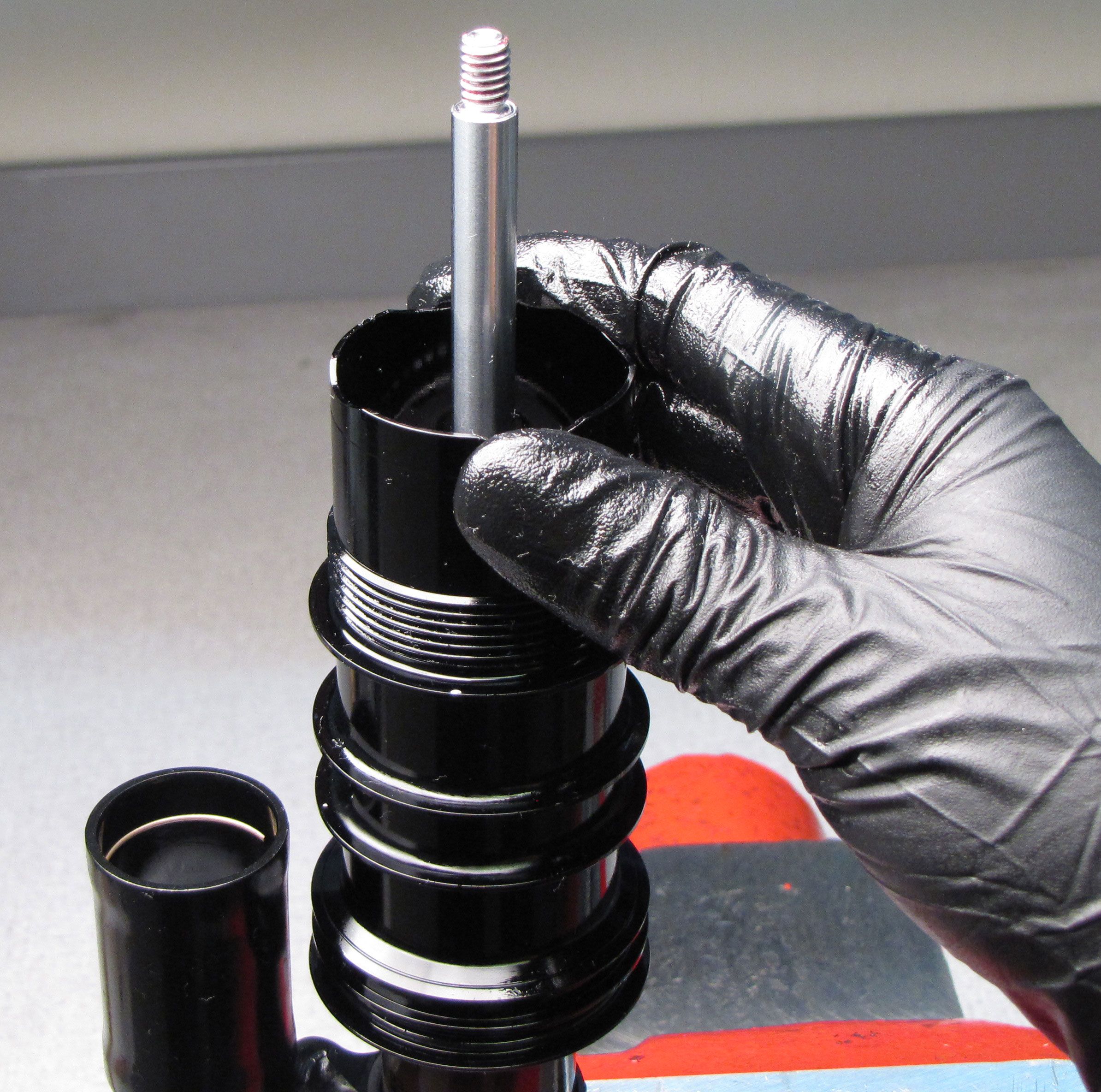
Take a new nitrile glove and stretch it over the open main body making an airtight seal.

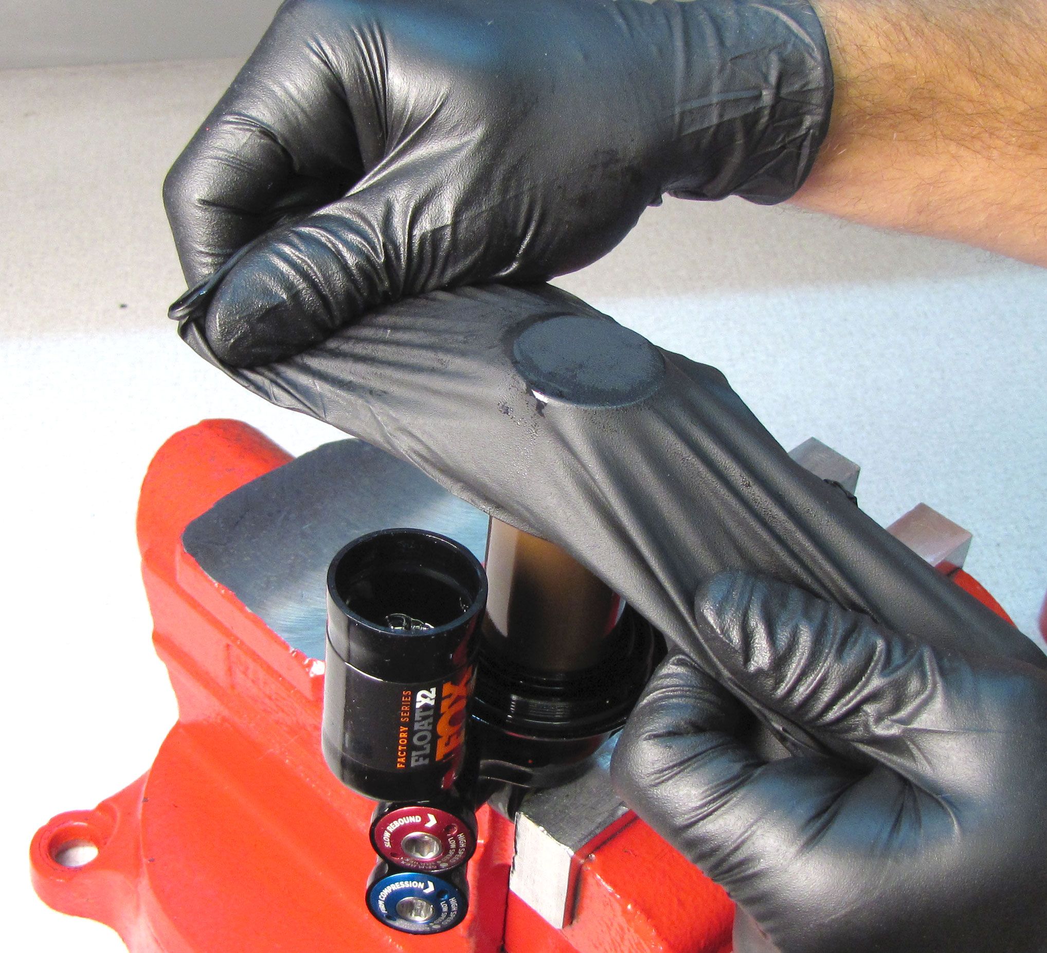
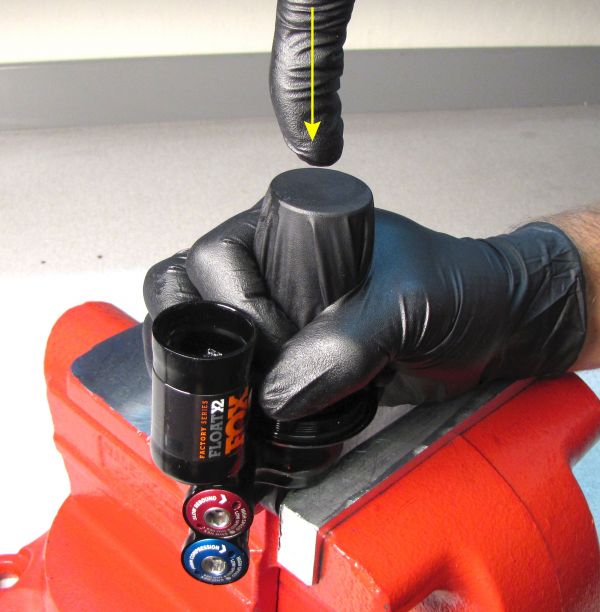
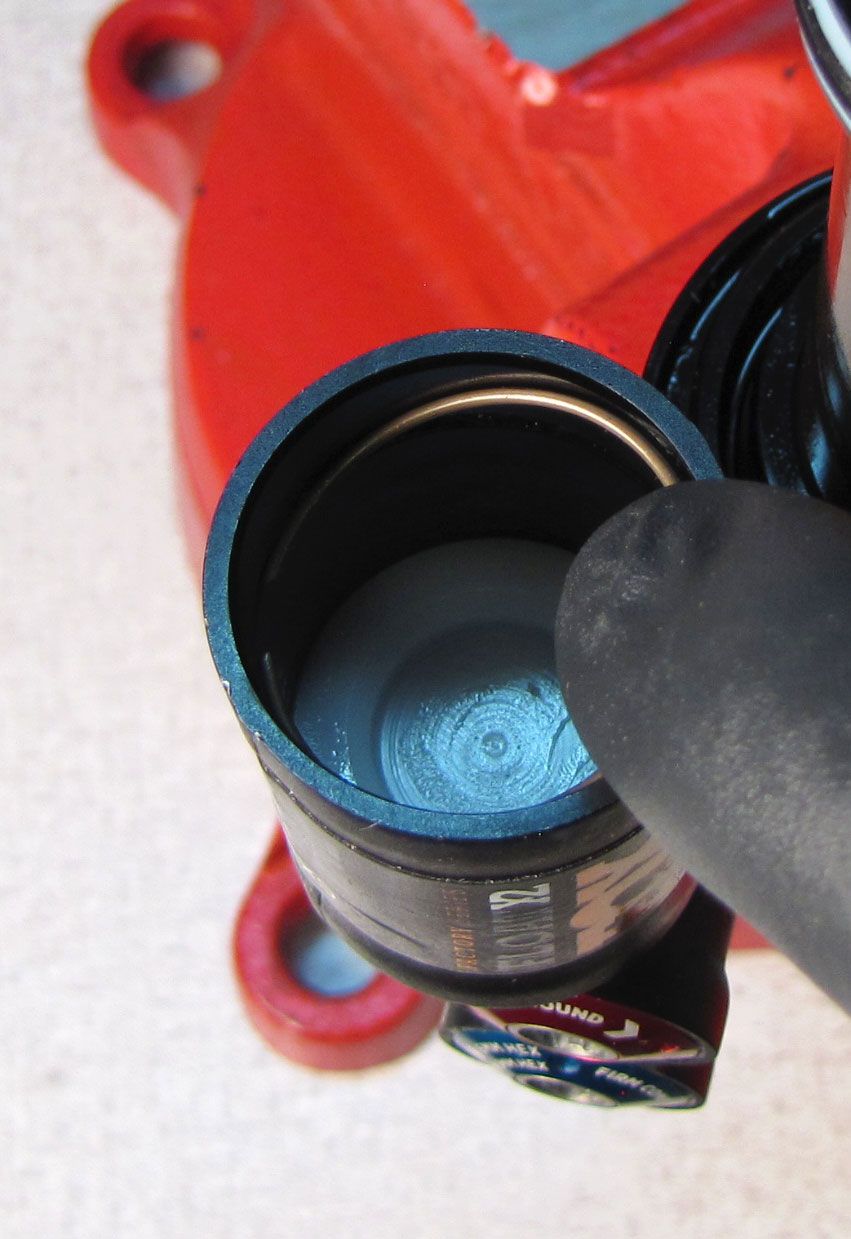
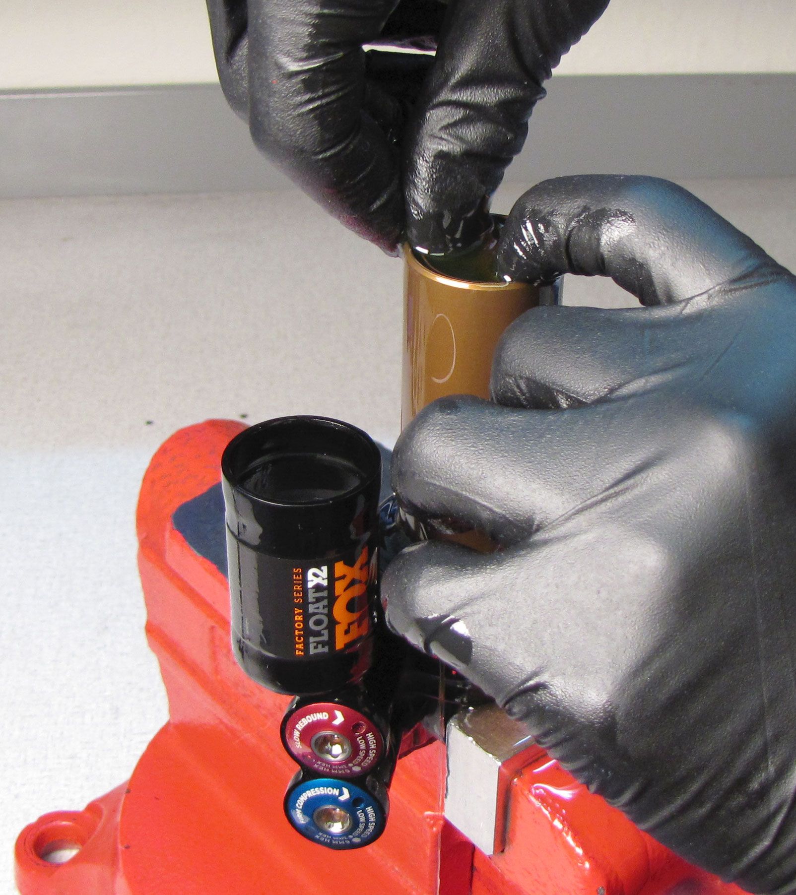
Step 4
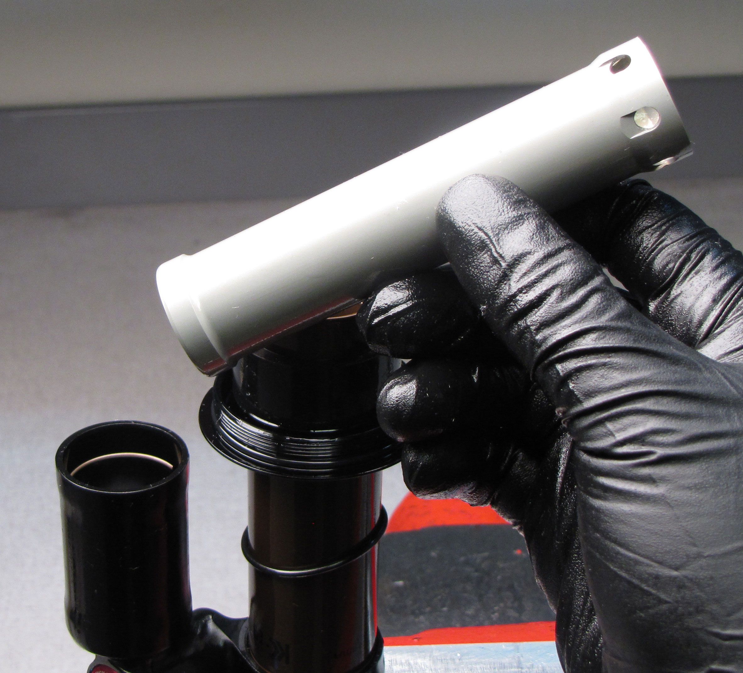
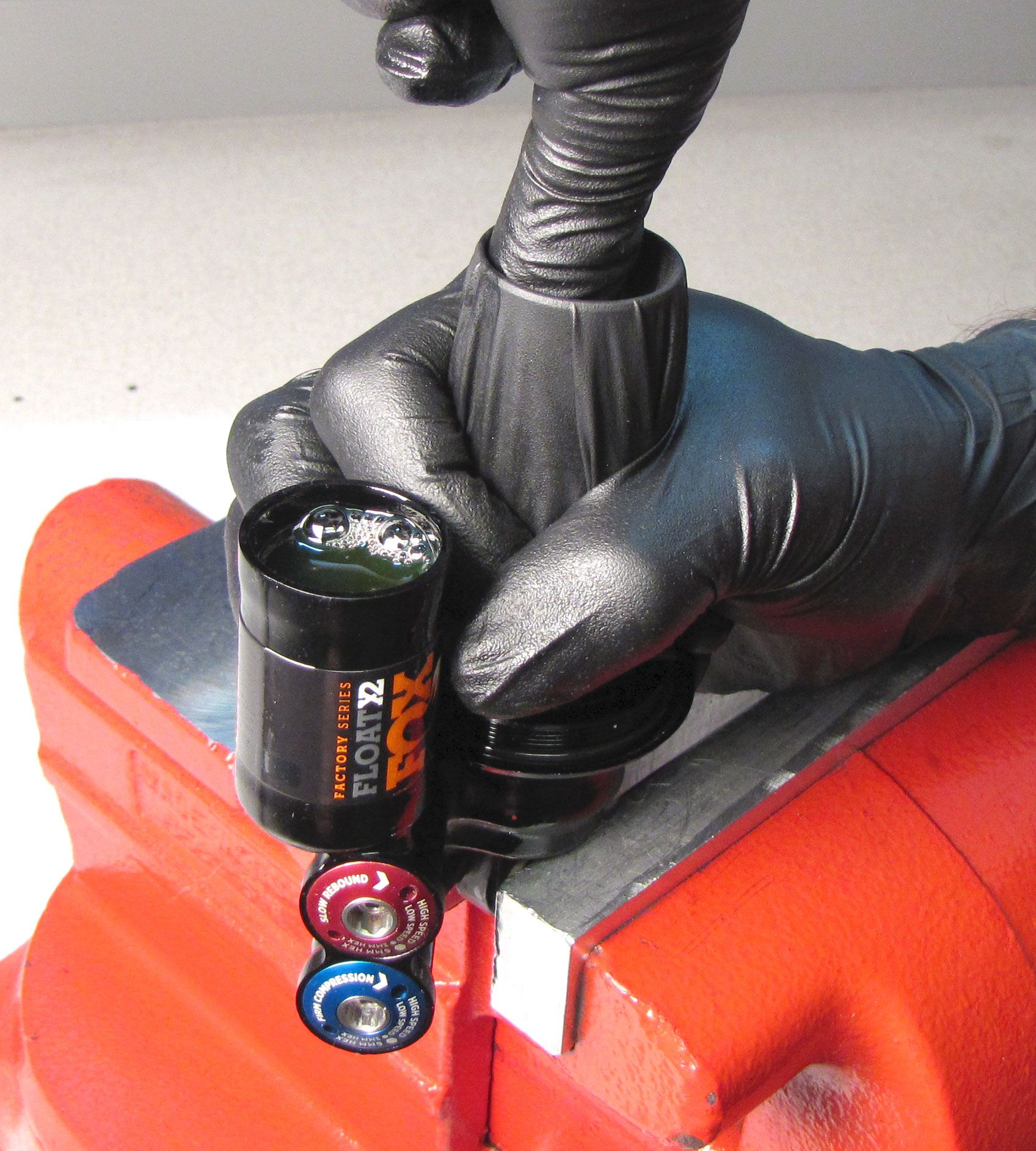
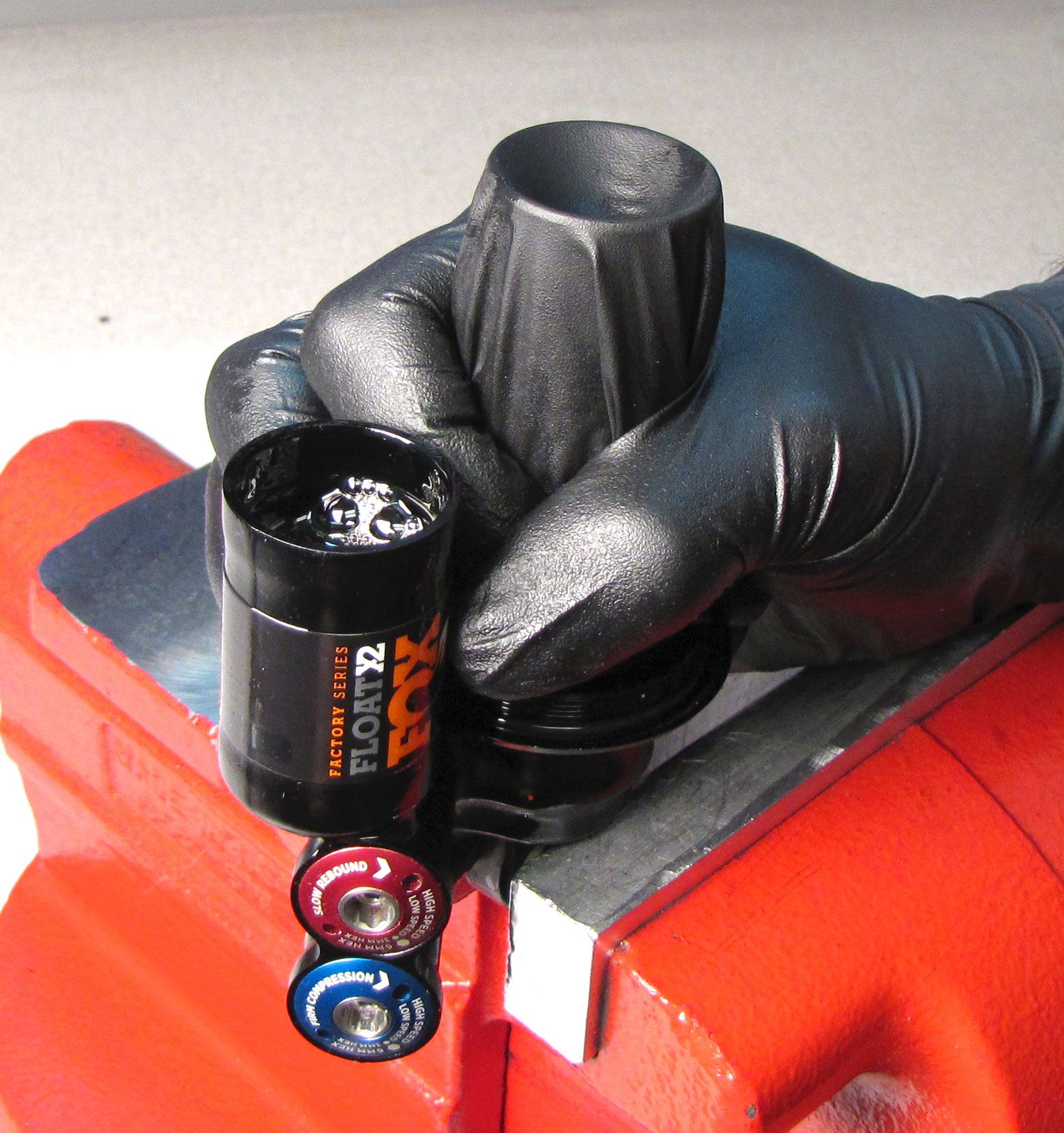
Hold the glove tightly over the main body, then slowly push a finger into the main body and remove. This forces fluid and any air through the eyelet and adjuster, into the piggy-back reservoir. Repeat until you feel that only clean fluid is moving through the eyelet and no new bubbles appear in the reservoir.


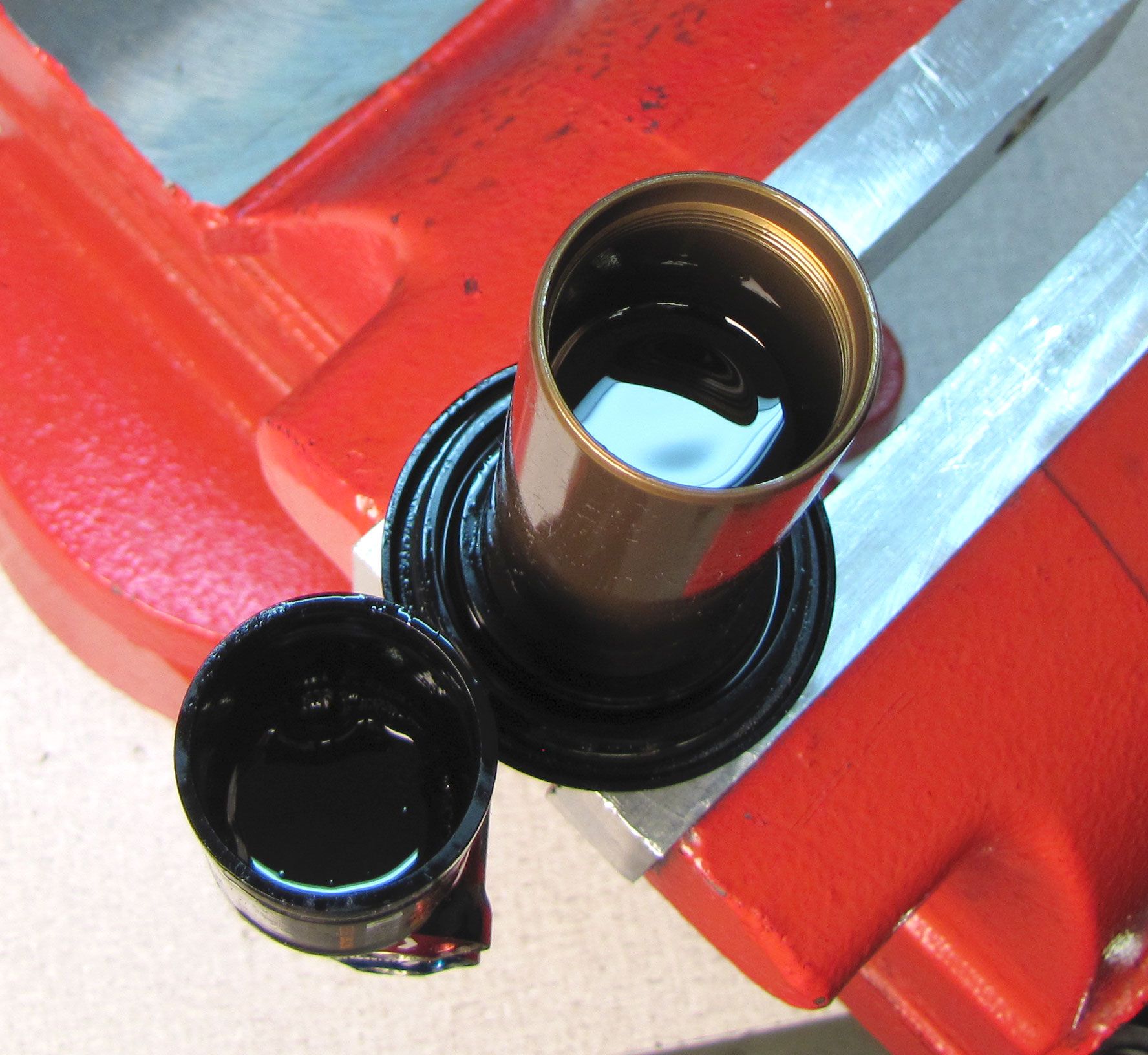
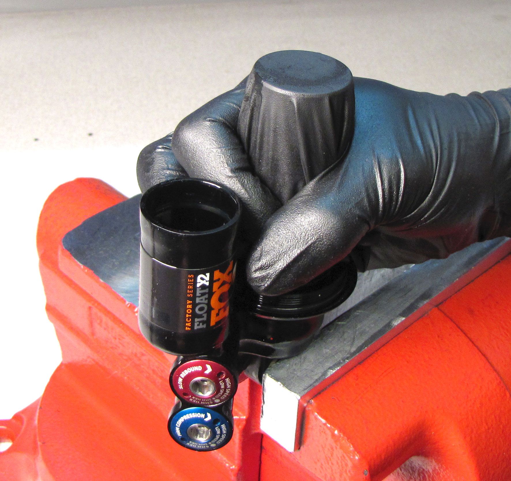
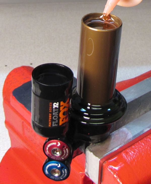
Step 5
Remove the glove and add fluid to the main body until the fluid level in the reservior slowly rises to the very top.
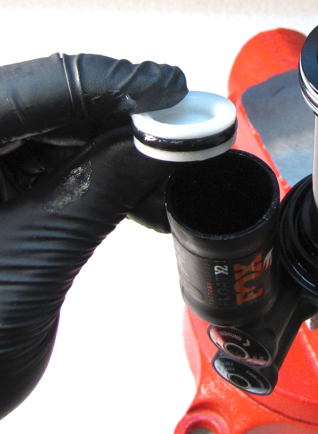
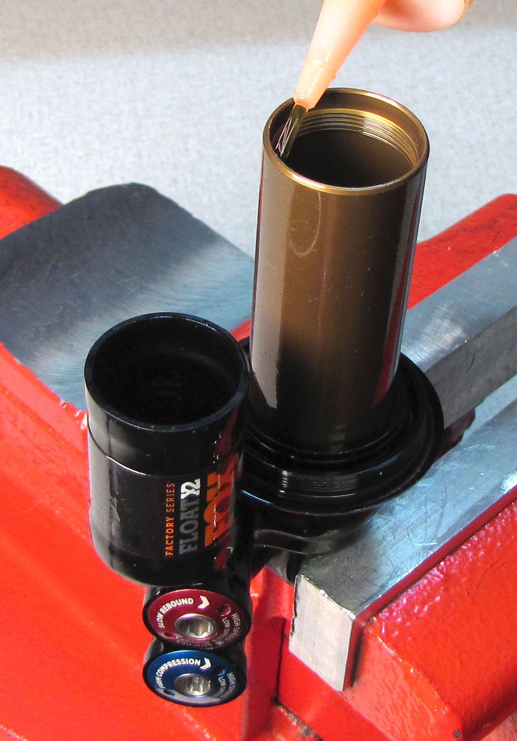
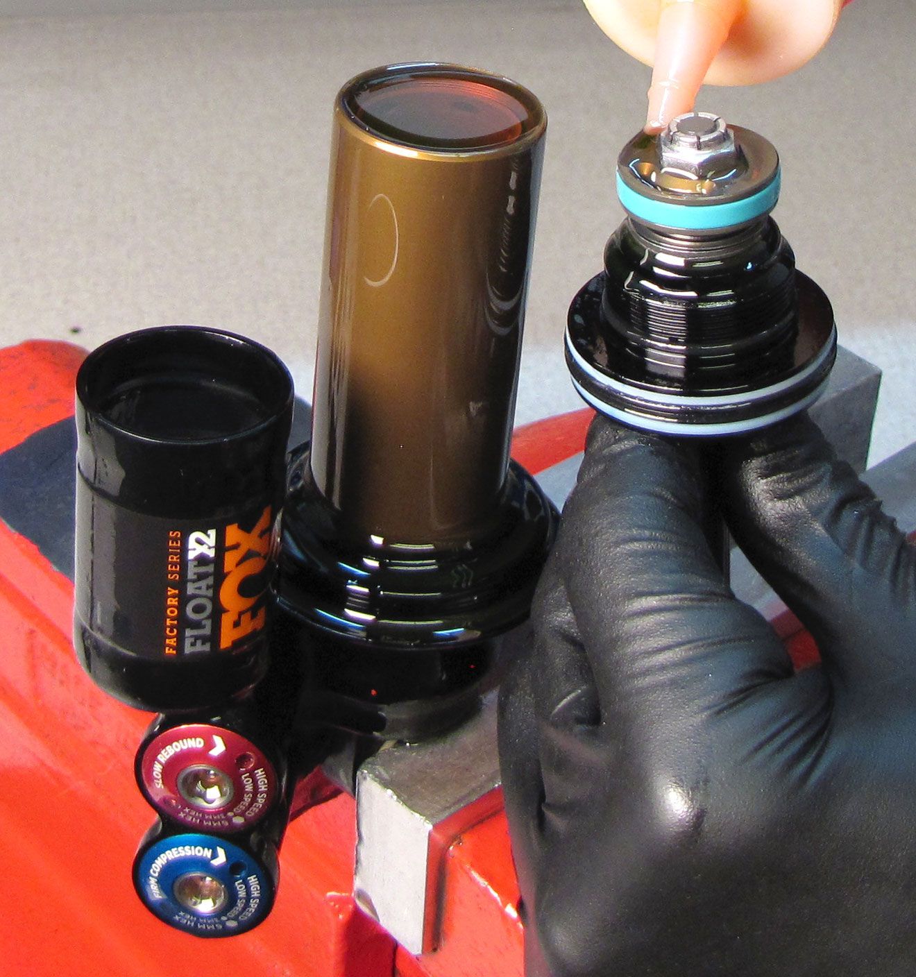
Step 6
Install a new greased o-ring onto the IFP, then slowly slide it into the reservoir making sure to not trap any air beneath it. Orient the IFP so the counterbore faces up. Keep the IFP flat and press it into the reservoir until it is beneath the retaining ring groove.


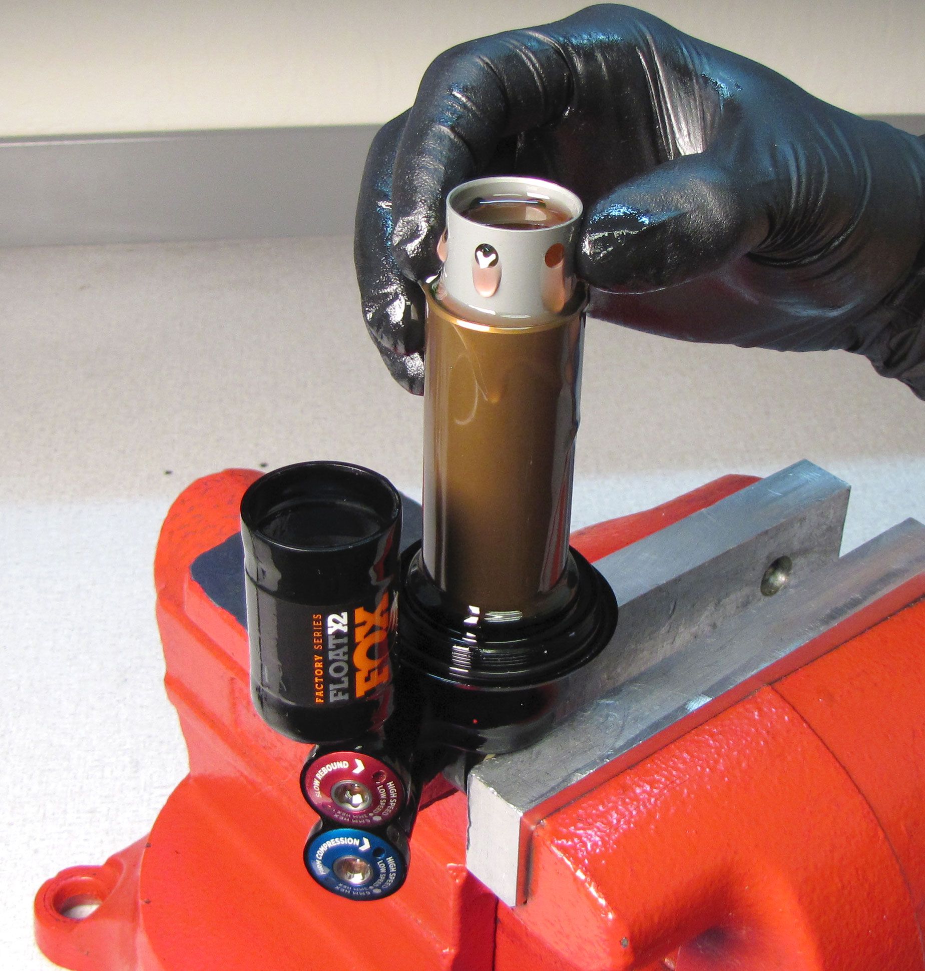
Step 7
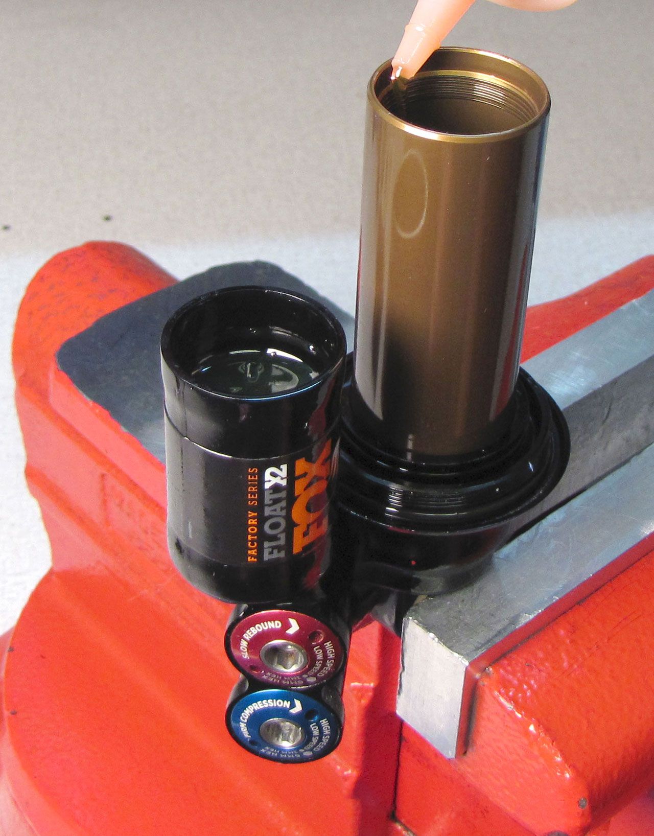
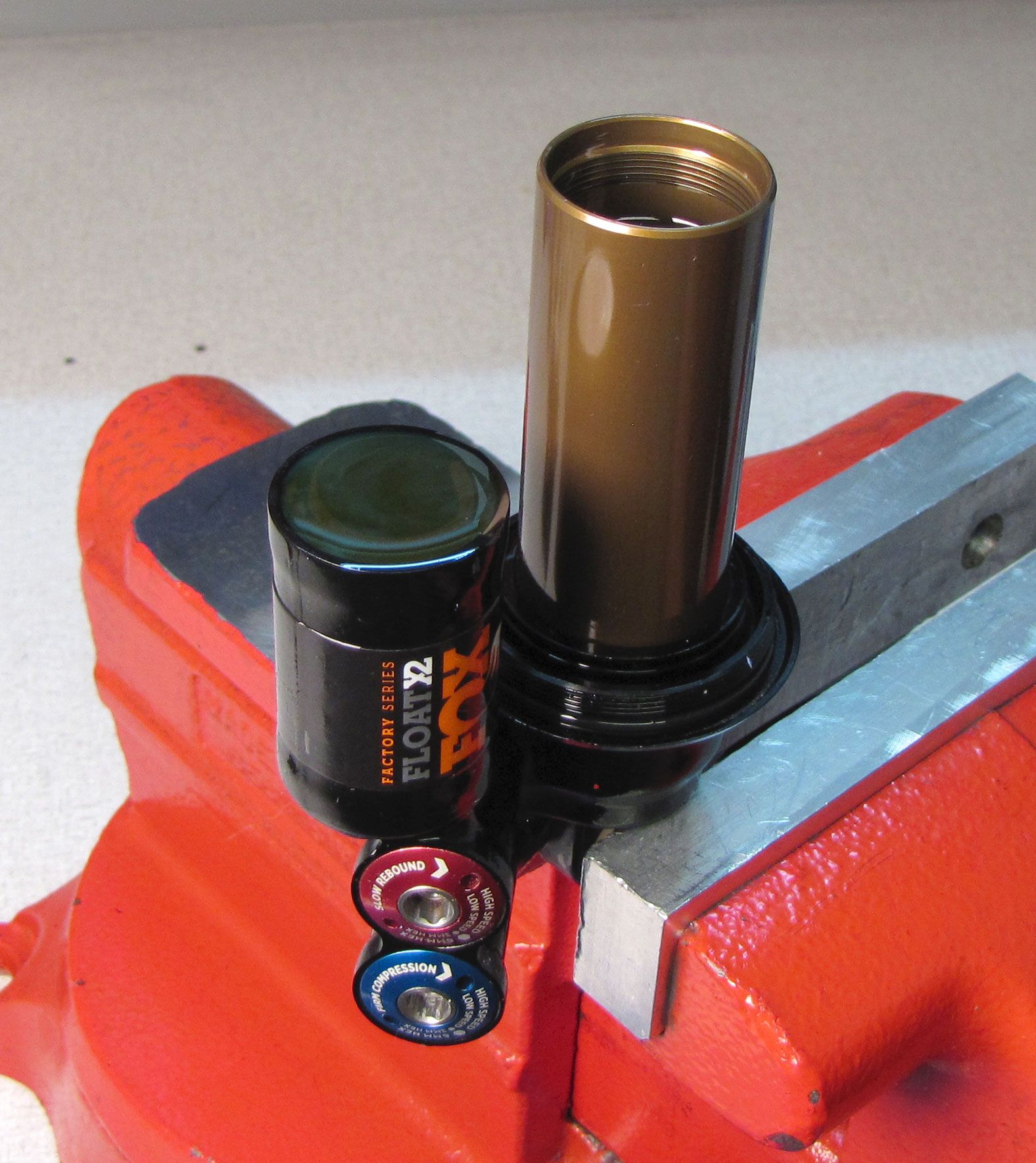
Separate the inner body from the shaft assembly and slowly install it into the body with it's ports at the top. Push the inner body in to fully seat it in the eyelet.
Step 8
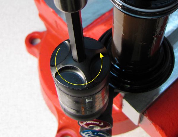
Top off the body and pre-fill all ports of the piston and bearing assembly with FOX R3 5wt. red oil. Quickly and smoothly, install the piston assembly into the body and turn it clockwise to begin threading it in.


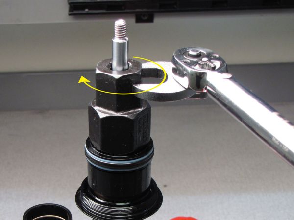
Step 9
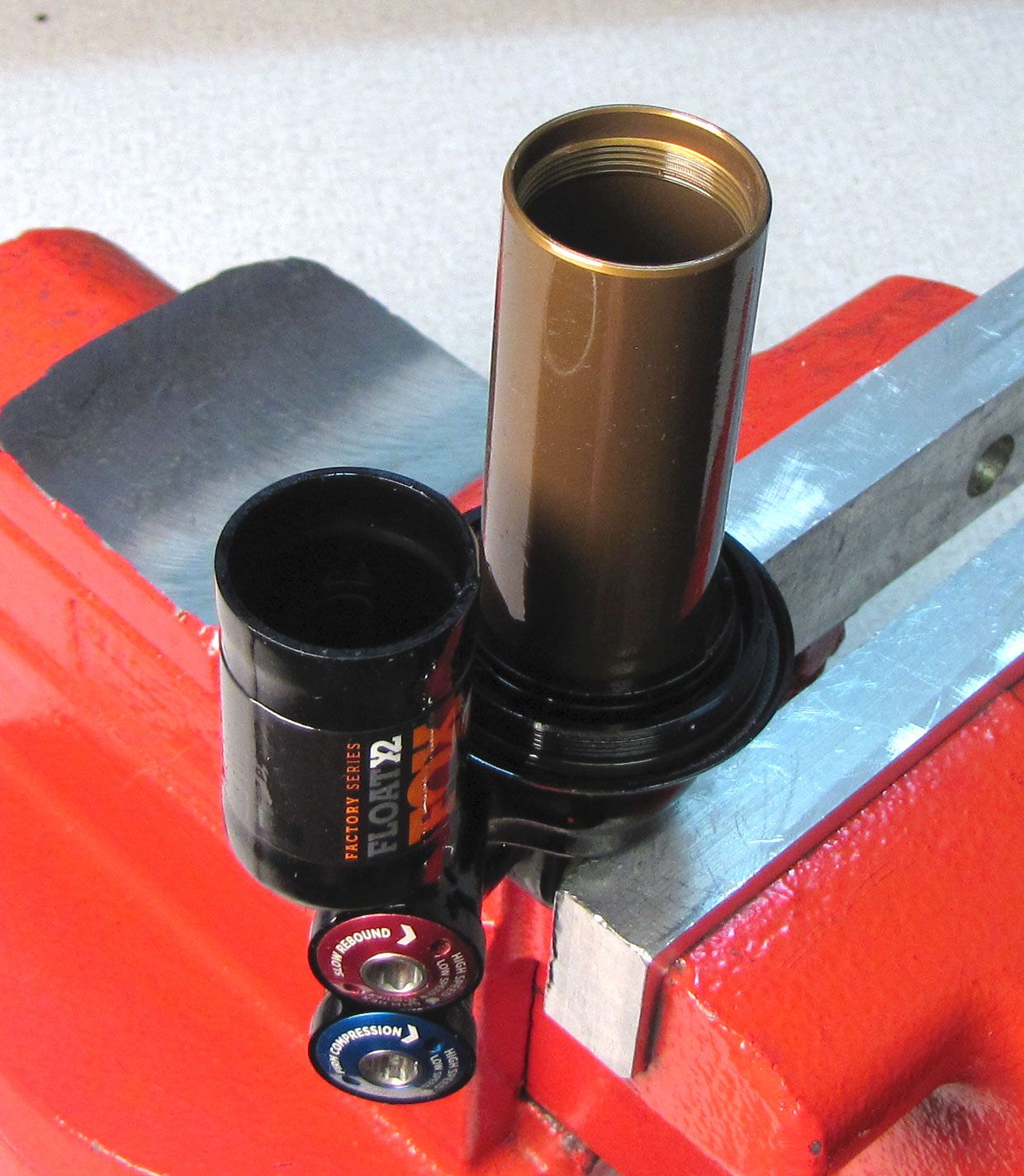
Use the 20 tooth BB tool to tighten (clockwise) the bearing assembly to 145 in-lb (16.3 Nm). Reposition your shock in the vice so the bleed port on the back of the eyelet is the highest part of the shock as shown.

Step 10
Remove the bleed screw from the back of the eyelet with a 2mm hex wrench. Set the IFP to the appropriate depth using your IFP depth setting tool (803-00-566). Reinstall the set screw with a new greased o-ring from the kit and tighten to 14 in-lb (1.6 Nm).
| Shock Size | IFP Height (+/-0.050in) |
| All | 1.343in +/- 0.020in |


After completing the hand bleed, please return to step 29 for instructinos to finalize the shock rebuild.