2019-2023 LIVE Valve MTB Shock Rebuild
Required Parts
- 803-00-142 Kit: Rebuild, FLOAT Line Air Sleeve, Special Q-Ring
- 803-01-363 Service Kit: LIVE Shocks Rebuild kit
Required Tools
- 398-00-280 Tooling: Eyelet Torque Tool
- 398-00-806 Tooling: LIVE Valve Solenoid Housing Puller
- 398-00-820 Tooling: LIVE Solenoid Switcher
- 398-00-951 Tooling: Torque Fixture, 54mm Trunnion Eyelet, Tall
- 803-00-566 Kit: Bike IFP Depth Setting Tool Set
- 803-00-805 Kit: Shaft Clamps, Shocks, CTD 9mm, 3/8in, 1/2in, 5/8in
- 803-01-360 Kit: Tooling: LIVE Valve Clamp, Solenoid Housing, 8mm Shaft, Pressure Tube
- 803-01-369 Kit: Tooling: Glide Band Sizer, Live Valve, Fork/Shock
- 803-01-370 Kit: Fill Machine Adapter, Live Valve Fork/Shock
Supplies Needed
WARNING: Always wear safety glasses and protective gloves during service to prevent potential injury. Failure to wear protective equipment during service may lead to SERIOUS INJURY OR DEATH.
NOTE: The LIVE Valve damper is extremely sensitive to contamination from debris. It is critical that all work be performed in a clean environment using only new lint-free paper towels and Isopropyl alcohol to clean.
Disassembly
Step 1
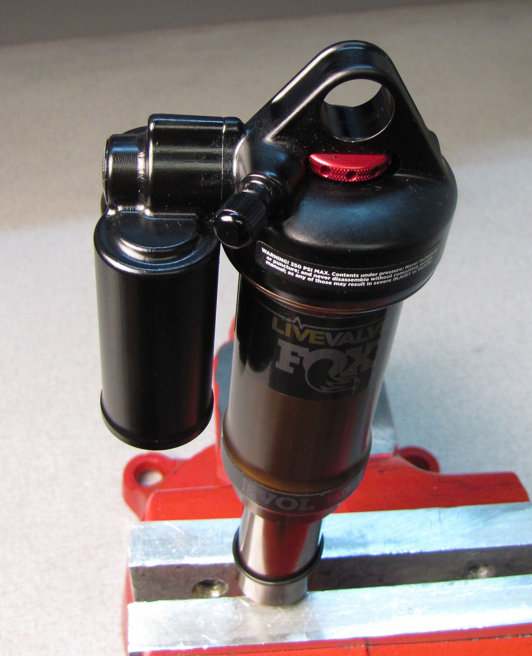
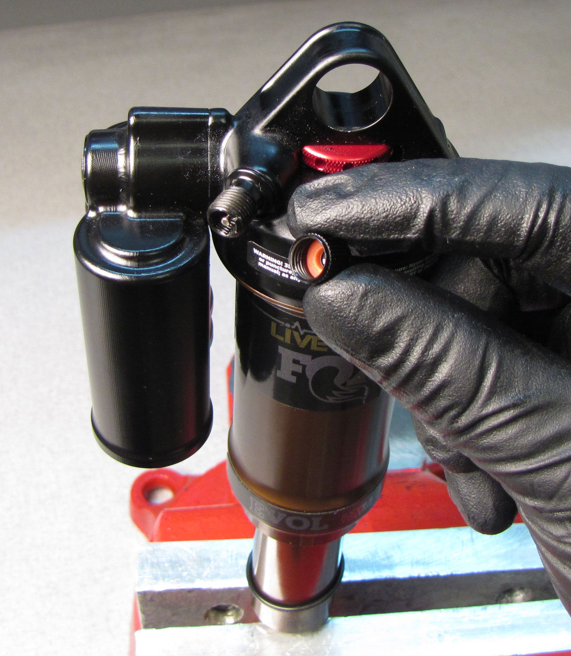
Remove the black air cap and release all air pressure from the main air chamber by depressing the Schrader valve core.

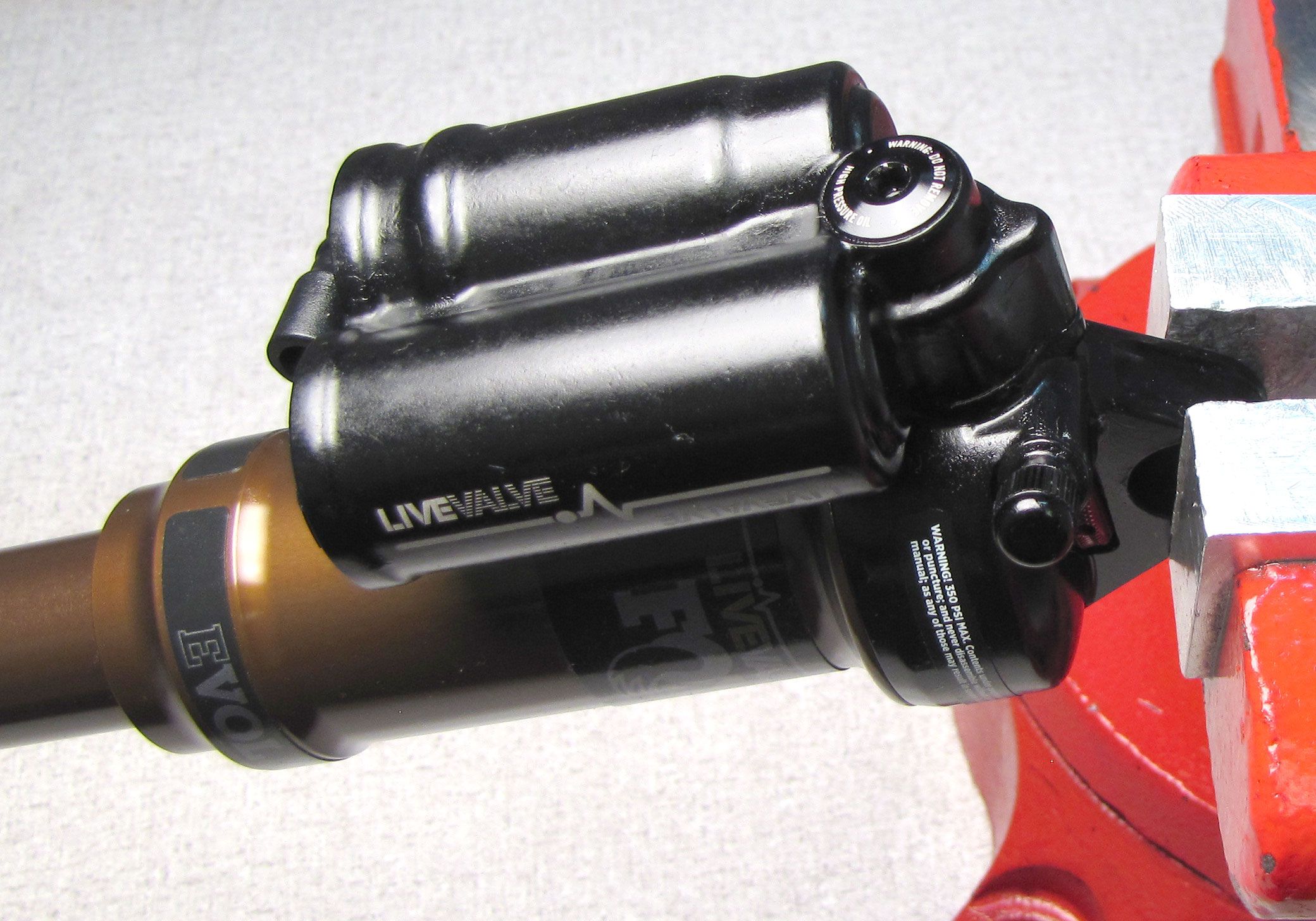
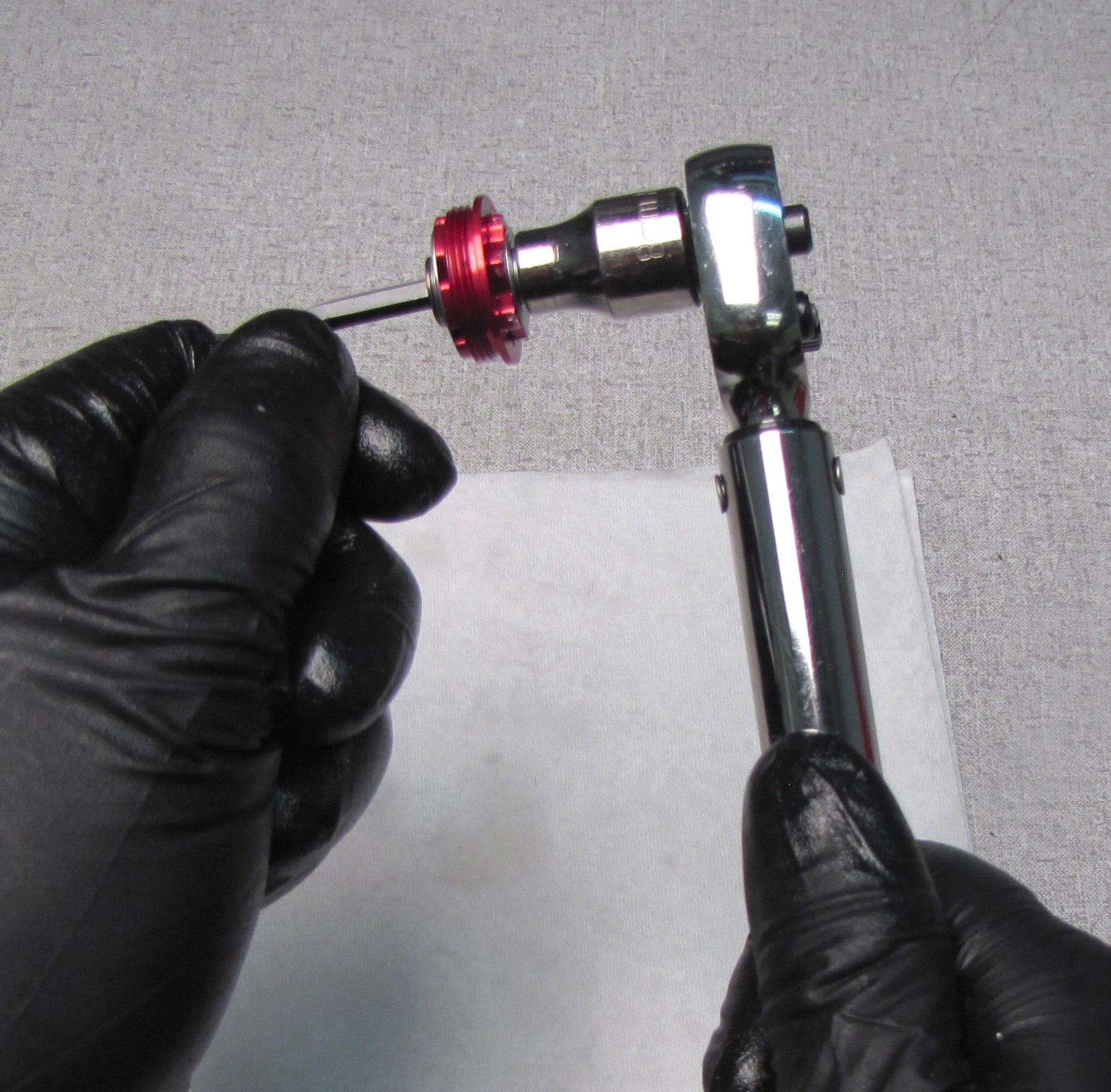
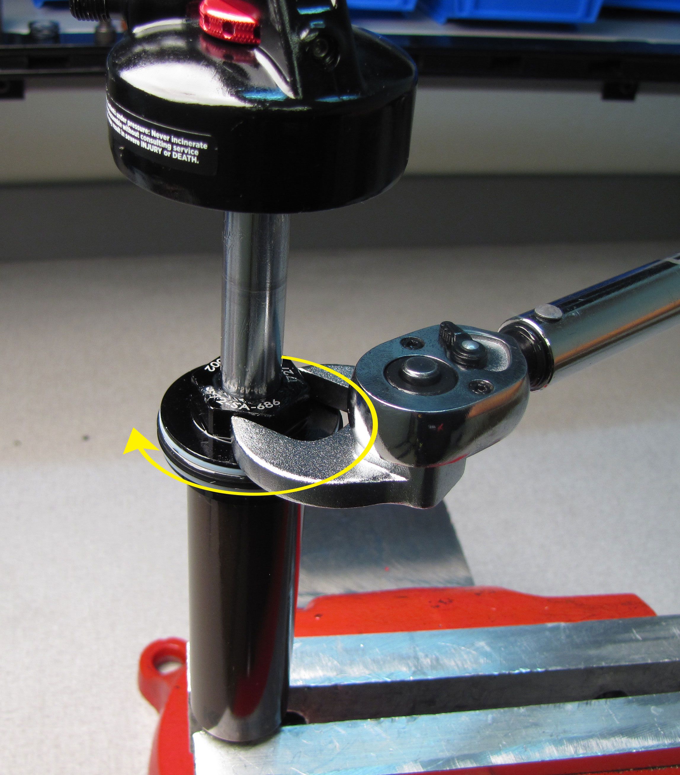
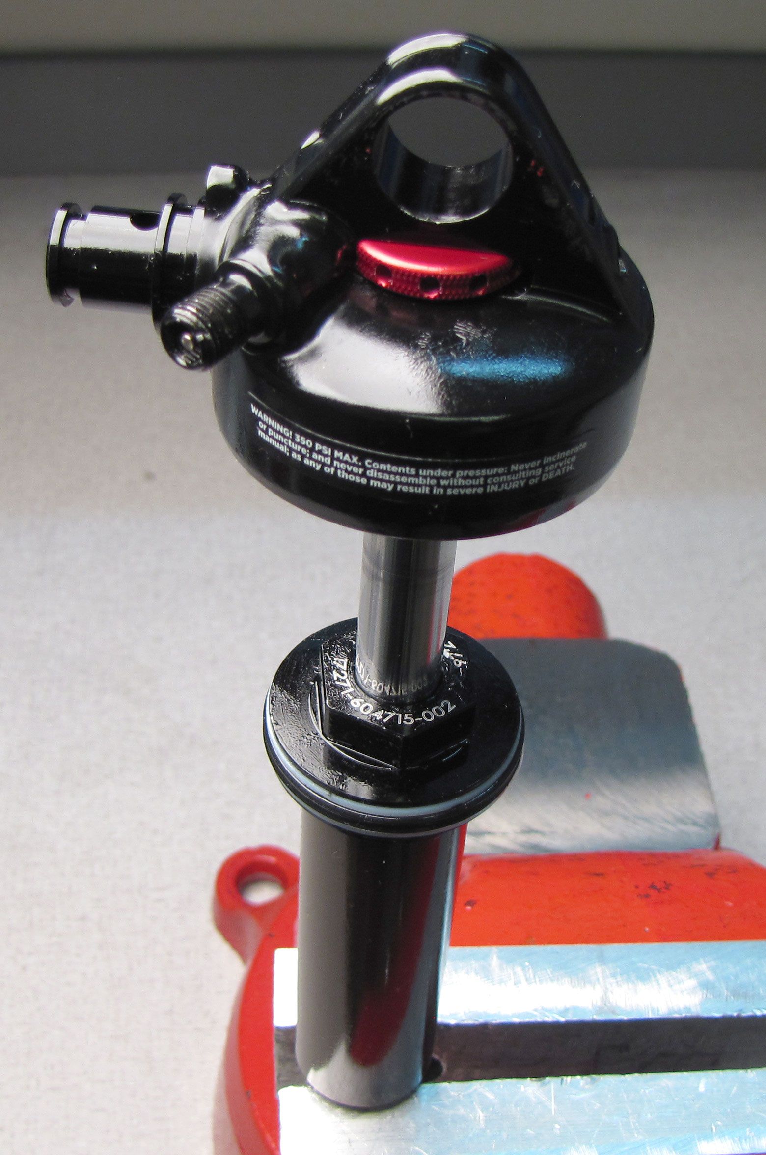
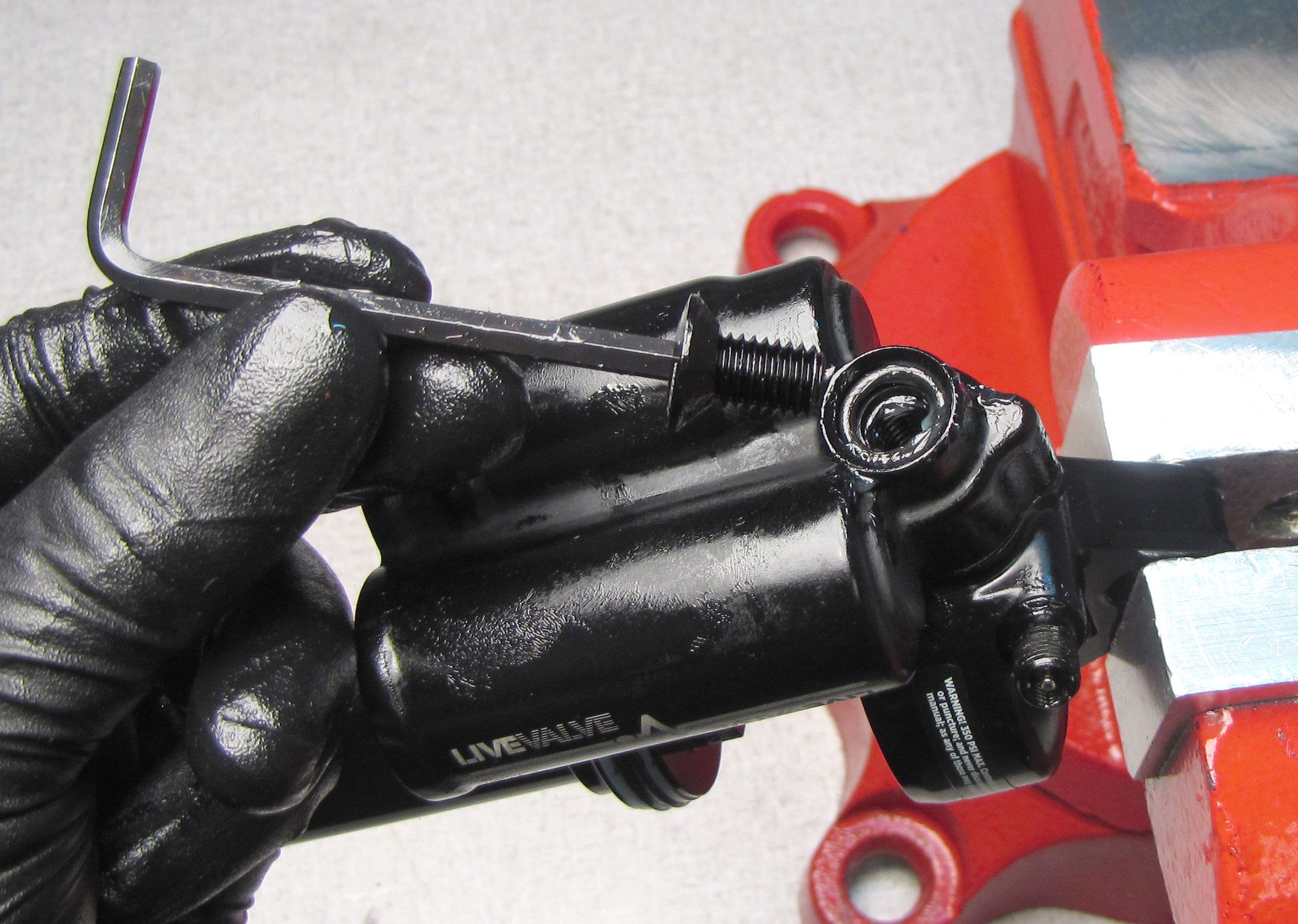
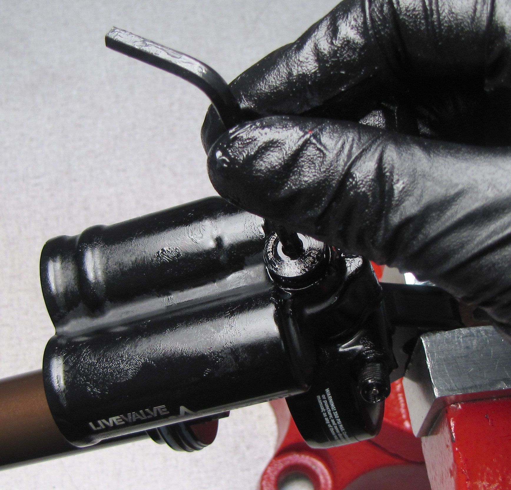
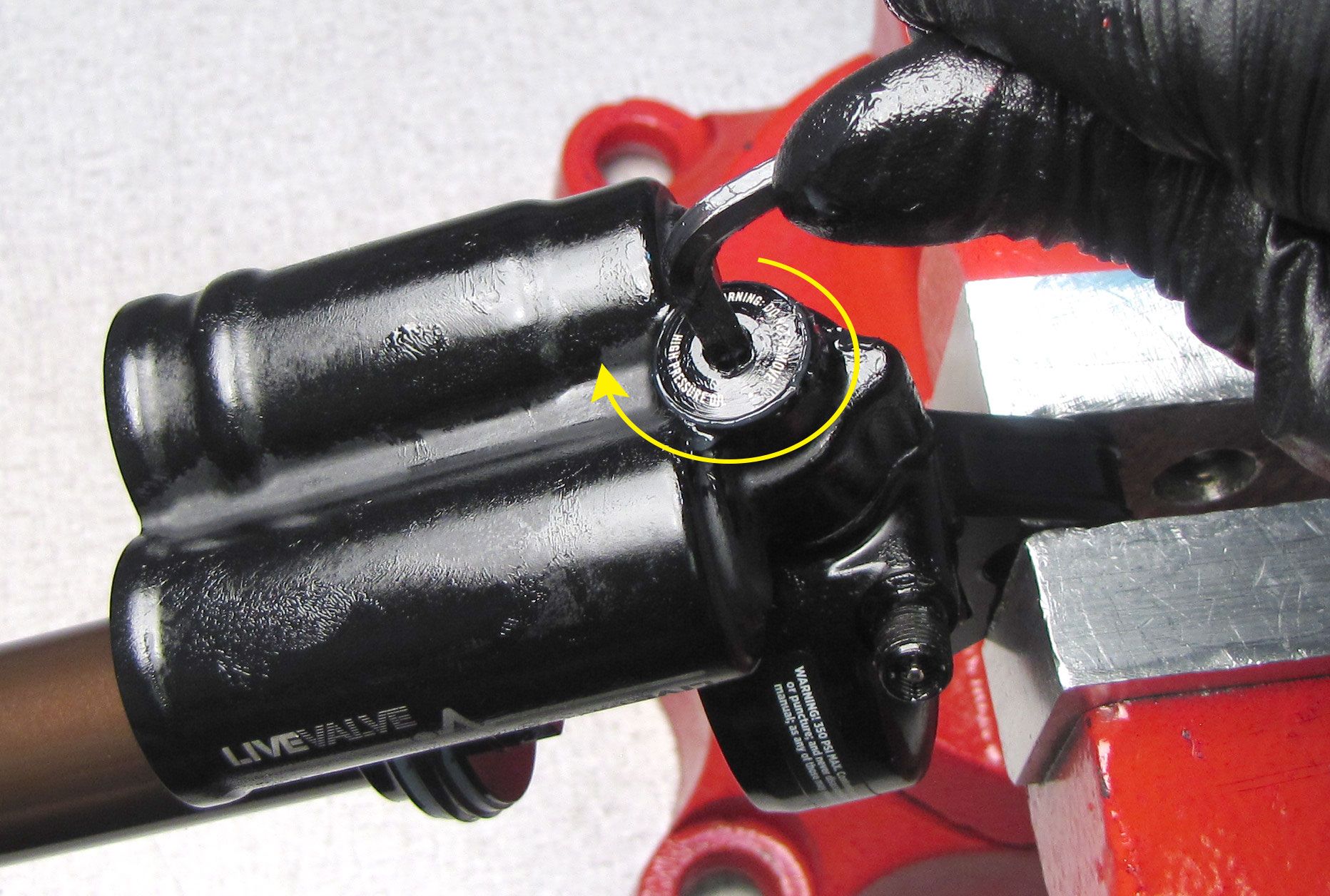
Step 2
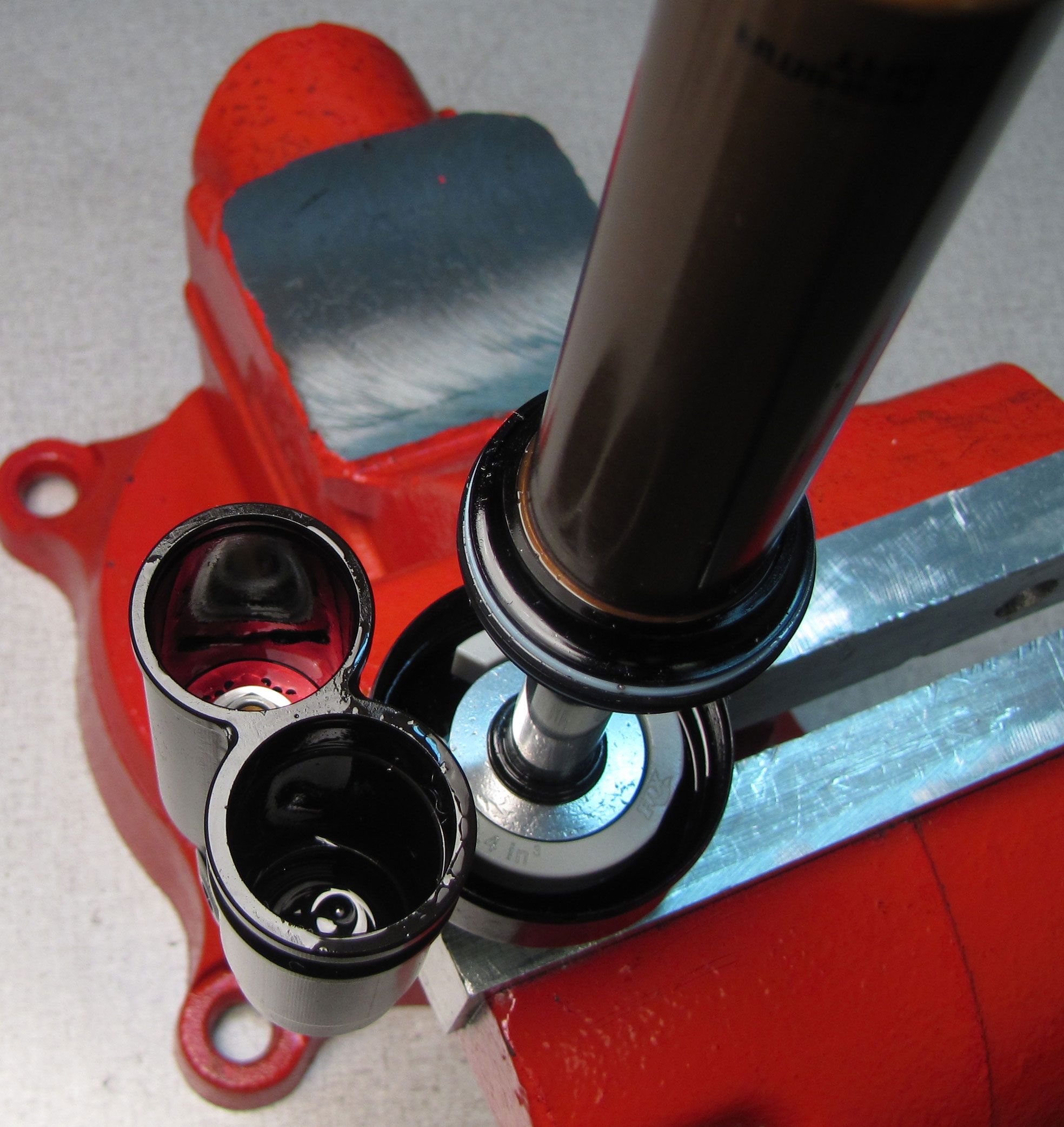
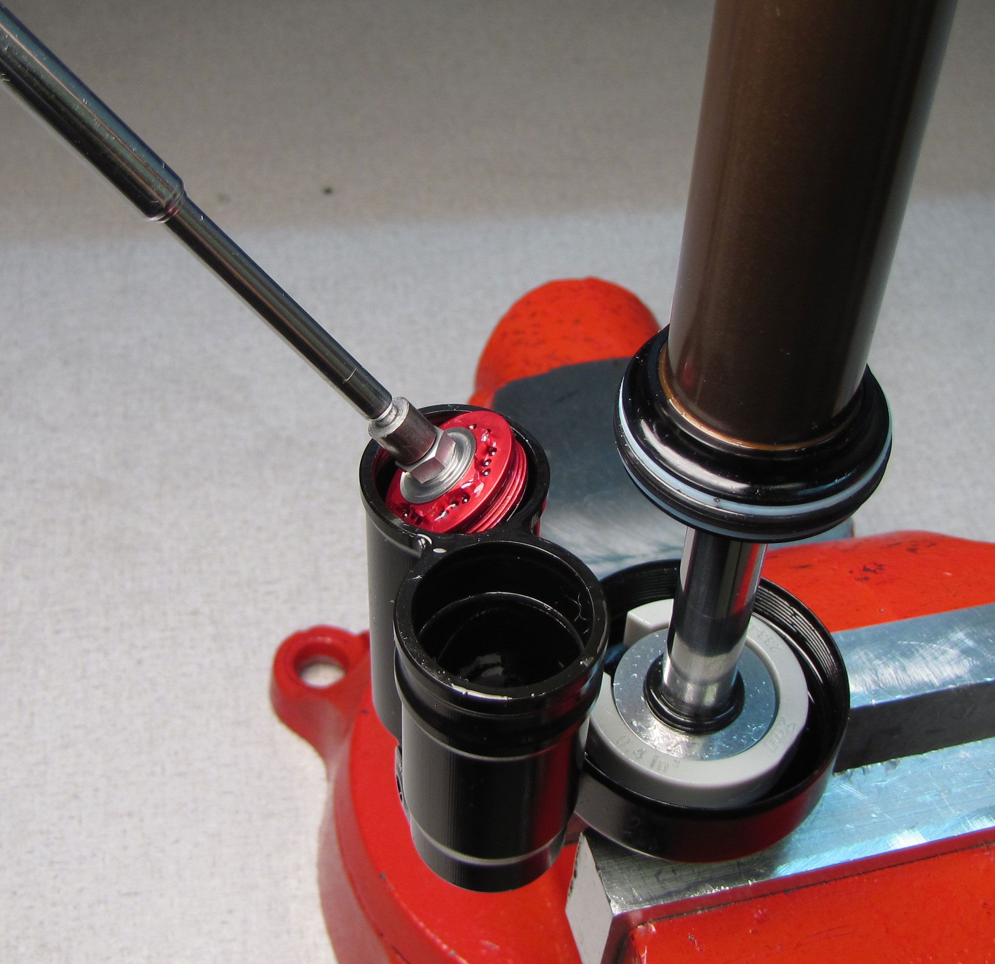
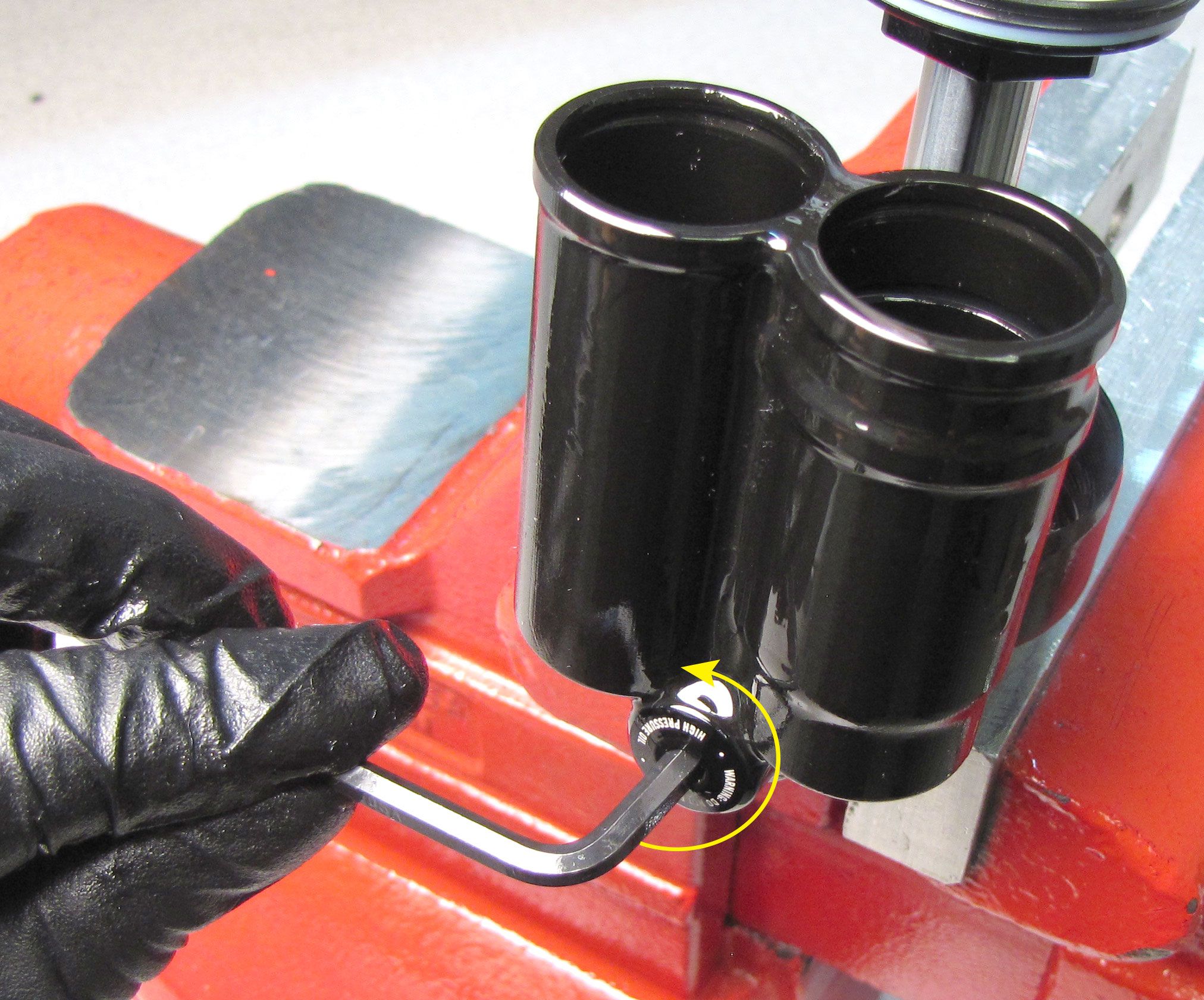
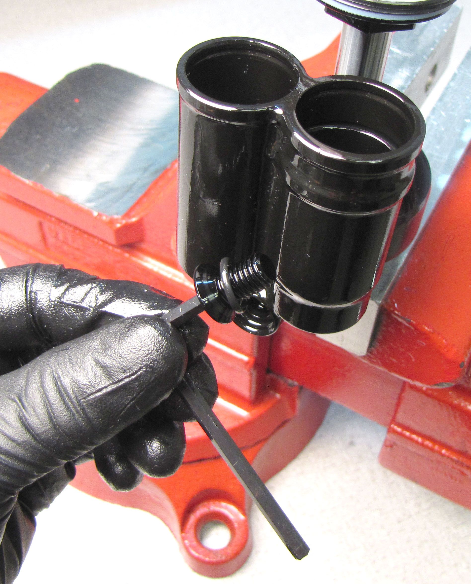
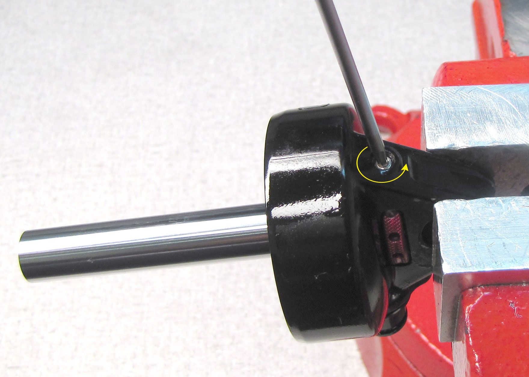
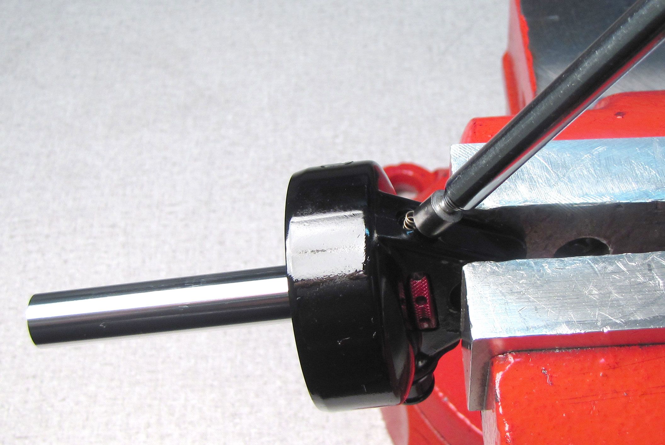
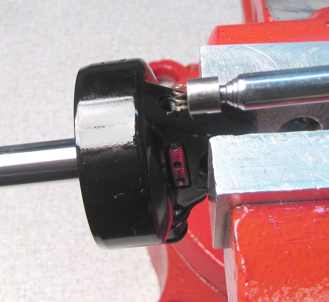
Invert the shock then clamp in your soft-jawed vice. Remove the white Delrin ball from the pellet retainer in the reservoir end cap. Release the Nitrogen charge by unthreading the pellet retainer counter-clockwise. Remove the pellet retainer with a 4mm hex wrench.

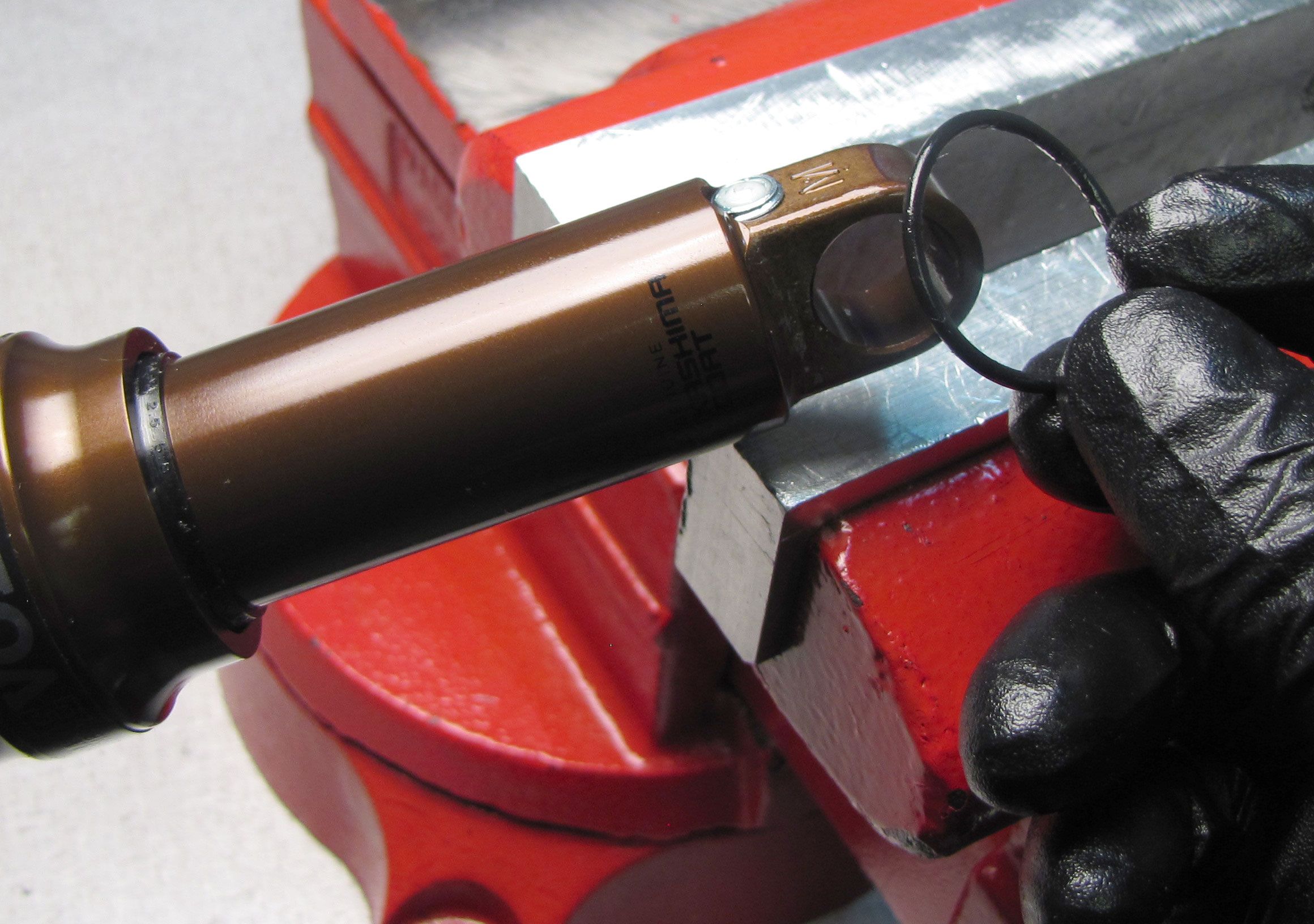
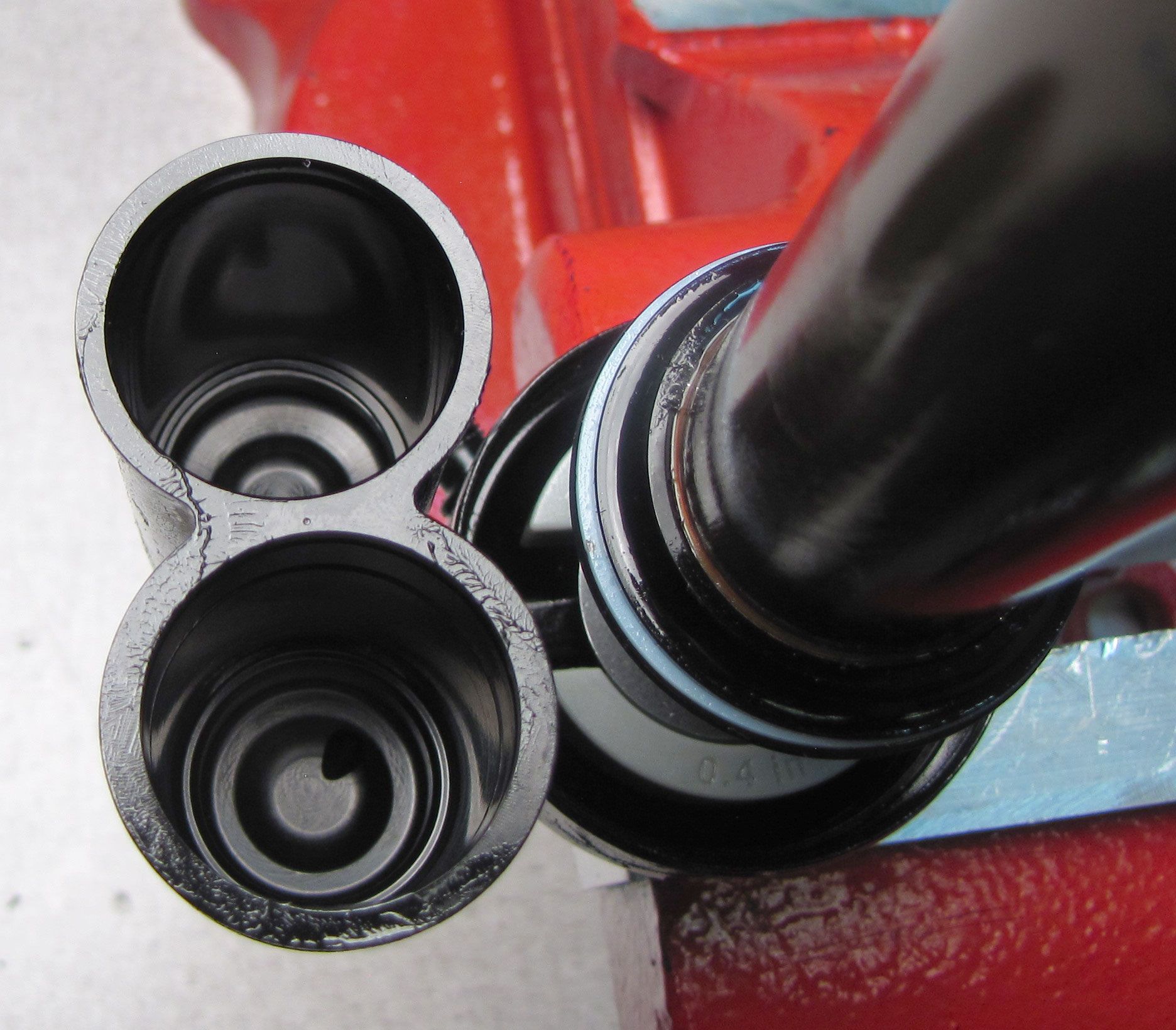
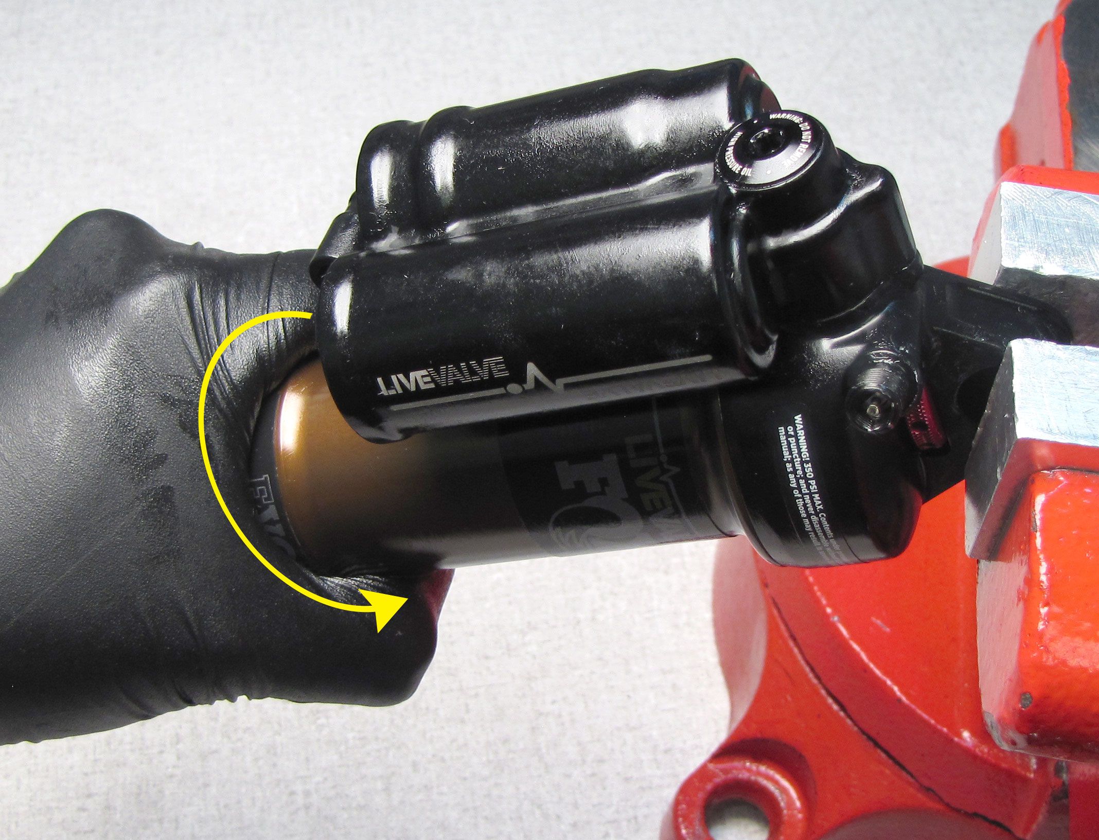
Step 3
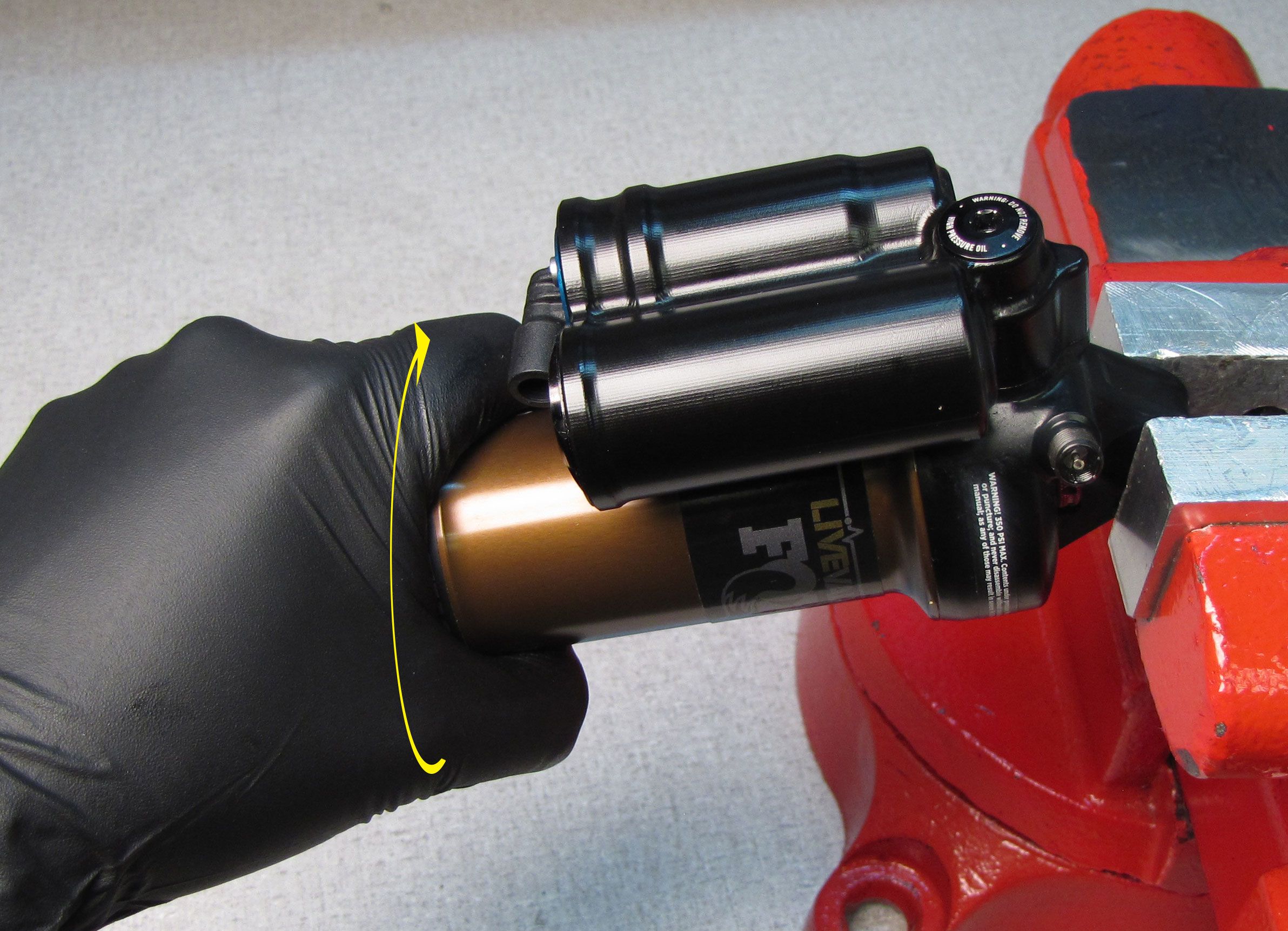
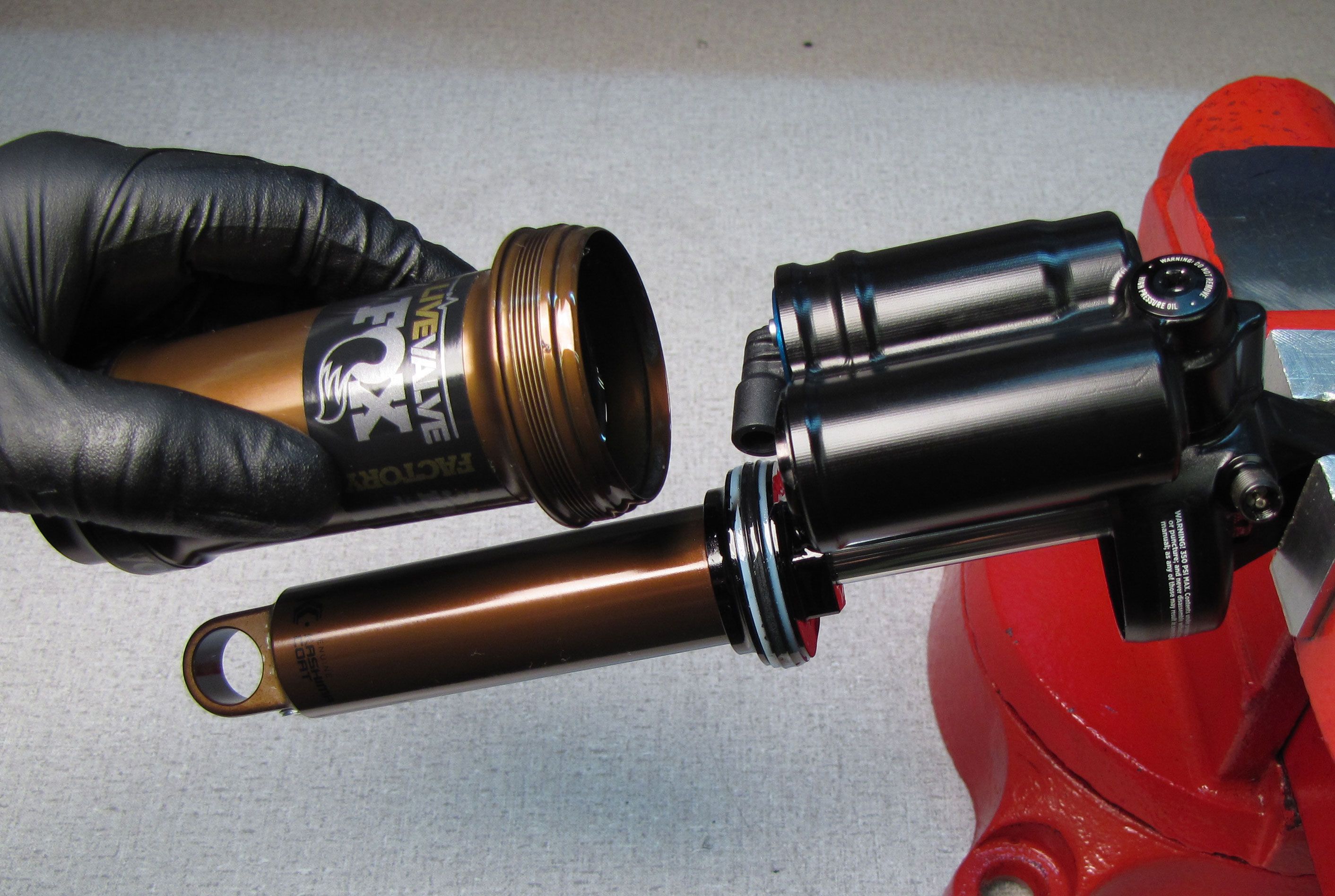
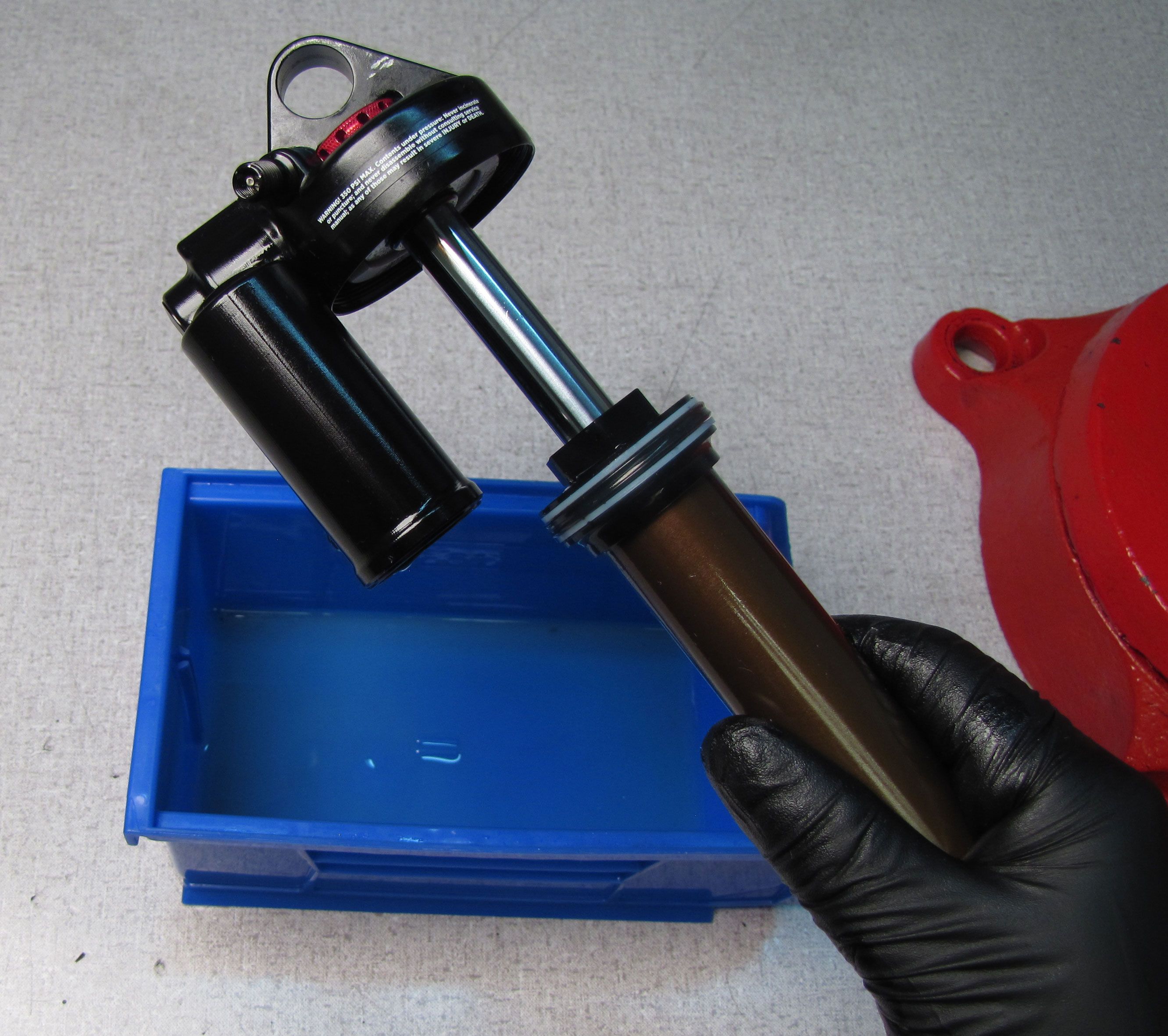
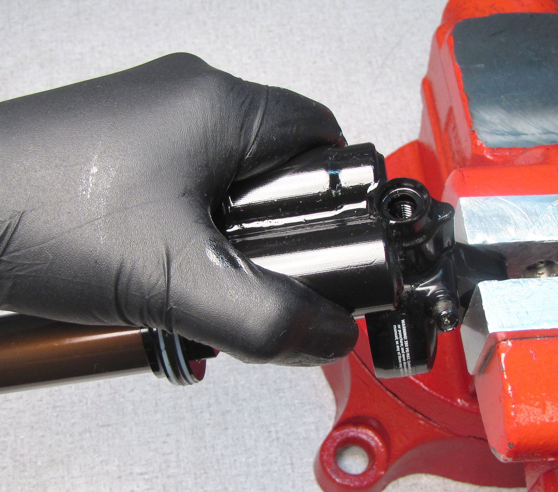
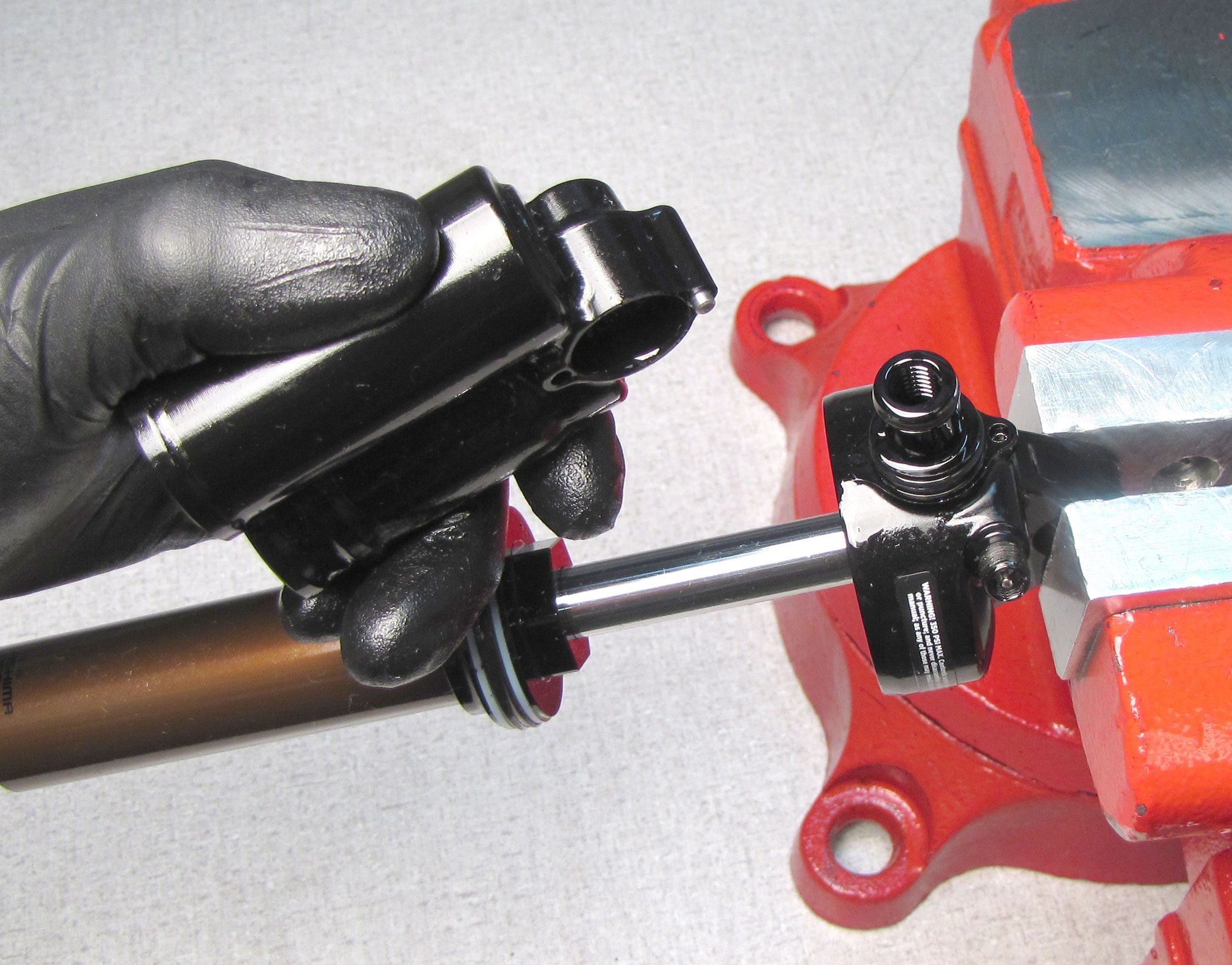
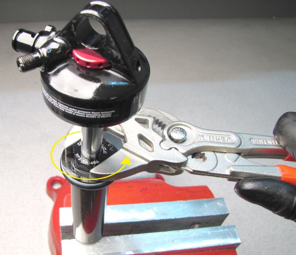
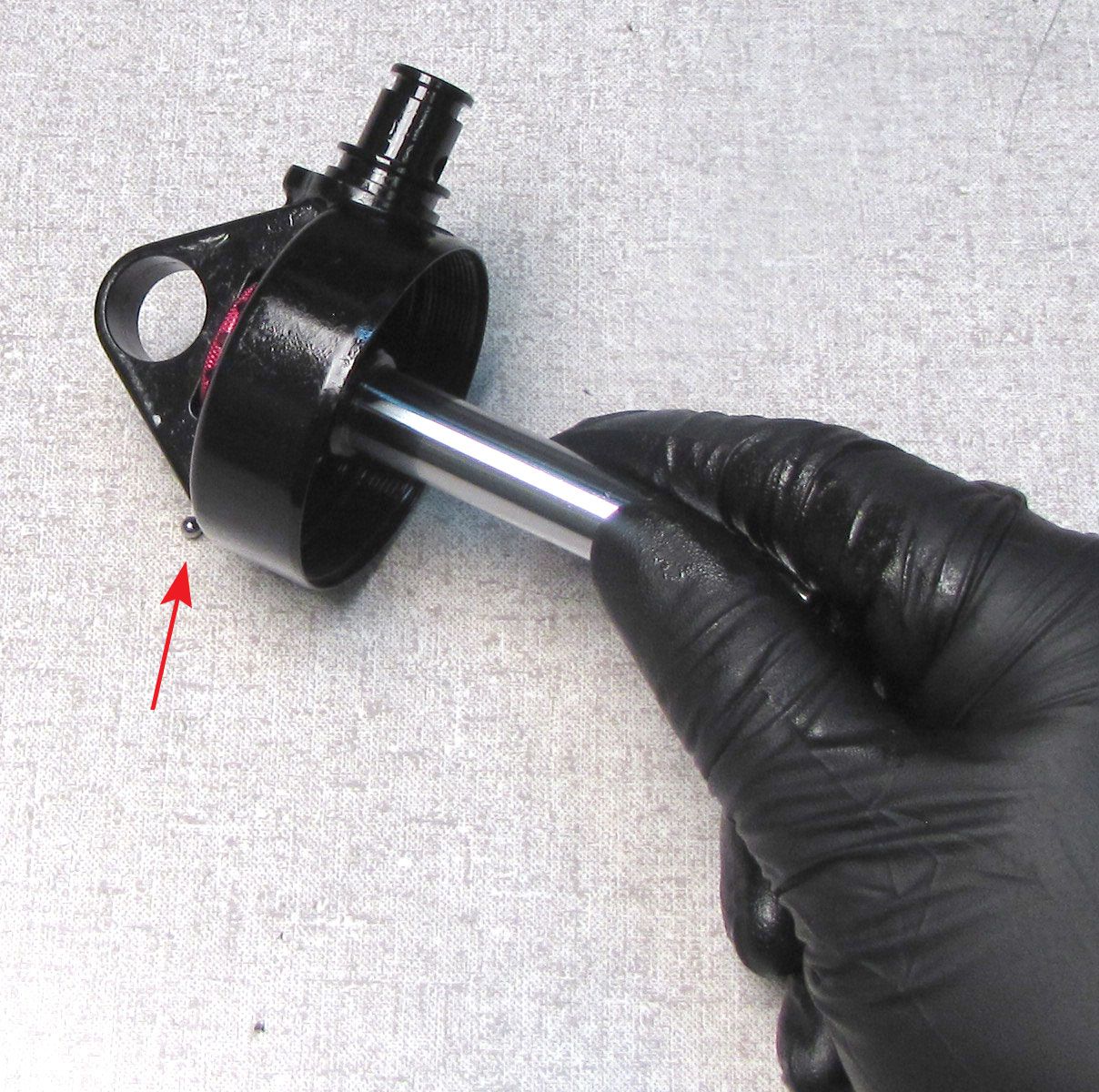
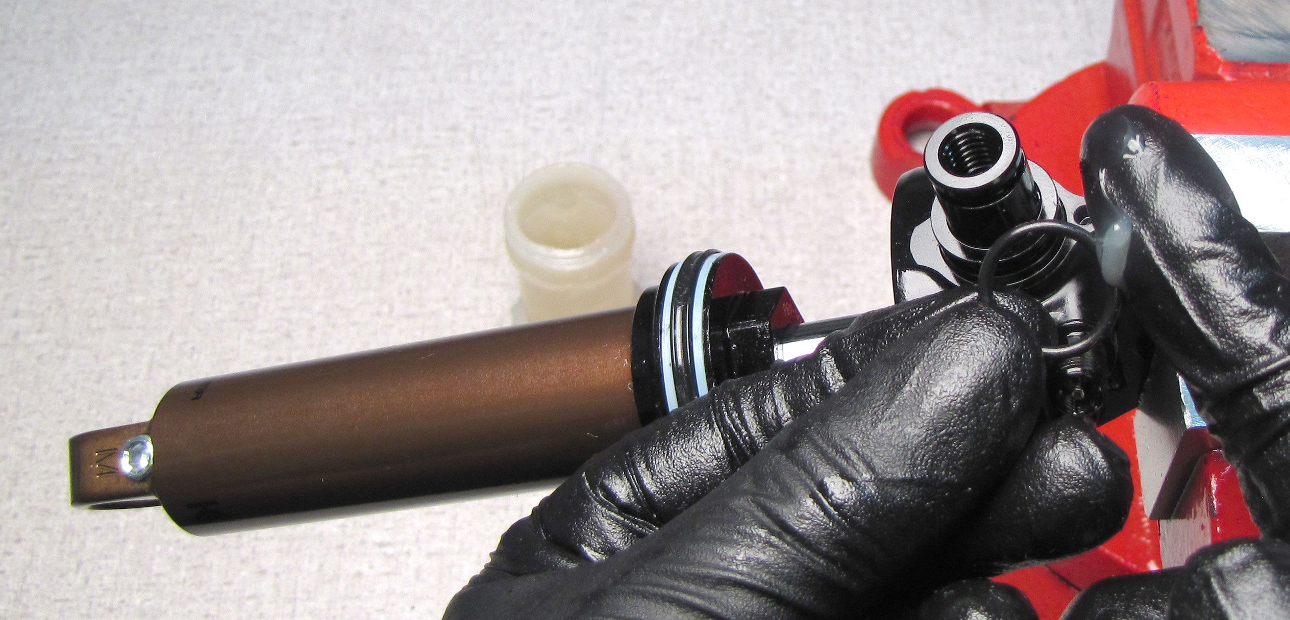
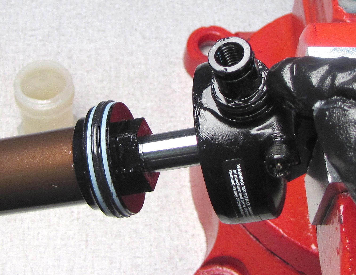
Unthread and remove the air sleeve from the eyelet by turning it counter-clockwise.
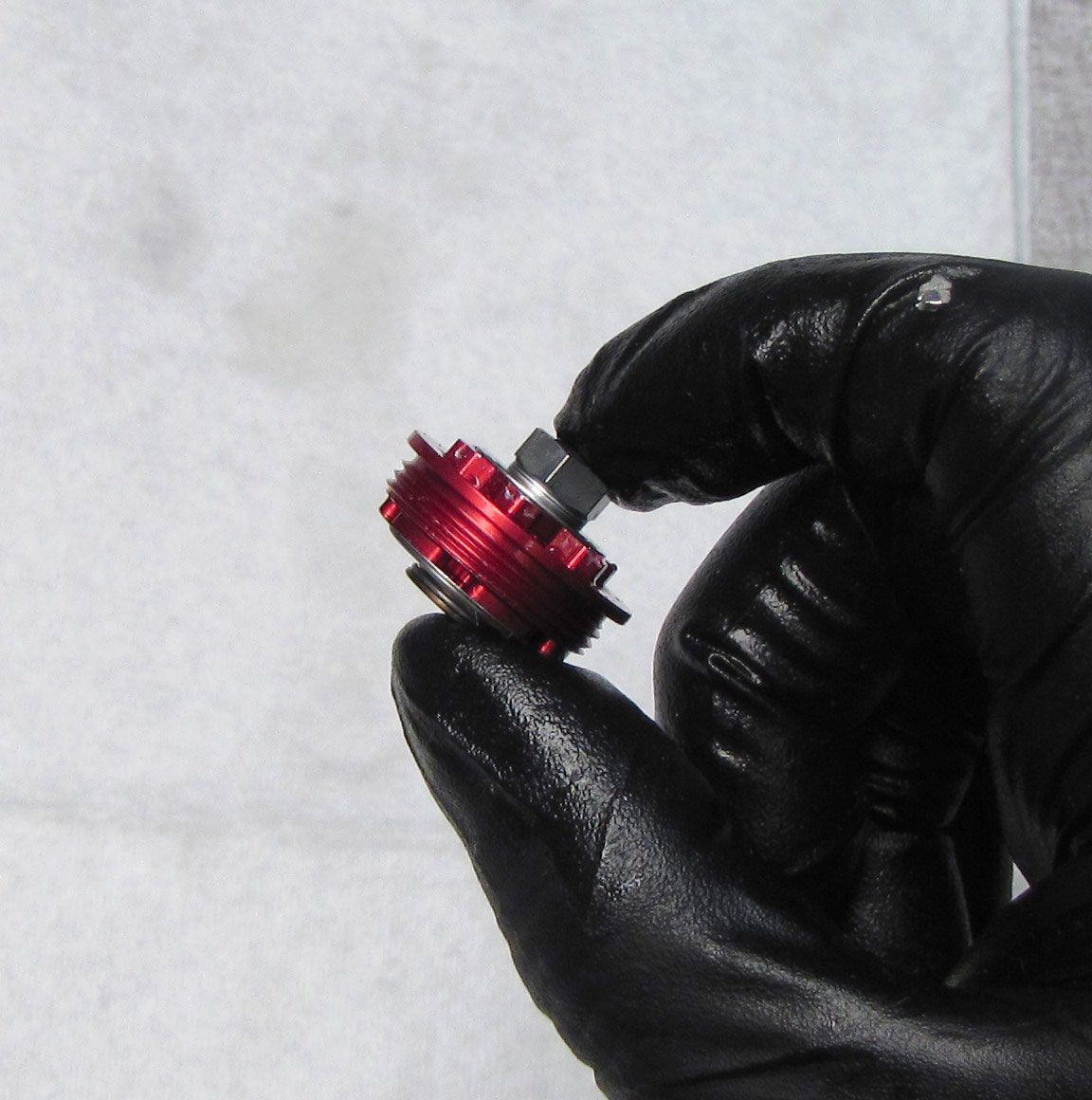
Step 4
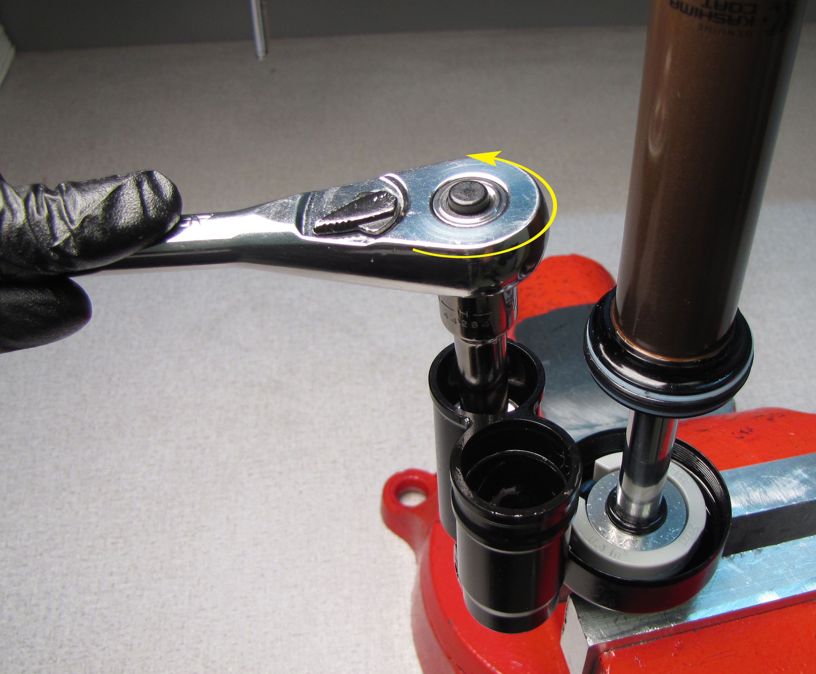
Unthread and remove the End Cap Lockring by turning it counter-clockwise. Remove the black rubber pellet from the Reservoir End Cap then discard the pellet.

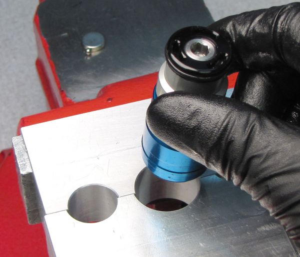
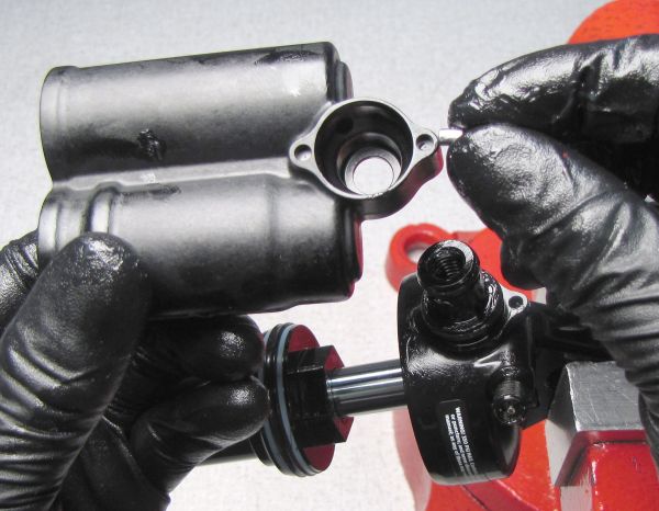
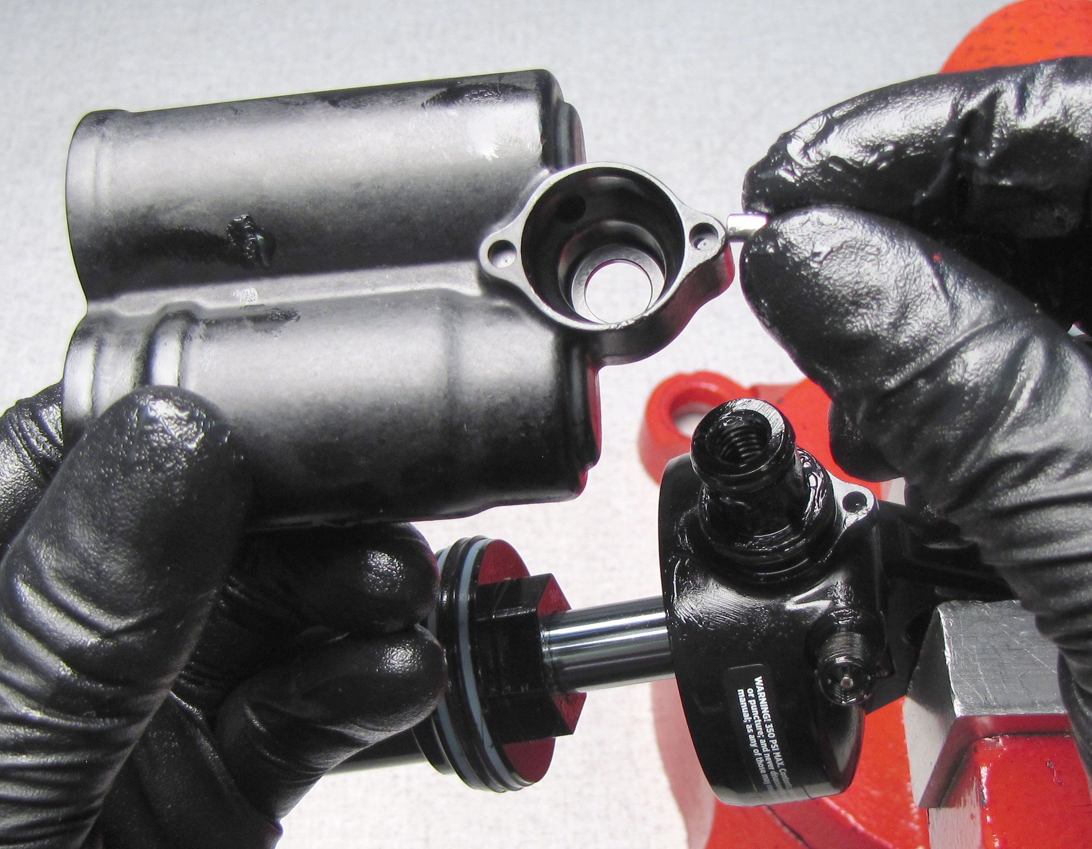
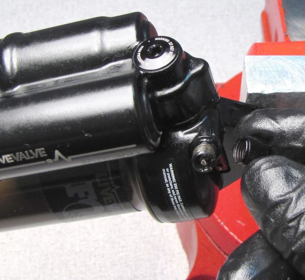
Step 5
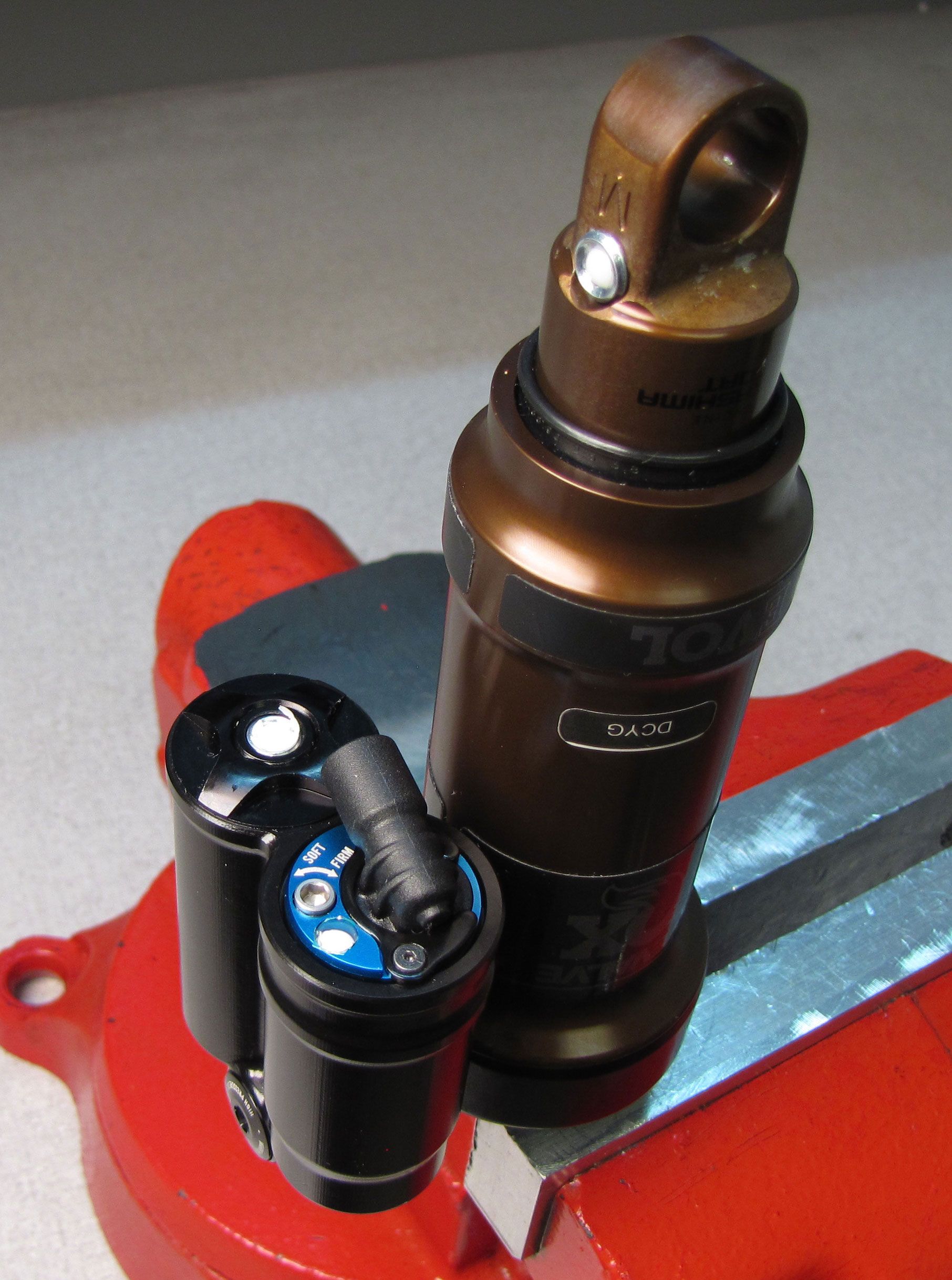
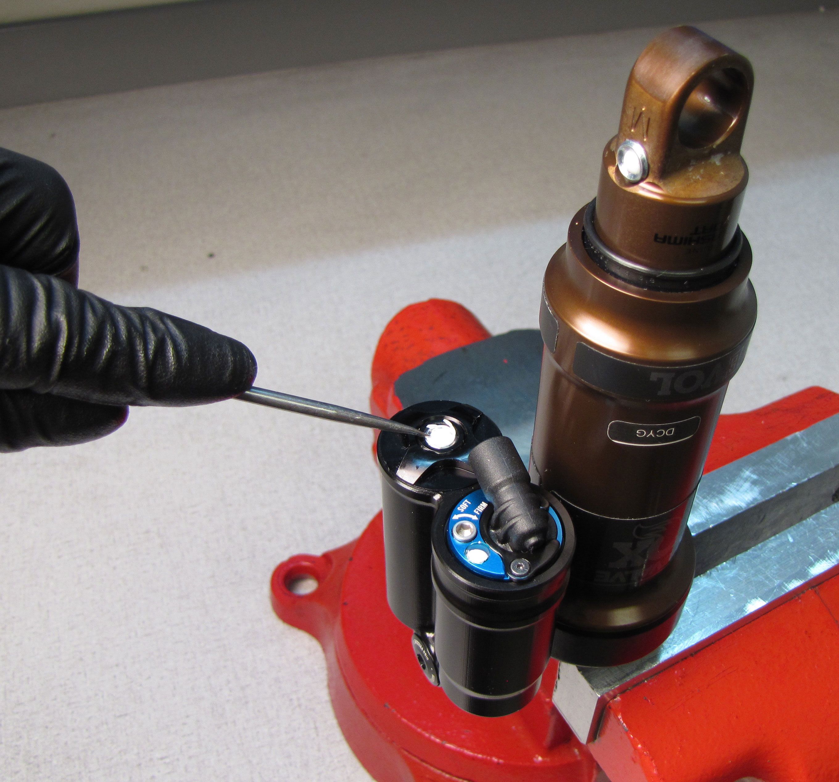
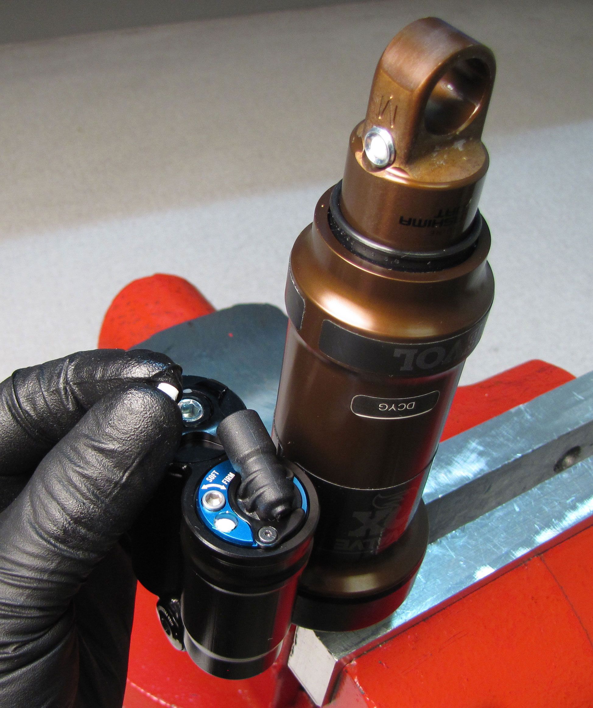
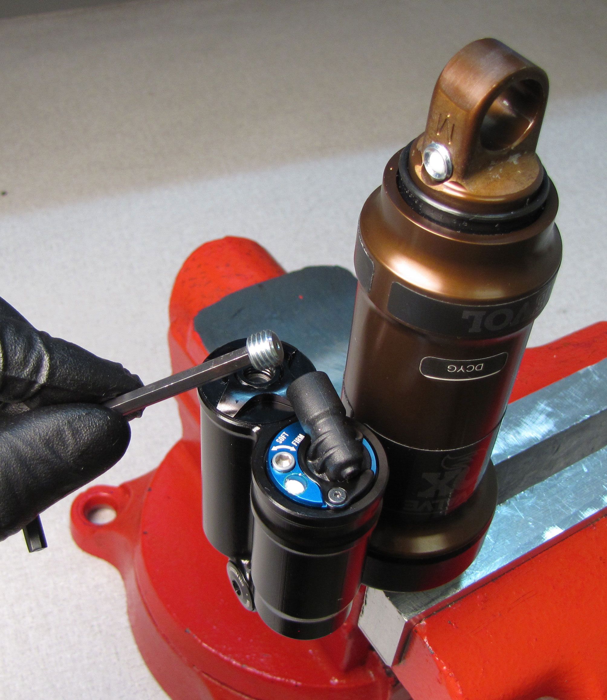
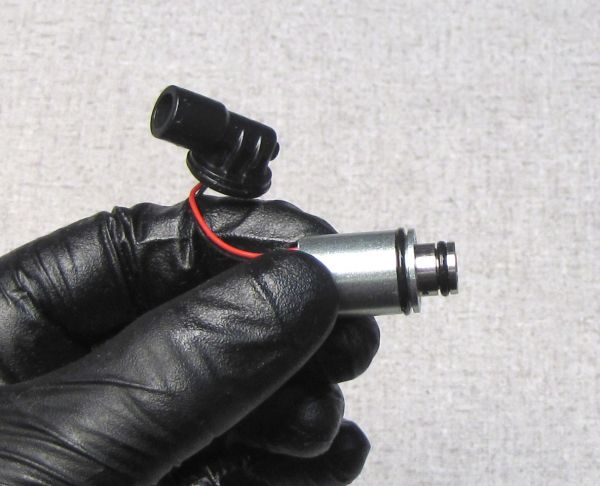
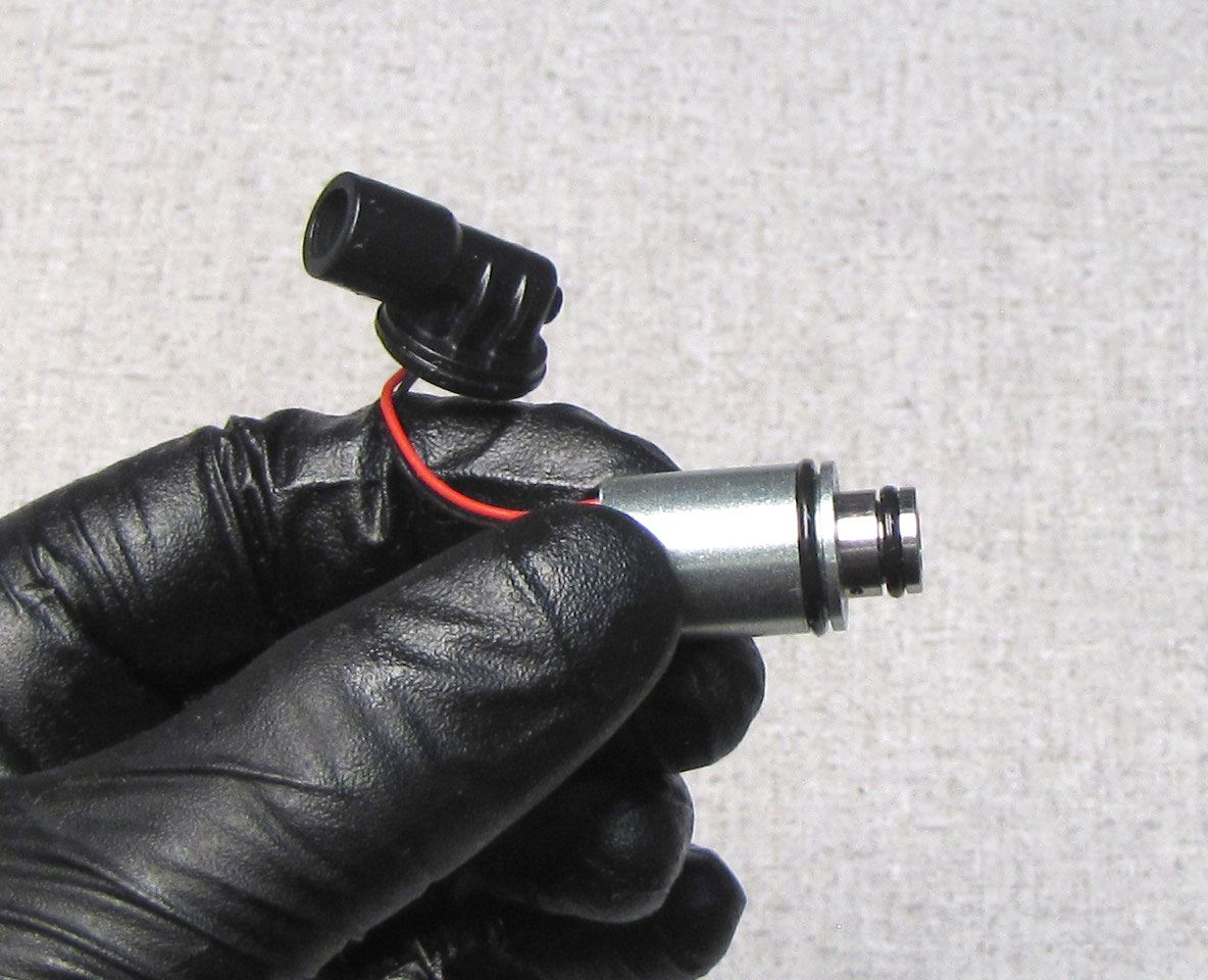
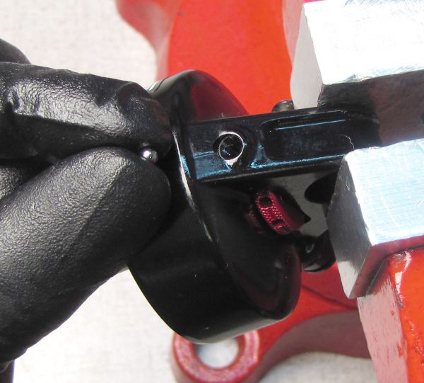
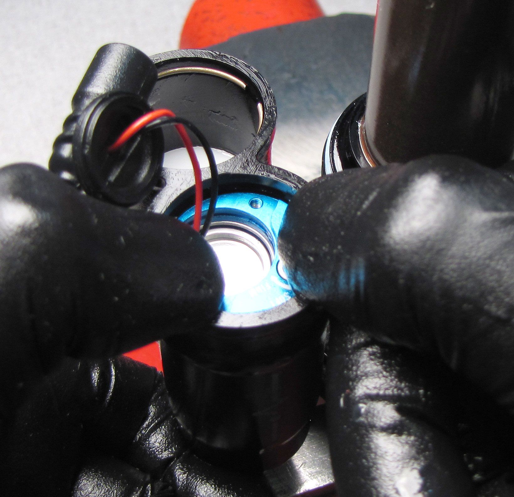
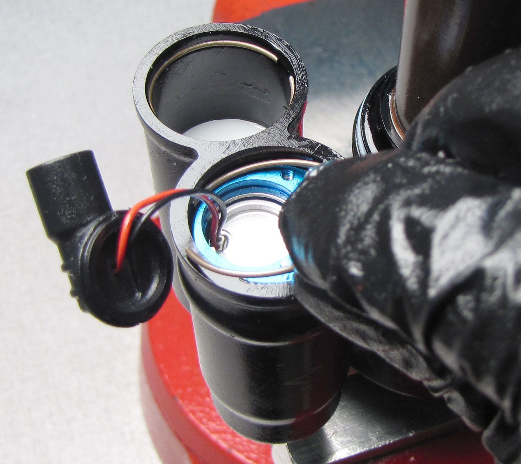
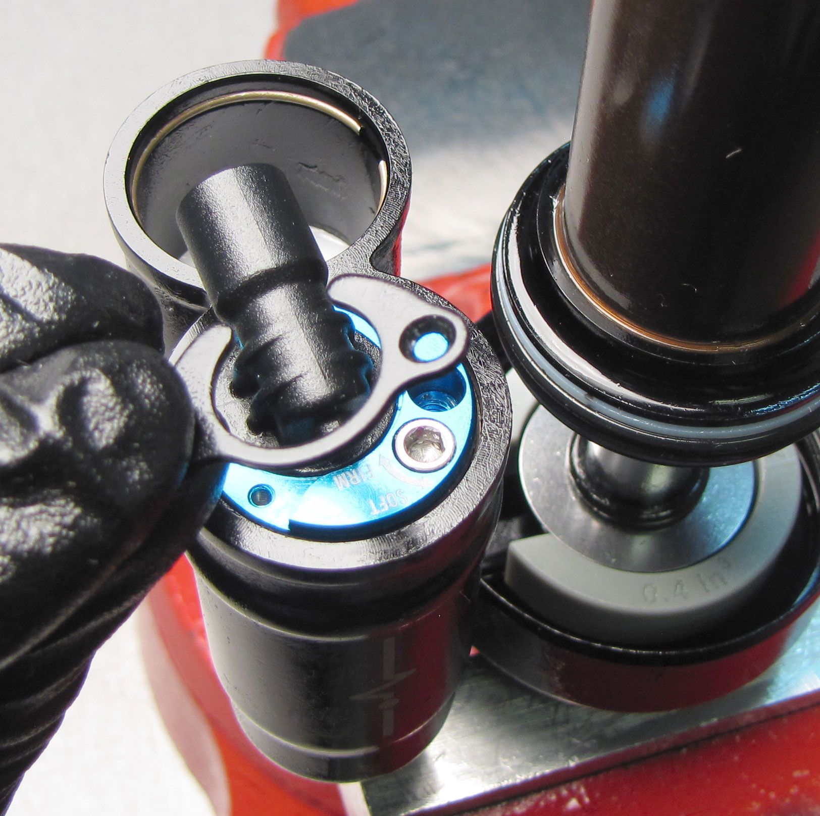
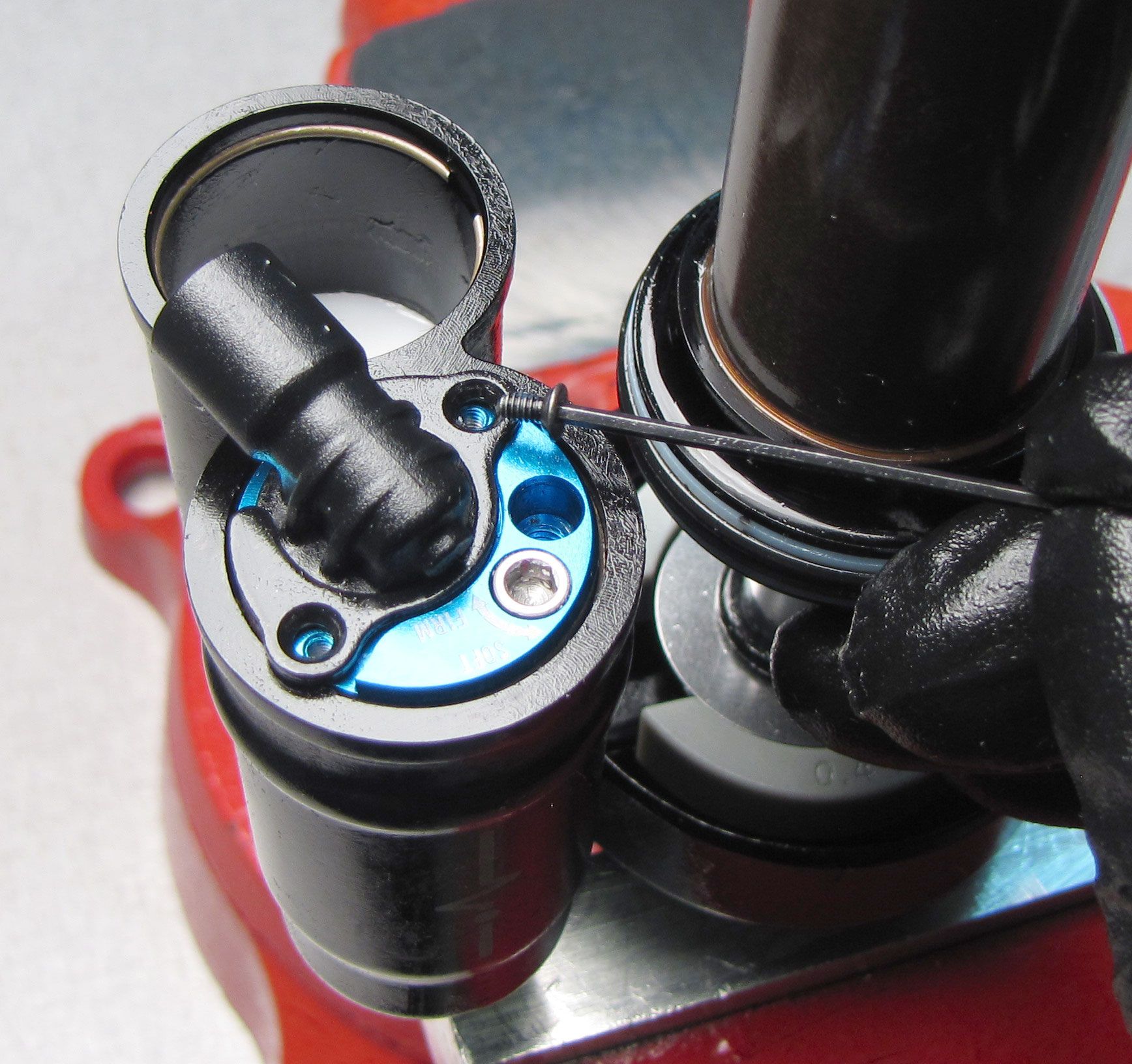
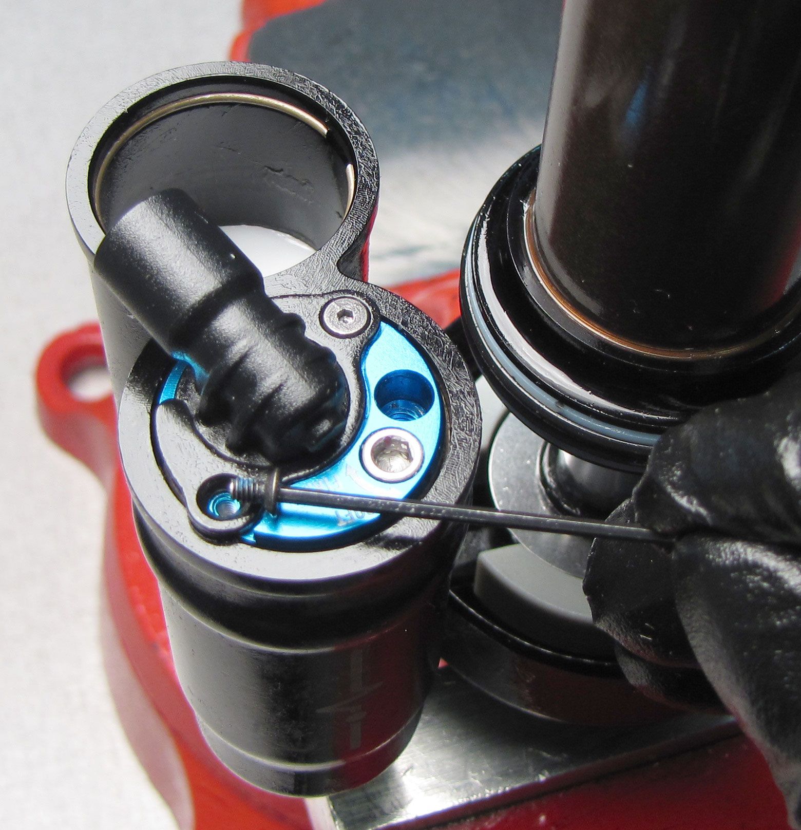
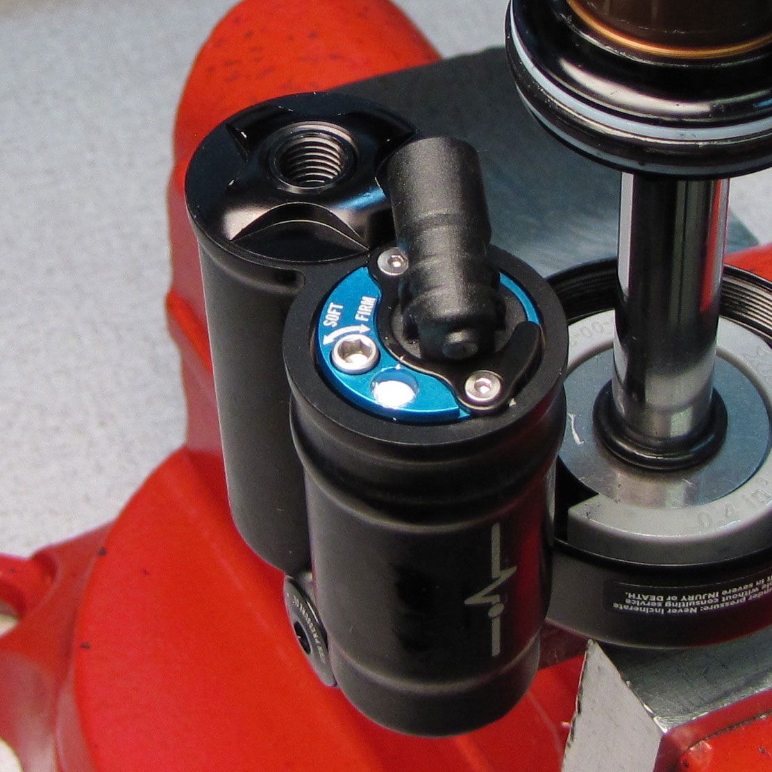
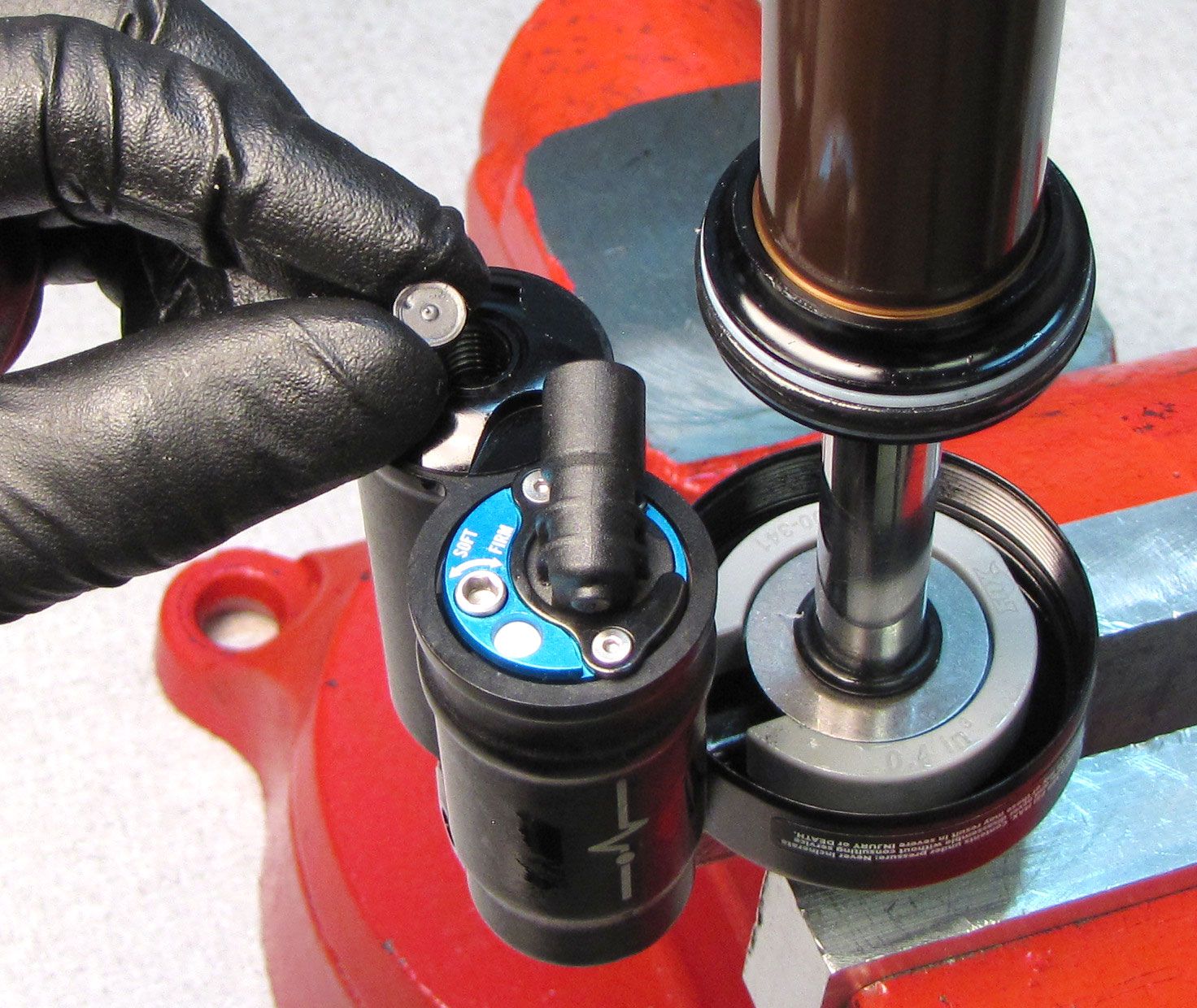
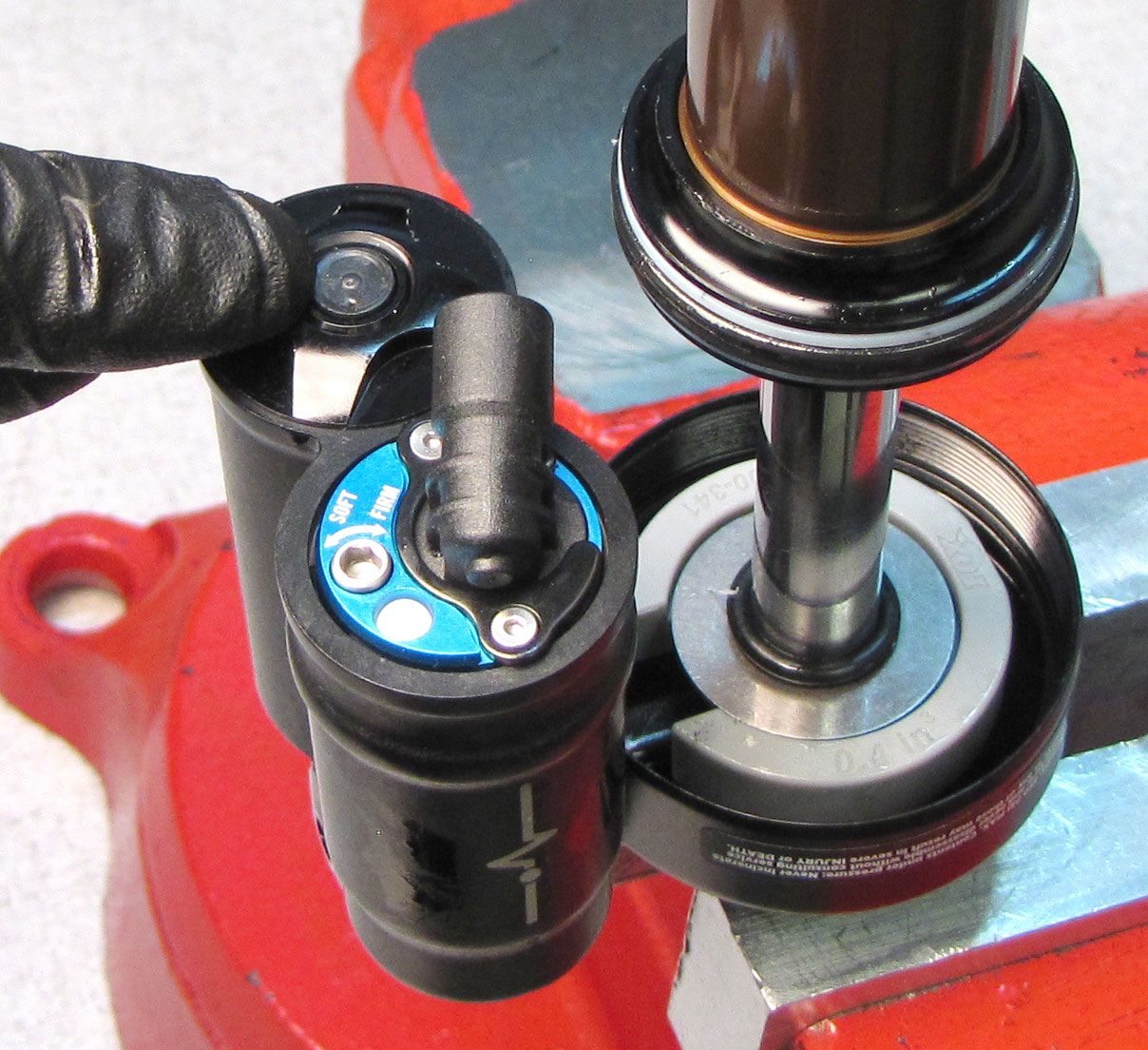
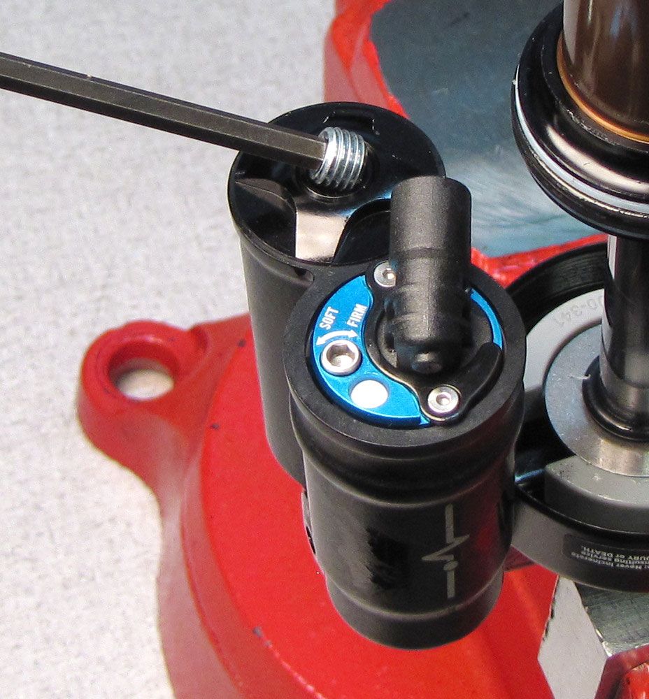
Unthread the two screws holding the Solenoid End Cap Retainer Plate by turning them counter-clockwise with a 0.050in hex wrench. Remove the Solenoid End Cap Retainer Plate.
Never pull on the wires connecting the Solenoid to the cable connector as damage may occur. Any damage to the Solenoid, Solenoid wires, or cable connector will require replacement of the Solenoid assembly.
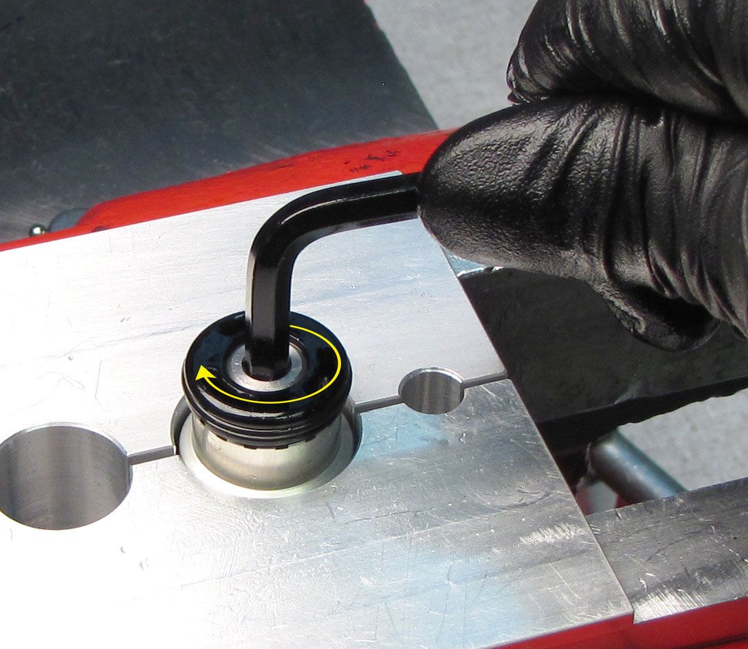
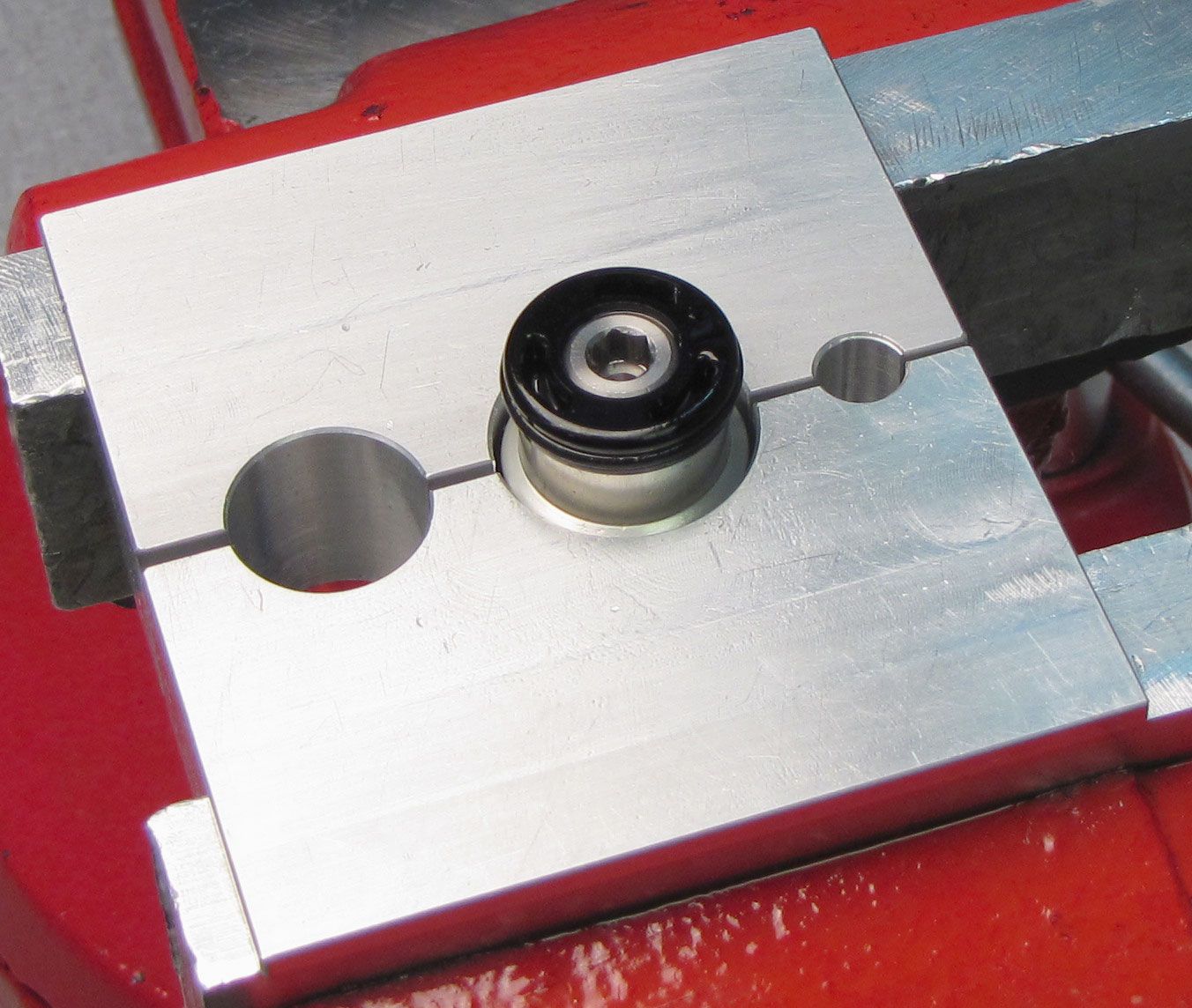
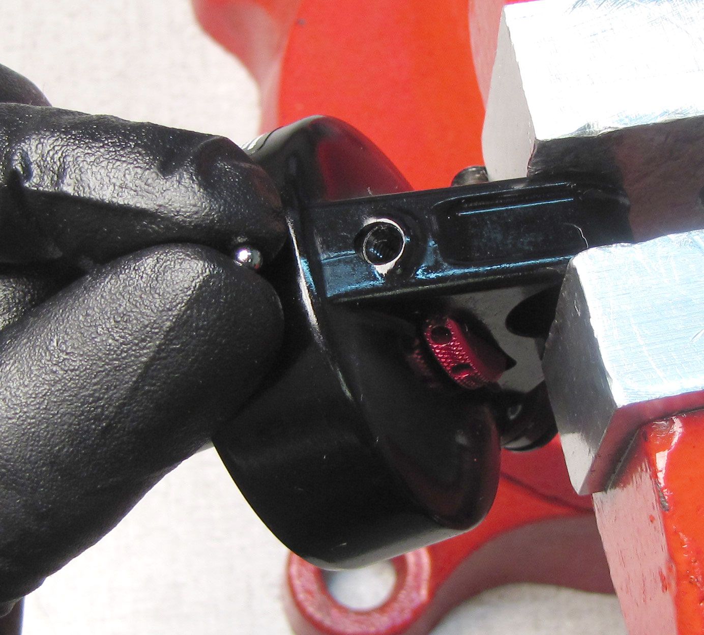
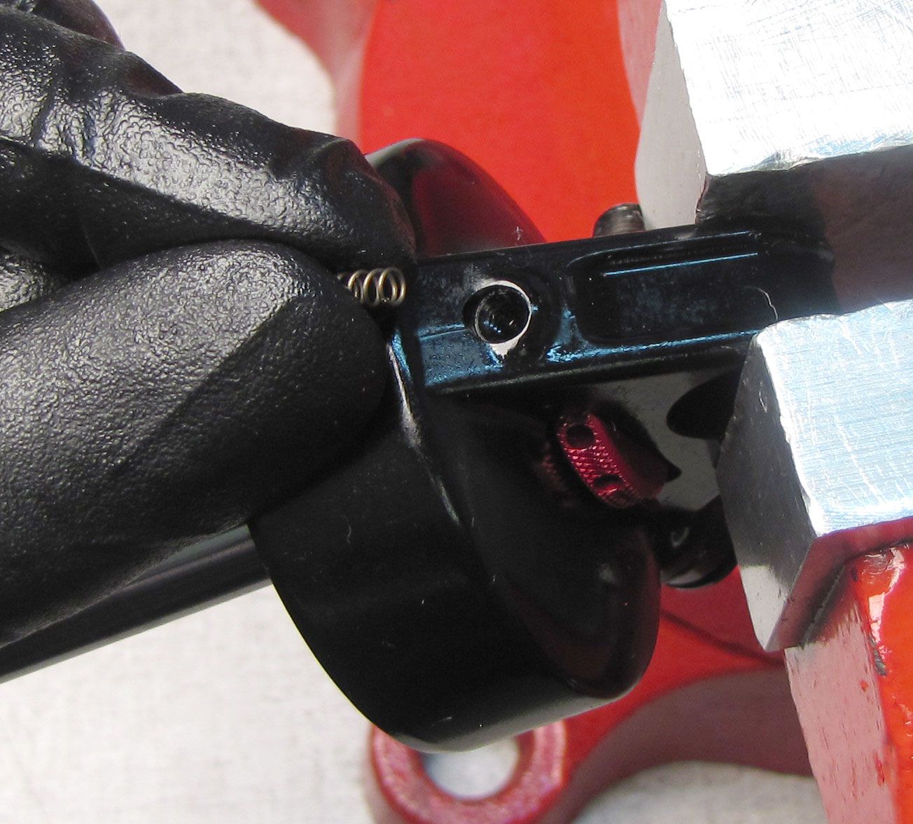
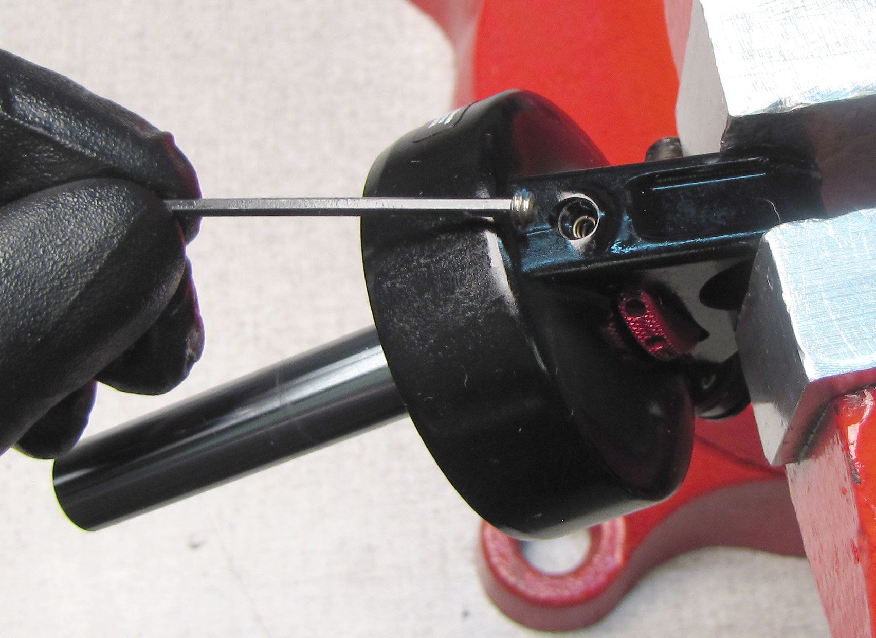
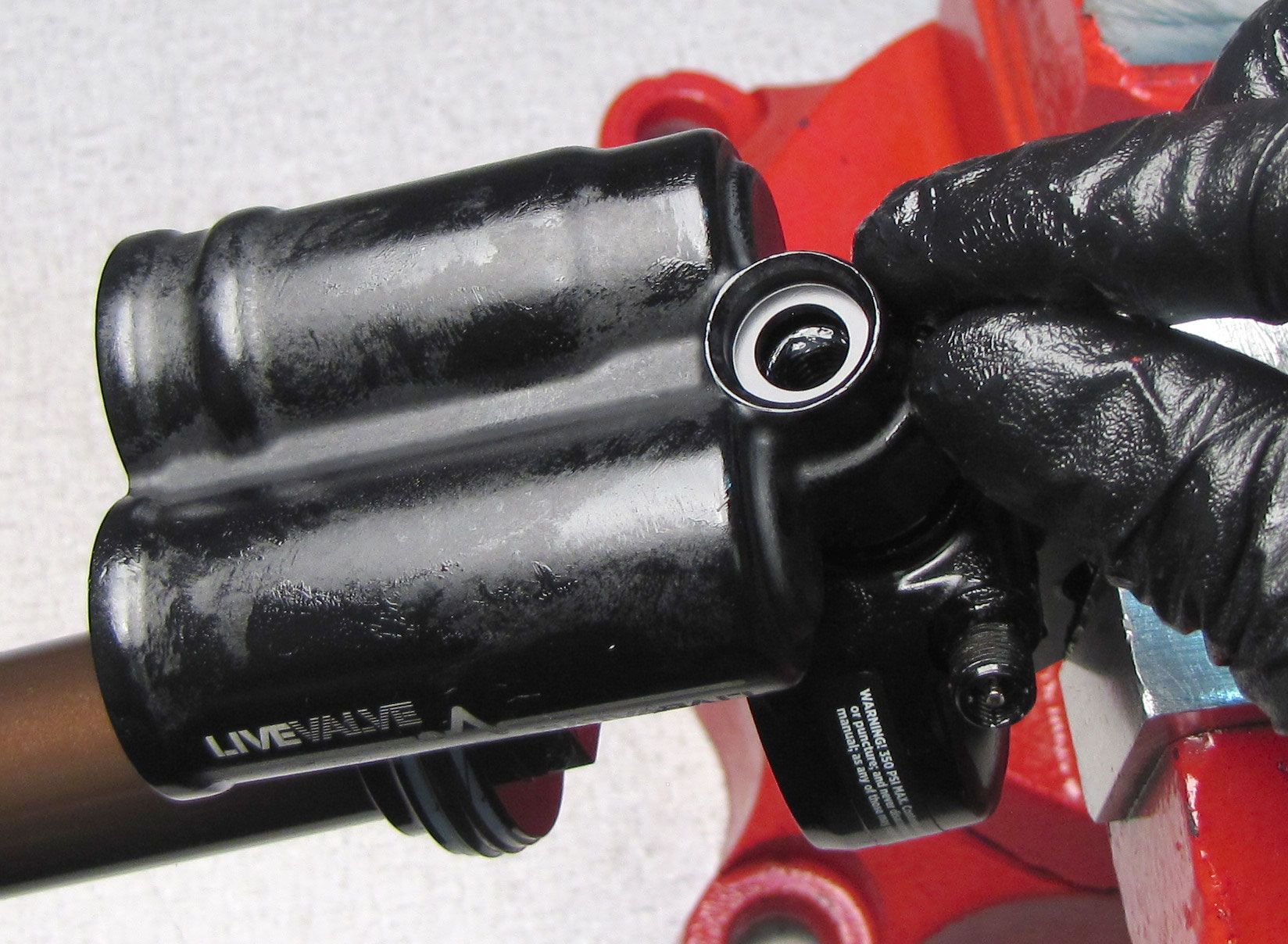
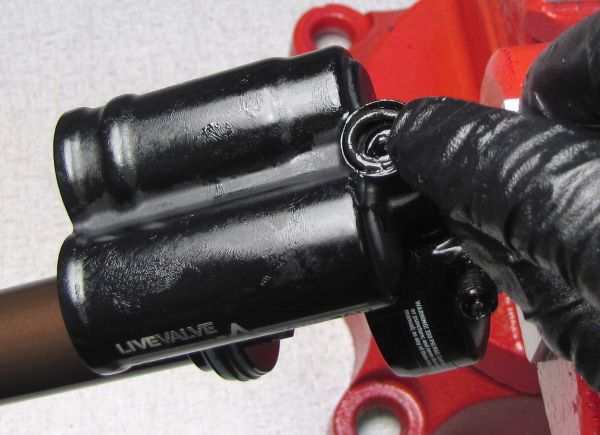
Step 6
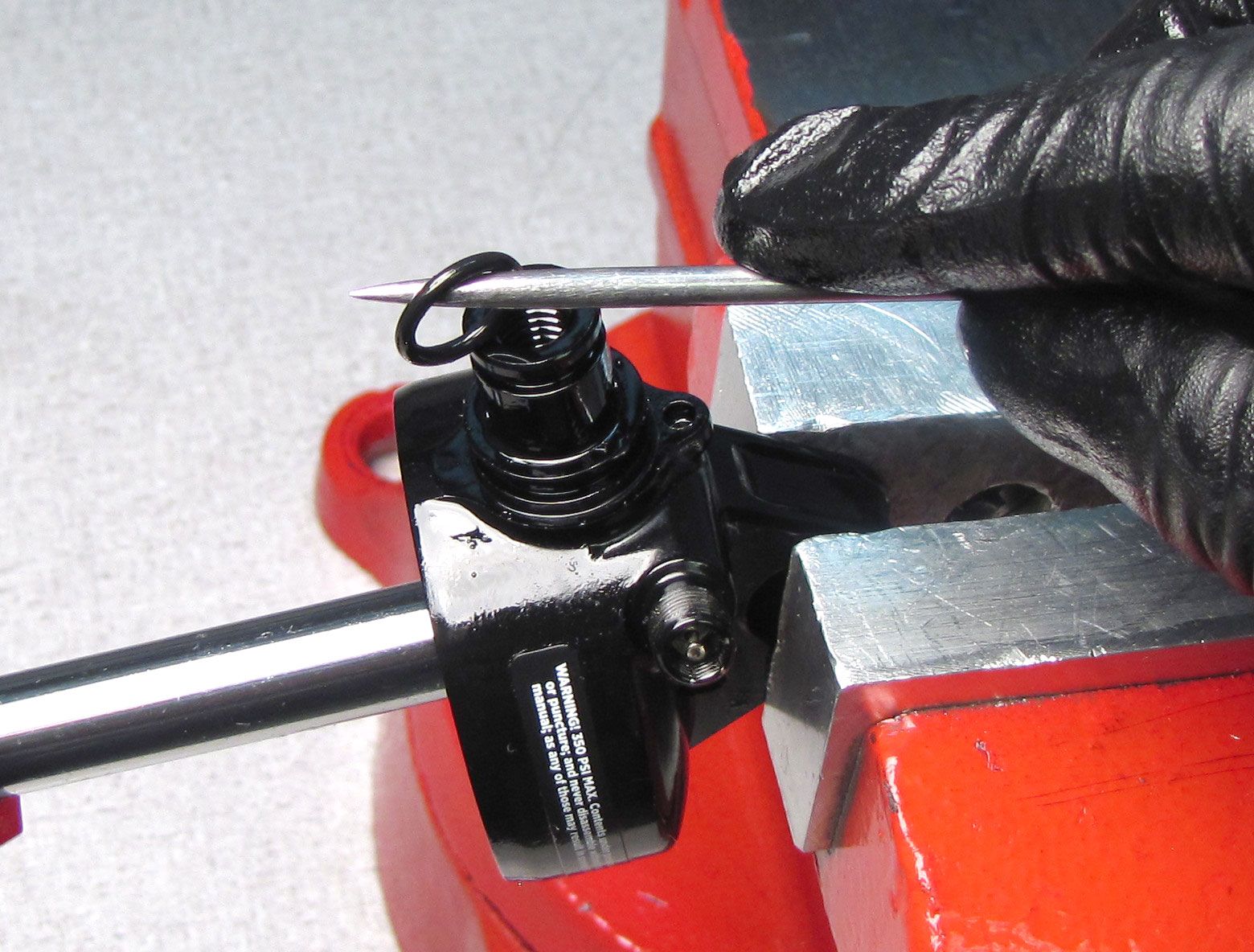
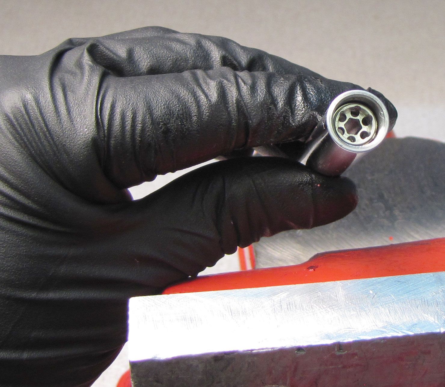
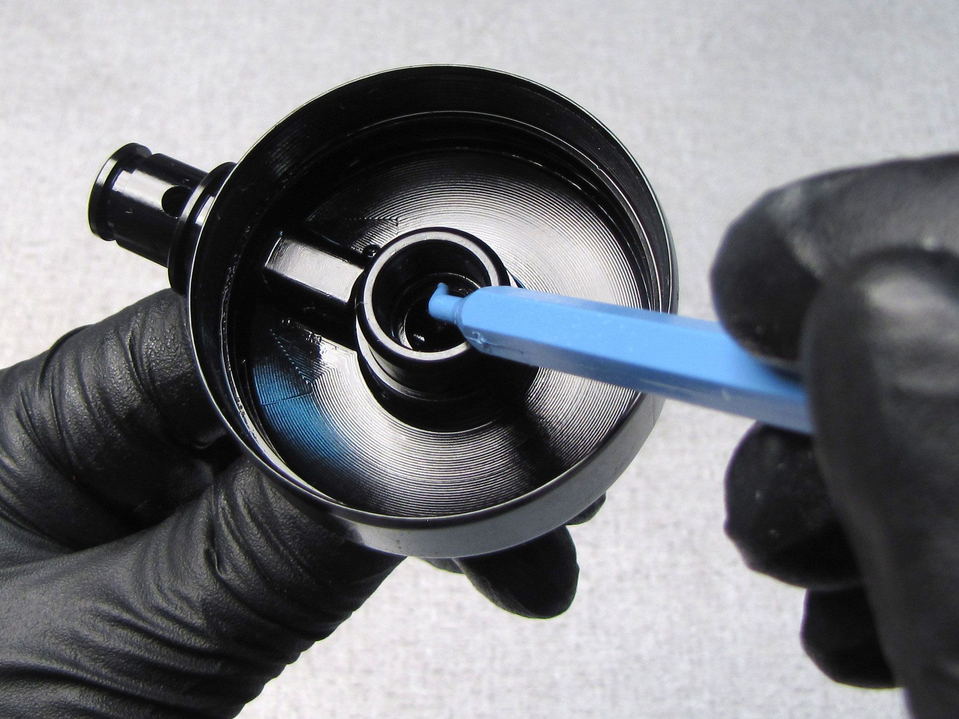
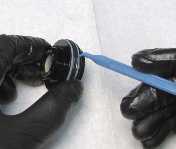
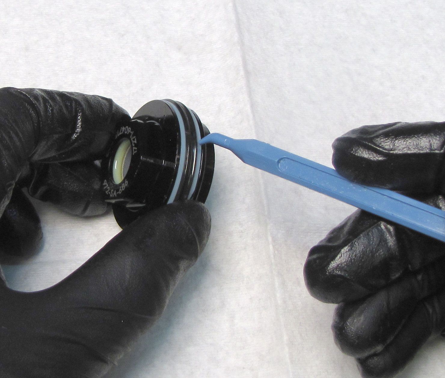
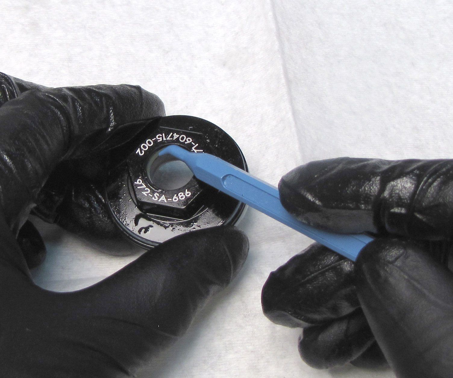
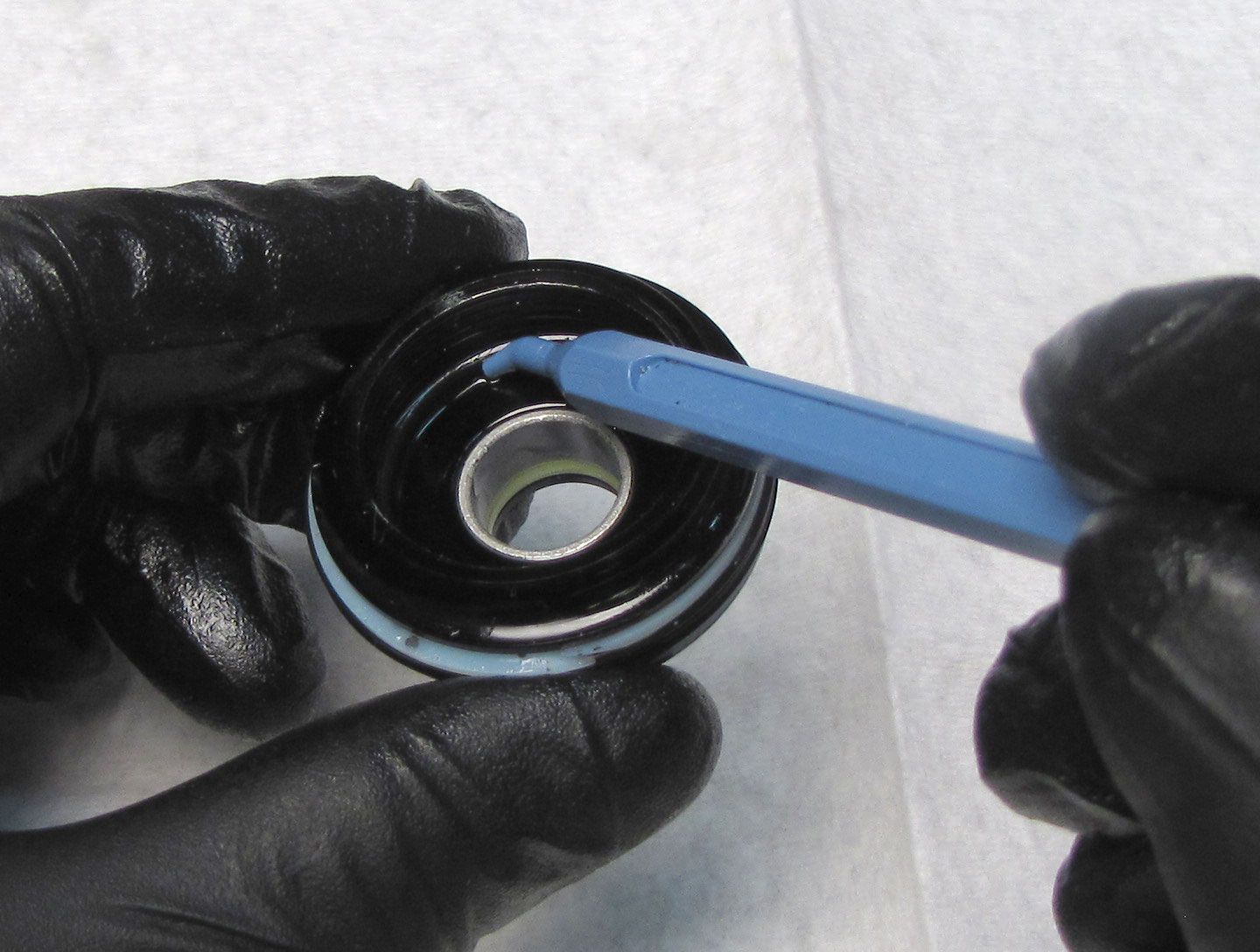
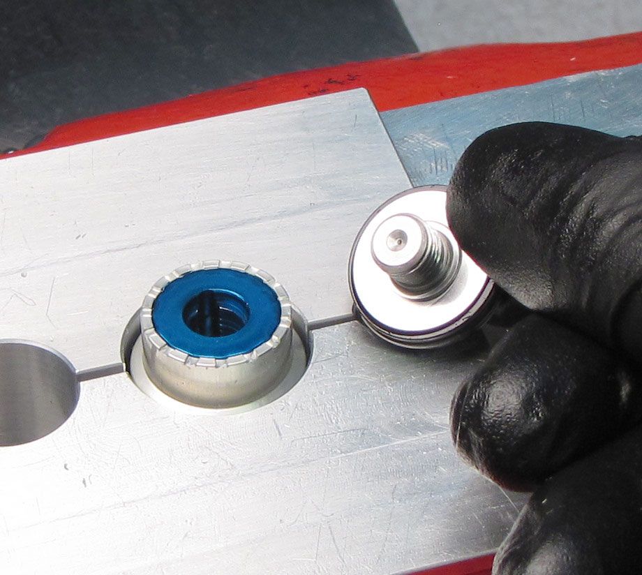
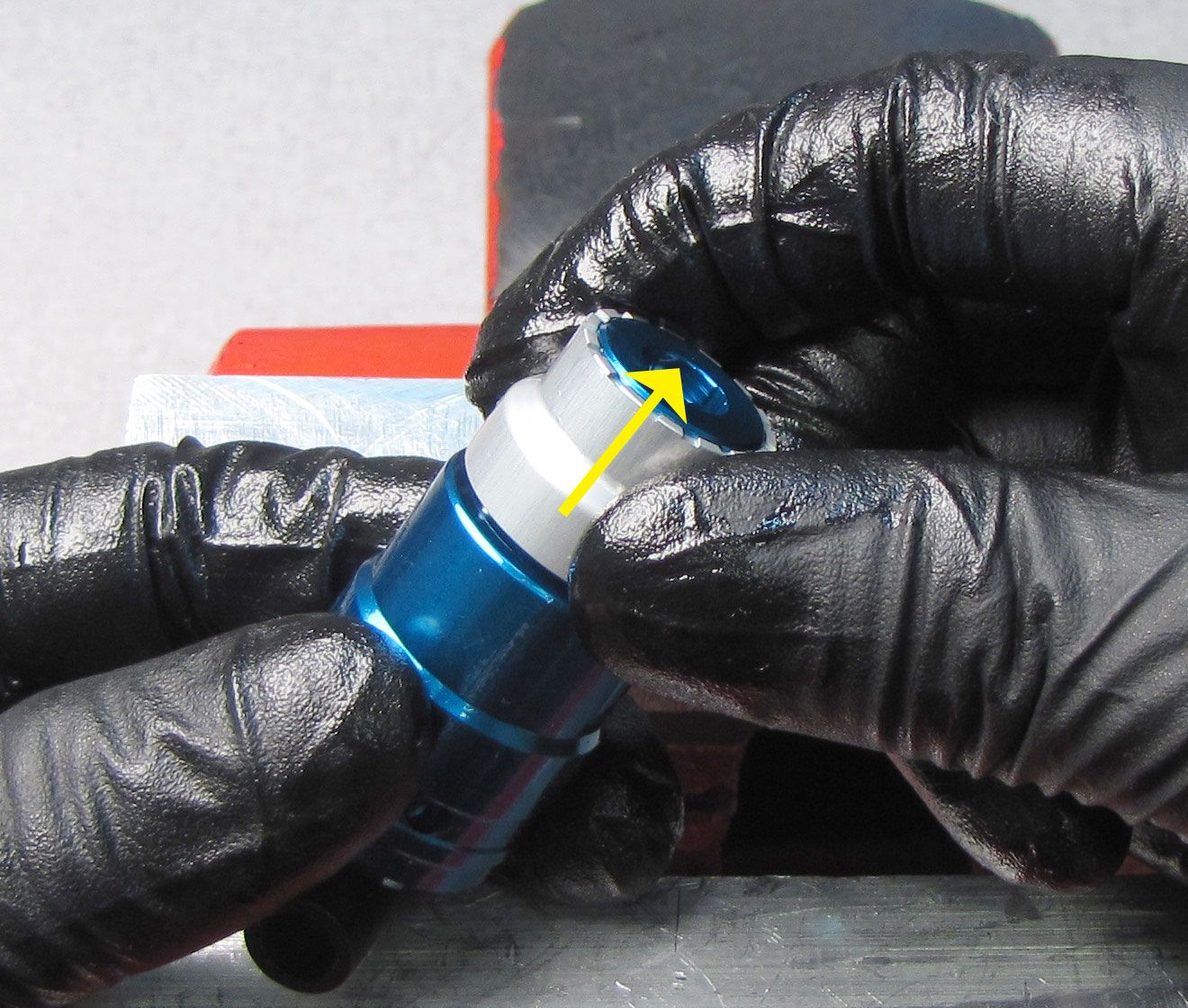
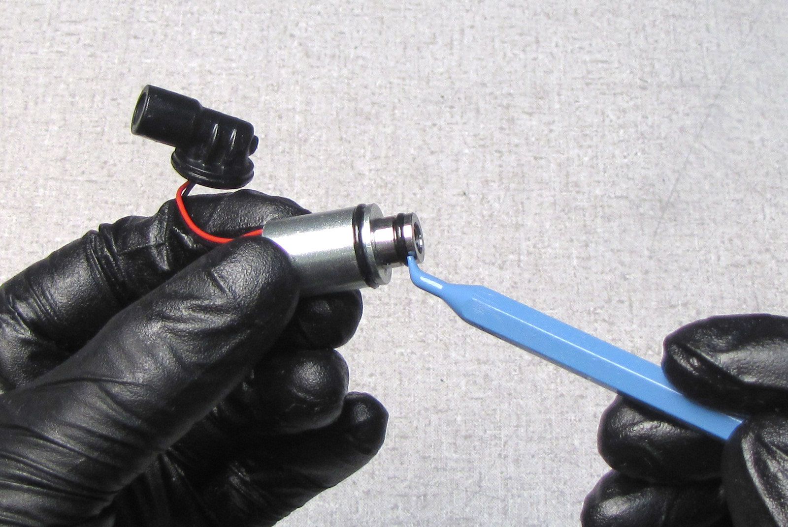
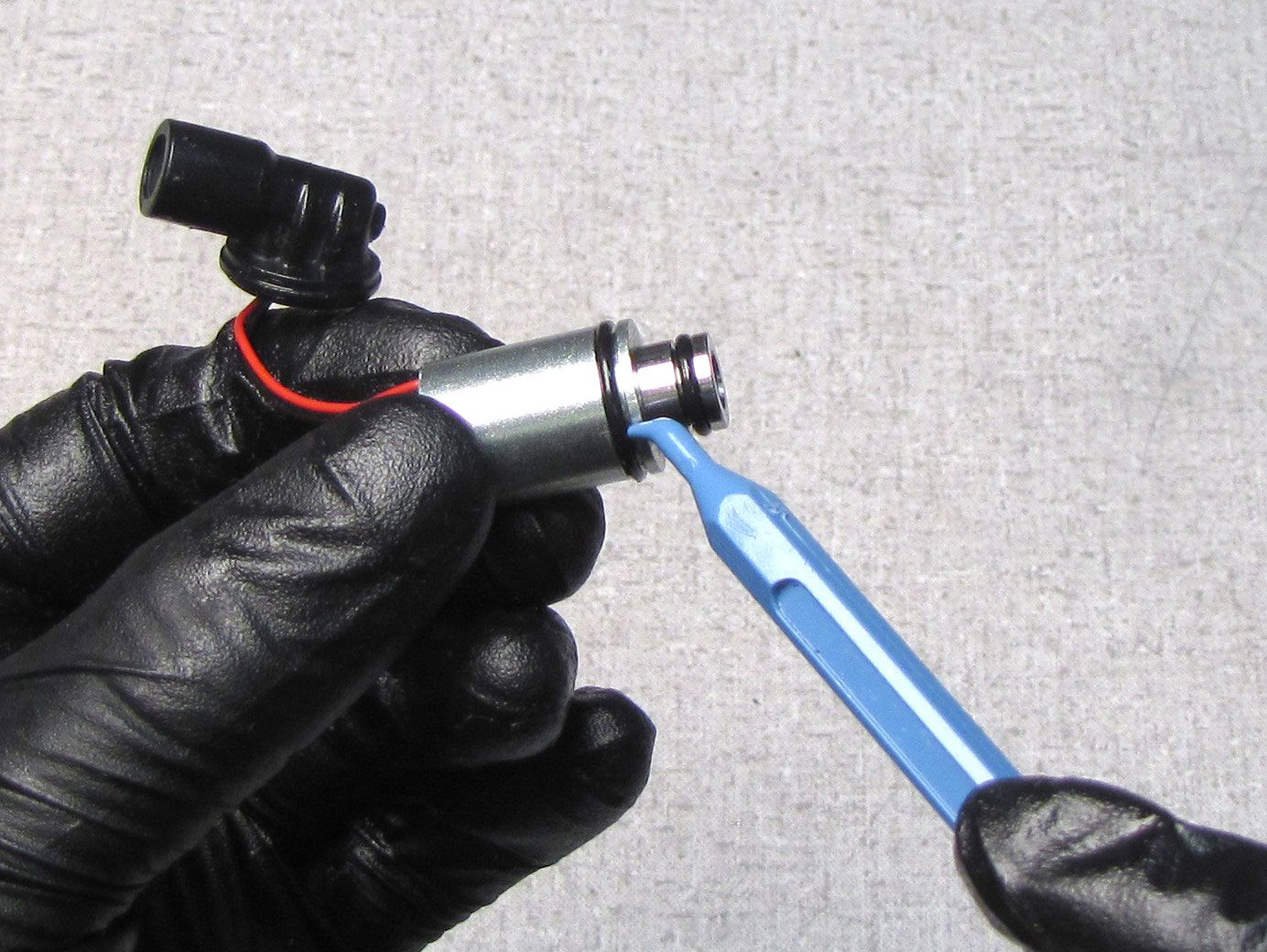
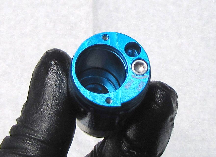
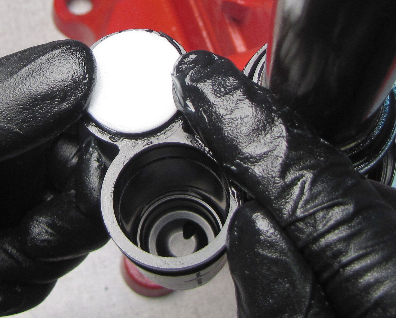
Remove the white Delrin ball from the Compression Cartridge Housing bleed port. It can be helpful to heat your metal pick before removing the Delrin ball. Unthread and remove the bleed screw counter-clockwise with a 5/64" hex wrench. Remove the 0.125" ball bearing from the bleed port with a magnet.


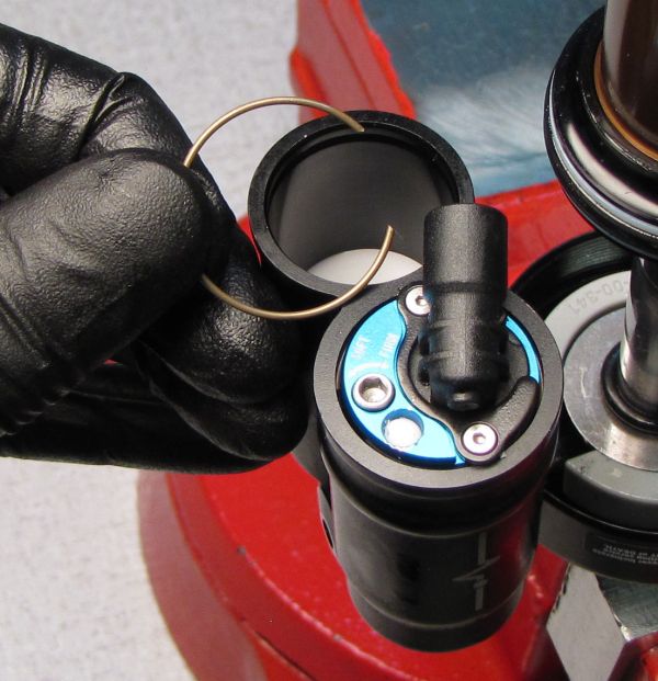
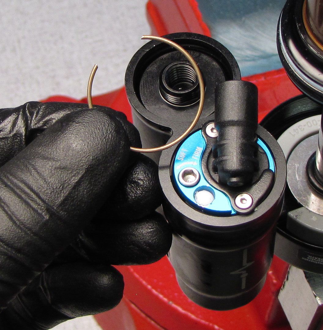
Step 7
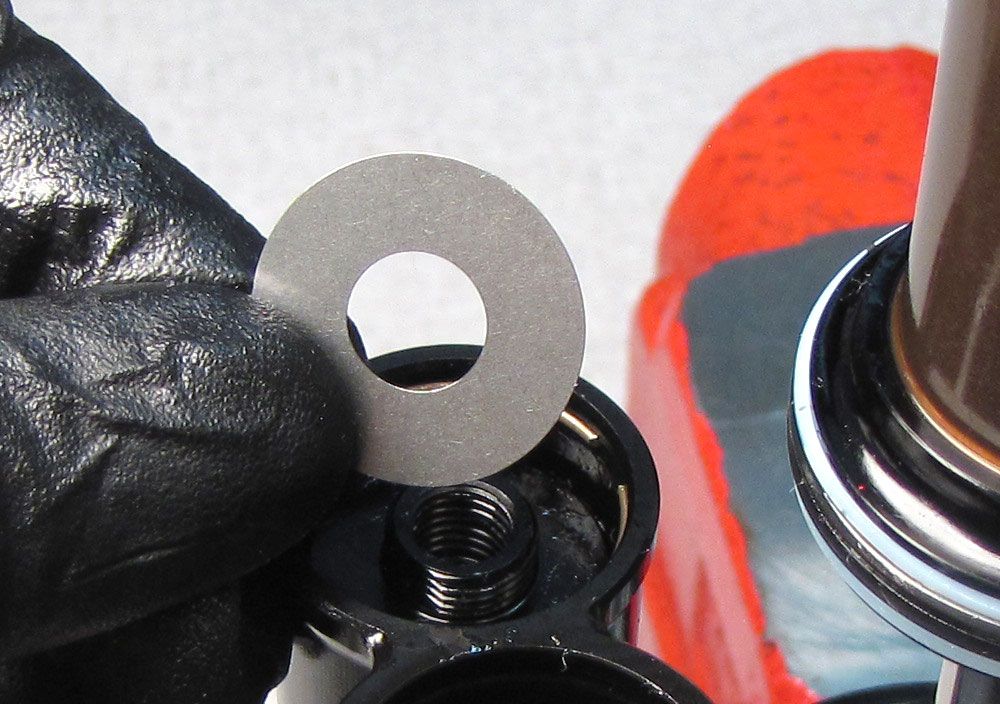
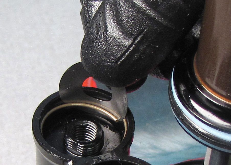
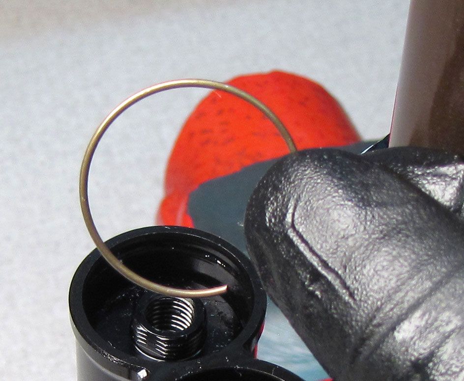
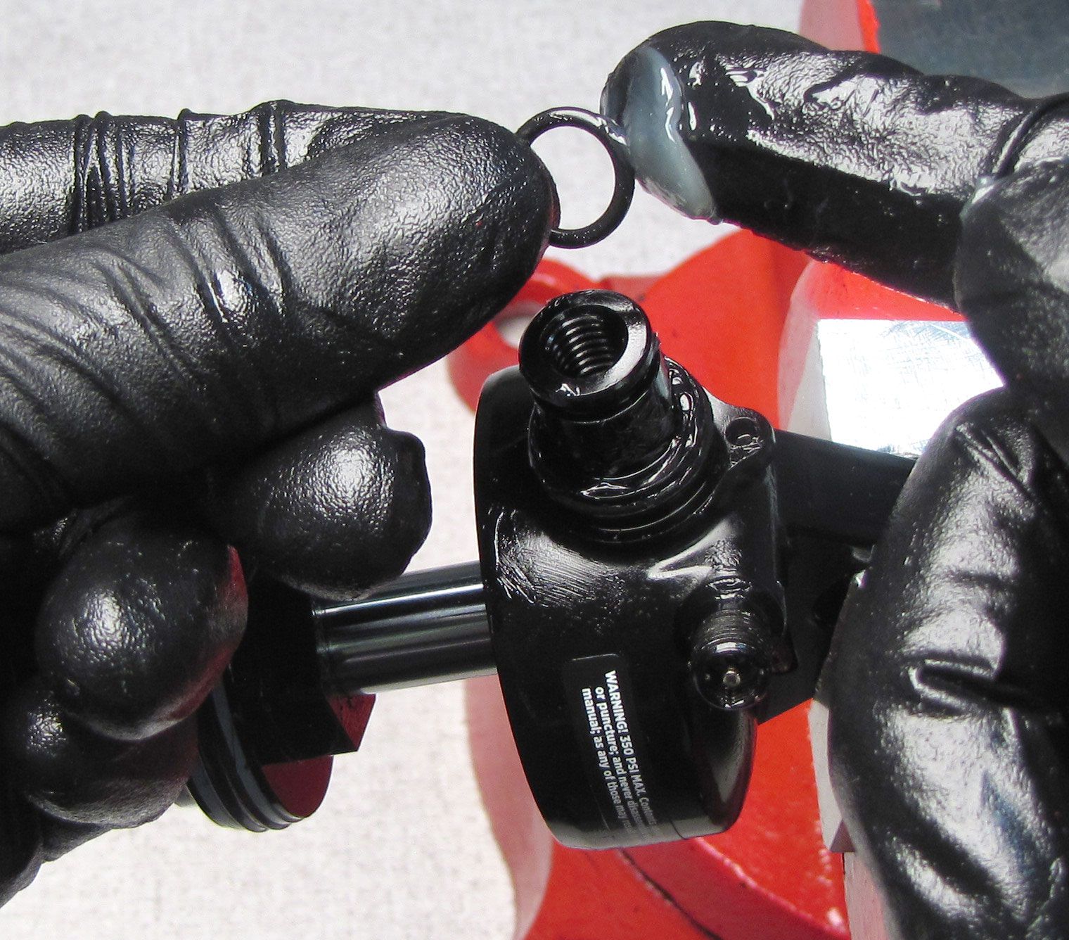
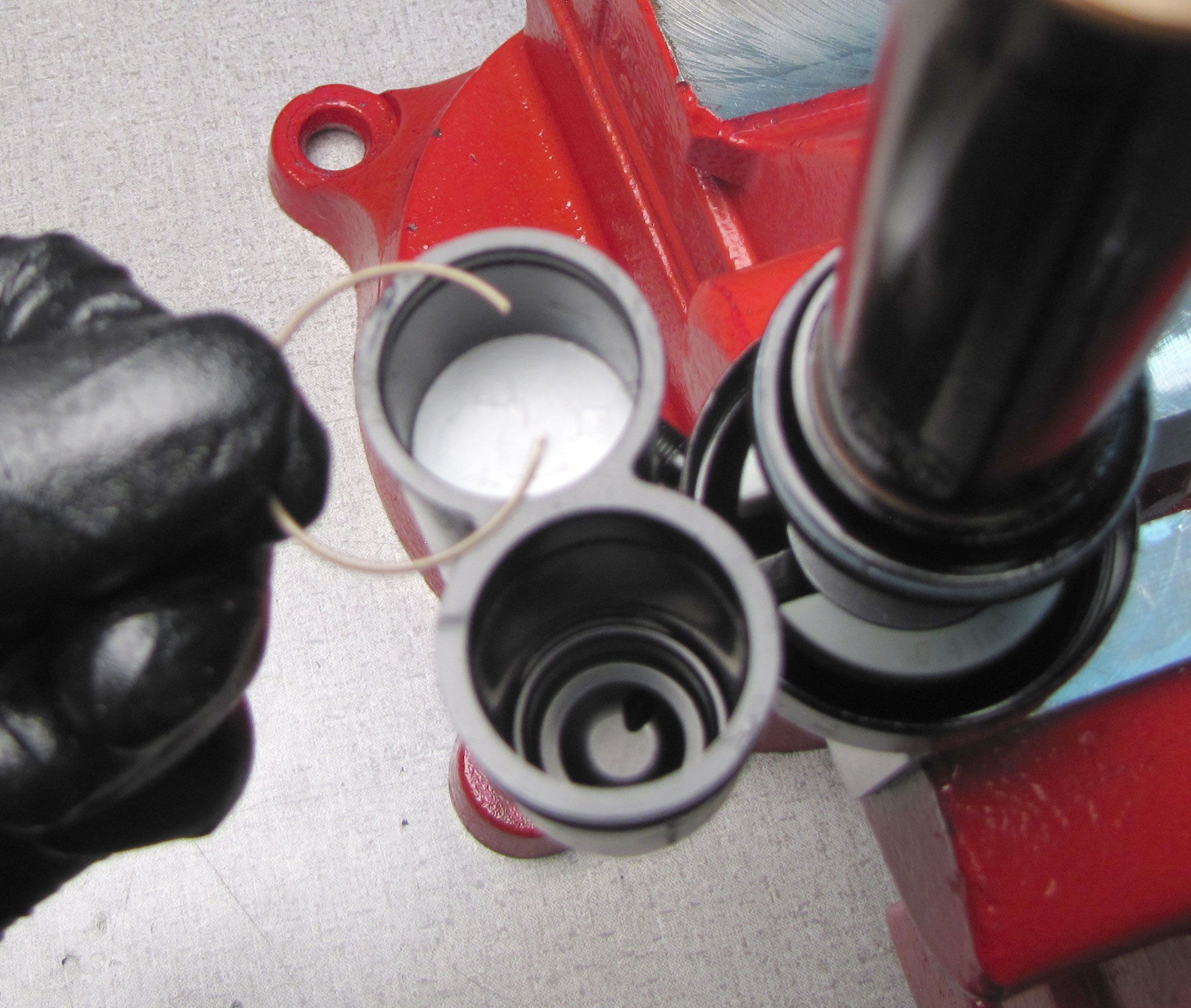
Push the End Cap Assembly into the reservoir to access the wire retaining ring. Remove the wire retaining ring from within the reservoir. You may use a shim to help lift the retaining ring.
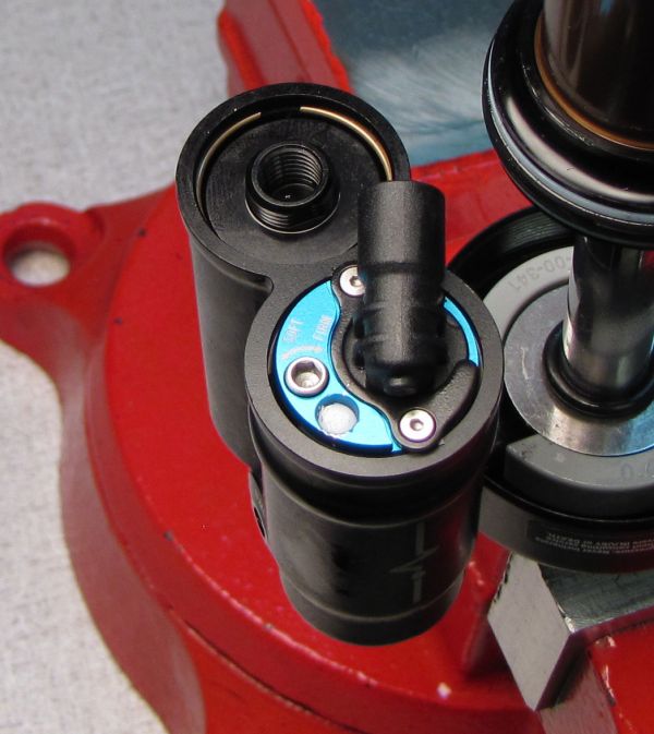
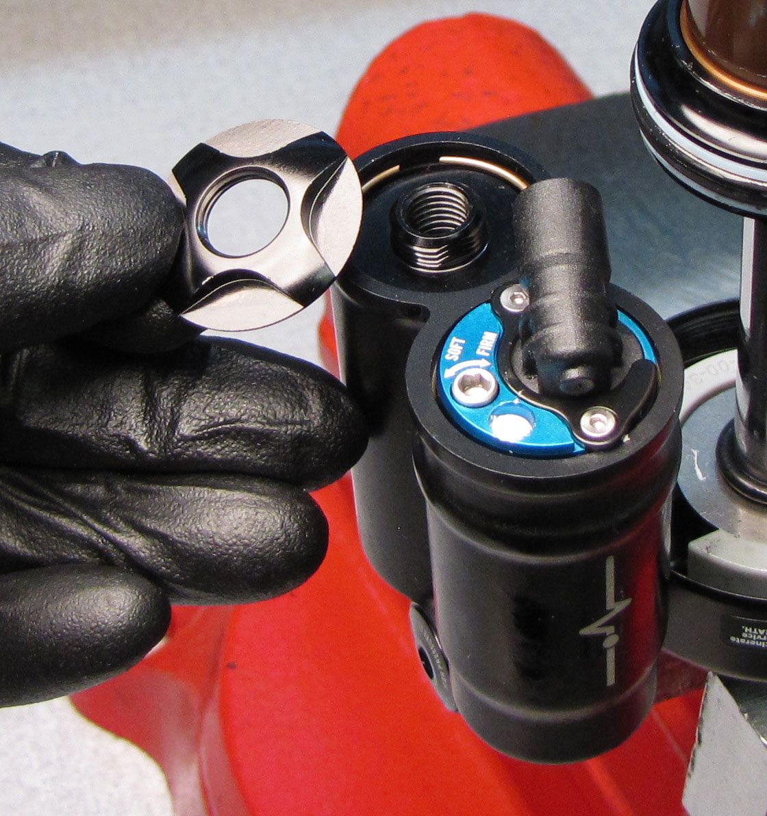
Step 8
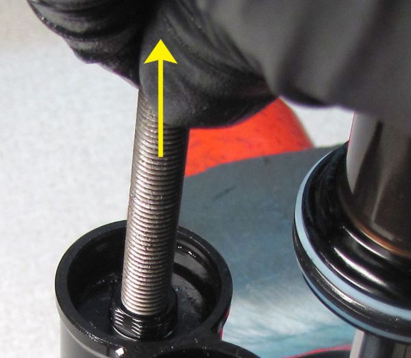
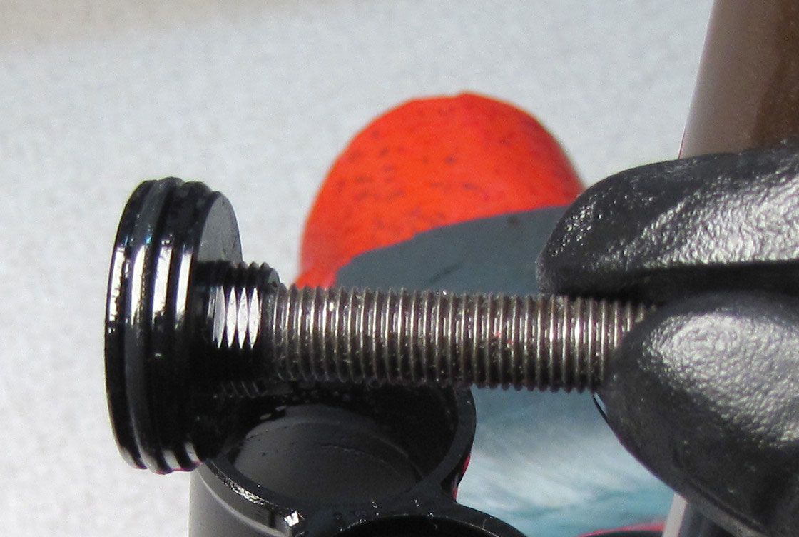
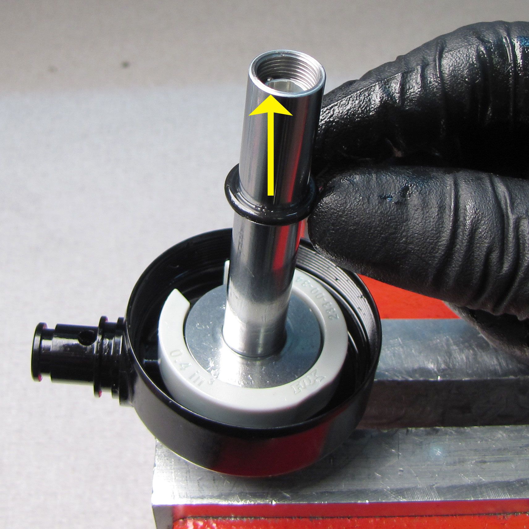
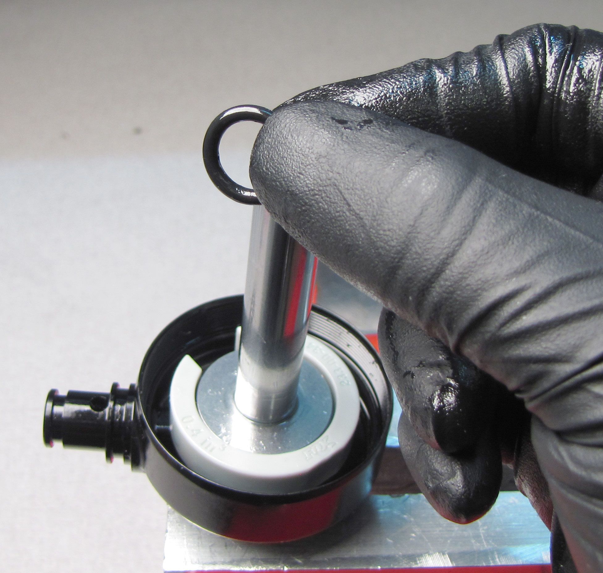
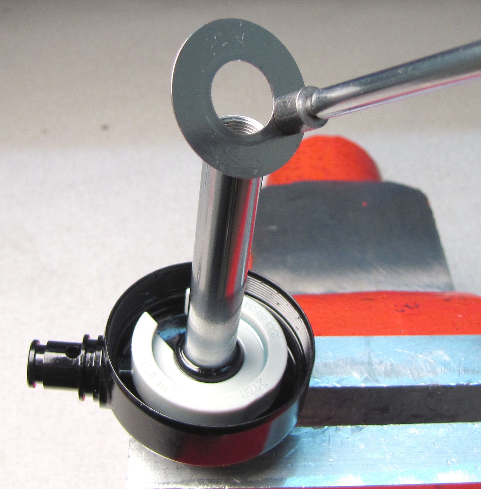
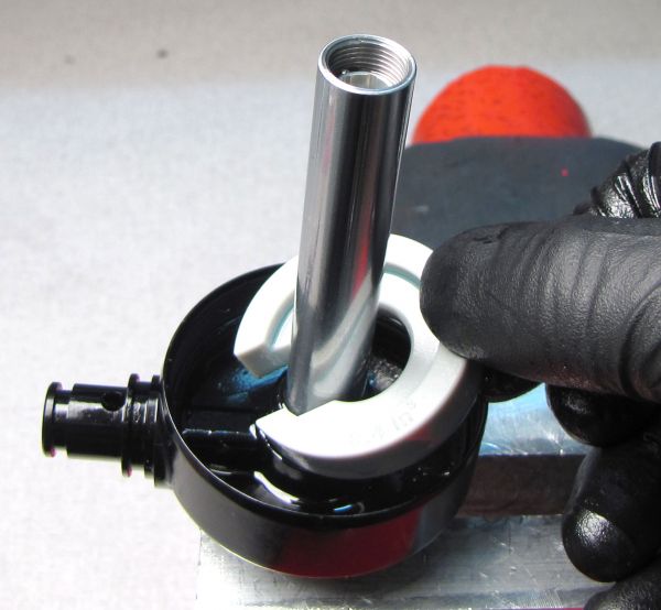
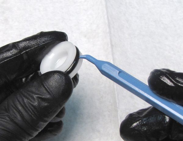
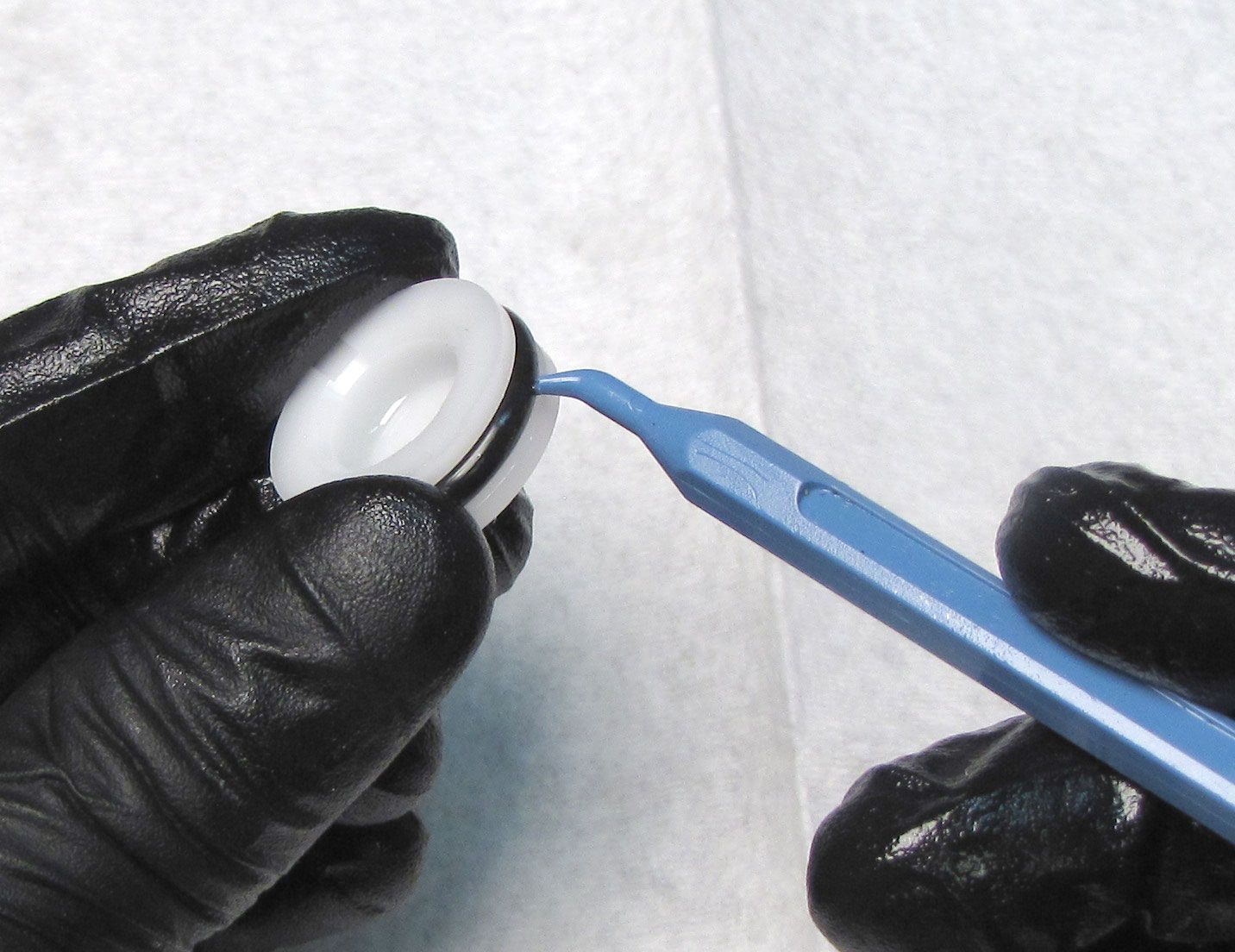
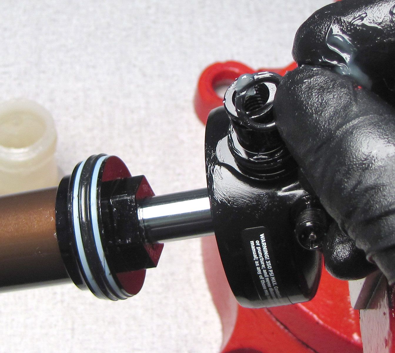
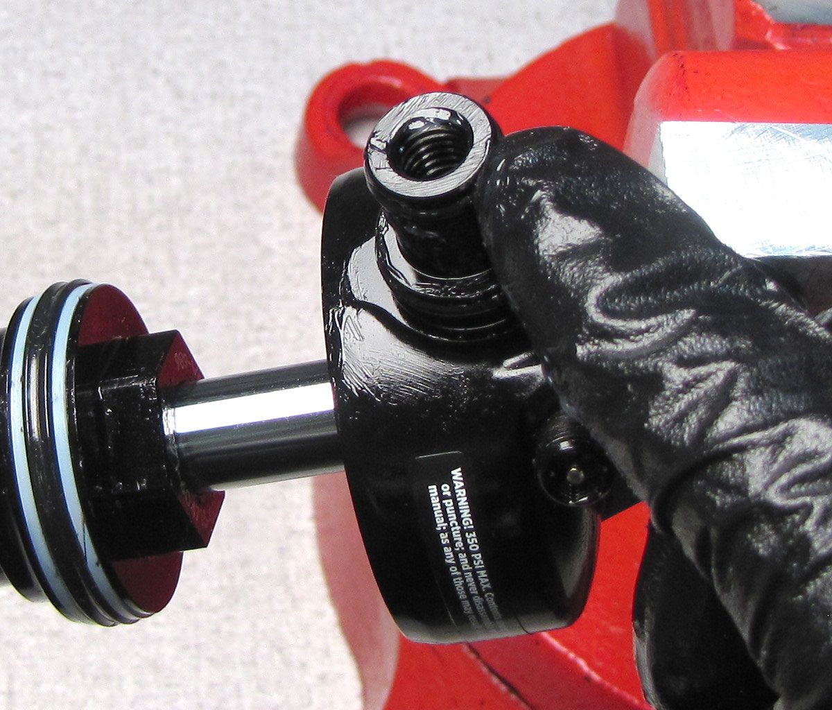
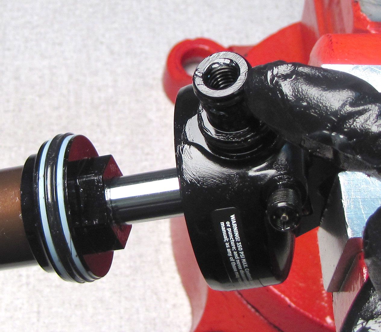
Thread a 5/16-24 threaded rod or bolt into the Reservoir End Cap then pull up to remove it. If you do not have a 5/16-24 threaded rod or bolt, pull up on the Reservoir End Cap with pliers on the flats of the raised portion of the end cap. Do not use pliers on the external threads of the end cap. Replace the o-ring on the end cap with a new greased one from the kit.


Step 9
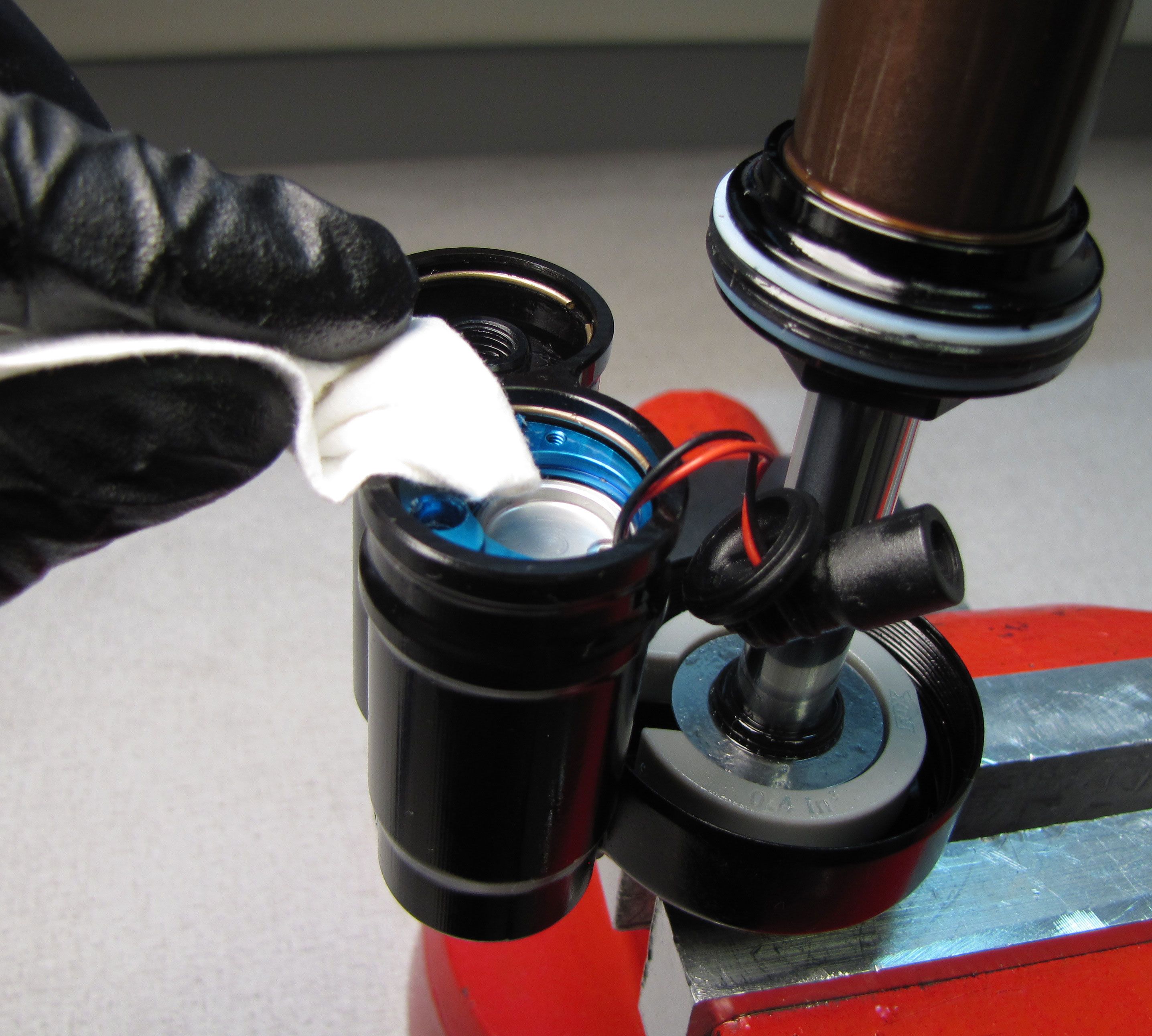
Cover the reservoir with a lint-free paper towel and inject compressed air into the bleed port on the Compression Cartridge Housing to blow out the IFP.

Step 10
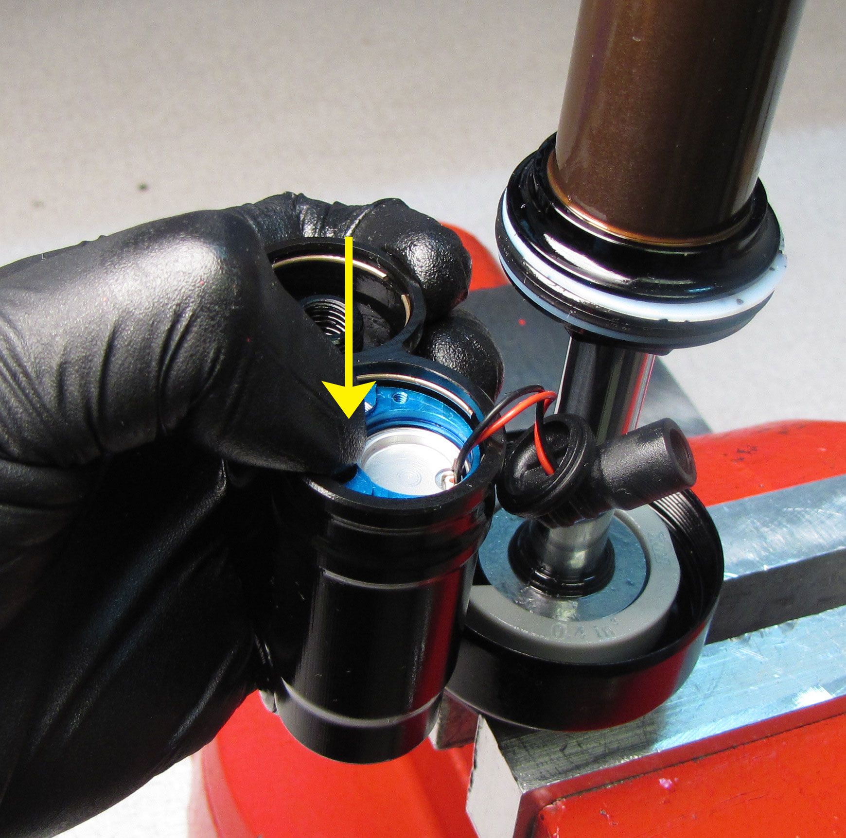
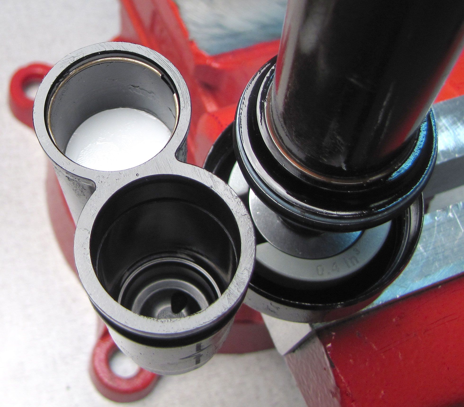
Invert the shock over a waste oil basin to pour out any oil from the bleed port in the Compression Cartridge Housing. Clean any oil residue from the Compression Cartridge Housing then press the Compression Cartridge Housing into the reservoir to expose the wire retaining ring.

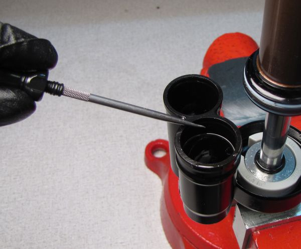
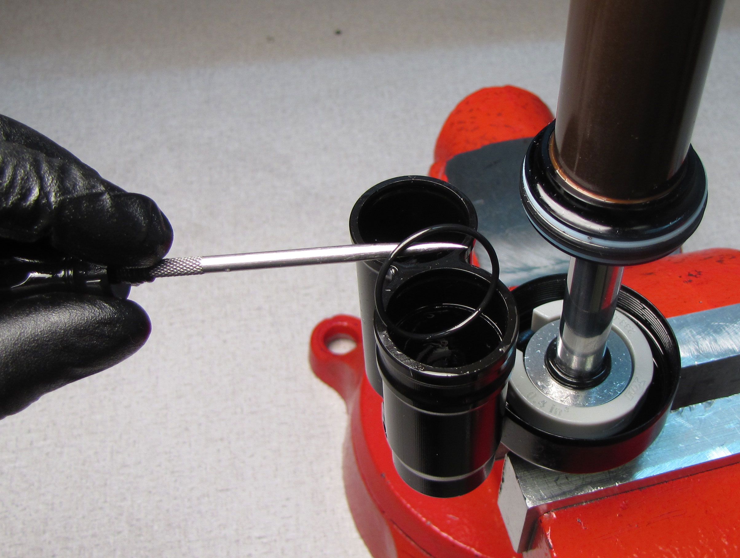
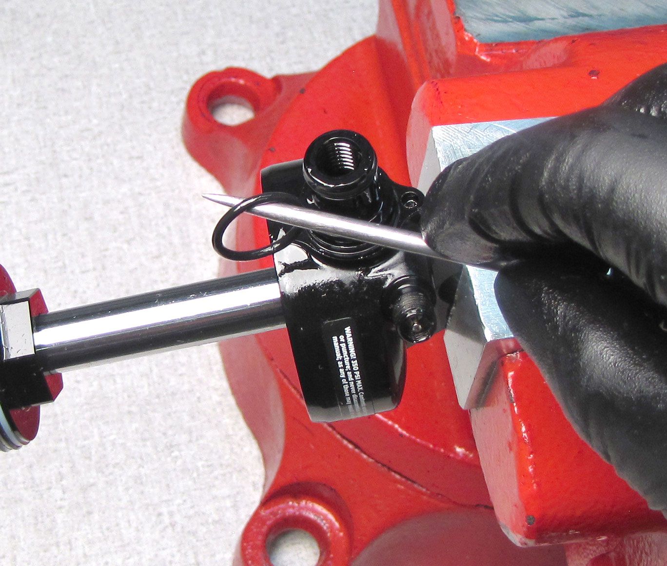
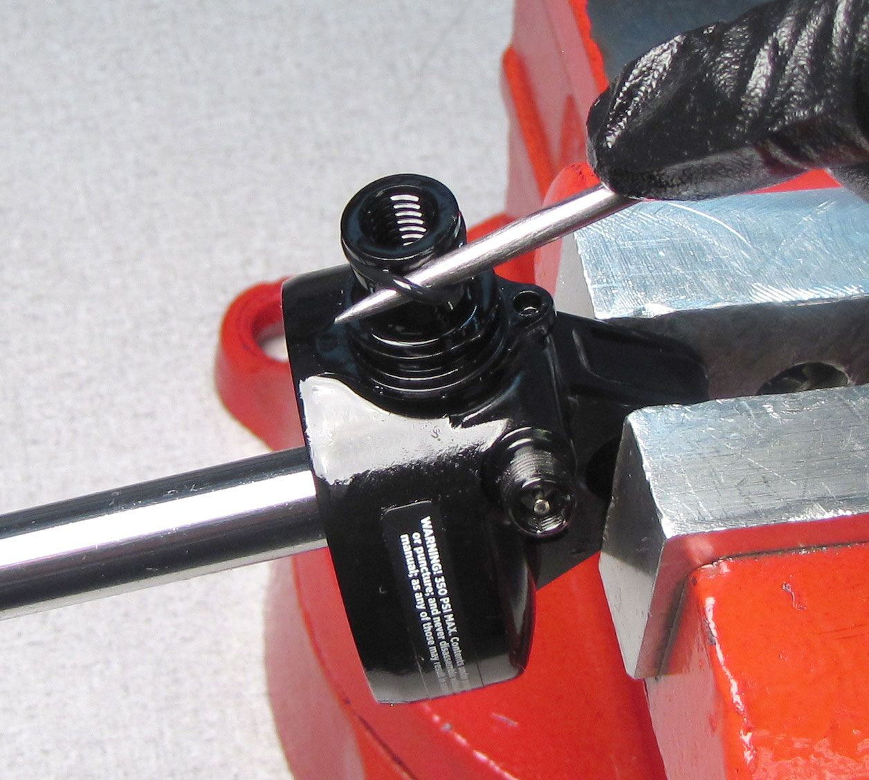
Step 11
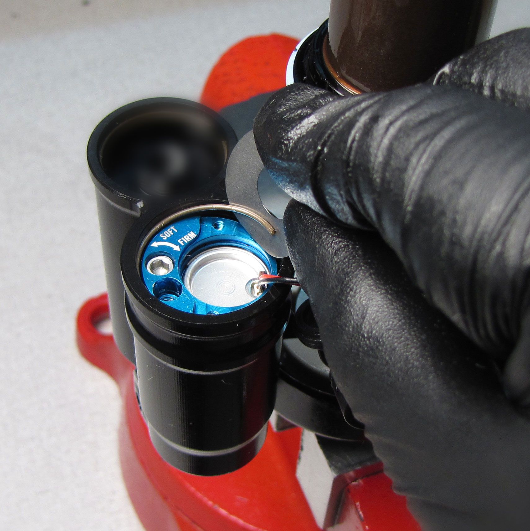
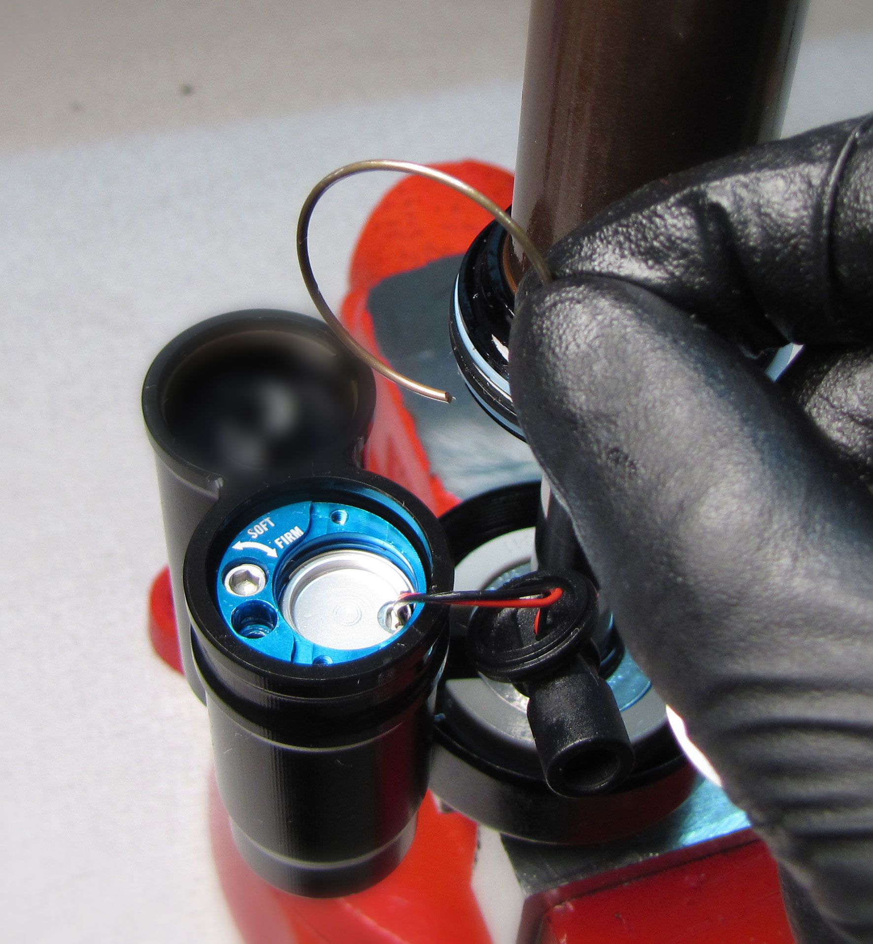
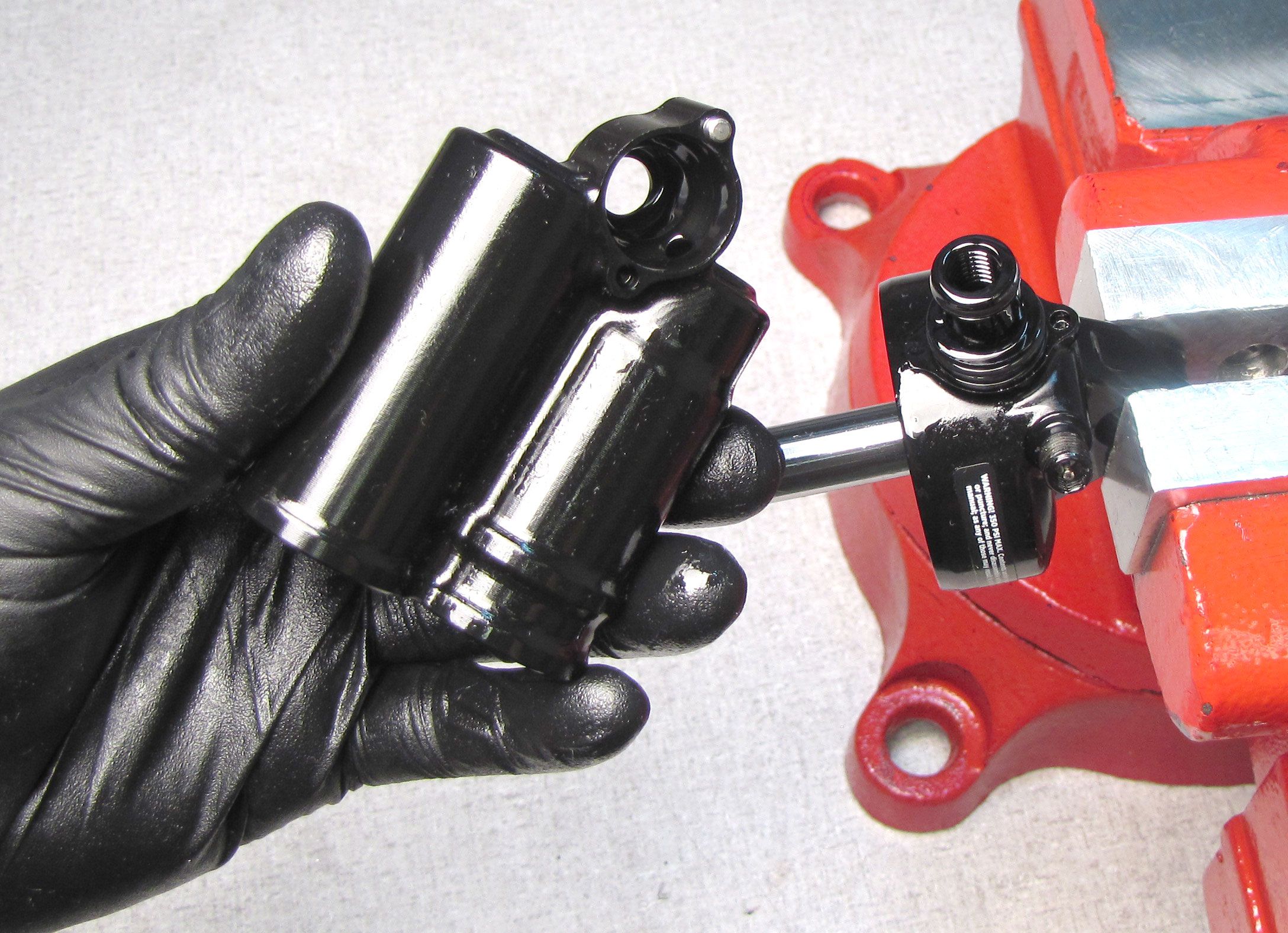
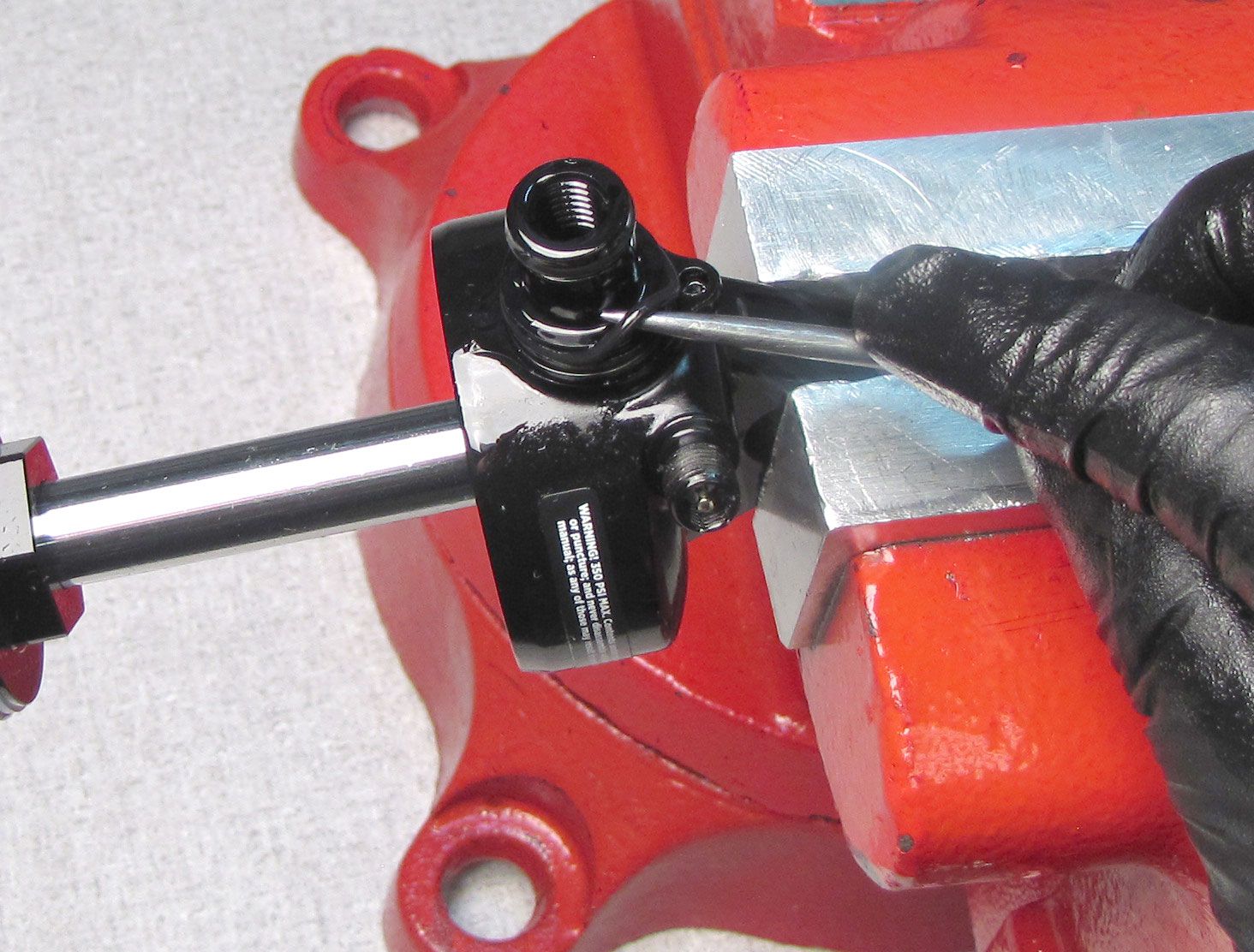
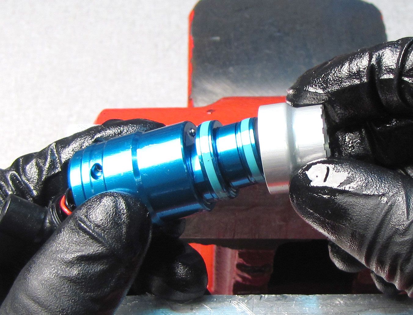
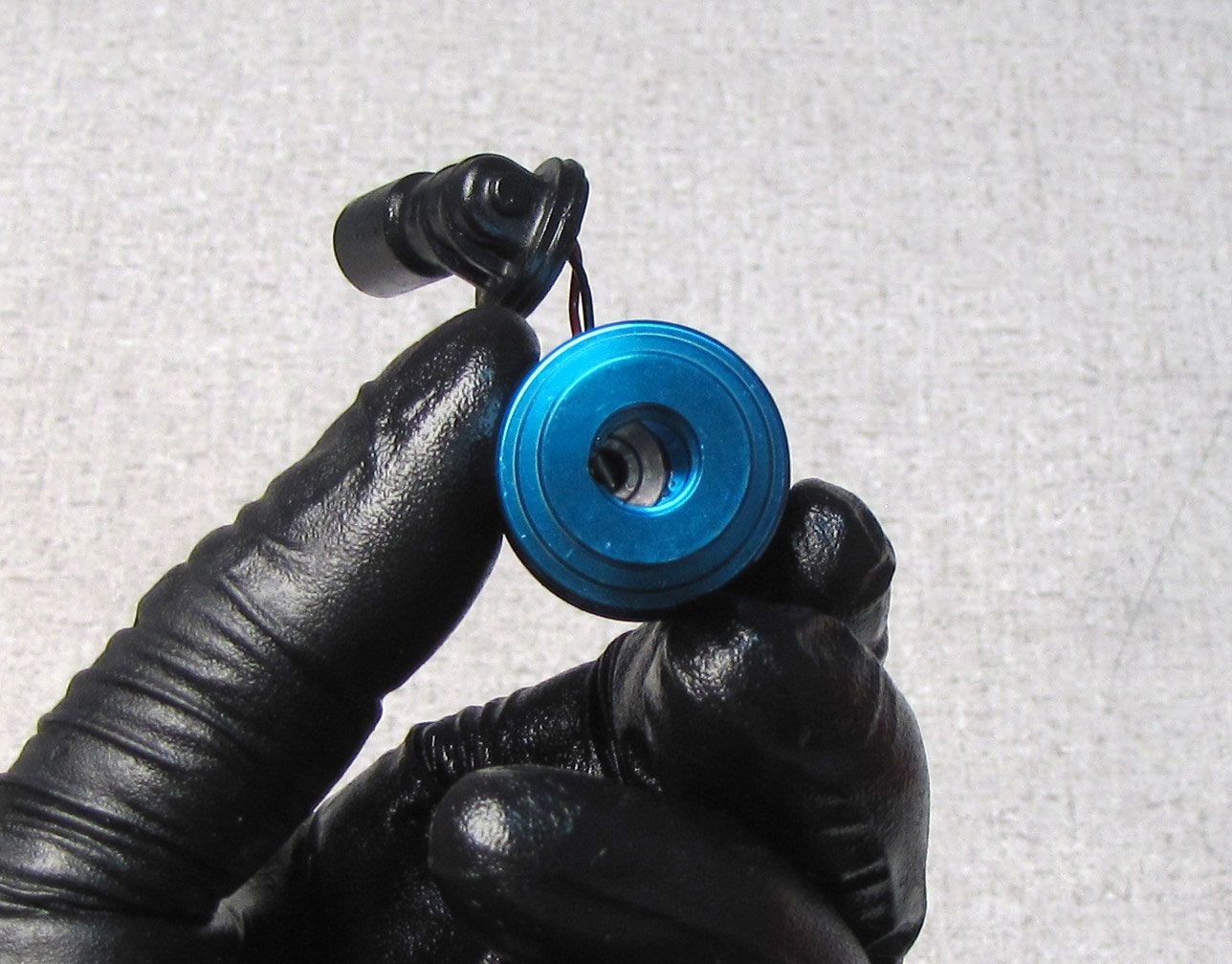
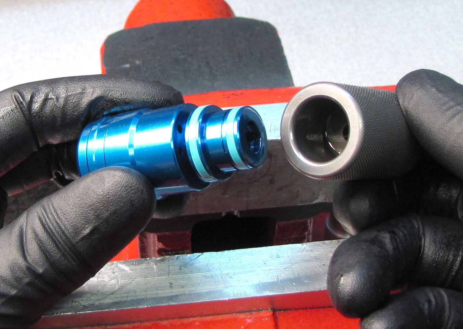
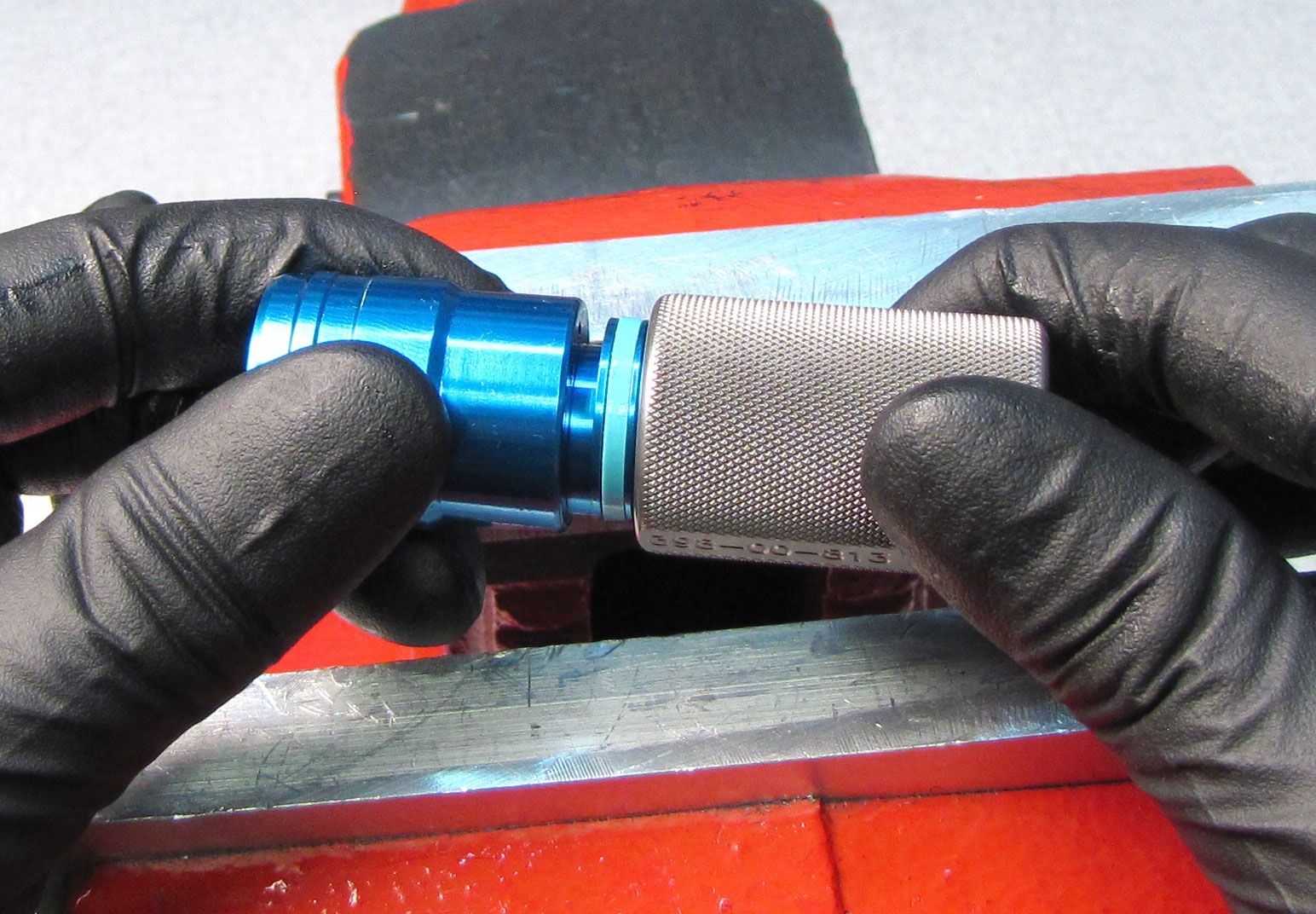
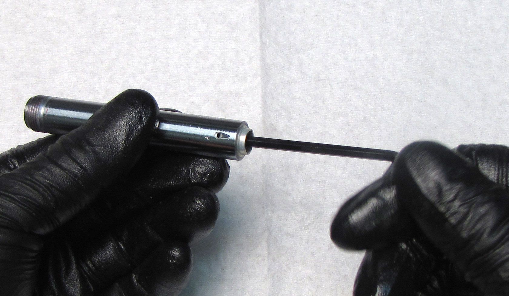
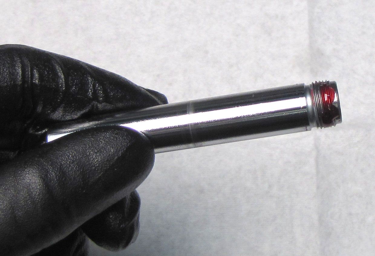
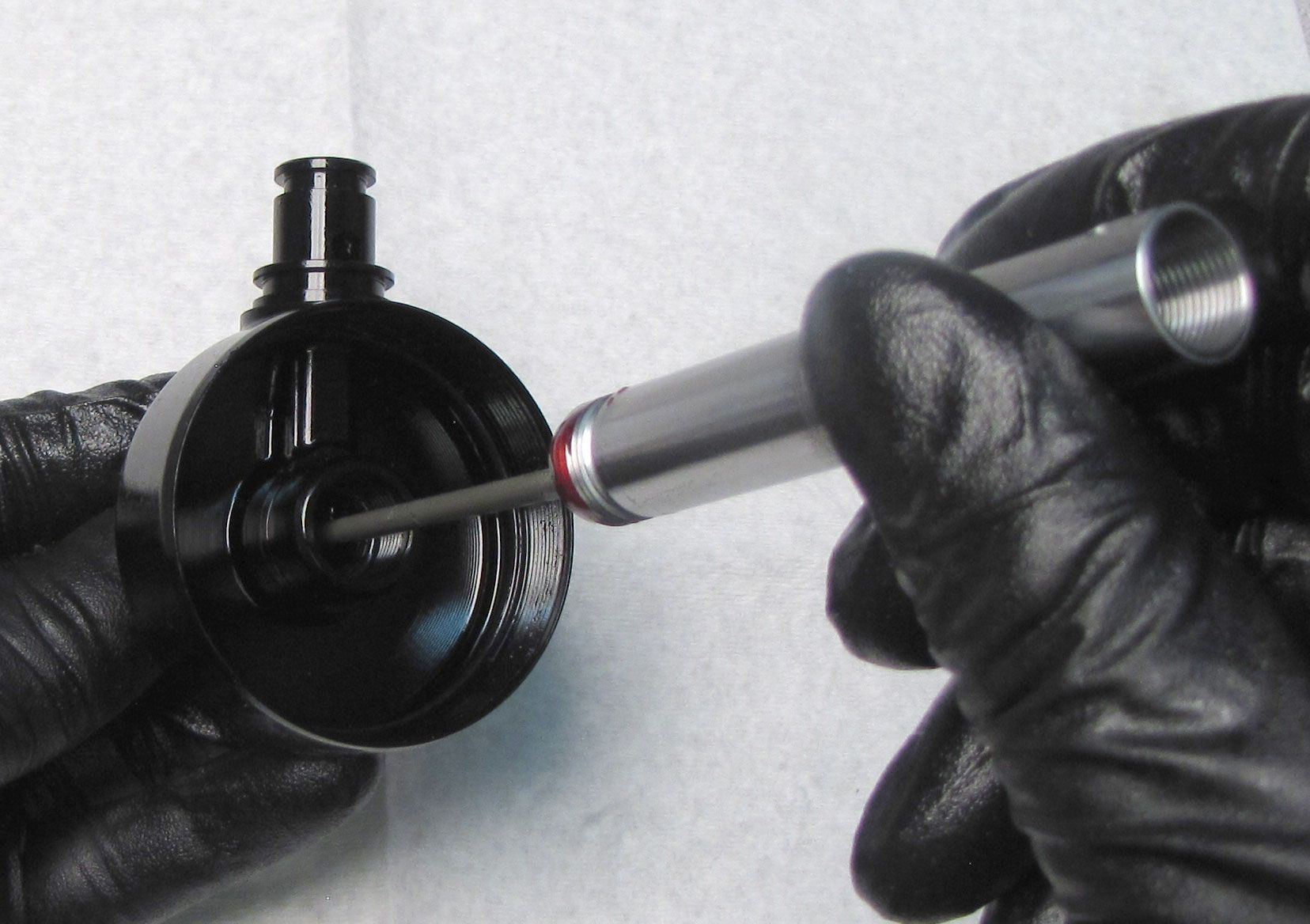
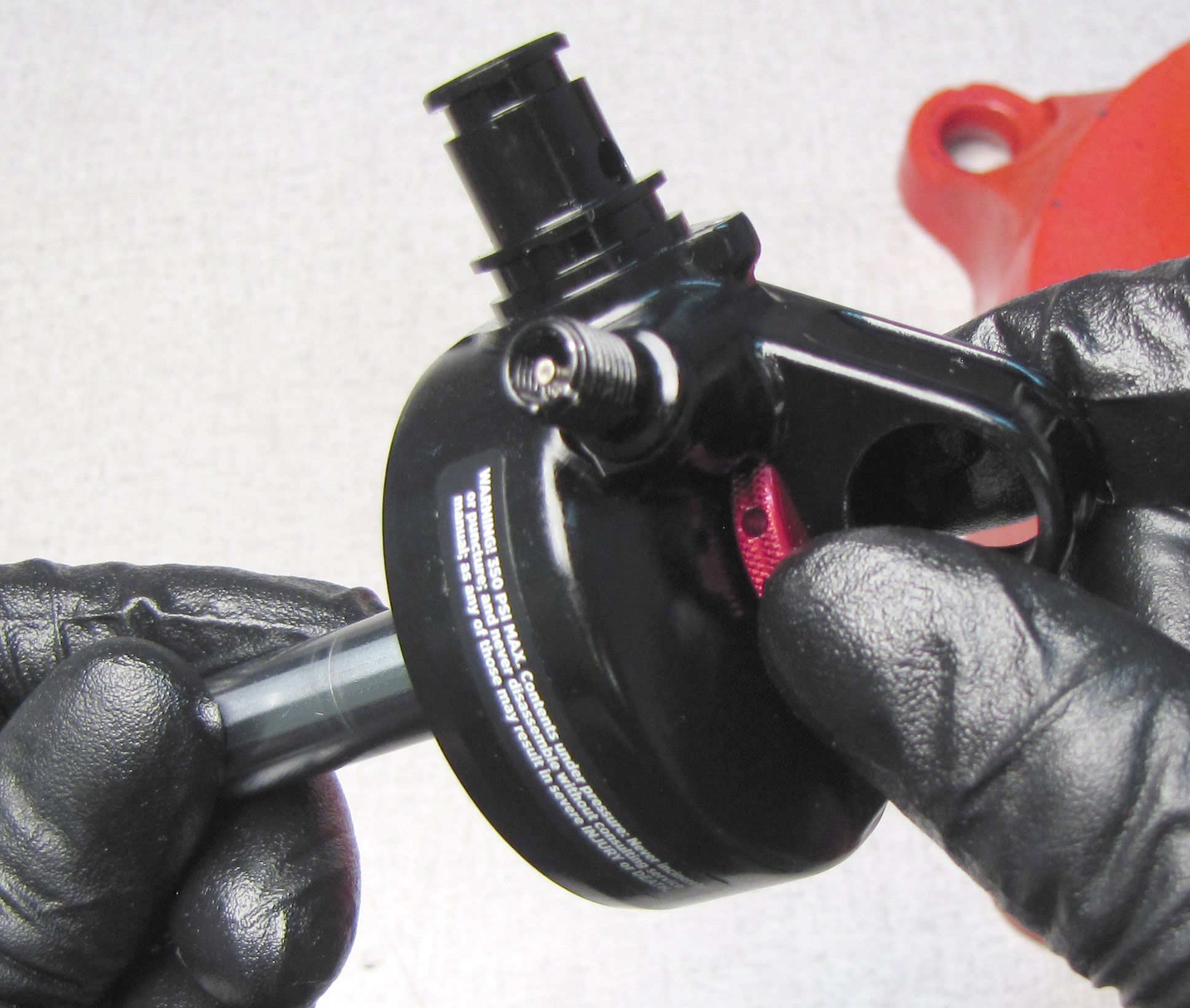
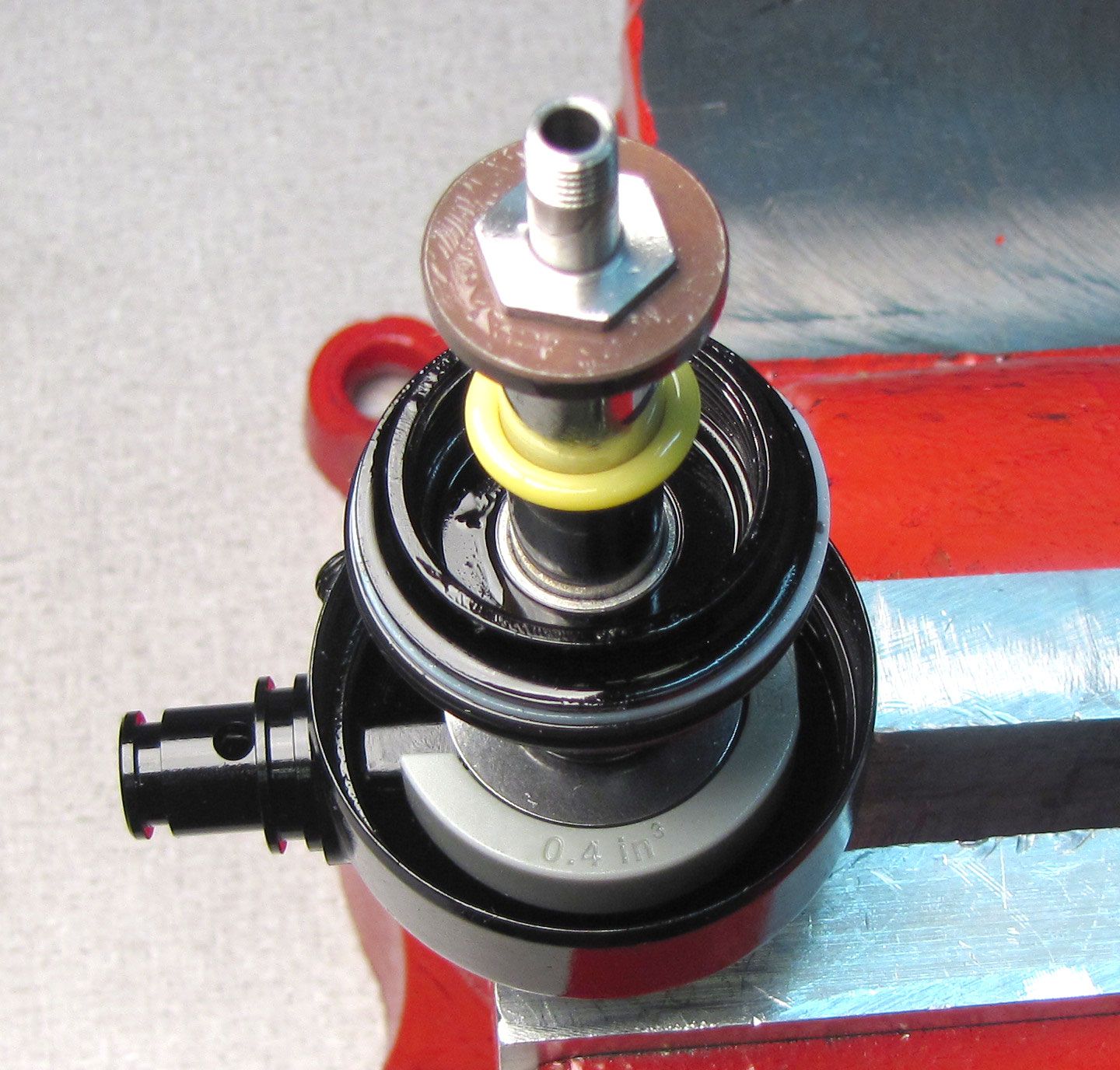
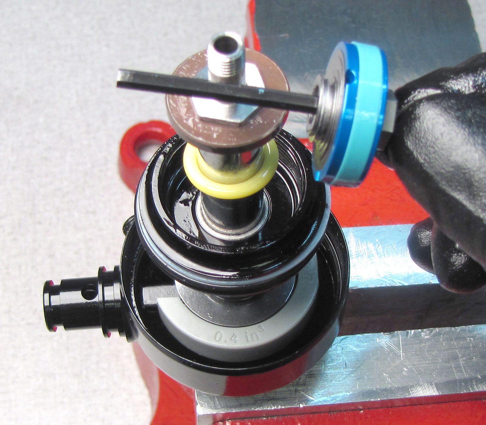
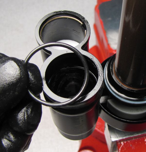
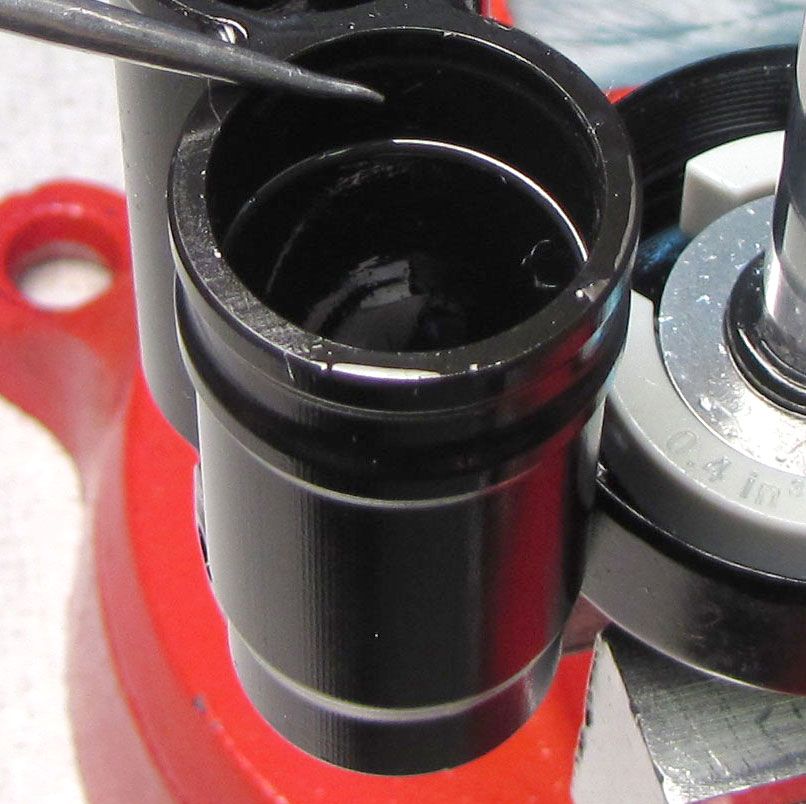
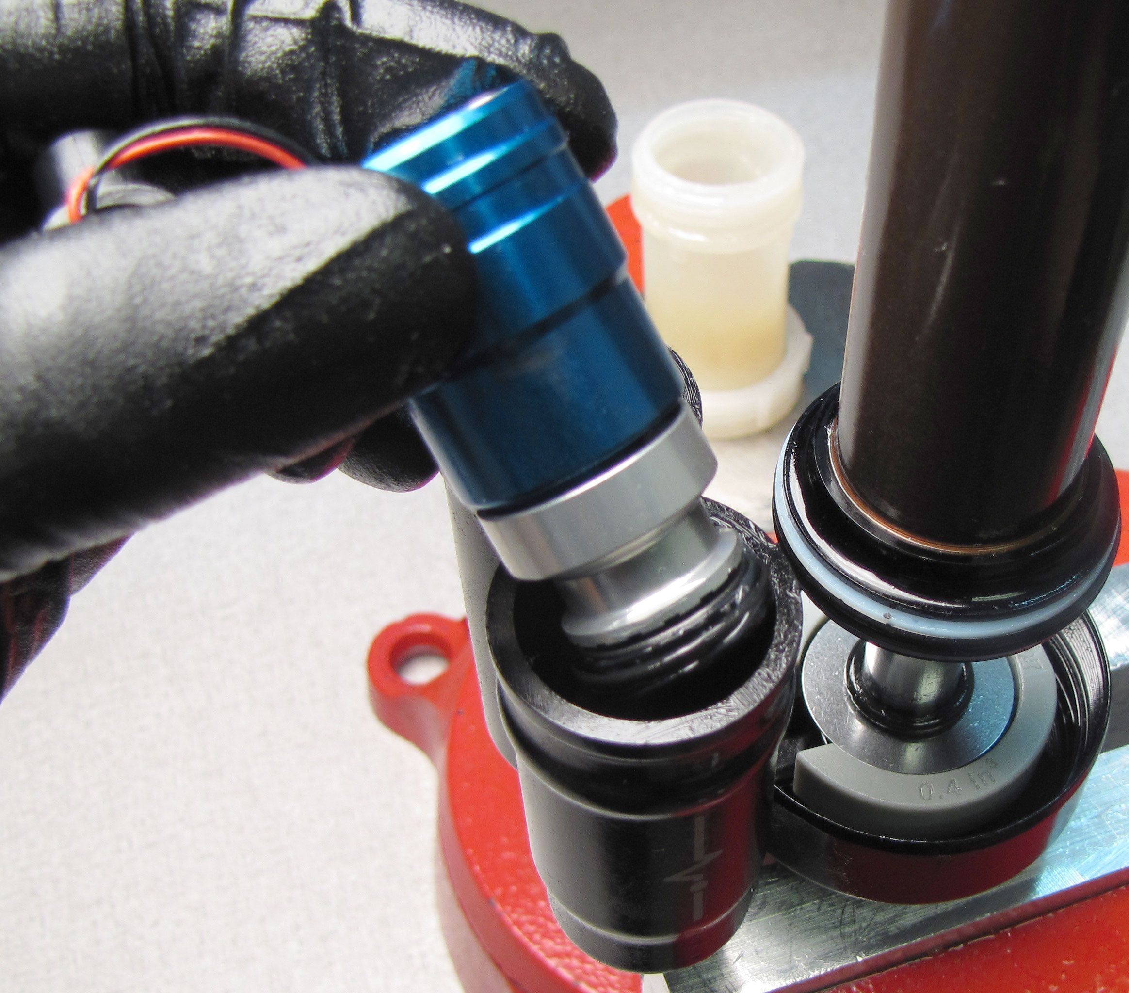
Remove the wire retaining ring using a thin damping shim then thread the LIVE Valve Solenoid Housing Puller (PN: 398-00-806) into the bleed port clockwise until hand tight.
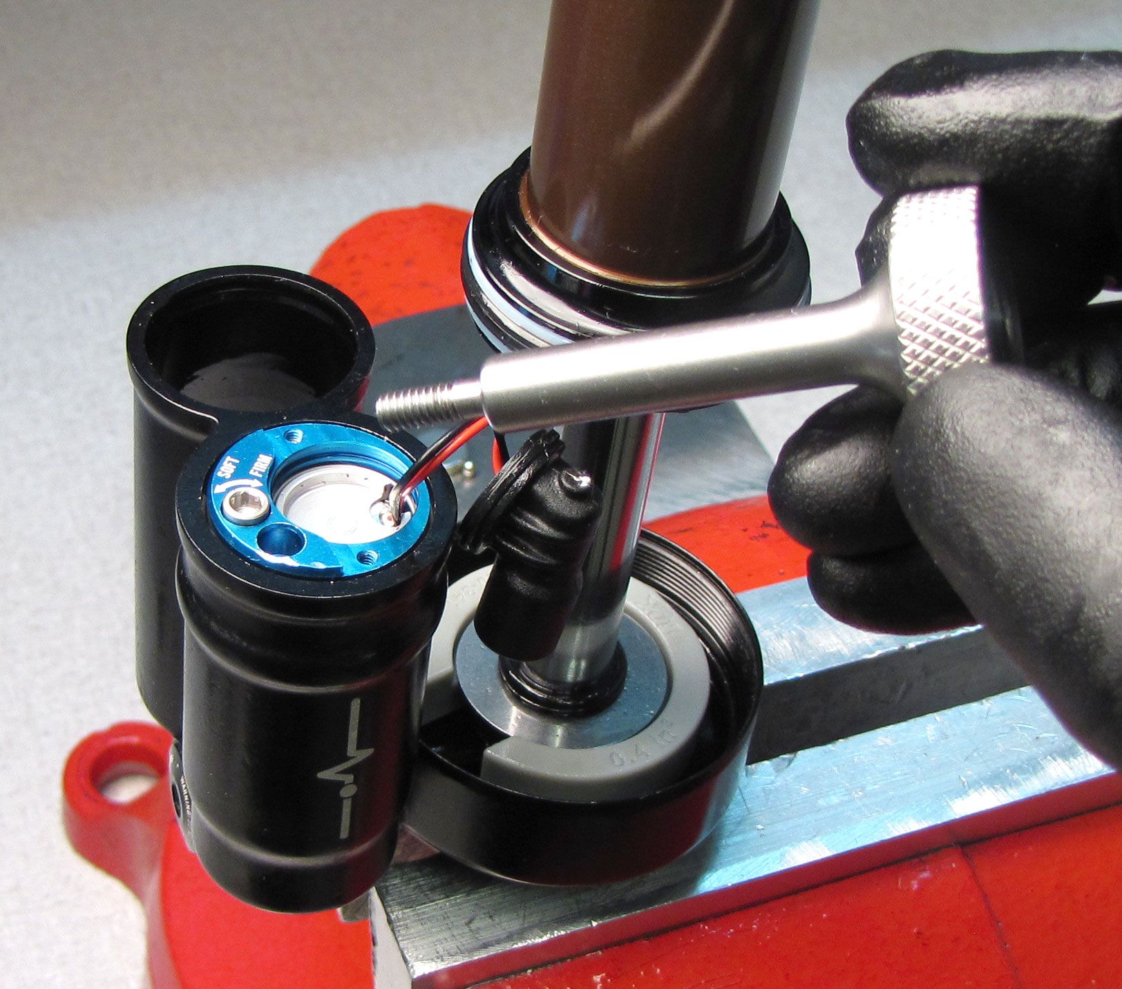
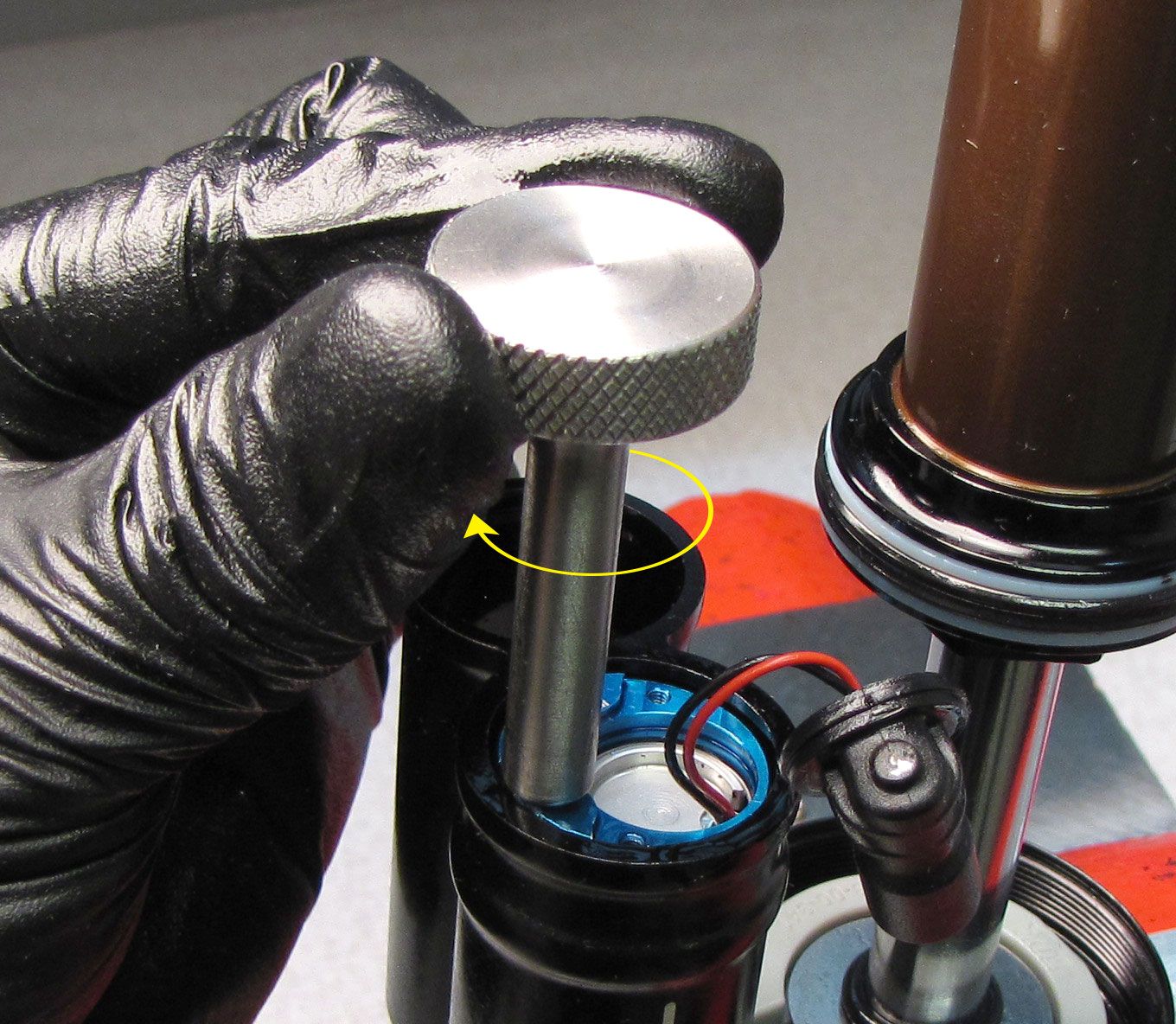

Step 12
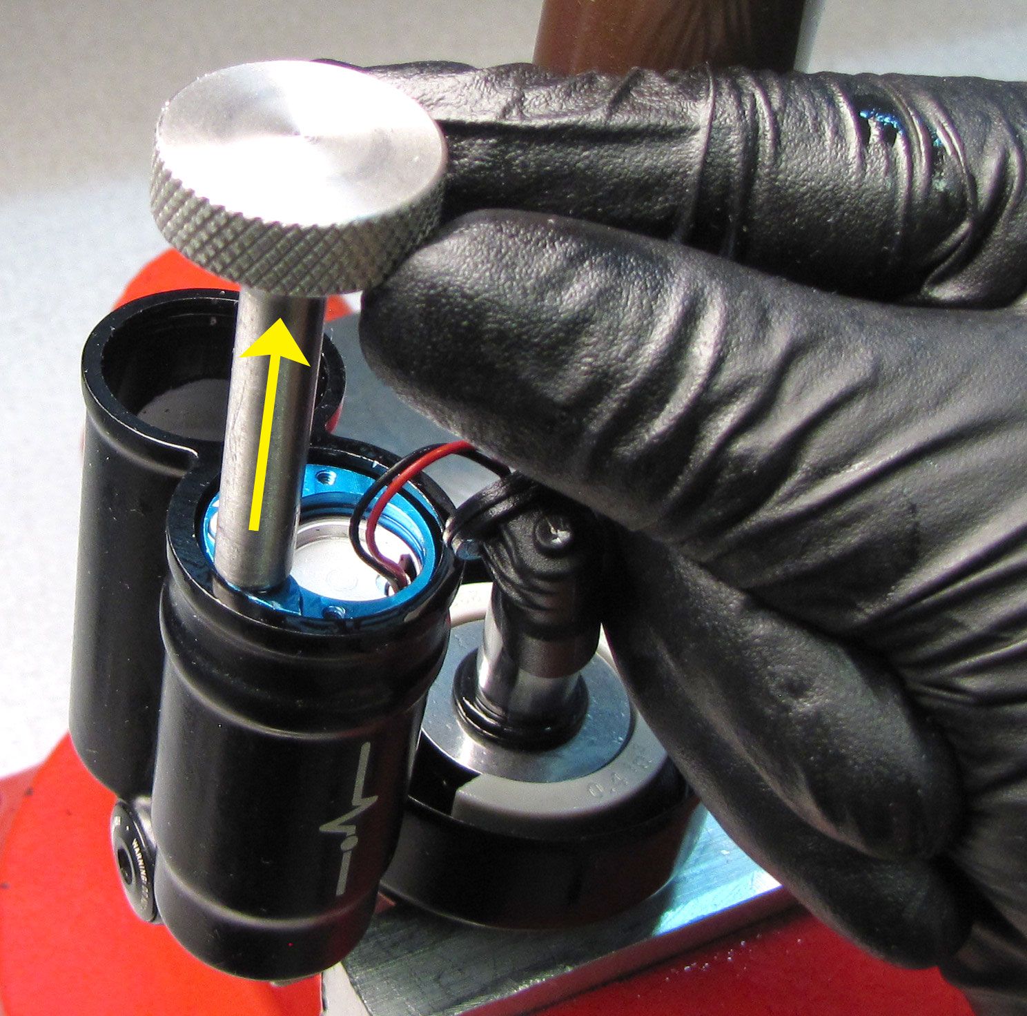
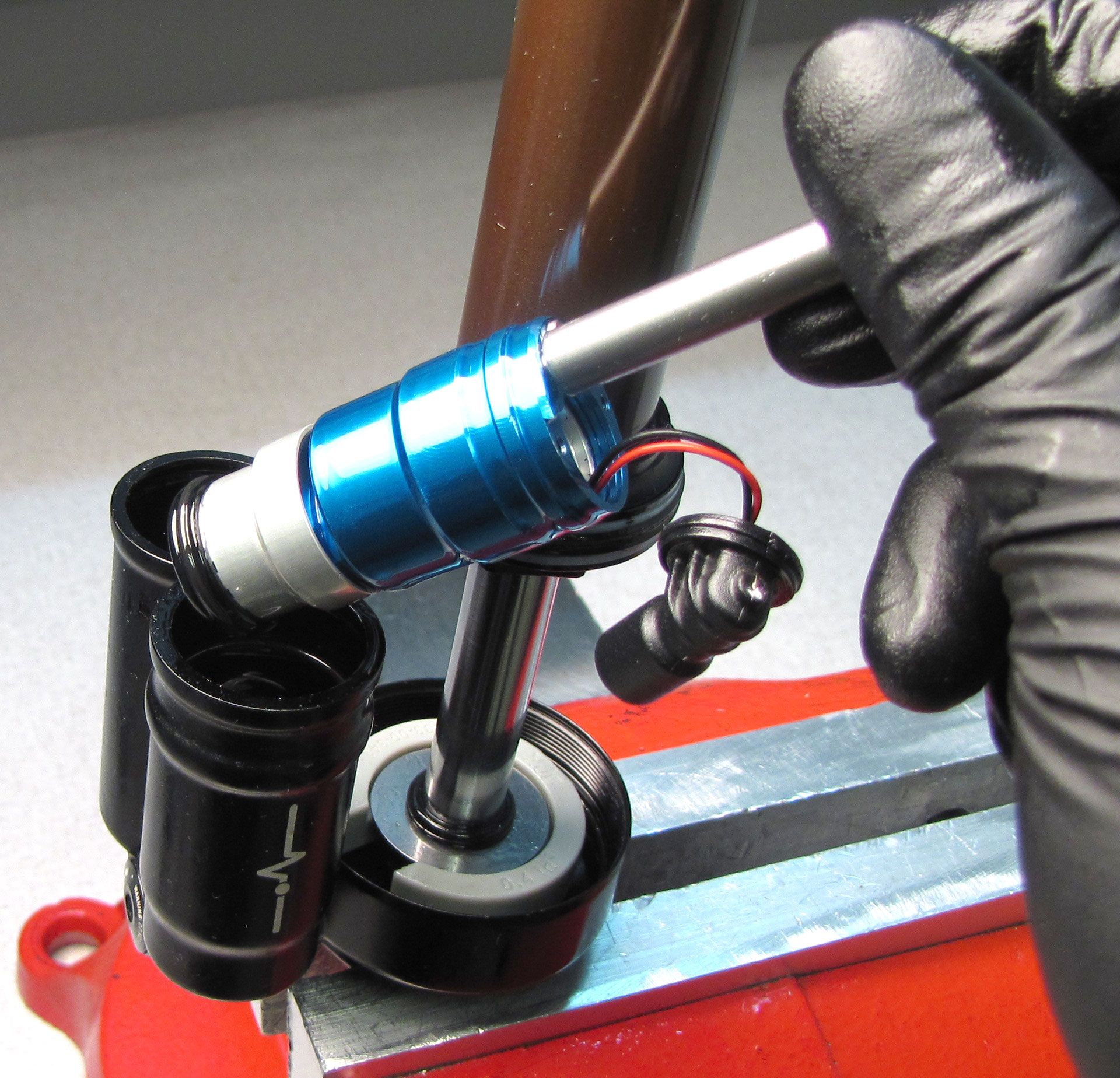
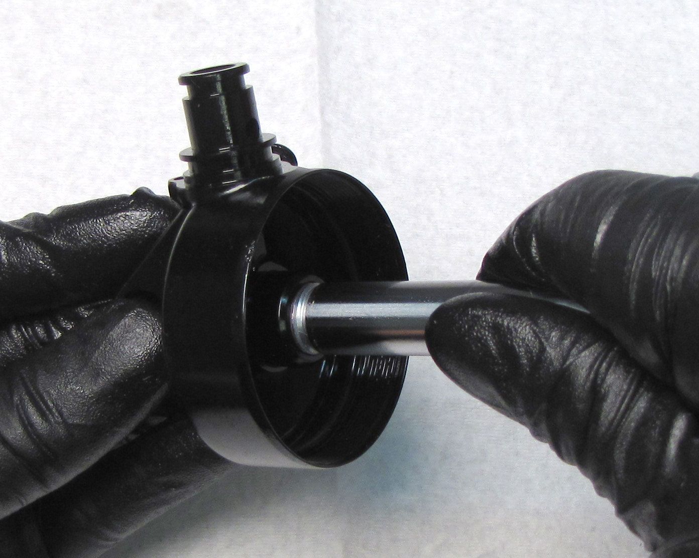
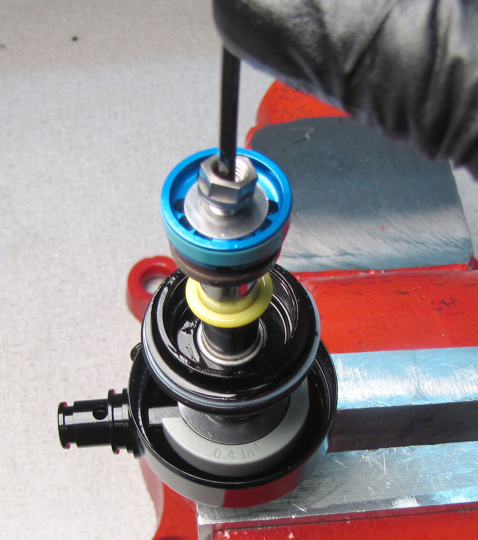
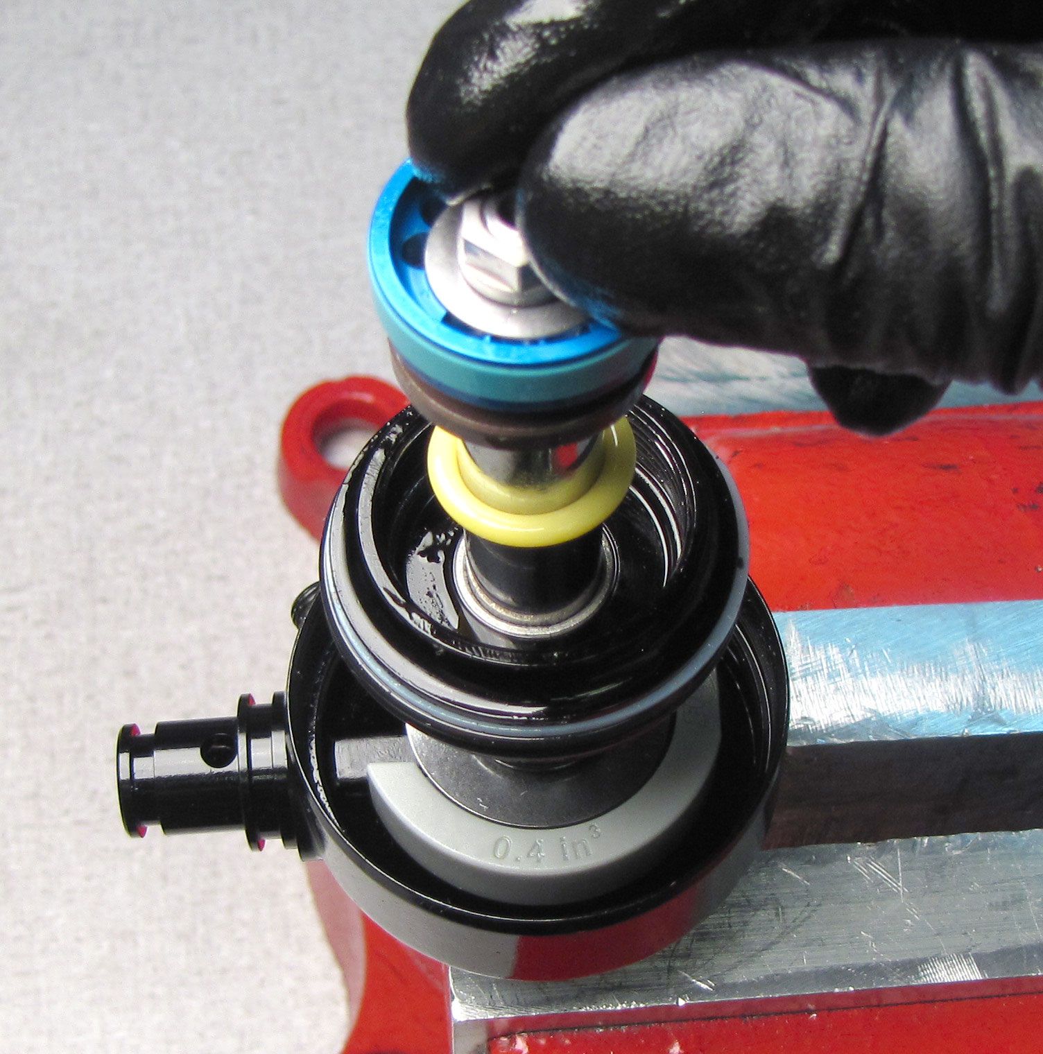
Lift up on the puller tool to remove the Compression Cartridge Housing from the reservoir.

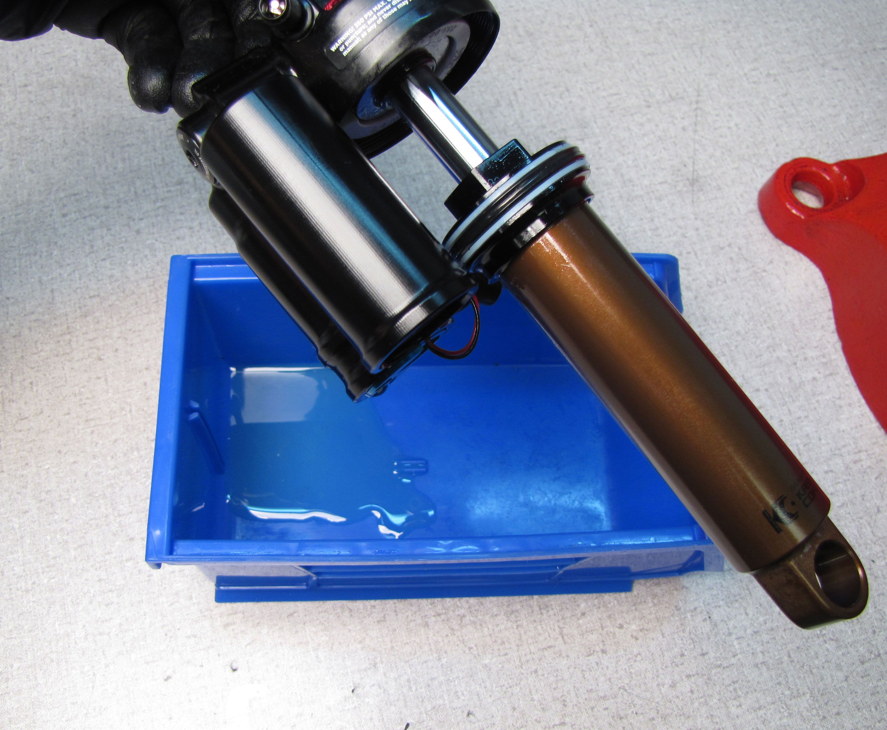
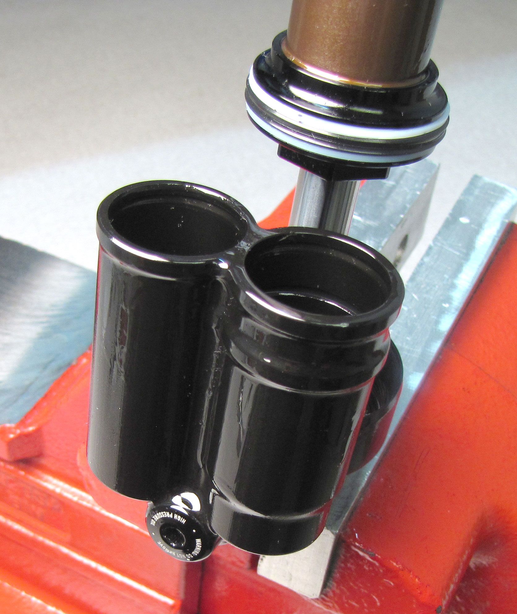
Step 13
Invert the shock over your waste oil basin to pour out any excess oil from the open reservoirs.

Step 14
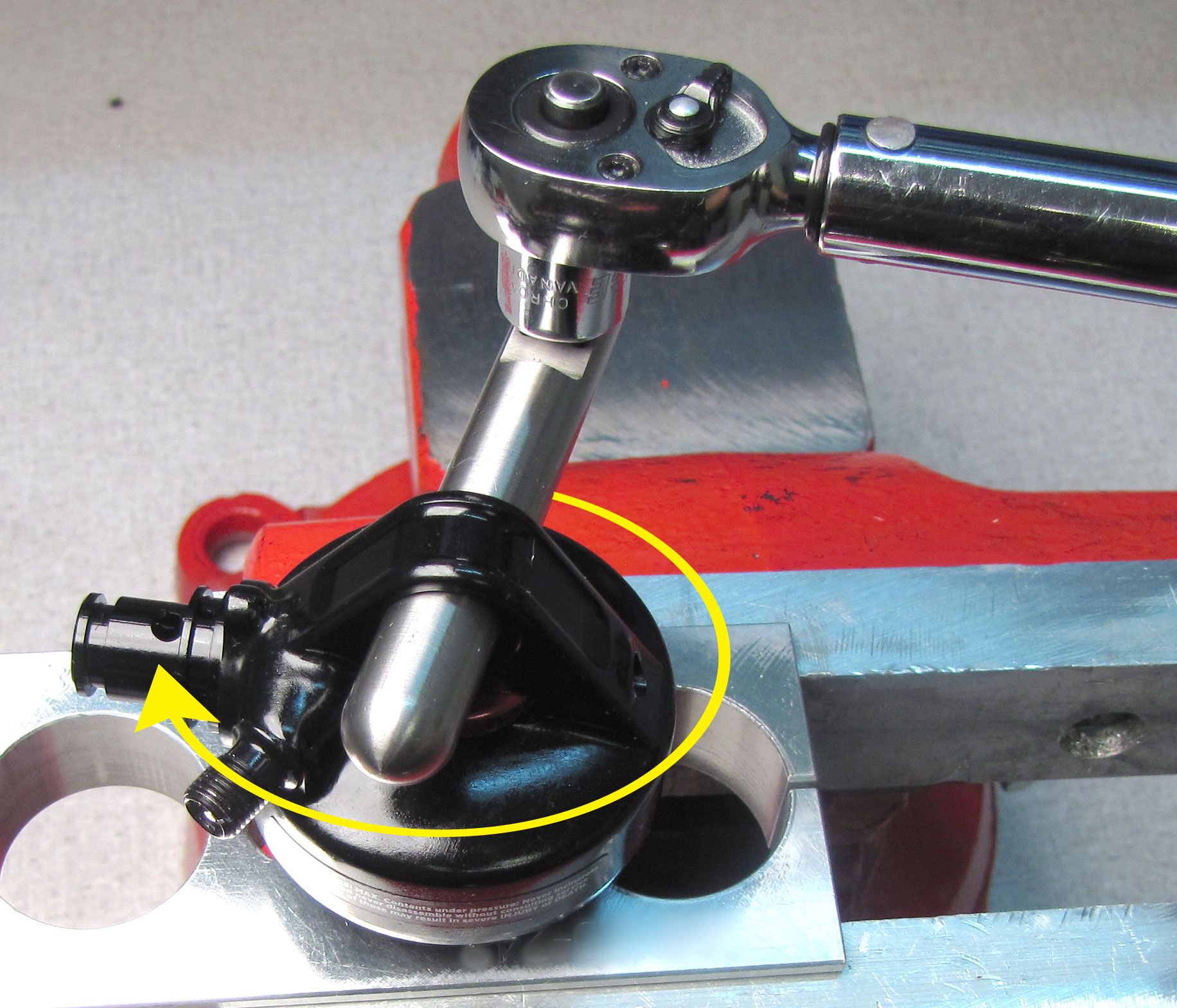
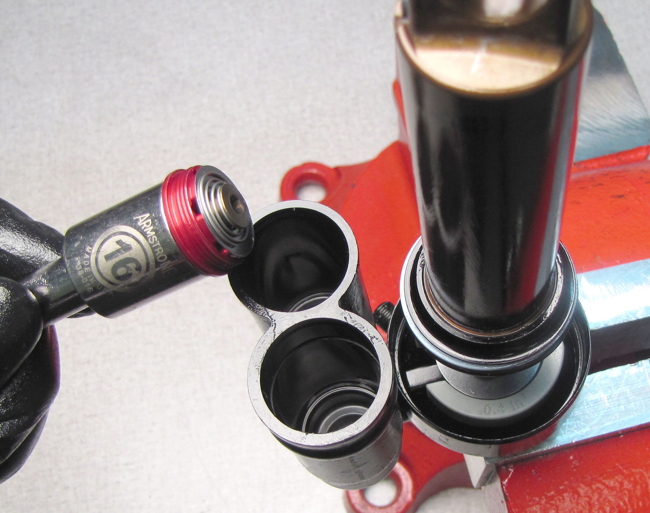
Unthread and remove the Lockout Blowoff Assembly by turning it counter-clockwise with a chamfer-less 16mm socket. Use a magnet to help pull the Lockout Blowoff Assy from the reservoir.
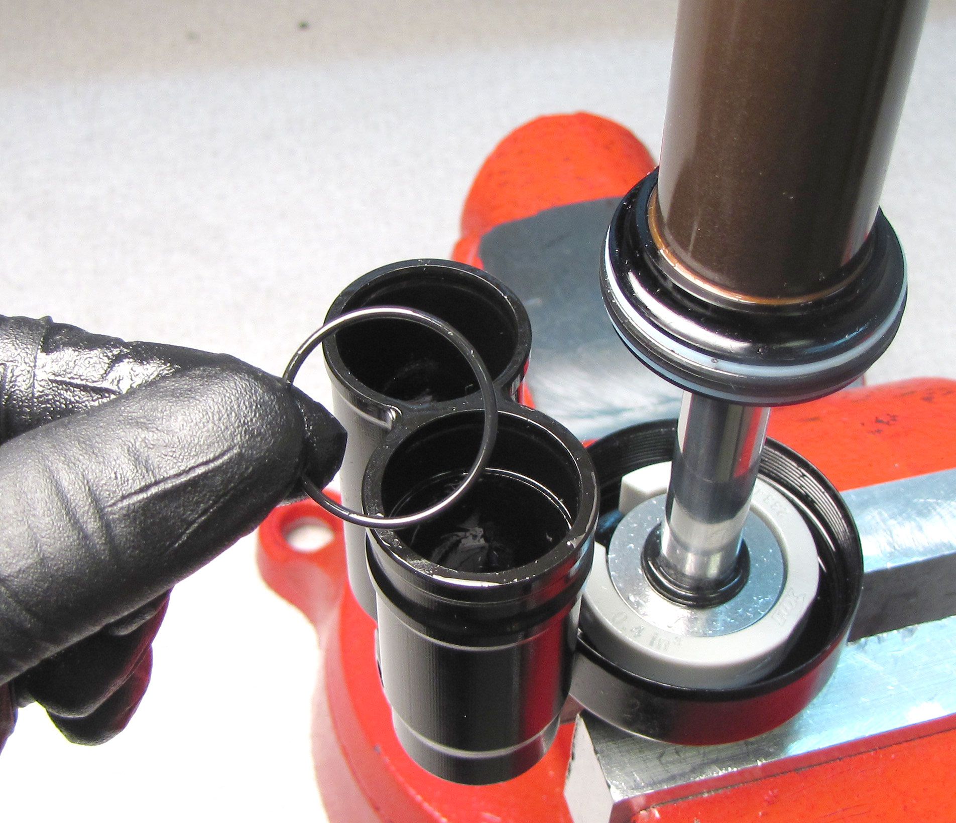
Step 15
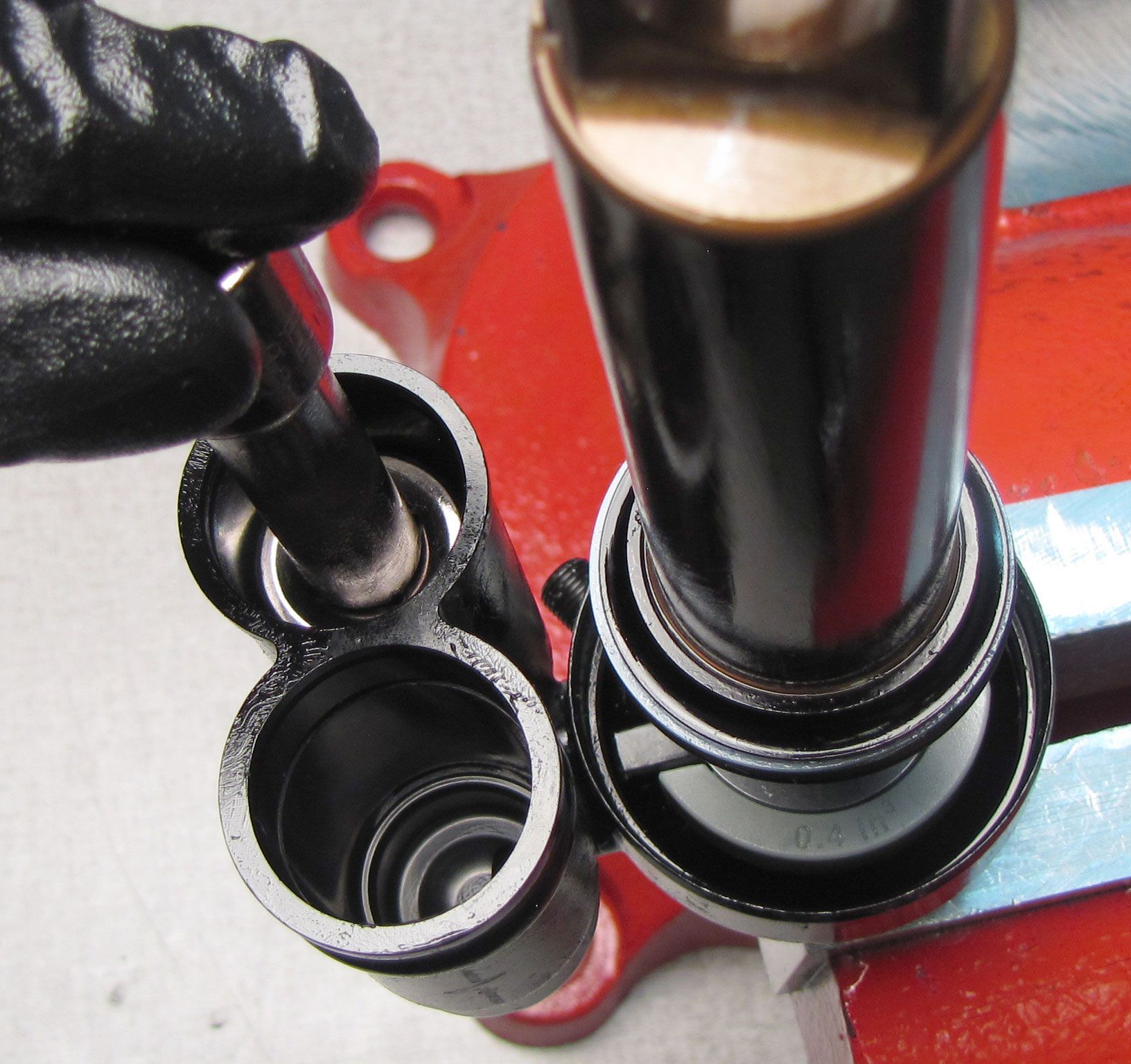
Remove the o-ring from within the reservoir that held the Compression Housing Sub Assembly.


Step 16
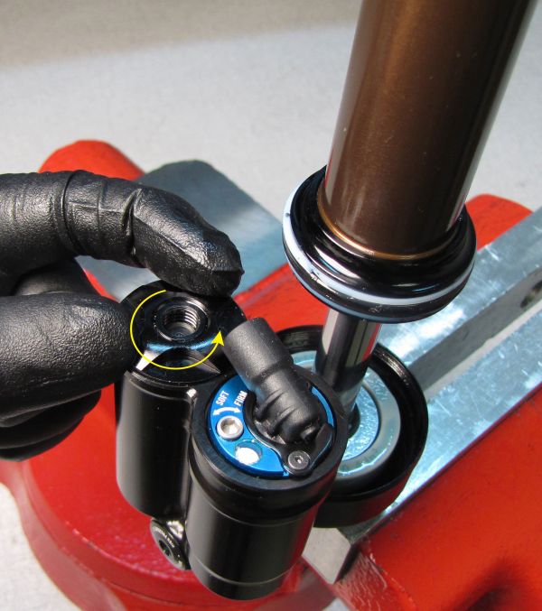
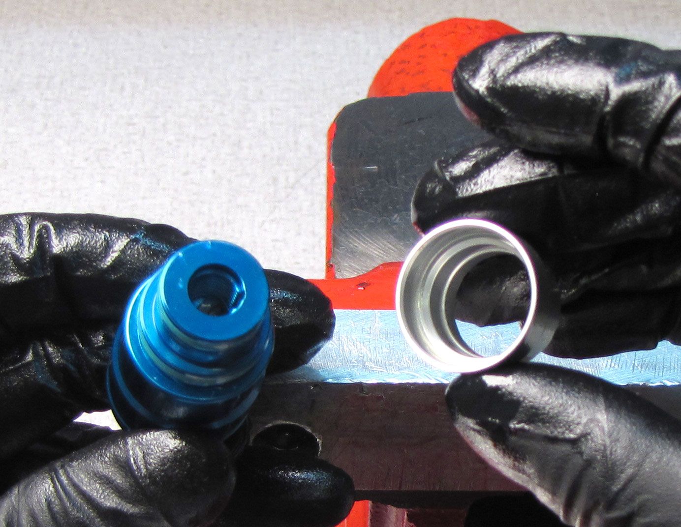
Remove the white Delrin ball from the screw connecting the Reservoir Assembly to the Eyelet Assembly. Unthread and remove the bolt holding the Reservoir Assembly to the Eyelet Assembly by turning it counter-clockwise with a 4mm hex wrench. Lift the Reservoir Assembly off of the Eyelet Assembly making sure to keep track of the small Dowel Pin between the two assemblies.

Step 17
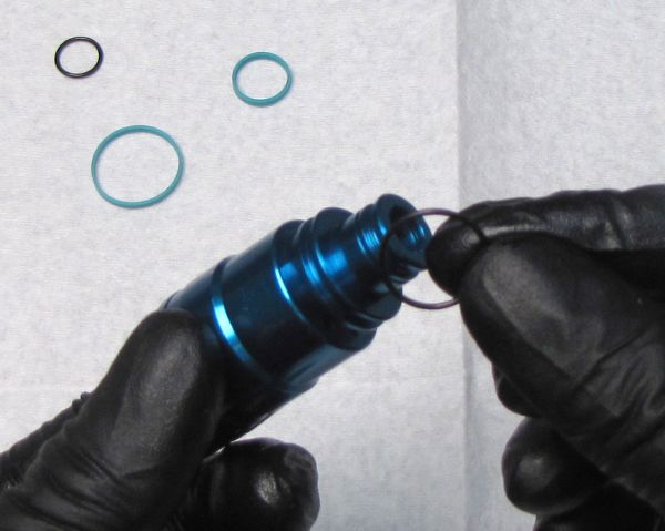
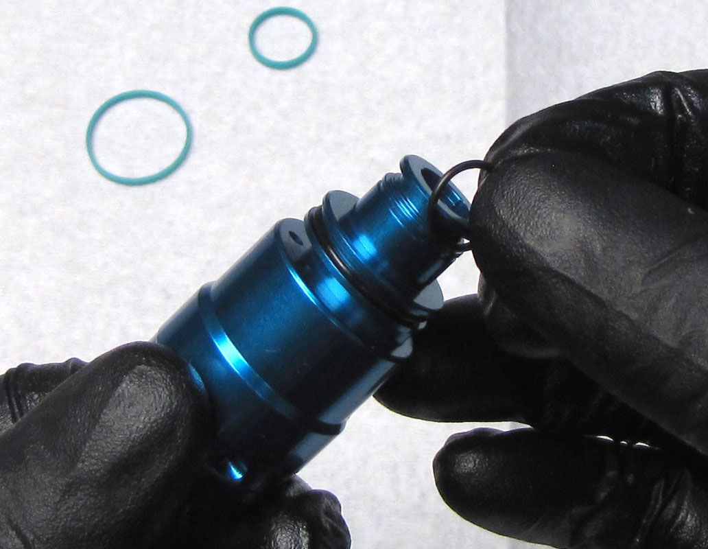
Remove the o-rings from the Eyelet Assembly that seal the Reservoir Assembly to the Eyelet Assembly.
Step 18
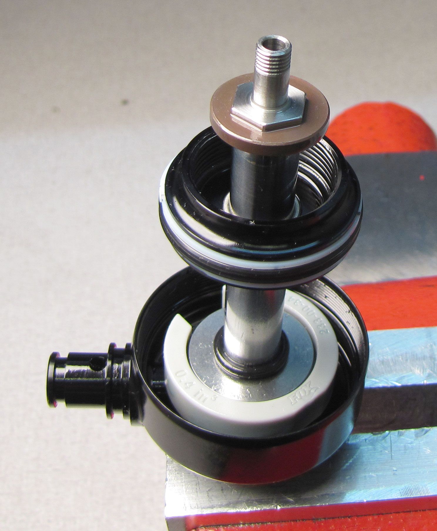
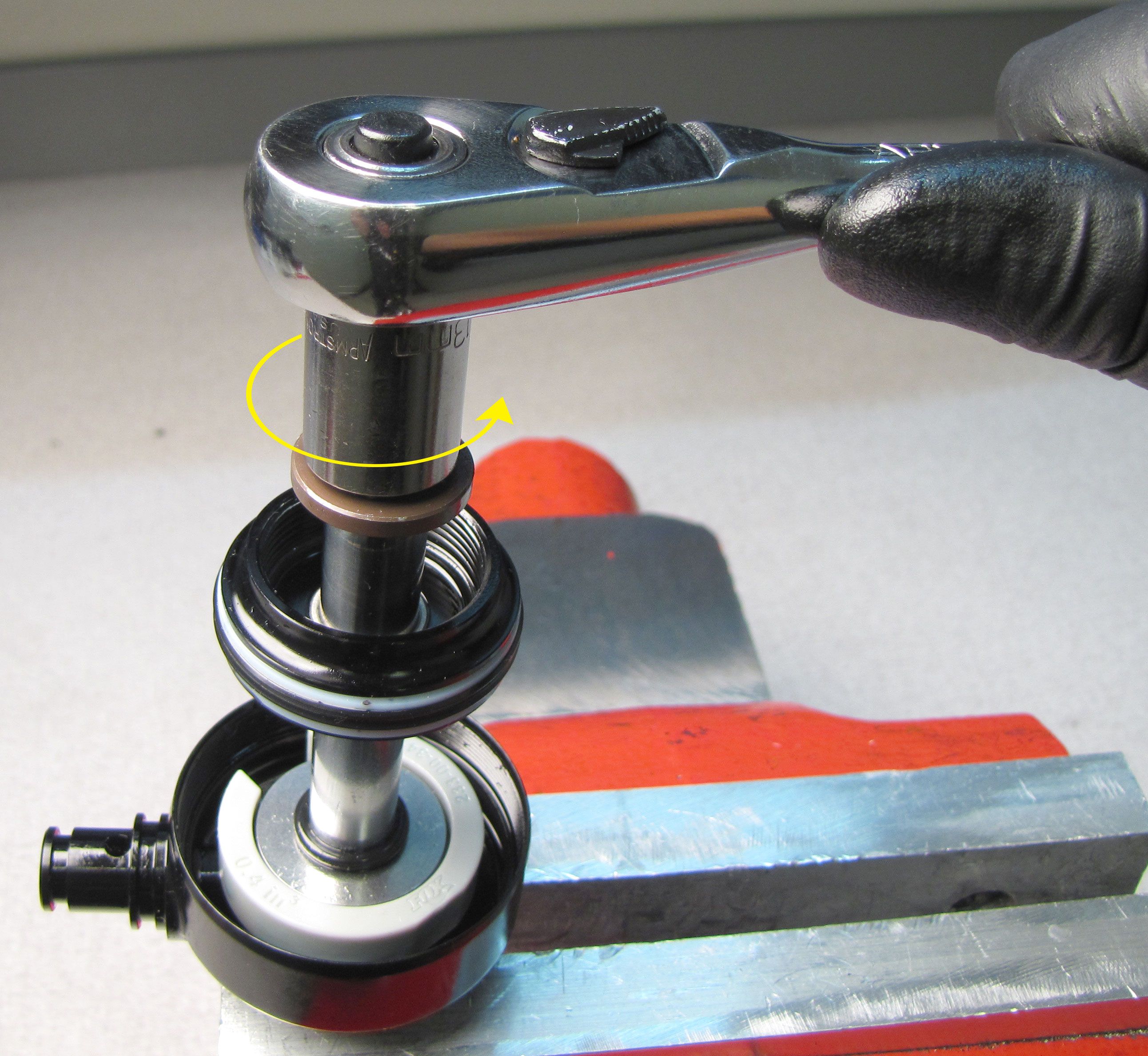
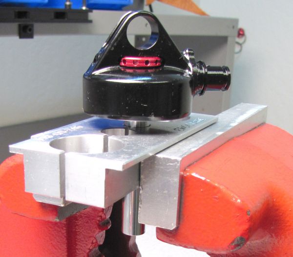
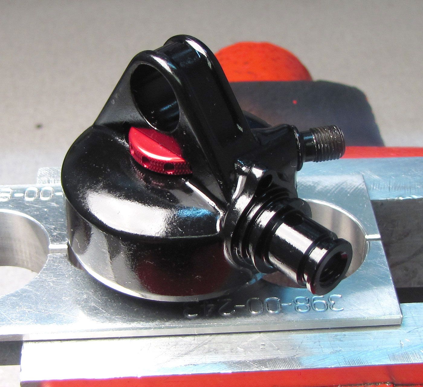
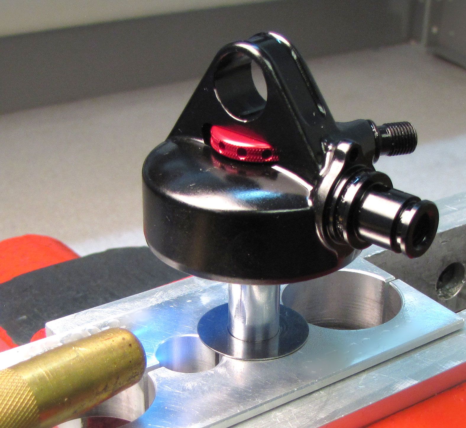
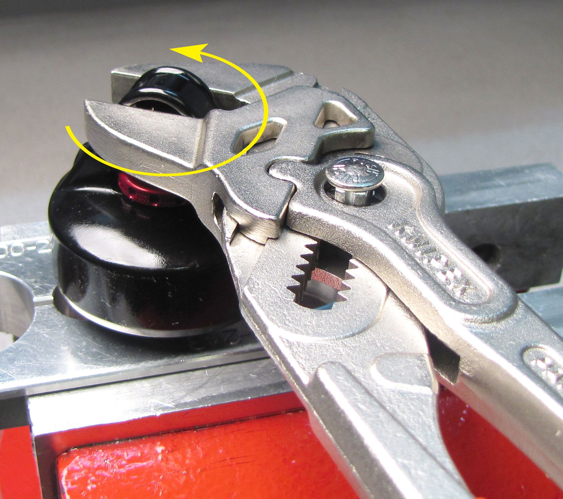
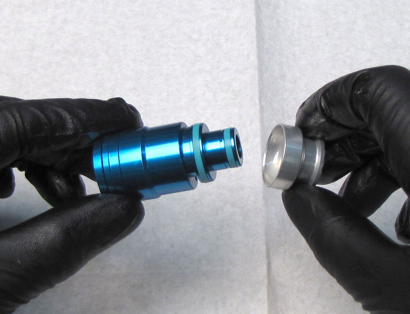
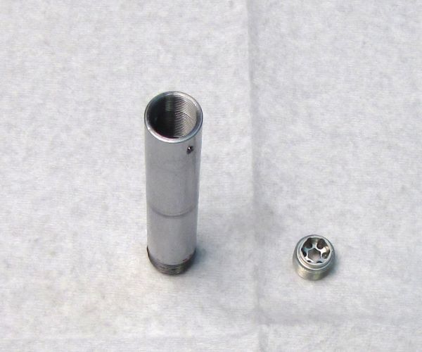
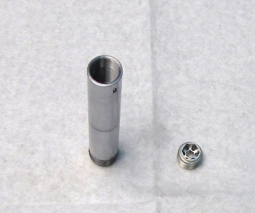
Clamp the body eyelet in your soft-jawed vise. Unthread the Bearing Assembly from the body by turning it counter-clockwise with a 22mm wrench or smooth jawed pliers (Knipex). Pour out all oil from the shock body.

Step 19
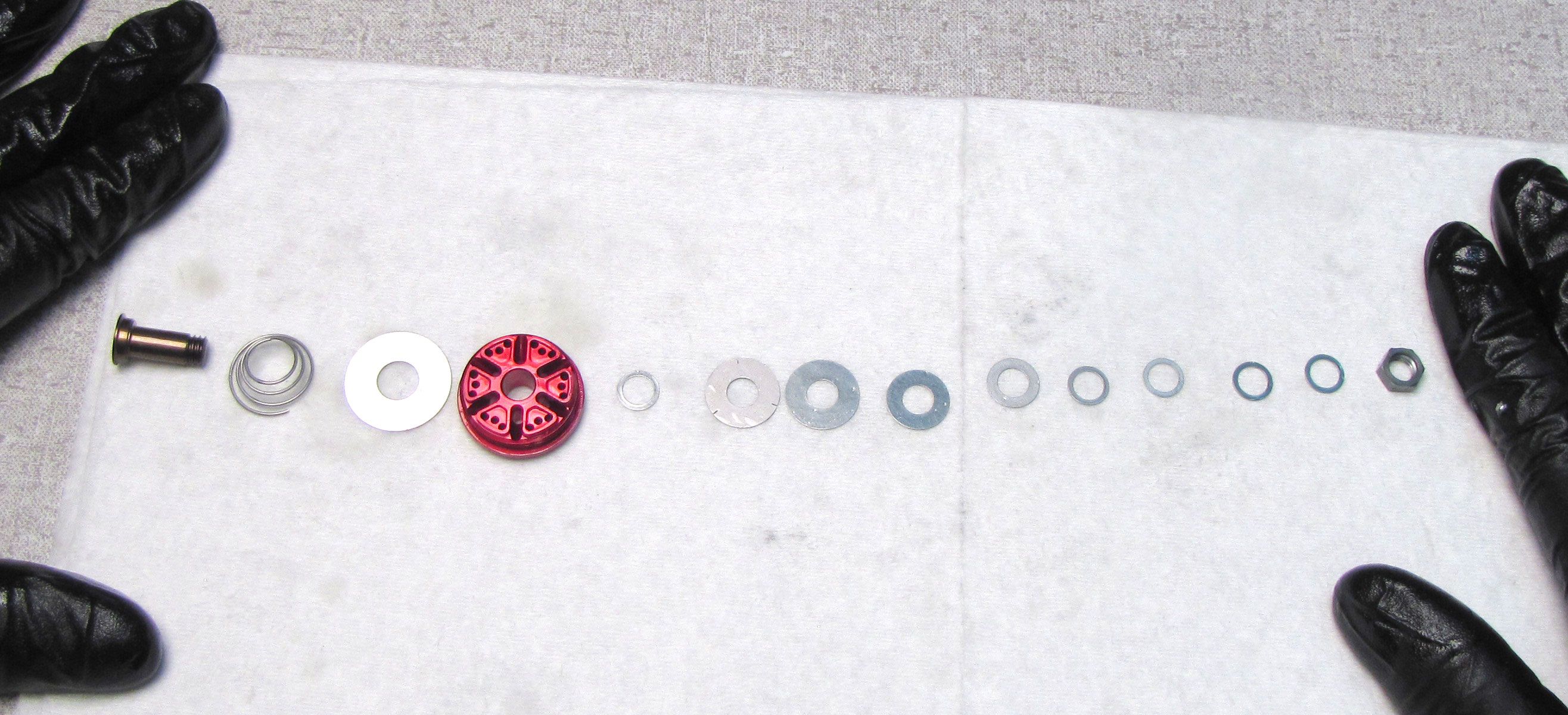
Clamp the shaft eyelet in your soft-jawed vise. Unthread the piston nut counter-clockwise with a 9mm socket. Remove the piston and valving assembly as a unit, keeping all parts in their original order.

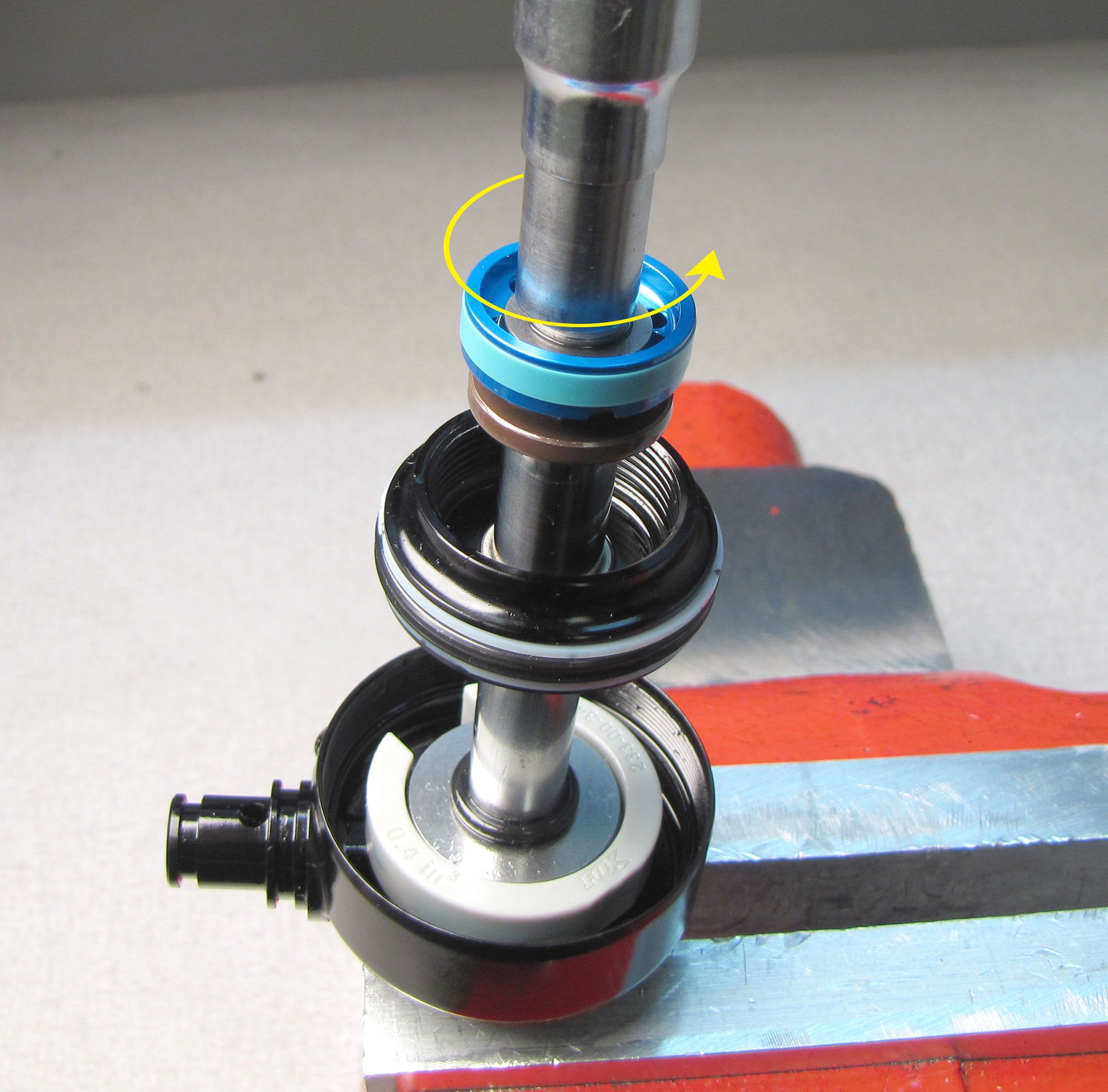
Step 20
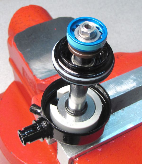
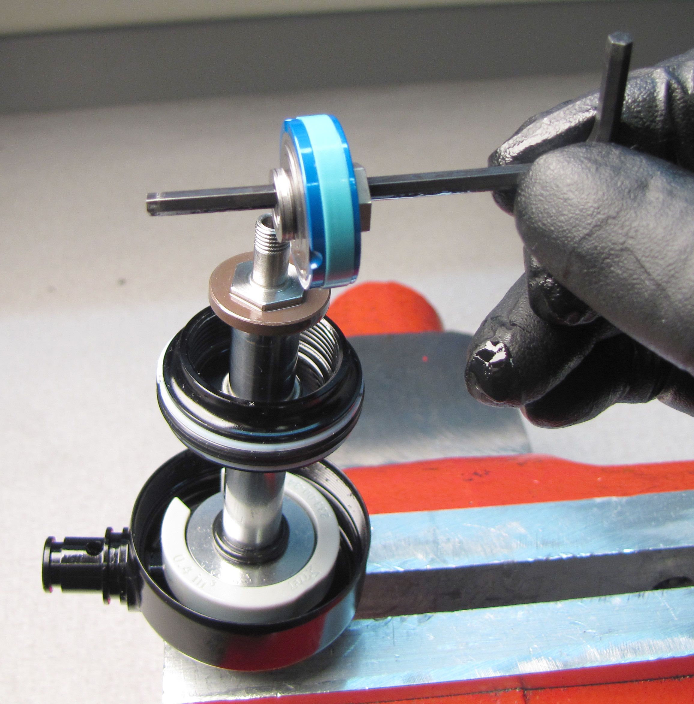
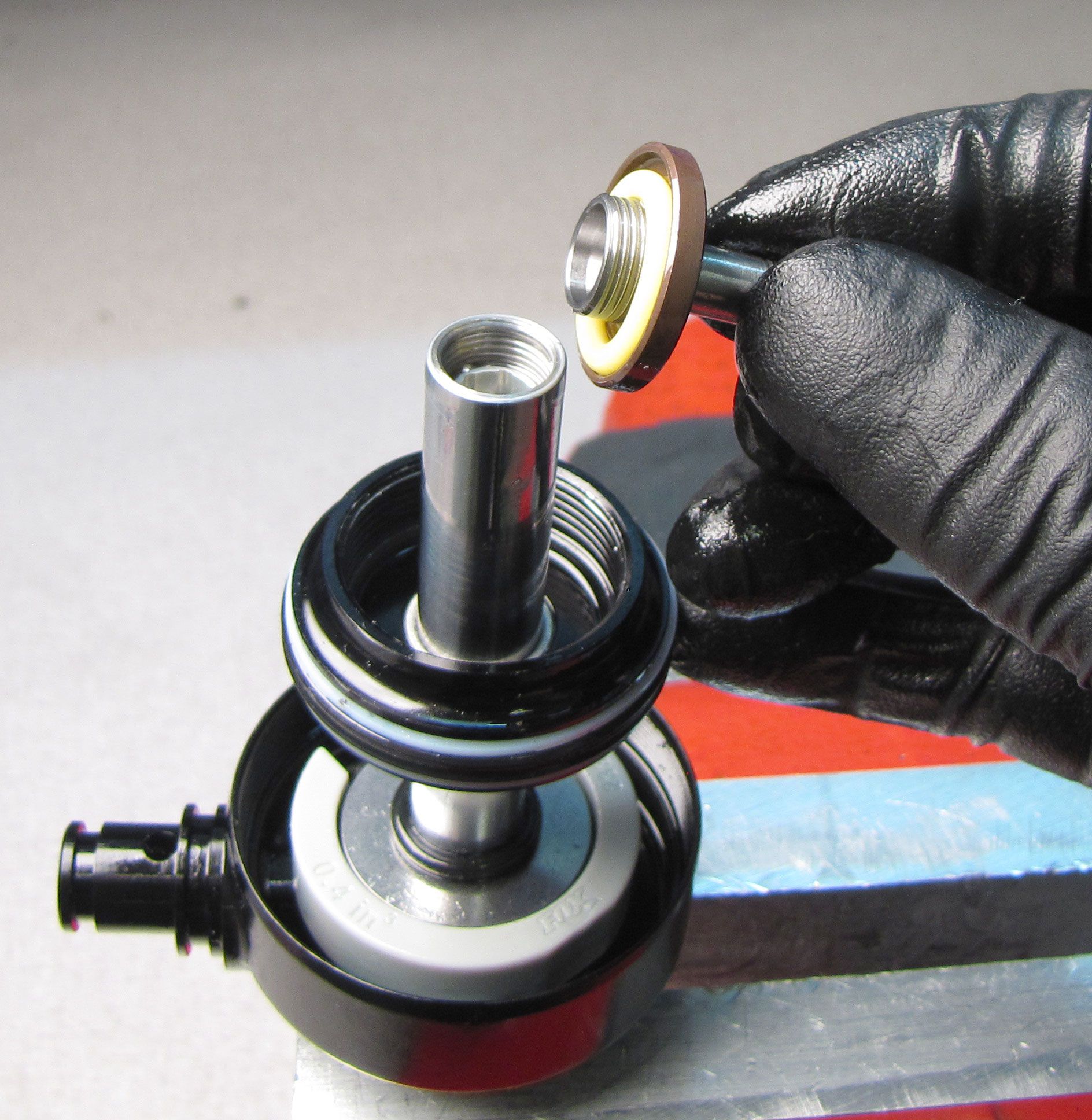
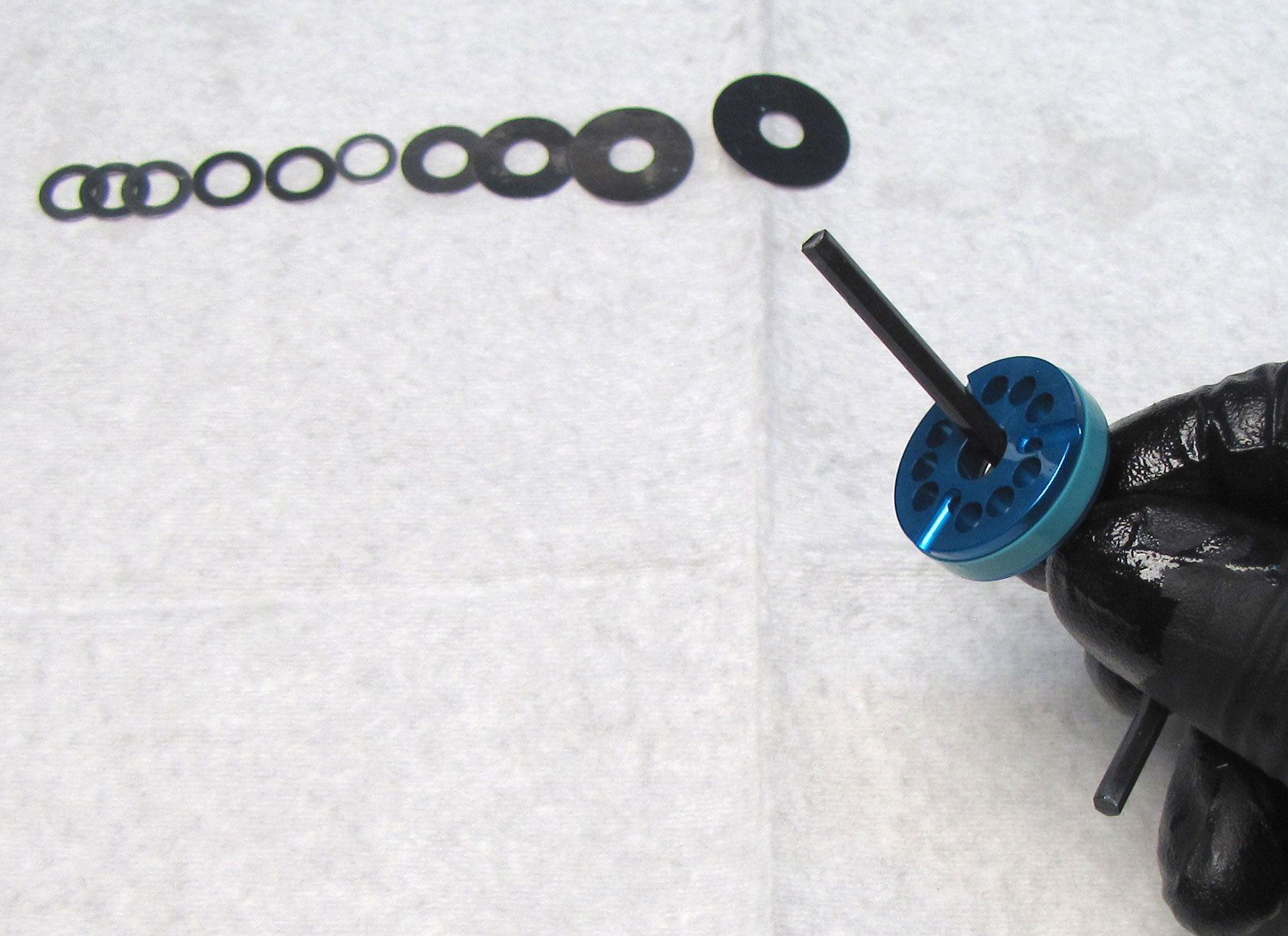
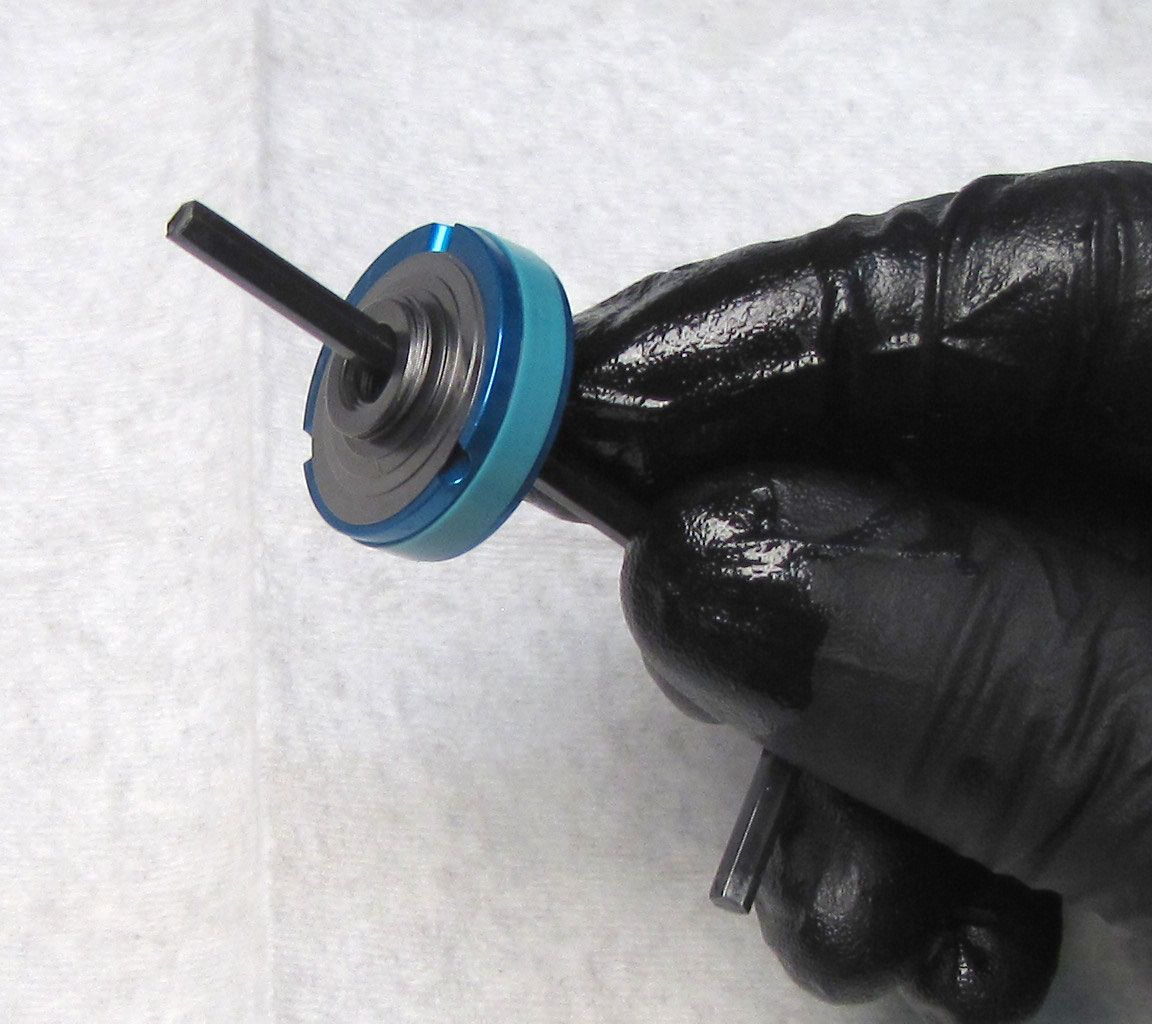
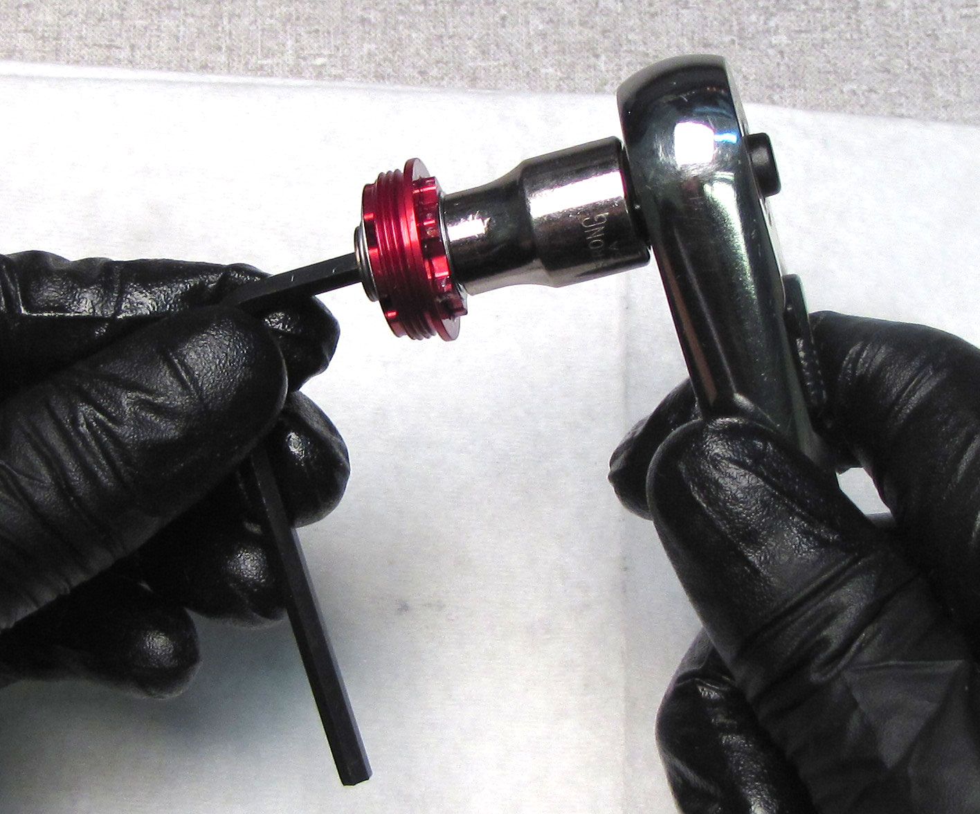
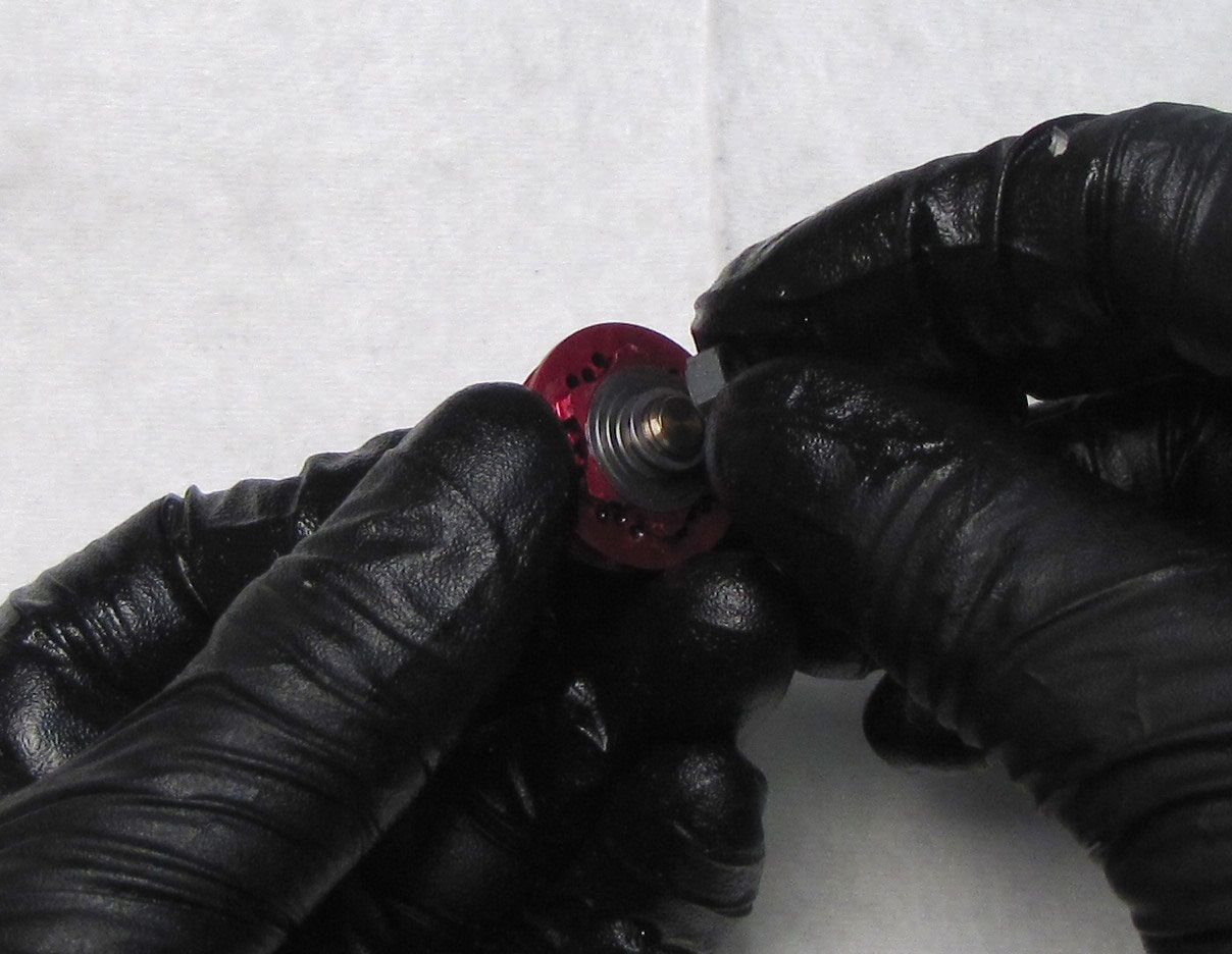
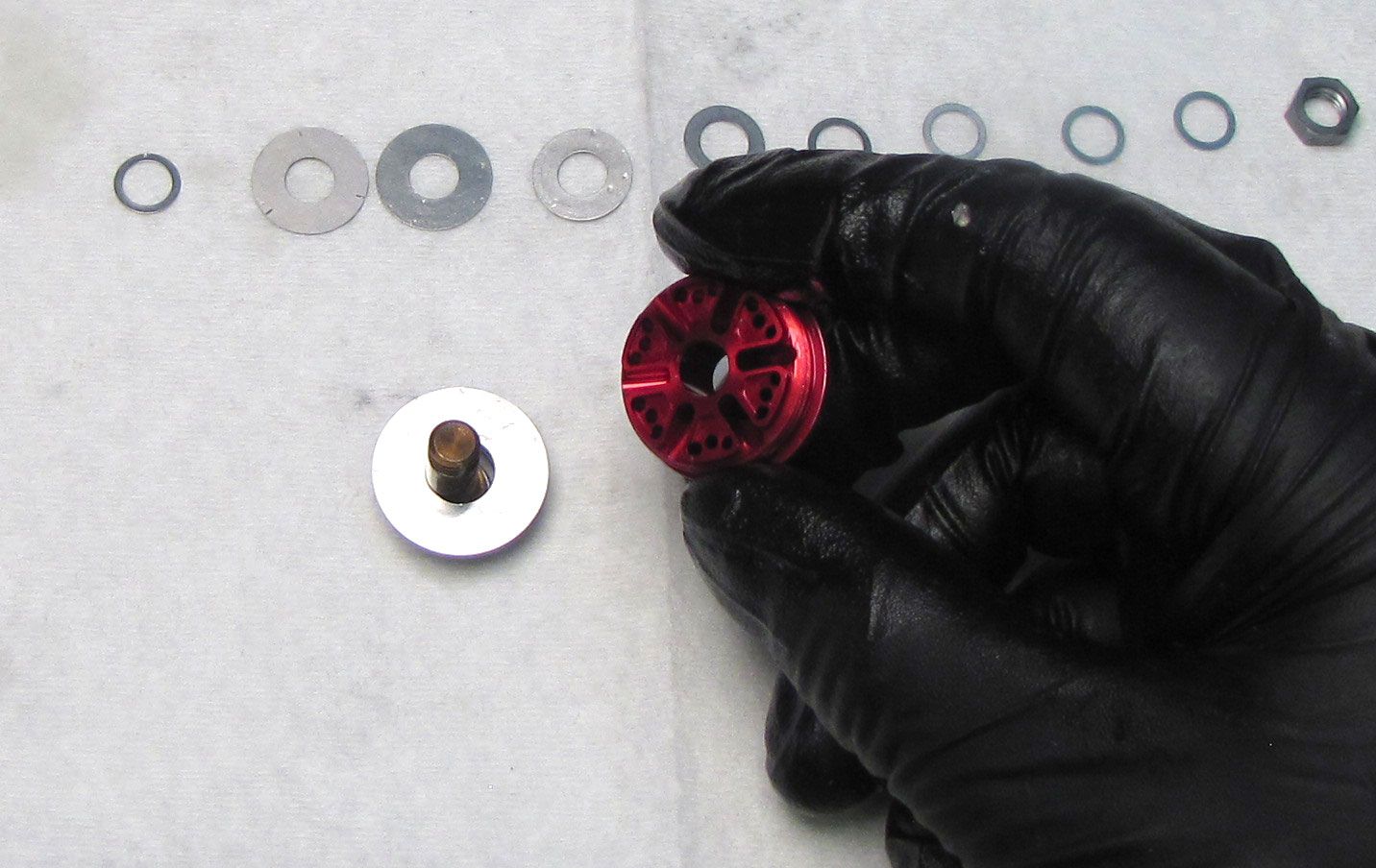
Unthread the Piston Stud counter-clockwise with a 6-point chamfer-less 1/2" socket. Lift up to remove the Piston Stud, Topout Plate, and Topout O-ring.

Step 21
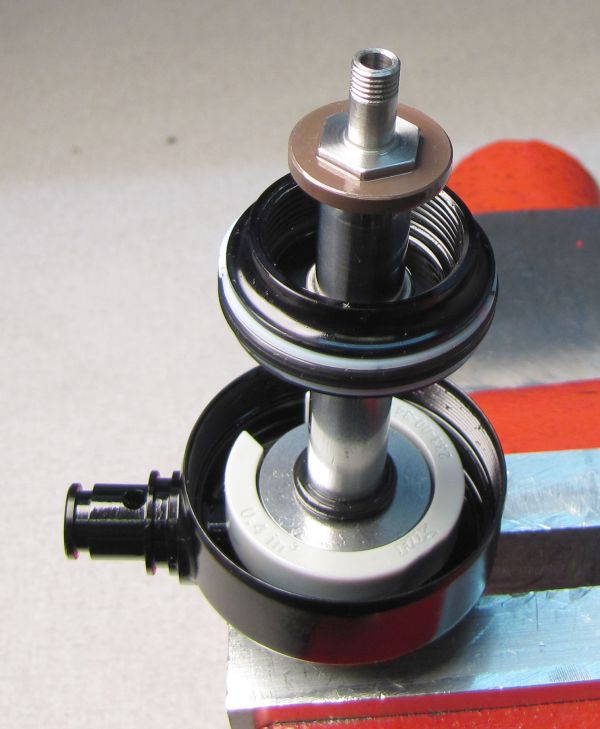
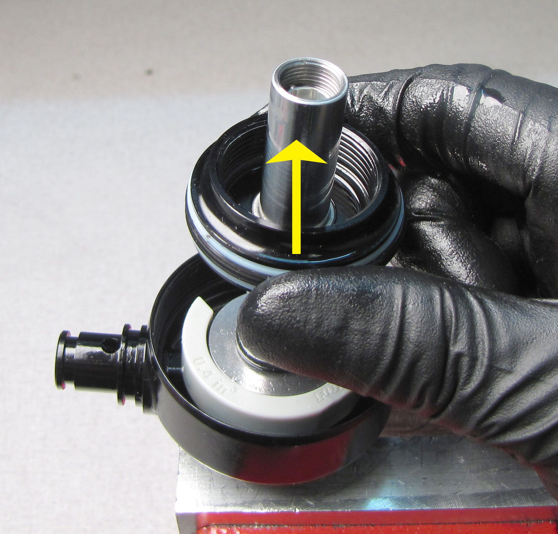
Remove the Bearing Assembly from the shaft followed by the Bottom Out O-ring and Bottom Out plate.
Step 22
Remove any volume spacers if present. Remove the o-ring from within the Eyelet.

Step 23
Non-Trunnion Eyelets: Remove the set screw from the rear of the Eyelet by turning it counter-clockwise with a 2mm hex wrench. Remove the detent spring and ball bearing.
Trunnion Eyelets: The rebound detent spring and ball bearing will be disassembled as you remove the Rebound Metering Rod in a later step.
Step 24
Clean the shaft with Isopropyl Alcohol, then dry it completely with a lint-free paper towel. Clamp the shaft in your shaft clamps (PN: 803-00-805) just tightly enough for you to unthread the Eyelet Assembly from the shaft without allowing the shaft to rotate in the clamps.


Step 25
For Trunnion Eyelets: Install the Trunnion Eyelet Tool (PN: 398-00-099) onto the Eyelet Assembly making sure to thread the bolts fully clockwise into the Trunnion Eyelet holes.
For All Eyelets: Heat the shaft for 4-5 seconds with a propane torch to break down the red Loctite bond. Unthread the Eyelet Assembly counter-clockwise to remove it from the shaft.
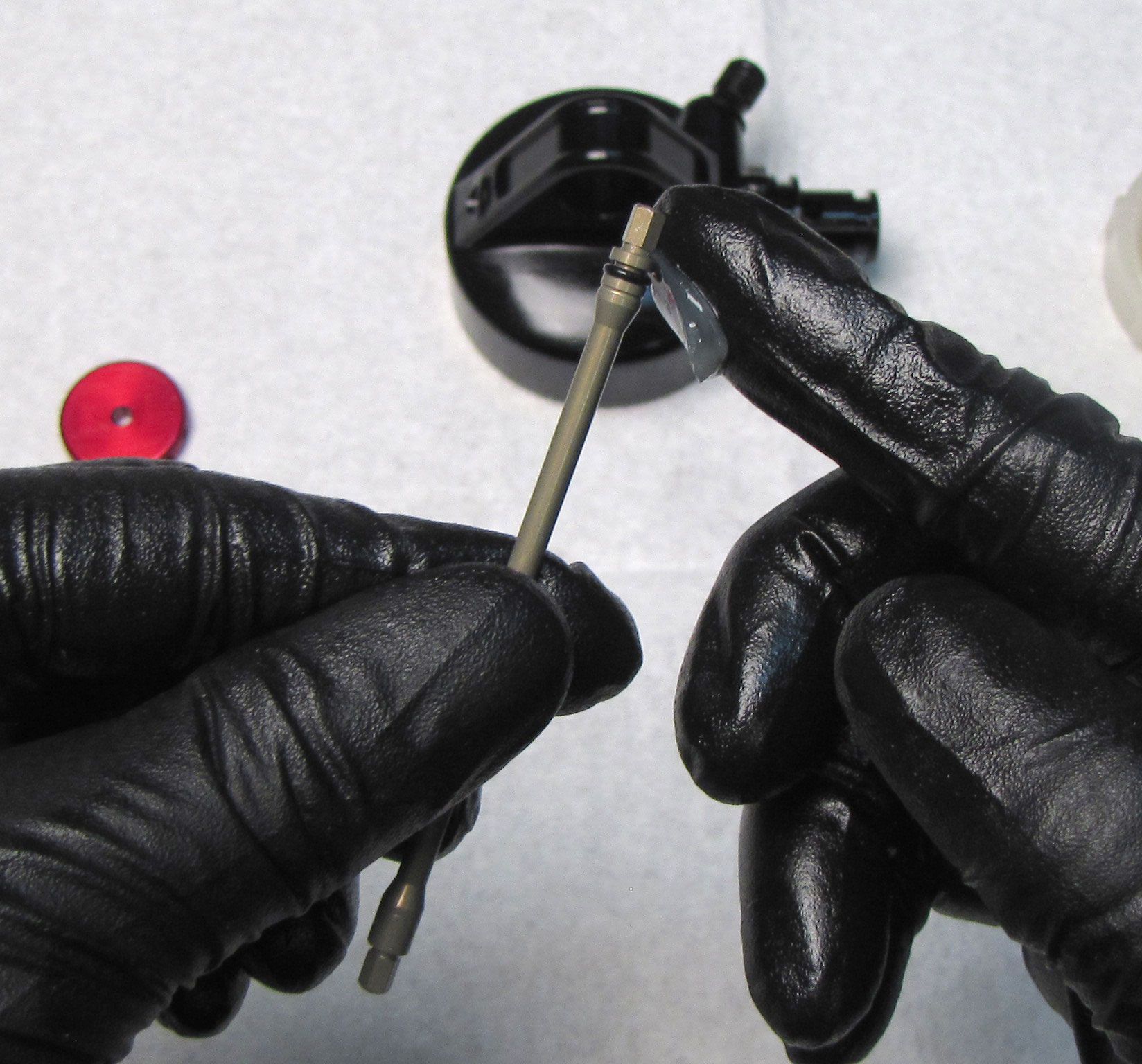
Step 26
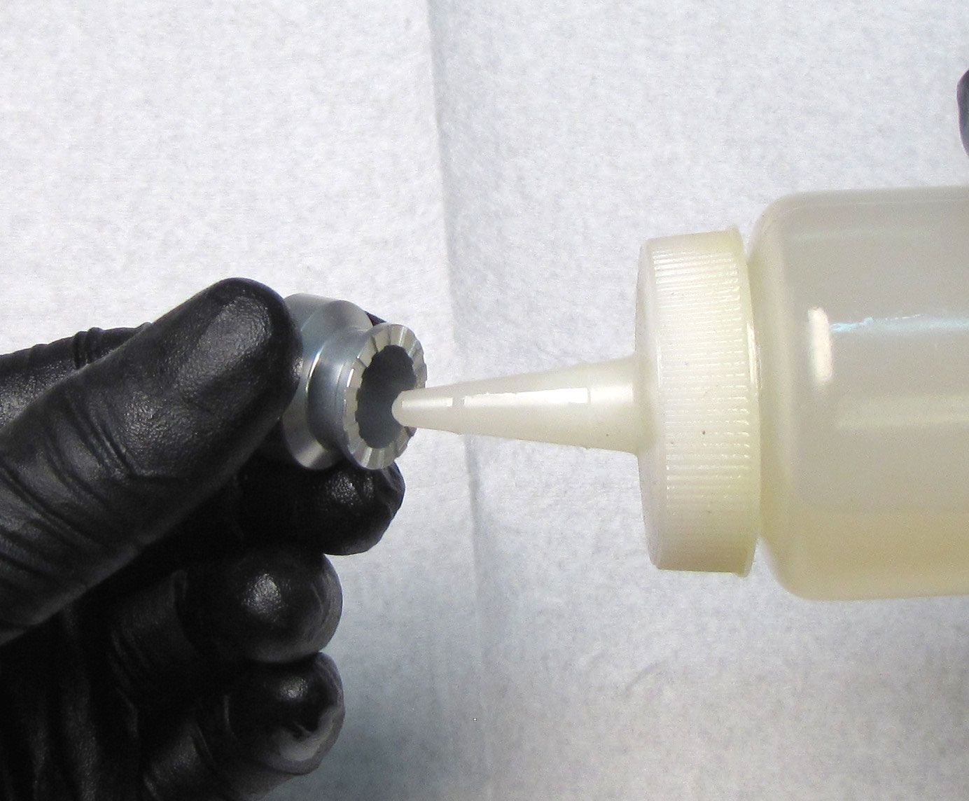
Remove the Rebound Metering Rod from the Eyelet by pulling it out. Use the hex feature on the end of the Rebound Metering Rod to unthread the Rebound Adjuster Insert counter-clockwise from within the shaft. Clean any Loctite residue from the shaft threads within the Eyelet. Replace the shaft o-ring within the Eyelet with a new greased one from the kit.

Step 27
Replace the main air seal and backup rings on the outside of the Bearing Assembly with new greased ones from the kit. Replace the 2 o-rings on the inside of the Bearing Assembly with new greased ones from the kit.
Step 28
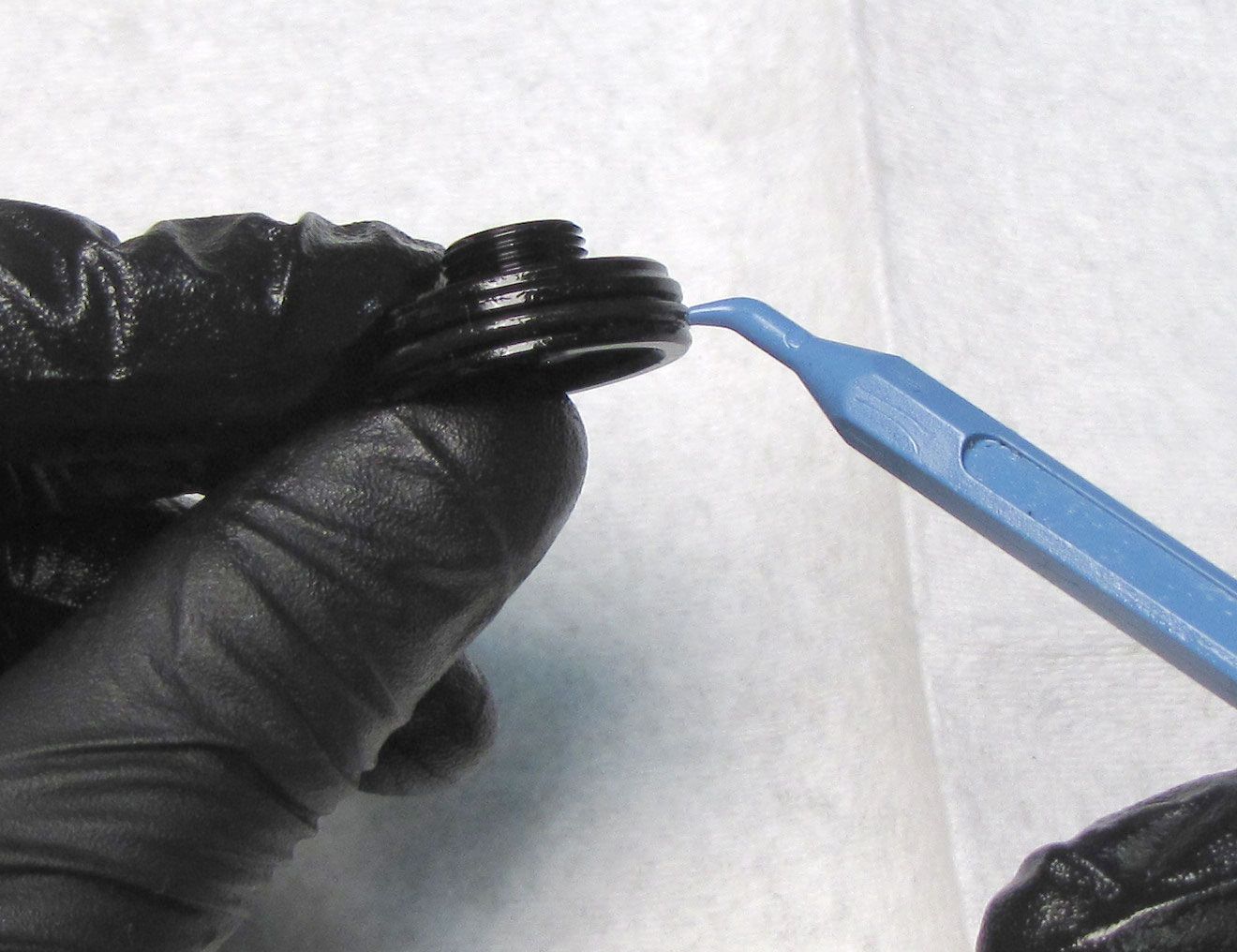
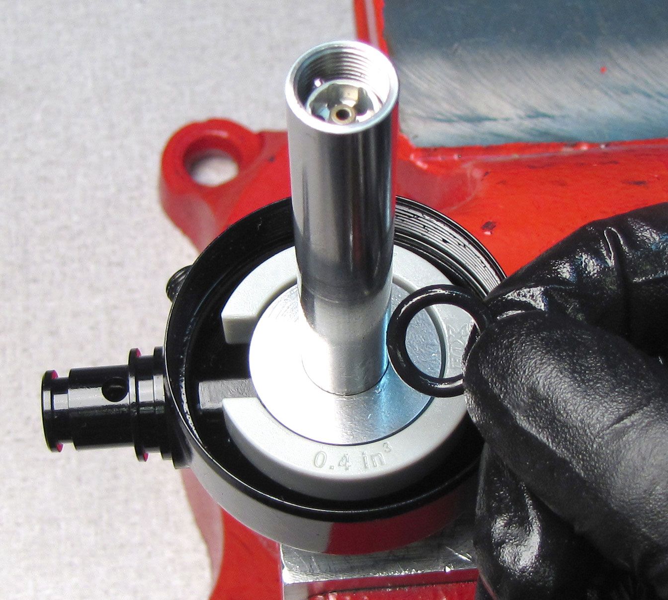
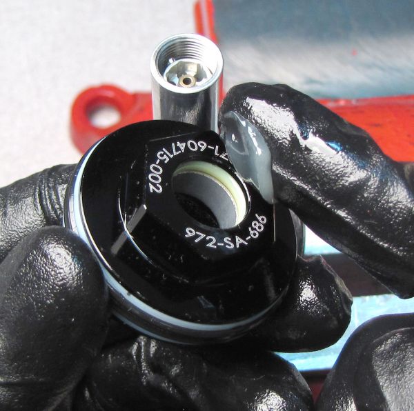
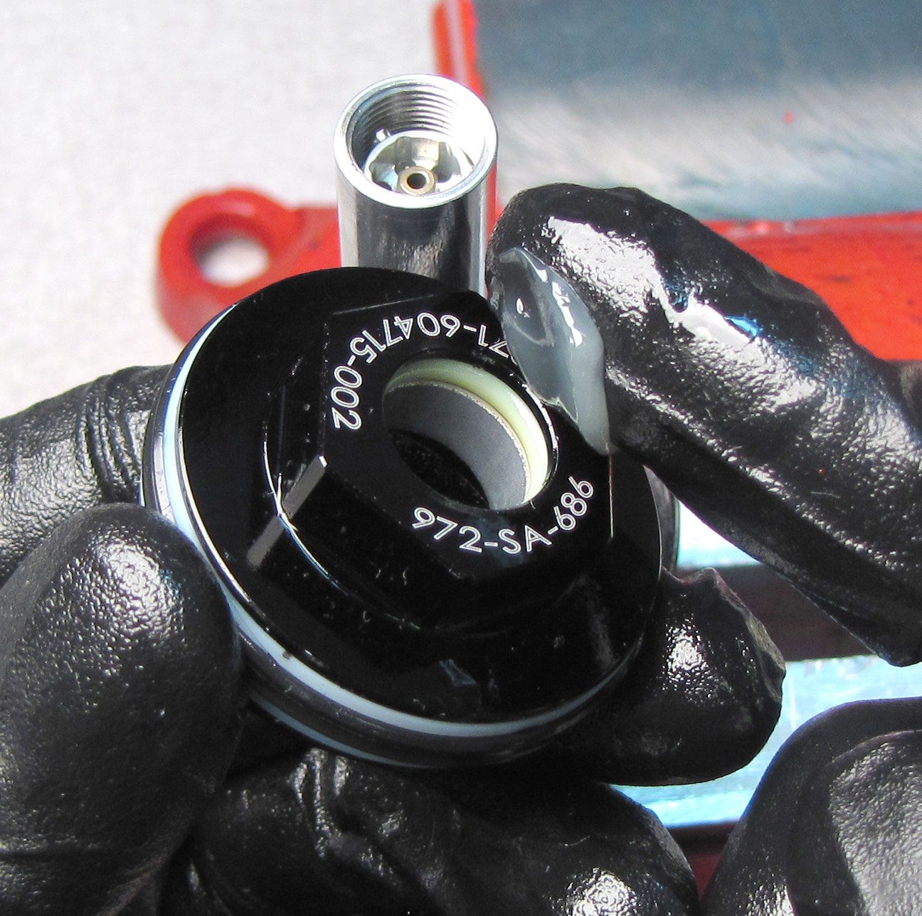
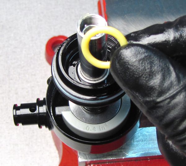
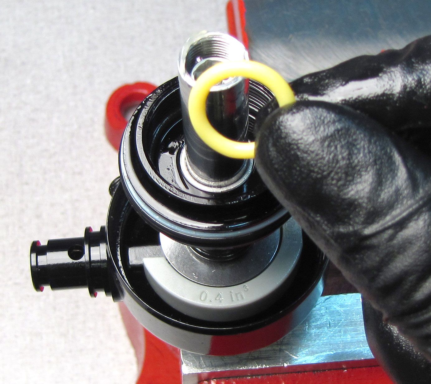
Replace the o-ring on the IFP with a new greased one from the kit. Replace the o-ring on the Reservoir Endcap with a new greased one from the kit.
Step 29
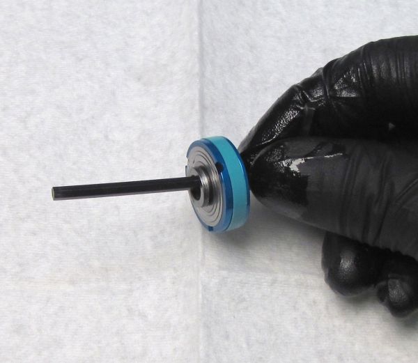
Inspect the shims on the main piston for wear or damage and replace as needed. Replace the glide ring on the piston with a new one from the kit. Replace the shims on the piston in their original order.
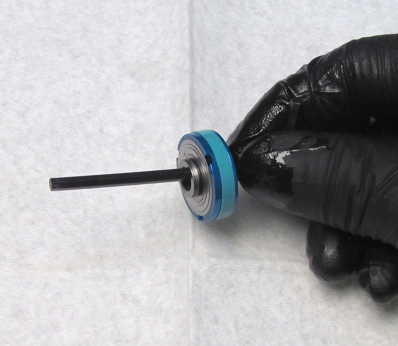
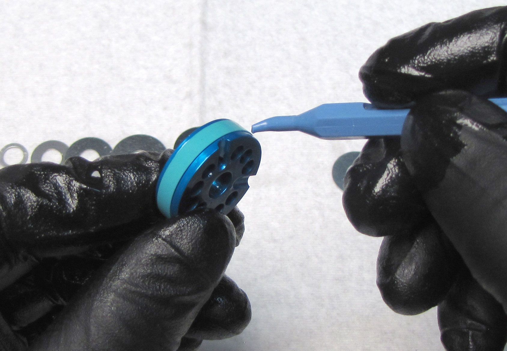
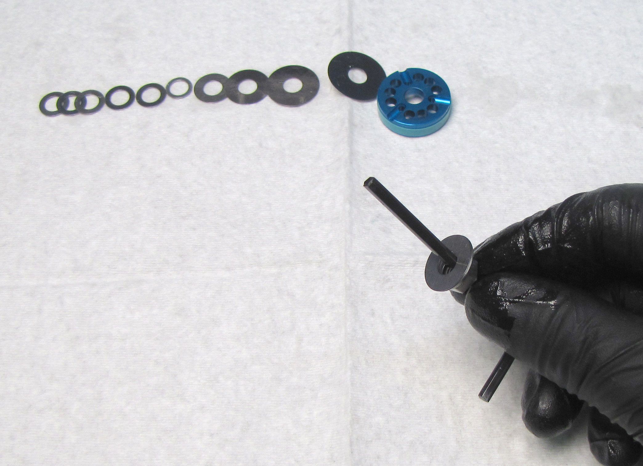

Step 30
Unthread the Piston Bolt and Piston Nut of the Lockout Blowoff Assembly by turning them counter-clockwise with a 4mm hex wrench and an 8mm socket. Inspect the shims for wear or damage and replace as needed. Keep all parts in their original order.

Step 31
Replace the shims on the Lockout Blowoff piston in their original order. Thread the Piston Bolt and Piston Nut together tightening clockwise to 40 in-lb (4.5 Nm) torque with a 4mm hex wrench and an 8mm socket on your torque wrench.
LIVE Compression Housing Rebuild
Step 1
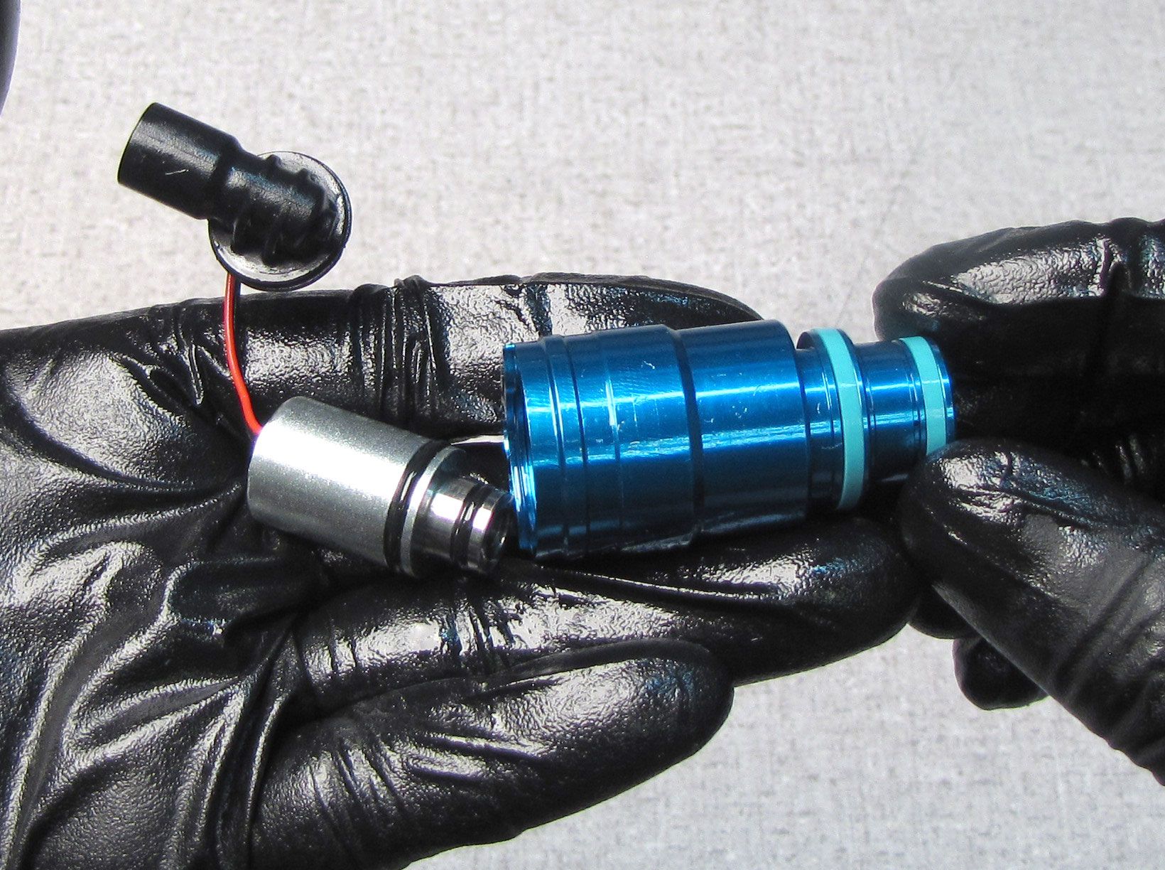
Clamp the Compression Cartridge Housing in your LIVE Valve shaft clamps (PN: 803-01-360) then unthread and remove the Reservoir Compression Assembly by turning it counter-clockwise with a 5mm hex wrench. Replace the o-ring on the Compression Piston with a new greased one from the kit.


Step 2
Remove the Boost Valve from the Compression Cartridge Housing.
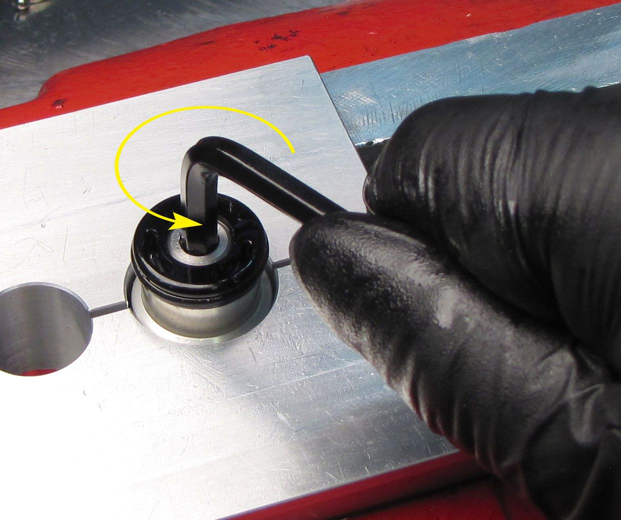
Step 3
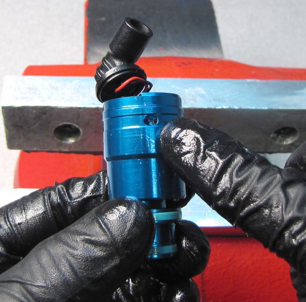
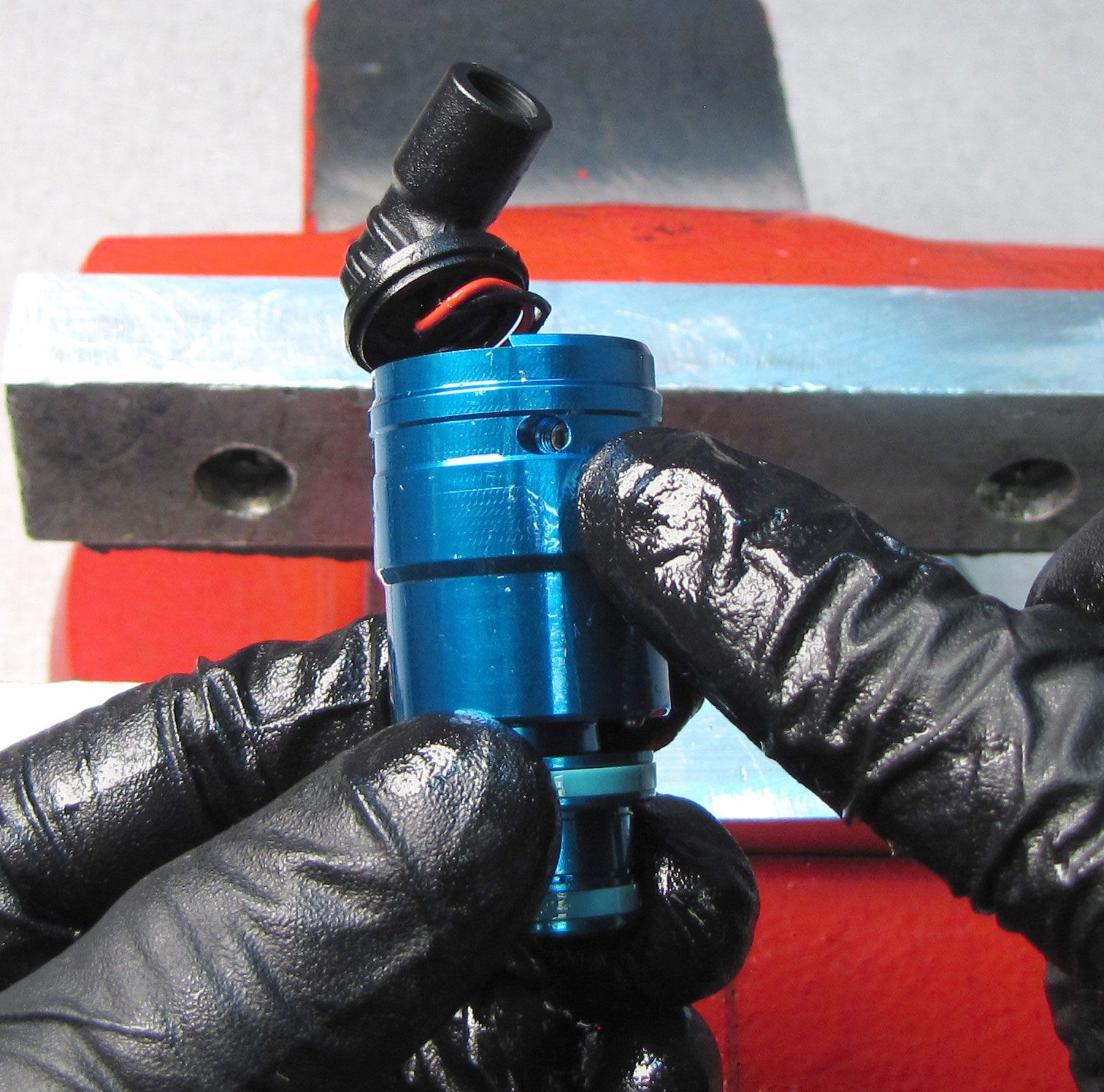
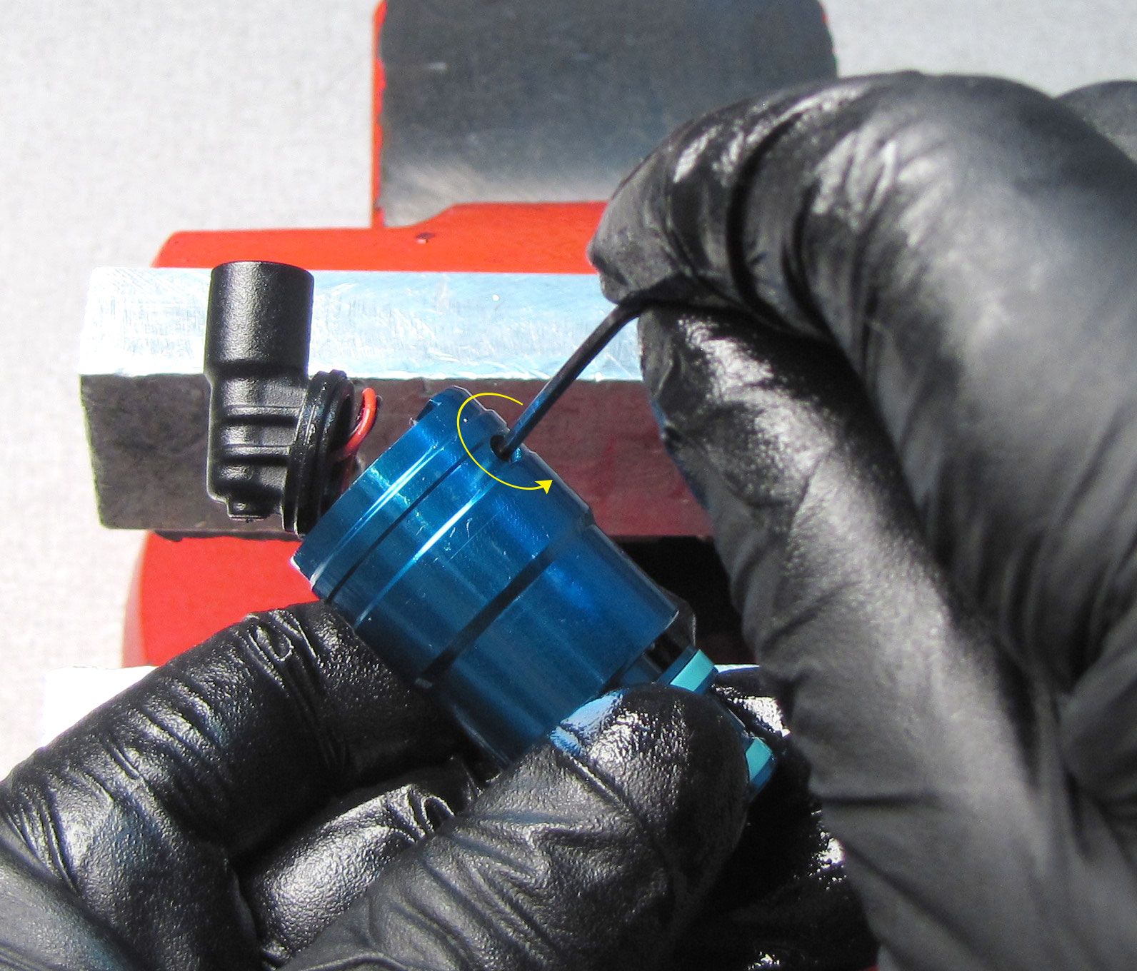
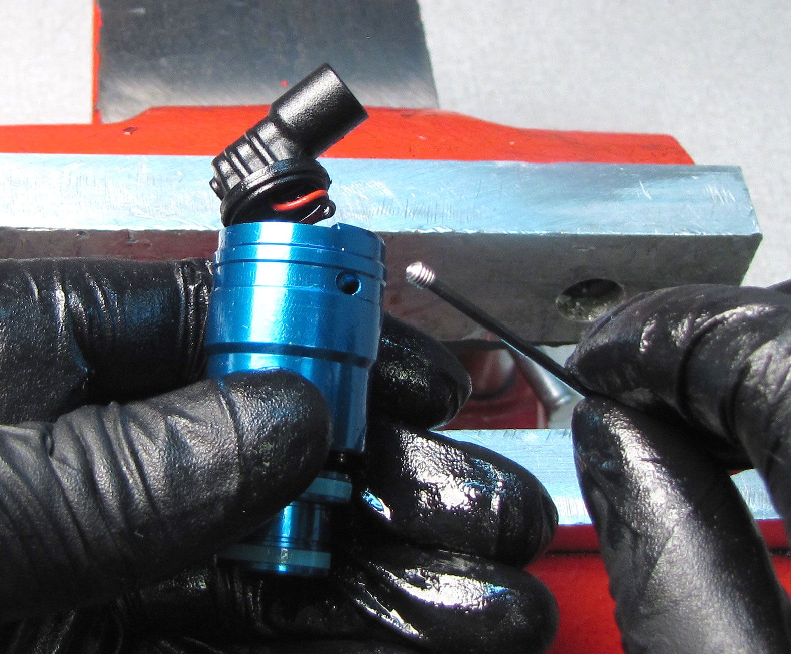
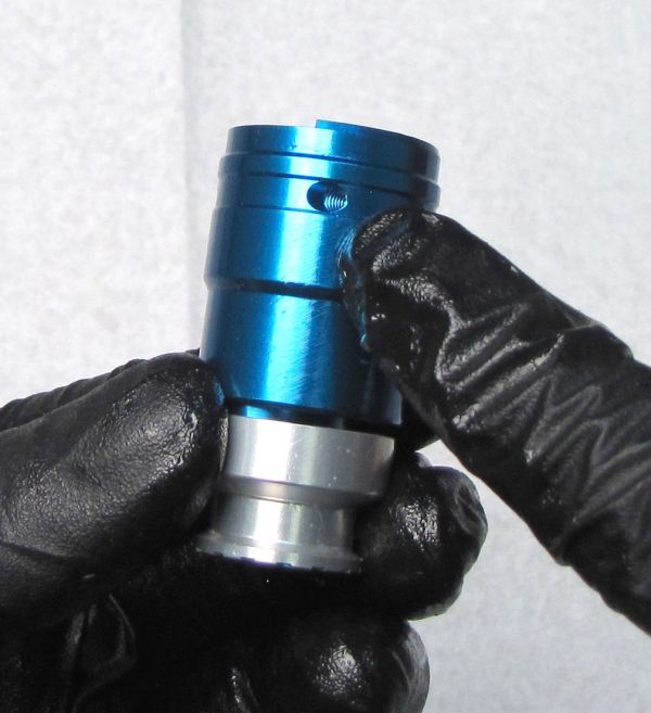
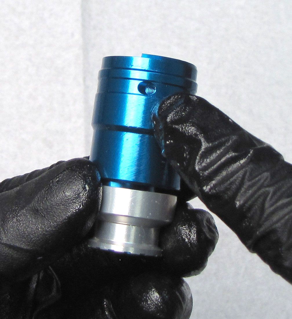
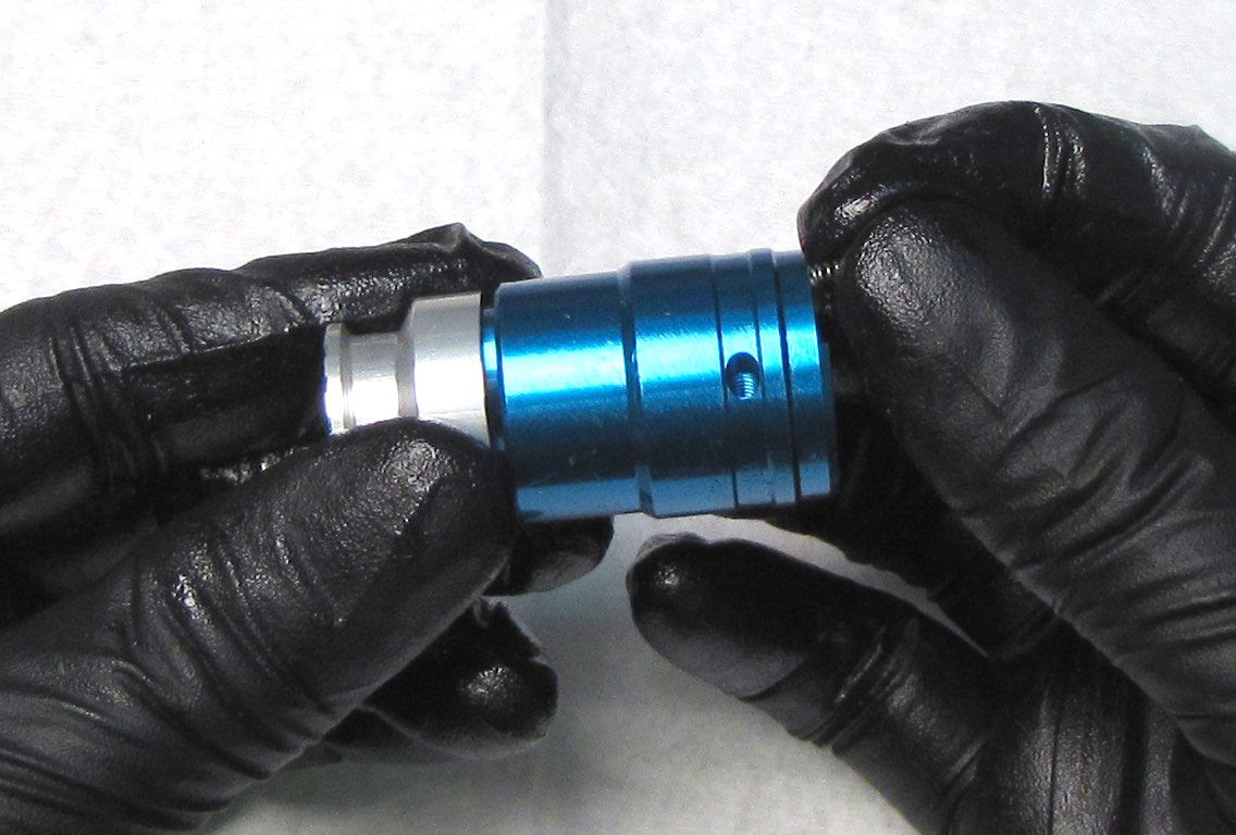
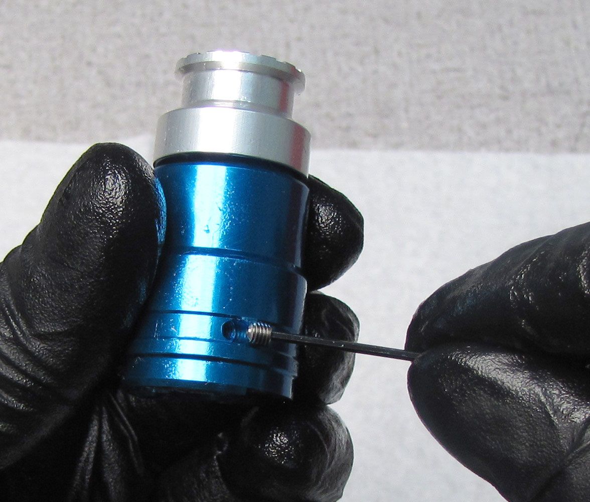
Unthread the set screw from the side of the Compression Cartridge Housing by turning it counter-clockwise with a 1.5mm hex wrench. Remove the detent ball and spring with a magnet.

Step 4
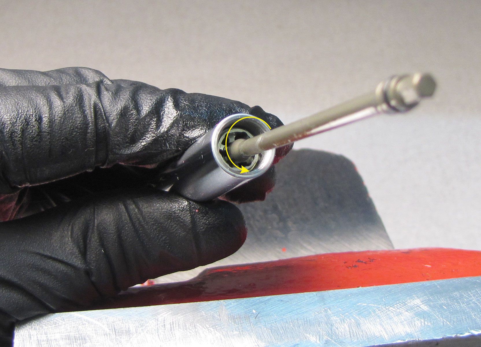
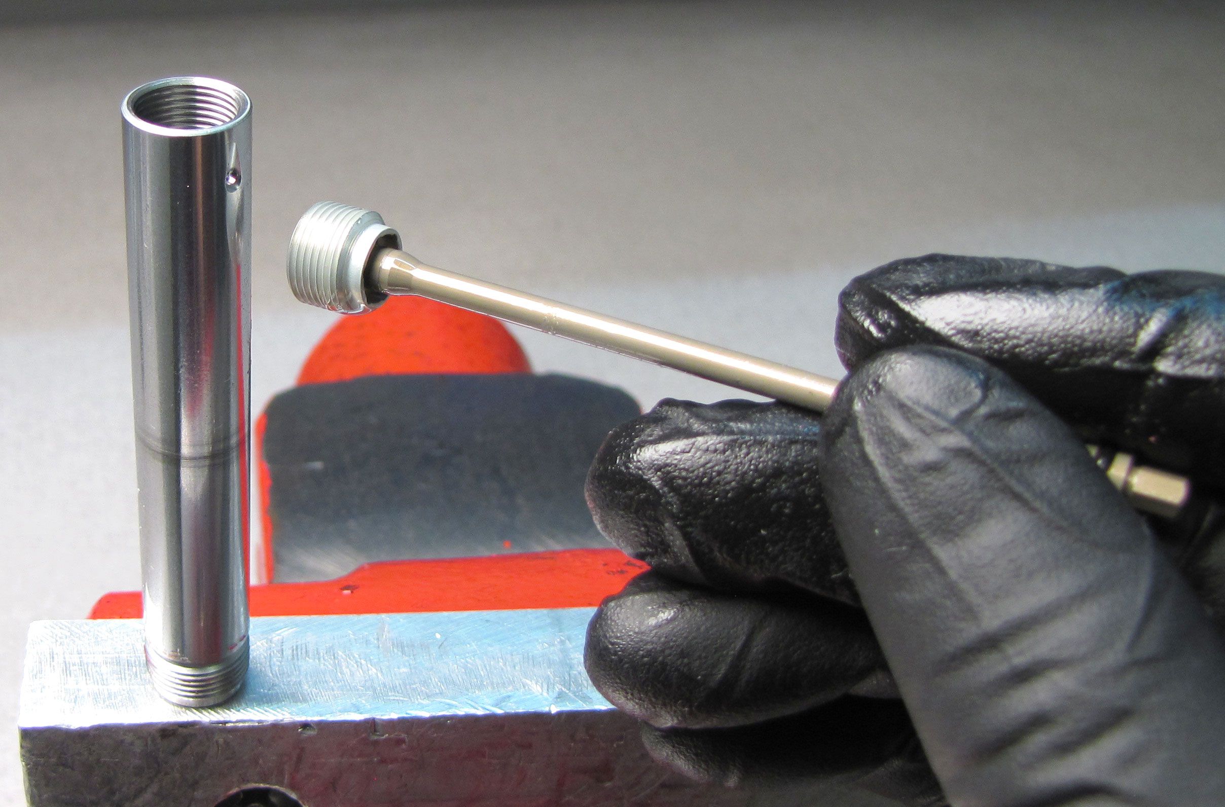
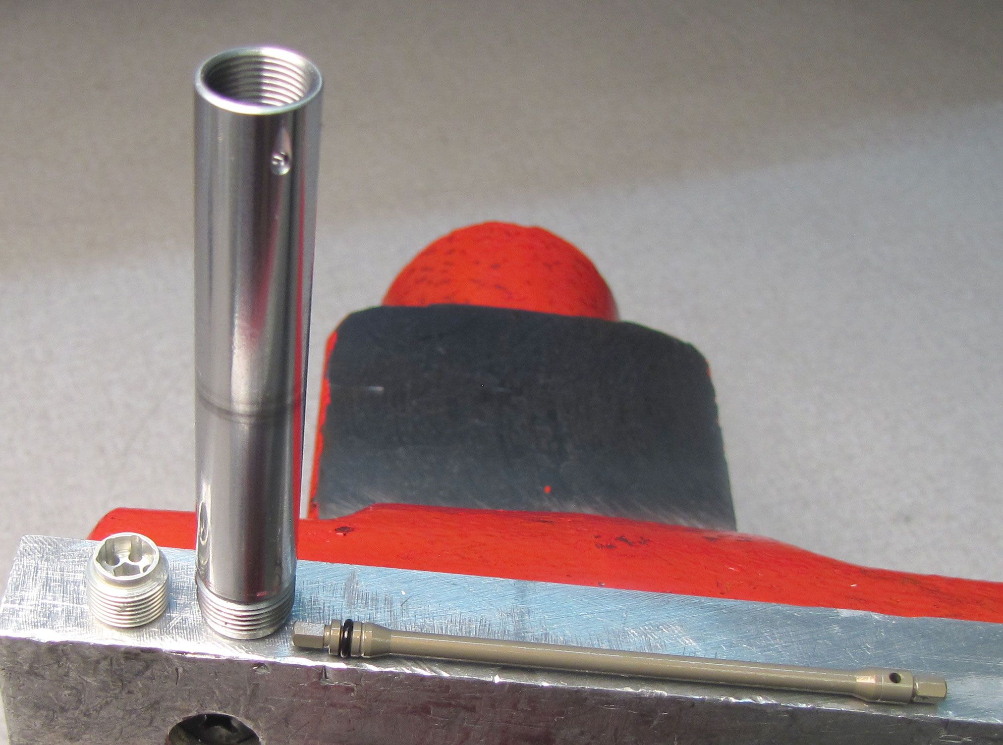
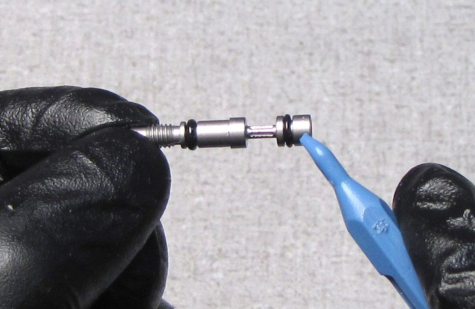
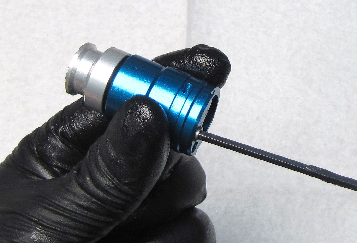
Unthread the Compression Needle counter-clockwise with a 3mm hex wrench. Pull out the Compression Needle to remove it once unthreaded.

Step 5
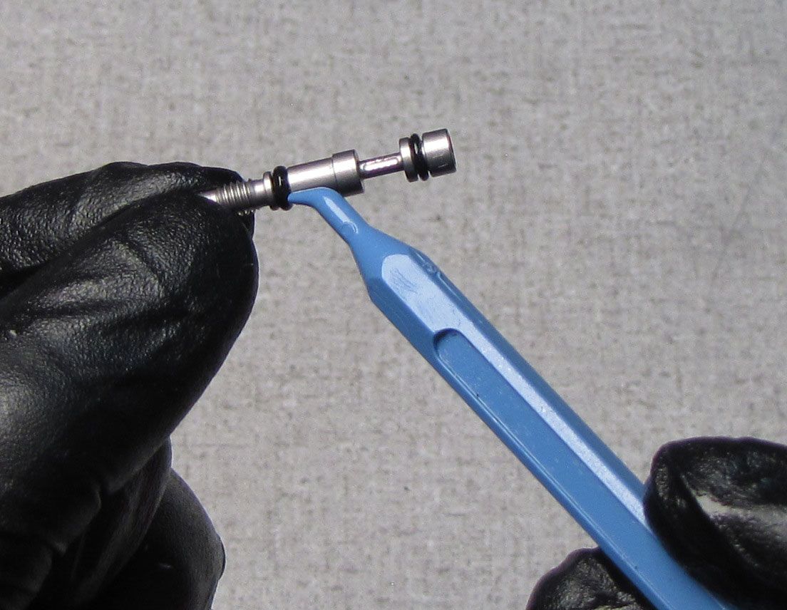
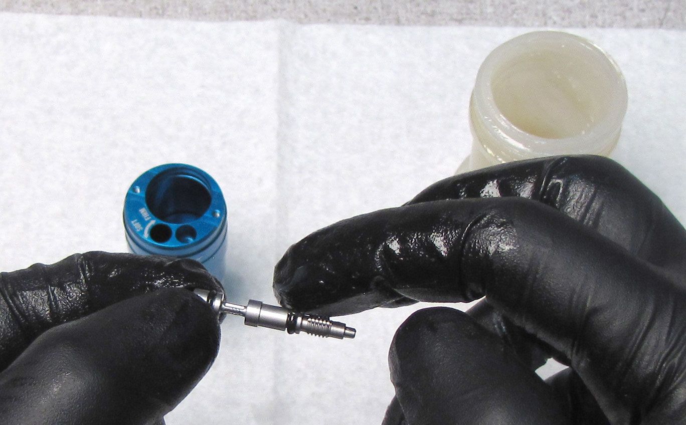
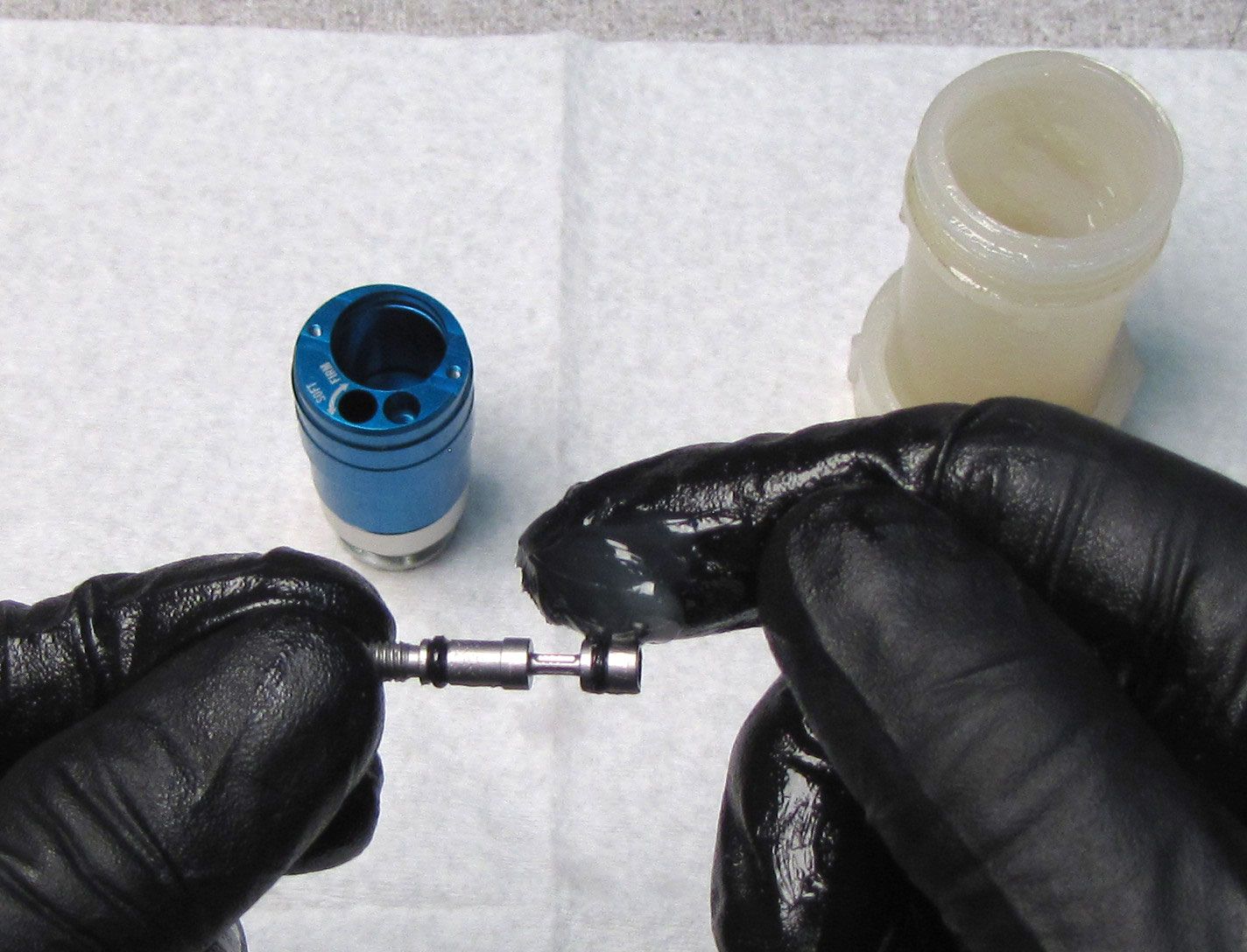
Replace the two o-rings on the Compression Needle with new ones from the kit. Coat the o-rings in FOX 5wt Teflon Infused oil.
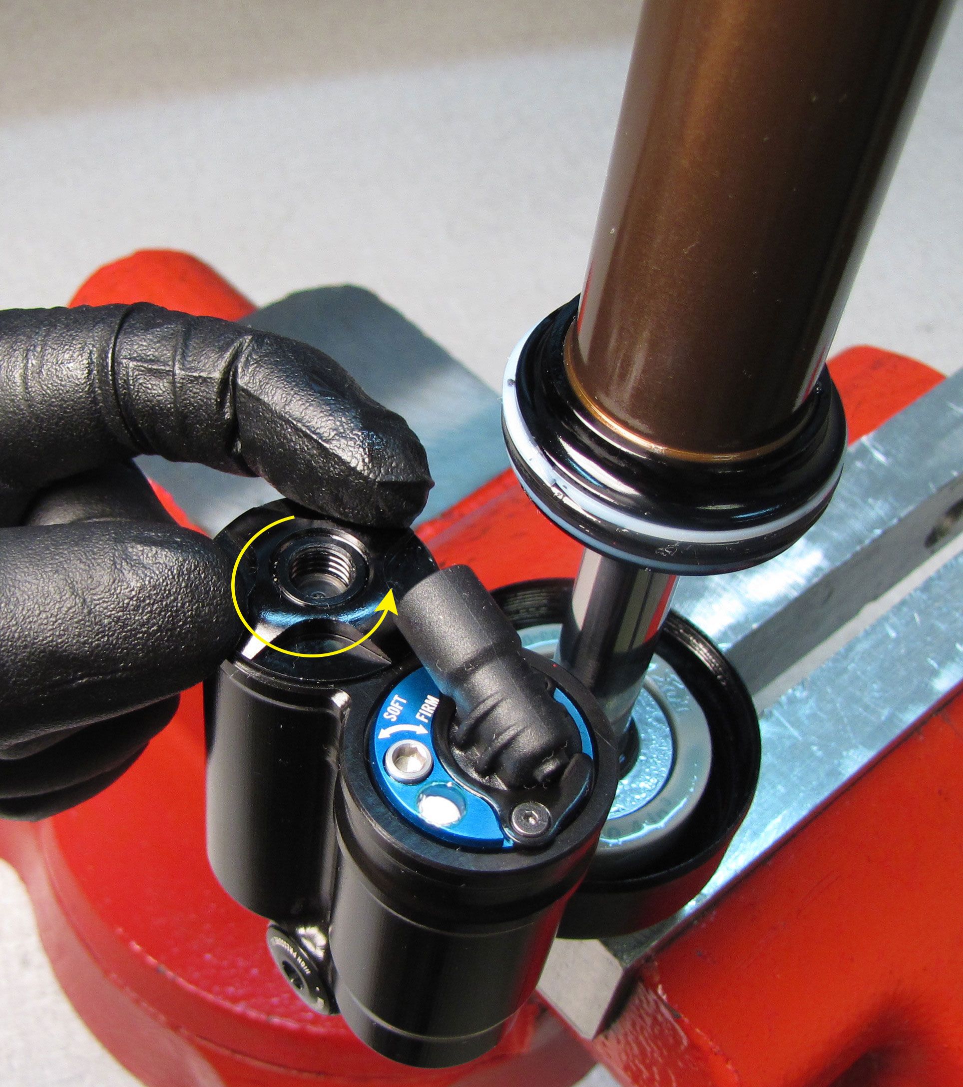
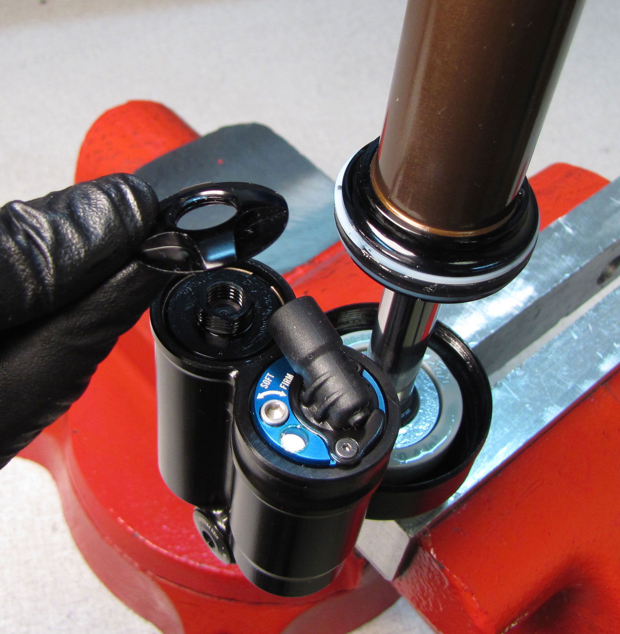
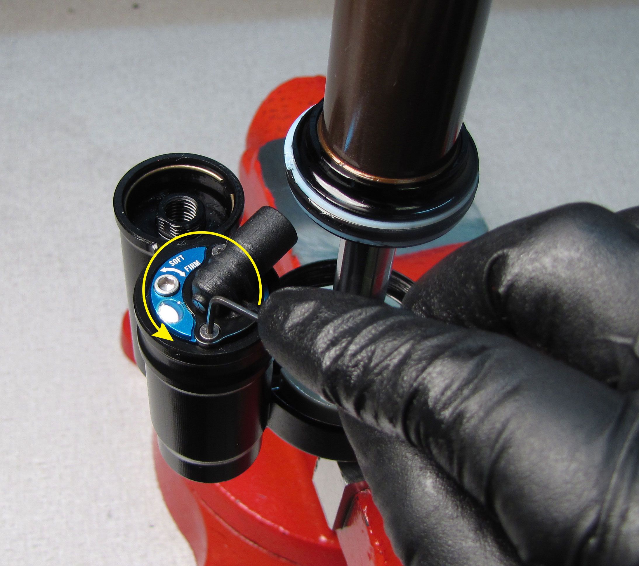
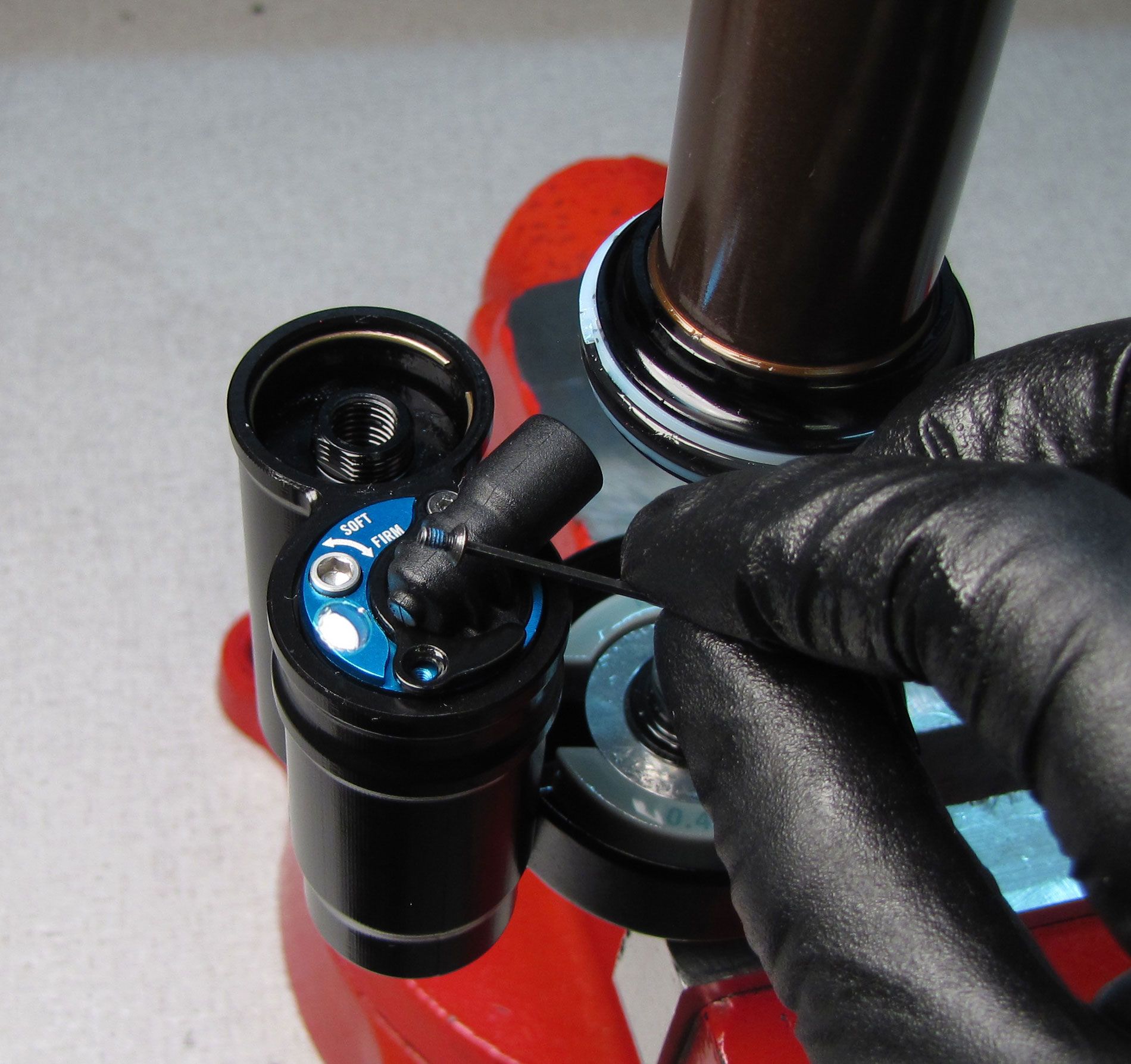
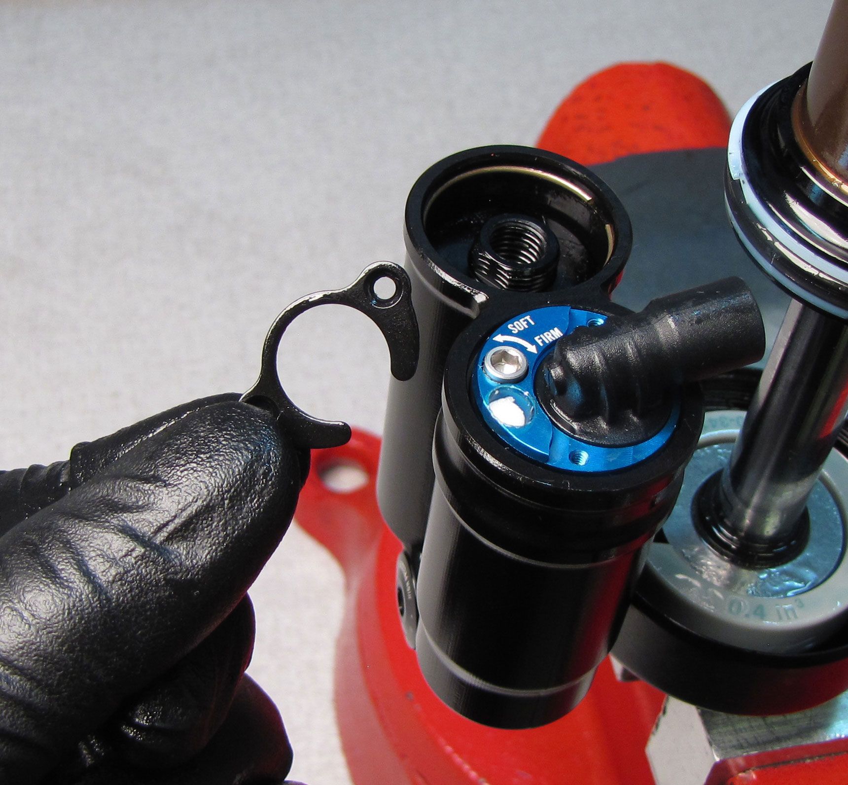
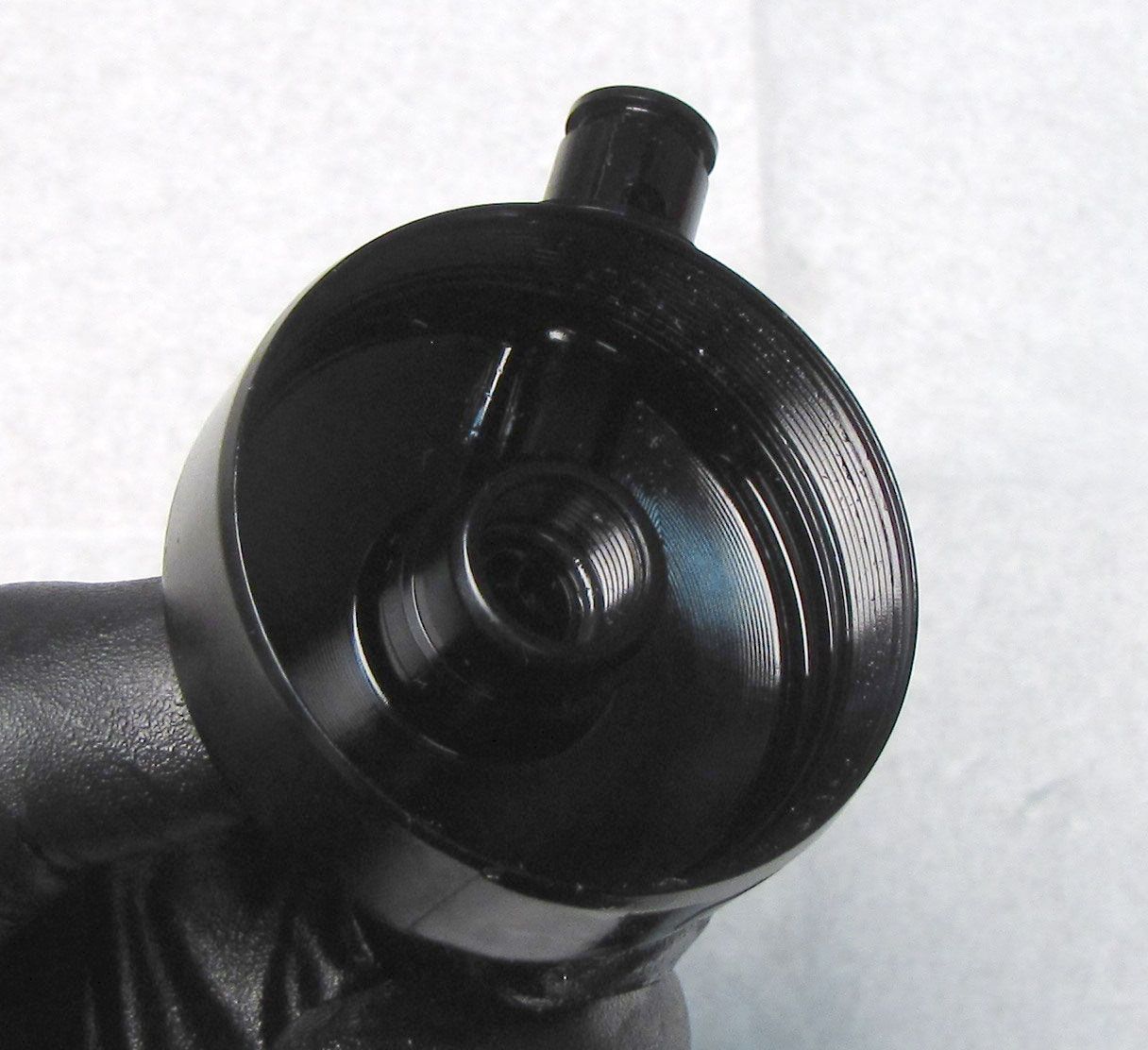
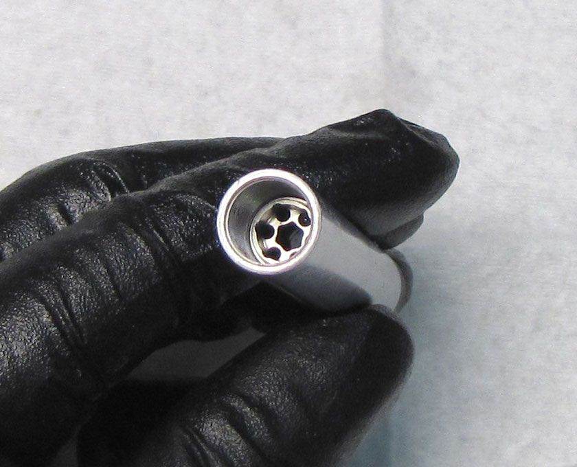
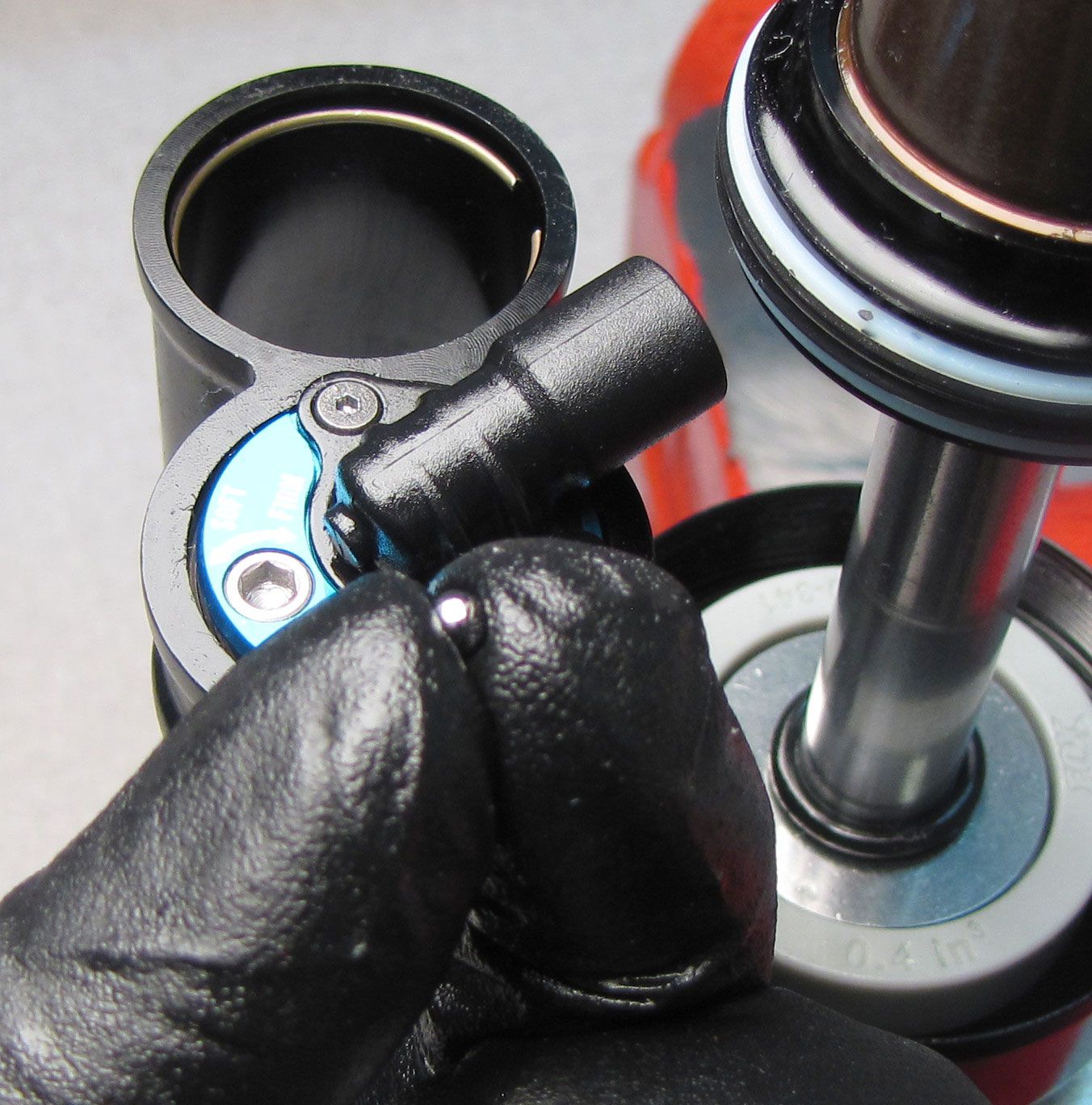
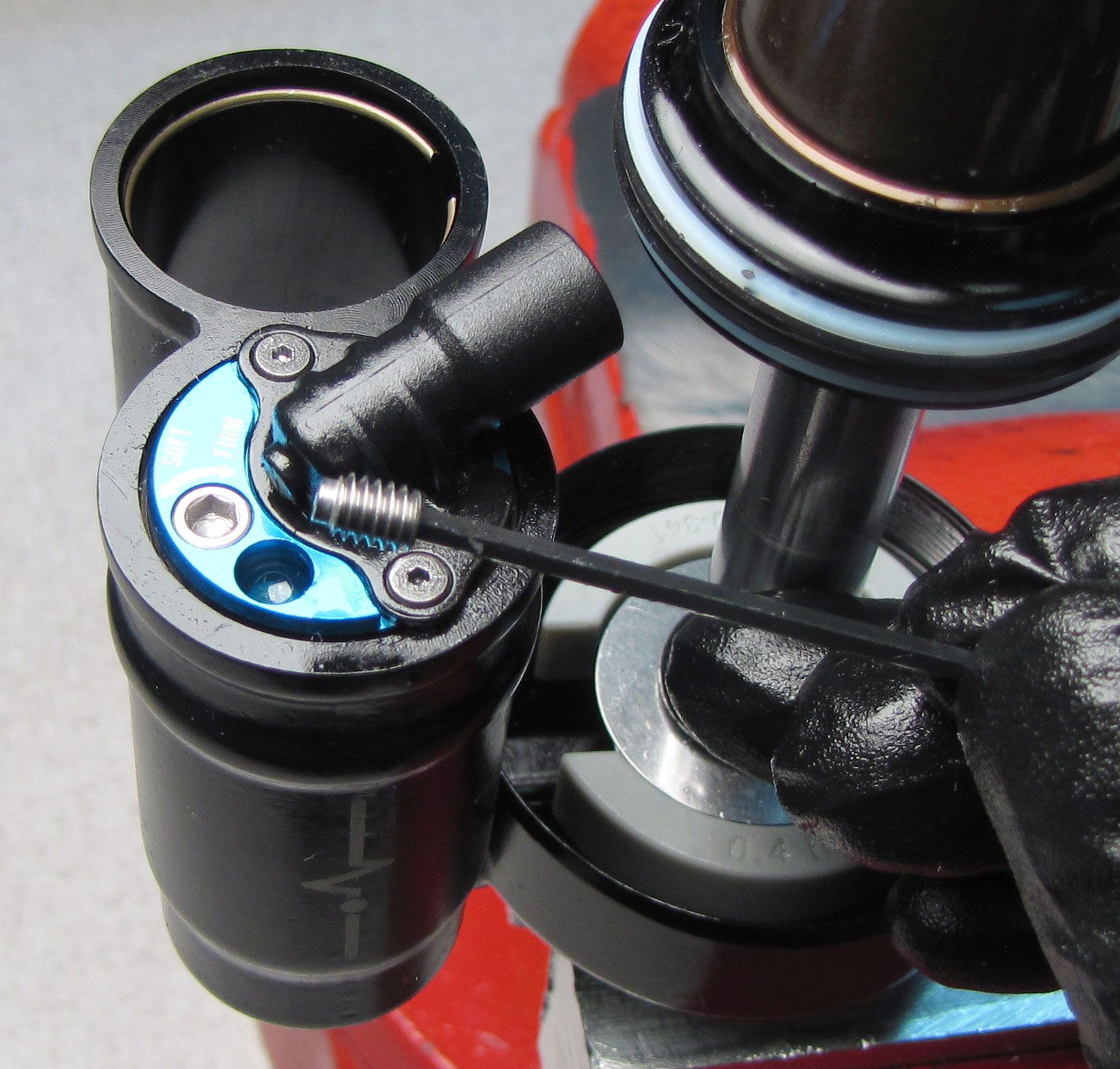
Step 6
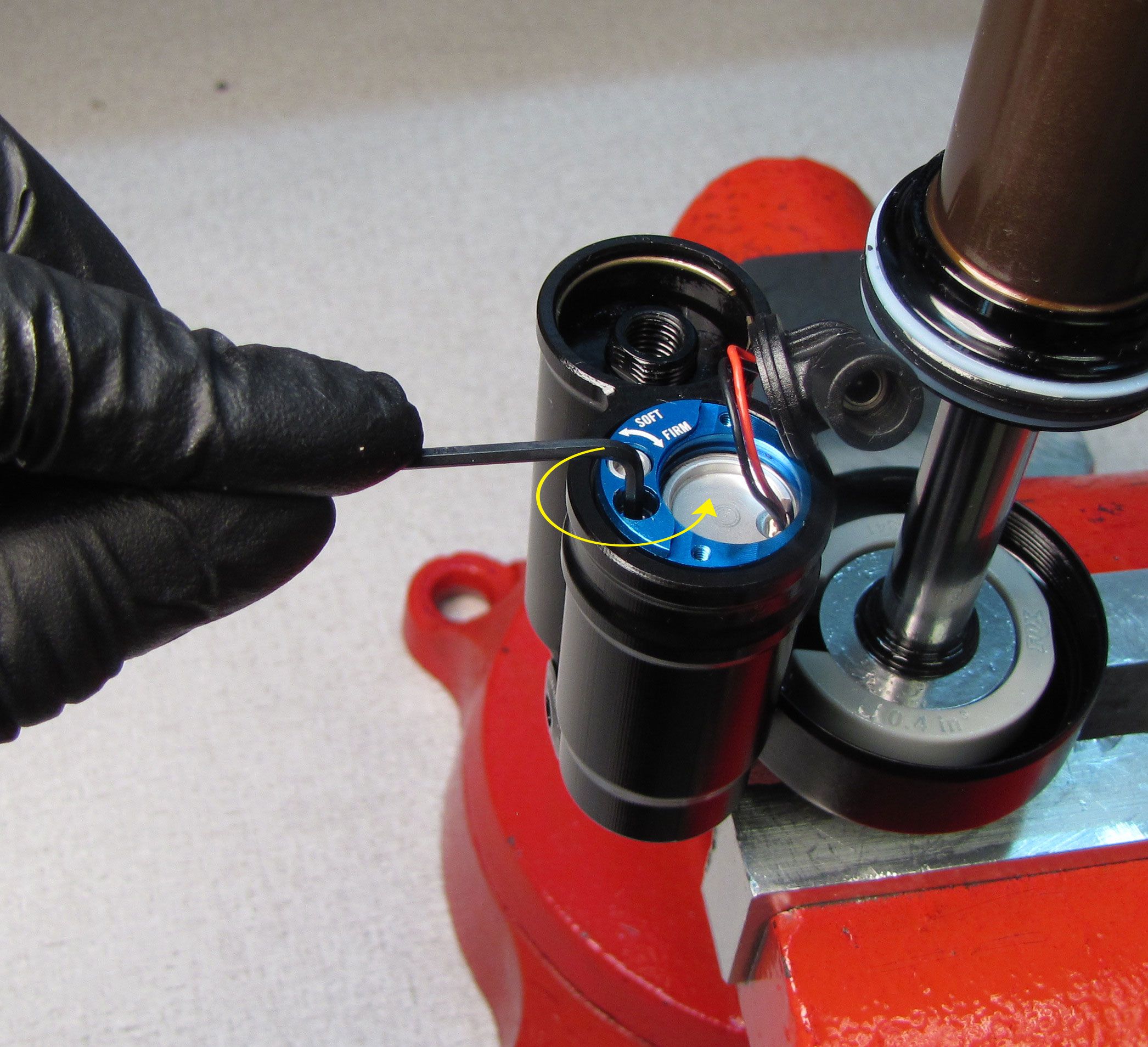
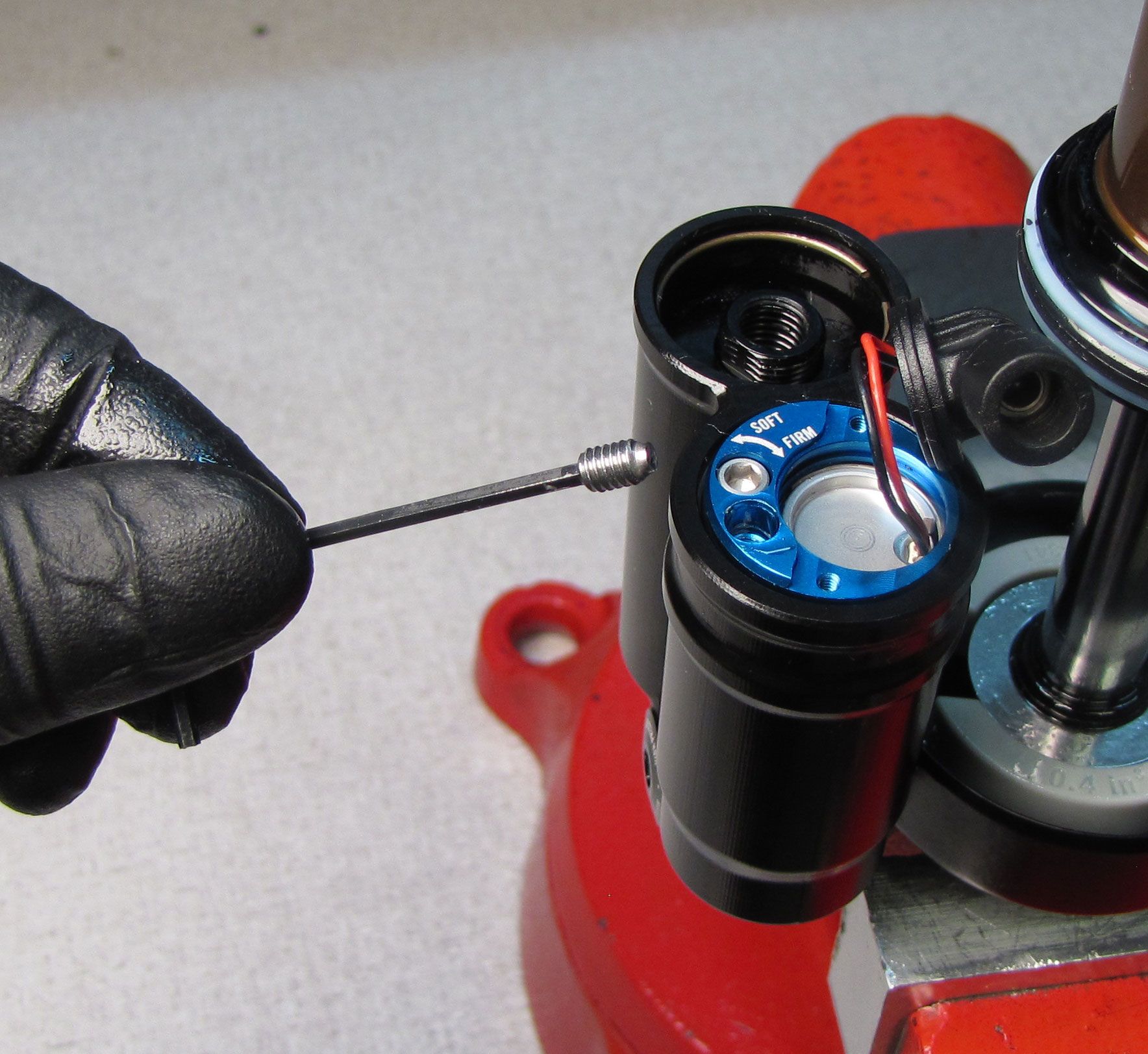
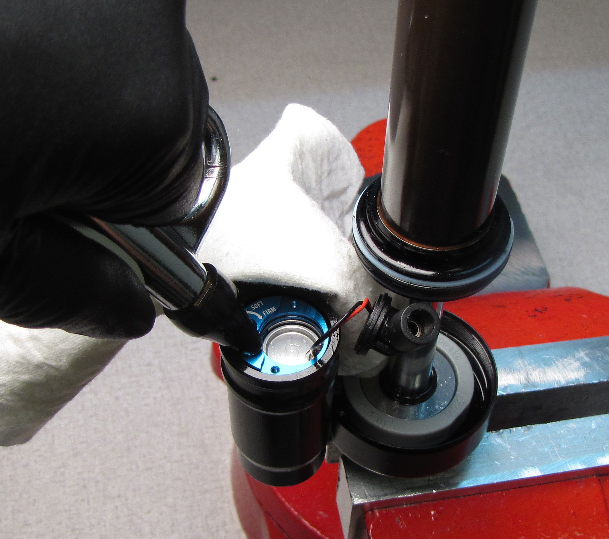
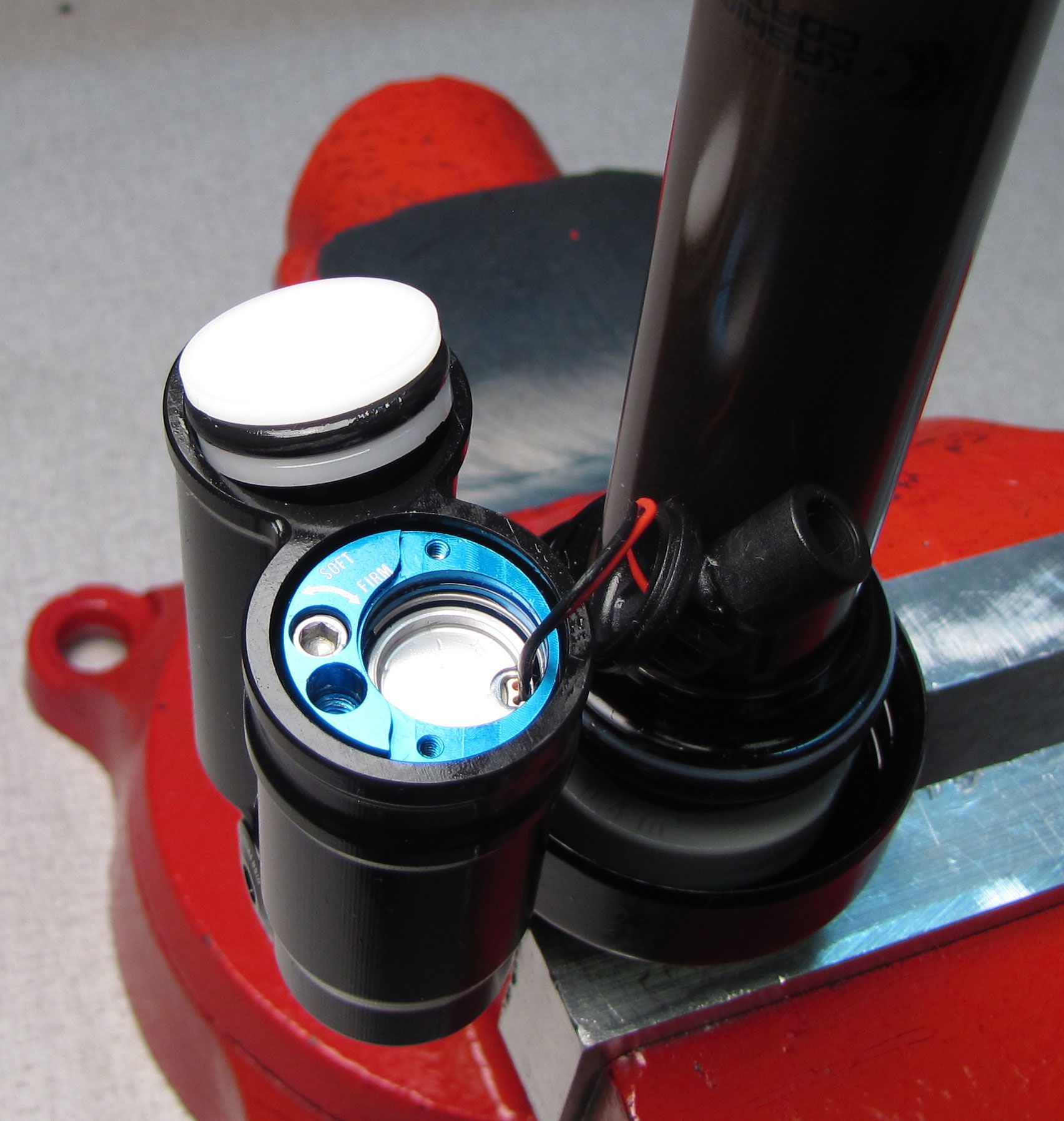
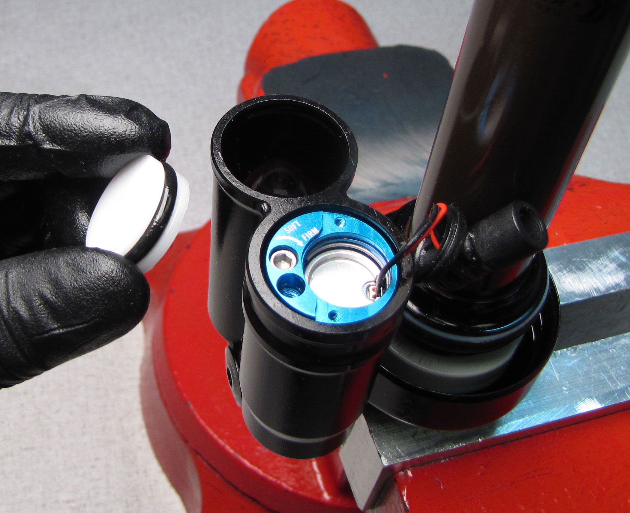
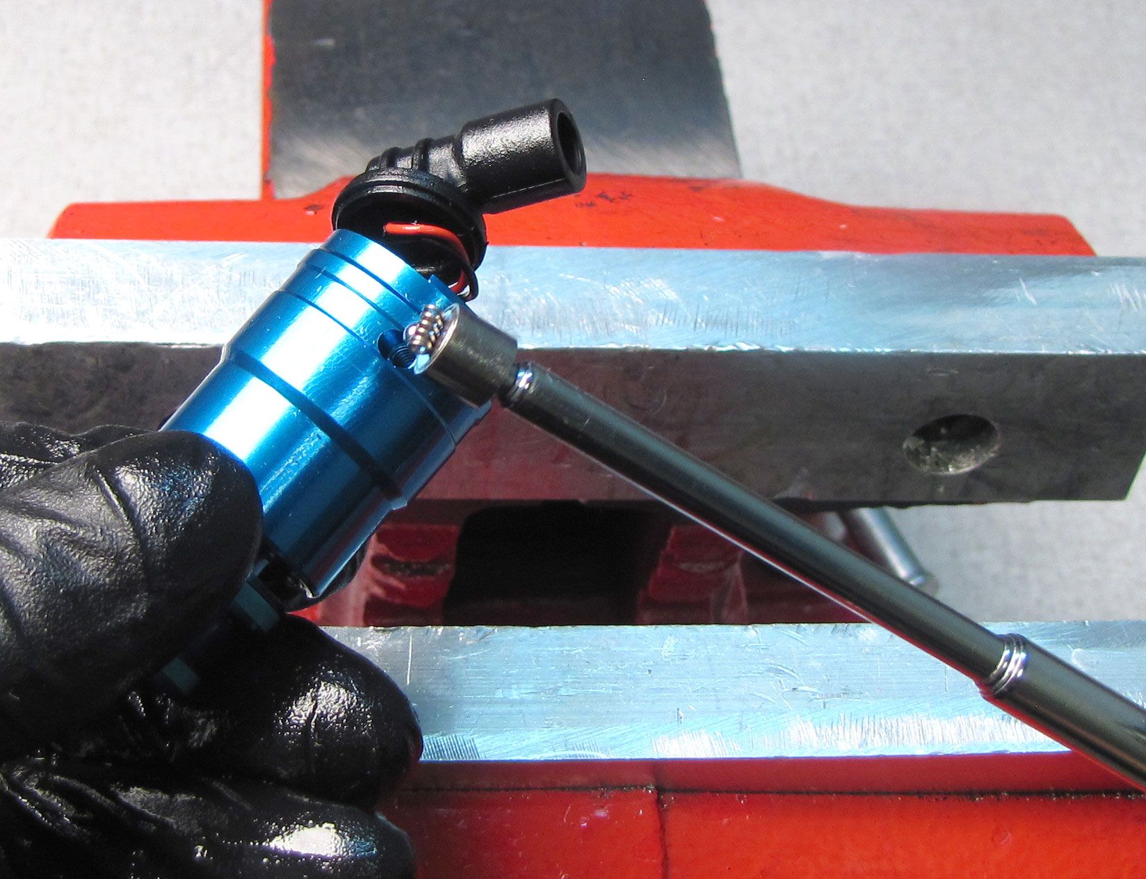
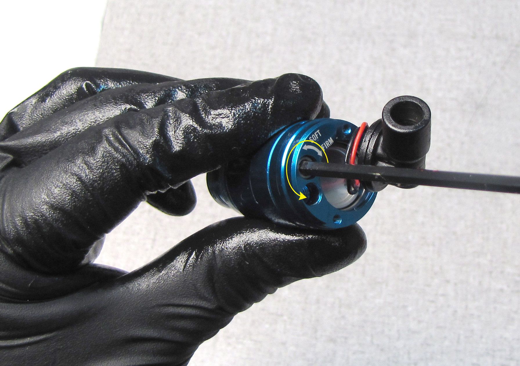
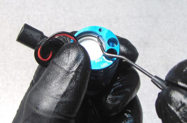
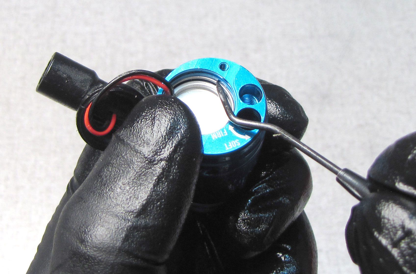
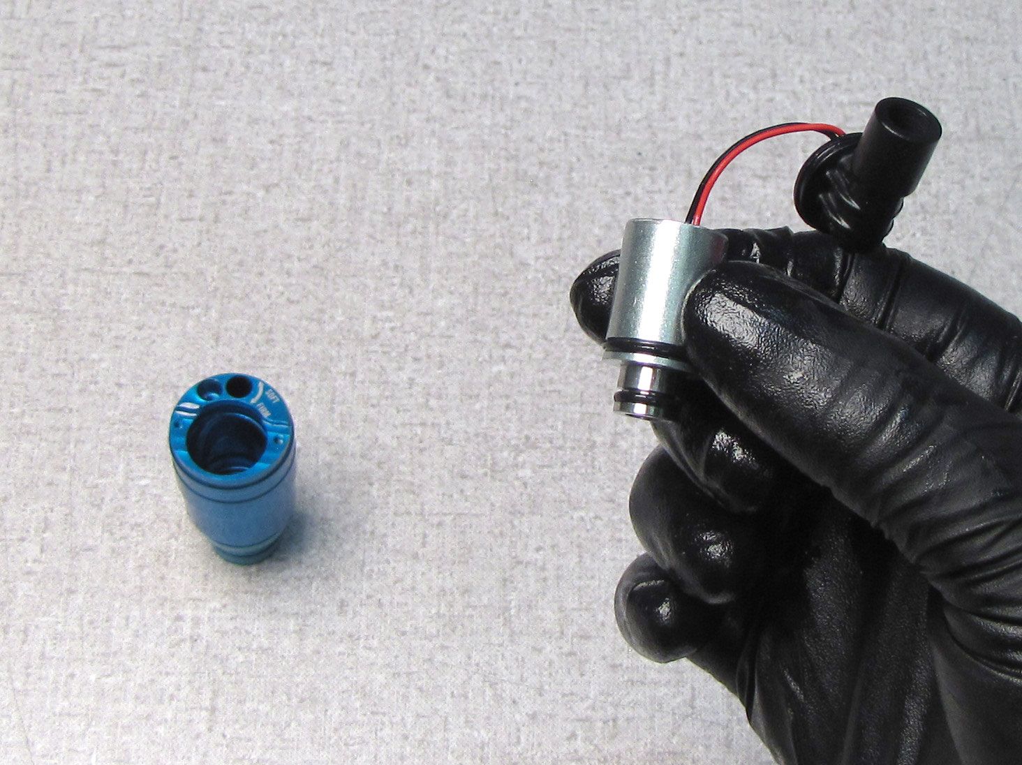
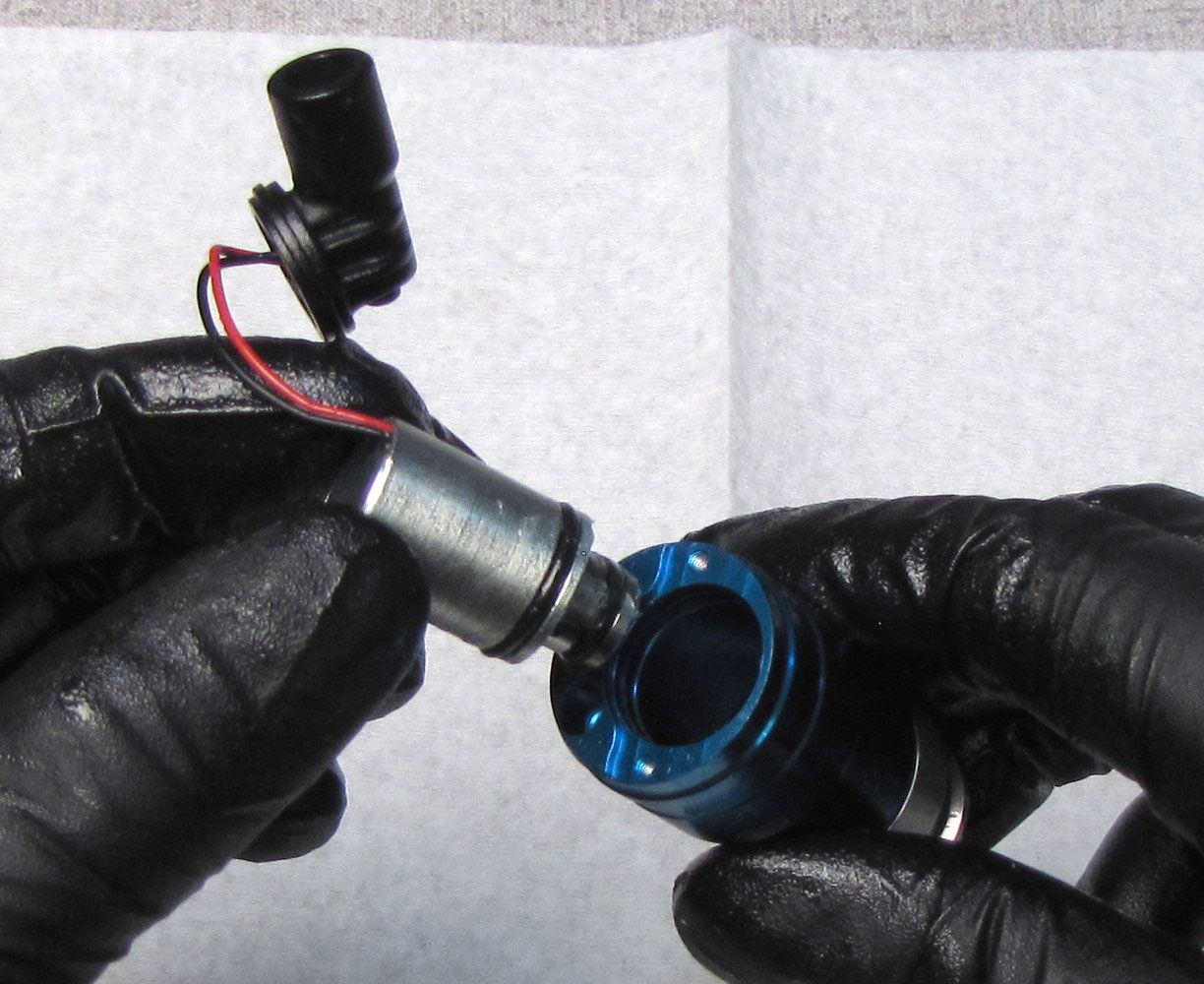
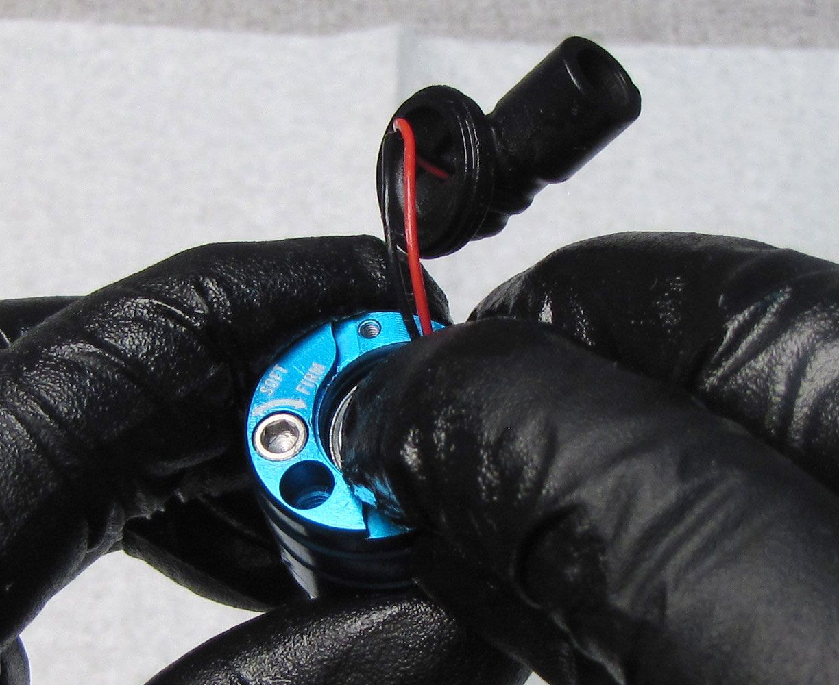
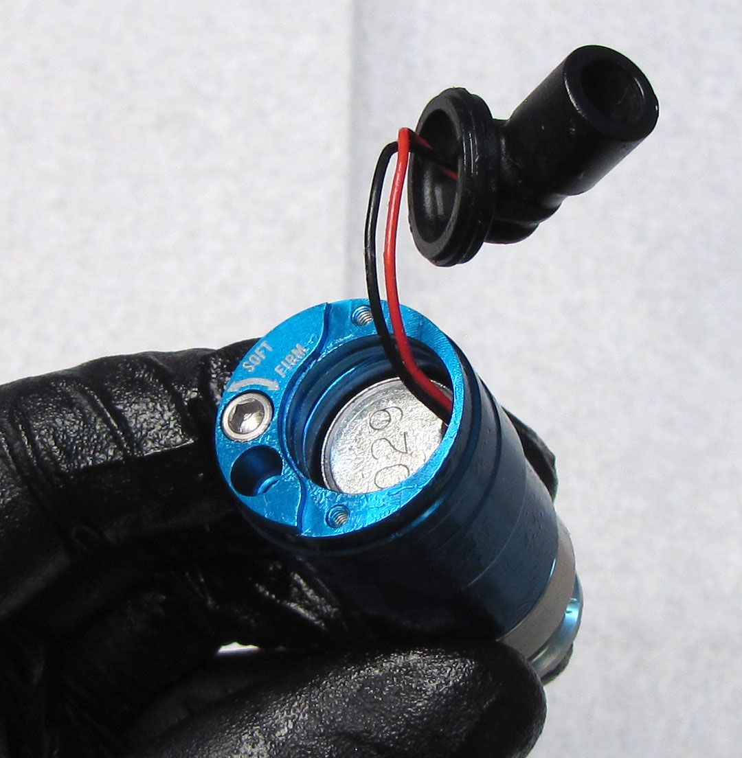
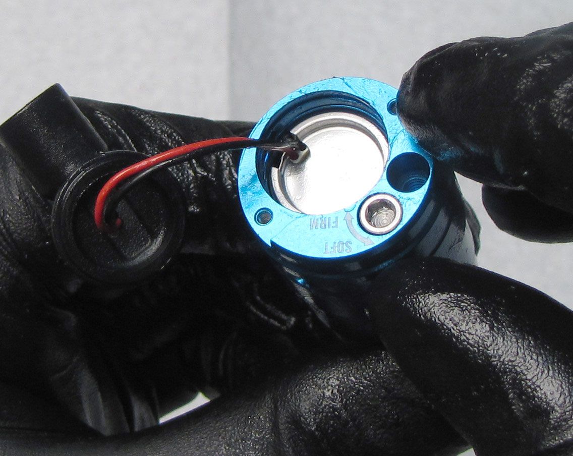
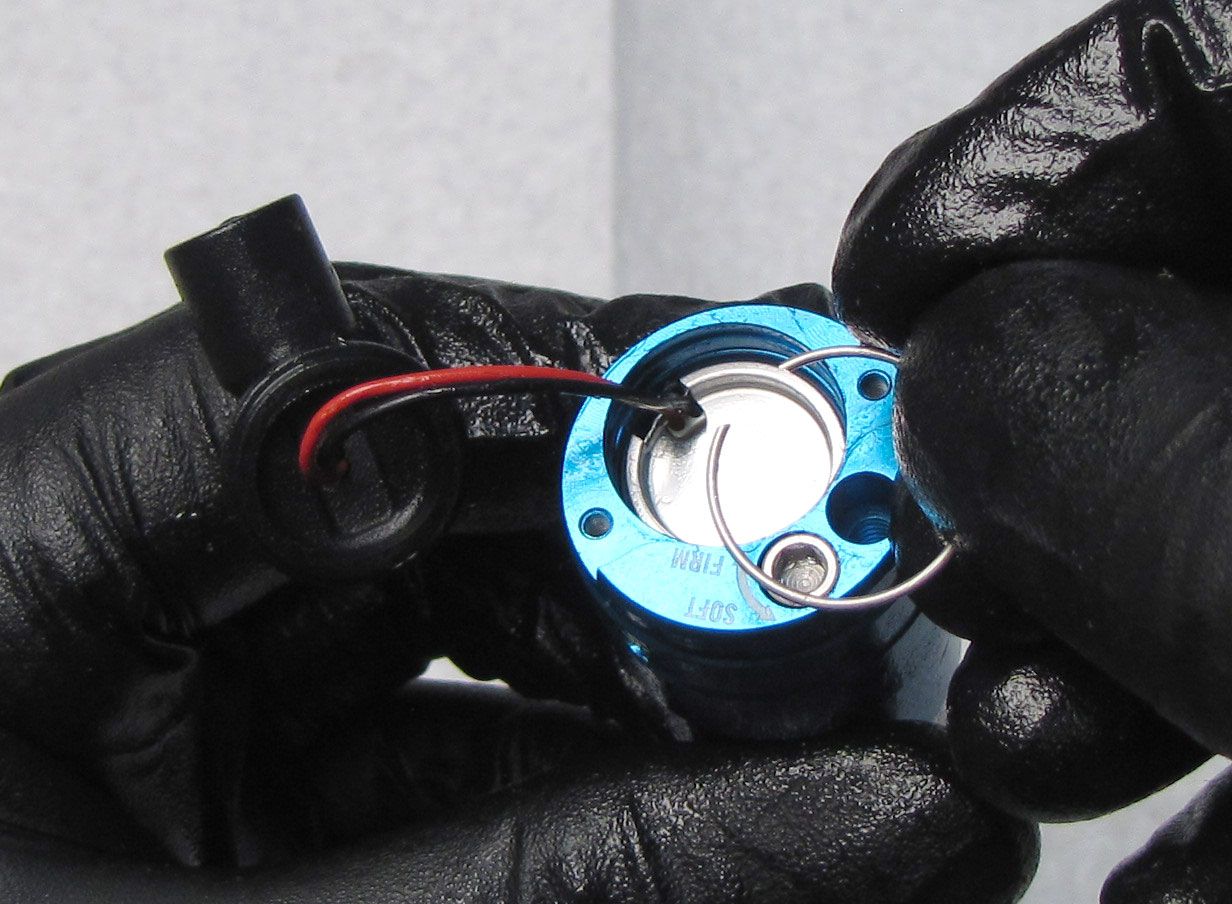
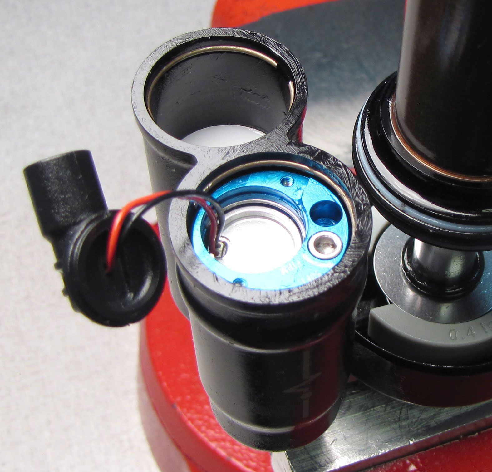
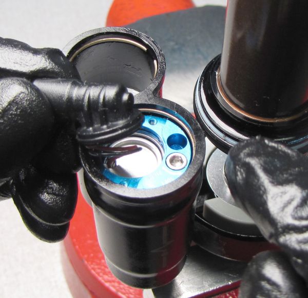
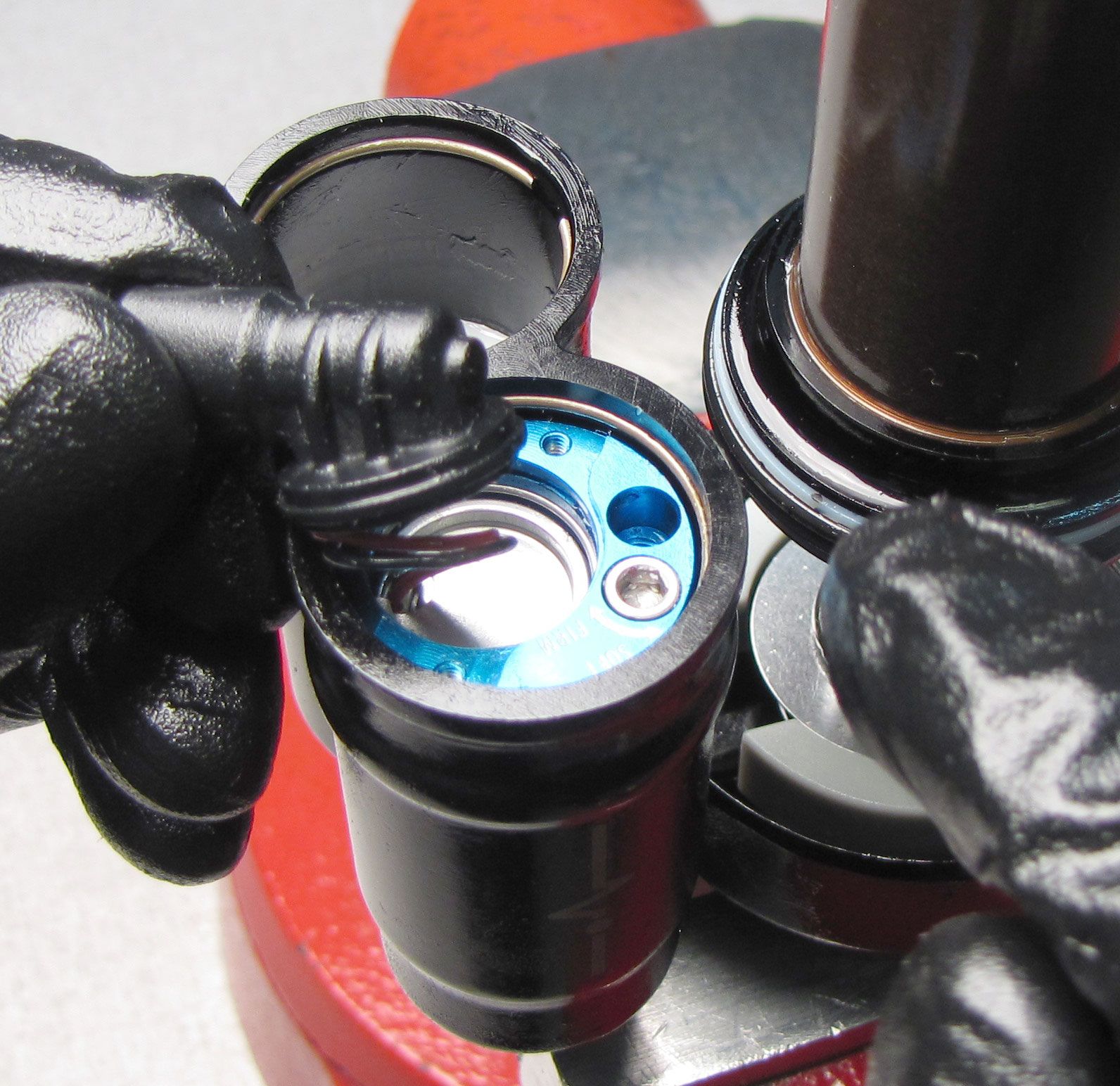
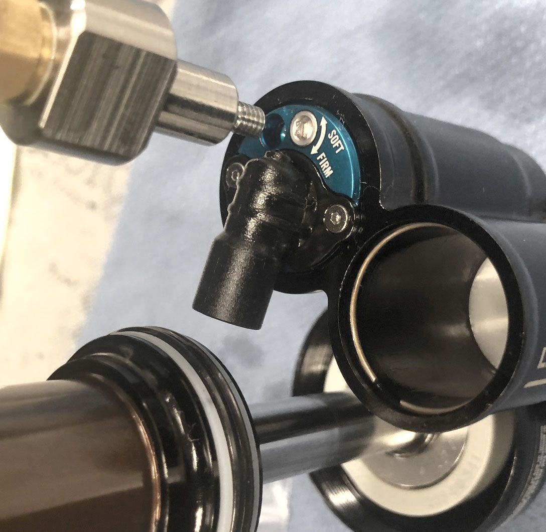
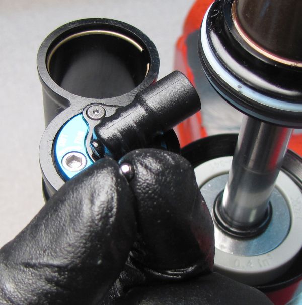
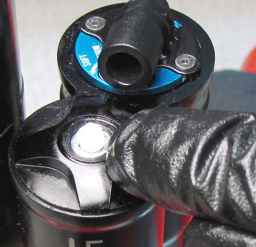
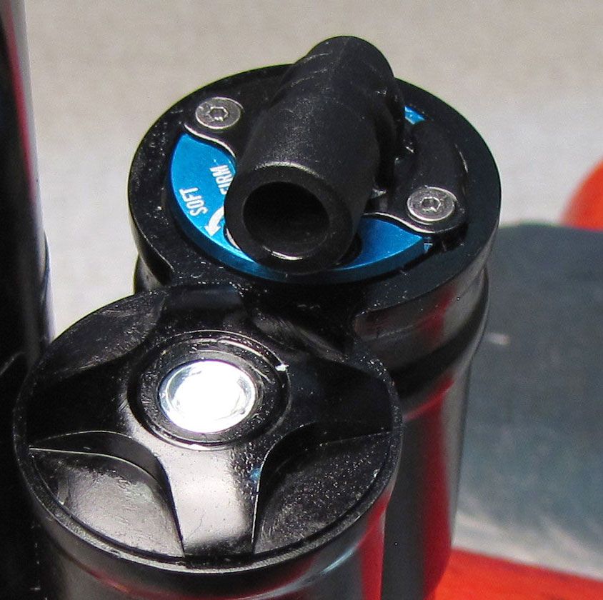
Remove the wire retaining ring from above the Solenoid, then turn the Compression Cartridge Housing over to let the Solenoid Retainer Plate fall out. There is a small releif in the Compression Cartridge Housing near the "SOFT-FIRM" laser-etching to help with retaining ring removal.

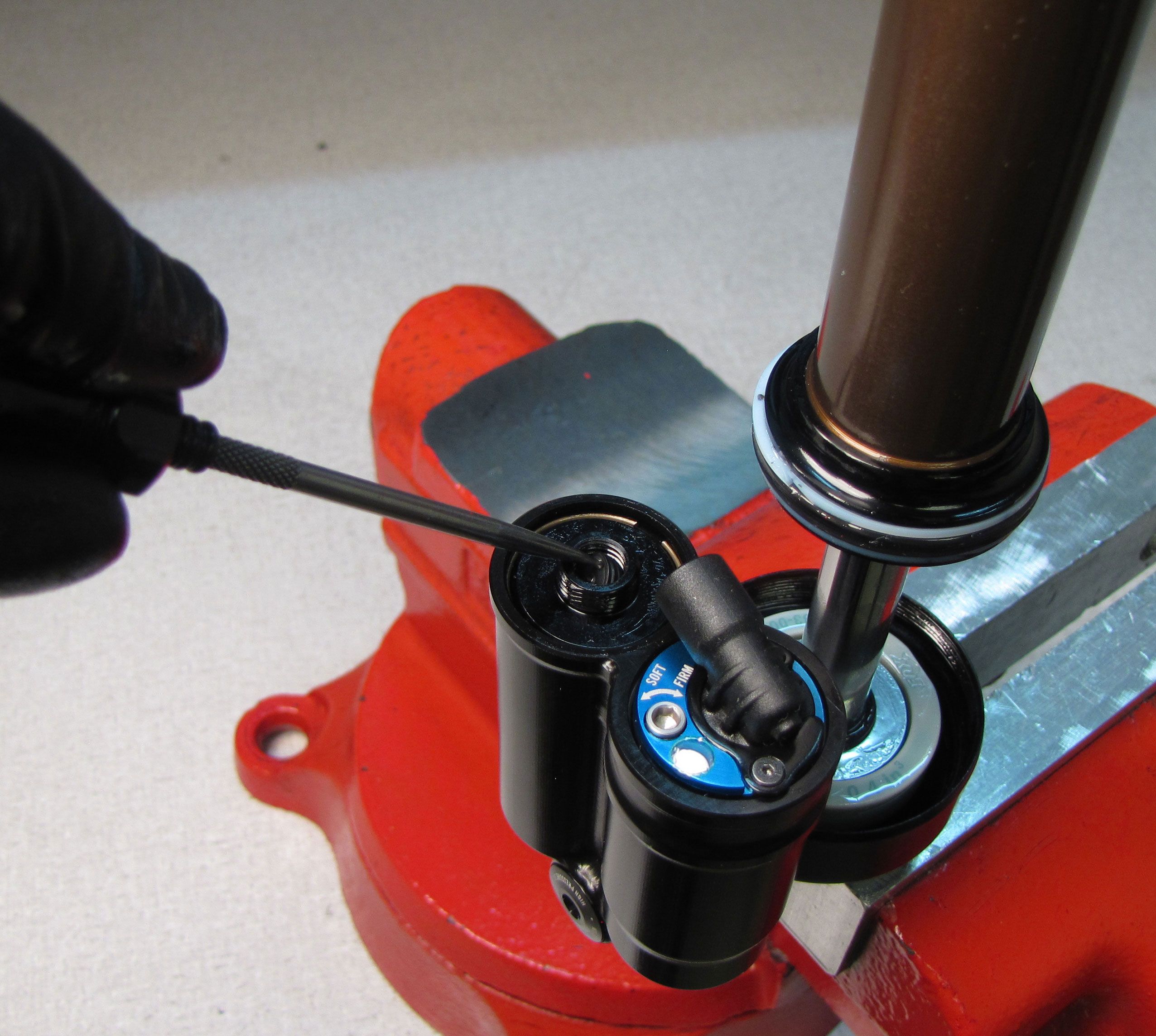
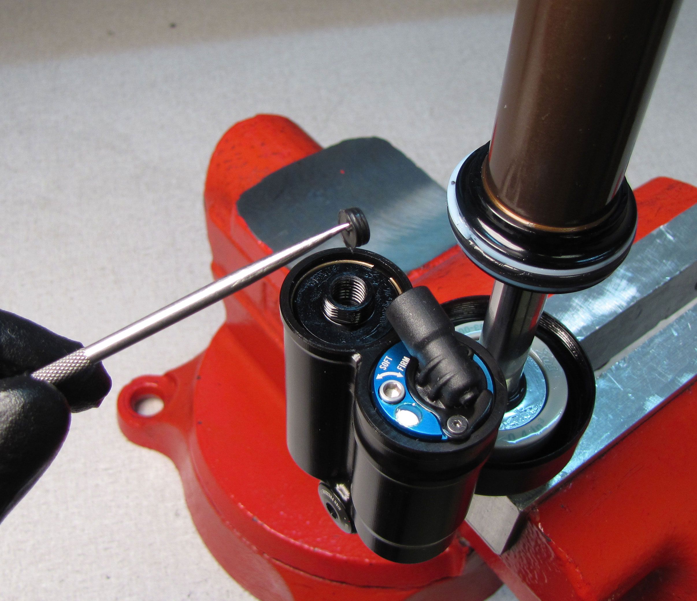
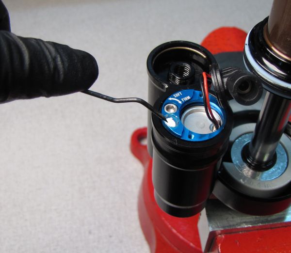
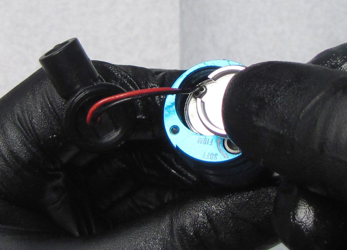
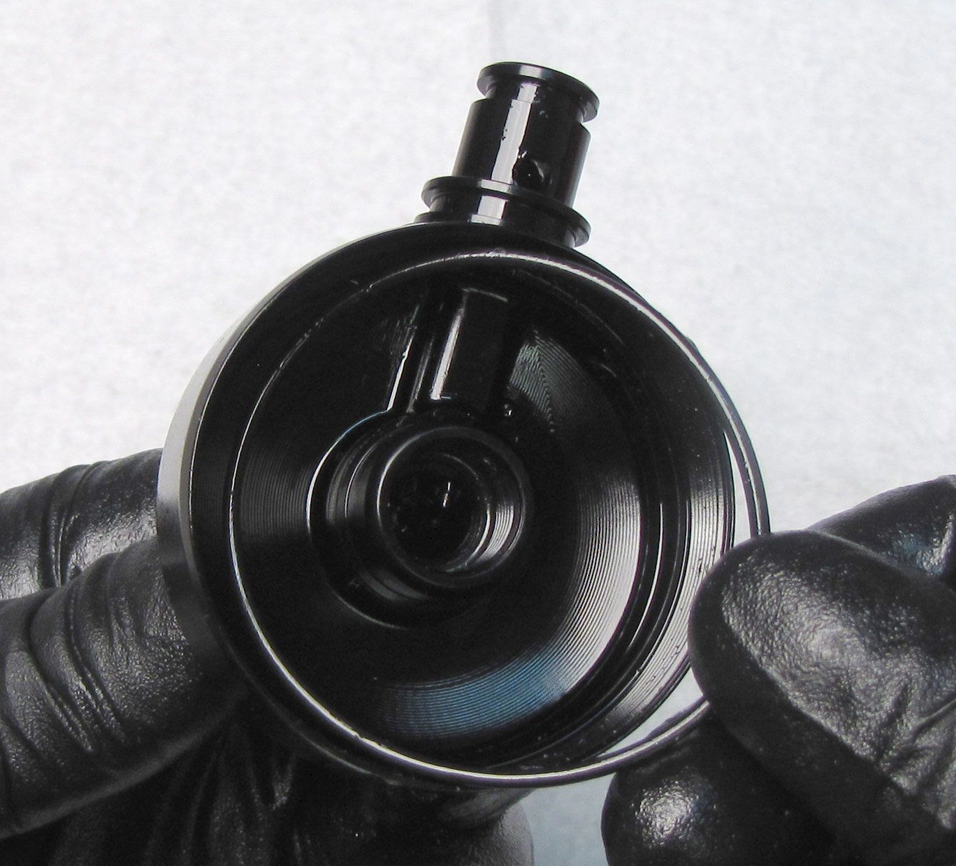
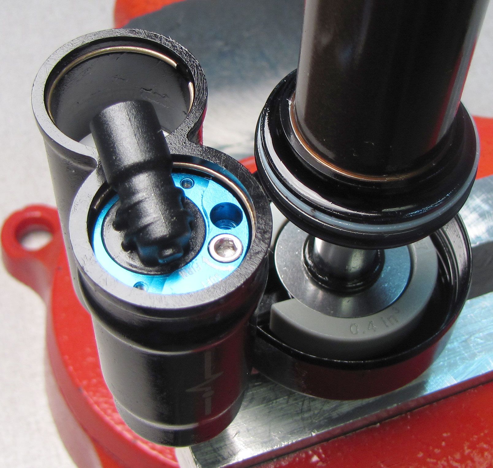
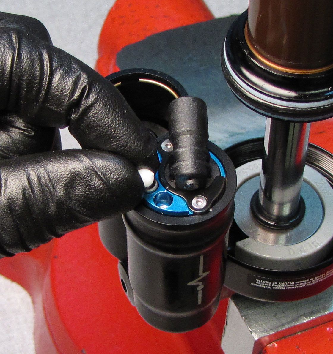
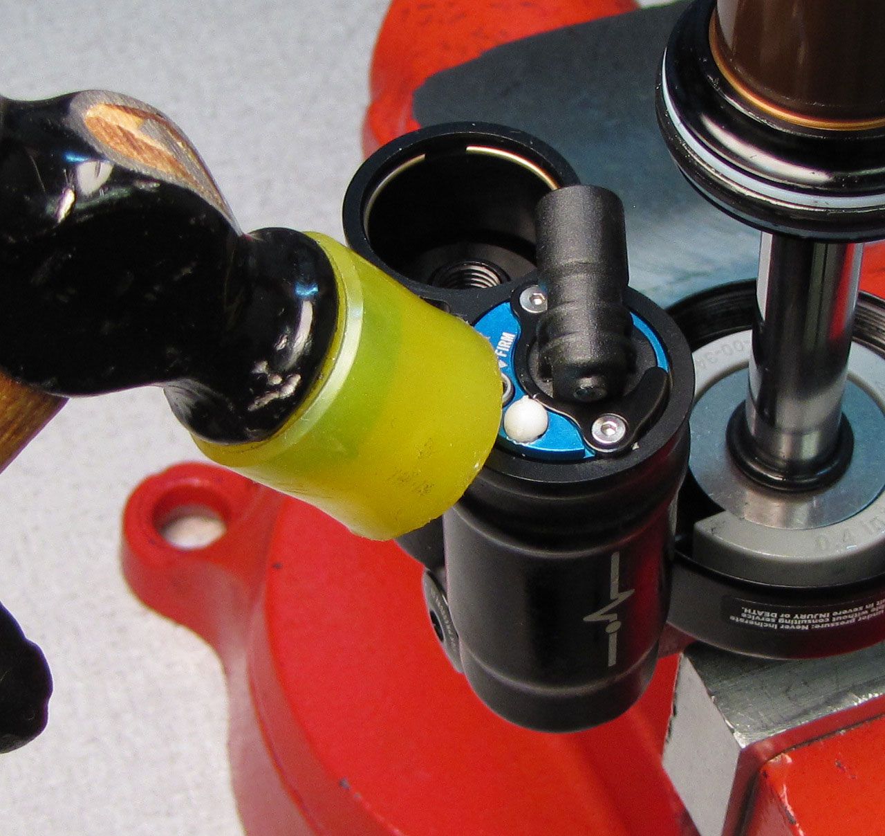
Step 7
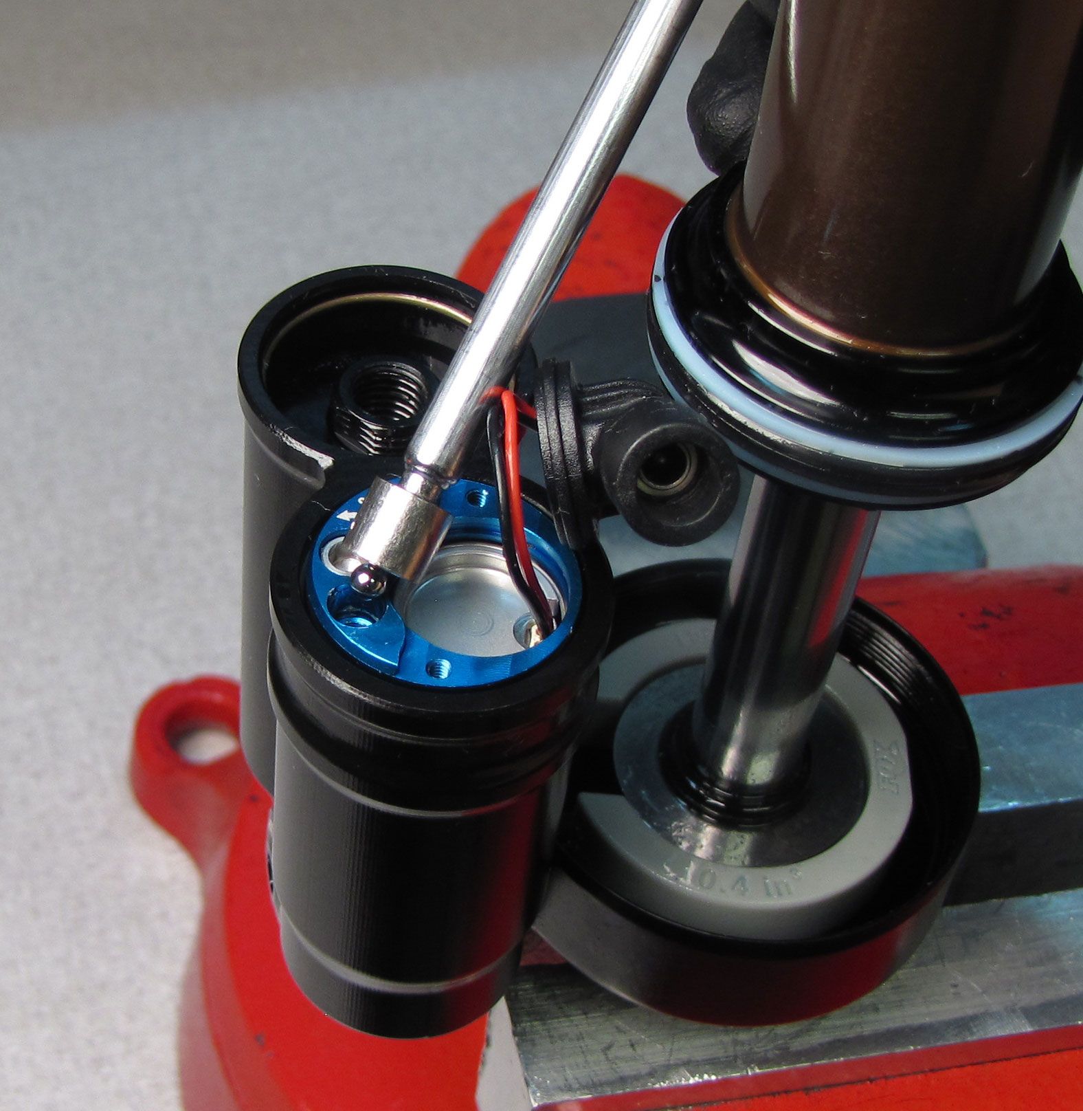
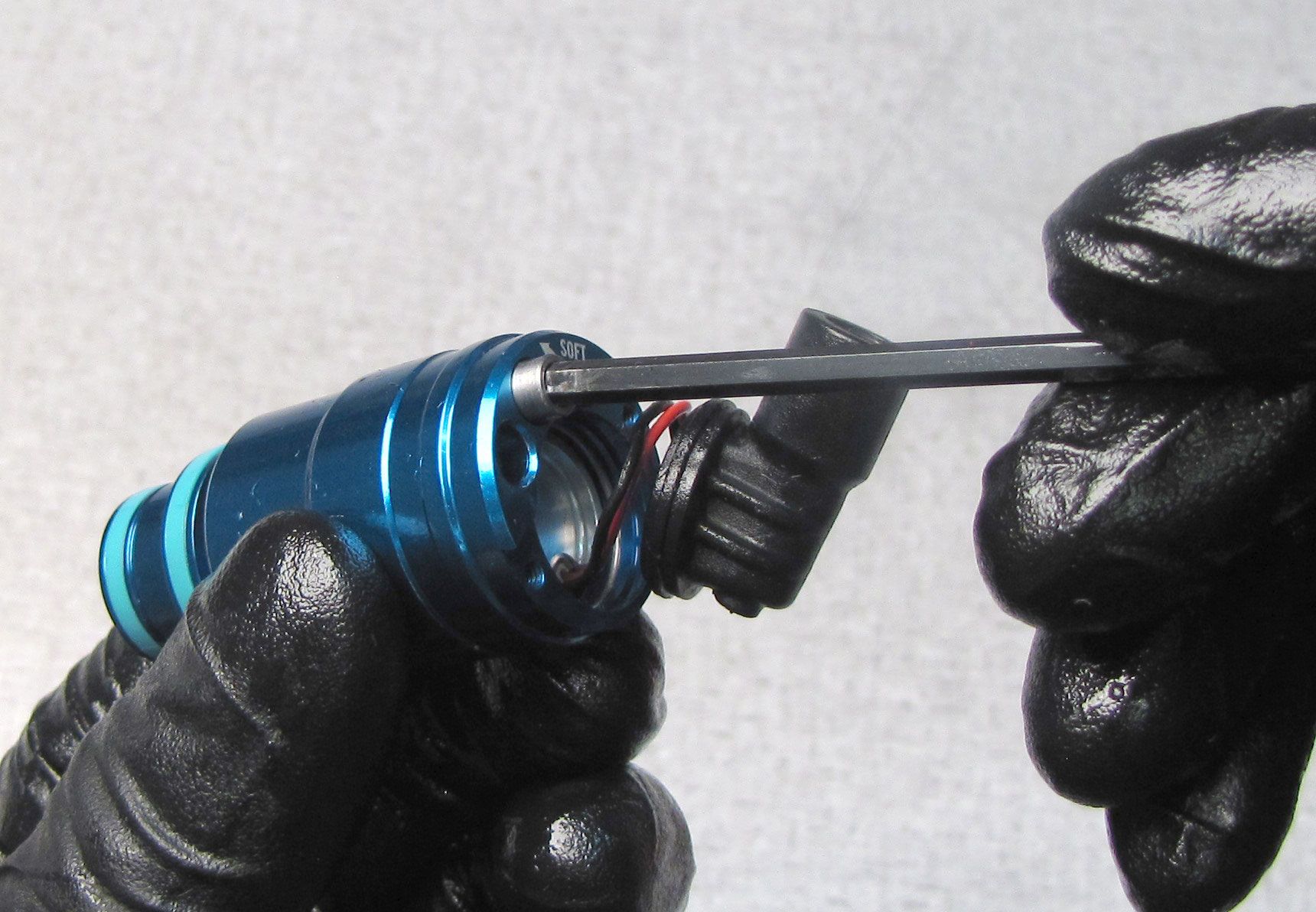
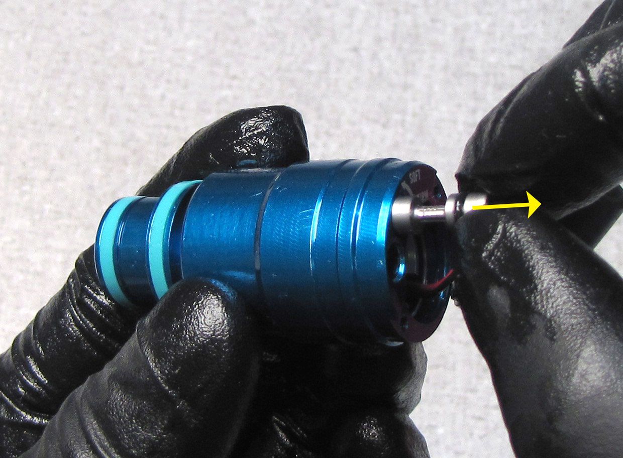
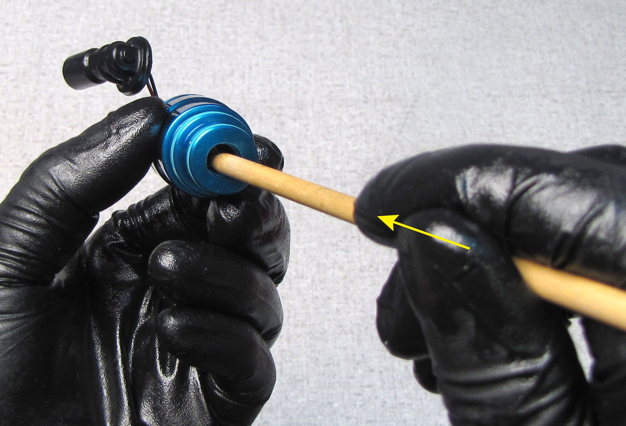
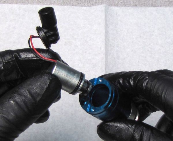
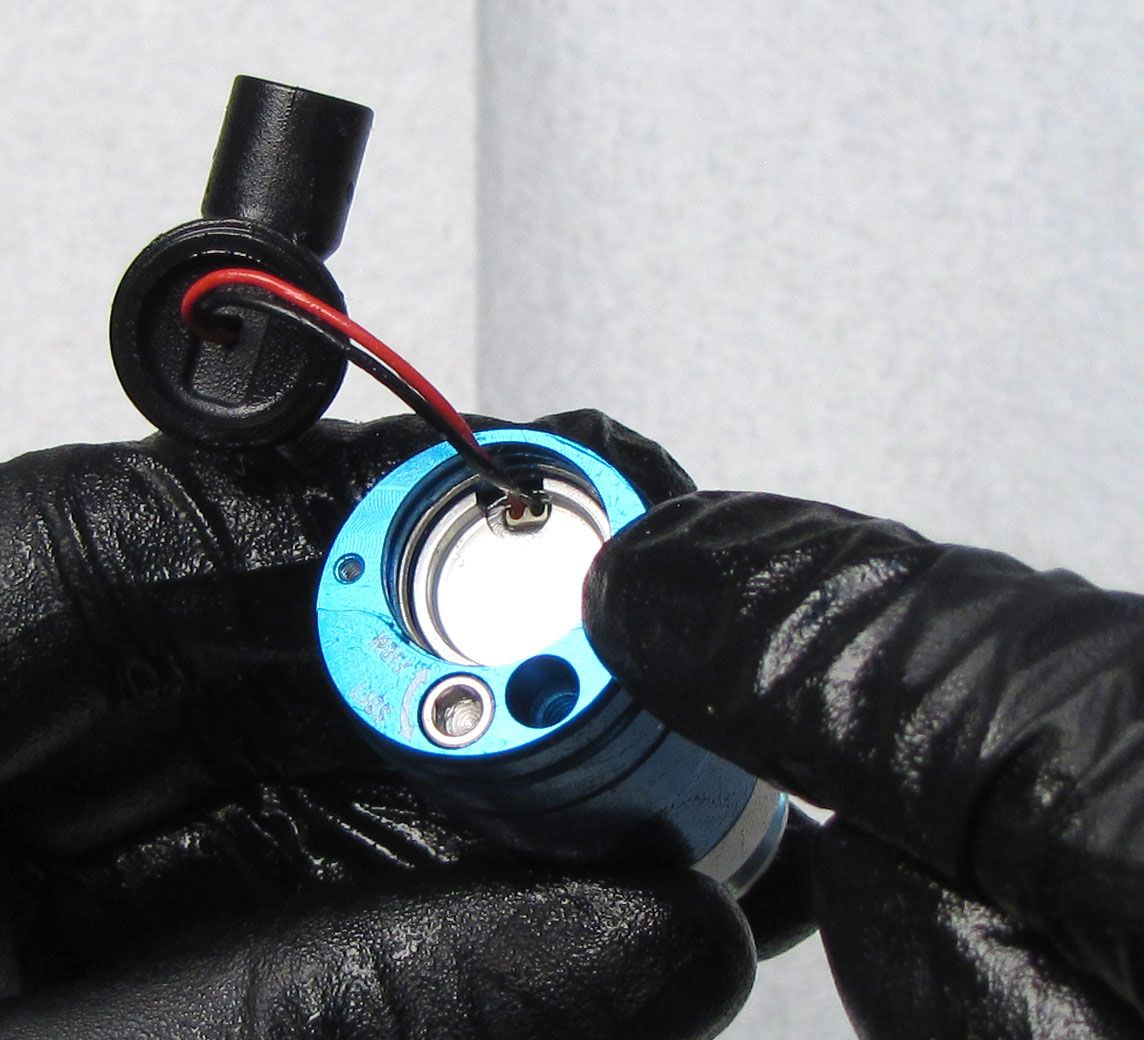
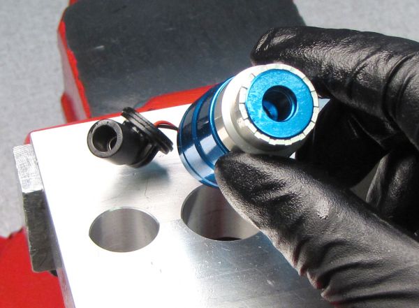
Use a blunt non-marring tool to push the Solenoid out through the top of the Compression Cartridge Housing.
Step 8
Replace the two o-rings on the Solenoid with new ones from the kit. Coat the o-rings in FOX 5wt Teflon Infused oil.
Step 9
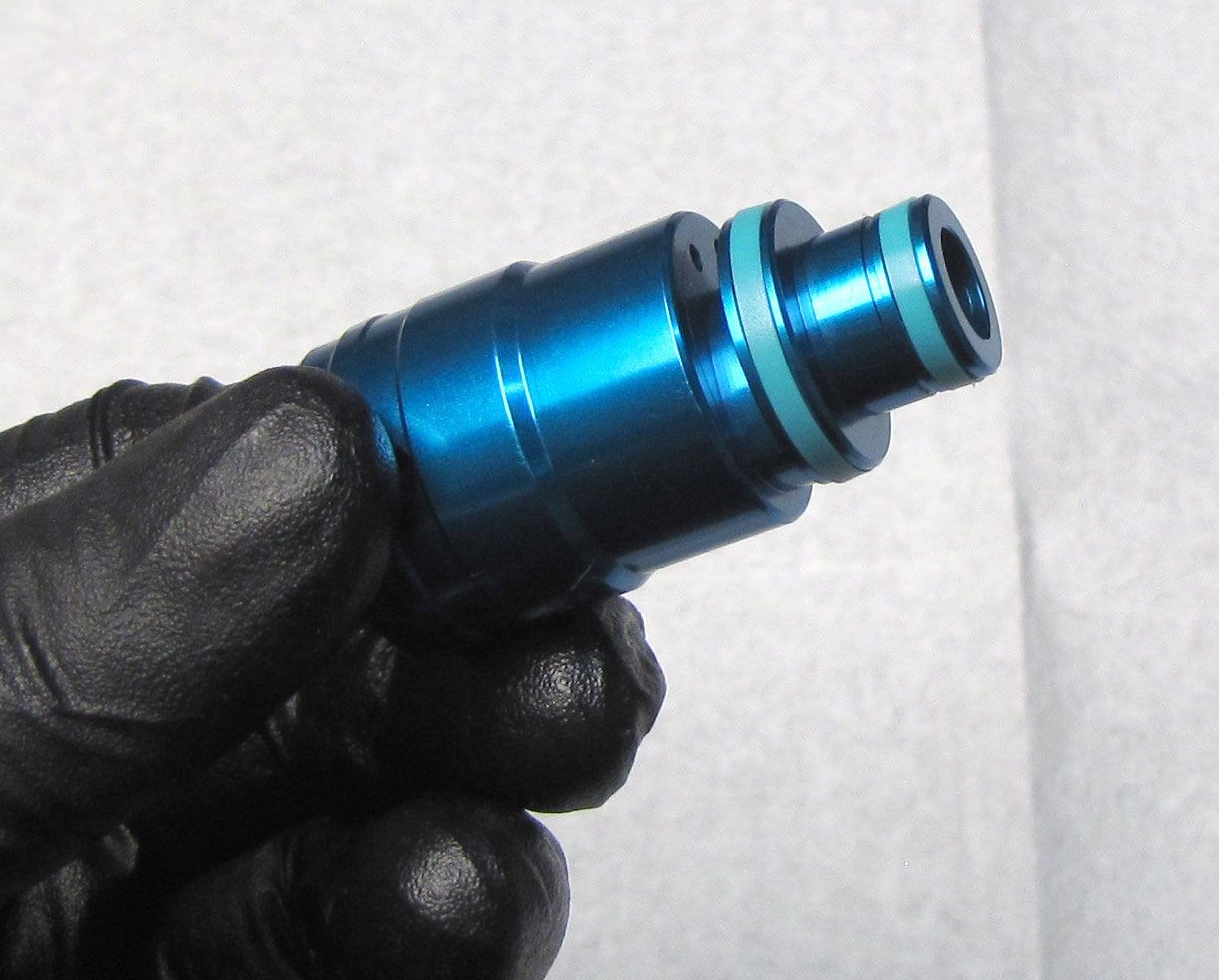
Remove the two glide rings and two o-rings from the Compression Cartridge Housing. Replace the two o-rings on the Compression Cartridge Housing with new ones from the kit. Coat the o-rings with FOX 5wt Teflon Infused oil. Replace the two glide rings with new ones from the kit. Make sure that the o-rings do not get pinched by the glide rings during installation.

Step 10
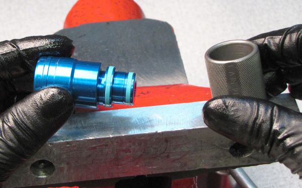
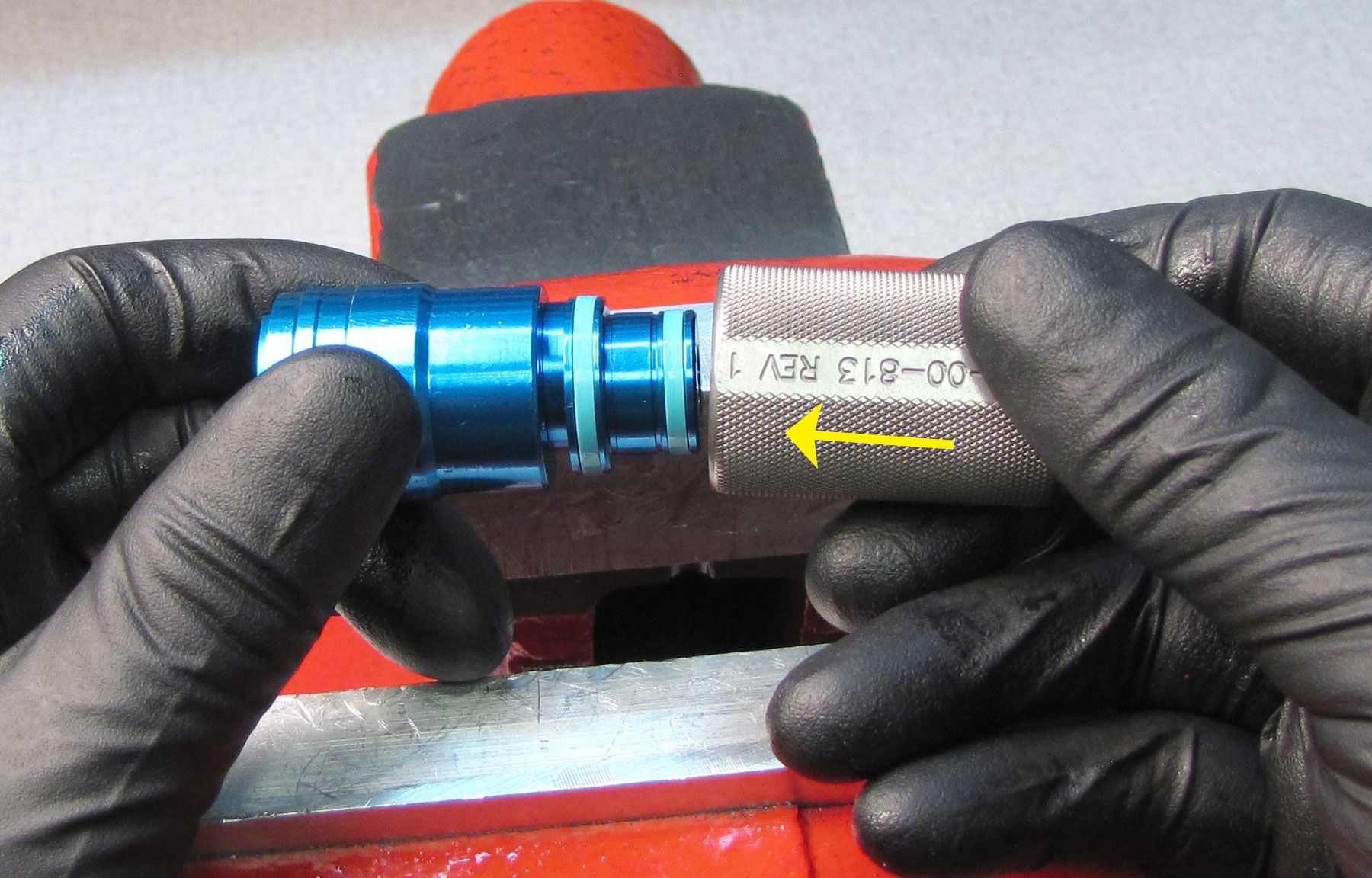
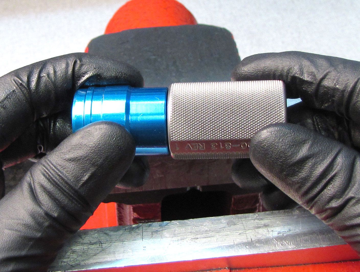
Insert the Compression Housing Assembly with new glide rings into the larger end of the approriate sizer (fork or shock) then remove. Repeat with the smaller end of the appropriate sizer.


Step 11
Coat the Boost Valve with a thin film of FOX 5wt Teflon Infused Oil then slide it onto the Compression Cartridge Housing. Make sure the Boost Valve slides freely after installation.

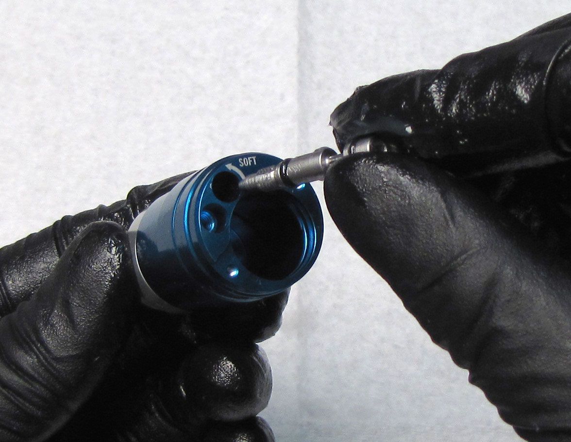
Step 12
Coat the Compression Needle with a thin film of FOX 5wt Teflon Infused oil then reinstall into the Compression Cartridge Housing by turning it clockwise until flush.
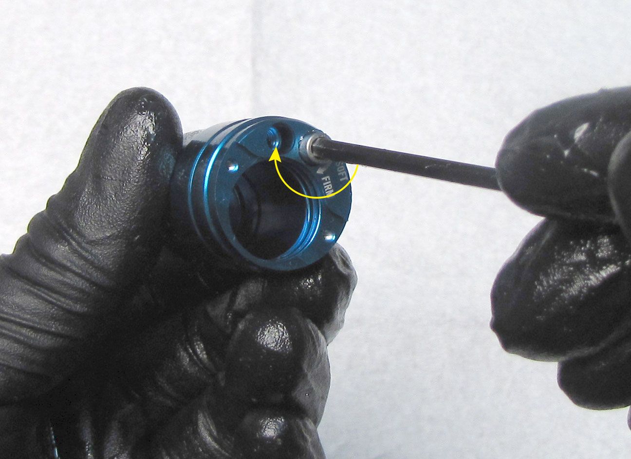
Step 13
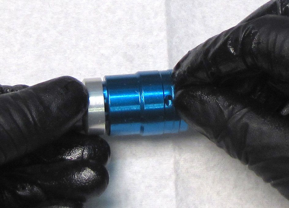
Reinstall the detent ball followed by the spring and set screw. Tighten the set screw clockwise until bottomed out then turn it counter-clockwise 1/2 turn with your 1.5mm hex wrench. Check for audible detent clicks when turning the Compression Needle with a 3mm hex wrench.
Step 14
Coat the Solenoid o-rings in FOX 5wt Teflon Infused oil then reinstall the Solenoid into the Compression Cartridge Housing. Push the Solenoid into the Compression Cartridge Housing to create space for the Retainer Plate and Retaining Ring.

Step 15
Reinstall the Solenoid Retainer Plate with its notch aligned with the two wires exiting the Solenoid. Reinstall the wire retaining ring making sure that it is fully seated in the groove. Orient the retaining ring so the gap in the ring is opposite the gap in the plate that the wires go through.

Step 16
Clamp the Compression Cartridge Housing in your shaft clamps (PN: 803-01-360) then reinstall the Resi Compression Assembly tightening clockwise to 40 in-lb (4.5 Nm) torque with a 5mm hex wrench.

General Reassembly

Step 1
Install a new greased air sleeve o-ring from the kit into the eyelet. Replace the o-ring on the Rebound Metering Rod with a new greased one from the kit.
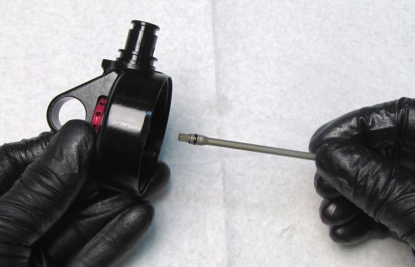
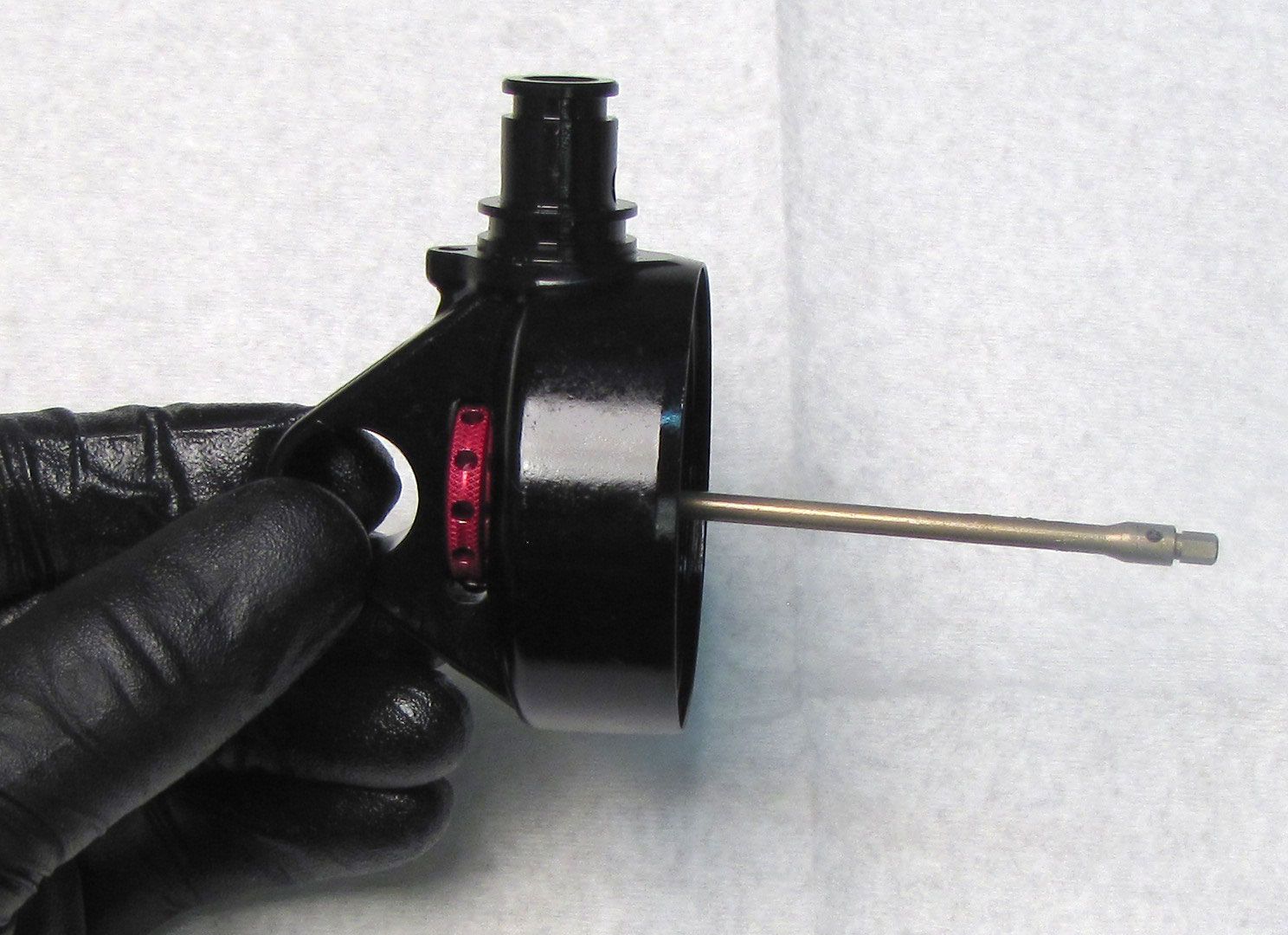
Step 2
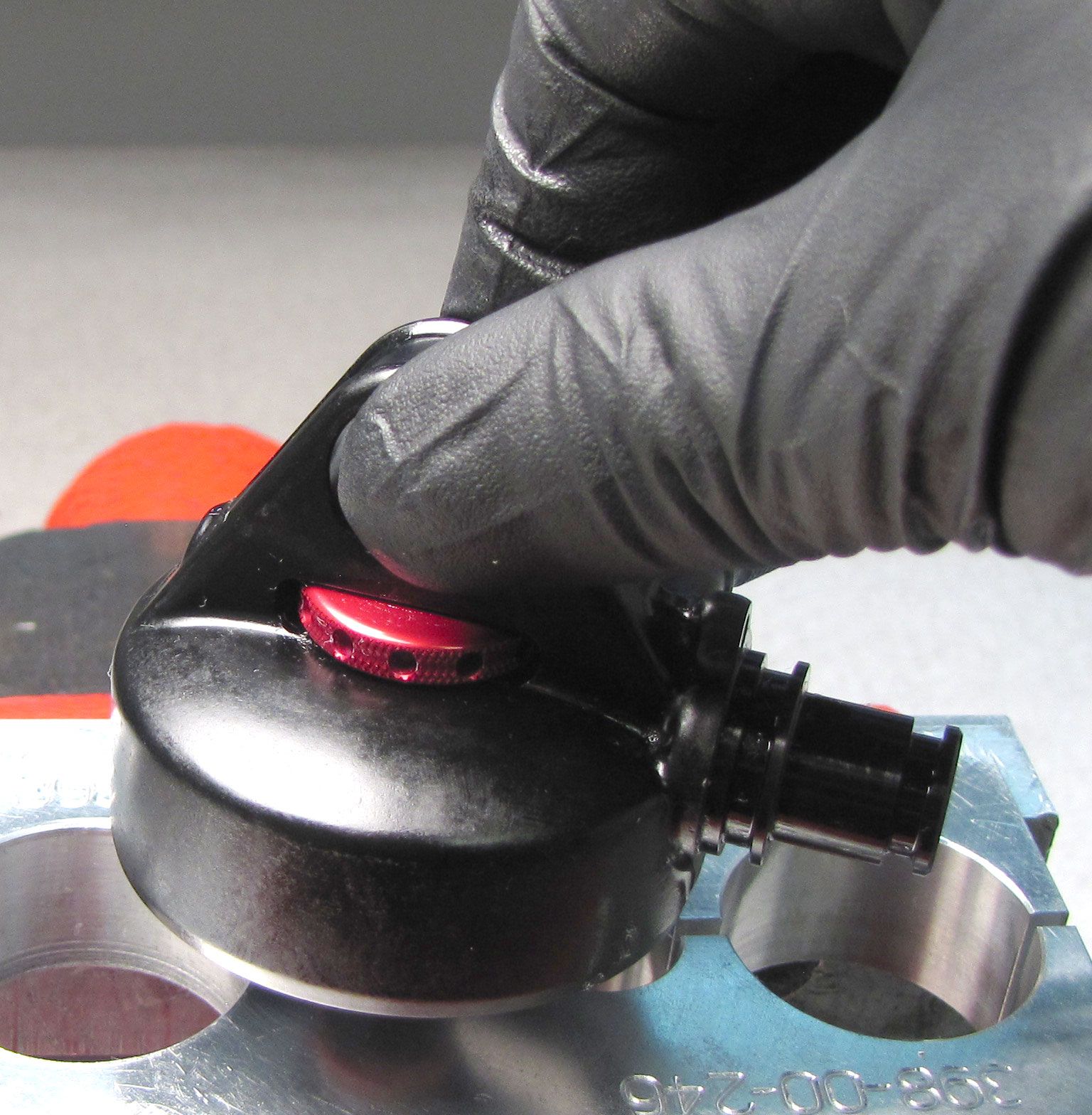
For non-Trunnion Eyelets: Insert the red Rebound Knob into its position in the slot of the Eyelet. Insert the Rebound Metering Rod into the Eyelet through the hole for the Shaft with the o-ring end first. Engage the hex feature of the Rebound Metering Rod with the flats on the Rebound Knob.
For Trunnion Eyelets: Insert the Rebound Detent Spring followed by the detent ball into the hole in the eyelet adjacent to the Rebound Knob location. Insert the red Rebound Knob into its position in the Eyelet. Insert the Rebound Metering Rod into the Eyelet through the hole for the Shaft with the o-ring end first. Engage the hex feature of the Rebound Metering Rod with the flats on the Rebound Knob.

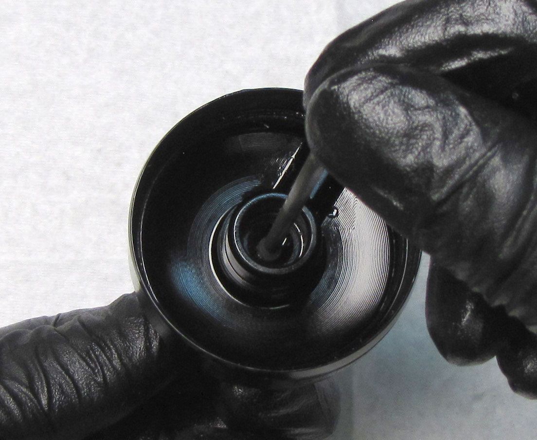
Step 3
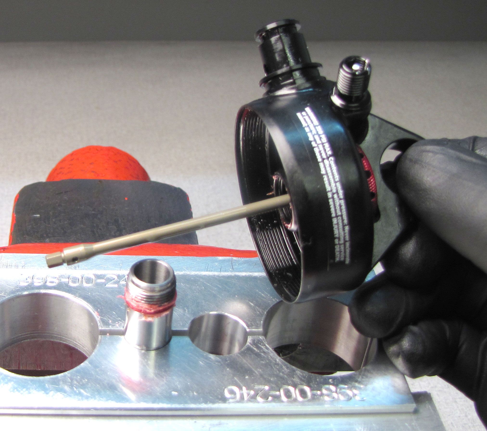
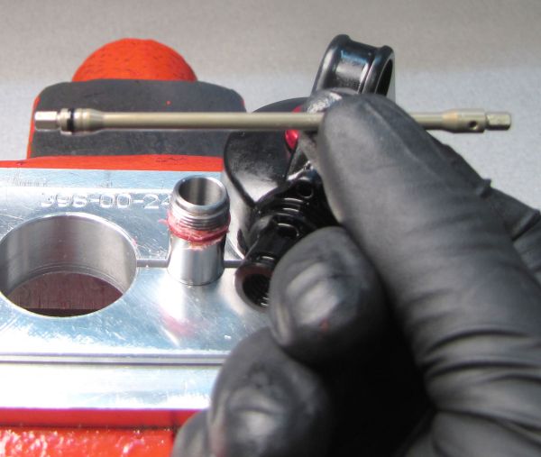
Install the Rebound Insert into the female threaded end of the Shaft so the tapered portion of the insert is facing out of the Shaft. Use a 1/8" hex wrench to help thread the Insert into the Shaft.
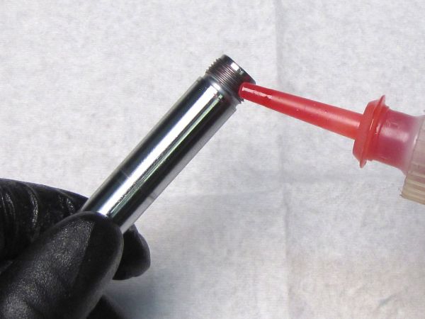
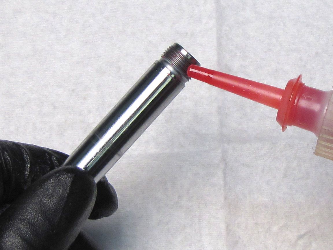
Step 4
Apply 1 drop of red Loctite 277 to the external threads of the Shaft. Guide the hex feature of the Rebound Metering Rod into the Rebound Insert as you install the Shaft into the Eyelet threading it clockwise by hand.

Step 5
Clean the Shaft with Isopropyl alcohol and a lint-free paper towel. Clamp the Shaft in your shaft clamps leaving space between the Eyelet and the clamps to allow for further tightening. Tighten the Eyelet clockwise to 110 in-lb (12.4 Nm) torque with the Eyelet Torque Tool (PN: 398-00-280) or the Trunnion Eyelet Torque Tool (PN: 398-00-099).
Step 6
Reinstall the rebound detent ball followed by the rebound detent spring. Reinstall the set screw tightening until flush. Check the rebound knob for detent clicks when turned and adjust set screw tension accordingly to acheive proper detent clicks.
Step 7
Reinstall the Volume Spacer if present. Make sure to seat it fully within the Eyelet by orienting the split toward the piggy-back reservoirs.

Step 8
Reinstall the Bottom Out Plate followed by a new greased Bottom Out o-ring from the kit onto the Shaft.

Step 9
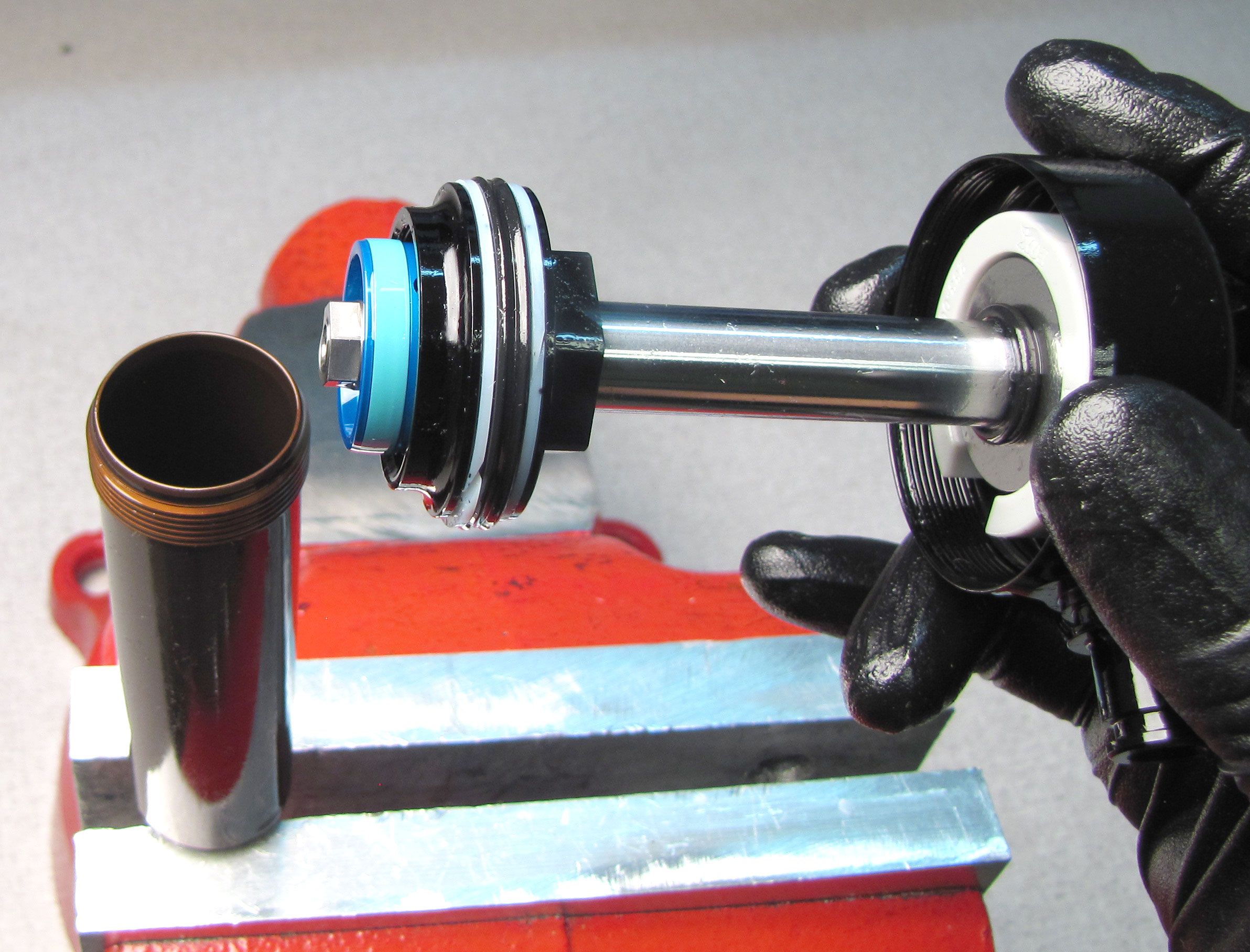
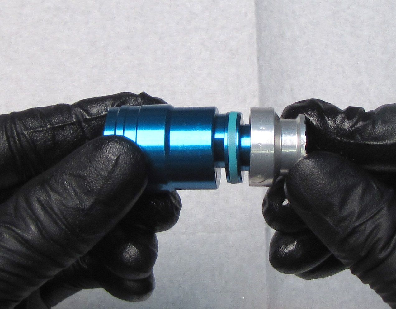
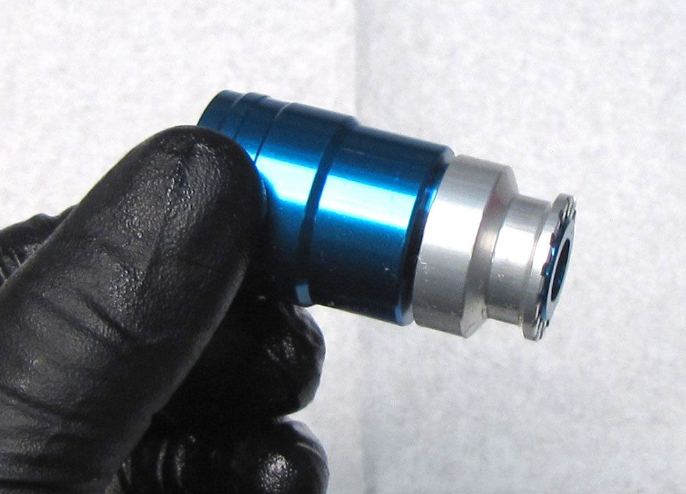
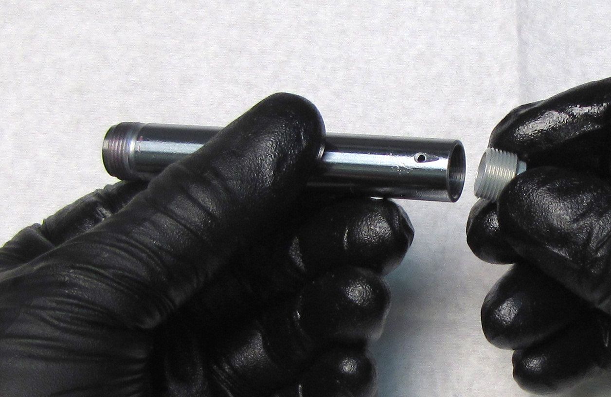
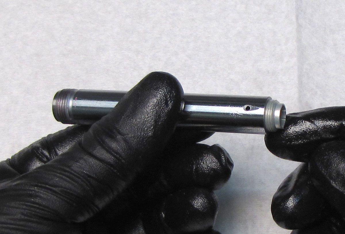
Reinstall the Bearing Assembly (with new greased seals from the kit) onto the shaft as shown.
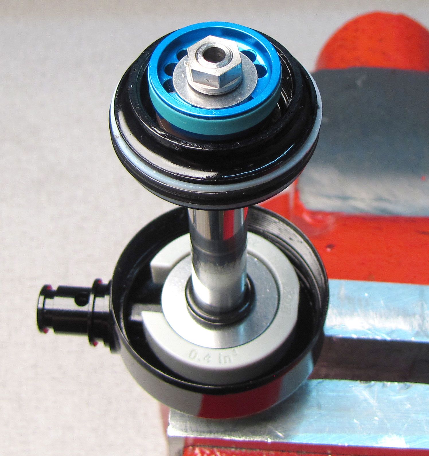
Step 10
Install a new greased topout o-ring from the kit followed by the Topout Spacer with the counterbored face oriented toward the Eyelet. Reinstall the Piston Post tightening clockwise by hand.

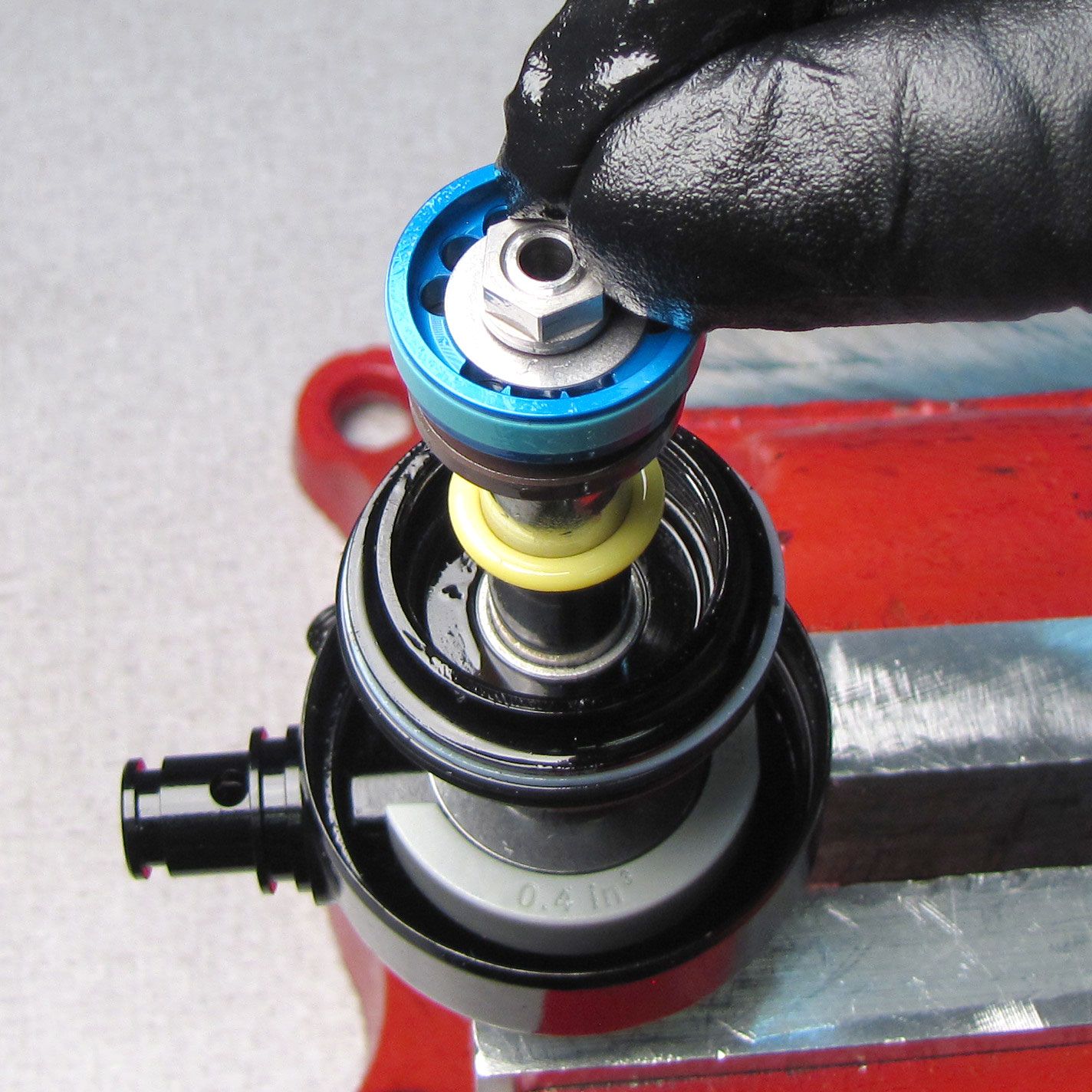
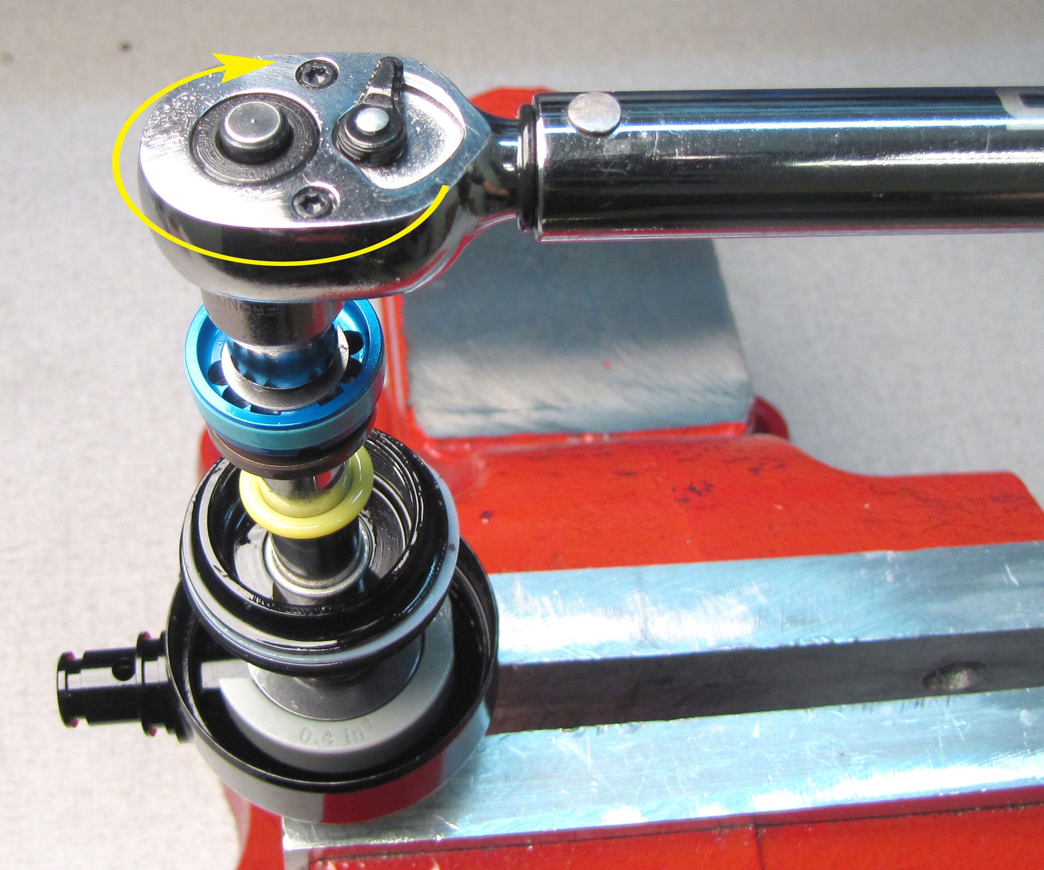
Step 11
Reinstall the main Piston Assembly in its original order. Tighten the Piston Nut clockwise to 60 in-lb (6.8 Nm) torque with a 9mm socket.

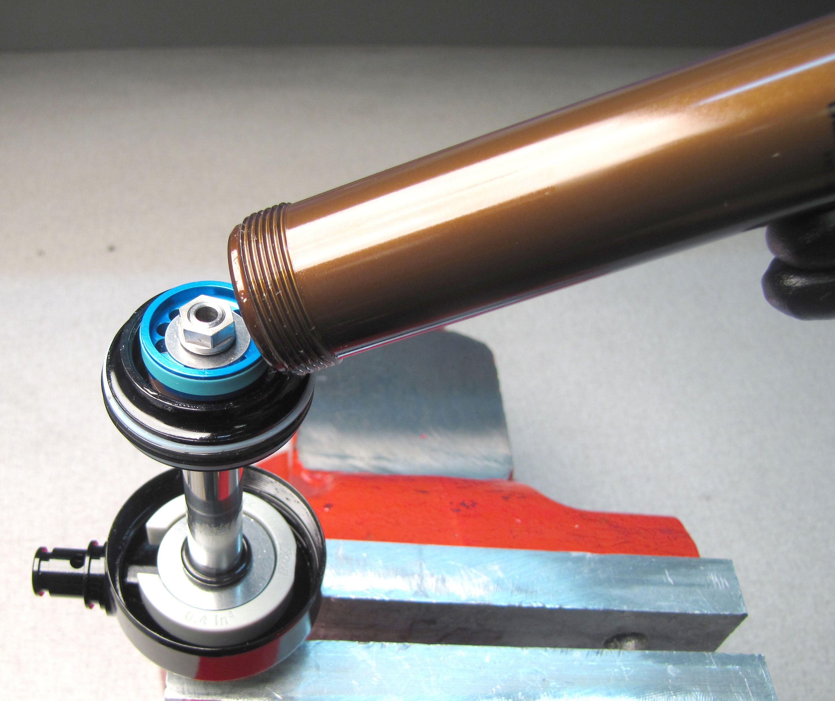
Step 12
Thread the Body to the Body Bearing tightening clockwise to 240 in-lbs (27.1 Nm) torque with a 22mm crow's foot.

Step 13
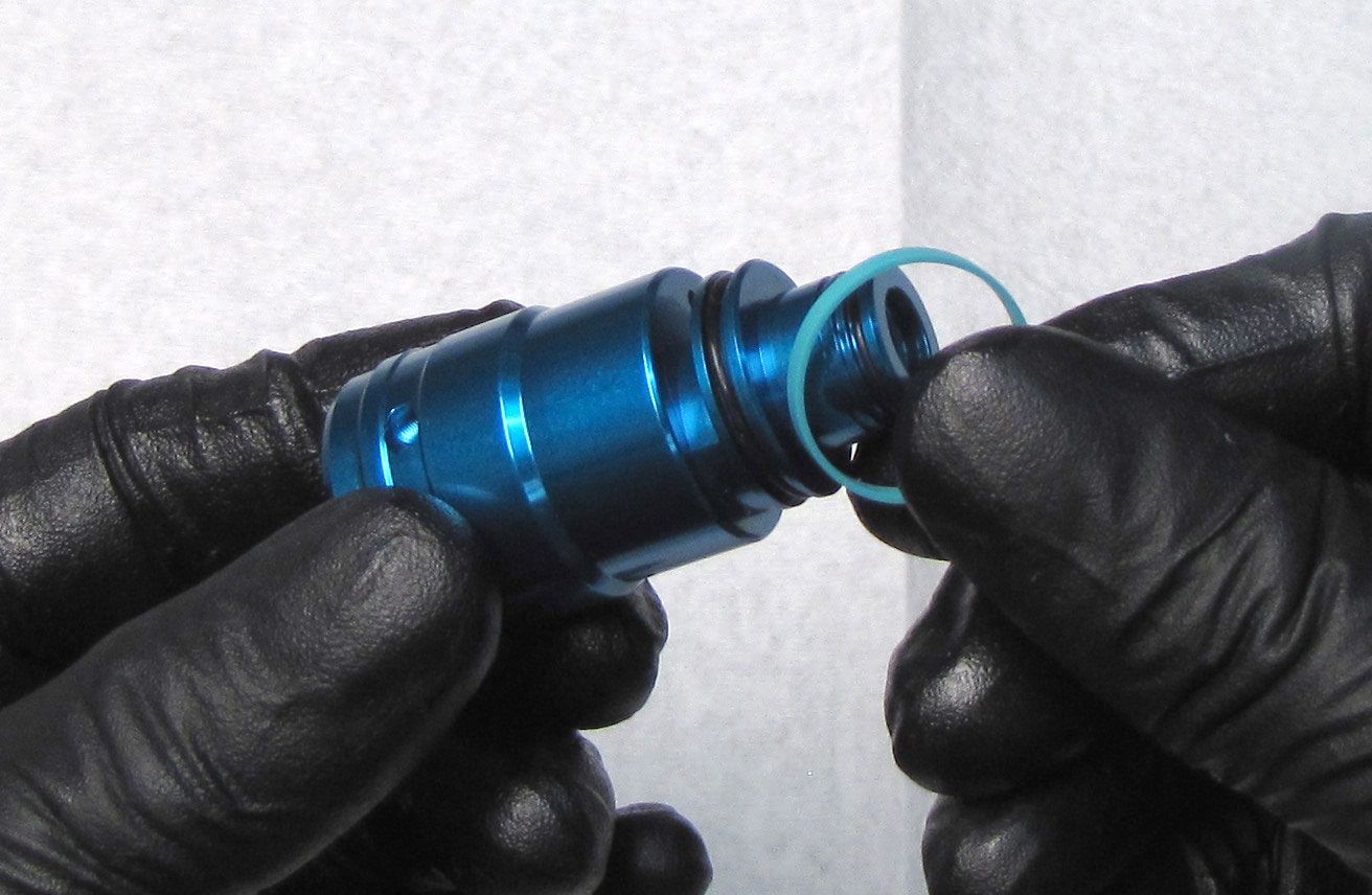
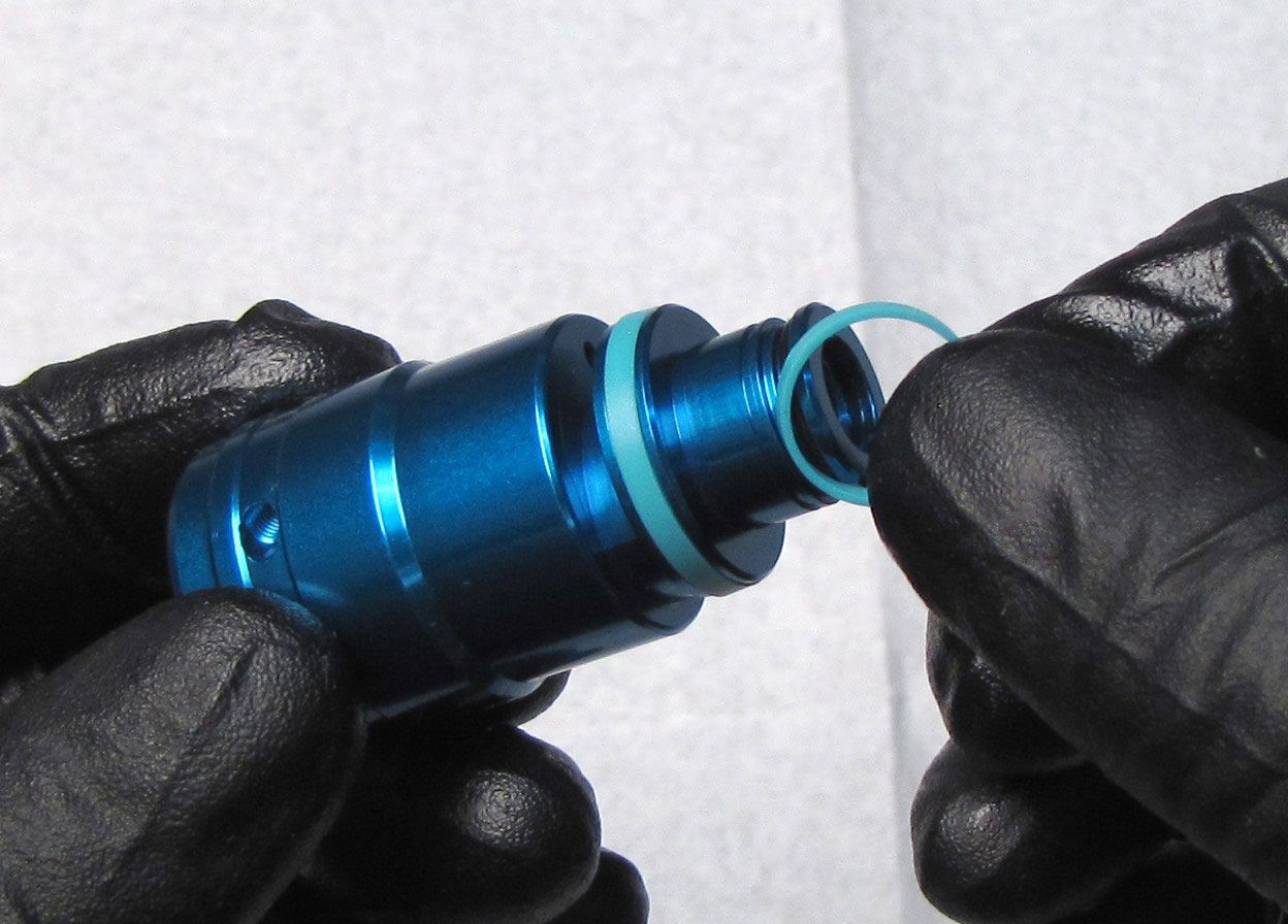
Install two new o-rings from the kit onto the Eyelet Assembly. Coat the o-rings with FOX 5wt Teflon Infused Oil.
Step 14
The Reservoir Assembly can be mounted in two different orientations. Reinstall the Dowel Pin into the hole in the reservoir that allows for proper reservoir orientation in its original configuration. Reinstall the Reservoir Assembly onto the Eyelet making sure to engage the Dowel Pin.
Step 15
Install a new FOX 5wt. Teflon Infused Oil coated o-ring from the kit into the mounting hole for the Reservoir Assembly. Reinstall the Reservoir Mounting Screw tightening clockwise to 50 in-lb (5.7 Nm) with a 4mm hex wrench. Press a new white Delrin ball from the kit into the screw connecting the Reservoir Assembly to the Eyelet Assembly.


Step 16
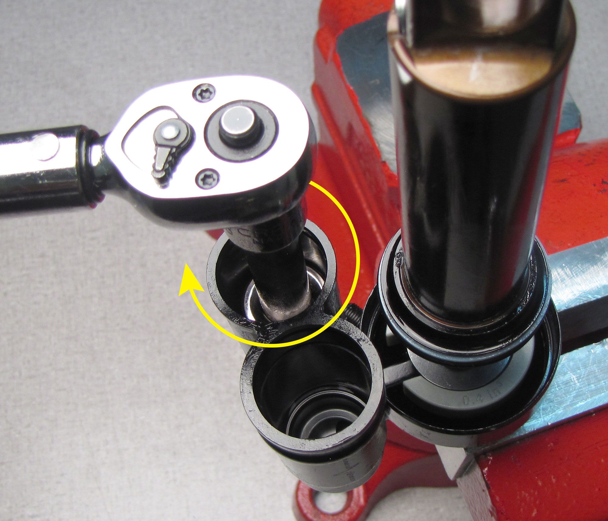
Reinstall the Lockout Blowoff Assembly into the side of the Reservoir with internal threading. Tighten clockwise to 150 in-lb (16.9 Nm) with a chamfer-less 16mm socket.

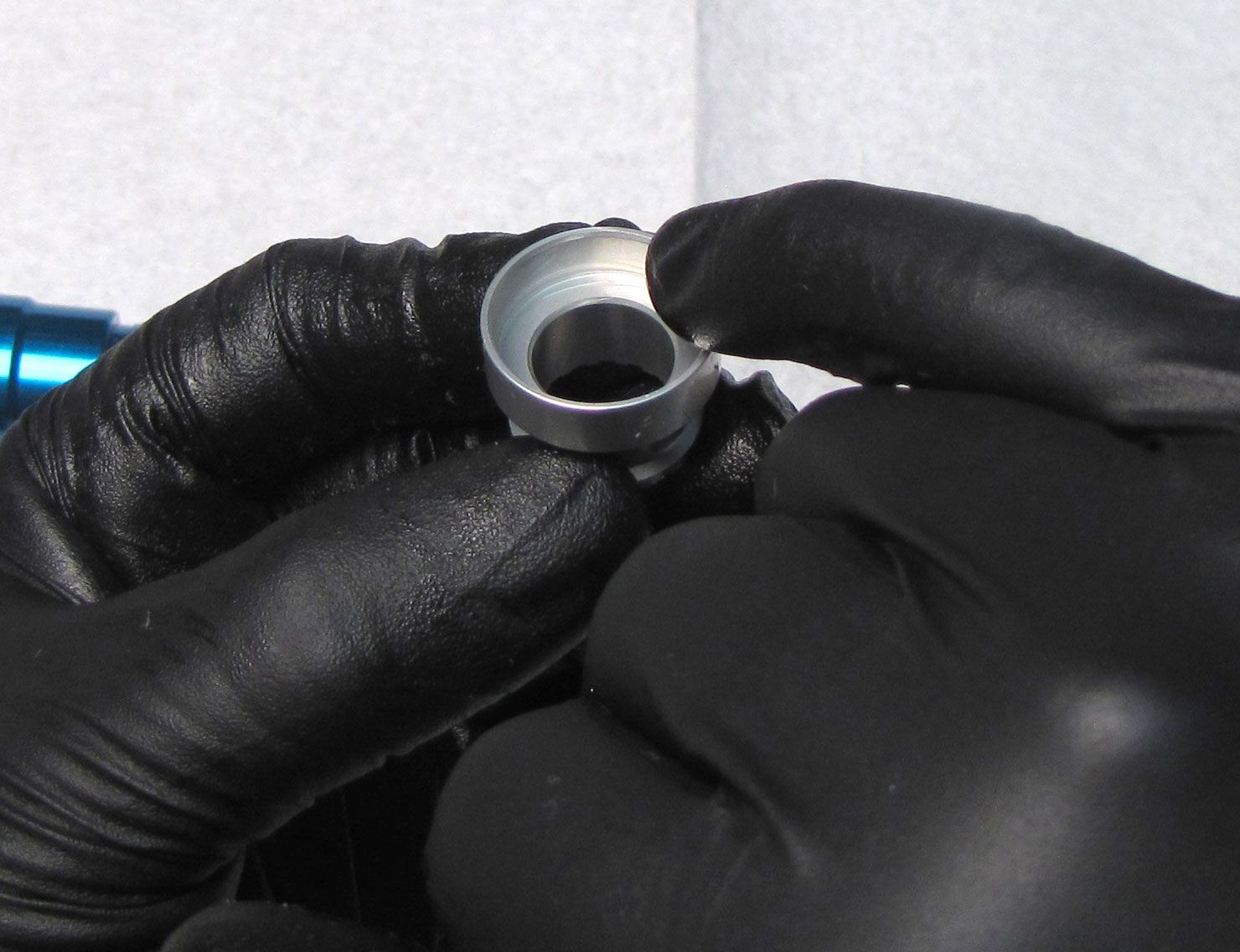
Step 17
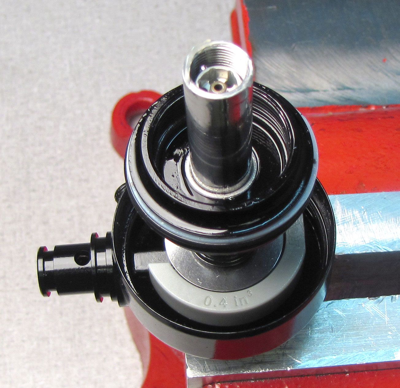
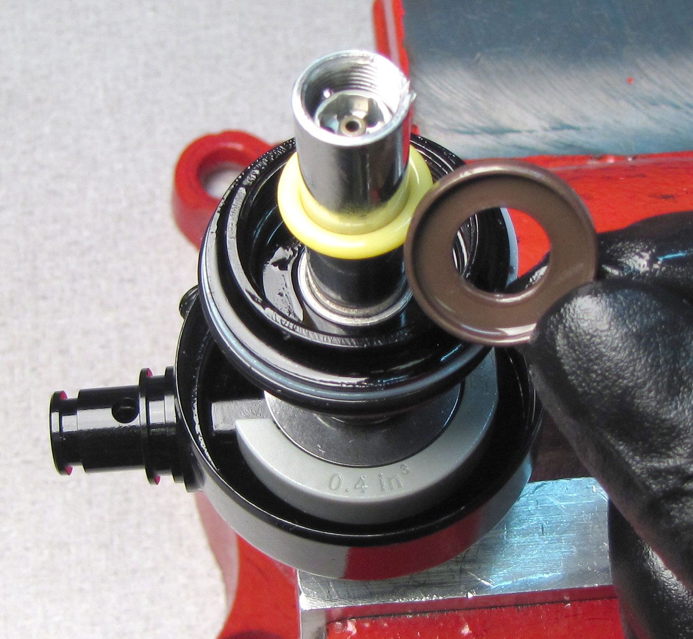
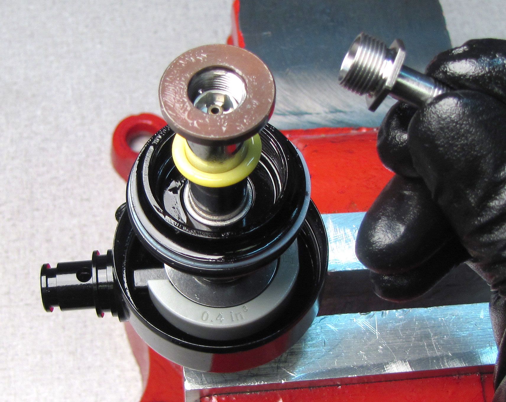
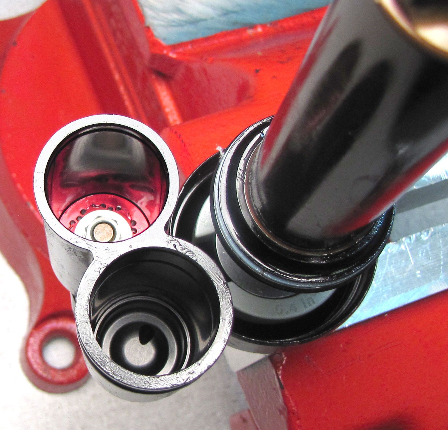
Replace the o-ring on the IFP with a new one from the kit coated in FOX 5wt. Teflon Infused Oil. Reinstall the IFP with its flat side facing out, into the side of the Reservoir with the Lockout Blowoff Assy. Reinstall the wire retaining ring into the reservoir bore above the IFP.
Step 18
Install a new FOX 5wt. Teflon Infused Oil coated o-ring from the kit into the groove in the LIVE Valve Reservoir.


Step 19
Reinstall the Compression Cartridge Housing Assembly into the Reservoir so you can access the two screws for the Solenoid End Cap Retainer Plate with the Cable Connector facing toward the IFP Reservoir. Press it in fully to allow room for the retaining ring. Reinstall the wire retaining ring making sure it is fully seated.
Step 20
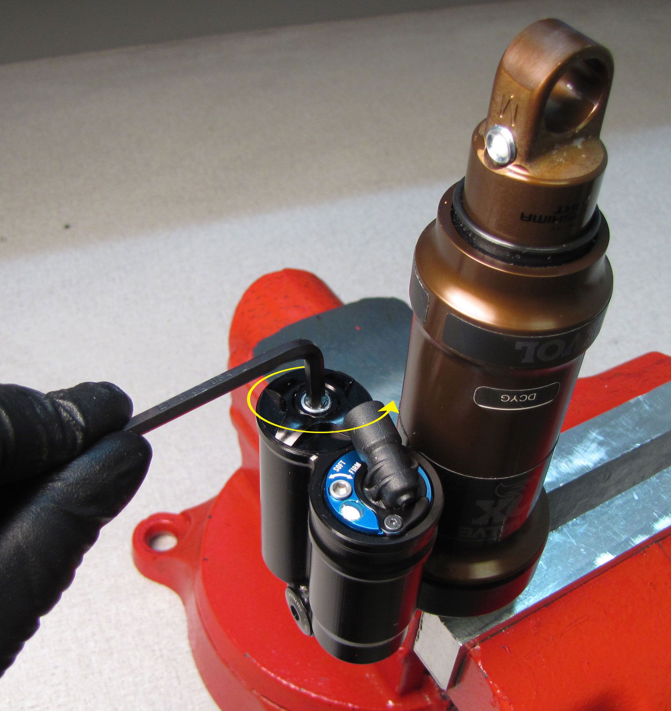
Position the Cable Connector of the Solenoid in its position above the Solenoid Retainer Plate. Orient the Cable Connector so it faces toward the IFP Reservoir. Coil the Solenoid wires carefully so you do not pinch them during Cable Connector installation. Reinstall the Solenoid End Cap Retainer Plate tightening the two set screws clockwise to 2 in-lb (0.2 Nm) torque with a 0.050" hex wrench.

Step 21
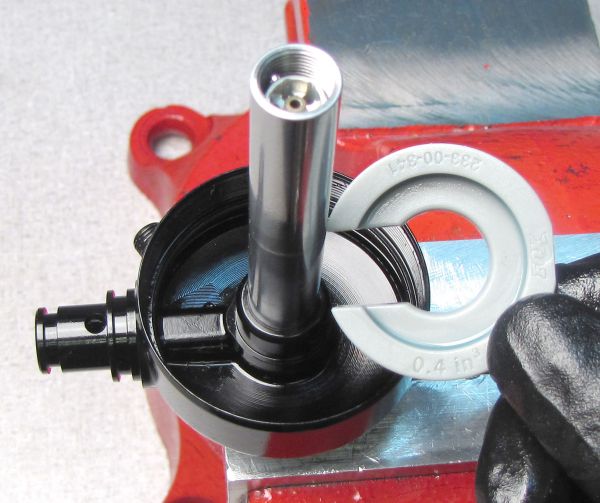
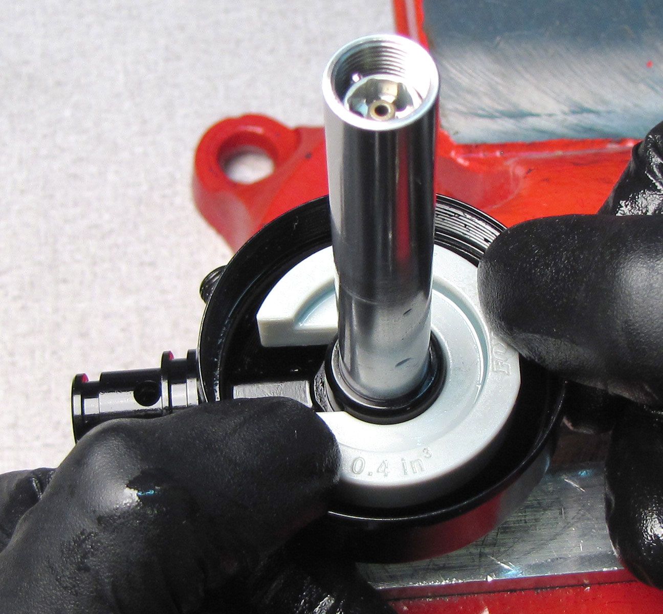
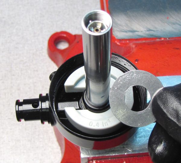
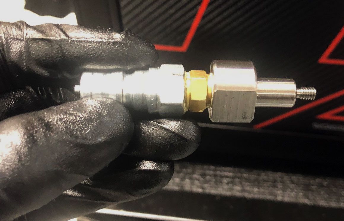
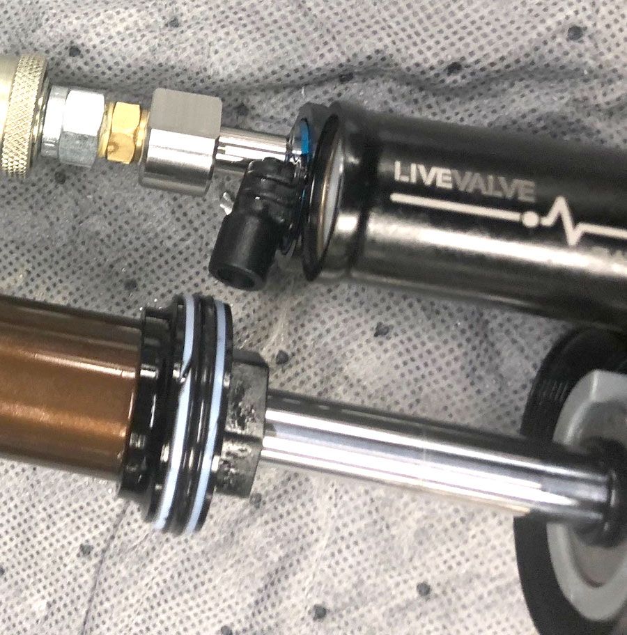
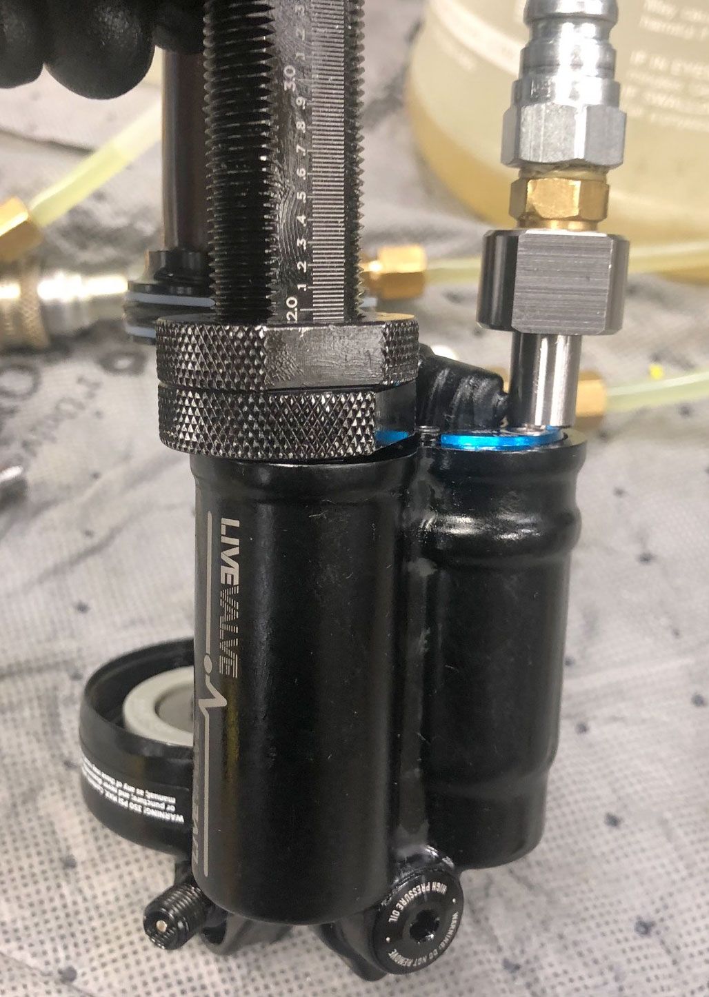
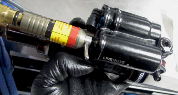
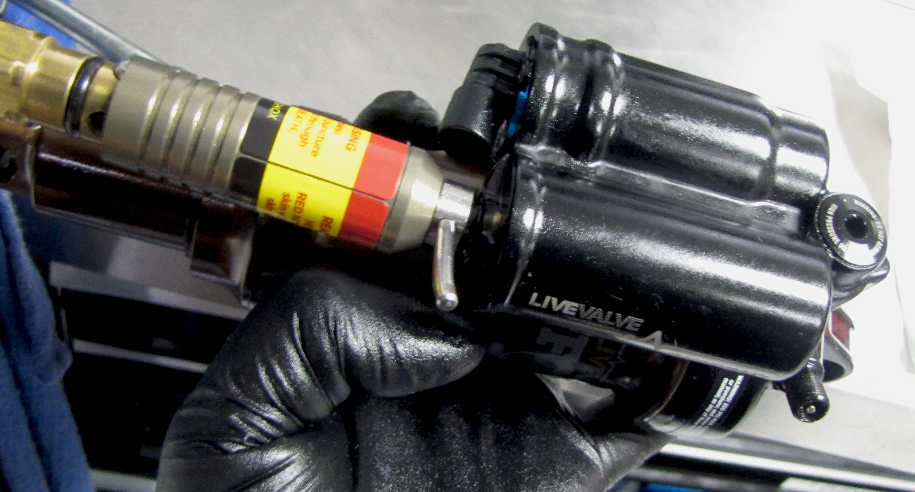
Connect the Andreani Fill Machine to the bleed port of the LIVE Valve shock using the Fill Machine Adaptor (PN: 803-00-370). Cycle the shock by hand while you perform the vacuum cycle. Then cycle the shock by hand as you perform the fill cycle. Repeat as necessary to purge all air from the shock. Set the IFP to 1.310" (33.3mm). Remove the Fill Adaptor.
Step 22
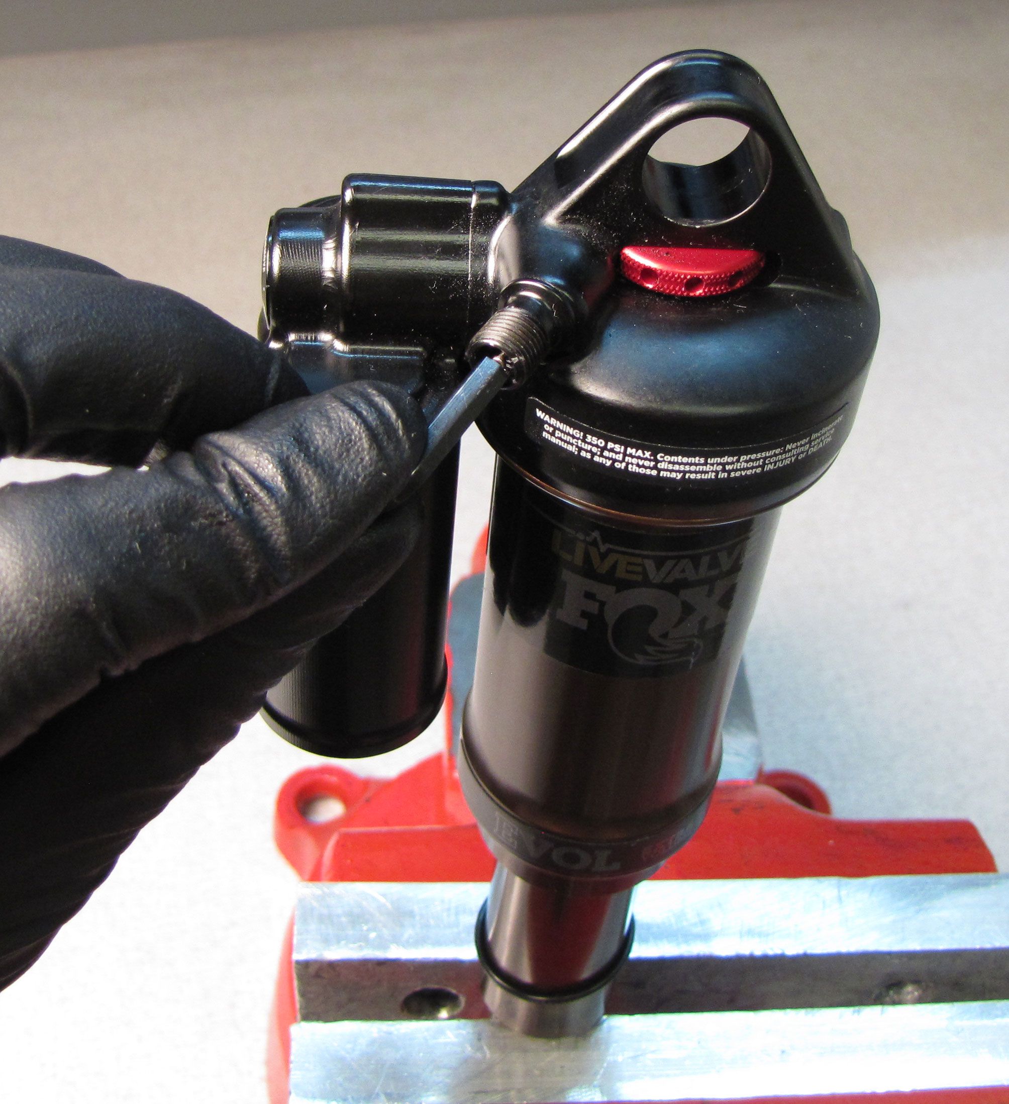
Reinstall the 0.125" ball bearing into the bleed port followed by the bleed screw. Tighten the bleed screw clockwise to 11 in-lb (1.2 Nm) torque with a 5/64" hex wrench. Install a new white Delrin ball from the kit into the bleed port.
Step 23
Remove the wire Retaining Ring from the IFP Reservoir. Reinstall the Rezi Endcap Assembly with new greased o-ring into the end of the Reservoir. Replace the wire Retaining Ring making sure to seat it fully in the groove of the Reservoir.


Step 24
Pull up on the Rezi Endcap Assembly to seat it against the wire Retaining Ring. Thread a 5/16-24 threaded rod or bolt into the Reservoir End Cap then pull up. If you do not have a 5/16-24 threaded rod or bolt, pull up on the Reservoir End Cap with pliers on the flats of the raised portion of the end cap. Do not use pliers on the external threads of the end cap. Replace the Resi End Cap Lockring, tightening it clockwise until hand tight.


Step 25
Install a new black pellet from the kit into the Rezi Endcap Assembly with its flat side facing out. Reinstall the Pellet Retainer, tightening clockwise with a 4mm hex wrench until just snug.
Step 26
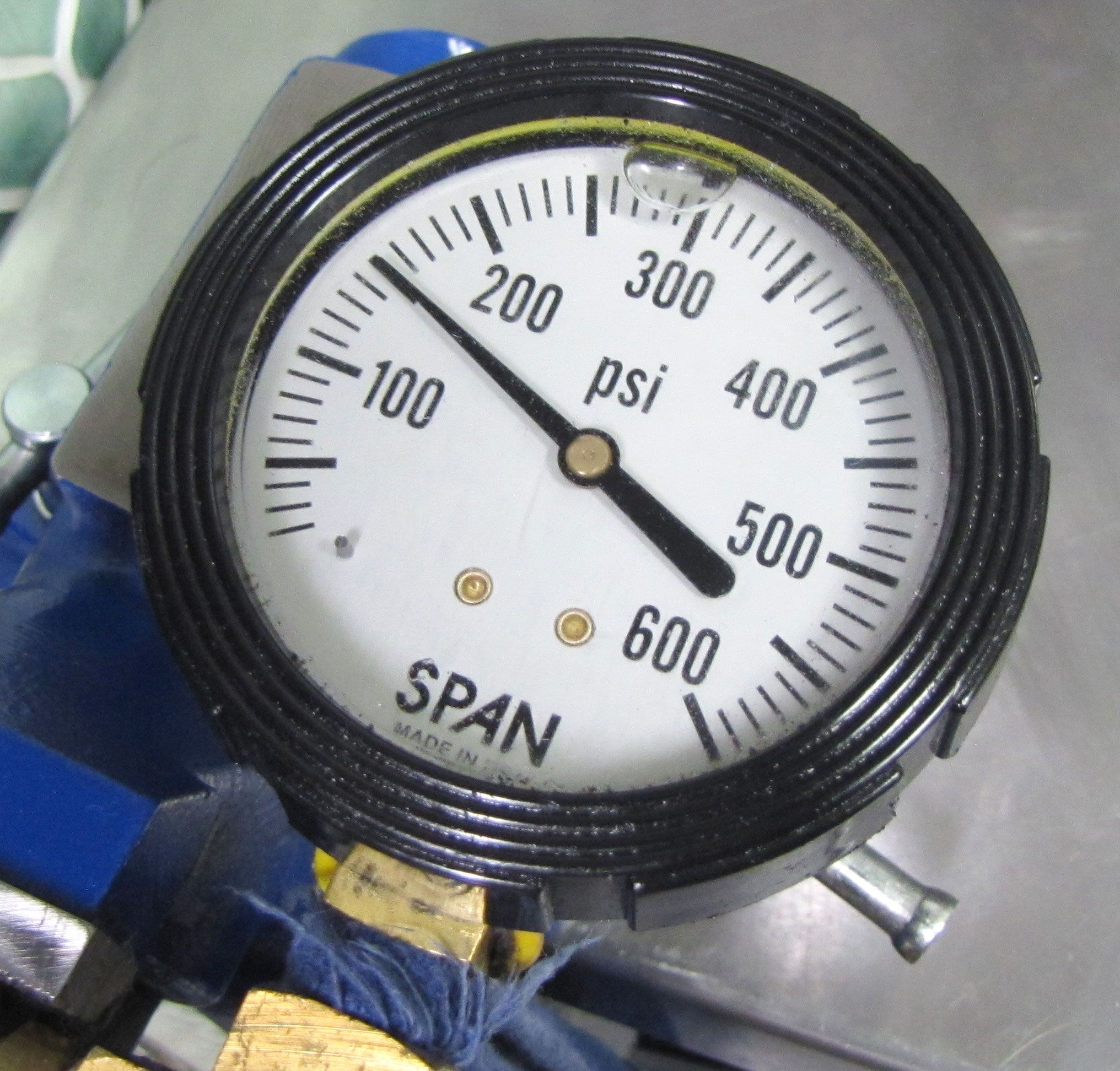
With the Pellet Retainer just snug, fill the IFP chamber to 150psi. Tighten the pellet retainer clockwise to 14 in-lb (1.6 Nm) torque. Use the Solenoid Switcher tool (398-00-820) to dyno the shock to check all damper functions. Once happy with the dyno results, install a new white Delrin ball into the Pellet Retainer.
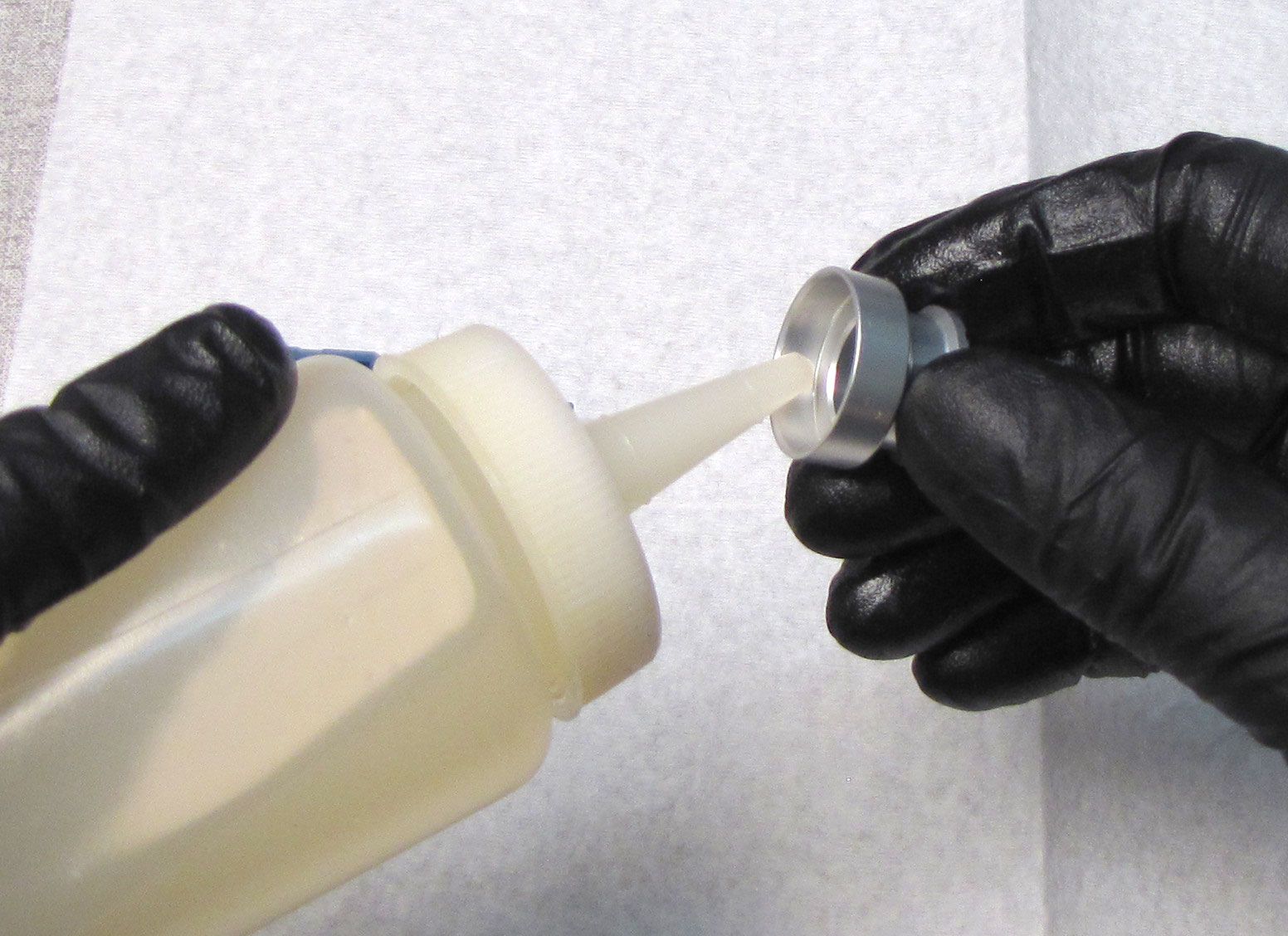
Step 27
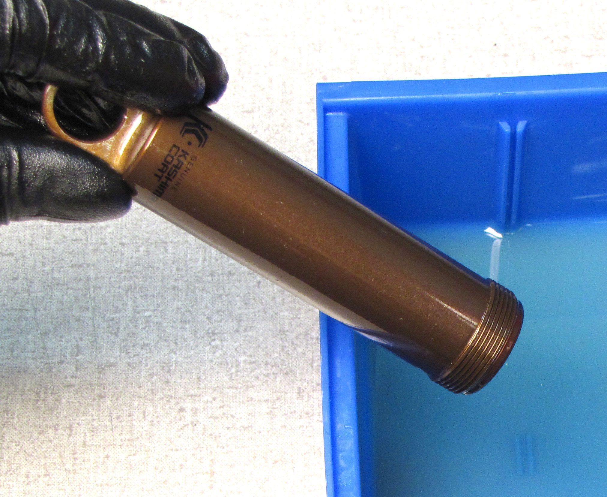
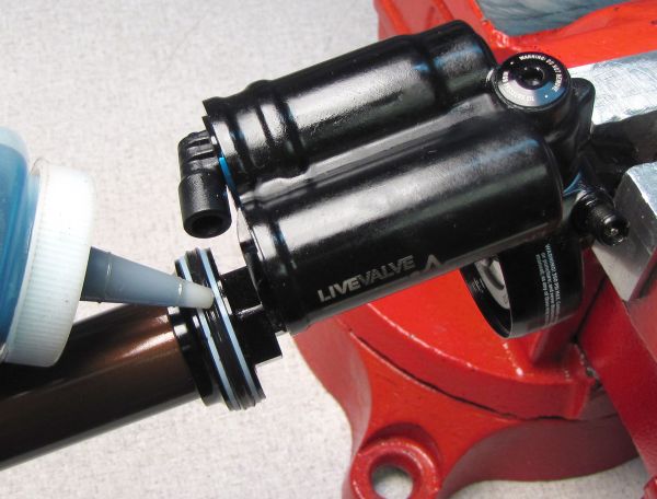
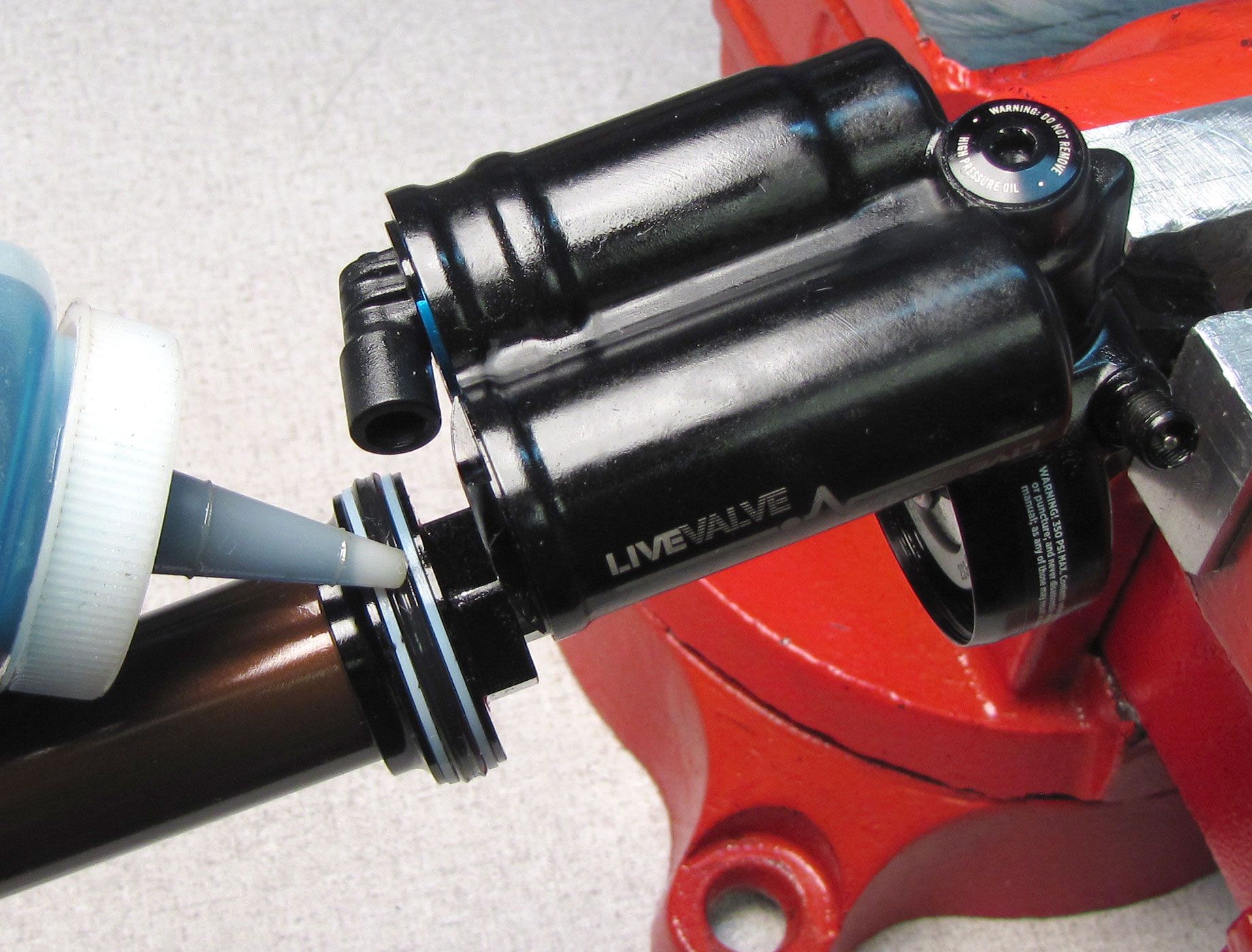
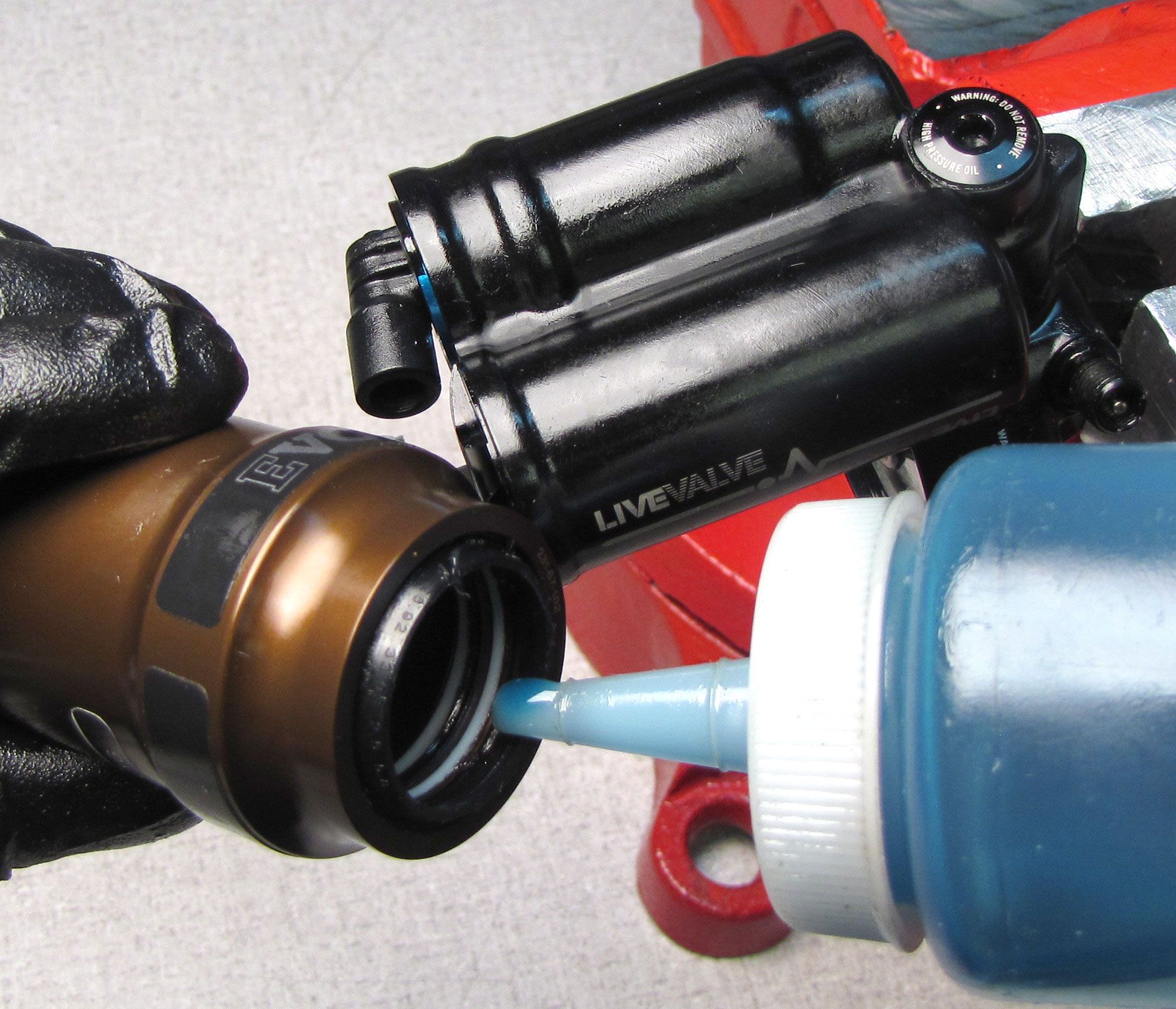
Coat the main air seals on the Bearing Assembly with a film of Float Fluid. Coat the negative air seals in the end of the Air Sleeve Assembly with a film of Float Fluid. Start reinstalling the Air Sleeve onto the shock damper. Inject 2cc of Float Fluid into the main air chamber. Continue to install the Air Sleeve Assembly threading it clockwise into the Eyelet tightening until hand tight.

Step 28
Add air pressure to the main air chamber then replace the black Air Valve Cap. Clean the exterior of the shock. Install a new sag indicator o-ring from the kit onto the shock body.