2019-2023 LIVE Valve MTB Fork Cartridge Rebuild
Required Parts
- 803-01-361 Service Kit: All LIVE Cartridge Rebuild
Required Tools
- 398-00-320 Tool: 8mm Shaft Bullet, 32 FIT Cartridge
- 398-00-681 2002-017 32 Damper-side and ALL 32-34-36-40 Spring-side Removal Tool
- 398-00-682 2005-017 34-36-40 Damper-side Removal Tool
- 398-00-707 Tooling: Fork Topcap Socket, 28mm V2, 3/8 Drive
- 398-00-806 Tooling: LIVE Valve Solenoid Housing Puller
- 398-00-820 Tooling: LIVE Solenoid Switcher
- 803-00-147 Kit: Shaft Clamps, 07 FORX, Set #2 (32 X Body, 36, 40 Forx)
- 803-01-360 Kit: Tooling: LIVE Valve Clamp, Solenoid Housing, 8mm Shaft, Pressure Tube
- 803-01-369 Kit: Tooling: Glide Band Sizer, Live Valve, Fork/Shock
- 803-01-370 Kit: Fill Machine Adapter, Live Valve Fork/Shock
WARNING: Always wear safety glasses and protective gloves during service to prevent potential injury. Failure to wear protective equipment during service may lead to SERIOUS INJURY OR DEATH.
Disassembly
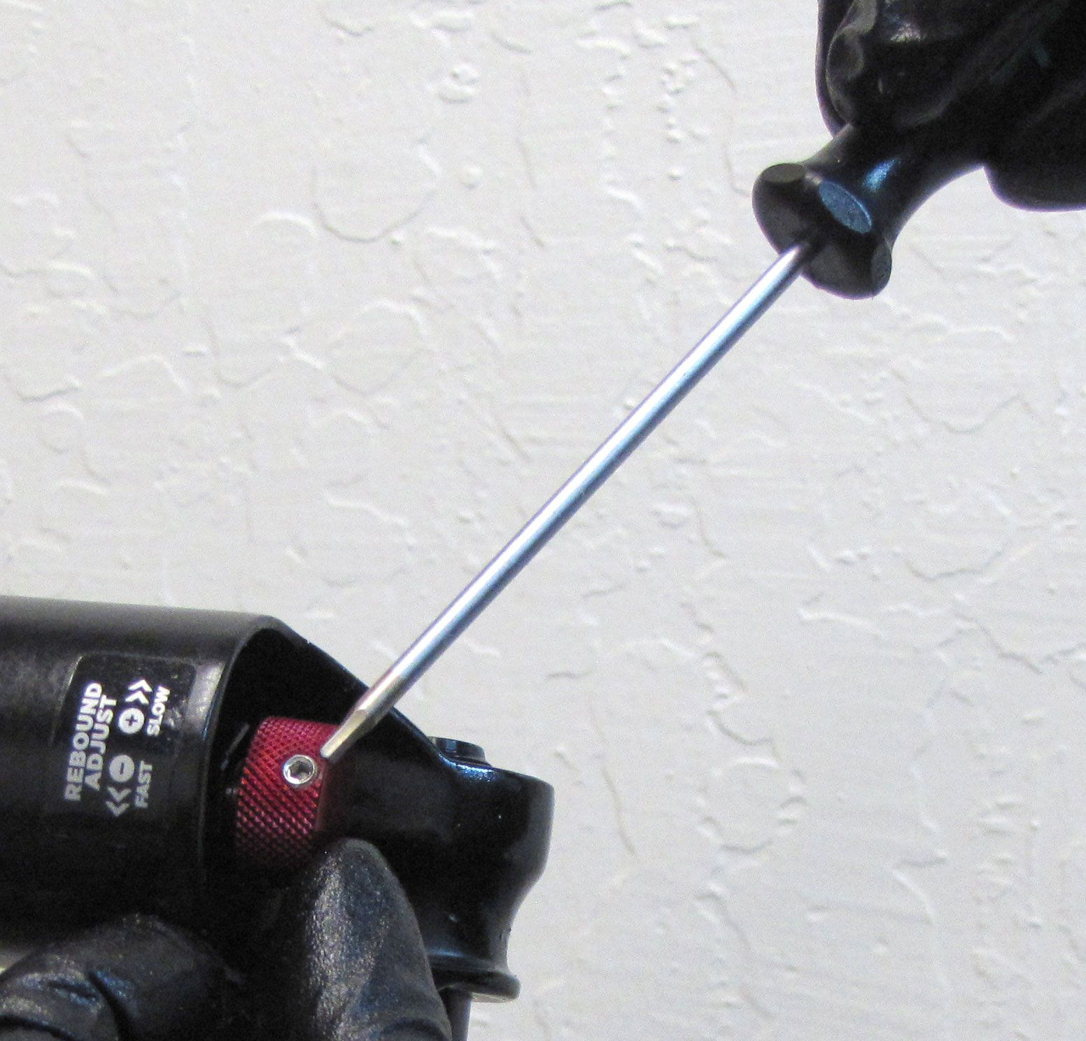
Step 1
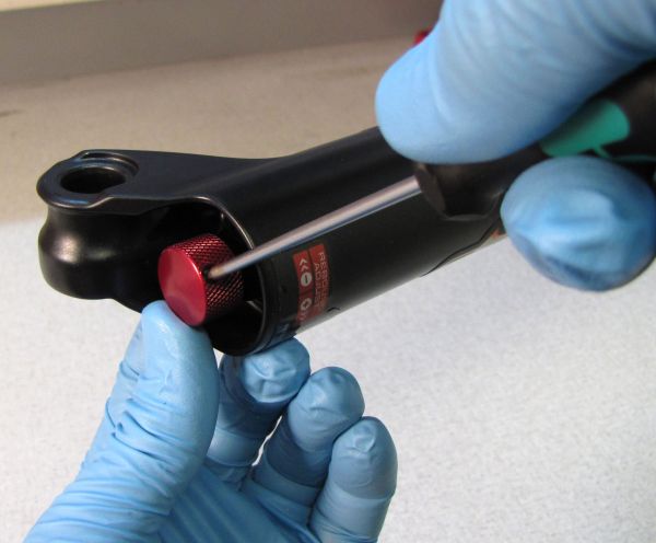
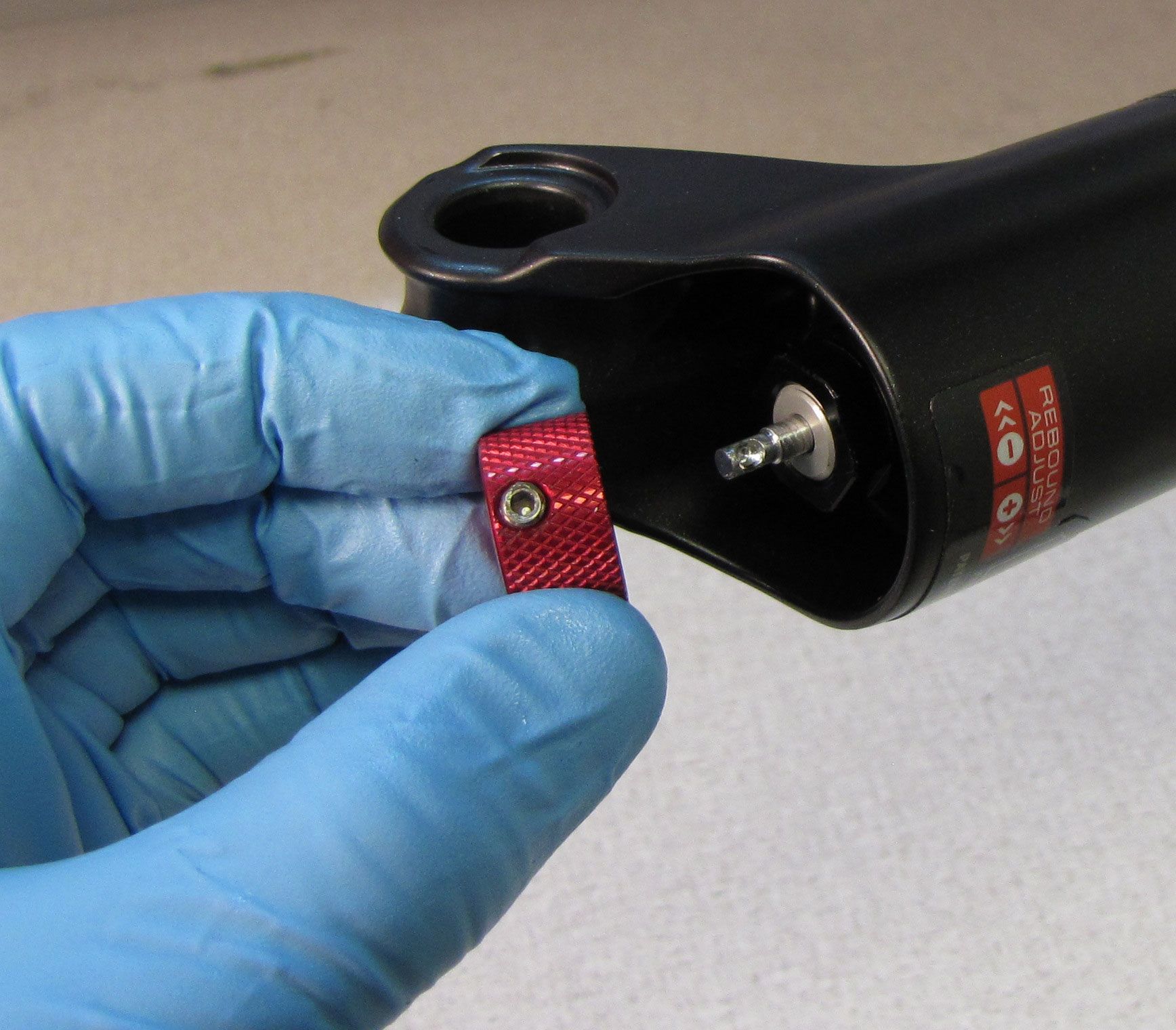
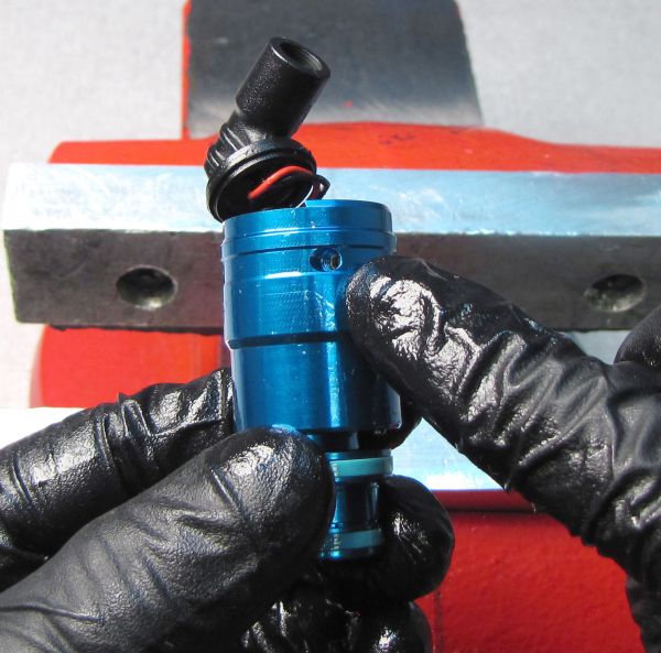
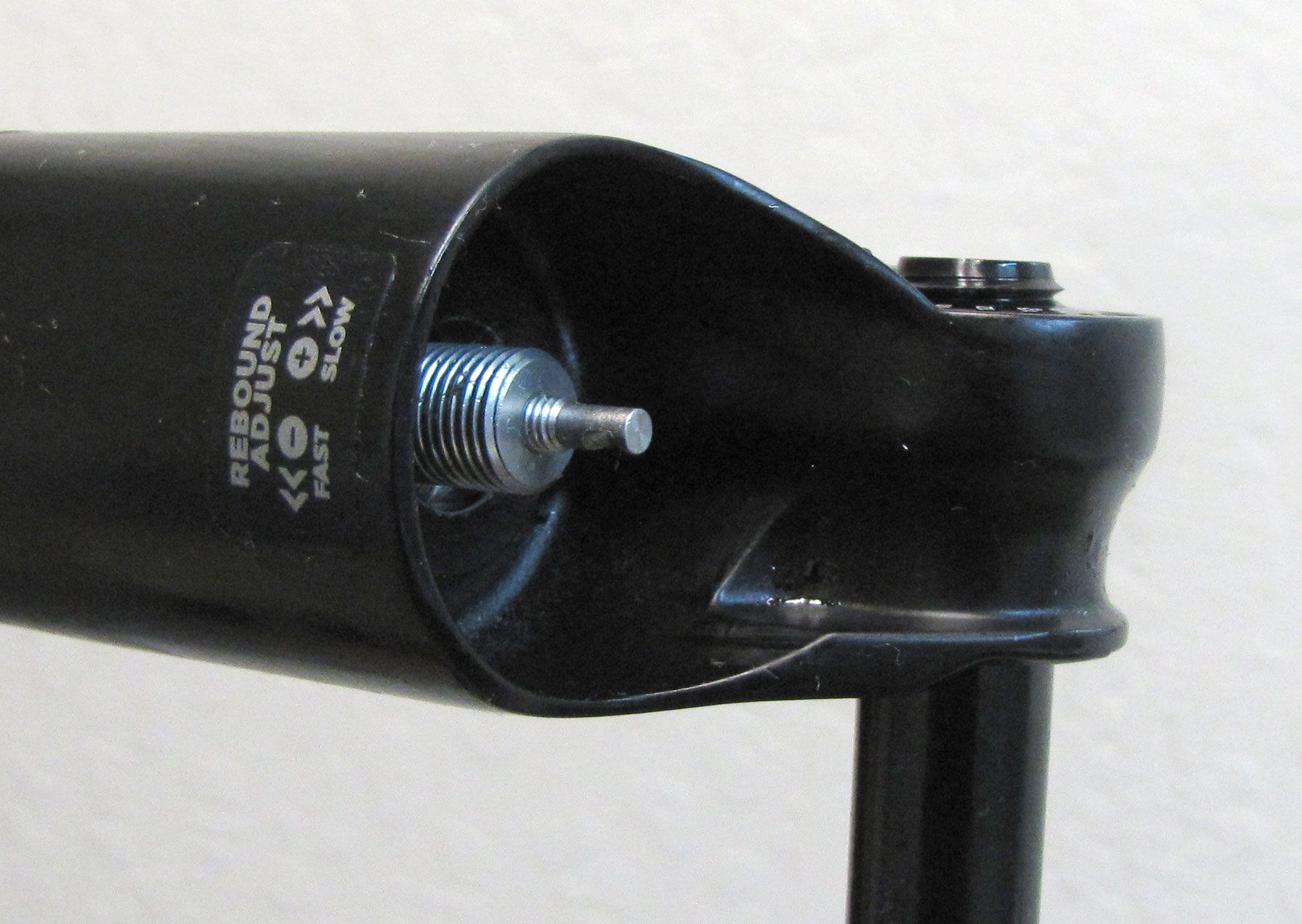
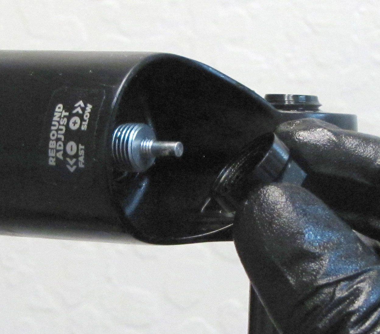
With the fork slightly inverted (the bottom of the fork up past horizontal), remove the black cover if present, then use a 2mm hex wrench to remove the red rebound knob.


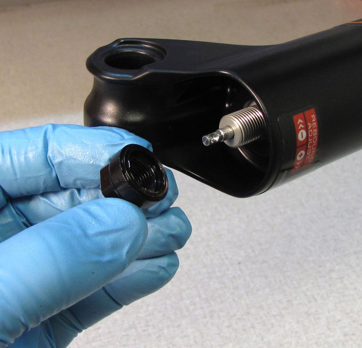
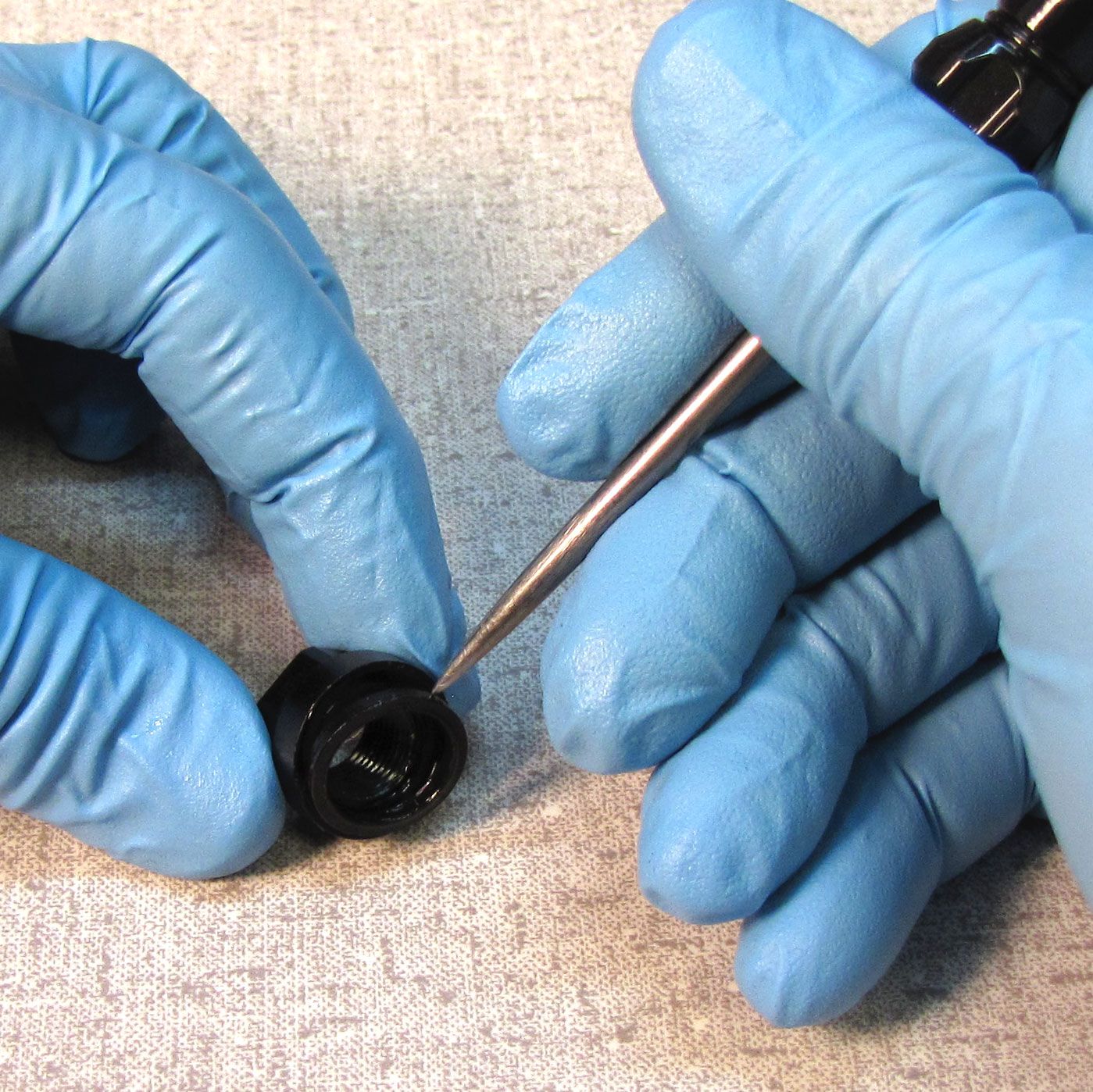
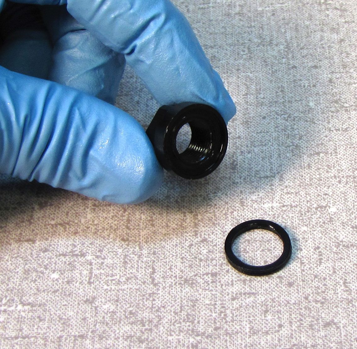
Step 2
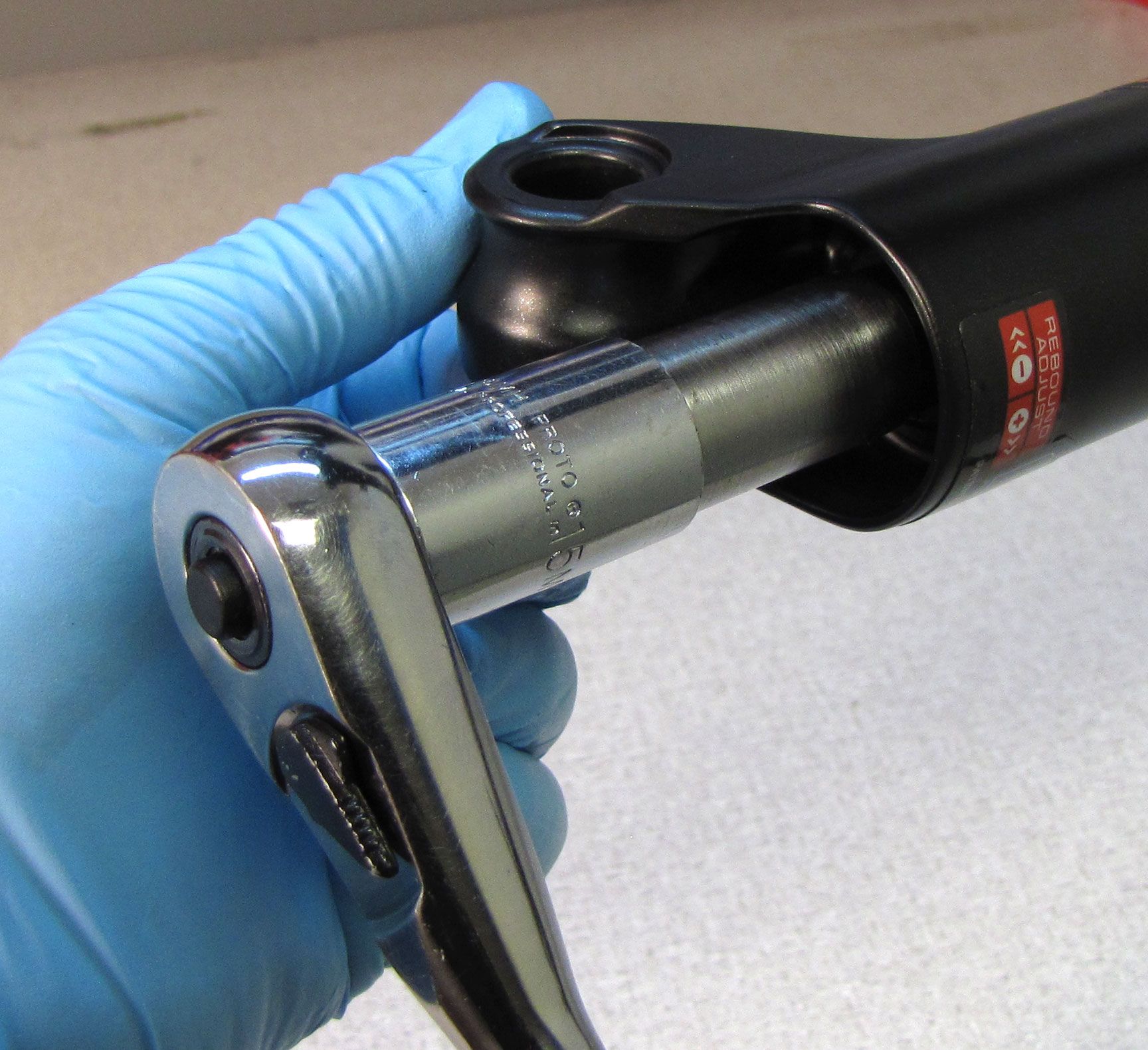
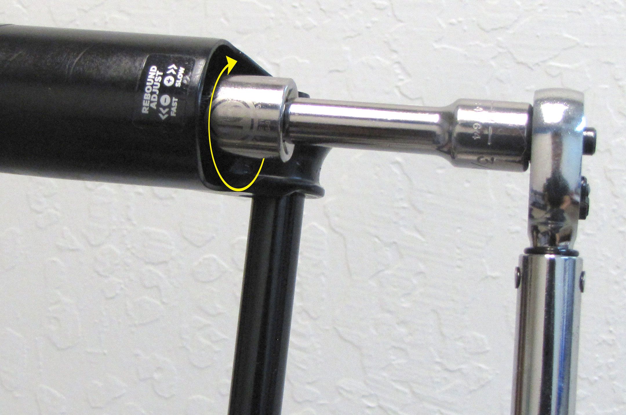
Use a 10mm socket (for 32mm forks) or a 15mm socket (for 34mm and 36mm forks) to remove the damper side bottom nut. Make sure to remove and discard the orginal crushwasher which may be stuck to the bottom nut.

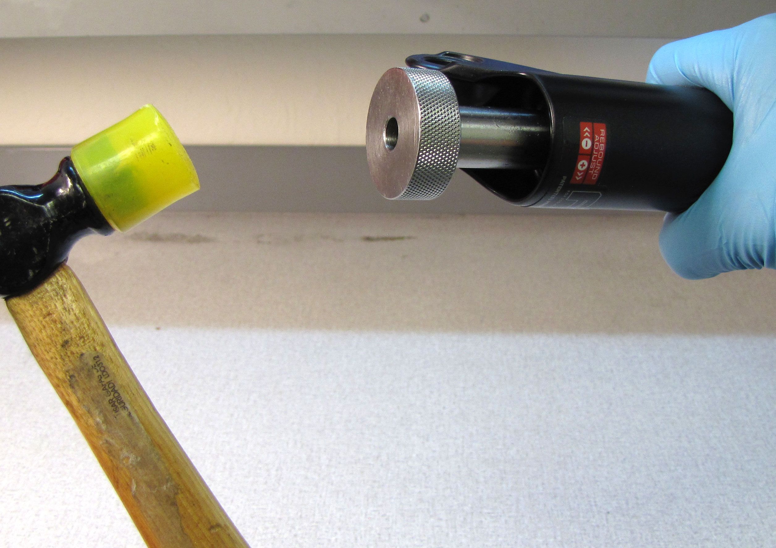
Step 3
Use Damper Removal Tool 398-00-681 (for 32mm forks) or 398-00-682 (for 34mm and 36mm forks) to dislodge the shaft from the lowers. Make sure that you have approximately half of the available threads engaged with your tool before striking with your mallet. Remove the damper removal tools, then bring the fork upright over an oil basin to drain.
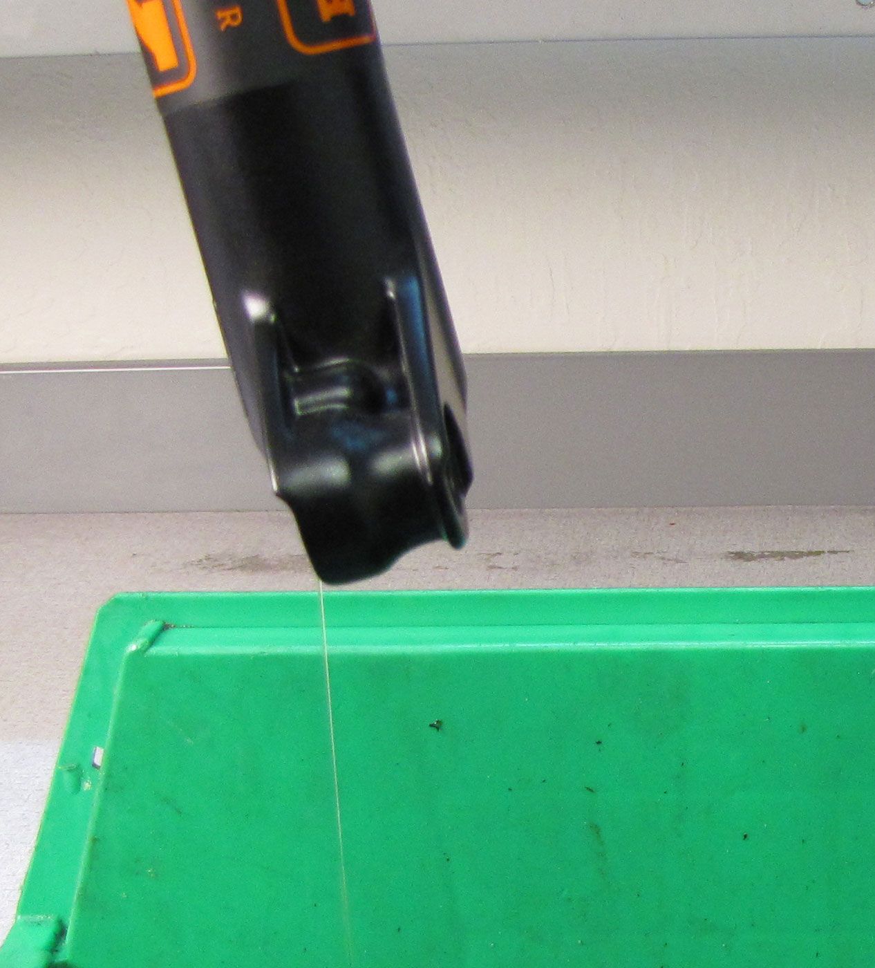
Step 4
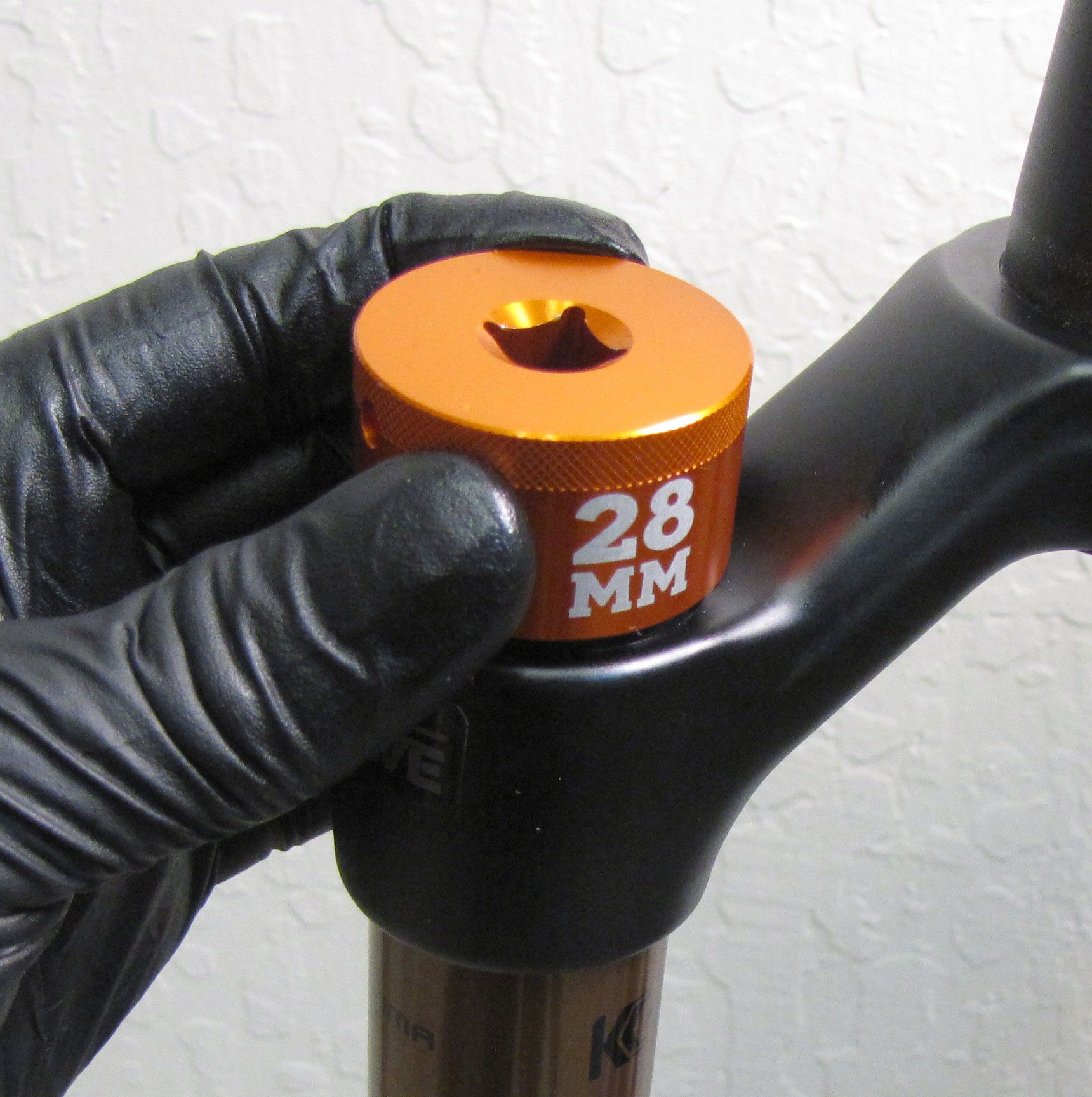
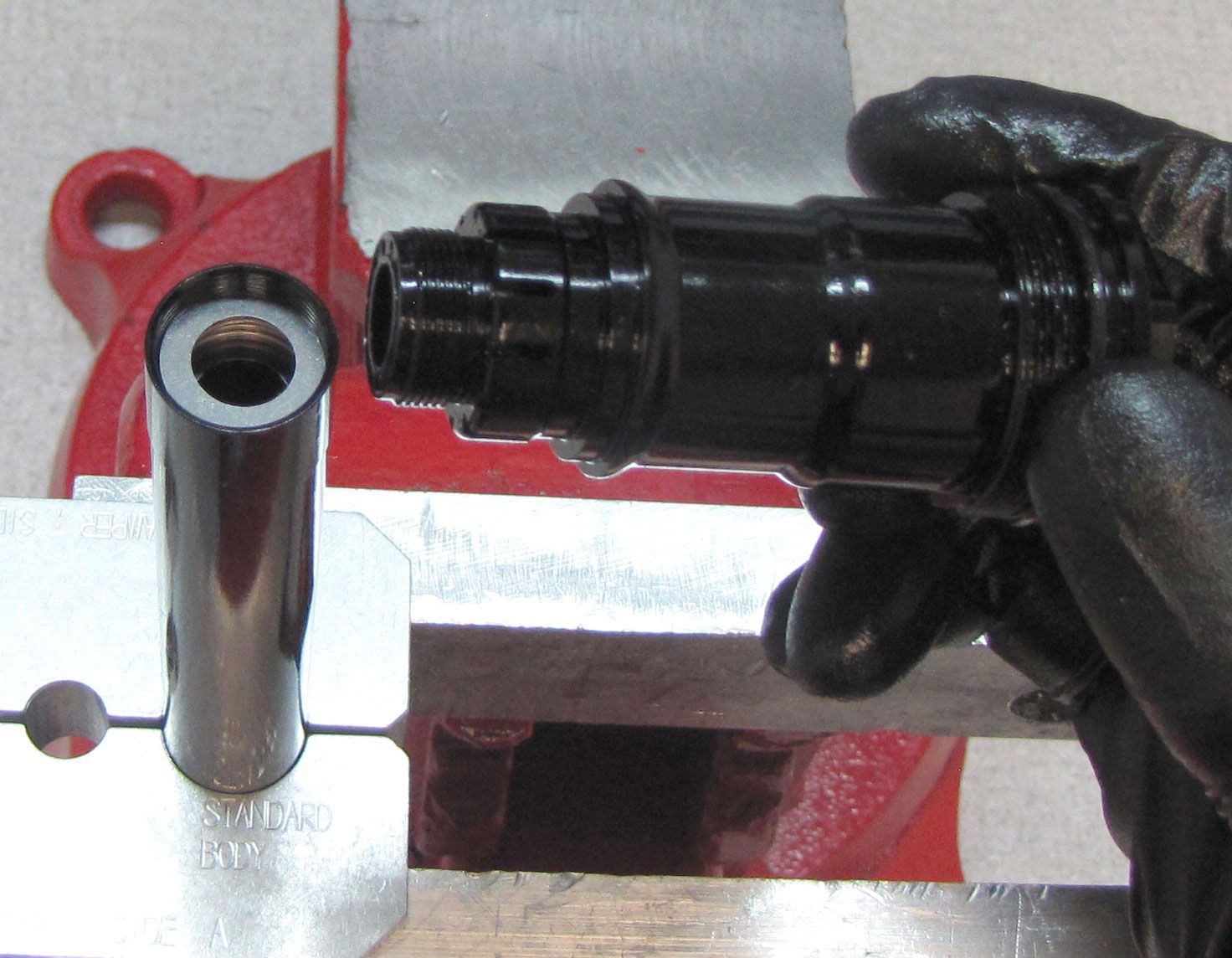
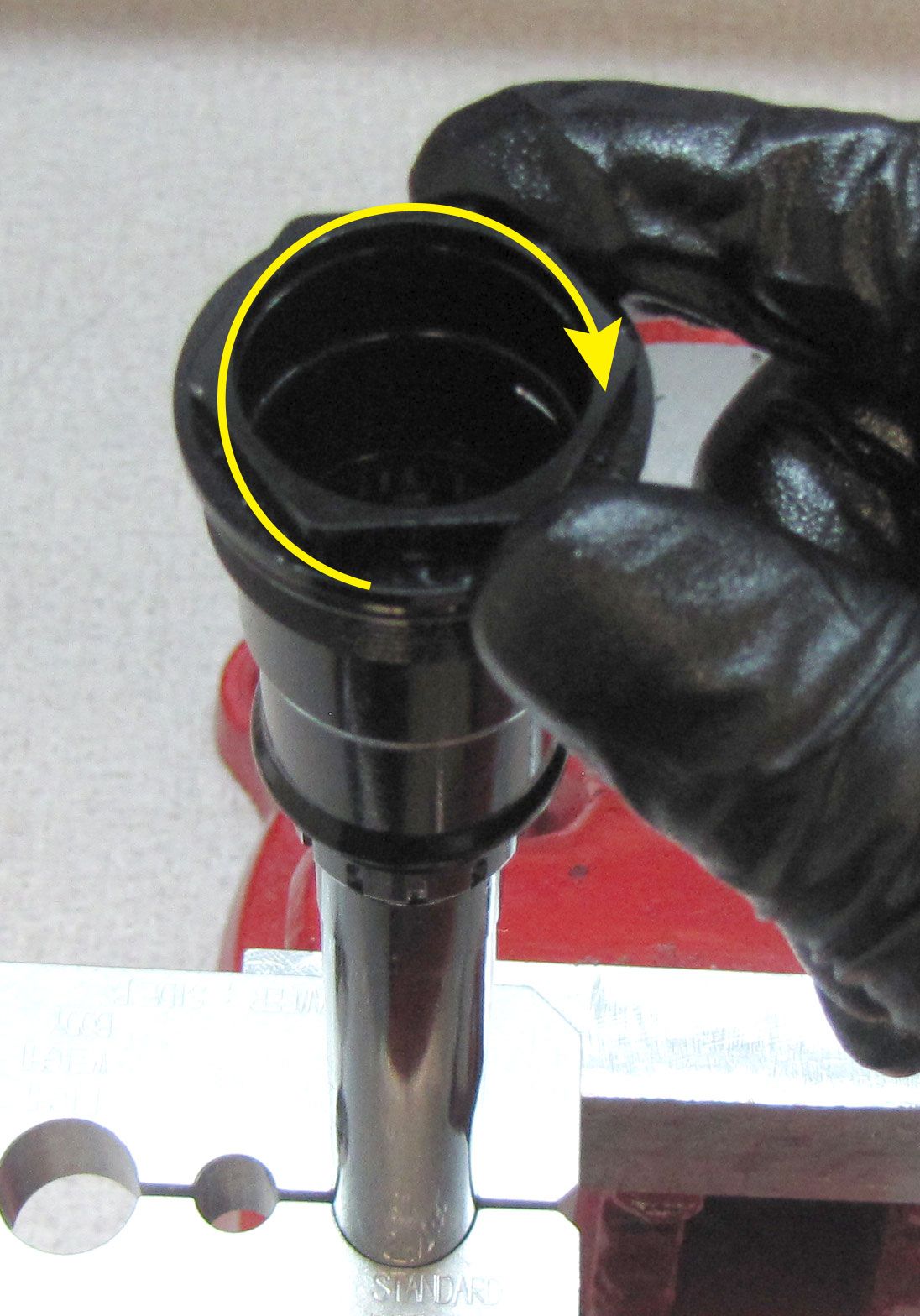
Note: For LIVE Valve forks, you must use the 398-00-707 socket to properly clear the cable connector without causeing part damage.
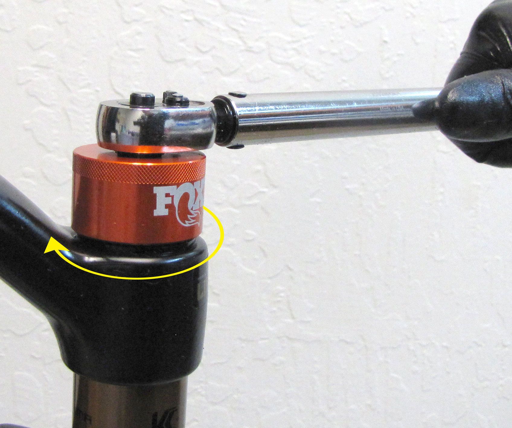
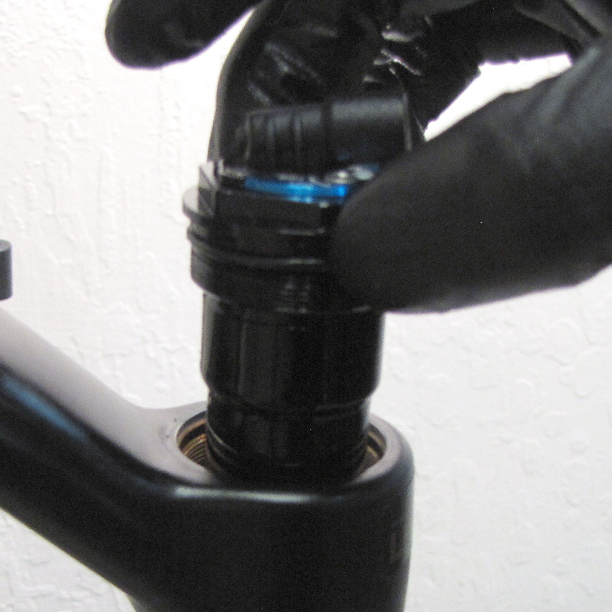
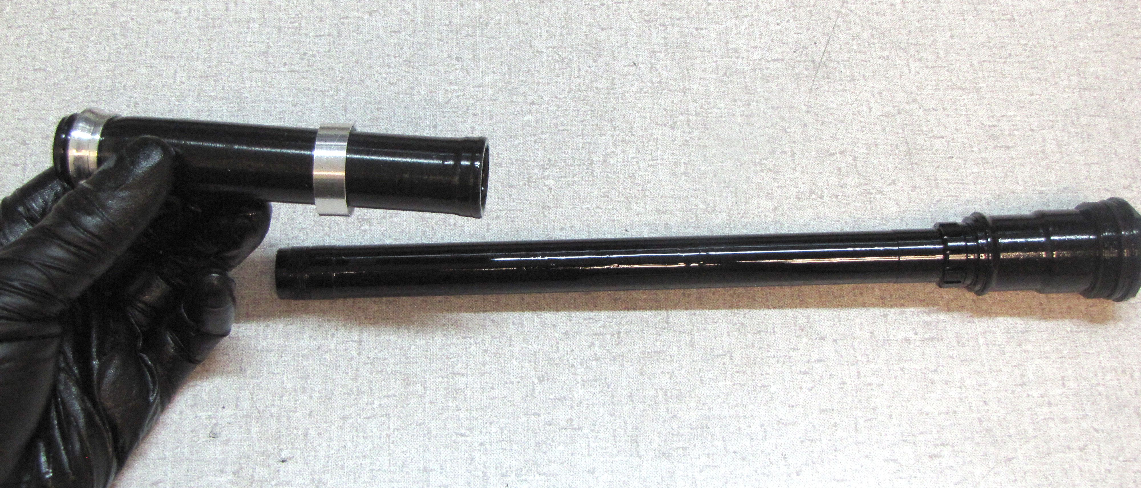
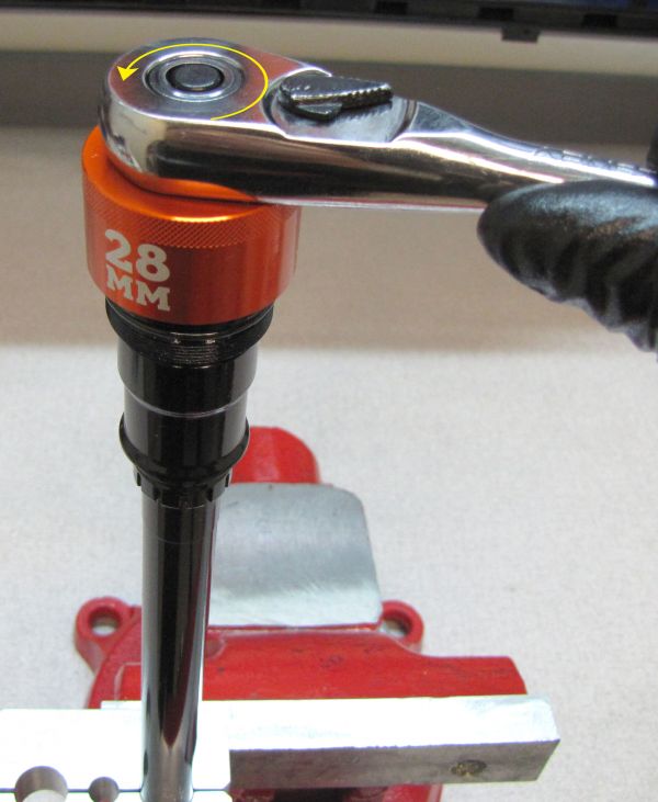
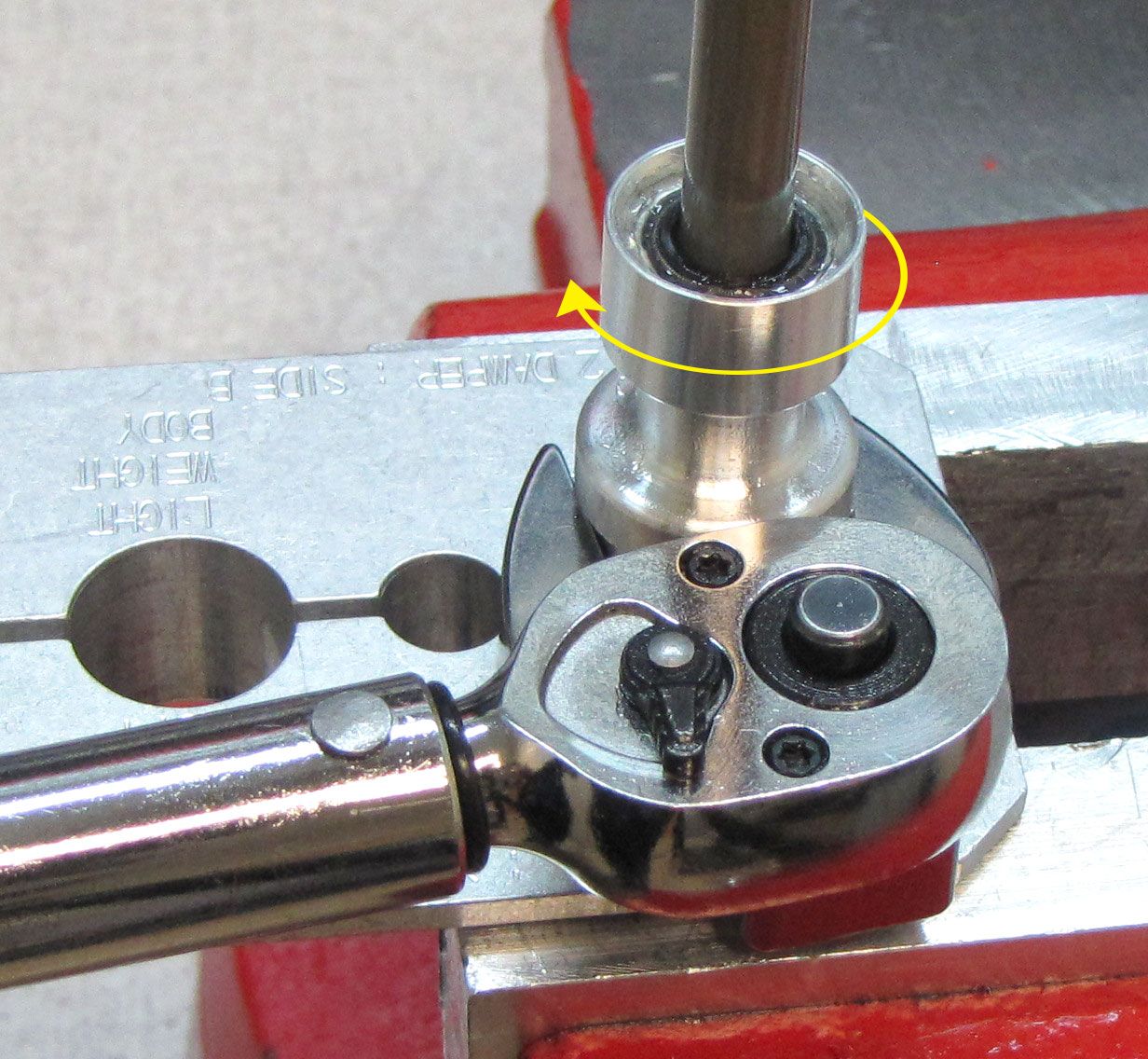
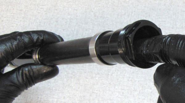
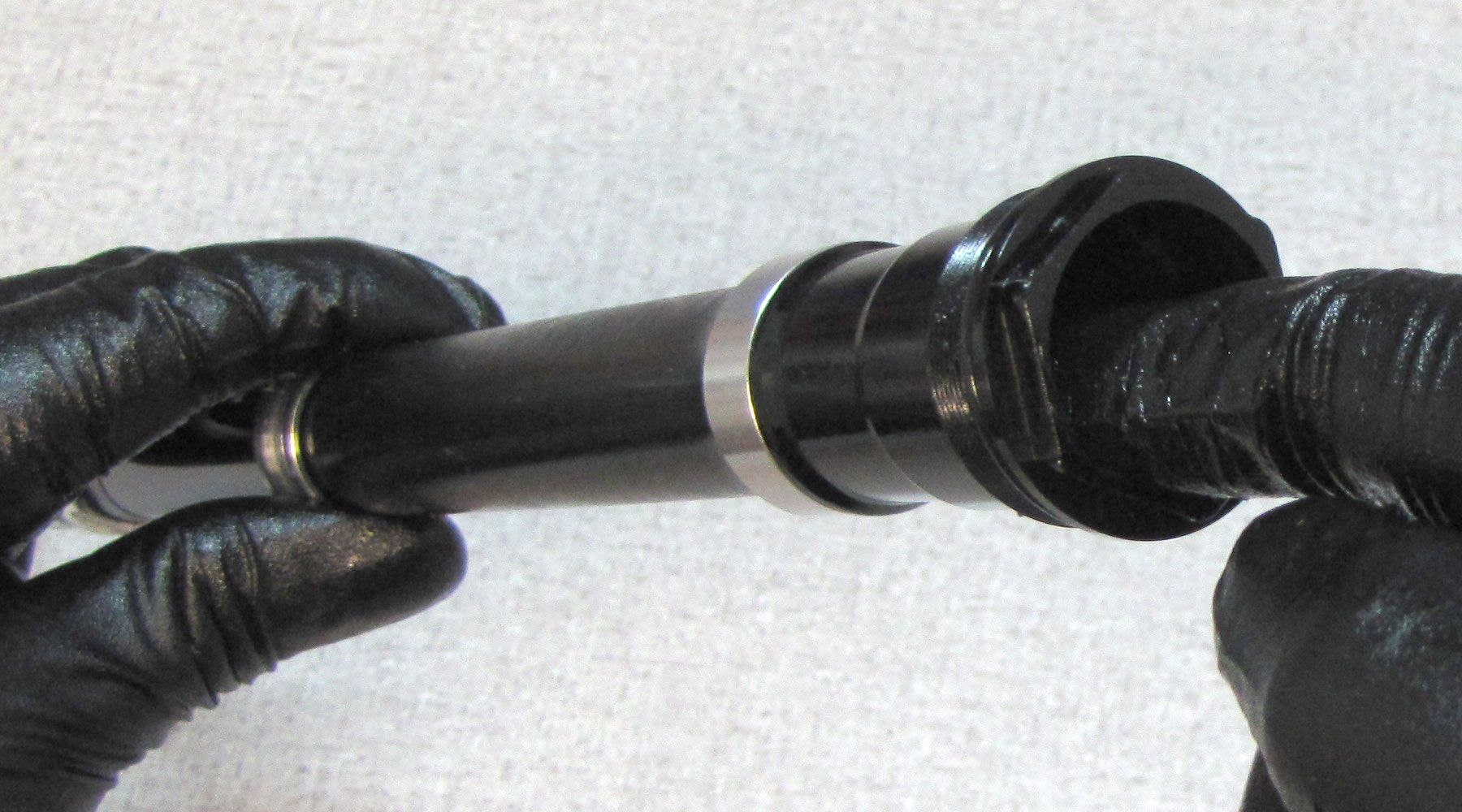
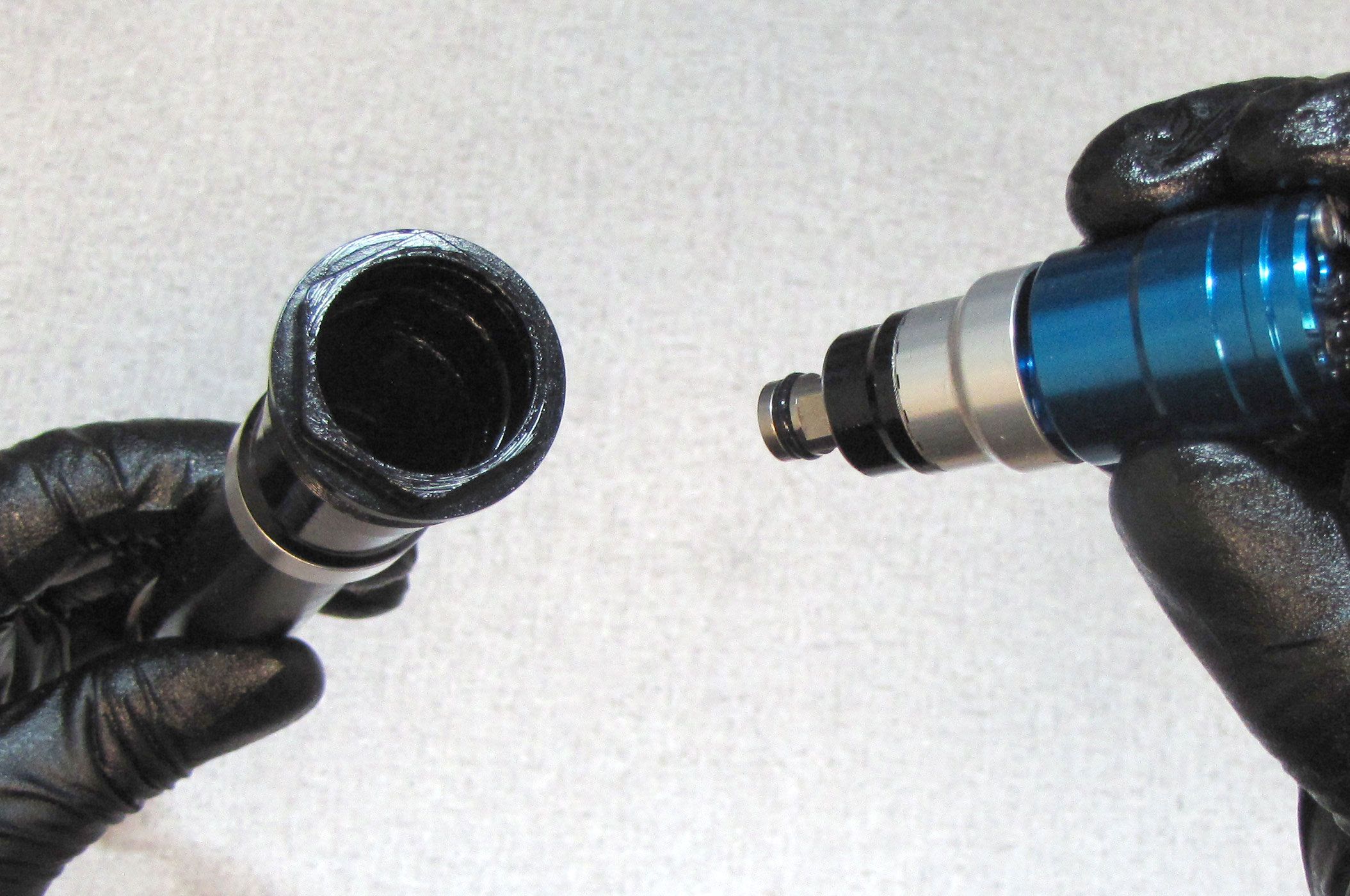
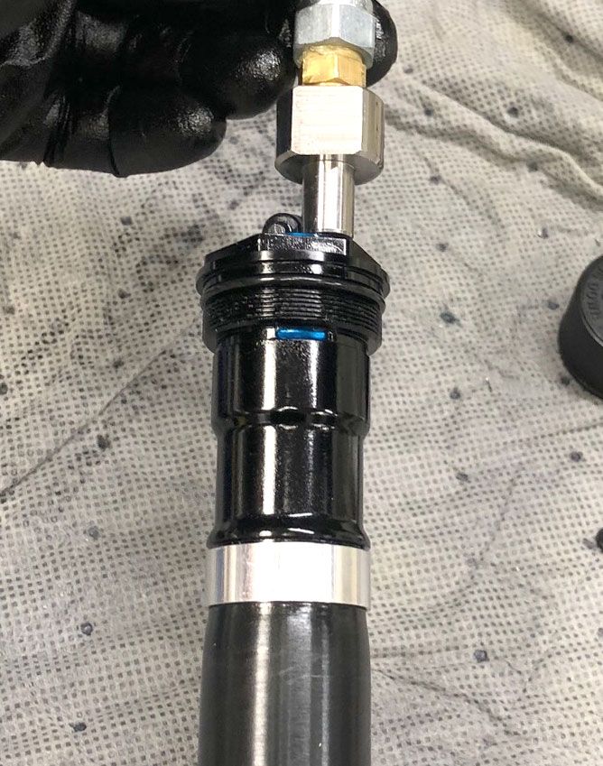
With a chamfer-less 6-point 28mm socket (PN: 398-00-707), unthread the damper cartridge completely (counter-clockwise). Pull straight up to remove the entire damper cartridge from the right side upper tube. Clean off excess bath oil with a lint-free paper towel.
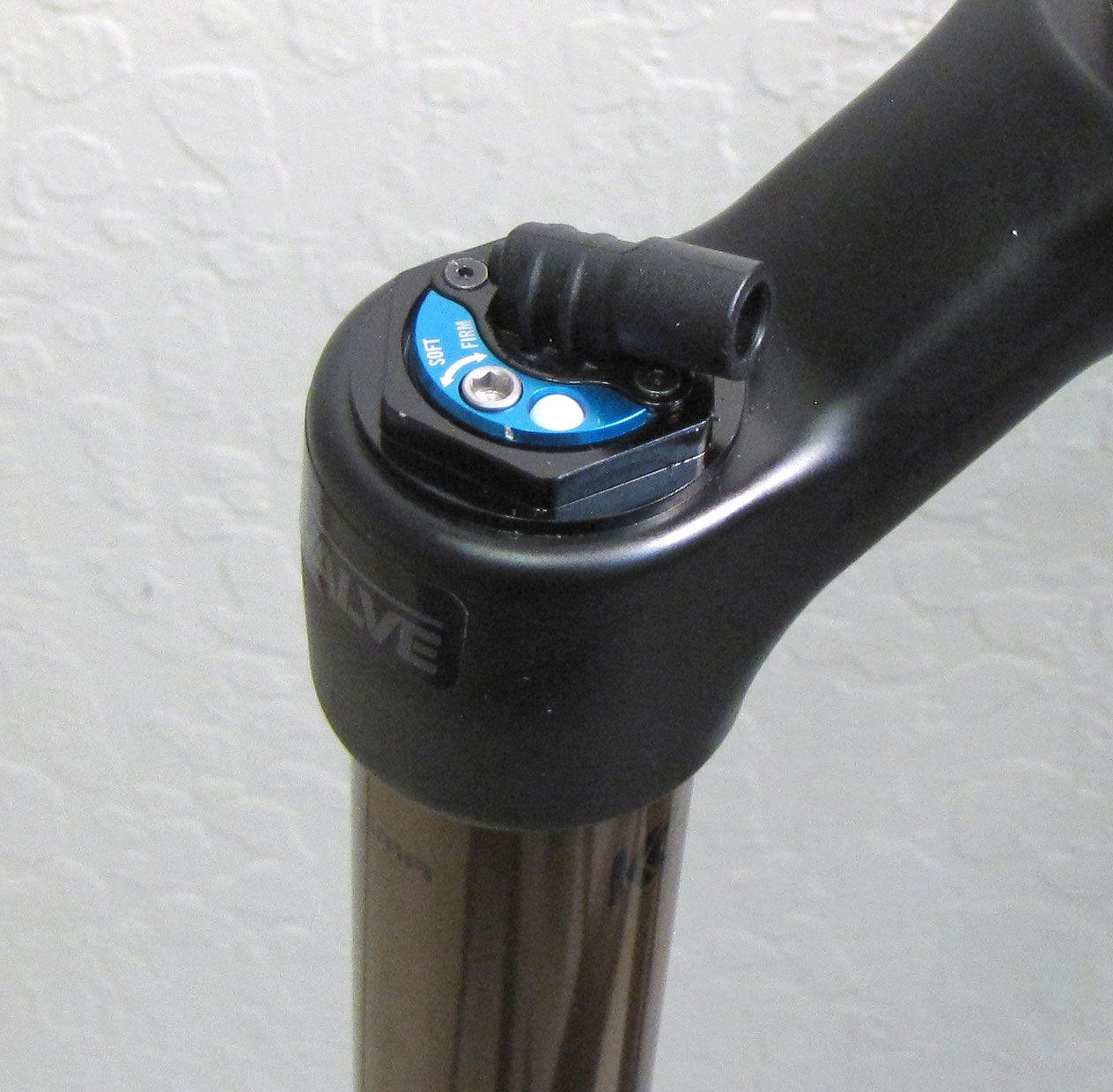
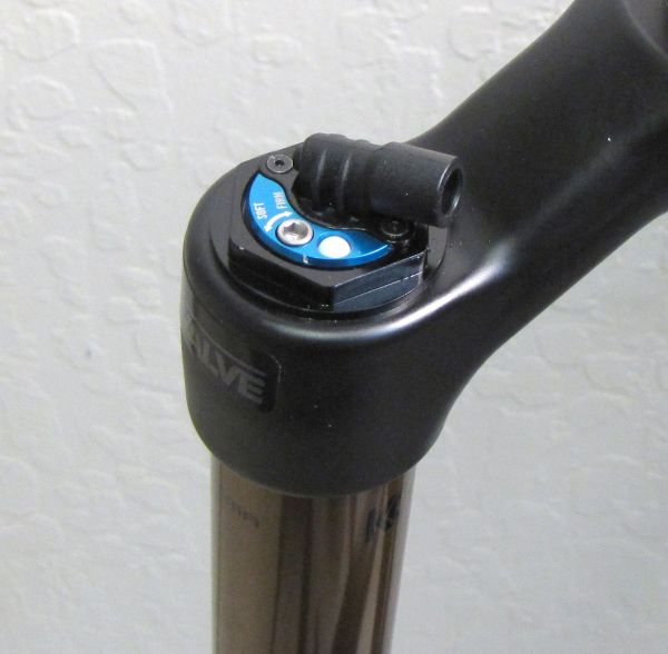
Step 5
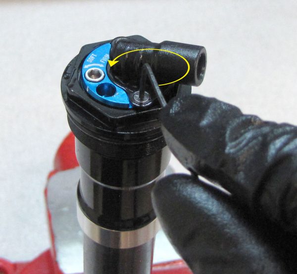
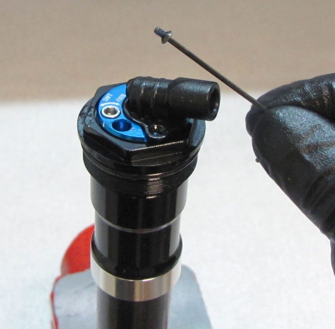
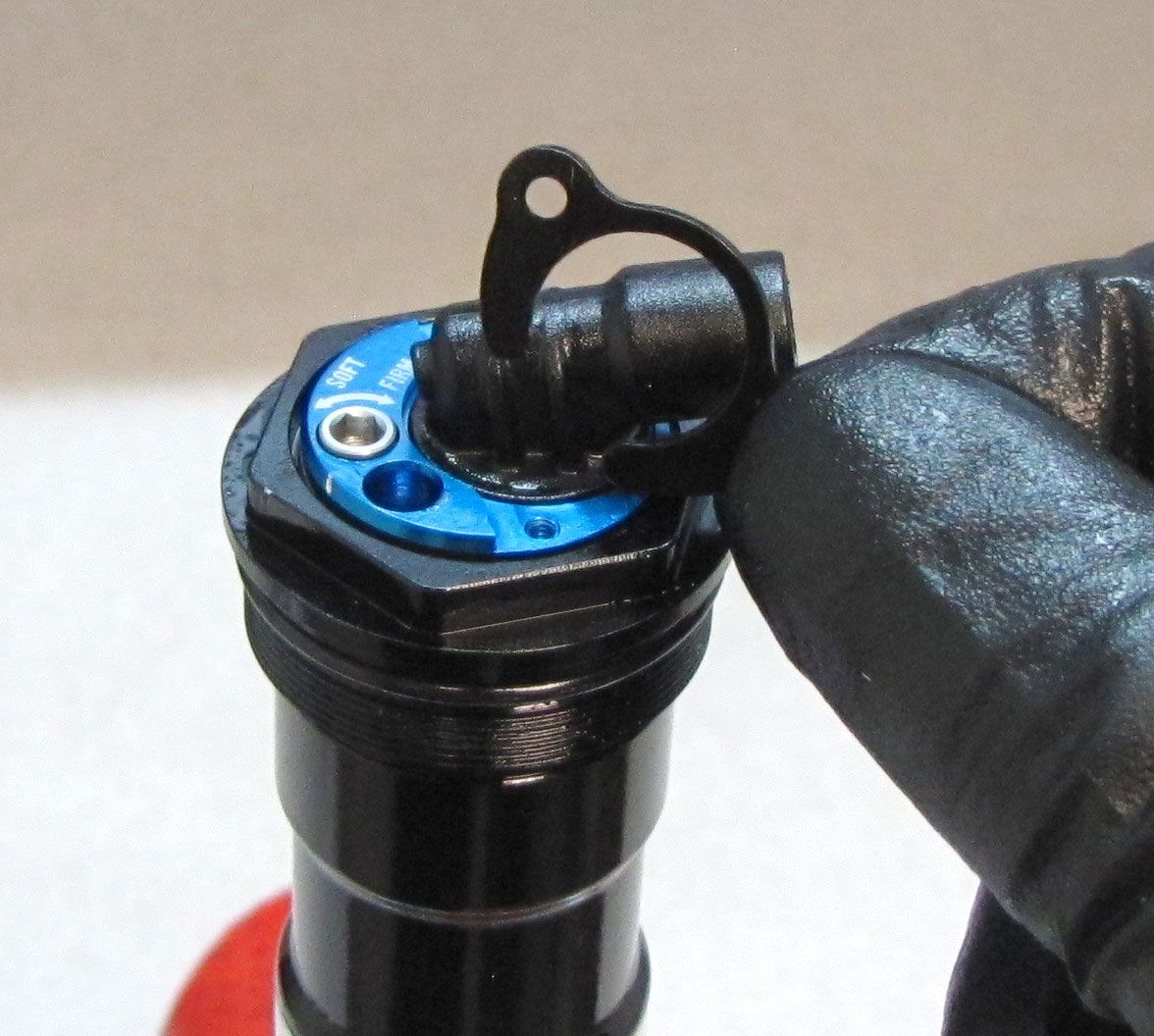
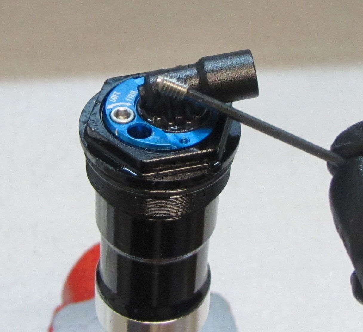
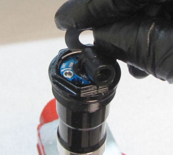
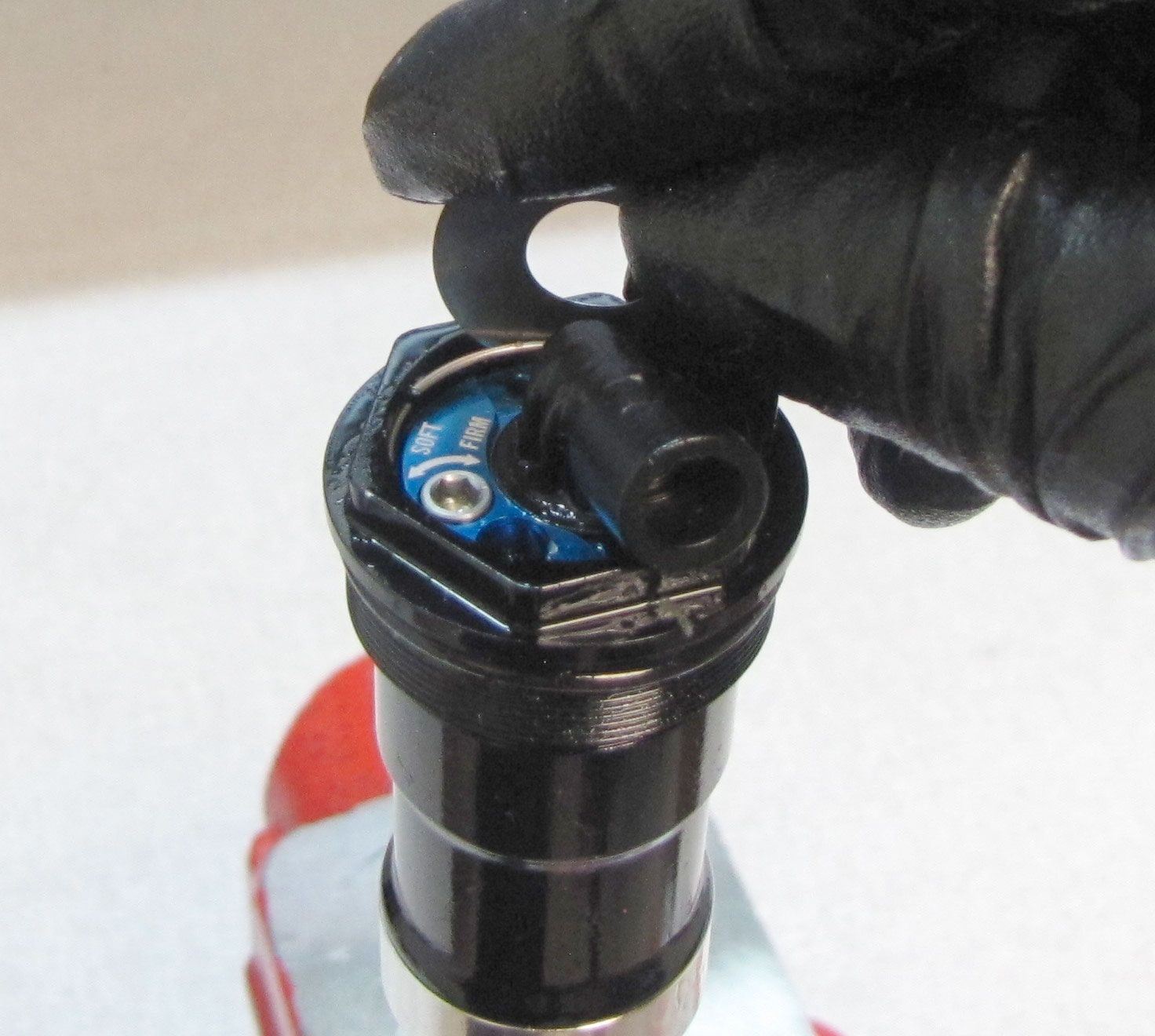
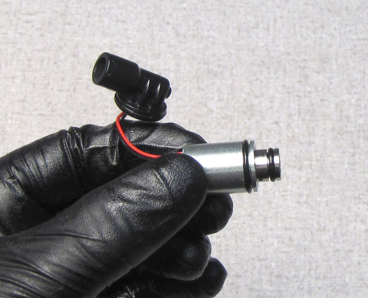
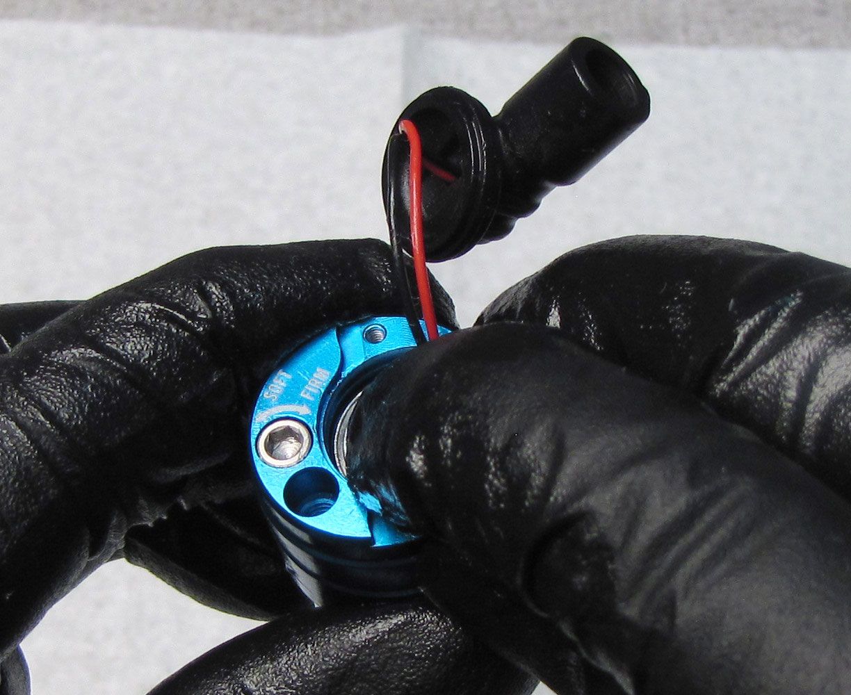
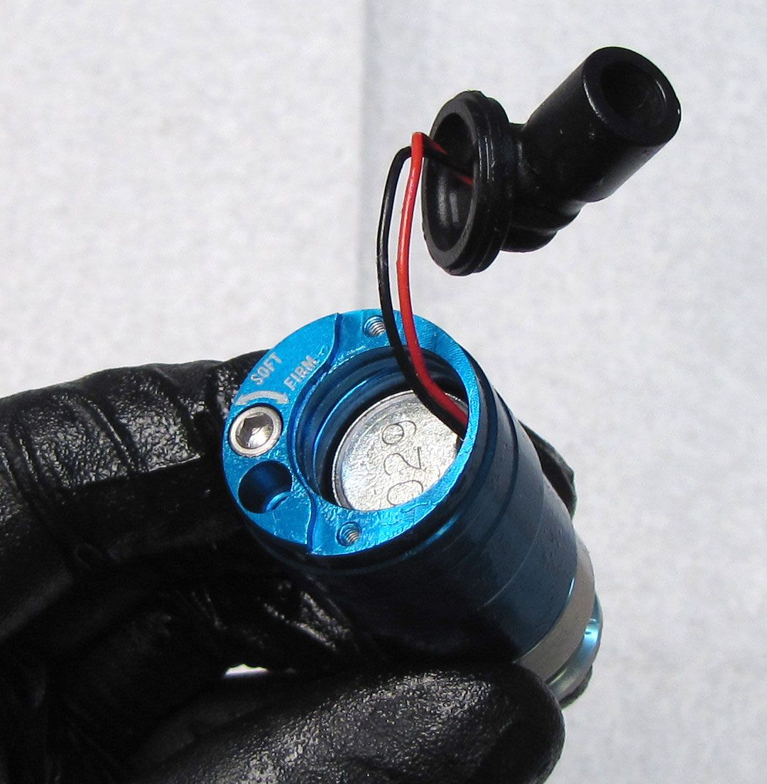
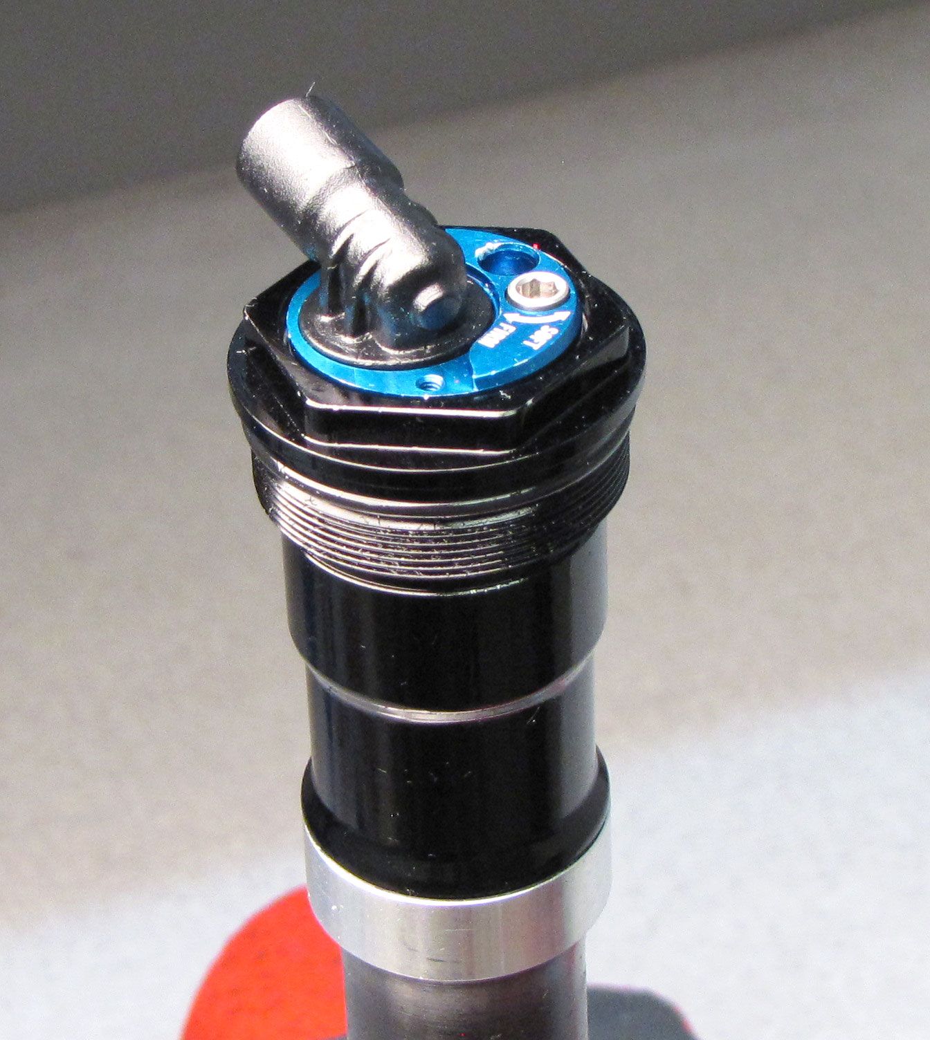
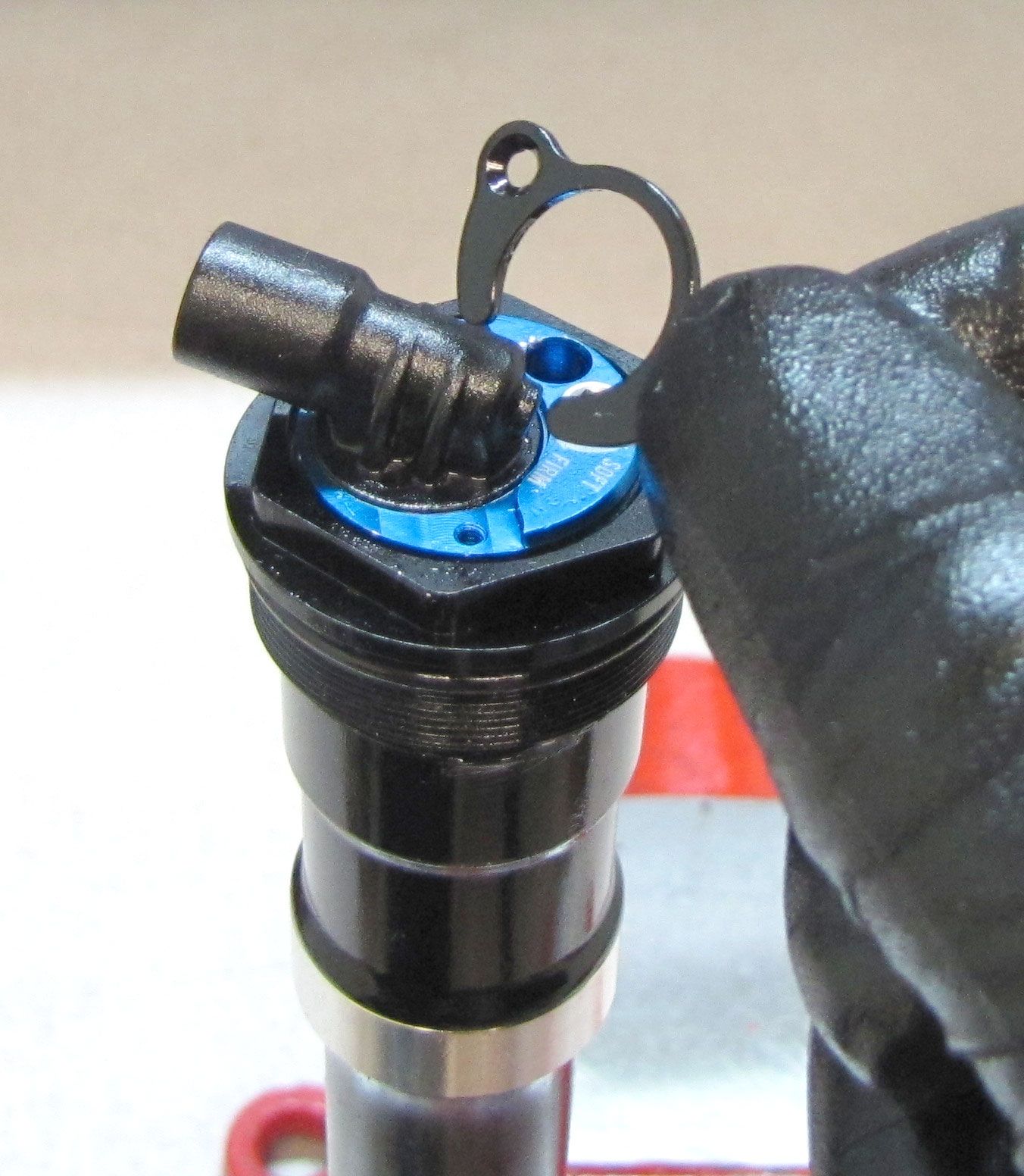
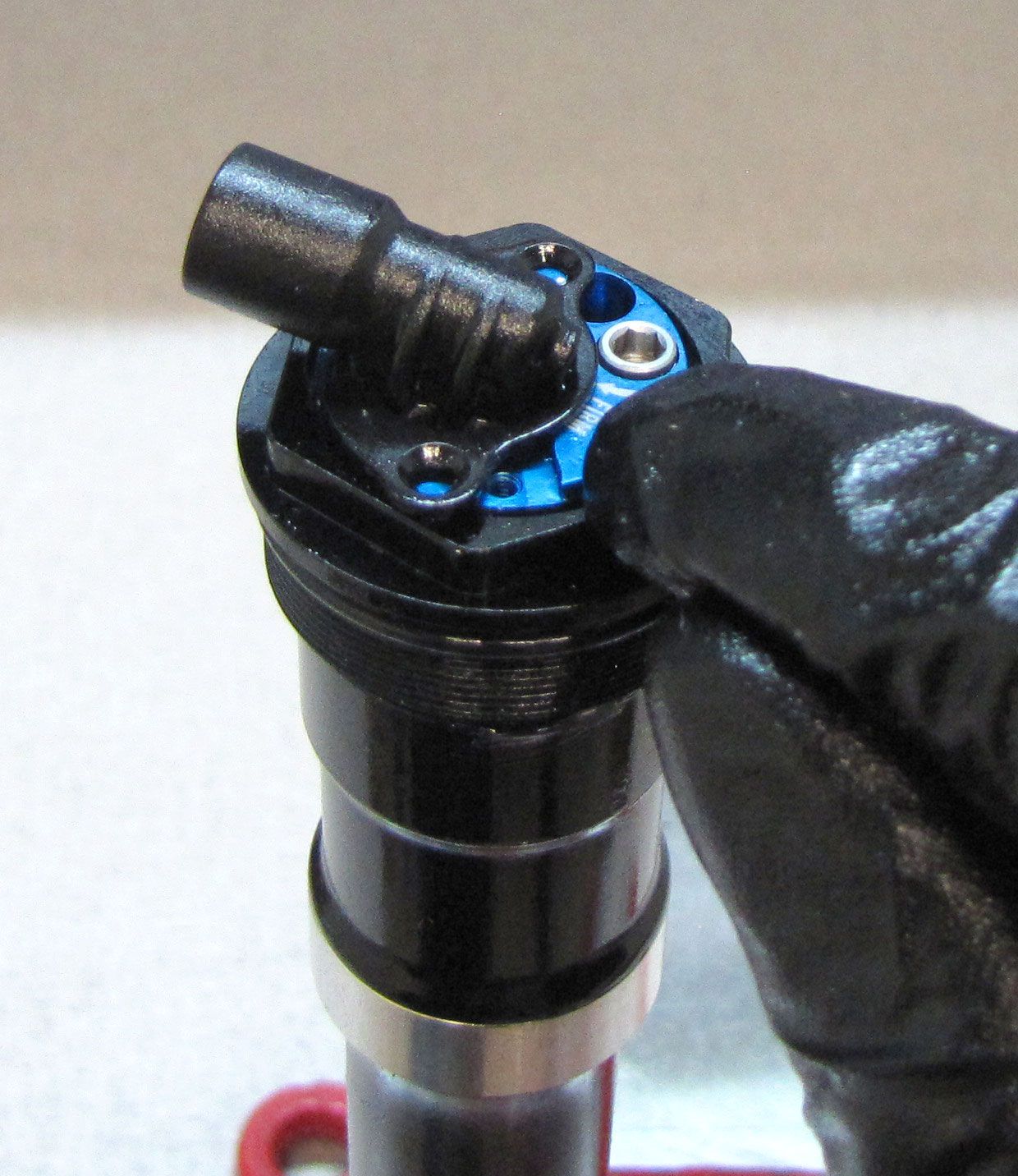
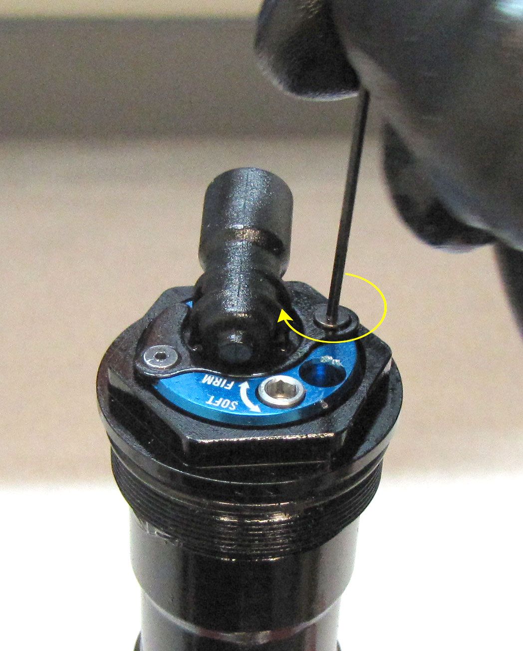
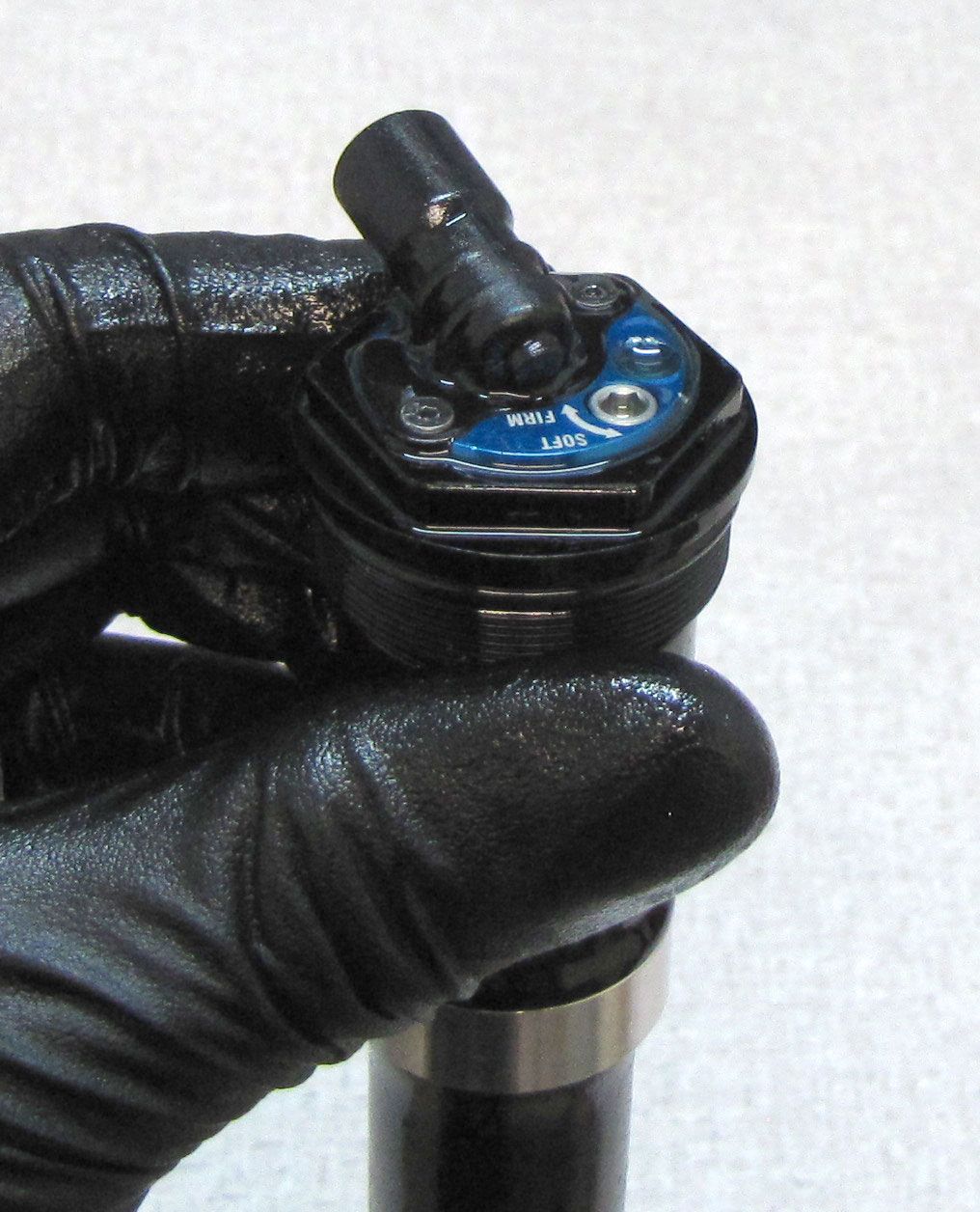
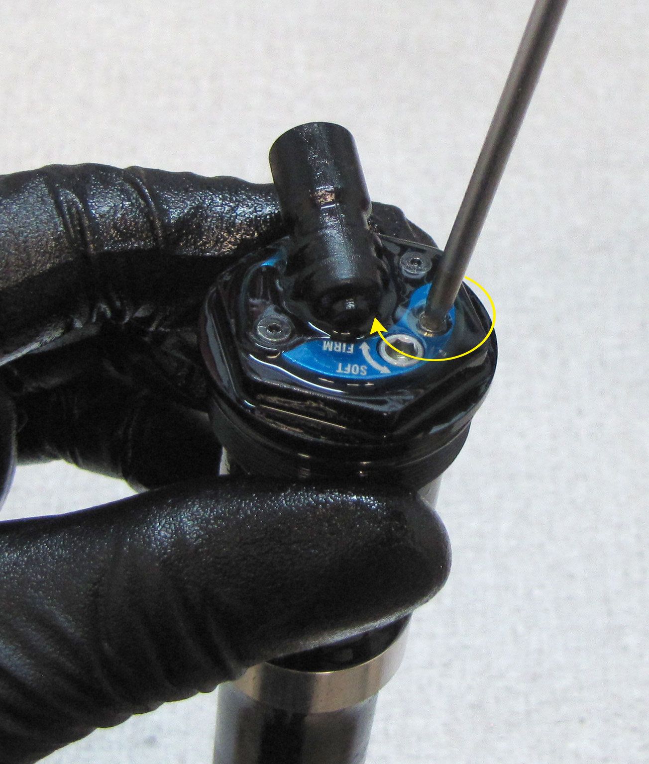
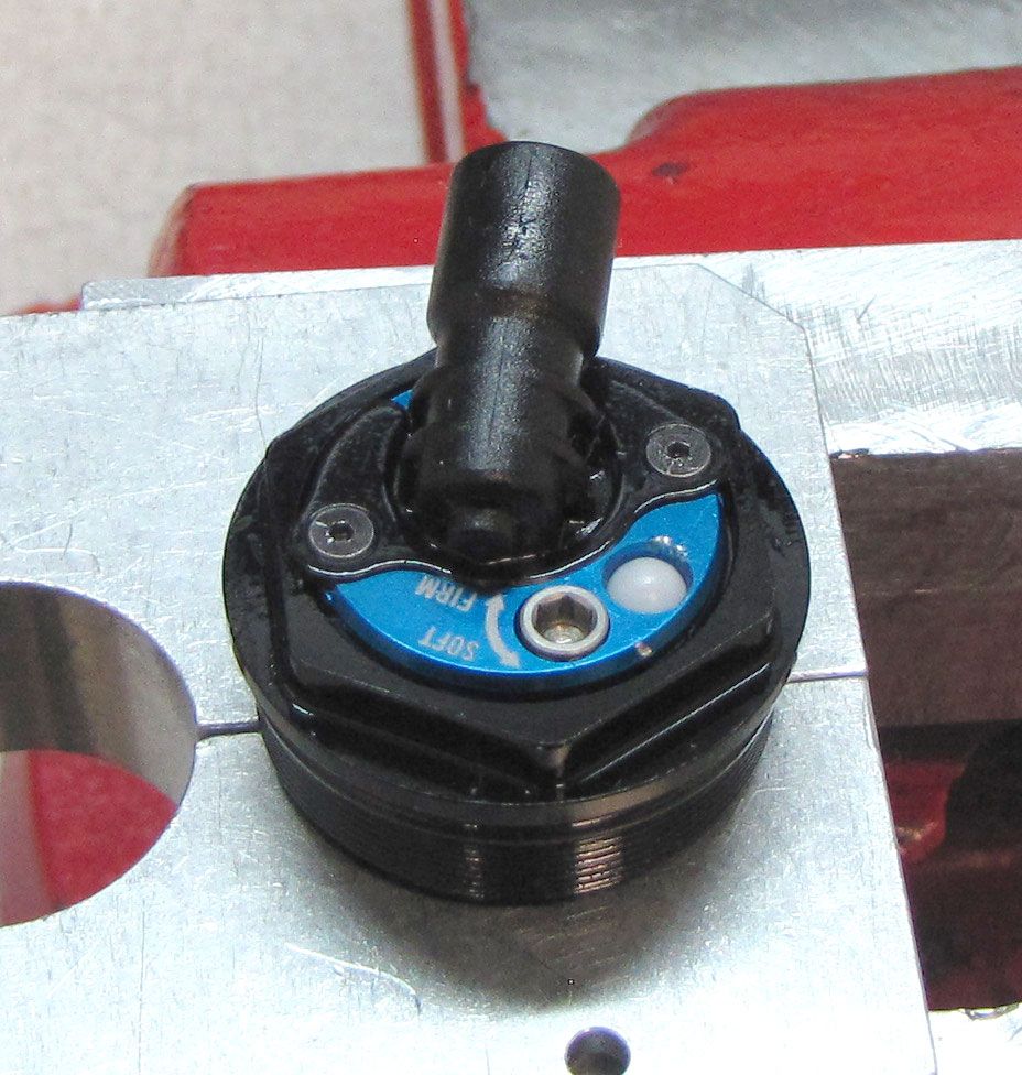
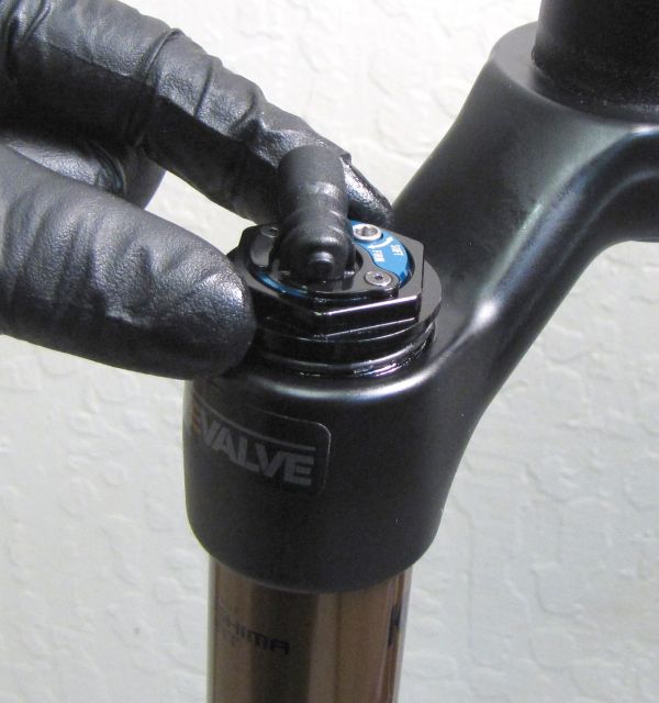
Unthread the two screws holding the Solenoid End Cap Retainer Plate by turning them counter-clockwise with a 0.050in hex wrench. Remove the Solenoid End Cap Retainer Plate.


Step 6
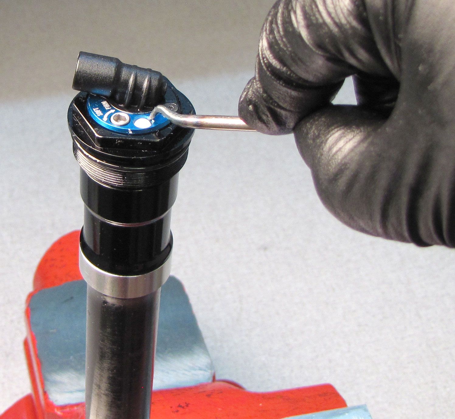
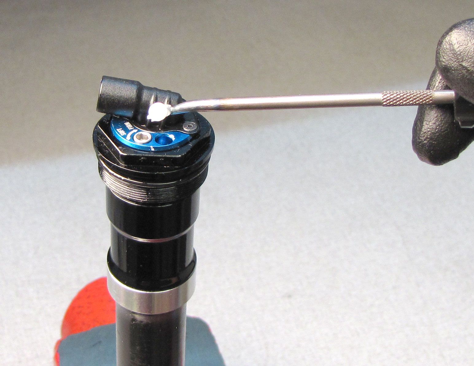
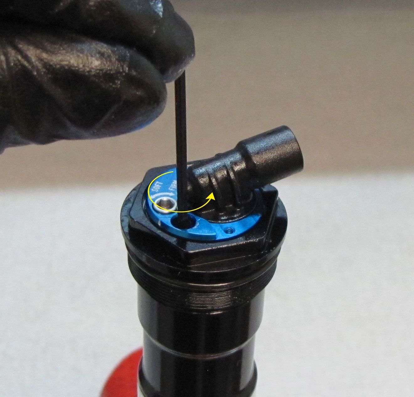
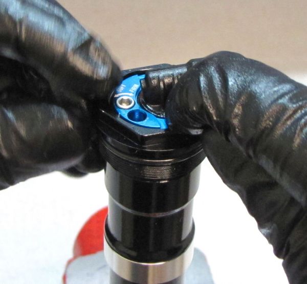
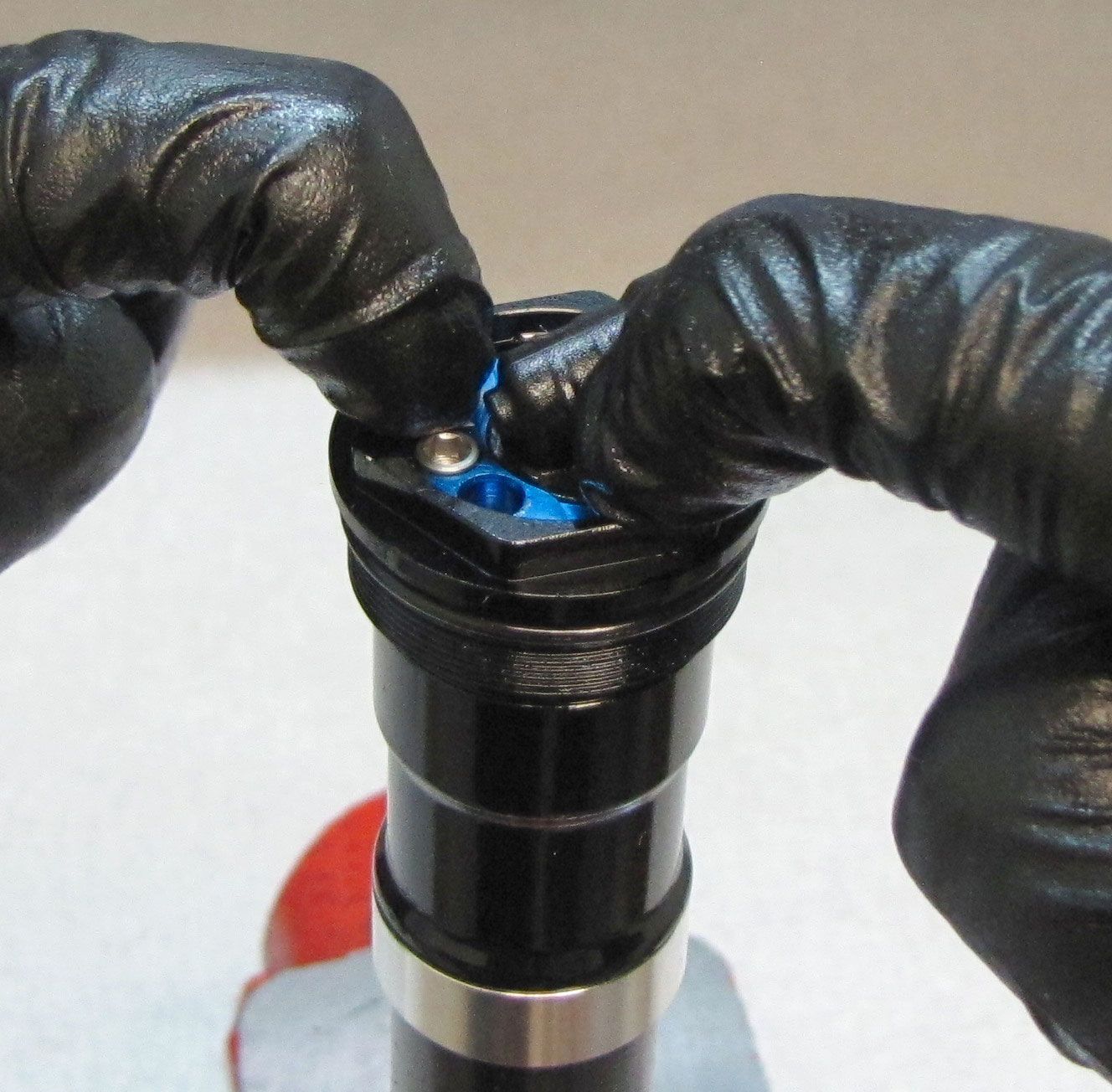
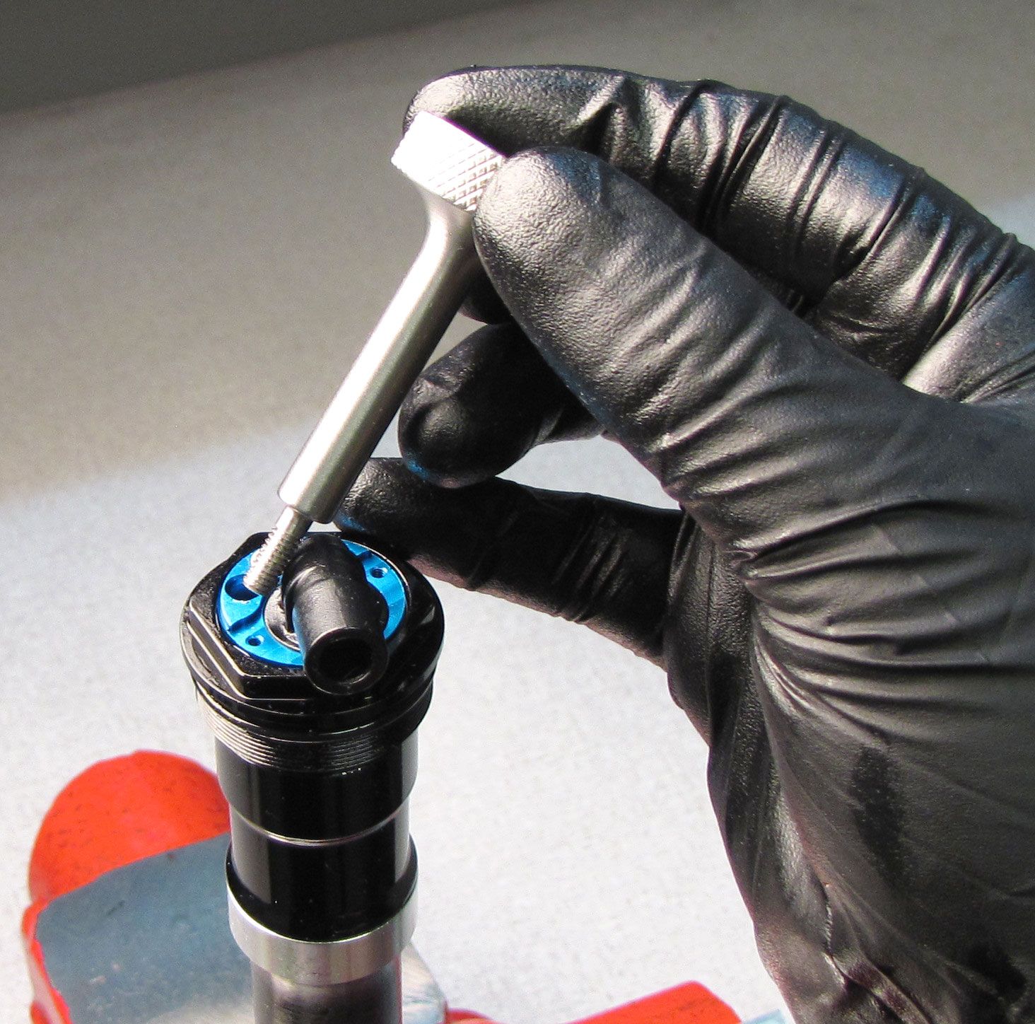
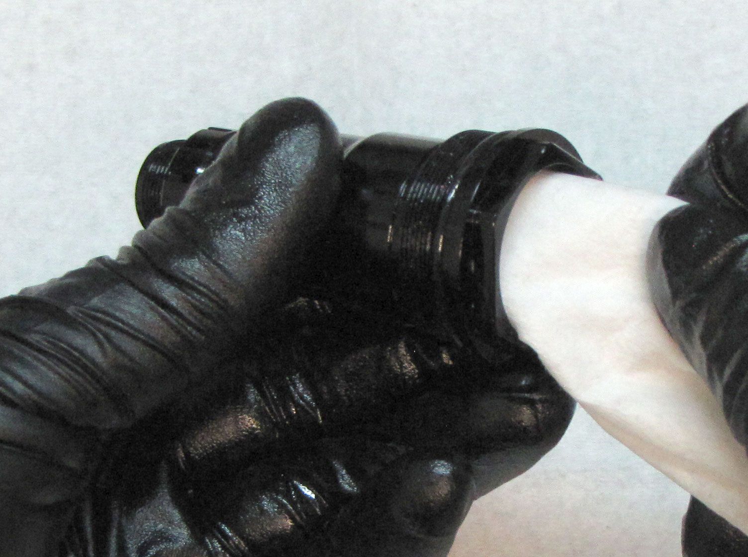
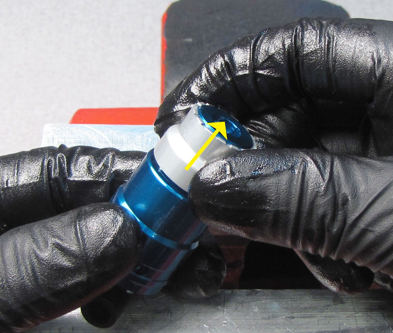
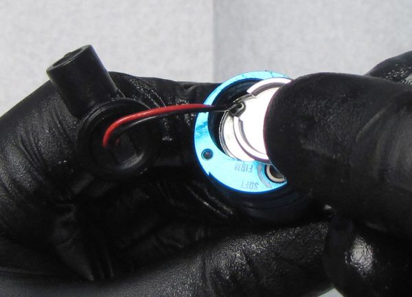
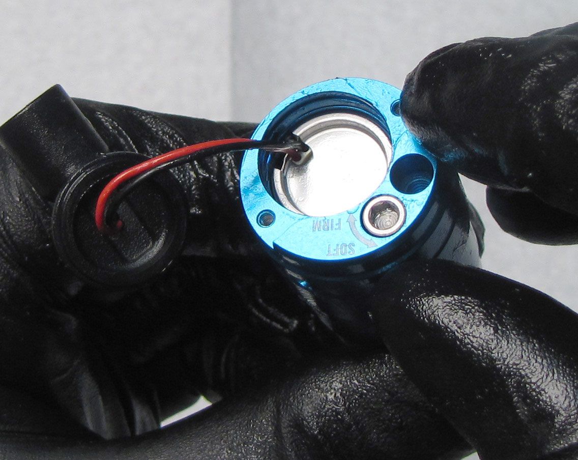
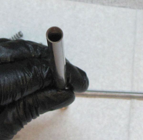
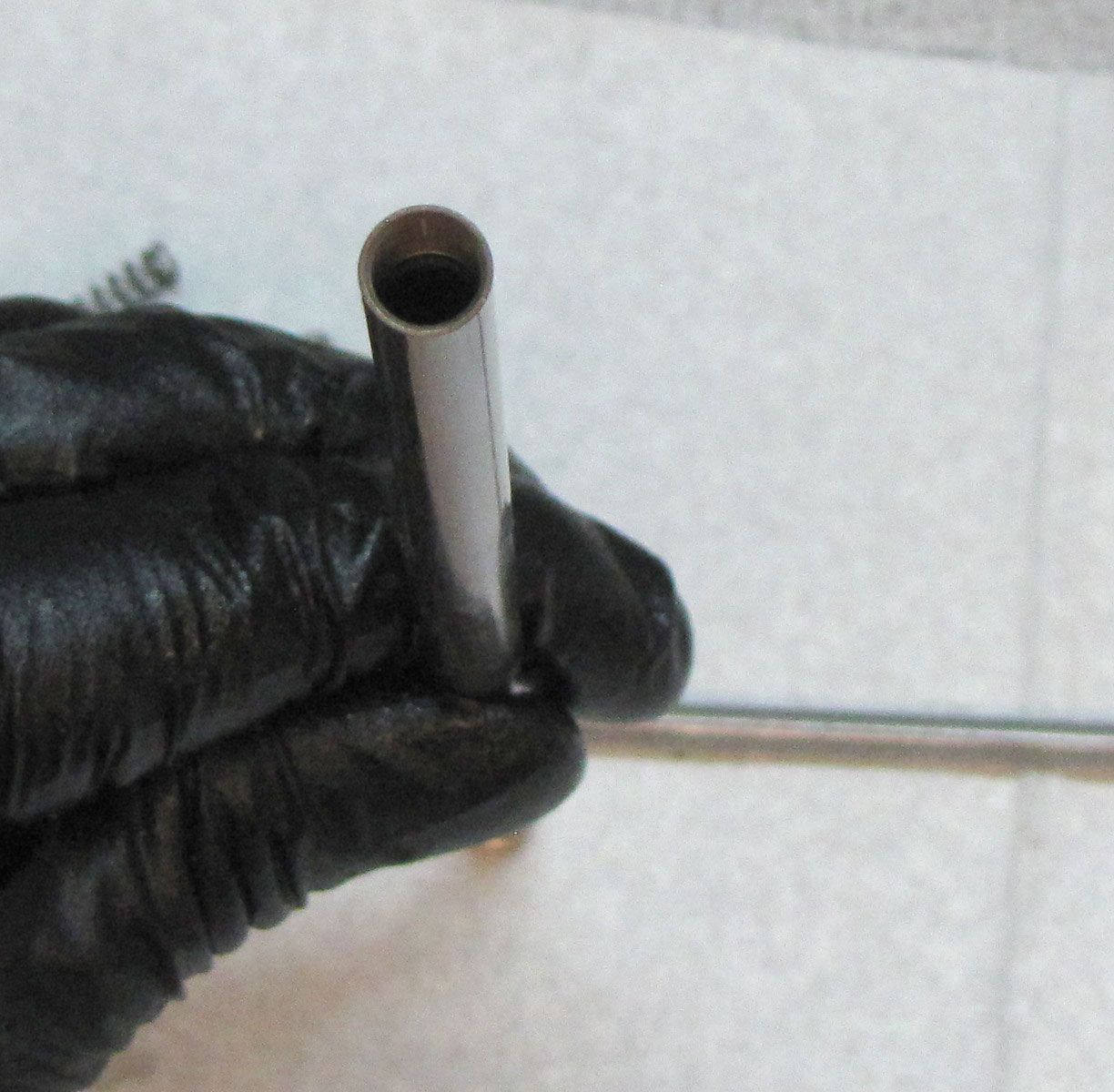
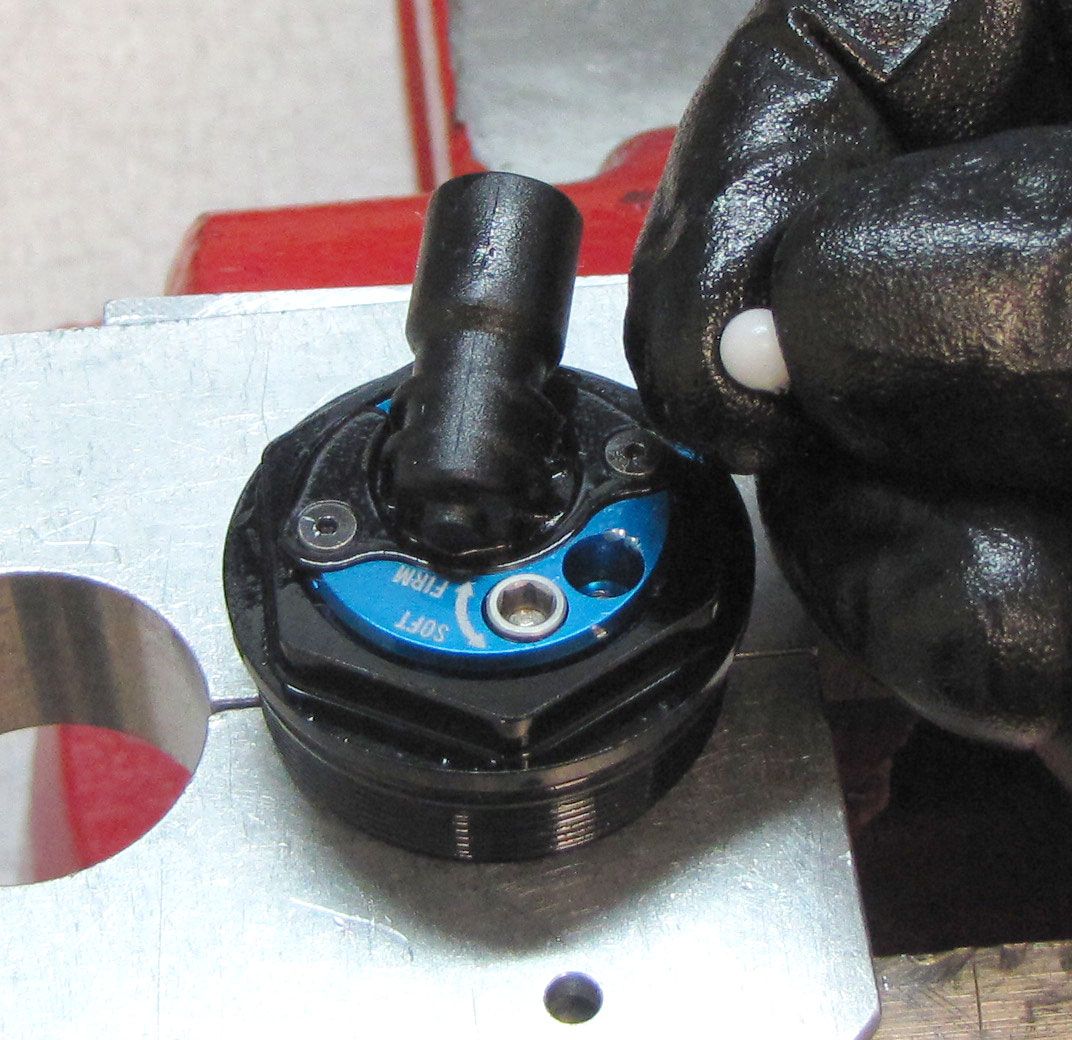
Remove the white Delrin ball from the Compression Cartridge Housing bleed port. It can be helpful to heat your metal pick before removing the Delrin ball. Unthread and remove the bleed screw counter-clockwise with a 5/64" hex wrench. Remove the 0.125" ball bearing from the bleed port with a magnet or by inverting the cartridge over your work bench.
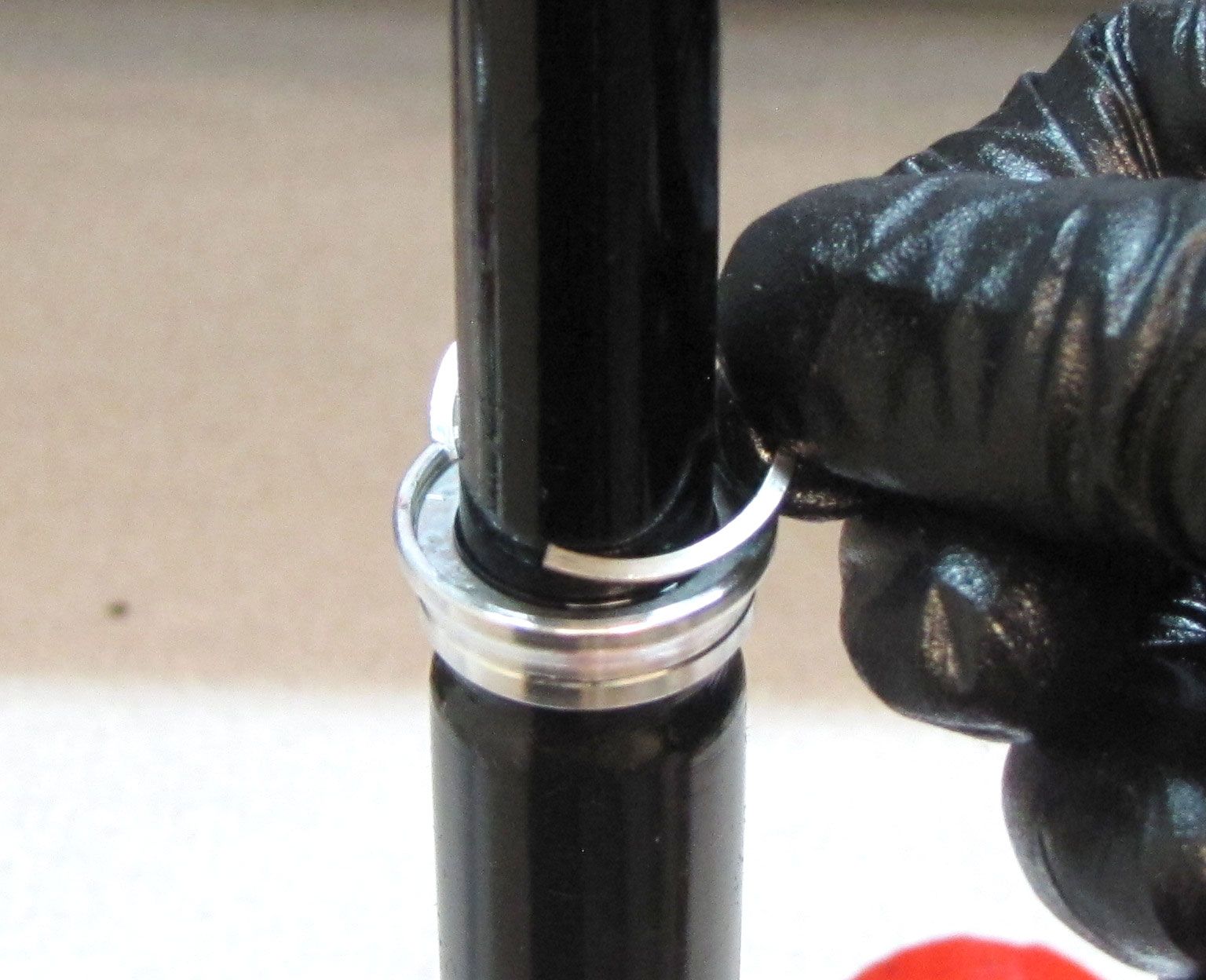
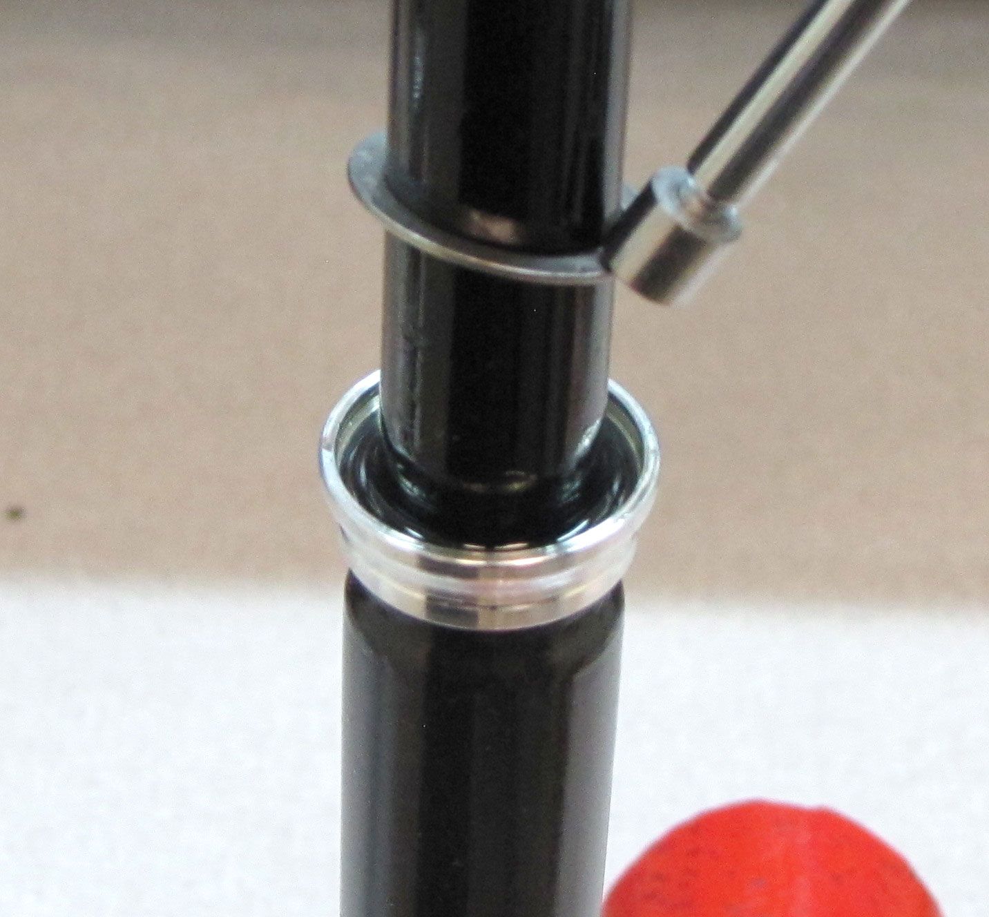
Step 7
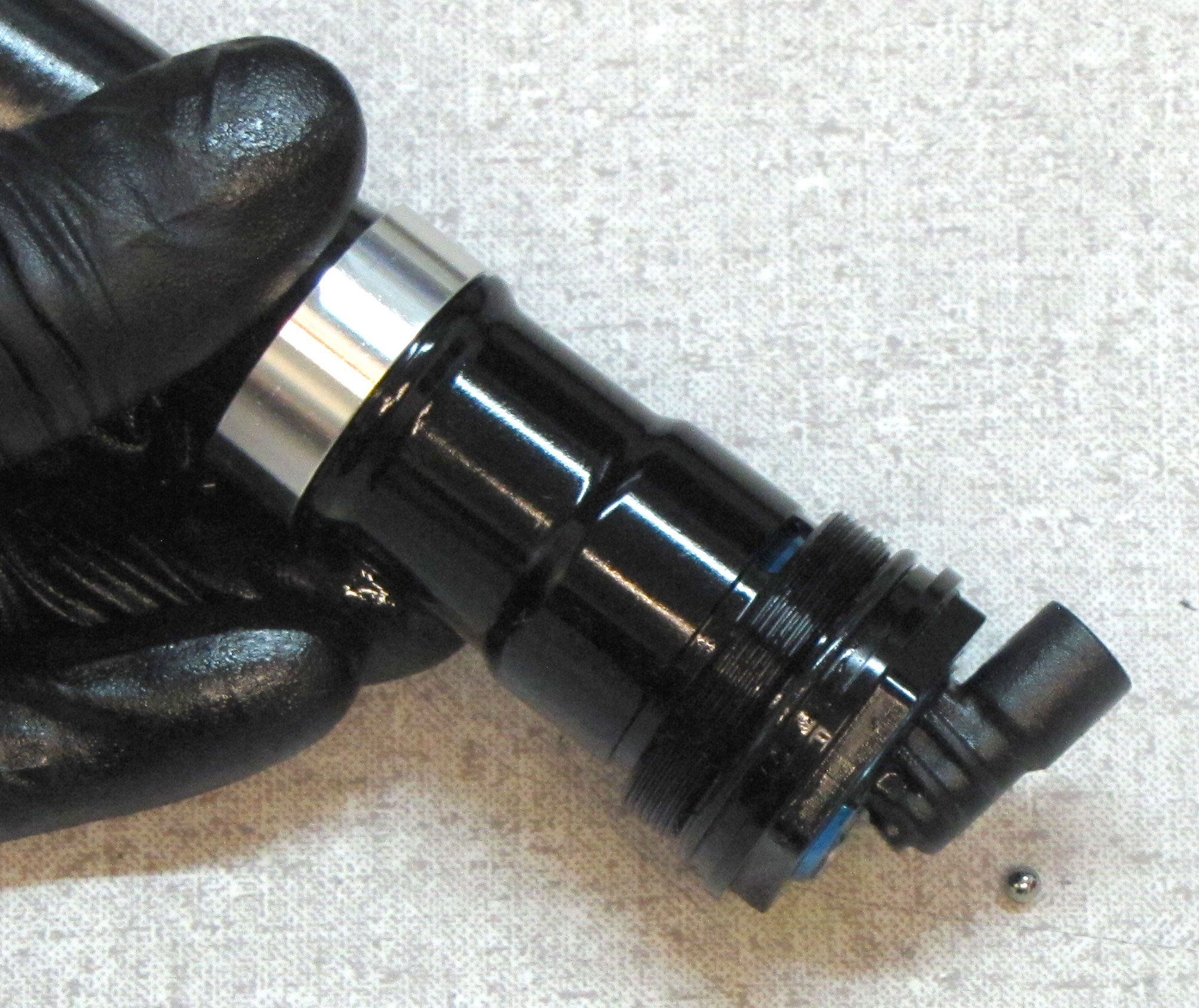
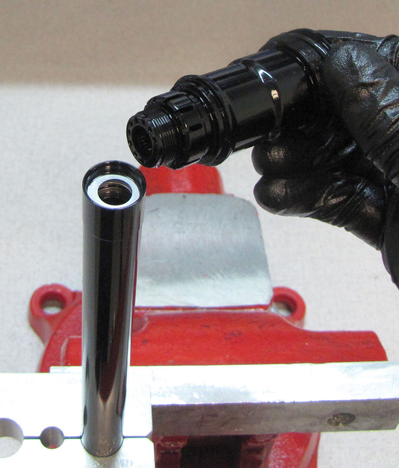
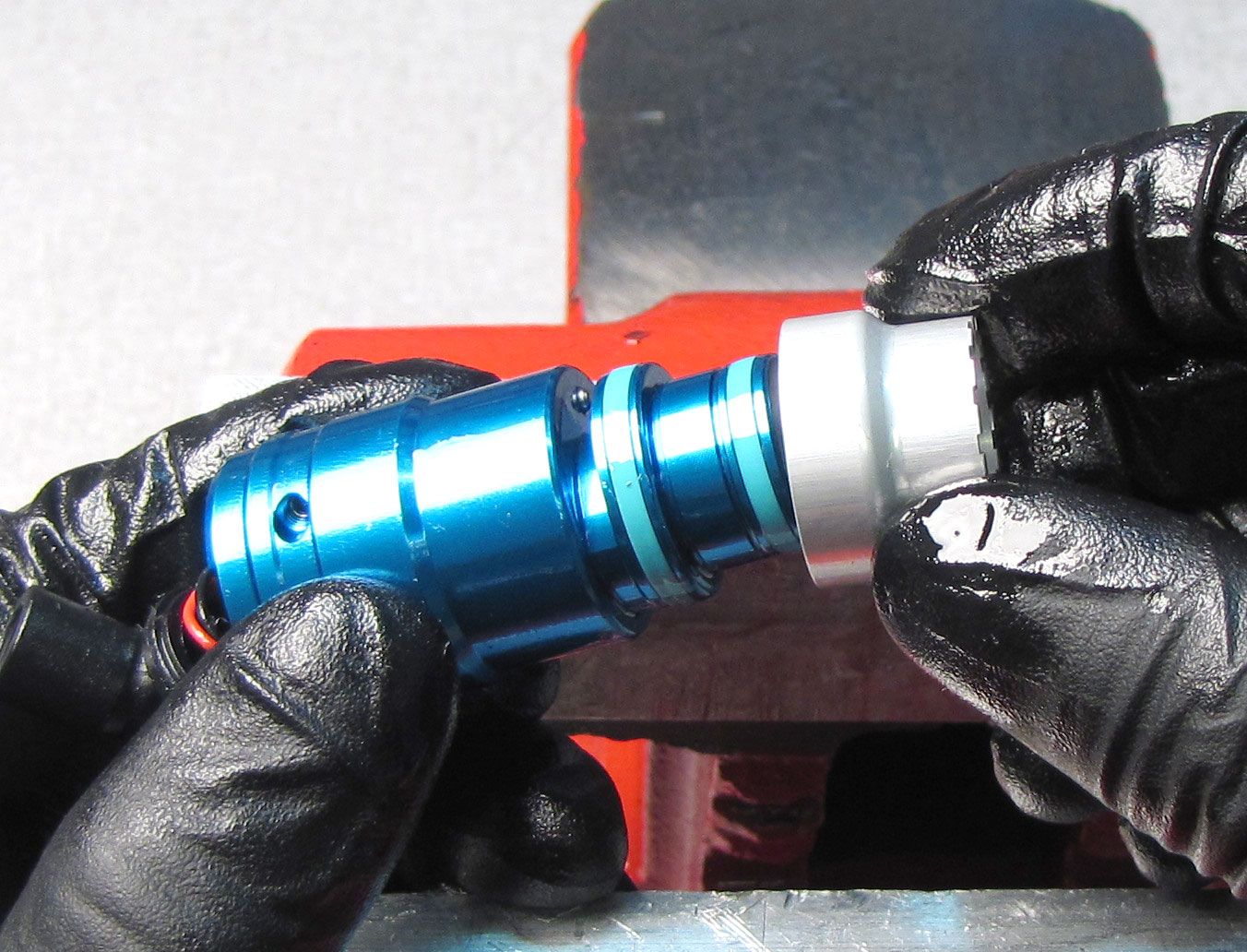
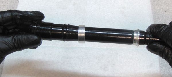
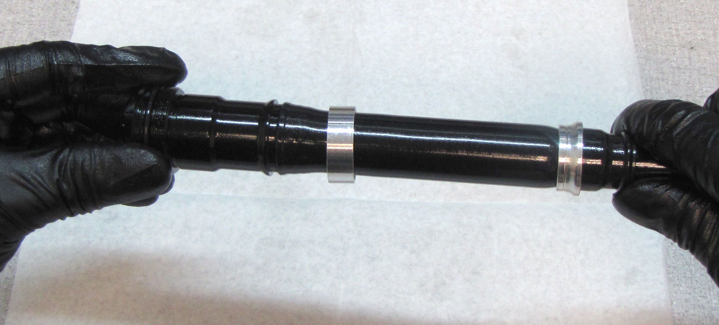
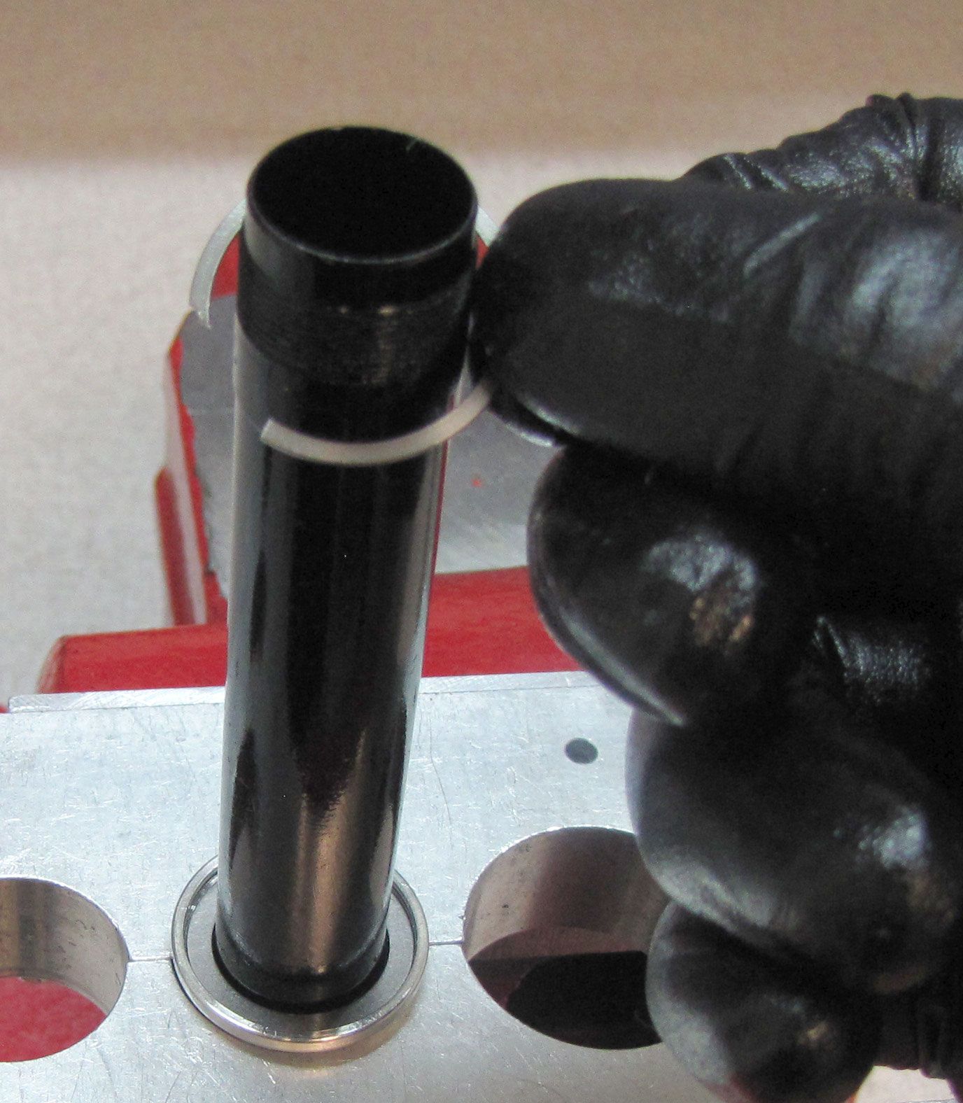
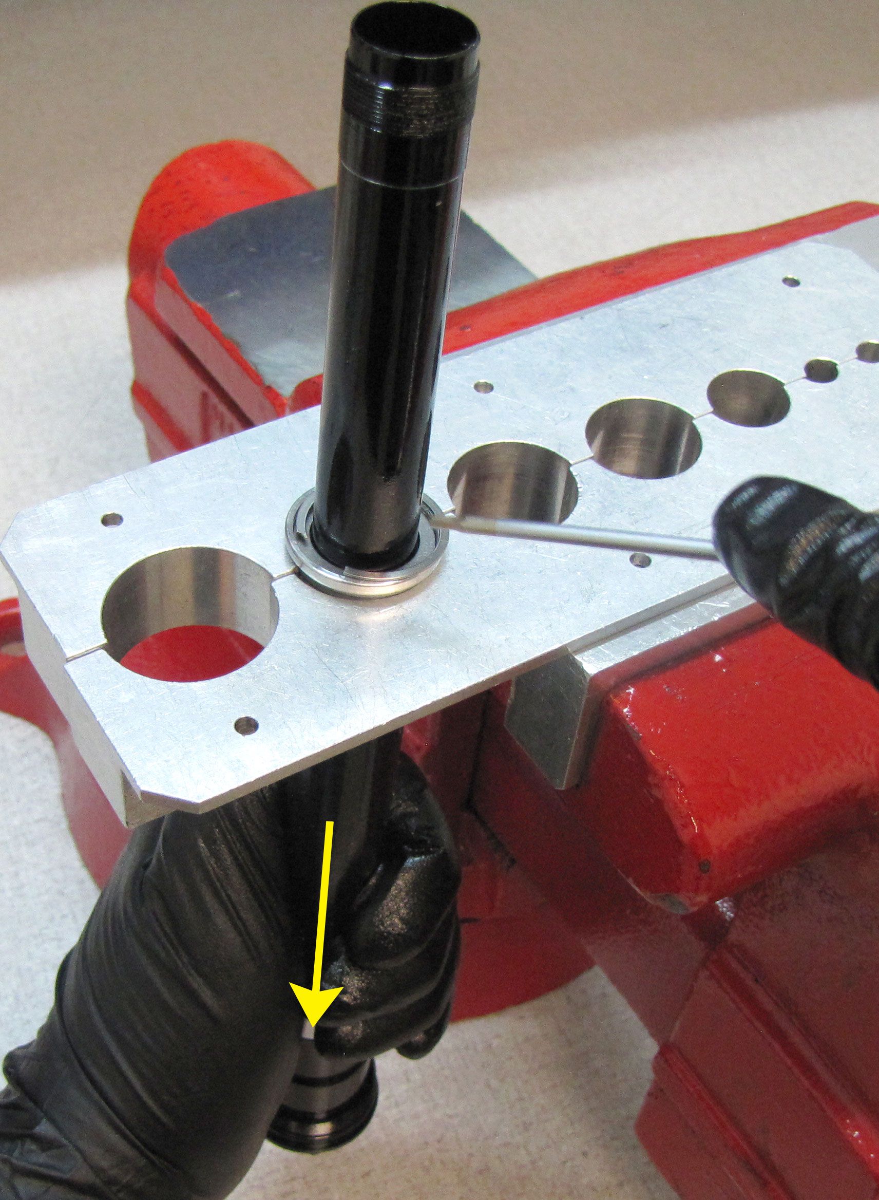
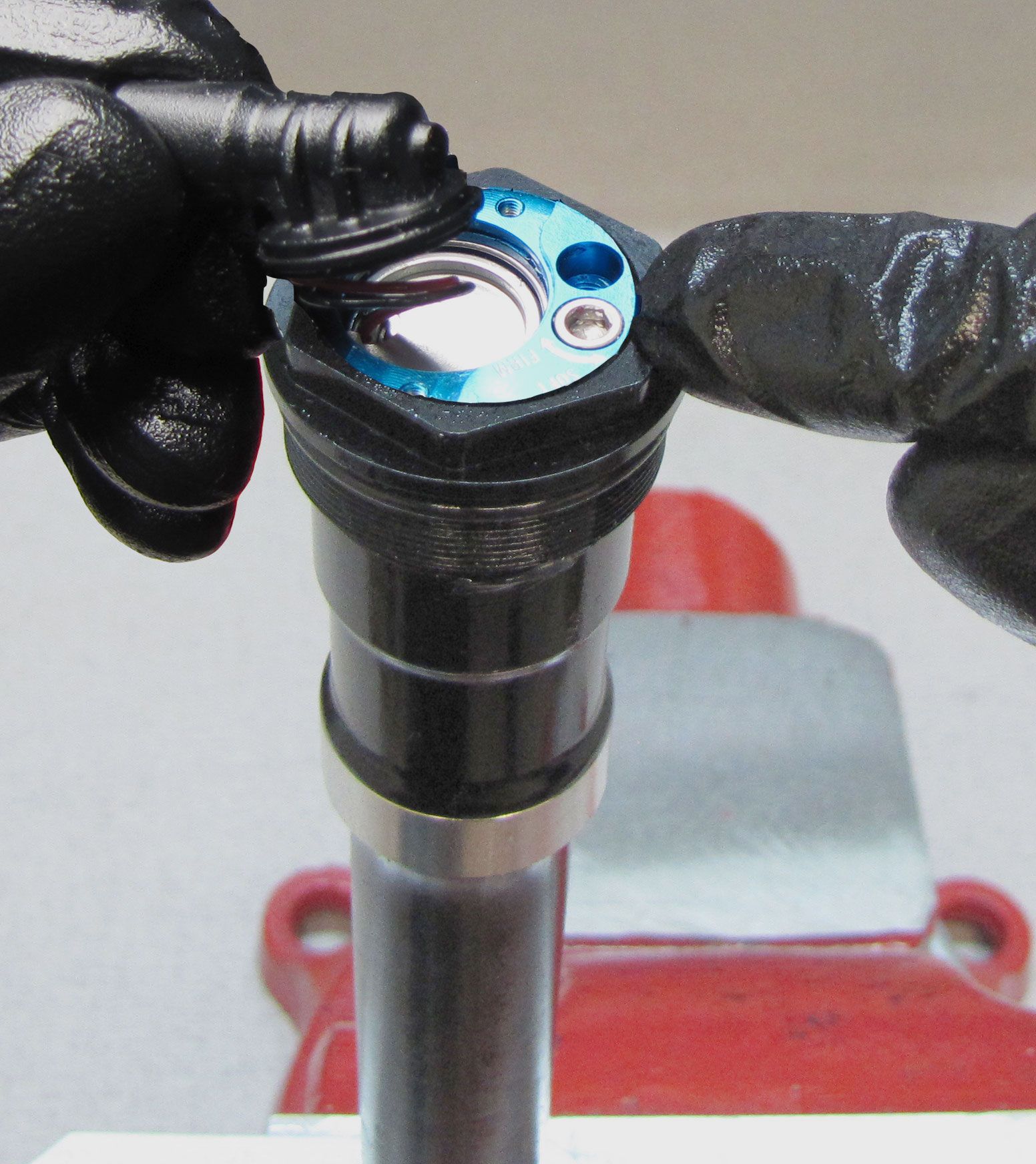
Clean any oil residue from the Compression Cartridge Housing then press the Compression Cartridge Housing into the reservoir to expose the wire retaining ring.

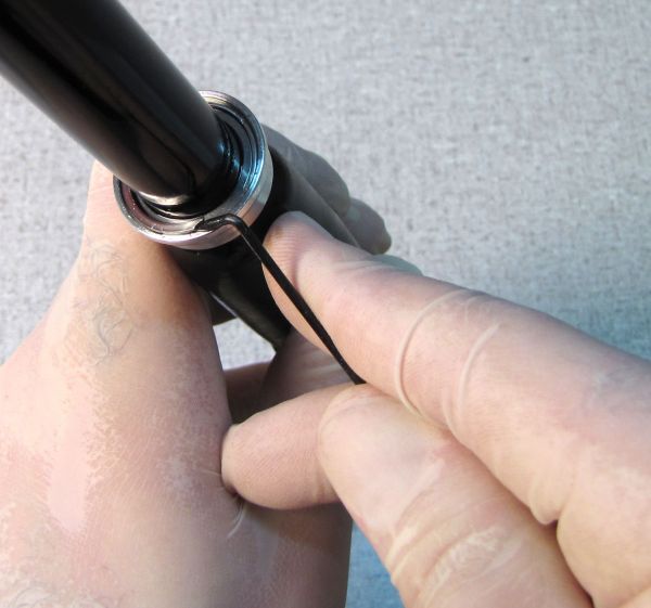
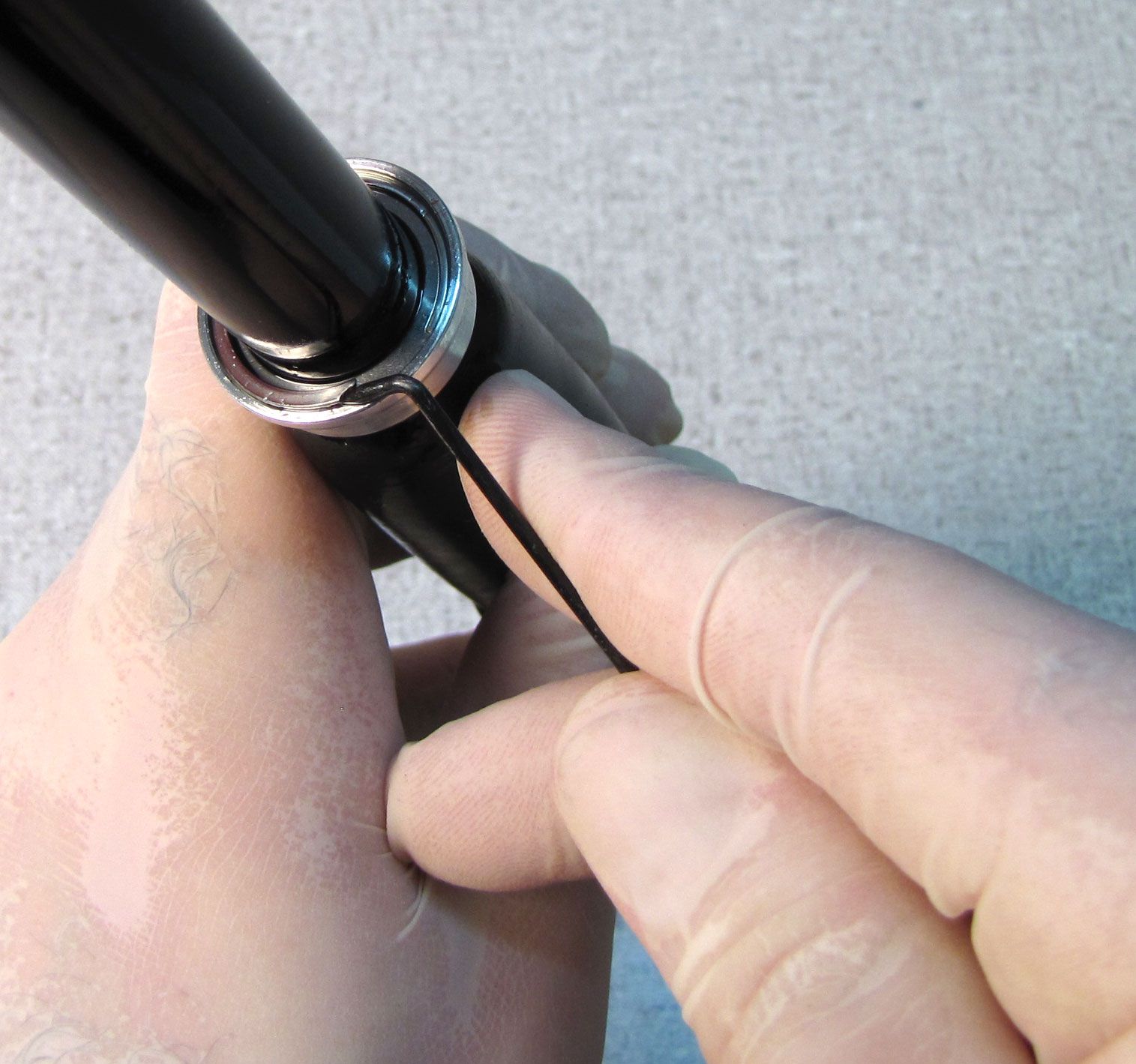
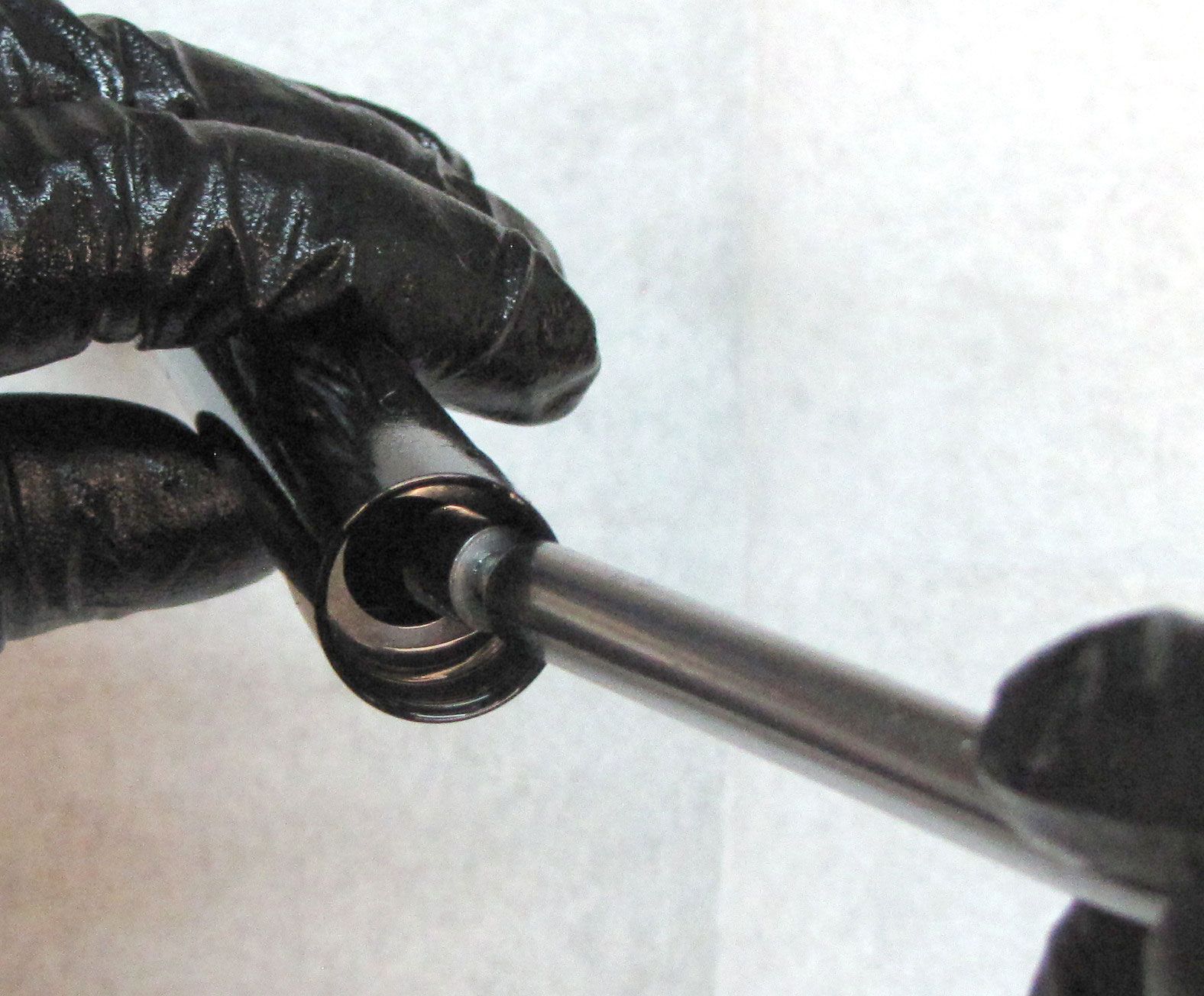
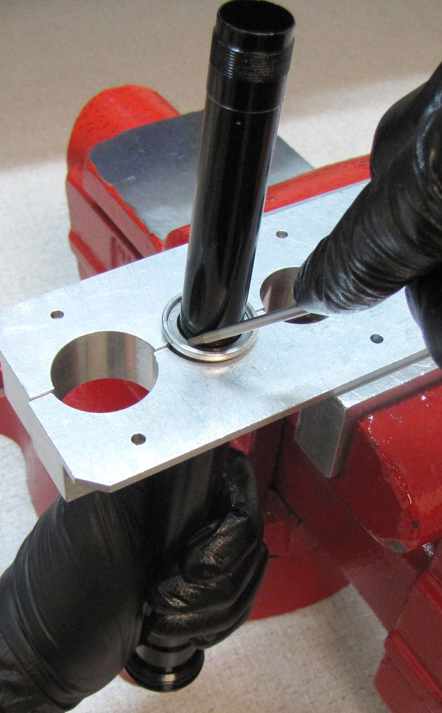
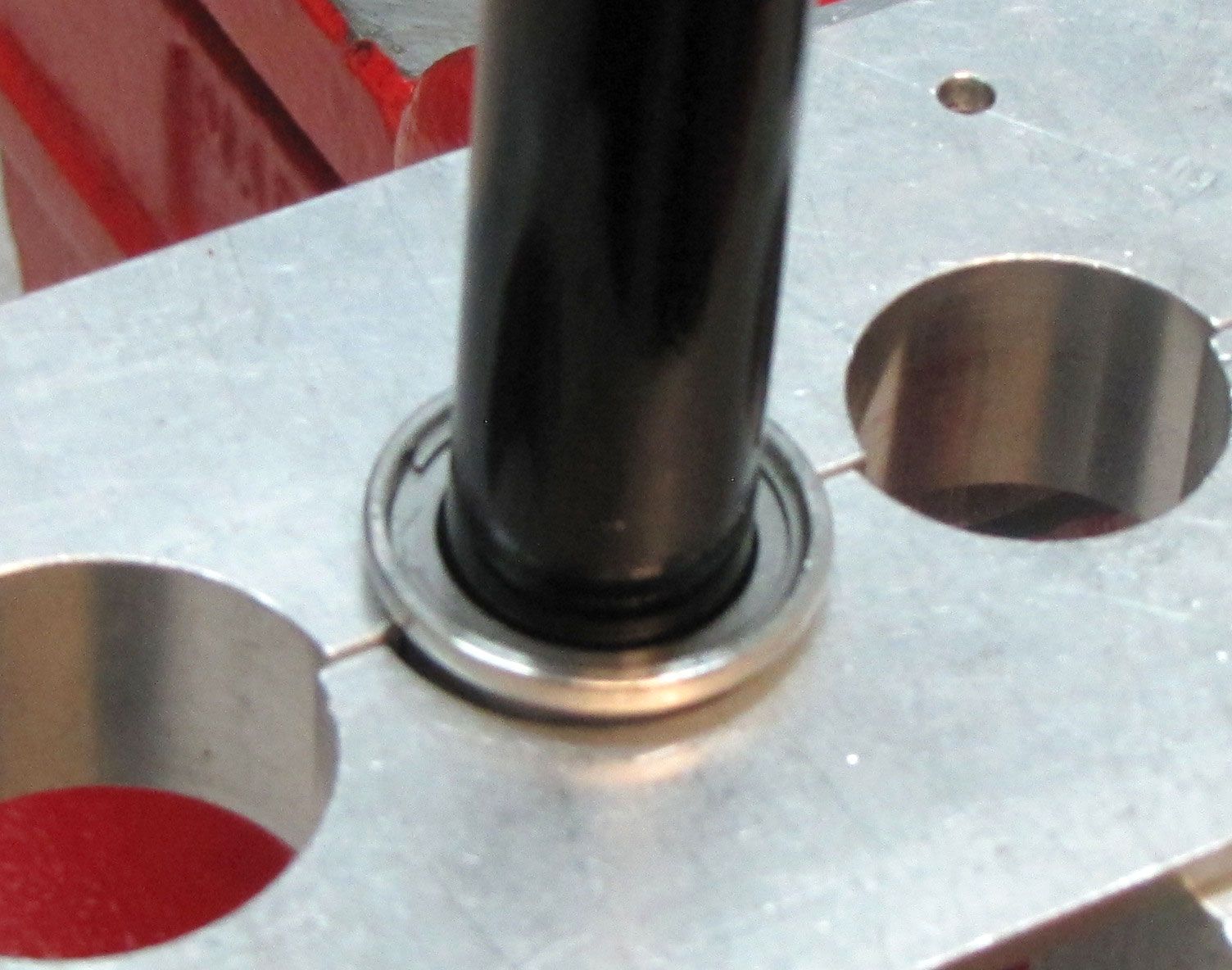
Step 8
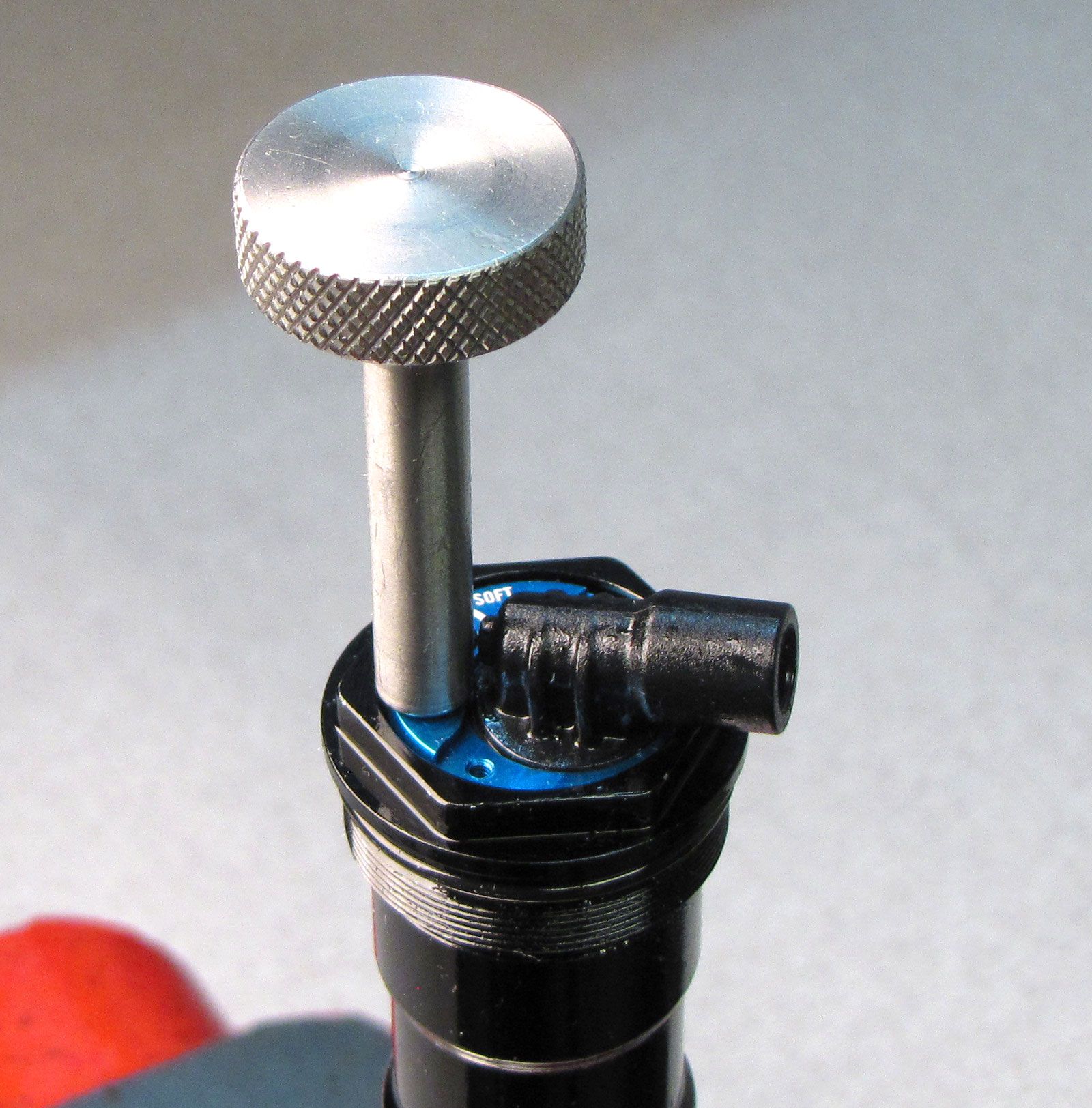
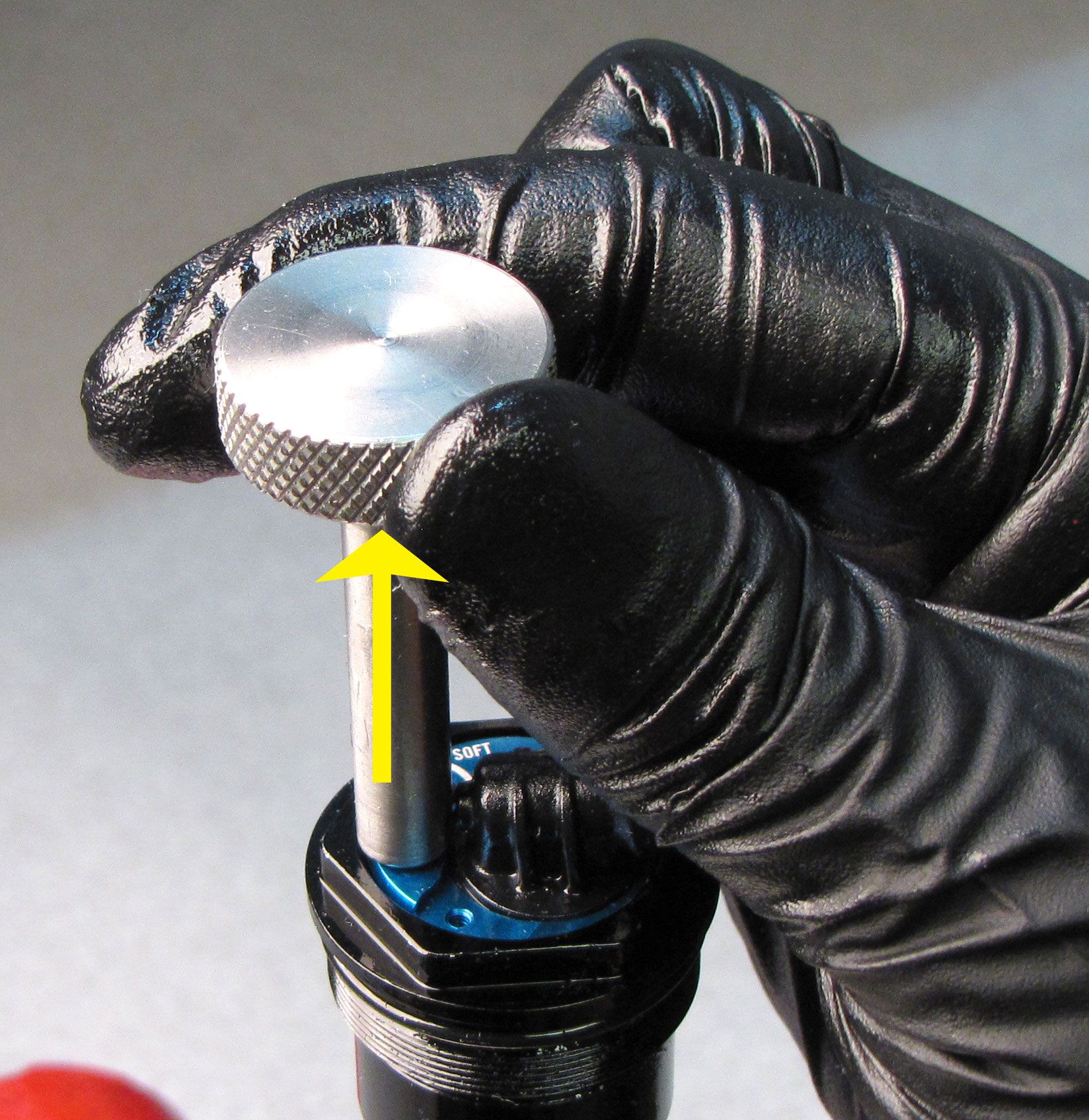
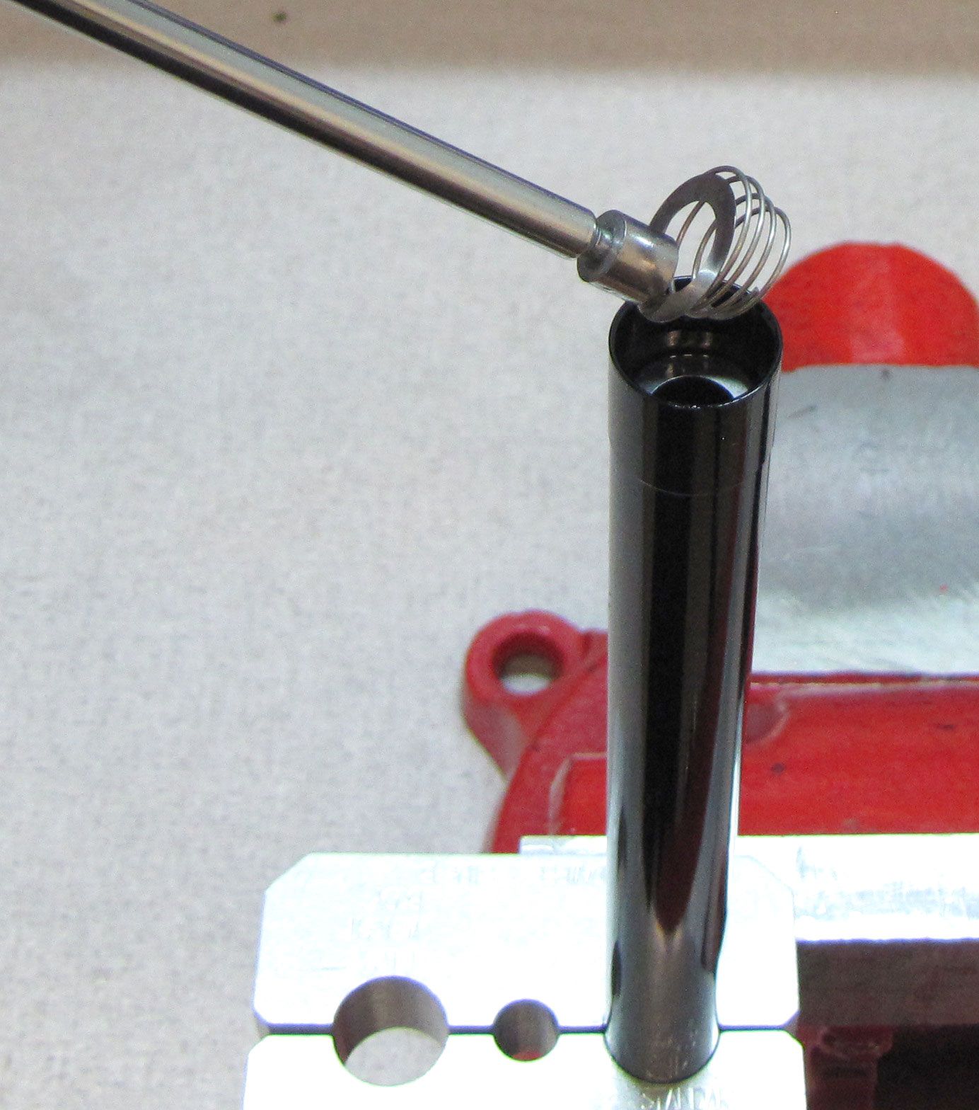
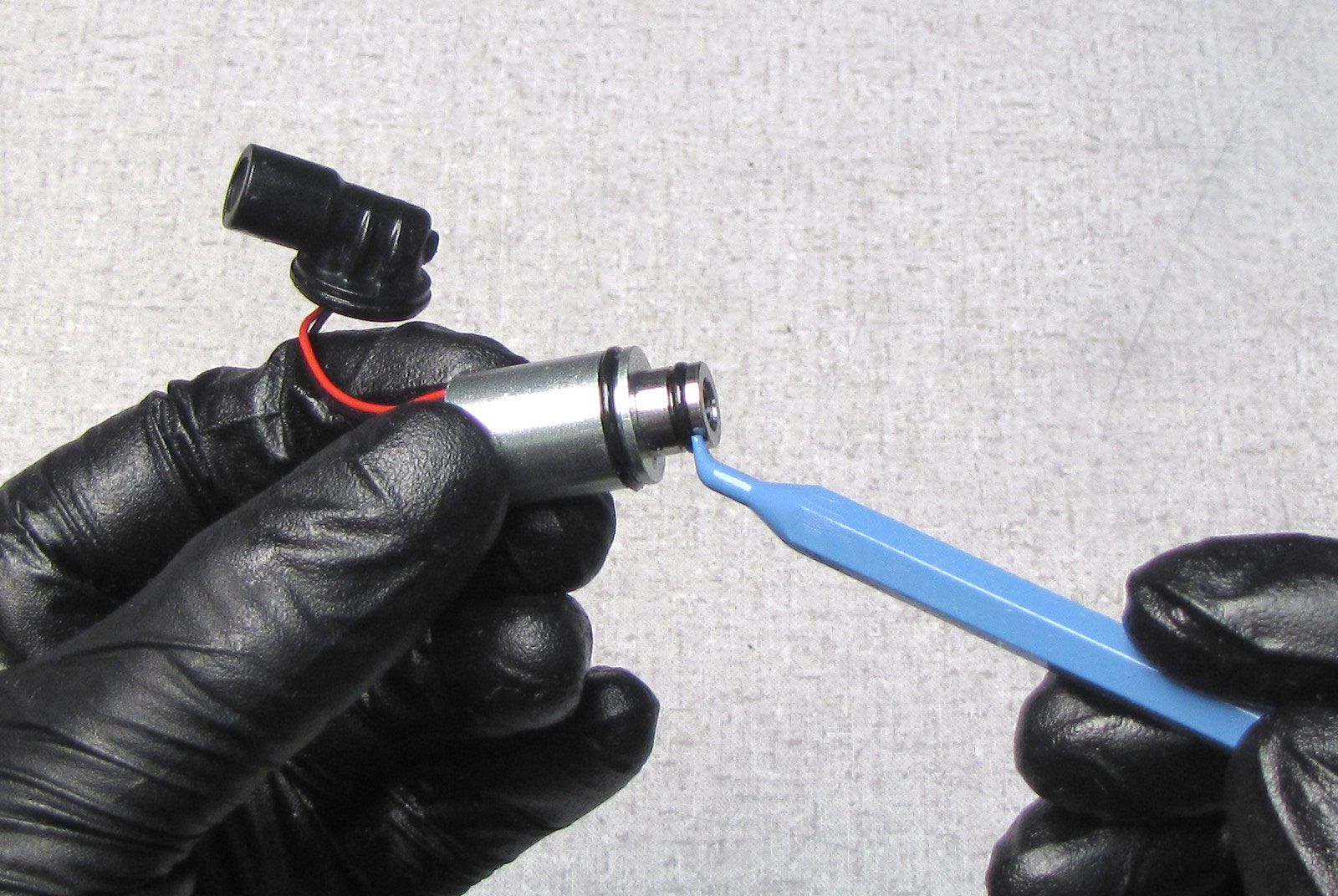
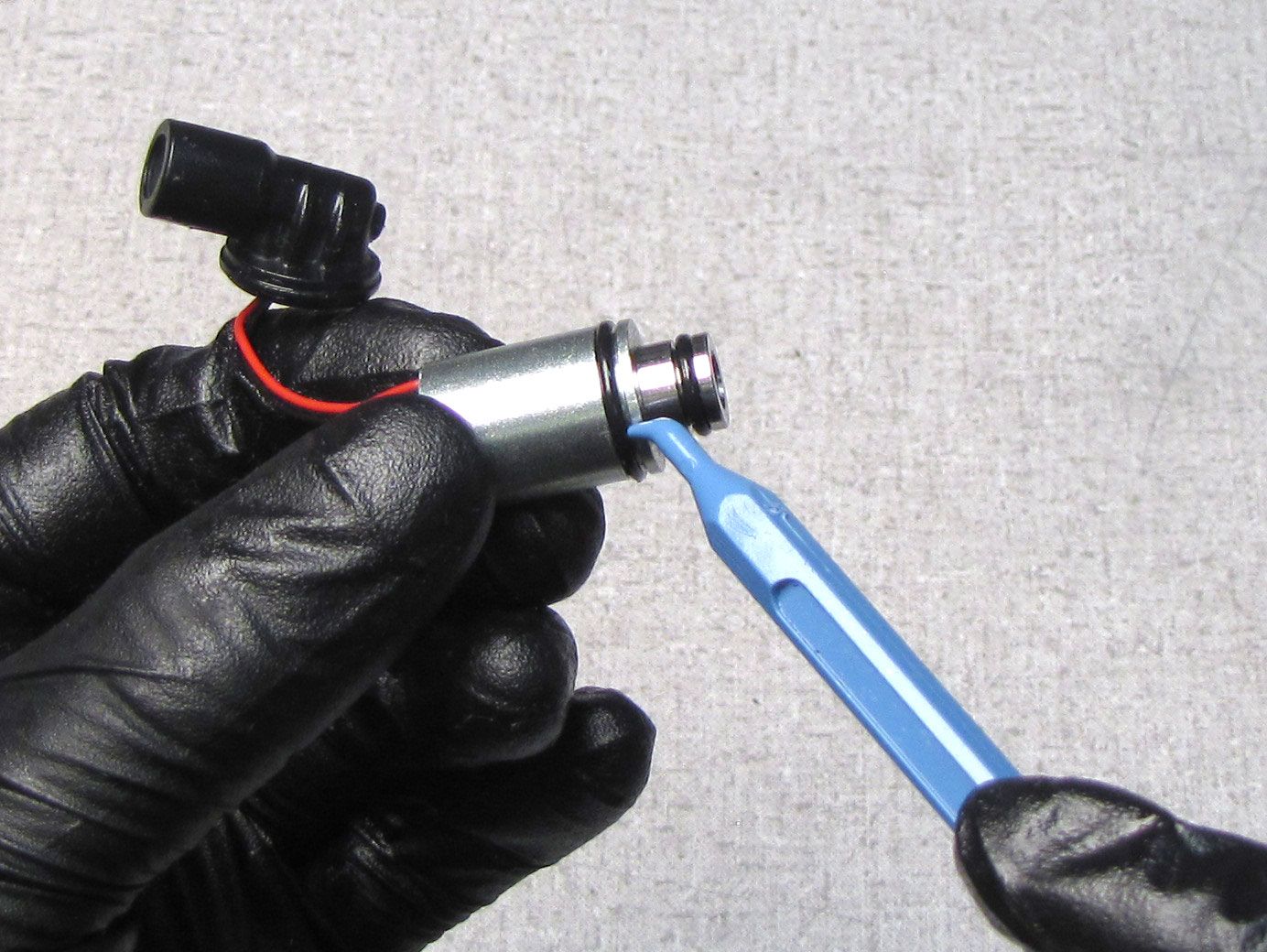
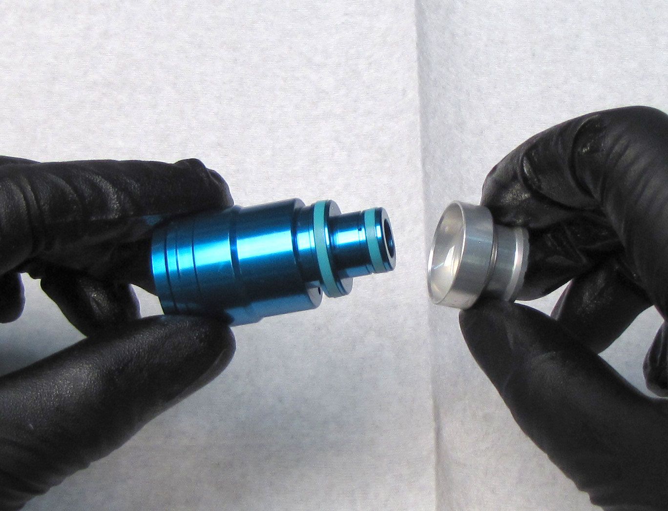
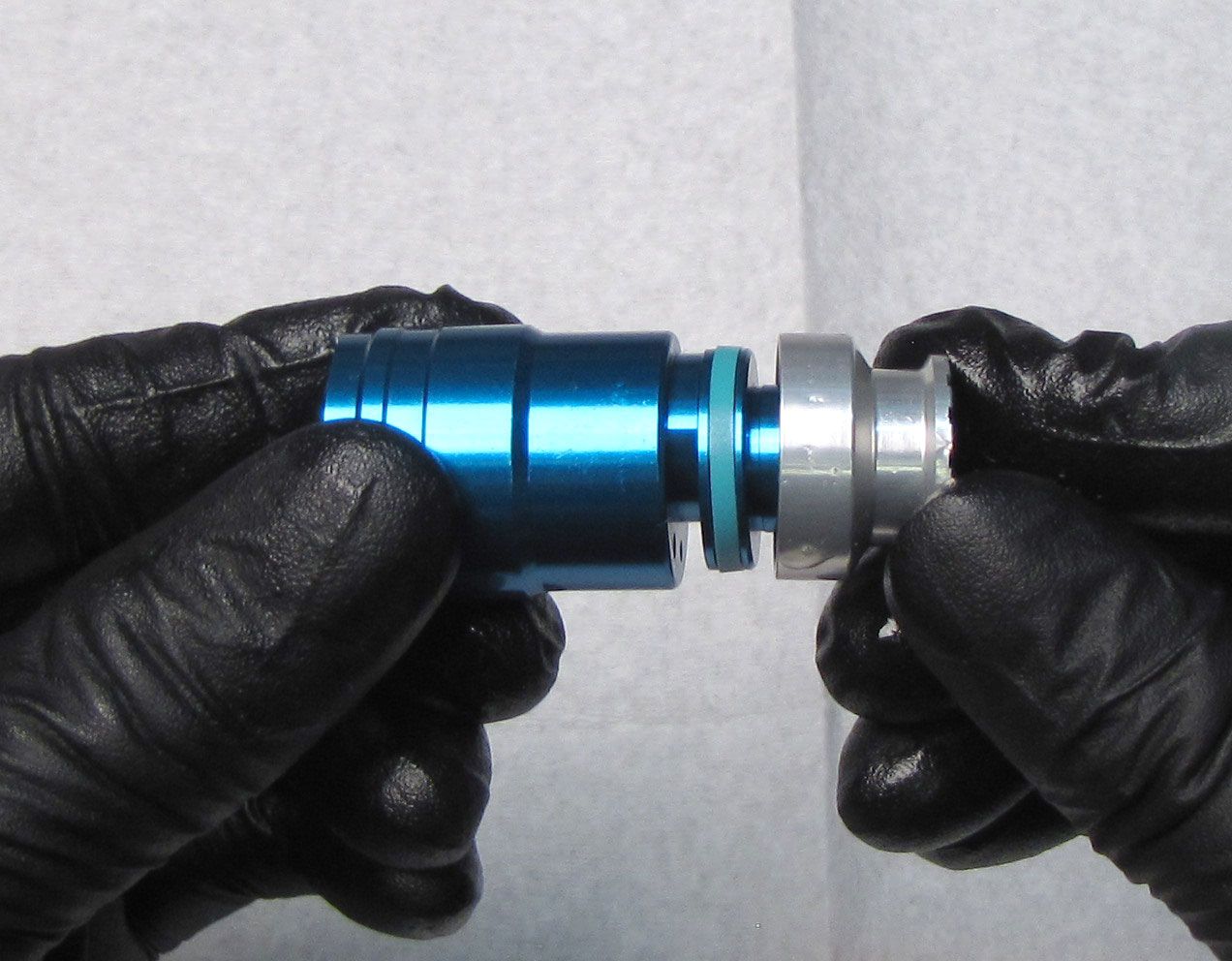
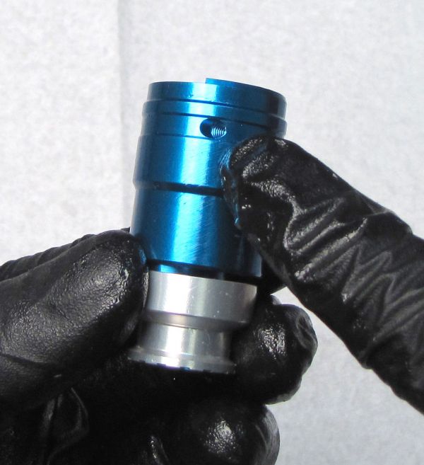
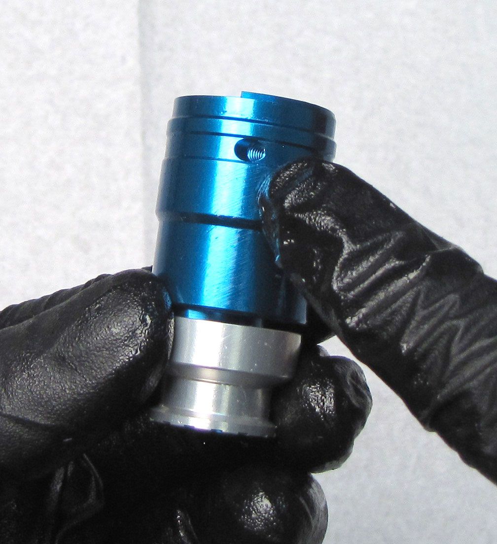
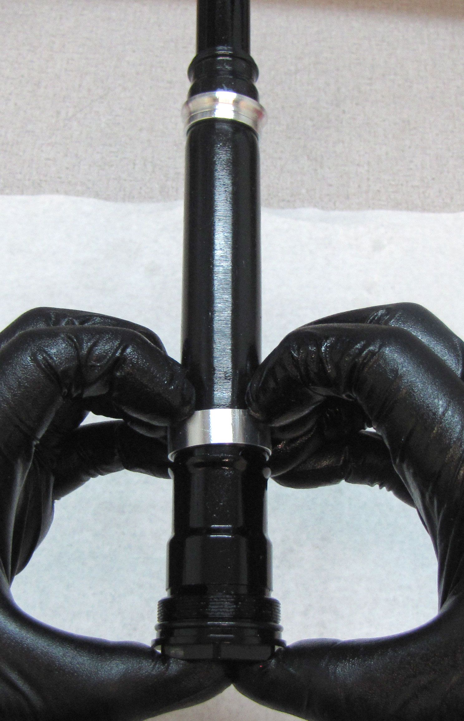
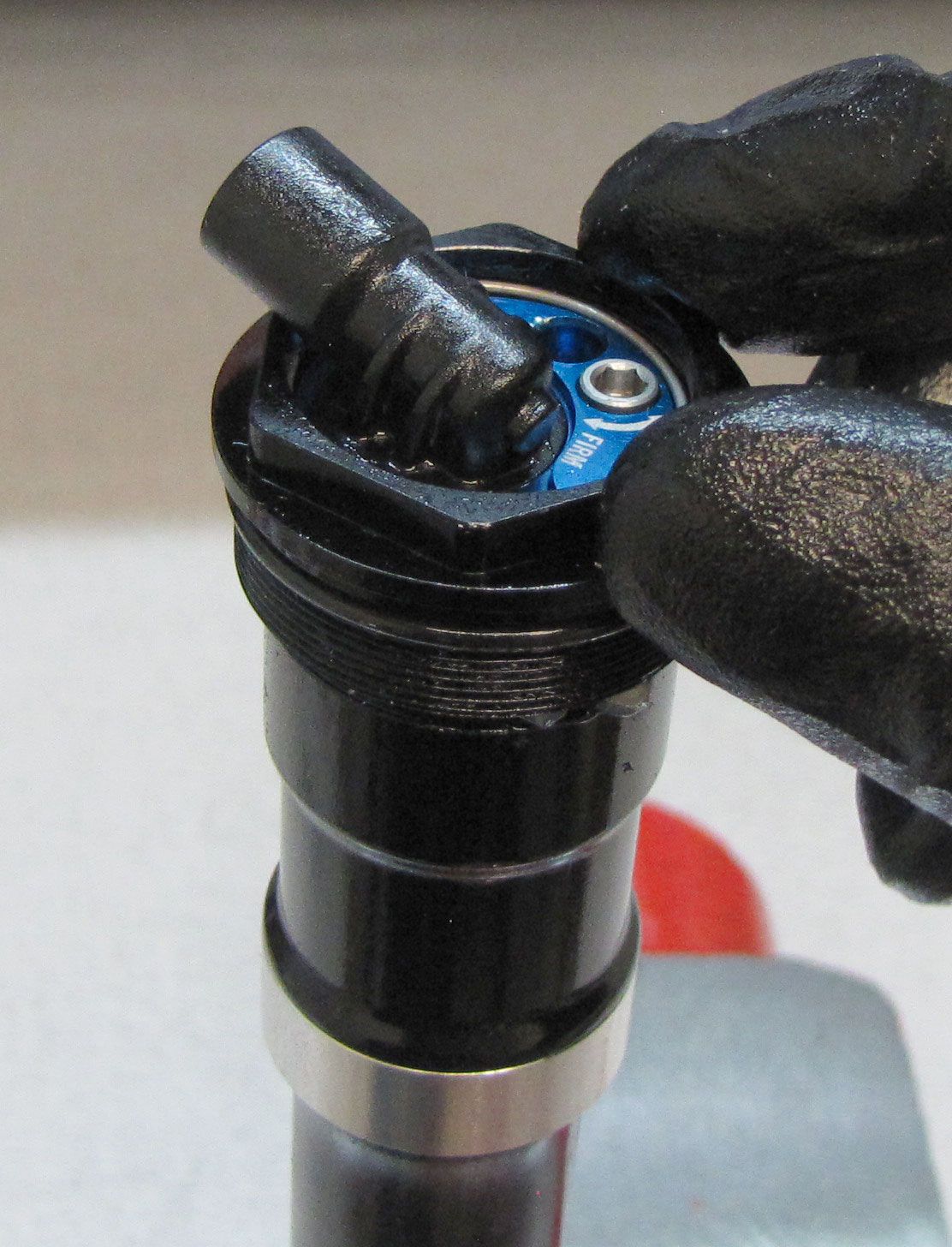
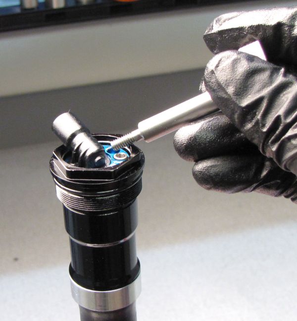
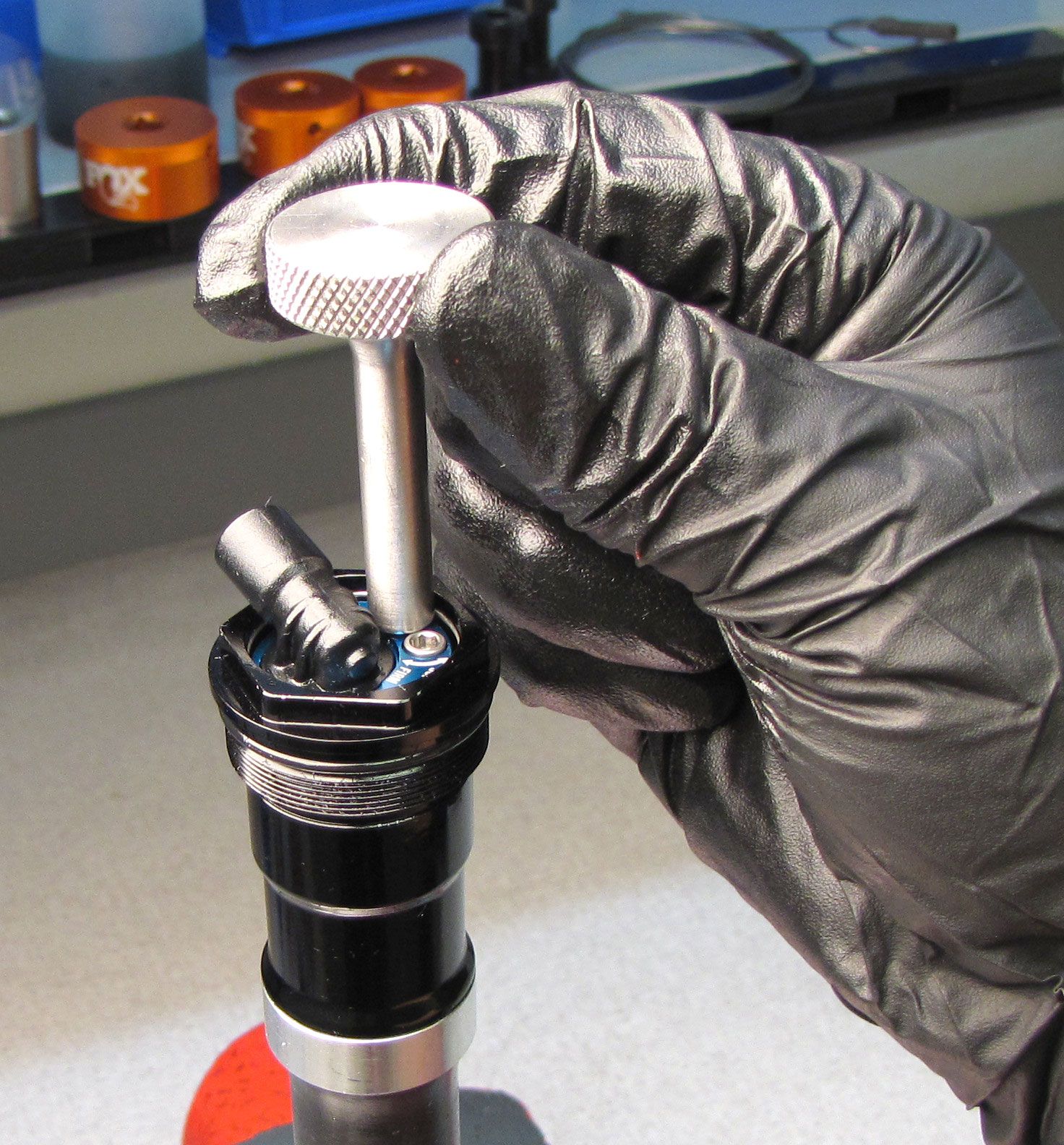
Remove the wire retaining ring using a thin damping shim then thread the LIVE Valve Solenoid Housing Puller (PN: 398-00-806) into the bleed port clockwise until hand tight.

Step 9
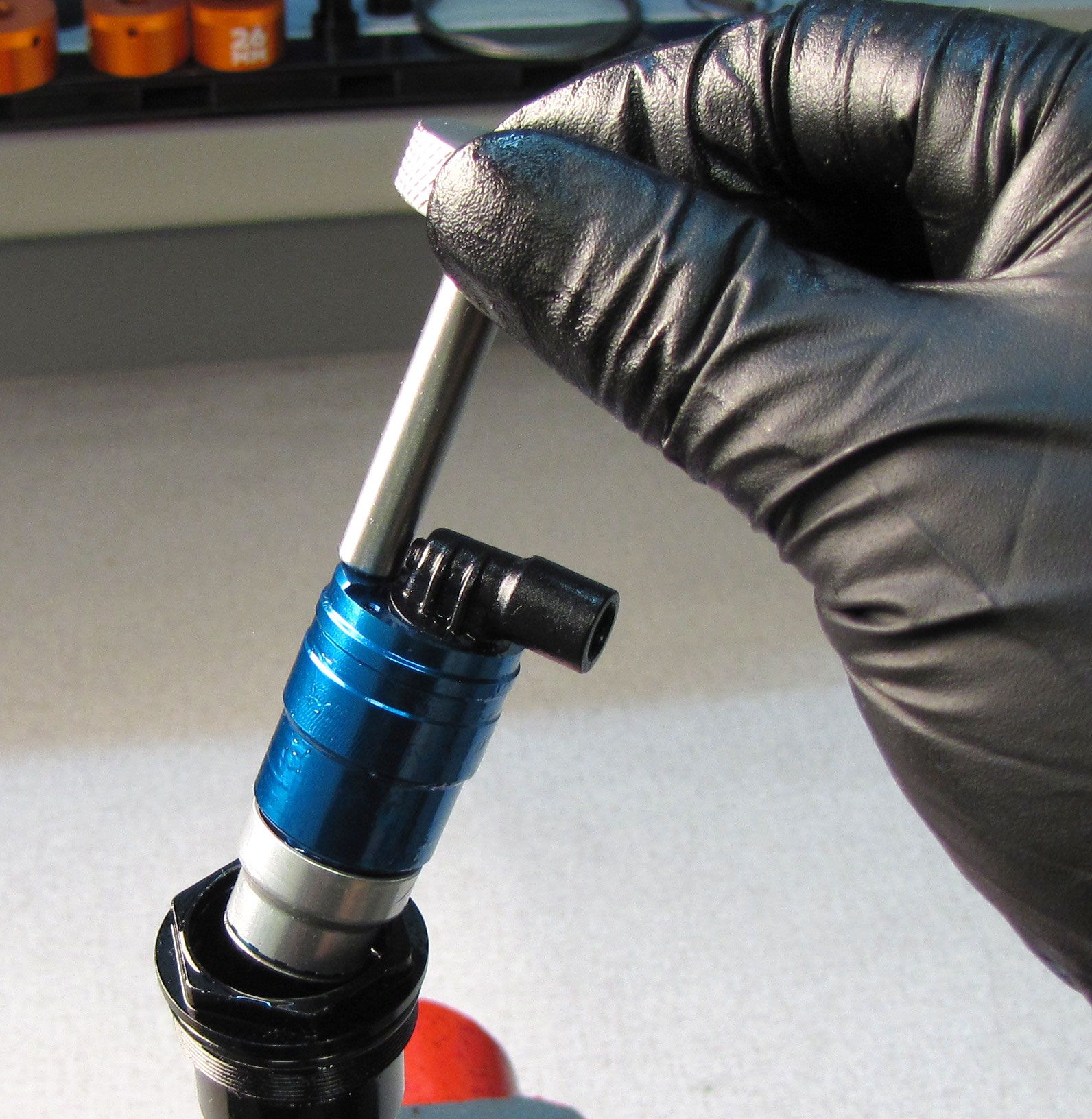
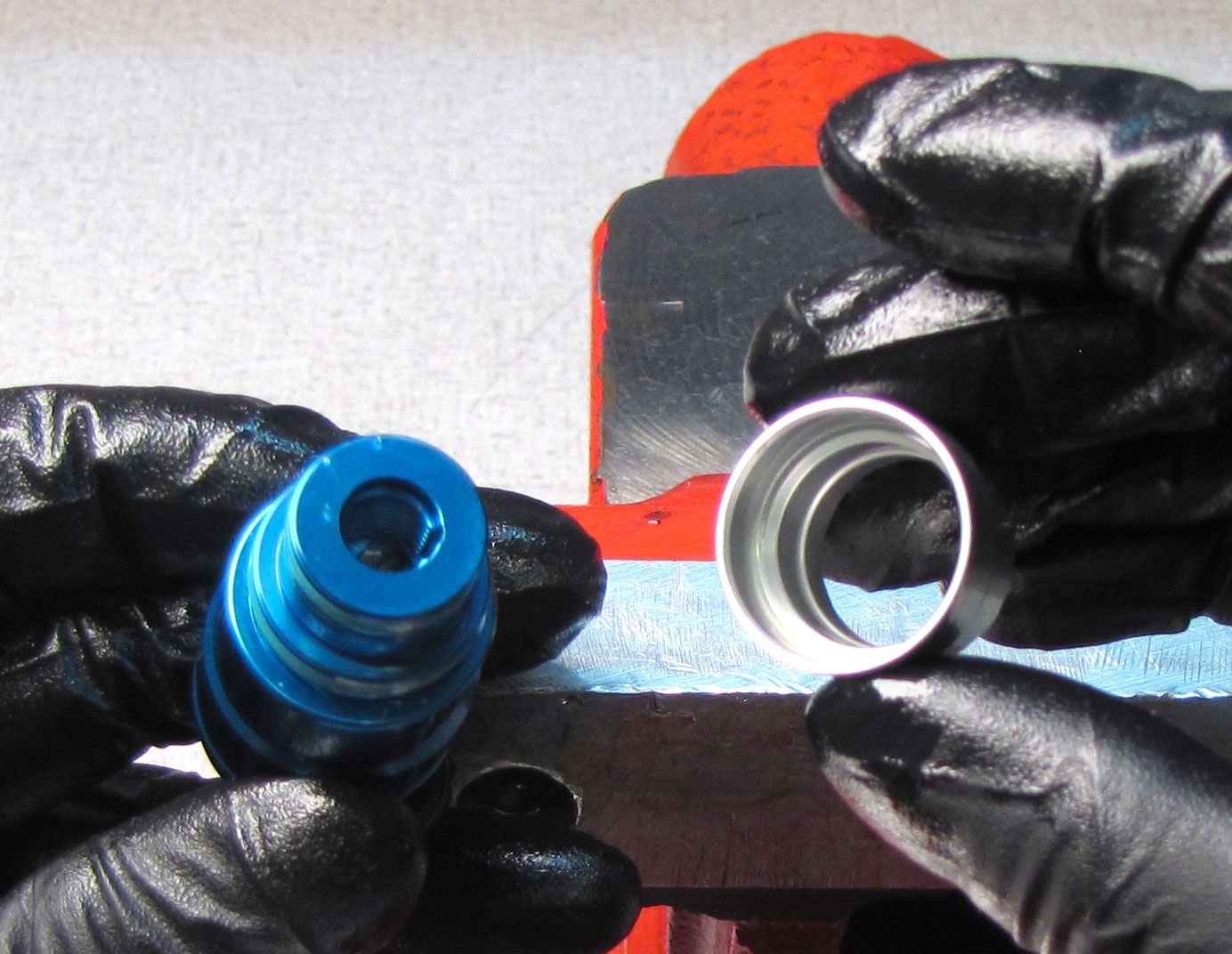
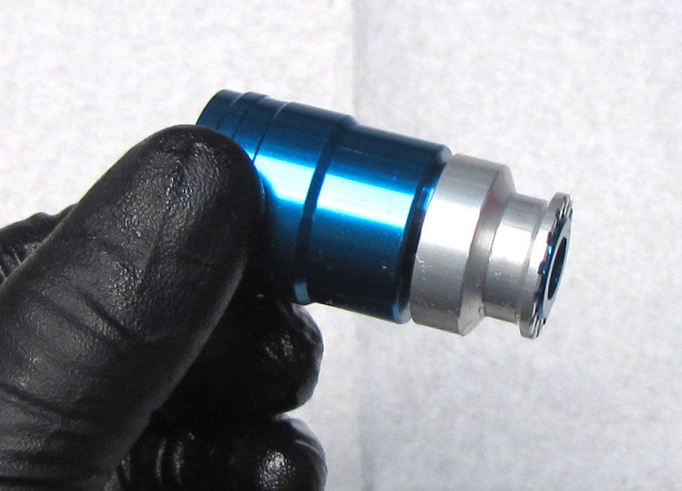
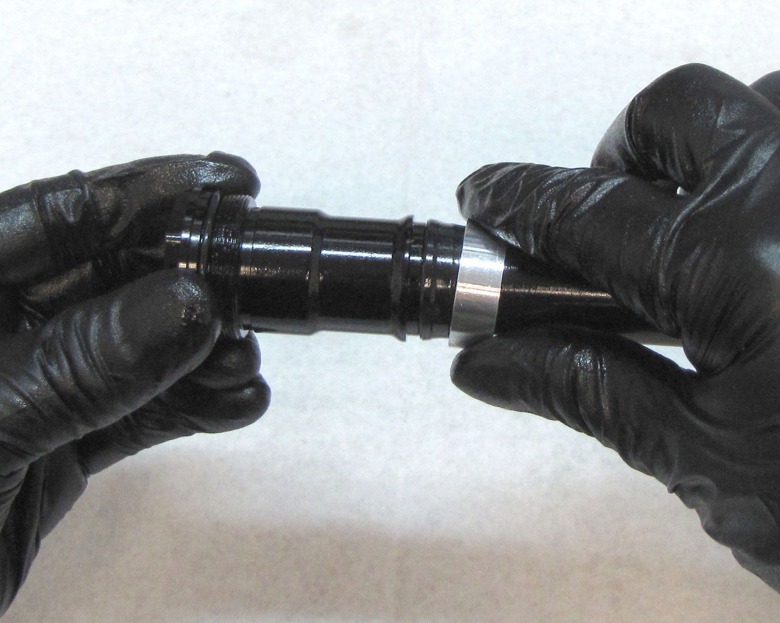
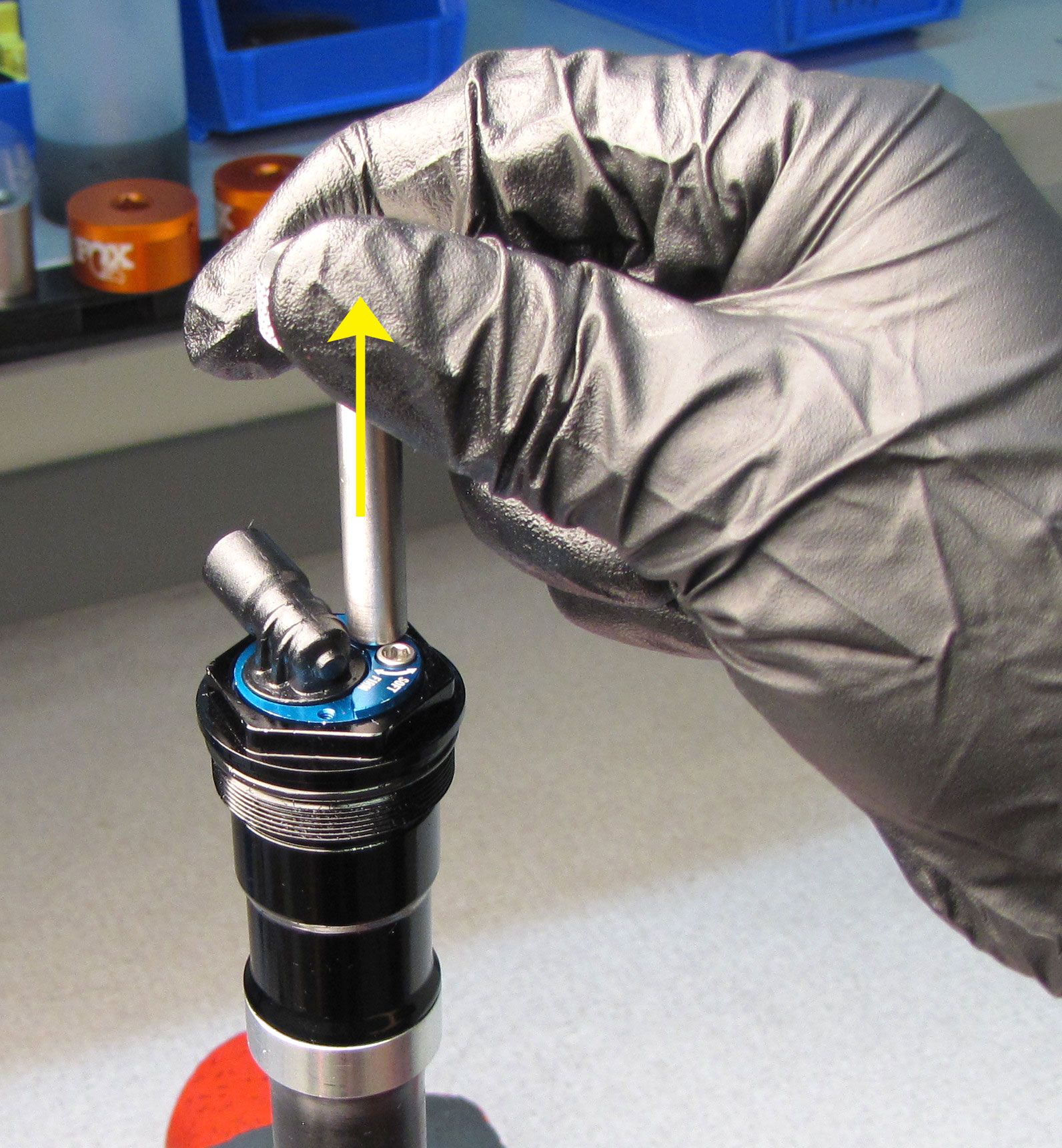
Lift up on the puller tool to remove the Compression Cartridge Housing from the reservoir.
Step 10
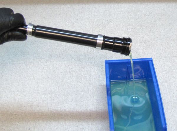
Invert the cartridge over your waste oil basin to pour out any excess oil from the open topcap. Squeeze the bladder and cycle the damper shaft over your basin to purge most of the old oil from the cartridge.

Step 11
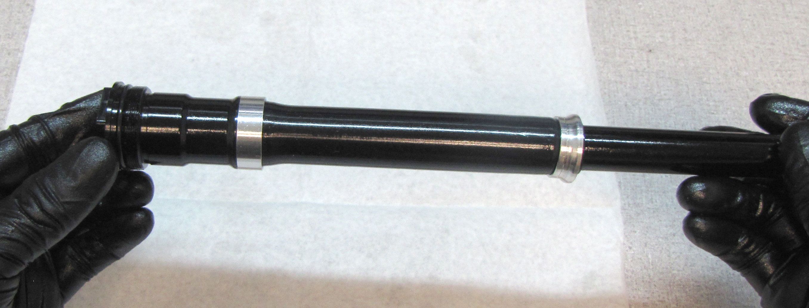
Clean the cartridge body with isopropyl alcohol and a lint-free paper towel, then invert it and clamp it in your shaft clamps (PN: 803-01-360) as shown. Unthread the Sealhead assembly counter-clockwise with a thin 19mm wrench. Remove the Damper Shaft Assembly then pour out any additional oil from the open cartridge body.
Step 12
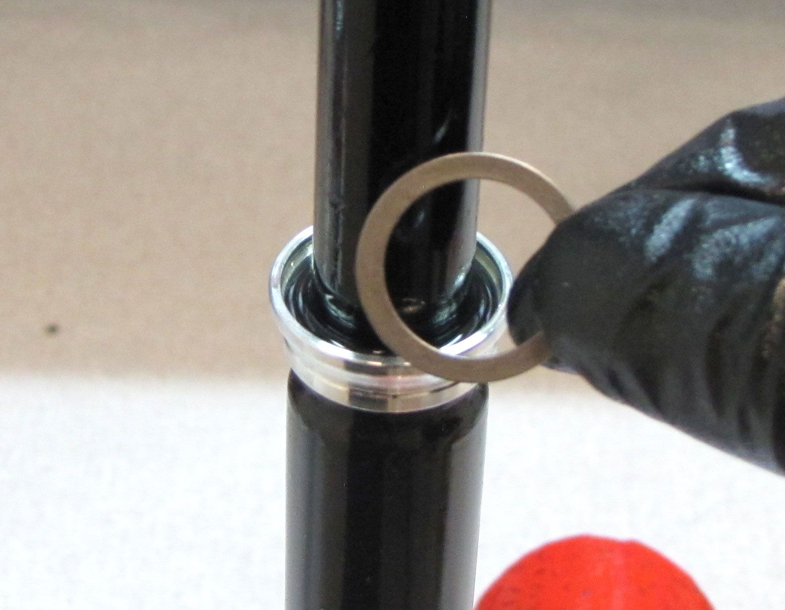
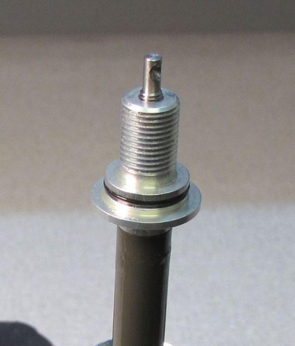
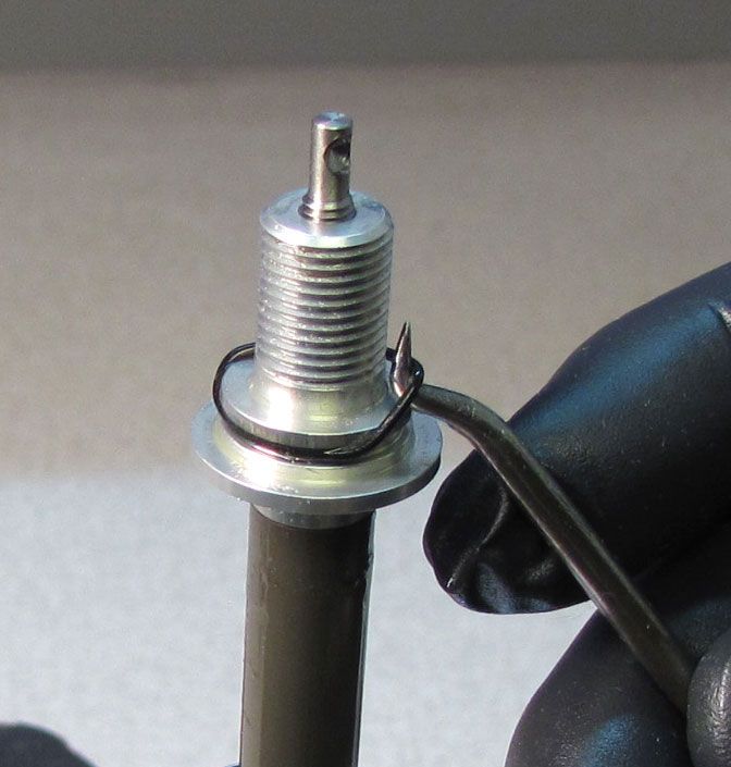
Remove the retaining ring and bladder ring retainer being careful not to scratch the smooth bladder sealing surface on the black cartridge body.
Step 13
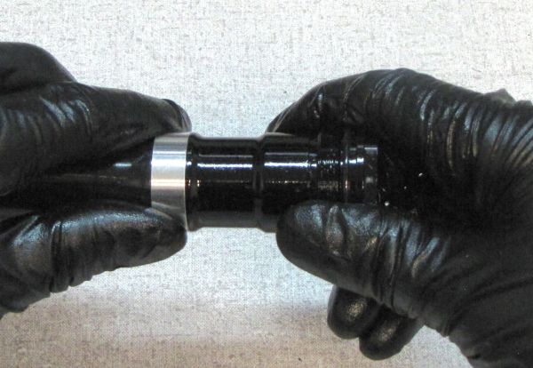
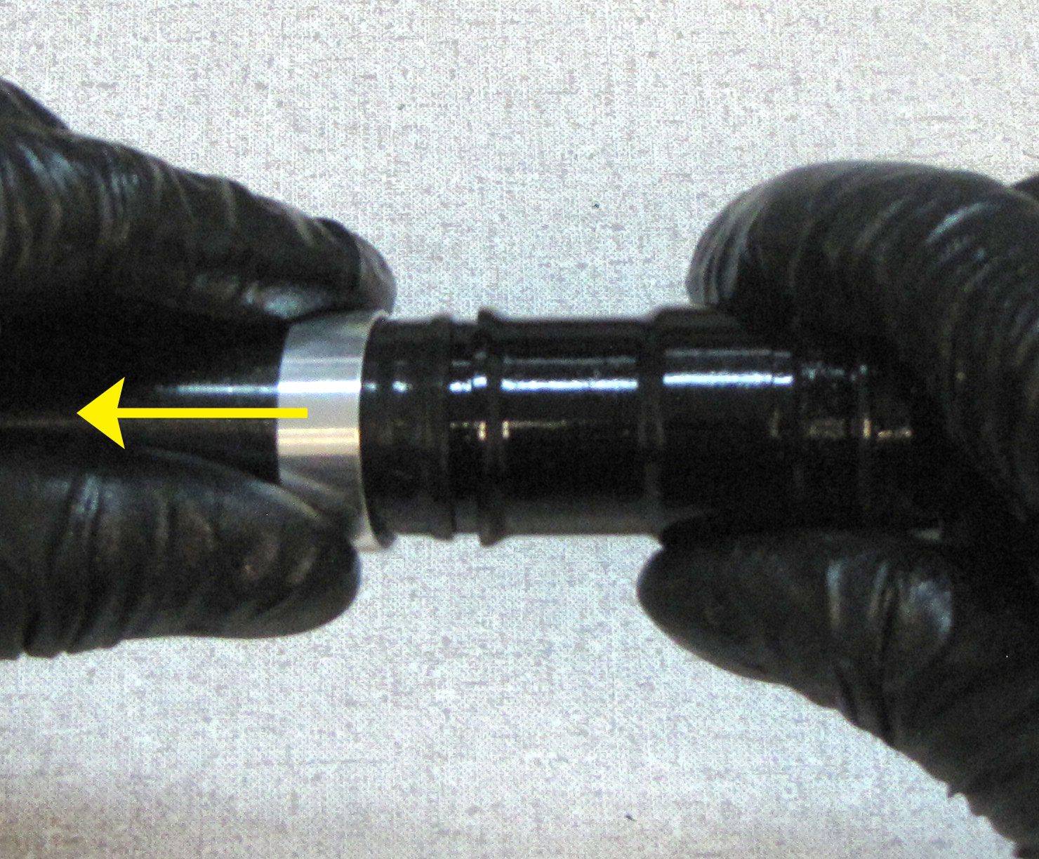
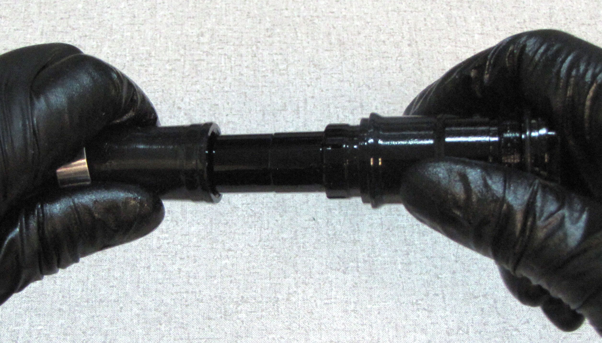
Slide the upper bladder ring down away from the topcap to release the bladder. Slide the bladder with bladder rings off of the open cartridge body.

Step 14
Clean the cartridge body with isopropyl alcohol and a lint-free paper towel, then invert it and clamp it in your shaft clamps (PN: 803-01-360) as shown. Unthread the topcap from the cartridge body by turning it counter-clockwise with a 6-point chambfer-less 28mm socket. Remove the topcap. Remove the two shims and compression check spring from the cartridge body with a magnet.

Step 15
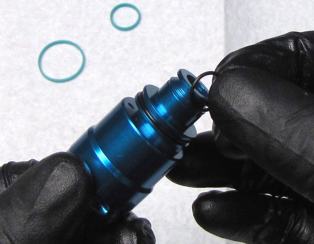
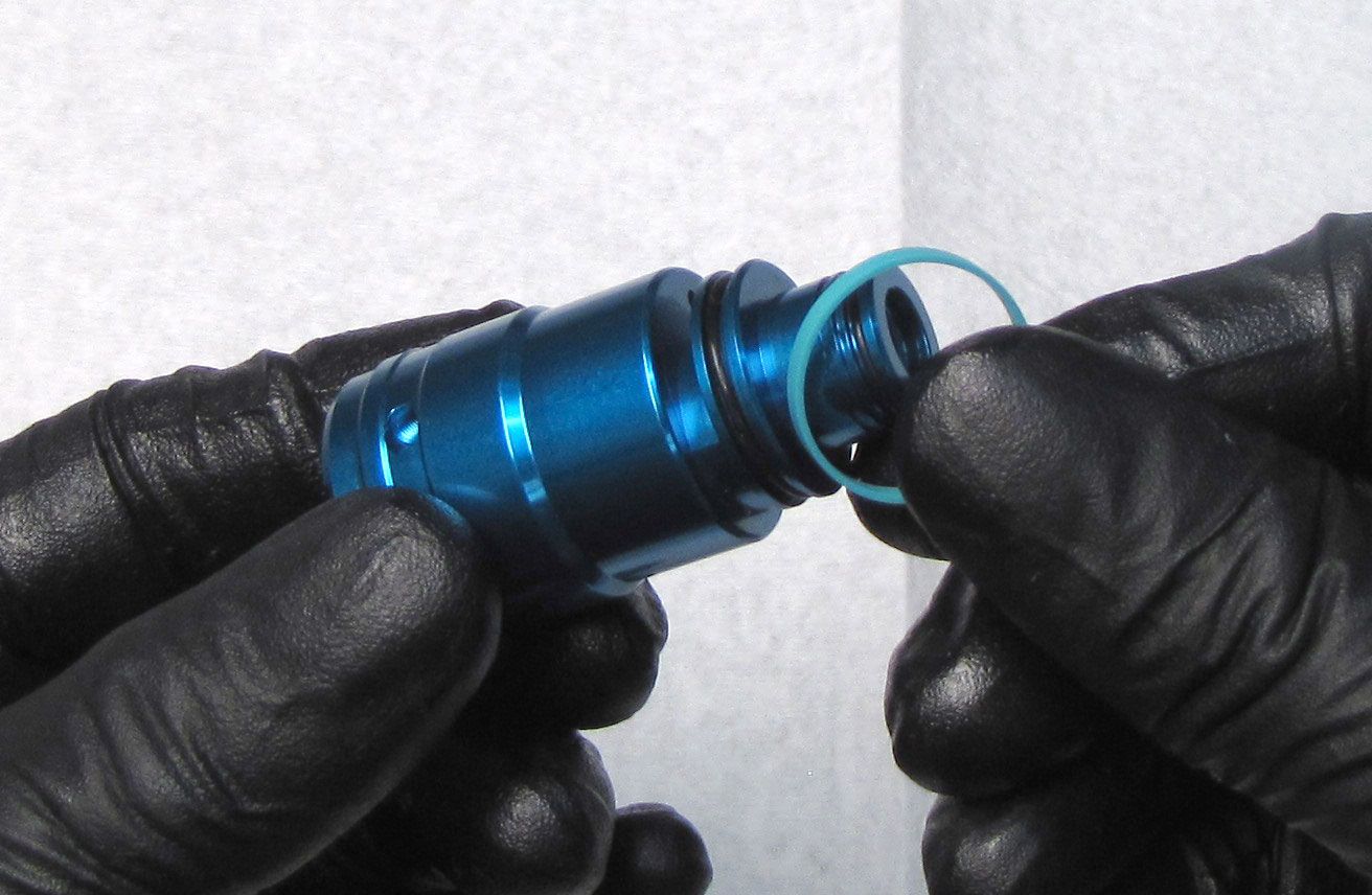
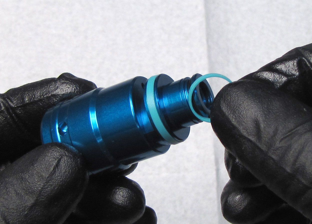
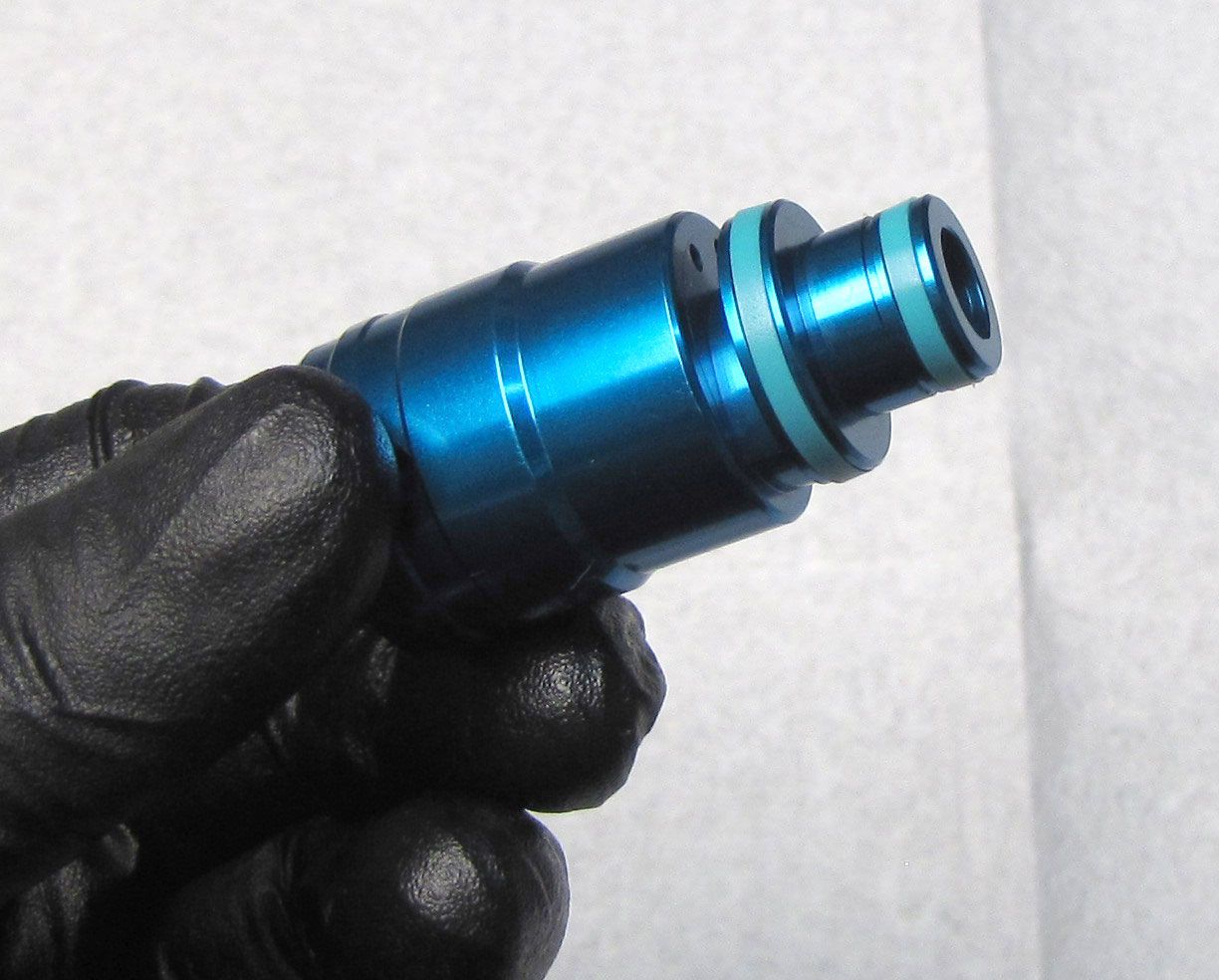
Remove the two o-rings inside the Topcap and the single o-ring around the outside. Clean the Topcap then replace the o-rings with new FOX 5wt. Teflon Infused oil coated ones from the kit.
Step 16
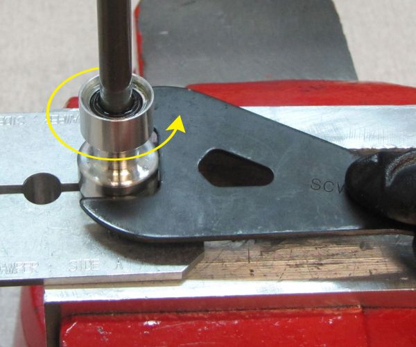
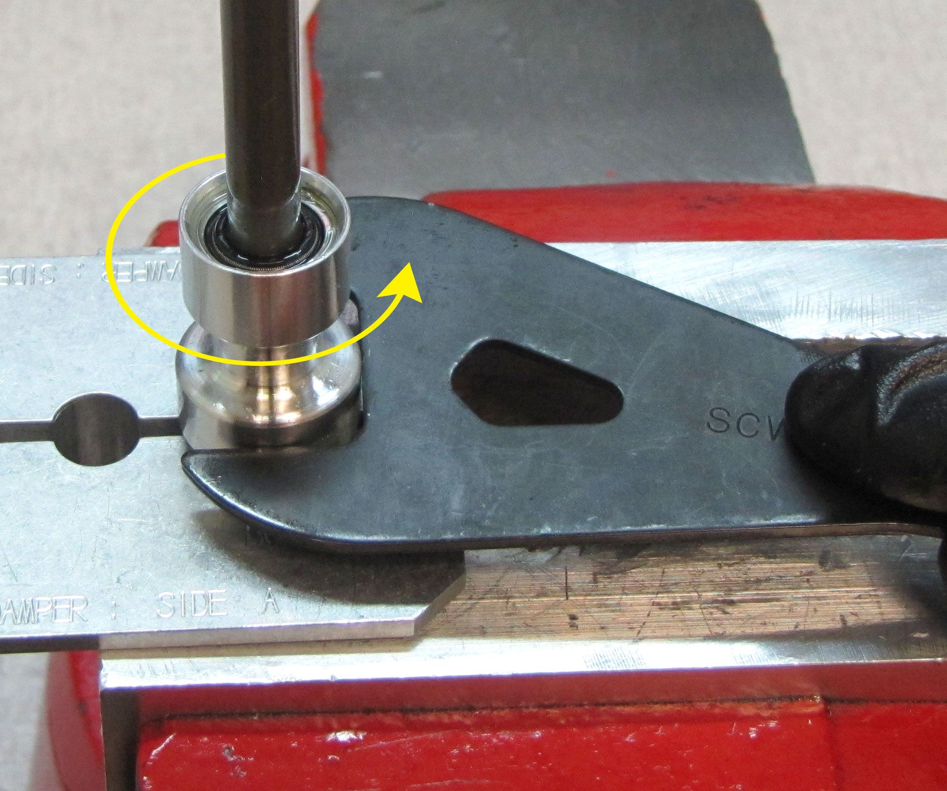
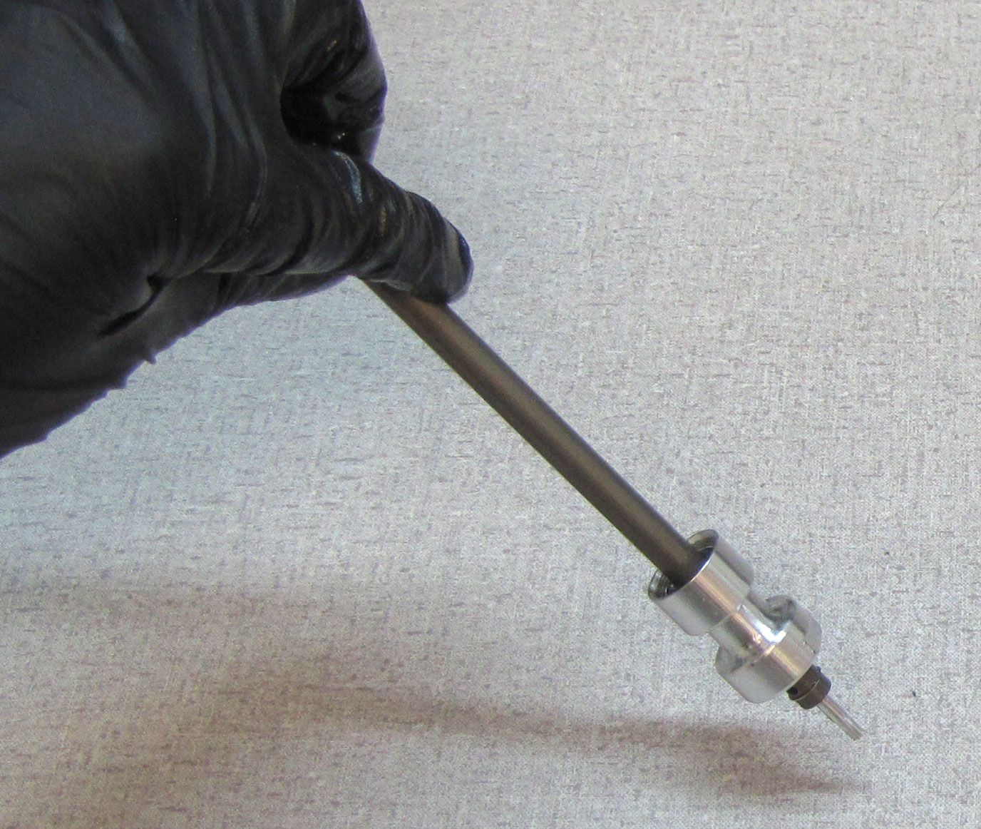
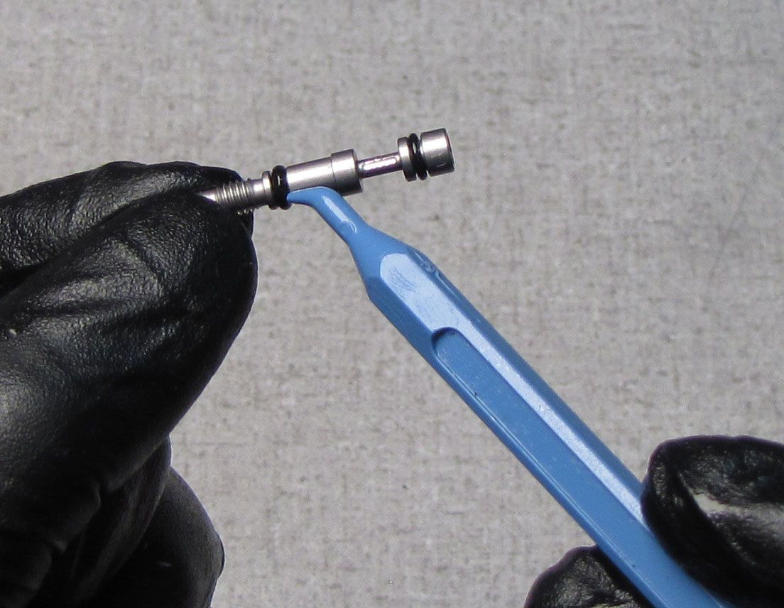
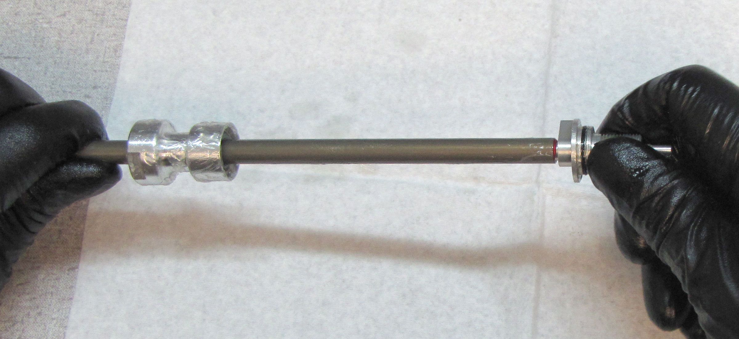
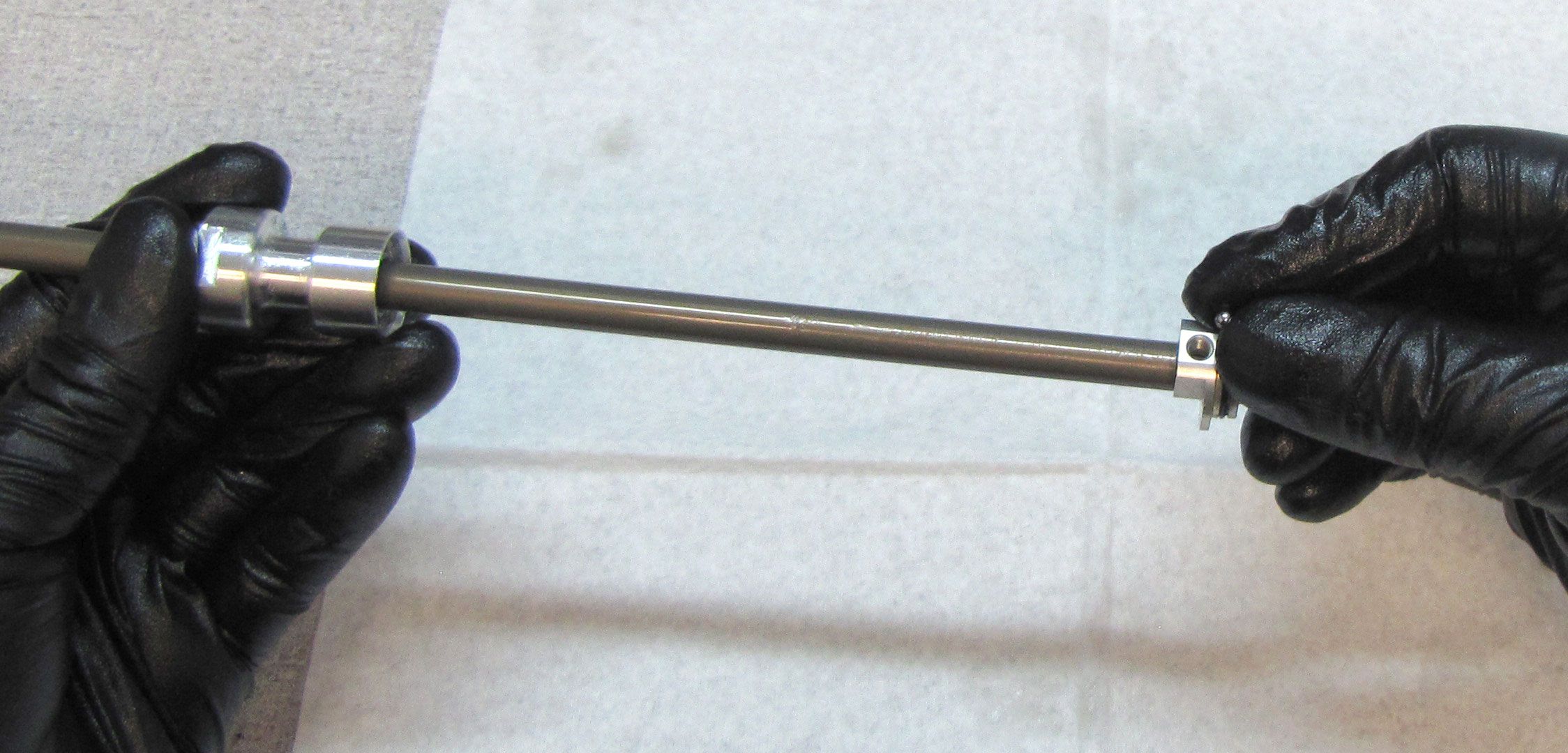
Clean the damper shaft with isopropyl alcohol and a lint-free paper towel, then clamp it in your shaft clamps (PN: 803-00-147) as shown. Unthread the Rebound Piston Assembly by turning it counter-clockwise with an 8mm socket. Remove the Piston Assembly keeping all parts in their original order.

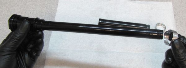
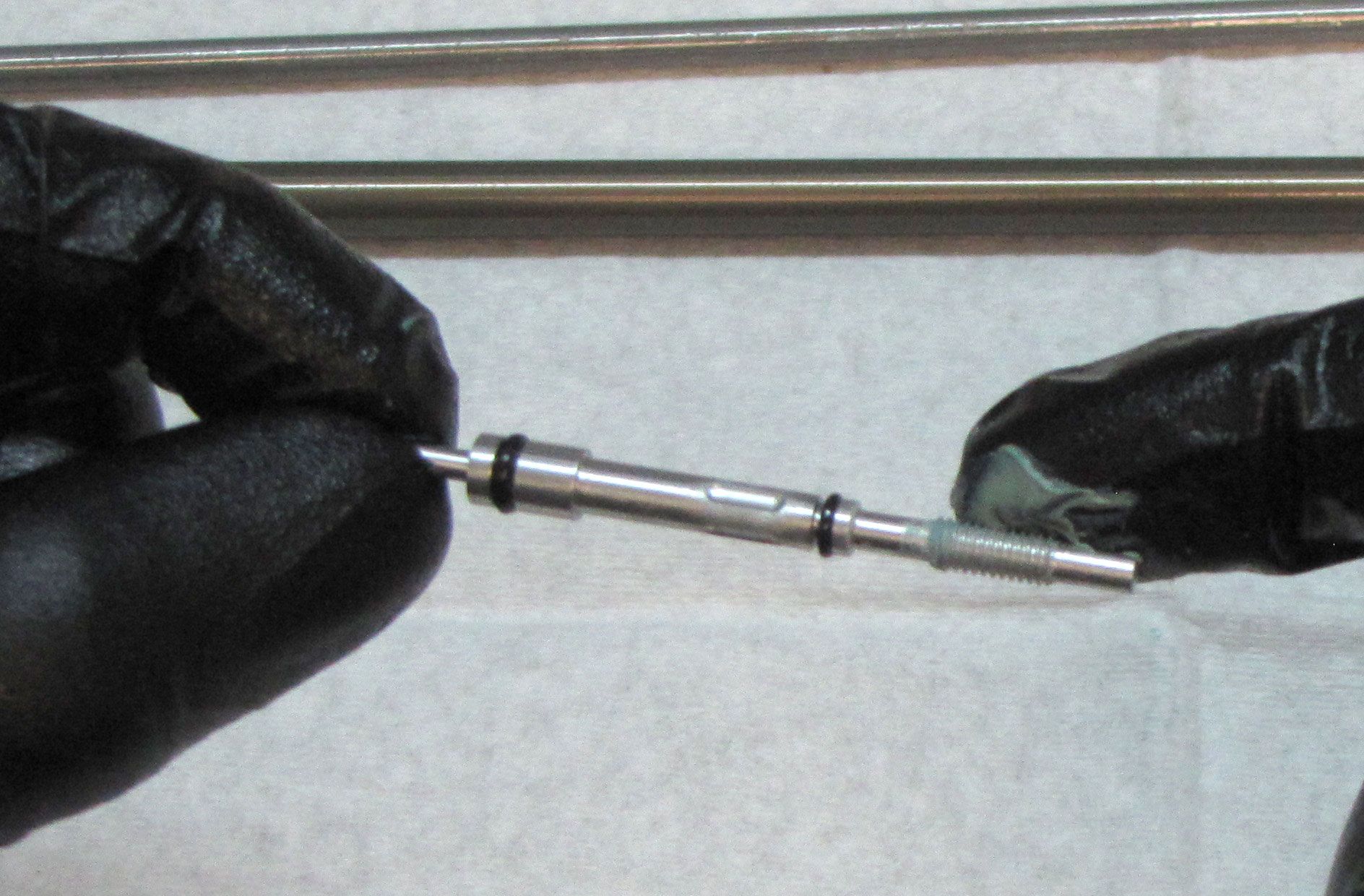
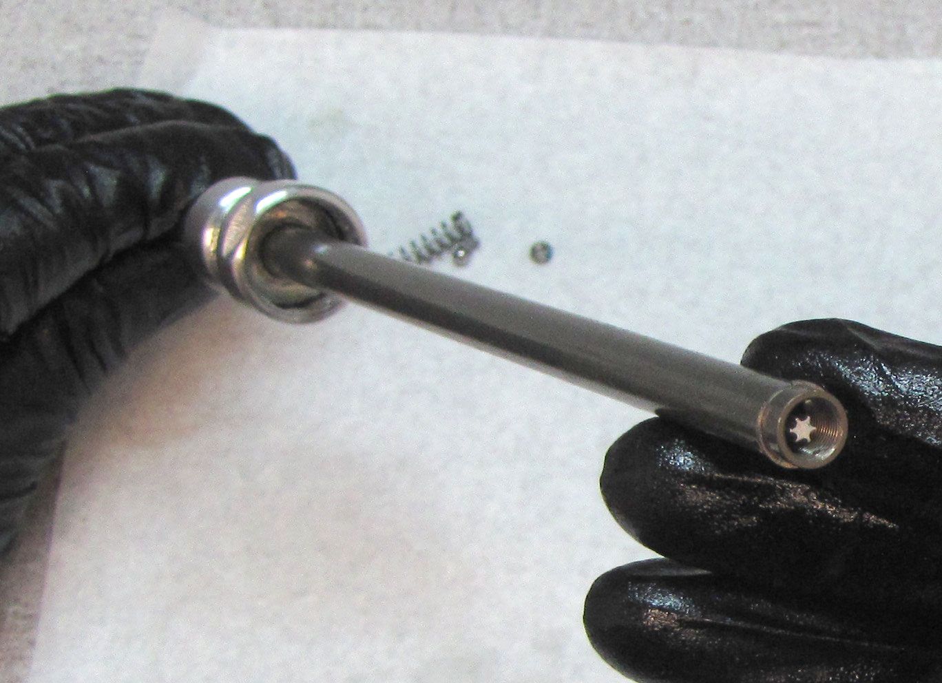
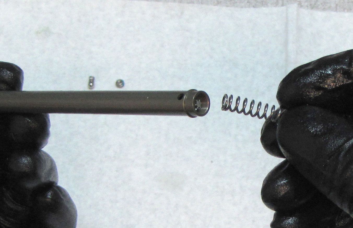
Step 17
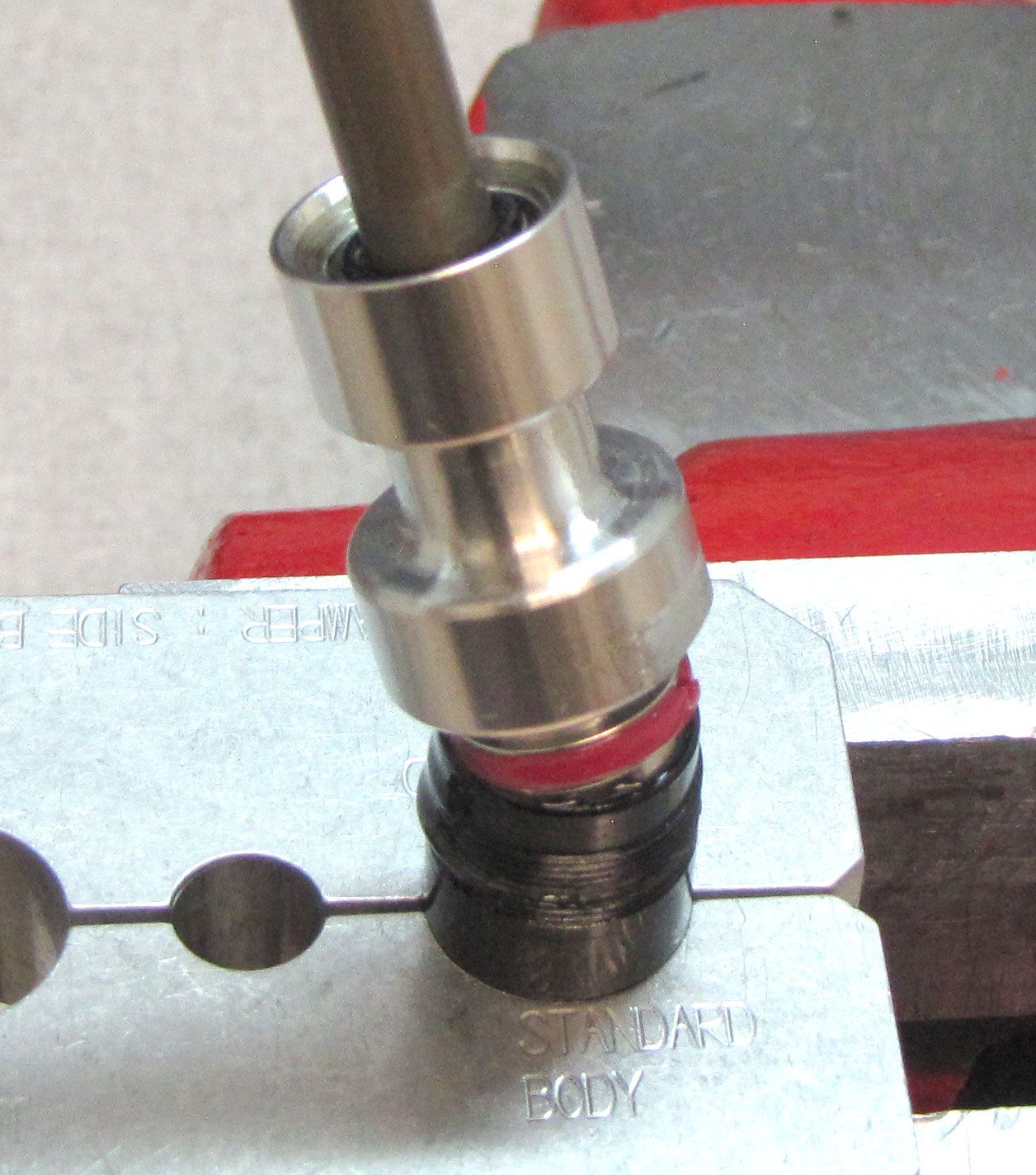
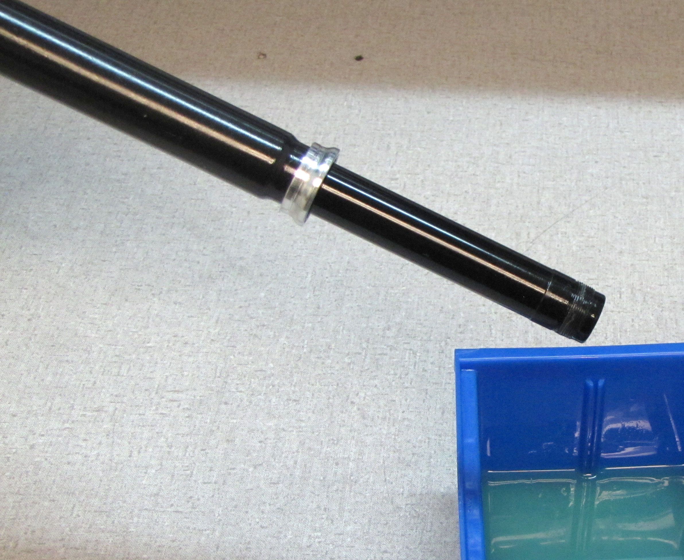
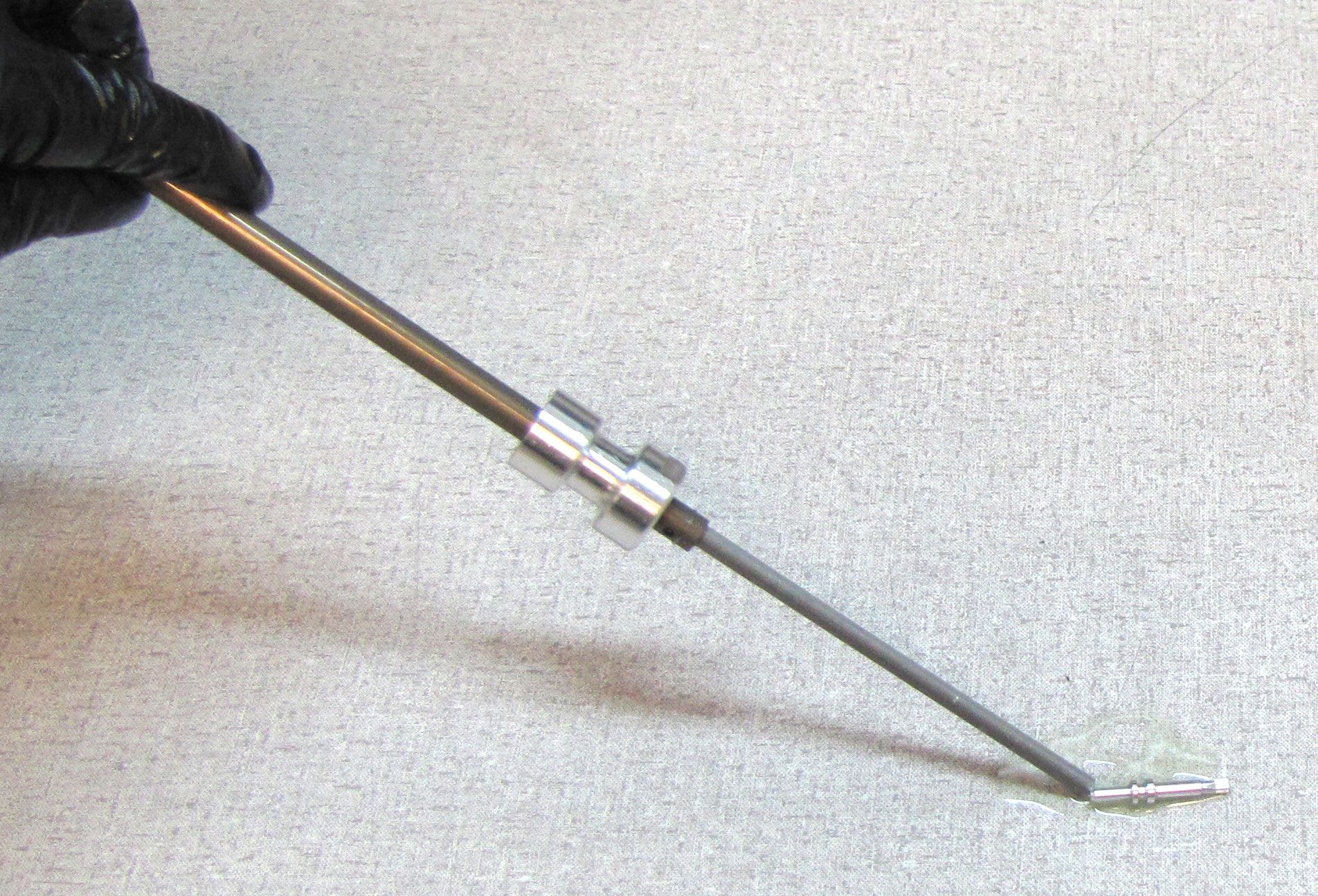
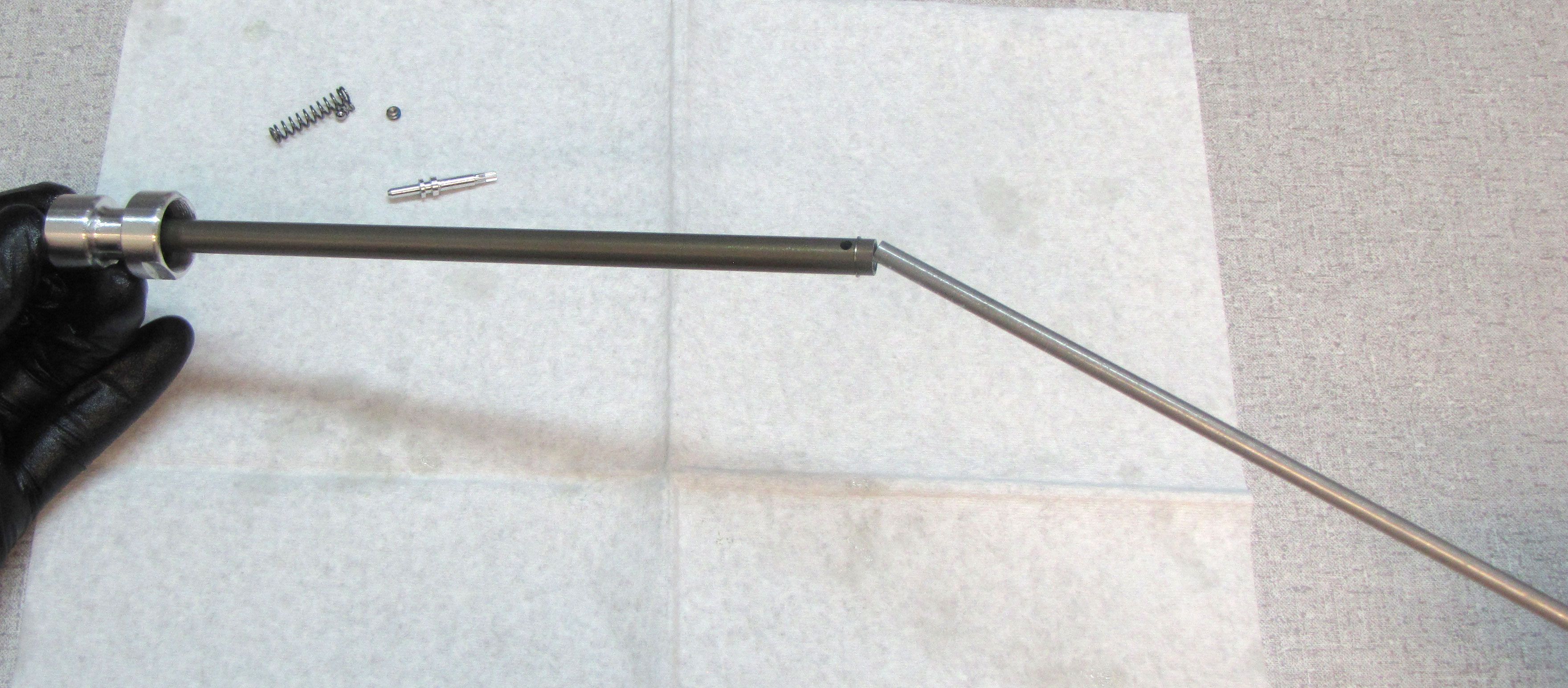
Remove the Rebound Needle Spring and Rebound Needle. Invert the shaft over your workbench to help remove the Rebound Needle. Remove the Rebound tube.

Step 18
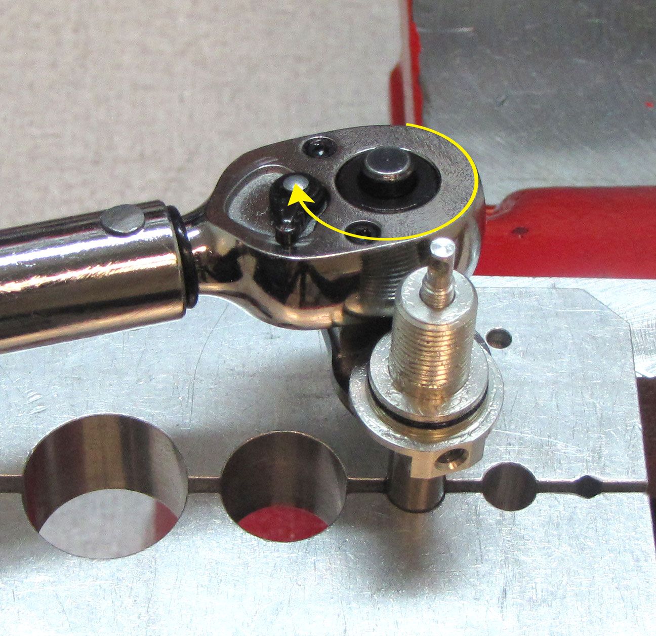
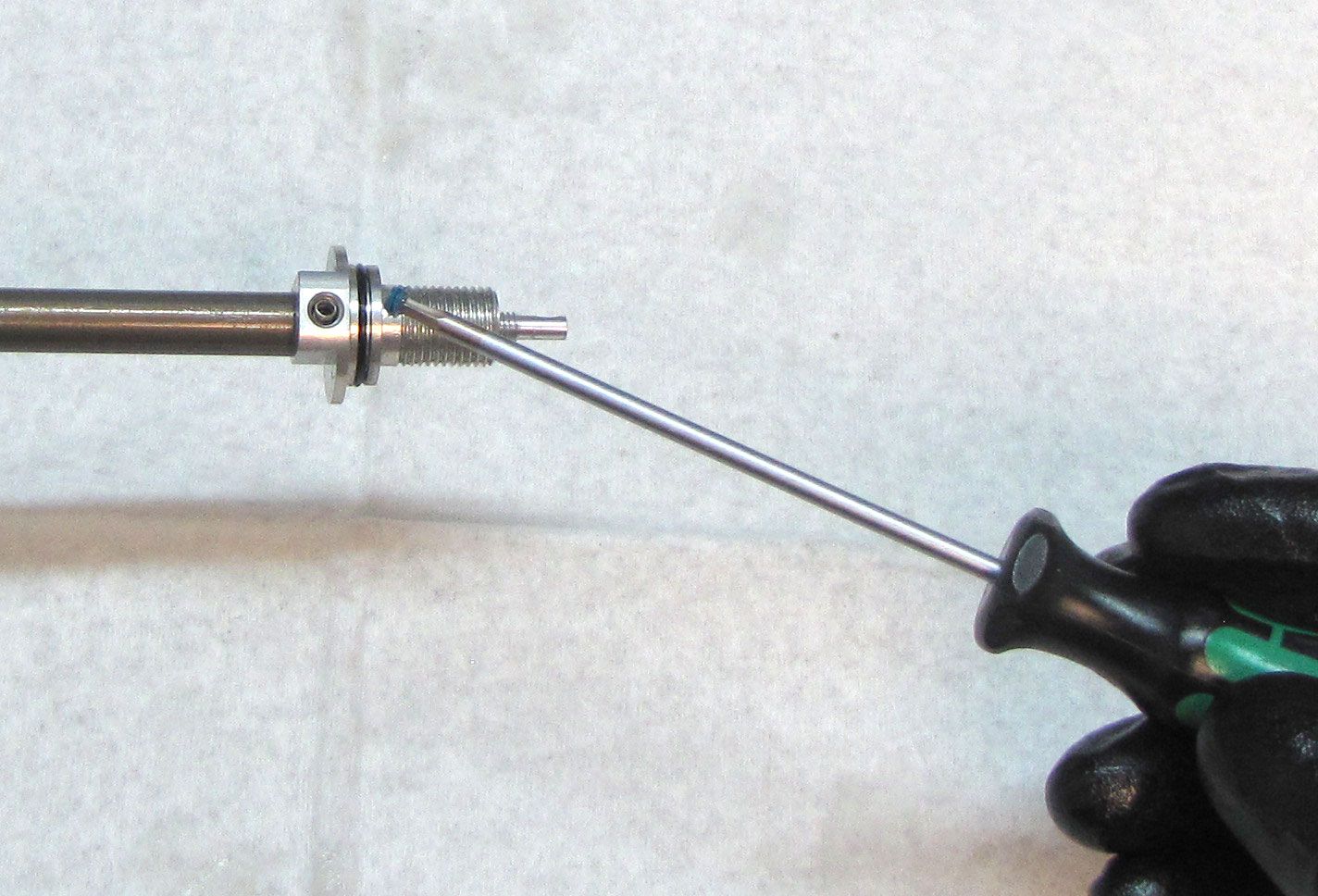
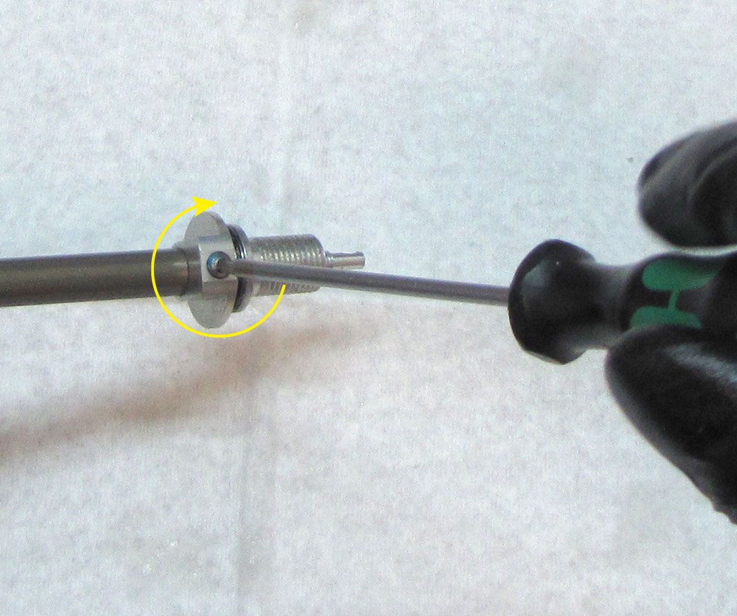
Invert the shaft and clamp in your shaft clamps. Unthread the set screw for the rebound detent by turning it counter-clockwise with a 2mm hex wrench. Remove the rebound detent spring and ball and set aside.
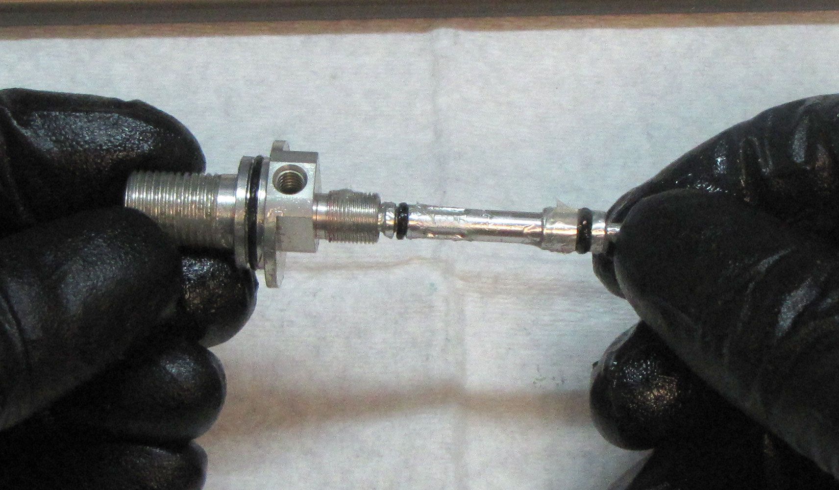
Step 19
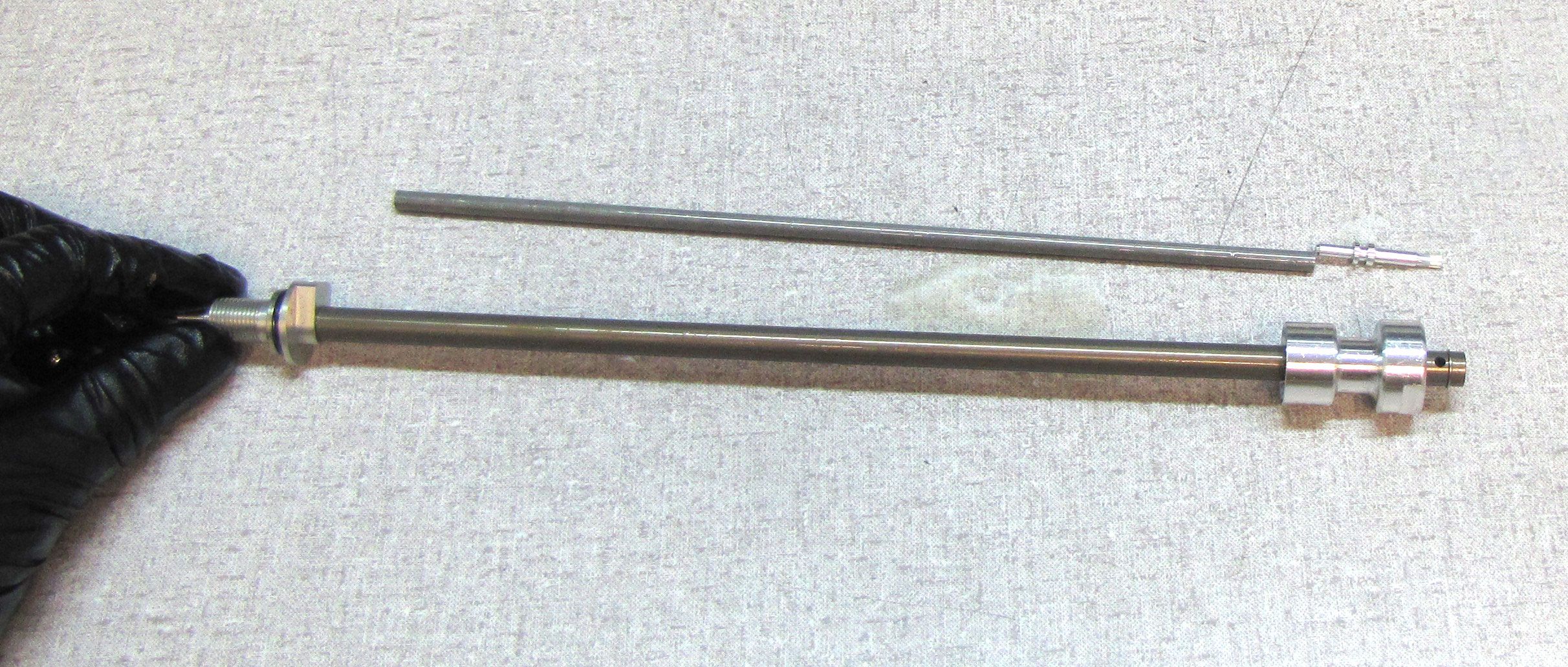
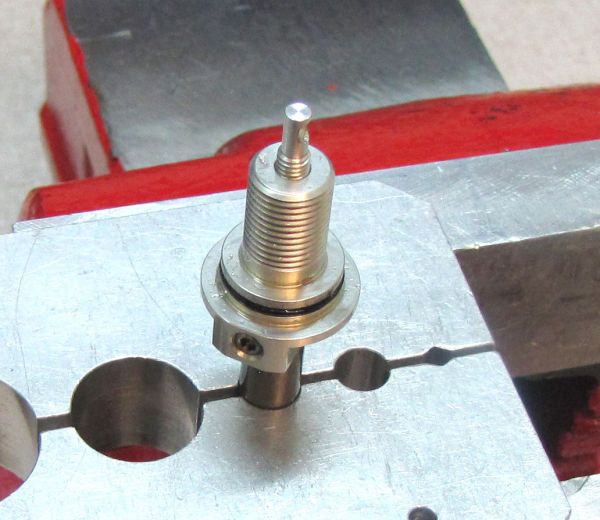
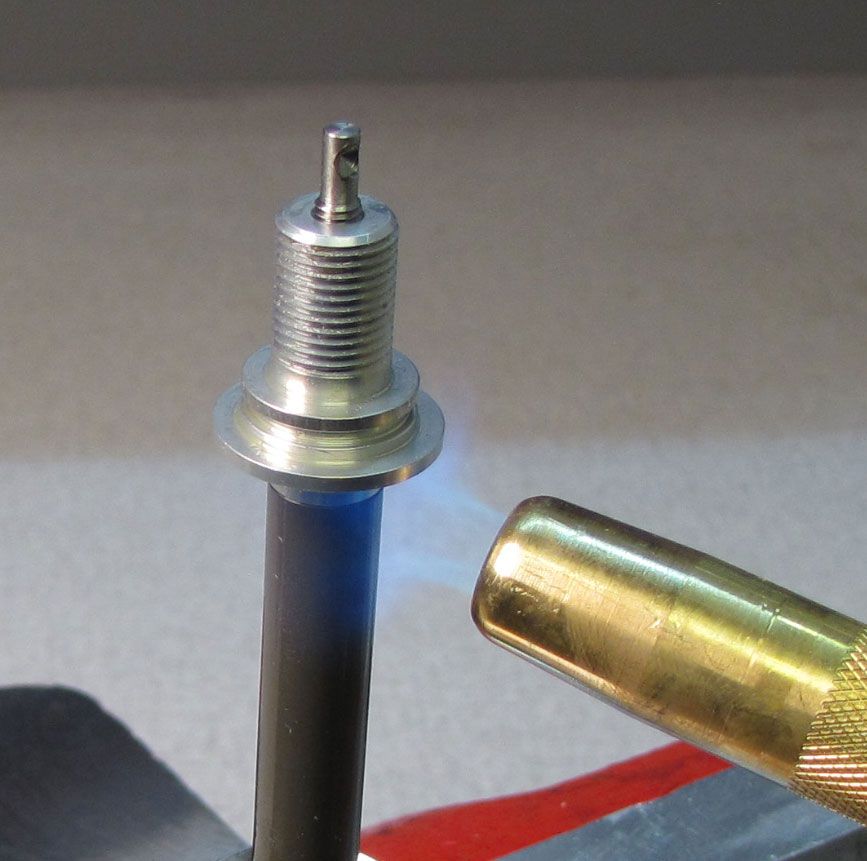
Remove and discard the o-ring from the rebound adjuster. Carefully apply heat to the shaft at the rebound adjuster with a propane torch for 5-10 seconds to break down the Loctite. Unthread the rebound adjuster counter-clockwise with a 10mm wrench.

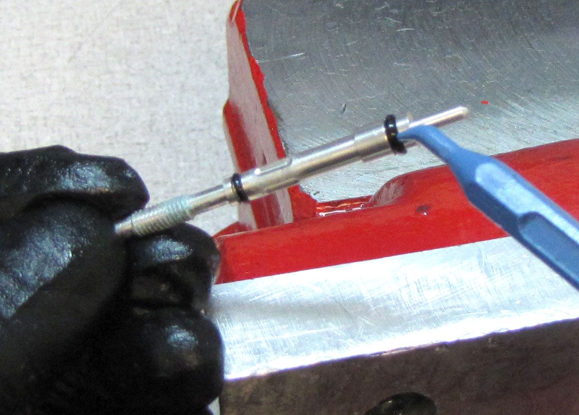
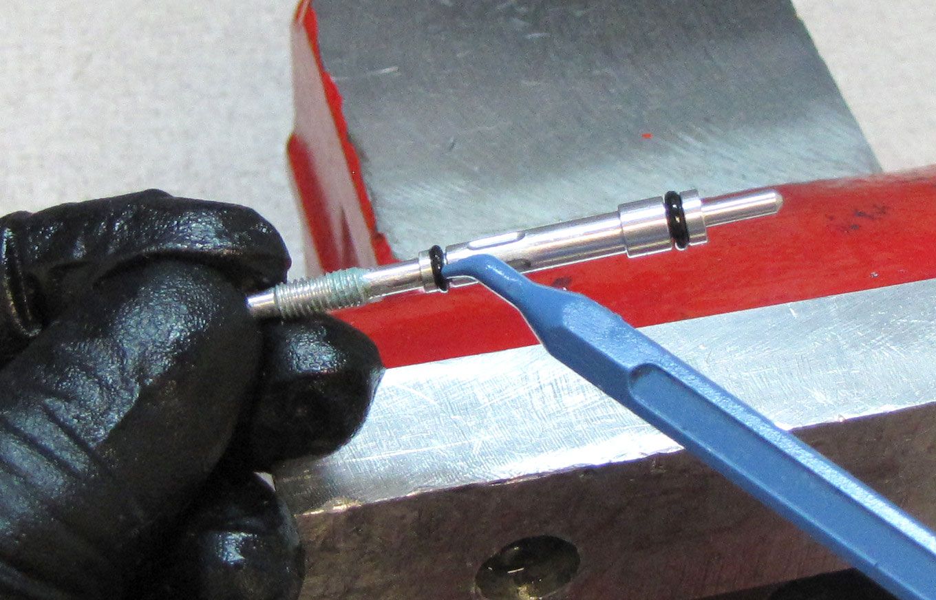
Step 20
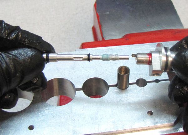
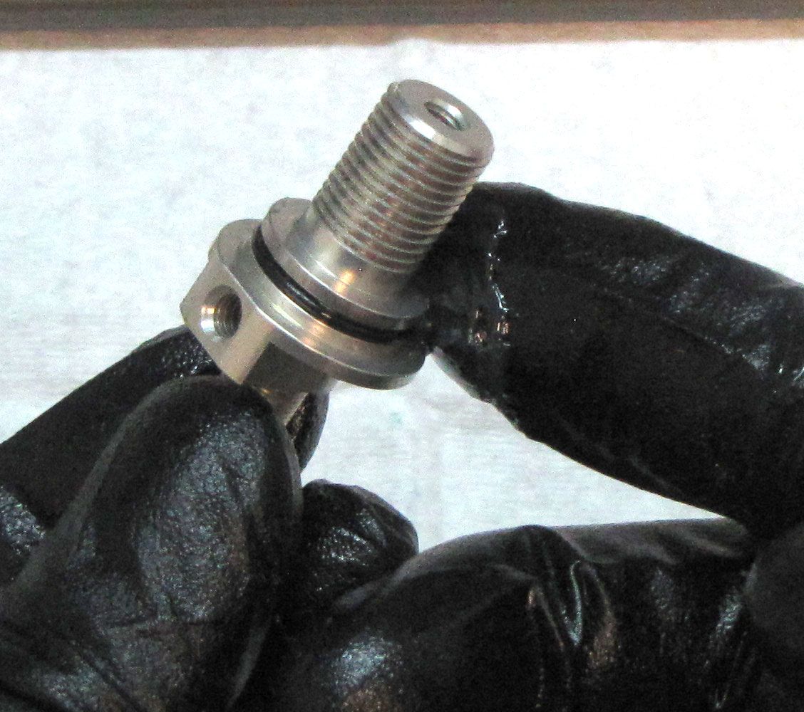
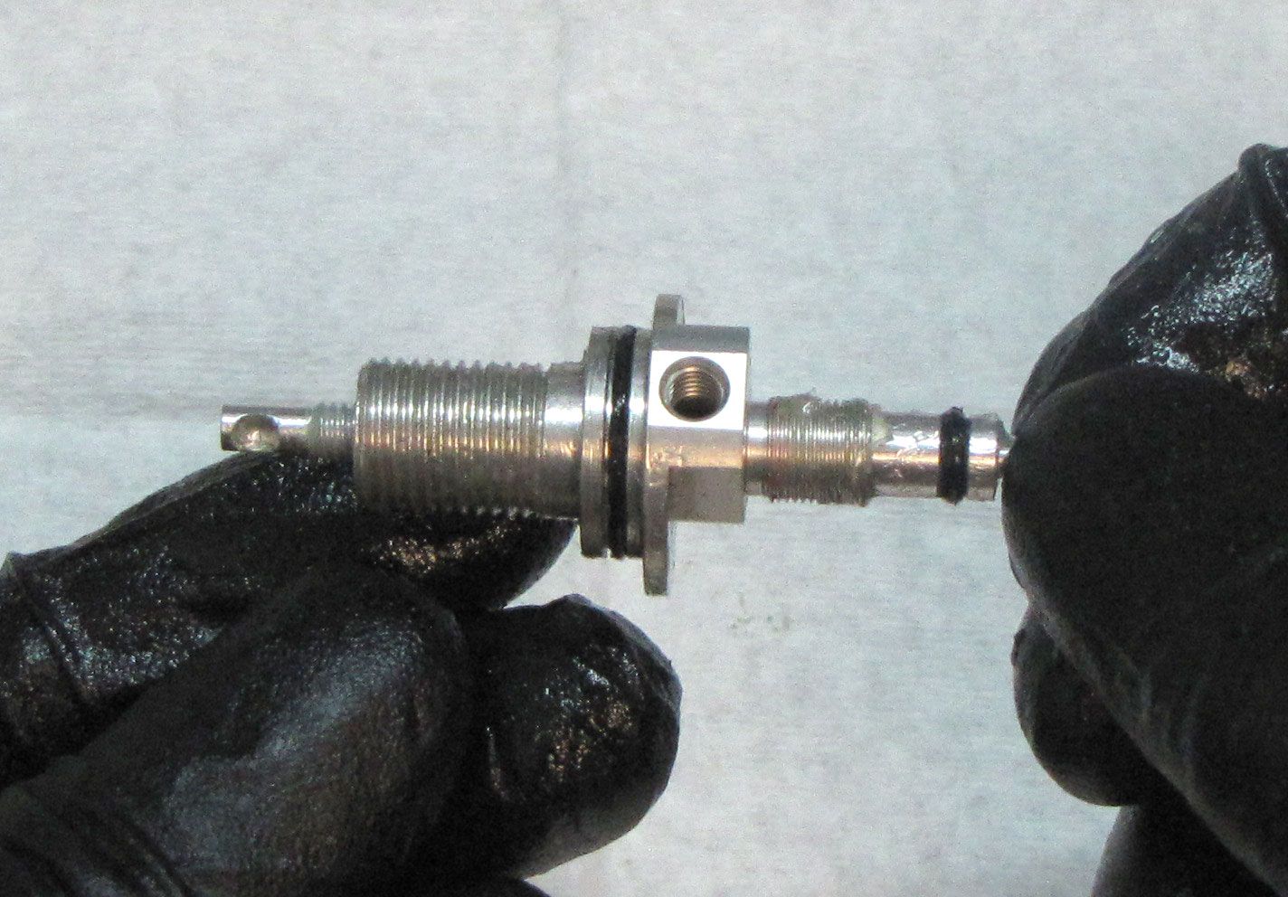
Separate the Rebound Adjuster Screw from the Rebound Adjuster Assembly by unthreading it counter-clockwise. Replace the 2 o-rings on Rebound Adjuster Screw with new geased ones from the kit.
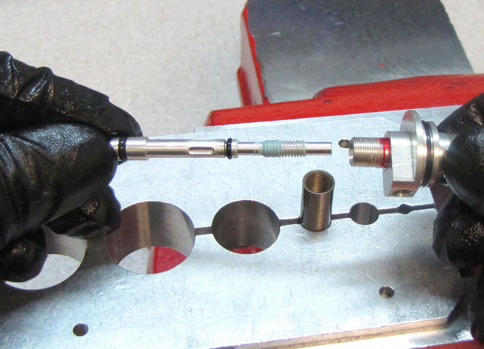
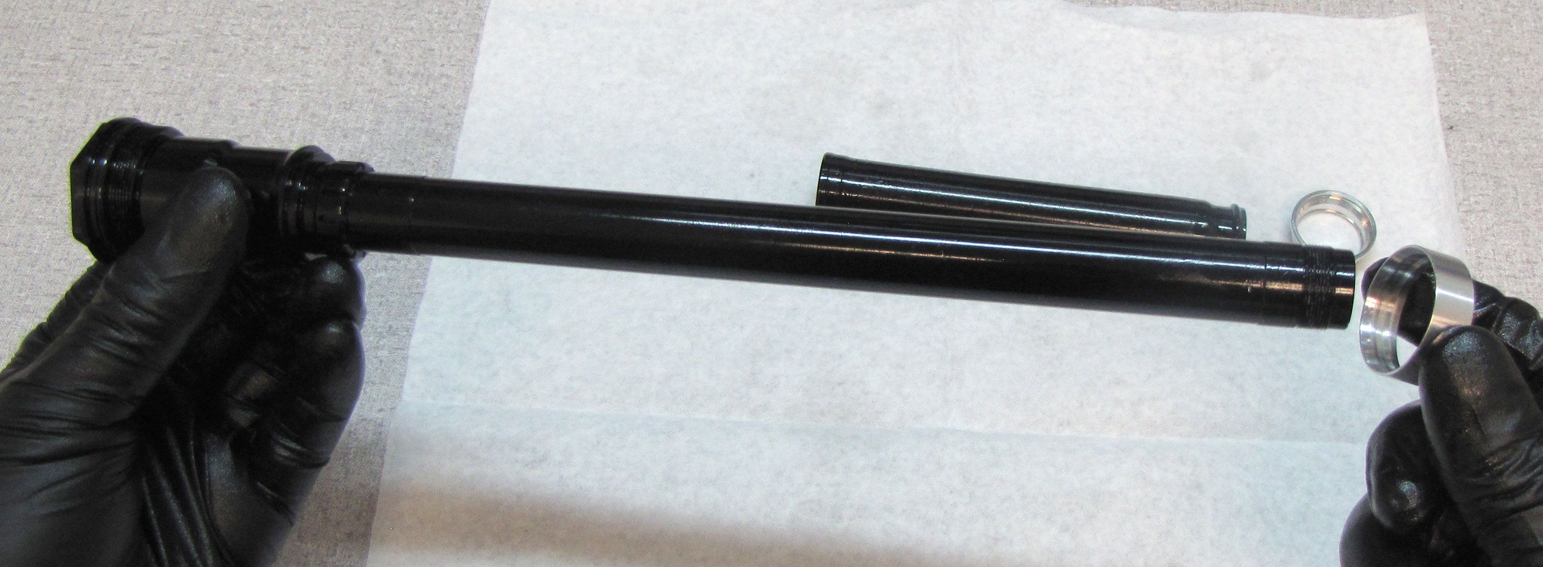
Step 21
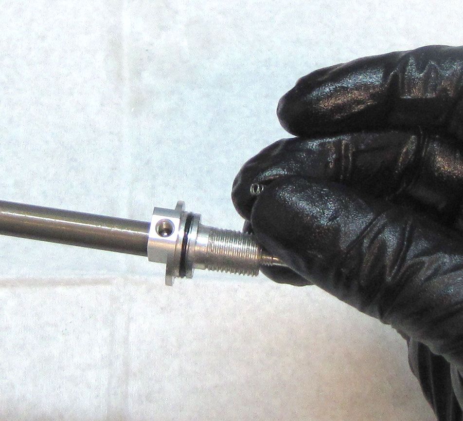
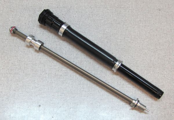
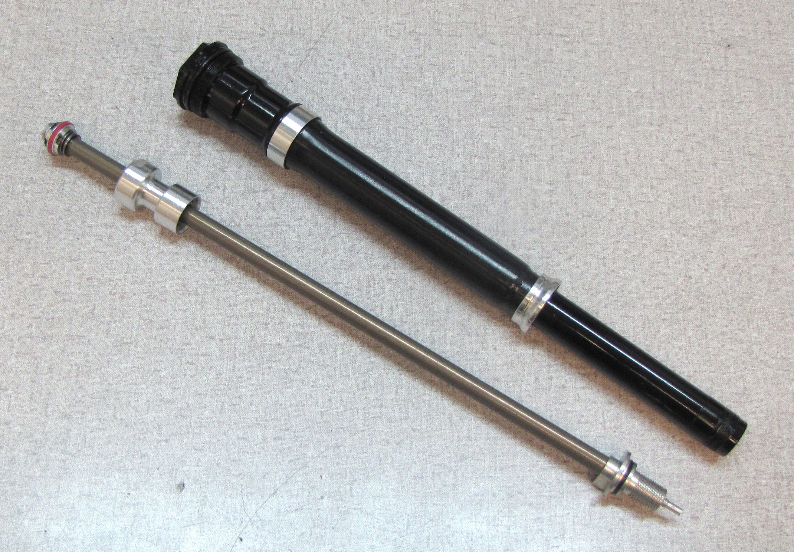
Remove the Sealhead Assembly from the shaft by pulling it off the Rebound Adjuster end.

LIVE Compression Housing Rebuild
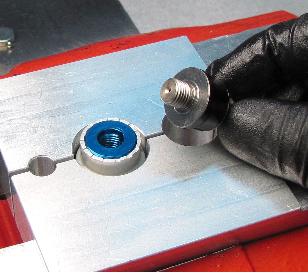
Step 1
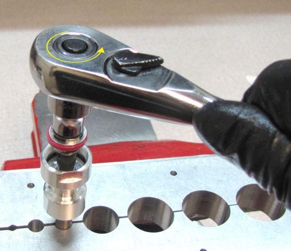
Clamp the Compression Cartridge Housing in your LIVE Valve shaft clamps (PN: 803-01-360) then unthread and remove the Fork Compression Valving Assembly by turning it counter-clockwise with an 8mm wrench. Replace the o-ring on the Compression Piston with a new greased one from the kit.


Step 2
Remove the Boost Valve from the Compression Cartridge Housing.
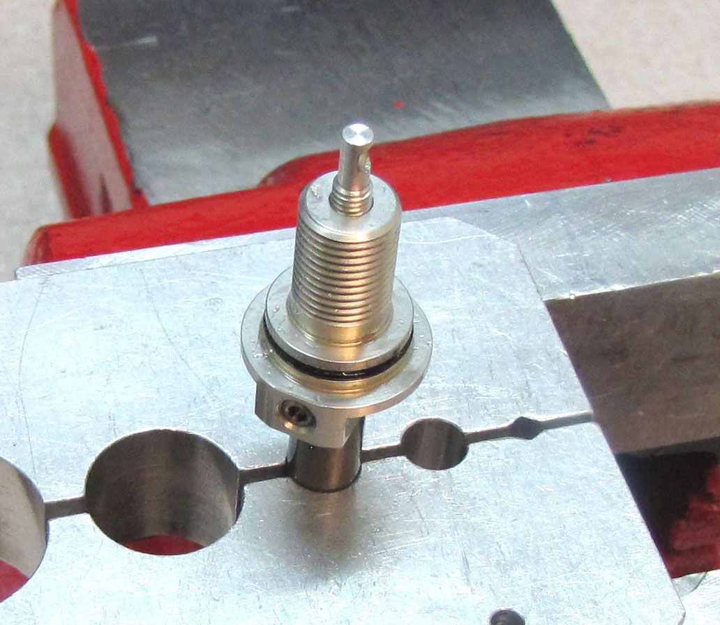
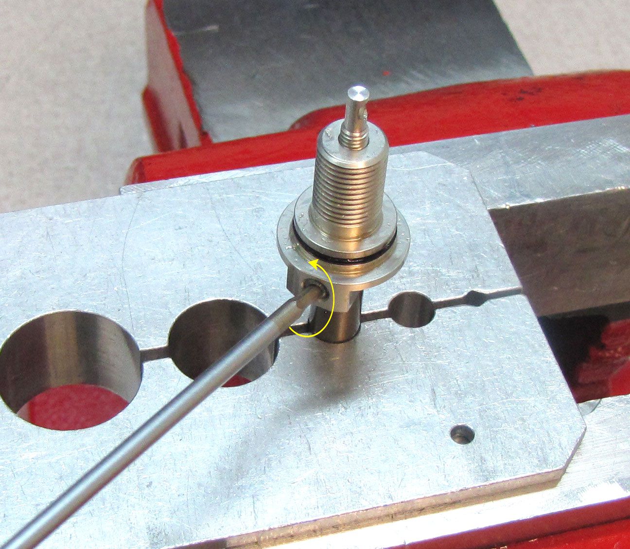
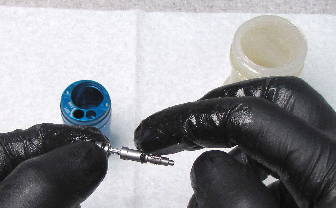
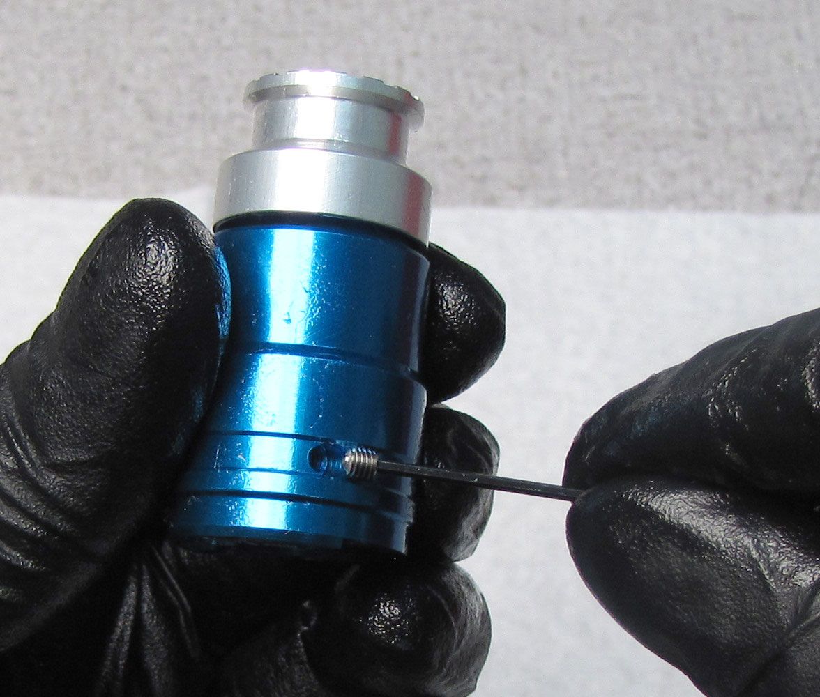
Step 3
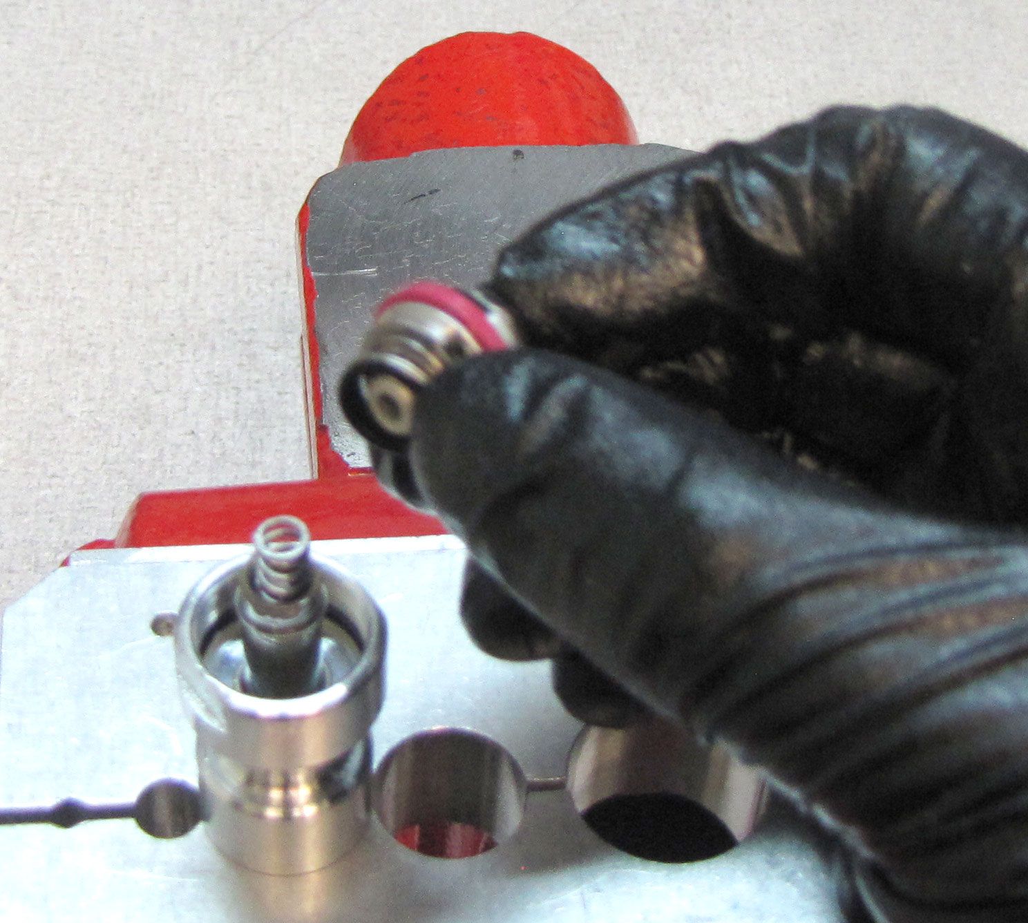
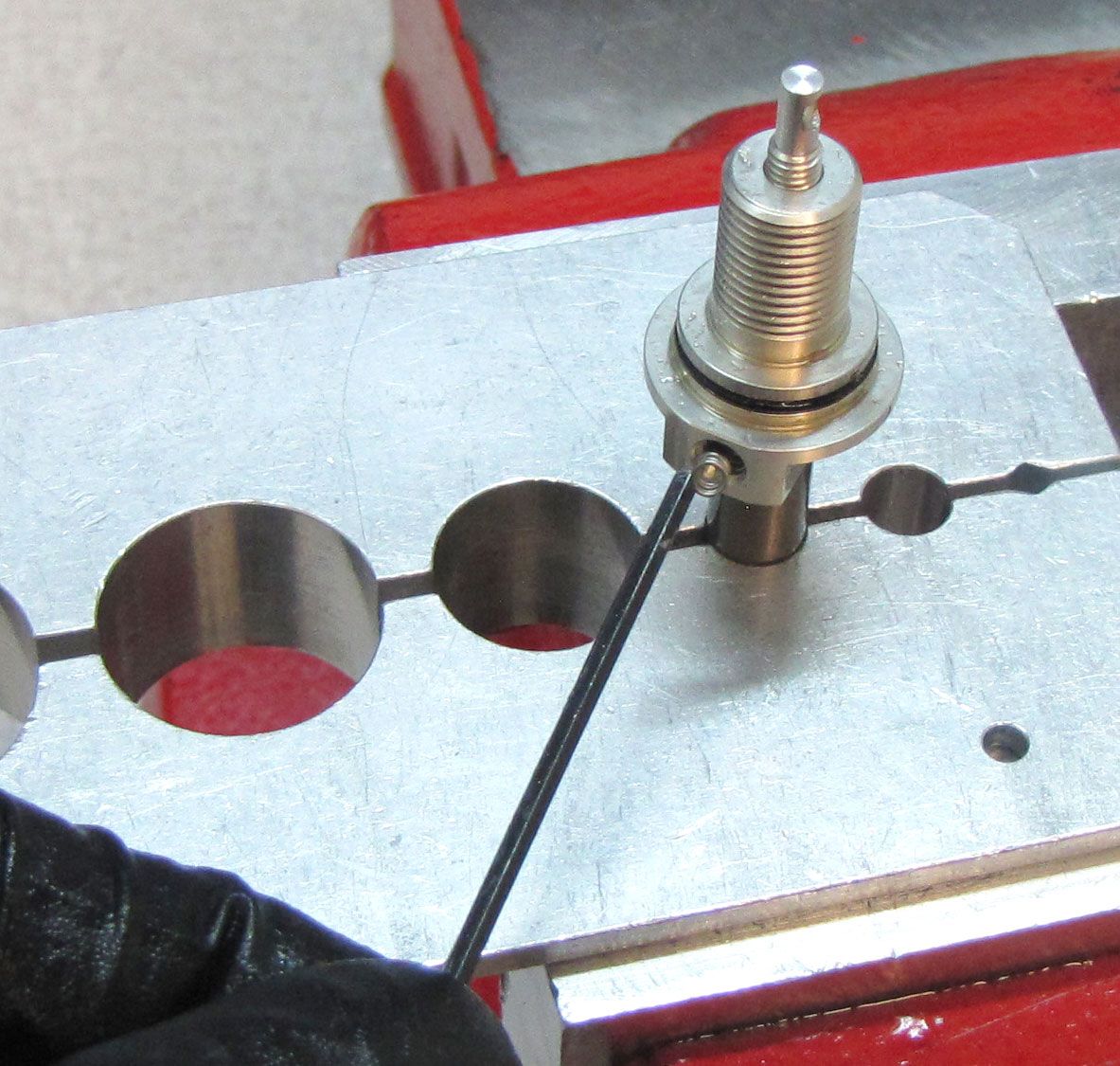
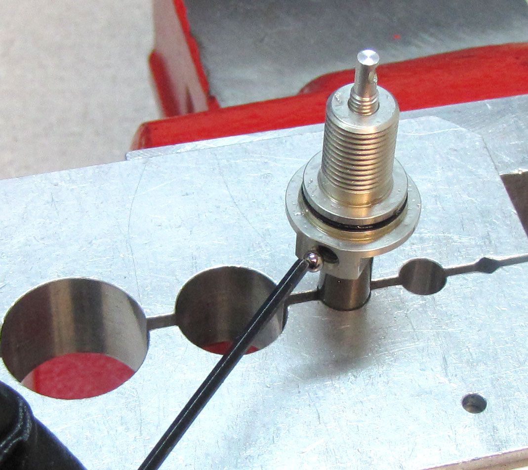
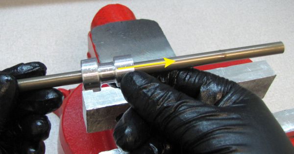
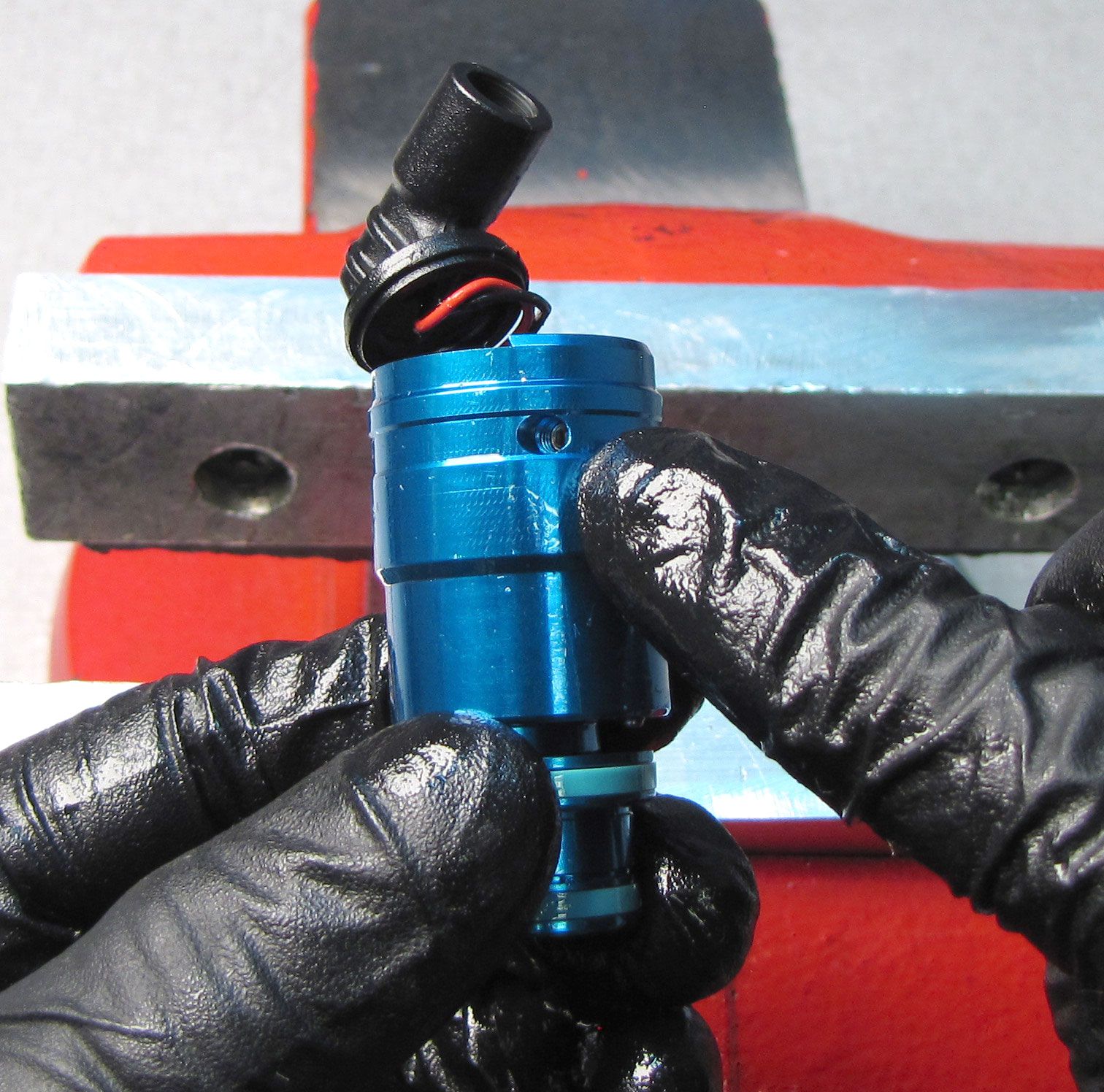
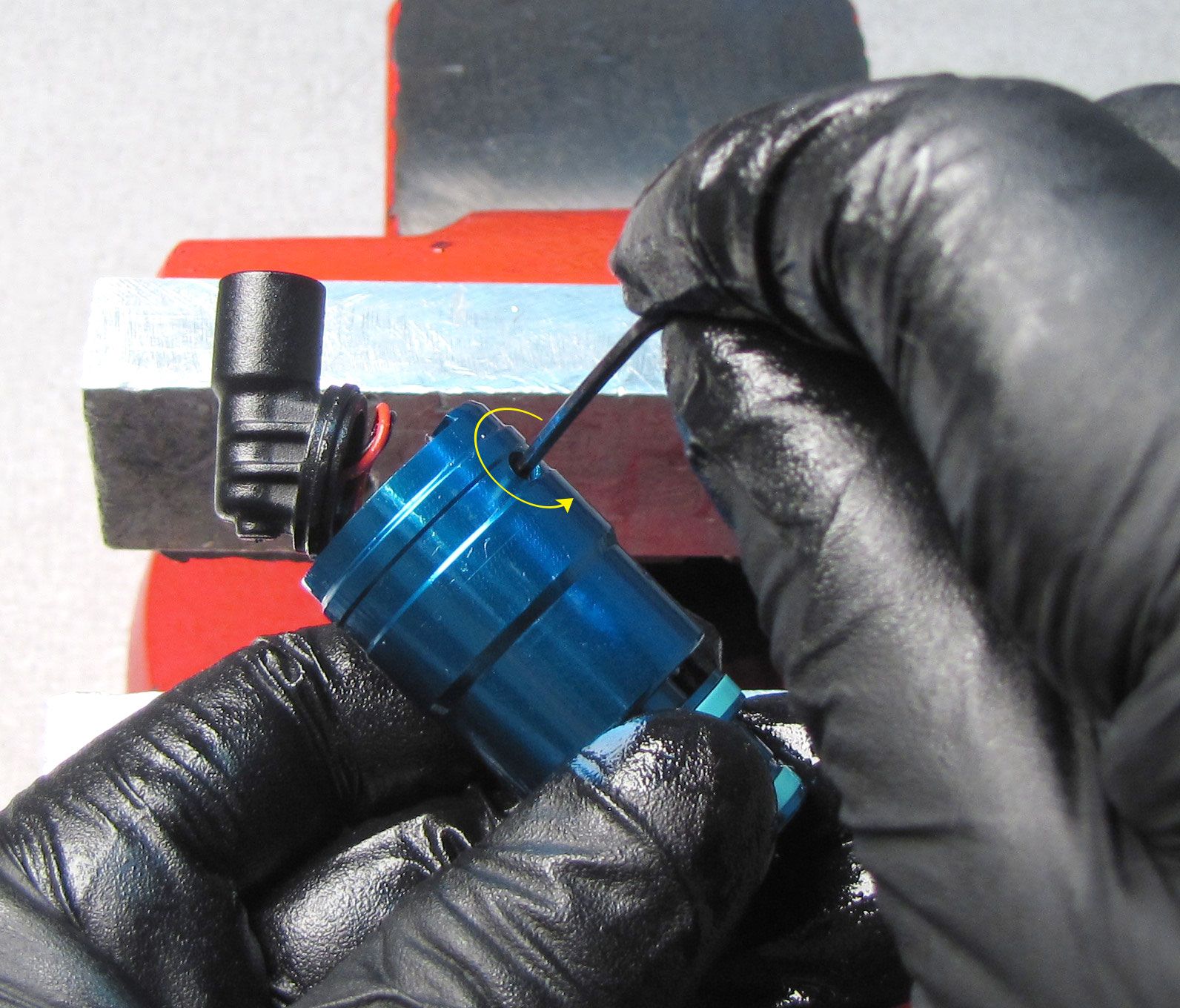
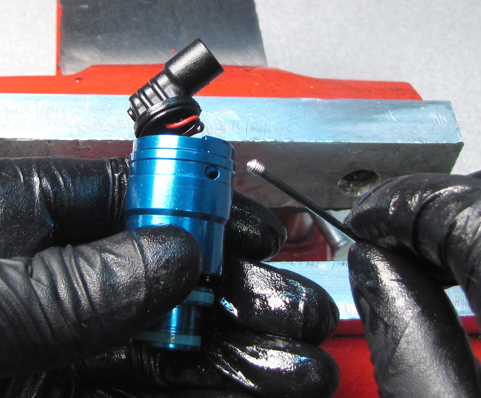
Unthread the set screw from the side of the Compression Cartridge Housing by turning it counter-clockwise with a 1.5mm hex wrench. Remove the detent ball and spring with a magnet.

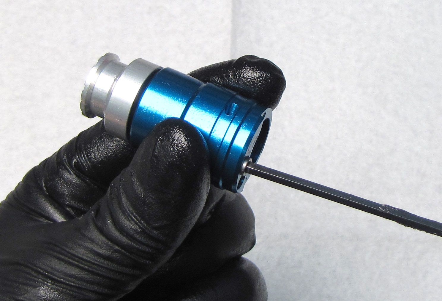
Step 4
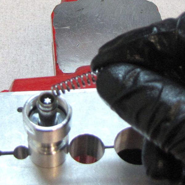
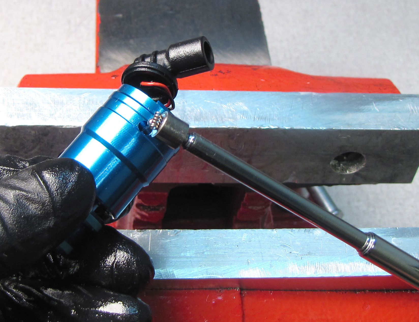
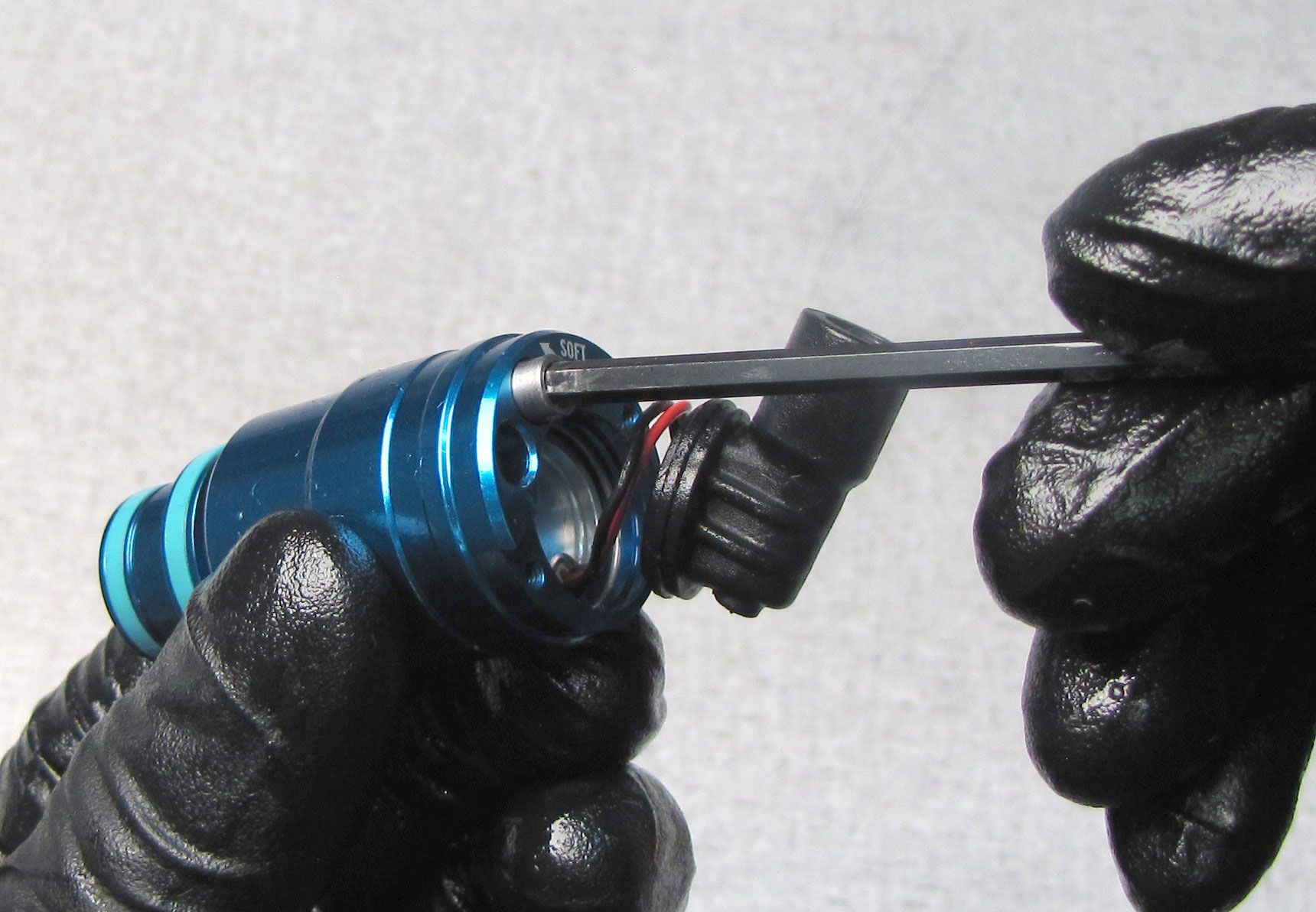
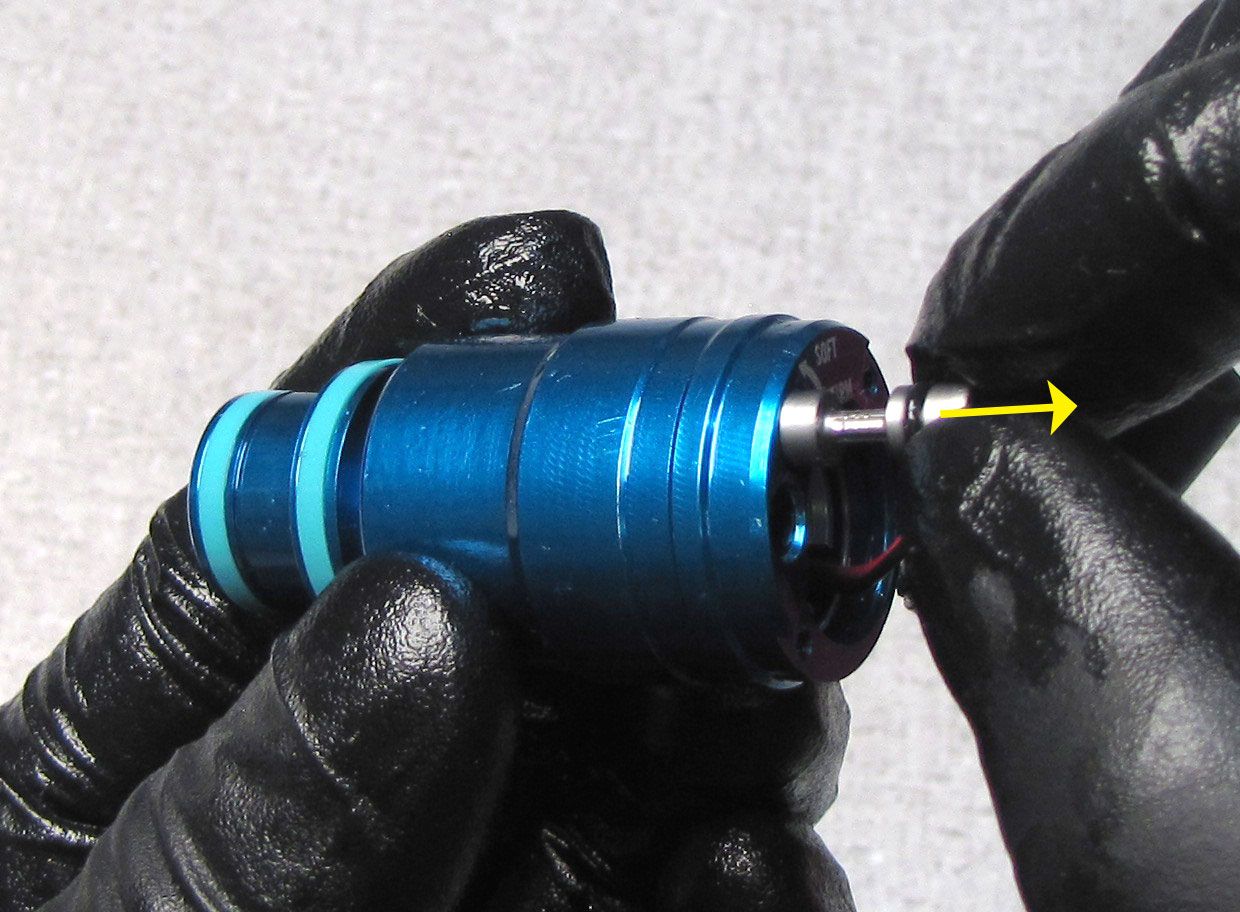
Unthread the Compression Needle counter-clockwise with a 3mm hex wrench. Pull out the Compression Needle to remove it once unthreaded.
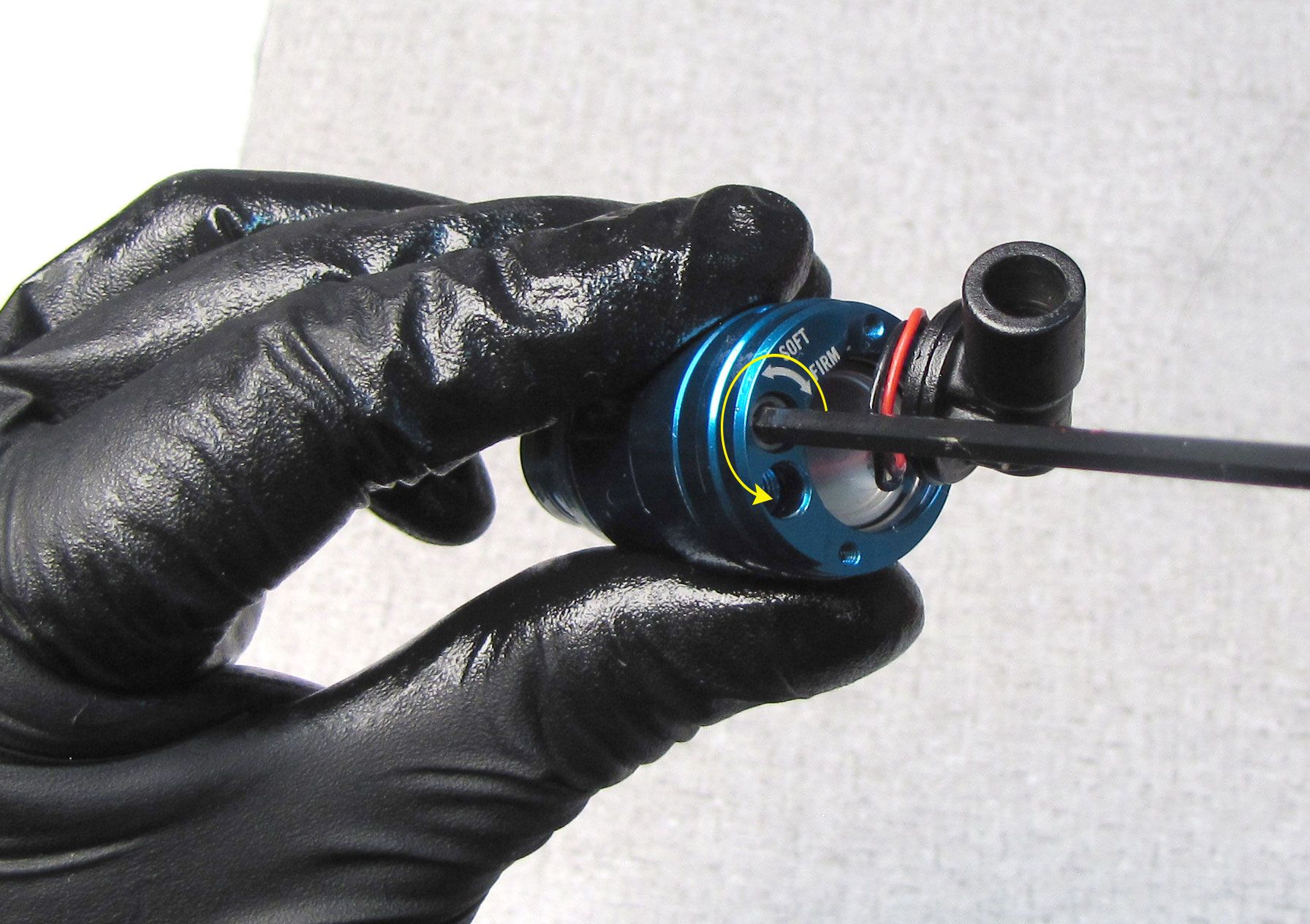

Step 5
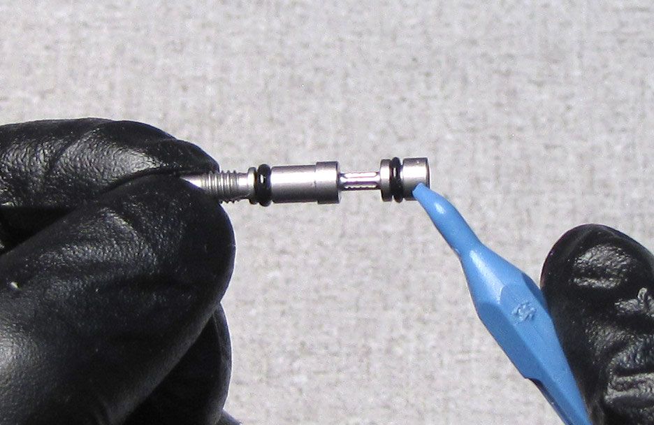
Replace the two o-rings on the Compression Needle with new ones from the kit. Coat the o-rings in FOX 5wt Teflon Infused oil.
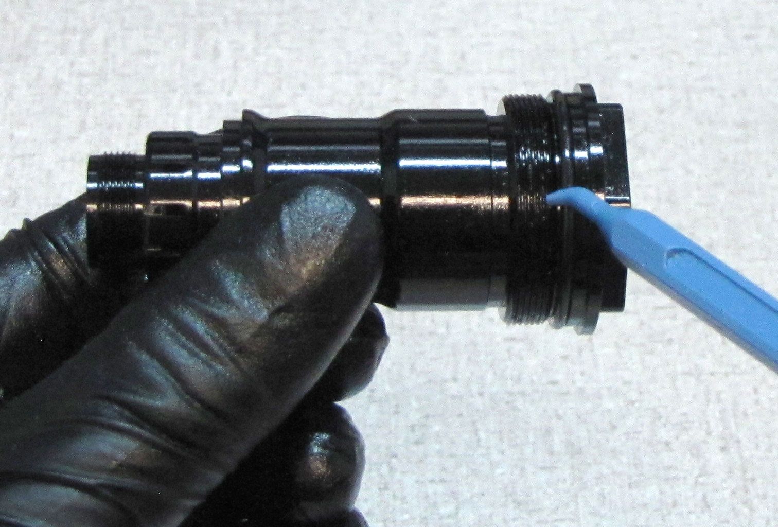
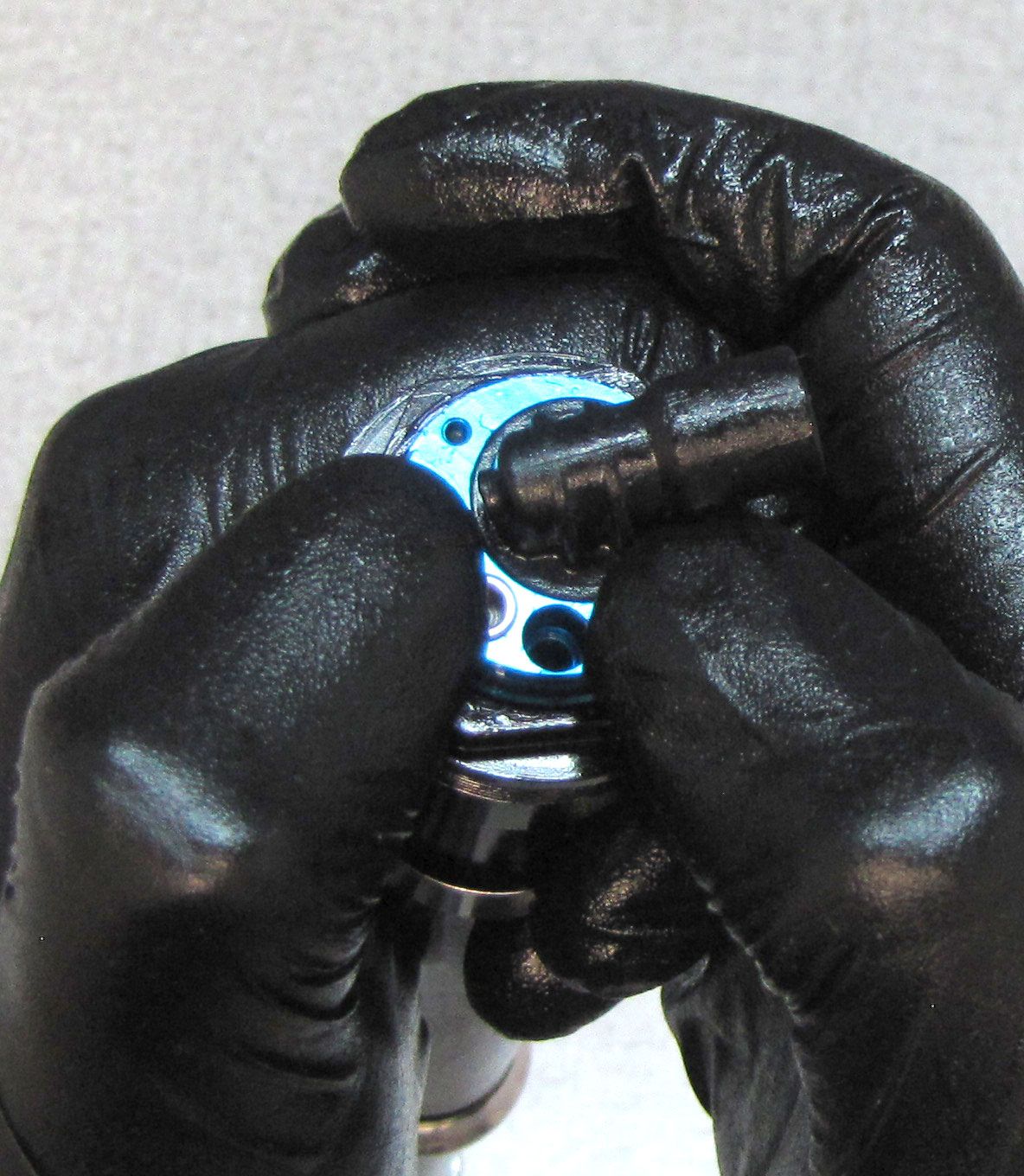
Step 6
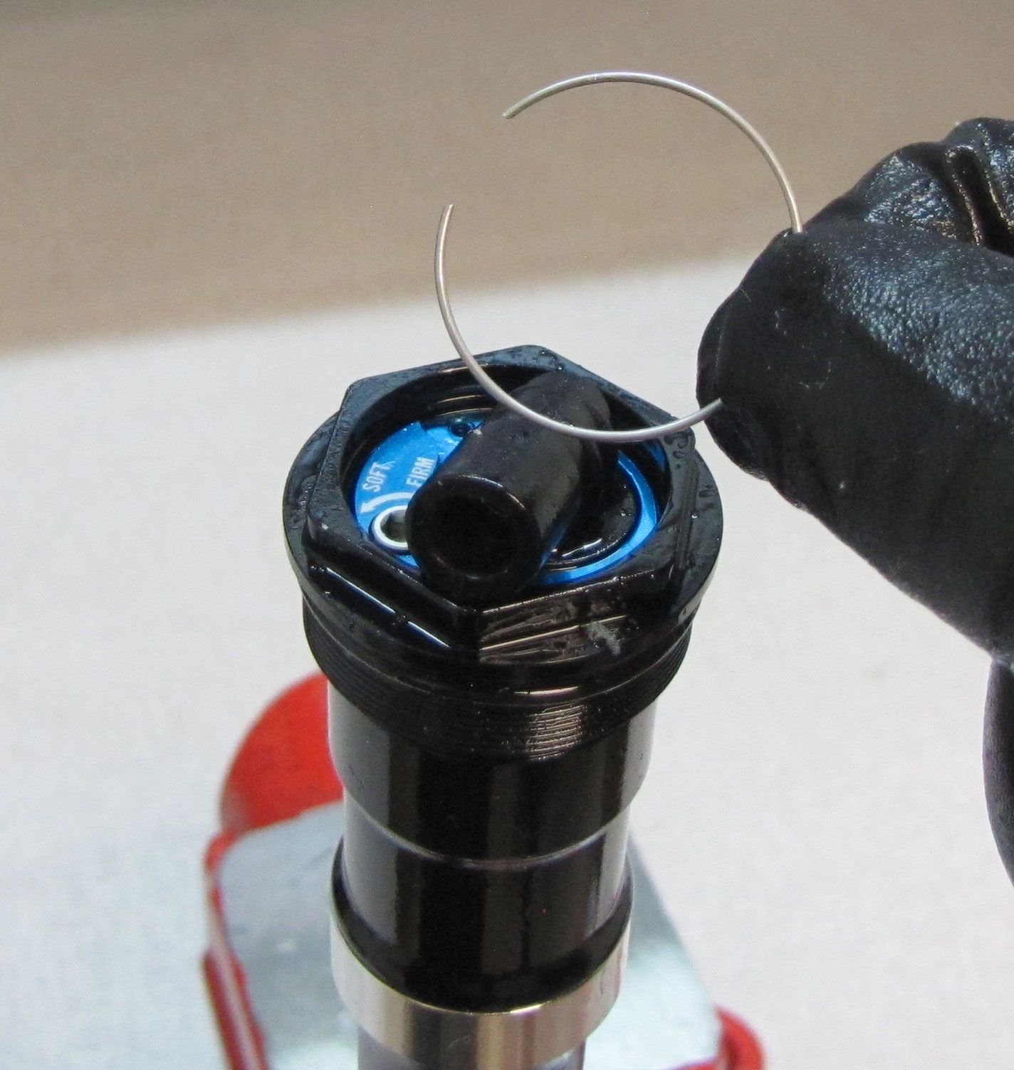
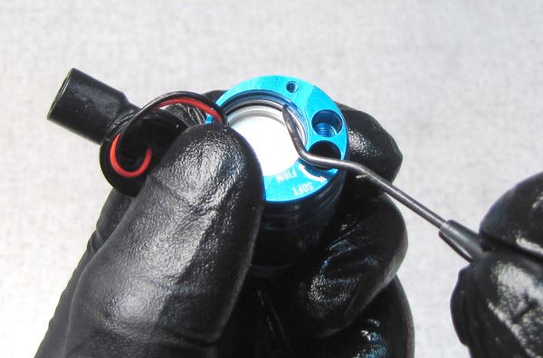
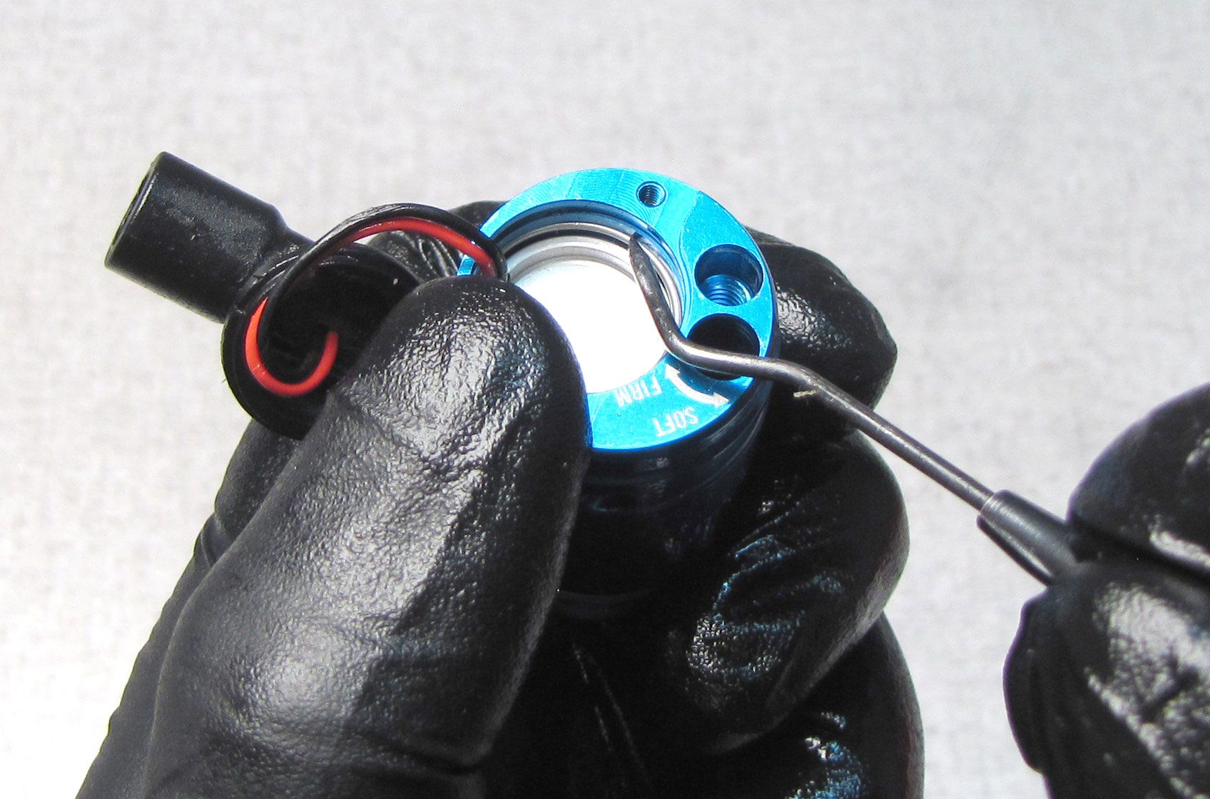
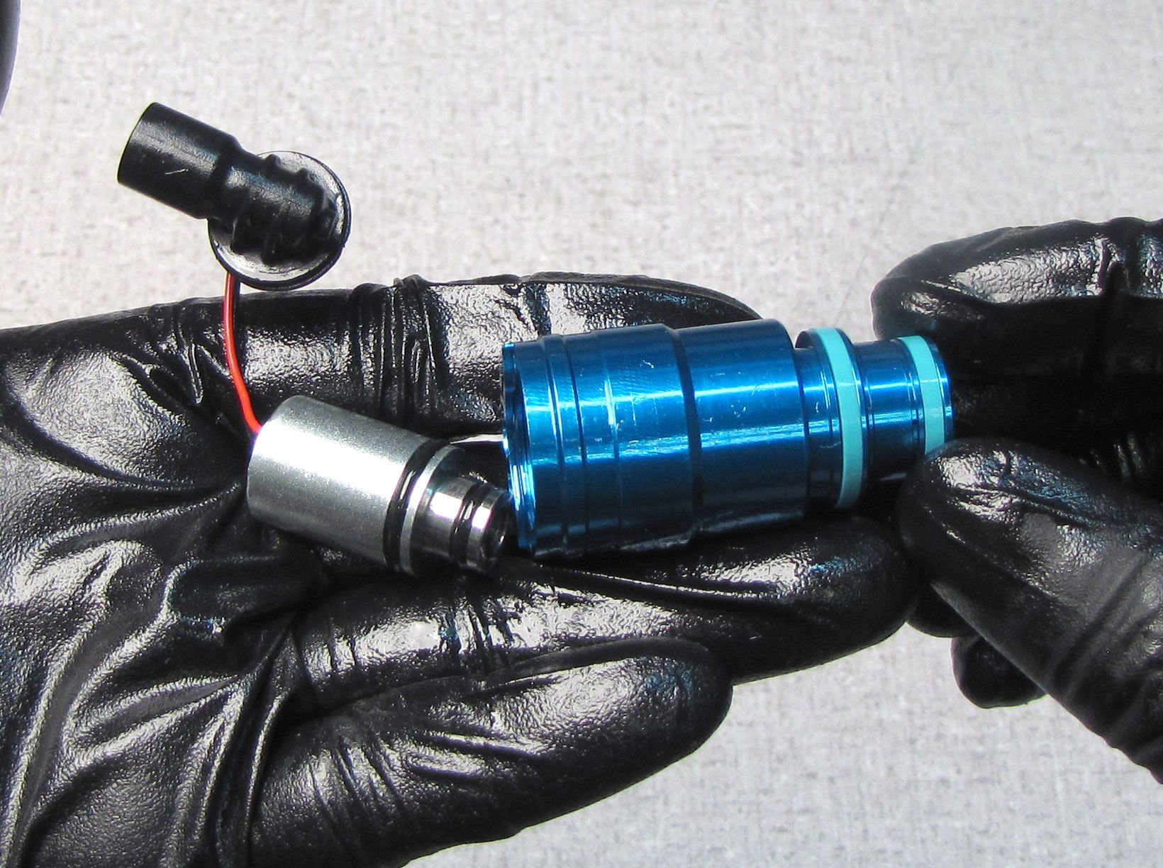
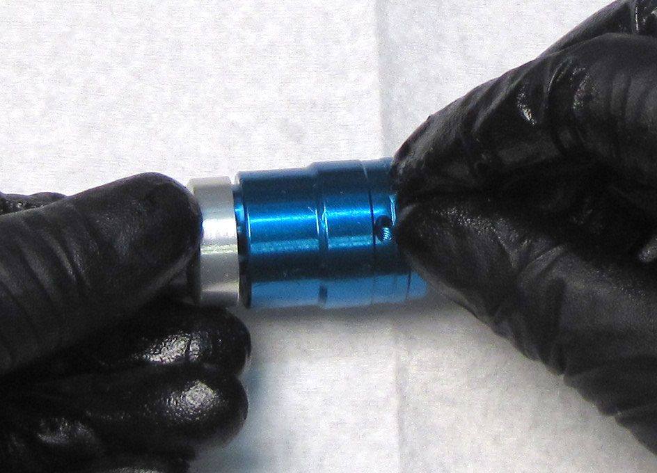
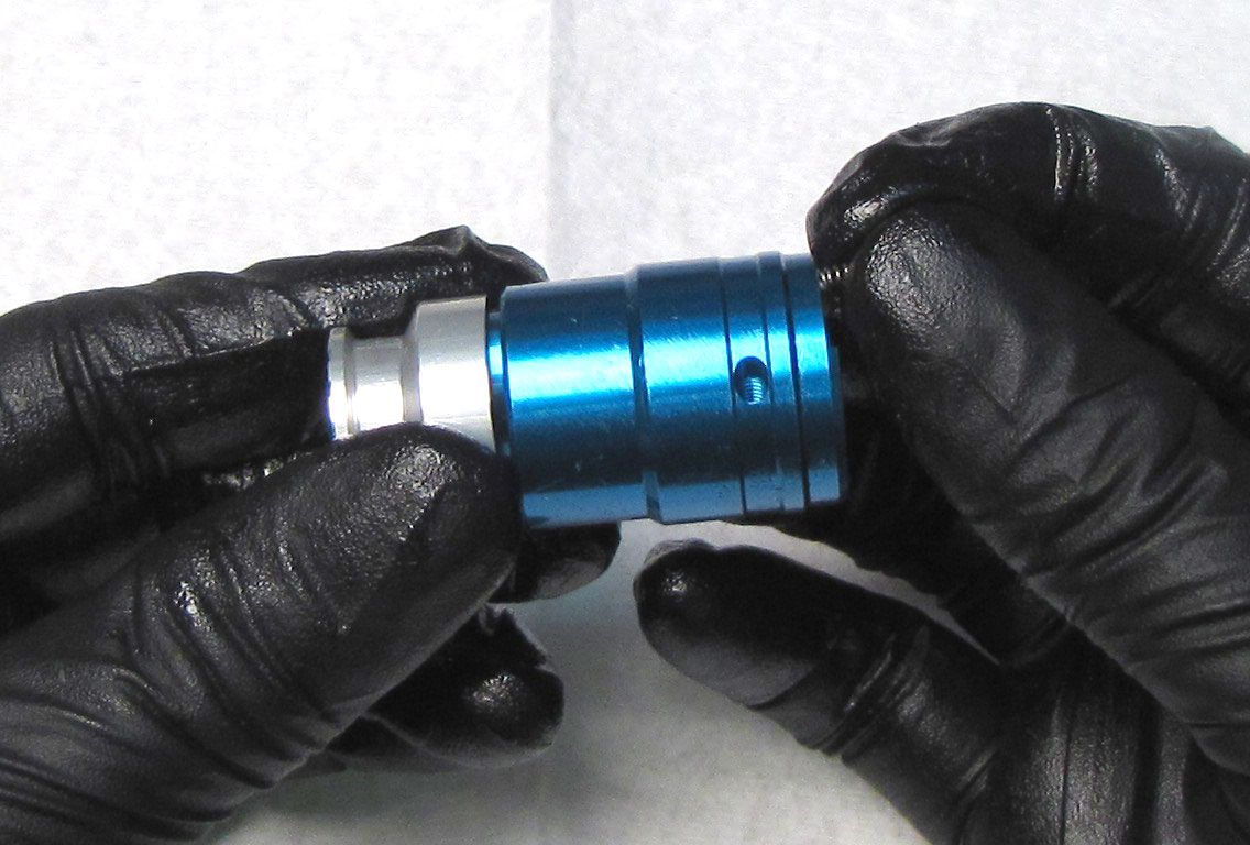
Remove the wire retaining ring from above the Solenoid, then turn the Compression Cartridge Housing over to let the Solenoid Retainer Plate fall out. There is a small releif in the Compression Cartridge Housing near the "SOFT-FIRM" laser-etching to help with retaining ring removal.
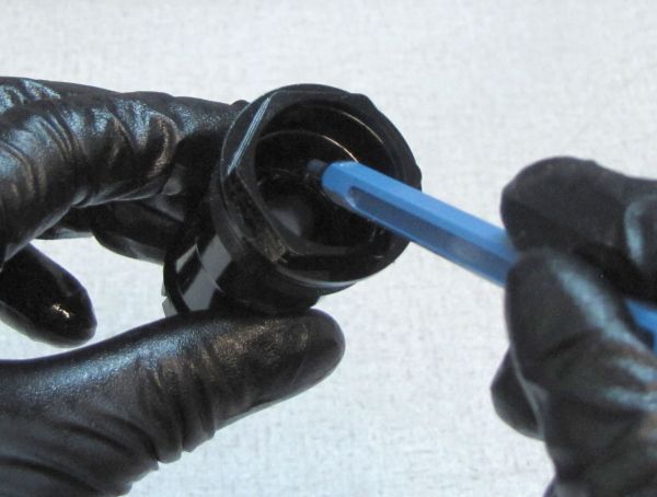
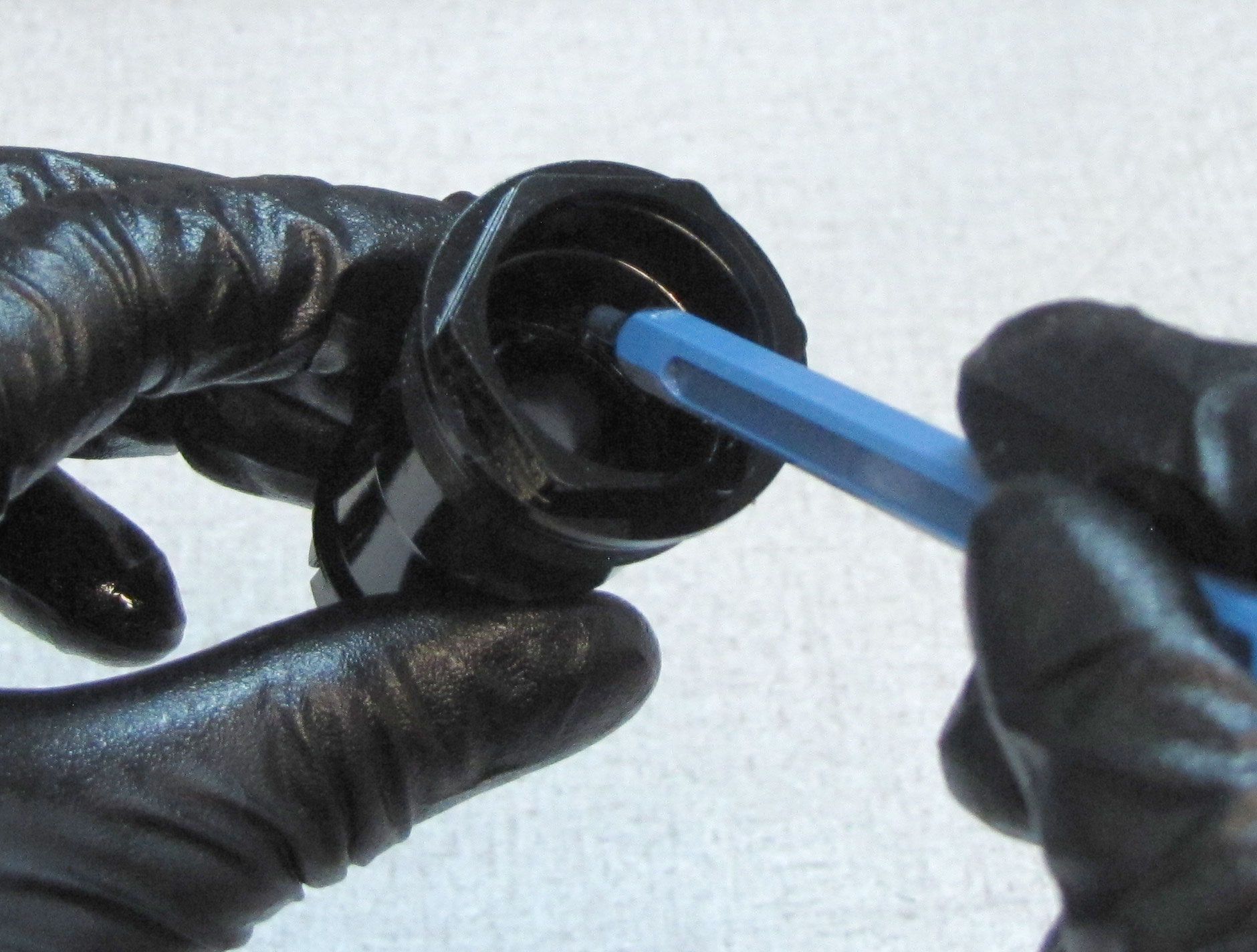
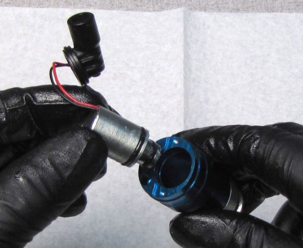
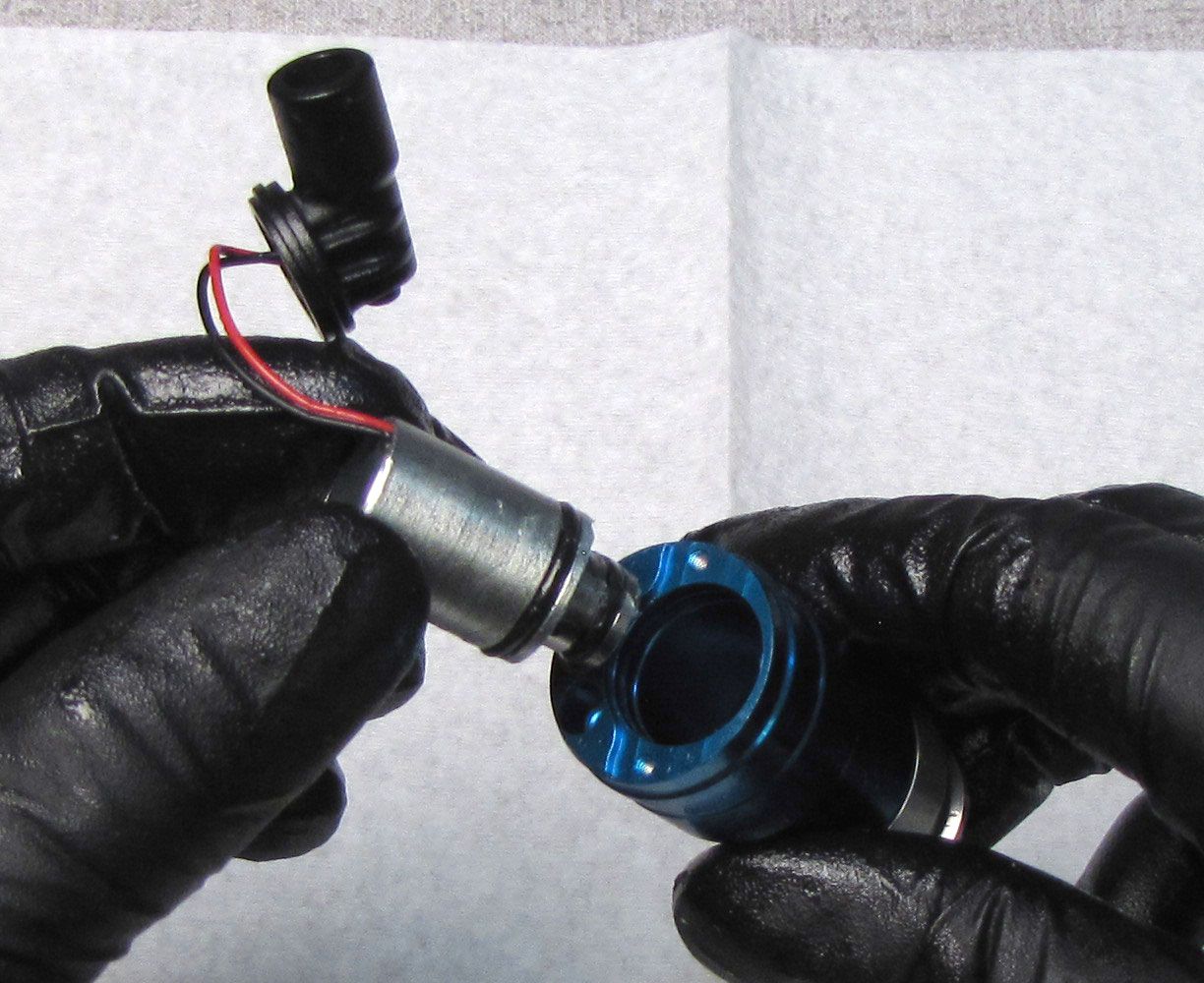
Step 7
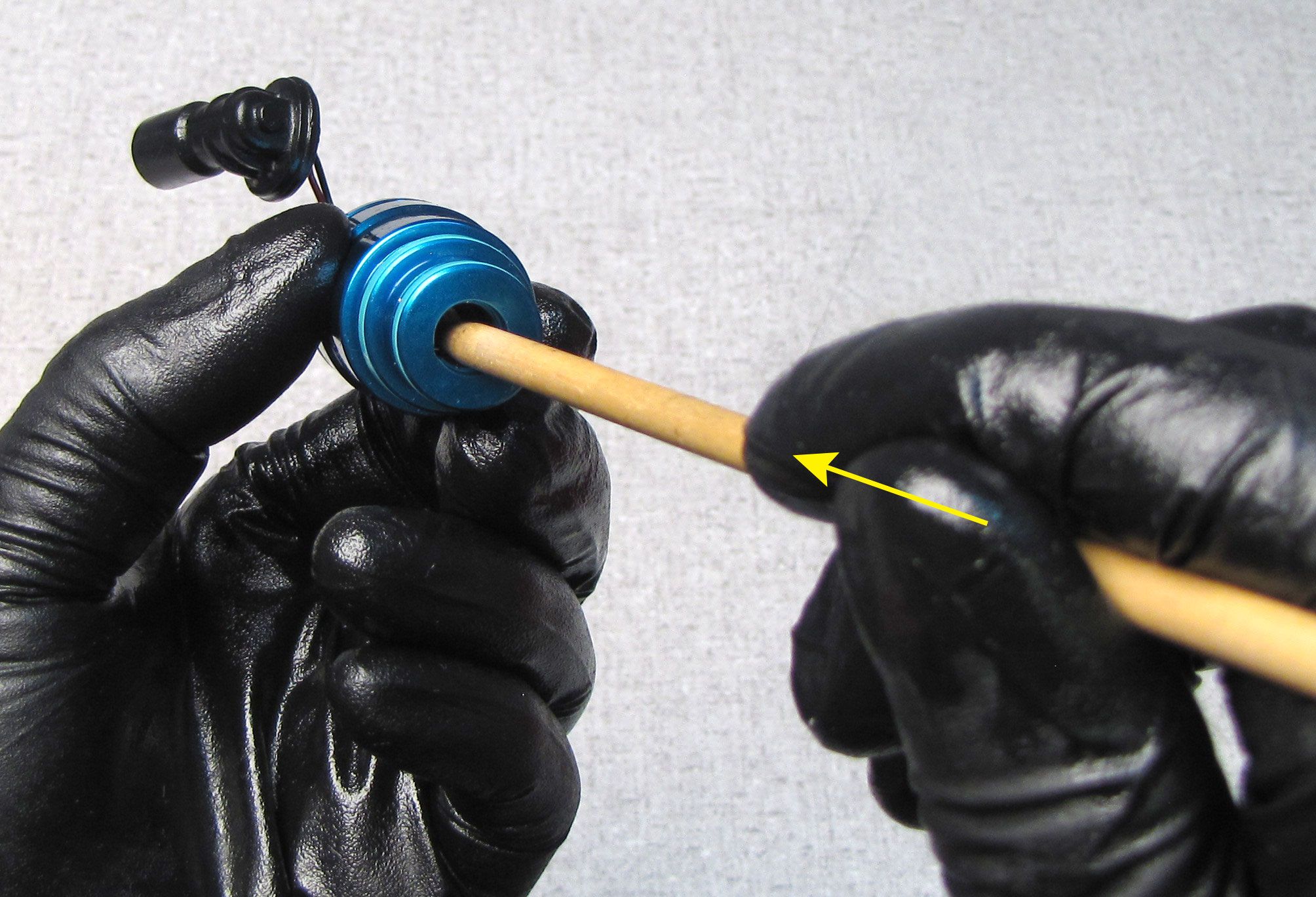
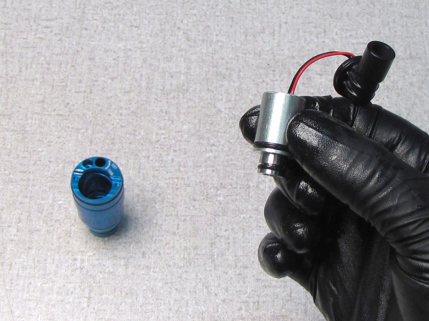
Use a blunt non-marring tool to push the Solenoid out through the top of the Compression Cartridge Housing.

Step 8
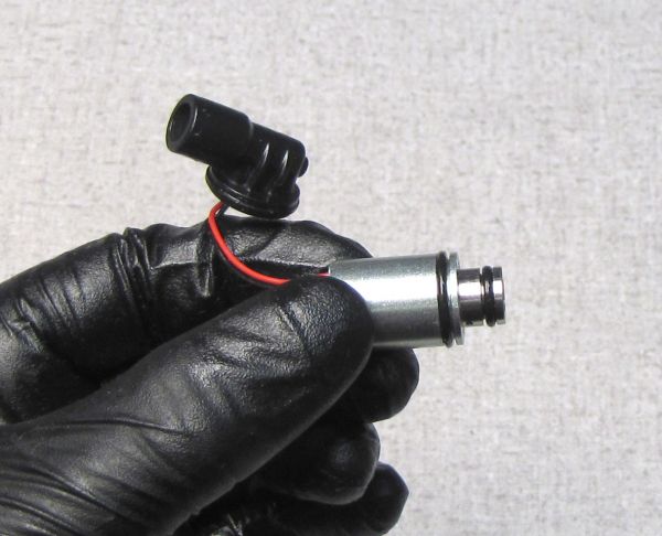
Replace the two o-rings on the Solenoid with new ones from the kit. Coat the o-rings in FOX 5wt Teflon Infused oil.

Step 9
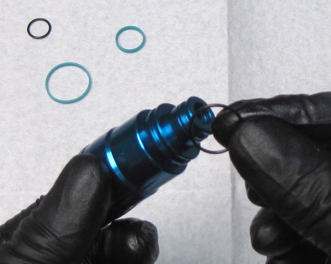
Remove the two glide rings and two o-rings from the Compression Cartridge Housing. Replace the two o-rings on the Compression Cartridge Housing with new ones from the kit. Coat the o-rings with FOX 5wt Teflon Infused oil. Replace the two glide rings with new ones from the kit. Make sure that the o-rings do not get pinched by the glide rings during installation.
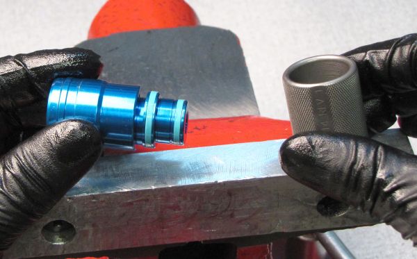
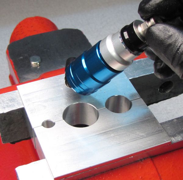
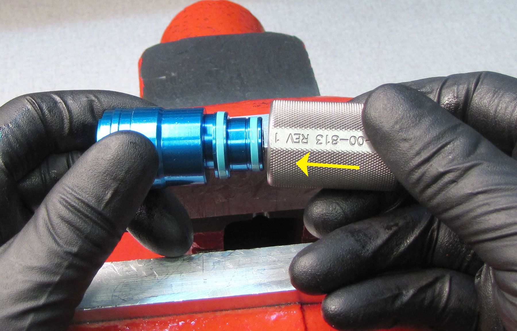
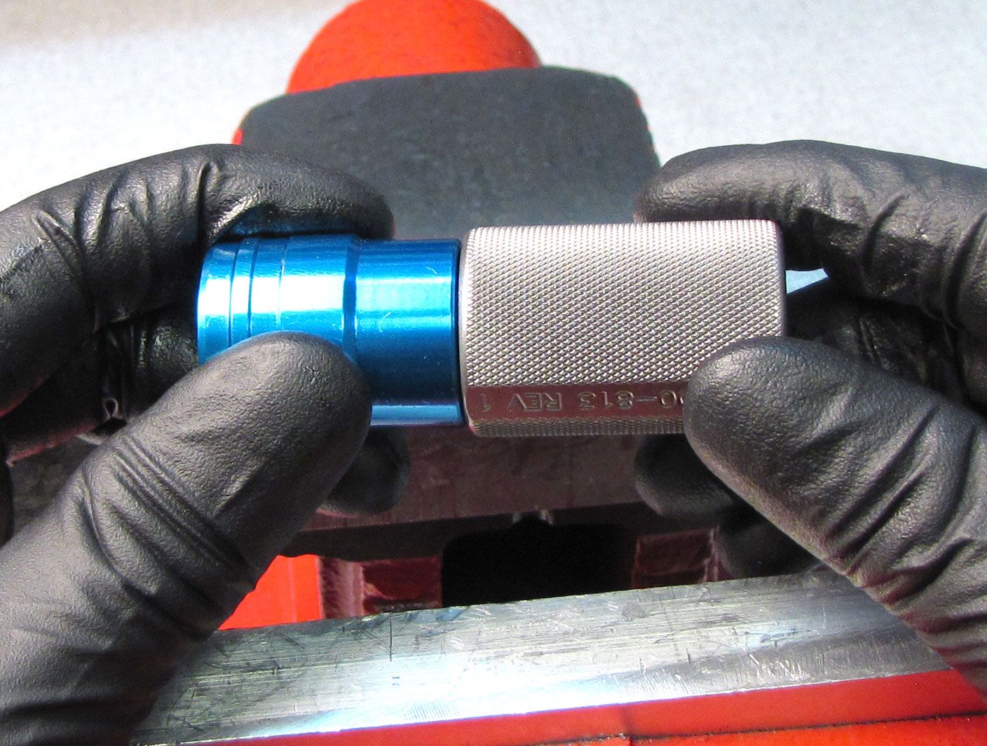
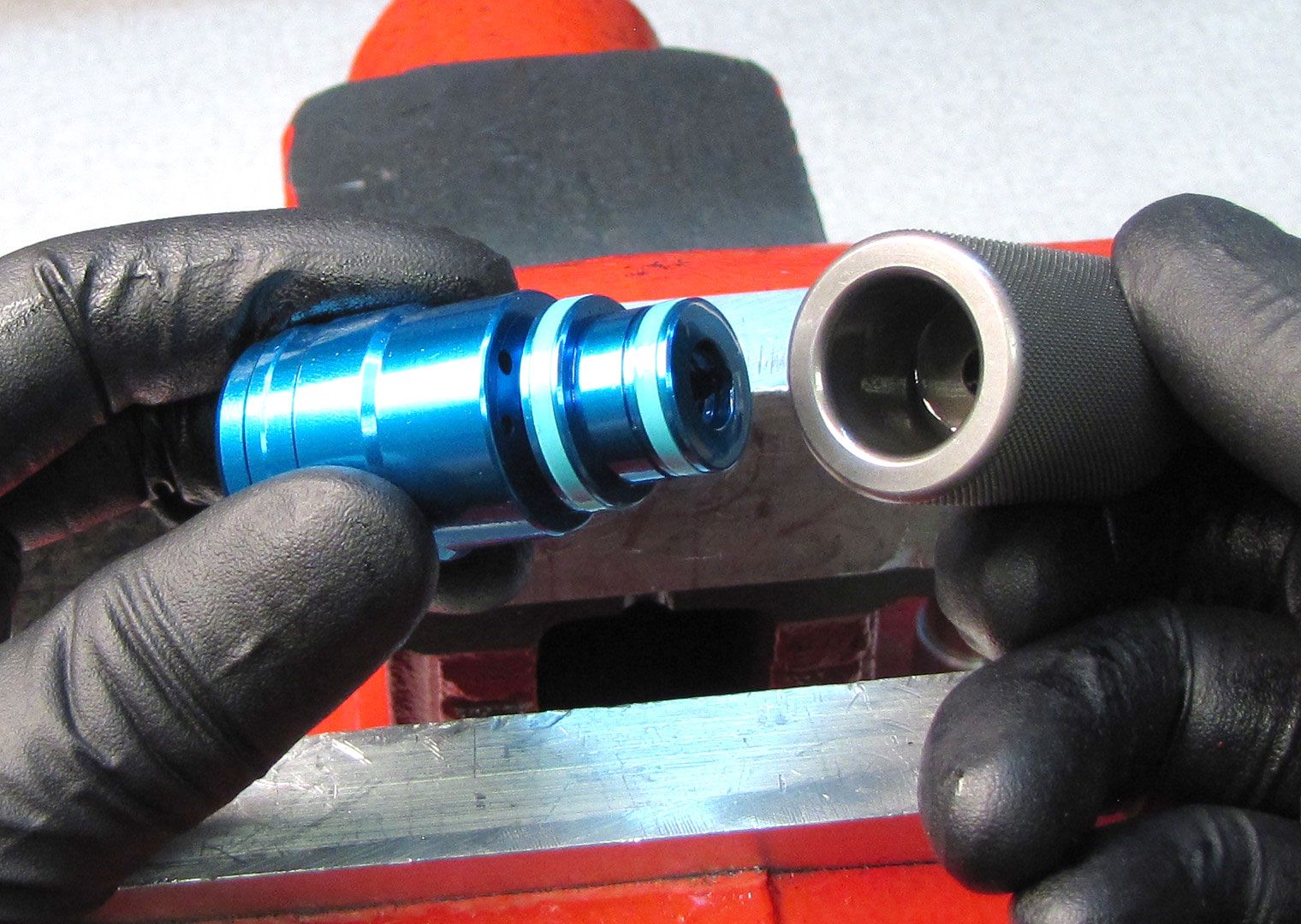
Step 10
Insert the Compression Housing Assembly with new glide rings into the larger end of the approriate sizer (fork or shock) then remove. Repeat with the smaller end of the appropriate sizer.


Step 11
Coat the Boost Valve with a thin film of FOX 5wt Teflon Infused Oil then slide it onto the Compression Cartridge Housing. Make sure the Boost Valve slides freely after installation.

Step 12
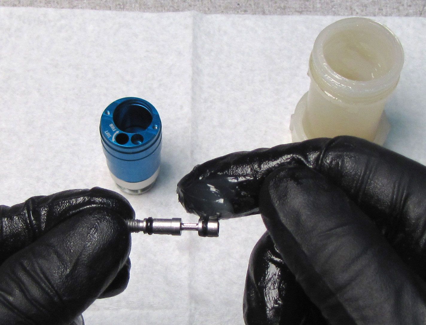
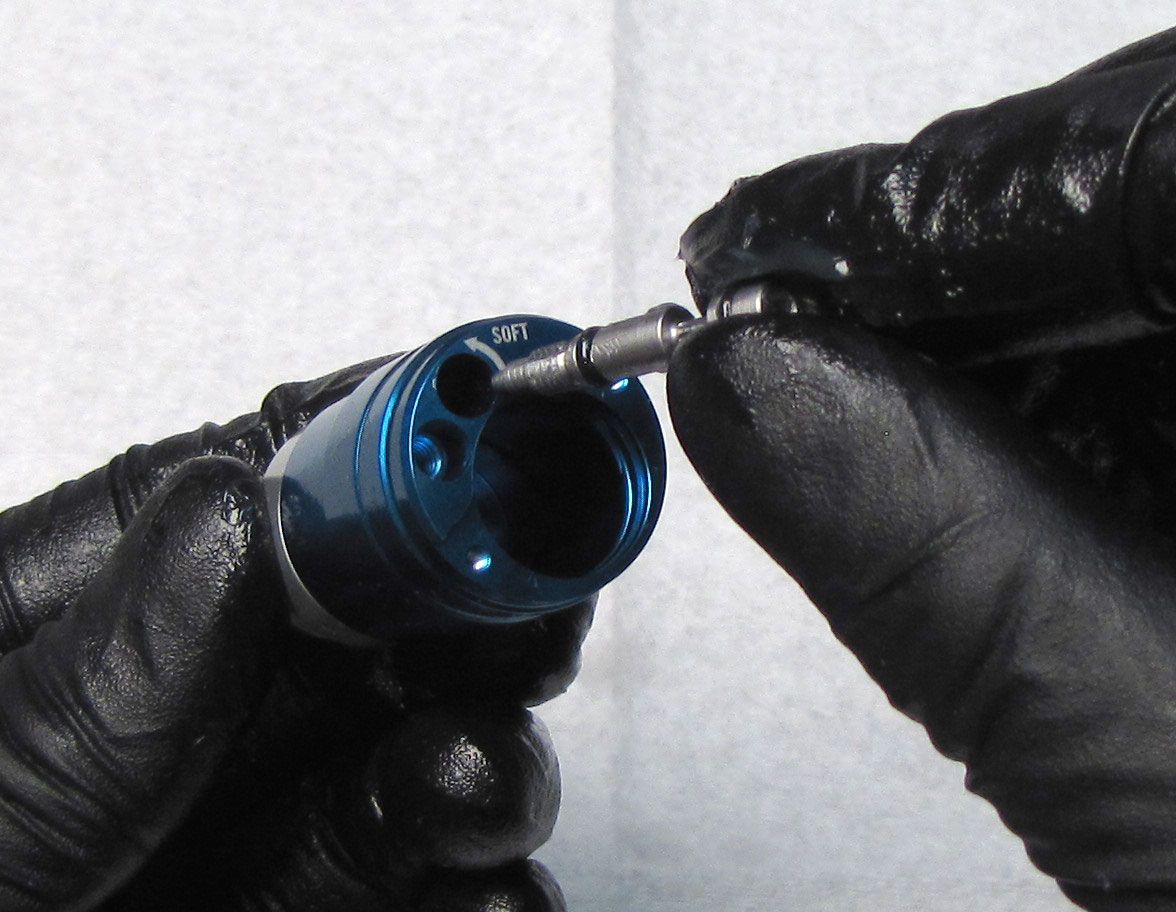
Coat the Compression Needle with a thin film of FOX 5wt Teflon Infused oil then reinstall into the Compression Cartridge Housing by turning it clockwise until flush.
Step 13
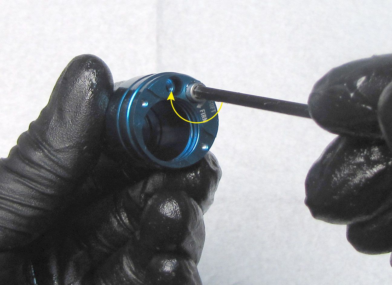
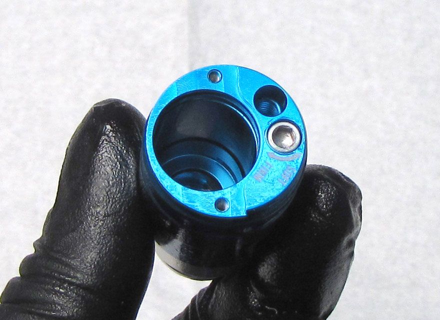
Reinstall the detent ball followed by the spring and set screw. Tighten the set screw clockwise until bottomed out then turn it counter-clockwise 1/2 turn with your 1.5mm hex wrench. Check for audible detent clicks when turning the Compression Needle with a 3mm hex wrench.
Step 14
Coat the Solenoid o-rings in FOX 5wt Teflon Infused oil then reinstall the Solenoid into the Compression Cartridge Housing. Push the Solenoid into the Compression Cartridge Housing to create space for the Retainer Plate and Retaining Ring.
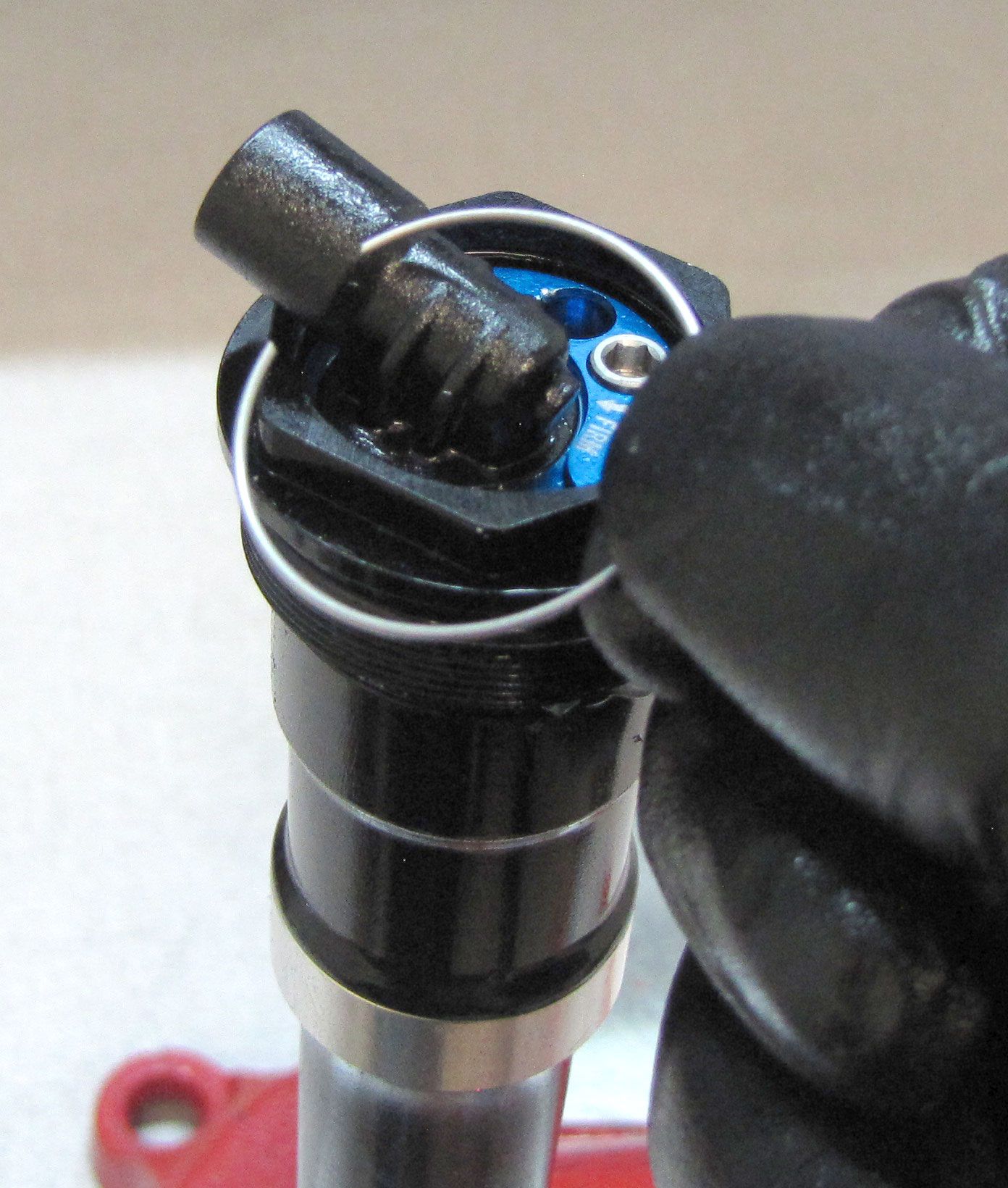
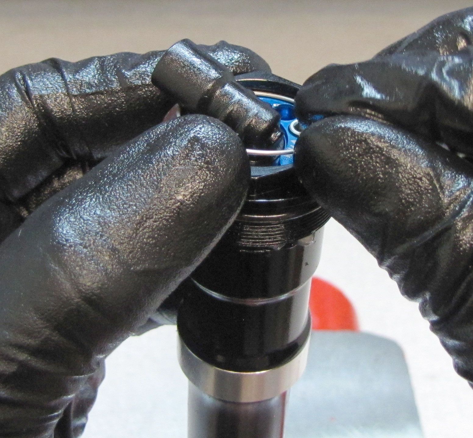
Step 15
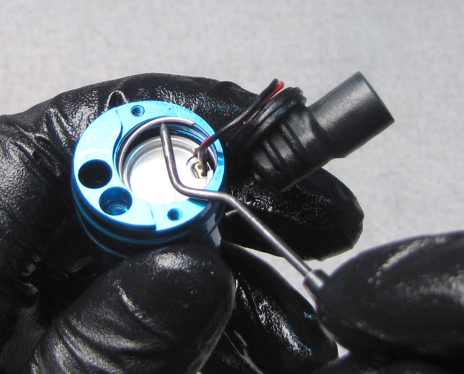
Reinstall the Solenoid Retainer Plate with its notch aligned with the two wires exiting the Solenoid. Reinstall the wire retaining ring making sure that it is fully seated in the groove. Orient the retaining ring so the gap in the ring is opposite the gap in the plate that the wires go through.


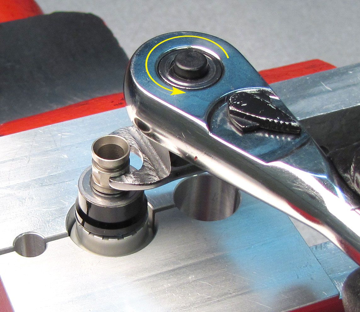
Step 16
Clamp the Compression Cartridge Housing in your shaft clamps (PN: 803-01-360) then reinstall the Fork Compression Valving Assembly tightening clockwise to 40 in-lb (4.5 Nm) torque with an 8mm crowsfoot.

Reassembly
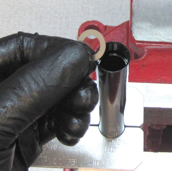
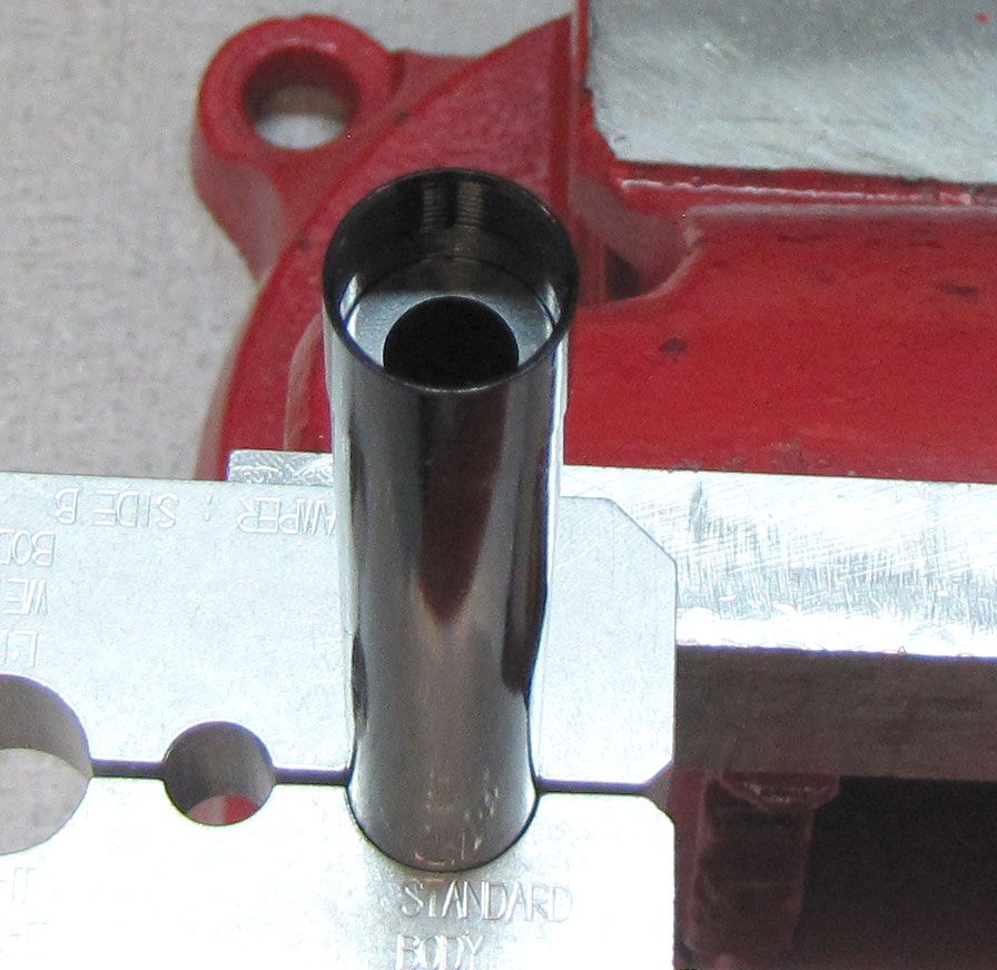
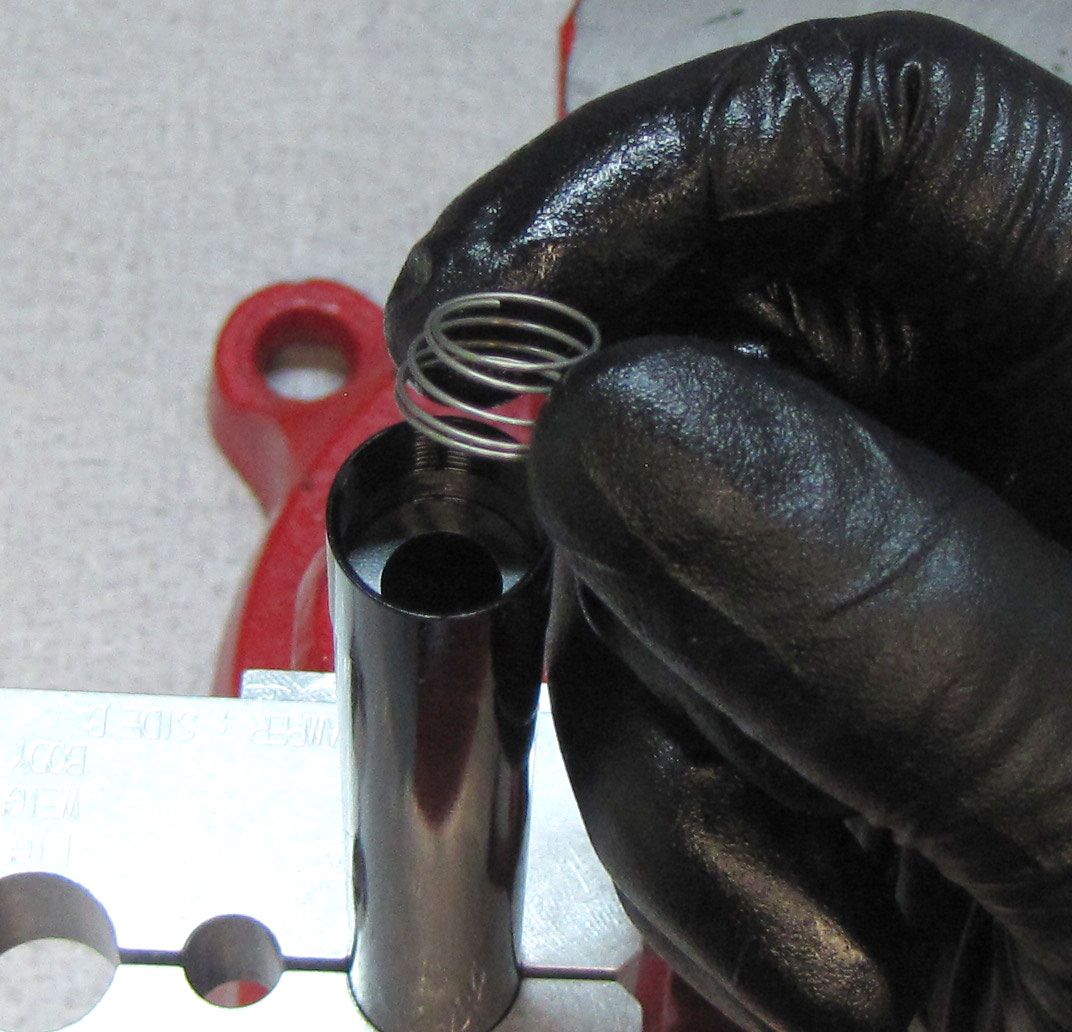
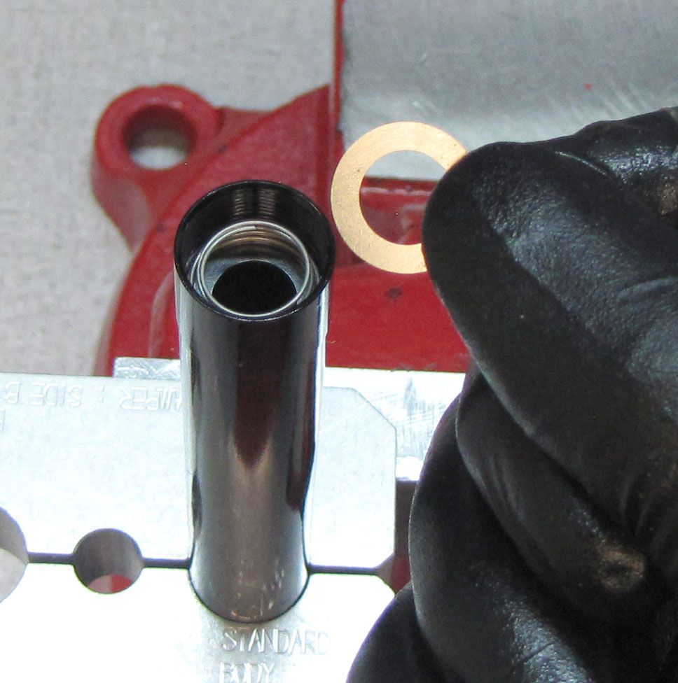
Step 1
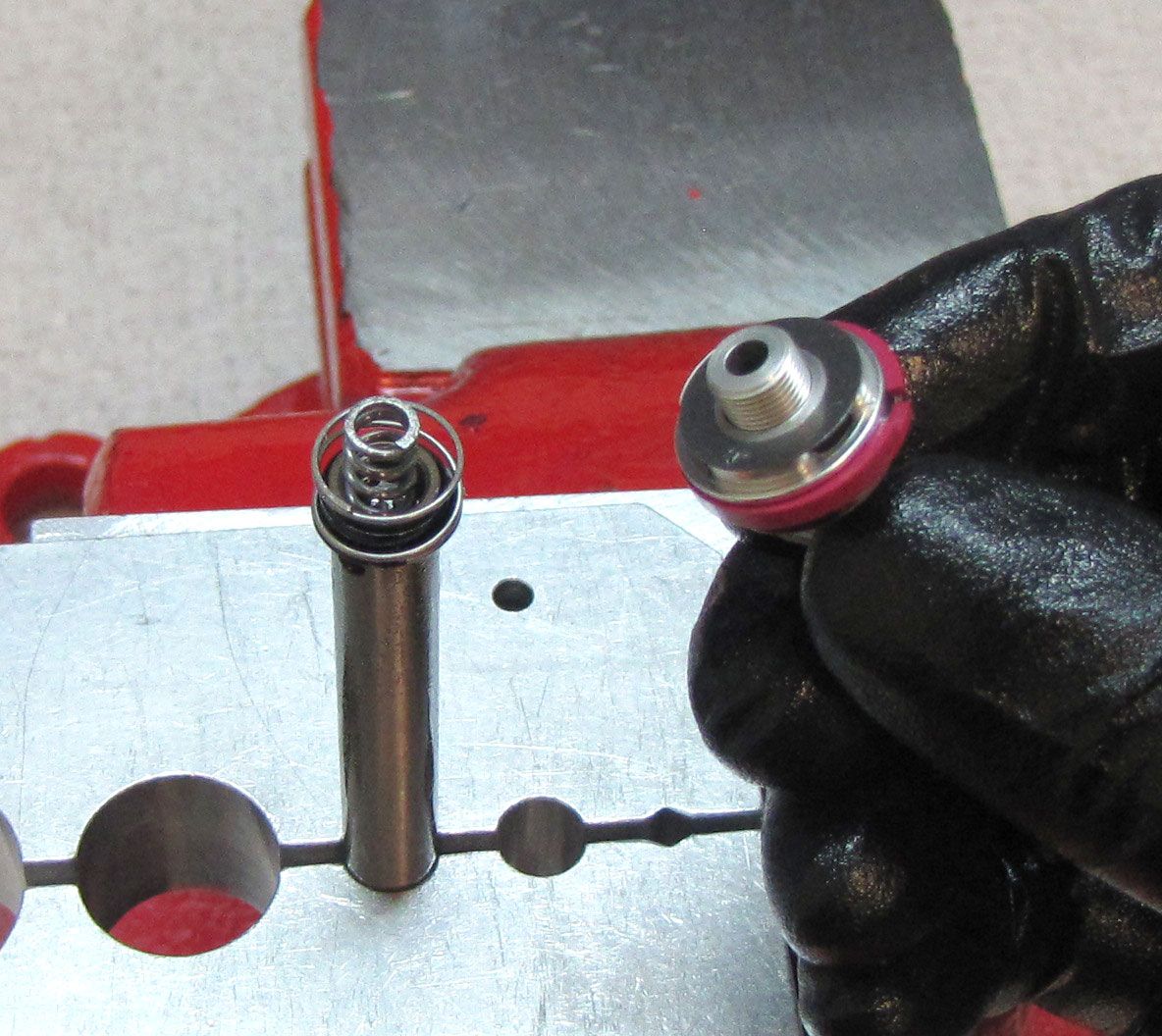
Reinstall once of the two Compression Check shims into the cartridge body resting it on the internal retaining ring. Reinstall the Compression Check spring with it's narrow end oriented toward the topcap. Reinstall the second Compression Check shim on top of the spring.


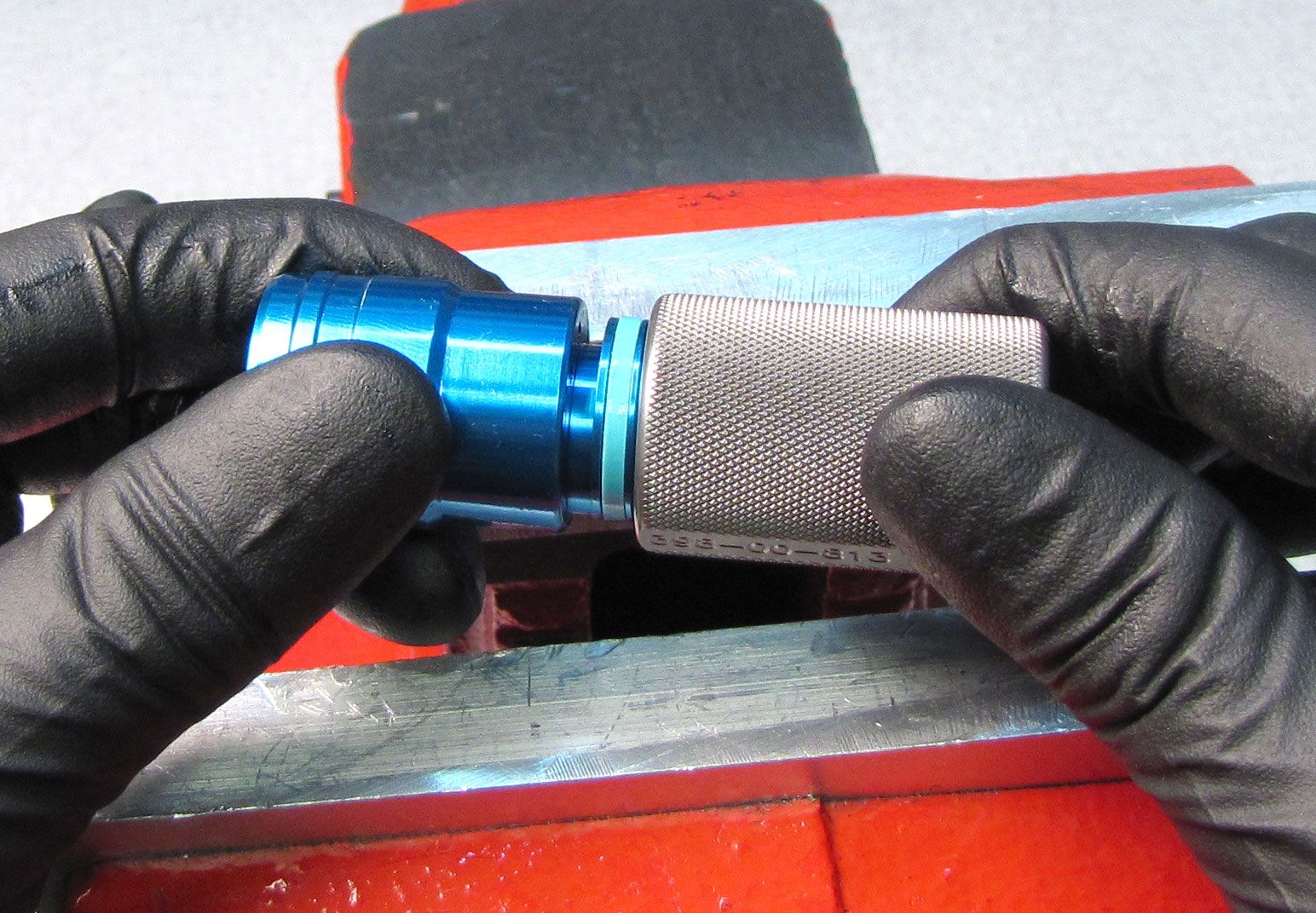
Step 2
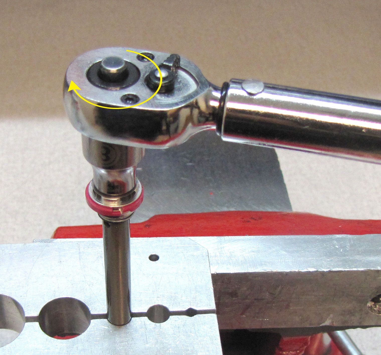
Thread the Topcap clockwise into the end of the Cartridge Body. Clean the cartridge body with isopropyl alcohol and a lint-free paper towel, then clamp it in your shaft clamps (PN: 803-01-360) as shown. Tighten the Topcap clockwise to 55 in-lb (6.2 Nm) torque with a 6-point chamfer-less 28mm socket (PN: 398-00-707).
Step 3
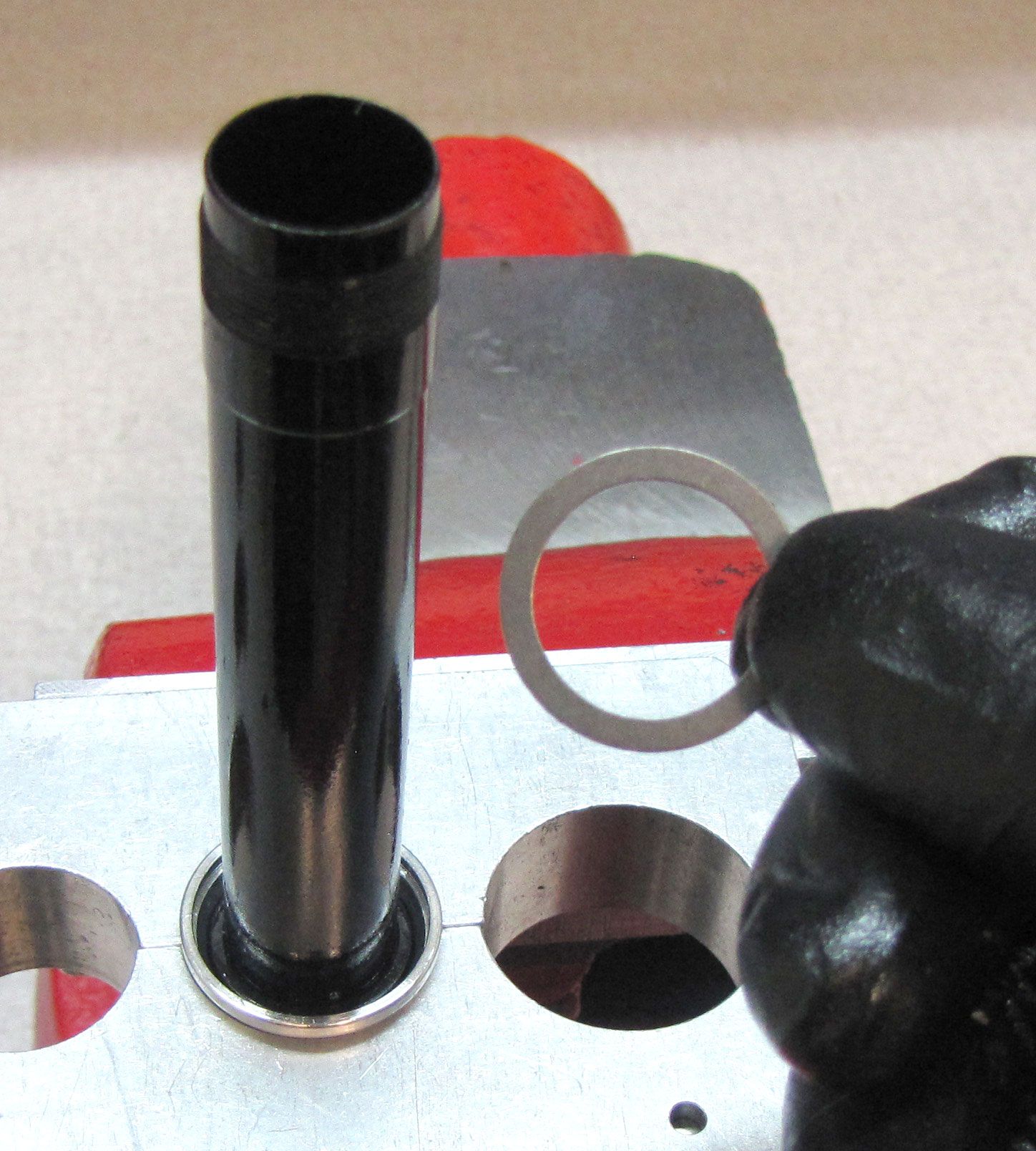
Slide the Upper Bladder Ring onto the Cartridge Body against the Topcap. Apply a thin coating of FOX 5wt. Teflon Infused Oil to the inside and outside of both ends of a new bladder from the kit, then install the Lower Bladder Ring as shown with it's larger end oriented toward the small end of the bladder.
Step 4
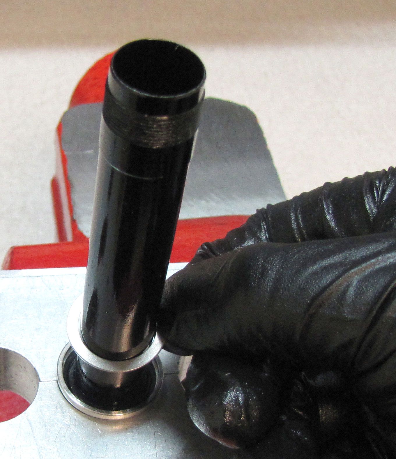
Slide the Upper Bladder Ring down over the large end of the new Bladder. Slide the Bladder all the way up against the topcap. Slide the Upper Bladder Ring up seating it against the topcap.
Step 5
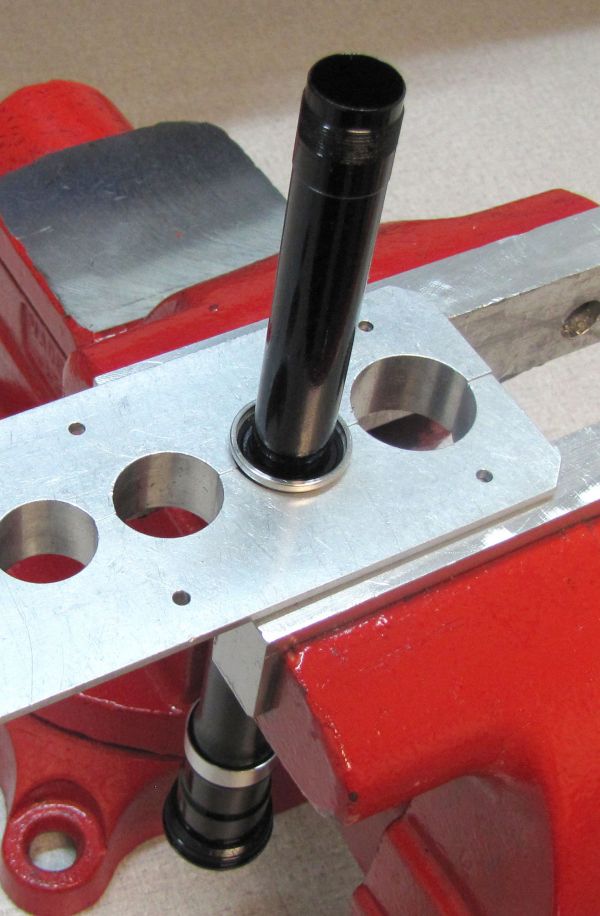
Place the bladder and cartridge body assembly into the second largest hole in the sahft clamps #2 (PN: 803-00-147) as shown; loosely resting the bladder ring on the clamps, no clamping pressure applied to the bladder ring. While gently tugging the bladder from below, you will seat the bladder in the bladder ring deep enough to install the bladder retainer and retaining ring.


Step 6
Install a new greased o-ring from the kit onto the outside of the Rebound Adjuster. Coat the threads of the Rebound Adjuster Screw with a thin film of waterproof marine grease such as Sta-Lube SL3125. Thread the Rebound Adjuster Screw clockwise into the Rebound Adjuster.
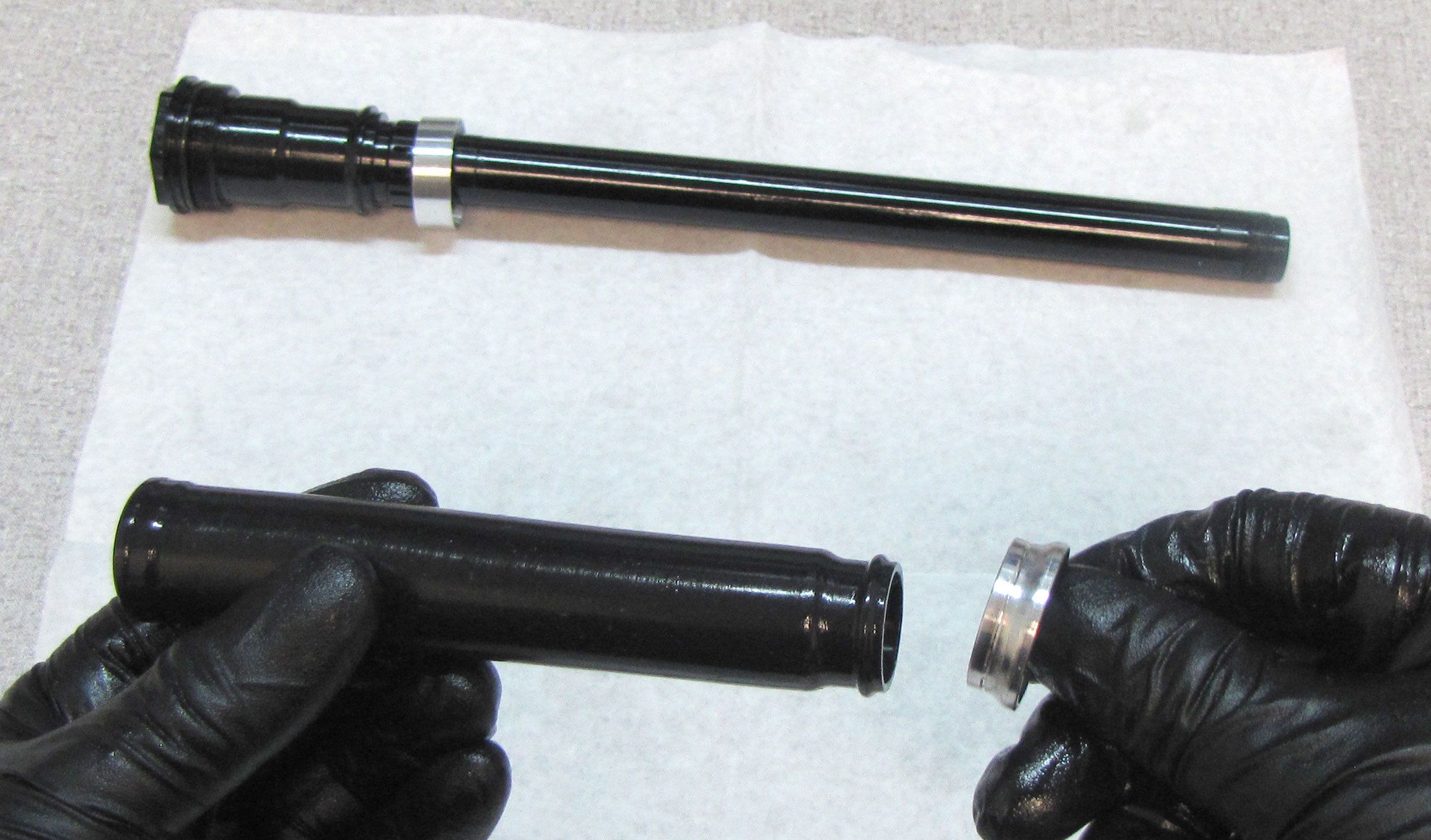
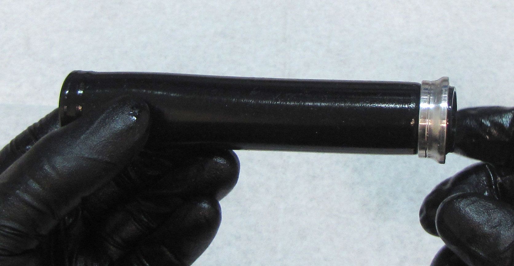
Step 7
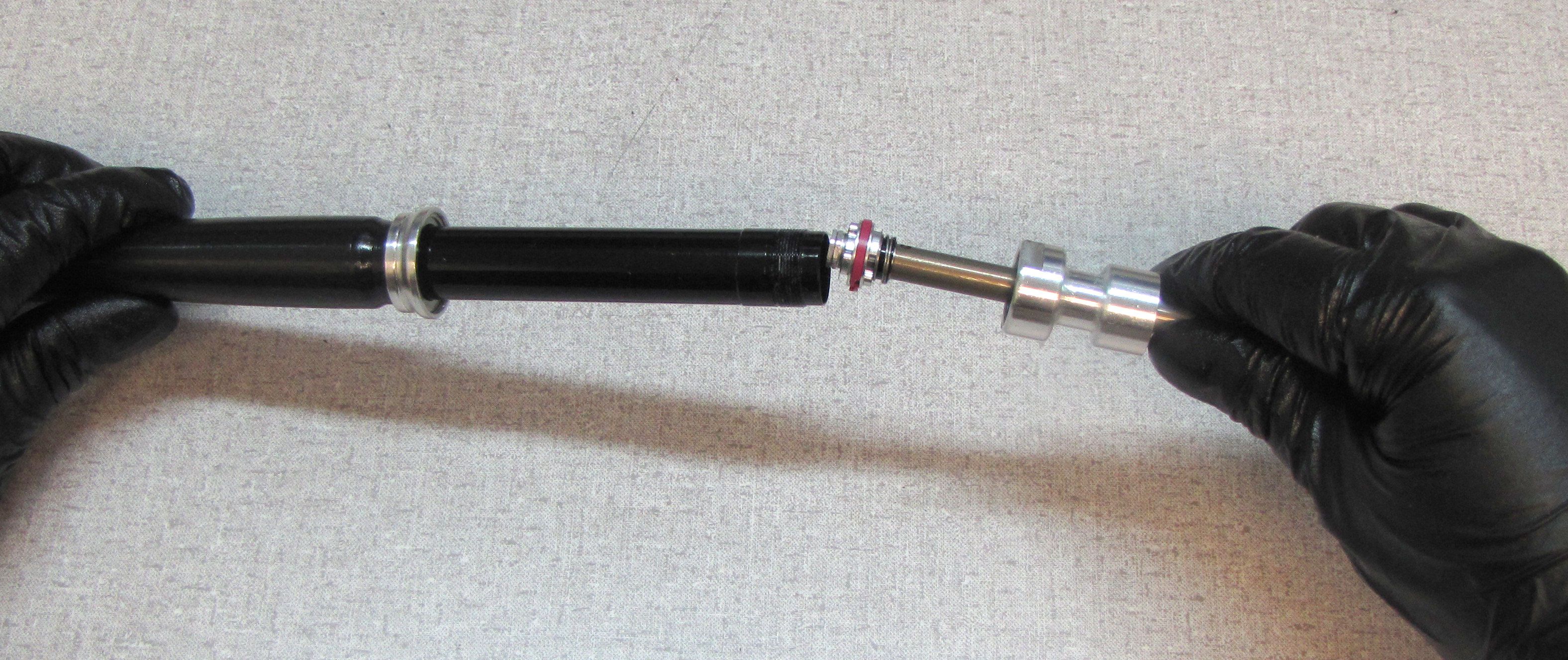
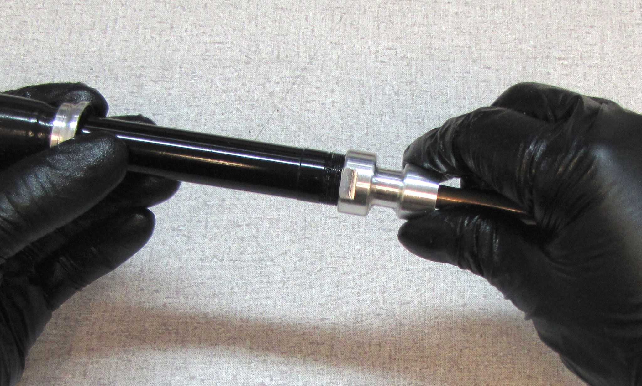
Install the 8mm Bullet Tool (PN: 398-00-320) into the end of the shaft without the retaining ring groove. Coat the Bullet tool with a thin film of Slick Honey. Install the new Sealhead from the kit with its threaded end first. Remove the Bullet tool.
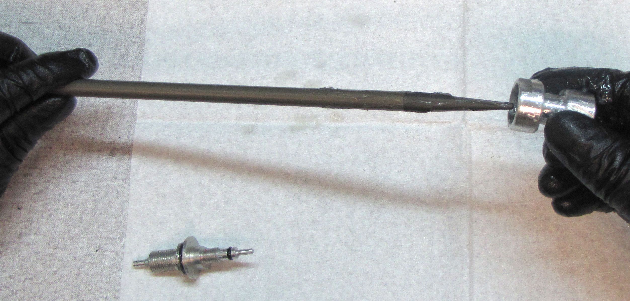
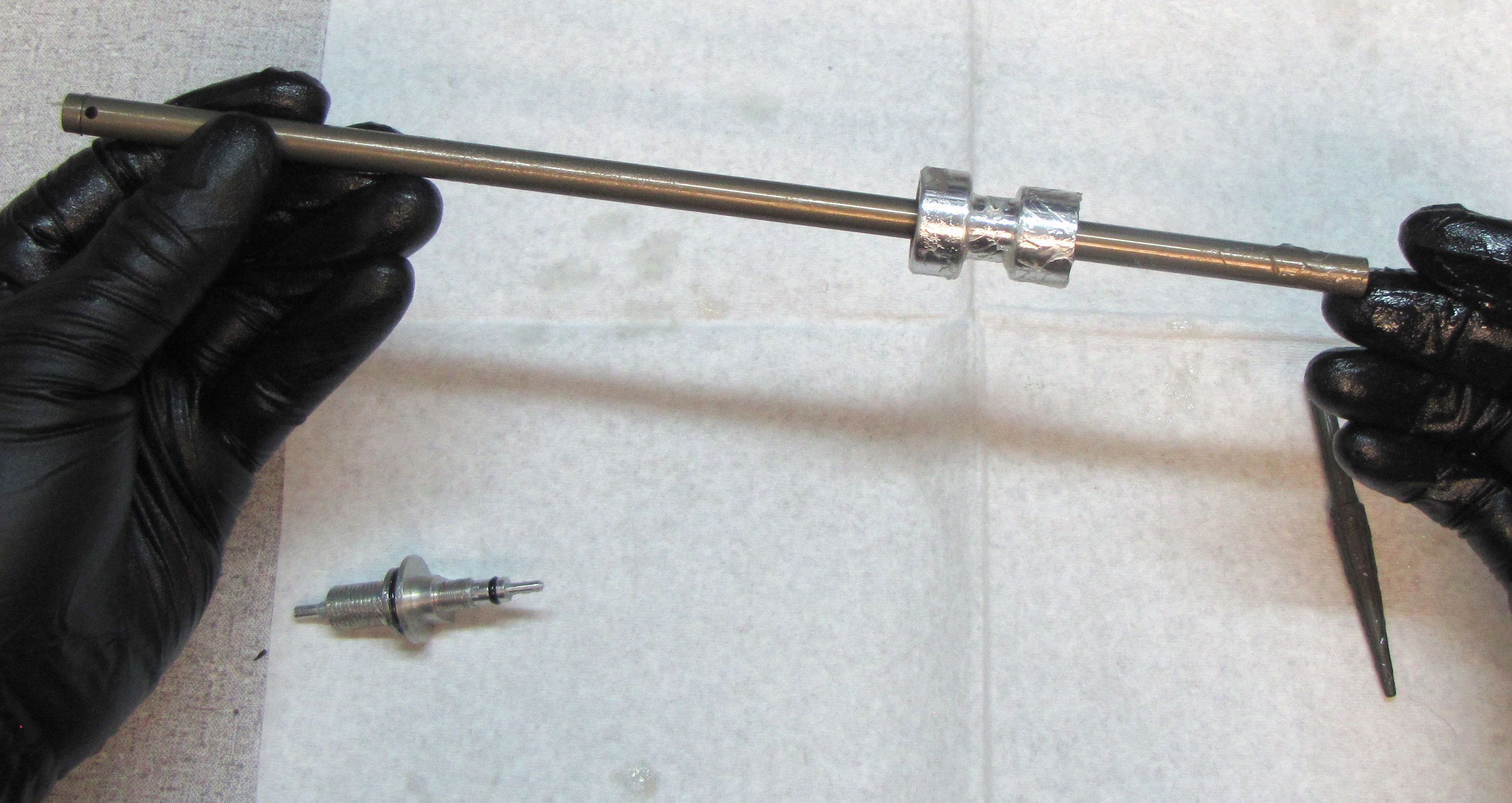

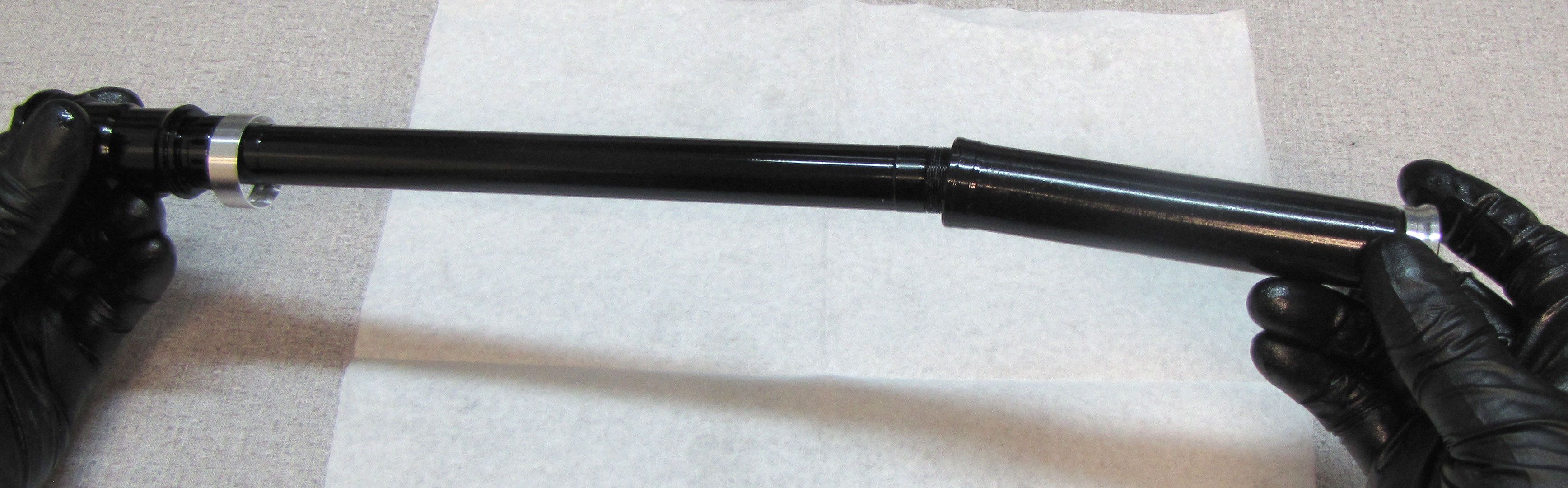
Step 8
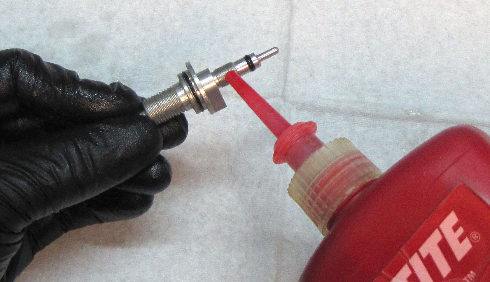
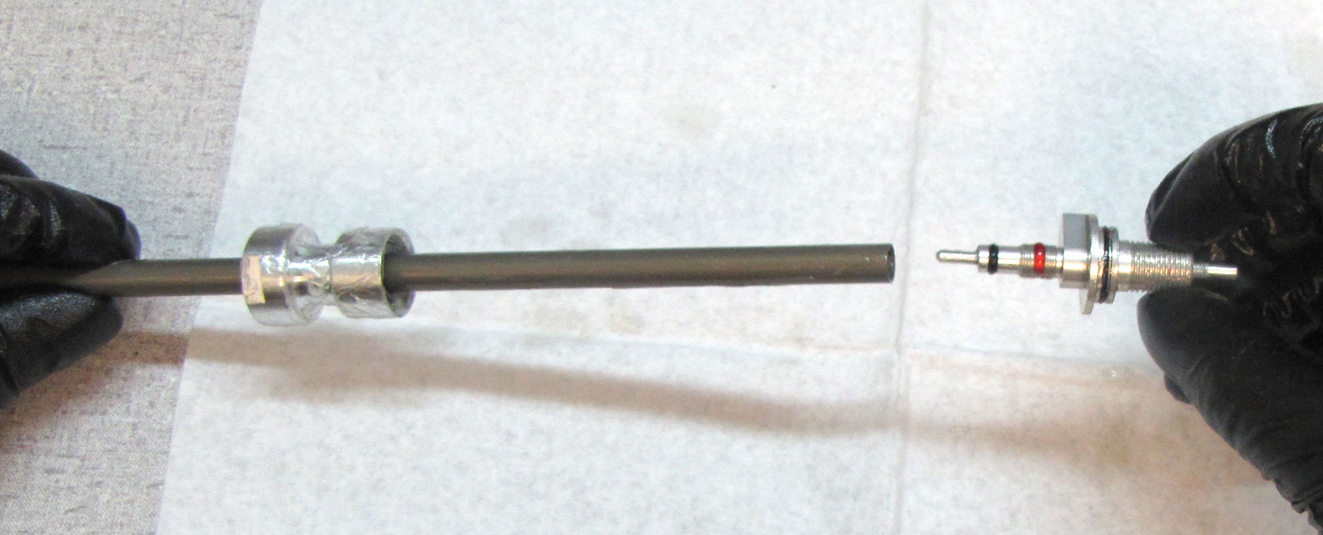
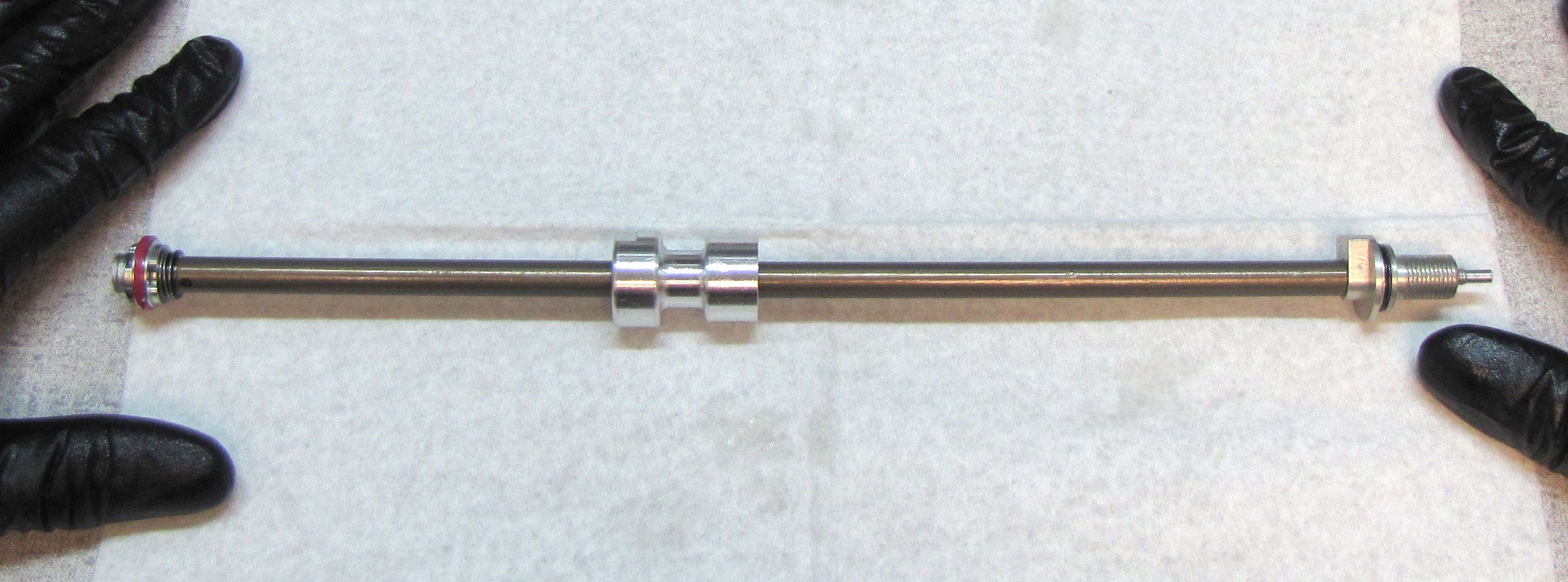
Clean any grease or Loctite residue from the threads of the shaft and Rebound Adjuster. Apply 1 drop of red Loctite 277 to the threads of the Rebound Adjuster. Reinstall the Rebound Adjuster Assembly into the shaft tightening clockwise by hand. Clean the damper shaft with isopropyl alcohol and a lint-free paper towel, then clamp it in your shaft clamps (PN: 803-00-147) as shown. Tighten the Rebound Adjuster clockwise to 55 in-lb (6.2 Nm) torque with a 10mm crowsfoot.

Step 9
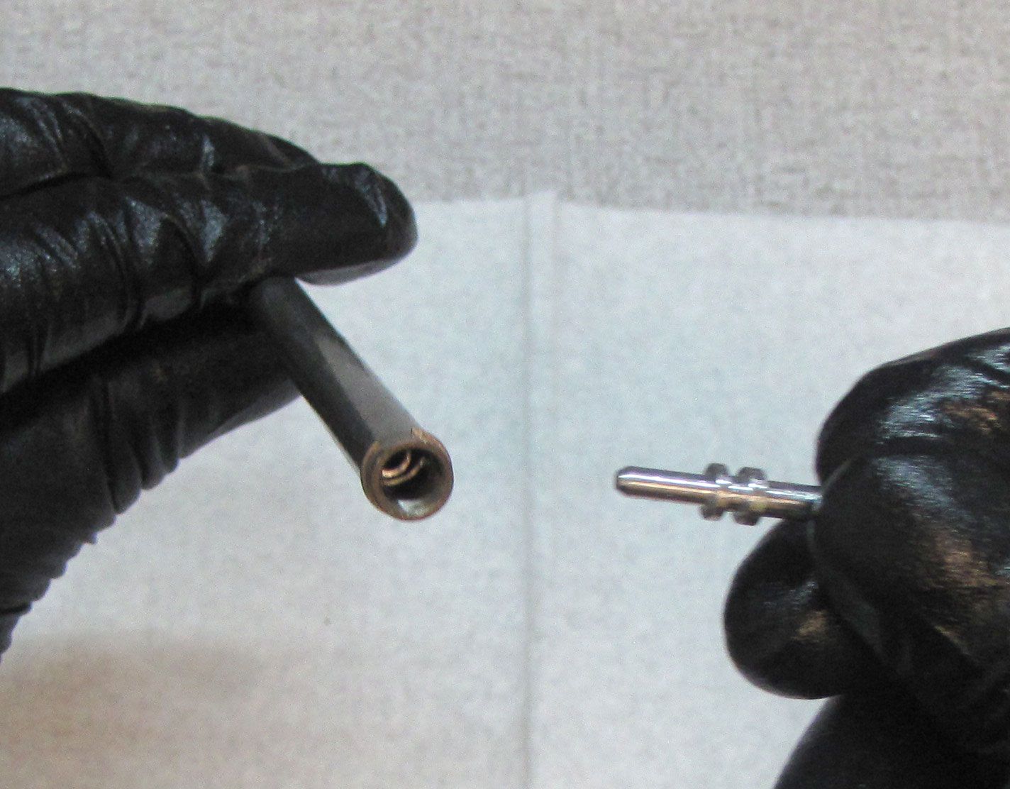
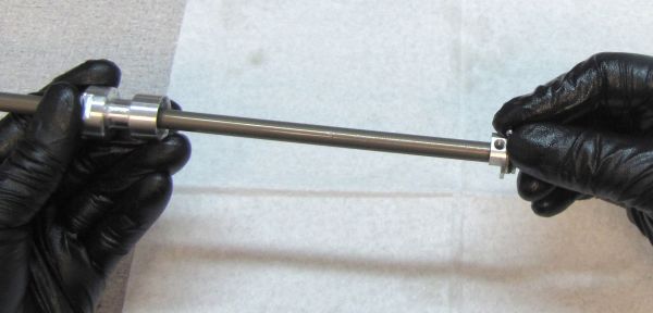
Reinsert the Rebound Tube into the Shaft making sure to engage its end with the post on the Rebound Adjuster Screw within the shaft. Reinstall the Rebound Needle with the fluted end facing out of the shaft. Make sure to engage the post of the Rebound Needle with the Rebound tube. Reinsert the Rebound Needle Spring.

Step 10
Clean the damper shaft with isopropyl alcohol and a lint-free paper towel, then clamp it in your shaft clamps (PN: 803-00-147) as shown. Replace the pink glide ring on the Rebound Piston Assembly with a new one from the kit. Reinstall the Check Limiter so the wide flange is seated against the retaining ring on the shaft. Reinstall the check spring. Reinstall the Rebound Piston Assembly making sure that the check shim (the shim under the piston assembly) can move freely as isn't pinched between the piston and the end of the damper shaft. Once sure that the check shim is not pinched, tighten the piston bolt to 55 in-lb (6.2 Nm) torque with an 8mm socket.
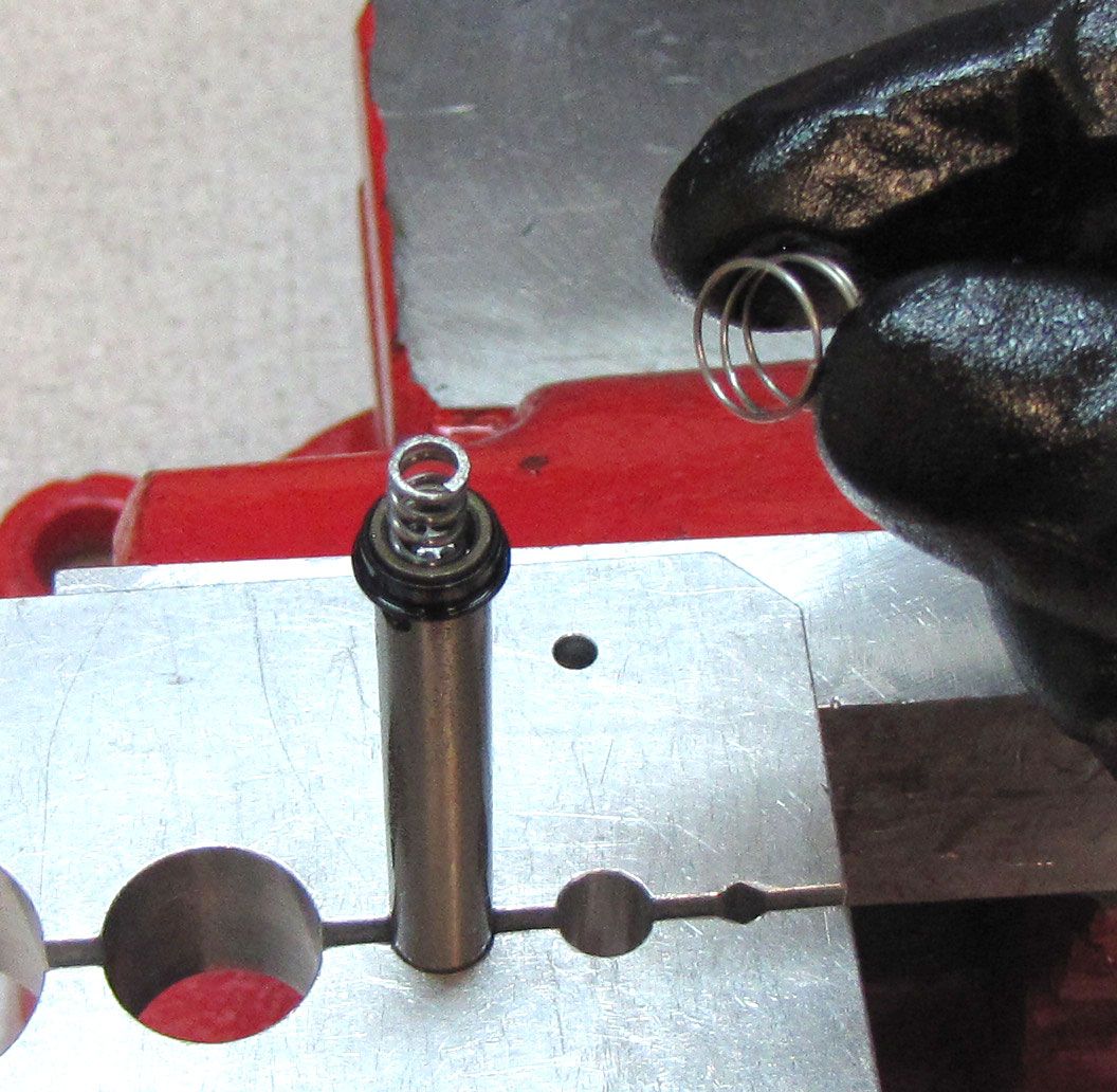
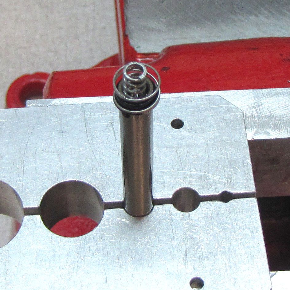
Step 11
Reinstall the Rebound Detent Ball into the open hole in the Rebound Adjuster Assembly then reinstall the Rebound Detent Spring. Reinstall the set screw, tightening clockwise until flush.
Step 12
Insert the Rebound Piston Assembly into the Cartridge Body then thread the Sealhead clockwise onto the Cartridge Body. Clean the cartridge body with isopropyl alcohol and a lint-free paper towel, then clamp it in your shaft clamps (PN: 803-01-360) as shown. Tighten the Sealhead clockwise to 55in-lb (6.2 Nm) torque with a thin 19mm crowsfoot.
Step 13
Coat the o-rings inside the Topcap with a thin film of FOX 5wt. Teflon Infused Oil. Reinstall the Compression Cartridge Housing Assembly into the Reservoir. Make sure that the Solenoid wires are carefully coiled under the Cable Connector so you do not pinch them during Cable Connector installation. Press the Compression Cartridge Housing Assembly in fully to allow room for the retaining ring. Reinstall the wire retaining ring making sure it is fully seated.
Step 14
Thread the LIVE Valve Solenoid Housing Puller (PN: 398-00-806) clockwise into the bleed port until hand tight. Pull up gently to seat the Compression Cartridge Housing up against the Retaining ring. Remove the tool.


Step 15
Reinstall the Solenoid End Cap Retainer Plate tightening the two set screws clockwise to 2 in-lb (0.2 Nm) torque with a 0.050" hex wrench.
Step 16
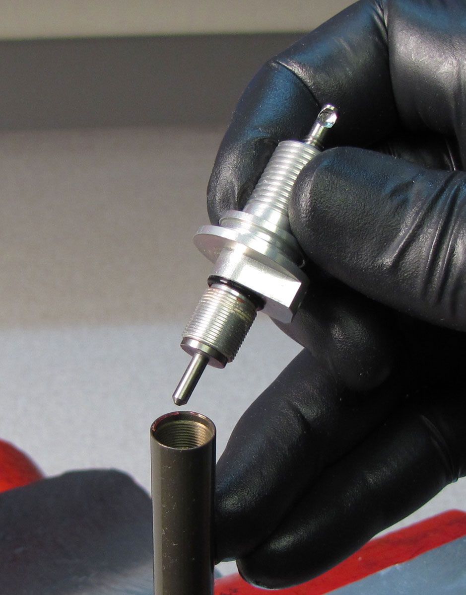
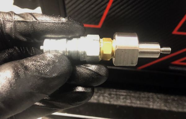
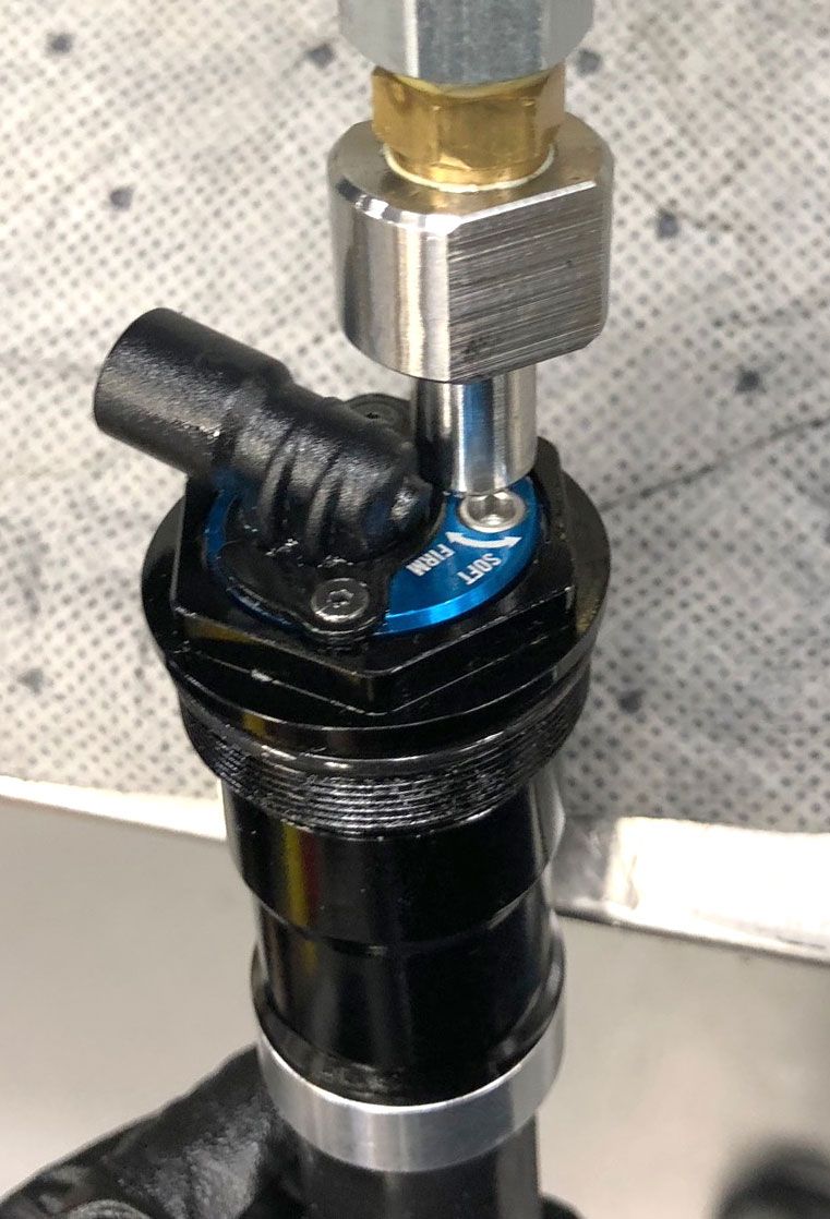
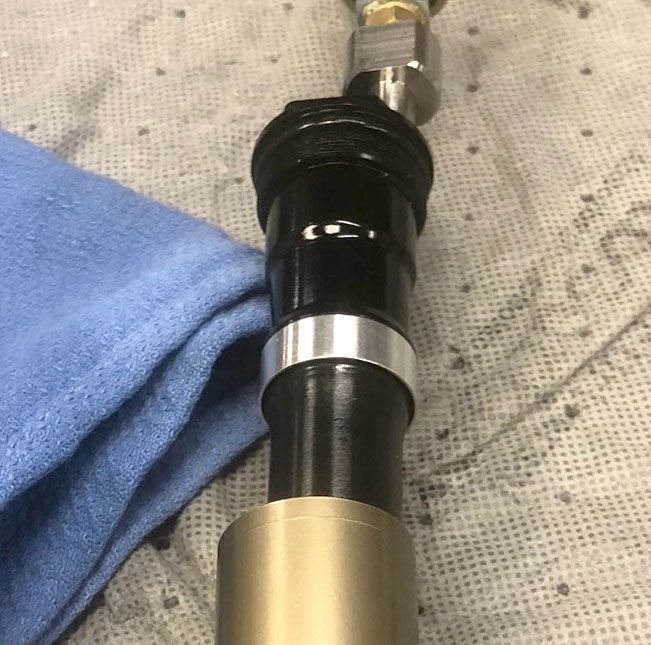
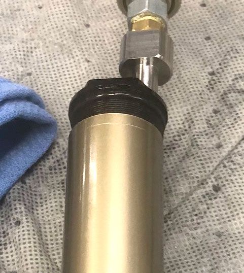
Connect the Andreani Fill Machine to the bleed port of the LIVE Valve fork cartridge using the Fill Machine Adaptor (PN: 803-01-370). Insert the cartridge into an upper tune to prevent over-expansion of the bladder during the fill stage. Vacuum the cartridge then perform the fill cycle. Keep the cartridge vertical while you remove the fill tool.


Step 17
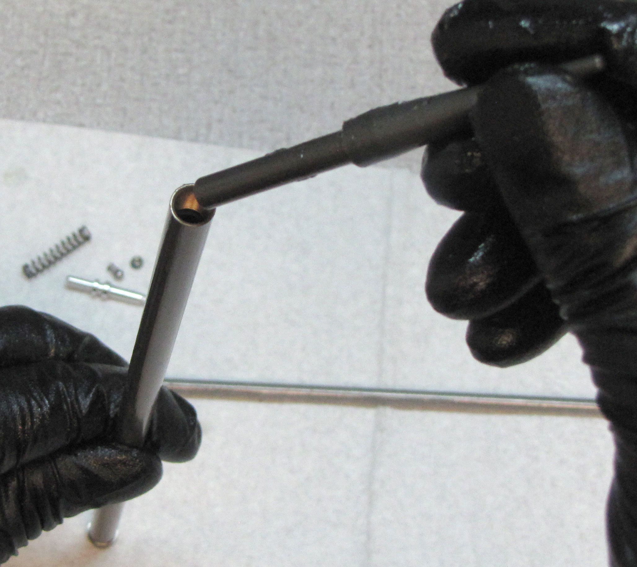
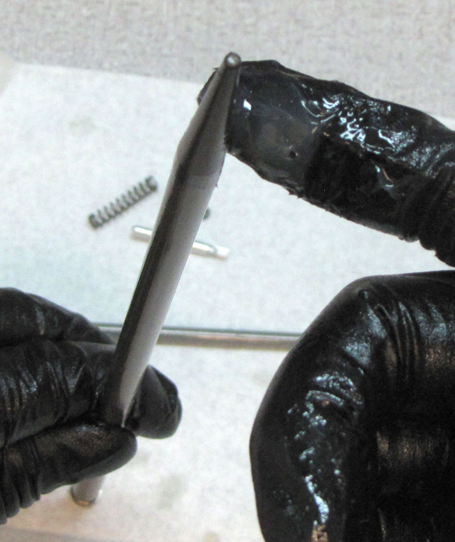
Reinstall the 0.125" ball bearing into the bleed port followed by the bleed screw. Tighten the bleed screw clockwise to 11 in-lb (1.2 Nm) torque with a 5/64" hex wrench. Use the Solenoid Switcher tool (398-00-820) to dyno the damper by hand to check all damper functions. Once happy with the dyno results, install a new white Delrin ball into the bleed port.
Step 18
Reinsert the cartridge into the upper tube threading the topcap in clockwise until just hand tight. Install a new crushwasher from the kit followed by the bottom nut, making sure to align the washer with the nut. For 32mm forks, tighten the bottom nut clockwise to 50 in-lb (5.7 Nm) torque with a 10mm socket. For 34mm and 36mm forks, tighten the bottom nut to 80 in-lb (9.0 Nm) torque with a 15mm socket.

Step 19
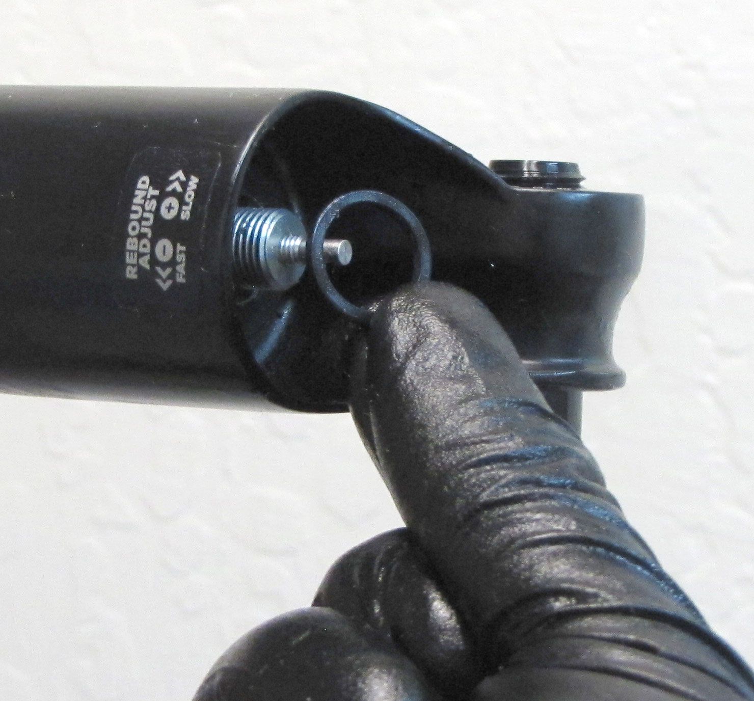
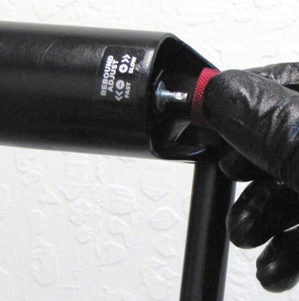
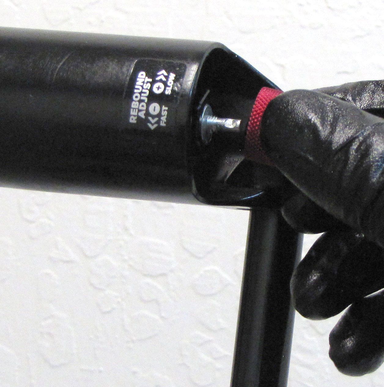
Reinstall the red Rebound Knob tightening the set screw to 5 in-lb torque with a 2mm hex wrench. For non-SC forks, make sure to align the set screw with the depression on the Rebound Adjuster. For SC forks, make sure to engage the hex of the knob with the hex of the Rebound Adjuster before tightening the set screw.
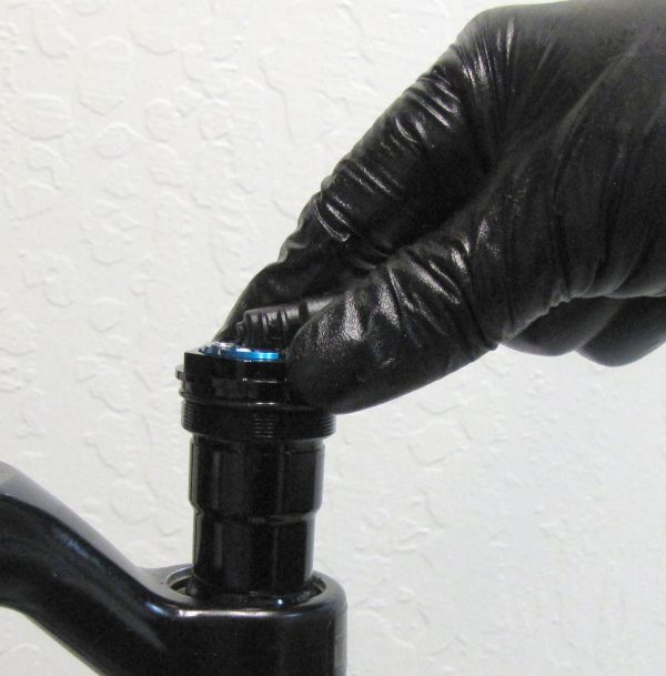
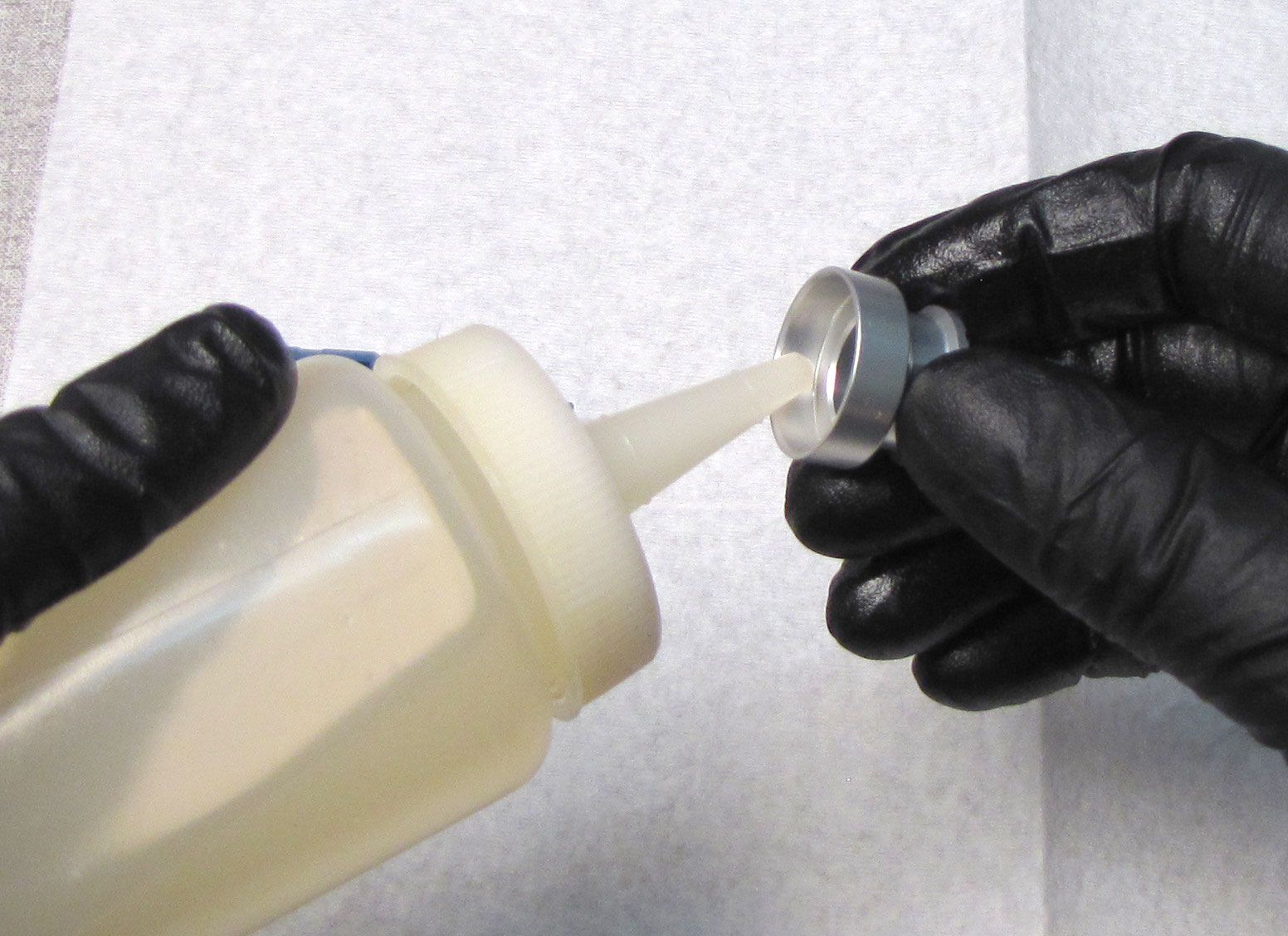
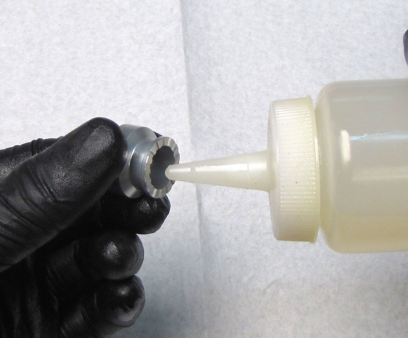
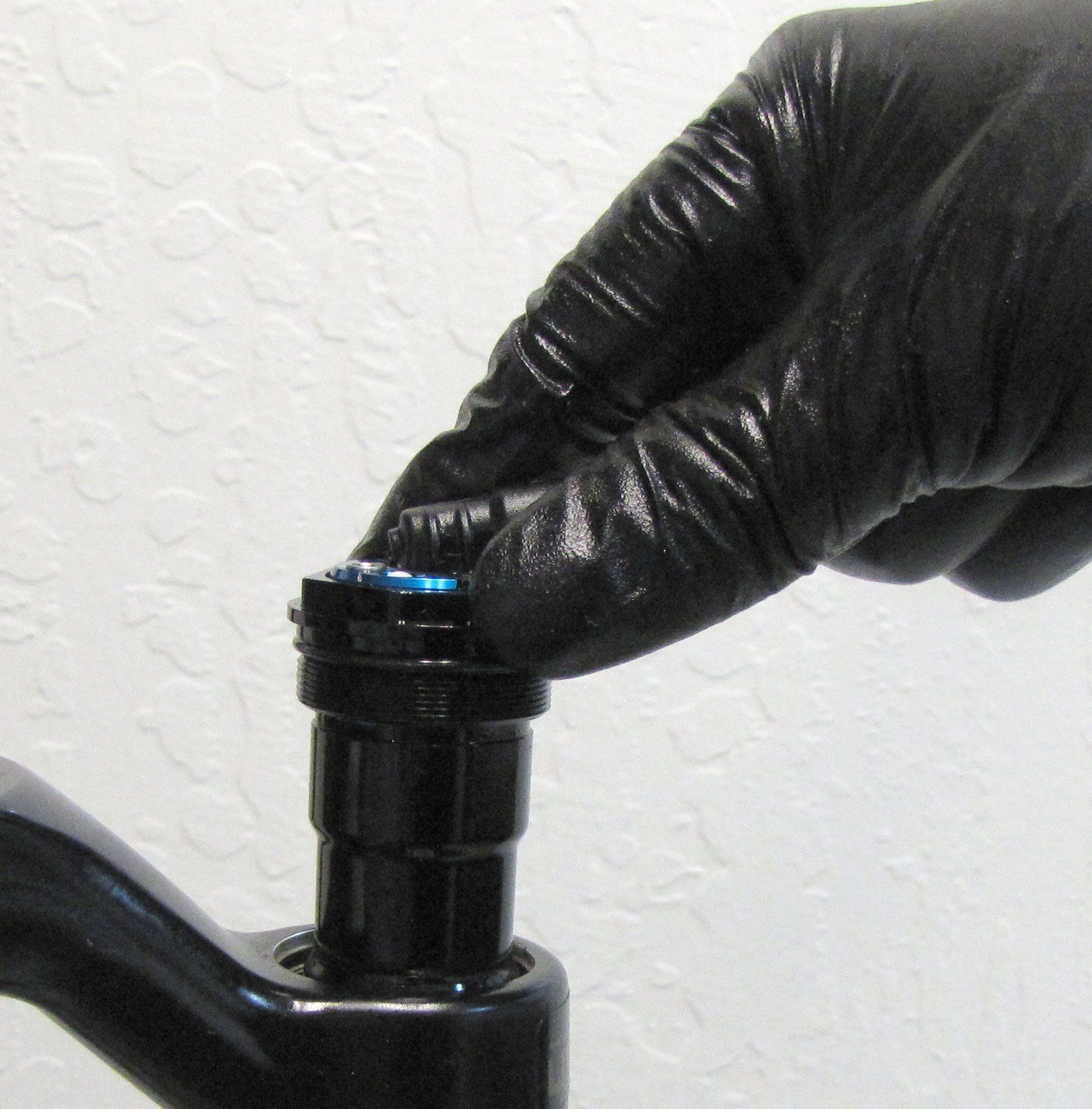
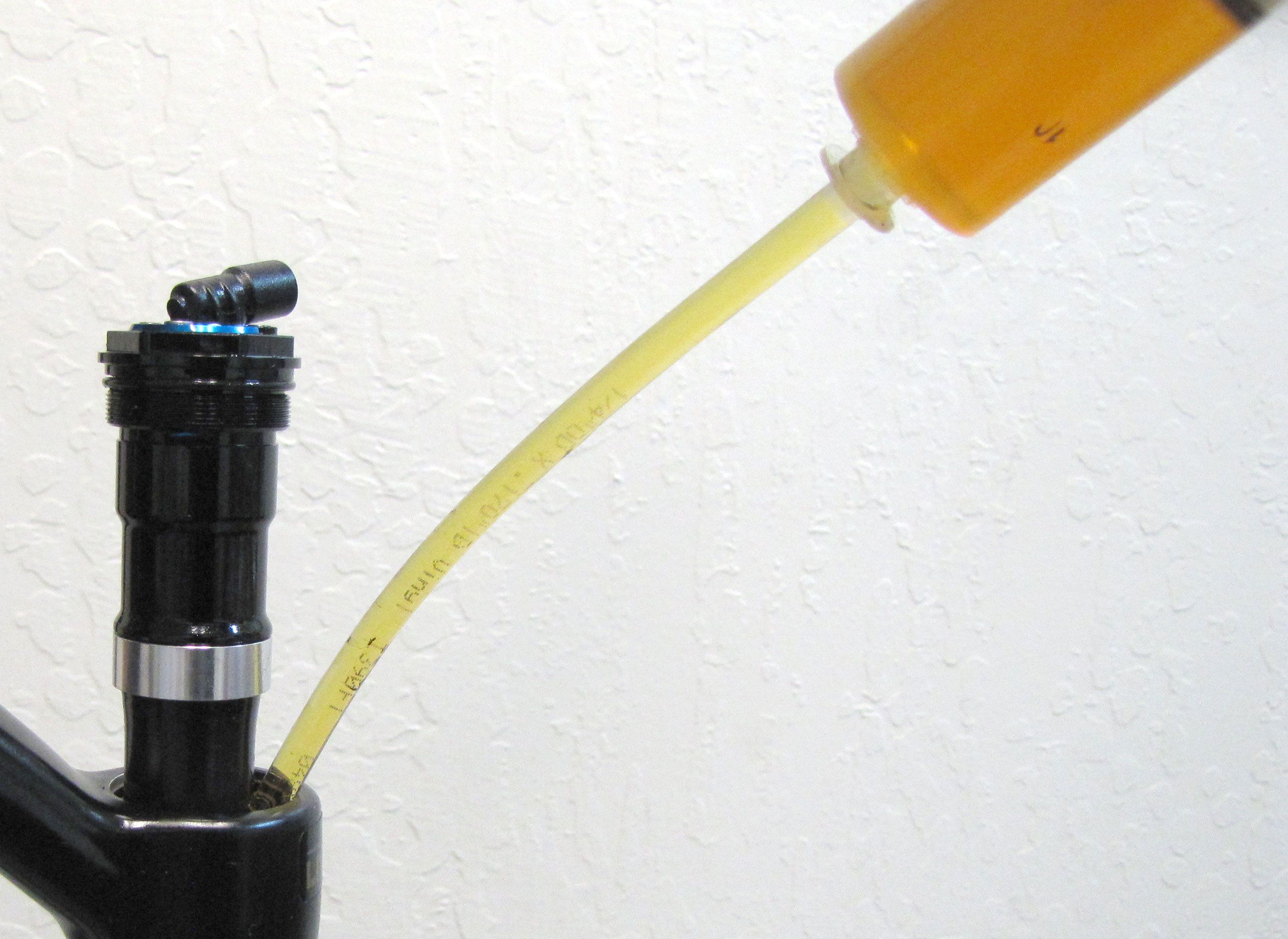
Step 20
Unthead the topcap and pull it up enough for you to inject the bath oil into the upper tube.
| Application | 20wt. Gold Bath Oil Volume |
| 32mm SC | 15cc |
| 34mm SC | 15cc |
| 34mm | 20cc |
| 36mm | 20cc |
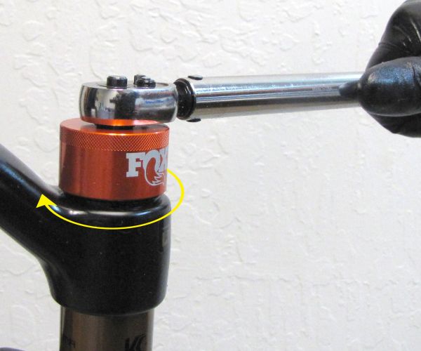
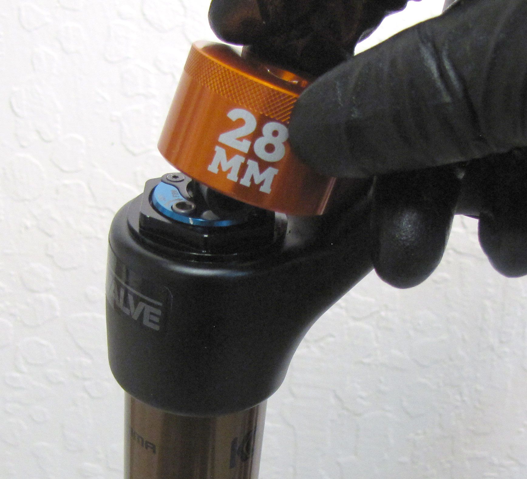
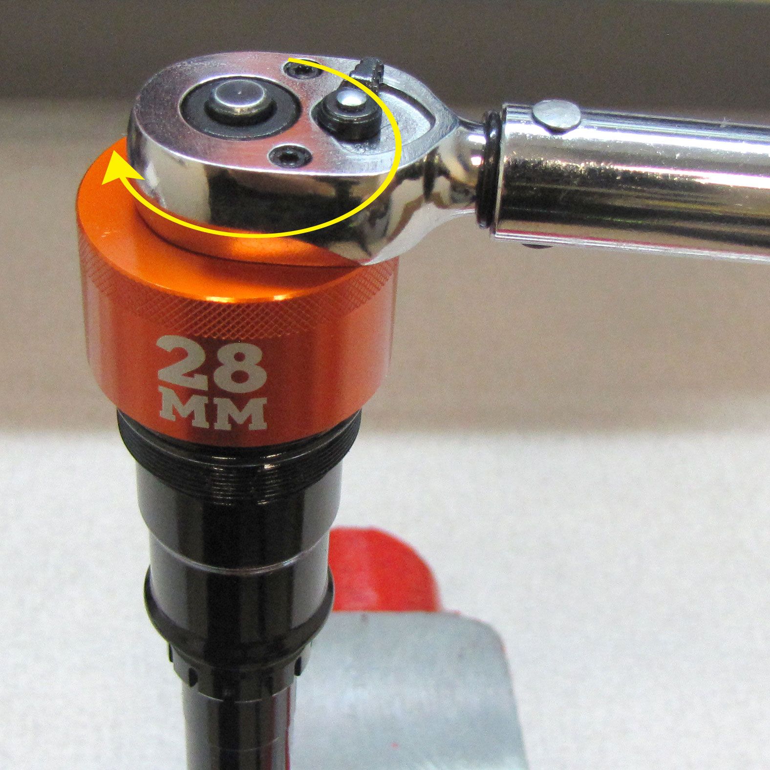
Step 21
Tighten the Topcap into the upper tube by threading it clockwise to 220 in-lb (24.8 Nm) torque with a 6-point chamfer-less 28mm socket (PN: 398-00-707). Rotate the Cable Connector as little as possible to orient so it points approximately 30 degrees forward of the steer tube. Clean the exterior of the fork.