|
|

|
WARNING: Some models of FOX forks are equipped with the 15QR axle system to help facilitate easy installation and removal of the bicycle front wheel assembly. Failure to properly install the 15QR axle and wheel onto your bicycle could cause the wheel to become detached from the bicycle while you are riding, and result in serious or fatal bodily injury. Before using, carefully read the 15QR instructions in your owner's manual. If you have any questions, ask your dealer for further instruction and training. |

|
CAUTION: Use extra caution to keep your fingers away from the rotating disc brake rotor when installing or servicing the front wheel. The rotor is sharp enough to inflict severe injury to your fingers if caught in the openings of the moving rotor. CAUTION: The calipers and rotor will become very hot when the brakes are normally operated. Do not touch them while riding or immediately after dismounting from the bicycle, or you may get burned. Ensure that the brake components have cooled down sufficiently, before attempting to adjust or service your disc brakes. |
Before beginning the installation procedure, take note of the following points that would indicate a successfully installed 15QR Axle System.
WARNING: Dirt and debris can accumulate between the fork axle openings; always check and clean this area when installing the wheel. Dirt and debris can compromise the security of the axle system, potentially leading to serious or fatal bodily injury. Improper hub and axle installation can result with serious or fatal bodily injury.
Figure 1: Inserting the Wheel into the Fork Dropouts
Note: The term "right side" here means from the perspective of the rider looking at the front of the bicycle.
Figure 2: Inserting the 15QR Axle
 .
.
This step will ensure that when the 15QR lever is closed, it will be positioned properly forward of the fork leg, as shown in the image on the right in Figure 3: Tighten and Close the 15QR Lever.
Note: Do not thread the 15QR axle into the axle nut beyond the five to six (5-6) complete turns, or it will begin to bind into the 15QR lever-side fork dropout.
Figure 3: Tighten and Close the 15QR Lever
WARNING: Improper adjustment of the axle nut can lead to serious or fatal bodily injury!
Figure 4: 15QR Lever Resistance Point
Figure 5: 15QR Lever Closing Action
Figure 6: Closing the 15QR Lever
WARNING: Never use any other tool to tighten the 15QR lever onto the lower legs. Over-tightening the 15QR lever can damage the axle, axle nut or fork dropouts, potentially leading to sudden failure resulting with serious or fatal bodily injury.
Figure 7: Correct Orientation of the Closed 15QR Lever
The 15QR lever should be fully pushed in to close, the side of the lever with the engraved inscription CLOSED must be facing outwards from the wheel, and the lever must be positioned between one (1) and twenty (20) mm forward of the fork leg, as shown in Figure 7: Correct Orientation of the Closed 15QR Lever.
CAUTION: Positioning the closed 15QR lever below the fork leg dropout may leave it vulnerable to hitting an object, posing a potential risk of quickly loosening the axle. If you position the closed 15QR lever in front of the fork leg, this potential hazard may be reduced.
WARNING: Improper adjustment of the axle nut can lead to serious or fatal bodily injury! Follow these instructions very carefully.
If the 15QR lever cam tension is either too loose or too tight when the 15QR lever is positioned between one (1) and twenty (20) mm forward of the fork leg when it's closed (as shown in Figure 7: Correct Orientation of the Closed 15QR Lever above), use the following procedure to correct this misadjustment.
Figure 8: Dropout Indicator Arrow and Axle Number
Figure 9: Loosening the Axle Nut Keeper
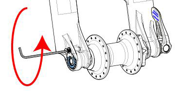
Figure 10: Adjusting the Axle Nut
CAUTION: After closing the 15QR axle lever, do not attempt to re–position or spin the lever, as either of these actions can cause the axle to dangerously loosen.
Figure 11: 15QR Axle Lever Warning
WARNING: Never attempt to install the 15QR axle system by only rotating the 15QR lever to tighten and fasten. This will not be sufficient means to safely attach the wheel, and can result in serious or fatal bodily injury.
Always check your front 15QR and rear quick release levers before riding, to verify that you have installed your wheels correctly and safely. Before every ride, inspect the proper tension level of your 15QR lever by opening and closing the lever by hand. If you are not certain as to whether you have your 15QR lever adjusted and tightened correctly, repeat the 15QR Axle System installation instructions.
It is very important to be sure that you have pushed the 15QR lever fully to the CLOSED position. The side of the lever with the inscription CLOSED must be facing outwards from the wheel, and the axle lever must be positioned between one (1) and twenty (20) mm (see Figure 7: Correct Orientation of the Closed 15QR Lever).
As shown in Figure 4: 15QR Lever Resistance Point and Figure 6: Closing the 15QR Lever,
the 15QR lever must:
As you rotate and inspect your wheels, verify that your brake disc rotor, hub or rotor bolts do not interfere with any other component. If you are not familiar with adjusting your disc brakes, see the brake manufacture's instructions.
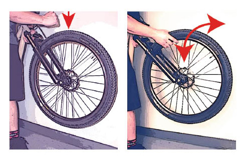
Before every ride, lift up the front end of the bicycle to suspend the wheel off the ground to give the top of the tire a few sharp downward blows. The wheel should not be loose at all; wiggle the wheel side-to-side to confirm this (see Figure 12: Testing the Front Wheel).
Figure 12: Testing the Front Wheel
![]()
![]()
Bushing Technology & Inspection | Seals & Foam Rings | Control Direction | Oil Volumes | Structural Inspection | Dropout Thickness Inspection | Torque Values | Unit Conversion | Suspension Tuning Tips | Using the Pump | Important Safety Information | Service Intervals | Contact FOX Service | Warranty Information | FOXHelp Service Web Site
Copyright © 2010
FOX Factory Inc.