


|
|
|
|
|
Installing Your Fork | Before You Ride | Setting Sag | Adjusting Rebound | Adjusting High-Speed Compression | Adjusting Low-Speed Compression | Changing Travel | Service Intervals | Important Safety Information
|
|
travel |
170 RC2: 6.7 in./170 mm |
|
air spring travel |
Travel is adjustable down to 130 mm, in 10 mm increments |
|
|
features/adjustments |
low-speed compression, high-speed compression, air spring pressure, rebound |
|
|
spring/damper type |
air/FIT RC2 |
|
|
intended use |
downhill, all-mountain, freeride |
Note: This fork is designed to use the downhill brake system only. The disc brake caliper mounts directly to the fork leg and is positioned specifically for the use of 200-225 mm rotors.
Be sure your fork is properly installed before proceeding. If your fork came pre-installed on your bicycle, continue to the next section.
Note: Do not use any solvents or de-greasers, as these products can cause serious damage to paint and anodized parts (upper tubes, knobs, steerers).
Do not spray water directly on the seal/upper tube junction. Do not use a high pressure washer on your fork.
You can also view a Flash video on Setting Sag.
To get the best performance from your fork, it is necessary to set and adjust sag. Generally, sag should be set to 15 – 25% of total fork travel.
Rider | Suggested Air Spring Pressure Settings PSI | |
170 mm | 180 mm | |
≤125 | 45 | 45 |
125 - 135 | 48 | 48 |
135 - 145 | 50 | 50 |
145 - 155 | 53 | 53 |
155 - 170 | 55 | 55 |
170 - 185 | 60 | 60 |
185 - 200 | 70 | 70 |
200 - 215 | 80 | 80 |
215 - 230 | 90 | 90 |
230 - ≥250 | 100 | 100 |
Travel | All-Mountain | Freeride/DH |
170 mm (6.70") | 25 mm (1.00") | 42 mm (1.65") |
180 mm (7.09") | 27 mm (1.06") | 45 mm (1.77") |
Symptom | Remedy |
Too much sag | (+) air pressure in 5 psi increments |
Too little sag | (-) air pressure in 5 psi increments |
Excessive bottoming | (+) air pressure in 5 psi increments |
Harsh ride; full travel not utilized | (-) air pressure in 5 psi increments |
The rebound knob is located on the bottom of the right fork leg, and has 18 clicks of adjustment. Rebound controls the speed at which the fork extends after compressing. Turning the knob clockwise slows down rebound; turning the knob counter-clockwise speeds up rebound. As a starting point, turn the rebound adjuster knob all the way clockwise (full in) until it stops, then turn counter-clockwise (out) 9 clicks.
The rebound knob is protected by a black protective cap. Never ride your FOX 36 without this black protective cap.
|
Knob Setting |
Setting Description |
Tuning Tips |
Setup Tips |
|
|
Slow Rebound |
Too slow and your fork will pack down and ride harsh. |
If you increase your spring rate or air pressure, you will need to slow down your rebound |
|
9 (Factory setting) |
Average Rebound |
||
|
|
Fast Rebound |
Too fast and you will experience poor traction and wheel hop. |
If you decrease your spring rate or air pressure, you will need to speed up your rebound setting. |
High-speed compression damping controls the force it takes to move the fork through its travel and how the wheel reacts to a bump. This adjuster rotates to stops at each end and has 24 clicks of adjustment. It is set from the factory at 12 clicks out from the full closed (clockwise) position.
|
Knob Setting |
Setting Description |
Tuning Tips |
|
|
Soft Compression |
Maximum wheel traction and bump compliance. If setting is too soft, you may bottom often on square-edged hits and G-outs. |
|
12 (Factory setting) |
Average Compression |
|
|
|
Firm Compression |
Reduces bottom-out and provides maximum bump absorption. If setting is too firm, you may experience a harsh ride with bad traction and use too little available travel. |
Low-speed compression damping controls the influence of the rider’s weight shifts and bike attitude under braking. This adjuster rotates to stops at each end and has 24 clicks of adjustment. It is set from the factory at 12 clicks out from the full closed (clockwise) position.
|
Knob Setting |
Setting Description |
Tuning Tips |
|
|
Soft Compression |
Maximum wheel traction and bump compliance. Too soft and you maybe have excessive brake dive and wallowy feel. |
|
12 (Factory setting) |
Average Compression |
|
|
|
Firm Compression |
Resists brake dive and keeps the fork up in the travel. Too firm and you may have poor traction in loose conditions. |
Travel on your 36 FLOAT FIT RC2 170 or 180 mm fork can be changed, by adding or removing air spring travel spacers. After changing travel, check the fork for proper operation before riding. If there is noticeable play in the fork or if it makes strange noises, disassemble the air spring leg of the fork and recheck your travel spacer configuration.
Note: 36 FLOAT FIT RC2 170 and 180 mm forks can be reduced in travel, but they cannot be increased beyond 180 mm.
|
Quantity |
Part Number |
Part Name |
|
1 |
025-02-003 |
1 qt. bottle of FOX Suspension Fluid (10 wt.) |
|
1 |
025-03-002-A |
5 cc Pillow Pack of FOX FLOAT Fluid |
|
2 |
241-01-002-C |
Crush washer |
|
1 |
803-00-078 |
FLOAT Forx Air Piston Seal Kit (optional) |
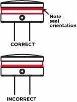
Note: Spacers snap onto the air shaft between the negative spring guide and topout plate, as shown in the travel spacer orientation drawing below.
|
|
|
Bushing Technology & Inspection | Seals & Foam Rings | Control Direction | Oil Volumes | Structural Inspection | Dropout Thickness Inspection | Torque Values | Unit Conversion | Suspension Tuning Tips | Using the Pump | Important Safety Information | Service Intervals | Contact FOX Service | Warranty Information | FOXHelp Service Web Site
Copyright © 2011
FOX Factory Inc.