You are here: Forks > 40 mm > Installing the 40

Installing the 40

WARNING:  FOX Racing Shox highly recommends that a qualified bicycle technician install the 40 on your bicycle. Improperly installed forks are dangerous, and can cause loss of control and SERIOUS INJURY or DEATH. Read this page in its entirety before beginning the installation of your FOX 40.

  1. Verifying the Total Stack Height

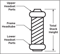
    NOTE:  The 40 direct mount crown requires a total stack height range from 105 mm to 166.8 mm.

    See Figure 1: 40 Headset Stack Height to understand what defines total stack height. Measure to verify whether your total stack height falls within this height range specification.

    NOTE:  If you're installing a steerer tube-mounted stem, the total height of spacers used on a FOX steerer tube should never exceed 30 mm.

    Figure 1: 40 Headset Stack Height

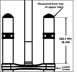
    The 40 with a direct mount upper crown is assembled with the lower crown set to 163.7 mm below the top of the upper tubes (see Figure 2: 40 Crown Height). The lower crown position is set to allow 6 mm clearance between the bottom of the crown and the top of a 2.80" tire when bottomed out. Do not change the position of the lower crown.

    Figure 2: 40 Crown Height

  2. Removing the Fork, Installing the Crown Race

    1. Place the bicycle in a repair stand.
    2. Remove the new 40 fork from its packaging.
    3. Remove the original fork from the bicycle, if this is the case.
    4. Remove the crown race from the original fork with a crown race removal tool, and install it with a crown race setter tool onto the new 40. The crown race must be firmly seated against the top surface of the lower crown.

    WARNING:  If the steerer has any nicks or gouges, the crown/steerer assembly must be replaced. A nick or gouge can cause the steerer to fail prematurely, which can cause loss of control of the bicycle resulting in SERIOUS INJURY OR DEATH.

  3. Cutting the Steerer to Proper Length

    NOTE:  The FOX 40 can be set up with either a direct-mount or a steerer mounted stem.

    CAUTION:  FOX Racing Shox does not manufacture a direct mount stem. Be sure to refer to your stem manufacturer's installation instructions. Measure at least twice to be certain of all measurements, before cutting the fork steerer!

    1. Install your new 40 on the bicycle with all of the headset parts, stem spacers, and upper crown. The deep–pocketed side of the upper crown faces downward on the bicycle.
    2. After eliminating play in the headset, lightly tighten the steerer pinch bolt on the upper crown with a 5 mm hex wrench.
    3. Add any additional stem spacer(s) or steerer-mounted stem onto the steerer above the upper crown that will affect the steerer tube finished cut length. This will depend on personal preference.
    4. Mark the steerer with a scribe at the top edge of the uppermost installed part. With a direct mount stem, you can scribe the mark on the steerer at the top edge of the upper crown.
    5. Remove the 40 from the bicycle and cut the steerer 3 mm below the scribed mark. This 3 mm clearance allows room for the stem cap to lightly tension the headset and eliminate any free play.

    WARNING:  Do not cut the steerer more than three (3) mm below the uppermost installed part. If the steerer length is mistakenly cut too short, it MUST BE REPLACED! Using a fork with clamped steerer engagement that is too short can lead to sudden fork failure, which can cause irrecoverable loss of control of the bicycle resulting in SERIOUS INJURY OR DEATH.

    1. Use a file to de-burr the outer and inner top edges of the newly cut steerer.
  4. Installing the Star-fangled Nut, Steering Stop Bumpers

    1. With a star-fangled nut installation tool, install the star-fangled nut into the steerer to the proper depth; see Figure 3: Star-fangled Nut Installation Depth.

      Figure 3: Star-fangled Nut Installation Depth

    2. Install one steering stop bumper onto each upper tube and place midway on the upper tube; see Figure 4: 40 Upper Crown Installation.
  5. Installing the Fork

    1. Install the new 40 fork on the bicycle with all of the headset parts, upper crown, spacer(s), and steerer-mount stem (if applicable).
    2. Install the stem cap and M6 stem cap bolt.

      NOTE:  It is important that the Direct Mount stem stays loose or uninstalled (NOT torque-tightened), to allow proper adjustment of the headset.

    3. With all three upper crown bolts left loosened, lightly tighten the headset stem cap bolt to remove play in the system so that it turns freely without drag.
    4. With a 5 mm hex key socket and torque wrench, torque all three upper crown bolts to 65 in-lb (7.34 Nm); see Figure 4: 40 Upper Crown Installation.

      Figure 4: 40 Upper Crown Installation


    5. Be sure the torque specification of 65 in-lb (7.34 Nm) is achieved for each of the four lower crown bolts.

      WARNING:  Do not over-tighten the pinch bolts. Too much torque can damage the bolts, fracture the crown, or damage the threads. Any of these maladjustments could cause fork failure, leading to your loss of control and SERIOUS INJURY OR DEATH.

  6. Tire Size Specifications

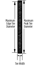
    In the table below, all values assume that your tire is installed and fully inflated.

    WARNING:  For any fork model and size, do not use a tire if any of its measurement specifications exceeds its maximum safe value in the table below. Using tires with larger than these maximum safe values may cause you to lose control and suffer SERIOUS INJURY OR DEATH.

    Specifications Fork Families
    All 32 mm
    26 inch
    All 32 mm
    29 inch
    All 34 mm
    26 inch
    All 34 mm
    27.5 inch
    All 34 mm
    29 inch
    All 36 mm
    26 inch
    40 mm
    26 inch
    Maximum Tire Size 26 x 2.40 29 x 2.30 26 x 2.40 27.5 x 2.40 29 x 2.55 26 x 2.80 26 x 2.80
    Maximum Peak Tire Diameter 686 mm (27.00") 744 mm (29.29") 686 mm (27.00") 716 mm (28.19") 748 mm (29.45") 694 mm (27.32") 694 mm (27.30")
    Maximum Edge Tire Diameter 652 mm (25.67") 721 mm (28.38") 652 mm (25.67") 690 mm (27.16") 733 mm (28.85") 670 mm (26.37") 670 mm (26.40")
    Maximum Tire Width 61.0 mm (2.40") 58.5 mm (2.30") 61.0 mm (2.40") 61.0 mm (2.40") 60.6 mm (2.55") 71.0 mm (2.80") 71 mm (2.80")
  7. Installing the Front Wheel

    Figure 5: 40 Axle Clamps

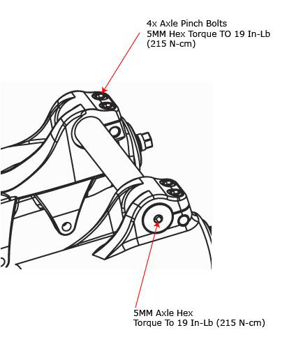
    Refer to Figure 5: 40 Axle Clamps for the following procedure:

    1. Loosen the four (4) axle pinch bolts on the lower leg with a 5 mm hex key wrench.
    2. Using a 5 mm hex key wrench, turn the axle counter-clockwise to loosen and remove.
    3. Install the front wheel into the dropouts and install the axle into the lower leg.
    4. Using a 5 mm hex key wrench, turn clockwise and lightly tighten the axle to the lower leg to 19 in-lb (2.15 Nm) torque (see Figure 5: 40 Axle Clamps).
    5. Tighten the two left side (from the seated rider's perspective) dropout pinch-bolts to 19 in-lb (2.15 Nm) torque.
    6. Compress the fork on the bike a couple of times to let the right side of the dropout float and settle to its low-friction point. Tighten the two right side dropout pinch-bolts to 19 in-lb (2.15 Nm) torque.
  8. Installing the Stem and Handlebars

    1. If installing a Direct Mount stem: use four (4) M6 x 1 threaded bolts in accordance with the stem manufacturer's assembly instructions. Be sure to confirm the following criteria:
      • There must be a minimum of 10 mm of thread engagement of the bolts into the upper crown.
      • The torque specification of the four (4) M6 mounting bolts must not exceed 110 in-lb (12.4 Nm).
      • If the bolts protrude from the bottom of the crown, be sure there is no interference with the frame or cables throughout the entire span of fork rotation.

      If installing a Steerer Mounted stem: tighten the steerer pinch bolts on the stem, according to the stem manufacturer's instructions.

    Figure 6: 40 Upper Crown International 4-Bolt Pattern (Specification)

    1. Set the bike on the ground and sit on your bike, to set the handlebar position.
    2. Rotate the handlebars to your desired position, and tighten the handlebar pinch bolts to the stem manufacturer's torque specification.
  9. Adjusting the Steering Stop Bumpers Position

    1. Adjust the height and angle of the steering stop bumpers on the upper tubes, so that you have the maximum turning angle and protect your frame and upper tubes from getting dented in a crash.
    2. Depending on the shape and size of the frame tubes, you may need to use the tall part of the bumper to contact the frame tubes.

Disc Brake Installation

The 40 is designed only for use with DH disc brakes with disc rotor sizes of 200 – 225 mm. The 40 can use DH mechanical or hydraulic disc brake systems.

WARNING:  Never modify the lower leg or use cantilever rim brakes, as this could lead to your loss of control, and SERIOUS INJURY OR DEATH.

The 40 disc bolt pattern uses:

  1. Install the DH disc brake system, according to disc brake manufacturer's specifications.
  2. Be sure to torque all fasteners and bolts to manufacturer's recommendations. Consult the instructions that came with your disc brakes for proper installation procedures. It is recommended that NEW disc brake pads be installed, to ensure proper alignment and to minimize drag.
  3. Route the disc brake hose (for hydraulic disc brakes) or brake cable housing (for mechanical disc brakes) from the caliper to the inside of the lower leg and through the supplied disc brake hose guide as shown in Figure 8: 40 Disc Brake Hose Guide Routing below.
  4. Tighten the disc brake hose guide screw (M3 x 12) with a 2.5 mm-hex key wrench, and torque it to 8 in-lb (0.90 Nm).
  5. Test the brakes for proper operation on level ground before hitting the trails.

Figure 7: 40 Brake Hose Guide Installation

Figure 8: 40 Disc Brake Hose Guide Routing


Bushing Technology & Inspection | Control Direction | Oil Volumes | Structural Inspection | Dropout Thickness Inspection | Torque Values | Unit Conversion | Suspension Tuning Tips | Using the Pump | Important Safety Information | Service Intervals | Contact FOX Service | Warranty Information | FOXHelp Service Web Site


Copyright © 2012
FOX Factory Inc.