Installing the 40
You can also view a Flash video of the 40
Installation.
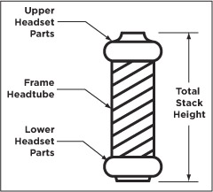
The 40 is available in two upper crown sizes to cover the varying range
of headset tube dimensions. Measure the total stack height (see the figure
below) to determine the proper upper crown size.
For total stack heights
of 90 – 165 mm, your 40 should have the SMALL-LARGE UPPER CROWN.
For total stack heights
of 165 – 181 mm, your 40 should have the EXTRA LARGE UPPER CROWN.
The total height of spacers used on a FOX steerer tube
should never exceed 30mm.
Have a qualified bicycle mechanic install
the 40. Improperly installed forks are dangerous and can cause loss of
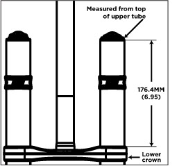
control and serious or fatal injuries. The 40 is assembled with the lower
crown set to 176.4mm below the top of the upper tubes. The lower crown
position is set to allow a 6mm clearance between the bottom of the crown
and the top of a 2.80" tire when bottomed out. Do not change the
position of the lower crown.
- Remove fork
and install crown race:
- Place the bicycle
in a repair stand.
- Remove the existing
fork from the bicycle.
- Remove the crown
race from the old fork with a crown race removal tool and install it with
a crown race setter tool onto the new 40. The crown race must be firmly
seated against the top surface of the lower crown.
If the steerer has any nicks or gouges, the crown/steerer
assembly must be replaced. A nick or gouge can cause the steerer to fail
prematurely, which can cause loss of control of the bicycle resulting
in serious or fatal injuries.
- Cut steerer
to proper length:
- Install the fork
on the bicycle with all of the headset parts and upper crown. The deep
pocketed side of the upper crown faces downward on the bicycle.
- After eliminating
play in the headset, lightly tighten the steerer pinch bolt on the upper
crown with a 5mm hex wrench.
- Install the headset
spacers (not required) and stem on the steerer and lightly tighten the
stem pinch bolt(s).
- Mark the steerer
with a scribe at the top edge of the stem.
- Remove the 40 from
the bicycle and cut the steerer 3mm below the scribed mark. This 3mm clearance
allows room for the stem cap to lightly tension the headset and eliminate
any play.
- Use a flat file
to deburr the outer and inner top edges of the newly cut steerer.
- Install
star-fangled nut and steering stop bumpers:
- With a star-fangled
nut installation tool, install the star-fangled nut into the steerer to
the proper depth (see Star-fangled nut installation depth diagram below).
- Install one steering
stop bumper onto each uppertube and place midway on the uppertube.
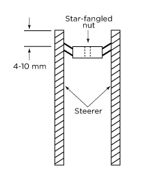 Star-fangled nut installation
depth
Star-fangled nut installation
depth
- Installing
fork onto bicycle:
- Install the 40
on the bicycle with all of the headset parts and upper crown.
- Install stem, stem
cap and M6 stem cap bolt.
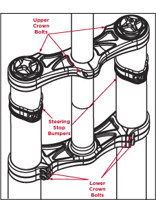
- With all three
upper crown bolts loosened, lightly tighten the headset stem cap bolt
to remove play in the system so that it turns freely without drag.
- With a 5mm hex
key socket and torque wrench, torque all three upper crown bolts (see
figure below) to 65 in-lb.
- Check that the
torque on the four lower crown bolts (see figure below) is at 65 in-lb.
Do not over-torque the
pinch bolts. Over-torquing
can damage the bolt(s),
fracture the crown or damage the threads, and can cause failure of the
fork and loss of control with serious or fatal injuries.
Tire Sizes
- The 40 will accept
tire sizes up to 2.80 inches wide. Any tire larger than 26 x 2.60 must
be checked for clearance using the following method.
Determining correct tire size
- With the tire installed
and inflated
on the rim, measure the following three dimensions:
Maximum Peak Tire Diameter
= 694 mm = 27.3 inch
Maximum Edge Tire Diameter
= 670 mm = 26.41 inch
Maximum Tire Width =
71
mm = 2.80 inch
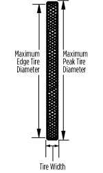
Do not use a tire if any measurement exceeds the maximum
dimensions shown above. Using larger tires is not recommended and can
cause serious or fatal injuries.
- Installing
the front wheel:
- Loosen the 4 axle
pinch bolts on the lower leg with a 5mm hex key wrench.
- Using a 5mm hex
key wrench, turn counterclockwise to loosen and remove the axle.
- Install the front
wheel into the dropouts and install the axle into the lower leg.
- Using a 5mm hex
key wrench, turn clockwise and lightly tighten and torque the axle to
the lower leg to 19 in-lb (215 N-cm).
- Torque the two
left side dropout pinch-bolts to 19 in-lb (215 N-cm).
- Compress the fork
on the bike a couple of times to let the right side of the dropout float
and settle to its low-friction point. Torque the two right side dropout
pinch-bolts to 19 in-lb (215 N-cm).
- Setting
handlebars straight and torquing stem bolts:
- Set the bike on
the ground and sit on your bike to set the handlebars straight relative
to the front wheel.
- Tighten the stem
pinch bolts and torque fasteners according to the stem manufacturer's
specifications.
- Check that the
handlebar pinch bolts are torqued to the stem manufacturer's specifications.
- Adjusting
position of the steering stop bumpers:
- Adjust the height
and angle of the steering stop bumpers on the upper tubes so that you
have the maximum turning angle, and protect your frame and upper tubes
from denting during a crash.
- Depending on the
shape and size of the frame tubes, you may need to use the tall part of
the bumper to contact the frame tubes (see figure below).
Disc Brake Installation
The 40 is designed only for use with DH disc
brakes with disc rotor sizes of 200 – 225 mm. The 40 can use DH mechanical
or hydraulic brake systems.
Never modify the lower leg or use cantilever rim brakes.
The 40 disc bolt pattern uses:
- XC Caliper
- XC Caliper Mount for International
XC mount pattern
- DH Size Rotor (200 – 225
mm outside diameter)
- Install DH disc brake
system according to disc brake manufacturer's specifications.
- Be sure to torque all
fasteners and bolts to manufacturer's recommendations.
Consult the instructions that came with your disc brakes for proper installation
procedures. It is recommended that NEW disc brake pads be installed to
ensure proper alignment and to minimize drag.
- Test
brakes for proper operation on flat land before hitting the trails.
- Route the disc brake
hose (for hydraulic disc brakes) or brake cable housing (for mechanical
disc brakes) from the caliper to the inside of the lower leg and through
the supplied disc brake hose guide as shown in the figure below.
- Assemble the supplied
disc brake hose guide parts as shown in the figure below.
- Tighten the disc brake
hose guide screw with a 2.5 mm-hex key wrench and torque to 8 in-lb (90
N-cm).
eng022