

|
|
|
|
Dual Rate Control Valve (DRCV) Technology | Installing Your Shock | General Maintenance | Before You Ride | Measuring Sag | Setting Sag | Adjusting Rebound: RP23 / RP3 / RP2 | ProPedal: RP23 / RP3 / RP2 | Service Intervals | Important Safety Information | Stuck Down Shock | Air Sleeve Maintenance
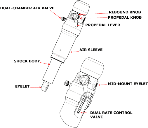
The Dual Rate Control Valve (DRCV) deploys a dual air chamber system, in which a secondary air chamber opens at a specific point during shock travel. The DRCV system combines the efficiency of a smaller air volume ride with the plush response of a large air volume shock deeper into its travel stroke.
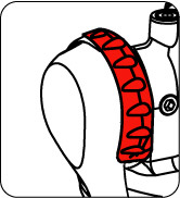
The secondary air chamber is positioned on the top of the shock, requiring the upper eyelet to be placed midway between the secondary chamber and main air sleeve.
If you are installing your shock (on a bike for which the shock is original equipment only):
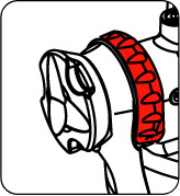
There may be a small amount of air sleeve lubricant residue on the body. This is normal. If this residual air sleeve lubricant is not present, this is an indication that the air sleeve should be re-lubricated. Some other things to consider for all shock models:
To set sag:
Note: The dual-chamber air valve looks very similar to a Schrader valve, but internally it's quite different. This valve automatically equalizes air pressure between the main and secondary air chambers, as air is pumped into or released from this dual-chamber valve.
CAUTION: Do not attempt to service the dual-chamber air valve, or remove and reinstall its core! Doing so will risk causing irreparable damage to the valve, in turn impairing normal shock operation. Any damage to this valve is repairable only by an Authorized Fox Service Center.
Note: For proper sag adjustment, it is mandatory to thread the pump hose an additional 1¼ turns past the point where the pump initially shows a pressure reading.
Note: It is necessary to cycle the shock beyond 50% of its full travel at least once after the pump hose is removed, before measuring your sag.
Shock Travel | Sag |
1.75/44.4 | .44/11.1 |
2.00/50.8 | .50/12.7 |
2.25/57.1 | .56/14.2 |
Rebound controls the rate at which your shock returns after it has been compressed. The proper rebound setting is a personal preference, and changes with rider weight, riding style and conditions. A rule of thumb is that rebound should be as fast as possible without kicking back and pushing the rider off the saddle.
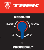
The rebound knob has 12-15 clicks of adjustment.
For slower rebound, turn the red adjuster knob clockwise.
For faster rebound, turn the red adjuster knob counterclockwise.
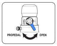
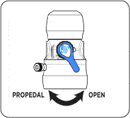
The ProPedal lever allows for on-the-fly ProPedal adjustment. ProPedal damping reduces pedal-induced suspension bob. The two ProPedal lever settings are:
Use each setting to adjust the shock for different riding conditions and situations. For example, use PROPEDAL for riding to the top of the mountain, and then switch to OPEN for the descent.
To determine which ProPedal position is better for your condition and situation, pedal the bicycle and monitor the shock movement. Switch between positions and select the one that reduces suspension movement most effectively while providing the desired amount of bump absorption.
Because suspension designs and riding skills vary, optimal settings can vary from bike to bike and rider to rider. For more precise ProPedal tuning and to further eliminate pedal-induced bob while maintaining bump compliance, adjust the ProPedal knob. As with the ProPedal lever, switch positions and select a setting that reduces suspension movement most effectively while providing the desired amount of bump absorption.
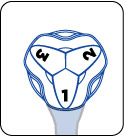
The 3-position ProPedal knob (shown below) allows you to adjust ProPedal firmness when the ProPedal lever is in the PROPEDAL position. The ProPedal knob only changes damping when the ProPedal lever is in the PROPEDALposition.
The ProPedal knob settings are denoted by the numbers etched onto the ProPedal knob. The three ProPedal knob settings are:
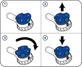
To adjust the ProPedal knob:
CAUTION: The ProPedal knob should NOT be adjusted on-the-fly. It should only be adjusted while in a stationary position.
Rebound controls the rate at which your shock returns after it has been compressed. The proper rebound setting is a personal preference, and changes with rider weight, riding style and conditions. A rule of thumb is that rebound should be as fast as possible without kicking back and pushing the rider off the saddle.
The rebound knob has 12-15 clicks of adjustment.
For slower rebound, turn the red adjuster knob clockwise.
For faster rebound, turn the red adjuster knob counterclockwise.
The ProPedal lever allows for on-the-fly ProPedal adjustment. ProPedal damping reduces pedal-induced suspension bob. The three ProPedal lever settings are:
Use each setting to adjust the shock for different riding conditions and situations. For example, use PROPEDAL 3 for riding to the top of the mountain, PROPEDAL 1 for general trail riding, then switching to OPEN for the descent.
To determine which ProPedal position is better for your condition and situation, pedal the bicycle and monitor the shock movement. Switch between positions and select the one that reduces suspension movement most effectively while providing the desired amount of bump absorption.
Rebound controls the rate at which your shock returns after it has been compressed. The proper rebound setting is a personal preference, and changes with rider weight, riding style and conditions. A rule of thumb is that rebound should be as fast as possible without kicking back and pushing the rider off the saddle.
The rebound knob has 12-15 clicks of adjustment.
For slower rebound, turn the red adjuster knob clockwise.
For faster rebound, turn the red adjuster knob counterclockwise.
The ProPedal lever allows for on-the-fly ProPedal adjustment. ProPedal damping reduces pedal-induced suspension bob. The two ProPedal lever settings are:
Use each setting to adjust the shock for different riding conditions and situations. For example, use PROPEDAL for riding to the top of the mountain, and then switch to OPEN for the descent.
To determine which ProPedal position is better for your condition and situation, pedal the bicycle and monitor the shock movement. Switch between positions and select the one that reduces suspension movement most effectively while providing the desired amount of bump absorption.
![]()
Bushing Technology & Inspection | | Oil Volumes | Dropout Thickness Inspection | Using the FOX HP Pump | Important Safety Information | Service Intervals | Contact FOX Service | FOXHelp Service Web Site