FORK- General Information and Installation Guide
Sections
- Single-Crown Fork Installation
- Dual-Crown Fork Installation (40mm)
- Mounting Disc Brakes
- Tire Size Specifications
- Using the 15QR Axle
- Using the 15mm Pinch-axle (36 Fork Models)
- Using the 20mm Pinch-axle (36 Fork Models)
- Using the Kabolt
- Using the 20mm axle (40 Fork Model)
- Service Intervals
- Safety Warnings
WARNING: FOX products should be installed by a trained bicycle service technician, in accordance with FOX installation specifications. Improperly installed forks can fail, causing the rider to lose control resulting in SERIOUS INJURY OR DEATH.
WARNING: If the steerer tube has any nicks or gouges that can be felt with your fingernail, the crown/steerer tube assembly must be replaced. A nick or gouge can cause the steerer tube to fail, resulting in a loss of control of the bicycle and SERIOUS INJURY OR DEATH.
WARNING: Never attempt to cut threads into the threadless steerers of FOX forks. Cutting threads into a threadless steerer can cause the steerer tube to fail, resulting in a loss of control of the bicycle and SERIOUS INJURY OR DEATH.
WARNING: Never use more than 30 mm of height of steerer stem spacers under the steerer stem, as this condition can cause the steerer tube to fail, causing a loss of control resulting in SERIOUS INJURY OR DEATH.
WARNING: Never allow things such as cable or cable housing to come in contact with the steer tube of a fork. If your bike has internal cable and cable housing routing, please contact FOX or consult your bicycle manufacturer's owners guide for safety instructions. Cable and/or cable housing that comes in contact with a steer tube can cause the steerer tube to fail, resulting in a loss of control of the bicycle and SERIOUS INJURY OR DEATH.
CAUTION: Cable housing contacting the fork crown will cause abrasion damage to the crown over time. If contact is unavoidable, use vinyl tape or similar protection to cover the point of contact. The FOX warranty does not cover abrasion damage to the FOX fork crown.
WARNING: Do not cut the steerer more than three (3) mm below the uppermost installed part. If the steerer length is mistakenly cut too short, it MUST BE REPLACED! Using a fork with clamped steerer engagement that is too short can lead to sudden fork failure, which can cause irrecoverable loss of control of the bicycle resulting in SERIOUS INJURY OR DEATH.
Single-Crown Fork Installation
WARNING: Never attempt to remove or replace the steerer or upper tubes independently from the crown. Modifying the integrated crown, steerer, or upper tubes can cause an assembly failure, resulting in a loss of control of the bicycle and SERIOUS INJURY OR DEATH.
- Remove the existing fork from the bicycle.
- Remove the crown race from the old fork.
- Measure the steerer tube length of the existing fork. Transfer this measurement to your new FOX fork's steerer tube.
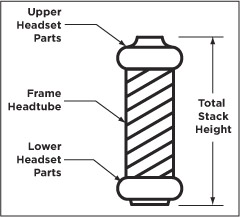
- If you don't have an existing fork to measure, measure the headset stack height (shown in the diagram below) and refer to your stem manufacturer's instructions to be sure there will be enough clamping surface for the stem. In some cases you may need to cut your steerer tube slightly shorter than the total stack height plus the stem height to allow enough clamping surface so that the stem cap bolt can pull up on the steerer tube, ensuring a snug fit.

- If you don't have an existing fork to measure, measure the headset stack height (shown in the diagram below) and refer to your stem manufacturer's instructions to be sure there will be enough clamping surface for the stem. In some cases you may need to cut your steerer tube slightly shorter than the total stack height plus the stem height to allow enough clamping surface so that the stem cap bolt can pull up on the steerer tube, ensuring a snug fit.
- If it is necessary to cut the steerer tube, measure twice and cut once. It is also recommended that a cutting guide be used while cutting the steerer tube.
- Use a crown race setter to install the crown race firmly against the top of the crown. Install the star-fangled nut in the steerer tube with a star-fangled nut installation tool to a depth of 4-10mm below the top of the steertube (see Star-fangled nut installation depth diagram below).


- Install the fork on to the bicycle. Install any steerer stem spacers (no more than 30mm), the stem, stem cap and M6 stem cap bolt on to the bicycle. Lightly tighten the stem cap bolt so that the fork turns freely without drag or free play.
Dual-Crown Fork Installation (40mm)
WARNING: FOX bicycle suspension products are designed only for bicycle applications as recommended by FOX. DO NOT use the FOX 40 fork on any throttle-equipped motorized vehicle. Misuse or incorrect application of FOX suspension products may void the warranty and further may result in suspension failure, which could result in property damage, SERIOUS BODILY INJURY OR DEATH.
WARNING: Never attempt to remove or replace the steerer independently from the crown. Modifying the integrated crown, steerer can cause an assembly failure, resulting in a loss of control of the bicycle and SERIOUS INJURY OR DEATH.
Verify your Total Stack Height
Measure to verify whether your total stack height falls within the specified range.
Total Stack Height = Frame headtube length + total headset stack height. Total Stack Height must be between 91-150mm.
- If your total stack height is less than 91mm, add a headset spacer between the upper headset parts and the upper crown, to meet the total headset stack height specification.
- If your total stack height is greater than 150mm, consider installing a shorter stack headset to meet the total headset stack height specification.
NOTE: FOX Racing Shox does not manufacture a direct mount stem. Be sure to refer to your stem manufacturer's installation instructions. Measure at least twice to be certain of all measurements, before cutting the fork steerer!
Cutting the Steertube to Proper Length
- Remove the existing fork from the bicycle.
- Remove the crown race from the old fork.
- Install your new 40 on the bicycle with all of the headset parts, stem spacers, and upper crown.
- After eliminating play in the headset, lightly tighten the steerer pinch bolt on the upper crown with a 5 mm hex wrench.
- Add any additional stem spacer(s) or steerer-mounted stem onto the steerer above the upper crown that will affect the steerer tube finished cut length. This will depend on personal preference.
- Mark the steerer with a scribe at the top edge of the uppermost installed part. With a direct mount stem, you can scribe the mark on the steerer at the top edge of the upper crown.
- Remove the 40 from the bicycle and cut the steerer 3 mm below the scribed mark. This 3 mm clearance allows room for the stem cap to lightly tension the headset and eliminate any free play.
- Use a file to de-burr the outer and inner top edges of the newly cut steerer.
WARNING: If you're installing a steerer tube-mounted stem, the total height of spacers used on a FOX steerer tube should never exceed 30 mm, as this condition can cause the steerer tube to fail, causing a loss of control resulting in SERIOUS INJURY OR DEATH.
Installing the Star-Fangled Nut and Steering Stops
Use a crown race setter to install the crown race firmly against the top of the crown. Install the star-fangled nut in the steerer tube with a star-fangled nut installation tool to a depth of 4-10mm below the top of the steertube (see Star-fangled nut installation depth diagram below).
Install one steering stop bumper onto each upper tube and place midway on the upper tube

WARNING: The 2021 FOX 27.5in. and 29in. 40mm upper tube position is factory-set to safely clear a bottomed-out 2.50” tire. Standard "top of the crown" to "top of upper tube" position is 137.50mm. Never increase "top of the crown" to "top of upper tube" measurement beyond 137mm (A). Any Upper tube position greater than 137mm would reduce tire to crown clearance and cause a rider to lose control, resulting in SERIOUS INJURY OR DEATH.
NOTE: For 2021 27.5in and 29in 40mm forks, users can slacken the headtube angle by reducing "top of the crown" to "top of upper tube" distance up to the minimum limit of 127.mm.
WARNING: The FOX 26in. 40mm upper tube position is factory-set to safely clear a bottomed-out 2.60” tire. Standard "top of the crown" to "top of upper tube" position is 157.20mm. Never increase "top of the crown" to "top of upper tube" measurement beyond 157.20mm (A). Any Upper tube position greater than 157.20mm would reduce tire to crown clearance and cause a rider to lose control, resulting in SERIOUS INJURY OR DEATH.
WARNING: The Pre-2021 FOX 27.5in. 40mm upper tube position is factory-set to safely clear a bottomed-out 2.35” tire. Standard "top of the crown" to "top of upper tube" position is 157.20mm. Never increase "top of the crown" to "top of upper tube" measurement beyond 157.20mm (A). Any Upper tube position greater than 157.20mm would reduce tire to crown clearance and cause a rider to lose control, resulting in SERIOUS INJURY OR DEATH.
WARNING: The Pre-2021 FOX 29 in. 40 mm upper tube position is factory-set to safely clear a bottomed-out 2.50 in. tire. Standard “top of the crown” to “top of upper tube” position is 137.00 mm. Never increase “top of the crown” to “top of upper tube” measurement beyond 137.00 mm (A). Any Upper tube position greater than 137.00 mm would reduce tire to crown clearance and cause a rider to lose control, resulting in SEVERE INJURY OR DEATH.
NOTE: For Pre-2021 26in/27.5in 40mm forks, users can slacken the headtube angle by reducing "top of the crown" to "top of upper tube" distance up to the minimum limit of 147.20mm. For 29in 40mm forks, users can slacken the headtube angle by reducing "top of the crown" to "top of upper tube" distance up to the minimum limit of 127.mm.
WARNING: Do not over-tighten the pinch bolts. Strictly adhere to all FOX specified torque requirements. Too much torque can damage the bolts, fracture the crown, or damage the threads. Any of these maladjustments could cause fork failure, leading to your loss of control and SERIOUS INJURY OR DEATH.
Final Fork Installation
- Install the new 40 fork on the bicycle with all of the headset parts, upper crown, spacer(s), and steerer-mount stem (if applicable).
- Install the stem cap and M6 stem cap bolt.
- With all three upper crown bolts left loosened, lightly tighten the headset stem cap bolt to remove play in the system so that the fork turns freely without drag.
- With a 5 mm hex wrench bit for your torque wrench, torque all three upper crown bolts to 65 in-lb (7.34 Nm).
- Make sure that the four lower crown bolts are torqued to 65 in-lb (7.34 Nm).
NOTE: The FOX 40 can be set up with either a direct-mount or a steerer mounted stem.
Stem Installation:
If installing a Direct Mount stem: use four (4) M6 x 1 threaded bolts in accordance with the stem manufacturer's assembly instructions. Be sure to confirm the following criteria:
- There must be a minimum of 10 mm of thread engagement of the bolts into the upper crown.
- The torque specification of the four (4) M6 mounting bolts must not exceed 110 in-lb (12.4 Nm).
- If the bolts protrude from the bottom of the crown, be sure there is no interference with the frame or cables throughout the entire span of fork rotation.

If installing a Steerer Mounted stem: tighten the steerer pinch bolts on the stem, according to the stem manufacturer's instructions.
Mounting Disc Brakes
WARNING: To avoid potential disc brake failure that could result in SERIOUS INJURY OR DEATH, the disc brake caliper mounting bolts must 1) always have 10-12 mm of thread engagement with the fork and 2) be kept torque wrench tightened to the disc brake manufacturer’s torque specification. In all cases, the disc brake caliper mounting bolt tightening torque level must never be less than the disc brake manufacturer’s torque specification, or exceed 90 in-lb torque.
WARNING: Before riding, verify that the brakes on your bicycle are installed and adjusted correctly in accordance with the brake manufacturer’s instructions. Improperly installed and adjusted brakes may cause a crash and result in property damage, SERIOUS INJURY, OR DEATH.
WARNING: Follow your brake manufacturer's installation instructions for proper installation and adjustment of the brake system. Failure to properly install and adjust your brakes can lead to a loss of control of the bicycle which can result in SERIOUS INJURY OR DEATH.
WARNING: Do not use rotors larger in diameter than 180mm with Step Cast 27.5in forks. Rotors larger than 180mm can damage Step Cast 27.5in forks causing suspension failure. Suspension failure may cause a crash and result in property damage, SERIOUS INJURY OR DEATH.
Maximum brake rotor diameter for all 32mm and 34mm FOX forks except 32 Step Cast 27.5in is 203mm. 32 Step Cast 27.5in forks have a maximum rotor diameter of 180mm.
Maximum brake rotor diameter for all 2021 36mm, 38mm, and 40mm forks is 230mm.
Use the following steps to install disc brakes on your FOX fork:
- 32mm Step Cast forks use a 160mm direct Post Mount that allows you to bolt your caliper directly to the fork and utilize a 160mm rotor.
- 32mm forks use a 160mm direct Post Mount that allows you to bolt your caliper directly to the fork and utilize a 160mm rotor.
- Pre-2022 34mm and 2022 34 SC forks use a 160mm direct Post Mount that allows you to bolt your caliper directly to the fork and utilize a 160mm rotor.
- 2022 34mm non-Step-Cast forks use a 180mm direct Post Mount that allows you to bolt your caliper directly to the fork and utilize a 180mm rotor.
- 36mm 15mm/20mm thru-axle or 15QR forks use a 180mm direct Post Mount that allows you to bolt your caliper directly to the fork and utilize a 180mm rotor.
- 38mm 15QR forks use a 180mm direct Post Mount that allows you to bolt your caliper directly to the fork and utilize a 180mm rotor.
- 40mm forks use a 203mm direct Post Mount that allows you to bolt your caliper directly to the fork and utilize a 203mm rotor.
- Install disc brakes and torque all fasteners according to manufacturer’s specifications.

- Route the front disc brake housing to the inside of the lower leg, and through the supplied disc brake housing guide. Tighten the M3 x 12 disc brake hose guide screw with a 2.5 mm hex key wrench to 8 in-lb (0.90 Nm) torque.


Tire Size Specifications
WARNING: Individual tire and rim combinations must be checked with fork fully compressed and have a minimum of 8.0mm tire to crown clearance. Reduced tire to crown clearance may cause a rider to lose control, resulting in SERIOUS INJURY OR DEATH.
WARNING: FOX forks may contain high air pressures. Release ALL air pressure from the main air chamber before disassembly. Failure to do so may result in parts or fluids ejecting from the fork which can cause SEVERE INJURY OR DEATH.
All tire and rim combinations must be checked for clearance before use.
- Release all air pressure from the fork by depressing the Schrader valve. For coil spring forks, you will need to remove the coil to compress the fork completely. Please refer to the Changing the Coil Spring (40 Performance Elite Series)» section for the coil spring removal and installation procedures.
- Compress the fork completely.
- Measure the distance between the top of the inflated tire and the bottom of the crown. There must be AT LEAST 8.5 mm* of clearance.
- Add air pressure to your desired setting using a FOX high pressure pump. See the Sag Setting section for more information.
- You must repeat this test EVERY time you change tires or rims.

*8.5mm tire clearance includes the thickness of the internal bottom out bumper.
WARNING: Failure to leave at least 8.5 mm of clearance between the top of the inflated tire and the bottom of the crown will cause the tire to jam against the crown when the fork is fully compressed, which can result in SEVERE INJURY OR DEATH.
Using the 15QR Axle
WARNING: Some models of FOX forks are equipped with the 15QR axle system to help facilitate easy installation and removal of the bicycle front wheel assembly. Before using, carefully read the 15QR instructions in your owner's manual. If you have any questions, contact your dealer or FOX for further instruction and training. Failure to properly install the 15QR axle and wheel onto your bicycle could cause the wheel to become detached from the bicycle while you are riding, and result in SERIOUS INJURY OR DEATH.
WARNING: Never use any other tool other than hand pressure to tighten the 15QR lever onto the lower leg. Over-tightening the QR lever or improperly adjusting the 15QR axle nut can damage the axle, axle nut or fork dropouts, leading to a sudden failure with one or more of these components, resulting in SERIOUS INJURY OR DEATH.
WARNING: Always rotate the 15QR axle with the lever in the open position and then cam the lever over to tighten. Never attempt to install the 15QR axle system by only rotating the 15QR lever to tighten and fasten. This will not be sufficient means to safely attach the wheel, and can result in SERIOUS OR FATAL BODILY INJURY.
15QR Axle Installation:
Wheel installation is identical for both the 15x100 mm and 15x110 mm 15QR axles.
- Install the front wheel into the fork dropouts. Slide the axle through the non-drive side dropout and hub.
- Open the axle lever.

- Turn the axle clockwise 5-6 complete turns into the axle nut.
- Close the lever. The lever must have enough tension to leave an imprint on your hand.
- The closed lever position must be between 1-20 mm in front of the fork leg.
- If the lever does not have enough tension, or has too much tension when closed at the recommended position (1-20mm in front of the fork), see the Adjusting 15QR Lever Position below.

Adjusting 15QR Lever Position
If the 15QR lever tension is either too loose or too tight when the 15QR lever is positioned between one (1) and twenty (20) mm forward of the fork leg when closed, use one of the following procedures to correct this.
- Note the axle number, which is the number at the indicator arrow.
- Use a 2.5 mm hex wrench to loosen the axle nut keeper screw approximately 4 turns, but do not completely remove the screw.
- Move the 15QR to the open position and unthread the axle approximately 4 turns.
- Push the 15QR axle in from the open lever side. This will push the axle nut keeper out and allow you to rotate it out of the way.
- Continue to push on the 15QR axle and turn the axle nut clockwise to increase the lever tension, or counter-clockwise to decrease the lever tension.
- Return the axle nut keeper into place and torque the bolt to 0.90 Nm (8 in-lb).
- Repeat the axle installation instructions to verify proper installation and adjustment.

Adjusting the 2021 QR Lever Position (Non-adjustable Axle Nut):
- Note which direction the axle lever needs to turn to achieve proper orientation.
- Open the axle lever in the fork.
- While holding the QR lever open and stationary so it cannot rotate, use a 4mm hex wrench in the center of the end of the axle to adjust the lever position. With the 4mm adjuster set properly, you should start to feel tension in the axle when the QR lever is 90 degrees before full closure in the vertical position.
- Repeat the axle installation instructions to verify proper installation and adjustment.
Using the 15mm Pinch-axle (36 Fork Models)

- Install the front wheel into the dropouts and slide the axle through the dropouts and hub.
- Using a 5mm hex wrench, torque the axle to 19 in-lb (2.15 Nm).
- Torque the two pinch bolts on the rider's left dropout to 19 in-lb (2.15 Nm).
- Compress the fork a couple of times to let the right side of the dropout float and settle to its low-friction point.
- Torque the two pinch bolts on the rider's right dropout to 19 in-lb (2.15 Nm).
WARNING: The 15mm axle should only be used with the 15mm axle adapters and 15mm axle slit shims. Do not use the 15mm axle without the 15mm axle adapters. Do not use the 15mm axle with the 20mm axle slit shims. Failure to use the proper adapters and axle slit shims with the 15mm axle can damage the fork dropouts which can lead to a loss of control of the bicycle which can result in SERIOUS INJURY OR DEATH.
WARNING: Never attempt to modify axle slit shims or axle adapters. Modification of these parts can lead to improper installation which can lead to a loss of control of the bicycle which can result in SERIOUS INJURY OR DEATH.
WARNING: When using the 15mm axle slit shims, make sure to install the notched shim in the rider's left dropout. Failure to install the 15mm axle slit shims in their correct locations may result in damage to the dropout that can lead to a loss of control of the bicycle which can result in SERIOUS INJURY OR DEATH.
WARNING: Never attempt to force any parts to fit. Doing so may result in dropout damage, which can lead to a loss of control of the bicycle that can result in SERIOUS INJURY OR DEATH.
Using the 20mm Pinch-axle (36 Fork Models)

- Install the front wheel into the dropouts and slide the axle through the dropouts and hub.
- Using a 5mm hex wrench, torque the axle to 19 in-lb (2.15 Nm).
- Torque the two pinch bolts on the rider's left dropout to 19 in-lb (2.15 Nm).
- Compress the fork a couple of times to let the right side of the dropout float and settle to its low-friction point.
- Torque the two pinch bolts on the rider's right dropout to 19 in-lb (2.15 Nm).
WARNING: The 20mm axle slit shims must be used when using the 20mm axle. Leaving the 20mm axle slit shims out when using the 20mm axle will cause dropout damage to occur, which can lead to a loss of control of the bicycle that can result in SERIOUS INJURY OR DEATH.
Using the Kabolt
Wheel installation is identical for both the 15x100 mm and 15x110 mm Kabolt axles.
- Install the front wheel into the fork dropouts. Slide the Kabolt axle through the non-drive side dropout and hub.
- Tighten the Kabolt axle (clockwise) to the torque specification printed on the head of the Kabolt.

Using the 20mm axle (40 Fork Model)
- Loosen the four (4) axle pinch bolts on the lower leg with a 5 mm hex key wrench.
- Using a 5 mm hex key wrench, turn the axle counter-clockwise to loosen and remove.
- Install the front wheel into the dropouts and install the axle into the lower leg.
- Using a 5 mm hex key wrench, turn clockwise and lightly tighten the axle to the lower leg to 19 in-lb (2.15 Nm) torque.
- Tighten the two left side (from the seated rider's perspective) dropout pinch-bolts to 19 in-lb (2.15 Nm) torque.
- Compress the fork on the bike a couple of times to let the right side of the dropout float and settle to its low-friction point. Tighten the two right side dropout pinch-bolts to 19 in-lb (2.15 Nm) torque.

Service Intervals
Make sure to properly maintain your fork and shock
To best maintain the performance and durability of your product under normal use, FOX recommends that you have regular fork and shock maintenance performed according to the service intervals listed below.


*Suspension product will require more frequent servicing the harder they are worked. For those who ride lift-accessed DH, Park, or Extreme Freeride or in extremely wet/muddy or dry/dusty environmental conditions where trail debris is sprayed onto the fork or shock while on the trail, or e-mtb's, FOX encourages riders to perform maintenance earlier than recommended above as needed. If you hear, see, or feel something unusual, stop riding immediately and contact a FOX Authorized Service Center for proper servicing.
Safety Warnings
WARNING: DO NOT use any FOX bicycle suspension products on any pedal-assisted motorized cycle or motorized vehicle that produces more than 500 watts of power. Any such misuse may result in failure of the suspension. Suspension failure may cause a crash and result in property damage, SERIOUS INJURY OR DEATH. Misuse of FOX suspension may void the warranty.
WARNING: DO NOT use standard FOX bicycle suspension products on any pedal-assisted motorized cycle or motorized vehicle that produces more than 250 watts of power. Only FOX E-BIKE OPTIMIZED suspension products should be used on motorized cycles or motorized vehicles producing between 250-500 watts of power. Any such misuse may result in failure of the suspension. Suspension failure may cause a crash and result in property damage, SERIOUS INJURY OR DEATH. Misuse of FOX suspension may void the warranty.

NOTE: Any FOX bicycle suspension products can be used on pedal-assisted motorized cycles or motorized vehicles that produce less than 250 watts of power.
WARNING: DO NOT use any FOX bicycle suspension products on any throttle-equipped motorized cycle or motorized vehicle. Any such misuse may result in failure of the suspension. Suspension failure may cause a crash and result in property damage, SERIOUS INJURY OR DEATH. Misuse of FOX suspension may void the warranty.
WARNING: Modification, improper service, or use of aftermarket replacement parts with FOX forks and shocks may cause the product to malfunction, resulting in SERIOUS INJURY OR DEATH. DO NOT modify any part of a fork or shock, including the fork brace (lower leg cross brace), crown, steerer, upper and lower leg tubes, or internal parts, except as instructed herein. Any unauthorized modification may void the warranty, and may cause failure or the fork or shock, resulting in SERIOUS INJURY OR DEATH.
WARNING: DO NOT use FOX bicycle suspension products on any vehicle carrying more than one operator or rider, such as a tandem bicycle or heavy utility bicycle.
WARNING: Always use genuine FOX parts and proper service methods when maintaining your FOX bicycle product. Improper service, or use of aftermarket replacement parts with FOX forks and shocks may cause the product to malfunction, resulting in SERIOUS INJURY OR DEATH.
WARNING: As dirt and debris can accumulate between the fork axle openings, always check and clean these areas before installing the wheel. Improper hub and axle installation can result in SERIOUS INJURY OR DEATH.