You are here: CTD Remote Setup Guide
CTD Remote Setup Guide

Installing the CTD Remote Lever Assembly
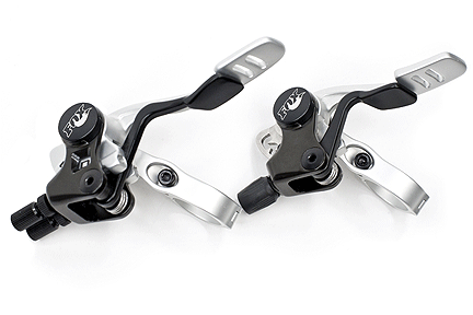
The dual or single CTD Remote lever assembly can be installed on the right or left side of the handlebar, as well as underneath or on top, giving you a total of four setup possibilities from two basic configurations:
- on the right and on top: or flipped, to be installed on the left side underneath the handlebar.
- After converting the remote lever, it can then be installed on the left on top; or flipped, to be installed on the right side underneath the handlebar.
TIP: You do not need to remove the handlebar grip to install the CTD remote lever assembly on your handlebar.
- With a 3 mm hex key wrench, loosen the bar mount bolt.
- Install the lever assembly onto your handlebar. Make sure the lever assembly does not interfere with the brake or shifter operating range in all three CTD modes; adjust if necessary.
- Tighten the bar mount clamp bolt to seven 15 in-lb (1.7 N-m) torque for aluminum handlebars.
CAUTION: it is strongly advised to use less tightening torque with carbon fiber handlebars. As a general rule, only tighten to the point when movement on the carbon fiber is just prevented. Consult the bicycle or handlebar manufacturer’s documentation regarding the specified level of tightening torque for your carbon handlebars.
CTD Fork Remote Lever Setup

- Set the remote lever to descend mode.
- Thread a new shifter cable through the remote lever assembly, exiting through an open cable adjuster barrel.
- Lightly lubricate the cable, and slide it through a ferruled end of the cable housing.
NOTE: Note: you do not need to use a ferrule at the fork remote base assembly end of the cable housing.
- Tighten the cable barrel on the remote lever all the way in clockwise, then back out a half turn.
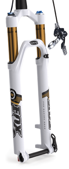
- Feed the cable and cable housing through the cable holder assembly under the fork crown, then into the port in the fork remote base assembly on top of the right fork leg.
WARNING: Always use the Remote cable holder assembly to secure the Remote fork cable housing to the fork crown. Unsecured cable housing can snag and cause a crash, resulting in SERIOUS INJURY OR DEATH.
- As you loosen the remote base set screw with a 3 mm hex key wrench, wrap the cable snugly around the groove in the base pulley, seating the cable under the screw.
- While firmly holding the cable in place, tighten the base cable set screw to 7 in-lb torque.
- Test the fork remote system:
- Engage the remote lever into the climb mode.
- The fork should be locked out (in climb mode).
- If the fork is failing to lock out:
- Set the remote lever to descend mode.
- Adjust the remote lever cable adjuster barrel counter-clockwise out a full turn.
- Repeat the items in step number eight above, until fork lockout is successfully achieved.
CTD Rear Shock Remote Lever Setup

- Set the remote lever to descend mode.
- Thread a new shifter cable through the remote lever assembly, exiting through an open cable adjuster barrel.
- Lightly lubricate the cable, and slide it through the cable housing ferruled at both ends.
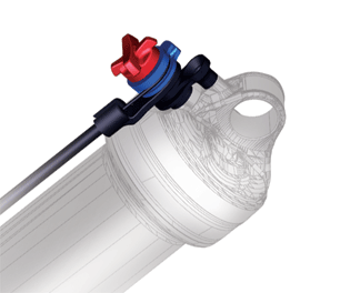
- Threading the cable through the pulley on the remote shock, pull on it firmly while tightening the cable set screw to 5 in-lb torque.
- Test the rear shock remote system:
- Slowly cycle the shock through all three CTD modes.
- The remote lever must physically engage with each of the three modes, and the shock should feel distinctly different in firmness with each mode: descend mode = soft, trail mode = medium, climb mode = firm.
- If the shock is failing to engage into each of the three modes:
- Engage the remote lever into descend mode.
- Make sure the cable is not slack, and the cable set screw is tightened to 5 in-lb torque; repeat step 4 above if necessary.
- If you repeated step 4 above, re-test the rear shock remote system. If you achieve success per step 5.b above, you are done. If not, continue with step 6.d.
- Adjust the remote cable tension by turning the remote lever cable adjuster barrel counter-clockwise one or two turns.
- Repeat the items in step five and six until the remote lever and rear shock engagement with each mode is successfully achieved.
Bushing
Technology & Inspection | Control
Direction | Oil Volumes | Structural
Inspection | Dropout Thickness Inspection | Torque Values | Unit
Conversion | Suspension Tuning Tips | Using
the Pump | Important Safety Information | Service Intervals | Contact FOX Service | Warranty Information | FOXHelp Service Web Site
Copyright © 2012
FOX Factory Inc.


