You are here: Forks > 40 mm > 40

40 RC2

Installing Your Fork | Before You Ride | Setting Sag | Adjusting Rebound | Adjusting High-Speed Compression | Adjusting Low-Speed Compression | Changing the Coil Spring | Changing Travel | Changing Oil | Service Intervals | Important Safety Information


travel

8 in./203 mm, adjustable in ½-inch increments down to 6.5 in./165 mm

features/adjustments

internally adjustable travel, low-speed compression, high-speed compression, hydraulic bottom-out in damper, coil spring preload, rebound

spring/damper type

titanium spring/RC2 FIT damper

intended use

downhill, freeride

Installing Your Fork

Be sure your fork is properly installed before proceeding. Clicking on the link above will take you to a new page.

Before You Ride

  1. Check that the 20mm axle pinch bolts and crown pinch bolts are properly adjusted and tightened.
  2. Clean the outside of your fork with only mild soap and water, and wipe dry with a soft dry rag.

    Note:  Do not use any solvents or de-greasers, as these products can cause serious damage to paint and anodized parts (upper tubes, knobs, steerers).

    Do not spray water directly on the seal/upper tube junction. Do not use a high pressure washer on your fork.

  3. Inspect entire exterior of fork for damage. The fork should not be used if any of the exterior parts appear to be damaged. Please contact your local dealer or FOX Racing Shox for further inspection and repair.
  4. Check headset adjustment. If loose, adjust according to manufacturer’s recommendations.
  5. Check that brake cables or hoses are properly fastened.
  6. Check that the front and rear brakes operate properly on flat land.

Setting Sag

You can also view a Flash video on Setting Sag.

To get the best performance from your fork, it is necessary to set and adjust sag. Generally, sag should be set to 15 – 25% of total fork travel.

  1. Install a zip tie with light friction on the upper tube and push it down until it contacts the fork seal.
  2. Carefully sit on the bike and assume a normal riding position. The fork should compress slightly.
  3. Being careful not to further compress the fork, dismount the bicycle. Measure the distance between the seal and the zip tie. This distance is sag.
  4. Compare your sag measurement to the Sag Setup table below.

    If sag is lower than in the table
    , turn the preload knob (shown below) counter-clockwise one (1) full turn. Measure sag again and repeat adjustment if necessary.

    If sag is higher than in the table
    , turn the preload knob clockwise one (1) full turn. Measure sag again and repeat adjustment if necessary. If correct sag cannot be achieved by adjusting the preload knob, see the 40 Coil Spring Settings table below. You may need to obtain a coil with a different spring rate.


    40 Coil Spring Settings

    FOX Part #

    Spring Rate

    Color Code

    Rider Weight (lbs.)

    039-05-070

    30 lb/in

    Black

    <90 – 120

    039-05-071

    35 lb/in

    Purple

    120 – 150

    039-05-062

    40 lb/in

    Blue

    150 –180

    039-05-073

    45 lb/in

    Green

    180 – 210

    039-05-074

    50 lb/in

    Yellow

    210 – >240


    Sag Setup

    Travel

    15 - 25% Sag

    6 in. (152 mm)

    0.9 - 1.5 in. (23 - 38 mm)

    6.5 in. (165 mm)

    1.0 - 1.6 in. (25 - 41 mm)

    7 in. (178 mm)

    1.1 - 1.8 in. (27 - 45 mm)

    7.5 in. (191 mm)

    1.1 - 1.9 in. (29 - 48 mm)

    8 in. (203 mm)

    1.2 - 2.0 in. (30 - 51 mm)


    Sag Troubleshooting

    Symptom

    Remedy

    Too much sag

    Change to higher rate coil spring

    Too little sag

    Change to lower rate coil spring

    Excessive bottoming

    Change to higher rate coil spring

    Harsh ride; full travel not utilized

    Change to lower rate coil spring

Adjusting Rebound

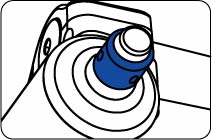
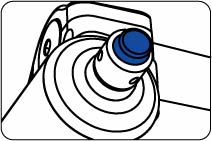
The rebound knob (shown below) is located on the top of the right fork leg, and has 15 clicks of adjustment. Rebound controls the speed at which the fork extends after compressing. Turning the knob clockwise slows down rebound; turning the knob counterclockwise speeds up rebound. As a starting point, turn the rebound adjuster knob all the way clockwise (full in) until it stops, then turn counterclockwise (out) 8 clicks.


Knob Setting
(clicks out from full in)

Setting Description

Tuning Tips

Setup Tips

1

Slow Rebound

Too slow and your fork will pack down and ride harsh.

If you increase your spring rate or air pressure, you will need to slow down your rebound

8

(Factory setting)

Average Rebound


15

Fast Rebound

Too fast and you will experience poor traction and wheel hop.

If you decrease your spring rate or air pressure, you will need to speed up your rebound setting.

Adjusting High-Speed Compression

High-speed compression damping controls the force it takes to move the fork through its travel and how the wheel reacts to a bump. This adjuster rotates to stops at each end and has 15 clicks of adjustment. It is set from the factory at 8 clicks out from the full closed (clockwise) position. The knob is protected by the black protective cap. Never ride your FOX 40 without the black protective cap.


Knob Setting
(clicks IN from full OUT)

Setting Description

Tuning Tips

1

Soft Compression

Maximum wheel traction and bump compliance. If setting is too soft, you may bottom often on square-edged hits and G-outs.

8

(Factory setting)

Average Compression


15

Firm Compression

Reduces bottom-out and provides maximum bump absorption. If setting is too firm, you may experience a harsh ride with bad traction and use too little available travel.


Adjusting Low-Speed Compression

Low-speed compression damping controls the influence of the rider’s weight shifts and bike attitude under braking. This adjuster rotates to stops at each end and has 17 clicks of adjustment. It is set from the factory at 8 clicks out from the full closed (clockwise) position. The knob is protected by the black protective cap. Never ride your FOX 40 without the black protective cap.


Knob Setting
(clicks IN from full OUT)

Setting Description

Tuning Tips

1

Soft Compression

Maximum wheel traction and bump compliance. Too soft and you maybe have excessive brake dive and a wallowy feel.

8

(Factory setting)

Average Compression


17

Firm Compression

Resists brake dive and keeps the fork up in the travel. Too firm and you may have poor traction in loose conditions.


Hydraulic Bottom-Out System

The 40 is equipped with a patent-pending Internally Adjustable Hydraulic Bottom-Out Control System. This feature can be adjusted inside the cartridge by FOX Racing Shox or an Authorized Service Center. It comes preset from the factory at the FIRM setting.

Changing the Coil Spring

  1. With a 32 mm 6-point socket wrench, loosen and remove the preload top cap (top of left leg).
  2. Remove the black spring spacers (three (3) spacers for 8 in./203 mm travel, two (2) for 7.5 in./190 mm travel, one (1) for 7 in./178 mm travel, zero (0) for 6.5 in./165 mm travel).
  3. Compress the fork slightly and remove the coil spring. You may need to firmly pull up on the spring to disengage it from the plunger shaft.
  4. Wipe the spring dry with a rag and check the color code.
  5. Install the new spring by dropping it into the upper tube.
  6. Install the travel spacers, then torque the top cap to 165 in-lbs (1864 N-cm).
  7. Measure and set sag. Adjust the preload topcap adjustment if necessary.

Changing Travel

Travel on the 40 can be changed in 1/2” increments, by rearranging the three internal travel spacers inside the left leg of the fork. With the proper tools and oil, changing the travel can be achieved in about 15 minutes.

The following tools and supplies will be needed: A 32 mm 6-point socket, 10 mm open end wrench or socket, torque wrench, plastic hammer, oil drain pan, clean dry lint-free towels, measuring container, as well as the following:


Quantity

Part Number

Part Name

1

025-03-004-A

1 qt. bottle of Fox Suspension Fluid (7 wt.)

  1. The fork does not have to be removed from the bicycle for changing travel.
  2. Place the bicycle (or fork, if removed) in a bike stand.
  3. Using a 32 mm socket wrench, remove the left side topcap.
  4. Remove the spacer(s) on top of the coil spring (three (3) spacers for 8 in./203 mm travel, two (2) for 7.5 in./190 mm travel, one (1) for 7 in./178 mm travel, zero (0) for 6.5 in./165 mm travel).
  5. Using a 10 mm socket wrench, unscrew the left side bottom nut 6 turns.
  6. Place a clean dry oil pan underneath the left side of the fork.
  7. Tap on the bottom nut with a plastic faced hammer to disengage the plunger shaft from the lower leg.
  8. Unscrew and remove the bottom nut and crush washer.
  9. Push up on the shaft with a thin screwdriver and let the oil drain.
  10. Compress the fork and pull the coil spring/plunger shaft assembly out of the top of the left side upper tube.
  11. Pull the coil spring off the plunger assembly.  
  12. Looking at the table below, determine the number of travel spacer(s) needed on the plunger shaft for your desired travel.
  13. Slide the black negative spring guide away from the flanged head of the aluminum plunger shaft.
  14. Push and snap on the correct number of the travel spacers to the plunger shaft and slide back the black negative spring guide against the spacers.

    Travel Spacer Settings

    Travel Setting

    # of Spacers Under Topcap

    # of Spacers on Plunger Shaft

    8.0" (203 mm)

    3

    0

    7.5" (190 mm)

    2

    1

    7.0" (178 mm)

    1

    2

    6.5" (165 mm)

    0

    3


  15. Push and snap on the coil spring to the plunger shaft assembly.
  16. Install the coil spring/plunger shaft assembly into the top of the left side upper tube. Install the correct number of spacers on top of the coil spring and thread the topcap into the upper tube.
  17. Remove the bicycle from bike stand and turn the bike upside down.
  18. Using a thin screwdriver and sliding the lower leg up or down, push and align the plunger shaft so that it is aligned and comes through the hole in the lower leg.
  19. Once aligned, push the lower leg down and install the crush washer and bottom nut.
  20. Using a 10 mm socket and torque wrench, torque the bottom nut to 50 in-lb (565 N-cm).
  21. Turn the bike right side up and place it back into the bike stand.
  22. Remove the left side preload topcap and pour in 50 cc of FOX Suspension Fluid (7 wt.).
  23. Install and torque the preload topcap to 165 in-lb (1864 N-cm).
  24. After changing the travel, compress the fork a few times and check for proper operation before riding—there should be no free movement or play in travel. If there is free movement in the fork or if it makes strange noises, disassemble the fork and check that all three spacers are in the fork and in the correct orientation for the desired travel.
  25. Go ride.

Changing Oil

The following tools and supplies will be needed: A 32 mm 6-point socket, 10 mm open end wrench or socket, 15 mm deep 6-point socket, torque wrench, 2 mm hex key wrench, plastic hammer, small screwdriver, oil drain pan, clean dry lint-free towels, as well as the following:


Quantity

Part Number

Part Name

1

025-03-004-A

1 qt. bottle of Fox Suspension Fluid (7 wt.)

1

241-01-002-C

8 mm Crush washer

1

241-01-011

13 mm Crush Washer


An oil change with the FOX 40 RC2 fork consists of changing the lower leg oil bath in each leg. This oil bath service can be performed with the common tools listed above, and the fork does not have to be removed from the bicycle. This service will not require any disassembly of the closed RC2 cartridge.

CAUTION:  Do not attempt to disassemble the FOX 40 RC2 closed cartridge system. Only FOX Racing Shox or an Authorized Service Center should perform such a procedure.

  1. Place the bicycle or fork in a stand.
  2. Remove the disc brake caliper from the lower leg and secure it to the handlebars or frame.
  3. Using a 5 mm hex key wrench, loosen the four axle pinch bolts.
  4. Using a 5 mm hex key wrench, unscrew the axle five full revolutions counterclockwise and remove from the lower leg.
  5. Remove the front wheel from the bike.  
  6. Place a clean dry oil pan underneath the left side of the fork. Using a 10 mm open-end wrench or socket, loosen the bottom nut 6 full turns.
  7. Tap on the bottom nut with a plastic faced hammer to disengage the plunger shaft from the lower leg.
  8. Unscrew and remove the bottom nut and 8 mm crush washer. Pull the lower leg downward until you feel it stop. Let the oil drain into the oil pan.
  9. RC2: Unscrew and remove the black protective cap. Using a 2 mm hex key wrench, unscrew the set-screw approximately two turns and remove the low-speed compression adjuster knob.  Using a 2 mm hex key wrench, unscrew the set-screw approximately two turns and remove the high-speed compression adjuster knob.

    Note:  The 1/8” diameter chrome steel detent ball and detent spring are in the machined hole in the high-speed compression adjuster knob.

  10. Using a 15 mm deep socket wrench, unscrew the bottom nut four turns. Place a clean dry oil pan underneath the right side of the fork.
  11. Using a 15 mm deep socket on the bottom nut (to protect the adjusters), tap on the bottom nut with a plastic hammer to disengage the base stud from the lower leg.
  12. Remove the bottom nut and 13 mm crush washer from the base stud and set them aside.  
  13. Push up on the base stud to let the oil bath oil drain out of the fork into the drain pan. If the oil looks black or a dark gray, flush both sides of the lower leg with clean oil.
  14. To flush the lower leg, turn the fork upside-down and add about 20 cc of oil into each leg. If the fork is off the bike, you can move it around to get the clean oil all over the inside of the fork. Let the fork drain into the drain pan until it stops dripping.
  15. Turn the bike or fork upside-down, pull up on the lower leg and add 40 cc of FOX Suspension Fluid (7 wt) into the right-side bottom hole (damper side) of the lower leg. Keeping the lower leg in the up position, add 40 cc of FOX Suspension Fluid (7 wt) into the left-side bottom hole (spring side) of the lower leg.  
  16. Slide the lower leg down until you can put on a NEW right-side 13 mm crush washer with the old bottom nut. Thread on the bottom nut (2 to 3 turns max).
  17. Using a 15 mm deep 6-point socket, torque the cartridge bottom nut to 50 in-lb.
  18. Slide the lower leg down further so the plunger stud on the left side of the fork goes through the hole of the lower leg. You may need to use a thin screwdriver to move and align the plunger shaft so that it goes through the hole of the lower leg.
  19. Install a NEW left-side 8 mm crush washer with the old bottom nut. Thread on the bottom nut (2 to 3 turns max).
  20. Using a 10 mm socket, torque the plunger bottom nut to 50 in-lb.
  21. RC2: Turn the bicycle right side up. Look at the two compression adjuster shafts on the bottom of the right side damper. If you cannot find both flat spots, rotate the adjuster shaft by lightly turning the shaft with needle nose pliers (see figure above). Using a 2 mm hex key wrench, align and install the RC2 high-speed compression adjuster knob so that the set screw tightens on the flat spot of the shaft.  Be careful that the detent spring and chrome steel ball are in the top-side of the machined hole. Be careful not to over-torque this knob because it will cause the knobs to bind. Now align and install the RC2 low-speed compression adjuster knob so that the set screw tightens on the flat spot of the shaft. The torque for both compression knobs is 4 in-lb. Turn the knobs to make sure they turn freely and install the black protective cap.  
  22. Wipe down the lower leg. Reinstall your disc brake caliper and torque fasteners to disc brake manufacturer’s specifications. Using a 5 mm hex key socket and torque wrench, reinstall the front wheel and thread in the axle and torque to 19 in-lb. Tighten the 2 left-side axle pinch bolts and torque to 19 in-lb. Compress the fork a few times to allow the right side of the fork leg to settle into its low friction spot. Tighten the 2 right side axle pinch bolts and torque to 19 in-lb. Your oil change is complete. Now go ride!

WHEREVER YOU RIDE. WHEREVER YOU RIDE.


Bushing Technology & Inspection | Seals & Foam Rings | Control Direction | Oil Volumes | Structural Inspection | Dropout Thickness Inspection | Torque Values | Unit Conversion | Suspension Tuning Tips | Using the Pump | Important Safety Information | Service Intervals | Contact FOX Service | Warranty Information | FOXHelp Service Web Site


Copyright © 2010
FOX Factory Inc.